ITR – Ingress Tunnel Router – devices which accepts traffic from the client and looks at transmitting to the destination.
ETR – Egress Tunnel Router – device which transmits traffic to the client, this is where destination client is attached.
These above roles of LISP would be on Fabric Edge node.
Example of Ping (I am omitting the full lookup against Map Resolver and RLOC etc): Client A —> Switch A (ITR) —> Switch B (ETR) —> Client B
Reply: Client A <— Switch A (ETR) <— Switch B (ITR) <— Client B
If a node has both roles ITR and ETR, that Fabric Edge switch is referenced as xTR
(P – Proxy) PITR and PETR would be the Border node which communicates with destinations outside the fabric, Similarly to the last example, one border node can have both roles and can be referenced as PxTR.
Traffic example: Client A —> Switch A (ITR) — Border A (PITR) —> Server A
Reply: Client A <— Switch A (ETR) <— Border A (PETR) <— Server A
If you look Proxy Egress tunnel router is actually inbound from the endpoint’s perspective and inbound means back in the direction of Fabric site and similarly Proxy Ingress Tunnel router is packet entering the fabric from endpoint
ESXI and VCenter Deployment
-: Z840 :-
Upgrade BIOS Factory Reset BIOS set controller mode to AHCI from RAID enable Intel VTd under System Security section
192.168.0.10 esxi01.home.local <<<< 192.168.0.11 vcenter.home.local <<<< This is checked from local machine when running VCSA setup to install vcenter, this check is different from vcenter A and PTR record lookup by installer, that is why DNS server on Windows server 2016 is needed
Bring up a winserver 2016 instance in eveng metal and configure DNS server on it
Import vcenter Certificates in Installation station
Because we are deploying appliance through VA launcher script, we need to import certificates of vcenter into local computer trusted root certificate’s store, go to https://vCenter_FQDN/certs/download.zip, download ZIP and extract all the certs and import them
Windows Server DNS deployment
configure forward zone configure reverse zone create A record vcenter.home.local 192.168.0.11 dnac.home.local 10.21.1.2
Windows 10 and VYOS deployment
Windows 10 VM Create Windows 10 VM for VYOS deployment validation and internet access check 2 vCPUs 5GB RAM 25GB disk
admin/Test123
Pet name dnac
City born in dnac
City parents met dnac
Assign only 192.168.0.200/24 and do not assign gateway 192.168.0.1 Disable IPv6 on the Windows VM interface connect VM’s interface in vcenter Go to Network folder and join the network Share Downloads folder copy wub and debloater to downloads folder once all done then put network interface in DHCP again
VYOS deployment 2 CPUs RAM 2 GB 4 GB Disk
! Install open-vm-tools on VY OS gateway

vyos@vy-gateway:~$ sudo vim /etc/apt/sources.list

! press esc to make sure we are in normal mode
! press i to go in insert mode

! enter first line
deb http://deb.debian.org/debian bullseye main contrib

! press escape
! enter ":wq"

vyos@vy-gateway:~$ sudo cat /etc/apt/sources.list
deb http://deb.debian.org/debian bullseye main contrib

! Update failed because of no DNS resolution
vyos@vy-gateway:~$ sudo apt update
Ign:1 http://deb.debian.org/debian bullseye InRelease
Ign:1 http://deb.debian.org/debian bullseye InRelease
Ign:1 http://deb.debian.org/debian bullseye InRelease
Err:1 http://deb.debian.org/debian bullseye InRelease
  System error resolving 'deb.debian.org:http' - getaddrinfo (16: Device or resource busy)
Reading package lists... Done
Building dependency tree... Done
Reading state information... Done
All packages are up to date.
W: Failed to fetch http://deb.debian.org/debian/dists/bullseye/InRelease  System error resolving 'deb.debian.org:http' - getaddrinfo (16: Device or resource busy)
W: Some index files failed to download. They have been ignored, or old ones used instead.

vyos@vy-gateway:~$ sudo bash

root@vy-gateway:/home/vyos# sudo bash -c 'cat > /etc/resolv.conf <<EOF
nameserver 8.8.8.8
nameserver 1.1.1.1
EOF'

root@vy-gateway:/home/vyos# cat /etc/resolv.conf
nameserver 8.8.8.8
nameserver 1.1.1.1

root@vy-gateway:/home/vyos# apt update
Get:1 http://deb.debian.org/debian bullseye InRelease [75.1 kB]
Get:2 http://deb.debian.org/debian bullseye/main amd64 Packages [8,066 kB]
Get:3 http://deb.debian.org/debian bullseye/main Translation-en [6,235 kB]
Get:4 http://deb.debian.org/debian bullseye/contrib amd64 Packages [50.4 kB]
Get:5 http://deb.debian.org/debian bullseye/contrib Translation-en [46.9 kB]
Fetched 14.5 MB in 4s (4,084 kB/s)
Reading package lists... Done
Building dependency tree... Done
Reading state information... Done
8 packages can be upgraded. Run 'apt list --upgradable' to see them.

! install should work now
root@vy-gateway:/home/vyos# apt install -y open-vm-tools
Reading package lists... Done
Building dependency tree... Done
Reading state information... Done
The following additional packages will be installed:
  libdrm-common libdrm2 libmspack0 libssl1.1 libxmlsec1 libxmlsec1-openssl
  libxslt1.1
Suggested packages:
  open-vm-tools-desktop cloud-init
Recommended packages:
  zerofree
The following NEW packages will be installed:
  libdrm-common libdrm2 libmspack0 libssl1.1 libxmlsec1 libxmlsec1-openssl
  libxslt1.1 open-vm-tools
0 upgraded, 8 newly installed, 0 to remove and 8 not upgraded.
Need to get 2,793 kB of archives.
After this operation, 8,598 kB of additional disk space will be used.
Get:1 http://deb.debian.org/debian bullseye/main amd64 libdrm-common all 2.4.104-1 [14.9 kB]
Get:2 http://deb.debian.org/debian bullseye/main amd64 libdrm2 amd64 2.4.104-1 [41.5 kB]
Get:3 http://deb.debian.org/debian bullseye/main amd64 libmspack0 amd64 0.10.1-2 [50.3 kB]
Get:4 http://deb.debian.org/debian bullseye/main amd64 libssl1.1 amd64 1.1.1w-0+deb11u1 [1,566 kB]
Get:5 http://deb.debian.org/debian bullseye/main amd64 libxslt1.1 amd64 1.1.34-4+deb11u1 [240 kB]
Get:6 http://deb.debian.org/debian bullseye/main amd64 libxmlsec1 amd64 1.2.31-1 [149 kB]
Get:7 http://deb.debian.org/debian bullseye/main amd64 libxmlsec1-openssl amd64 1.2.31-1 [100.0 kB]
Get:8 http://deb.debian.org/debian bullseye/main amd64 open-vm-tools amd64 2:11.2.5-2+deb11u3 [632 kB]
Fetched 2,793 kB in 0s (10.4 MB/s)
Preconfiguring packages ...
Selecting previously unselected package libdrm-common.
(Reading database ... 84389 files and directories currently installed.)
Preparing to unpack .../0-libdrm-common_2.4.104-1_all.deb ...
Unpacking libdrm-common (2.4.104-1) ...
Selecting previously unselected package libdrm2:amd64.
Preparing to unpack .../1-libdrm2_2.4.104-1_amd64.deb ...
Unpacking libdrm2:amd64 (2.4.104-1) ...
Selecting previously unselected package libmspack0:amd64.
Preparing to unpack .../2-libmspack0_0.10.1-2_amd64.deb ...
Unpacking libmspack0:amd64 (0.10.1-2) ...
Selecting previously unselected package libssl1.1:amd64.
Preparing to unpack .../3-libssl1.1_1.1.1w-0+deb11u1_amd64.deb ...
Unpacking libssl1.1:amd64 (1.1.1w-0+deb11u1) ...
Selecting previously unselected package libxslt1.1:amd64.
Preparing to unpack .../4-libxslt1.1_1.1.34-4+deb11u1_amd64.deb ...
Unpacking libxslt1.1:amd64 (1.1.34-4+deb11u1) ...
Selecting previously unselected package libxmlsec1:amd64.
Preparing to unpack .../5-libxmlsec1_1.2.31-1_amd64.deb ...
Unpacking libxmlsec1:amd64 (1.2.31-1) ...
Selecting previously unselected package libxmlsec1-openssl:amd64.
Preparing to unpack .../6-libxmlsec1-openssl_1.2.31-1_amd64.deb ...
Unpacking libxmlsec1-openssl:amd64 (1.2.31-1) ...
Selecting previously unselected package open-vm-tools.
Preparing to unpack .../7-open-vm-tools_2%3a11.2.5-2+deb11u3_amd64.deb ...
Unpacking open-vm-tools (2:11.2.5-2+deb11u3) ...
Setting up libssl1.1:amd64 (1.1.1w-0+deb11u1) ...
Setting up libmspack0:amd64 (0.10.1-2) ...
Setting up libxslt1.1:amd64 (1.1.34-4+deb11u1) ...
Setting up libxmlsec1:amd64 (1.2.31-1) ...
Setting up libdrm-common (2.4.104-1) ...
Setting up libxmlsec1-openssl:amd64 (1.2.31-1) ...
Setting up libdrm2:amd64 (2.4.104-1) ...
Setting up open-vm-tools (2:11.2.5-2+deb11u3) ...
Created symlink /etc/systemd/system/vmtoolsd.service → /lib/systemd/system/open-vm-tools.service.
Created symlink /etc/systemd/system/multi-user.target.wants/open-vm-tools.service → /lib/systemd/system/open-vm-tools.service.
Created symlink /etc/systemd/system/open-vm-tools.service.requires/vgauth.service → /lib/systemd/system/vgauth.service.
Processing triggers for libc-bin (2.36-9+deb12u10) ...
localepurge: Disk space freed:      0 KiB in /usr/share/locale
localepurge: Disk space freed:      0 KiB in /usr/share/man
localepurge: Disk space freed:      0 KiB in /usr/share/aptitude
localepurge: Disk space freed:      0 KiB in /usr/share/vim/vim90/lang

Total disk space freed by localepurge: 0 KiB

root@vy-gateway:/home/vyos#
vyos/C0mplex30
Install from live image
install image
show configuration
show configuration commands

configure
set interfaces ethernet eth0 address '192.168.0.12/24'
set interfaces ethernet eth0 description 'home'

set interfaces ethernet eth1 address '172.16.25.1/24'
set interfaces ethernet eth1 description 'mgmt'

set interfaces ethernet eth2 address '10.21.1.1/24'
set interfaces ethernet eth2 description 'data'


show interface ethernet
show interface ethernet eth0
show interface ethernet eth0 physical

set protocols static route 0.0.0.0/0 next-hop 192.168.0.1 distance '1'
set service ssh port '22'
set system host-name 'vy-gateway'

commit
save
vcenter edit host and create a new standard switch and call it mgmt edit host and create a new standard switch and call it data
add 2nd interface for vy-gateway into mgmt add 3rd interface for vy-gateway into data
home router Add routes for networks 10.21.1.0/24 and 172.16.25.0/24
vyos routing is reachable
Cisco Catalyst Center 2.3.7.x on ESXi Deployment – Part 1
Virtual Machine Minimum Requirements
Feature
Description
Virtualization platform and hypervisor
VMware vSphere (which includes ESXi and vCenter Server) 7.0.x or later, including all patches.
Processors
Intel Xeon Scalable server processor (Cascade Lake or newer) or AMD EPYC Gen2 with 2.1 GHz or better clock speed.32 vCPUs with 64-GHz reservation must be dedicated to the VM.
Memory
256-GB DRAM with 256-GB reservation must be dedicated to the VM.
Storage
3-TB solid-state drive (SSD).If you plan to create backups of your virtual appliance, also reserve additional datastore space. For information, see “Backup Server Requirements” in the Cisco Catalyst Center on ESXi Administrator Guide.
I/O Bandwidth
180 MB/sec.
Input/output operations per second (IOPS) rate
2000-2500, with less than 5 ms of I/O completion latency.
Latency
Catalyst Center on ESXi to network device connectivity: 200 ms.
Cisco Catalyst Assurance uses near real-time streaming analytics, which requires heavy resource usage. When operating Catalyst Center on ESXi close to maximum scale, this functionality may be impacted by uncontrolled external events, such as host resource oversubscriptions and edge use cases that result in a resource usage spike. A number of things can indicate that these events are taking place, such as slow performance, data processing gaps, high I/O latency, and a CPU readiness percentage that’s higher than normal.
Catalyst Center VM can be deployed using Catalyst Center VA Launcher
Import the IdenTrust Certificate Chain
The Catalyst Center on ESXi OVA file is signed with an IdenTrust CA certificate, which is not included in VMware’s default truststore. As a result, the Deploy OVF Template wizard’s Review details page will indicate that you are using an invalid certificate while completing the wizard. You can prevent this by importing the IdenTrust certificate chain to the host or cluster on which you want to deploy the OVA file.
Cat center requires access to following URLs during install
In order to…
…Catalyst Center on ESXi must access these URLs and FQDNs
Download updates to the system and application package software; submit user feedback to the product team.
Recommended: *.ciscoconnectdna.com:4431Customers who want to avoid wildcards can specify these URLs instead:https://www.ciscoconnectdna.comhttps://cdn.ciscoconnectdna.comhttps://registry.ciscoconnectdna.comhttps://registry-cdn.ciscoconnectdna.com
Manage Cisco Enterprise Network Function Virtualization Infrastructure Software (NFVIS) devices.
*.amazonaws.com
Collect product telemetry.
https://data.pendo.io
Allow API calls to enable access to Cisco CX Cloud Success Tracks. Otherwise, the enhancements made to extended configuration-based scanning for the Security Advisories, Bug Identifier, and EOX features that Machine Reasoning Engine (MRE) supports will not operate as expected.
Recommended: *.meraki.com:443Customers who want to avoid wildcards can specify these URLs instead:dashboard.meraki.com:443api.meraki.com:443n63.meraki.com:443
Check SSL/TLS certificate revocation status using OCSP/CRL.
Allow Cisco authorized specialists to collect troubleshooting data when Catalyst Center on ESXi Remote Support functionality is enabled.
wss://prod.radkit-cloud.cisco.com:443
Integrate with cisco.com and Cisco Smart Licensing.
*.cisco.com:443Customers who want to avoid wildcards can specify these URLs instead:software.cisco.comcloudsso.cisco.comcloudsso1.cisco.comcloudsso2.cisco.comapiconsole.cisco.comapi.cisco.comapx.cisco.comsso.cisco.comapmx-prod1-vip.cisco.comapmx-prod2-vip.cisco.comtools.cisco.comtools1.cisco.comtools2.cisco.comsmartreceiver.cisco.com
Connect to the Network-Based Application Recognition (NBAR) cloud.
prod.sdavc-cloud-api.com:443
Render accurate information in site and location maps.
www.mapbox.com*.tiles.mapbox.com/* :443. For a proxy, the destination is *.tiles.mapbox.com/*
For Cisco AI Network Analytics data collection, configure your network or HTTP proxy to allow outbound HTTPS (TCP 443) access to the cloud hosts.
In the File Explorer, navigate to: Control Panel\System and Security\Administrative Tools Double-click Services. This same task can be completed by entering services.msc in the Windows Run dialog (Windows Key + R).
In the Services list, right-click on Windows Time and click Stop. Note: The Windows Time service may already be stopped. In this case, skip this step and go to the next step to Update the Windows Registry
Update the Windows Registry to Create a Local NTP Service
Launch Windows Run (Windows Key + R). Enter regedit and click OK.
Navigate to the registry key: Computer\HKEY_LOCAL_MACHINE\SYSTEM\CurrentControlSet\Services\W32Time\Parameters
If you do not see LocalNTP REG_DWORD in the list, create it using the following steps. Right-click in the Registry Editor, select New, select DWORD and enter LocalNTP (note that this name is case sensitive).
Double-click LocalNTP, change the Value data to 1, select a Base of Hexadecimal , and click OK. Do not close the Registry Editor because it is used in the following steps.
Update the Windows Registry to Configure the Time Provider
Navigate to the registry key: Computer\HKEY_LOCAL_MACHINE\SYSTEM\CurrentControlSet\Services\W32Time\TimeProviders Select NtpServer, double-click Enabled, change the Value Data to 1, select a Base of Hexadecimal and click OK.
Do not close the Registry Editor because it is used in the following steps.
Update the Windows Registry to Configure the Announce Flags
Navigate to the registry key: Computer\HKEY_LOCAL_MACHINE\SYSTEM\CurrentControlSet\Services\W32Time\Config Double-click AnnounceFlags, change the Value data to 5, select a Base of Hexadecimal, and click OK. Close the Registry Editor.
Start the Local Windows NTP Time Service
In the File Explorer, navigate to: Control Panel\System and Security\Administrative Tools Double-click Services. In the Services list, right-click on Windows Time and configure the following settings: Startup type: Automatic Service Status: Start OK
Finally, enable UDP port 123 on the Windows firewall for incoming connections.
In Search find Firewall in Windows Defender… Go to Incoming rules In the right column, select New rule… Select the rule Port Enter UDP port 123 and click Next Select Allow connection and click Next Select all domains Enter the rule name, e.g. Local NTP server, and click Finish.
The local NTP Time Server configuration is now complete. You now can synchronize the time of other computers and devices on your local network.
In case unable to login Login to CLI as maglev on VM’s console and reset password for admin
Logins
Default GUI login admin/maglev1@3 Login to create account admin_anas/C0mplex30 SSH login on port 2222 maglev/C0mplex30 DNAC VM Console login maglev/C0mplex30
Initial Login
provide user here that will be super admin such as admin_anas provide your cco in email and not personal email admin_anas/C0mplex30
provide company’s CCO details here that has contract and active cco – this is very important otherwise packages will not work
With new build make sure DNAC has internet access, go ahead and download the applications packages which are needed for SGT and SDA, Cisco has divided these features into applications or packages and with fresh install / build download these packages
Download these packages
Turn off the VM
Take Snapshot with exact date and time
Turn off time syncing of VM with ESXI
ESXI add NTP server same as Windows Server
Windows Server move back time on server when it is time to restore the VM
When restore cut off internet access to DNAC
Here do not use personal email instead use email from company’s cco
on next deployment also download below modules also Sensor Assurance AI Endpoint Analytics Application Visibility and Policy (EasyQoS)
! Check service status
sudo systemctl status ssh

! Check if SSH is listening on port 22
sudo ss -tlnp | grep :22

! Check service state quickly
systemctl is-active ssh

! If SSH is not running, start it
sudo systemctl start ssh

! Enable it at boot:
sudo systemctl enable ssh
Turns on Port Address Translation (PAT) using a pool of IP addresses instead of a single interface IP
Spread outbound traffic across multiple public IPs
Avoid port exhaustion
Improve performance for large user bases
Use Round Robin Allocation: Distributes sessions evenly across IPs in the PAT pool. Firewall may keep using the same IP until ports fill up, Connections rotate across pool addresses evenly, this is recommended for medium / large environments
Extended PAT Table: “Usually fine disabled unless scaling issues exist” Allows multiple translations using the same IP:port combination under certain conditions. Supports higher connection density Useful in high-volume NAT environments
Flat Port Range: Allows PAT to use the entire available port range equally instead of reserving segments From v6.7+, it’s always enabled automatically Improves port utilization efficiency
Include Reserve Ports: Allows firewall to use ports normally reserved for special services if needed Prevents port exhaustion
show platform hardware fed switch active fwd-asic resource tcam utilization
CAM Utilization for ASIC  [0]
 Table                                              Max Values        Used Values
 --------------------------------------------------------------------------------
 Unicast MAC addresses                               32768/1024      1223/21
 L3 Multicast entries                                 8192/512          0/9
 L2 Multicast entries                                 8192/512          0/11
 Directly or indirectly connected routes             24576/8192      4934/1996
 QoS Access Control Entries                           5120            153
 Security Access Control Entries                      5120            246
 Ingress Netflow ACEs                                  256              8
 Policy Based Routing ACEs                            1024             22
 Egress Netflow ACEs                                   768              8
 Flow SPAN ACEs                                       1024             13
 Control Plane Entries                                 512            255
 Tunnels                                               512             17
 Lisp Instance Mapping Entries                        2048              3
 Input Security Associations                           256              4
 SGT_DGT                                              8192/512          0/1
 CLIENT_LE                                            4096/256         35/0
 INPUT_GROUP_LE                                       1024              0
 OUTPUT_GROUP_LE                                      1024              0
 Macsec SPD                                            256              2
shows TCAM (Ternary Content Addressable Memory) utilisation on a Cisco switch ASIC AM is a limited hardware resource used to store things like routing entries, ACLs, QoS rules If it fills up, the switch can’t program new entries in hardware (which can cause drops or punt-to-CPU issues).
Some Max Values have 2 values divided by / First number = hardware maximum Second number = software or per-region allocation such as Unicast MAC addresses 32768/1024 1223/21 Means: Currently used = 1223 (hardware), 21 (allocated region) Max hardware = 32,768 MACs Allocated region = 1,024
MAC Addressing (Layer 2)
Unicast MAC addresses 32768/1024 1223/21
Very low usage → ✅ healthy
No concern at all
Routing (Layer 3)
Directly or indirectly connected routes 24576/8192 4936/1996
This is important
You’re using:
~5K out of 24K hardware → ✅ fine
~2K out of 8K allocated → ⚠️ moderate
Watch this if:
You add more routes (e.g. BGP, OSPF growth)
You hit the 8192 allocation, not just the 24576 max
So what happens if software limit is reached but not hardware limit For example for Routing (Layer 3), 8K allocated is reached Does hardware allocate more to software?
No — the hardware will NOT automatically give more TCAM to that feature.
If the software/allocated limit (e.g. 8K for L3 routes) is reached, you can hit problems even if the total hardware TCAM isn’t full
What’s really going on
Think of TCAM like a building:
Hardware limit (24K) = total building capacity
Software allocation (8K) = rooms assigned to “routing”
Other rooms are assigned to ACLs, QoS, etc.
If routing fills its 8K “room”:
It cannot spill into other rooms
Even if those rooms are empty
What happens when the 8K allocation is hit?
For L3 routes:
1. New routes fail to install in hardware
FIB (Forwarding Information Base) can’t program entries into TCAM
2. Traffic impact
Depending on platform:
Packets may be dropped
Or punted to CPU (slow path → performance issues)
3. You may see logs like:
FIB TCAM full
Hardware programming failed
CEF adjacency install failed
4. Control plane vs data plane mismatch
Route exists in routing table (RIB) ✅
But not in hardware (FIB) ❌
This is where things break.
Hardware DOES NOT auto-rebalance
Unlike RAM or CPU:
TCAM is statically partitioned
No dynamic borrowing between features
So what can you do?
1. Change TCAM allocation (SDM template)
On Cisco switches (e.g. Catalyst), you typically use:
Cisco ASA and FTD, the IKEv2 priority is determined by a numerical value where the lower the number, the higher the priority
Priority Ranking: A policy with a priority of 1 is the highest priority, while higher numbers (e.g., 65,535) are lower priority.
Negotiation Order: When negotiating security associations (SA), the device starts with the lowest priority number and works its way up until it finds a match.
Best Practice: It is recommended to configure your most secure, desired settings with the highest priority (lowest number).
Concept of OIL / OIF and Incoming interfaces are that the routers in the path should only forward the stream if there are interested receivers downstream. If no one has joined the multicast group on a given path, the routers should not send traffic that way
When a switch sees Broadcast MAC address of FF:FF:FF:FF:FF:FF, it knows the frame is a broadcast and floods it out of all ports in the same VLAN, “except the port it was received on”.
Multicast handling
If routers see destination address is a multicast address, routers treat it as multicast traffic and not like unicast traffic
Similarly if switches look at the ethernet frame and detect it to be multicast mac address then they treat it differently
Multicast IP address is never used as source address and it is always used as destination address, source IP will be the unicast IP address of the sender.
Simiarly the destination MAC on layer 2 will be a Multicast MAC address starting with “01:00:5E”
Multicast ranges
224.0.0.0 to 224.0.0.255 – Reserved for local network control traffic and TTL of 1 232.0.0.0 to 232.255.255.255 – Reserved for Source Specific Multicast (SSM). 239.0.0.0 to 239.255.255.255 – These addresses are meant to be used inside an organization
Multicast Forwarding with PIM-DM first
PIM-SM has mandtory requirement for RP so to keep things simple we will start learning from PIM-DM first, even though we never deploy PIM-DM due to high control plane footprint
Source starts sending traffic to a multicast IP address Any number of receivers can choose to subscribe to that group
You can see that r1 forwards the multicast traffic toward r3 because there is an interested receiver behind it.
Multicast Reverse Path Forwarding (RPF)
This is required to prevent duplicate packets arriving,
RPF checks “source IP address” of that packet in unicast routing table If multicast packet arrive on the interface it would use to reach the source?’ If the answer is yes, the RPF check passes, and that multicast traffic is accepted
If the packet arrived on any other interface, the RPF check fails, and the packet is dropped
IGMP – Internet Group Management Protocol
IGMP (Layer 2) playes key role in multicast on LHR and FHR’s LAN side Switches have to perform IGMP snooping
Part of IGMP also runs on host Host uses IGMP to signal their interest in multicast traffic Host sends IGMP Membership Report, also known as an IGMP join to the multicast group address
if PIM neighborship is established on LHR then (PIM-DM will start forwarding traffic right away) in case of PIM-SM LHR will send join towards RP
IGMPv1 is the original version. It allows hosts to join a multicast group but does not support leaving a group explicitly, Routers rely on timeouts to figure out when receivers are no longer interested
IGMPv2 improves on this by adding an explicit leave message.
IGMPv3 adds support for Source Specific Multicast. With IGMPv3, receivers can specify not only the multicast group they want to join, but also which source they want to receive traffic from
IGMPv2
IGMP messages are carried inside IP packets using IP protocol number 2, IP because it is the router that initiates using General Membership query / Group specific query and also the Membership report or IGMP join has to come from end host inside IP
They are always sent with a TTL of 1
IGMPv2 General Membership query
As soon as PIM is enabled on router interface, IGMP is also enabled automatically Router immediately starts sending IGMP General Membership Queries with source as the interface IP and destination is 224.0.0.1 (All hosts)
The router periodically sends IGMP General Membership Queries to check if receivers are still interested. As long as reports continue to arrive, the router keeps forwarding the multicast stream.
in General Membership Query multicast address is set to 0.0.0.0
As a result all the hosts still interested in even one Multicast group will respond with IGMP Membership report or IGMP join with their randomzied Max response time among themselves
Host whose max response timer expires first, responds to the General Membership query with an IGMP membership or IGMP Join to 239.1.1.1 and other host also see that because they are also listning for 239.1.1.1, If those other hosts are listening for same group and see that IGMP join then they do not send their membership report and suppress it
This report suppression mechanism is to keep IGMP traffic low, otherwise hundreds of hosts can respond at the same time or different times and burden the router’s CPU
IGMPv2 Join or IGMPv2 Membership Report
Host sends Memership report to the Multicast group address and not to 224.0.0.2 or 224.0.0.13
IGMP Leave Message
When a host no longer wants to receive a multicast stream, it sends an IGMP Leave Group message
The source IP of this message is the unicast IP of the host, and the destination IP is the all routers multicast address 224.0.0.2.
The router sends two group-specific queries, one second apart, and if no membership report is received within 0.5 seconds after the last query, the router removes the multicast group from that interface.
IGMP Snooping
Switch gleans or snoops into the IGMP exchange between router and the hosts to map the Multicast group to ports mapping, this whole mechanism exists because of the way switch performs forwarding using source based learning, once a mac is learned by switch, frames with that destination address it is not flooded but unicasted according to mac table on switch
But multicast mac address is never used as source address so its entry is never built By default, the switch has no idea which ports actually have interested receivers, so the safest option is to flood multicast traffic out of all ports in the VLAN which is very ineffecient subjecting all connected hosts to the multicast traffic.
When IGMP snooping is enabled, It watches for IGMP membership reports from receivers and notes which ports those reports came in on
From this, the switch builds a table that maps multicast groups to specific switch ports
When multicast traffic starts flowing, the switch no longer floods it everywhere. Instead, it forwards the multicast frames only out of the ports where it has seen joins for that multicast group. Ports with no interested receivers do not get the traffic
Switch also learns which port is connected to the routers by listening on IGMP and PIM messages
The switch also listens for IGMP leave messages. When a receiver leaves a group, the switch updates its table and stops forwarding multicast traffic to that port
IGMP Behvaiour deviation from standard
Remember earlier we talked about how, when a router sends an IGMP query, only one receiver replies due to the report suppression mechanism. This behaviour creates a challenge for the switch.
With this approach, sometimes the switch would not know which ports actually have active receivers for the multicast group, and it would have no way to build an accurate multicast forwarding table.
Switch changes the beahviour and forwards the first IGMP membership report toward the router, but it does not flood that report to other hosts. This way other receivers on different ports get delay timers expire and then send their own reports. The switch sees these reports locally and learns that there are multiple interested ports for the same multicast group even though only one report was forwarded upstream to the router.
Similarly, when the switch receives an IGMP Leave message on a port, the switch only forwards a leave message to the router when the leaving host is actually last host
For example, if two receivers are joined to the same multicast group and one of them sends a leave, the switch does not forward that leave to the router. Only when the last receiver leaves does the switch forward the leave message upstream.
Also worth mentioning that when the switch receives IGMP leave message on a port, it does not immediately assume that there are no receivers left on that port. It sends an IGMP query out of that same port to check if there are any other interested receivers. This is important in cases where multiple hosts exist behind a single port or when that port connects to another switch.
If you enable IGMP immediate leave, the switch skips this verification step and removes the port from the multicast group as soon as it sees the leave message.
Using Cisco routers as hosts for Multicast send and Multicast receive
no ip routing
ip default-gateway x.x.x.x
Basic PIM-DM configuration
no ip pim autorp
!
ip multicast-routing
!
interface Ethernet0/1
 description r1 -> sender
 ip address 10.1.0.1 255.255.255.0
 ip pim dense-mode
!
interface Ethernet0/2
 description r1 -> [receiver_01,receiver_02]
 ip address 10.1.1.1 255.255.255.0
 ip pim dense-mode
!
As soon as we enable PIM, IGMPv2 is automatically enabled on those interfaces. The router immediately starts sending IGMP General Membership Query messages out of the interfaces, effectively asking, ’Is there any interested receiver on this segment?’
You can check the -IGMP enabled -Timers like 60 seconds query interval -10 seconds max response time -IGMP querier router -Multicast designated router -R1 is the only router on the segments
r1#show ip igmp interface
!
Ethernet0/1 is up, line protocol is up
 Internet address is 10.1.0.1/24
 IGMP is enabled on interface
 Current IGMP host version is 2
 Current IGMP router version is 2
 IGMP query interval is 60 seconds
 IGMP configured query interval is 60 seconds
 IGMP robustness-variable is 2
 IGMP querier timeout is 120 seconds
 IGMP configured querier timeout is 120 seconds
 IGMP max query response time is 10 seconds
 Last member query count is 2
 Last member query response interval is 1000 ms
 Inbound IGMP access group is not set
 IGMP activity: 0 joins, 0 leaves
 Multicast routing is enabled on interface
 Multicast TTL threshold is 0
 Multicast designated router (DR) is 10.1.0.1 (this system)
 IGMP querying router is 10.1.0.1 (this system)
 No multicast groups joined by this system
!
Ethernet0/2 is up, line protocol is up
 Internet address is 10.1.1.1/24
 IGMP is enabled on interface
 Current IGMP host version is 2
 Current IGMP router version is 2
 IGMP query interval is 60 seconds
 IGMP configured query interval is 60 seconds
 IGMP robustness-variable is 2
 IGMP querier timeout is 120 seconds
 IGMP configured querier timeout is 120 seconds
 IGMP max query response time is 10 seconds
 Last member query count is 2
 Last member query response interval is 1000 ms
 Inbound IGMP access group is not set
 IGMP activity: 0 joins, 0 leaves
 Multicast routing is enabled on interface
 Multicast TTL threshold is 0
 Multicast designated router (DR) is 10.1.1.1 (this system)
 IGMP querying router is 10.1.1.1 (this system)
 No multicast groups joined by this system
Download CA certificate and upload it to the Trusted store of ISE
We will select this option “Trust for client authentication and Syslog” as certificate presented to ISE during EAP TLS 802.1x authentication will be certificates issued by this same CA
Create CSR for Admin usage
enter DNS Name as $FQDN$ and also enter second DNS name as wildcard with remaining domain name *.or2.sys.cisco and also add the SAN entry of type IP address with value of 172.16.32.12
ISE gave this error
So I removed first entry of $FQDN$
it is trusted now in browser if we access it on its FQDN
CNI Channel utilization Noise levels Interference data – contains Rogue
Rogue
A Cisco Wireless LAN Controller (WLC) classifies a MAC address as rogue when it detects a wireless device that is not part of your authorized infrastructure but is visible to your access points.
-Unknown Access Point Detected by Your APs If your access points hear another AP’s beacon frames and that AP is not registered on the WLC, it’s classified as a rogue AP.
-Device Connected to the Wired Network but Advertising Wi-Fi If the WLC detects that a wireless device’s MAC address also appears on the wired network, it may flag it as a rogue-on-wire device (higher risk)
-Unauthorized AP Using Your SSID If another AP broadcasts your organisation’s SSID, the WLC treats it as Evil twin attack.
-Client Device Associated with a Rogue AP client connected to a rogue AP, not the AP itself. The controller still flags it because it’s interacting with an untrusted wireless source
-Temporary Classification During Discovery A device may briefly appear rogue simply because It hasn’t yet been classified
Co-channel interference vs Adjacent channel interference
Co-channel Interference
Co-channel interference occurs when two transmitters use the same frequency channel in different cells and their signals overlap at a receiver.
Example: Two base stations far apart reuse Channel A, but a user near the edge of a cell receives signals from both → interference.
Adjacent channel Interference
Adjacent channel interference occurs when signals from nearby frequency channels spill over into each other.
Example:Channel A and Channel B sit next to each other in frequency. A strong Channel A signal leaks into Channel B’s receiver.
conf t
!
! Enable the archive feature
archive
 log config
  logging enable
  notify syslog contenttype plaintext
  hidekeys
!
! Optional: Set up where the archived configs are stored
 path flash:config-archive
 write-memory
!
end
!
! Ensure syslog logging is enabled (optional but recommended)
conf t

logging buffered 64000
service timestamps log datetime msec
!
end
write mem
Imagine how critical it is for medical device that controlled a life support or patient safety function, you would probably want the wireless network to be fast, reliable, and available
Cisco also uses the Plan-Build-Manage (PBM) process
Meet with a customer to gather requirements as part of the Prepare phase. You perform site surveys as part of the Plan and Design phases
Verifying, monitoring, optimizing, troubleshooting, and hardening—tasks that usually take place in the Operate and Optimize phases.
Coverage vs Density
You might notice that one building has several large classrooms and a large lobby area. If you toured the building at a time when those areas were empty, you might not realize that the customer expects every classroom to support streaming video over the wireless network and that the lobby must support large numbers of people as they move between classes.
A healthcare customer might show you a large emergency department and an outdoor area where ambulances arrive. Unless you ask, you might not realize that the customer expects the outdoor area to have full wireless coverage for emergency staff, each carrying a wireless phone, as they move in and around a large number of ambulance vehicles. Ask about the need to cover stairwells, elevators, outside entrances, and other gathering places.
Some areas might need basic wireless coverage for users who are located throughout, and other areas have densely packed users and expect a high level of network performance, when more people are under one AP, air time is reduced for that AP and also load increases on that AP also
Always evaluate each area according to RF coverage versus capacity.
These topics are covered in greater detail in Chapter 5, “Applying Wireless Design Requirements.”
It might seem obvious that the focus of a wireless design is to provide wireless coverage in all desired areas. We should also take the client or user population into account so that network performance is acceptable to all users
With thorough site survey work, you should be able to choose the number and location of APs that are necessary because you have to buy APs based on site surveys, considering coverage and client density into the account
Types of endpoints
It is also important to find out the “type of devices” that will be using this wireless network for example in hosiptal environment we might have RFID tags , wireless body cameras, wireless phones and so on so it is important to ask in advance
When you have mix of devices, then compare all 802.11 standards supported for example some devices support a/b/g/n, while others support ac and one for ax. This information becomes important if you decide to disable specific data rates to improve performance and adjust the cell size of the APs. Fortunately, none of the devices requires “only” 802.11b, so you might think about disabling the slowest corresponding data rates.
Locked to specific channels
Sometimes devices are hard locked to use certain channels, each device type supports a specific list of channels on each band. On 2.4GHz, some voice communicator can work with channels 1 through 11, which may mean the device can be used only in the United States. The 5GHz channel specifications listed are not very consistent across the devices. This becomes important if a device supports channels that your design might have disabled. The device will still find APs operating on valid channels, but it may spend valuable time scanning the disabled channels to look for APs there. This wasted time can make roaming from one AP to another much longer, disrupting the user experience.
DFS channels
The embedded wireless module in hospital beds and expensive medical equipment can support all 5GHz channels but includes a note that discourages use of any Dynamic Frequency Selection (DFS) channel. DFS channels carry a special requirement that the AP and all clients using a channel must abandon it temporarily if a radar signal is detected
The process of abandoning a channel and moving to a different one takes valuable time, which would disrupt communications. Therefore, if you had planned on enabling all of the U-NII-1, U-NII-2, U-NII-2 Extended, and U-NII-3 bands to take advantage of the greatest number of available channels, you might be disregarding the recommendation. Instead, you should consider disabling the “U-NII-2 and U-NII-2 Extended bands to avoid using the DFS channels“.
Disabling Data rates
You should also pay attention to the data rates supported by each device type. As you will learn later in this book, you will want to disable some of the lowest data rates on the APs to limit the size of their RF coverage or cell areas
As long as each device type can still support the remaining higher data rates that you will leave enabled, it should operate successfully. However, you might have some legacy or unique devices that require some lower data rates. If you disable those rates, the devices will not be able to operate at all.
Transmit power levels
A higher transmit power generally allows a wireless device to send its signal over a longer distance. This is because stronger signals lose strength more slowly as they travel through space (a process called path loss).
Higher transmit power helps with following:
-Increasing communication distance between device and AP -Helps signals penetrate obstacles (walls, furniture, etc.) -Can improve signal-to-noise ratio (SNR) -improves signal reliability at the edge of coverage – increasing transmit power on an access point (AP) can push the edge of coverage further, but only to a limited extent, because Wi-Fi coverage is two-way
When you raise the AP’s transmit power:
Devices farther away can still hear the AP’s signal The usable coverage boundary moves outward Signal reliability improves near the previous edge of coverage
So in that sense, yes—the edge of coverage shifts outward.
The key limitation (client transmit power) – 2 way
However, client devices (phones, laptops, tablets):
usually transmit at much lower power than the AP may not be able to reply back reliably from that new outer edge
This creates a situation where:
-the client can hear the AP -but the AP cannot hear the client clearly
Wireless communication is two-way. Increasing transmit power on only one device does not fully extend usable range unless the receiving device can respond with sufficient power too.
Different device transmit powers due to battery conservation
Wireless devices can also differ according to their RF capabilities. For example, the transmit power level of one device might be very different from that of another device. This variation is usually due to the form factor involved. If a device is relatively small, such as a wireless phone or voice communicator, its battery is probably small too. The device may limit its transmit power to a lower level so that it can conserve its battery power throughout the day.
Ideally, the device and AP transmit power levels should be equal or symmetric so that the signals can travel and be received in both directions.
Receiver Sensitivity
When a client device is located near the edge of an AP cell, it must be able to receive the AP’s signal at a level that is above the threshold its receiver requires to interpret the signal. That threshold is known as the receiver sensitivity.
Higher data rates need higher RSSI and SNR
As a rule of thumb, increasing data rates use more complex methods to encode and modulate the signal. This, in turn, requires higher signal-to-noise ratios (SNRs) and receive signal levels that are higher than the sensitivity threshold
Client Density
Client density is essentially the number of devices per AP. As more clients join an AP, they must all compete for the available airtime on the channel. The end results are poor performance and unsatisfactory user experience. The design should provide an adequate number of APs such that the user population is distributed across the APs
Crowded venues may require more dense wireless support, if only to distribute the airtime and bandwidth to users who may be downloading or viewing identical content for a class.
WIPS
Cisco WLCs offer a rich set of WIPS signatures that are used to match against traffic passing over a WLAN
Applications on clients
You also have to ask the nature of applications that will be used by clients, if client is using realtime services such as voice, video, VDI or heavy file transfer, then we need to think on how each client running these applications will affect the airtime in peak times
A dense population of bandwidth-intensive applications might starve users of available bandwidth
Lower data rates, longer distance – Higher data rates, shorter distance
The main factor in a data deployment is the minimum data rate supported by each AP. Lower data rates can be successfully used at greater distances from the AP because simpler modulation and coding methods are used to carry the data over the air. Such signals are easier to interpret at the receiving end
Higher data rates use more complex methods and are more sensitive to the signal and noise levels. Therefore, they are dependable when the signal is stronger, nearer to the AP.
In Design A, a low data rate of 6Mbps is acceptable, while Design B raises the rate to a minimum of 24Mbps. Notice that the AP cell sizes are considerably larger in Design A than in Design B. That means only four APs can cover the area in Design A. To cover the same area in Design B, eight APs are required.
With the focus on RF coverage, a low minimum data rate translates to a lower number of APs required. As the minimum data rate is raised, more APs are needed.
Reducing the AP cell size has one more effect. The number of clients associated to each AP is reduced, even if the clients are densely packed into the area. Therefore, a higher density of users can best be served by a higher density of APs. AP cell size and density are topics that are covered in greater detail in Chapter 5.
Voice/Video Deployment Model
Voice or video devices will usually have a limit on the acceptable amount of jitter. As well, these devices will need seamless roaming so that the voice or video calls are not dropped or interrupted as the clients move around.
A source of interference can cause packet errors that interrupt a voice or video stream.
Other factors like -poor radio frequency (RF) coverage (having low or poor access to channel) -high channel utilization (too many devices on a single channel) -excessive collisions (contended airtime and high channel use) can also impede good data throughput and integrity
If roaming has problems and is not smooth then during the roaming process, wireless frames might get dropped
An AP deployment model that is focused on voice and video application traffic is not too different from a data deployment
For voice minimum mandatory data rate of 12 or 24Mbps, with boundaries at −67 dBm.
Location Deployment Model
Sometimes real-time location services (RTLS) are needed to automatically determine the physical location of wireless devices. RTLS can be used to
“to track the locations of wireless clients” “track assets like healthcare equipment” “to track rogue devices that might be causing problems on the network” “to locate sources of wireless interference”
A device is located by measuring its RSSI from several APs that can receive its signal, then using the multilateration technique to compute its physical location relative to the receiving APs
If a single AP is used to determine a device’s location, the distance from the AP to the device can be estimated by the RSSI and attenuation from free space path loss. However, the device could be located anywhere along a circle surrounding the AP, If more APs are added to the computation, the number of possible locations can be greatly narrowed. Ideally, a wireless design should have enough APs distributed across the covered area such that a signal from any device location can be received by at least three APs
RFID Tag
If an object has no 802.11 capability, a small 802.11 RFID tag can be attached to it. The tag periodically transmits an 802.11 probe request frame to announce itself to any listening APs, allowing its location to be computed. Usually RFID tags transmit at the lowest mandatory data rate so that their signals can reach the greatest number of APs. Depending on their capabilities, some tags can send a payload of information such as push button and so on
Typical location-based AP deployment models do not focus on any requirements other than RF coverage but there is one special requirement, some of the APs are required to be located around the perimeter of the coverage area because of that even when a tracked device is located near an outer wall, its location can be computed accurately
If a customer wants to use a combination of wireless devices that does not fit one specific model, such as laptops and tablets, along with wireless phones and RFID tags. Which model should drive your wireless design? You can combine all three to form a hybrid model that can support all of the devices.
Wireless Interference
Wireless interference refers to unwanted radio frequency (RF) signals that disrupt or degrade the performance of a Wi-Fi network
Rogue devices
There are different kinds of rogue devices:
Rogue AP: An employee plugs in a personal Wi-Fi router to get better signal at their desk which simply connects into the switch, Attackers can connect through it and bypass enterprise security controls.
Evil Twin AP: A malicious AP pretending to be your legitimate network, Clients connect unknowingly and attackers capture credentials.
Rogue Client: An unauthorized wireless client connected to your infrastructure, such as third party device or BYOD device somehow connected to Corp SSID
Chapter 2. Conducting an Offsite Site Survey
Radio frequency (RF) propagation depends on the environment, and if you do not know the environment, you cannot possibly design your network properly. This does not mean that you should rush onsite with site survey tools. The site survey starts before traveling
Type of building
Some of the first elements you should collect in preparation for a site survey are a map and building materials
Type of business / building
Covering an office building is not the same as covering a warehouse, and knowing the line of business and activity
Number of APs – Density vs Coverage vs Application
you should have a clear idea of the type of coverage needed, data, real-time applications, and location-based services, this will help in determining the number of APs needed
Knowing the number of APs will help you plan how much time it will take to survey the facility.
Attenuation
The loss of signal strength is more pronounced as the signal passes through different objects, Therefore, knowing the expected obstacles will help you estimate the size of each cell.
Transmit power and signal propogation / Attenuation
The power of AP radio signals is expressed in dBm. dB stands for decibels, a unit to measure relative power on a logarithmic scale, and m stands for milliwatt, m or milliwatt helps scale or measures the transmitted or received power, using 1 milliwatt as the reference value.
Because the dB scale uses logarithms, it is not linear, doubling the transmit power is represented by a gain of 3 dB (and, symmetrically, halving the power is represented by a loss of 3 dB)
Increasing the power by 10 is represented by adding 10 dB, and dividing the power by 10 is represented by subtracting 10 dB
For example, a transmit power of 20 mW can be represented as 13 dBm. This is because you start from a 1 mW reference, which is expressed as 0 dBm, because you have nothing more or less than the reference starting point. You then multiply that reference power by 10, thus reaching 10 mW (or [0 + 10] dBm), and you double that power, thus reaching 20 mW (or [0 + 10 + 3] dBm).
For example, the AP radio is “set” to 13 dBm But attenuation is measured in dB and not hte dBm
Each obstacle and each material absorb some of the signal. In the Cisco world, there is a common reference table
Object in Signal Path
Signal Attenuation Through the Object
Plasterboard wall
3 dB
Glass wall with metal frame
6 dB
Cinderblock wall
4 dB
Office window
1–3 dB
Metal door
6 dB
Brick wall
8 dB
Concrete wall
12 dB
Phone and body position
3–6 dB
Phone near field absorption
Up to 15 dB
Different countries use different building practices. A brick wall that represents 8 dB attenuation in one country may be labeled as 12 dB attenuation in another because the brick is different—thicker, with additive isolating material, with or without inner air chambers, and so on.
Keep in mind that each site surveyed will have different levels of multipath distortion, signal loss, and signal noise.
Enterprise Office
Enterprise Wi-Fi environments show two main trends:
Increase in devices: Workers commonly get laptops (wired and fixed stations become less common), and users also bring phones and tablets. The wireless space becomes crowded with devices
Throughput reduces as more clients are boarded
You should also explain to your customer that a wireless network is designed for a target throughput and that adding throughput is not just about adding more APs later. Adding more throughput typically means conducting a new site survey. If any change in user density is expected, it is better to take this possibility into account early.
Large open spaces & Atrium
Providing coverage in such an open space might prove challenging. The signals from many APs around the atrium, on different floors, may bleed through and travel far in the open space. The result may be that too many APs are detected from the atrium area. You may have to plan ahead and take this difficulty into consideration, positioning the APs far from the atrium area and using only one or two APs specifically to cover the open space.
Another type of issue may be encountered in large meeting rooms or auditoriums where you may expect a very high density of users (perhaps several hundreds of users). Because of the size of this type of room, using standard APs with internal antennas is often not feasible. You may have to come up with creative solutions, such as using directional antennas or a high density of APs set to low power.
Client floors in the building
You may need to know how many floors in a building are leased by client, in these cases you should expect RF neighbors you cannot control. They may use all possible channels and be set to maximum power. You should be ready to work around these limitations
Healthcare
Healthcare site surveys are often time-consuming because almost every hospital is a multistory building with numerous small rooms.
Hospitals also have special rooms, like trauma and X-ray areas, where the walls might be lead-lined and completely stop RF signals.
In addition, hospitals have restricted access policies that apply to some areas, such as surgical rooms and clean rooms. It is often difficult to obtain access to these rooms, and when you do, you may not be allowed to carry your laptop. Even so, you may still be expected to provide wireless access inside these areas.
Healthcare environments often require the WLAN to support a large number of application types: paging, voice, a wide range of data applications (such as mobile carts and patient monitoring devices), and location services. These applications may be critical for keeping patients alive, and your design should ensure optimal signal to every corner of every room, even when all doors are closed.
Hospitals also use laptops on wheels (also called workstations on wheels, or WoWs) that are pushed
They may be transmitting while moving, requiring you to design your network by taking into account roaming paths and required throughput. Hospitals also often provide public Internet access for their patients and visitors, and this service may compete with the staff network.
Another common use case for wireless in healthcare environments is location tracking. This tracking may be used for assets (for example, blood pumps, beds, wheelchairs, and other assets
Hotels
Hotels are much like hospitals in their building construction and configuration (that is, usually multiple floors with many rooms). Beyond guest Wi-Fi, hotels have started using WLANs to support devices for taking inventory of things such as minibars, staff location, equipment status, and more
Hotels want to offer their guests fast, reliable Internet access, which means fewer users per AP. This can easily be achieved in guest rooms. However, hotels often have restaurants and retail and convention areas, where user density may be much higher
These are usually public places and thus susceptible to theft and vandalism. A common requirement is to properly secure APs to ceilings or walls or to hide them above the ceiling.
Guest should be able to connect to the wireless network without requiring external assistance, which means that connection security is often very limited to allow for compatibility with the largest possible number of devices
Hotels also have many of the same concerns as hospitals regarding aesthetics. APs may need to be hidden in the walls or ceiling, where possible, or behind elements of the furniture.
Education
In high schools and universities, personal devices are common, and many students carry several devices. Most of these devices will be configured to connect to the school network and will associate as soon as they are in range. They may then perform automatic updates and stay connected all day long, even if the student is not actively using them. The density of devices may place a serious strain on the wireless infrastructure and may force you to set up a security policy by which each student has credentials, allowing one session at a time.
You may also have to implement congestion policies. A common design is to account for 25 to 30 students (not devices) per AP, which may mean that in some cases you need more than one AP per classroom.
School buildings present the same issues as large office buildings and hospitals. The survey needs to be conducted with 3D in mind, as signal will bleed through floors and ceilings
You are also likely to need to deal with large atriums and large auditoriums with high student density, where you may face too much signal from too many APs. Here again, you may need to use directional antennas to increase the AP density without creating too much interference.
National Electrical Manufacturers Association (NEMA) enclosures with enclosed locks can help prevent tampering or theft. You can use these enclosures in locations where APs cannot be hidden easily or in truly high-risk areas
Retail
Stores must also often comply with specific regulations, such as those from the Payment Card Industry (PCI). These requirements may create additional constraints in the type of encryption and the characteristic of the Wi-Fi cells deployed for the staff. Another concern in the retail industry is the close proximity of the store to other RF devices. Some locations might stock and display RF devices in the store, such as satellite systems, baby monitors, and cordless phones. Others may use non-Wi-Fi cameras or cordless phone systems. Many of these devices might operate in the 2.4GHz range, and some might operate in the 5GHz range. APs should not be installed next to this type of equipment because they typically have a higher transmitter power.
Keep in mind that coverage may be needed on loading docks or inside trucks at the loading dock. Depending on the WLAN design, there might be enough RF coverage extending to the outside of the buildings to accommodate this need, but it should be factored into the design. You need to observe customer behavior. If staff scan goods from inside the trucks while loading or unloading, you need to plan for coverage accordingly. Trucks may have metallic trailers, and providing coverage inside a truck might require a directional antenna. The goods may absorb the signal, so you might need to place your APs strategically to work around the absorption issue. Here again, observing customer habits is key to a good design.
Warehousing
There might be a limited number of users during the day, but when a shipment comes in (or when multiple shipments come in at the same time), many or all users might be operating at the same time. Coverage areas are generally large and subject to a lot of multipath distortion or RF interference because of concrete floors, metal roofing, and metal shelving. Cell size is more important than data rates because warehouse applications are generally transaction driven, with small packet sizes. Cell coverage overlap needs to be from 10% to 15%. The usage is not very high, but the users are highly mobile and must roam often.
Stock levels vary over time
A warehouse at a 50% stocking level has a much better RF footprint than it has at 100%. Goods such as lead-based paint will reflect the signal, and paper or pet food will absorb the signal and reduce the usable cell size
if you plan to install an AP in a harsh environment, you may need to put it in a protective box, NEMA 4X rating ensures protection against corrosion, windblown dust and rain, and splashing water and hose-directed water; this is the right level of protection for an AP.
Outside the United States, other ratings agencies may provide equivalent ratings. For example, the International Electrotechnical Commission (IEC) has released the standard IEC 60529, which defines the protections offered by casing devices. Under this standard, IP66 provides the same level of protection as NEMA 4X.
RF regulatory bodies and transmit power / channel use
each country has its own regulations governing the RF spectrum
In the United States, the Federal Communications Commission (FCC) determines what frequencies and transmission power levels can be used
Europe and some other countries follow the specifications of the European Telecommunications Standards Institute (ETSI).
When implementing a wireless network, you must make sure that the AP transmissions comply with local regulations.
5GHz Band Channel Allocation
FCC regulates the effective isotropic radiated power (EIRP), which is the total energy radiated out of the AP antennas on a particular channel.
Spatial stream
Instead of sending data one piece at a time, modern Wi-Fi splits data into parallel streams and sends them simultaneously. This increases speed without needing extra bandwidth.
Think of spatial streams like extra lanes on a motorway 🚗: More lanes = more traffic moving at once.
When you use an access point that has multiple radio chains (for example, with four possible spatial streams), the EIRP represents the combined energy of all chains
A chain = one hardware signal path that can transmit or receive one spatial stream
A 4×4 MIMO access point has: 4 transmit chains, 4 receive chains supports up to 4 spatial streams. That means it can send four separate data signals at the same time (if the client also supports them).
A radio chain (often called an RF chain) is a complete transmit/receive signal path inside a wireless device. Each chain includes its own electronics that generate, process, and send one independent radio signal to an antenna (or antenna port).
This means that each radio chain may transmit at higher or lower power, depending on which other radio chains are also transmitting. The AP makes that change automatically and dynamically on a per-frame basis, per frame because air acts as half duplex
This also means that the energy radiated per unit of frequency (for example, per MHz) is lower when you use a larger channel (such as 80 MHz) than when you use a narrower channel (such as 20 MHz), as the total amount of radiated energy needs to stay the same regardless of the channel width.
The key idea here is power is fixed, but bandwidth changes — so the power per MHz decreases when the channel gets wider
So if the same total power is spread across: 20 MHz → more power per MHz
80 MHz → less power per MHz
its more like you are qasting energy by sending on 20 Mhz frequency
EIRP is calculated by adding the transmitter power (in dBm) to antenna gain (expressed in isotropic antenna or decibel referenced to isotropic antenna [dBi]) and subtracting any cable losses (in decibels):
EIRP = Tx power (dBm) + Antenna gain (dBi) − Cable loss (dB)
There are many regulatory rules, and you are supposed to know them. Most importantly, you need to keep in mind that your design and survey should incorporate the regulatory settings matching the country where the network is to be deployed. Do not use “default” settings or “U.S. settings” when designing a network for a European country (and vice versa). Always look for the settings that activate the appropriate regulatory domain in your AP, WLC, survey laptop, or site survey software. Otherwise, your conclusions may be invalid (and as a professional, you may be liable if the system you designed exceeds the local maximums).
Choosing the Right Survey Type
Surveys can be divided in two types: offsite and onsite
The goal of an offsite survey is to evaluate the building blueprint and estimate the number of APs needed.
Blueprint study: In this type of study, you study the floor plans to identify areas that require specific focus, such as areas that are hard to cover because of their shape, building material, or obstacles (such as machines); thinking in 3D terms will help because of attenuation from lead and metal, ir concrete divisions or walls etc, areas of high user density; etc
Predictive survey: In a predictive survey, you use a tool to position APs on a map representing each floor to cover. In some cases, you can account for the obstacles (such as walls) that you expect to find onsite, expected service (voice and so on), and user density. You can use these tools to estimate an AP count and identify areas where special antennas may provide the coverage you need.
Types of onsite surveys
Walkthrough: In a walkthrough, you walk through the facility and visually inspect the location. A walkthrough is important to complement the blueprint study and identify areas that require special consideration. A walkthrough is also important for observing users’ behaviors when available (for example, people cutting through a meeting room, thus indicating roaming paths that you did not see from the blueprint, people pacing when on calls or video conferences). You can also use this time to exchange and gain useful insights about how users expect the Wi-Fi network to operate.
Layer 1 site survey: Sometimes called a Layer 1 sweep, this type of survey aims to detect the (non-Wi-Fi) RF activity in the facility. Even if you are covering an office building, you should always perform this type of survey because you are likely to discover non-Wi-Fi devices that will compete for your spectrum. Discovering sources of interference early allows you to address the issue before it blocks your design. You can inquire about the interferers and maybe have them removed, or at least you can account for them in your channel plan and your performance projections.
Layer 2 site survey: This is what most people think of when referring to site survey, but there are two subtypes: passive surveys (also called validation surveys), where you assess the presence of existing Wi-Fi networks in the environments, and AP-on-a-stick (APoS) surveys (sometimes called active surveys), where you install temporary APs and evaluate their coverage area. We will cover them more in detail in Chapter 3.
Post-deployment site survey: You conduct this type of survey after the Wi-Fi network you designed has been deployed in order to test the coverage and performance. This survey is critical to the success of your design and is covered in Chapter 12, “Implementing Multicast.”
A Survey of Wireless Planning Tools
Hundreds of tools claim to help design Wi-Fi networks. They tend to offer multiple functions, and you will see people using a single tool for all tasks. However, keep in mind that these tools should be divided in two categories, based on their goals
Offsite predictive tools: These tools allow you to upload a map, specify its scale, and project the number of access points needed. Some tools are generic; others allow you to choose the AP vendor and model, specify the user density, draw obstacles, specify the target application, set the expected AP height, and so on. Some of these tools come in the form of an application running on a laptop or tablet (local installation), some require a server installation (LAN server), and others are completely online (cloud and web access). Sharing the project becomes easier as you move toward the “fully online” categories.
Onsite survey tools: These tools allow you to run Layer 1 or Layer 2 (validation or APoS) surveys, often with a specific wireless adapter. They can sometimes emulate other clients (for example, major smartphone or tablet vendors and models). Chapter 3 provides more details.
To become a Cisco networking professional, you should know a few tool names and have some exposure to their functions:
Hamina Wireless Network Planner: This is a cloud-based 3D network planning tool that allows you to design enterprise Wi-Fi, private 5G, and wireless IoT networks. You can also use it to plan for switching and cabling (including port and PoE budget). The tool can generate coverage maps, bills of materials (BoMs), and browser-based and PDF reports.
Ekahau Pro: This is a professional tool that has all the functions described so far, and it comes as an application you install on a laptop. Although primarily intended for onsite surveys, Ekahau Pro incorporates a planning mode (supporting obstacles, application types, user density, and AP models—including most Cisco APs). A lighter version exists for tablets (Ekahau Survey for iPads). A cloud version is also available (Ekahau Cloud) to share projects.
Yagna RF Wi-Fi site planner: This is a simple online planning tool that supports most Cisco APs, obstacles, application types, user densities, and more. It integrates with Google maps and can also generate BoMs.
Chapter 6. Designing Radio Management
Lowering AP cell size can be done in two common ways in Wi-Fi design:
Reducing the lowest mandatory data rate
Reducing the transmit power
They both shrink coverage—but they behave very differently in practice.
Reducing cell size by increasing lowest mandatory rate
When you increase the minimum mandatory data rate (for example from 6 Mbps → 12 Mbps → 24 Mbps), you effectively shrink the usable coverage area because slower modulation schemes (which travel farther) are no longer allowed. What actually happens
Clients: must maintain a stronger signal roam earlier cannot stay connected at long distances
The AP: still transmits at the same power still physically reaches far distances but refuses low-speed connections So this is a logical cell size reduction, not a physical one.
Why engineers do this Benefits: Faster roaming Less sticky clients Higher airtime efficiency Better VoIP/video performance Reduced co-channel contention
Think of it as: “Clients can still hear the AP—but they’re not allowed to stay connected.”
Reducing cell size by lowering transmit power
Lowering transmit power reduces the actual RF footprint of the AP.
Now: fewer devices can hear the AP at all
interference range shrinks
contention domain shrinks
spatial reuse improves
This is a physical cell size reduction.
Think of it as: “Clients cannot hear the AP anymore beyond this boundary.”
Suppose you need to provide wireless coverage in a rectangular-shaped building. For simplicity, assume that the building has one floor and no interior walls or other objects that would affect RF propagation. Using the information you have learned from this book, you decide to use six APs and locate them such that they form a staggered, regular pattern.
So far, you have considered the layout pattern and an average cell size, but you still have to tackle the puzzle of selecting the transmit power level and channel number for each AP. The transmit power level will affect the final cell size, and the channel assignment will affect co-channel interference and roaming handoff. At this point, if all the APs are powered up, they might all end up transmitting on the same channel at maximum power (100 mW, for example).
Each of the AP cells overlaps its neighbors by about 50 percent, and all the APs (and their clients) are fighting to use channel 36
Where do you begin to prevent such mayhem? Because the AP locations are already nailed down, you can figure out the transmit power level that will give the proper cell overlap. Then you can work your way through the AP layout, choosing an alternating pattern of channel numbers. The example with six APs might not present a daunting task, but a large building with many APs on many floors is an entirely different situation.
Do not forget to repeat the transmit power and channel assignment tasks for the 2.4, 5, and 6GHz bands, as many APs have multi-band radios.
Remember that only the 5 and 6GHz bands are capable of supporting wide channels. Also remember that your choice of channel width also affects the available number of non-overlapping channels you can assign to the APs.
Suppose you happen to notice one day that an AP has failed. You could always reconfigure its neighboring APs to increase their transmit power level to expand their cells and cover the hole left by the failed AP.
One day in the future, you might identify an area where a higher density of users begins to gather. If you decide to introduce additional APs to distribute the client load, you will need to revisit the entire configuration again to make room for new cells and channels. As a result, you will probably need to rework the channel assignment on all of the APs to accommodate the new APs and their channels
Did your life as the wireless LAN administrator just become depressing and tedious? Cisco Radio Resource Management (RRM) can handle all these tasks regularly and automatically. RRM consists of several algorithms that can look at a large portion of a wireless network and work out an optimum transmit power level and channel number for each AP
If conditions that affect the RF coverage change over time, RRM can detect that and make the appropriate adjustments dynamically. The sections that follow explain each of the mechanisms and algorithms used by RRM.
RRM
RRM uses the Network Discovery Protocol (NDP) to advertise each AP’s presence. If an AP’s advertisements are received by other APs, those APs must be in proximity to each other.
AP-1 is transmitting NDP messages to announce itself. Each of the other APs is able to receive AP-1’s advertisement and measure its received signal strength—one of the components necessary for RRM calculations.
NDP advertisements are sent to the multicast address 01:0B:85:00:00:00, which is recognized by all other Cisco APs. The messages are transmitted at the highest power allowed for the channel and band
RRM always know the strength of the signal as it leaves the AP’s antenna (because NDP are sent at the highest power for that channel). Then when that signal is received by other neighboring APs, RRM can use the RSSI to gauge the free space path loss between the transmitting and receiving APs.
NDP advertisements are transmitted using the lowest data rate possible in the band—regardless of whether or not that data rate has been enabled for use. For example, 1Mbps is always used in the 2.4GHz band and 6Mbps in the 5GHz band. By using the lowest data rate, the advertisements are more likely to be intelligible farther away from the transmitting AP and in noisy environments.
AP collect the advertisements it receives and report the results to the wireless LAN controller (WLC), WLC RRM can then compute any adjustments to the transmitting AP’s power level to tune its cell size appropriately.
RRM running on WLC can then compute any adjustments to the transmitting AP’s power level to tune its cell size appropriately, RRM also evaluates the interaction between APs on the channels they are using. Then it can compute and make changes to both transmit power levels and channel assignments.
To reach neighboring APs that might be operating on any arbitrary channel, each AP must transmit its NDP advertisement on every channel it is configured to support. It does this by waiting for an idle period on the current channel and then quickly tuning to a different channel and sending the NDP frame there. It must work through the entire set of channels over a period of 180 seconds. DFS channels are the exception; an NDP frame will be sent on a DFS channel only if the AP is currently the channel master and has determined that no radar signals are present.
Each AP must include its normal operating channel number in its NDP advertisement so that other APs will know its channel assignment
over-the-air packet capture of NDP advertisements that were transmitted by a single AP
Channel column and how the AP has cycled through the channels sequentially over time. It even cycled through the 2.4 and 5GHz bands.
Notice how the neighbor lists also contain data that can indicate co-channel interference. For example, AP-4 is operating on channel 52 and its neighbor list shows AP-3 also operating on channel 52 with a reasonably strong signal strength.
Once the APs send their neighbor lists to the WLC, RRM can compute any adjustments needed to form a more effective channel assignment layout.
Each AP maintains a list of NDP advertisements received from up to 34 neighbors due to small ASIC limits. To maintain some stability in the data, entries are automatically pruned and removed if no NDP message has been received from a neighbor after 15 minutes has elapsed
NDP advertisements contain the following information about the sending AP:
Radio ID: Designates which radio (2.4GHz, 5GHz, 6GHz) sent the frame
Group ID and hash: Designates the logical group name where the AP is a member
Encryption: Key information if the NDP message is encrypted
IP address: The address of the WLC where RRM algorithms are running
AP channel: Normal operating channel
Message channel: Channel used to transmit the NDP message
Message power: Transmit power level (dBm) used to transmit the NDP message
Antenna pattern: The transmitting antenna pattern used
Every Cisco lightweight AP is expected to send periodic NDP advertisements. If a beacon frame is received from an AP that has not sent an NDP advertisement, the wireless intrusion detection system (WIDS) running on the Cisco WLC will flag that AP as a rogue device.
RF Groups
RRM only works on APs in RF Group, all of the APs that belong to an enterprise can be contained in a single RF group.
Enterprise RF Group
By default, an RF group contains all the APs that are joined to a single controller, If you have multiple controllers, you can include all of their associated APs in the group by configuring the same RF group name on each controller. All of the controllers must be able to communicate with each other through the normal wired network infrastructure.
An RF group can span multiple controllers, but only one of them can run the RRM algorithms for all of the APs involved in the RF group. That means one controller must be elected as the RF group leader.
The group leader can be elected automatically or through static configuration. In an automatic election, the WLCs exchange information about each other. The WLC with the highest-performing platform and the greatest AP license will become the group leader
If there is a tie among identical controllers, the one with the highest IP address will win the election
Each band has its own separate instance of RRM and its own RF group leader. After the group leader elections, you may see a single controller acting as group leader on all bands
or one controller as group leader on one band and a different controller as group leader on another band.
AP send AP neighbor list updates to RF group leader for that RF where RRM algorithm runs
If a change is made to one AP, other neighboring APs could be impacted and need adjusting, too, causing their neighbors to be impacted, and so on. In other words, any RF change can have a cascading effect across all APs in a geographic area.
RRM organizes all APs contained in an RF group into RF neighborhoods, or sets of APs that are in close RF proximity to each other. The criteria is simple: Any two APs that appear in each other’s AP neighbor list will become members of the same RF neighborhood, as long as the RSSI is −80 dBm or greater.
An AP will be removed from the neighborhood at the next purge cycle (default 15 minutes or three times the scan interval) only if the RSSI of its received NDP messages drops below −85 dBm.
An RF group can expand across floors in a building, as long as an AP’s signal can propagate through the floor or ceiling and be received by another AP located there.
All nine APs are part of the RF group “Enterprise” because they are all under the same administrative control. AP-1 through AP-6 all become members of RF neighborhood “A” because each one can be heard by another member of the neighborhood at an RSSI of −80 dBm or above. AP-7 and AP-8 form a separate RF neighborhood; they have a close RF proximity to each other but not to any members of RF neighborhood “A.” Likewise, AP-9 becomes the sole member of RF neighborhood “C” because it is not close enough to be heard by any APs in the other two neighborhoods.
RF groups and RF neighborhoods have been defined, RRM can proceed with its analysis and computations. Each RF neighborhood can be handled independently because any transmit power or channel changes made to one will be too far away to affect any other.
Transmit Power Control (TPC)
TPC is part of RRM, The transmit power control (TPC) algorithm is one facet of RRM that focuses on one goal: setting each AP’s transmit power level to an appropriate value so that it offers good coverage for clients while avoiding interference with neighboring APs that are using the same channel.
TPC makes ajustments so APs that were once transmitting too strongly and overlapping each other’s cells too much are adjusted for proper coverage, reducing the cell size more appropriately to support clients.
Likewise, if any AP cells are too small and cannot effectively overlap their neighbors’ cells, TPC will attempt to increase the transmit power levels to expand the cell size.
you can see that the APs are arranged in a nice evenly spaced pattern, but the controller cannot see that.
From the AP’s point of view, it can gauge how other APs are impacting its own cell but not how it is impacting others. However, the RRM algorithm is able to compute the impact that each AP has on its neighbors
If an AP’s signal is being received too strongly in other AP cells, the TPC algorithm can configure a lower transmit power level on that AP. Likewise, if other APs have measured its signal as too weak, TPC can raise the AP’s power level appropriately.
TPC Selects the AP That Has Received the Third Strongest NDP Message from AP-1
To gauge how far AP-1 is capable of reaching into other AP cells, the neighbor list of AP-5 is used because it has the third strongest RSSI recorded for AP-1. The goal is for AP-1 to be received at −70 dBm at AP-5’s location, but it has been received at −66 dBm instead. That means AP-1’s transmit power level can be lowered by 4 dBm from the maximum. Lowering the transmit power of AP-1 by 4 dbm will make AP-1’s measurement -70 dbm at AP-5
this is done so the AP-1’s signal are not too strong and end up creating a massive overlap with AP-5
The same calculation is performed for every AP in the RF group, using the following formula:
Chapter 16. Monitoring and Troubleshooting WLAN Components
Monitoring includes observing load levels (client counts, interface counters, and other volume-related metrics)
Catalyst Center is where many new functions are developed, such as issue root cause analysis and network trend prediction through machine learning, you should make sure to be familiar with this tool as well.
CleanAir shows interferers
Reports on Cisco Catalyst Center
Catalyst Center is aimed at integrating advanced network monitoring and performance analysis functions grouped under the label “Assurance.”
Catalyst Center Assurance continuously collects information about your network and runs reports that can be visualized directly in the Catalyst Center Assurance interface
Dashboards: The dashboards include the Health component (Overall/Summary, Network, Client, and Applications), the Issue and Events component (Open, Resolved, and Ignored), and Wireless Sensors, Wi-Fi 6, Rogue and aWIPS, and Dashboard library.
AI Network Analytics: This section includes Trends and Insights, Network Heatmap, Peer Comparison, Network Comparison, Baselines, and AI-Enhanced RRM
Network Health page displays device counts and status (up/down) their health level as a measure of elements that can disrupt normal activity such as lost session or authentication issues
Heath can be good (green status), fair (orange status), poor (red status), or unmonitored (grey status). For example, for access points, radio health can be impacted by interferers
health status is displayed as the percentage of devices that have a good health score (that is, a score of 8 to 10)
In this case, the “network” dashboard has 42 access points, with a global health score slightly above 80, which means that at least a few APs have a health score lower than 80
If we click Access Points
In this example, all 42 APs have a good CPU and memory utilization level, but 4 APs have low key performance indicators, and 2 APs have high radio utilization
You can click each parameter (such as the Radio Utilization zone) to focus the graph on the right on a particular aspect of your network. Then, below the graph, you can click each hyperlink to get additional details
“Latest option”
For each element, the dashboard provides a view of the current state of elements (if you click the Latest option)
as well as counters for the last 24 hours (if you click the Trend option).
At the top of the main Network Health page, you can use the slider to reduce or extend the computed time window
In addition, lower down in the main Network Health page, you can use the Network Devices section to see all your network elements, organized by type (all, routers, core, distribution, access, wireless controllers, and access points) and by health levels (all, poor, fair, good, or no health) because this is health focused view
You can click the Export button to export the devices in table in CSV format.
AI Network Analytics
The dashboards are built by computing performance numbers based on key performance indicators (KPIs) collected from network elements. Catalyst Center also integrates a machine learning engine that uses multiple techniques to predict trends or issues. So there is a machine learning step that improves the results
………….
WLC and Catalyst Center Client Troubleshooting Tools
Once the RF conditions have been validated, it may be time to go back to individual client troubleshooting. A WLC is a network management tool, and one of its functions is to provide visibility into your network and its conditions.
Client Troubleshooting on the WLC
Monitoring > Clients > Details page in the C9800 WLC
The 360 View tab includes general client information along with the top applications list.
The General tab includes five subtabs: Client Properties, AP Properties (client), Security Information (client policy), Client Statistics, and QoS Properties (QoS policies applied to the client)
The C9800 also includes a Troubleshooting page that is intended to help you troubleshoot most client and network issues
Keep in mind that the logs can provide a view of past client issues.
With the Radioactive Trace function, you can enter a client MAC address and let the system collect in a single file all the previously generated logs related to this client.
Core Dump and System Report and Debug Bundle menus are used to troubleshoot the WLC platform
The Packet Capture menu only applies to wired capture (physical or VLAN interfaces). Therefore, you should use it only if you suspect that the client issue you are troubleshooting has a strong wired component
If you suspect a wireless component, you can use the AP Packet Capture function. The function works only if you have defined how and where the capture should be stored, and it is available only in older (IOS) APs, like the 17xx/27xx/37xx series and before. Newer APs (18xx/28xx/38xx and 91xx series) do not support this function, which has been superseded by Intelligent Capture on Catalyst Center.
You can also set your APs to Sniffer mode to capture an entire channel and send the captured traffic to a station where Wireshark can analyze the capture.
In some cases, you will conclude that the issue occurs during the 802.1X/EAP authentication phase and that the AAA server is either rejecting the authentication (Authentication Failure) or simply not responding (AAA Timeout message)
In the first case, the WLC will display an authentication failure message. In the second case, the WLC will display a AAA timeout message
In both cases, you may need to go to the Identity Services Engine (ISE) interface to investigate further
For most nonsecurity issues, the WLC, your efforts might lead you to Catalyst Center because WLC does not store historical information and therefore can provide only a live snapshot of the network conditions.
By contrast Catalyst Center is configured to store historical information and can be preferred if you need to look at past events, either in search of a particular point in time when an issue occurred or because you need to compare past states or conditions to the present.
The connection score is 100% if the client connects at the maximum MCS/data rate it supports. In most cases, clients may not be close enough to the AP to connect at max MCS, and a lower connection score may not be of concern
If your client runs Apple iOS 11 or later, you will also see the Client Scan report section in the page. Right after (re)association, the iOS client sends an unsolicited 802.11k neighbor report to its connecting AP, listing all the other APs it detected (for the target SSID) while scanning before it joined the local AP.
Do not be alarmed if the client does not list all APs. When an AP signal is strong, the client may stop scanning and directly join that AP.
Client Troubleshooting in Catalyst Center
When you navigate to Assurance > Dashboards > Health > Client, you see global statistical graphs at the top and then the list of all clients in the Client Devices section. For each client, you can see the username, IP address, device type, latest health score, traffic volume (usage), AP name, band, RSSI, location (and the time the client was last reported)
The health score is a composite index for the client
Catalyst Center defines “good RSSI” as −72 dBm and above, and it defines “good SNR” as 9 dB and above
The client will display a health index of 1 if it failed to complete association, 4 if it connected but has both poor RSSI and poor SNR, 7 if RSSI or SNR gets above the threshold, and 10 if both RSSI and SNR get above the threshold for the connected client.
At the top of the section, you can use Type selection buttons to reduce the display list to only wireless clients or wired clients
only inactive clients, or only clients with poor (4 or less), fair (7 or less), or good health (more than 7).
You can also refine the display with the Data button to show only the clients whose onboarding times exceed key values (more than 5 seconds for authentication [WebAuth, 802.1X, PSK], more than 10 seconds for total onboarding time, more than 5 seconds for association, more than 5 seconds for DHCP, less than −72 dBm RSSI, and less than 9 dB SNR)
You can also use the Filter button and enter a particular client MAC address, IP address, username, or any other criterion for a client (health score, RSSI, connected AP, and so on) to focus your attention on a particular case
The client’s Details page is organized around the idea of performance monitoring and issue root cause analysis.
The top of the page shows a graph of the client health over time. You can use the date on the upper-right part of the screen or the sliders on each side of the graph to change the monitored interval. The default is a sliding 24-hour window.
Below the graph is a list of issues (if any) for the same period
an onboarding section showing the various steps (association, AAA, DHCP) and their status (green or red), a list of frames for each of these events, and a graph of the client connection (SSID, AP, WLC)
However, you will notice that Catalyst Center provides more information than the other interfaces (for example, the count of other clients on the same AP or the WLC, the IP address of the AAA authentication server, and so on)
Lower in the page, the Application Experience section shows the applications used by that client. Instead of providing a list sorted by default by volume, Catalyst Center organizes applications based on their policy classification: Business Relevant, Business Irrelevant, or Default (that is, either business relevant or not, depending on what payload the application carries). In the Catalyst Center Policy menu, you can change this classification.
Before a device transmits on a channel, it must cooperate with all other devices and contend for use of the channel There is a lot of difference between 802.11 frame and 802.3 frames and how they work When the recipient receives a frame that has its own MAC address as the destination, the frame is then accepted and processed.
The switch that connects the two hosts forwards frames between them as needed, but it does not intervene or actively participate in the exchange. In other words, neither host has to be aware of the switch’s existence at all. Frames enter and exit a switch simply because hosts are connected to it through wires or cables, The switch silently forwards the frames based on the destination MAC addresses and there is no interaction with the clients
In contrast, the APs in an 802.11 network are active participants AP has to act as the central “hub” or manager of a basic service set (BSS) A client must join/associate with a specific wireless network by first getting permission from the AP After that client sends all traffic to other clients “through” the AP or it can coordinate with AP for direct “client-to-client” communication 802.11z or Direct Link Setup (DLS)
Wireless clients use same format MAC address as used on wired network, Each client’s radio interface must have a unique MAC address so that frames can be sent from and received to that address. To direct frames through an AP, the AP must also have a MAC address of its own. Wireless clients know the AP’s address as the BSS identifier (BSSID), which must be included in each frame sent to the AP.
BSSID stands for Basic Service Set Identifier
It is used to identify the specific wireless network (Basic Service Set, or BSS) and specific AP in that SSID – BSSID = which is a mac address on AP’s radio specifically for that SSID
Each SSID on that AP has a unique MAC address or BSSID So if one AP is broadcasting multiple SSIDs – there will be a different BSSID per SSID on that AP’s radio
Multiple APs sharing the same SSID
SSID: OfficeWiFi
BSSID 1: 00:11:22:33:44:55
BSSID 2: 00:11:22:33:44:66
BSSID also helps in roaming when SSID remains same but BSSID changes
BSSID filter is applied on clients for data traffic, unless a client is scanning the air For data traffic stations ignore frames whose BSSID does not match their connected network (except special cases like scanning).
802.11 frames can carry a maximum payload of 2304 bytes in length below is an example of Data frame The frame begins with a 2-byte Frame Control field which identifies the “frame type” and the “direction” in which the frame is traveling as it moves from one wireless device to another.
802.11n and 802.11ac amendments allow frames to be aggregated and sent as a single unit, to reduce overhead and increase throughput.
Distribution System – DS
AP’s not just have wireless connectivity, but they also have upstream connectivity into wired network which is called Distribution System or DS in wireless language
Data frames are either coming from clients toward the DS or coming from the DS toward the clients. Frame motion is indicated by 2 bits, To DS and From DS, contained in the 802.11 frame header
Step 1. When Client-1 sends wireless frames, it sets the “To DS” bit to 1 and the “From DS” bit to 0, as shown in step 1 in the diagram below (in yellow). This means that the frame is destined for the Distribution System for switching/routing to the correct destination. (Client-1 doesn’t know where Client-2 is.)
Figure 6. 802.11 frames between wireless clients.
Step 2. If this is a split-MAC architecture, the “frame from Client-1 reaches the AP and then the wireless controller via the CAPWAP tunnels. The controller switches the frame back to the access point”. Before the AP sends the frame to Client-2, it changes the directions – it sets the “To DS” bit to 0 and the “From DS” bit to 1, as shown in step 2 in the diagram above (in yellow).
Yes it is true for frames from client 1 to reach client 2 (on same SSID) by going to WLC on capwap if WLAN is configured for central switching
Let’s look at another example. Client-2 sends data to Client-3, which is connected somewhere on the wired side of the network. Client-2 sets the directions as shown in step 1 in the diagram below (in yellow).
Figure 7. 802.11 frames between a wireless and a wired clients – reversed.
When Client-3 responds, the AP changes direction in the 802.11 frame, as shown in step 2 in the diagram below (in yellow). It sets the “To DS” bit to 0 and the “From DS” bit to 1 to indicate that the traffic is coming from the Distribution System.
At this point, you might ask: Okay, if there are only two possible directions in the network (to DS and from DS), why don’t we use a single bit? For example, set to 0 for one direction and set to 1 for the reverse direction. Why does the frame header use two bits?
The answer is that there are special cases where data is not just going between devices and the DS but somewhere else, leading to four possible direction types.
One special case occurs when an AP sends a broadcast frame to all connected clients, meaning the frame does not originate from the DS. Another example is when a client sends a management frame directly to the AP, making the AP itself the destination.
Frame Control: To DS
Frame Control: From DS
Use case
0
0
An AP itself, not the DS, is the source or destination of the frame. For example, an AP sends a control frame to all associated devices.
0
1
A 802.11 frame is sent from the DS to a client.
1
0
A 802.11 frame is sent from a client to the DS.
1
1
An AP relay a frame to another AP over a “wireless” backhaul link. The link is neither in the BSS nor in the DS.
A different scenario arises in mesh networks, where APs communicate wirelessly with each other over backhaul links. Since these links are not part of a basic service set (BSS) or the DS, both direction bits in the frame header are set to 1, indicating that the frame is traveling between APs rather than between clients or the wired network, as shown in the diagram below.
Figure 10. From AP-2 to AP-1.
In the following examples, both the To DS and From DS bits are set to 0:
An AP sends a management or control frame, which is broadcast to all wireless clients in the BSS. The AP, and not the DS, is the source of the frame.
A client sends a management frame to an AP, such that the AP itself is the destination.
One client sends a frame directly to another client via DLS. The frame is not destined for the AP or the DS.
The other special case is related to mesh AP networks, where frames are relayed from AP to AP over “wireless” backhaul links. A backhaul link is neither in the BSS nor in the DS, so both direction bits are set to 1
802.11 Frame Addresses
802.11 frame header can contain up to four different address fields
There is a concept of Transmitter Address (TA) and Receiver address (RA) and then we have original Source Address (SA) and original Destination Address (DA) Consider a frame sent from a device on the DS to a wireless client. When the frame is sent over the wireless medium, the AP’s radio is the transmitter address, but the AP did not originate the frame—a device on the DS did.
Receiver Address (RA)
Who is this frame being sent to right now (over the air)?
This is the next device that should receive the frame.
Example:
Laptop → Access Point RA = Access Point
Transmitter Address (TA)
Who is sending the frame right now (over the air)?
This is the device that actually transmitted the frame wirelessly.
Example:
Laptop → Access Point TA = Laptop
Original Source Address (SA)
Who originally created the data?
Even if the frame passes through an access point, this stays the real sender of the data.
Example: Laptop → AP → Server SA = Laptop
Original Destination Address (DA)
Who is the final intended recipient?
This is the real target device, not just the next hop.
Example: Laptop → AP → Server DA = Server
The most common scenario (Client talking to Access Point)
Example: Laptop sends data to a web server
Field
Contains
Address 1
Receiver (AP)
Address 2
Transmitter (Laptop)
Address 3
Destination (Server)
Address 4
Not used
So:
Addr1 = RA
Addr2 = TA
Addr3 = DA
In a real routed network, Address 3 is usually not the server’s MAC address. It is typically the MAC address of the next Layer-3 hop (for example, the VLAN SVI / default gateway).
Access Point forwarding data to client
Example: Server sends data back to laptop
Field
Contains
Address 1
Receiver (Laptop)
Address 2
Transmitter (AP)
Address 3
Source (Server)
Address 4
Not used
So:
Addr1 = RA
Addr2 = TA
Addr3 = SA
In a real routed network, Address 3 is usually not the server’s MAC address. It is typically the MAC address of the next Layer-3 hop (for example, the VLAN SVI / default gateway).
When Address 4 is used (rare case)
Address 4 appears only in Wireless Distribution System (WDS) or AP-to-AP forwarding.
Address4 is not present in the frame unless the frame is being transported from one AP to another AP across a wireless link, In that case, the frame has to carry the original SA and DA, in addition to the MAC addresses of a receiver (RA) and transmitter (TA)—the APs relaying the frame over the air.
Accessing the Wireless Medium
Once a wireless device has data to send, it must access the network medium and try to send it. Remember that a wireless channel is a shared medium or very much like a hub and that every device trying to use it must share the airtime and contend for its use.
There is no centralized function that coordinates the use of a wireless channel. Instead, this effort is distributed to each device that uses a channel. This is known as a distributed coordination function (DCF)
With a shared medium, such as wired Ethernet or wireless, two or more stations transmitting at the same time can cause collisions. A collision ruins the transmitted data, wastes time on the medium, and causes the data to be retransmitted—wasting even more time. When full-duplex operation isn’t possible, some collisions are inevitable; therefore, every device should make its best attempt to mitigate and/or hopefully prevent collisions in the first place.
Devices based on the 802.3 and 802.11 standards must use the “carrier sense” multiple access (CSMA) technique to determine if the media is available before transmitting. Wired devices are able to sense an electrical signal on the wire to detect a transmission already in progress. Wireless devices can use a two-fold process to detect a channel in use:
Physical carrier sense—When a wireless client is not transmitting, it can listen to the channel to overhear any other transmissions that might be occurring. In the case of an 802.11n or 802.11ac device, a high-bandwidth frame may involve multiple channels simultaneously, so any secondary channels must also be checked. If it overhears a frame that is destined for its own MAC address, then it receives the frame for processing. Otherwise, if a transmission is detected (just the signalling without even interpretting it as a frame) but the client decides that the channel is busy. This process is also known as clear channel assessment (CCA). While CCA is effective, it isn’t a proactive approach and must be used in conjunction with other methods.
Virtual carrier sense—When a wireless client transmits a frame, it must include a duration field in the Duration/ID frame header field. The duration indicates how much time is required for the whole frame, plus an interframe gap, plus a return ACK frame, to be sent over the channel. This effectively reserves the channel for that length of time. As long as other wireless clients can overhear a frame and its header (due to air being a shared medium) , they can predict how long they should wait for the frame to complete.
Each wireless client must maintain a network allocation vector (NAV) timer that is used to predict when the channel will become free. Each time a frame is overheard on the channel, its Duration value is loaded into the NAV. The NAV timer then counts down while the client waits to transmit.
Sensing the carrier alone can alert a client when the medium is quiet and available—except that every client on the channel will come to the same conclusion at the same time! If multiple clients have frames to transmit and all decide that the channel is free at the same time, collisions are still likely.
Collision Avoidance
Wired devices can detect collisions in real time so that they can back off and wait a random time to try again. This is known as CSMA/CD (collision detection).
Wireless devices always operate in “half-duplex” mode, which prevents a client from receiving signals on a channel while it is transmitting. This means that a transmitting wireless client can’t detect when a collision occurs at all. Therefore, 802.11 devices must try to avoid collisions in the first place, resulting in the CSMA/CA (collision avoidance) scheme.
Wireless clients avoid collisions by backing off and waiting a random time before transmitting. If a client has a frame to transmit, it must wait until the channel is quiet, then it chooses a random number 0 to 31 timeslots to use as a backoff timer. If there are multiple clients with frames ready to transmit, their random backoff timer values will lessen the likelihood that they will contend to use a channel at the same time. All these timers values is called the contention window.
If the channel becomes busy before the backoff timer reaches zero, the timer is paused and the overheard frame duration value is added to the NAV. The waiting client can transmit only when every timer mechanism has expired and the channel is available.
Believe it or not, there is one more timing scheme that controls frame transmission. The 802.11 standard defines a few different interframe space periods that provide a safety cushion between frames. These periods of silence give the channel enough time for signals to dampen out—especially when multipath is involved and some reflected copies take longer to propagate than others.
Several different interframe space periods are used, according to the type and priority of the frame being transmitted:
Reduced interframe space (RIFS)—The shortest period of time, used before each data frame during a burst of 802.11n frames; not used by 802.11ac because it allows aggregated frames instead
Short interframe space (SIFS)—Used between data frames and frame acknowledgements or CTS 802.11g protection mode control frames
Distributed interframe space (DIFS)—The default period used after most standard priority frame types
Extended interframe space (EIFS)—The longest period of time, used after collisions and before retransmitted frames
Before a device can transmit on a channel, it must do the following:
1. Wait until the channel is quiet for a DIFS period.
2. Choose a random number and count down the backoff timer.
3. Listen during the countdown; pause counting if another station’s transmission is heard; resume counting after the channel has been quiet for a DIFS period.
4. Once the countdown reaches zero and the channel is clear, the client may transmit.
Acknowledgement
Assuming all of the carrier sense and collision avoidance methods have worked, how does a transmitting client know that the frame it just sent arrived in good condition? During transmission, the receiver must be off, so there is no way to listen to the channel.
Each time a client receives a unicast frame, it must send a unicast acknowledgement frame back to the sender. The 802.11 standard requires this one-to-one response for every frame received, except in the case of 802.11n, 802.11ac, and 802.11e (WMM) blocks of frames, which require one acknowledgement for a whole block of frames.
If a transmitted frame fails and is not acknowledged, the sending client must try again by retransmitting the frame. The client chooses a new backoff timer value from a contention window that is double the previous range. In effect, this relaxes the conditions on the channel to give the retransmitted frame a better chance of surviving. With every failed attempt, the contention window is doubled, up to a maximum of 1023 timeslots.
Avoiding Collisions with the DCF Process
1. Client A has been waiting at least a DIFS period and determines that no other devices are transmitting. Client A waits a random backoff timer period before transmitting Frame-A. The frame’s duration is advertised in the header’s duration field.
2. Client B has a frame to transmit. It must wait until Client A’s frame is completed and then wait until a DIFS period has expired.
3. Client B waits a random backoff time before attempting to transmit.
4. While Client B is waiting, Client C has a frame to transmit. Like Client B, Client C must wait until the DIFS period after Client A’s transmission has elapsed. Client C then listens and detects that no one else is transmitting. It then waits a random backoff time that is shorter than Client B’s backoff timer.
5. Client C transmits a frame and advertises the frame duration in the duration field.
6. Client B must now wait the duration of Client C’s frame plus a DIFS period plus the remainder of its own backoff timer before attempting to transmit.
Another DCF example
-Client A and C have frame to send -Client A and C have to find the channel quiet for at least DIFS period before they can determine that channel is quiet and only then they can initiate their Contention Window or random back off timers -Client A and Client C have passes DIFS time and determined that channel is quiet and select their CW timers -Client A has smaller CW timer and finished couting it and because channel was still quiet sends Frame to Client B -Client C freezes its backoff time (currently, w is set to 6) when it detects busy channel due to Client A’s transmission of data packet -Client C heard the header of data sent by Client A (considers only header not the whole data frame) and noticed duration header, puts it in NAV timer so it can find the time it takes for SIFS and time it takes for Client B to send ACK back -once ACK is sent by Client B and NAV timer is finished, Client A, Client B and Client C, all have to wait for DIFS timer in order to determine that channel is free -Client A and B will start new CW timer if they have more frames to send but Client C will resume -Once CW timer counts down for Client C, it then sends frame
802.11 Frame Types
The 802.11 standard defines three different frame types that can be used:
Management frames Control frames Data frames
Each of the three frame types can have several different subtypes that perform various functions.
Management Frames
Management frames are used to “advertise a BSS and its capabilities” and to manage clients as they join or leave the BSS. For example, 802.11ac management frames include “very high throughput (VHT) capabilities” such as “channel width”, “guard interval”, “beamforming”, and “MCS support”. Management frames are also used to manage clients as they join or leave the BSS. A client must first locate a candidate BSS to join, authenticate itself to an AP, and associate itself with the BSS.
Although there are 14 different management frame subtypes available, you should become familiar with just the following:
Beacon—The AP broadcasts this frame “to advertise the BSS”, the “data rates necessary” and allowed in the BSS, an optional security set identifier “(SSID) string”, and “vendor-specific” information when necessary. Beacons are sent to any and all devices about “ten times per second (100-ms intervals)”. If the AP supports multiple SSIDs, a different beacon is broadcast for each SSID.
A wireless device can learn about BSSs within range by listening to the beacons that are received. This is known as “passive scanning”.
Probe—A wireless device can send probe request frames to ask any APs within range or a specific AP to provide information about their BSSs. An AP answers by sending a probe response that contains most of the beacon information. “Probing for BSS information is known as active scanning”
In Wireless Authentication happens before association Think of it like entering a secure building:
Authentication = proving who you are Association = getting permission to enter and use resources
Authentication and deauthentication—To join a BSS, a wireless device must first send an authentication request frame to an AP. The AP sends the result of the authentication in an authentication response frame.
Association, disassociation, and reassociation—Once a device is authenticated, it can send an association request frame to the AP to ask permission to join the BSS. If the device supports “compatible parameters and is allowed to join”, then the AP will reply with an “association response frame, along with a unique association identifier (AID) for that client”.
If a device wants to gracefully leave a BSS, it can send a disassociation frame to the AP. An AP can also decide to drop a client by sending it a disassociation frame.
When a client wants to leave one BSS for another, while staying within the same SSID, it can send a reassociation request frame to the new AP. In effect, the client is attempting to reassociate with the SSID, not an AP. The new AP responds with a reassociation response frame. (Moving from one BSS to another is covered in greater detail in Chapter 12, “Understanding Roaming.”)
Action—An action frame provides a way to communicate an extended management action to be taken. For example,
in the 802.11k, a wireless station can use action frames to request radio measurement information from other devices, as well as a report of neighboring APs to make its roaming decisions more efficient.
The 802.11v amendment uses action frames to allow network-assisted client power savings.
The 802.11y amendment leverages action frames to allow an AP to announce an impending channel change or channel width change to its associated clients.
Control Frames
Control frames contain only frame header information and no data payload. There are nine different control frames possible. Be familiar with the following four:
ACK—A short frame that is sent as an acknowledgment of a unicast frame that has been received.
Block ACK—A short frame that is sent as an acknowledgment of a burst of frames sent as a single block of data.
PS-Poll (Power Save Poll)—A frame sent from a client to an AP to request the next frame that was buffered while the client’s radio was powered down.
RTS/CTS—Frames that are used to reserve a channel. RTS/CTS frames carry a Duration value that reserves the channel airtime for the frame they are protecting. RTS/CTS frames are used to help avoid collisions between clients that cannot hear each other because of the distance between them. When clients cannot hear each other, they also cannot hear the Duration values or detect a carrier to know when to cease transmitting. As long as the clients can hear the AP when it sends RTS/CTS frames, they can remain silent while others are transmitting.
In contrast, RTS and CTS frames are not needed for hidden nodes or backward compatibility with 802.11ac. This is because all devices on the 5-GHz band use OFDM, so 802.11a, 802.11n, and 802.11ac stations can all understand the same frame header information. Instead, RTS and CTS frames are used with 802.11ac to reserve additional channel space. Recall that the bandwidth can change on a frame-by-frame basis—one frame may require a 20-MHz channel, while the next frame may require 80 MHz or 160 MHz. The RTS and CTS frames are duplicated and sent on each secondary channel that makes up the appropriate bandwidth to signal that those channels are needed and are free to be used for a frame.
Data Frames
Data is sent to and from clients in data frames. A data frame contains up to four address fields that identify the sender and recipient and identify the BSSID (AP + its SSID)
MCS
Client and an AP have to use the same modulation and coding scheme (MCS) to successfully communicate. The scheme can be changed dynamically, if needed, as long as both ends agree on the choice. The MCS directly affects the data rate between the client and the AP.
An AP is configured with a set of data rates that it can use. Each data rate can be set to one of the following states:
Disabled—The AP will not use the data rate for any client communication.
Supported—The AP can use the data rate if a client also supports its use, but the client is not required to support it, hence why supported
Mandatory—The AP can use the data rate and expects every client to support it. This is also known as an 802.11 BSS basic rate.
At least one data rate must be mandatory to provide a common rate that can be used for “management and control frames”
In fact, the AP will always send broadcast management frames using the lowest mandatory rate. The idea is to “leverage a lower data rate to get better signal-to-noise ratio (SNR)” and greater signal range to reliably manage client devices within the BSS.
Other data rates can be configured as supported. Normal data frames and unicast management frames will be sent at whatever supported rate is most optimal between the client and the AP. Acknowledgment frames are sent at the first mandatory rate that is below the current optimal data rate.
APs advertise their mandatory and supported data rates in each beacon frame
802.11a/n/ac radios consider 6, 12, and 24 Mbps to be mandatory.
Before a wireless device can join a BSS, it must be satisfied that it can support the AP’s list of advertised data rates. The device can then announce its own set of mandatory and supported data rates in an association request frame. The AP compares the client’s list of data rates with its own. If the client can support all of the AP’s mandatory rates, the client can take the next step to be associated with the BSS
A Client Scans for APs
To join a BSS, a wireless device first has to scan its surroundings to look for any live APs that might offer network service. Beyond that, the device might need to build a list of SSIDs that are available. A device can scan the wireless horizon in two ways:
Passive scan—The device simply listens for any beacon frames broadcast from nearby APs.
The beacon frames specify the BSSIDs and SSIDs that are offered, as well as supported data rates and other information about their BSSs.
Active scan—The device must take an active role and broadcast a probe request frame to ask any APs within range to identify themselves. The device can include a specific SSID name in the request. Any APs that receive the probe request must send a unicast probe response frame back to the device
A Client Joins a BSS
The device performs an active scan and discovers the two APs. Through some algorithm, it decides that AP-1 is more preferable than AP-2
Step 1. Host-1 sends an authentication request frame to AP-1’s BSSID address.
Step 2. If AP-1 is satisfied with the host’s identity, it sends an authentication response frame back to Host-1.
Step 3. Now that Host-1 is known to the AP, it must ask for BSS membership by sending an association request frame to AP-1. Host-1 includes a list of its 802.11 capabilities, the SSID it wants to join, a list of data rates and channels it supports, and any parameters that are needed to secure the wireless link to the AP.
Step 4. If the AP is satisfied with the request, it sends an association response frame back to Host-1.
Step 5. The response also contains the AID that uniquely identifies Host-1 as an associated client. In effect, the AID is Host-1’s membership card while it remains a part of the BSS.
A Client Leaves a BSS
Disassociating and Deauthenticating—Two Ways to Leave a BSS
Once a wireless device successfully becomes a client of a BSS, it keeps that relationship with the AP until something happens to remove it. For example, a wireless client might be removed if it violates a security policy, is recognized as a rogue device, has a “session that stays idle for too long”, and so on.
If a client is disassociated, it loses only its associated status but is still authenticated. To rejoin the BSS, the client can simply reassociate. Deauthentication is a bit more drastic. Once that happens, the device must start the whole authentication and association process over again
Client leaves BSS outside of AP’s cell range or goes to sleep
What happens if a client physically leaves a BSS without informing the AP? For example, suppose Client-B in Figure 6-12 reaches the edge of AP-1’s cell, but does not send a deauthentication frame? Once it goes outside the cell range, the AP might not even notice. Even before it leaves the cell, the client might just go into sleep mode and stop communicating with the AP altogether. In this case, the AP maintains the AID entry for the device, in case it returns to the cell or wakes up, but only for a certain amount of time. “Cisco APs age out unresponsive clients after 5 minutes. In case the client is still listening, the AP also sends a deauthentication frame to it.“
Roaming from one BSS to another
When a wireless client is within range of several APs, it must choose to associate with only one of them. A client might move out of range and into the cell of an adjacent BSS (AP). Moving seamlessly from one BSS to another is called roaming
To switch BSSs seamlessly, the client must recognize that it is nearing the cell boundary and that it needs to find other potential cells to move into before losing the signal completely.
Step 1. Client-1 notices that the signal from AP-1 is degrading. Based on various conditions like the received signal strength indicator (RSSI) and SNR, the client will decide that it needs to roam.
Step 2. Client-1 begins to search for a successor BSS to move into. It broadcasts a probe request frame to look for nearby APs that can offer the same “guest” SSID.
Step 3. AP-2 receives the probe request and returns a probe response, advertising its BSSID and the “guest” SSID. Other APs may also hear the request and send probe responses of their own.
Step 4. Client-1 must decide which AP is the best candidate out of all probe responses that are received. It then sends a reassociation request frame to the new AP, asking to transfer its ESS membership from AP-1’s BSS to AP-2.
Step 5. AP-2 communicates with AP-1 over the wired DS network to begin the client handoff. Client-1’s association will be moved from AP-1 to AP-2. Any frames that are destined for the client during the handoff will be buffered on AP-1, then relayed to AP-2 and transmitted to the client.
Step 6. If the reassociation is accepted, AP-2 will inform the client with a reassociation response frame.
A Client Saves Power
Wireless devices are commonly small in size and powered by batteries. Because the devices are mobile and carried around, it is not very practical to stop and charge the batteries. To maximize the battery life, the device should conserve as much power as possible.
By default, the radio (both transmitter and receiver) is powered on all the time, so that the device is always ready to send and receive data. That might be good for performance, but applies a constant drain on the battery. Fortunately, the 802.11 standard defines some methods to save power by putting the radio to sleep when it is not needed.
Be aware that a device’s radio sleeping is different than the whole device sleeping, as when you close the lid on a laptop. While a radio is sleeping, its transmitter and receiver are powered down for a short amount of time and cannot send or receive wireless frames. In contrast, when a laptop is sleeping, most of its functions are paused for a long period of time and can be timed out by AP
In a nutshell, the method works by letting the client’s radio power down and go to sleep “while the AP stores up any frames that are destined for the client”. The client’s radio must periodically wake up and fetch any buffered frames from the AP:
Step 1. The client informs the AP that it is entering power save mode by setting the Power Management bit in the Frame Control field of the frame header
Step 2. The client shifts its wireless radio into a very low power or “sleep” mode.
Step 3. The AP begins to buffer any unicast frames that are destined for the client while it is in power save mode.
Step 4. To check for any potentially buffered frames, the “client’s radio must wake up in time to receive a beacon frame”.
Step 5. The beacon can contain a “traffic indication map (TIM), or a list of AID entries for clients that have buffered frames”. The client, known as AID 7, has frames available and is listed in the TIM.
Step 6. The client can begin to retrieve its buffered frames one by one. To do so, it must send a PS-Poll control frame to the AP.
Step 7. The AP sends the next buffered frame to the client, along with a flag that indicates more buffered frames are available.
Step 8. The client and AP continue the exchange in Steps 6 and 7 until no more frames are available in the buffer.
Broadcast and multicast frames become special cases for clients that have radios in power save mode. Such frames are not destined for any specific client; rather, they are destined for mass delivery.
An AP can also buffer broadcast and multicast frames and deliver them at regular intervals. The “delivery traffic indication message (DTIM)” is a beacon that is sent at some multiple of regular beacon periods. The DTIM period is advertised in every beacon so that all clients know to wake up their radios in time to receive the next DTIM. At that time, the DTIM is sent, followed by any buffered broadcast and multicast frames.
The legacy TIM and DTIM schemes have one drawback—they are AP-centric. Even though a client needs to conserve its battery power, it is the AP that dictates when and how often the client’s radio should wake up and consume more power.
The 802.11e amendment, certified by the Wi-Fi Alliance and known as Wi-Fi Multimedia (WMM), introduced a new quality-of-service (QoS) mechanism along with a new and improved power save mode that is more client-centric.
Traffic to and from a wireless client can be handled according to four different categories, in order of decreasing time-critical delivery: voice, video, best effort, and background. While a client is in a power save mode, the AP buffers its frames in four queues that correspond to the QoS categories. When the client is ready to wake its radio up, it sends a frame marked for one of the queues. The AP responds by sending the buffered frames in that queue to the client in a burst.
This method is known as “unscheduled automatic power save delivery (U-APSD)“, and “must be supported on both the client and the AP”.
U-APSD Power Save Delivery Method
Step 1. The client informs the AP that it is entering power save mode by setting the Power Management bit in a frame.
Step 2. The client puts its radio into power down or sleep mode.
Step 3. The AP buffers any frames destined for the client in the appropriate QoS queues.
Step 4. The client decides to wake its radio.
Step 5. The client is ready to receive any buffered frames from the “voice” queue, so it marks a frame as voice and signals the AP that it is awake.
Step 6. The AP sends the frames it has buffered in the voice queue in a burst.
Chapter 12. Understanding Roaming
Naturally, roaming is not limited to only two APs; instead, it occurs between two APs at any given time. To cover a large area, you will probably install many APs in a pattern such that their cells overlap. shows a typical pattern. When a wireless client begins to move, it might move along an arbitrary path. Each time the client decides that the signal from one AP has degraded enough, it attempts to roam to a new, better signal from a different AP and cell. The exact location of each roam depends on the client’s roaming algorithm
Intracontroller Roaming
In a Cisco wireless network, lightweight APs are bound to a wireless LAN controller through CAPWAP tunnels
The controller maintains a client database
The Database contains APs, associated clients, client MAC and IP addresses, quality of service (QoS) parameters and so on
When client roams to AP-2, Not much has changed except that the controller has updated the client association from AP-1 to AP-2. Because both APs are bound to the same controller, the roam occurs entirely within the controller, This is known as intracontroller roaming
If both APs involved in a client roam are bound to the same controller, the roaming process is simple and efficient. The controller has to update its client association table so that it knows which CAPWAP tunnel to use to reach the client
Thanks to the simplicity, an intracontroller roam takes less than 10 ms to complete—the amount of processing time needed for the controller to switch the client entry from AP-1 to AP-2. From the client’s perspective, an intracontroller roam is no different than any other roam.
Efficient roaming is especially important when time-critical applications are being used over the wireless network. For example, wireless phones need a consistent connection so that the audio stream is not garbled or interrupted. When a roam occurs, there could be a brief time when the client is not fully associated with either AP. So long as that time is held to a minimum, the end user probably will not even notice that the roam occurred.
It should be the goal to not have DHCP and Client authentication such as Dot1x trigger during the roam
The client authentication process presents the biggest challenge because of dialog between a controller and a RADIUS server, in addition to the cryptographic keys that need to be generated and exchanged between the client and an AP or controller
Cisco controllers offer three techniques to minimize the time and effort spent on key exchanges during roams:
Cisco Centralized Key Management (CCKM)—One controller maintains a database of clients and keys on behalf of its APs and provides them to other controllers and their APs as needed during client roams. CCKM requires Cisco Compatible Extensions (CCX) support from clients.
Key caching—Each client maintains a list of keys used with prior AP associations and presents them as it roams. The destination AP must be present in this list, which is limited to eight AP-key entries.
802.11r—An 802.11 amendment that addresses fast roaming or fast BSS transition; a client can cache a portion of the authentication server’s key and present that to future APs as it roams. The client can also maintain its QoS parameters as it roams.
Cisco Catalyst 9800-L Cisco Catalyst 9800-40 Cisco Catalyst 9800-80 Cisco Catalyst 9800-CL for Private Cloud Cisco Catalyst 9800-CL for Public Cloud Cisco Catalyst 9800 Embedded Wireless Controllers (EWC) on Catalyst Access Points Cisco Catalyst 9800 Embedded Wireless Controllers (EWC) on Catalyst Switches
Multiprocess architecture: Every important function in C9800 is a seperate process, seperate thread with separated memory and fault domain: the AP and client Session Manager (known as the Wireless Network Controller Daemon, or WNCd), radio resource management (RRM), Mobility Manager, Rogue Management, and so on
Resiliency: A multiprocess architecture and data externalization (both configuration and operational data) allow IOS-XE to provide a much more resilient software architecture. This is the foundation for process restart, process patching, and for In-Service Software Upgrades (ISSUs) and rolling AP upgrades, an RF-based intelligent AP software upgrade mechanism. All of these are important innovations that deliver unprecedented resiliency to your wireless network.
Catalyst 9800 is built on a programmable application-specific integrated circuit (ASIC), as with the Cisco Quantum Flow Processor (QFP) in the C8000-80 and 9800-40 or the Unified Access Data Plane (UADP) chip in the C9800 embedded in the Catalyst 9000 switches
The Cisco RF ASIC is a software-defined “radio on a module” whose main purpose is to analyze a large range of frequencies and convert the RF baseband to data, which is then analyzed by the CleanAir engine. Capable of extremely high resolution of 78.125 kHz (at least four times better than the nearest competitor), the module is embedded in the Catalyst 9130, 9120, and 9124 access points.
It provides Cisco’s RF features
CleanAir: Monitors the spectrum for and identifies non–Wi-Fi sources of interference, remember that cleanair looks for cleaner environment and finds interferers. CleanAir continuously monitors the RF environment and reports:
Zero Wait Dynamic Frequency Selection (DFS): Allows a channel availability check of the DFS channel; allows immediate use without 60s penalty
Some 5 GHz Wi-Fi channels are shared with weather radar, military radar, and aviation systems. To avoid interference:
A router must listen first before using those channels This listening period is called a Channel Availability Check (CAC) It usually takes about 60 seconds During that time, the router cannot transmit Wi-Fi
So users experience:
delays after reboot delays when switching channels temporary network dropouts
Zero Wait DFS removes that waiting time.
It works by:
scanning DFS channels in advance storing which ones are safe instantly switching when needed
So instead of:
Wait 60 seconds → then use channel
Dual Filter Dynamic Frequency Selection (DFS): Provides dedicated radar detection to augment the radio vendor detection algorithms; reduces false detection by 99.9 percent
Standard DFS already detects radar signals. Dual Filter DFS adds an extra detection layer.
Instead of relying on one detection method, it uses:
1. the radio vendor’s built-in radar detection algorithm 2. an additional dedicated radar detection filter
Think of it like two security scanners instead of one at an airport.
FastLocate: Provides consistent and fast location updates, without requiring dedicated monitor hardware to capture data traffic
FastLocate can:
track a device’s position frequently update location in near real time maintain accuracy even when the device is moving
Traditional location systems sometimes need:
extra network sensors signal probes monitoring boxes installed at base stations
FastLocate does not require those.
Instead, it works by:
using existing mobile network signalling data analysing normal communication between the phone and nearby cell towers estimating location from that information
So telecom providers don’t need to install new infrastructure.
Off-Channel RRM: Provides zero client impact off-channel monitoring for RF management, leaving the client serving on radio 100% of the time on-channel availability
Off-Channel RRM (Radio Resource Management) is a Wi-Fi optimisation technique where an access point (AP) briefly scans other radio channels without disrupting connected users
Wi-Fi access points need to monitor nearby channels to:
detect interference find neighbouring APs choose the best channel adjust transmit power automatically
Normally, when an AP scans other channels, it temporarily leaves its current channel, which can cause:
This is especially noticeable for real-time apps like VoIP, Teams, Zoom, or roaming devices.
With Off-Channel RRM, the AP performs background scanning in a way that clients don’t notice.
So instead of:
AP leaves channel → clients pause → scan completes → AP returns
It behaves like:
AP quickly checks other channels in tiny time slices → returns instantly → clients stay connected smoothly
Result:
zero visible service interruption continuous data transmission better RF awareness without performance loss
API-driven: Every single configuration for the Catalyst 9800 is available through programmatic interfaces and open configuration models (Yang and OpenConfig models).
Model-driven telemetry: Deep analytics information is captured and streamed efficiently and at scale thanks to streaming telemetry protocols like gRPC/gNMI.
Configuration > Wireless Setup > Advanced
Packet Capture tool allows you to capture traffic on any interface (wireless management interface, port channel, or physical ports)
access point CAPWAP traffic is DTLS encrypted but they are visible or unencrypted in WLC captures but not in the captures taken from switch
The Catalyst 9800’s Web GUI leverages Virtual Teletype (VTY) lines for processing HTTP requests. At times, when multiple connections are open, the 15 VTY lines set by the device (the default number) might get exhausted. Therefore, it is strongly recommended that you increase the number of VTY lines to 50. Use the following configuration commands to do this:
C9800(config)# line vty 16-50
Another useful recommendation is to configure the service tcp-keepalives to monitor the TCP connection to the box. In this case, use the following commands:
C9800(config)# service tcp-keepalives-in
C9800(config)# service tcp-keepalives-out
Starting with release 17.3, you are able to configure HTTP/HTTPs independently for WebUI access and for portal redirection of client web authentications.
For more secure access to the box, it is recommended you disable HTTP for WebUI access. You can go to Administration > Management > HTTP/HTTPs/NETCONF and enable it. On the same page, it’s also important to explicitly associate a trustpoint to be used for HTTPs connections.
Enable NETCONF
Configure AAA
C9800(config)#aaa authorization exec default local|radius|tacacs group
C9800(config)#aaa authentication login default local|radius|tacacs group
Wireless Management Interface (WMI) IP address is used for SSH and login
It’s also important to keep in mind that DNA Center pushes its own self-signed certificate to the managed devices; the default certificate is sdn-network-infra-iwan. When the Catalyst 9800 has more than one certificate configured on the box (for example the self-generated trustpoint and the one pushed by DNA Center), it is strongly recommended you specify the certificate to be used for HTTPs access to the device. Not doing so may result in the Catalyst 9800 picking the wrong one and breaking access to the graphical user interface. In this case, use the following CLI command:
Cisco Smart Software Licensing allows you to create a pool of license resources that can be shared across multiple C9800 wireless controllers by removing older device-level entitlement and enforcement.
No licenses are required to boot up a C9800 wireless controller. However, each access point requires two licenses to be entitled to connect: one AIR Network License and one AIR DNA License. Both of these licenses can be configured to be either Essential or Advantage level. If there are not sufficient Cisco DNA licenses to cover all the access points connected to a Cisco Catalyst controller, an out-of-compliance message is displayed. This out-of-compliance message is purely informational and does not impact the functionality of the wireless deployment.
Starting with software release 17.3.2a, C9800 supports the Smart Licensing Using Policy, which is an enhanced version of Smart Licensing, with the overarching objective to further simplify the licensing solution:
Cisco DNA Spaces. Whether it’s learning more about visitors to your organization, your employees, or your things, such as assets and sensors, Cisco DNA Spaces digitizes your physical space. It does so by synthesizing location data across your sites to deliver location-based services
Cisco DNA Spaces is a cloud-based platform for location: it leverages information from Wi-Fi to BLE tags, beacons, and other IoT sensors, and with gateway-enabled Cisco Wi-Fi 6 access points
Chapter 2. Hardware and Software Architecture of the C9800
Embedded Wireless Controller on AP (for Catalyst APs), where the AP acts both as an AP and a WLC
Split MAC Architecture
CAPWAP stands for Control and Provisioning of Wireless Access Points
It builds two tunnels between an access point and the WLC: one for control and one for data. The control channel uses UDP 5246 port, and the data channel uses UDP 5247 on the WLC side (it’s the destination port when the AP sends traffic to the WLC, and the source port when the WLC sends traffic to the APs)
The control protocol allows the WLC to centrally manage and configure all the access points and make sure they are always on the same software versions that correspond to the WLC version
All CAPWAP communication is protected qith datagram Transport Layer Security (DTLS)
The data protocol is an optionally encrypted way of tunneling back all the client data to the controller to simplify the topology.
Benefits of tunneling the traffic back to the controller are
You don’t need to span many VLANs to all the wired infrastructure hosting the APs. APs are connected on access ports in a management VLAN (typically dedicated to the APs).
The WLC can host the client policies such as QoS or ACLs.
The WLC is a central and unique point of contact for RADIUS and AAA authentication.
Simplifies roaming because WMall mac are behind the WLC
Access Point MAC Functions
Controller MAC Functions
802.11 beacons and probe responses (although probes are forwarded to the WLC as well)
802.11 associations requests, management and action frames
802.11 frame transmission and acknowledgments (including client power save handling and buffering)
802.11 QoS resource reservation
802.11 QoS frame queuing and packet prioritization
Client authentication in general
802.11 MAC layer data encryption and decryption
Client data traffic forwarding
Monitoring RF environment and scanning other channels
in line 1, when it shows that controller is responsible for 802.11 association requests , management frames and action frames, WLC processes these frames so definitely these frames are relayed from AP to the WLC and then WLC sends them out to AP and then to client
In Split MAC architecture
Client sends a management frame (e.g., association request)
AP receives it over the air
AP tunnels it to the WLC (via CAPWAP)
WLC processes the frame
WLC decides the response
Response is sent back to the AP
AP transmits it to the client
Some time-critical RF management tasks stay on the AP because they must be immediate, for example:
Beacons
Probe responses
ACK frames
Power-save buffering
Channel scanning
These cannot wait for controller round-trip latency.
Which management frames are handled by the WLC? Typically forwarded to the controller:
Association / reassociation requests
Authentication exchanges
Action frames
QoS reservation decisions
Policy enforcement decisions
The AP forwards these upstream first, then transmits the WLC’s response.
AP = real-time radio operations WLC = decisions, policies, authentication, control
Optionally for branch offices , flexconnect mode can be used to route traffic out locally on the switch from APs
All Cisco APs and appliance controllers are shipped with a manufacturer installed certificate (MIC), which is used to establish the CAPWAP DTLS tunnel and mutual authentication
A locally significant certificate can also be generated and used for this purpose. CAPWAP data packet encryption is an optional setting (automatically turned on in OfficeExtend mode).
DTLS “data” encryption can have a performance impact on the global throughput numbers forwarded by the WLC, so enabling it when the data is transported over unsecured networks is advised
The data over the air is encrypted with the L2 security defined in the WLAN, if any (for example, WPA2-AES), and is always decrypted at the AP
IOS-XE Software Architecture
IOS-XE is based on a UNIX system named binOS internally (or Polaris as of its 16 and 17.x versions) and is a Cisco-modified version of UNIX. IOS (the now legacy one) was a monolithic operating system, a single process with a single memory space and fault domain
IOS-XE moves away from this architecture by adopting a multiprocess, modular, and scalable approach, separating the operating system (binOS) from the “network tasks that are now managed by a process called IOSd”.
IOSd still takes care of the routing and interface configuration, but more specific tasks (like wireless tasks) are separated into dedicated processes. The management and config replication (in case of high availability) is also separated
WNCd: The Heart of the Wireless Controller Control Plane
Each process has its own database that is then synced with central database such as WNCD with its own database
The key wireless process is called Wireless Network Control daemon. The number of WNCd processes varies depending on the hardware that 9800 is running on
The WNCd process is a critical process managing APs and client sessions. Each WNCd process handles a specific set of access points and all the clients present on those access points
The WNCd process is a single point for receiving and sending packets to the APs it manages but also implements a few other AP-facing capabilities like RRM client or probe handling.
This approach gives the vision of scalability of future Catalyst wireless platforms that will support an ever-increasing number of APs and clients simply by running more WNCd processes on more CPU cores
To oversee these processes, the WNCMgrd process manages the load-balancing of APs to WNCd instances, This means that the WNCMgrd is the one handling CAPWAP discoveries for the whole controller and assigns each new AP to a specific WNCd process
The WNCMgrd is also in charge of centralizing information from each WNCd process in order to have a single go-to place for the “show wireless” CLI commands providing all the APs and clients information regardless of the number of WNCd processes
It achieves this by having access to the Centralized Wireless operational Database (CWDB), which contains all the real-time operational data. It can then consolidate information from each WNCd process and perform AP load-balancing and CLI information centralization tasks.
WNCd is a large process that is the center pillar of the Catalyst Wireless architecture (specific to the C9800) and contains many libraries inside it. You may hear a lot about SANET and SISF and see references to them in the logs and believe they are processes, but they are libraries inside the WNCd process. As a matter of fact, the general IOS-XE SANET library (in charge of AAA) has been copied (although modified) inside the WNCd process to manage the AAA authentication of wireless clients and their session management within the same process.
On top of that modified SANET library within WNCd, the Catalyst 9800 still has a SANET library inside the Session Manager Daemon (SMD) process just like other IOS-XE devices
That one handles wired session management (not really used in the Catalyst 9800) but also central Change of Authorization processing.
Similarly, the Switch Integrated Security Features (SISF) library is integrated in the WNCd process to handle the wireless client DHCP or IP tracking process, among other things.
SISF responsibilities on the Catalyst 9800 include
IPv6 NDP inspection (barring bogus NDP messages)
NDP address gleaning: populating the binding table with information snooped in NDP traffic
Device tracking
IPv4 address gleaning: ARP and DHCP messages snooping
DHCP relay with configured helper address
NDP and ARP multicast suppression: unicasting NDP or ARP messages or responding on behalf of targets to save on broadcast/multicast traffic
DAD proxy: duplicate address detection
DHCP requirement: making sure the IP can only be learned through DHCP process
WLC ARP Proxy
The default behavior is for the 9800 to transform broadcast ARP messages destined to the wireless clients into a unicast message for the specific MAC address. This saves on airtime because the message does not have to be sent on all access points at the same time. It also brings efficiency because the destination client of the ARP request also learns about the source MAC at the same time
Enabling ARP proxy then allows the WLC to reply to the ARP request on behalf of the destination client without having bothered that client at all in the process (as long as it’s a known and registered wireless client with the WLC).
Chapter 6. Mobility and Client Roaming
Mobility, or Roaming, refers to the ability of a wireless client to move from one access point (AP) to another while maintaining a wireless connection.
When a client is onboarded to a Service Set Identifier (SSID), it goes through association, authentication, and IP addressing phases before it can pass traffic
Client needs to be onboarded on the roam-to AP, within milliseconds, in order for the voice and video traffic to not be impacted
802.11 Roaming
The decision to roam is made by the wireless client. A wireless client usually roams in the following circumstances:
Chapter 7 RF Deployment and Guidelines
RF is the physcal layer for wireless clients In wired Ethernet networks, the cable is an isolated and dedicated piece of wire and hence often considered to be reliable (and even if not, can be replaced) and to perform consistently. It also connects only two devices
Wi-Fi relies on a shared medium: it’s a half-duplex technology, and this brings many complexities.
Radio Resources Management (RRM) Concepts and Components
Antennas and Signal Propagation
Wireless signal power is measured in decibel-milliwatt (dBm) dBm is logarithmic scale which means when 3 decibels are added, the power in milliwatts is doubled. If you add 6 decibels, you quadruple the power and so on. Each time 10 decibels are added, the power is multiplied by 10
0 dBm = 1 mW of power, 10 dBm = 10 mW and 20 dBm = 100 mW
The antenna gain is often mentioned in dBi units, the i referring to a comparison against an identical perfectly isotropic antenna, This unit of dBi has the advantage that it can be added and subtracted from the dBm scale
An antenna is a passive device requiring no electricity, however, an antenna can add gain, measured in dB.
You have different points of losses, gains and attenuation -Transmit power (applied to antenna connector) -Antenna gain -Connector loss -Free Space Path Loss (FSPL) is the attenuation of radio energy as it spreads over distance in a vacuum or obstruction-free environment
Concept of EIRP
EIRP means that total dBm measurement or output from atenna must be a fixed value after transmit power, connector loss and antenna gain, based on regulatory domain of a country
if an AP transmits at 20 dBm (100 mW), and you are using an antenna providing 3 dBi of gain, the AP actually is said to have 23 dBm (200 mW) of equivalent isotropically radiated power (EIRP)
if you had the perfect antenna (that is, isotropical radiator) radiating your signal equally in all directions so that the energy leaving the antenna is 20 dBm and then you replaced the antenna with one that focuses the signal in one direction and not the other, what would happen? In one direction, you would have no signal at all (real life is not so black and white, but this is an example), and in the other direction you would have double the amount of energy in a given location, While your transmit power has not changed and is still 20 dBm, you would have 23 dBm of EIRP, considering the antenna gave a 3 dBi gain.
C9800 considers transmit power (which is power sent to antenna connector) and antenna gains separately, that is why antenna gain can be configured for each AP on the 9800 and as you increase antenna gain, power levels or transmit power is reduced to make sure not to radiate too much power and exceed the EIRP for a regulatory domain
Indeed, the more gain you configure, the lower (in dBm) the value of each power level will be to keep meeting the maximum EIRP allowed in the country.
The AP has different power levels. Power level 1 is the maximum power the AP can use, Power level 2 then sets itself to be half of the power level 1 value (which means 3 dBm less because it is a logarithmic scale). Each power level then is half of the previous power level and basically is 3 dBm less each time
Antennas
Antennas provide a passive gain (otherwise, they would be called amplifiers rather than antennas) and are, typically “dumb” devices in the sense that the access point is not able to talk with the antenna and figure out its characteristics. However, Cisco has released a number of antennas called self-identifying antennas (SIAs) that contain an EEPROM that can be read by the AP to automatically configure the antenna type and gain. SIA antennas exist with RP-TNC connectors as well as DART4 or DART8 connectors. The SIA antennas help you, as administrator, by automatically configuring the right antenna gain and make sure the AP EIRP stays within legal boundaries. Cisco pushed the smart antenna concept even further by releasing a stadium antenna with a dynamically configurable beamwidth so that each AP can configure its antenna to radiate the most optimal way.
Countries and Domains
It is essential for the APs to broadcast their configured country code in their beacons to make it clear to the clients what channels and power they can use and under which conditions.
AP must be configured with Country
The AP itself can be set to any of the configured countries that match its regulatory domain, you can set the AP to Belgium or South Africa because they both match the fact that the AP model has “-E” in the end, covering ETSI countries (C9130AXI-E in this example). The AP cannot be set to Canada because Canada corresponds to -A or -B domains.
WLC are also configured with countries Country codes configured globally on the wireless LAN controller represent all the possible countries its APs can be assigned to. The WLC country list is thus a superset of the countries its joined APs are in.
The country code is configured in an AP join profile to assign the same specific country to a group of APs belonging to the same site, A given AP can be assigned only one country (because it can logically be present in only one country at a time)
Purpose of assigning the country code is not just country assignment but also to only use allowed “channels and power”
Cisco is now releasing APs belonging to the -ROW (Rest of World) domain, which allows for much more simplicity because the AP is physically the same and adapts its channel and power settings to the configured country. A lot of former regulatory domains are now folded into the -ROW domain and can therefore be software-configured when you assign the country to the AP
Challenging RF Environments
What is a challenging environment from a wireless perspective? A lot of environments could qualify for the term challenging: designing a network for a very high-density deployment where you may have hundreds of clients under the coverage of a single AP is indeed challenging. A completely different type of challenge would be designing a network in a factory with very few clients but a lot of metal surfaces around or dealing with a large open space and interflow coverage like you would find in a mall.
Metal-Heavy Areas
Steel is probably one of the worst enemies of a wireless engineer. If you survey a factory filled with steel machinery
you may not see a lot of impact on your data if you are only focused on signal strength as a metric
Indeed, in a place filled with steel, the signal faces a lot of multipath effects as it rebounds differently on different steel surfaces. Many mobile clients still have just one antenna, or two at the most, and are therefore subject to multipath effects
Reflection is somewhat of an invisible adversary because you cannot prove it through RSSI (the signal is not weaker in strength due to the presence of metal reflections); you cannot see it in a spectrum analysis but you simply experience a lot of corrupted frames (because you are receiving reflection and not the actual signal sent by AP’s antenna)
The best workaround is to place the APs (and especially antennas) as far away as possible from pillars, corners, metallic surfaces, and other obstacles even if you have to place them on walls quiet lower at the waist height
High-Density Crowd Areas
Major events, whether they are in a conference center or an outdoor venue like a stadium, typically go for a high-density coverage because they expect of lot of attendees proportionally to the area surface. The problem rookie designers might forget is that bodies create a lot of attenuation: an empty venue behaves very differently from a filled venue. You will probably have to configure RF profiles to a transmit power that would be considered too high when the place is empty but perfectly fine when the place is filled with attendees.
For stadium/conference-style deployments, Cisco’s public-venue guidance says large public networks are often configured to specific power levels using RF profiles, with an example of TPC Min 5 dBm and TPC Max maximum/30 dBm.
Shielded Doors and Sudden Turns
The problems caused by shielded doors and sudden turns can happen in very different types of environments, but using the example of a shielded door makes it maybe a bit more obvious. Imagine a mobile device such as a smartphone that is located in a room, with an AP nearby, and this room is closed with a shielded door that creates a very strong attenuation
The device therefore does not hear (or at least not at a good signal level) any APs located behind that door. Suddenly, same user decides to walk out and, within 2 seconds, opens the door and closes it behind. At this point, the Wi-Fi client cannot get a good signal to the AP located inside the room where it was connected previously, and it must scan in emergency to find out on which channel it can find APs on this side of the door. Depending on the algorithm and the channels on which the APs are located, this scan could take any amount of time from a few seconds to close to a minute.
Beyond shielded doors, this type of situation happens in a corridor with thick walls when the corridor makes 90-degree turns create this effect of looking for WiFi.
The workarounds to this problem are to -set APs around that area on non-DFS channels (that are typically scanned more quickly by client devices), -to enable 802.11k support (it helps only if the APs are able to hear each other, which is not necessarily the case depending on the physical configuration of the space), -and to add an AP in the problematic transition area.
Uneven Ceilings
Places like supermarkets, warehouses, or convention centers are typically huge indoor buildings with a natural ceiling that is very high, but often there are trusses or fake lower ceilings to place lighting, smoke detectors, and other devices (such as access points sometimes) but also to provide a more pleasant ceiling to the human eye, at a more reasonable height. Given these surroundings, technicians might place APs at different heights from each other, or simply very high compared to the ground. If APs are on a 30-foot (10-meter) high ceiling, they actually hear each other louder than they hear their clients, and the RRM algorithm does not perform as expected because it mostly focuses on how APs hear each other. If APs are at varying heights, depending on their antenna patterns, you may face similar RRM algorithm glitches because one AP might hear its neighbors (the ones broadcasting from above itself), but the opposite would not necessarily be true. The AP height entered on the map is currently not taken into account in the RRM algorithm, so the solution is to use RF profiles for groups of APs that are at similar height to better control their behavior.
Atriums
In the words of a lot of wireless engineers: “Atriums are the worst!”
These areas are inside a building where many floors communicate through some kind of well (for light, air circulation, or simply visual effect), which means that the AP signal leaks between floors. This setup is especially problematic for location tracking because clients can connect to an AP from another floor very easily.
Even just from a signal propagation standpoint, the atrium is a place of big adjacent channel interference. There is no one-size-fits-all solution, and placing APs far away from the atrium while maintaining coverage might be a solution to avoid too many APs being heard in the atrium area. For location tracking, APs in monitor mode may help.
Radio Resources Management (RRM)
Radio Resources Management is Cisco’s state-of-the-art radio frequency management system that provides a systemwide view of your entire wireless RF environment
RRM defines RRM neighborhoods of APs that can hear one another, They are centrally managed by the RF Group leader WLC, which is the elected WLC
RRM Data Collection
An AP operates on a given channel, which may change over time but has to stay stable for a good while for the sake of client stability which is channel assigned to AP. While on the channel, the AP listens to the medium whenever it is not transmitting, and during these times it is very easy for the AP to collect statistics on the current channel it sits on without any effort.
On top of that, it scans other channels very briefly (to not disrupt their currently connected clients while switching to other channel for scan) with the objective of figuring out which APs are nearby and what are the statistics of other channels (from a “load“ and “noise“ standpoint or channel health). This is the monitoring task of an AP (monitor mode APs do this full time).
APs also send Neighbor Discovery Protocol (NDP) messages when they are on other channels, to help other APs locate them in their neighborhood.
These NDP messages are managed centrally from the WLC. They are sent to the special multicast address 01:0B:85:00:00:00 that all Cisco APs monitor, sent at the “highest power“ allowed for the channel and at the “lowest data rate“ supported in the band. This is to allow APs to figure out which other managed APs are around them (in other channels), regardless of the power and data rate configuration on the WLC
An NDP packet contains the antenna details of the sending radio, the power the message was sent at, the channel it was sent on, the operating channel of the AP, optional encryption details, the IP address of the sender AP’s RRM group leader WLC, the hashed RF group name, the radio slot ID, and a group ID
When an AP hears an NDP message while operating on its usual channel, it validates that the message comes from a member of its RF group (via the hashed RF Group name) and, if so, forwards the message along with the received channel and RSSI at which it was heard to the controller. Each WLC keeps a list of up to 24 neighbors for each AP radio, and this data is forwarded to the RF group leader regularly. The WLC can then compute out of this data for each target AP:
RX neighbors: How this radio hears other radios
TX neighbors: How other radios can hear this radio.
The NDP message exchange between APs basically allows the WLC to calculate the free space path loss (including walls and obstacles or signal attenuation) between all the APs. The RRM > General pages
You might want to change RRM configuration here and want your APs to scan only DCA channels and not all country channels such as 1, 6, and 11 (which are the commonly configured DCA channels in 2.4 GHz) and never spend any time on the channels in between because they probably have no value and little activity. The RRM Neighbor Discovery type field allows you to either have NDP packets sent as clear (the “transparent” setting) or encrypted (the “protected” setting).
The intervals at which the AP scans and sends NDP can also be configured. The default Neighbor Packet Frequency is 180 seconds, which means the AP goes over all the channels to monitor every 180 seconds or 3 minutes, and depending on the number of channels you allowed, this defines the interval between two scans. If you configured 2.4 GHz to monitor only DCA channels and configured those to be only 1, 6, and 11, it means your APs go off-channel every minute or 60 seconds to scan one of them. If your 5 GHz band is set to monitor country channels (say 20 channels for this example), that means your APs go off-channel every 9 seconds (180 seconds divided by 20).
The reporting interval has default 180-second values which means AP reports RRM information every 3 minutes. RRM (Radio Resource Management) settings shown, Reporting Interval (seconds) is when AP sends status/update report that an Access Point sends to the wireless controller.
These reports typically include things like:
Channel utilization
Noise levels
Interference data
Neighbor AP information
CleanAir/RF statistics
The controller uses this information to make RF optimization decisions such as:
Changing channels (DCA)
Adjusting transmit power (TPC)
Detecting interference or rogue devices
Lower value (more frequent reports)
Faster RF updates and reactions
Slightly higher control traffic/CPU usage
Higher value (less frequent reports)
Less overhead
Slower response to RF changes/interference
AP goes off-channel twice (once for 50 ms for listening and once just for sending an NDP frame) for every channel configured in the monitor list.
The timeout factor is the number of reporting intervals after which an AP will delete a given neighbor AP from its table if it didn’t hear about it anymore (20 would mean the neighboring AP wasn’t heard in the last 20 reporting periods, that is, 20 × 180 seconds = 1 hour). As this per radio AP neighbor list is being made. There are valid reasons why this timeout factor has to be relatively high like that: a busy network or a configured voice SSID (where off-channel scan defer is enabled) decreases the opportunities for the AP to go off-channel, and the AP might skip cycles and not scan a specific channel at all in the usual 3-minute interval. You typically do not want a neighbor to disappear from the list of AP neighbors in such a situation. The only reason an AP should be deleted from the neighbor list is if that AP went down or if the RF environment changed (for example, obstacles) and the two APs cannot physically hear each other anymore.
On the same page, the Profile Threshold for Traps section defines thresholds and conditions for sending SNMP traps. They do not have any operational effect on RRM apart from sending an SNMP message.
NDP forms the foundation of the understanding of the RF propagation. It is very important for
RF group
Transmit Power Control (TPC)
Flexible Radio Assignment (FRA)
Rogue detection
Dynamic Channel Assignment (DCA)
CleanAir merging of interferers (based on which APs are close to each other and could hear the same interferer)
CMX/DNA Spaces calculation of AP RF distance and pathloss measurements
It is possible to analyze what other APs are heard on a specific AP by going to the Monitoring > Wireless > Radio Statistics page on the WLC, clicking a specific access point, and going to the Client/AP tab.
RF Group
An RF group is defined by the RF group name you defined on your wireless LAN controller in the initial configuration. It can be changed at any time in the Configuration > Wireless >Wireless Global configuration page. It is a string-based name that you can assign to multiple WLCs which have AP in same RF space. Using a different RF group name on WLCs with AP operating in same RF space can result in WLC reporting the other APs (heard above an RSSI threshold) as rogue because these APs belong to a different RF management domain.
RF Group Leader
Because more than one WLC can share the same RF group name, an RF group leader needs to be elected and put in charge of running most of the RRM algorithms on behalf of the whole RF group.
When a WLC initializes, it has to assume that it is alone in the RF group and therefore acts at least temporarily as RF group leader, creates a unique group ID, and instructs its APs to use the RF group name in their NDP messages.
NDP messages received from APs belonging to another WLC mention their RF group leader IP address as well as RF group name. If they share the same RF group name but have another leader, the WLC contacts this other WLC to be added to the RF group list.
The RF group leader can then start to assemble an RF neighborhood, that is, a group of APs that hear each other at a signal better than –80 dBm. If the signal of an AP suddenly goes lower than –85, it is deleted from the neighborhood. The WLC sends Hello messages every 10 seconds to every other WLC in the currently formed RF group.
RF Grouping Modes
RRM starts in automatic grouping mode, which basically behaves as explained in the previous section.
It is also possible to turn off grouping to have each WLC act as standalone.
Leader setting, in Configuration > Radio Configurations > RRM, makes the grouping static. When this mode is set, you can manually add the other WLCs to the RF group one by one. A more deterministic approach allows you to choose a specific bigger controller to act as RF leader.
It is interesting to note that there is a maximum number of APs for which a WLC can act as leader in an RF group, so it is not realistic to keep one big campus with tens of thousands of APs in an RF group because that will go over the limit of the strongest controller hardware available. If too many APs have to be managed by an RF group leader, another WLC is elected to be a second leader, and the APs are split among them, so there is no impact there.
Table 7-1RF Grouping Maximum AP Limits
Group Leader WLC
Maximum APs
Maximum APs per RF group
9800-L
250 (500 with performance license)
500
5508
500
1000
9800-CL Small
1000
2000
9800-40
2000
4000
9800-CL Medium
3000
6000
5520
1500
3000
8510/8540
6000
6000
9800-CL Large
6000
12,000
9800-80
6000
12,000
Because the RF group leader is running the RRM algorithms, only the RRM configuration on the leader WLC matters when it comes to RRM. It is a classic mistake to change RRM settings on a given WLC and be surprised that there are no effects when the RF group leader was in fact another WLC.
TPC
Transmit Power Control (TPC) is the name of the RRM algorithm that focuses on lowering the transmit power of APs if needed.The only case where TPC can increase the transmit power is covered in the coverage hole detection section. The objective of a good wireless deployment is to have sufficient coverage but without having too much signal overlap, which would cause co-channel interference.
TPC Overview
TPC runs on the RF group leader WLC, The TPC algorithm can run automatically every 10 minutes (that’s the default setting), can also run on demand at the click of a button only, or not run and freeze the power settings until instructed otherwise.
TPC runs separately for each AP in the RF group and determines whether the transmit power of the AP should be lowered based on the AP neighbor details. Based on the power threshold which is –70 dBm by default
If three APs are heard louder than this threshold (no matter which channel they operate on), the algorithm starts to consider lowering the power. But the point is that if a specific AP is isolated and does not hear many neighbors, it may be expected to run at full power.
When a power change is recommended, the AP decreases its power by one level (that is, 3 dB).
TPC does not take channels into account by default because DCA might change them at the same time TPC runs. It is, however, advised to enable TPC Channel Aware for the 5 GHz band, which typically allows for several neighbors on different channels. It is better to leave Channel Aware disabled for the 2.4 GHz band.
The same TPC web interface page shows you which WLC is the current RF group leader, what time the algorithm interval is set to, and when it ran the last time.
While TPC mostly lowers the transmit power, it can also increase in case of sudden AP failure to compensate for the coverage gap.
TPC Minimum and Maximum
If you let the TPC algorithm run without guidelines, it would lower the power severely because APs can hear each other very well with a clear line of sight in the hallways. However, coverage in the rooms would probably suffer, and some places would not have a good coverage. You probably would be ready to accept a bit of co-channel interference in the hallways if that means a proper coverage of the places where devices will effectively be used: this can be achieved by increasing the TPC minimum power. Similarly, if you’re mounting APs very high on the ceiling in warehouses or similar venues, the AP signal not might even reach the ground if it is under a certain level. If you don’t set a TPC minimum, there is a good chance that the APs would go below this threshold because they probably hear each other very well on the ceiling as they are closer to each other than they are to the clients. Decreasing the maximum TPC power could make sense in situations where APs cannot hear each other too well because of distance or antenna orientation, but clients can hear all APs very well.
TPC minimum and maximum fields expect a value in dBm and not in power level. This value does not take any antenna gain into account and is the transmit power as shown by an AP. This means the value is absolute and is comparable regardless of AP and antenna model or channel used. The maximum allowed power may vary depending on the channel, so this is something to take into account when designing your plan and settings.
Coverage Hole Detection
The coverage hole detection algorithm is different from the TPC algorithm because it is in charge of increasing the transmit power only if a coverage hole is detected. It focuses on clients and is able to discriminate between clients that genuinely have a low signal strength because they are in an area of poor coverage that can be remediated and clients that might have a static lower transmit power and where any remediation would not help.
Coverage hole detection can be enabled globally in the RRM settings. You can configure a long list of thresholds for coverage holes to trigger
If the WLC detects a single client that keeps showing a signal worse than –80 dBm (by default) for more than 5 seconds without roaming to another access point, it logs a precoverage hole event. This is a syslog and trap sent to the management platform, but no action is taken because a single client may not be representative of the situation. The type of client that holds on to an access point without roaming, ignoring the possibility of a better connection through a different AP, is called a “sticky” client (although if these clients are in a real coverage hole, they should not be called that because any client in such an area is forced to stay connected at low RSSI). The signal threshold can be configured for both data and voice frames seperately (it makes sense to have a more sensitive threshold for voice-tagged frames because those clients are more critical, although the packet count is higher because voice packets are less frequent). You can also configure the number of clients (three by default) required to trigger an actual coverage hole event. On top of that, the Percent Coverage Exception Level per AP Setting must be met for the remediation to occur. For example, if it is set to 25 percent, it requires that the three sticky clients represent at least 25 percent of the client count of the AP (which means the AP should have 12 clients or fewer for 3 clients eith poor RSSI to trigger CHD). When all conditions are met, the WLC raises the power level of the AP hearing those clients by one level.
Because the AP reports this data every 90 seconds to the WLC, it means that it requires several clients to stay connected at a poor signal strength to the same AP for a bit of time before any action happens.
This condition helps to avoid false positives and avoid having your APs climb to max power all the time (before TPC calms things down) only because of a couple of clients with poor roaming logic. Extra settings such as packet count or packet percentage also allow you to require a certain amount of traffic to be received at a poor signal before something is done (to avoid triggering for clients that are connected but barely passing any traffic).
Coverage hole detection can be enabled on a per-WLAN basis, in the WLAN settings. This means clients of that WLAN are used for the coverage hole detection algorithm. WLANs in which the feature is disabled do not have their client participate in the coverage hole detection algorithm, but it is important to understand that if enough clients in a given WLAN with CHD enabled are in a coverage hole, the power is increased for all clients on the AP. The feature only segregates which clients count or do not count for matching a coverage hole trigger condition. It can be useful to exclude a WLAN where legacy devices (which may have a poor roaming algorithm) connect to avoid spurious coverage hole events.
DCA
The Dynamic Channel Assignment (DCA) algorithm also runs on the RF group leader and runs on a per AP basis. It oversees the determination of the best channel for the AP to operate on. DCA calculates an RSSI-based custom metric that allows you to compare channels with each other. It takes several factors into consideration when computing this metric:
Same channel contention: The impact of managed APs and client communication on the channel served by the AP.
Foreign channel or rogue: The impact of nonmanaged APs and client operating on the same channel as the target AP.
Noise: Non–Wi-Fi communications that might interfere with the target AP.
Channel load: Actual usage (through the QBSS element) of the channel is taken into account. The QBSS Information Element is present in quality of service–enabled BSS (when you enabled WMM basically) and advertises the amount of airtime the AP is busy receiving or transmitting useful signals.
A sensitivity threshold can also be specified to choose the difference margin that will be required for DCA to consider moving an AP to another channel. A “high” sensitivity means the algorithm needs a difference of only 5 dB between two channels to move the AP to the better channels, whereas a “low” setting means a difference of 20 dB is required to change the channel.
The 5 dB vs 20 dB difference refers to the difference in measured interference/noise (channel quality) between the current channel and a candidate channel.
DCA runs by default every 10 minutes, which can sometimes be a bit too aggressive. However, it does not mean that DCA will change your channels on every AP each 10 minutes. But it will run at that interval and evaluate for each AP if it is worth changing the channel. Changing the channel causes a tiny interruption of service because the clients need to understand where the AP went, but operating on a channel that is impacted by interference is also very disruptive. Some administrators prefer that the DCA algorithm runs once or twice per day only, which can be achieved by increasing the interval. You can even specify an anchor time that will specify the time of day at which it will run the first time (and it will run again after one interval). Having DCA run only a few times per day works great in environments that are somewhat stable in terms of interference or foreign APs. The complete opposite administrative decision is to have the APs react to every noticeable interference and try to switch to a better channel. This effect can be achieved with a shorter DCA interval but also by enabling event-driven RRM (ED-RRM). This feature, when combined with CleanAir-enabled access points, has the APs react in real time (outside of the DCA interval) to interferers that are considered severe enough to cause an impact. This mechanism can be very helpful in environments where people can fire up any kind of interferer at any time and you do not want your channels to be completely unusable for a long time.
DCA allows you to choose the channel width you want DCA to assign to your APs. The setting “Best” tries to use larger channels (up to 80 MHz) wherever possible and where 802.11ac or Wi-Fi 6 clients are detected. It may choose to use 40 MHz or 20 MHz channels if it notices that APs are very close to each other, if there are interferences, or simply if it thinks the network would perform better with smaller channels. One inconvenience of the “Best” setting is that some clients always try to connect to the largest channel available before looking at the best RSSI. (Apple has documented this issue in its client roaming behavior; other clients don’t often publish their roaming logic, so it’s hard to know the real ratio.) Having APs with varying channel width would then be detrimental because clients would not necessarily pick the closest AP to them but the AP with the largest channel around. It is possible to also configure a sort of “ceiling” by defining the Dynamic Bandwidth Selection Max Channel Width. Enabling this setting can be useful if you know that 80 MHz will not be efficient at all in your network and that you want to aim at 40 MHz whenever possible, but some areas could benefit by using 20 MHz channels due to their density. FlexDFS is an automatic feature (that is, there is nothing to configure for it) where if an AP is set to use a 40 or 80 MHz channel and “radar is detected“ in a 20 MHz subchannel, the AP can reduce its bandwidth to 20 or 40 MHz to avoid the problematic 20 MHz range. This may explain why some APs keep using smaller channels even if you set DCA to use larger ones.
The same configuration page allows you to select the DCA channel list, which is the list of channels the algorithm will choose from and possibly the list of channels that the APs will be monitoring completely. This page allows you to completely remove some channels if you are aware of specific static interferers.
Similarly to the transmit power level, APs use their previous channel when they join any WLC. However, out of the box, on their initial configuration, they use the first channel of the band. When a new standalone WLC starts or reboots, or when a new RF leader is elected in a group, DCA enters a “startup mode” for 100 minutes. This consists of 10 runs of the DCA algorithm (every 10 minutes) regardless of your interval configuration. These runs use the high sensitivity setting to help shuffle the APs and create a channel plan. After this startup mode is finished, the DCA algorithm uses the configured settings and interval.
Overlapping Basic Service Set (BSS)
To keep interoperability with legacy versions of the Wi-Fi standard, larger channel widths keep using a primary 20 MHz channel where management frames are still sent at legacy mandatory data rates (which is not the case anymore in the 6 GHz band, which drops legacy support). When setting a channel statically—for example, by going to the radio list for a specific band in Configuration->Wireless>Access Points and choosing 80 MHz and channel 100—the AP chooses the configured channel as the primary 20 MHz and the channels above to complete the 80 MHz width.
The DCA algorithm also prioritizes this behavior, and if it has to place APs on the same channel, it tries to assign the primary 20 MHz to be the same so that APs can hear each other’s management frames and act nicely. However, that is not always the best option, and DCA might choose to assign the primary channel differently. Notice that the 9130 AP uses channels 52 through 64 (which makes for 80 MHz of width) but channel 64 is the primary 20 MHz. This setup can complicate sniffer captures because sniffers typically offer to sniff channels only above the primary channel. It is more efficient at first sight to use another primary channel for another AP that would operate on overlapping channels because potentially both APs could transmit at the same time management frames (since they are on different channels), but they still compete for the whole channel width when sending data frames. This situation gets even more complicated if you consider varying channel sizes (APs with 20 MHz, some with 40, some with 80, and some on 160 MHz), because on top of a primary 20 MHz, there is also a primary 40 MHz and 80 MHz (for stations not supporting the whole width). Different Wi-Fi versions of the protocol have different rules and thresholds to access the medium, and shuffling primary channels like this could cause some stations to forbid access to the medium by other stations. Long story short, it is often better to have APs use the same primary channel for all their clients to play nicely together, but in a busier environment, the DCA algorithm may use overlapping channels with a different primary 20 MHz if it feels justified from a load or interference standpoint. If you see this happening, the WLC is trying to squeeze the most efficiency out of the network but is lacking some channel reutilization. You can inspect whether rogue wireless networks are active on some of your channels, study the possibility of adding more channels, or hunt for interferers.
Figure 7-14Complex primary and secondary channel plans for various channel widths
Cloud-Based RRM
By the time you read this, Cisco will have released a cloud-based RRM solution. The data collection and measurements stay the same, but moving the RRM algorithm “brain” to the cloud brings a few advantages. The first is scale because the cloud can compute the best RRM for your network regardless of the deployment size, whereas the current RRM solution might elect different RF leaders if there are many APs to take into account.
RRM automates a lot of tasks for you but currently works based on a set of thresholds that are configurable and where the defaults should work fine for most deployments. A cloud RRM solution brings the power of AI and gets rid of thresholds. Patterns are identified based on your real environment assurance data, and the RRM decisions are made accordingly. Decisions are not only snapshot-based (that is, based on the data at a given fixed time of the day) but can be taken based on usage patterns, identified peak hours, and historical data. The algorithm can also self-improve because it is able to observe the results of previous RRM decisions on assurance data and identify what works best.
Finally, an RRM control center gives you comprehensive data about the network current status, the RRM changes, and settings applied.
RF Profiles
An AP gets its RF settings based on the RF tag it is assigned to. The RF tag is configured with RF profiles, one for each frequency band. An AP that is not configured with any specific RF profile uses the default RF settings policy globally configured on the WLC. You can define them in Configuration > Tags and Profiles > RF/Radio. You can configure the name, radio band, and NDP mode. The basic NDP mode is auto, where the AP uses its serving radio to send the NDP messages. When set to off-channel, the AP uses its software monitor radio chipset (only on Catalyst 9120 and above) to send the NDP messages (they are heard with the main serving radio on the current channel mostly), completely freeing the client-serving radio of this task. Off-channel is therefore a better setting, but not available in all APs and also not necessarily optimal if you have a dual 5 GHz radio with external antennas where the software radio with the CleanAir chipset then does not have the same propagation pattern as the data traffic. This can be the case on a 9130 with external antennas where you may be using very directional antennas for the 5 GHz radios with different orientations between the two 5 GHz radios. The internal software-defined radio is not connected to all the external antenna chains and has a different view of the RF space.
The 802.11 tab allows you to define the data rates supported. To this day, it is still a good idea to offer support for legacy data rates (that is, up to 54 Mbps) because many clients expect this support. On top of disabling or enabling support for certain data rates, you can also define (for the legacy rates) which rates are mandatory. The lowest mandatory data rate is the rate at which the beacons and management frames are sent by the AP. Professionals often consider this as defining the coverage area of a given radio cell. Although it is a little abuse of language (because the signal energy travels the same distance regardless of the data rate configuration), it does define the usable coverage area, that is, the maximum distance at which beacons are heard and a client can send an association frame that will be decodable by the AP. Defining more than one mandatory rate helps with multicast traffic, which can be sent at a higher mandatory data rate. There is no particular effect in disabling certain 802.11n MCS data rates apart from making sure the clients downshift rates a bit faster.
RF profiles allow you to configure the typical coverage hole and TPC settings specifically for the APs assigned to this RF profile. The DCA tab offers some (not all) of the global DCA configuration knob and is especially handy in letting you configure the channel width and channel list for the specific group of APs, as shown in Figure 7-17. It also allows you to configure certain 802.11v settings for high-speed client roaming.
The Advanced Settings tab offers configuration for High Density (such as Receiver Start of Packet, or RxSoP), aggressive client load balancing, airtime fairness, FRA, and Wi-Fi 6 OBSS-PD, as illustrated in Figure 7-18.
Screenshot
RxSoP is an advanced feature that should be enabled only in high density environments and with adequate testing. High density means that you want to have small cells and have clients roam to the nearest AP as soon as possible to maintain the best connectivity and data rate. However, some clients might be slow to roam and stick to an access point that is not the best and nearest to them. Even if you select directional antennas and do the best RF deployment possible, clients might still hear the AP at a low signal level, such as –78 dBm or –80 dBm, and decide to stick to that AP, taking precious AP airtime because the communication would be slower. They might even cause retries and use low data rates, impacting the whole cell. RxSoP can be set to a custom value between –85 and –60 dBm. Below this threshold, the AP completely ignores the received frame and considers it as background energy (noise). This means that a client probe received below the configured RxSoP RSSI level is ignored and the AP does not waste resources for this communication. This frees up the AP to work only with closer clients and not waste time with sticky clients. Configuring RxSoP settings requires you to have a dense coverage and to be sure that the client will be able to roam easily. On top of the custom values, it is possible to use predefined value thresholds.
The same Advanced tab allows you to configure the multicast data rate, which by default is the highest mandatory rate, but thanks to RF profiles can be configured to be a specific data rate. That data rate chosen in the RF profile should still be configured as a mandatory rate to make sure all clients support it. The Advanced tab also allows you to configure Overlapping Basic Service Set Preamble Detection (OBSS-PD), which is covered in the Wi-Fi 6 features section later in this chapter.
Since the 17.6 version of IOS-XE, you can also configure a Radio profile, illustrated in Figure 7-19, which allows you to configure the radiation pattern of the C-ANT9104 antenna and the C9130AXE-STA AP, which is a stadium antenna that can adapt its radiation pattern dynamically through configuration. This Radio profile can be assigned along with the RF profile in the RF tag, as shown in Figure 7-20.
Screenshot
Spectrum Intelligence and CleanAir
When you’re operating a wireless network, especially one covering one of the challenging environments described, it is essential to have some form of visibility over the wireless medium. Wi-Fi is a form of free-for-all where there are rules to access the medium, but it is not possible to fully prevent another device from transmitting. All Wi-Fi devices are expected to play by the rules and get along together, but if this does not happen (for example, due to a faulty device or driver), there is not much other devices can do. This situation is made even more complicated if you consider that 802.11 is just one of the protocols allowed to use the 2.4 GHz and 5 GHz bands. Non Wi-Fi devices do not operate by the same rules and transmit without respecting your clients’ transmissions. The least you can do, considering the band is unlicensed and free for use, is to identify devices that are actively using the same frequency space as yours but do not belong to you or your wireless network.
This activity of detecting and recognizing other types of transmitters is broadly known as spectrum intelligence (SI). This implies that the Cisco AP use its Wi-Fi radio chipset to get as much data as possible on those transmissions it cannot decode as Wi-Fi signals. From those patterns (for example, the bandwidth of the transmission or its hopping pattern in the case of frequency hopping), it may be able to figure out what type of device/protocol is in action.
Higher-end Cisco Catalyst access points embed a dedicated, software-programmable, radio chipset to do the job. On Wi-Fi 4 and 5 access points (802.11n and 802.11ac), this is called a Cisco CleanAir chipset. The Catalyst 9120 and 9130 series access points include a separate software-defined radio of a new generation that performs the CleanAir duty. These dedicated radio chipsets include a full-blown spectrum analyzer that is specialized in this task.
Although the RF-ASIC present in the Catalyst access points is capable of much more than the previous generation CleanAir chipsets, they still both work in the same way with regards to the interference detection process. The spectrum analysis radio constantly listens to the medium and scans the whole frequency range more or less every second. CleanAir can analyze the spectrum only when the AP is not transmitting (because the AP transmissions would be way too loud and cover everything else). When the AP is listening to the medium (which is basically all the time it is not transmitting), if a Wi-Fi frame is received, it is processed directly by the Wi-Fi radio, but any other non–Wi-Fi signal is processed and analyzed by the CleanAir chipset. It listens to the signals received by the Wi-Fi radio on its current channel. Both chips share the same antenna chain, but the CleanAir chip has a very high sampling rate and dedicated hardware. This allows the CleanAir chip to detect different Bluetooth transmitters that hop at the same time to different neighboring 1 MHz-spaced frequencies.
Both spectrum intelligence (available on the 1800 series and 9105/9115 series APs) and CleanAir focus on detecting non–Wi-Fi interferers. The latter do it with better resolution and detect more types of interferers. The former have a small performance impact because the AP needs to spend a bit more time off-channel to perform the detection, whereas CleanAir has no performance toll whatsoever (except only if you enable BLE detection by CleanAir, which causes a 10 percent packet loss on the 2.4 GHz band).
CleanAir provides interference device reports (IDRs), illustrated in Figure 7-21, back to the controller that can be consulted in real-time under Monitoring > Wireless > CleanAir Statistics. The information contained in the report includes
The AP that is closest to the interference.
The type of interferer if it was recognized.
The Wi-Fi channels that will be affected by it (because a non–Wi-Fi interferer can affect multiple channels).
The duty cycle, which is a percentage representing the amount of airtime blocked by the interferer.
The severity, which is a number between 1 and 100 representing the severity of the impact. It is majorly influenced by the duty cycle (the more airtime wasted, the higher the impact) but also by the proximity/loudness of the interference (if an interferer transmits 100 percent of the time but is of very low signal strength because it is far away, its severity is less).
The RSSI at which it is heard.
A device ID that uniquely identifies the interferer and differentiates separate interferers that are in the same physical space.
A Cluster ID that allows you to cross-identify a unique interferer heard by two separate reporting APs so that it shows up as a single interferer and not two different entries. Clustering is done by client-serving APs on the basis of their list of neighboring APs (and comparing the interferer-heard RSSI, among other things). Monitor mode APs do not participate in this activity because they do not transmit neighboring messages.
Another thing reported by CleanAir is the air quality (AQ). It is reported by a virtual index between 0 and 100, where 100 represents perfection. CleanAir takes a rolling average of the number or severity of the interferers present on a given channel to compute this metric. This metric helps giving an easy overview of the channel when interferers may come and go and not be constantly present in the real-time interferer list.
Configuring CleanAir
In the Configuration > Radio Configurations > CleanAir page illustrated in Figure 7-22, you can enable CleanAir globally. You then can check the CleanAir status (up or down) for each AP depending on its support for CleanAir. The same location allows you to enable spectrum intelligence for the non–CleanAir-capable APs. There is little to no reason to disable CleanAir because it does not bring a performance impact. It is, however, recommended to keep spectrum intelligence disabled if your network is sensitive to performance or a small packet loss due to the increased off-channel activity.
You can enable the reporting of interferers (otherwise, only air quality indexes are calculated) and select which interferer is reported. The BLE beacon is the only one excluded by default because it has some performance impact, whereas all other interferer types do not have any performance toll.
Monitoring the Spectrum Live
APs with the CleanAir capability also allow you to connect to them and see the live view of their spectrum. This basically means having as many spectrum analyzers onsite as you have APs, and all of them are accessible remotely without any effort. In the past, having this capability required putting the AP in a special mode called SE-connect, but this mode is not required anymore. Simply go to Configure > Access Points and click a CleanAir-enabled AP. In the General section of the settings, you can find the CleanAir NSI key, which you need to connect to the AP, as illustrated on Figure 7-23.
To connect to the AP spectrum analyzer, you need either Cisco Spectrum Expert or some third-party tool that supports CleanAir APs. You can then connect to the AP and enter the NSI key to see the live spectrum. Cisco DNA Center also allows you to view this within your web browser and without entering any key; to do so, click Spectrum Analysis in the AP 360 Assurance view, as shown in Figure 7-24.
Interferer Location Tracking
If you have Cisco CMX or DNA Spaces, it is possible to locate interferers on the map. This capability, however, suffers from several issues that impact its accuracy. While Wi-Fi devices have an expected and typically similar transmit power, any other type of interferer could have very different and even varying transmit power throughout its transmission. CleanAir mostly works on the current Wi-Fi channel, and therefore, it is typically harder to have at least three of your APs hearing the same interferer because it would require all these APs to operate on a channel that overlaps with the interfering device. This requirement can be countered by having CleanAir-capable APs in monitor mode, which can scan all the frequencies rapidly. Most regulatory agencies agreed to open up the 5 GHz frequency range only if the new devices (Wi-Fi clients and APs) operated in total respect of the incumbents (the radars).
Monitoring the RF Space
Going to Monitoring > Wireless > AP Statistics, you can have a 360-degree view of the AP RF status. The main metric is Channel Utilization, as seen in Figure 7-25, which corresponds to the logical airtime consumed by signals above the clear channel assessment line. This includes the AP utilization as well as other APs on the same channel and non–Wi-Fi interferers.
The transmit and receive utilization indicate how much of the airtime is used by the AP receiving or sending traffic. Therefore, subtracting the Rx/Tx utilization from the channel utilization allows you to see how much of the airtime is consumed by other devices and interferers.
Advanced RF Features
Next, we cover a number of RF-related features that allow you to tweak certain client or RF-related behaviors:
The 5 GHz band is generally much better than the 2.4 GHz band because it provides more channels and less interference (at least in most cases). If your WLAN network is dual-band (that is, available in both bands), you could face several issues such as the clients sometimes going to the 2.4 GHz band (because it typically has a stronger RSSI) and facing worse performance. You could also have the clients going back and forth between the 2.4 GHz and the 5 GHz bands, which can cause longer roaming times because roaming between different frequency bands can require some time for a client adapter to achieve. The Band Select feature pushes the AP to ignore all the client 2.4 GHz probing requests if it has seen that the client is 5 GHz capable. This means that upon the first probe request on 2.4 GHz received by a client, the WLC does not answer for a little while, waiting to see if the client is also 5 GHz capable. If the client shows dual-band capability, the WLC answers only the 5 GHz probe requests. If the client is seen probing only in 2.4 GHz, the WLC replies to the 2.4 GHz probe requests. When a client is classified as dual-band, there is no negative impact at all caused by Band Select (apart from the client believing there is no 2.4 GHz network at all), but this dual-band classification does delay the first probes from the client. This impact may become greater because lately many Wi-Fi devices (especially smartphones) use randomized MAC addresses to probe, meaning the WLC cannot relate one probe request with another from the same client if the client changed the MAC address in-between. This may lead the WLC to introduce delay to all probe responses toward such a client, which is why this feature is particularly not recommended for SSIDs carrying voice applications.
Band Select can be enabled or disabled on a per-WLAN basis in the WLAN settings.
Global Band Select settings can be configured in Configuration > Wireless > Advanced web page, as shown in Figure 7-26, but should be left at the default most of the time. Those settings give you an idea of the delays in question though. Clients that hear better than –80 dBm are considered for Band Select. When they are declared to be dual-band, for 60 seconds the 2.4 GHz probes are suppressed. The WLC, upon seeing a new 2.4 GHz probe request, waits to see if the client also probes on 5 GHz. If it sees two 2.4 GHz probes without corresponding 5 GHz probes in the 200 ms that follow, it declares the client single band and keeps answering the 2.4 GHz probe requests.
Aggressive Client Load Balancing
Seeing all the clients on one AP while other APs around it have little to no clients may be upsetting sometimes. This situation may have a variety of possible causes: typically, the first AP in the entrance of a larger area attracts the client initially, and it may not be in a hurry to move to another AP slightly further away. This can happen in large reception areas or in large auditoriums, for example. Aggressive load balancing is a way to remediate this situation by having a busy AP push clients to connect to another AP. When load balancing is enabled in the WLAN advanced settings, an AP that has too many clients (we cover what “too many” means in a moment) starts to reject new association requests with the proper association response code 17 (“AP busy”). The hope is that the client will look for another AP to join. Some client drivers are not so well programmed and do not understand this response code, whereas other clients may have understood perfectly but consider there is no other decent candidate AP to join, so there is a safety mechanism, and the AP ends up accepting the association request after a couple of attempts. The load balancing window that you can configure in the load balancing settings (Configuration > Wireless Advanced > Load Balancing tab) is the acceptable client count delta between the AP and the neighbor APs.
If a neighboring AP has three clients and load balancing is configured with a window of five, the AP with eight clients starts rejecting the ninth client, hoping to see it connect to the AP with three clients, for example.
The load balancing window and attempt count can be configured in the RF profile as well as global in the advanced wireless settings.
Off-Channel Scanning Defer
Off-channel scanning defer is a per-WLAN setting (Configuration > Tags & Profiles > WLANs > Advanced tab) and has a profound impact on your QoS applications and the RF algorithms as well. We already covered in detail how each AP goes off-channel to scan and to send NDPs, which is the source of data for many algorithms, including RRM. This off-channel scan is short and does not impact data transfer but can be noticed on WLANs that are used for critical real-time voice applications. The AP going off-channel for around 50 ms or a bit more should ideally not be noticed if buffering is in place, but combined with other events, it could lead to small disruptions. You can enable off-channel scanning defer per UP category. By default, as shown in Figure 7-27, it is enabled for UP 5 and 6 (the voice category basically) for a duration of 100 ms. This means the AP postpones any off-channel activity for 100 ms upon receiving a frame tagged with UP 5 or 6. This process can repeat, and as long as voice frames are sent, the AP keeps postponing its off-channel scanning duty and stays on-channel to serve the clients. Although this process is great for the client traffic, it means the AP does not participate in rogue detection or metrics collection for RRM. It can be interesting to also enable UP 7, which is used for 802.1X authentication: you probably prefer your AP not to move away to another channel while a client is starting a long EAP-TLS authentication, for example. If you enable all UPs, it effectively disables all off-channel scanning while there is any traffic ongoing.
Figure 7-27Off-Channel Scanning Defer setting
Airtime Fairness (ATF)
Traditional methods for reaching user fairness like rate limiting do not cater well to the bandwidth consumption over the air, giving rise to the need for airtime fairness. Rate limiting is sometimes required due to business reasons but is never an efficient way to restrict bandwidth because packets are being dropped on the wired network with no restrictions whatsoever taking place over the wireless network, where clients can still monopolize the airtime with retries, low data rates, and so on. ATF happens mostly on the AP, which takes note of every client’s airtime utilization. It makes more sense to restrict clients to a percentage of usable airtime because that airtime can depend on many things: load and interference caused by other APs on the same channel, low data rates, or retries taking place. When the AP receives a frame to transmit downstream to the client, it verifies whether the client still has some airtime available in its bucket. If not, it defers the frame and leaves it in the client priority queue for a while until the client has some airtime available in its configured bucket and potentially drops the frame if it cannot send it for some time.
Airtime fairness allows you to configure profiles that restrict the percentage of airtime available for a given SSID (compared to other SSIDs) or for each client in the SSID. It applies only on data frames (not management or control frames) and in the downstream direction only. ATF is configured in the Configuration > Wireless > Air T ime Fairness page, where it can be enabled globally for each band. You can then create ATF profiles with a specific weight that you are able to assign in the policy profile you attach to SSIDs.
Airtime fairness is supported only on 802.11ac access points at the time of this writing and not yet on Catalyst access points.
Wi-Fi 6 Features
Wi-Fi 6 is the Wi-Fi Alliance name for 802.11ax and was designed to improve the efficiency of the protocol rather than pure throughput like previous amendments of the standard, which is why it is called High Efficiency (HE) in the protocol itself. The major change to the protocol itself is the move from orthogonal frequency-division multiplexing (OFDM) to orthogonal frequency-division multiple access (OFDMA). Two extra more complex modulations are added (MCS 10 and 11) for increased throughput at very close range. Less visible but still important changes were done to the modulation rules such as the four times increase in subcarriers, while at the same time the intersymbol guard time has been drastically increased. These last two changes to the modulation rules do not change the overall throughput (because both measures somewhat balance each other out) but are meant to bring more resiliency, especially outdoors. Here, we cover the biggest Wi-Fi 6 features and their impact.
Wi-Fi 6E starts to be referenced in IOS-XE 17.7.1 and gets full support in later releases. Wi-Fi 6E is Wi-Fi 6 but in the 6 GHz band. In 2021, many countries worldwide started to release this new band, which typically ranges from 500 to 1200 MHz of spectrum depending on the country. The first and largest advantage of Wi-Fi 6E is more channels for more capacity and less interference. While Wi-Fi 5 (802.11ac) already offered 160 MHz channels, they have been rarely usable in the enterprise setting so far due to the fragmented bandwidth available in the 5 GHz band. Wi-Fi 6E is the same protocol but gives a better chance to 80 MHz and 160 MHz channels to work in the enterprise segment. It also helps support high-density venues like stadiums or concerts by providing less channel reuse and allowing more cells to cover an area. There are other benefits like the fact that the 6 GHz band is not opened to legacy Wi-Fi devices, making it a “Wi-Fi 6 and above only” band. The 6 GHz band is not covered by DFS but by automated frequency coordination (AFC) to make sure Wi-Fi does not interfere with incumbents on the same frequency. Due to the sheer number of possible 20 MHz channels in the 6 GHz band, discovering APs also happens differently for Wi-Fi 6E. Although scanning specific “primary” channels in 6 GHz is possible, it is expected that clients discover 6 GHz radios through existing 5 GHz radios and specific advertisement mechanisms. Last but not least, Wi-Fi 6E only allows WPA3 security or Enhanced Open (that is, no unencrypted networks).
OFDMA
The new OFDMA access rules allow the AP to subdivide the channel into several resource units (RUs), which are basically smaller channels. This means that for a given transmission opportunity a specific client can use 2 MHz out of the channel width to send its data, whereas other clients are assigned other subchannel widths, and everyone can then transmit their data at the same time. This capability increases efficiency drastically, reduces latency (because everyone can transmit at the same time), reduces collision probability (because clients have their own dedicated subchannel bandwidth), and allows deterministic performance where the AP can prioritize clients that have smaller real-time data frames to send. Multi-user OFDMA transmissions can happen both in uplink and downlink.
Multi User–Multiple Input Multiple Output (MU-MIMO)
Already present in 802.11ac, MU-MIMO is taken to the next level in Wi-Fi 6 because it becomes bidirectional and is more efficient with APs having more transmit and receive chains (like the 8×8 9130 AP). MU-MIMO allows up to eight users to send or receive data in parallel on a 106 RU or higher. Acknowledgments (ACKs) and clear-to-send (CTS) frames can be processed for all clients simultaneously. The AP is in charge of maintaining a channel matrix with device locations and moving devices between user groups; they move around so that the AP always knows which clients can receive traffic at the same time through MU-MIMO because it requires destination clients to be physically separated by some distance for the beamforming to work. Each MU-MIMO client can have a different MCS rate. All these improvements combined with a better support on the client side for MU-MIMO promise a better adoption of this feature than 802.11ac wave 2 brought us.
Target Wake Time (TWT)
Target wake time is targeted at increasing battery life and reducing power-save–related management overhead. Until now, devices could sleep and wake up every few beacons to check if there was buffered traffic. Devices could hardly sleep for more than 1 second without facing the risk of being deauthenticated. Thanks to TWT, devices can communicate with the AP and go for very long sleep durations, which is essential for IoT devices that need to run on low power.
All the Wi-Fi 6 features can be enabled or disabled granularly in the Advanced tab of the WLAN configuration page, as shown in Figure 7-28.
You can configure other Wi-Fi 6 settings in the global network configuration page under Configuration> Radio configuration>Parameters, as shown in Figure 7-29.
BSS Coloring
The idea behind BSS coloring is that in the real world, in a high-density Wi-Fi deployment, you can have APs on the same channel, and their respective clients could still be transmitting at the same time toward their own APs without really interfering with the other ones. Before Wi-Fi 6, if a client heard a Wi-Fi transmission on its channel louder than –82 dBm, it had to stay silent. However, if clients are decently close to their APs, they can potentially talk at the same time, provided that they each talk to a different AP, and the APs would hear their client just fine. This allows for a lot of channel reuse between floors or in large warehouses where APs hear each other but the clients on the ground don’t necessarily hear other APs. The way to achieve this is to mark each BSS with a “color,” which is basically a unique identifier between 0 and 63. If a client hears another transmission on its channel and using its color (that is, belonging to the same BSS), it stays silent if it is louder than –82dBm. However, if the client hears a transmission on another BSS (using another color), it uses a much higher RSSI threshold (for example, –62 dBm) to determine whether it can talk at the same time. The color is advertised by the BSS in the beacons, and the client has to use the color after associating to the BSS.
It is required for devices to understand and use the BSS color (which is included in the Wi-Fi 6 certification), but some devices do not use the differentiated RSSI level for overlapping BSS transmission (called OBSS-PD) and keep operating like before and simply use the color advertised by the BSS, therefore not really getting any benefit from the feature. So as with previous certifications, the Wi-Fi Alliance ensures devices can interoperate with each other, but not every device pulls every possible benefit from the IEEE standard.
BSS coloring PD with a custom threshold (that is, the RSSI above which even a signal from another BSS is considered to be too loud for clients to transmit at the same time) can be configured in the RF Profiles Advanced tab.
BSS coloring as a whole (assigning colors to each AP/BSS) can be toggled in the RRM menu, as shown in Figure 7-30.
On each AP radio, you can configure whether the AP follows the global BSS Color RRM settings or if it uses an AP-specific configuration, as shown in Figure 7-31. In this case, you can even set the color manually. It is generally a better idea to let the RRM algorithm choose the colors itself though.
Channel Width
Similar to 802.11ac wave 2, Wi-Fi 6 offers 20 MHz, 40 MHz, 80 MHz, 160 MHz, and 80+80 MHz channels. Each doubling of the channel width comes with a 3 dB penalty to the SNR because of the physics of wider channels, and therefore, it makes it harder to reach higher data rate modulations on wider channels at the same distance. An exception to this rule is 6 GHz Wi-Fi where the rules allow a 3 dB power increase each time the channel doubles in width to compensate for this effect. An AP with more MIMO chains can compensate the drop in signal to noise ratio when using larger channels a little bit by using the combined gain on all transmit and receive antennas when using 8×8 MIMO.
Dynamic Frequency Selection (DFS)
Dynamic Frequency Selection sounds like the name of a fancy feature but is in reality the required access-to-medium protocol in certain frequency ranges in certain parts of the world. In the past, radars used to be the only devices operating in their frequency ranges. But over time, more and more radars have become present in many regions (ships, airports, and also weather radars), and more and more devices are asked to operate on the same frequency range as radar devices.
DFS Overview
The general behavior of a device complying with the DFS protocol is to be able to detect when a radar occupies the channel, then to stop using that occupied channel for a long period of time, to monitor another channel and jump on it only if it is clear from radars.
The process of detecting a radar is complicated and left to radio chipset vendor implementation. Regulatory domain agencies (ETSI, FCC, OFCOM, and so on) have specific tests set up, and as long as the wireless device detects specific types of radar and does not interfere with it, it is approved. Nothing around radar detection is configurable, and each vendor takes the responsibility of fine-tuning the algorithm to avoid false detections (the AP backing off from a channel despite no radars being present) as much as possible. This detection accuracy also depends on the radio chipset used because a radar pulse has very different characteristics from a Wi-Fi signal; it is hard to catch accurately on the lower-end chipsets. DFS was required early on for ETSI devices working in the European Union (and countries following ETSI regulations) in the ETSI 5 GHz band. It is not necessarily mandatory in other parts of the world and also depends on the frequency range. The FCC has now made it mandatory for the UNII-2 and UNII-2 extended frequency range like ETSI.
Radars may be fixed (often civilian airport or military base, but also weather radar) or mobile (ships). A radar station transmits a set of powerful pulses periodically and observes the reflections. Because the energy reflected back to the radar is much weaker than the original signal, the radar has to transmit a very powerful signal. Also, because the energy reflected back to the radar is very weak, the radar could confuse that energy with other radio signals (like a wireless LAN, for example).
Because the 2.4 GHz band is free of radar, the DFS rules apply only to the 5.250–5.725 GHz band.
When the radio detects a radar, it must stop using the channel for 30 minutes at least to protect that service. It then monitors another channel for at least 1 minute and can start using it if no radar is detected during that period.
The burden of DFS compliance falls mostly on the AP. It can hardly be feasible to require the same detection accuracy from all the mobile clients out there, and it’s much simpler for regulatory bodies to certify the APs instead. The clients can use a channel if an AP is broadcasting beacons on it, while an AP has to perform a silent detection on a new channel before being able to transmit anything on it. This has important implications. An AP has to listen carefully for 1 minute, checking whether any radar is heard, before being able to send beacons on a given DFS-regulated channel, which severely impacts the ability of the AP to change channel in case of interference (it still can but typically has to face a 1-minute blackout at least or more if it has to scan several DFS channels). On the other side, the client, when moving to a new DFS channel, cannot send a probe request until it has heard a probe response or a beacon from an AP: at that moment, it can safely assume that the AP did the proper verifications and that the channel is clear of radars. However, this has more importance than it may first seem because clients scan other channels much more frequently than APs do. While an AP might decide after a while to consider moving to another channel, which may offer less interference or less congestion, a client has to constantly scan all channels to find an appropriate AP to roam to when it is moving away from the current AP (or even when standing still if the RF conditions change). A client would have to spend only a few milliseconds on a non-DFS channel, basically the time to set its radio to the new channel, send a probe request, wait for the response, and move back to the original channel, causing very little disturbance or absence from its current channel where the APs can be buffering traffic in the meantime. On the contrary, scanning a DFS channel implies moving to that channel, then waiting for the next beacon, and then changing the channel again, which often means a scan time longer than 100 ms. Because of this impact to operations, a lot of client devices prioritize scanning the non-DFS channels over the DFS channels. Considering the typically high number of DFS channels combined with the 100 ms complete traffic loss, client devices can scan a given DFS channel only once every 30 seconds or once every minute.
It is possible that APs falsely report radar events when no radars are around. Cisco has a clear competitive advantage with the APs that have a CleanAir or RF ASIC chipset that can participate along with the Wi-Fi radio to detect radar with a much higher accuracy than any classical wireless radio. A radar event is declared only if both chipsets have heard the radar, which drastically reduces false positives to close to zero.
Some channels, like channels 120, 124, and 128, have even stricter DFS rules because they are used for Terminal Doppler Weather Radar (TDWR), which is of critical importance. The scan time for an AP to be able to use these channels goes up to 10 minutes instead of one. Not all AP models decide to use these channels. The 2800, 3800, and 4800 do support these three channels, for example. Support among AP models is subject to change because APs are able to get certified.
Transmit Power Control (TPC), not to be confused with the RRM feature of the same name, is a system that got defined in the 802.11 standard along with DFS and that allows for the AP to set a transmit power maximum (that is lower or equal to the country maximum) for all stations to respect, in case you want to force your clients to use a lower transmit power.
DFS in the C9800
The Configuration > Radio Configurations > Parameters page contains several settings related to the DFS behavior.
Smart DFS is a feature you can enable on the WLC. Without it, each time a radar is heard on a given channel, the AP blocklists this channel for 30 minutes, as per the regulation requirement. The idea is that if there is a constant radar using a channel, you probably do not want your APs to keep trying to use that channel all the time, so Smart DFS, when enabled, doubles the blocklist time each time the channel is blocklisted. As an example, the first time radar is heard on a given channel, that channel is blocked for use on that AP for 30 minutes. If, some time later, radar is heard again on that channel, it is blocked for 1 hour, then for 2, and so on with a maximum of 24 hours’ block time.
The Power Constraint field becomes available if you disable DTPC support in the Network page. You can then specify in dBm what is the maximum power clients should be allowed to transmit at.
Enabling the channel switch status means that your outdoor APs (indoor APs typically do not hear radar), when hearing radar on their channel, announce that radar was heard and that the AP will go offline on this particular channel. In loud mode, the AP announces what channel it plans on going toward, but if that new channel is a DFS-regulated one, the AP has to observe the 1-minute scan time when moving to it before being able to transmit beacons. In quiet mode, the AP orders all stations (including clients) that heard the channel switch announcement frame to stop any transmission immediately, whereas loud mode allows for a couple more beacons to be transmitted to make sure everyone heard the change. Some specific clients support the channel switch announcement frame, but so far it is not a majority of the mainstream clients unfortunately. There is no harm in enabling it though. This capability is extremely handy in the case of a mesh network where other outdoor APs are connected to your root AP and not all access points may have heard the radar directly. This way, all the APs go offline at the same time if one of the APs detected radar.
Flexible Radio Assignment (FRA)
Flexible Radio Assignment is a feature focused on APs with dual 5 GHz capability like the Aironet 2800, 3800, 4800 or the Catalyst 9120, 9124, or 9130. Those APs have a radio that can either operate on 2.4 GHz or 5 GHz via configuration while the other radio slot is a static 5 GHz radio. Having a dual 5GHz capability is becoming more and more of a need because the 2.4 GHz space is overcrowded and very limited in terms of number of channels; therefore, adding more APs typically does not add more capacity. Having APs with two 5 GHz radios allows you to add more density and more capacity to the network without overcrowding the RF space, thanks to the typically larger number of 5 GHz channels available in most countries. Having dual 5 GHz radios on an AP is possible only thanks to hardware filtering but also an enforced separation of at least 100 MHz between the two 5 GHz radios and sometimes a difference in transmit power. For internal antenna AP models, when both radios are set to 5 GHz, one of them can reach the maximum transmit power while the other faces a limitation of transmit power to avoid signal bleeding between the two radios. These are called macro and micro cells (literally, big and small cells). When you use external antennas, thanks to a different set of antennas and a bigger physical separation between the transmitters, no transmit power limitations are in place at all.
FRA refers to the algorithm that automatically defines the best role for a flexible radio. It is possible to statically assign that flexible radio to be monitoring or to be client serving in 2.4 GHz or in 5 GHz, but you could also rely on FRA to determine the best course of action. FRA calculates the redundancy level of the 2.4 GHz coverage and computes the Coverage Overlap Factor (COF). This calculation can even run on APs that do not have a flexible radio. When the COF is above a certain level, FRA moves some flexible radio to client-serving 5 GHz. If the 5 GHz coverage is already dense enough, flexible radios can be moved into the monitoring state and can scan both bands continuously.
FRA can be configured globally in Configuration > Radio Configuration > RRM, as shown in Figure 7-32. When enabled, FRA runs at every FRA interval (which needs to be higher or equal to the DCA interval). If the COF calculated for an AP is higher than the sensitivity threshold (100 for low, 95 for medium, and 90 for high), the AP flexible radio role is changed.
Screenshot
You can verify the COF factor calculated for your APs with the command show ap fra. The algorithm also mentions the suggested mode for the radio (5 GHz client serving or monitoring). One problem with the algorithm configured as shown in Figure 7-32 is that once the radios are moved to 5 GHz, they do not scan 2.4 GHz coverage at all. So, with every flexible radio moved to 5 GHz operation, the WLC loses a bit of visibility in the 2.4 GHz coverage. Enabling Client Aware FRA allows you to move between 5 GHz monitor and client serving modes when the load on the other 5 GHz radio requires it.
One point to keep in mind is that the RF group leader should ideally be the same WLC between 2.4 GHz and 5 GHz when FRA is in use. To have consistent COF calculations, it is advised to statically set the leader to avoid any problems. This note raises the fact that indeed you could potentially have different WLCs acting as the RF leader for 2.4 GHz and 5 GHz, which sounds a bit weird but is fine. The reason is that 2.4 GHz has a different coverage range from 5 GHz, and therefore, the number of APs in the RF neighborhood is different, and possibly the list of WLCs involved is not the same between both bands.
Tri-radio
Certain AP models such as the Catalyst 9130 and the 9124 are capable of tri-radio operations. The flexible slot is not the 2.4 GHz slot anymore, but thanks to the 8×8 5 GHz radio, they can divide their 5 GHz radio (slot 1) into two separate 5 GHz radios (slot 1 and slot 2), each capable of 4×4 operations. This makes for three Wi-Fi radios (one 2.4 GHz and two 5 GHz) on top of the Bluetooth and IoT radios that can still be operational at the same time and the RF-ASIC, which could also count as an extra radio.
By default, such APs operate with a single 5 GHz radio in 8×8. Enabling tri-radio must first be done globally; otherwise, the AP-specific option stays inactive. The global setting is in Configuration > Radio Configuration > Network, as shown in Figure 7-33.
Screenshot
By default, these tri-radio–capable APs show the slot 2 radio, but it stays disabled and the 5 GHz radio still operates in 8×8 MIMO mode. Each tri-radio–capable AP is then, by default, in “auto” radio role. These radios can be statically enabled (to get a dual 4×4 5 GHz radio) or disabled (to keep the 8×8 single radio). If they are enabled, the second slot becomes operational and can be configured like an independent radio. When they are left to auto, FRA is in charge of determining the radio role (either one 8×8 radio or two 4×4 radios). FRA can decide to keep a single 5 GHz radio, use both, or have one in monitoring mode and the other in 4×4 client serving mode.
Figure 7-34 illustrates the slot 1 configuration, which allows you to set the modes to auto or manual. Notice the Global Tri-Radio Mode is displayed and gives you a warning if it is disabled.
Screenshot
An important note is that 160 MHz operations require both radios to operate together in 8×8 and are not available in tri-radio mode.
Wireless Intrusion Prevention System (WIPS) and Rogue Detection
Wireless brings a new level of possible problems and attack vectors: even if your network is very secure with the latest encryption, you can still be subject to a lot of impersonation or Layer 1 attacks. Rogue detection (not rouge as can often be read on the Internet) refers to the detection of unwanted access points in your physical area. A Wireless Intrusion Prevention System refers to the detection and possibly mitigation of low-level (Layer 1 and Layer 2) attacks against your network. A rogue client is defined as a client that connects to a rogue AP. Although a rogue AP is always, by definition, an unwanted device in your network, a rogue client can be one of your own legitimate clients that got tricked into connecting to a rogue AP or could also be an unwanted client.
Rogue AP Detection and Classification
A rogue access point is defined as an access point that you do not manage. The definition could even be extended to “an access point that you do not manage through the same management system.” This term can refer to a malicious access point that you probably want to have removed but can also apply to an AP from the neighboring company that can still be heard from your premises or even one of your own APs that is joined to a lab WLC. This means classification of rogues is important so that you know what actions to take (or not) against them.
Detecting a Rogue Access Point
We have already established that APs scan other channels regularly (in a 3-minute interval by default) and briefly listen on those channels for around 50 ms. This gives over a 50 percent chance to hear a beacon transmitted by any AP present on that other channel (considering the most default beaconing interval of 100 ms). All these APs heard are considered rogues by default, but from this list, you need to subtract APs that are managed by the same WLC or other WLCs from the same managed domain. If the AP has heard an NDP frame from the candidate rogue AP and this NDP could be decoded (that is, if the two APs belong to the same RF group), it is not a rogue but an AP from the same deployment. APs that did not send an NDP frame (non-Cisco APs) or whose NDP frame could not be decoded (they belong to another RF group name) are unclassified rogue access points.
A few more facts on rogue detection:
Monitor mode APs, because they spend all of their time scanning all channels and not serving clients at all, are much more efficient at detecting rogue APs.
Rogue detection is disabled on OfficeExtend access points because typically there is little use in detecting rogues in domestic areas at each remote office worker location.
APs with an RF-ASIC (9120 and 9130 series) benefit from the extra software-defined radio doing the scanning for rogue detection; the client serving radio is offloaded from this task. This is also true for aWIPS signatures (discussed later).
The Configuration > Security > Wireless Protection Policies page offers some configuration settings for rogue detection and classification, as shown in Figure 7-35. The Low, High, and Critical settings are an easy way to automatically configure the rest of the settings. You can choose any level and see what it configures, or choose Custom and define settings yourself. Table 7-2 details the settings configured by each level.
Screenshot
Table 7-2Rogue Severity Level Settings
Parameter
Critical
High
Low
Cleanup Timer
3600
1200
240
AAA Validate Clients
Disabled
Disabled
Disabled
Adhoc Reporting
Enabled
Enabled
Enabled
Monitor-Mode Report Interval
10 seconds
30 seconds
60 seconds
Minimum RSSI
–128 dBm
–80 dBm
–80 dBm
Transient Interval
600 seconds
300 seconds
120 seconds
Auto ContainWorks only on Monitor Mode APs
Disabled
Disabled
Disabled
Auto Contain Level
1
1
1
Auto Contain Same-SSID
Disabled
Disabled
Disabled
Auto Contain Valid Clients on Rogue AP
Disabled
Disabled
Disabled
Auto Contain Adhoc
Disabled
Disabled
Disabled
Containment Auto-Rate
Enabled
Enabled
Enabled
Validate Clients with CMX
Enabled
Enabled
Enabled
Containment FlexConnect
Enabled
Enabled
Enabled
The Expiration Timeout for Rogue APs setting defines the amount of time a rogue AP or client is remembered and stored after the time it was last heard. If it is constantly being heard, the timeout does not hit (until it stops being heard).
One problem with WPA2 or open networks is that management frames are not encrypted or signed in any way. A typical attack vector from malicious devices is to spoof beacons of your APs or spoof your APs’ MAC addresses to deauthenticate your clients, for example. We already covered having the NDP frames protected rather than “transparent,” but that still does not provide a good layer of protection. Enabling AP authentication uses infrastructure 802.11w (also known as Protected Management Frames, or PMF). Every AP then attaches an AP authentication information element to its management frames, which allows other APs hearing it to validate that the frame is coming from a managed AP. In case a management frame is heard with a source MAC address corresponding to a managed AP but the AP authentication information element is either missing or invalid, an AP impersonation attack alarm is thrown.
Management Frame Protection (MFP) can also be configured on the same page. MFP was the prestandard Cisco feature covering the same gap as PMF, and they are therefore mutually exclusive. PMF is now the de facto standard supported by all AP models, whereas MFP support will deprecate in the future.
Classifying Rogue Access Points
You can create custom classification rules in the Rogue AP Rules tab. For example, Figure 7-36 creates a friendly rogue rule where all the APs heard broadcasting the SSID of the neighbor company are classified as Friendly (and therefore mostly ignored).
Screenshot
Internal is the maximum level of trust for a rogue AP. External means the WLC acknowledges the presence of that rogue and does not contain it; the rogue is listed but no alerts are thrown. Alert means actively throwing rogue AP alerts.
Similarly, you could create a rule that classifies as malicious any rogue AP that is heard using any of the managed SSID names and that has a decent RSSI level, as shown in Figure 7-37.
Screenshot
The action chosen here is to contain it and not simply alert. The WLC actively tries to block this rogue AP (see the later section for more information on containment).
Understanding the Danger of a Rogue Access Point
Attackers have great benefits in placing a rogue access point in the physical area of a network. If the rogue AP advertises the same SSID as the corporate SSID targeted, clients might connect to it inadvertently, and the attacker can collect private data. Authentication and encryption help with this problem but not completely. If a rogue AP is connected to your wired network, it can give attackers access to your wired network from a safe place within the premises but outside of the secured zone. So, detecting whether a rogue AP is connected via wire to the same network is a key element. Finally, rogue APs can simply perform a denial of service against your APs and/or your clients and prevent them from communicating. A combination of all of the previous can be put in place as well: a denial of service at Layer 1 forces the legitimate client to connect to the rogue AP that impersonates the corporate SSID; then the rogue can act as an on-path attacker with the rest of the network and perform various types of attacks.
Containing Rogue Access Points
Containing represents the main mitigation method of rogue APs. It is often misunderstood, and people often have wrong expectations about its effects and impact. There is no way to prevent a rogue AP from transmitting signals. There are no invisible electromagnetic pulses you can send to disable a device remotely and no way you can prevent a foreign device from transmitting RF energy. So what does containment consist of? Managed APs can send deauthentication frames to clients that are trying to connect to the rogue AP, therefore preventing any client from connecting to the rogue and therefore negating its potential malicious impact but not affecting the RF nuisance of the rogue AP that will still beacon.
As usual, things are a bit more complicated in reality. It’s important to understand that containment is only an effort to prevent clients from connecting to a rogue AP, but it does not have a 100 percent efficiency. Your APs cannot possibly be using 100 percent of airtime to send deauthentication frames, so the client could still connect very briefly to the rogue, but things also depend on the client behavior. Some clients ignore the deauthentication frame when they see a lot of it, precisely because they assume it’s a foreign AP trying to contain them and they persist in trying to connect, whereas other clients might give up trying to connect and instead blacklist the AP (which is the behavior network admins hope for).
Enabling auto containment means that the WLC picks the best access points to contain the rogues that are in the “contain” state (typically, the best is the closest, but if one is very busy, it may pick another one that is less busy). You can decide to limit this activity to only monitor mode APs if you do not want your APs to face any performance impact (spending time off-channel to contain a rogue means less time spent servicing clients). Each AP radio can contain up to three rogues at a given time.
A few facts about rogue containment:
If you manually contain a rogue, the rogue entry stays in the rogue AP list. If you let a rogue entry expire (because it is not heard anymore), all containment activity related to it stops.
Deauthentication frames are sent only if rogue clients are detected to be connected to the rogue AP. There is no point in sending deauthentication frames if no clients are connected to the rogue.
Rogue clients are contained with unicast deauthentication frames targeted at their MAC address.
Rogue containment cannot happen on DFS channels. It is forbidden to move onto such a channel and to transmit anything until you are certain there are no radars or if a trusted access point is already beaconing on the channels. Cisco APs do not allow containment on DFS channels to avoid violating this rule.
Only the “alert” rogue state sends the rogue alert to management controllers such as Prime Infrastructure or Cisco DNA Center. Internal or external states do not send any alert.
It is easy to forget that if rogue containment works for you (that is, it prevents your company clients from associating with rogue APs), it can also work for others. Imagine a neighboring company also having a Cisco wireless network. That company’s APs will definitely consider your APs as rogue devices and will prevent any client (including your legitimate clients) from connecting to your access points. For this reason, containing rogues is considered illegal in many countries. Be sure to do your due diligence before configuring any containment activity. Also work with your RF neighbors to mark each other’s APs and networks as friendly rogues so that all wireless networks can coexist peacefully.
On top of this, rogue containment is based solely on sending deauthentication frames and spoofing the rogue AP MAC address. If PMF is enabled on the rogue SSID (which can be set optionally on WPA2 networks but is mandatory on WPA3 SSIDs), Cisco APs are technically unable to contain the rogue AP because they are not able to spoof the rogue AP identity and correctly sign their management frames. Rogue containment therefore works only with open SSIDs or WPA2 networks that do not use PMF. The good news is that configuring PMF on your networks also makes you immune from containment from foreign APs.
The AP join profile allows you to define a few rogue detection and containment settings for groups of APs. As you can see in Figure 7-38, you can enable or disable the detection of rogues but also define the report frequency and the time a rogue has to be seen for it to count as a rogue AP. An interesting setting is the RSSI threshold because it may be interesting to require a certain level of signal to even consider a rogue to represent any concern. If the rogue is below –80 dBm, you could very well decide that the risk it represents for your clients is minimal. The Rogue Containment Automatic Rate Selection makes the AP determine the best data rate to use to contain the rogue client based on the received RSSI of that client. The Auto Containment on FlexConnect Standalone option makes the FlexConnect APs that lost their links to the WLC keep containing the malicious rogues they are still detecting. The same page allows you to enable aWIPS on the APs, which is covered in the next section.
Screenshot
Adaptive WIPS
In the past, the controller was able to detect only low complexity attacks, and external servers were required to correlate attacks over different access points. The Catalyst 9800 has an integrated Adaptive Wireless Intrusion Prevention System (aWIPS), and although DNA Center gives a great dashboard for reporting and managing attacks, no device other than the WLC is required to run the attack detection.
The following attacks were detected as of IOS-XE 17.6:
Authentication flood: An attacker could be sending 802.11 authentication frames with ever-changing client MAC addresses, therefore filling up the AP client table quickly.
Association request flood and reassociation request flood: An attacker could be sending abusive association requests to the AP, having the same effect as the previous attack.
Probe request flood: An attacker could be sending probe requests, forcing the AP to answer nonexistent clients with probe responses and wasting airtime.
Disassociation flood: An attacker could contain legitimate clients by spoofing disassociation frames from the AP, forcing clients to associate again to regain connectivity.
Broadcast disassociation flood: An attacker could send disassociation frames with the AP source MAC address with the broadcast destination MAC to disassociate all the clients connected at once.
Deauthentication flood: Similar to the two previous attacks, sending deauthentication frames spoofed with the AP MAC typically disconnects clients.
Broadcast deauthentication flood: This flood is similar to the preceding attack, but with a broadcast destination MAC.
EAPOL-Logoff: An attacker could spoof a client MAC and send an EAPOL-Logoff frame, which terminates the 802.1X authentication status and has the effect of forcing the client to reauthenticate with 802.1X.
Request to send flood: A wireless device could perform a denial of service if sending back-to-back requests-to-send frames in order to reerve the medium and prevent other devices from transmitting.
Clear to send flood: Similar to the request to send flood, a clear to send flood prevents other wireless devices from getting a fair chance of accessing the medium.
Fuzzed beacons and probes: These attacks detect when clients send invalid SSID lengths and fuzzed beacons and probe frames.
PS Poll flood: A client could be sending too many PS Poll frames to ask for buffered traffic, therefore preventing everyone else from transmitting.
Eapol-start flood: A client could be sending eapol-start, causing constant restarts of the 802.1X state machine and leaving many sessions opened.
Beacon flood: An attacker could be sending dummy beacons from nonexistent APs to flood the airtime and make it hard for clients to find the right SSID.
Probe response flood: An attacker could respond to probe requests on behalf of APs and therefore lure clients into believing wrong settings.
Block ACK flood: An attacker could be flooding block ACKs to force the client to send retries.
AirDrop: Apple offers the AirDrop feature, which allows you to send files directly between two devices on a separate channel, which could consume all the airtime on that channel.
Malformed authentication and association frames, invalid MAC OUI (reserved by IEEE) and authentication failure flood: This alarm includes various malformation conditions of authentication and association frames as well as invalid MAC formats.
Cisco DNA Center has an optional Rogue Management application that gives you rogue management capabilities on top of allowing you to receive aWIPS reports. Click the menu icon and choose Assurance > Rogue and Awips . Choose aWIPS > Enable to enable aWIPS detection on all the APs.
Cisco DNA Center allows you to configure aWIPS profile to select which alarms you want to focus on. It also correlates all the alarms in an easy-to-read dashboard where you can replay a timeline slider showing the attacks for each time period (the 9800 WLC provides you only with raw alarm counts per AP). Last but not least, Cisco DNA Center also allows you to collect Intelligent Capture forensics of the attack.
On the WLC, you can verify the aWIPS status of an AP with show awips status <ap Radio MAC> and list all alarms with show awips alarm detailed. The Catalyst 9800 also offers the possibility to send aWIPS alarms (as well as regular rogue alarms) through syslog, which allows for another monitoring tool to receive the information.
Client Exclusion
A basic, yet efficient, method of limiting low-level attacks is to exclude misbehaving clients. Excluding means that for a given period of time (60 seconds by default, but this is configured in the advanced settings of the policy profile), the misbehaving client is completely ignored by the WLC:
no data traffic is passed
association requests are completely ignored.
You can configure the conditions for exclusion in Configuration > Security > Wireless Protection Policies. They mostly revolve around excessive attempts at “associating” or “authenticating” as well as “stealing the IP address” of another device.
Summary
RF environments can be very challenging, and although 802.11 is a resilient protocol, it cannot operate optimally without a proper design or configuration. Cisco has got your back with a variety of features and constantly improving automated RF tuning. However, it is still critically important to make the right hardware purchasing decision, have good site survey data, mount APs properly, and configure appropiate settings, depending on your environment, to make the best out of your network. This chapter covered the basic antenna concepts and algorithm tuning details you need to have a wireless network running like clockwork.
VXLAN (tunnel packets) routed across the point to point L3 (underlay) Edge and border run L3 eliminating L2 Underlay routing is only there for mostly learning loopbacks of switches in fabric
Client data can be vlan tagged or untagged Edge switches receive data from clients, if destination is on another switch in the fabric or in an outside world (via border) then VXLAN encapsulation (tunnel) is created to other switch or border node
Client can roam from one location to another keeping their original IP address and L2 domain due to “stretched” subnets, Same subnets (SVIs and also vlans) are available in all edge switches for both wired and wireless
Network segmentation (different virtual networks) or Micro segmentation (using SGT tags and TrustSec)
You can also have “Fabric” enabled WLC and AP, this makes wireless clients consistent policy wise in DNAC same as wired clients policies
Edge nodes detect the endpoints and updates the control plane about these endpoints Edge nodes are also responsible for VXLAN encapsulation and decapsulation Control plane node is the brains of the Fabric and provides “Endpoint to Location mapping” to the edge nodes and border nodes using LISP
Control plane node(s) is LISP Map Server and LISP Map Resolver VXLAN can carry both Layer 2 frames and also Layer 3 packets Border node and control plane node should be deployed in pair (2x) to have redundancy in the network
Fabric border node – acts as a gateway to fabric world Network traffic will need to leave via the fabric border node to access the rest of the enterprise network and internet Border node peers with external “Fusion” router and advertise Fabric -> fusion and also redistribute external networks -> fabric.
Any external routes learned will be registered with control plane so that those external destinations are registered in LISP Because edge nodes only follow LISP routing and not any other routing protocol
Control plane is consulted if any packets need to leave for destination other than local switch
There are 2 types of border nodes 1. Known Border Node 2. “Default Border Node” Known Border node is for destinations that are known subnets Second type of border node is that deals with unknown routes and is also called Default Border
Traffic is encapsulated to Default Border if LISP has no entry in control plane and control plane responds back with Default Border
Both Known Border and Unknown Border can live on same device or two different devices but sometimes in diagrams they are shown to be 2 different devices
control plane node
border node
known border node
default border node
Intermediate Underlay device:
Intermediate Underlay devices need to be able to support the “Jumbo frame” and use ISIS Cisco recommends this intermediate devices to participate ISIS (shortest path) with redundant links there should be no spanning-tree or layer 2 in the Fabric.
Underlay Intermediate device aggregate all the access edge nodes into something and then connect into border switch or router Direct connections to border are supported but should not be done for larger site due to scalability issues
Fabric mode WLCs still manages the AP and maintains client connection information via CAPWAP control channel Fabric mode WLC reports to control plane node and lets it know about the client Communicates associations and communicates roaming to control plane Controller sits outside of the fabric and APs sit inside the fabric directly connected to edge nodes
WLC can be connected outside the fabric as long as it has reachability to the border and control and APs
Fabric mode AP (Data tunnel) they will not send data to WLC for it to be centrally switched but exit data locally on the fabric via VXLAN tunnel > edge switch Fabric AP participates in VXLAN encapsulation however they maintain CAPWAP tunnel (Control tunnel only) to the WLC at the same time,
This allows wireless clients to be treated within the same system and policies of the fabric.
Control: AP <–CAPWAP CONTROL–> WLC Control: WLC <–LISP–> Control node Data: AP <–VXLAN–> Edge node
AP must connect to edge node “directly”, there should be no switches in between AP and Edge node
WLC sits outside the fabric or Fabric border node and APs sits directly under the edge nodes
because Access points connect to edge nodes directly clients are connected like Client <–Wireless–> AP <–VXLAN–> Edge node
DNAC
ISE maintains the security policy and contains Authentication / Authorization policy and also TrustSec related components DNAC uses APIs to push configuration to ISE for SGT but ISE is separately managed
Management loosing network such as DNAC will keep the data forwarding and not cause outage
One thing to keep in mind is that we need to have high speed LAN like access between all fabric nodes and DNAC, that is why DNAC cannot be spanned across WAN, all Fabrics must have high speed access to DNAC
DNAC is available as C220-M4 which is same C series server as APIC for ACI It is always recommended by Cisco to deploy DNAC in cluster of 3
For connectivity DNAC has 2x (redundant) 10G VIC Cards – Data interfaces for fabric facing communication
It is not mandatory to configure the OOB interface for management connections Data port IP can also be used for management unlike ACI, where GUI and SSH must strictly be done via OOB IP
CIMC interface – Server interface for KVM and firmware upgrades Console interface – in case network connectivity is lost
OOB Mgmt interface – optional for HTTP and SSH it is recommended so we have another path for accessing the GUI and SSH
There are 2 engines running on DNAC, APIC-EM NDP
There is 3rd engine called policy engine but it does not run on DNAC but on ISE
APIC-EM shares a lot of features with APIC and helps with Network topology discovery, software management and upgrades aspect etc, APIC-EM is also responsible for the network automation
NDP stands for Network Data Platform NDP takes care of the, “monitoring”, “telemetry”, “assurance” and “data analytics”, This is like Solarwinds NPM NDP is more with Analysis and alerting while the APIC-EM is like NCM for pushing changes and making changes
In NDP Assurance comes from the fact that it goes one level deep and it not just relies on polling from network devices for system stats and health but it also gets the Client’s connectivity monitored from client and their experience perspective
Client connection stats and connection health and client experience is one of the big things, and it is client connectivity that “assures” that network is working because clients are live and using the network, so instead of SLA on the box, client data traversing the network is a better testament that network is working or not NDP also has “machine learning” elements
DNAC Assurance or NDP collects data from various sources, once data is received, Assurance engine does correlation and provide bigger picture pieced together to reveal issues which administrators are either not aware or know before
SDA is not fully supported by all switches / routers Some devices have some features supported Others fully support all the features. This sheet can be found on google, Y and N in column have been added, older hardware possibly cannot support those features
We can see that very first switch that can do SDA is 3650 Copper
Some cisco models can be the edge nodes only but not the border node or control node. So make sure that we order right kind of hardware before deployment. Cat 9k will support most of the SDA features
This list also includes routers, as routers are also supported in SDA for Border and control nodes but do not deploy anything outside of Validated designs in CVD
Similarly there are WLCs that are validated for SDA, be sure to check SDA hardware sheet
Always consult “ordering guide” for new deployments
Fabric is consistent across the network and is not different unlike legacy network which can have different networks between switches because of inconsistent configuration. Fabric on the other hand is consistent from L2 and L3 perspective.
All the underlay network is going to see is UDP packets
Fabric edge nodes tell the control plane about new endpoint by snooping the ARP response and DHCP offer packets (device tracking on edge), information told to control pane includes “MAC addresses”, “IP addresses”, “port connected to”, “Liveliness” (to see if host is there or not) and “VNI host belongs to” (VNI is equivalent of the VLAN in VXLAN world).
Edge node sends a “MAP register” message to control node
Control node creates an EID (Endpoint identifier) to RLOC (Routing locator) entry is created in database VTEP and RLOC refers to same thing, the loopback IP address on the switch
Border node does the same thing the edge nodes do with control node but instead of registering Endpoint IDs it has prefixes to register prefixes it learns from Fusion for external networks (outside of fabric) as prefixes to Control node.
Control plane node not only maintains the EID but also the prefixes border node needs to be redundant
Caching: border or edge node then caches in a local cache that RLOC entry for future use
because edge and border receives or caches the RLOC entries on need to basis it keeps their routing table or FIB small and this translates to scalability, Remember that edges only use LISP and not routing table
Edge nodes have Anycast gateway which makes SVI available on all the edge and border nodes These SVIs also have same MAC addresses so when client roams from one node to another, it is seamless
These SVI anycast gateways exist on both Border nodes and also on edge nodes
Here we have two different virtual networks or VRFs
Scenario 1: Packet stays on same switch
In this scenario packet does not leave the switch and is switched from one port to another and that makes it fastest, if you have low latency requirement where even couple of milliseconds of latency such as 2 ms or latency of VXLAN packetization and encapsulation is not tolerable then place the hosts on same switch
Scenario 2: Packet stays within the Fabric, IntraVN (same VN) traffic
When PC needs to communicate to the printer, it speaks to control node (because printer is on another edge node) obtains RLOC for that edge node where printer is attached, it will create a vxlan packet with correct L2 VNI tag, and correct outer L3 RLOC destination IP address and insert original IP packet into it as a payload send it out to the underlay to deliver. Underlay will deliver As seen in diagram, this VXLAN flow will not touch border node As these VXLAN packets reach Intermediate Nodes, because loopbacks being advertised in ISIS (shortest paths for loopbacks) VXLAN packets will be switched from “edge node to Intermediate node to edge node” Triangle: Edge <–> Intermediate <–> Edge
Scenario 3: Packet destined for “Known” external network outside the fabric.
Edge node inquires the control plane for destination Control plane returns the RLOC of the border node that registered the prefix then edge sends the packet to border node, it will create a vxlan packet with L2 VNI tag, outer IP header will have RLOC destination IP address and insert original IP packet into it send it out to the underlay to deliver. Underlay will deliver vxlan packets to the border node border node will “decapsulate and deliver it out to the external network” Packets will flow from edge node to intermediate node to border node and then fusion node to get to external networks Edge <–> Intermediate <–> Border <–> Fusion <–> External destinations
Scenario 4: Packet destined for “Unknown” external network outside the fabric.
Edge node inquires the control plane for destination Control plane returns the RLOC of the Default Border Node then edge sends the packet to default border node it will create a vxlan packet with L2 VNI tag, outer IP header will have RLOC destination IP address and insert original IP packet into it send it out to the underlay to deliver. Underlay will deliver vxlan packets to the border node border node will “decapsulate and deliver it out to the external network” Packets will flow from edge node to intermediate node to border node and then fusion node to get to external networks Edge <–> Intermediate <–> Border <–> Fusion <–> External destinations
Scenario 5: Packet destined for another Virtual Network, InterVN (to another VN) traffic
This scenario applies when host in Virtual Network 1 needs to communicate with host inside Virtual Network 2 below, queries will still happen as in previous scenarios with control plane
Now this gets a bit trickier in these notes because this is an old video for an old release when SDA did not allow route leaking inside the Fabric, so that meant that packets will be routed all the way out of the fabric to the fusion router and fusion router will route it towards other virtual network making packet route back into the fabric, because border node cannot be routing “between” different Virtual Networks, and for this to work fusion router also needs one “transit” sub-interface per Virtual Network or VRF
Obviously this is not optimal as InterVN traffic will face more delays than IntraVN traffic and fusion router is also single point of failure
AP maintains the CAPWAP to WLC but it is only for CAPWAP control connection, data is locally switched to the edge node over the mini VXLAN tunnel. This VXLAN tunnel between Fabric mode AP and edge is only between AP and edge that are directly connected, it does not extend from AP to remote edge switches
Client will associate and authenticate with the SSID, obtain IP address
“WLC will do MAP register with control plane node” and tell control plane node about the client as EID and which AP it belongs to (just like it does same for switchport)
When wired client needs to communicate with the wireless client
edge node of the wired client will obtains the RLOC from control plane and make tunnel to the edge switch where wireless client’s AP is connected
once edge node de-encapsulates the VXLAN tunnel, it checks and sees that mac address of the wireless client is behind that mini VXLAN tunnel, so it will re-encapsulate the traffic and send that to AP and vice versa in reverse
The reason for AP mini VXLAN is so that AP can inform the switch of the correct VNI the client belongs to This is the mechanism that keeps consistency from the wired world for VNI Making wireless clients seem like just like wired clients policy and monitoring wise SGT are tagged on the VXLAN packets themselves
When user roams from one AP on one edge switch to another AP on another edge switch WLC will be informed about the roam by the roamed to and from APs WLC will inform the control plane also and control plane will update the entry’s RLOC to be the new edge switch whose new AP client has roamed to
While in Fabric, WLC and APs can still be connected to the Fabric but operate in “Legacy mode” which is also called “over the top” setup, in which data from AP is sent in CAPWAP (Data tunnel) to WLC and WLC switches the traffic out
There is also a low latency requirement of 20ms between the WLC and AP so keep in mind that APs have to stay somewhat close to the controller in the campus setup
Licensing DNA Essential gives most of the feature set of the APIC-EM DNA Advantage gives most of the features in Assurance and NDP + SDA
SDA is only available with DNA Advantage license
Cisco offers a license called One Advantage that offers DNA + ISE + Stealthwatch all in one license
Right after installation of DNAC and first GUI login we need to quickly download the packages or software apps which are GBAC Group Based Acccess Control ( SGT / SXP / ISE ) and also SDA package to enable SDA in DNAC. Cisco does not readily ship the DNAC with ova or iso, SDA and a lot of other modules need to be downloaded using below very specific settings
Group Based Access Control is not there and needs to be downloaded
Installation kept failing at download stage
I had to remove the VM as there was something wrong and when new dnac was installed, one thing I did is I added the company’s cco information here but not in the smart licensing, dont add to the smart licensing section instead add at the beginning on first GUI login
Finally it installed well
now Group Based Access Control GBAC is showing in menu now
We will take a look at installing certificate as ISE needs to be integrated, and for that we need to take information from default certificate’s information, common name is the name that we provided during the initial installation of DNAC
If we look at subject alternative names we can see a lot of SAN entries, these SAN entries contain IP addresses as well and one of those IP addresses will be of the VIP in case we have multiple DNAC appliances
Enhanced Key Usage: Server Authentication, Client Authentication as this is used for ISE PX Grid integration
We have added those lines Make sure that Data and OOB IP addresses are added including all Data and OOB IP addresses from clusters too
This Web Server EKU as Extended Key Usage has Client Authentication
We will append the root ca certificate (because identity cert comes first) in this notepad file and combine it for DNAC, in case you have any intermediate CA certificates then add them as well in the middle of identity and root ca certificate
DNAC also issues certificates to devices which get added to it, and by default DNAC acts as the internal root ca but we can add our enterprise root ca or windows root ca too and this decision should be made right at the beginning before adding devices in DNAC or SDA fabric but once enterprise root ca is added we cannot convert this setting back to internal CA, usually we leave DNAC as the root ca for those devices
We can control the period for certificate’s validity
We will just click on option to enable SubCA mode but will not enable it just to see the message from DNAC
But if we were to enable it then following will be the steps
Checking imported CA certificate in Trusted Certificates section
ISE is part of the SDA architecture by using RADIUS (Policy Server with mab and dot1x), TACACS and PXGrid
We need to have dot1x and mab authentication and authorization configured in ISE
It used to be that ISE should not have TrustSec configuration configured, as config from DNAC will overwrite the existing config
If you bypass Cisco DNA Center and manually modify an SGACL directly inside ISE, the systems will fall out of sync. Cisco DNA Center will not automatically inherit changes made locally on ISE, creating a configuration mismatch until a manual resynchronisation or re-integration is performed
After integration, DNAC continues to poll ISE in order to keep trustsec configuration in sync
Integration between DNAC and ISE is very version specific so make sure you check documentation to see which version of ISE will integrate with which version of DNAC
Make sure that DNAC can reach ISE on ssh, and it is very important that GUI and CLI credentials are same
Also make sure that our ISE certificate has SAN entries for ISE IP and FQDN in ISE certificate
Make sure that when DNAC’s cert is presented it is trusted by ISE, for that we will have to upload the root CA cert
Download CA certificate and upload it to the Trusted store of ISE
We will select this option “Trust for client authentication and Syslog” as certificate presented to ISE during EAP TLS 802.1x authentication will be certificates issued by this same CA
Create CSR for Admin usage
enter DNS Name as $FQDN$ and also enter second DNS name as wildcard with remaining domain name *.or2.sys.cisco and also add the SAN entry of type IP address with value of 172.16.32.12
ISE gave this error
So I removed first entry of $FQDN$
it is trusted now in browser if we access it on its FQDN
CN is the FQDN of the ISE
Because DNAC uses API to communicate with ISE, ERS needs to be enabled
Make sure PXgrid service is running
Currently in Client management we do not have any PXgrid clients yet
We will import the root ca cert in dnac so it can trust the certificate presented by ISE
Make sure dnac can reach ise 172.16.32.12
Add ISE server 172.16.32.12 and this shared secret is the secret that will be used on catalyst devices which are added to dnac
It should say IN PROGRESS and then it should move on to ACTIVE
In ISE we will check Administration > pxgrid > summary for 1 client that is dnac
in pxgrid > client management, if dnac is showing pending then approve it
We should have installed Group based policy analytics, which we will do now
This message basically says to config sync between DNAC and ISE and use DNAC as the administration point for GBAC policy
In order to begin using Catalyst Center as the administration point for Group-Based Access Control, Catalyst Center must migrate policy data from the Cisco Identity Services Engine (ISE):
Any policy features in Cisco ISE that are currently not supported in Catalyst Center will not be migrated, you will have a chance to review the migration rule after click on "Start migration"
Any policy information in Catalyst Center not already exist in Cisco ISE will be copied to Cisco ISE to ensure the 2 sources are in sync
Once the data migration is initiated, you cannot use Group-Based Access Control in Catalyst Center until the operation is complete. Start migration
After policy data migration has completed, if you prefer to manage Group-Based Access Control in Cisco Identity Services Engine, you can select that option under “Group-Based Access Control Configuration”.
We need to click on Start migration, Backup is recommended because this is a 2 way sync and configuration in ISE will also change if there is pre existing config in DNAC
After migration DNAC has become the policy administration point and all changes should be made in ISE
“Migration is complete. Catalyst Center will be the policy administration point, and screens of Security Groups, Access Contracts and Policies in Cisco Identity Services Engine will be read-only. You can review the policy migration log, and/or change the administration mode in Group-Based Access Control Configurations”
All these security groups have been downloaded into DNAC and any future configuration changes you make in DNAC will be reflected in ISE
An area represents the geographical location such as country, city or campus (regardless of the size of area), next level is building which represents physical structure, there cannot be buidling inside a building
Cisco recommends the hierarchy as Continent > Country > City > Campus > Buildings
This is how you are on safe side and covered for any future locations and changes with flexibility built in as it can difficult to adjust the hierarchy later on once everything is configured
For example, today you are domestic but tomorrow you might go international and open new offices in new country / continent
We will create 3 sites in EU > GB > London
Finsbury Circus Garden, 14 Finsbury Circus, London EC2M 7EB
7 King Edward St, London EC1A 1HQ
Cardinal Place, 84 Victoria St, London SW1E 5JL
We should add HQ, BR2 and BR3
We can add floors and floors are mostly used for placing wireless access points but for SDA we can add ground floor, if customer had prime we can import APs on floor plans already from prime
for RF model on the floor just stick with default of “Cubes And Walled Offices”
see that when I changed width, dnac maintained the aspect ratio from the image I uploaded
Network contains common settings similar to what DHCP contains but more such as AAA server, DHCP server, DNS server, Image Distribution (used to download the Catalyst IOS XE image), NTP server, Time Zone and Message of the day but looking at it feels like that this configuration is for the switches because this is the configuration that will be pushed to devices as they get provisioned into DNAC
In DHCP servers section we will also specify ISE IP address because it is one of the ways for ISE to perform profiling based on DHCP request from device
Create DHCP scopes as shown below
AAA “Network” is for network device administration and AAA “Client/Endpoint” is 802.1x, we will only configure 802.1x for now
When we click on lower network in hierarchy, for first time we see this symbol which when used in GUI means that configuration is being inherited but they can be overwritten on lower levels
Device credentials is where we feed DNAC with device login details for SSH, SNMPv3 and HTTPS (usually not used
for dnac credentials, try not to use admin as it can cause conflict instead use dnacadmin
IP address pool is where you define all the subnets that we need to deploy all across SDA, make sure to reserve the supernet at global level
Make sure that we carefully plan and deploy subnets because once it becomes part of SDA, it can be hard to remove it
You can only create IP pools at the global level, Add button is only available at global level and at lower hierarchy you simply reserve IP pools for use
IP address pool type for SDA will be “generic”
When defining IP address pools at Global level then we don’t need to define the gateway IP address, DHCP server and DNS server
Telemetry section is where DNAC configured devices to uses SNMP, netflow and syslog to send telemetry information to DNAC A lot of telemetry is being confirmed or supported by SNMP, netflow and syslog
While configuring the Telemetry section, there are options to configure DNAC as SNMP Trap server, Syslog server and netflow collector also but under all these option there is an option also by dnac to configure other syslog and snmp trap server if desired such as SolarWinds
conf t
license boot level network-advantage addon dna-advantage
end
write memory
reload

conf t
!
snmp-server community ciscoro RO
snmp-server community ciscorw RW
!
aaa new-model
!
aaa authentication login default local
aaa authorization exec default local
!
aaa session-id common
!
ip routing
!
license boot level network-advantage addon dna-advantage
!
system mtu 8978
!
enable secret 9 $9$WsbGbEnlY7ZnOE$8Y5qUmOgCatKFC2M/Kpmov7Dbd08QBhQlA8nlOXjnfA
!
username cisco privilege 15 secret 9 $9$K2c68lctCCR3v.$SgFneM9tcIGiIKFFsAsZDcBT/DX0ty2rJ01pQSVW5LU
username dnacadmin privilege 15 secret 9 $9$ss2NT8jXdGqUGU$QVfZV.IgKGnzd8GNy5oCLpfZvamjwuusTVNBK61XPMQ
!
interface GigabitEthernet1/0/x
description SDA-HQ-FXX-01
switchport access vlan 12
!
interface GigabitEthernet1/0/x
description SDA-HQ-FXX-01
switchport access vlan 12
!
interface Vlan1
no ip address
!
interface Vlan12
ip address 172.17.0.x 255.255.255.128
ip ospf mtu-ignore
!
router ospf 100
router-id 172.17.0.x
network 172.17.0.0 0.0.0.127 area 0
!
snmp-server community ciscoro RO
snmp-server community ciscorw RW
!
alias router show do show
alias interface show do show
alias configure show do show
!
line vty 0 98
privilege level 15
transport input ssh
!
netconf-yang
end
write mem
HQ-SW config !!! old LAB
HQ-SW#show run
Building configuration...

Current configuration : 3914 bytes
!
! Last configuration change at 03:22:03 UTC Mon Oct 6 2025
!
version 15.2
service timestamps debug datetime msec
service timestamps log datetime msec
no service password-encryption
service compress-config
!
hostname HQ-SW
!
boot-start-marker
boot-end-marker
!
!
!
username cisco privilege 15 secret 5 $1$SACq$2ExGwHsqUe3mKfho1B3AQ1
no aaa new-model
!
!
!
!
!
!
!
!
ip cef
no ipv6 cef
!
!
!
spanning-tree mode pvst
spanning-tree extend system-id
!
vlan internal allocation policy ascending
!
!
!
!
!
!
!
!
!
!
!
!
!
!
interface GigabitEthernet0/0
 description INTERNET
 no switchport
 ip address 1.1.1.11 255.255.255.0
 negotiation auto
!
interface GigabitEthernet0/1
 description WINSERVER
 media-type rj45
 negotiation auto
!
interface GigabitEthernet0/2
 description home.local network
 switchport access vlan 11
 media-type rj45
 negotiation auto
!
interface GigabitEthernet0/3
 description ISE01
 media-type rj45
 negotiation auto
!
interface GigabitEthernet1/0
 description SDA-HQ-FBS-01 HQ-DATA
 switchport access vlan 12
 switchport mode access
 media-type rj45
 negotiation auto
!
interface GigabitEthernet1/1
 media-type rj45
 negotiation auto
!
interface GigabitEthernet1/2
 media-type rj45
 negotiation auto
!
interface GigabitEthernet1/3
 media-type rj45
 negotiation auto
!
interface Vlan1
 description HQ-OOB network
 ip address 172.16.32.1 255.255.255.0
!
interface Vlan11
 description home.local network
 ip address 192.168.0.15 255.255.255.0
!
interface Vlan12
 ip address 172.17.0.3 255.255.255.128
 ip ospf mtu-ignore
!
router ospf 100
 router-id 172.17.0.3
 network 172.17.0.0 0.0.0.127 area 0
 default-information originate
!
ip forward-protocol nd
!
no ip http server
no ip http secure-server
!
ip route 0.0.0.0 0.0.0.0 192.168.0.1
ip route 1.1.0.0 255.255.255.0 1.1.1.250
ip route 10.21.1.0 255.255.255.0 192.168.0.12
ip route 172.16.25.0 255.255.255.0 192.168.0.12
!
!
!
!
!
control-plane
!
banner exec ^CCC
**************************************************************************
* IOSv is strictly limited to use for evaluation, demonstration and IOS  *
* education. IOSv is provided as-is and is not supported by Cisco's      *
* Technical Advisory Center. Any use or disclosure, in whole or in part, *
* of the IOSv Software or Documentation to any third party for any       *
* purposes is expressly prohibited except as otherwise authorized by     *
* Cisco in writing.                                                      *
**************************************************************************^C
banner incoming ^CCC
**************************************************************************
* IOSv is strictly limited to use for evaluation, demonstration and IOS  *
* education. IOSv is provided as-is and is not supported by Cisco's      *
* Technical Advisory Center. Any use or disclosure, in whole or in part, *
* of the IOSv Software or Documentation to any third party for any       *
* purposes is expressly prohibited except as otherwise authorized by     *
* Cisco in writing.                                                      *
**************************************************************************^C
banner login ^CCC
**************************************************************************
* IOSv is strictly limited to use for evaluation, demonstration and IOS  *
* education. IOSv is provided as-is and is not supported by Cisco's      *
* Technical Advisory Center. Any use or disclosure, in whole or in part, *
* of the IOSv Software or Documentation to any third party for any       *
* purposes is expressly prohibited except as otherwise authorized by     *
* Cisco in writing.                                                      *
**************************************************************************^C
alias router show do show
alias interface show do show
alias configure show do show
!
line con 0
line aux 0
line vty 0 4
 login
!
!
netconf-yang
end
! 1005-EFS-01

interface range Ethernet0/1 - 2
 switchport access vlan 10
 switchport mode access


interface Vlan10
 ip address 10.22.255.249 255.255.255.248
 ip ospf 1 area 0

do write mem

! ping DNAC and see if response comes

ping 10.21.1.2 source vlan 10
! 1005-FBS-01

vlan 10
exit

interface Vlan10
 ip address 10.22.255.250 255.255.255.248
 exit

interface range Gi1/0/1
 switchport access vlan 10
 switchport mode access

ip route 0.0.0.0 0.0.0.0 10.22.255.249

! add the route for DNAC
! because LAN automation sometimes removes the default route
! and this can affect the underlay routing to DNAC as well

ip route 10.21.1.2 255.255.255.255 10.22.255.249

do write mem
! 1005-FBS-02

vlan 10
exit

interface Vlan10
 ip address 10.22.255.251 255.255.255.248
 exit

interface range Gi1/0/1
 switchport access vlan 10
 switchport mode access

ip route 0.0.0.0 0.0.0.0 10.22.255.249

! add the route for DNAC
! because LAN automation sometimes removes the default route
! and this can affect the underlay routing to DNAC as well

ip route 10.21.1.2 255.255.255.255 10.22.255.249

do write mem
one very important point to keep in mind is that we need is the latency requirements for SDA between DNAC and devices is 100ms and 200ms is kind of pushing
From ISE we only have 100ms to play with anyway
latency requirement between WLC and AP is 20ms
Within the cluster of DNAC (which includes ISE as policy node) needs to be 10 msec
another requirement is that all devices be configured with SSH access with credentials that were configured in DNAC with full access and not just enable prompt
Device controllability during discovery means that configuration changes will be done during inventory / discovery or when device is associated to site, it is enabled by default
Zero-touch provisioning: Network devices are -dynamically discovered -onboarded from their factory default state
Redundancy bult in, Automation
Seed device
Pre-deployed device and initial point through which LAN automation discovers and onboards new downstream switches Uses Plug and Play (PnP) One seed device can do the job but two can be deployed
PnP agents
The PnP agent is a Cisco Catalyst switch with factory default settings or candidate switches The switch uses 0 day communication to communicate with Catalyst Center (PnP server)
LAN automation in Catalyst Center supports a maximum of two hops from the initial automation boundary point device. Any additional network devices beyond two hops might be discovered but cannot be automated Given that seed devices are core switches from the three tier model:
Scenario 1: You have a three-tier network and you want to LAN “automate distribution and access layer switches”, both distribution- and access-layer switches will be discovered and LAN automated.
Scenario 2: You have a three-tier network and you want to LAN automate distribution and access-layer switches. You already LAN automated the distribution layer. You decide to add access-layer switches later to your network at a later date (this is the difference from Scenario 1) and you want to LAN automate these switches. “Because the distribution switches are already LAN automated and links converted to “Layer 3”, Tier 1 or core switches cannot be used as the seed. You must choose distribution as the seed in this scenario“.
Multistep LAN automation for large topologies: First pass
Large topologies are brought up by performing LAN automation multiple times. During the first pass, core devices are chosen as seed devices to bring up the “distribution” switches as new devices.
Multistep LAN automation for large topologies: Second pass with first group
During the second pass, two of the distribution switches act as seed devices to bring up the edge devices as new devices. All new devices in this session must connect directly to the two distribution switches that act as new seed devices. Repeat this process for the remaining set of distribution switches laterally, two at a time (in pair).
There can be two tiers of devices below the seeds.
Perform stacking before hand
Layer 3 link configuration after LAN Automation
After all devices are added to the Catalyst Center inventory, you can stop the LAN automation session on the GUI to begin the Layer 3 link configuration process.
If you accidentally stop the LAN automation process before all PnP devices are added to the Catalyst Center inventory, You must bring the in-progress devices to the factory-default state in order to do LAN automation again.
Catalyst Center Release 2.3.5 and later provide the support for day-n link configurations (add and delete link). For more information, see Create a link between interfaces.
Supported switches for each role at different layers
Site planning
Use the Catalyst Center Design feature to create the required sites, buildings, and floors. Create a global pool in DNAC, reserve IP Pool specific per site
Different types of IP address assignments used:
DHCP (temporary, later claimed back or unreserved)
P2P L3 /31 links
Loopbacks
Underlay multicast IP
Temporary DHCP pool so new device can get IP and speak to DNAC
Temporary DHCP pool so new device can get IP and speak to DNAC, but after that when DNAC is able to login (IP reachability) it will change and assign different IP addresses
One part of the IP pool per site, is reserved for a temporary DHCP server, this DHCP server runs on DNAC itself and seed devices are used as relay to relay DHCP request from PnP agent or new switch without IP towards DNAC, Temporary DHCP on Catalyst Center leases IP addresses from this temporary DHCP subpool.
Those IPs allow the new device to:
Boot up with a valid IP address.
Contact Catalyst Center over the network.
Be discovered and provisioned automatically
Once the LAN automation session is finished:
The DHCP service stops.
The temporary subpool is released.
All those IP addresses go back to the main LAN pool.
The switches now have permanent IPs assigned by the automation process (usually from a different IP pool).
The size of this pool depends on the size of the parent LAN pool. For example, if the parent pool is 192.168.10.0/”24″, a /”26″ subpool is allocated for the DHCP server, Therefore, a /”24″ pool reserves /”26″ 64 hosts We can think of this temporary DHCP pool size with the + 2 rule A /23 pool reserves /”25″ 128 hosts, a /22 pool reserves /24 256 hosts, and larger pools reserve (max) 512 IP addresses for the DHCP server, it steps up in this way and max pool size is 512 addresses for even bigger parent pools
for example initial blocks of 192.168.10.0/24 can be used since site is not operational and LAN automation is being run to deploy the site, once LAN automation is complete these chunks are released back in order for them to be reserved in site and used
To start LAN automation, the pool size must be at least /25, which reserves a /27 pool or 32 IP addresses for the DHCP pool.
This IP pool is reserved temporarily for the duration of the LAN automation discovery session. After the LAN automation discovery session completes, the DHCP pool is released, and the IPs are returned to the LAN pool
IP pool for loopback and /31 interswitch links
Another part of the IP pool is reserved internally with a size of fixed size /27. This pool is for allocating single IPs for Loopback0 and Loopback60000 always. IPs for point-to-point L3 /31 links are allocated from this pool also, if this pool is exhausted a new /27 pool is created for allocating IPs
This pool remain throughout the process and are not allowed to be removed. Due to this allocation logic, the IP pool usage in IPAM counts these pools as allocated unlike pools used for DHCP which are released back in parent pool
Each of the devices discovered via LAN automation gets a unique /31 per interface for point-to-point connection, and a unique /32 for Loopback0 and the underlay multicast.
Single Site vs Shared IP pool (overlaps between sites)
When a dedicated (single) IP pool is used to build the underlay networks, each device discovered via LAN automation gets a unique /31 per interface for point-to-point connection, and a unique /32 for Loopback0 and the underlay multicast.
A link overlapping IP pool (only for /31 interswitch links) or shared IP pool is used to optimize the IPv4 addressing in the underlay network by allowing overlapping /31 IP addresses for a multisite deployment. Hosts in different sites can get duplicate IP addresses on the /31 links. The /31s in the underlay are not advertised outside of the fabric site and hence there is no need for them to be unique. However, the /32 loopback needs to be unique to every device, and should be advertised to the global routing table to identify the device in the entire network.
IP pool roles
The LAN IP pool can have these two roles:
Link Overlapping IP Pool: This pool role is optional for a LAN automation session. If provided, the allocation of IP addresses is only on the /31 point-to-point Layer 3 links, and can be same through out different sites, hence overlapping is in the name.
Main IP Pool (Principal IP Address Pool in Catalyst Center Release 2.3.5 and later): This pool role is mandatory for every LAN automation session. This is the pool that is used for all management-related IP addressing such as loopbacks, multicast, and DHCP. If the Link Overlapping IP Pool is not provided, then the Main IP Pool is the default fallback pool for the /31 Layer 3 links IP addressing also.
Configuration on seed devices
Enter hostname
hostname 1005-FBS-01
Ensure that the system MTU (maximum transmission unit) value is at least 9100 or jumbo frame – show sys mtu
Extra step for FES and FIS after all of the above is done
pnpa service reset no-prompt
so they are reset back to pnp autoinstall on vlan 1 after license install and do not follow below process for FIS or FES, this is only for Seed node or FBS
hostname 1005-FXXXX
system mtu 8978
license boot level network-advantage addon dna-advantage
reload

! for all except FBS or FIB
pnpa service reset no-prompt

ip routing
username admin privilege 15 secret C0mplex30
enable secret C0mplex30

snmp-server community C0mplex30

ip ssh version 2
crypto key generate rsa modulus 2048 label 1005-FXXXX
line vty 0 98
transport input ssh telnet

aaa new-model
aaa authentication login default local
aaa authorization exec default local

netconf-yang

line vty 0 98
privilege level 15

ip name-server 1.0.0.11
ip domain name home.local

line console 0
privilege level 15
conf t
!
! Enable the archive feature
archive
 log config
  logging enable
  notify syslog contenttype plaintext
  hidekeys
!
! Optional: Set up where the archived configs are stored
 path flash:config-archive
 write-memory
!
end
!
! Ensure syslog logging is enabled (optional but recommended)
conf t

logging buffered 64000
service timestamps log datetime msec
!
end
write mem
Should I connect links between FBS switches even though they connect to EFS upstream?
Underlay Routing and Path Redundancy
If one of your border switches loses its direct physical uplink to the Fusion switch, it needs an alternative route to reach the rest of the network. A direct physical link between 1005-FBS-01 and 1005-FBS-02 allows underlay routing protocols (like IS-IS or OSPF) to quickly reroute traffic through the adjacent border node without traffic being dropped.
Preventing Packet Blackholing (The Overlay Risk)
In the SDA overlay, traffic is tunneled between Routing Locators (RLOCs)—which are bound to the Loopback 0 interfaces of your fabric devices.
If a border switch’s uplink to the Fusion switch fails, its Loopback 0 interface (RLOC) remains up and reachable from inside the fabric.
The Fabric Edge nodes will continue sending north-bound traffic to that failed border.
Without a direct link between the borders to pass that traffic over to the surviving node, the isolated border will have no path out to the Fusion layer, resulting in black-holed traffic.
2. How to Connect and Configure Them
Depending on how you are provisioning your lab in Cisco Catalyst Center (formerly DNAC), you have two options for the cross-link:
Option A: Standard Underlay Routed Link (Recommended)
You configure a direct Layer 3 routed link (or a Layer 3 EtherChannel) between FBS-01 and FBS-02.
Underlay: Include this link in your underlay routing configuration so RLOCs can talk to each other across it.
Overlay Handoff: You will configure iBGP neighbor relationships between the two border switches for every Virtual Network (VN/VRF) as well as the Global Routing Table (GRT). This ensures that if one border loses its external eBGP path to the Fusion switch, it learns the external routes from its twin border via iBGP.
Option B: LAN Automation
If you are using LAN Automation in Catalyst Center to discover and build your underlay, Catalyst Center will automatically detect this cross-link, configure it as a Layer 3 routed point-to-point link, and add it to the IS-IS routing process.
Summary Checklist for Your Lab
🟢 Physical/Virtual Topology: Draw/connect a link directly between 1005-FBS-01 and 1005-FBS-02.
🟢 Underlay: Ensure the link is routed and participating in your underlay IGP.
🟢 Control Plane Handoff: Ensure you have eBGP running from each border to the Fusion switch, and iBGP running over the cross-link between the borders for your VRFs.
For a deeper dive into the configuration mechanics and why this architecture prevents traffic disruptions, you can watch this SD-Access Fabric Border Design Video https://www.youtube.com/watch?v=-0l8Wq-8FsI. This video provides an excellent visual walkthrough of border-to-fusion design considerations and demonstrates how lacking full-mesh/cross-links can lead to packet blackholing in a lab environment
IP address allocation in Catalyst Center Release 2.3.7.x and later
In Catalyst Center Release 2.3.7.x and later, IP address allocation from LAN pool is based on IP address range instead of subnet allocation. This approach helps in minimizing the issue of IP address loss during subnet creation and in effective management of the IP addresses. Instead of creating a subnet, IP address range is blocked for both DHCP pool allocation and IP address assignment for point-to-point links, loopback, and multicast.
LAN Automation Example
Imagine you want to LAN automate 10 devices in a site using the same pool, where each device has one link to the primary seed and another link to the secondary.
Consider a 192.168.199.0/24 as an example pool. When LAN automation starts, a first /26 pool is reserved for the DHCP addresses. In this example, 192.168.199.”1″ to 192.168.199.”63″ are reserved and assigned to VLAN 1 for the 10 devices.
Next, a “/27” pool is reserved for loopback addresses. If there is no shared IP pool, then this pool is used for point-to-point links as well. Because there are 10 devices with two links each, a total of 40 IP addresses are reserved for point-to-point links, 40 addresses because each switch needs 4 IP addressess (2 assigned on switch’s uplinks itself and 1 assigned on primary seed device and 1 assigned on peer seed device)
In total, 60 IP addresses are reserved for the 10 devices: 10 for each VLAN 1, 10 for each loopback, and 40 for the point-to-point links between devices and seeds.
After LAN automation stops, the VLAN 1 IP addresses are released back to the pool
We recommend that you use the default interfaces connected to PnP agents. If the peer seed device has IP interfaces configured on the interfaces connecting to PnP agents, those links are not configured.
Default the interfaces connecting to agents and perform an inventory synchronization on the peer seed device. LAN automation works only when the ports are Layer 2. The ports on the Cisco Catalyst 6000 Series Switches are Layer 3 by default. Convert the ports to Layer 2 before starting LAN automation.
LAN automation configures loopback on the seed devices if they are not configured.
If you change configuration on the seed devices before running LAN automation, synchronize the seed devices with the Catalyst Center inventory.
If you plan to run multiple discovery sessions to onboard devices across different buildings and floors connected to the same seed devices, we recommend that you block the ports for PnP agents that do not participate in the upcoming discovery session yet.
For example, imagine seed devices in Building-23 connected to PnP agents on Floor-1 and Floor-2. Floor-1 devices are connected on interfaces Gig 1/0/10 through Gig 1/0/15. Floor-2 devices are connected on interfaces Gig 1/0/16 through Gig 1/0/20. For the discovery session on Floor-1, we recommend that you shut down ports connected to Gig 1/0/16 through Gig 1/0/20. Otherwise, the PnP agents connected to Floor-2 might also get DHCP IPs from the server running on the primary seed device. Because these interfaces aren’t selected for the discovery session, they remain as stale entries in the PnP database. When you run the discovery session for Floor-2, the discovery doesn’t function correctly until these devices are deleted from the PnP application and write erase/reloaded. Therefore, we recommend that you shut down other discovery interfaces
For Catalyst Center Release 1.2.8 and earlier, if clients are connected to a switch being discovered, they may contend for DHCP IP and exhaust the pool, causing LAN automation to fail. Therefore, we recommend that you connect the client after LAN automation is complete. but that is for older DNAC versions This endpoint/client integration restriction does not apply to Catalyst Center Release 1.2.10 and later. Clients can remain connected while the switch is undergoing LAN automation.
on the edge nodes add license and then reset pnpa so pnp wizard becomes active after putting license otherwise LAN Automation commands will fail as there is no dna-advantage
license boot level network-advantage addon dna-advantage
end
write mem
reload
pnpa service reset no-prompt
Steps for LAN Automation
Default the interfaces connected to agents and perform an inventory synchronization on the peer seed device
LAN automation configures loopback on the seed devices if they are not configured.
If you change configuration on the seed devices before running LAN automation, synchronize the seed devices with the Catalyst Center inventory.
Add Site > Add Area
Add Site > Add Building
Add Site > Add Floor
Design > Network Settings > Device Credentials
Manage Credentials
CLI
SNMPV2C Read
Netconf
Create an underlay pool that is not used any where in the network
See how the gateway address is set 172.16.0.1 and you ask why is that needed? This is the address that will be assigned to FBS on vlan 1 interface (which is removed later on once LAN automation ends)
Discover seed devices with discovery
Make sure that discovered devices are in Reachable + Managed state
Actions > Provision > Assign Device to Site to assign the device to a site.
This is the configuration that will go on the seed device after only adding it to the site
Old LAB config Push Upon Site Assignment
logging host 10.21.1.2 transport udp port 514
logging source-interface Vlan12
logging trap 6
snmp-server enable traps
snmp-server host 10.21.1.2 traps version 2c ****** udp-port 162
snmp-server source-interface traps Vlan12
ip http client source-interface Vlan12
ip ssh source-interface Vlan12
ip ssh version 2
ip domain lookup
crypto pki trustpoint DNAC-CA
source interface Vlan12
enrollment mode ra
enrollment terminal
usage ssl-client
revocation-check crl none
exit
crypto pki authenticate DNAC-CA
-----BEGIN CERTIFICATE-----
MIIDnzCCAoegAwIBAgIQYJ1ACvIQRIlBAEITkoGNuzANBgkqhkiG9w0BAQsFADBi
MRUwEwYKCZImiZPyLGQBGRYFY2lzY28xEzARBgoJkiaJk/IsZAEZFgNzeXMxEzAR
BgoJkiaJk/IsZAEZFgNvcjIxHzAdBgNVBAMTFm9yMi1XSU4tVlEwOEc2VTk4R0Yt
Q0EwHhcNMjUwNzA2MjE1MjA1WhcNMzAwNzA2MjIwMjA1WjBiMRUwEwYKCZImiZPy
LGQBGRYFY2lzY28xEzARBgoJkiaJk/IsZAEZFgNzeXMxEzARBgoJkiaJk/IsZAEZ
FgNvcjIxHzAdBgNVBAMTFm9yMi1XSU4tVlEwOEc2VTk4R0YtQ0EwggEiMA0GCSqG
SIb3DQEBAQUAA4IBDwAwggEKAoIBAQCr6cjaoJz3vzgHlQ1hzhuy5WfIL/Ao0isM
ltIaGL+Z+9WftM1hNh10YECbxR71+lIpQKyBQTXQz8Of4nycxHjoI3dQdUvEYb8H
fysDXh4lYjQ60x82e5c7f1KPbD+AOhC31Zw1dgReMlPIuaa9LK903+z0FRnuCHaI
EG/Z9uCmv3JC22NgL69hscZc+NUGymMy1iBPN8G4EBkgqNVZ+zlRf/adW0JxEdc6
Sy53bp586/fXziRTW++jgdnhvfpn+VJ+BdG88/rEgMl7PUQE95lq4dih7qx0+OXu
ihFwQQvFxvi3dyqWWc0C1RKHPHtYQFz8rRuBJrR+uzgc0lVhrNHdAgMBAAGjUTBP
MAsGA1UdDwQEAwIBhjAPBgNVHRMBAf8EBTADAQH/MB0GA1UdDgQWBBQ/bI8yZeKD
fgjmmeWorjGo25t5hzAQBgkrBgEEAYI3FQEEAwIBADANBgkqhkiG9w0BAQsFAAOC
AQEAdtt6aiABkDDg/mAlcZfFPHcqmEEvQaMPeBaUqvfZKNrFVO8GMb9kingZJ62n
K05x5wE3tHy3jBmAl6eHZ/nUjXS11C06NwZMHpcDhty5BcDN08oEYdLF24upisNA
aRLOBhyEtKI9VKLAWfMkpWYEd/dqgVWs67GjAFT0Osgva9QHbz24iT6/c09jbZMt
41opmxacw8FFZcHMH9Afv1fIW9PwscrdlgjSSHR4XQLyDbyuDGsolzeh9PUVyPOd
f+/LYkLwH9jVcHlxl4Oy7MHRPtcbG9T3+vQGLjSAXu3Ybrl2R9Tn/sz5lYs44EEB
mqCxT00LxB3et6jAxJlEyE5vCw==
-----END CERTIFICATE-----
do cts credentials id 7c71627623014c0a83668477604a0c57 password ******
New LAB config Push Upon Site Assignment
sxsxsxsx
SDA-HQ-FBS-01# conf t
SDA-HQ-FBS-01# ! for reachability testing only
SDA-HQ-FBS-01# interface vlan 1
SDA-HQ-FBS-01# ip address 172.16.0.1 255.255.255.0
SDA-HQ-FBS-01# end
unable to reach
because missing route on HQ-SW in lab
after adding route now we can reach
because it was only for testing, we will now remove it
Now lets LAN Automate
When LAN automation starts, Catalyst Center pushes the loopback and IS-IS configuration to the primary and peer seed devices and the temporary configuration to the primary seed device Catalyst Center Release 2.3.3 and later support is-type level-2-only as part of IS-IS configurations. discovers new devices. upgrades the device software image and pushes the configuration to discovered devices. The image is updated only if a golden image is marked for that switch type in Catalyst Center under Design > Image repository. When LAN automation starts, the temporary configuration is pushed to the primary seed device. This allows the device to discover and onboard the PnP agent. Next, the PnP agent image is upgraded and basic configurations such as loopback address, system MTU, and IP routing are pushed to the PnP agent.
on PnP agent, Do not press Yes or No. Leave the device in the same state.
Allow extra time to make sure that all members in the stack are up. Do not start LAN automation until all switches are up.
LAN automation always begins on the active switch. When all switches in a stack are booted together, the switch with the lowest MAC address (assuming no switch priority is configured) becomes active. The switch with the second lowest MAC address becomes the standby, and so on. Some customers require the first switch to always be active. In this case, if all the switches are booted together and the first switch does not have the lowest MAC address, it does not become the active switch. To ensure that the first switch is active, boot the switches in a staggered manner: boot Switch 1; after 120 seconds, boot Switch 2, and so on. This approach ensures that the switch becomes active in the correct order—Switch 1 is active, Switch 2 is standby, and so on. However, after a reload, the order may change because switches obtain their role based on their MAC address.
To make sure that the switches maintain their order after reload, it is a good practice to assign switch priorities to ensure that the switches always come up in the same order. The highest priority is 15. During LAN automation, the priority of active switch is set to 15 by default. The priority of other switches is not altered. When priorities are assigned, they take precedence over the switch MAC address. Assigning switch priorities does not change the NVRAM configuration. The values are written to ROMMON and persist after reload or write erase. Refer to this sample code:
3850_edge_2#switch 1 priority ? <1-15> Switch Priority 3850_edge_2#switch 1 priority 14 WARNING: Changing the switch priority may result in a configuration change for that switch. Do you want to continue?[y/n]? [yes]: y
You might have to clean up the switch after assigning priorities using “pnpa service reset no-prompt“
Connect PnP agents directly to seed devices. Do not connect PnP agents to any other network (for example, even the management network)
Interface Selection
consider four directly connected PnP agents: device 1 is connected through Gig1/0/10, device 2 through Gig 1/0/11, device 3 through Gig 1/0/12, and device 4 through Gig 1/0/13. If you choose Gig 1/0/11 and Gig 1/0/12 as discovery interfaces, LAN automation discovers only device 1 and device 2. If device 3 and device 4 try to initiate the PnP flow, LAN automation filters them because they connect through unselected interface.
You can also choose interfaces between the primary seed and the peer seed to configure with Layer 3 links. If there are multiple interfaces between the primary and peer seeds, you can choose to configure any set of these interfaces with Layer 3 links. If no interfaces are chosen, they aren’t configured with Layer 3 links.
You can reuse the same LAN pool for multiple LAN automation sessions. For example, you can run a discovery session to find the initial set of devices. After the session completes, you can provide the same IP pool for subsequent LAN automation sessions. Similarly, you can choose a different LAN pool for other discovery sessions. Make sure the LAN pool you select has enough capacity.
in order to catch all commands pushed by LAN automation to switches add below config and sync with DNAC
conf t
!
! Enable the archive feature
archive
 log config
  logging enable
  notify syslog contenttype plaintext
  hidekeys
!
! Optional: Set up where the archived configs are stored
 path flash:config-archive
 write-memory
!
end
!
! Ensure syslog logging is enabled (optional but recommended)
conf t

logging buffered 64000
service timestamps log datetime msec
!
end
write mem
who
show user
! to see if DNAC is logged in and running commands
! to see commands
show logg | inc CFGLOG
Quickly as confiiguration is being deployed, intervene and remove using “no” following part of the configuration from “all” switches / routers
When the LAN automation process stops, the discovery phase ends, and all point-to-point links between the seed and discovered devices and between the discovered devices (maximum of two hops) are converted to Layer 3.
Add a static route for LAN pool on DNAC through Enterprise facing interface


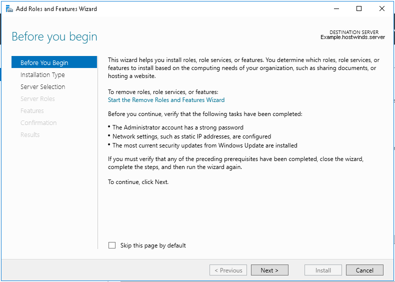
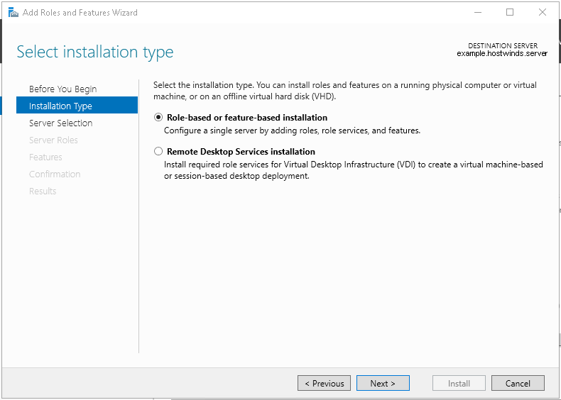
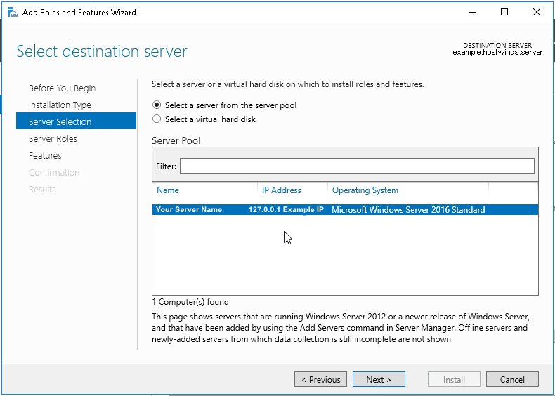
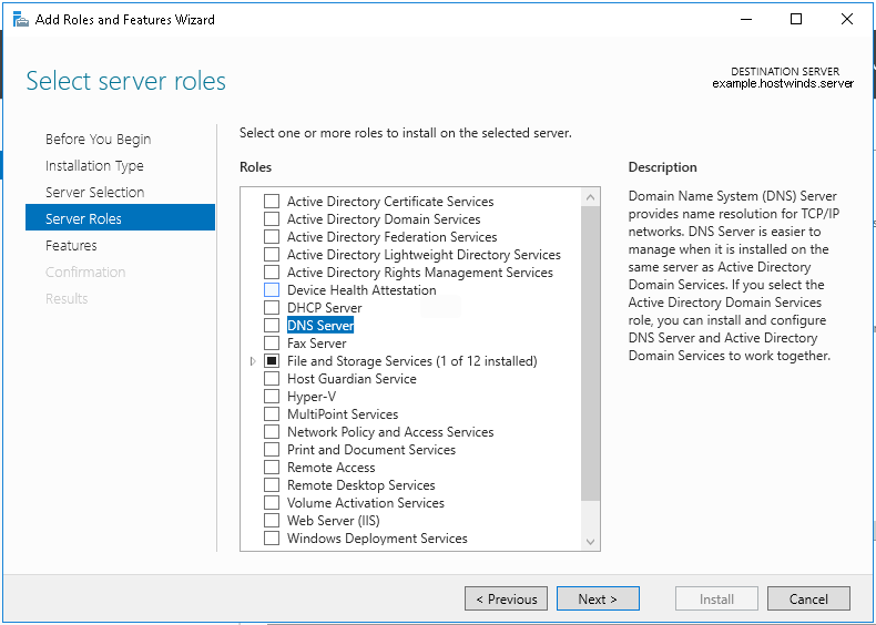
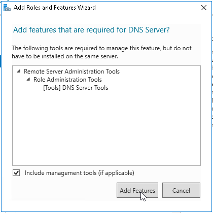
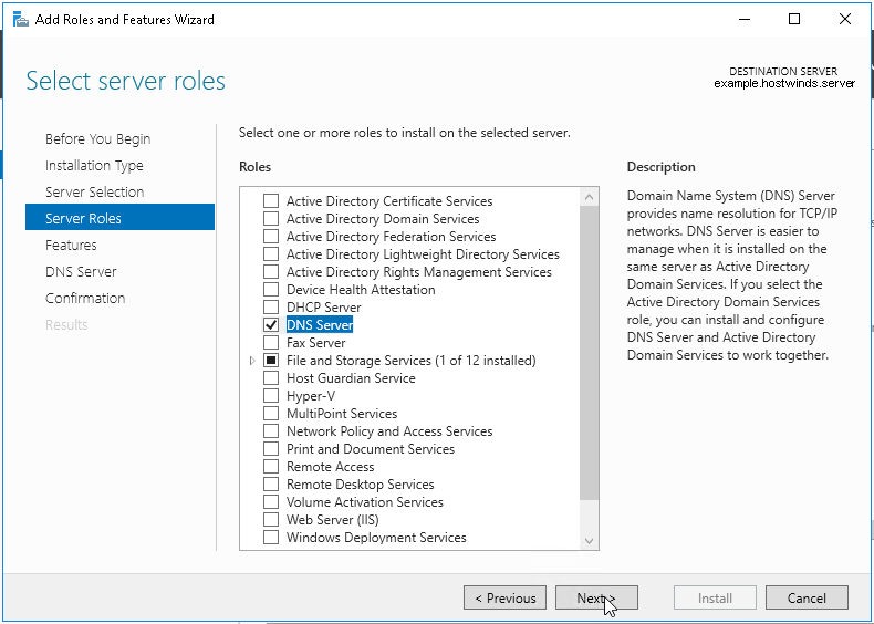
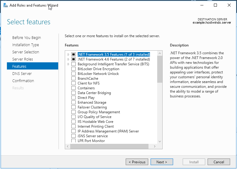

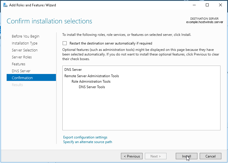
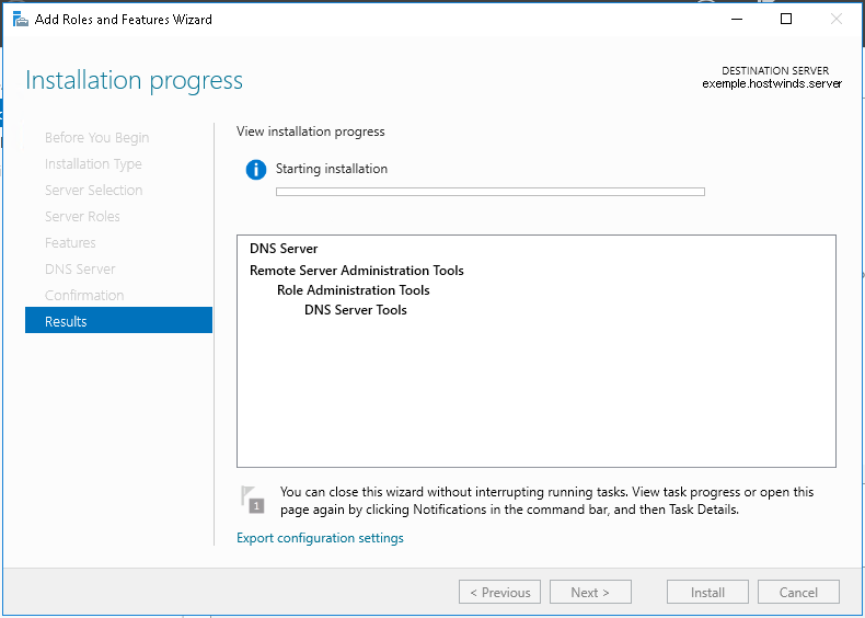
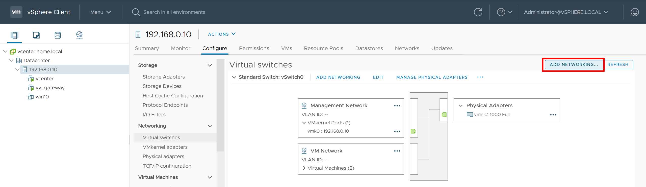
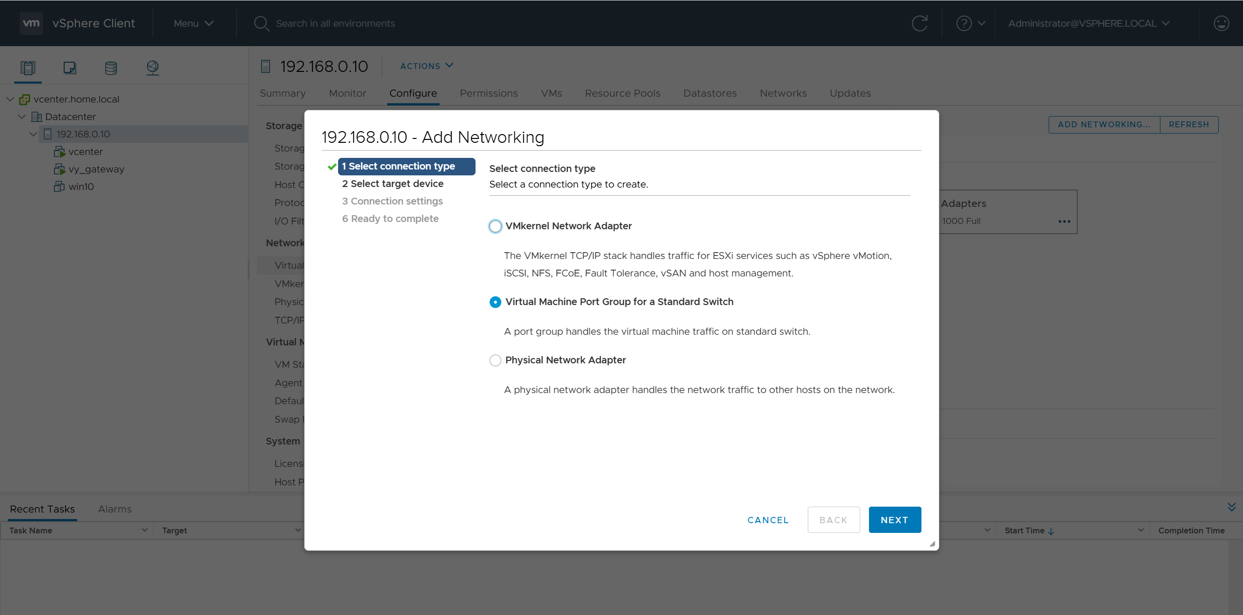
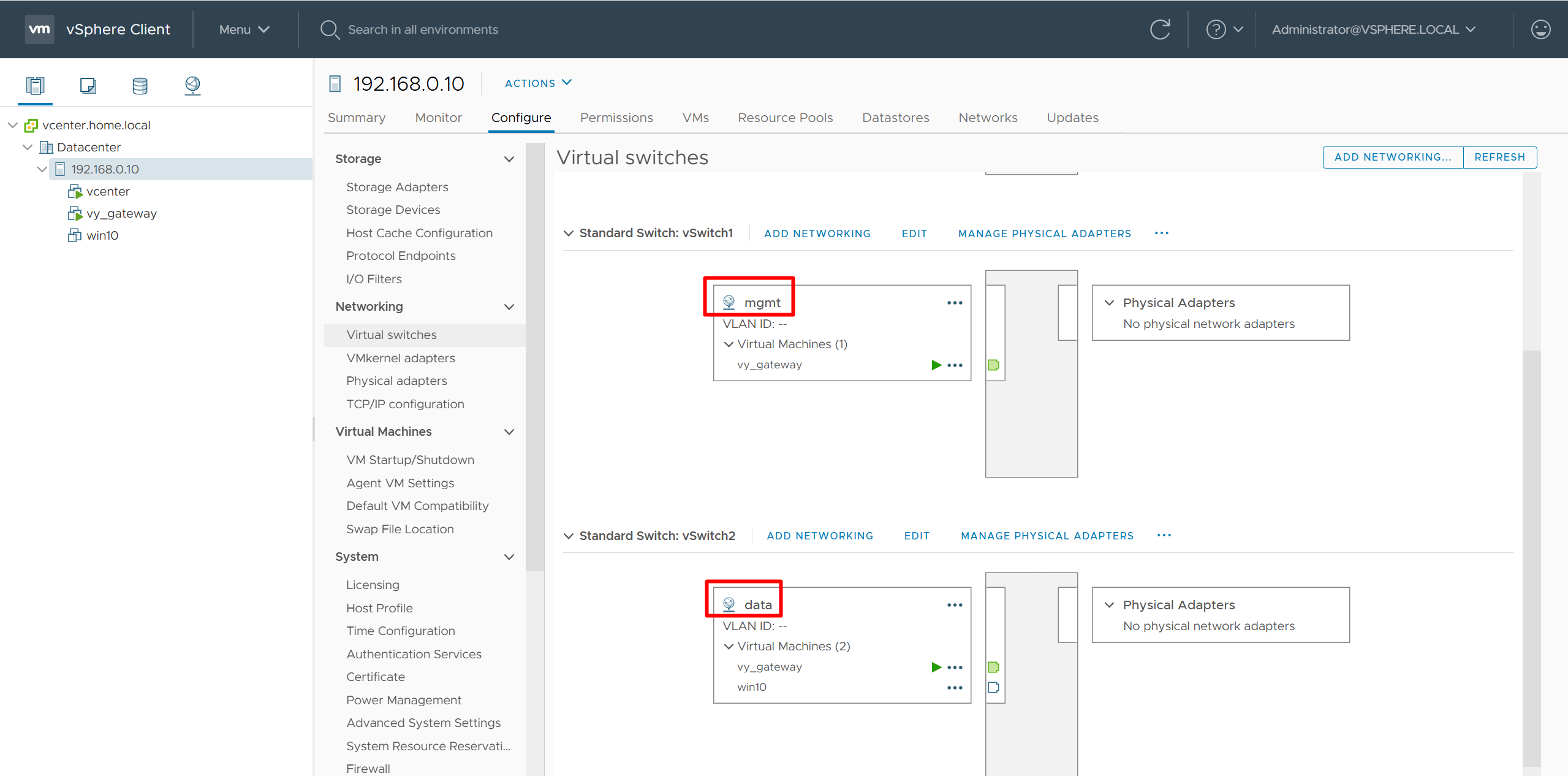


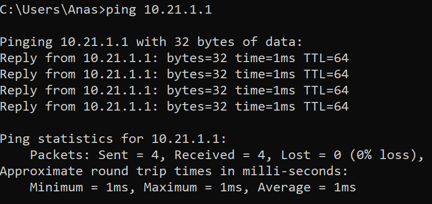
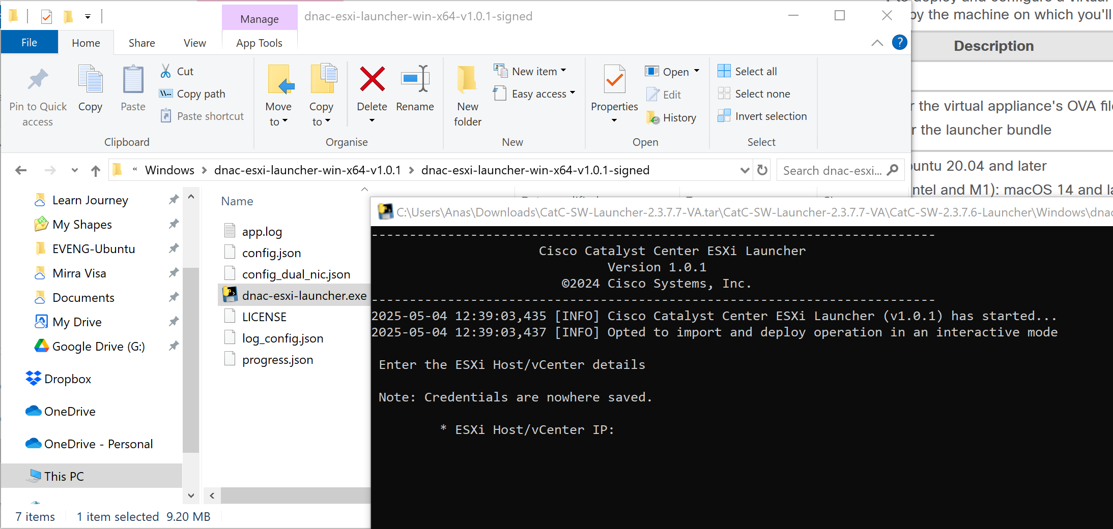

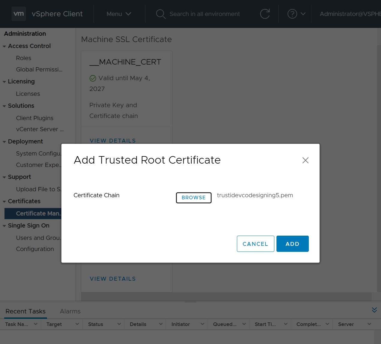
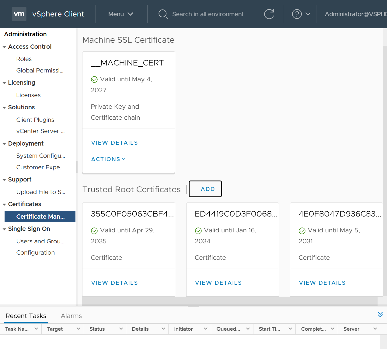
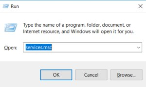
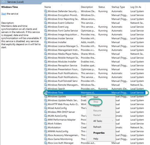
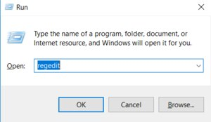
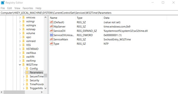
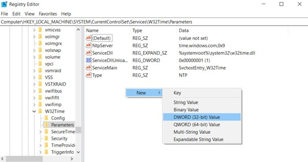
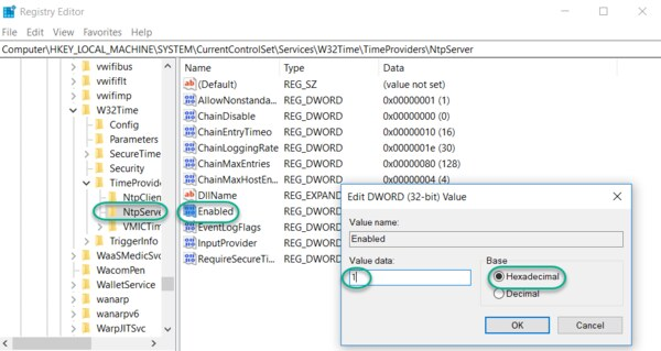
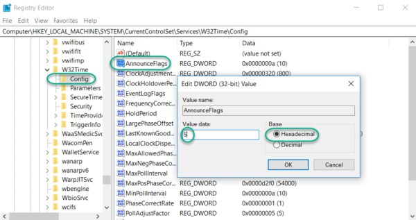
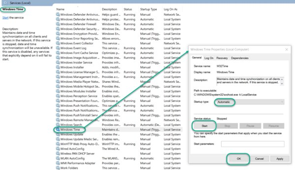
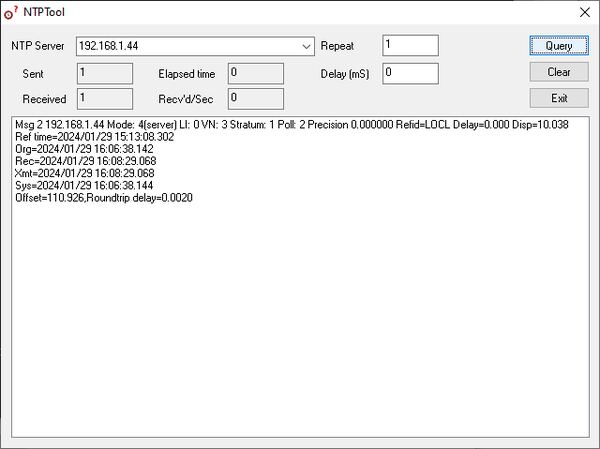


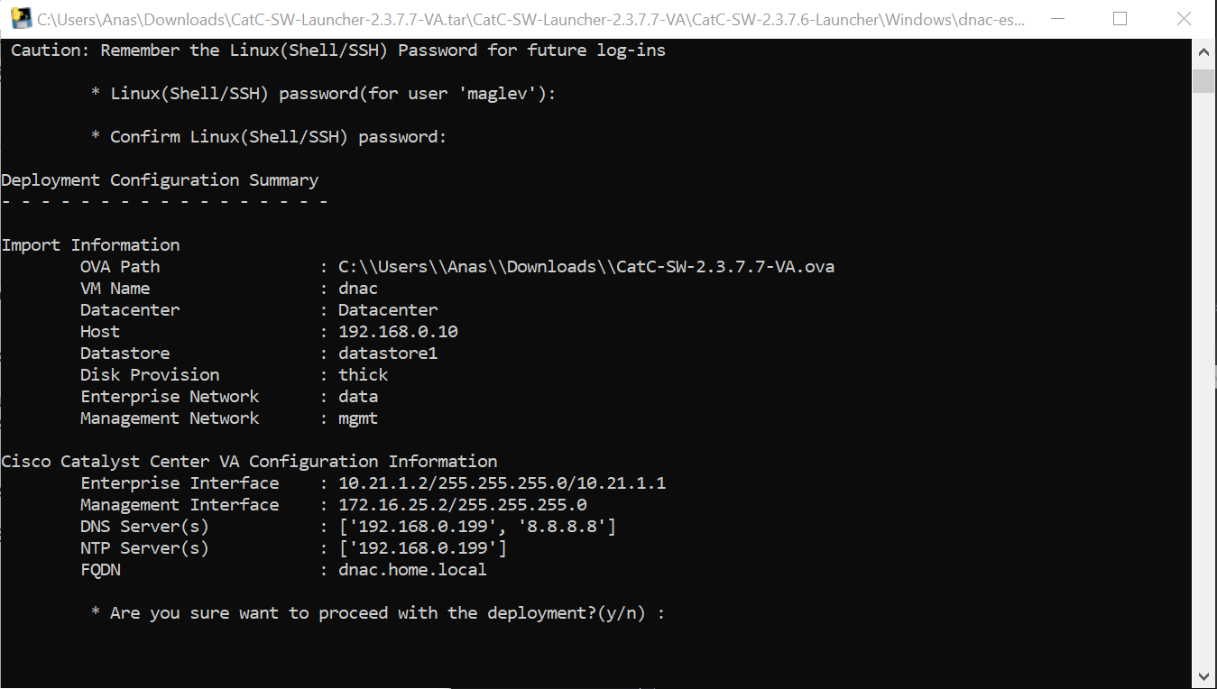


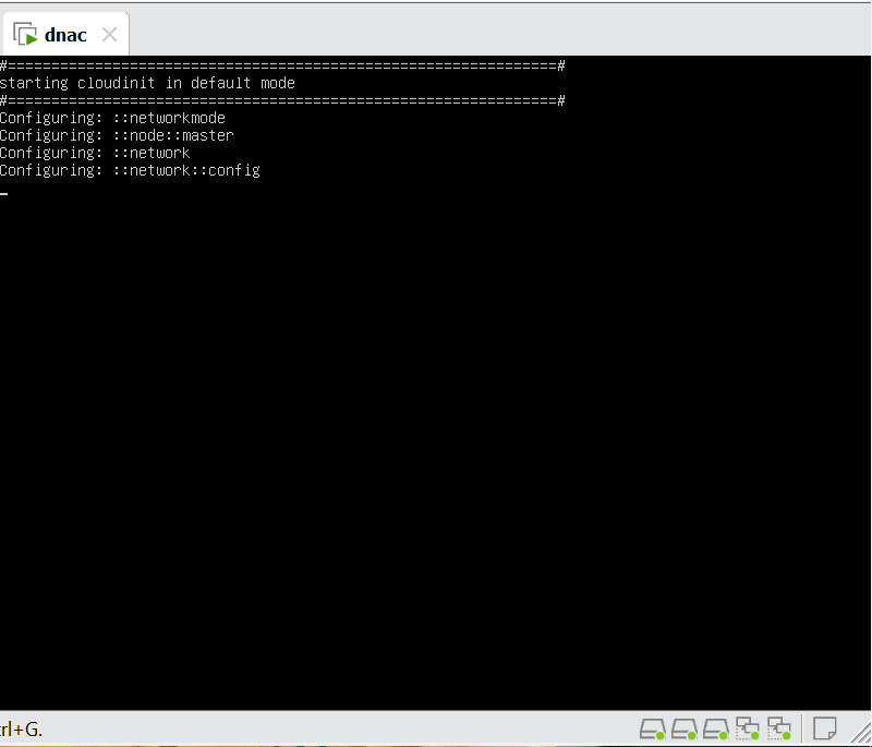


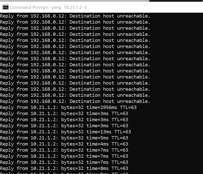

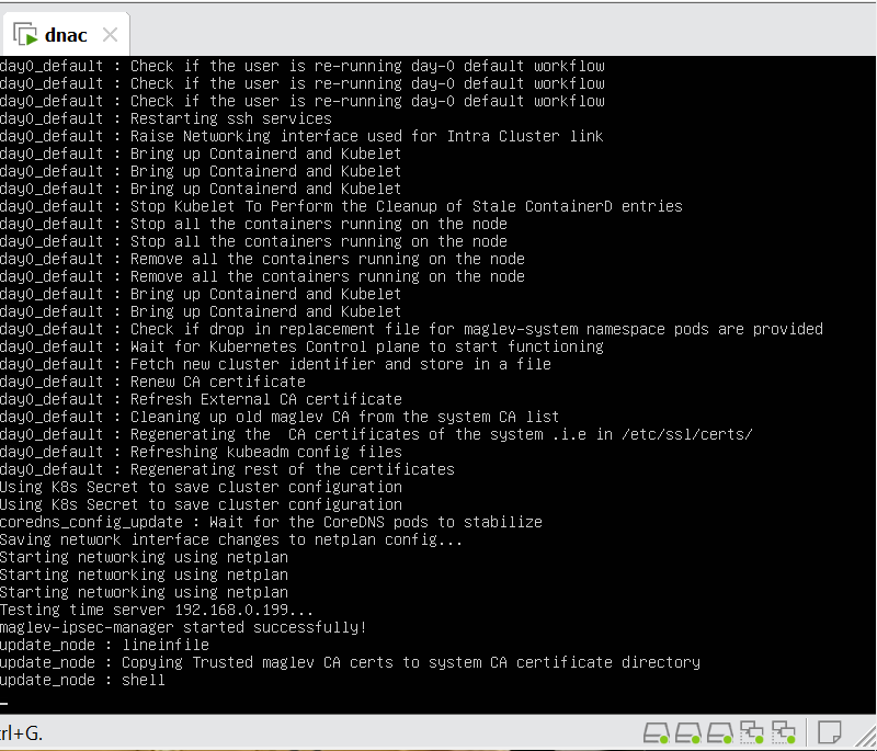
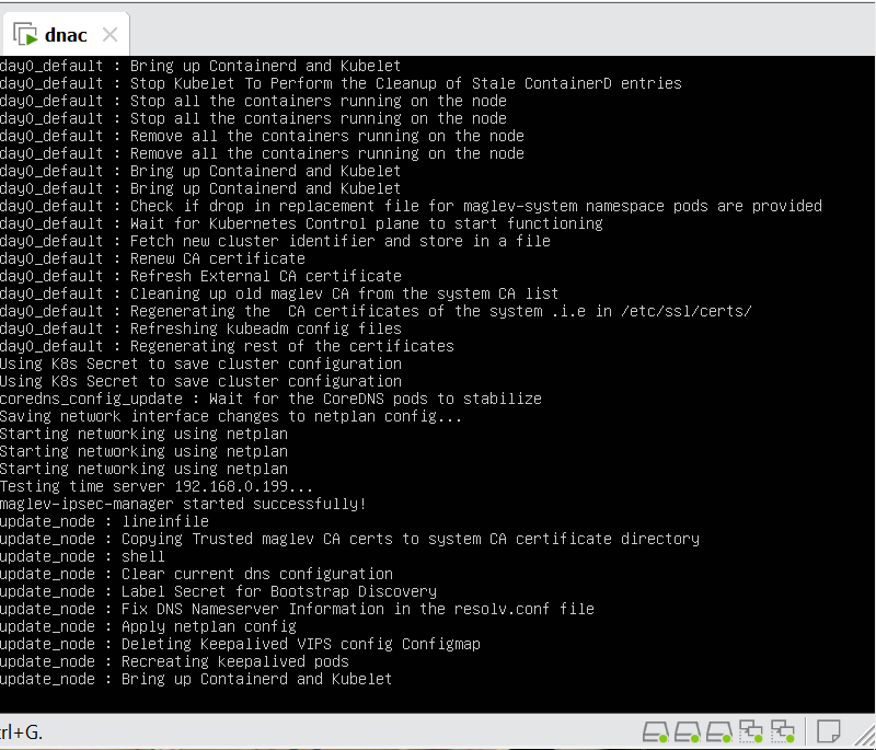
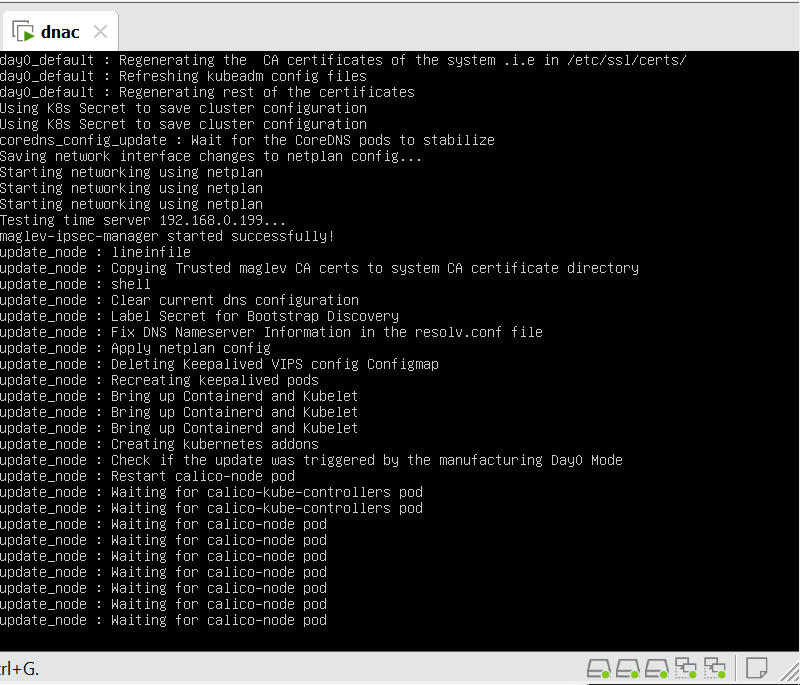
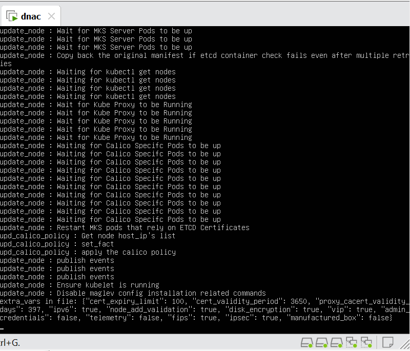

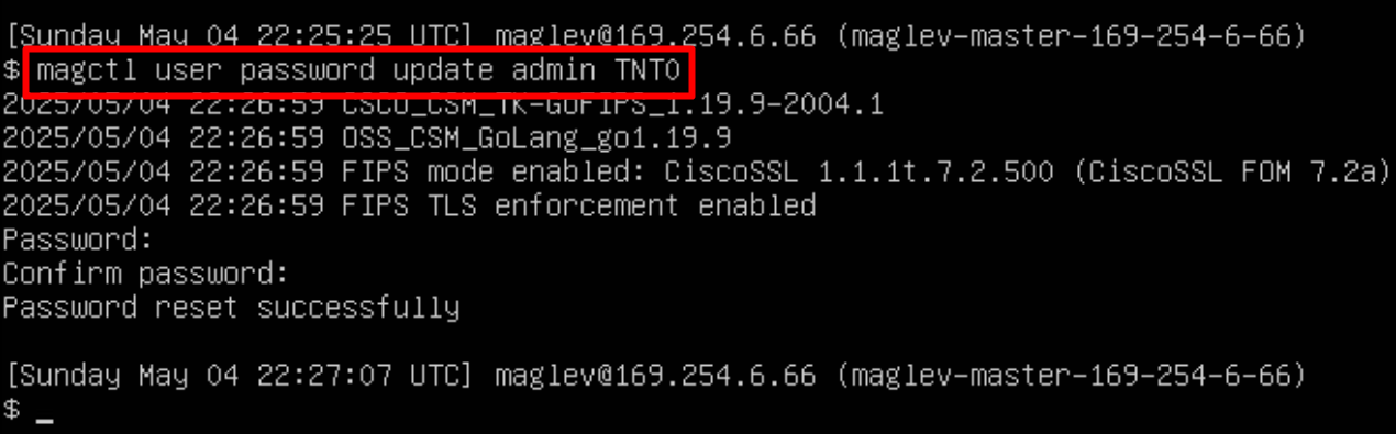

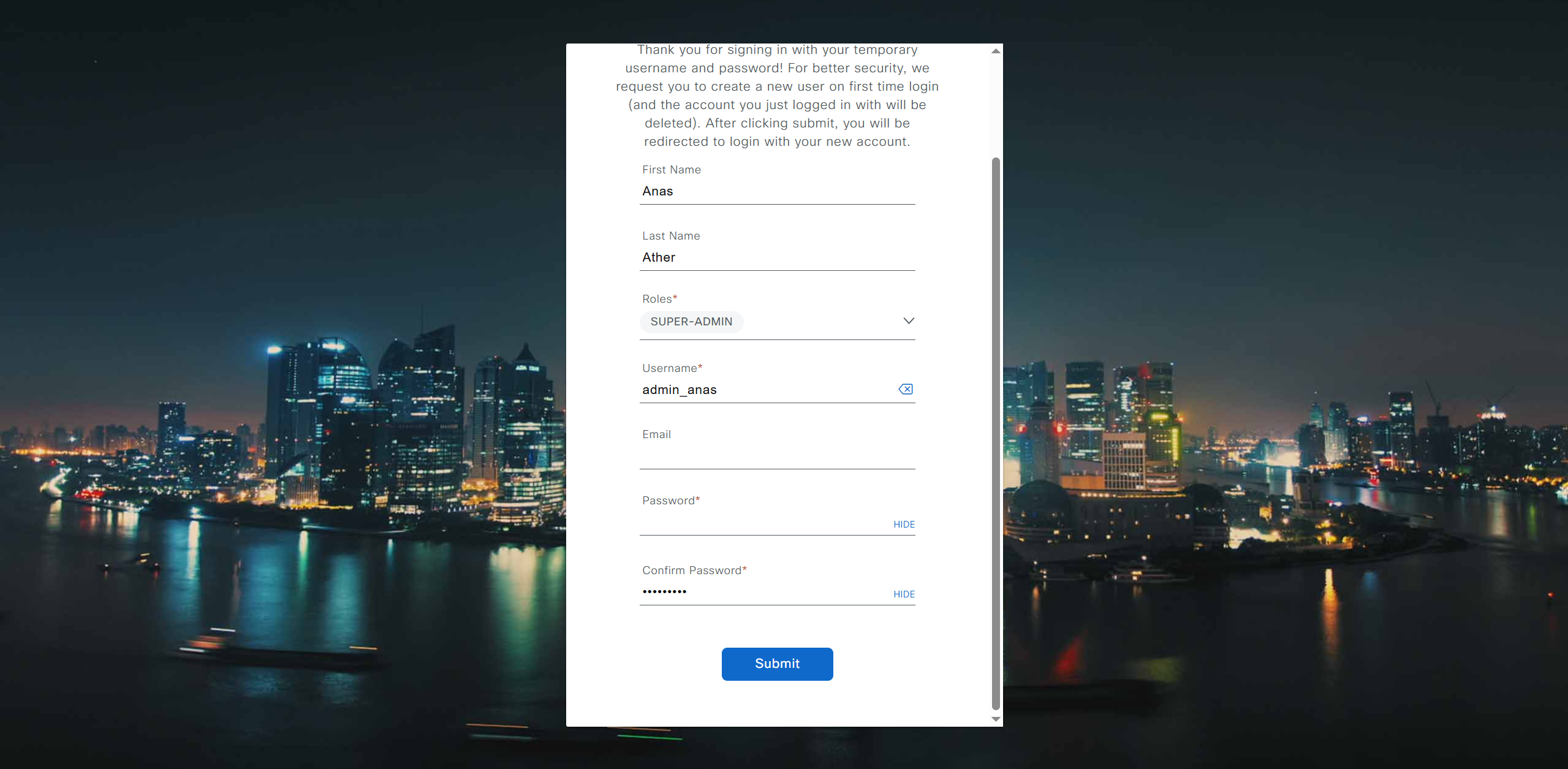
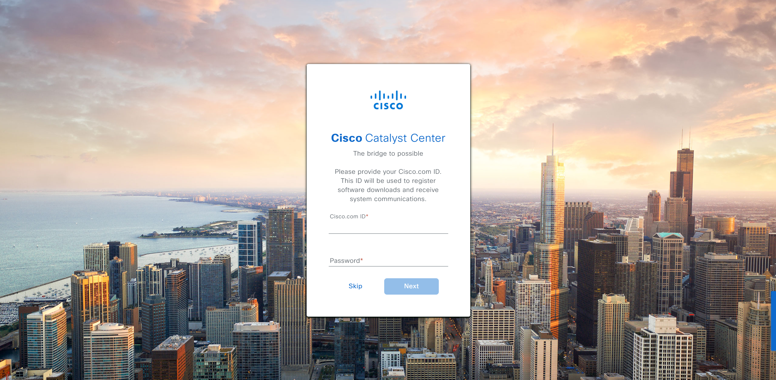

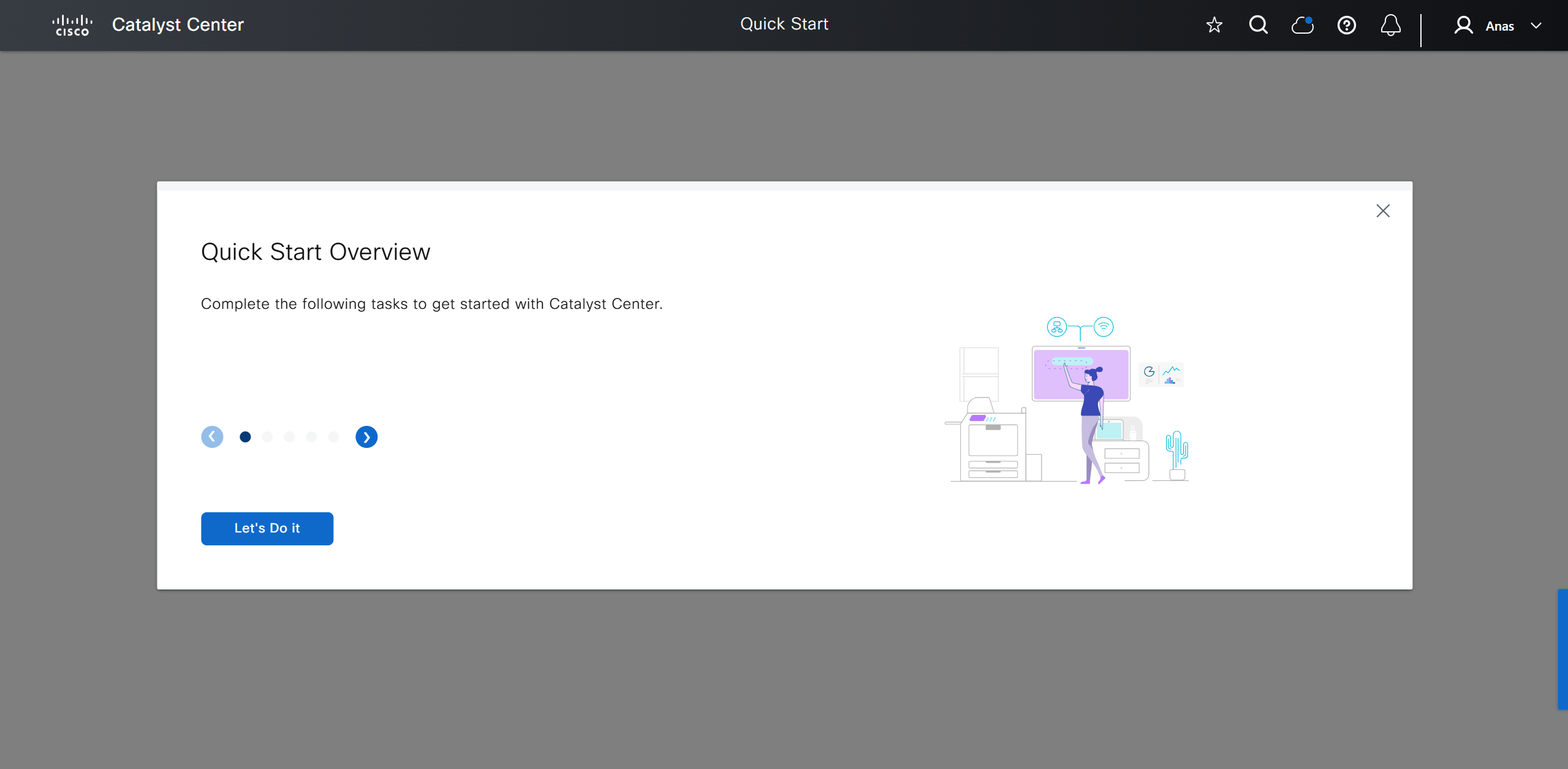


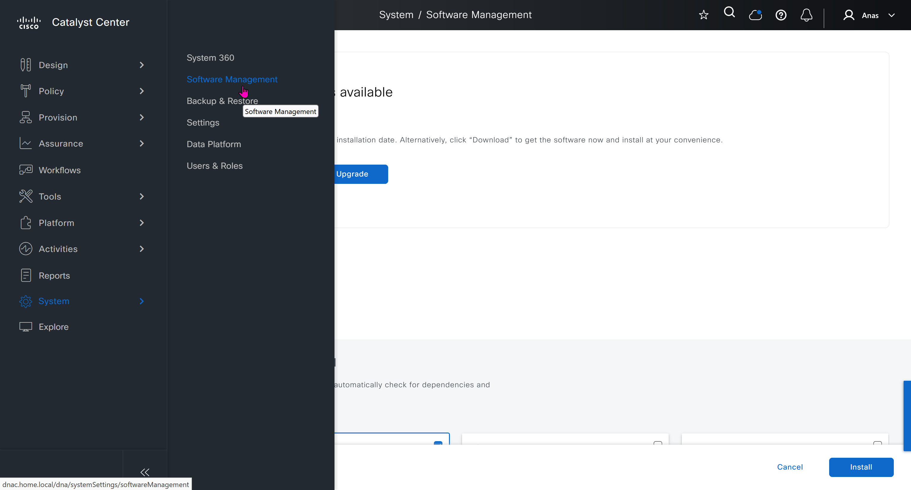
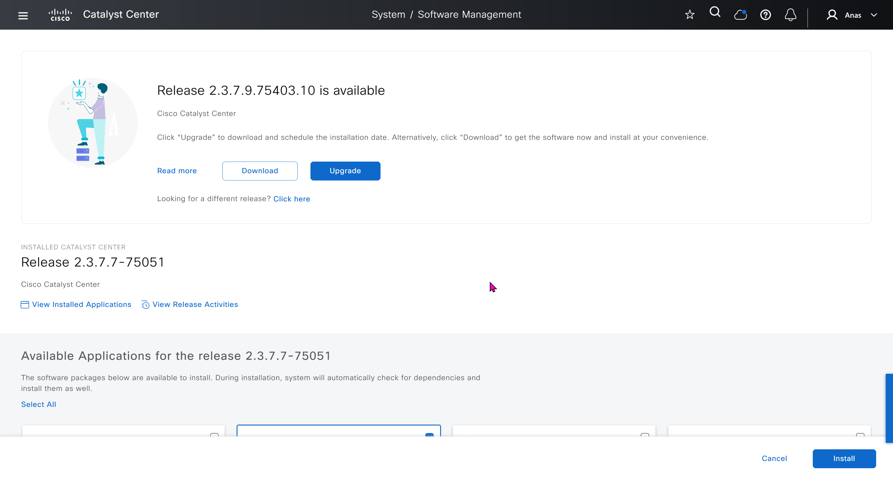


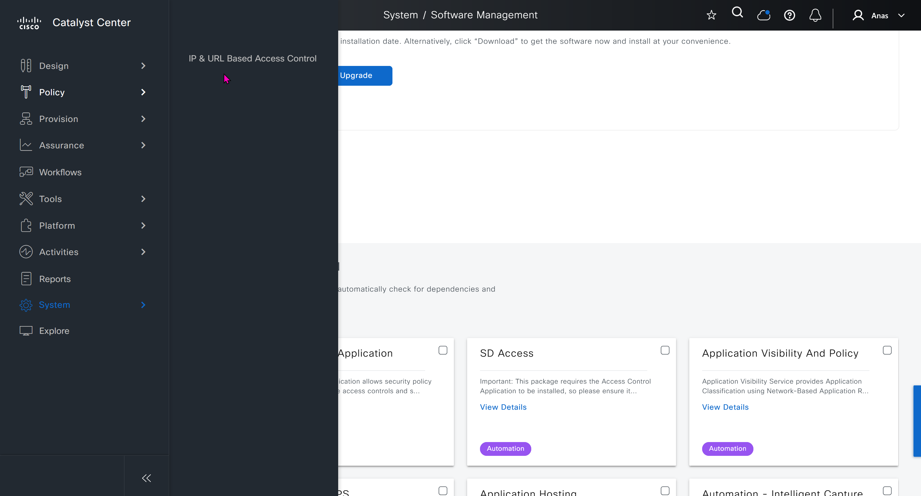
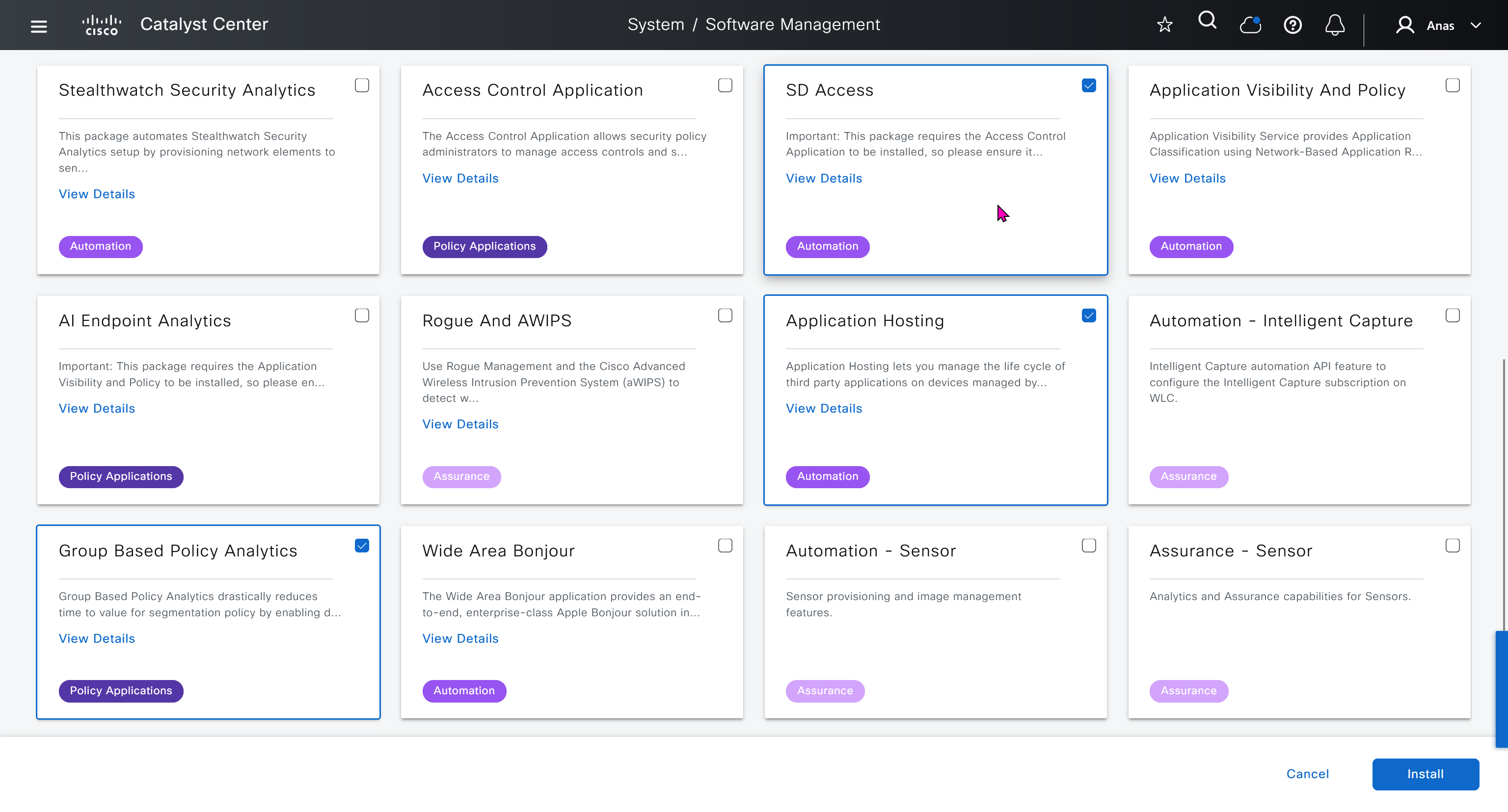

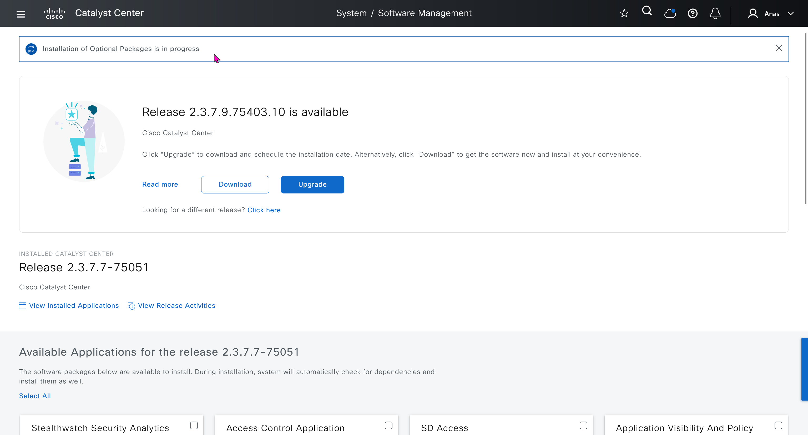


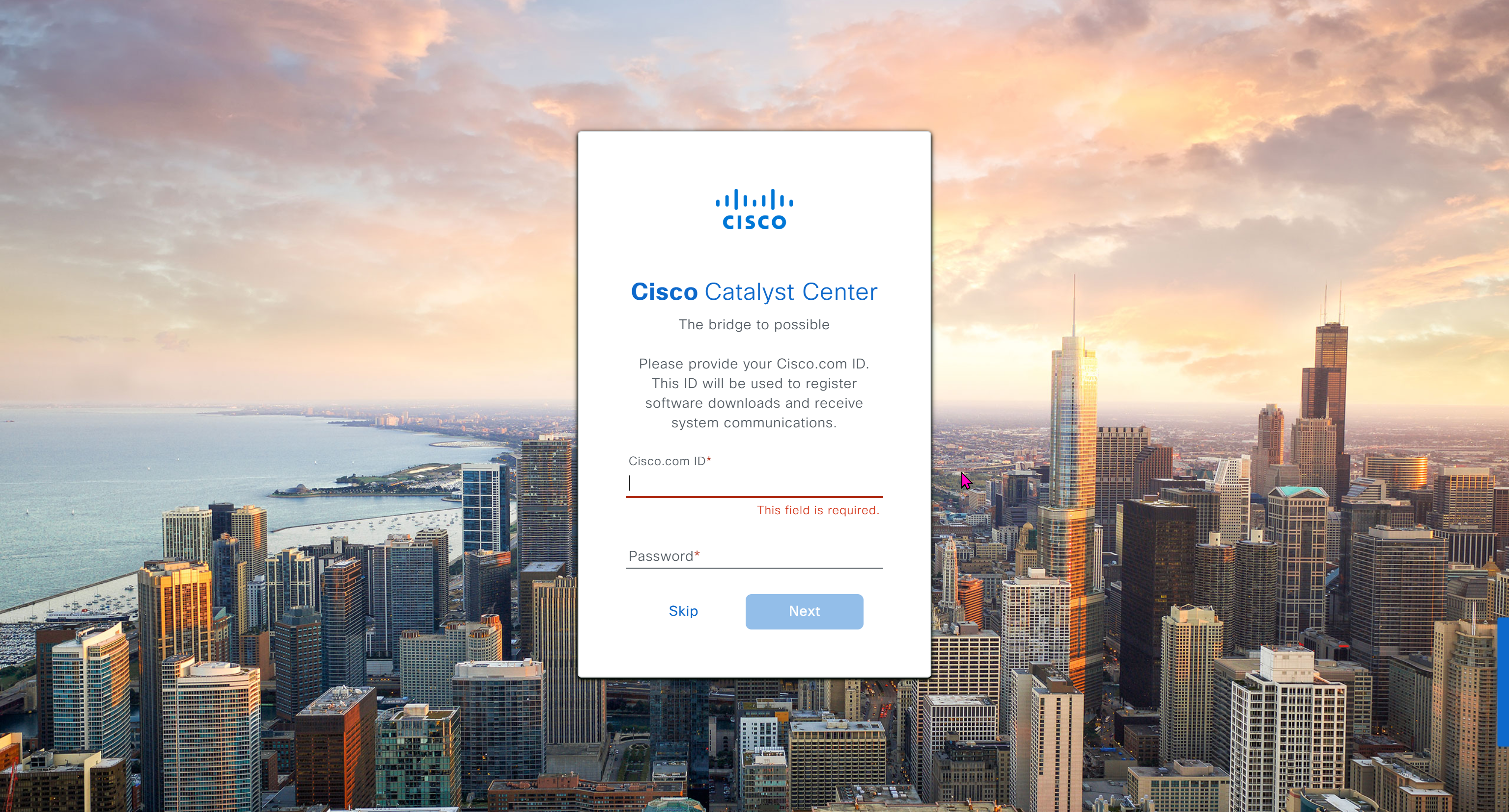


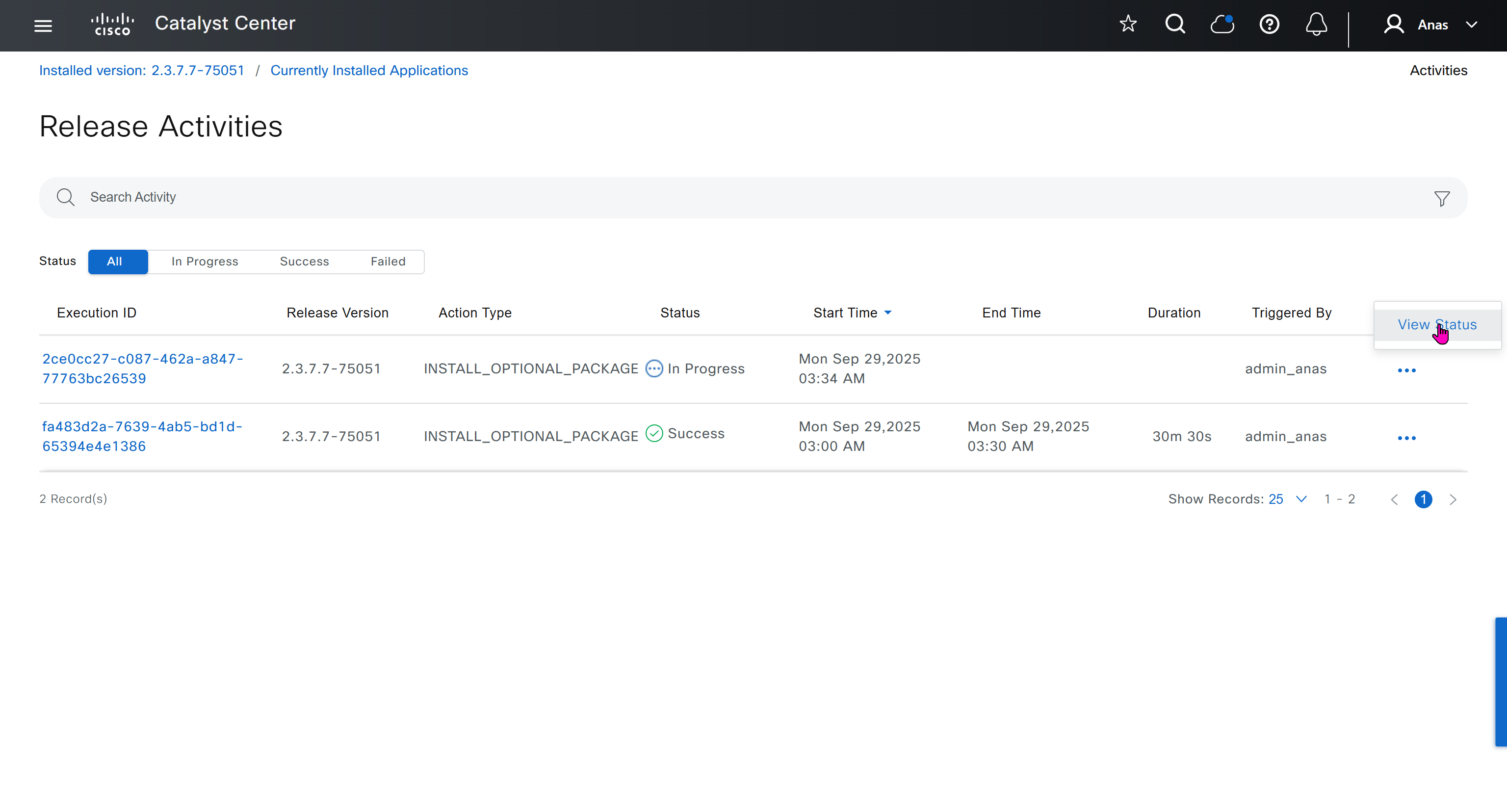


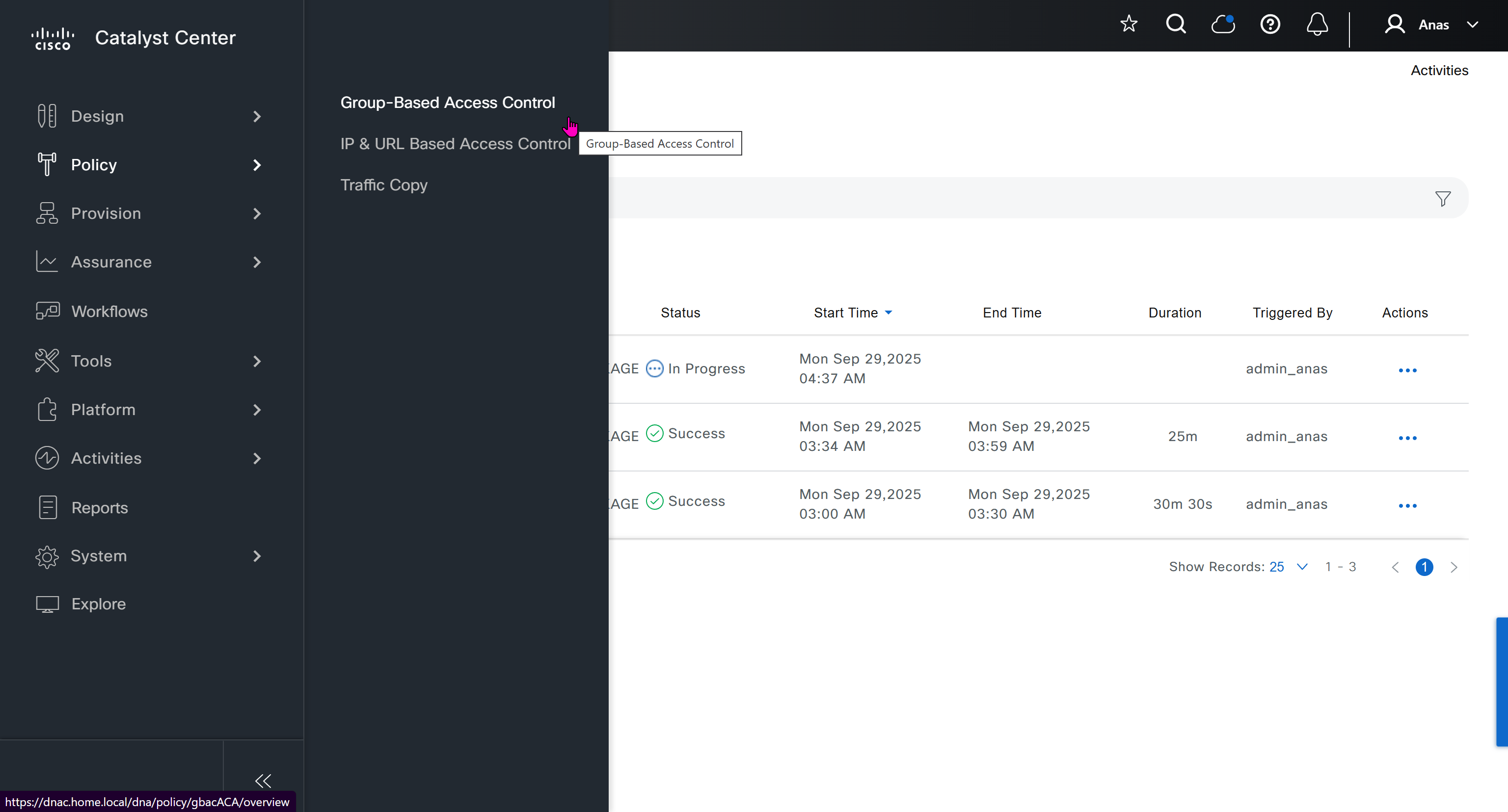
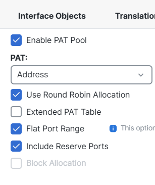
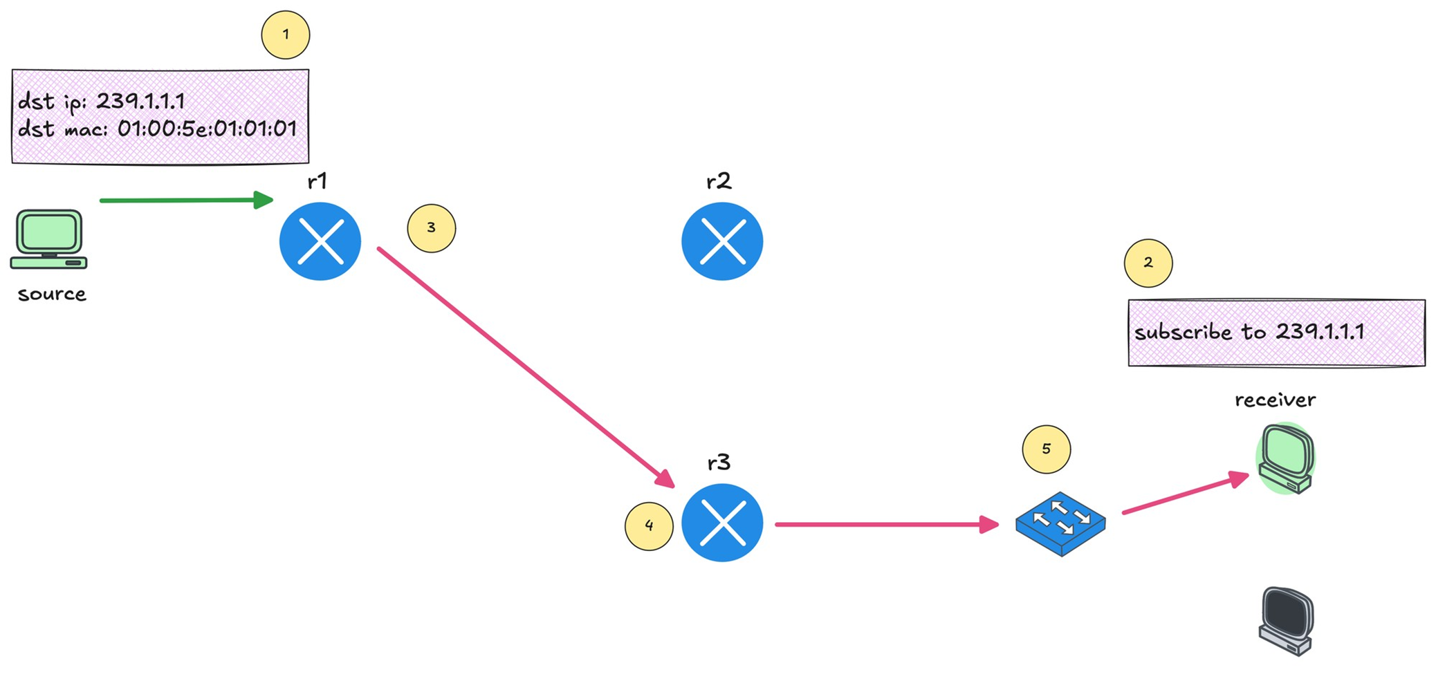
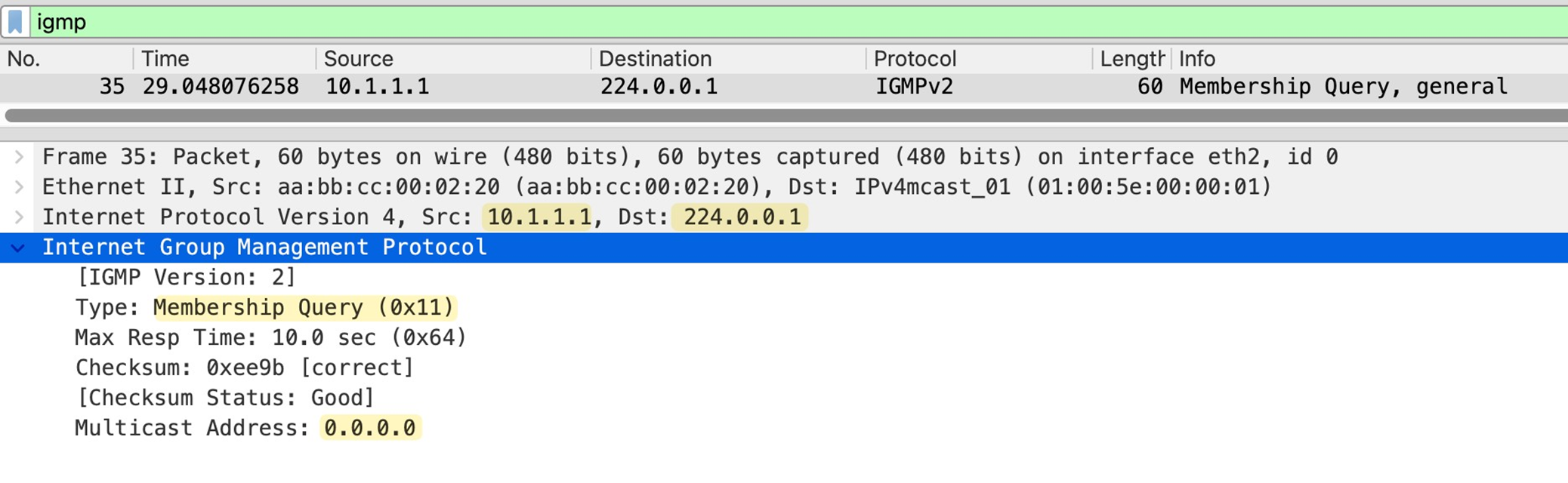

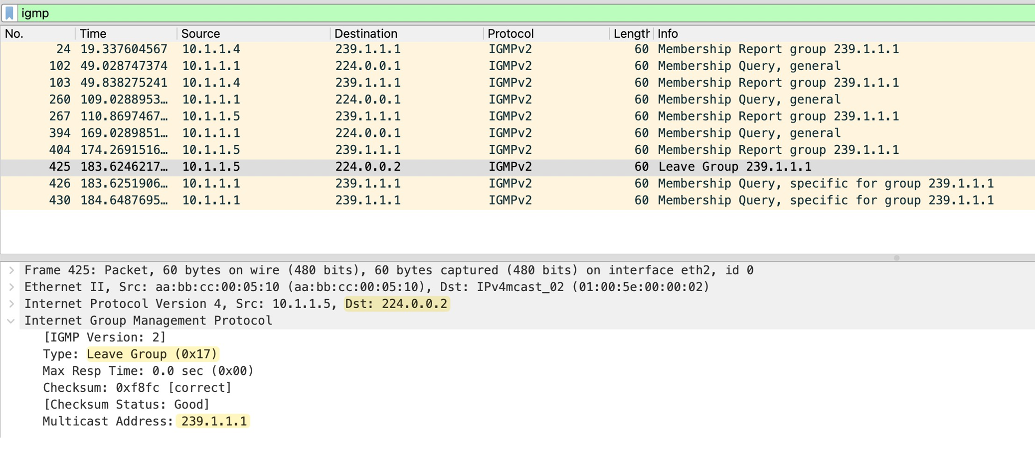
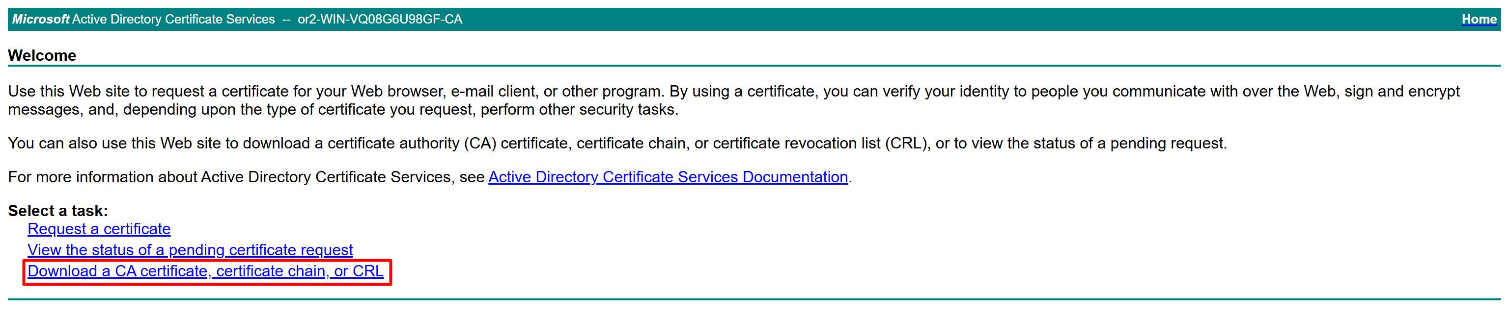
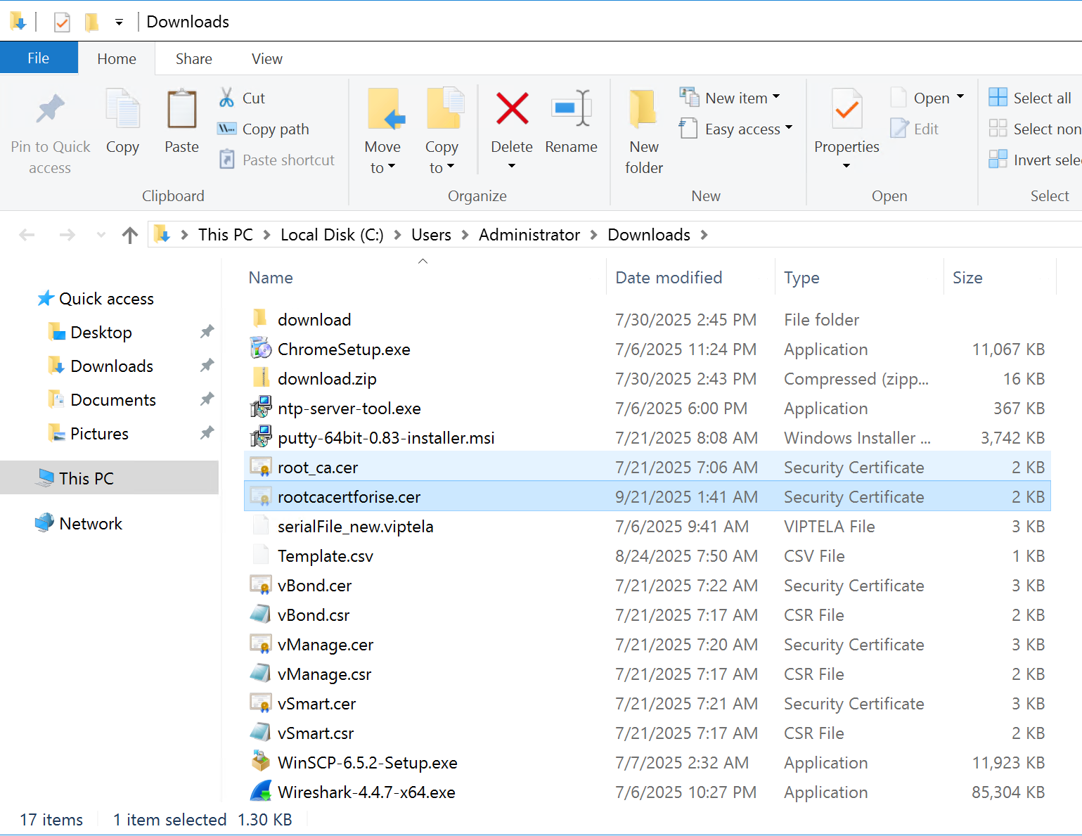
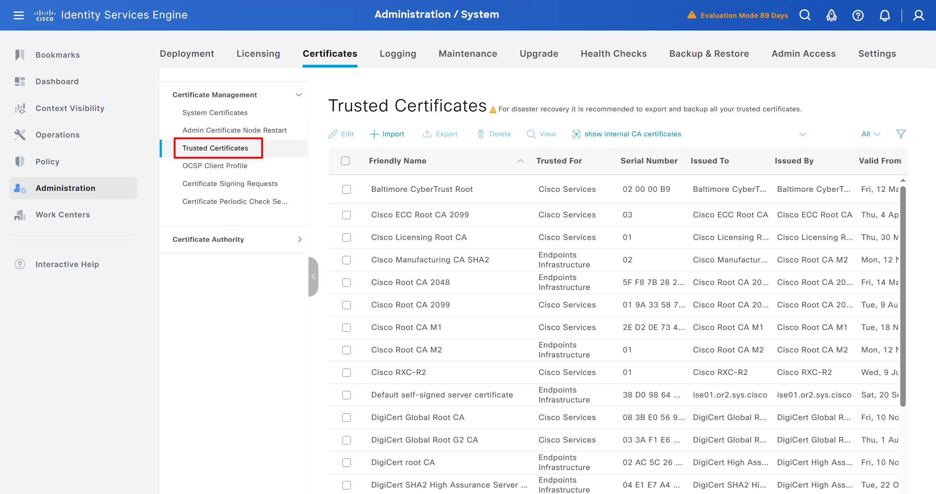
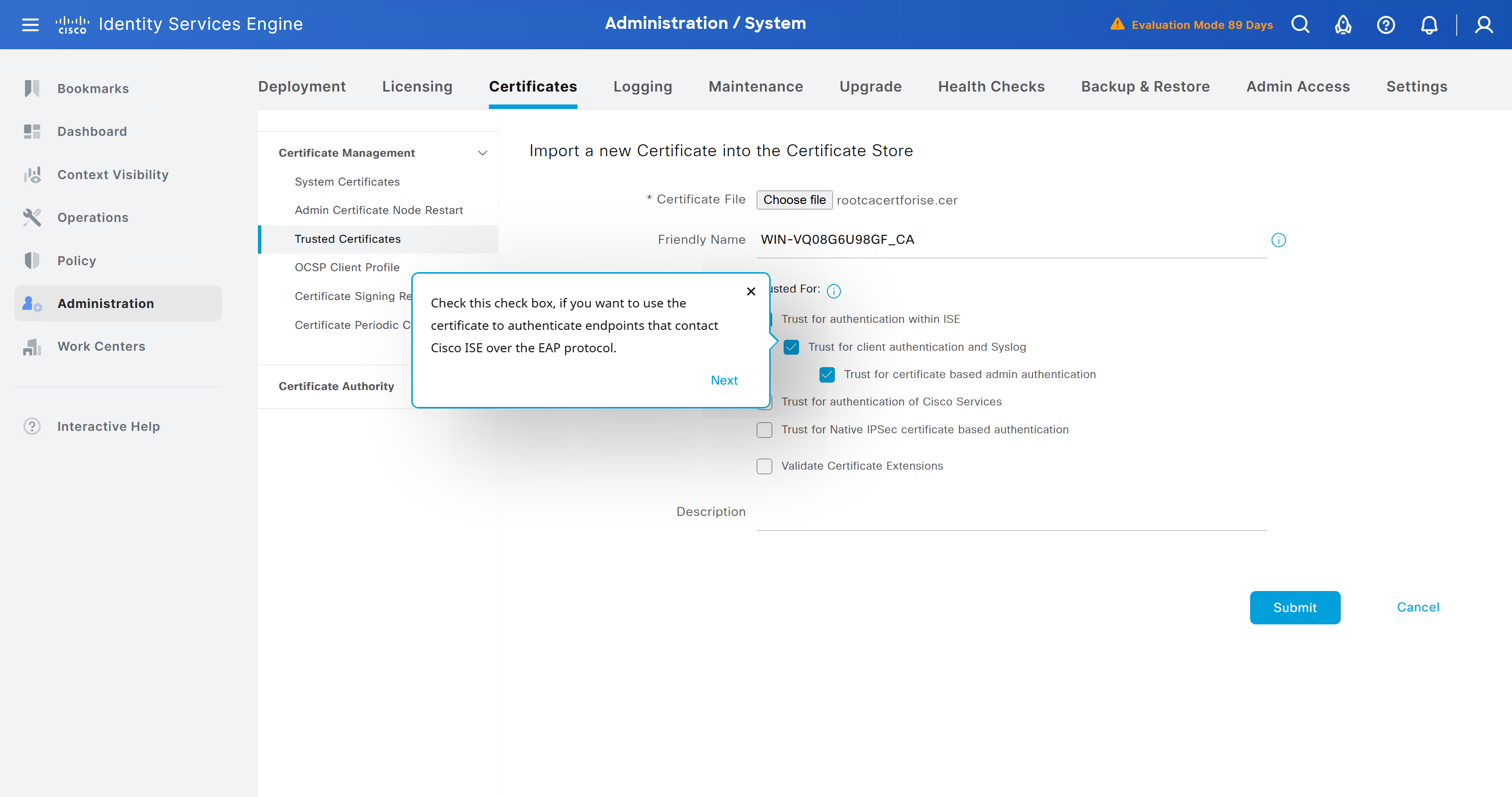
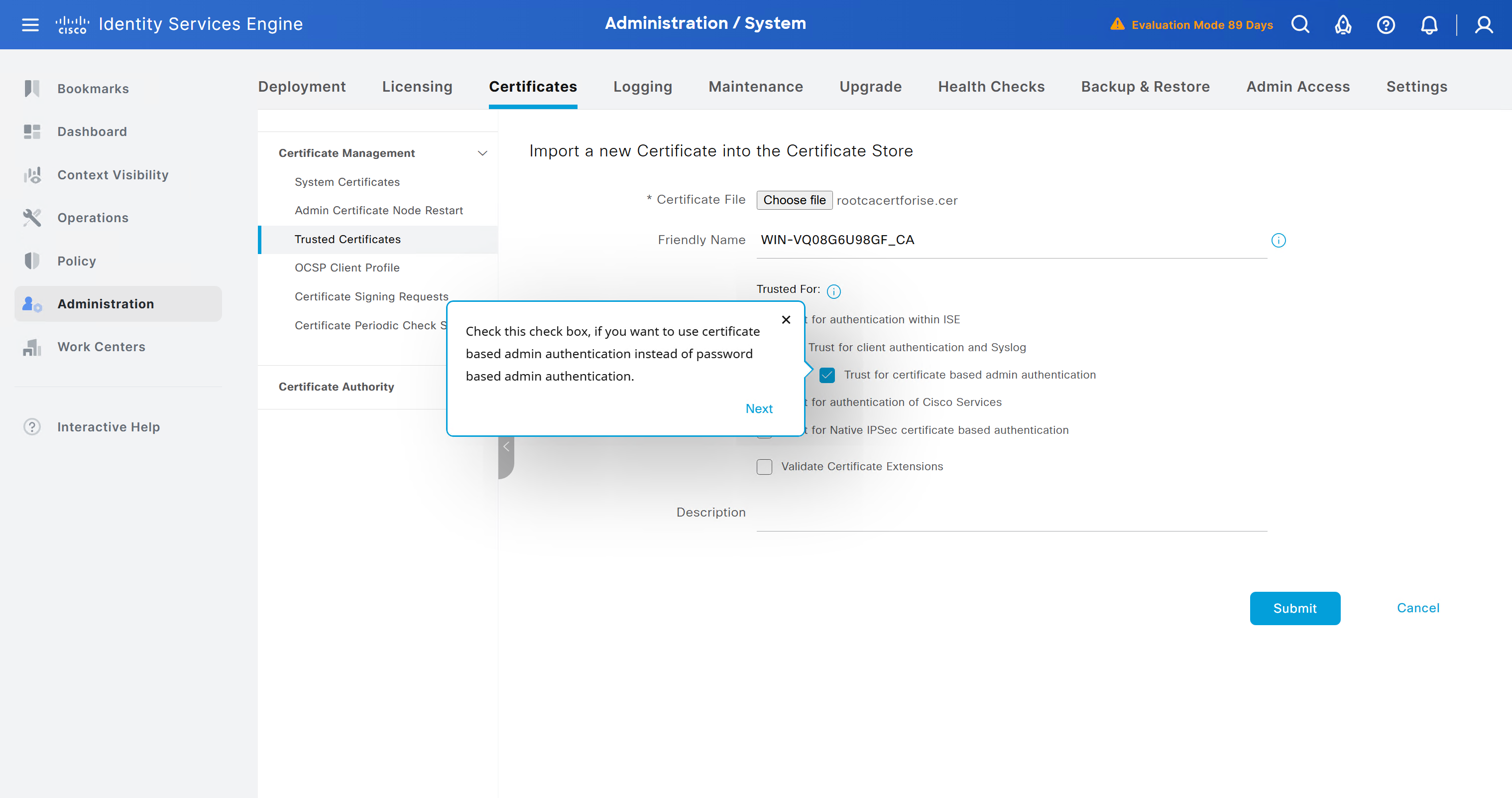
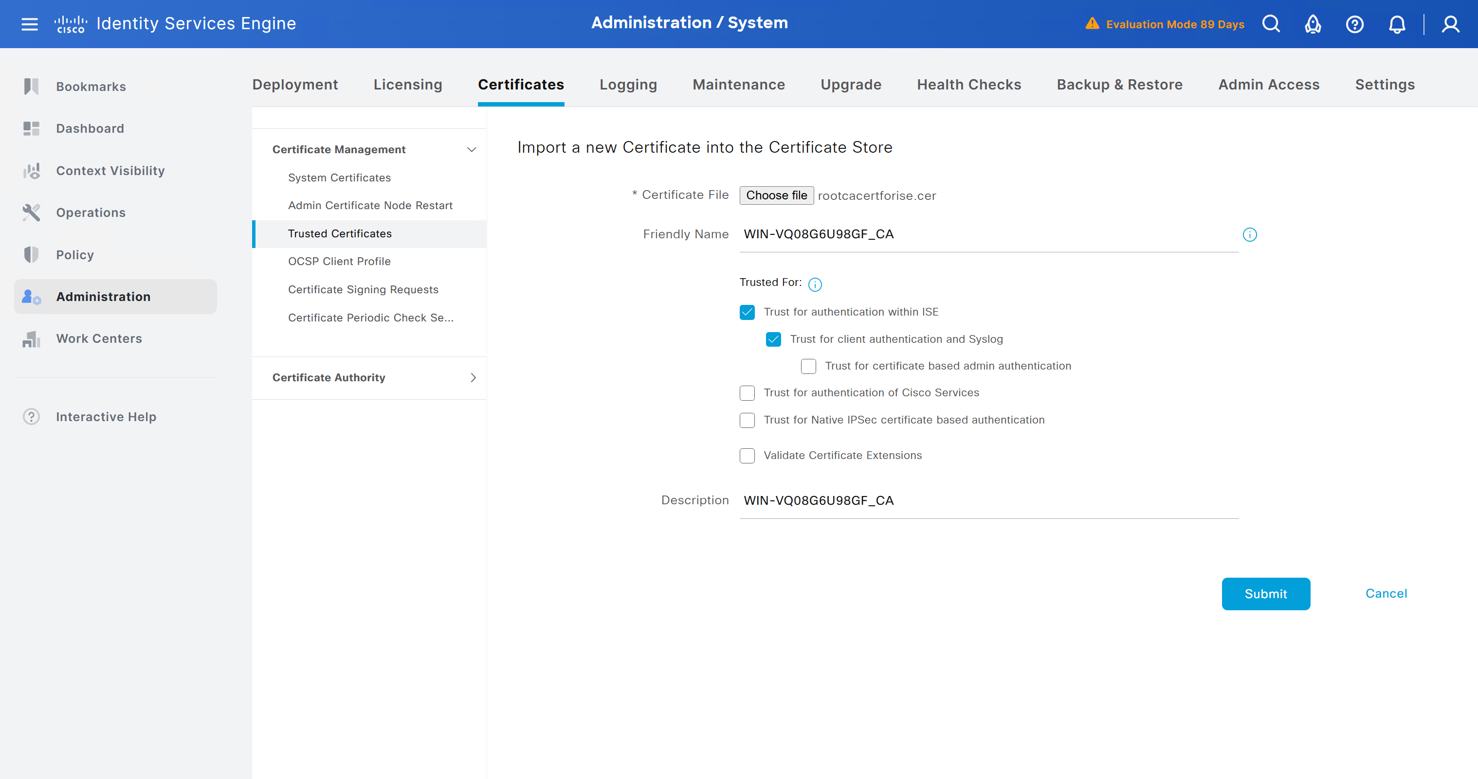
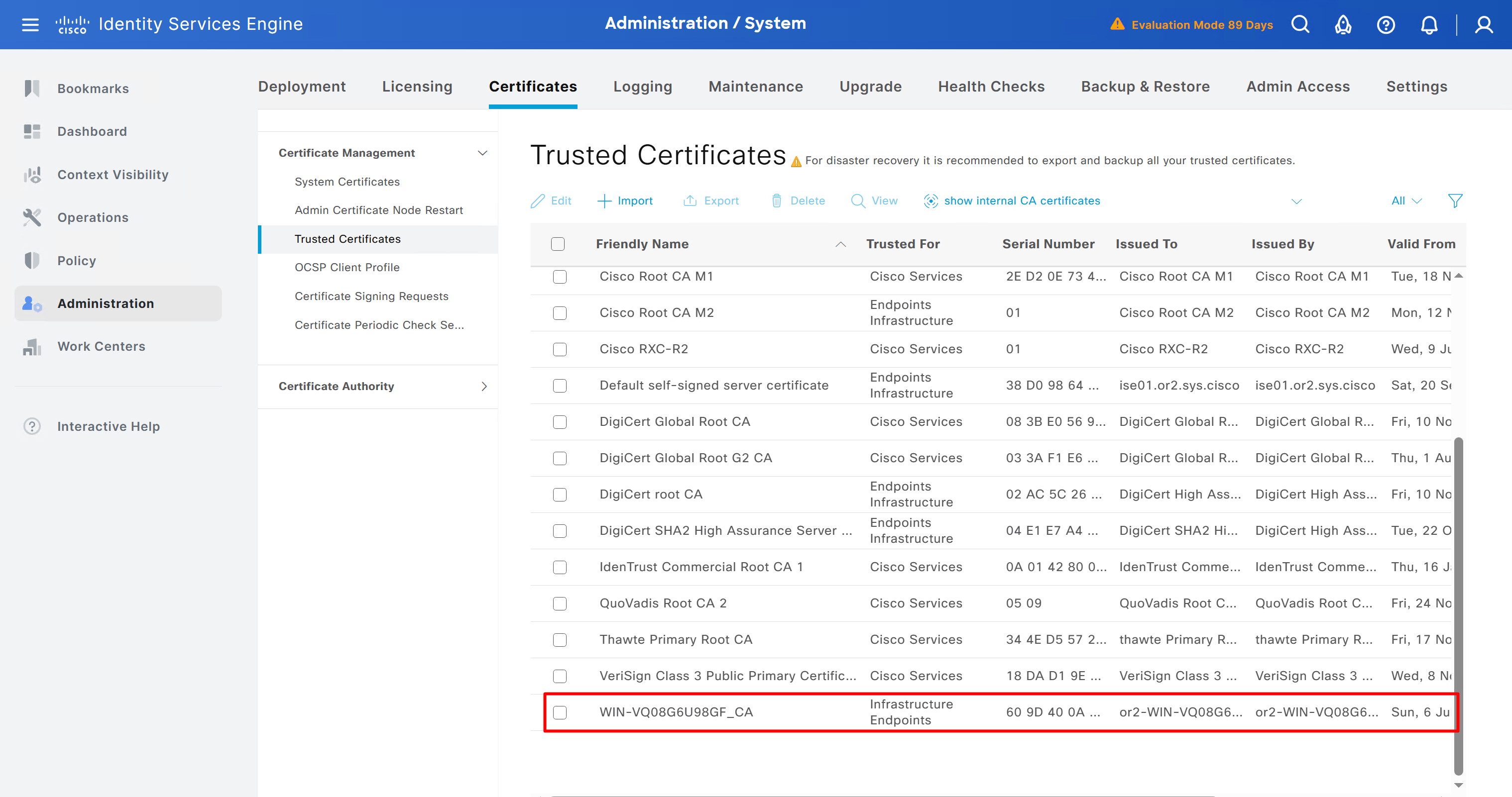
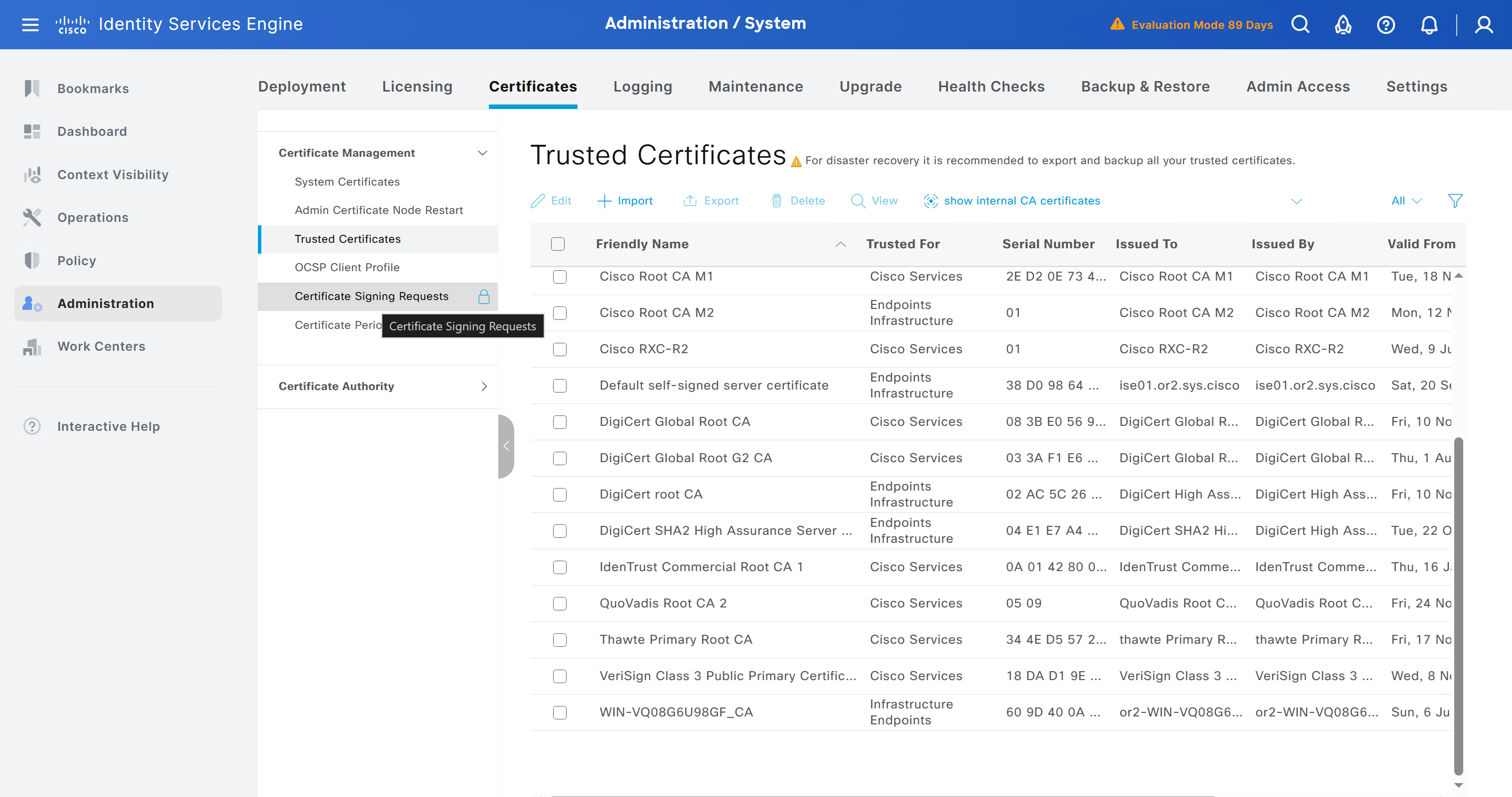
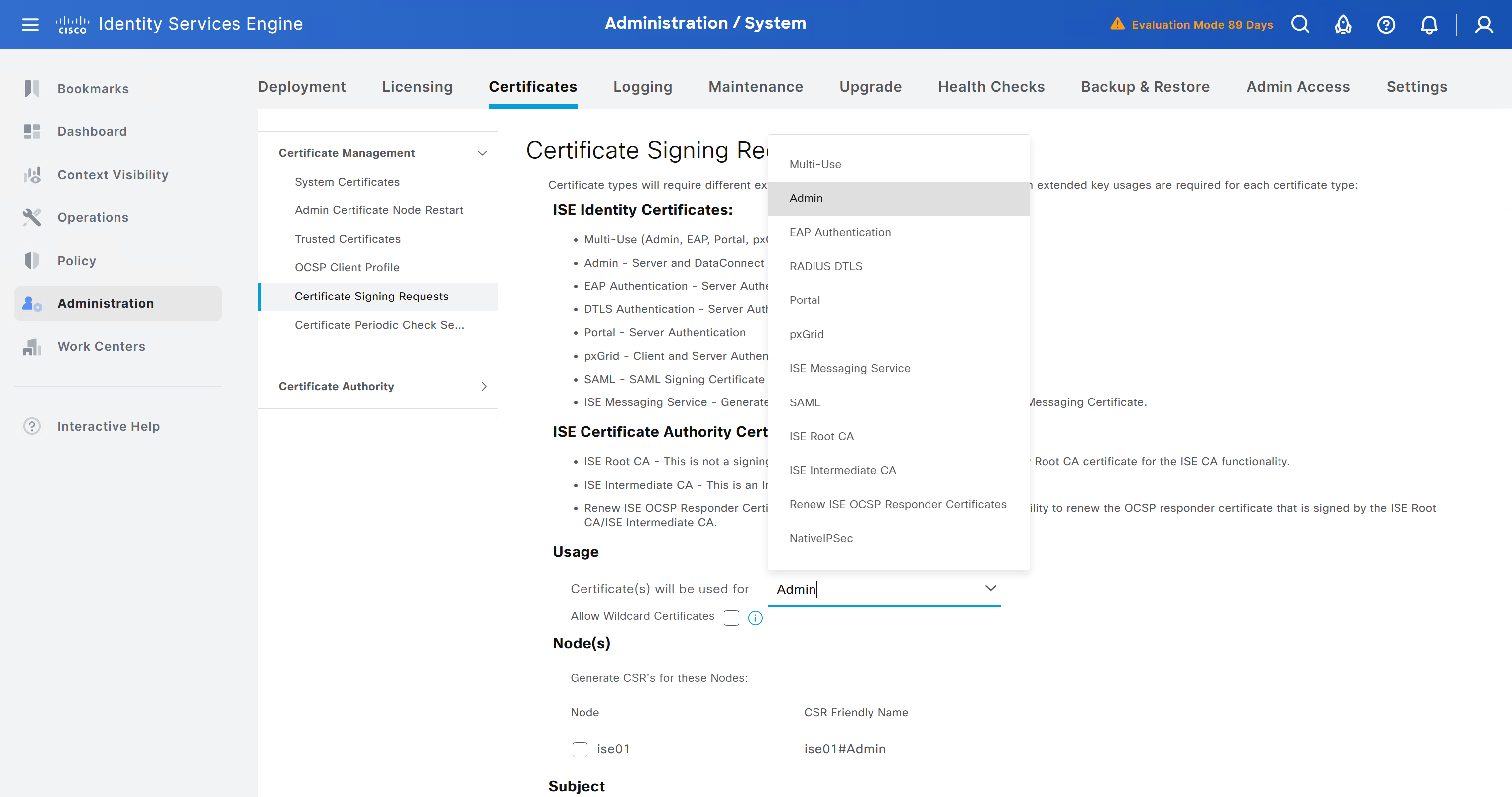
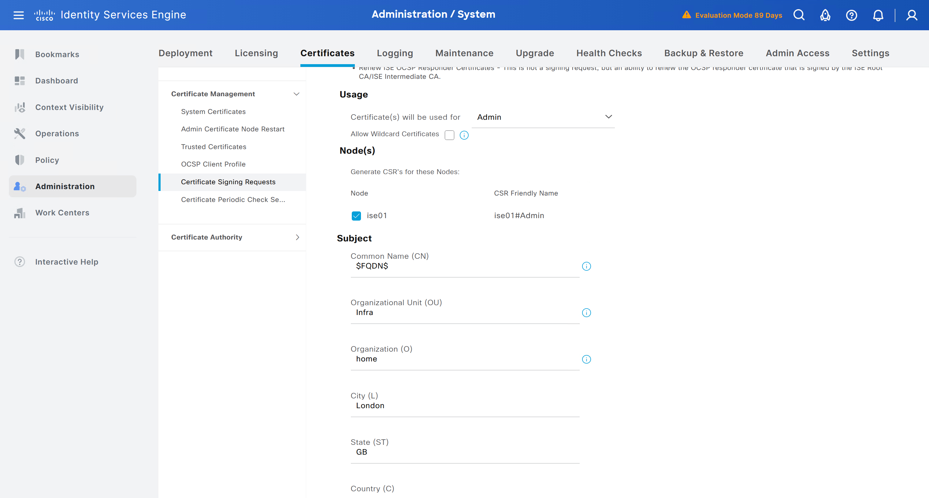
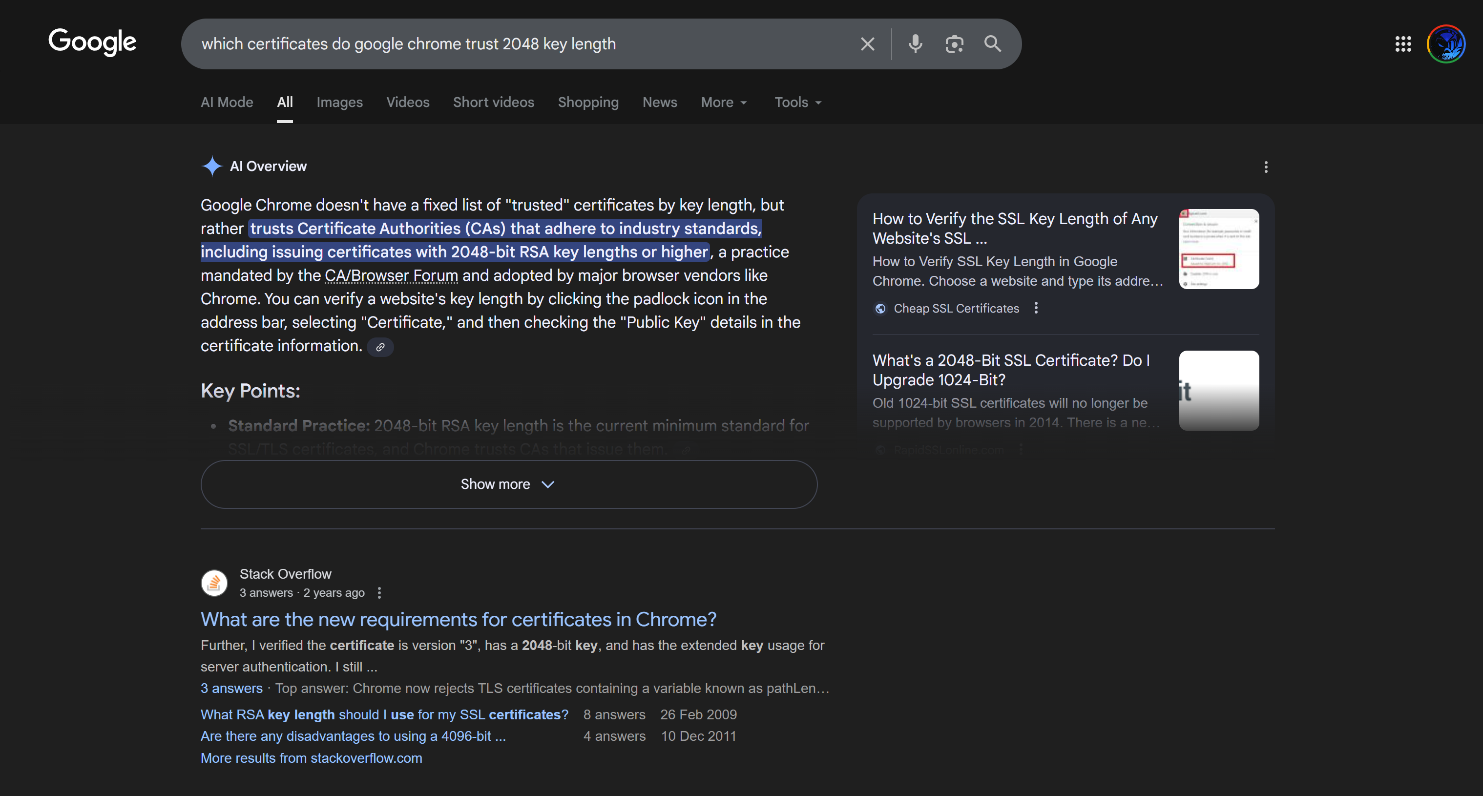
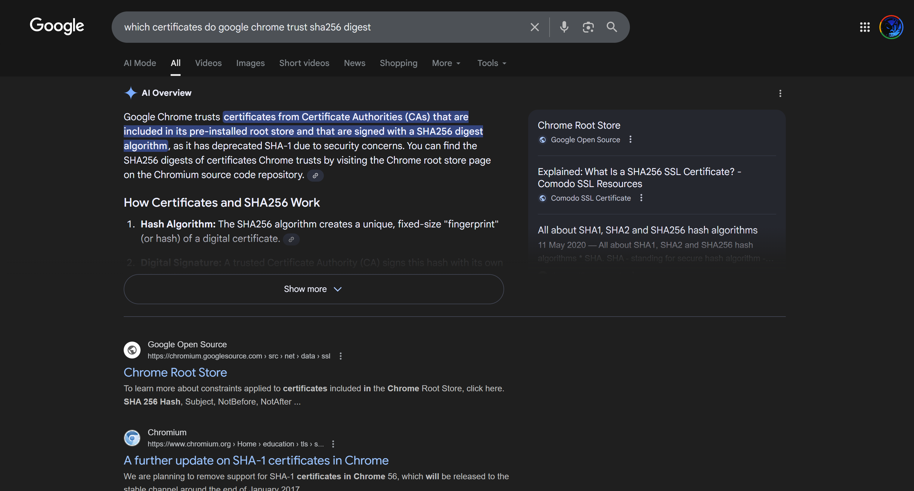
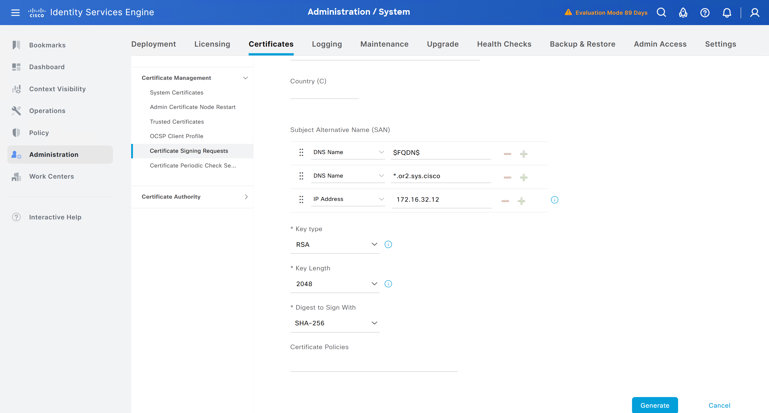
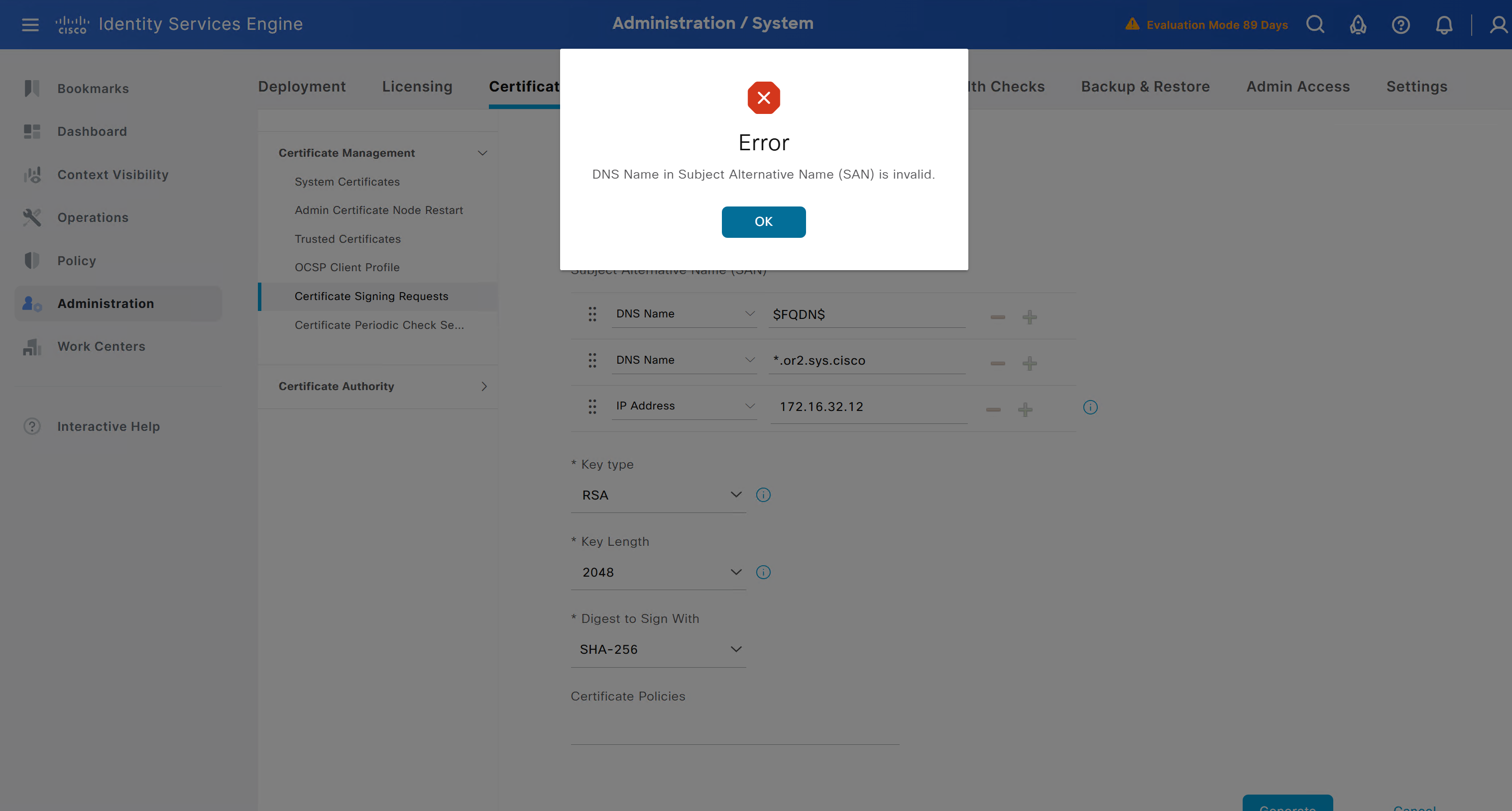
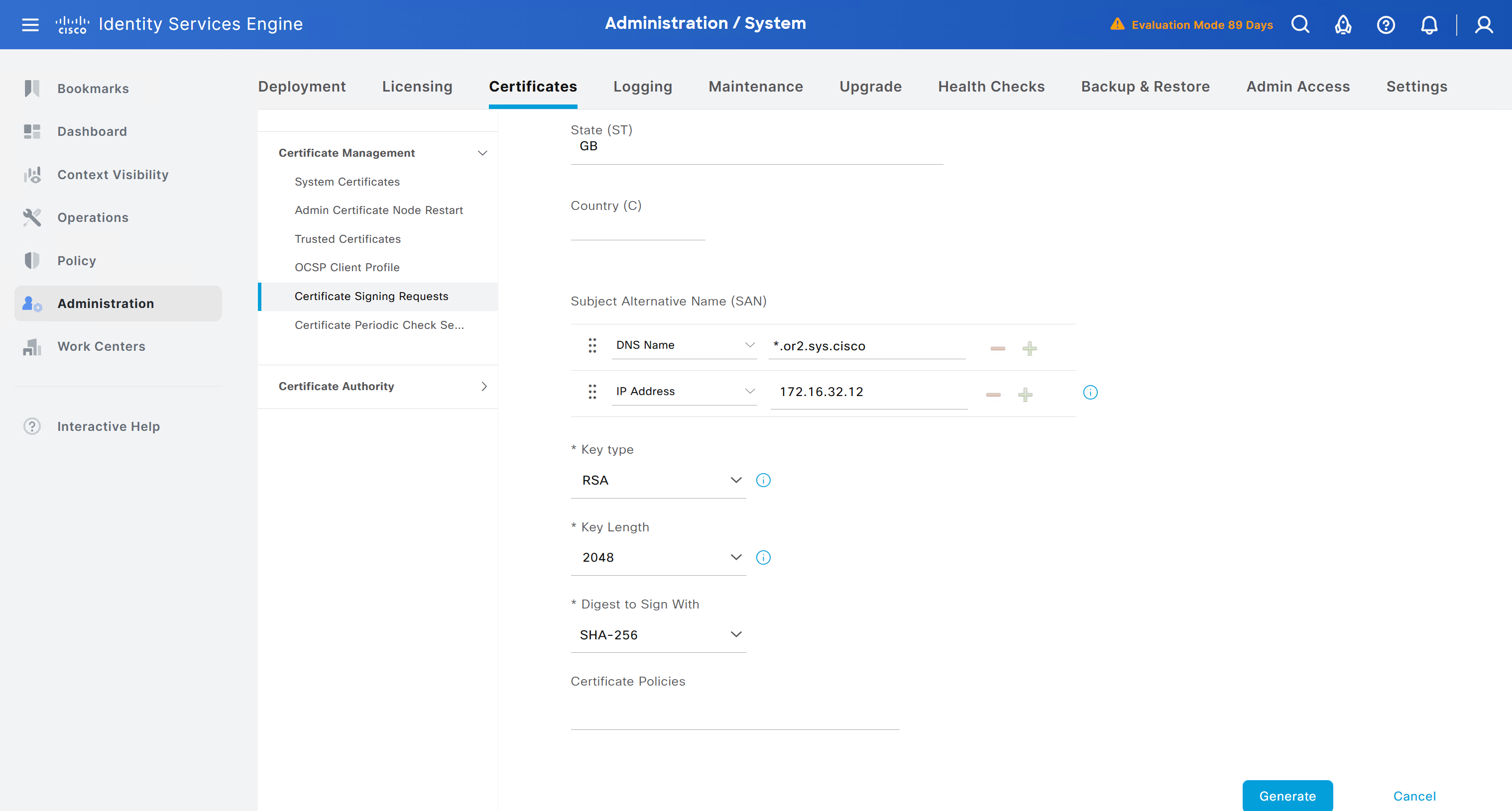
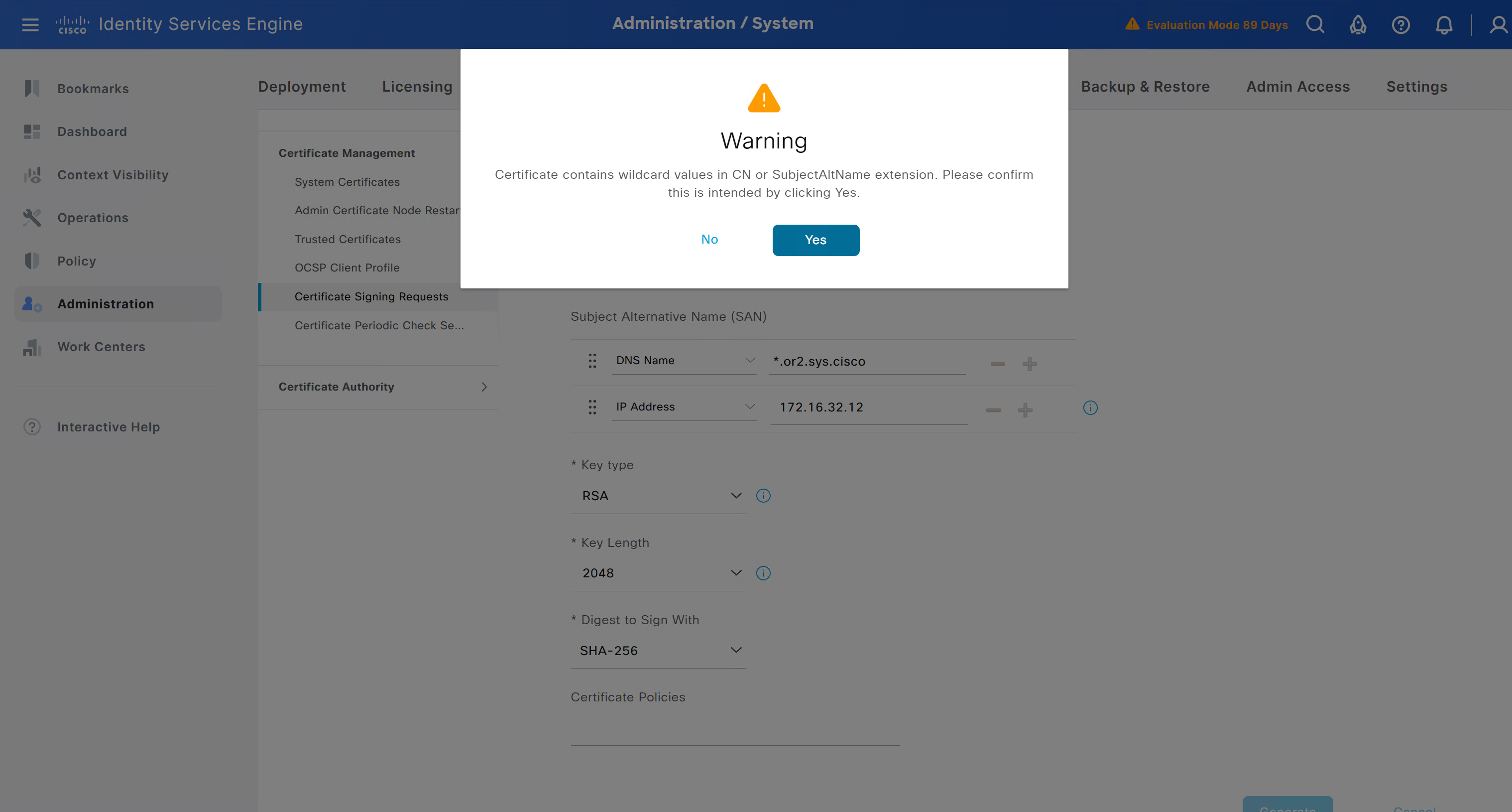
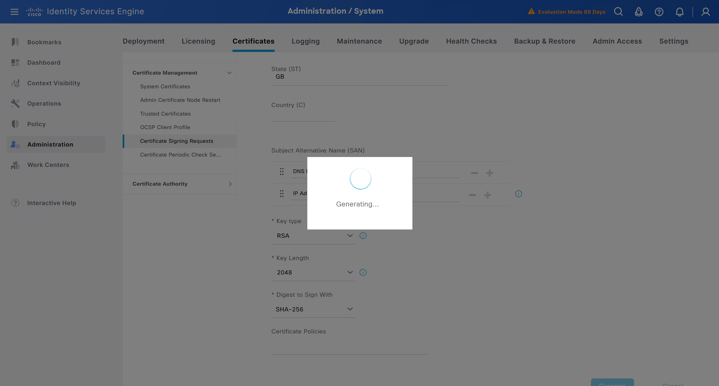
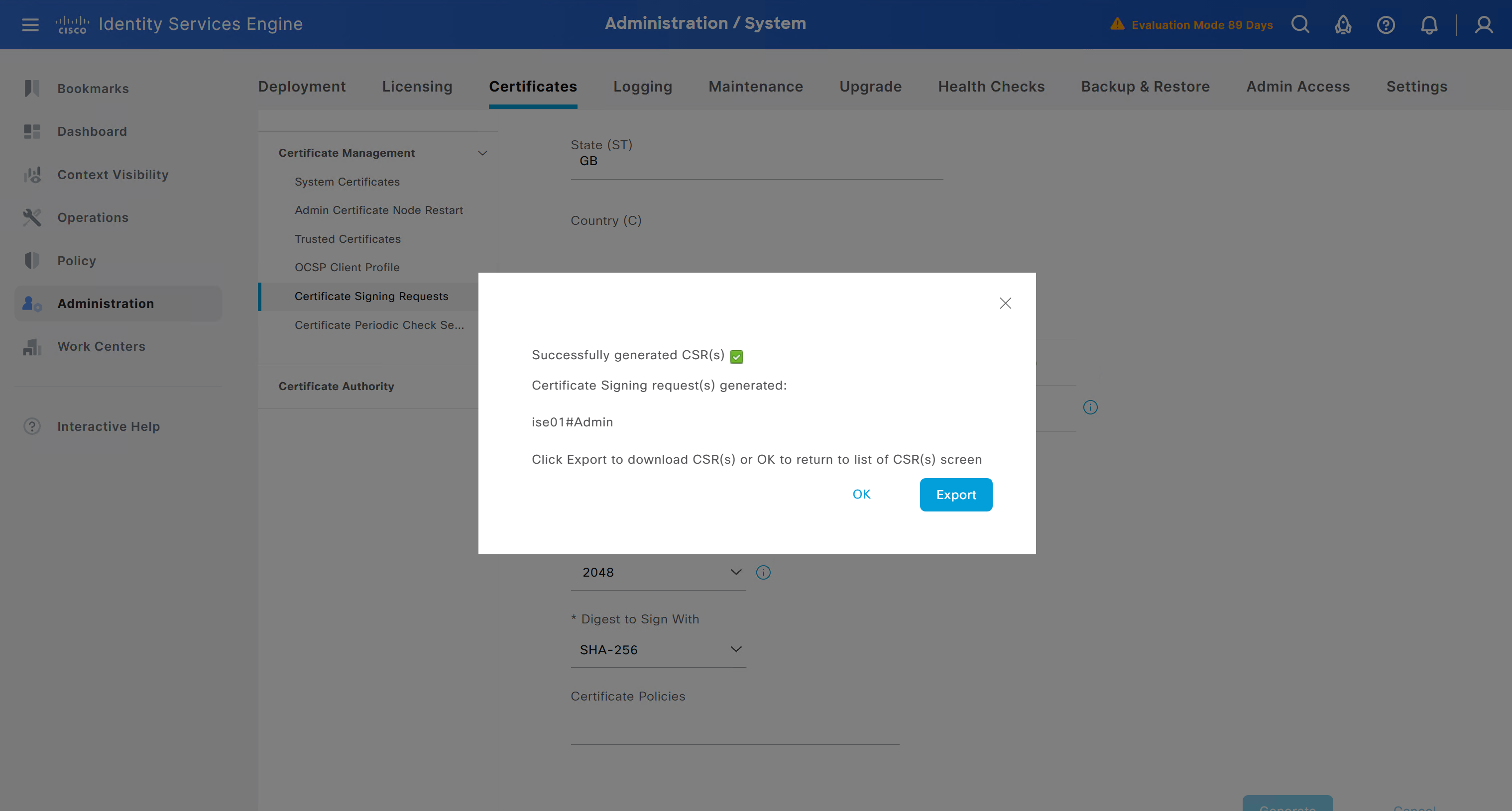
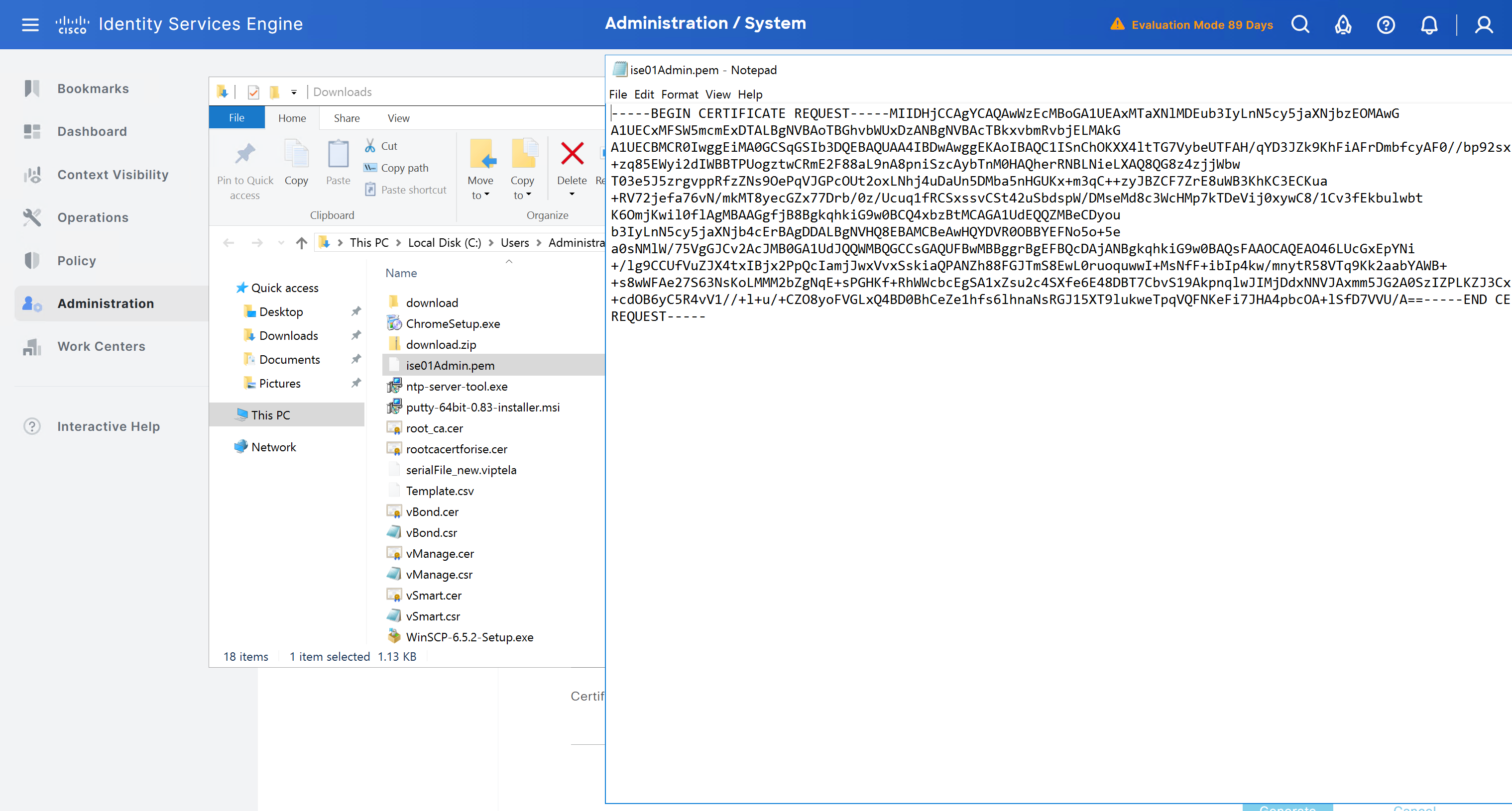
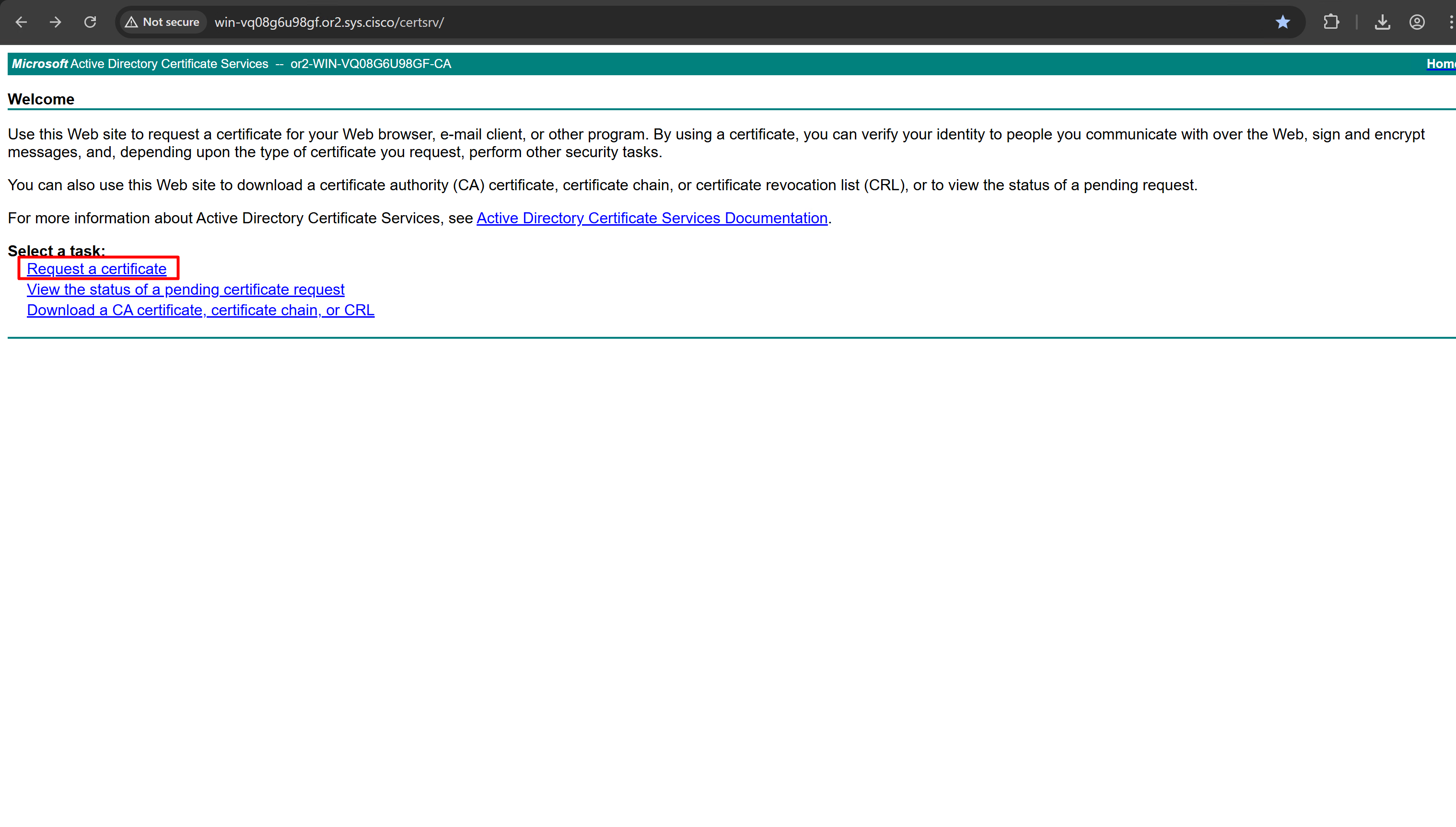
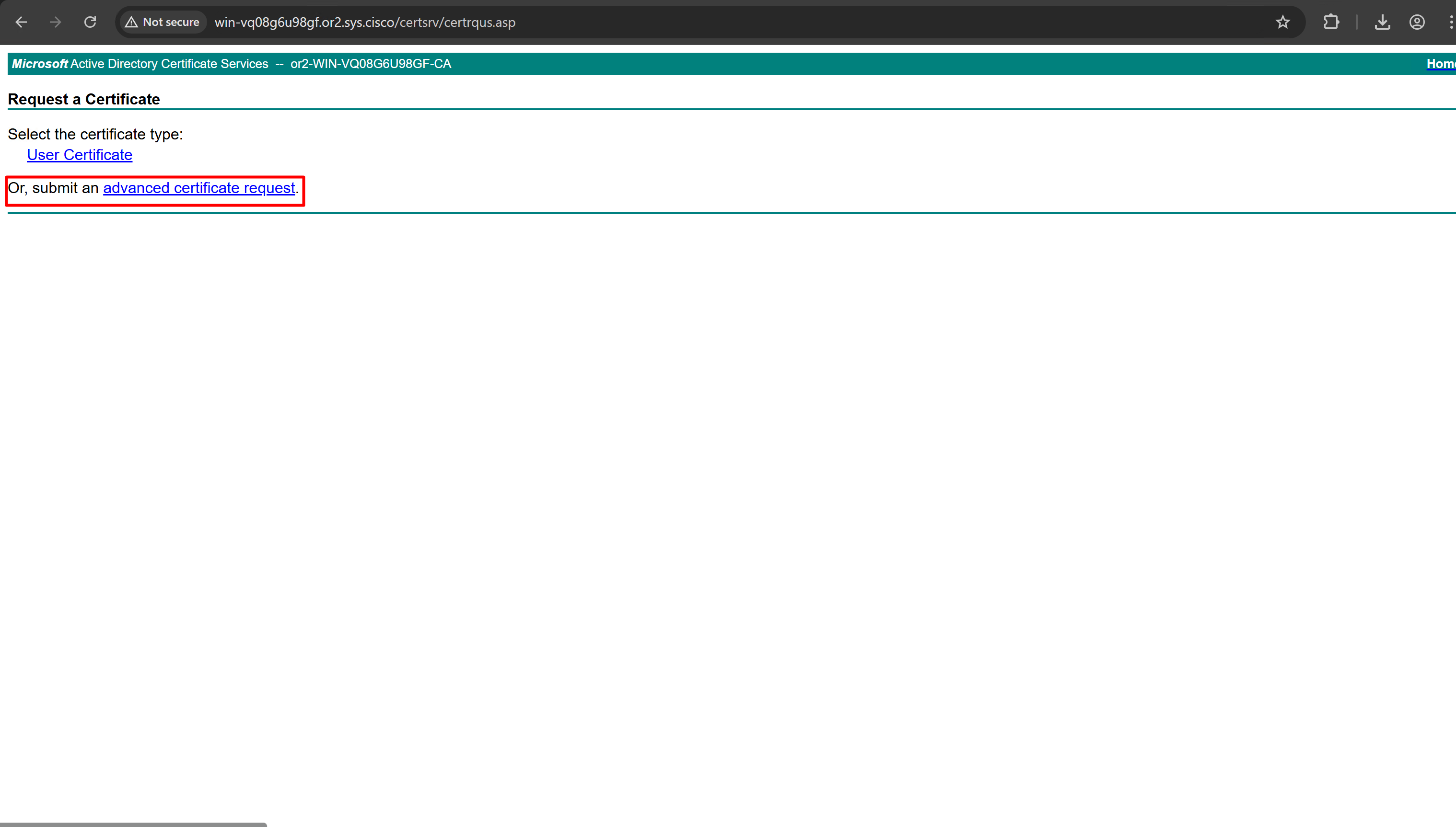
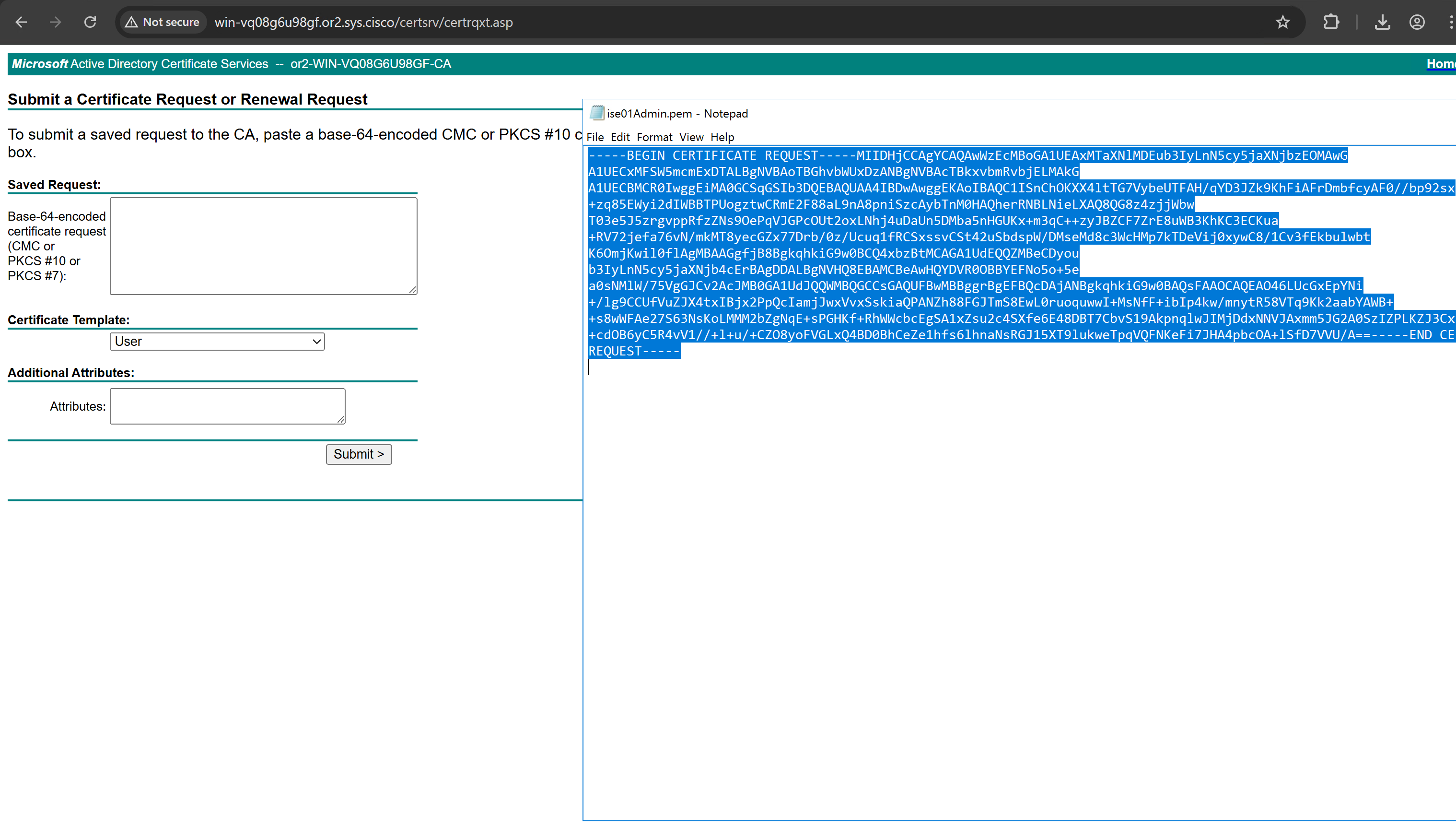
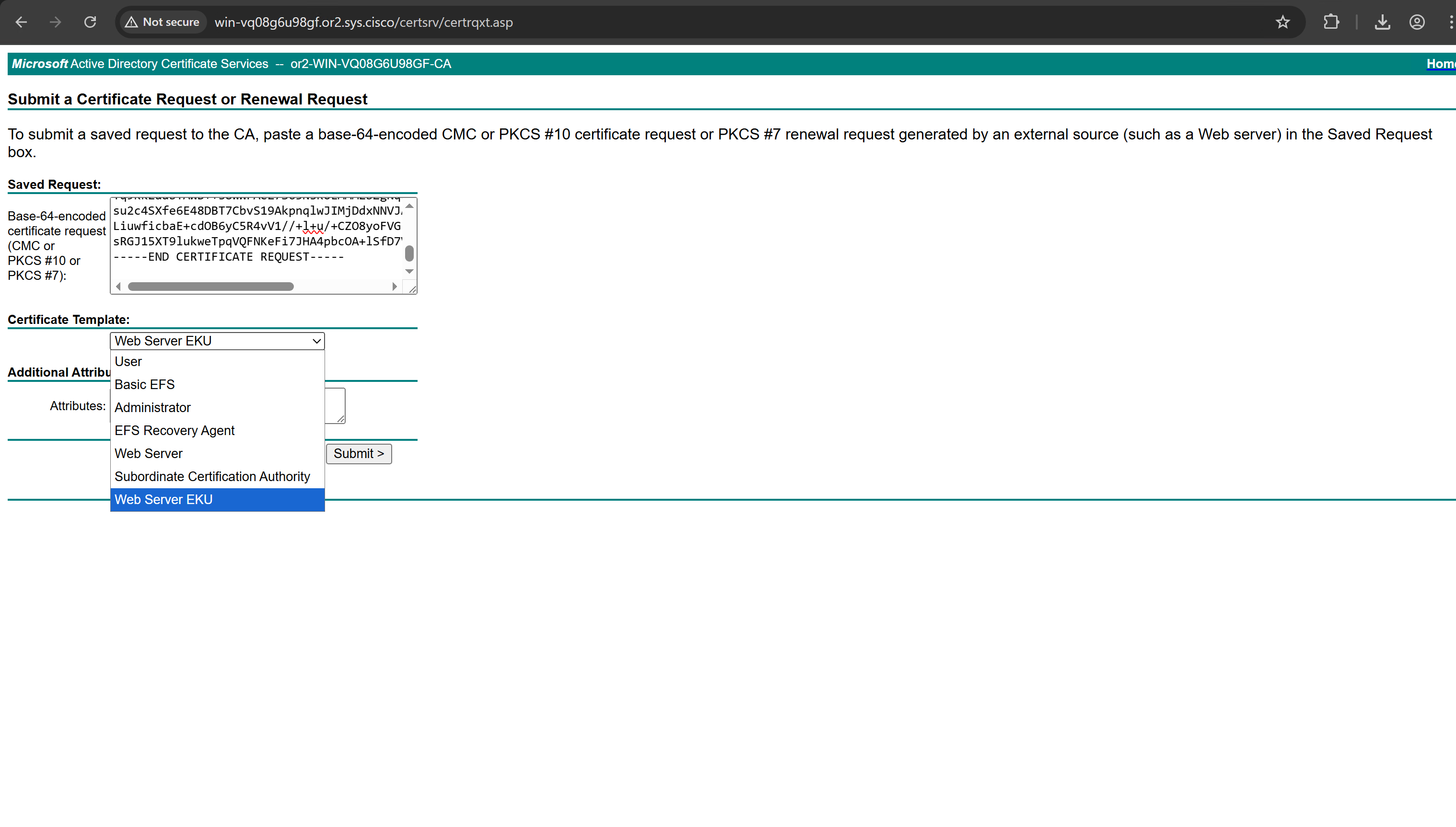
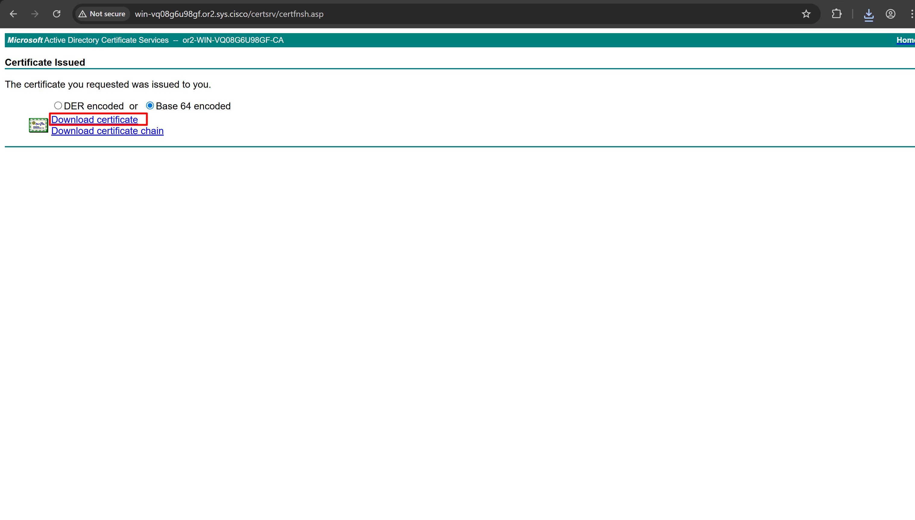
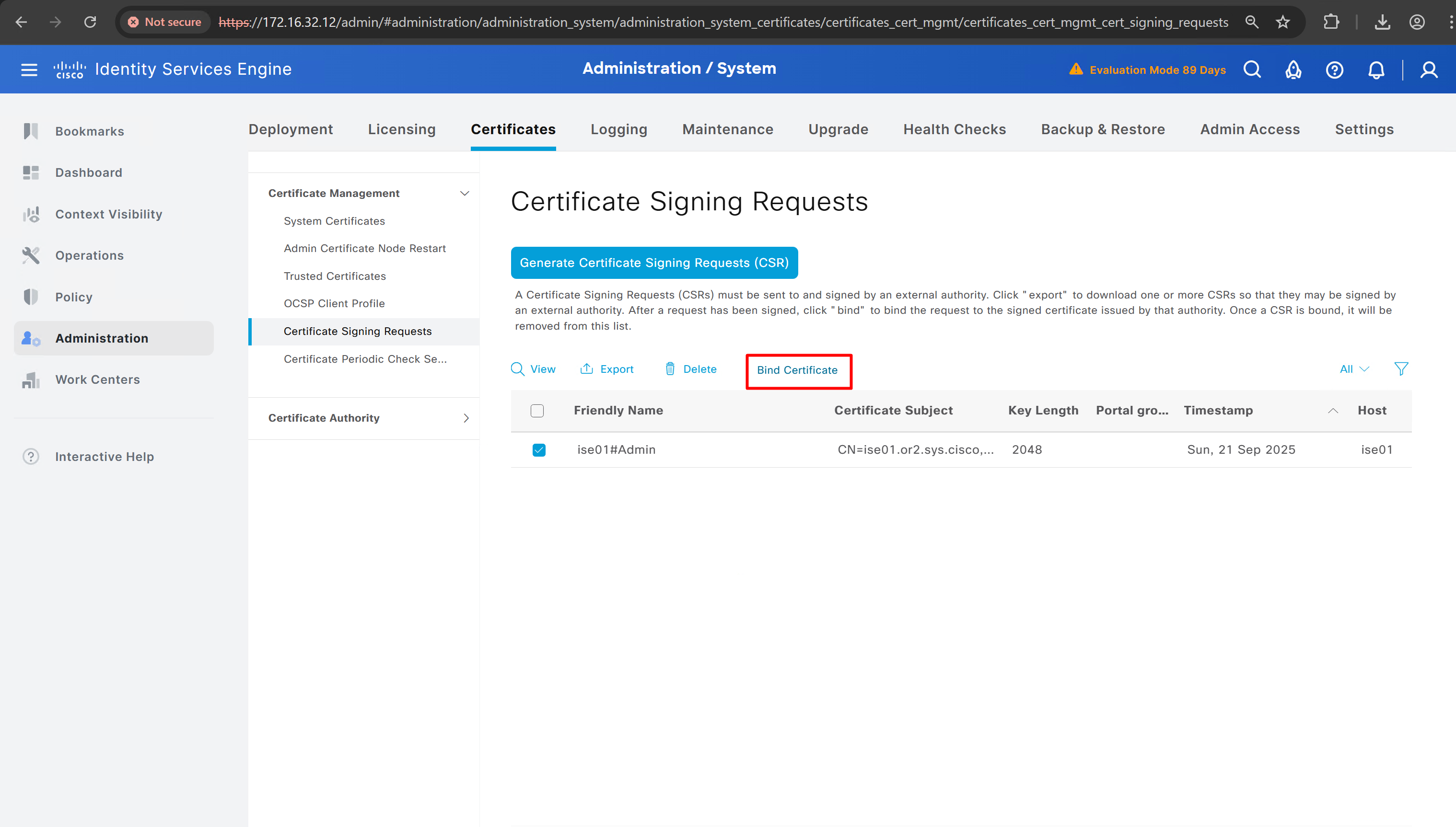
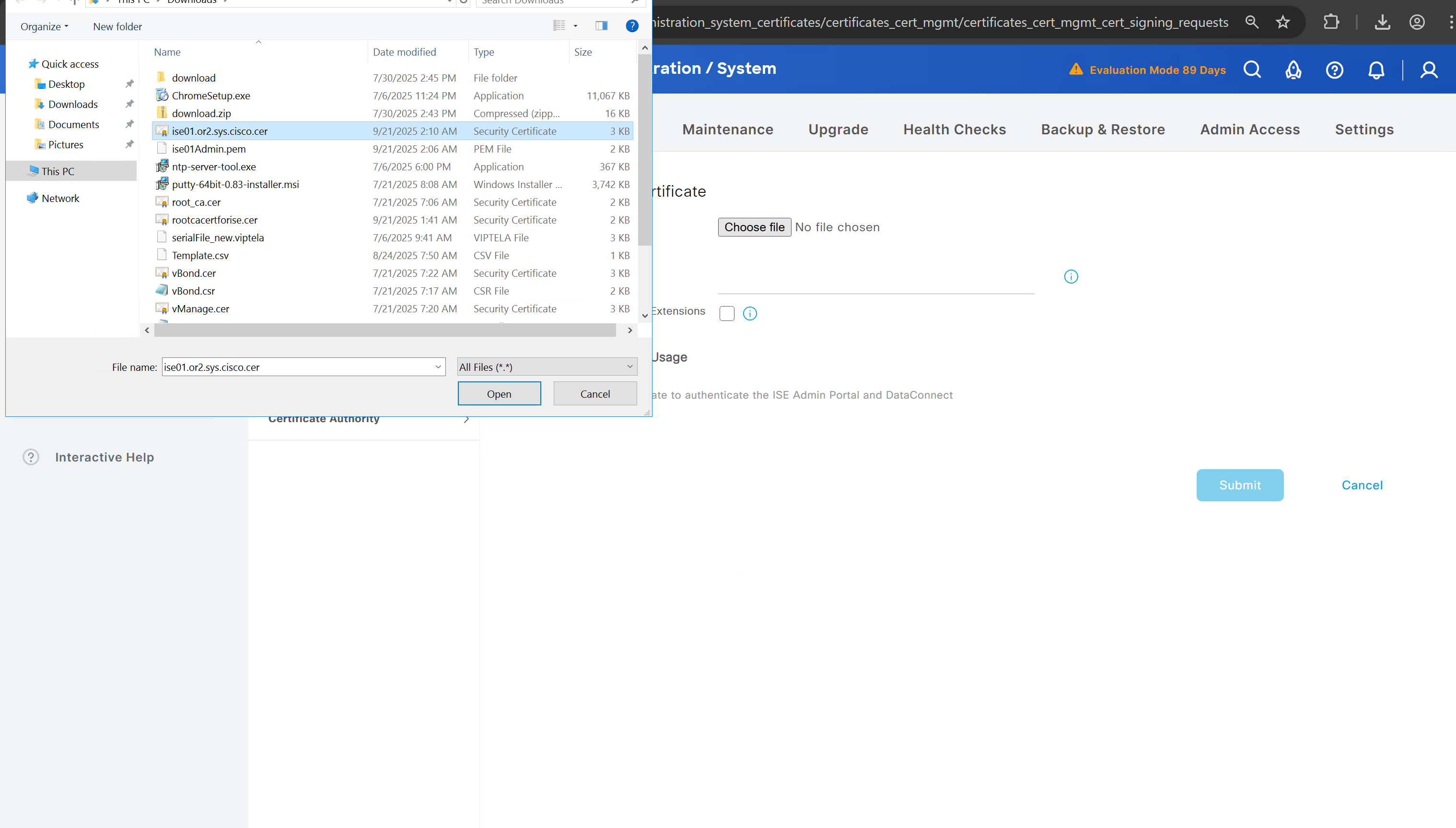
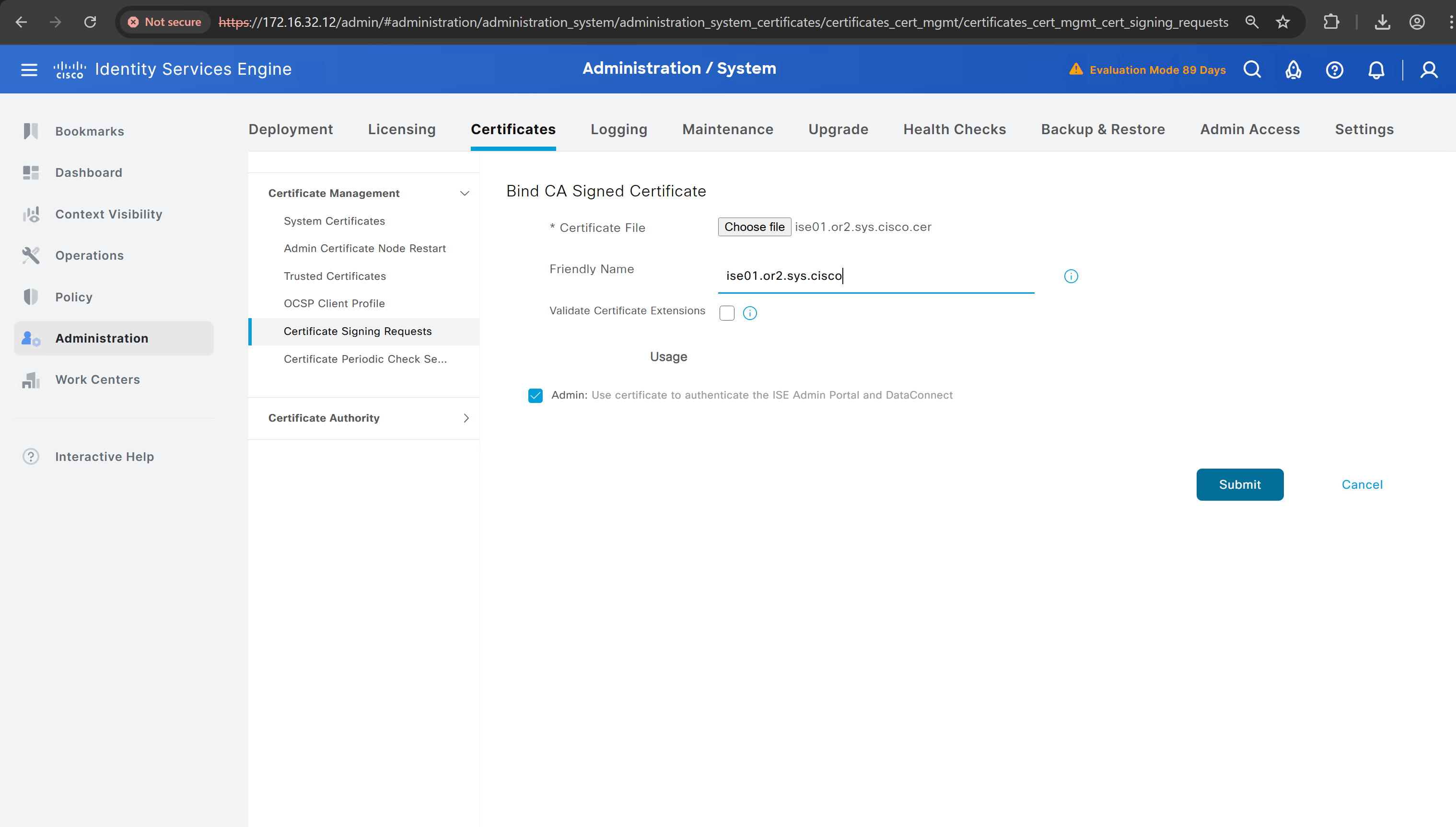
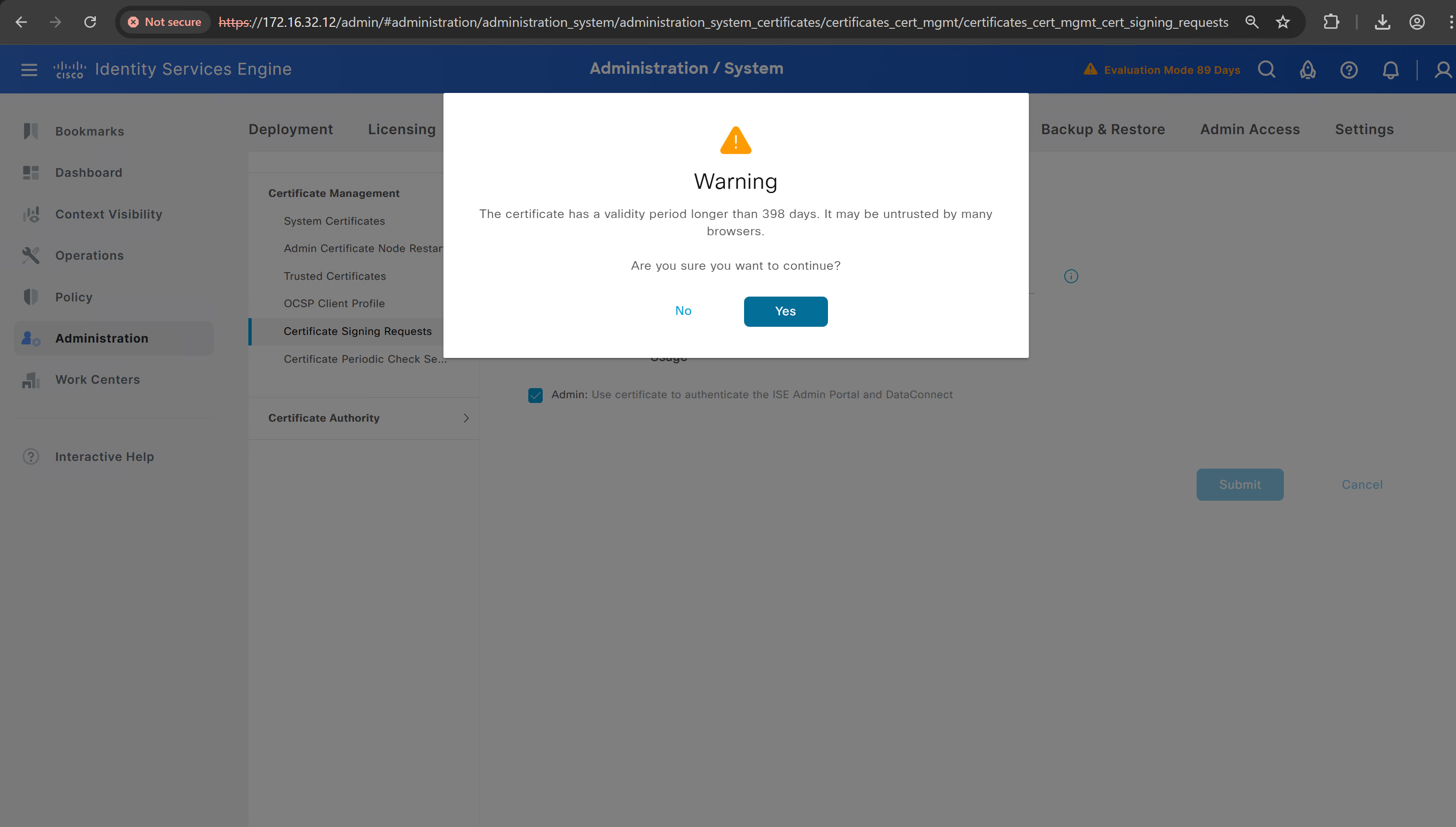
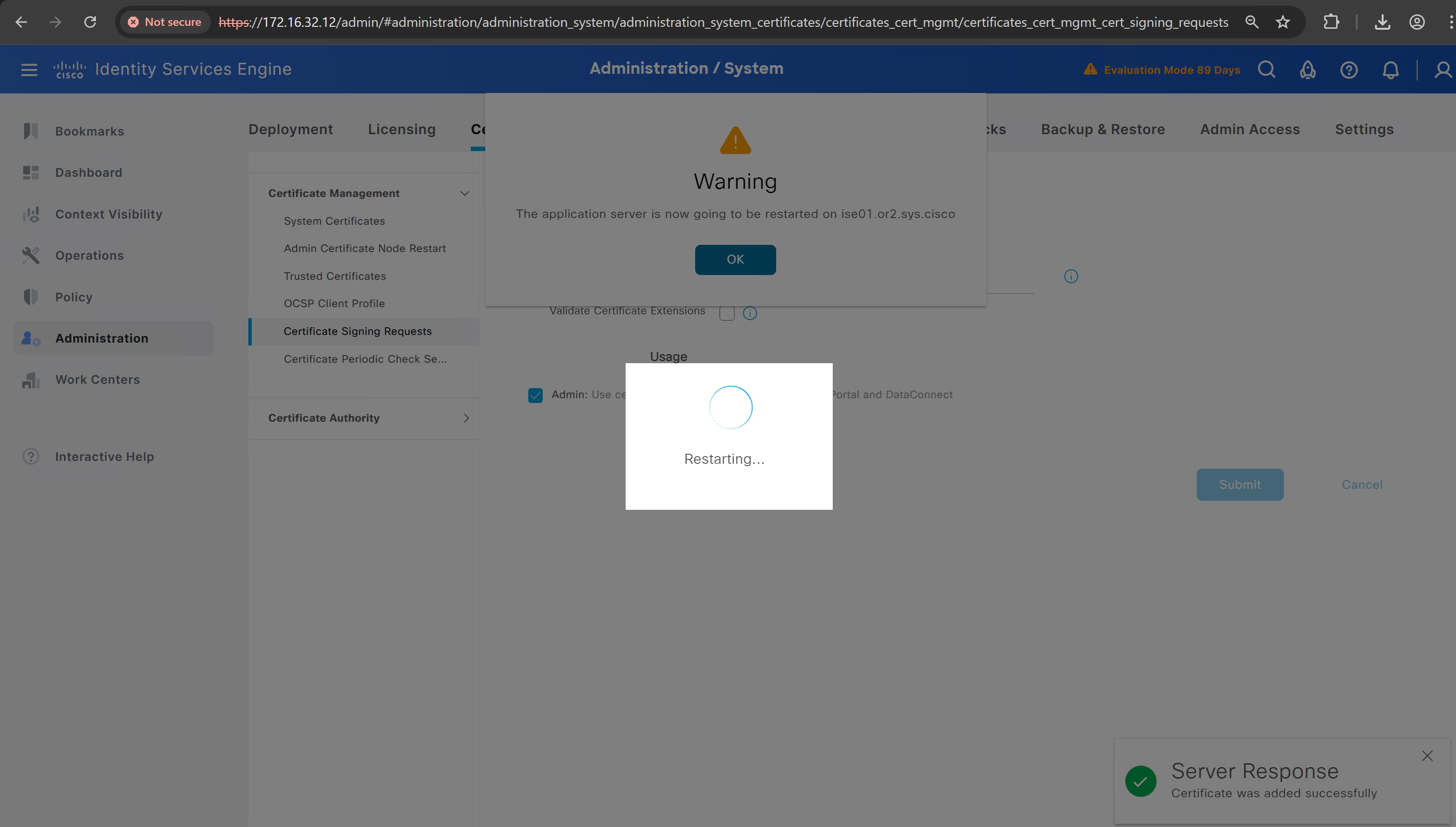
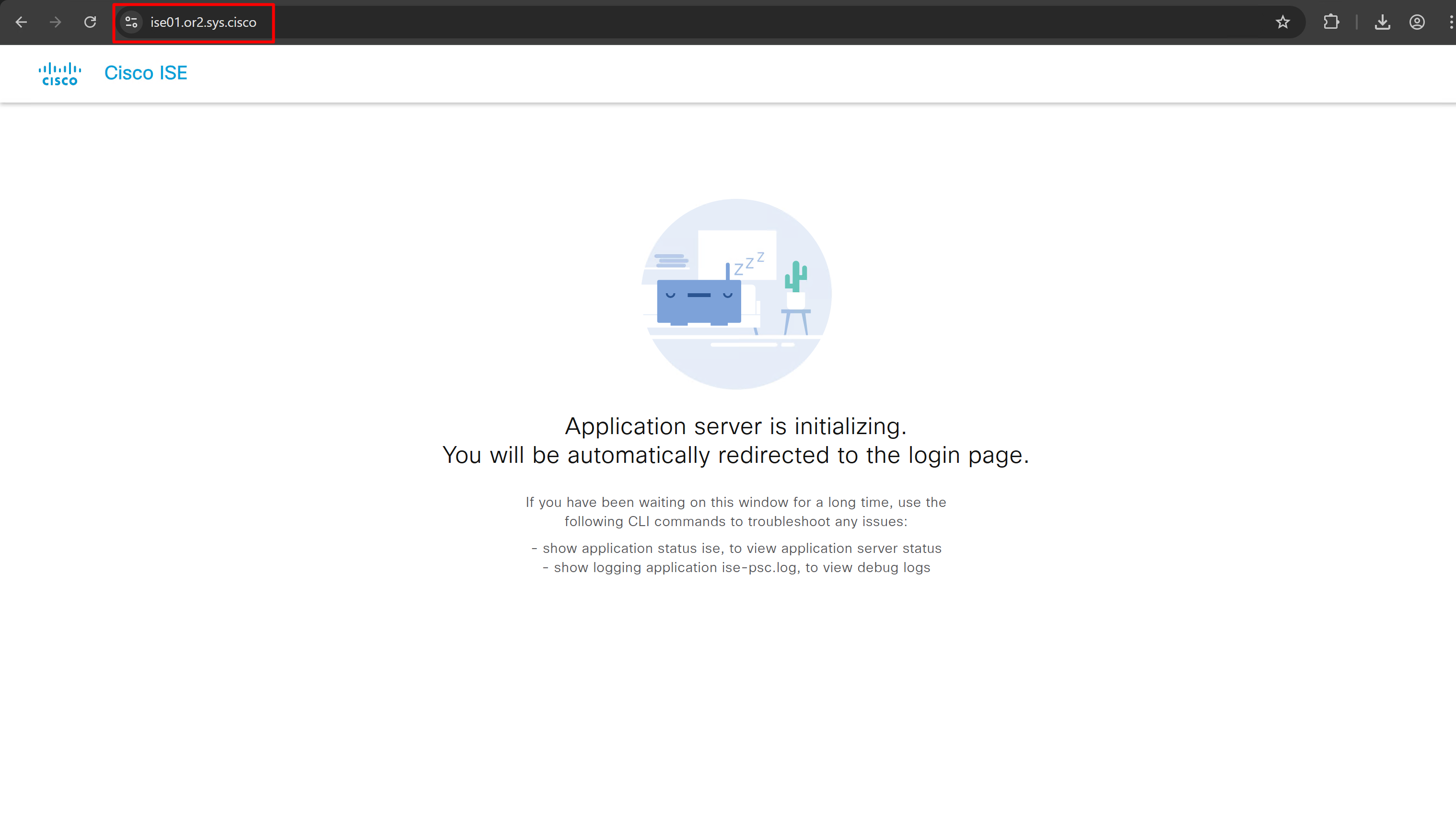
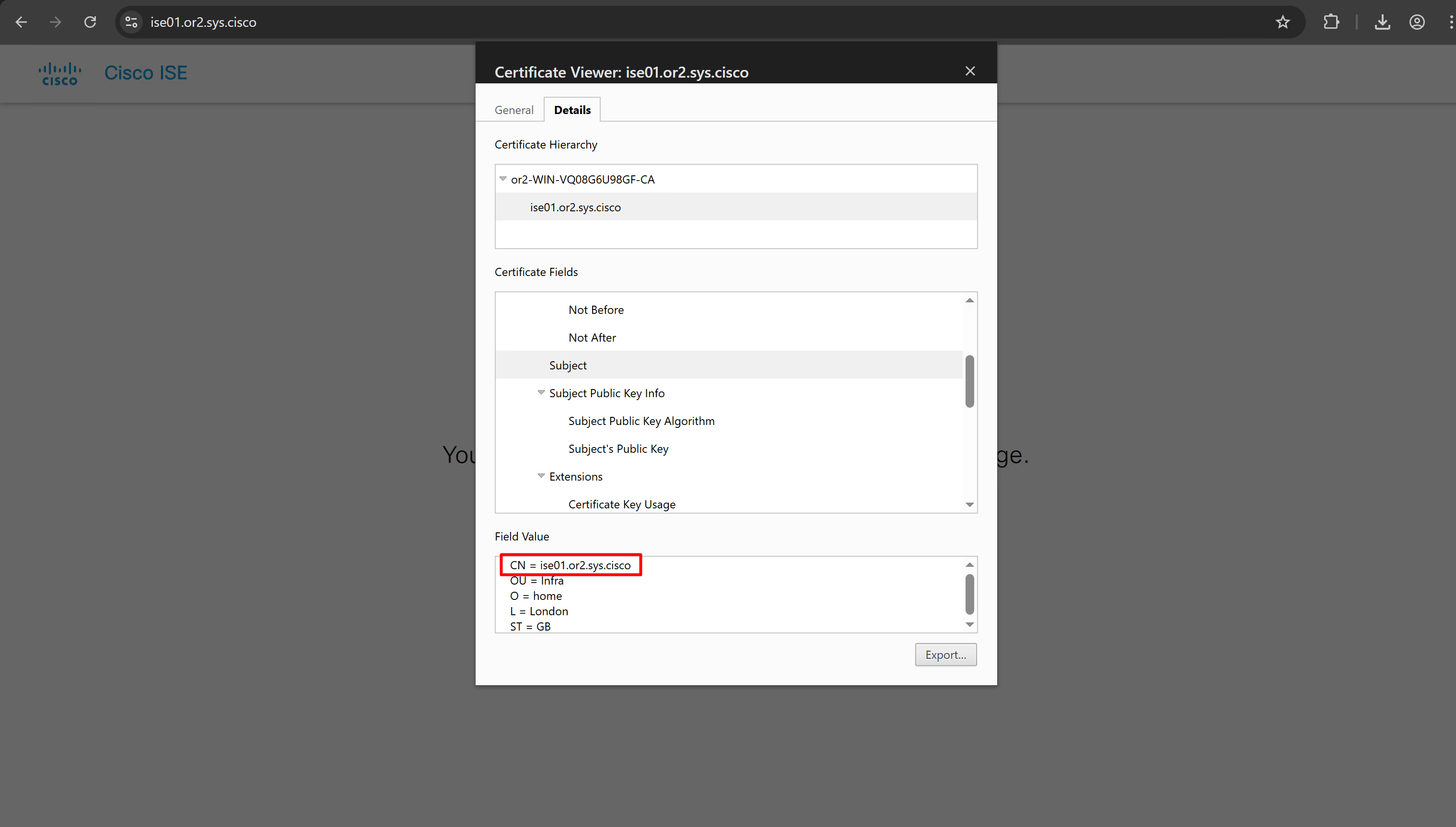
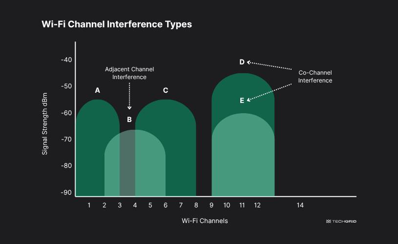
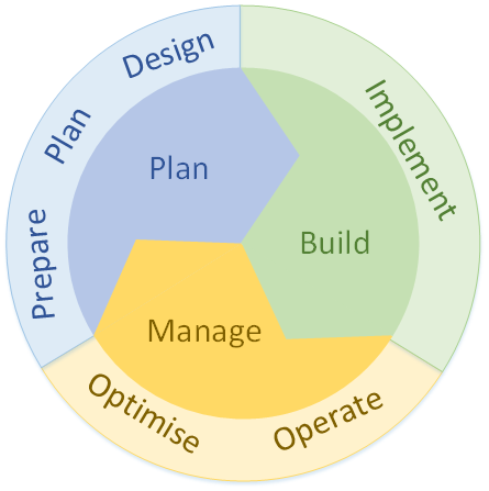
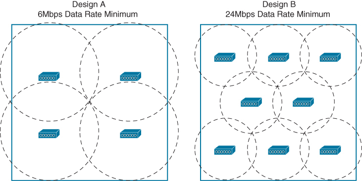
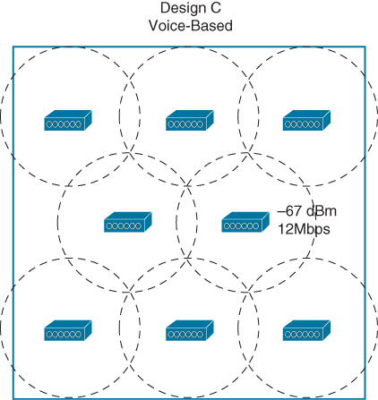
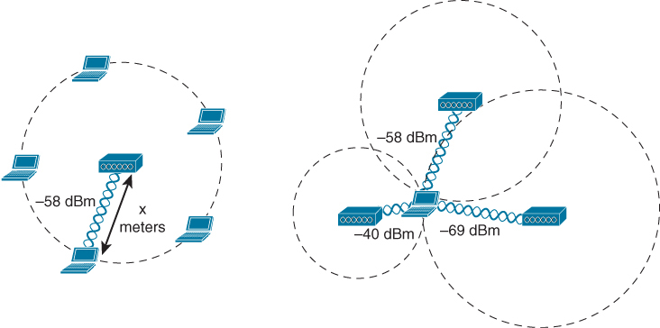
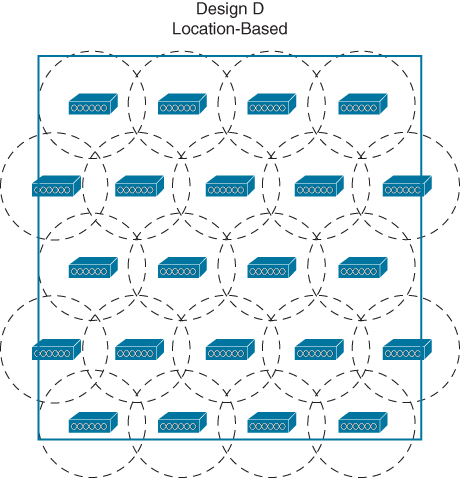

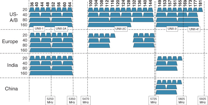
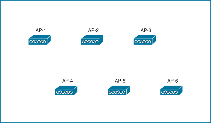
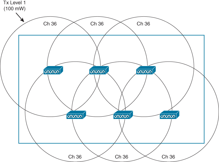
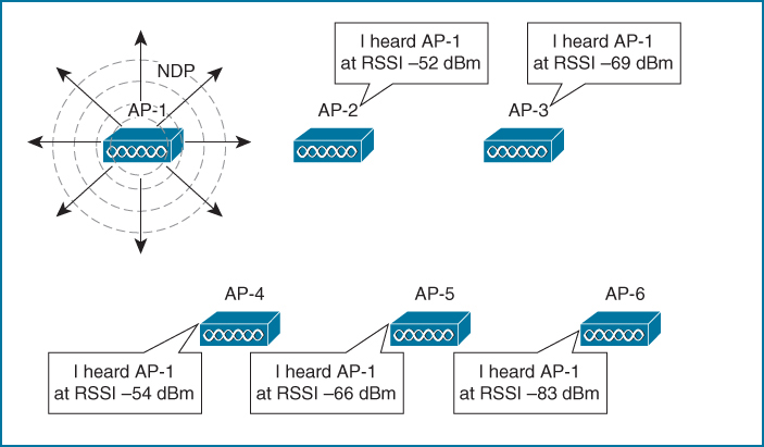
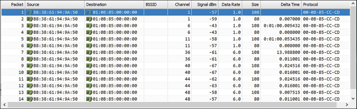
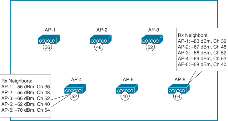
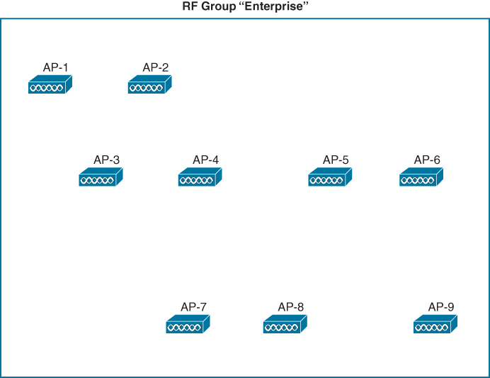
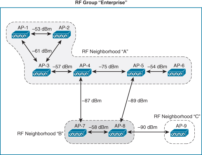
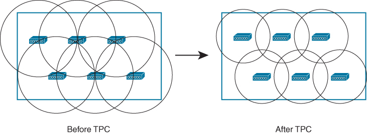
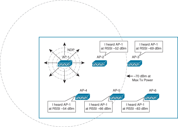
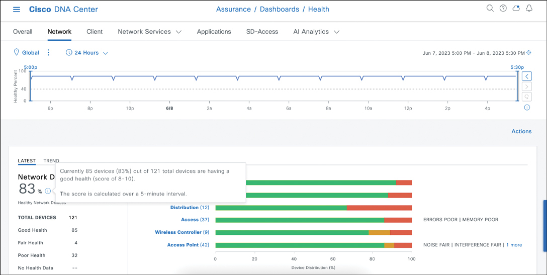
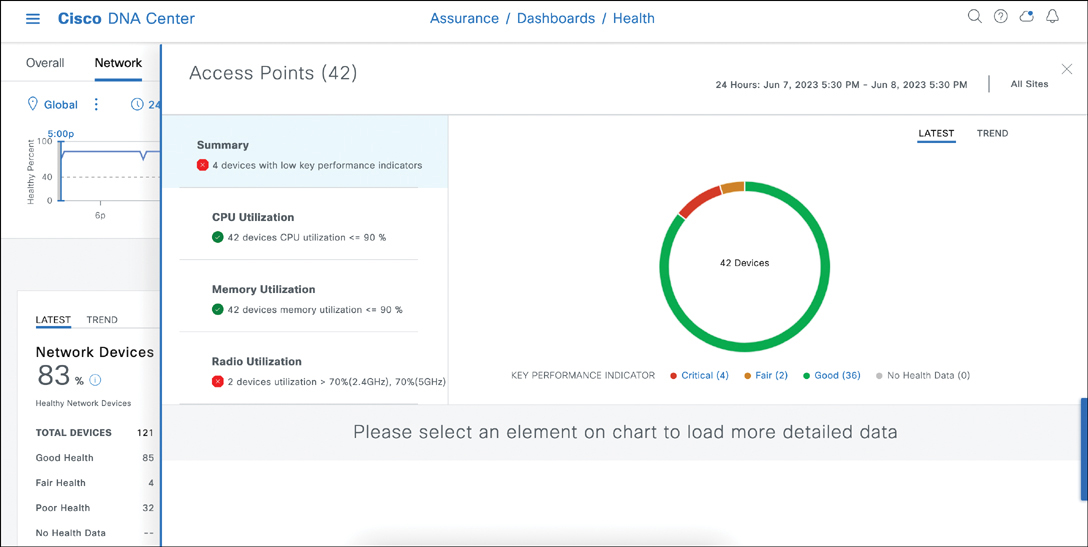
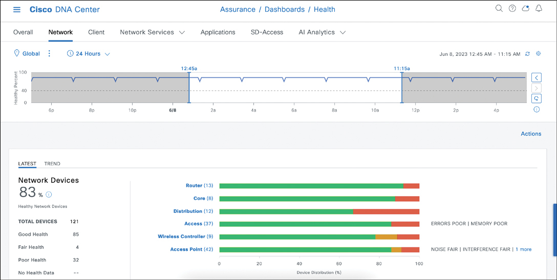
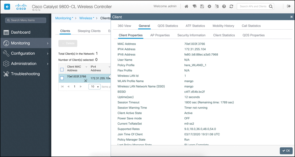
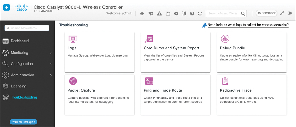
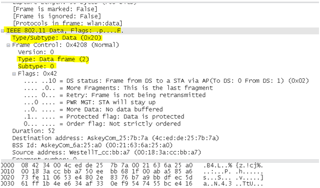
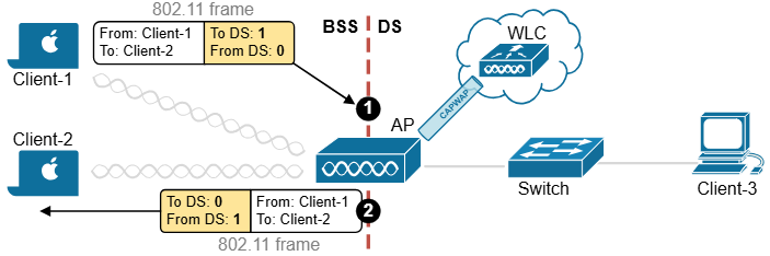
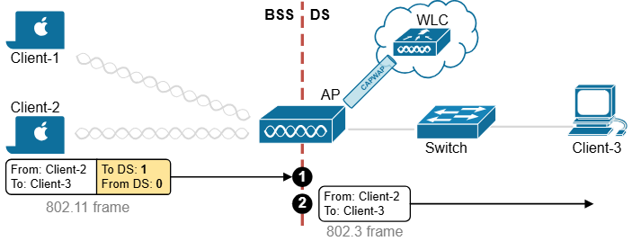
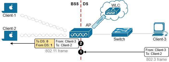
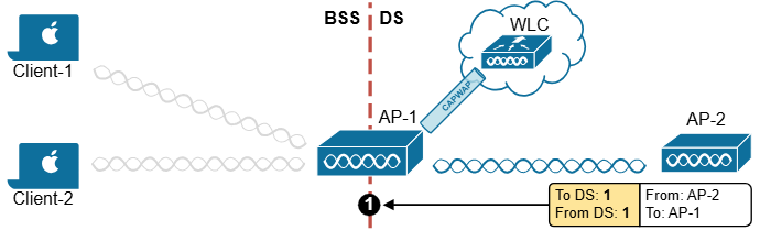
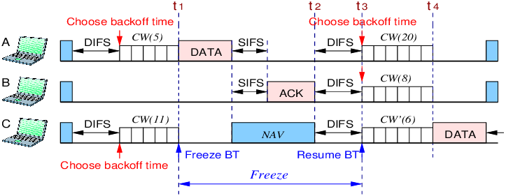
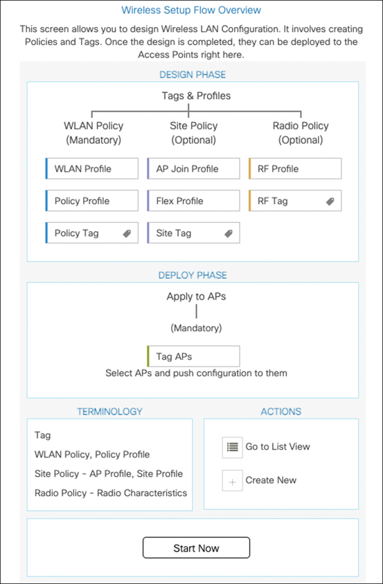
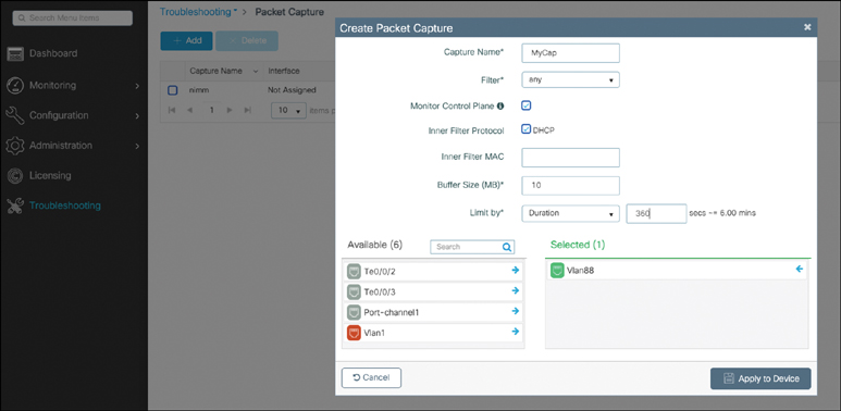
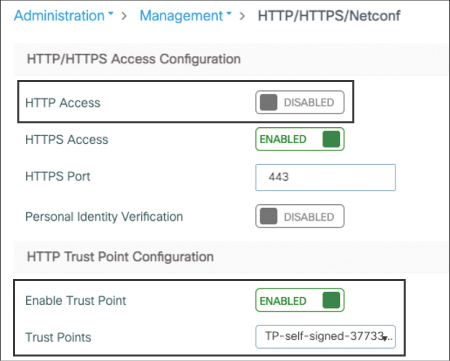
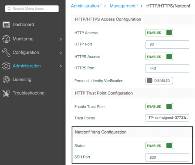
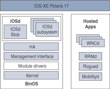
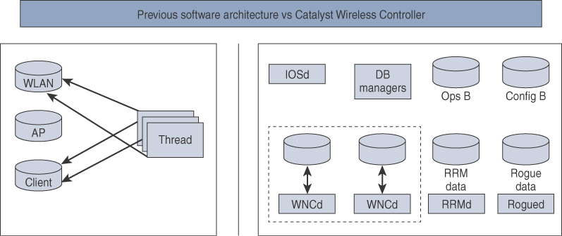
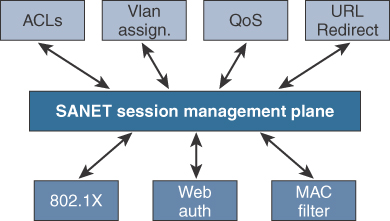
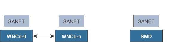
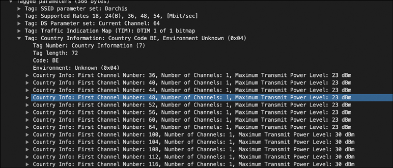
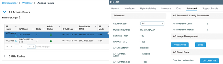
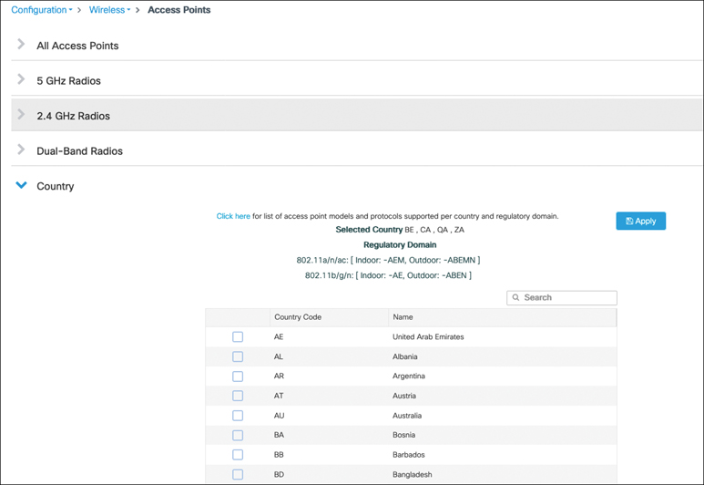


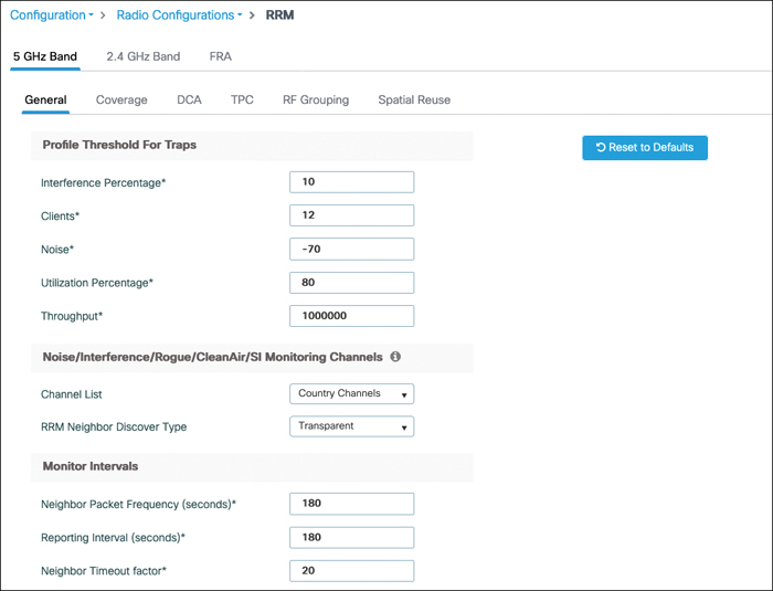
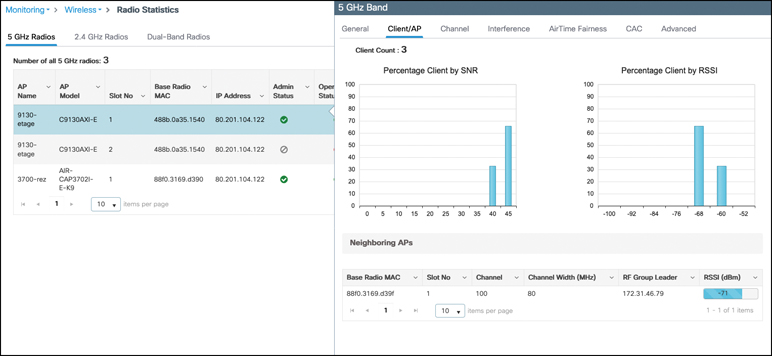
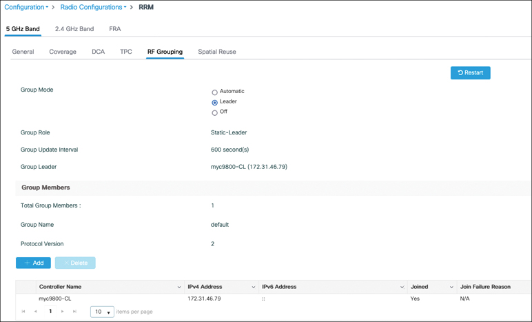
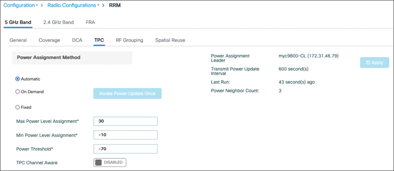
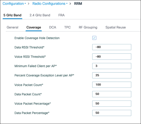
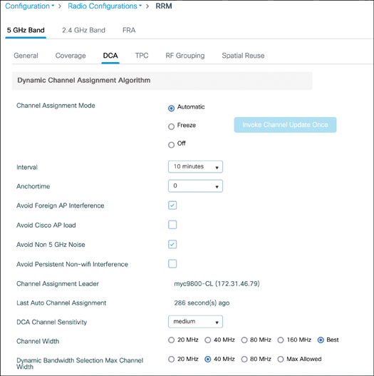
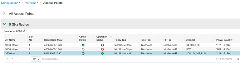
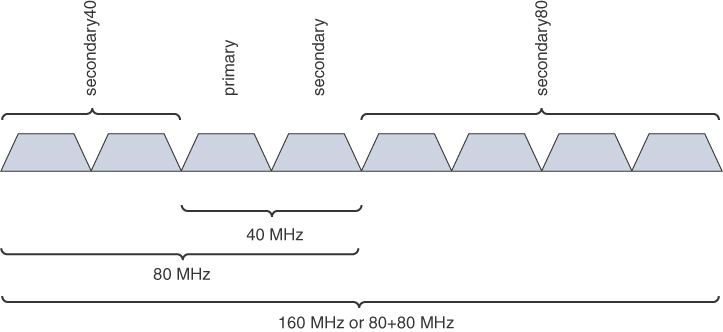
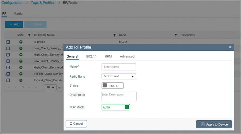
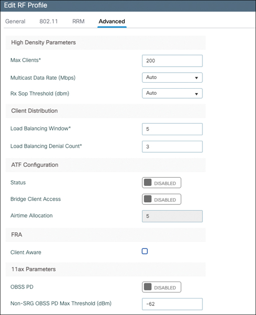
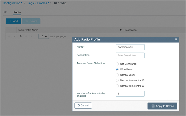
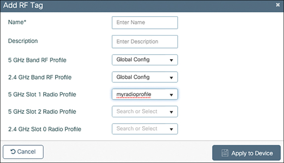
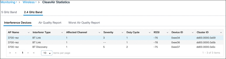
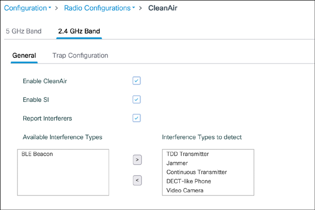
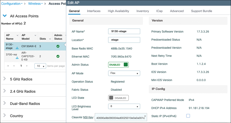
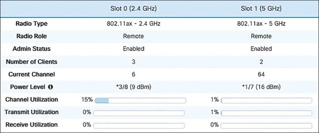
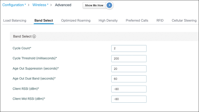
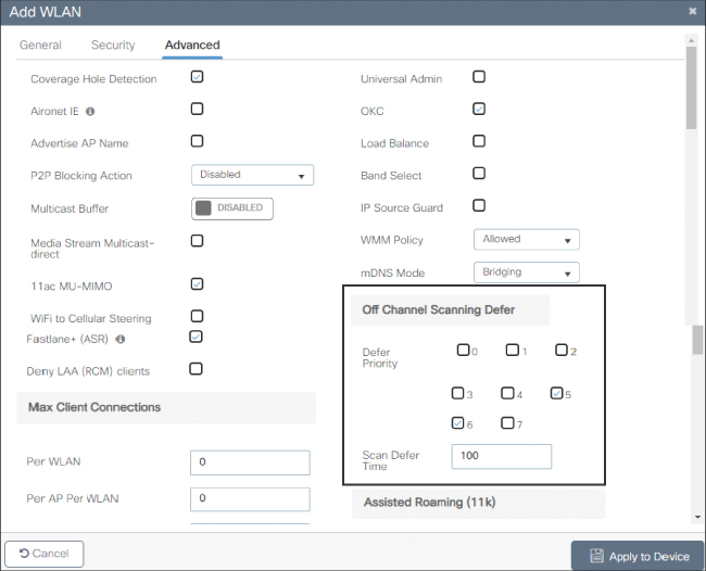
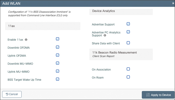
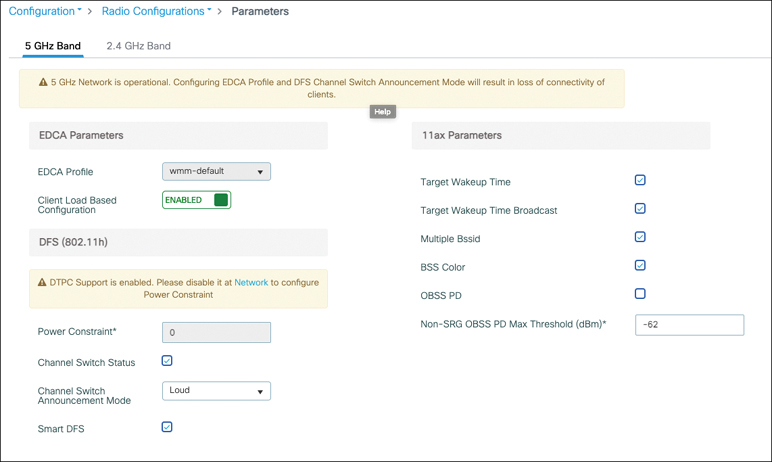
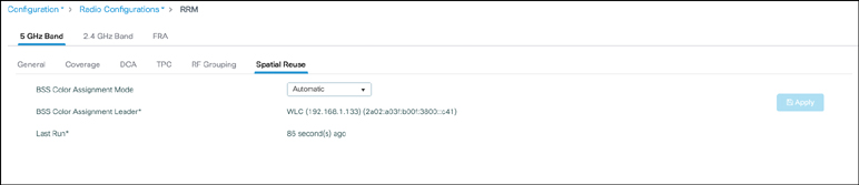
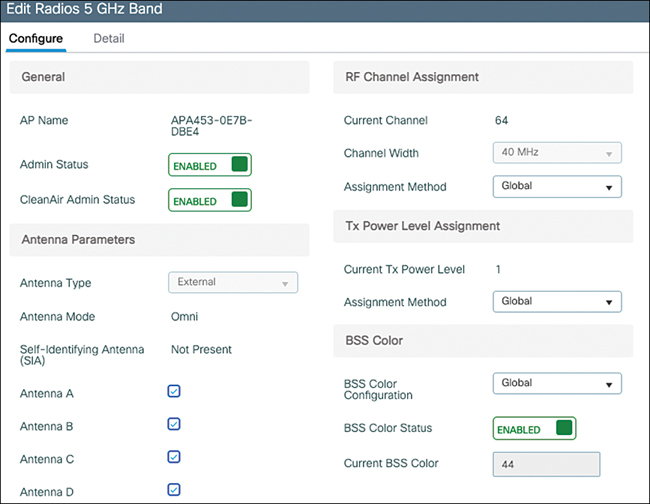
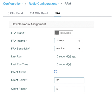
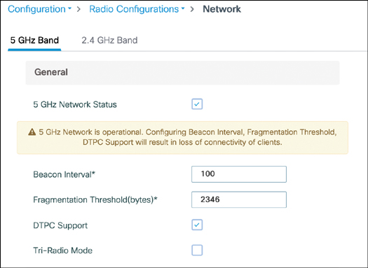
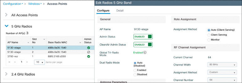
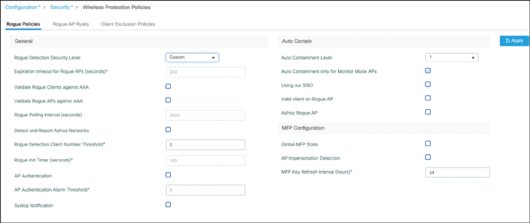
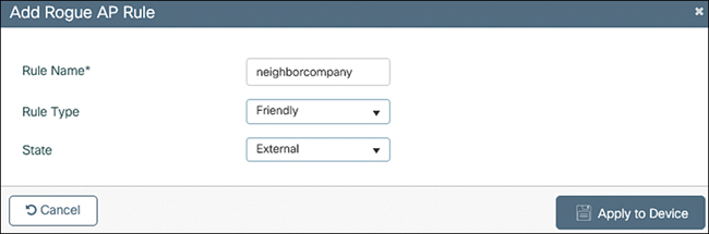
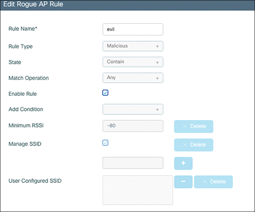
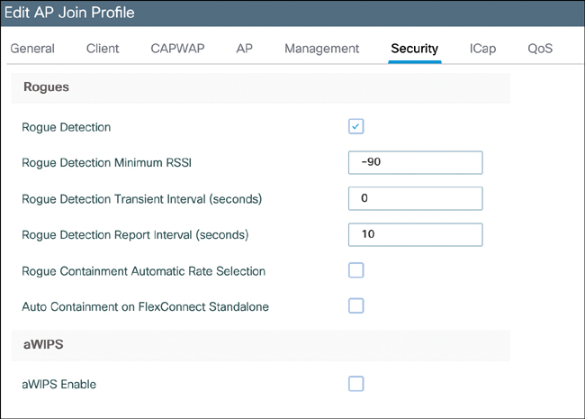
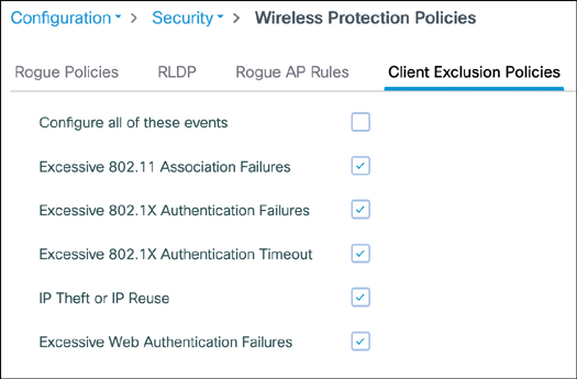
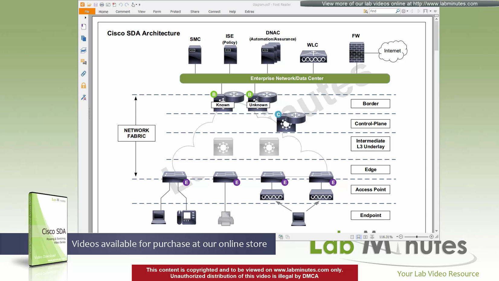
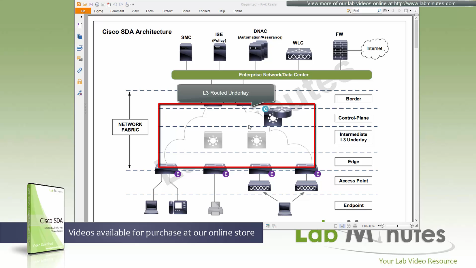
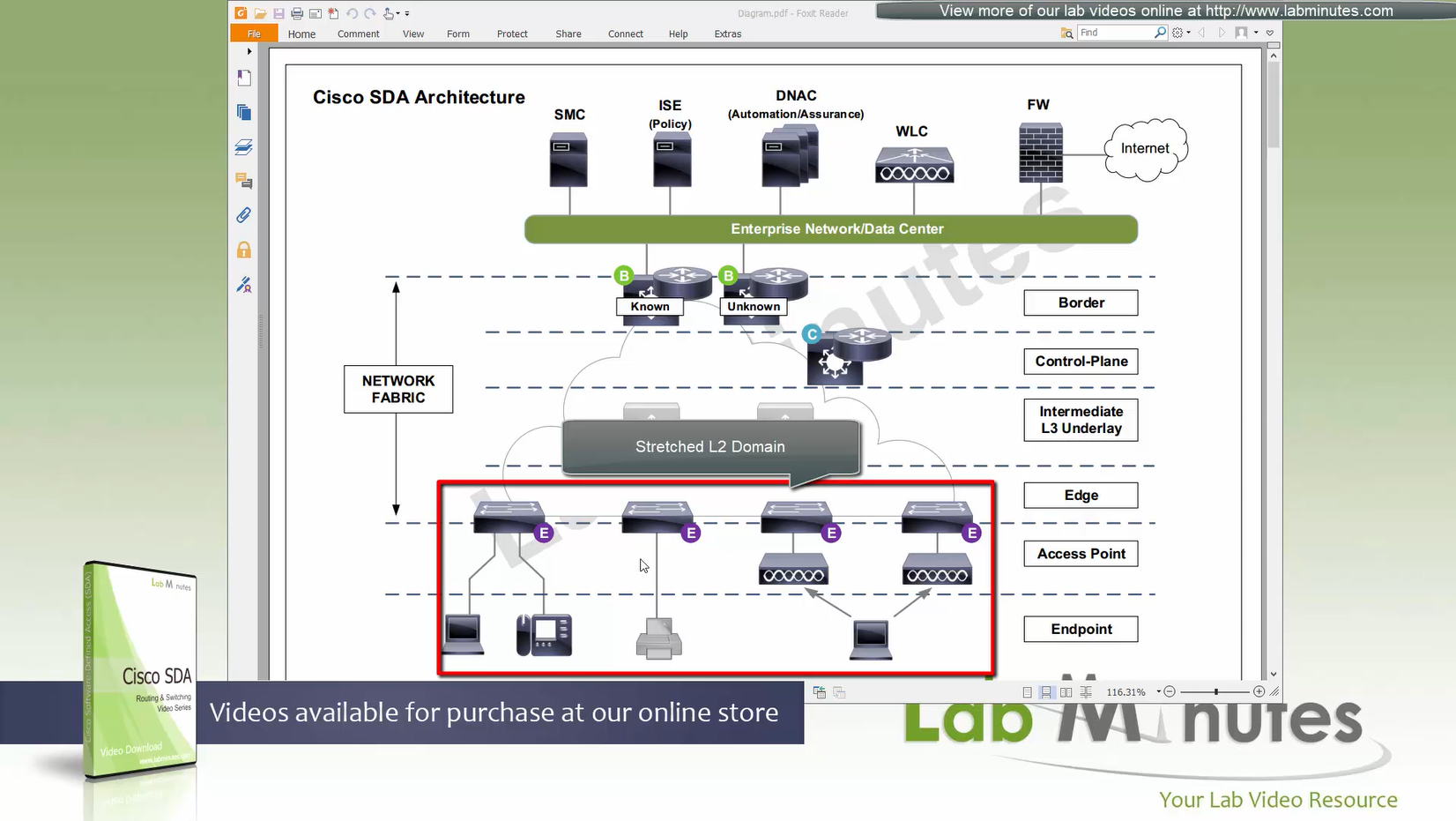
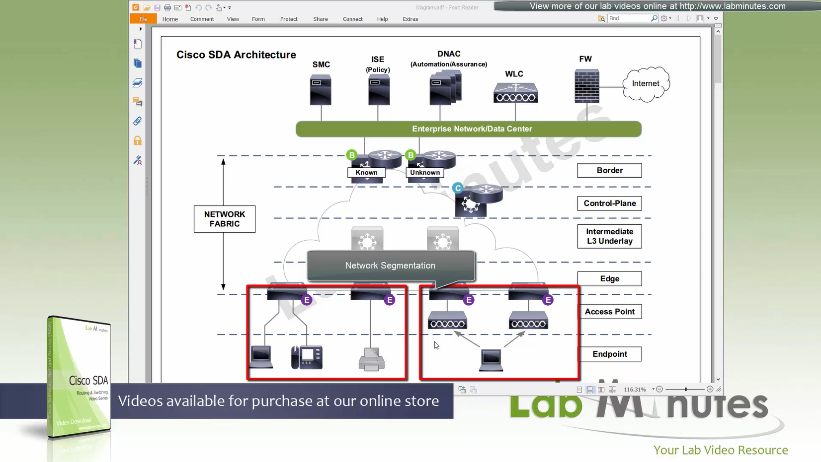
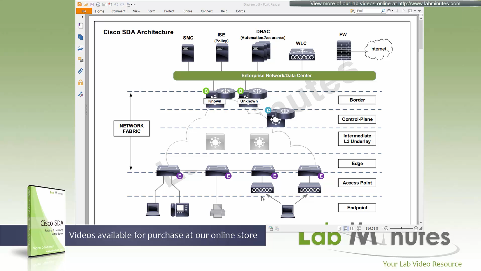
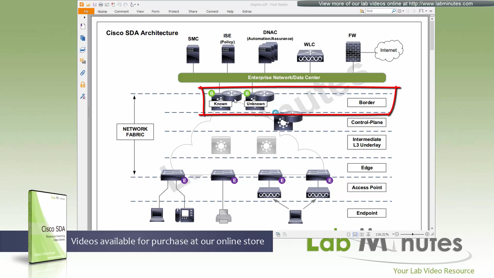
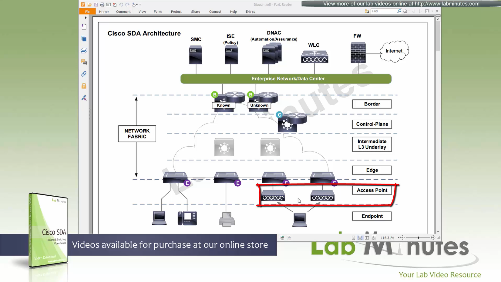
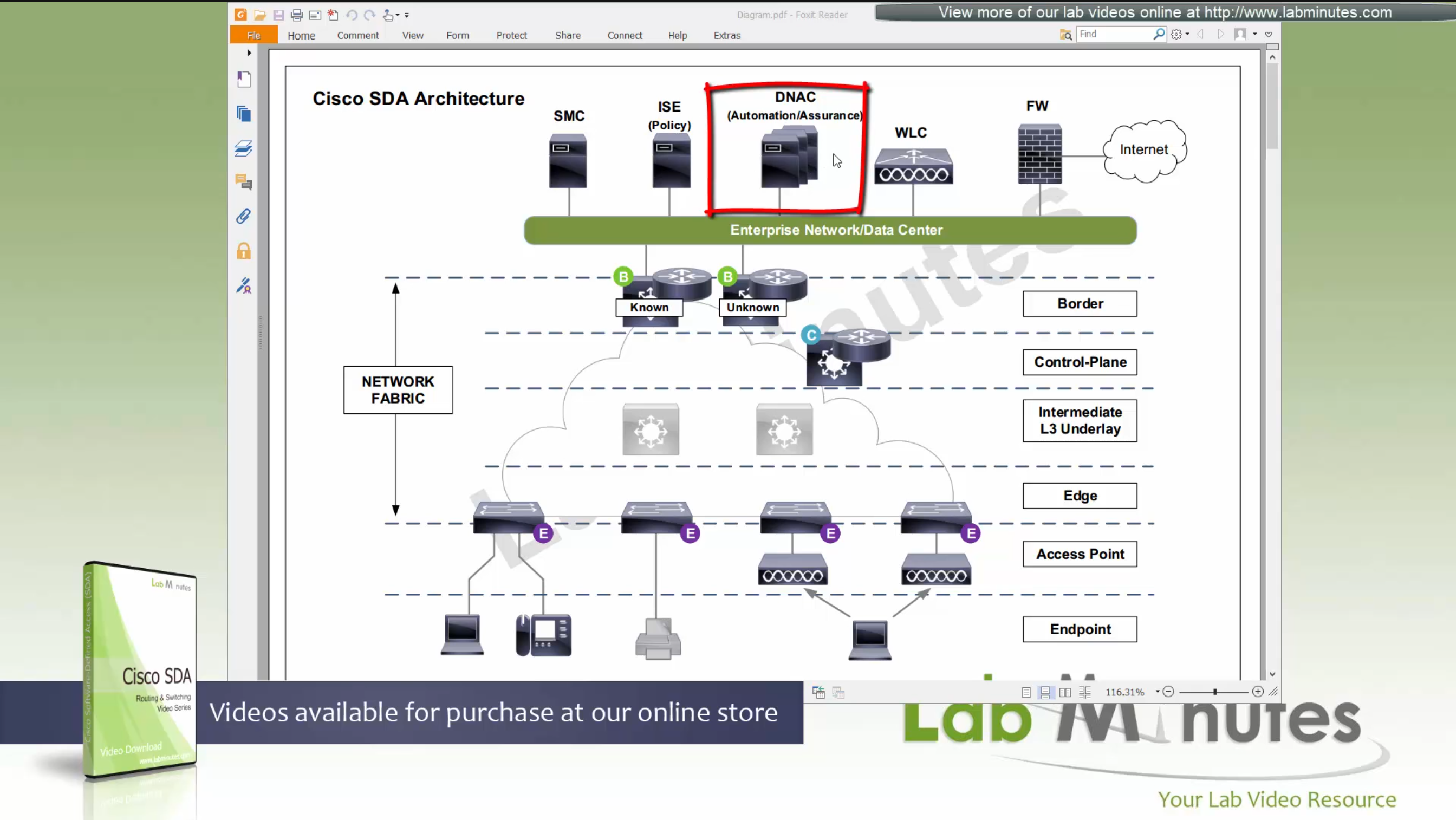
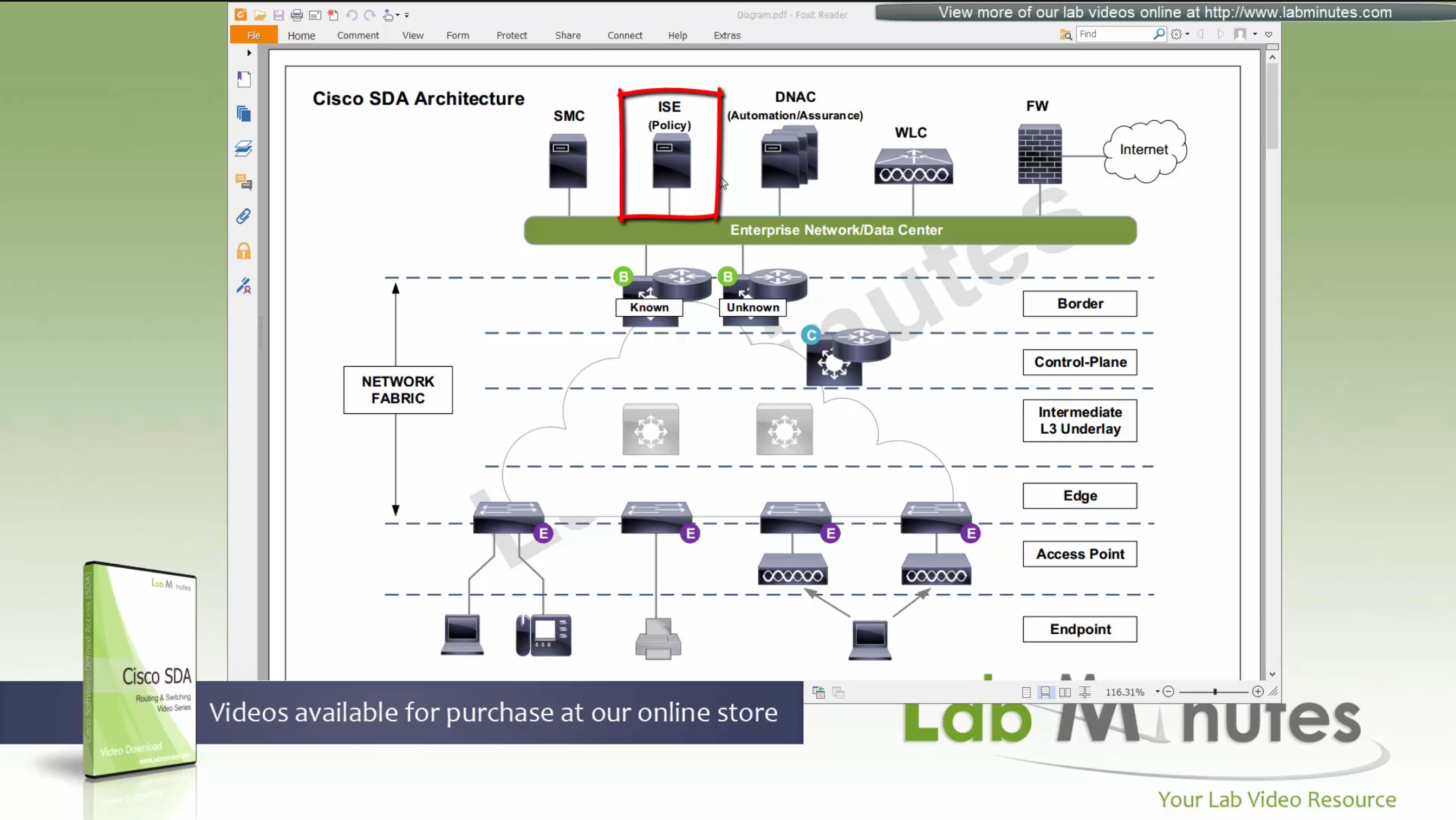
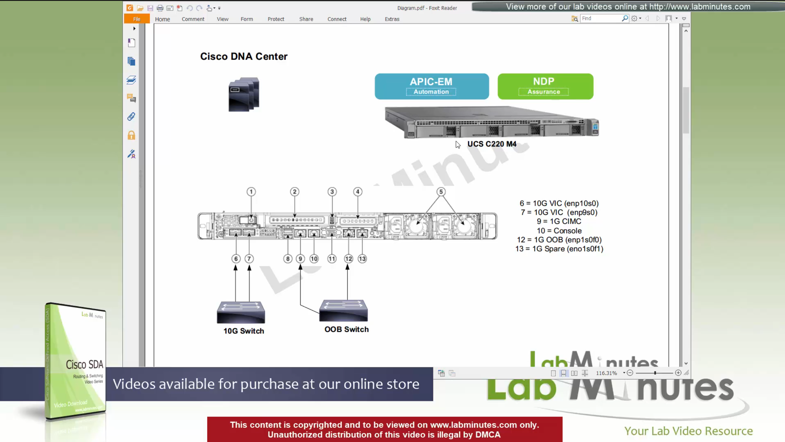
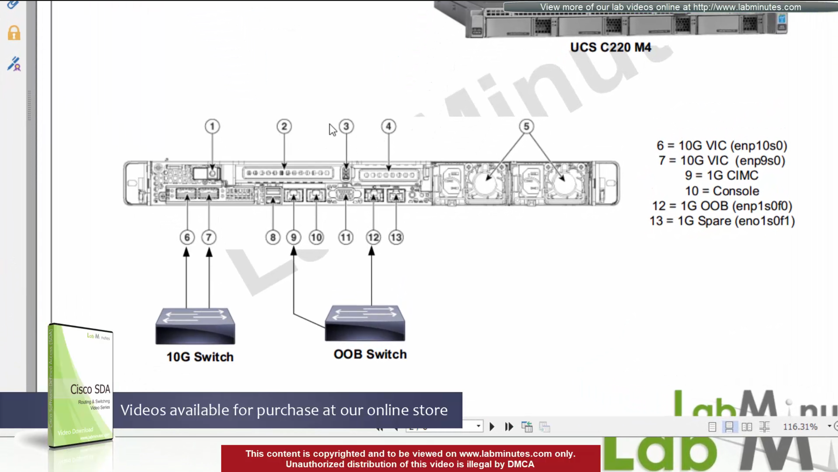
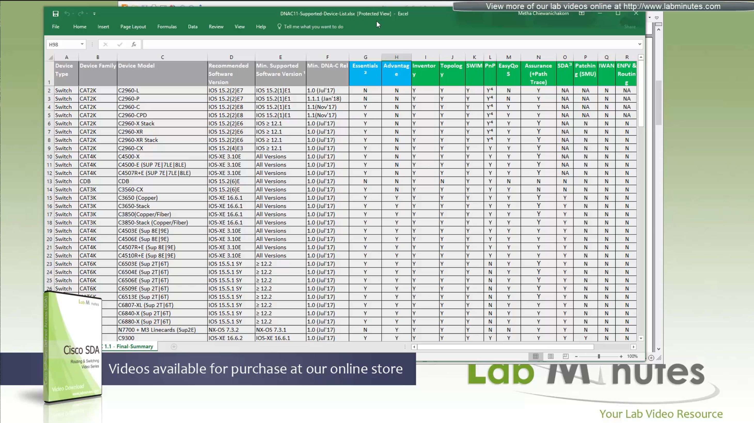
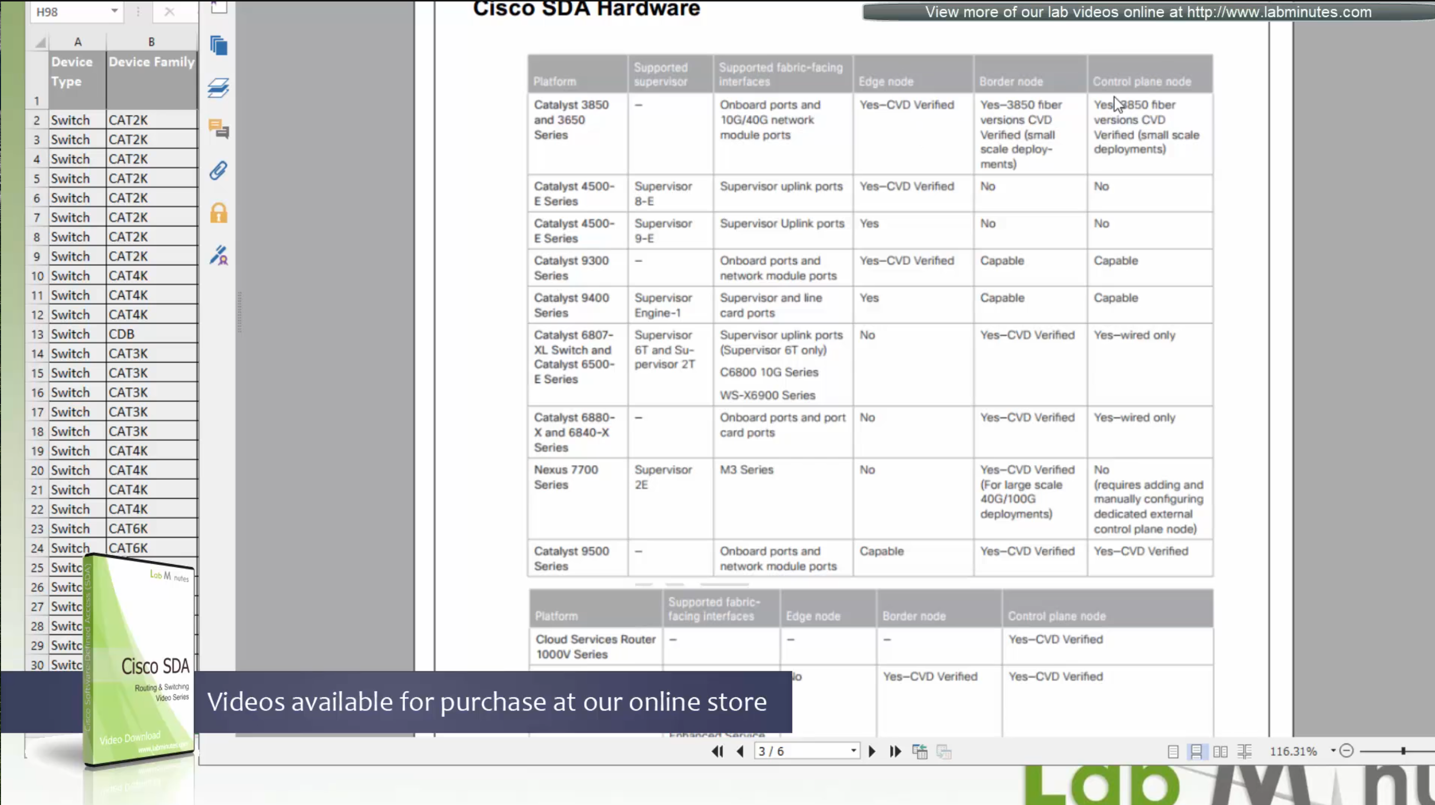
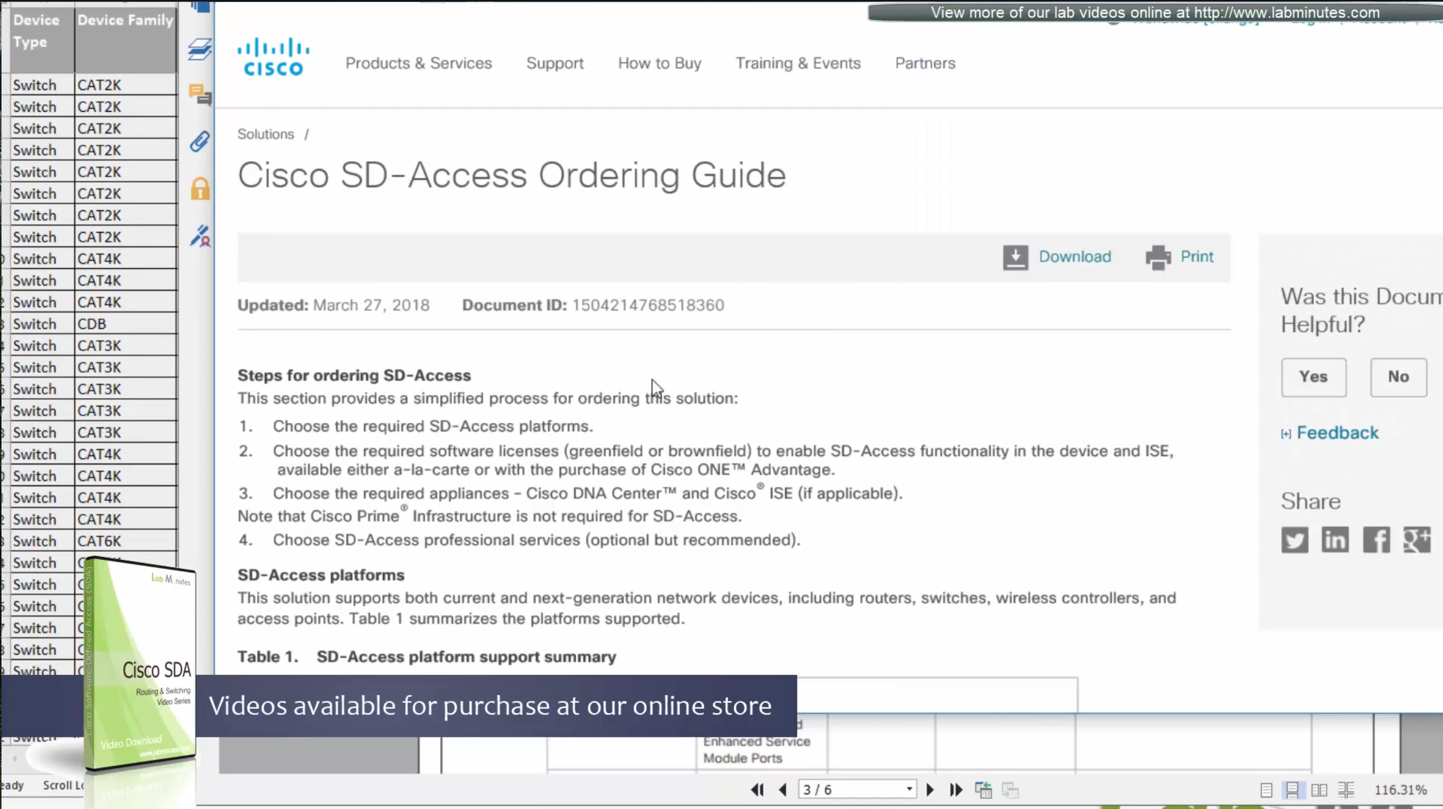
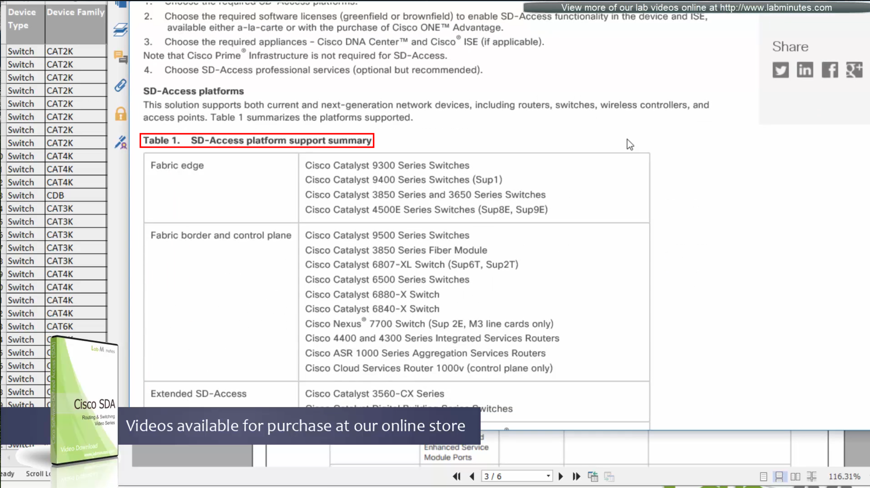


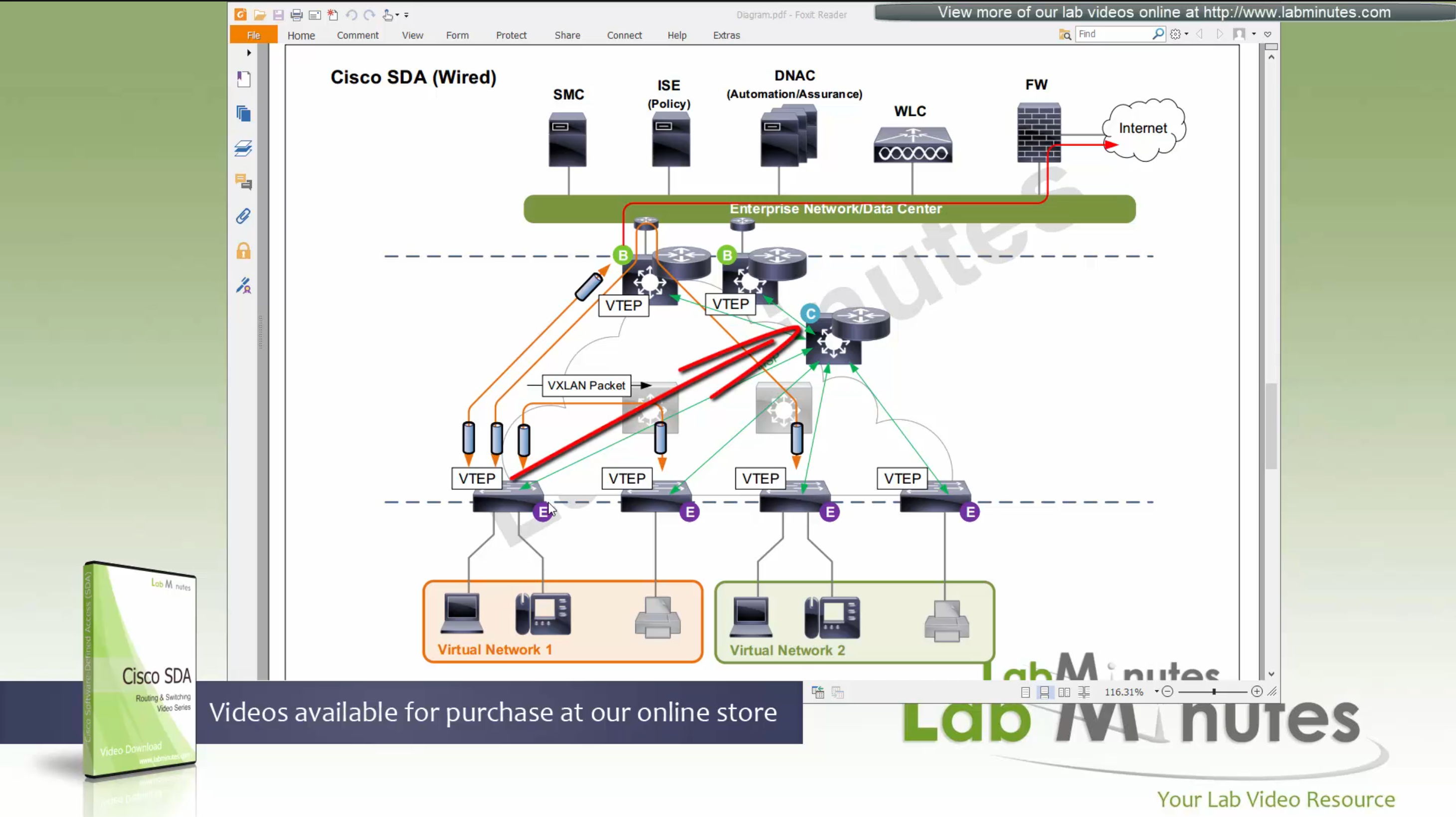


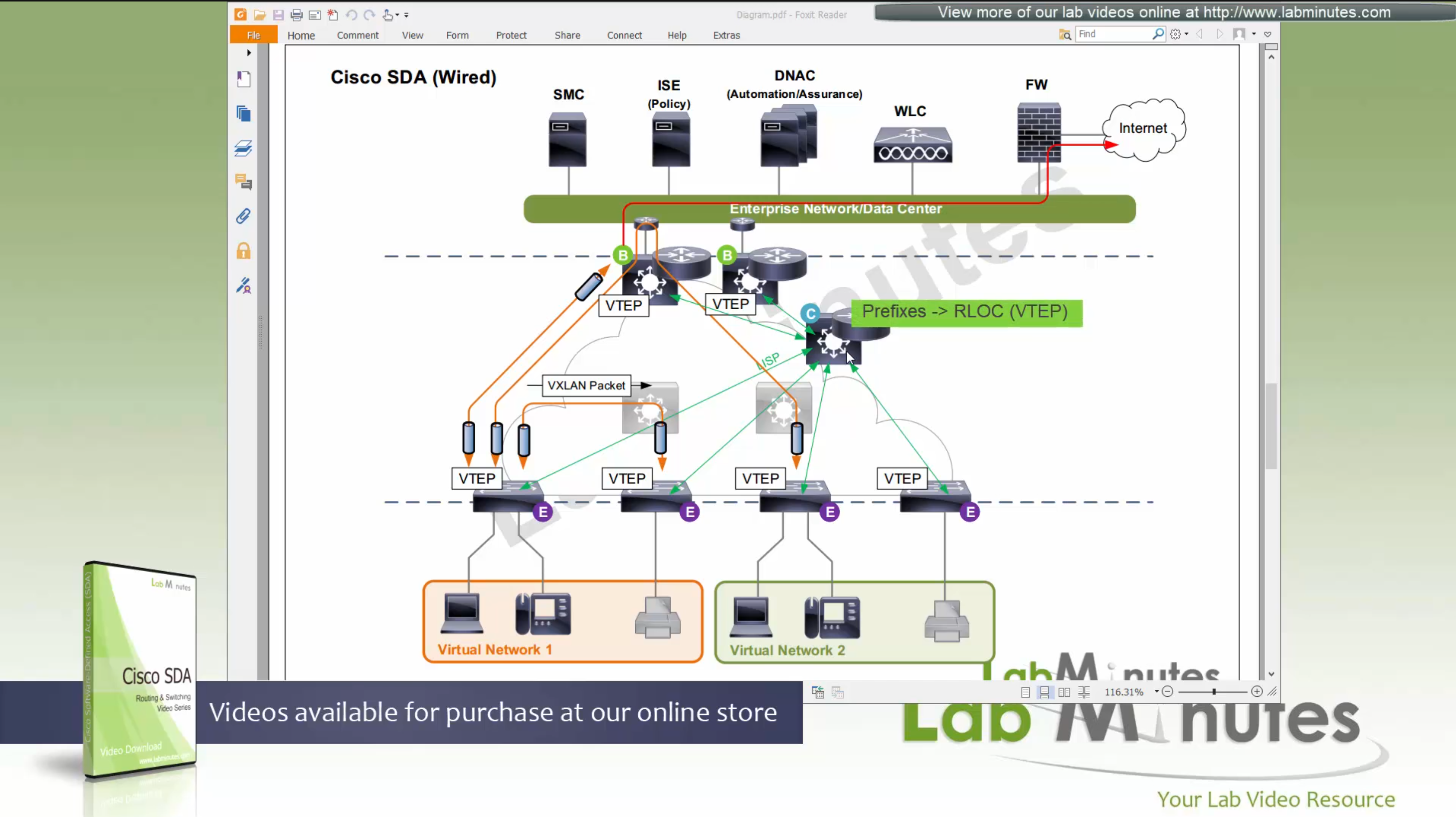

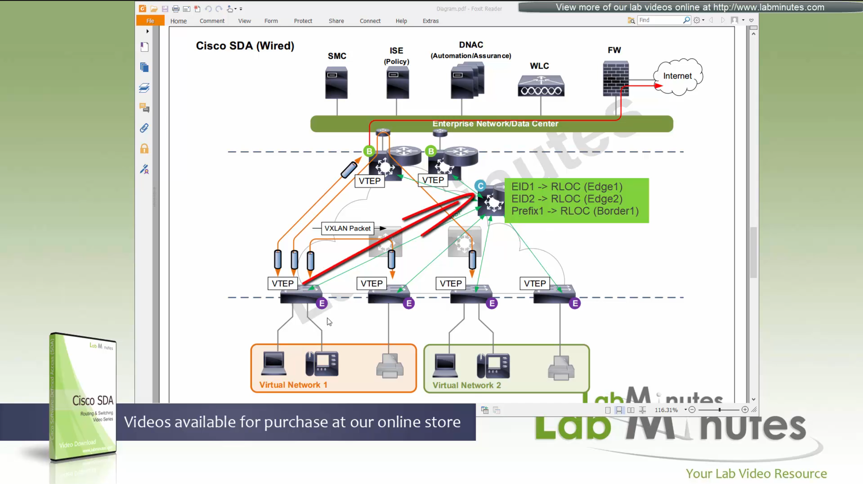
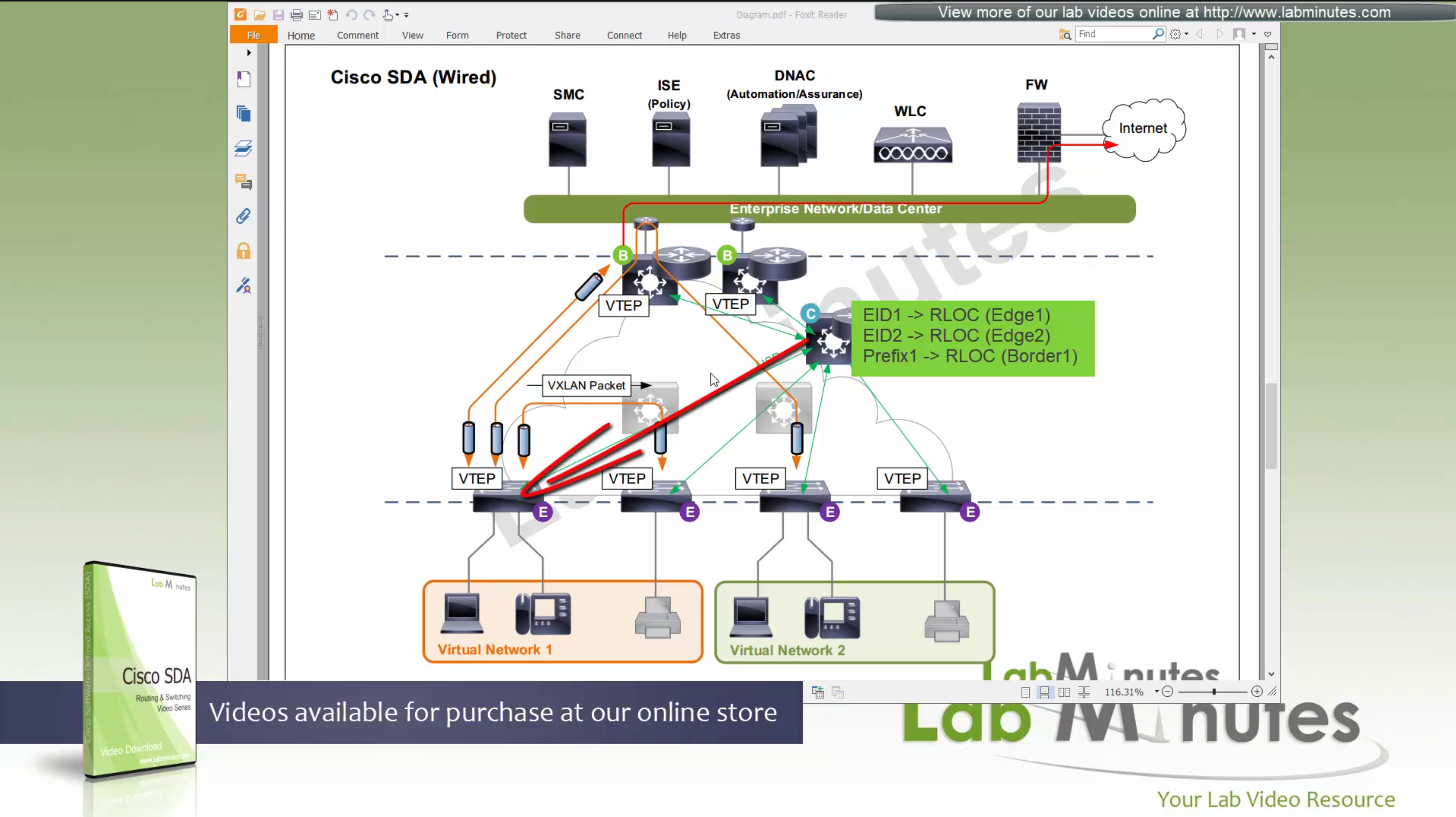
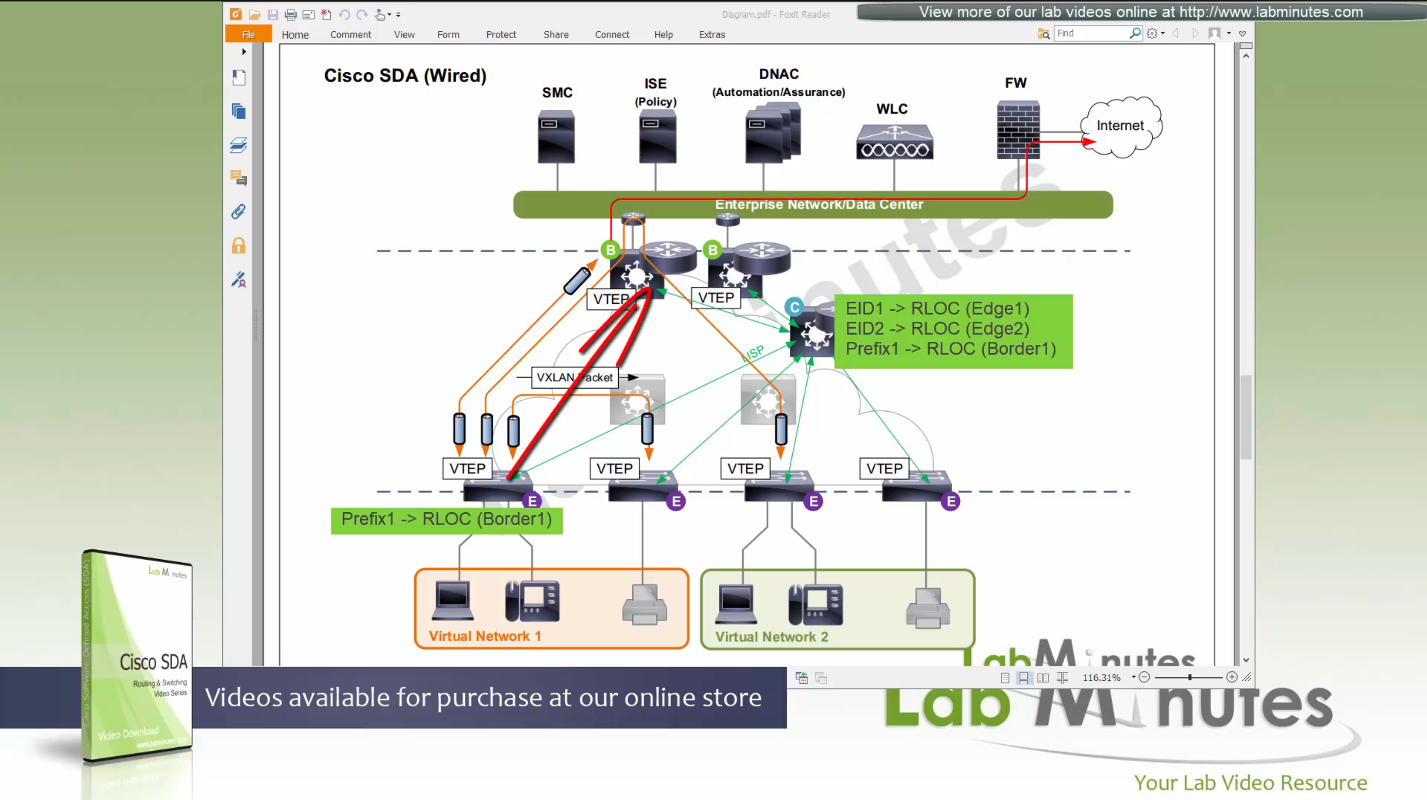
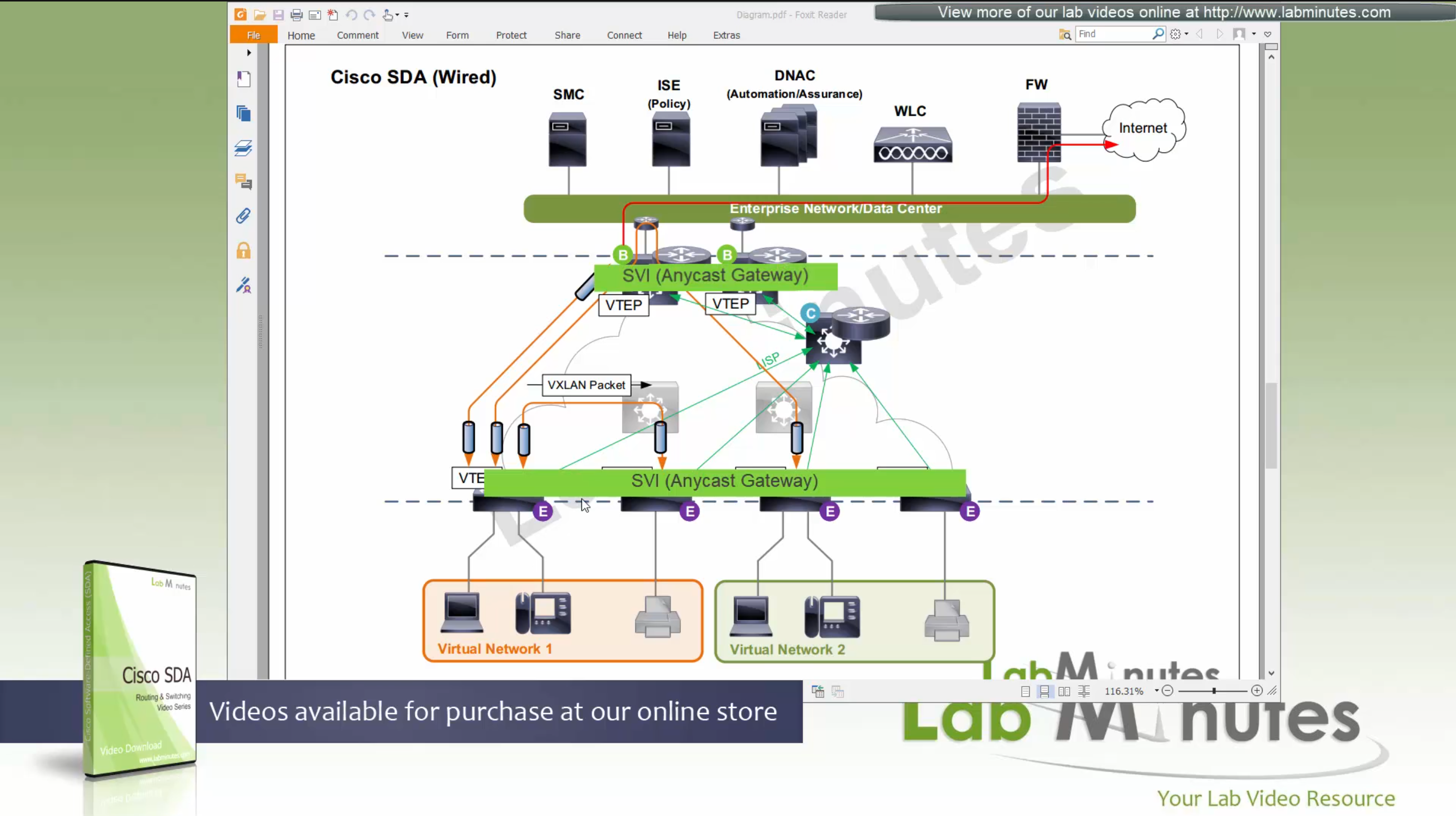
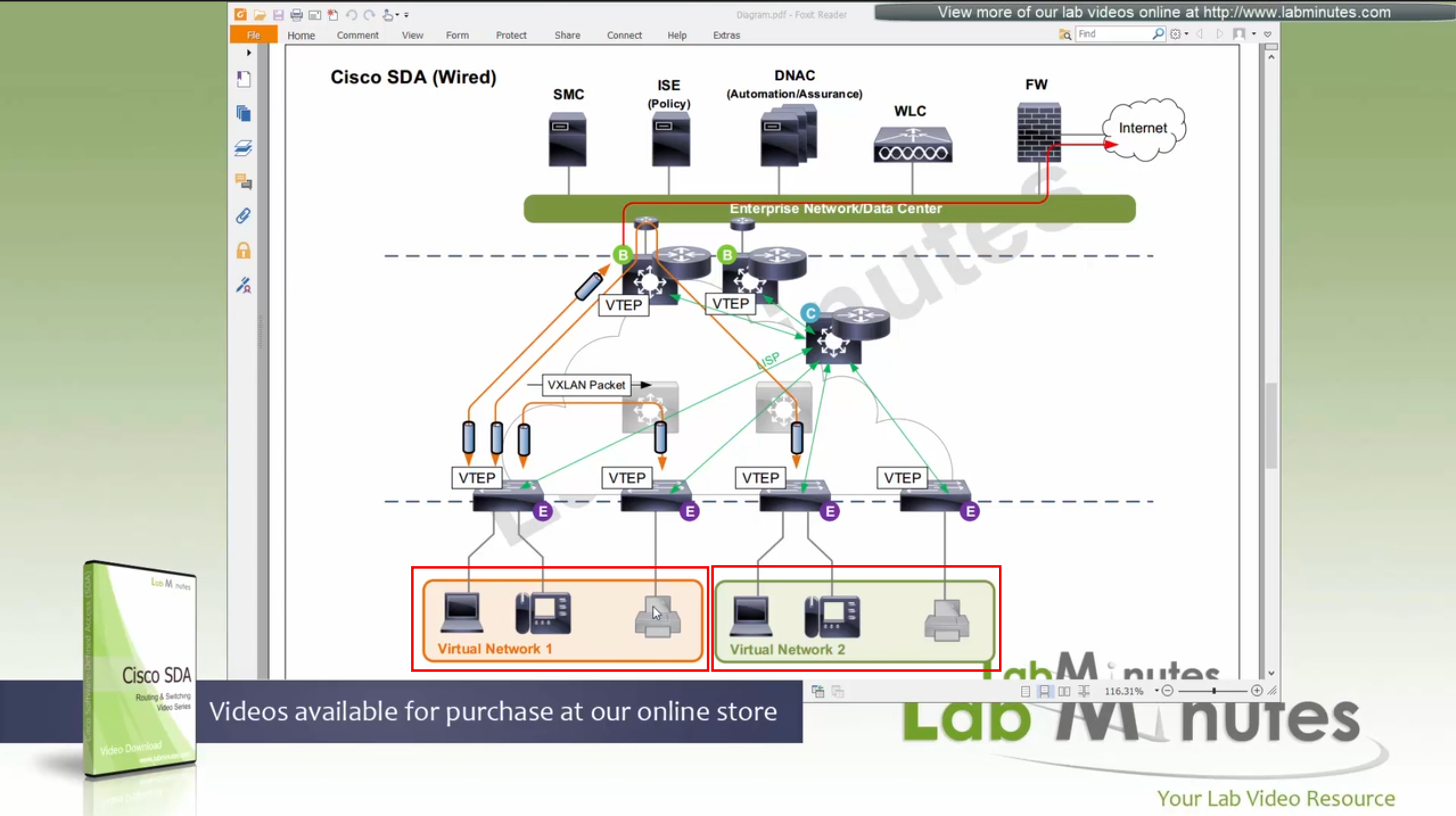
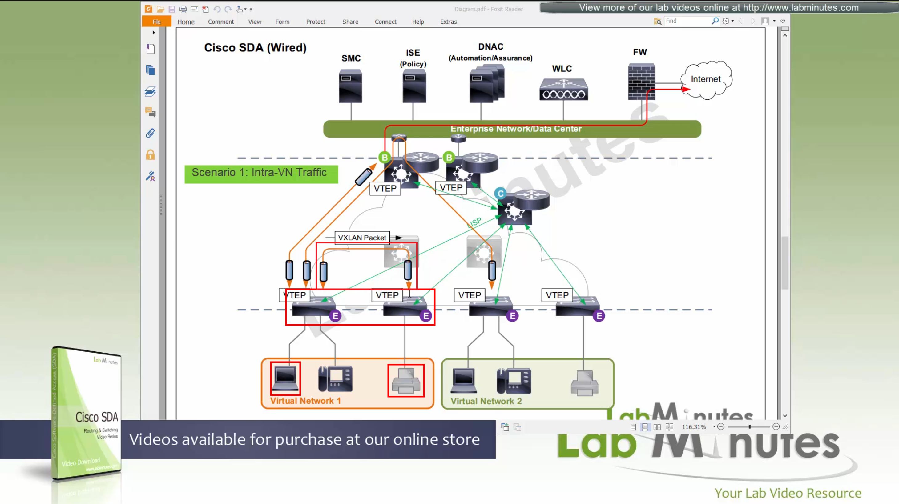
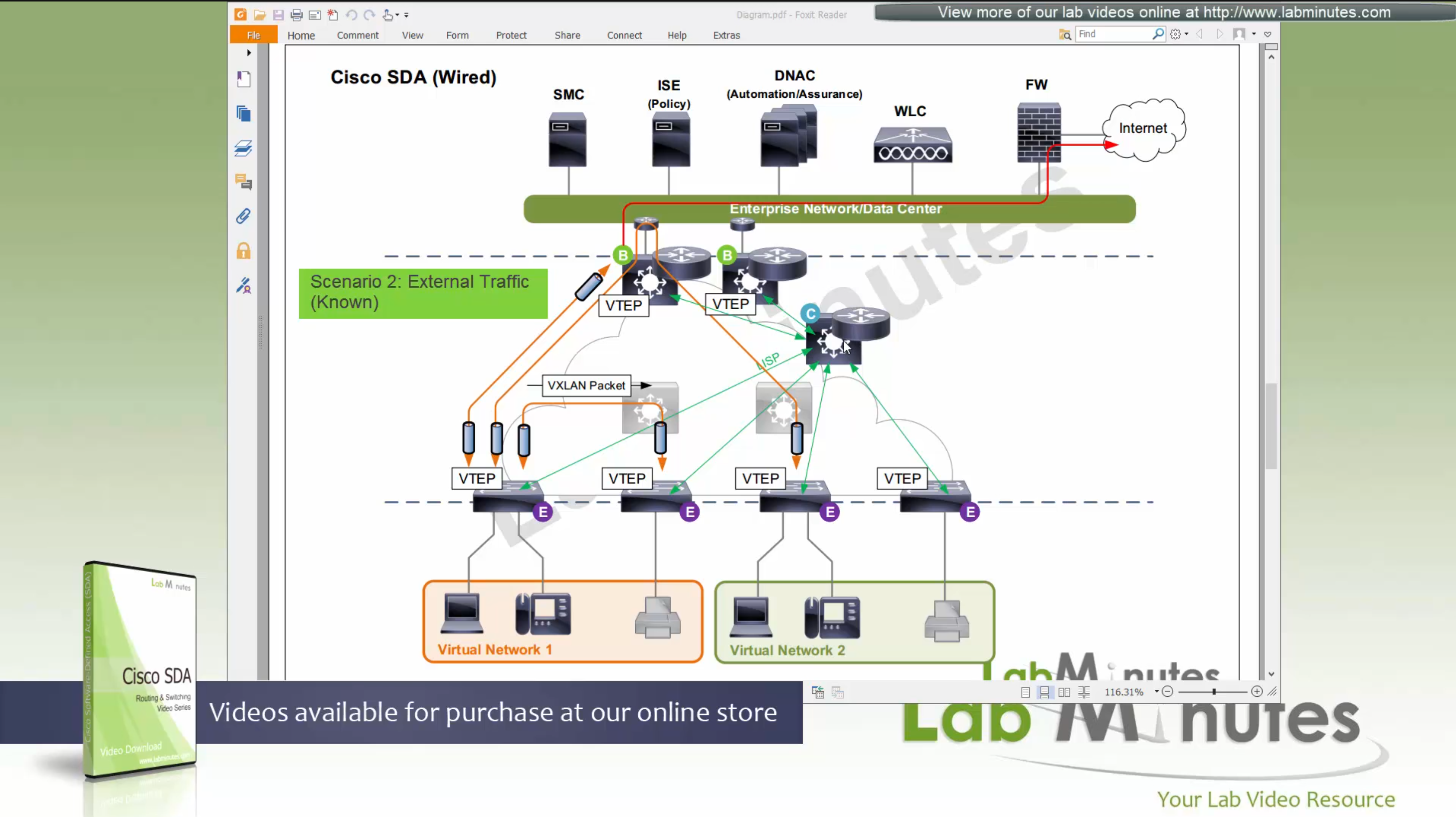

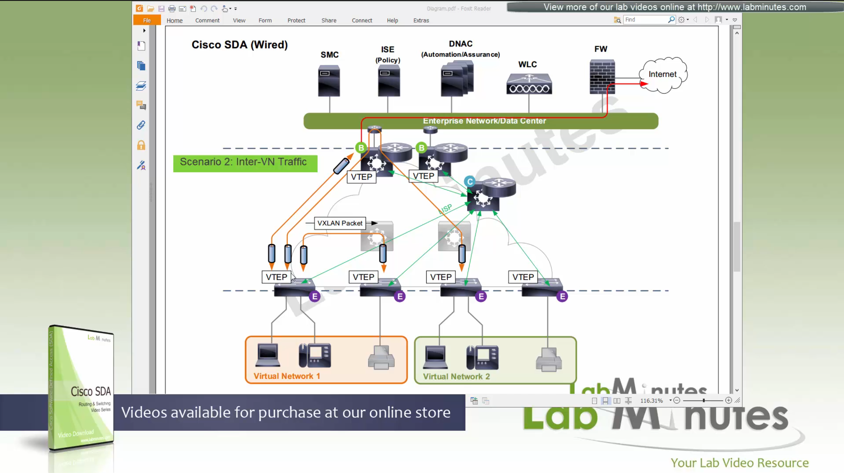
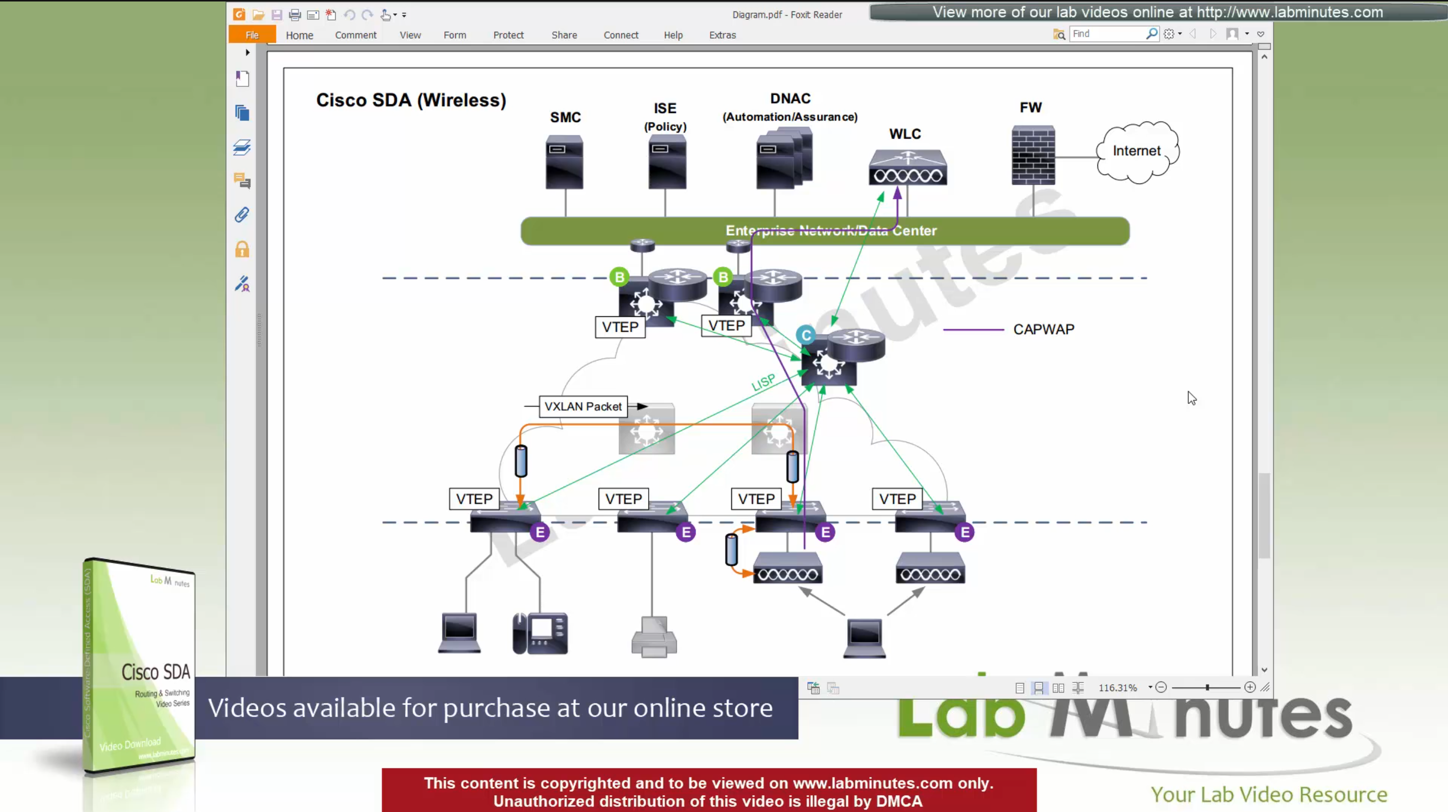

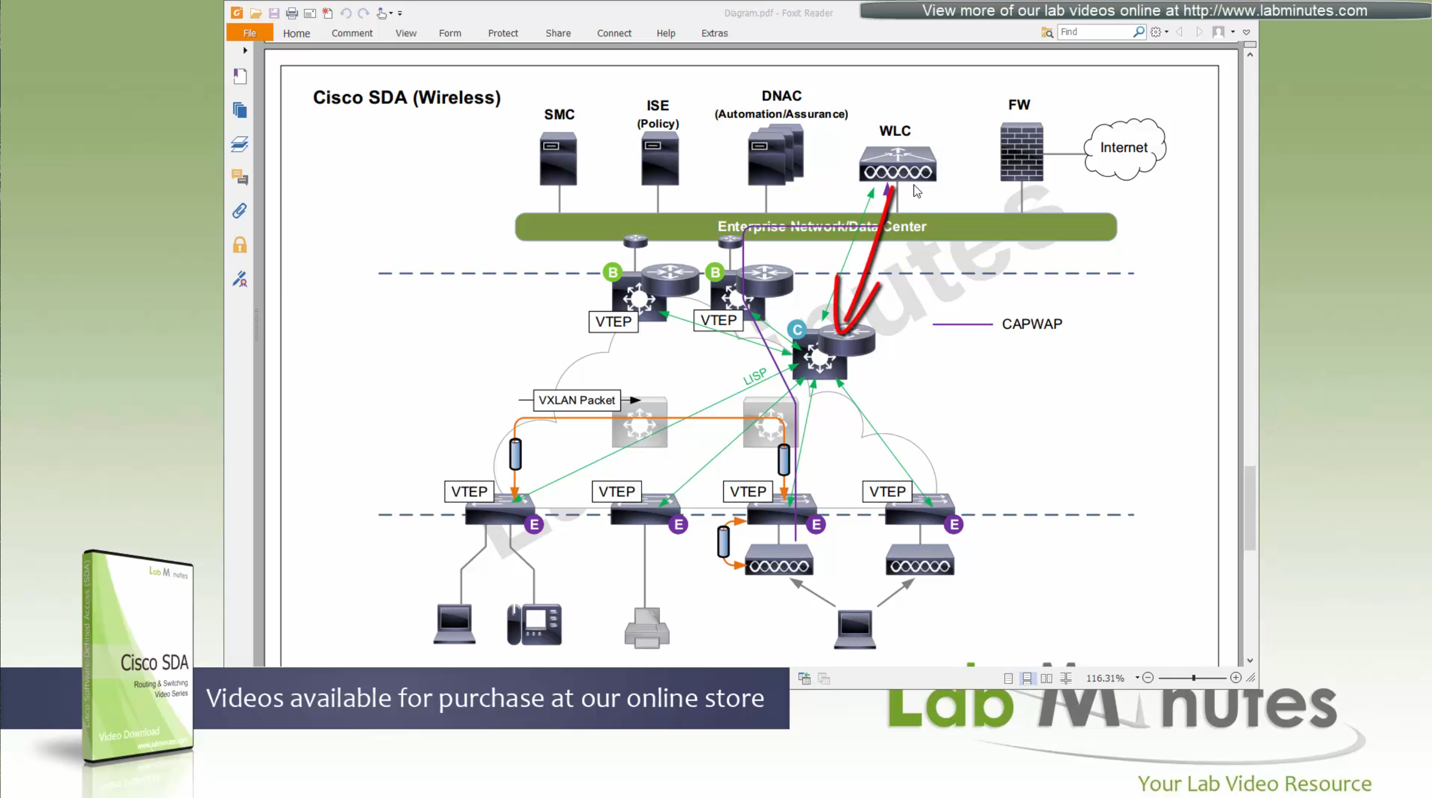

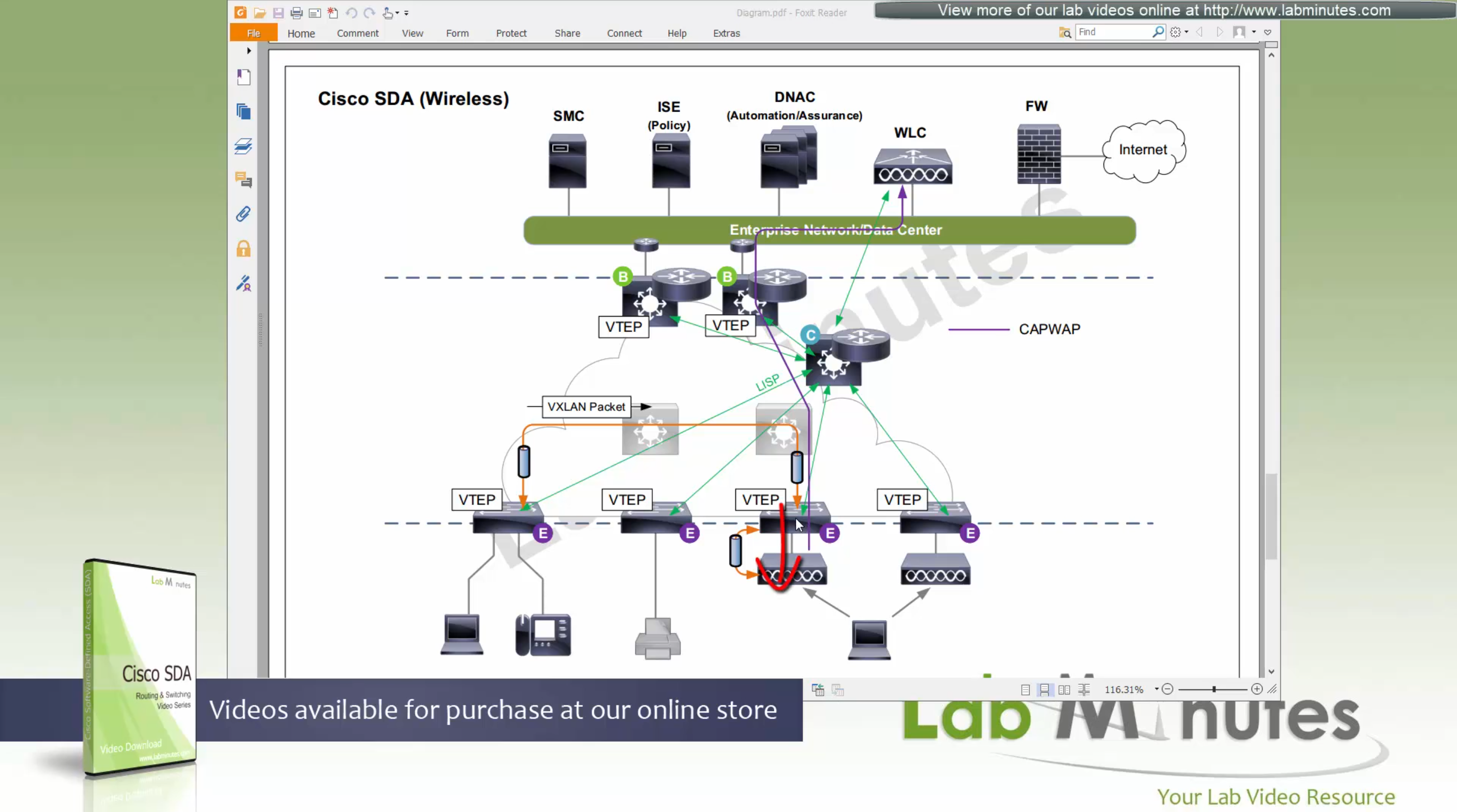
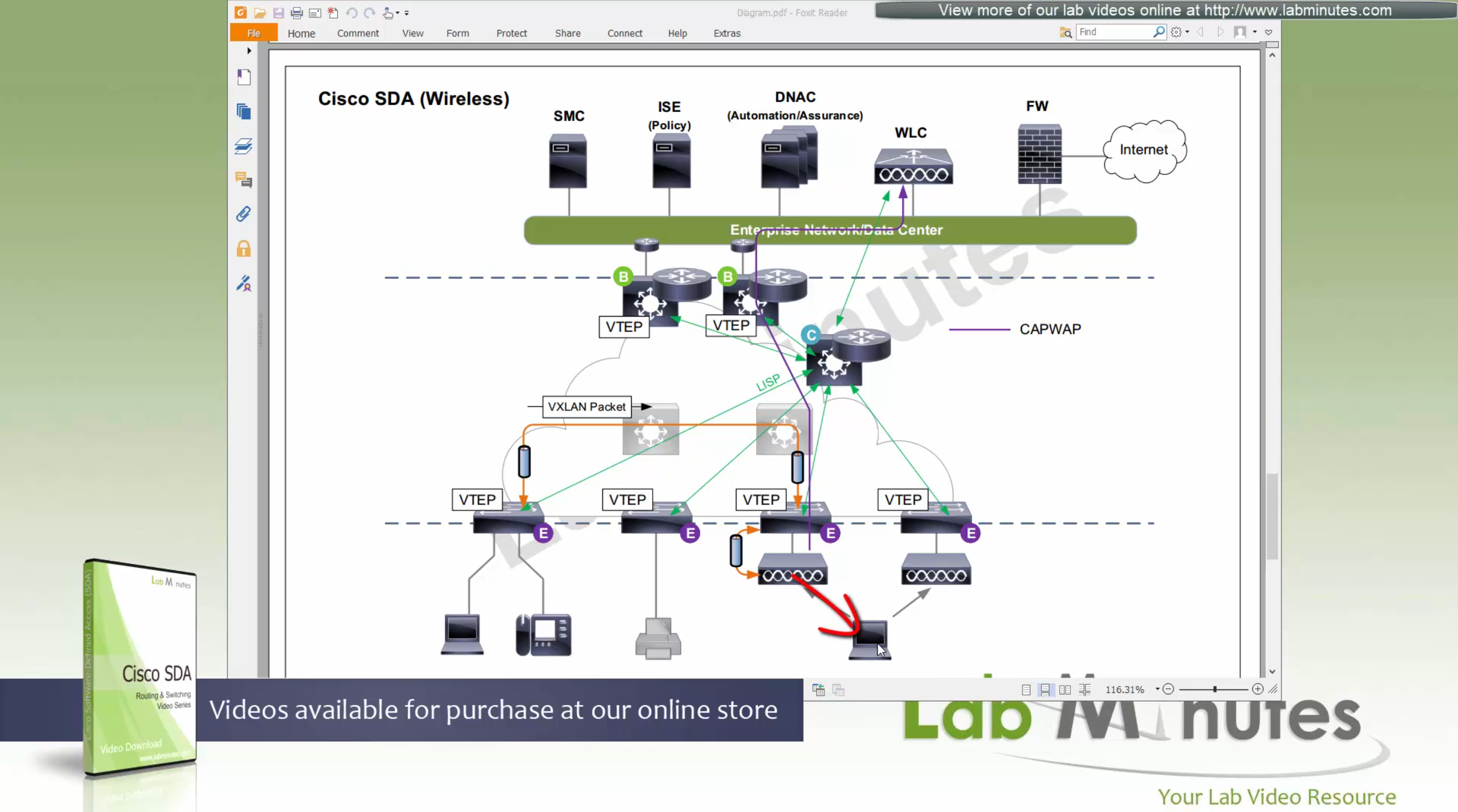


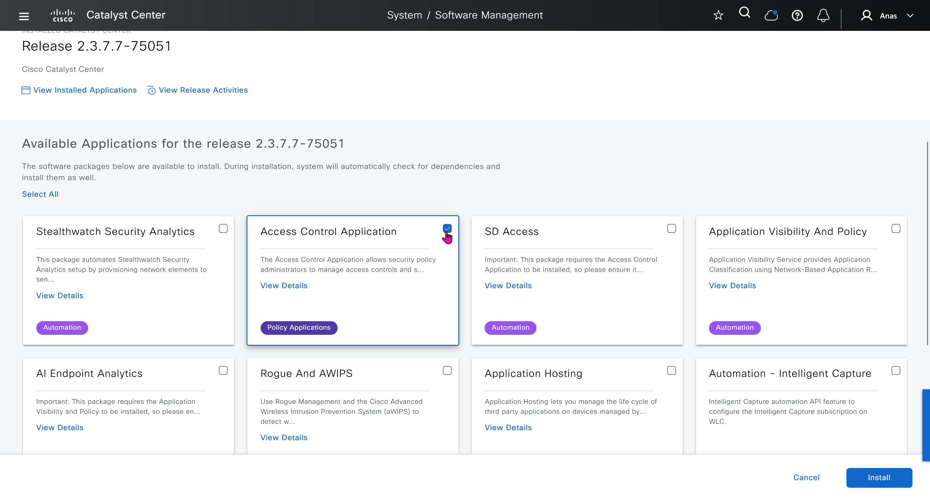
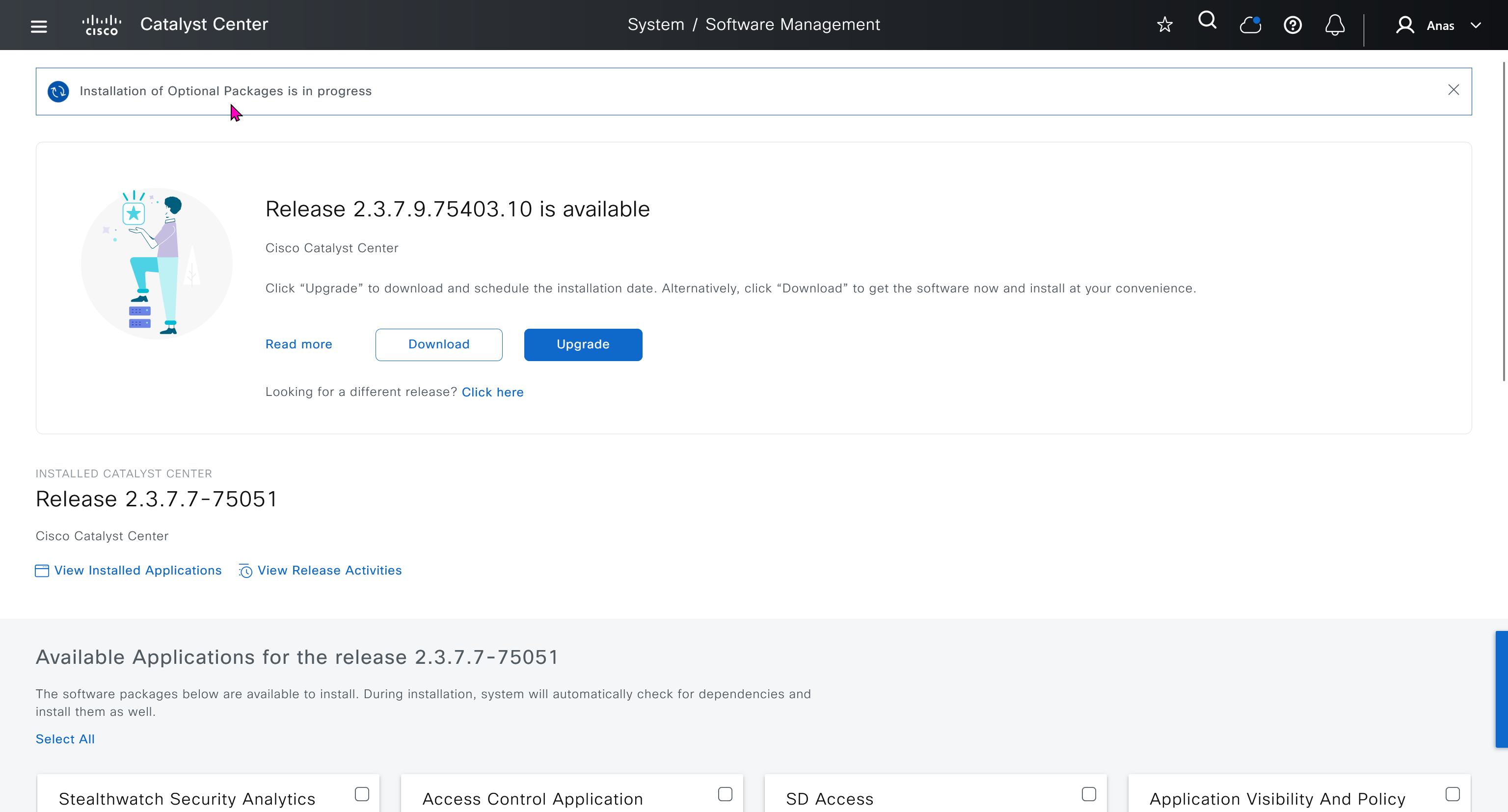
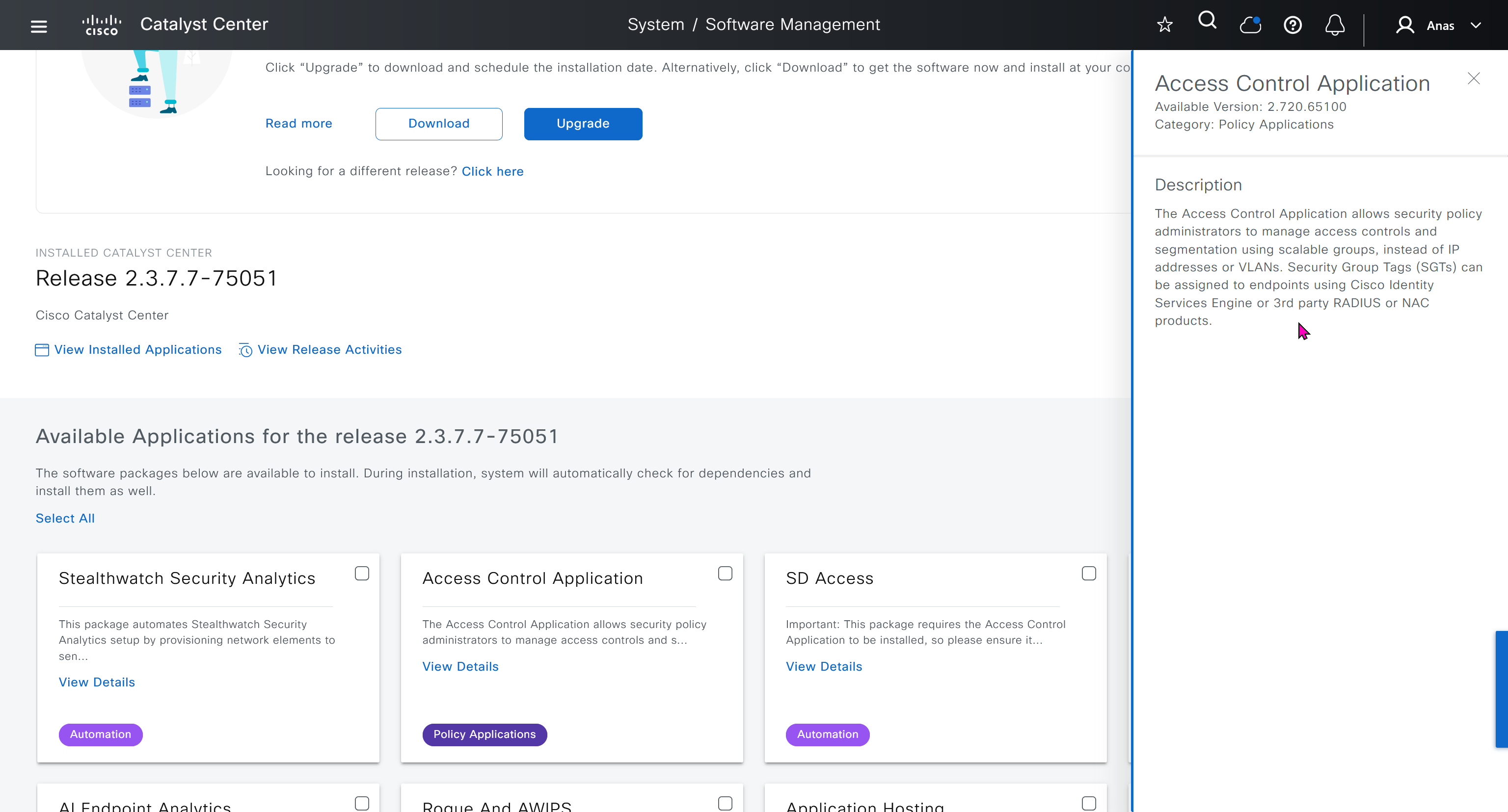

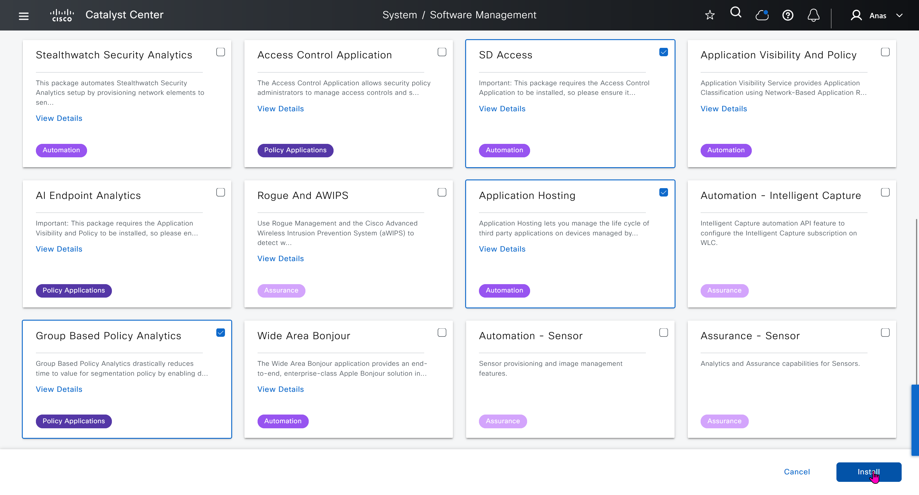

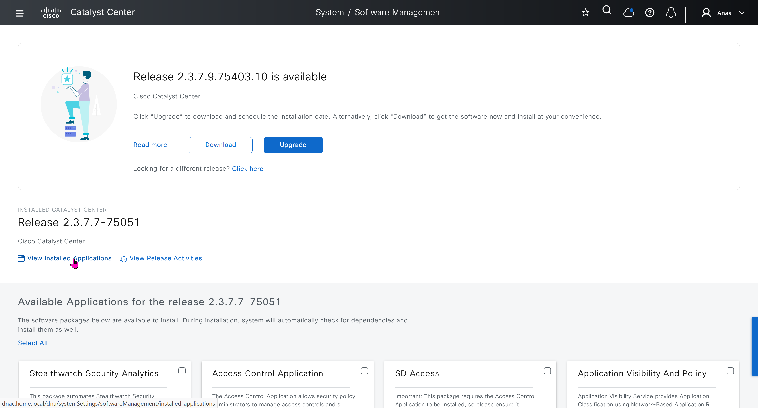

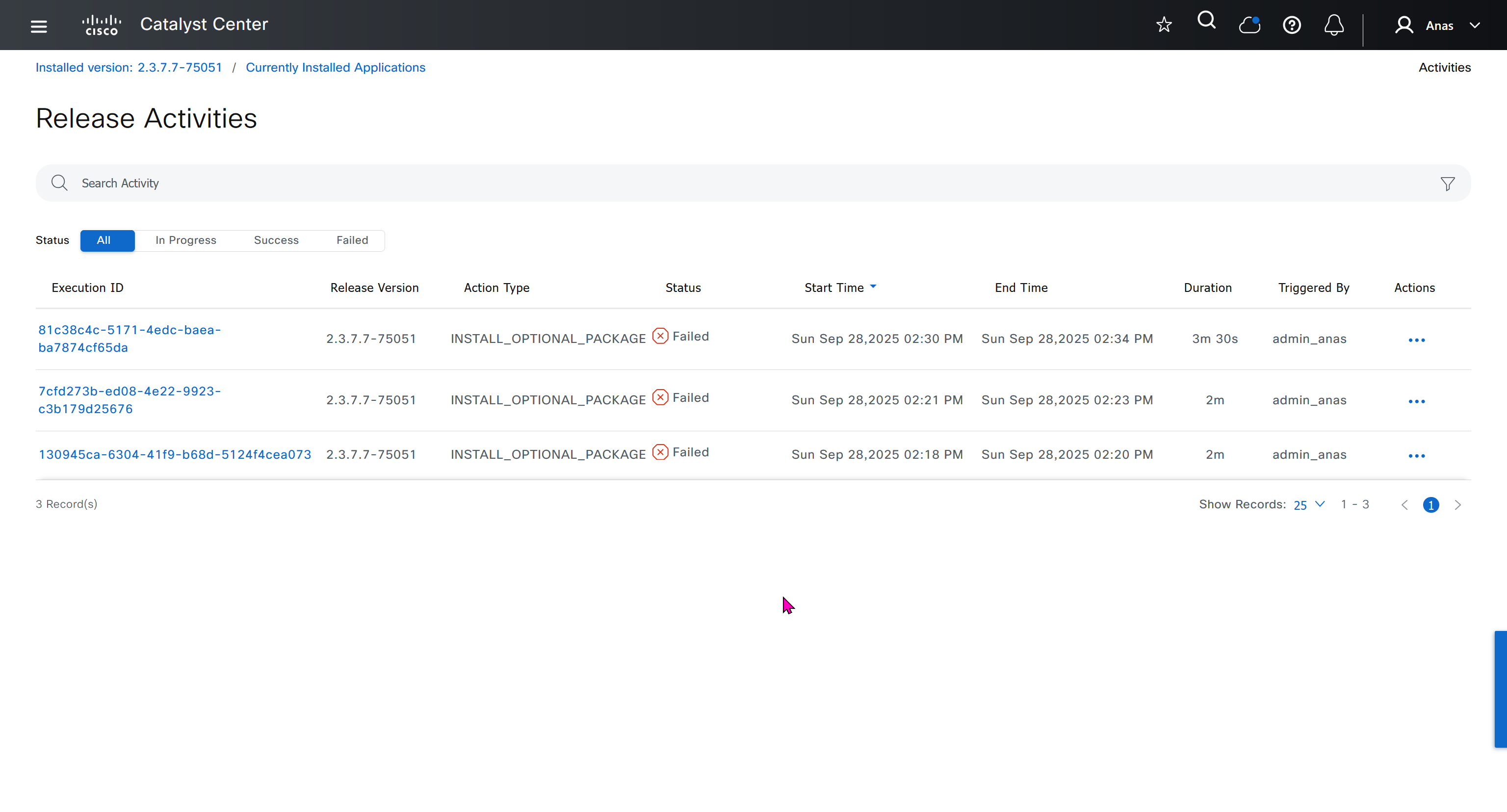


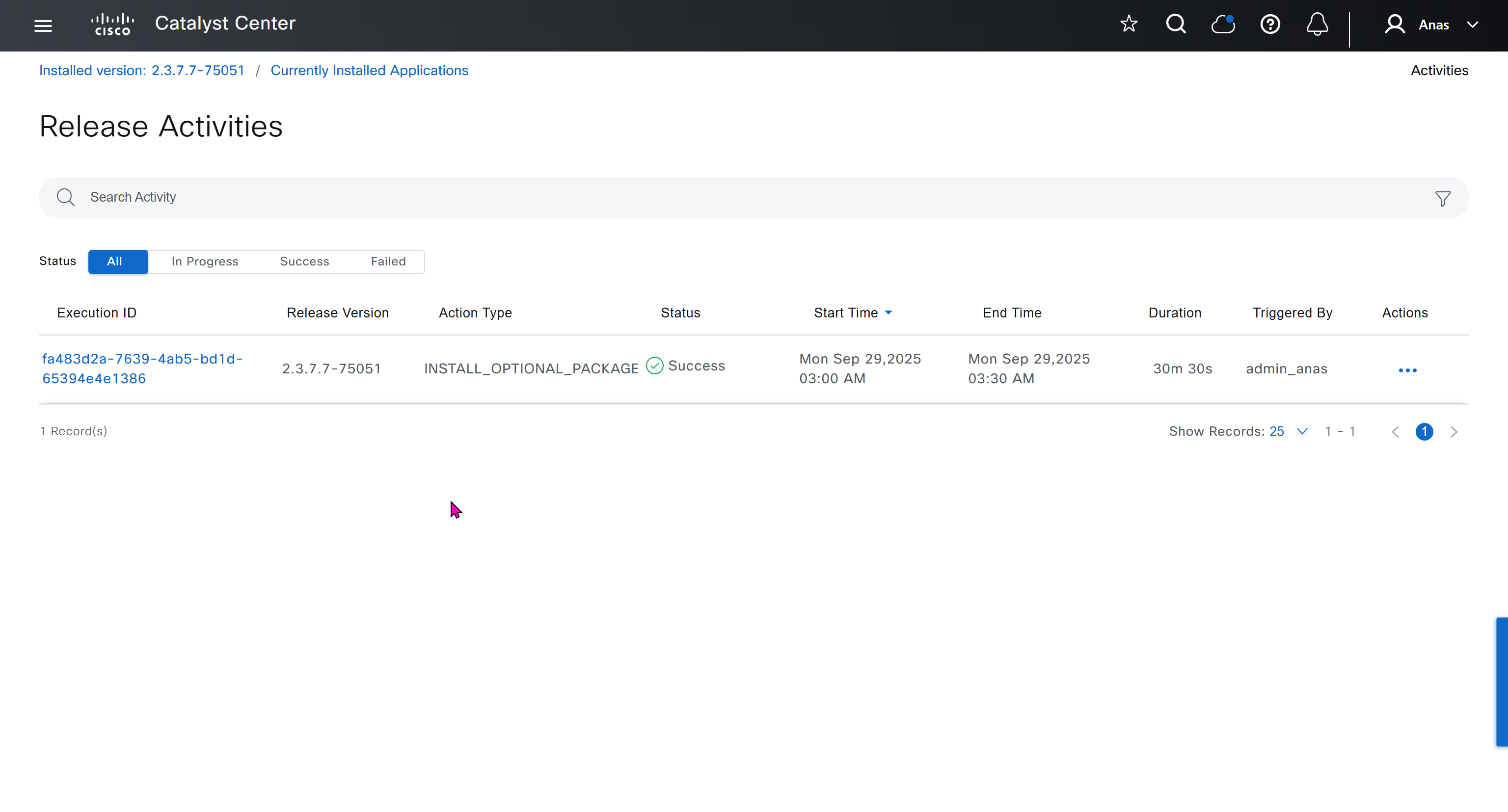
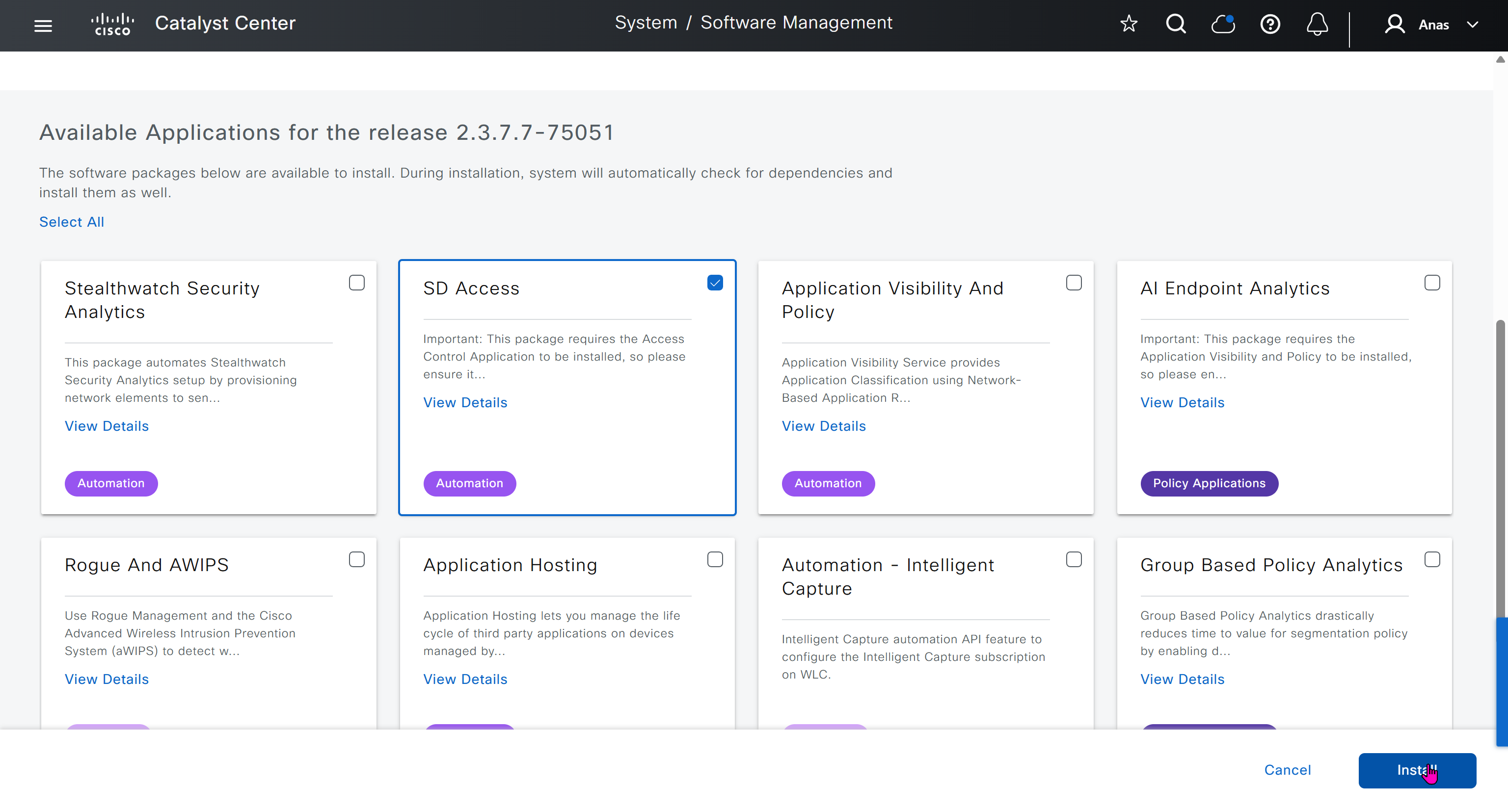
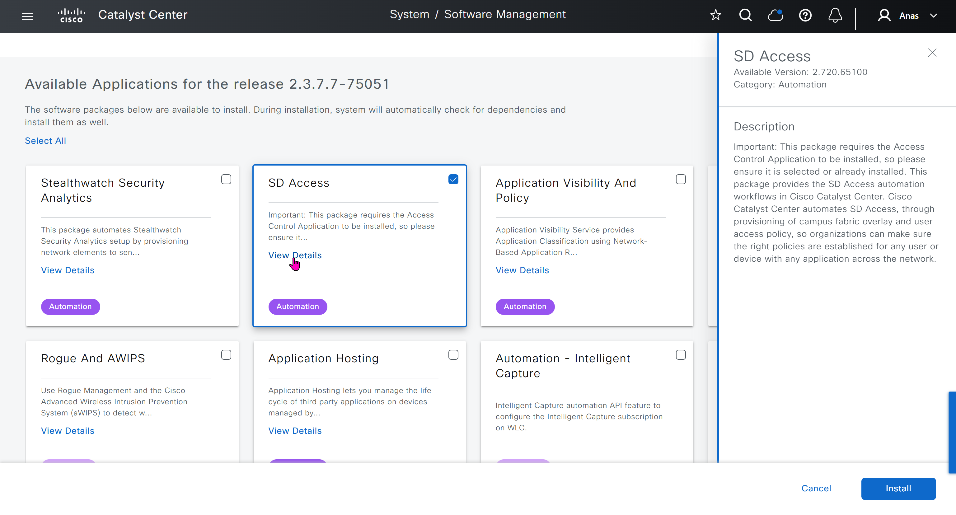

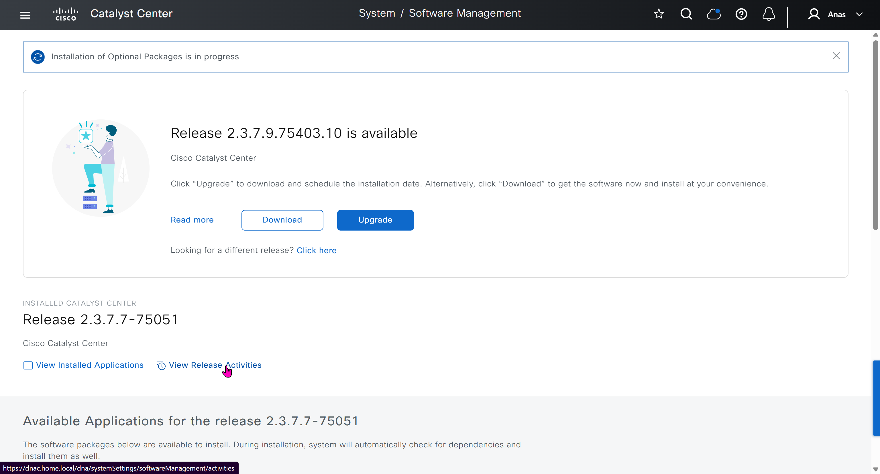

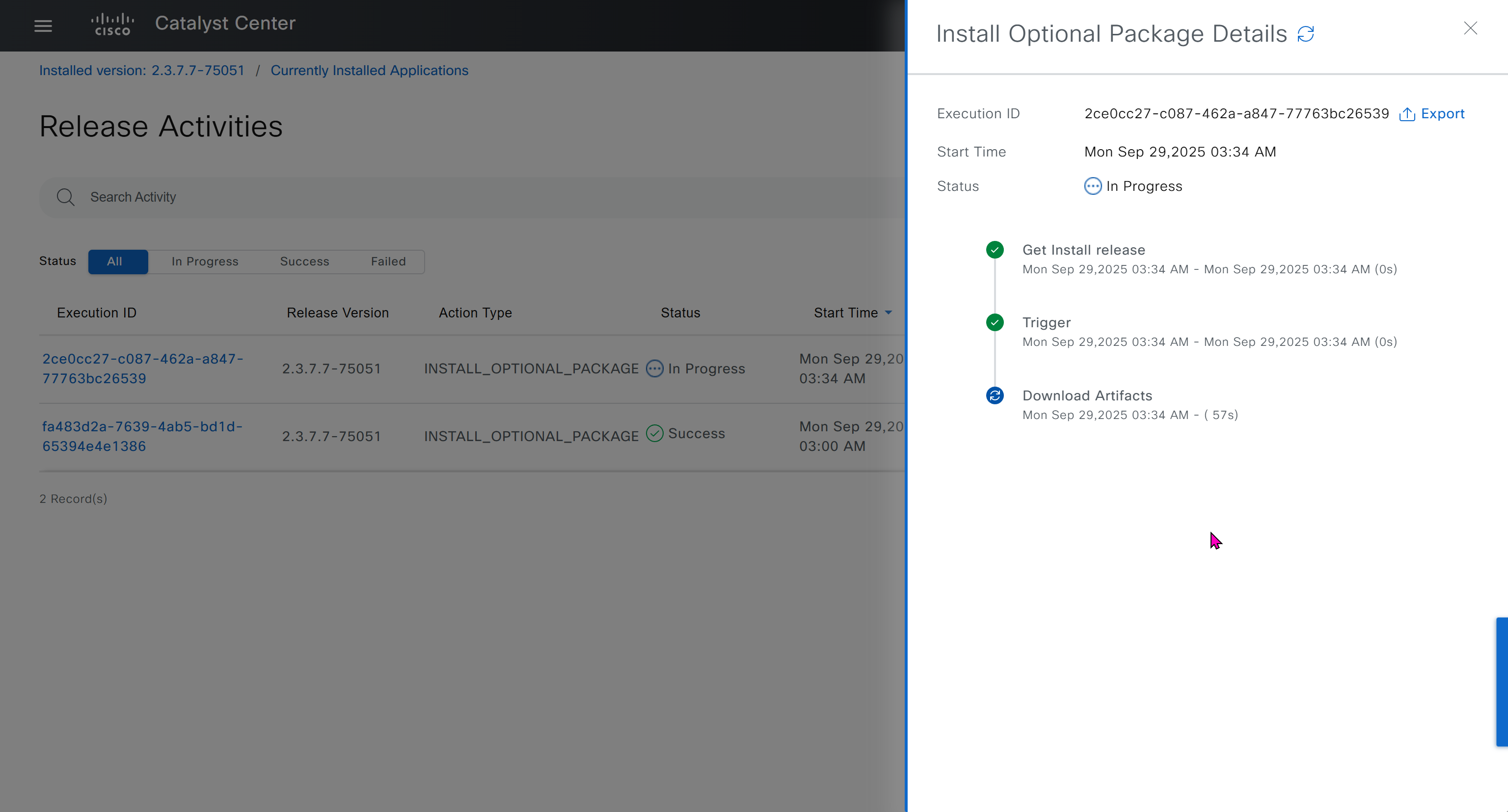
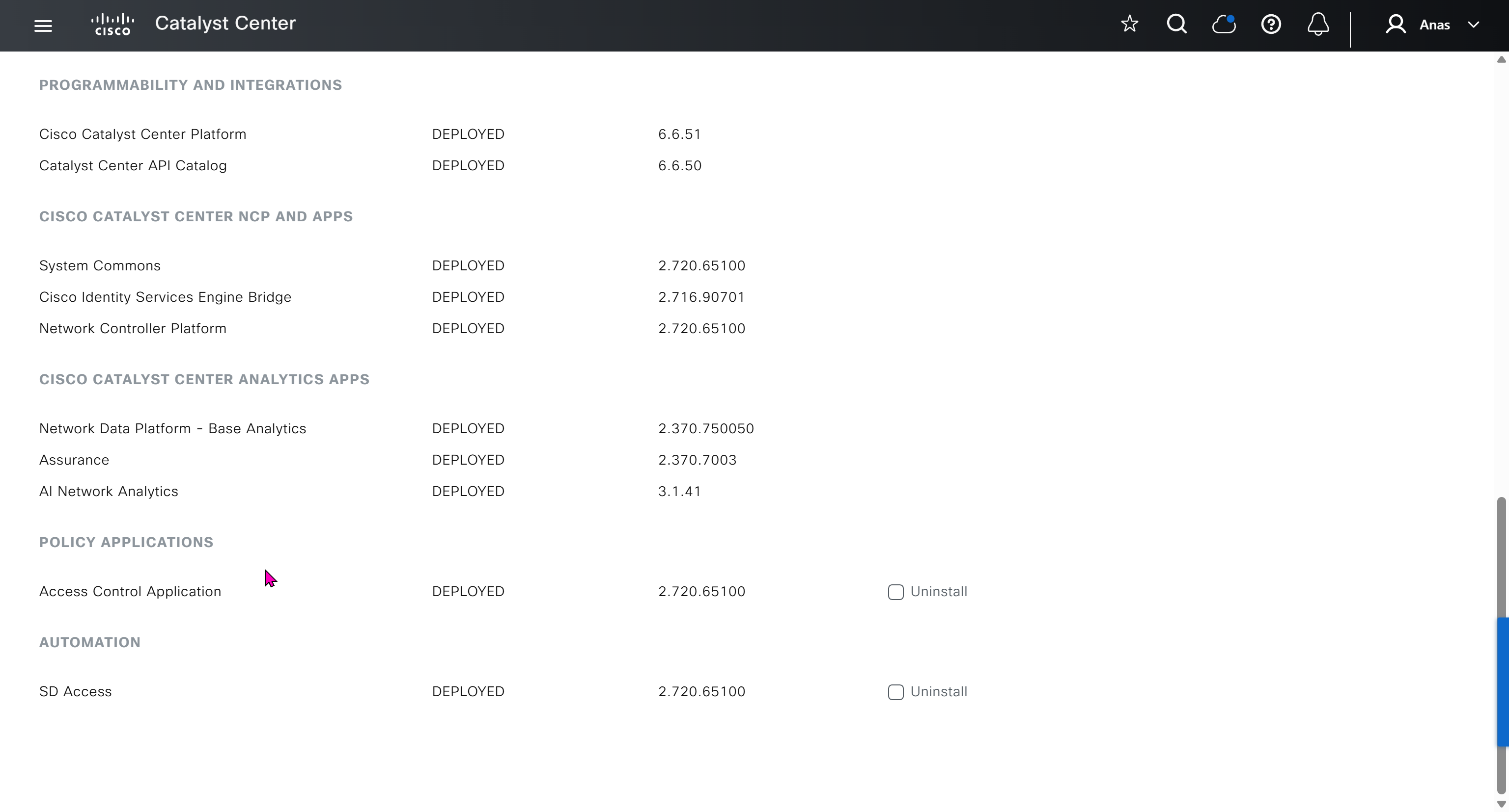
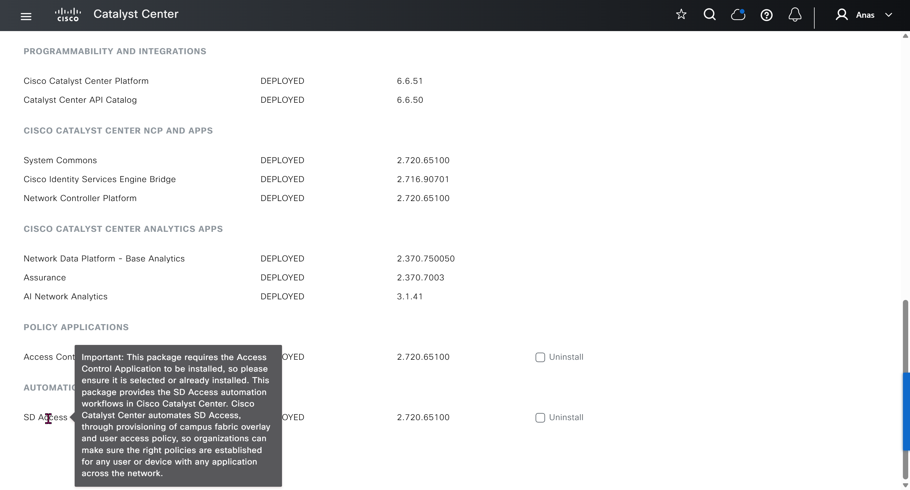
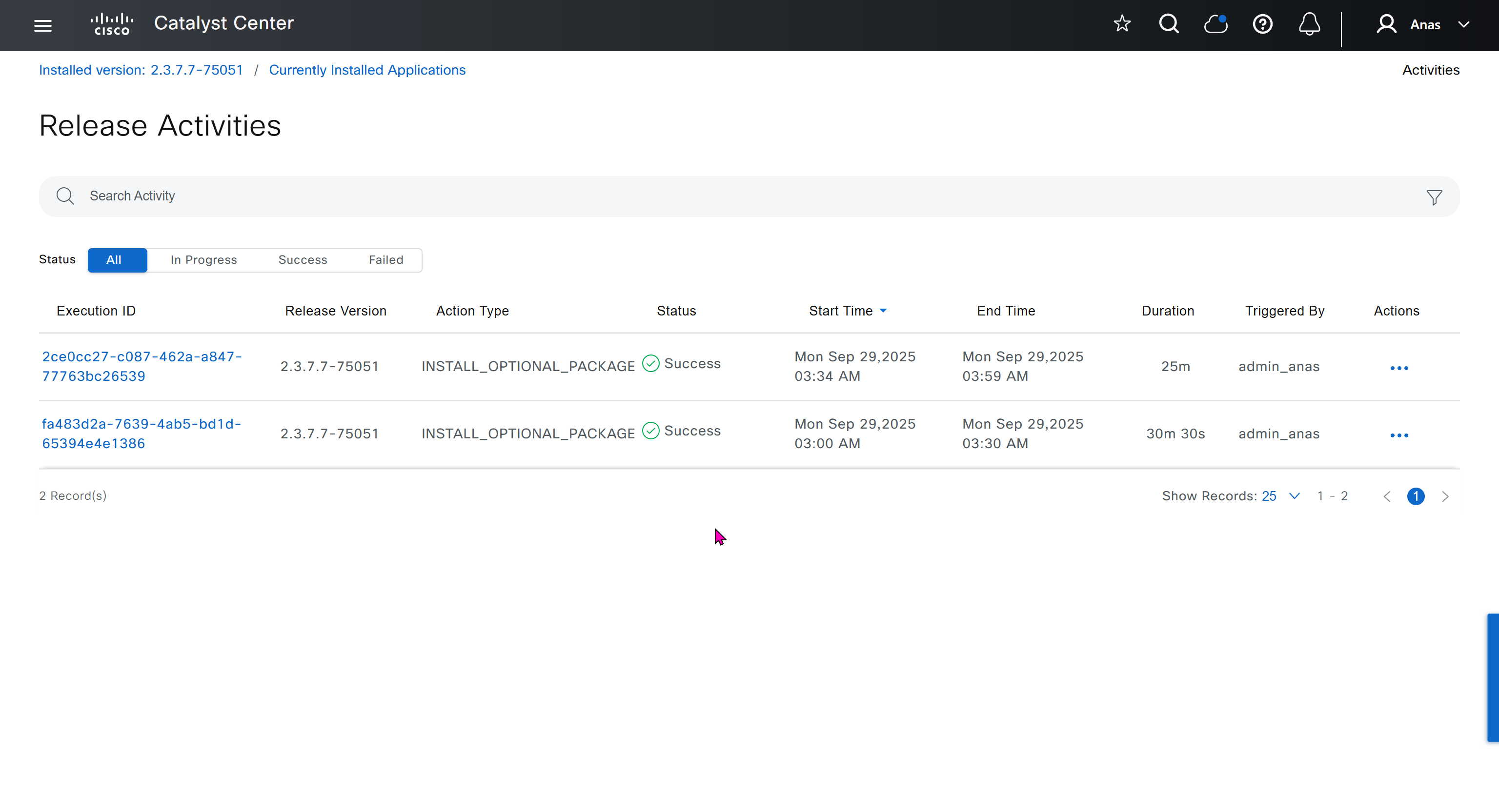


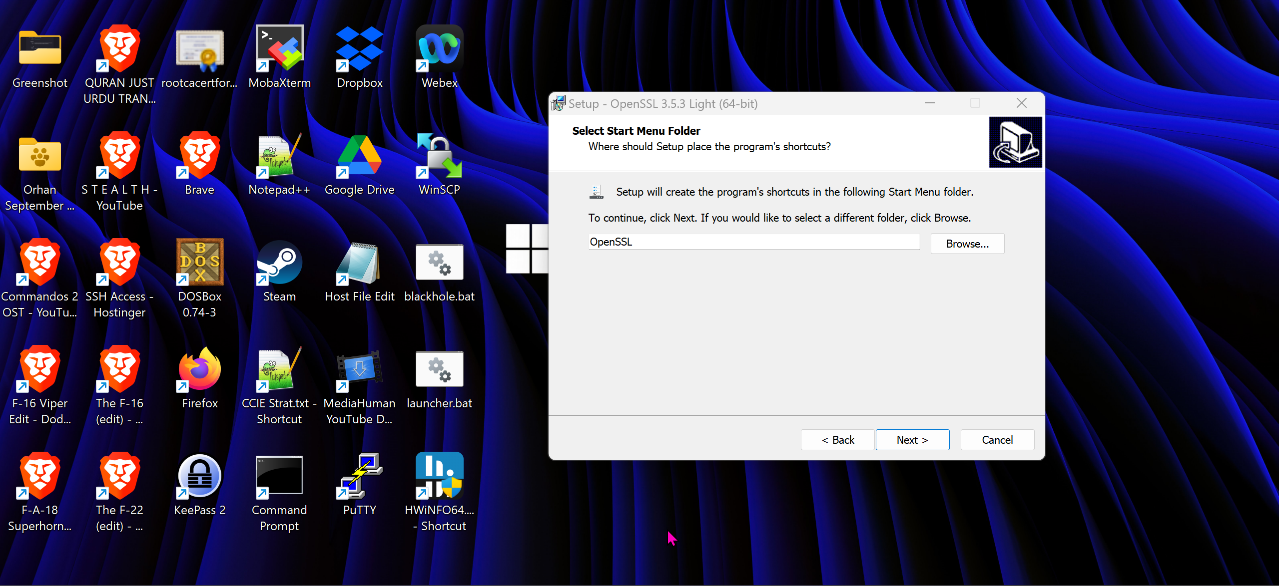
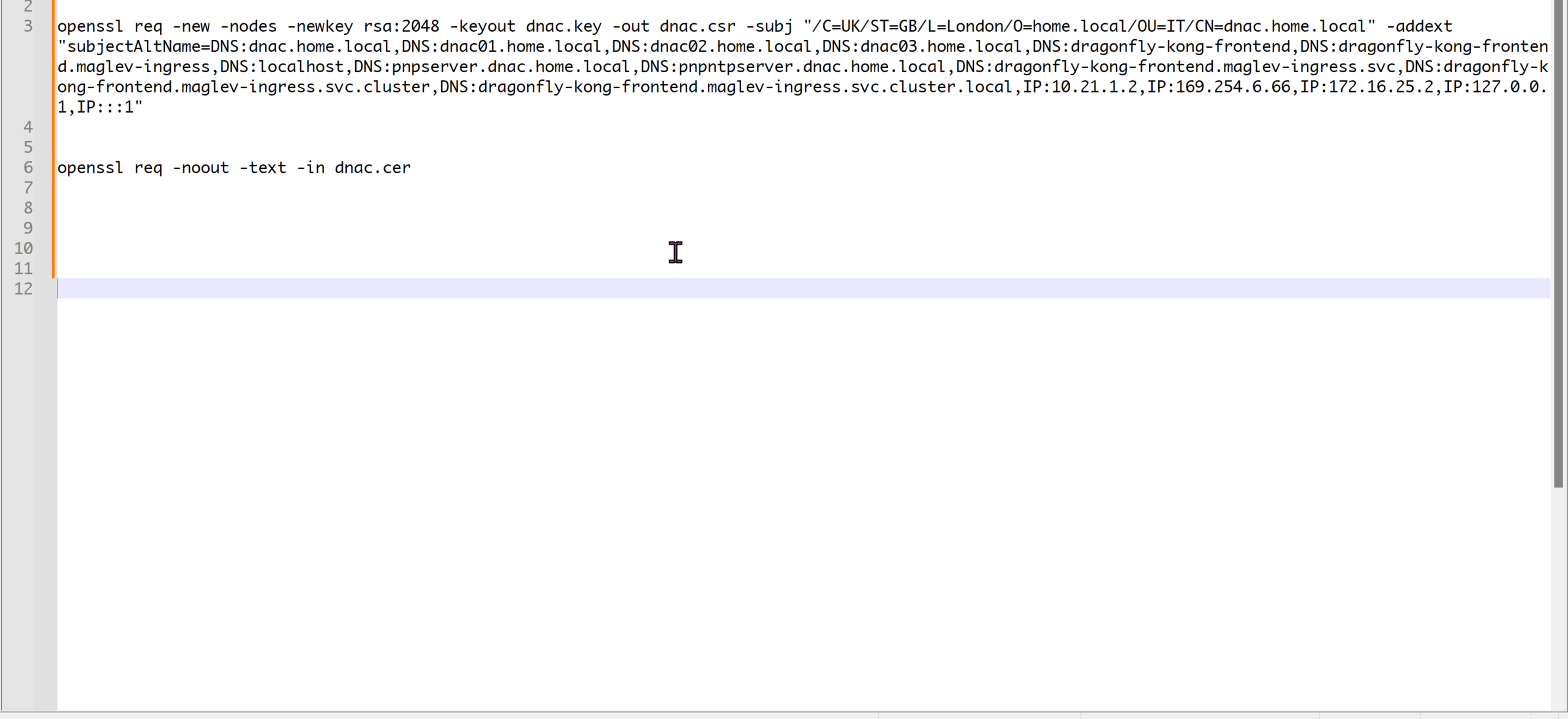

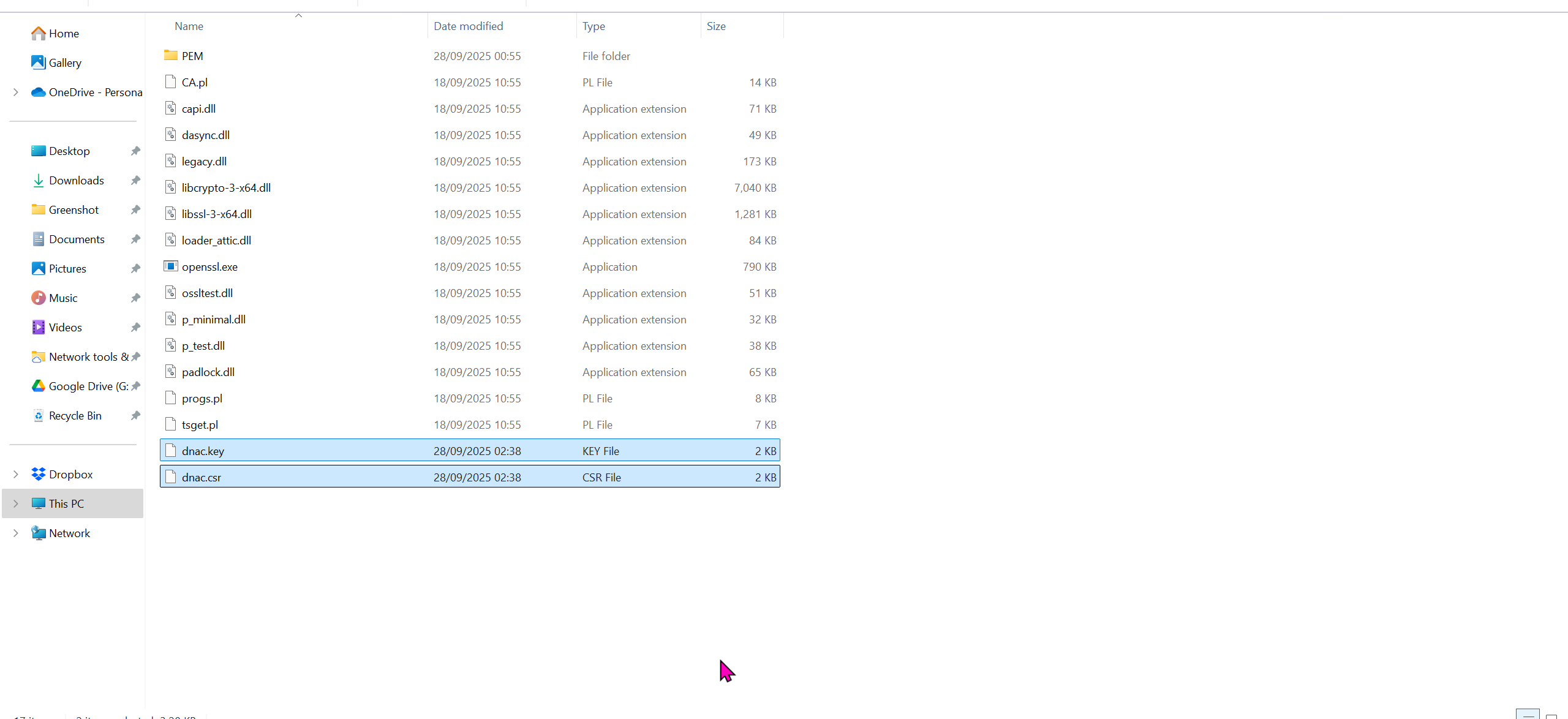

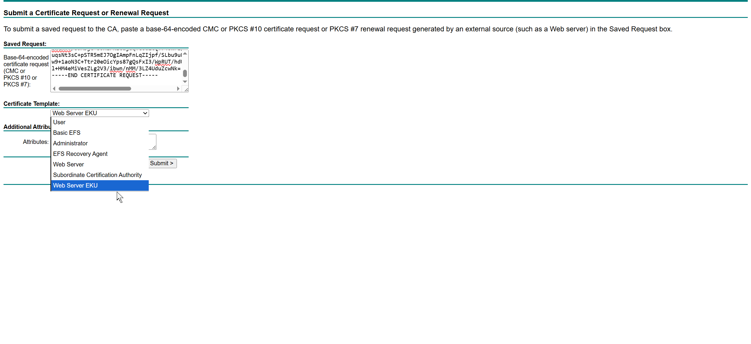
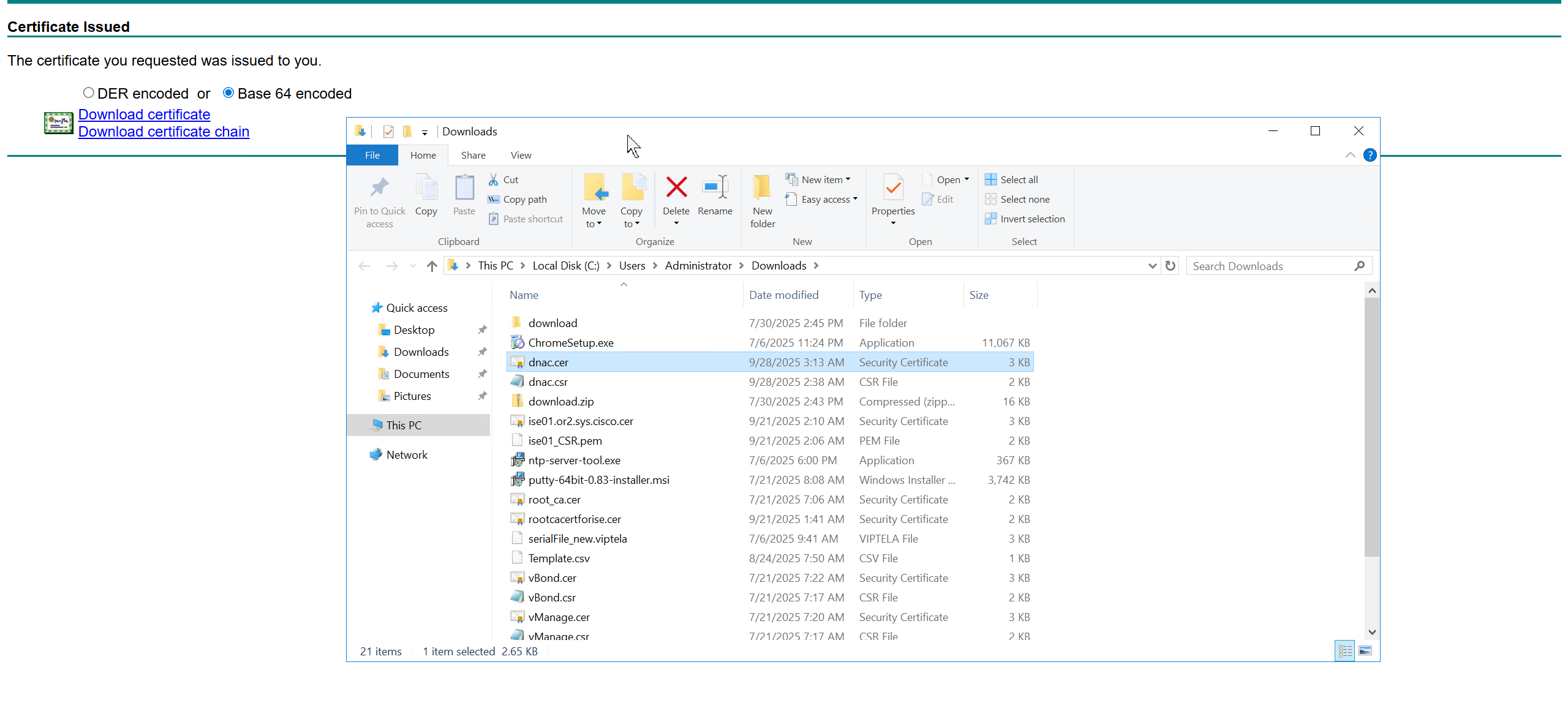
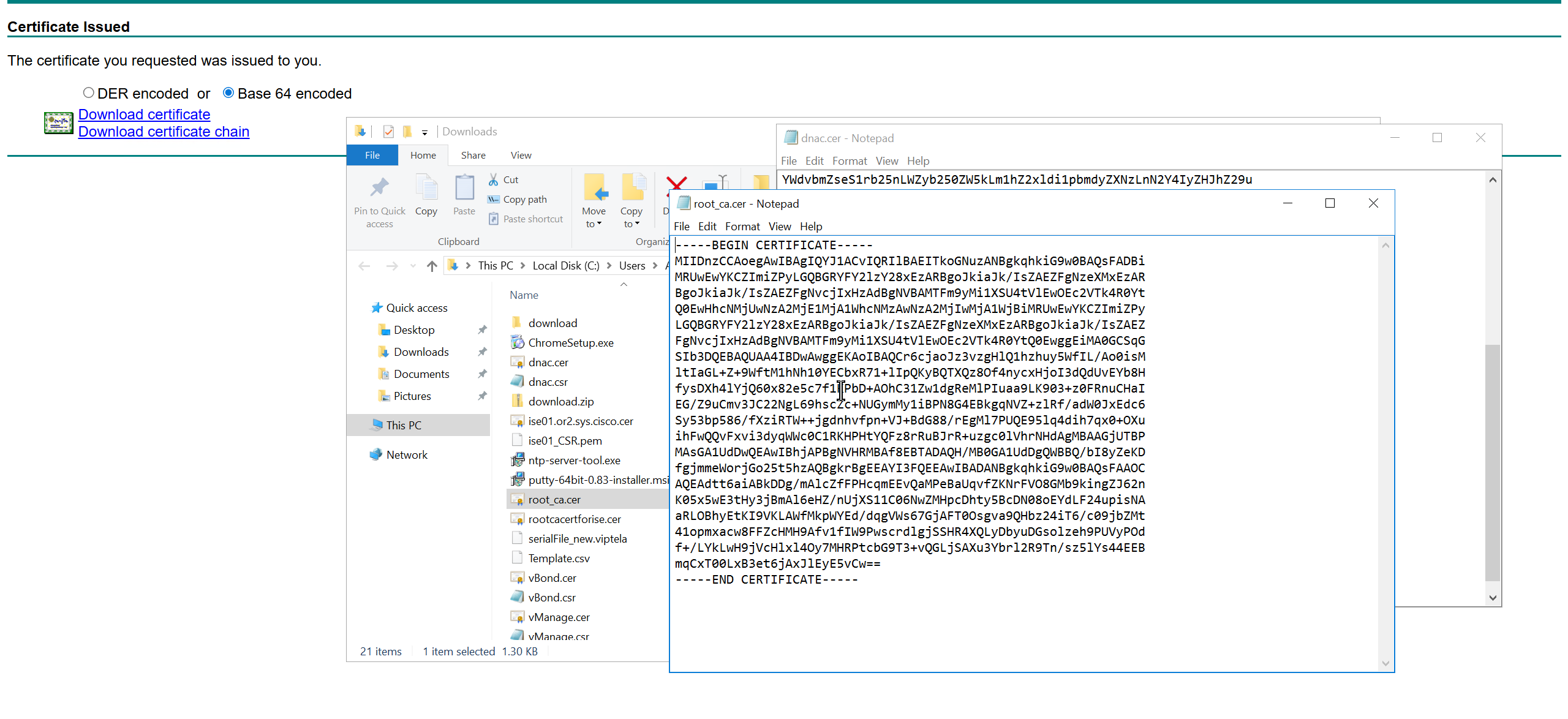

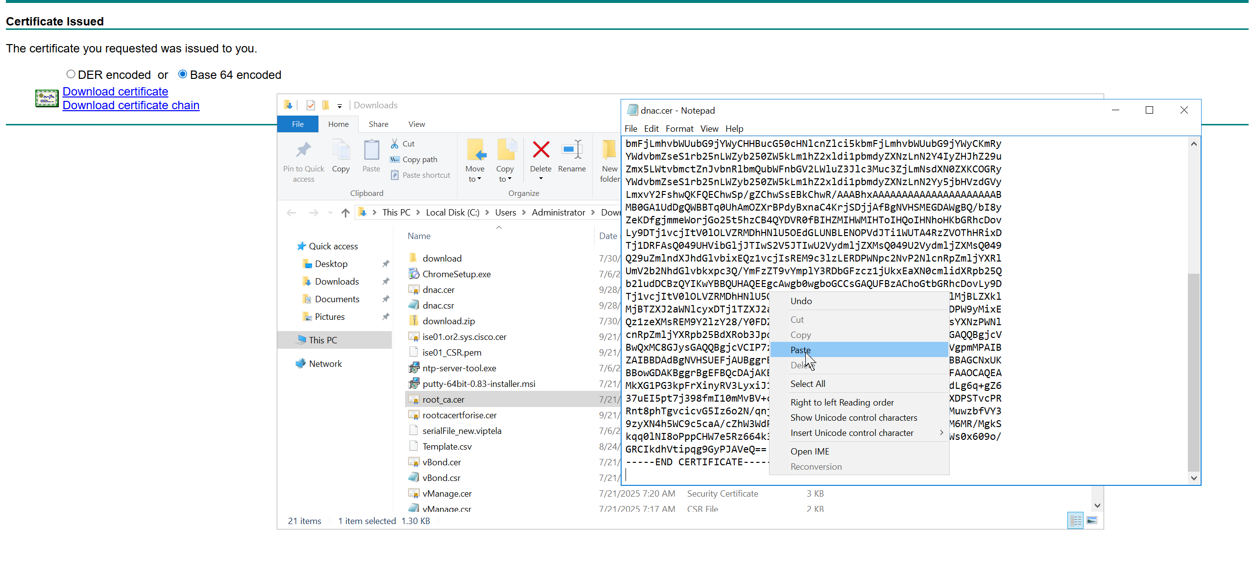
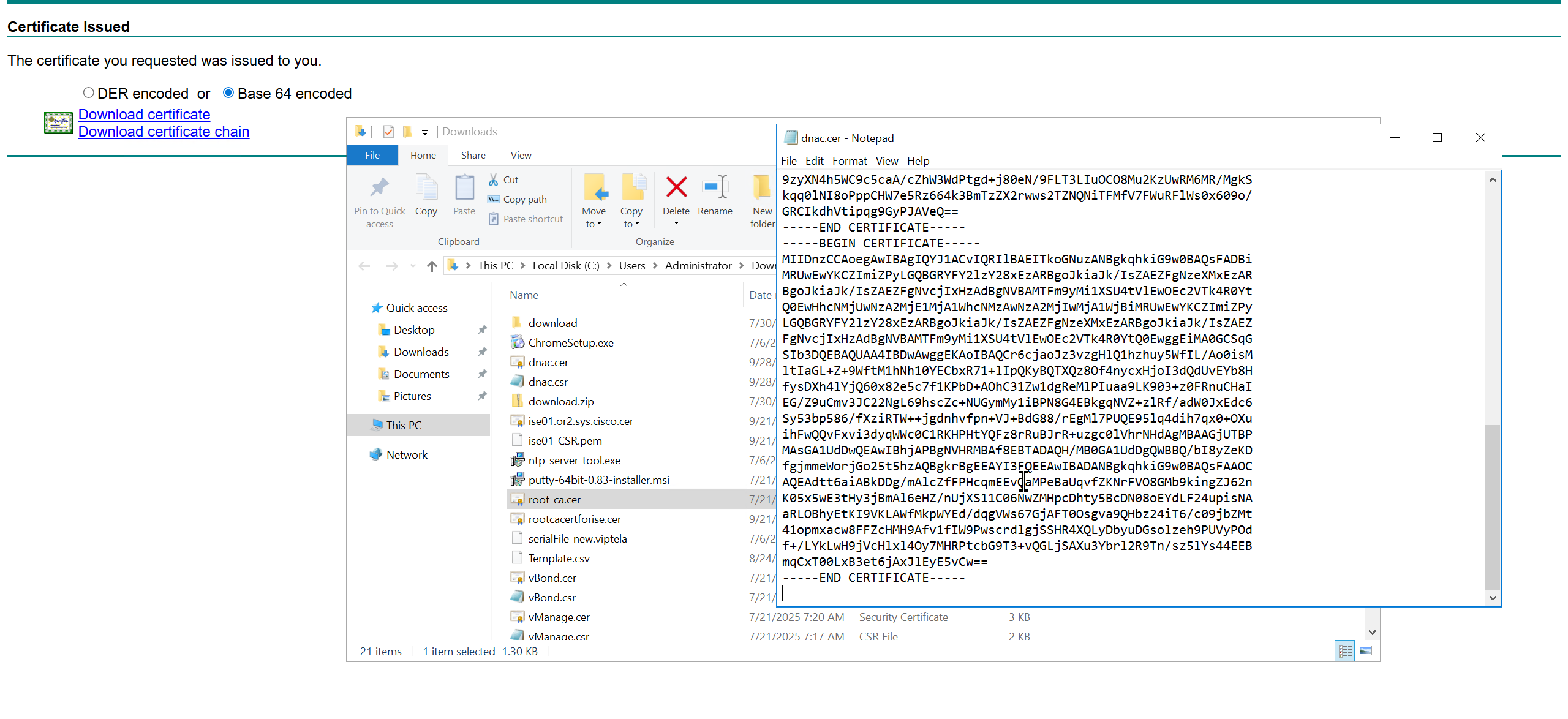
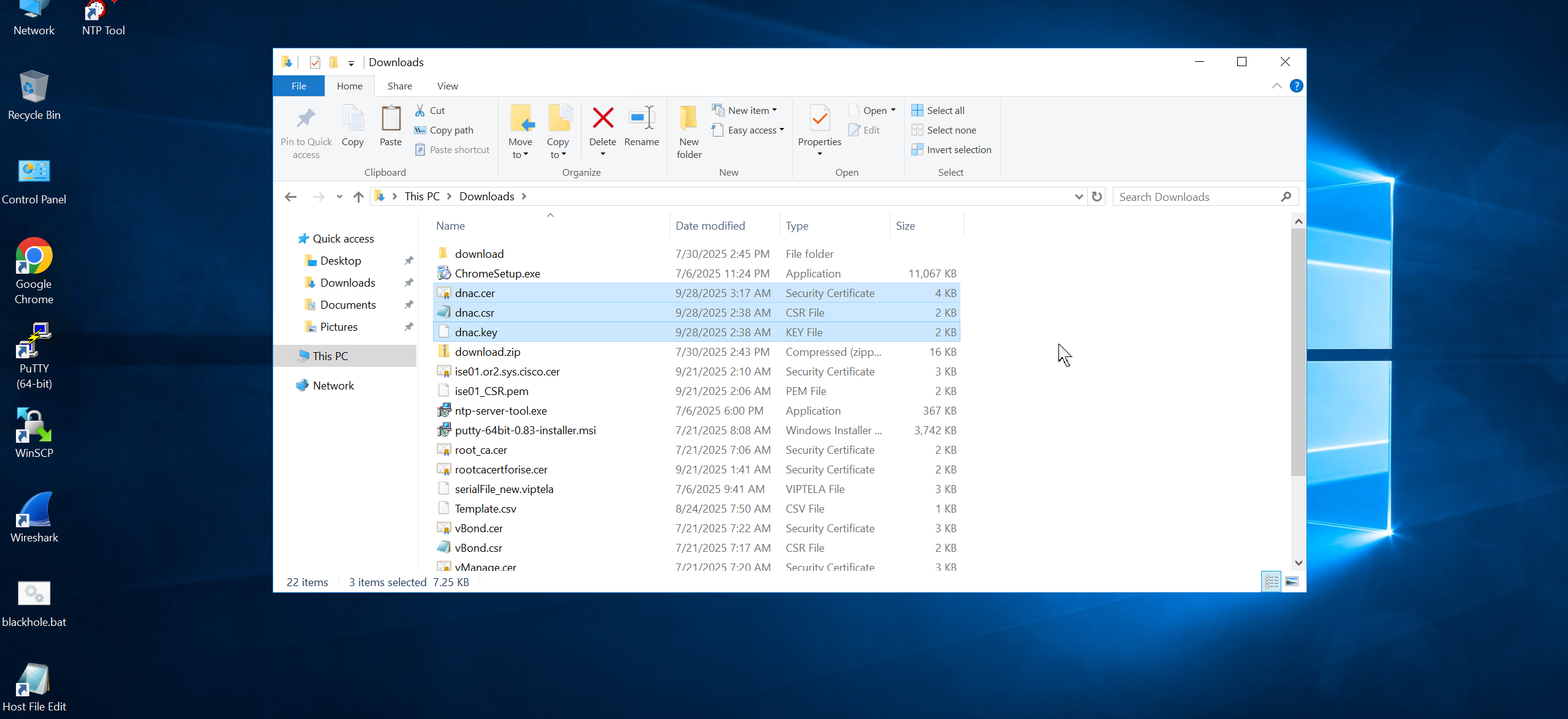

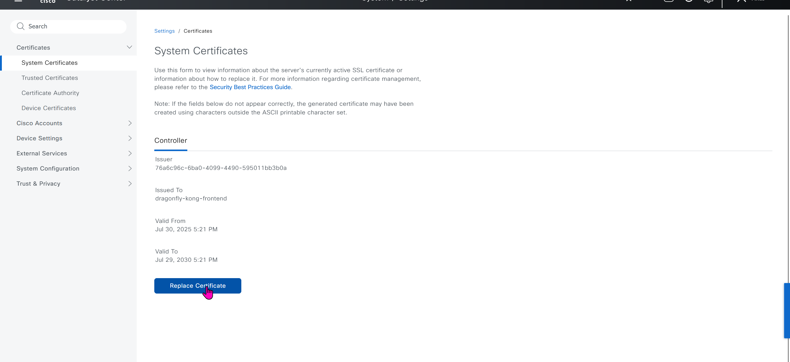
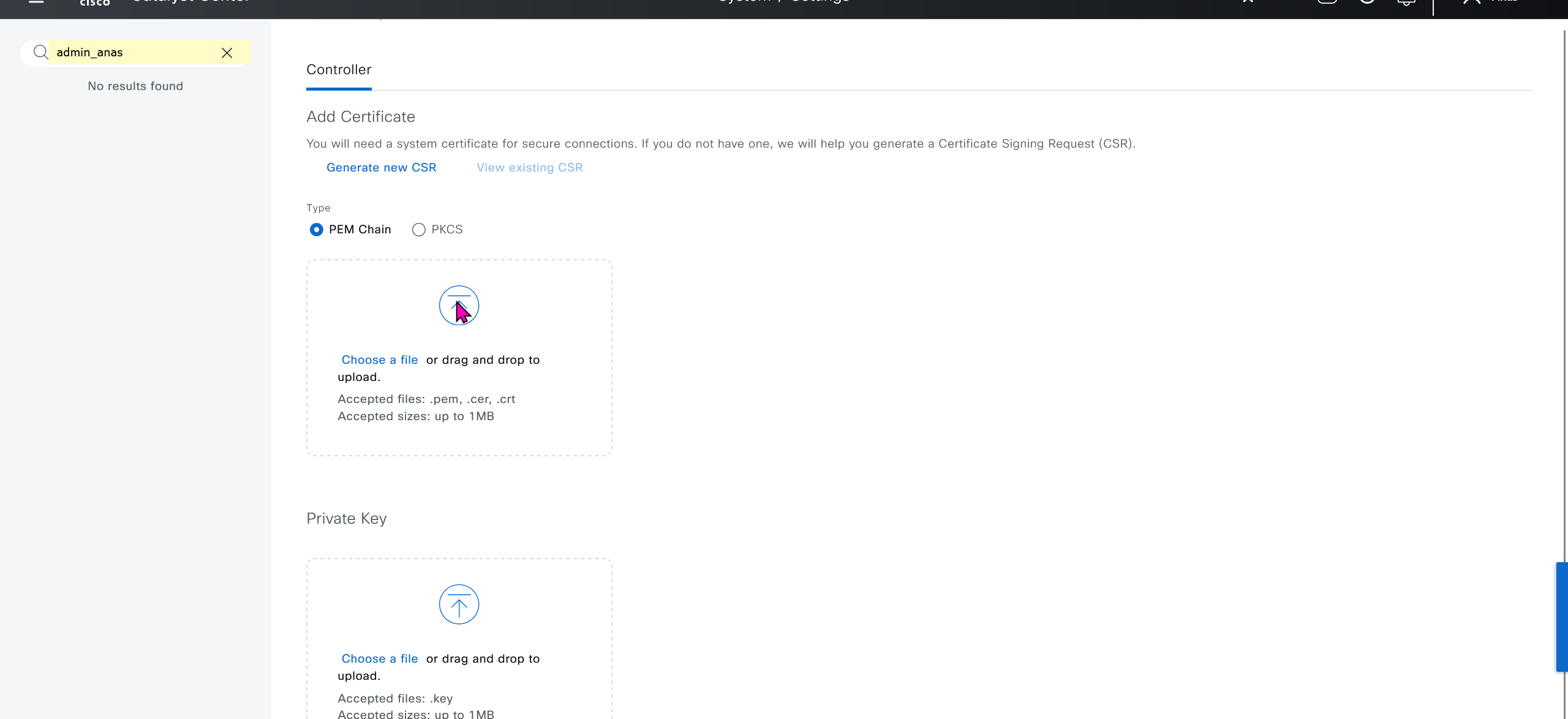
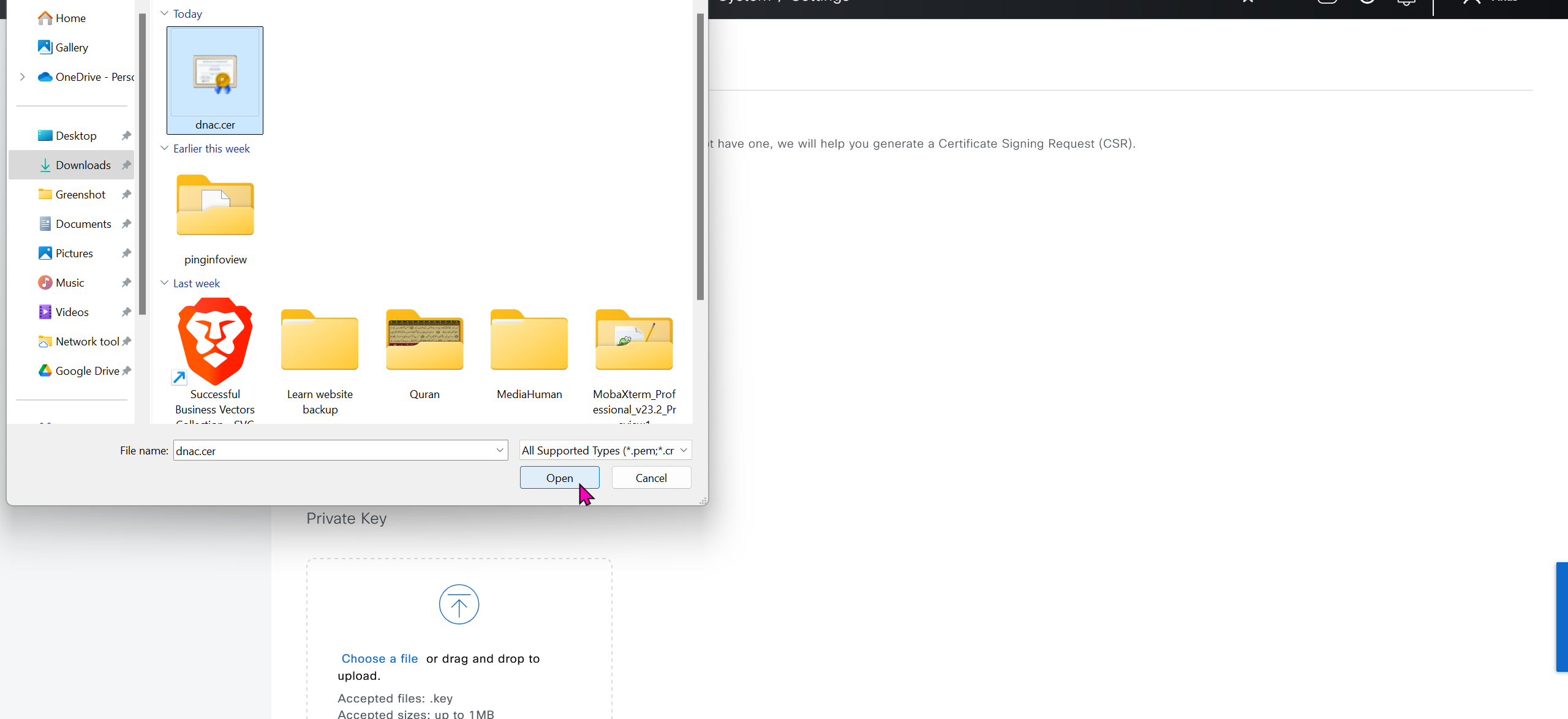

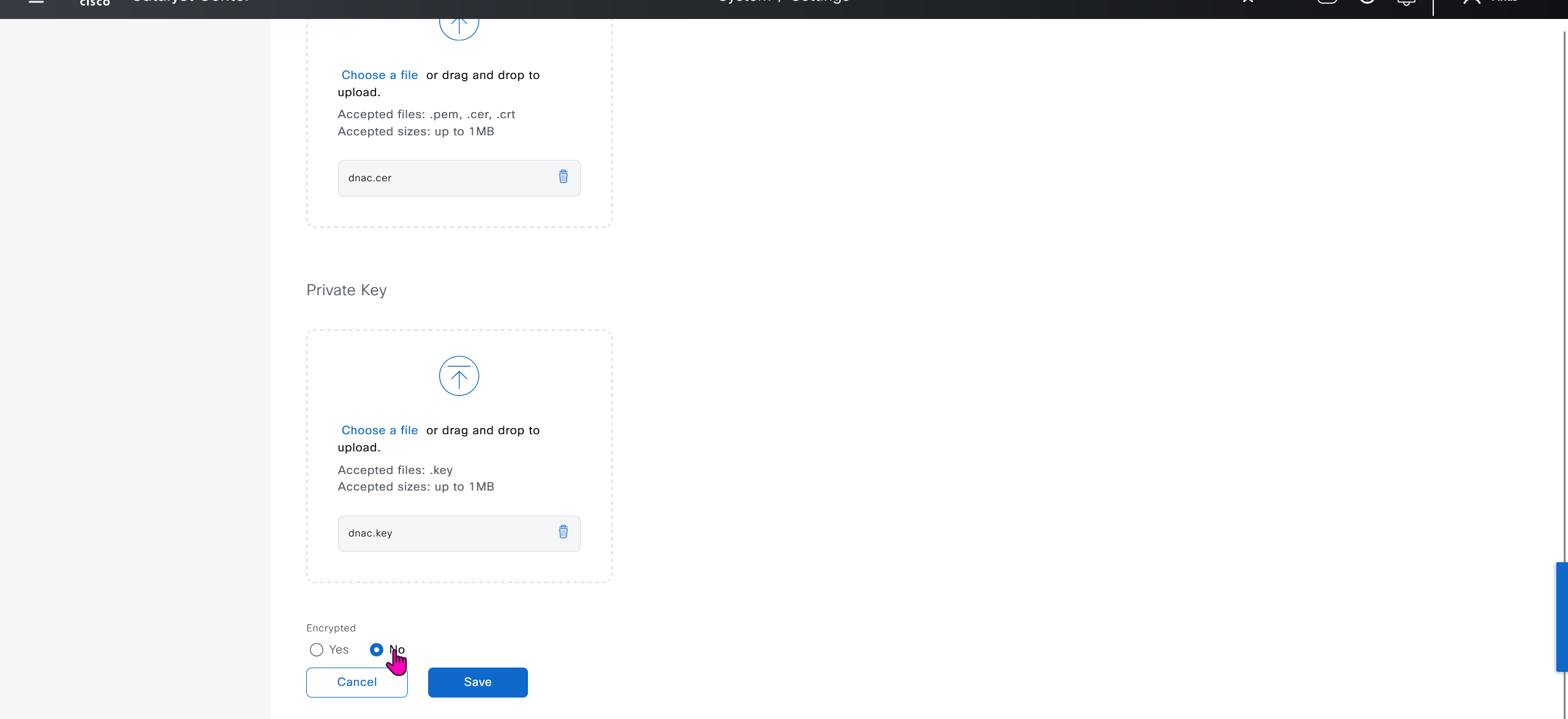
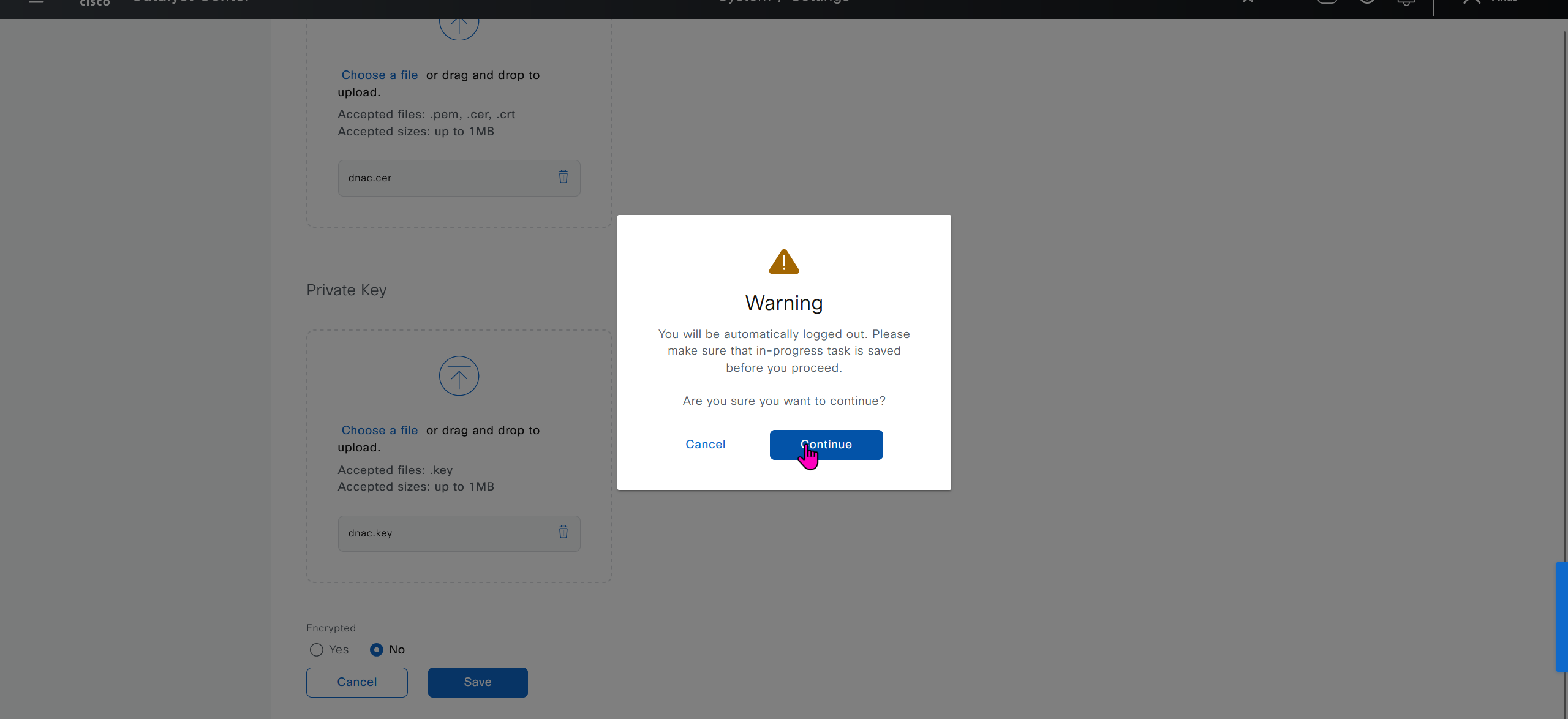


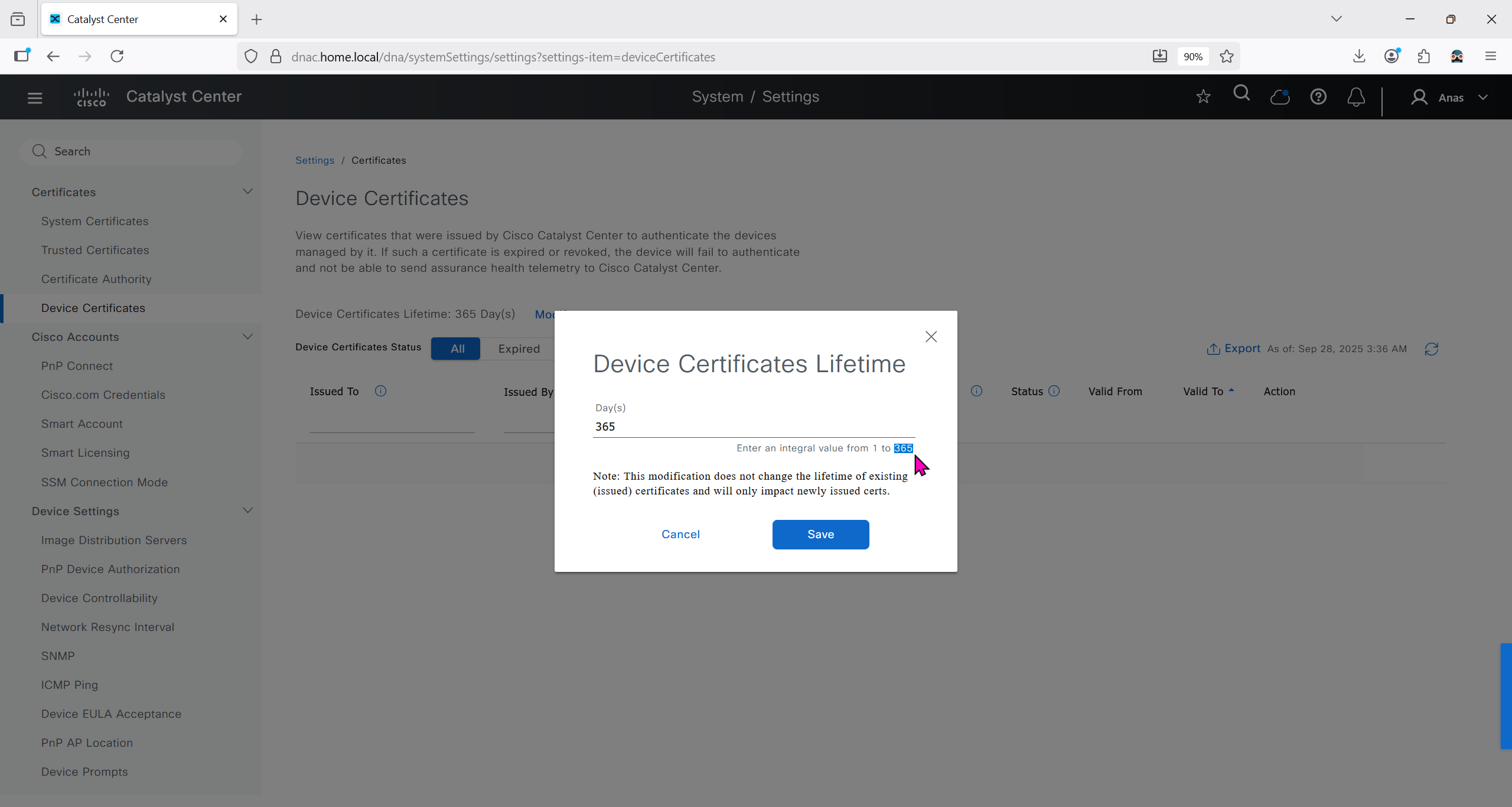
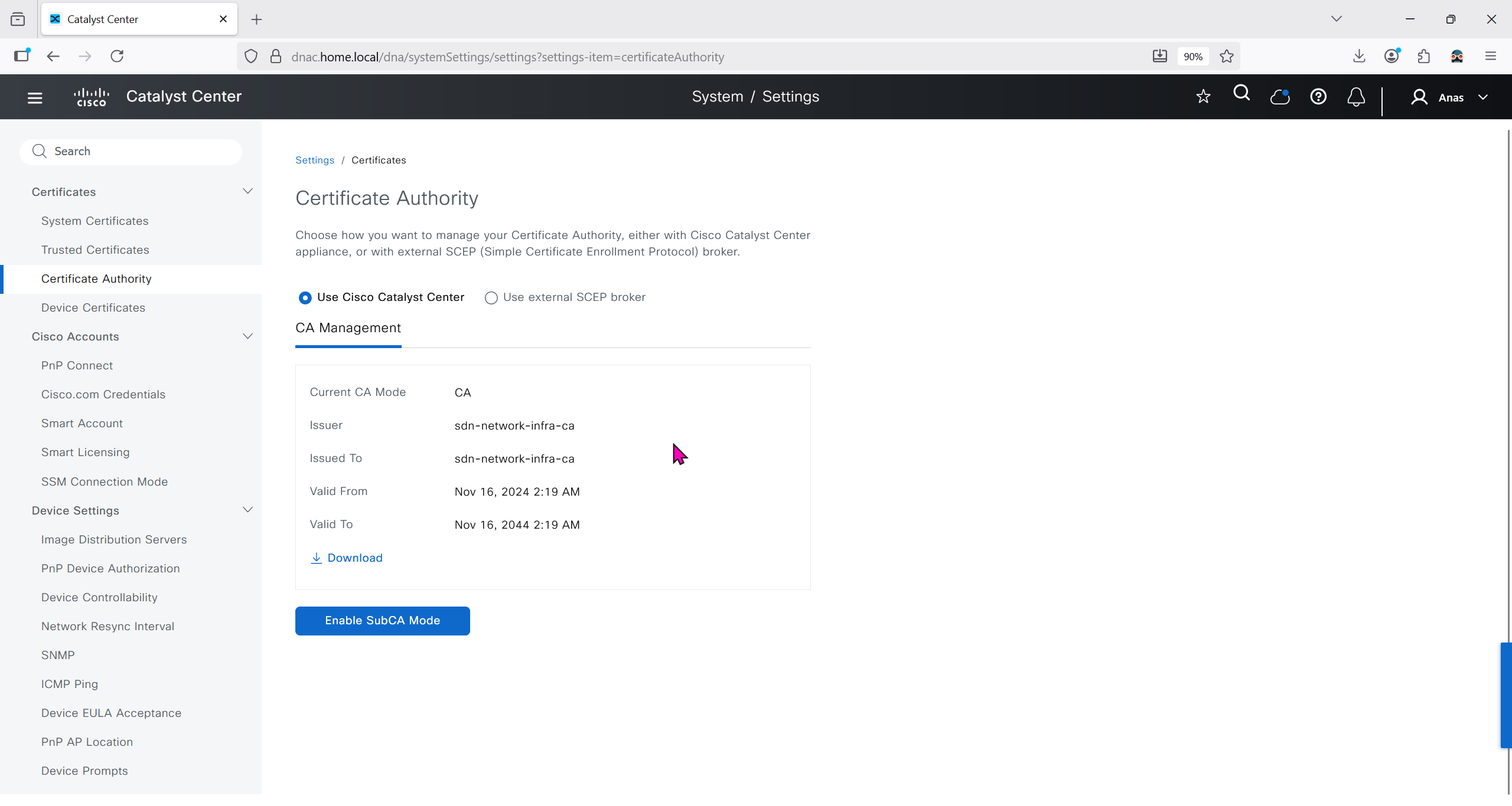
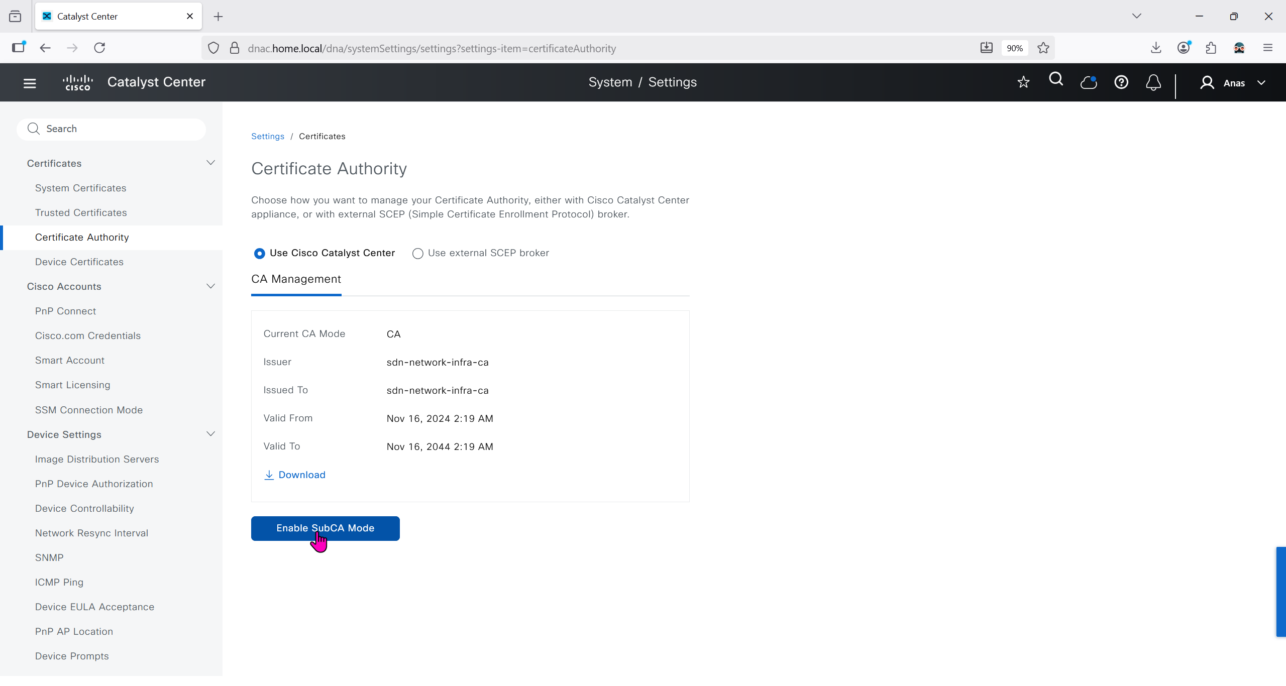
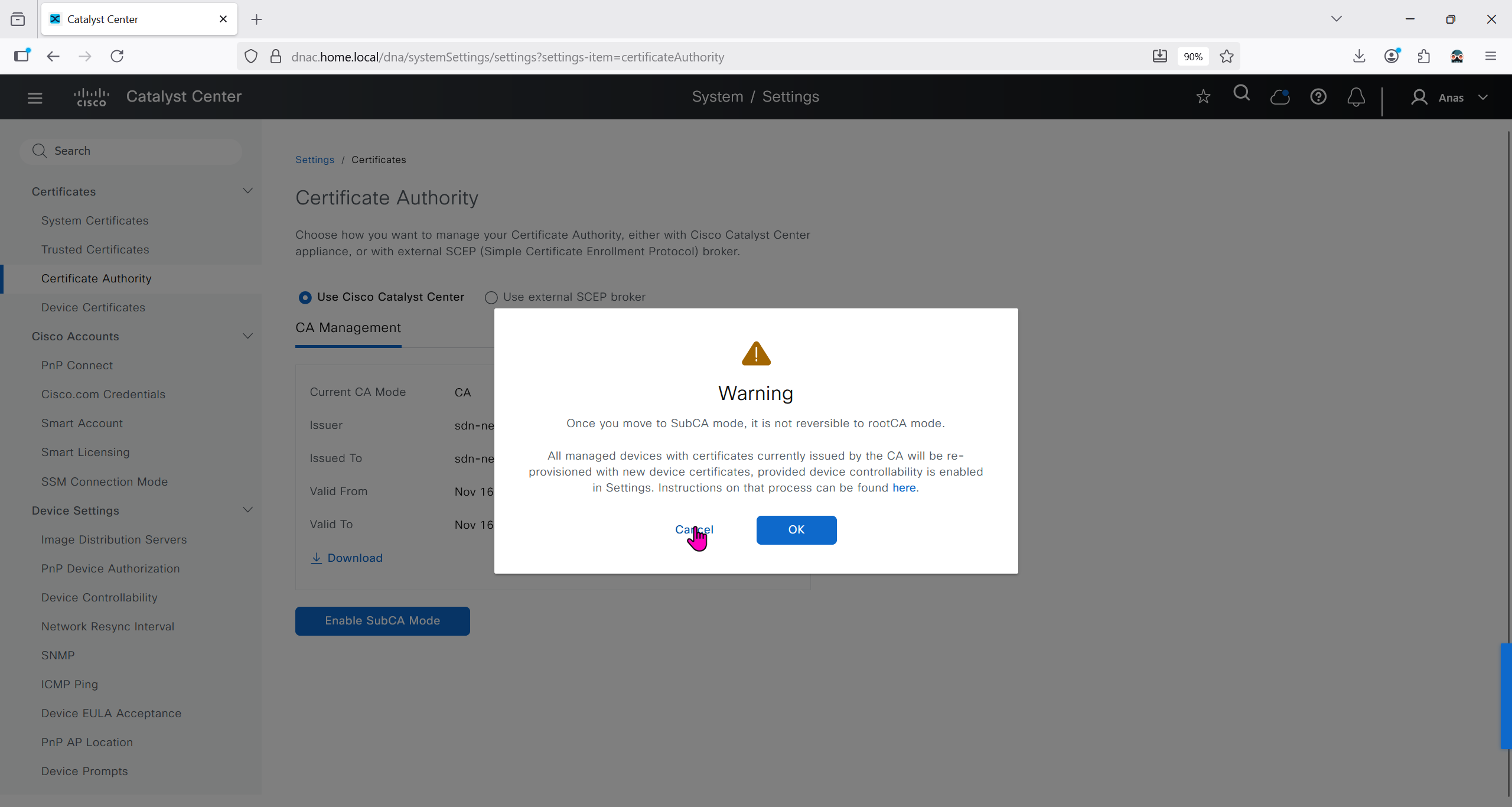
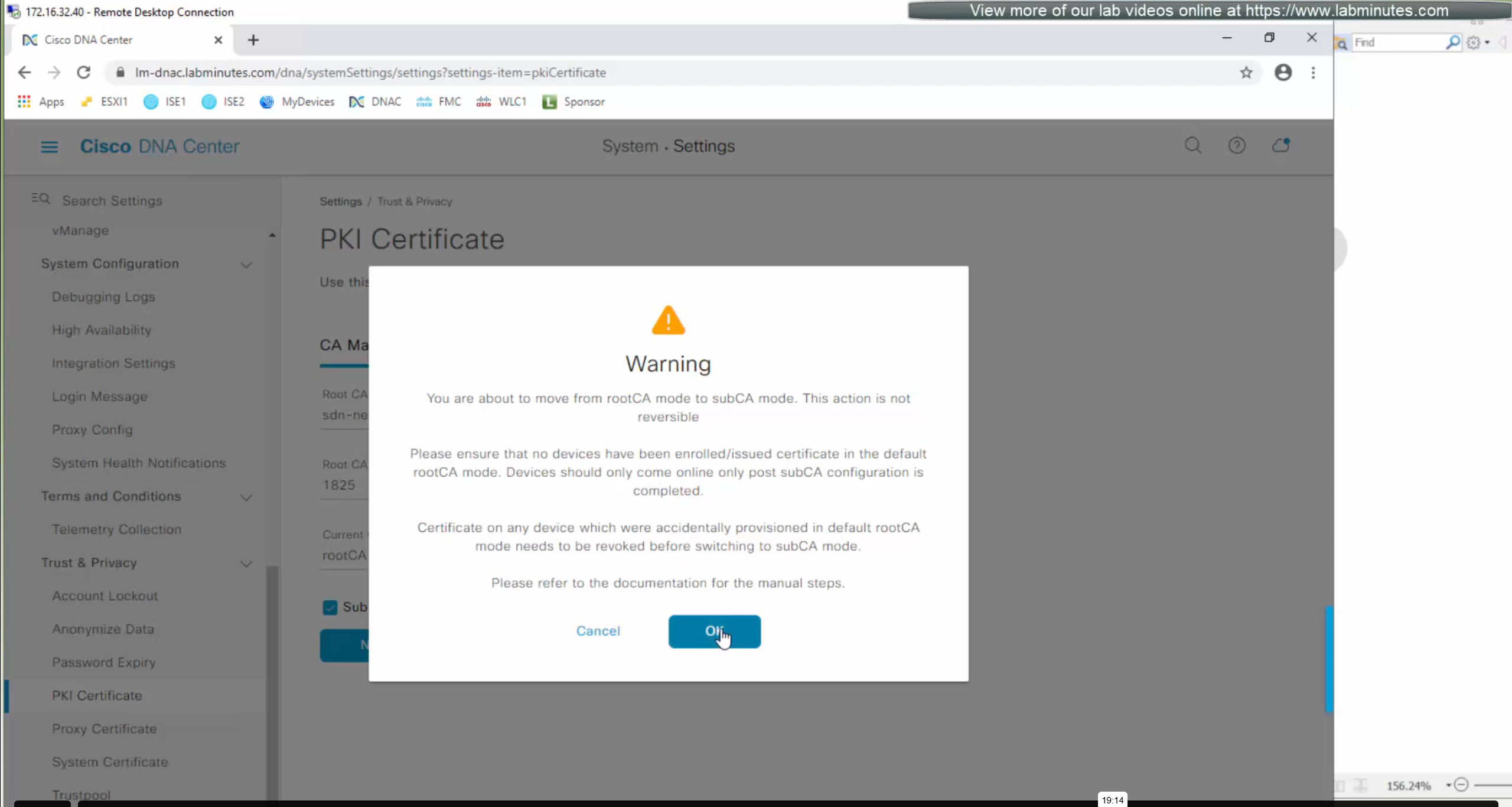
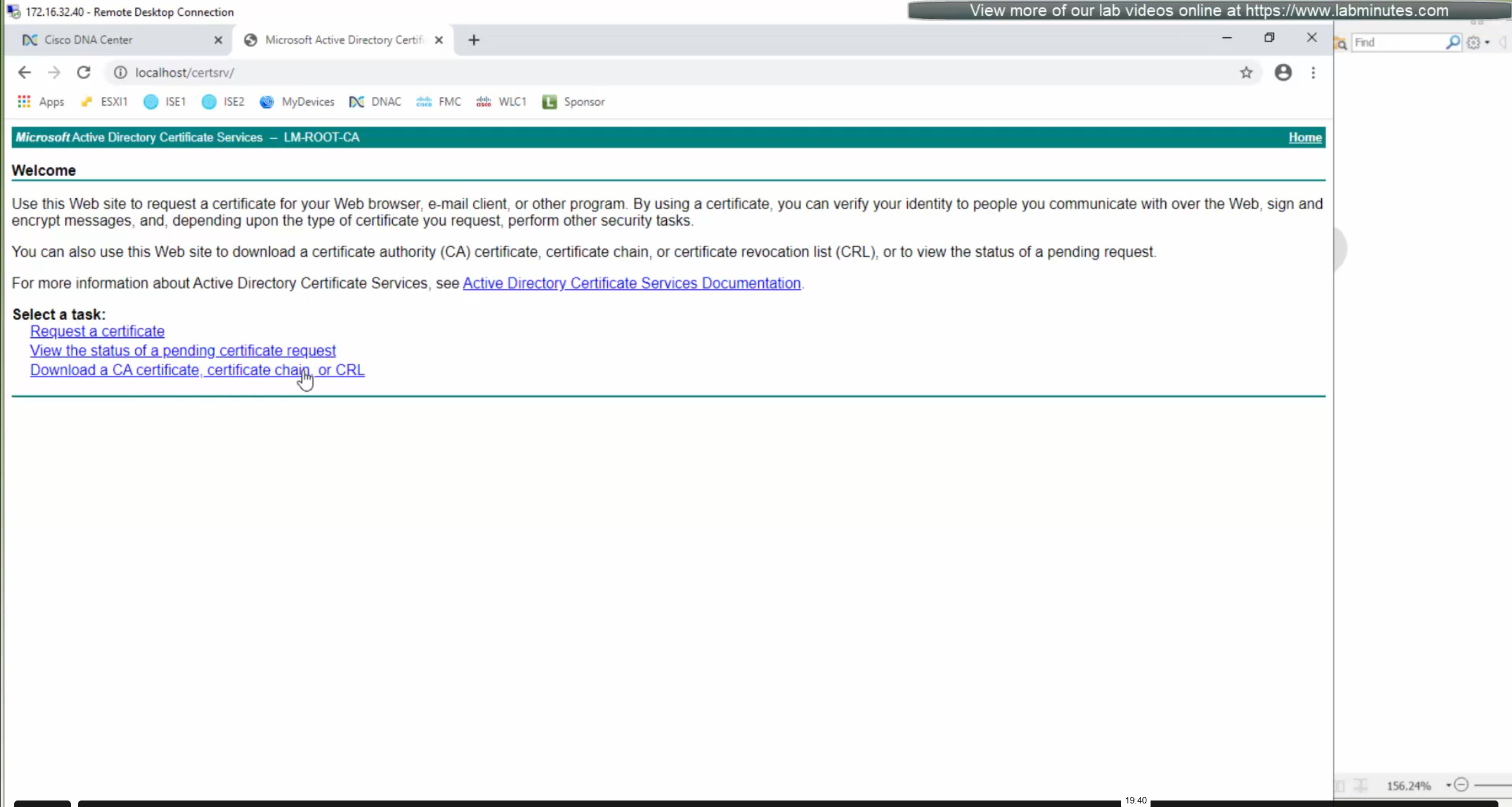
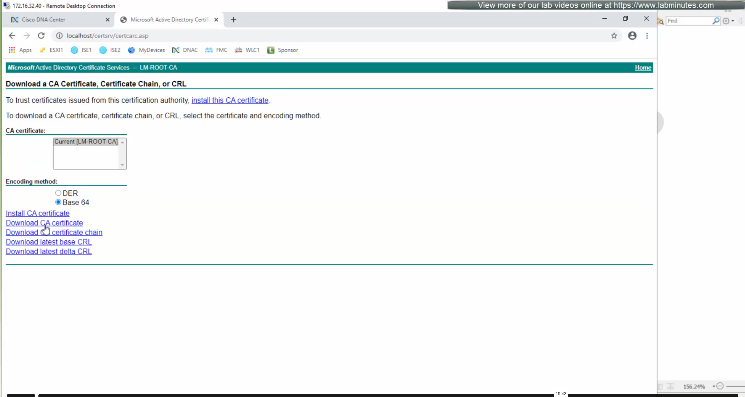
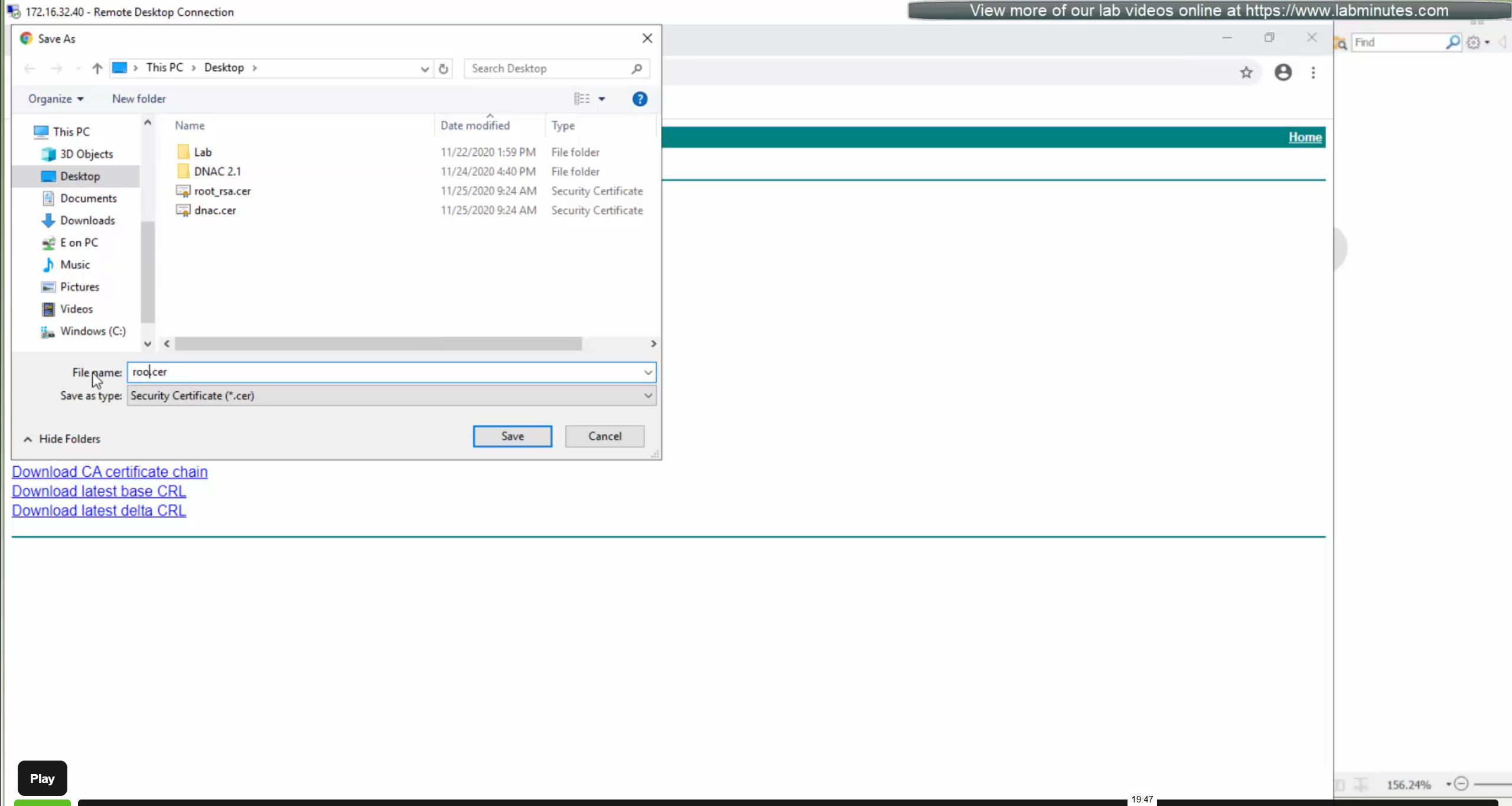
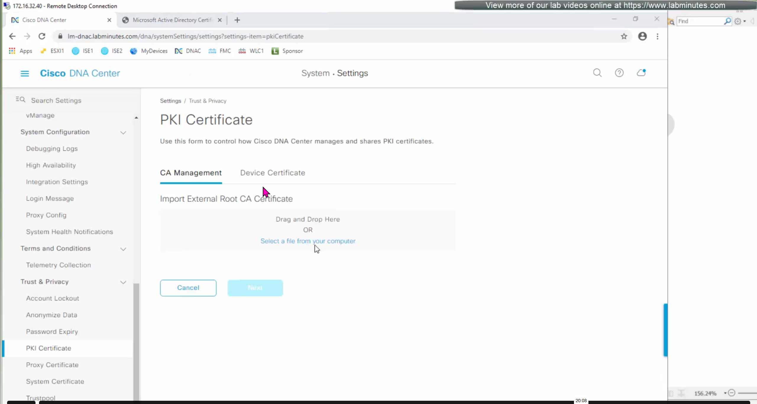
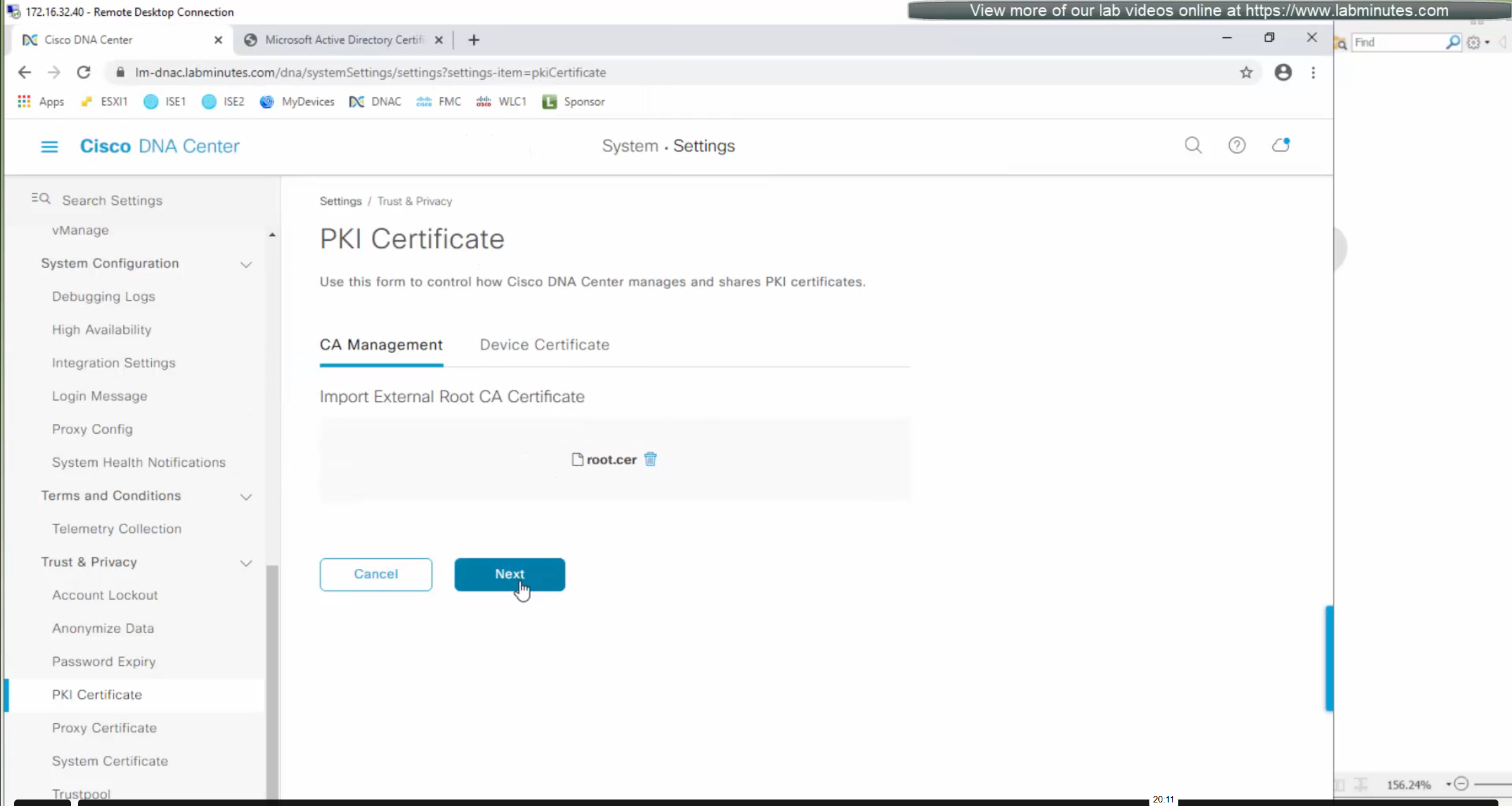
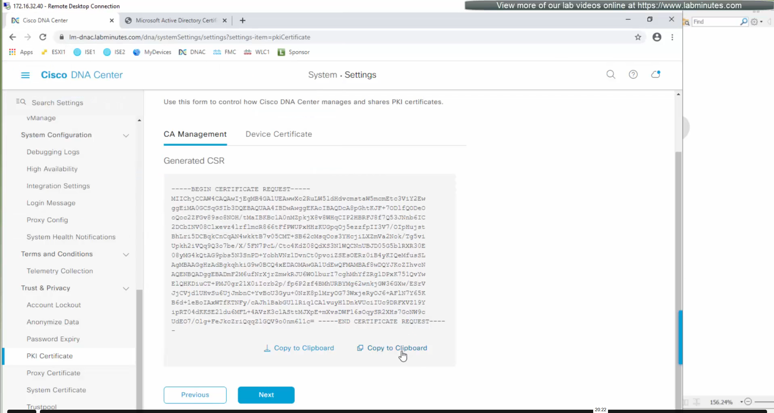

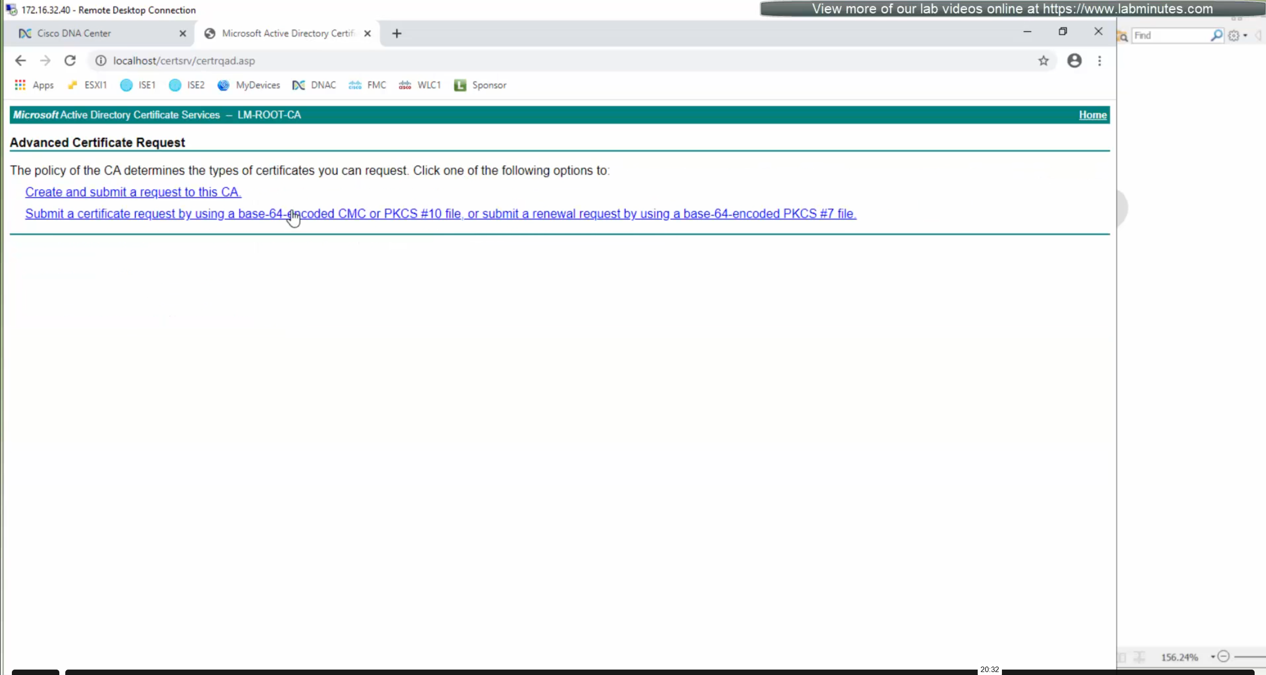
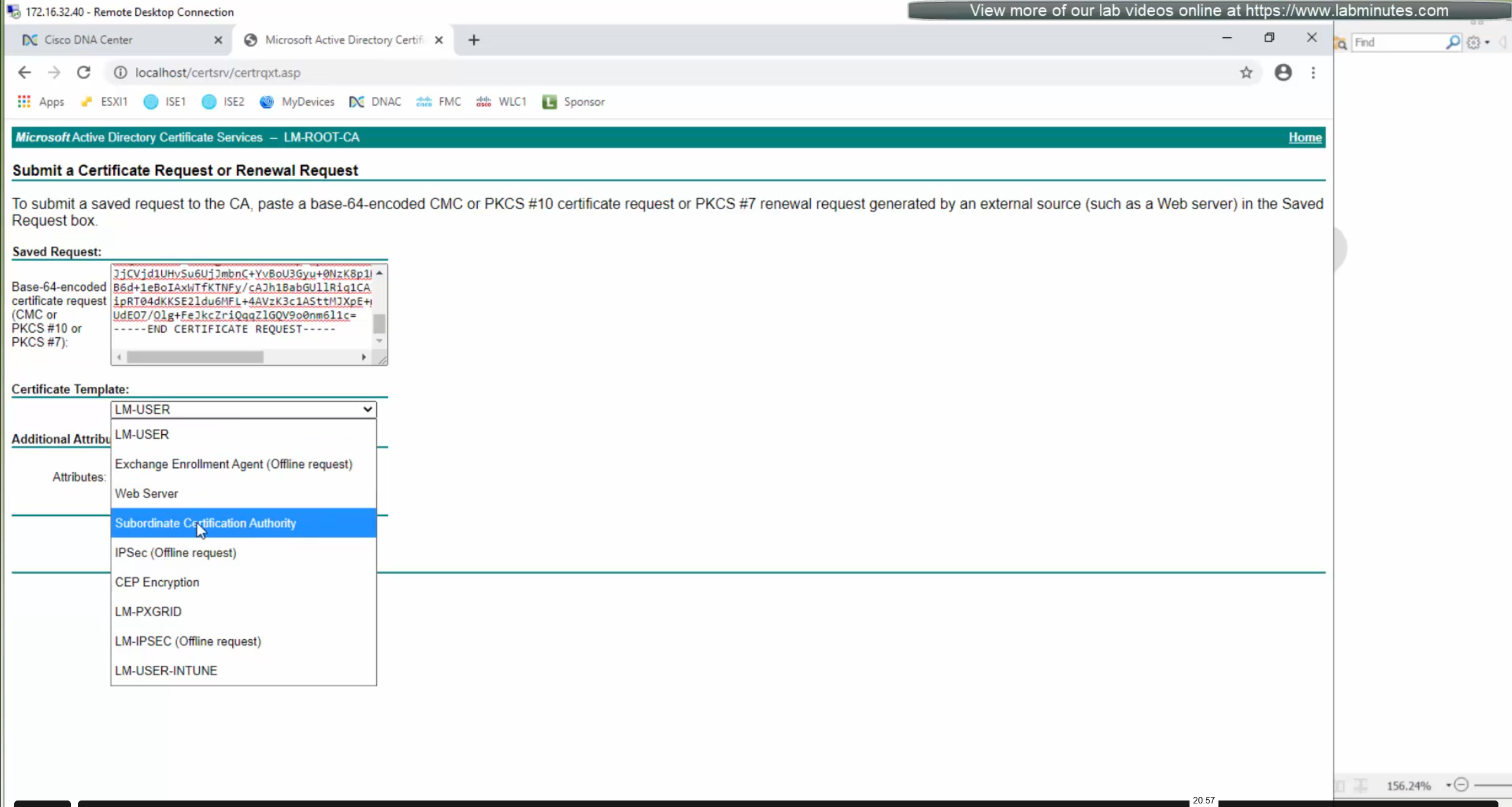
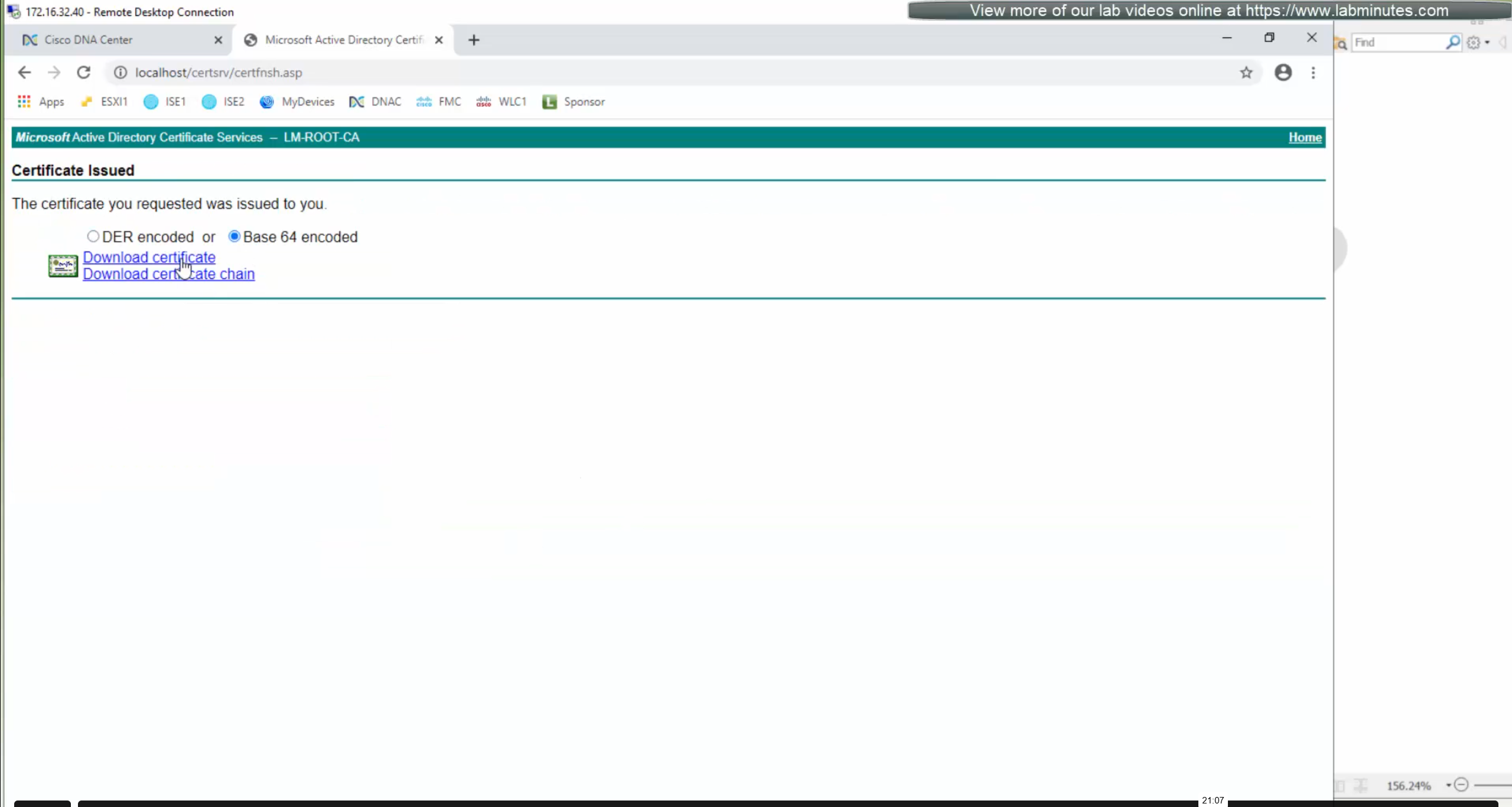
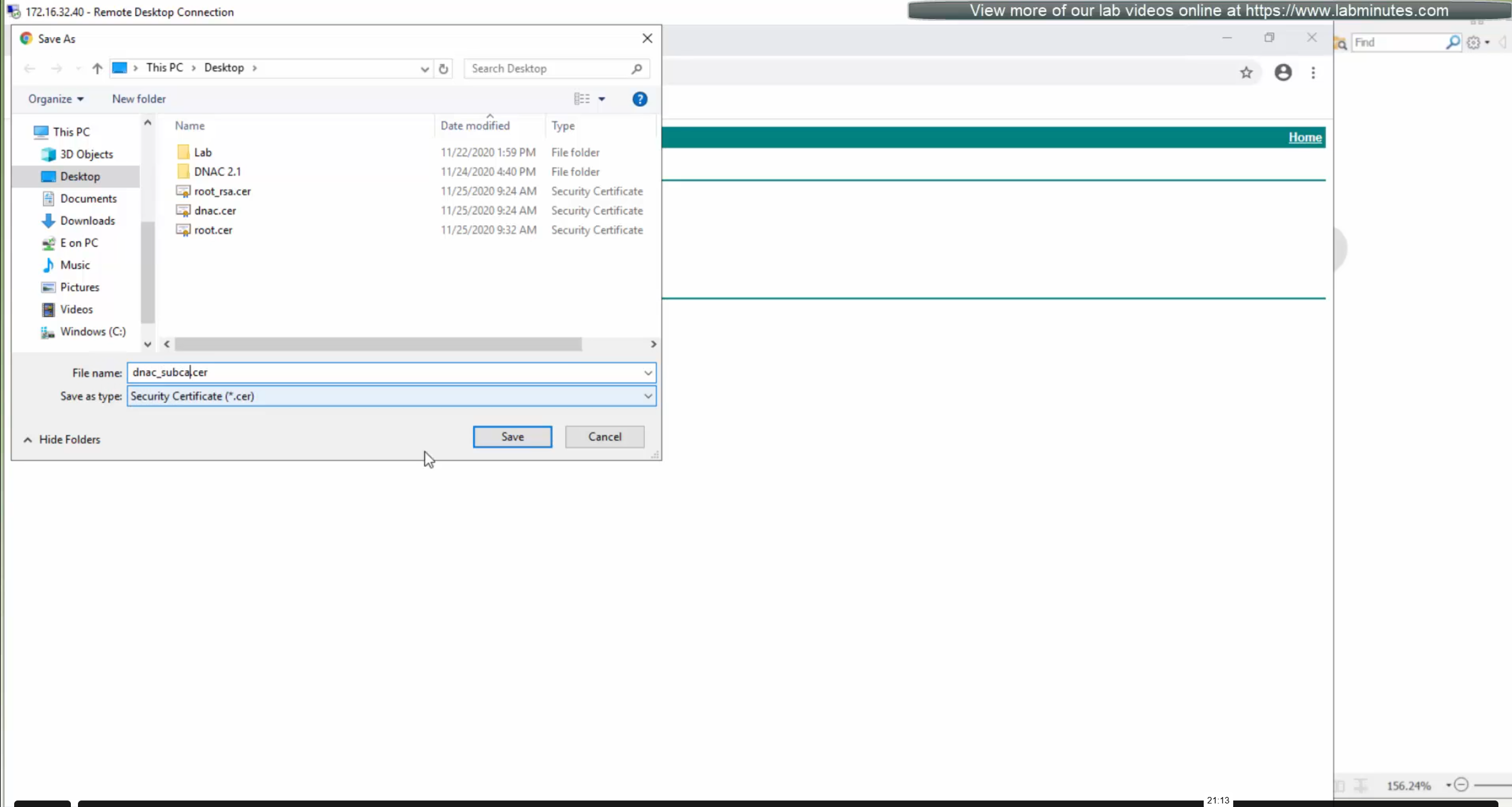
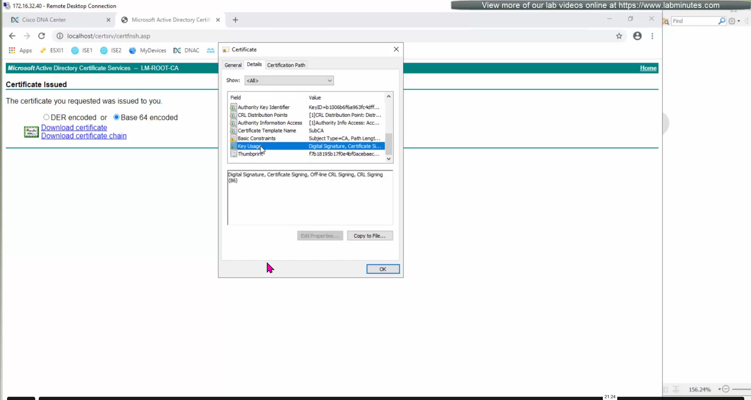
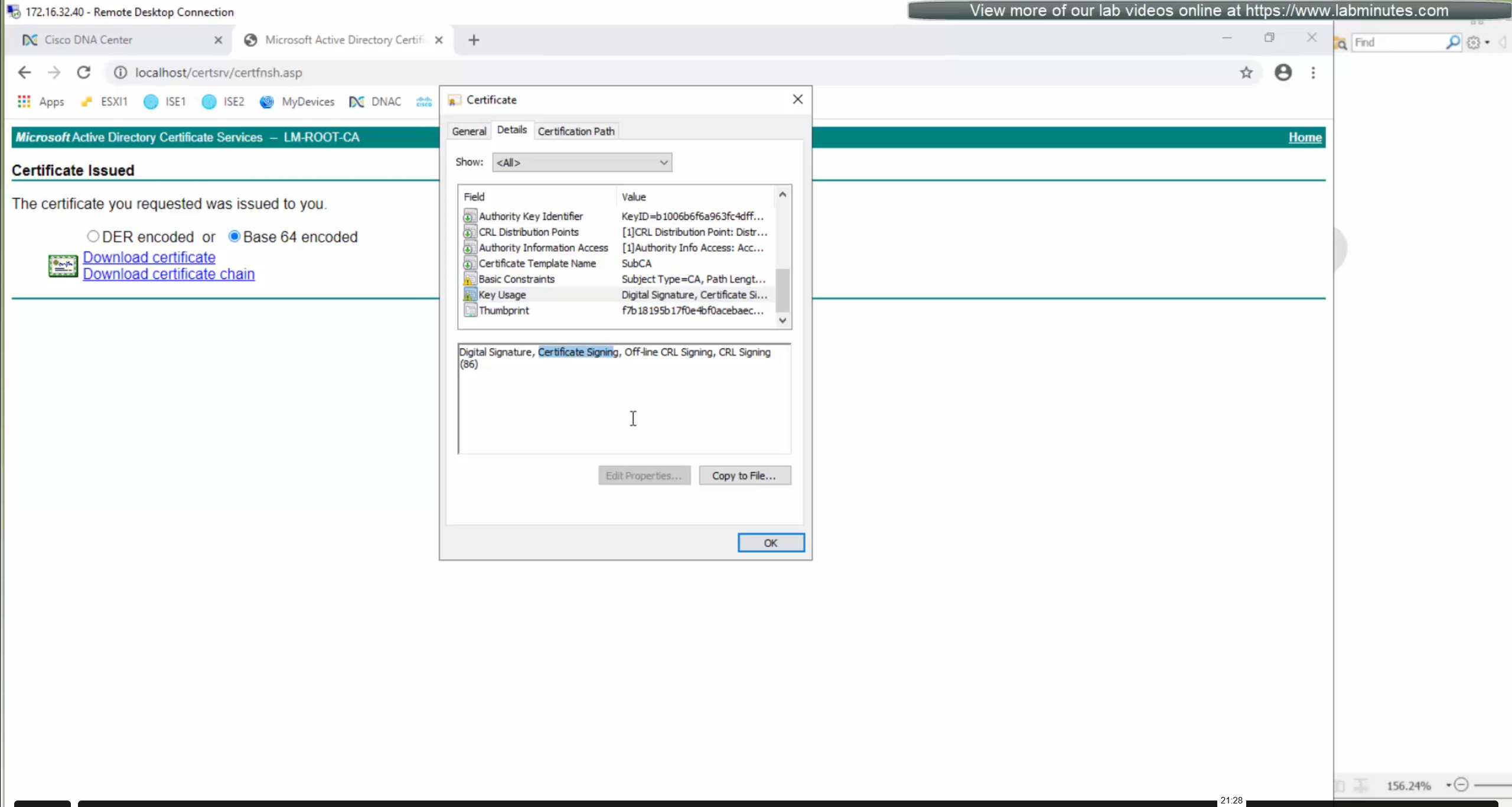


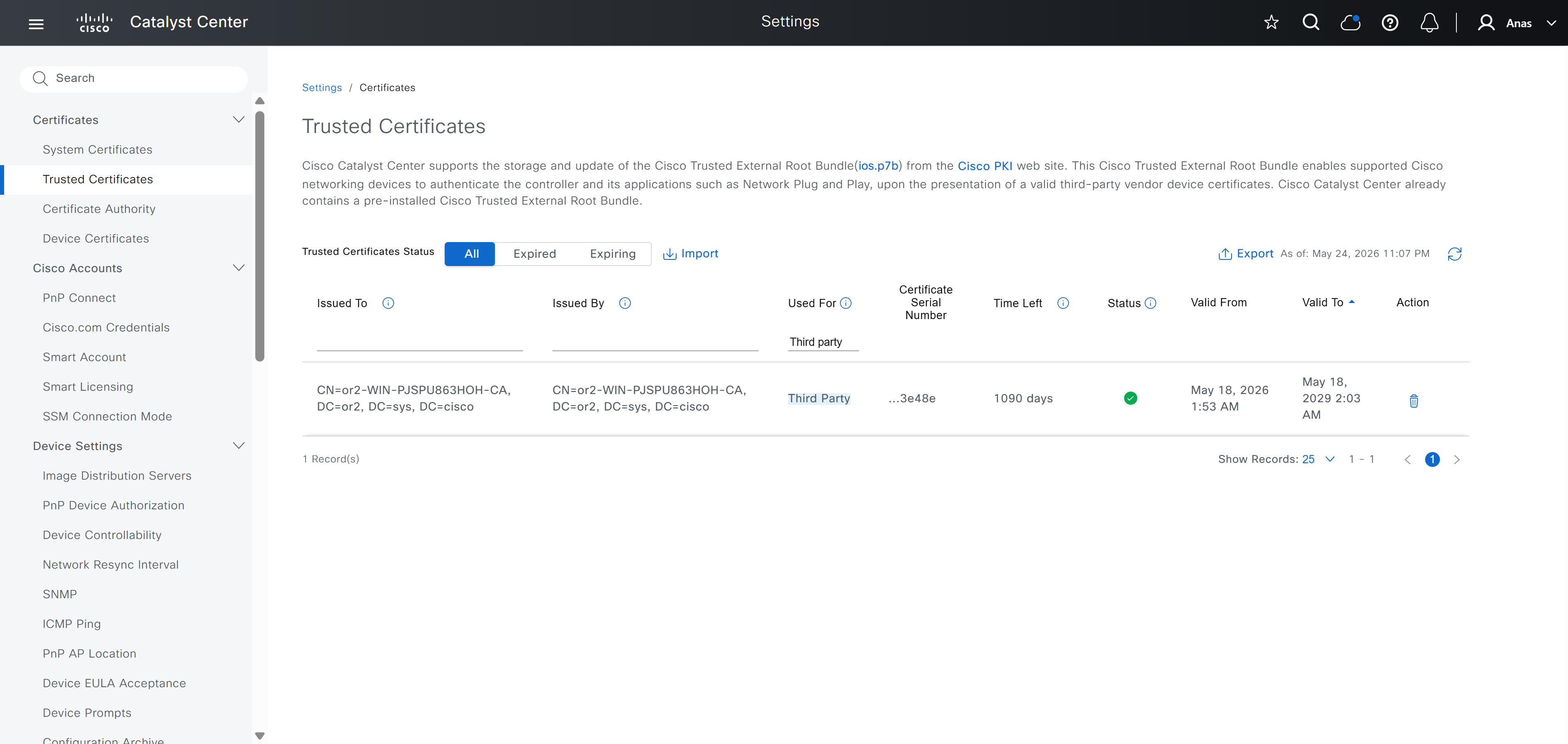
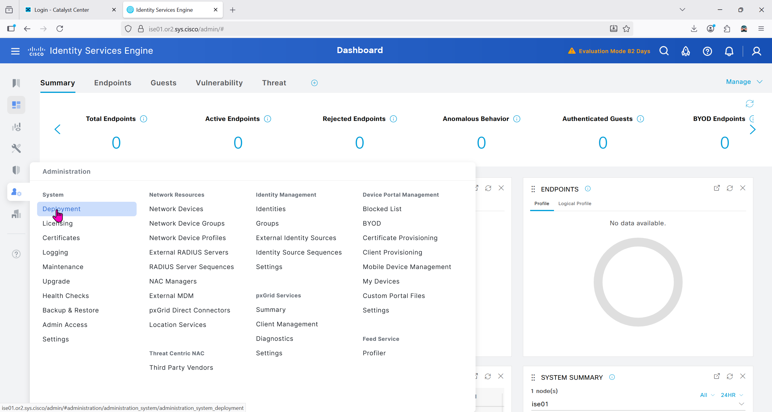


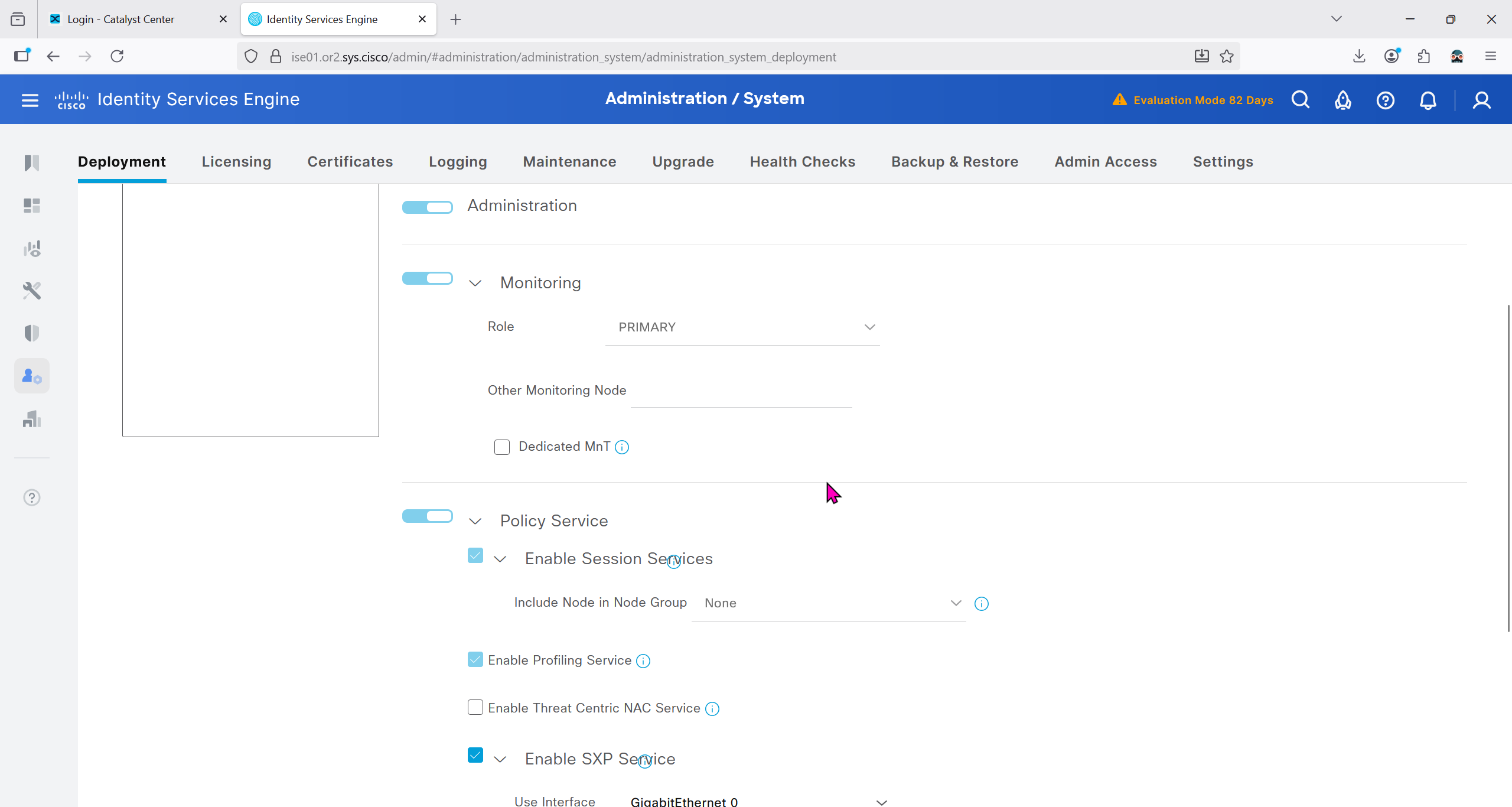
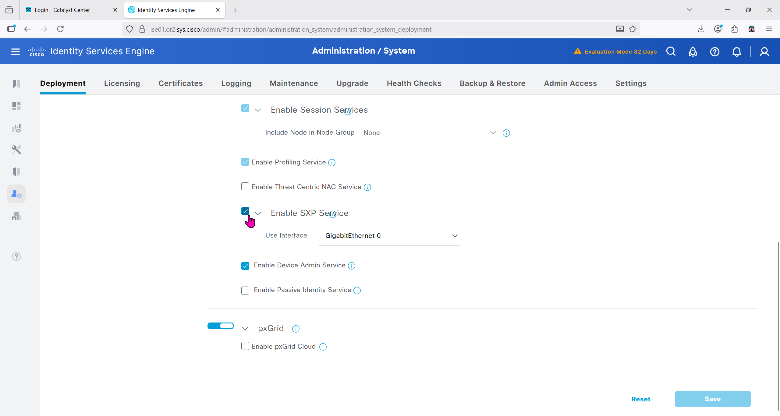
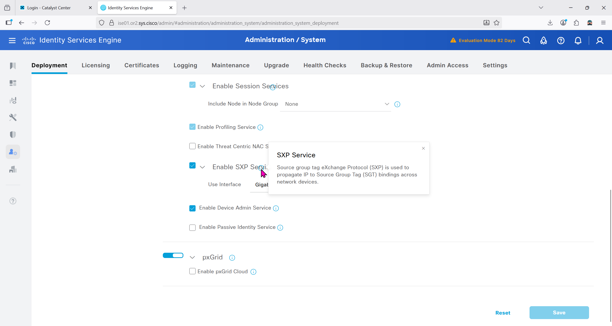
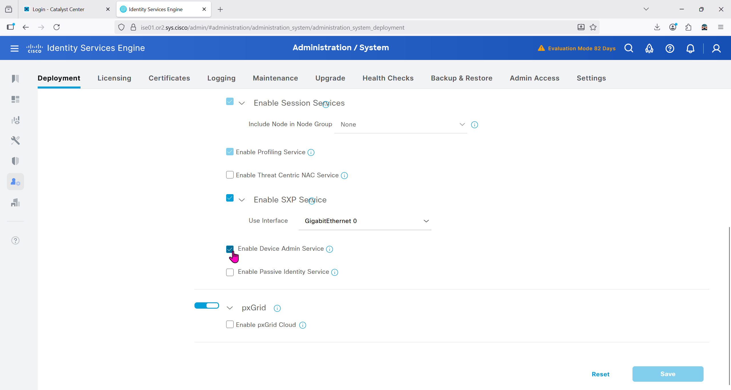


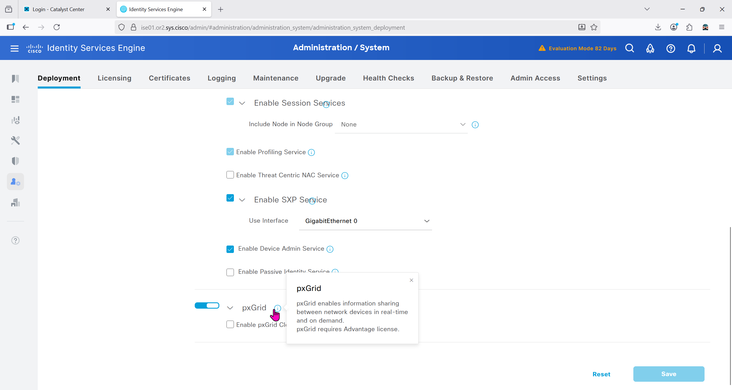

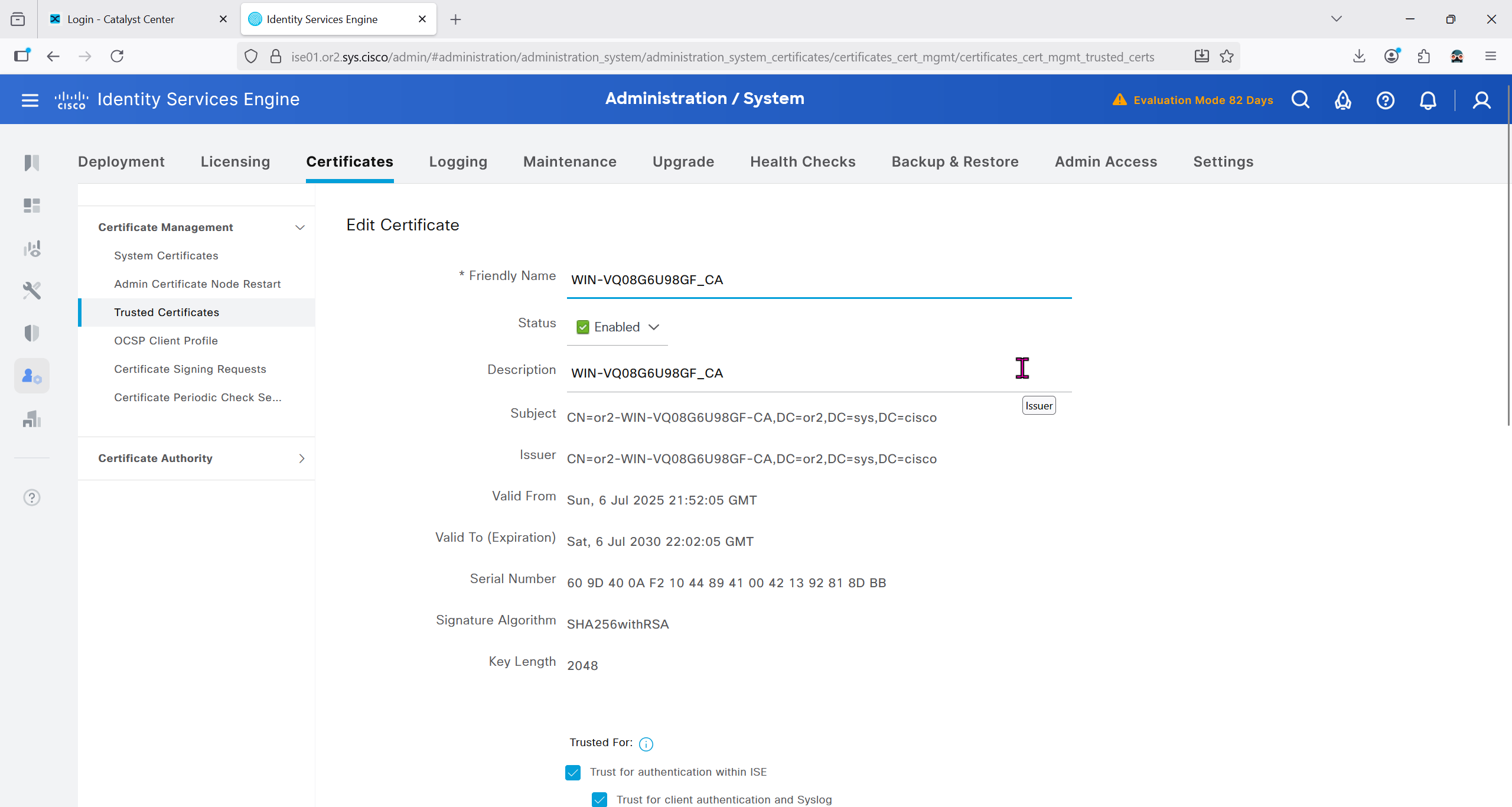
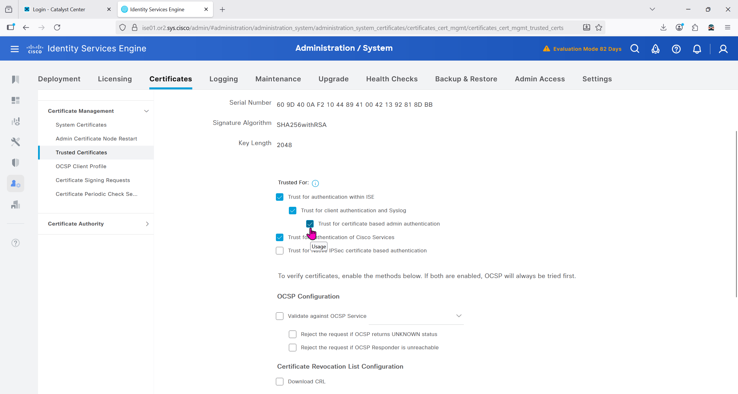

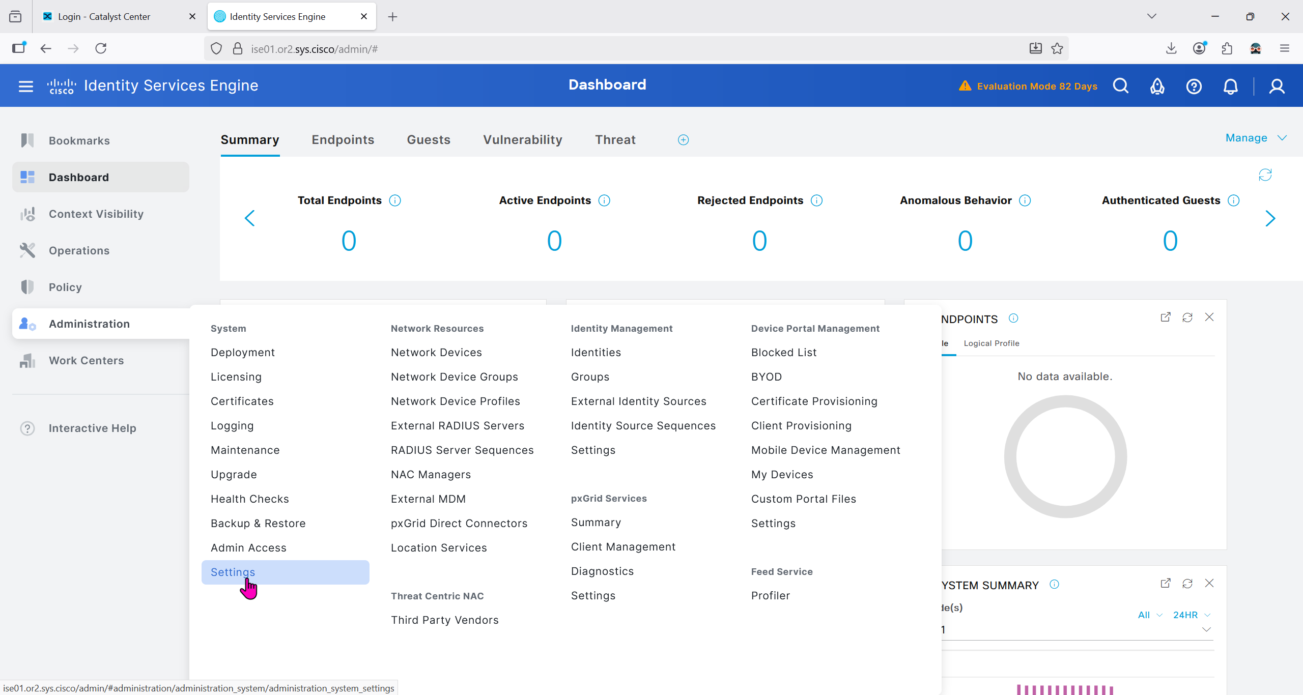
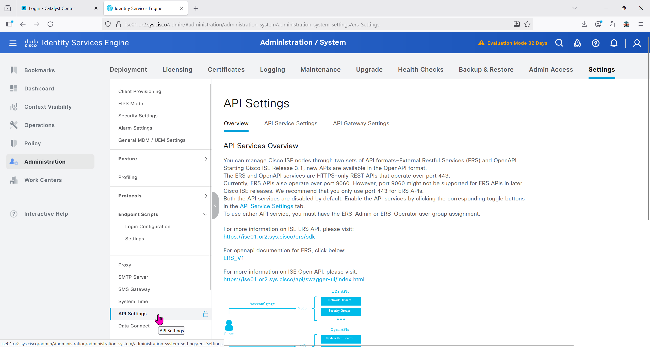


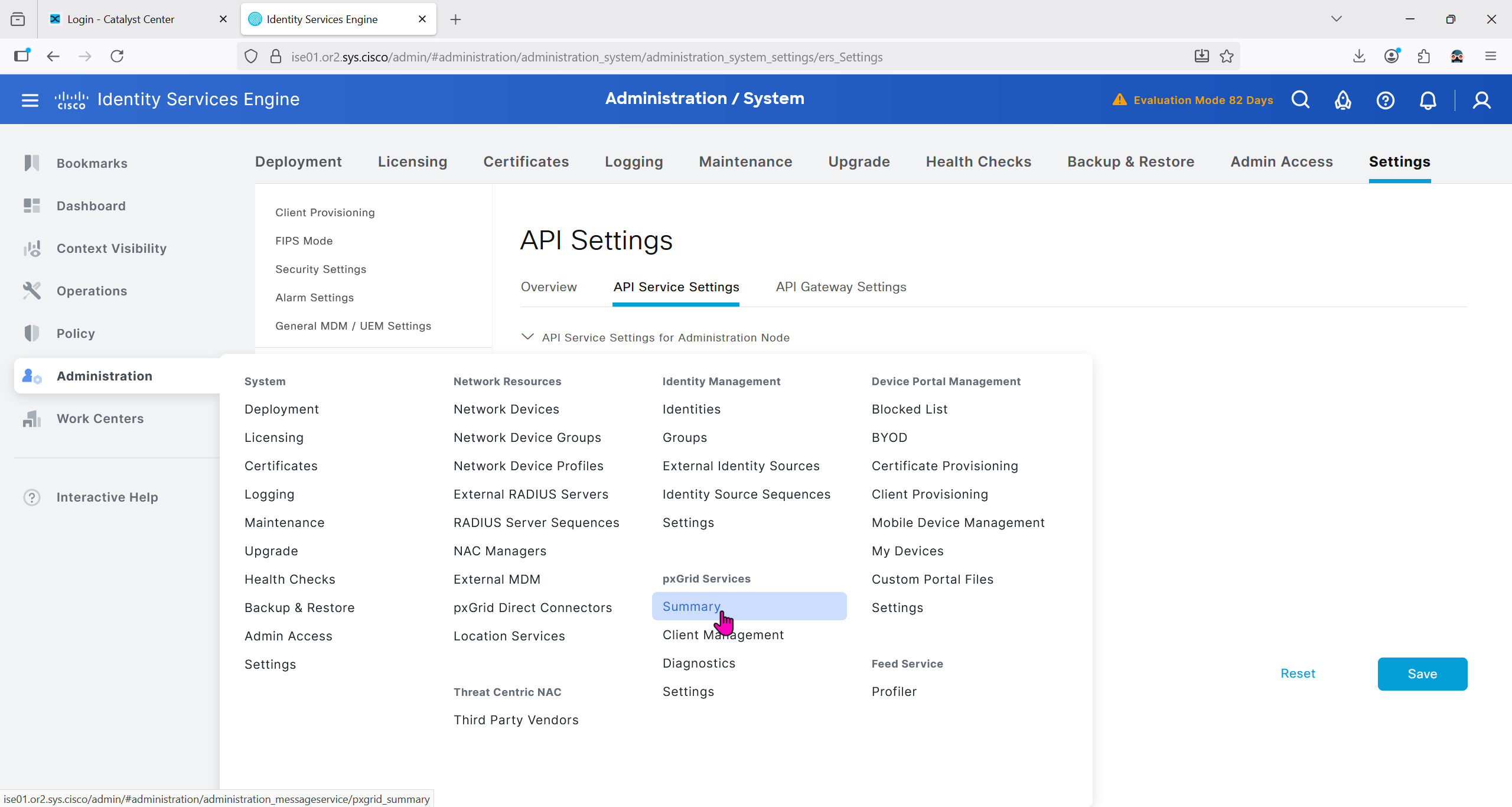
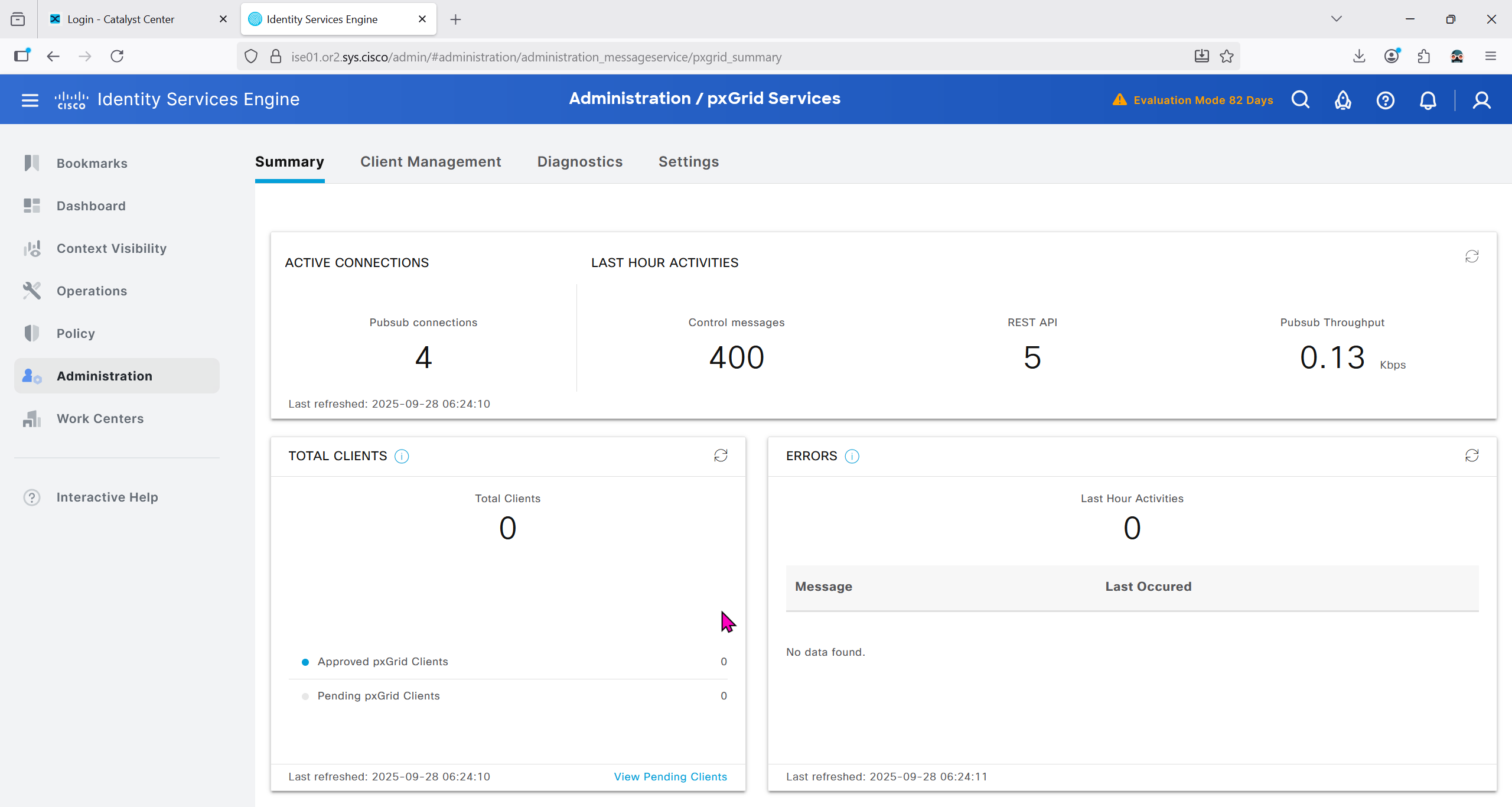
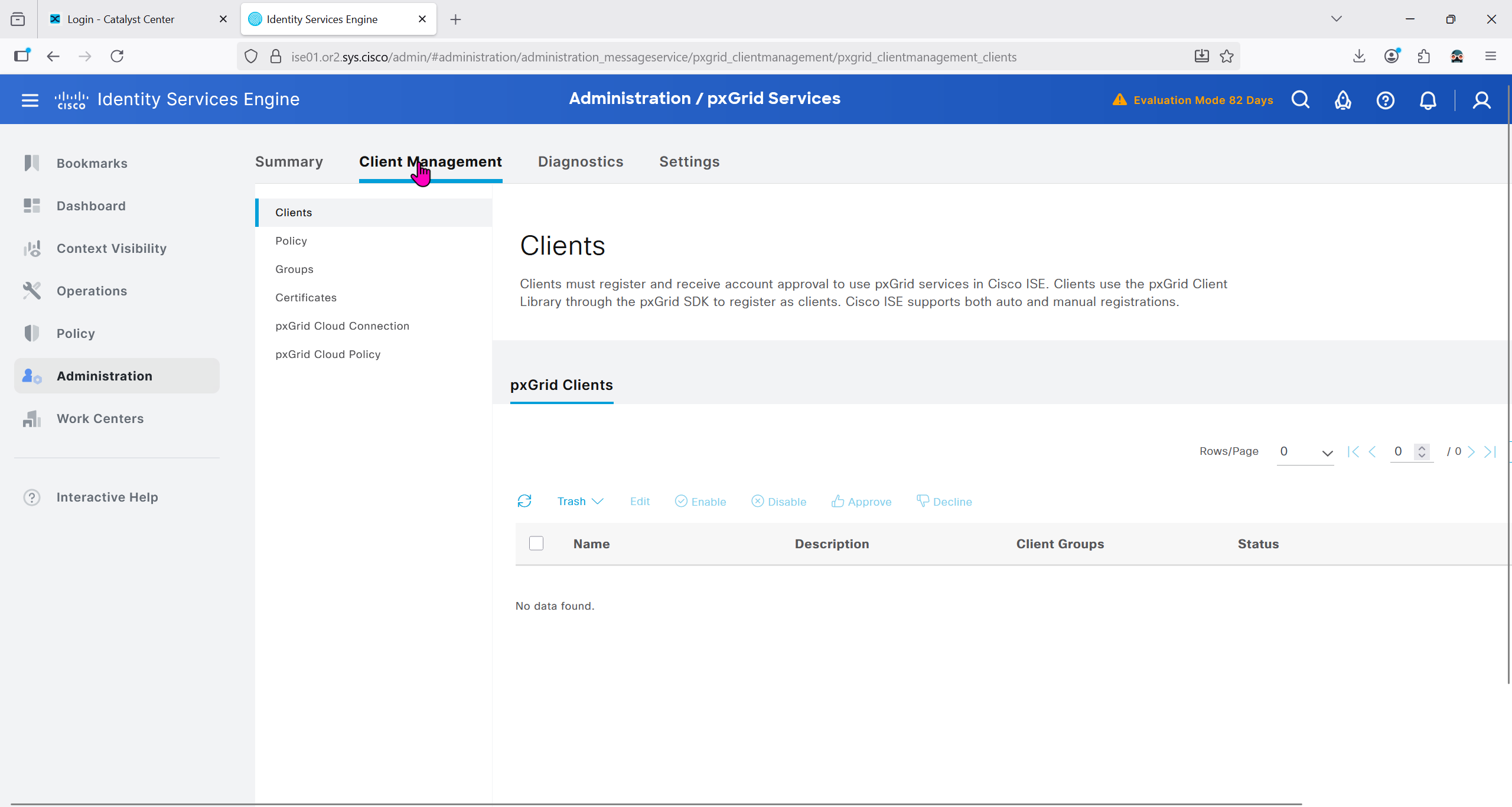
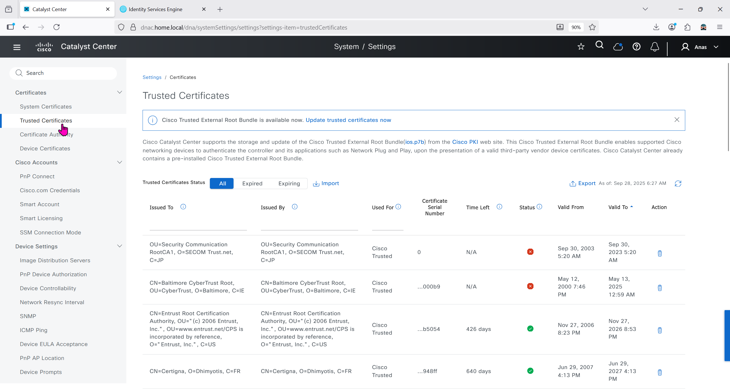
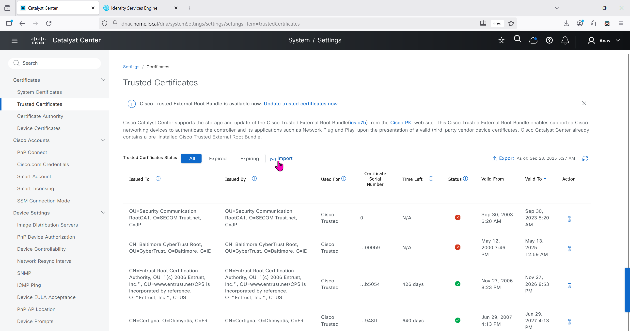
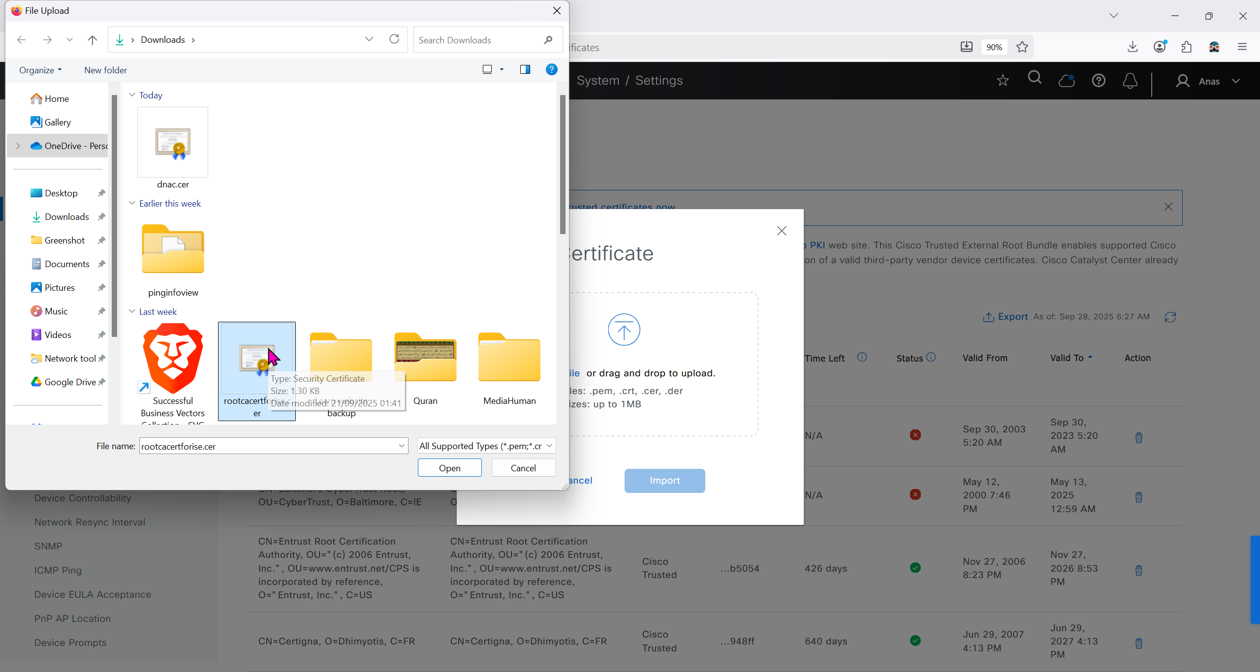
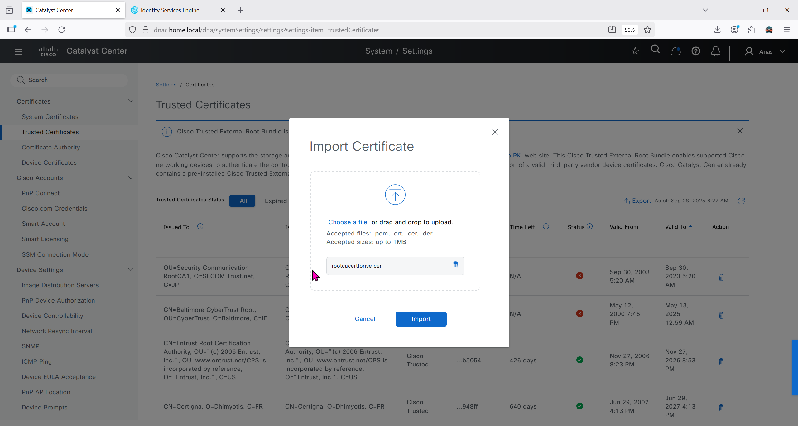

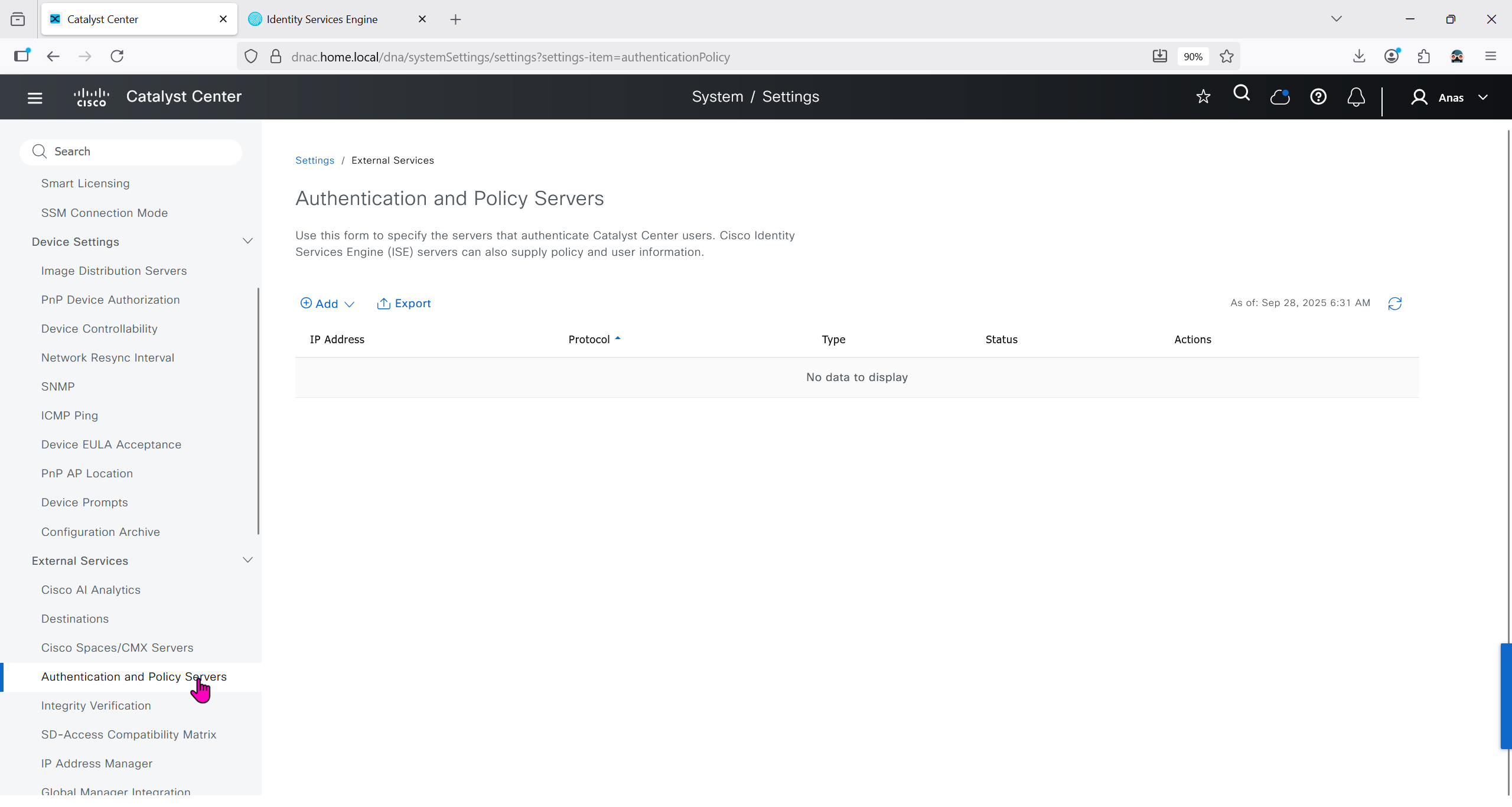
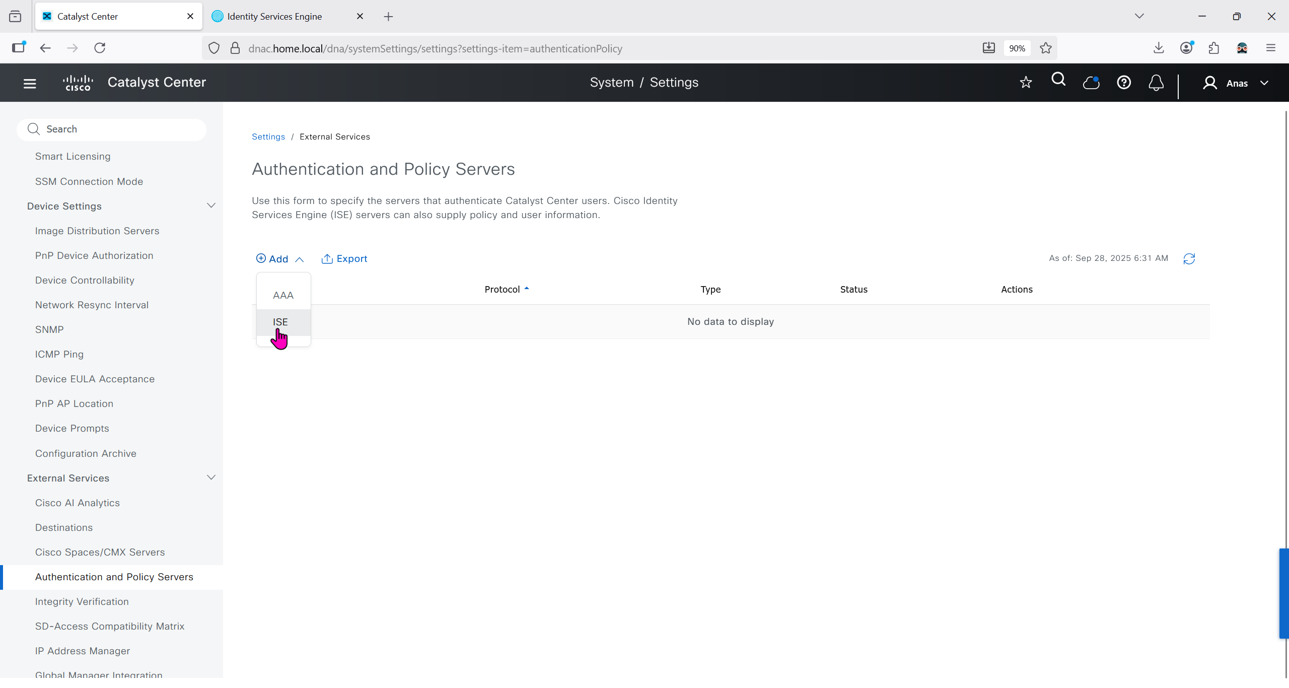

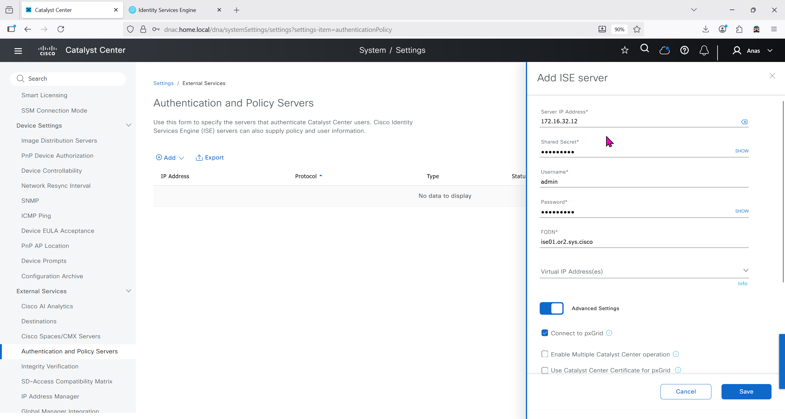
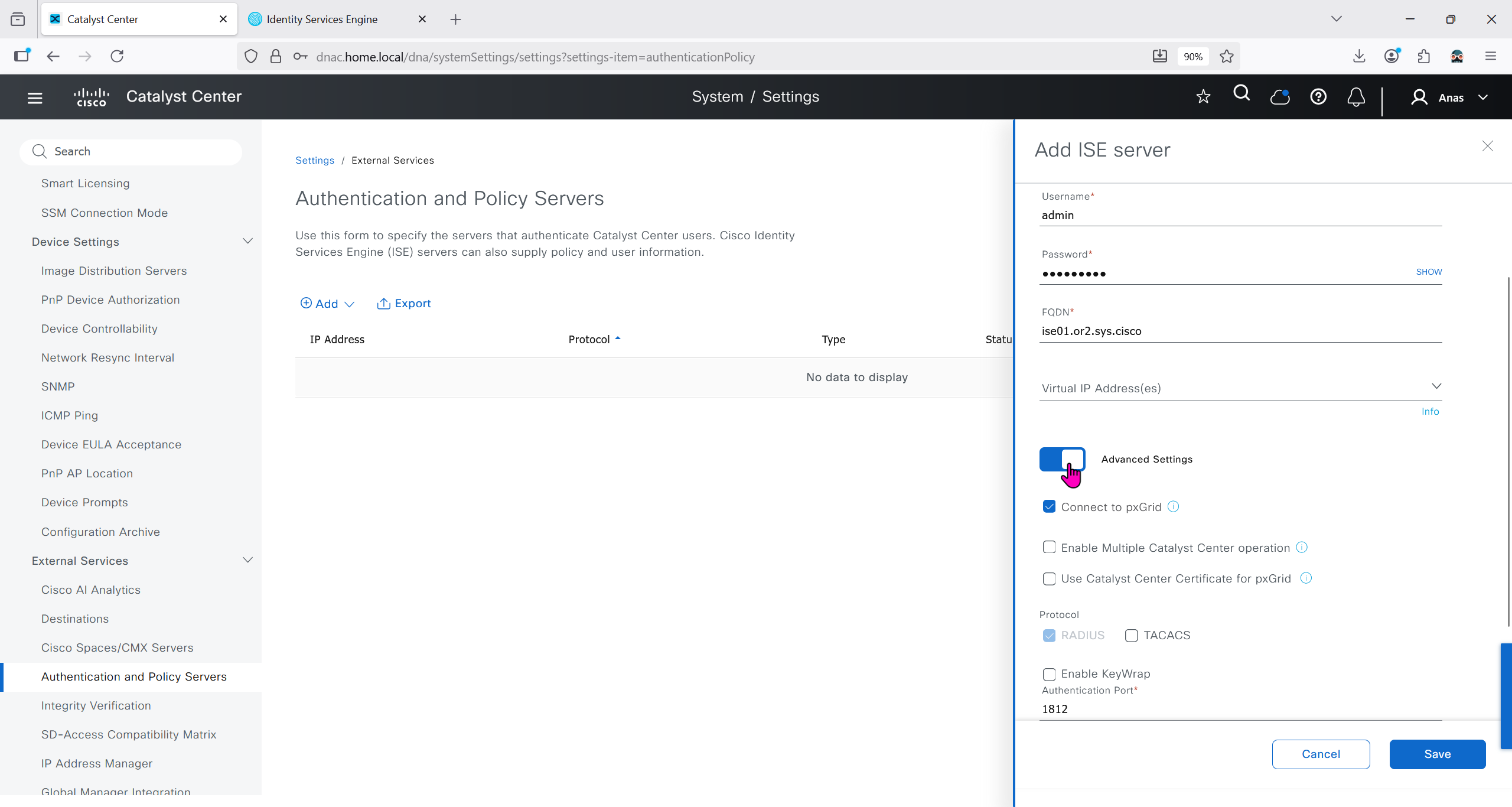
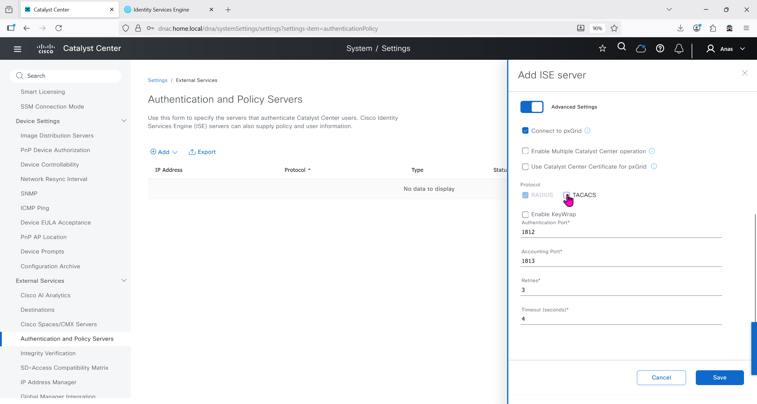
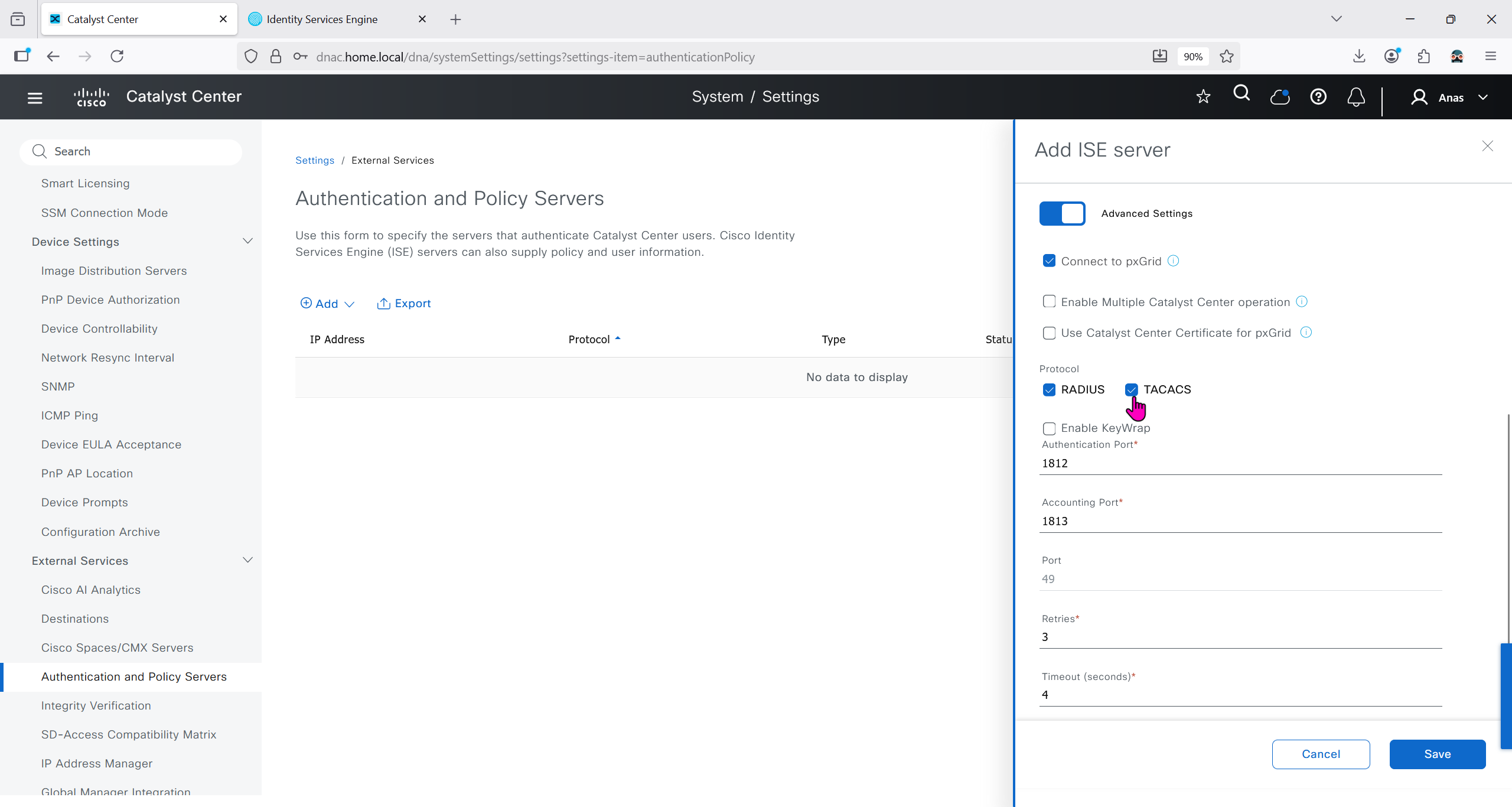

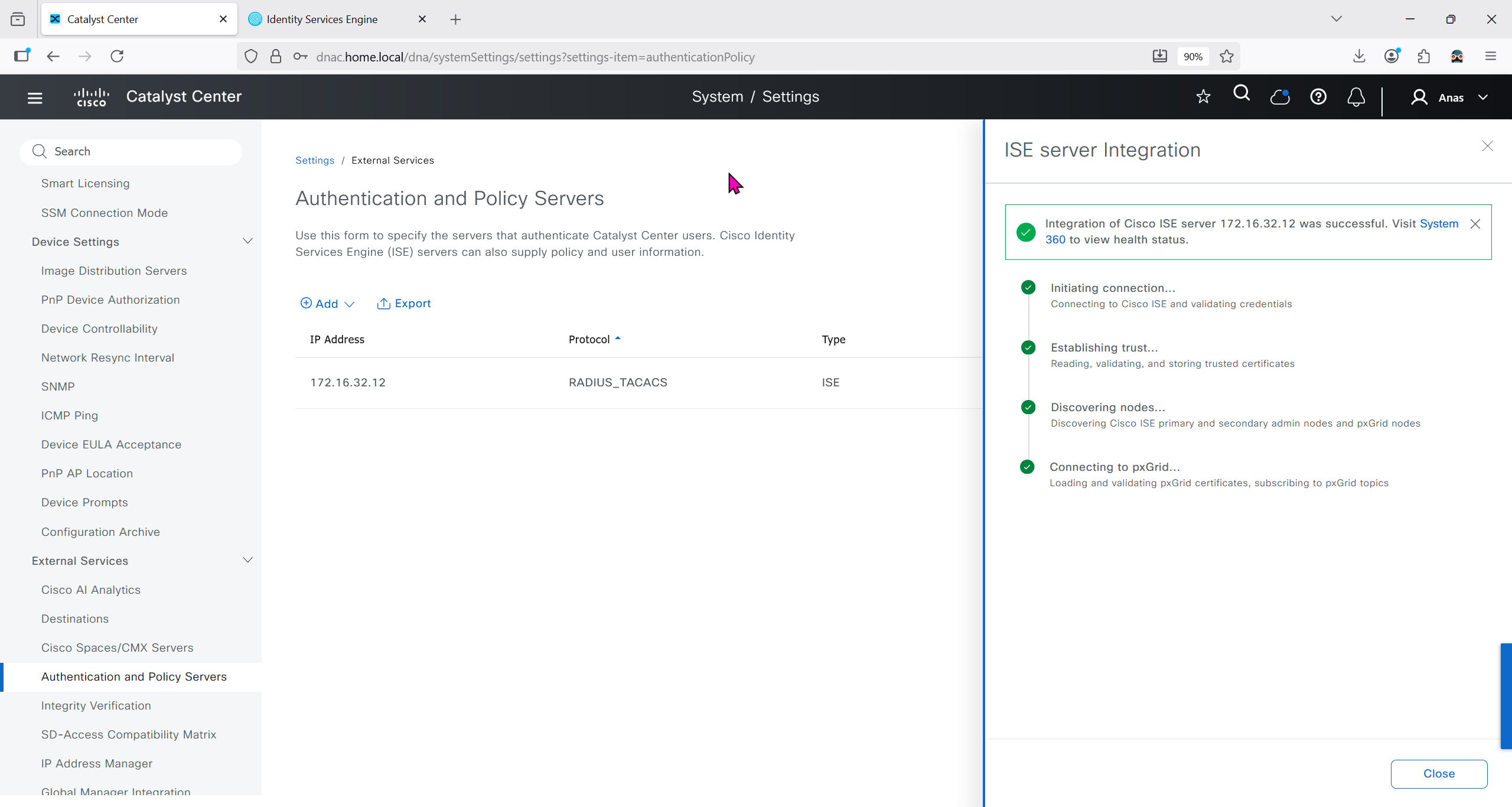


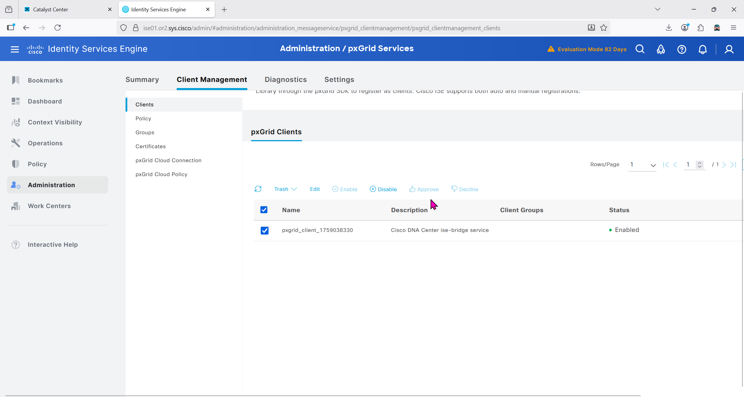
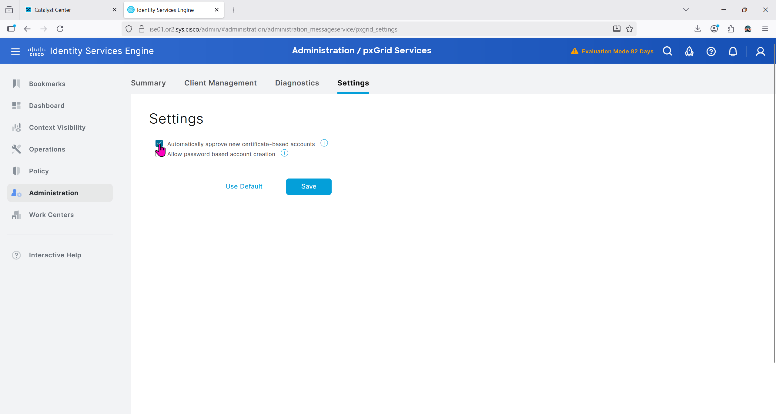


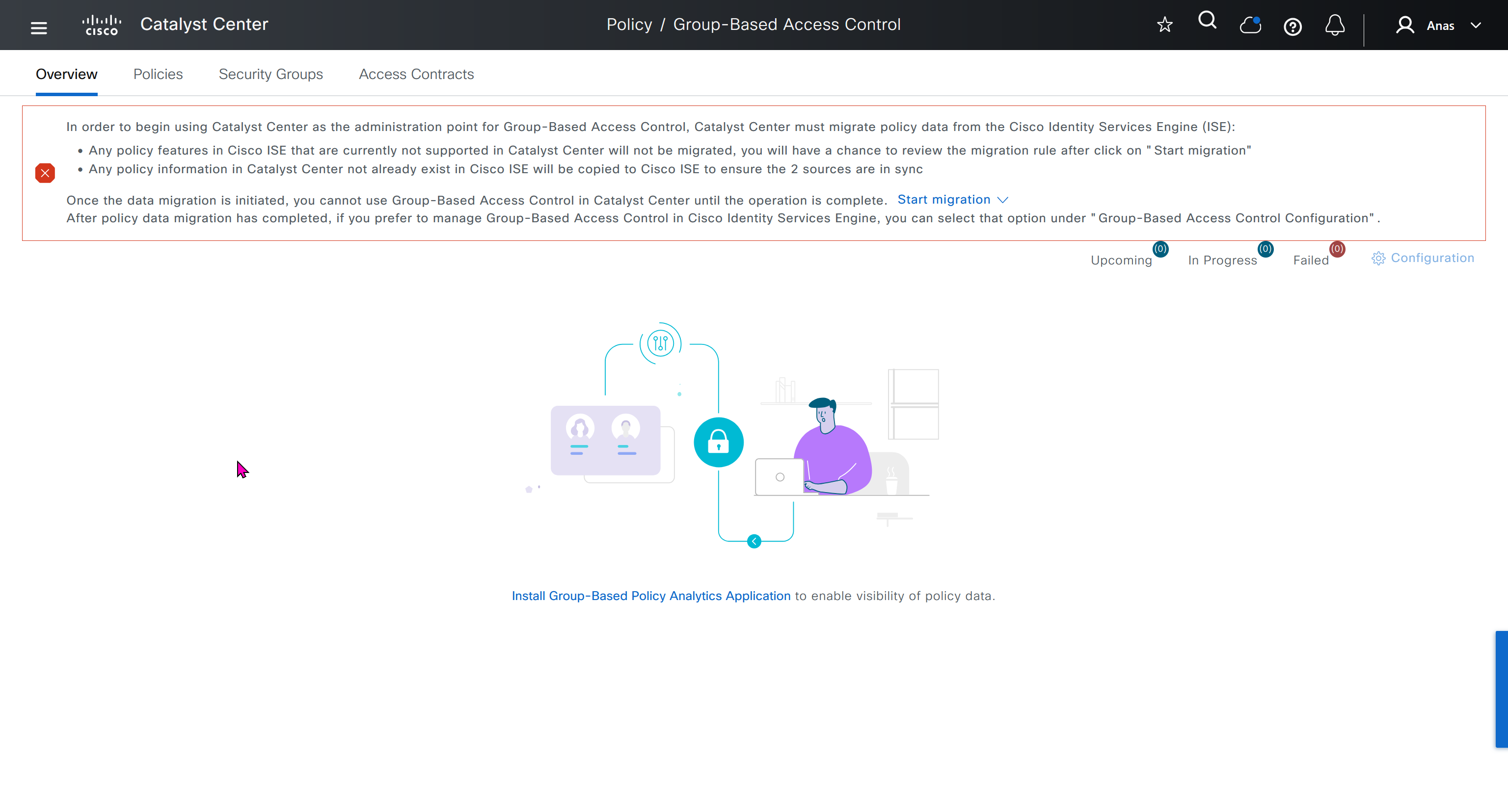
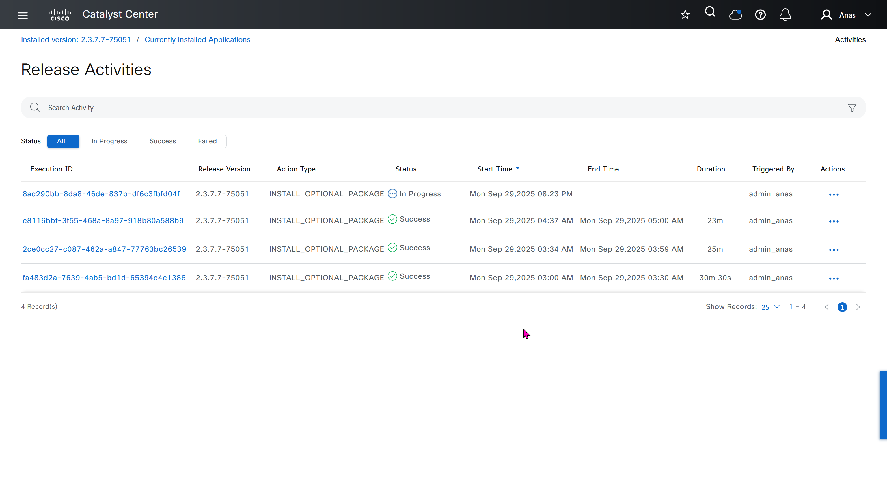

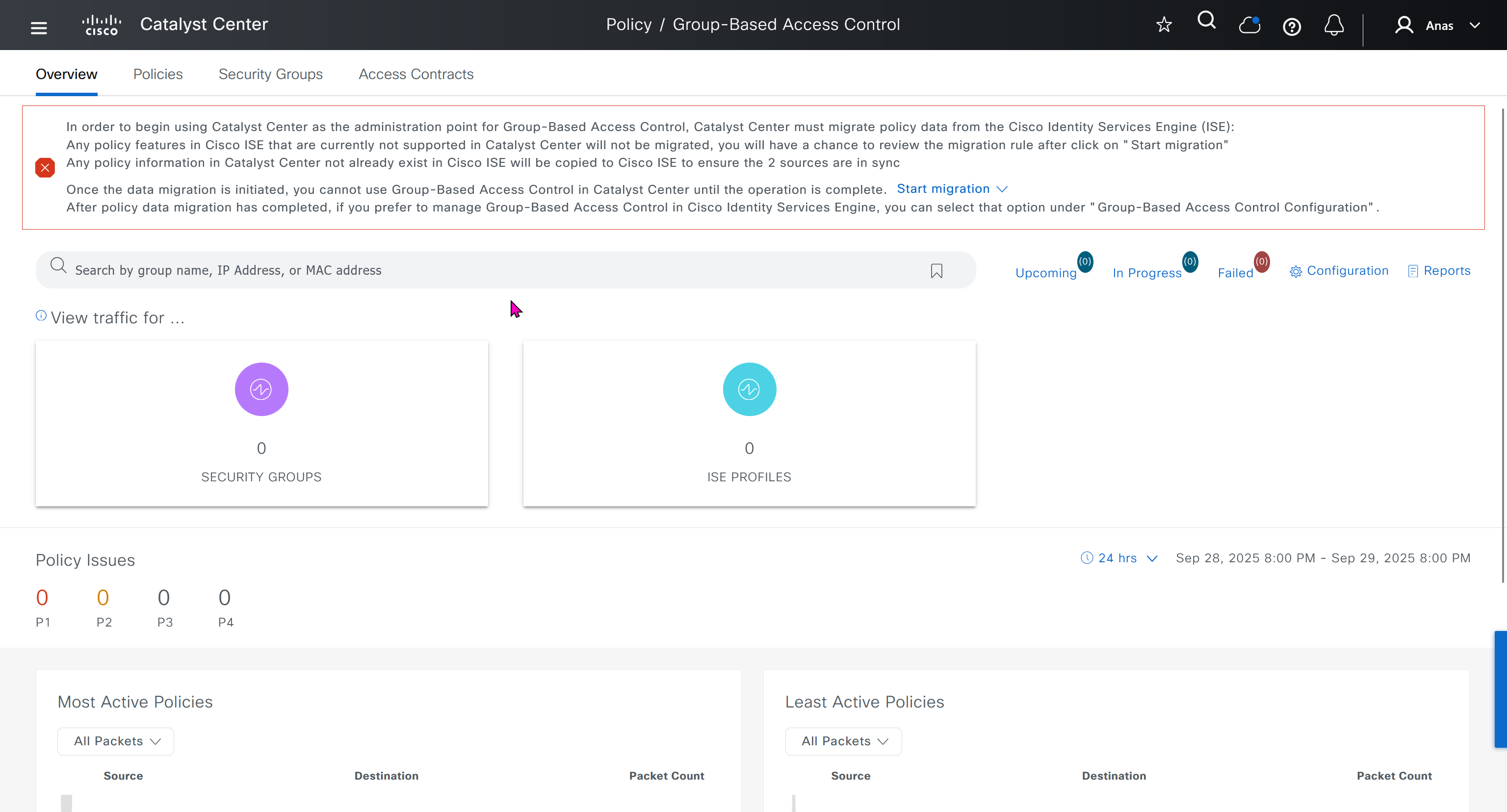
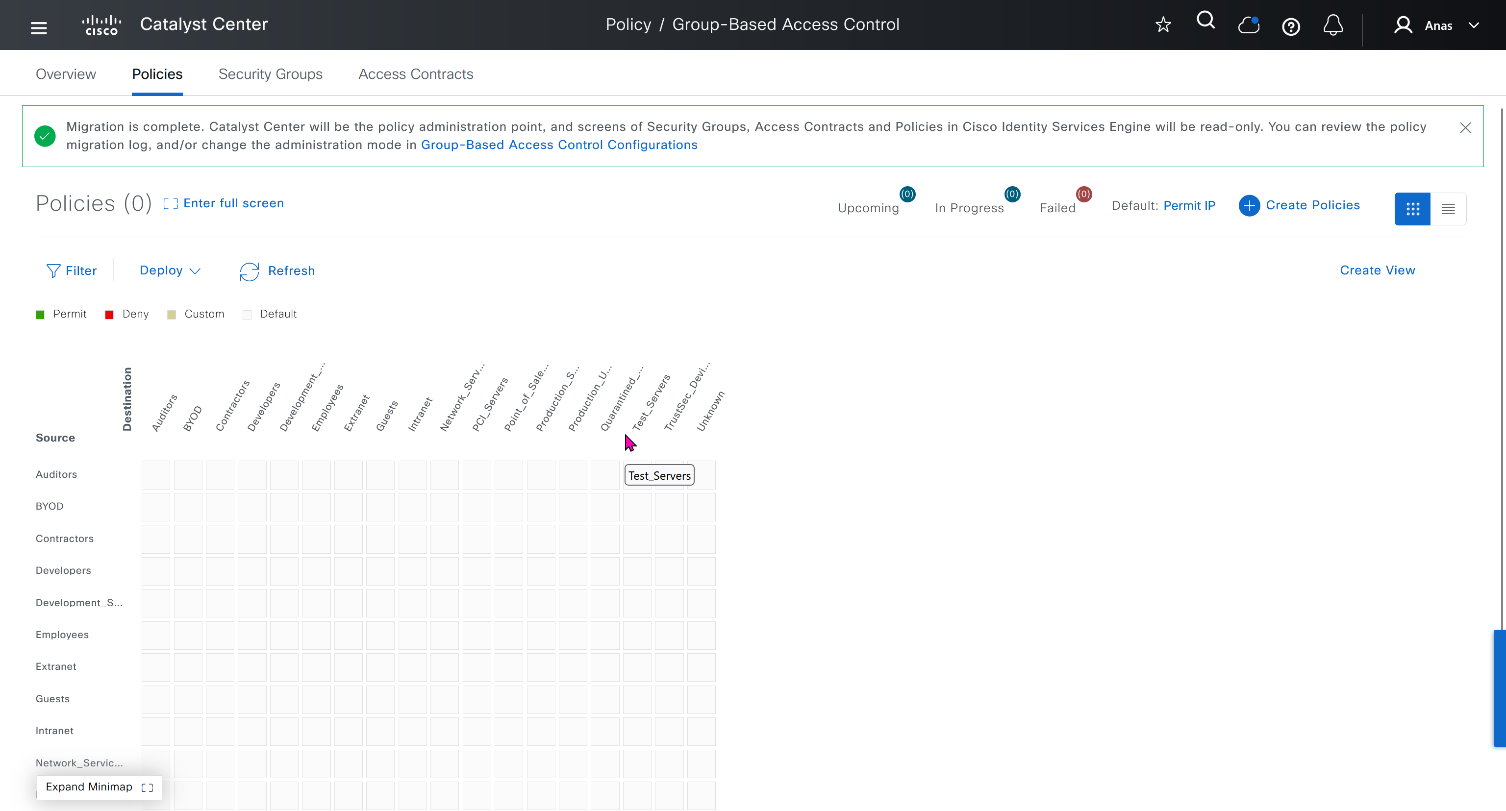
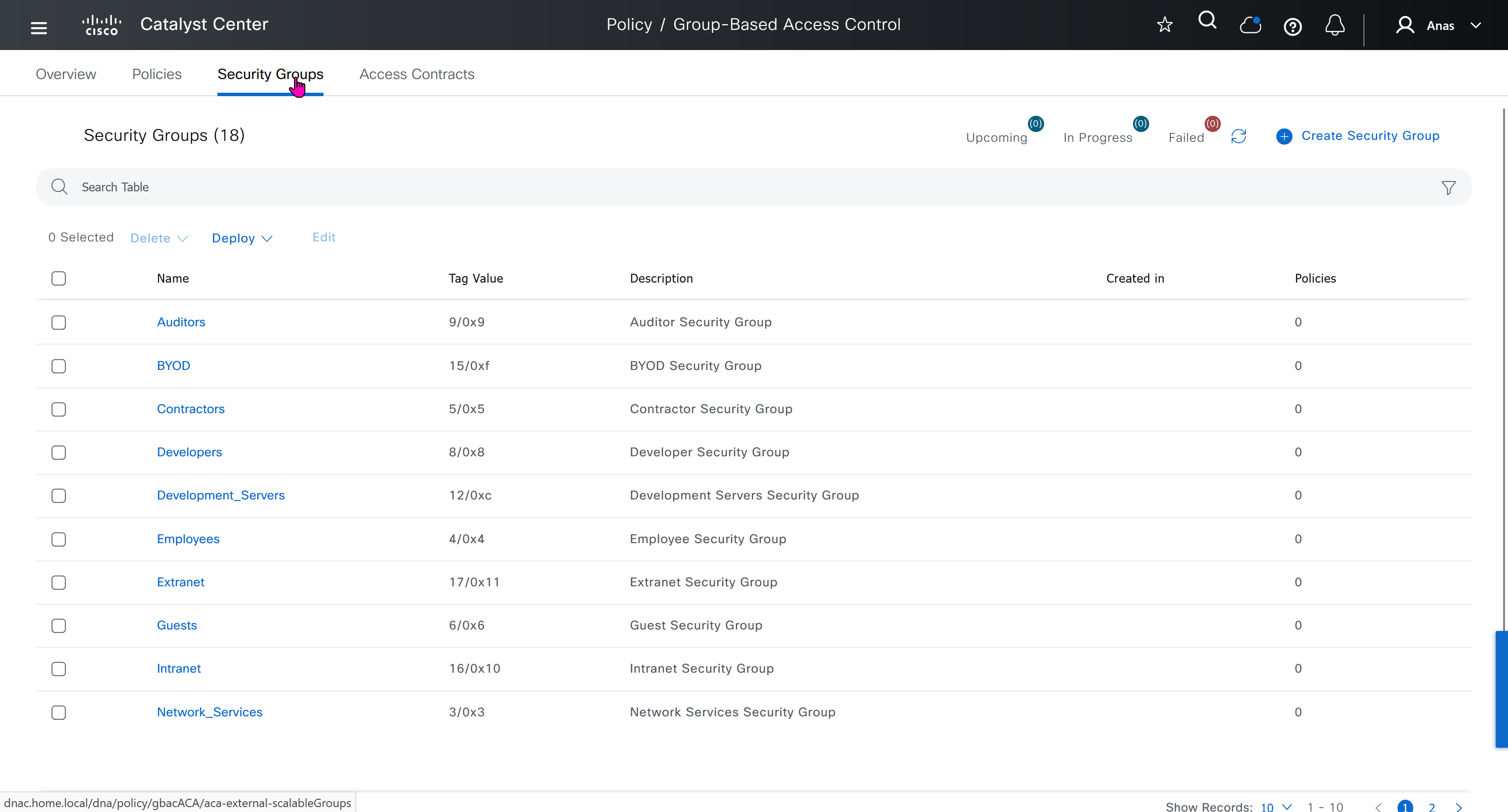


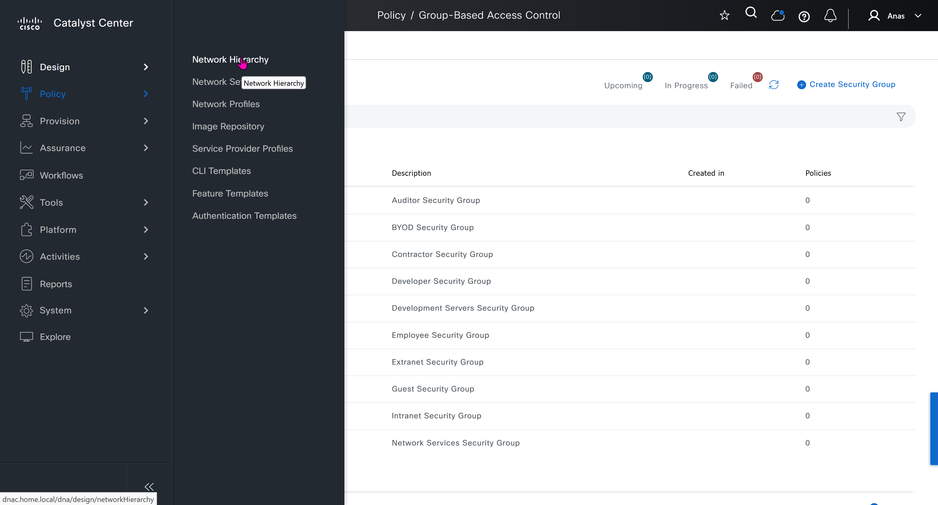
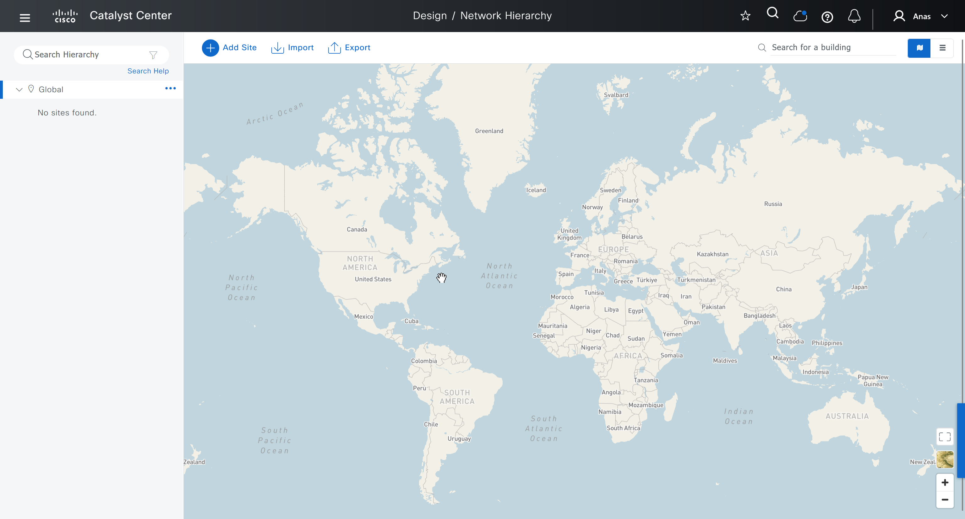

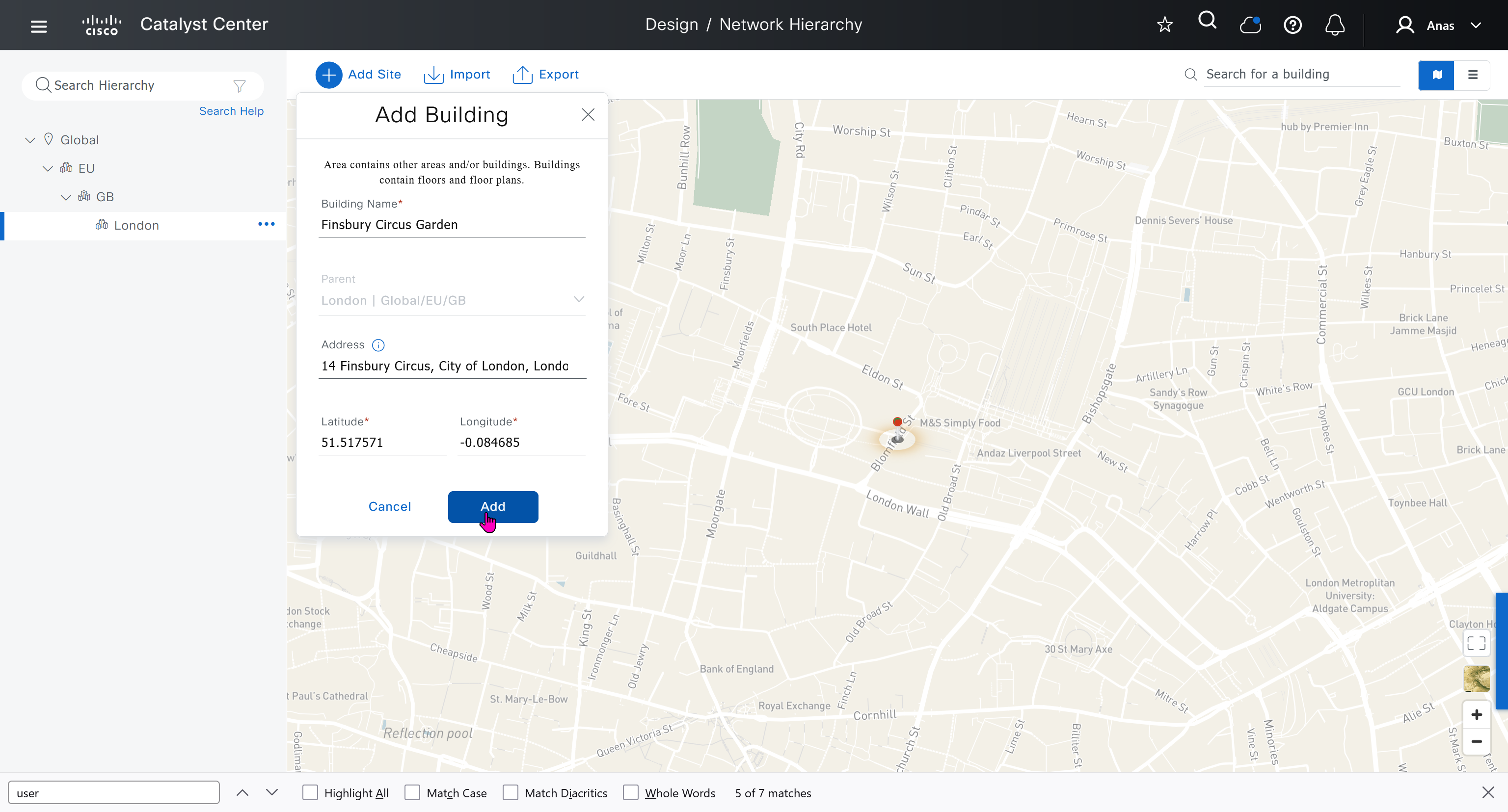


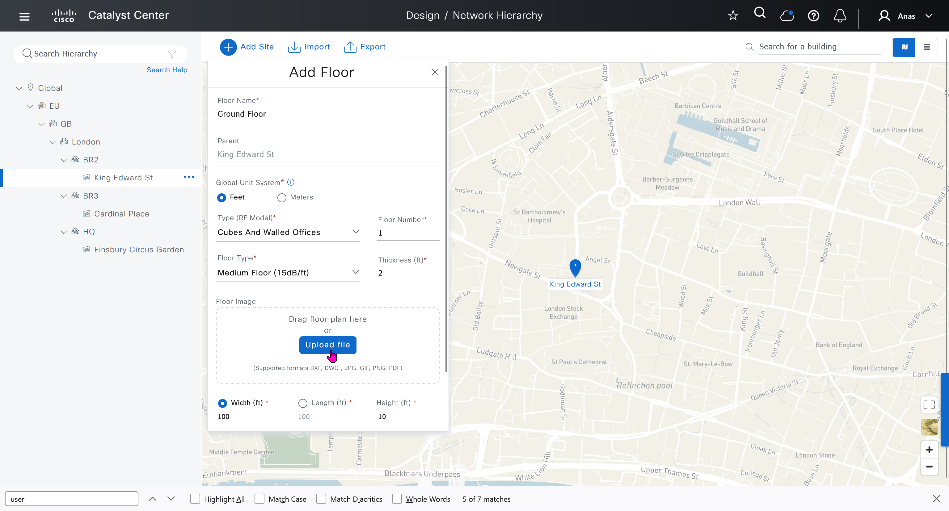
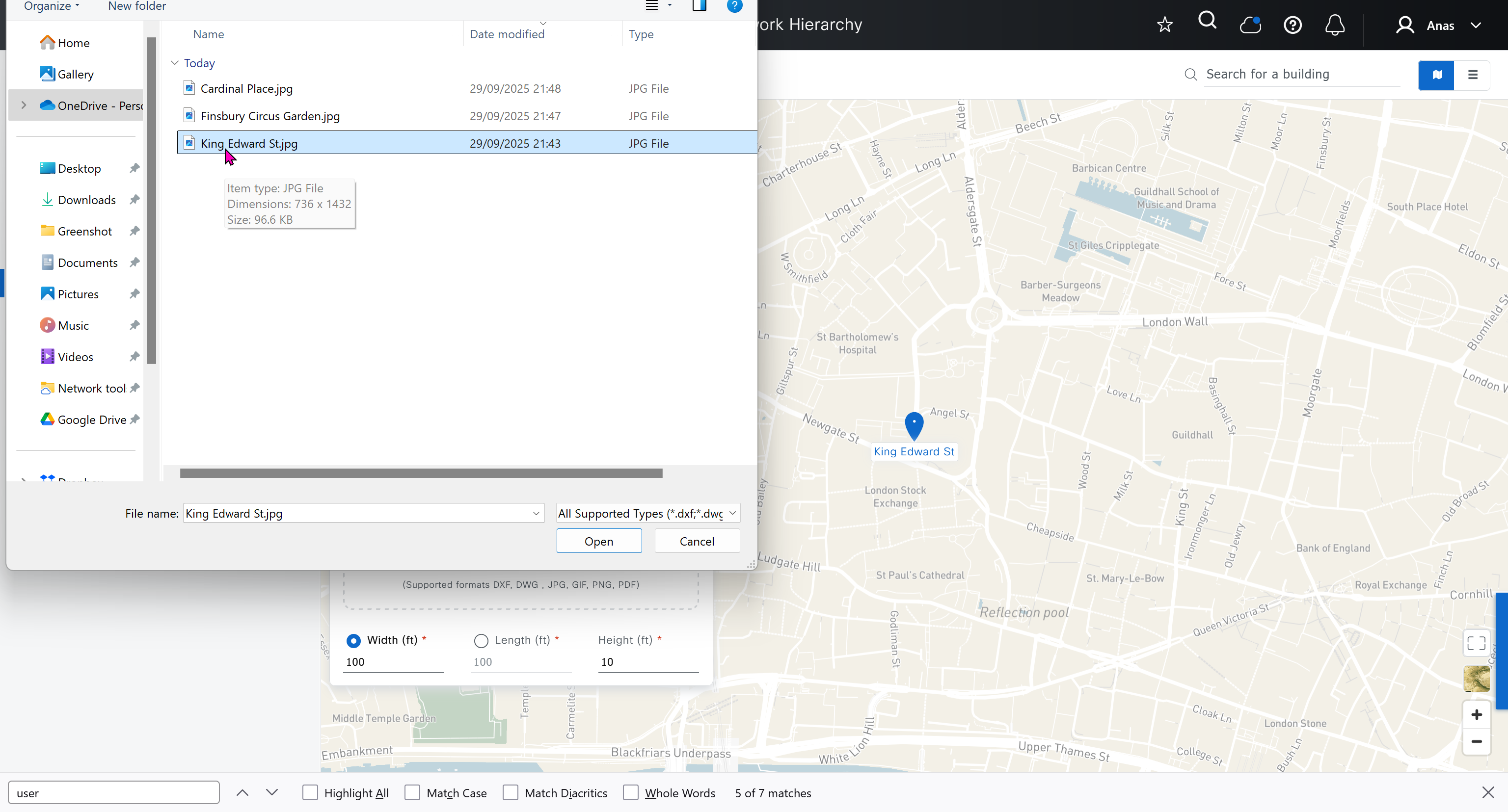
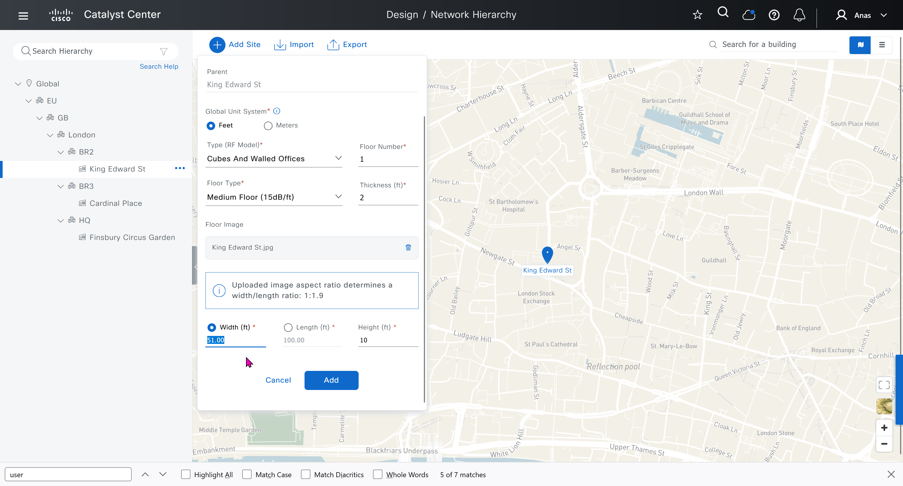
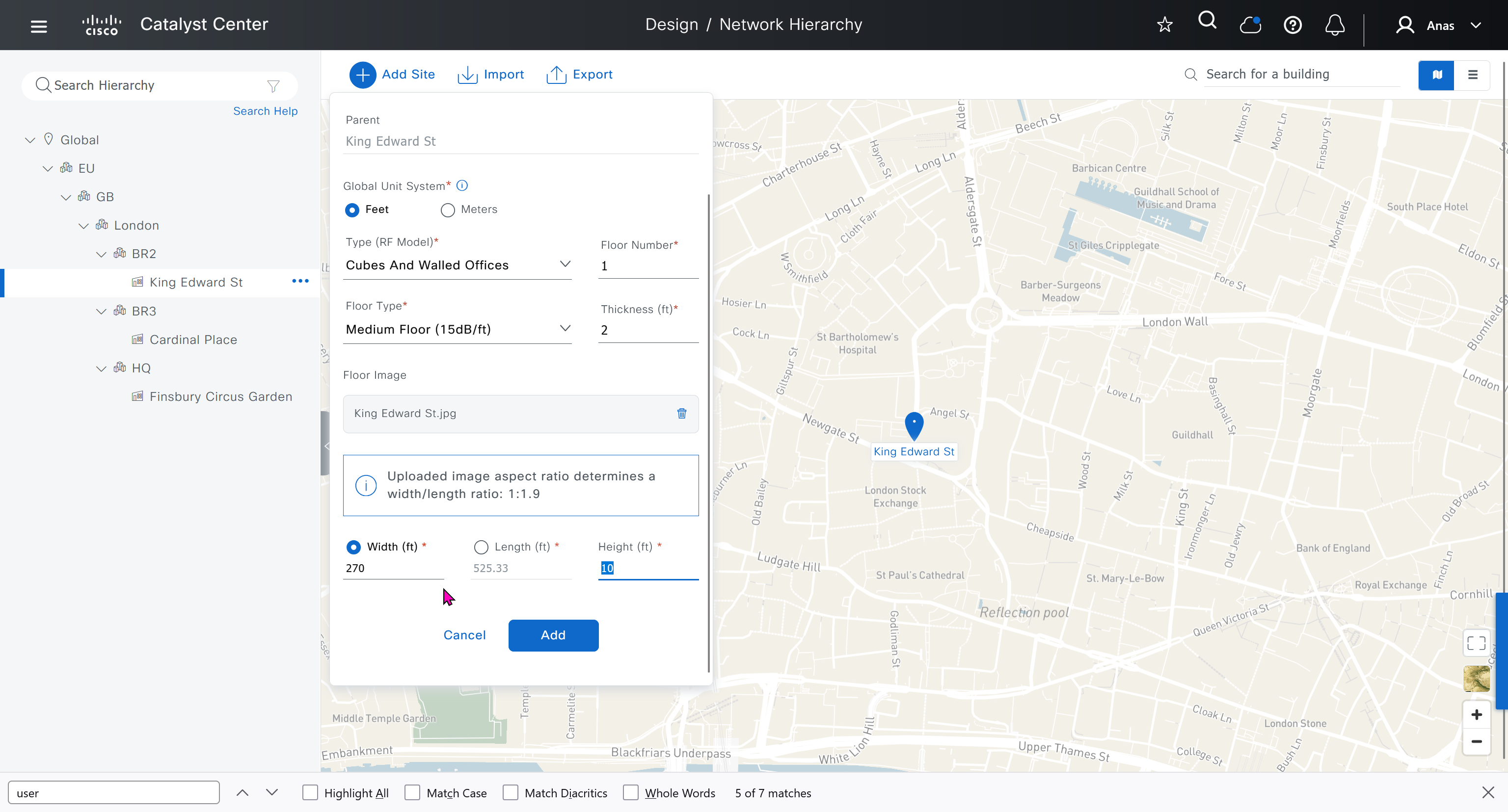
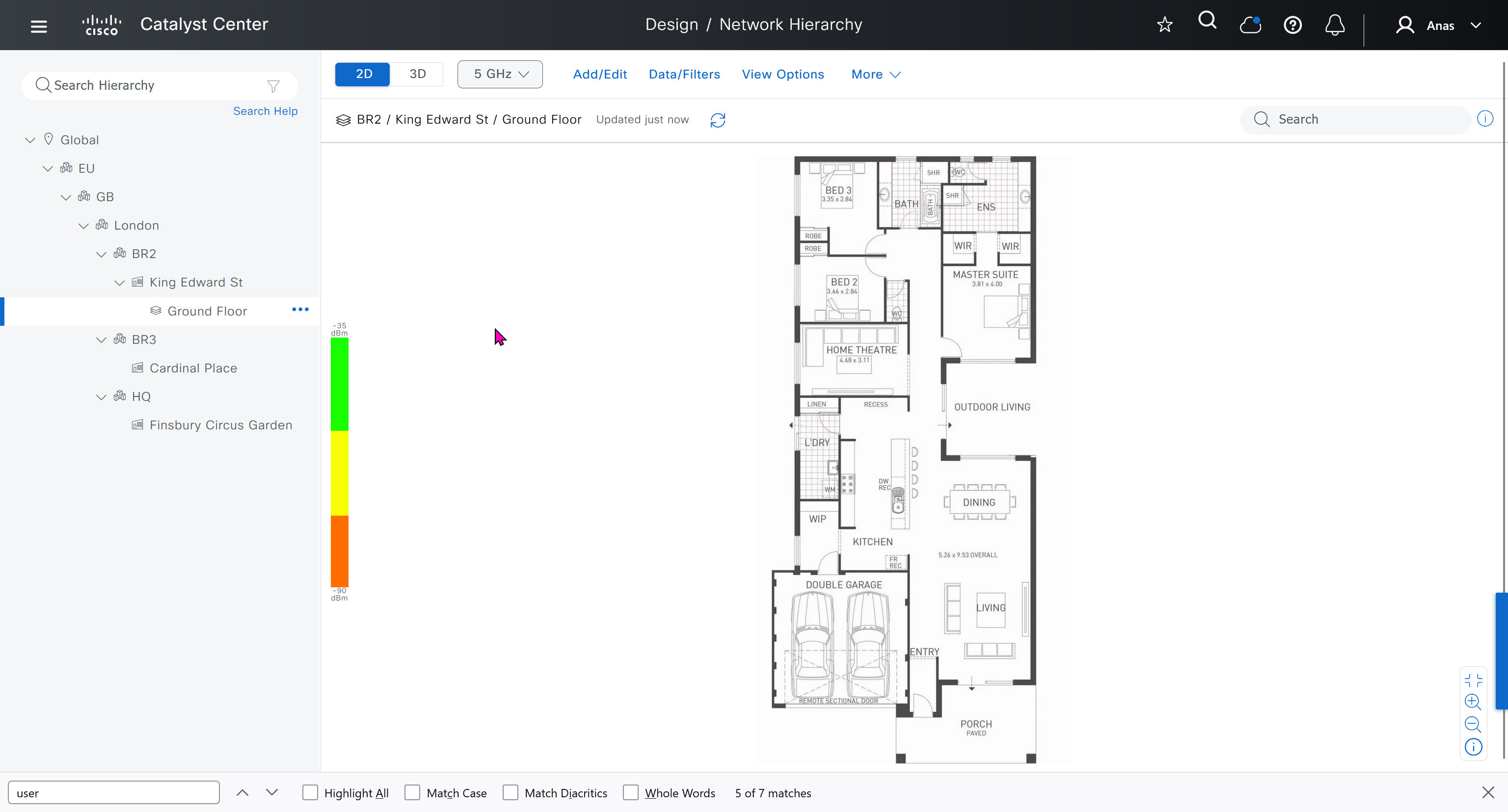
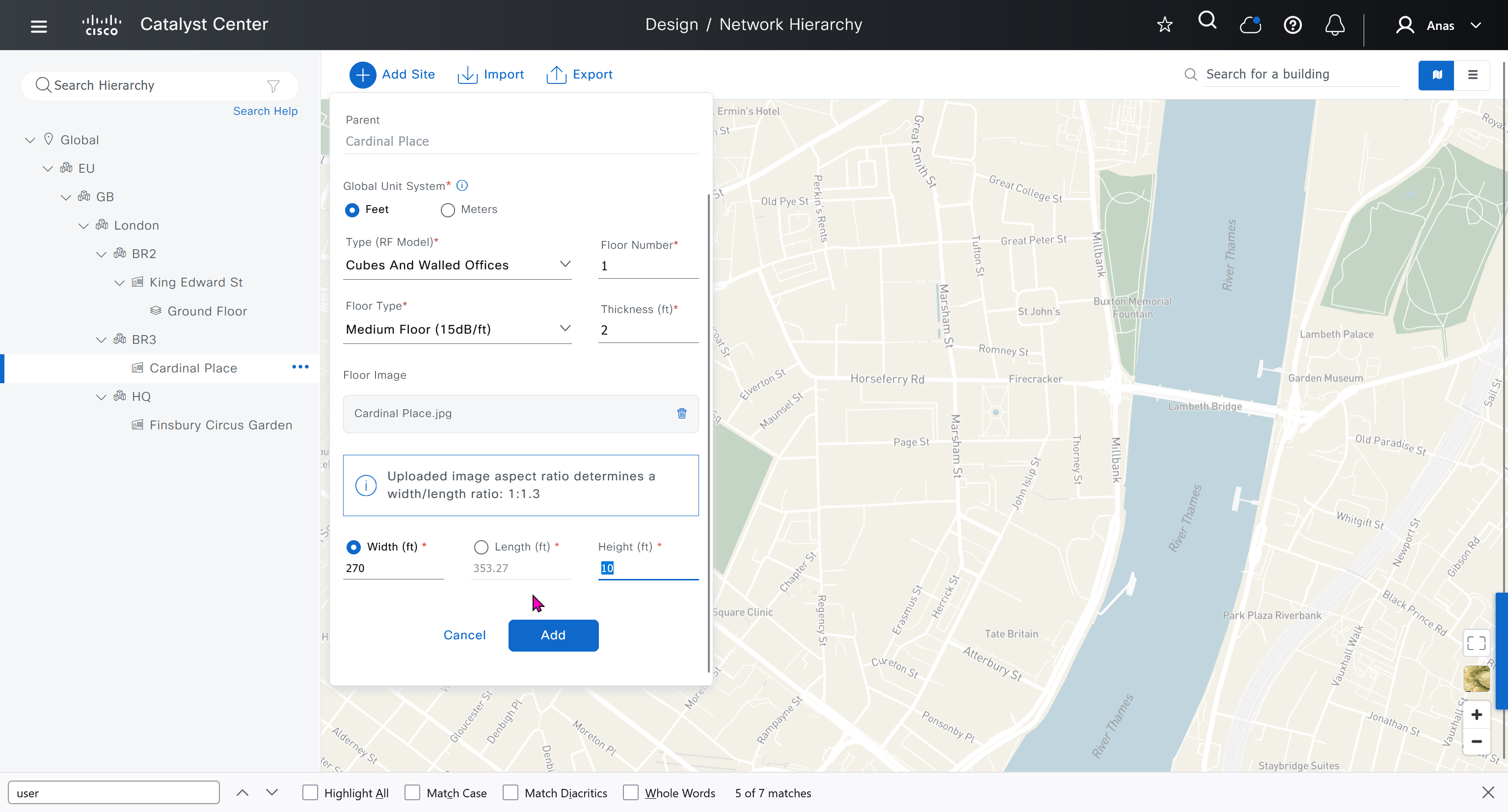
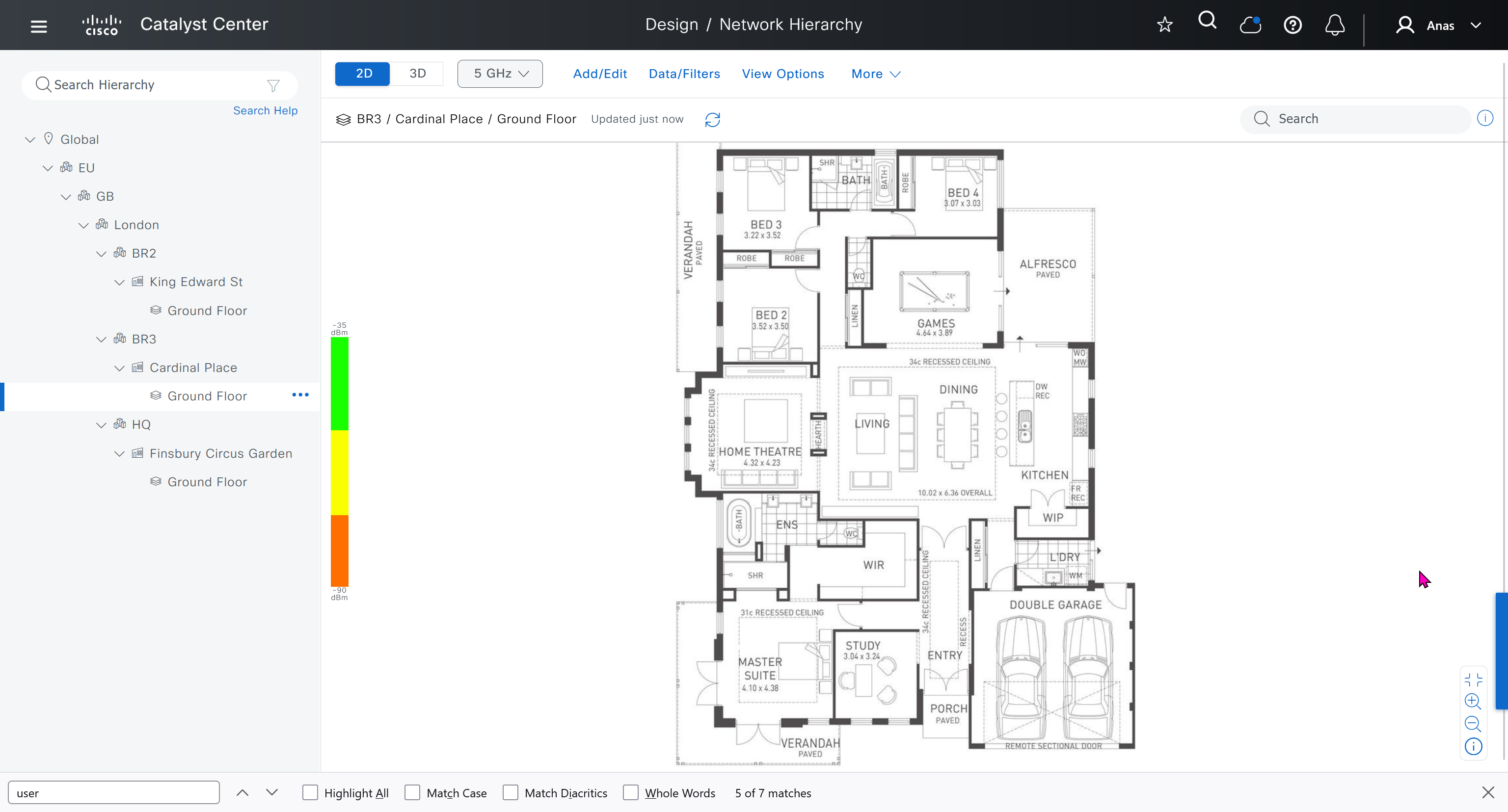

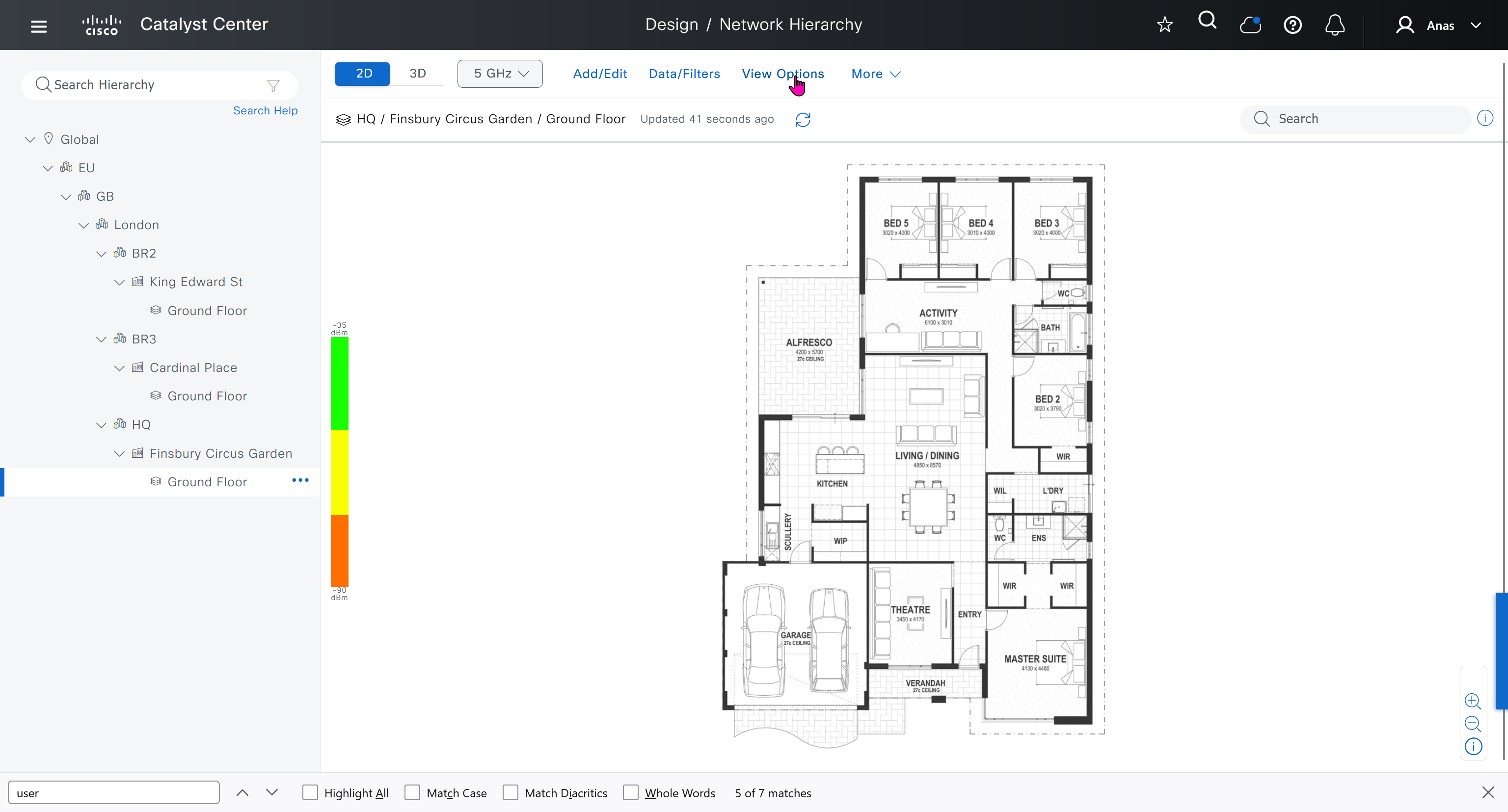
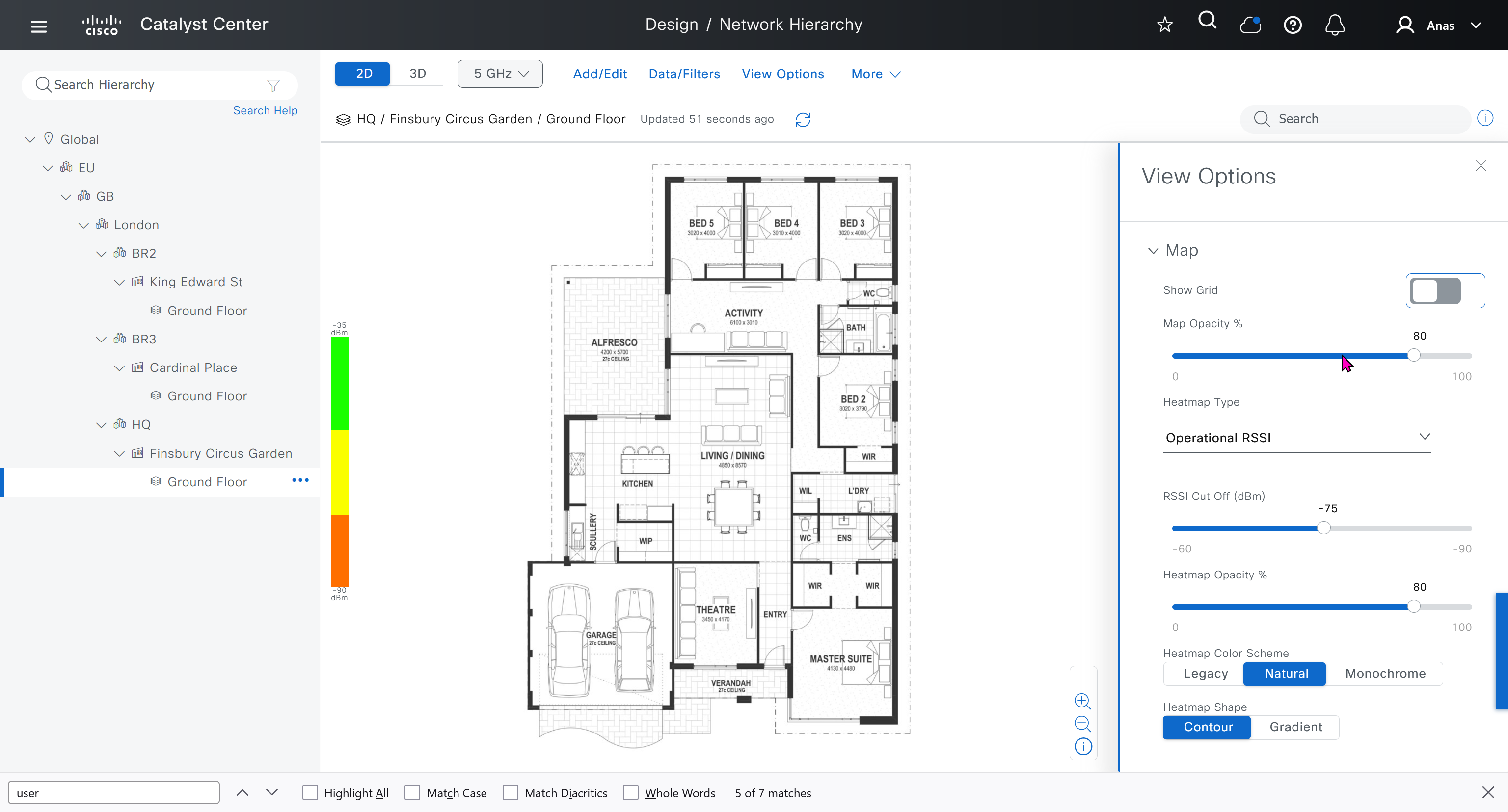
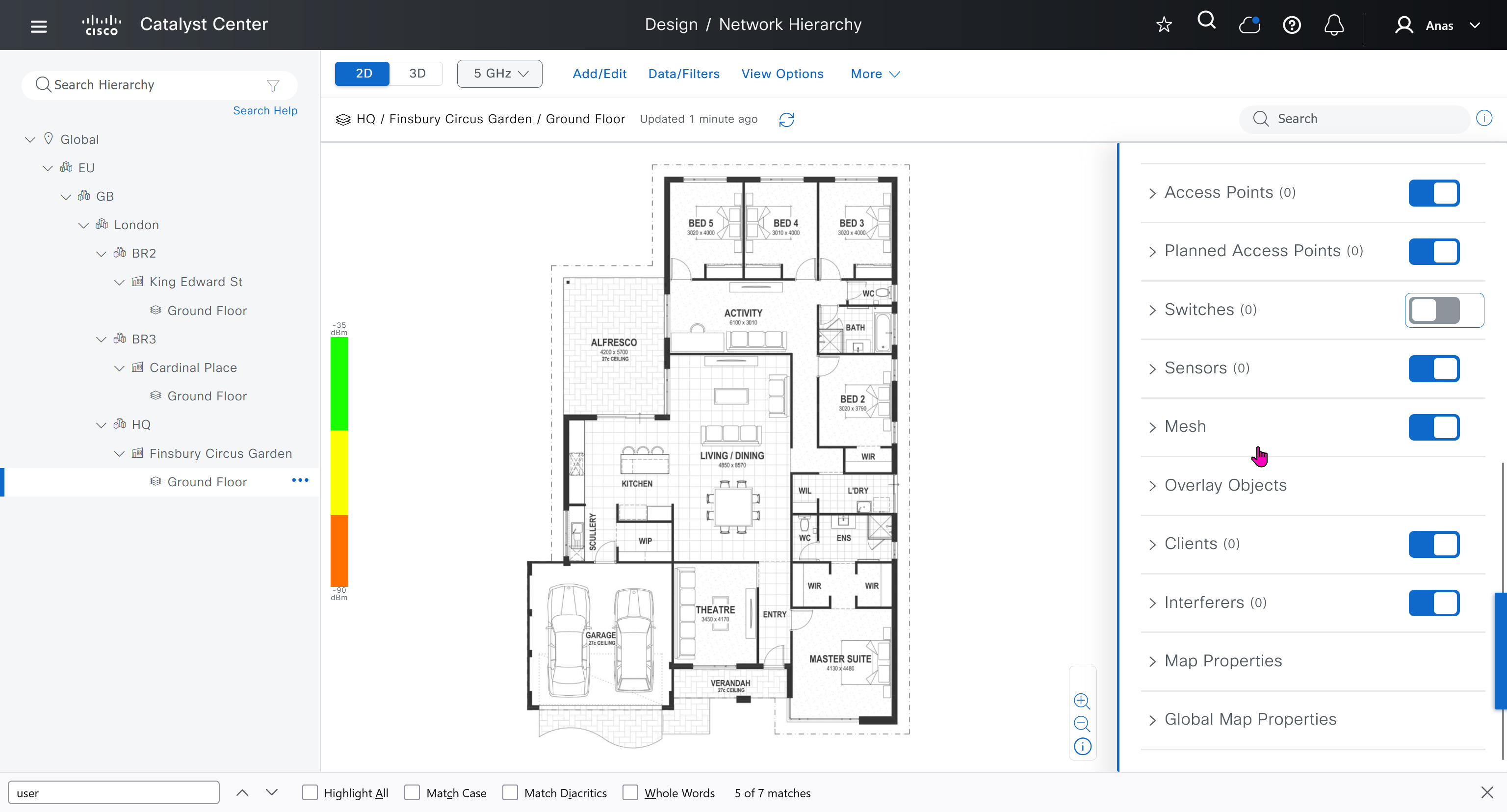
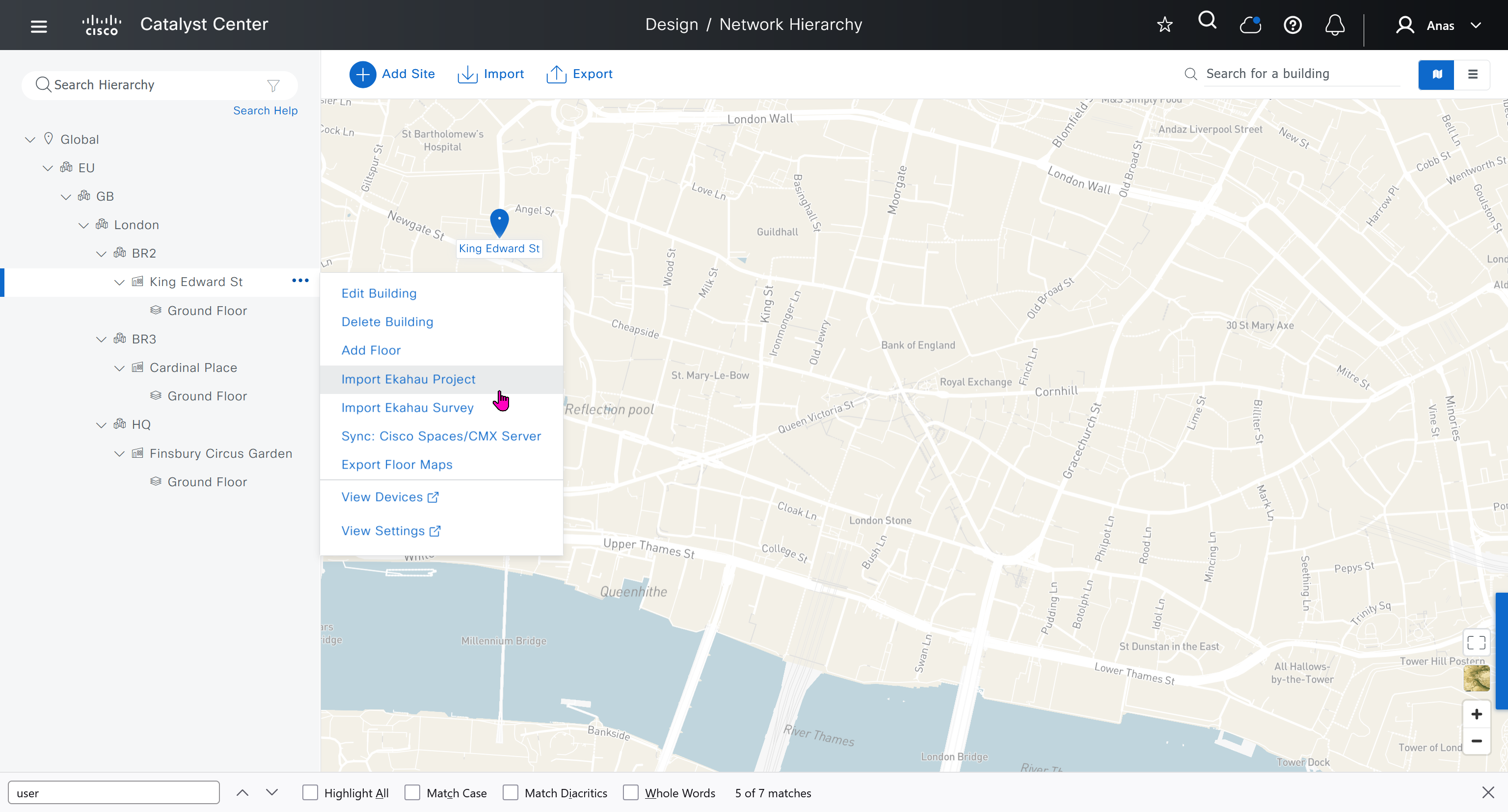

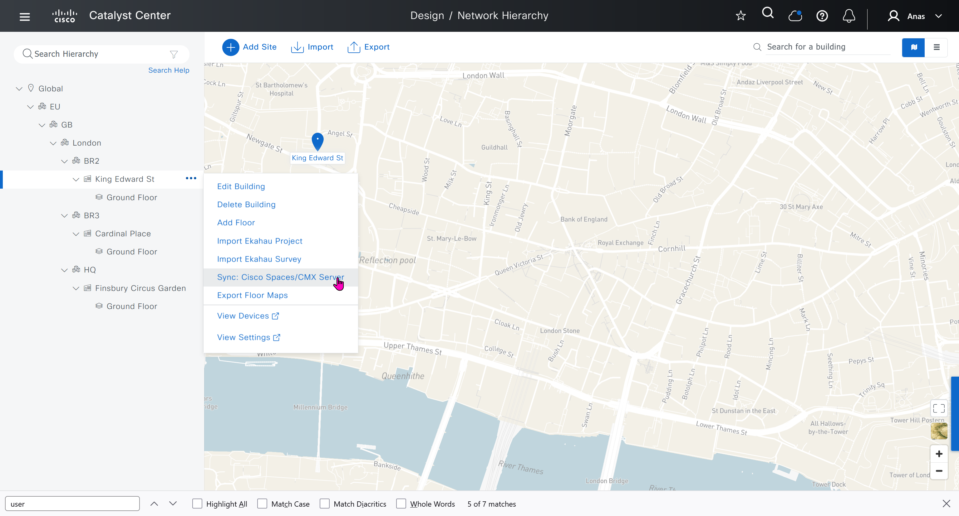
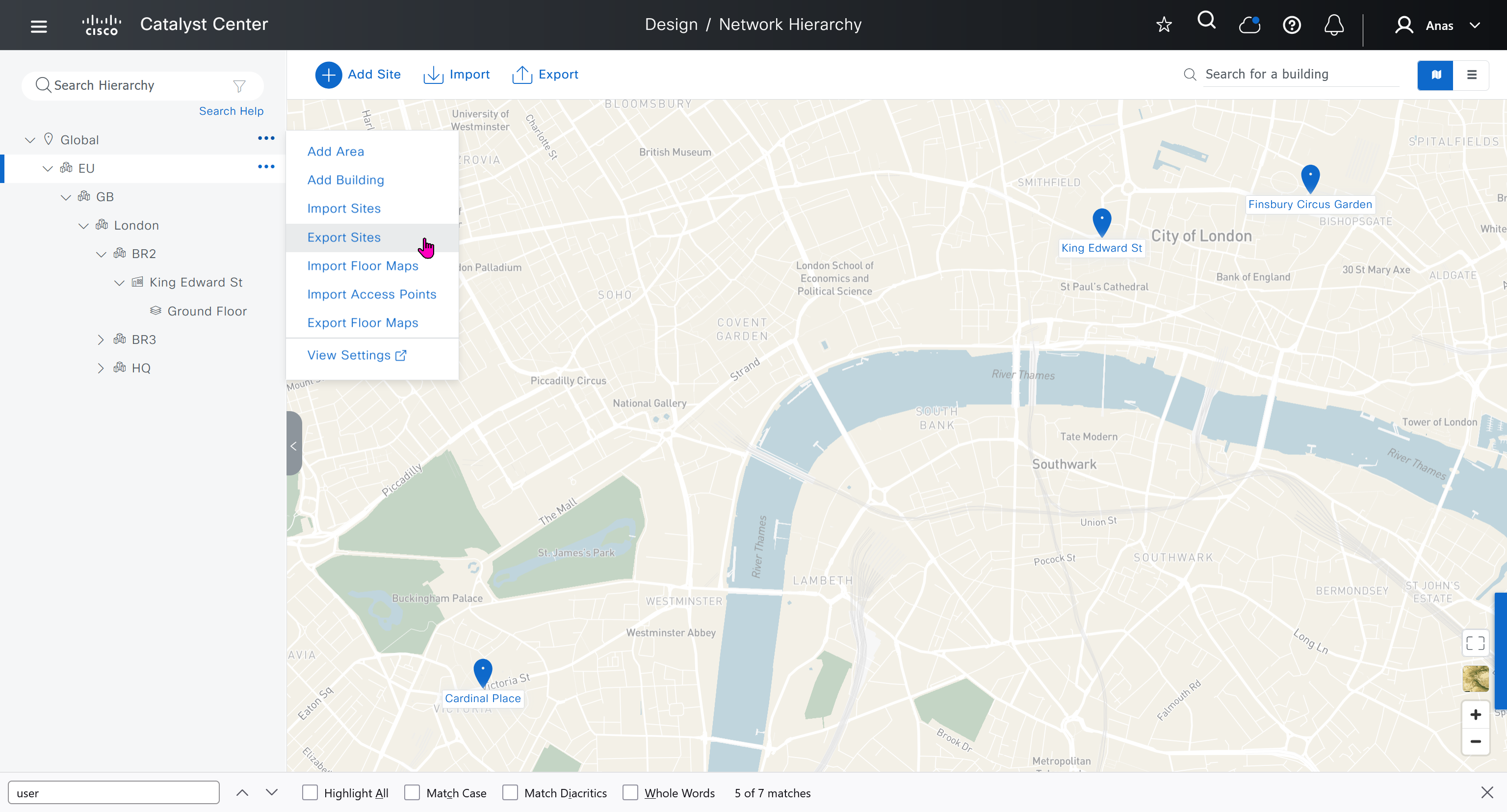
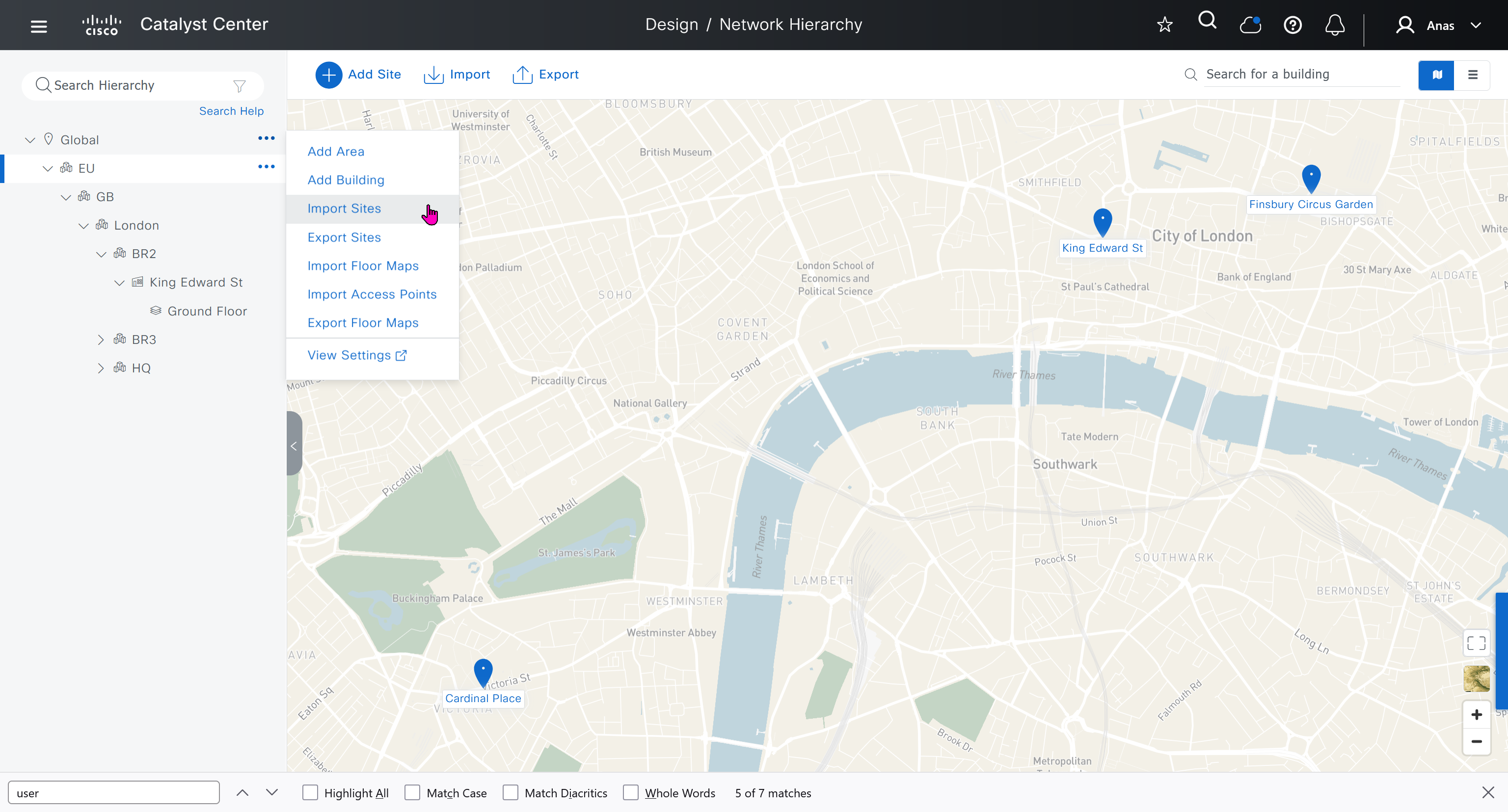
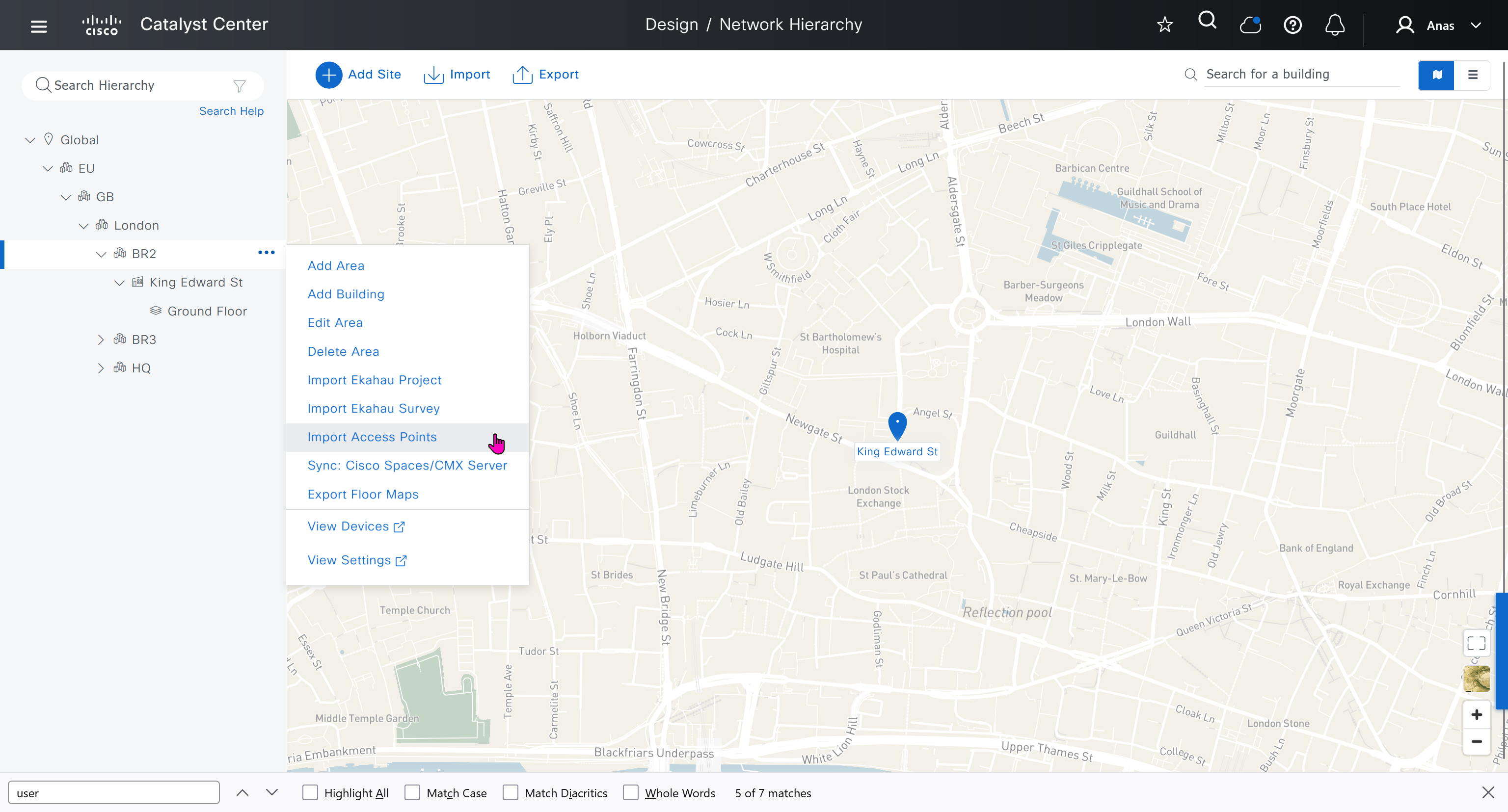
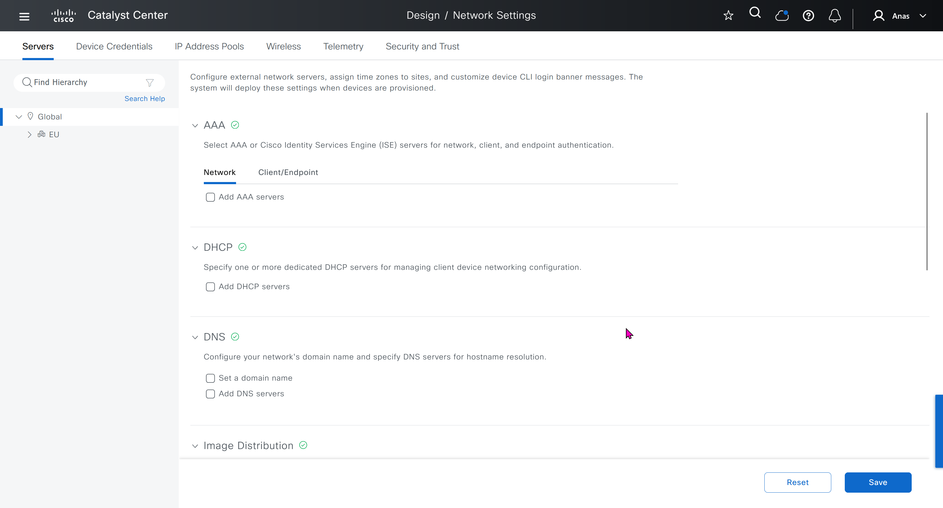
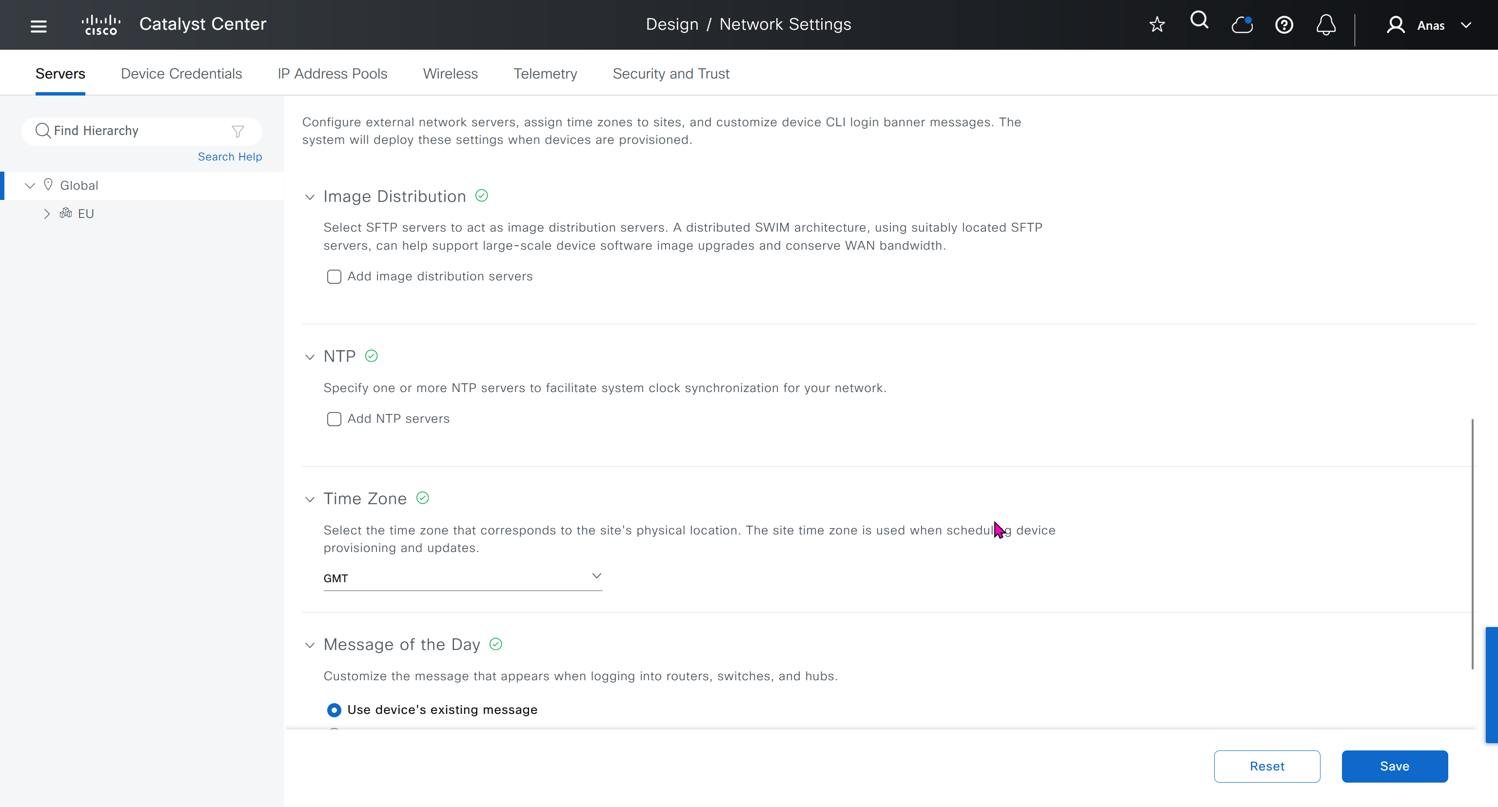
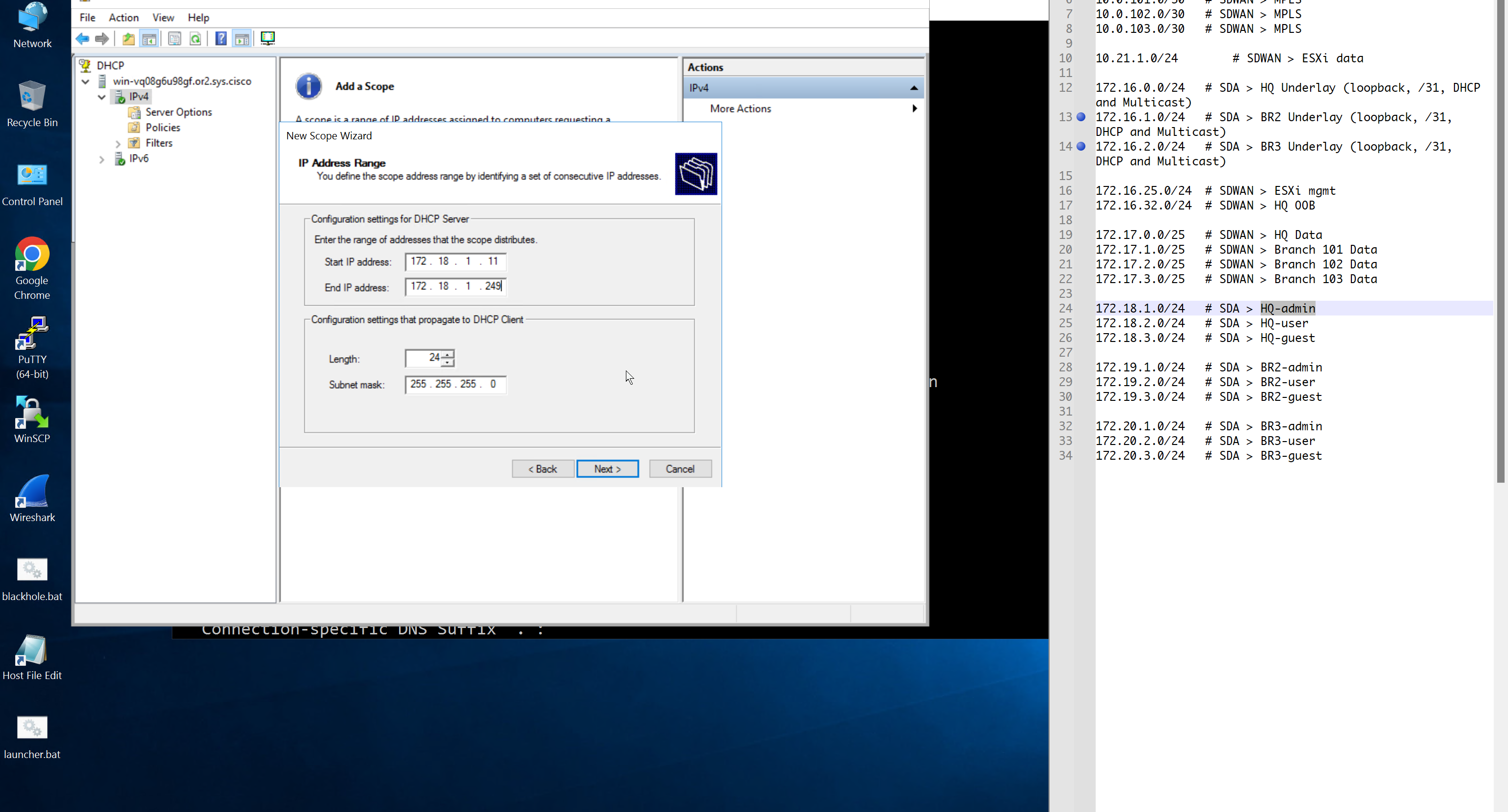

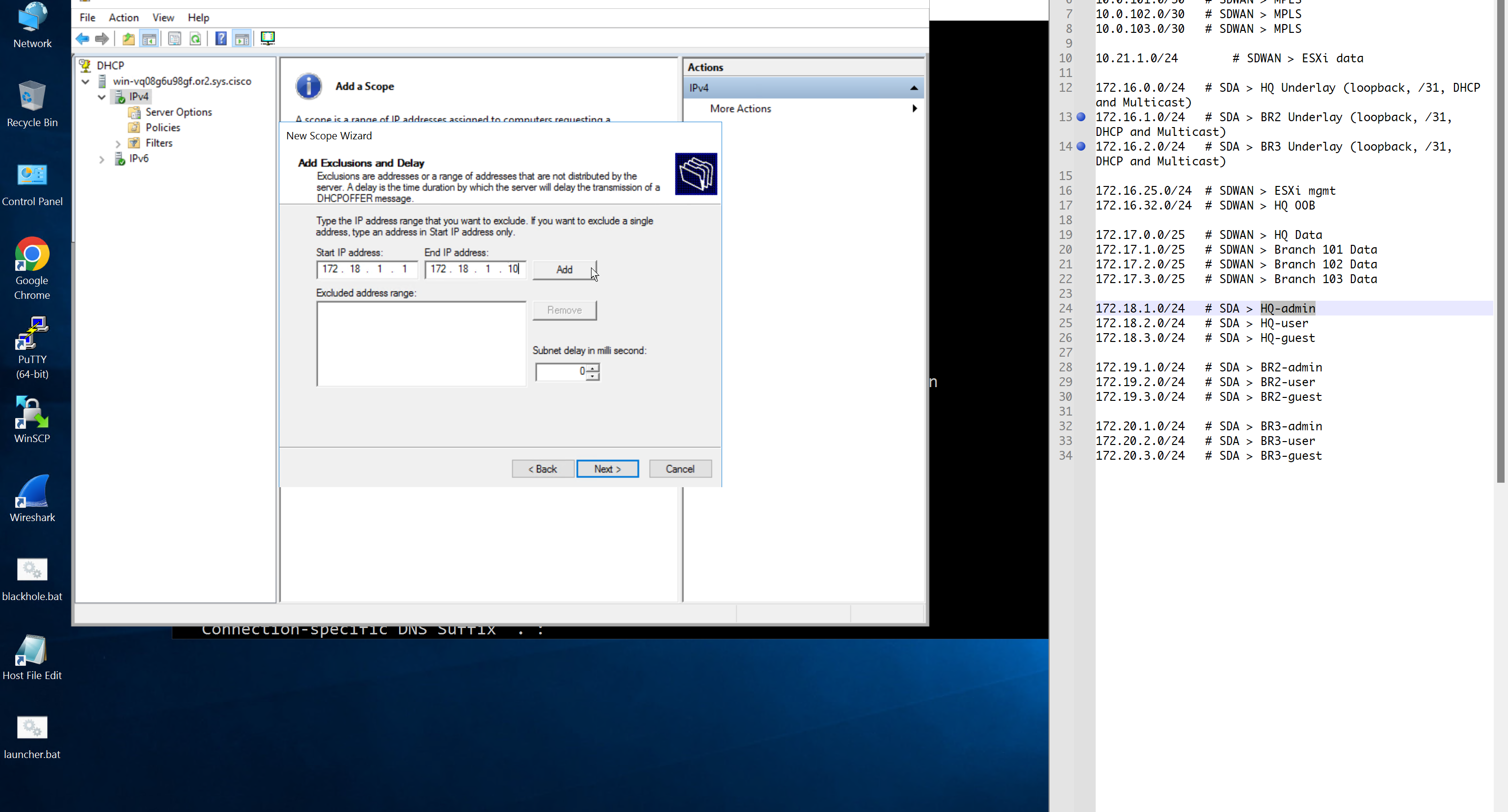
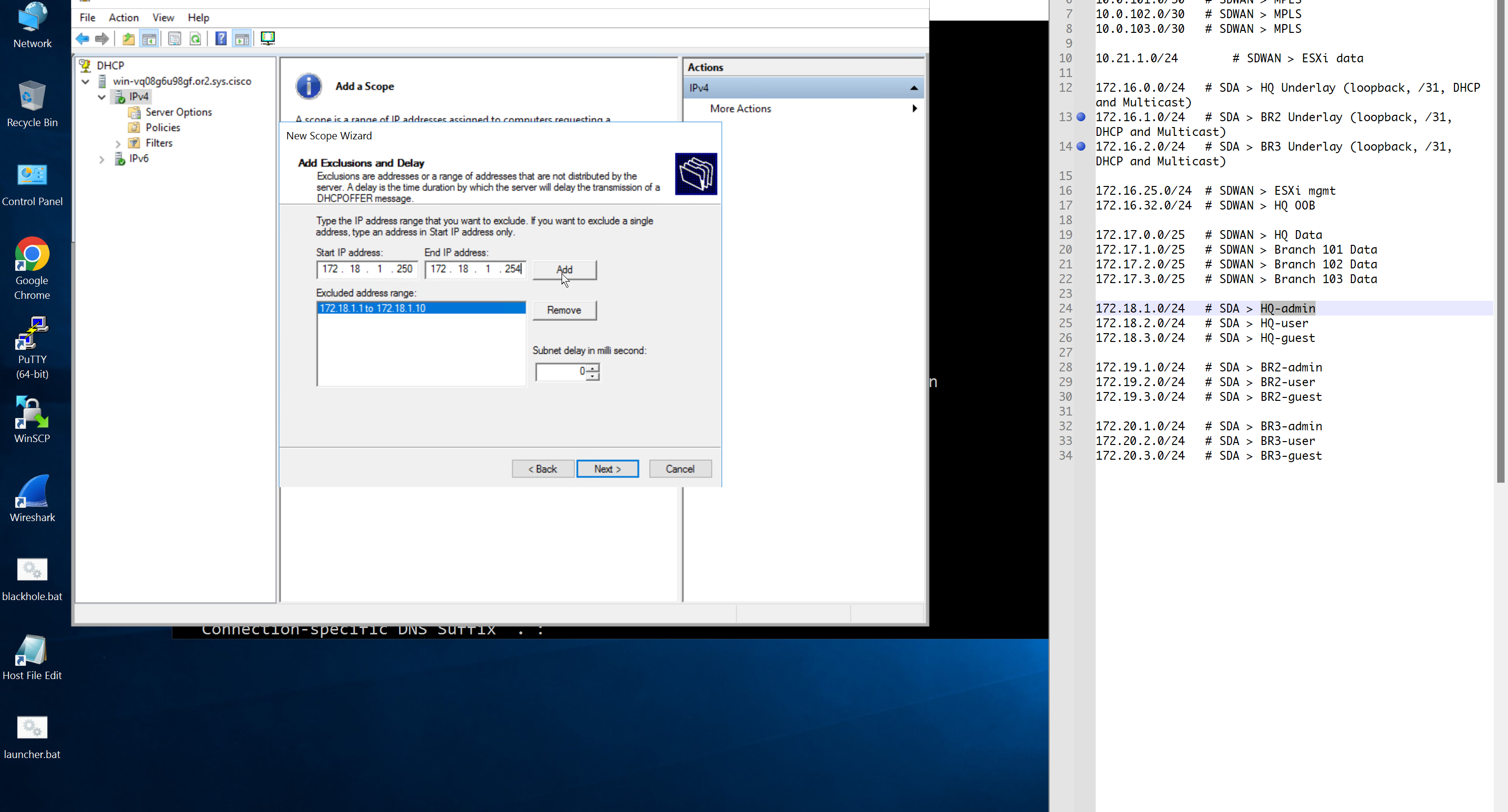


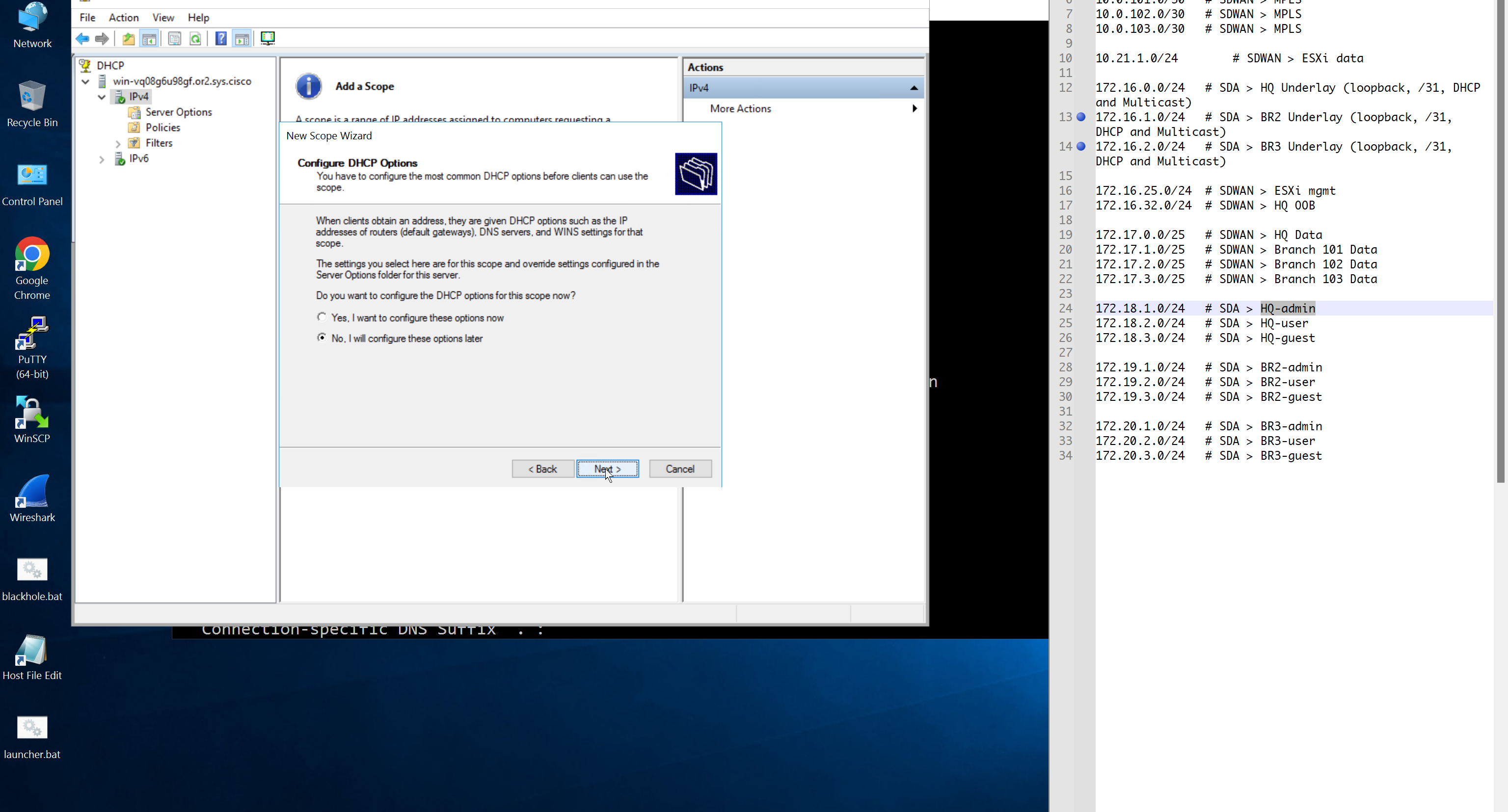
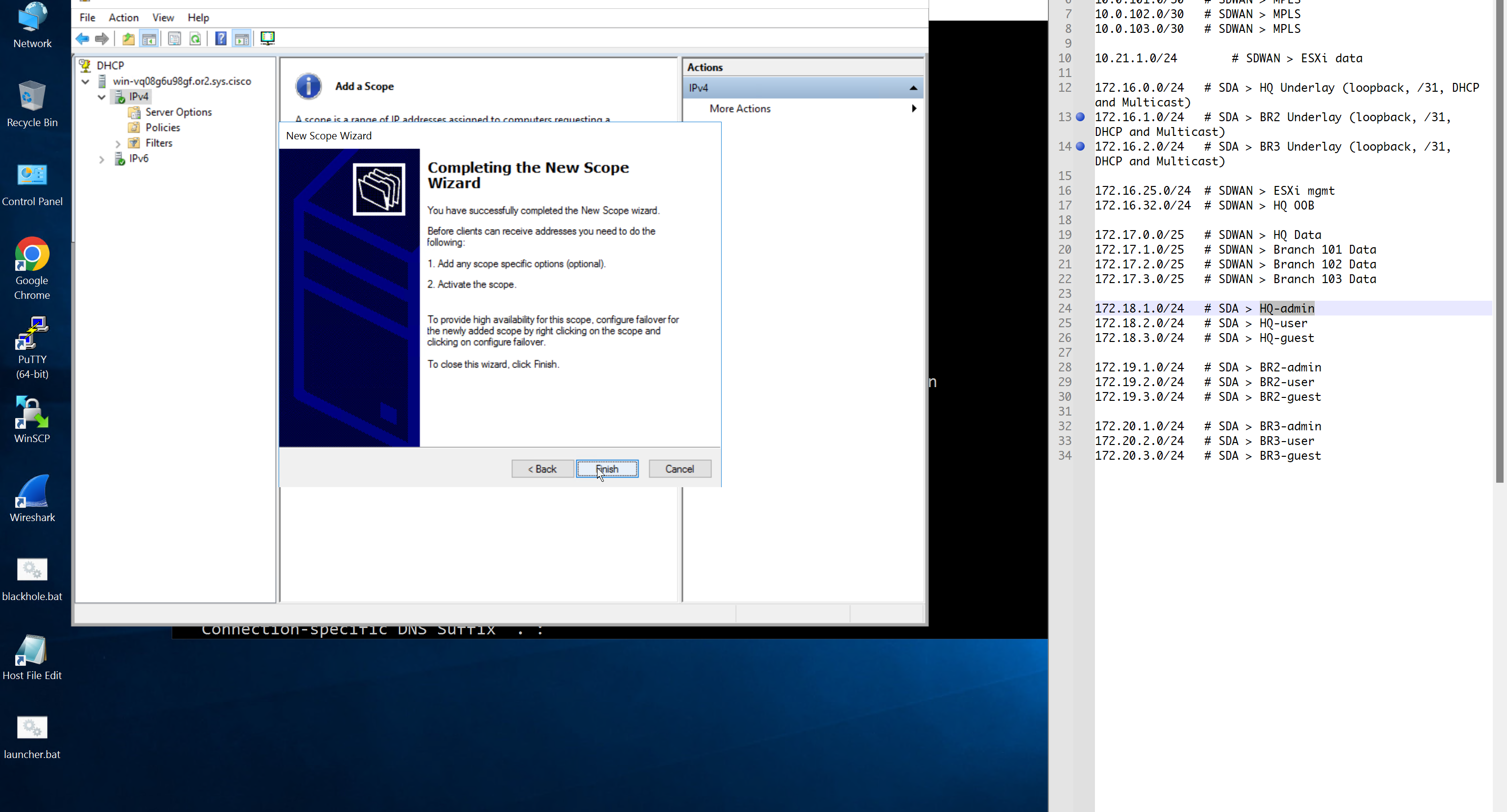

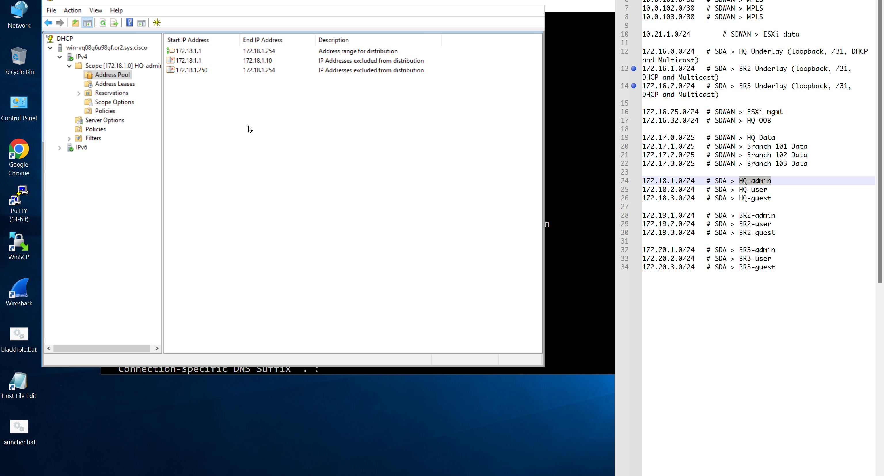
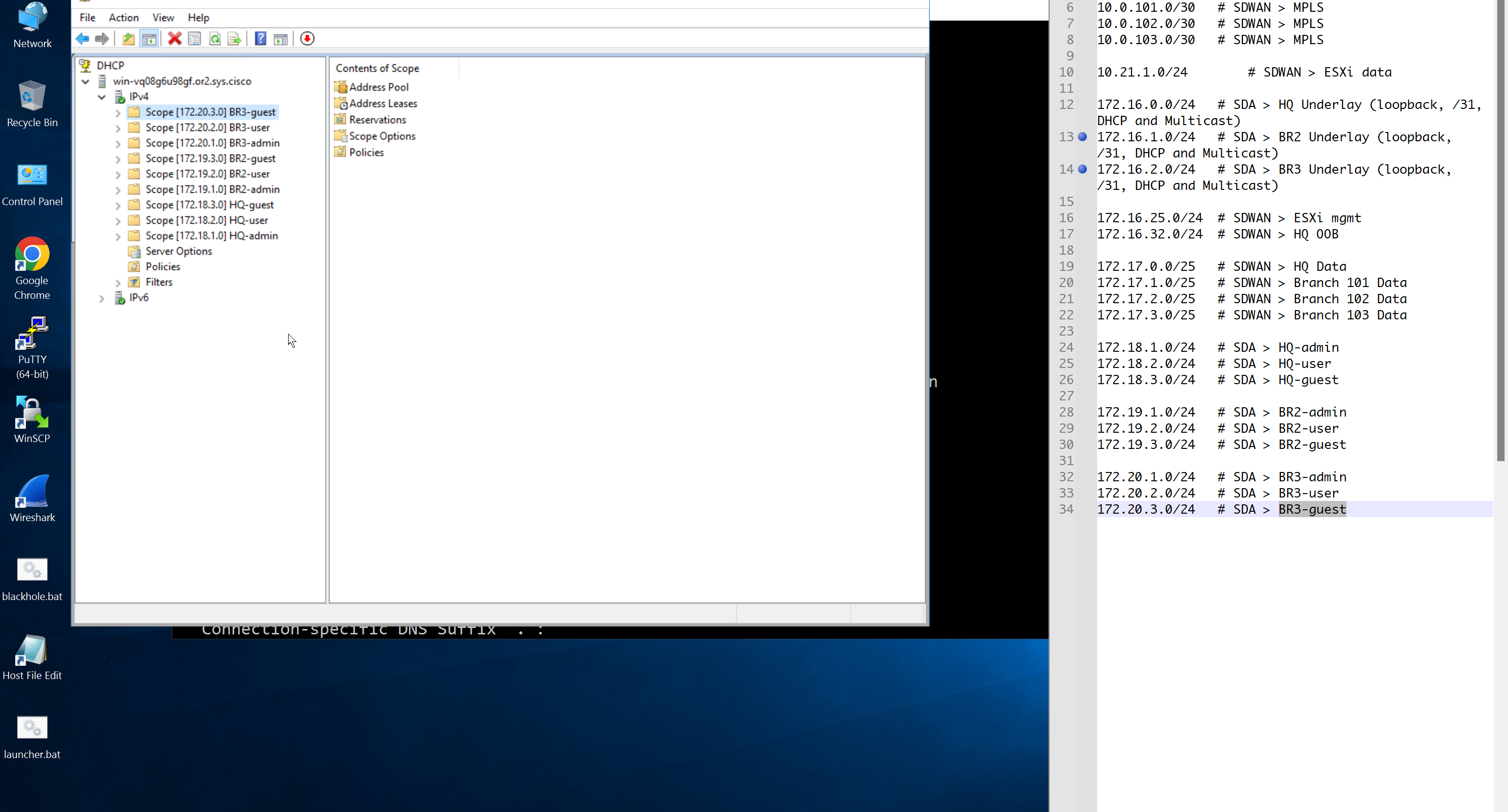
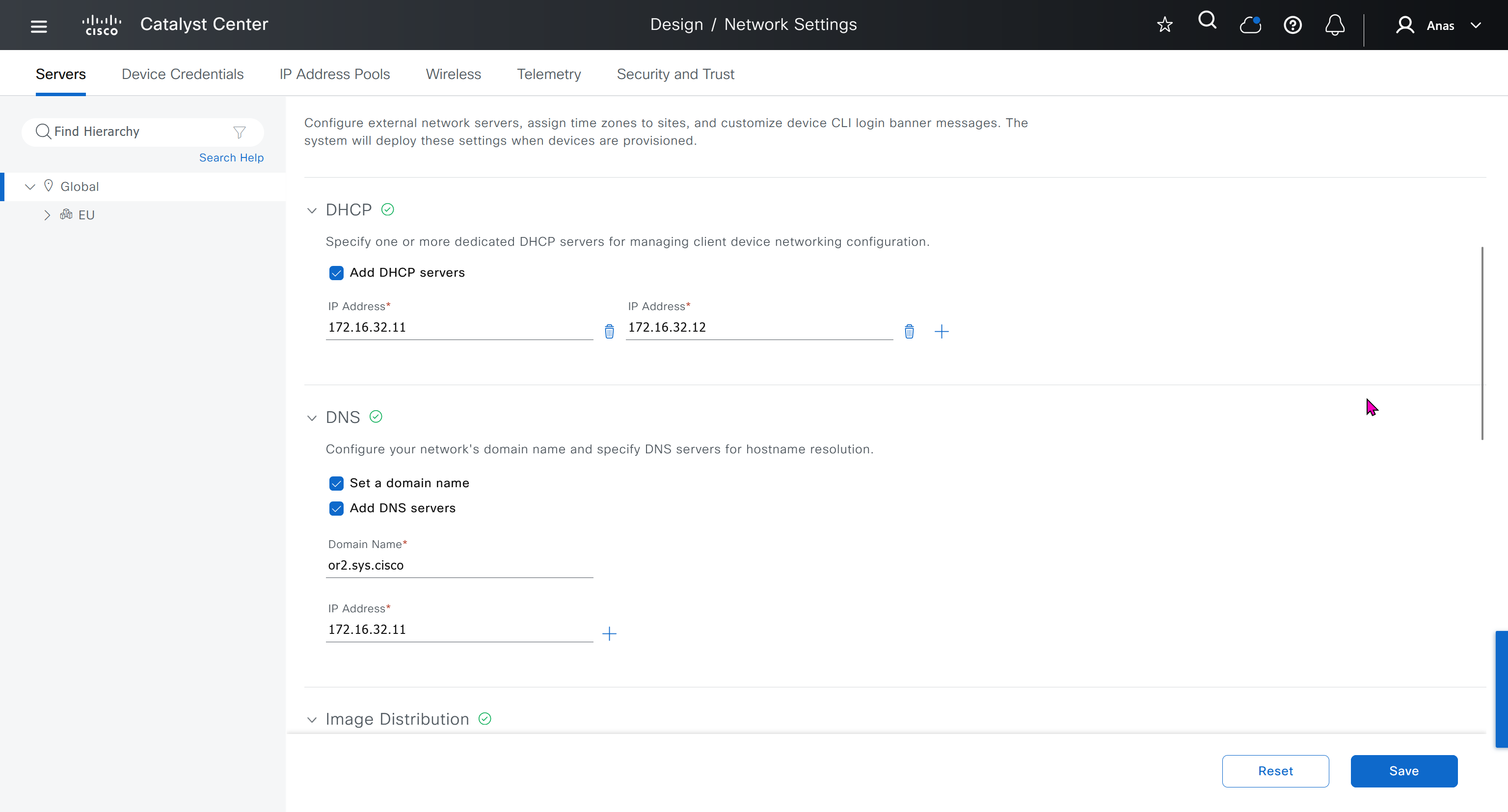
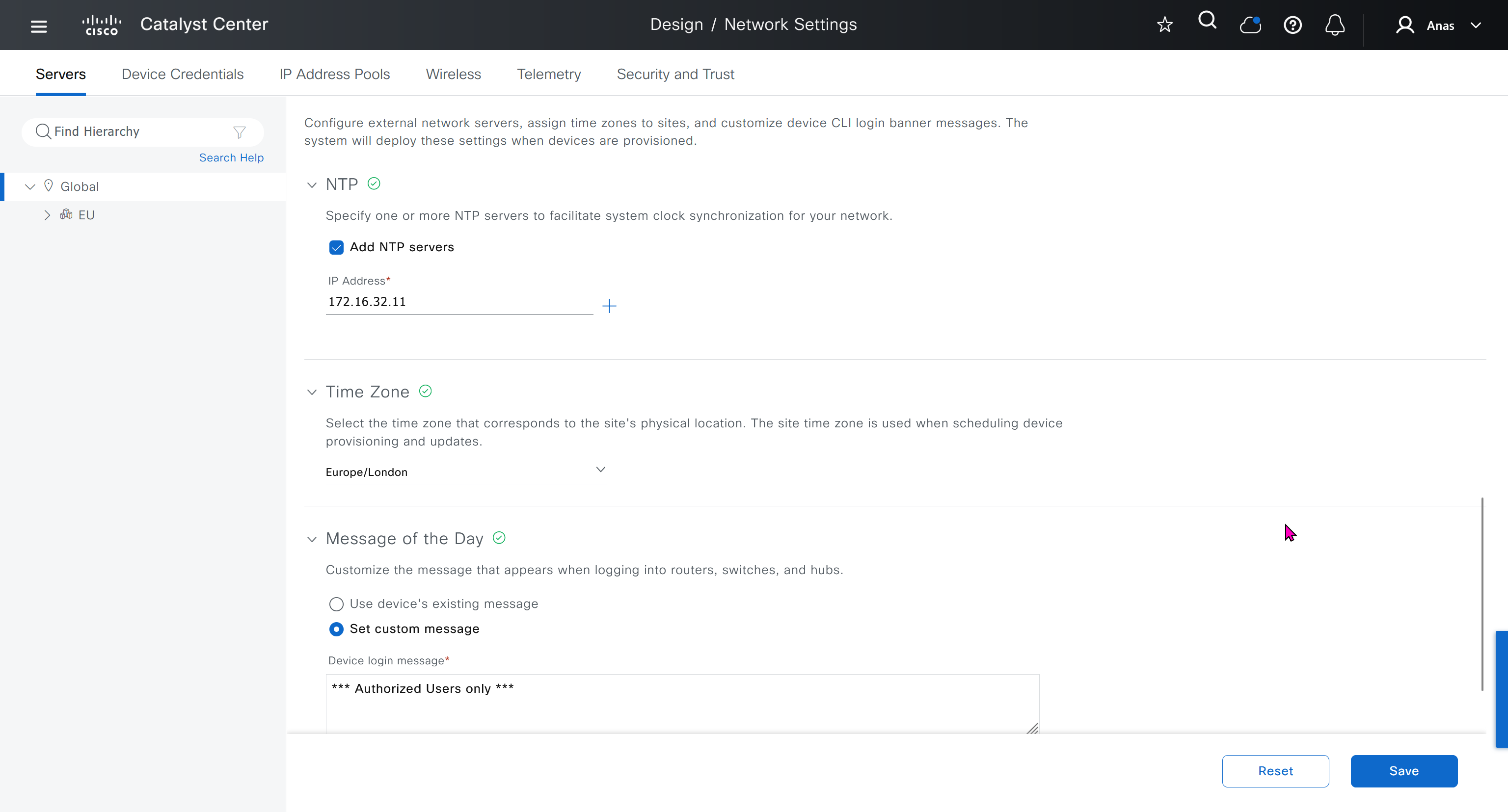


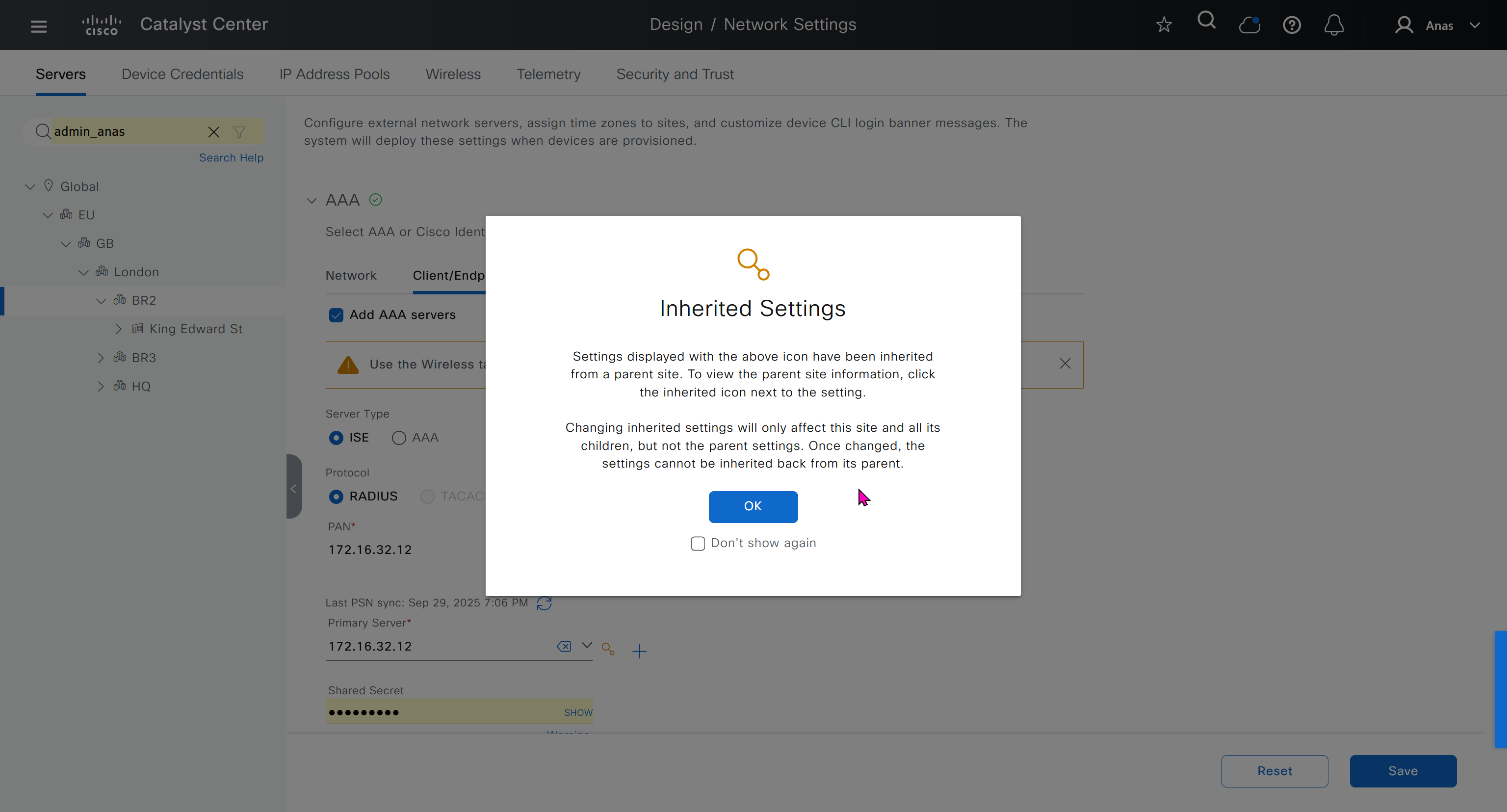

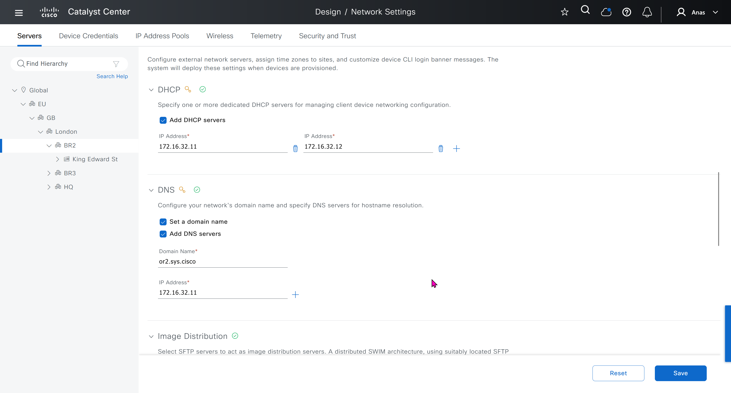


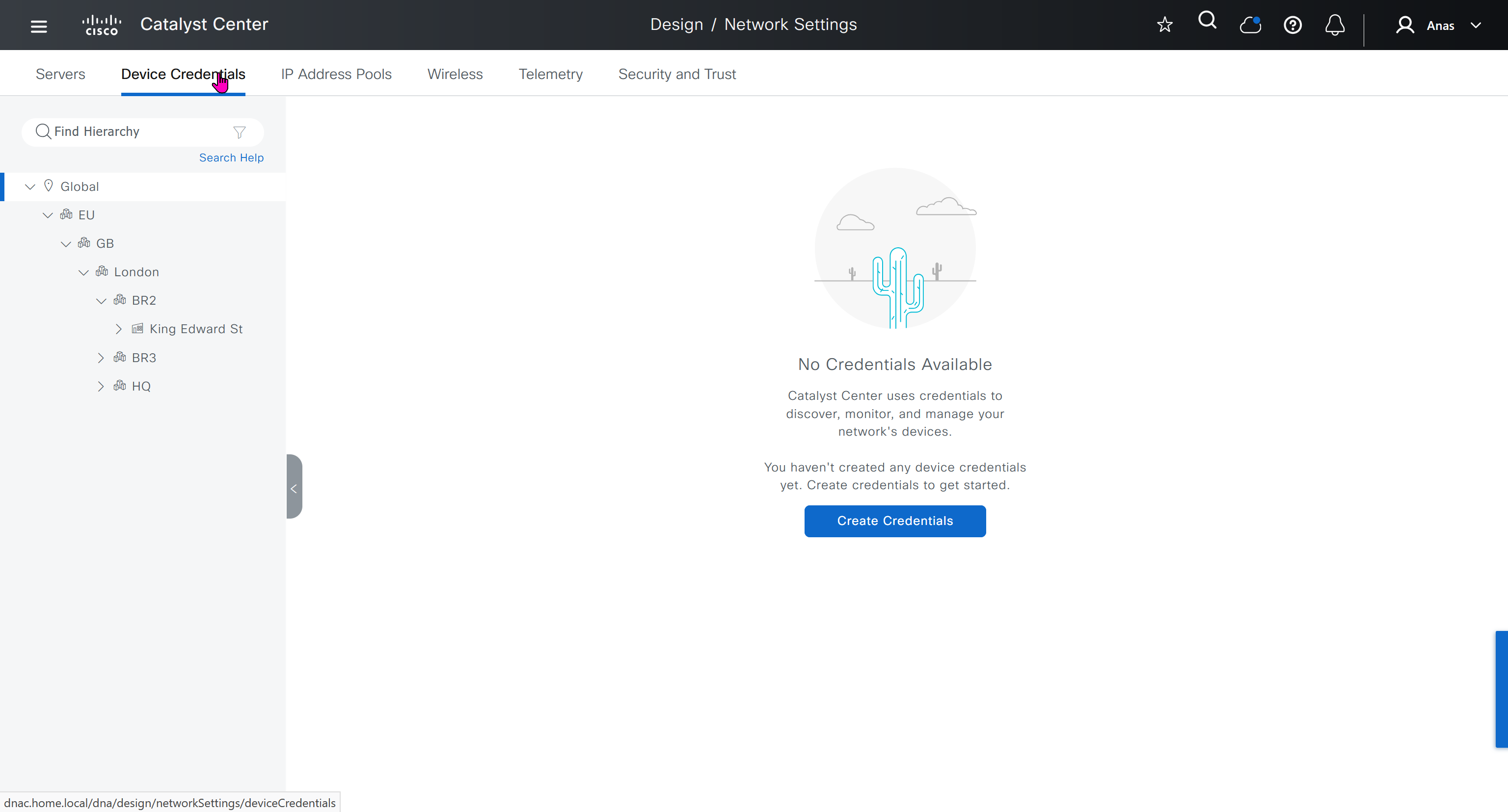
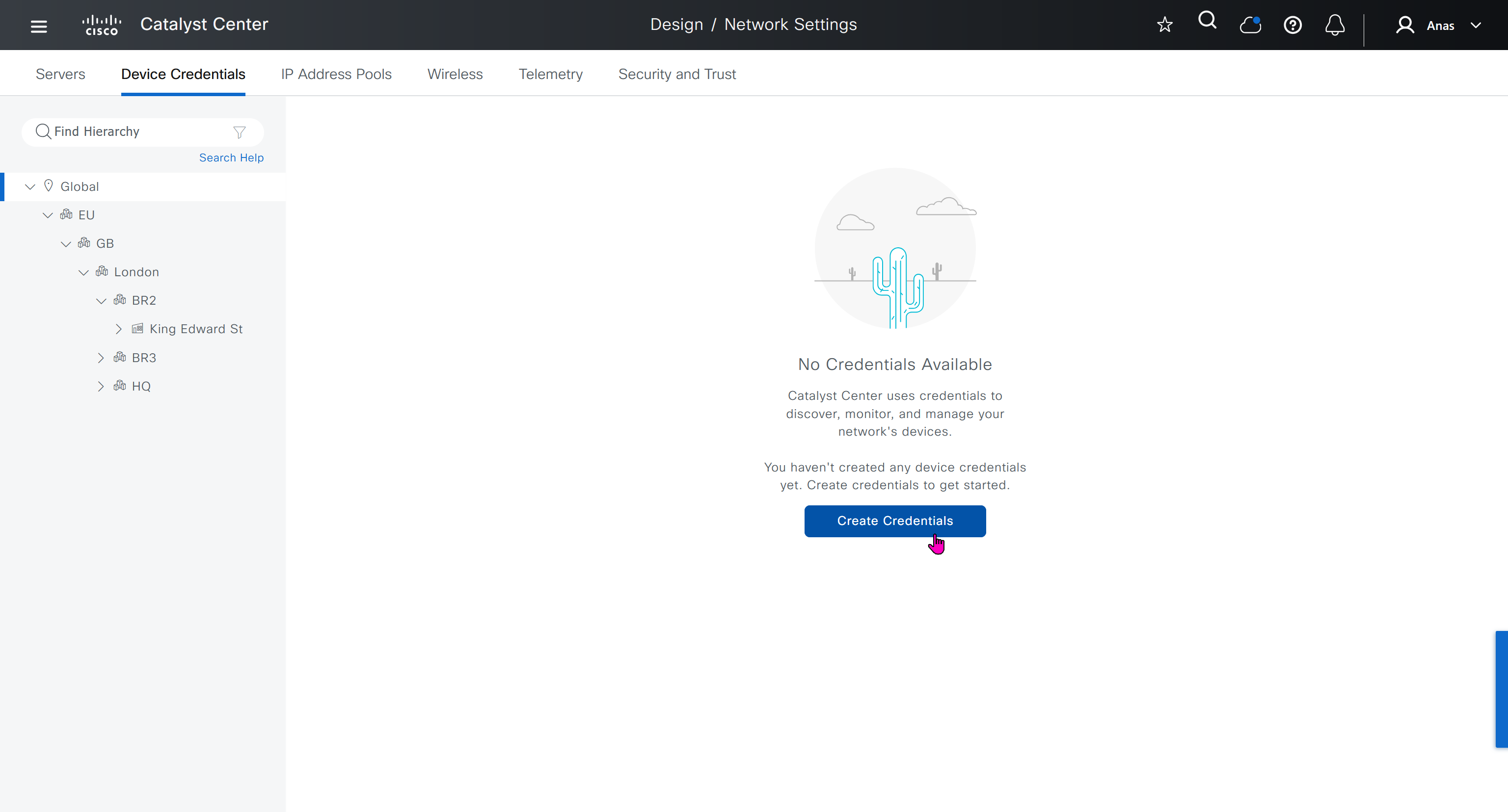
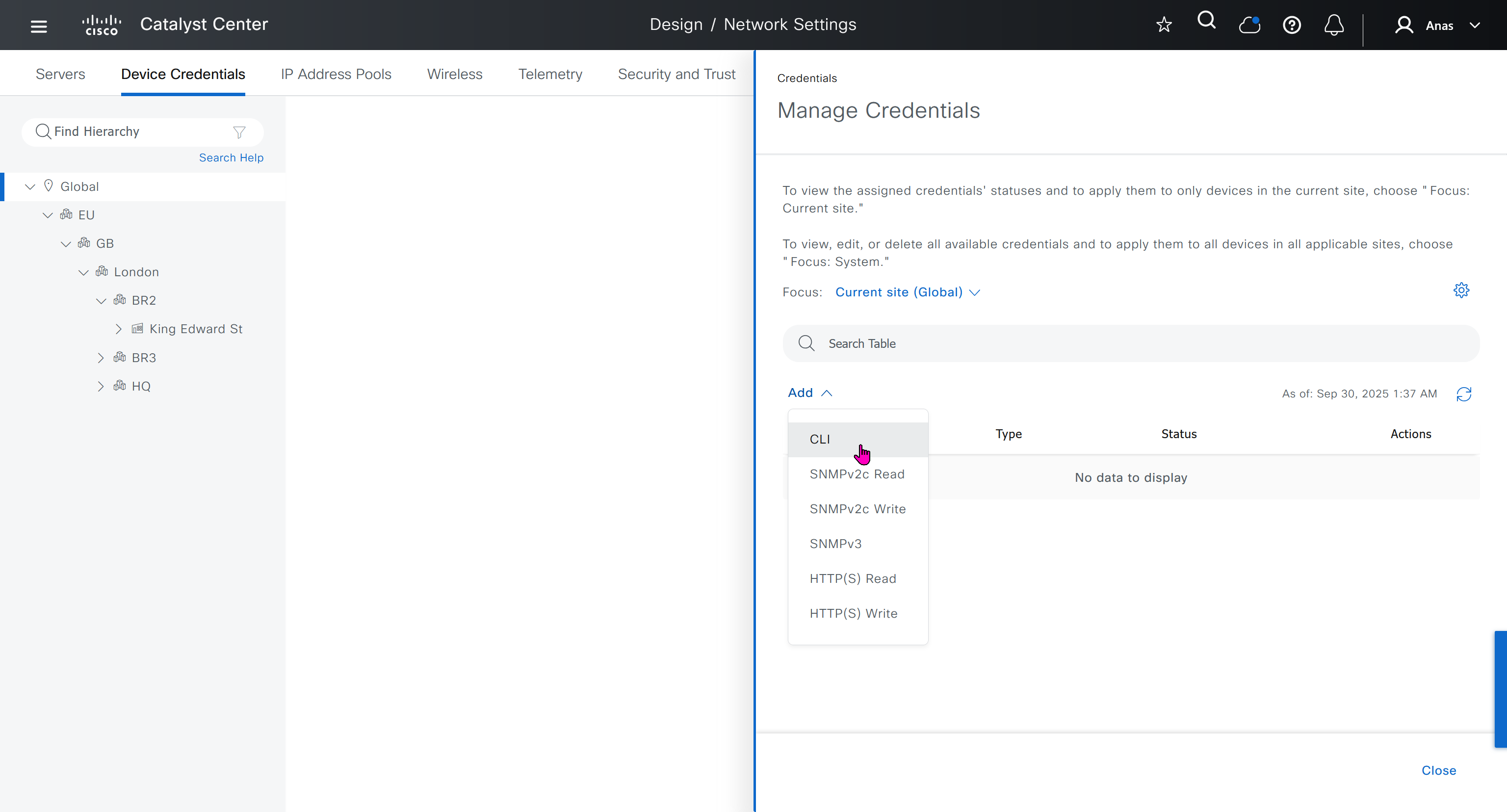
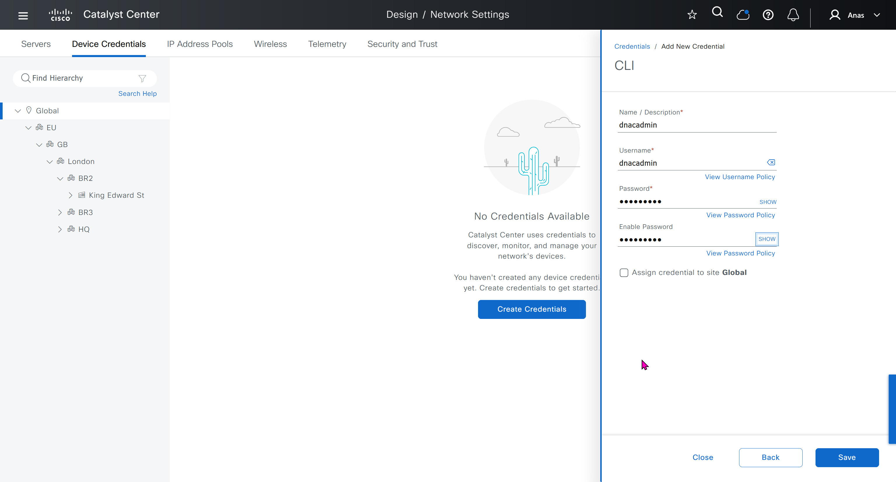
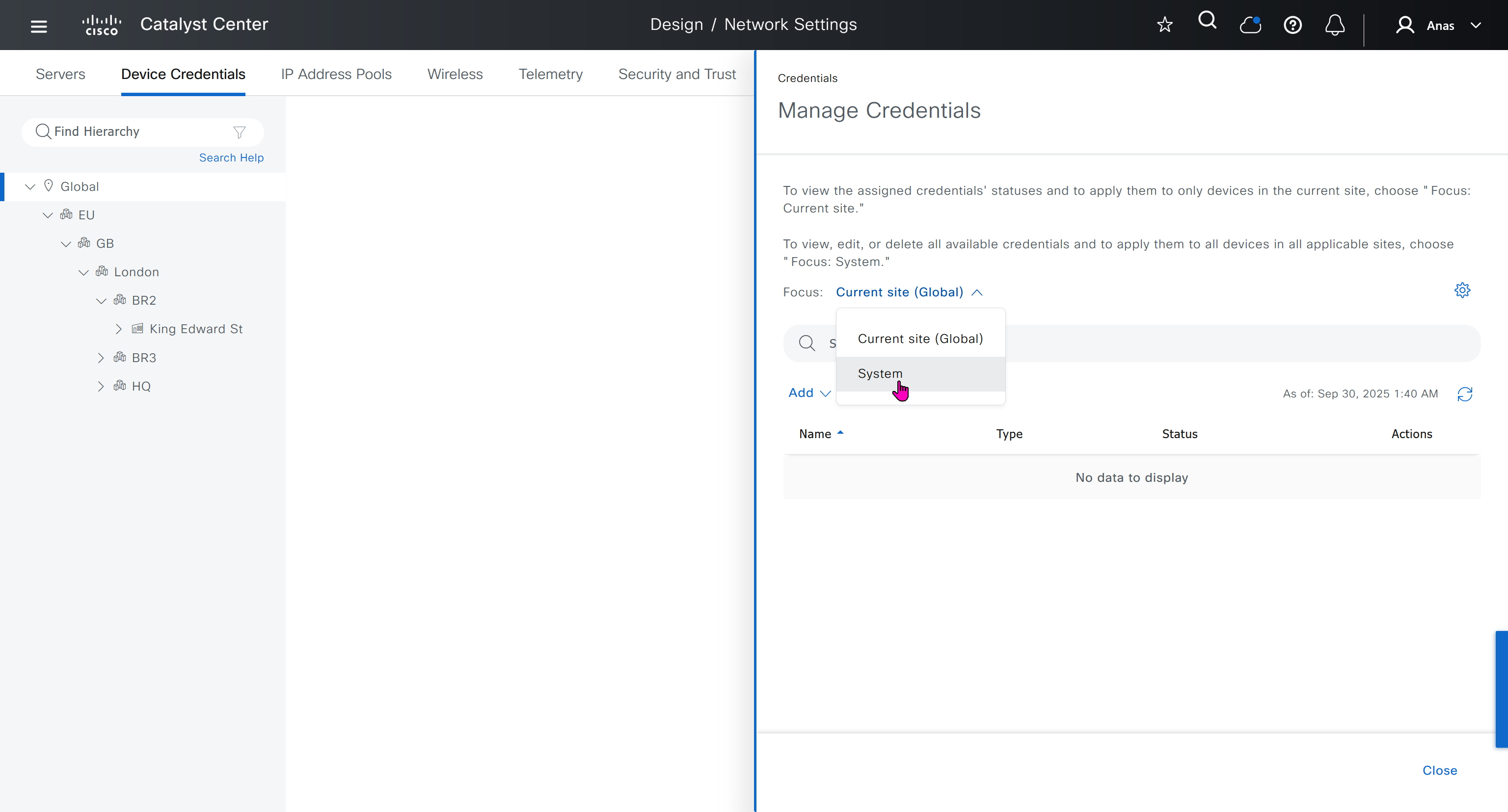
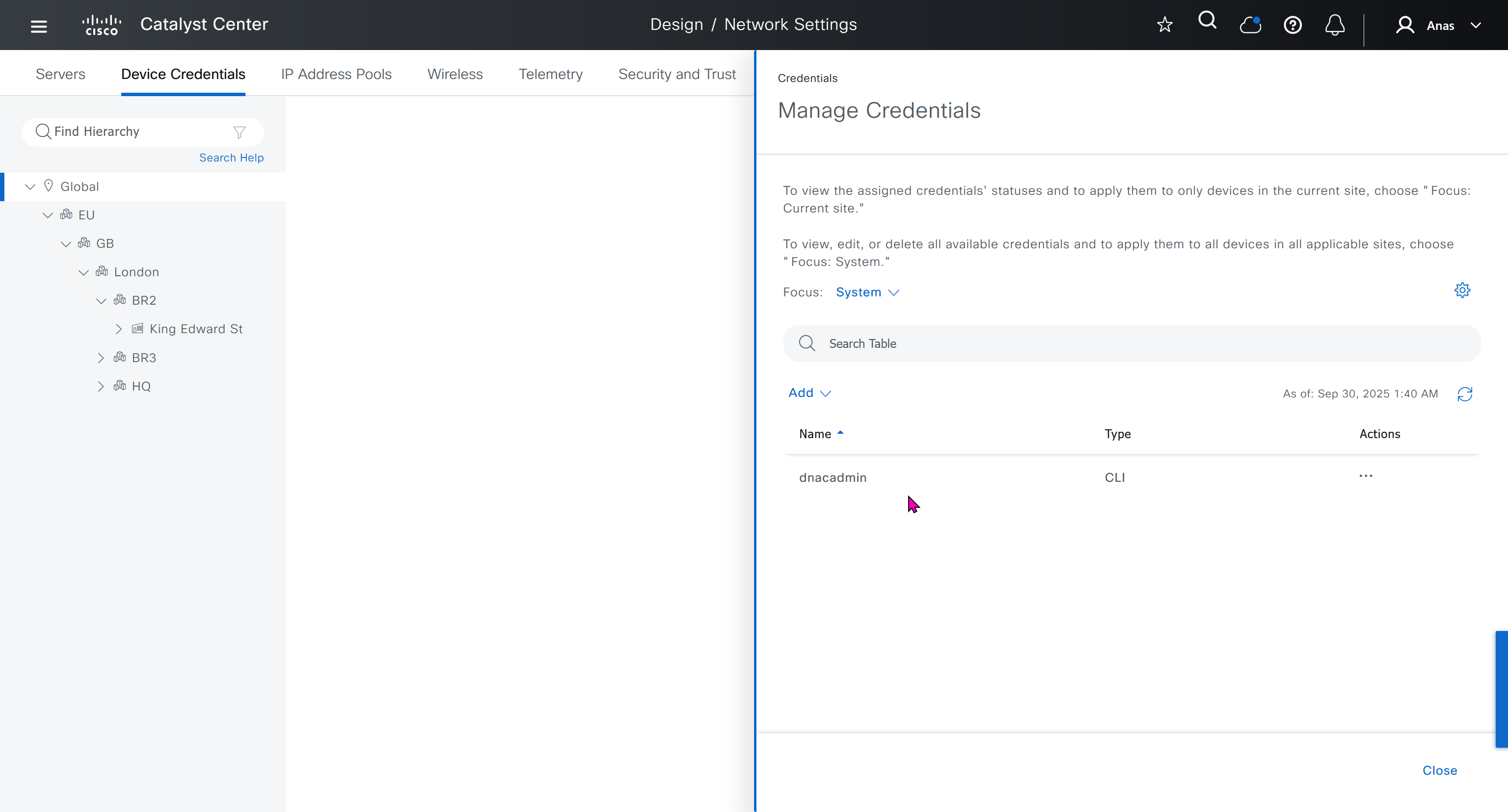
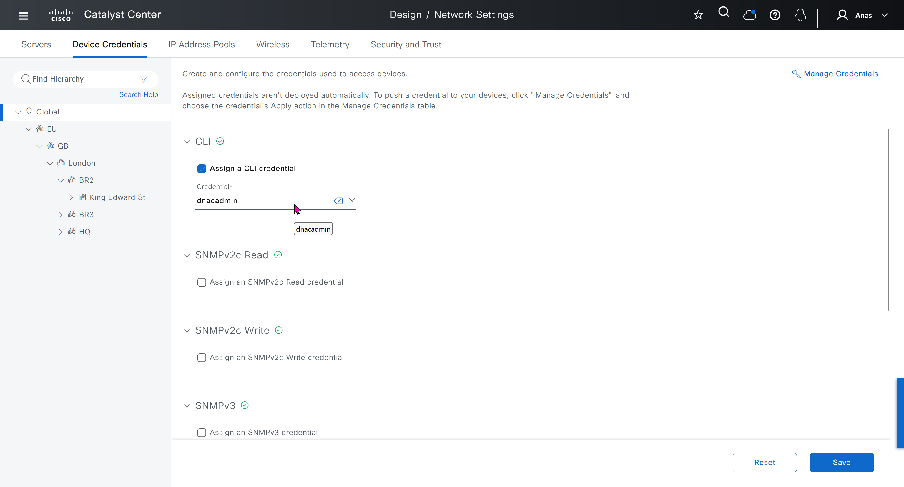
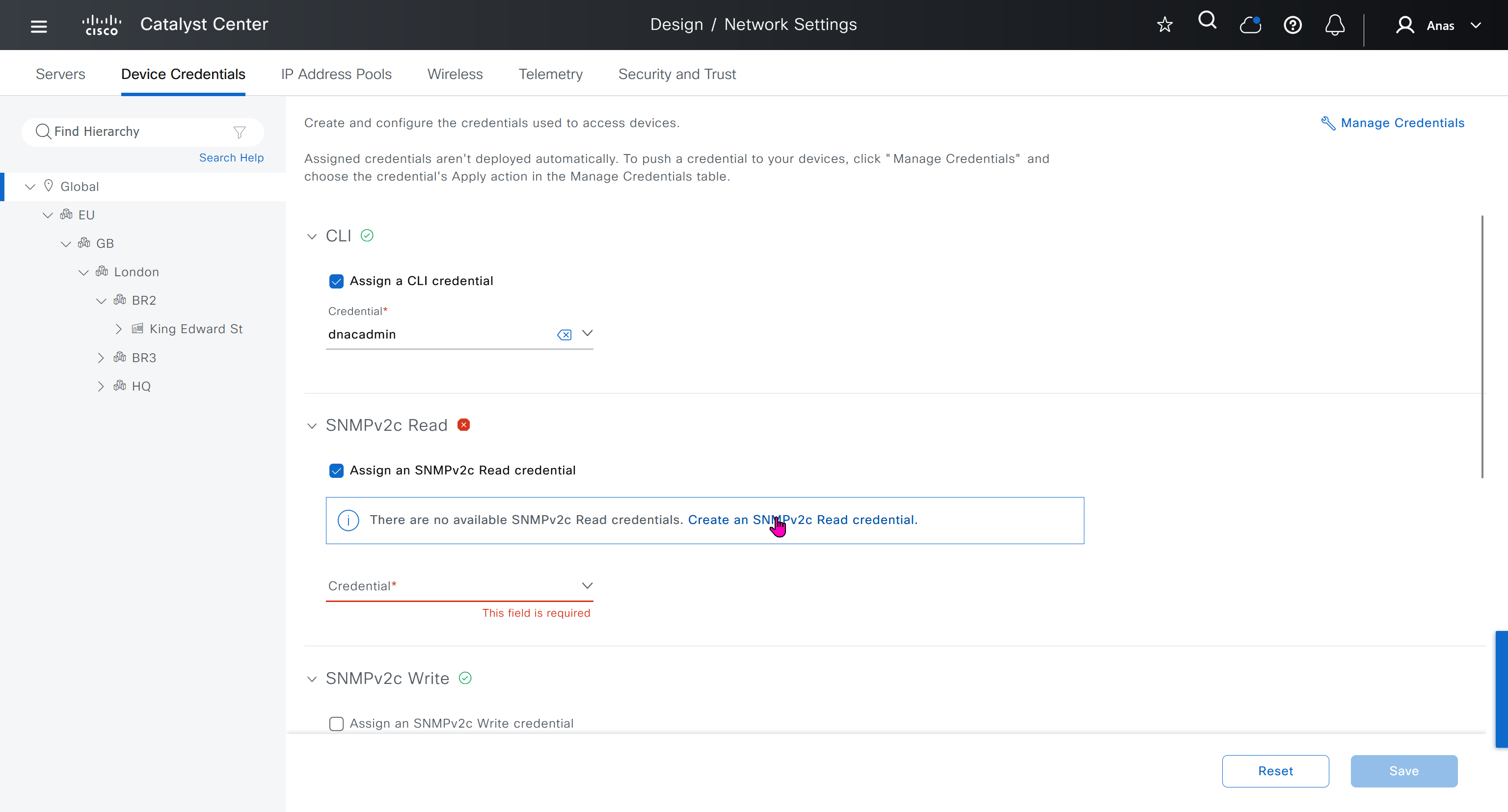
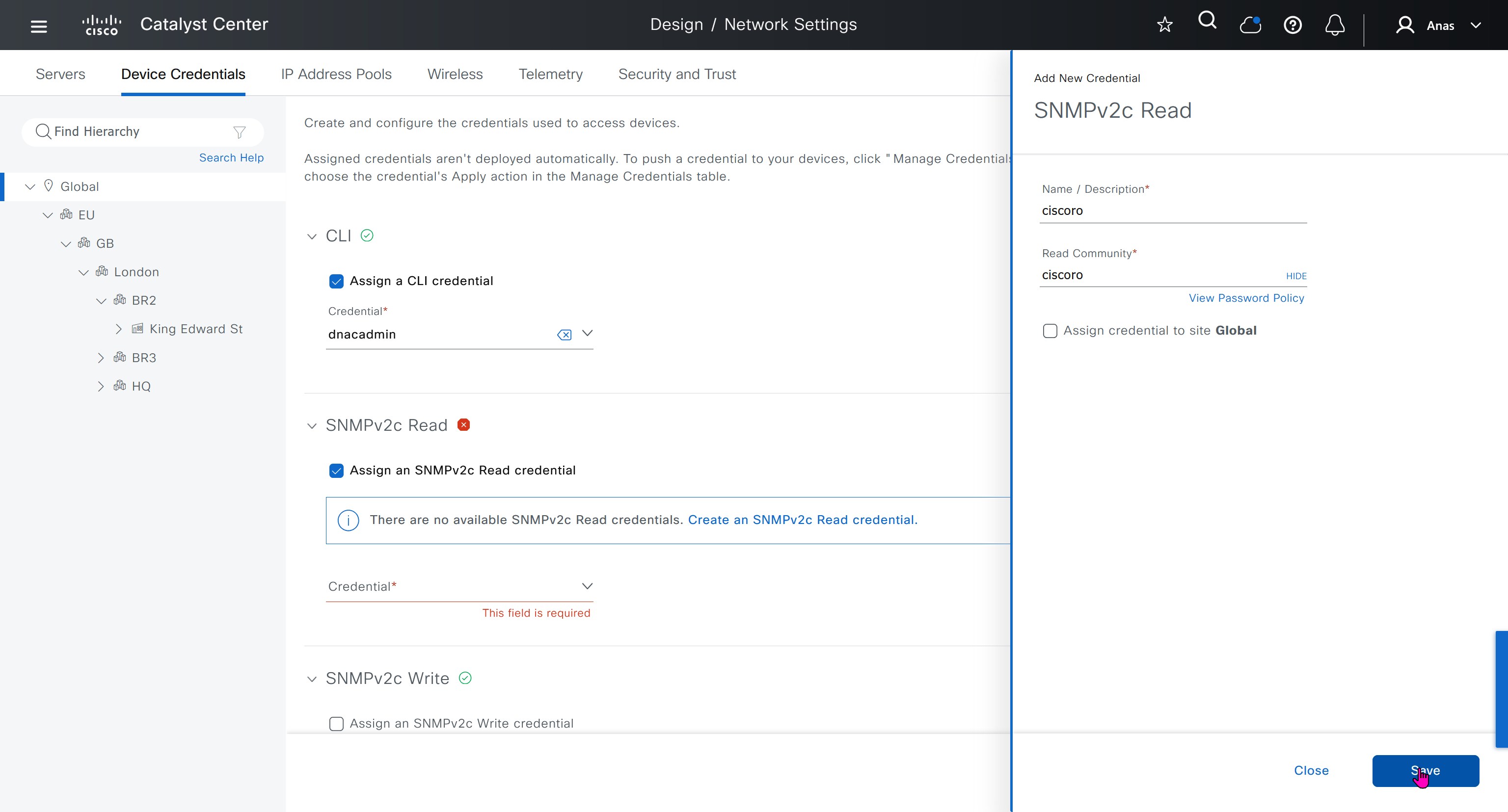
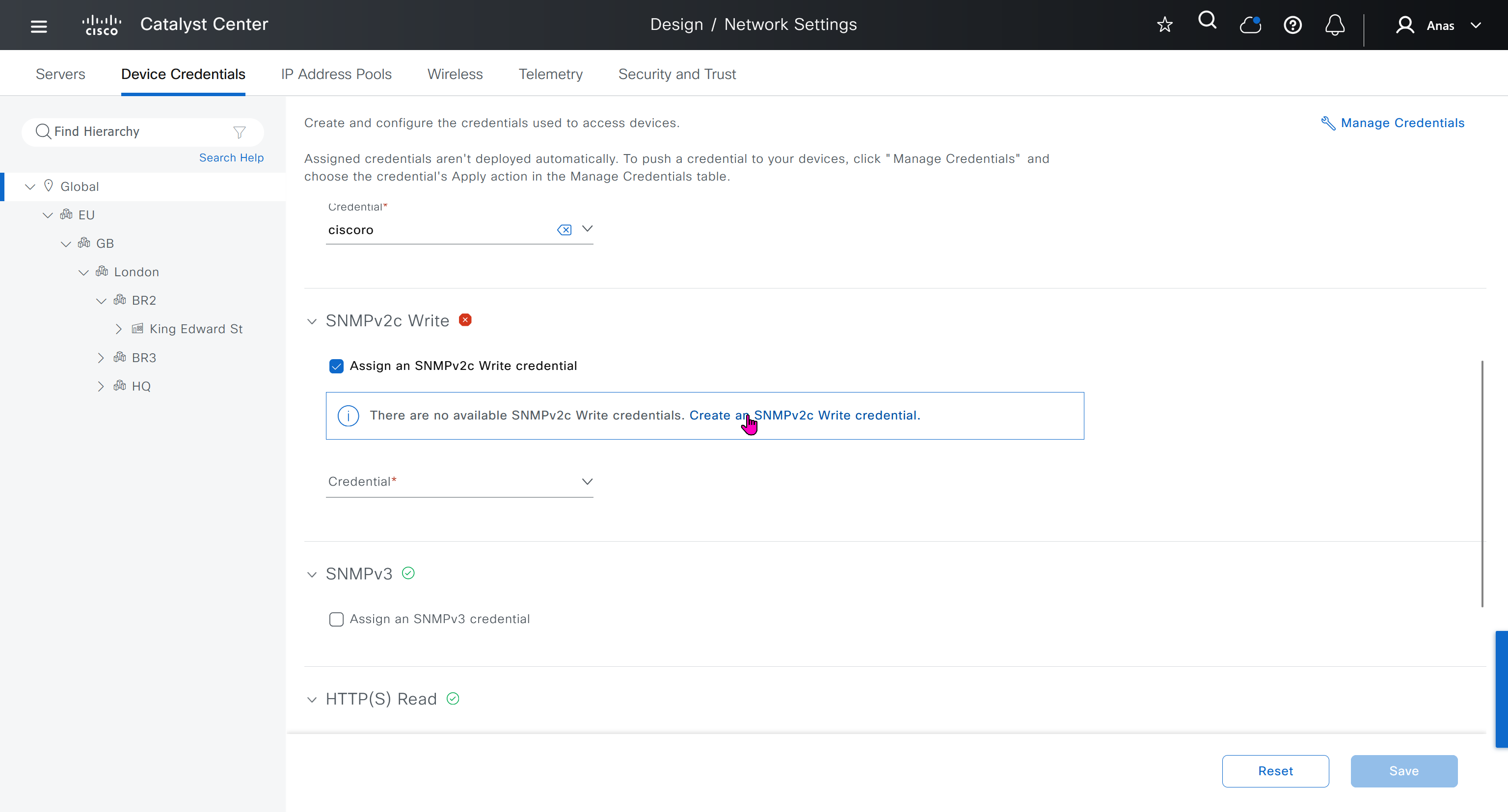
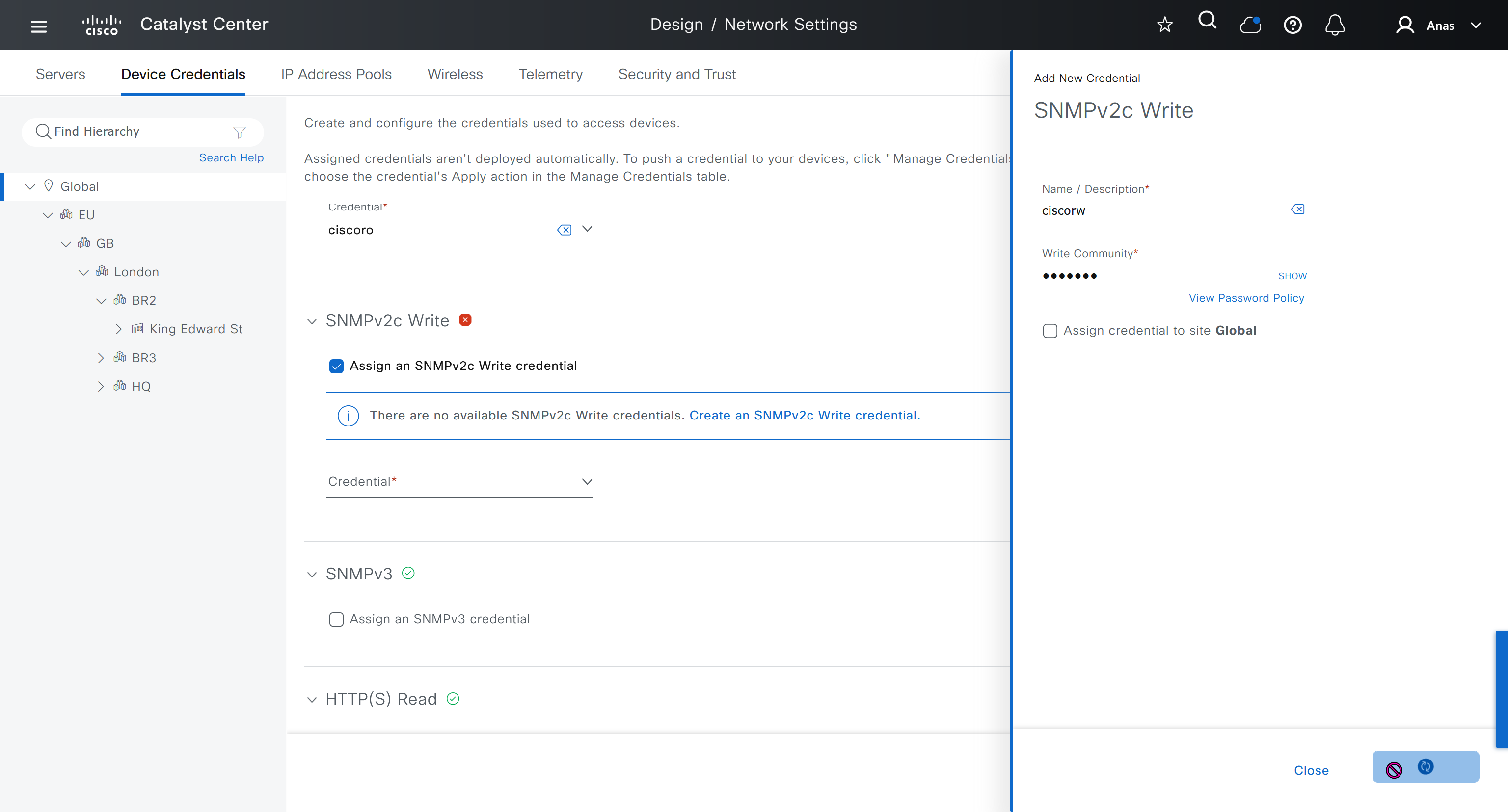
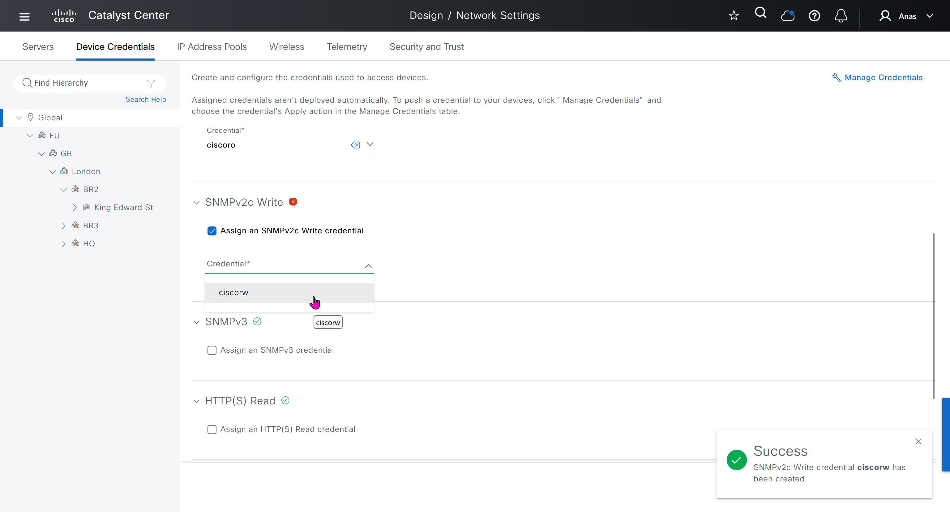
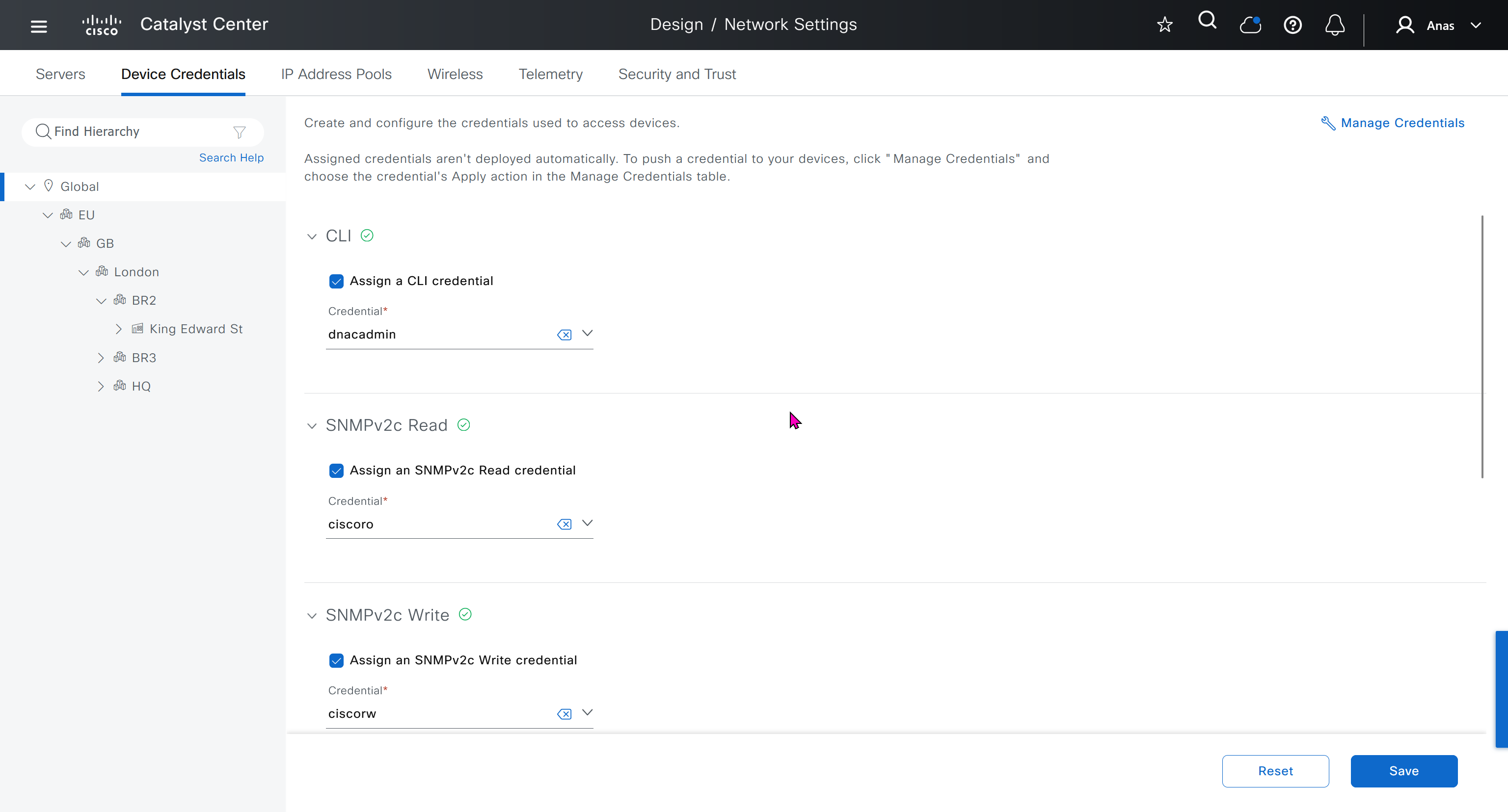
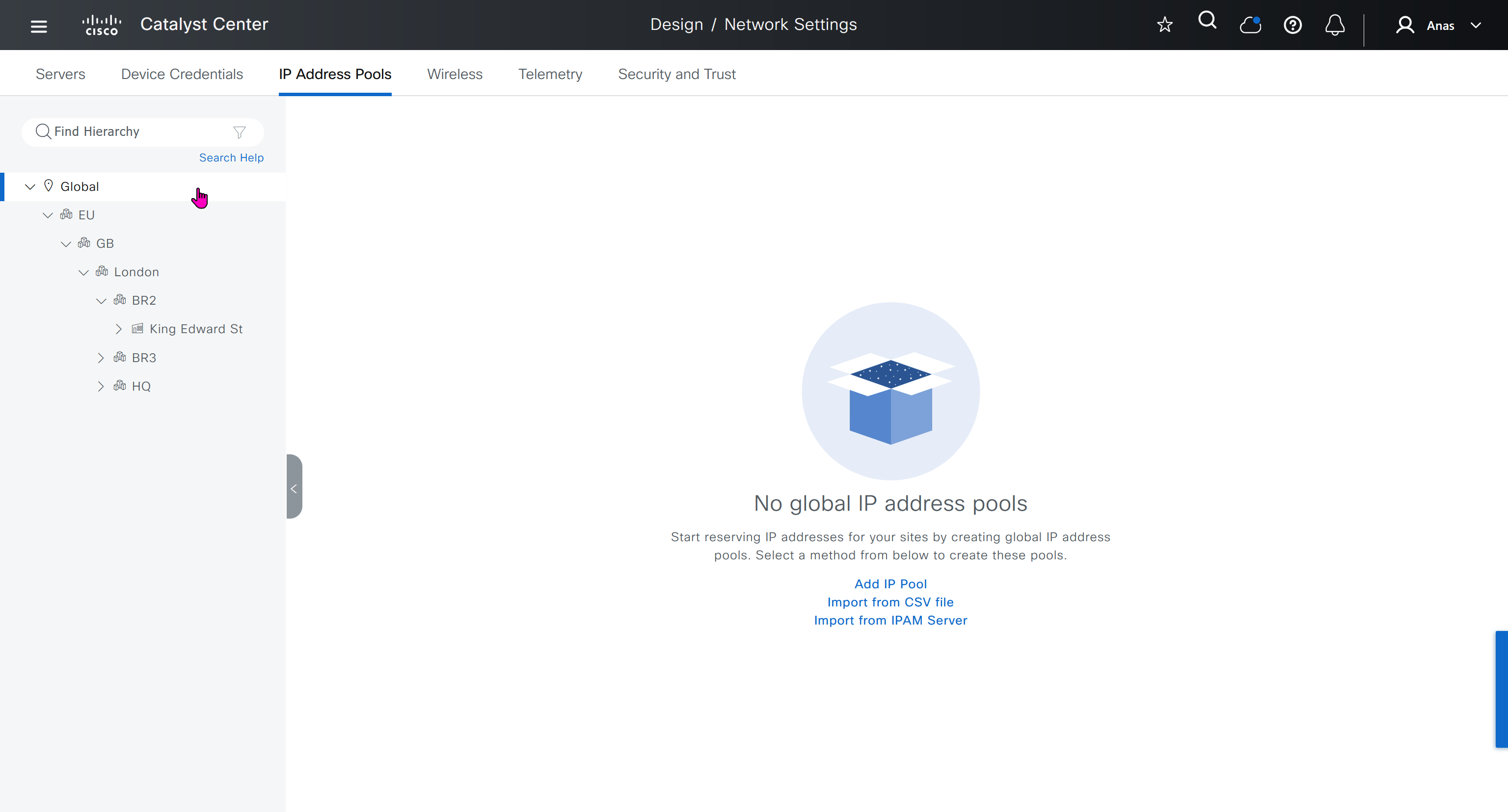
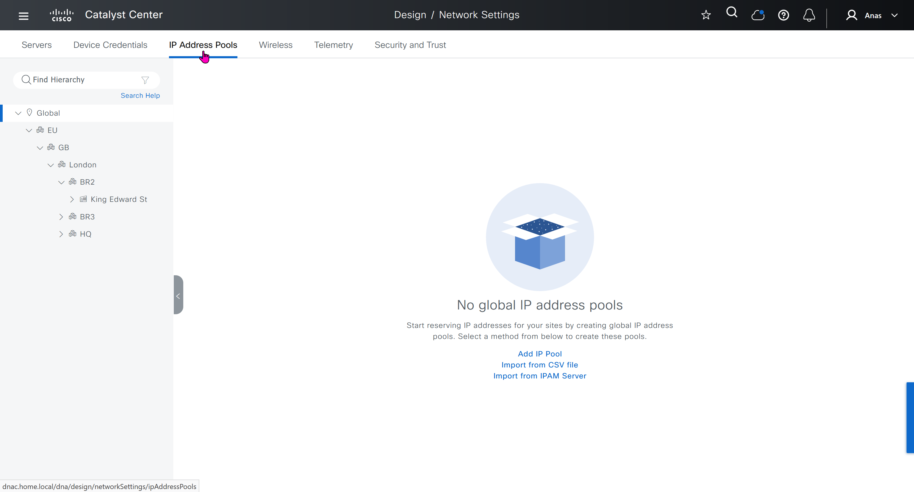
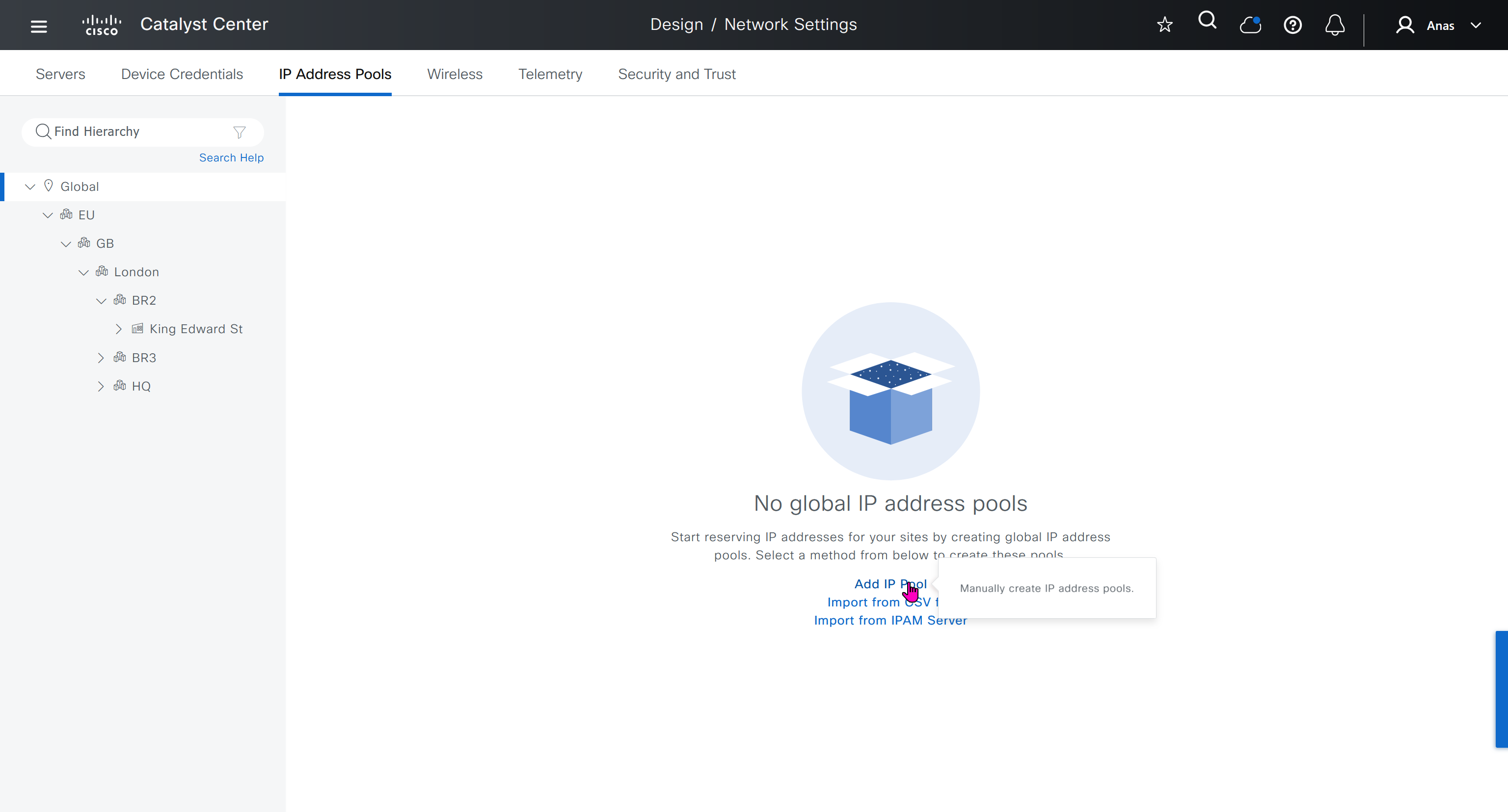
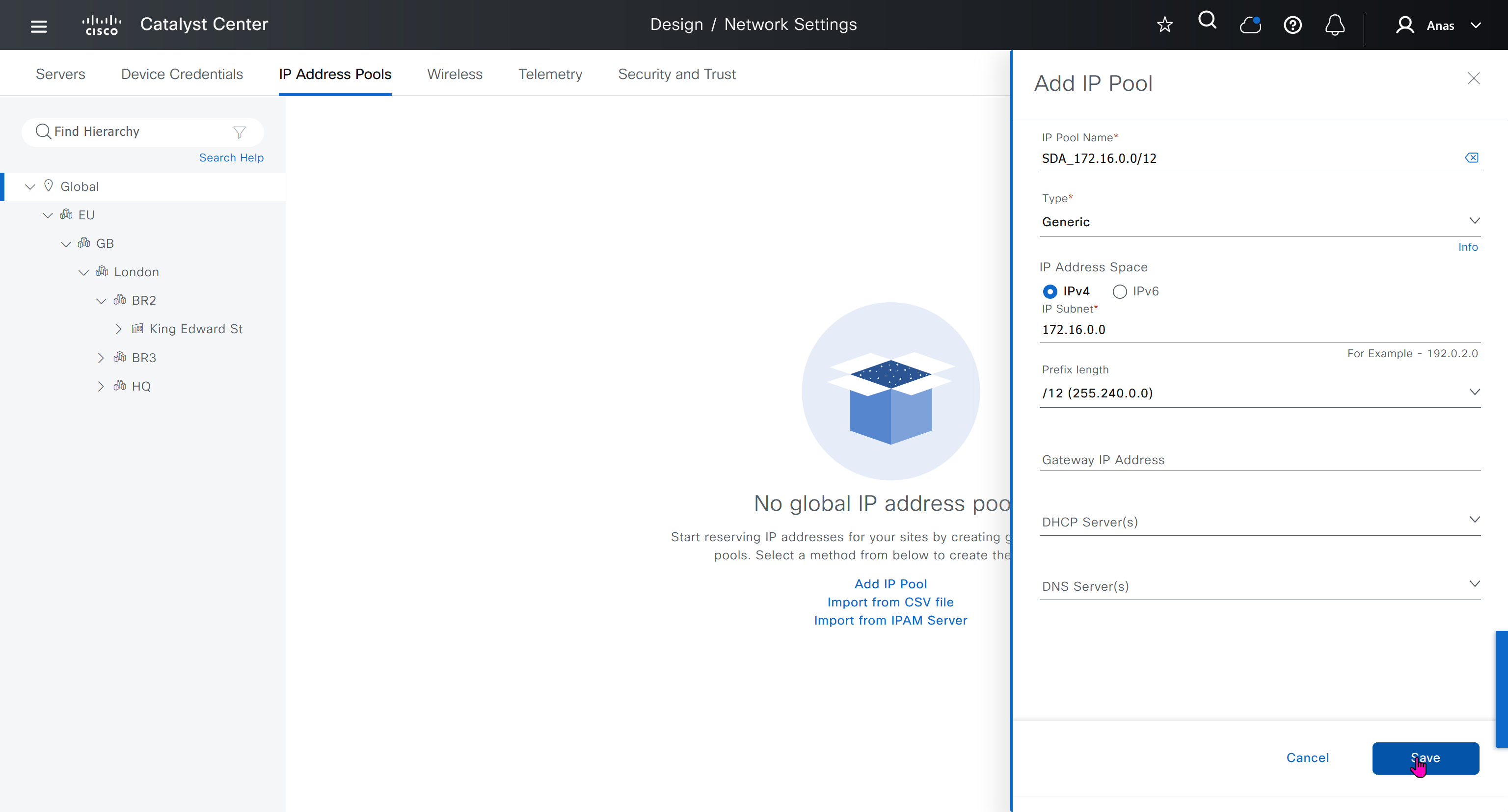
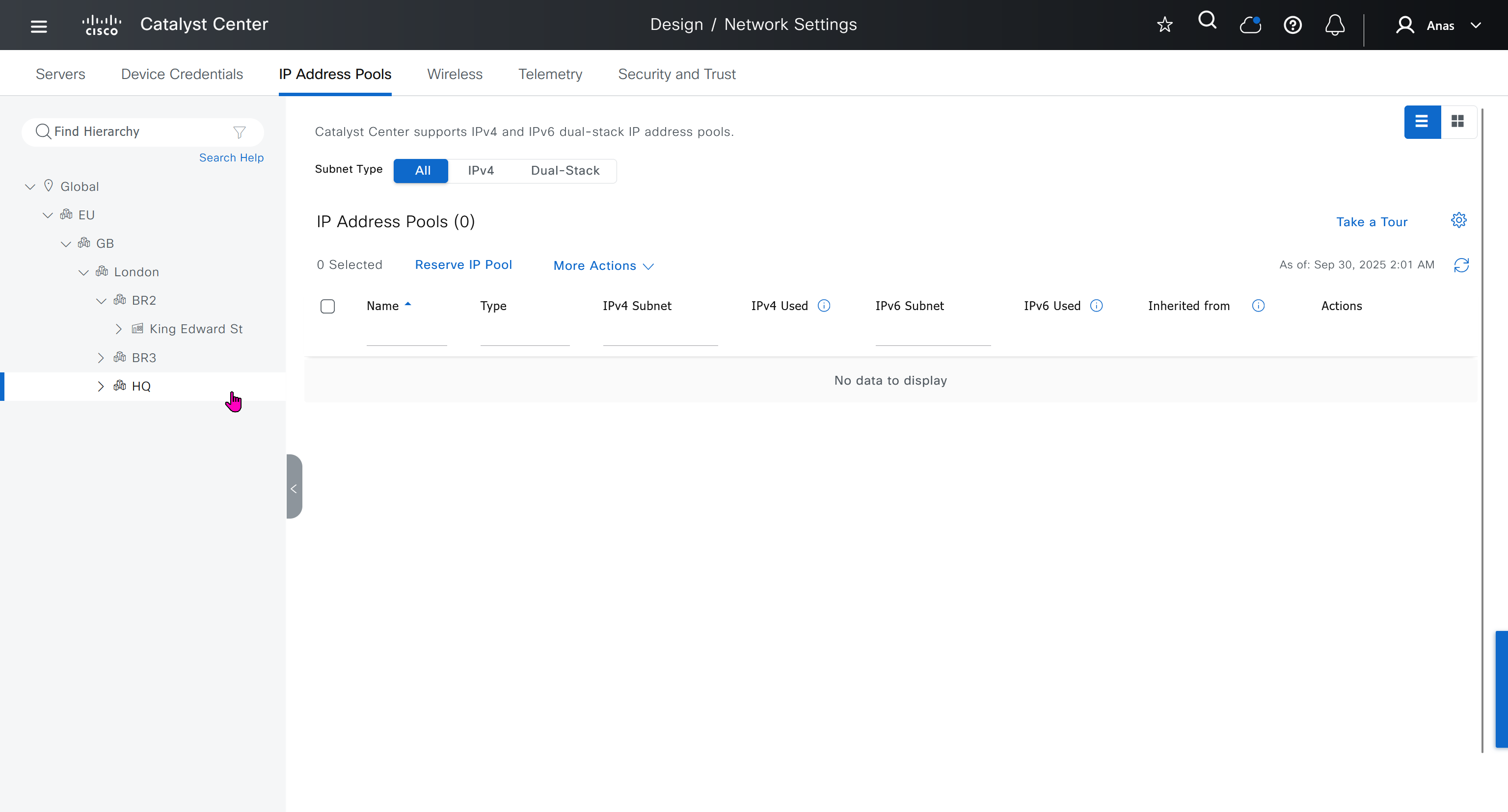
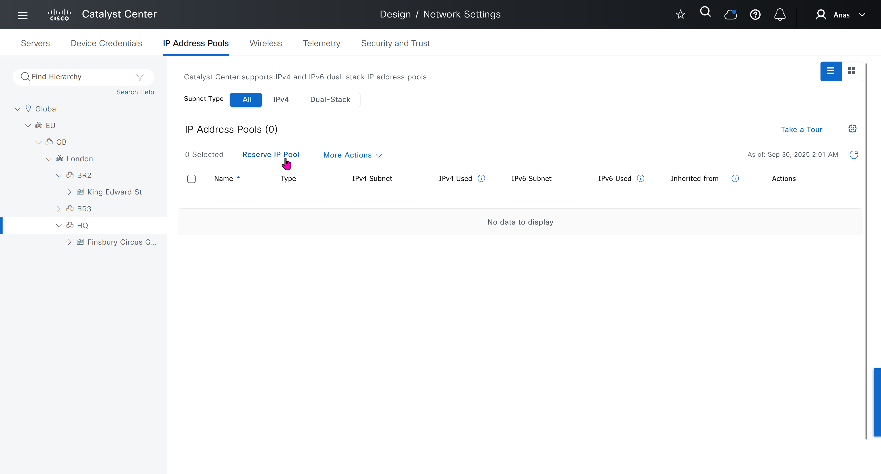
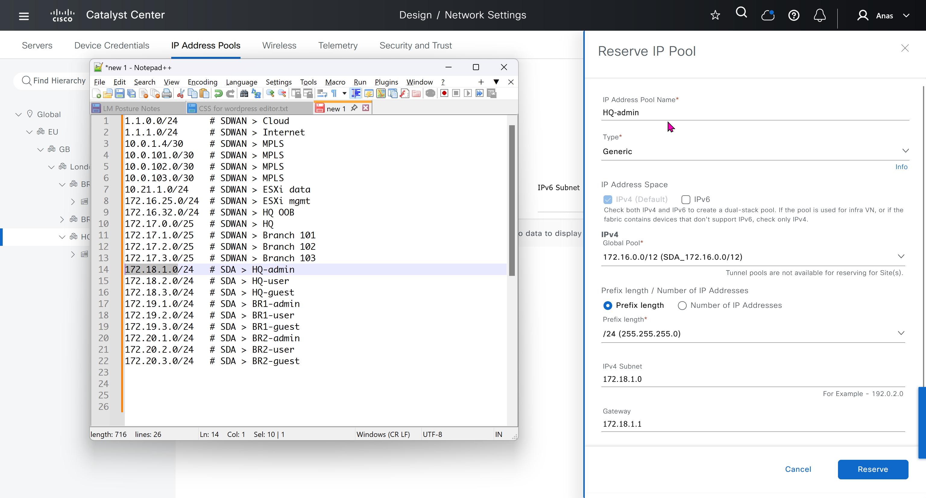
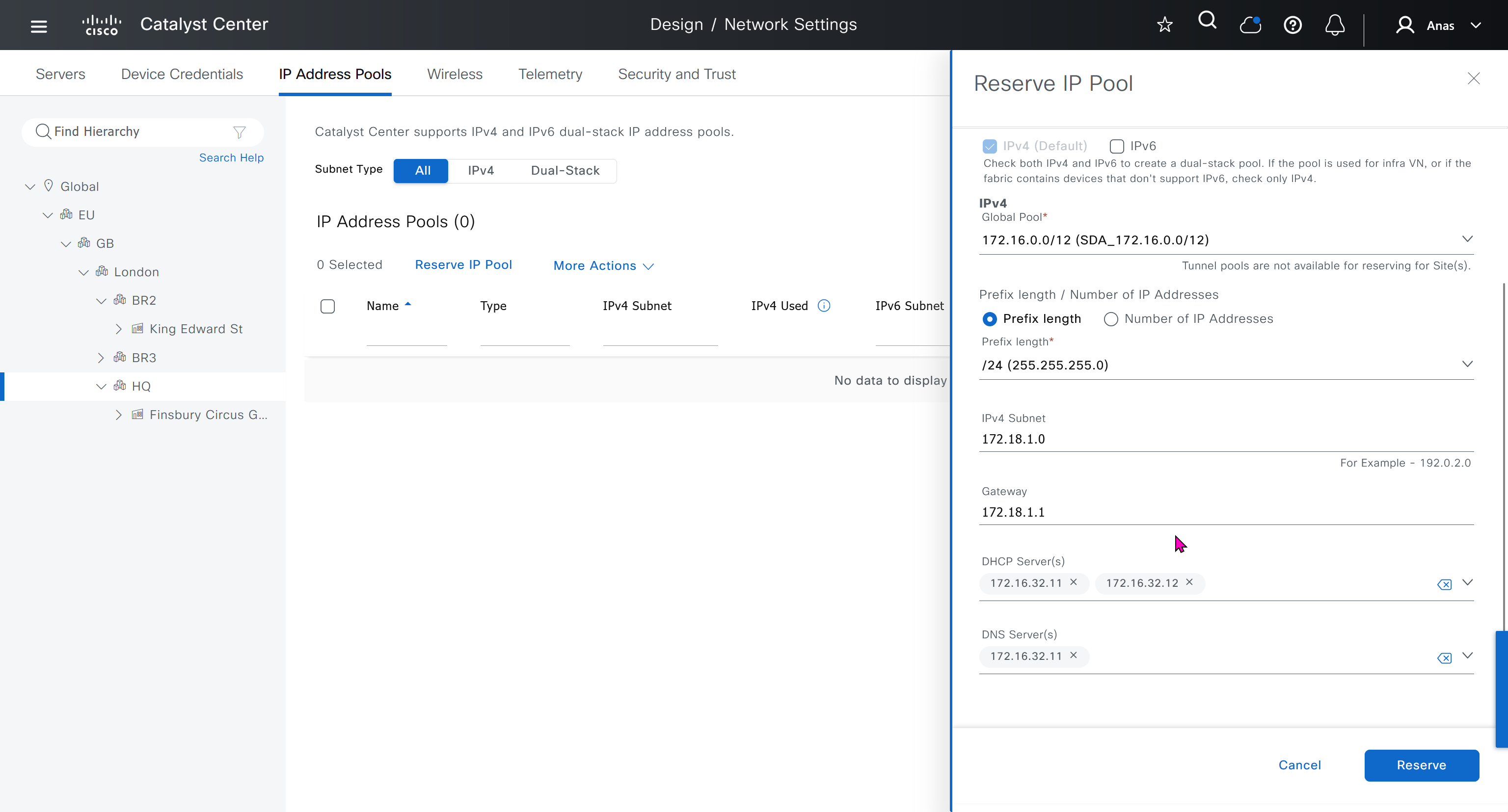
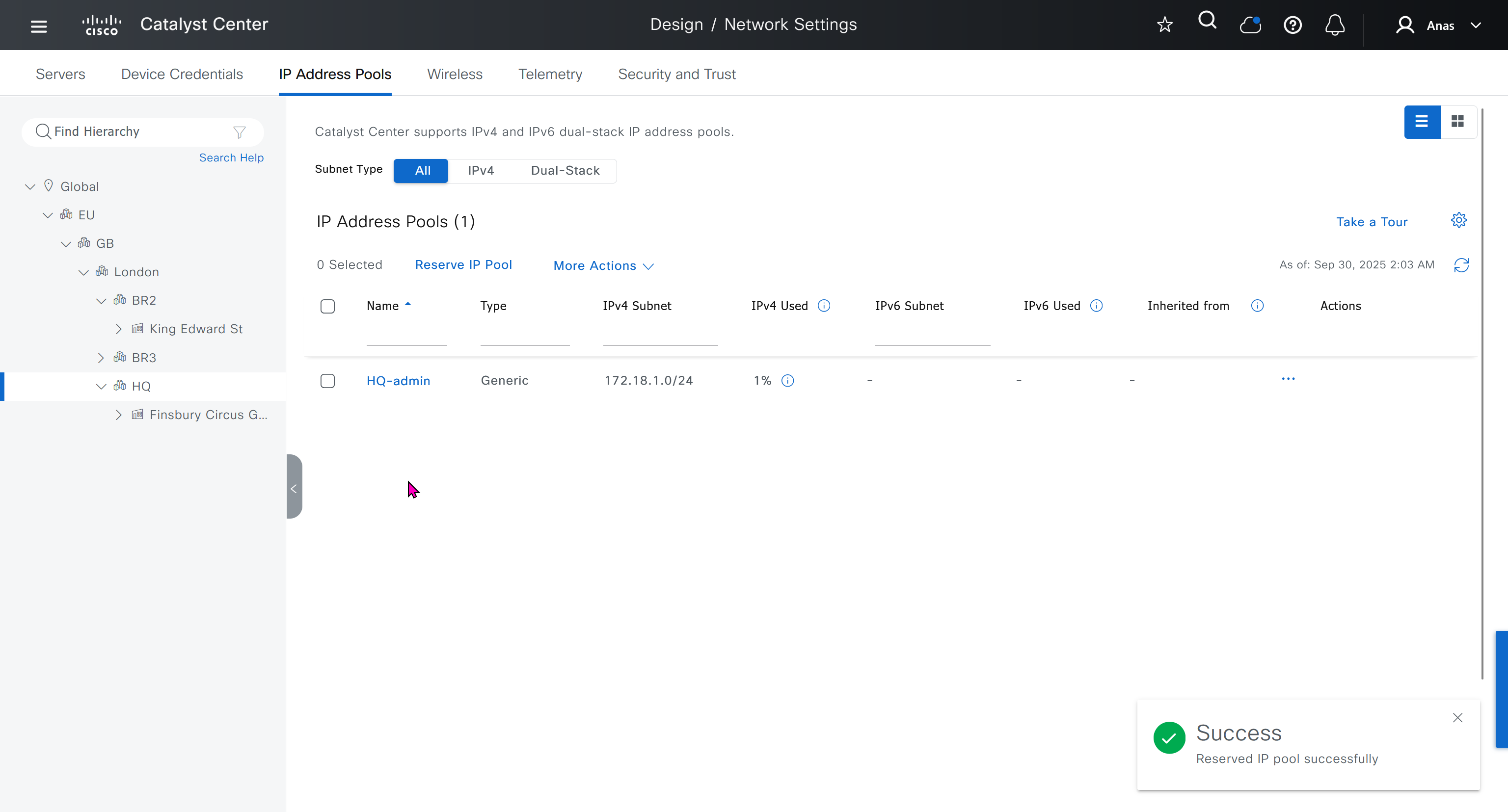
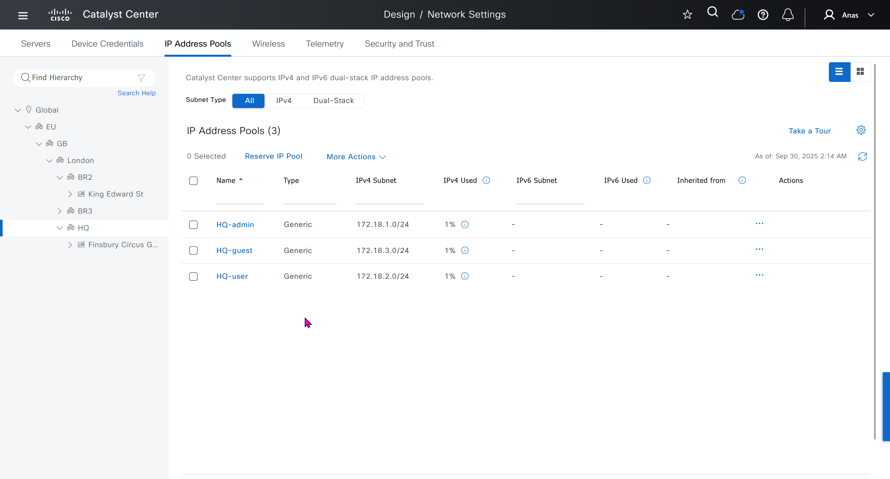
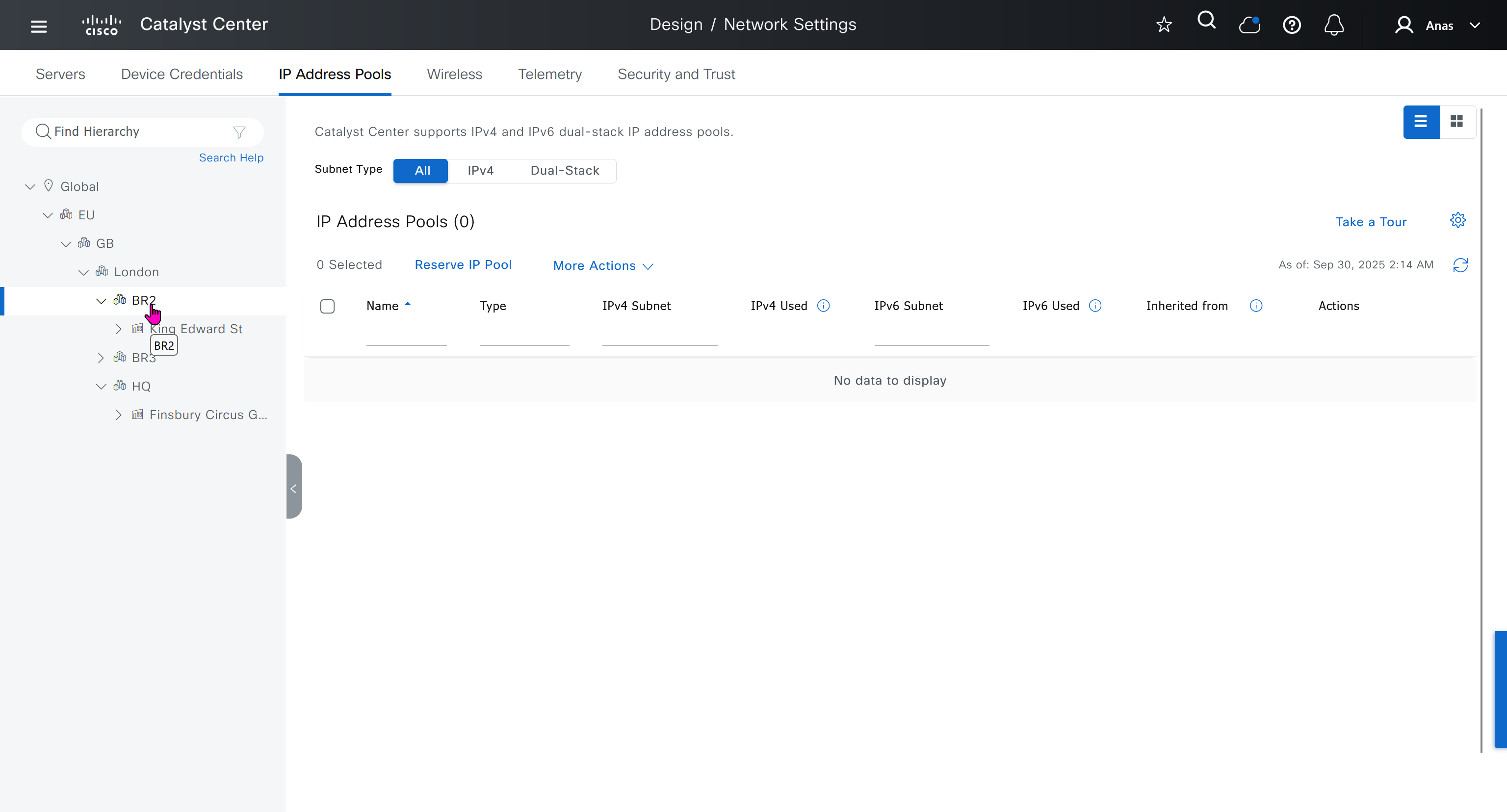


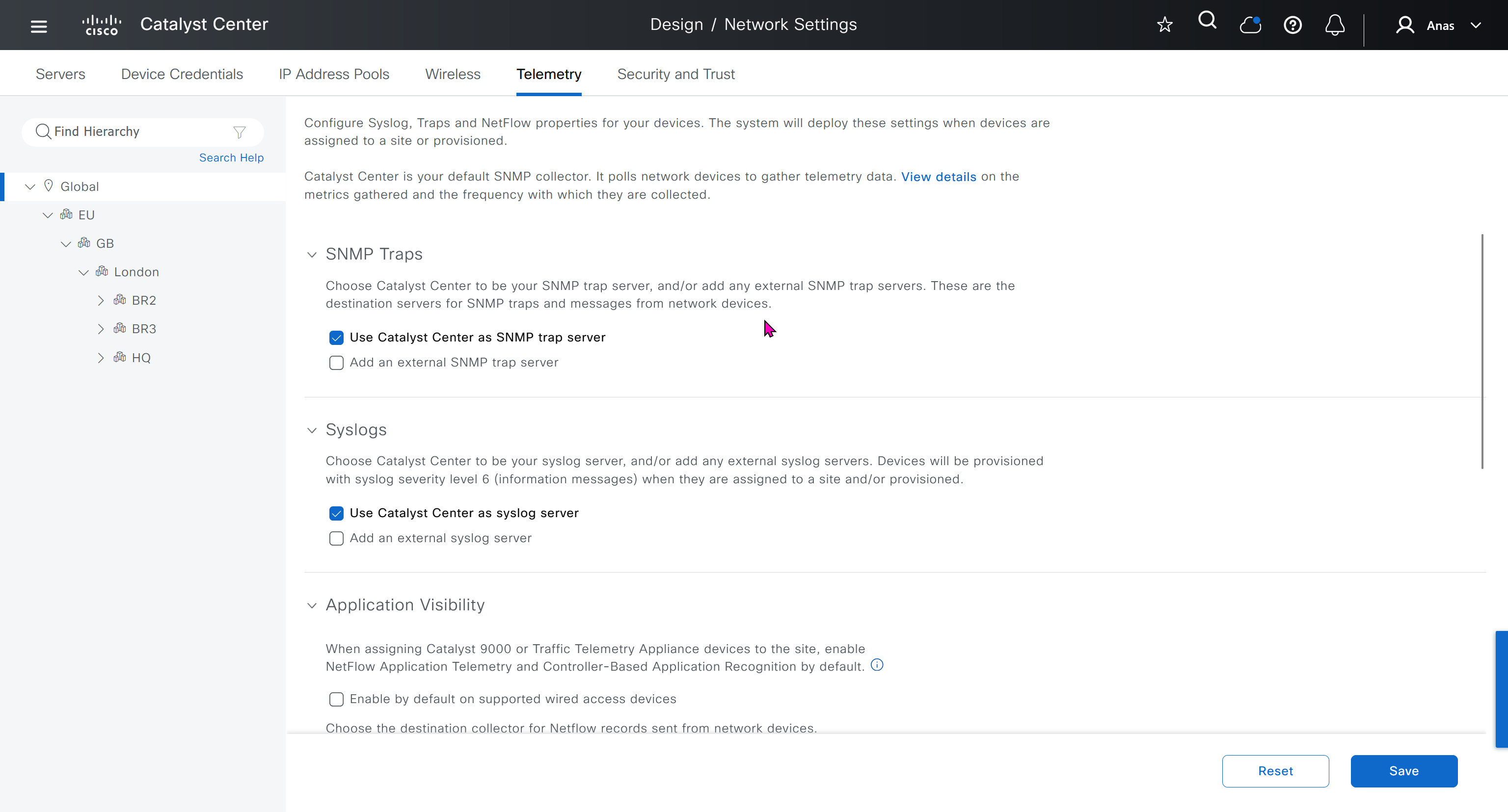

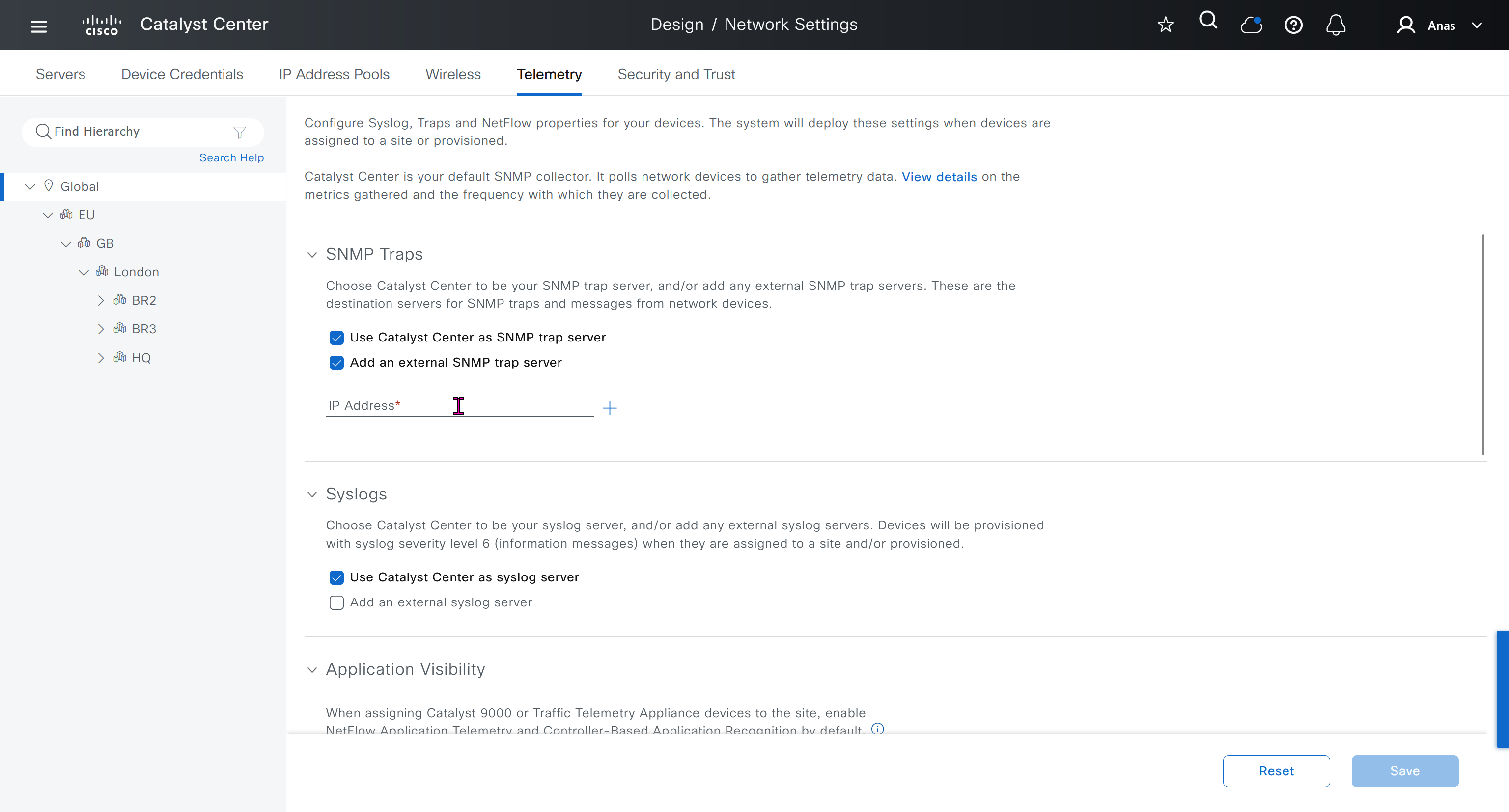
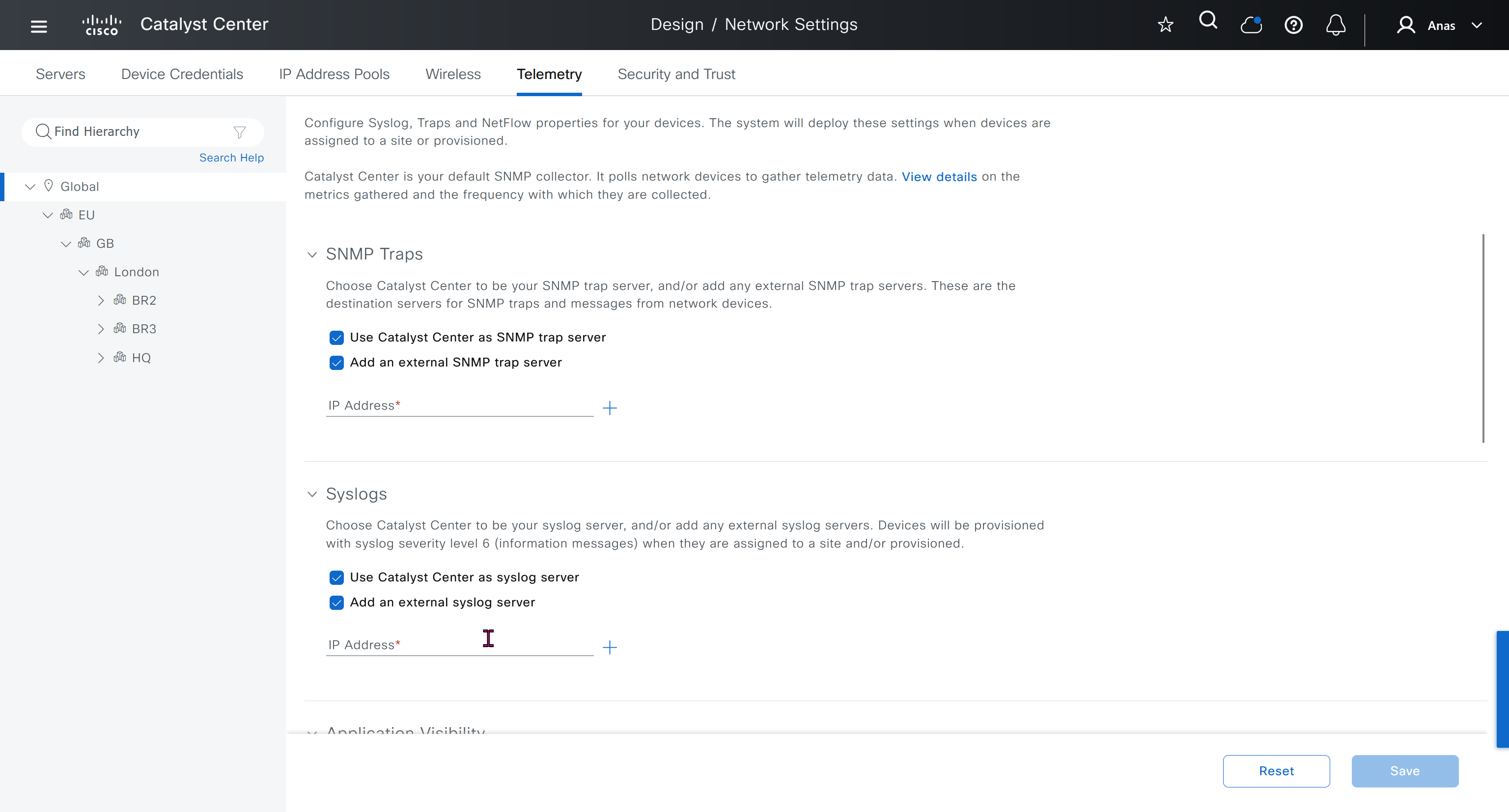
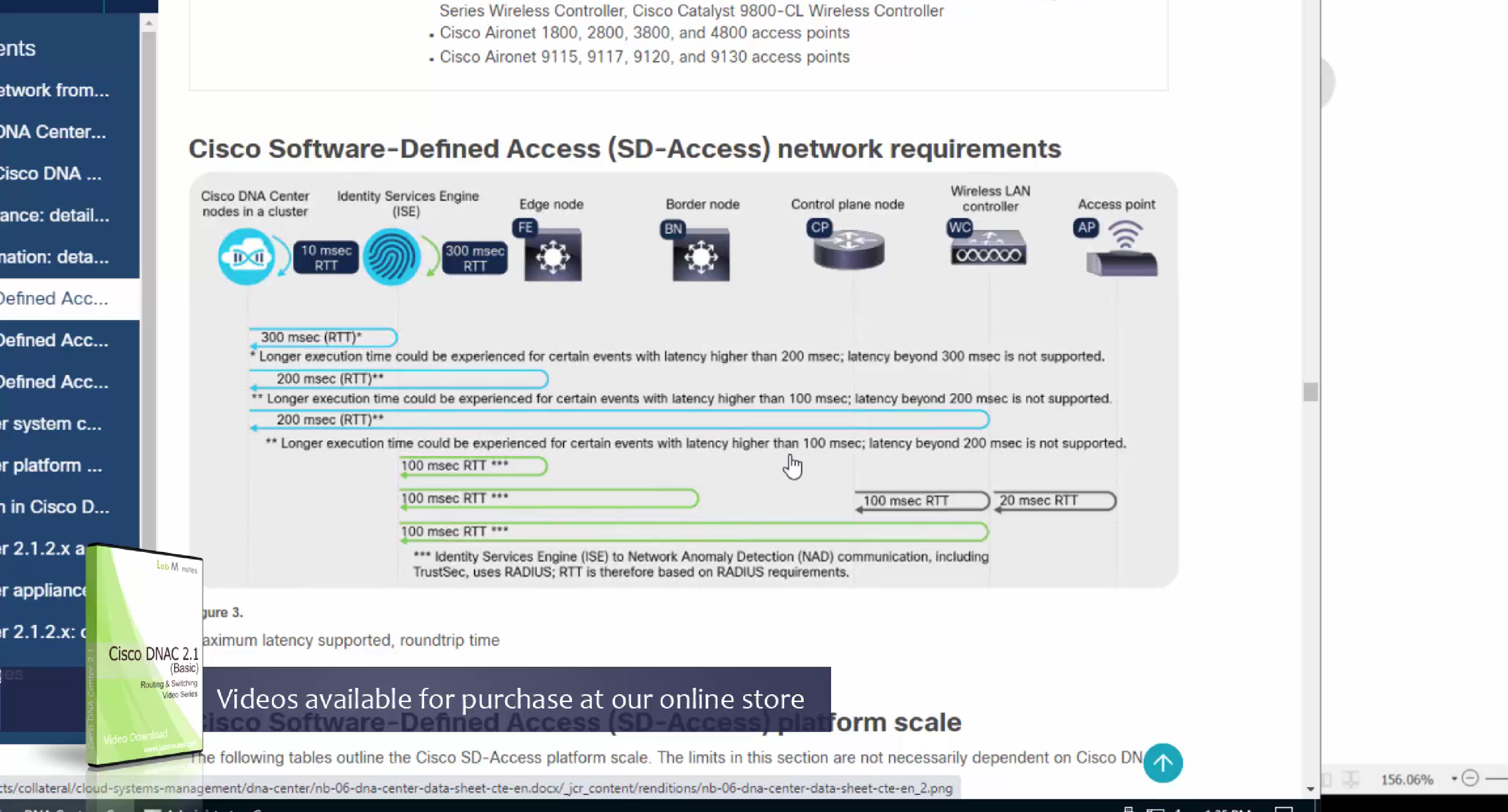
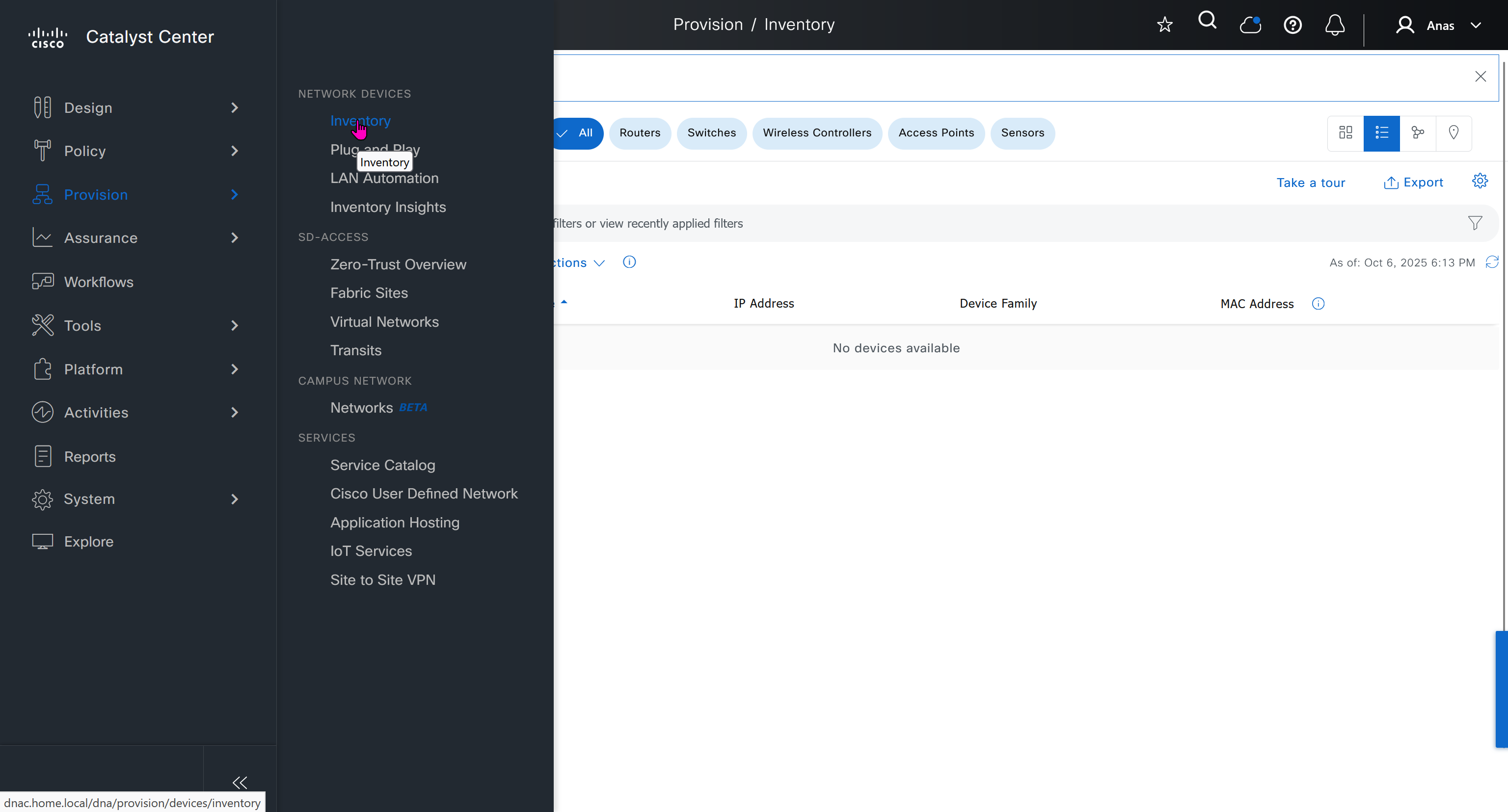
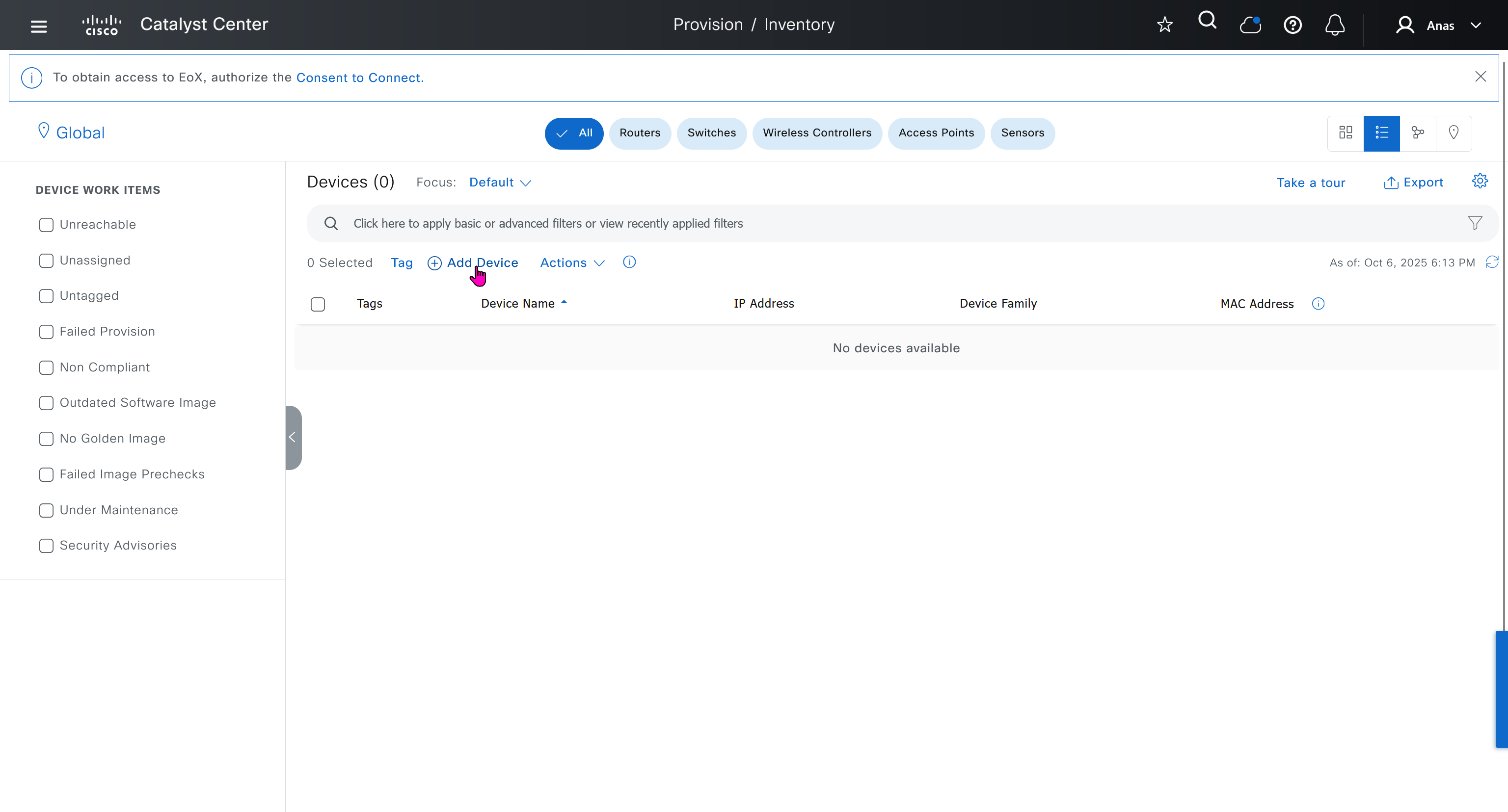
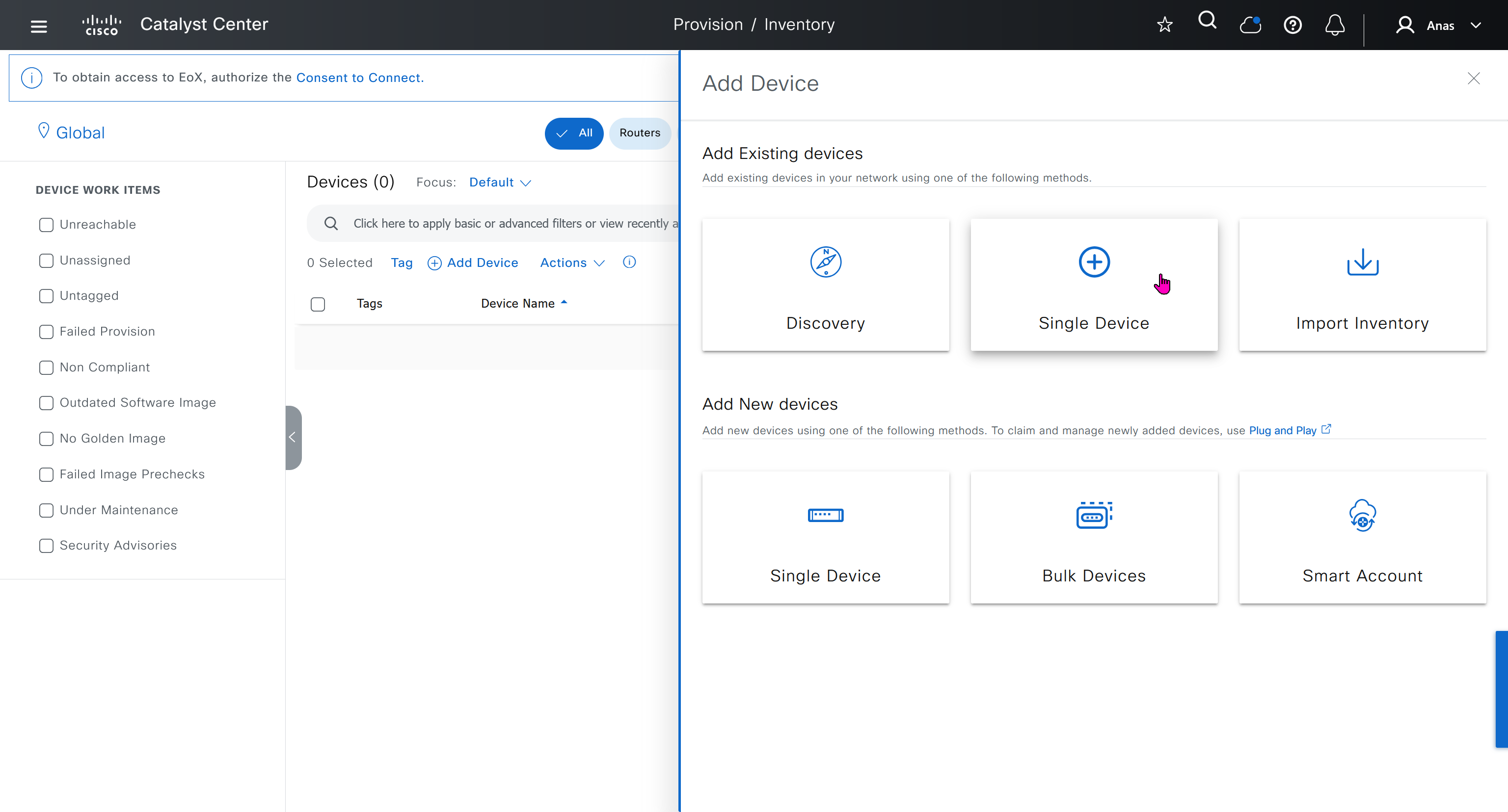
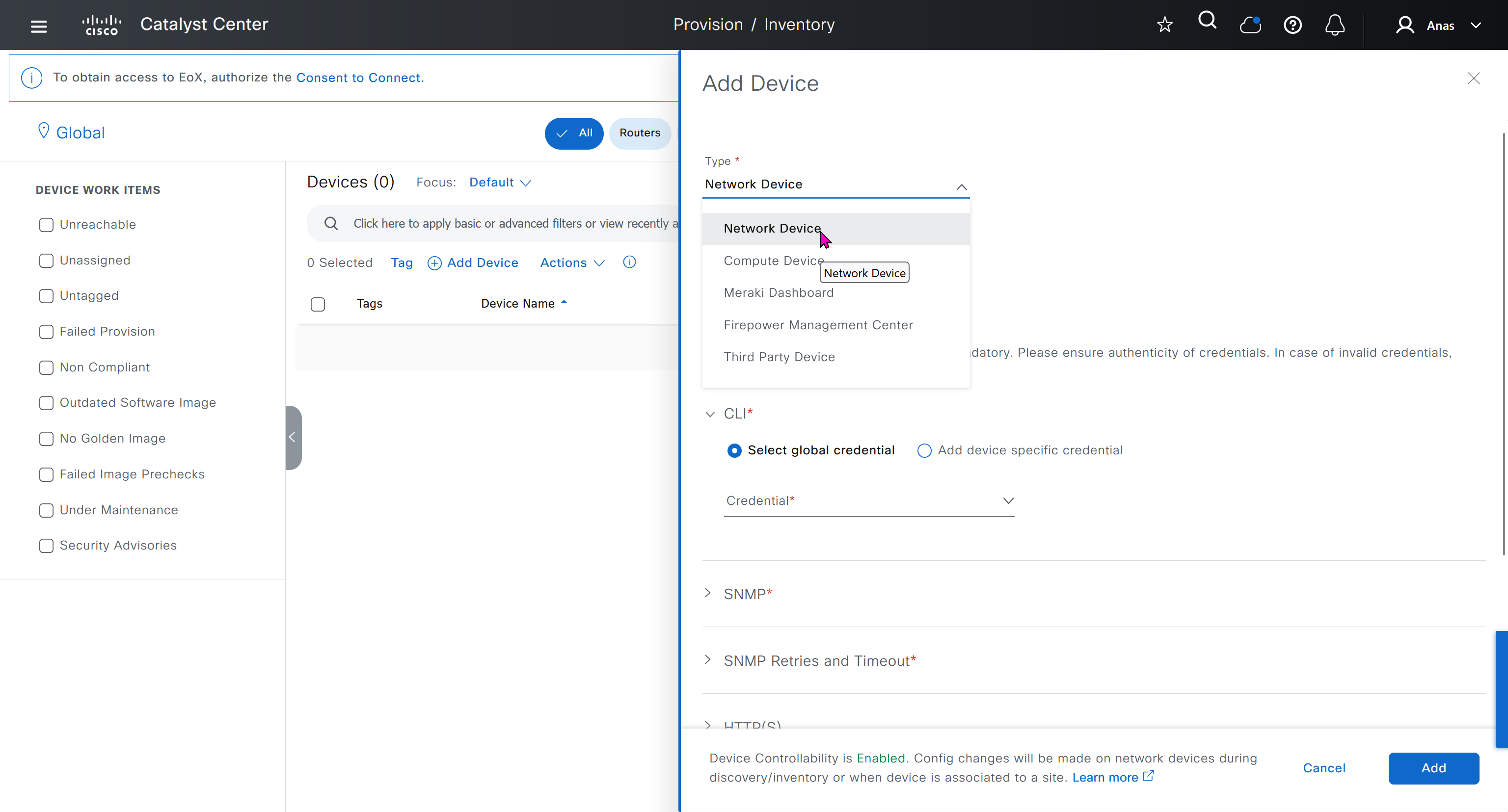
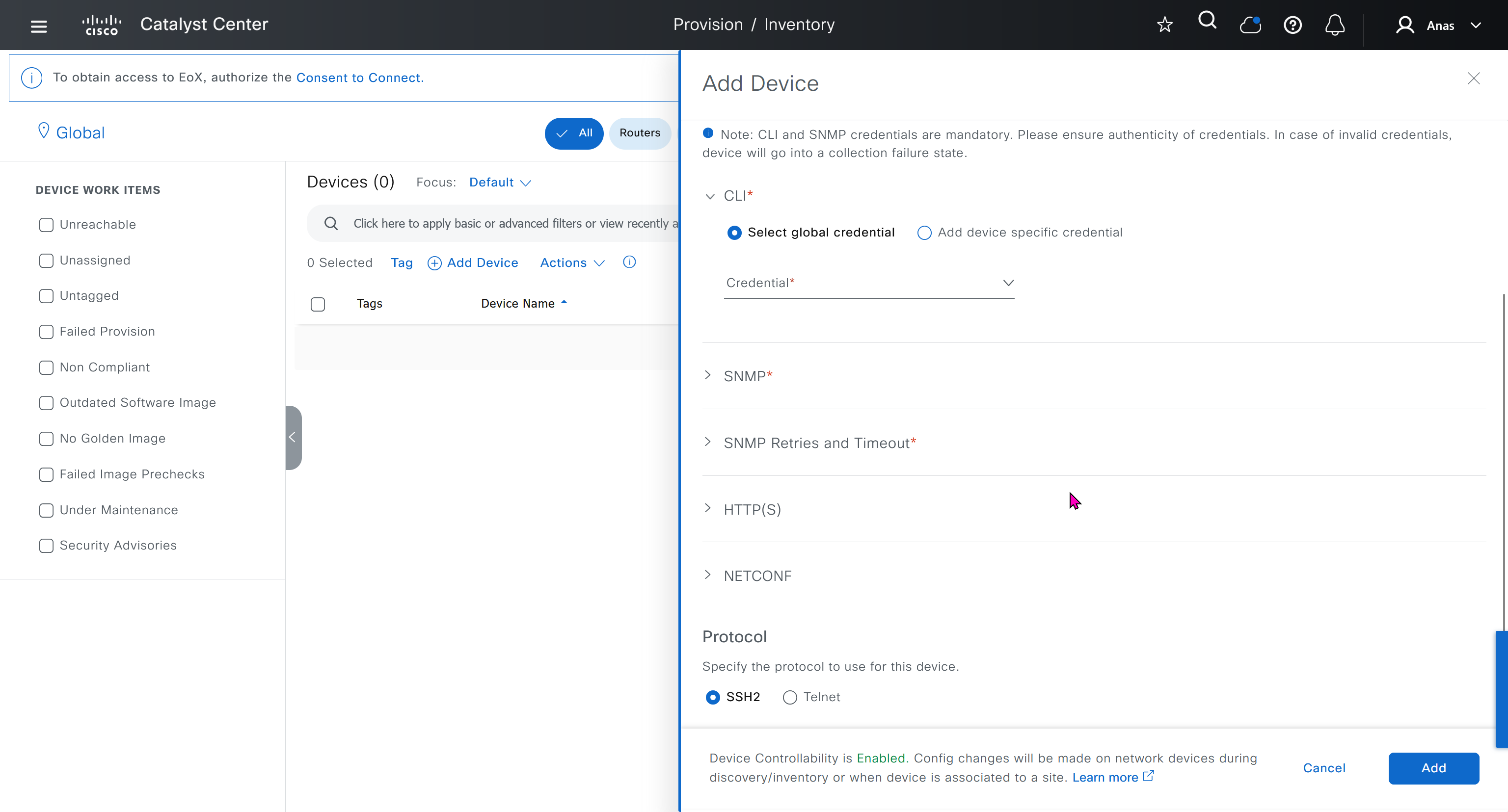

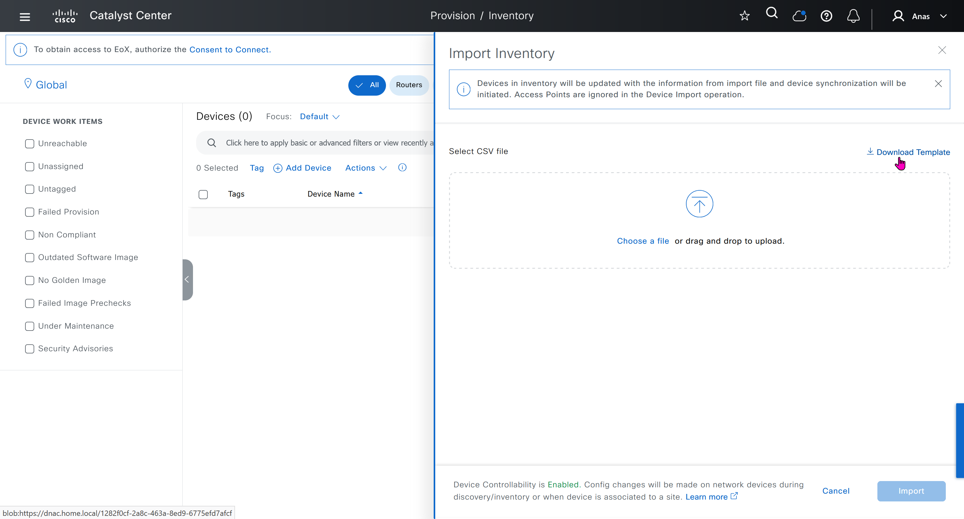

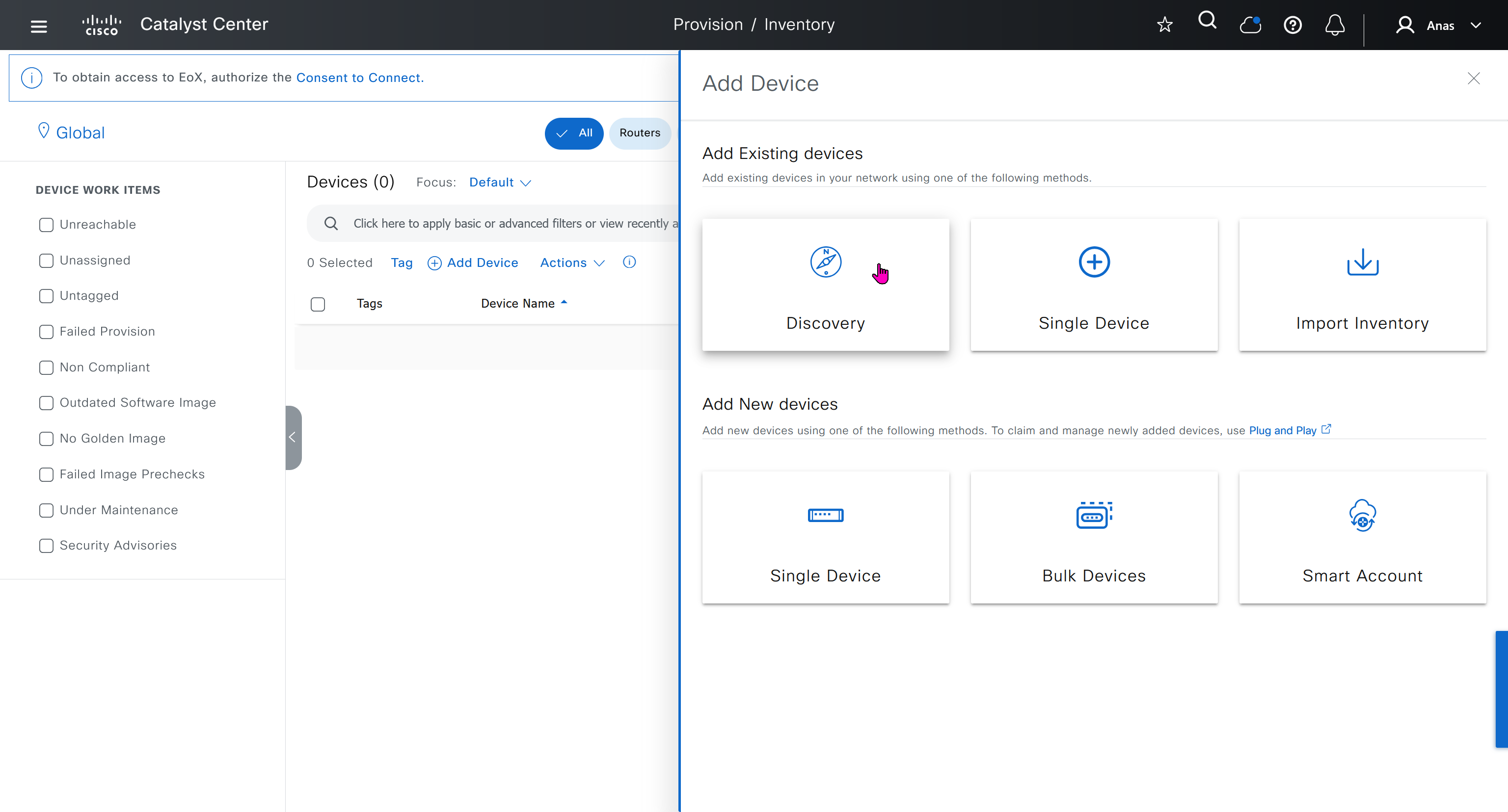
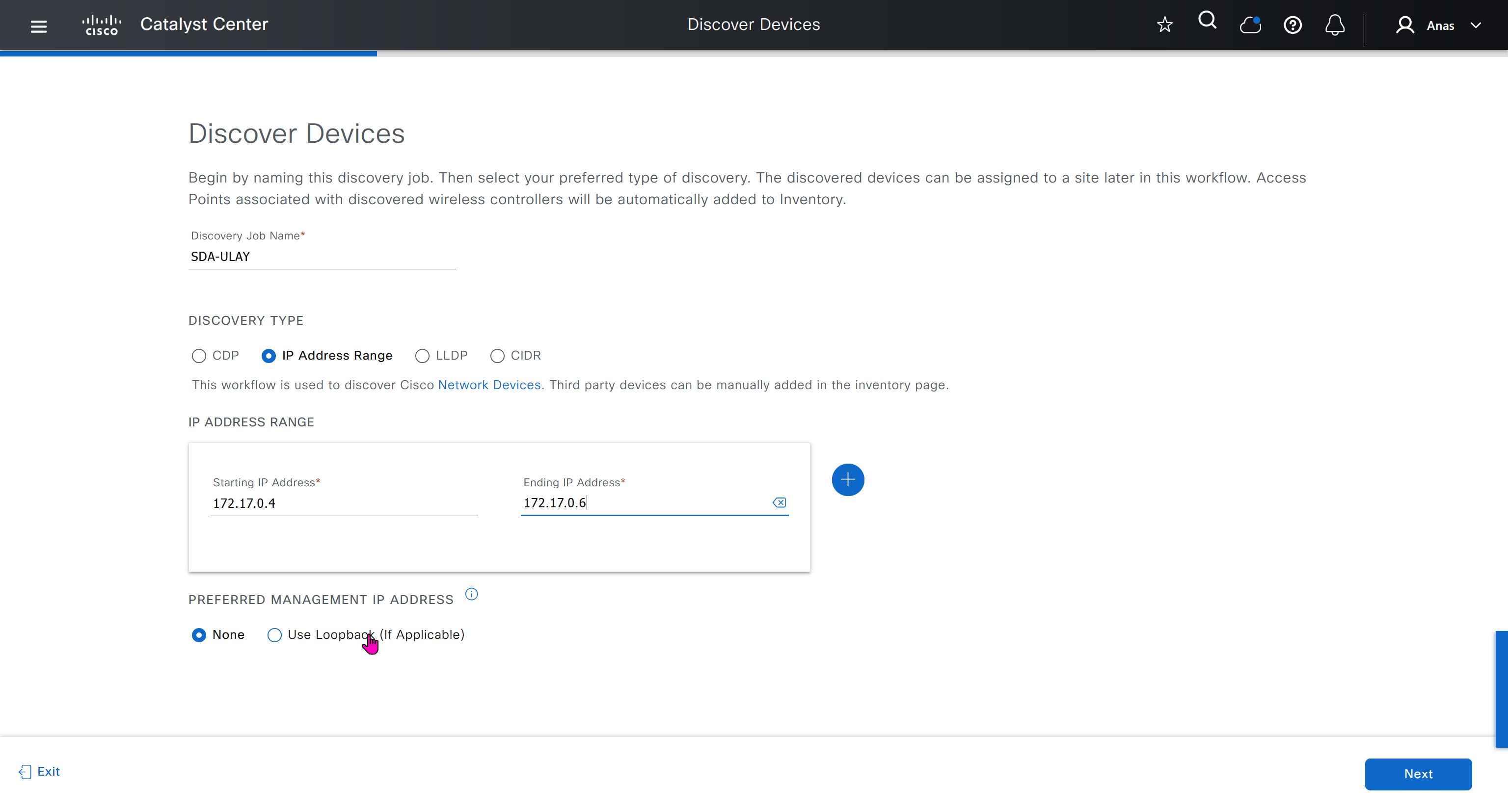
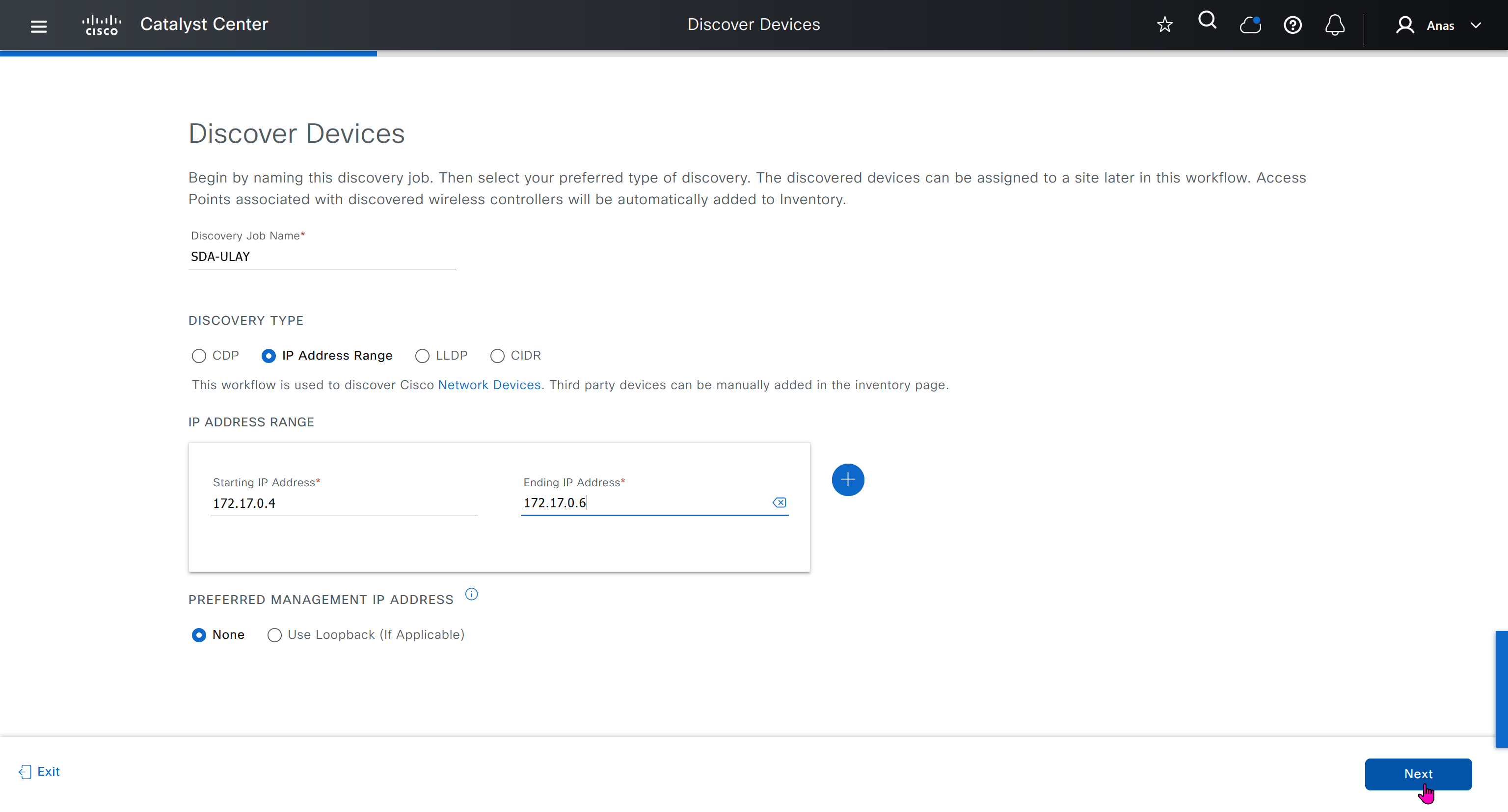

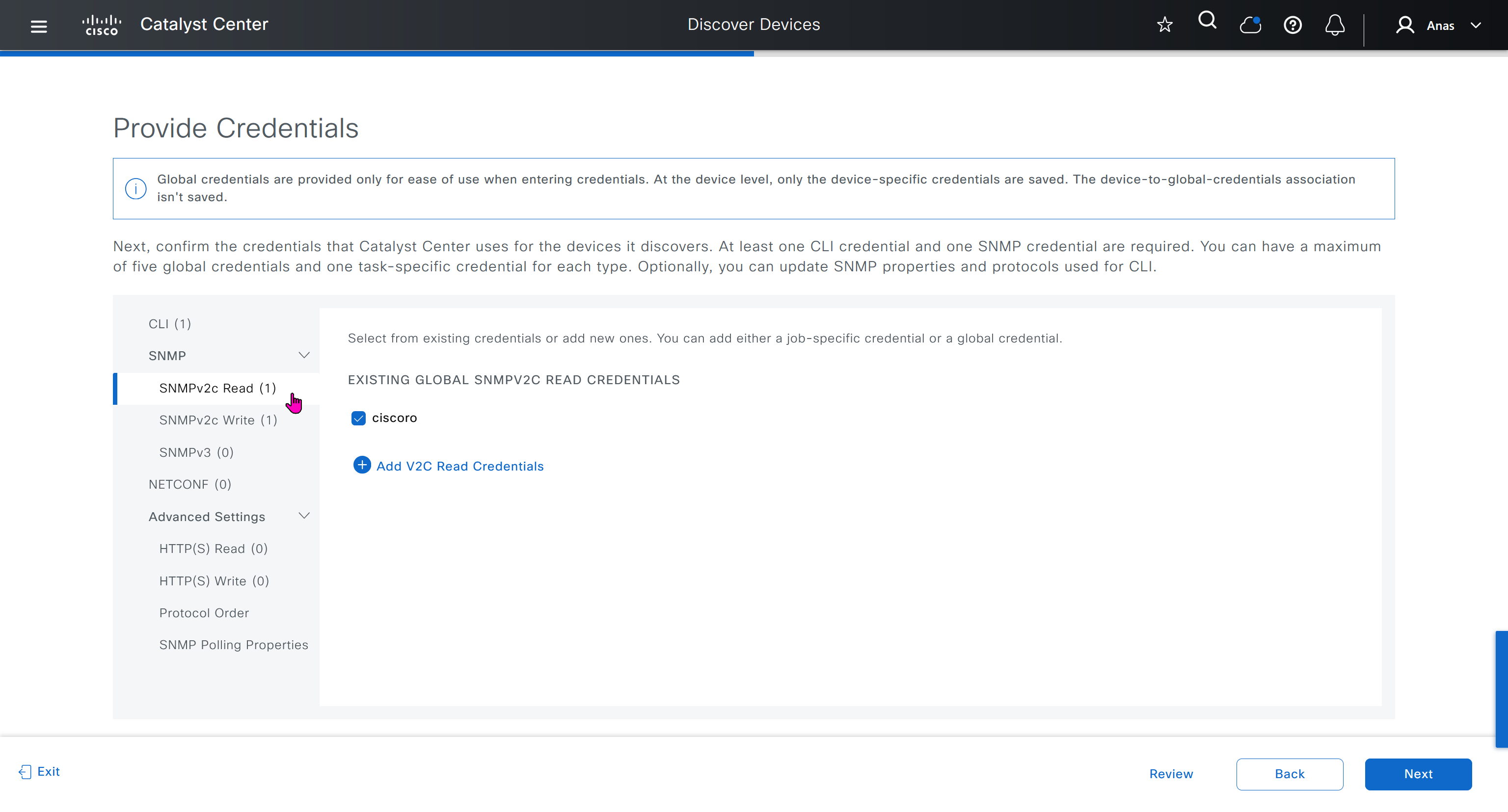


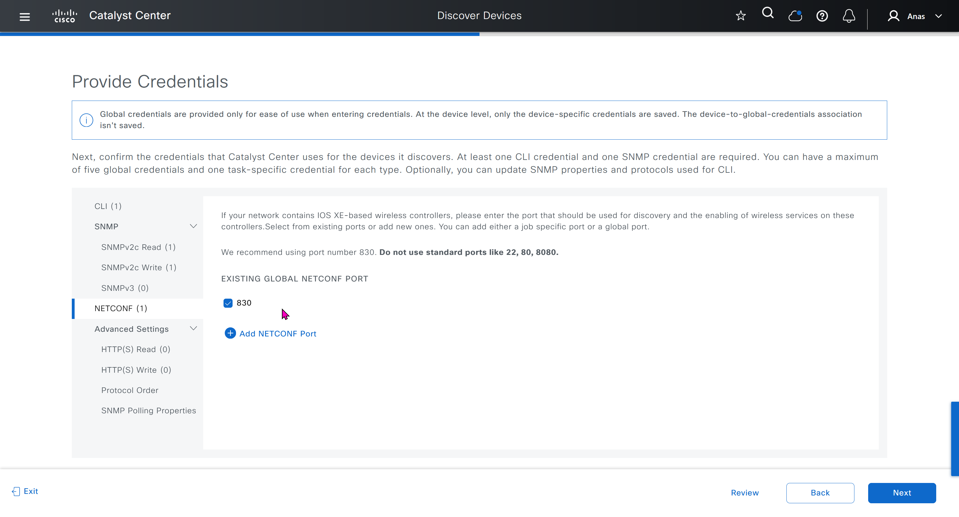
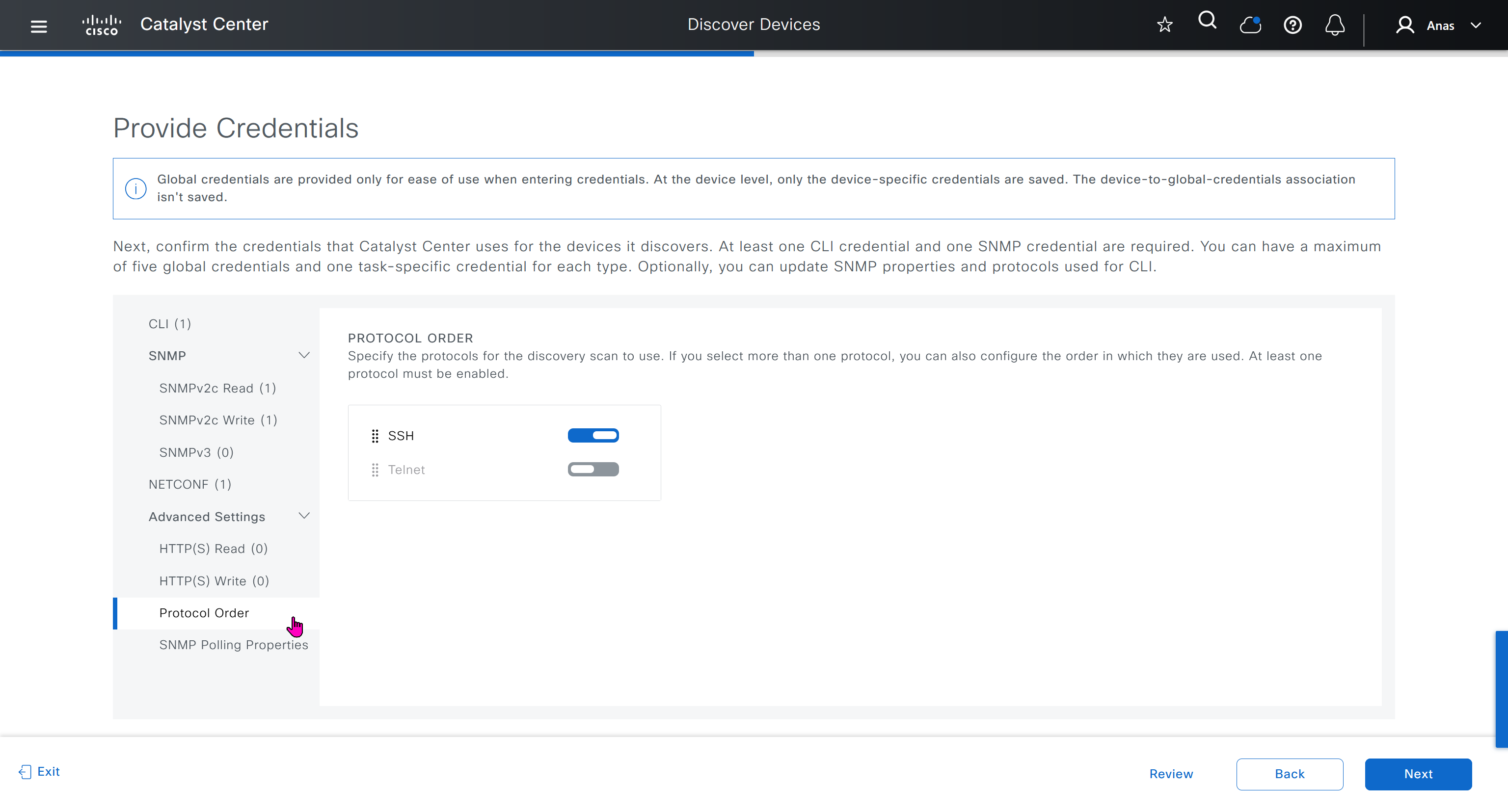
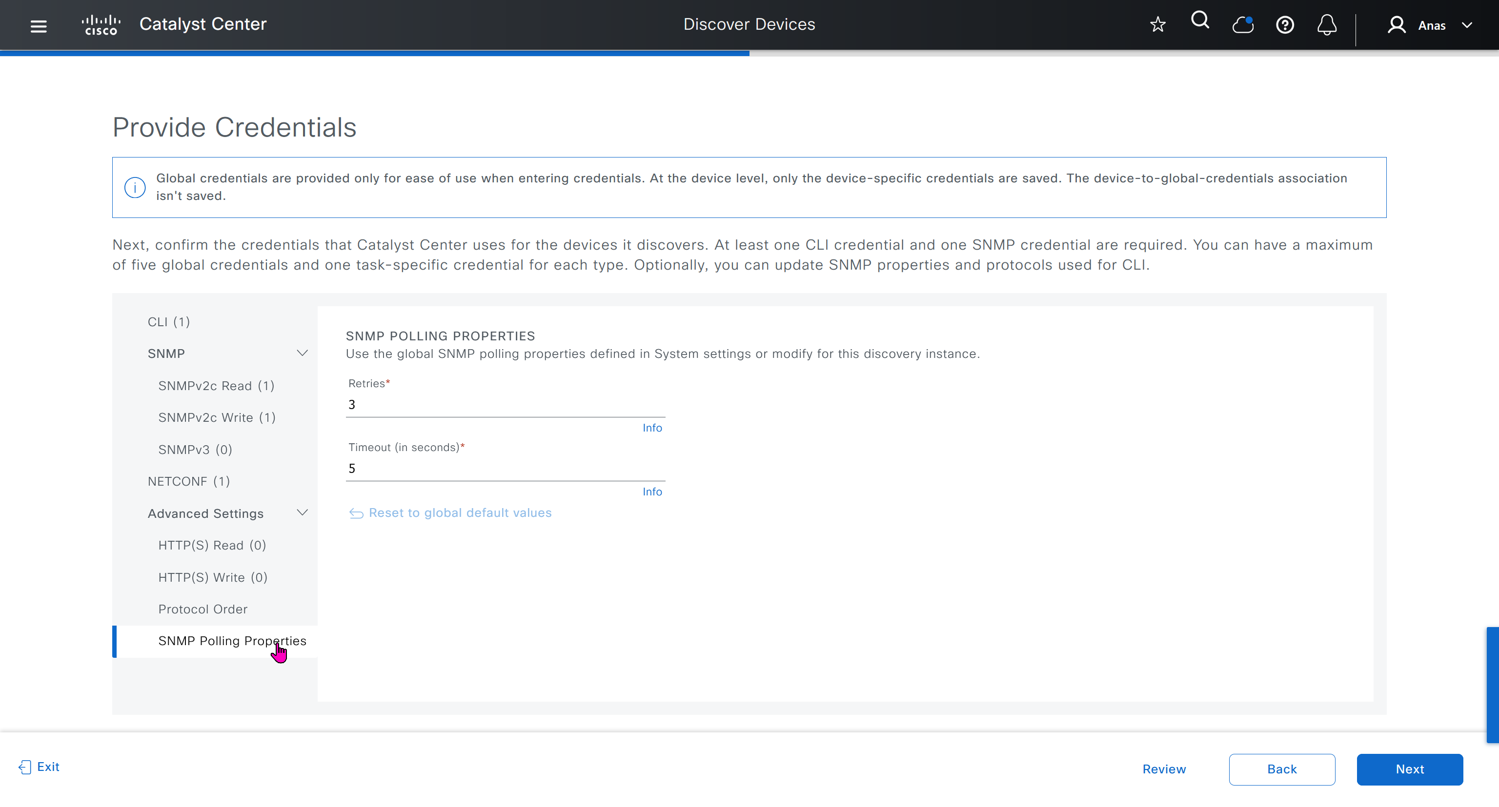
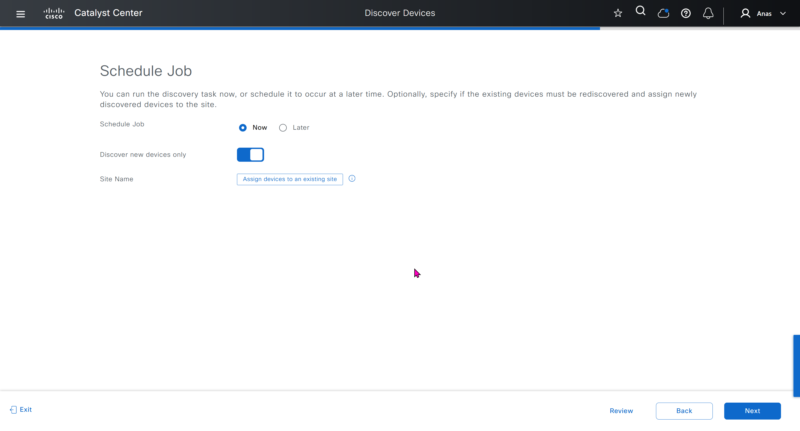

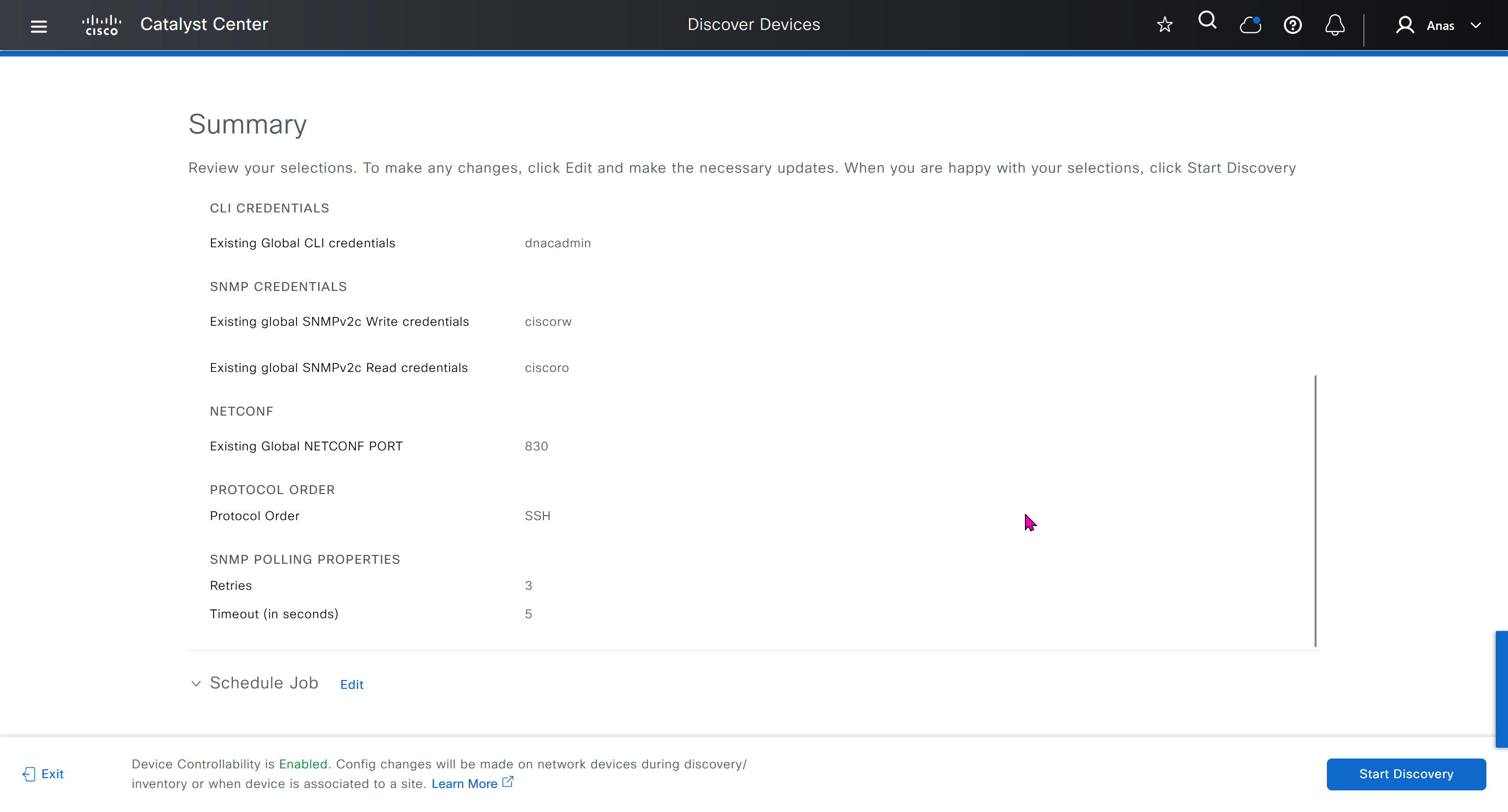
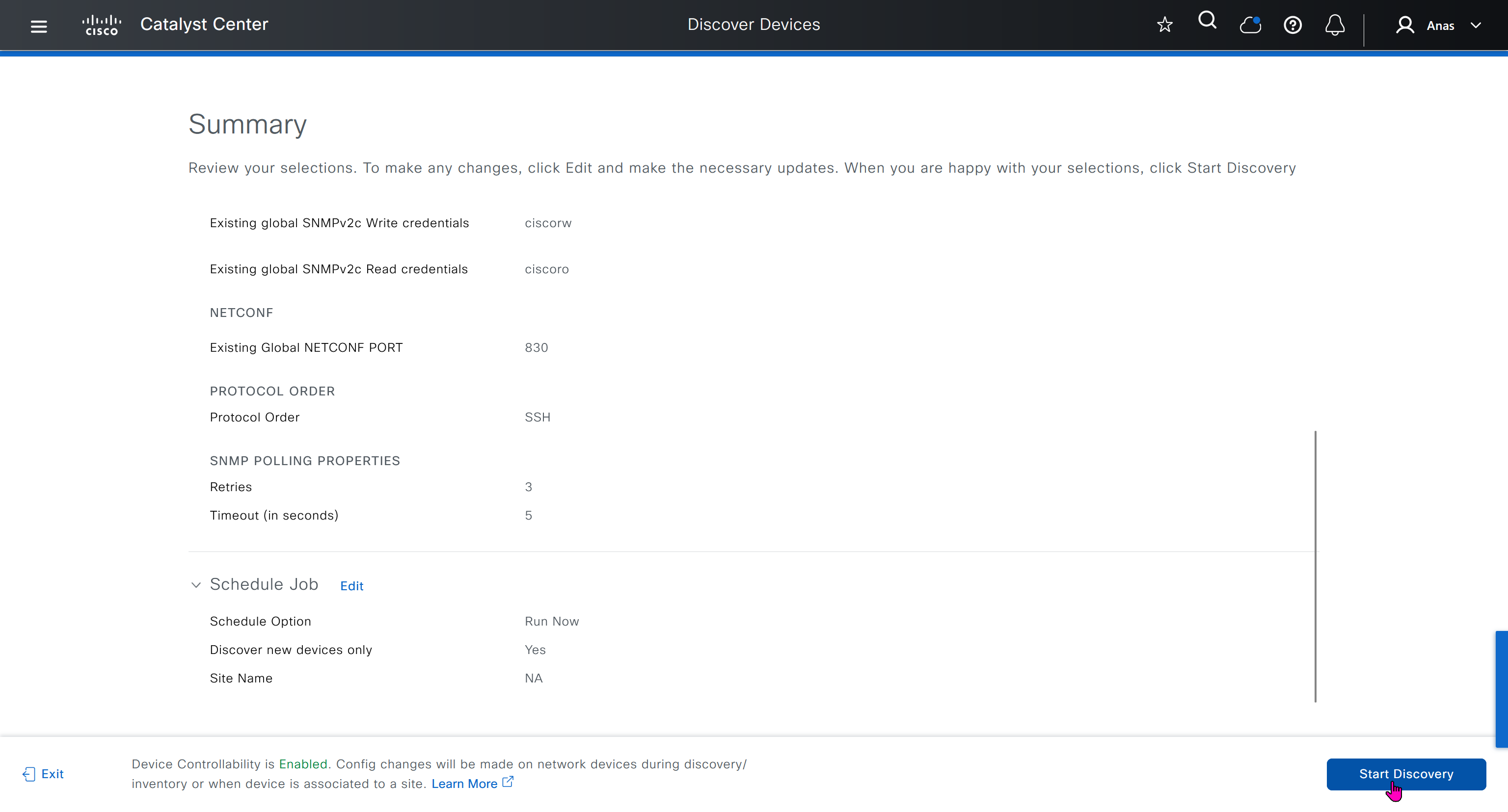
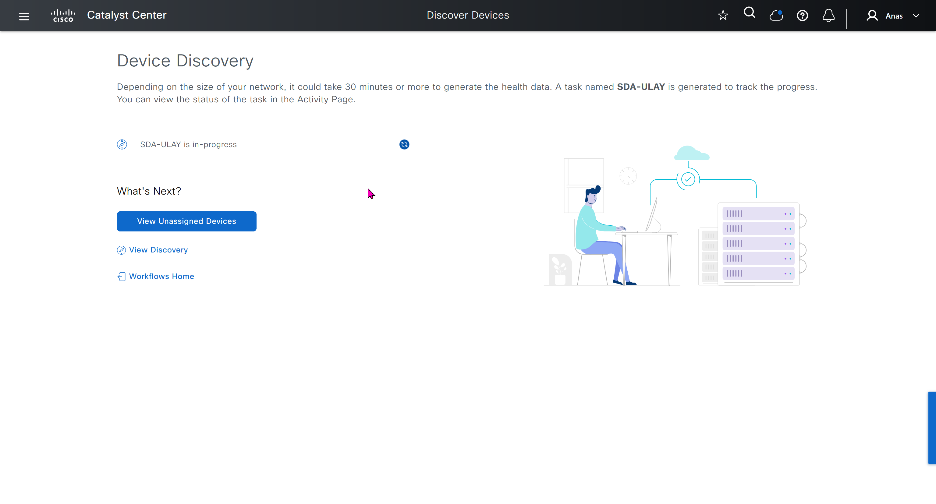
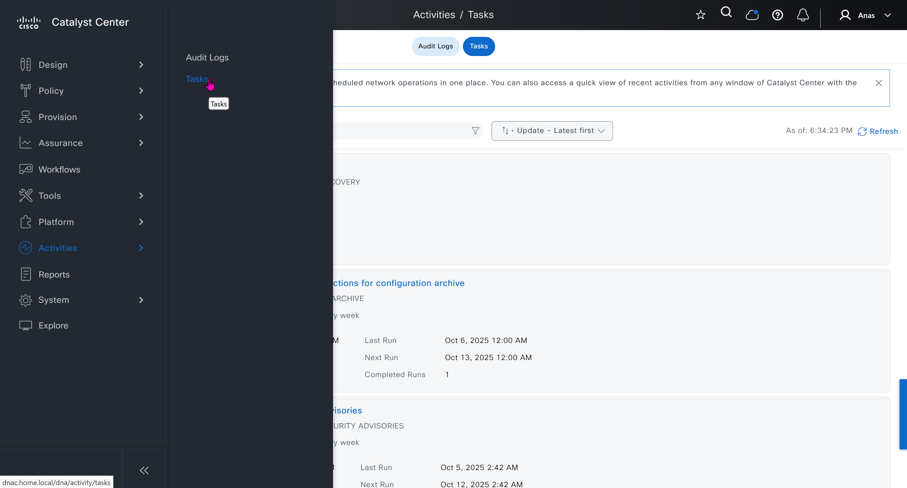
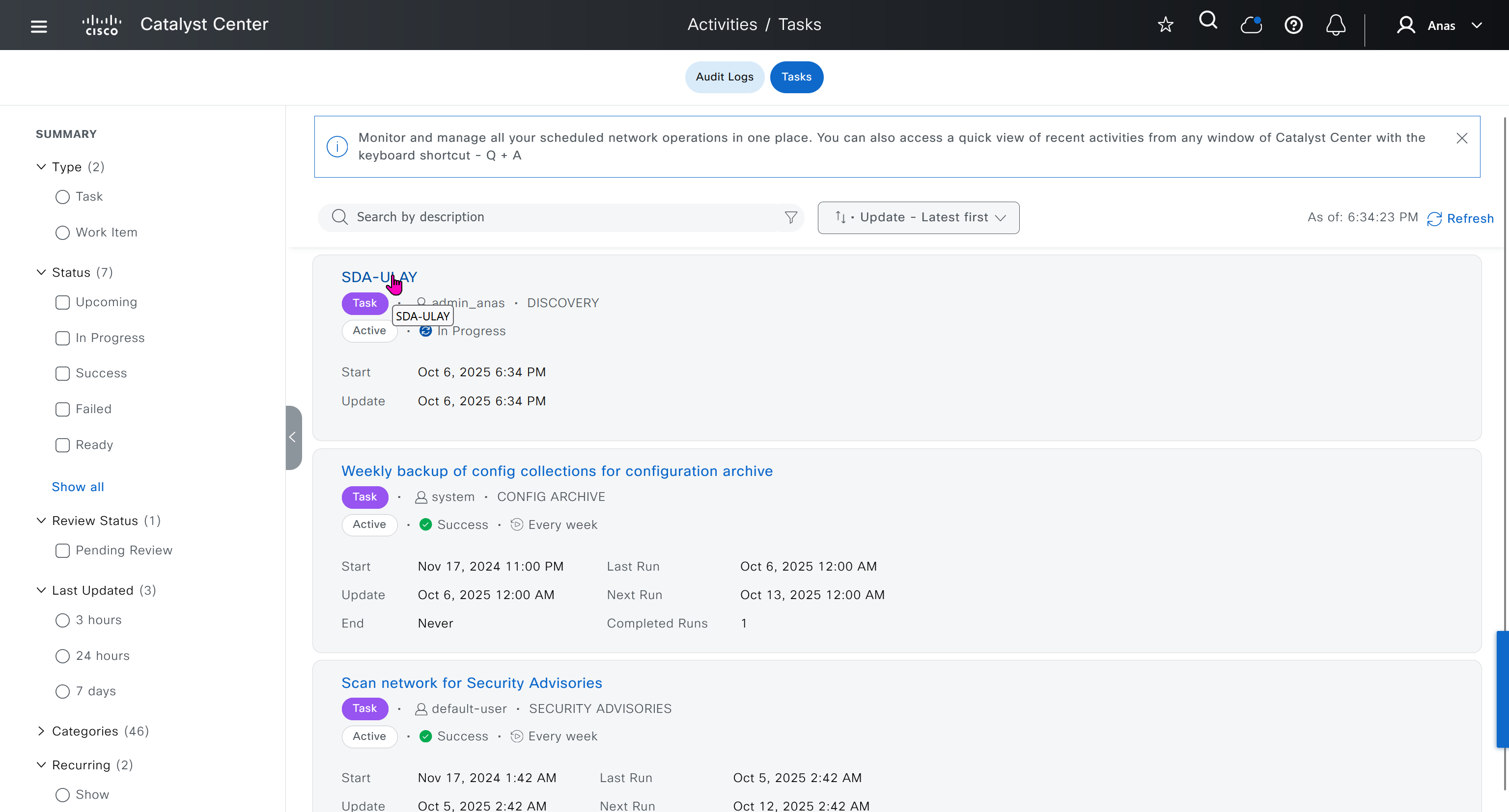

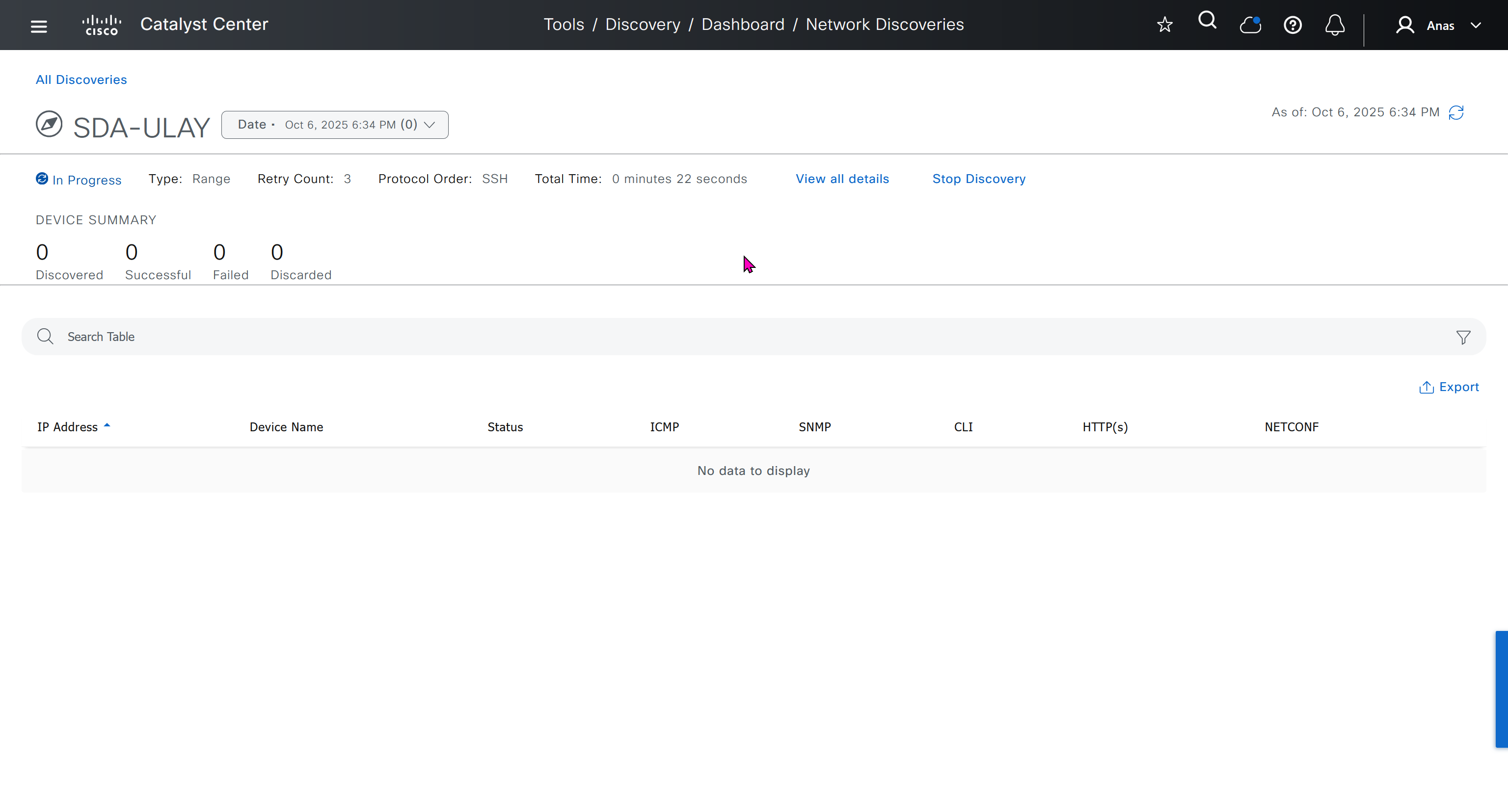
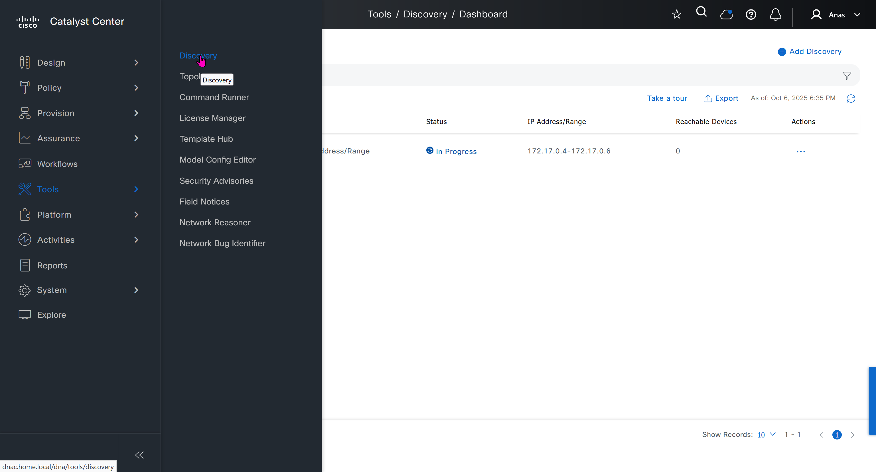
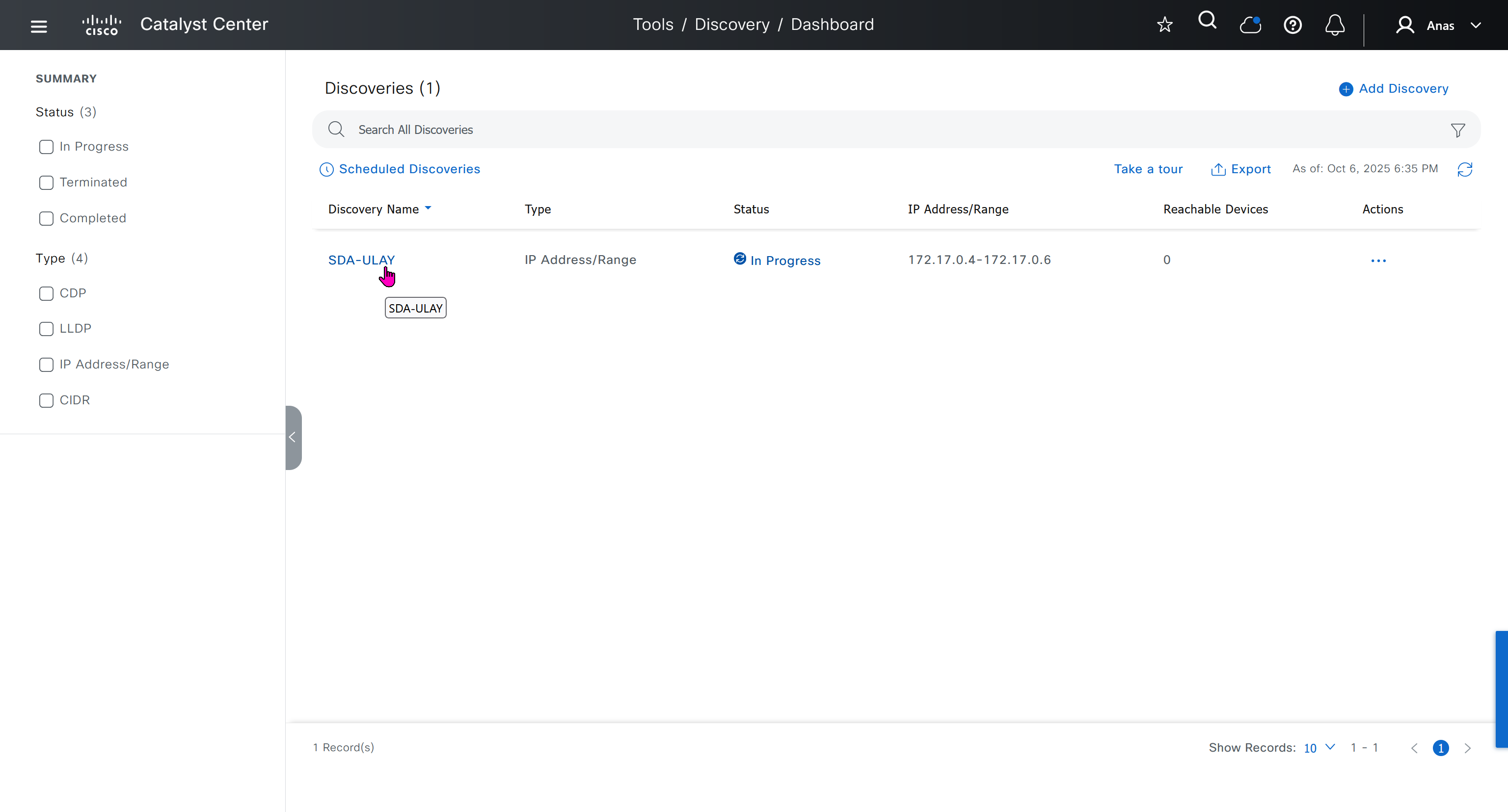
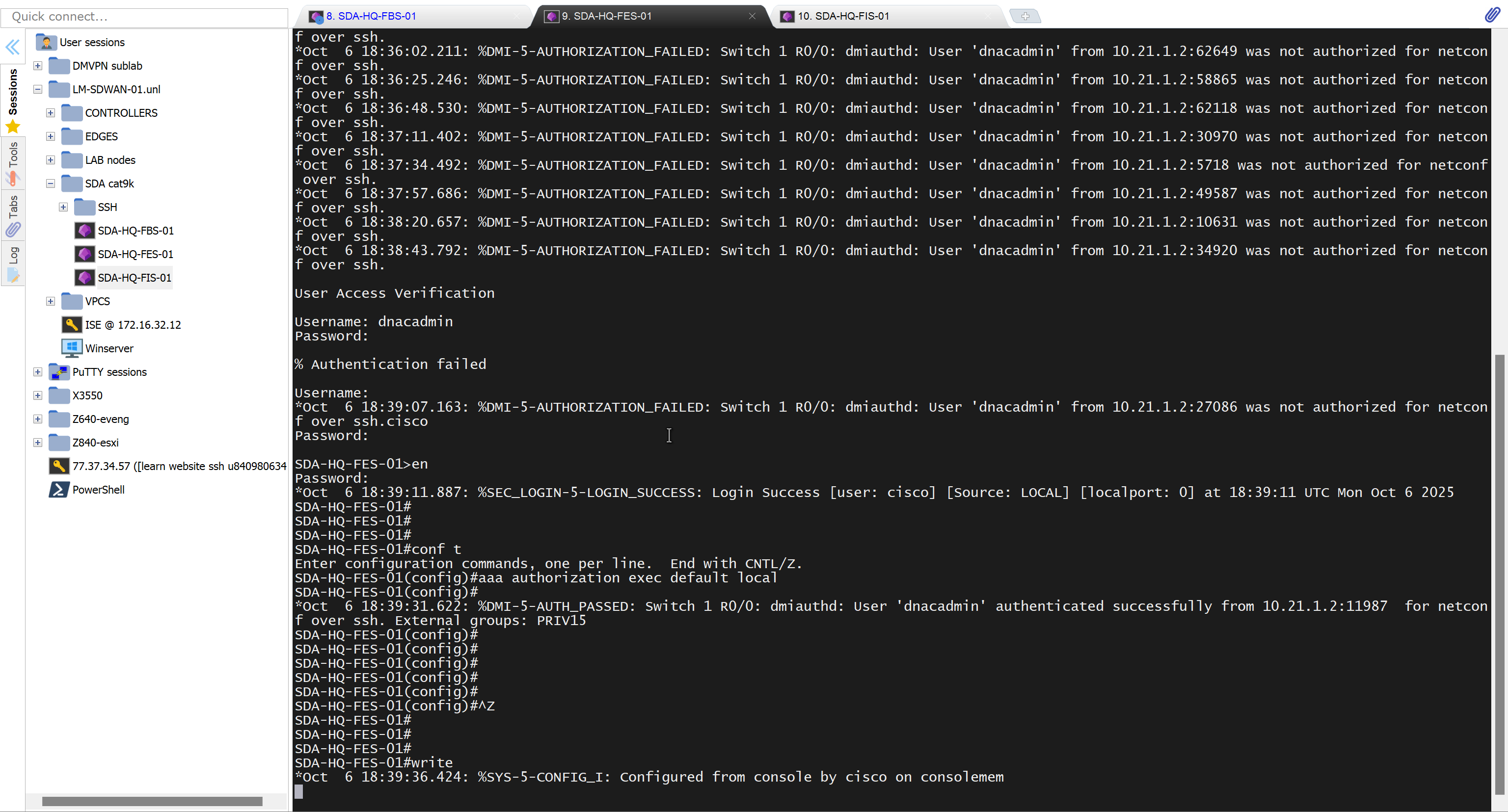

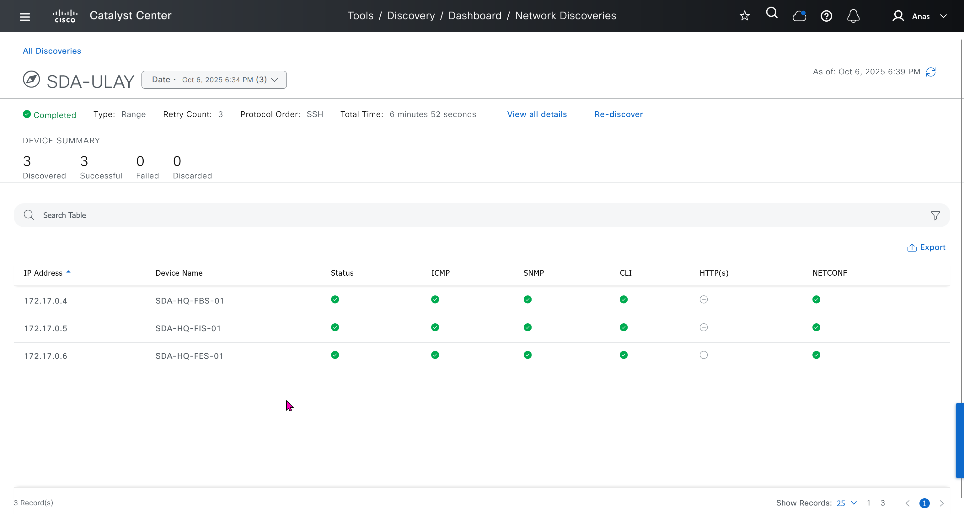

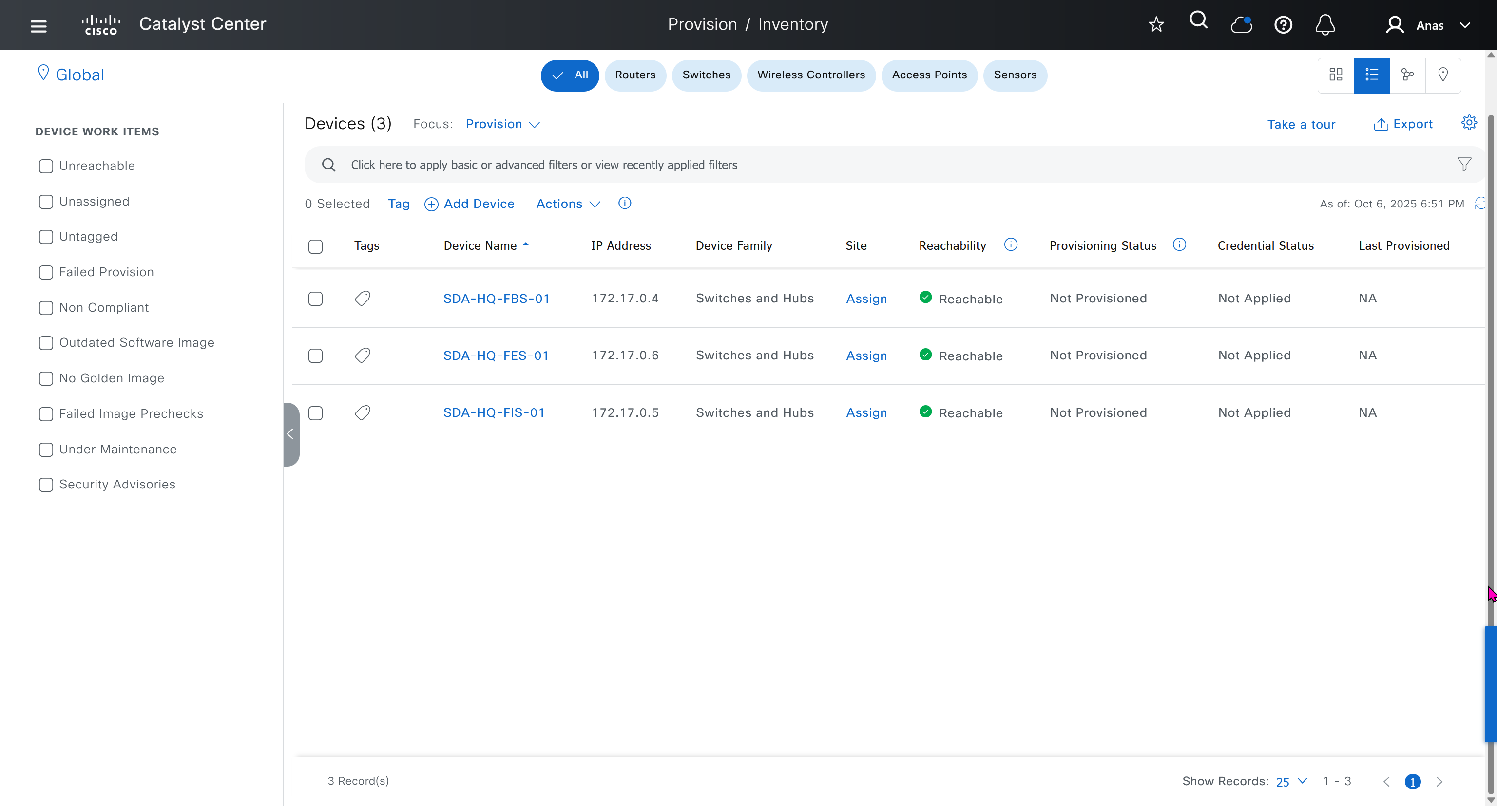
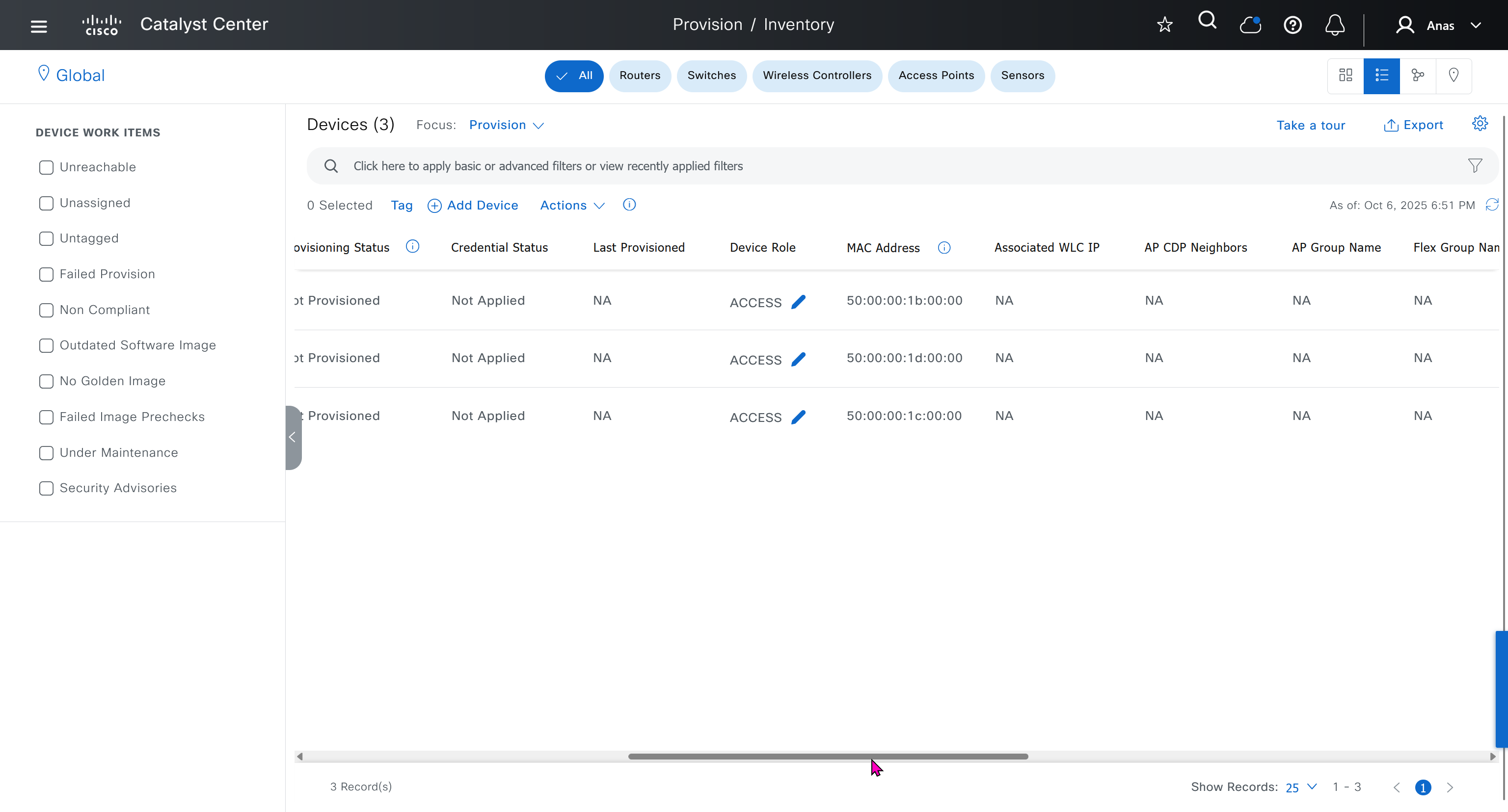
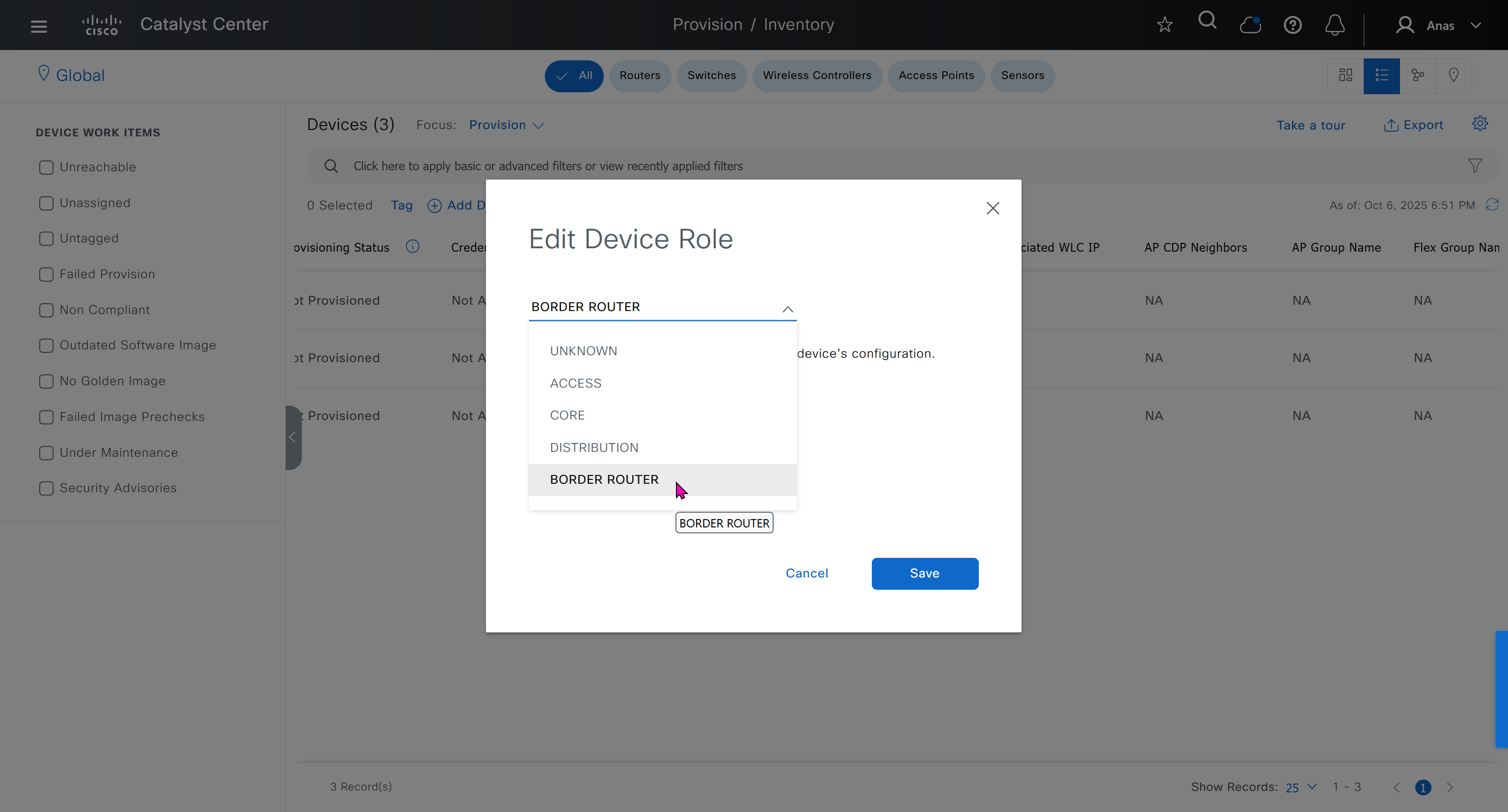
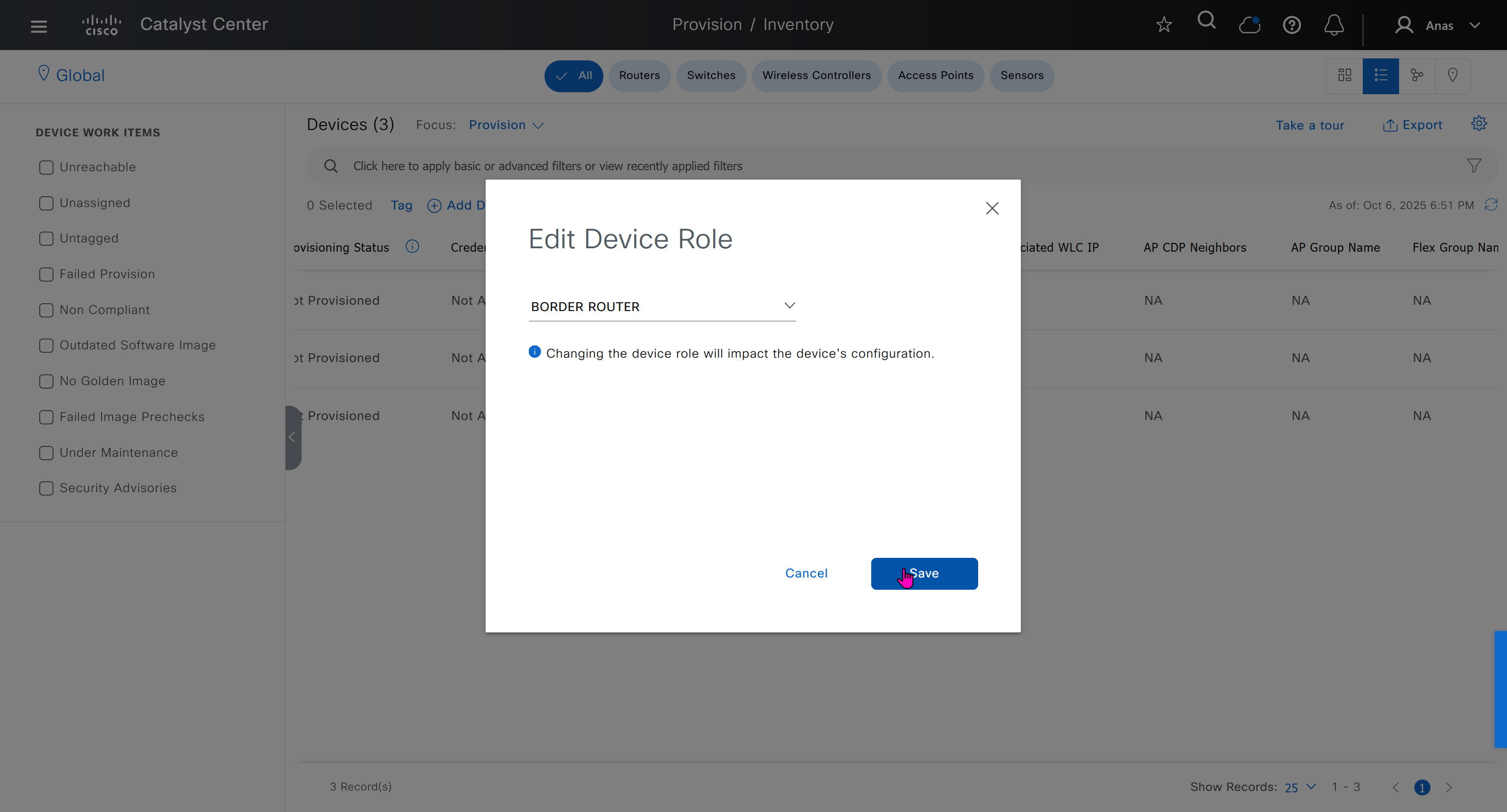
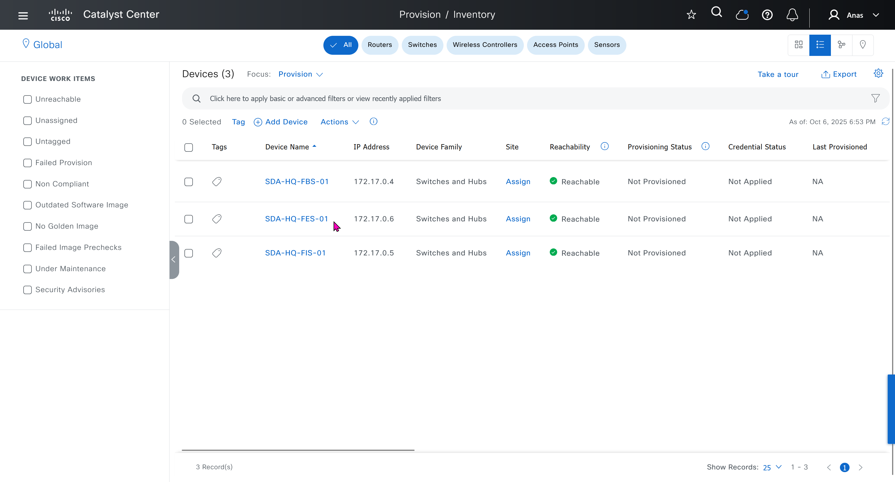


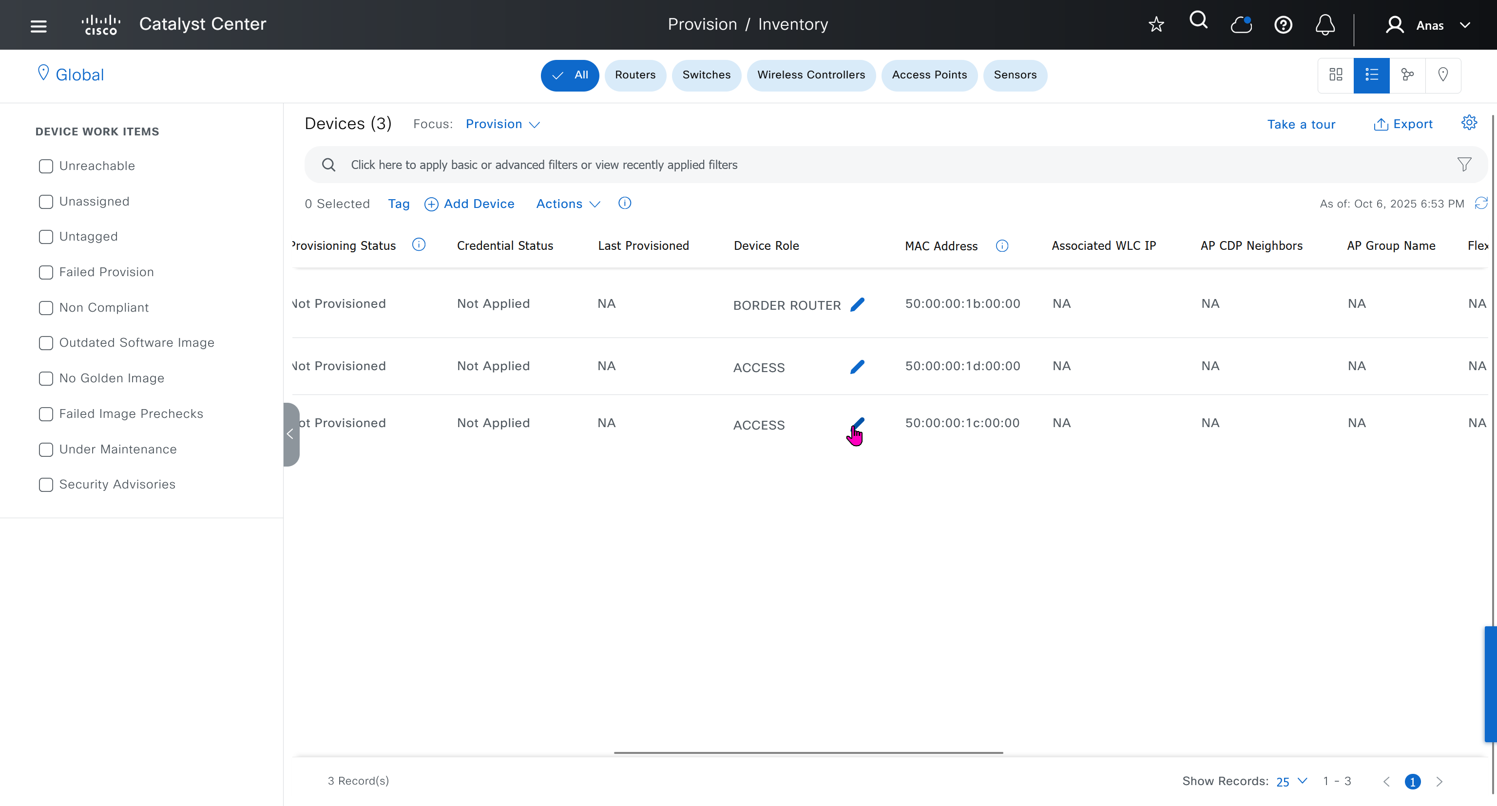

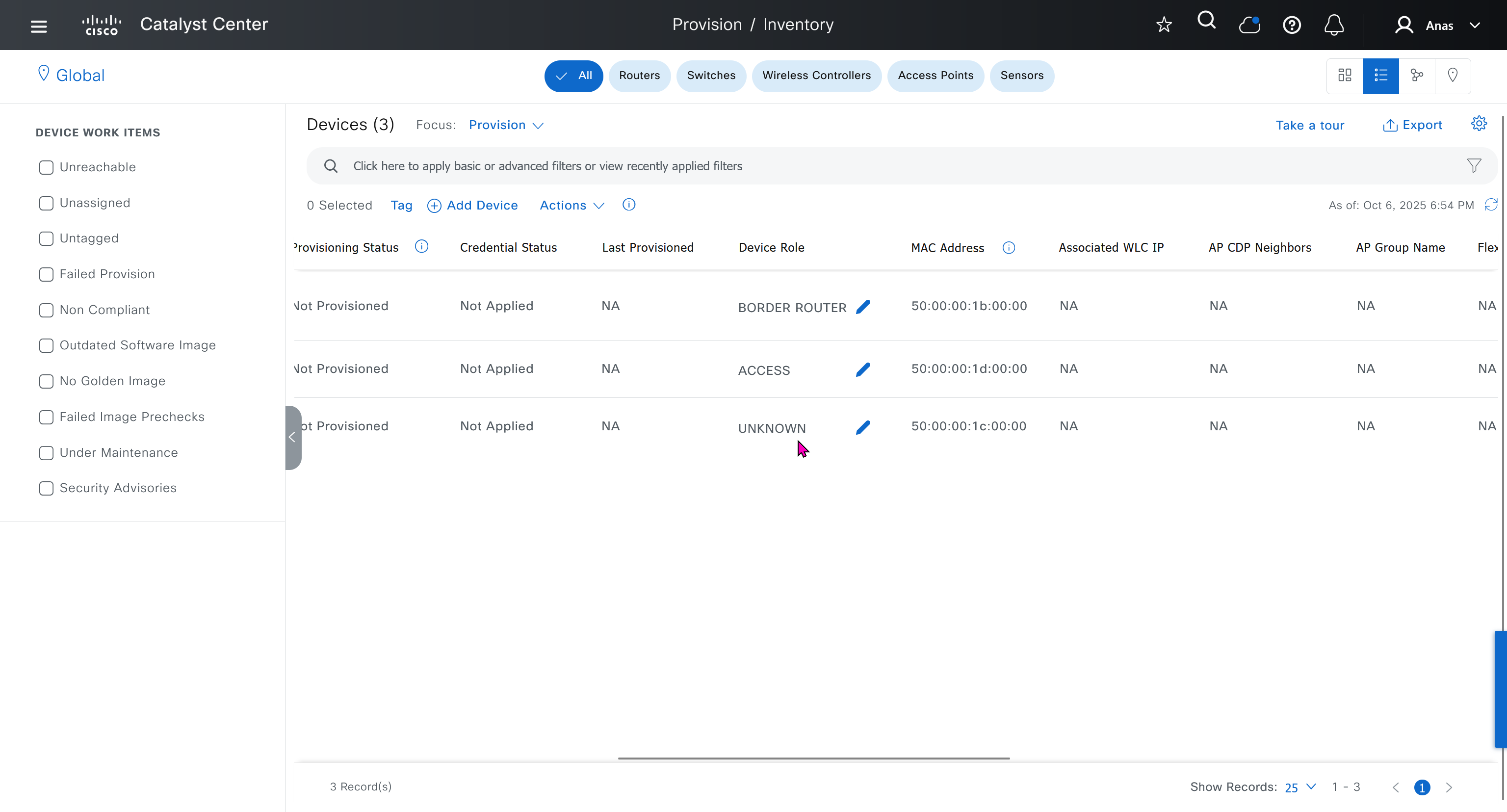
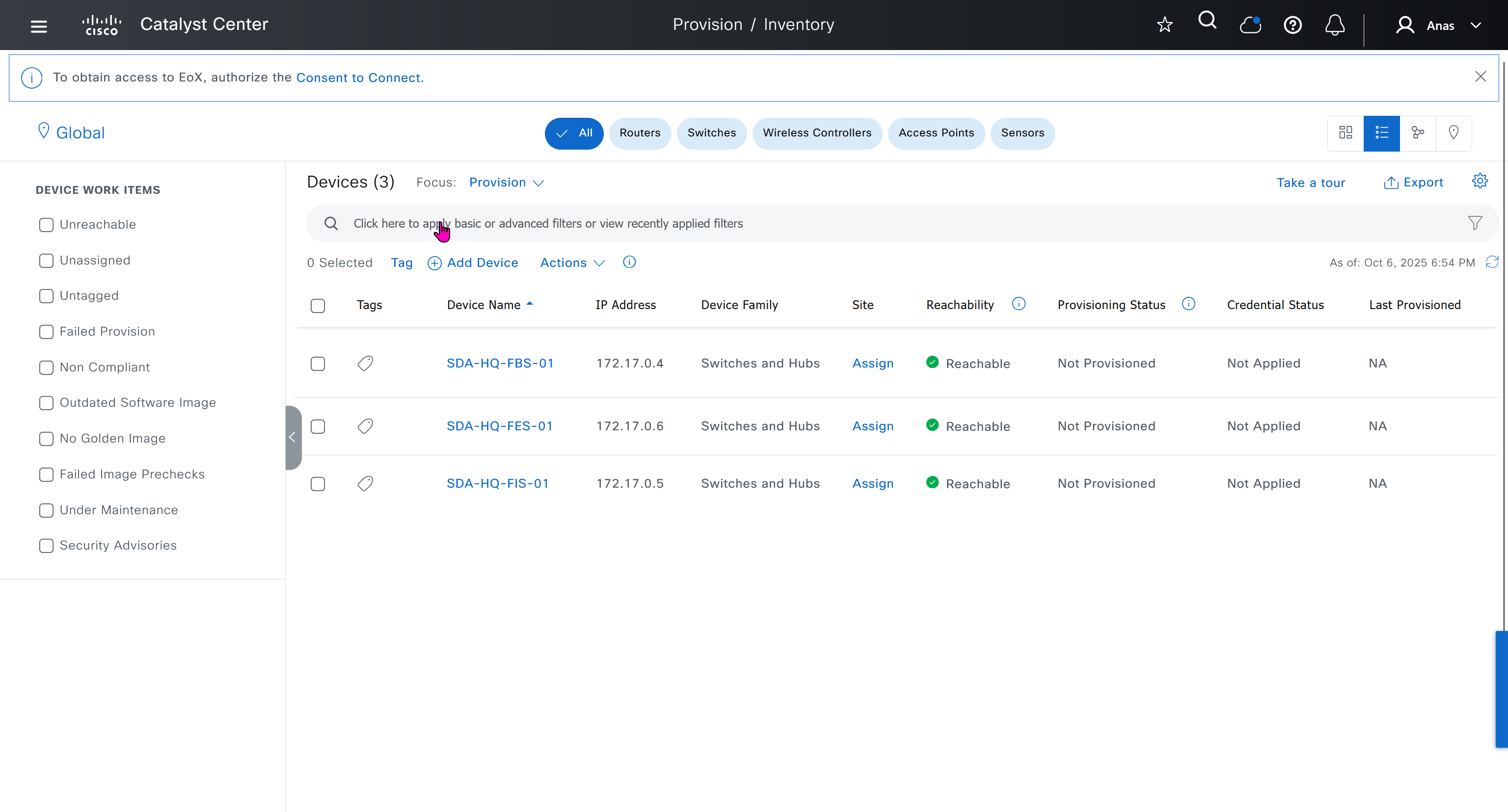
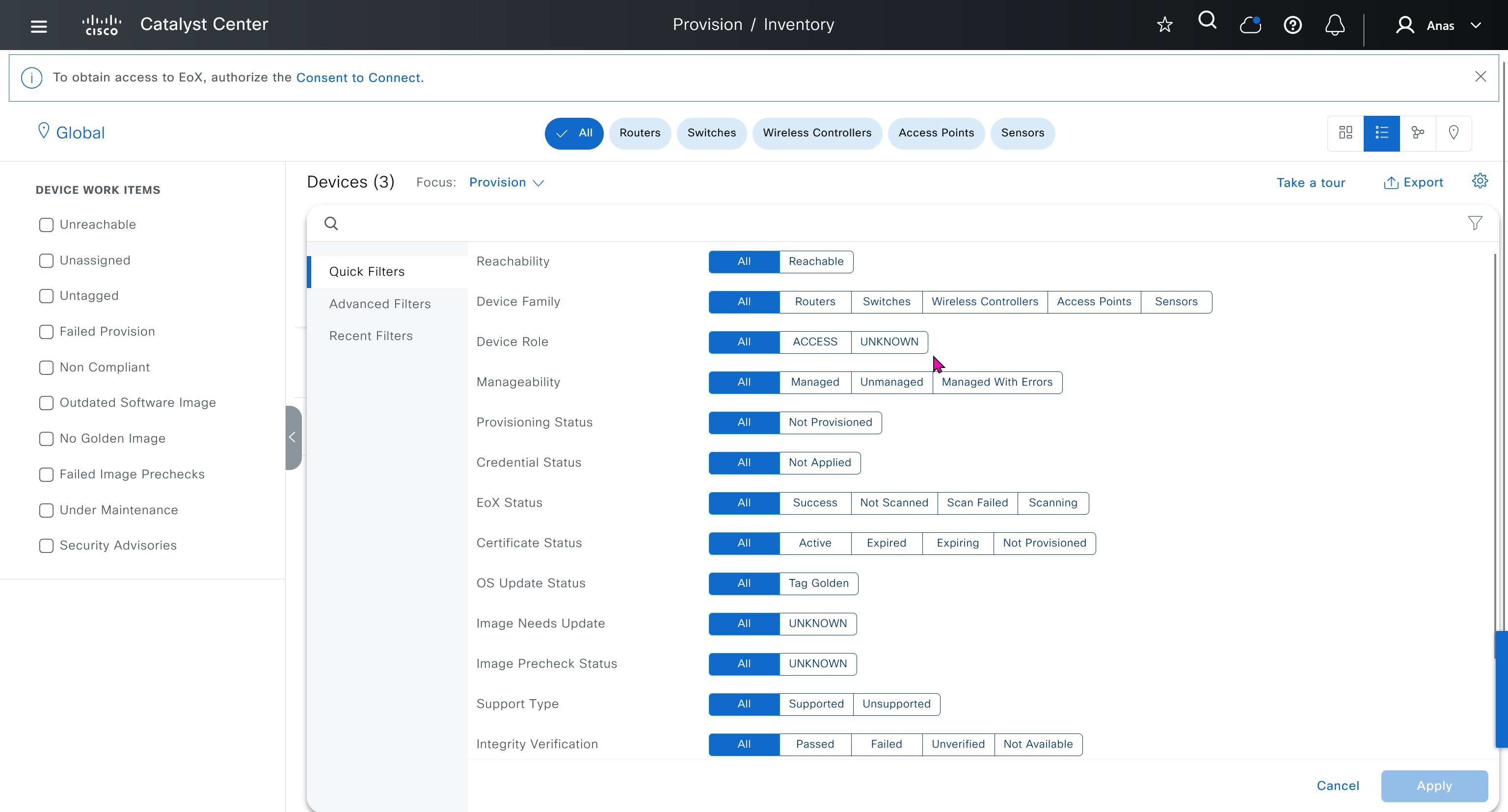
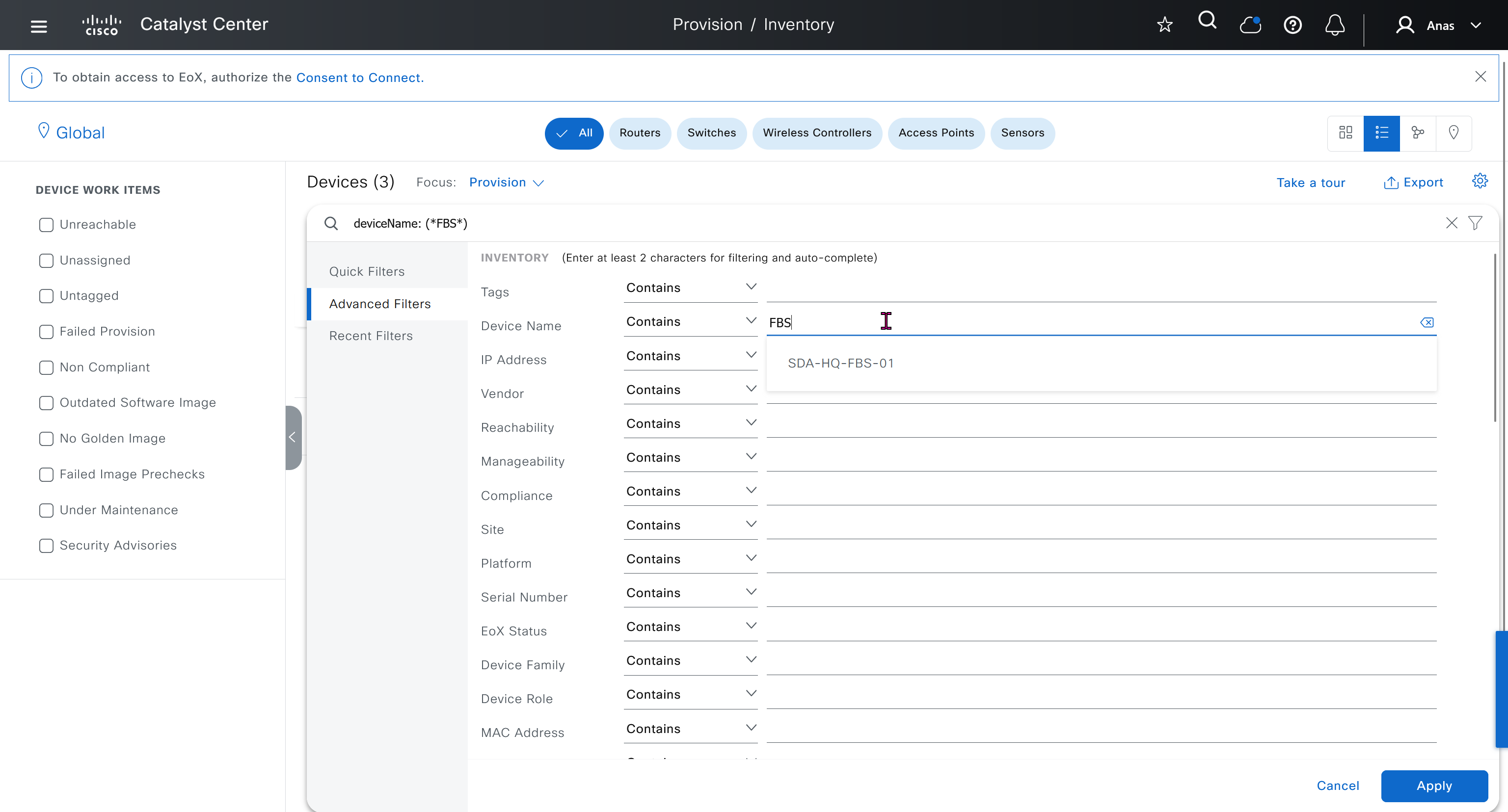

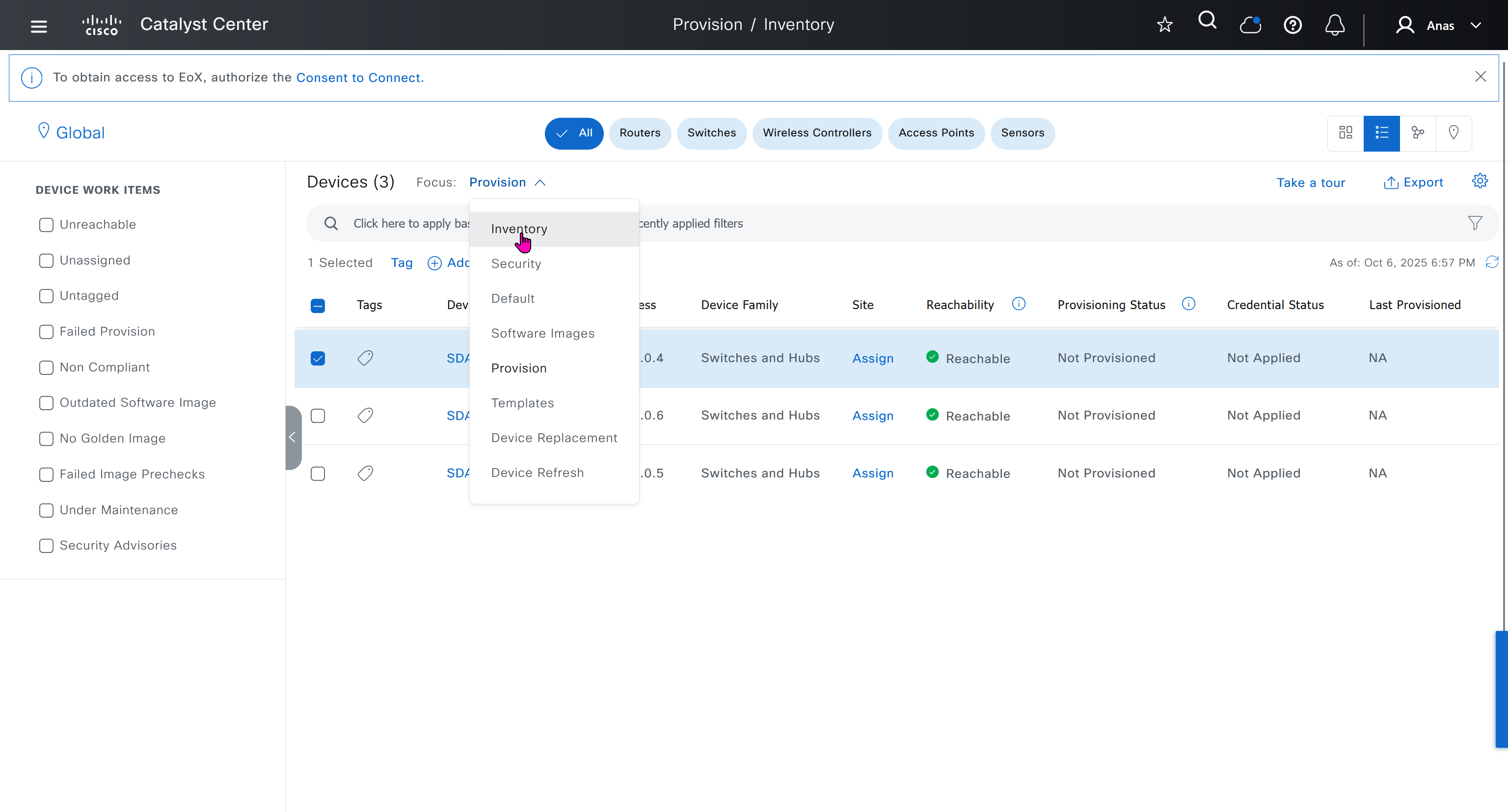
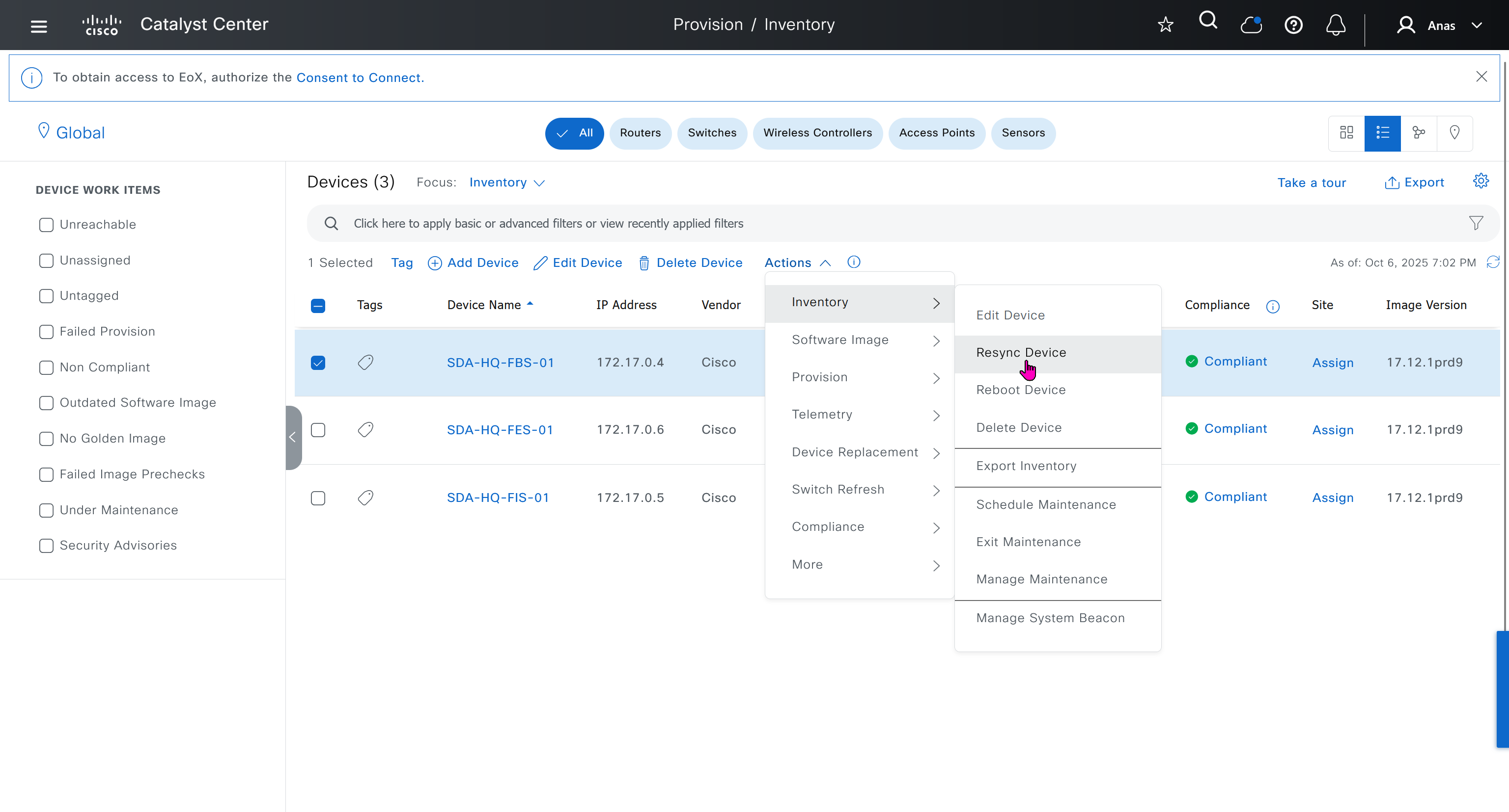

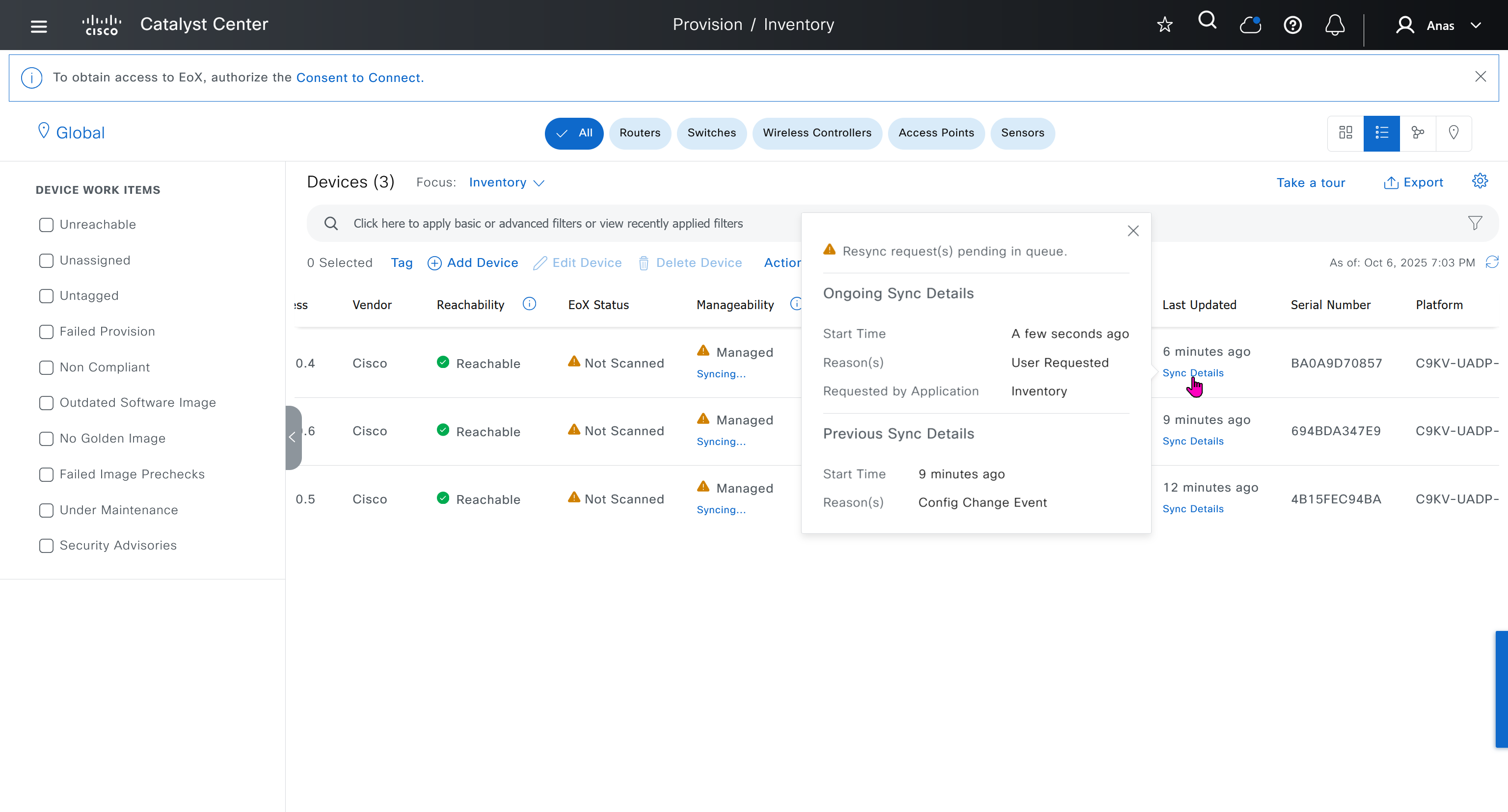
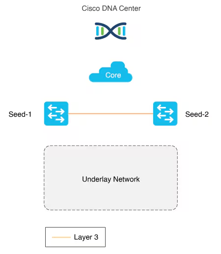
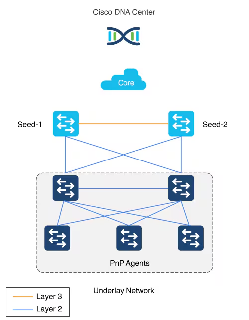
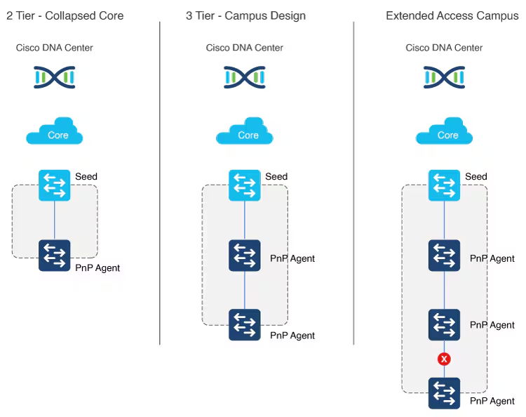
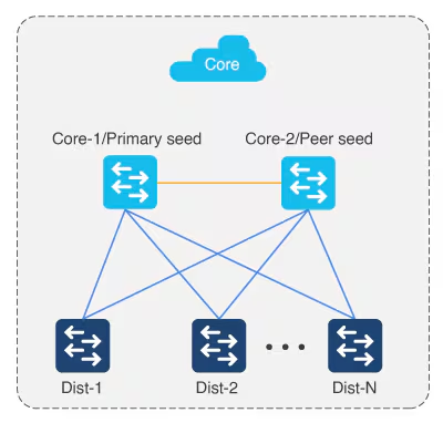
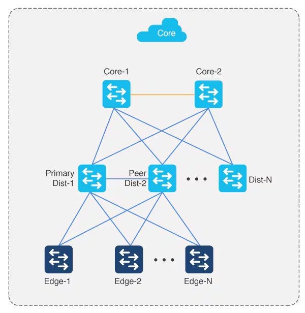
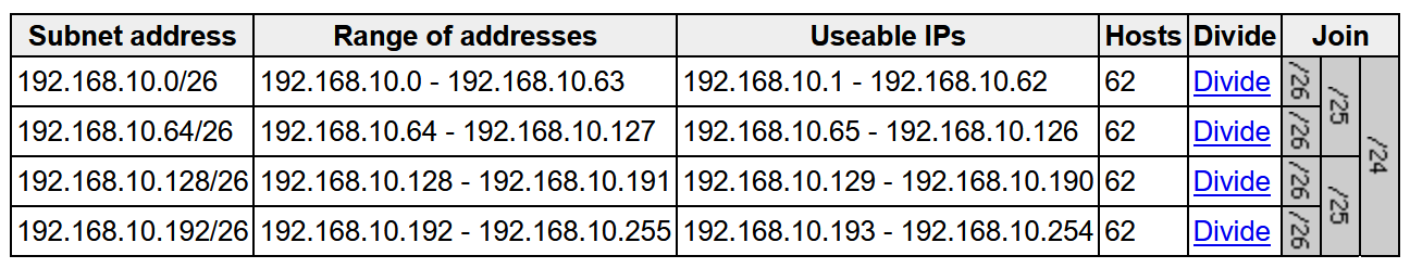
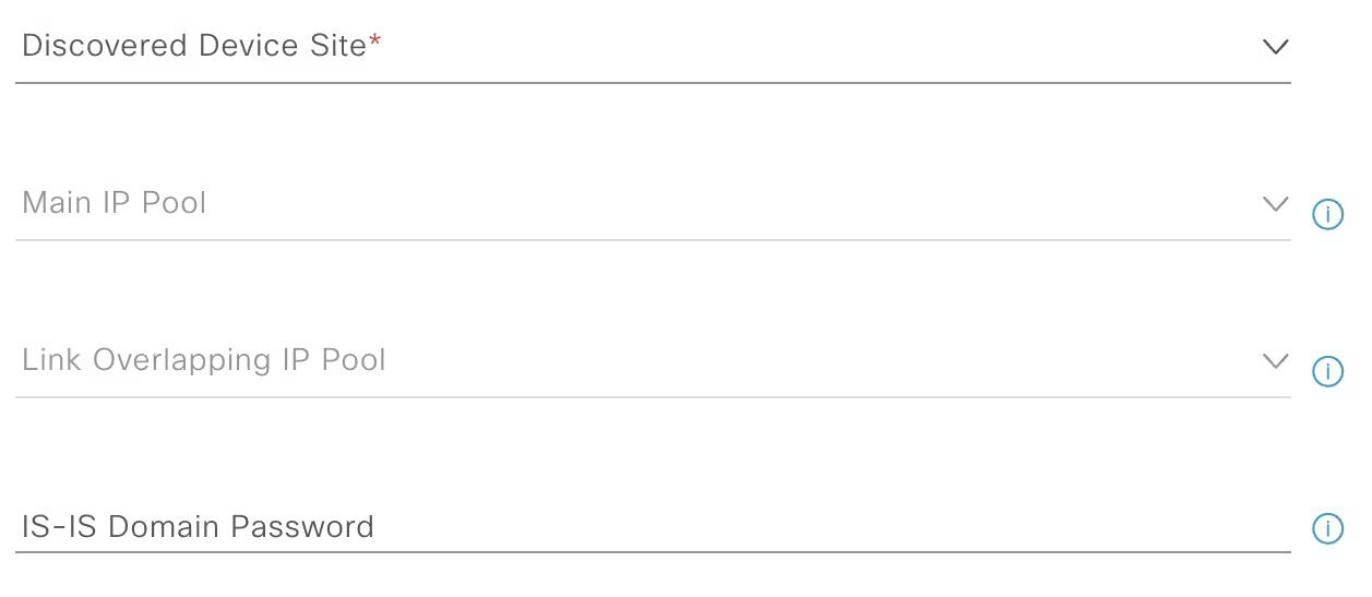
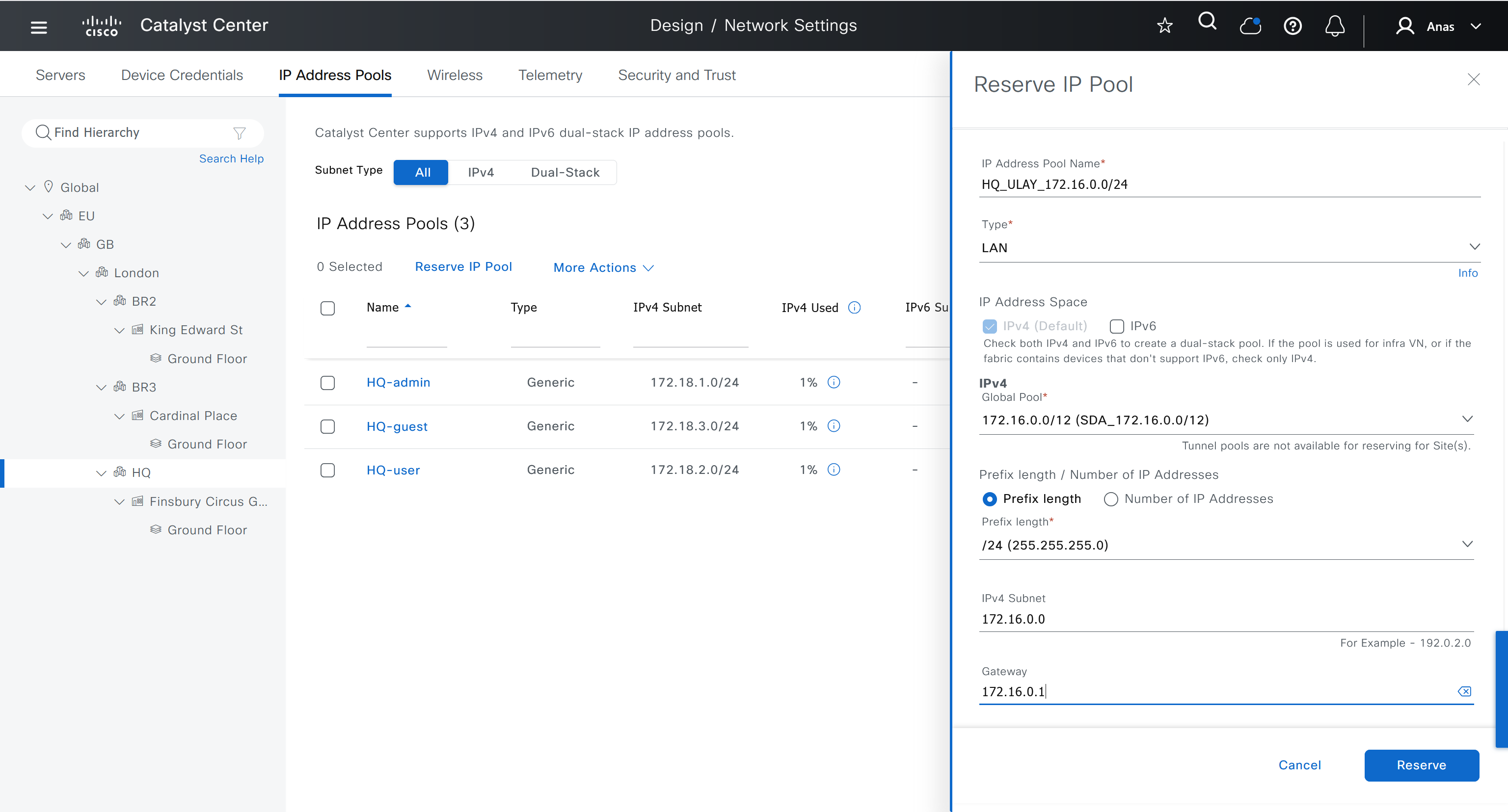
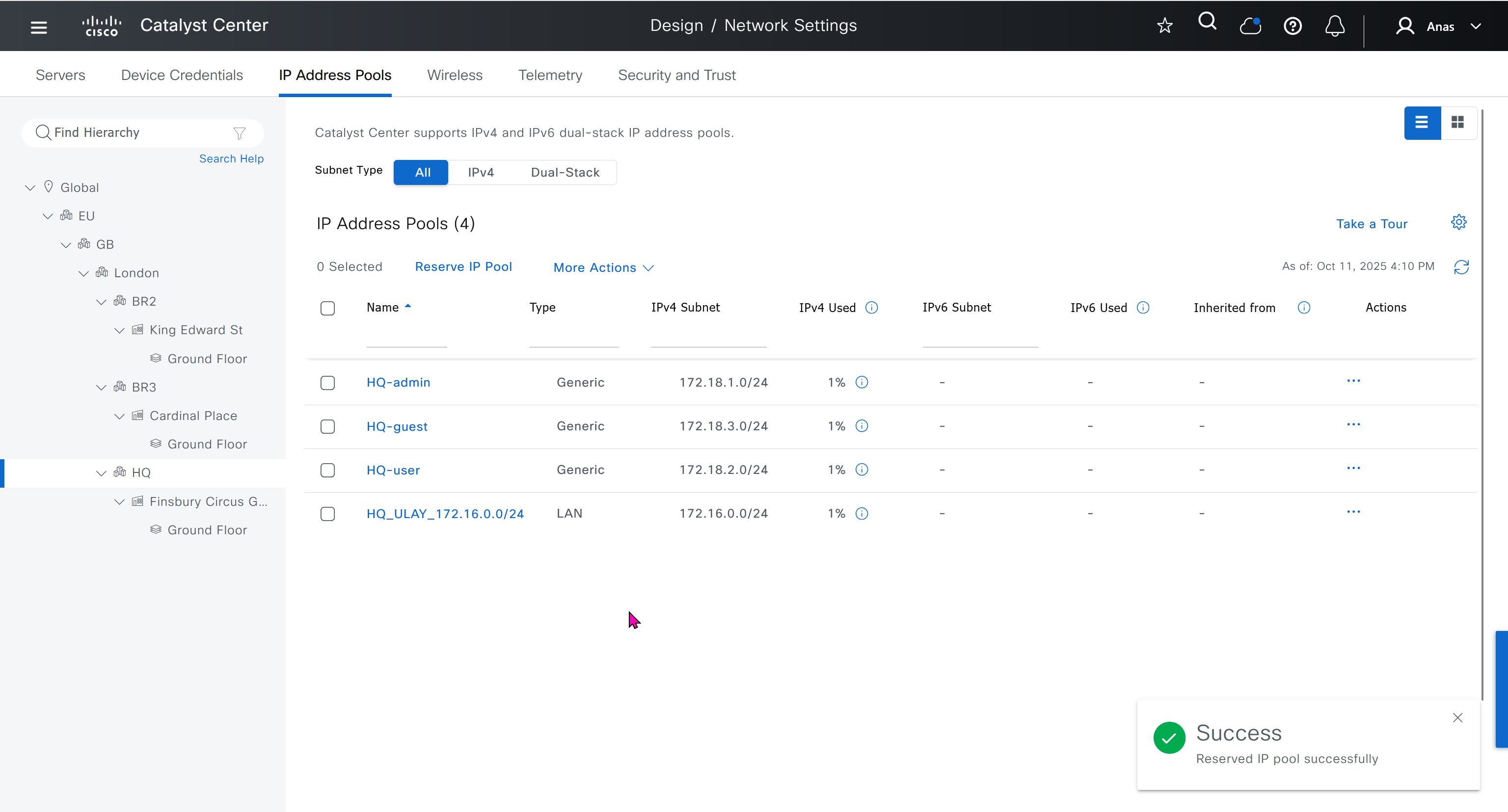
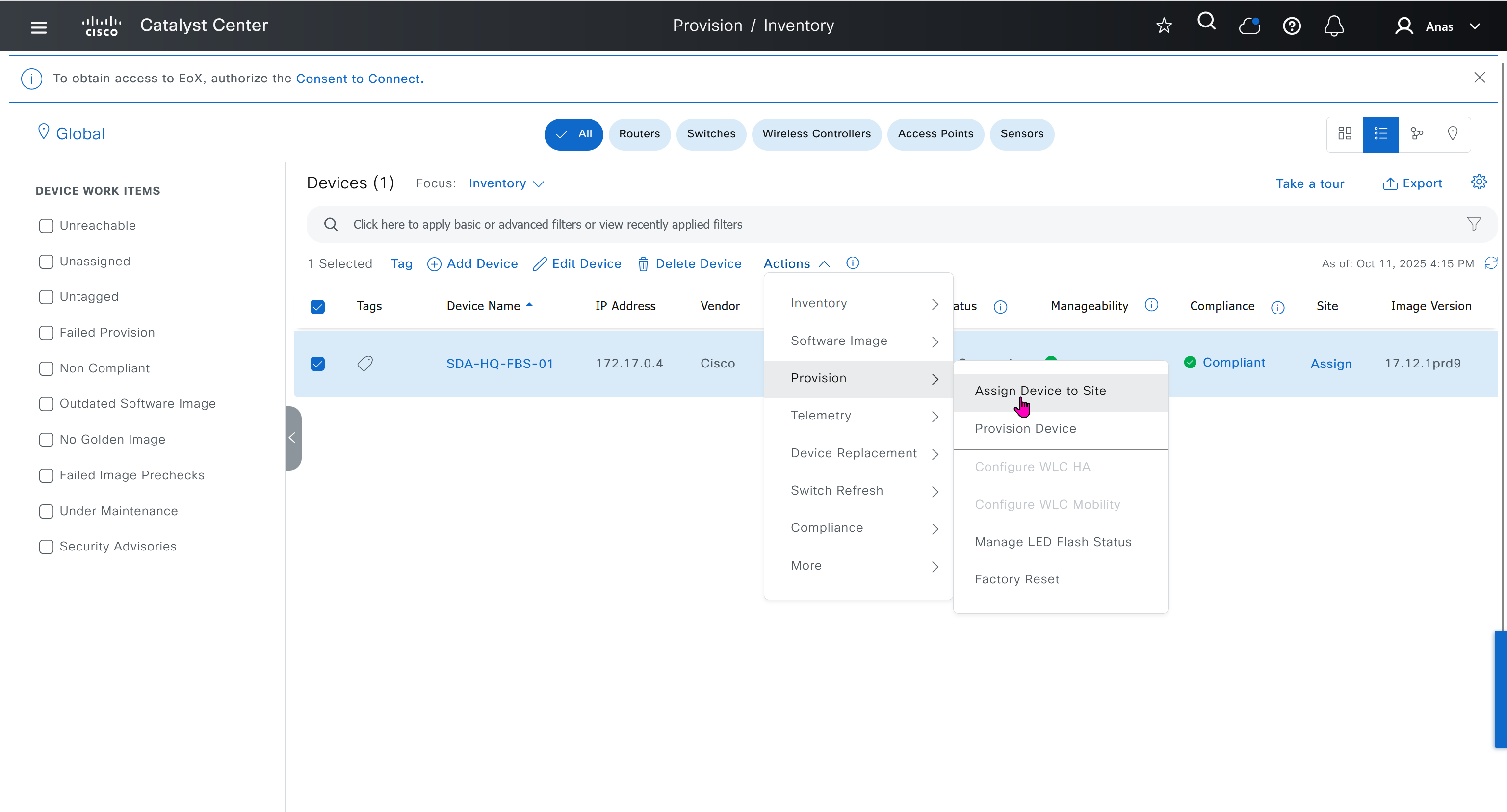
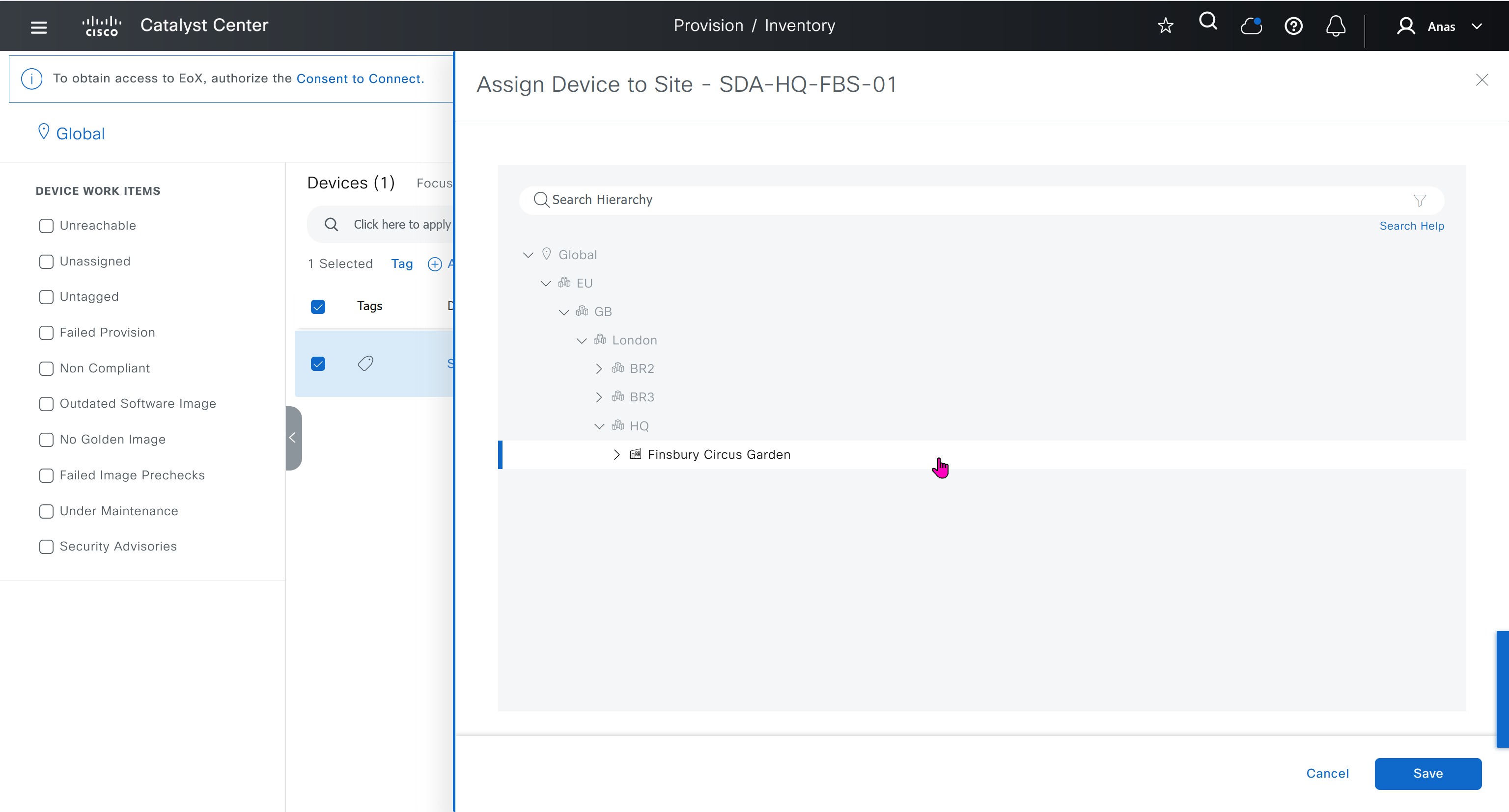

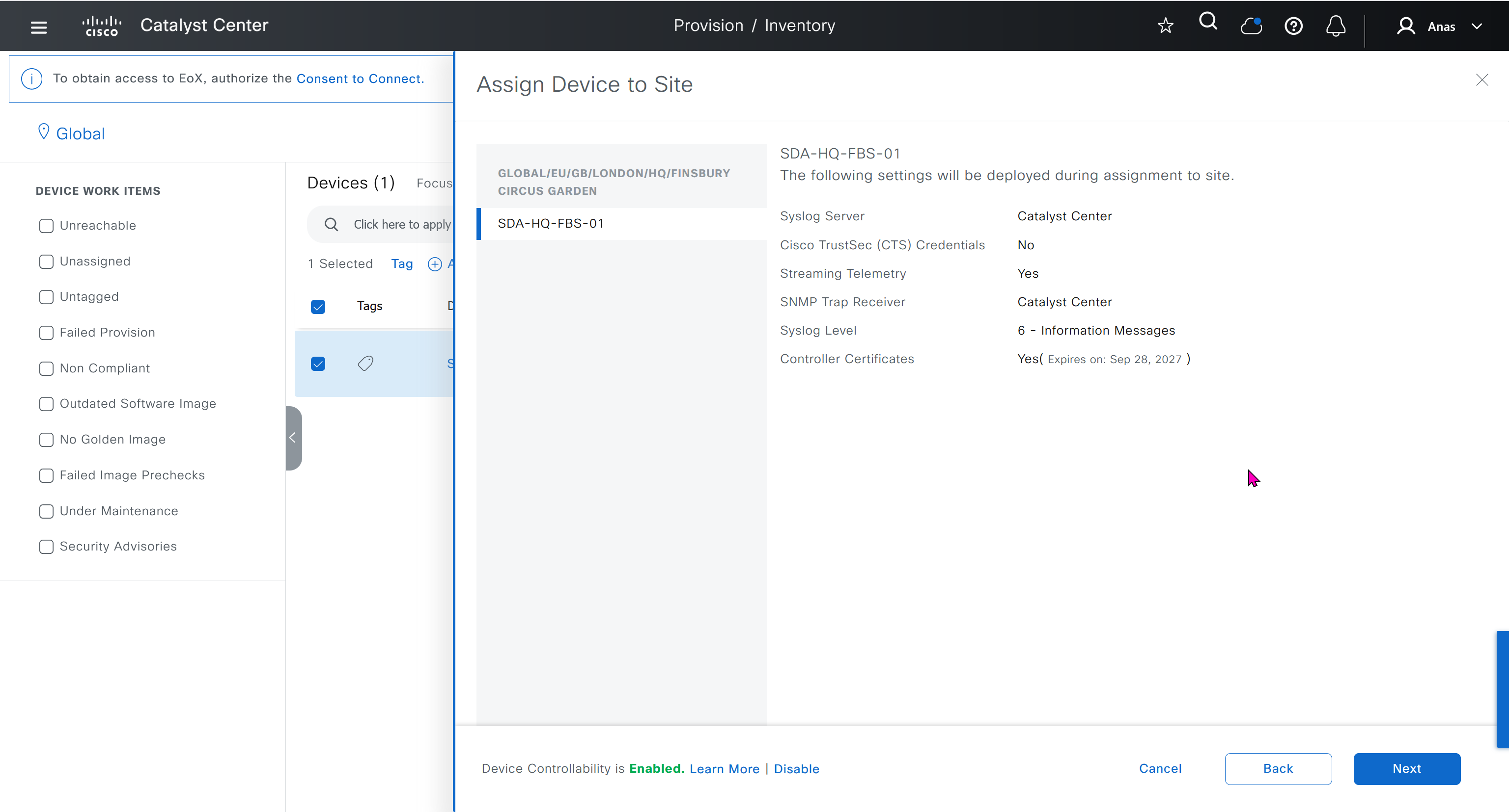


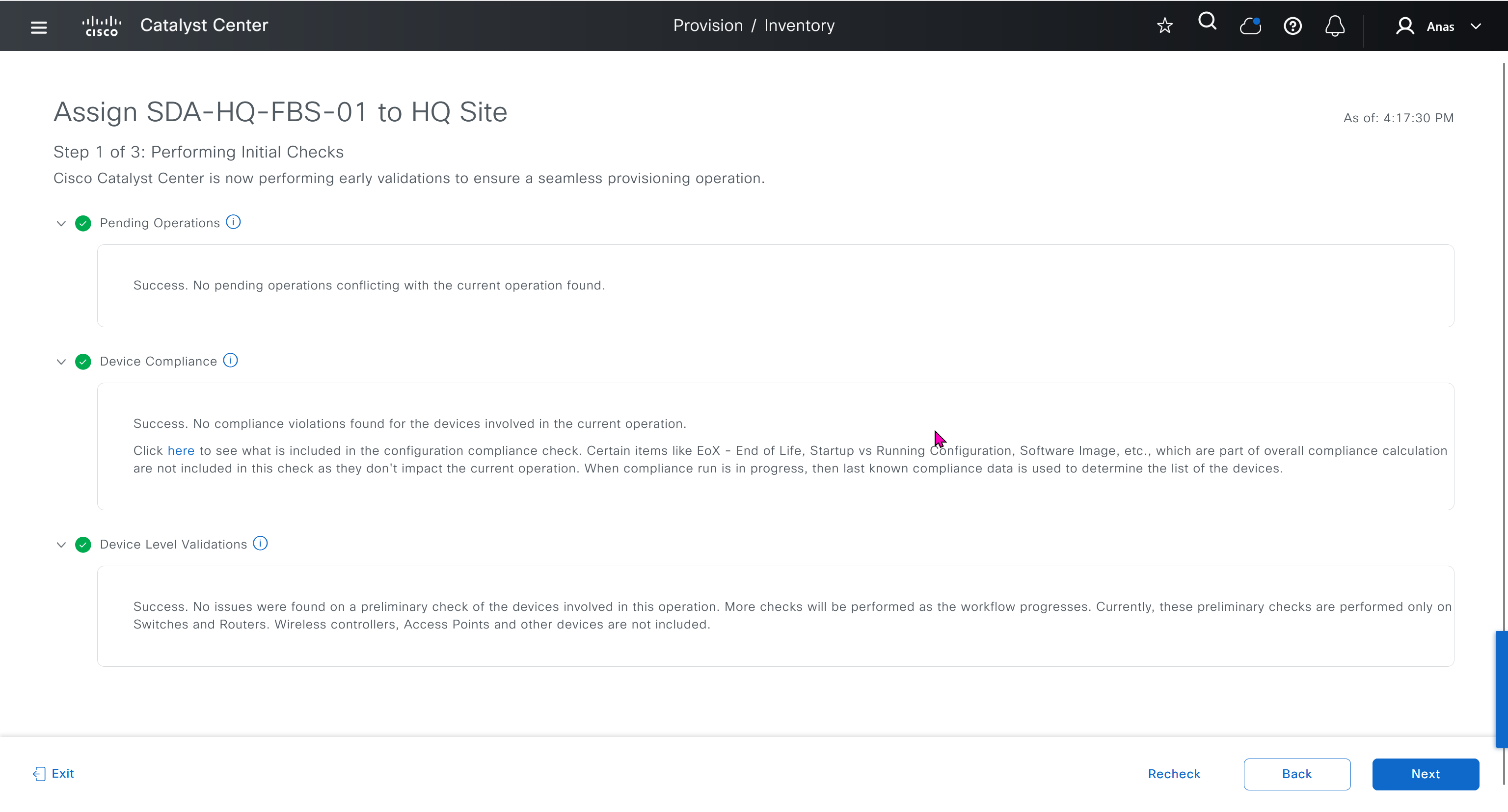
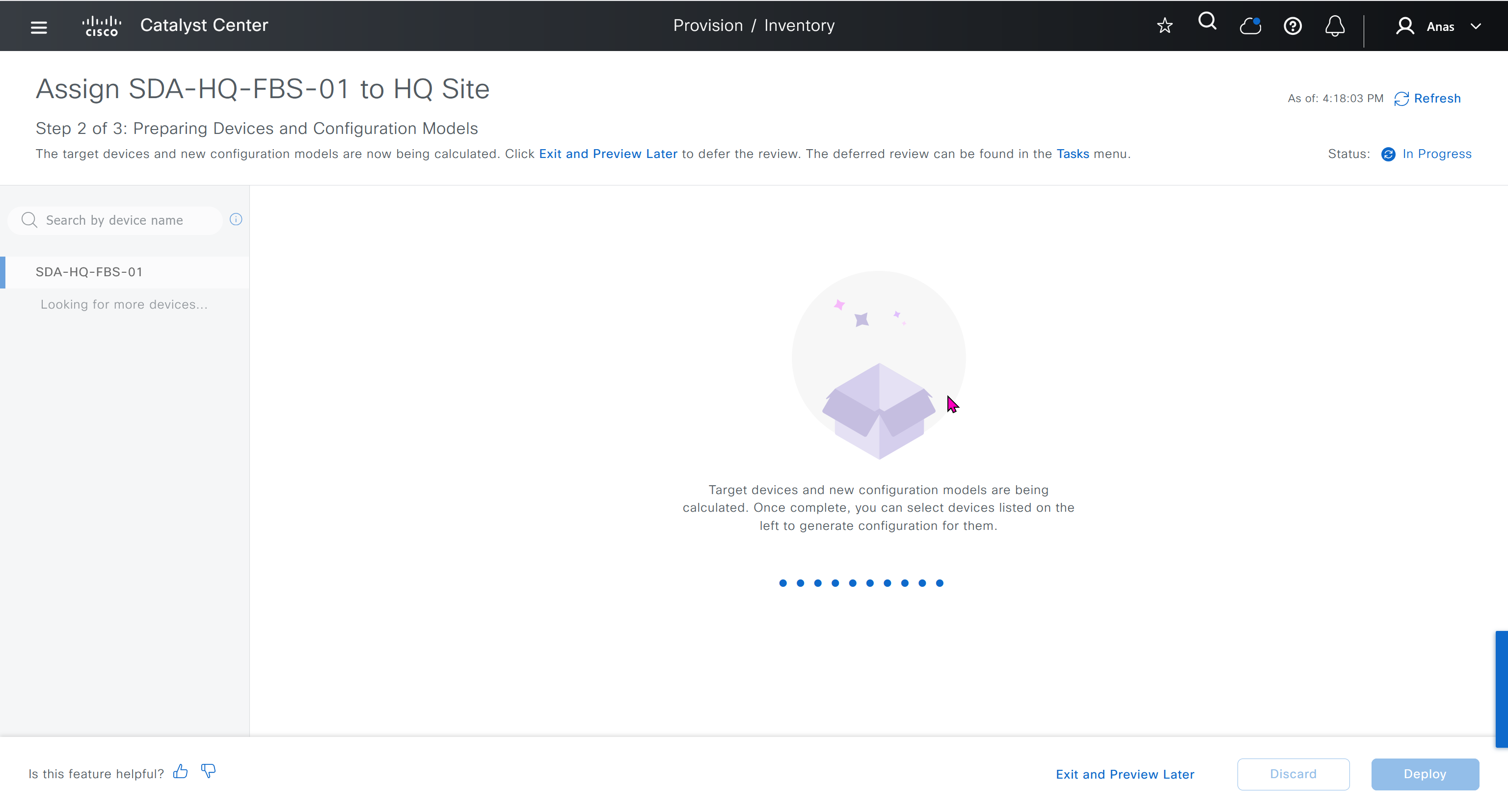
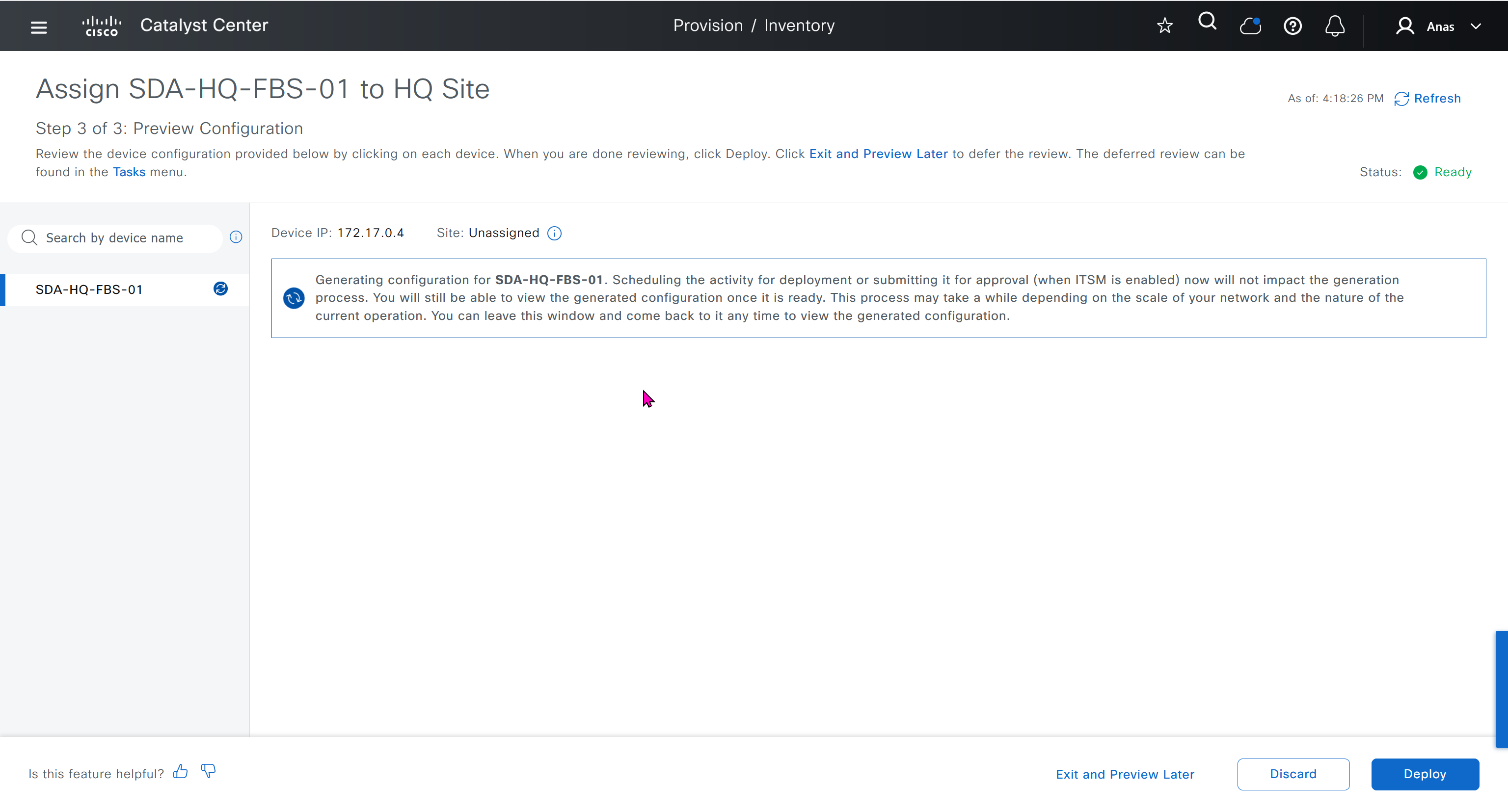
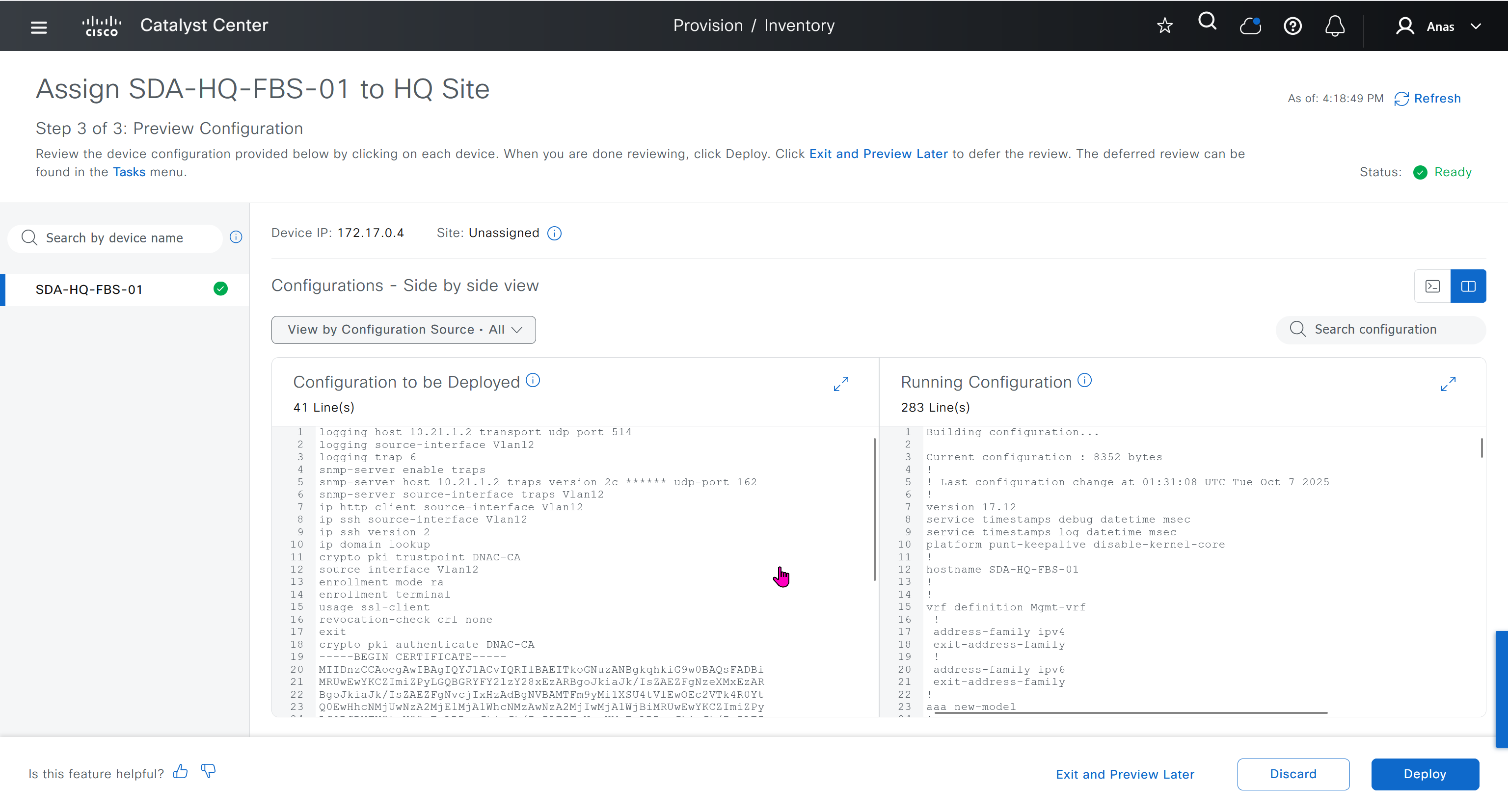

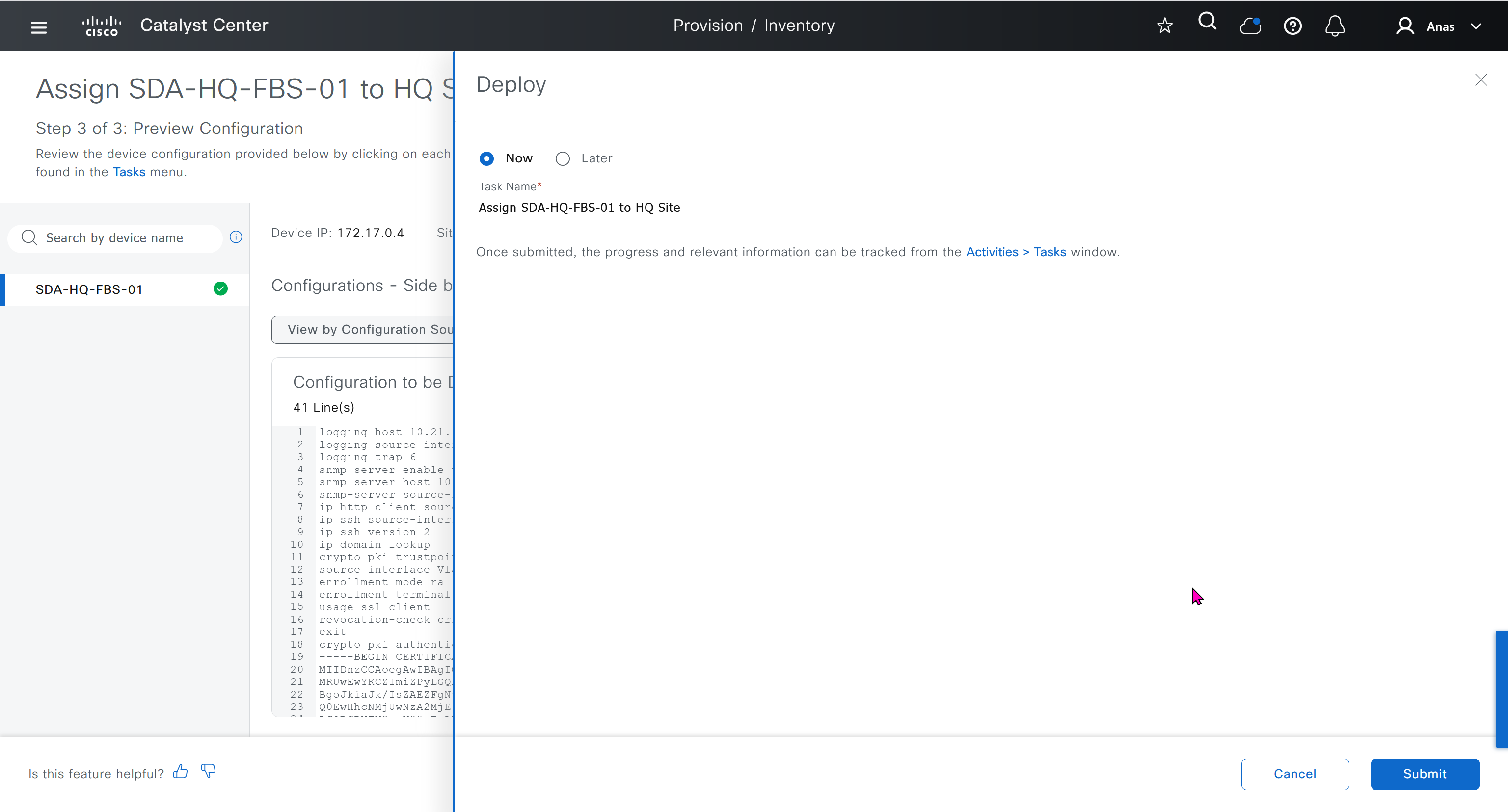
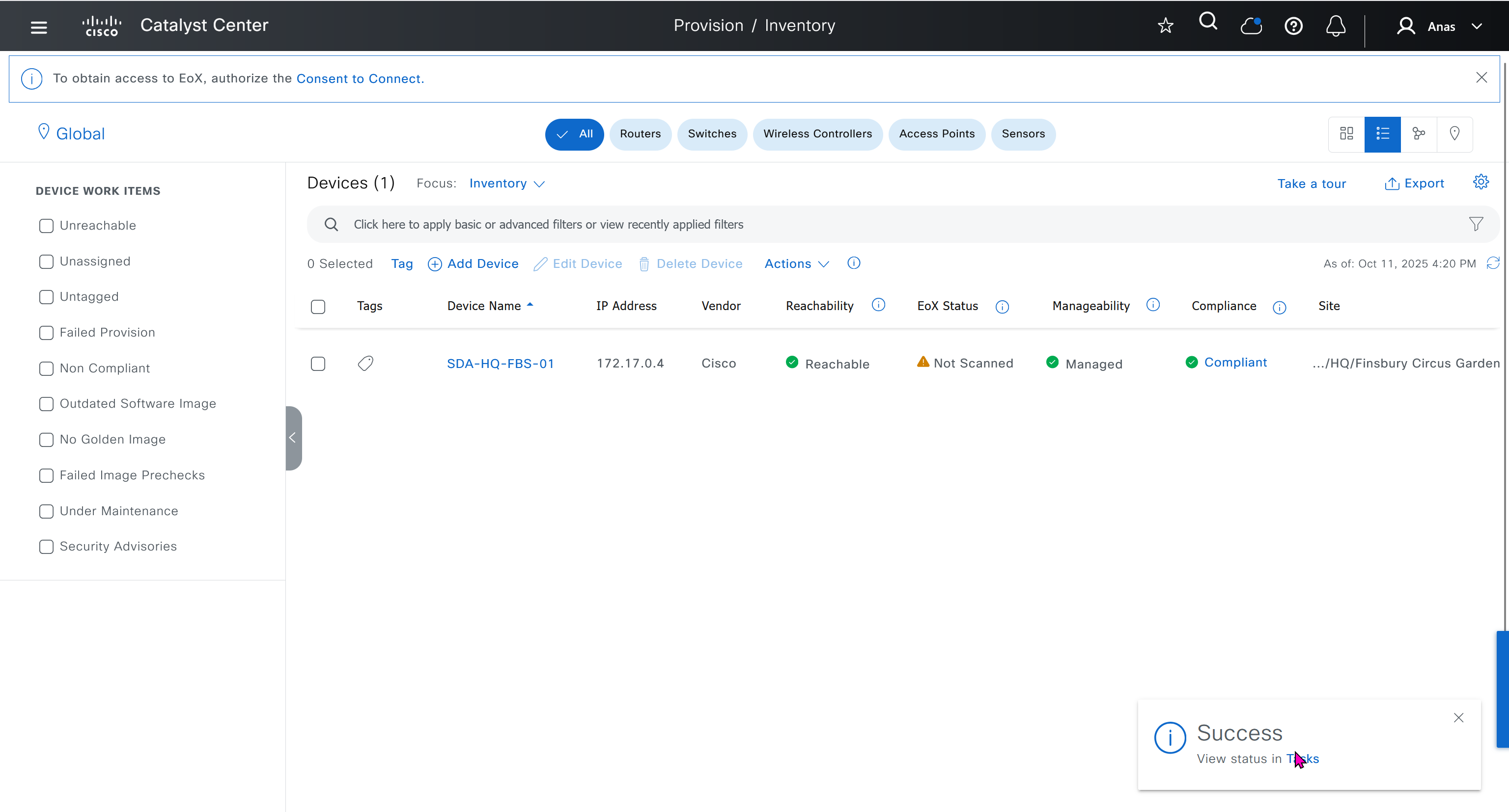
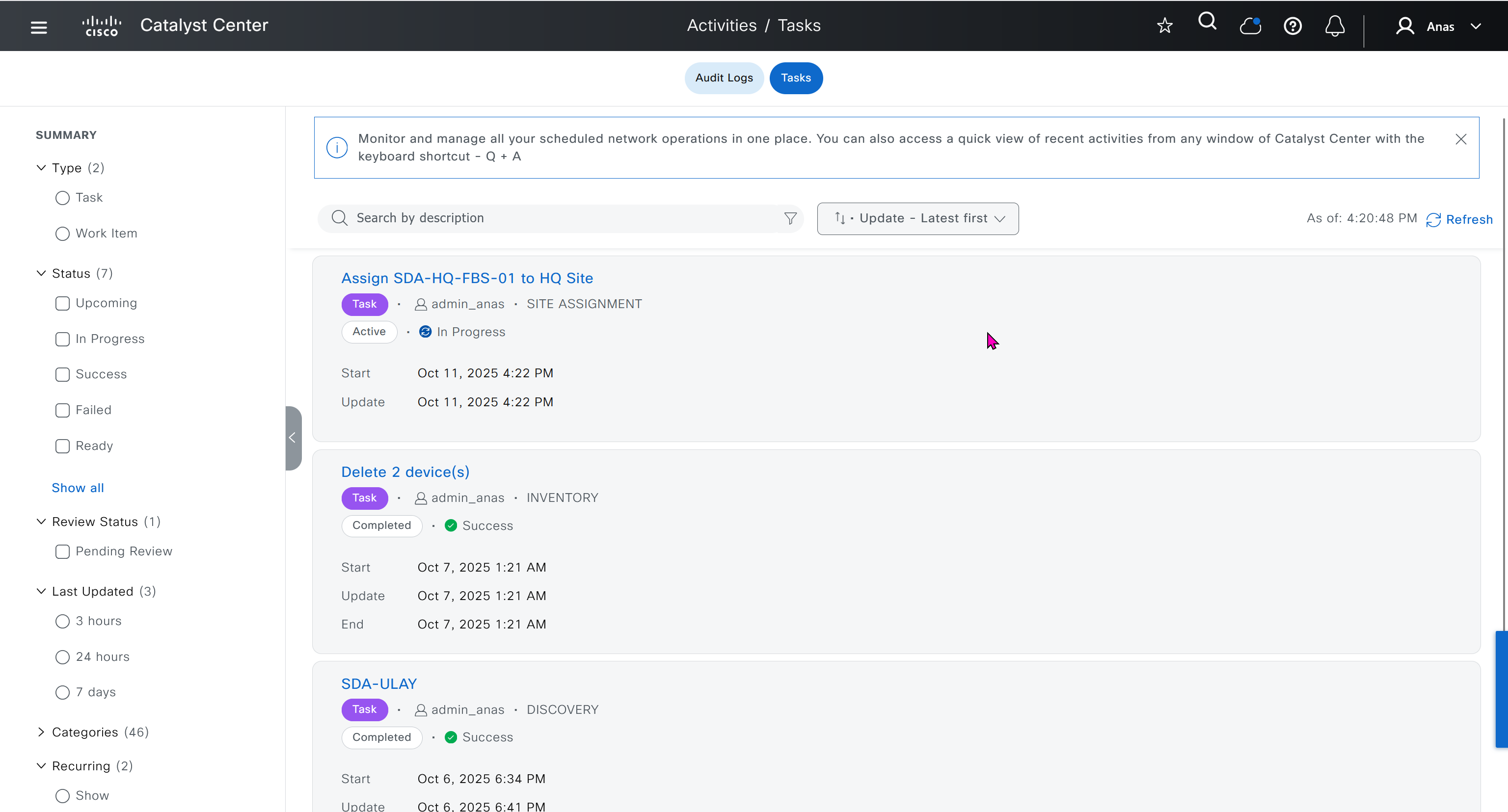
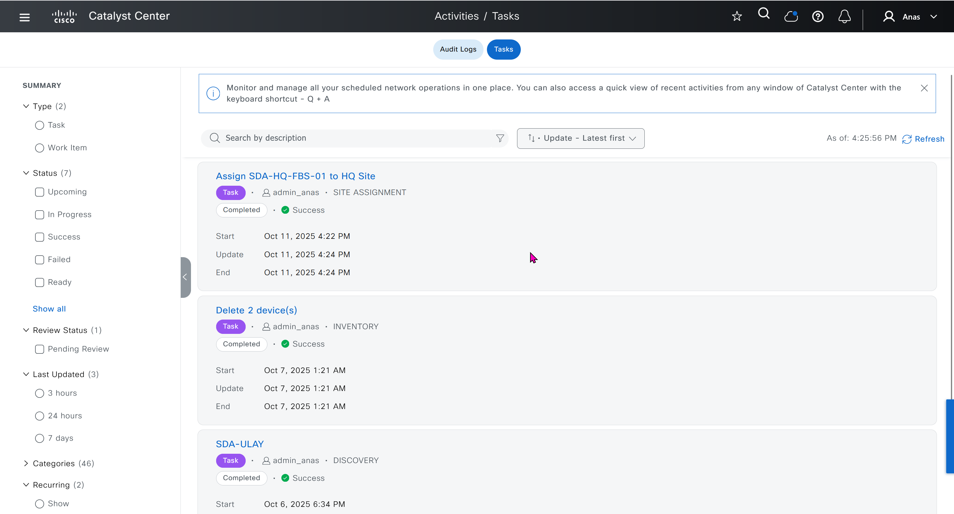
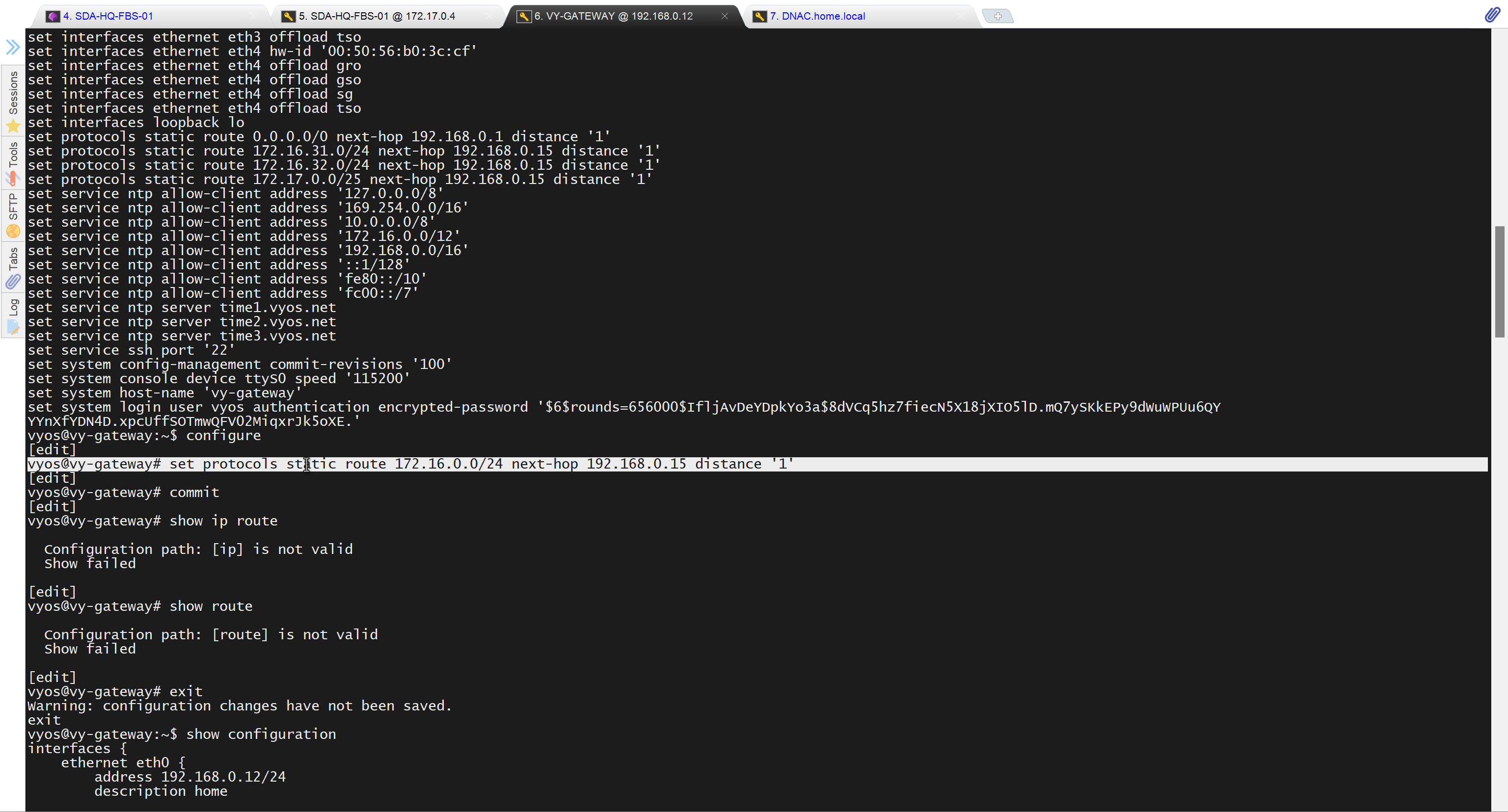
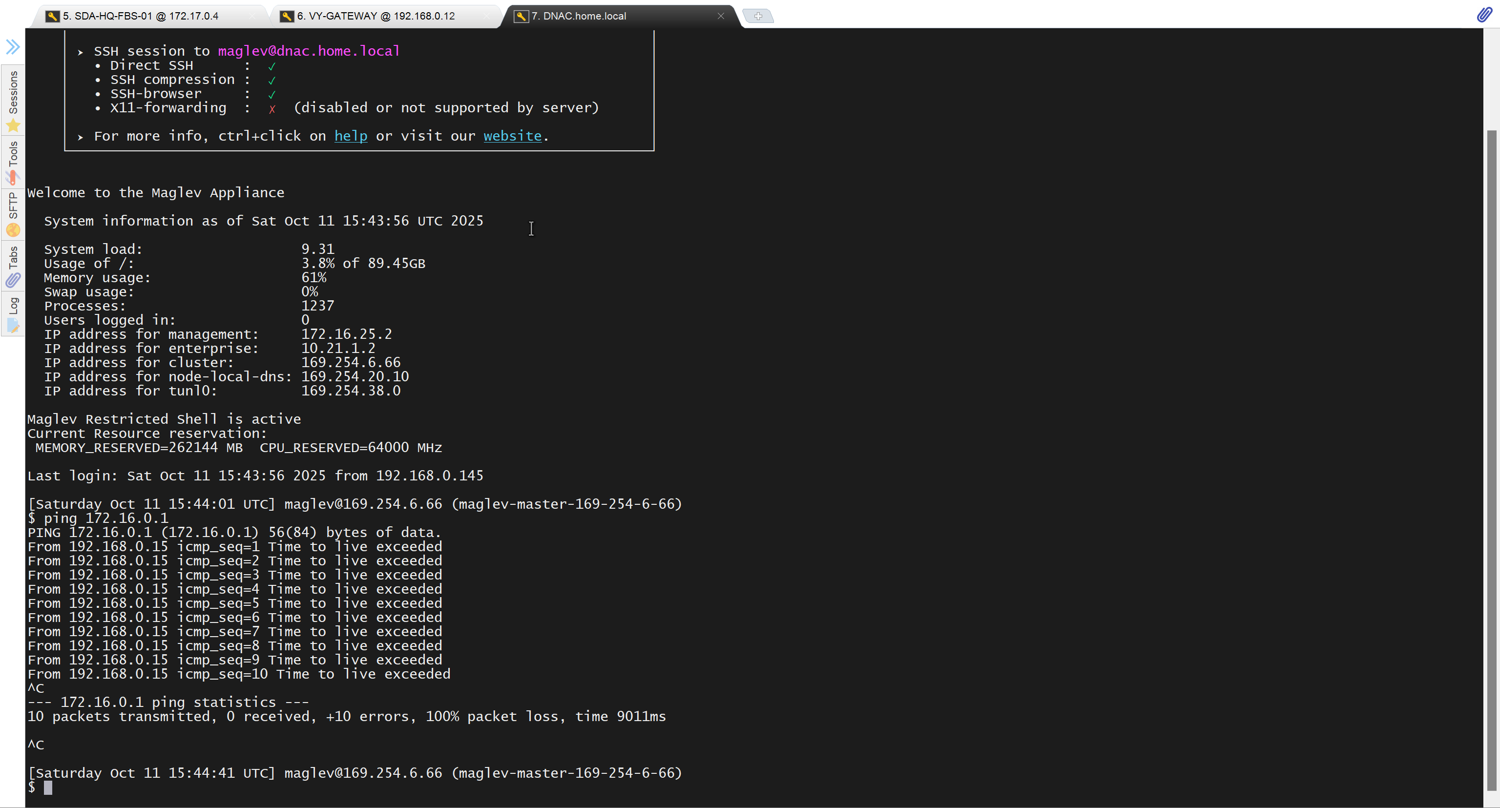
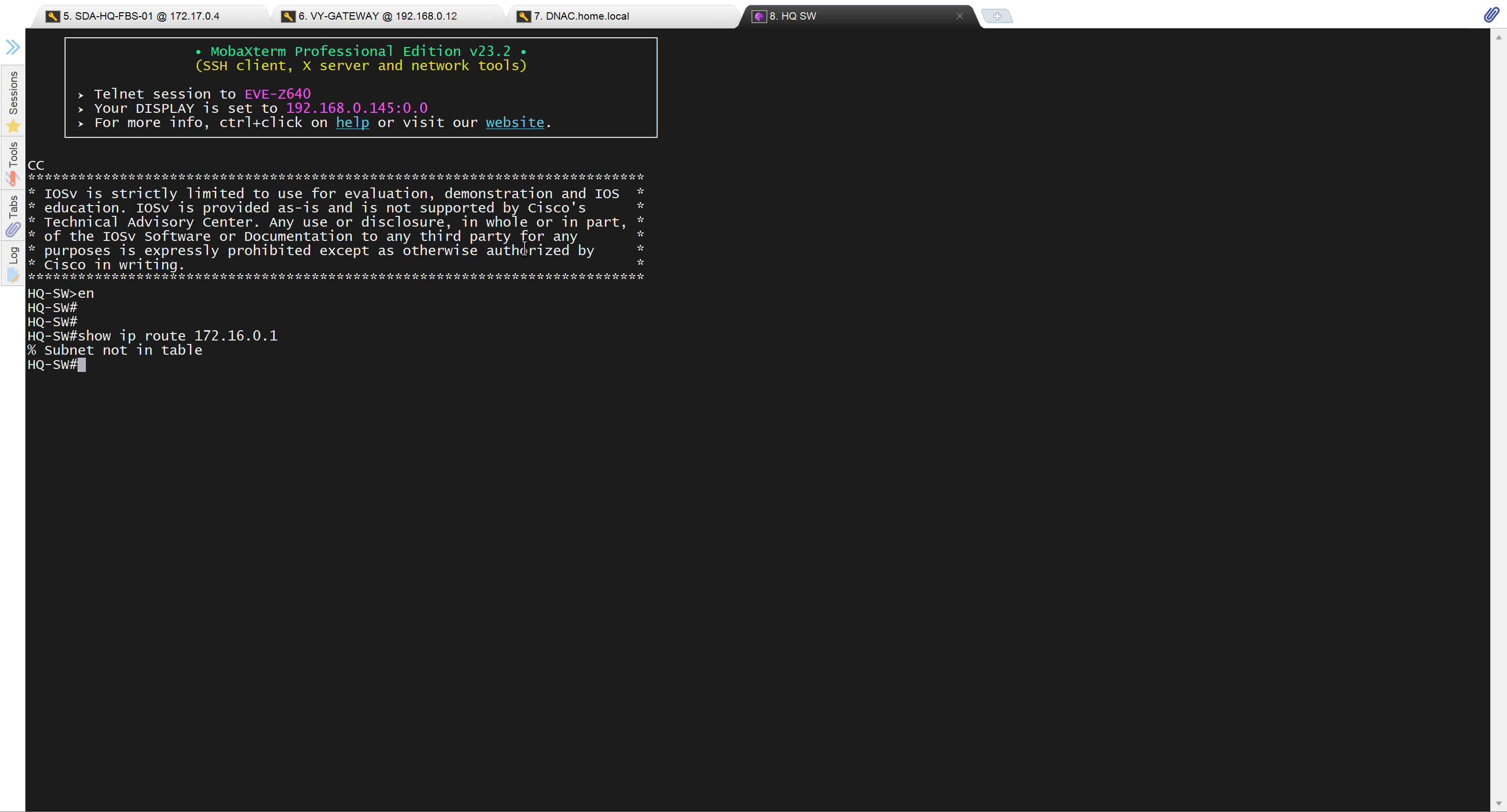
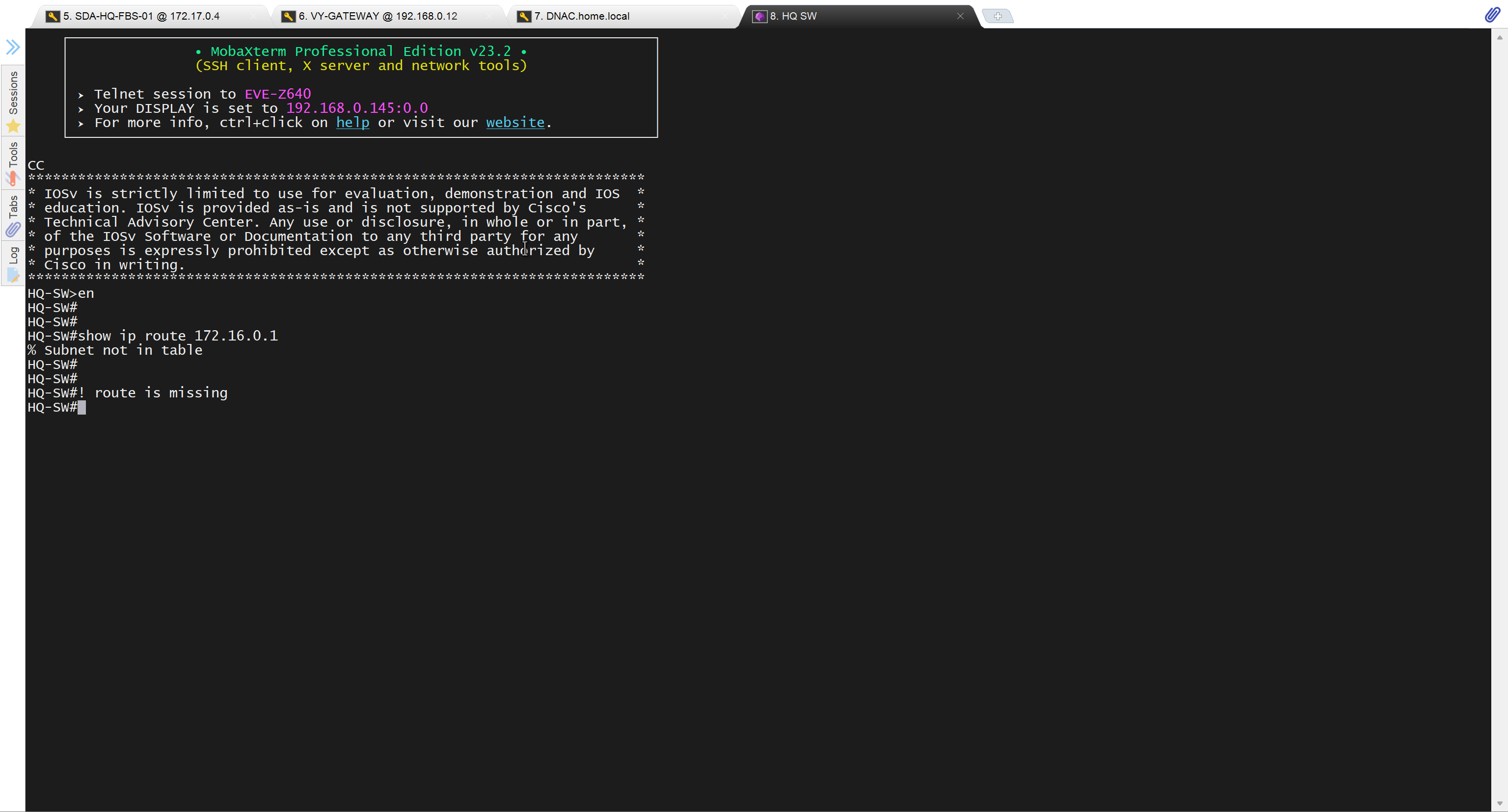
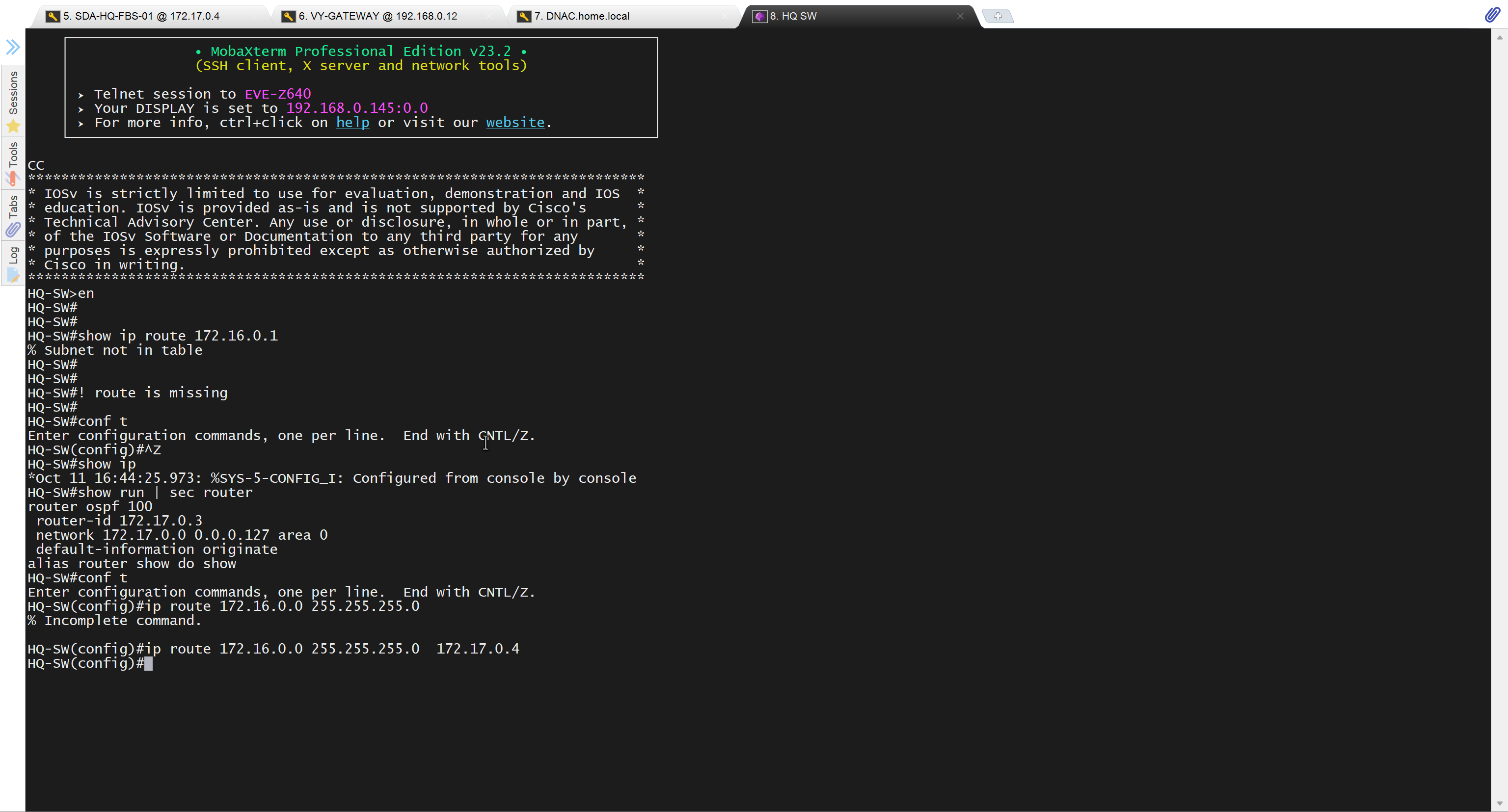
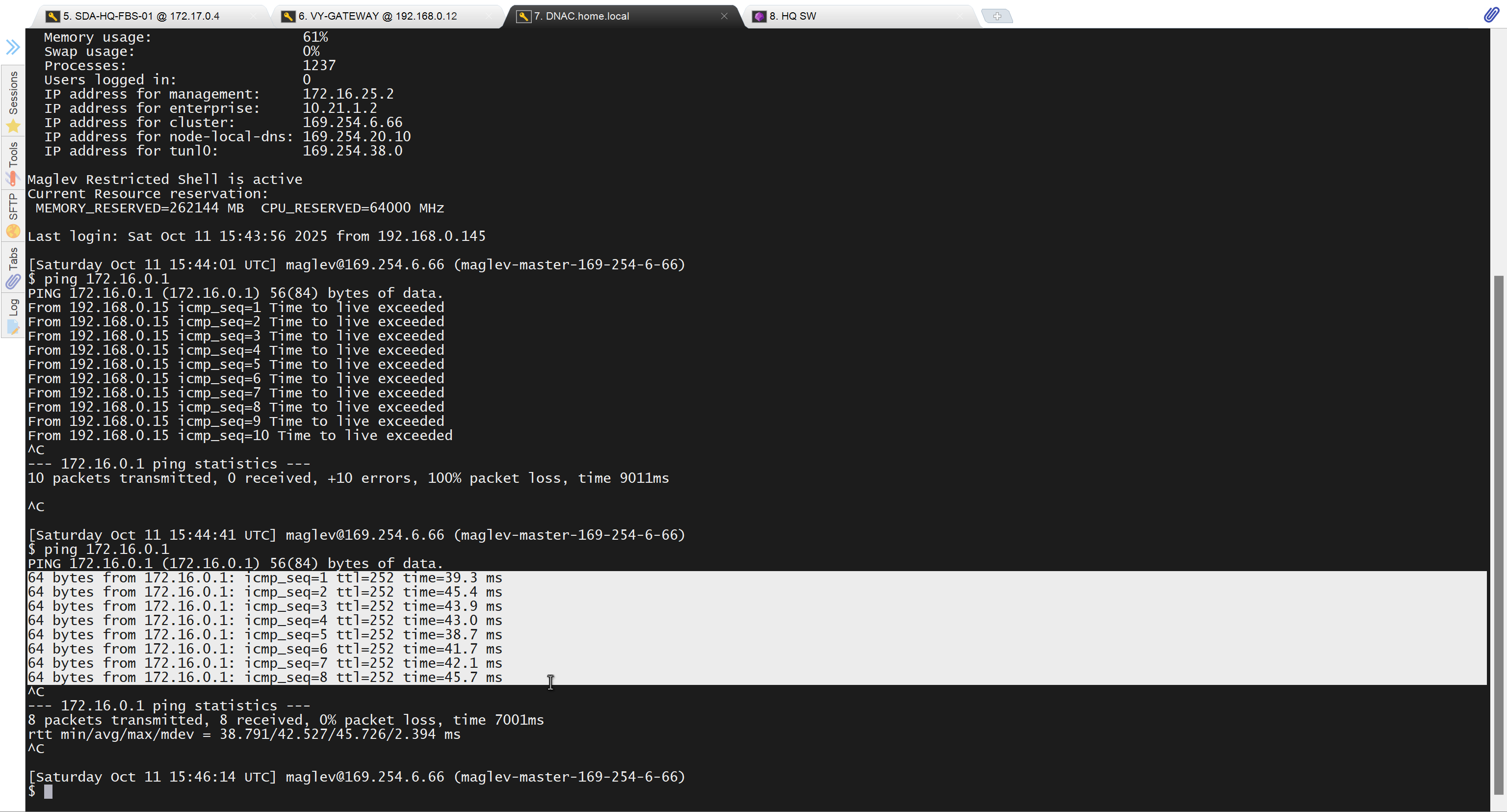
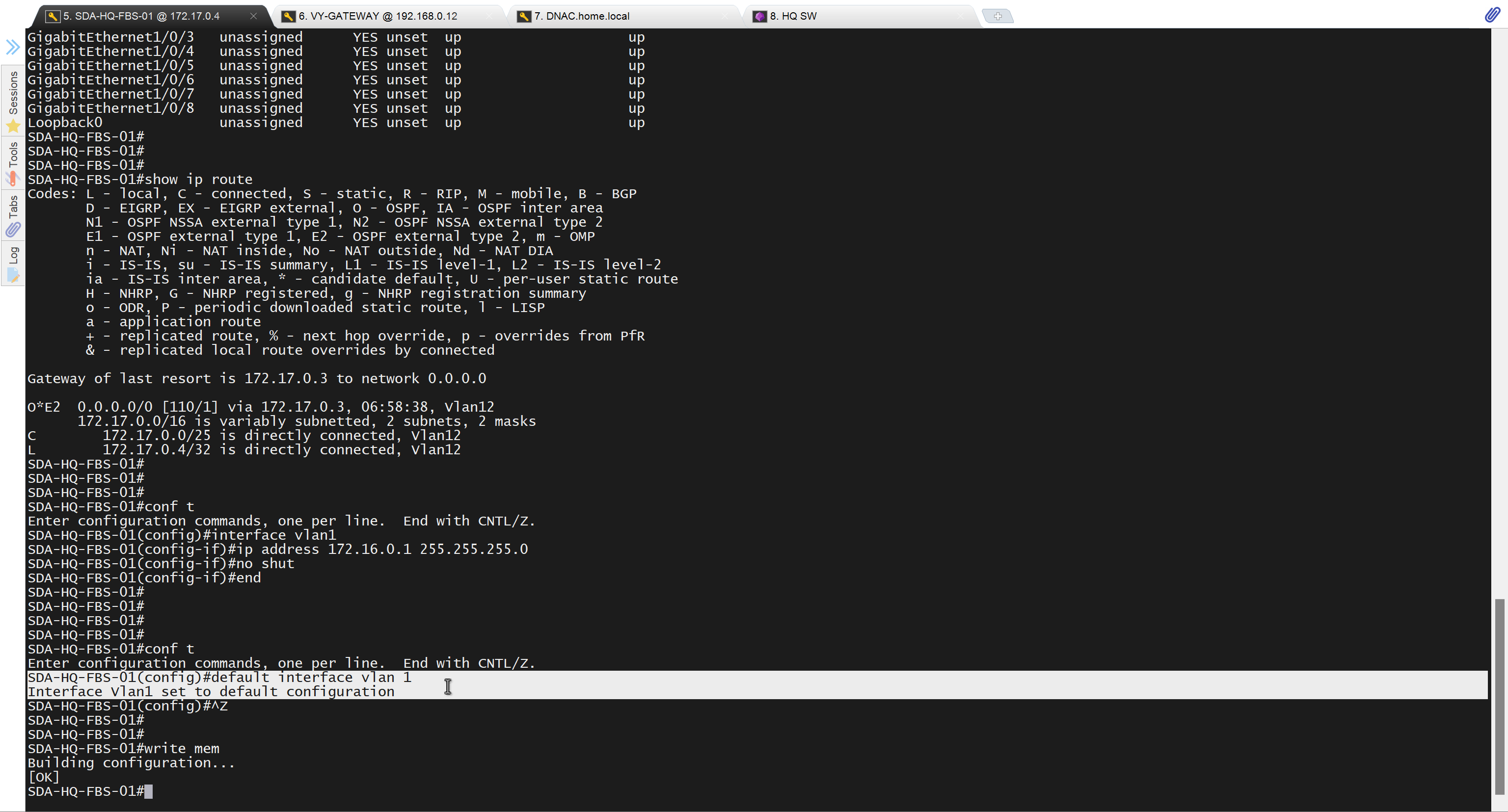
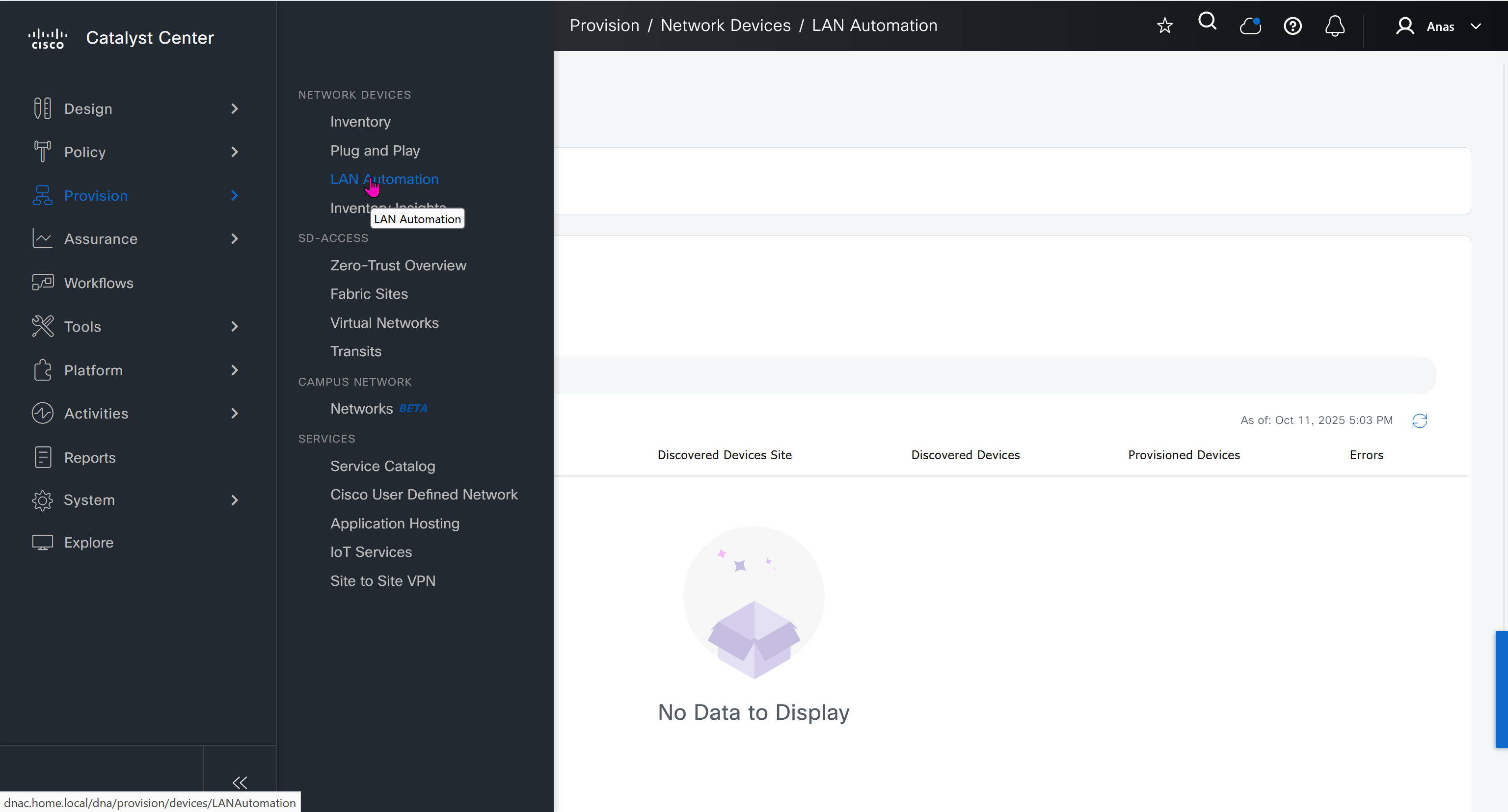
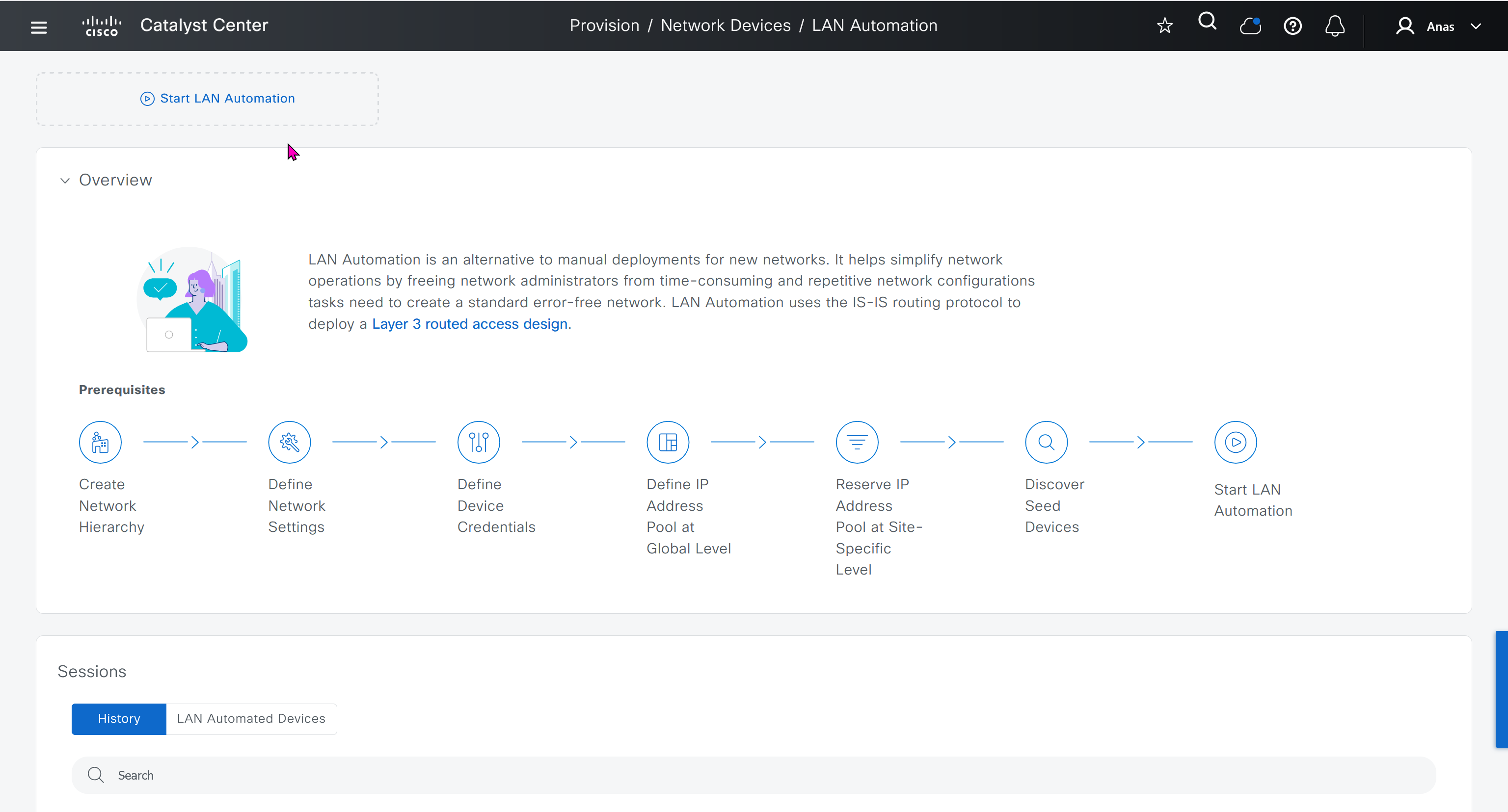
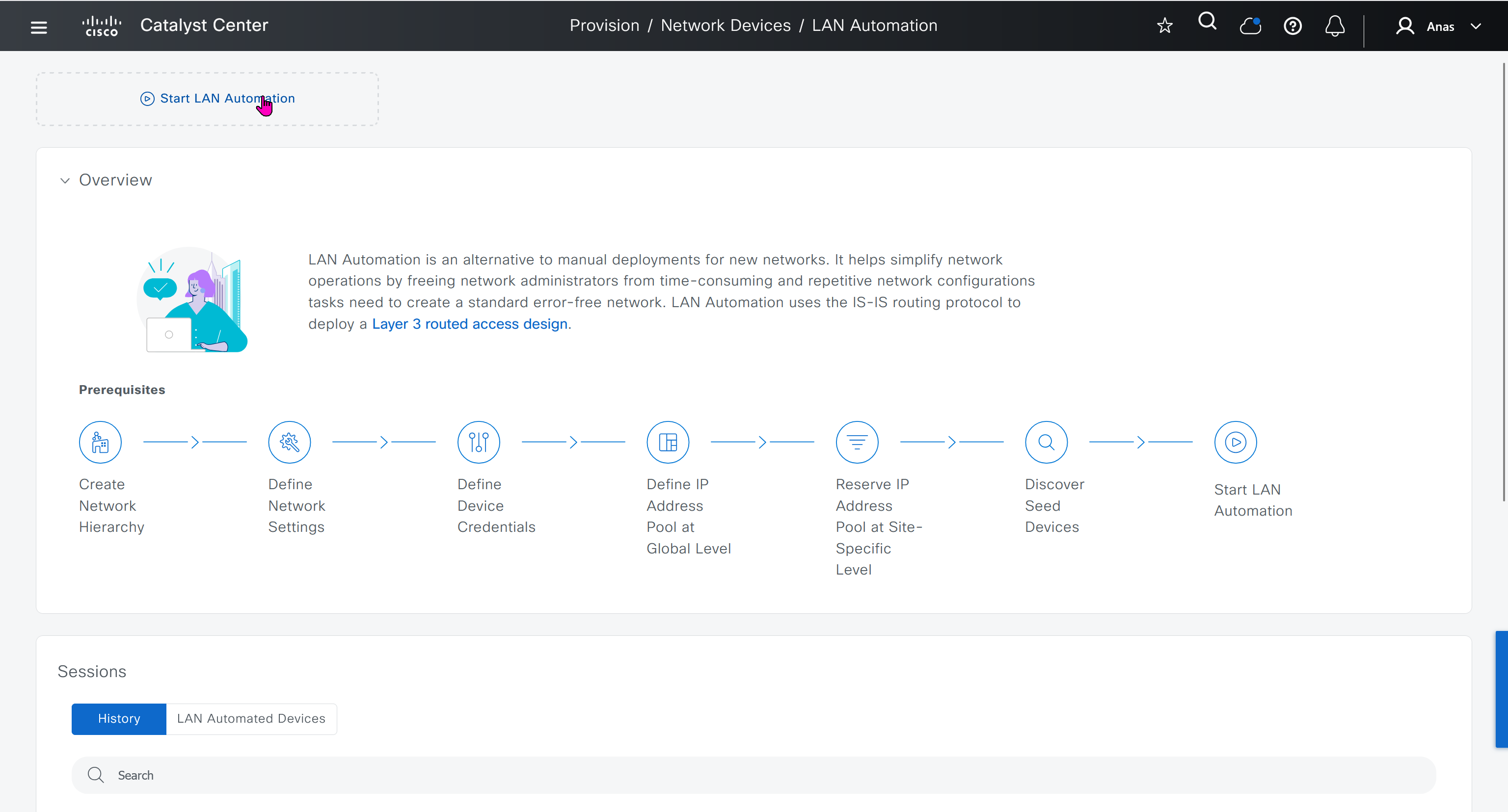
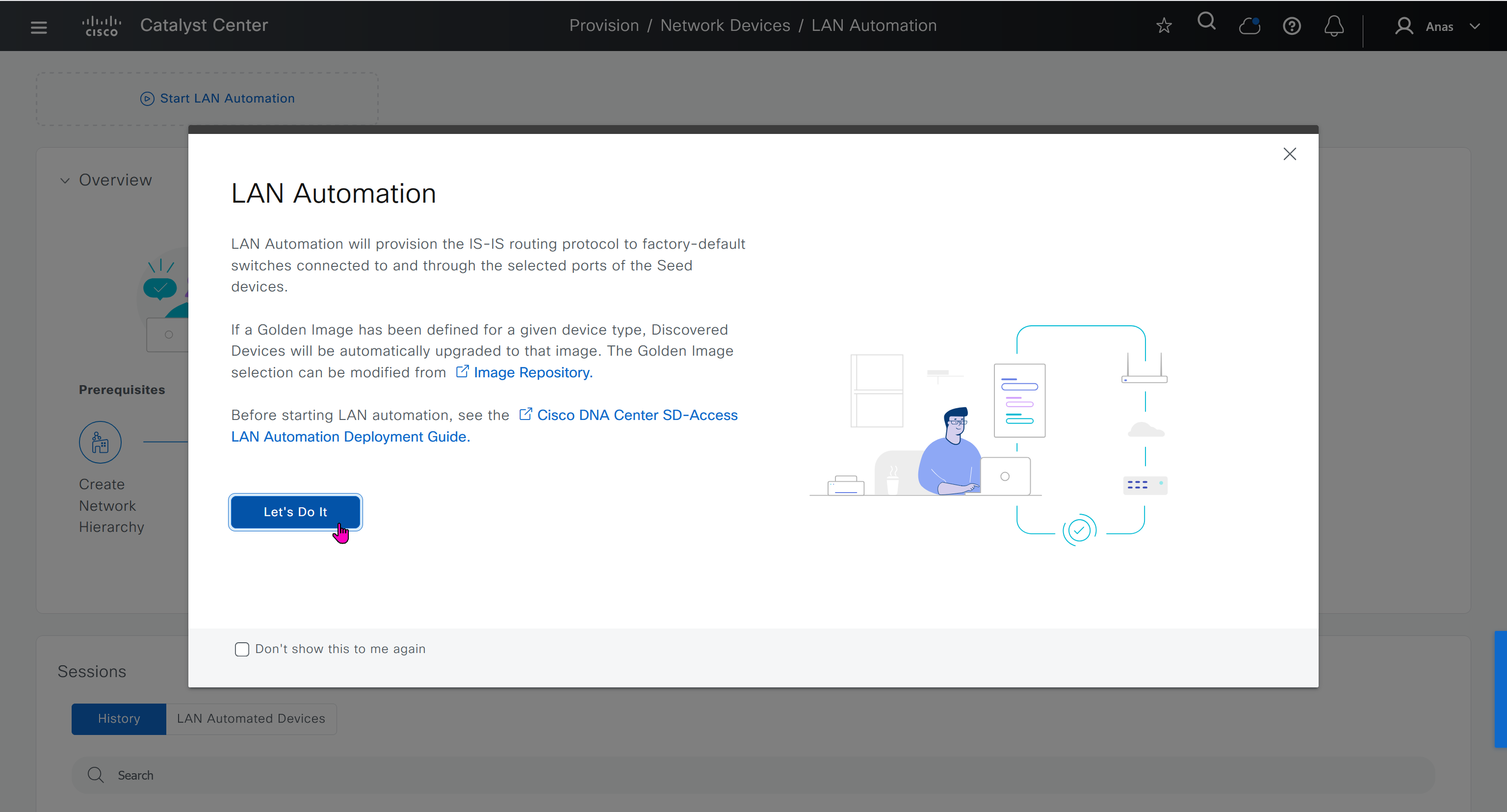
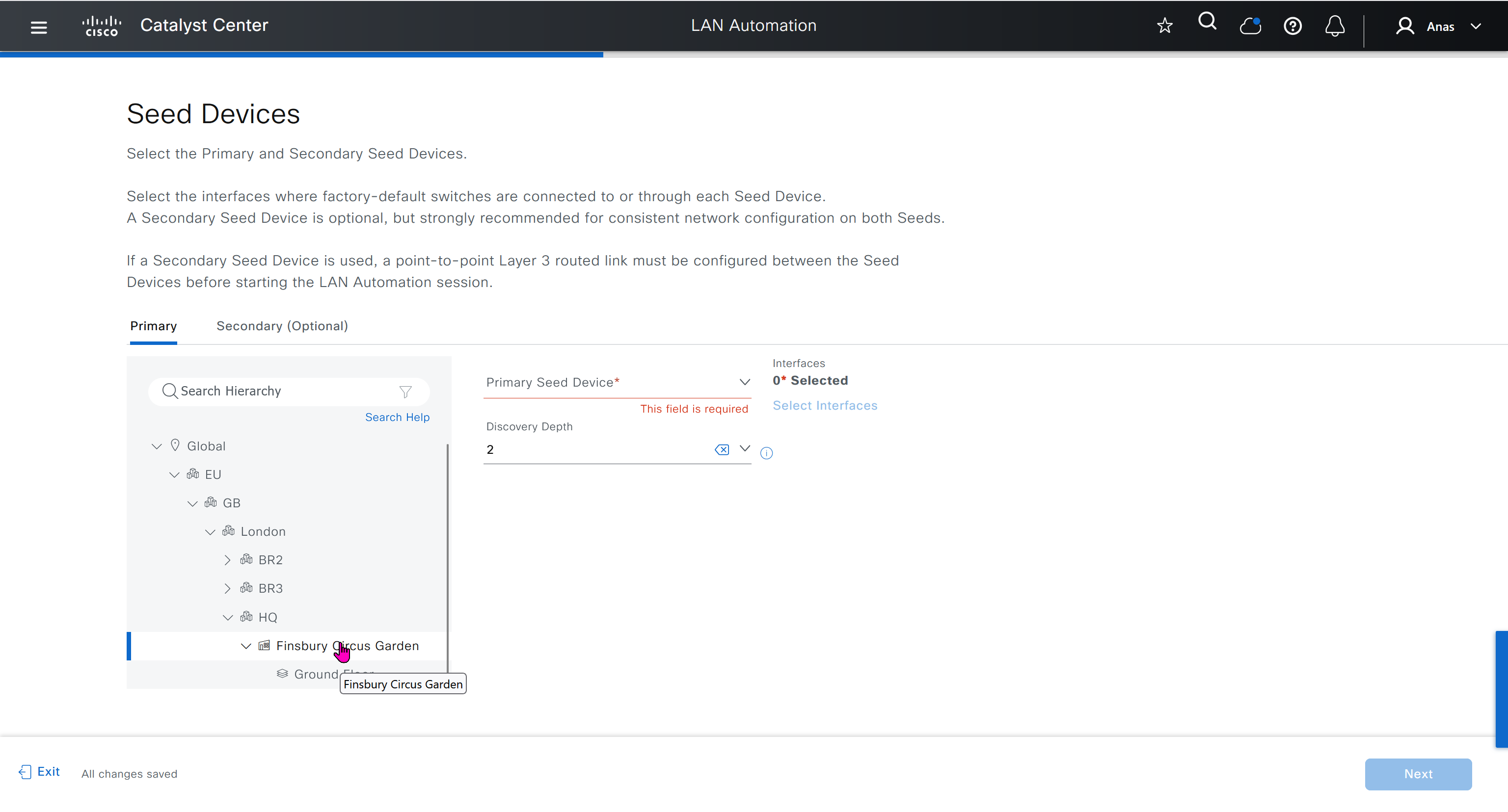
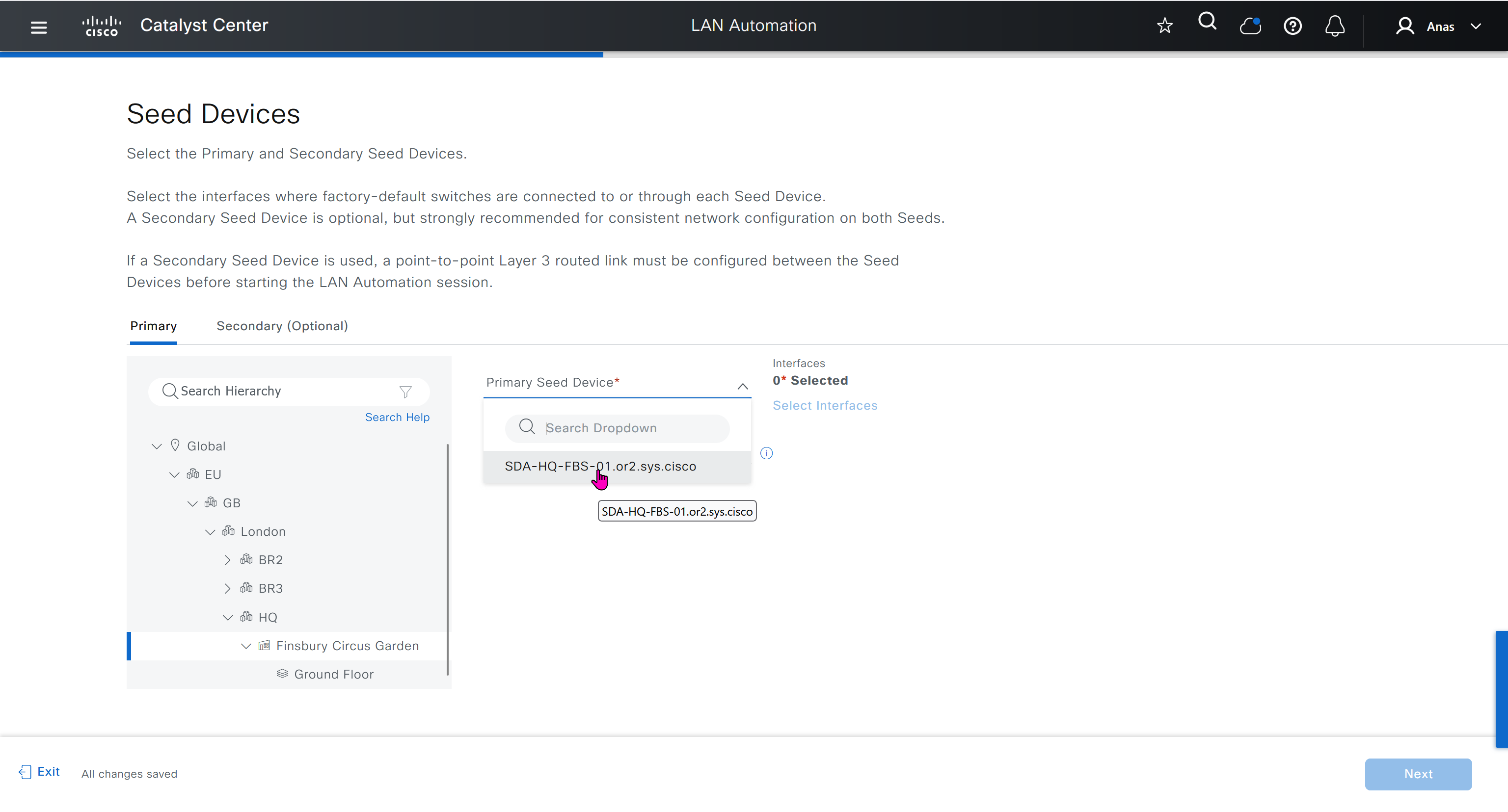
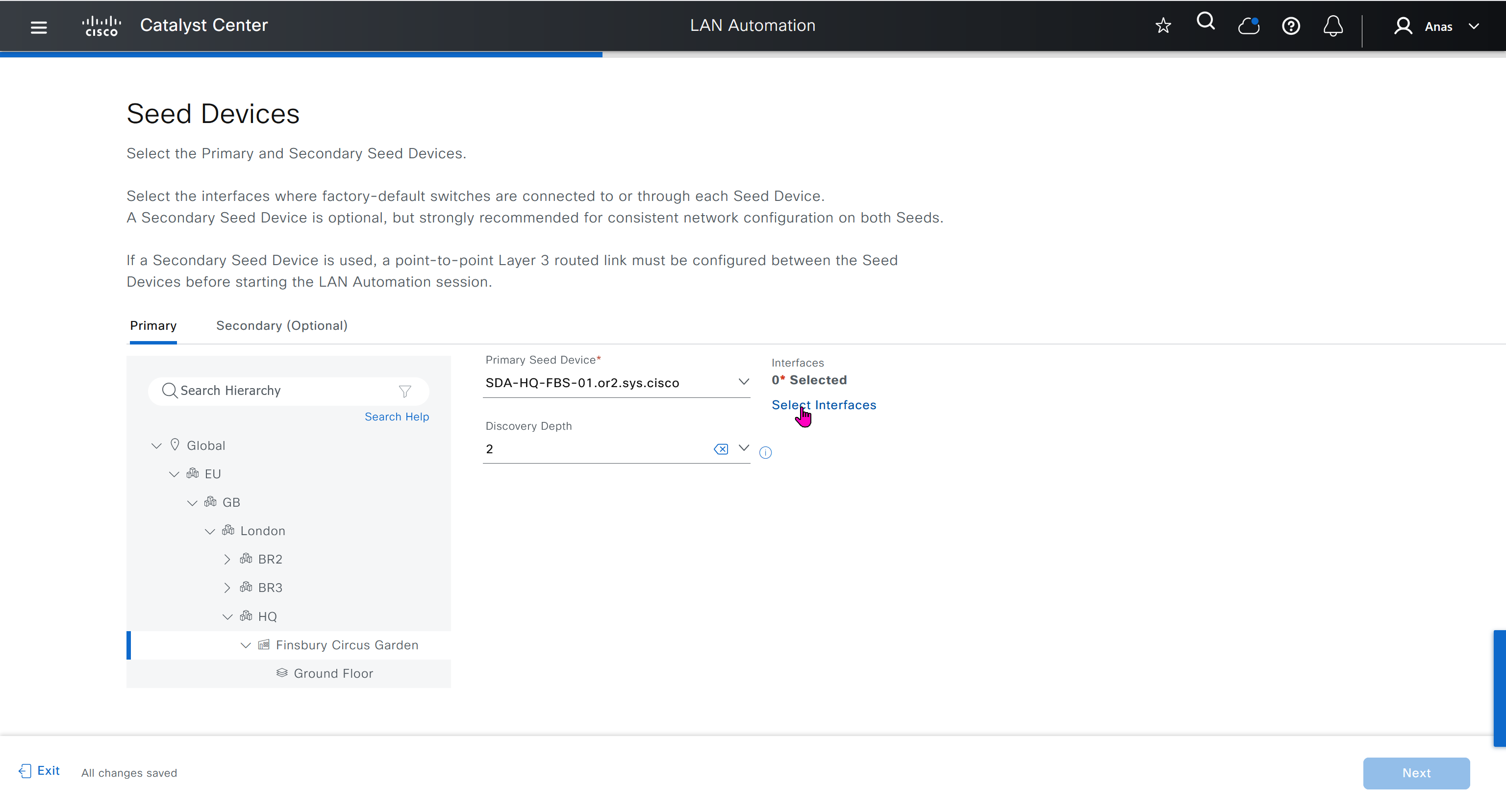

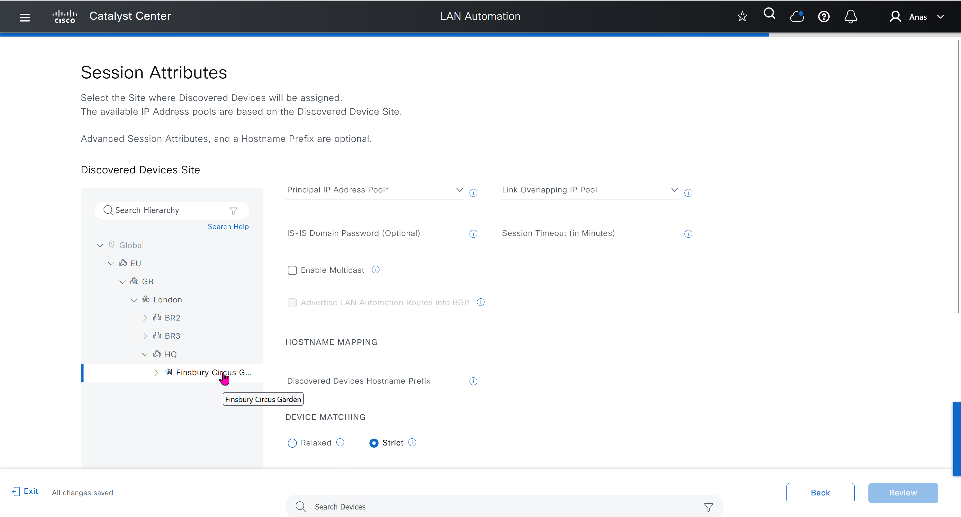
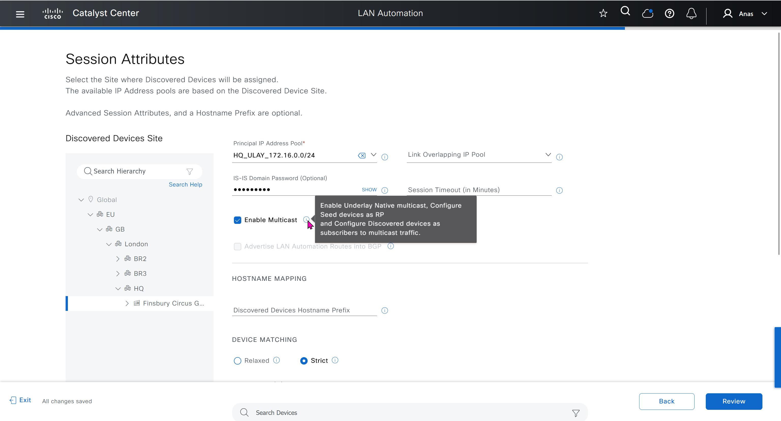


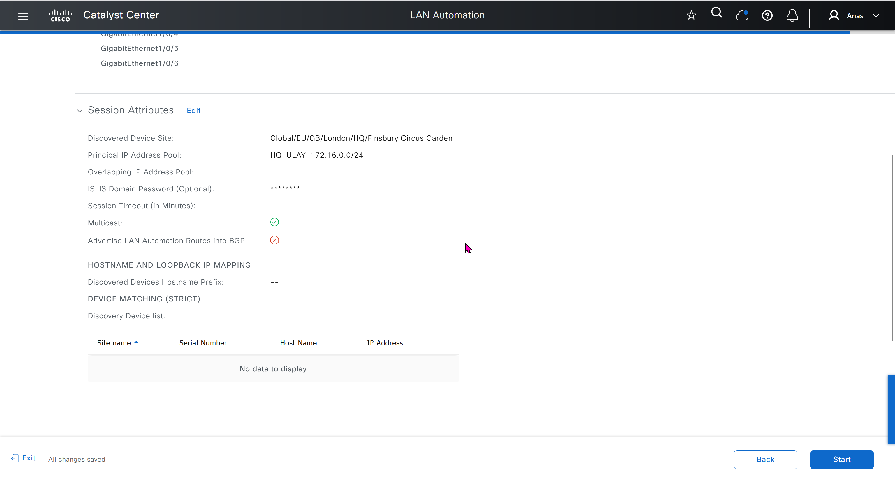
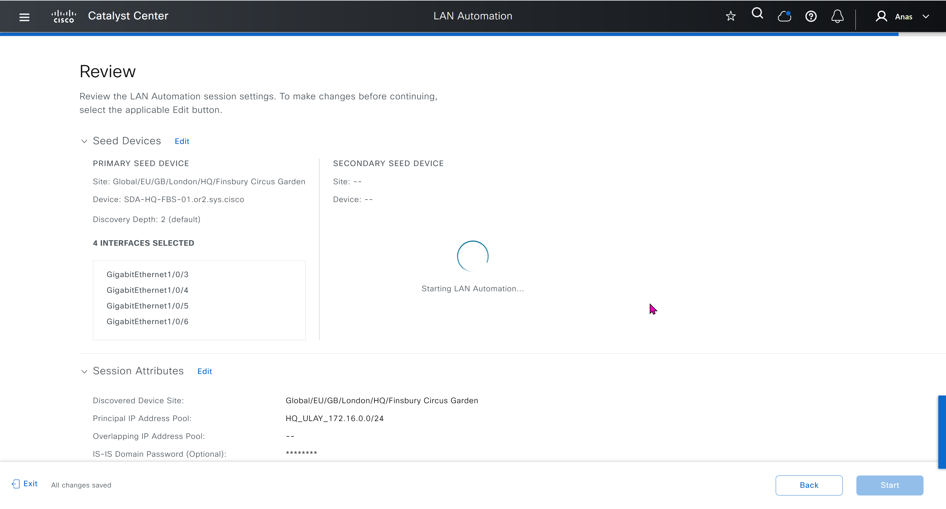
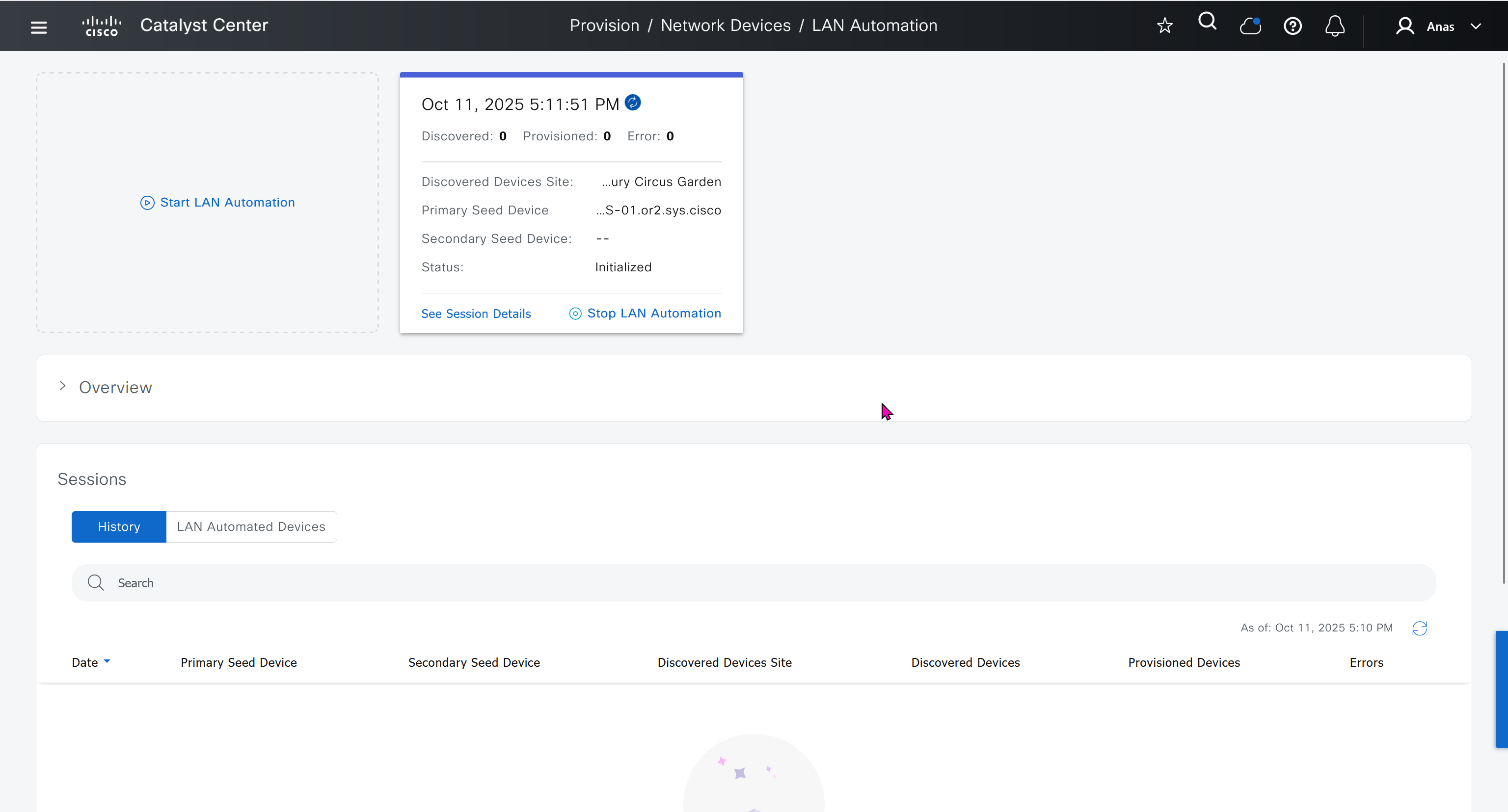
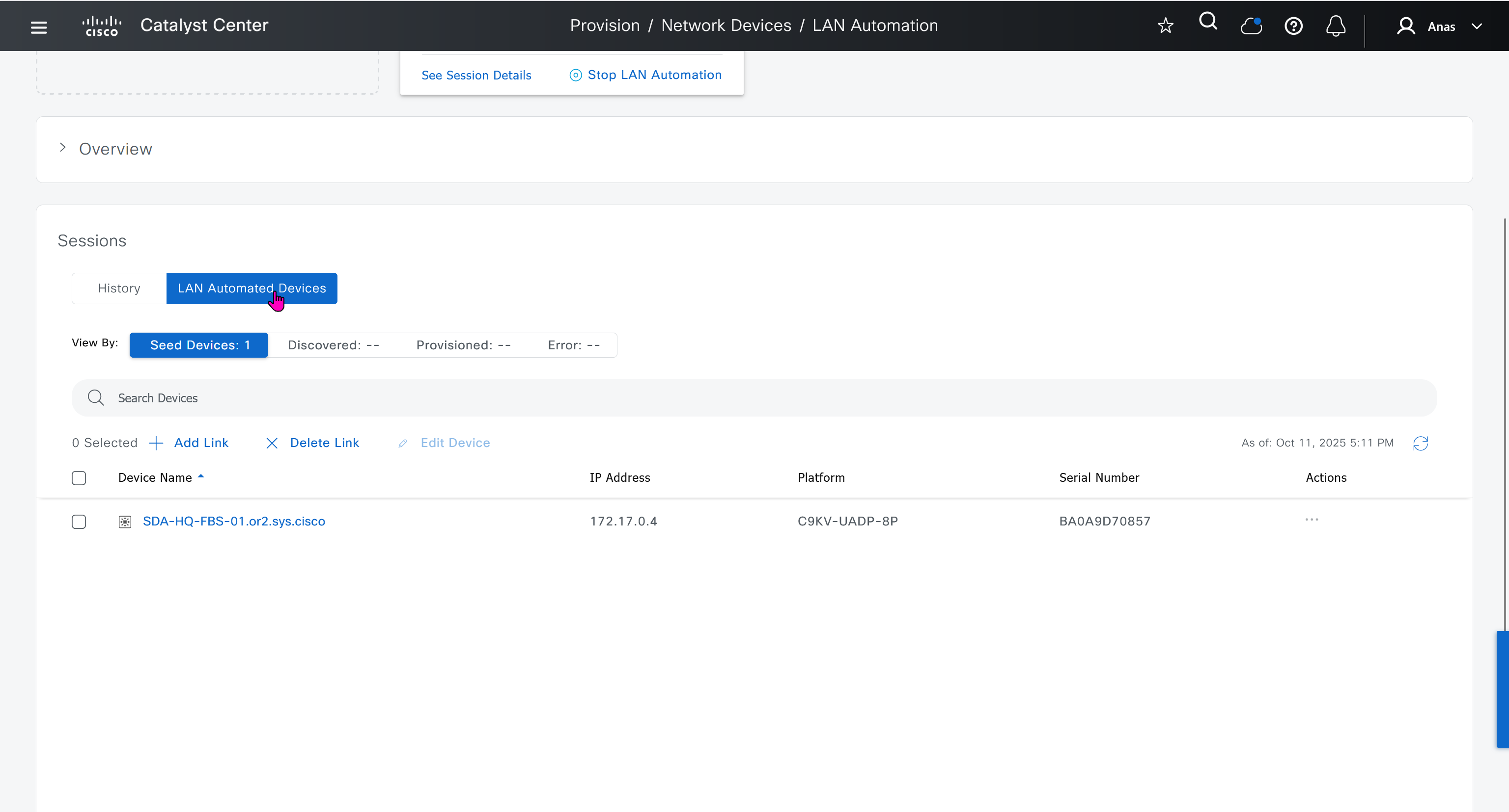
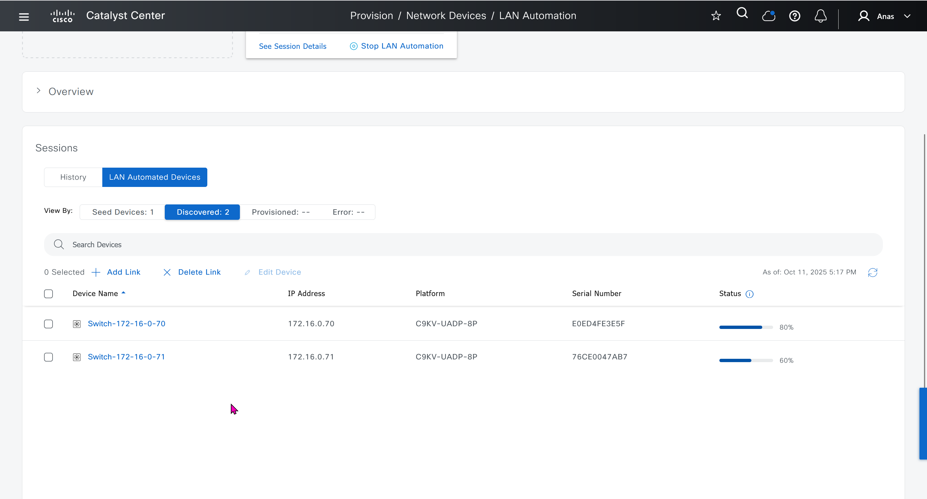


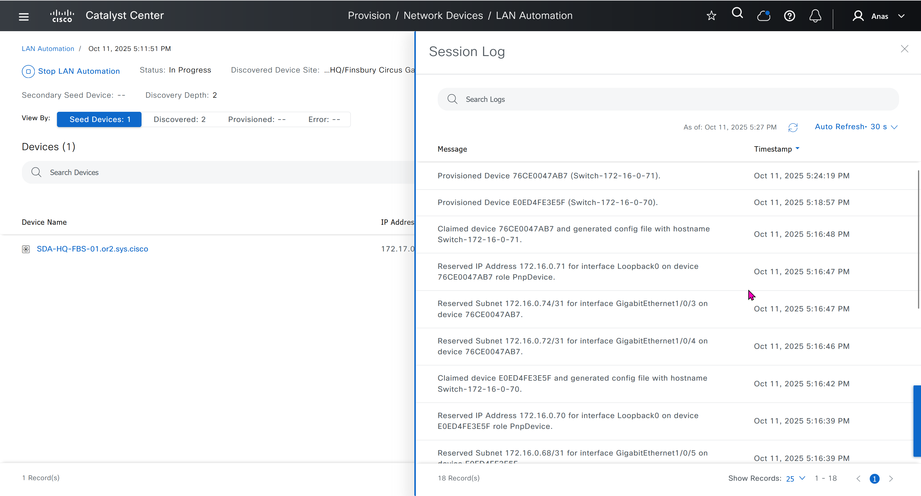
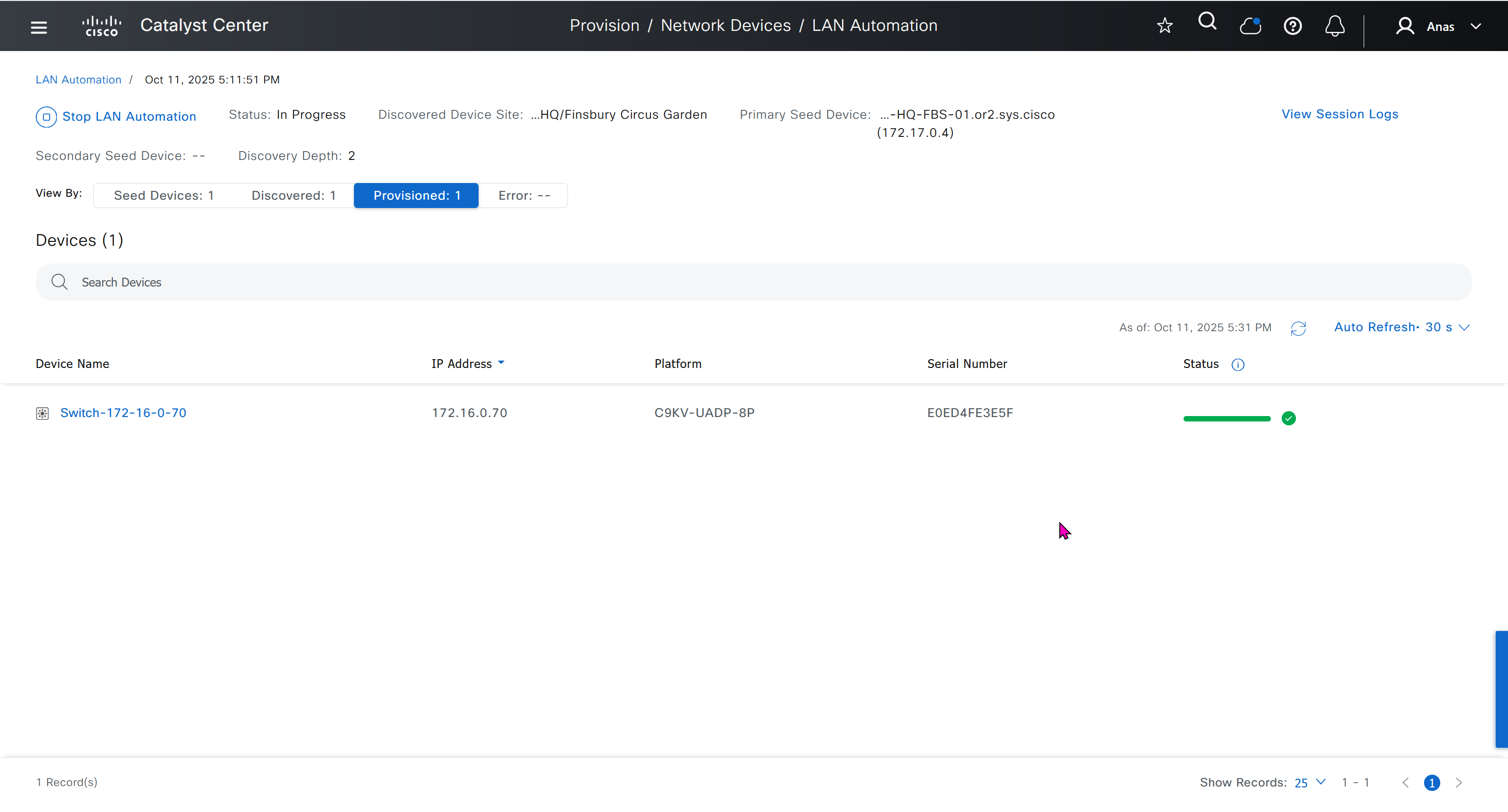
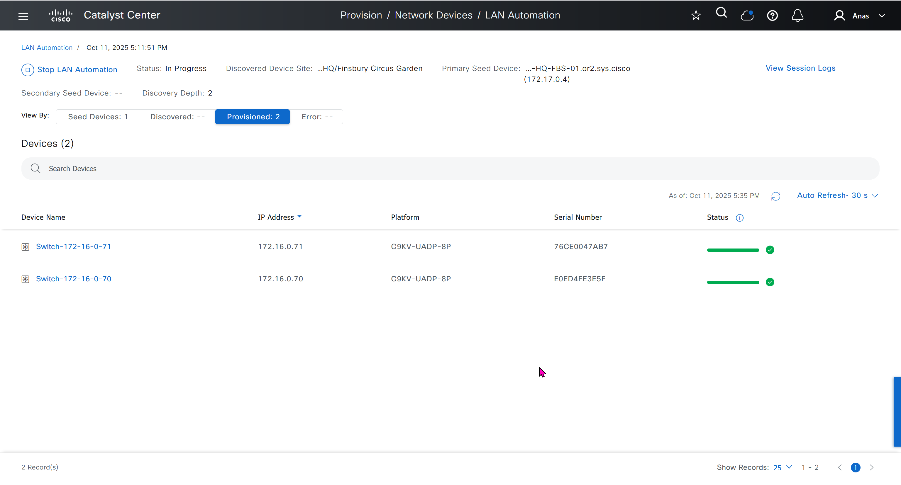
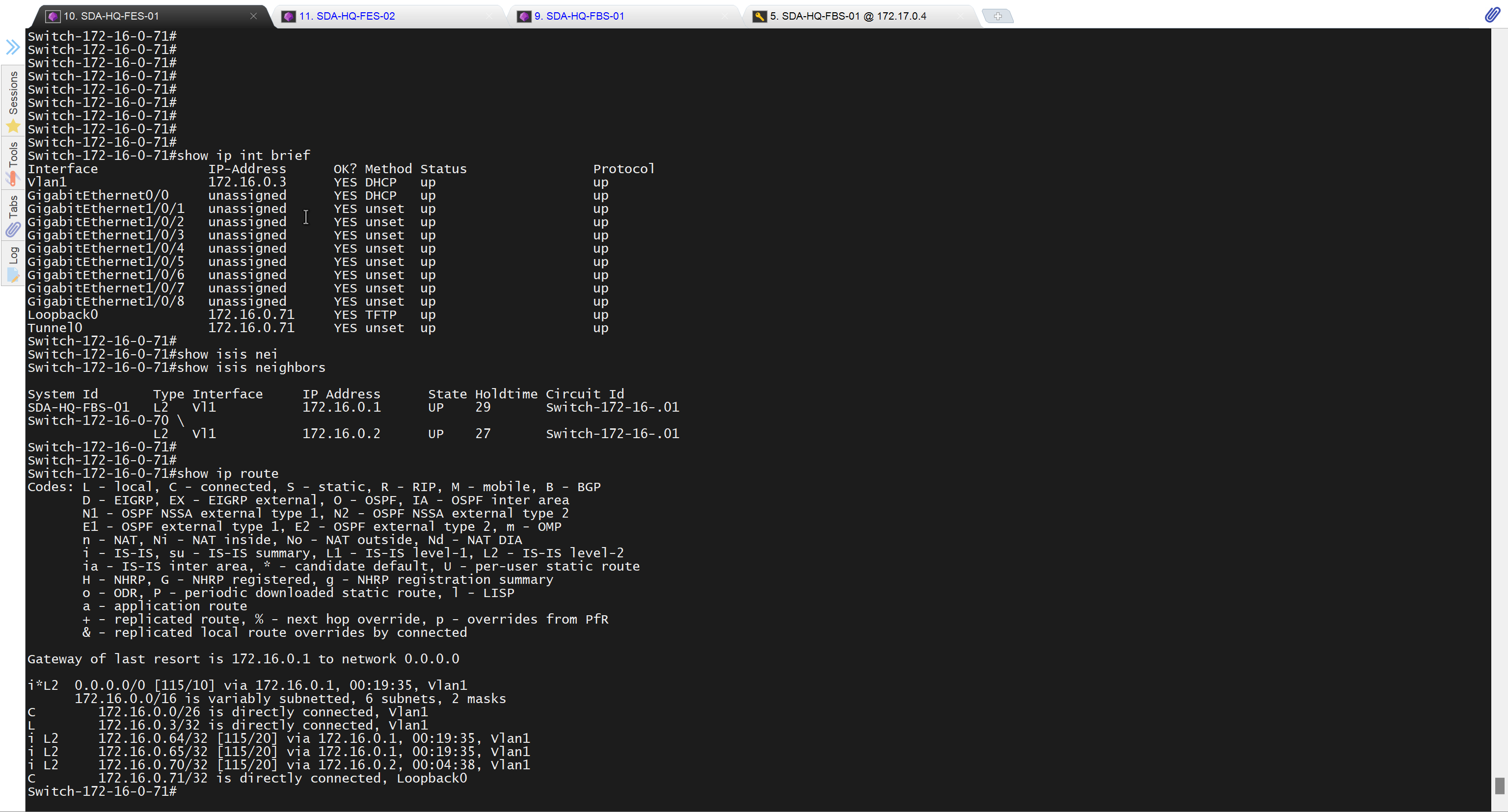

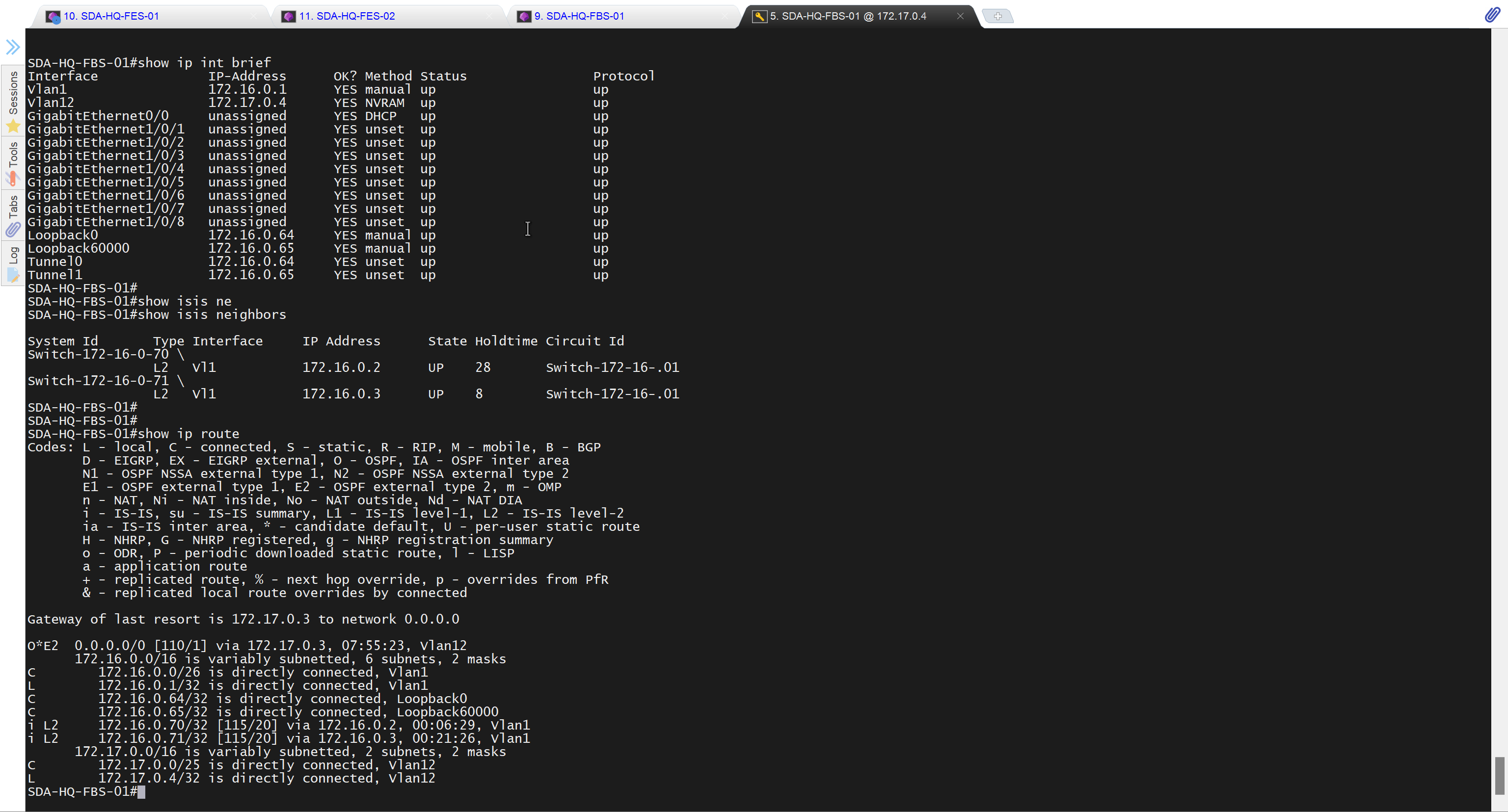


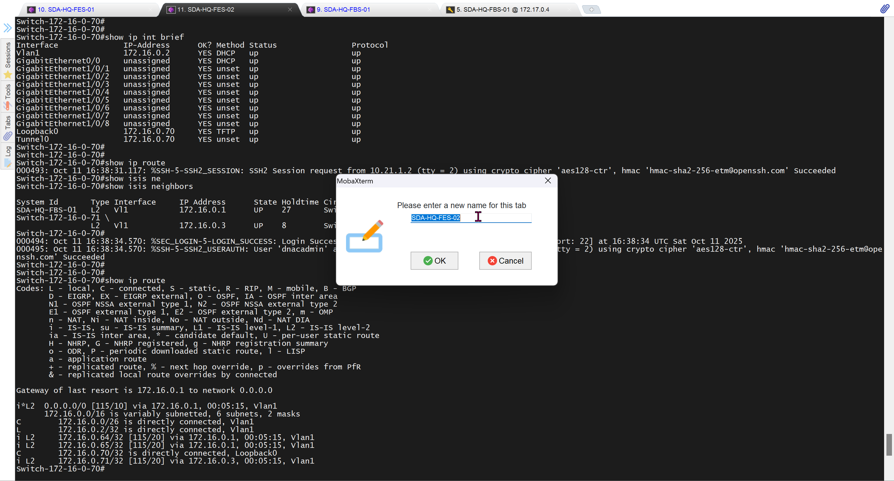
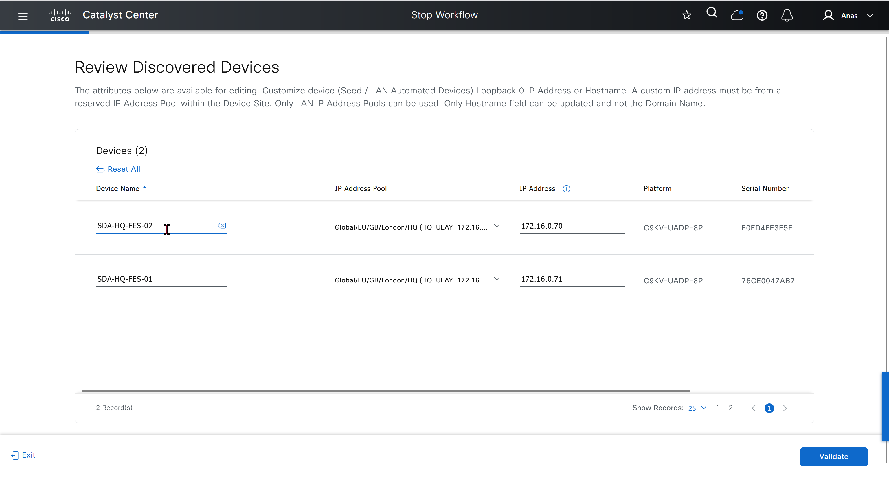


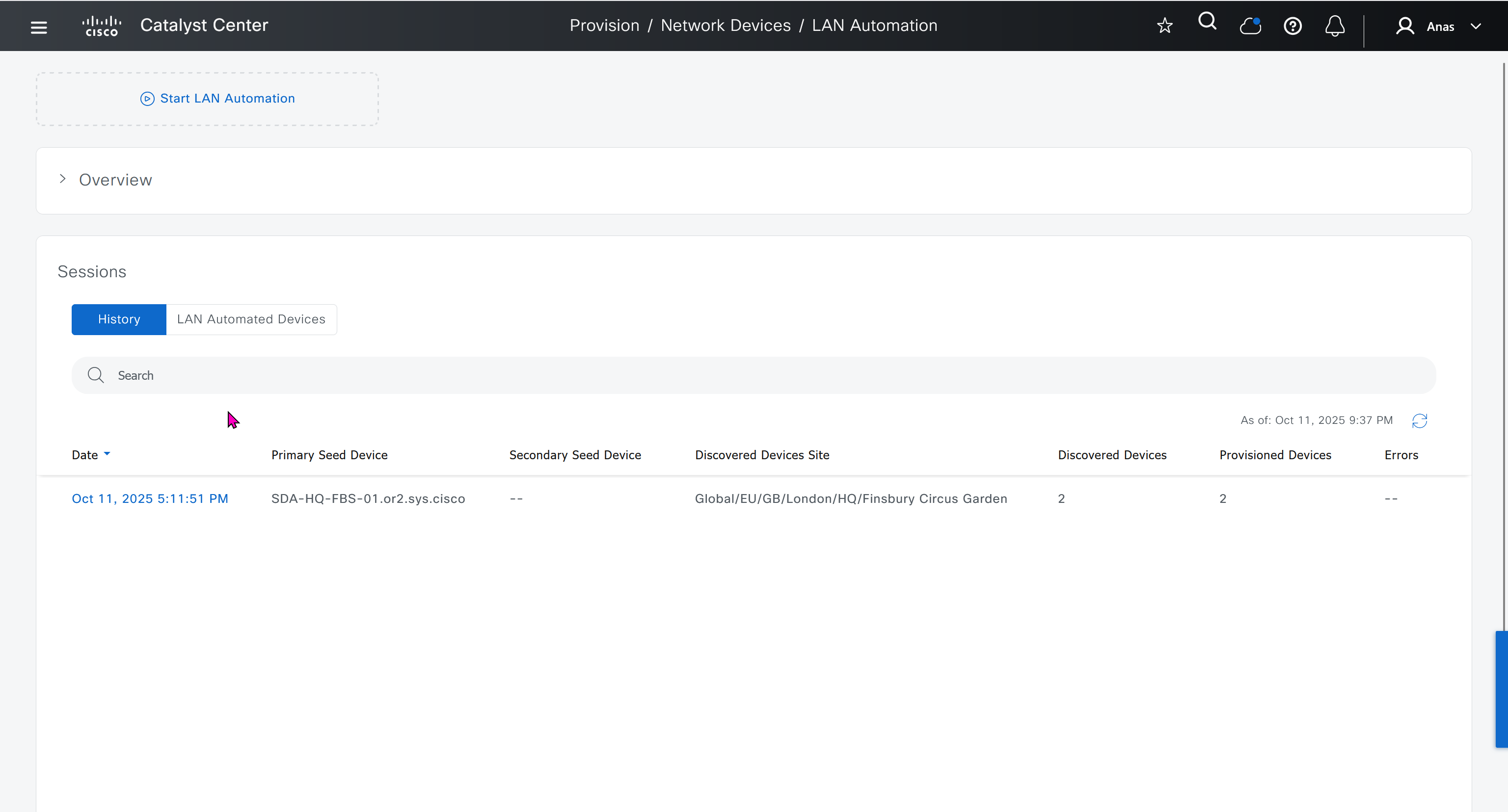

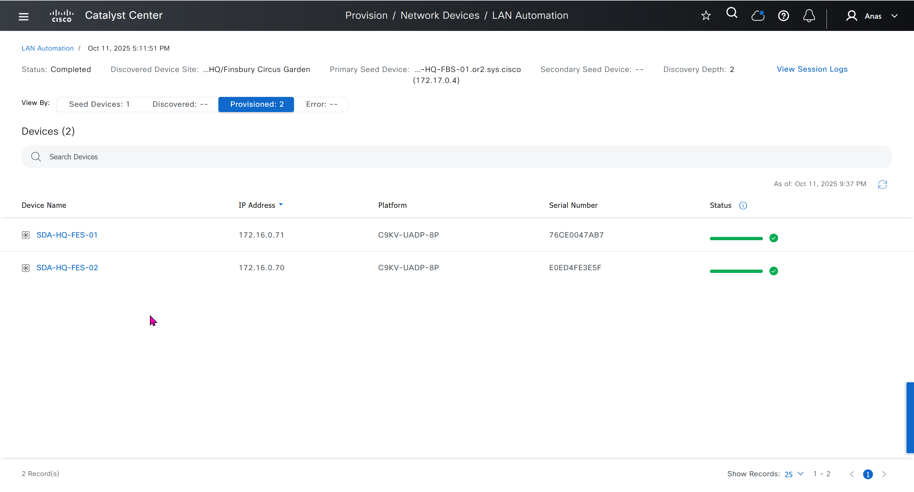
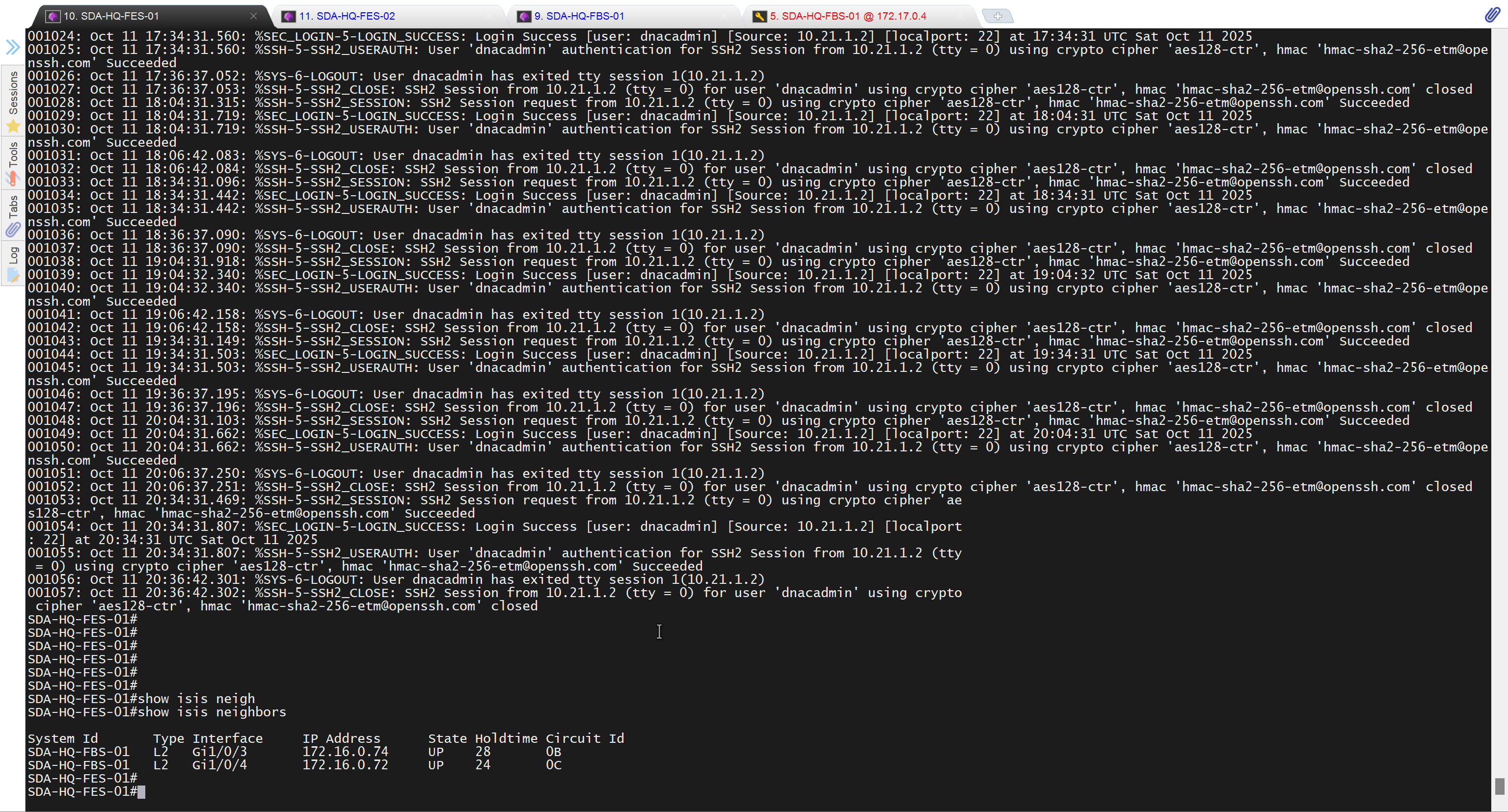

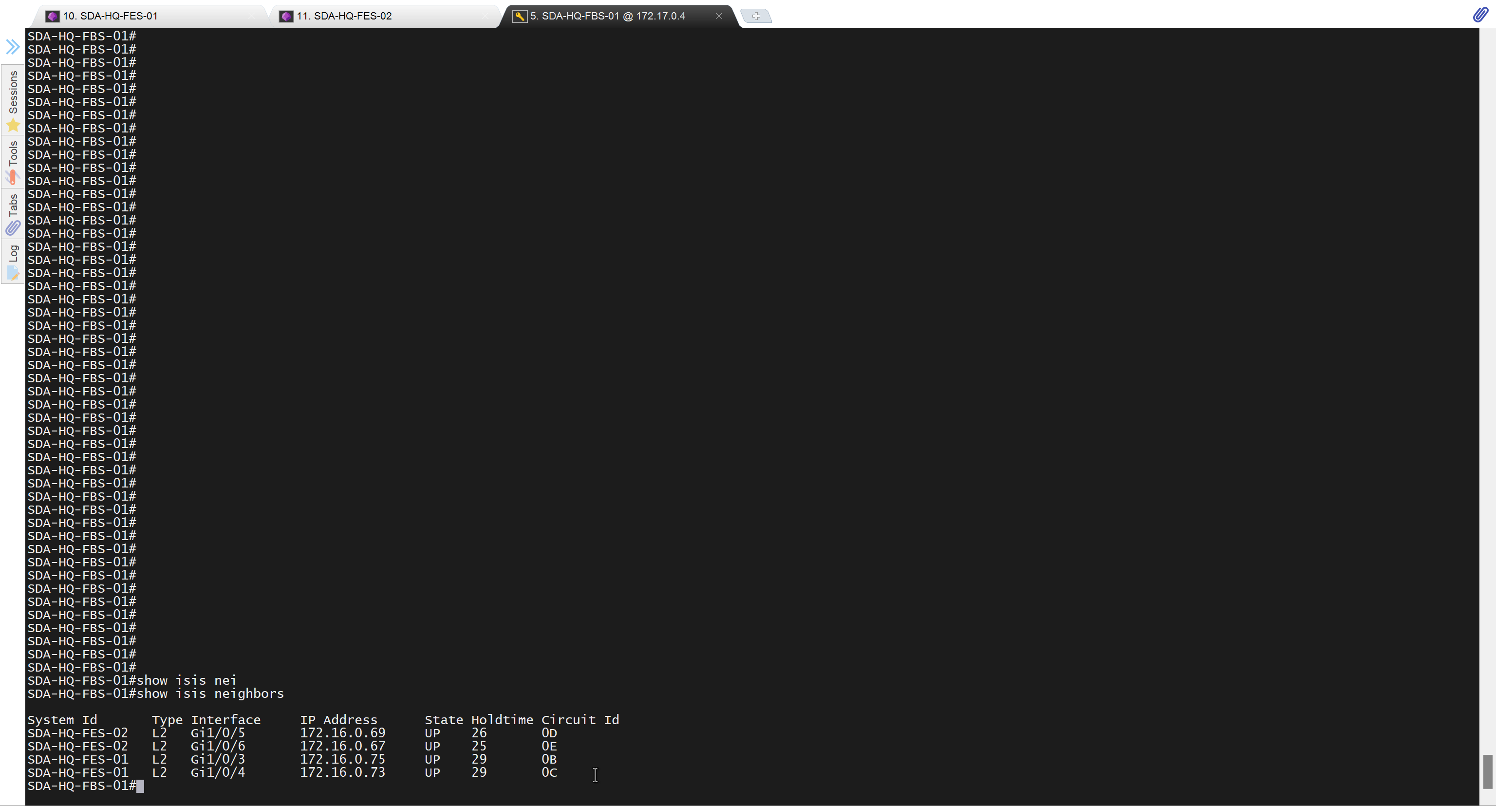