CCNA Wireless
Chapters to do
Chapter 6. Understanding 802.11 Frame Types
Before a device transmits on a channel, it must cooperate with all other devices and contend for use of the channel
There is a lot of difference between 802.11 frame and 802.3 frames and how they work
When the recipient receives a frame that has its own MAC address as the destination, the frame is then accepted and processed.
The switch that connects the two hosts forwards frames between them as needed, but it does not intervene or actively participate in the exchange. In other words, neither host has to be aware of the switch’s existence at all. Frames enter and exit a switch simply because hosts are connected to it through wires or cables, The switch silently forwards the frames based on the destination MAC addresses and there is no interaction with the clients
In contrast, the APs in an 802.11 network are active participants
AP has to act as the central “hub” or manager of a basic service set (BSS)
A client must join/associate with a specific wireless network by first getting permission from the AP
After that client sends all traffic to other clients “through” the AP
or it can coordinate with AP for direct “client-to-client” communication 802.11z or Direct Link Setup (DLS)
Wireless clients use same format MAC address as used on wired network, Each client’s radio interface must have a unique MAC address so that frames can be sent from and received to that address.
To direct frames through an AP, the AP must also have a MAC address of its own. Wireless clients know the AP’s address as the BSS identifier (BSSID), which must be included in each frame sent to the AP.
BSSID stands for Basic Service Set Identifier
It is used to identify the specific wireless network (Basic Service Set, or BSS) and specific AP in that SSID – BSSID = which is a mac address on AP’s radio specifically for that SSID
Each SSID on that AP has a unique MAC address or BSSID
So if one AP is broadcasting multiple SSIDs – there will be a different BSSID per SSID on that AP’s radio
Multiple APs sharing the same SSID
SSID: OfficeWiFi
BSSID 1: 00:11:22:33:44:55
BSSID 2: 00:11:22:33:44:66
BSSID also helps in roaming when SSID remains same but BSSID changes
BSSID filter is applied on clients for data traffic, unless a client is scanning the air
For data traffic stations ignore frames whose BSSID does not match their connected network (except special cases like scanning).
802.11 frames can carry a maximum payload of 2304 bytes in length
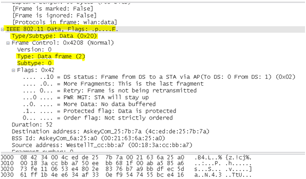
below is an example of Data frame
The frame begins with a 2-byte Frame Control field which identifies the “frame type” and the “direction” in which the frame is traveling as it moves from one wireless device to another.
802.11n and 802.11ac amendments allow frames to be aggregated and sent as a single unit, to reduce overhead and increase throughput.
Distribution System – DS
AP’s not just have wireless connectivity, but they also have upstream connectivity into wired network which is called Distribution System or DS in wireless language
Data frames are either coming from clients toward the DS or coming from the DS toward the clients.
Frame motion is indicated by 2 bits, To DS and From DS, contained in the 802.11 frame header
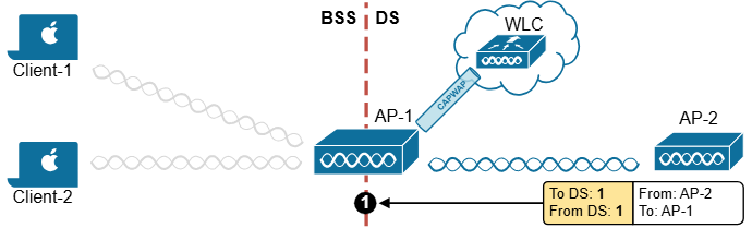
Step 1. When Client-1 sends wireless frames, it sets the “To DS” bit to 1 and the “From DS” bit to 0, as shown in step 1 in the diagram below (in yellow). This means that the frame is destined for the Distribution System for switching/routing to the correct destination. (Client-1 doesn’t know where Client-2 is.)
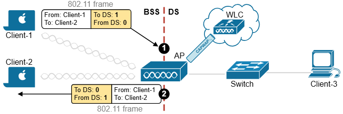
Step 2. If this is a split-MAC architecture, the “frame from Client-1 reaches the AP and then the wireless controller via the CAPWAP tunnels. The controller switches the frame back to the access point”. Before the AP sends the frame to Client-2, it changes the directions – it sets the “To DS” bit to 0 and the “From DS” bit to 1, as shown in step 2 in the diagram above (in yellow).
Yes it is true for frames from client 1 to reach client 2 (on same SSID) by going to WLC on capwap if WLAN is configured for central switching
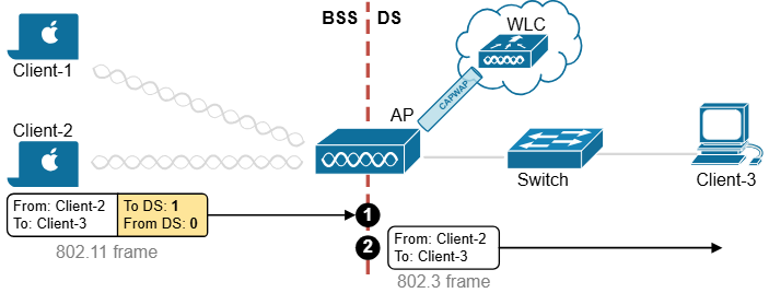
Let’s look at another example. Client-2 sends data to Client-3, which is connected somewhere on the wired side of the network. Client-2 sets the directions as shown in step 1 in the diagram below (in yellow).
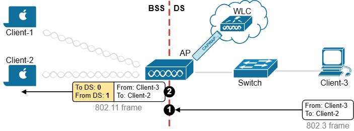
When Client-3 responds, the AP changes direction in the 802.11 frame, as shown in step 2 in the diagram below (in yellow). It sets the “To DS” bit to 0 and the “From DS” bit to 1 to indicate that the traffic is coming from the Distribution System.
At this point, you might ask: Okay, if there are only two possible directions in the network (to DS and from DS), why don’t we use a single bit? For example, set to 0 for one direction and set to 1 for the reverse direction. Why does the frame header use two bits?
The answer is that there are special cases where data is not just going between devices and the DS but somewhere else, leading to four possible direction types.
One special case occurs when an AP sends a broadcast frame to all connected clients, meaning the frame does not originate from the DS. Another example is when a client sends a management frame directly to the AP, making the AP itself the destination.
| Frame Control: To DS | Frame Control: From DS | Use case |
| 0 | 0 | An AP itself, not the DS, is the source or destination of the frame. For example, an AP sends a control frame to all associated devices. |
| 0 | 1 | A 802.11 frame is sent from the DS to a client. |
| 1 | 0 | A 802.11 frame is sent from a client to the DS. |
| 1 | 1 | An AP relay a frame to another AP over a “wireless” backhaul link. The link is neither in the BSS nor in the DS. |
A different scenario arises in mesh networks, where APs communicate wirelessly with each other over backhaul links. Since these links are not part of a basic service set (BSS) or the DS, both direction bits in the frame header are set to 1, indicating that the frame is traveling between APs rather than between clients or the wired network, as shown in the diagram below.
In the following examples, both the To DS and From DS bits are set to 0:
- An AP sends a management or control frame, which is broadcast to all wireless clients in the BSS. The AP, and not the DS, is the source of the frame.
- A client sends a management frame to an AP, such that the AP itself is the destination.
- One client sends a frame directly to another client via DLS. The frame is not destined for the AP or the DS.
The other special case is related to mesh AP networks, where frames are relayed from AP to AP over “wireless” backhaul links. A backhaul link is neither in the BSS nor in the DS, so both direction bits are set to 1
802.11 Frame Addresses
802.11 frame header can contain up to four different address fields
There is a concept of Transmitter Address (TA) and Receiver address (RA)
and then we have original Source Address (SA) and original Destination Address (DA)
Consider a frame sent from a device on the DS to a wireless client. When the frame is sent over the wireless medium, the AP’s radio is the transmitter address, but the AP did not originate the frame—a device on the DS did.
Receiver Address (RA)
Who is this frame being sent to right now (over the air)?
This is the next device that should receive the frame.
Example:
- Laptop → Access Point
RA = Access Point
Transmitter Address (TA)
Who is sending the frame right now (over the air)?
This is the device that actually transmitted the frame wirelessly.
Example:
- Laptop → Access Point
TA = Laptop
Original Source Address (SA)
Who originally created the data?
Even if the frame passes through an access point, this stays the real sender of the data.
Example:
Laptop → AP → Server
SA = Laptop
Original Destination Address (DA)
Who is the final intended recipient?
This is the real target device, not just the next hop.
Example:
Laptop → AP → Server
DA = Server
The most common scenario (Client talking to Access Point)
Example:
Laptop sends data to a web server
| Field | Contains |
|---|---|
| Address 1 | Receiver (AP) |
| Address 2 | Transmitter (Laptop) |
| Address 3 | Destination (Server) |
| Address 4 | Not used |
So:
Addr1 = RA
Addr2 = TA
Addr3 = DA
In a real routed network, Address 3 is usually not the server’s MAC address.
It is typically the MAC address of the next Layer-3 hop (for example, the VLAN SVI / default gateway).
Access Point forwarding data to client
Example:
Server sends data back to laptop
| Field | Contains |
|---|---|
| Address 1 | Receiver (Laptop) |
| Address 2 | Transmitter (AP) |
| Address 3 | Source (Server) |
| Address 4 | Not used |
So:
Addr1 = RA
Addr2 = TA
Addr3 = SA
In a real routed network, Address 3 is usually not the server’s MAC address.
It is typically the MAC address of the next Layer-3 hop (for example, the VLAN SVI / default gateway).
When Address 4 is used (rare case)
Address 4 appears only in Wireless Distribution System (WDS) or AP-to-AP forwarding.
Example:
Laptop → AP1 → AP2 → Server
Then:
| Field | Contains |
|---|---|
| Address 1 | Receiver |
| Address 2 | Transmitter |
| Address 3 | Destination |
| Address 4 | Source |
Address 1 = Receiver
Address 2 = Transmitter
Address 3 = Source or Destination
Address 4 = Extra (only AP-to-AP cases)
Address4 is not present in the frame unless the frame is being transported from one AP to another AP across a wireless link, In that case, the frame has to carry the original SA and DA, in addition to the MAC addresses of a receiver (RA) and transmitter (TA)—the APs relaying the frame over the air.
Accessing the Wireless Medium
Once a wireless device has data to send, it must access the network medium and try to send it.
Remember that a wireless channel is a shared medium or very much like a hub and that every device trying to use it must share the airtime and contend for its use.
There is no centralized function that coordinates the use of a wireless channel. Instead, this effort is distributed to each device that uses a channel. This is known as a distributed coordination function (DCF)
With a shared medium, such as wired Ethernet or wireless, two or more stations transmitting at the same time can cause collisions. A collision ruins the transmitted data, wastes time on the medium, and causes the data to be retransmitted—wasting even more time. When full-duplex operation isn’t possible, some collisions are inevitable; therefore, every device should make its best attempt to mitigate and/or hopefully prevent collisions in the first place.
Devices based on the 802.3 and 802.11 standards must use the “carrier sense” multiple access (CSMA) technique to determine if the media is available before transmitting. Wired devices are able to sense an electrical signal on the wire to detect a transmission already in progress. Wireless devices can use a two-fold process to detect a channel in use:
Physical carrier sense—When a wireless client is not transmitting, it can listen to the channel to overhear any other transmissions that might be occurring. In the case of an 802.11n or 802.11ac device, a high-bandwidth frame may involve multiple channels simultaneously, so any secondary channels must also be checked.
If it overhears a frame that is destined for its own MAC address, then it receives the frame for processing. Otherwise, if a transmission is detected (just the signalling without even interpretting it as a frame) but the client decides that the channel is busy. This process is also known as clear channel assessment (CCA). While CCA is effective, it isn’t a proactive approach and must be used in conjunction with other methods.
Virtual carrier sense—When a wireless client transmits a frame, it must include a duration field in the Duration/ID frame header field. The duration indicates how much time is required for the whole frame, plus an interframe gap, plus a return ACK frame, to be sent over the channel. This effectively reserves the channel for that length of time. As long as other wireless clients can overhear a frame and its header (due to air being a shared medium) , they can predict how long they should wait for the frame to complete.
Each wireless client must maintain a network allocation vector (NAV) timer that is used to predict when the channel will become free. Each time a frame is overheard on the channel, its Duration value is loaded into the NAV. The NAV timer then counts down while the client waits to transmit.
Sensing the carrier alone can alert a client when the medium is quiet and available—except that every client on the channel will come to the same conclusion at the same time! If multiple clients have frames to transmit and all decide that the channel is free at the same time, collisions are still likely.
Collision Avoidance
Wired devices can detect collisions in real time so that they can back off and wait a random time to try again. This is known as CSMA/CD (collision detection).
Wireless devices always operate in “half-duplex” mode, which prevents a client from receiving signals on a channel while it is transmitting. This means that a transmitting wireless client can’t detect when a collision occurs at all. Therefore, 802.11 devices must try to avoid collisions in the first place, resulting in the CSMA/CA (collision avoidance) scheme.
Wireless clients avoid collisions by backing off and waiting a random time before transmitting.
If a client has a frame to transmit, it must wait until the channel is quiet, then it chooses a random number 0 to 31 timeslots to use as a backoff timer. If there are multiple clients with frames ready to transmit, their random backoff timer values will lessen the likelihood that they will contend to use a channel at the same time. All these timers values is called the contention window.
If the channel becomes busy before the backoff timer reaches zero, the timer is paused and the overheard frame duration value is added to the NAV. The waiting client can transmit only when every timer mechanism has expired and the channel is available.
Believe it or not, there is one more timing scheme that controls frame transmission. The 802.11 standard defines a few different interframe space periods that provide a safety cushion between frames. These periods of silence give the channel enough time for signals to dampen out—especially when multipath is involved and some reflected copies take longer to propagate than others.
Several different interframe space periods are used, according to the type and priority of the frame being transmitted:
Reduced interframe space (RIFS)—The shortest period of time, used before each data frame during a burst of 802.11n frames; not used by 802.11ac because it allows aggregated frames instead
Short interframe space (SIFS)—Used between data frames and frame acknowledgements or CTS 802.11g protection mode control frames
Distributed interframe space (DIFS)—The default period used after most standard priority frame types
Extended interframe space (EIFS)—The longest period of time, used after collisions and before retransmitted frames
Before a device can transmit on a channel, it must do the following:
1. Wait until the channel is quiet for a DIFS period.
2. Choose a random number and count down the backoff timer.
3. Listen during the countdown; pause counting if another station’s transmission is heard; resume counting after the channel has been quiet for a DIFS period.
4. Once the countdown reaches zero and the channel is clear, the client may transmit.
Acknowledgement
Assuming all of the carrier sense and collision avoidance methods have worked, how does a transmitting client know that the frame it just sent arrived in good condition? During transmission, the receiver must be off, so there is no way to listen to the channel.
Each time a client receives a unicast frame, it must send a unicast acknowledgement frame back to the sender. The 802.11 standard requires this one-to-one response for every frame received, except in the case of 802.11n, 802.11ac, and 802.11e (WMM) blocks of frames, which require one acknowledgement for a whole block of frames.
If a transmitted frame fails and is not acknowledged, the sending client must try again by retransmitting the frame. The client chooses a new backoff timer value from a contention window that is double the previous range. In effect, this relaxes the conditions on the channel to give the retransmitted frame a better chance of surviving. With every failed attempt, the contention window is doubled, up to a maximum of 1023 timeslots.
Avoiding Collisions with the DCF Process
1. Client A has been waiting at least a DIFS period and determines that no other devices are transmitting. Client A waits a random backoff timer period before transmitting Frame-A. The frame’s duration is advertised in the header’s duration field.
2. Client B has a frame to transmit. It must wait until Client A’s frame is completed and then wait until a DIFS period has expired.
3. Client B waits a random backoff time before attempting to transmit.
4. While Client B is waiting, Client C has a frame to transmit. Like Client B, Client C must wait until the DIFS period after Client A’s transmission has elapsed. Client C then listens and detects that no one else is transmitting. It then waits a random backoff time that is shorter than Client B’s backoff timer.
5. Client C transmits a frame and advertises the frame duration in the duration field.
6. Client B must now wait the duration of Client C’s frame plus a DIFS period plus the remainder of its own backoff timer before attempting to transmit.
Another DCF example
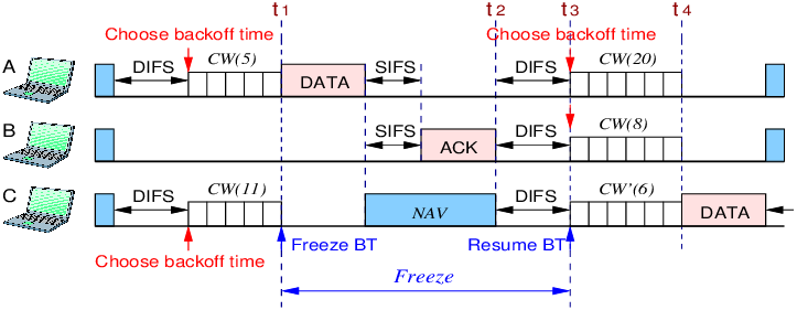
-Client A and C have frame to send
-Client A and C have to find the channel quiet for at least DIFS period before they can determine that channel is quiet and only then they can initiate their Contention Window or random back off timers
-Client A and Client C have passes DIFS time and determined that channel is quiet and select their CW timers
-Client A has smaller CW timer and finished couting it and because channel was still quiet sends Frame to Client B
-Client C freezes its backoff time (currently, w is set to 6) when it detects busy channel due to Client A’s transmission of data packet
-Client C heard the header of data sent by Client A (considers only header not the whole data frame) and noticed duration header, puts it in NAV timer so it can find the time it takes for SIFS and time it takes for Client B to send ACK back
-once ACK is sent by Client B and NAV timer is finished, Client A, Client B and Client C, all have to wait for DIFS timer in order to determine that channel is free
-Client A and B will start new CW timer if they have more frames to send but Client C will resume
-Once CW timer counts down for Client C, it then sends frame
802.11 Frame Types
The 802.11 standard defines three different frame types that can be used:
Management frames
Control frames
Data frames
Each of the three frame types can have several different subtypes that perform various functions.
Management Frames
Management frames are used to “advertise a BSS and its capabilities” and to manage clients as they join or leave the BSS. For example, 802.11ac management frames include “very high throughput (VHT) capabilities” such as “channel width”, “guard interval”, “beamforming”, and “MCS support”. Management frames are also used to manage clients as they join or leave the BSS. A client must first locate a candidate BSS to join, authenticate itself to an AP, and associate itself with the BSS.
Although there are 14 different management frame subtypes available, you should become familiar with just the following:
Beacon—The AP broadcasts this frame “to advertise the BSS”, the “data rates necessary” and allowed in the BSS, an optional security set identifier “(SSID) string”, and “vendor-specific” information when necessary. Beacons are sent to any and all devices about “ten times per second (100-ms intervals)”. If the AP supports multiple SSIDs, a different beacon is broadcast for each SSID.
A wireless device can learn about BSSs within range by listening to the beacons that are received. This is known as “passive scanning”.
Probe—A wireless device can send probe request frames to ask any APs within range or a specific AP to provide information about their BSSs. An AP answers by sending a probe response that contains most of the beacon information. “Probing for BSS information is known as active scanning”
In Wireless Authentication happens before association
Think of it like entering a secure building:
Authentication = proving who you are
Association = getting permission to enter and use resources
Authentication and deauthentication—To join a BSS, a wireless device must first send an authentication request frame to an AP. The AP sends the result of the authentication in an authentication response frame.
Association, disassociation, and reassociation—Once a device is authenticated, it can send an association request frame to the AP to ask permission to join the BSS. If the device supports “compatible parameters and is allowed to join”, then the AP will reply with an “association response frame, along with a unique association identifier (AID) for that client”.
If a device wants to gracefully leave a BSS, it can send a disassociation frame to the AP. An AP can also decide to drop a client by sending it a disassociation frame.
When a client wants to leave one BSS for another, while staying within the same SSID, it can send a reassociation request frame to the new AP. In effect, the client is attempting to reassociate with the SSID, not an AP. The new AP responds with a reassociation response frame. (Moving from one BSS to another is covered in greater detail in Chapter 12, “Understanding Roaming.”)
Action—An action frame provides a way to communicate an extended management action to be taken. For example,
in the 802.11k, a wireless station can use action frames to request radio measurement information from other devices, as well as a report of neighboring APs to make its roaming decisions more efficient.
The 802.11v amendment uses action frames to allow network-assisted client power savings.
The 802.11y amendment leverages action frames to allow an AP to announce an impending channel change or channel width change to its associated clients.
Control Frames
Control frames contain only frame header information and no data payload. There are nine different control frames possible. Be familiar with the following four:
ACK—A short frame that is sent as an acknowledgment of a unicast frame that has been received.
Block ACK—A short frame that is sent as an acknowledgment of a burst of frames sent as a single block of data.
PS-Poll (Power Save Poll)—A frame sent from a client to an AP to request the next frame that was buffered while the client’s radio was powered down.
RTS/CTS—Frames that are used to reserve a channel. RTS/CTS frames carry a Duration value that reserves the channel airtime for the frame they are protecting. RTS/CTS frames are used to help avoid collisions between clients that cannot hear each other because of the distance between them. When clients cannot hear each other, they also cannot hear the Duration values or detect a carrier to know when to cease transmitting. As long as the clients can hear the AP when it sends RTS/CTS frames, they can remain silent while others are transmitting.
In contrast, RTS and CTS frames are not needed for hidden nodes or backward compatibility with 802.11ac. This is because all devices on the 5-GHz band use OFDM, so 802.11a, 802.11n, and 802.11ac stations can all understand the same frame header information. Instead, RTS and CTS frames are used with 802.11ac to reserve additional channel space. Recall that the bandwidth can change on a frame-by-frame basis—one frame may require a 20-MHz channel, while the next frame may require 80 MHz or 160 MHz. The RTS and CTS frames are duplicated and sent on each secondary channel that makes up the appropriate bandwidth to signal that those channels are needed and are free to be used for a frame.
Data Frames
Data is sent to and from clients in data frames. A data frame contains up to four address fields that identify the sender and recipient and identify the BSSID (AP + its SSID)
MCS
Client and an AP have to use the same modulation and coding scheme (MCS) to successfully communicate. The scheme can be changed dynamically, if needed, as long as both ends agree on the choice. The MCS directly affects the data rate between the client and the AP.
An AP is configured with a set of data rates that it can use. Each data rate can be set to one of the following states:
Disabled—The AP will not use the data rate for any client communication.
Supported—The AP can use the data rate if a client also supports its use, but the client is not required to support it, hence why supported
Mandatory—The AP can use the data rate and expects every client to support it. This is also known as an 802.11 BSS basic rate.
At least one data rate must be mandatory to provide a common rate that can be used for “management and control frames”
In fact, the AP will always send broadcast management frames using the lowest mandatory rate. The idea is to “leverage a lower data rate to get better signal-to-noise ratio (SNR)” and greater signal range to reliably manage client devices within the BSS.
Other data rates can be configured as supported. Normal data frames and unicast management frames will be sent at whatever supported rate is most optimal between the client and the AP. Acknowledgment frames are sent at the first mandatory rate that is below the current optimal data rate.
APs advertise their mandatory and supported data rates in each beacon frame
802.11a/n/ac radios consider 6, 12, and 24 Mbps to be mandatory.
Before a wireless device can join a BSS, it must be satisfied that it can support the AP’s list of advertised data rates. The device can then announce its own set of mandatory and supported data rates in an association request frame. The AP compares the client’s list of data rates with its own. If the client can support all of the AP’s mandatory rates, the client can take the next step to be associated with the BSS
A Client Scans for APs
To join a BSS, a wireless device first has to scan its surroundings to look for any live APs that might offer network service. Beyond that, the device might need to build a list of SSIDs that are available. A device can scan the wireless horizon in two ways:
Passive scan—The device simply listens for any beacon frames broadcast from nearby APs.
The beacon frames specify the BSSIDs and SSIDs that are offered, as well as supported data rates and other information about their BSSs.
Active scan—The device must take an active role and broadcast a probe request frame to ask any APs within range to identify themselves. The device can include a specific SSID name in the request. Any APs that receive the probe request must send a unicast probe response frame back to the device
A Client Joins a BSS
The device performs an active scan and discovers the two APs. Through some algorithm, it decides that AP-1 is more preferable than AP-2
Step 1. Host-1 sends an authentication request frame to AP-1’s BSSID address.
Step 2. If AP-1 is satisfied with the host’s identity, it sends an authentication response frame back to Host-1.
Step 3. Now that Host-1 is known to the AP, it must ask for BSS membership by sending an association request frame to AP-1. Host-1 includes a list of its 802.11 capabilities, the SSID it wants to join, a list of data rates and channels it supports, and any parameters that are needed to secure the wireless link to the AP.
Step 4. If the AP is satisfied with the request, it sends an association response frame back to Host-1.
Step 5. The response also contains the AID that uniquely identifies Host-1 as an associated client. In effect, the AID is Host-1’s membership card while it remains a part of the BSS.
A Client Leaves a BSS
Disassociating and Deauthenticating—Two Ways to Leave a BSS
Once a wireless device successfully becomes a client of a BSS, it keeps that relationship with the AP until something happens to remove it. For example, a wireless client might be removed if it violates a security policy, is recognized as a rogue device, has a “session that stays idle for too long”, and so on.
If a client is disassociated, it loses only its associated status but is still authenticated. To rejoin the BSS, the client can simply reassociate. Deauthentication is a bit more drastic. Once that happens, the device must start the whole authentication and association process over again
Client leaves BSS outside of AP’s cell range or goes to sleep
What happens if a client physically leaves a BSS without informing the AP? For example, suppose Client-B in Figure 6-12 reaches the edge of AP-1’s cell, but does not send a deauthentication frame? Once it goes outside the cell range, the AP might not even notice. Even before it leaves the cell, the client might just go into sleep mode and stop communicating with the AP altogether. In this case, the AP maintains the AID entry for the device, in case it returns to the cell or wakes up, but only for a certain amount of time. “Cisco APs age out unresponsive clients after 5 minutes. In case the client is still listening, the AP also sends a deauthentication frame to it.“
Roaming from one BSS to another
When a wireless client is within range of several APs, it must choose to associate with only one of them. A client might move out of range and into the cell of an adjacent BSS (AP). Moving seamlessly from one BSS to another is called roaming
To switch BSSs seamlessly, the client must recognize that it is nearing the cell boundary and that it needs to find other potential cells to move into before losing the signal completely.
Step 1. Client-1 notices that the signal from AP-1 is degrading. Based on various conditions like the received signal strength indicator (RSSI) and SNR, the client will decide that it needs to roam.
Step 2. Client-1 begins to search for a successor BSS to move into. It broadcasts a probe request frame to look for nearby APs that can offer the same “guest” SSID.
Step 3. AP-2 receives the probe request and returns a probe response, advertising its BSSID and the “guest” SSID. Other APs may also hear the request and send probe responses of their own.
Step 4. Client-1 must decide which AP is the best candidate out of all probe responses that are received. It then sends a reassociation request frame to the new AP, asking to transfer its ESS membership from AP-1’s BSS to AP-2.
Step 5. AP-2 communicates with AP-1 over the wired DS network to begin the client handoff. Client-1’s association will be moved from AP-1 to AP-2. Any frames that are destined for the client during the handoff will be buffered on AP-1, then relayed to AP-2 and transmitted to the client.
Step 6. If the reassociation is accepted, AP-2 will inform the client with a reassociation response frame.
A Client Saves Power
Wireless devices are commonly small in size and powered by batteries. Because the devices are mobile and carried around, it is not very practical to stop and charge the batteries. To maximize the battery life, the device should conserve as much power as possible.
By default, the radio (both transmitter and receiver) is powered on all the time, so that the device is always ready to send and receive data. That might be good for performance, but applies a constant drain on the battery. Fortunately, the 802.11 standard defines some methods to save power by putting the radio to sleep when it is not needed.
Be aware that a device’s radio sleeping is different than the whole device sleeping, as when you close the lid on a laptop. While a radio is sleeping, its transmitter and receiver are powered down for a short amount of time and cannot send or receive wireless frames. In contrast, when a laptop is sleeping, most of its functions are paused for a long period of time and can be timed out by AP
In a nutshell, the method works by letting the client’s radio power down and go to sleep “while the AP stores up any frames that are destined for the client”. The client’s radio must periodically wake up and fetch any buffered frames from the AP:
Step 1. The client informs the AP that it is entering power save mode by setting the Power Management bit in the Frame Control field of the frame header
Step 2. The client shifts its wireless radio into a very low power or “sleep” mode.
Step 3. The AP begins to buffer any unicast frames that are destined for the client while it is in power save mode.
Step 4. To check for any potentially buffered frames, the “client’s radio must wake up in time to receive a beacon frame”.
Step 5. The beacon can contain a “traffic indication map (TIM), or a list of AID entries for clients that have buffered frames”. The client, known as AID 7, has frames available and is listed in the TIM.
Step 6. The client can begin to retrieve its buffered frames one by one. To do so, it must send a PS-Poll control frame to the AP.
Step 7. The AP sends the next buffered frame to the client, along with a flag that indicates more buffered frames are available.
Step 8. The client and AP continue the exchange in Steps 6 and 7 until no more frames are available in the buffer.
Broadcast and multicast frames become special cases for clients that have radios in power save mode. Such frames are not destined for any specific client; rather, they are destined for mass delivery.
An AP can also buffer broadcast and multicast frames and deliver them at regular intervals. The “delivery traffic indication message (DTIM)” is a beacon that is sent at some multiple of regular beacon periods. The DTIM period is advertised in every beacon so that all clients know to wake up their radios in time to receive the next DTIM. At that time, the DTIM is sent, followed by any buffered broadcast and multicast frames.
The legacy TIM and DTIM schemes have one drawback—they are AP-centric. Even though a client needs to conserve its battery power, it is the AP that dictates when and how often the client’s radio should wake up and consume more power.
The 802.11e amendment, certified by the Wi-Fi Alliance and known as Wi-Fi Multimedia (WMM), introduced a new quality-of-service (QoS) mechanism along with a new and improved power save mode that is more client-centric.
Traffic to and from a wireless client can be handled according to four different categories, in order of decreasing time-critical delivery: voice, video, best effort, and background. While a client is in a power save mode, the AP buffers its frames in four queues that correspond to the QoS categories. When the client is ready to wake its radio up, it sends a frame marked for one of the queues. The AP responds by sending the buffered frames in that queue to the client in a burst.
This method is known as “unscheduled automatic power save delivery (U-APSD)“, and “must be supported on both the client and the AP”.
U-APSD Power Save Delivery Method
Step 1. The client informs the AP that it is entering power save mode by setting the Power Management bit in a frame.
Step 2. The client puts its radio into power down or sleep mode.
Step 3. The AP buffers any frames destined for the client in the appropriate QoS queues.
Step 4. The client decides to wake its radio.
Step 5. The client is ready to receive any buffered frames from the “voice” queue, so it marks a frame as voice and signals the AP that it is awake.
Step 6. The AP sends the frames it has buffered in the voice queue in a burst.
Chapter 12. Understanding Roaming
Naturally, roaming is not limited to only two APs; instead, it occurs between two APs at any given time. To cover a large area, you will probably install many APs in a pattern such that their cells overlap. shows a typical pattern. When a wireless client begins to move, it might move along an arbitrary path. Each time the client decides that the signal from one AP has degraded enough, it attempts to roam to a new, better signal from a different AP and cell. The exact location of each roam depends on the client’s roaming algorithm
Intracontroller Roaming
In a Cisco wireless network, lightweight APs are bound to a wireless LAN controller through CAPWAP tunnels
The controller maintains a client database
The Database contains APs, associated clients, client MAC and IP addresses, quality of service (QoS) parameters and so on
When client roams to AP-2, Not much has changed except that the controller has updated the client association from AP-1 to AP-2. Because both APs are bound to the same controller, the roam occurs entirely within the controller, This is known as intracontroller roaming
If both APs involved in a client roam are bound to the same controller, the roaming process is simple and efficient. The controller has to update its client association table so that it knows which CAPWAP tunnel to use to reach the client
Thanks to the simplicity, an intracontroller roam takes less than 10 ms to complete—the amount of processing time needed for the controller to switch the client entry from AP-1 to AP-2. From the client’s perspective, an intracontroller roam is no different than any other roam.
Efficient roaming is especially important when time-critical applications are being used over the wireless network. For example, wireless phones need a consistent connection so that the audio stream is not garbled or interrupted. When a roam occurs, there could be a brief time when the client is not fully associated with either AP. So long as that time is held to a minimum, the end user probably will not even notice that the roam occurred.
It should be the goal to not have DHCP and Client authentication such as Dot1x trigger during the roam
The client authentication process presents the biggest challenge because of dialog between a controller and a RADIUS server, in addition to the cryptographic keys that need to be generated and exchanged between the client and an AP or controller
Cisco controllers offer three techniques to minimize the time and effort spent on key exchanges during roams:
Cisco Centralized Key Management (CCKM)—One controller maintains a database of clients and keys on behalf of its APs and provides them to other controllers and their APs as needed during client roams. CCKM requires Cisco Compatible Extensions (CCX) support from clients.
Key caching—Each client maintains a list of keys used with prior AP associations and presents them as it roams. The destination AP must be present in this list, which is limited to eight AP-key entries.
802.11r—An 802.11 amendment that addresses fast roaming or fast BSS transition; a client can cache a portion of the authentication server’s key and present that to future APs as it roams. The client can also maintain its QoS parameters as it roams.
Continue…
more…
coming soon