Wireless C9800
Chapter 1. Cisco C9800 Series
C9800 Models
Cisco Catalyst 9800-L
Cisco Catalyst 9800-40
Cisco Catalyst 9800-80
Cisco Catalyst 9800-CL for Private Cloud
Cisco Catalyst 9800-CL for Public Cloud
Cisco Catalyst 9800 Embedded Wireless Controllers (EWC) on Catalyst Access Points
Cisco Catalyst 9800 Embedded Wireless Controllers (EWC) on Catalyst Switches
Multiprocess architecture: Every important function in C9800 is a seperate process, seperate thread with separated memory and fault domain: the AP and client Session Manager (known as the Wireless Network Controller Daemon, or WNCd), radio resource management (RRM), Mobility Manager, Rogue Management, and so on
Resiliency: A multiprocess architecture and data externalization (both configuration and operational data) allow IOS-XE to provide a much more resilient software architecture. This is the foundation for process restart, process patching, and for In-Service Software Upgrades (ISSUs) and rolling AP upgrades, an RF-based intelligent AP software upgrade mechanism. All of these are important innovations that deliver unprecedented resiliency to your wireless network.
Catalyst 9800 is built on a programmable application-specific integrated circuit (ASIC), as with the Cisco Quantum Flow Processor (QFP) in the C8000-80 and 9800-40 or the Unified Access Data Plane (UADP) chip in the C9800 embedded in the Catalyst 9000 switches
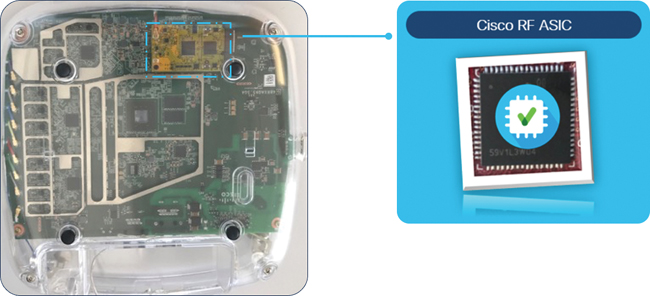
The Cisco RF ASIC is a software-defined “radio on a module” whose main purpose is to analyze a large range of frequencies and convert the RF baseband to data, which is then analyzed by the CleanAir engine. Capable of extremely high resolution of 78.125 kHz (at least four times better than the nearest competitor), the module is embedded in the Catalyst 9130, 9120, and 9124 access points.
It provides Cisco’s RF features
CleanAir: Monitors the spectrum for and identifies non–Wi-Fi sources of interference, remember that cleanair looks for cleaner environment and finds interferers.
CleanAir continuously monitors the RF environment and reports:
Noise floor levels
Non-Wi-Fi RF interference
Channel quality
This helps controllers decide whether a channel is becoming unusable.
This is CleanAir’s primary role. It detects and classifies devices such as:
Microwave ovens
Bluetooth transmitters
Zigbee devices
Wireless cameras
Cordless phones
Rogue RF sources
It also provides:
Interferer type
Severity score
Duty cycle
Affected channels
Location (with location-capable deployments)
Zero Wait Dynamic Frequency Selection (DFS): Allows a channel availability check of the DFS channel; allows immediate use without 60s penalty
Some 5 GHz Wi-Fi channels are shared with weather radar, military radar, and aviation systems. To avoid interference:
A router must listen first before using those channels
This listening period is called a Channel Availability Check (CAC)
It usually takes about 60 seconds
During that time, the router cannot transmit Wi-Fi
So users experience:
delays after reboot
delays when switching channels
temporary network dropouts
Zero Wait DFS removes that waiting time.
It works by:
scanning DFS channels in advance
storing which ones are safe
instantly switching when needed
So instead of:
Wait 60 seconds → then use channel
Dual Filter Dynamic Frequency Selection (DFS): Provides dedicated radar detection to augment the radio vendor detection algorithms; reduces false detection by 99.9 percent
Standard DFS already detects radar signals.
Dual Filter DFS adds an extra detection layer.
Instead of relying on one detection method, it uses:
1. the radio vendor’s built-in radar detection algorithm
2. an additional dedicated radar detection filter
Think of it like two security scanners instead of one at an airport.
Result:
higher detection accuracy
fewer mistakes
better reliability
FastLocate: Provides consistent and fast location updates, without requiring dedicated monitor hardware to capture data traffic
FastLocate can:
track a device’s position frequently
update location in near real time
maintain accuracy even when the device is moving
Traditional location systems sometimes need:
extra network sensors
signal probes
monitoring boxes installed at base stations
FastLocate does not require those.
Instead, it works by:
using existing mobile network signalling data
analysing normal communication between the phone and nearby cell towers
estimating location from that information
So telecom providers don’t need to install new infrastructure.
Off-Channel RRM: Provides zero client impact off-channel monitoring for RF management, leaving the client serving on radio 100% of the time on-channel availability
Off-Channel RRM (Radio Resource Management) is a Wi-Fi optimisation technique where an access point (AP) briefly scans other radio channels without disrupting connected users
Wi-Fi access points need to monitor nearby channels to:
detect interference
find neighbouring APs
choose the best channel
adjust transmit power automatically
Normally, when an AP scans other channels, it temporarily leaves its current channel, which can cause:
packet delay
jitter
dropped voice/video frames
brief connectivity interruptions
This is especially noticeable for real-time apps like VoIP, Teams, Zoom, or roaming devices.
With Off-Channel RRM, the AP performs background scanning in a way that clients don’t notice.
So instead of:
AP leaves channel → clients pause → scan completes → AP returns
It behaves like:
AP quickly checks other channels in tiny time slices → returns instantly → clients stay connected smoothly
Result:
zero visible service interruption
continuous data transmission
better RF awareness without performance loss
API-driven: Every single configuration for the Catalyst 9800 is available through programmatic interfaces and open configuration models (Yang and OpenConfig models).
Model-driven telemetry: Deep analytics information is captured and streamed efficiently and at scale thanks to streaming telemetry protocols like gRPC/gNMI.
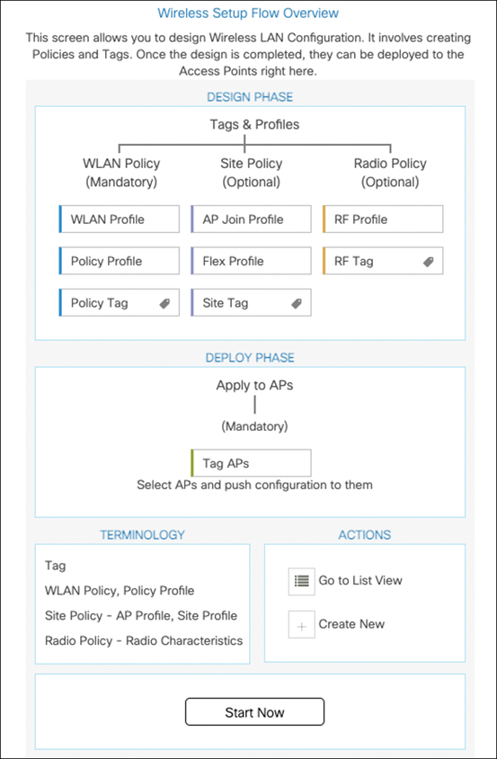
Configuration > Wireless Setup > Advanced
Packet Capture tool allows you to capture traffic on any interface (wireless management interface, port channel, or physical ports)
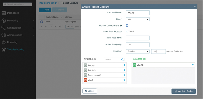
access point CAPWAP traffic is DTLS encrypted but they are visible or unencrypted in WLC captures but not in the captures taken from switch
The Catalyst 9800’s Web GUI leverages Virtual Teletype (VTY) lines for processing HTTP requests. At times, when multiple connections are open, the 15 VTY lines set by the device (the default number) might get exhausted. Therefore, it is strongly recommended that you increase the number of VTY lines to 50. Use the following configuration commands to do this:
C9800(config)# line vty 16-50Another useful recommendation is to configure the service tcp-keepalives to monitor the TCP connection to the box. In this case, use the following commands:
C9800(config)# service tcp-keepalives-in
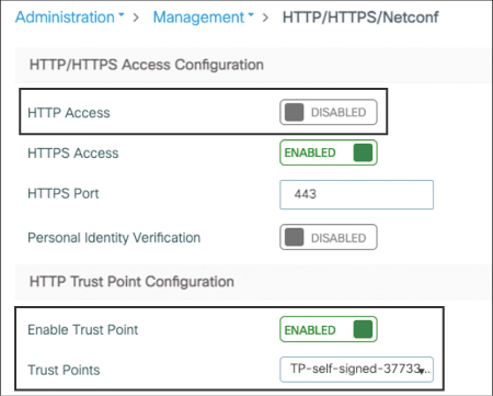
C9800(config)# service tcp-keepalives-outStarting with release 17.3, you are able to configure HTTP/HTTPs independently for WebUI access and for portal redirection of client web authentications.
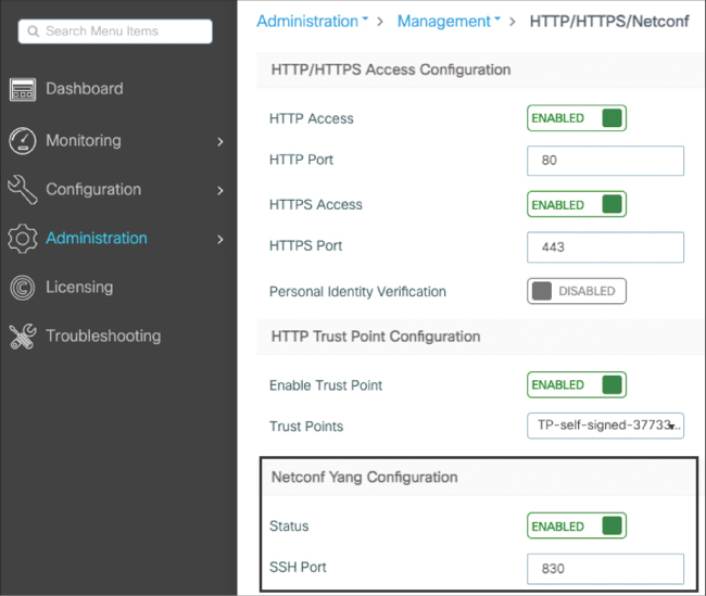
For more secure access to the box, it is recommended you disable HTTP for WebUI access. You can go to Administration > Management > HTTP/HTTPs/NETCONF and enable it. On the same page, it’s also important to explicitly associate a trustpoint to be used for HTTPs connections.
Enable NETCONF
Configure AAA
C9800(config)#aaa authorization exec default local|radius|tacacs group
C9800(config)#aaa authentication login default local|radius|tacacs group
Wireless Management Interface (WMI) IP address is used for SSH and login
It’s also important to keep in mind that DNA Center pushes its own self-signed certificate to the managed devices; the default certificate is sdn-network-infra-iwan. When the Catalyst 9800 has more than one certificate configured on the box (for example the self-generated trustpoint and the one pushed by DNA Center), it is strongly recommended you specify the certificate to be used for HTTPs access to the device. Not doing so may result in the Catalyst 9800 picking the wrong one and breaking access to the graphical user interface. In this case, use the following CLI command:
c9800(config)#ip http secure-trustpoint trustpoint-nameCisco Smart Software Licensing allows you to create a pool of license resources that can be shared across multiple C9800 wireless controllers by removing older device-level entitlement and enforcement.
No licenses are required to boot up a C9800 wireless controller. However, each access point requires two licenses to be entitled to connect: one AIR Network License and one AIR DNA License. Both of these licenses can be configured to be either Essential or Advantage level. If there are not sufficient Cisco DNA licenses to cover all the access points connected to a Cisco Catalyst controller, an out-of-compliance message is displayed. This out-of-compliance message is purely informational and does not impact the functionality of the wireless deployment.
Starting with software release 17.3.2a, C9800 supports the Smart Licensing Using Policy, which is an enhanced version of Smart Licensing, with the overarching objective to further simplify the licensing solution:
Cisco DNA Spaces. Whether it’s learning more about visitors to your organization, your employees, or your things, such as assets and sensors, Cisco DNA Spaces digitizes your physical space. It does so by synthesizing location data across your sites to deliver location-based services
Cisco DNA Spaces is a cloud-based platform for location: it leverages information from Wi-Fi to BLE tags, beacons, and other IoT sensors, and with gateway-enabled Cisco Wi-Fi 6 access points
Chapter 2. Hardware and Software Architecture of the C9800
Embedded Wireless Controller on AP (for Catalyst APs), where the AP acts both as an AP and a WLC
Split MAC Architecture
CAPWAP stands for Control and Provisioning of Wireless Access Points
It builds two tunnels between an access point and the WLC: one for control and one for data. The control channel uses UDP 5246 port, and the data channel uses UDP 5247 on the WLC side (it’s the destination port when the AP sends traffic to the WLC, and the source port when the WLC sends traffic to the APs)
The control protocol allows the WLC to centrally manage and configure all the access points and make sure they are always on the same software versions that correspond to the WLC version
All CAPWAP communication is protected qith datagram Transport Layer Security (DTLS)
The data protocol is an optionally encrypted way of tunneling back all the client data to the controller to simplify the topology.
Benefits of tunneling the traffic back to the controller are
- You don’t need to span many VLANs to all the wired infrastructure hosting the APs. APs are connected on access ports in a management VLAN (typically dedicated to the APs).
- The WLC can host the client policies such as QoS or ACLs.
- The WLC is a central and unique point of contact for RADIUS and AAA authentication.
- Simplifies roaming because WMall mac are behind the WLC
| Access Point MAC Functions | Controller MAC Functions |
|---|---|
| 802.11 beacons and probe responses (although probes are forwarded to the WLC as well) | 802.11 associations requests, management and action frames |
| 802.11 frame transmission and acknowledgments (including client power save handling and buffering) | 802.11 QoS resource reservation |
| 802.11 QoS frame queuing and packet prioritization | Client authentication in general |
| 802.11 MAC layer data encryption and decryption | Client data traffic forwarding |
| Monitoring RF environment and scanning other channels |
in line 1, when it shows that controller is responsible for 802.11 association requests , management frames and action frames, WLC processes these frames so definitely these frames are relayed from AP to the WLC and then WLC sends them out to AP and then to client
In Split MAC architecture
- Client sends a management frame (e.g., association request)
- AP receives it over the air
- AP tunnels it to the WLC (via CAPWAP)
- WLC processes the frame
- WLC decides the response
- Response is sent back to the AP
- AP transmits it to the client
Some time-critical RF management tasks stay on the AP because they must be immediate, for example:
- Beacons
- Probe responses
- ACK frames
- Power-save buffering
- Channel scanning
These cannot wait for controller round-trip latency.
Which management frames are handled by the WLC?
Typically forwarded to the controller:
- Association / reassociation requests
- Authentication exchanges
- Action frames
- QoS reservation decisions
- Policy enforcement decisions
The AP forwards these upstream first, then transmits the WLC’s response.
AP = real-time radio operations
WLC = decisions, policies, authentication, control
Optionally for branch offices , flexconnect mode can be used to route traffic out locally on the switch from APs
All Cisco APs and appliance controllers are shipped with a manufacturer installed certificate (MIC), which is used to establish the CAPWAP DTLS tunnel and mutual authentication
A locally significant certificate can also be generated and used for this purpose. CAPWAP data packet encryption is an optional setting (automatically turned on in OfficeExtend mode).
DTLS “data” encryption can have a performance impact on the global throughput numbers forwarded by the WLC, so enabling it when the data is transported over unsecured networks is advised
The data over the air is encrypted with the L2 security defined in the WLAN, if any (for example, WPA2-AES), and is always decrypted at the AP
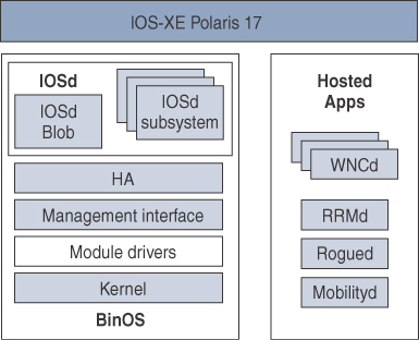
IOS-XE Software Architecture
IOS-XE is based on a UNIX system named binOS internally (or Polaris as of its 16 and 17.x versions) and is a Cisco-modified version of UNIX. IOS (the now legacy one) was a monolithic operating system, a single process with a single memory space and fault domain
IOS-XE moves away from this architecture by adopting a multiprocess, modular, and scalable approach, separating the operating system (binOS) from the “network tasks that are now managed by a process called IOSd”.
IOSd still takes care of the routing and interface configuration, but more specific tasks (like wireless tasks) are separated into dedicated processes. The management and config replication (in case of high availability) is also separated
WNCd: The Heart of the Wireless Controller Control Plane
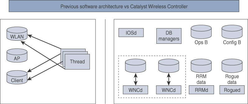
Each process has its own database that is then synced with central database such as WNCD with its own database
The key wireless process is called Wireless Network Control daemon. The number of WNCd processes varies depending on the hardware that 9800 is running on
The WNCd process is a critical process managing APs and client sessions. Each WNCd process handles a specific set of access points and all the clients present on those access points
The WNCd process is a single point for receiving and sending packets to the APs it manages but also implements a few other AP-facing capabilities like RRM client or probe handling.
This approach gives the vision of scalability of future Catalyst wireless platforms that will support an ever-increasing number of APs and clients simply by running more WNCd processes on more CPU cores
To oversee these processes, the WNCMgrd process manages the load-balancing of APs to WNCd instances, This means that the WNCMgrd is the one handling CAPWAP discoveries for the whole controller and assigns each new AP to a specific WNCd process
The WNCMgrd is also in charge of centralizing information from each WNCd process in order to have a single go-to place for the “show wireless” CLI commands providing all the APs and clients information regardless of the number of WNCd processes
It achieves this by having access to the Centralized Wireless operational Database (CWDB), which contains all the real-time operational data. It can then consolidate information from each WNCd process and perform AP load-balancing and CLI information centralization tasks.
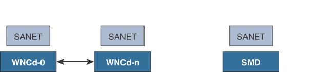
WNCd is a large process that is the center pillar of the Catalyst Wireless architecture (specific to the C9800) and contains many libraries inside it. You may hear a lot about SANET and SISF and see references to them in the logs and believe they are processes, but they are libraries inside the WNCd process. As a matter of fact, the general IOS-XE SANET library (in charge of AAA) has been copied (although modified) inside the WNCd process to manage the AAA authentication of wireless clients and their session management within the same process.
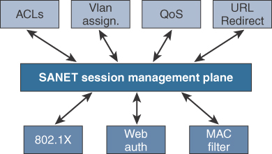
On top of that modified SANET library within WNCd, the Catalyst 9800 still has a SANET library inside the Session Manager Daemon (SMD) process just like other IOS-XE devices
That one handles wired session management (not really used in the Catalyst 9800) but also central Change of Authorization processing.
Similarly, the Switch Integrated Security Features (SISF) library is integrated in the WNCd process to handle the wireless client DHCP or IP tracking process, among other things.
SISF responsibilities on the Catalyst 9800 include
- IPv6 NDP inspection (barring bogus NDP messages)
- NDP address gleaning: populating the binding table with information snooped in NDP traffic
- Device tracking
- IPv4 address gleaning: ARP and DHCP messages snooping
- DHCP relay with configured helper address
- NDP and ARP multicast suppression: unicasting NDP or ARP messages or responding on behalf of targets to save on broadcast/multicast traffic
- DAD proxy: duplicate address detection
- DHCP requirement: making sure the IP can only be learned through DHCP process
WLC ARP Proxy
The default behavior is for the 9800 to transform broadcast ARP messages destined to the wireless clients into a unicast message for the specific MAC address. This saves on airtime because the message does not have to be sent on all access points at the same time. It also brings efficiency because the destination client of the ARP request also learns about the source MAC at the same time
Enabling ARP proxy then allows the WLC to reply to the ARP request on behalf of the destination client without having bothered that client at all in the process (as long as it’s a known and registered wireless client with the WLC).
Chapter 6. Mobility and Client Roaming
Mobility, or Roaming, refers to the ability of a wireless client to move from one access point (AP) to another while maintaining a wireless connection.
When a client is onboarded to a Service Set Identifier (SSID), it goes through association, authentication, and IP addressing phases before it can pass traffic
Client needs to be onboarded on the roam-to AP, within milliseconds, in order for the voice and video traffic to not be impacted
802.11 Roaming
The decision to roam is made by the wireless client. A wireless client usually roams in the following circumstances:
Chapter 7 RF Deployment and Guidelines
RF is the physcal layer for wireless clients
In wired Ethernet networks, the cable is an isolated and dedicated piece of wire and hence often considered to be reliable (and even if not, can be replaced) and to perform consistently. It also connects only two devices
Wi-Fi relies on a shared medium: it’s a half-duplex technology, and this brings many complexities.
Radio Resources Management (RRM) Concepts and Components
Antennas and Signal Propagation
Wireless signal power is measured in decibel-milliwatt (dBm)
dBm is logarithmic scale which means when 3 decibels are added, the power in milliwatts is doubled. If you add 6 decibels, you quadruple the power and so on. Each time 10 decibels are added, the power is multiplied by 10
0 dBm = 1 mW of power, 10 dBm = 10 mW and 20 dBm = 100 mW
The antenna gain is often mentioned in dBi units, the i referring to a comparison against an identical perfectly isotropic antenna, This unit of dBi has the advantage that it can be added and subtracted from the dBm scale
An antenna is a passive device requiring no electricity, however, an antenna can add gain, measured in dB.
You have different points of losses, gains and attenuation
-Transmit power (applied to antenna connector)
-Antenna gain
-Connector loss
-Free Space Path Loss (FSPL) is the attenuation of radio energy as it spreads over distance in a vacuum or obstruction-free environment
Concept of EIRP
EIRP means that total dBm measurement or output from atenna must be a fixed value after transmit power, connector loss and antenna gain, based on regulatory domain of a country
if an AP transmits at 20 dBm (100 mW), and you are using an antenna providing 3 dBi of gain, the AP actually is said to have 23 dBm (200 mW) of equivalent isotropically radiated power (EIRP)
if you had the perfect antenna (that is, isotropical radiator) radiating your signal equally in all directions so that the energy leaving the antenna is 20 dBm and then you replaced the antenna with one that focuses the signal in one direction and not the other, what would happen? In one direction, you would have no signal at all (real life is not so black and white, but this is an example), and in the other direction you would have double the amount of energy in a given location, While your transmit power has not changed and is still 20 dBm, you would have 23 dBm of EIRP, considering the antenna gave a 3 dBi gain.
C9800 considers transmit power (which is power sent to antenna connector) and antenna gains separately, that is why antenna gain can be configured for each AP on the 9800 and as you increase antenna gain, power levels or transmit power is reduced to make sure not to radiate too much power and exceed the EIRP for a regulatory domain
Indeed, the more gain you configure, the lower (in dBm) the value of each power level will be to keep meeting the maximum EIRP allowed in the country.
The AP has different power levels. Power level 1 is the maximum power the AP can use, Power level 2 then sets itself to be half of the power level 1 value (which means 3 dBm less because it is a logarithmic scale). Each power level then is half of the previous power level and basically is 3 dBm less each time
Antennas
Antennas provide a passive gain (otherwise, they would be called amplifiers rather than antennas) and are, typically “dumb” devices in the sense that the access point is not able to talk with the antenna and figure out its characteristics. However, Cisco has released a number of antennas called self-identifying antennas (SIAs) that contain an EEPROM that can be read by the AP to automatically configure the antenna type and gain. SIA antennas exist with RP-TNC connectors as well as DART4 or DART8 connectors. The SIA antennas help you, as administrator, by automatically configuring the right antenna gain and make sure the AP EIRP stays within legal boundaries. Cisco pushed the smart antenna concept even further by releasing a stadium antenna with a dynamically configurable beamwidth so that each AP can configure its antenna to radiate the most optimal way.
Countries and Domains
It is essential for the APs to broadcast their configured country code in their beacons to make it clear to the clients what channels and power they can use and under which conditions.
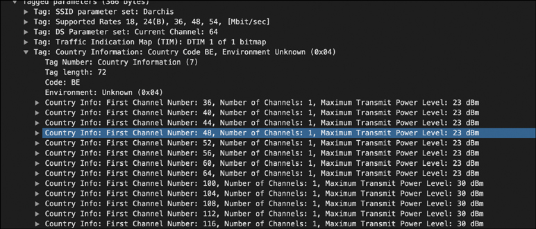
AP must be configured with Country
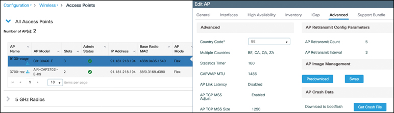
The AP itself can be set to any of the configured countries that match its regulatory domain, you can set the AP to Belgium or South Africa because they both match the fact that the AP model has “-E” in the end, covering ETSI countries (C9130AXI-E in this example).
The AP cannot be set to Canada because Canada corresponds to -A or -B domains.
WLC are also configured with countries
Country codes configured globally on the wireless LAN controller represent all the possible countries its APs can be assigned to. The WLC country list is thus a superset of the countries its joined APs are in.
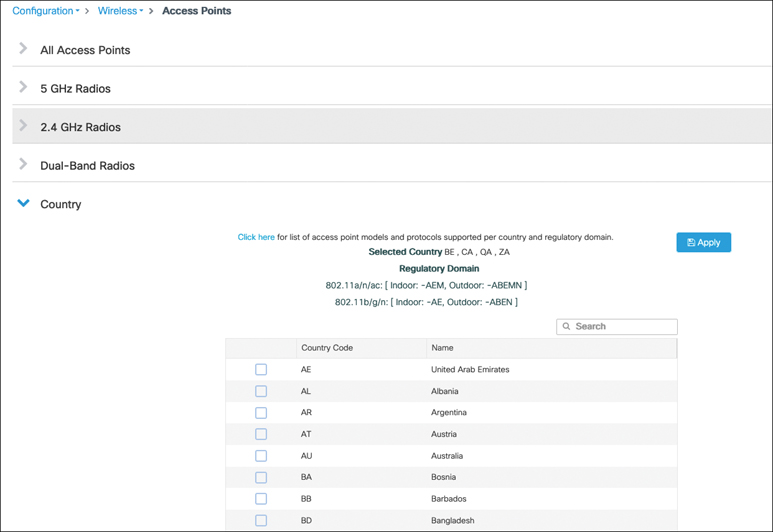
The country code is configured in an AP join profile to assign the same specific country to a group of APs belonging to the same site, A given AP can be assigned only one country (because it can logically be present in only one country at a time)
Purpose of assigning the country code is not just country assignment but also to only use allowed “channels and power”
Cisco is now releasing APs belonging to the -ROW (Rest of World) domain, which allows for much more simplicity because the AP is physically the same and adapts its channel and power settings to the configured country. A lot of former regulatory domains are now folded into the -ROW domain and can therefore be software-configured when you assign the country to the AP
Challenging RF Environments
What is a challenging environment from a wireless perspective? A lot of environments could qualify for the term challenging: designing a network for a very high-density deployment where you may have hundreds of clients under the coverage of a single AP is indeed challenging. A completely different type of challenge would be designing a network in a factory with very few clients but a lot of metal surfaces around or dealing with a large open space and interflow coverage like you would find in a mall.
Metal-Heavy Areas
Steel is probably one of the worst enemies of a wireless engineer. If you survey a factory filled with steel machinery

you may not see a lot of impact on your data if you are only focused on signal strength as a metric
Indeed, in a place filled with steel, the signal faces a lot of multipath effects as it rebounds differently on different steel surfaces. Many mobile clients still have just one antenna, or two at the most, and are therefore subject to multipath effects
Reflection is somewhat of an invisible adversary because you cannot prove it through RSSI (the signal is not weaker in strength due to the presence of metal reflections); you cannot see it in a spectrum analysis but you simply experience a lot of corrupted frames (because you are receiving reflection and not the actual signal sent by AP’s antenna)
The best workaround is to place the APs (and especially antennas) as far away as possible from pillars, corners, metallic surfaces, and other obstacles even if you have to place them on walls quiet lower at the waist height
High-Density Crowd Areas
Major events, whether they are in a conference center or an outdoor venue like a stadium, typically go for a high-density coverage because they expect of lot of attendees proportionally to the area surface. The problem rookie designers might forget is that bodies create a lot of attenuation: an empty venue behaves very differently from a filled venue. You will probably have to configure RF profiles to a transmit power that would be considered too high when the place is empty but perfectly fine when the place is filled with attendees.
For stadium/conference-style deployments, Cisco’s public-venue guidance says large public networks are often configured to specific power levels using RF profiles, with an example of TPC Min 5 dBm and TPC Max maximum/30 dBm.
Shielded Doors and Sudden Turns
The problems caused by shielded doors and sudden turns can happen in very different types of environments, but using the example of a shielded door makes it maybe a bit more obvious. Imagine a mobile device such as a smartphone that is located in a room, with an AP nearby, and this room is closed with a shielded door that creates a very strong attenuation
The device therefore does not hear (or at least not at a good signal level) any APs located behind that door. Suddenly, same user decides to walk out and, within 2 seconds, opens the door and closes it behind. At this point, the Wi-Fi client cannot get a good signal to the AP located inside the room where it was connected previously, and it must scan in emergency to find out on which channel it can find APs on this side of the door. Depending on the algorithm and the channels on which the APs are located, this scan could take any amount of time from a few seconds to close to a minute.
Beyond shielded doors, this type of situation happens in a corridor with thick walls when the corridor makes 90-degree turns create this effect of looking for WiFi.
The workarounds to this problem are to
-set APs around that area on non-DFS channels (that are typically scanned more quickly by client devices),
-to enable 802.11k support (it helps only if the APs are able to hear each other, which is not necessarily the case depending on the physical configuration of the space),
-and to add an AP in the problematic transition area.
Uneven Ceilings
Places like supermarkets, warehouses, or convention centers are typically huge indoor buildings with a natural ceiling that is very high, but often there are trusses or fake lower ceilings to place lighting, smoke detectors, and other devices (such as access points sometimes) but also to provide a more pleasant ceiling to the human eye, at a more reasonable height. Given these surroundings, technicians might place APs at different heights from each other, or simply very high compared to the ground. If APs are on a 30-foot (10-meter) high ceiling, they actually hear each other louder than they hear their clients, and the RRM algorithm does not perform as expected because it mostly focuses on how APs hear each other. If APs are at varying heights, depending on their antenna patterns, you may face similar RRM algorithm glitches because one AP might hear its neighbors (the ones broadcasting from above itself), but the opposite would not necessarily be true. The AP height entered on the map is currently not taken into account in the RRM algorithm, so the solution is to use RF profiles for groups of APs that are at similar height to better control their behavior.
Atriums

In the words of a lot of wireless engineers: “Atriums are the worst!”
These areas are inside a building where many floors communicate through some kind of well (for light, air circulation, or simply visual effect), which means that the AP signal leaks between floors. This setup is especially problematic for location tracking because clients can connect to an AP from another floor very easily.
Even just from a signal propagation standpoint, the atrium is a place of big adjacent channel interference. There is no one-size-fits-all solution, and placing APs far away from the atrium while maintaining coverage might be a solution to avoid too many APs being heard in the atrium area. For location tracking, APs in monitor mode may help.
Radio Resources Management (RRM)
Radio Resources Management is Cisco’s state-of-the-art radio frequency management system that provides a systemwide view of your entire wireless RF environment
RRM defines RRM neighborhoods of APs that can hear one another, They are centrally managed by the RF Group leader WLC, which is the elected WLC
RRM Data Collection
An AP operates on a given channel, which may change over time but has to stay stable for a good while for the sake of client stability which is channel assigned to AP. While on the channel, the AP listens to the medium whenever it is not transmitting, and during these times it is very easy for the AP to collect statistics on the current channel it sits on without any effort.
On top of that, it scans other channels very briefly (to not disrupt their currently connected clients while switching to other channel for scan) with the objective of figuring out which APs are nearby and what are the statistics of other channels (from a “load“ and “noise“ standpoint or channel health). This is the monitoring task of an AP (monitor mode APs do this full time).
APs also send Neighbor Discovery Protocol (NDP) messages when they are on other channels, to help other APs locate them in their neighborhood.
These NDP messages are managed centrally from the WLC. They are sent to the special multicast address 01:0B:85:00:00:00 that all Cisco APs monitor, sent at the “highest power“ allowed for the channel and at the “lowest data rate“ supported in the band. This is to allow APs to figure out which other managed APs are around them (in other channels), regardless of the power and data rate configuration on the WLC
An NDP packet contains the antenna details of the sending radio, the power the message was sent at, the channel it was sent on, the operating channel of the AP, optional encryption details, the IP address of the sender AP’s RRM group leader WLC, the hashed RF group name, the radio slot ID, and a group ID
When an AP hears an NDP message while operating on its usual channel, it validates that the message comes from a member of its RF group (via the hashed RF Group name) and, if so, forwards the message along with the received channel and RSSI at which it was heard to the controller. Each WLC keeps a list of up to 24 neighbors for each AP radio, and this data is forwarded to the RF group leader regularly. The WLC can then compute out of this data for each target AP:
- RX neighbors: How this radio hears other radios
- TX neighbors: How other radios can hear this radio.
The NDP message exchange between APs basically allows the WLC to calculate the free space path loss (including walls and obstacles or signal attenuation) between all the APs. The RRM > General pages
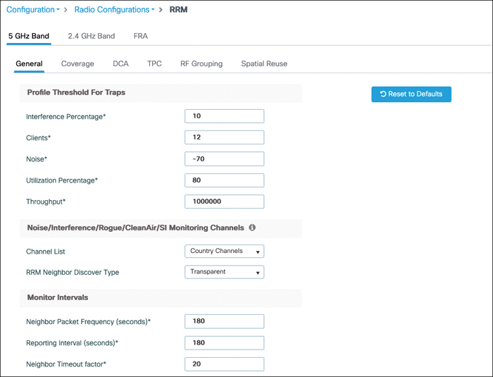
You might want to change RRM configuration here and want your APs to scan only DCA channels and not all country channels such as 1, 6, and 11 (which are the commonly configured DCA channels in 2.4 GHz) and never spend any time on the channels in between because they probably have no value and little activity. The RRM Neighbor Discovery type field allows you to either have NDP packets sent as clear (the “transparent” setting) or encrypted (the “protected” setting).
The intervals at which the AP scans and sends NDP can also be configured. The default Neighbor Packet Frequency is 180 seconds, which means the AP goes over all the channels to monitor every 180 seconds or 3 minutes, and depending on the number of channels you allowed, this defines the interval between two scans. If you configured 2.4 GHz to monitor only DCA channels and configured those to be only 1, 6, and 11, it means your APs go off-channel every minute or 60 seconds to scan one of them. If your 5 GHz band is set to monitor country channels (say 20 channels for this example), that means your APs go off-channel every 9 seconds (180 seconds divided by 20).
The reporting interval has default 180-second values which means AP reports RRM information every 3 minutes.
RRM (Radio Resource Management) settings shown, Reporting Interval (seconds) is when AP sends status/update report that an Access Point sends to the wireless controller.
These reports typically include things like:
- Channel utilization
- Noise levels
- Interference data
- Neighbor AP information
- CleanAir/RF statistics
The controller uses this information to make RF optimization decisions such as:
- Changing channels (DCA)
- Adjusting transmit power (TPC)
- Detecting interference or rogue devices
Lower value (more frequent reports)
- Faster RF updates and reactions
- Slightly higher control traffic/CPU usage
Higher value (less frequent reports)
- Less overhead
- Slower response to RF changes/interference
AP goes off-channel twice (once for 50 ms for listening and once just for sending an NDP frame) for every channel configured in the monitor list.
The timeout factor is the number of reporting intervals after which an AP will delete a given neighbor AP from its table if it didn’t hear about it anymore (20 would mean the neighboring AP wasn’t heard in the last 20 reporting periods, that is, 20 × 180 seconds = 1 hour). As this per radio AP neighbor list is being made. There are valid reasons why this timeout factor has to be relatively high like that: a busy network or a configured voice SSID (where off-channel scan defer is enabled) decreases the opportunities for the AP to go off-channel, and the AP might skip cycles and not scan a specific channel at all in the usual 3-minute interval. You typically do not want a neighbor to disappear from the list of AP neighbors in such a situation. The only reason an AP should be deleted from the neighbor list is if that AP went down or if the RF environment changed (for example, obstacles) and the two APs cannot physically hear each other anymore.
On the same page, the Profile Threshold for Traps section defines thresholds and conditions for sending SNMP traps. They do not have any operational effect on RRM apart from sending an SNMP message.
NDP forms the foundation of the understanding of the RF propagation. It is very important for
- RF group
- Transmit Power Control (TPC)
- Flexible Radio Assignment (FRA)
- Rogue detection
- Dynamic Channel Assignment (DCA)
- CleanAir merging of interferers (based on which APs are close to each other and could hear the same interferer)
- CMX/DNA Spaces calculation of AP RF distance and pathloss measurements
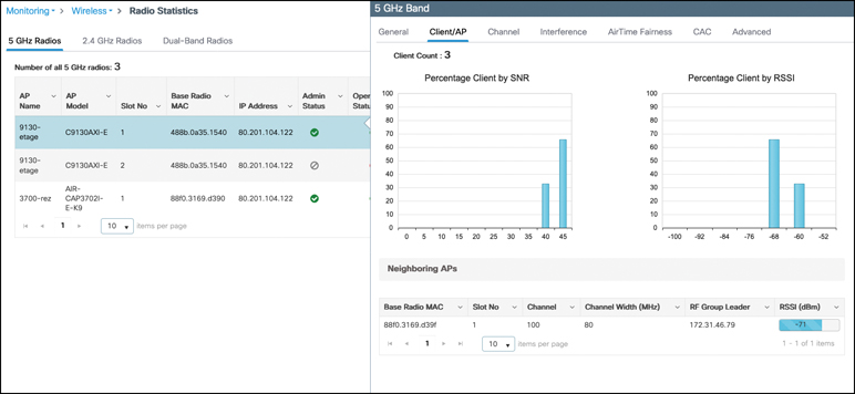
It is possible to analyze what other APs are heard on a specific AP by going to the Monitoring > Wireless > Radio Statistics page on the WLC, clicking a specific access point, and going to the Client/AP tab.
RF Group
An RF group is defined by the RF group name you defined on your wireless LAN controller in the initial configuration. It can be changed at any time in the Configuration > Wireless >Wireless Global configuration page.
It is a string-based name that you can assign to multiple WLCs which have AP in same RF space.
Using a different RF group name on WLCs with AP operating in same RF space can result in WLC reporting the other APs (heard above an RSSI threshold) as rogue because these APs belong to a different RF management domain.
RF Group Leader
Because more than one WLC can share the same RF group name, an RF group leader needs to be elected and put in charge of running most of the RRM algorithms on behalf of the whole RF group.
When a WLC initializes, it has to assume that it is alone in the RF group and therefore acts at least temporarily as RF group leader, creates a unique group ID, and instructs its APs to use the RF group name in their NDP messages.
NDP messages received from APs belonging to another WLC mention their RF group leader IP address as well as RF group name. If they share the same RF group name but have another leader, the WLC contacts this other WLC to be added to the RF group list.
The RF group leader can then start to assemble an RF neighborhood, that is, a group of APs that hear each other at a signal better than –80 dBm. If the signal of an AP suddenly goes lower than –85, it is deleted from the neighborhood. The WLC sends Hello messages every 10 seconds to every other WLC in the currently formed RF group.
RF Grouping Modes
RRM starts in automatic grouping mode, which basically behaves as explained in the previous section.
It is also possible to turn off grouping to have each WLC act as standalone.
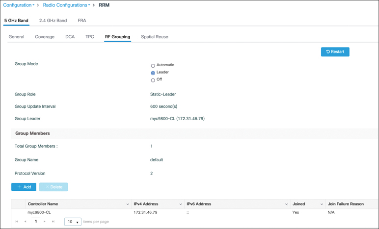
Leader setting, in Configuration > Radio Configurations > RRM, makes the grouping static. When this mode is set, you can manually add the other WLCs to the RF group one by one. A more deterministic approach allows you to choose a specific bigger controller to act as RF leader.
It is interesting to note that there is a maximum number of APs for which a WLC can act as leader in an RF group, so it is not realistic to keep one big campus with tens of thousands of APs in an RF group because that will go over the limit of the strongest controller hardware available. If too many APs have to be managed by an RF group leader, another WLC is elected to be a second leader, and the APs are split among them, so there is no impact there.
Table 7-1 RF Grouping Maximum AP Limits
| Group Leader WLC | Maximum APs | Maximum APs per RF group |
|---|---|---|
| 9800-L | 250 (500 with performance license) | 500 |
| 5508 | 500 | 1000 |
| 9800-CL Small | 1000 | 2000 |
| 9800-40 | 2000 | 4000 |
| 9800-CL Medium | 3000 | 6000 |
| 5520 | 1500 | 3000 |
| 8510/8540 | 6000 | 6000 |
| 9800-CL Large | 6000 | 12,000 |
| 9800-80 | 6000 | 12,000 |
Because the RF group leader is running the RRM algorithms, only the RRM configuration on the leader WLC matters when it comes to RRM. It is a classic mistake to change RRM settings on a given WLC and be surprised that there are no effects when the RF group leader was in fact another WLC.
TPC
Transmit Power Control (TPC) is the name of the RRM algorithm that focuses on lowering the transmit power of APs if needed. The only case where TPC can increase the transmit power is covered in the coverage hole detection section. The objective of a good wireless deployment is to have sufficient coverage but without having too much signal overlap, which would cause co-channel interference.
TPC Overview
TPC runs on the RF group leader WLC, The TPC algorithm can run automatically every 10 minutes (that’s the default setting), can also run on demand at the click of a button only, or not run and freeze the power settings until instructed otherwise.
TPC runs separately for each AP in the RF group and determines whether the transmit power of the AP should be lowered based on the AP neighbor details. Based on the power threshold which is –70 dBm by default
If three APs are heard louder than this threshold (no matter which channel they operate on), the algorithm starts to consider lowering the power. But the point is that if a specific AP is isolated and does not hear many neighbors, it may be expected to run at full power.
When a power change is recommended, the AP decreases its power by one level (that is, 3 dB).
TPC does not take channels into account by default because DCA might change them at the same time TPC runs. It is, however, advised to enable TPC Channel Aware for the 5 GHz band, which typically allows for several neighbors on different channels. It is better to leave Channel Aware disabled for the 2.4 GHz band.
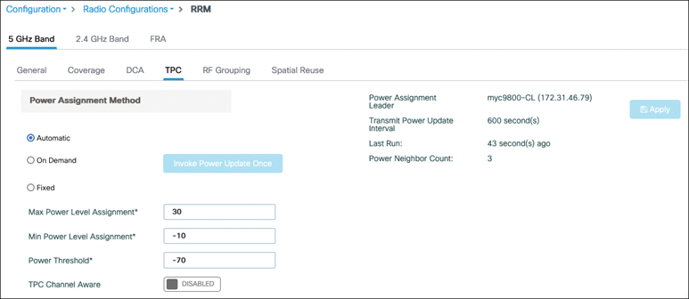
The same TPC web interface page shows you which WLC is the current RF group leader, what time the algorithm interval is set to, and when it ran the last time.
While TPC mostly lowers the transmit power, it can also increase in case of sudden AP failure to compensate for the coverage gap.
TPC Minimum and Maximum
If you let the TPC algorithm run without guidelines, it would lower the power severely because APs can hear each other very well with a clear line of sight in the hallways. However, coverage in the rooms would probably suffer, and some places would not have a good coverage. You probably would be ready to accept a bit of co-channel interference in the hallways if that means a proper coverage of the places where devices will effectively be used: this can be achieved by increasing the TPC minimum power. Similarly, if you’re mounting APs very high on the ceiling in warehouses or similar venues, the AP signal not might even reach the ground if it is under a certain level. If you don’t set a TPC minimum, there is a good chance that the APs would go below this threshold because they probably hear each other very well on the ceiling as they are closer to each other than they are to the clients. Decreasing the maximum TPC power could make sense in situations where APs cannot hear each other too well because of distance or antenna orientation, but clients can hear all APs very well.
TPC minimum and maximum fields expect a value in dBm and not in power level. This value does not take any antenna gain into account and is the transmit power as shown by an AP. This means the value is absolute and is comparable regardless of AP and antenna model or channel used. The maximum allowed power may vary depending on the channel, so this is something to take into account when designing your plan and settings.
Coverage Hole Detection
The coverage hole detection algorithm is different from the TPC algorithm because it is in charge of increasing the transmit power only if a coverage hole is detected. It focuses on clients and is able to discriminate between clients that genuinely have a low signal strength because they are in an area of poor coverage that can be remediated and clients that might have a static lower transmit power and where any remediation would not help.
Coverage hole detection can be enabled globally in the RRM settings. You can configure a long list of thresholds for coverage holes to trigger
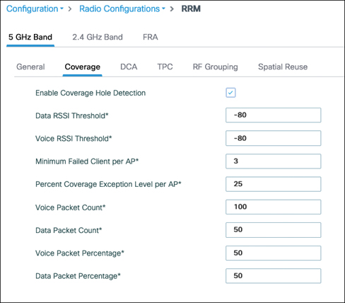
If the WLC detects a single client that keeps showing a signal worse than –80 dBm (by default) for more than 5 seconds without roaming to another access point, it logs a precoverage hole event. This is a syslog and trap sent to the management platform, but no action is taken because a single client may not be representative of the situation. The type of client that holds on to an access point without roaming, ignoring the possibility of a better connection through a different AP, is called a “sticky” client (although if these clients are in a real coverage hole, they should not be called that because any client in such an area is forced to stay connected at low RSSI). The signal threshold can be configured for both data and voice frames seperately (it makes sense to have a more sensitive threshold for voice-tagged frames because those clients are more critical, although the packet count is higher because voice packets are less frequent). You can also configure the number of clients (three by default) required to trigger an actual coverage hole event. On top of that, the Percent Coverage Exception Level per AP Setting must be met for the remediation to occur. For example, if it is set to 25 percent, it requires that the three sticky clients represent at least 25 percent of the client count of the AP (which means the AP should have 12 clients or fewer for 3 clients eith poor RSSI to trigger CHD). When all conditions are met, the WLC raises the power level of the AP hearing those clients by one level.
Because the AP reports this data every 90 seconds to the WLC, it means that it requires several clients to stay connected at a poor signal strength to the same AP for a bit of time before any action happens.
This condition helps to avoid false positives and avoid having your APs climb to max power all the time (before TPC calms things down) only because of a couple of clients with poor roaming logic. Extra settings such as packet count or packet percentage also allow you to require a certain amount of traffic to be received at a poor signal before something is done (to avoid triggering for clients that are connected but barely passing any traffic).
Coverage hole detection can be enabled on a per-WLAN basis, in the WLAN settings. This means clients of that WLAN are used for the coverage hole detection algorithm. WLANs in which the feature is disabled do not have their client participate in the coverage hole detection algorithm, but it is important to understand that if enough clients in a given WLAN with CHD enabled are in a coverage hole, the power is increased for all clients on the AP. The feature only segregates which clients count or do not count for matching a coverage hole trigger condition. It can be useful to exclude a WLAN where legacy devices (which may have a poor roaming algorithm) connect to avoid spurious coverage hole events.
DCA
The Dynamic Channel Assignment (DCA) algorithm also runs on the RF group leader and runs on a per AP basis. It oversees the determination of the best channel for the AP to operate on. DCA calculates an RSSI-based custom metric that allows you to compare channels with each other. It takes several factors into consideration when computing this metric:
- Same channel contention: The impact of managed APs and client communication on the channel served by the AP.
- Foreign channel or rogue: The impact of nonmanaged APs and client operating on the same channel as the target AP.
- Noise: Non–Wi-Fi communications that might interfere with the target AP.
- Channel load: Actual usage (through the QBSS element) of the channel is taken into account. The QBSS Information Element is present in quality of service–enabled BSS (when you enabled WMM basically) and advertises the amount of airtime the AP is busy receiving or transmitting useful signals.
A sensitivity threshold can also be specified to choose the difference margin that will be required for DCA to consider moving an AP to another channel. A “high” sensitivity means the algorithm needs a difference of only 5 dB between two channels to move the AP to the better channels, whereas a “low” setting means a difference of 20 dB is required to change the channel.
The 5 dB vs 20 dB difference refers to the difference in measured interference/noise (channel quality) between the current channel and a candidate channel.
DCA runs by default every 10 minutes, which can sometimes be a bit too aggressive. However, it does not mean that DCA will change your channels on every AP each 10 minutes. But it will run at that interval and evaluate for each AP if it is worth changing the channel. Changing the channel causes a tiny interruption of service because the clients need to understand where the AP went, but operating on a channel that is impacted by interference is also very disruptive. Some administrators prefer that the DCA algorithm runs once or twice per day only, which can be achieved by increasing the interval. You can even specify an anchor time that will specify the time of day at which it will run the first time (and it will run again after one interval). Having DCA run only a few times per day works great in environments that are somewhat stable in terms of interference or foreign APs. The complete opposite administrative decision is to have the APs react to every noticeable interference and try to switch to a better channel. This effect can be achieved with a shorter DCA interval but also by enabling event-driven RRM (ED-RRM). This feature, when combined with CleanAir-enabled access points, has the APs react in real time (outside of the DCA interval) to interferers that are considered severe enough to cause an impact. This mechanism can be very helpful in environments where people can fire up any kind of interferer at any time and you do not want your channels to be completely unusable for a long time.
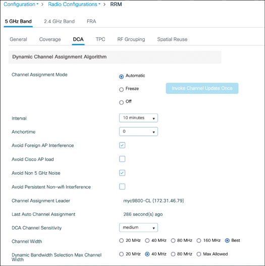
DCA allows you to choose the channel width you want DCA to assign to your APs. The setting “Best” tries to use larger channels (up to 80 MHz) wherever possible and where 802.11ac or Wi-Fi 6 clients are detected. It may choose to use 40 MHz or 20 MHz channels if it notices that APs are very close to each other, if there are interferences, or simply if it thinks the network would perform better with smaller channels. One inconvenience of the “Best” setting is that some clients always try to connect to the largest channel available before looking at the best RSSI. (Apple has documented this issue in its client roaming behavior; other clients don’t often publish their roaming logic, so it’s hard to know the real ratio.) Having APs with varying channel width would then be detrimental because clients would not necessarily pick the closest AP to them but the AP with the largest channel around. It is possible to also configure a sort of “ceiling” by defining the Dynamic Bandwidth Selection Max Channel Width. Enabling this setting can be useful if you know that 80 MHz will not be efficient at all in your network and that you want to aim at 40 MHz whenever possible, but some areas could benefit by using 20 MHz channels due to their density. FlexDFS is an automatic feature (that is, there is nothing to configure for it) where if an AP is set to use a 40 or 80 MHz channel and “radar is detected“ in a 20 MHz subchannel, the AP can reduce its bandwidth to 20 or 40 MHz to avoid the problematic 20 MHz range. This may explain why some APs keep using smaller channels even if you set DCA to use larger ones.
The same configuration page allows you to select the DCA channel list, which is the list of channels the algorithm will choose from and possibly the list of channels that the APs will be monitoring completely. This page allows you to completely remove some channels if you are aware of specific static interferers.
Similarly to the transmit power level, APs use their previous channel when they join any WLC. However, out of the box, on their initial configuration, they use the first channel of the band. When a new standalone WLC starts or reboots, or when a new RF leader is elected in a group, DCA enters a “startup mode” for 100 minutes. This consists of 10 runs of the DCA algorithm (every 10 minutes) regardless of your interval configuration. These runs use the high sensitivity setting to help shuffle the APs and create a channel plan. After this startup mode is finished, the DCA algorithm uses the configured settings and interval.
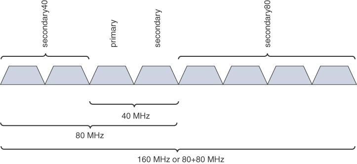
Overlapping Basic Service Set (BSS)
To keep interoperability with legacy versions of the Wi-Fi standard, larger channel widths keep using a primary 20 MHz channel where management frames are still sent at legacy mandatory data rates (which is not the case anymore in the 6 GHz band, which drops legacy support). When setting a channel statically—for example, by going to the radio list for a specific band in Configuration->Wireless>Access Points and choosing 80 MHz and channel 100—the AP chooses the configured channel as the primary 20 MHz and the channels above to complete the 80 MHz width.
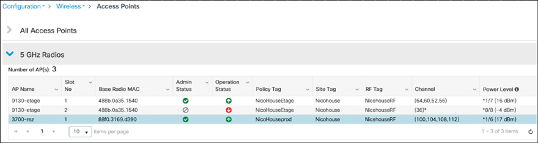
The DCA algorithm also prioritizes this behavior, and if it has to place APs on the same channel, it tries to assign the primary 20 MHz to be the same so that APs can hear each other’s management frames and act nicely. However, that is not always the best option, and DCA might choose to assign the primary channel differently. Notice that the 9130 AP uses channels 52 through 64 (which makes for 80 MHz of width) but channel 64 is the primary 20 MHz. This setup can complicate sniffer captures because sniffers typically offer to sniff channels only above the primary channel. It is more efficient at first sight to use another primary channel for another AP that would operate on overlapping channels because potentially both APs could transmit at the same time management frames (since they are on different channels), but they still compete for the whole channel width when sending data frames. This situation gets even more complicated if you consider varying channel sizes (APs with 20 MHz, some with 40, some with 80, and some on 160 MHz), because on top of a primary 20 MHz, there is also a primary 40 MHz and 80 MHz (for stations not supporting the whole width). Different Wi-Fi versions of the protocol have different rules and thresholds to access the medium, and shuffling primary channels like this could cause some stations to forbid access to the medium by other stations. Long story short, it is often better to have APs use the same primary channel for all their clients to play nicely together, but in a busier environment, the DCA algorithm may use overlapping channels with a different primary 20 MHz if it feels justified from a load or interference standpoint. If you see this happening, the WLC is trying to squeeze the most efficiency out of the network but is lacking some channel reutilization. You can inspect whether rogue wireless networks are active on some of your channels, study the possibility of adding more channels, or hunt for interferers.
Cloud-Based RRM
By the time you read this, Cisco will have released a cloud-based RRM solution. The data collection and measurements stay the same, but moving the RRM algorithm “brain” to the cloud brings a few advantages. The first is scale because the cloud can compute the best RRM for your network regardless of the deployment size, whereas the current RRM solution might elect different RF leaders if there are many APs to take into account.
RRM automates a lot of tasks for you but currently works based on a set of thresholds that are configurable and where the defaults should work fine for most deployments. A cloud RRM solution brings the power of AI and gets rid of thresholds. Patterns are identified based on your real environment assurance data, and the RRM decisions are made accordingly. Decisions are not only snapshot-based (that is, based on the data at a given fixed time of the day) but can be taken based on usage patterns, identified peak hours, and historical data. The algorithm can also self-improve because it is able to observe the results of previous RRM decisions on assurance data and identify what works best.
Finally, an RRM control center gives you comprehensive data about the network current status, the RRM changes, and settings applied.
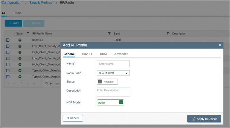
RF Profiles
An AP gets its RF settings based on the RF tag it is assigned to. The RF tag is configured with RF profiles, one for each frequency band. An AP that is not configured with any specific RF profile uses the default RF settings policy globally configured on the WLC. You can define them in Configuration > Tags and Profiles > RF/Radio. You can configure the name, radio band, and NDP mode. The basic NDP mode is auto, where the AP uses its serving radio to send the NDP messages. When set to off-channel, the AP uses its software monitor radio chipset (only on Catalyst 9120 and above) to send the NDP messages (they are heard with the main serving radio on the current channel mostly), completely freeing the client-serving radio of this task. Off-channel is therefore a better setting, but not available in all APs and also not necessarily optimal if you have a dual 5 GHz radio with external antennas where the software radio with the CleanAir chipset then does not have the same propagation pattern as the data traffic. This can be the case on a 9130 with external antennas where you may be using very directional antennas for the 5 GHz radios with different orientations between the two 5 GHz radios. The internal software-defined radio is not connected to all the external antenna chains and has a different view of the RF space.
The 802.11 tab allows you to define the data rates supported. To this day, it is still a good idea to offer support for legacy data rates (that is, up to 54 Mbps) because many clients expect this support. On top of disabling or enabling support for certain data rates, you can also define (for the legacy rates) which rates are mandatory. The lowest mandatory data rate is the rate at which the beacons and management frames are sent by the AP. Professionals often consider this as defining the coverage area of a given radio cell. Although it is a little abuse of language (because the signal energy travels the same distance regardless of the data rate configuration), it does define the usable coverage area, that is, the maximum distance at which beacons are heard and a client can send an association frame that will be decodable by the AP. Defining more than one mandatory rate helps with multicast traffic, which can be sent at a higher mandatory data rate. There is no particular effect in disabling certain 802.11n MCS data rates apart from making sure the clients downshift rates a bit faster.
RF profiles allow you to configure the typical coverage hole and TPC settings specifically for the APs assigned to this RF profile. The DCA tab offers some (not all) of the global DCA configuration knob and is especially handy in letting you configure the channel width and channel list for the specific group of APs, as shown in Figure 7-17. It also allows you to configure certain 802.11v settings for high-speed client roaming.
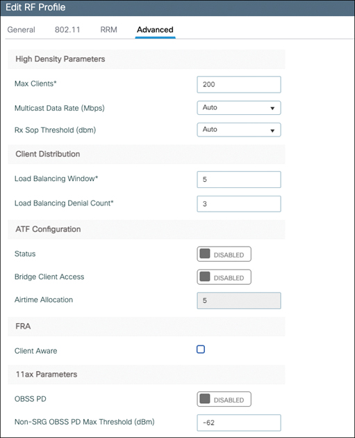
The Advanced Settings tab offers configuration for High Density (such as Receiver Start of Packet, or RxSoP), aggressive client load balancing, airtime fairness, FRA, and Wi-Fi 6 OBSS-PD, as illustrated in Figure 7-18.
RxSoP is an advanced feature that should be enabled only in high density environments and with adequate testing. High density means that you want to have small cells and have clients roam to the nearest AP as soon as possible to maintain the best connectivity and data rate. However, some clients might be slow to roam and stick to an access point that is not the best and nearest to them. Even if you select directional antennas and do the best RF deployment possible, clients might still hear the AP at a low signal level, such as –78 dBm or –80 dBm, and decide to stick to that AP, taking precious AP airtime because the communication would be slower. They might even cause retries and use low data rates, impacting the whole cell. RxSoP can be set to a custom value between –85 and –60 dBm. Below this threshold, the AP completely ignores the received frame and considers it as background energy (noise). This means that a client probe received below the configured RxSoP RSSI level is ignored and the AP does not waste resources for this communication. This frees up the AP to work only with closer clients and not waste time with sticky clients. Configuring RxSoP settings requires you to have a dense coverage and to be sure that the client will be able to roam easily. On top of the custom values, it is possible to use predefined value thresholds.
The same Advanced tab allows you to configure the multicast data rate, which by default is the highest mandatory rate, but thanks to RF profiles can be configured to be a specific data rate. That data rate chosen in the RF profile should still be configured as a mandatory rate to make sure all clients support it. The Advanced tab also allows you to configure Overlapping Basic Service Set Preamble Detection (OBSS-PD), which is covered in the Wi-Fi 6 features section later in this chapter.
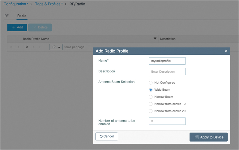
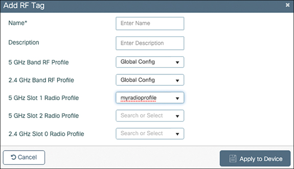
Since the 17.6 version of IOS-XE, you can also configure a Radio profile, illustrated in Figure 7-19, which allows you to configure the radiation pattern of the C-ANT9104 antenna and the C9130AXE-STA AP, which is a stadium antenna that can adapt its radiation pattern dynamically through configuration. This Radio profile can be assigned along with the RF profile in the RF tag, as shown in Figure 7-20.
Spectrum Intelligence and CleanAir
When you’re operating a wireless network, especially one covering one of the challenging environments described, it is essential to have some form of visibility over the wireless medium. Wi-Fi is a form of free-for-all where there are rules to access the medium, but it is not possible to fully prevent another device from transmitting. All Wi-Fi devices are expected to play by the rules and get along together, but if this does not happen (for example, due to a faulty device or driver), there is not much other devices can do. This situation is made even more complicated if you consider that 802.11 is just one of the protocols allowed to use the 2.4 GHz and 5 GHz bands. Non Wi-Fi devices do not operate by the same rules and transmit without respecting your clients’ transmissions. The least you can do, considering the band is unlicensed and free for use, is to identify devices that are actively using the same frequency space as yours but do not belong to you or your wireless network.
This activity of detecting and recognizing other types of transmitters is broadly known as spectrum intelligence (SI). This implies that the Cisco AP use its Wi-Fi radio chipset to get as much data as possible on those transmissions it cannot decode as Wi-Fi signals. From those patterns (for example, the bandwidth of the transmission or its hopping pattern in the case of frequency hopping), it may be able to figure out what type of device/protocol is in action.
Higher-end Cisco Catalyst access points embed a dedicated, software-programmable, radio chipset to do the job. On Wi-Fi 4 and 5 access points (802.11n and 802.11ac), this is called a Cisco CleanAir chipset. The Catalyst 9120 and 9130 series access points include a separate software-defined radio of a new generation that performs the CleanAir duty. These dedicated radio chipsets include a full-blown spectrum analyzer that is specialized in this task.
Although the RF-ASIC present in the Catalyst access points is capable of much more than the previous generation CleanAir chipsets, they still both work in the same way with regards to the interference detection process. The spectrum analysis radio constantly listens to the medium and scans the whole frequency range more or less every second. CleanAir can analyze the spectrum only when the AP is not transmitting (because the AP transmissions would be way too loud and cover everything else). When the AP is listening to the medium (which is basically all the time it is not transmitting), if a Wi-Fi frame is received, it is processed directly by the Wi-Fi radio, but any other non–Wi-Fi signal is processed and analyzed by the CleanAir chipset. It listens to the signals received by the Wi-Fi radio on its current channel. Both chips share the same antenna chain, but the CleanAir chip has a very high sampling rate and dedicated hardware. This allows the CleanAir chip to detect different Bluetooth transmitters that hop at the same time to different neighboring 1 MHz-spaced frequencies.
Both spectrum intelligence (available on the 1800 series and 9105/9115 series APs) and CleanAir focus on detecting non–Wi-Fi interferers. The latter do it with better resolution and detect more types of interferers. The former have a small performance impact because the AP needs to spend a bit more time off-channel to perform the detection, whereas CleanAir has no performance toll whatsoever (except only if you enable BLE detection by CleanAir, which causes a 10 percent packet loss on the 2.4 GHz band).
CleanAir provides interference device reports (IDRs), illustrated in Figure 7-21, back to the controller that can be consulted in real-time under Monitoring > Wireless > CleanAir Statistics. The information contained in the report includes
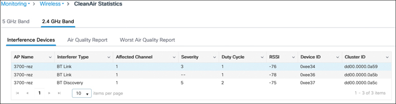
- The AP that is closest to the interference.
- The type of interferer if it was recognized.
- The Wi-Fi channels that will be affected by it (because a non–Wi-Fi interferer can affect multiple channels).
- The duty cycle, which is a percentage representing the amount of airtime blocked by the interferer.
- The severity, which is a number between 1 and 100 representing the severity of the impact. It is majorly influenced by the duty cycle (the more airtime wasted, the higher the impact) but also by the proximity/loudness of the interference (if an interferer transmits 100 percent of the time but is of very low signal strength because it is far away, its severity is less).
- The RSSI at which it is heard.
- A device ID that uniquely identifies the interferer and differentiates separate interferers that are in the same physical space.
- A Cluster ID that allows you to cross-identify a unique interferer heard by two separate reporting APs so that it shows up as a single interferer and not two different entries. Clustering is done by client-serving APs on the basis of their list of neighboring APs (and comparing the interferer-heard RSSI, among other things). Monitor mode APs do not participate in this activity because they do not transmit neighboring messages.
Another thing reported by CleanAir is the air quality (AQ). It is reported by a virtual index between 0 and 100, where 100 represents perfection. CleanAir takes a rolling average of the number or severity of the interferers present on a given channel to compute this metric. This metric helps giving an easy overview of the channel when interferers may come and go and not be constantly present in the real-time interferer list.
Configuring CleanAir
In the Configuration > Radio Configurations > CleanAir page illustrated in Figure 7-22, you can enable CleanAir globally. You then can check the CleanAir status (up or down) for each AP depending on its support for CleanAir. The same location allows you to enable spectrum intelligence for the non–CleanAir-capable APs. There is little to no reason to disable CleanAir because it does not bring a performance impact. It is, however, recommended to keep spectrum intelligence disabled if your network is sensitive to performance or a small packet loss due to the increased off-channel activity.
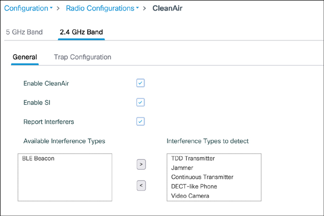
You can enable the reporting of interferers (otherwise, only air quality indexes are calculated) and select which interferer is reported. The BLE beacon is the only one excluded by default because it has some performance impact, whereas all other interferer types do not have any performance toll.
Monitoring the Spectrum Live
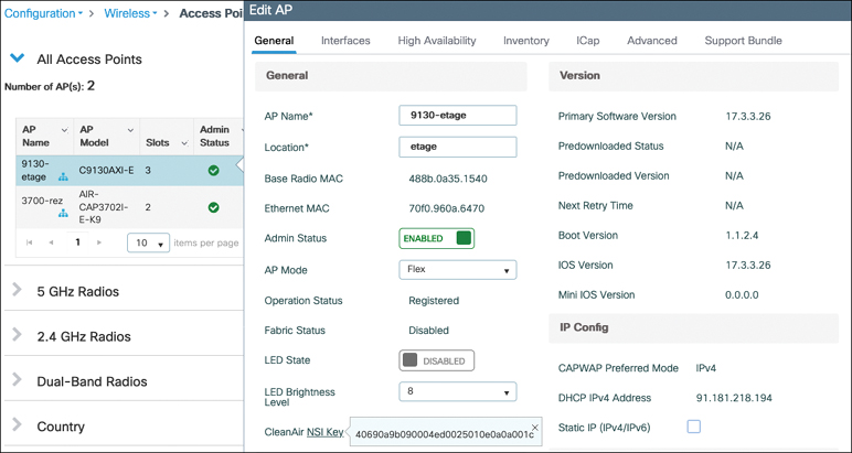
APs with the CleanAir capability also allow you to connect to them and see the live view of their spectrum. This basically means having as many spectrum analyzers onsite as you have APs, and all of them are accessible remotely without any effort. In the past, having this capability required putting the AP in a special mode called SE-connect, but this mode is not required anymore. Simply go to Configure > Access Points and click a CleanAir-enabled AP. In the General section of the settings, you can find the CleanAir NSI key, which you need to connect to the AP, as illustrated on Figure 7-23.
To connect to the AP spectrum analyzer, you need either Cisco Spectrum Expert or some third-party tool that supports CleanAir APs. You can then connect to the AP and enter the NSI key to see the live spectrum. Cisco DNA Center also allows you to view this within your web browser and without entering any key; to do so, click Spectrum Analysis in the AP 360 Assurance view, as shown in Figure 7-24.
Interferer Location Tracking
If you have Cisco CMX or DNA Spaces, it is possible to locate interferers on the map. This capability, however, suffers from several issues that impact its accuracy. While Wi-Fi devices have an expected and typically similar transmit power, any other type of interferer could have very different and even varying transmit power throughout its transmission. CleanAir mostly works on the current Wi-Fi channel, and therefore, it is typically harder to have at least three of your APs hearing the same interferer because it would require all these APs to operate on a channel that overlaps with the interfering device. This requirement can be countered by having CleanAir-capable APs in monitor mode, which can scan all the frequencies rapidly. Most regulatory agencies agreed to open up the 5 GHz frequency range only if the new devices (Wi-Fi clients and APs) operated in total respect of the incumbents (the radars).
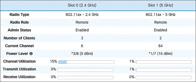
Monitoring the RF Space
Going to Monitoring > Wireless > AP Statistics, you can have a 360-degree view of the AP RF status. The main metric is Channel Utilization, as seen in Figure 7-25, which corresponds to the logical airtime consumed by signals above the clear channel assessment line. This includes the AP utilization as well as other APs on the same channel and non–Wi-Fi interferers.
The transmit and receive utilization indicate how much of the airtime is used by the AP receiving or sending traffic. Therefore, subtracting the Rx/Tx utilization from the channel utilization allows you to see how much of the airtime is consumed by other devices and interferers.
Advanced RF Features
Next, we cover a number of RF-related features that allow you to tweak certain client or RF-related behaviors:
- Band select
- Client load balancing
- Off-channel scan defer
- Airtime fairness
- Wi-Fi-6–specific features
Optimized roaming could have a place here but is discussed in greater detail in Chapter 6, “Mobility/Client Roaming.”
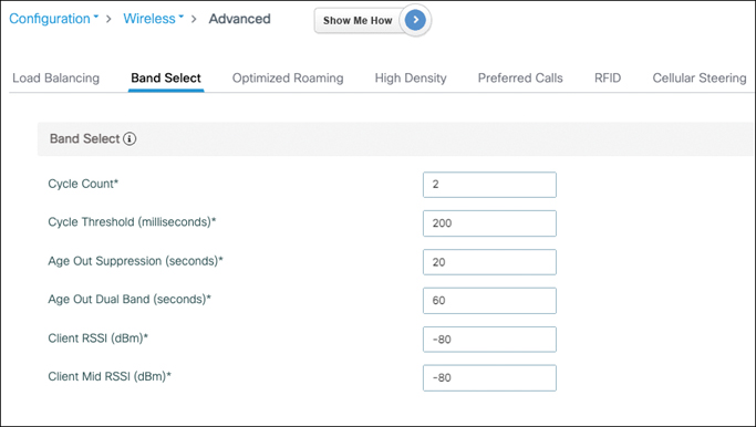
Band Select
The 5 GHz band is generally much better than the 2.4 GHz band because it provides more channels and less interference (at least in most cases). If your WLAN network is dual-band (that is, available in both bands), you could face several issues such as the clients sometimes going to the 2.4 GHz band (because it typically has a stronger RSSI) and facing worse performance. You could also have the clients going back and forth between the 2.4 GHz and the 5 GHz bands, which can cause longer roaming times because roaming between different frequency bands can require some time for a client adapter to achieve. The Band Select feature pushes the AP to ignore all the client 2.4 GHz probing requests if it has seen that the client is 5 GHz capable. This means that upon the first probe request on 2.4 GHz received by a client, the WLC does not answer for a little while, waiting to see if the client is also 5 GHz capable. If the client shows dual-band capability, the WLC answers only the 5 GHz probe requests. If the client is seen probing only in 2.4 GHz, the WLC replies to the 2.4 GHz probe requests. When a client is classified as dual-band, there is no negative impact at all caused by Band Select (apart from the client believing there is no 2.4 GHz network at all), but this dual-band classification does delay the first probes from the client. This impact may become greater because lately many Wi-Fi devices (especially smartphones) use randomized MAC addresses to probe, meaning the WLC cannot relate one probe request with another from the same client if the client changed the MAC address in-between. This may lead the WLC to introduce delay to all probe responses toward such a client, which is why this feature is particularly not recommended for SSIDs carrying voice applications.
Band Select can be enabled or disabled on a per-WLAN basis in the WLAN settings.
Global Band Select settings can be configured in Configuration > Wireless > Advanced web page, as shown in Figure 7-26, but should be left at the default most of the time. Those settings give you an idea of the delays in question though. Clients that hear better than –80 dBm are considered for Band Select. When they are declared to be dual-band, for 60 seconds the 2.4 GHz probes are suppressed. The WLC, upon seeing a new 2.4 GHz probe request, waits to see if the client also probes on 5 GHz. If it sees two 2.4 GHz probes without corresponding 5 GHz probes in the 200 ms that follow, it declares the client single band and keeps answering the 2.4 GHz probe requests.
Aggressive Client Load Balancing
Seeing all the clients on one AP while other APs around it have little to no clients may be upsetting sometimes. This situation may have a variety of possible causes: typically, the first AP in the entrance of a larger area attracts the client initially, and it may not be in a hurry to move to another AP slightly further away. This can happen in large reception areas or in large auditoriums, for example. Aggressive load balancing is a way to remediate this situation by having a busy AP push clients to connect to another AP. When load balancing is enabled in the WLAN advanced settings, an AP that has too many clients (we cover what “too many” means in a moment) starts to reject new association requests with the proper association response code 17 (“AP busy”). The hope is that the client will look for another AP to join. Some client drivers are not so well programmed and do not understand this response code, whereas other clients may have understood perfectly but consider there is no other decent candidate AP to join, so there is a safety mechanism, and the AP ends up accepting the association request after a couple of attempts. The load balancing window that you can configure in the load balancing settings (Configuration > Wireless Advanced > Load Balancing tab) is the acceptable client count delta between the AP and the neighbor APs.
If a neighboring AP has three clients and load balancing is configured with a window of five, the AP with eight clients starts rejecting the ninth client, hoping to see it connect to the AP with three clients, for example.
The load balancing window and attempt count can be configured in the RF profile as well as global in the advanced wireless settings.
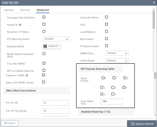
Off-Channel Scanning Defer
Off-channel scanning defer is a per-WLAN setting (Configuration > Tags & Profiles > WLANs > Advanced tab) and has a profound impact on your QoS applications and the RF algorithms as well. We already covered in detail how each AP goes off-channel to scan and to send NDPs, which is the source of data for many algorithms, including RRM. This off-channel scan is short and does not impact data transfer but can be noticed on WLANs that are used for critical real-time voice applications. The AP going off-channel for around 50 ms or a bit more should ideally not be noticed if buffering is in place, but combined with other events, it could lead to small disruptions. You can enable off-channel scanning defer per UP category. By default, as shown in Figure 7-27, it is enabled for UP 5 and 6 (the voice category basically) for a duration of 100 ms. This means the AP postpones any off-channel activity for 100 ms upon receiving a frame tagged with UP 5 or 6. This process can repeat, and as long as voice frames are sent, the AP keeps postponing its off-channel scanning duty and stays on-channel to serve the clients. Although this process is great for the client traffic, it means the AP does not participate in rogue detection or metrics collection for RRM. It can be interesting to also enable UP 7, which is used for 802.1X authentication: you probably prefer your AP not to move away to another channel while a client is starting a long EAP-TLS authentication, for example. If you enable all UPs, it effectively disables all off-channel scanning while there is any traffic ongoing.
Airtime Fairness (ATF)
Traditional methods for reaching user fairness like rate limiting do not cater well to the bandwidth consumption over the air, giving rise to the need for airtime fairness. Rate limiting is sometimes required due to business reasons but is never an efficient way to restrict bandwidth because packets are being dropped on the wired network with no restrictions whatsoever taking place over the wireless network, where clients can still monopolize the airtime with retries, low data rates, and so on. ATF happens mostly on the AP, which takes note of every client’s airtime utilization. It makes more sense to restrict clients to a percentage of usable airtime because that airtime can depend on many things: load and interference caused by other APs on the same channel, low data rates, or retries taking place. When the AP receives a frame to transmit downstream to the client, it verifies whether the client still has some airtime available in its bucket. If not, it defers the frame and leaves it in the client priority queue for a while until the client has some airtime available in its configured bucket and potentially drops the frame if it cannot send it for some time.
Airtime fairness allows you to configure profiles that restrict the percentage of airtime available for a given SSID (compared to other SSIDs) or for each client in the SSID. It applies only on data frames (not management or control frames) and in the downstream direction only. ATF is configured in the Configuration > Wireless > Air T ime Fairness page, where it can be enabled globally for each band. You can then create ATF profiles with a specific weight that you are able to assign in the policy profile you attach to SSIDs.
Airtime fairness is supported only on 802.11ac access points at the time of this writing and not yet on Catalyst access points.
Wi-Fi 6 Features
Wi-Fi 6 is the Wi-Fi Alliance name for 802.11ax and was designed to improve the efficiency of the protocol rather than pure throughput like previous amendments of the standard, which is why it is called High Efficiency (HE) in the protocol itself. The major change to the protocol itself is the move from orthogonal frequency-division multiplexing (OFDM) to orthogonal frequency-division multiple access (OFDMA). Two extra more complex modulations are added (MCS 10 and 11) for increased throughput at very close range. Less visible but still important changes were done to the modulation rules such as the four times increase in subcarriers, while at the same time the intersymbol guard time has been drastically increased. These last two changes to the modulation rules do not change the overall throughput (because both measures somewhat balance each other out) but are meant to bring more resiliency, especially outdoors. Here, we cover the biggest Wi-Fi 6 features and their impact.
Wi-Fi 6E starts to be referenced in IOS-XE 17.7.1 and gets full support in later releases. Wi-Fi 6E is Wi-Fi 6 but in the 6 GHz band. In 2021, many countries worldwide started to release this new band, which typically ranges from 500 to 1200 MHz of spectrum depending on the country. The first and largest advantage of Wi-Fi 6E is more channels for more capacity and less interference. While Wi-Fi 5 (802.11ac) already offered 160 MHz channels, they have been rarely usable in the enterprise setting so far due to the fragmented bandwidth available in the 5 GHz band. Wi-Fi 6E is the same protocol but gives a better chance to 80 MHz and 160 MHz channels to work in the enterprise segment. It also helps support high-density venues like stadiums or concerts by providing less channel reuse and allowing more cells to cover an area. There are other benefits like the fact that the 6 GHz band is not opened to legacy Wi-Fi devices, making it a “Wi-Fi 6 and above only” band. The 6 GHz band is not covered by DFS but by automated frequency coordination (AFC) to make sure Wi-Fi does not interfere with incumbents on the same frequency. Due to the sheer number of possible 20 MHz channels in the 6 GHz band, discovering APs also happens differently for Wi-Fi 6E. Although scanning specific “primary” channels in 6 GHz is possible, it is expected that clients discover 6 GHz radios through existing 5 GHz radios and specific advertisement mechanisms. Last but not least, Wi-Fi 6E only allows WPA3 security or Enhanced Open (that is, no unencrypted networks).
OFDMA
The new OFDMA access rules allow the AP to subdivide the channel into several resource units (RUs), which are basically smaller channels. This means that for a given transmission opportunity a specific client can use 2 MHz out of the channel width to send its data, whereas other clients are assigned other subchannel widths, and everyone can then transmit their data at the same time. This capability increases efficiency drastically, reduces latency (because everyone can transmit at the same time), reduces collision probability (because clients have their own dedicated subchannel bandwidth), and allows deterministic performance where the AP can prioritize clients that have smaller real-time data frames to send. Multi-user OFDMA transmissions can happen both in uplink and downlink.
Multi User–Multiple Input Multiple Output (MU-MIMO)
Already present in 802.11ac, MU-MIMO is taken to the next level in Wi-Fi 6 because it becomes bidirectional and is more efficient with APs having more transmit and receive chains (like the 8×8 9130 AP). MU-MIMO allows up to eight users to send or receive data in parallel on a 106 RU or higher. Acknowledgments (ACKs) and clear-to-send (CTS) frames can be processed for all clients simultaneously. The AP is in charge of maintaining a channel matrix with device locations and moving devices between user groups; they move around so that the AP always knows which clients can receive traffic at the same time through MU-MIMO because it requires destination clients to be physically separated by some distance for the beamforming to work. Each MU-MIMO client can have a different MCS rate. All these improvements combined with a better support on the client side for MU-MIMO promise a better adoption of this feature than 802.11ac wave 2 brought us.
Target Wake Time (TWT)
Target wake time is targeted at increasing battery life and reducing power-save–related management overhead. Until now, devices could sleep and wake up every few beacons to check if there was buffered traffic. Devices could hardly sleep for more than 1 second without facing the risk of being deauthenticated. Thanks to TWT, devices can communicate with the AP and go for very long sleep durations, which is essential for IoT devices that need to run on low power.
All the Wi-Fi 6 features can be enabled or disabled granularly in the Advanced tab of the WLAN configuration page, as shown in Figure 7-28.
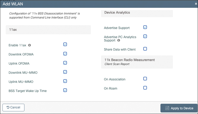
You can configure other Wi-Fi 6 settings in the global network configuration page under Configuration> Radio configuration>Parameters, as shown in Figure 7-29.
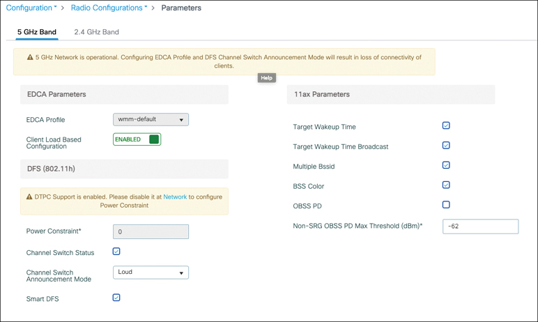
BSS Coloring
The idea behind BSS coloring is that in the real world, in a high-density Wi-Fi deployment, you can have APs on the same channel, and their respective clients could still be transmitting at the same time toward their own APs without really interfering with the other ones. Before Wi-Fi 6, if a client heard a Wi-Fi transmission on its channel louder than –82 dBm, it had to stay silent. However, if clients are decently close to their APs, they can potentially talk at the same time, provided that they each talk to a different AP, and the APs would hear their client just fine. This allows for a lot of channel reuse between floors or in large warehouses where APs hear each other but the clients on the ground don’t necessarily hear other APs. The way to achieve this is to mark each BSS with a “color,” which is basically a unique identifier between 0 and 63. If a client hears another transmission on its channel and using its color (that is, belonging to the same BSS), it stays silent if it is louder than –82dBm. However, if the client hears a transmission on another BSS (using another color), it uses a much higher RSSI threshold (for example, –62 dBm) to determine whether it can talk at the same time. The color is advertised by the BSS in the beacons, and the client has to use the color after associating to the BSS.
It is required for devices to understand and use the BSS color (which is included in the Wi-Fi 6 certification), but some devices do not use the differentiated RSSI level for overlapping BSS transmission (called OBSS-PD) and keep operating like before and simply use the color advertised by the BSS, therefore not really getting any benefit from the feature. So as with previous certifications, the Wi-Fi Alliance ensures devices can interoperate with each other, but not every device pulls every possible benefit from the IEEE standard.
BSS coloring PD with a custom threshold (that is, the RSSI above which even a signal from another BSS is considered to be too loud for clients to transmit at the same time) can be configured in the RF Profiles Advanced tab.
BSS coloring as a whole (assigning colors to each AP/BSS) can be toggled in the RRM menu, as shown in Figure 7-30.
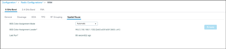
On each AP radio, you can configure whether the AP follows the global BSS Color RRM settings or if it uses an AP-specific configuration, as shown in Figure 7-31. In this case, you can even set the color manually. It is generally a better idea to let the RRM algorithm choose the colors itself though.
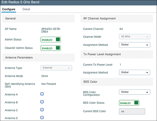
Channel Width
Similar to 802.11ac wave 2, Wi-Fi 6 offers 20 MHz, 40 MHz, 80 MHz, 160 MHz, and 80+80 MHz channels. Each doubling of the channel width comes with a 3 dB penalty to the SNR because of the physics of wider channels, and therefore, it makes it harder to reach higher data rate modulations on wider channels at the same distance. An exception to this rule is 6 GHz Wi-Fi where the rules allow a 3 dB power increase each time the channel doubles in width to compensate for this effect. An AP with more MIMO chains can compensate the drop in signal to noise ratio when using larger channels a little bit by using the combined gain on all transmit and receive antennas when using 8×8 MIMO.
Dynamic Frequency Selection (DFS)
Dynamic Frequency Selection sounds like the name of a fancy feature but is in reality the required access-to-medium protocol in certain frequency ranges in certain parts of the world. In the past, radars used to be the only devices operating in their frequency ranges. But over time, more and more radars have become present in many regions (ships, airports, and also weather radars), and more and more devices are asked to operate on the same frequency range as radar devices.
DFS Overview
The general behavior of a device complying with the DFS protocol is to be able to detect when a radar occupies the channel, then to stop using that occupied channel for a long period of time, to monitor another channel and jump on it only if it is clear from radars.
The process of detecting a radar is complicated and left to radio chipset vendor implementation. Regulatory domain agencies (ETSI, FCC, OFCOM, and so on) have specific tests set up, and as long as the wireless device detects specific types of radar and does not interfere with it, it is approved. Nothing around radar detection is configurable, and each vendor takes the responsibility of fine-tuning the algorithm to avoid false detections (the AP backing off from a channel despite no radars being present) as much as possible. This detection accuracy also depends on the radio chipset used because a radar pulse has very different characteristics from a Wi-Fi signal; it is hard to catch accurately on the lower-end chipsets. DFS was required early on for ETSI devices working in the European Union (and countries following ETSI regulations) in the ETSI 5 GHz band. It is not necessarily mandatory in other parts of the world and also depends on the frequency range. The FCC has now made it mandatory for the UNII-2 and UNII-2 extended frequency range like ETSI.
Radars may be fixed (often civilian airport or military base, but also weather radar) or mobile (ships). A radar station transmits a set of powerful pulses periodically and observes the reflections. Because the energy reflected back to the radar is much weaker than the original signal, the radar has to transmit a very powerful signal. Also, because the energy reflected back to the radar is very weak, the radar could confuse that energy with other radio signals (like a wireless LAN, for example).
Because the 2.4 GHz band is free of radar, the DFS rules apply only to the 5.250–5.725 GHz band.
When the radio detects a radar, it must stop using the channel for 30 minutes at least to protect that service. It then monitors another channel for at least 1 minute and can start using it if no radar is detected during that period.
The burden of DFS compliance falls mostly on the AP. It can hardly be feasible to require the same detection accuracy from all the mobile clients out there, and it’s much simpler for regulatory bodies to certify the APs instead. The clients can use a channel if an AP is broadcasting beacons on it, while an AP has to perform a silent detection on a new channel before being able to transmit anything on it. This has important implications. An AP has to listen carefully for 1 minute, checking whether any radar is heard, before being able to send beacons on a given DFS-regulated channel, which severely impacts the ability of the AP to change channel in case of interference (it still can but typically has to face a 1-minute blackout at least or more if it has to scan several DFS channels). On the other side, the client, when moving to a new DFS channel, cannot send a probe request until it has heard a probe response or a beacon from an AP: at that moment, it can safely assume that the AP did the proper verifications and that the channel is clear of radars. However, this has more importance than it may first seem because clients scan other channels much more frequently than APs do. While an AP might decide after a while to consider moving to another channel, which may offer less interference or less congestion, a client has to constantly scan all channels to find an appropriate AP to roam to when it is moving away from the current AP (or even when standing still if the RF conditions change). A client would have to spend only a few milliseconds on a non-DFS channel, basically the time to set its radio to the new channel, send a probe request, wait for the response, and move back to the original channel, causing very little disturbance or absence from its current channel where the APs can be buffering traffic in the meantime. On the contrary, scanning a DFS channel implies moving to that channel, then waiting for the next beacon, and then changing the channel again, which often means a scan time longer than 100 ms. Because of this impact to operations, a lot of client devices prioritize scanning the non-DFS channels over the DFS channels. Considering the typically high number of DFS channels combined with the 100 ms complete traffic loss, client devices can scan a given DFS channel only once every 30 seconds or once every minute.
It is possible that APs falsely report radar events when no radars are around. Cisco has a clear competitive advantage with the APs that have a CleanAir or RF ASIC chipset that can participate along with the Wi-Fi radio to detect radar with a much higher accuracy than any classical wireless radio. A radar event is declared only if both chipsets have heard the radar, which drastically reduces false positives to close to zero.
Some channels, like channels 120, 124, and 128, have even stricter DFS rules because they are used for Terminal Doppler Weather Radar (TDWR), which is of critical importance. The scan time for an AP to be able to use these channels goes up to 10 minutes instead of one. Not all AP models decide to use these channels. The 2800, 3800, and 4800 do support these three channels, for example. Support among AP models is subject to change because APs are able to get certified.
Transmit Power Control (TPC), not to be confused with the RRM feature of the same name, is a system that got defined in the 802.11 standard along with DFS and that allows for the AP to set a transmit power maximum (that is lower or equal to the country maximum) for all stations to respect, in case you want to force your clients to use a lower transmit power.
DFS in the C9800
The Configuration > Radio Configurations > Parameters page contains several settings related to the DFS behavior.
Smart DFS is a feature you can enable on the WLC. Without it, each time a radar is heard on a given channel, the AP blocklists this channel for 30 minutes, as per the regulation requirement. The idea is that if there is a constant radar using a channel, you probably do not want your APs to keep trying to use that channel all the time, so Smart DFS, when enabled, doubles the blocklist time each time the channel is blocklisted. As an example, the first time radar is heard on a given channel, that channel is blocked for use on that AP for 30 minutes. If, some time later, radar is heard again on that channel, it is blocked for 1 hour, then for 2, and so on with a maximum of 24 hours’ block time.
The Power Constraint field becomes available if you disable DTPC support in the Network page. You can then specify in dBm what is the maximum power clients should be allowed to transmit at.
Enabling the channel switch status means that your outdoor APs (indoor APs typically do not hear radar), when hearing radar on their channel, announce that radar was heard and that the AP will go offline on this particular channel. In loud mode, the AP announces what channel it plans on going toward, but if that new channel is a DFS-regulated one, the AP has to observe the 1-minute scan time when moving to it before being able to transmit beacons. In quiet mode, the AP orders all stations (including clients) that heard the channel switch announcement frame to stop any transmission immediately, whereas loud mode allows for a couple more beacons to be transmitted to make sure everyone heard the change. Some specific clients support the channel switch announcement frame, but so far it is not a majority of the mainstream clients unfortunately. There is no harm in enabling it though. This capability is extremely handy in the case of a mesh network where other outdoor APs are connected to your root AP and not all access points may have heard the radar directly. This way, all the APs go offline at the same time if one of the APs detected radar.
Flexible Radio Assignment (FRA)
Flexible Radio Assignment is a feature focused on APs with dual 5 GHz capability like the Aironet 2800, 3800, 4800 or the Catalyst 9120, 9124, or 9130. Those APs have a radio that can either operate on 2.4 GHz or 5 GHz via configuration while the other radio slot is a static 5 GHz radio. Having a dual 5GHz capability is becoming more and more of a need because the 2.4 GHz space is overcrowded and very limited in terms of number of channels; therefore, adding more APs typically does not add more capacity. Having APs with two 5 GHz radios allows you to add more density and more capacity to the network without overcrowding the RF space, thanks to the typically larger number of 5 GHz channels available in most countries. Having dual 5 GHz radios on an AP is possible only thanks to hardware filtering but also an enforced separation of at least 100 MHz between the two 5 GHz radios and sometimes a difference in transmit power. For internal antenna AP models, when both radios are set to 5 GHz, one of them can reach the maximum transmit power while the other faces a limitation of transmit power to avoid signal bleeding between the two radios. These are called macro and micro cells (literally, big and small cells). When you use external antennas, thanks to a different set of antennas and a bigger physical separation between the transmitters, no transmit power limitations are in place at all.
FRA refers to the algorithm that automatically defines the best role for a flexible radio. It is possible to statically assign that flexible radio to be monitoring or to be client serving in 2.4 GHz or in 5 GHz, but you could also rely on FRA to determine the best course of action. FRA calculates the redundancy level of the 2.4 GHz coverage and computes the Coverage Overlap Factor (COF). This calculation can even run on APs that do not have a flexible radio. When the COF is above a certain level, FRA moves some flexible radio to client-serving 5 GHz. If the 5 GHz coverage is already dense enough, flexible radios can be moved into the monitoring state and can scan both bands continuously.
FRA can be configured globally in Configuration > Radio Configuration > RRM, as shown in Figure 7-32. When enabled, FRA runs at every FRA interval (which needs to be higher or equal to the DCA interval). If the COF calculated for an AP is higher than the sensitivity threshold (100 for low, 95 for medium, and 90 for high), the AP flexible radio role is changed.
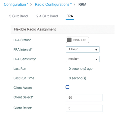
You can verify the COF factor calculated for your APs with the command show ap fra. The algorithm also mentions the suggested mode for the radio (5 GHz client serving or monitoring). One problem with the algorithm configured as shown in Figure 7-32 is that once the radios are moved to 5 GHz, they do not scan 2.4 GHz coverage at all. So, with every flexible radio moved to 5 GHz operation, the WLC loses a bit of visibility in the 2.4 GHz coverage. Enabling Client Aware FRA allows you to move between 5 GHz monitor and client serving modes when the load on the other 5 GHz radio requires it.
One point to keep in mind is that the RF group leader should ideally be the same WLC between 2.4 GHz and 5 GHz when FRA is in use. To have consistent COF calculations, it is advised to statically set the leader to avoid any problems. This note raises the fact that indeed you could potentially have different WLCs acting as the RF leader for 2.4 GHz and 5 GHz, which sounds a bit weird but is fine. The reason is that 2.4 GHz has a different coverage range from 5 GHz, and therefore, the number of APs in the RF neighborhood is different, and possibly the list of WLCs involved is not the same between both bands.
Tri-radio
Certain AP models such as the Catalyst 9130 and the 9124 are capable of tri-radio operations. The flexible slot is not the 2.4 GHz slot anymore, but thanks to the 8×8 5 GHz radio, they can divide their 5 GHz radio (slot 1) into two separate 5 GHz radios (slot 1 and slot 2), each capable of 4×4 operations. This makes for three Wi-Fi radios (one 2.4 GHz and two 5 GHz) on top of the Bluetooth and IoT radios that can still be operational at the same time and the RF-ASIC, which could also count as an extra radio.
By default, such APs operate with a single 5 GHz radio in 8×8. Enabling tri-radio must first be done globally; otherwise, the AP-specific option stays inactive. The global setting is in Configuration > Radio Configuration > Network, as shown in Figure 7-33.
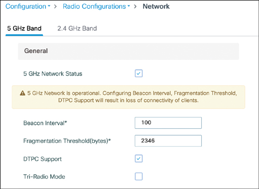
By default, these tri-radio–capable APs show the slot 2 radio, but it stays disabled and the 5 GHz radio still operates in 8×8 MIMO mode. Each tri-radio–capable AP is then, by default, in “auto” radio role. These radios can be statically enabled (to get a dual 4×4 5 GHz radio) or disabled (to keep the 8×8 single radio). If they are enabled, the second slot becomes operational and can be configured like an independent radio. When they are left to auto, FRA is in charge of determining the radio role (either one 8×8 radio or two 4×4 radios). FRA can decide to keep a single 5 GHz radio, use both, or have one in monitoring mode and the other in 4×4 client serving mode.
Figure 7-34 illustrates the slot 1 configuration, which allows you to set the modes to auto or manual. Notice the Global Tri-Radio Mode is displayed and gives you a warning if it is disabled.
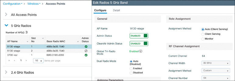
An important note is that 160 MHz operations require both radios to operate together in 8×8 and are not available in tri-radio mode.
Wireless Intrusion Prevention System (WIPS) and Rogue Detection
Wireless brings a new level of possible problems and attack vectors: even if your network is very secure with the latest encryption, you can still be subject to a lot of impersonation or Layer 1 attacks. Rogue detection (not rouge as can often be read on the Internet) refers to the detection of unwanted access points in your physical area. A Wireless Intrusion Prevention System refers to the detection and possibly mitigation of low-level (Layer 1 and Layer 2) attacks against your network. A rogue client is defined as a client that connects to a rogue AP. Although a rogue AP is always, by definition, an unwanted device in your network, a rogue client can be one of your own legitimate clients that got tricked into connecting to a rogue AP or could also be an unwanted client.
Rogue AP Detection and Classification
A rogue access point is defined as an access point that you do not manage. The definition could even be extended to “an access point that you do not manage through the same management system.” This term can refer to a malicious access point that you probably want to have removed but can also apply to an AP from the neighboring company that can still be heard from your premises or even one of your own APs that is joined to a lab WLC. This means classification of rogues is important so that you know what actions to take (or not) against them.
Detecting a Rogue Access Point
We have already established that APs scan other channels regularly (in a 3-minute interval by default) and briefly listen on those channels for around 50 ms. This gives over a 50 percent chance to hear a beacon transmitted by any AP present on that other channel (considering the most default beaconing interval of 100 ms). All these APs heard are considered rogues by default, but from this list, you need to subtract APs that are managed by the same WLC or other WLCs from the same managed domain. If the AP has heard an NDP frame from the candidate rogue AP and this NDP could be decoded (that is, if the two APs belong to the same RF group), it is not a rogue but an AP from the same deployment. APs that did not send an NDP frame (non-Cisco APs) or whose NDP frame could not be decoded (they belong to another RF group name) are unclassified rogue access points.
A few more facts on rogue detection:
- Monitor mode APs, because they spend all of their time scanning all channels and not serving clients at all, are much more efficient at detecting rogue APs.
- Rogue detection is disabled on OfficeExtend access points because typically there is little use in detecting rogues in domestic areas at each remote office worker location.
- APs with an RF-ASIC (9120 and 9130 series) benefit from the extra software-defined radio doing the scanning for rogue detection; the client serving radio is offloaded from this task. This is also true for aWIPS signatures (discussed later).
The Configuration > Security > Wireless Protection Policies page offers some configuration settings for rogue detection and classification, as shown in Figure 7-35. The Low, High, and Critical settings are an easy way to automatically configure the rest of the settings. You can choose any level and see what it configures, or choose Custom and define settings yourself. Table 7-2 details the settings configured by each level.
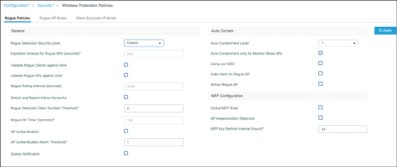
Table 7-2 Rogue Severity Level Settings
| Parameter | Critical | High | Low |
|---|---|---|---|
| Cleanup Timer | 3600 | 1200 | 240 |
| AAA Validate Clients | Disabled | Disabled | Disabled |
| Adhoc Reporting | Enabled | Enabled | Enabled |
| Monitor-Mode Report Interval | 10 seconds | 30 seconds | 60 seconds |
| Minimum RSSI | –128 dBm | –80 dBm | –80 dBm |
| Transient Interval | 600 seconds | 300 seconds | 120 seconds |
| Auto ContainWorks only on Monitor Mode APs | Disabled | Disabled | Disabled |
| Auto Contain Level | 1 | 1 | 1 |
| Auto Contain Same-SSID | Disabled | Disabled | Disabled |
| Auto Contain Valid Clients on Rogue AP | Disabled | Disabled | Disabled |
| Auto Contain Adhoc | Disabled | Disabled | Disabled |
| Containment Auto-Rate | Enabled | Enabled | Enabled |
| Validate Clients with CMX | Enabled | Enabled | Enabled |
| Containment FlexConnect | Enabled | Enabled | Enabled |
The Expiration Timeout for Rogue APs setting defines the amount of time a rogue AP or client is remembered and stored after the time it was last heard. If it is constantly being heard, the timeout does not hit (until it stops being heard).
One problem with WPA2 or open networks is that management frames are not encrypted or signed in any way. A typical attack vector from malicious devices is to spoof beacons of your APs or spoof your APs’ MAC addresses to deauthenticate your clients, for example. We already covered having the NDP frames protected rather than “transparent,” but that still does not provide a good layer of protection. Enabling AP authentication uses infrastructure 802.11w (also known as Protected Management Frames, or PMF). Every AP then attaches an AP authentication information element to its management frames, which allows other APs hearing it to validate that the frame is coming from a managed AP. In case a management frame is heard with a source MAC address corresponding to a managed AP but the AP authentication information element is either missing or invalid, an AP impersonation attack alarm is thrown.
Management Frame Protection (MFP) can also be configured on the same page. MFP was the prestandard Cisco feature covering the same gap as PMF, and they are therefore mutually exclusive. PMF is now the de facto standard supported by all AP models, whereas MFP support will deprecate in the future.
Classifying Rogue Access Points
You can create custom classification rules in the Rogue AP Rules tab. For example, Figure 7-36 creates a friendly rogue rule where all the APs heard broadcasting the SSID of the neighbor company are classified as Friendly (and therefore mostly ignored).
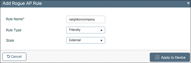
Internal is the maximum level of trust for a rogue AP. External means the WLC acknowledges the presence of that rogue and does not contain it; the rogue is listed but no alerts are thrown. Alert means actively throwing rogue AP alerts.
Similarly, you could create a rule that classifies as malicious any rogue AP that is heard using any of the managed SSID names and that has a decent RSSI level, as shown in Figure 7-37.
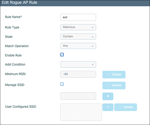
The action chosen here is to contain it and not simply alert. The WLC actively tries to block this rogue AP (see the later section for more information on containment).
Understanding the Danger of a Rogue Access Point
Attackers have great benefits in placing a rogue access point in the physical area of a network. If the rogue AP advertises the same SSID as the corporate SSID targeted, clients might connect to it inadvertently, and the attacker can collect private data. Authentication and encryption help with this problem but not completely. If a rogue AP is connected to your wired network, it can give attackers access to your wired network from a safe place within the premises but outside of the secured zone. So, detecting whether a rogue AP is connected via wire to the same network is a key element. Finally, rogue APs can simply perform a denial of service against your APs and/or your clients and prevent them from communicating. A combination of all of the previous can be put in place as well: a denial of service at Layer 1 forces the legitimate client to connect to the rogue AP that impersonates the corporate SSID; then the rogue can act as an on-path attacker with the rest of the network and perform various types of attacks.
Containing Rogue Access Points
Containing represents the main mitigation method of rogue APs. It is often misunderstood, and people often have wrong expectations about its effects and impact. There is no way to prevent a rogue AP from transmitting signals. There are no invisible electromagnetic pulses you can send to disable a device remotely and no way you can prevent a foreign device from transmitting RF energy. So what does containment consist of? Managed APs can send deauthentication frames to clients that are trying to connect to the rogue AP, therefore preventing any client from connecting to the rogue and therefore negating its potential malicious impact but not affecting the RF nuisance of the rogue AP that will still beacon.
As usual, things are a bit more complicated in reality. It’s important to understand that containment is only an effort to prevent clients from connecting to a rogue AP, but it does not have a 100 percent efficiency. Your APs cannot possibly be using 100 percent of airtime to send deauthentication frames, so the client could still connect very briefly to the rogue, but things also depend on the client behavior. Some clients ignore the deauthentication frame when they see a lot of it, precisely because they assume it’s a foreign AP trying to contain them and they persist in trying to connect, whereas other clients might give up trying to connect and instead blacklist the AP (which is the behavior network admins hope for).
Enabling auto containment means that the WLC picks the best access points to contain the rogues that are in the “contain” state (typically, the best is the closest, but if one is very busy, it may pick another one that is less busy). You can decide to limit this activity to only monitor mode APs if you do not want your APs to face any performance impact (spending time off-channel to contain a rogue means less time spent servicing clients). Each AP radio can contain up to three rogues at a given time.
A few facts about rogue containment:
- If you manually contain a rogue, the rogue entry stays in the rogue AP list. If you let a rogue entry expire (because it is not heard anymore), all containment activity related to it stops.
- Deauthentication frames are sent only if rogue clients are detected to be connected to the rogue AP. There is no point in sending deauthentication frames if no clients are connected to the rogue.
- Rogue clients are contained with unicast deauthentication frames targeted at their MAC address.
- Rogue containment cannot happen on DFS channels. It is forbidden to move onto such a channel and to transmit anything until you are certain there are no radars or if a trusted access point is already beaconing on the channels. Cisco APs do not allow containment on DFS channels to avoid violating this rule.
- Only the “alert” rogue state sends the rogue alert to management controllers such as Prime Infrastructure or Cisco DNA Center. Internal or external states do not send any alert.
- It is easy to forget that if rogue containment works for you (that is, it prevents your company clients from associating with rogue APs), it can also work for others. Imagine a neighboring company also having a Cisco wireless network. That company’s APs will definitely consider your APs as rogue devices and will prevent any client (including your legitimate clients) from connecting to your access points. For this reason, containing rogues is considered illegal in many countries. Be sure to do your due diligence before configuring any containment activity. Also work with your RF neighbors to mark each other’s APs and networks as friendly rogues so that all wireless networks can coexist peacefully.
- On top of this, rogue containment is based solely on sending deauthentication frames and spoofing the rogue AP MAC address. If PMF is enabled on the rogue SSID (which can be set optionally on WPA2 networks but is mandatory on WPA3 SSIDs), Cisco APs are technically unable to contain the rogue AP because they are not able to spoof the rogue AP identity and correctly sign their management frames. Rogue containment therefore works only with open SSIDs or WPA2 networks that do not use PMF. The good news is that configuring PMF on your networks also makes you immune from containment from foreign APs.
The AP join profile allows you to define a few rogue detection and containment settings for groups of APs. As you can see in Figure 7-38, you can enable or disable the detection of rogues but also define the report frequency and the time a rogue has to be seen for it to count as a rogue AP. An interesting setting is the RSSI threshold because it may be interesting to require a certain level of signal to even consider a rogue to represent any concern. If the rogue is below –80 dBm, you could very well decide that the risk it represents for your clients is minimal. The Rogue Containment Automatic Rate Selection makes the AP determine the best data rate to use to contain the rogue client based on the received RSSI of that client. The Auto Containment on FlexConnect Standalone option makes the FlexConnect APs that lost their links to the WLC keep containing the malicious rogues they are still detecting. The same page allows you to enable aWIPS on the APs, which is covered in the next section.
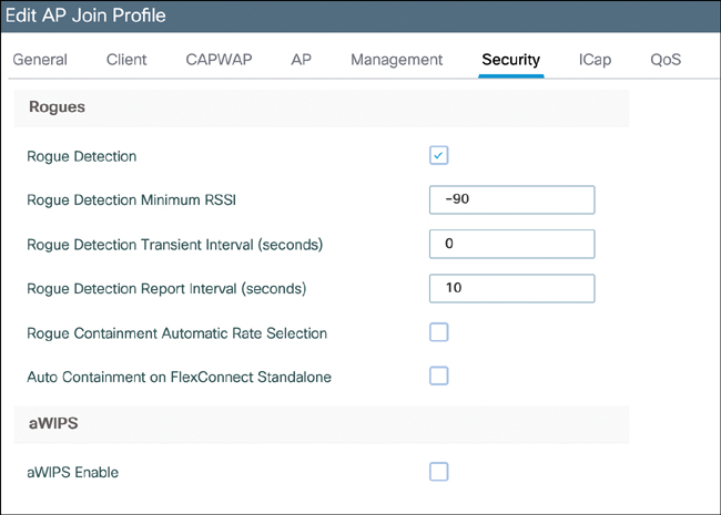
Adaptive WIPS
In the past, the controller was able to detect only low complexity attacks, and external servers were required to correlate attacks over different access points. The Catalyst 9800 has an integrated Adaptive Wireless Intrusion Prevention System (aWIPS), and although DNA Center gives a great dashboard for reporting and managing attacks, no device other than the WLC is required to run the attack detection.
The following attacks were detected as of IOS-XE 17.6:
- Authentication flood: An attacker could be sending 802.11 authentication frames with ever-changing client MAC addresses, therefore filling up the AP client table quickly.
- Association request flood and reassociation request flood: An attacker could be sending abusive association requests to the AP, having the same effect as the previous attack.
- Probe request flood: An attacker could be sending probe requests, forcing the AP to answer nonexistent clients with probe responses and wasting airtime.
- Disassociation flood: An attacker could contain legitimate clients by spoofing disassociation frames from the AP, forcing clients to associate again to regain connectivity.
- Broadcast disassociation flood: An attacker could send disassociation frames with the AP source MAC address with the broadcast destination MAC to disassociate all the clients connected at once.
- Deauthentication flood: Similar to the two previous attacks, sending deauthentication frames spoofed with the AP MAC typically disconnects clients.
- Broadcast deauthentication flood: This flood is similar to the preceding attack, but with a broadcast destination MAC.
- EAPOL-Logoff: An attacker could spoof a client MAC and send an EAPOL-Logoff frame, which terminates the 802.1X authentication status and has the effect of forcing the client to reauthenticate with 802.1X.
- Request to send flood: A wireless device could perform a denial of service if sending back-to-back requests-to-send frames in order to reerve the medium and prevent other devices from transmitting.
- Clear to send flood: Similar to the request to send flood, a clear to send flood prevents other wireless devices from getting a fair chance of accessing the medium.
- Fuzzed beacons and probes: These attacks detect when clients send invalid SSID lengths and fuzzed beacons and probe frames.
- PS Poll flood: A client could be sending too many PS Poll frames to ask for buffered traffic, therefore preventing everyone else from transmitting.
- Eapol-start flood: A client could be sending eapol-start, causing constant restarts of the 802.1X state machine and leaving many sessions opened.
- Beacon flood: An attacker could be sending dummy beacons from nonexistent APs to flood the airtime and make it hard for clients to find the right SSID.
- Probe response flood: An attacker could respond to probe requests on behalf of APs and therefore lure clients into believing wrong settings.
- Block ACK flood: An attacker could be flooding block ACKs to force the client to send retries.
- AirDrop: Apple offers the AirDrop feature, which allows you to send files directly between two devices on a separate channel, which could consume all the airtime on that channel.
- Malformed authentication and association frames, invalid MAC OUI (reserved by IEEE) and authentication failure flood: This alarm includes various malformation conditions of authentication and association frames as well as invalid MAC formats.
Cisco DNA Center has an optional Rogue Management application that gives you rogue management capabilities on top of allowing you to receive aWIPS reports. Click the menu icon and choose Assurance > Rogue and Awips . Choose aWIPS > Enable to enable aWIPS detection on all the APs.
Cisco DNA Center allows you to configure aWIPS profile to select which alarms you want to focus on. It also correlates all the alarms in an easy-to-read dashboard where you can replay a timeline slider showing the attacks for each time period (the 9800 WLC provides you only with raw alarm counts per AP). Last but not least, Cisco DNA Center also allows you to collect Intelligent Capture forensics of the attack.
On the WLC, you can verify the aWIPS status of an AP with show awips status <ap Radio MAC> and list all alarms with show awips alarm detailed. The Catalyst 9800 also offers the possibility to send aWIPS alarms (as well as regular rogue alarms) through syslog, which allows for another monitoring tool to receive the information.
Client Exclusion
A basic, yet efficient, method of limiting low-level attacks is to exclude misbehaving clients. Excluding means that for a given period of time (60 seconds by default, but this is configured in the advanced settings of the policy profile), the misbehaving client is completely ignored by the WLC:
no data traffic is passed
association requests are completely ignored.
You can configure the conditions for exclusion in Configuration > Security > Wireless Protection Policies. They mostly revolve around excessive attempts at “associating” or “authenticating” as well as “stealing the IP address” of another device.
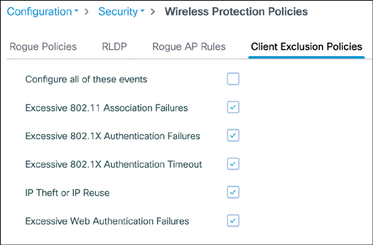
Summary
RF environments can be very challenging, and although 802.11 is a resilient protocol, it cannot operate optimally without a proper design or configuration. Cisco has got your back with a variety of features and constantly improving automated RF tuning. However, it is still critically important to make the right hardware purchasing decision, have good site survey data, mount APs properly, and configure appropiate settings, depending on your environment, to make the best out of your network. This chapter covered the basic antenna concepts and algorithm tuning details you need to have a wireless network running like clockwork.
more…
coming soon