⊹ 93. CCIE SDA ⊹
SDA Home LAB Deployment
SDA LISP Roles
ITR – Ingress Tunnel Router – devices which accepts traffic from the client and looks at transmitting to the destination.
ETR – Egress Tunnel Router – device which transmits traffic to the client, this is where destination client is attached.
These above roles of LISP would be on Fabric Edge node.
Example of Ping (I am omitting the full lookup against Map Resolver and RLOC etc):
Client A —> Switch A (ITR) —> Switch B (ETR) —> Client B
Reply:
Client A <— Switch A (ETR) <— Switch B (ITR) <— Client B
If a node has both roles ITR and ETR, that Fabric Edge switch is referenced as xTR
(P – Proxy) PITR and PETR would be the Border node which communicates with destinations outside the fabric, Similarly to the last example, one border node can have both roles and can be referenced as PxTR.
Traffic example: Client A —> Switch A (ITR) — Border A (PITR) —> Server A
Reply: Client A <— Switch A (ETR) <— Border A (PETR) <— Server A
If you look Proxy Egress tunnel router is actually inbound from the endpoint’s perspective and inbound means back in the direction of Fabric site and similarly Proxy Ingress Tunnel router is packet entering the fabric from endpoint
ESXI and VCenter Deployment
-: Z840 :-
Upgrade BIOS
Factory Reset BIOS
set controller mode to AHCI from RAID
enable Intel VTd under System Security section
-: ESXI DEPLOYMENT :-
VMware-VMvisor-Installer-7.0.0-15843807.x86_64
ESXi 7.0 keys
JJ2WR-25L9P-H71A8-6J20P-C0K3F
ESXI01.home.local
192.168.0.10
root
C0mplex30-
-: VCENTER DEPLOYMENT :-
Create following entries in host file
192.168.0.10 esxi01.home.local <<<<
192.168.0.11 vcenter.home.local <<<< This is checked from local machine when running VCSA setup to install vcenter, this check is different from vcenter A and PTR record lookup by installer, that is why DNS server on Windows server 2016 is needed
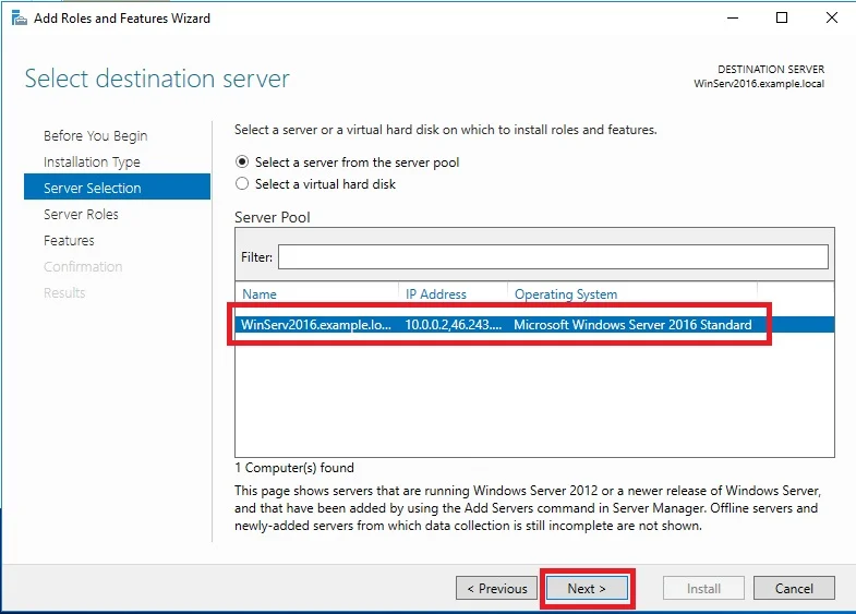
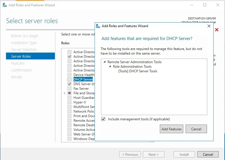
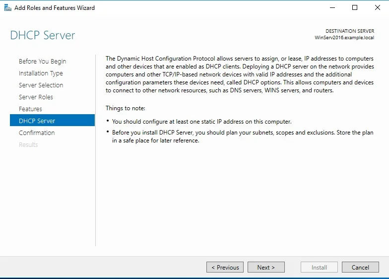
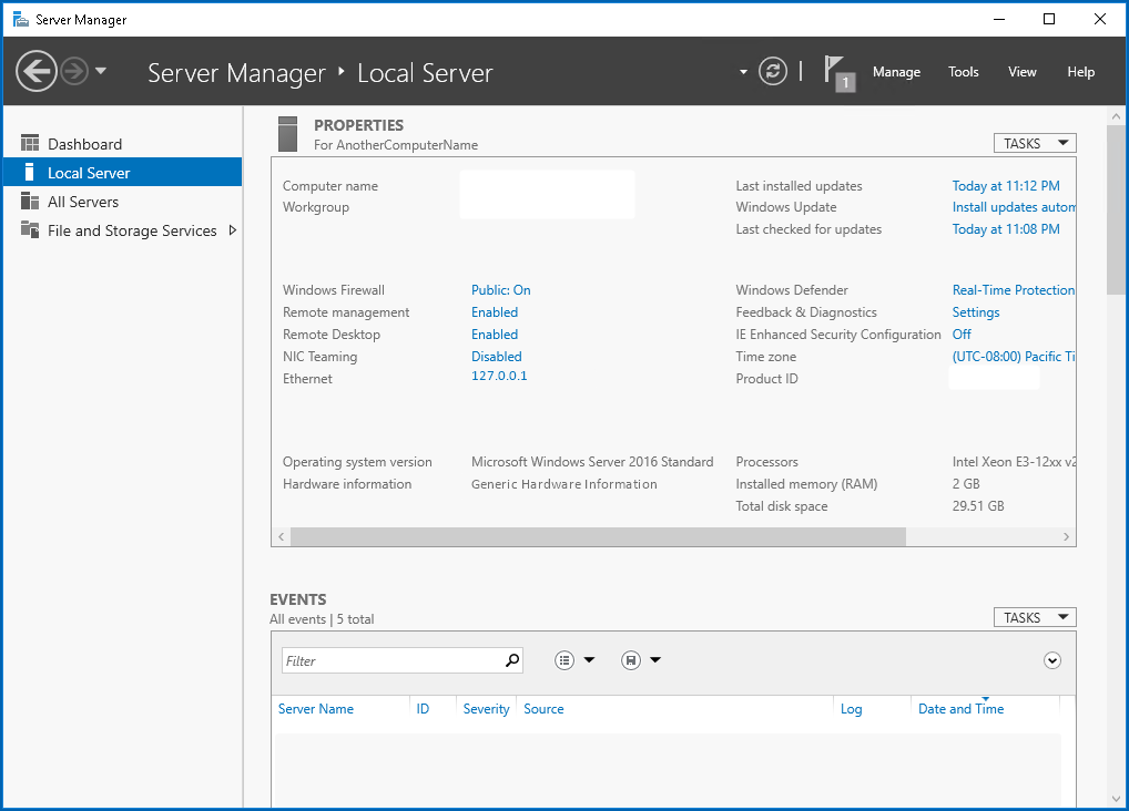
Bring up a winserver 2016 instance in eveng metal and configure DNS server on it
VMware-VCSA-all-7.0.0-16386292.iso
vCenter 7 keys
406DK-FWHEH-075K8-XAC06-0JH08
VCENTER.home.local
192.168.0.11
root
C0mplex30-
administrator@vsphere.local
C0mplex30-
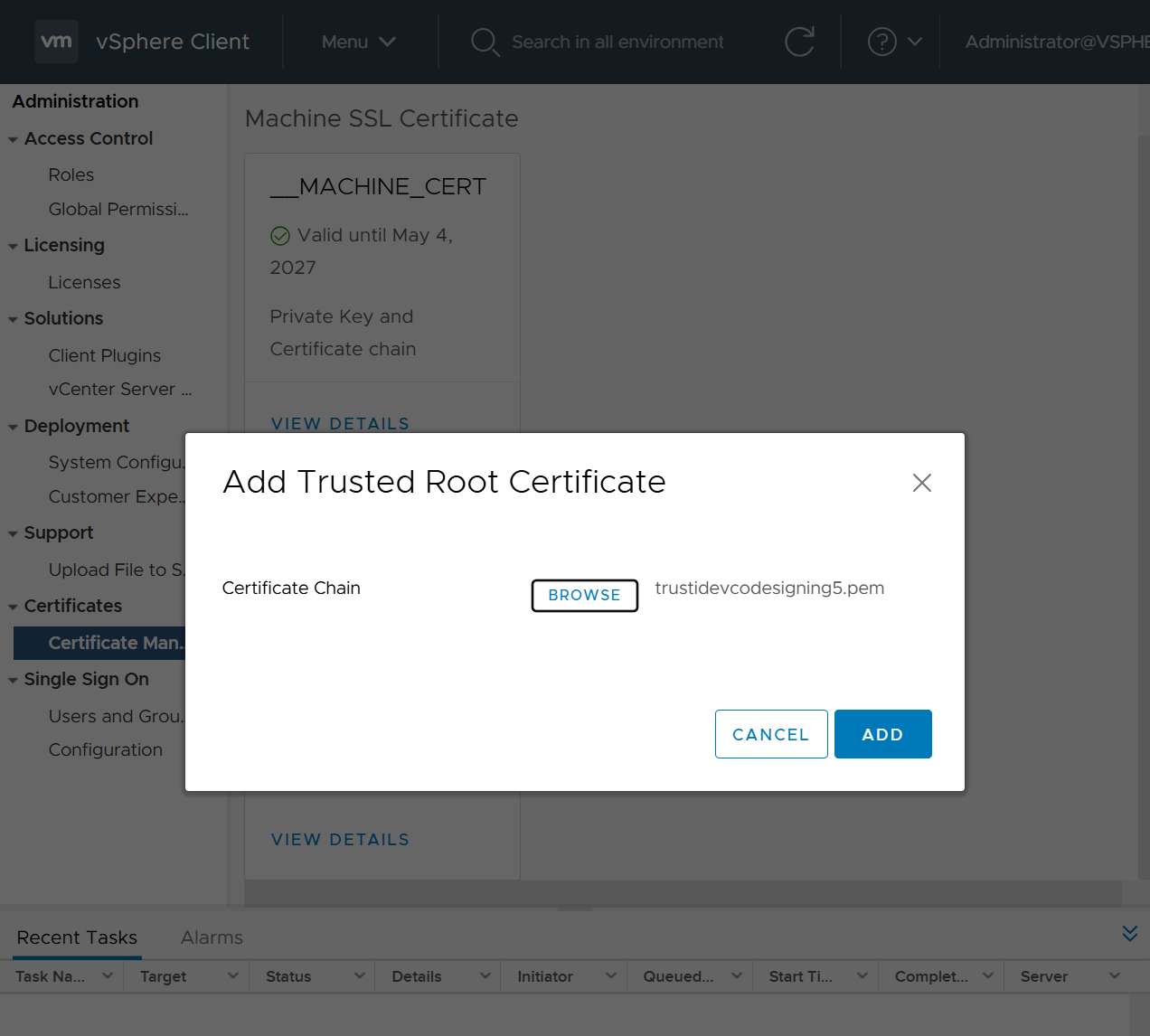
Import vcenter Certificates in Installation station
Because we are deploying appliance through VA launcher script, we need to import certificates of vcenter into local computer trusted root certificate’s store, go to https://vCenter_FQDN/certs/download.zip, download ZIP and extract all the certs and import them


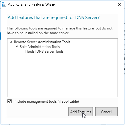
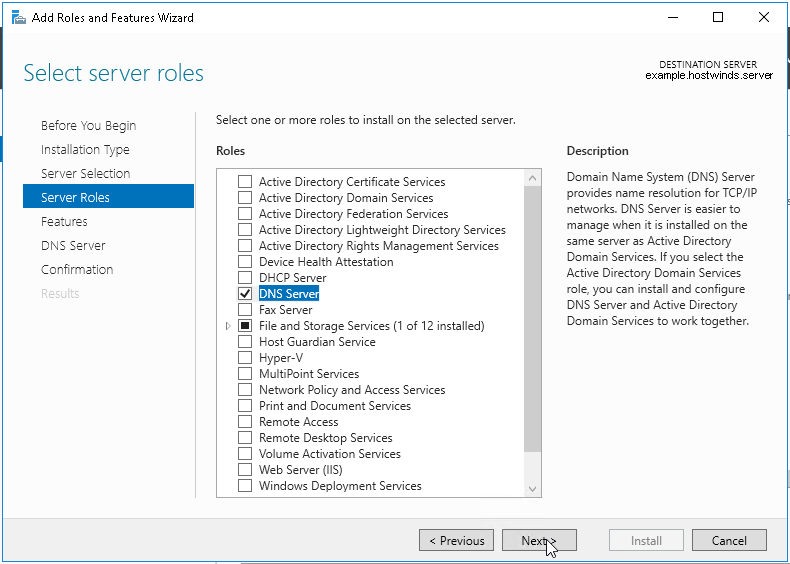
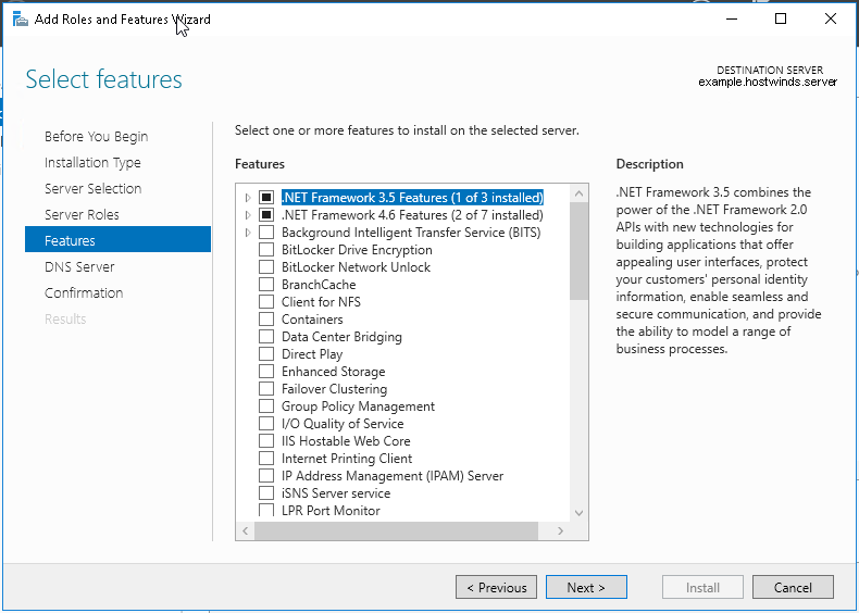
Windows Server DNS deployment

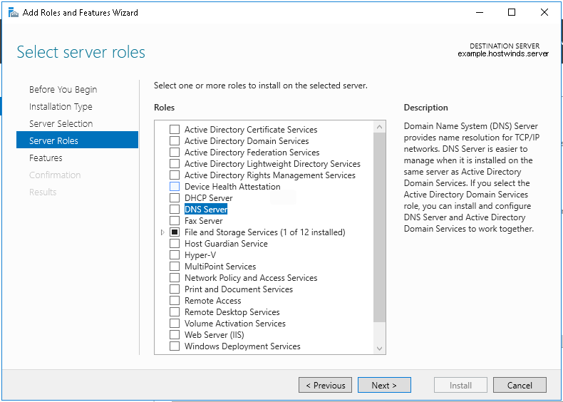

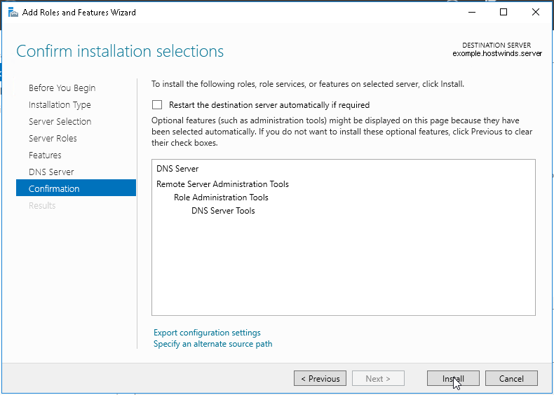
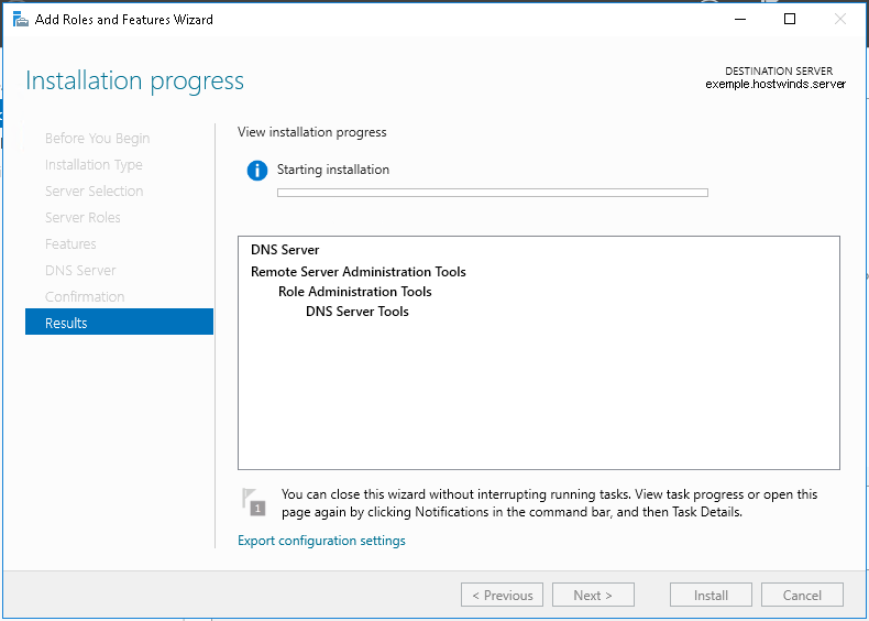
configure forward zone
configure reverse zone
create A record
vcenter.home.local 192.168.0.11
dnac.home.local 10.21.1.2
Windows 10 and VYOS deployment
Windows 10 VM
Create Windows 10 VM for VYOS deployment validation and internet access check
2 vCPUs
5GB RAM
25GB disk
admin/Test123
Pet name
dnac
City born in
dnac
City parents met
dnac
Assign only 192.168.0.200/24 and do not assign gateway 192.168.0.1
Disable IPv6 on the Windows VM interface
connect VM’s interface in vcenter
Go to Network folder and join the network
Share Downloads folder
copy wub and debloater to downloads folder
once all done then put network interface in DHCP again
VYOS deployment
2 CPUs
RAM 2 GB
4 GB Disk
! Install open-vm-tools on VY OS gateway

vyos@vy-gateway:~$ sudo vim /etc/apt/sources.list

! press esc to make sure we are in normal mode
! press i to go in insert mode

! enter first line
deb http://deb.debian.org/debian bullseye main contrib

! press escape
! enter ":wq"

vyos@vy-gateway:~$ sudo cat /etc/apt/sources.list
deb http://deb.debian.org/debian bullseye main contrib

! Update failed because of no DNS resolution
vyos@vy-gateway:~$ sudo apt update
Ign:1 http://deb.debian.org/debian bullseye InRelease
Ign:1 http://deb.debian.org/debian bullseye InRelease
Ign:1 http://deb.debian.org/debian bullseye InRelease
Err:1 http://deb.debian.org/debian bullseye InRelease
  System error resolving 'deb.debian.org:http' - getaddrinfo (16: Device or resource busy)
Reading package lists... Done
Building dependency tree... Done
Reading state information... Done
All packages are up to date.
W: Failed to fetch http://deb.debian.org/debian/dists/bullseye/InRelease  System error resolving 'deb.debian.org:http' - getaddrinfo (16: Device or resource busy)
W: Some index files failed to download. They have been ignored, or old ones used instead.

vyos@vy-gateway:~$ sudo bash

root@vy-gateway:/home/vyos# sudo bash -c 'cat > /etc/resolv.conf <<EOF
nameserver 8.8.8.8
nameserver 1.1.1.1
EOF'

root@vy-gateway:/home/vyos# cat /etc/resolv.conf
nameserver 8.8.8.8
nameserver 1.1.1.1

root@vy-gateway:/home/vyos# apt update
Get:1 http://deb.debian.org/debian bullseye InRelease [75.1 kB]
Get:2 http://deb.debian.org/debian bullseye/main amd64 Packages [8,066 kB]
Get:3 http://deb.debian.org/debian bullseye/main Translation-en [6,235 kB]
Get:4 http://deb.debian.org/debian bullseye/contrib amd64 Packages [50.4 kB]
Get:5 http://deb.debian.org/debian bullseye/contrib Translation-en [46.9 kB]
Fetched 14.5 MB in 4s (4,084 kB/s)
Reading package lists... Done
Building dependency tree... Done
Reading state information... Done
8 packages can be upgraded. Run 'apt list --upgradable' to see them.

! install should work now
root@vy-gateway:/home/vyos# apt install -y open-vm-tools
Reading package lists... Done
Building dependency tree... Done
Reading state information... Done
The following additional packages will be installed:
  libdrm-common libdrm2 libmspack0 libssl1.1 libxmlsec1 libxmlsec1-openssl
  libxslt1.1
Suggested packages:
  open-vm-tools-desktop cloud-init
Recommended packages:
  zerofree
The following NEW packages will be installed:
  libdrm-common libdrm2 libmspack0 libssl1.1 libxmlsec1 libxmlsec1-openssl
  libxslt1.1 open-vm-tools
0 upgraded, 8 newly installed, 0 to remove and 8 not upgraded.
Need to get 2,793 kB of archives.
After this operation, 8,598 kB of additional disk space will be used.
Get:1 http://deb.debian.org/debian bullseye/main amd64 libdrm-common all 2.4.104-1 [14.9 kB]
Get:2 http://deb.debian.org/debian bullseye/main amd64 libdrm2 amd64 2.4.104-1 [41.5 kB]
Get:3 http://deb.debian.org/debian bullseye/main amd64 libmspack0 amd64 0.10.1-2 [50.3 kB]
Get:4 http://deb.debian.org/debian bullseye/main amd64 libssl1.1 amd64 1.1.1w-0+deb11u1 [1,566 kB]
Get:5 http://deb.debian.org/debian bullseye/main amd64 libxslt1.1 amd64 1.1.34-4+deb11u1 [240 kB]
Get:6 http://deb.debian.org/debian bullseye/main amd64 libxmlsec1 amd64 1.2.31-1 [149 kB]
Get:7 http://deb.debian.org/debian bullseye/main amd64 libxmlsec1-openssl amd64 1.2.31-1 [100.0 kB]
Get:8 http://deb.debian.org/debian bullseye/main amd64 open-vm-tools amd64 2:11.2.5-2+deb11u3 [632 kB]
Fetched 2,793 kB in 0s (10.4 MB/s)
Preconfiguring packages ...
Selecting previously unselected package libdrm-common.
(Reading database ... 84389 files and directories currently installed.)
Preparing to unpack .../0-libdrm-common_2.4.104-1_all.deb ...
Unpacking libdrm-common (2.4.104-1) ...
Selecting previously unselected package libdrm2:amd64.
Preparing to unpack .../1-libdrm2_2.4.104-1_amd64.deb ...
Unpacking libdrm2:amd64 (2.4.104-1) ...
Selecting previously unselected package libmspack0:amd64.
Preparing to unpack .../2-libmspack0_0.10.1-2_amd64.deb ...
Unpacking libmspack0:amd64 (0.10.1-2) ...
Selecting previously unselected package libssl1.1:amd64.
Preparing to unpack .../3-libssl1.1_1.1.1w-0+deb11u1_amd64.deb ...
Unpacking libssl1.1:amd64 (1.1.1w-0+deb11u1) ...
Selecting previously unselected package libxslt1.1:amd64.
Preparing to unpack .../4-libxslt1.1_1.1.34-4+deb11u1_amd64.deb ...
Unpacking libxslt1.1:amd64 (1.1.34-4+deb11u1) ...
Selecting previously unselected package libxmlsec1:amd64.
Preparing to unpack .../5-libxmlsec1_1.2.31-1_amd64.deb ...
Unpacking libxmlsec1:amd64 (1.2.31-1) ...
Selecting previously unselected package libxmlsec1-openssl:amd64.
Preparing to unpack .../6-libxmlsec1-openssl_1.2.31-1_amd64.deb ...
Unpacking libxmlsec1-openssl:amd64 (1.2.31-1) ...
Selecting previously unselected package open-vm-tools.
Preparing to unpack .../7-open-vm-tools_2%3a11.2.5-2+deb11u3_amd64.deb ...
Unpacking open-vm-tools (2:11.2.5-2+deb11u3) ...
Setting up libssl1.1:amd64 (1.1.1w-0+deb11u1) ...
Setting up libmspack0:amd64 (0.10.1-2) ...
Setting up libxslt1.1:amd64 (1.1.34-4+deb11u1) ...
Setting up libxmlsec1:amd64 (1.2.31-1) ...
Setting up libdrm-common (2.4.104-1) ...
Setting up libxmlsec1-openssl:amd64 (1.2.31-1) ...
Setting up libdrm2:amd64 (2.4.104-1) ...
Setting up open-vm-tools (2:11.2.5-2+deb11u3) ...
Created symlink /etc/systemd/system/vmtoolsd.service → /lib/systemd/system/open-vm-tools.service.
Created symlink /etc/systemd/system/multi-user.target.wants/open-vm-tools.service → /lib/systemd/system/open-vm-tools.service.
Created symlink /etc/systemd/system/open-vm-tools.service.requires/vgauth.service → /lib/systemd/system/vgauth.service.
Processing triggers for libc-bin (2.36-9+deb12u10) ...
localepurge: Disk space freed:      0 KiB in /usr/share/locale
localepurge: Disk space freed:      0 KiB in /usr/share/man
localepurge: Disk space freed:      0 KiB in /usr/share/aptitude
localepurge: Disk space freed:      0 KiB in /usr/share/vim/vim90/lang

Total disk space freed by localepurge: 0 KiB

root@vy-gateway:/home/vyos#
vyos/C0mplex30
Install from live image
install image
show configuration
show configuration commands

configure
set interfaces ethernet eth0 address '192.168.0.12/24'
set interfaces ethernet eth0 description 'home'

set interfaces ethernet eth1 address '172.16.25.1/24'
set interfaces ethernet eth1 description 'mgmt'

set interfaces ethernet eth2 address '10.21.1.1/24'
set interfaces ethernet eth2 description 'data'


show interface ethernet
show interface ethernet eth0
show interface ethernet eth0 physical

set protocols static route 0.0.0.0/0 next-hop 192.168.0.1 distance '1'
set service ssh port '22'
set system host-name 'vy-gateway'

commit
save
vcenter
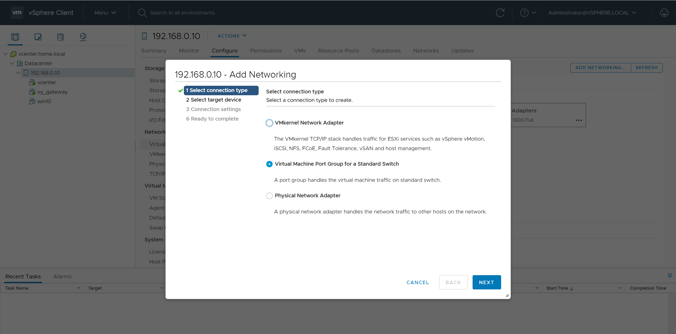
edit host and create a new standard switch and call it mgmt
edit host and create a new standard switch and call it data
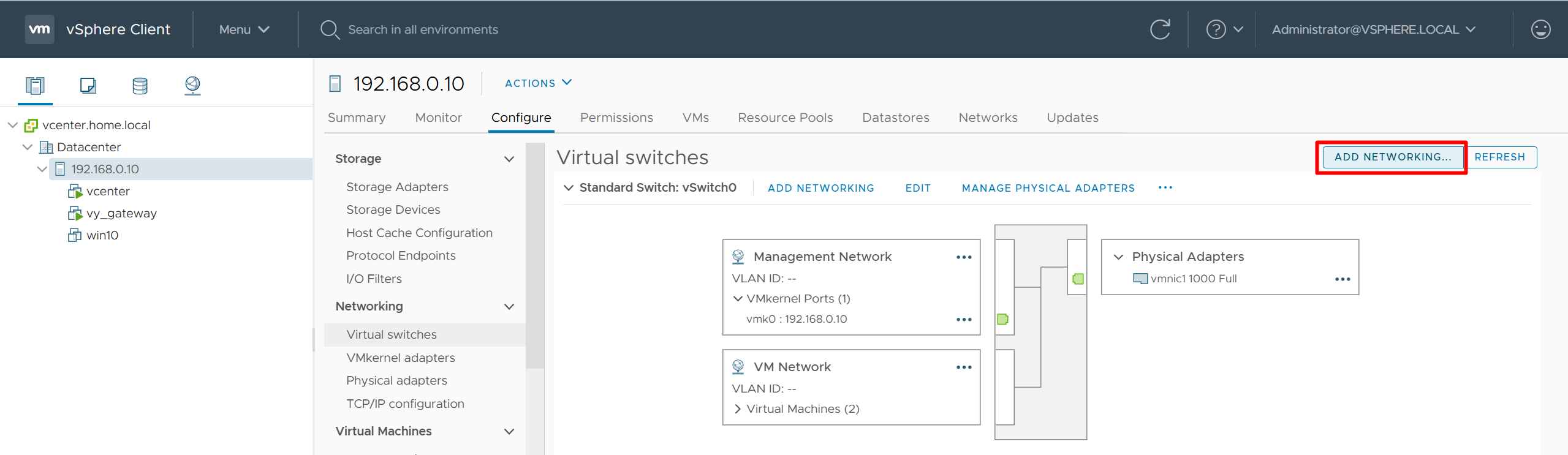
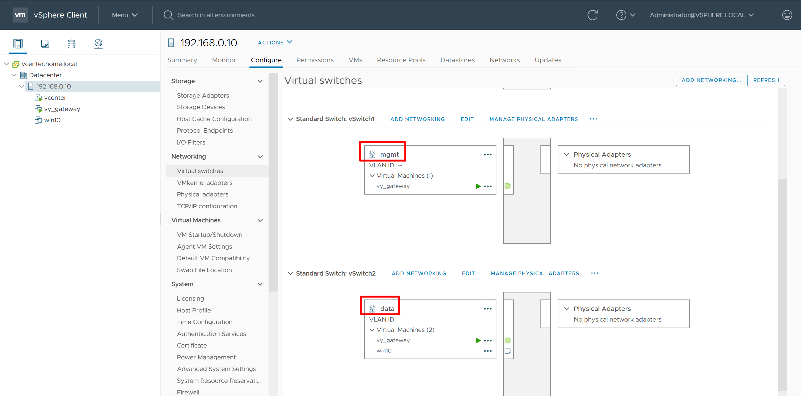
add 2nd interface for vy-gateway into mgmt
add 3rd interface for vy-gateway into data

home router
Add routes for networks 10.21.1.0/24 and 172.16.25.0/24

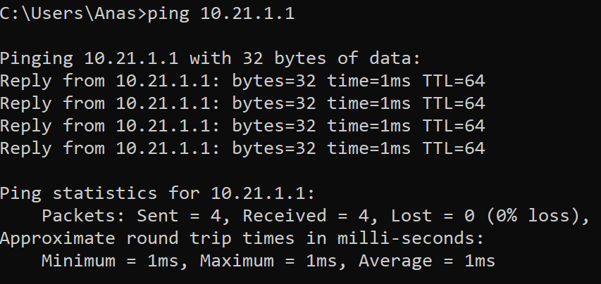
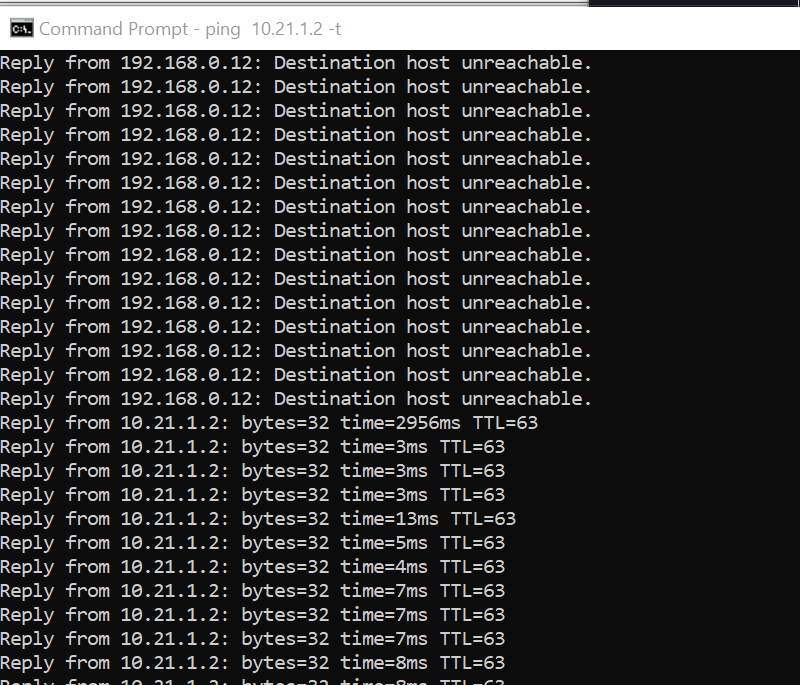
vyos routing is reachable
Cisco Catalyst Center 2.3.7.x on ESXi Deployment – Part 1
Virtual Machine Minimum Requirements
| Feature | Description |
|---|---|
| Virtualization platform and hypervisor | VMware vSphere (which includes ESXi and vCenter Server) 7.0.x or later, including all patches. |
| Processors | Intel Xeon Scalable server processor (Cascade Lake or newer) or AMD EPYC Gen2 with 2.1 GHz or better clock speed.32 vCPUs with 64-GHz reservation must be dedicated to the VM. |
| Memory | 256-GB DRAM with 256-GB reservation must be dedicated to the VM. |
| Storage | 3-TB solid-state drive (SSD).If you plan to create backups of your virtual appliance, also reserve additional datastore space. For information, see “Backup Server Requirements” in the Cisco Catalyst Center on ESXi Administrator Guide. |
| I/O Bandwidth | 180 MB/sec. |
| Input/output operations per second (IOPS) rate | 2000-2500, with less than 5 ms of I/O completion latency. |
| Latency | Catalyst Center on ESXi to network device connectivity: 200 ms. |
Scale numbers are different
for example maximum number of devices supported in non-fabric deployment is 1000 and maximum number of devices in fabric deployment is 2000, for more info
https://www.cisco.com/c/en/us/td/docs/cloud-systems-management/network-automation-and-management/catalyst-center/catalyst-center-va/esxi/2-3-7/deployment-guide/b_cisco_catalyst_center_237x_on_esxi_deployment_guide.html
Cisco Catalyst Assurance uses near real-time streaming analytics, which requires heavy resource usage. When operating Catalyst Center on ESXi close to maximum scale, this functionality may be impacted by uncontrolled external events, such as host resource oversubscriptions and edge use cases that result in a resource usage spike. A number of things can indicate that these events are taking place, such as slow performance, data processing gaps, high I/O latency, and a CPU readiness percentage that’s higher than normal.
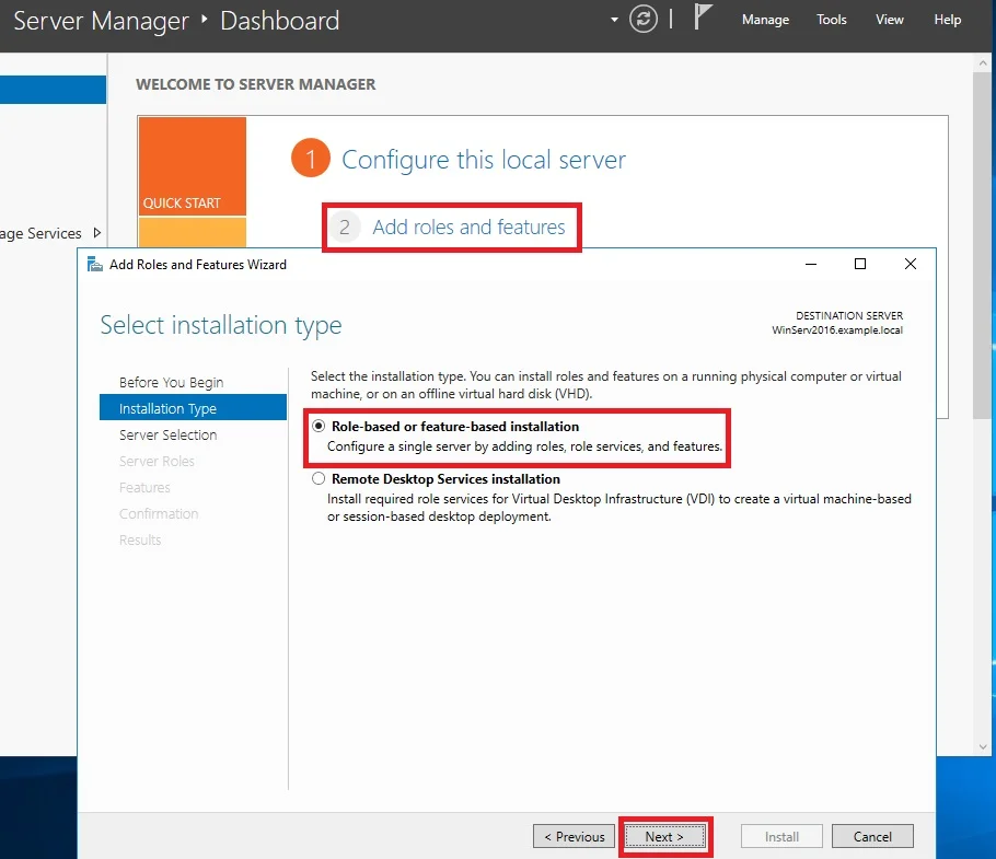
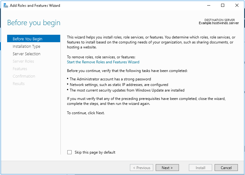
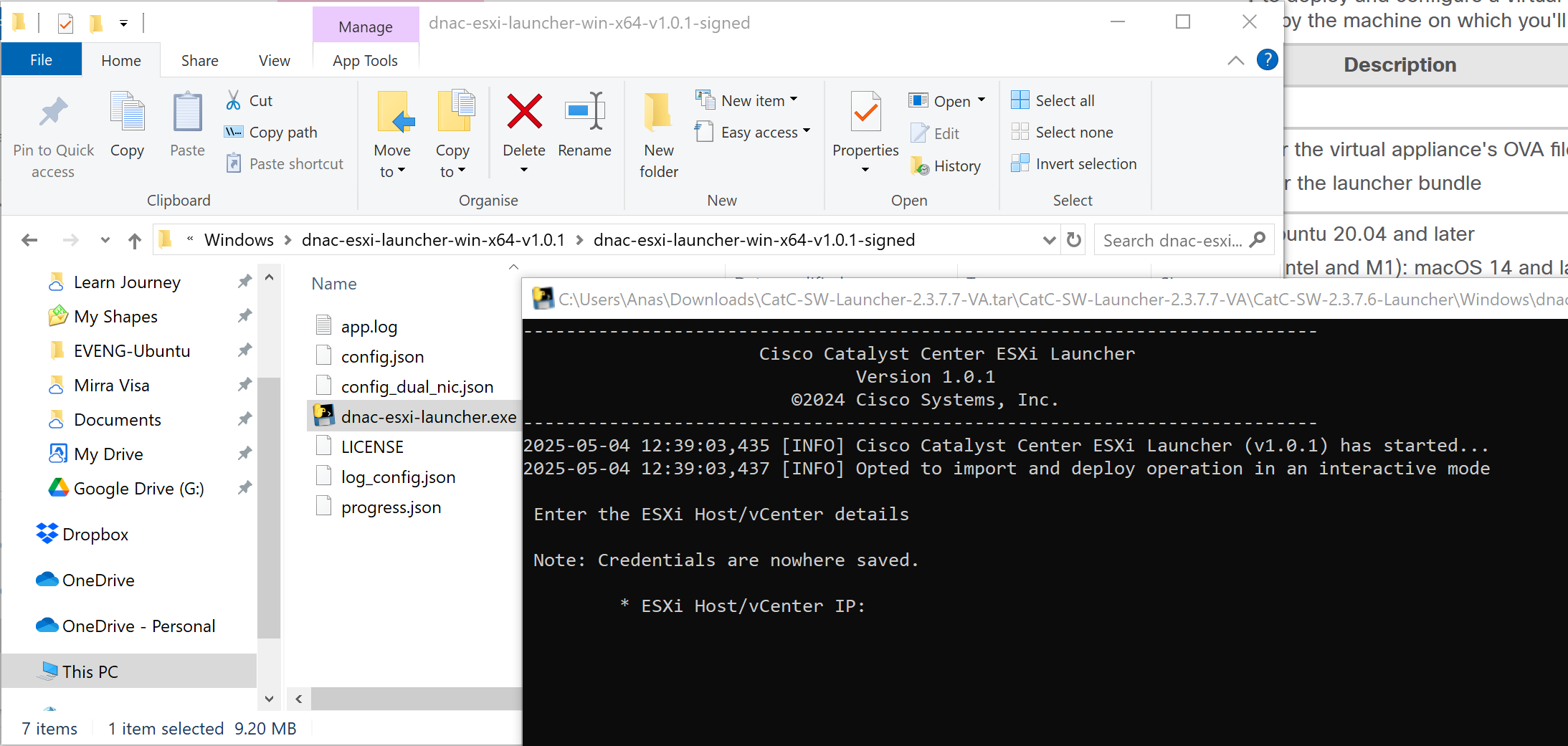
Catalyst Center VM can be deployed using Catalyst Center VA Launcher
Import the IdenTrust Certificate Chain
The Catalyst Center on ESXi OVA file is signed with an IdenTrust CA certificate, which is not included in VMware’s default truststore. As a result, the Deploy OVF Template wizard’s Review details page will indicate that you are using an invalid certificate while completing the wizard. You can prevent this by importing the IdenTrust certificate chain to the host or cluster on which you want to deploy the OVA file.

Cat center requires access to following URLs during install
| In order to… | …Catalyst Center on ESXi must access these URLs and FQDNs |
|---|---|
| Download updates to the system and application package software; submit user feedback to the product team. | Recommended: *.ciscoconnectdna.com:4431Customers who want to avoid wildcards can specify these URLs instead:https://www.ciscoconnectdna.comhttps://cdn.ciscoconnectdna.comhttps://registry.ciscoconnectdna.comhttps://registry-cdn.ciscoconnectdna.com |
| Catalyst Center on ESXi update package. | https://*.ciscoconnectdna.com/**.cloudfront.net*.tesseractcloud.com |
| Smart Account and SWIM software downloads. | https://apx.cisco.comhttps://cloudsso.cisco.com/as/token.oauth2https://*.cisco.com/*https://download-ssc.cisco.com/ |
| Authenticate with the cloud domain. | https://dnaservices.cisco.com |
| Integrate with ThousandEyes. | *.awsglobalaccelerator.comapi.thousandeyes.com |
| Manage Cisco Enterprise Network Function Virtualization Infrastructure Software (NFVIS) devices. | *.amazonaws.com |
| Collect product telemetry. | https://data.pendo.io |
| Allow API calls to enable access to Cisco CX Cloud Success Tracks. Otherwise, the enhancements made to extended configuration-based scanning for the Security Advisories, Bug Identifier, and EOX features that Machine Reasoning Engine (MRE) supports will not operate as expected. | https://api-cx.cisco.com |
| Integrate with Webex. | http://analytics.webexapis.comhttps://webexapis.com |
| User feedback. | https://dnacenter.uservoice.com |
| Integrate with Cisco Meraki. | Recommended: *.meraki.com:443Customers who want to avoid wildcards can specify these URLs instead:dashboard.meraki.com:443api.meraki.com:443n63.meraki.com:443 |
| Check SSL/TLS certificate revocation status using OCSP/CRL. | http://validation.identrust.com/crl/hydrantidcao1.crlhttp://commercial.ocsp.identrust.comNote These URLs should be reachable both directly and through the proxy server that’s configured for Catalyst Center. |
| Allow Cisco authorized specialists to collect troubleshooting data when Catalyst Center on ESXi Remote Support functionality is enabled. | wss://prod.radkit-cloud.cisco.com:443 |
| Integrate with cisco.com and Cisco Smart Licensing. | *.cisco.com:443Customers who want to avoid wildcards can specify these URLs instead:software.cisco.comcloudsso.cisco.comcloudsso1.cisco.comcloudsso2.cisco.comapiconsole.cisco.comapi.cisco.comapx.cisco.comsso.cisco.comapmx-prod1-vip.cisco.comapmx-prod2-vip.cisco.comtools.cisco.comtools1.cisco.comtools2.cisco.comsmartreceiver.cisco.com |
| Connect to the Network-Based Application Recognition (NBAR) cloud. | prod.sdavc-cloud-api.com:443 |
| Render accurate information in site and location maps. | www.mapbox.com*.tiles.mapbox.com/* :443. For a proxy, the destination is *.tiles.mapbox.com/* |
| For Cisco AI Network Analytics data collection, configure your network or HTTP proxy to allow outbound HTTPS (TCP 443) access to the cloud hosts. | https://api.use1.prd.kairos.ciscolabs.com (US East Region)https://api.euc1.prd.kairos.ciscolabs.com (EU Central Region) |
| Access a menu of interactive help flows that let you complete specific tasks from the GUI. | https://ec.walkme.com |
| Access the licensing service. | https://swapi.cisco.com |
| Integrate with Cisco Spaces. | https://dnaspaces.iohttps://dnaspaces.euhttps://ciscospaces.sg |
ciscoconnectdna.com is a cisco domain
Windows server NTP server
https://www.domat-int.com/en/how-to-configure-a-local-ntp-server
https://docs.litmus.io/litmusedge/product-features/system/network/configure-dns-ntp-servers/configure-local-ntp-server
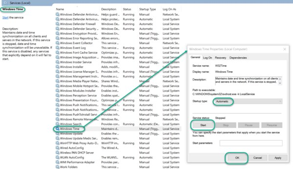
Configure the Windows Time Service
In the File Explorer, navigate to: Control Panel\System and Security\Administrative Tools
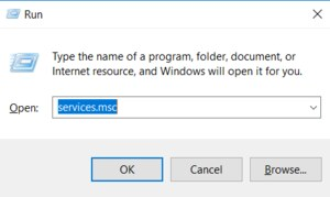
Double-click Services. This same task can be completed by entering services.msc in the Windows Run dialog (Windows Key + R).
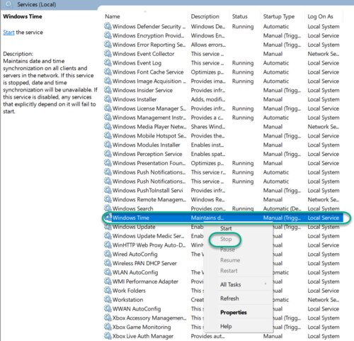
In the Services list, right-click on Windows Time and click Stop.
Note: The Windows Time service may already be stopped. In this case, skip this step and go to the next step to Update the Windows Registry
Update the Windows Registry to Create a Local NTP Service
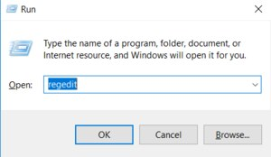
Launch Windows Run (Windows Key + R).
Enter regedit and click OK.
Navigate to the registry key: Computer\HKEY_LOCAL_MACHINE\SYSTEM\CurrentControlSet\Services\W32Time\Parameters
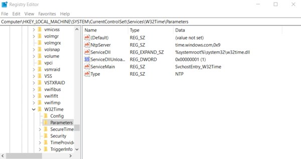
If you do not see LocalNTP REG_DWORD in the list, create it using the following steps.
Right-click in the Registry Editor, select New, select DWORD and enter LocalNTP (note that this name is case sensitive).
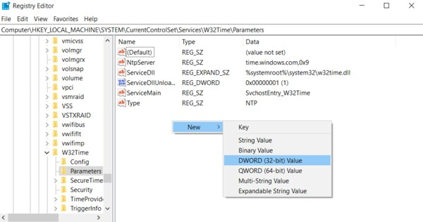
Double-click LocalNTP, change the Value data to 1, select a Base of Hexadecimal , and click OK.
Do not close the Registry Editor because it is used in the following steps.
Update the Windows Registry to Configure the Time Provider
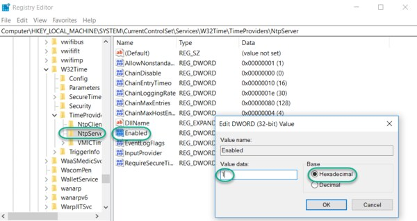
Navigate to the registry key: Computer\HKEY_LOCAL_MACHINE\SYSTEM\CurrentControlSet\Services\W32Time\TimeProviders
Select NtpServer, double-click Enabled, change the Value Data to 1, select a Base of Hexadecimal and click OK.
Do not close the Registry Editor because it is used in the following steps.
Update the Windows Registry to Configure the Announce Flags
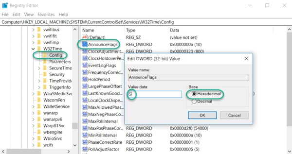
Navigate to the registry key: Computer\HKEY_LOCAL_MACHINE\SYSTEM\CurrentControlSet\Services\W32Time\Config
Double-click AnnounceFlags, change the Value data to 5, select a Base of Hexadecimal, and click OK.
Close the Registry Editor.
Start the Local Windows NTP Time Service
In the File Explorer, navigate to: Control Panel\System and Security\Administrative Tools
Double-click Services.
In the Services list, right-click on Windows Time and configure the following settings:
Startup type: Automatic
Service Status: Start
OK
Finally, enable UDP port 123 on the Windows firewall for incoming connections.
In Search find Firewall in Windows Defender…
Go to Incoming rules
In the right column, select New rule…
Select the rule Port
Enter UDP port 123 and click Next
Select Allow connection and click Next
Select all domains
Enter the rule name, e.g. Local NTP server, and click Finish.
The local NTP Time Server configuration is now complete. You now can synchronize the time of other computers and devices on your local network.
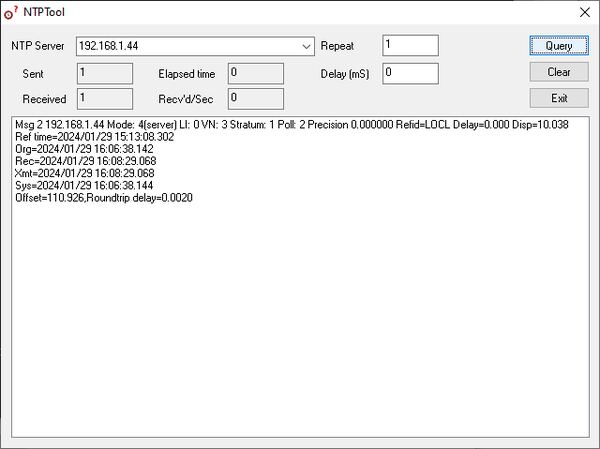
To test the server functionality from another PC (e.g. a service notebook) use for example the NTP Server Test Tool:
https://www.ntp-time-server.com/ntp-software/ntp-server-tool.html
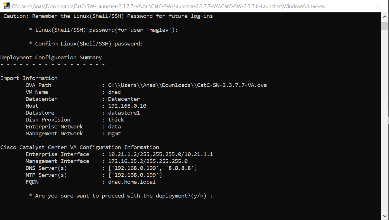
DNAC deployment

C:\\Users\\Anas\\Downloads\\CatC-SW-2.3.7.7-VA.ova
Add 2 backslashes for OVA path to escape it
vcenter.home.local
administrator@vsphere.local
C0mplex30-
C:\\Users\\Anas\\Desktop\\CatC-SW-2.3.7.7-VA.ova

dnac
thick
2

data
mgmt

10.21.1.2
255.255.255.0
10.21.1.1

Mgmt interface:
172.16.25.2
255.255.255.0

DNS
172.16.32.11

NTP
172.16.32.11

dnac.home.local
maglev
C0mplex30


maglev will load containers
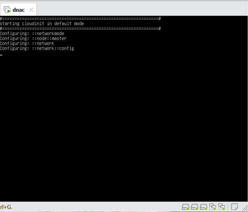
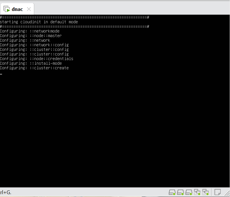
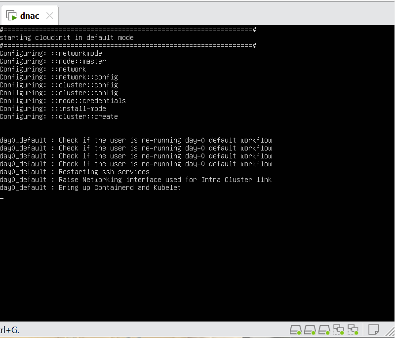


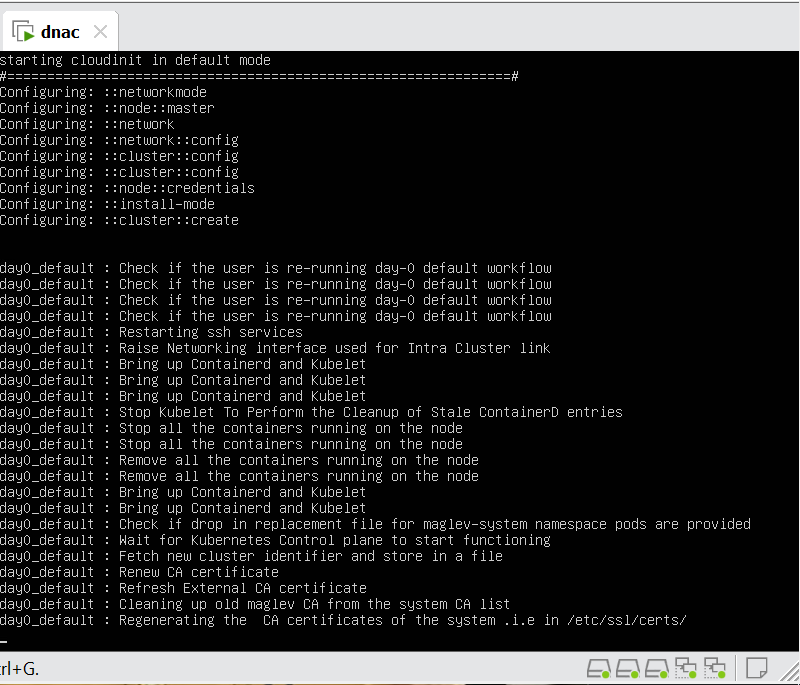
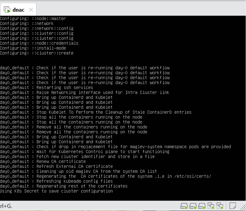

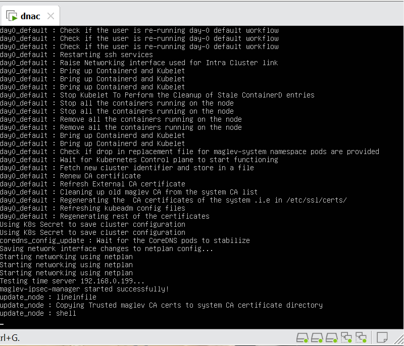
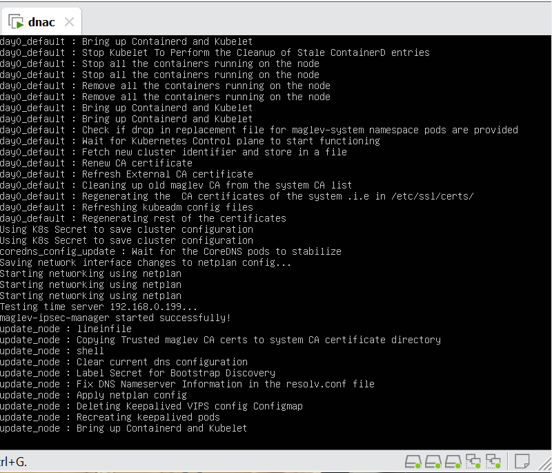
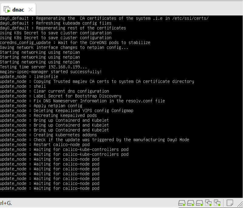
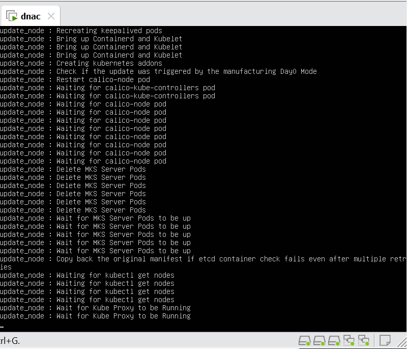
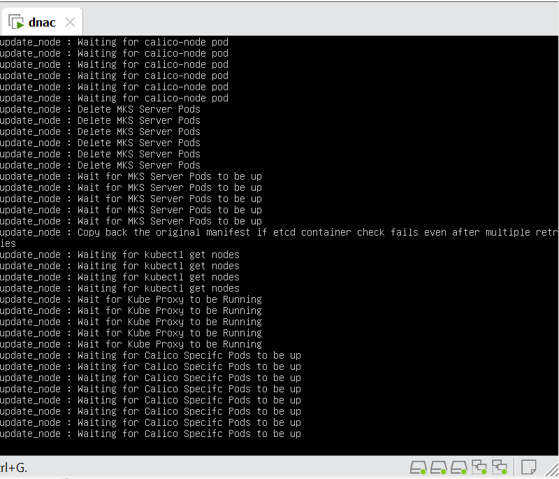
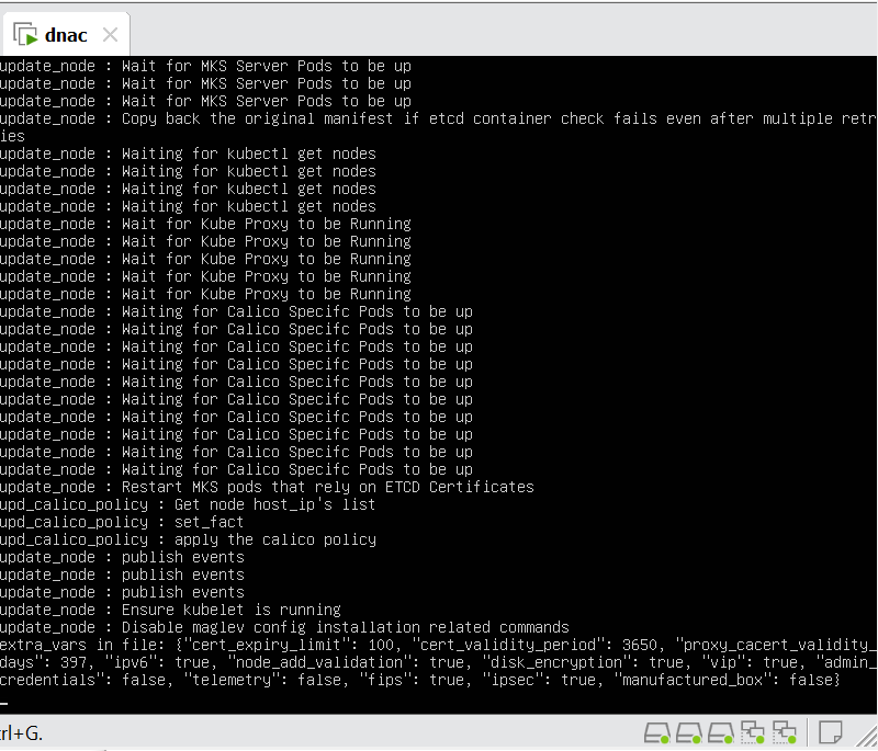

wait 30 mins before GUI shows up
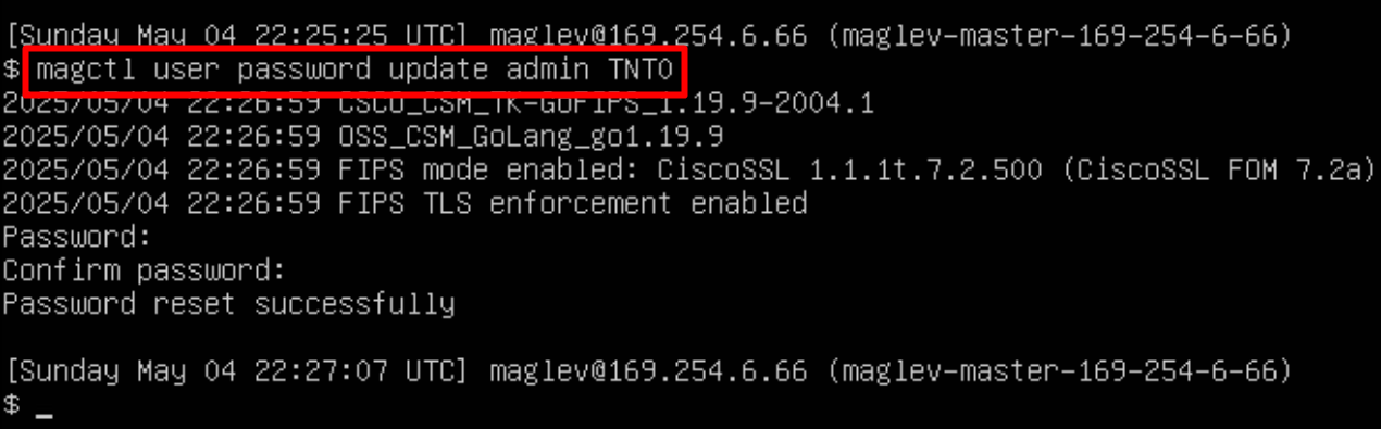
In case unable to login
Login to CLI as maglev on VM’s console and reset password for admin
Logins
Default GUI login admin/maglev1@3
Login to create account admin_anas/C0mplex30
SSH login on port 2222 maglev/C0mplex30
DNAC VM Console login maglev/C0mplex30
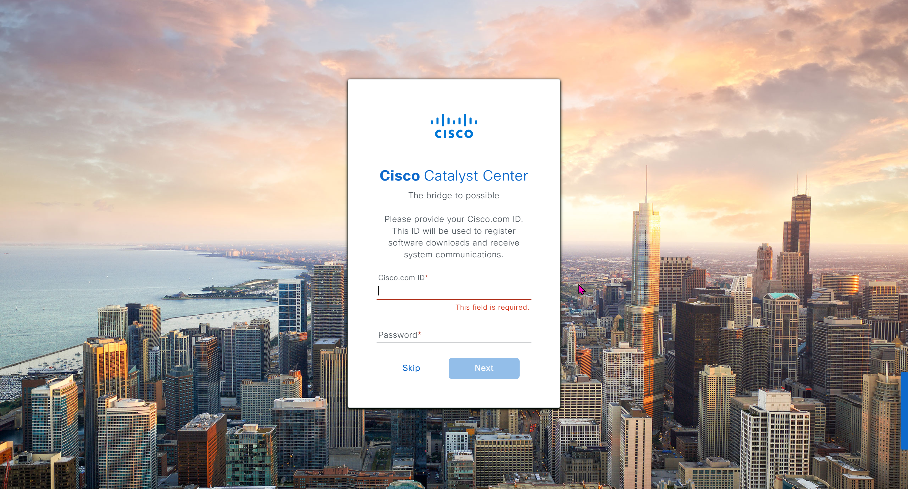
Initial Login

provide user here that will be super admin such as admin_anas
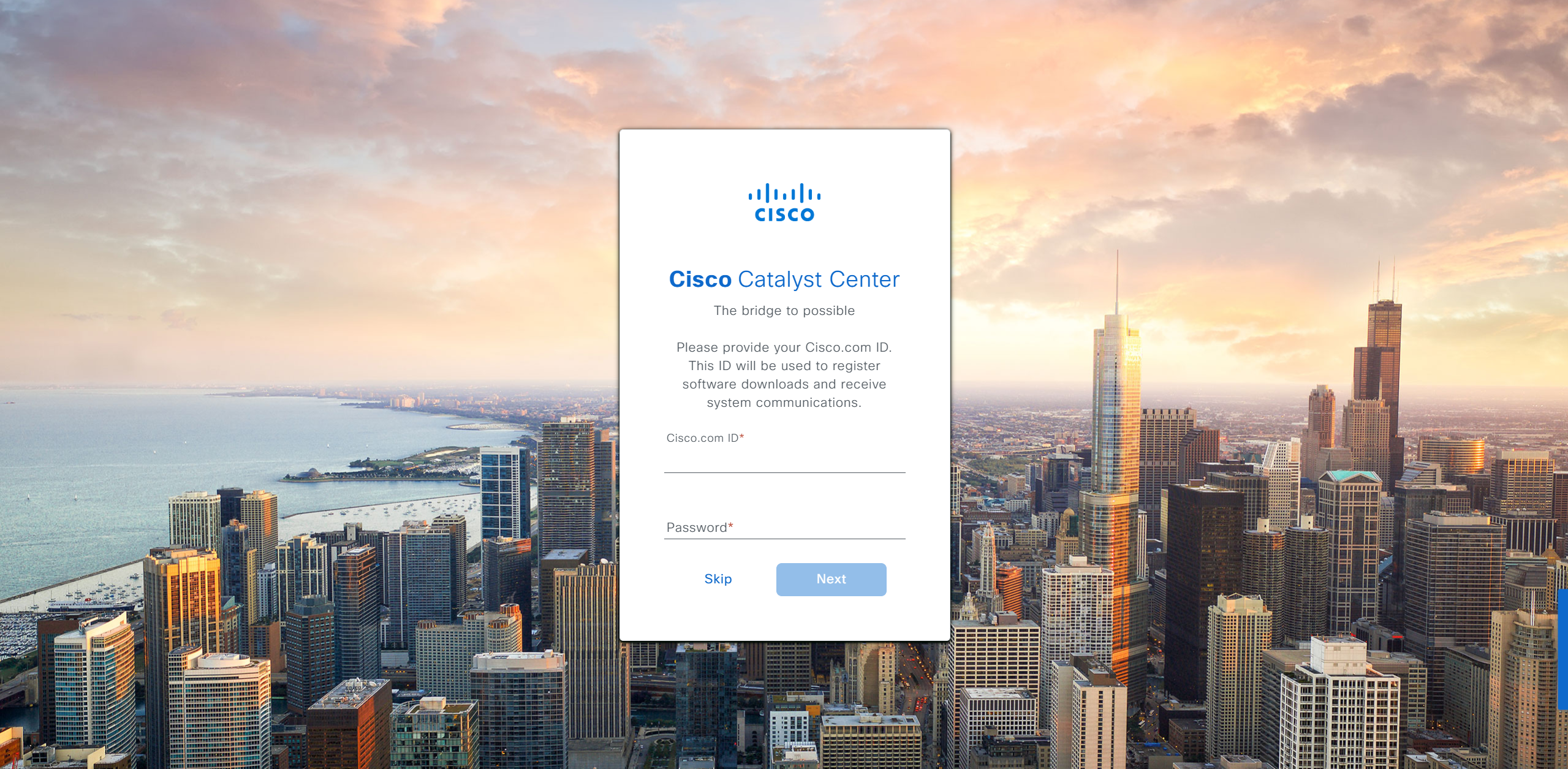
provide your cco in email and not personal email
admin_anas/C0mplex30
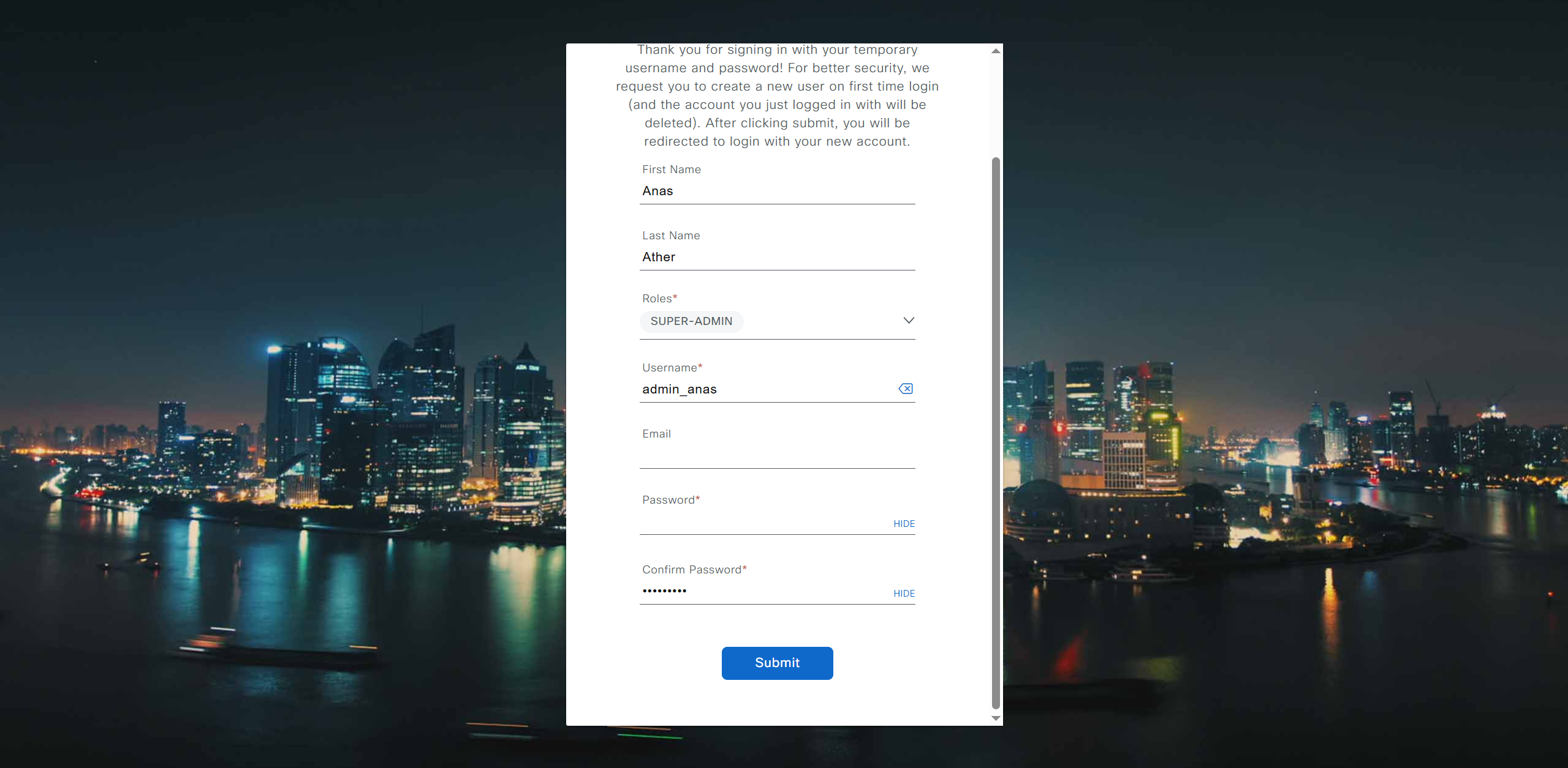
provide company’s CCO details here that has contract and active cco – this is very important otherwise packages will not work

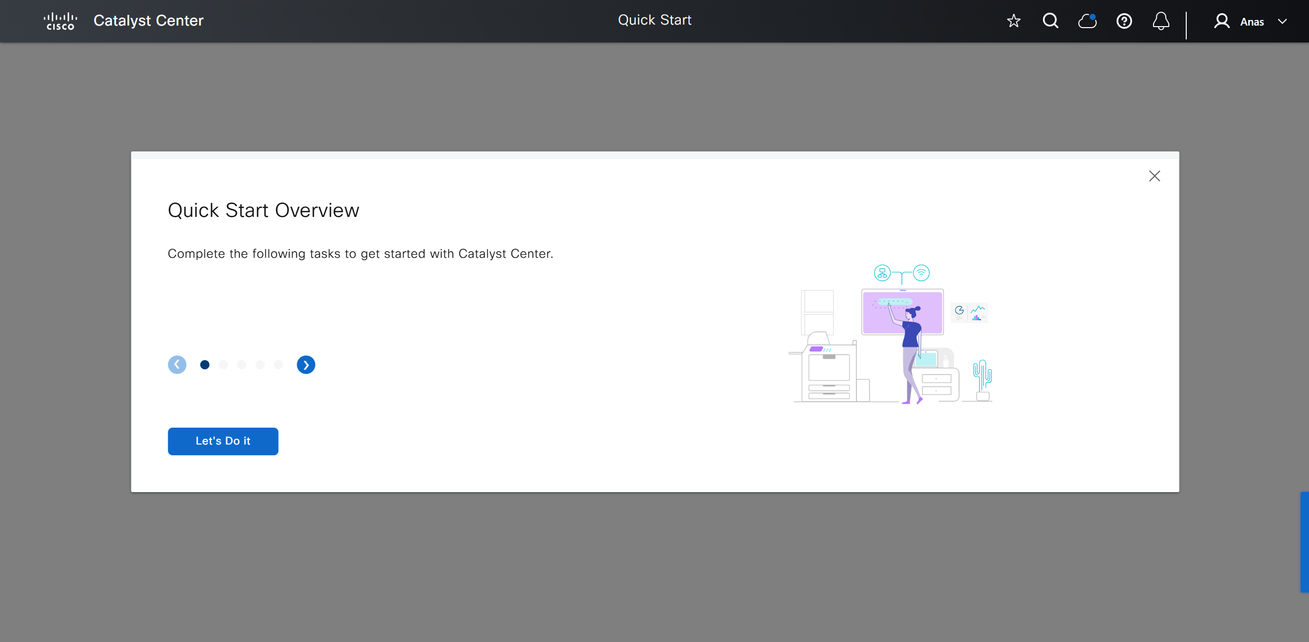


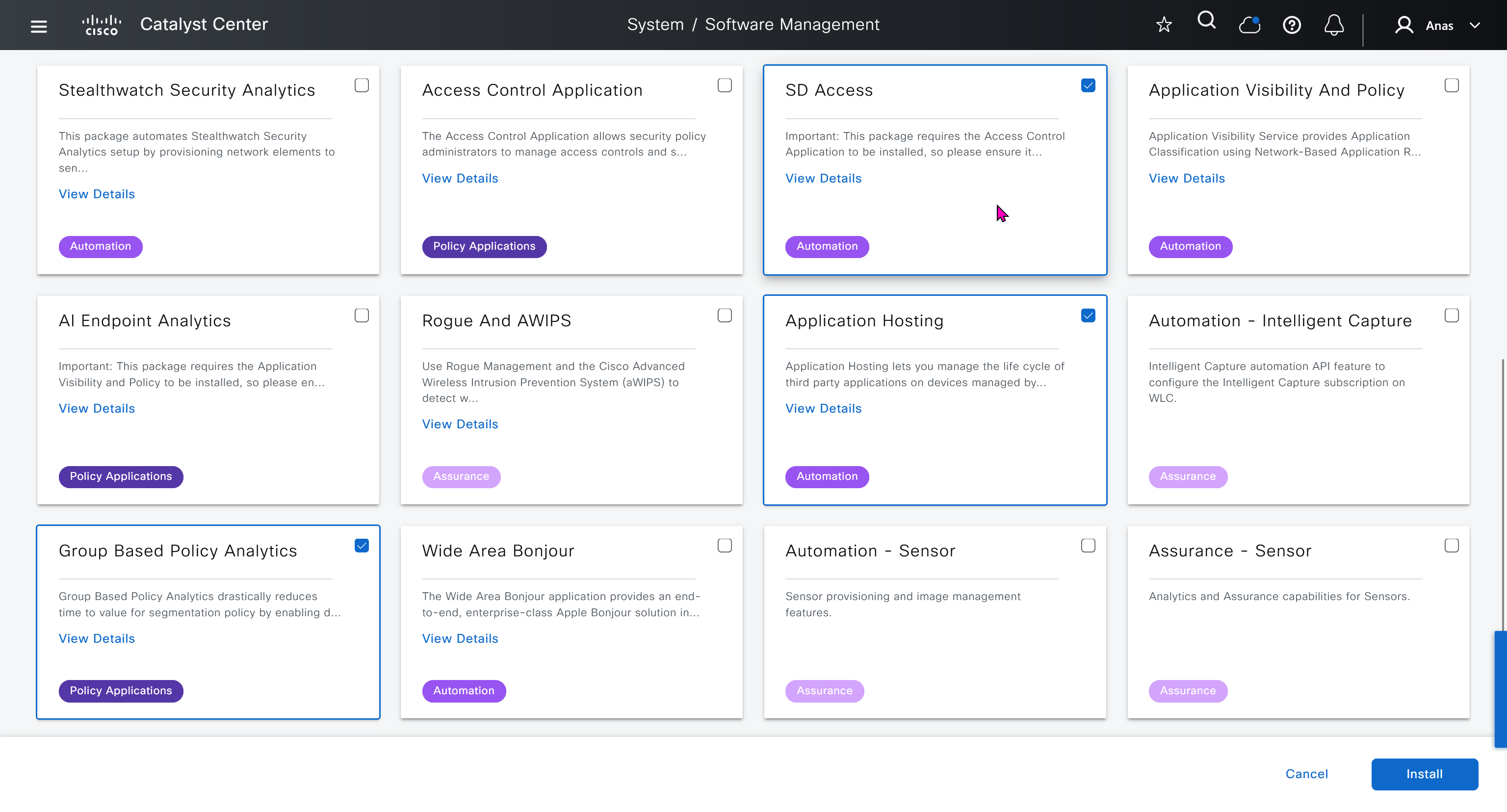
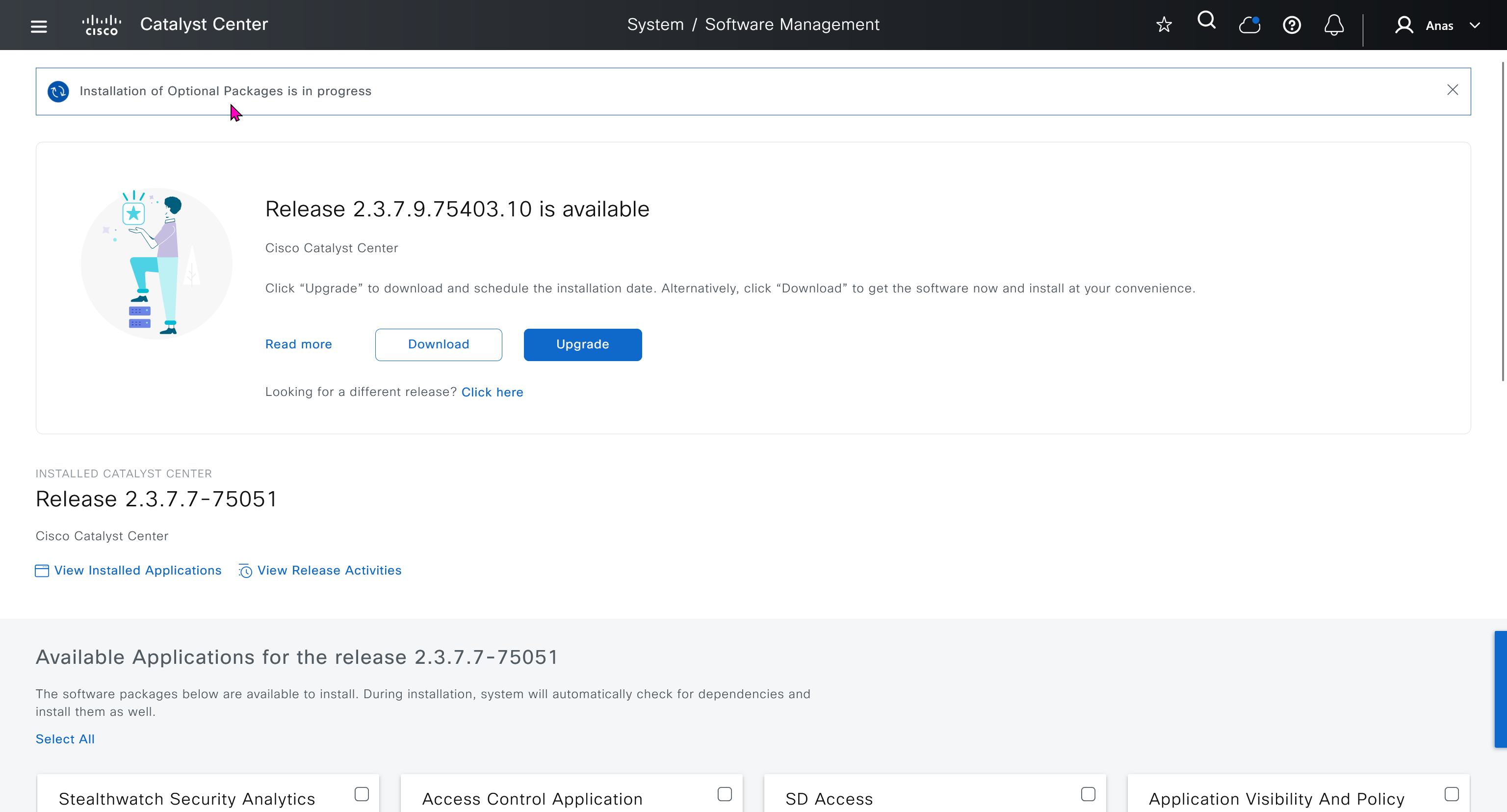
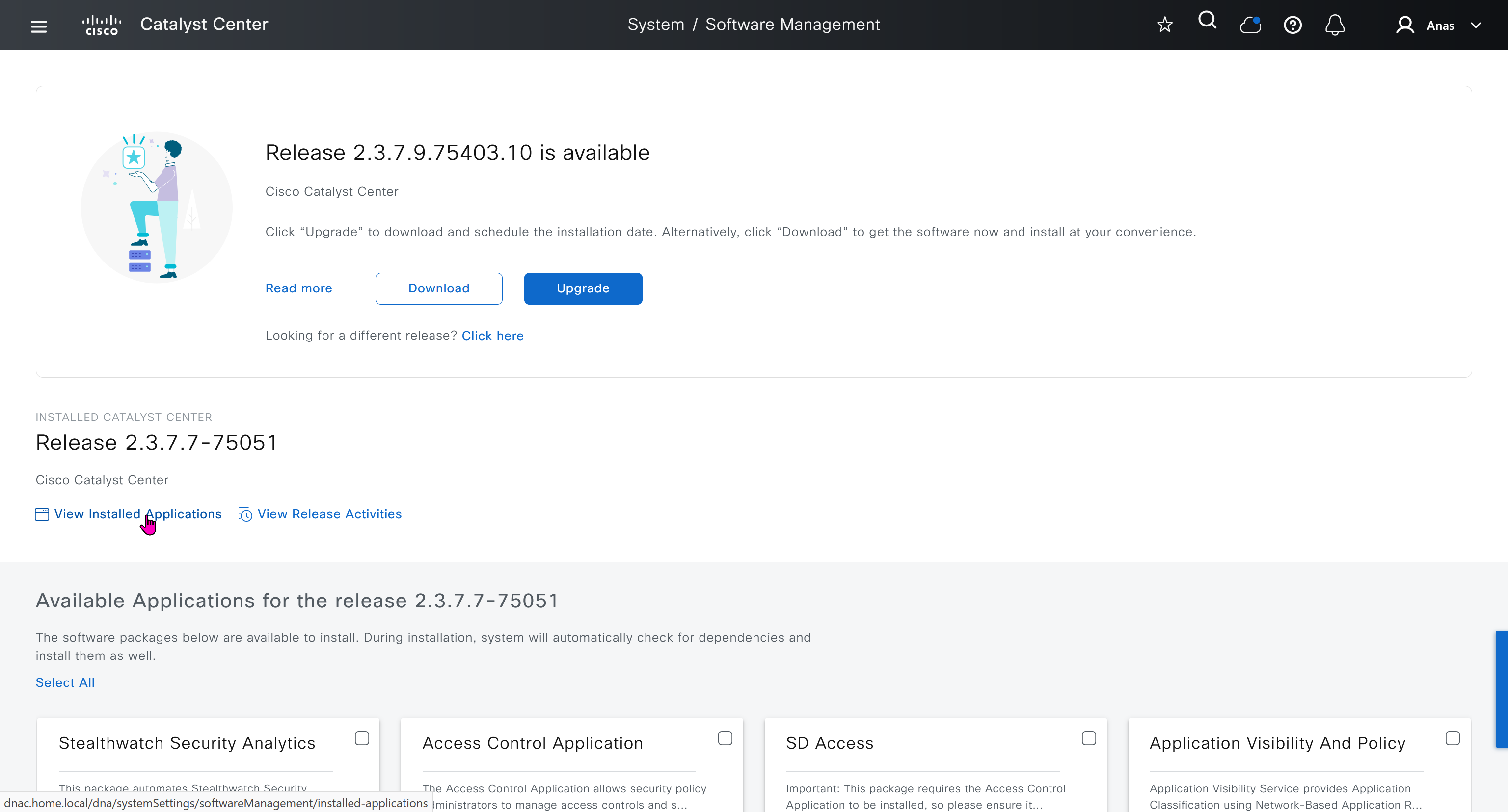
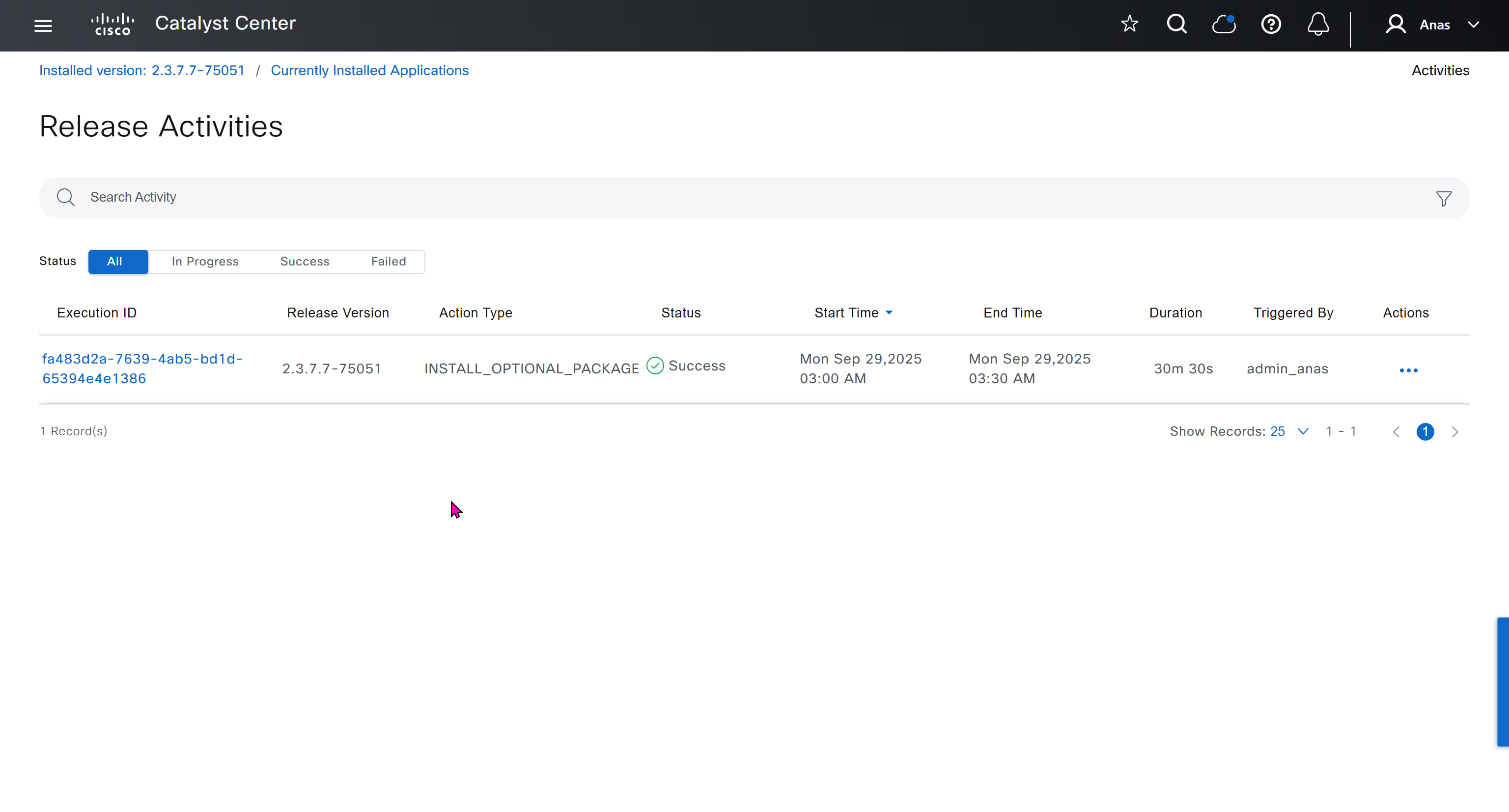
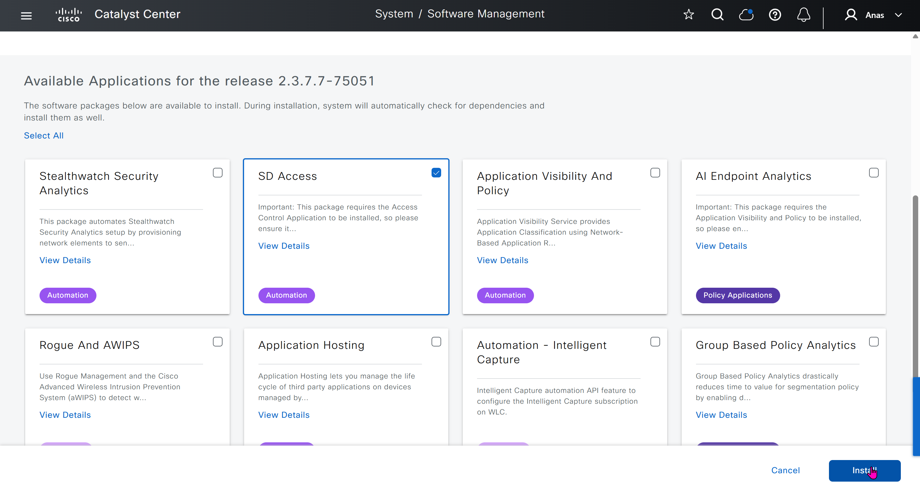
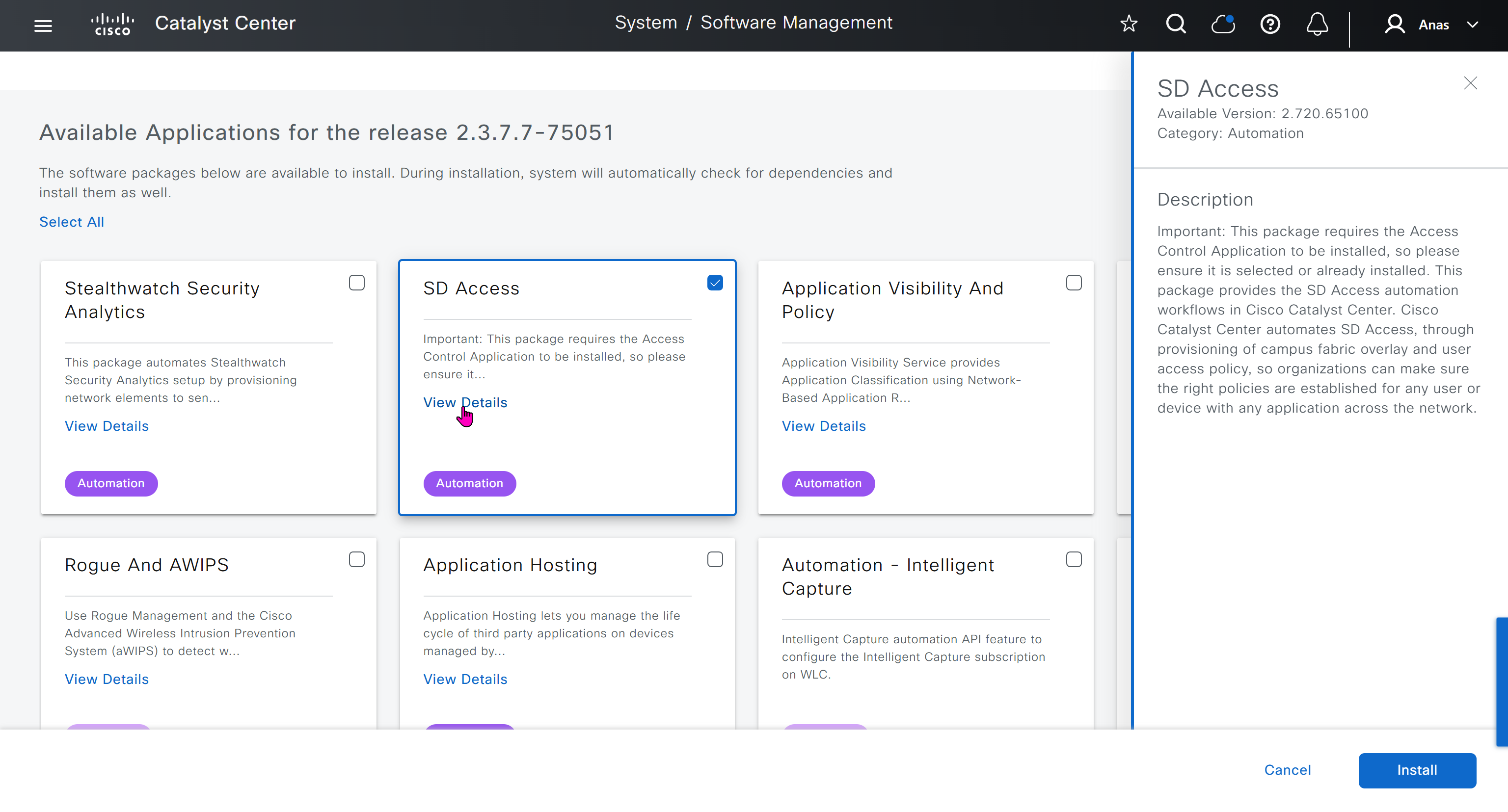
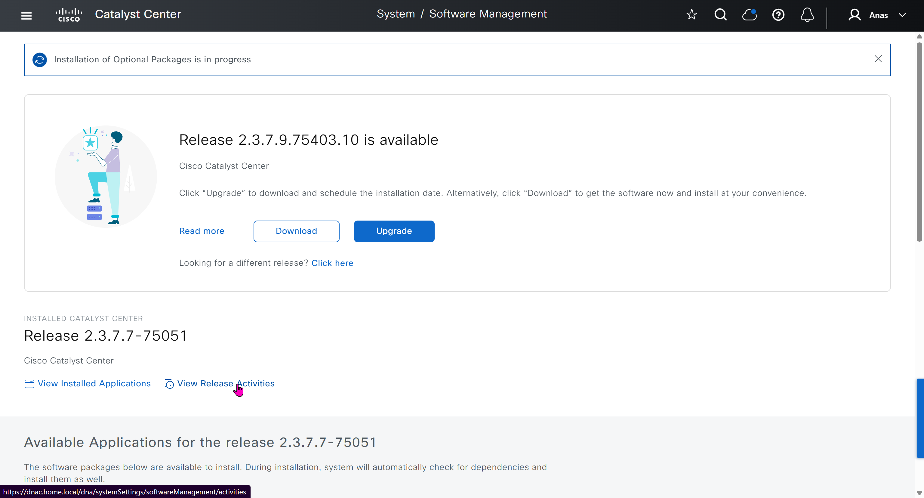
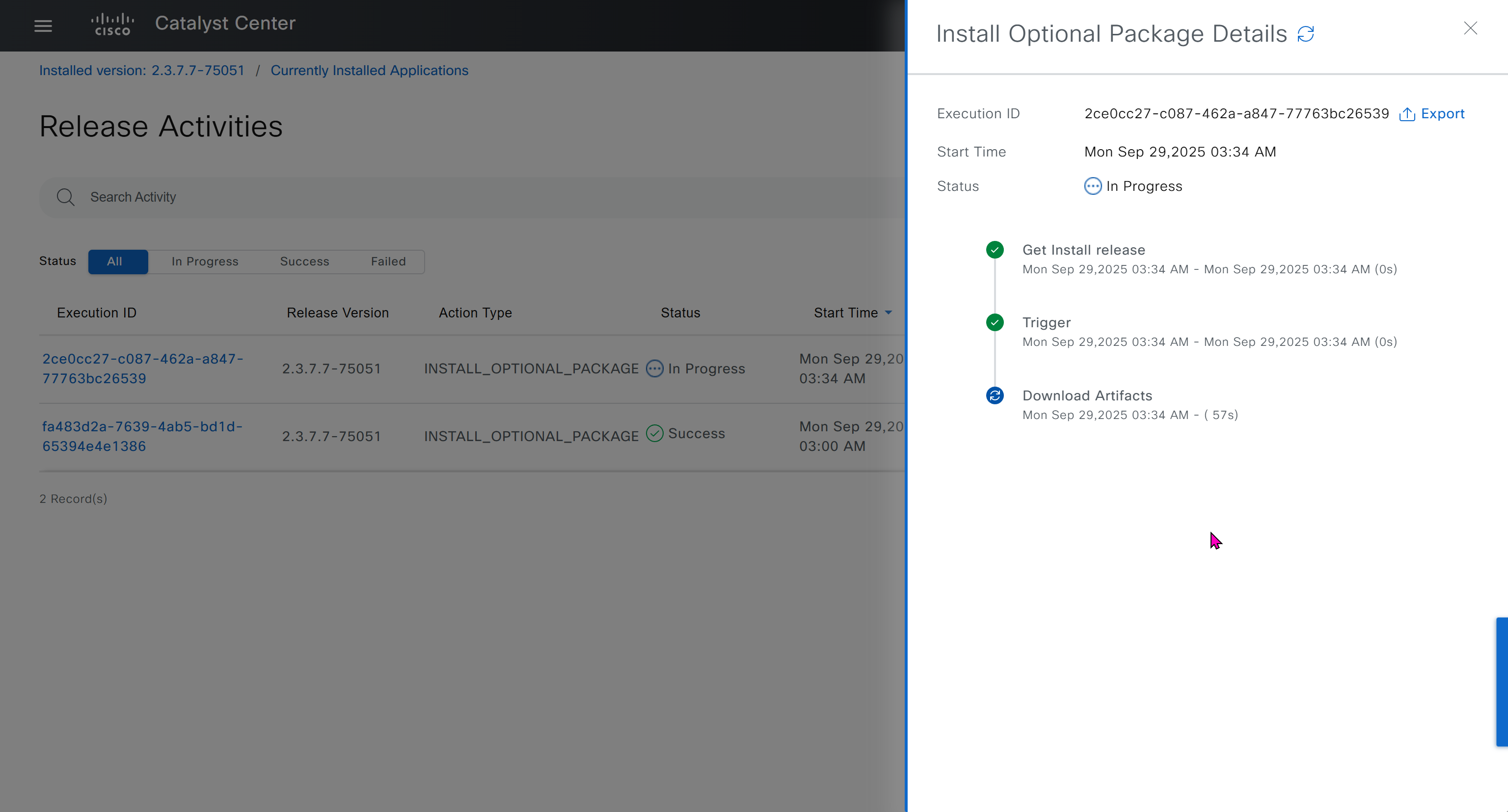
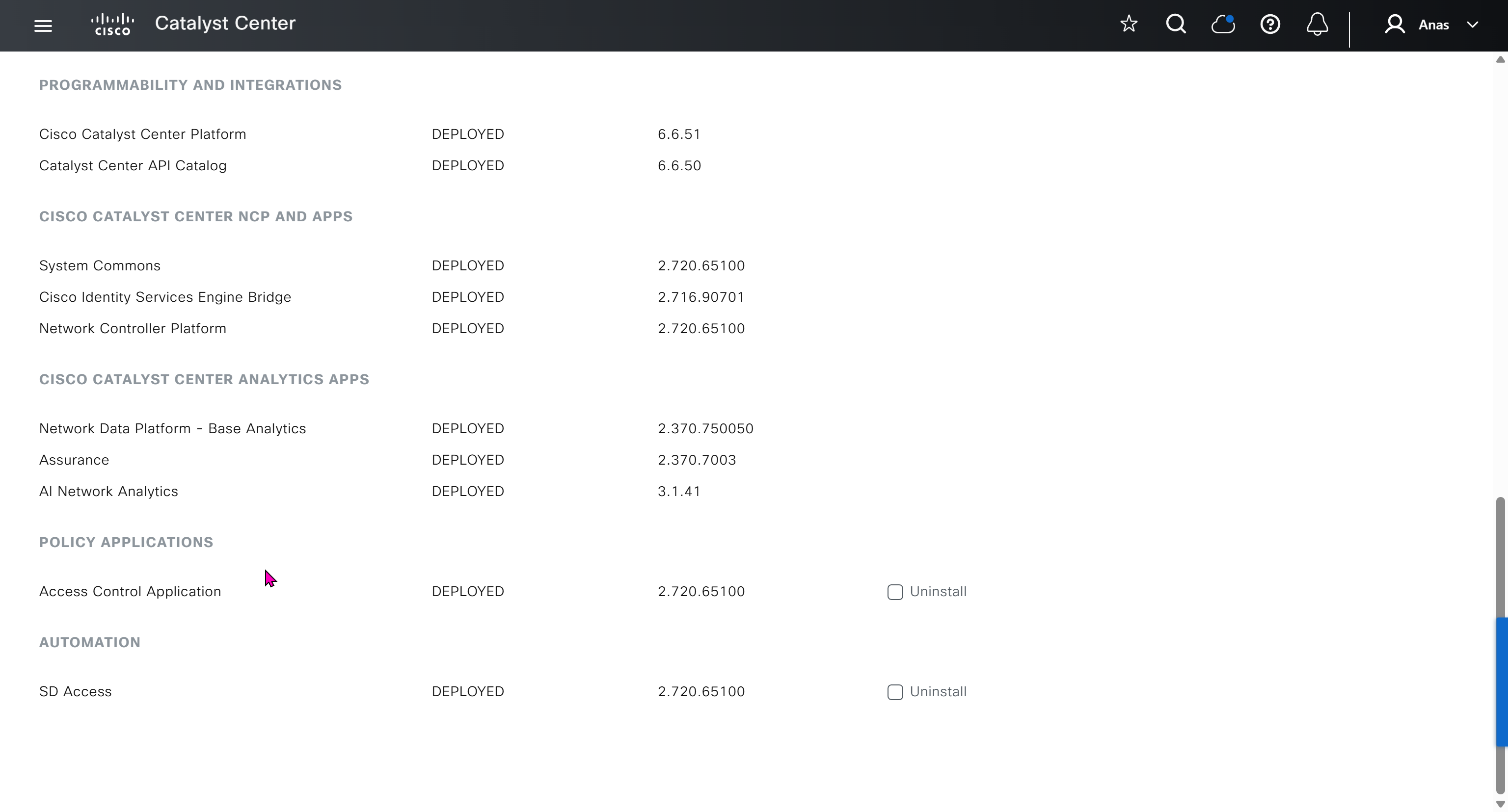
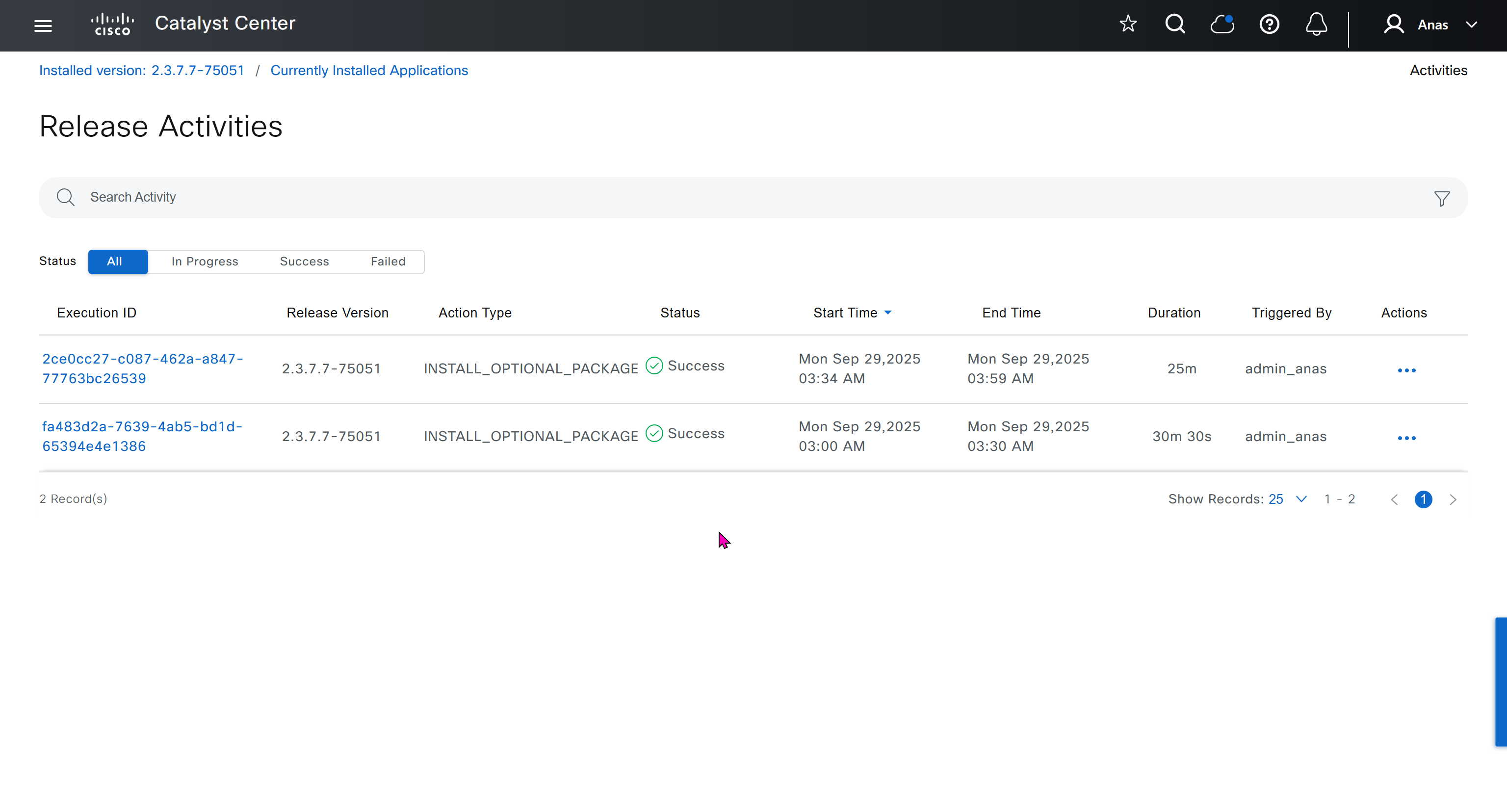
With new build make sure DNAC has internet access, go ahead and download the applications packages which are needed for SGT and SDA, Cisco has divided these features into applications or packages and with fresh install / build download these packages
- Download these packages
- Turn off the VM
- Take Snapshot with exact date and time
- Turn off time syncing of VM with ESXI
- ESXI add NTP server same as Windows Server
- Windows Server move back time on server when it is time to restore the VM
- When restore cut off internet access to DNAC


Here do not use personal email instead use email from company’s cco


on next deployment also download below modules also
Sensor Assurance
AI Endpoint Analytics
Application Visibility and Policy (EasyQoS)

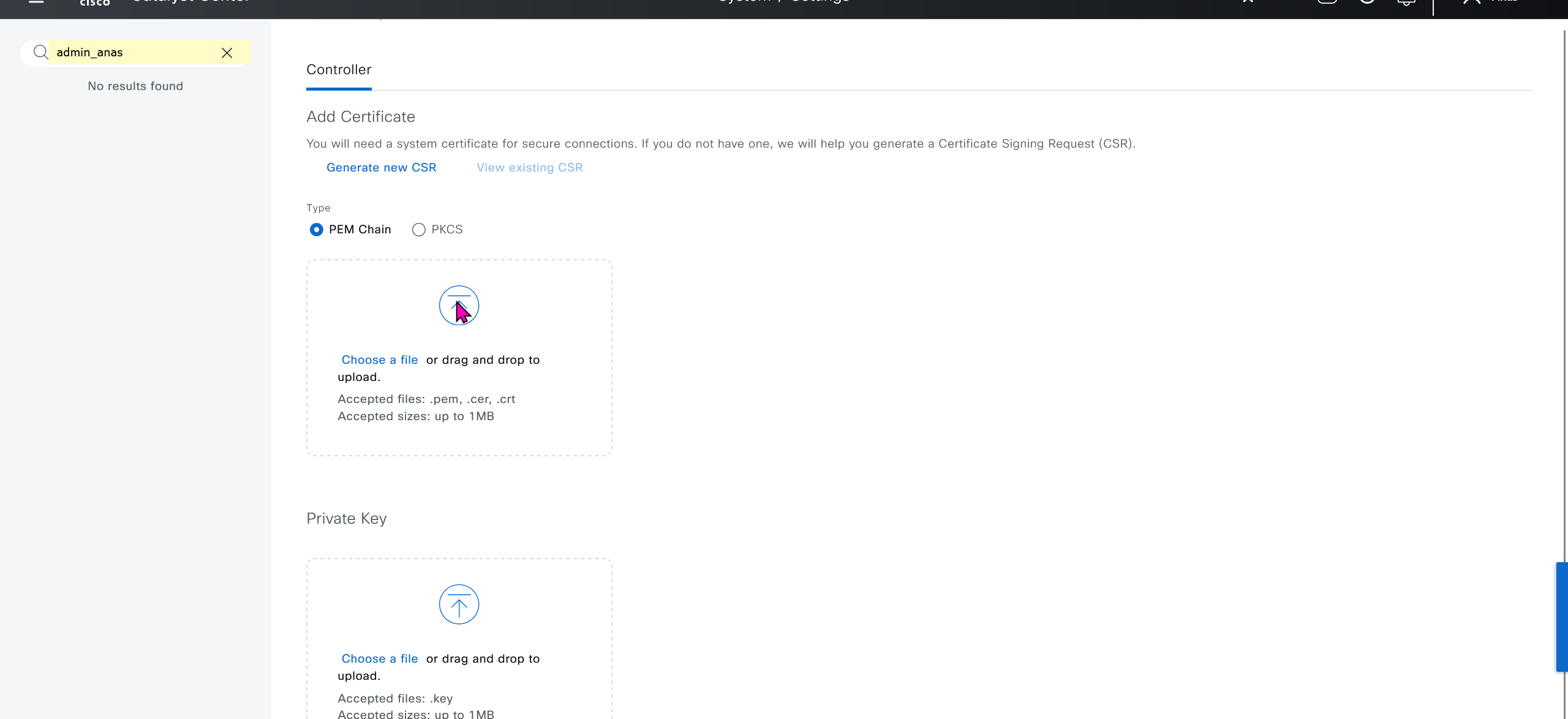
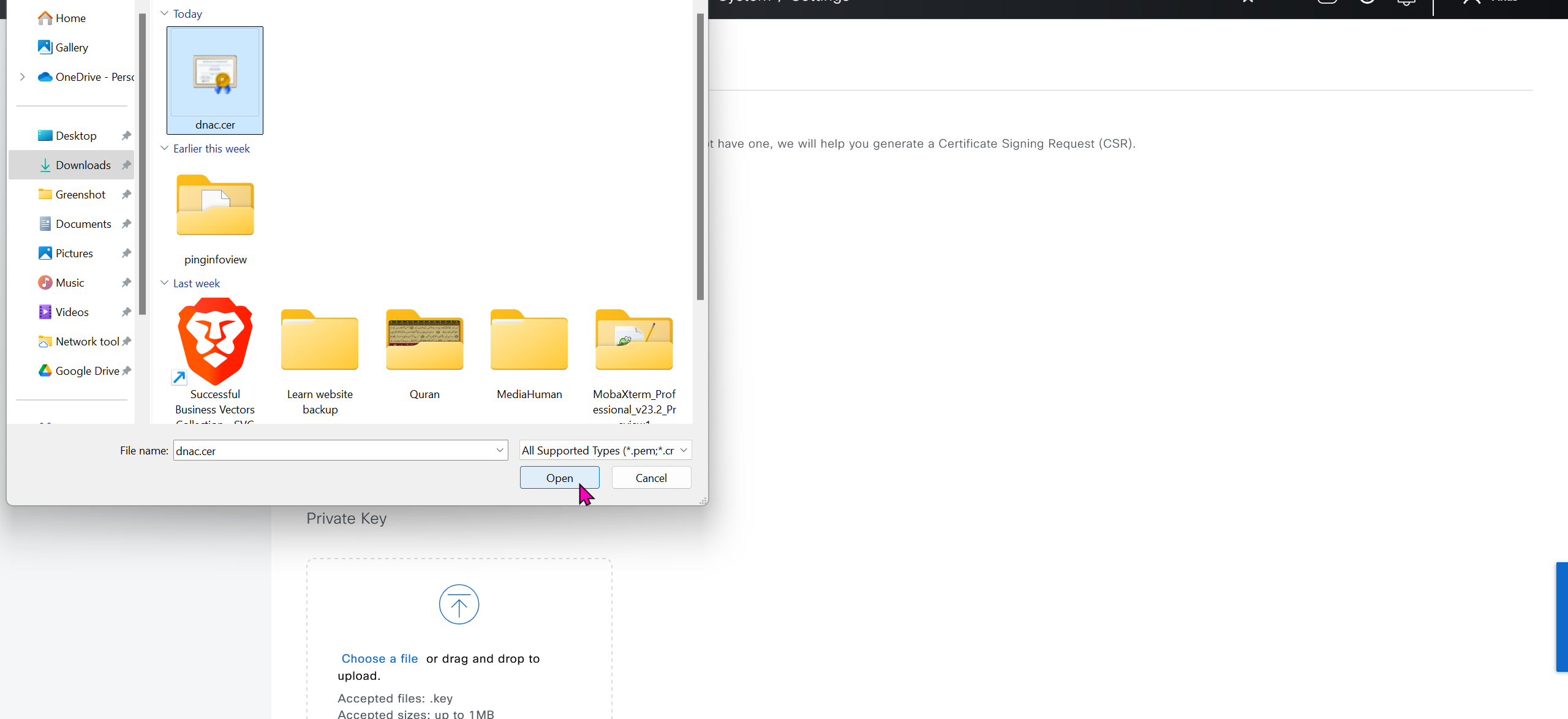
Only after these steps, add certificate to DNAC
Further configuration and ISE integration
Graceful shutdown DNAC
! Cat center shutdown
$ shutdown

! VYOS shutdown
sudo bash
shutdown -h now

! vcenter shutdown
Gracefully shutdown from esxi
SDA Links
https://www.cisco.com/c/en/us/td/docs/cloud-systems-management/network-automation-and-management/catalyst-center/catalyst-center-va/esxi/2-3-7/deployment-guide/b_cisco_catalyst_center_237x_on_esxi_deployment_guide.html#configure-a-virtual-appliance-using-the-interactive-cc-va-launcher
https://www.cisco.com/c/en/us/td/docs/solutions/CVD/Campus/SD-Access-Distributed-Campus-Deployment-Guide-2019JUL.html
https://www.cisco.com/c/dam/en/us/td/docs/solutions/CVD/Campus/sda-fabric-deploy-2019oct.pdf
https://www.cisco.com/c/en/us/td/docs/solutions/CVD/Campus/cisco-sda-design-guide.html
https://www.cisco.com/c/dam/en/us/td/docs/solutions/CVD/Campus/CVD-Software-Defined-Access-Segmentation-Design-Guide-2018MAY.pdf
next post
ISE Certificate lab
ISE Certificate lab
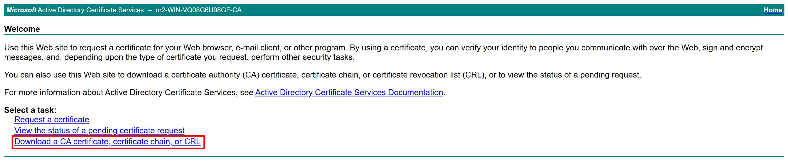
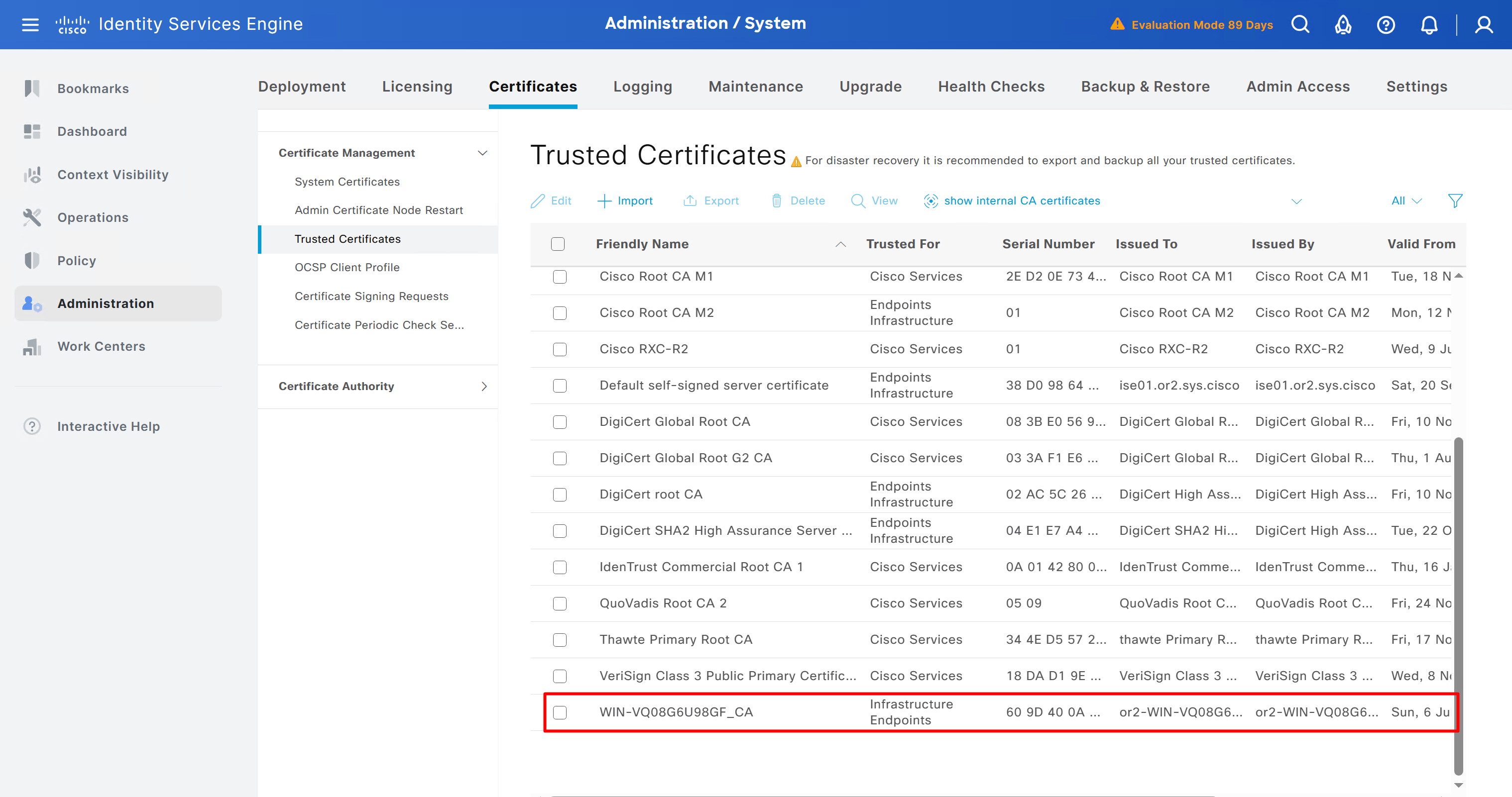
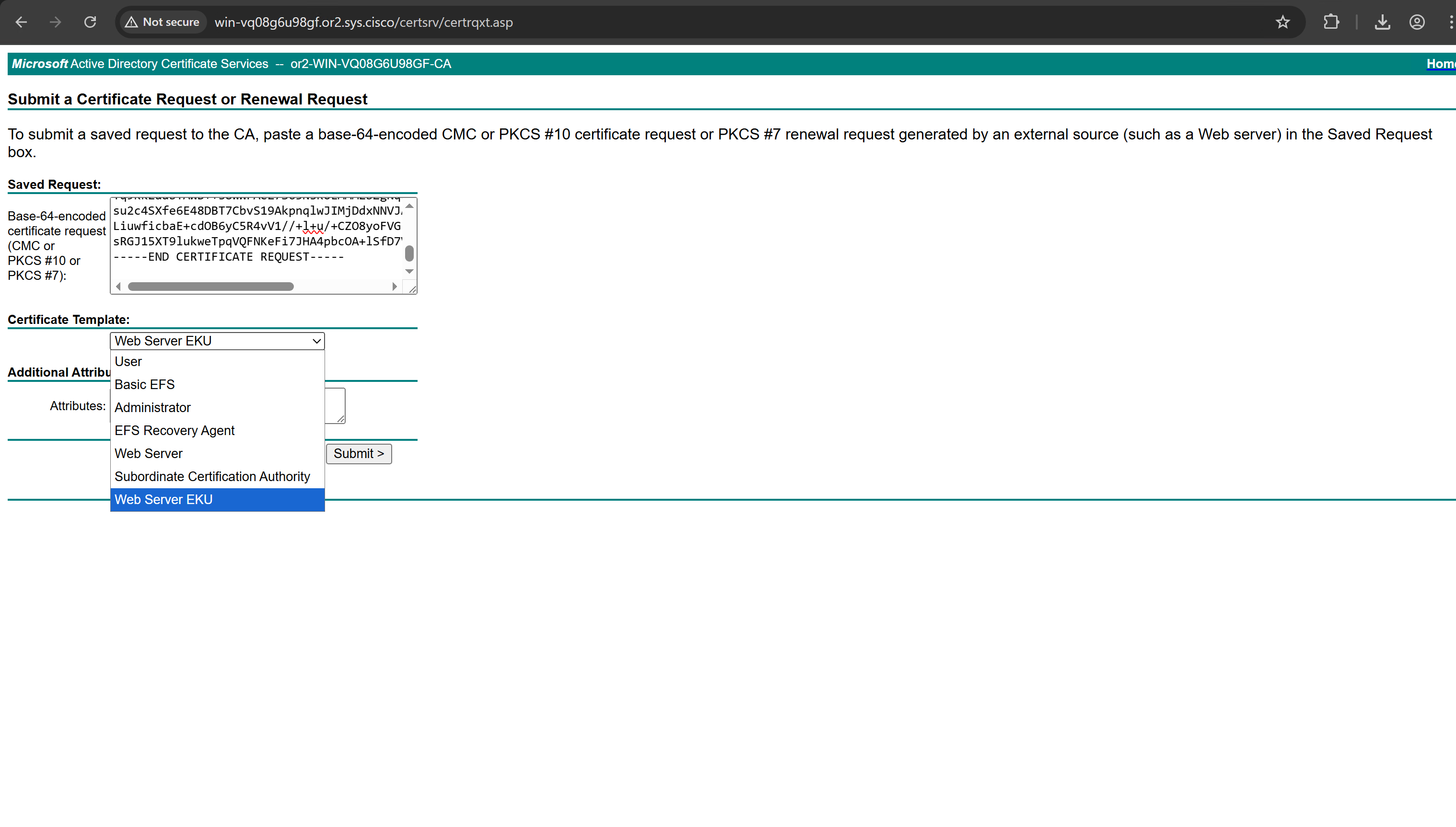
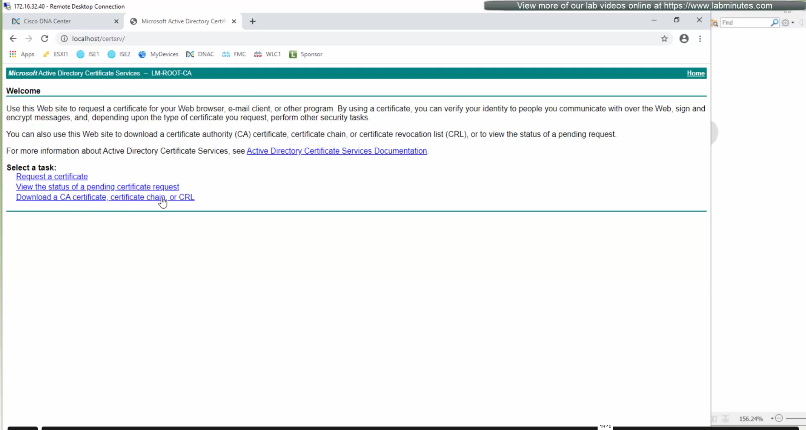
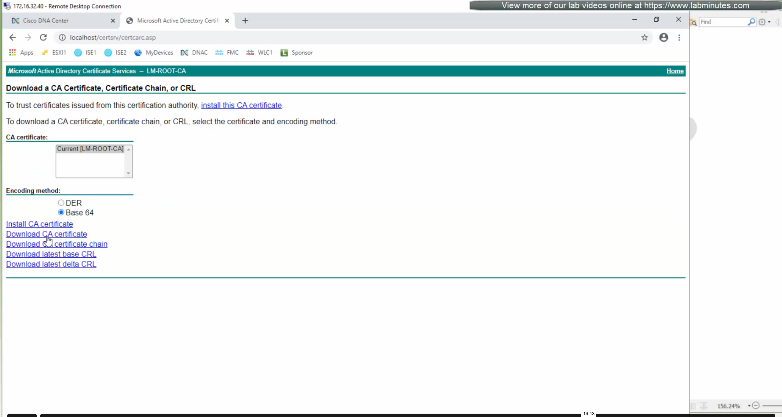
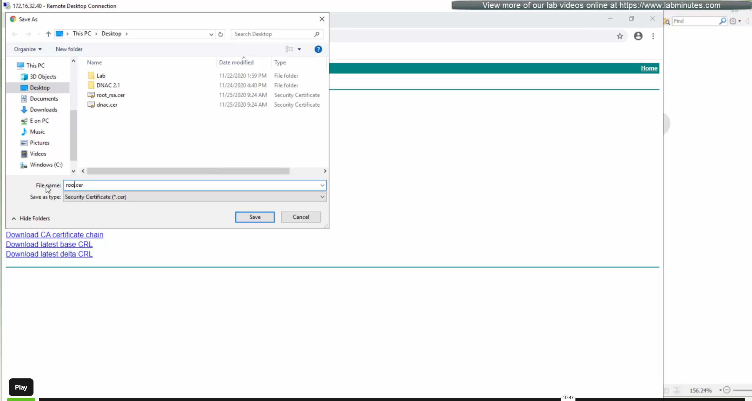
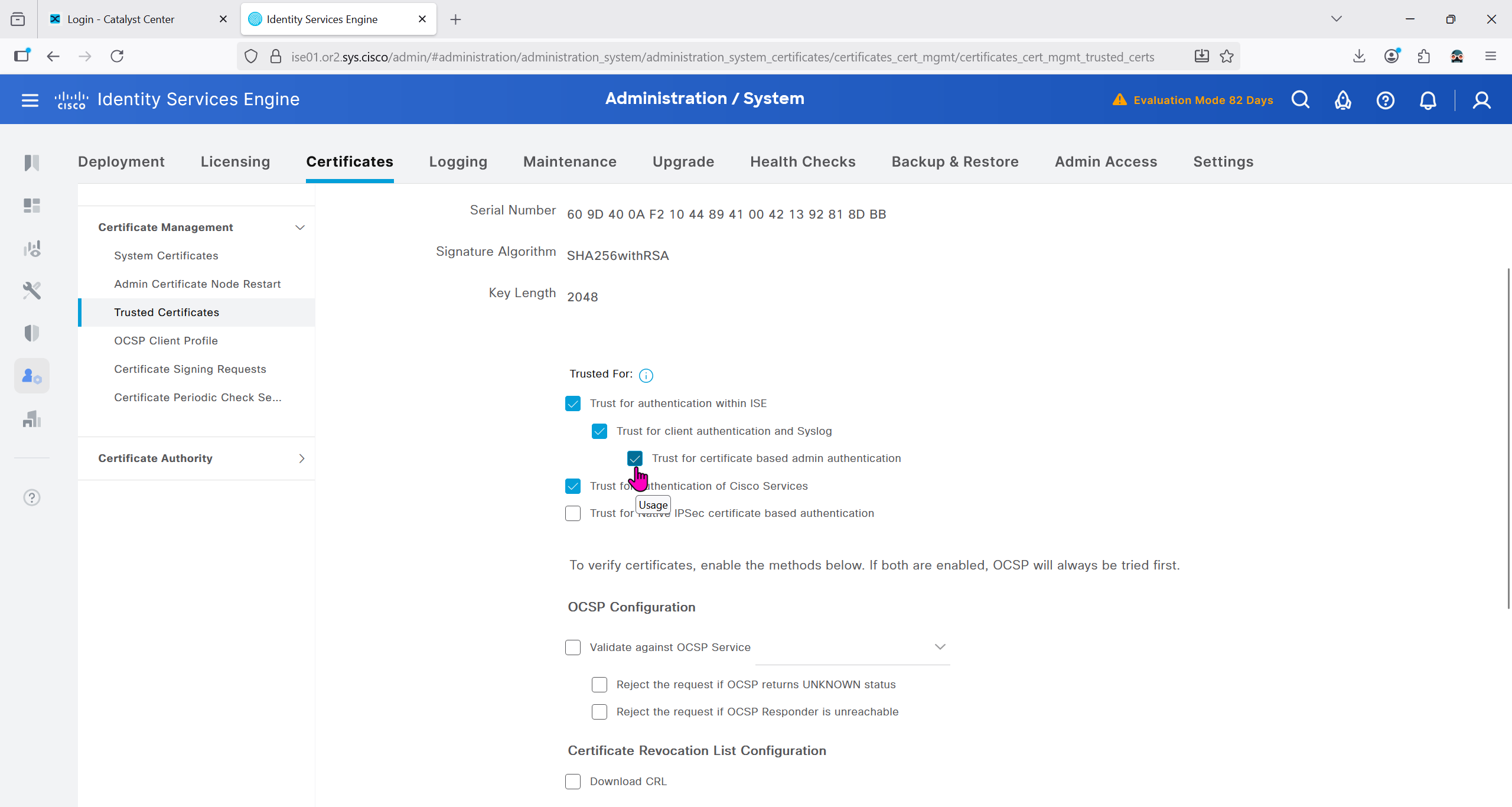
Download CA certificate and upload it to the Trusted store of ISE
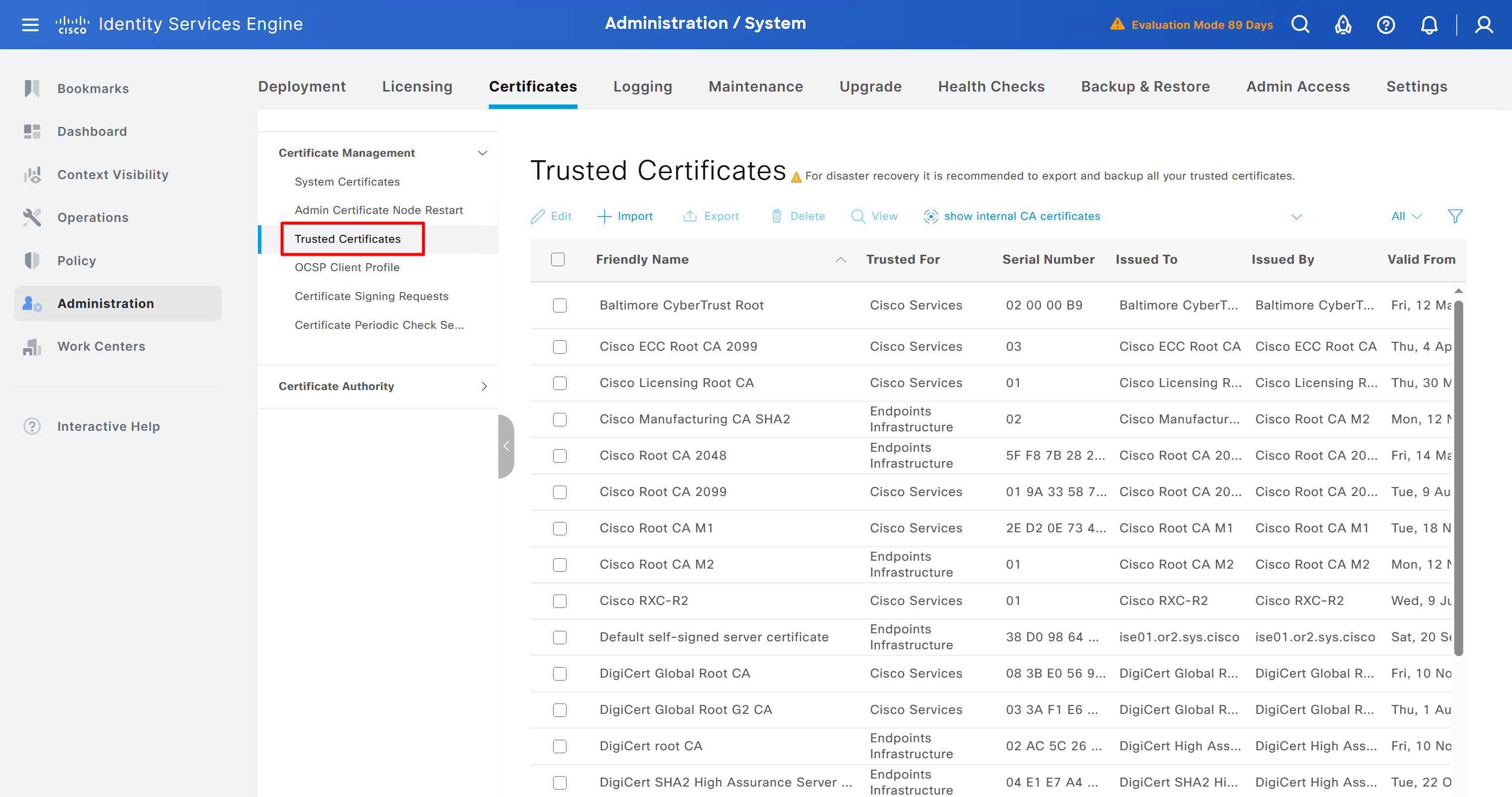
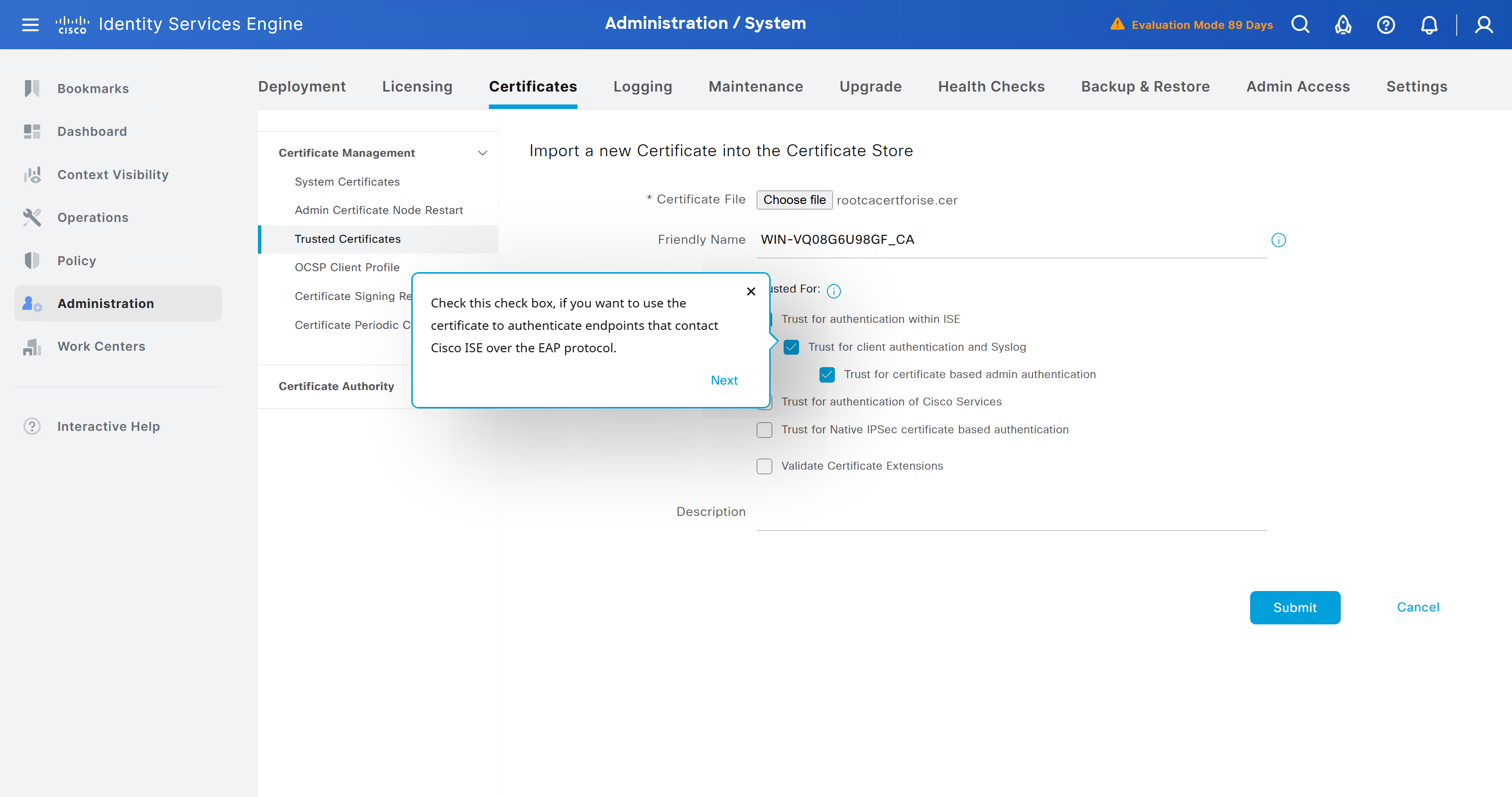
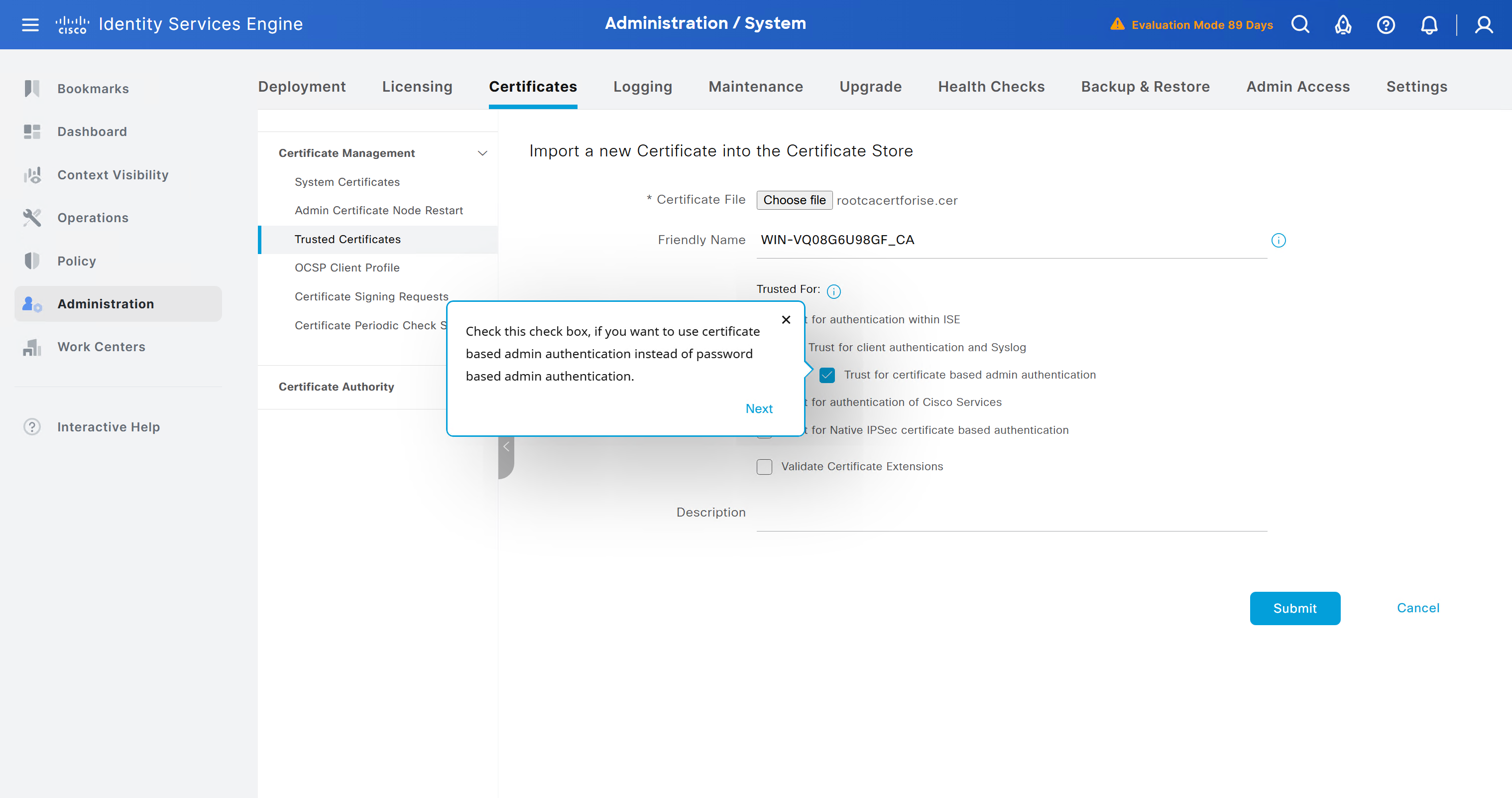
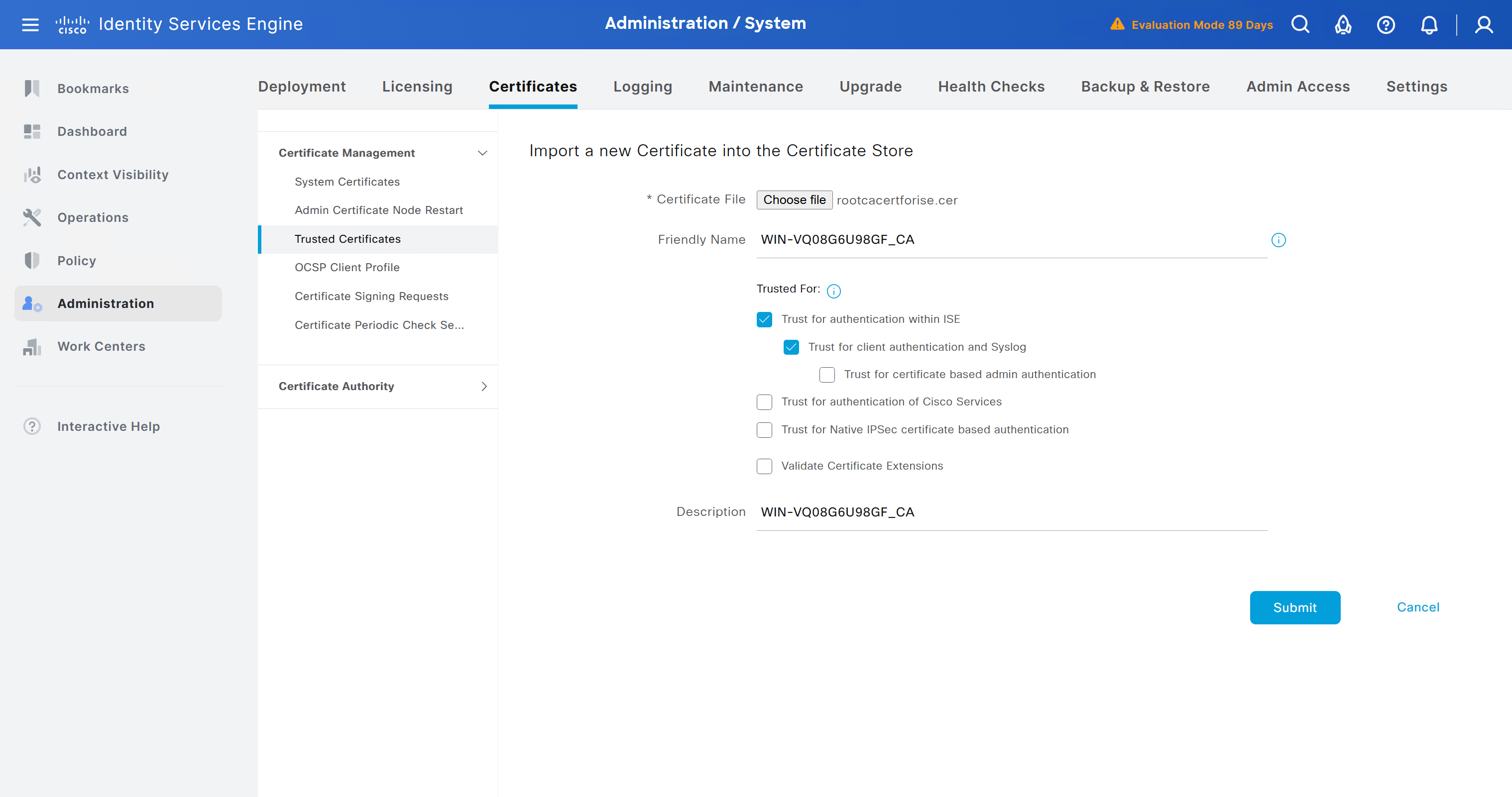
We will select this option “Trust for client authentication and Syslog” as certificate presented to ISE during EAP TLS 802.1x authentication will be certificates issued by this same CA
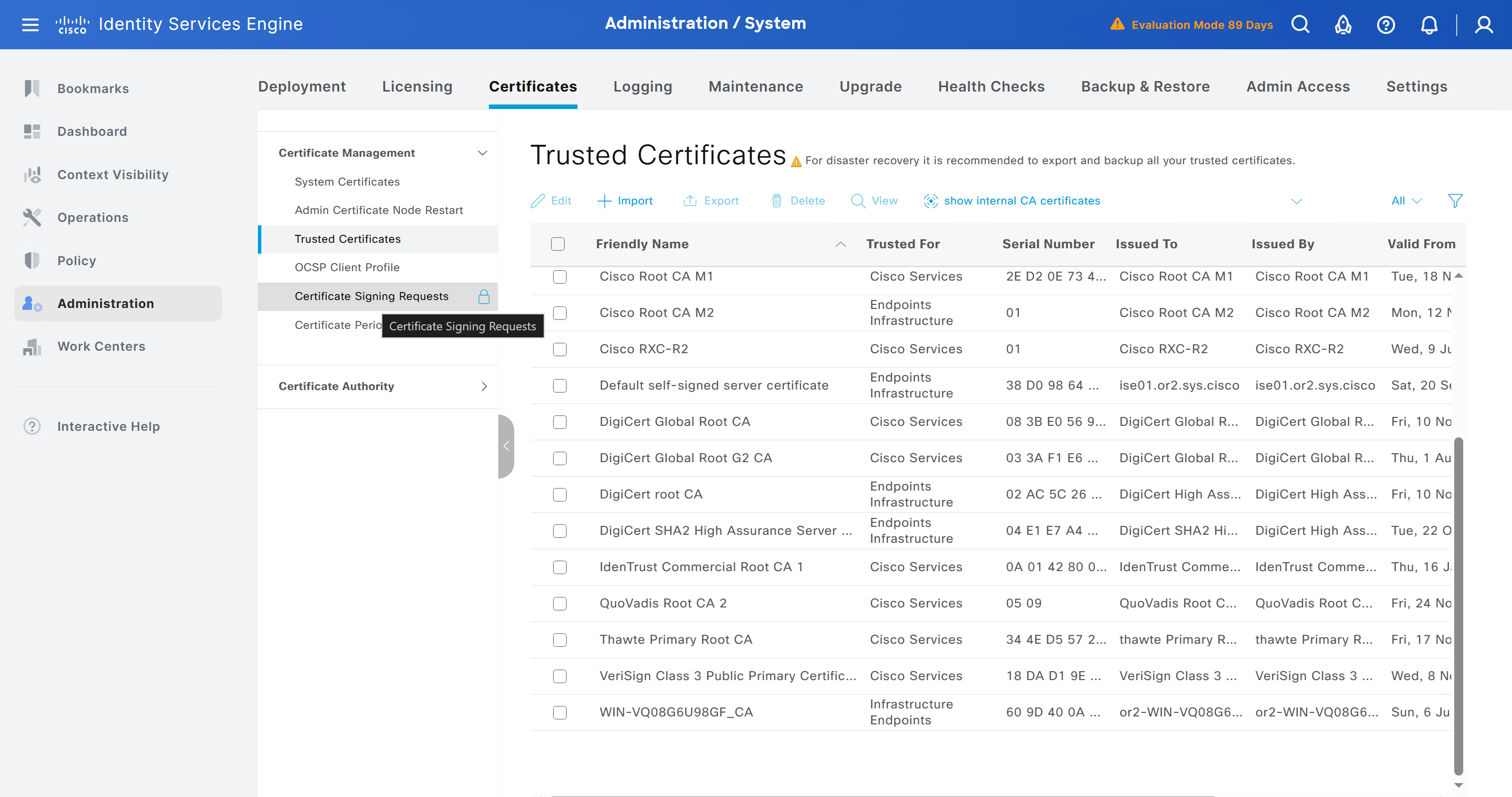
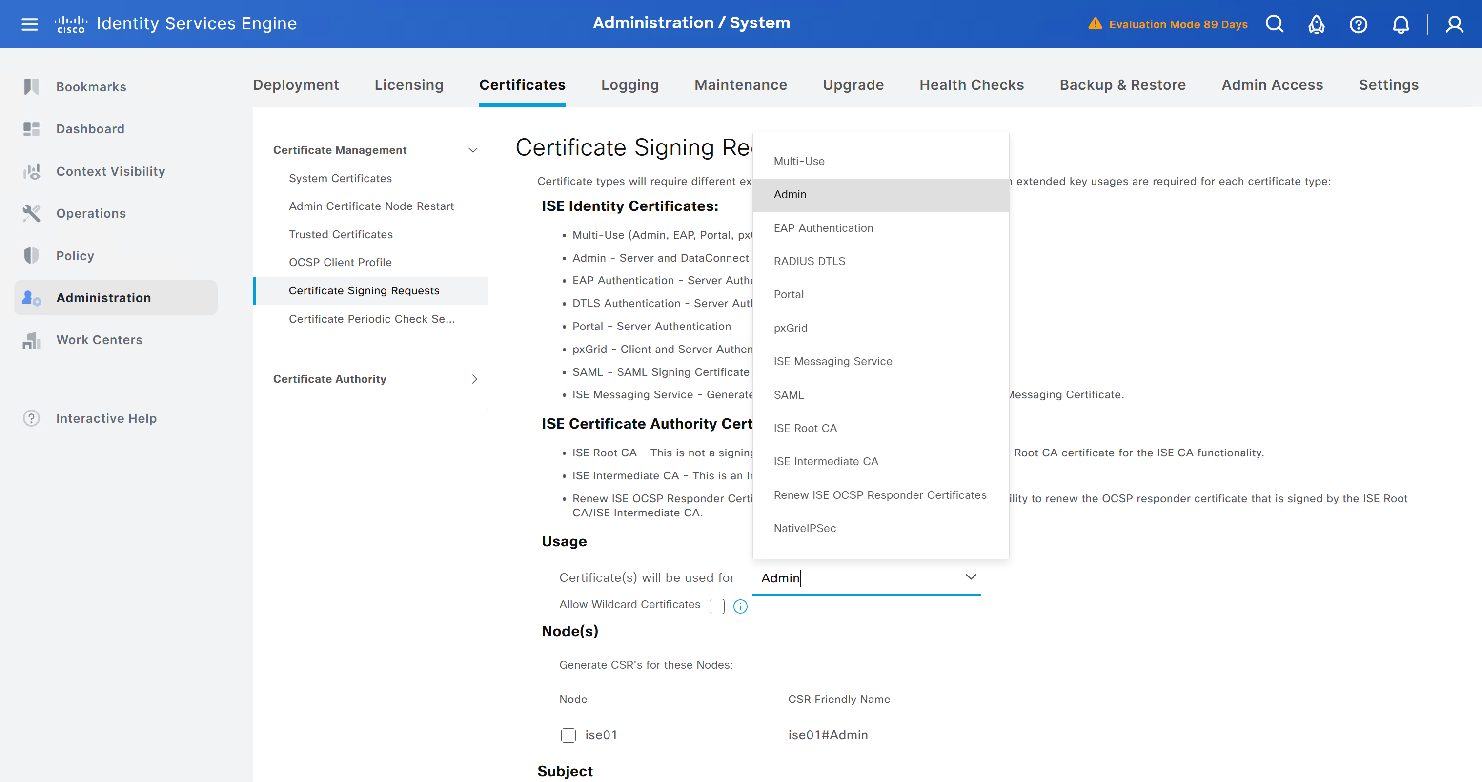
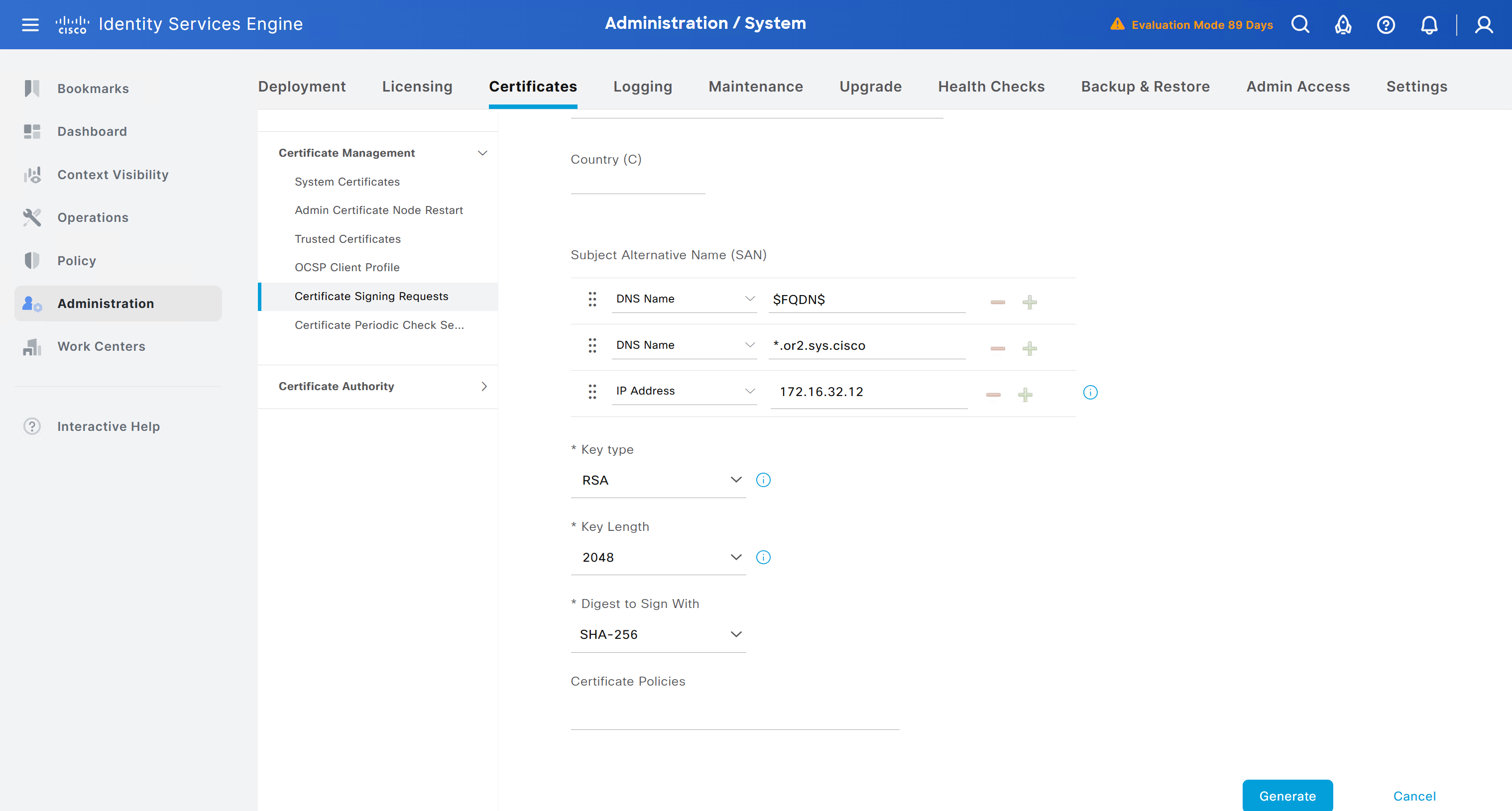
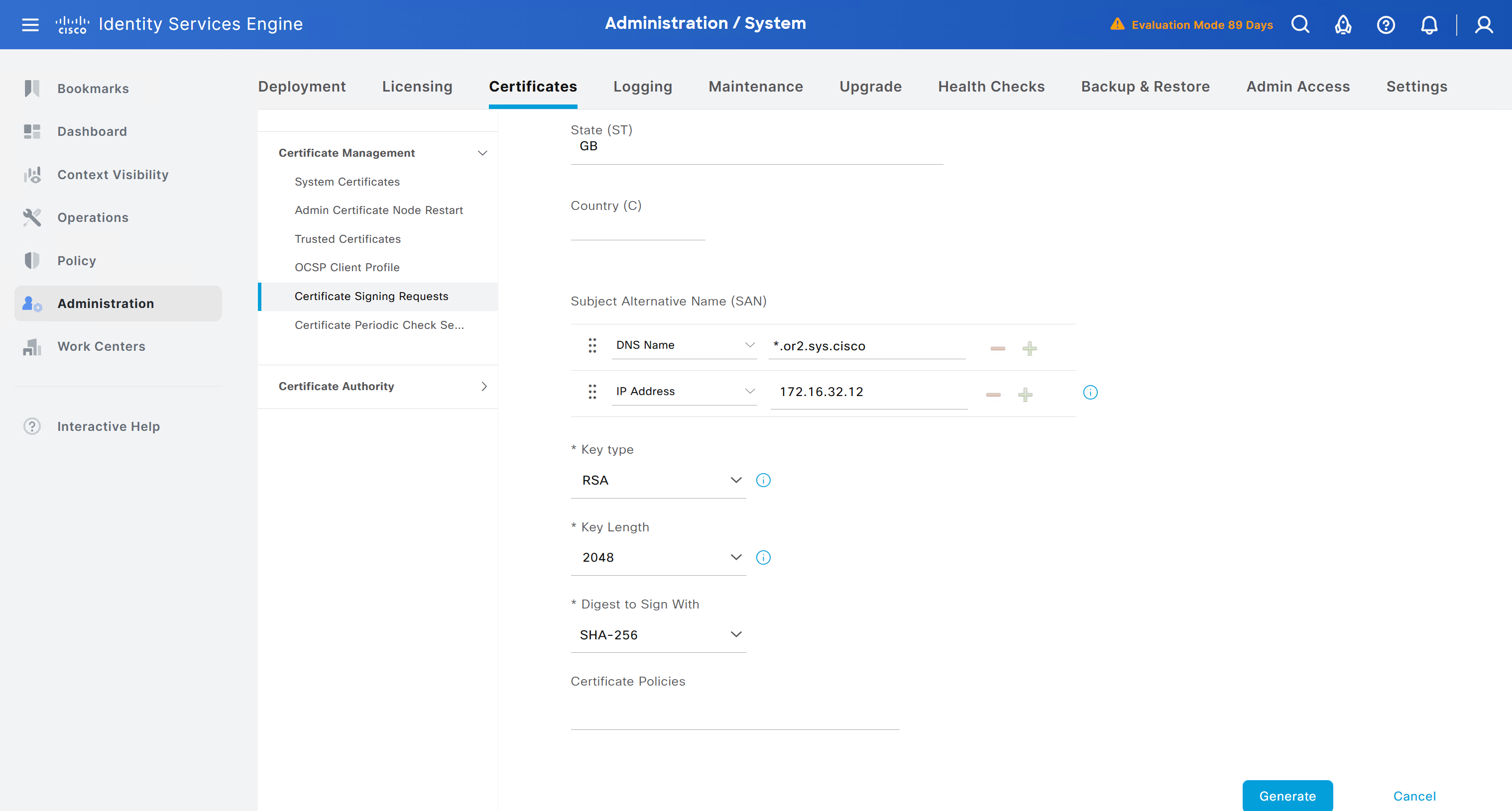
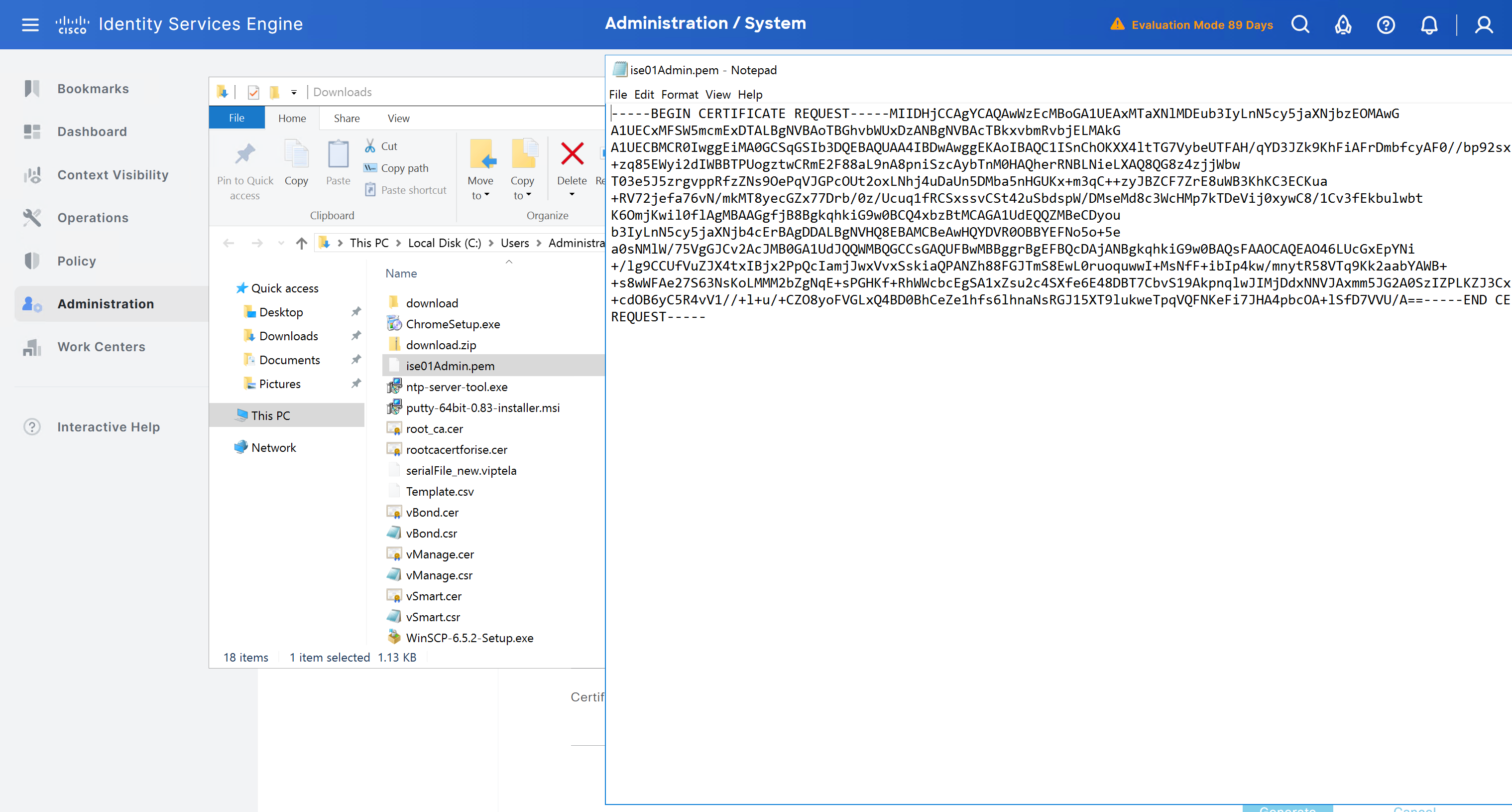
Create CSR for Admin usage
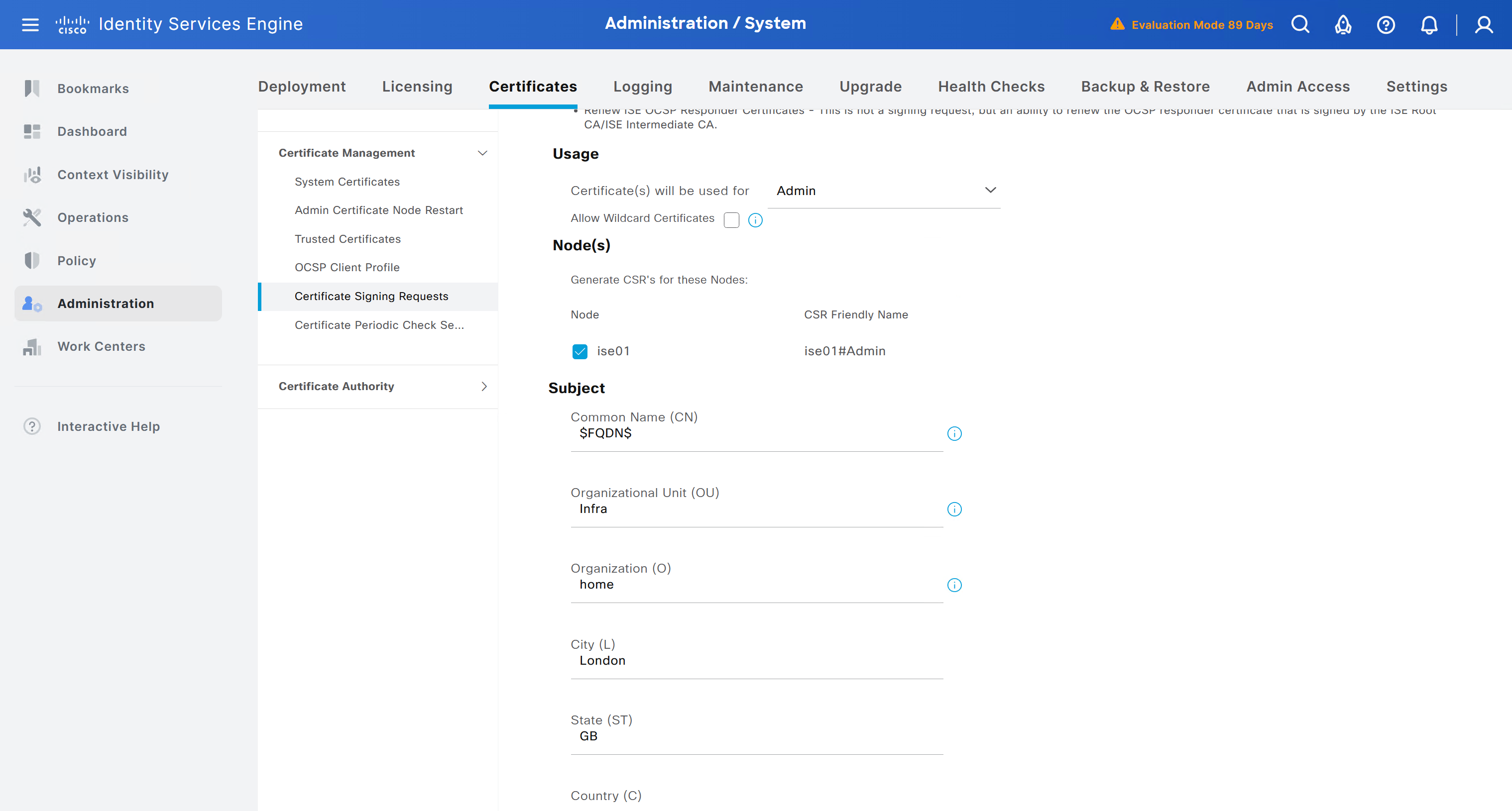
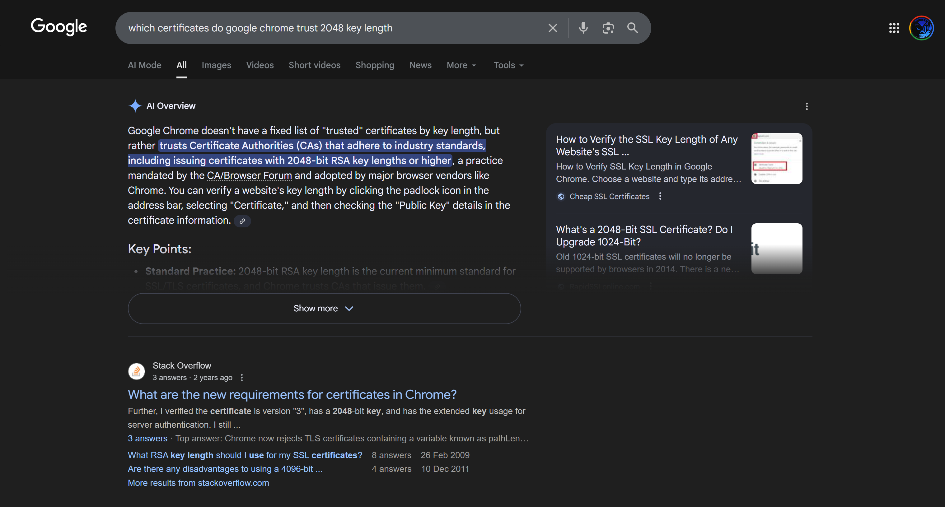
enter DNS Name as $FQDN$
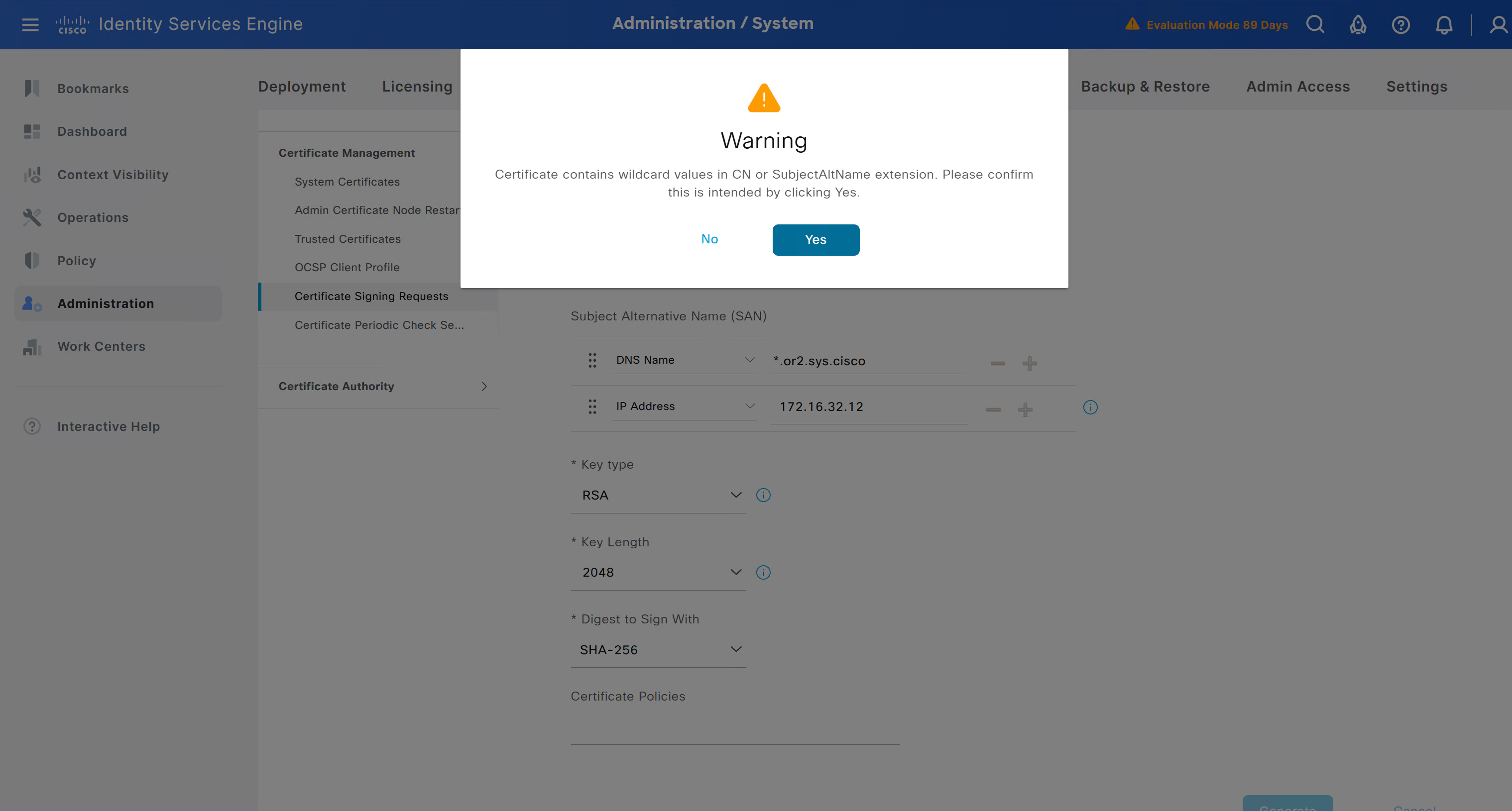
and also enter second DNS name as wildcard with remaining domain name *.or2.sys.cisco
and also add the SAN entry of type IP address with value of 172.16.32.12
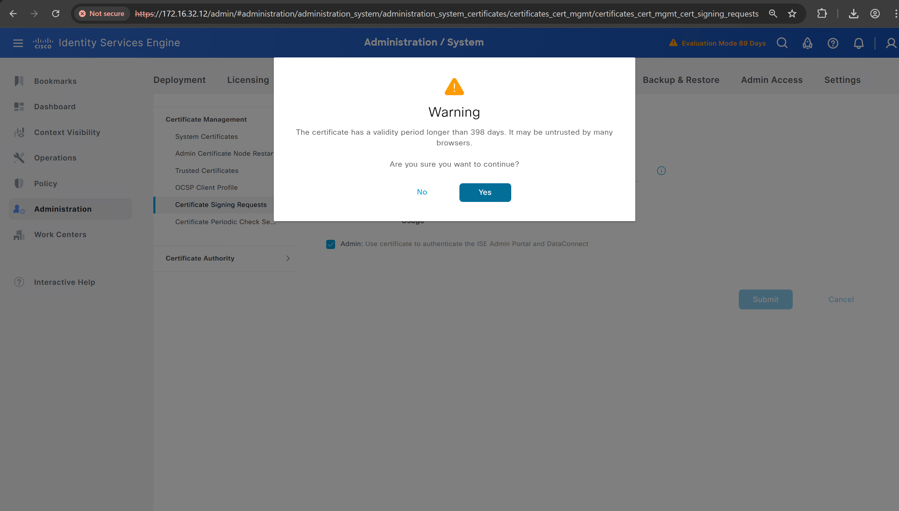
ISE gave this error
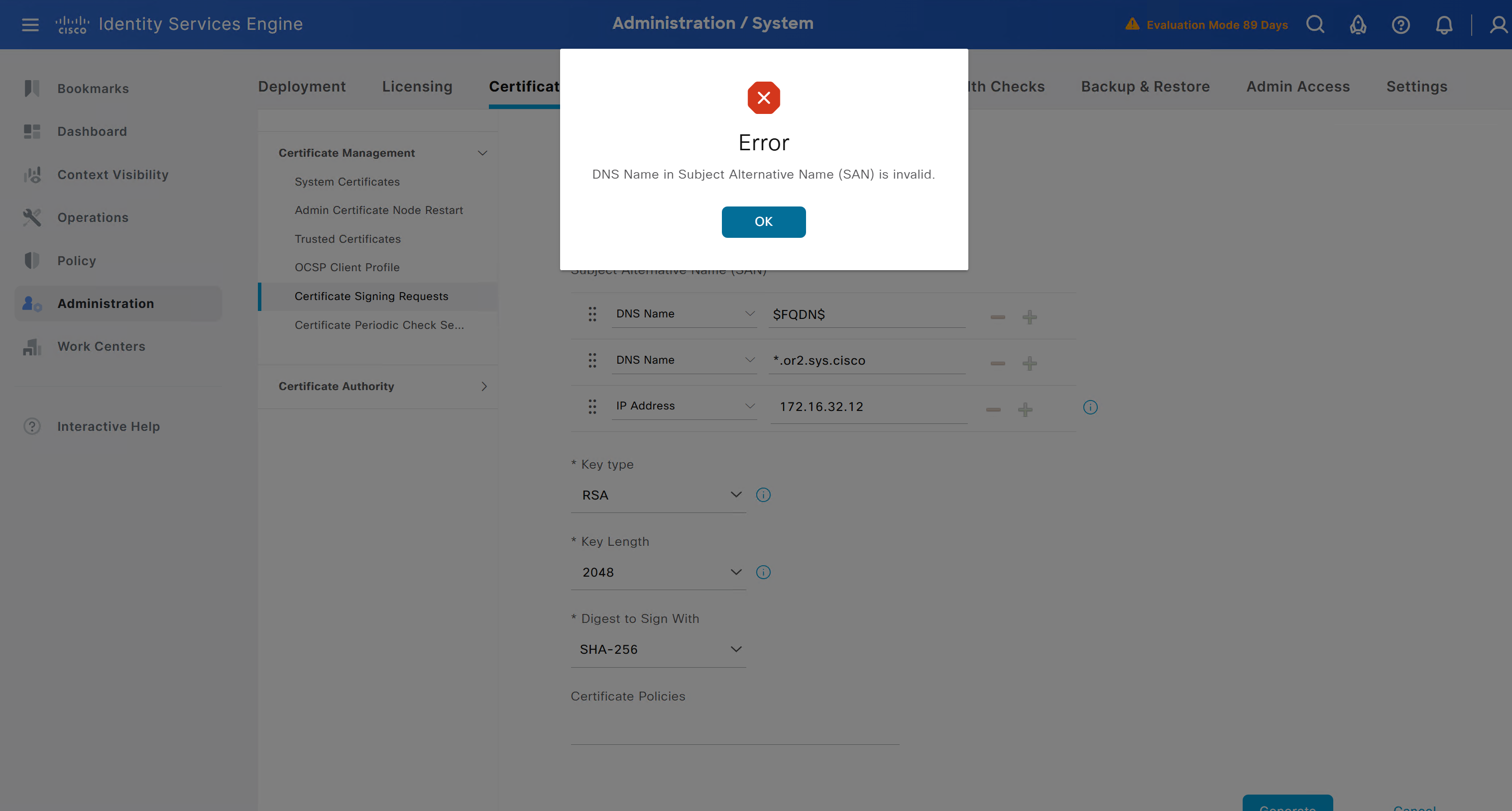
So I removed first entry of $FQDN$
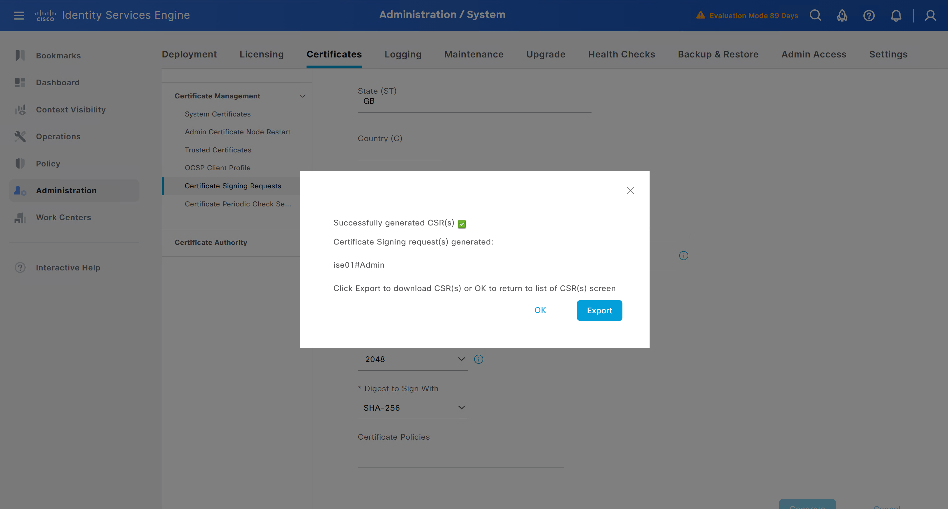
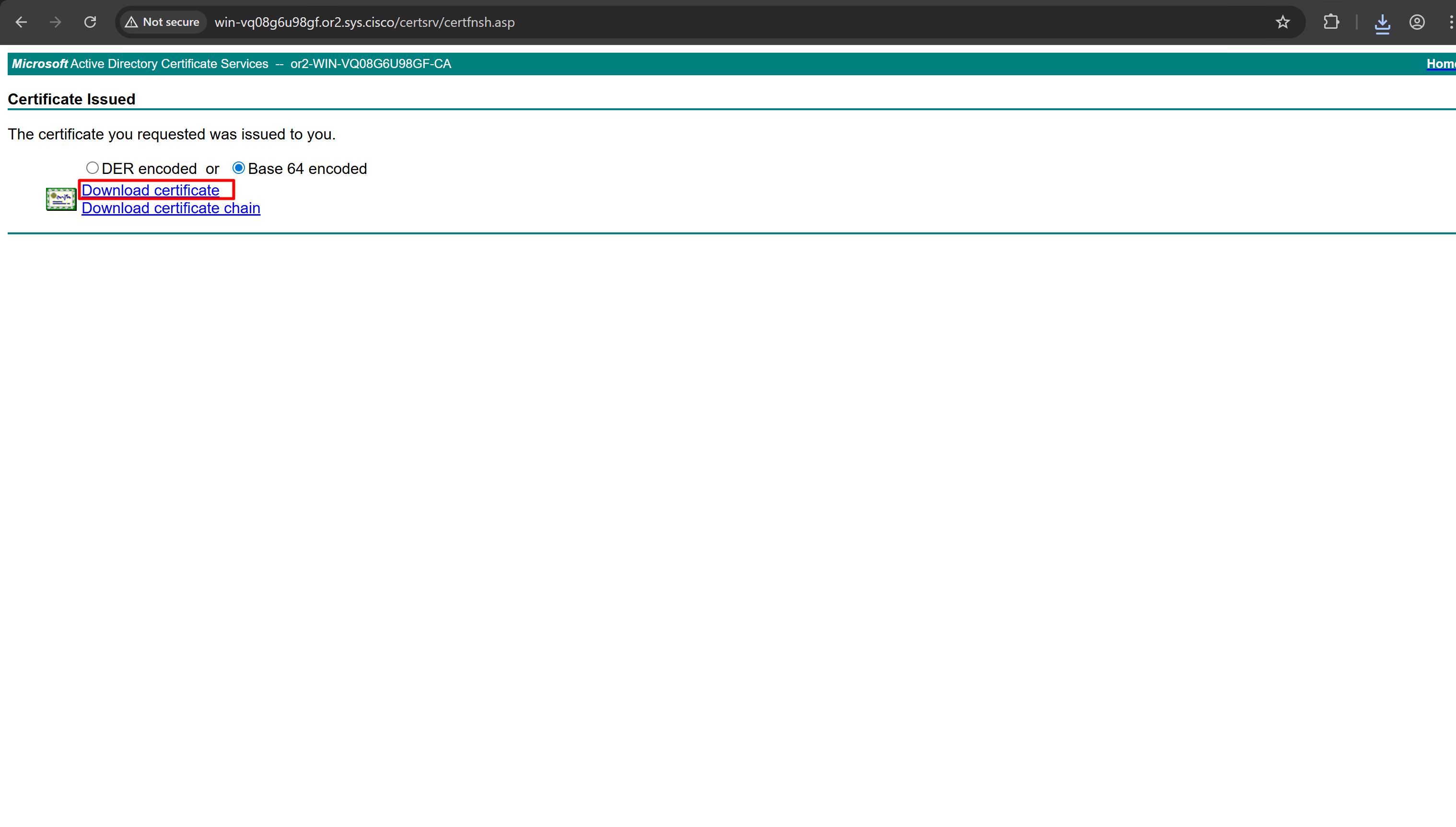
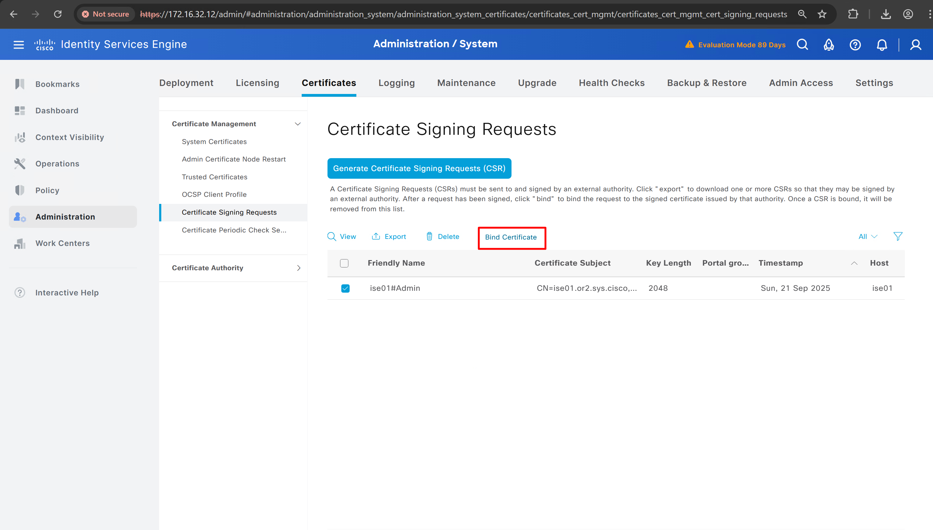
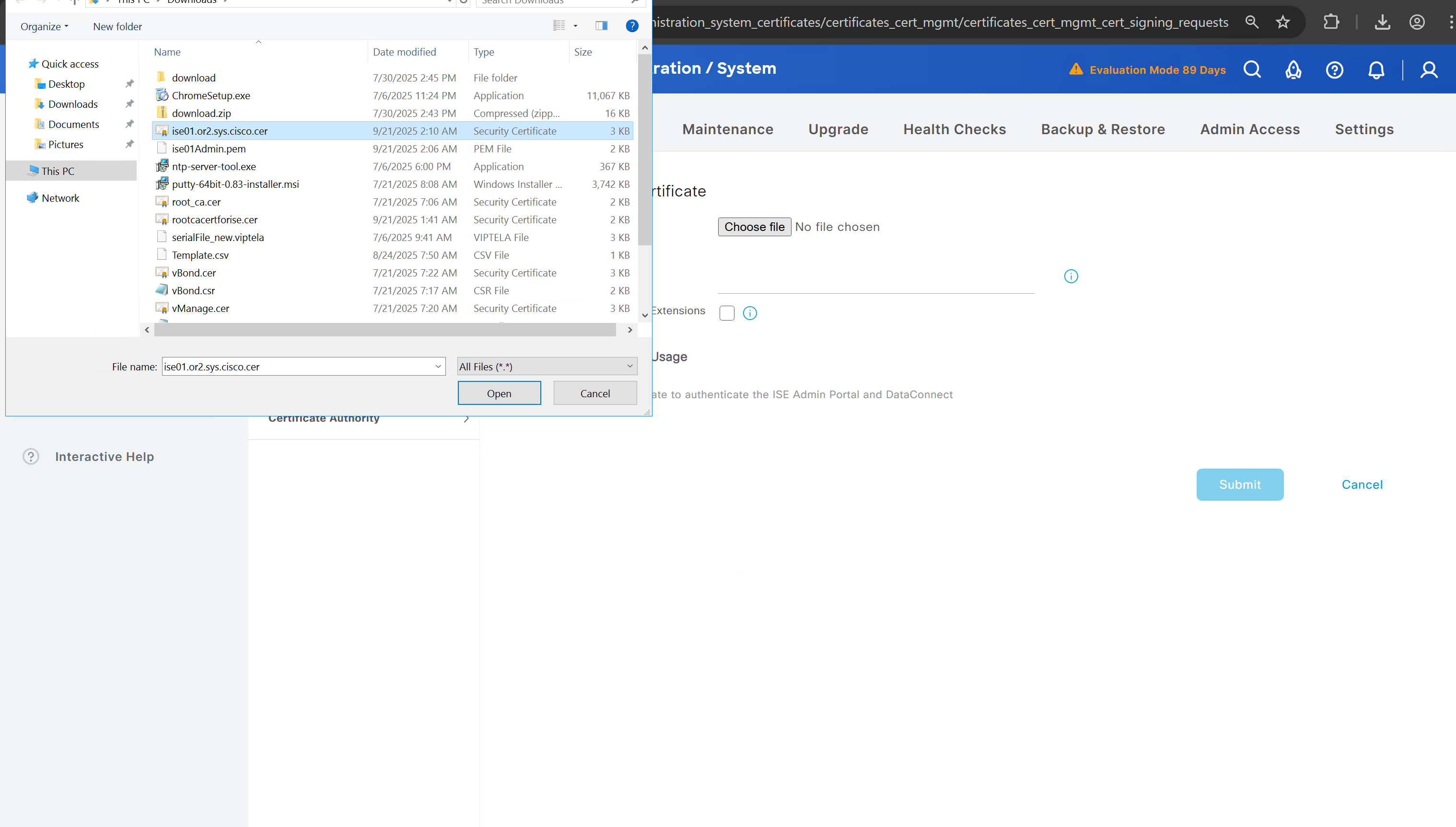
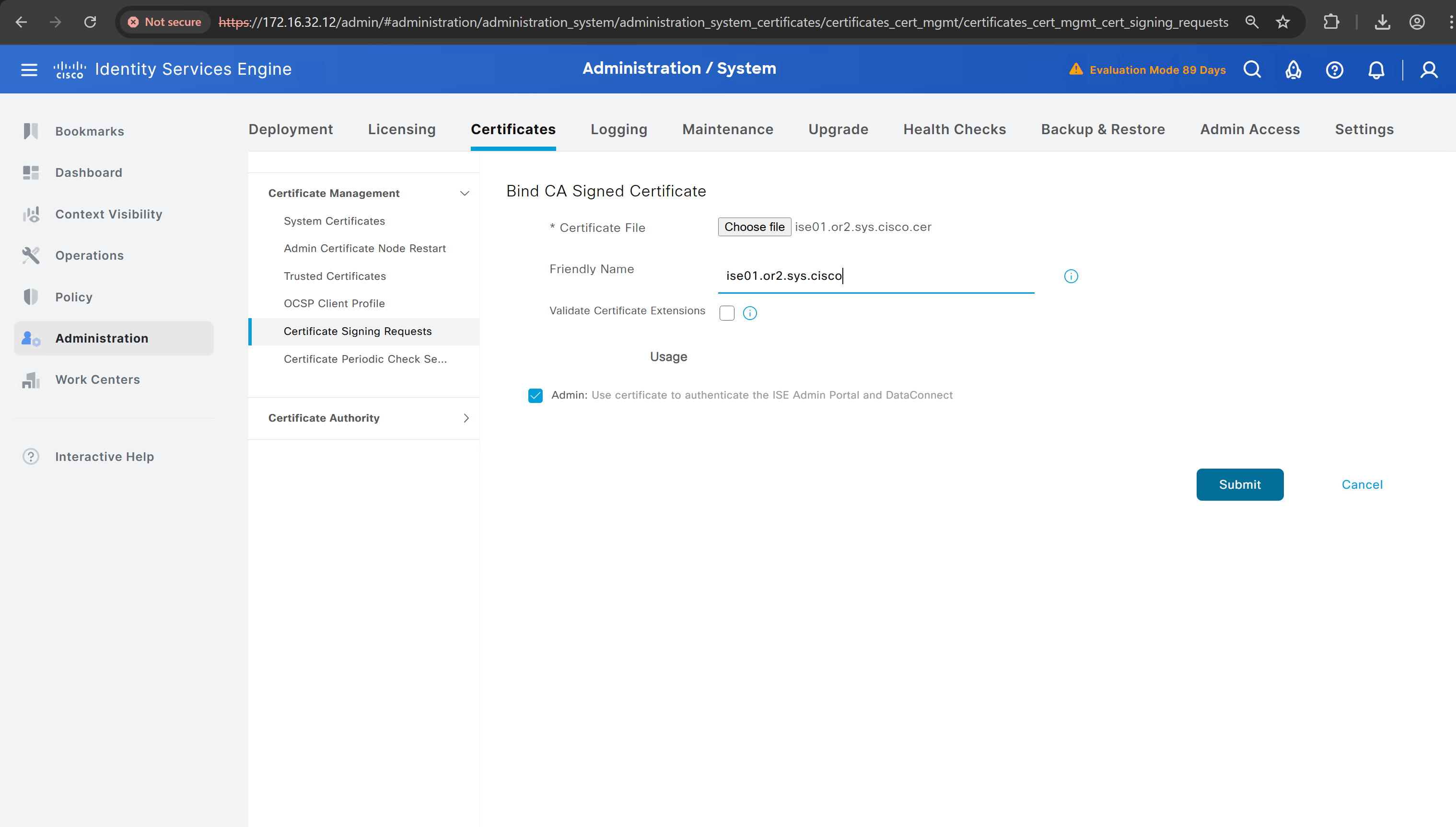
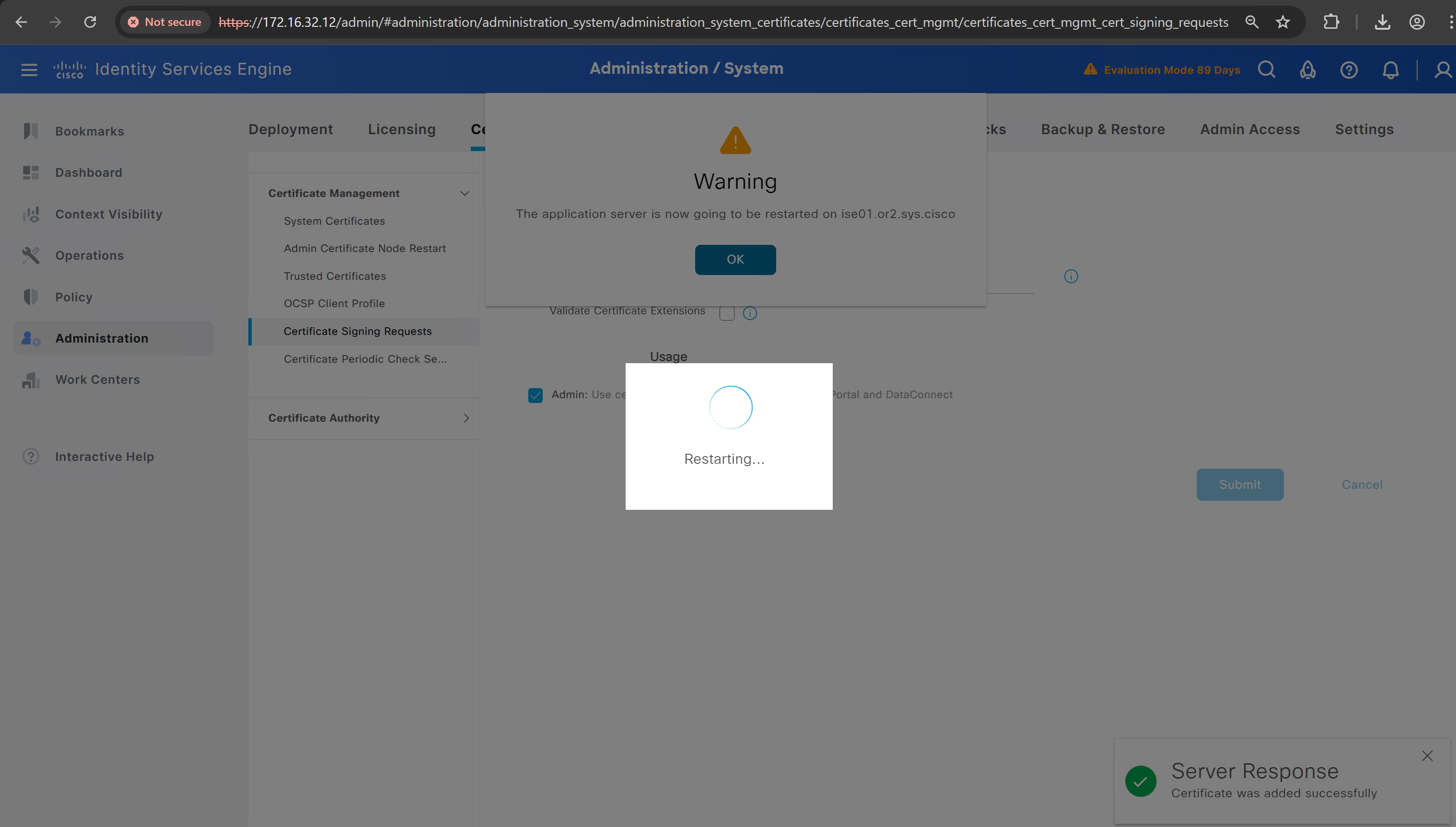
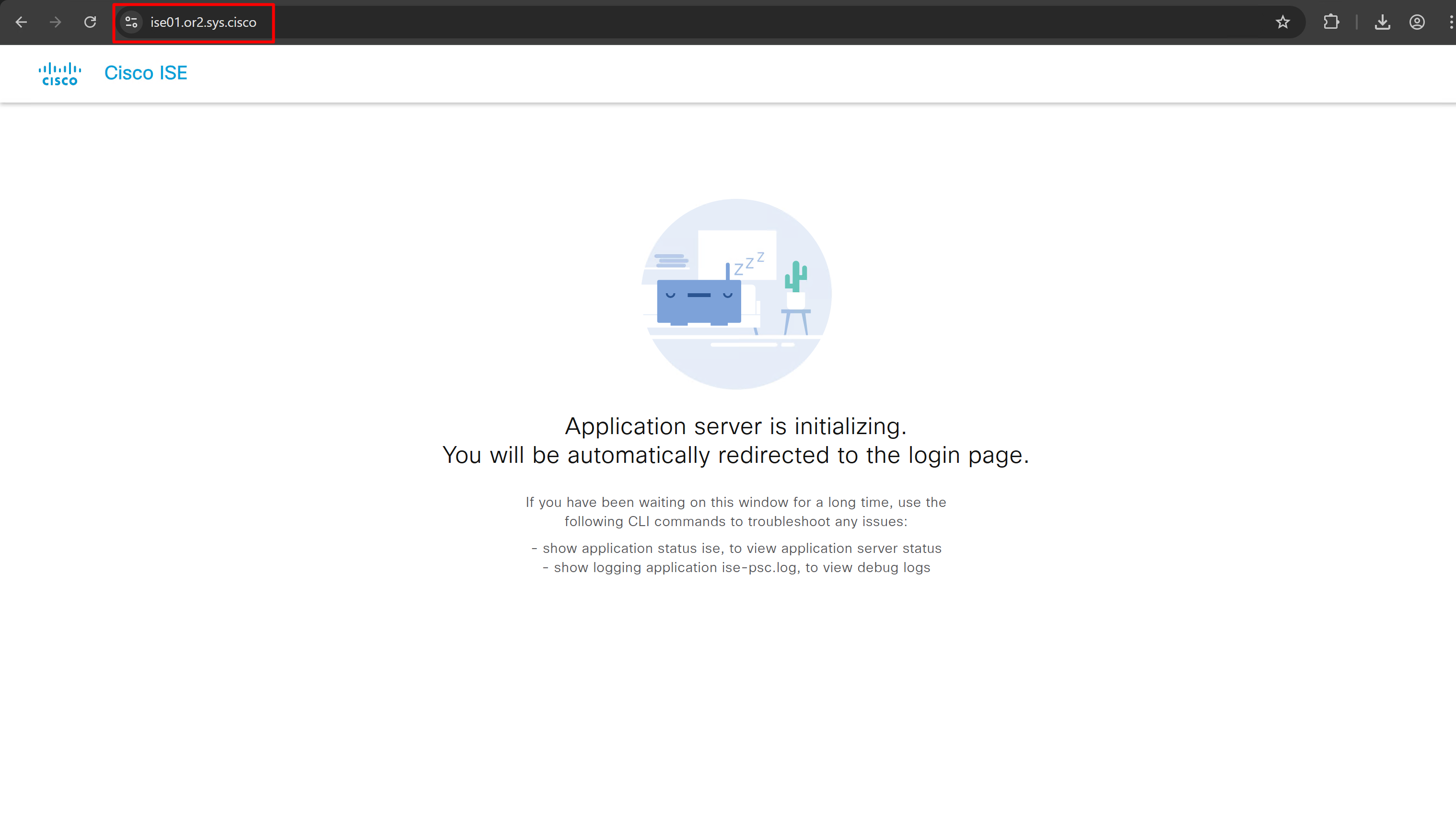
it is trusted now in browser if we access it on its FQDN
CN is the FQDN of the ISE
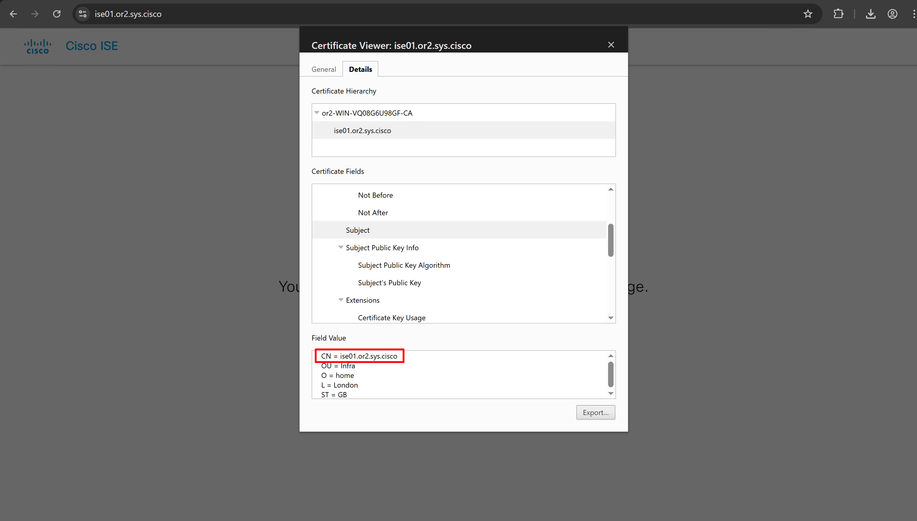
more…
coming soon
next post
Enable logging of commands by DNAC
Configuration
conf t
!
! Enable the archive feature
archive
 log config
  logging enable
  notify syslog contenttype plaintext
  hidekeys
!
! Optional: Set up where the archived configs are stored
 path flash:config-archive
 write-memory
!
end
!
! Ensure syslog logging is enabled (optional but recommended)
conf t

logging buffered 64000
service timestamps log datetime msec
!
end
write mem
next post
SDA LM 1 – Initial Configuration & Setup
Videos
SDA – LISP and Routing introduction
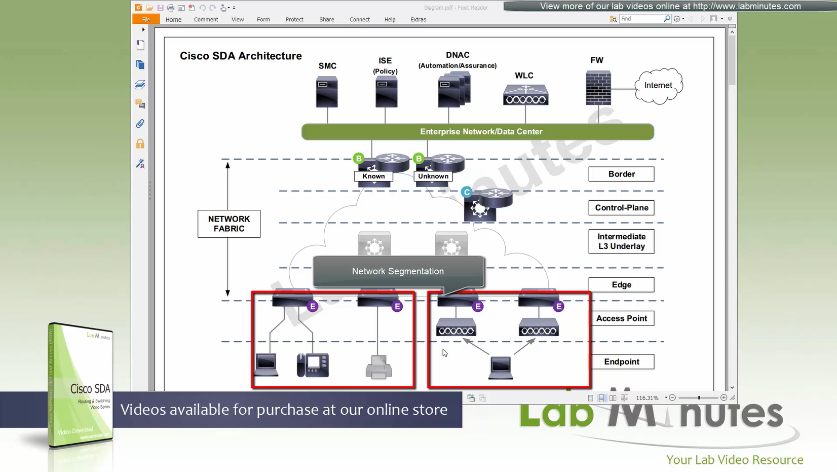
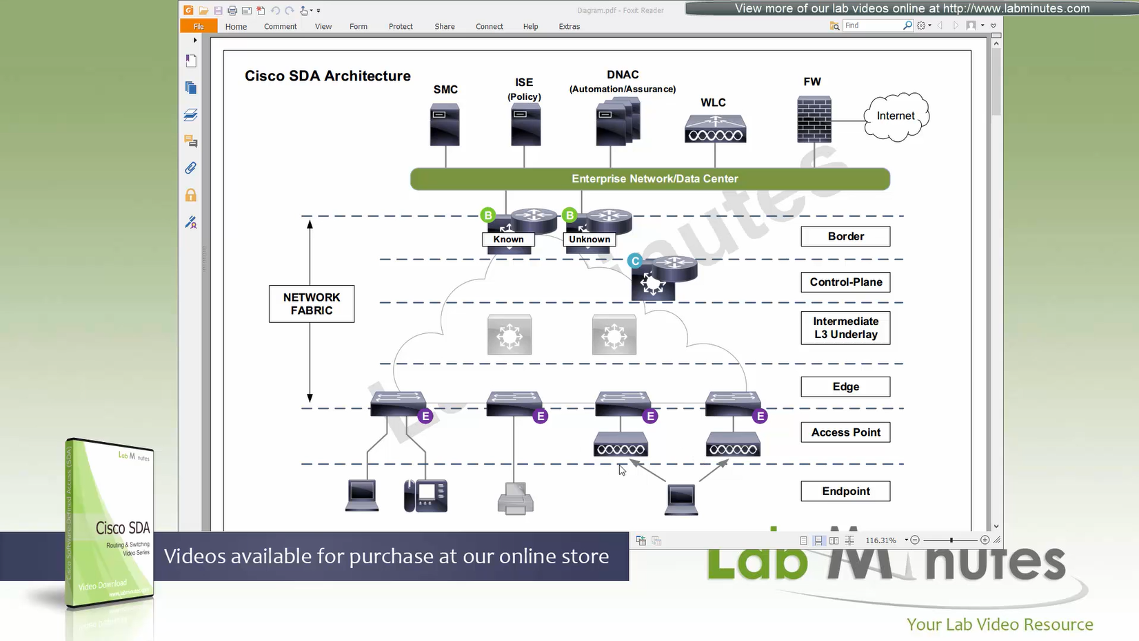
Fabric spans from border nodes
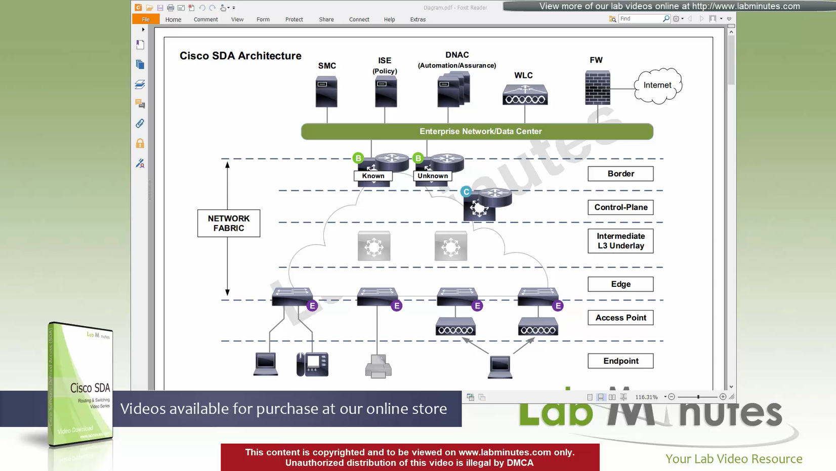
VXLAN (tunnel packets) routed across the point to point L3 (underlay)
Edge and border run L3 eliminating L2
Underlay routing is only there for mostly learning loopbacks of switches in fabric
Client data can be vlan tagged or untagged
Edge switches receive data from clients, if destination is on another switch in the fabric
or in an outside world (via border)
then VXLAN encapsulation (tunnel) is created to other switch or border node
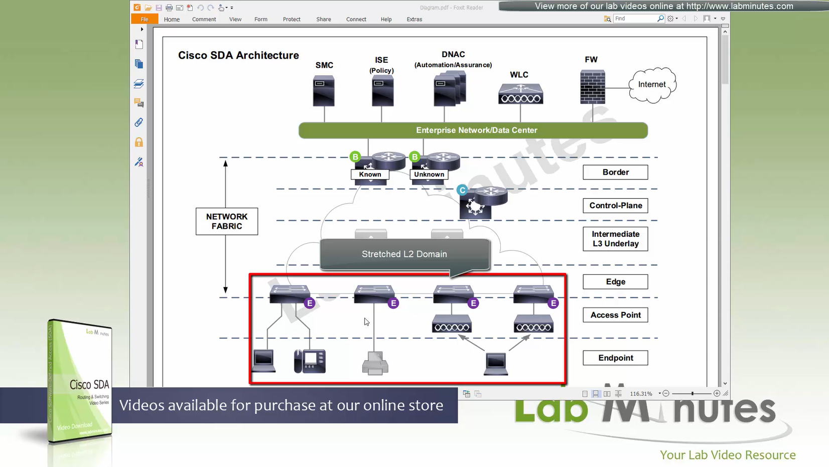
Client can roam from one location to another keeping their original IP address and L2 domain due to “stretched” subnets,
Same subnets (SVIs and also vlans) are available in all edge switches for both wired and wireless
Network segmentation (different virtual networks) or Micro segmentation (using SGT tags and TrustSec)
You can also have “Fabric” enabled WLC and AP,
this makes wireless clients consistent policy wise in DNAC same as wired clients policies
Edge nodes detect the endpoints and updates the control plane about these endpoints
Edge nodes are also responsible for VXLAN encapsulation and decapsulation
Control plane node is the brains of the Fabric and provides “Endpoint to Location mapping” to the edge nodes and border nodes using LISP
Control plane node(s) is LISP Map Server and LISP Map Resolver
VXLAN can carry both Layer 2 frames and also Layer 3 packets
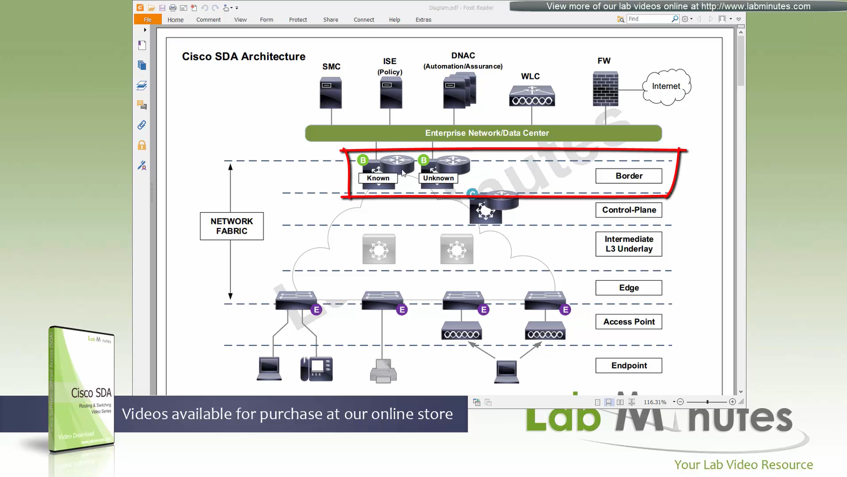
Border node and control plane node should be deployed in pair (2x) to have redundancy in the network
Fabric border node – acts as a gateway to fabric world
Network traffic will need to leave via the fabric border node to access the rest of the enterprise network and internet
Border node peers with external “Fusion” router and advertise Fabric -> fusion and also redistribute external networks -> fabric.
Any external routes learned will be registered with control plane so that those external destinations are registered in LISP
Because edge nodes only follow LISP routing and not any other routing protocol
Control plane is consulted if any packets need to leave for destination other than local switch
There are 2 types of border nodes
1. Known Border Node
2. “Default Border Node”
Known Border node is for destinations that are known subnets
Second type of border node is that deals with unknown routes and is also called Default Border
Traffic is encapsulated to Default Border if LISP has no entry in control plane and control plane responds back with Default Border
Both Known Border and Unknown Border can live on same device or two different devices
but sometimes in diagrams they are shown to be 2 different devices
- control plane node
- border node
- known border node
- default border node
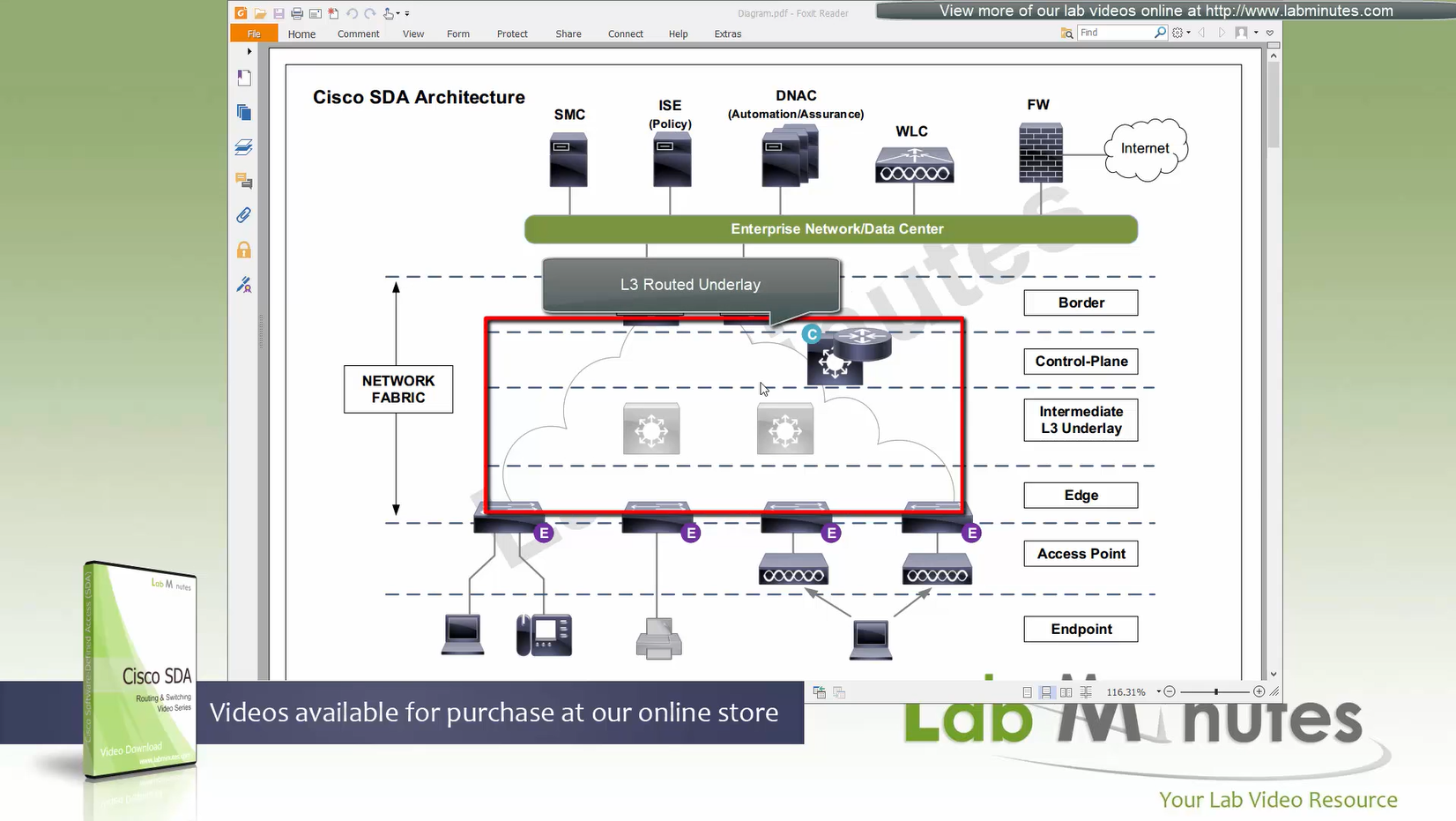
Intermediate Underlay device:
Intermediate Underlay devices need to be able to support the “Jumbo frame” and use ISIS
Cisco recommends this intermediate devices to participate ISIS (shortest path) with redundant links
there should be no spanning-tree or layer 2 in the Fabric.
Underlay Intermediate device aggregate all the access edge nodes into something and then connect into border switch or router
Direct connections to border are supported but should not be done for larger site due to scalability issues
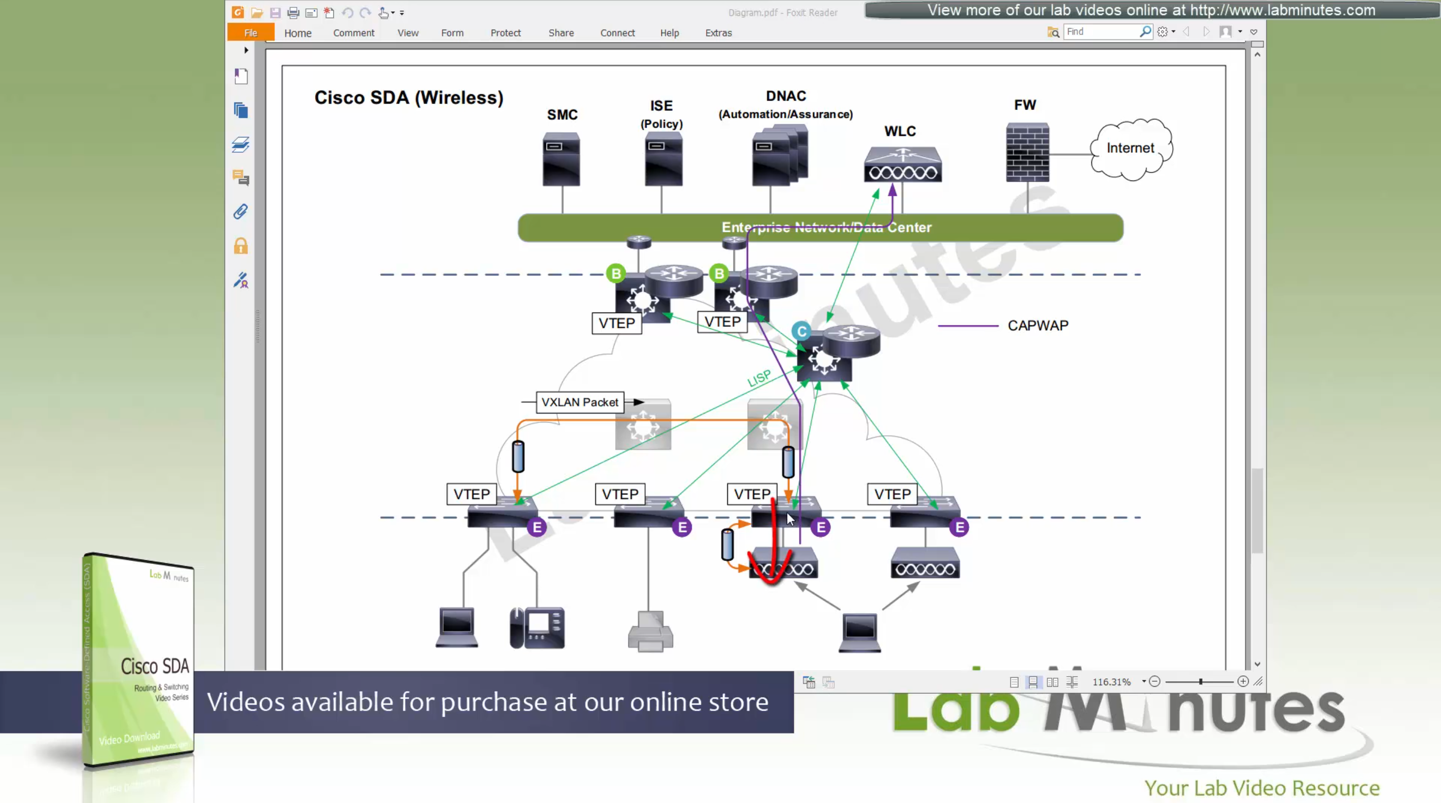
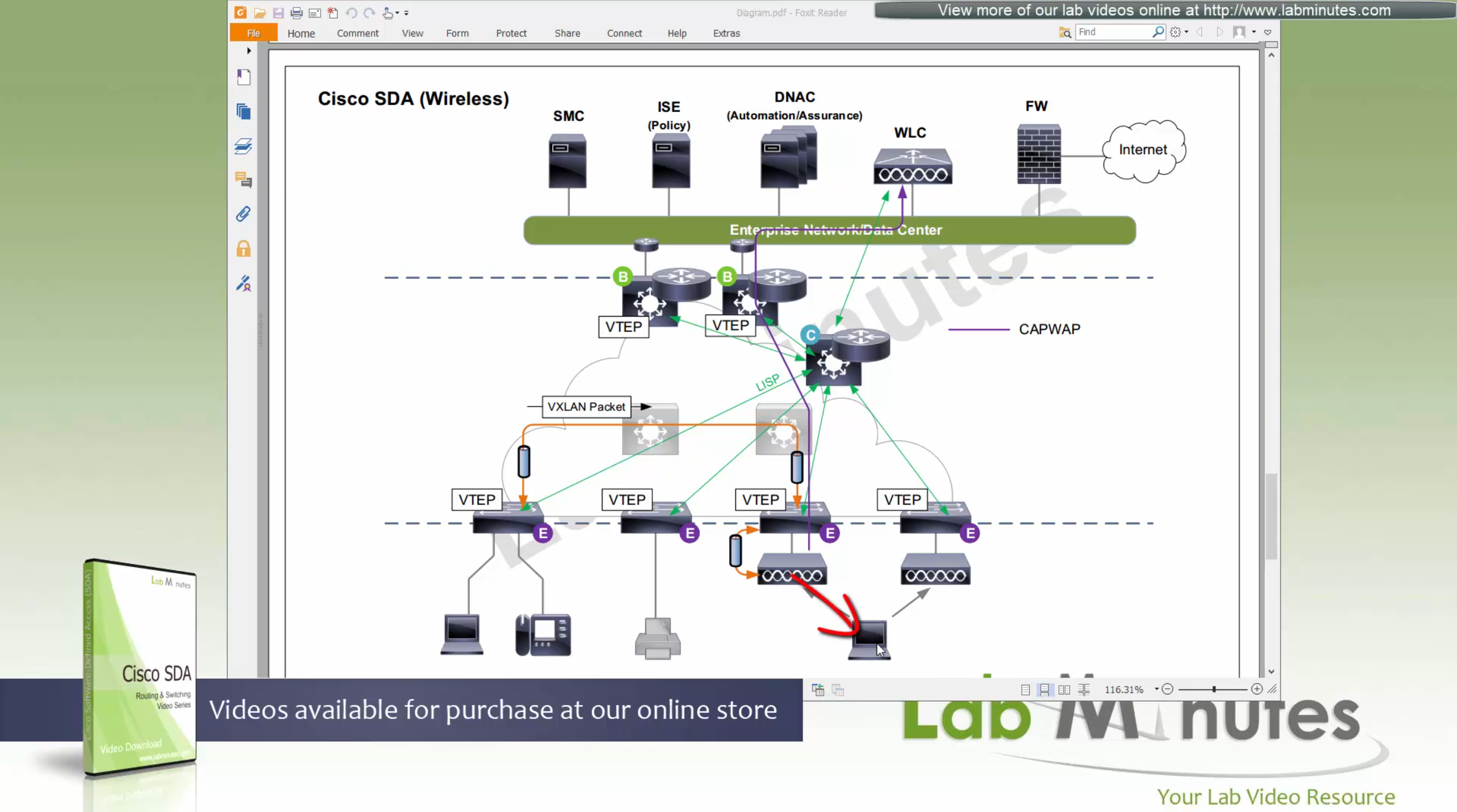
Fabric mode WLCs still manages the AP and maintains client connection information via CAPWAP control channel
Fabric mode WLC reports to control plane node and lets it know about the client
Communicates associations and communicates roaming to control plane
Controller sits outside of the fabric and APs sit inside the fabric directly connected to edge nodes
WLC can be connected outside the fabric as long as it has reachability to the border and control and APs
Fabric mode AP
(Data tunnel) they will not send data to WLC for it to be centrally switched but exit data locally on the fabric via VXLAN tunnel > edge switch
Fabric AP participates in VXLAN encapsulation
however they maintain CAPWAP tunnel (Control tunnel only) to the WLC at the same time,
This allows wireless clients to be treated within the same system and policies of the fabric.
Control: AP <–CAPWAP CONTROL–> WLC
Control: WLC <–LISP–> Control node
Data: AP <–VXLAN–> Edge node
AP must connect to edge node “directly”, there should be no switches in between AP and Edge node
WLC sits outside the fabric or Fabric border node and APs sits directly under the edge nodes
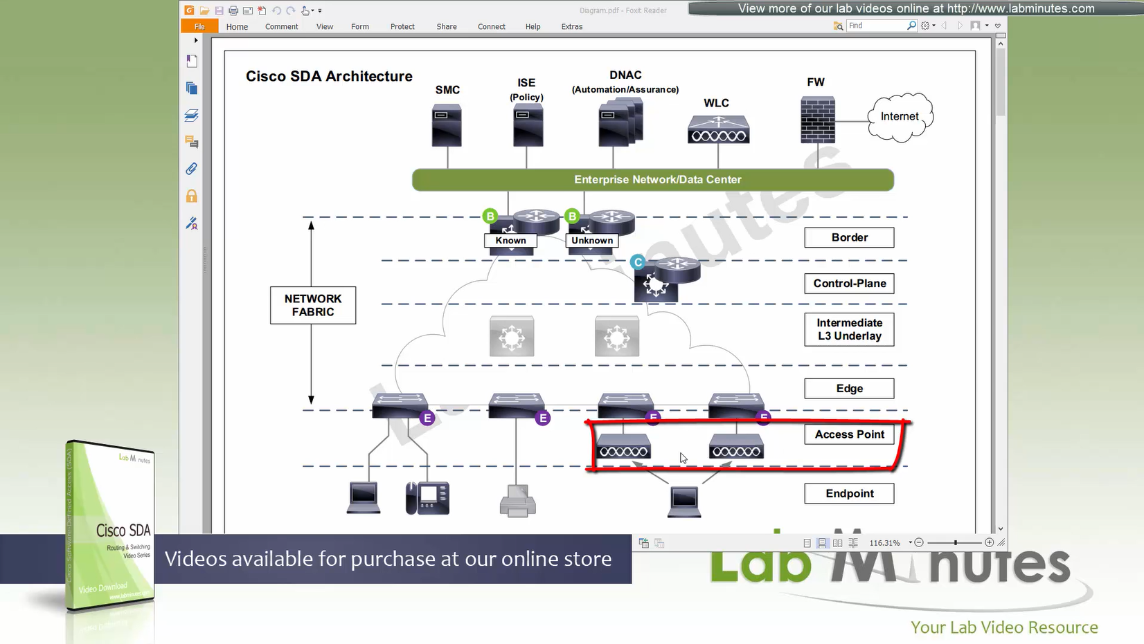
because Access points connect to edge nodes directly clients are connected like
Client <–Wireless–> AP <–VXLAN–> Edge node
DNAC
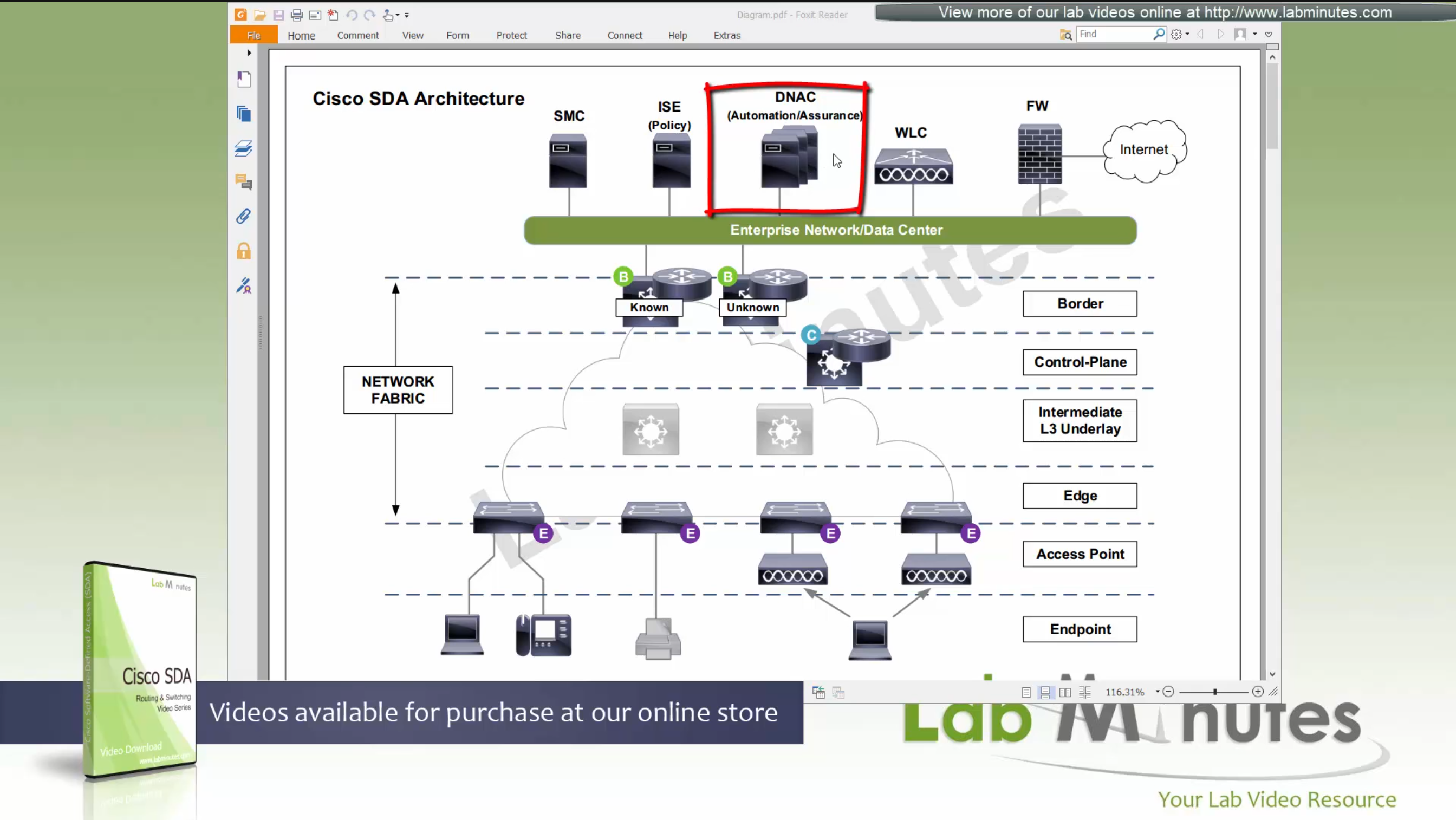
ISE maintains the security policy and contains Authentication / Authorization policy and also TrustSec related components
DNAC uses APIs to push configuration to ISE for SGT but ISE is separately managed
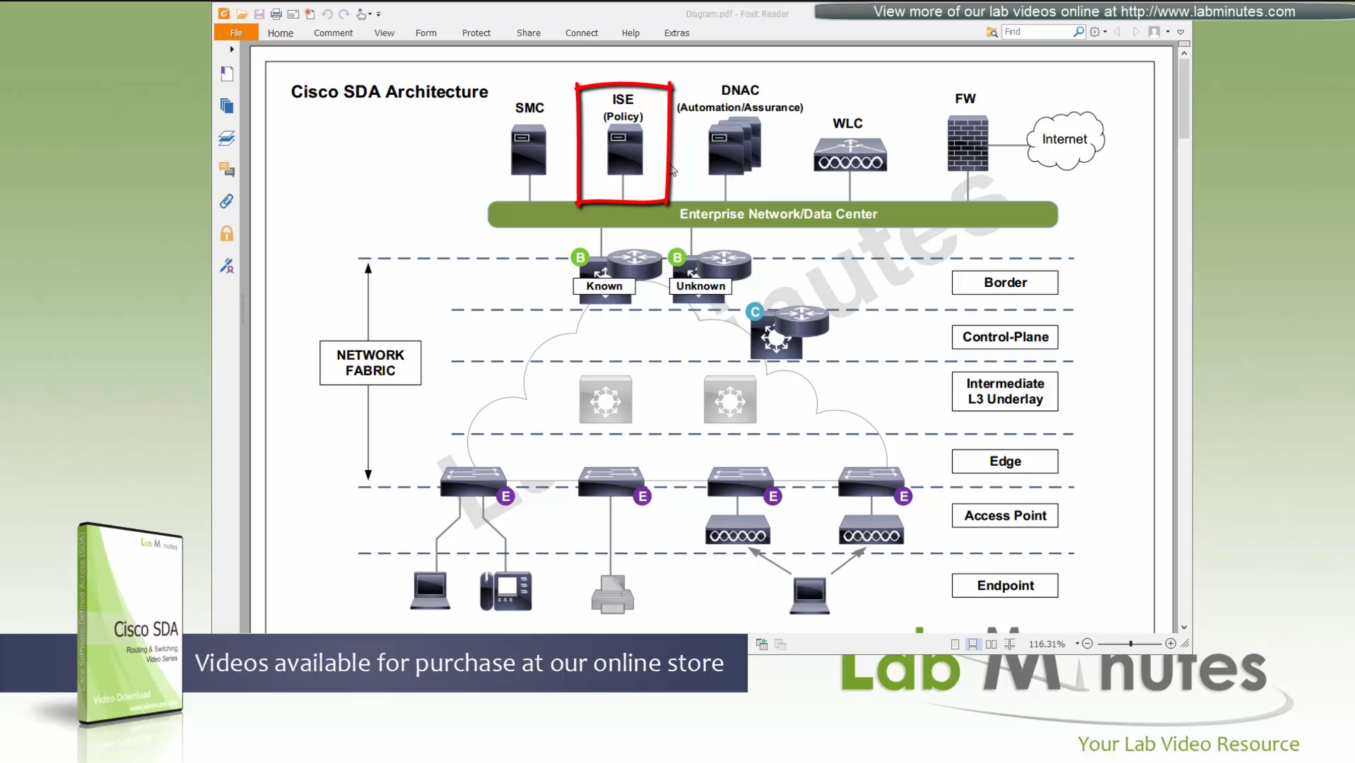
Management loosing network such as DNAC will keep the data forwarding and not cause outage
One thing to keep in mind is that we need to have high speed LAN like access between all fabric nodes and DNAC, that is why DNAC cannot be spanned across WAN, all Fabrics must have high speed access to DNAC
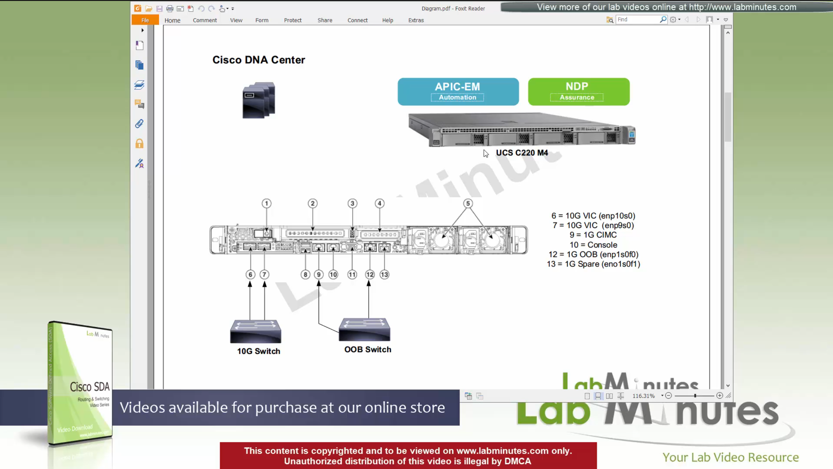
DNAC is available as C220-M4 which is same C series server as APIC for ACI
It is always recommended by Cisco to deploy DNAC in cluster of 3
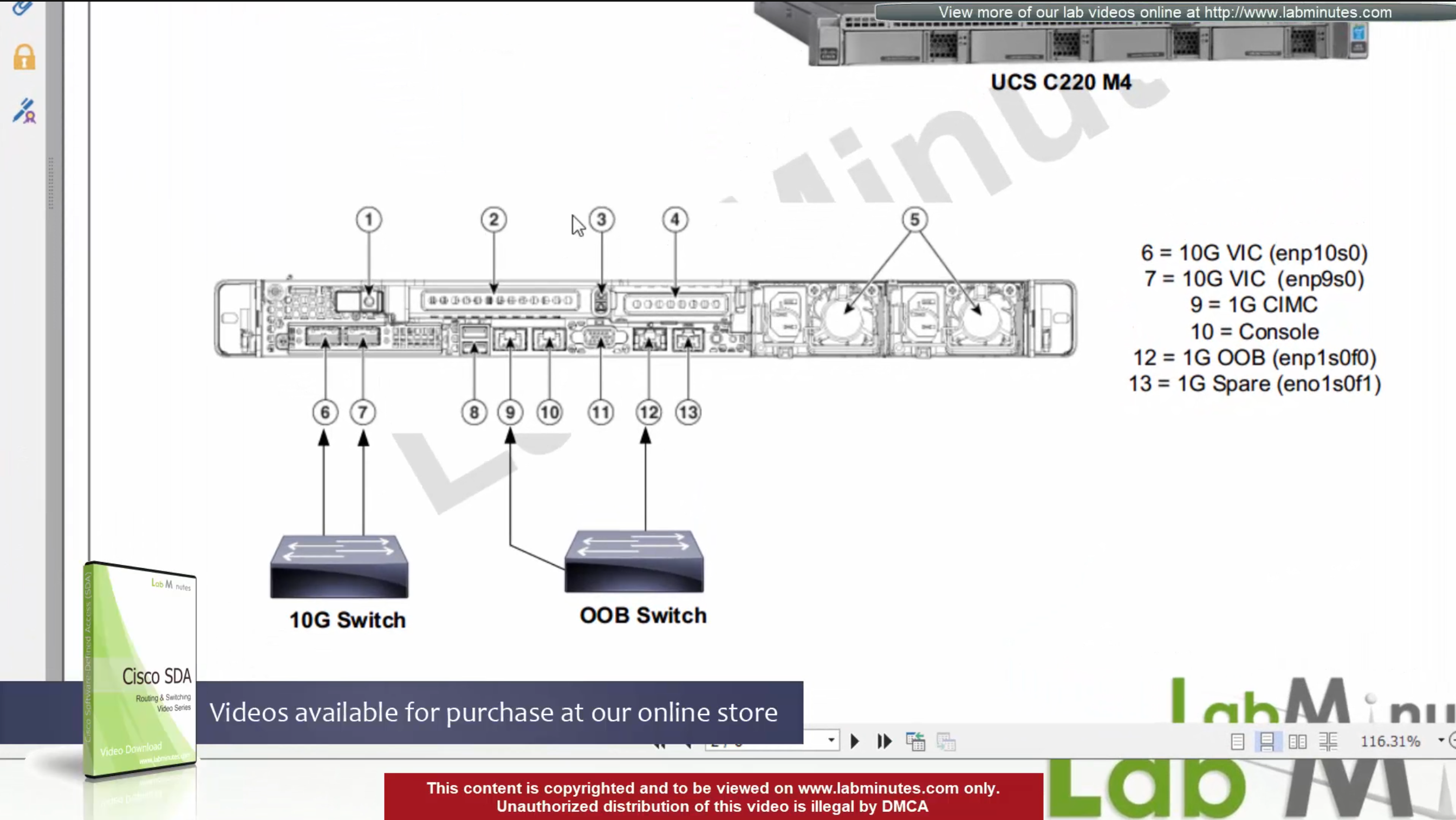
For connectivity DNAC has 2x (redundant) 10G VIC Cards – Data interfaces for fabric facing communication
It is not mandatory to configure the OOB interface for management connections
Data port IP can also be used for management
unlike ACI, where GUI and SSH must strictly be done via OOB IP
CIMC interface – Server interface for KVM and firmware upgrades
Console interface – in case network connectivity is lost
OOB Mgmt interface – optional for HTTP and SSH
it is recommended so we have another path for accessing the GUI and SSH
There are 2 engines running on DNAC,
APIC-EM
NDP
There is 3rd engine called policy engine but it does not run on DNAC but on ISE
APIC-EM shares a lot of features with APIC and helps with Network topology discovery, software management and upgrades aspect etc, APIC-EM is also responsible for the network automation
NDP stands for Network Data Platform
NDP takes care of the, “monitoring”, “telemetry”, “assurance” and “data analytics”, This is like Solarwinds NPM
NDP is more with Analysis and alerting
while the APIC-EM is like NCM for pushing changes and making changes
In NDP Assurance comes from the fact that it goes one level deep and it not just relies on polling from network devices for system stats and health but it also gets the Client’s connectivity monitored from client and their experience perspective
Client connection stats and connection health and client experience is one of the big things, and it is client connectivity that “assures” that network is working because clients are live and using the network, so instead of SLA on the box, client data traversing the network is a better testament that network is working or not
NDP also has “machine learning” elements
DNAC Assurance or NDP collects data from various sources, once data is received, Assurance engine does correlation and provide bigger picture pieced together to reveal issues which administrators are either not aware or know before
SDA is not fully supported by all switches / routers
Some devices have some features supported
Others fully support all the features.
This sheet can be found on google, Y and N in column have been added, older hardware possibly cannot support those features
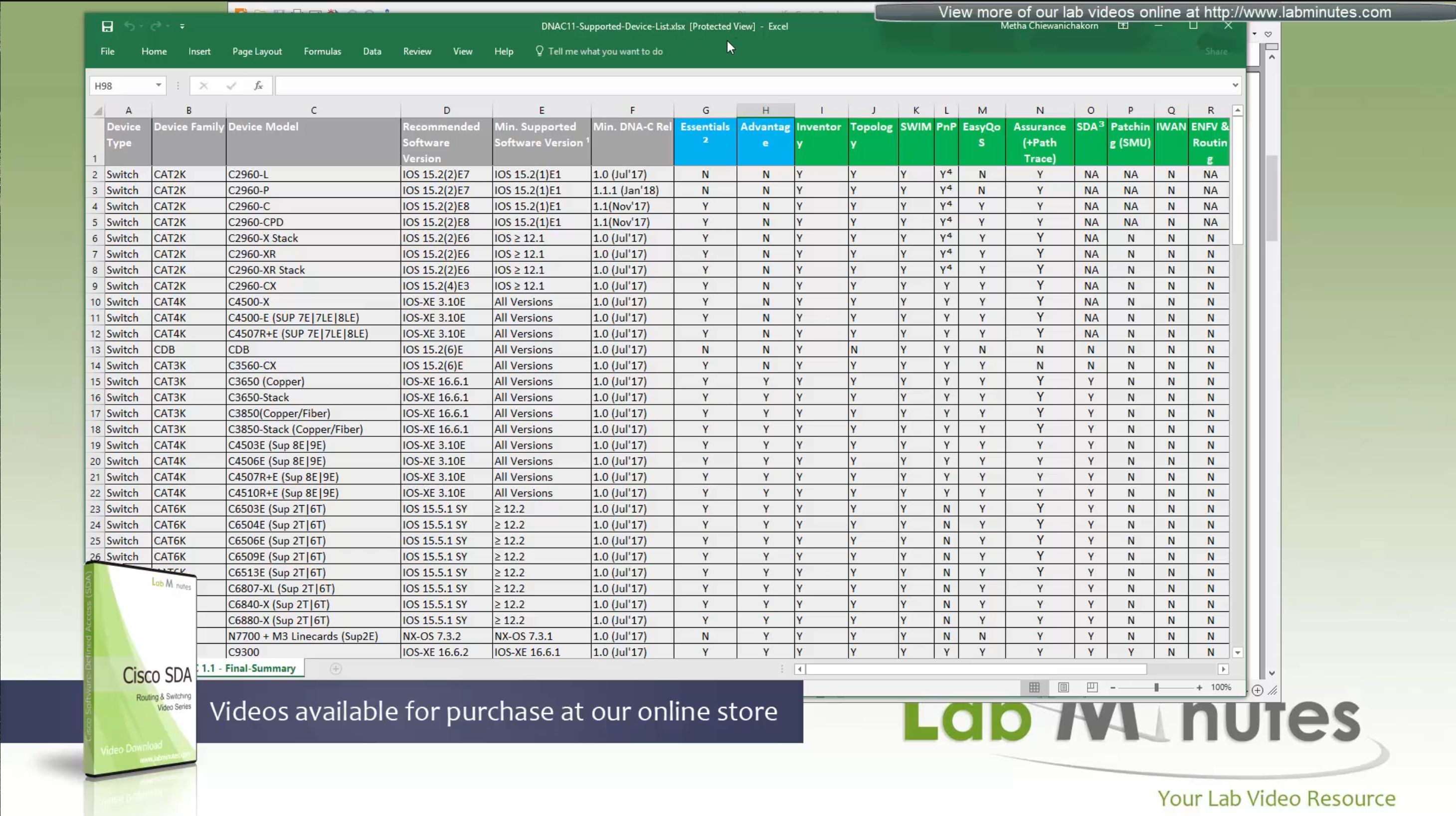
We can see that very first switch that can do SDA is 3650 Copper
Some cisco models can be the edge nodes only but not the border node or control node.
So make sure that we order right kind of hardware before deployment.
Cat 9k will support most of the SDA features
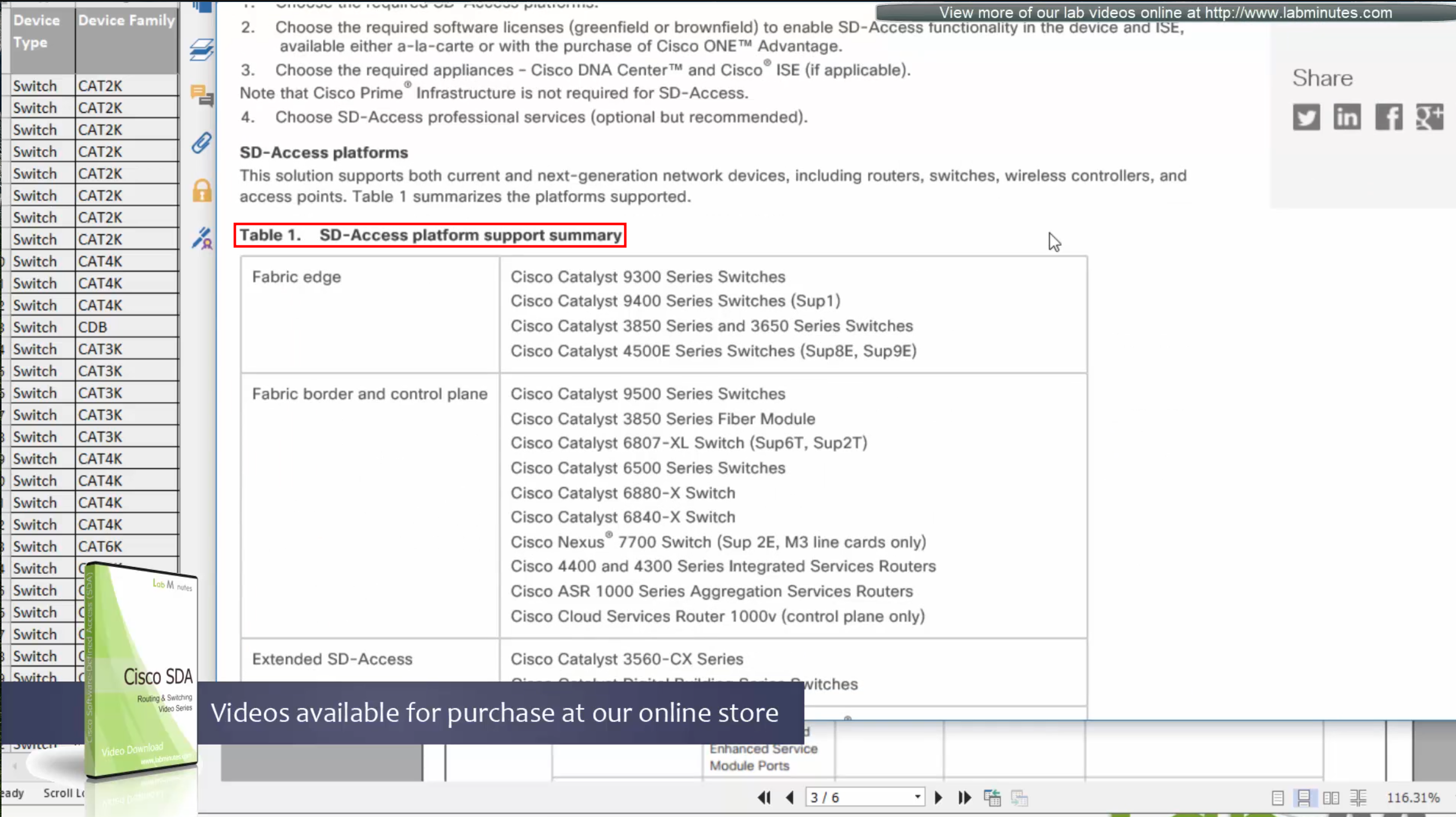
This list also includes routers, as routers are also supported in SDA for Border and control nodes but do not deploy anything outside of Validated designs in CVD
Similarly there are WLCs that are validated for SDA, be sure to check SDA hardware sheet
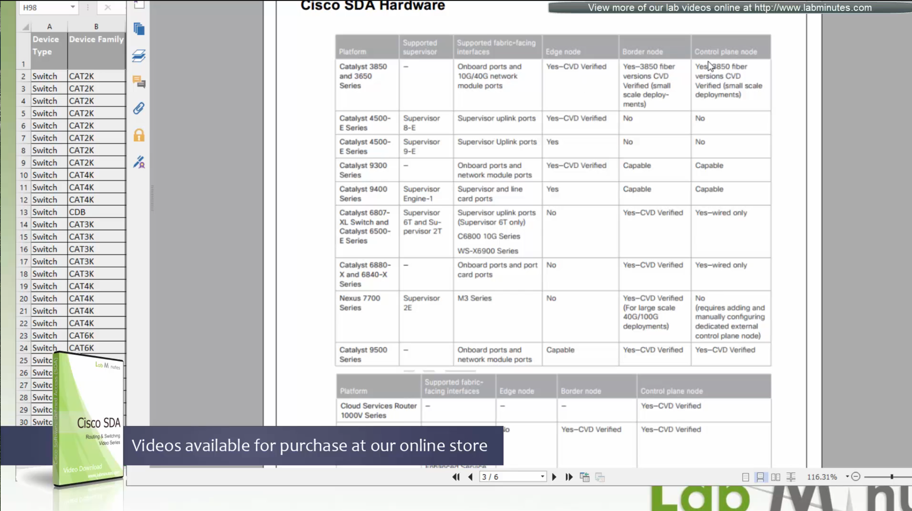
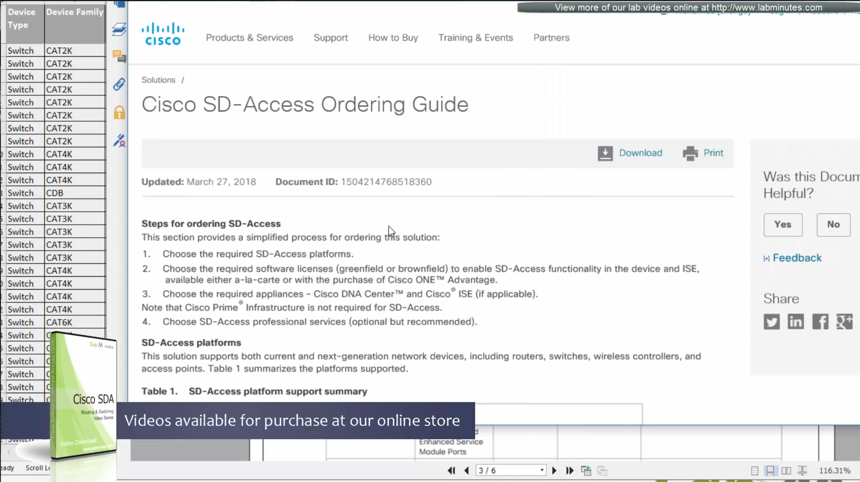
Always consult “ordering guide” for new deployments
Fabric is consistent across the network and is not different unlike legacy network which can have different networks between switches because of inconsistent configuration. Fabric on the other hand is consistent from L2 and L3 perspective.
All the underlay network is going to see is UDP packets


Fabric edge nodes tell the control plane about new endpoint
by snooping the ARP response and DHCP offer packets (device tracking on edge),
information told to control pane includes “MAC addresses”, “IP addresses”, “port connected to”, “Liveliness” (to see if host is there or not) and “VNI host belongs to” (VNI is equivalent of the VLAN in VXLAN world).
Edge node sends a “MAP register” message to control node
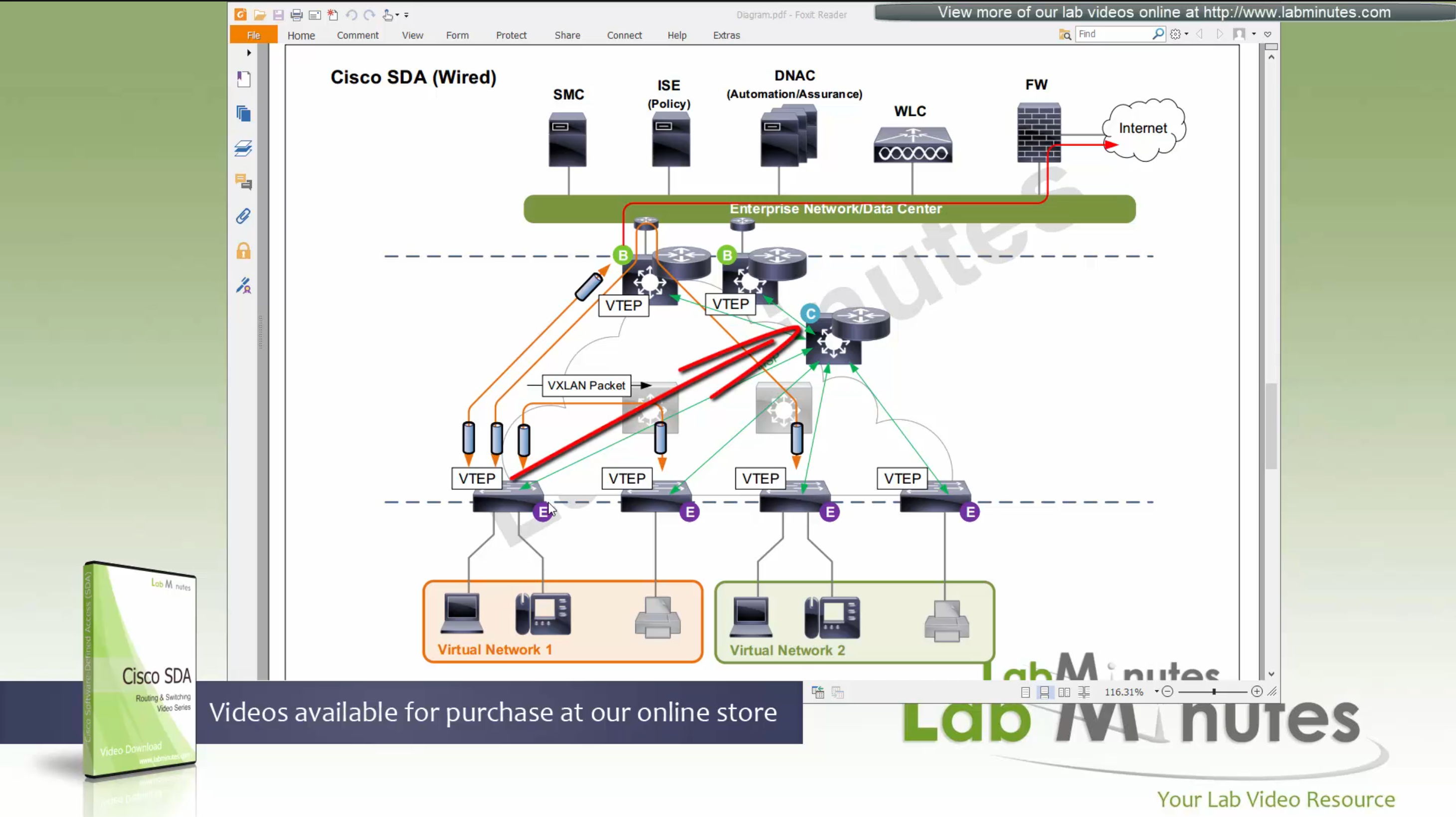
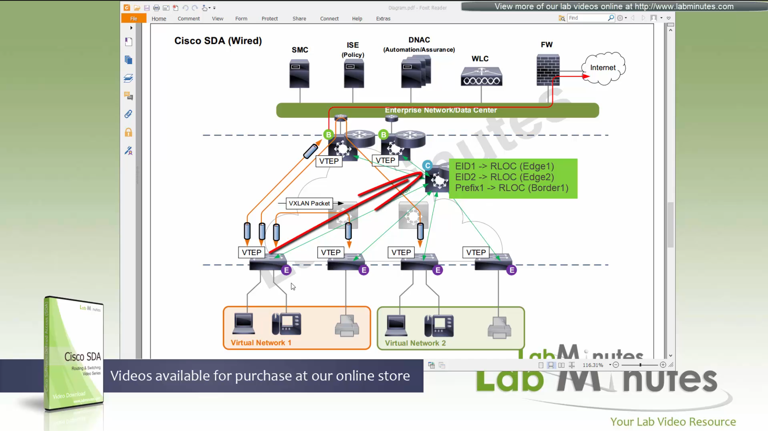
Control node creates an EID (Endpoint identifier) to RLOC (Routing locator) entry is created in database
VTEP and RLOC refers to same thing, the loopback IP address on the switch

Border node does the same thing the edge nodes do with control node
but instead of registering Endpoint IDs it has prefixes to register
prefixes it learns from Fusion for external networks (outside of fabric) as prefixes to Control node.

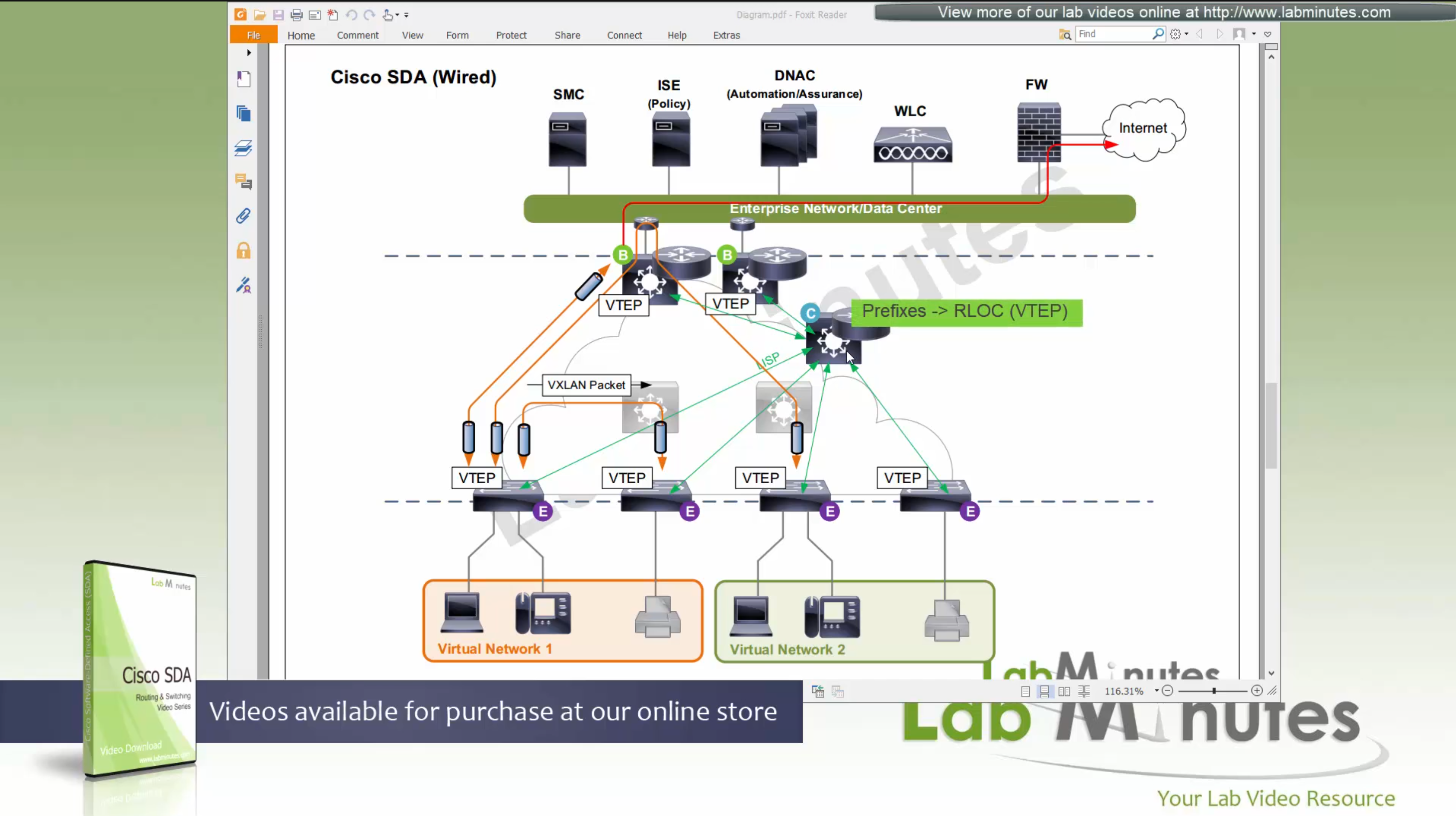
Control plane node not only maintains the EID but also the prefixes
border node needs to be redundant

Caching: border or edge node then caches in a local cache that RLOC entry for future use
because edge and border receives or caches the RLOC entries on need to basis
it keeps their routing table or FIB small and this translates to scalability,
Remember that edges only use LISP and not routing table
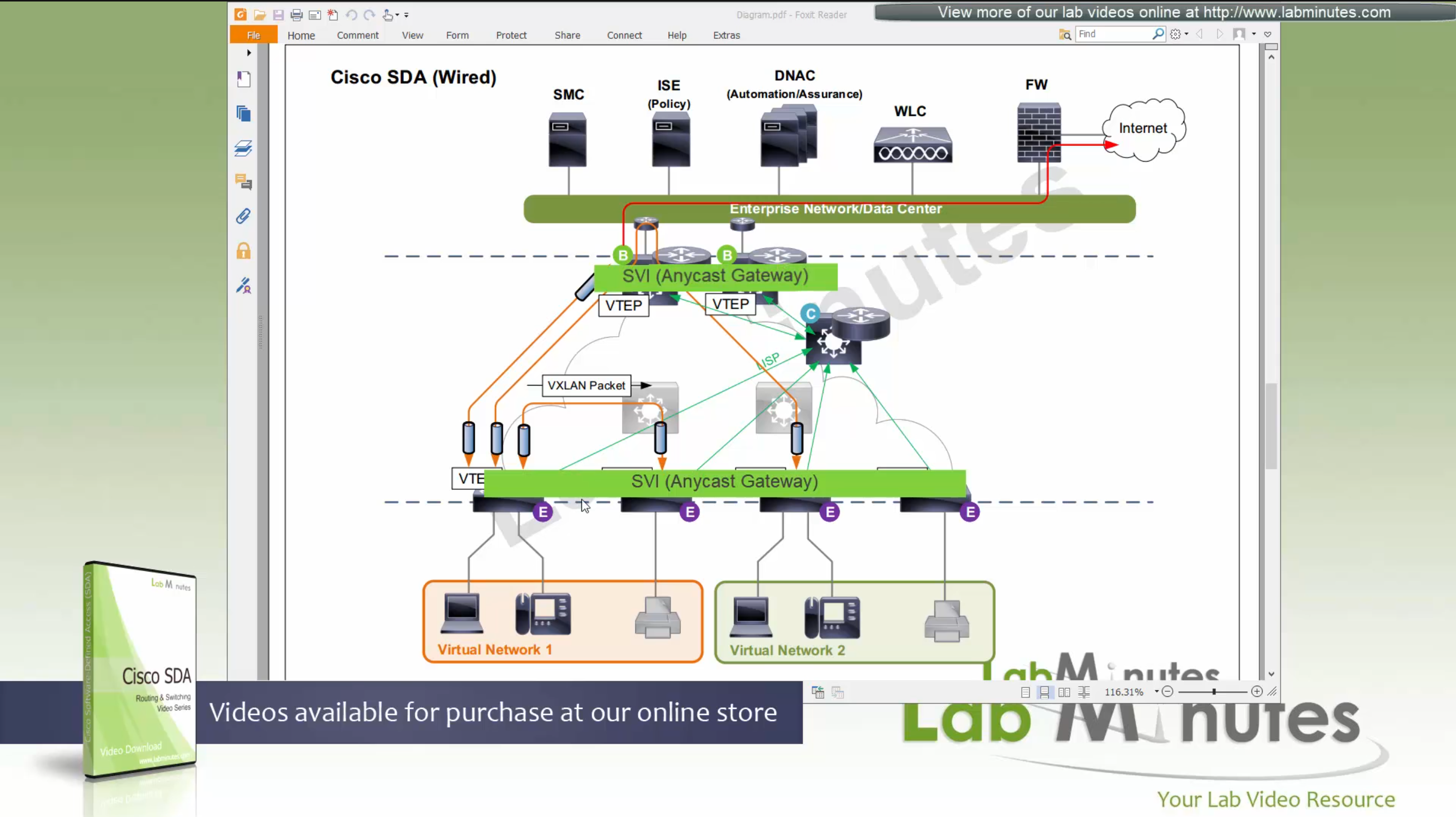
Edge nodes have Anycast gateway which makes SVI available on all the edge and border nodes
These SVIs also have same MAC addresses so when client roams from one node to another, it is seamless
These SVI anycast gateways exist on both Border nodes and also on edge nodes
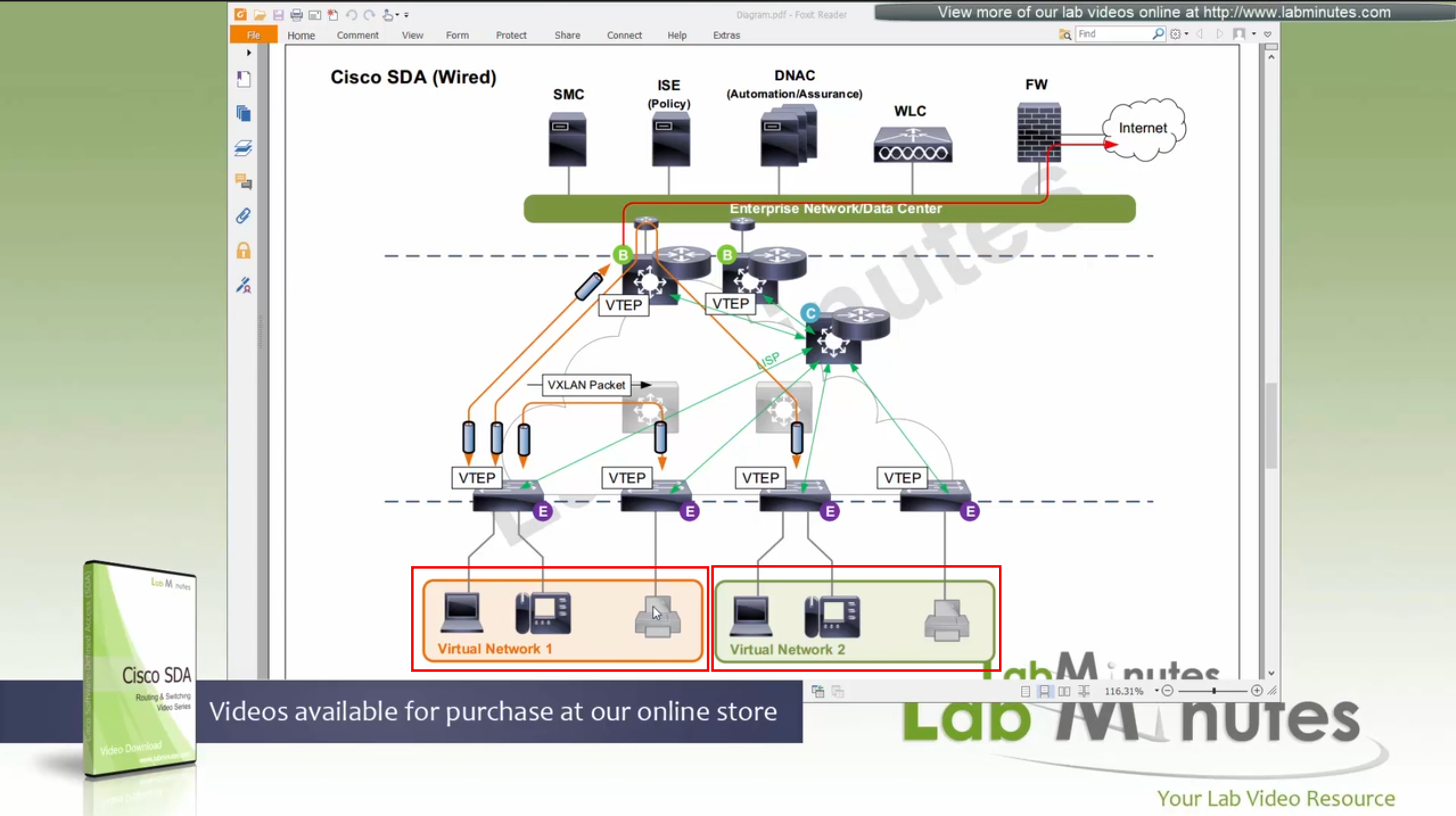
Here we have two different virtual networks or VRFs
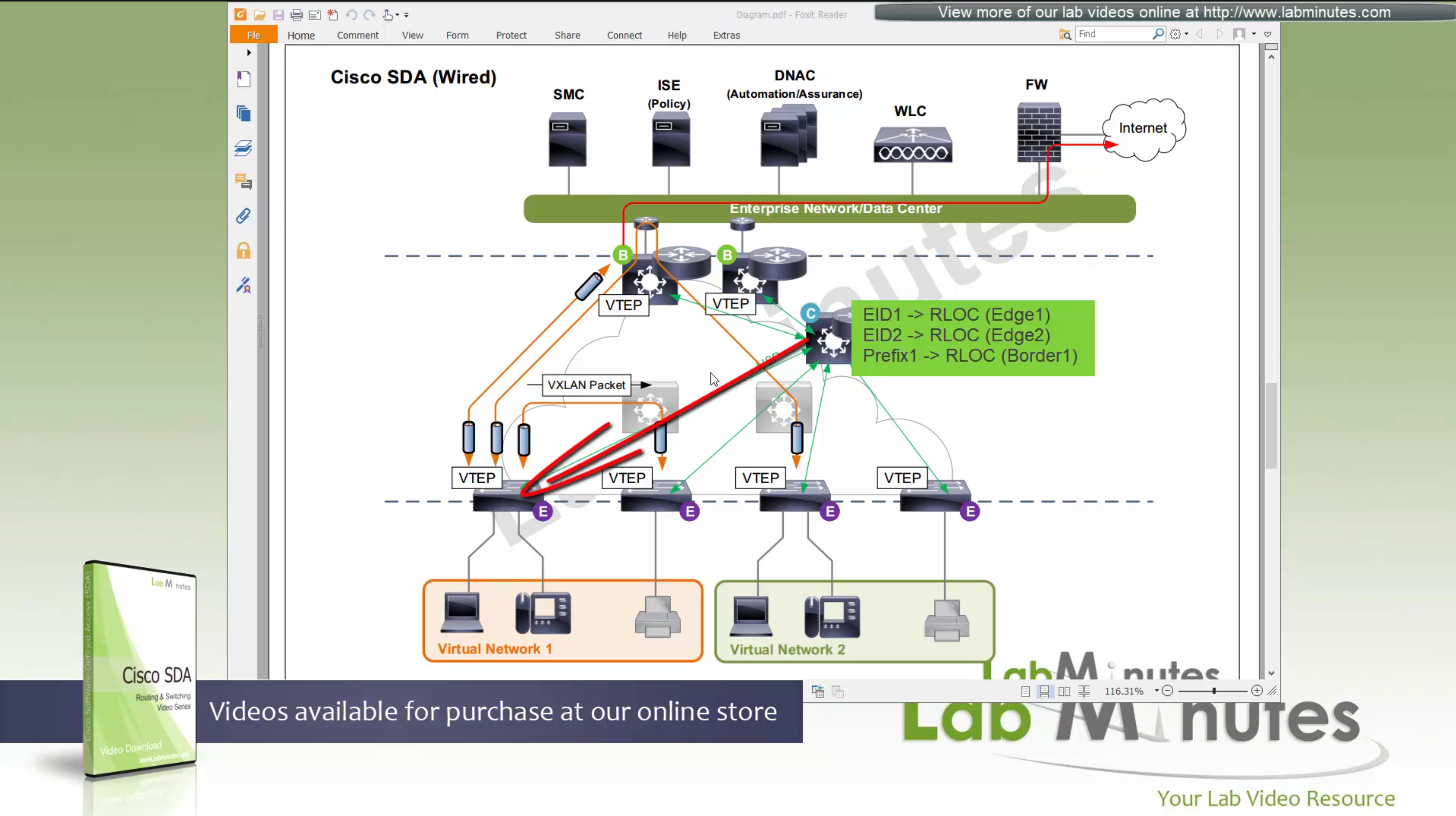
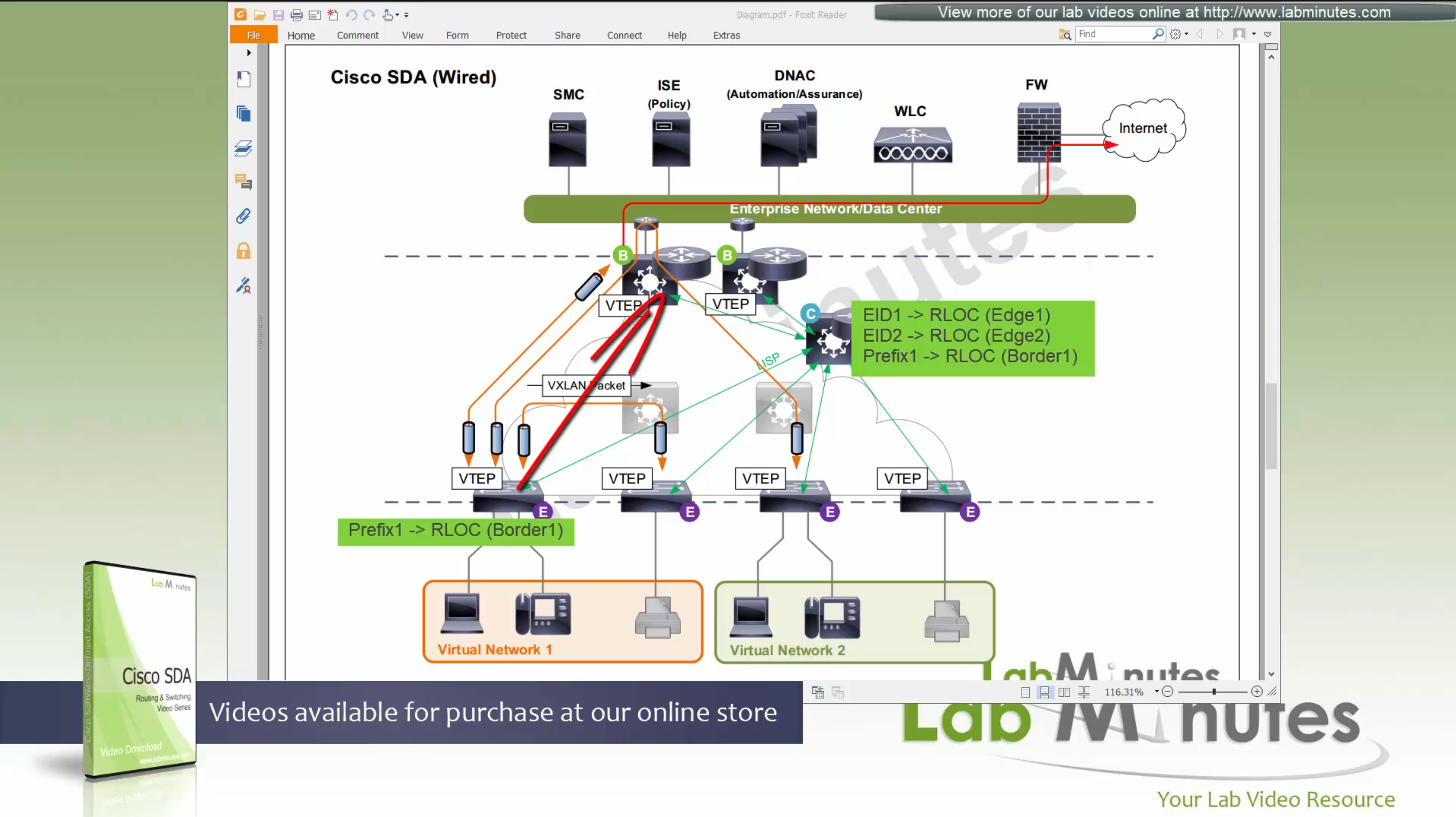
Scenario 1: Packet stays on same switch
In this scenario packet does not leave the switch and is switched from one port to another and that makes it fastest, if you have low latency requirement where even couple of milliseconds of latency such as 2 ms or latency of VXLAN packetization and encapsulation is not tolerable then place the hosts on same switch
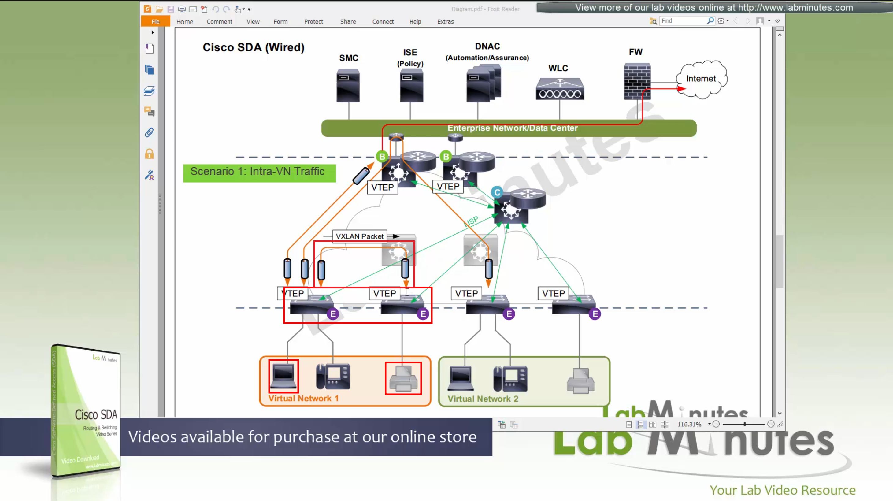
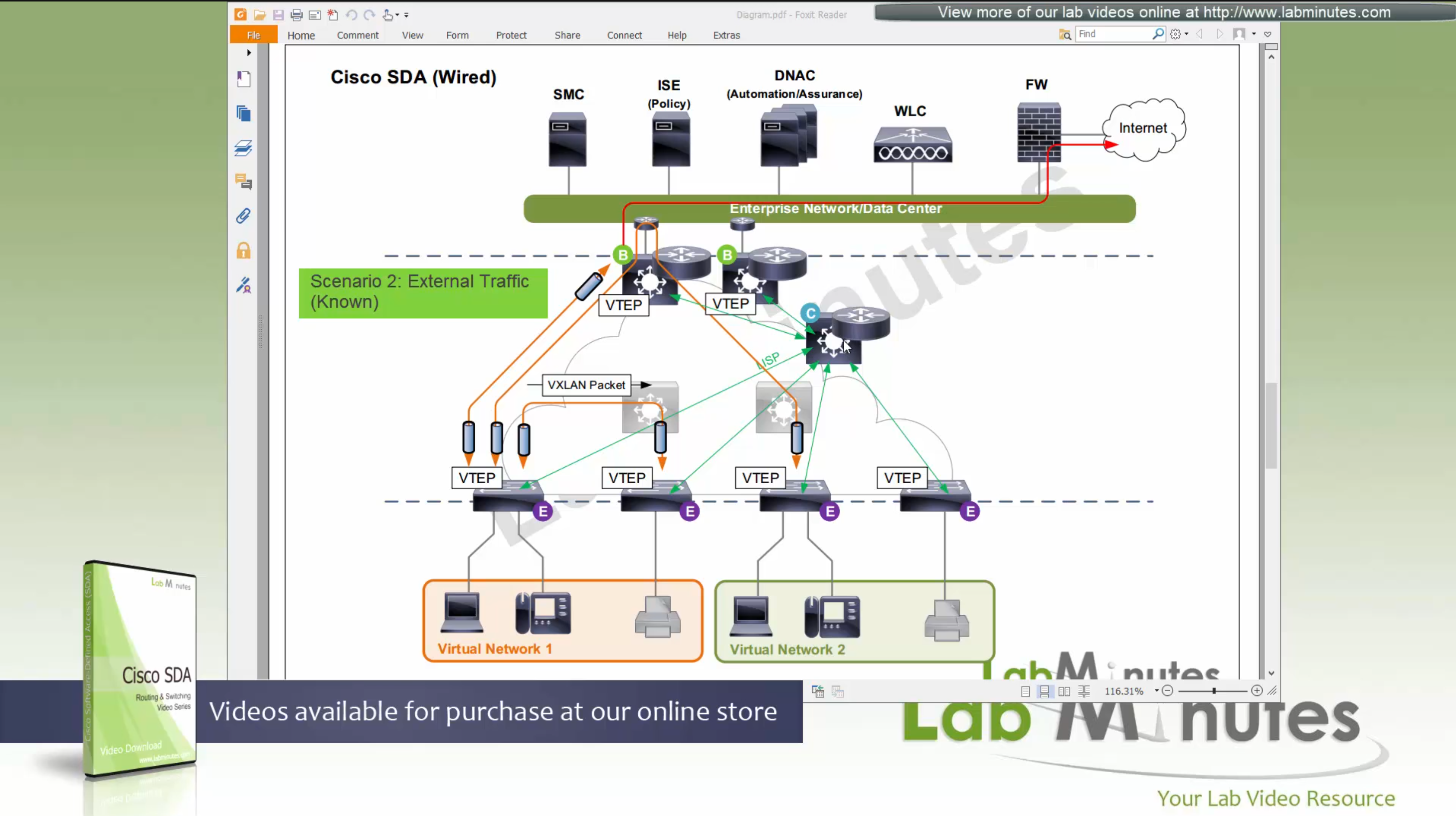
Scenario 2: Packet stays within the Fabric, IntraVN (same VN) traffic
When PC needs to communicate to the printer,
it speaks to control node (because printer is on another edge node)
obtains RLOC for that edge node where printer is attached,
it will create a vxlan packet with correct L2 VNI tag, and correct outer L3 RLOC destination IP address
and insert original IP packet into it as a payload
send it out to the underlay to deliver.
Underlay will deliver
As seen in diagram, this VXLAN flow will not touch border node
As these VXLAN packets reach Intermediate Nodes,
because loopbacks being advertised in ISIS (shortest paths for loopbacks) VXLAN packets will be switched from “edge node to Intermediate node to edge node” Triangle: Edge <–> Intermediate <–> Edge
Scenario 3: Packet destined for “Known” external network outside the fabric.
Edge node inquires the control plane for destination
Control plane returns the RLOC of the border node that registered the prefix
then edge sends the packet to border node,
it will create a vxlan packet with L2 VNI tag, outer IP header will have RLOC destination IP address
and insert original IP packet into it
send it out to the underlay to deliver.
Underlay will deliver vxlan packets to the border node
border node will “decapsulate and deliver it out to the external network”
Packets will flow from edge node to intermediate node to border node and then fusion node to get to external networks
Edge <–> Intermediate <–> Border <–> Fusion <–> External destinations
Scenario 4: Packet destined for “Unknown” external network outside the fabric.
Edge node inquires the control plane for destination
Control plane returns the RLOC of the Default Border Node
then edge sends the packet to default border node
it will create a vxlan packet with L2 VNI tag, outer IP header will have RLOC destination IP address
and insert original IP packet into it
send it out to the underlay to deliver.
Underlay will deliver vxlan packets to the border node
border node will “decapsulate and deliver it out to the external network”
Packets will flow from edge node to intermediate node to border node and then fusion node to get to external networks
Edge <–> Intermediate <–> Border <–> Fusion <–> External destinations

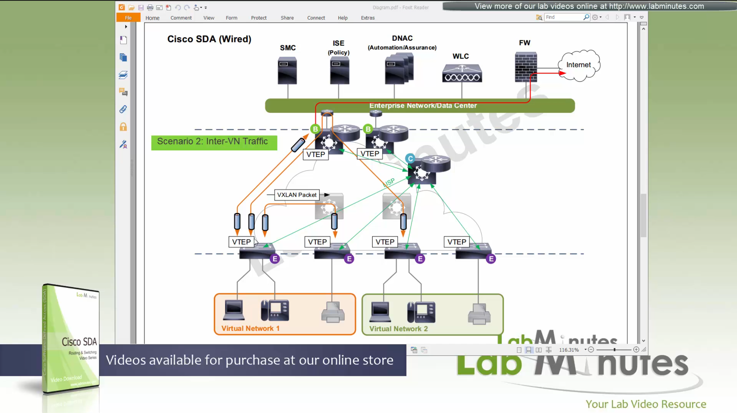
Scenario 5: Packet destined for another Virtual Network, InterVN (to another VN) traffic
This scenario applies when host in Virtual Network 1 needs to communicate with host inside Virtual Network 2 below, queries will still happen as in previous scenarios with control plane
Now this gets a bit trickier in these notes because this is an old video for an old release when SDA did not allow route leaking inside the Fabric, so that meant that packets will be routed all the way out of the fabric to the fusion router and fusion router will route it towards other virtual network making packet route back into the fabric, because border node cannot be routing “between” different Virtual Networks, and for this to work fusion router also needs one “transit” sub-interface per Virtual Network or VRF
Obviously this is not optimal as InterVN traffic will face more delays than IntraVN traffic and fusion router is also single point of failure
AP maintains the CAPWAP to WLC but it is only for CAPWAP control connection, data is locally switched to the edge node over the mini VXLAN tunnel.
This VXLAN tunnel between Fabric mode AP and edge is only between AP and edge that are directly connected, it does not extend from AP to remote edge switches
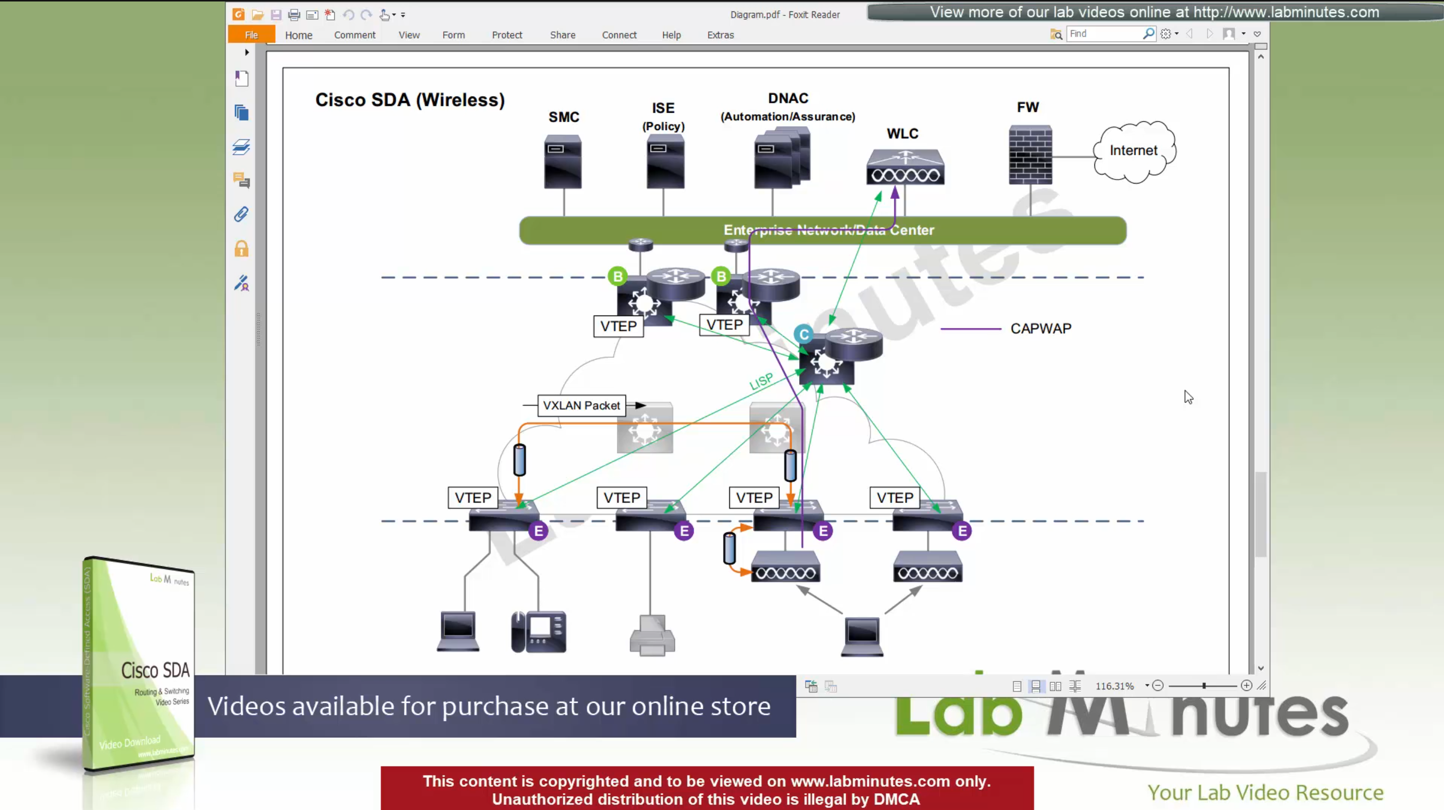
Client will associate and authenticate with the SSID, obtain IP address

“WLC will do MAP register with control plane node” and tell control plane node about the client as EID and which AP it belongs to (just like it does same for switchport)
When wired client needs to communicate with the wireless client

edge node of the wired client will obtains the RLOC from control plane and make tunnel to the edge switch where wireless client’s AP is connected
once edge node de-encapsulates the VXLAN tunnel, it checks and sees that mac address of the wireless client is behind that mini VXLAN tunnel, so it will re-encapsulate the traffic and send that to AP and vice versa in reverse
The reason for AP mini VXLAN is so that AP can inform the switch of the correct VNI the client belongs to
This is the mechanism that keeps consistency from the wired world for VNI
Making wireless clients seem like just like wired clients policy and monitoring wise
SGT are tagged on the VXLAN packets themselves
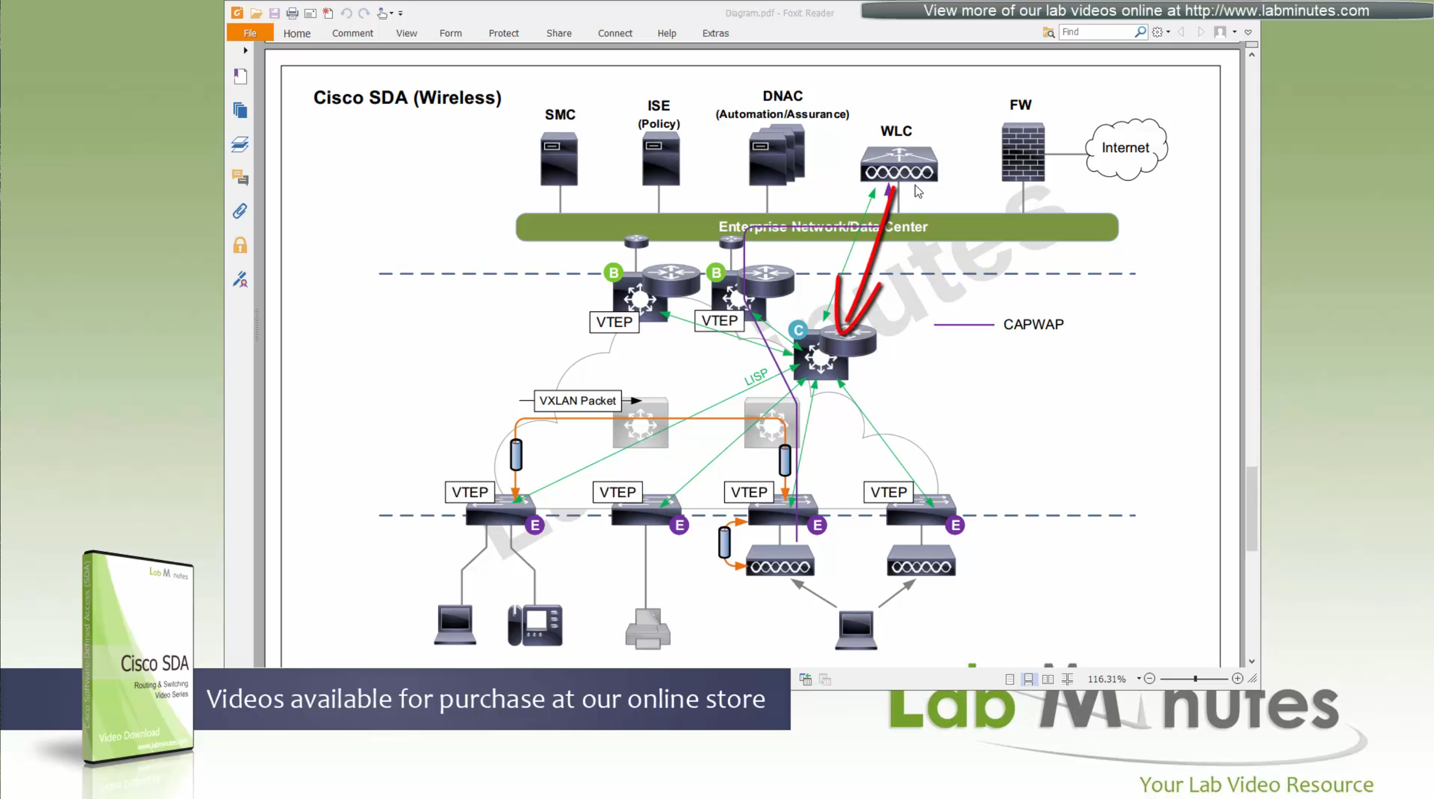
When user roams from one AP on one edge switch to another AP on another edge switch
WLC will be informed about the roam by the roamed to and from APs
WLC will inform the control plane also and control plane will update the entry’s RLOC to be the new edge switch whose new AP client has roamed to
While in Fabric, WLC and APs can still be connected to the Fabric but operate in “Legacy mode” which is also called “over the top” setup, in which data from AP is sent in CAPWAP (Data tunnel) to WLC and WLC switches the traffic out
There is also a low latency requirement of 20ms between the WLC and AP so keep in mind that APs have to stay somewhat close to the controller in the campus setup
Licensing
DNA Essential gives most of the feature set of the APIC-EM
DNA Advantage gives most of the features in Assurance and NDP + SDA
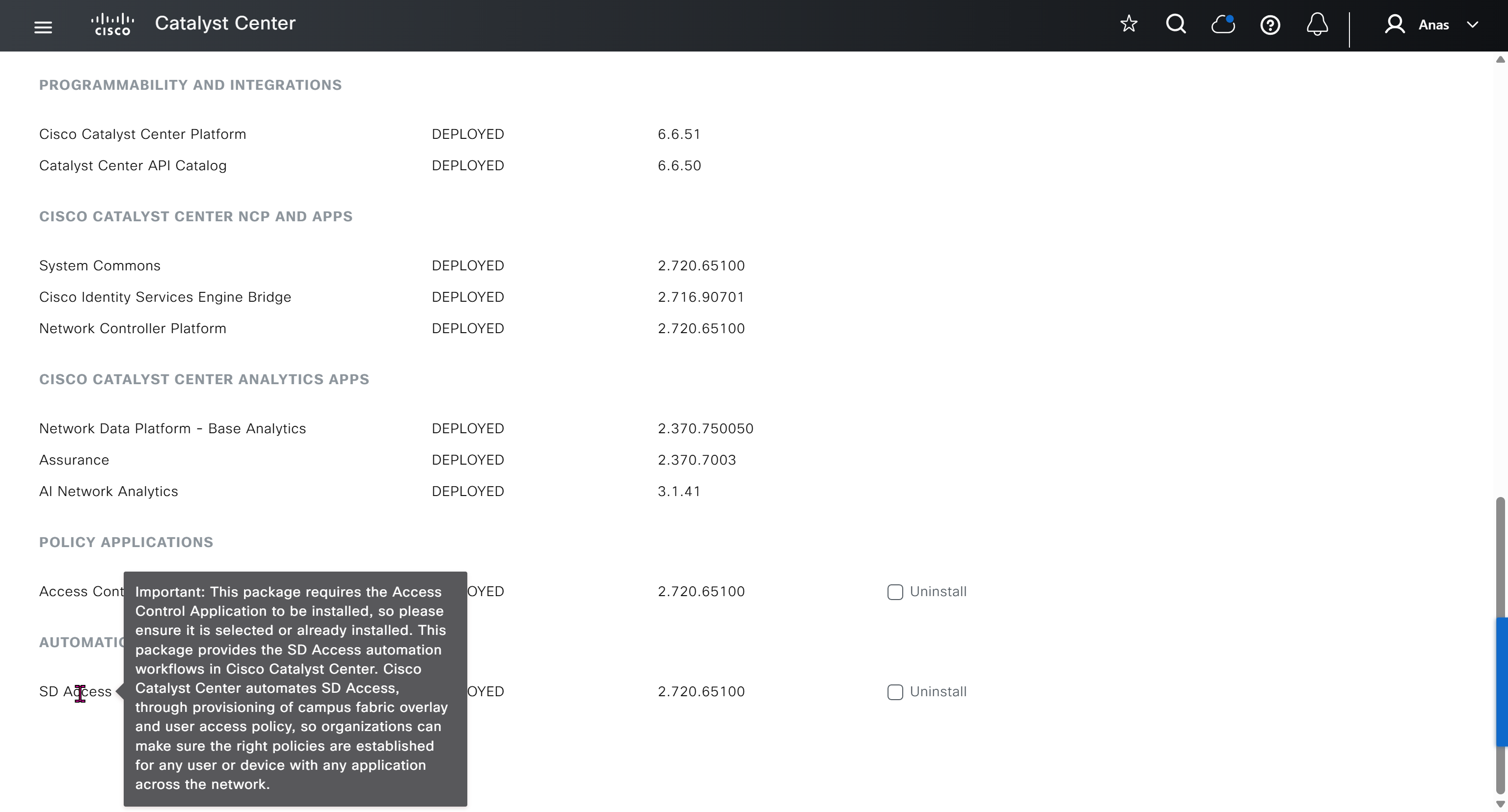
SDA is only available with DNA Advantage license
Cisco offers a license called One Advantage that offers DNA + ISE + Stealthwatch all in one license

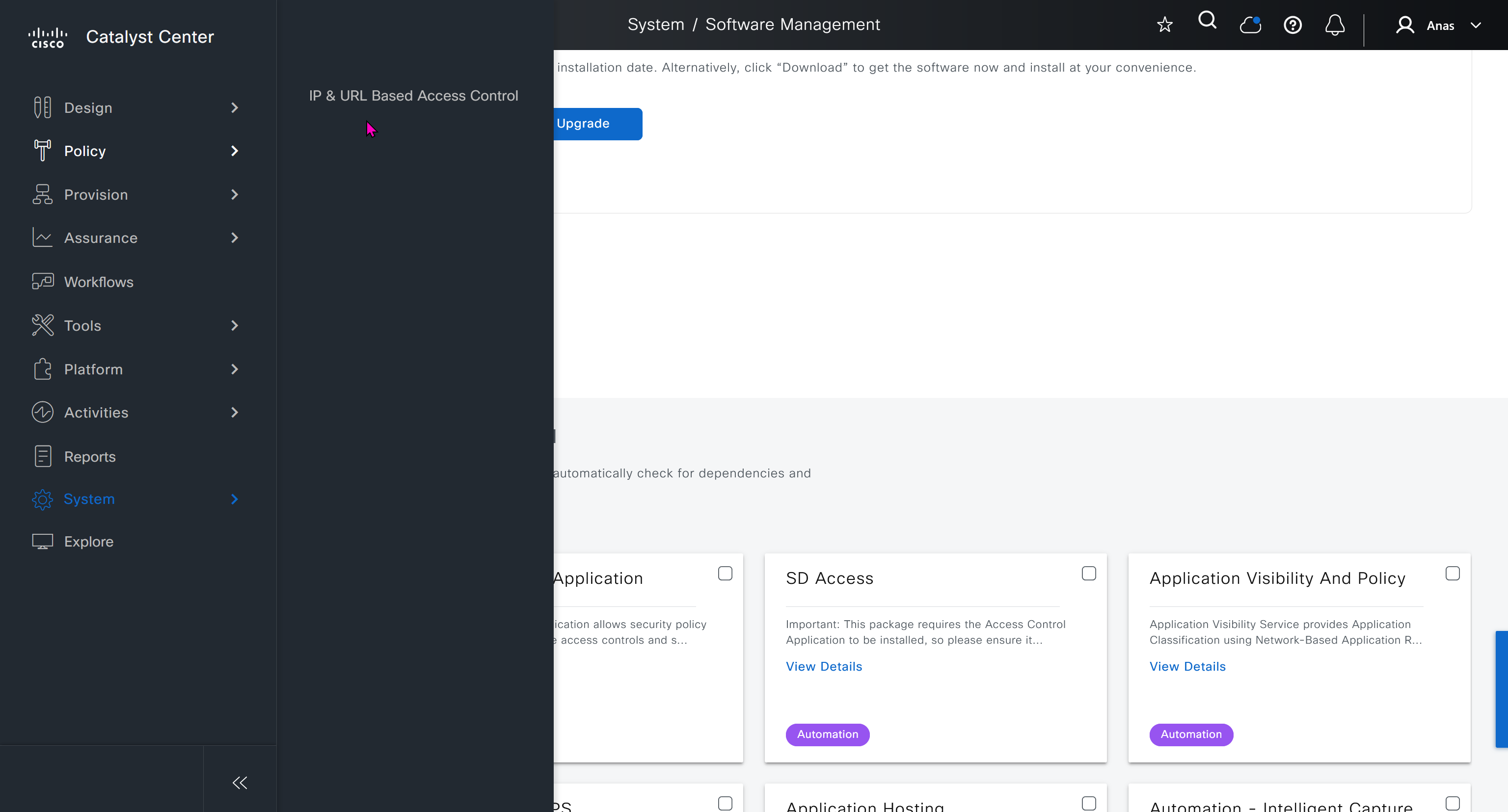
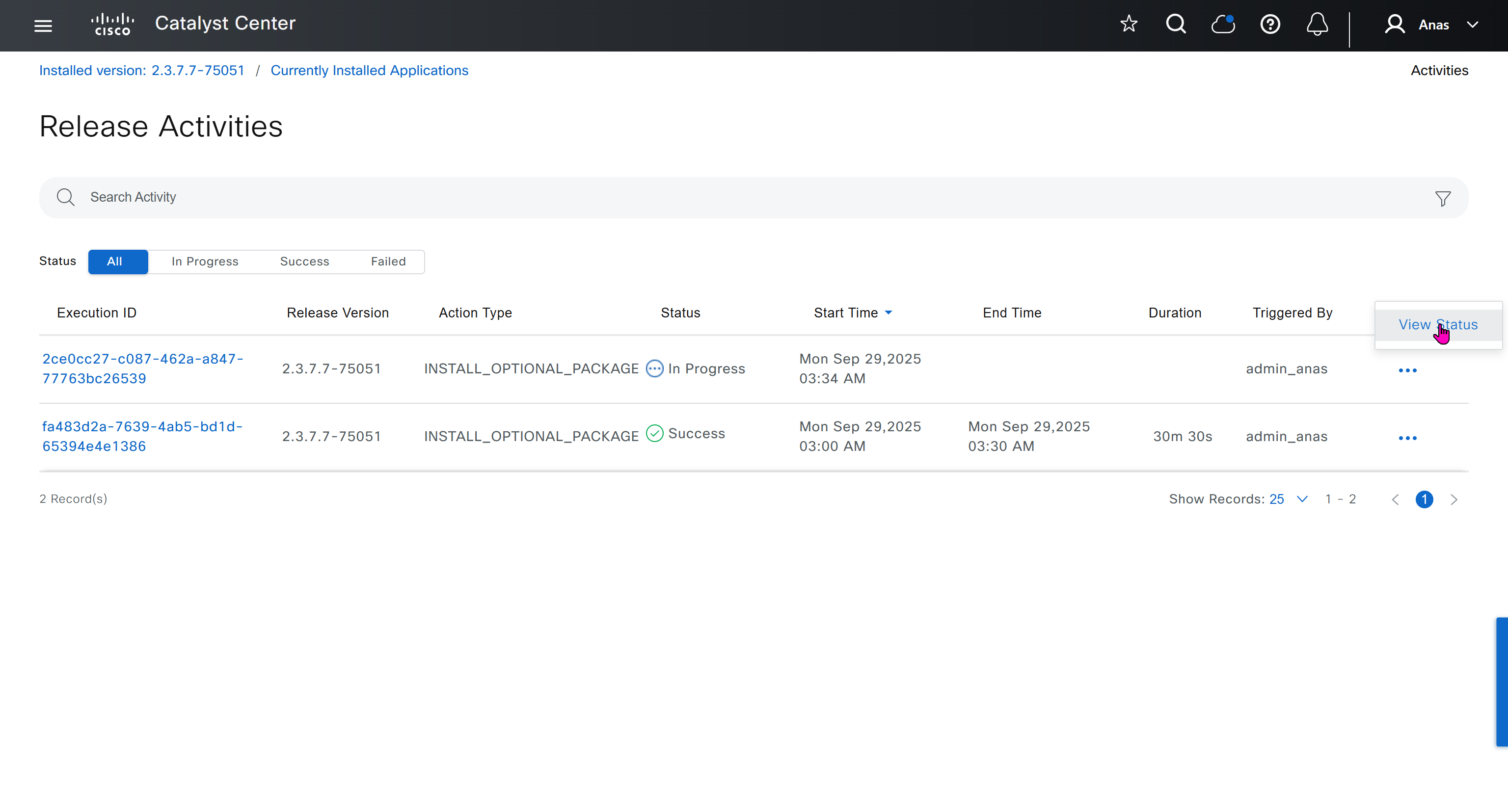
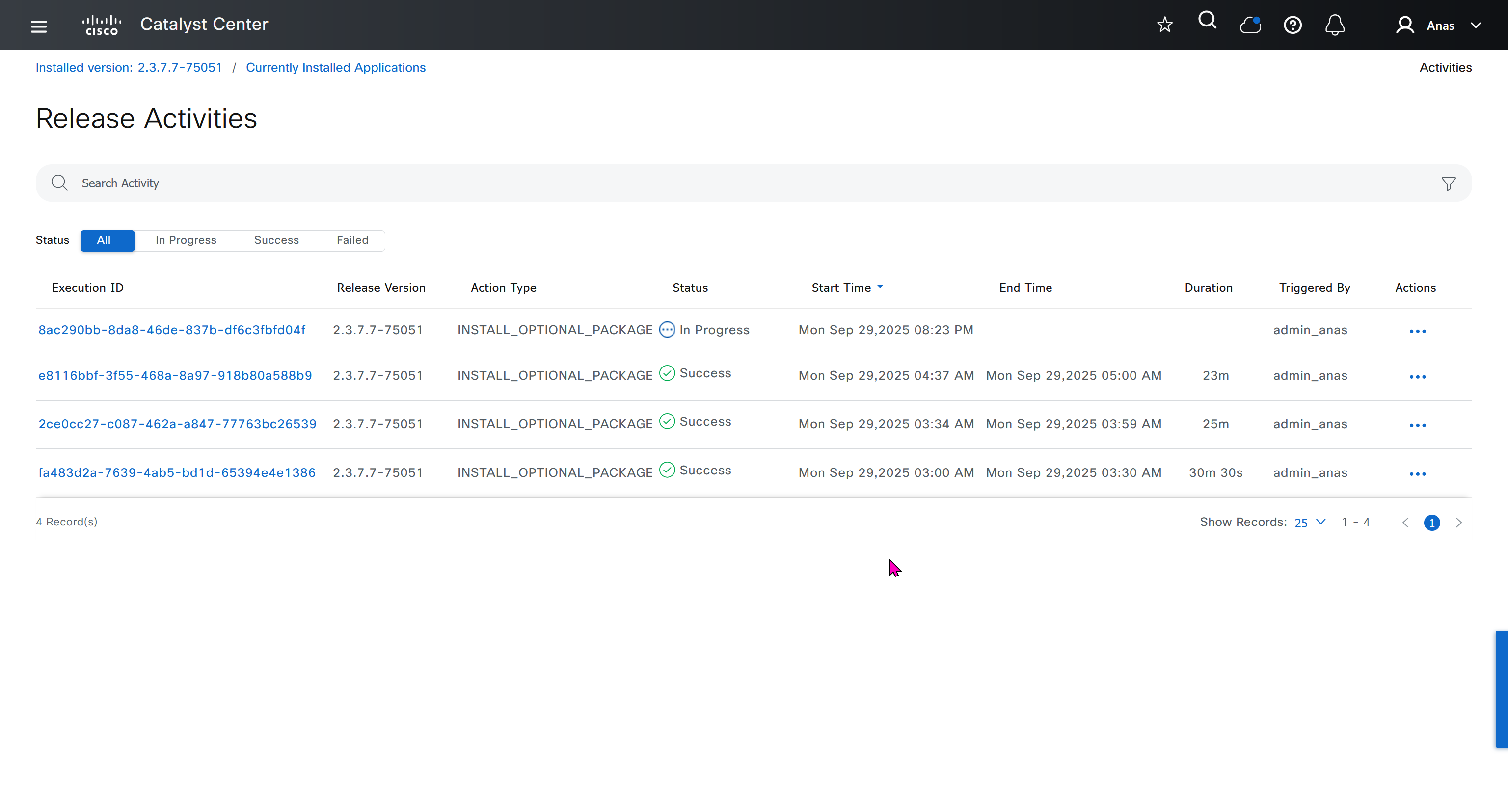
Right after installation of DNAC and first GUI login we need to quickly download the packages or software apps which are GBAC Group Based Acccess Control ( SGT / SXP / ISE ) and also SDA package to enable SDA in DNAC. Cisco does not readily ship the DNAC with ova or iso, SDA and a lot of other modules need to be downloaded using below very specific settings


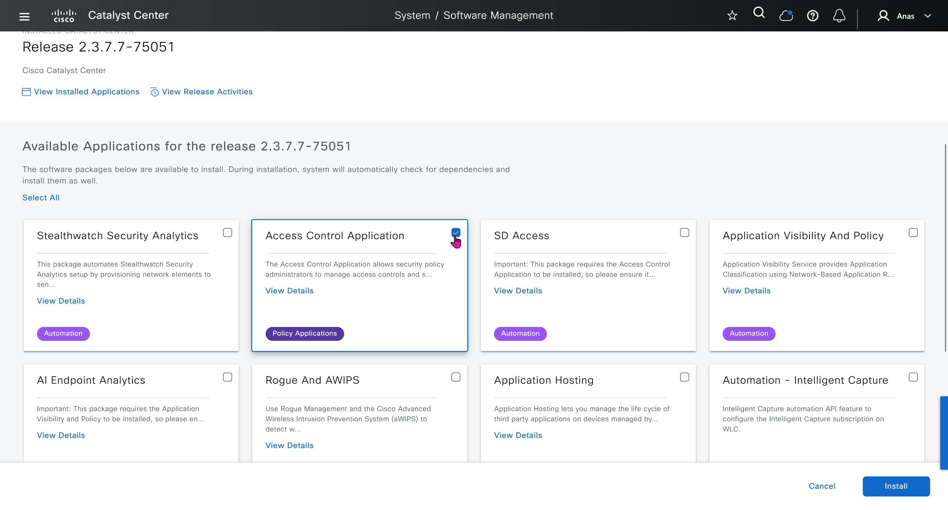
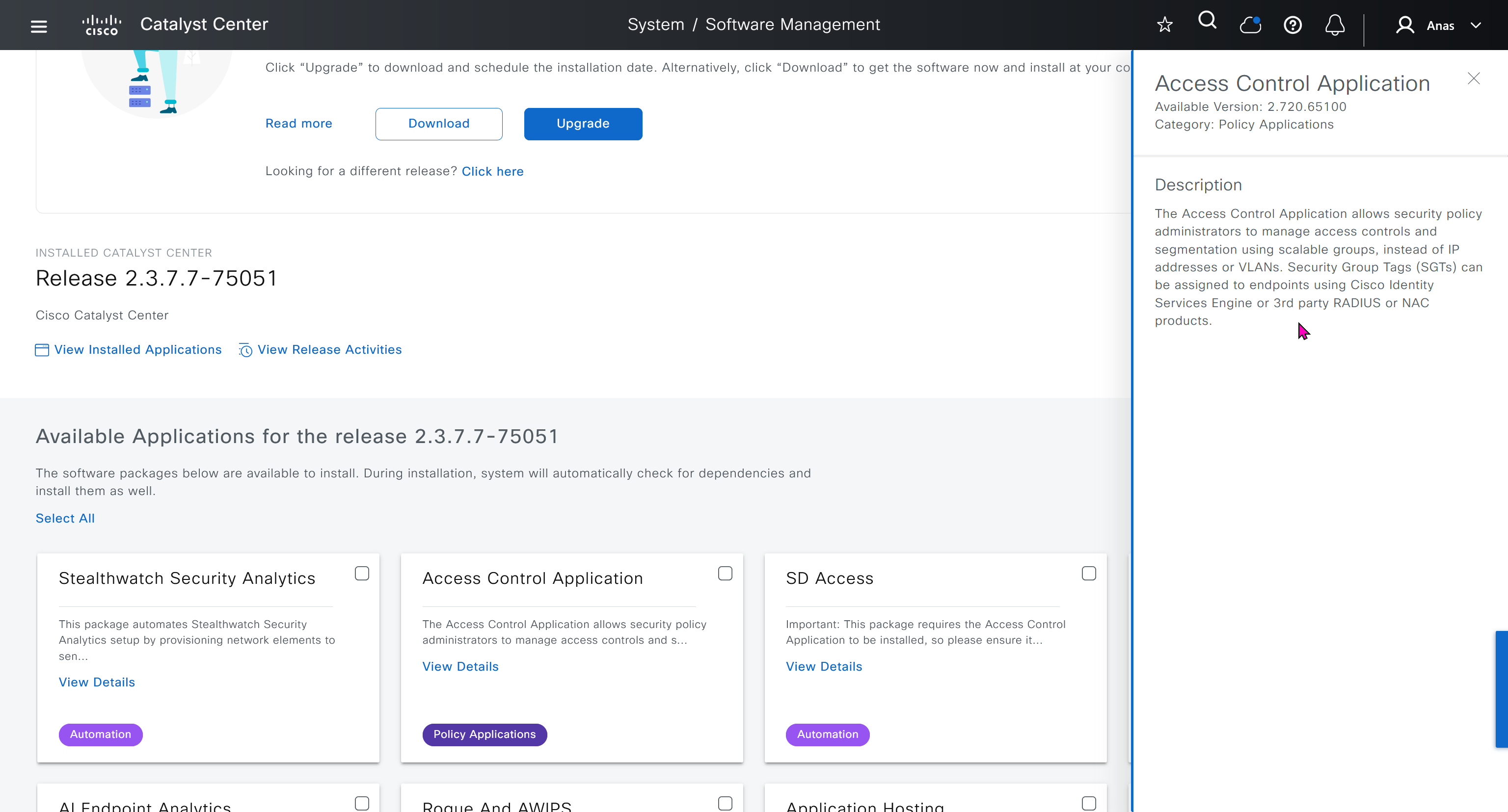
Group Based Access Control is not there and needs to be downloaded

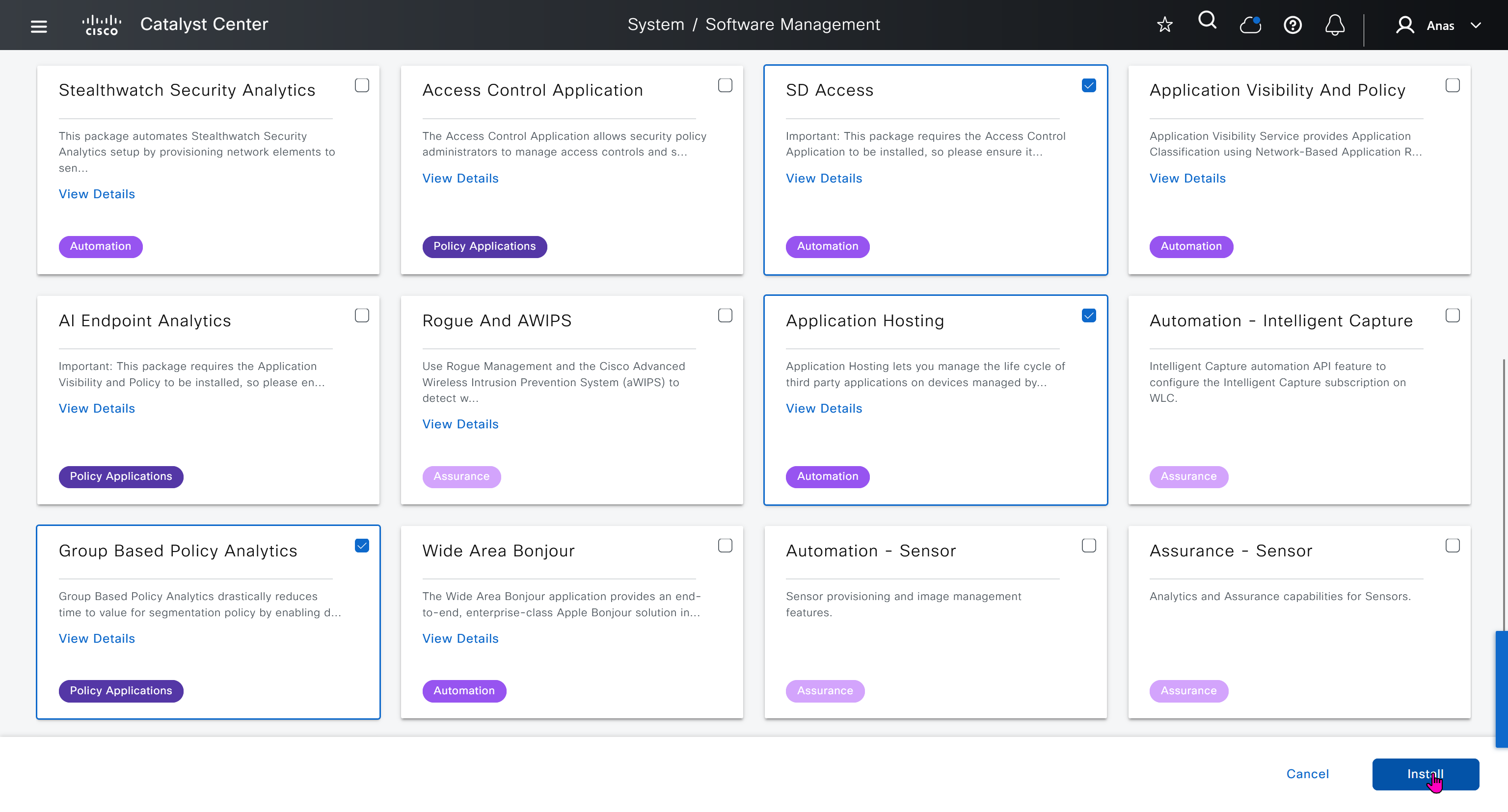


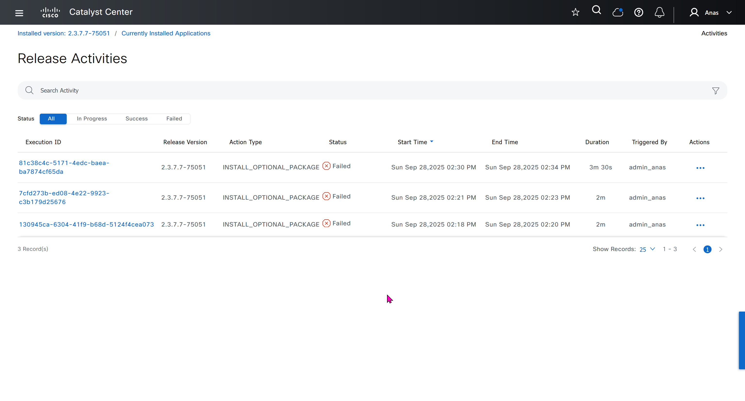
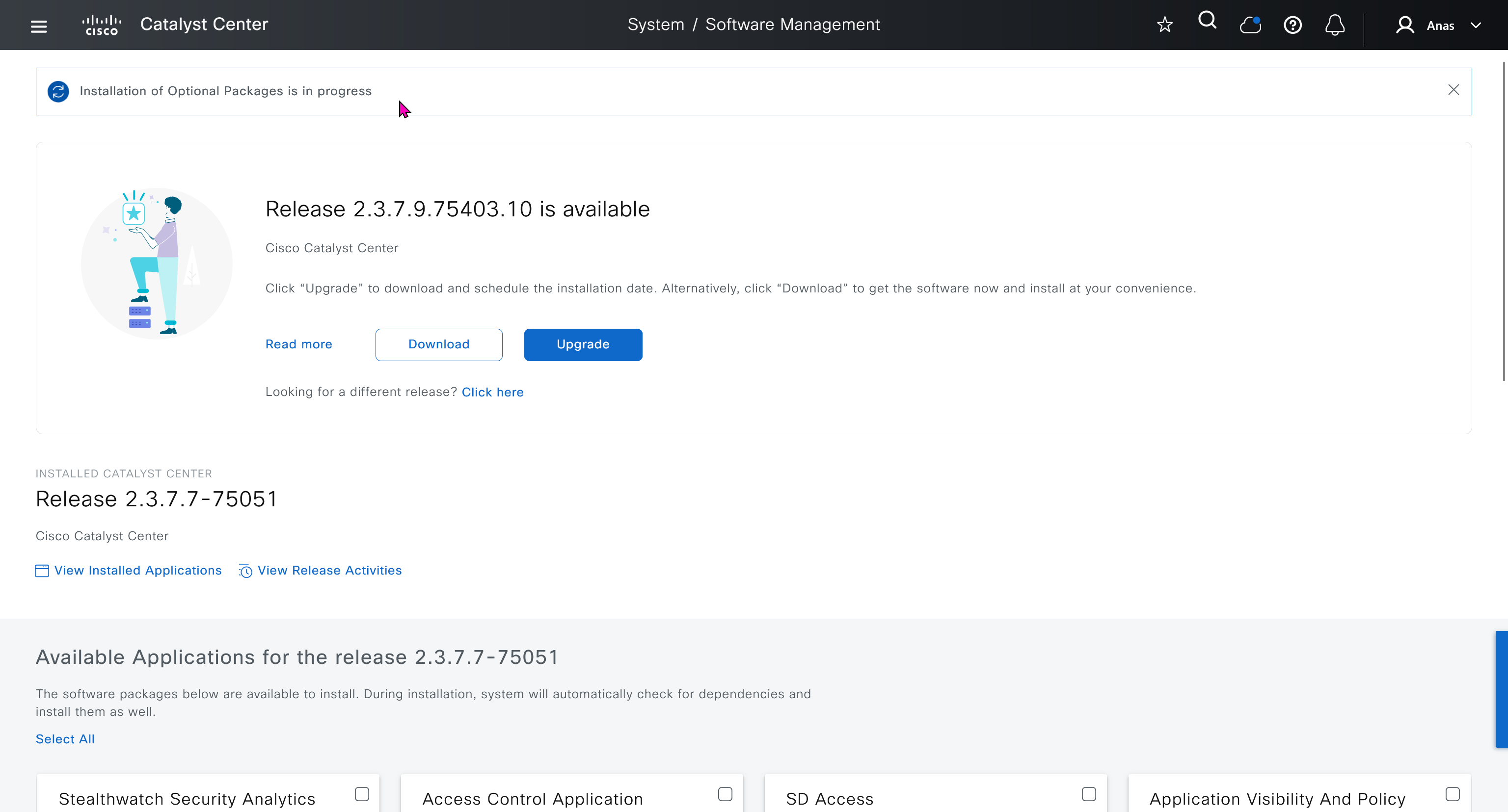
Installation kept failing at download stage

I had to remove the VM as there was something wrong and when new dnac was installed, one thing I did is I added the company’s cco information here but not in the smart licensing, dont add to the smart licensing section instead add at the beginning on first GUI login


Finally it installed well
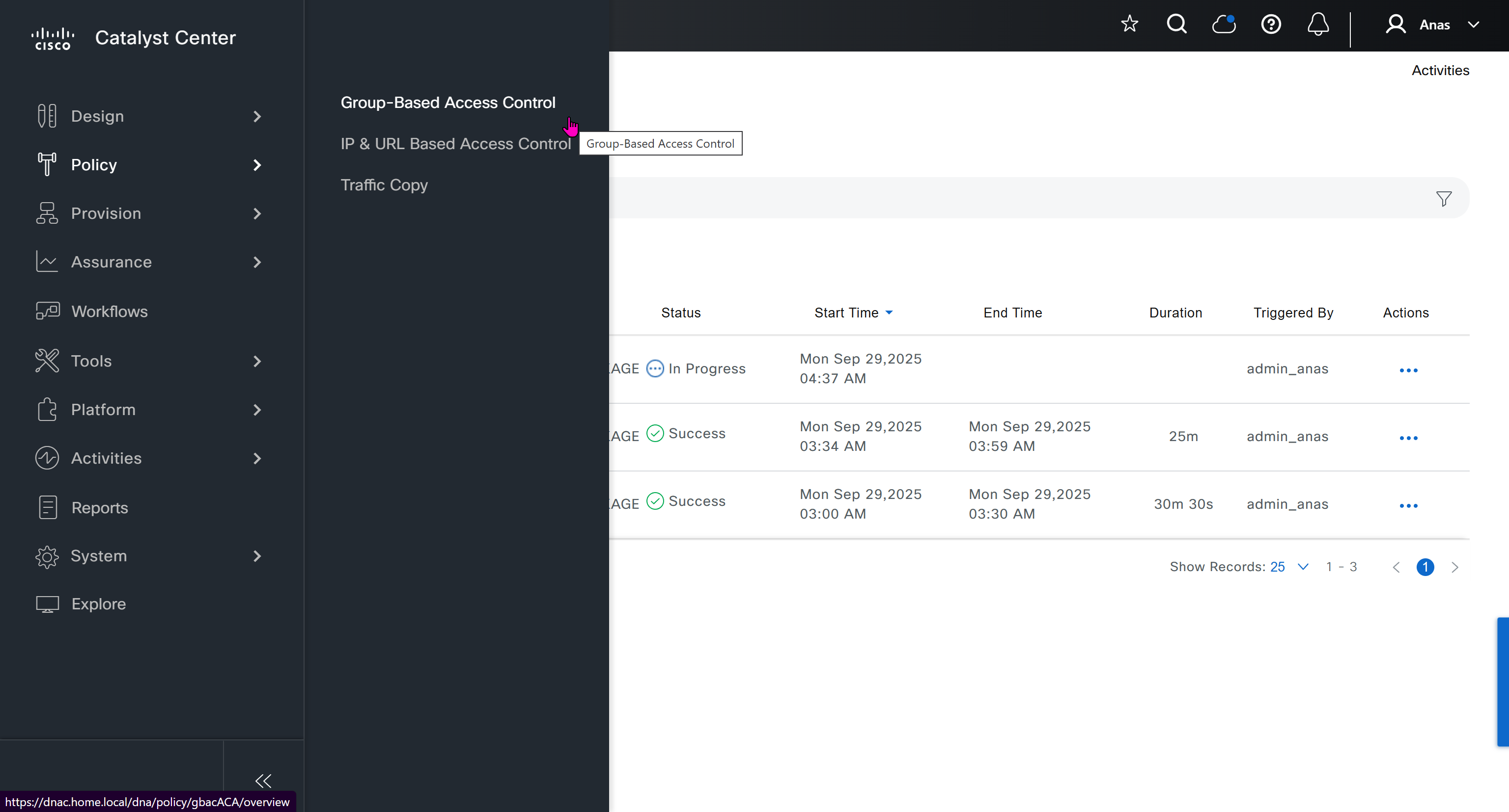
now Group Based Access Control GBAC is showing in menu now

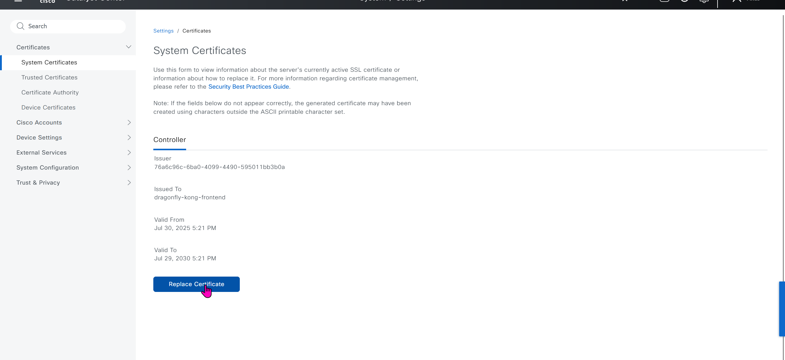
We will take a look at installing certificate as ISE needs to be integrated, and for that we need to take information from default certificate’s information, common name is the name that we provided during the initial installation of DNAC

If we look at subject alternative names we can see a lot of SAN entries, these SAN entries contain IP addresses as well and one of those IP addresses will be of the VIP in case we have multiple DNAC appliances

Enhanced Key Usage: Server Authentication, Client Authentication as this is used for ISE PX Grid integration

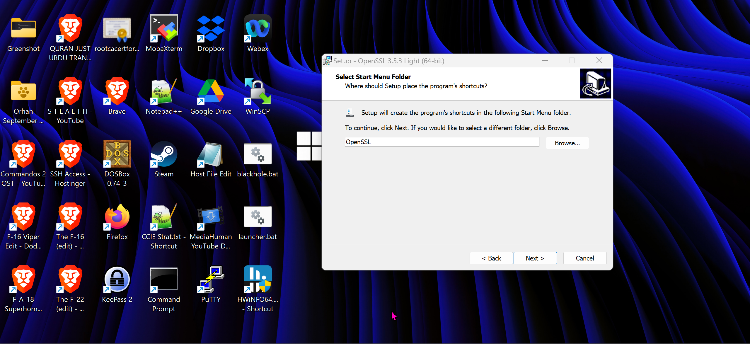
We will have to install the OpenSSL for Windows
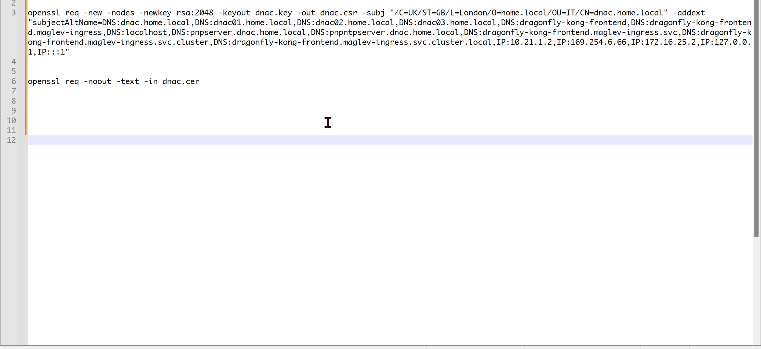
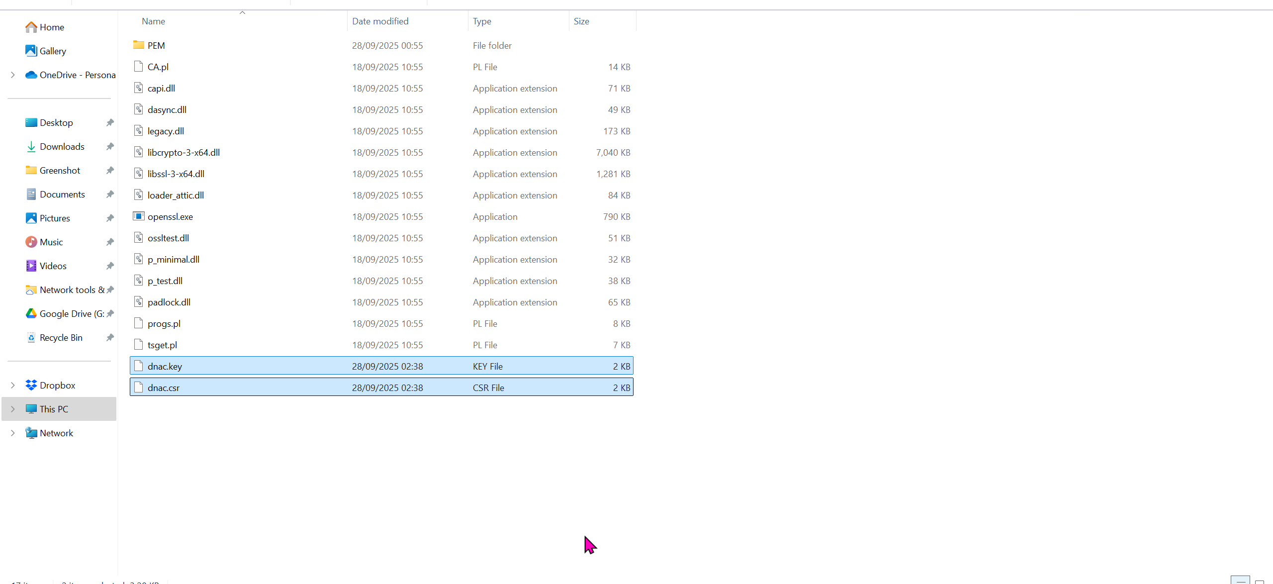
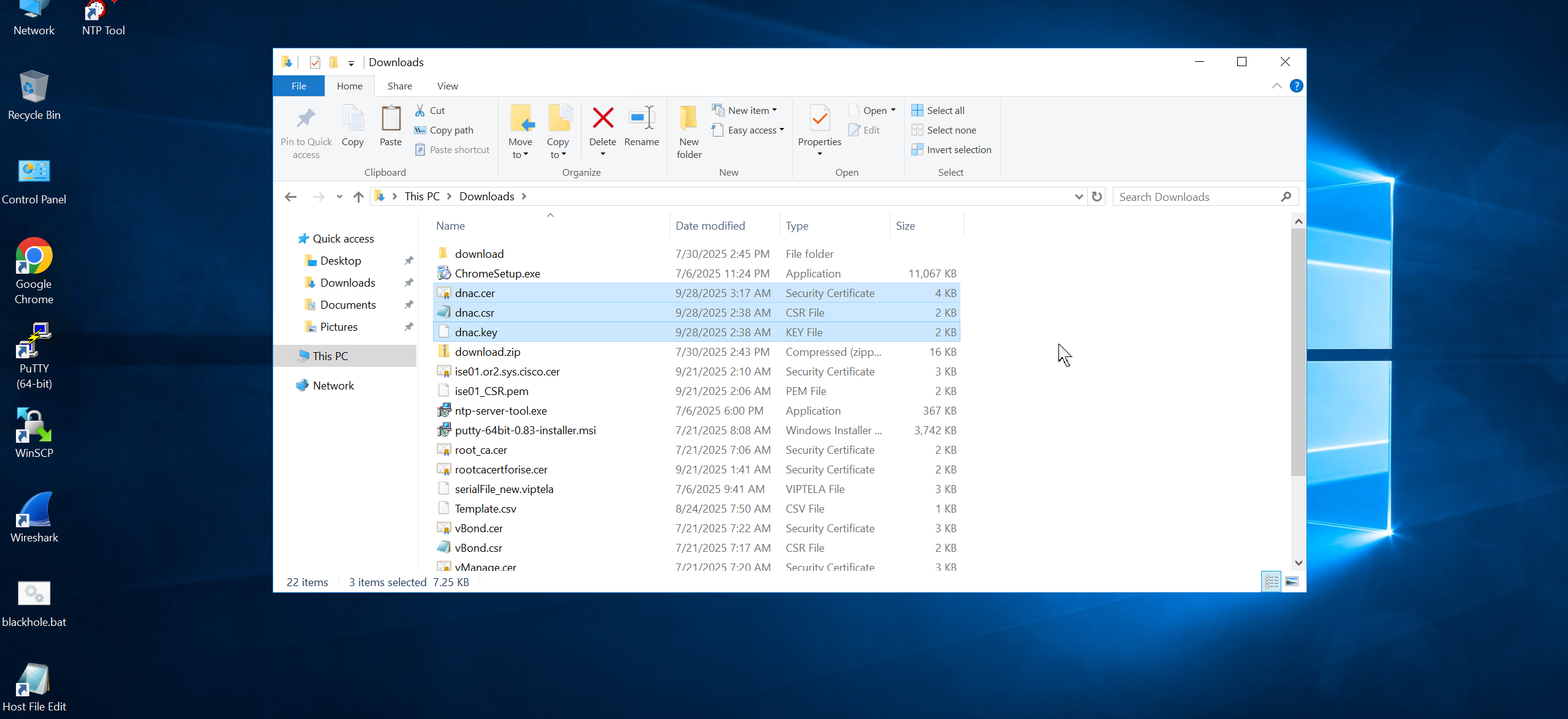
cd C:\Program Files\OpenSSL-Win64\binopenssl req -new -nodes -newkey rsa:2048 -keyout dnac.key -out dnac.csr -subj "/C=UK/ST=GB/L=London/O=home.local/OU=IT/CN=dnac.home.local" -addext "subjectAltName=DNS:dnac.home.local,DNS:dnac01.home.local,DNS:dnac02.home.local,DNS:dnac03.home.local,DNS:dragonfly-kong-frontend,DNS:dragonfly-kong-frontend.maglev-ingress,DNS:localhost,DNS:pnpserver.dnac.home.local,DNS:pnpntpserver.dnac.home.local,DNS:dragonfly-kong-frontend.maglev-ingress.svc,DNS:dragonfly-kong-frontend.maglev-ingress.svc.cluster,DNS:dragonfly-kong-frontend.maglev-ingress.svc.cluster.local,IP:10.21.1.2,IP:169.254.6.66,IP:172.16.25.2,IP:127.0.0.1,IP:::1"openssl req -noout -text -in dnac.cercd C:\Program Files\OpenSSL-Win64\bin
openssl req -new -nodes -newkey rsa:2048 -keyout dnac.key -out dnac.csr -subj "/C=UK/ST=GB/L=London/O=Cisco-DNA/OU=IT/CN=dragonfly-kong-frontend" -addext "subjectAltName=DNS:dnac.home.local, DNS:dragonfly-kong-frontend, DNS:dragonfly-kong-frontend.maglev-ingress, DNS:localhost, DNS:dragonfly-kong-frontend.maglev-ingress.svc, DNS:dragonfly-kong-frontend.maglev-ingress.svc.cluster, DNS:dragonfly-kong-frontend.maglev-ingress.svc.cluster.local, IP:10.21.1.2, IP:127.0.0.1, IP:::1"
openssl req -noout -text -in dnac.cerWe have added those lines
Make sure that Data and OOB IP addresses are added including all Data and OOB IP addresses from clusters too


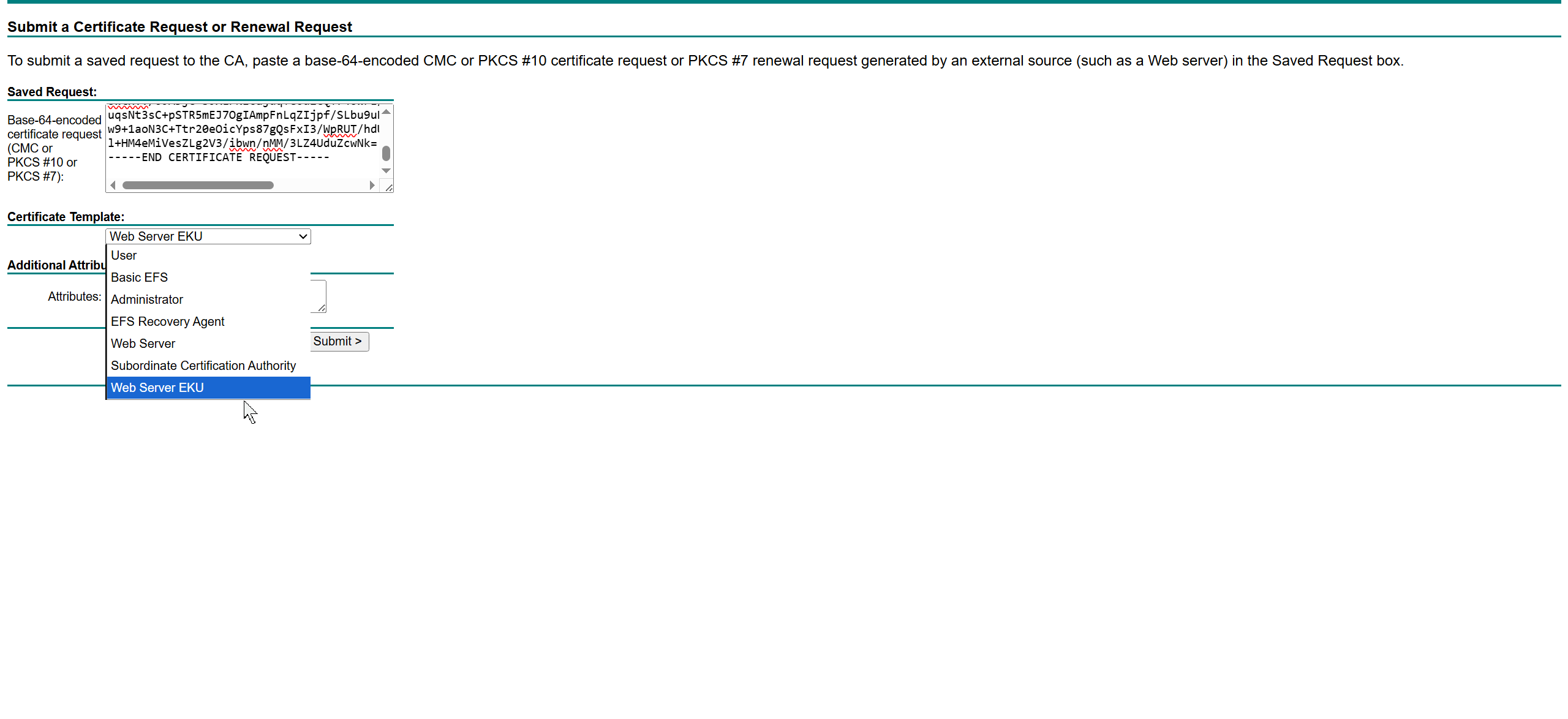
This Web Server EKU as Extended Key Usage has Client Authentication
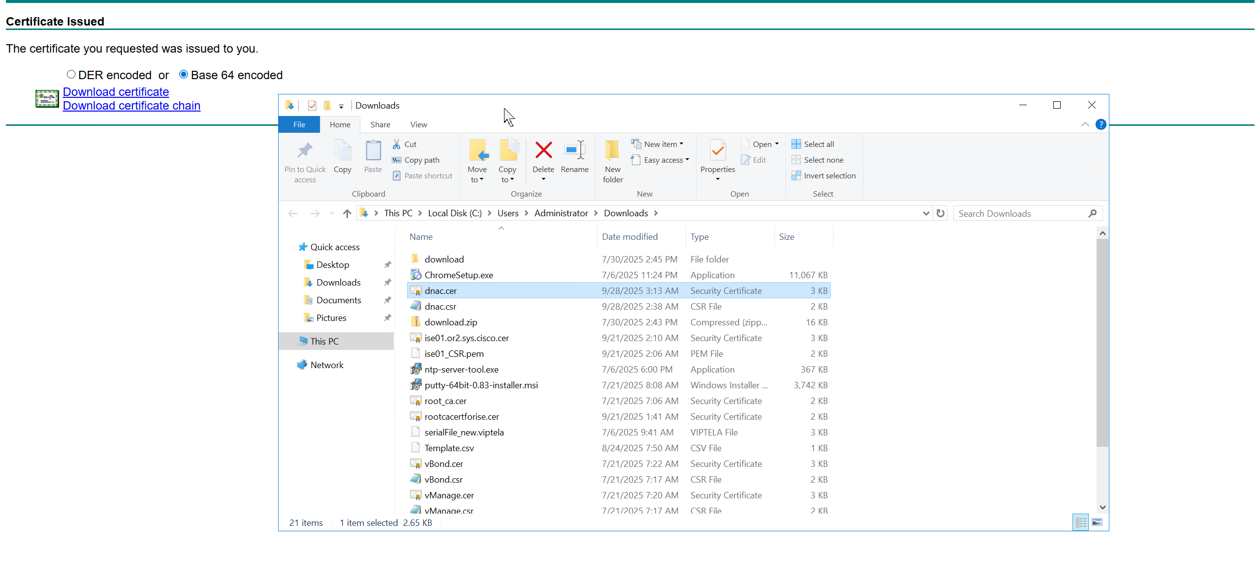
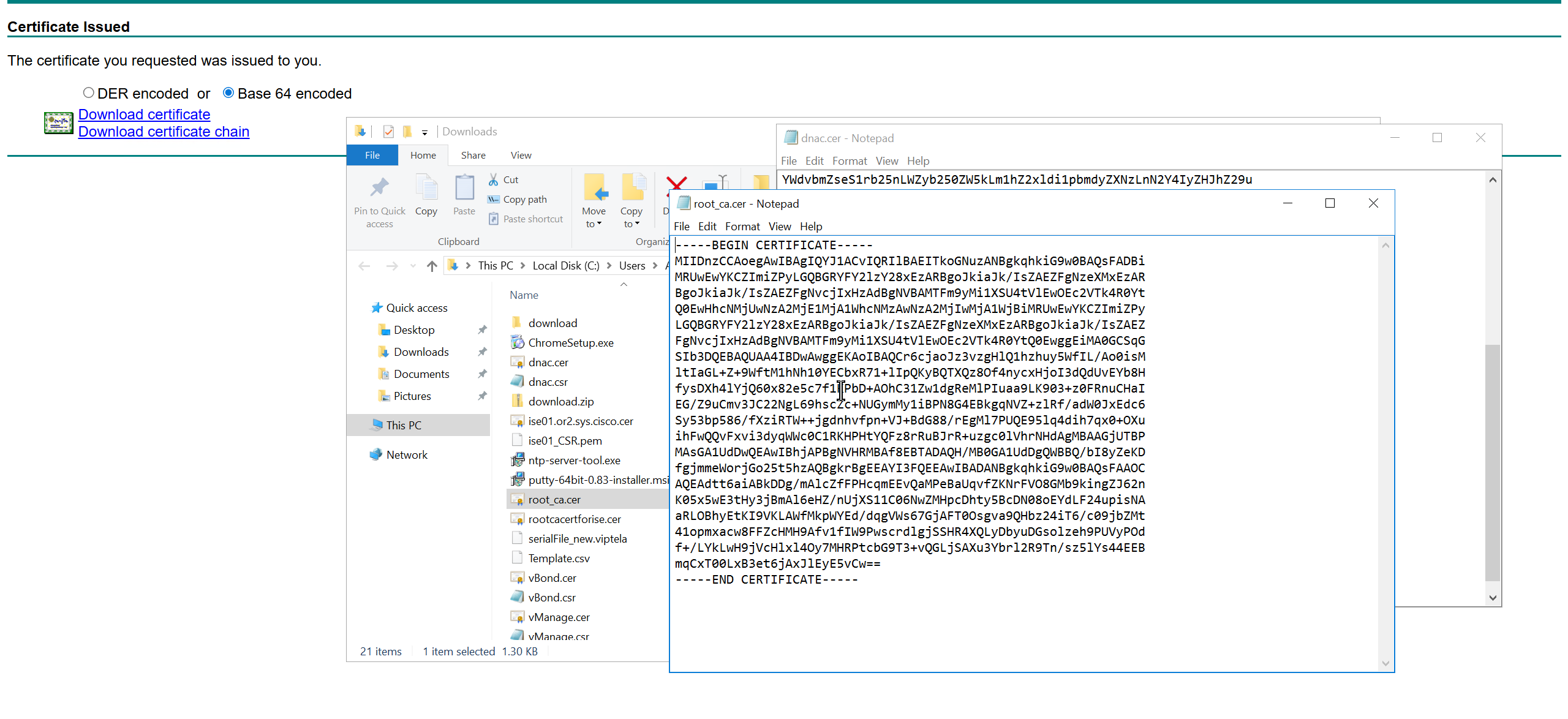

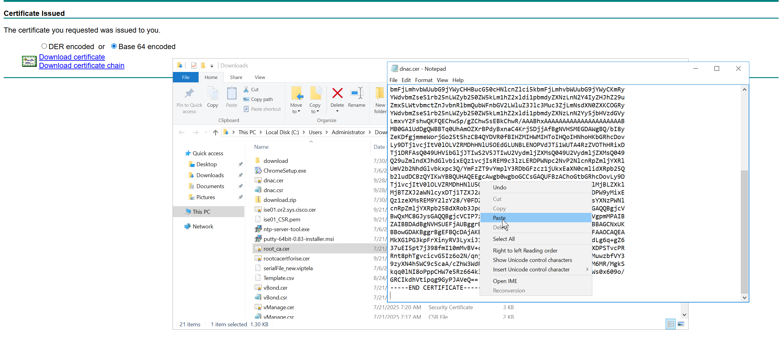
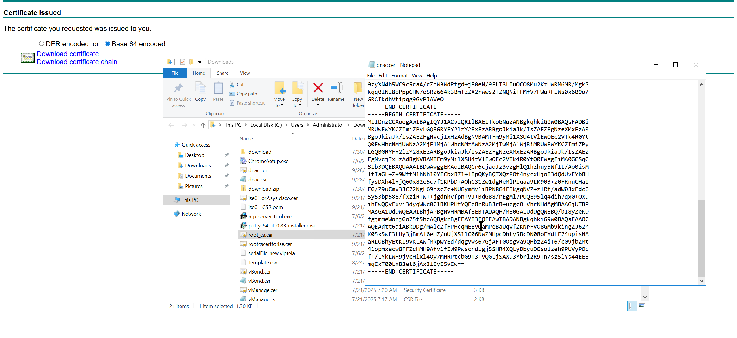
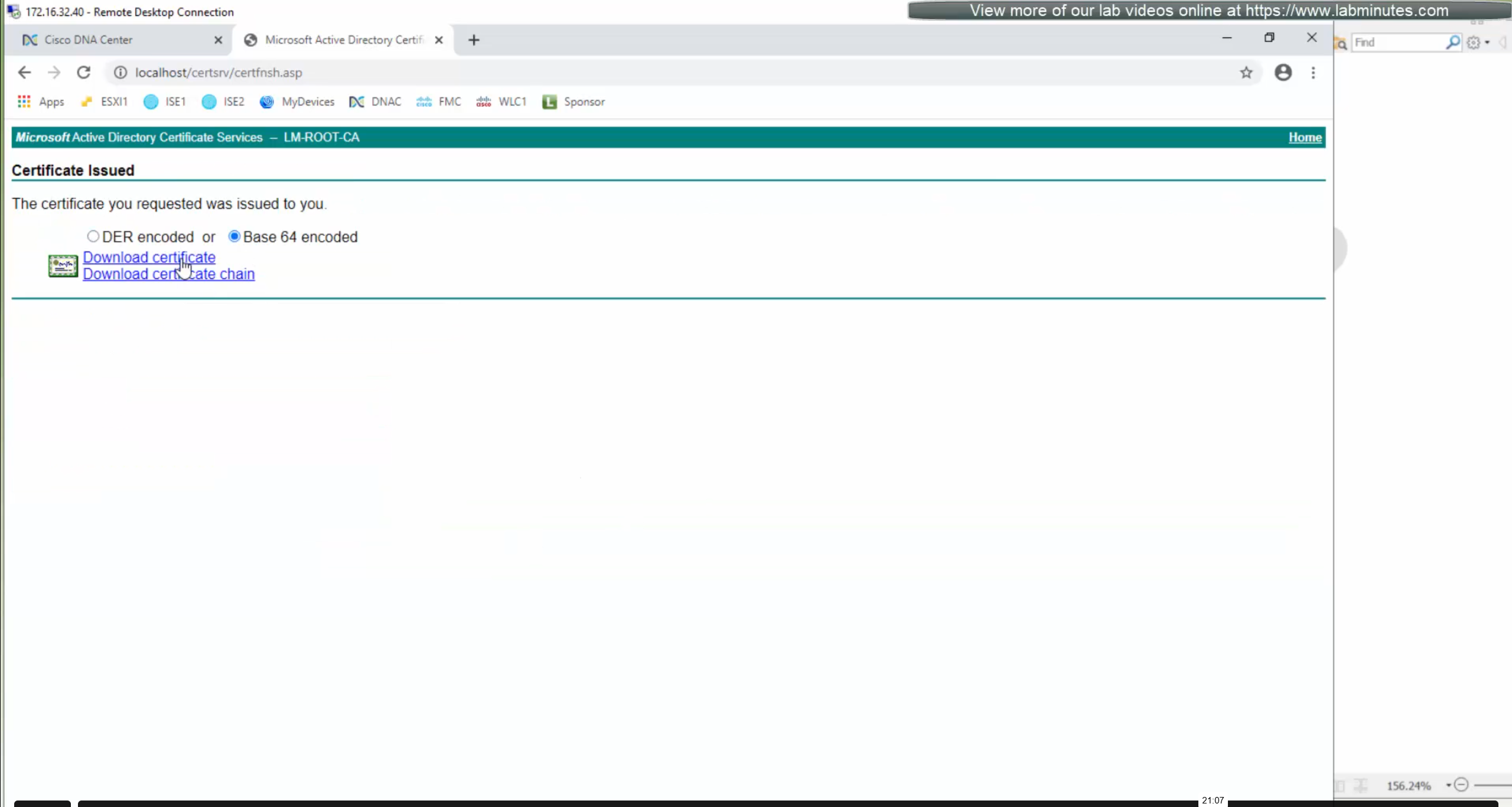
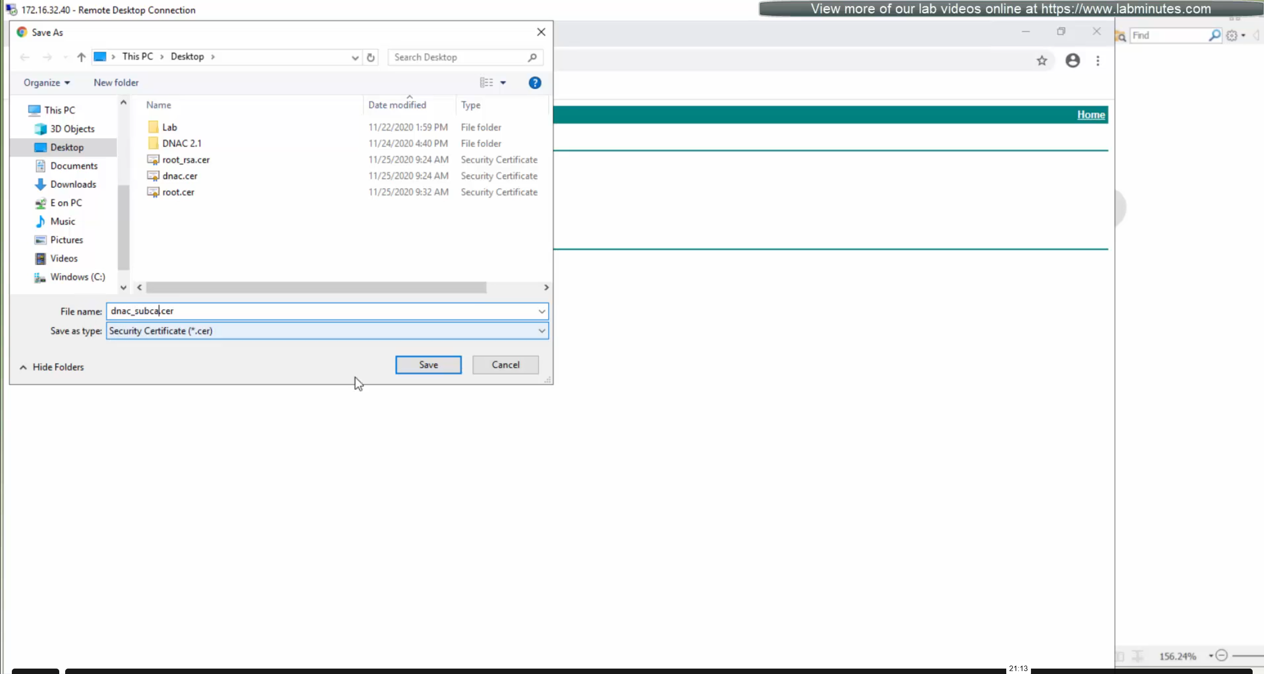
We will append the root ca certificate (because identity cert comes first) in this notepad file and combine it for DNAC, in case you have any intermediate CA certificates then add them as well in the middle of identity and root ca certificate


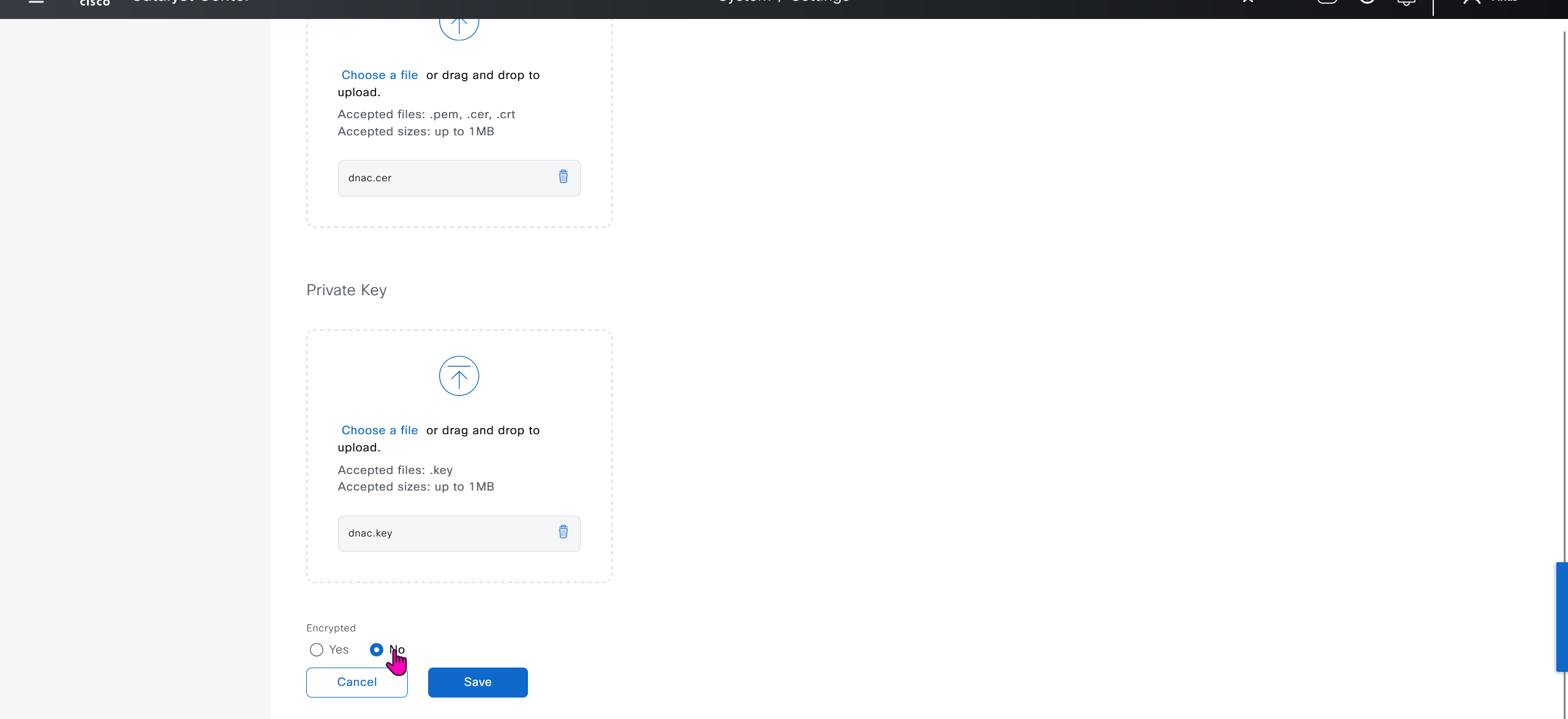


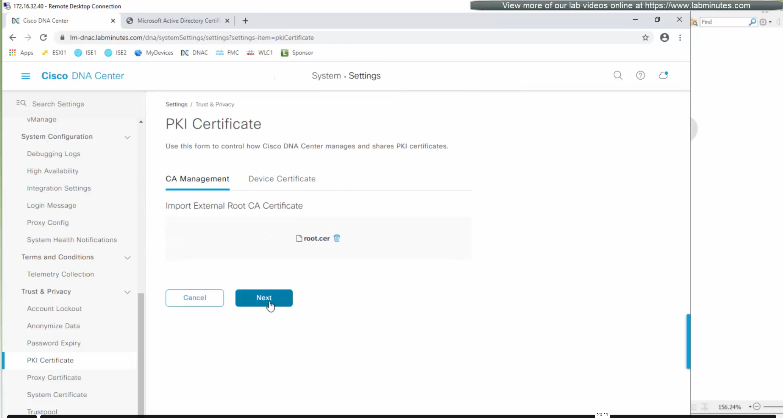
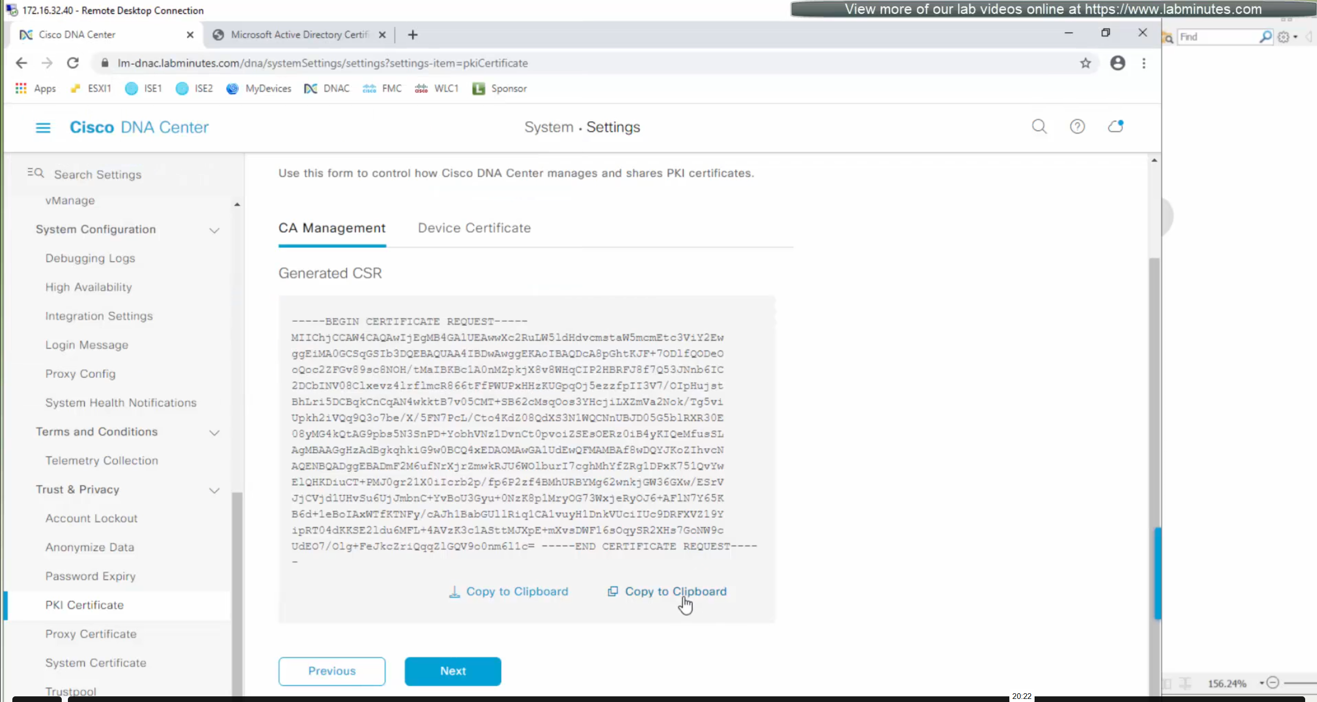
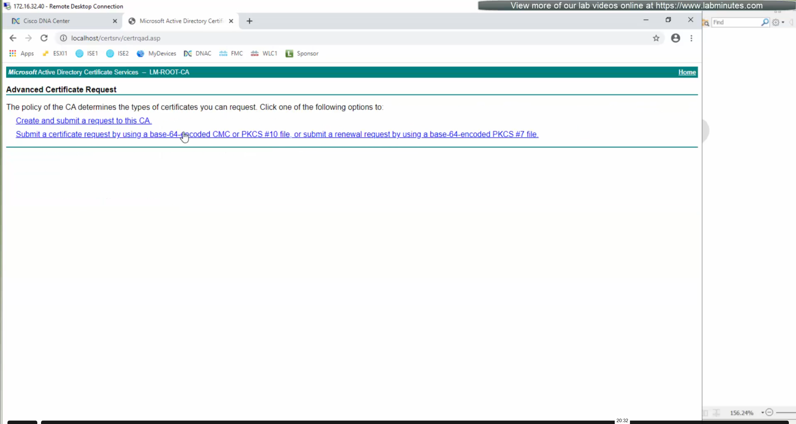
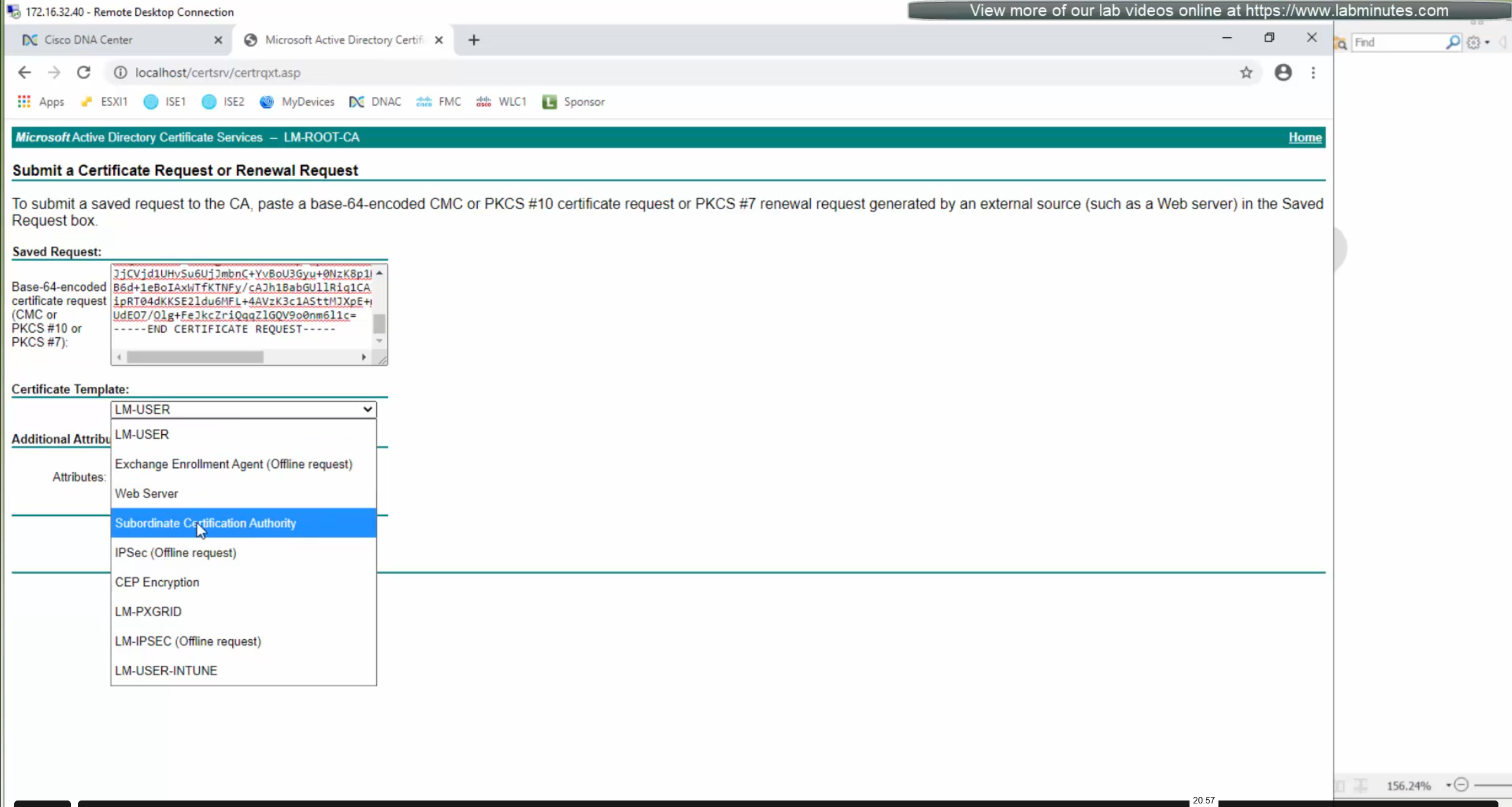
DNAC also issues certificates to devices which get added to it, and by default DNAC acts as the internal root ca but we can add our enterprise root ca or windows root ca too and this decision should be made right at the beginning before adding devices in DNAC or SDA fabric but once enterprise root ca is added we cannot convert this setting back to internal CA, usually we leave DNAC as the root ca for those devices

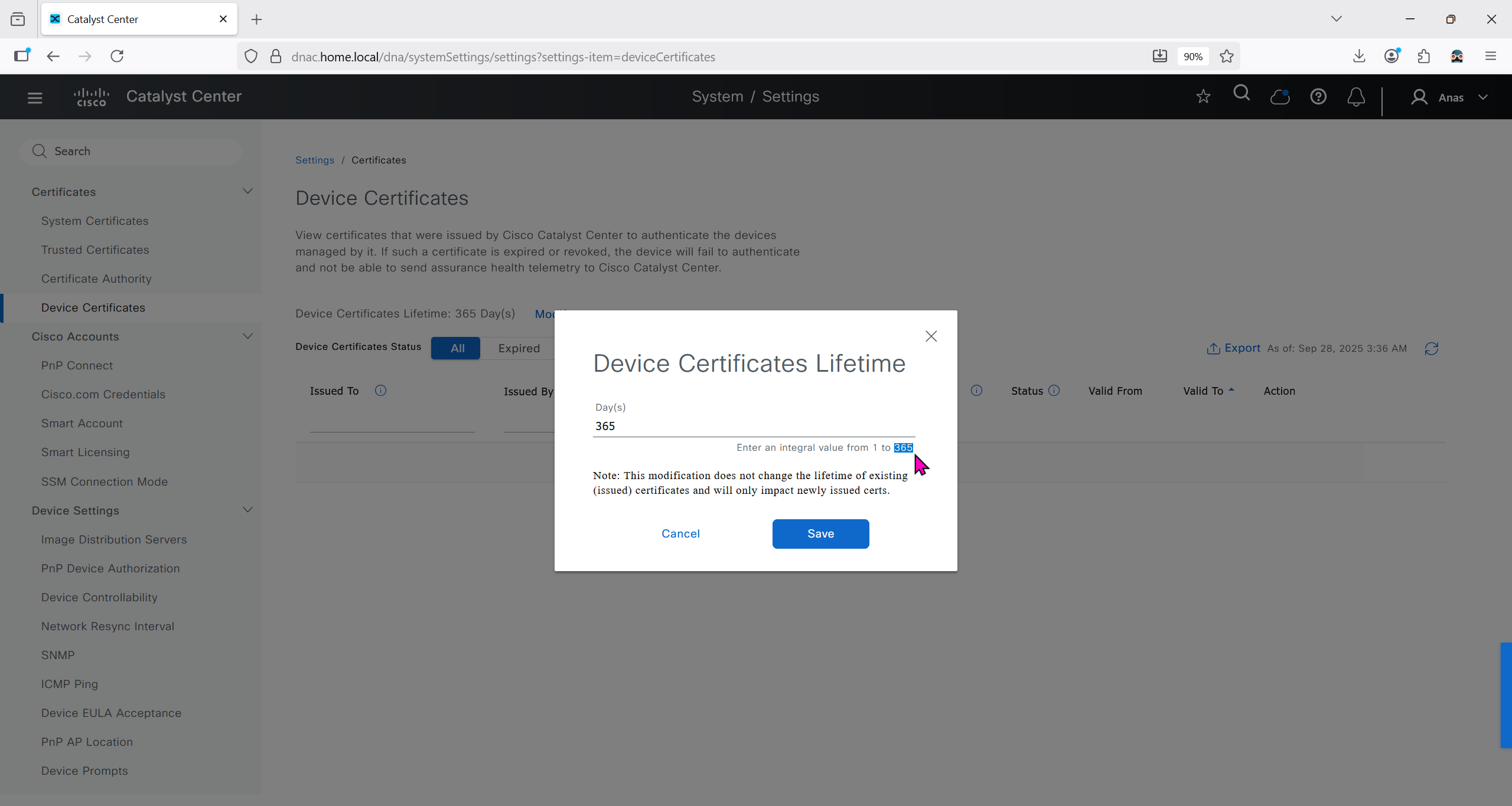
We can control the period for certificate’s validity
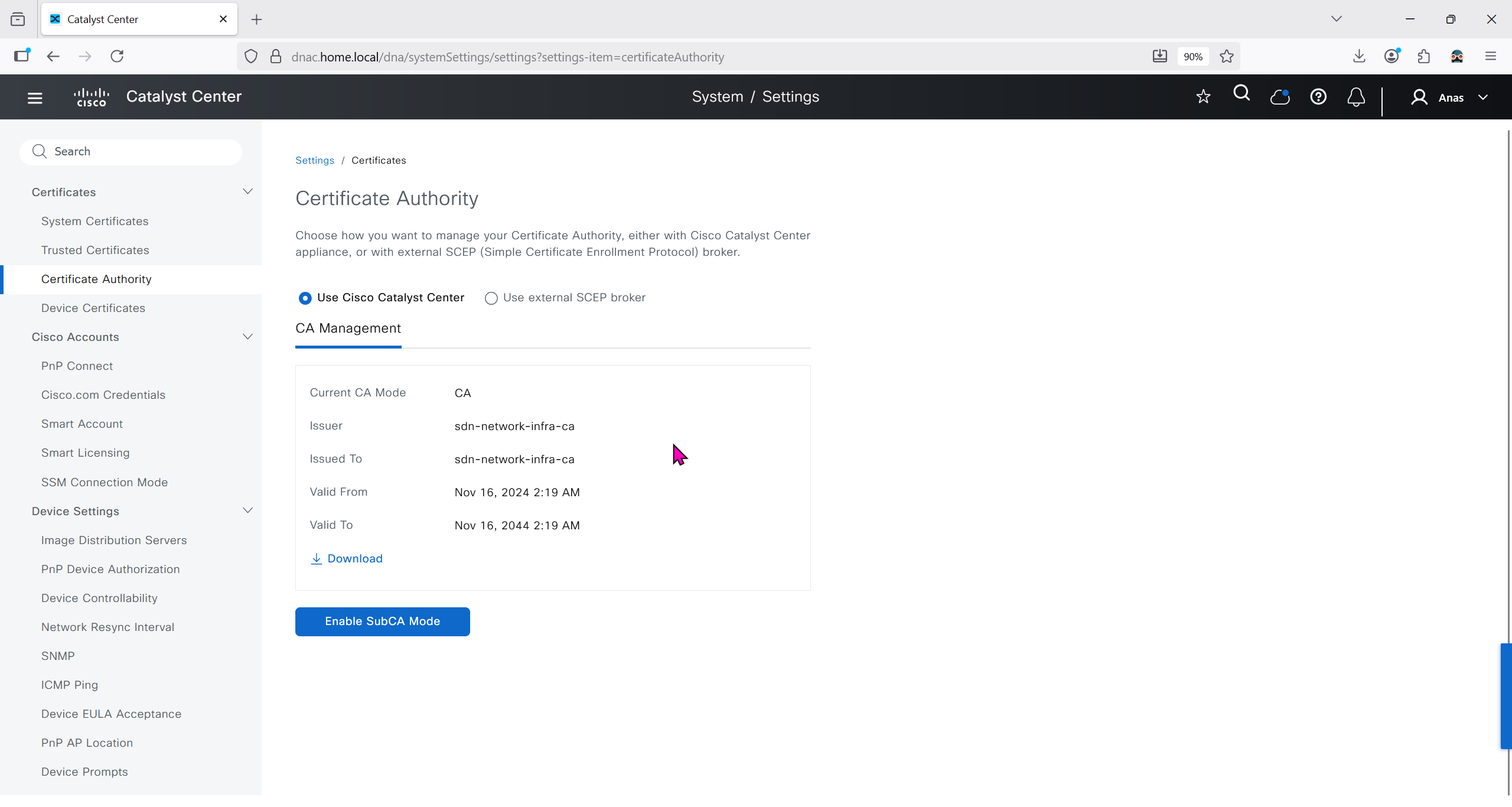
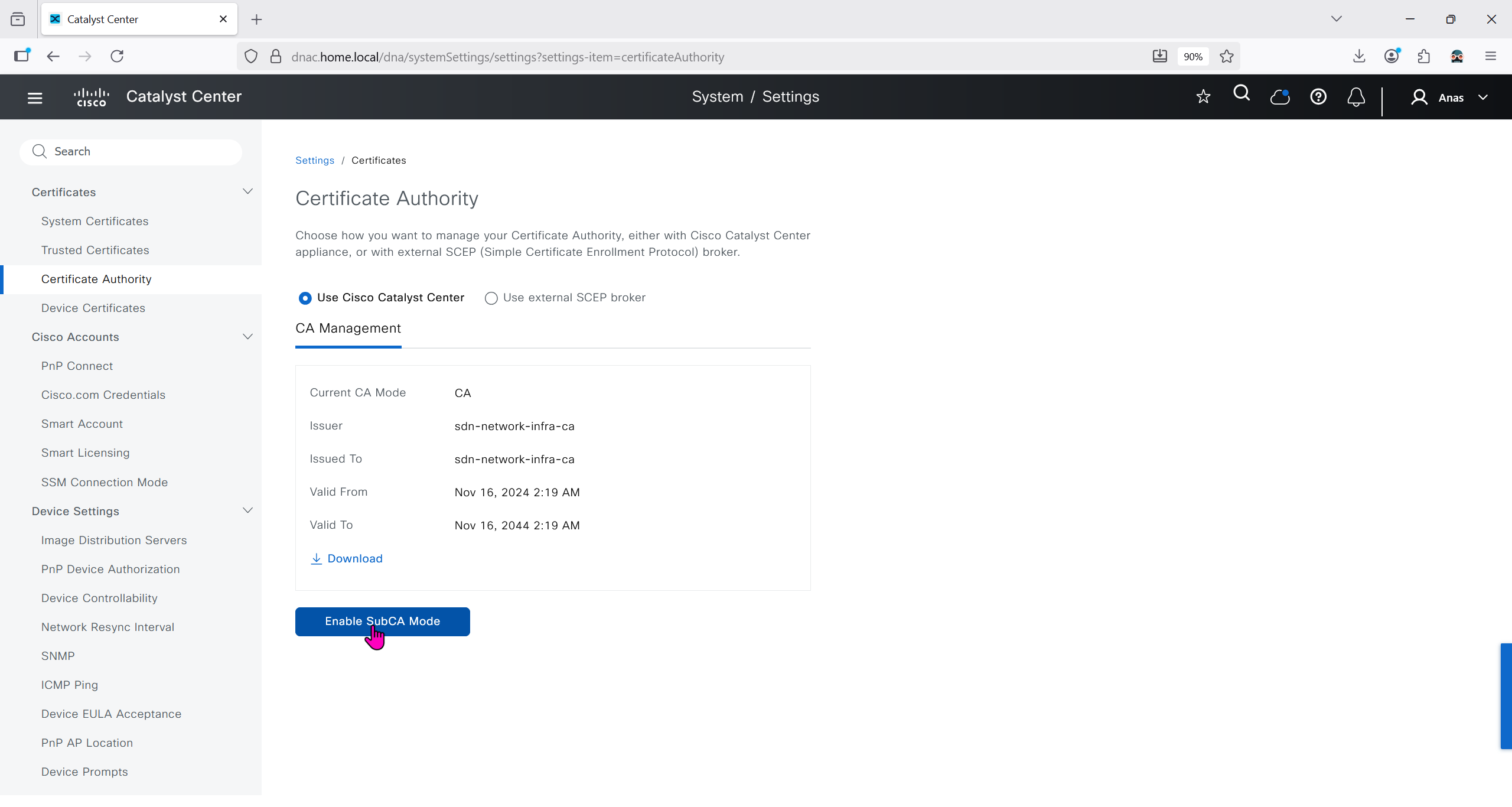
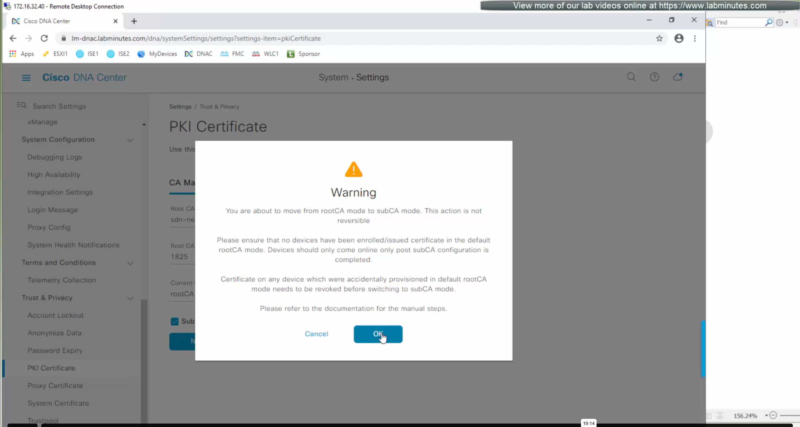
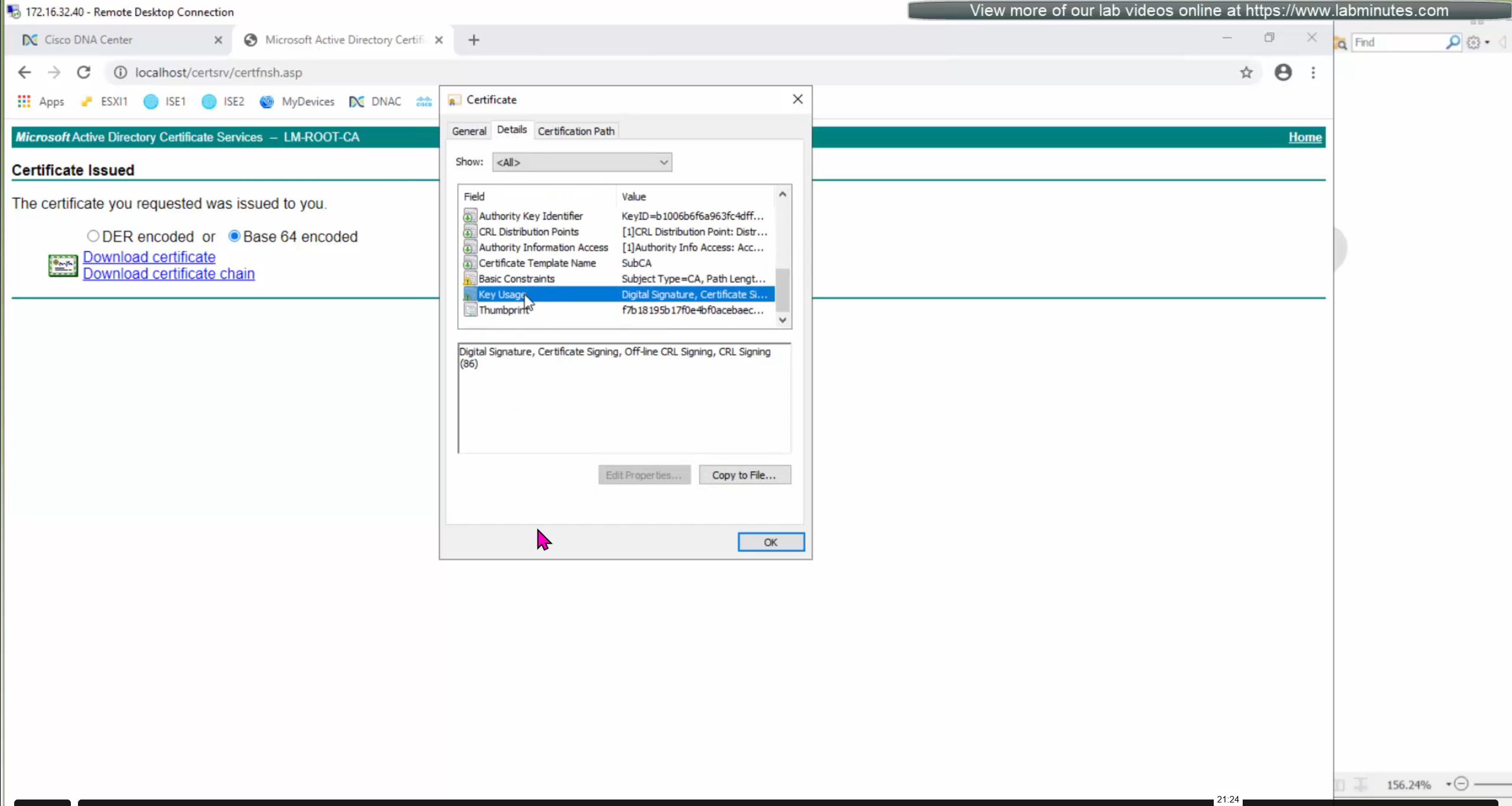
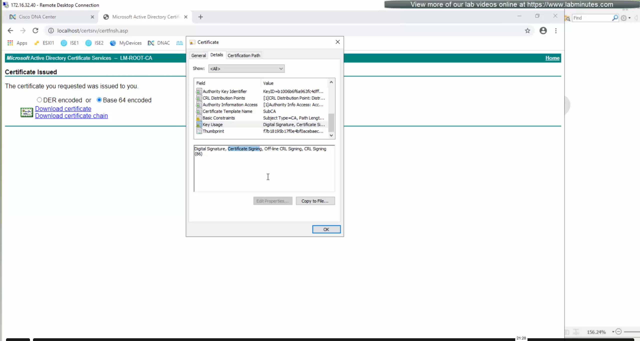
We will just click on option to enable SubCA mode but will not enable it just to see the message from DNAC
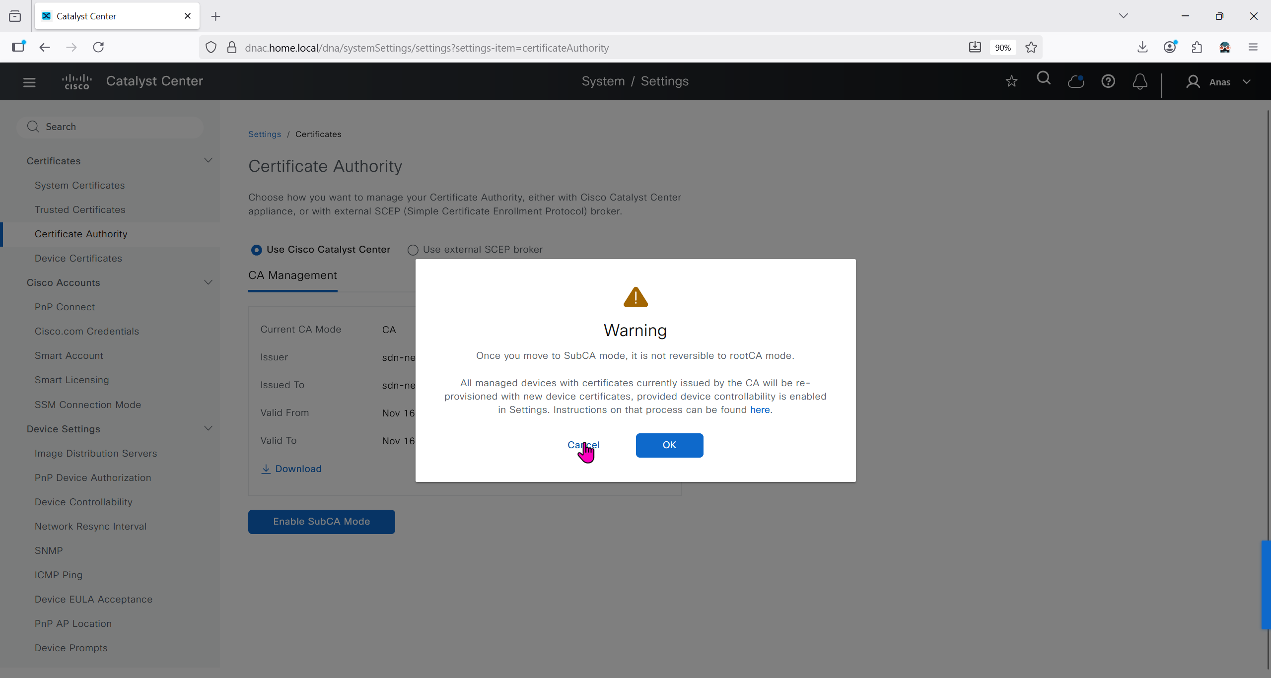
But if we were to enable it then following will be the steps


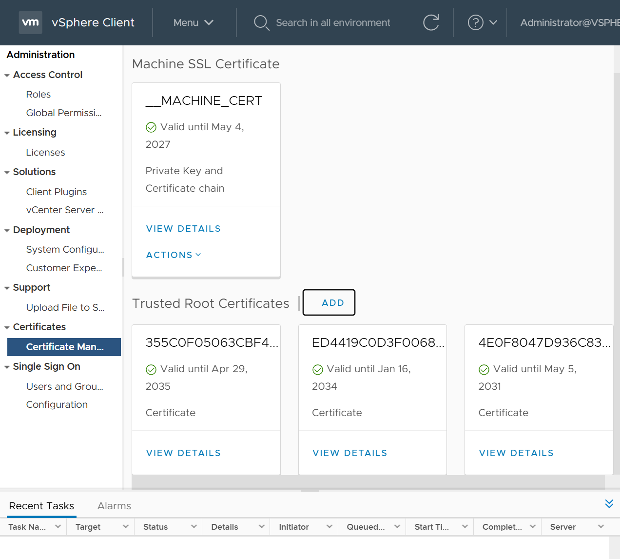
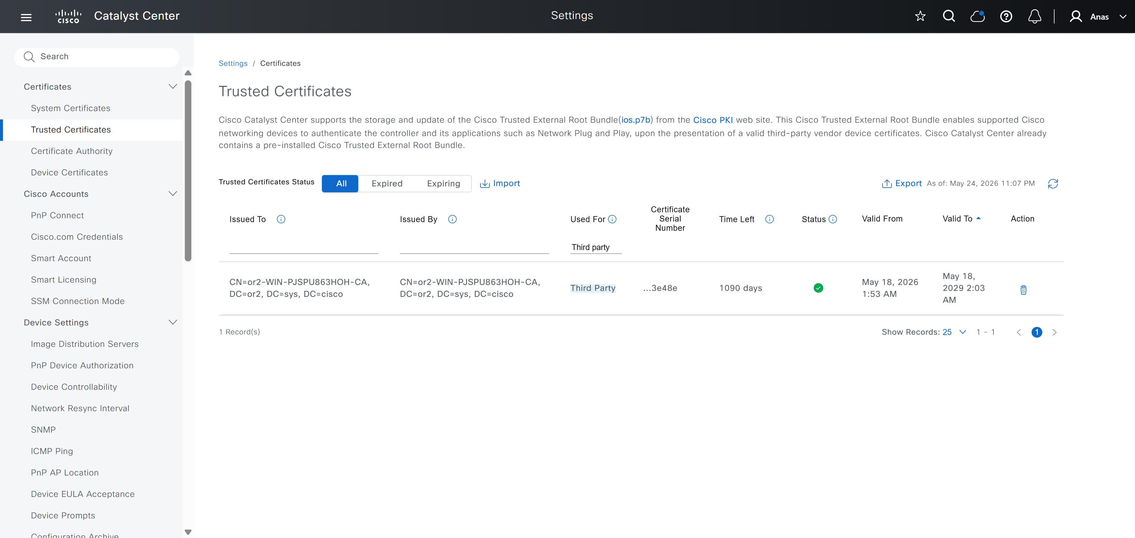
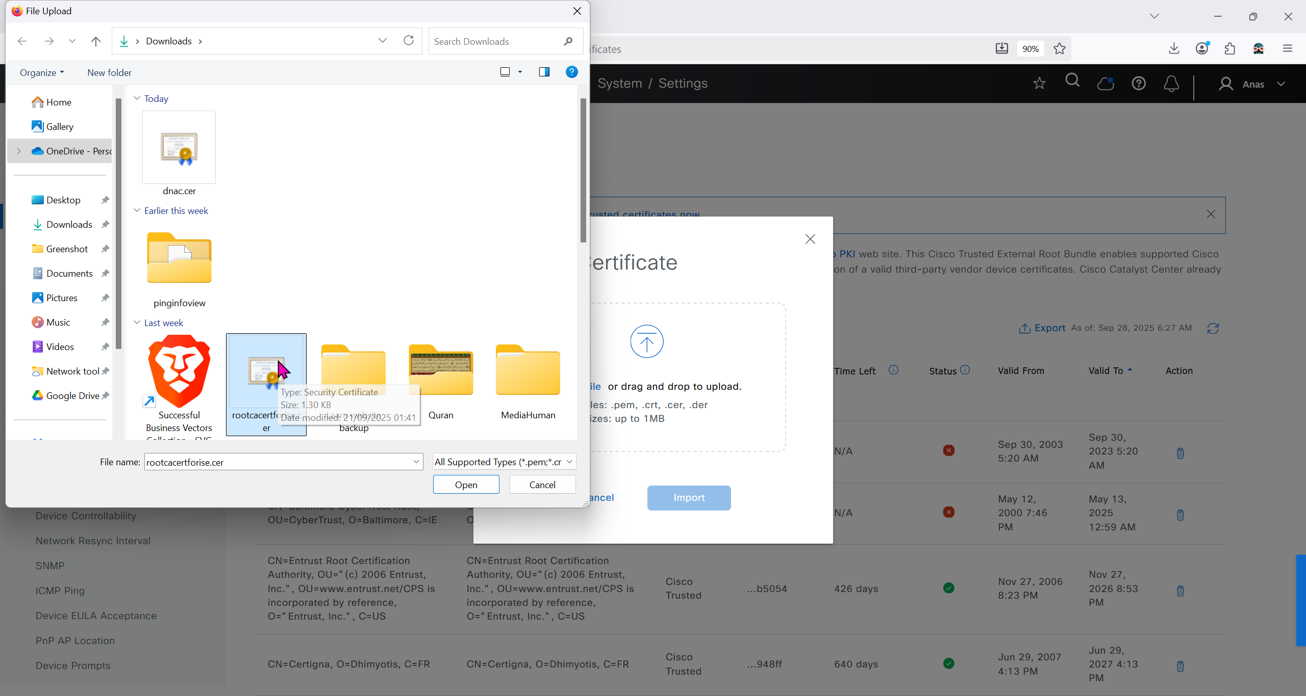
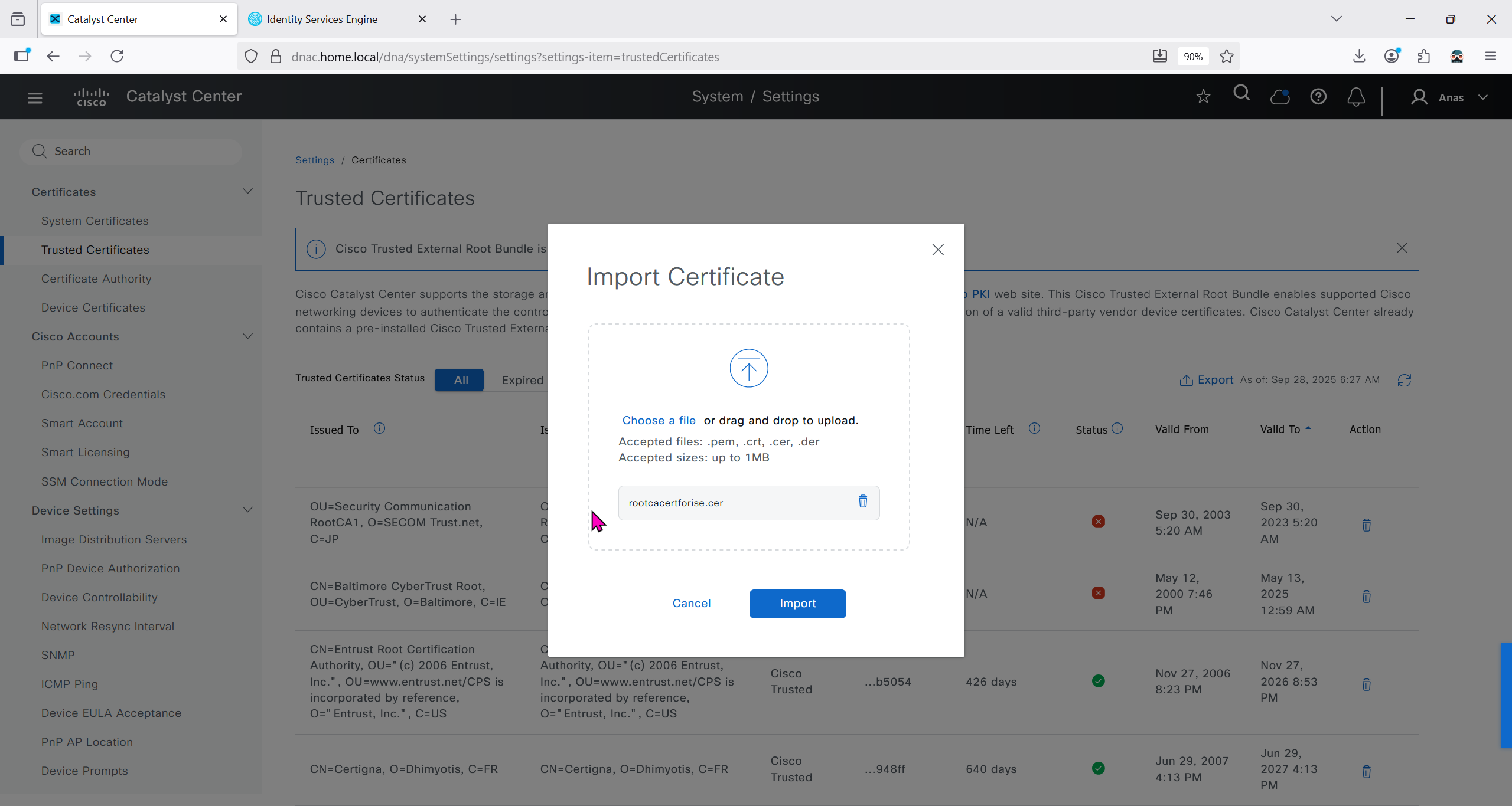
Checking imported CA certificate in Trusted Certificates section
ISE is part of the SDA architecture by using RADIUS (Policy Server with mab and dot1x), TACACS and PXGrid
We need to have dot1x and mab authentication and
authorization configured in ISE
It used to be that ISE should not have TrustSec configuration configured, as config from DNAC will overwrite the existing config
If you bypass Cisco DNA Center and manually modify an SGACL directly inside ISE, the systems will fall out of sync. Cisco DNA Center will not automatically inherit changes made locally on ISE, creating a configuration mismatch until a manual resynchronisation or re-integration is performed
After integration, DNAC continues to poll ISE in order to keep trustsec configuration in sync
Integration between DNAC and ISE is very version specific so make sure you check documentation to see which version of ISE will integrate with which version of DNAC
Make sure that DNAC can reach ISE on ssh, and it is very important that GUI and CLI credentials are same
Also make sure that our ISE certificate has SAN entries for ISE IP and FQDN in ISE certificate


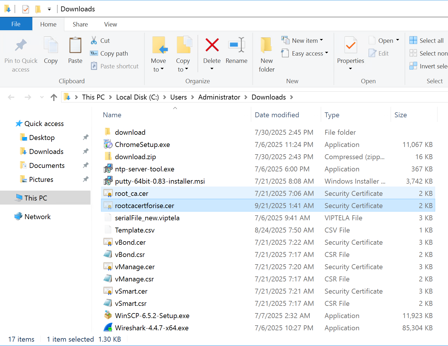
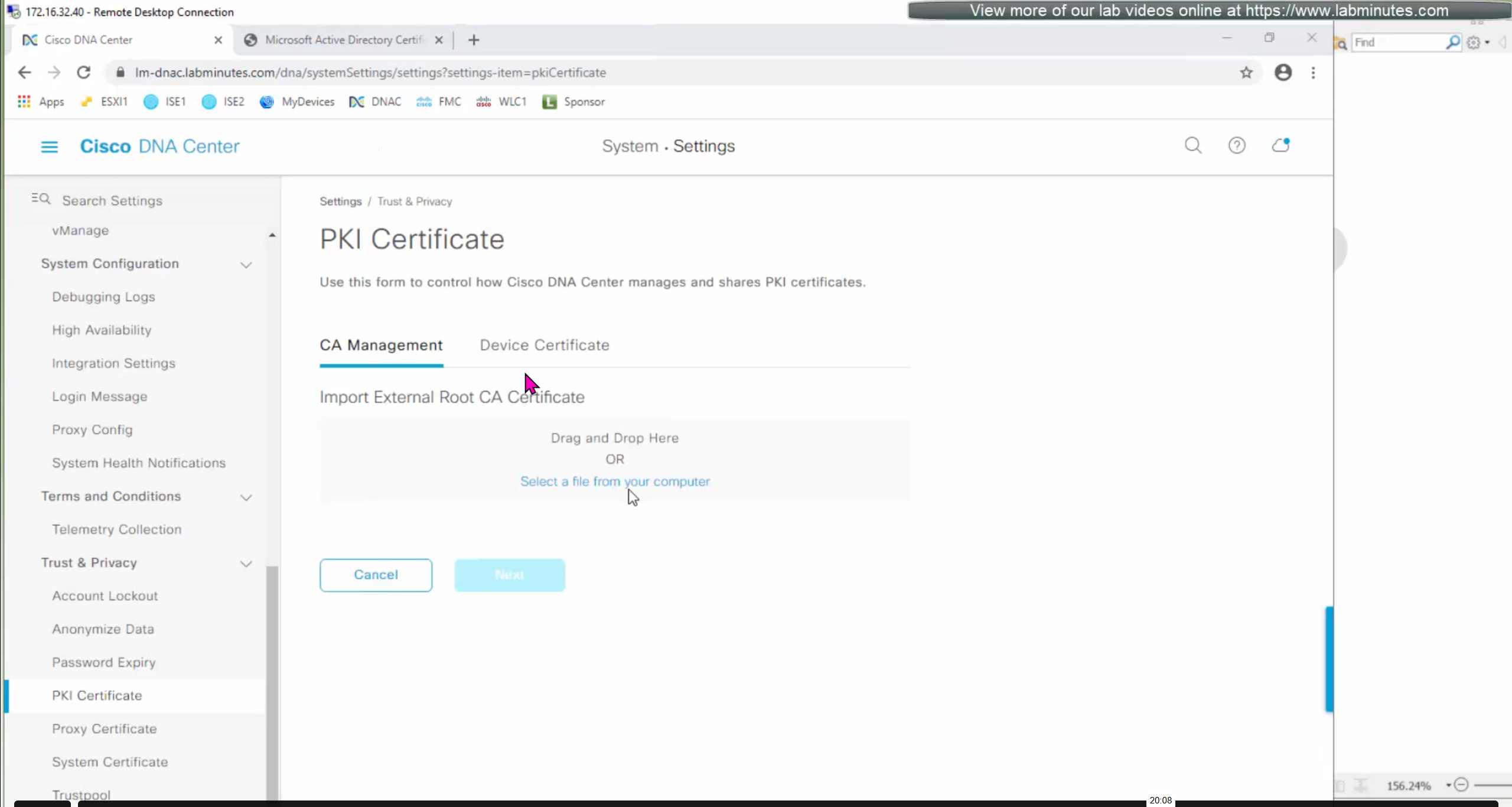
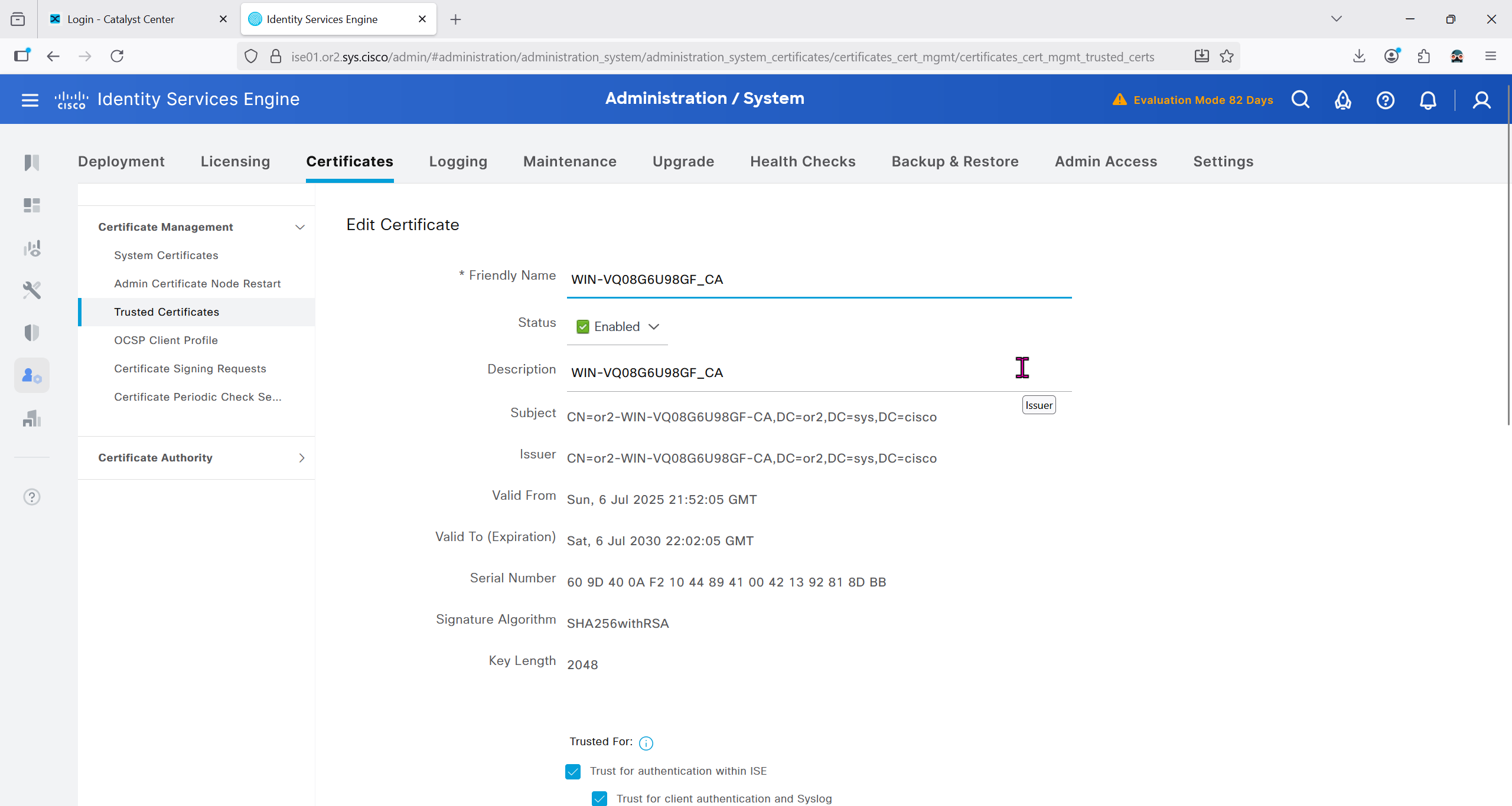
Make sure that when DNAC’s cert is presented it is trusted by ISE, for that we will have to upload the root CA cert
Download CA certificate and upload it to the Trusted store of ISE
We will select this option “Trust for client authentication and Syslog” as certificate presented to ISE during EAP TLS 802.1x authentication will be certificates issued by this same CA
Create CSR for Admin usage
enter DNS Name as $FQDN$
and also enter second DNS name as wildcard with remaining domain name *.or2.sys.cisco
and also add the SAN entry of type IP address with value of 172.16.32.12
ISE gave this error
So I removed first entry of $FQDN$
it is trusted now in browser if we access it on its FQDN
CN is the FQDN of the ISE


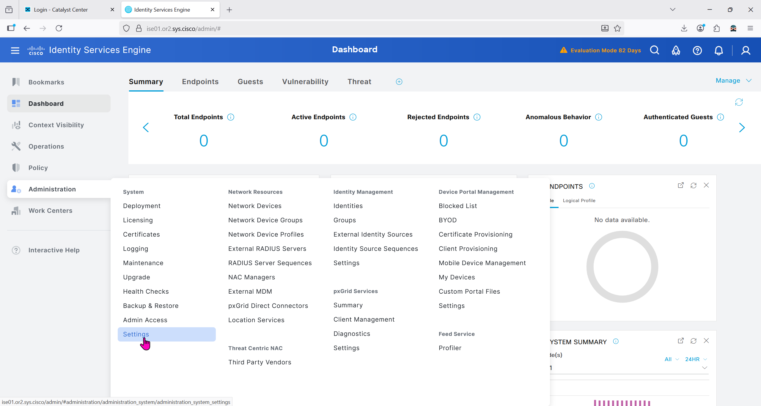
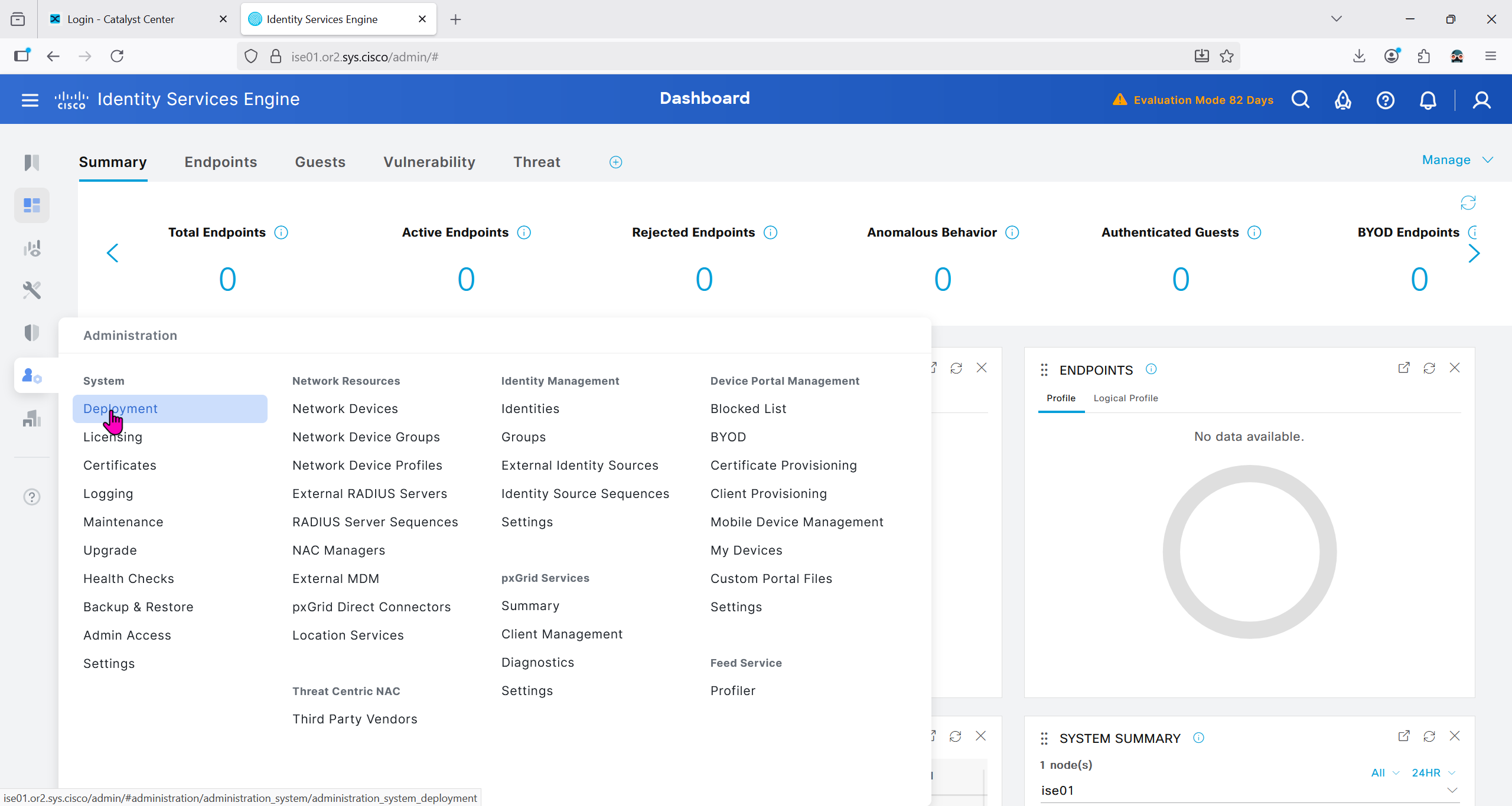
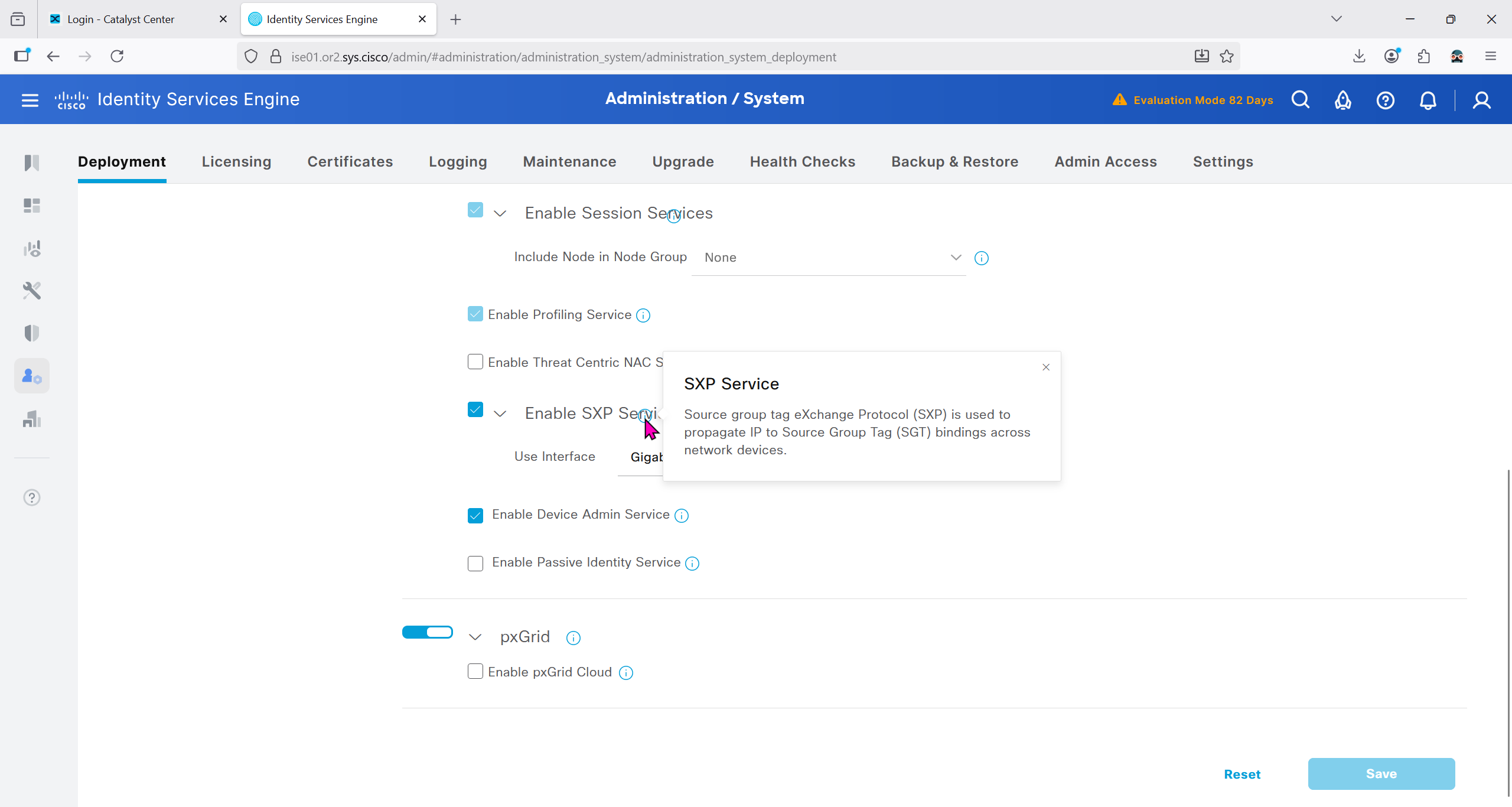
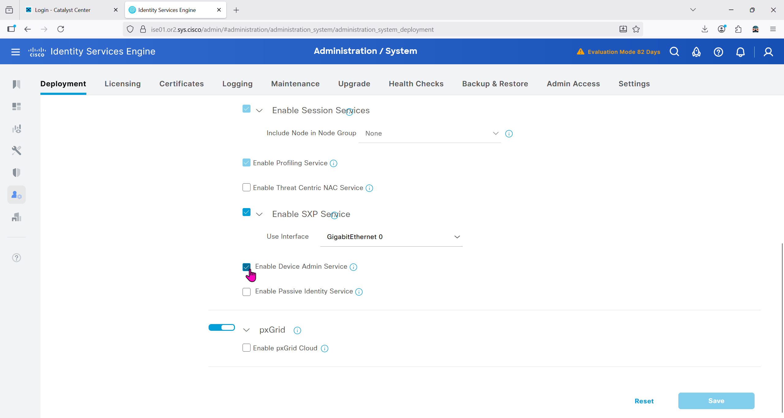
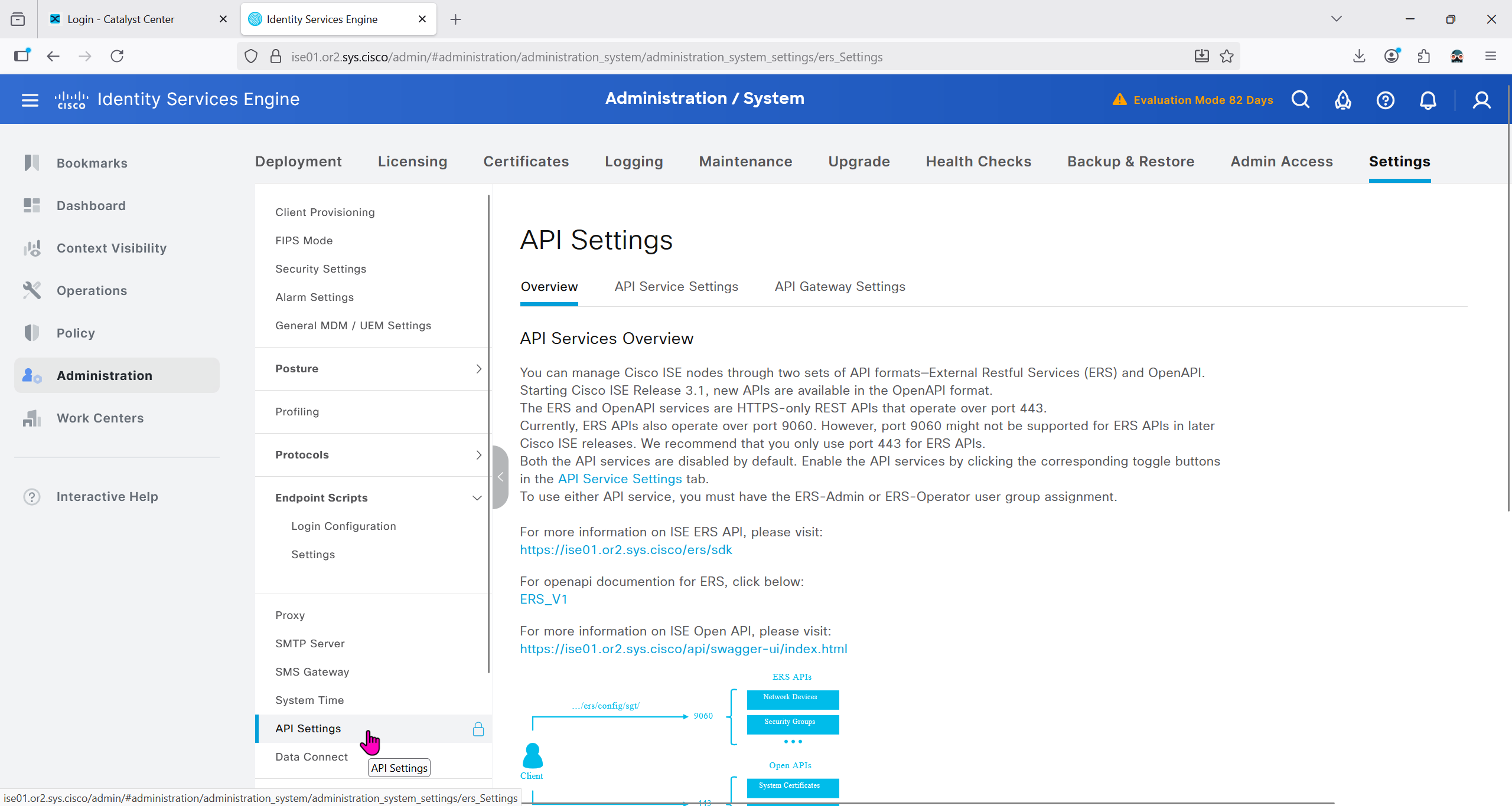
Because DNAC uses API to communicate with ISE, ERS needs to be enabled


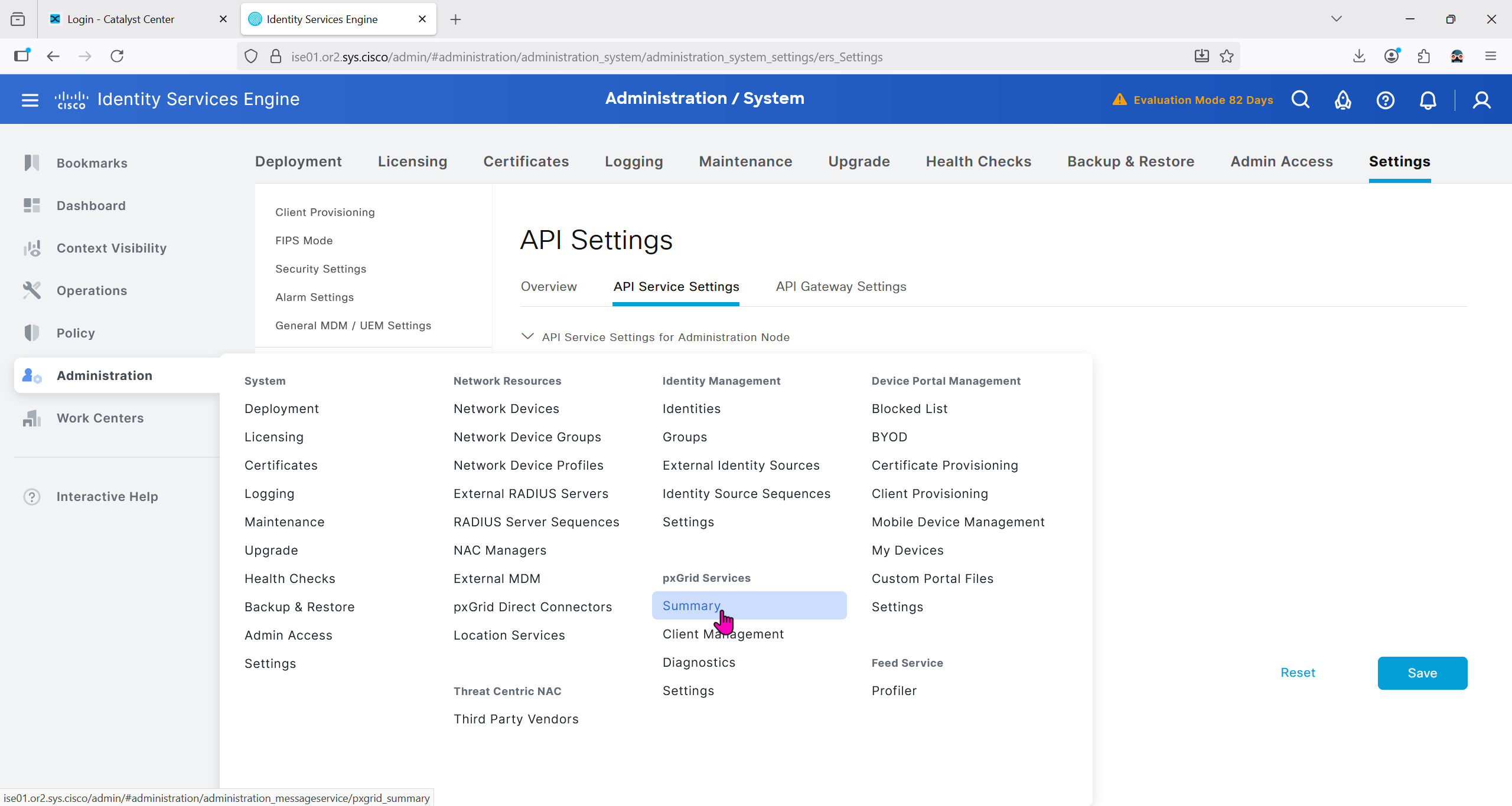
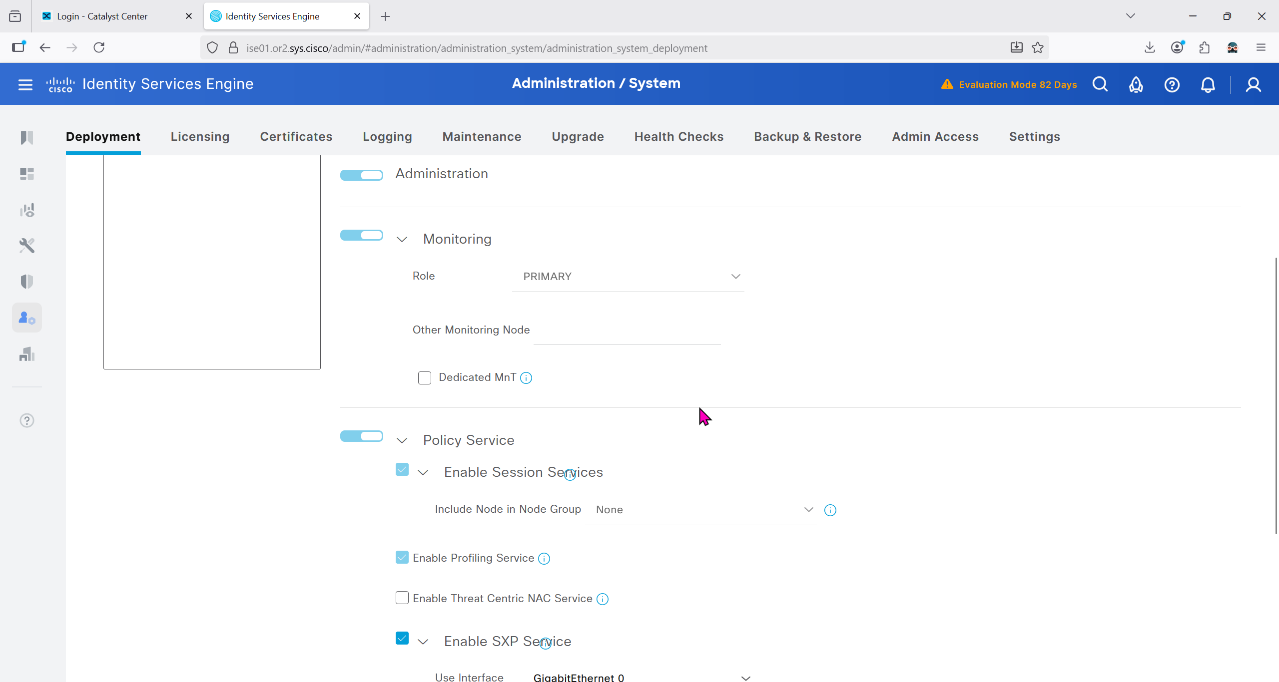
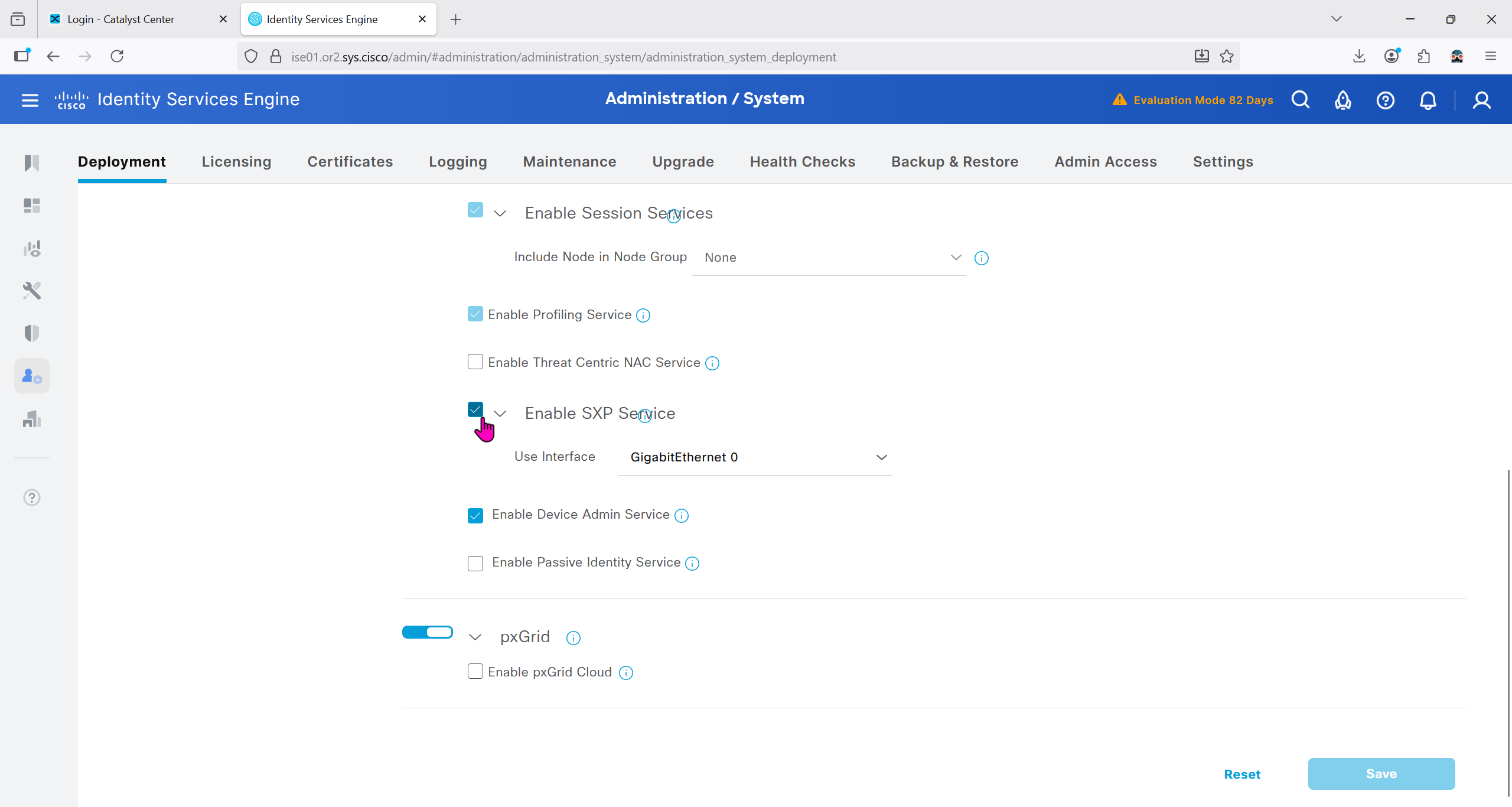
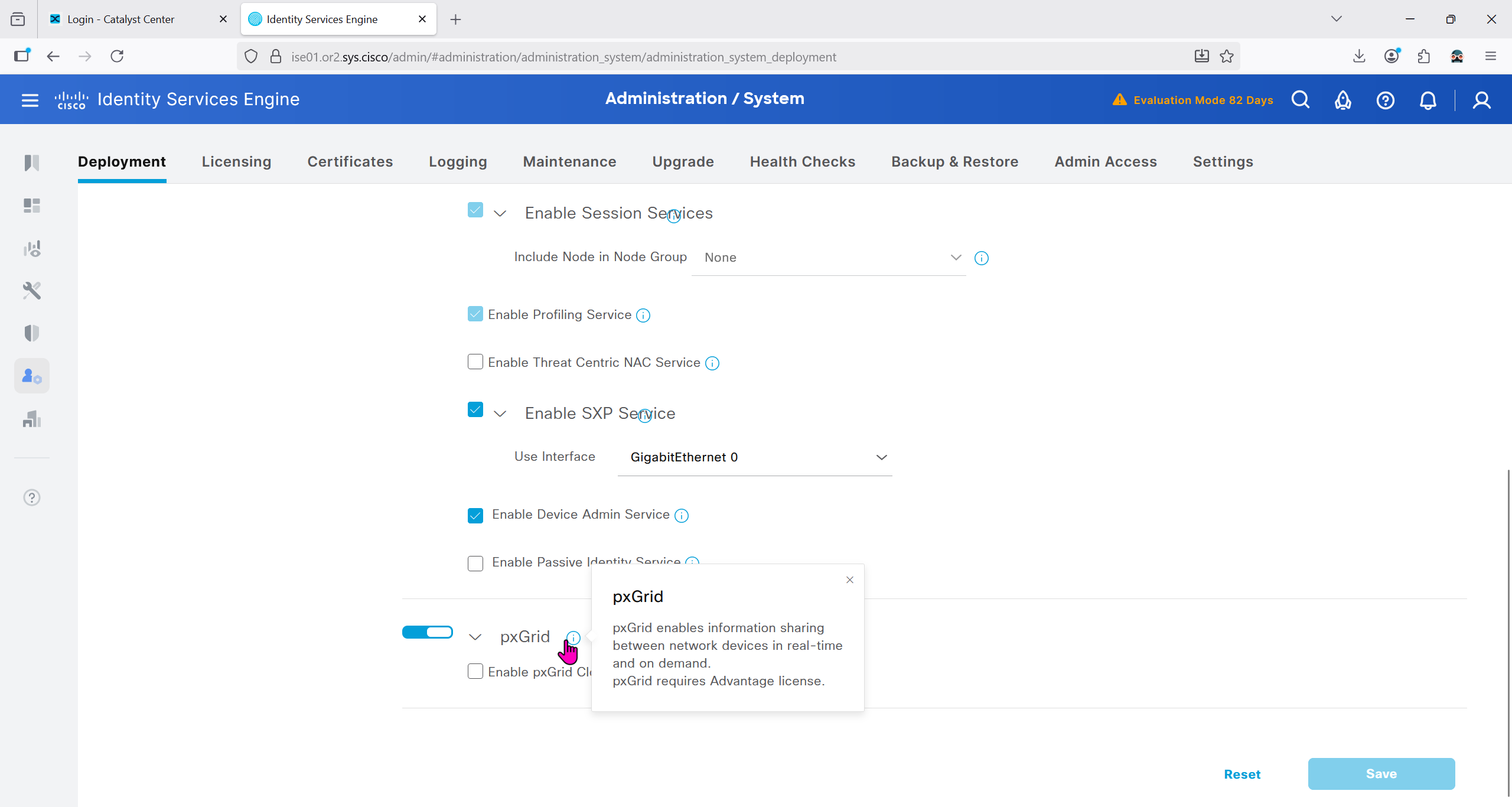
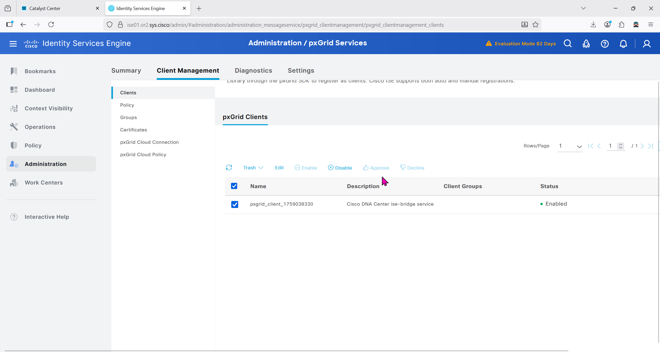
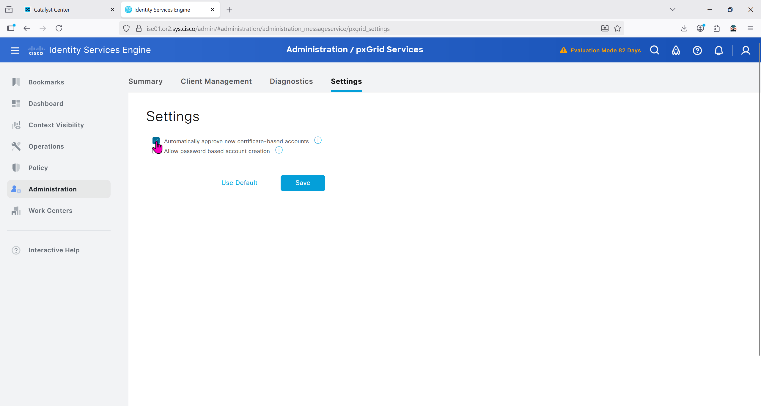
Make sure PXgrid service is running
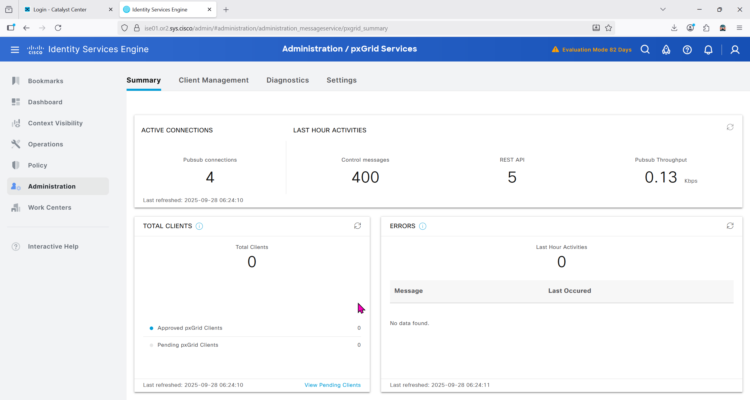
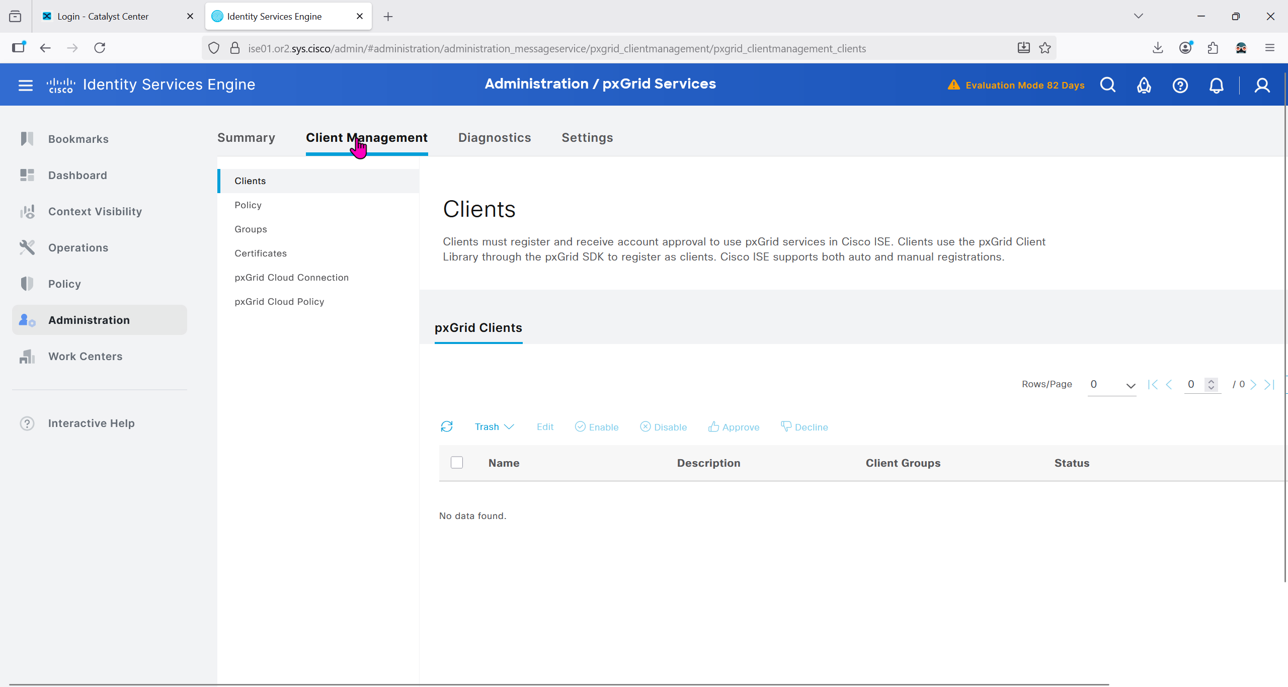
Currently in Client management we do not have any PXgrid clients yet
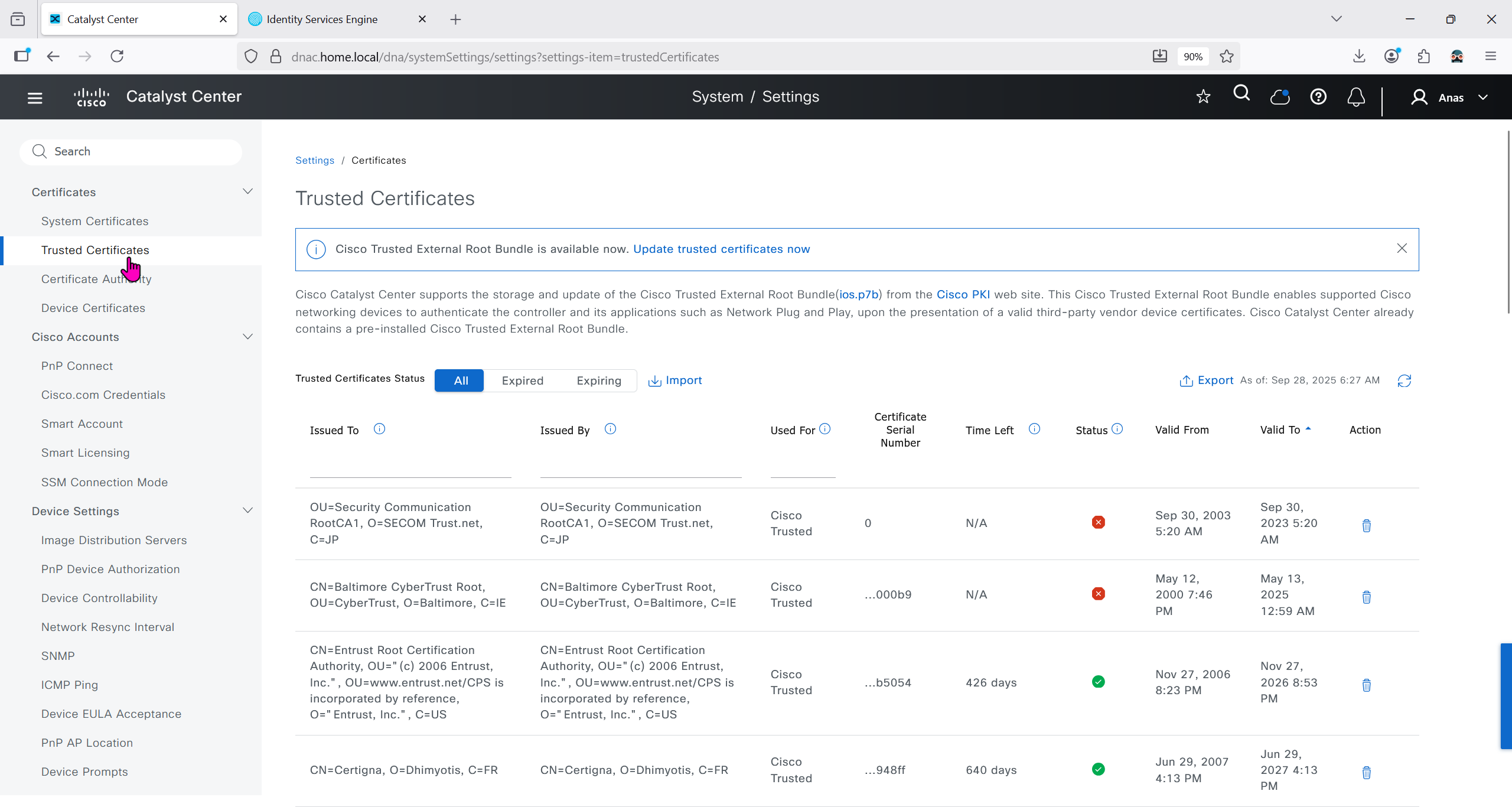
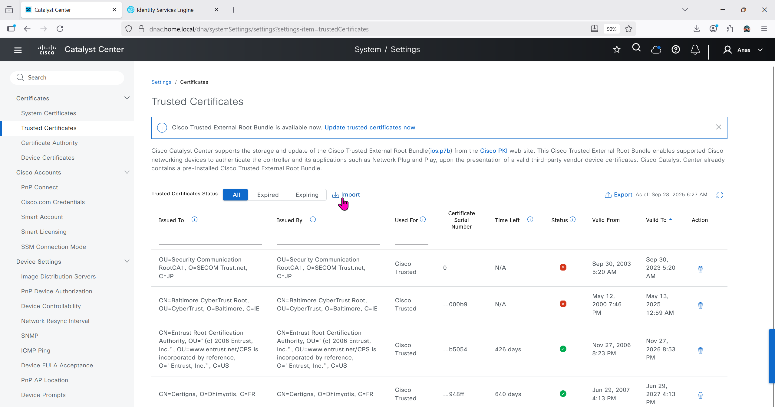
We will import the root ca cert in dnac so it can trust the certificate presented by ISE

Make sure dnac can reach ise 172.16.32.12

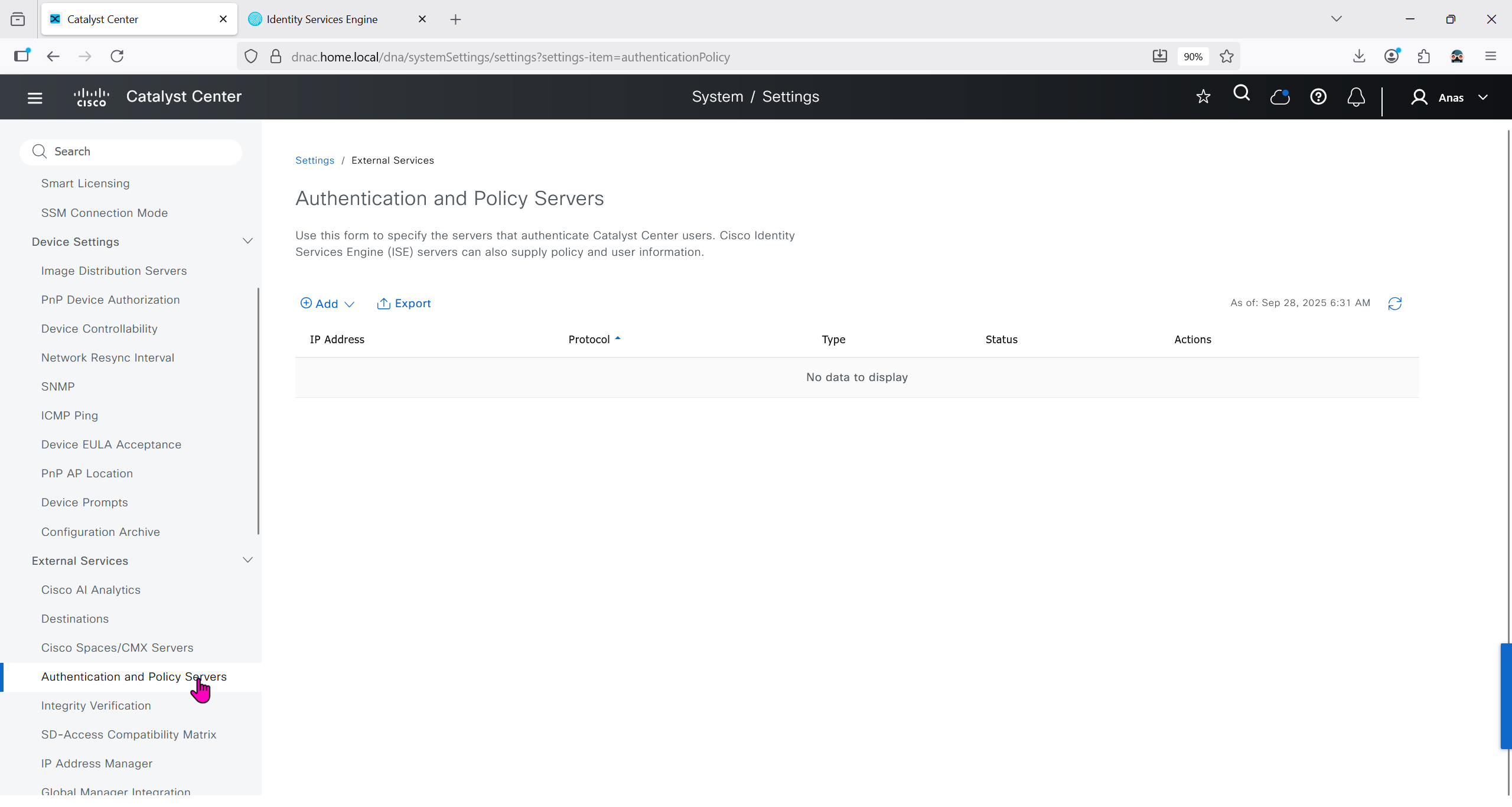
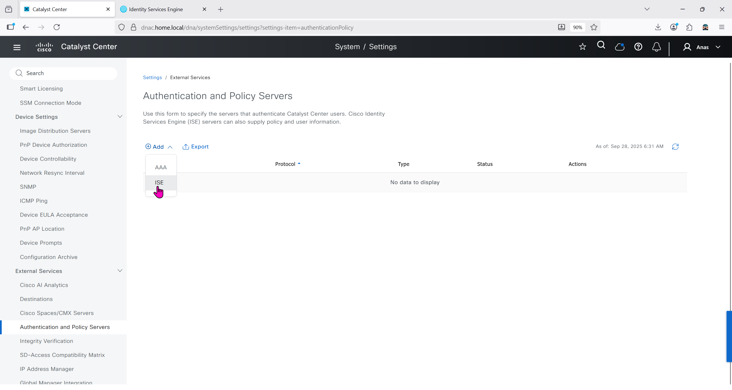
Add ISE server 172.16.32.12 and this shared secret is the secret that will be used on catalyst devices which are added to dnac
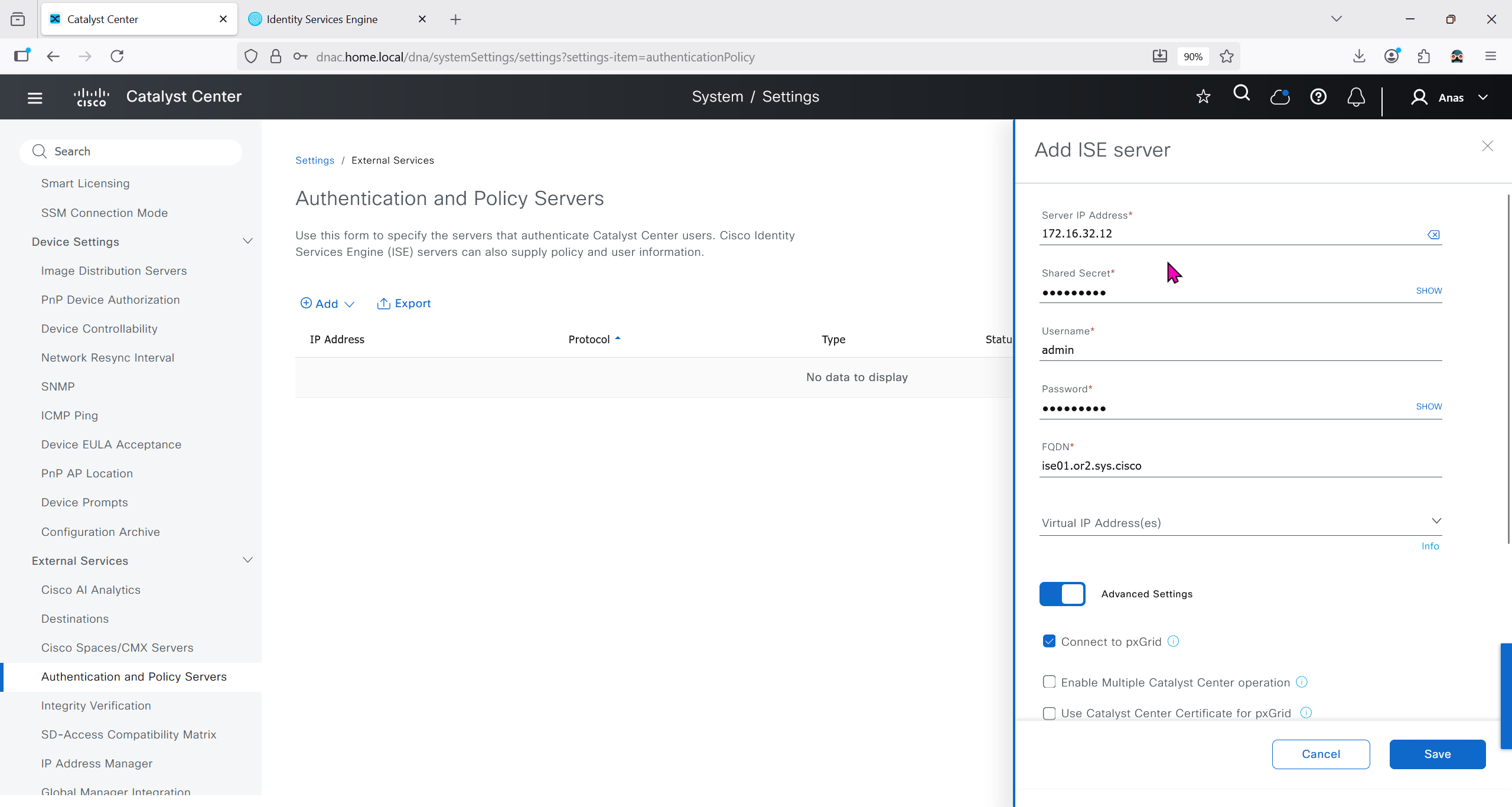
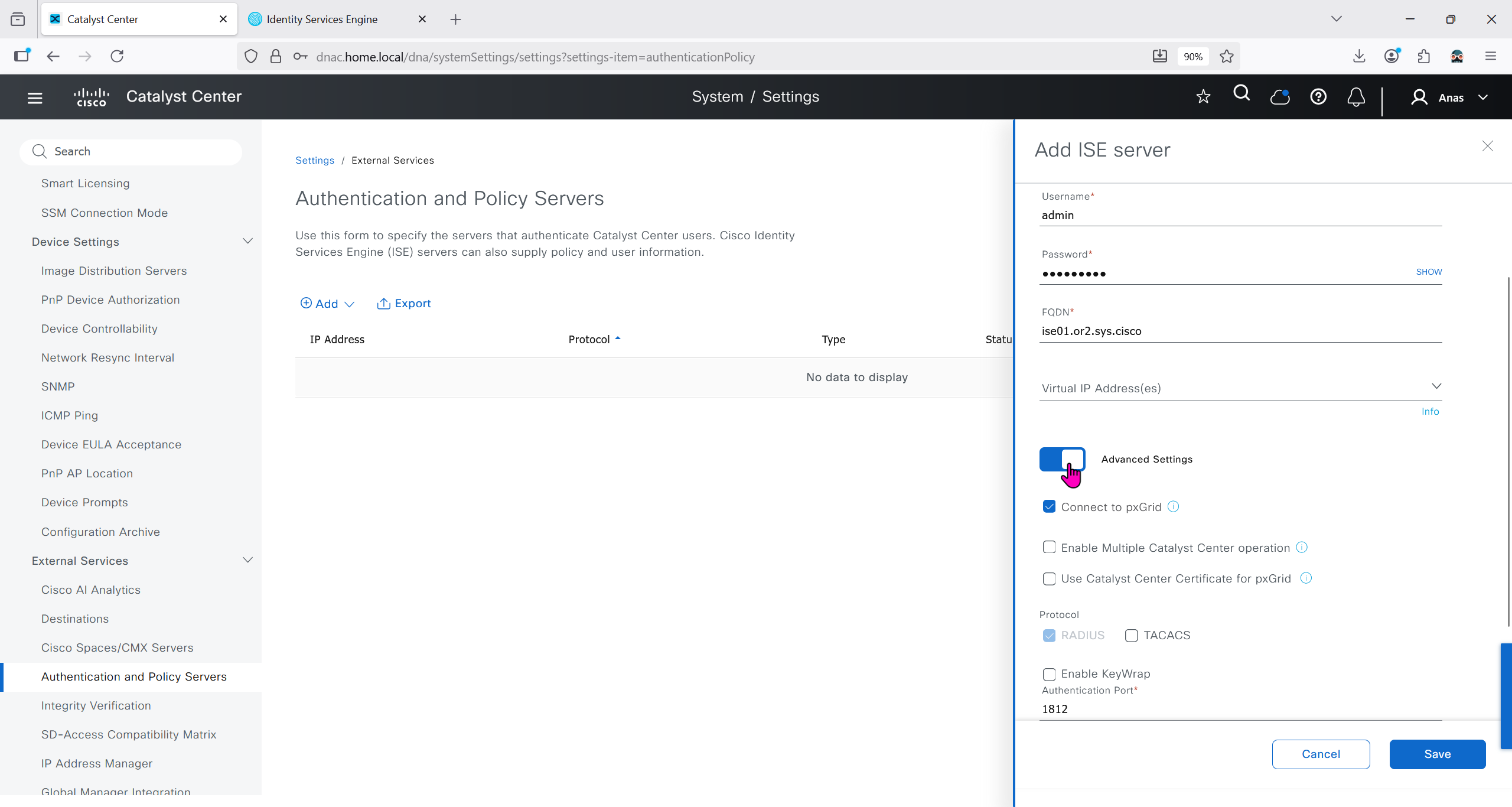
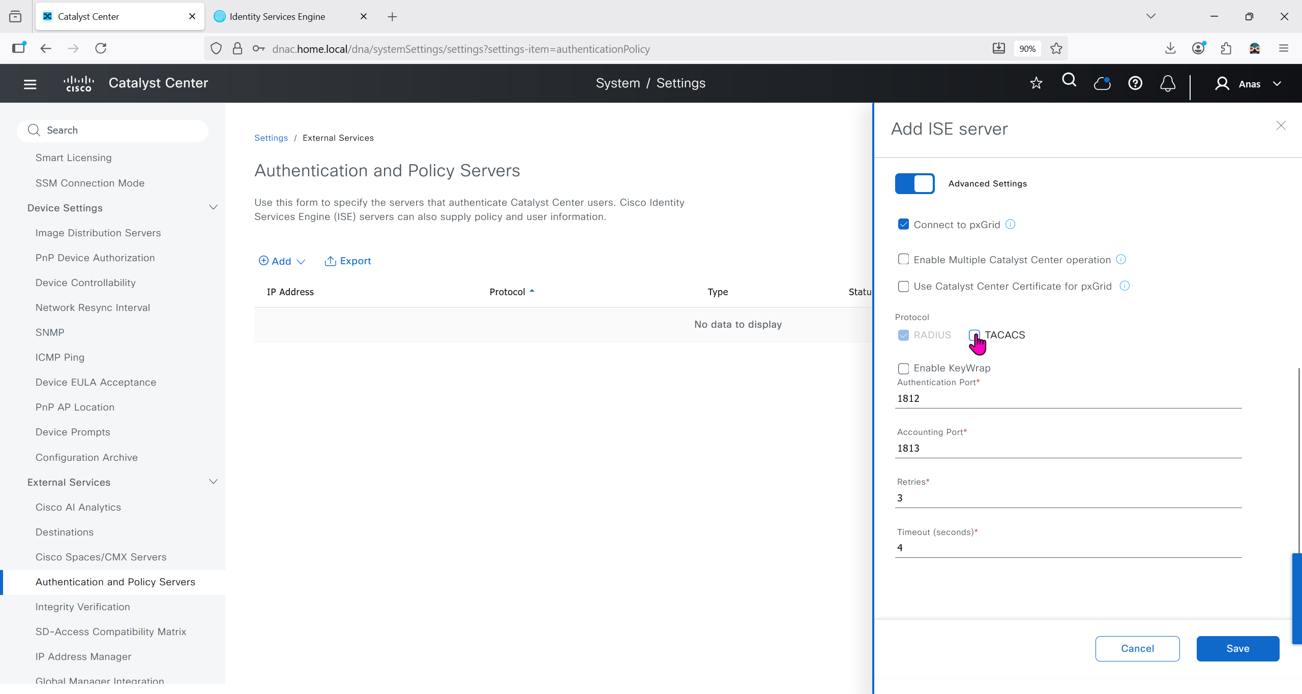
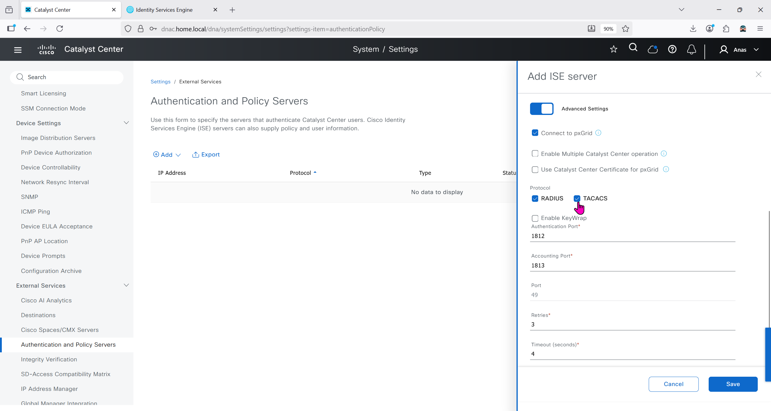

It should say IN PROGRESS and then it should move on to ACTIVE
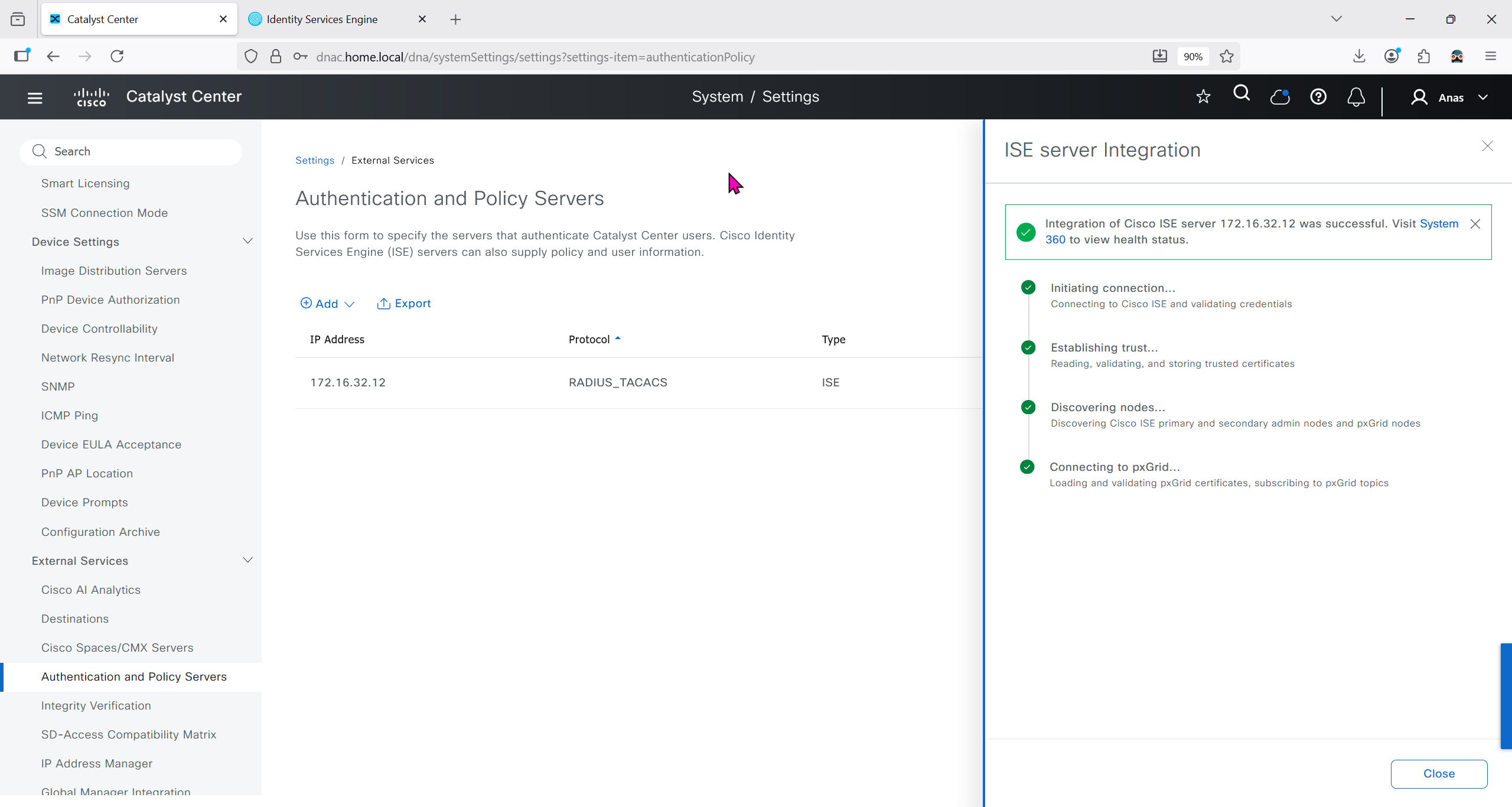
In ISE we will check Administration > pxgrid > summary for 1 client that is dnac

in pxgrid > client management, if dnac is showing pending then approve it


We should have installed Group based policy analytics, which we will do now
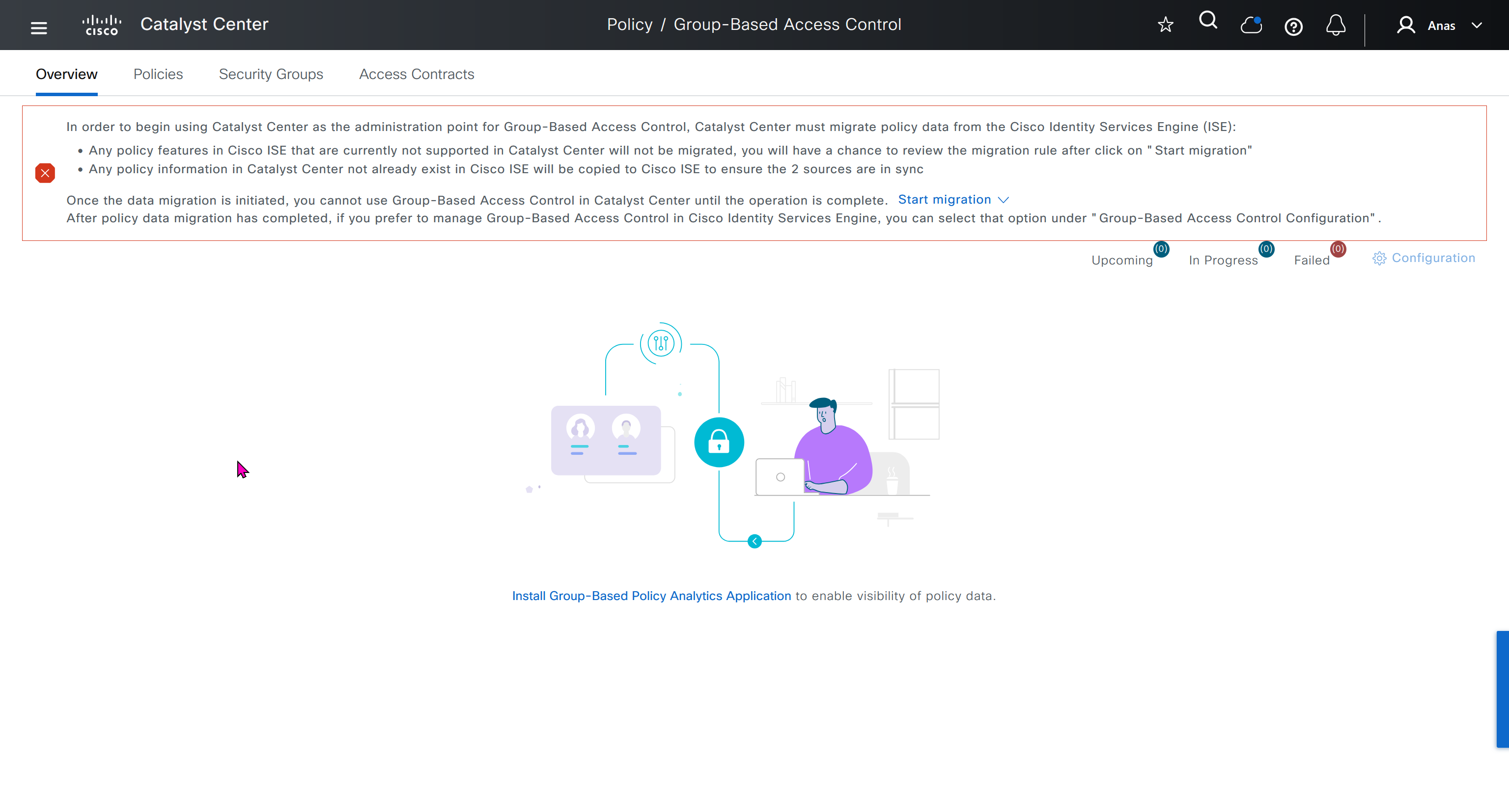

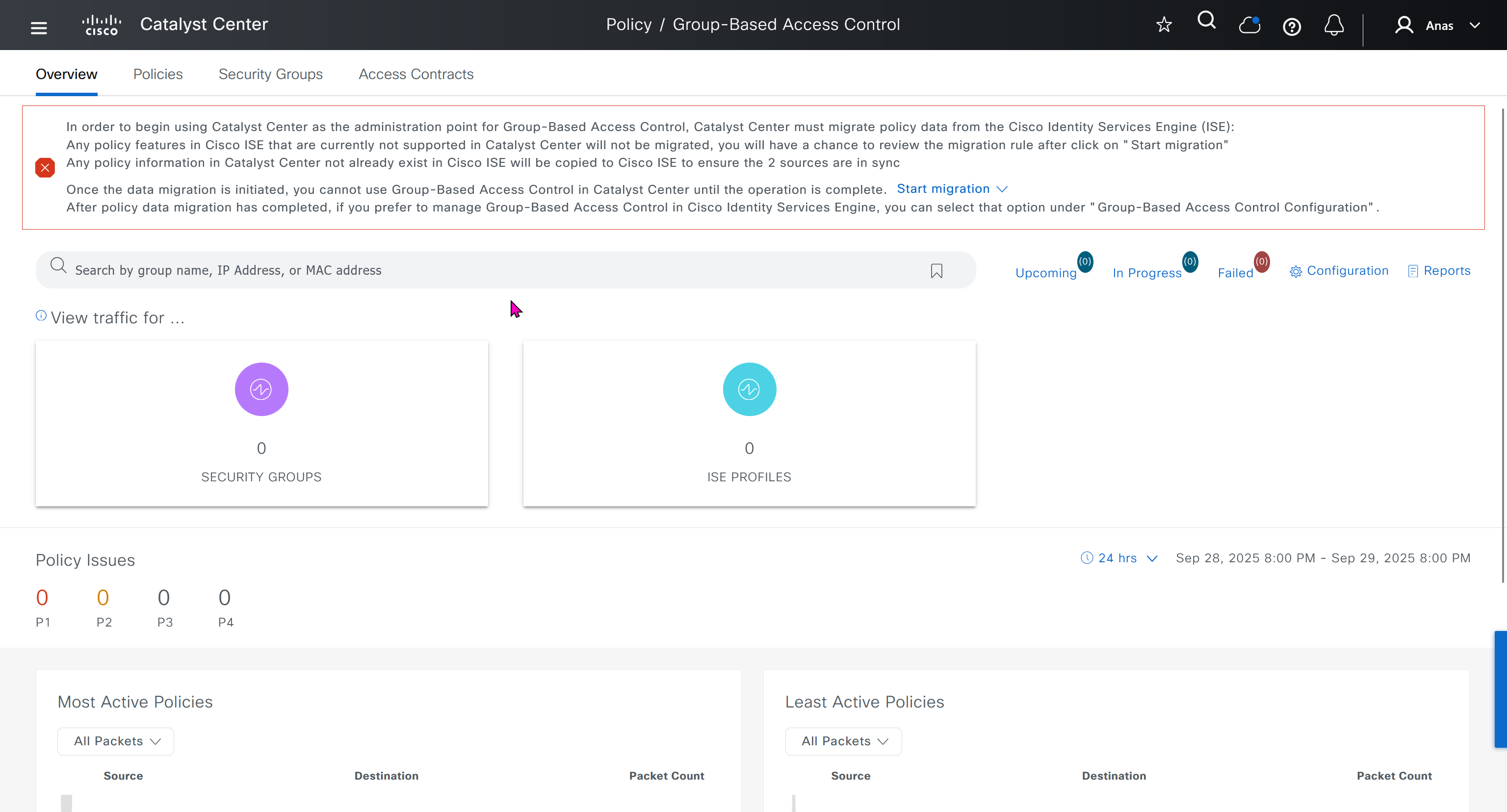
This message basically says to config sync between DNAC and ISE and use DNAC as the administration point for GBAC policy
In order to begin using Catalyst Center as the administration point for Group-Based Access Control, Catalyst Center must migrate policy data from the Cisco Identity Services Engine (ISE):
Any policy features in Cisco ISE that are currently not supported in Catalyst Center will not be migrated, you will have a chance to review the migration rule after click on "Start migration"
Any policy information in Catalyst Center not already exist in Cisco ISE will be copied to Cisco ISE to ensure the 2 sources are in sync
Once the data migration is initiated, you cannot use Group-Based Access Control in Catalyst Center until the operation is complete.
Start migration
After policy data migration has completed, if you prefer to manage Group-Based Access Control in Cisco Identity Services Engine, you can select that option under “Group-Based Access Control Configuration”.
We need to click on Start migration, Backup is recommended because this is a 2 way sync and configuration in ISE will also change if there is pre existing config in DNAC
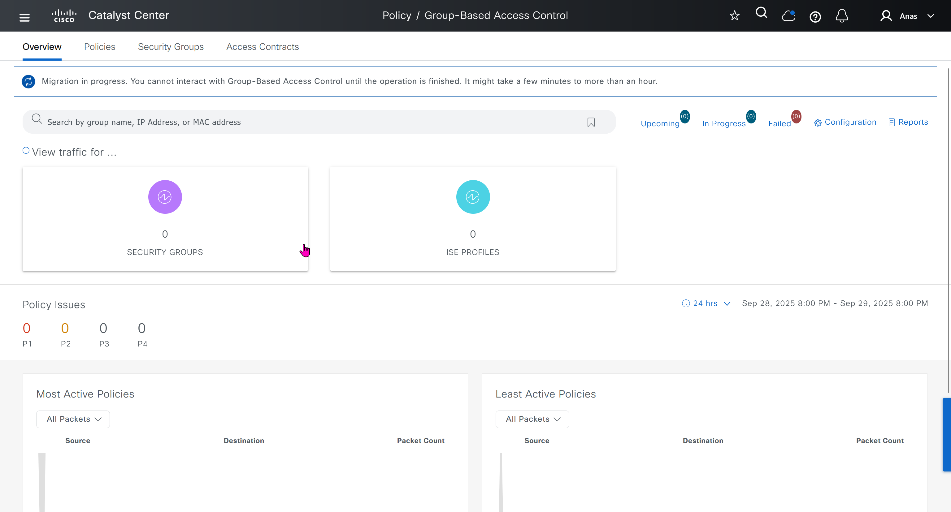
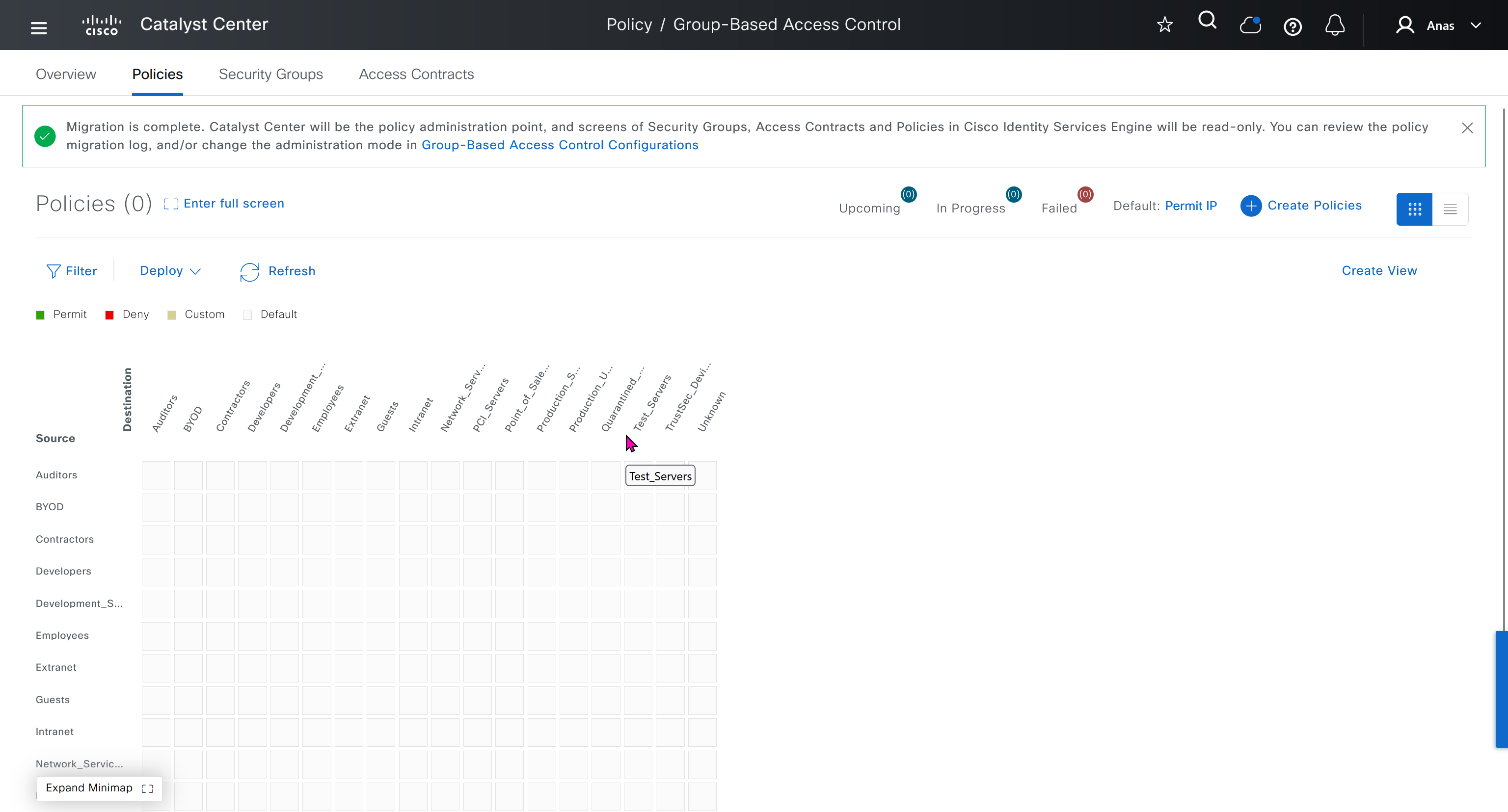
After migration DNAC has become the policy administration point and all changes should be made in ISE
“Migration is complete. Catalyst Center will be the policy administration point, and screens of Security Groups, Access Contracts and Policies in Cisco Identity Services Engine will be read-only. You can review the policy migration log, and/or change the administration mode in Group-Based Access Control Configurations”
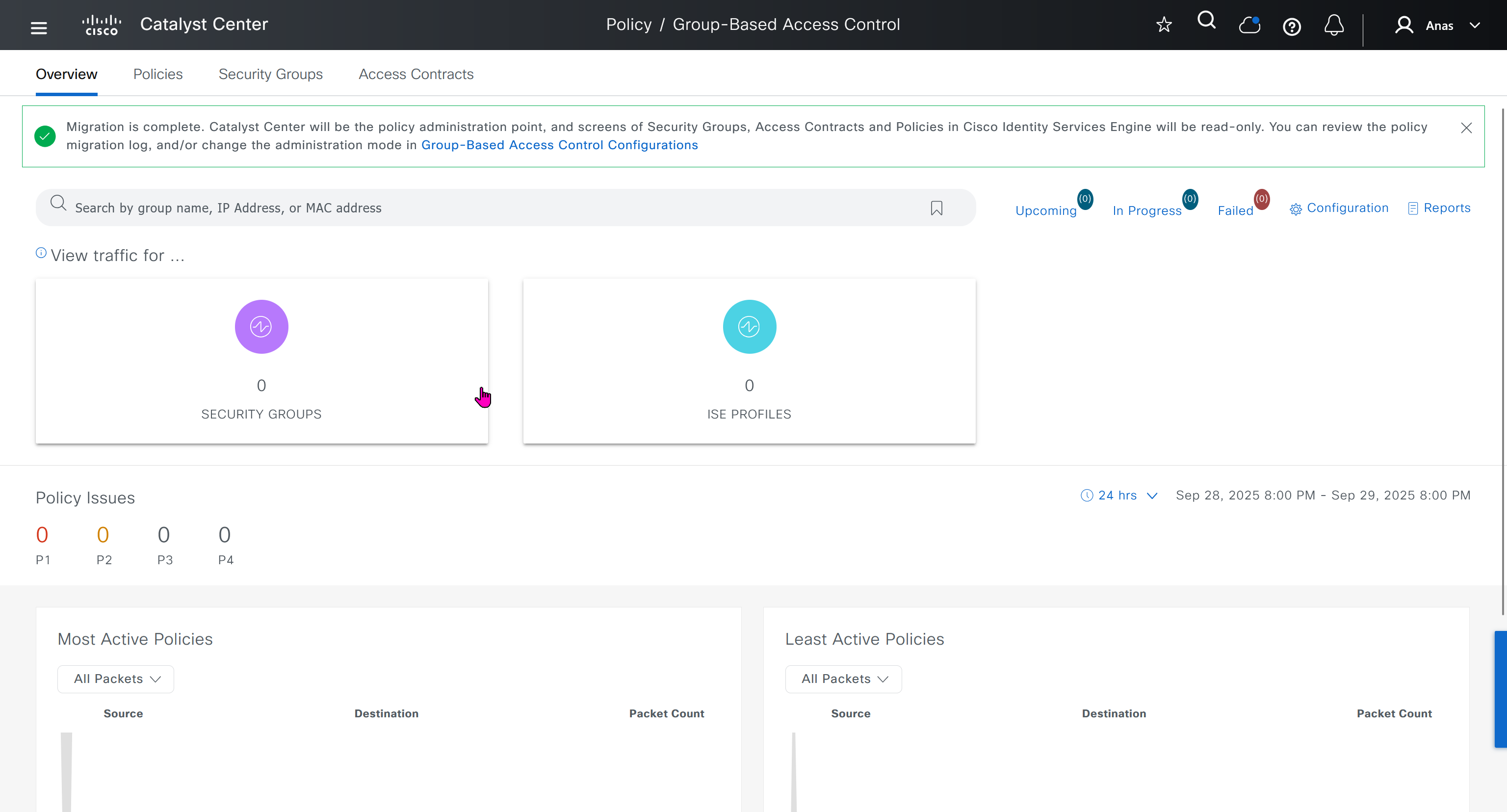
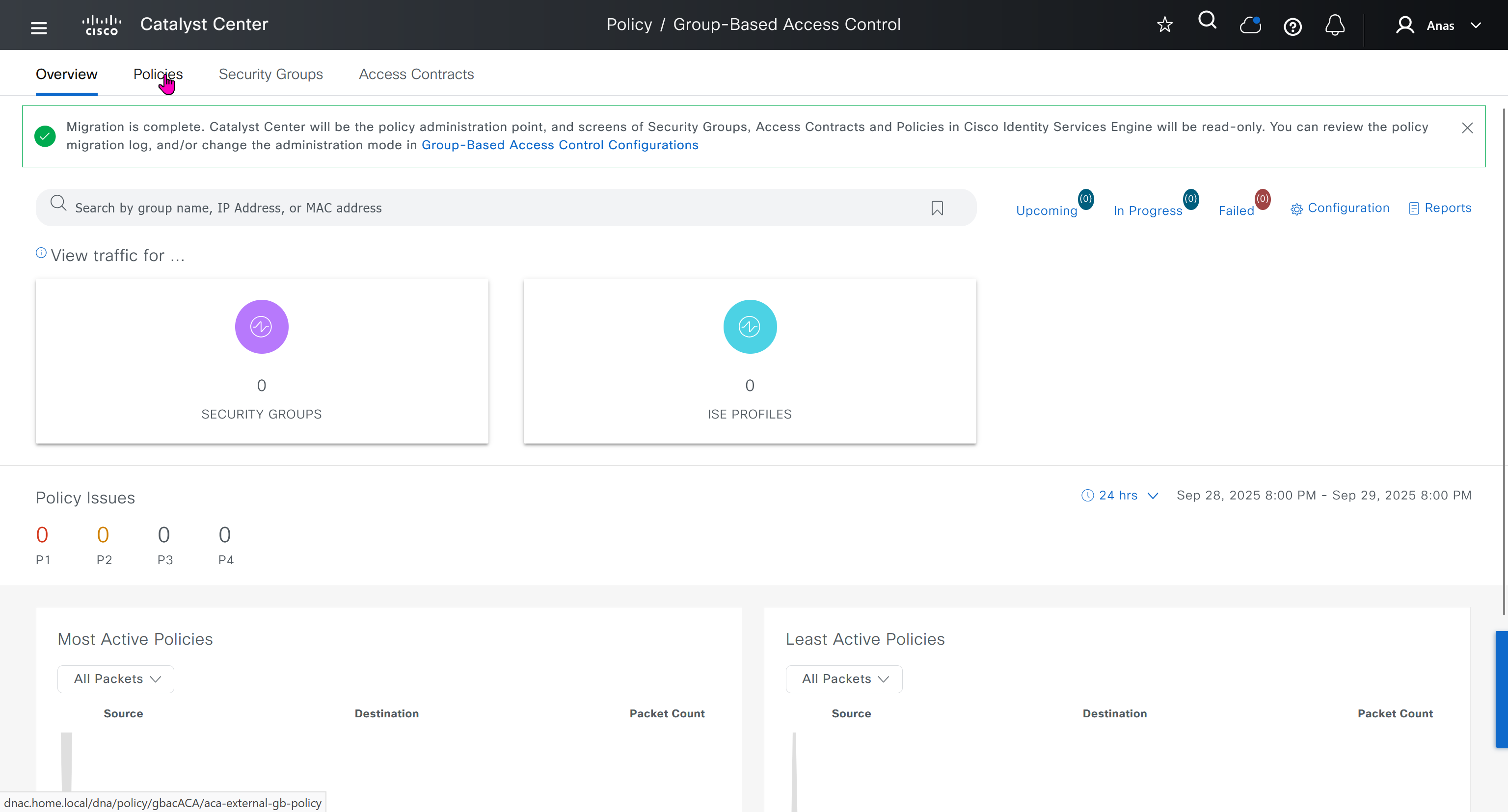
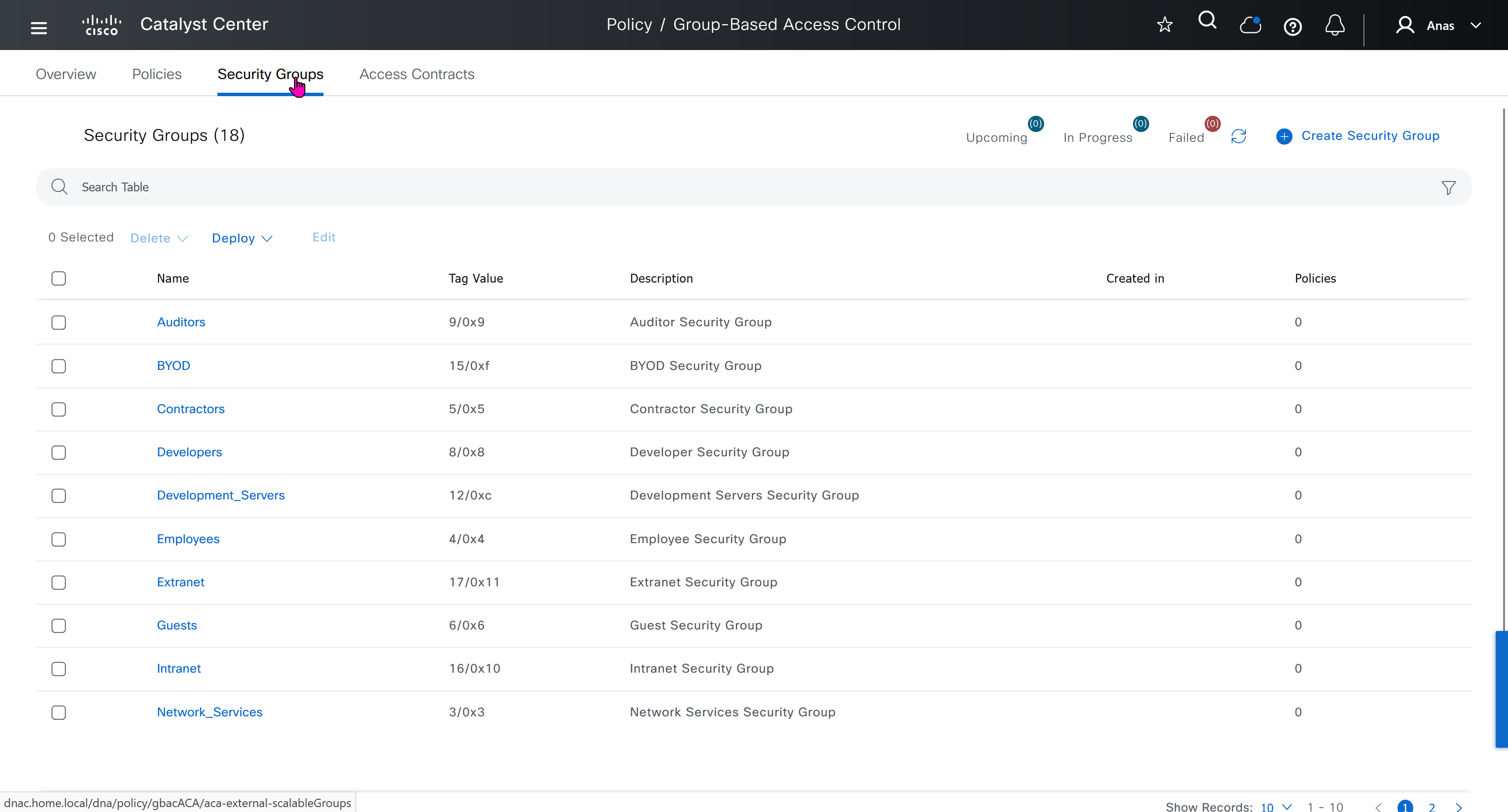
All these security groups have been downloaded into DNAC and any future configuration changes you make in DNAC will be reflected in ISE


next post
SDA LM 2 – Network Design
Videos
Network Design
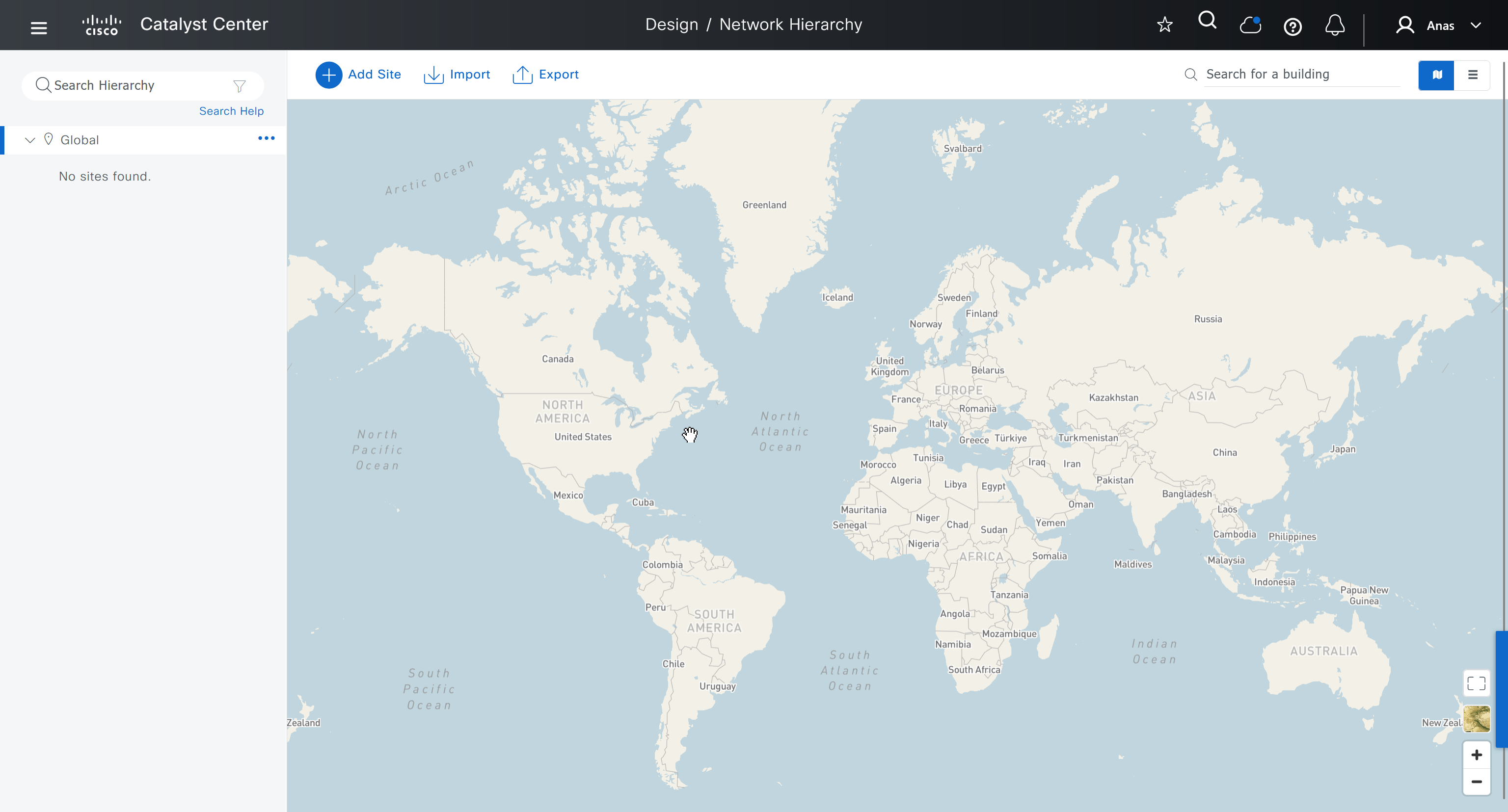
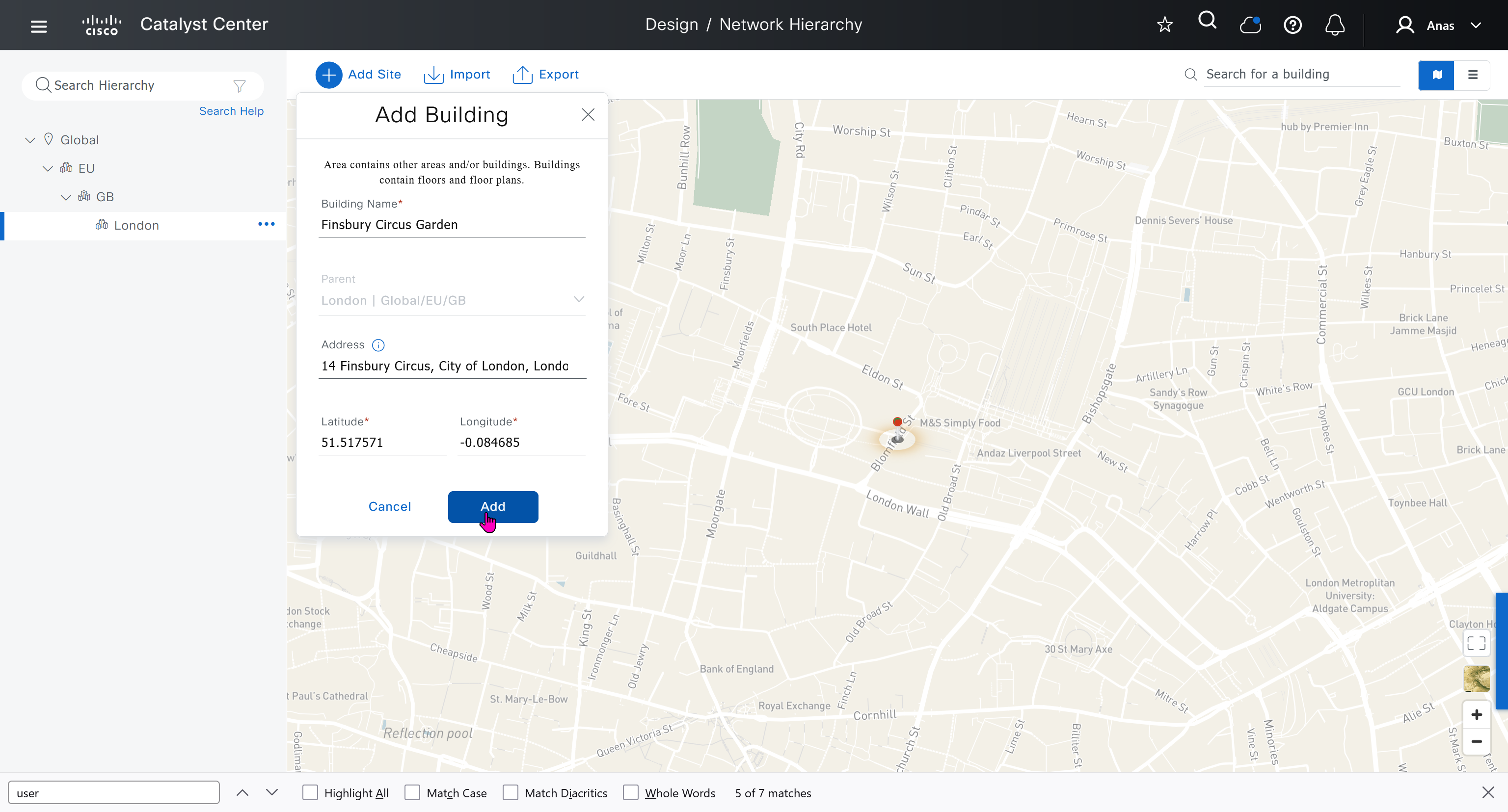
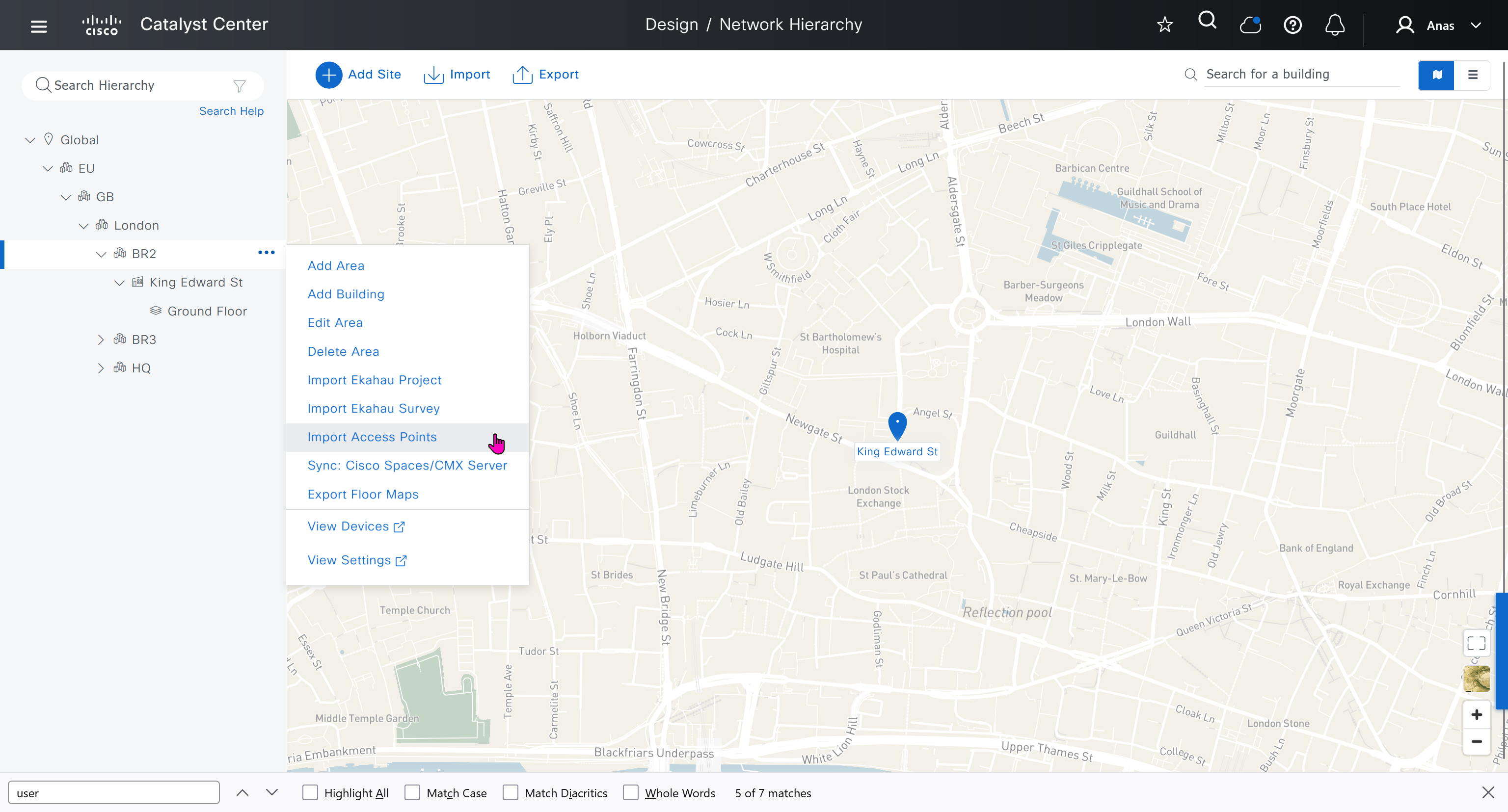
An area represents the geographical location such as country, city or campus (regardless of the size of area), next level is building which represents physical structure, there cannot be buidling inside a building
Cisco recommends the hierarchy as Continent > Country > City > Campus > Buildings
This is how you are on safe side and covered for any future locations and changes with flexibility built in as it can difficult to adjust the hierarchy later on once everything is configured
For example, today you are domestic but tomorrow you might go international and open new offices in new country / continent

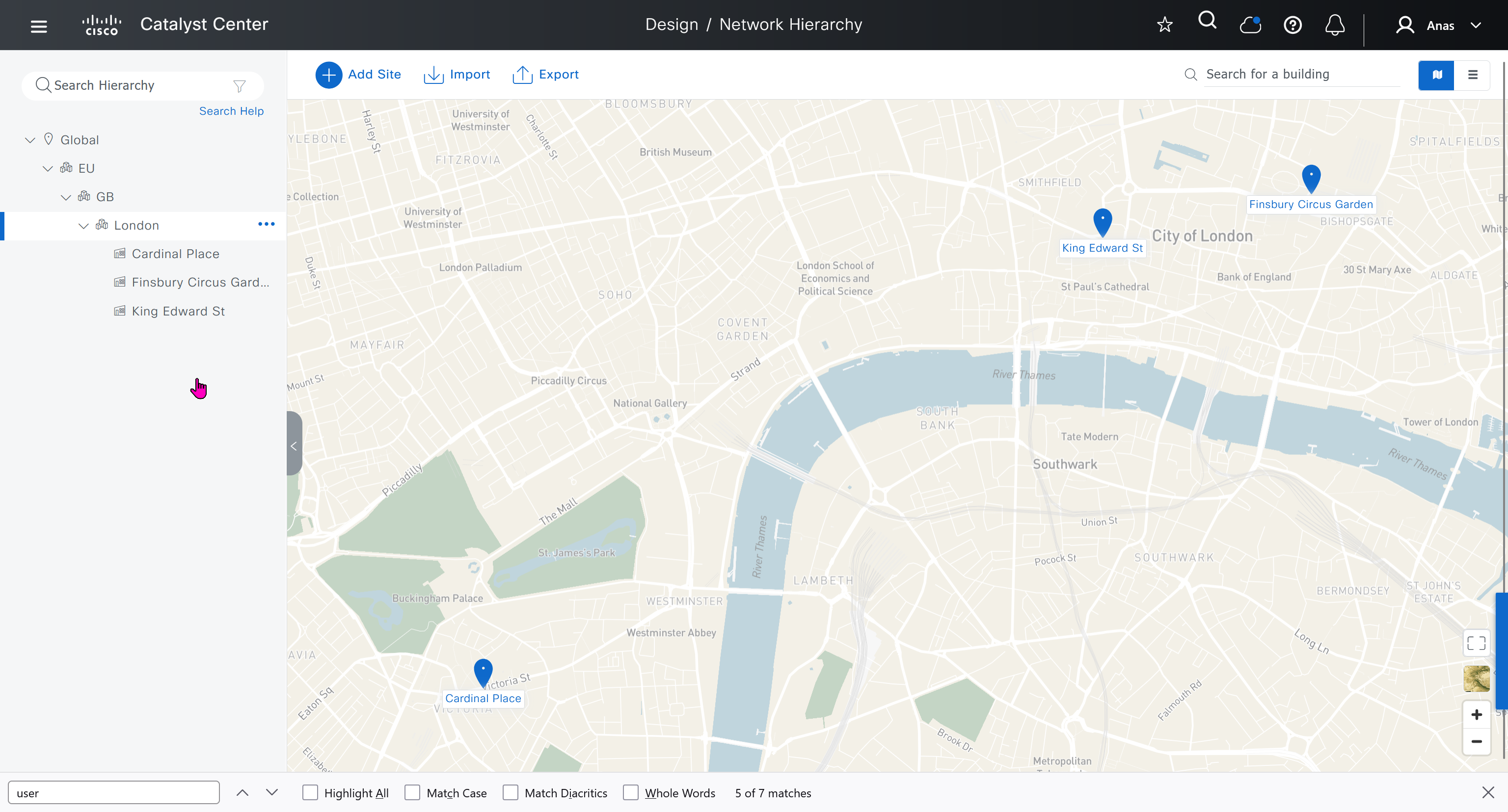
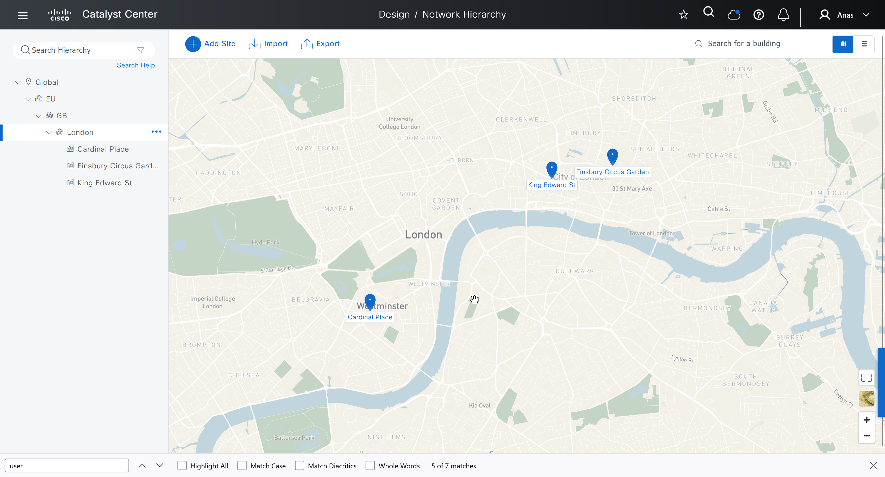
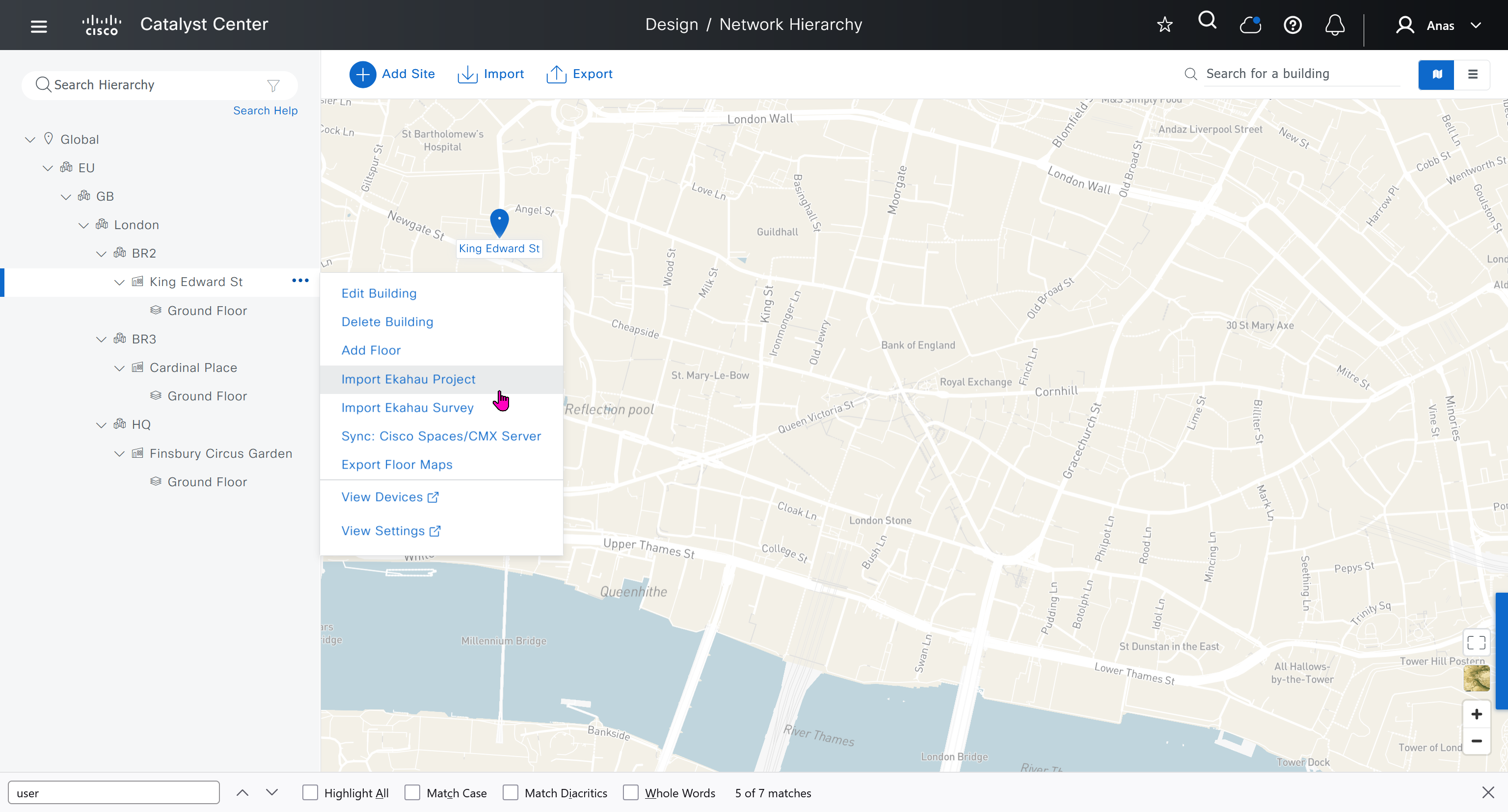
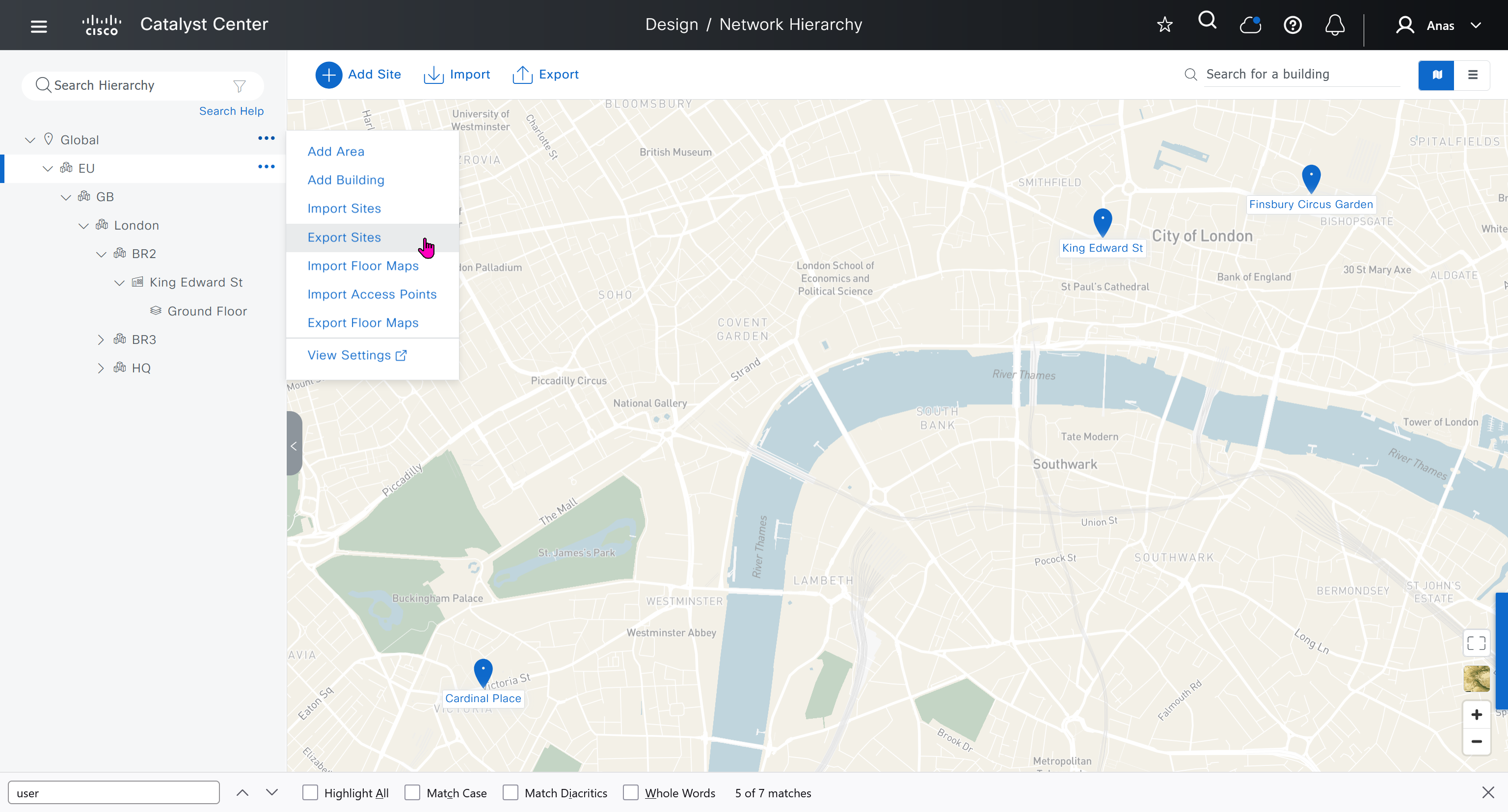
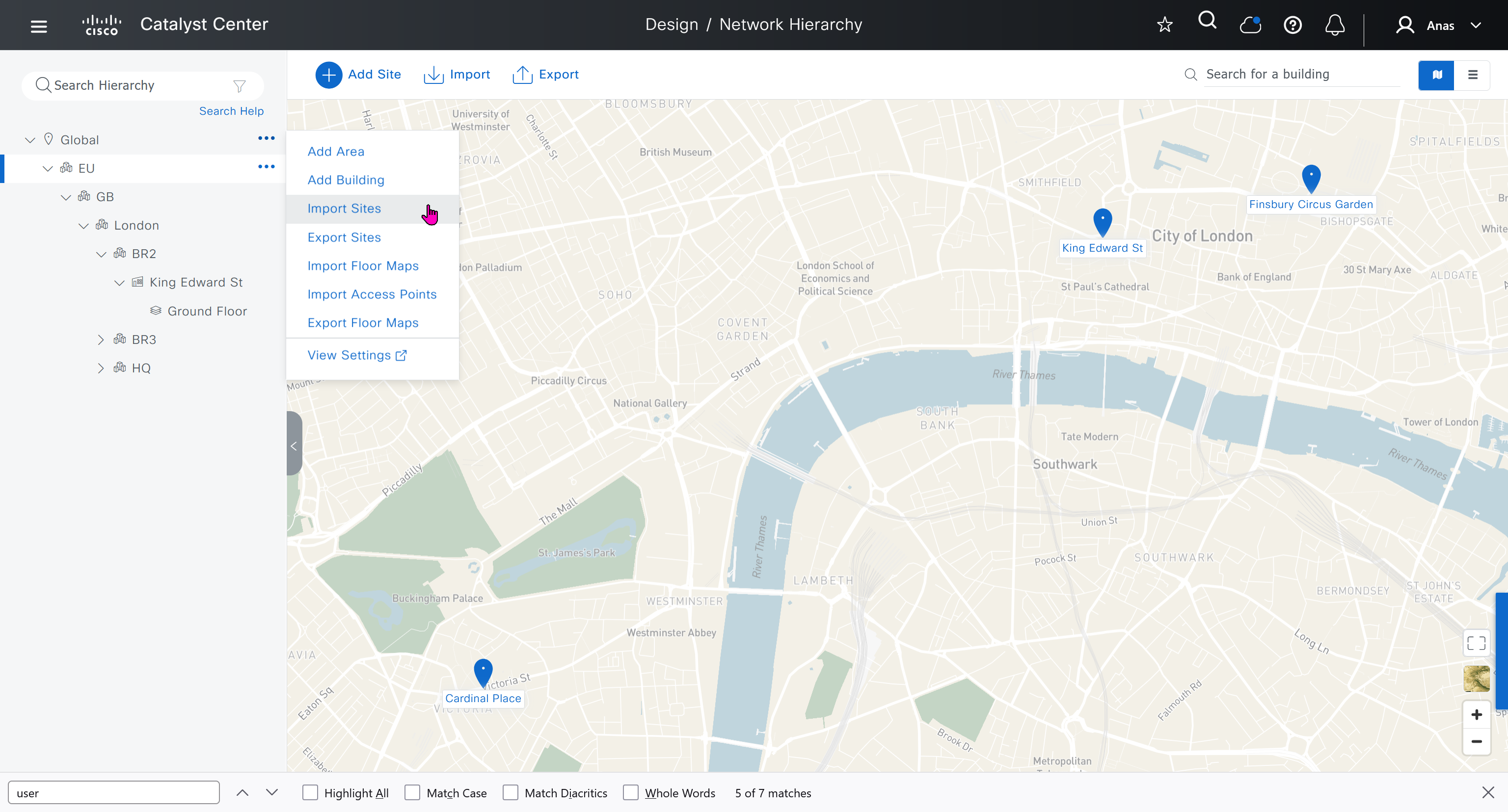
We will create 3 sites in EU > GB > London
- Finsbury Circus Garden, 14 Finsbury Circus, London EC2M 7EB
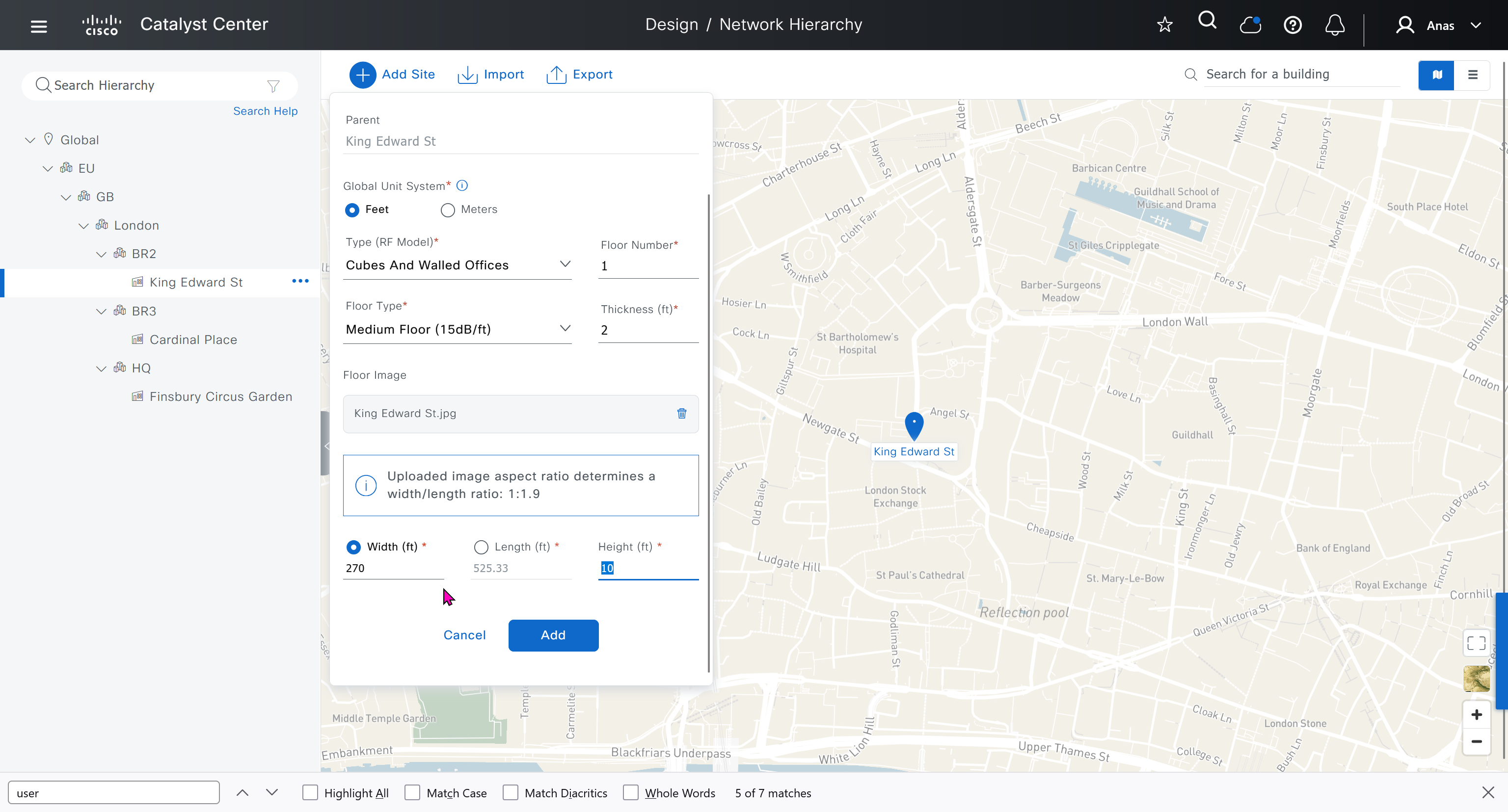
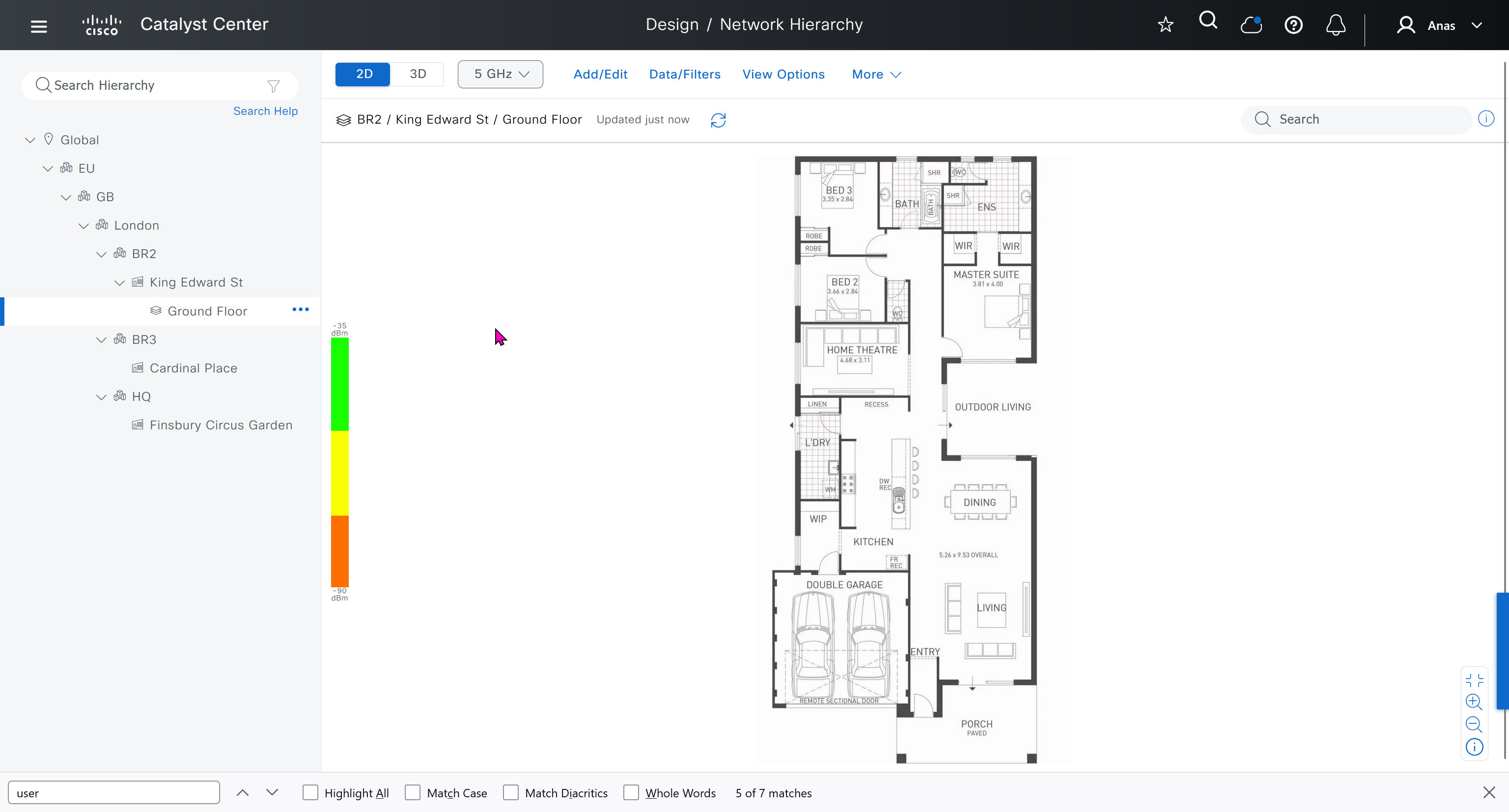
- 7 King Edward St, London EC1A 1HQ
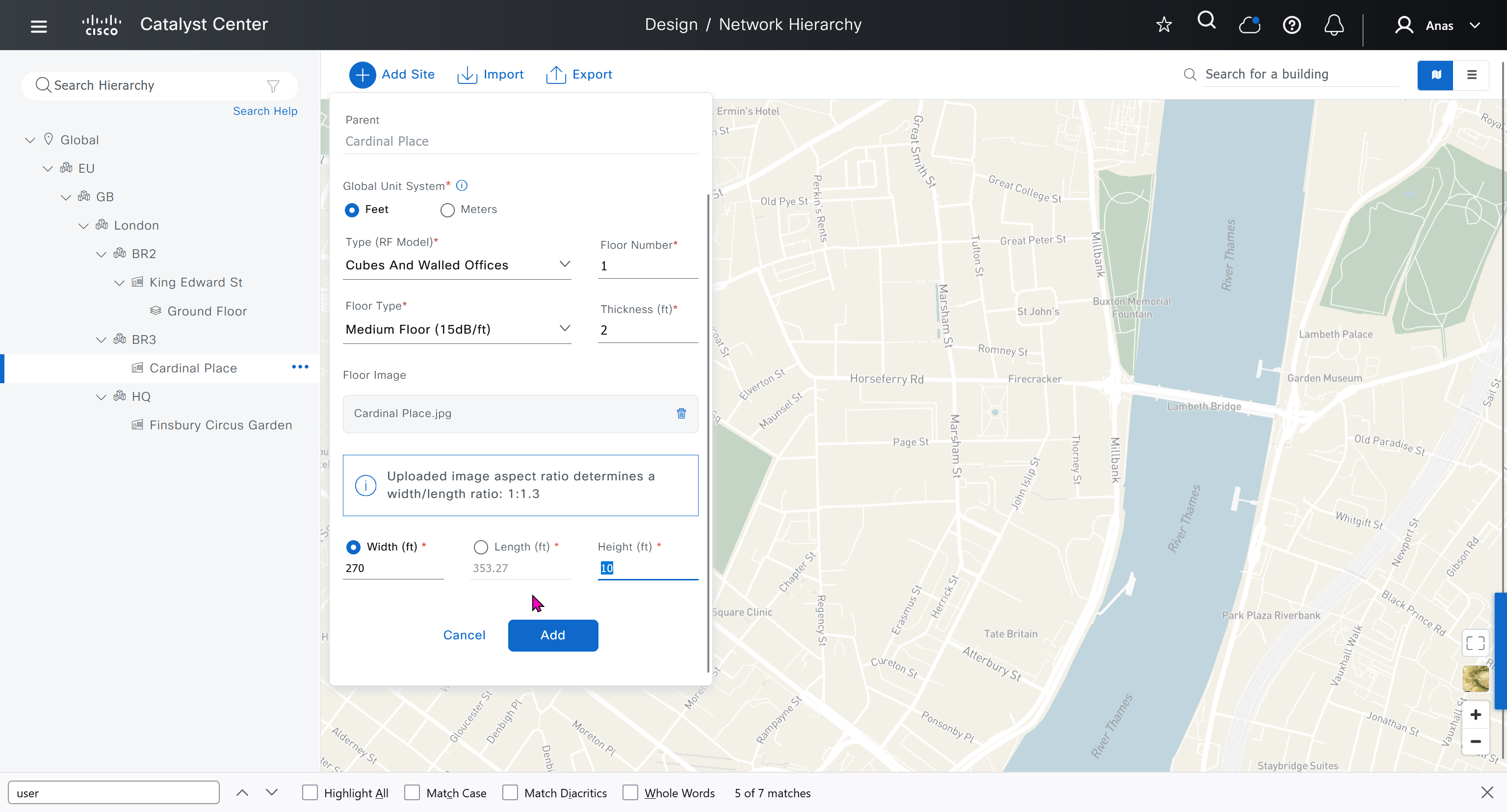
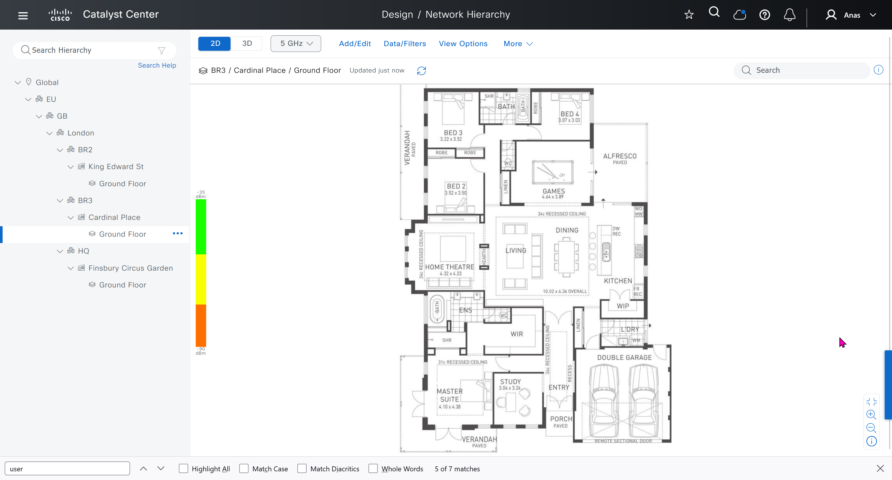
- Cardinal Place, 84 Victoria St, London SW1E 5JL

We should add HQ, BR2 and BR3

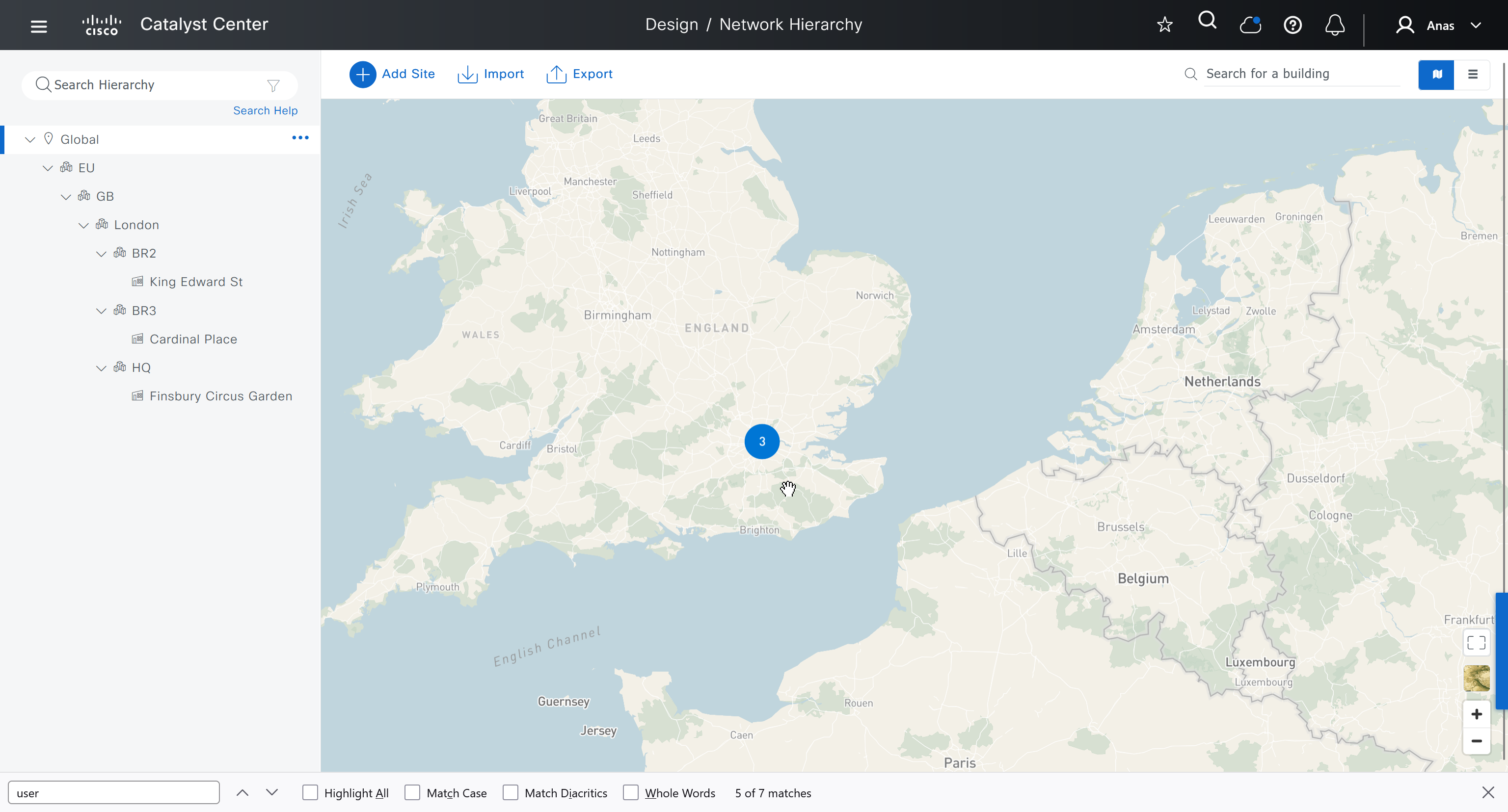
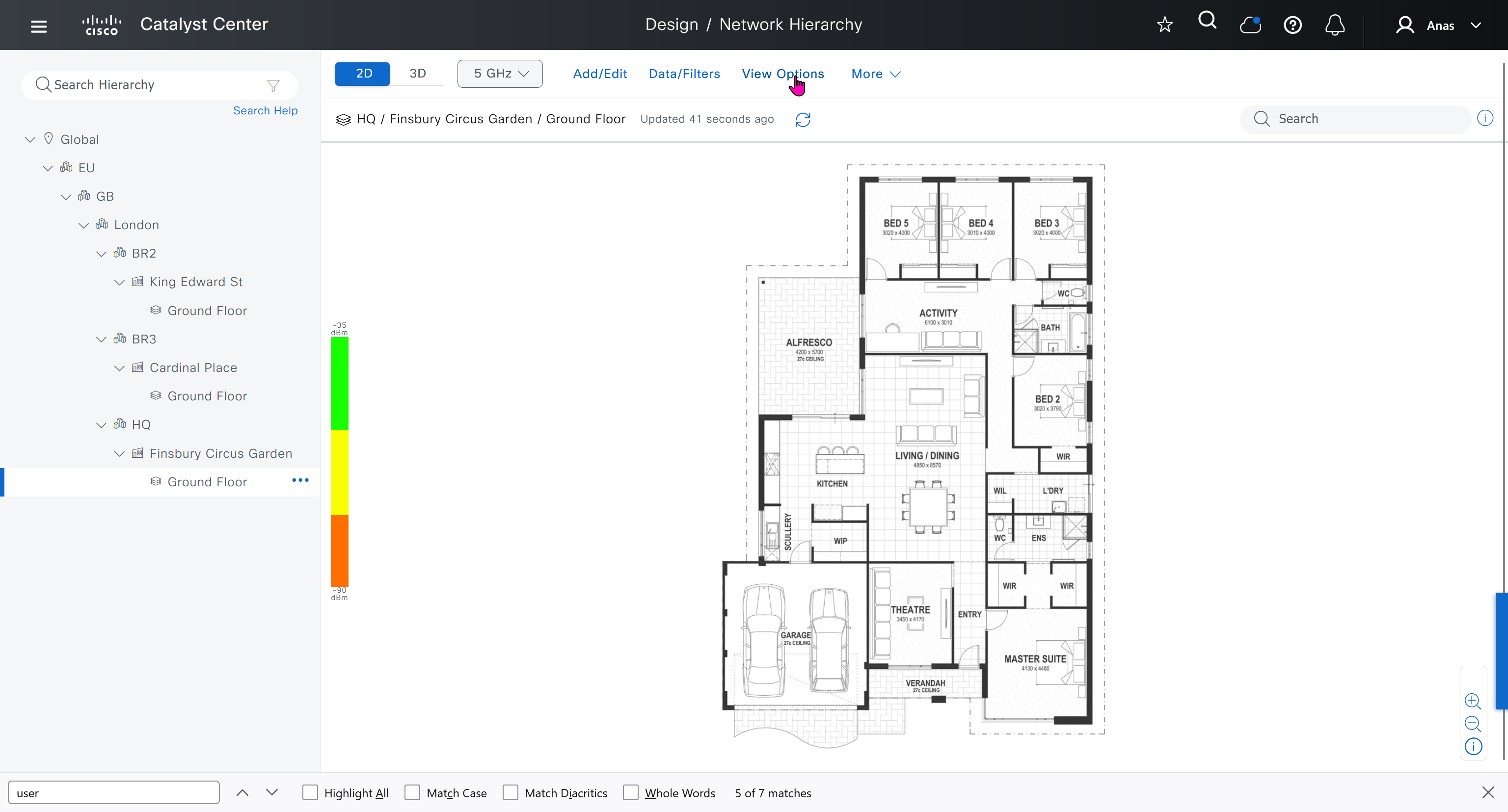
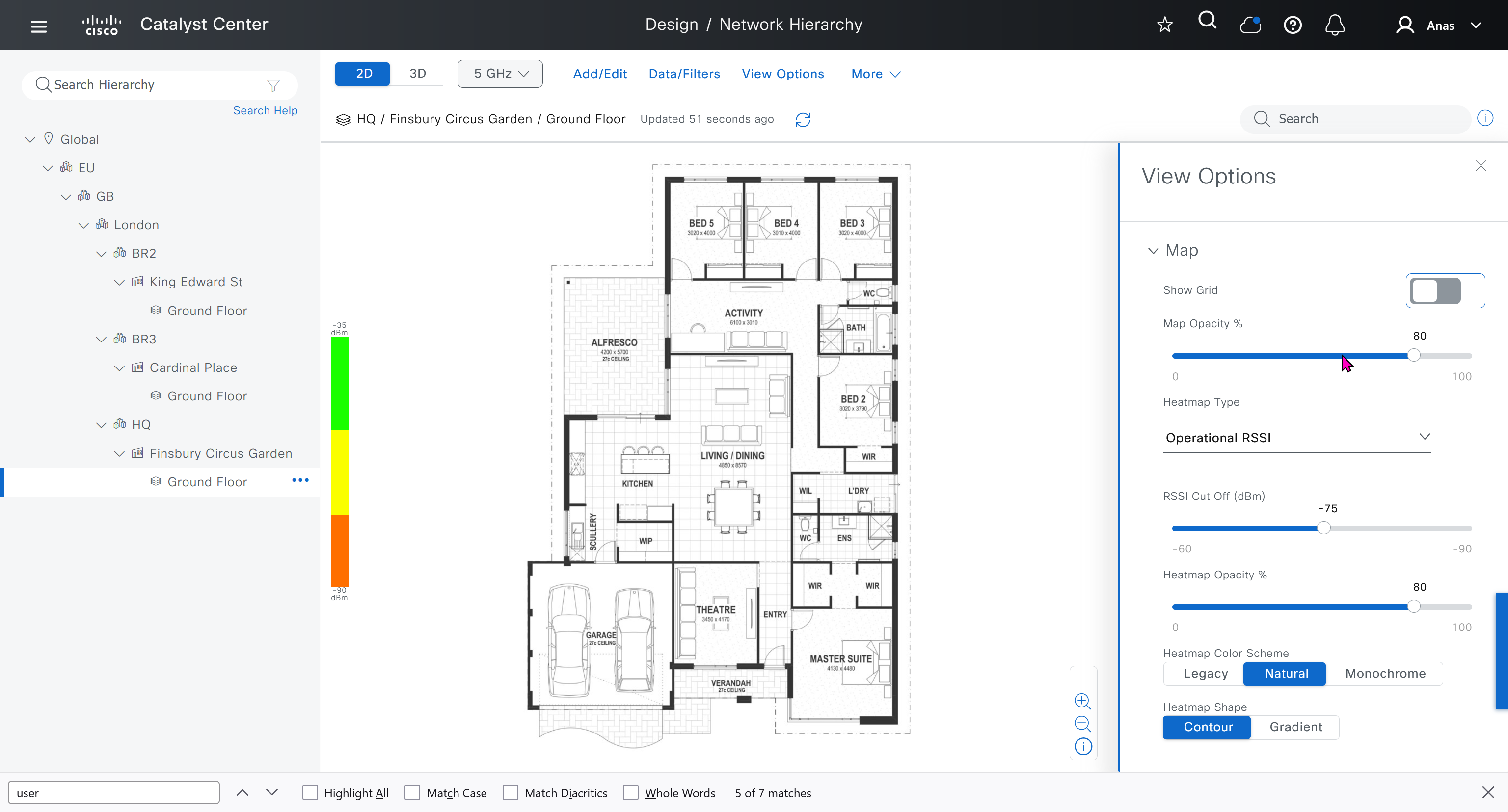
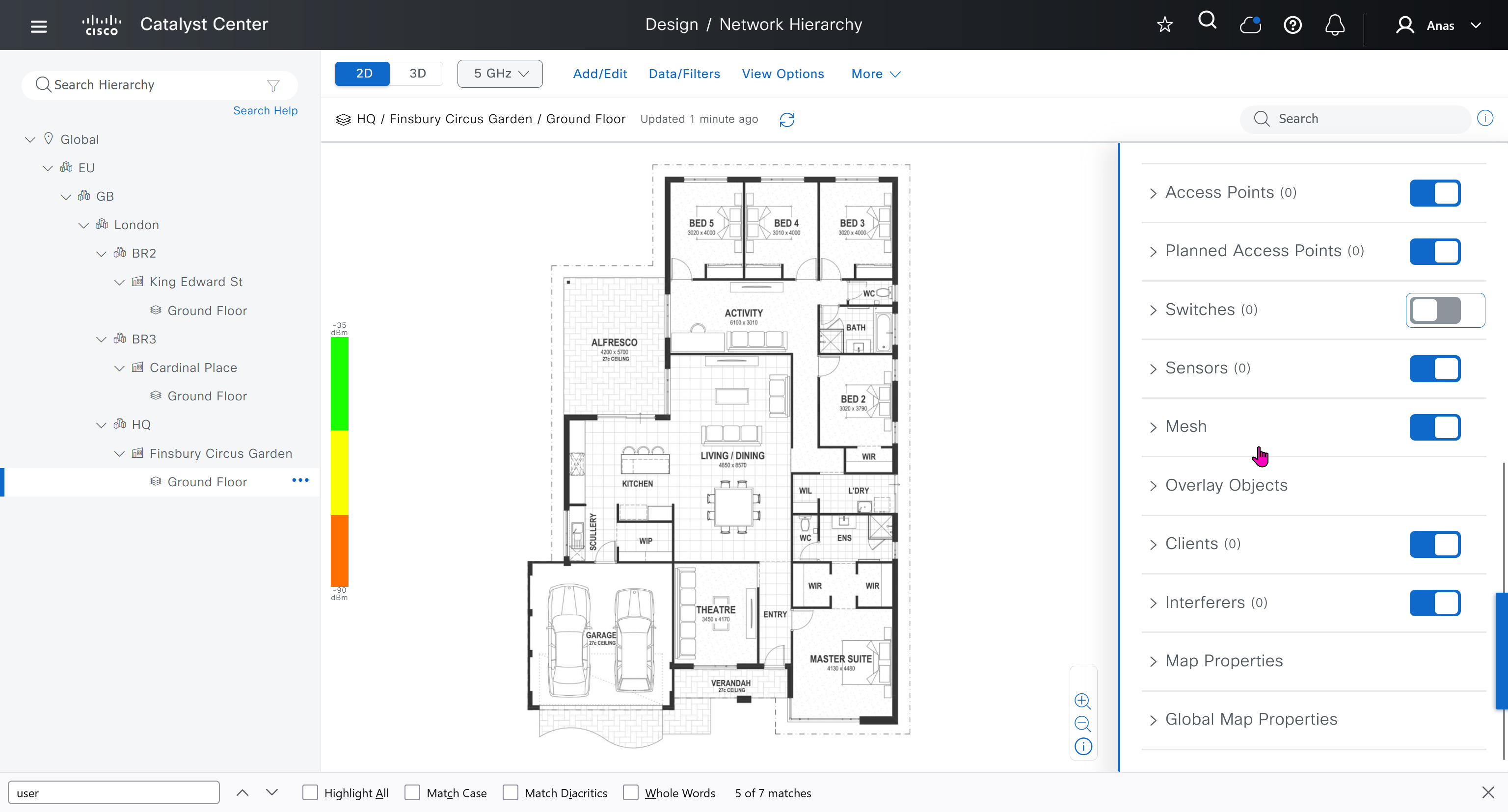
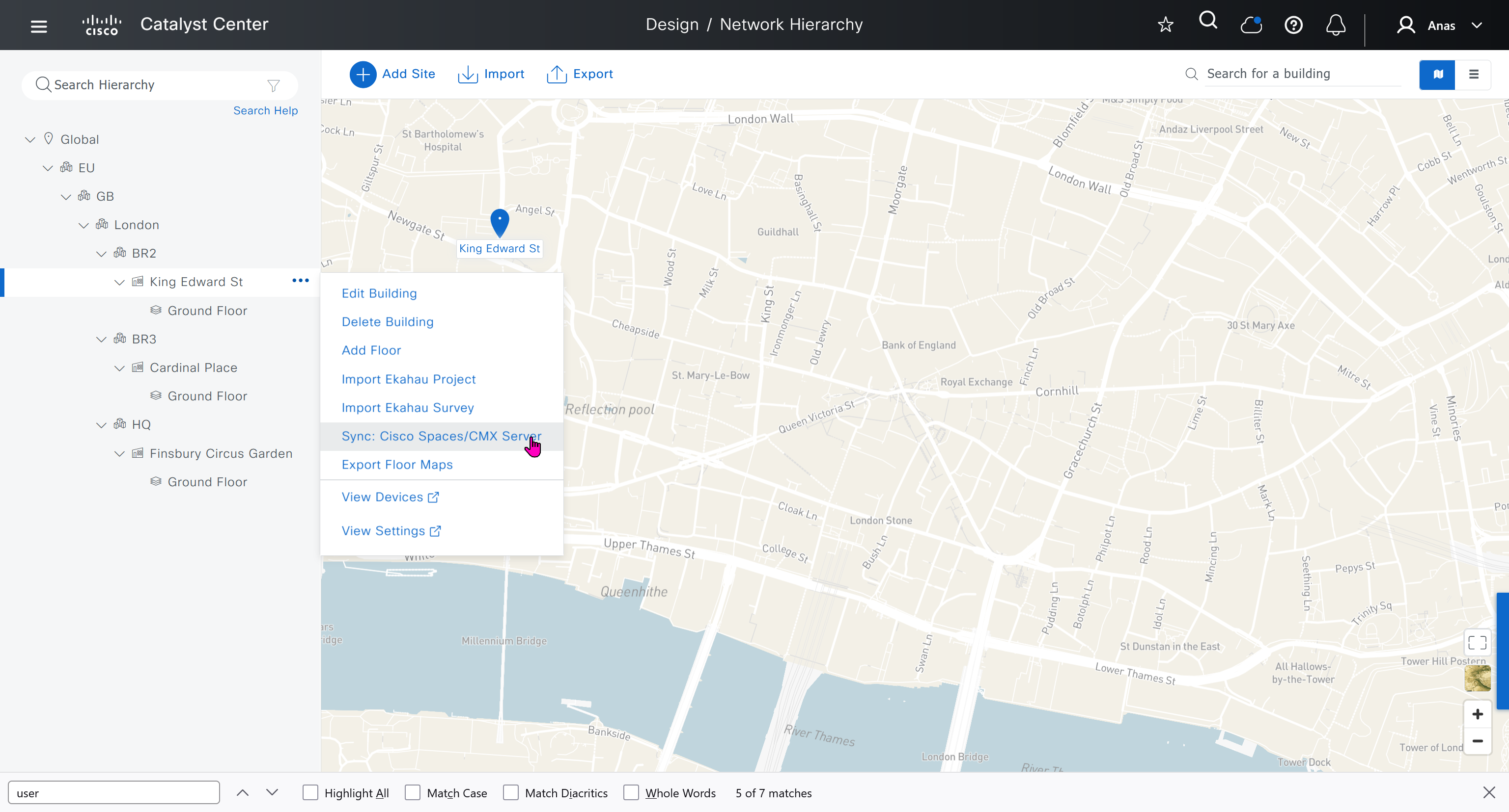
We can add floors and floors are mostly used for placing wireless access points but for SDA we can add ground floor, if customer had prime we can import APs on floor plans already from prime
for RF model on the floor just stick with default of “Cubes And Walled Offices”
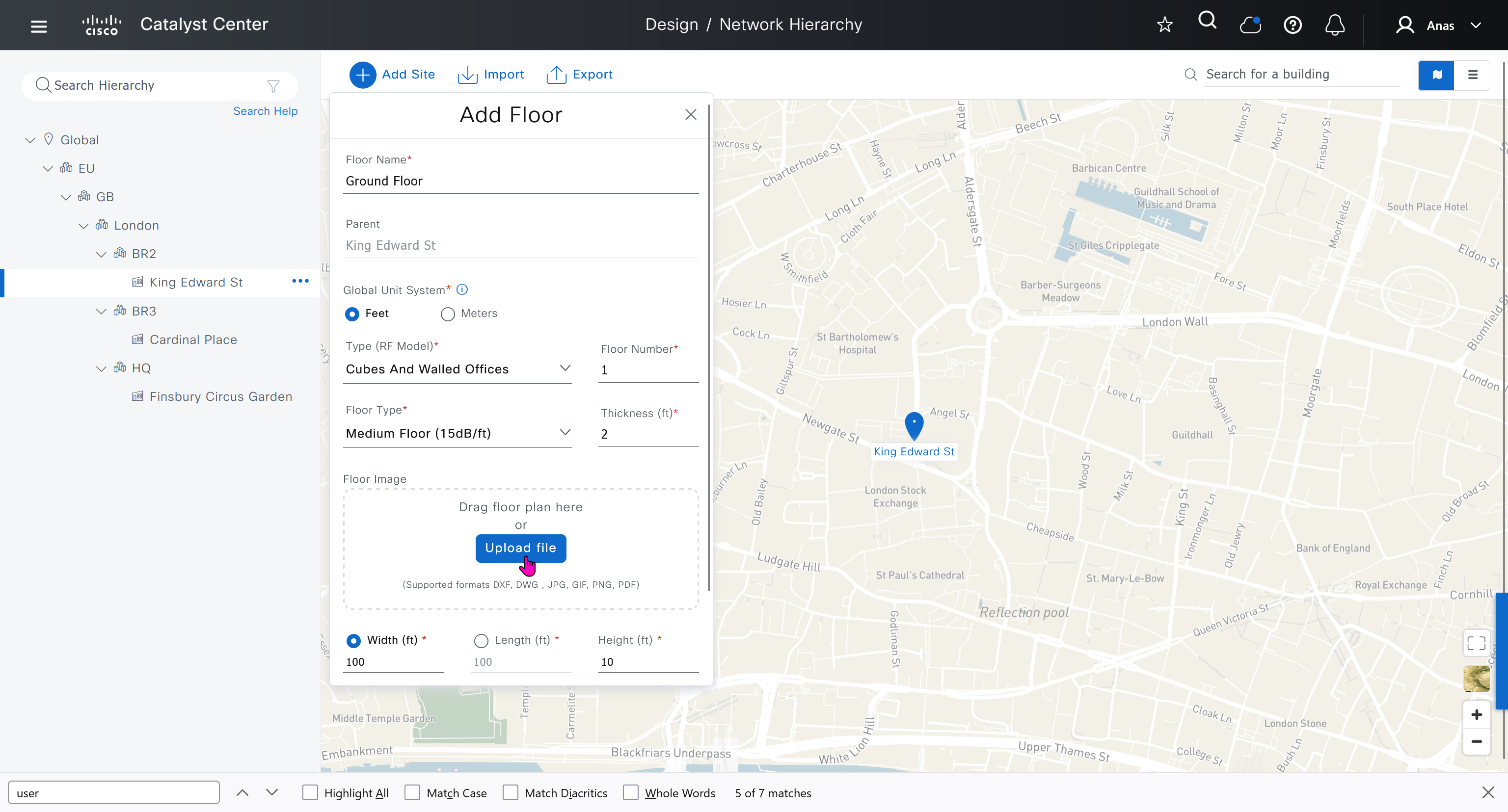
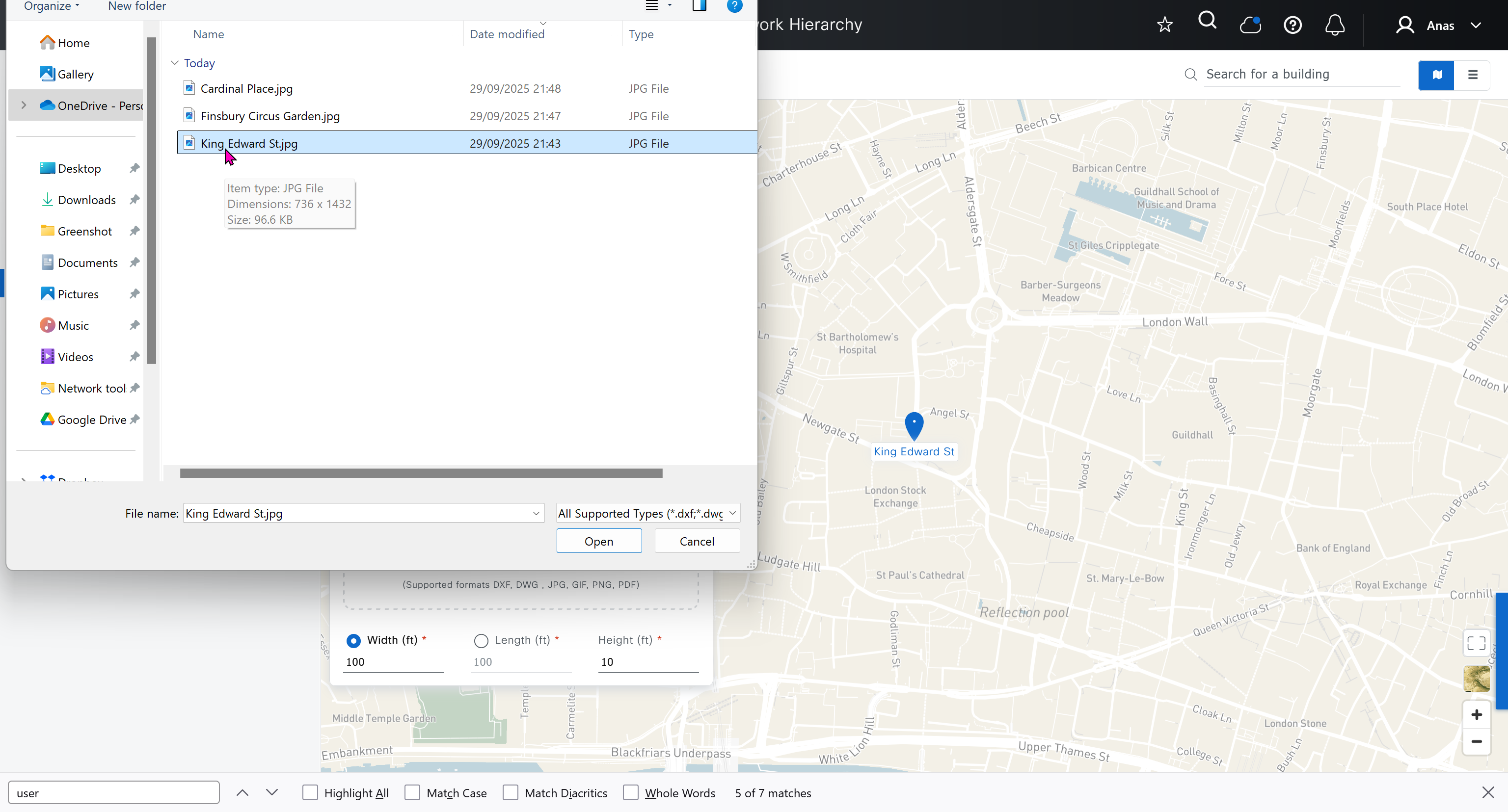
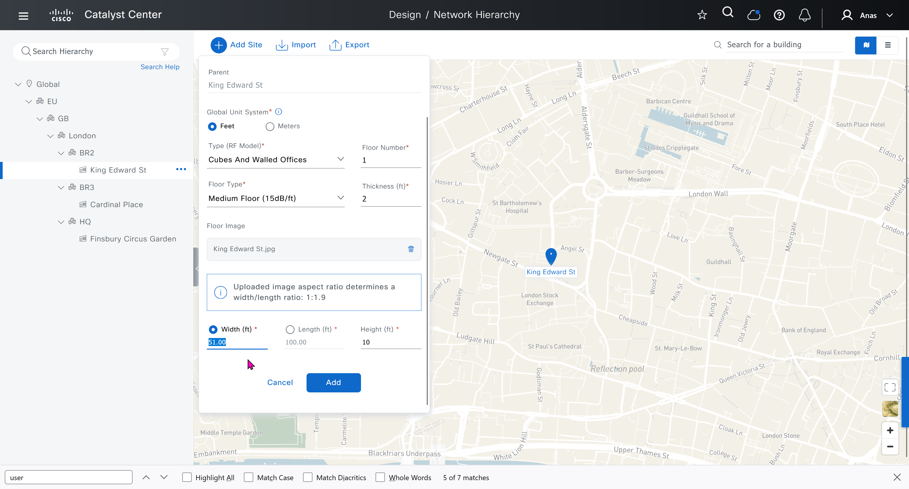
see that when I changed width, dnac maintained the aspect ratio from the image I uploaded


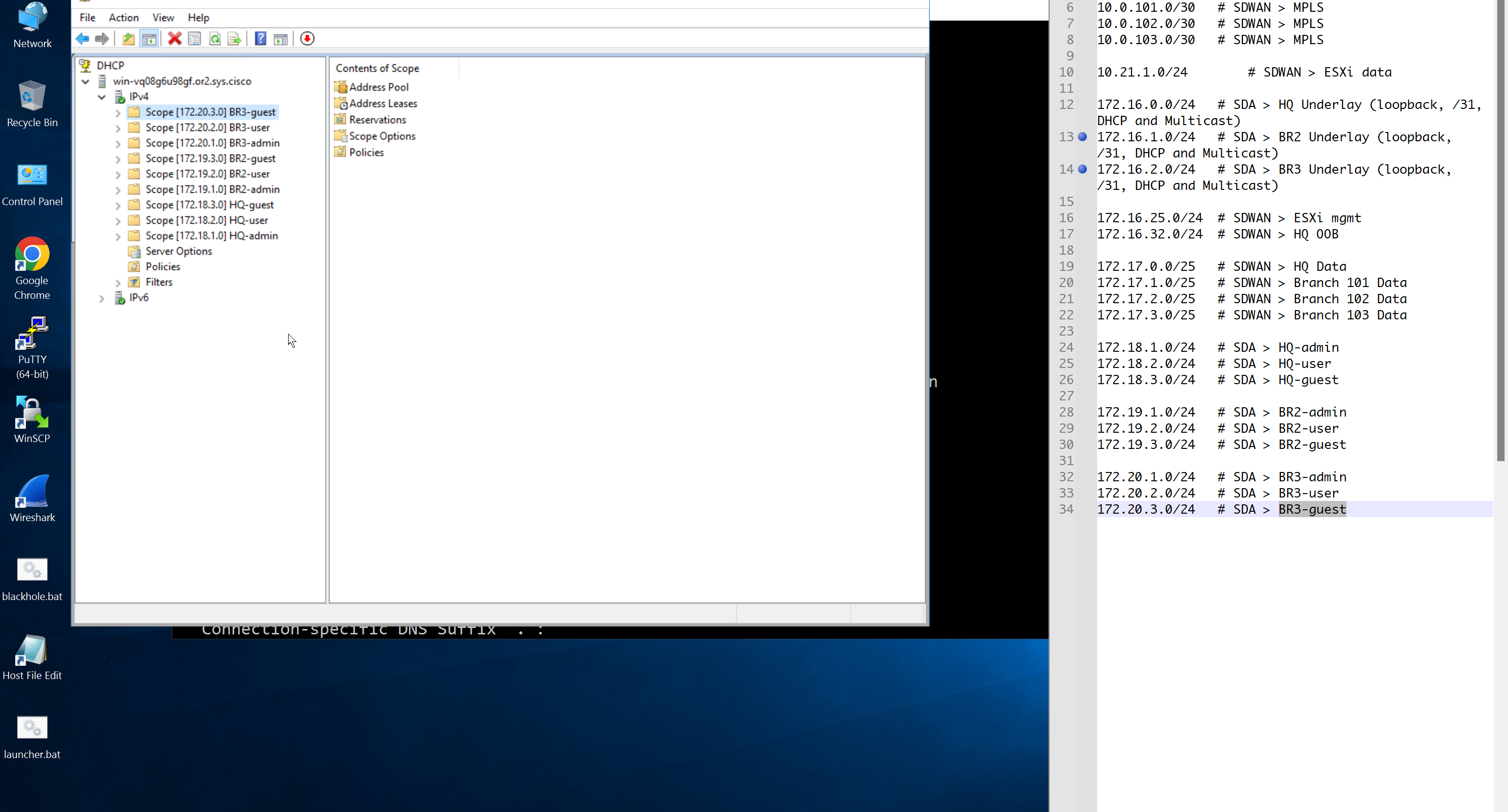
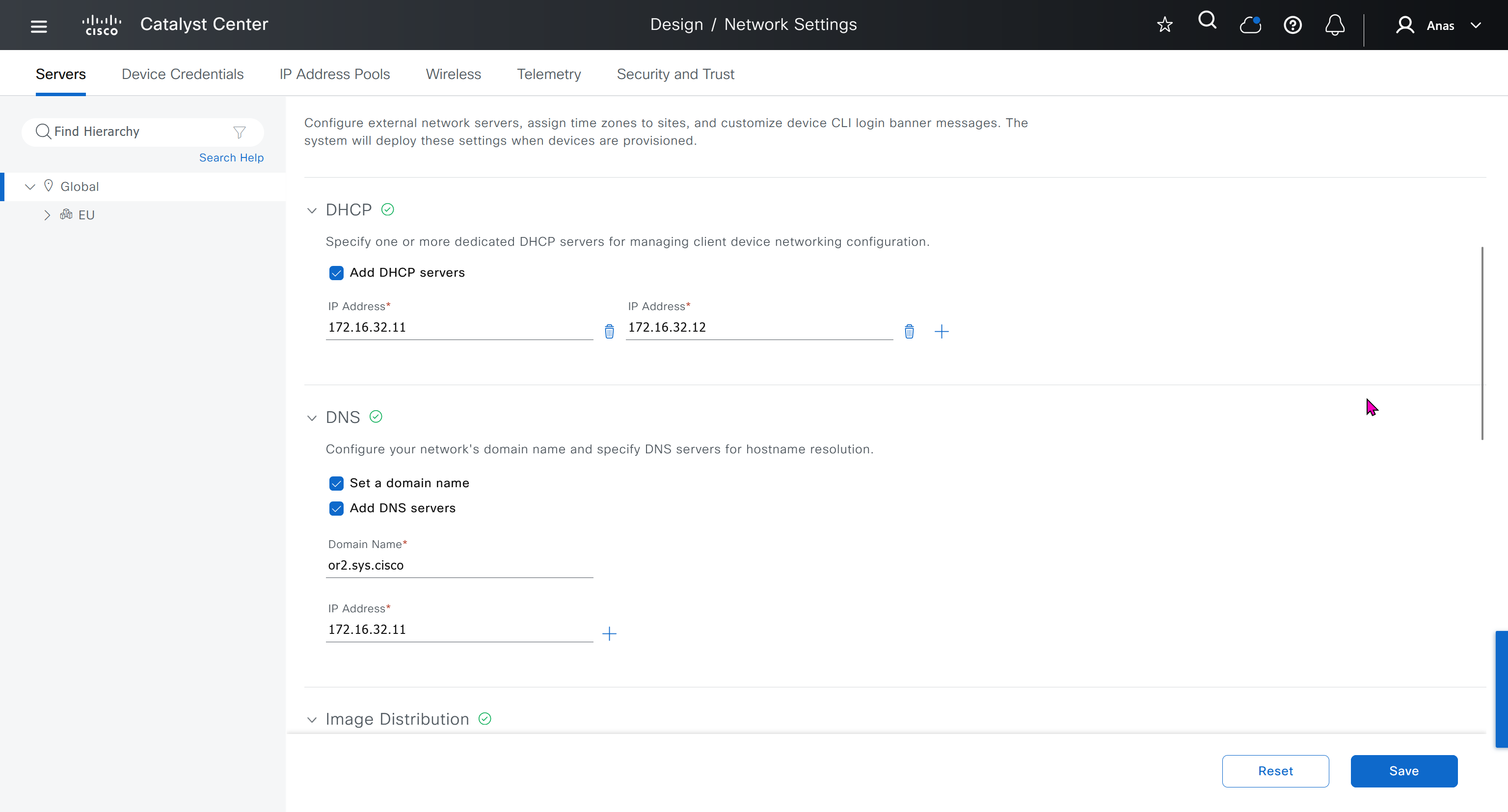
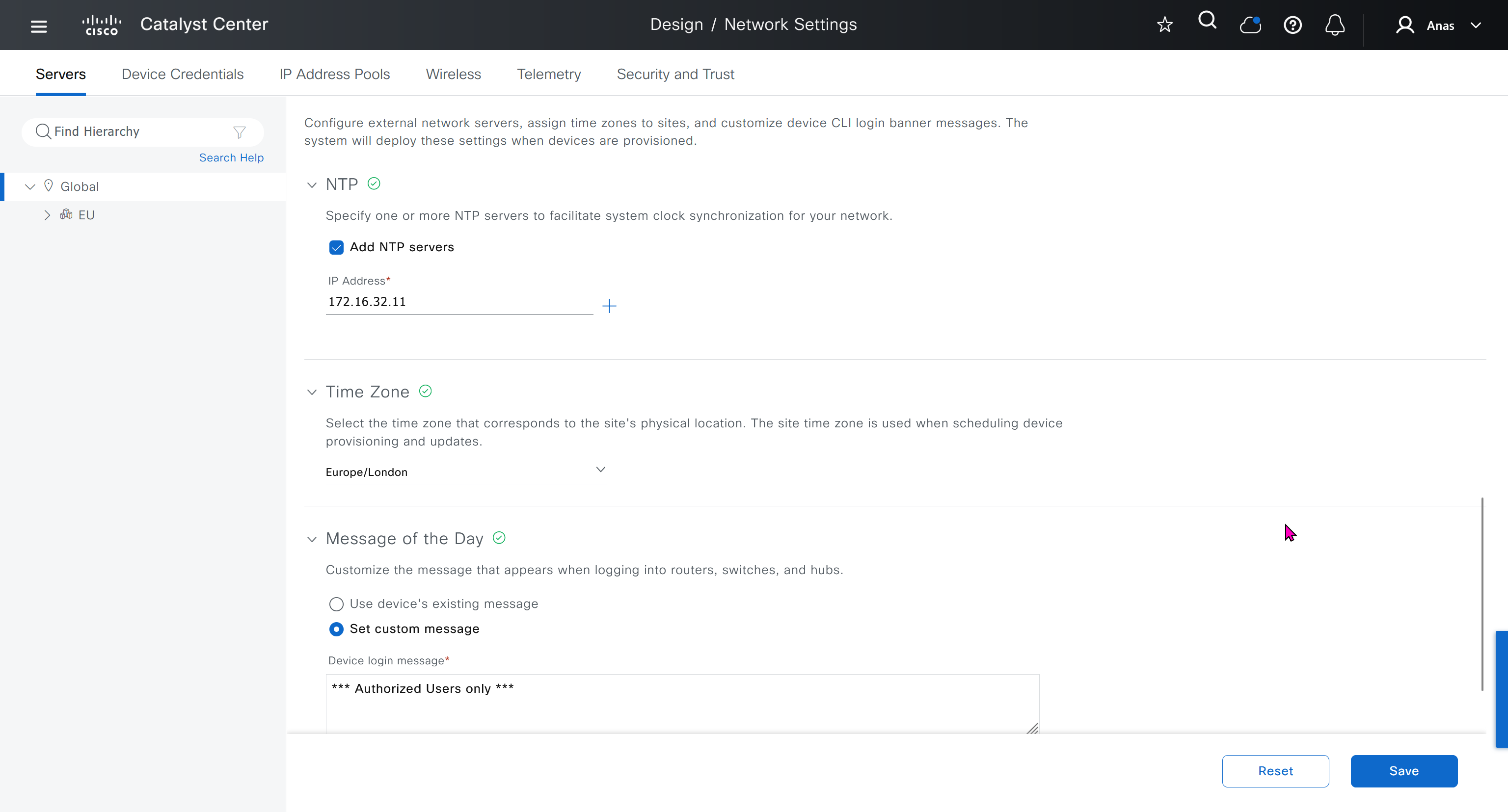
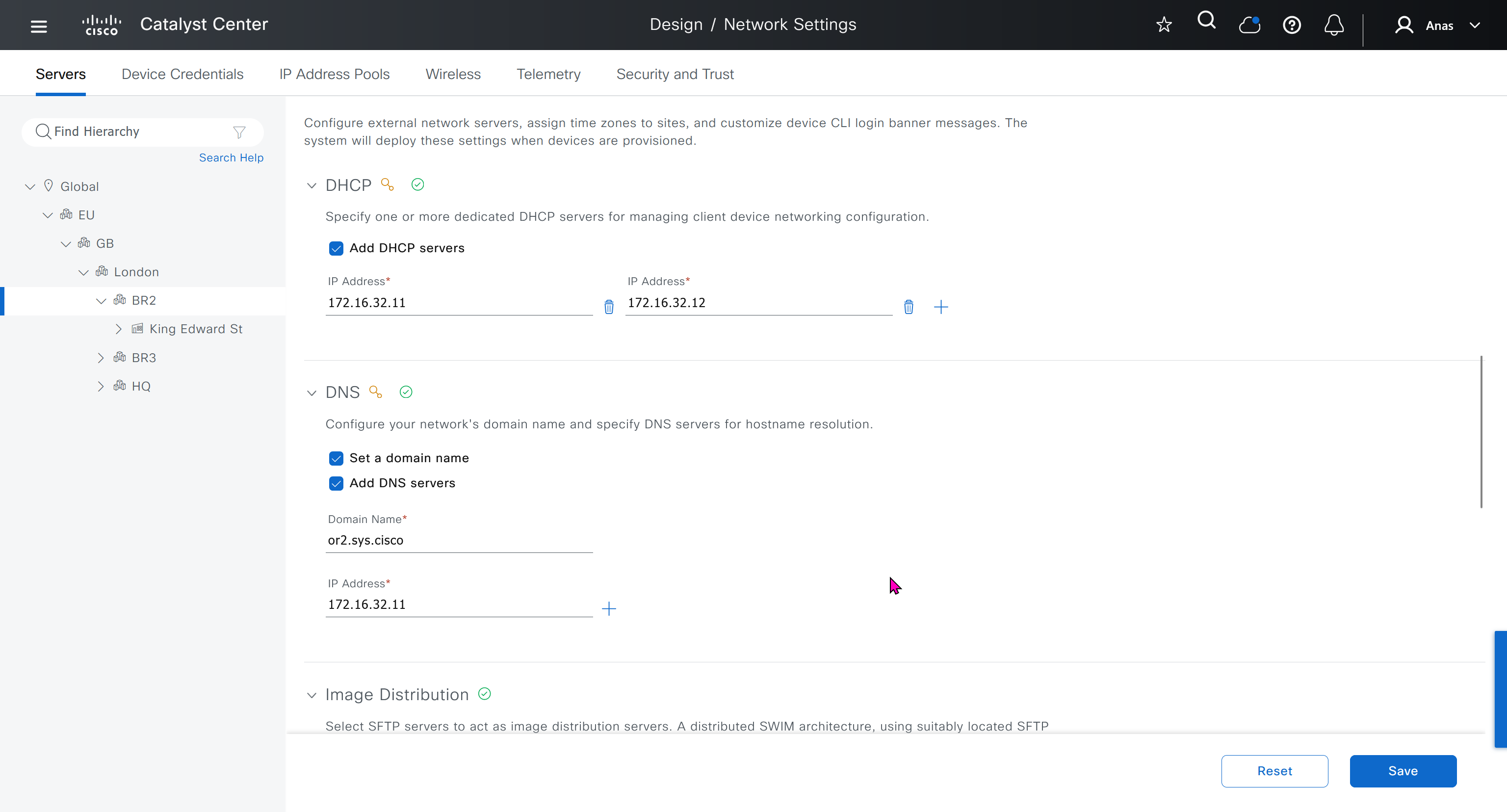
Network contains common settings similar to what DHCP contains but more such as AAA server, DHCP server, DNS server, Image Distribution (used to download the Catalyst IOS XE image), NTP server, Time Zone and Message of the day but looking at it feels like that this configuration is for the switches because this is the configuration that will be pushed to devices as they get provisioned into DNAC
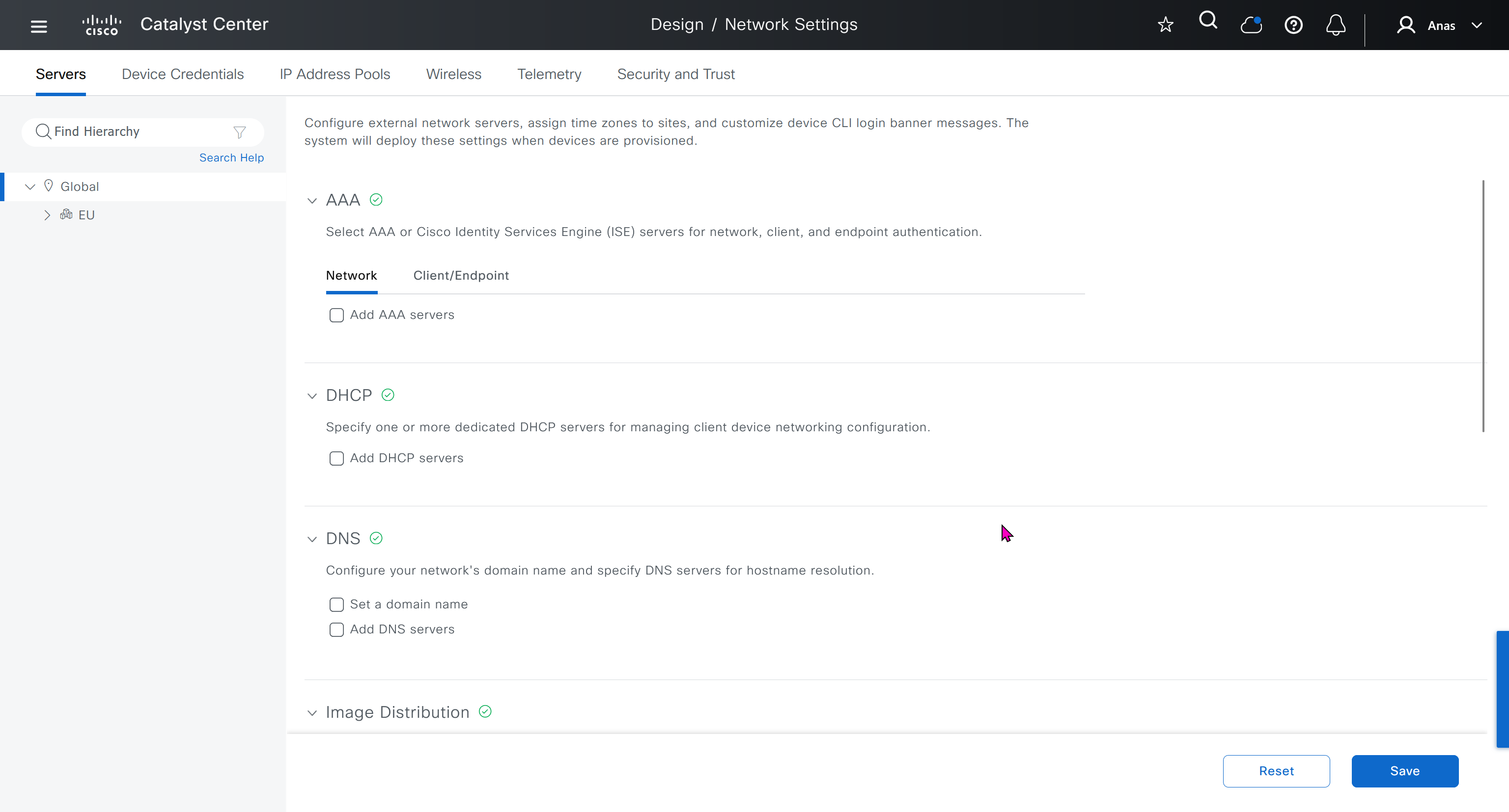
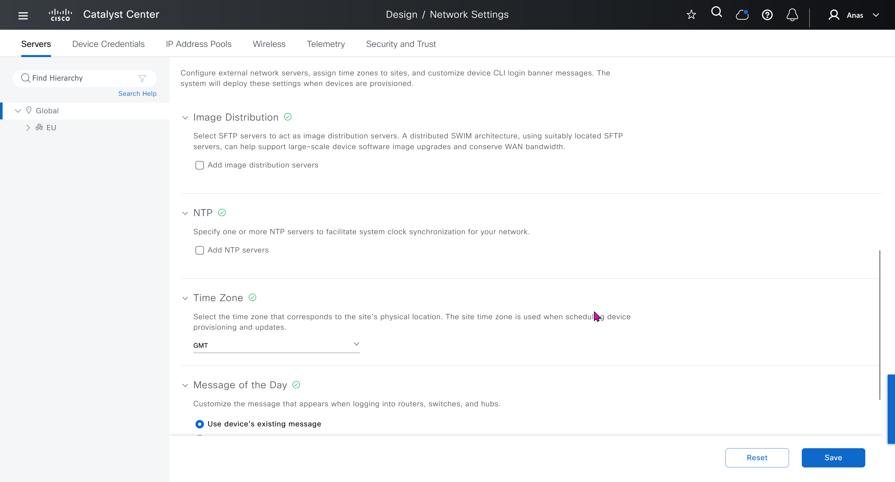
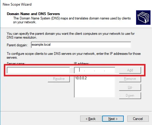
In DHCP servers section we will also specify ISE IP address because it is one of the ways for ISE to perform profiling based on DHCP request from device
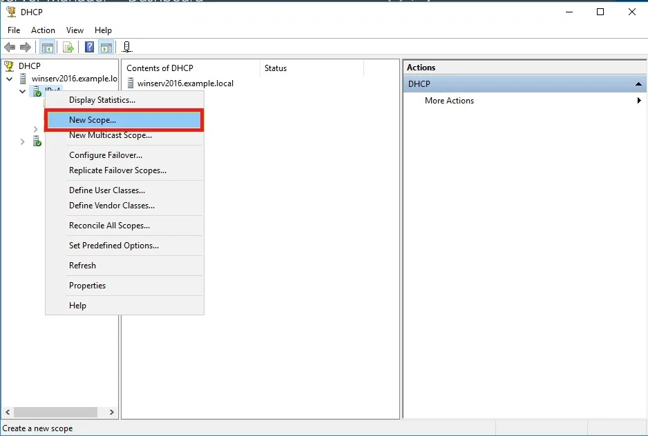
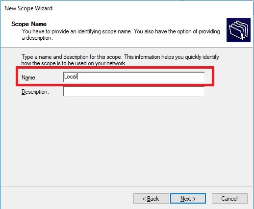
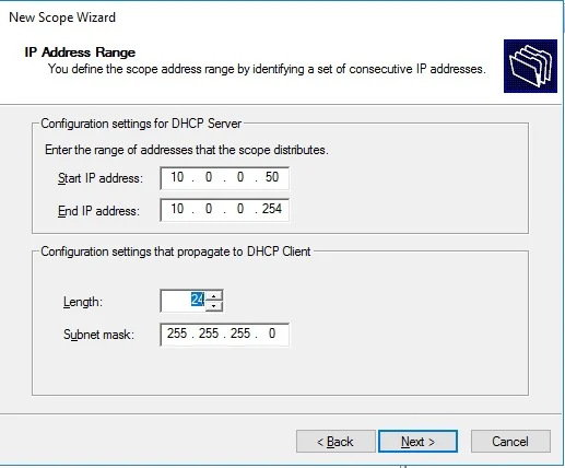
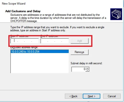
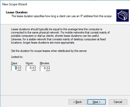
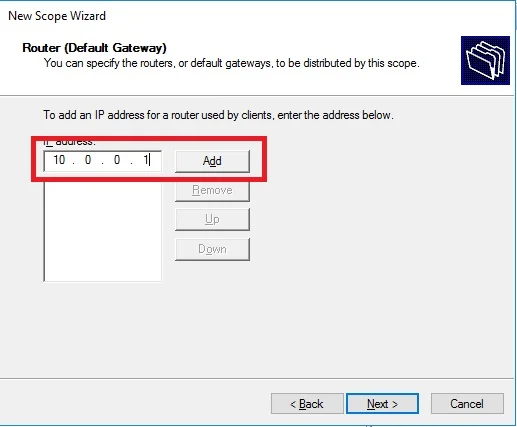
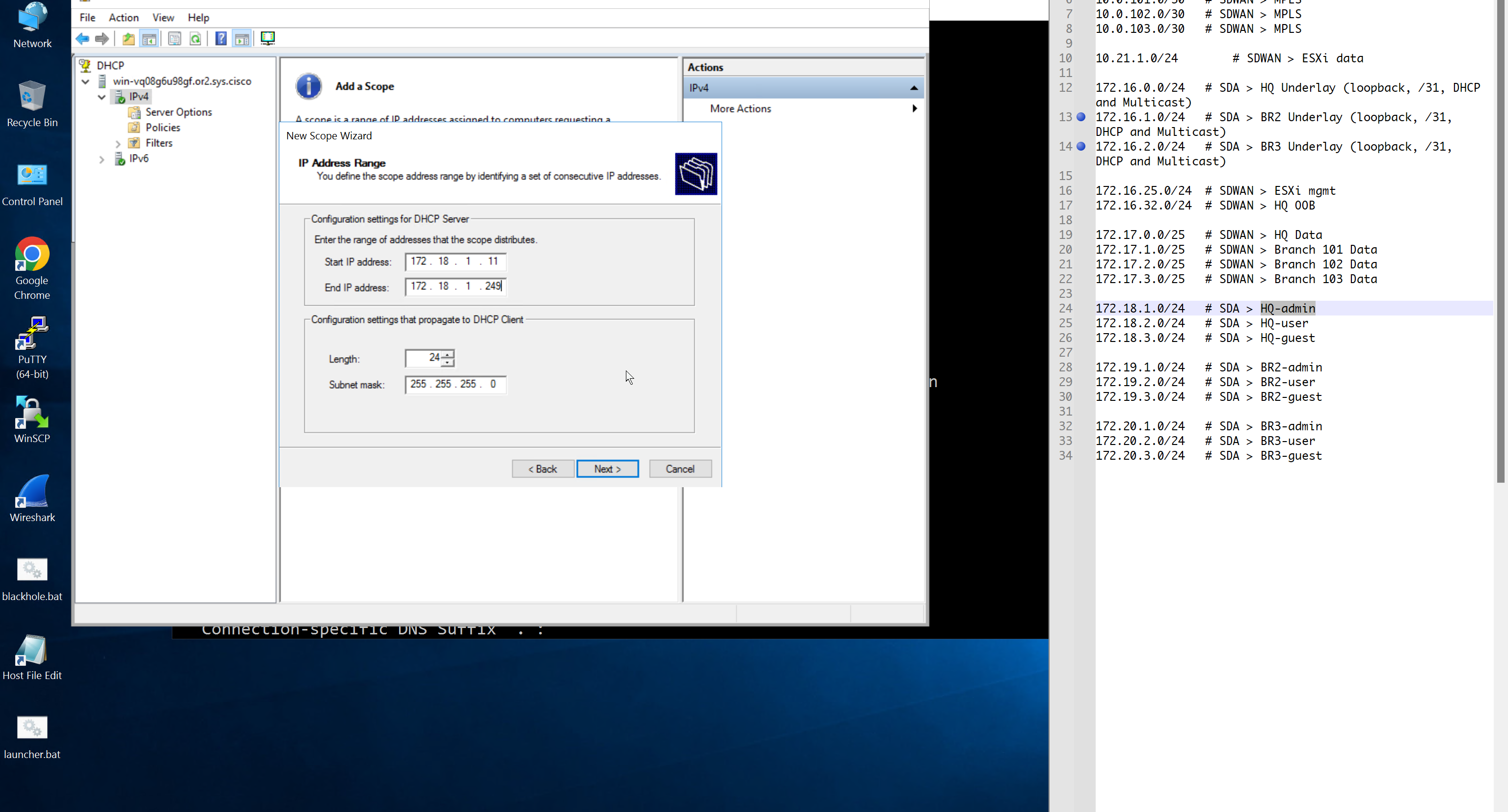
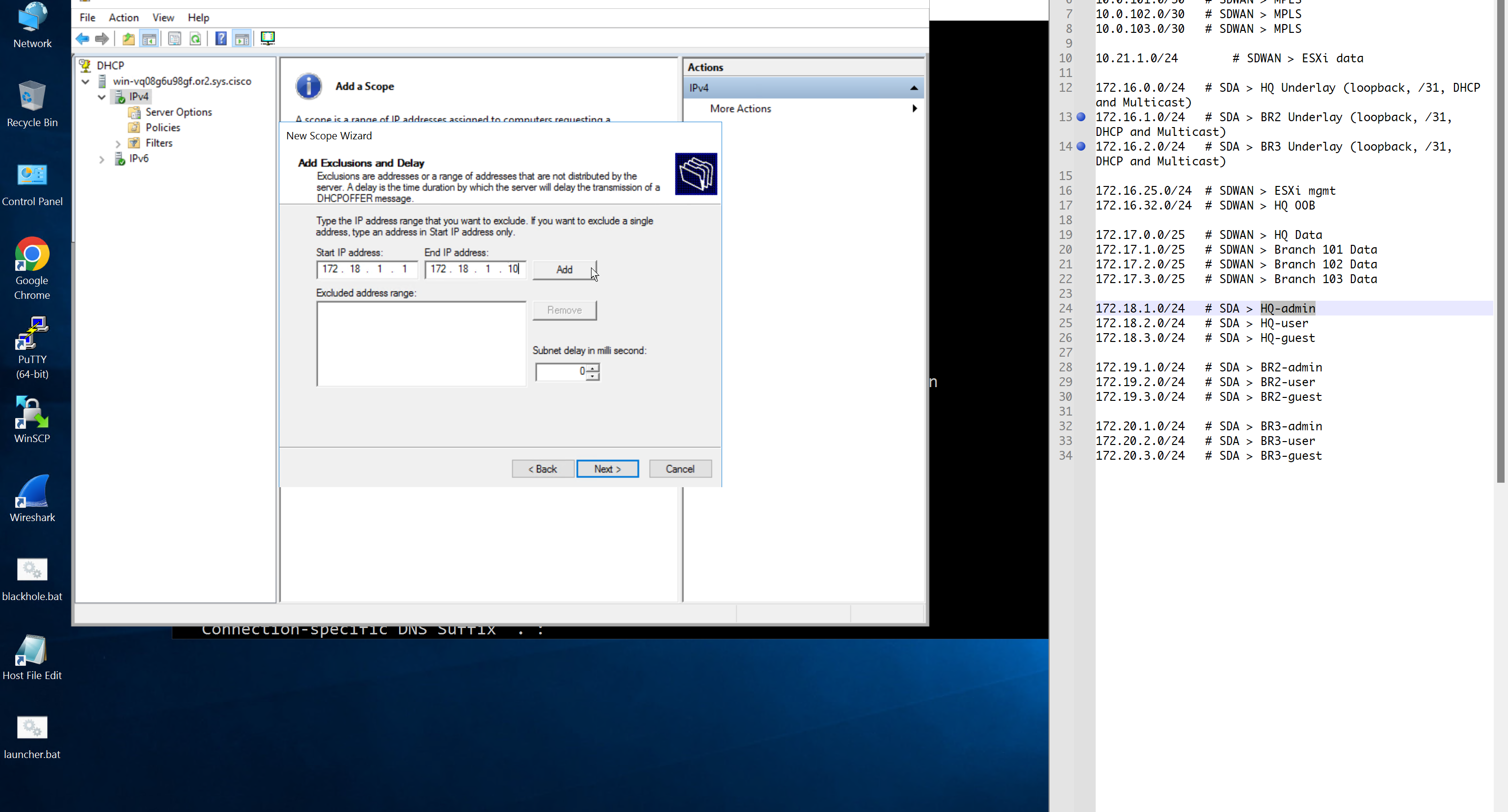
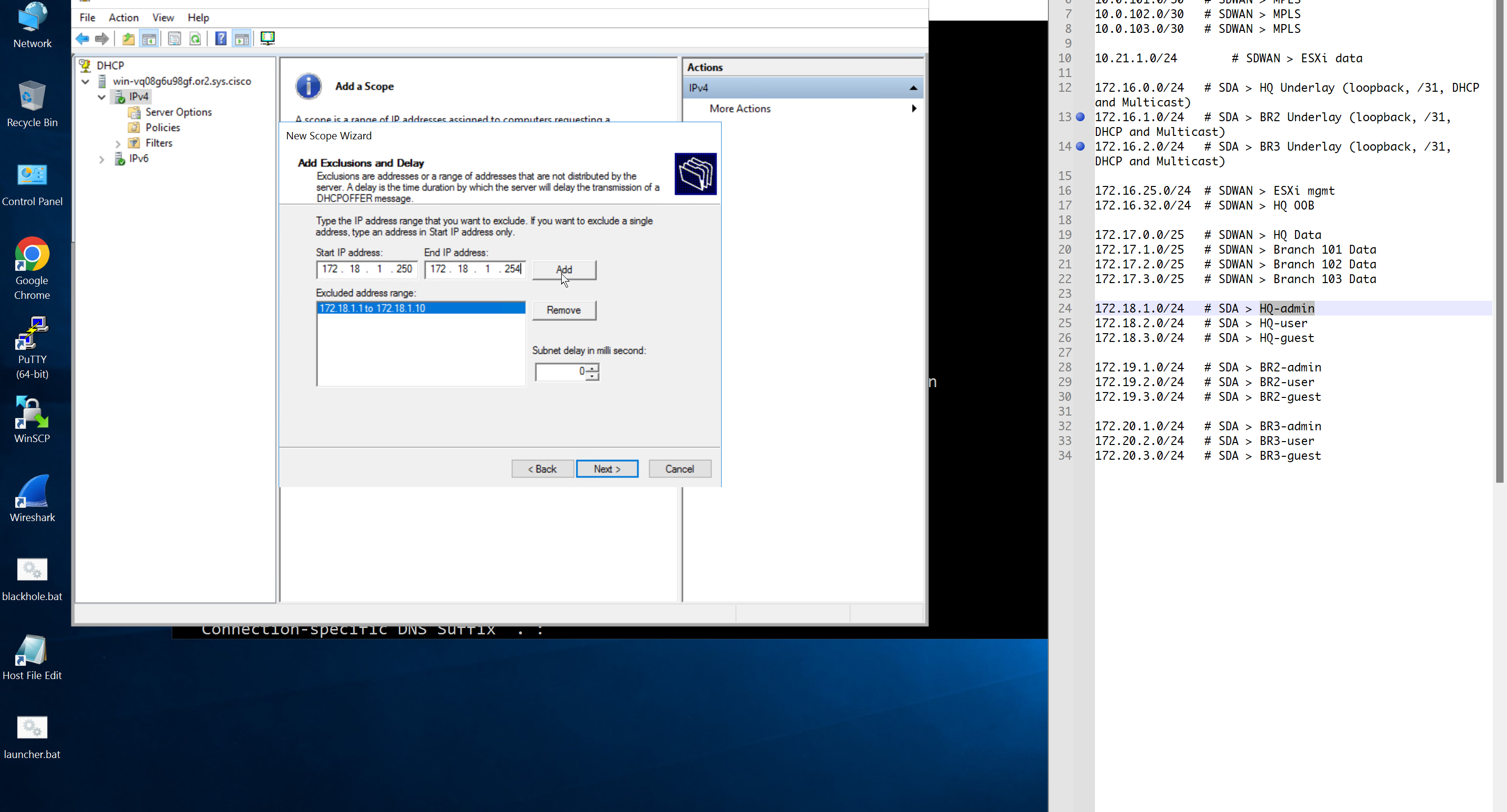
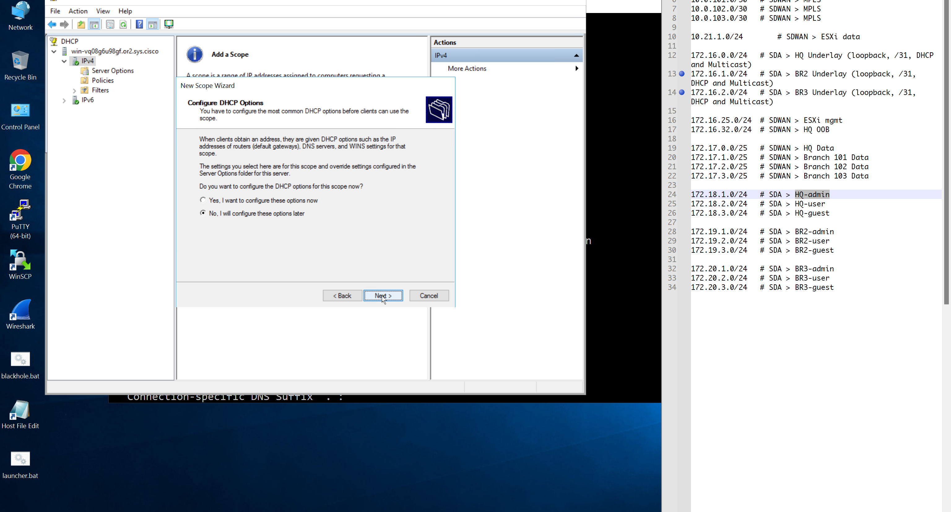
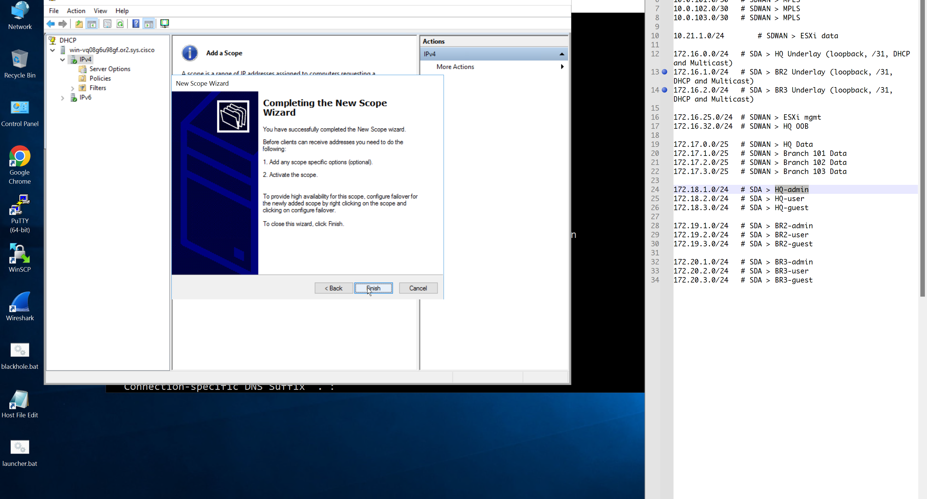
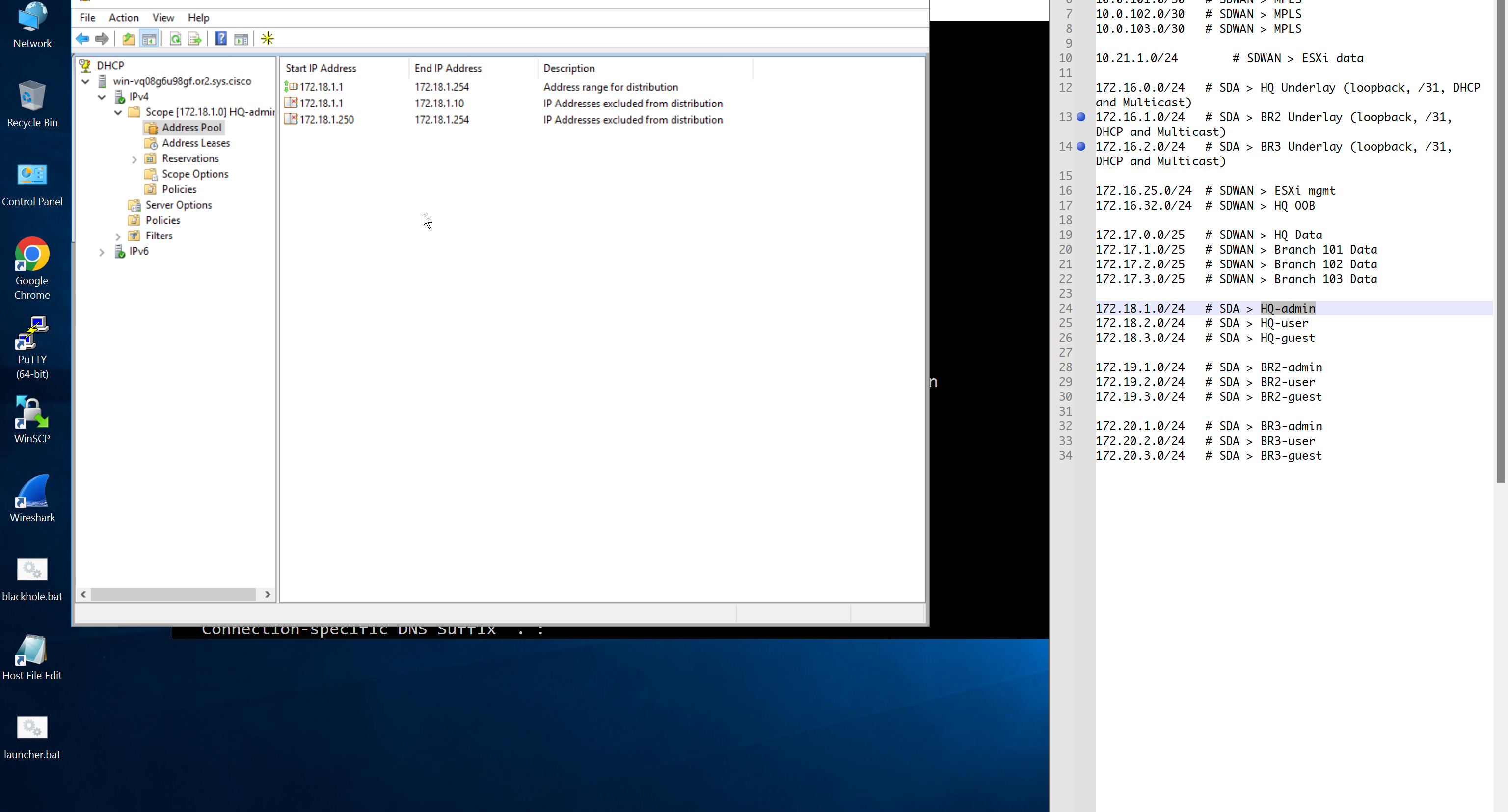
Create DHCP scopes as shown below


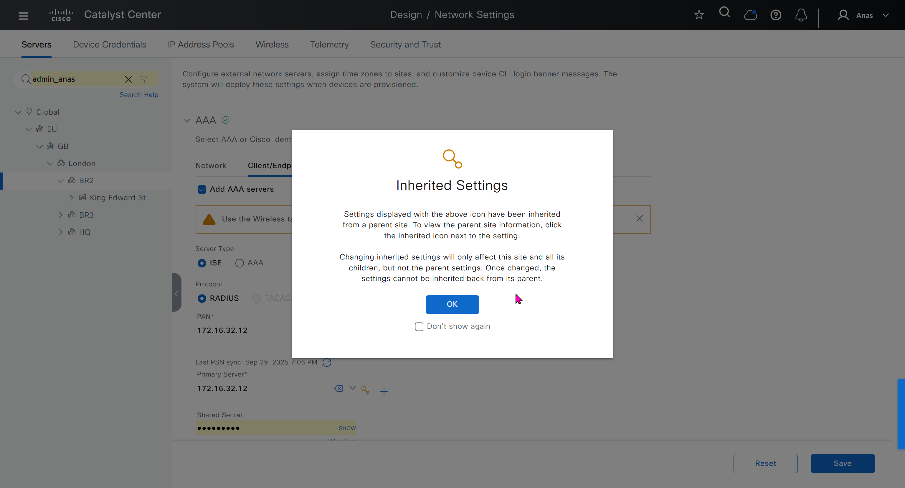
AAA “Network” is for network device administration
and AAA “Client/Endpoint” is 802.1x, we will only configure 802.1x for now


When we click on lower network in hierarchy, for first time we see this symbol which when used in GUI means that configuration is being inherited but they can be overwritten on lower levels


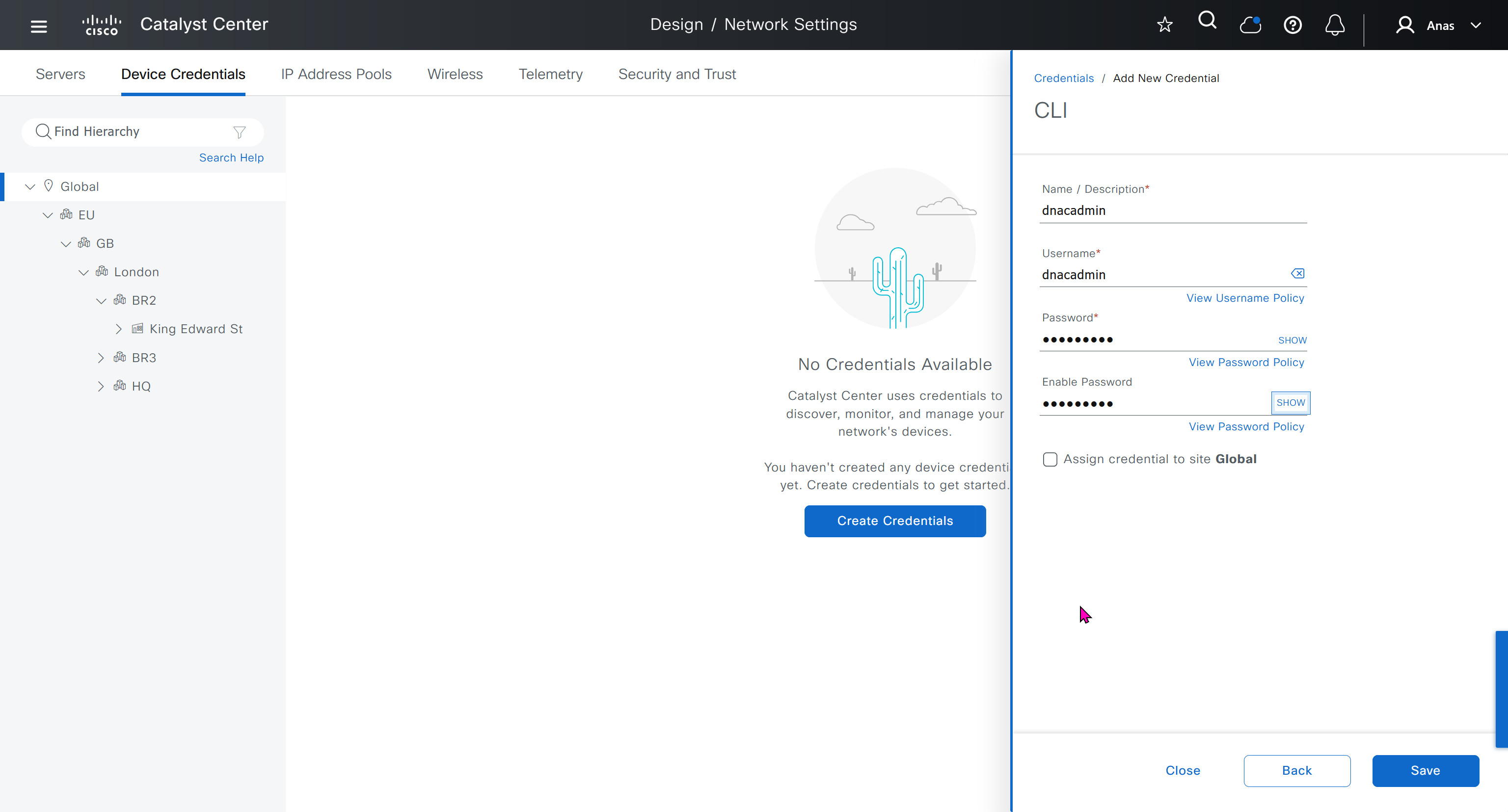
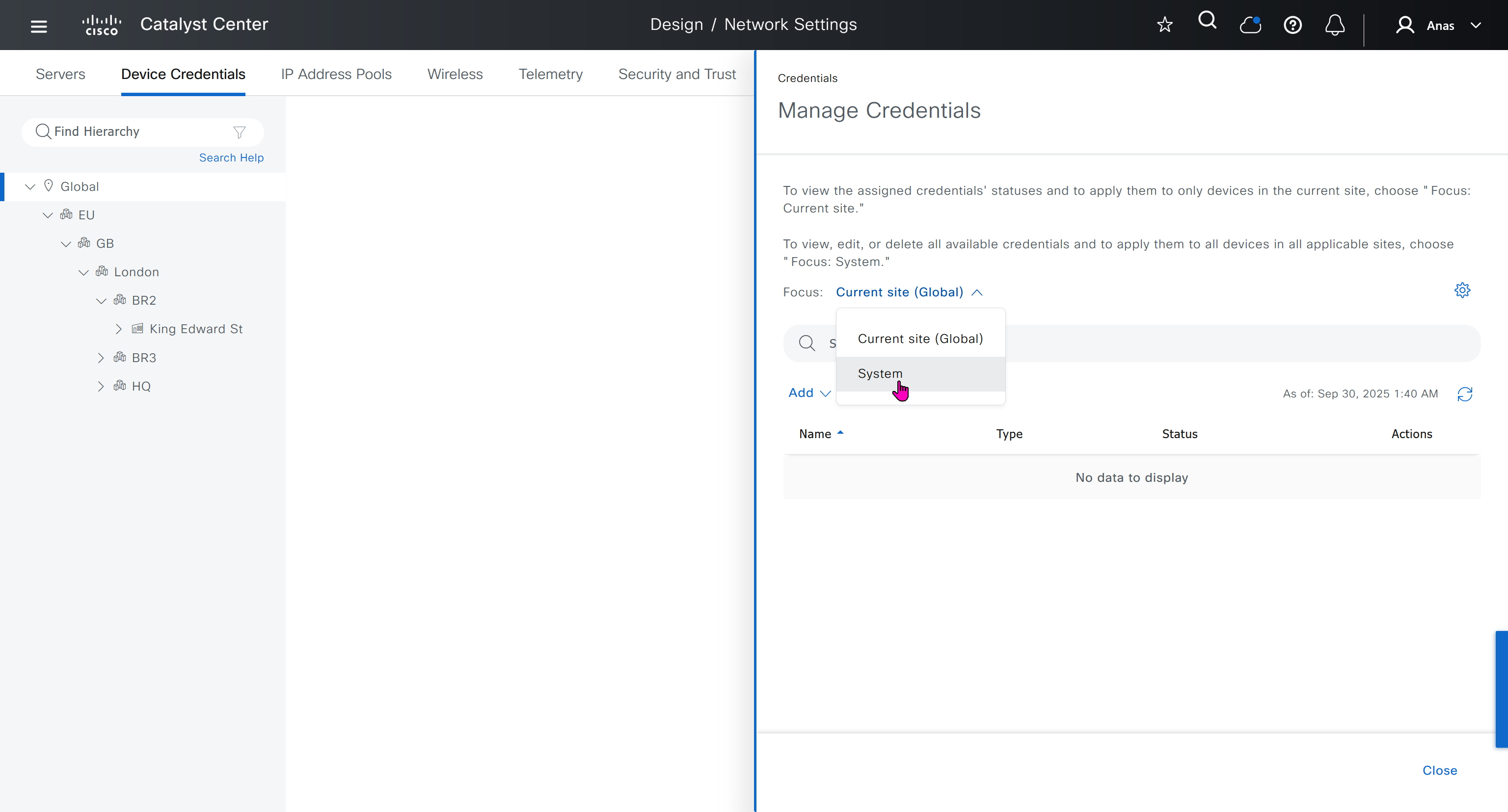
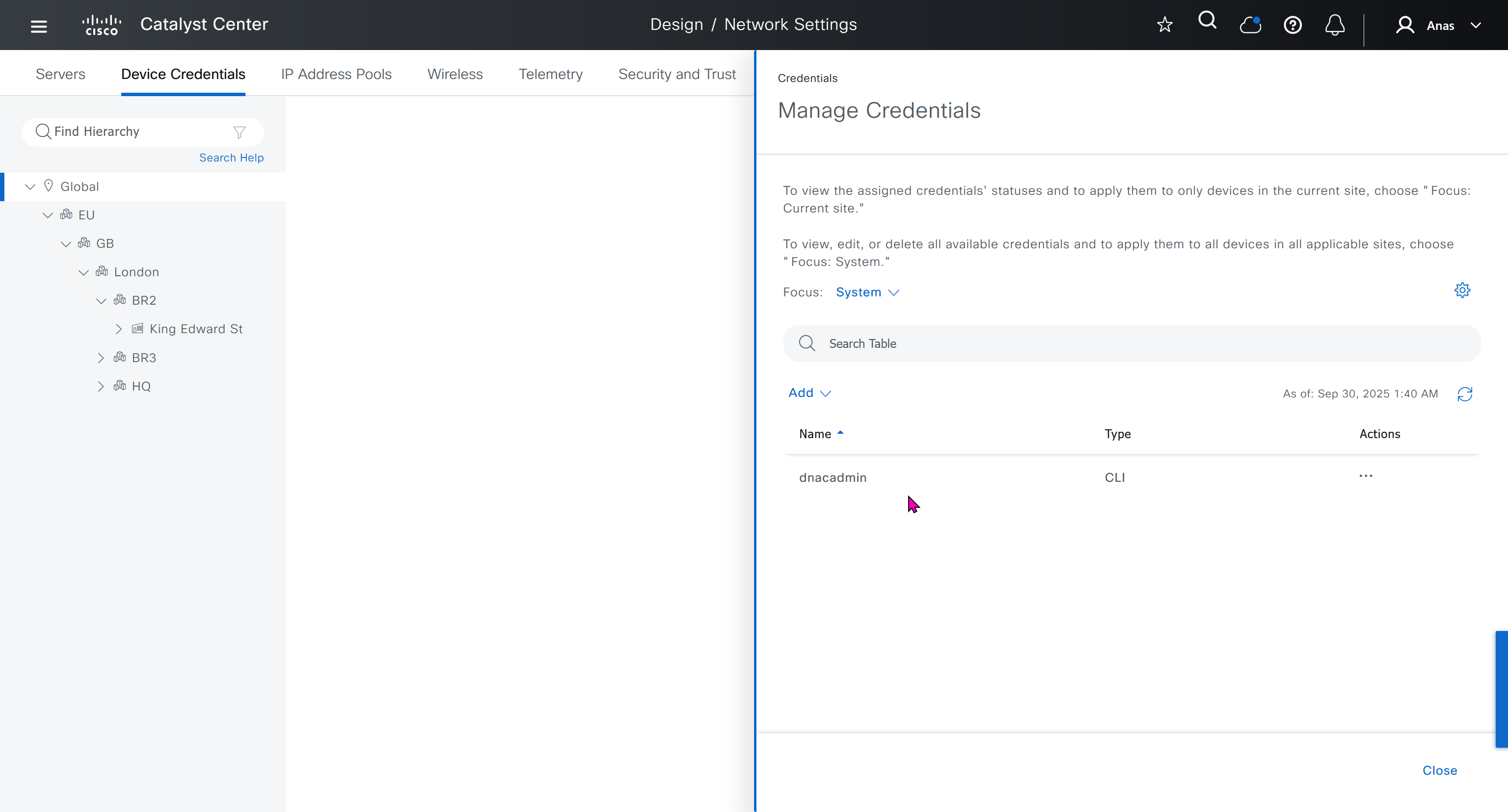
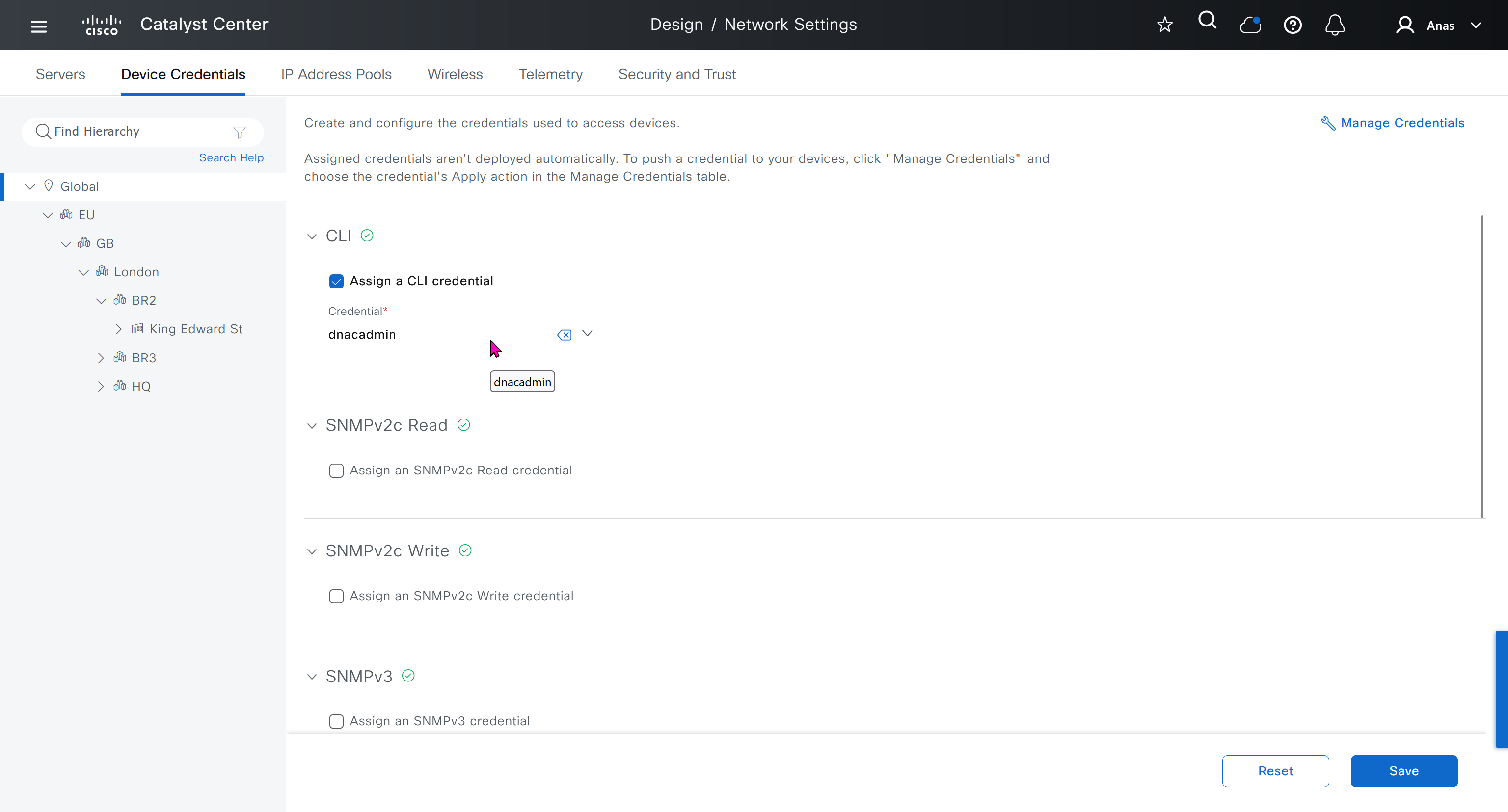
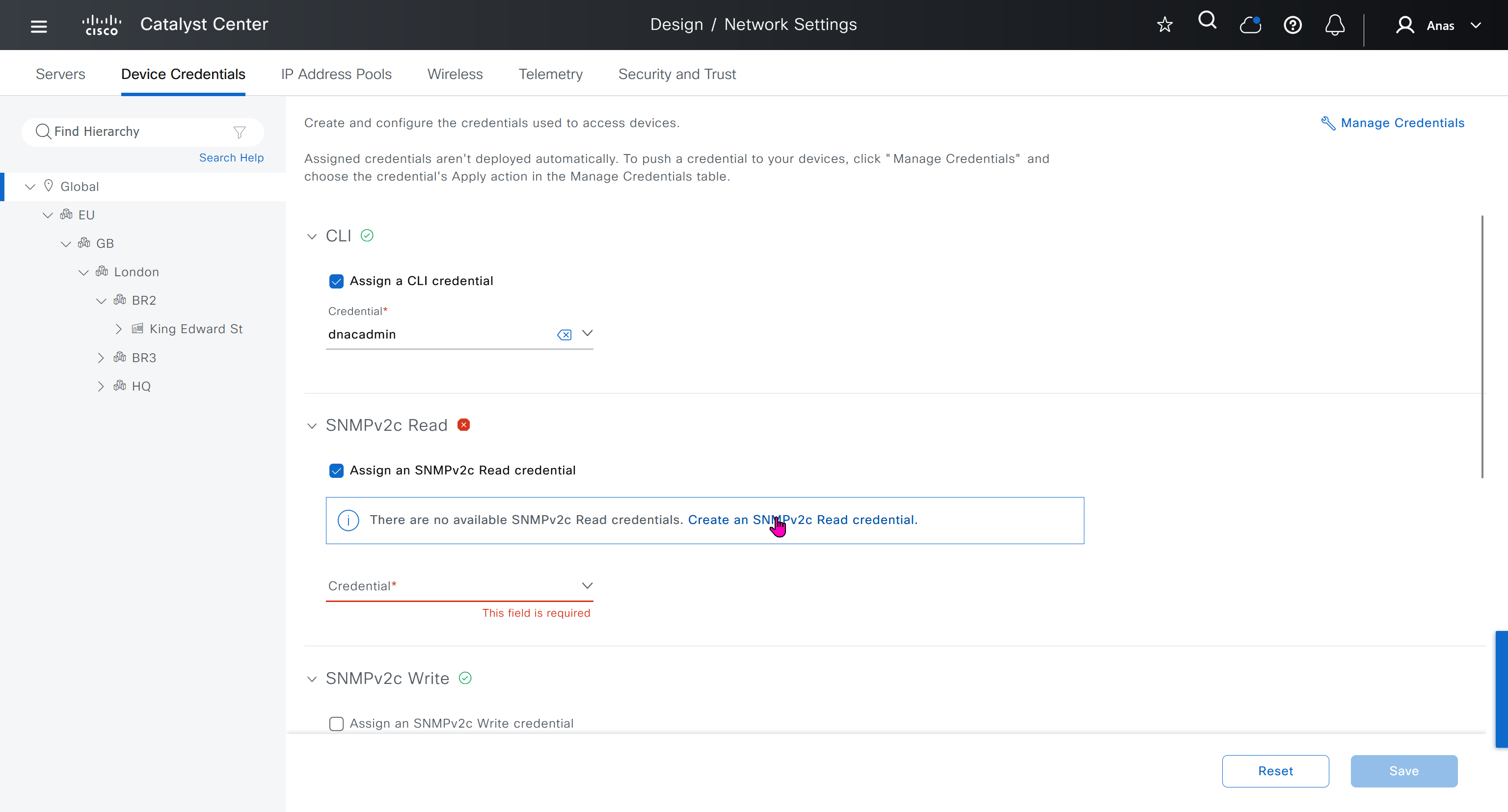
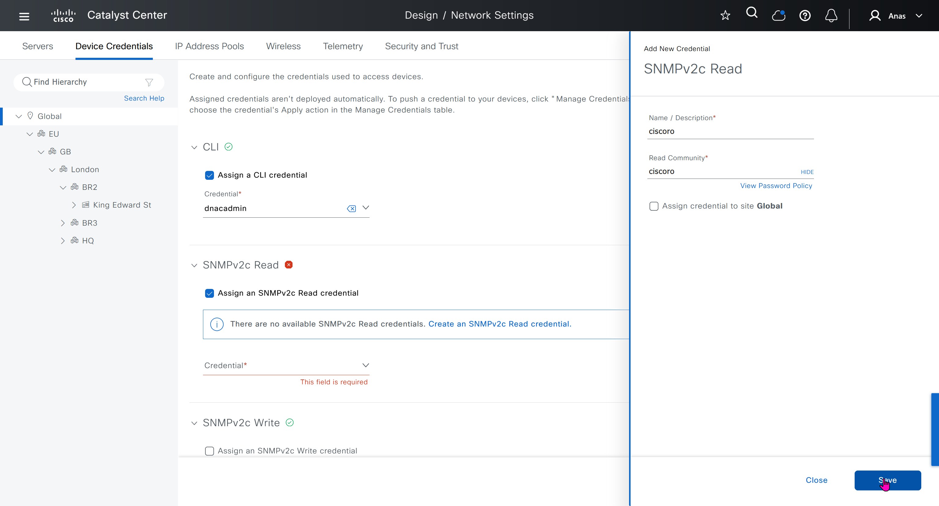
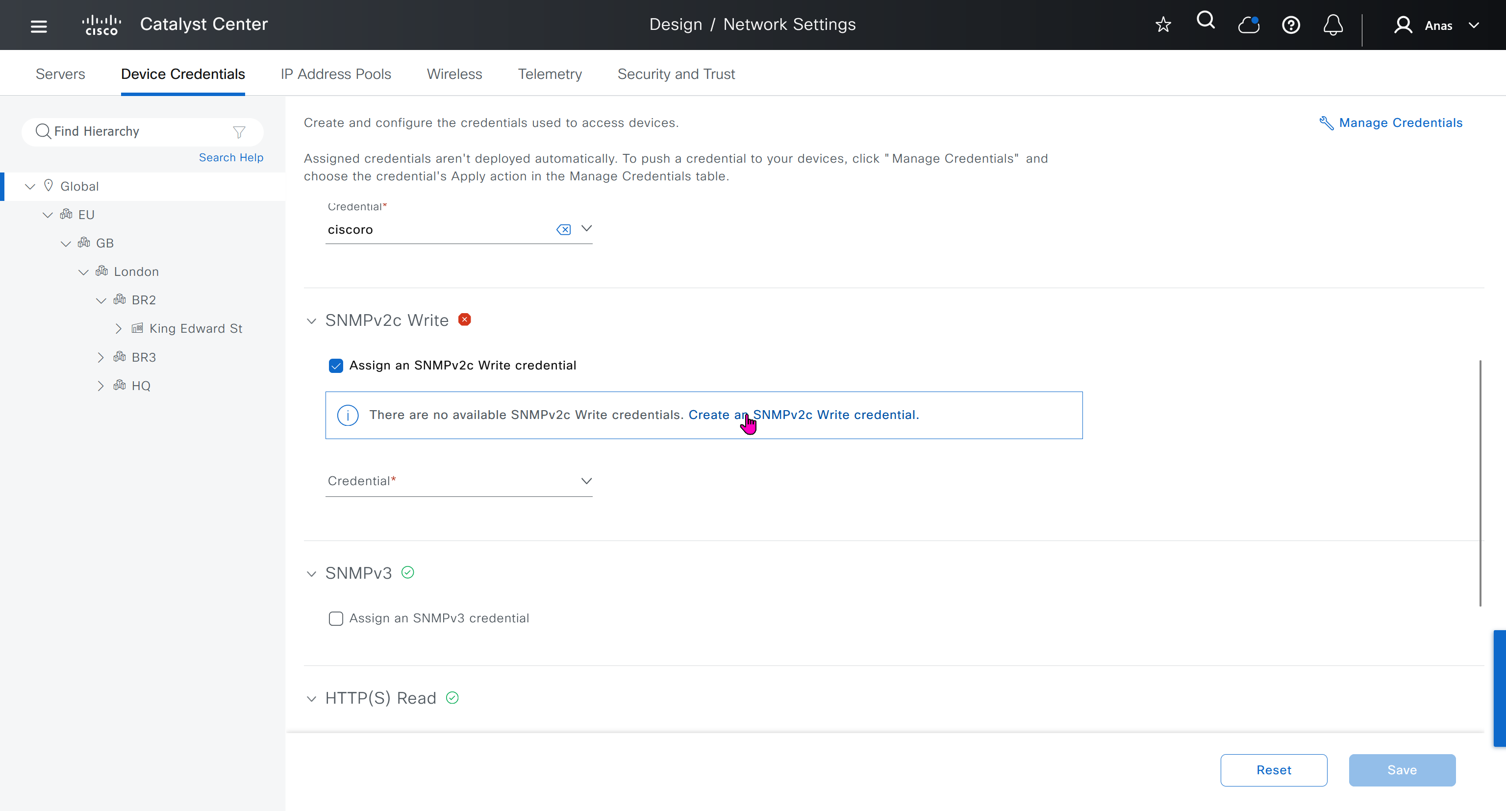
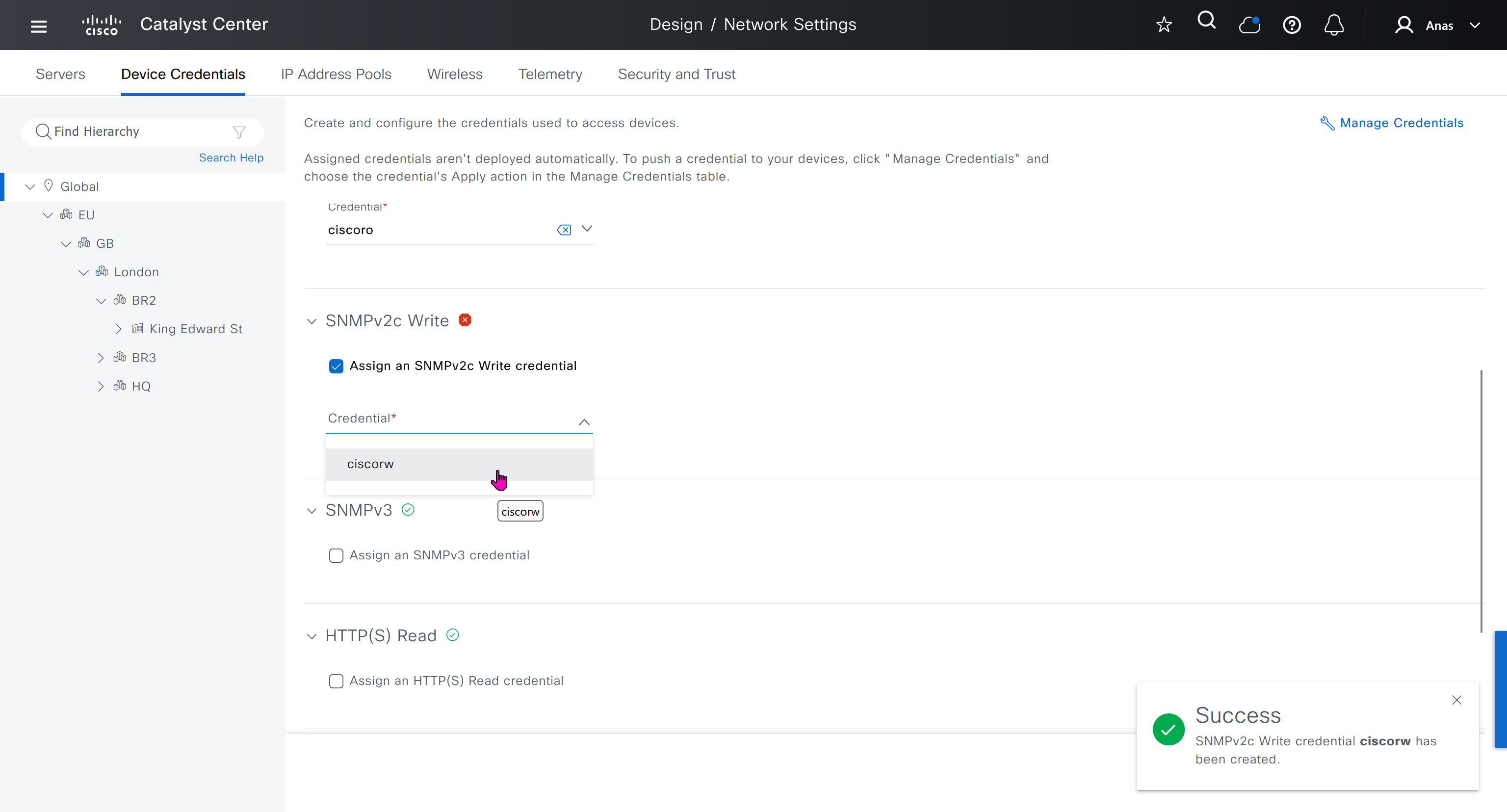
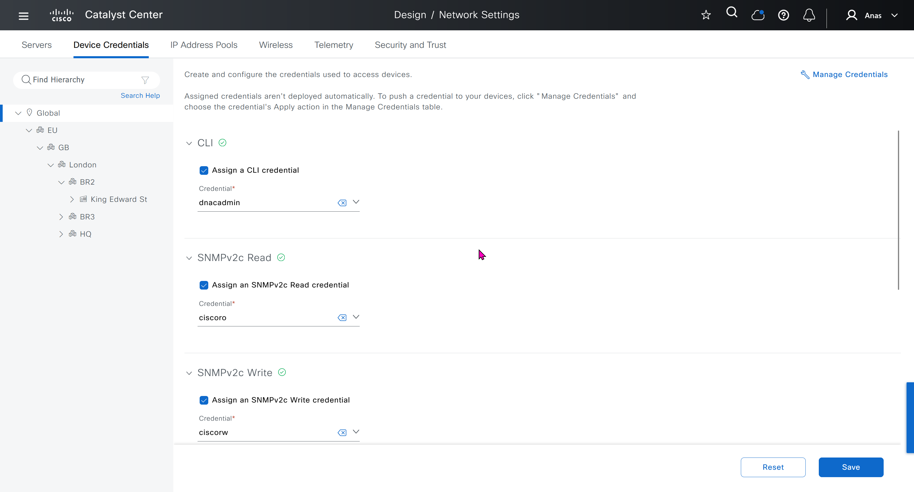
Device credentials is where we feed DNAC with device login details for SSH, SNMPv3 and HTTPS (usually not used

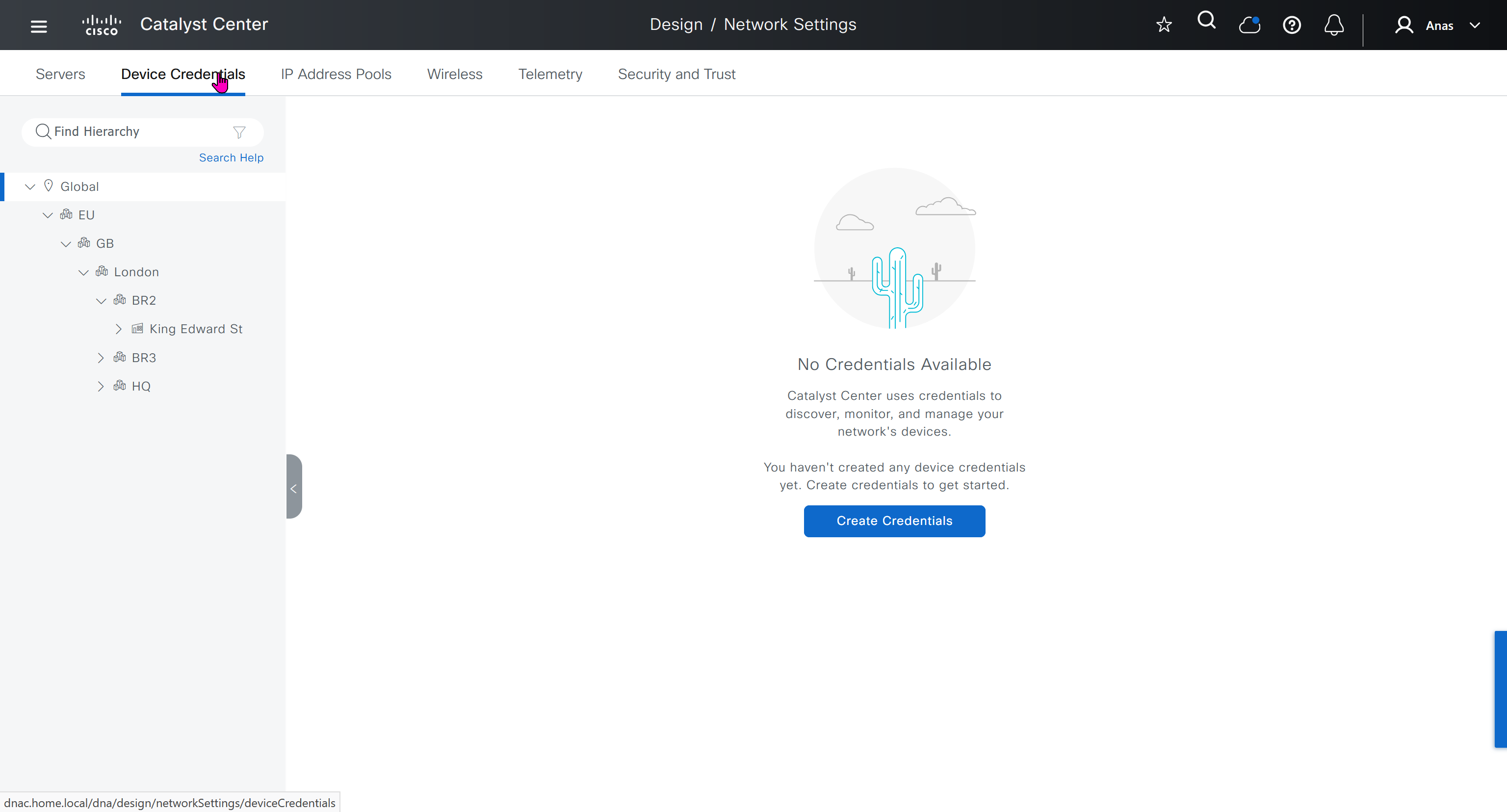
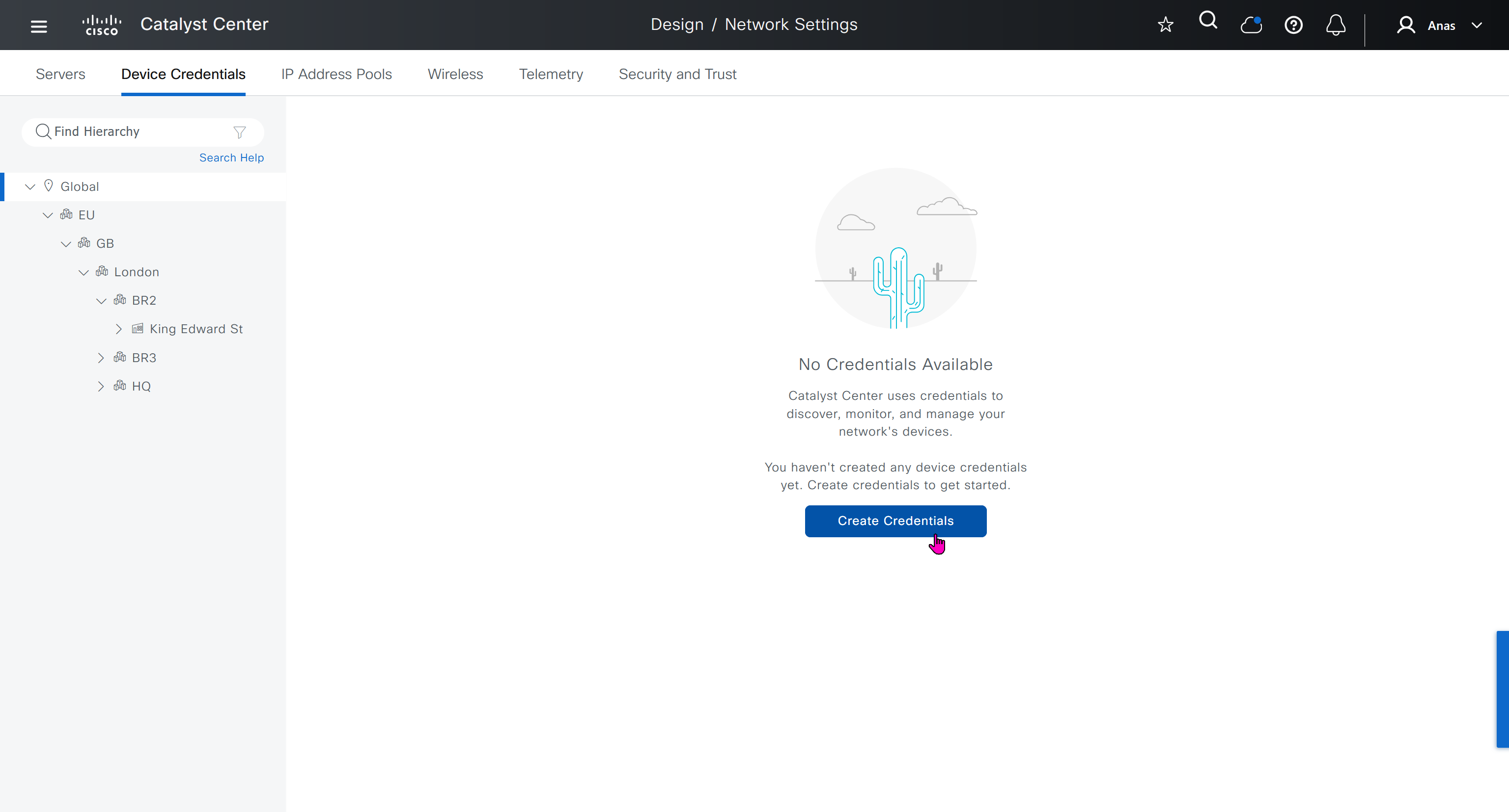
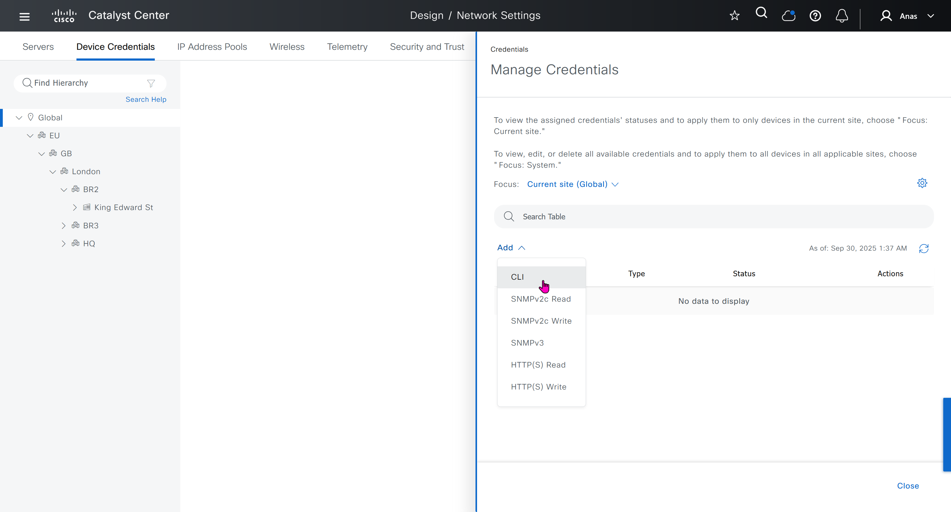
for dnac credentials, try not to use admin as it can cause conflict instead use dnacadmin
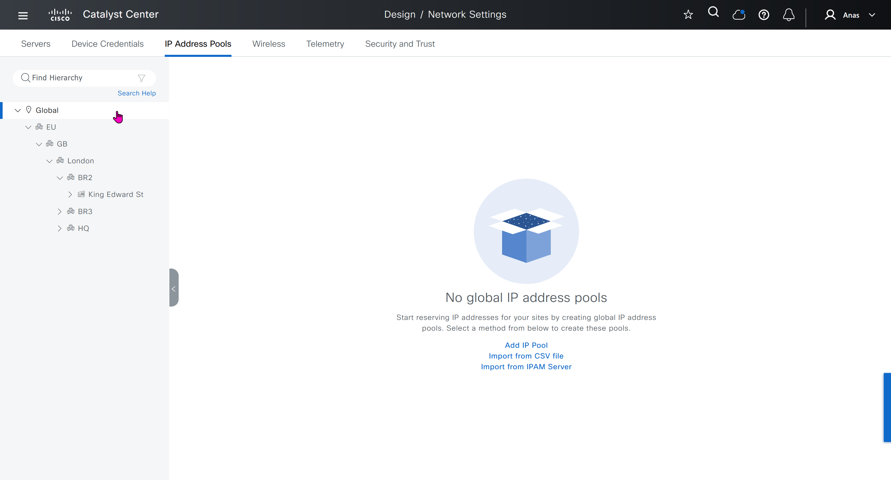
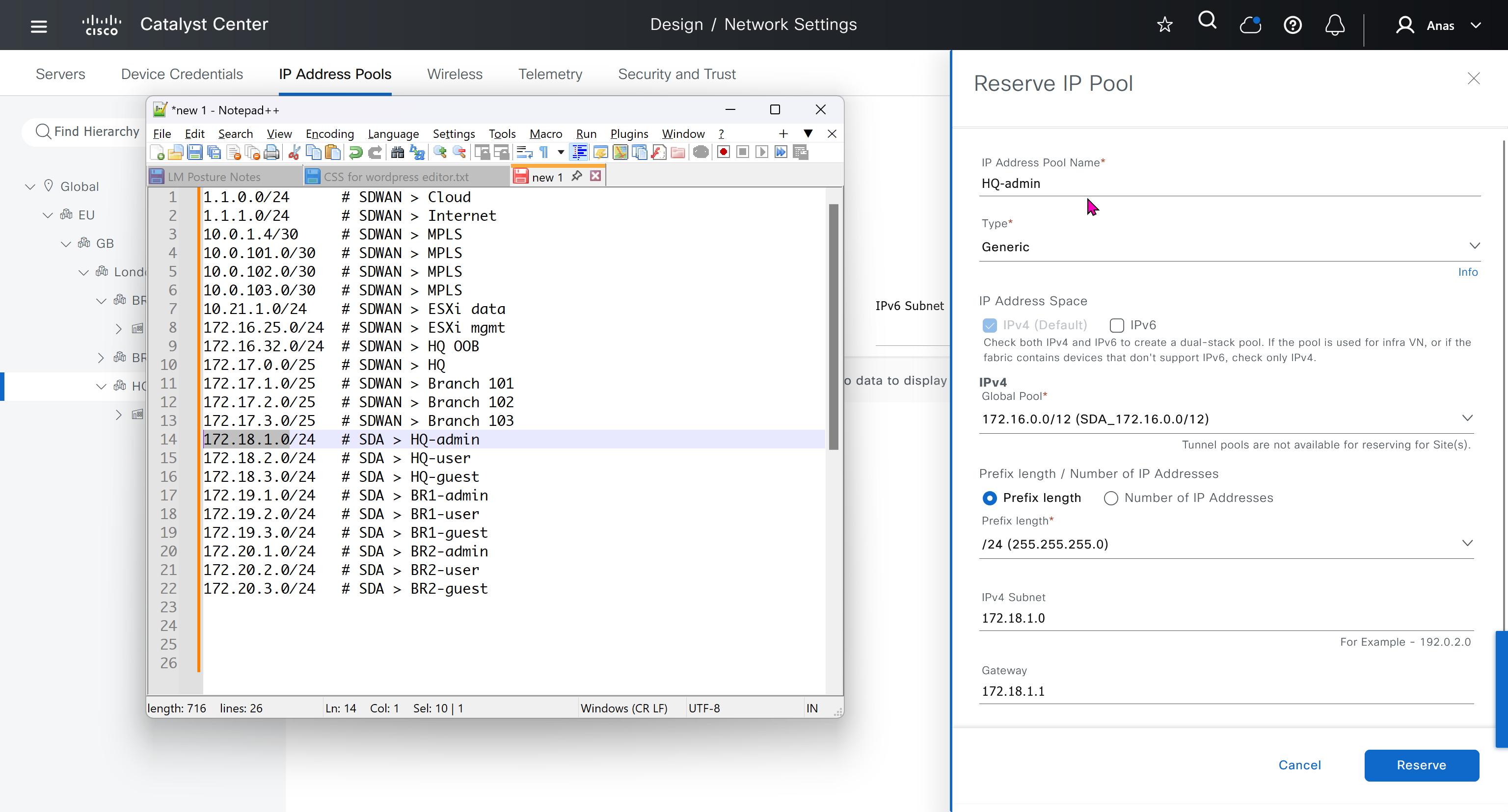
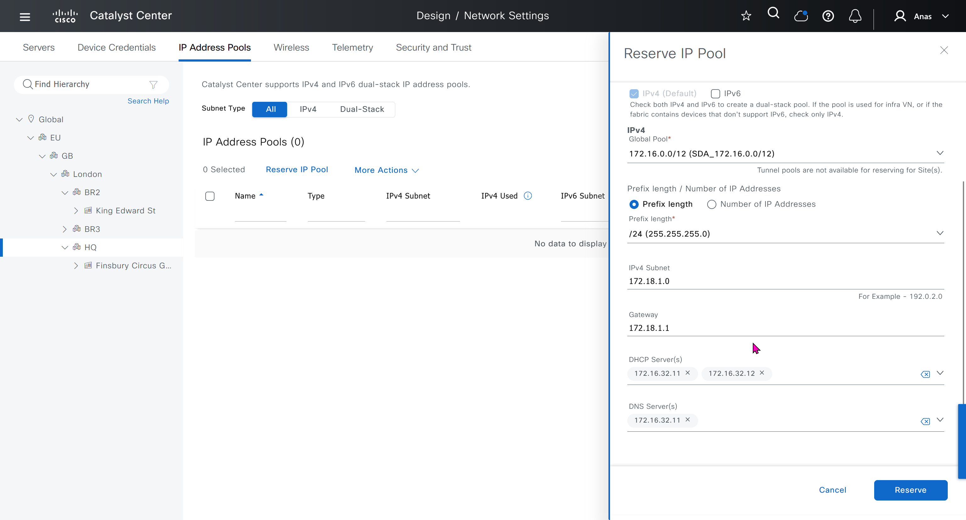
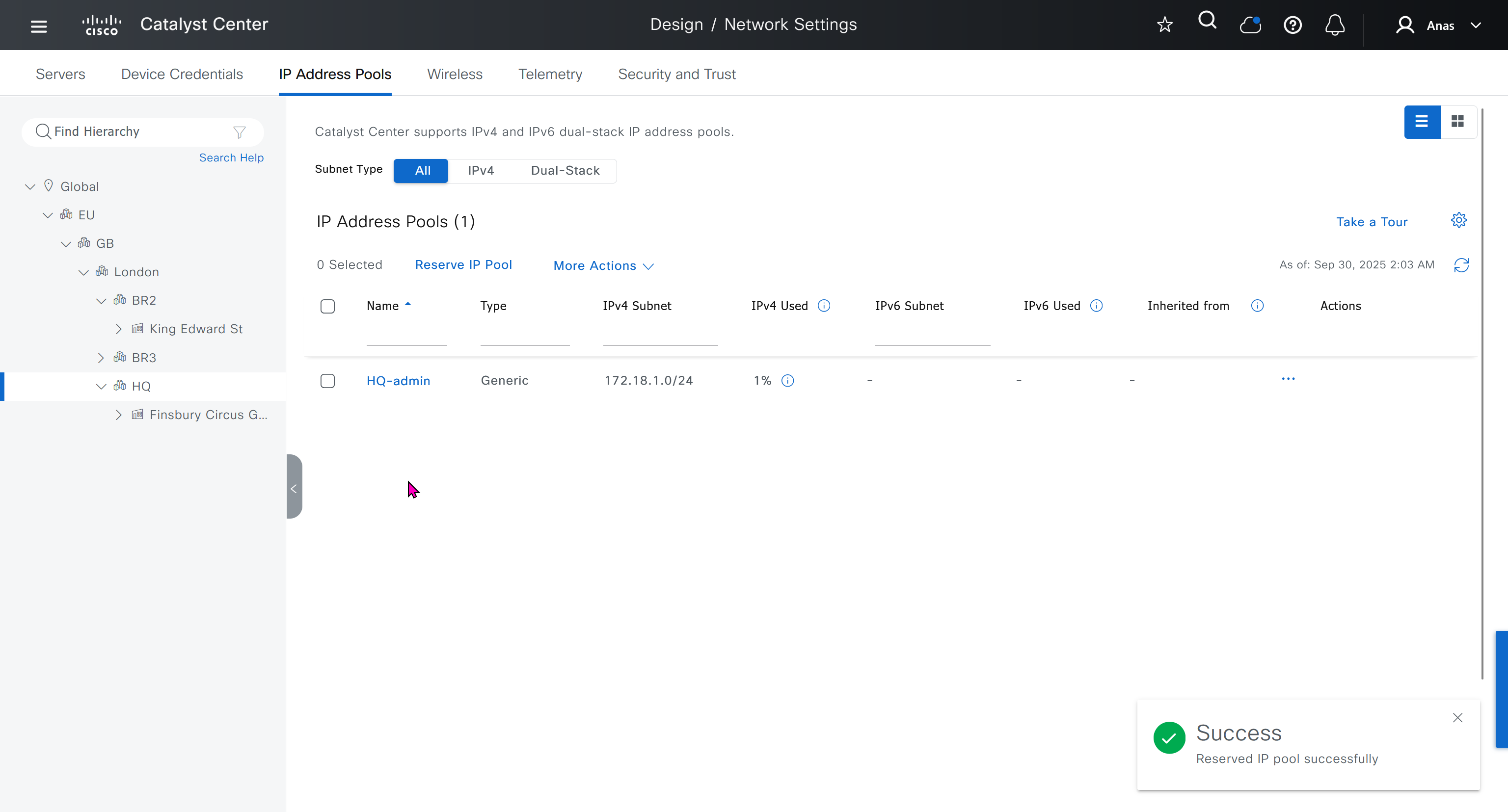
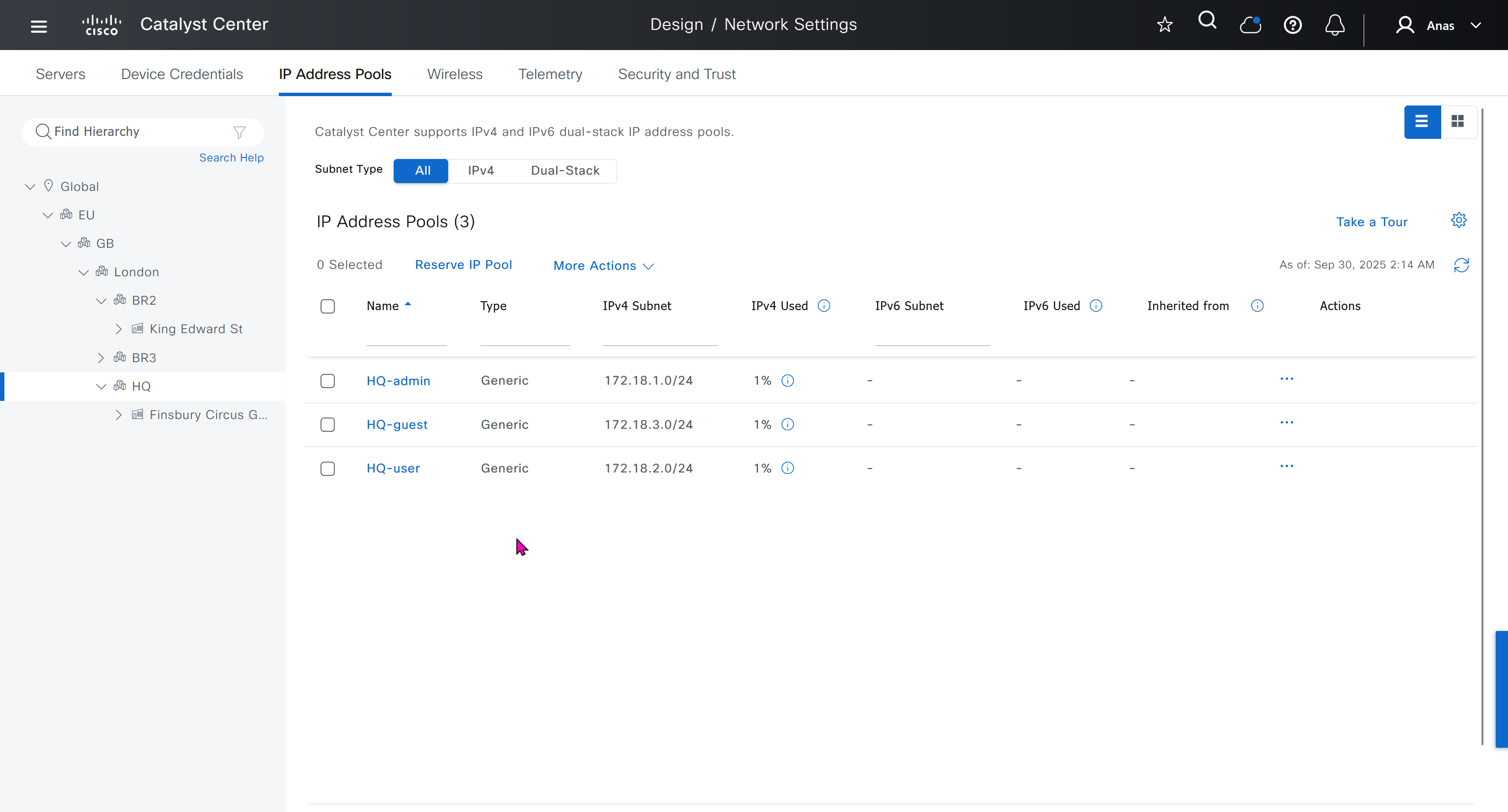
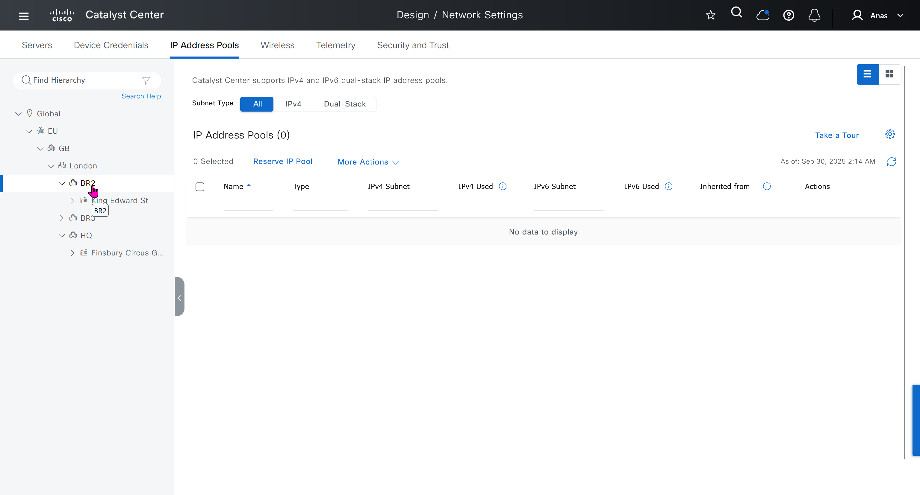
IP address pool is where you define all the subnets that we need to deploy all across SDA, make sure to reserve the supernet at global level
Make sure that we carefully plan and deploy subnets because once it becomes part of SDA, it can be hard to remove it
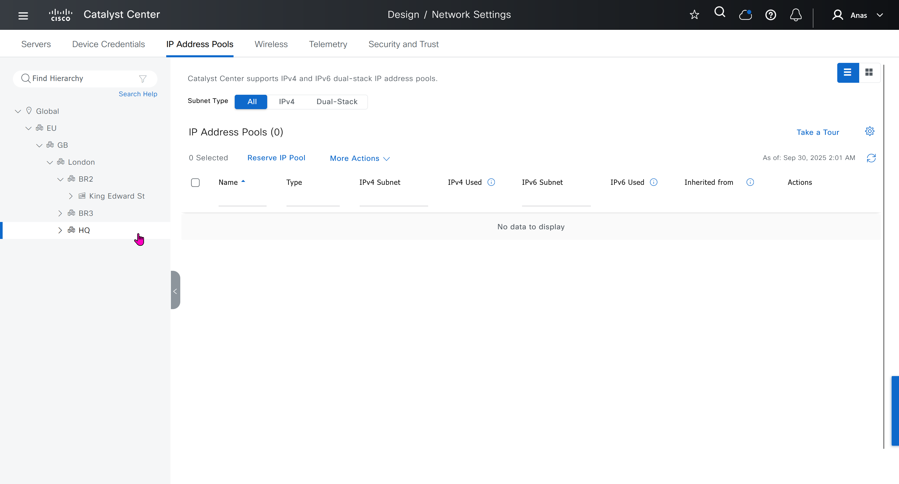
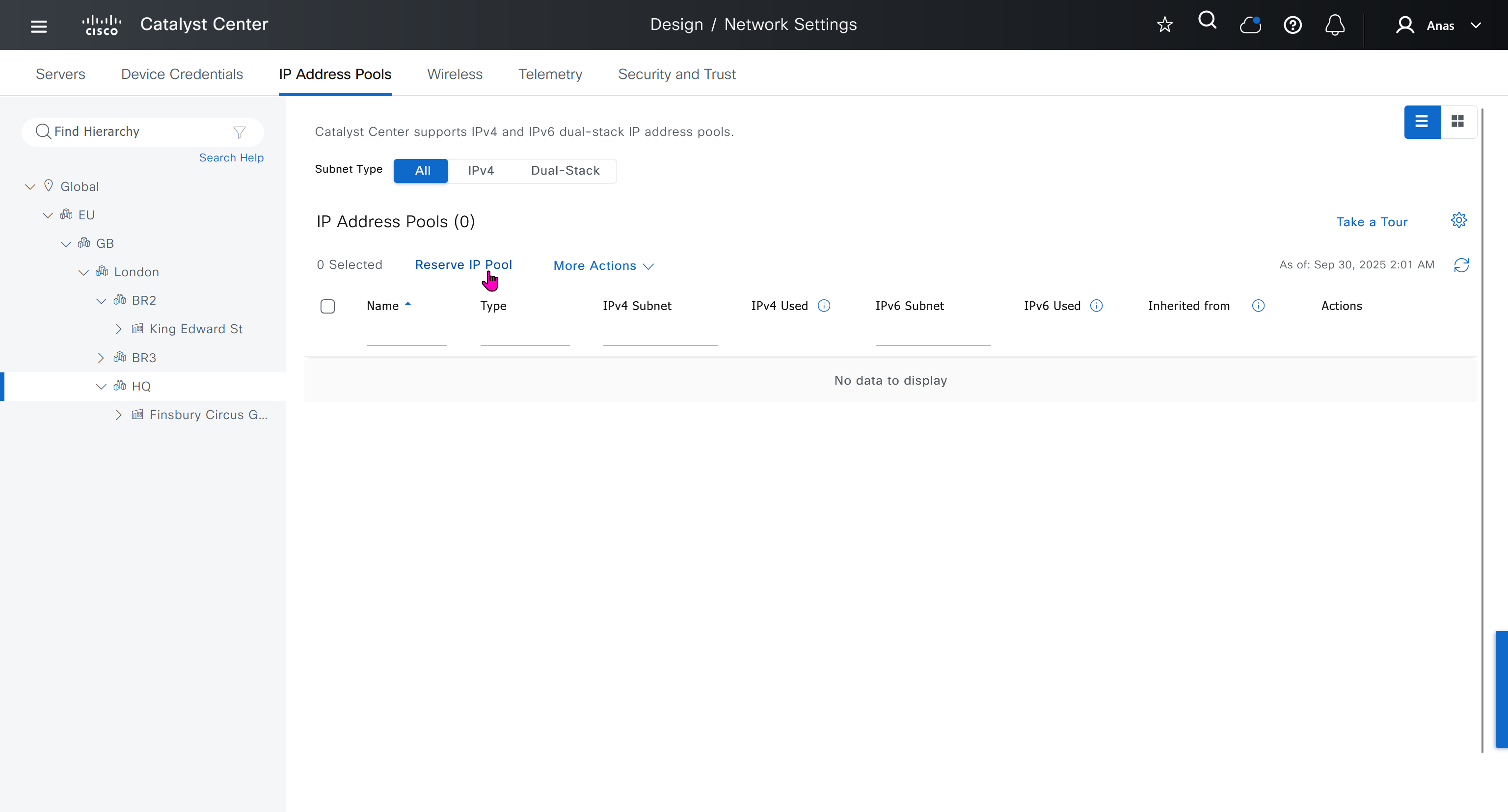
You can only create IP pools at the global level, Add button is only available at global level and at lower hierarchy you simply reserve IP pools for use
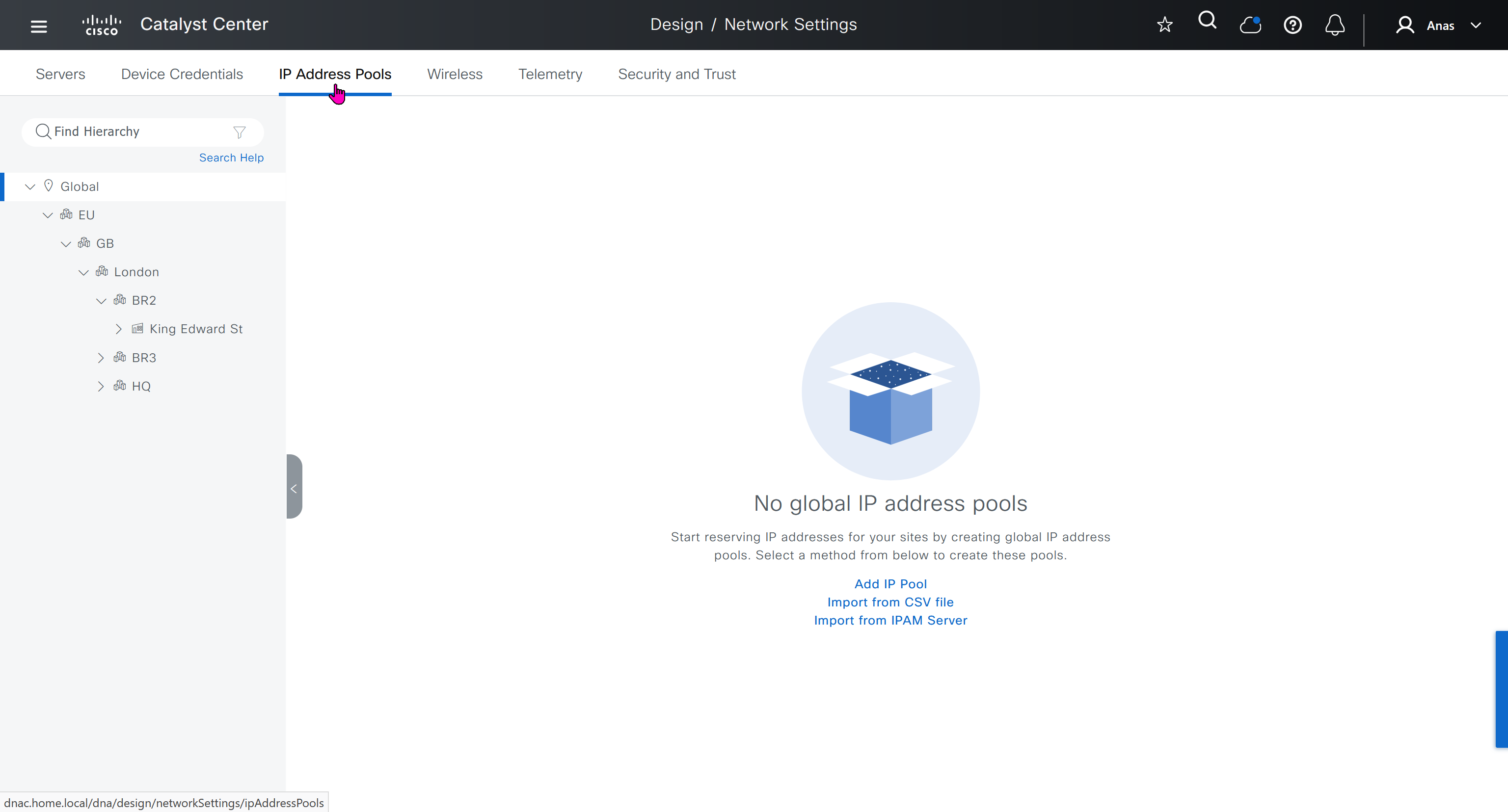
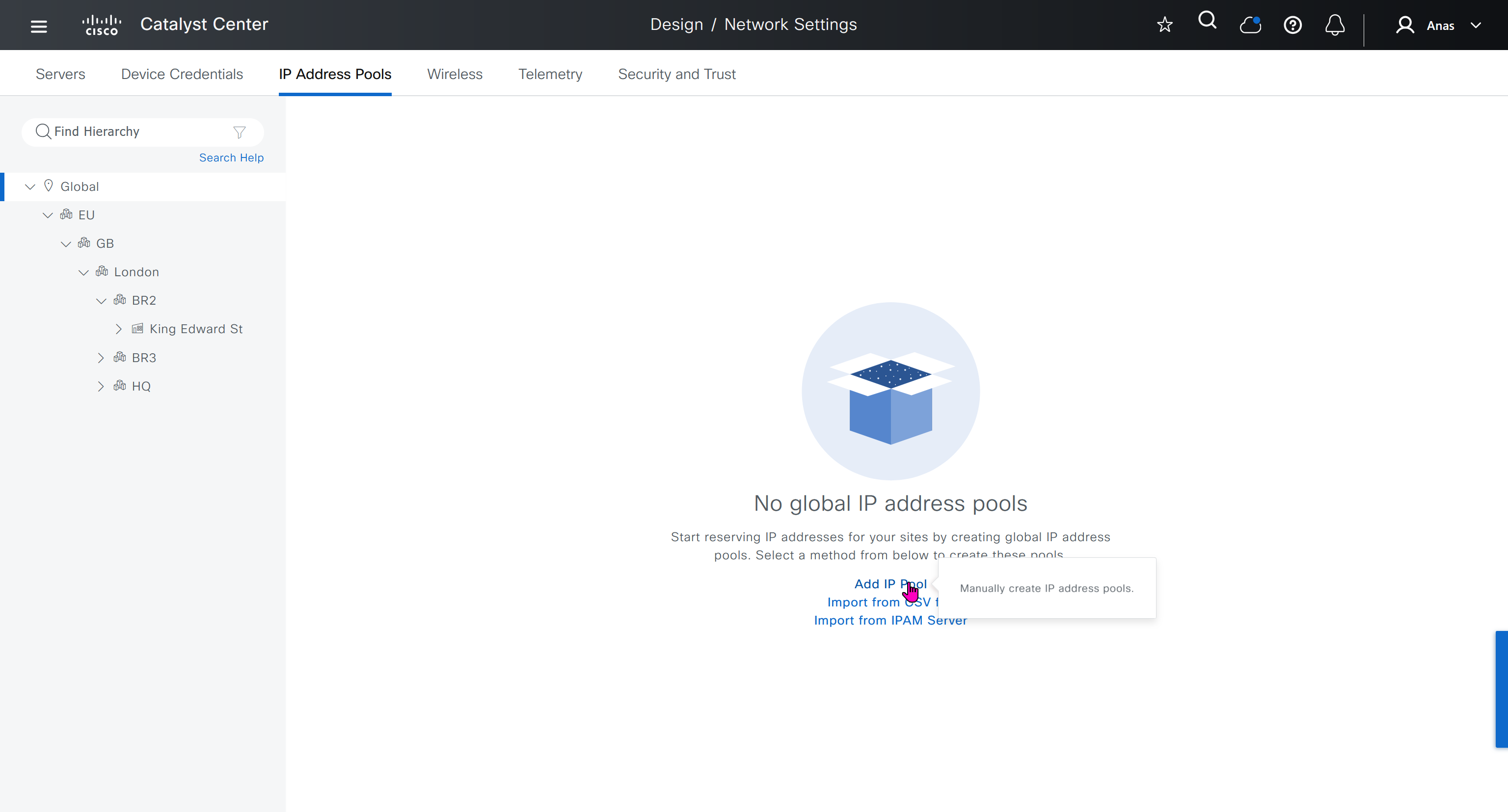
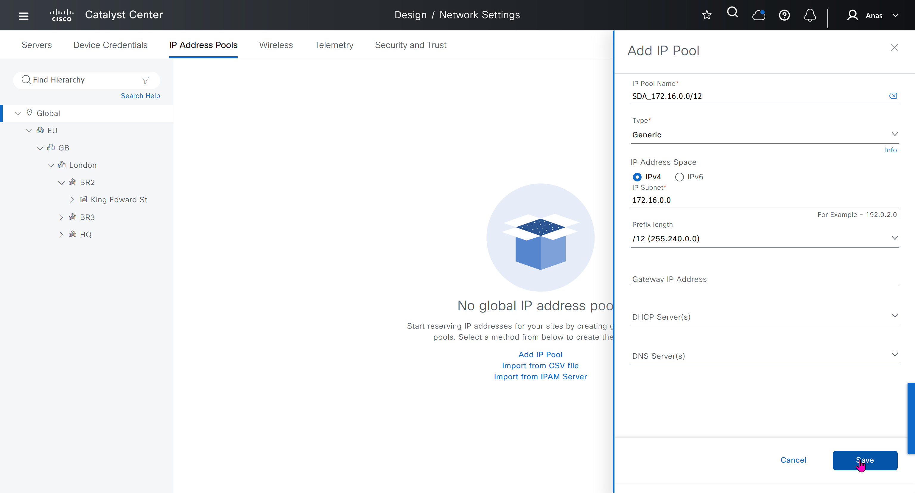
IP address pool type for SDA will be “generic”
When defining IP address pools at Global level then we don’t need to define the gateway IP address, DHCP server and DNS server


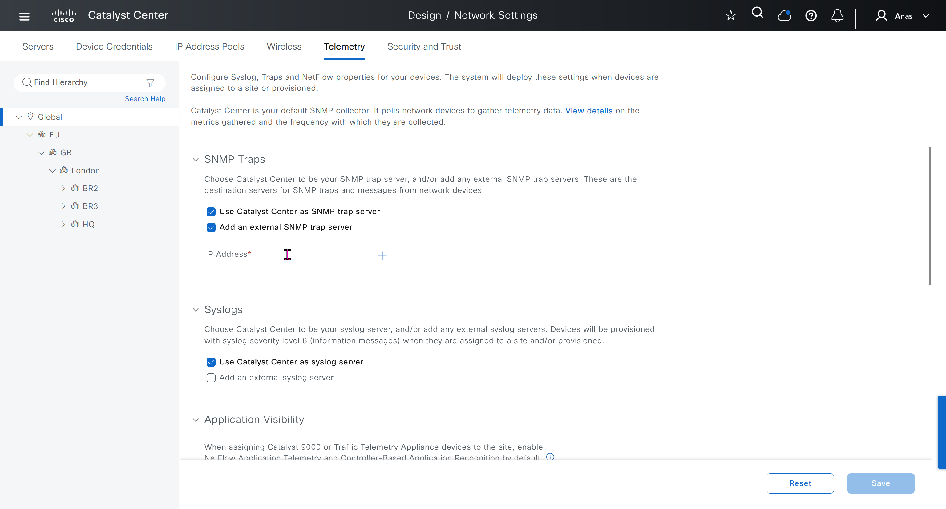
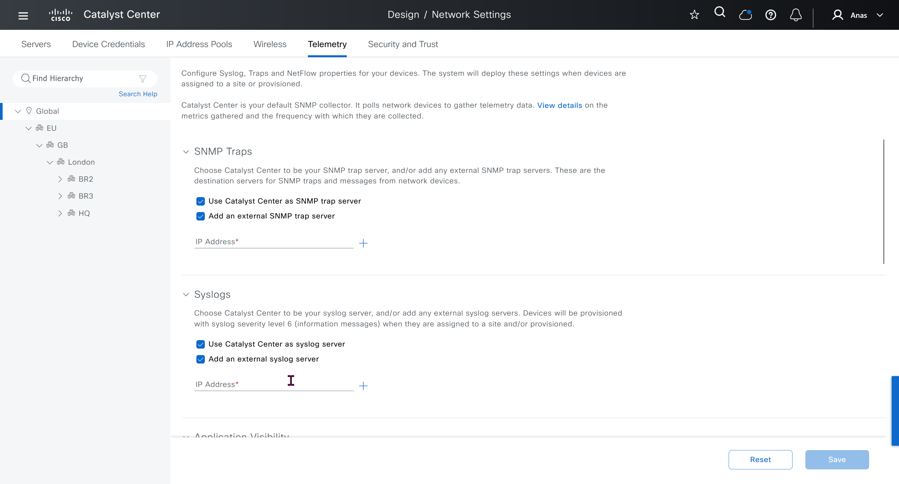
Telemetry section is where DNAC configured devices to uses SNMP, netflow and syslog to send telemetry information to DNAC
A lot of telemetry is being confirmed or supported by SNMP, netflow and syslog
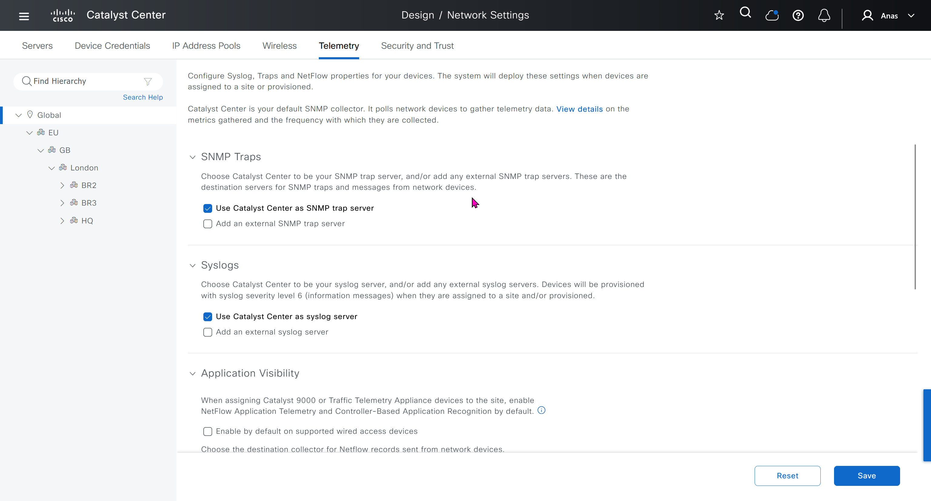

While configuring the Telemetry section, there are options to configure DNAC as SNMP Trap server, Syslog server and netflow collector also but under all these option there is an option also by dnac to configure other syslog and snmp trap server if desired such as SolarWinds
conf t
license boot level network-advantage addon dna-advantage
end
write memory
reload
conf t
!
snmp-server community ciscoro RO
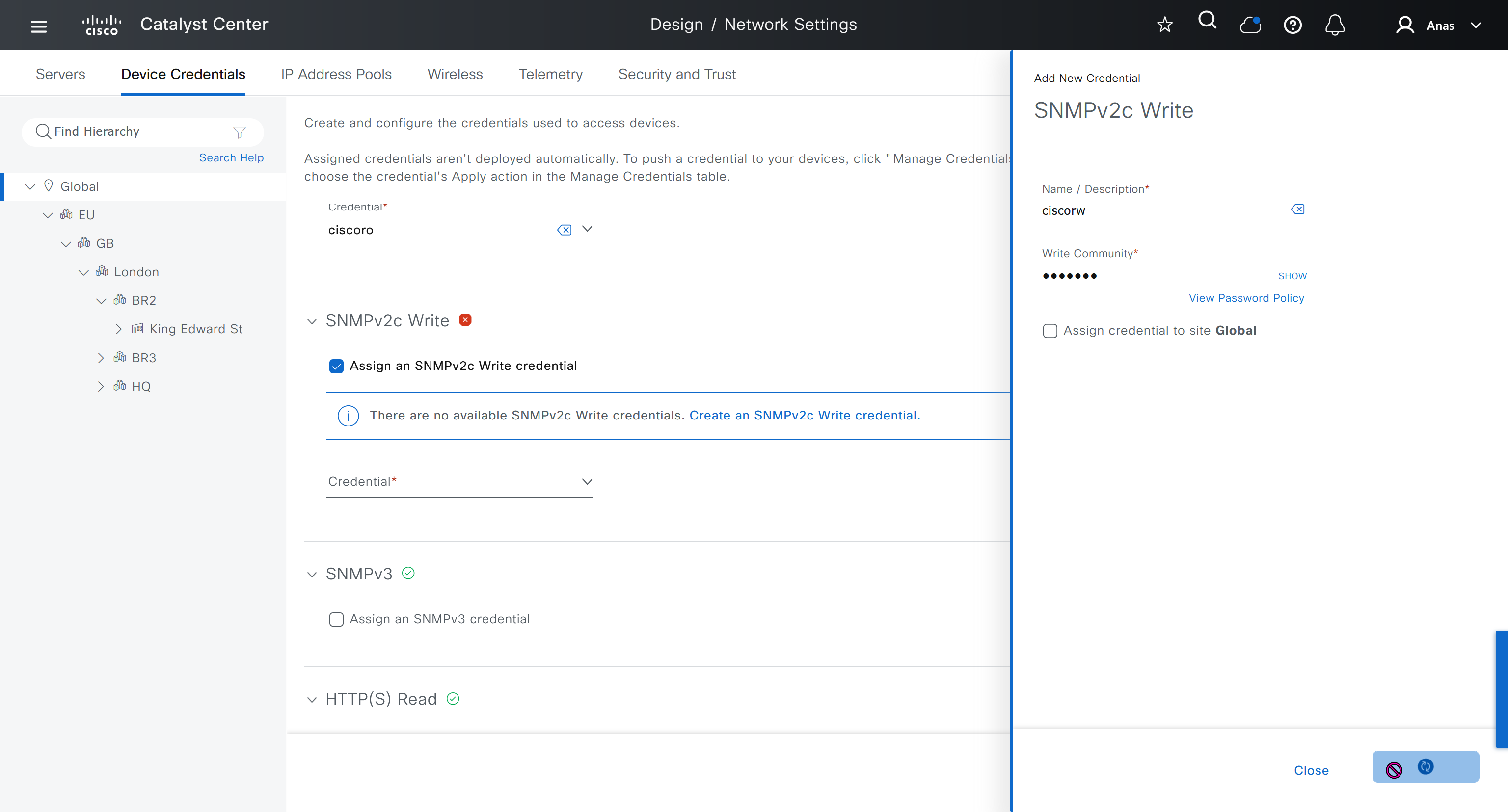
snmp-server community ciscorw RW
!
aaa new-model
!
aaa authentication login default local
aaa authorization exec default local
!
aaa session-id common
!
ip routing
!
license boot level network-advantage addon dna-advantage
!
system mtu 8978
!
enable secret 9 $9$WsbGbEnlY7ZnOE$8Y5qUmOgCatKFC2M/Kpmov7Dbd08QBhQlA8nlOXjnfA
!
username cisco privilege 15 secret 9 $9$K2c68lctCCR3v.$SgFneM9tcIGiIKFFsAsZDcBT/DX0ty2rJ01pQSVW5LU
username dnacadmin privilege 15 secret 9 $9$ss2NT8jXdGqUGU$QVfZV.IgKGnzd8GNy5oCLpfZvamjwuusTVNBK61XPMQ
!
interface GigabitEthernet1/0/x
description SDA-HQ-FXX-01
switchport access vlan 12
!
interface GigabitEthernet1/0/x
description SDA-HQ-FXX-01
switchport access vlan 12
!
interface Vlan1
no ip address
!
interface Vlan12
ip address 172.17.0.x 255.255.255.128
ip ospf mtu-ignore
!
router ospf 100
router-id 172.17.0.x
network 172.17.0.0 0.0.0.127 area 0
!
snmp-server community ciscoro RO
snmp-server community ciscorw RW
!
alias router show do show
alias interface show do show
alias configure show do show
!
line vty 0 98
privilege level 15
transport input ssh
!
netconf-yang
end
write memHQ-SW config !!! old LAB
HQ-SW#show run
Building configuration...

Current configuration : 3914 bytes
!
! Last configuration change at 03:22:03 UTC Mon Oct 6 2025
!
version 15.2
service timestamps debug datetime msec
service timestamps log datetime msec
no service password-encryption
service compress-config
!
hostname HQ-SW
!
boot-start-marker
boot-end-marker
!
!
!
username cisco privilege 15 secret 5 $1$SACq$2ExGwHsqUe3mKfho1B3AQ1
no aaa new-model
!
!
!
!
!
!
!
!
ip cef
no ipv6 cef
!
!
!
spanning-tree mode pvst
spanning-tree extend system-id
!
vlan internal allocation policy ascending
!
!
!
!
!
!
!
!
!
!
!
!
!
!
interface GigabitEthernet0/0
 description INTERNET
 no switchport
 ip address 1.1.1.11 255.255.255.0
 negotiation auto
!
interface GigabitEthernet0/1
 description WINSERVER
 media-type rj45
 negotiation auto
!
interface GigabitEthernet0/2
 description home.local network
 switchport access vlan 11
 media-type rj45
 negotiation auto
!
interface GigabitEthernet0/3
 description ISE01
 media-type rj45
 negotiation auto
!
interface GigabitEthernet1/0
 description SDA-HQ-FBS-01 HQ-DATA
 switchport access vlan 12
 switchport mode access
 media-type rj45
 negotiation auto
!
interface GigabitEthernet1/1
 media-type rj45
 negotiation auto
!
interface GigabitEthernet1/2
 media-type rj45
 negotiation auto
!
interface GigabitEthernet1/3
 media-type rj45
 negotiation auto
!
interface Vlan1
 description HQ-OOB network
 ip address 172.16.32.1 255.255.255.0
!
interface Vlan11
 description home.local network
 ip address 192.168.0.15 255.255.255.0
!
interface Vlan12
 ip address 172.17.0.3 255.255.255.128
 ip ospf mtu-ignore
!
router ospf 100
 router-id 172.17.0.3
 network 172.17.0.0 0.0.0.127 area 0
 default-information originate
!
ip forward-protocol nd
!
no ip http server
no ip http secure-server
!
ip route 0.0.0.0 0.0.0.0 192.168.0.1
ip route 1.1.0.0 255.255.255.0 1.1.1.250
ip route 10.21.1.0 255.255.255.0 192.168.0.12
ip route 172.16.25.0 255.255.255.0 192.168.0.12
!
!
!
!
!
control-plane
!
banner exec ^CCC
**************************************************************************
* IOSv is strictly limited to use for evaluation, demonstration and IOS  *
* education. IOSv is provided as-is and is not supported by Cisco's      *
* Technical Advisory Center. Any use or disclosure, in whole or in part, *
* of the IOSv Software or Documentation to any third party for any       *
* purposes is expressly prohibited except as otherwise authorized by     *
* Cisco in writing.                                                      *
**************************************************************************^C
banner incoming ^CCC
**************************************************************************
* IOSv is strictly limited to use for evaluation, demonstration and IOS  *
* education. IOSv is provided as-is and is not supported by Cisco's      *
* Technical Advisory Center. Any use or disclosure, in whole or in part, *
* of the IOSv Software or Documentation to any third party for any       *
* purposes is expressly prohibited except as otherwise authorized by     *
* Cisco in writing.                                                      *
**************************************************************************^C
banner login ^CCC
**************************************************************************
* IOSv is strictly limited to use for evaluation, demonstration and IOS  *
* education. IOSv is provided as-is and is not supported by Cisco's      *
* Technical Advisory Center. Any use or disclosure, in whole or in part, *
* of the IOSv Software or Documentation to any third party for any       *
* purposes is expressly prohibited except as otherwise authorized by     *
* Cisco in writing.                                                      *
**************************************************************************^C
alias router show do show
alias interface show do show
alias configure show do show
!
line con 0
line aux 0
line vty 0 4
 login
!
!
netconf-yang
end
SDA-HQ-FBS-01 config
SDA-HQ-FBS-01#show run
Building configuration...

Current configuration : 8301 bytes
!
! Last configuration change at 03:40:18 UTC Mon Oct 6 2025
!
version 17.12
service timestamps debug datetime msec
service timestamps log datetime msec
platform punt-keepalive disable-kernel-core
!
hostname SDA-HQ-FBS-01
!
!
vrf definition Mgmt-vrf
 !
 address-family ipv4
 exit-address-family
 !
 address-family ipv6
 exit-address-family
!
aaa new-model
!
!
aaa authentication login default local
aaa authorization exec default local
!
!
aaa session-id common
switch 1 provision c9kv-uadp-8p
!
!
!
!
ip routing
!
!
!
!
!
!
!
!
login on-success log
vtp version 1
!
!
!
!
!
!
!
!
crypto pki trustpoint SLA-TrustPoint
 enrollment pkcs12
 revocation-check crl
 hash sha256
!
crypto pki trustpoint TP-self-signed-2070352050
 enrollment selfsigned
 subject-name cn=IOS-Self-Signed-Certificate-2070352050
 revocation-check none
 rsakeypair TP-self-signed-2070352050
 hash sha256
!
!
crypto pki certificate chain SLA-TrustPoint
 certificate ca 01
  30820321 30820209 A0030201 02020101 300D0609 2A864886 F70D0101 0B050030
  32310E30 0C060355 040A1305 43697363 6F312030 1E060355 04031317 43697363
  6F204C69 63656E73 696E6720 526F6F74 20434130 1E170D31 33303533 30313934
  3834375A 170D3338 30353330 31393438 34375A30 32310E30 0C060355 040A1305
  43697363 6F312030 1E060355 04031317 43697363 6F204C69 63656E73 696E6720
  526F6F74 20434130 82012230 0D06092A 864886F7 0D010101 05000382 010F0030
  82010A02 82010100 A6BCBD96 131E05F7 145EA72C 2CD686E6 17222EA1 F1EFF64D
  CBB4C798 212AA147 C655D8D7 9471380D 8711441E 1AAF071A 9CAE6388 8A38E520
  1C394D78 462EF239 C659F715 B98C0A59 5BBB5CBD 0CFEBEA3 700A8BF7 D8F256EE
  4AA4E80D DB6FD1C9 60B1FD18 FFC69C96 6FA68957 A2617DE7 104FDC5F EA2956AC
  7390A3EB 2B5436AD C847A2C5 DAB553EB 69A9A535 58E9F3E3 C0BD23CF 58BD7188
  68E69491 20F320E7 948E71D7 AE3BCC84 F10684C7 4BC8E00F 539BA42B 42C68BB7
  C7479096 B4CB2D62 EA2F505D C7B062A4 6811D95B E8250FC4 5D5D5FB8 8F27D191
  C55F0D76 61F9A4CD 3D992327 A8BB03BD 4E6D7069 7CBADF8B DF5F4368 95135E44
  DFC7C6CF 04DD7FD1 02030100 01A34230 40300E06 03551D0F 0101FF04 04030201
  06300F06 03551D13 0101FF04 05300301 01FF301D 0603551D 0E041604 1449DC85
  4B3D31E5 1B3E6A17 606AF333 3D3B4C73 E8300D06 092A8648 86F70D01 010B0500
  03820101 00507F24 D3932A66 86025D9F E838AE5C 6D4DF6B0 49631C78 240DA905
  604EDCDE FF4FED2B 77FC460E CD636FDB DD44681E 3A5673AB 9093D3B1 6C9E3D8B
  D98987BF E40CBD9E 1AECA0C2 2189BB5C 8FA85686 CD98B646 5575B146 8DFC66A8
  467A3DF4 4D565700 6ADF0F0D CF835015 3C04FF7C 21E878AC 11BA9CD2 55A9232C
  7CA7B7E6 C1AF74F6 152E99B7 B1FCF9BB E973DE7F 5BDDEB86 C71E3B49 1765308B
  5FB0DA06 B92AFE7F 494E8A9E 07B85737 F3A58BE1 1A48A229 C37C1E69 39F08678
  80DDCD16 D6BACECA EEBC7CF9 8428787B 35202CDC 60E4616A B623CDBD 230E3AFB
  418616A9 4093E049 4D10AB75 27E86F73 932E35B5 8862FDAE 0275156F 719BB2F0
  D697DF7F 28
        quit
crypto pki certificate chain TP-self-signed-2070352050
 certificate self-signed 01
  30820330 30820218 A0030201 02020101 300D0609 2A864886 F70D0101 0B050030
  31312F30 2D060355 04030C26 494F532D 53656C66 2D536967 6E65642D 43657274
  69666963 6174652D 32303730 33353230 3530301E 170D3235 30393231 32313439
  32315A17 0D333530 39323132 31343932 315A3031 312F302D 06035504 030C2649
  4F532D53 656C662D 5369676E 65642D43 65727469 66696361 74652D32 30373033
  35323035 30308201 22300D06 092A8648 86F70D01 01010500 0382010F 00308201
  0A028201 0100BE6B 15431B3C C2F339F8 E68ED232 38C6D054 26256330 1860898B
  3427C857 6F821274 0C5B8B21 D2B908B2 71205F22 E9E2D9EF CCCEF719 CB65D798
  620546BE 724EFEE4 B7D9026F E94D9B0C A1B7755C 33C13A5B 5803DE7F DABC513B
  17181601 AE98D442 44694CF2 57D1505F 3A119649 E0F7C524 A2C544D1 8C986BC2
  89C8FAF7 0E72811A AC4FDC69 D0A4DE17 BE69A40F F83E5BFD B16E894B 18830516
  06726E02 3E6F1A7F 3A202286 600059F0 CF9EC6A8 420946BD A0F70AFF CE386017
  44CB8032 55B22C27 E240440C 39D3EEF3 B887DF4B ECECD738 76C531B7 DC43AC1F
  38AAE8C1 A12B5574 0DCA1A63 88E12E80 62411882 573FBF7A 85DD348B 425A477E
  9AF7DAB7 D9EF0203 010001A3 53305130 1D060355 1D0E0416 0414864F 5DC3AA3D
  570D29AC 614578D3 7BCFD3AF 76D5301F 0603551D 23041830 16801486 4F5DC3AA
  3D570D29 AC614578 D37BCFD3 AF76D530 0F060355 1D130101 FF040530 030101FF
  300D0609 2A864886 F70D0101 0B050003 82010100 3037A0B0 4EE53529 F17F5DAF
  A4B8BF4C 1B0B63D3 2F5785E9 4A2FFE10 46890D5C 3A50C253 6AF15B6F 13FA2AC8
  EBF67CBD CFA8D7AE 756B2596 B554A972 40F4E277 98310DC0 9EA3EB9A B8CCD9BE
  C5332F30 4C6A7F5B D76CF4DF 69E29977 745B232E EC606EB5 CD6CA542 A425C5CC
  D307EE95 FBF9FE6A F0561077 83079168 0DEA031B 00D4D850 EFED9136 607A5F2F
  FB848029 6C2457A0 1AD24EBB A915E9DE F0F4BFD5 DA125681 55183EE5 D62333F9
  97EA23F6 F2925C1E 440888B7 34A5F17D 66245CF7 3D4C53EB 1E364B3F 9861630D
  31F4E67F 05F58704 E4D4238D 539144CC 70F0A6AB F51BAFE9 F47D3E14 72AABFB8
  F44C060A BE7D007B DA1DF7FB B73C8E9D 1B24F792
        quit
!
!
license boot level network-advantage addon dna-advantage
memory free low-watermark processor 74862
!
system mtu 8978
diagnostic bootup level minimal
!
spanning-tree mode rapid-pvst
spanning-tree extend system-id
!
!
!
enable secret 9 $9$WsbGbEnlY7ZnOE$8Y5qUmOgCatKFC2M/Kpmov7Dbd08QBhQlA8nlOXjnfA
!
username cisco privilege 15 secret 9 $9$K2c68lctCCR3v.$SgFneM9tcIGiIKFFsAsZDcBT/DX0ty2rJ01pQSVW5LU
username dnacadmin privilege 15 secret 9 $9$ss2NT8jXdGqUGU$QVfZV.IgKGnzd8GNy5oCLpfZvamjwuusTVNBK61XPMQ
!
redundancy
 mode sso
!
!
!
!
!
!
class-map match-any system-cpp-police-topology-control
  description Topology control
class-map match-any system-cpp-police-sw-forward
  description Sw forwarding, L2 LVX data, LOGGING
class-map match-any system-cpp-default
  description EWLC control, EWLC data, Inter FED
class-map match-any system-cpp-police-sys-data
  description Learning cache ovfl, High Rate App, Exception, EGR Exception, NFL SAMPLED DATA, RPF Failed
class-map match-any system-cpp-police-punt-webauth
  description Punt Webauth
class-map match-any system-cpp-police-l2lvx-control
  description L2 LVX control packets
class-map match-any system-cpp-police-forus
  description Forus Address resolution and Forus traffic
class-map match-any system-cpp-police-multicast-end-station
  description MCAST END STATION
class-map match-any system-cpp-police-multicast
  description Transit Traffic and MCAST Data
class-map match-any system-cpp-police-l2-control
  description L2 control
class-map match-any system-cpp-police-dot1x-auth
  description DOT1X Auth
class-map match-any system-cpp-police-data
  description ICMP redirect, ICMP_GEN and BROADCAST
class-map match-any system-cpp-police-stackwise-virt-control
  description Stackwise Virtual
class-map match-any non-client-nrt-class
class-map match-any system-cpp-police-routing-control
  description Routing control and Low Latency
class-map match-any system-cpp-police-protocol-snooping
  description Protocol snooping
class-map match-any system-cpp-police-dhcp-snooping
  description DHCP snooping
class-map match-any system-cpp-police-system-critical
  description System Critical and Gold Pkt
!
policy-map system-cpp-policy
!
!
!
!
!
!
!
!
!
!
!
!
interface Loopback0
 no ip address
!
interface GigabitEthernet0/0
 vrf forwarding Mgmt-vrf
 ip address dhcp
 negotiation auto
!
interface GigabitEthernet1/0/1
 description HQ-SW
 switchport access vlan 12
!
interface GigabitEthernet1/0/2
!
interface GigabitEthernet1/0/3
!
interface GigabitEthernet1/0/4
!
interface GigabitEthernet1/0/5
!
interface GigabitEthernet1/0/6
!
interface GigabitEthernet1/0/7
 description SDA-HQ-FIS-01
 switchport access vlan 12
!
interface GigabitEthernet1/0/8
 description SDA-HQ-FIS-01
 switchport access vlan 12
!
interface Vlan1
 no ip address
!
interface Vlan12
 ip address 172.17.0.4 255.255.255.128
 ip ospf mtu-ignore
!
router ospf 100
 router-id 172.17.0.4
 network 172.17.0.0 0.0.0.127 area 0
!
ip forward-protocol nd
ip tcp mss 1280
ip tcp window-size 212000
ip http server
ip http authentication local
ip http secure-server
ip ssh bulk-mode 131072
!
!
!
!
snmp-server community ciscoro RO
snmp-server community ciscorw RW
!
!
!
!
control-plane
 service-policy input system-cpp-policy
!
!
alias router show do show
alias interface show do show
alias configure show do show
!
line con 0
 stopbits 1
line vty 0 4
 privilege level 15
 transport input ssh
line vty 5 98
 privilege level 15
 transport input ssh
!
!
!
!
!
!
!
netconf-yang
end
SDA-HQ-FES-01 config !!! old LAB
SDA-HQ-FES-01#show run
Building configuration...

Current configuration : 8213 bytes
!
! Last configuration change at 03:42:50 UTC Mon Oct 6 2025
!
version 17.12
service timestamps debug datetime msec
service timestamps log datetime msec
platform punt-keepalive disable-kernel-core
!
hostname SDA-HQ-FES-01
!
!
vrf definition Mgmt-vrf
 !
 address-family ipv4
 exit-address-family
 !
 address-family ipv6
 exit-address-family
!
aaa new-model
!
!
aaa authentication login default local
aaa authorization exec default local
!
!
aaa session-id common
switch 1 provision c9kv-uadp-8p
!
!
!
!
ip routing
!
!
!
!
!
!
!
!
login on-success log
vtp version 1
!
!
!
!
!
!
!
!
crypto pki trustpoint SLA-TrustPoint
 enrollment pkcs12
 revocation-check crl
 hash sha256
!
crypto pki trustpoint TP-self-signed-4128105830
 enrollment selfsigned
 subject-name cn=IOS-Self-Signed-Certificate-4128105830
 revocation-check none
 rsakeypair TP-self-signed-4128105830
 hash sha256
!
!
crypto pki certificate chain SLA-TrustPoint
 certificate ca 01
  30820321 30820209 A0030201 02020101 300D0609 2A864886 F70D0101 0B050030
  32310E30 0C060355 040A1305 43697363 6F312030 1E060355 04031317 43697363
  6F204C69 63656E73 696E6720 526F6F74 20434130 1E170D31 33303533 30313934
  3834375A 170D3338 30353330 31393438 34375A30 32310E30 0C060355 040A1305
  43697363 6F312030 1E060355 04031317 43697363 6F204C69 63656E73 696E6720
  526F6F74 20434130 82012230 0D06092A 864886F7 0D010101 05000382 010F0030
  82010A02 82010100 A6BCBD96 131E05F7 145EA72C 2CD686E6 17222EA1 F1EFF64D
  CBB4C798 212AA147 C655D8D7 9471380D 8711441E 1AAF071A 9CAE6388 8A38E520
  1C394D78 462EF239 C659F715 B98C0A59 5BBB5CBD 0CFEBEA3 700A8BF7 D8F256EE
  4AA4E80D DB6FD1C9 60B1FD18 FFC69C96 6FA68957 A2617DE7 104FDC5F EA2956AC
  7390A3EB 2B5436AD C847A2C5 DAB553EB 69A9A535 58E9F3E3 C0BD23CF 58BD7188
  68E69491 20F320E7 948E71D7 AE3BCC84 F10684C7 4BC8E00F 539BA42B 42C68BB7
  C7479096 B4CB2D62 EA2F505D C7B062A4 6811D95B E8250FC4 5D5D5FB8 8F27D191
  C55F0D76 61F9A4CD 3D992327 A8BB03BD 4E6D7069 7CBADF8B DF5F4368 95135E44
  DFC7C6CF 04DD7FD1 02030100 01A34230 40300E06 03551D0F 0101FF04 04030201
  06300F06 03551D13 0101FF04 05300301 01FF301D 0603551D 0E041604 1449DC85
  4B3D31E5 1B3E6A17 606AF333 3D3B4C73 E8300D06 092A8648 86F70D01 010B0500
  03820101 00507F24 D3932A66 86025D9F E838AE5C 6D4DF6B0 49631C78 240DA905
  604EDCDE FF4FED2B 77FC460E CD636FDB DD44681E 3A5673AB 9093D3B1 6C9E3D8B
  D98987BF E40CBD9E 1AECA0C2 2189BB5C 8FA85686 CD98B646 5575B146 8DFC66A8
  467A3DF4 4D565700 6ADF0F0D CF835015 3C04FF7C 21E878AC 11BA9CD2 55A9232C
  7CA7B7E6 C1AF74F6 152E99B7 B1FCF9BB E973DE7F 5BDDEB86 C71E3B49 1765308B
  5FB0DA06 B92AFE7F 494E8A9E 07B85737 F3A58BE1 1A48A229 C37C1E69 39F08678
  80DDCD16 D6BACECA EEBC7CF9 8428787B 35202CDC 60E4616A B623CDBD 230E3AFB
  418616A9 4093E049 4D10AB75 27E86F73 932E35B5 8862FDAE 0275156F 719BB2F0
  D697DF7F 28
        quit
crypto pki certificate chain TP-self-signed-4128105830
 certificate self-signed 01
  30820330 30820218 A0030201 02020101 300D0609 2A864886 F70D0101 0B050030
  31312F30 2D060355 04030C26 494F532D 53656C66 2D536967 6E65642D 43657274
  69666963 6174652D 34313238 31303538 3330301E 170D3235 31303035 31393137
  30325A17 0D333531 30303531 39313730 325A3031 312F302D 06035504 030C2649
  4F532D53 656C662D 5369676E 65642D43 65727469 66696361 74652D34 31323831
  30353833 30308201 22300D06 092A8648 86F70D01 01010500 0382010F 00308201
  0A028201 0100B7B2 70B7BDF4 91177742 63220480 4899E262 C48CF80E B97F5343
  5BC116D2 EFE21CC5 7B2C5BDA 8A2A1397 D1BEE9BF 8EB1BF36 82F1AC35 C87B876D
  B59424B1 E20EEE3C 1C0B2AC9 B769A6C9 2704BE3F F6C0C75C 2815086C 917819AA
  82EF8509 92B044E2 48CA015B B7703328 A60A9DFF 27475FE8 C868CF1E 33037F41
  F6B54D71 BB26B172 BB07764C 0805B093 DA0B75CD 0FC332B8 9E421DEB 10EF4640
  E43766A7 32B8ACF5 8031B253 26AF5CFB 33520DCA 0E30F1E5 C9A63627 34440ACB
  3F0368DD 0B0E3F3A BE744597 4820D2B1 2AF9D788 606318A6 7FCD560B E6DA777B
  1EF3CE00 F1B9A366 B6D1D54A AD0388E2 DA333E0D 647E6CCB FF102702 917725FF
  2F63BDC2 6DF30203 010001A3 53305130 1D060355 1D0E0416 0414B90C B90FAFDA
  1F2782DC 146CA7D0 8D14E721 EF83301F 0603551D 23041830 168014B9 0CB90FAF
  DA1F2782 DC146CA7 D08D14E7 21EF8330 0F060355 1D130101 FF040530 030101FF
  300D0609 2A864886 F70D0101 0B050003 82010100 2C21E6F0 C64F7362 5B29B2FB
  B45BCA4D 6A8E2C8E E5EFA844 7D8FC72C 274D3DA4 012F8940 464A1DE5 EA3D0E0D
  37D92810 DC75FD6B 7160B76A 4FD75857 2DC18727 E2CFCB55 AA43C8E2 5A9AF302
  FABFEF84 BC3D5CD1 4A2AB3AC D42FD4D6 5F588A68 B8F0788B 75634E4F 37F5D64B
  33E533F5 79B81E64 D9232BBE 5F7CBB1A 7AF088CA 0BB04ADB 332680A1 E23F22A7
  4F39F12F 82A0D7F3 D00F451E 5A247ABB E333C470 3C0A67D9 3D6DD9A3 554A51B8
  DA59EEFD 621970F5 4958AB38 92CECECF 7AF08EE2 803B5F2B 3FB7195D BA49B4E0
  4EB859F8 366D1A48 74B86593 6812A3E2 27683CA0 7C7045ED FD45961A C888D693
  D75AF59C E28965D3 B2B7931B 3CD50C73 1E0D378A
        quit
!
!
license boot level network-advantage addon dna-advantage
memory free low-watermark processor 74862
!
system mtu 8978
diagnostic bootup level minimal
!
spanning-tree mode rapid-pvst
spanning-tree extend system-id
!
!
!
enable secret 9 $9$WsbGbEnlY7ZnOE$8Y5qUmOgCatKFC2M/Kpmov7Dbd08QBhQlA8nlOXjnfA
!
username cisco privilege 15 secret 9 $9$K2c68lctCCR3v.$SgFneM9tcIGiIKFFsAsZDcBT/DX0ty2rJ01pQSVW5LU
username dnacadmin privilege 15 secret 9 $9$ss2NT8jXdGqUGU$QVfZV.IgKGnzd8GNy5oCLpfZvamjwuusTVNBK61XPMQ
!
redundancy
 mode sso
!
!
!
!
!
!
class-map match-any system-cpp-police-topology-control
  description Topology control
class-map match-any system-cpp-police-sw-forward
  description Sw forwarding, L2 LVX data, LOGGING
class-map match-any system-cpp-default
  description EWLC control, EWLC data, Inter FED
class-map match-any system-cpp-police-sys-data
  description Learning cache ovfl, High Rate App, Exception, EGR Exception, NFL SAMPLED DATA, RPF Failed
class-map match-any system-cpp-police-punt-webauth
  description Punt Webauth
class-map match-any system-cpp-police-l2lvx-control
  description L2 LVX control packets
class-map match-any system-cpp-police-forus
  description Forus Address resolution and Forus traffic
class-map match-any system-cpp-police-multicast-end-station
  description MCAST END STATION
class-map match-any system-cpp-police-multicast
  description Transit Traffic and MCAST Data
class-map match-any system-cpp-police-l2-control
  description L2 control
class-map match-any system-cpp-police-dot1x-auth
  description DOT1X Auth
class-map match-any system-cpp-police-data
  description ICMP redirect, ICMP_GEN and BROADCAST
class-map match-any system-cpp-police-stackwise-virt-control
  description Stackwise Virtual
class-map match-any non-client-nrt-class
class-map match-any system-cpp-police-routing-control
  description Routing control and Low Latency
class-map match-any system-cpp-police-protocol-snooping
  description Protocol snooping
class-map match-any system-cpp-police-dhcp-snooping
  description DHCP snooping
class-map match-any system-cpp-police-system-critical
  description System Critical and Gold Pkt
!
policy-map system-cpp-policy
!
!
!
!
!
!
!
!
!
!
!
!
interface GigabitEthernet0/0
 vrf forwarding Mgmt-vrf
 ip address dhcp
 negotiation auto
!
interface GigabitEthernet1/0/1
!
interface GigabitEthernet1/0/2
!
interface GigabitEthernet1/0/3
!
interface GigabitEthernet1/0/4
!
interface GigabitEthernet1/0/5
 description SDA-HQ-FIS-01
 switchport access vlan 12
!
interface GigabitEthernet1/0/6
 description SDA-HQ-FIS-01
 switchport access vlan 12
!
interface GigabitEthernet1/0/7
!
interface GigabitEthernet1/0/8
!
interface Vlan1
 no ip address
!
interface Vlan12
 ip address 172.17.0.6 255.255.255.128
 ip ospf mtu-ignore
!
router ospf 100
 router-id 172.17.0.6
 network 172.17.0.0 0.0.0.127 area 0
!
ip forward-protocol nd
ip tcp mss 1280
ip tcp window-size 212000
ip http server
ip http authentication local
ip http secure-server
ip ssh bulk-mode 131072
!
!
!
!
snmp-server community ciscoro RO
snmp-server community ciscorw RW
!
!
!
!
control-plane
 service-policy input system-cpp-policy
!
!
alias router show do show
alias interface show do show
alias configure show do show
!
line con 0
 stopbits 1
line vty 0 4
 privilege level 15
 transport input ssh
line vty 5 98
 privilege level 15
 transport input ssh
!
!
!
!
!
!
!
netconf-yang
end
SDA-HQ-FIS-01 config !!! old LAB
SDA-HQ-FIS-01#show run
Building configuration...

Current configuration : 8321 bytes
!
! Last configuration change at 03:43:50 UTC Mon Oct 6 2025
!
version 17.12
service timestamps debug datetime msec
service timestamps log datetime msec
platform punt-keepalive disable-kernel-core
!
hostname SDA-HQ-FIS-01
!
!
vrf definition Mgmt-vrf
 !
 address-family ipv4
 exit-address-family
 !
 address-family ipv6
 exit-address-family
!
aaa new-model
!
!
aaa authentication login default local
aaa authorization exec default local
!
!
aaa session-id common
switch 1 provision c9kv-uadp-8p
!
!
!
!
ip routing
!
!
!
!
!
!
!
!
login on-success log
vtp version 1
!
!
!
!
!
!
!
!
crypto pki trustpoint SLA-TrustPoint
 enrollment pkcs12
 revocation-check crl
 hash sha256
!
crypto pki trustpoint TP-self-signed-3709873604
 enrollment selfsigned
 subject-name cn=IOS-Self-Signed-Certificate-3709873604
 revocation-check none
 rsakeypair TP-self-signed-3709873604
 hash sha256
!
!
crypto pki certificate chain SLA-TrustPoint
 certificate ca 01
  30820321 30820209 A0030201 02020101 300D0609 2A864886 F70D0101 0B050030
  32310E30 0C060355 040A1305 43697363 6F312030 1E060355 04031317 43697363
  6F204C69 63656E73 696E6720 526F6F74 20434130 1E170D31 33303533 30313934
  3834375A 170D3338 30353330 31393438 34375A30 32310E30 0C060355 040A1305
  43697363 6F312030 1E060355 04031317 43697363 6F204C69 63656E73 696E6720
  526F6F74 20434130 82012230 0D06092A 864886F7 0D010101 05000382 010F0030
  82010A02 82010100 A6BCBD96 131E05F7 145EA72C 2CD686E6 17222EA1 F1EFF64D
  CBB4C798 212AA147 C655D8D7 9471380D 8711441E 1AAF071A 9CAE6388 8A38E520
  1C394D78 462EF239 C659F715 B98C0A59 5BBB5CBD 0CFEBEA3 700A8BF7 D8F256EE
  4AA4E80D DB6FD1C9 60B1FD18 FFC69C96 6FA68957 A2617DE7 104FDC5F EA2956AC
  7390A3EB 2B5436AD C847A2C5 DAB553EB 69A9A535 58E9F3E3 C0BD23CF 58BD7188
  68E69491 20F320E7 948E71D7 AE3BCC84 F10684C7 4BC8E00F 539BA42B 42C68BB7
  C7479096 B4CB2D62 EA2F505D C7B062A4 6811D95B E8250FC4 5D5D5FB8 8F27D191
  C55F0D76 61F9A4CD 3D992327 A8BB03BD 4E6D7069 7CBADF8B DF5F4368 95135E44
  DFC7C6CF 04DD7FD1 02030100 01A34230 40300E06 03551D0F 0101FF04 04030201
  06300F06 03551D13 0101FF04 05300301 01FF301D 0603551D 0E041604 1449DC85
  4B3D31E5 1B3E6A17 606AF333 3D3B4C73 E8300D06 092A8648 86F70D01 010B0500
  03820101 00507F24 D3932A66 86025D9F E838AE5C 6D4DF6B0 49631C78 240DA905
  604EDCDE FF4FED2B 77FC460E CD636FDB DD44681E 3A5673AB 9093D3B1 6C9E3D8B
  D98987BF E40CBD9E 1AECA0C2 2189BB5C 8FA85686 CD98B646 5575B146 8DFC66A8
  467A3DF4 4D565700 6ADF0F0D CF835015 3C04FF7C 21E878AC 11BA9CD2 55A9232C
  7CA7B7E6 C1AF74F6 152E99B7 B1FCF9BB E973DE7F 5BDDEB86 C71E3B49 1765308B
  5FB0DA06 B92AFE7F 494E8A9E 07B85737 F3A58BE1 1A48A229 C37C1E69 39F08678
  80DDCD16 D6BACECA EEBC7CF9 8428787B 35202CDC 60E4616A B623CDBD 230E3AFB
  418616A9 4093E049 4D10AB75 27E86F73 932E35B5 8862FDAE 0275156F 719BB2F0
  D697DF7F 28
        quit
crypto pki certificate chain TP-self-signed-3709873604
 certificate self-signed 01
  30820330 30820218 A0030201 02020101 300D0609 2A864886 F70D0101 0B050030
  31312F30 2D060355 04030C26 494F532D 53656C66 2D536967 6E65642D 43657274
  69666963 6174652D 33373039 38373336 3034301E 170D3235 31303035 31393137
  31335A17 0D333531 30303531 39313731 335A3031 312F302D 06035504 030C2649
  4F532D53 656C662D 5369676E 65642D43 65727469 66696361 74652D33 37303938
  37333630 34308201 22300D06 092A8648 86F70D01 01010500 0382010F 00308201
  0A028201 0100C759 F84AFB37 54B78EFF 9273D1C3 0D6C5070 A83E4D91 FCF8D23C
  448032EA 06A19825 5079D281 48A6864B B52DD90F 3B8D38FD A94746E0 2F704FE5
  9AEB1C6E 2641C6DE 7D8410A4 E9A7C403 F3C81746 2E68527D 3B7AD8DA 2CD42017
  5605E8A7 2F2A9F7B 9BDCC916 A305847B 10338575 99FCB13B C698BC10 0040FC1B
  008AC100 0CBE486E 2A3674F6 C3C29501 3225EB05 20948377 C5FB1B80 30B7C775
  059FC53D 43CDA2BC 4551028A C92B19AE 26A16499 2D95D48E 7BDD5B2B 499E9825
  A3355A37 BC1A0581 E5FAD1CD 9D71ED1F 394DCE1F 48BBB3B8 4B077745 385FE76D
  F2B90AC7 9F048D9E 29B83A57 022FBA37 4BADD628 D7DA69BA 9172BEDE 7518F3BB
  2E7878D3 A31F0203 010001A3 53305130 1D060355 1D0E0416 0414021D 7AFCBB5E
  378C9A0F 5864A7C3 A633ABE1 4517301F 0603551D 23041830 16801402 1D7AFCBB
  5E378C9A 0F5864A7 C3A633AB E1451730 0F060355 1D130101 FF040530 030101FF
  300D0609 2A864886 F70D0101 0B050003 82010100 95998C49 0D9ABEC9 1E1B1DE8
  54C08FCE 536685EB 9E3E8B44 FC13DDA4 658DD6D8 662DF08A 41749F88 891194E9
  AF06D23D 0980F173 4DDA2F20 3BC6751F 4BF45821 6C4071BE 9F9B24EA 47B224EB
  6E22FDA9 7B57181E 54691EFD DB0EC11D CBB42446 E4728F57 CA901250 A7C69207
  36DEDB9A 4B377903 92FC2684 AF2EAC79 5E45EB4C 29F8F083 77099D29 3877C84D
  CC7A28D8 2C1E8B2F 4E1361EE 2ABA2D60 A6DD101F 12560715 29439D98 AA1F3167
  404629FA D6CB1F8F 5A5A4C6E 181178BF 9500A404 1F3D13C8 22FE5BEA 8E8F247E
  BBCAE461 365EA67E DFF2F9F1 97AD52D2 8269E54F B4E63F25 797C2720 258F8505
  4ACCE8A9 6CC78BDA 532508B4 9D74C3A0 BE6F2A7B
        quit
!
!
license boot level network-advantage addon dna-advantage
memory free low-watermark processor 74862
!
system mtu 8978
diagnostic bootup level minimal
!
spanning-tree mode rapid-pvst
spanning-tree extend system-id
!
!
!
enable secret 9 $9$WsbGbEnlY7ZnOE$8Y5qUmOgCatKFC2M/Kpmov7Dbd08QBhQlA8nlOXjnfA
!
username cisco privilege 15 secret 9 $9$K2c68lctCCR3v.$SgFneM9tcIGiIKFFsAsZDcBT/DX0ty2rJ01pQSVW5LU
username dnacadmin privilege 15 secret 9 $9$ss2NT8jXdGqUGU$QVfZV.IgKGnzd8GNy5oCLpfZvamjwuusTVNBK61XPMQ
!
redundancy
 mode sso
!
!
!
!
!
!
class-map match-any system-cpp-police-topology-control
  description Topology control
class-map match-any system-cpp-police-sw-forward
  description Sw forwarding, L2 LVX data, LOGGING
class-map match-any system-cpp-default
  description EWLC control, EWLC data, Inter FED
class-map match-any system-cpp-police-sys-data
  description Learning cache ovfl, High Rate App, Exception, EGR Exception, NFL SAMPLED DATA, RPF Failed
class-map match-any system-cpp-police-punt-webauth
  description Punt Webauth
class-map match-any system-cpp-police-l2lvx-control
  description L2 LVX control packets
class-map match-any system-cpp-police-forus
  description Forus Address resolution and Forus traffic
class-map match-any system-cpp-police-multicast-end-station
  description MCAST END STATION
class-map match-any system-cpp-police-multicast
  description Transit Traffic and MCAST Data
class-map match-any system-cpp-police-l2-control
  description L2 control
class-map match-any system-cpp-police-dot1x-auth
  description DOT1X Auth
class-map match-any system-cpp-police-data
  description ICMP redirect, ICMP_GEN and BROADCAST
class-map match-any system-cpp-police-stackwise-virt-control
  description Stackwise Virtual
class-map match-any non-client-nrt-class
class-map match-any system-cpp-police-routing-control
  description Routing control and Low Latency
class-map match-any system-cpp-police-protocol-snooping
  description Protocol snooping
class-map match-any system-cpp-police-dhcp-snooping
  description DHCP snooping
class-map match-any system-cpp-police-system-critical
  description System Critical and Gold Pkt
!
policy-map system-cpp-policy
!
!
!
!
!
!
!
!
!
!
!
!
interface GigabitEthernet0/0
 vrf forwarding Mgmt-vrf
 ip address dhcp
 negotiation auto
!
interface GigabitEthernet1/0/1
!
interface GigabitEthernet1/0/2
!
interface GigabitEthernet1/0/3
!
interface GigabitEthernet1/0/4
!
interface GigabitEthernet1/0/5
 description SDA-HQ-FIS-01
 switchport access vlan 12
!
interface GigabitEthernet1/0/6
 description SDA-HQ-FIS-01
 switchport access vlan 12
!
interface GigabitEthernet1/0/7
 description SDA-HQ-FBS-01
 switchport access vlan 12
!
interface GigabitEthernet1/0/8
 description SDA-HQ-FBS-01
 switchport access vlan 12
!
interface Vlan1
 no ip address
!
interface Vlan12
 ip address 172.17.0.5 255.255.255.128
 ip ospf mtu-ignore
!
router ospf 100
 router-id 172.17.0.5
 network 172.17.0.0 0.0.0.127 area 0
!
ip forward-protocol nd
ip tcp mss 1280
ip tcp window-size 212000
ip http server
ip http authentication local
ip http secure-server
ip ssh bulk-mode 131072
!
!
!
!
snmp-server community ciscoro RO
snmp-server community ciscorw RW
!
!
!
!
control-plane
 service-policy input system-cpp-policy
!
!
alias router show do show
alias interface show do show
alias configure show do show
!
line con 0
 stopbits 1
line vty 0 4
 privilege level 15
 transport input ssh
line vty 5 98
 privilege level 15
 transport input ssh
!
!
!
!
!
!
!
netconf-yang
end
show netconf-yang statusNew LAB configuration for Seed plumbing
Dedicating last of 6 hosts subnet for Seed device uplink plumbing
10.22.255.248/29 255.255.255.248
10.22.255.249 – 10.22.255.254
! 1005-EFS-01

interface range Ethernet0/1 - 2
 switchport access vlan 10
 switchport mode access


interface Vlan10
 ip address 10.22.255.249 255.255.255.248
 ip ospf 1 area 0

do write mem

! ping DNAC and see if response comes

ping 10.21.1.2 source vlan 10
! 1005-FBS-01
vlan 10
exit
interface Vlan10
ip address 10.22.255.250 255.255.255.248
exit
interface range Gi1/0/1
switchport access vlan 10
switchport mode access
ip route 0.0.0.0 0.0.0.0 10.22.255.249
! add the route for DNAC
! because LAN automation sometimes removes the default route
! and this can affect the underlay routing to DNAC as well
ip route 10.21.1.2 255.255.255.255 10.22.255.249
do write mem! 1005-FBS-02
vlan 10
exit
interface Vlan10
ip address 10.22.255.251 255.255.255.248
exit
interface range Gi1/0/1
switchport access vlan 10
switchport mode access
ip route 0.0.0.0 0.0.0.0 10.22.255.249
! add the route for DNAC
! because LAN automation sometimes removes the default route
! and this can affect the underlay routing to DNAC as well
ip route 10.21.1.2 255.255.255.255 10.22.255.249
do write mem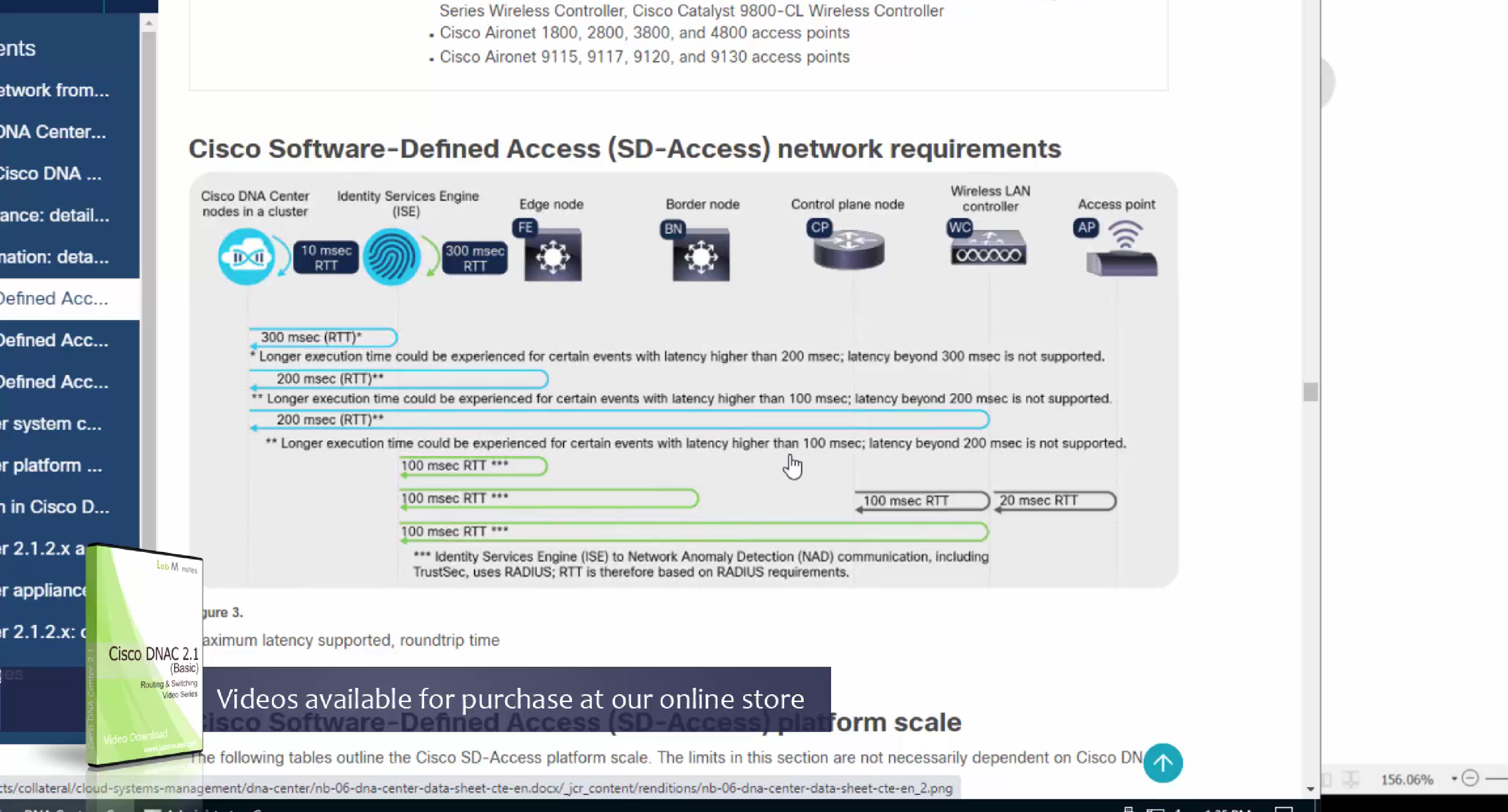
one very important point to keep in mind is that we need is the latency requirements for SDA between DNAC and devices is 100ms and 200ms is kind of pushing
From ISE we only have 100ms to play with anyway
latency requirement between WLC and AP is 20ms
Within the cluster of DNAC (which includes ISE as policy node) needs to be 10 msec
another requirement is that all devices be configured with SSH access with credentials that were configured in DNAC with full access and not just enable prompt
Device controllability during discovery means that configuration changes will be done during inventory / discovery or when device is associated to site, it is enabled by default
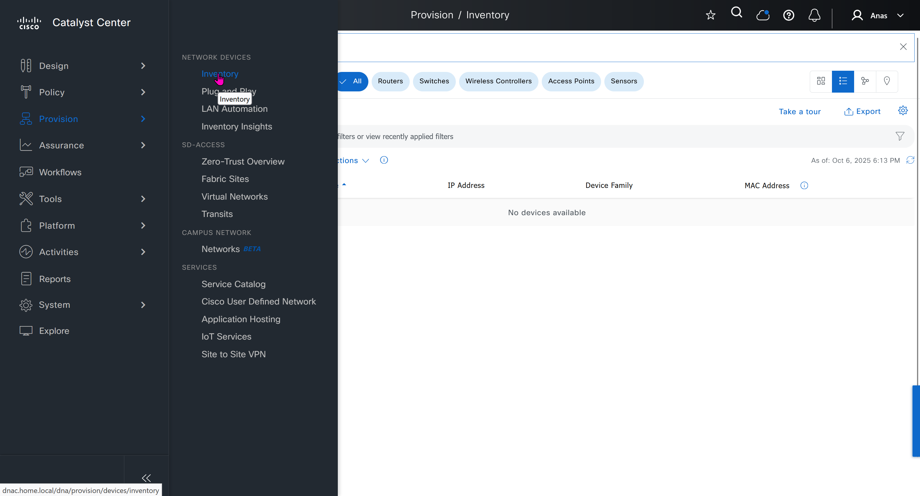
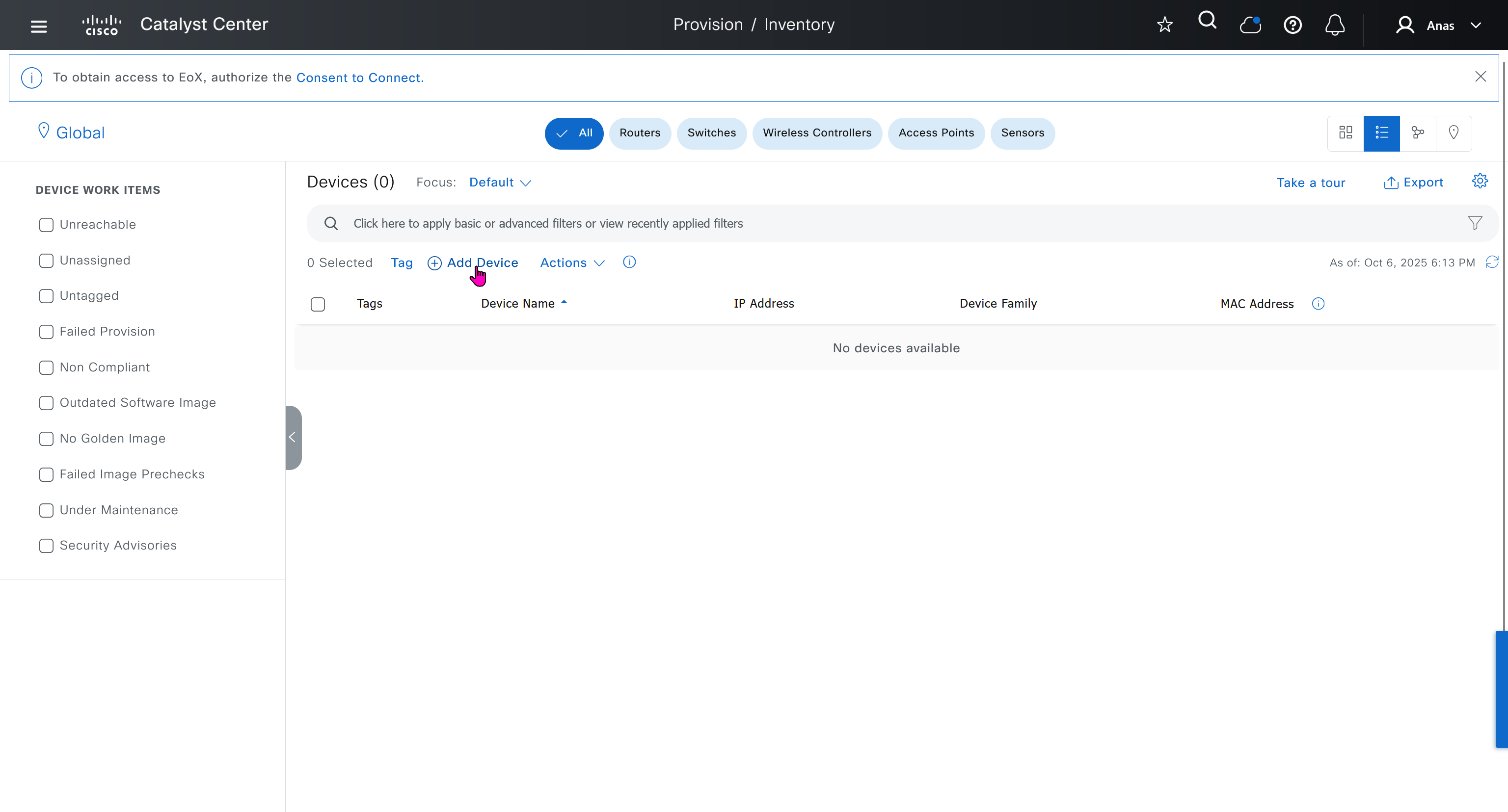
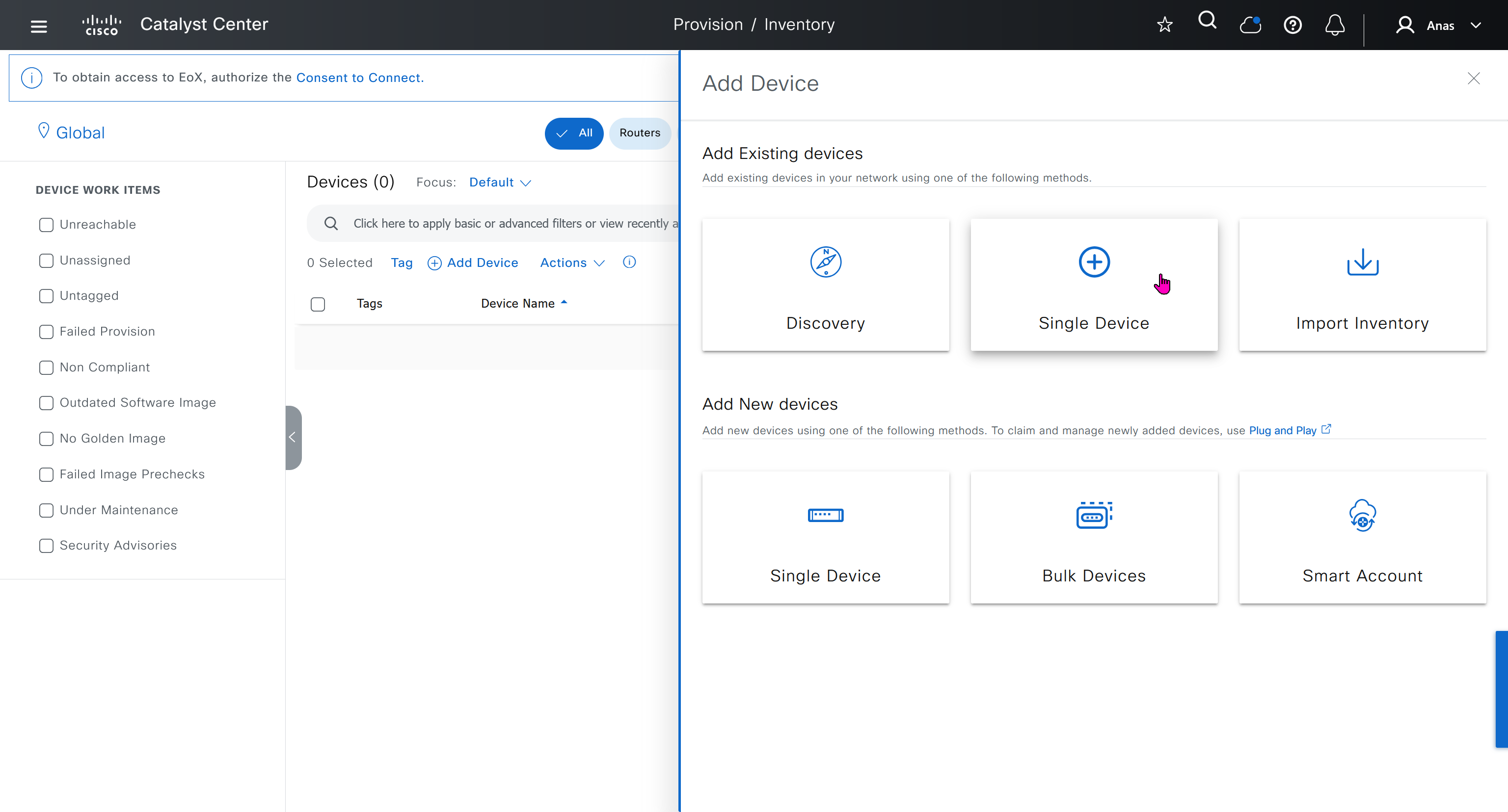
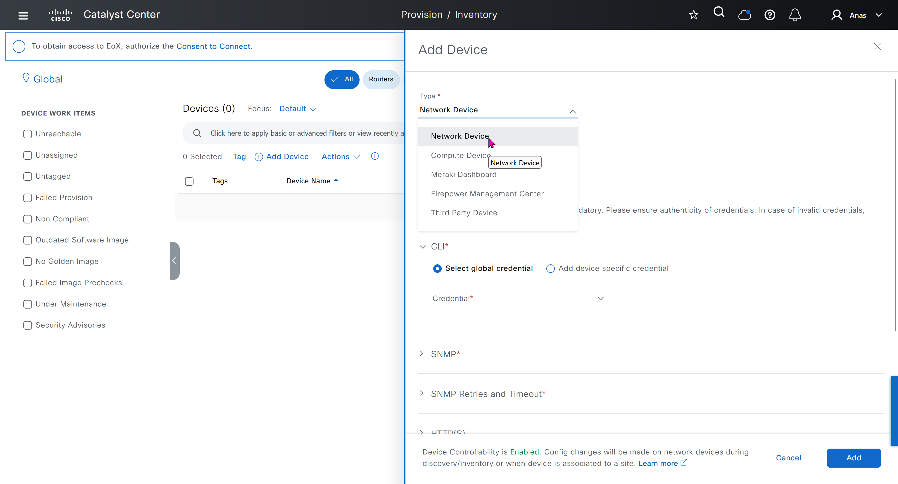
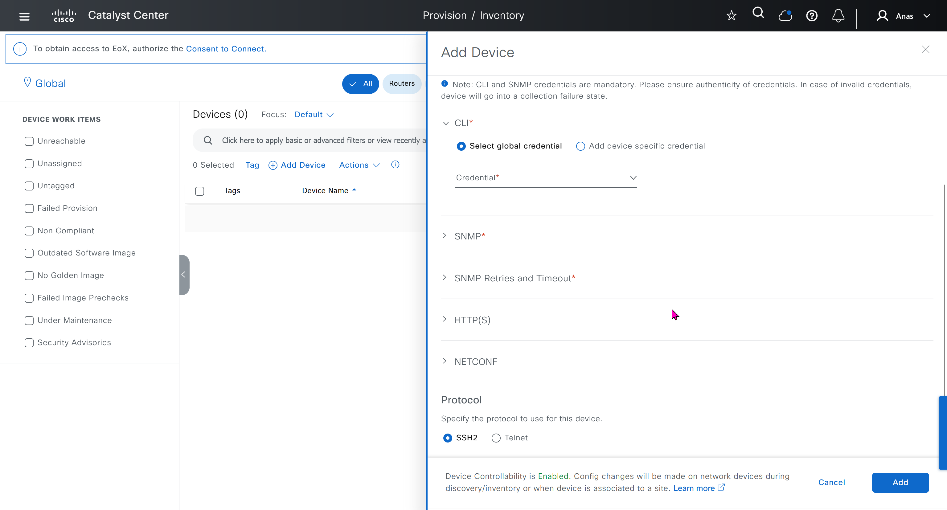

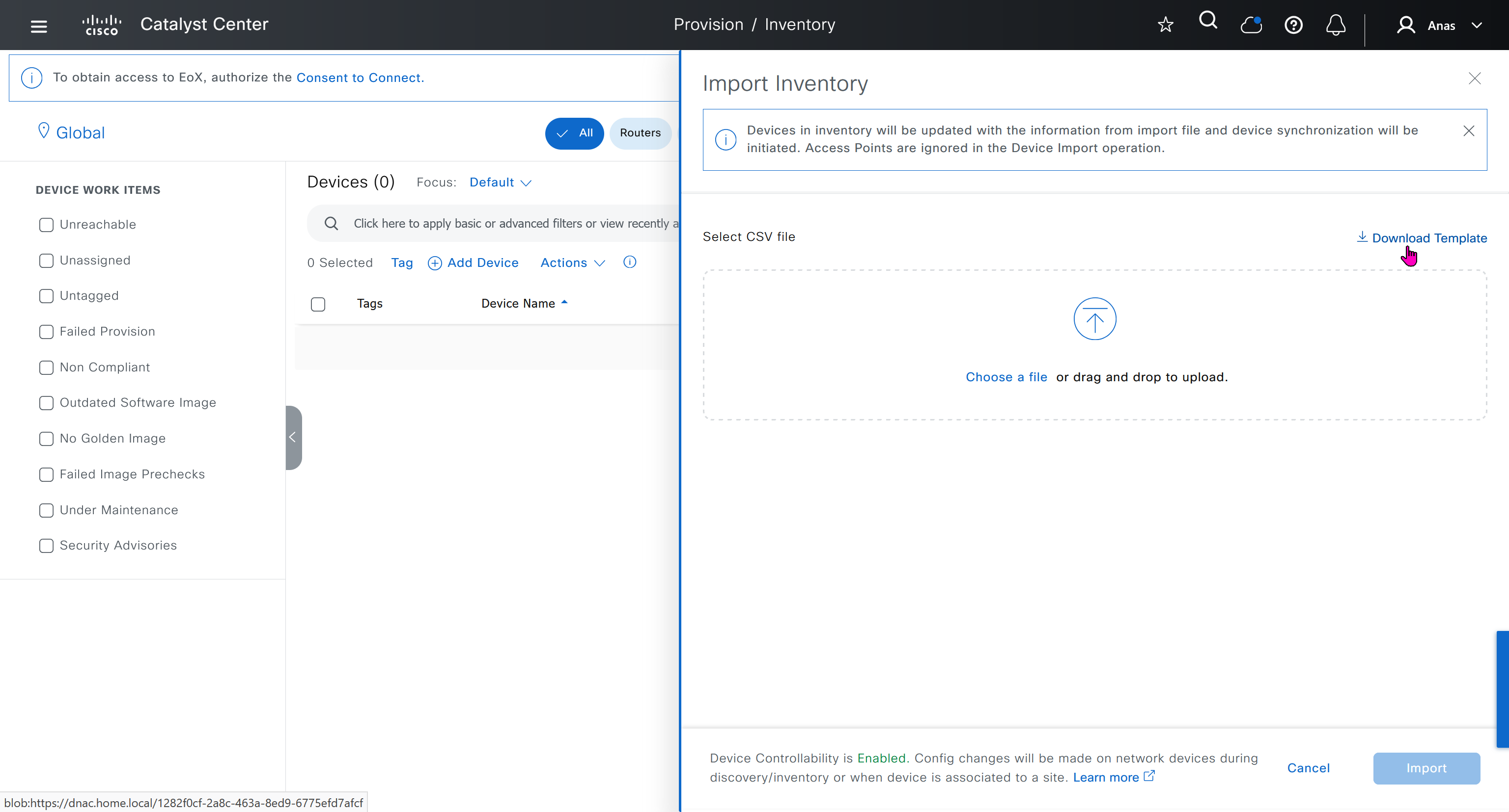

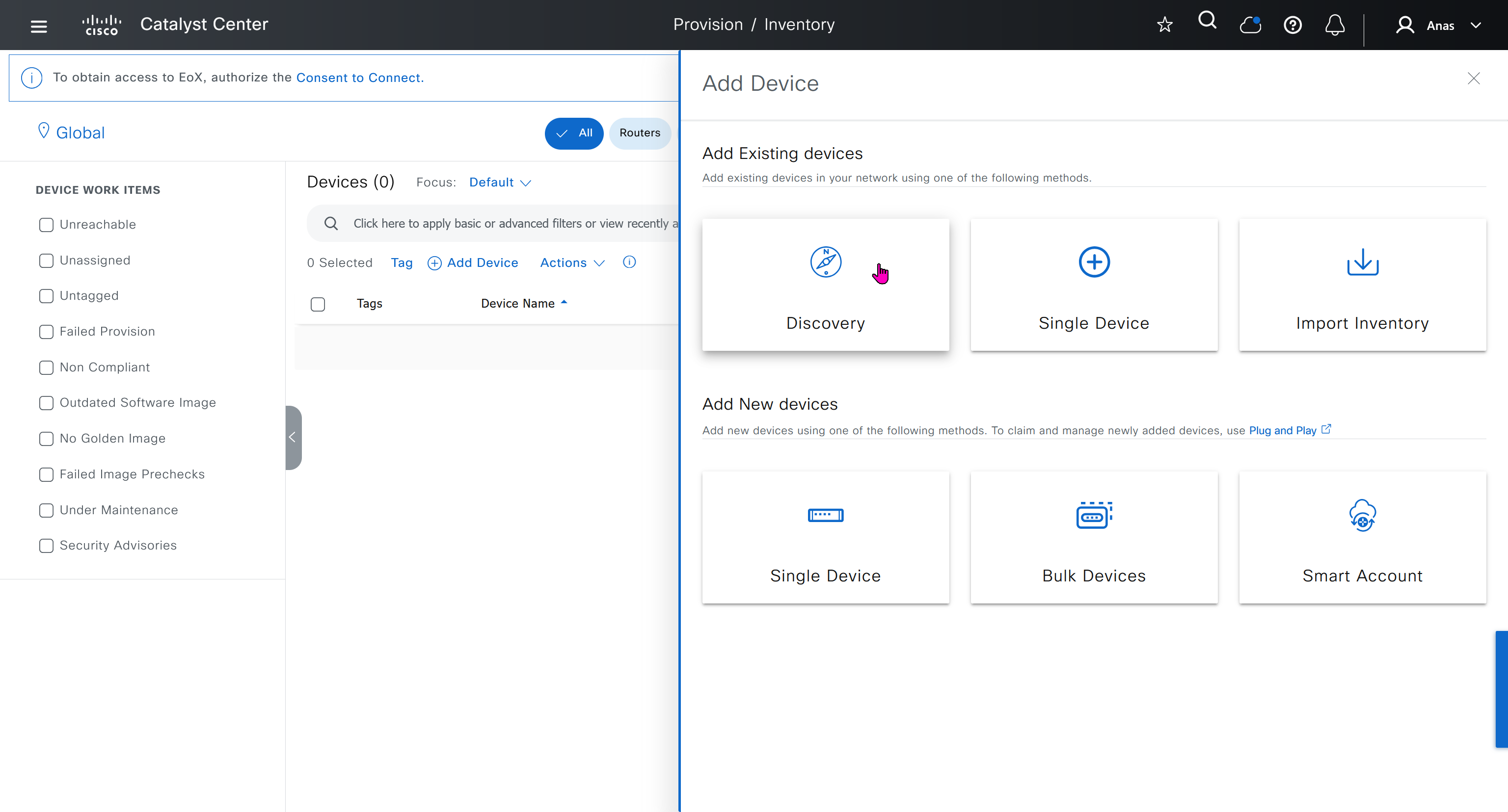
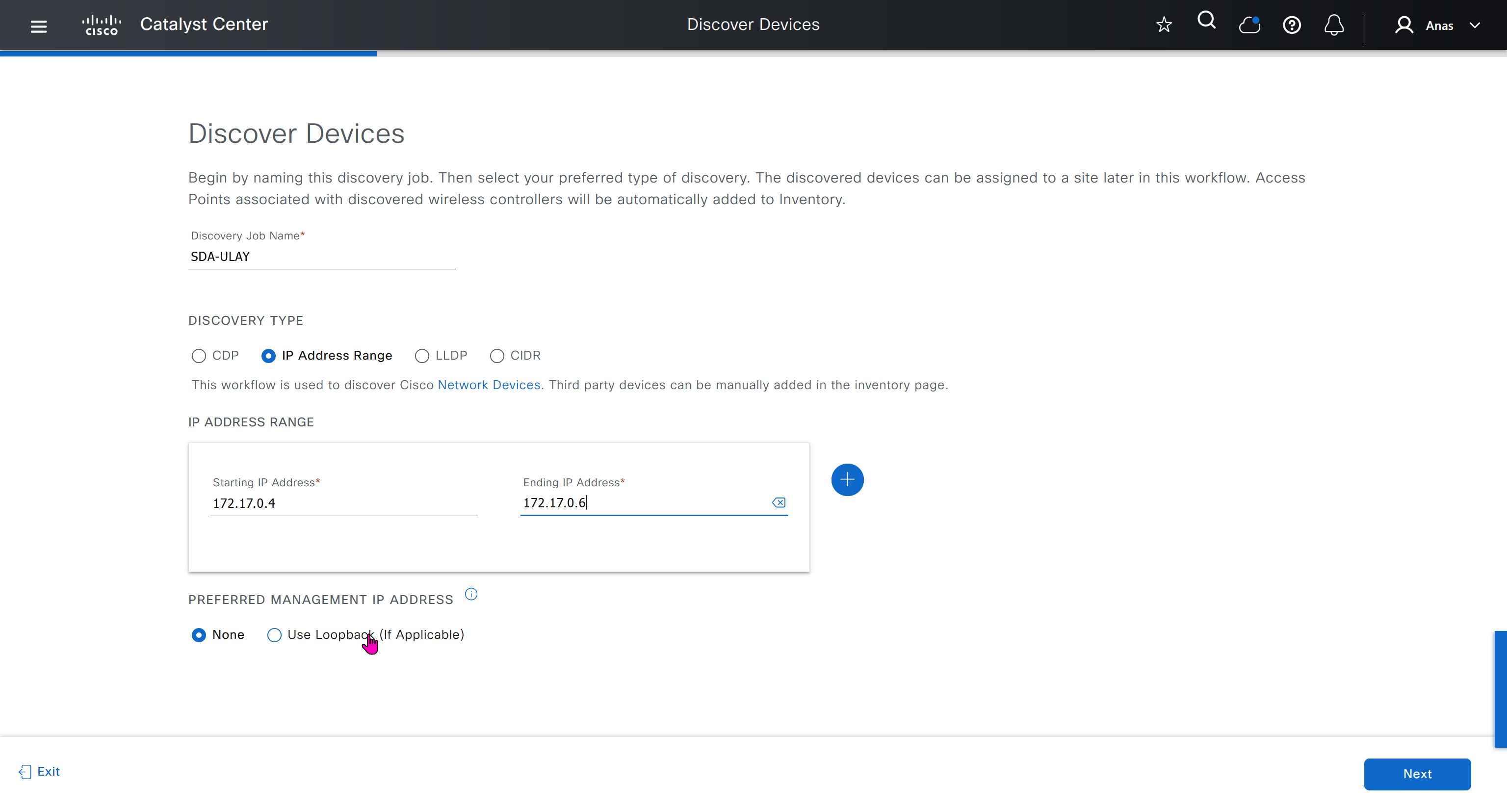
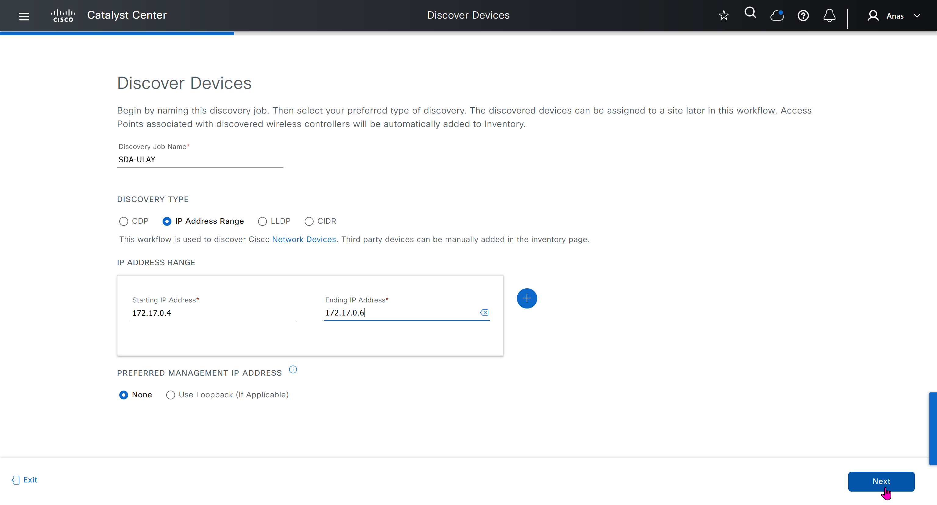

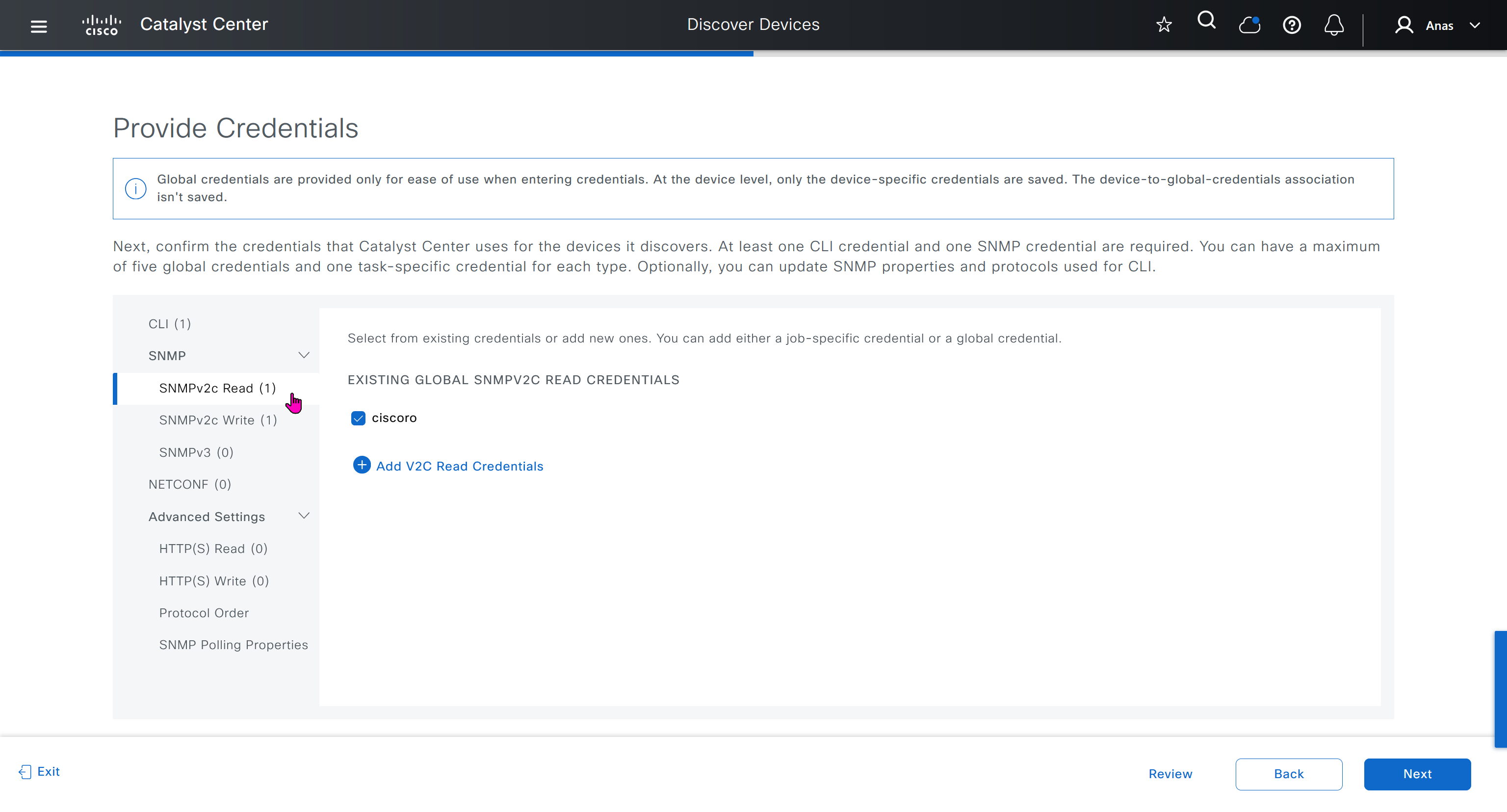


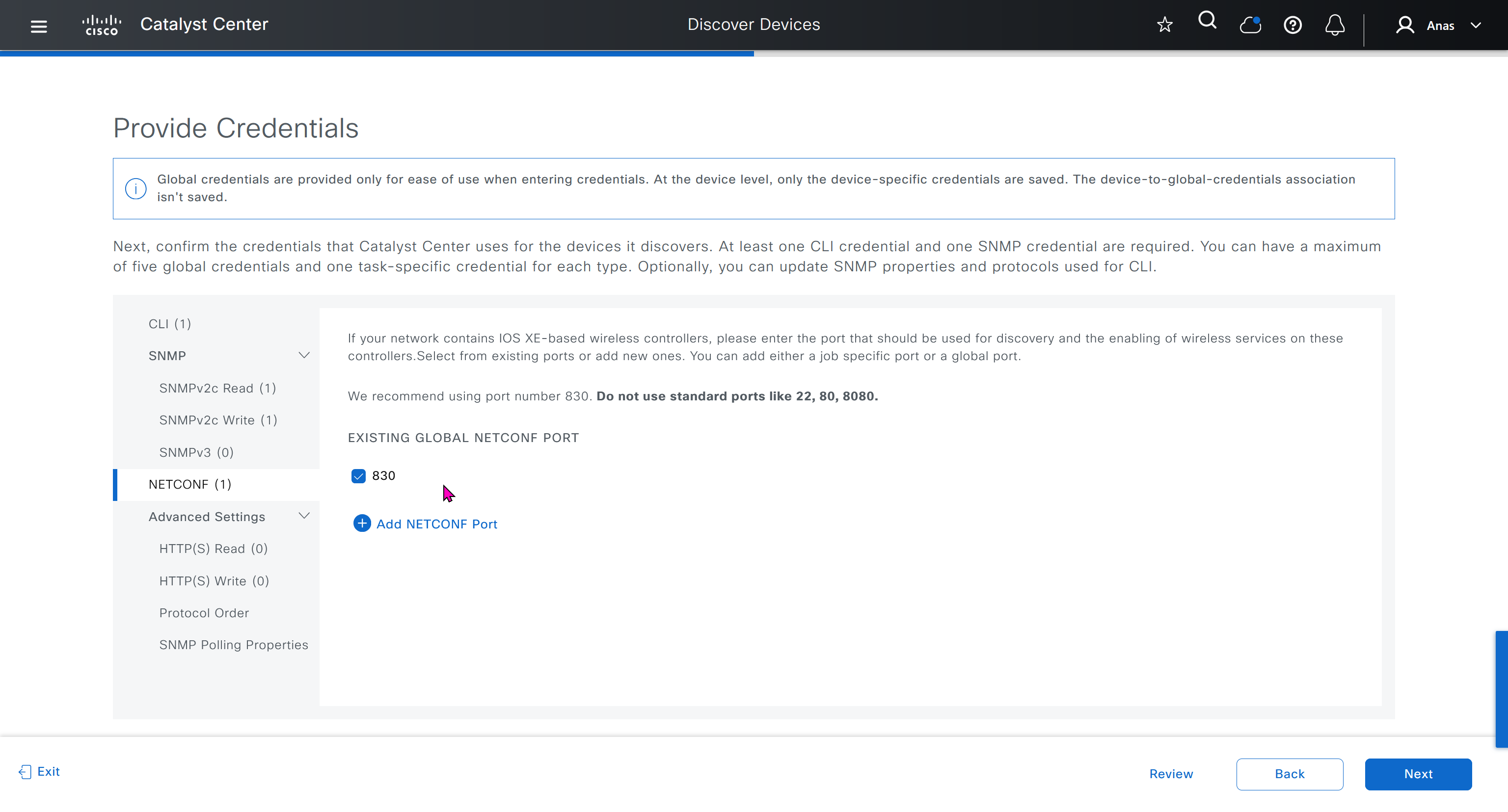
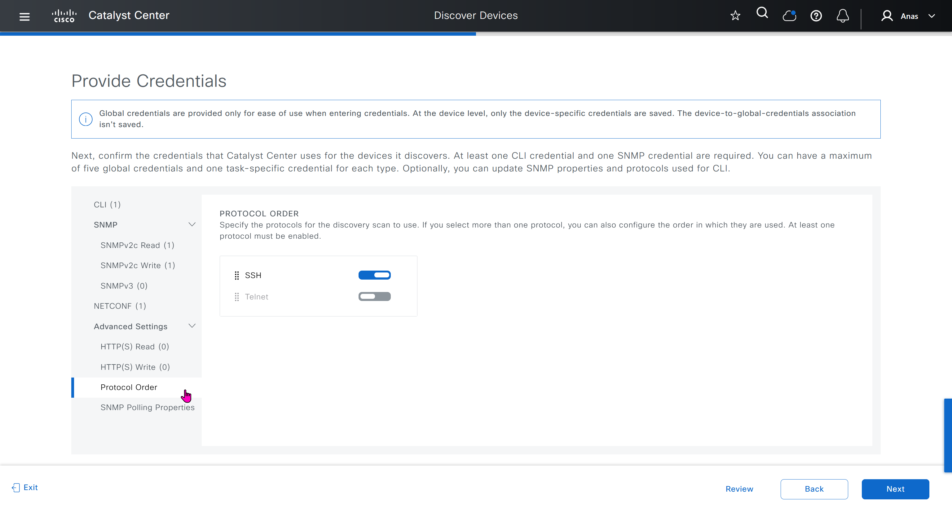
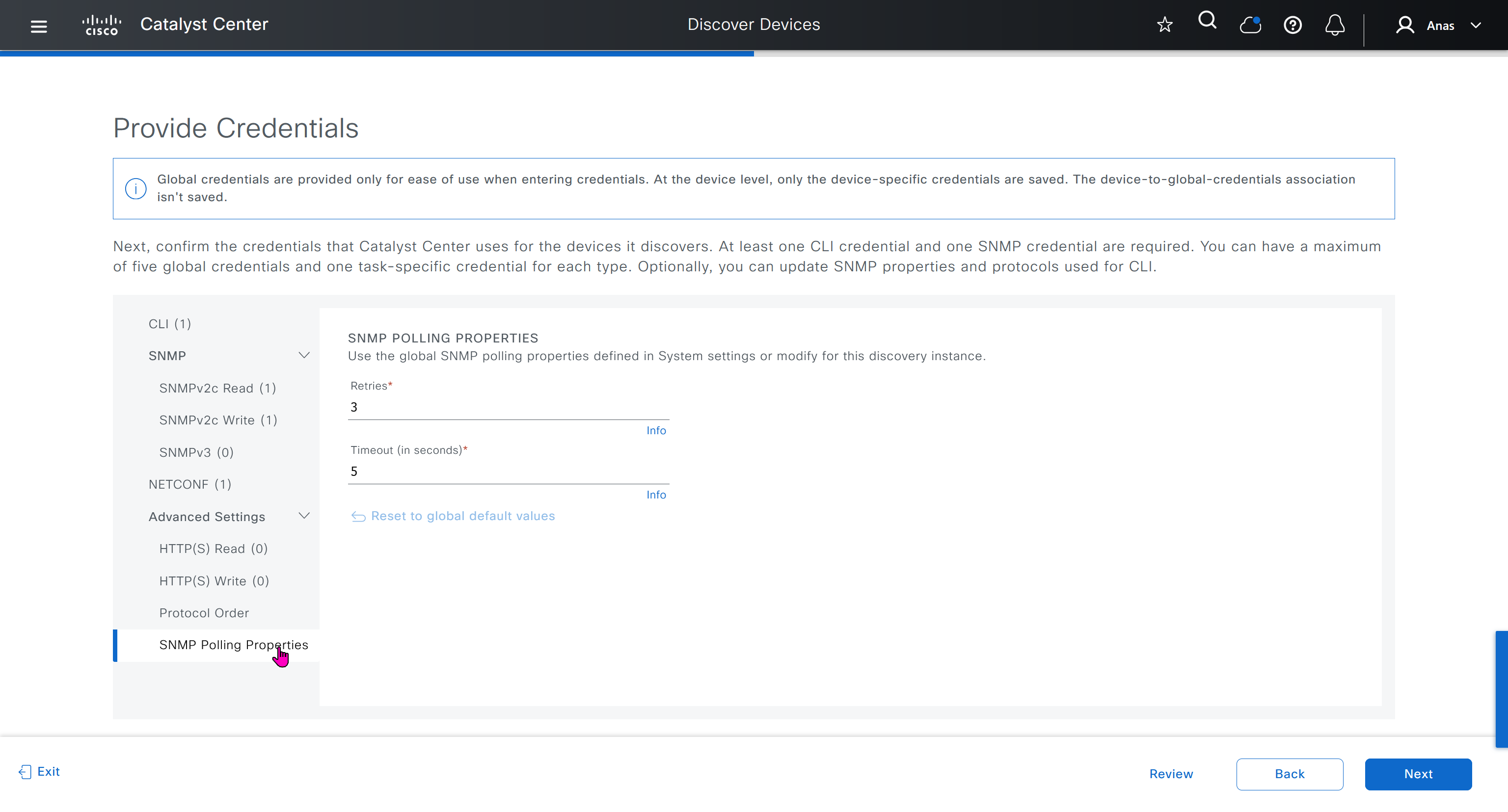
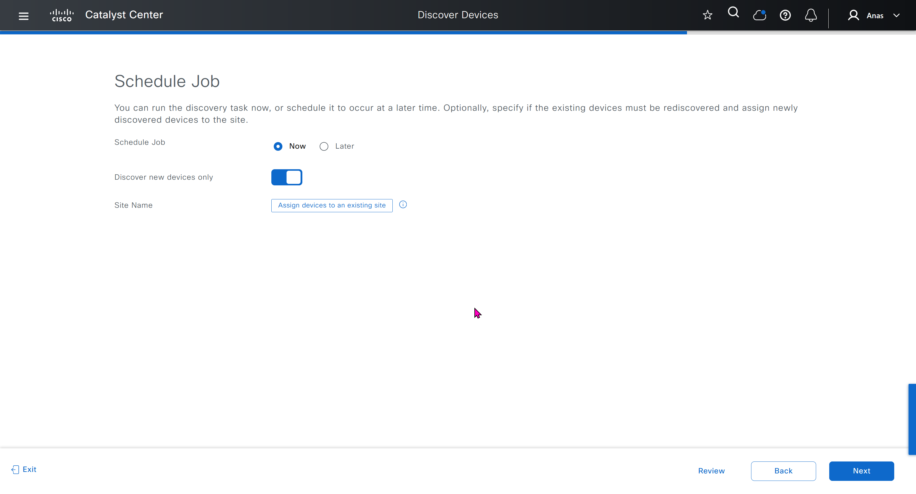

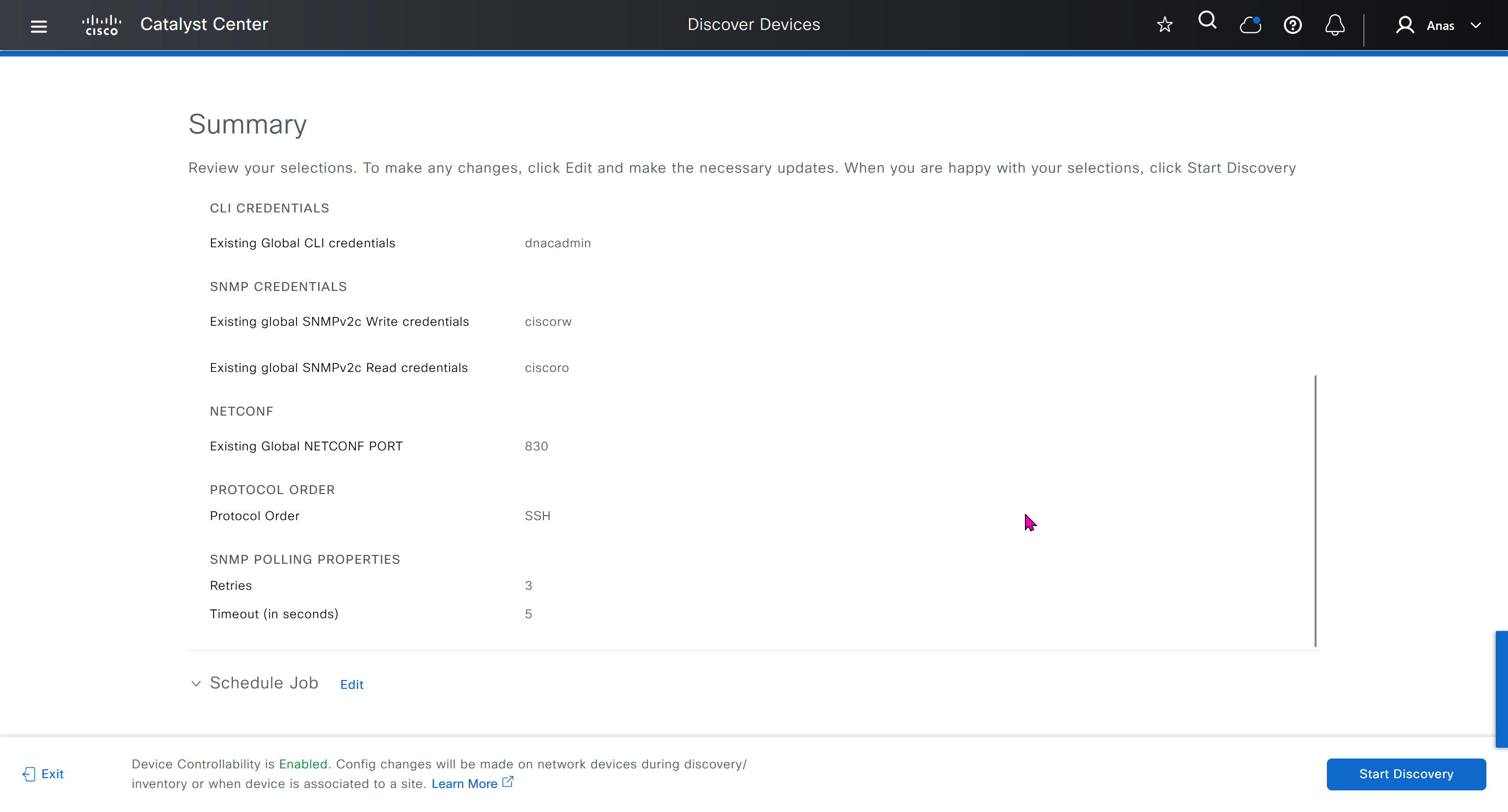
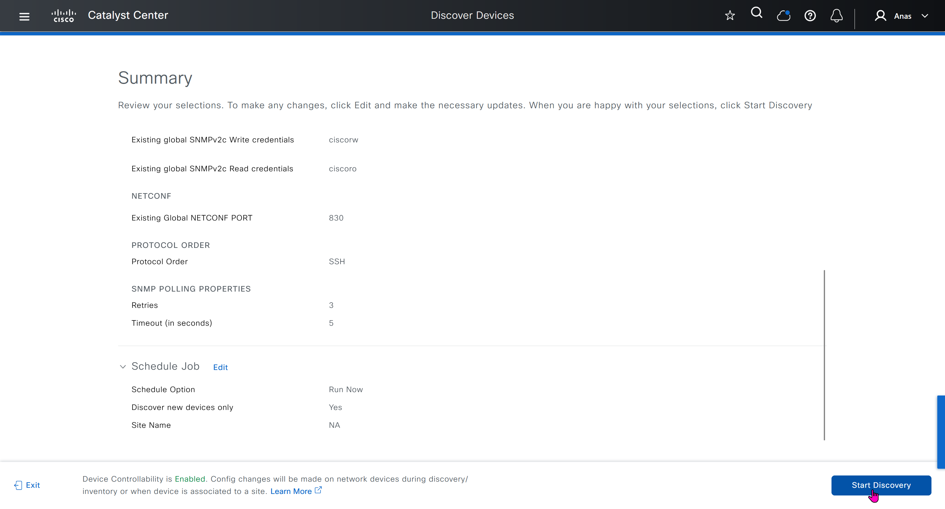
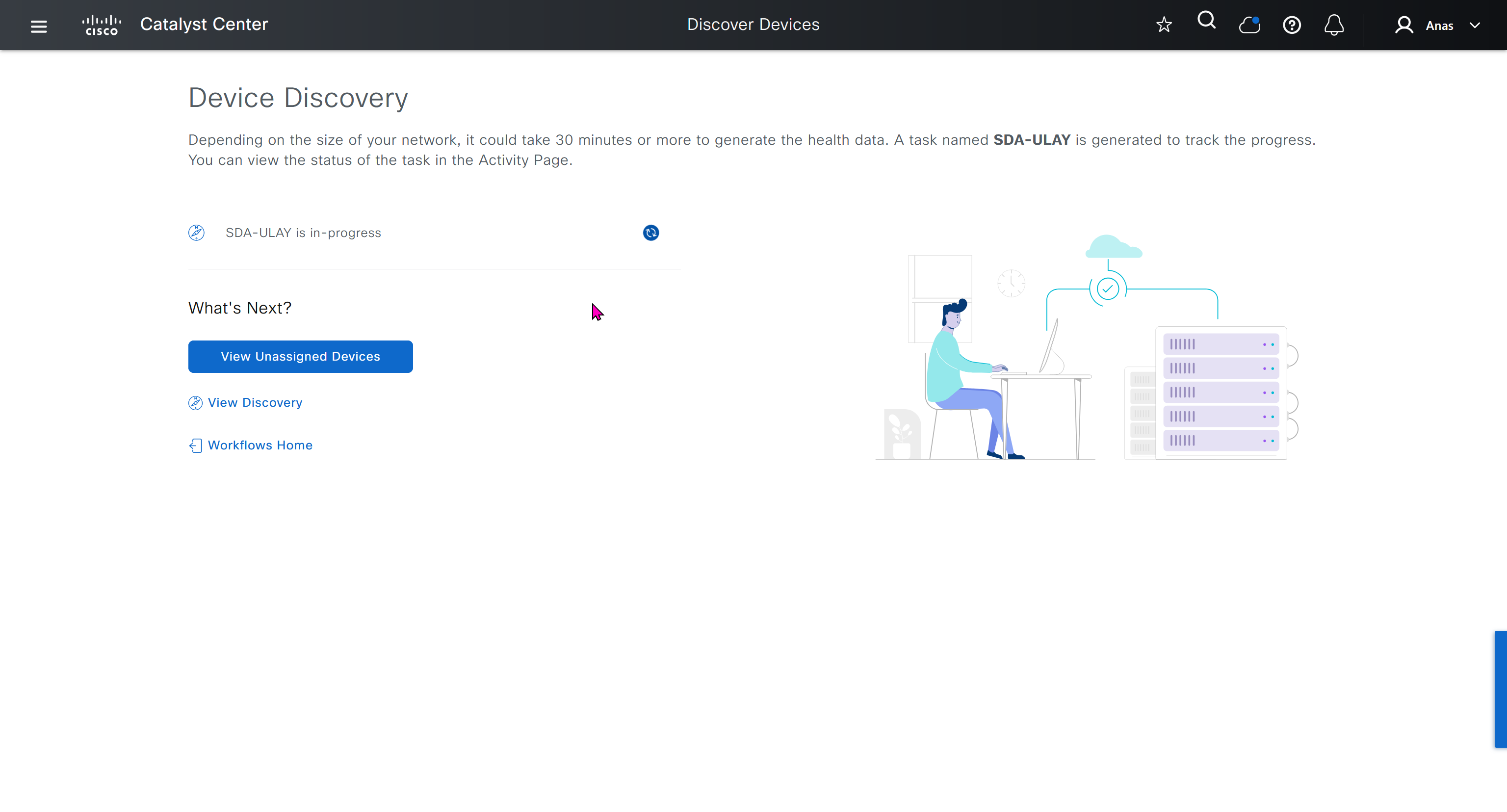
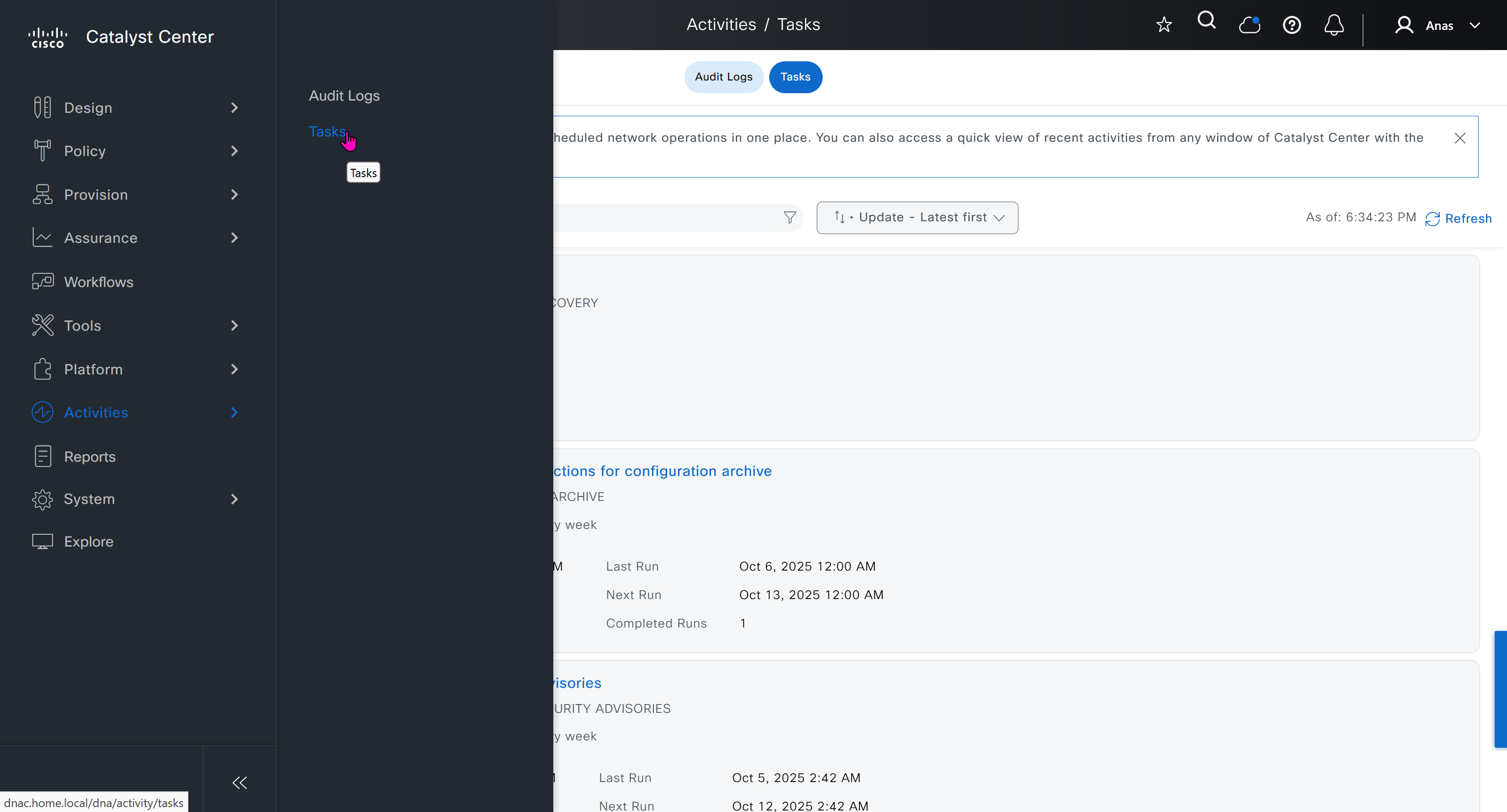
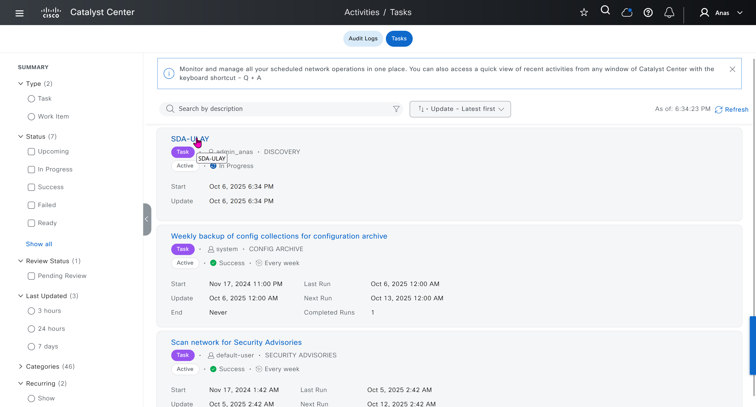

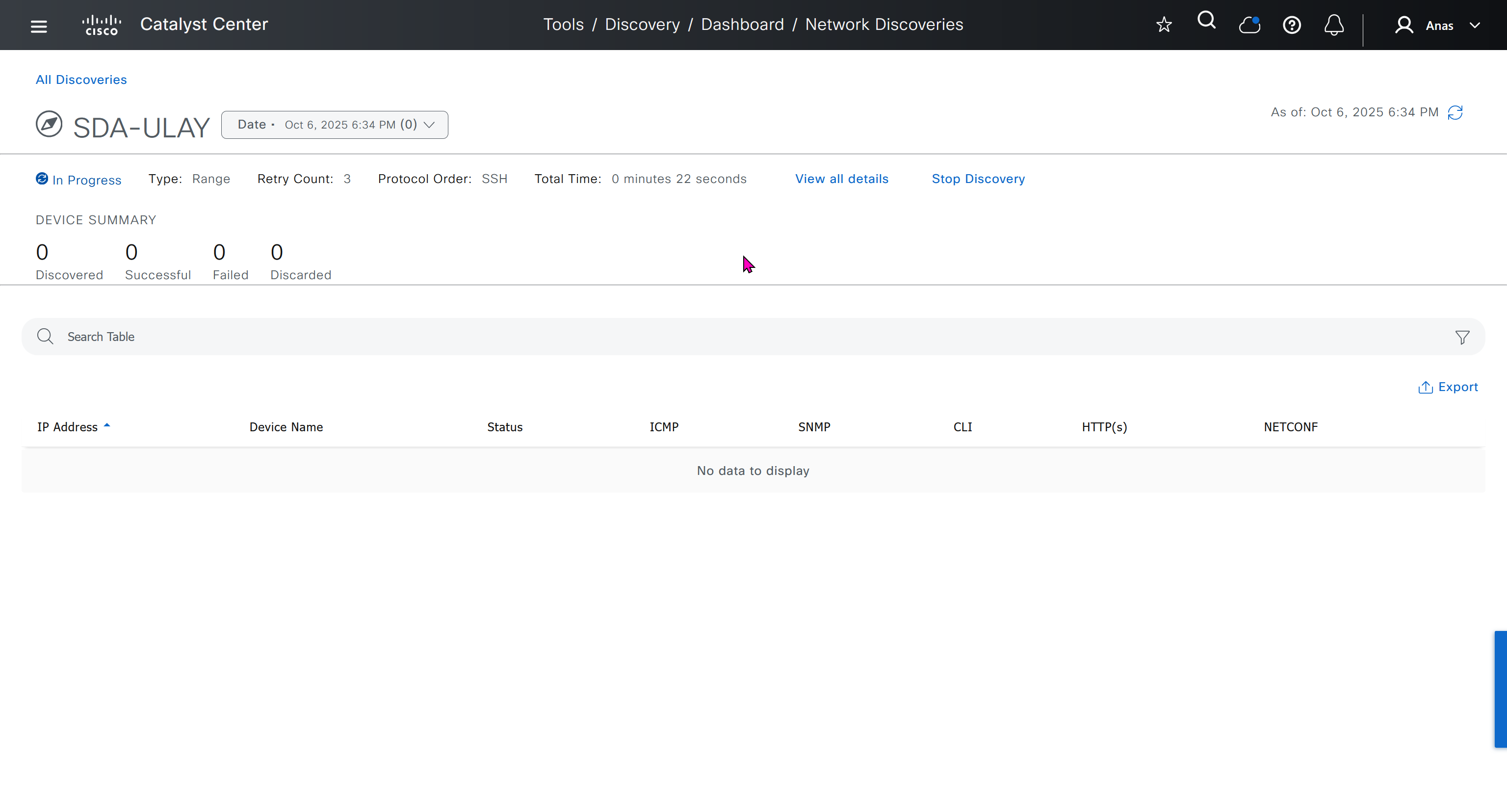
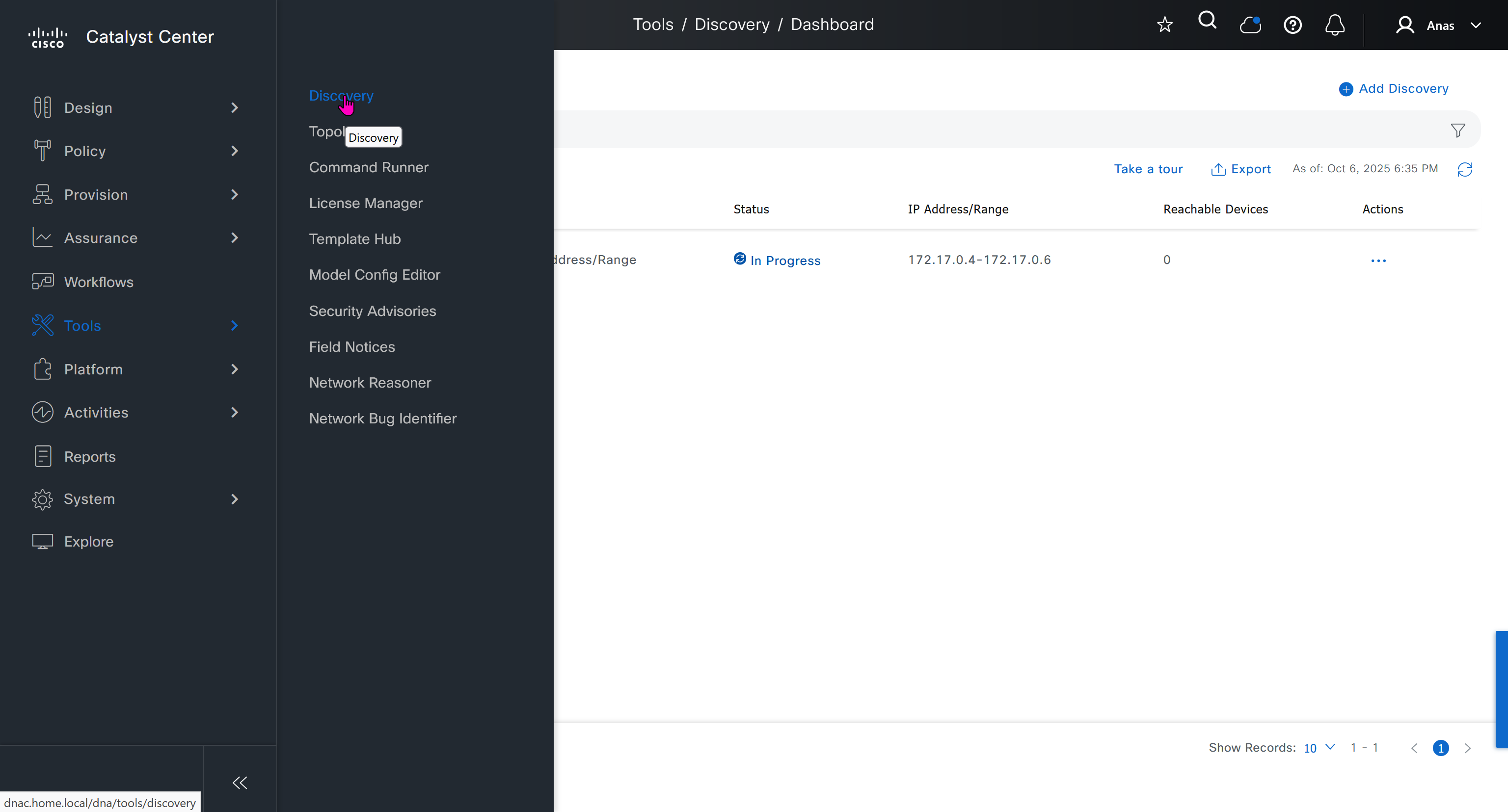
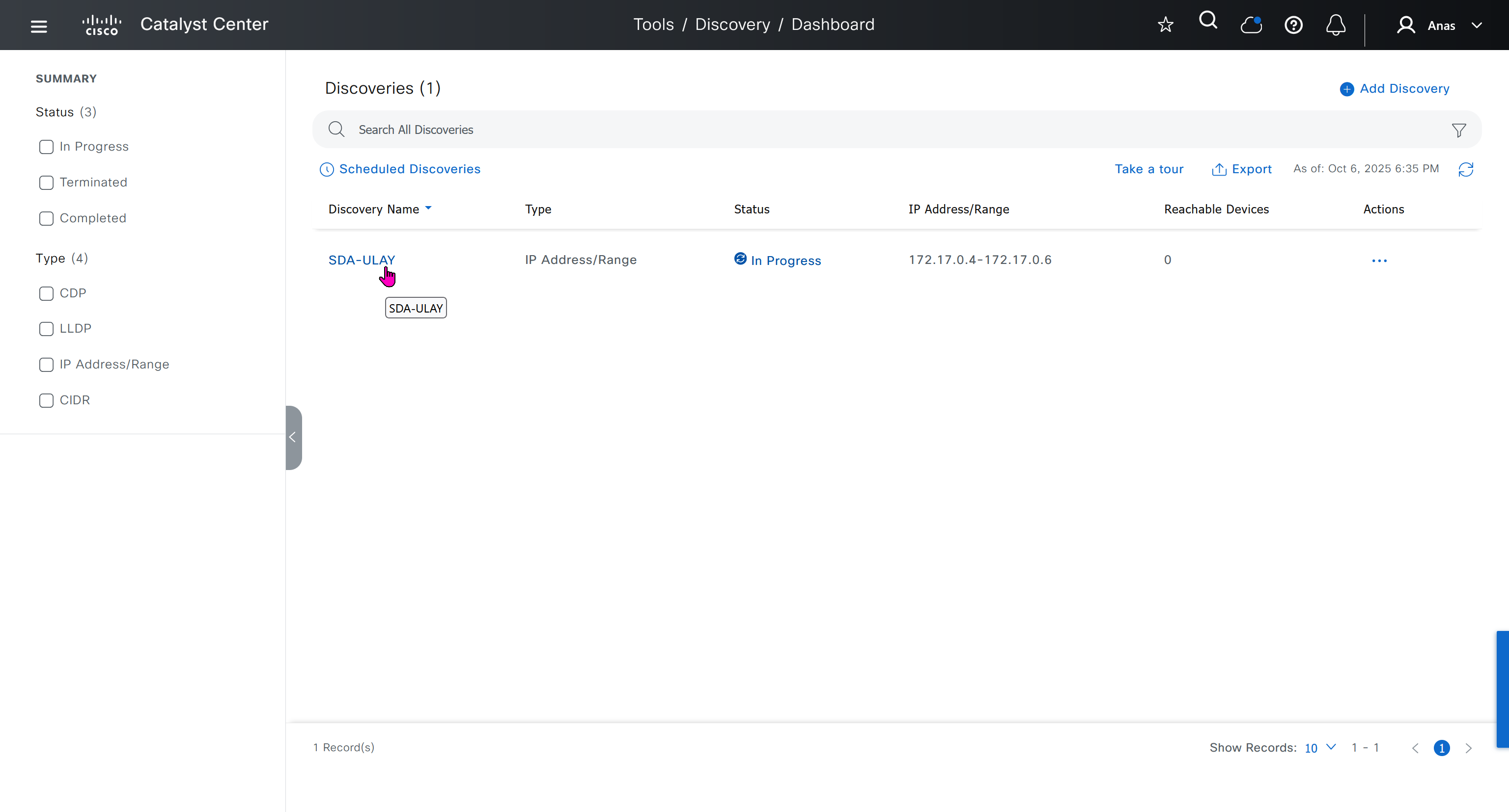
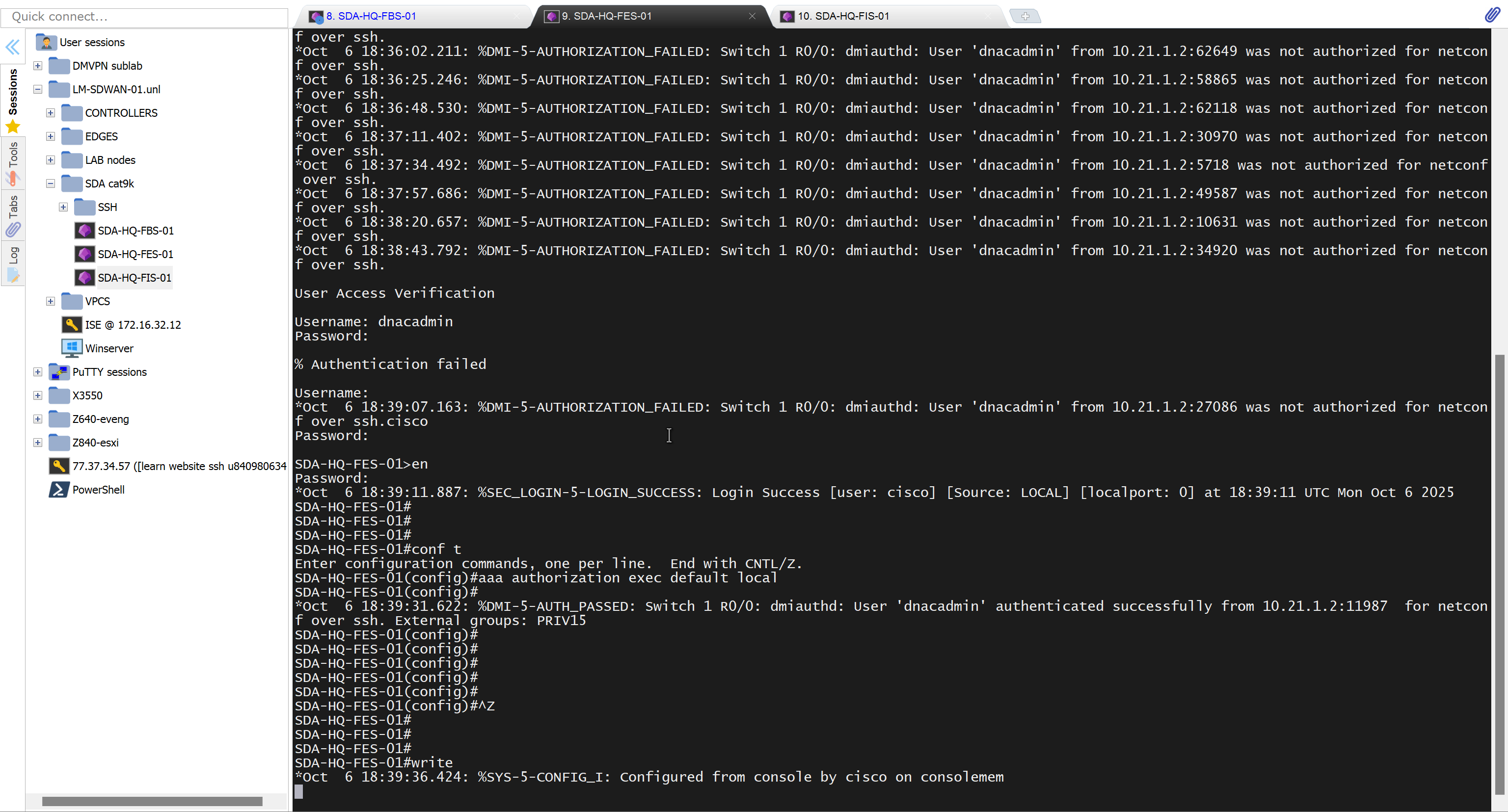

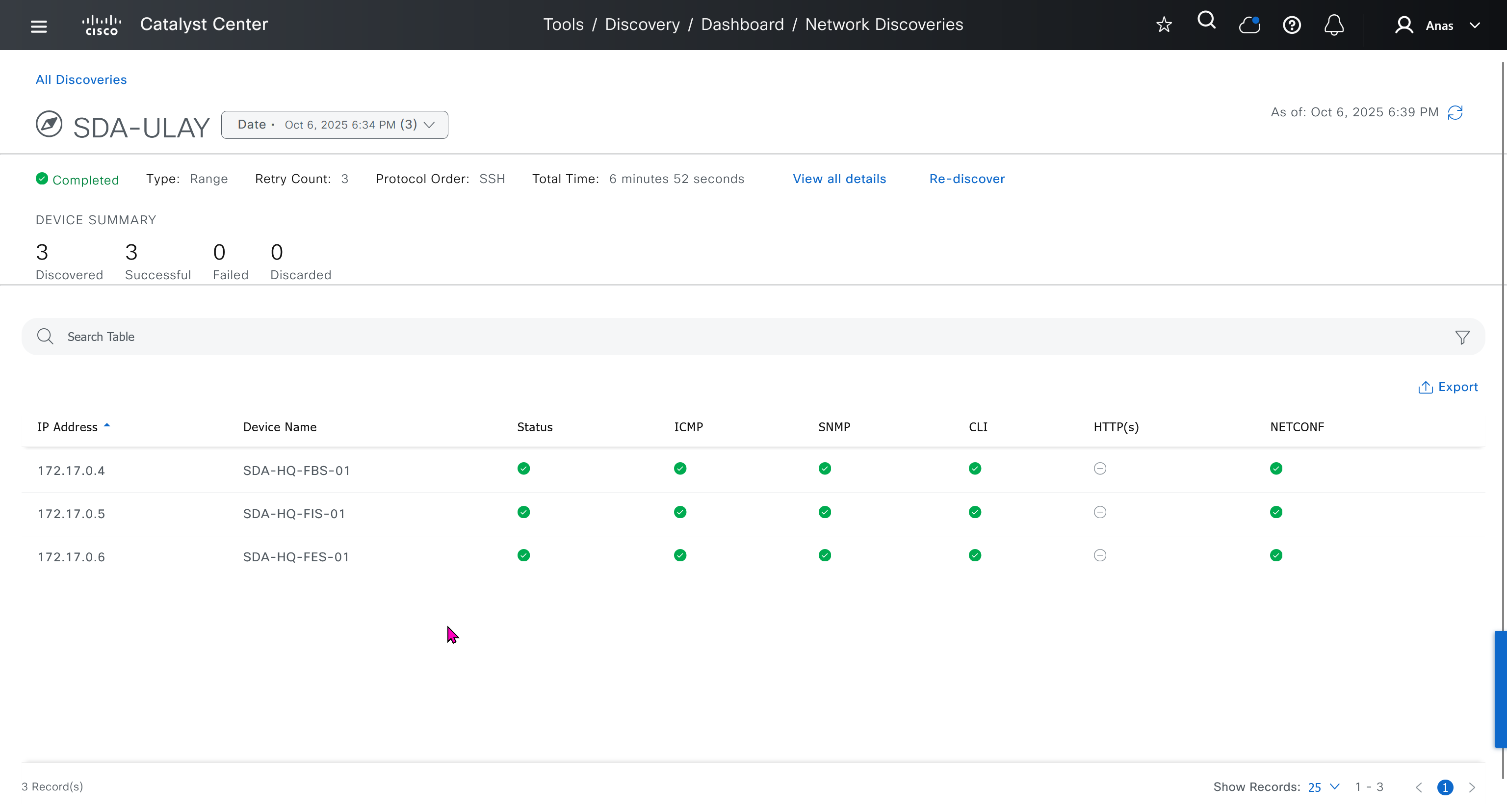

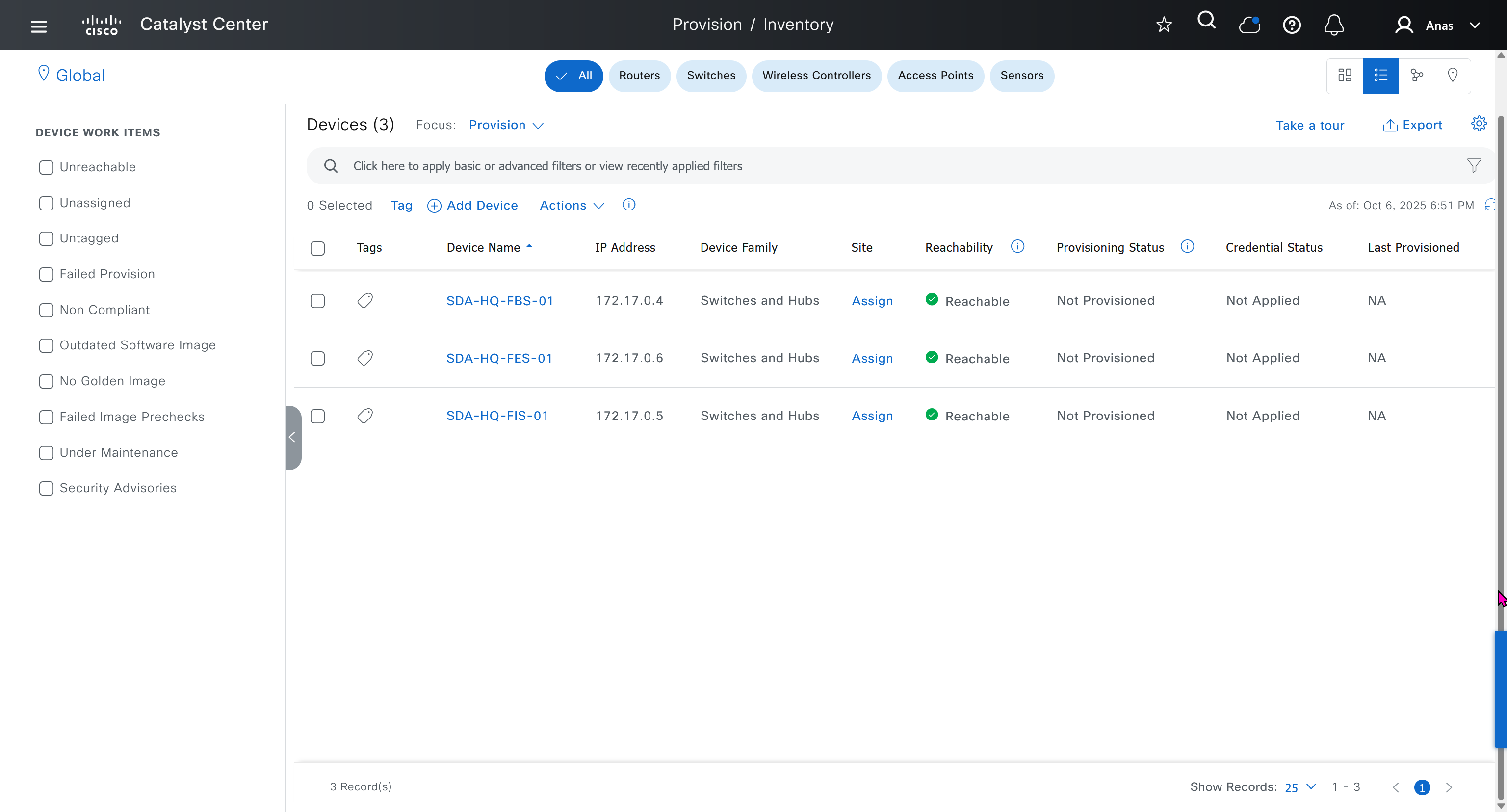
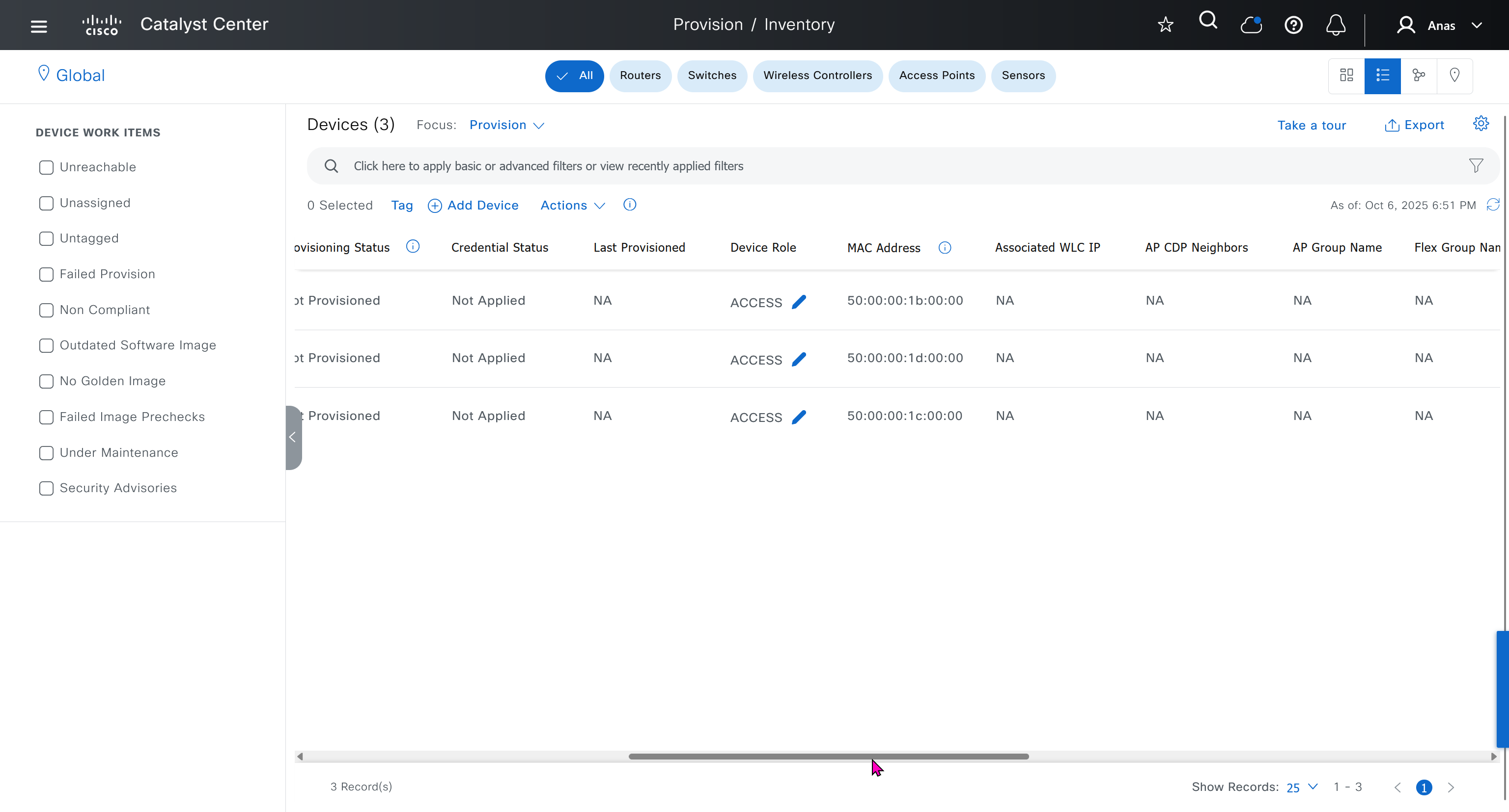
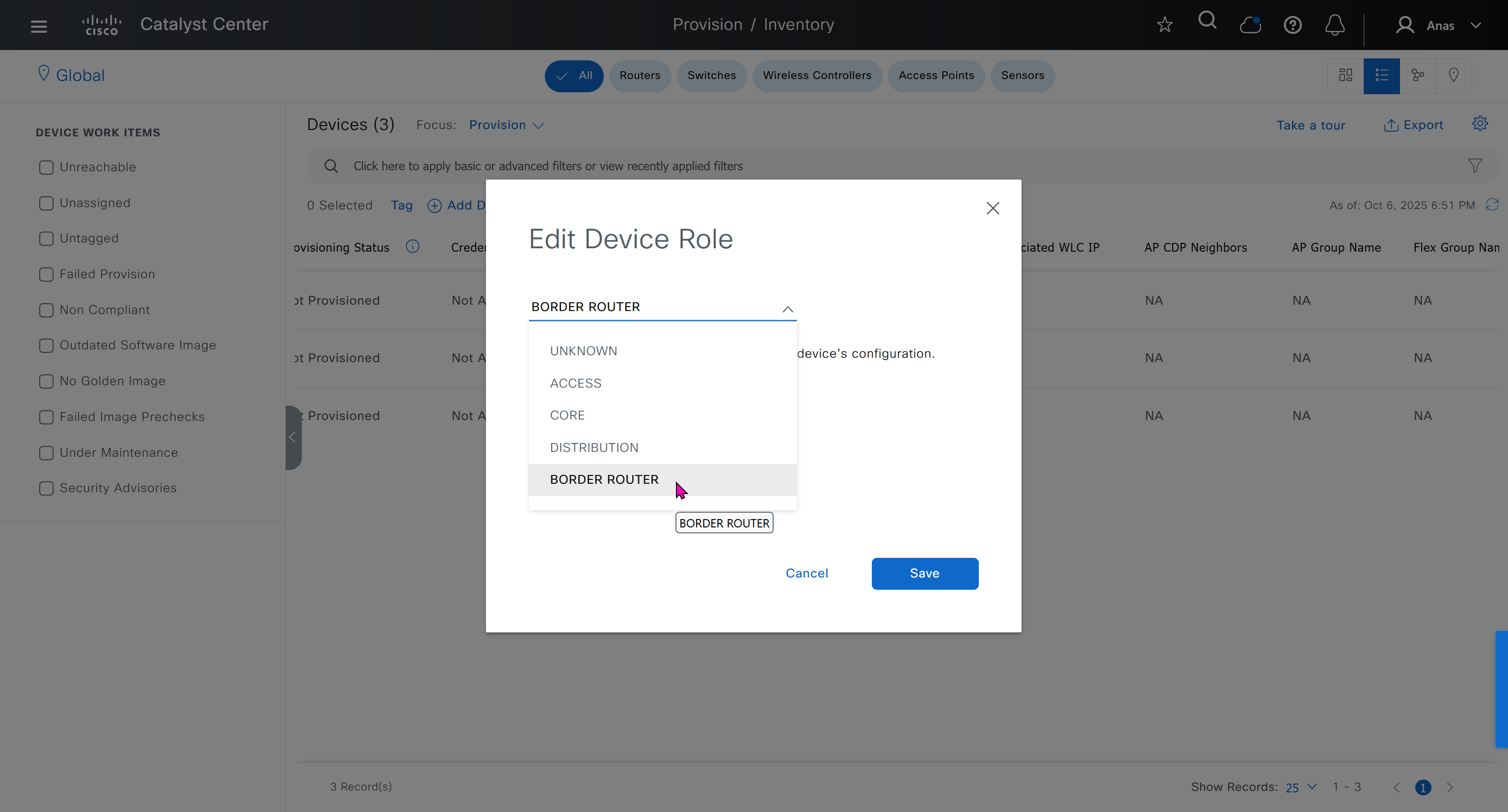
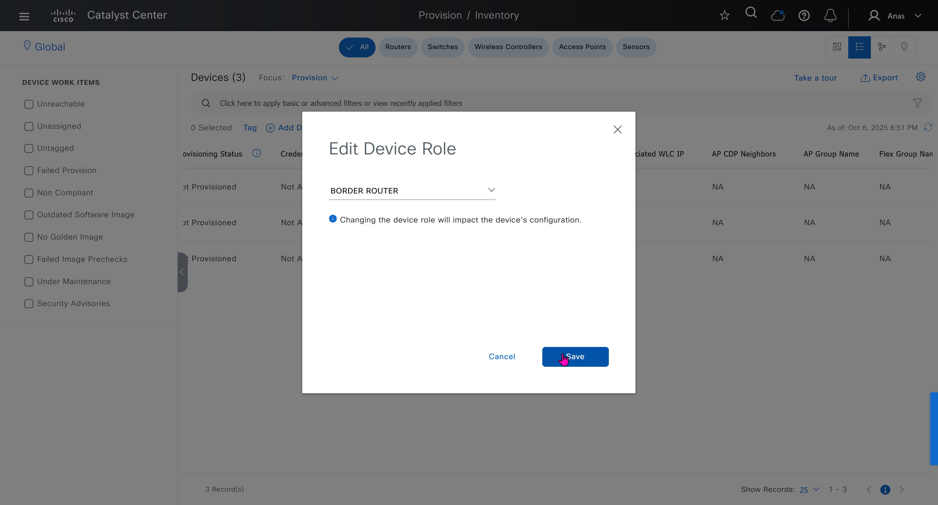
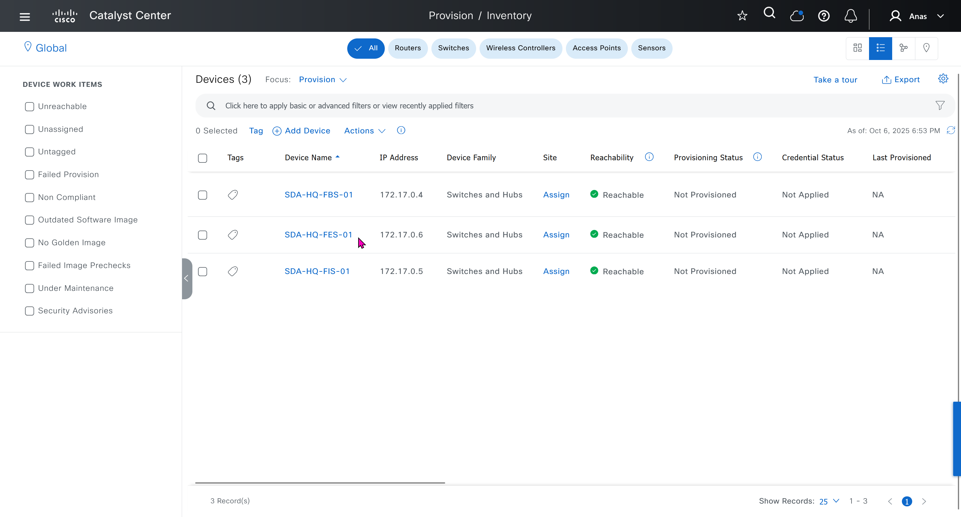


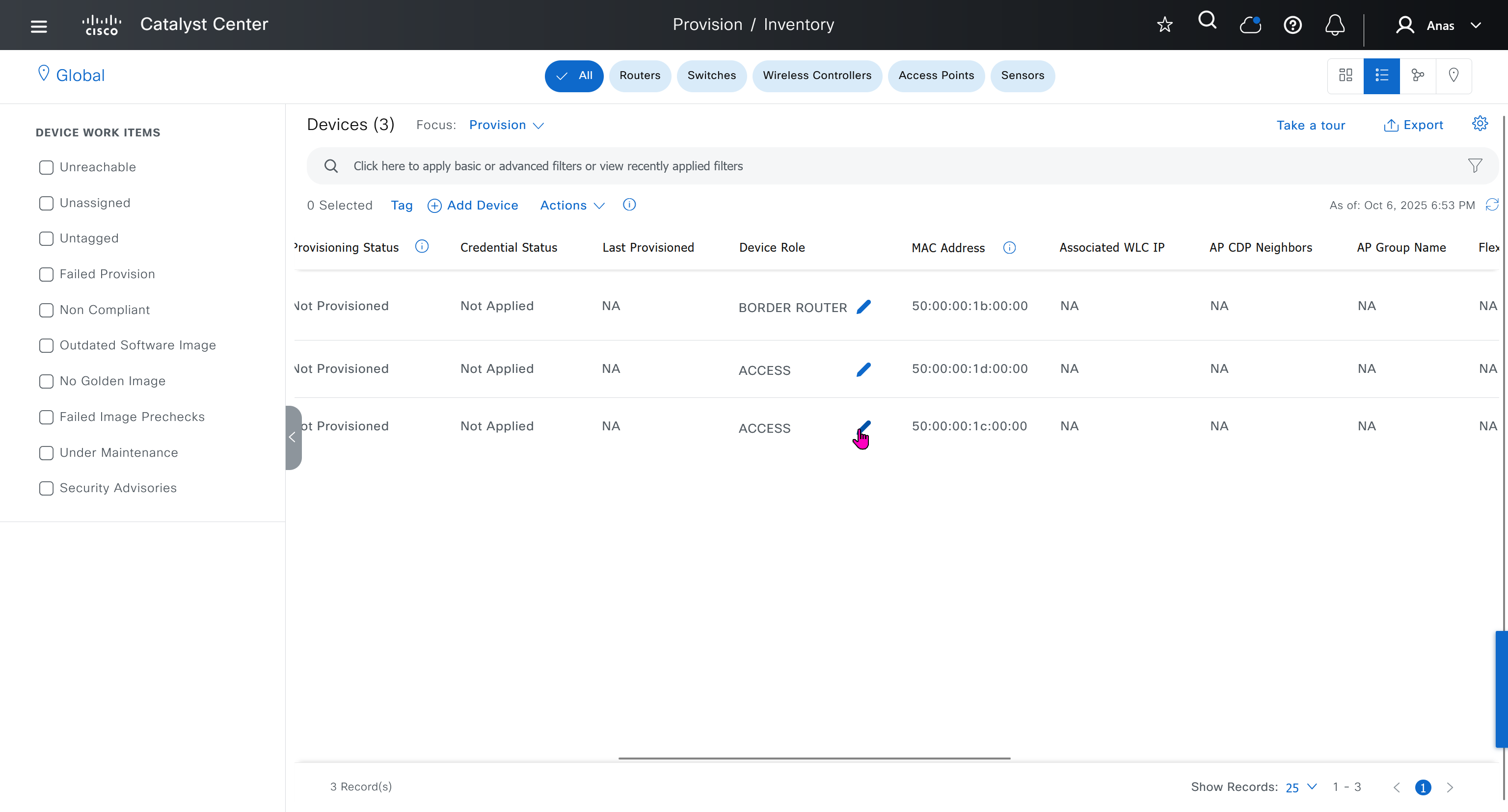

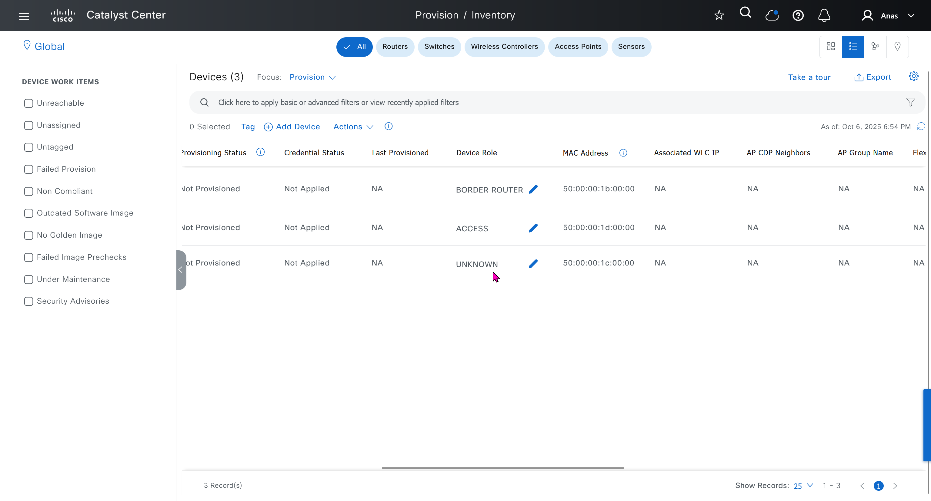
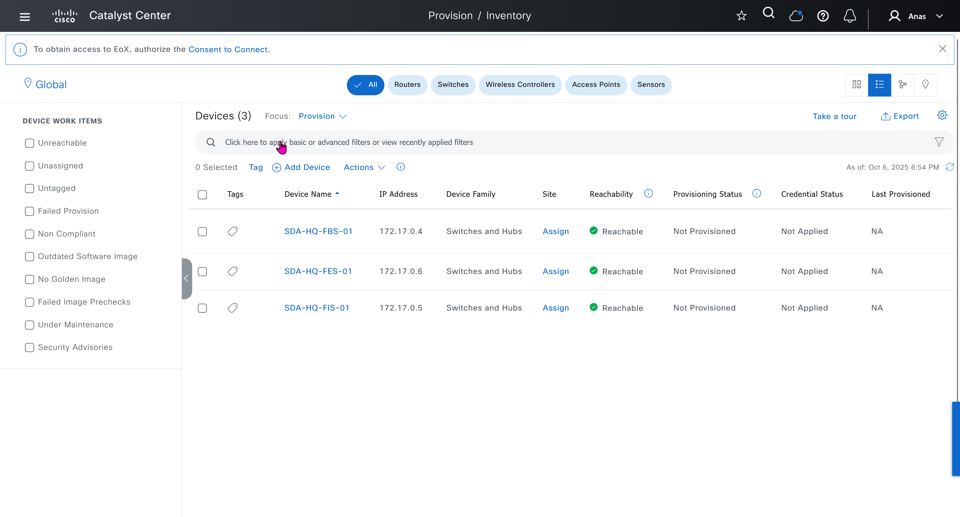
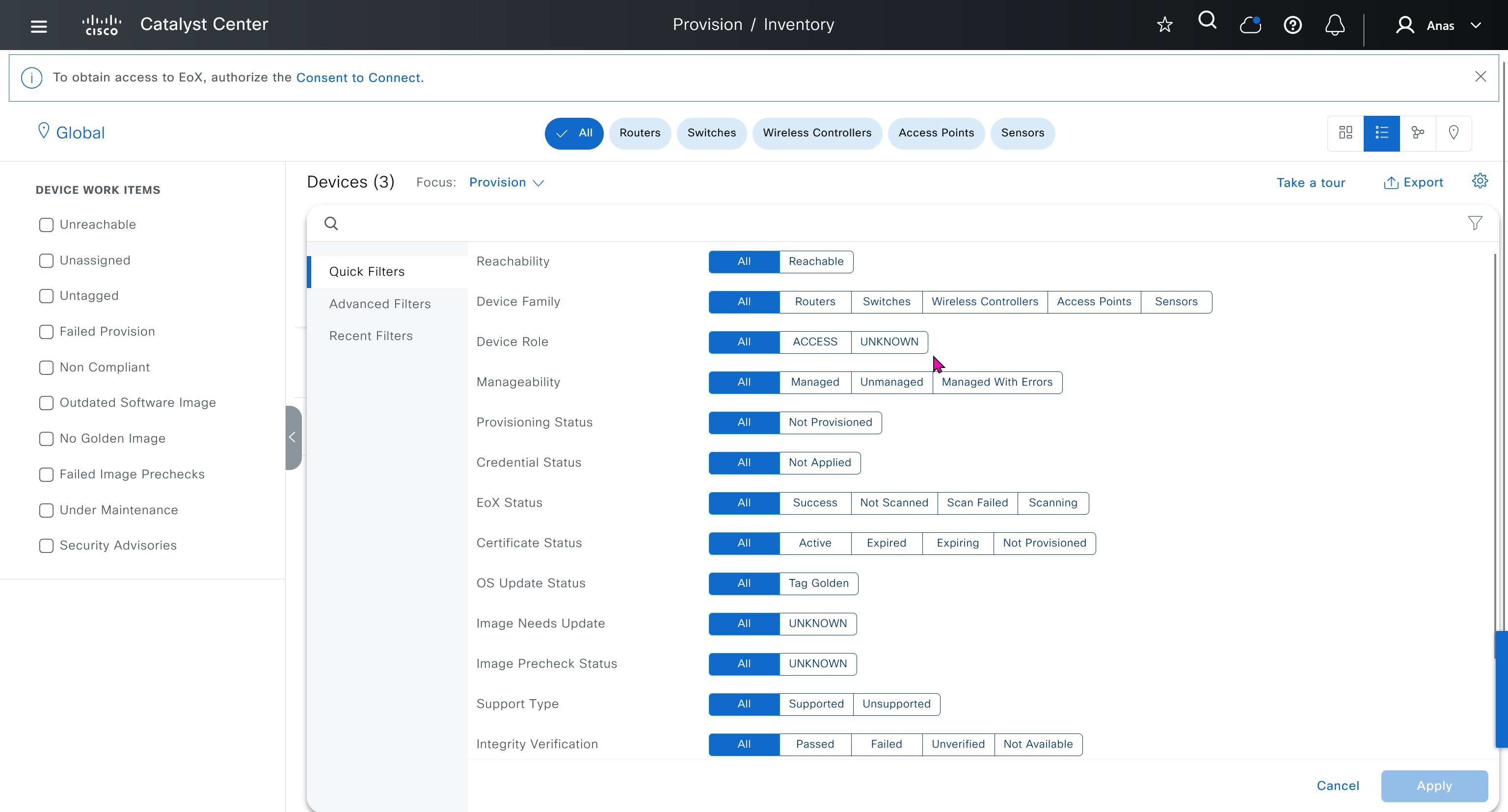
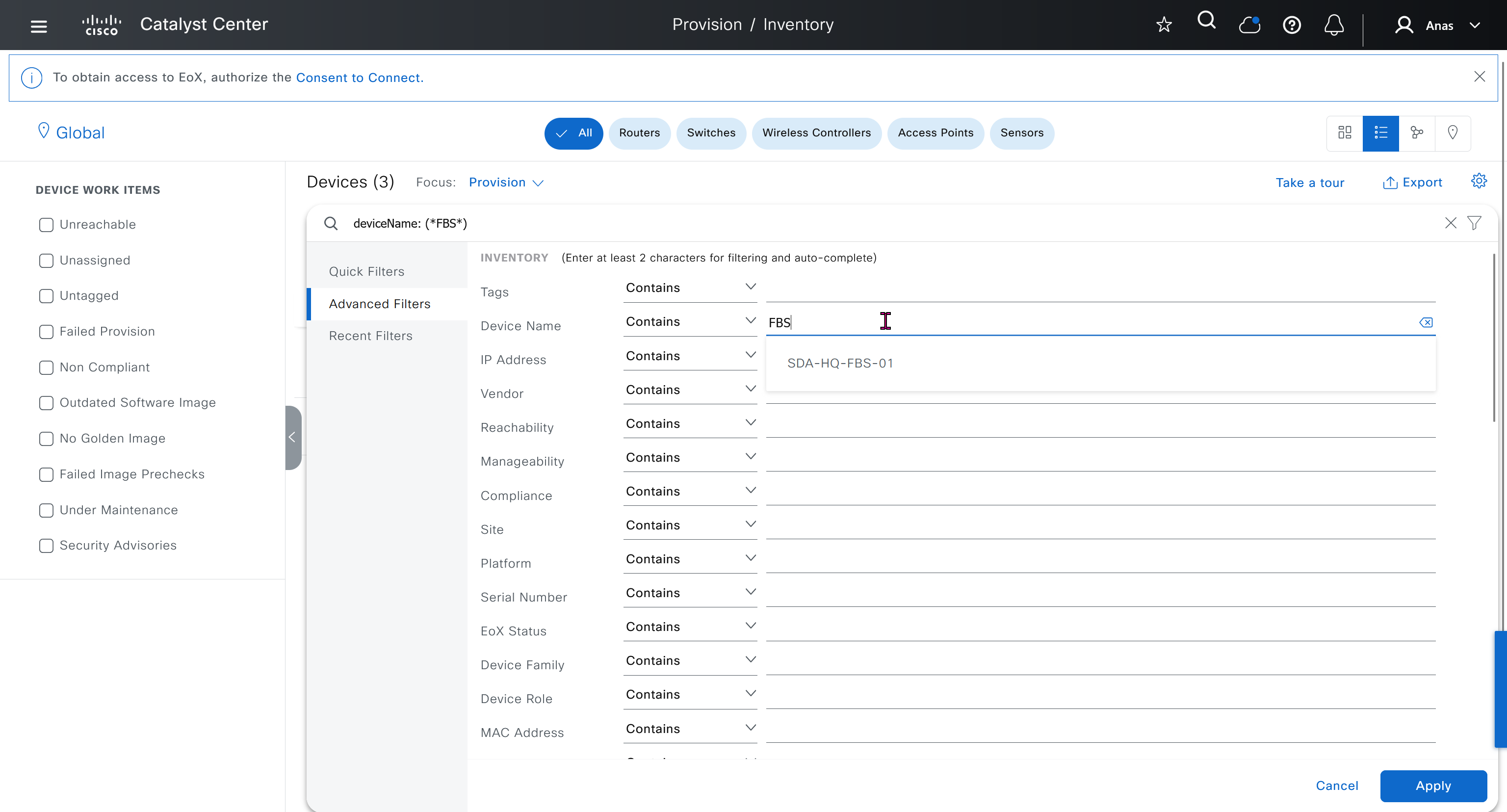

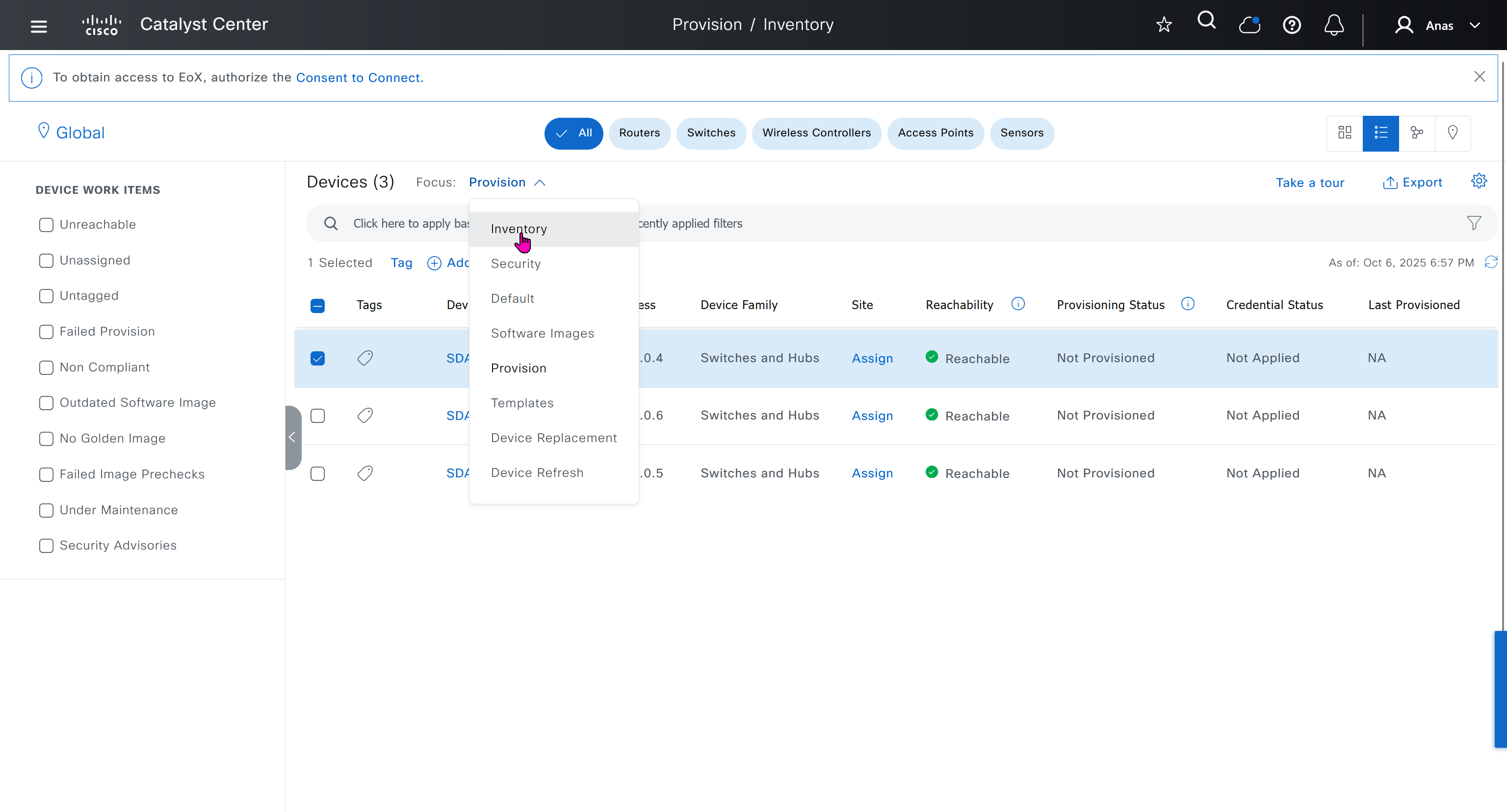
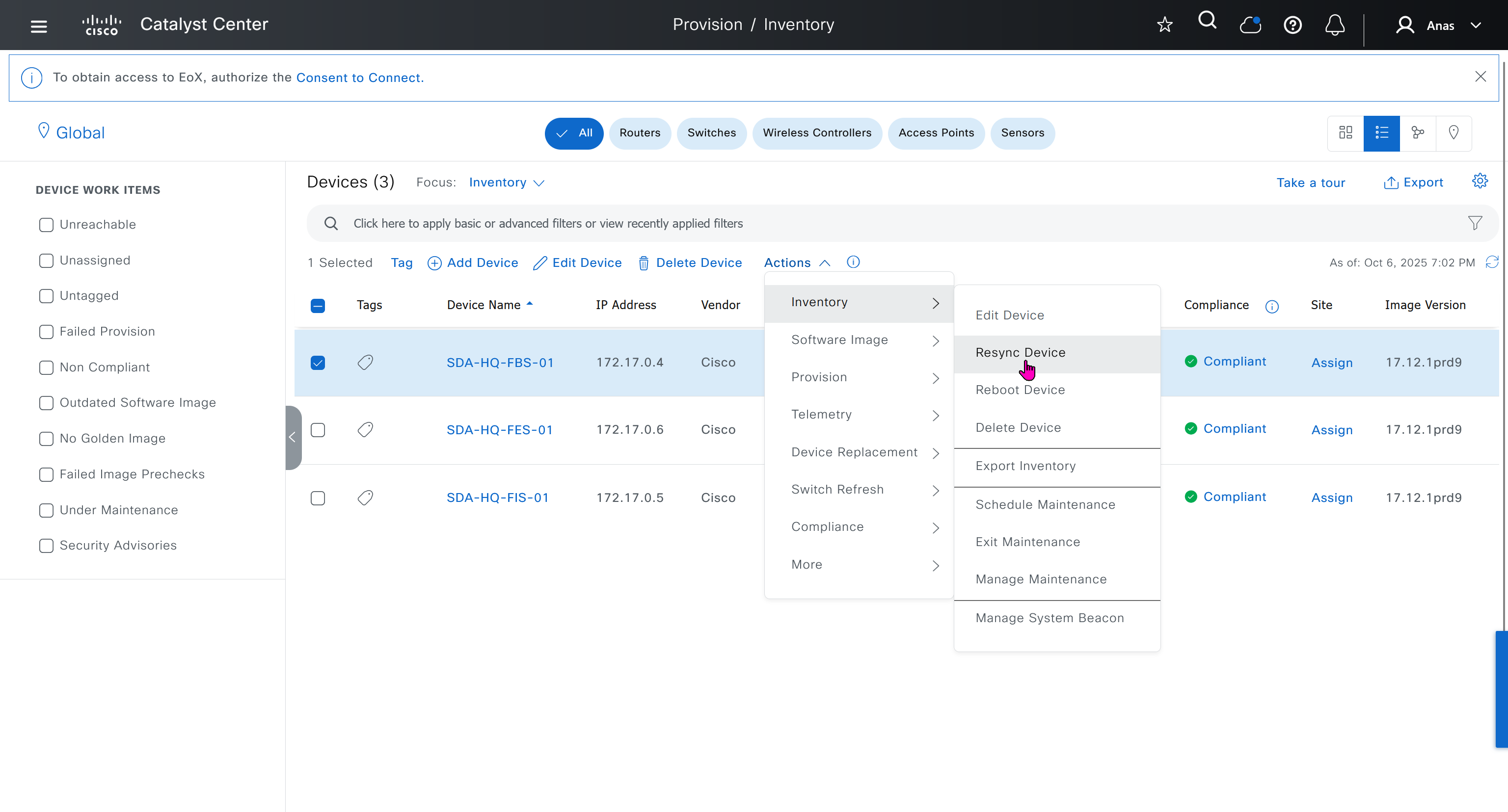

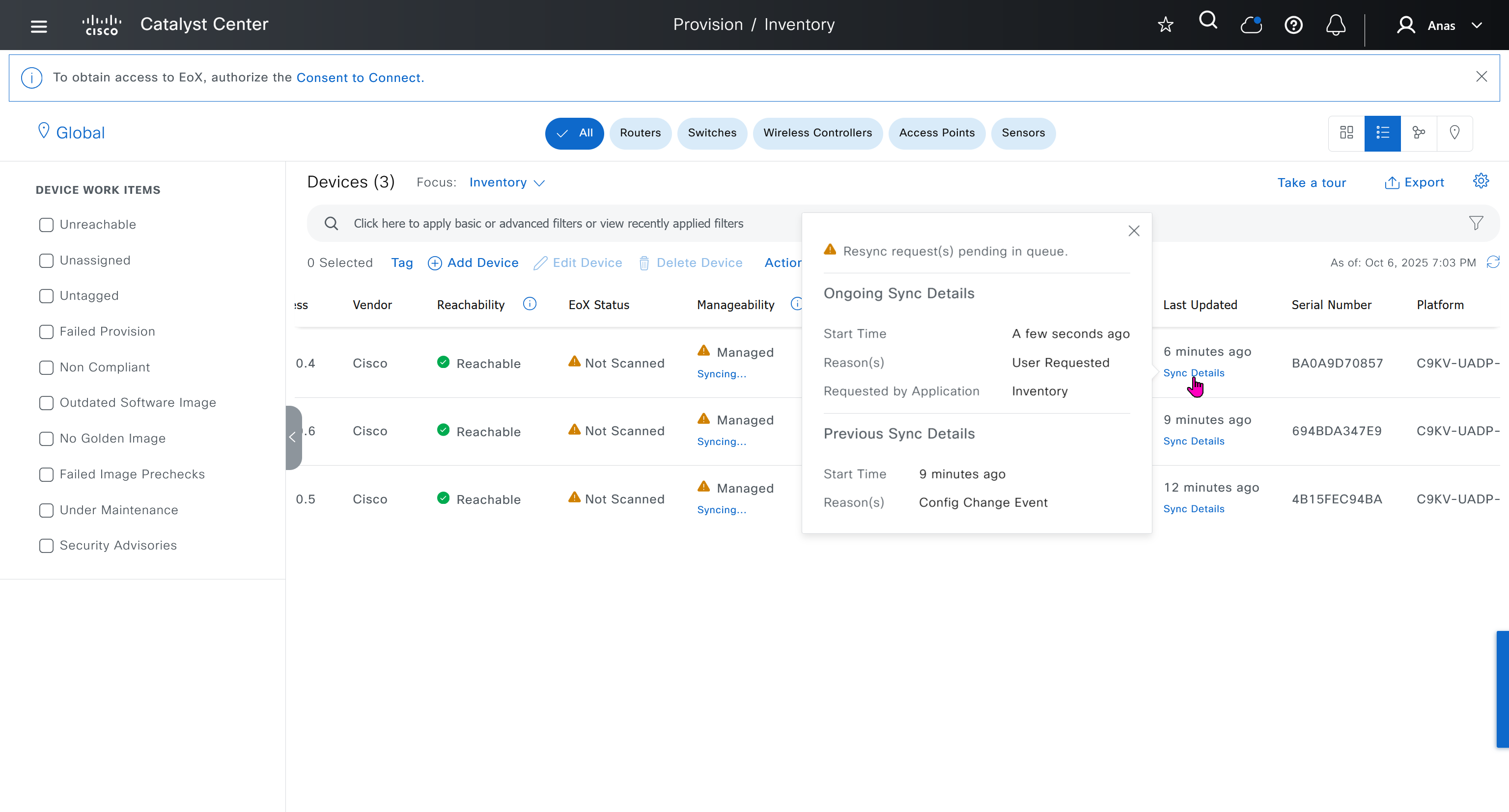
next post
SDA LAN Automation
LAN Automation Deployment
LAN automation
-simplifies underlay deployment
-eliminates manual, repetitive configuration
-establishes a standard, error-free underlay network.
Cisco LAN automation provides:
Zero-touch provisioning: Network devices are
-dynamically discovered
-onboarded
from their factory default state
Redundancy bult in, Automation
Seed device
Pre-deployed device and initial point through which LAN automation discovers and onboards new downstream switches
Uses Plug and Play (PnP)
One seed device can do the job but two can be deployed
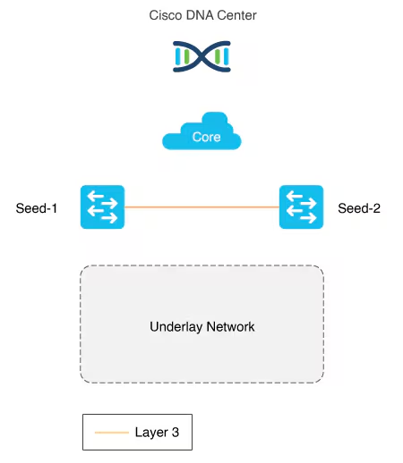
PnP agents
The PnP agent is a Cisco Catalyst switch with factory default settings or candidate switches
The switch uses 0 day communication to communicate with Catalyst Center (PnP server)
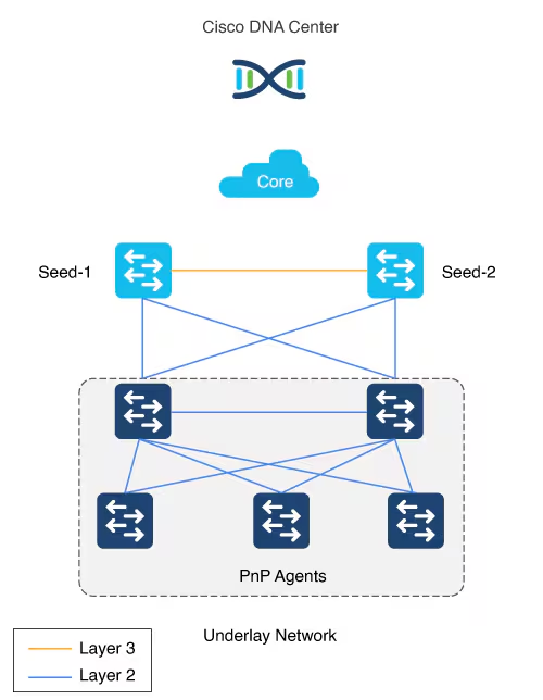
LAN automation in Catalyst Center supports a maximum of two hops from the initial automation boundary point device. Any additional network devices beyond two hops might be discovered but cannot be automated
Given that seed devices are core switches from the three tier model:
- Scenario 1: You have a three-tier network and you want to LAN “automate distribution and access layer switches”, both distribution- and access-layer switches will be discovered and LAN automated.
- Scenario 2: You have a three-tier network and you want to LAN automate distribution and access-layer switches.
You already LAN automated the distribution layer.
You decide to add access-layer switches later to your network at a later date (this is the difference from Scenario 1) and you want to LAN automate these switches. “Because the distribution switches are already LAN automated and links converted to “Layer 3”, Tier 1 or core switches cannot be used as the seed. You must choose distribution as the seed in this scenario“.
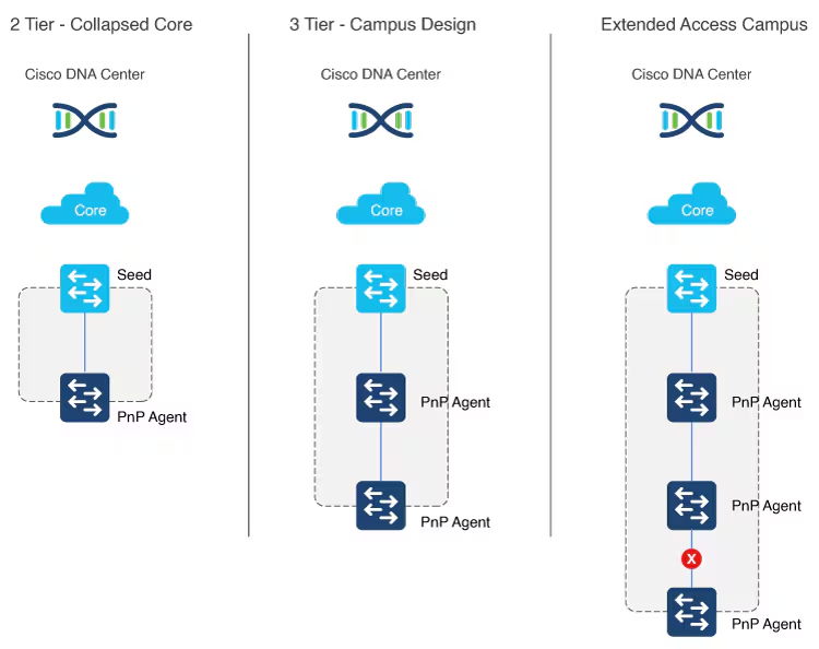
Multistep LAN automation for large topologies: First pass
Large topologies are brought up by performing LAN automation multiple times. During the first pass, core devices are chosen as seed devices to bring up the “distribution” switches as new devices.
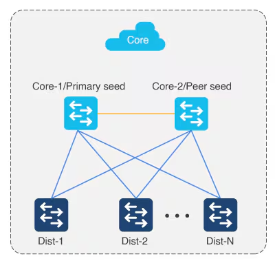
Multistep LAN automation for large topologies: Second pass with first group
During the second pass, two of the distribution switches act as seed devices to bring up the edge devices as new devices. All new devices in this session must connect directly to the two distribution switches that act as new seed devices.
Repeat this process for the remaining set of distribution switches laterally, two at a time (in pair).
There can be two tiers of devices below the seeds.
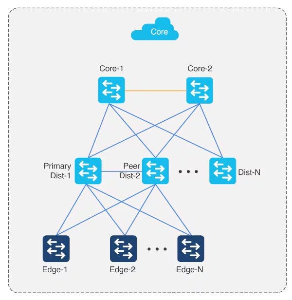
Perform stacking before hand
Layer 3 link configuration after LAN Automation
After all devices are added to the Catalyst Center inventory, you can stop the LAN automation session on the GUI to begin the Layer 3 link configuration process.
If you accidentally stop the LAN automation process before all PnP devices are added to the Catalyst Center inventory, You must bring the in-progress devices to the factory-default state in order to do LAN automation again.
Catalyst Center Release 2.3.5 and later provide the support for day-n link configurations (add and delete link). For more information, see Create a link between interfaces.
Supported switches for each role at different layers
Site planning
Use the Catalyst Center Design feature to create the required sites, buildings, and floors.
Create a global pool in DNAC, reserve IP Pool specific per site
Different types of IP address assignments used:
- DHCP (temporary, later claimed back or unreserved)
- P2P L3 /31 links
- Loopbacks
- Underlay multicast IP
Temporary DHCP pool so new device can get IP and speak to DNAC
Temporary DHCP pool so new device can get IP and speak to DNAC, but after that when DNAC is able to login (IP reachability) it will change and assign different IP addresses
One part of the IP pool per site, is reserved for a temporary DHCP server,
this DHCP server runs on DNAC itself and seed devices are used as relay to relay DHCP request from PnP agent or new switch without IP towards DNAC,
Temporary DHCP on Catalyst Center leases IP addresses from this temporary DHCP subpool.
Those IPs allow the new device to:
- Boot up with a valid IP address.
- Contact Catalyst Center over the network.
- Be discovered and provisioned automatically
Once the LAN automation session is finished:
- The DHCP service stops.
- The temporary subpool is released.
- All those IP addresses go back to the main LAN pool.
- The switches now have permanent IPs assigned by the automation process (usually from a different IP pool).
The size of this pool depends on the size of the parent LAN pool. For example, if the parent pool is 192.168.10.0/”24″, a /”26″ subpool is allocated for the DHCP server, Therefore, a /”24″ pool reserves /”26″ 64 hosts
We can think of this temporary DHCP pool size with the + 2 rule
A /23 pool reserves /”25″ 128 hosts, a /22 pool reserves /24 256 hosts, and larger pools reserve (max) 512 IP addresses for the DHCP server, it steps up in this way and max pool size is 512 addresses for even bigger parent pools
for example initial blocks of 192.168.10.0/24 can be used since site is not operational and LAN automation is being run to deploy the site, once LAN automation is complete these chunks are released back in order for them to be reserved in site and used
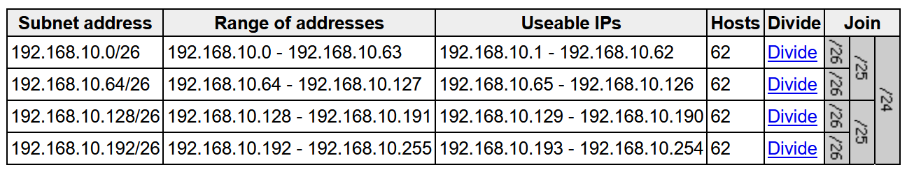
To start LAN automation, the pool size must be at least /25, which reserves a /27 pool or 32 IP addresses for the DHCP pool.
This IP pool is reserved temporarily for the duration of the LAN automation discovery session. After the LAN automation discovery session completes, the DHCP pool is released, and the IPs are returned to the LAN pool
IP pool for loopback and /31 interswitch links
Another part of the IP pool is reserved internally with a size of fixed size /27. This pool is for allocating single IPs for Loopback0 and Loopback60000 always. IPs for point-to-point L3 /31 links are allocated from this pool also, if this pool is exhausted a new /27 pool is created for allocating IPs
This pool remain throughout the process and are not allowed to be removed.
Due to this allocation logic, the IP pool usage in IPAM counts these pools as allocated unlike pools used for DHCP which are released back in parent pool
Each of the devices discovered via LAN automation gets a unique /31 per interface for point-to-point connection, and a unique /32 for Loopback0 and the underlay multicast.
Single Site vs Shared IP pool (overlaps between sites)
When a dedicated (single) IP pool is used to build the underlay networks, each device discovered via LAN automation gets a unique /31 per interface for point-to-point connection, and a unique /32 for Loopback0 and the underlay multicast.
A link overlapping IP pool (only for /31 interswitch links) or shared IP pool is used to optimize the IPv4 addressing in the underlay network by allowing overlapping /31 IP addresses for a multisite deployment. Hosts in different sites can get duplicate IP addresses on the /31 links. The /31s in the underlay are not advertised outside of the fabric site and hence there is no need for them to be unique. However, the /32 loopback needs to be unique to every device, and should be advertised to the global routing table to identify the device in the entire network.
IP pool roles
The LAN IP pool can have these two roles:
- Link Overlapping IP Pool: This pool role is optional for a LAN automation session. If provided, the allocation of IP addresses is only on the /31 point-to-point Layer 3 links, and can be same through out different sites, hence overlapping is in the name.
- Main IP Pool (Principal IP Address Pool in Catalyst Center Release 2.3.5 and later): This pool role is mandatory for every LAN automation session. This is the pool that is used for all management-related IP addressing such as loopbacks, multicast, and DHCP. If the Link Overlapping IP Pool is not provided, then the Main IP Pool is the default fallback pool for the /31 Layer 3 links IP addressing also.
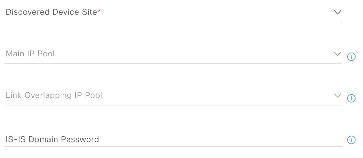
Configuration on seed devices
- Enter hostname
hostname 1005-FBS-01
- Ensure that the system MTU (maximum transmission unit) value is at least 9100 or jumbo frame –
show sys mtusystem mtu 8978
- Enable DNA advantage license and reload
license boot level network-advantage addon dna-advantagereload- Extra step for FES and FIS after all of the above is done
pnpa service reset no-prompt- so they are reset back to pnp autoinstall on vlan 1 after license install and do not follow below process for FIS or FES, this is only for Seed node or FBS
- Turn on IP routing on the seed devices.
ip routing
- Enable CLI credentials from DNAC
username admin privilege 15 secret *********
- Correct the enable secret with relaxed secret
enable secret *********
- Enable SNMP strings from DNAC
snmp-server community *********
- Enable SSH
ip ssh version 2crypto key generate rsa modulus 2048 label 1005-FBS-01line vty 0 98transport input ssh
- Enable local authentication
aaa new-modelaaa authentication login default localaaa authorization exec default local
- Enable netconf-yang
netconf-yang
- Enable privilege level 15 on vty lines
line vty 0 98privilege level 15
ip name-server 1.0.0.11ip domain name home.local- Set console login to privilege exec mode
line console 0privilege level 15
hostname 1005-FXXXX
system mtu 8978
license boot level network-advantage addon dna-advantage
reload

! for all except FBS or FIB
pnpa service reset no-prompt

ip routing
username admin privilege 15 secret C0mplex30
enable secret C0mplex30

snmp-server community C0mplex30

ip ssh version 2
crypto key generate rsa modulus 2048 label 1005-FXXXX
line vty 0 98
transport input ssh telnet

aaa new-model
aaa authentication login default local
aaa authorization exec default local

netconf-yang

line vty 0 98
privilege level 15

ip name-server 1.0.0.11
ip domain name home.local

line console 0
privilege level 15
conf t
!
! Enable the archive feature
archive
log config
logging enable
notify syslog contenttype plaintext
hidekeys
!
! Optional: Set up where the archived configs are stored
path flash:config-archive
write-memory
!
end
!
! Ensure syslog logging is enabled (optional but recommended)
conf t
logging buffered 64000
service timestamps log datetime msec
!
end
write mem Should I connect links between FBS switches even though they connect to EFS upstream?
Underlay Routing and Path Redundancy
If one of your border switches loses its direct physical uplink to the Fusion switch, it needs an alternative route to reach the rest of the network. A direct physical link between 1005-FBS-01 and 1005-FBS-02 allows underlay routing protocols (like IS-IS or OSPF) to quickly reroute traffic through the adjacent border node without traffic being dropped.
Preventing Packet Blackholing (The Overlay Risk)
In the SDA overlay, traffic is tunneled between Routing Locators (RLOCs)—which are bound to the Loopback 0 interfaces of your fabric devices.
- If a border switch’s uplink to the Fusion switch fails, its
Loopback 0interface (RLOC) remains up and reachable from inside the fabric. - The Fabric Edge nodes will continue sending north-bound traffic to that failed border.
- Without a direct link between the borders to pass that traffic over to the surviving node, the isolated border will have no path out to the Fusion layer, resulting in black-holed traffic.
2. How to Connect and Configure Them
Depending on how you are provisioning your lab in Cisco Catalyst Center (formerly DNAC), you have two options for the cross-link:
Option A: Standard Underlay Routed Link (Recommended)
You configure a direct Layer 3 routed link (or a Layer 3 EtherChannel) between FBS-01 and FBS-02.
- Underlay: Include this link in your underlay routing configuration so RLOCs can talk to each other across it.
- Overlay Handoff: You will configure iBGP neighbor relationships between the two border switches for every Virtual Network (VN/VRF) as well as the Global Routing Table (GRT). This ensures that if one border loses its external eBGP path to the Fusion switch, it learns the external routes from its twin border via iBGP.
Option B: LAN Automation
If you are using LAN Automation in Catalyst Center to discover and build your underlay, Catalyst Center will automatically detect this cross-link, configure it as a Layer 3 routed point-to-point link, and add it to the IS-IS routing process.
Summary Checklist for Your Lab
- 🟢 Physical/Virtual Topology: Draw/connect a link directly between
1005-FBS-01and1005-FBS-02. - 🟢 Underlay: Ensure the link is routed and participating in your underlay IGP.
- 🟢 Control Plane Handoff: Ensure you have eBGP running from each border to the Fusion switch, and iBGP running over the cross-link between the borders for your VRFs.
For a deeper dive into the configuration mechanics and why this architecture prevents traffic disruptions, you can watch this SD-Access Fabric Border Design Video https://www.youtube.com/watch?v=-0l8Wq-8FsI. This video provides an excellent visual walkthrough of border-to-fusion design considerations and demonstrates how lacking full-mesh/cross-links can lead to packet blackholing in a lab environment
IP address allocation in Catalyst Center Release 2.3.7.x and later
In Catalyst Center Release 2.3.7.x and later, IP address allocation from LAN pool is based on IP address range instead of subnet allocation. This approach helps in minimizing the issue of IP address loss during subnet creation and in effective management of the IP addresses. Instead of creating a subnet, IP address range is blocked for both DHCP pool allocation and IP address assignment for point-to-point links, loopback, and multicast.
LAN Automation Example
Imagine you want to LAN automate 10 devices in a site using the same pool, where each device has one link to the primary seed and another link to the secondary.
Consider a 192.168.199.0/24 as an example pool. When LAN automation starts,
a first /26 pool is reserved for the DHCP addresses. In this example, 192.168.199.”1″ to 192.168.199.”63″ are reserved and assigned to VLAN 1 for the 10 devices.
Next, a “/27” pool is reserved for loopback addresses.
If there is no shared IP pool, then this pool is used for point-to-point links as well.
Because there are 10 devices with two links each, a total of 40 IP addresses are reserved for point-to-point links,
40 addresses because each switch needs 4 IP addressess (2 assigned on switch’s uplinks itself and 1 assigned on primary seed device and 1 assigned on peer seed device)
In total, 60 IP addresses are reserved for the 10 devices: 10 for each VLAN 1, 10 for each loopback, and 40 for the point-to-point links between devices and seeds.
After LAN automation stops, the VLAN 1 IP addresses are released back to the pool
We recommend that you use the default interfaces connected to PnP agents.
If the peer seed device has IP interfaces configured on the interfaces connecting to PnP agents,
those links are not configured.
Default the interfaces connecting to agents and perform an inventory synchronization on the peer seed device. LAN automation works only when the ports are Layer 2. The ports on the Cisco Catalyst 6000 Series Switches are Layer 3 by default. Convert the ports to Layer 2 before starting LAN automation.
LAN automation configures loopback on the seed devices if they are not configured.
If you change configuration on the seed devices before running LAN automation, synchronize the seed devices with the Catalyst Center inventory.
If you plan to run multiple discovery sessions to onboard devices across different buildings and floors connected to the same seed devices, we recommend that you block the ports for PnP agents that do not participate in the upcoming discovery session yet.
For example, imagine seed devices in Building-23 connected to PnP agents on Floor-1 and Floor-2. Floor-1 devices are connected on interfaces Gig 1/0/10 through Gig 1/0/15. Floor-2 devices are connected on interfaces Gig 1/0/16 through Gig 1/0/20. For the discovery session on Floor-1, we recommend that you shut down ports connected to Gig 1/0/16 through Gig 1/0/20. Otherwise, the PnP agents connected to Floor-2 might also get DHCP IPs from the server running on the primary seed device. Because these interfaces aren’t selected for the discovery session, they remain as stale entries in the PnP database. When you run the discovery session for Floor-2, the discovery doesn’t function correctly until these devices are deleted from the PnP application and write erase/reloaded. Therefore, we recommend that you shut down other discovery interfaces
For Catalyst Center Release 1.2.8 and earlier, if clients are connected to a switch being discovered, they may contend for DHCP IP and exhaust the pool, causing LAN automation to fail. Therefore, we recommend that you connect the client after LAN automation is complete. but that is for older DNAC versions
This endpoint/client integration restriction does not apply to Catalyst Center Release 1.2.10 and later. Clients can remain connected while the switch is undergoing LAN automation.
on the edge nodes add license and then reset pnpa so pnp wizard becomes active after putting license
otherwise LAN Automation commands will fail as there is no dna-advantage
license boot level network-advantage addon dna-advantage
end
write mem
reload pnpa service reset no-promptSteps for LAN Automation
- Default the interfaces connected to agents and perform an inventory synchronization on the peer seed device
- LAN automation configures loopback on the seed devices if they are not configured.
- If you change configuration on the seed devices before running LAN automation, synchronize the seed devices with the Catalyst Center inventory.
- Add Site > Add Area
- Add Site > Add Building
- Add Site > Add Floor
- Design > Network Settings > Device Credentials
- Manage Credentials
- CLI
- SNMPV2C Read
- Netconf
- Create an underlay pool that is not used any where in the network
See how the gateway address is set 172.16.0.1 and you ask why is that needed?
This is the address that will be assigned to FBS on vlan 1 interface (which is removed later on once LAN automation ends)
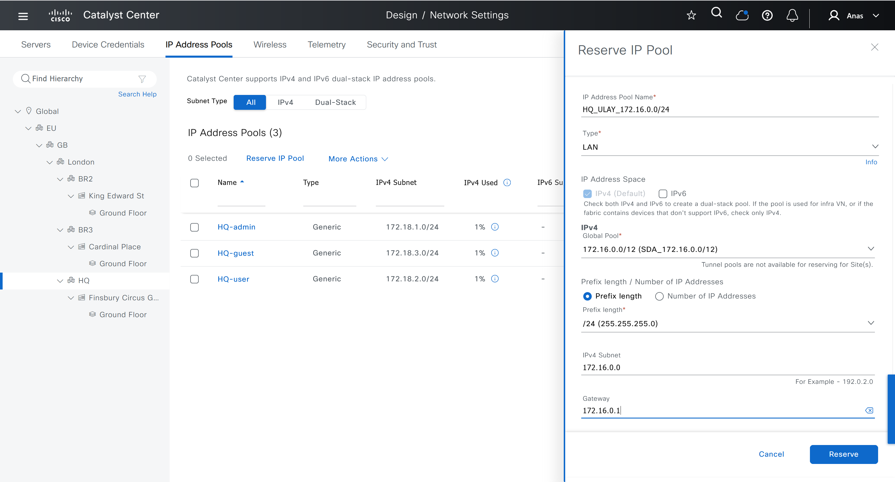
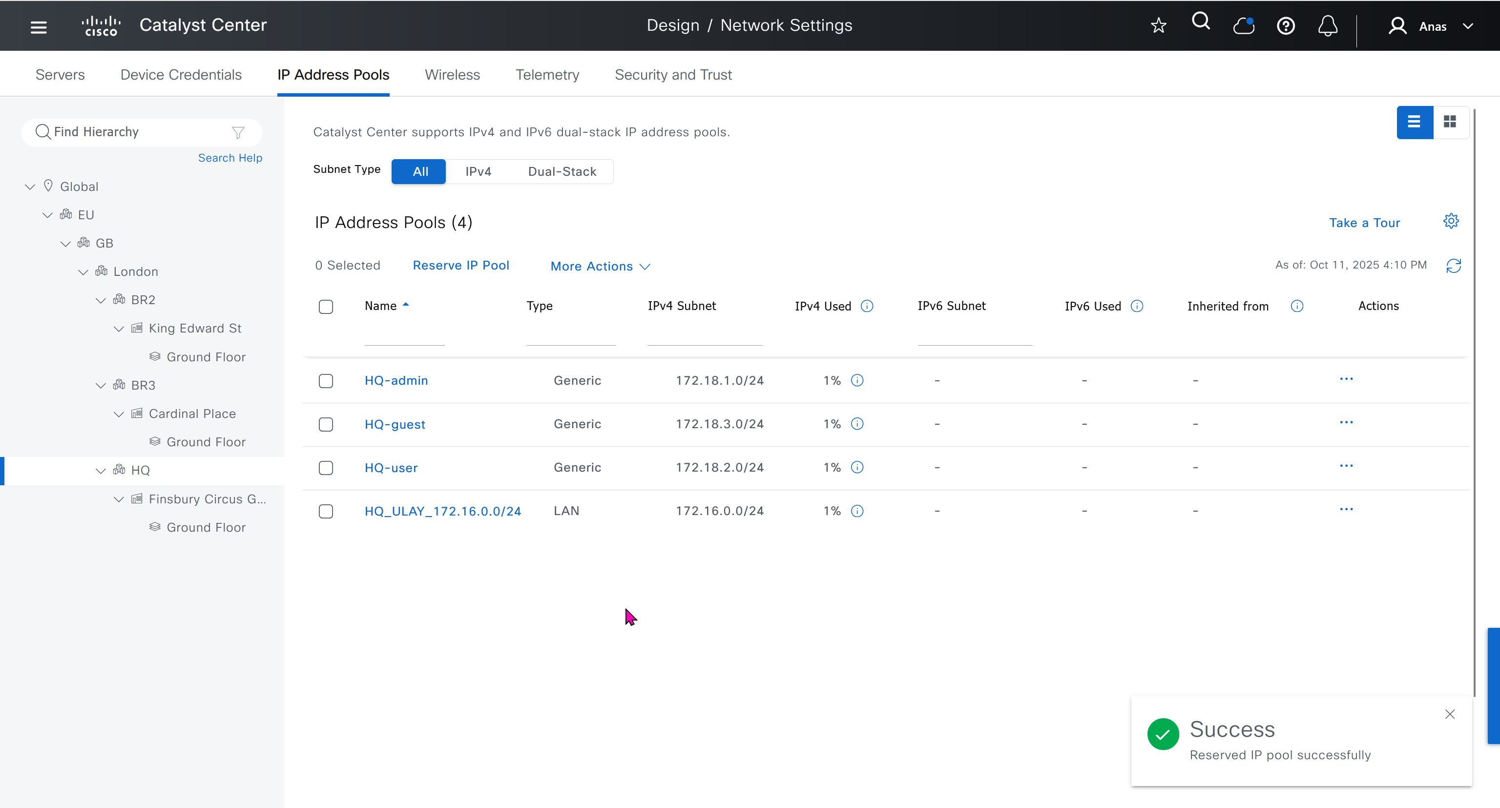
- Discover seed devices with discovery
- Make sure that discovered devices are in Reachable + Managed state
- Actions > Provision > Assign Device to Site to assign the device to a site.
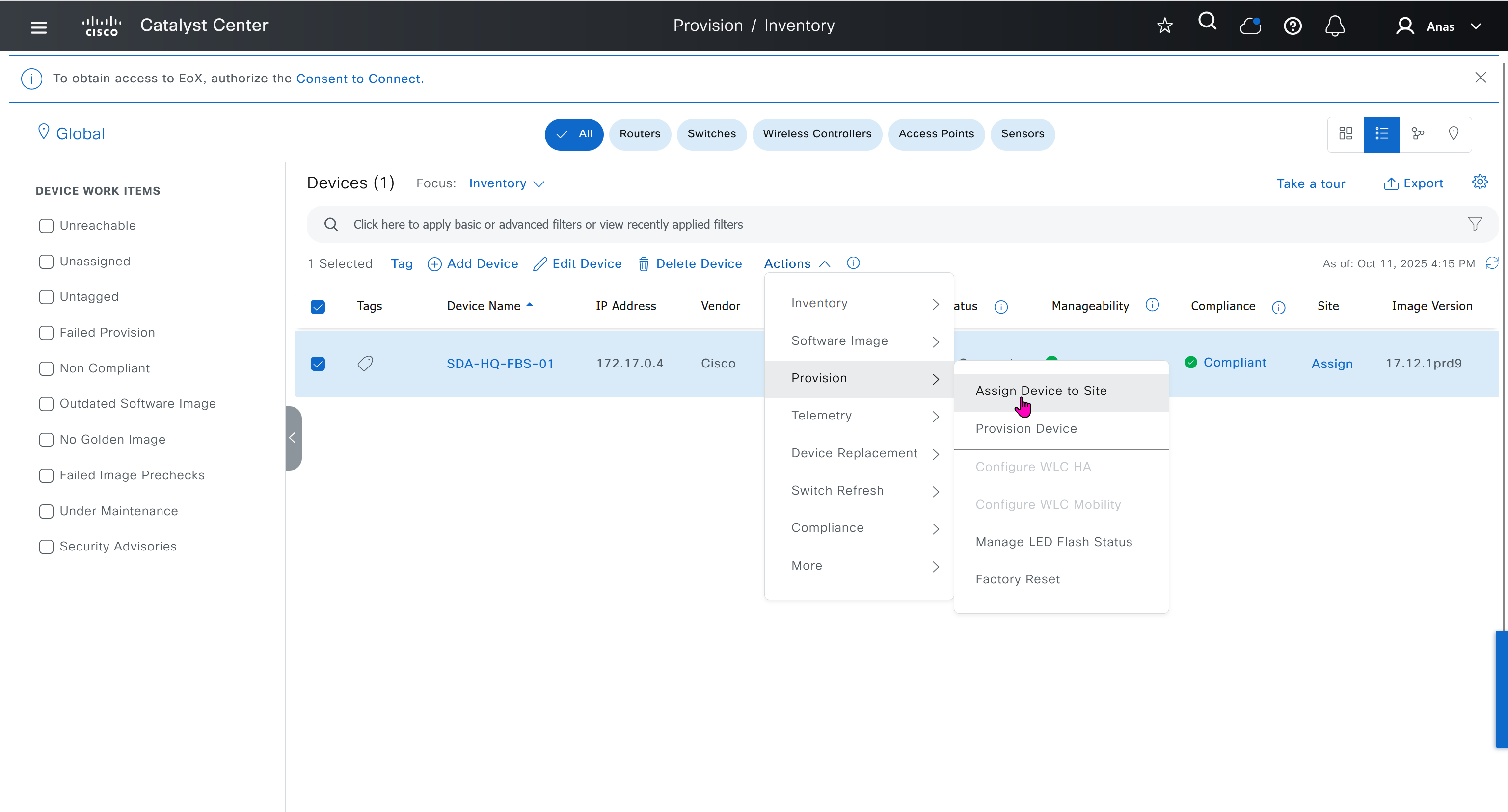
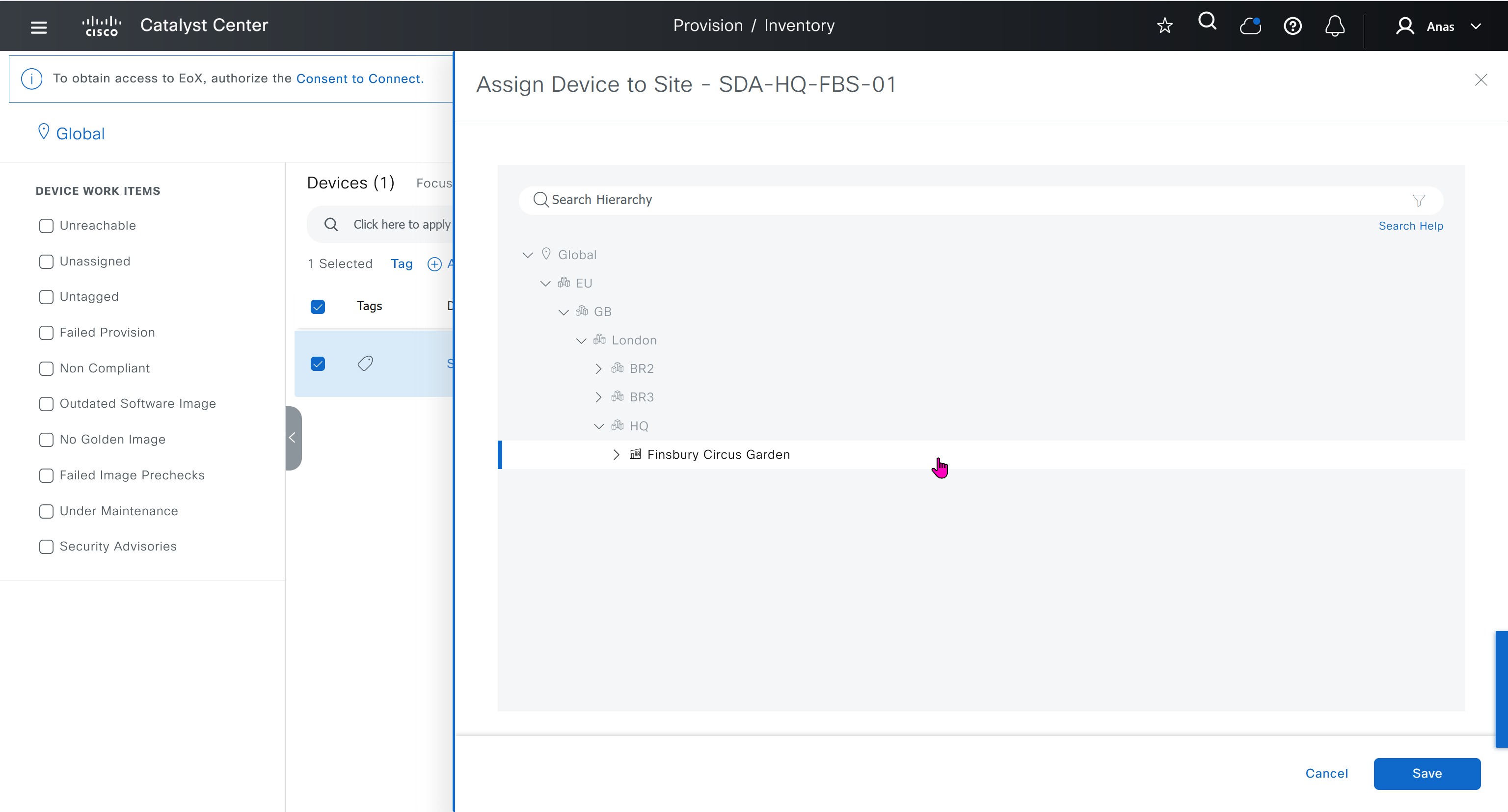

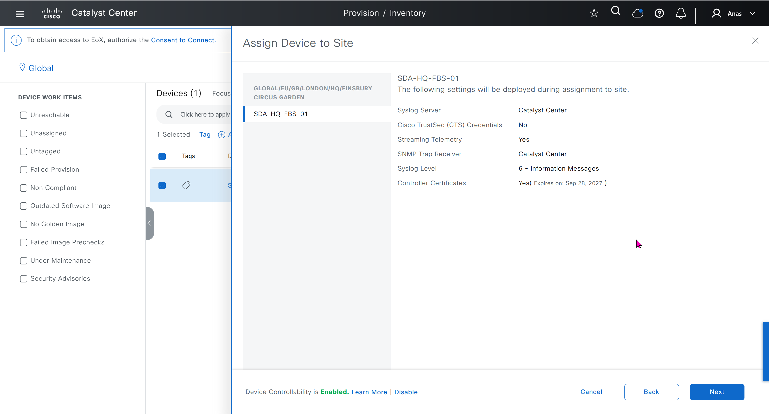


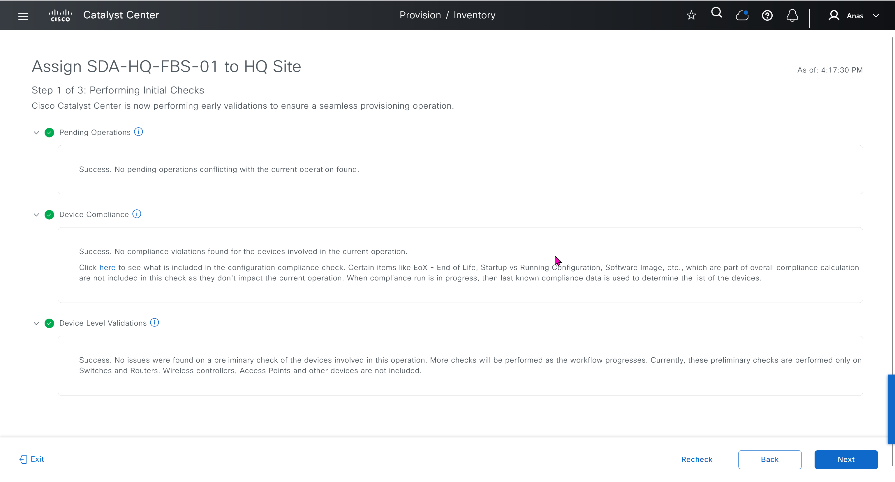
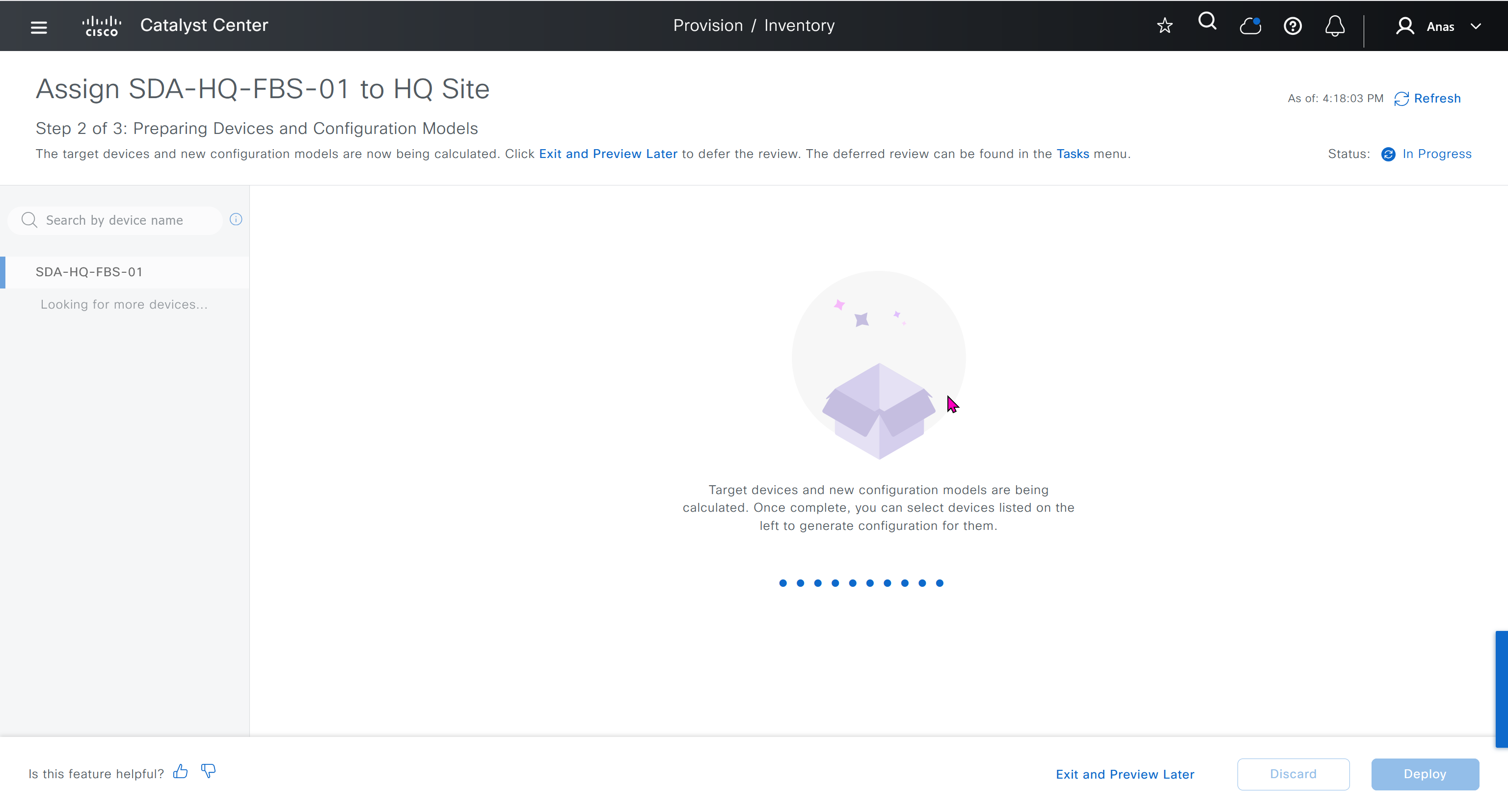
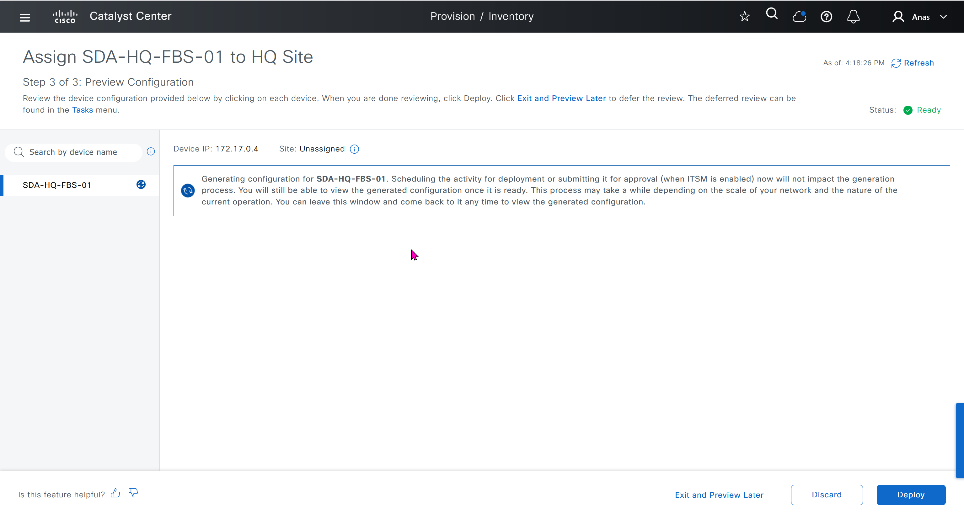
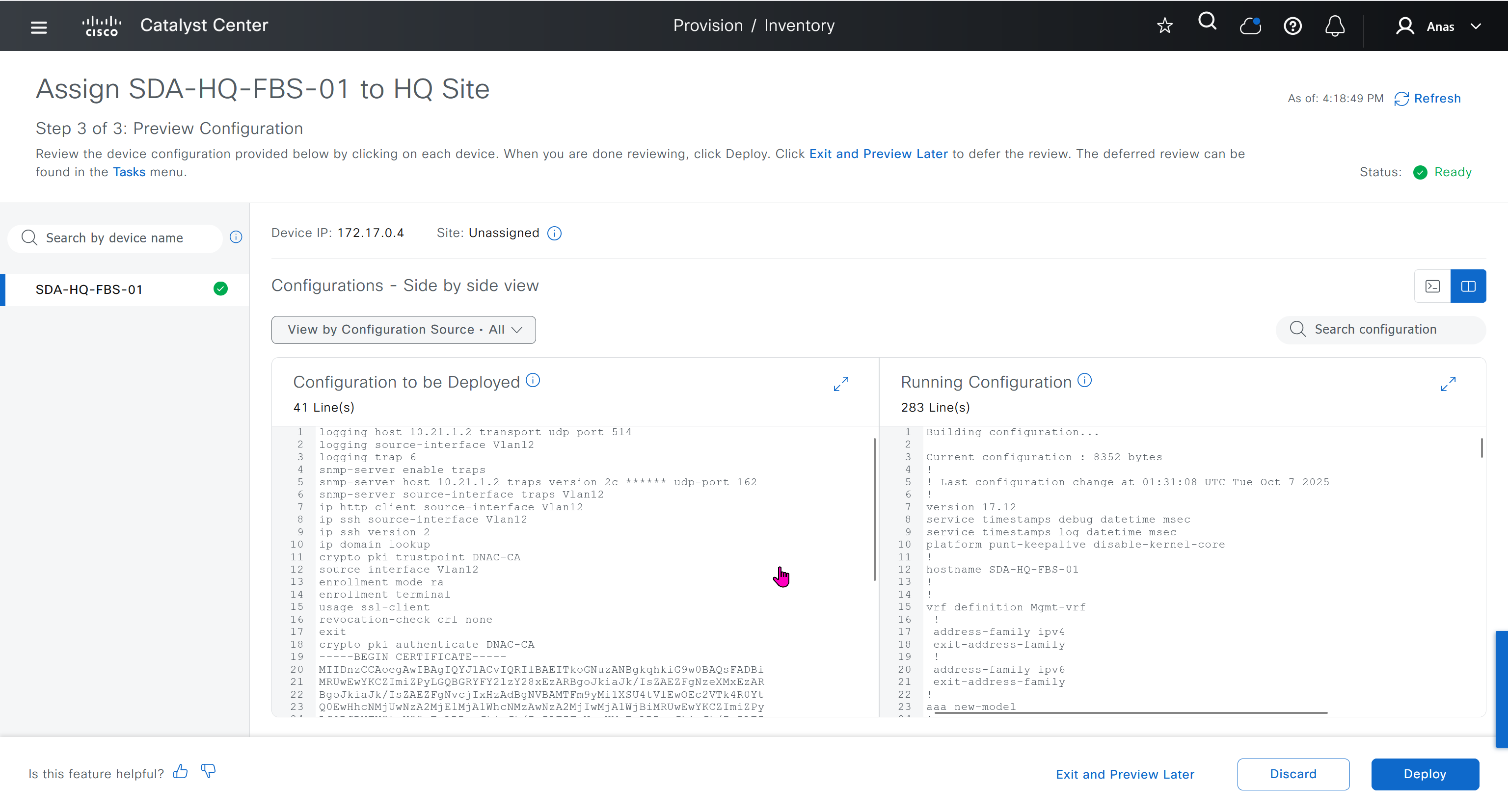

This is the configuration that will go on the seed device after only adding it to the site
Old LAB config Push Upon Site Assignment
logging host 10.21.1.2 transport udp port 514
logging source-interface Vlan12
logging trap 6
snmp-server enable traps
snmp-server host 10.21.1.2 traps version 2c ****** udp-port 162
snmp-server source-interface traps Vlan12
ip http client source-interface Vlan12
ip ssh source-interface Vlan12
ip ssh version 2
ip domain lookup
crypto pki trustpoint DNAC-CA
source interface Vlan12
enrollment mode ra
enrollment terminal
usage ssl-client
revocation-check crl none
exit
crypto pki authenticate DNAC-CA
-----BEGIN CERTIFICATE-----
MIIDnzCCAoegAwIBAgIQYJ1ACvIQRIlBAEITkoGNuzANBgkqhkiG9w0BAQsFADBi
MRUwEwYKCZImiZPyLGQBGRYFY2lzY28xEzARBgoJkiaJk/IsZAEZFgNzeXMxEzAR
BgoJkiaJk/IsZAEZFgNvcjIxHzAdBgNVBAMTFm9yMi1XSU4tVlEwOEc2VTk4R0Yt
Q0EwHhcNMjUwNzA2MjE1MjA1WhcNMzAwNzA2MjIwMjA1WjBiMRUwEwYKCZImiZPy
LGQBGRYFY2lzY28xEzARBgoJkiaJk/IsZAEZFgNzeXMxEzARBgoJkiaJk/IsZAEZ
FgNvcjIxHzAdBgNVBAMTFm9yMi1XSU4tVlEwOEc2VTk4R0YtQ0EwggEiMA0GCSqG
SIb3DQEBAQUAA4IBDwAwggEKAoIBAQCr6cjaoJz3vzgHlQ1hzhuy5WfIL/Ao0isM
ltIaGL+Z+9WftM1hNh10YECbxR71+lIpQKyBQTXQz8Of4nycxHjoI3dQdUvEYb8H
fysDXh4lYjQ60x82e5c7f1KPbD+AOhC31Zw1dgReMlPIuaa9LK903+z0FRnuCHaI
EG/Z9uCmv3JC22NgL69hscZc+NUGymMy1iBPN8G4EBkgqNVZ+zlRf/adW0JxEdc6
Sy53bp586/fXziRTW++jgdnhvfpn+VJ+BdG88/rEgMl7PUQE95lq4dih7qx0+OXu
ihFwQQvFxvi3dyqWWc0C1RKHPHtYQFz8rRuBJrR+uzgc0lVhrNHdAgMBAAGjUTBP
MAsGA1UdDwQEAwIBhjAPBgNVHRMBAf8EBTADAQH/MB0GA1UdDgQWBBQ/bI8yZeKD
fgjmmeWorjGo25t5hzAQBgkrBgEEAYI3FQEEAwIBADANBgkqhkiG9w0BAQsFAAOC
AQEAdtt6aiABkDDg/mAlcZfFPHcqmEEvQaMPeBaUqvfZKNrFVO8GMb9kingZJ62n
K05x5wE3tHy3jBmAl6eHZ/nUjXS11C06NwZMHpcDhty5BcDN08oEYdLF24upisNA
aRLOBhyEtKI9VKLAWfMkpWYEd/dqgVWs67GjAFT0Osgva9QHbz24iT6/c09jbZMt
41opmxacw8FFZcHMH9Afv1fIW9PwscrdlgjSSHR4XQLyDbyuDGsolzeh9PUVyPOd
f+/LYkLwH9jVcHlxl4Oy7MHRPtcbG9T3+vQGLjSAXu3Ybrl2R9Tn/sz5lYs44EEB
mqCxT00LxB3et6jAxJlEyE5vCw==
-----END CERTIFICATE-----
do cts credentials id 7c71627623014c0a83668477604a0c57 password ******New LAB config Push Upon Site Assignment
sxsxsxsx
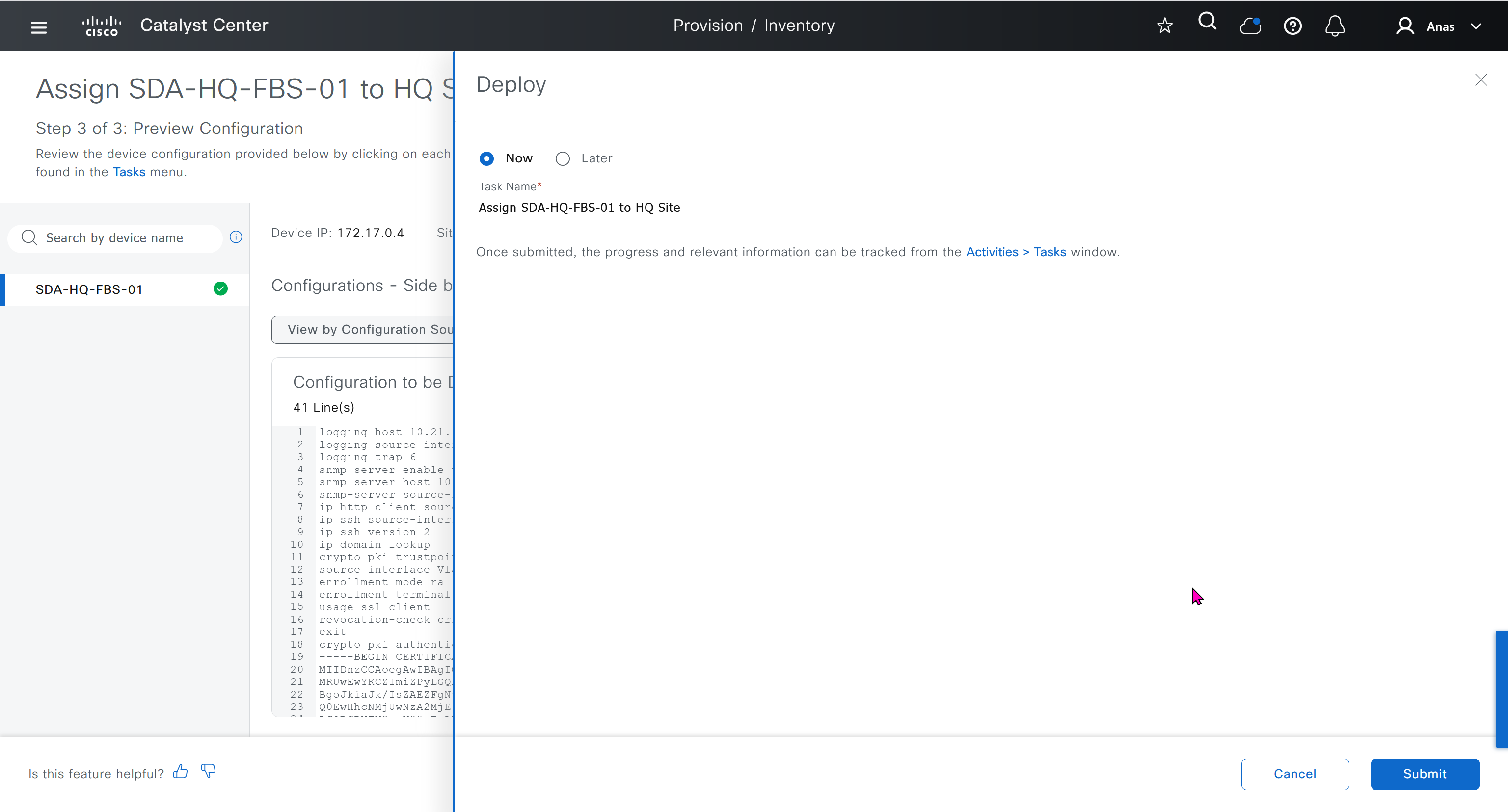
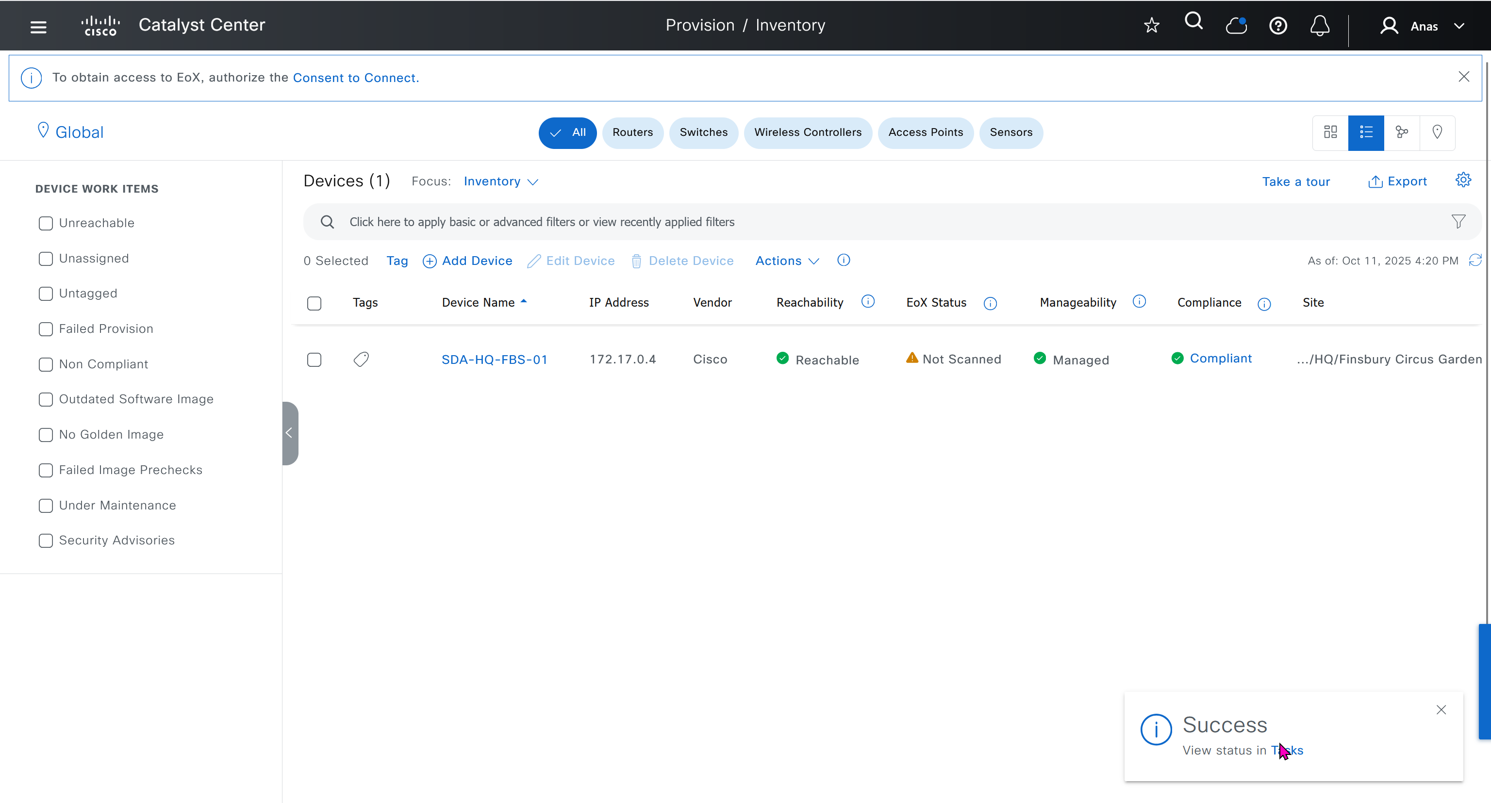
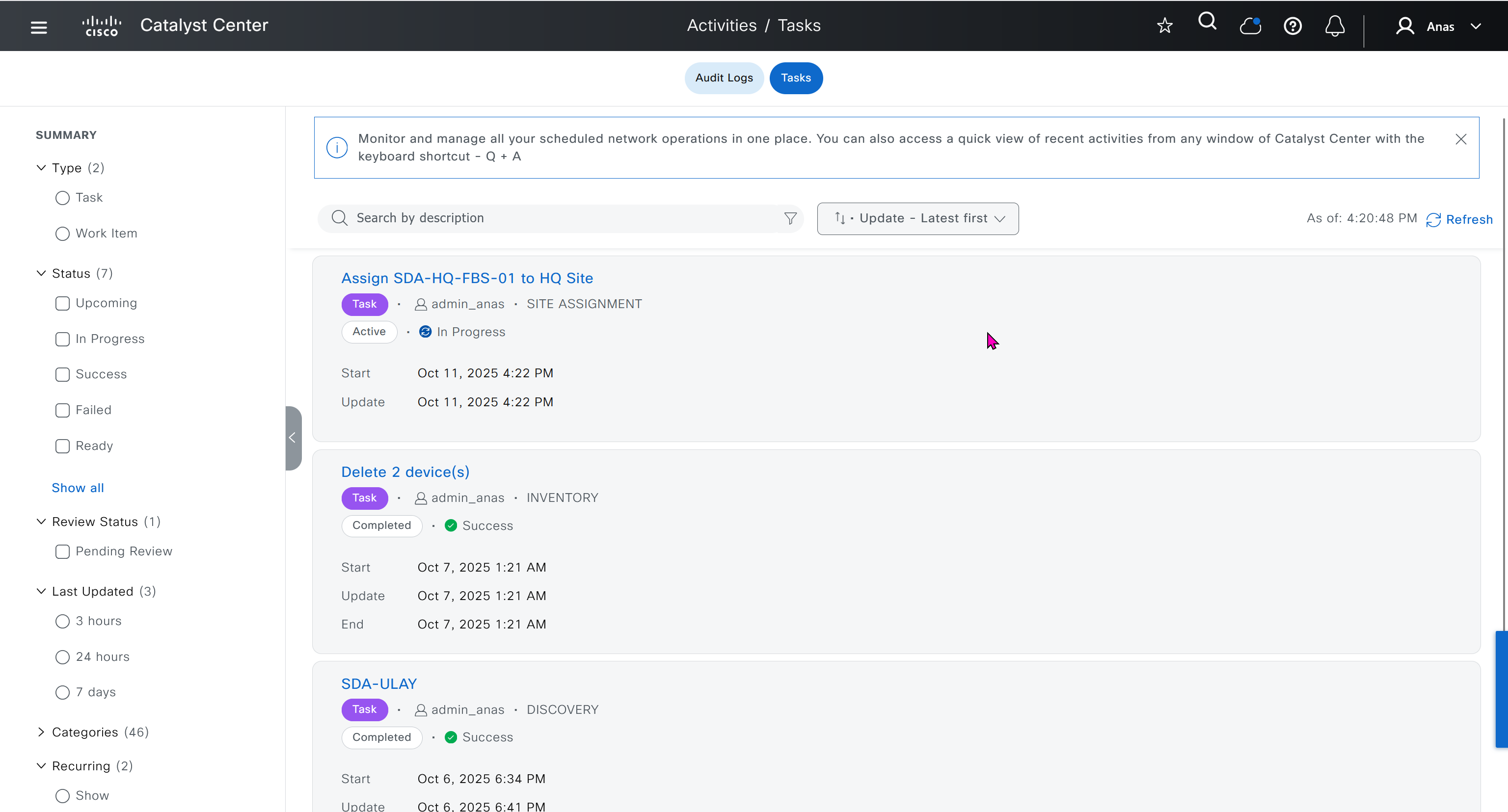
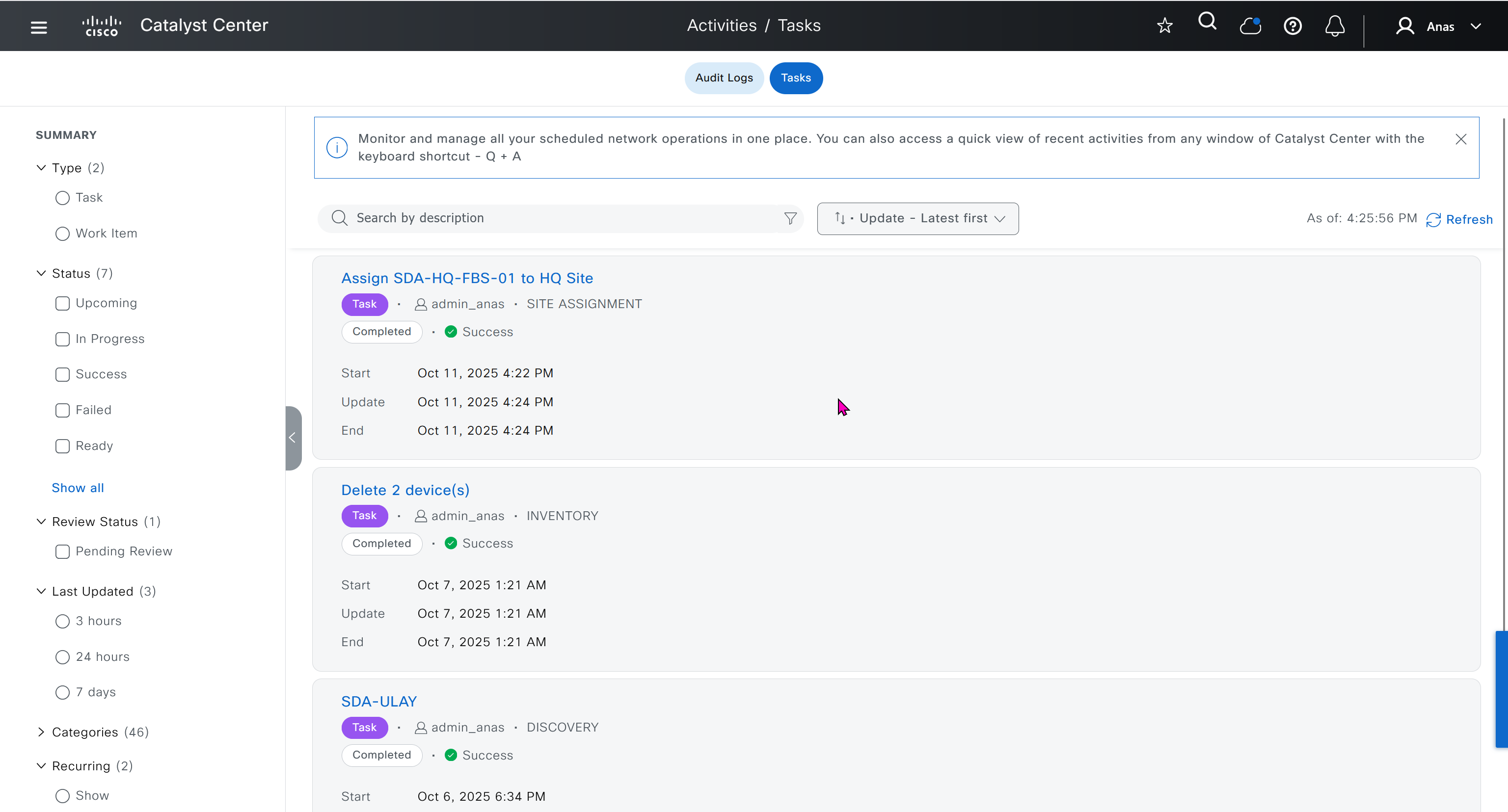
SDA-HQ-FBS-01# conf t
SDA-HQ-FBS-01# ! for reachability testing only
SDA-HQ-FBS-01# interface vlan 1
SDA-HQ-FBS-01# ip address 172.16.0.1 255.255.255.0
SDA-HQ-FBS-01# end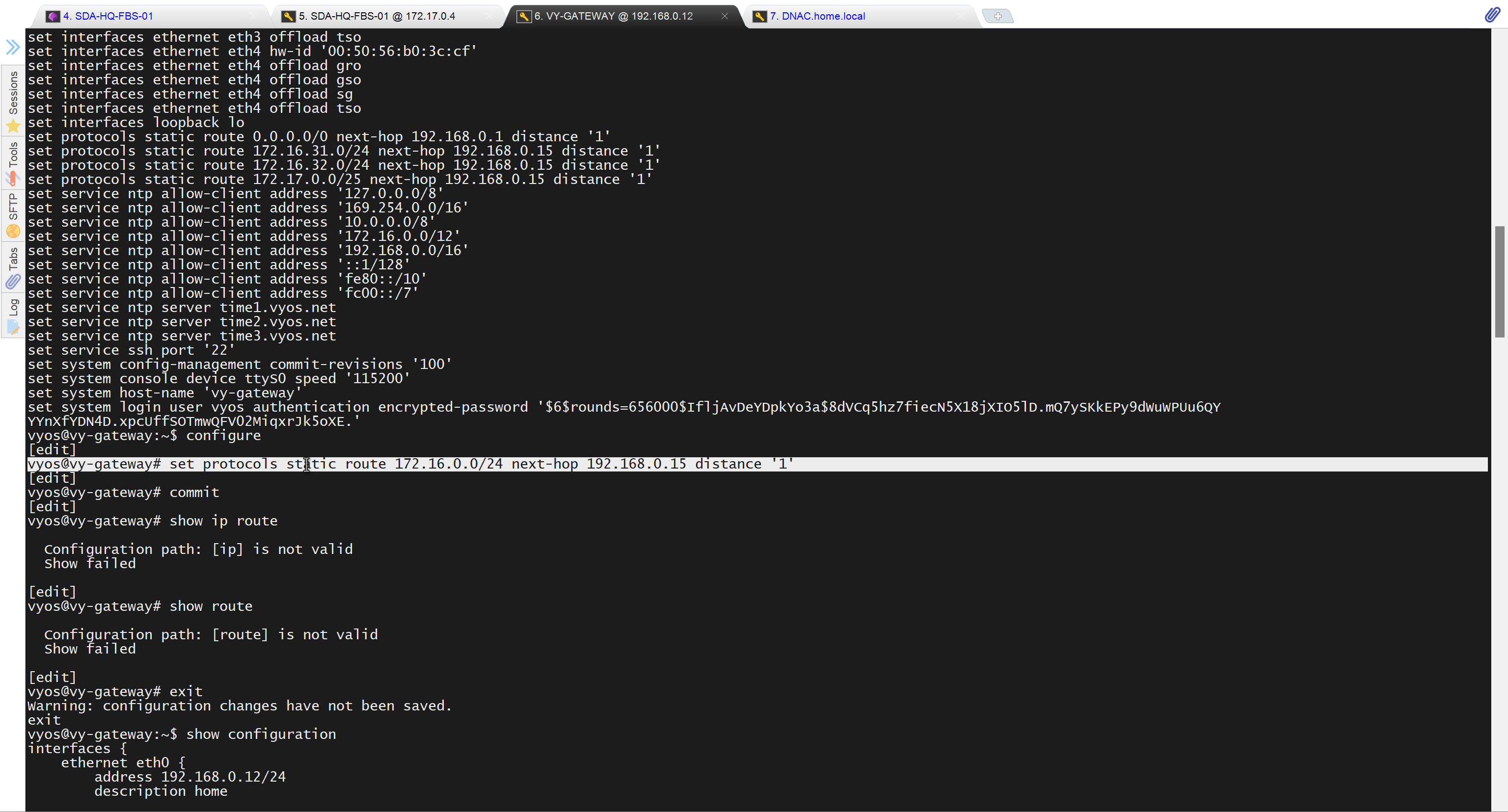
unable to reach
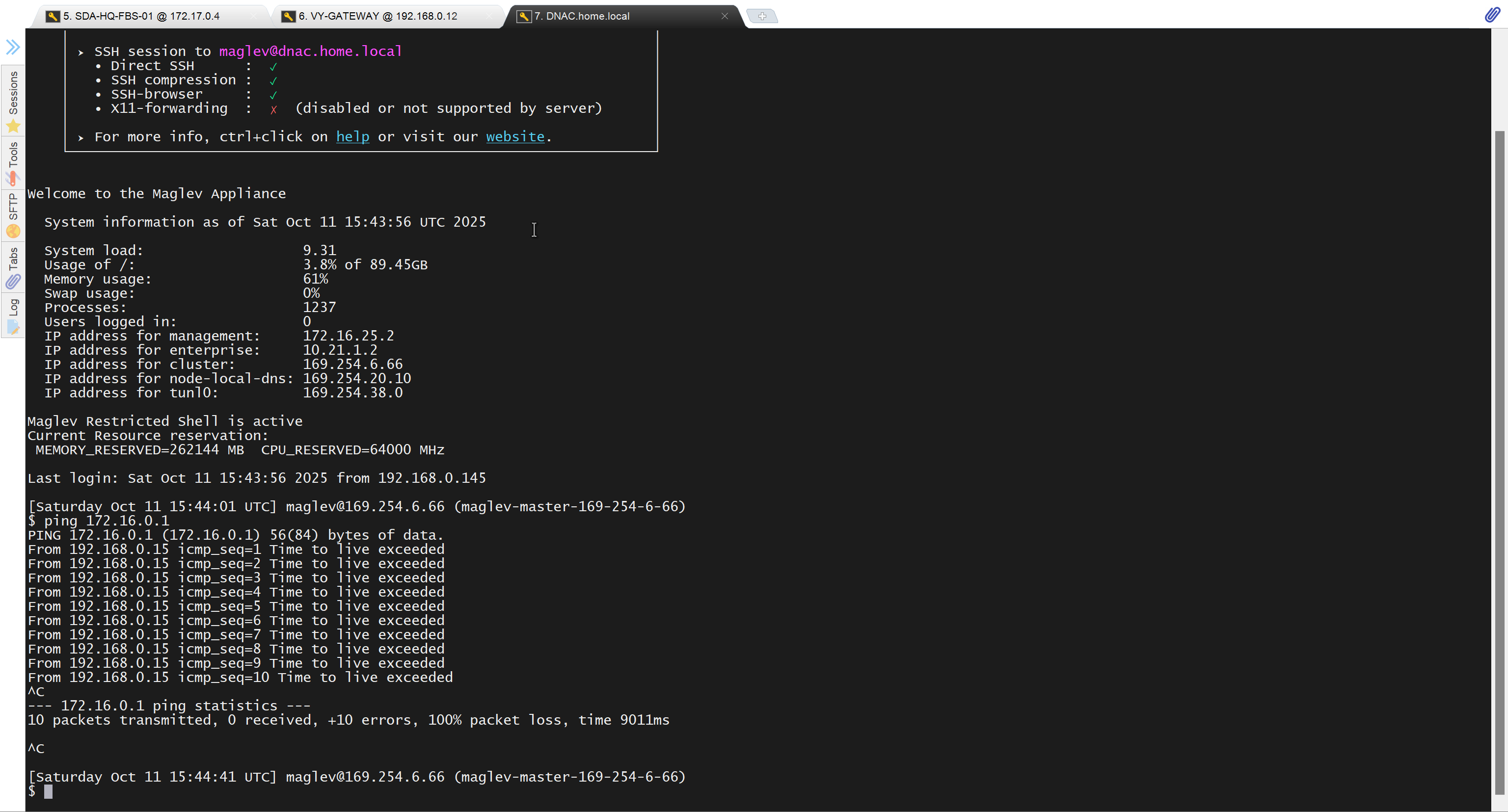
because missing route on HQ-SW in lab
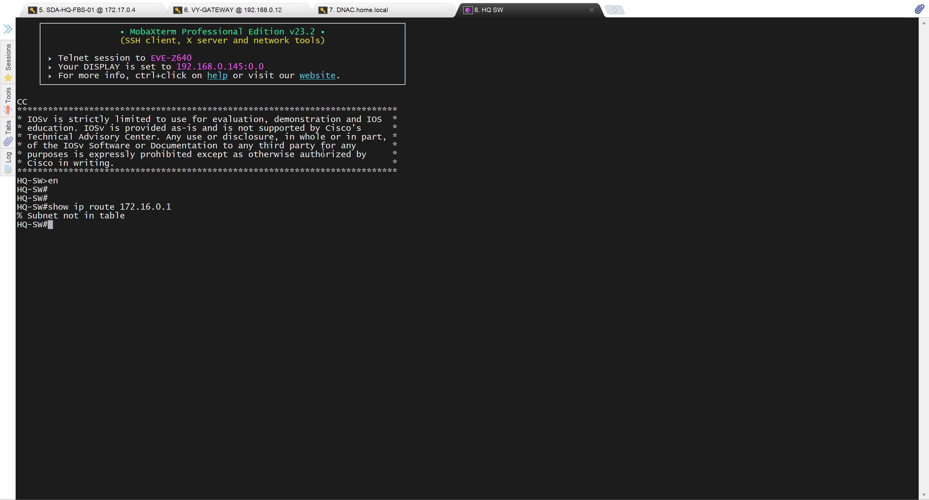
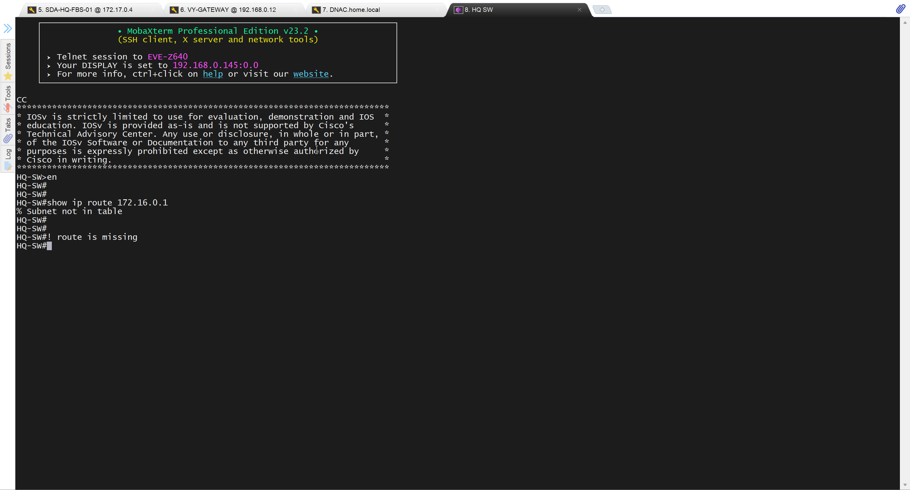
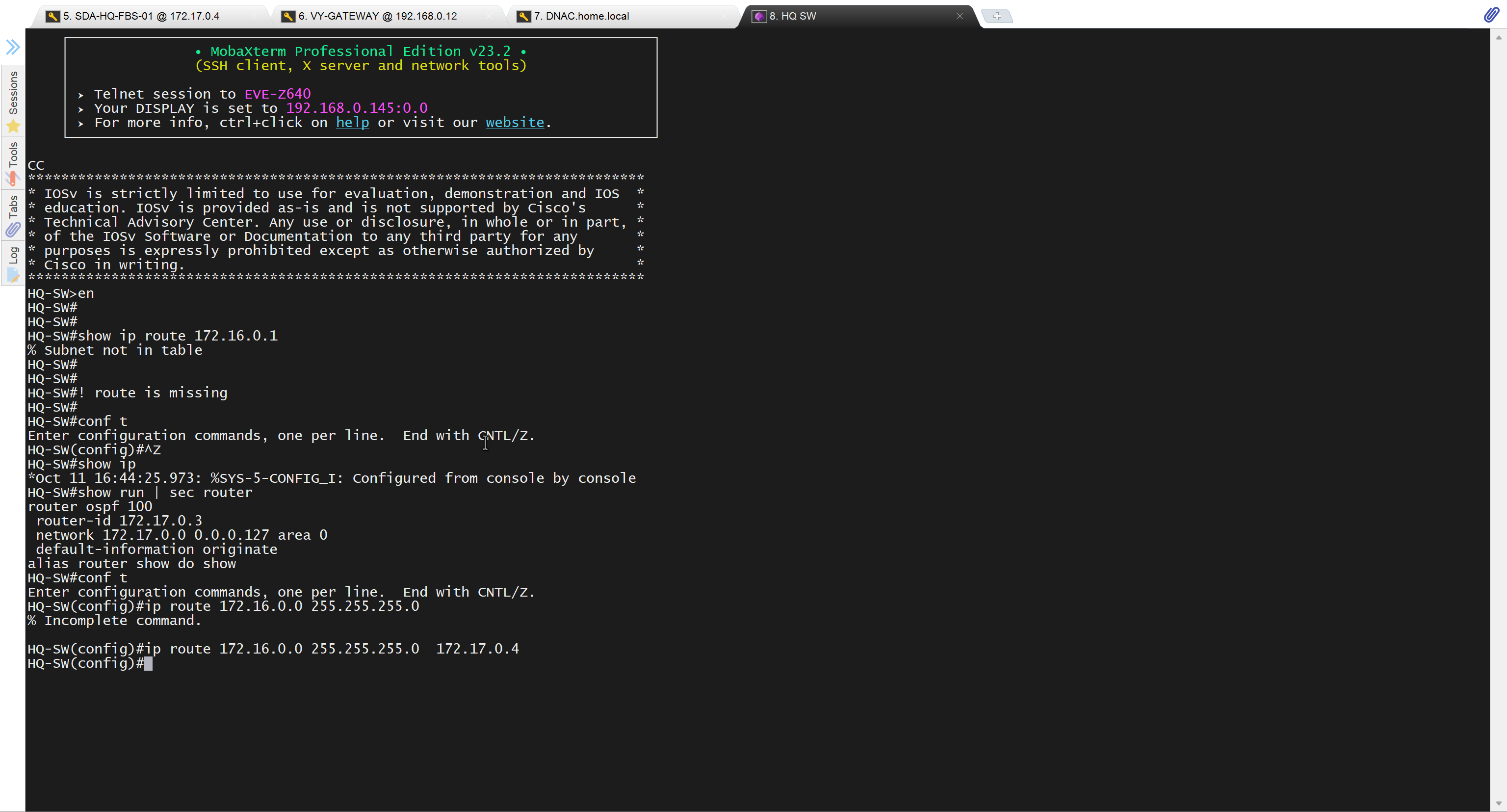
after adding route now we can reach
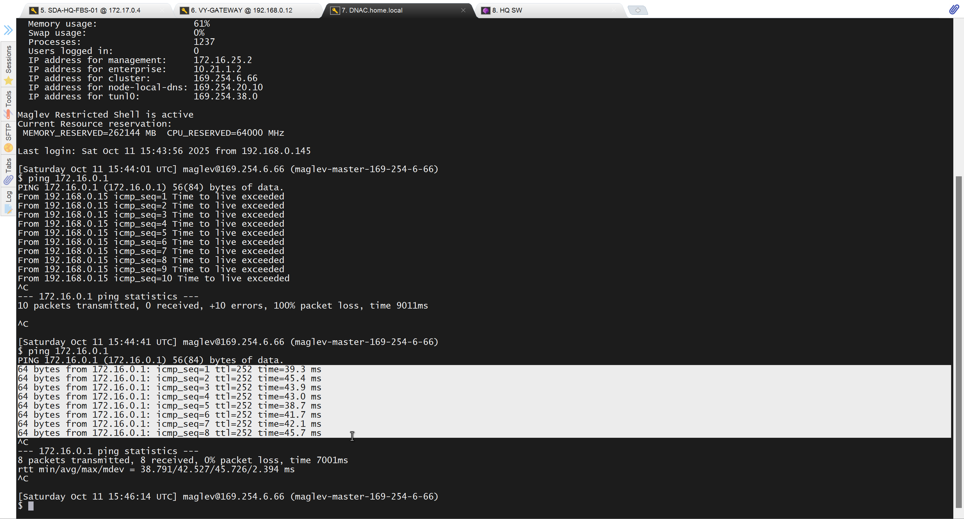
because it was only for testing, we will now remove it
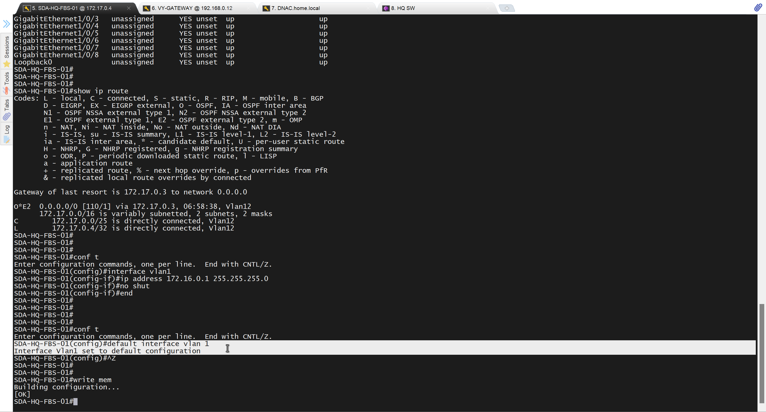
Now lets LAN Automate
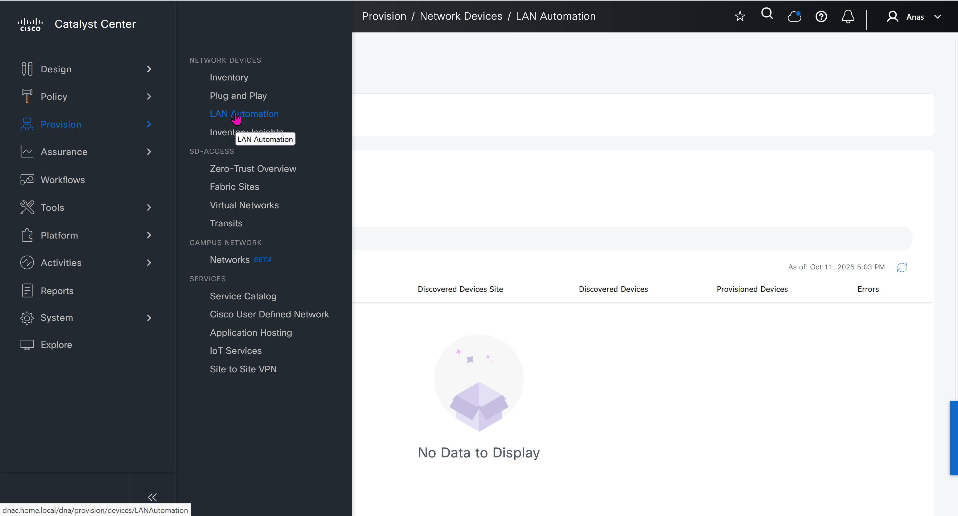
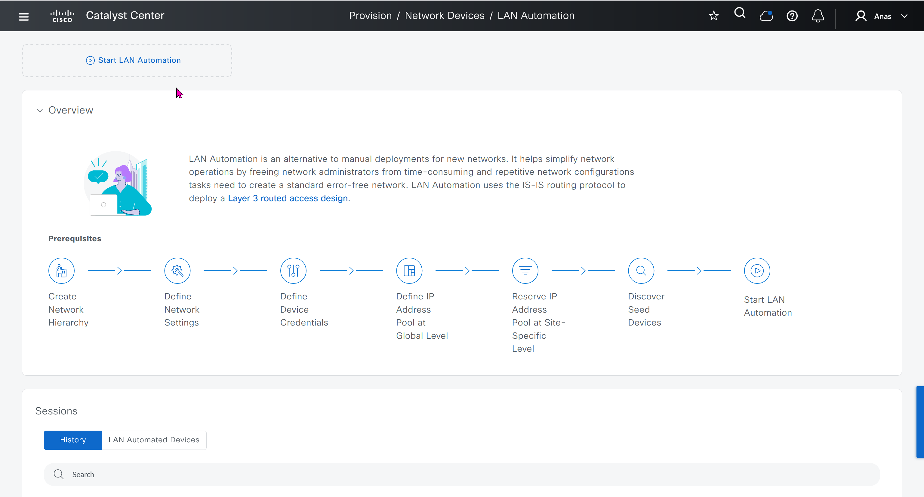
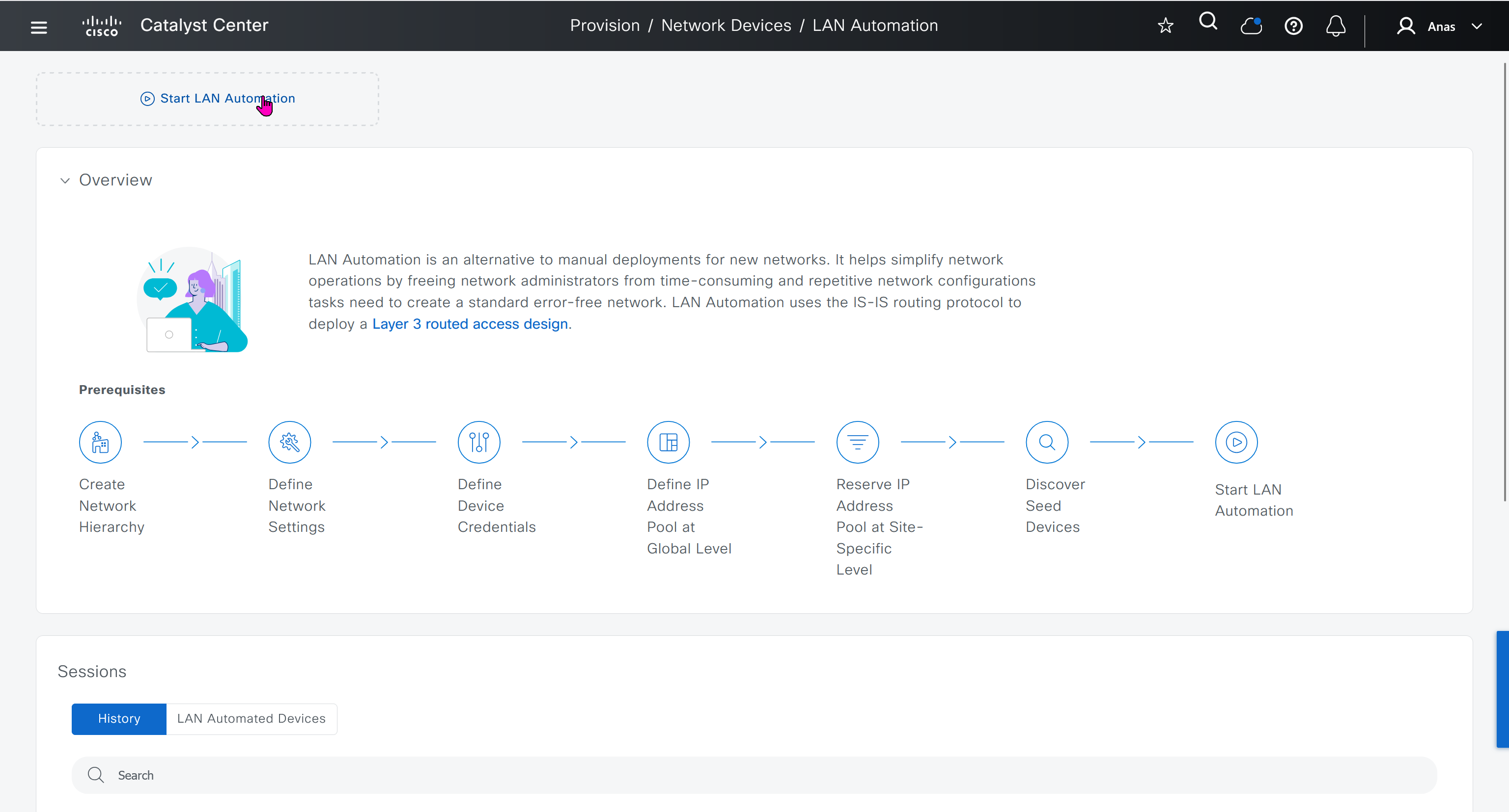
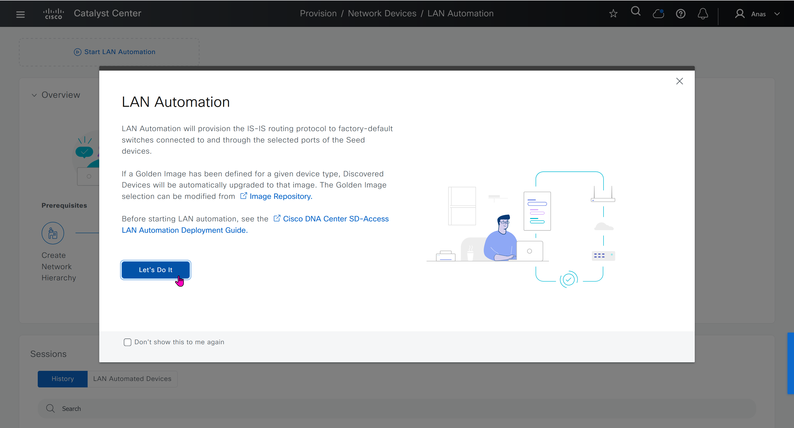
When LAN automation starts, Catalyst Center
pushes the loopback and IS-IS configuration to the primary and peer seed devices and the temporary configuration to the primary seed device
Catalyst Center Release 2.3.3 and later support is-type level-2-only as part of IS-IS configurations.
discovers new devices.
upgrades the device software image and pushes the configuration to discovered devices.
The image is updated only if a golden image is marked for that switch type in Catalyst Center under Design > Image repository.
When LAN automation starts, the temporary configuration is pushed to the primary seed device. This allows the device to discover and onboard the PnP agent. Next, the PnP agent image is upgraded and basic configurations such as loopback address, system MTU, and IP routing are pushed to the PnP agent.
- on PnP agent, Do not press Yes or No. Leave the device in the same state.
- Allow extra time to make sure that all members in the stack are up. Do not start LAN automation until all switches are up.
- LAN automation always begins on the active switch. When all switches in a stack are booted together, the switch with the lowest MAC address (assuming no switch priority is configured) becomes active. The switch with the second lowest MAC address becomes the standby, and so on. Some customers require the first switch to always be active. In this case, if all the switches are booted together and the first switch does not have the lowest MAC address, it does not become the active switch. To ensure that the first switch is active, boot the switches in a staggered manner: boot Switch 1; after 120 seconds, boot Switch 2, and so on. This approach ensures that the switch becomes active in the correct order—Switch 1 is active, Switch 2 is standby, and so on. However, after a reload, the order may change because switches obtain their role based on their MAC address.
- To make sure that the switches maintain their order after reload, it is a good practice to assign switch priorities to ensure that the switches always come up in the same order. The highest priority is 15. During LAN automation, the priority of active switch is set to 15 by default. The priority of other switches is not altered. When priorities are assigned, they take precedence over the switch MAC address. Assigning switch priorities does not change the NVRAM configuration. The values are written to ROMMON and persist after reload or write erase. Refer to this sample code:
3850_edge_2#switch 1 priority ? <1-15> Switch Priority 3850_edge_2#switch 1 priority 14 WARNING: Changing the switch priority may result in a configuration change for that switch. Do you want to continue?[y/n]? [yes]: y- You might have to clean up the switch after assigning priorities using “
pnpa service reset no-prompt“ - Connect PnP agents directly to seed devices. Do not connect PnP agents to any other network (for example, even the management network)
Interface Selection
consider four directly connected PnP agents: device 1 is connected through Gig1/0/10, device 2 through Gig 1/0/11, device 3 through Gig 1/0/12, and device 4 through Gig 1/0/13. If you choose Gig 1/0/11 and Gig 1/0/12 as discovery interfaces, LAN automation discovers only device 1 and device 2. If device 3 and device 4 try to initiate the PnP flow, LAN automation filters them because they connect through unselected interface.
You can also choose interfaces between the primary seed and the peer seed to configure with Layer 3 links. If there are multiple interfaces between the primary and peer seeds, you can choose to configure any set of these interfaces with Layer 3 links. If no interfaces are chosen, they aren’t configured with Layer 3 links.
You can reuse the same LAN pool for multiple LAN automation sessions. For example, you can run a discovery session to find the initial set of devices. After the session completes, you can provide the same IP pool for subsequent LAN automation sessions. Similarly, you can choose a different LAN pool for other discovery sessions. Make sure the LAN pool you select has enough capacity.
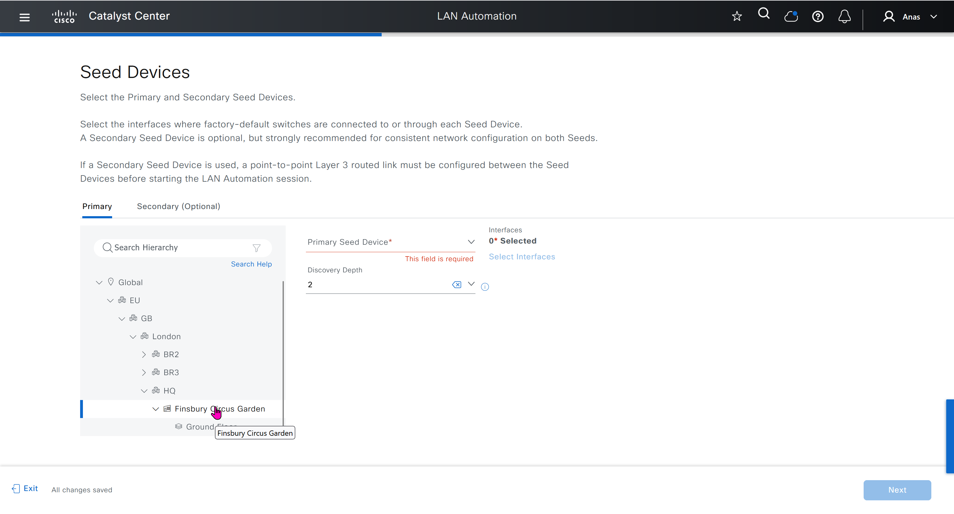
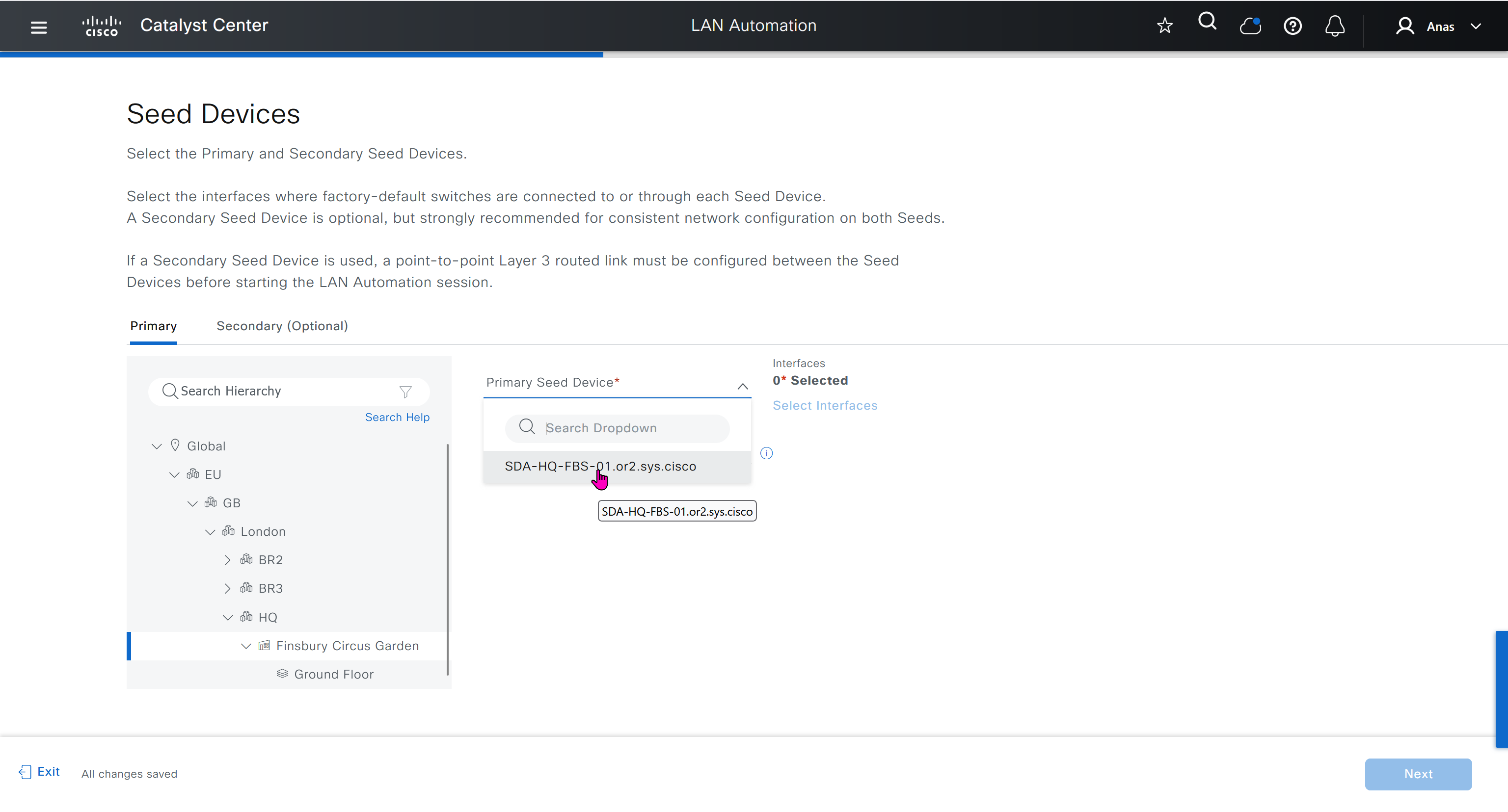
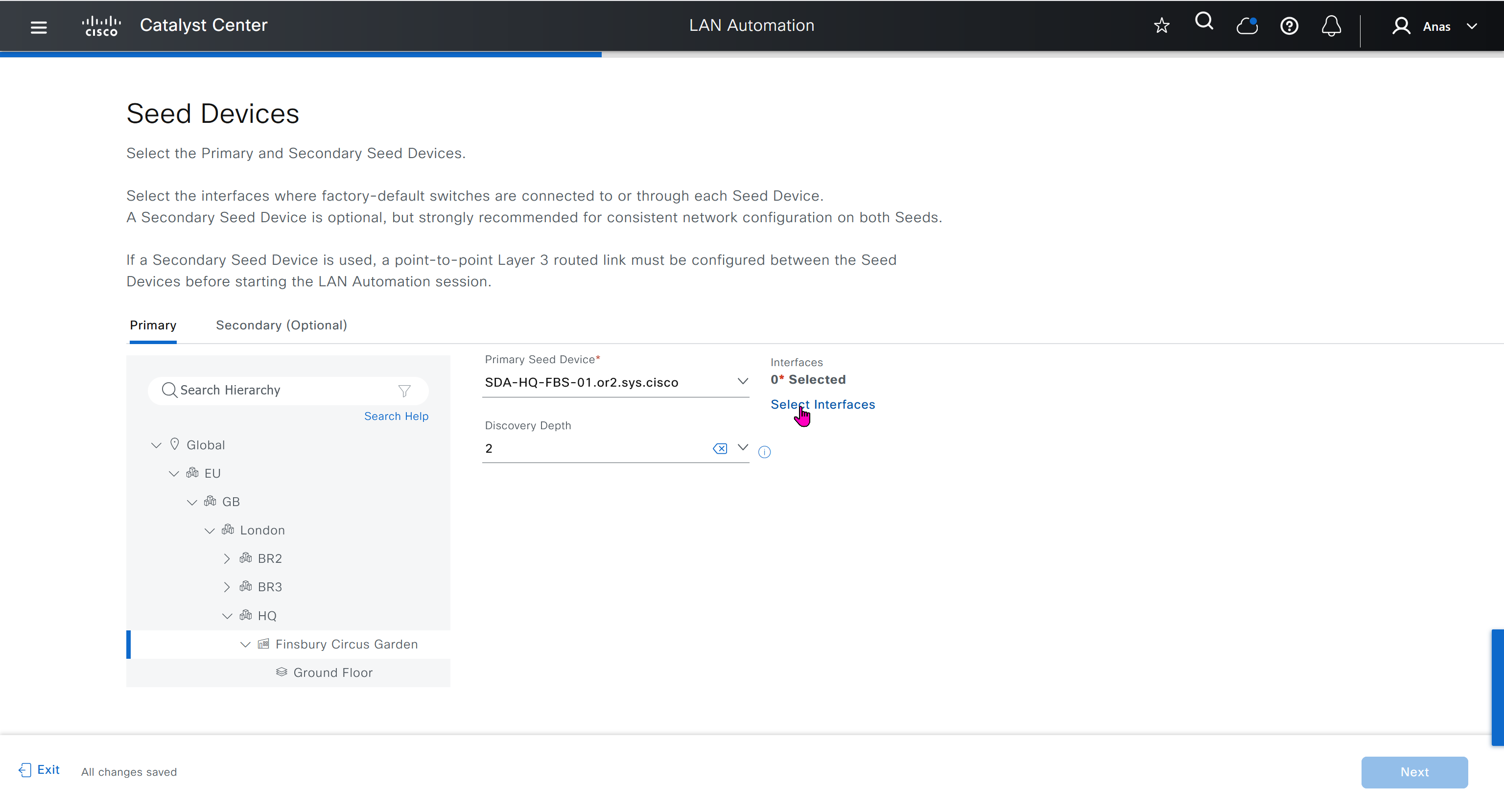

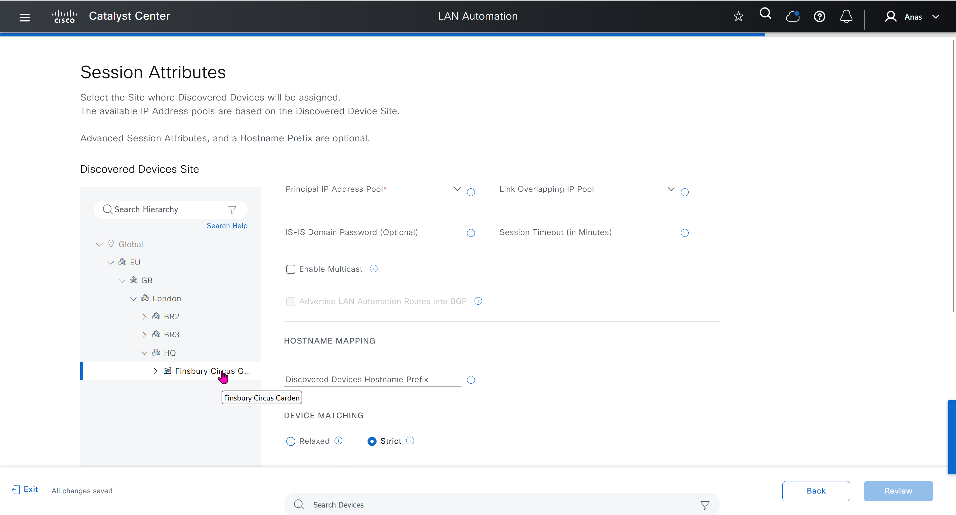
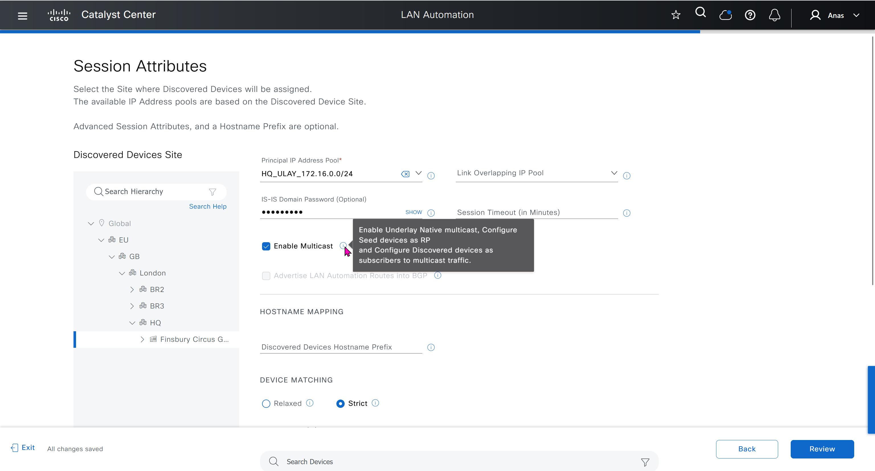


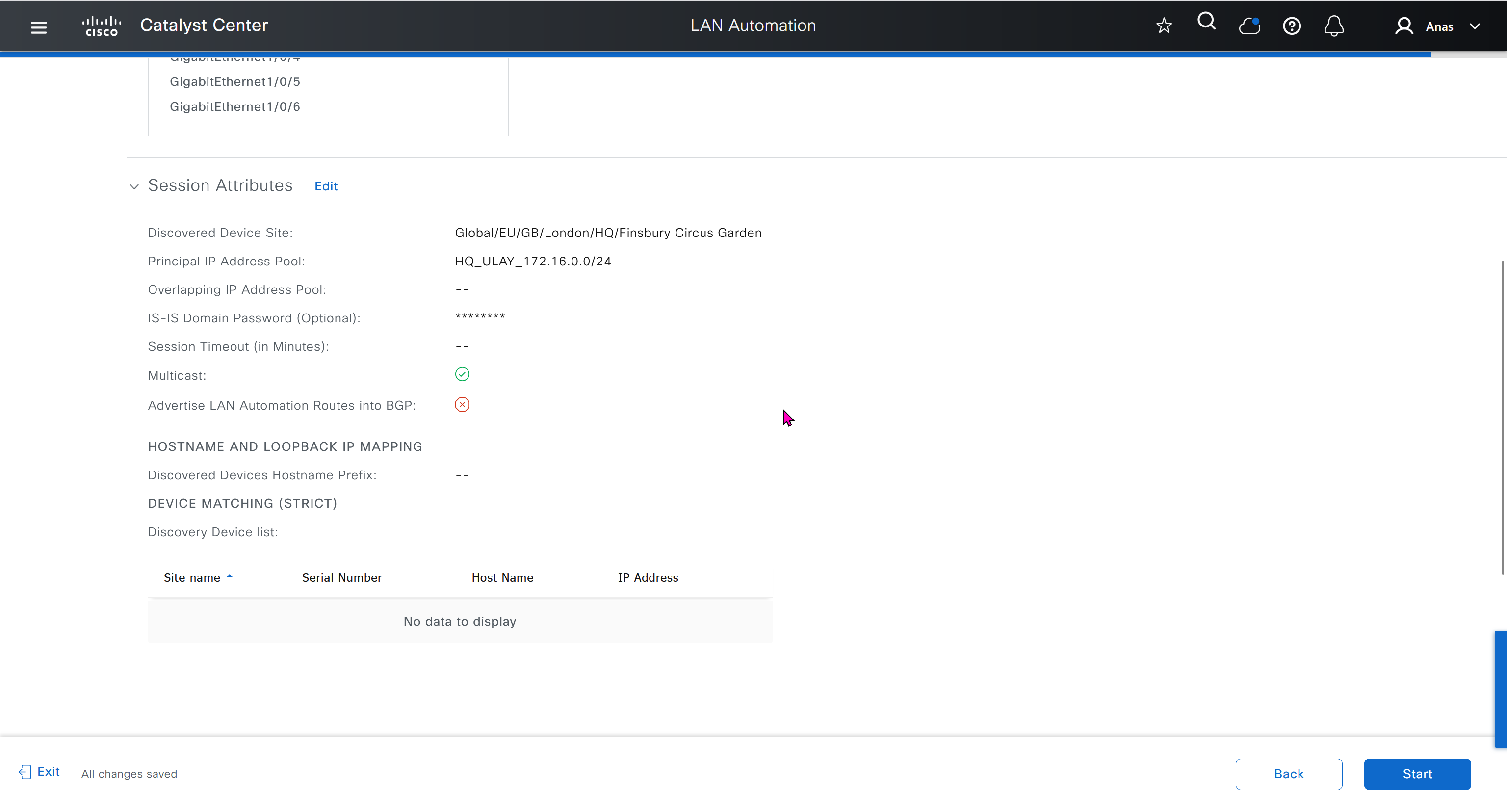
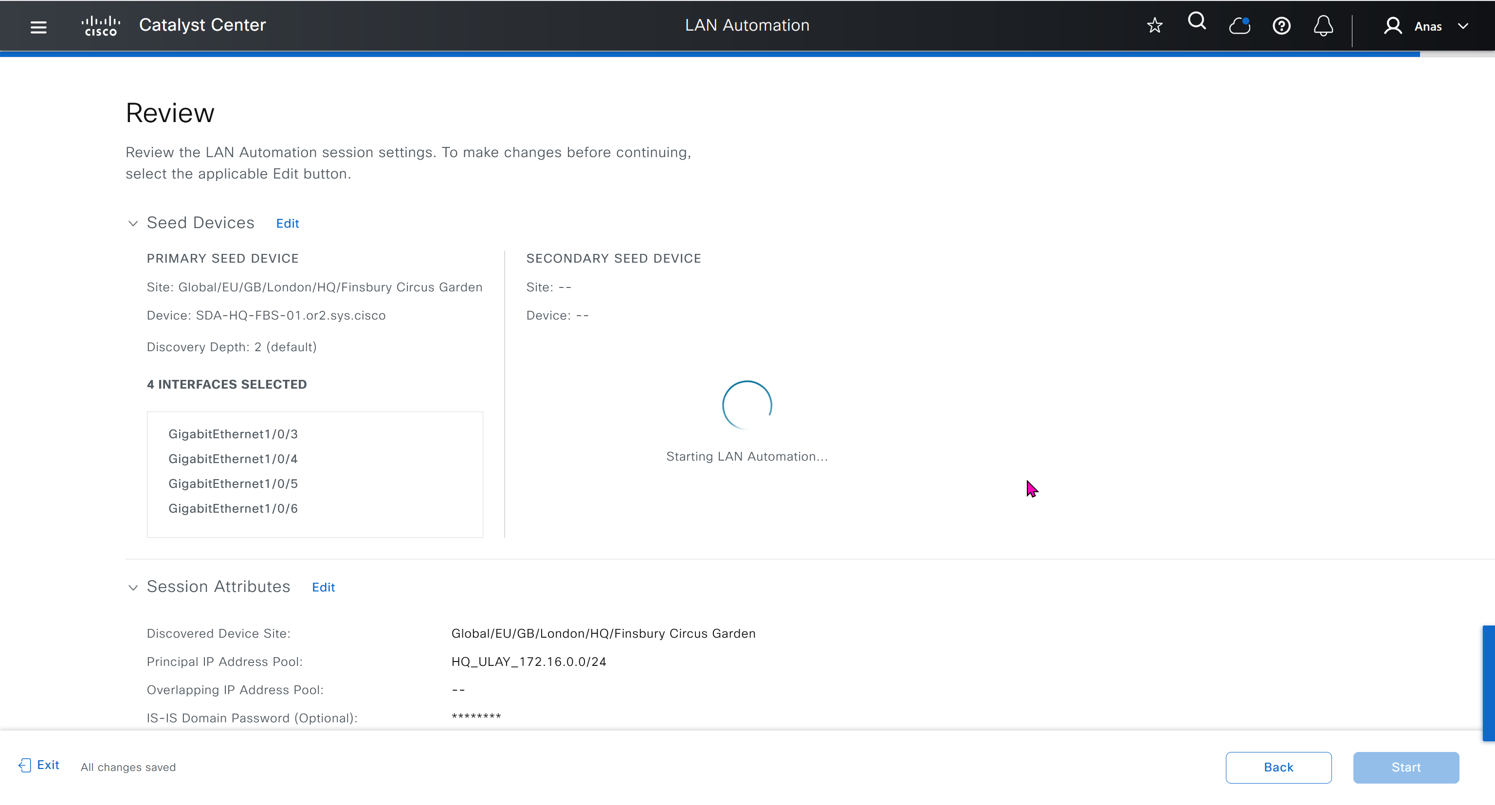
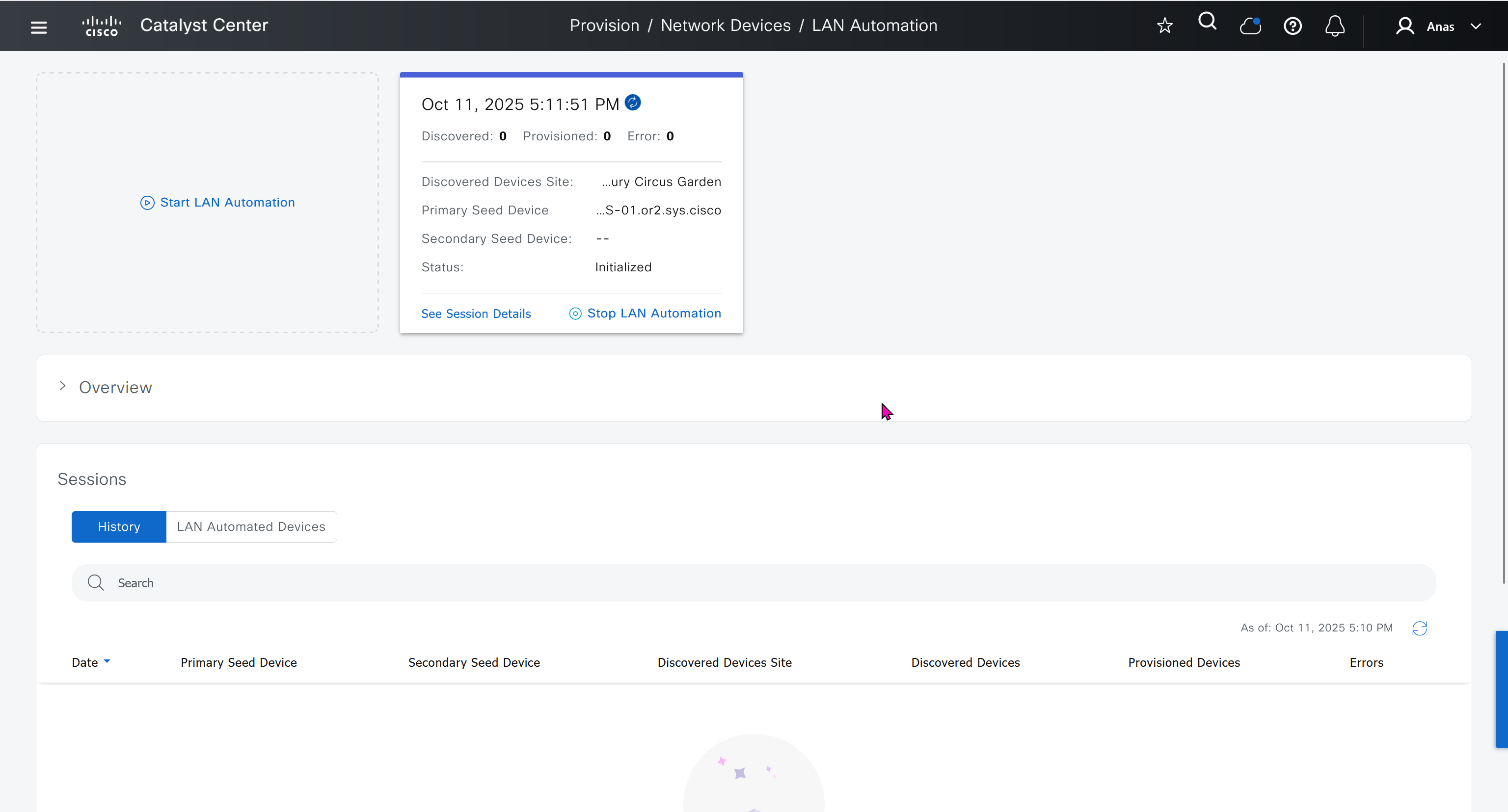
in order to catch all commands pushed by LAN automation to switches add below config and sync with DNAC
conf t
!
! Enable the archive feature
archive
 log config
  logging enable
  notify syslog contenttype plaintext
  hidekeys
!
! Optional: Set up where the archived configs are stored
 path flash:config-archive
 write-memory
!
end
!
! Ensure syslog logging is enabled (optional but recommended)
conf t

logging buffered 64000
service timestamps log datetime msec
!
end
write mem who
show user
! to see if DNAC is logged in and running commands
! to see commands
show logg | inc CFGLOG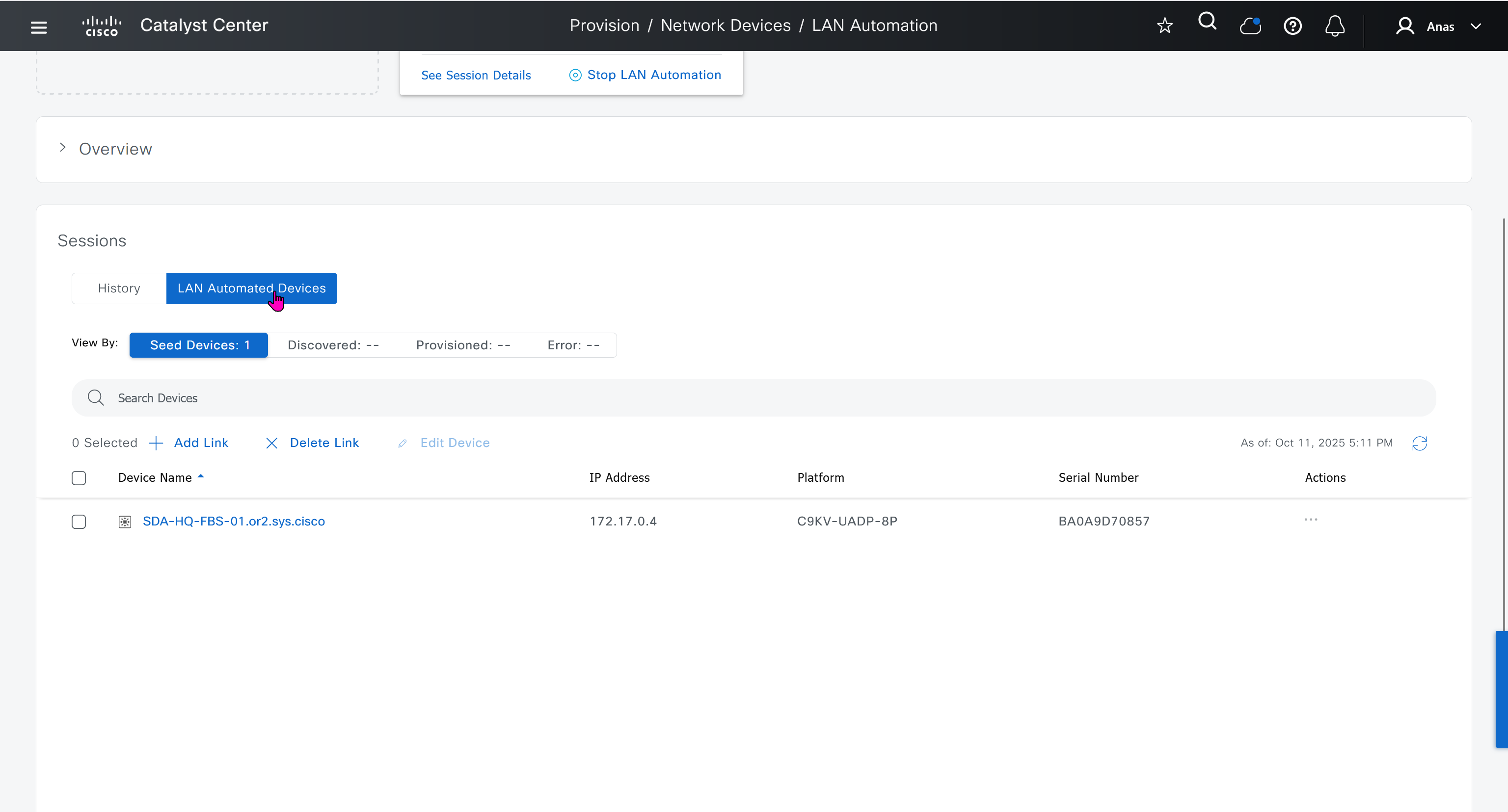
- Quickly as confiiguration is being deployed, intervene and remove using “no” following part of the configuration from “all” switches / routers
- router isis
net 49.0000.280e.ab15.fa02.00
is-type level-2-only
domain-password C0mplex30
metric-style wide
log-adjacency-changes
nsf ietf
bfd all-interfaces
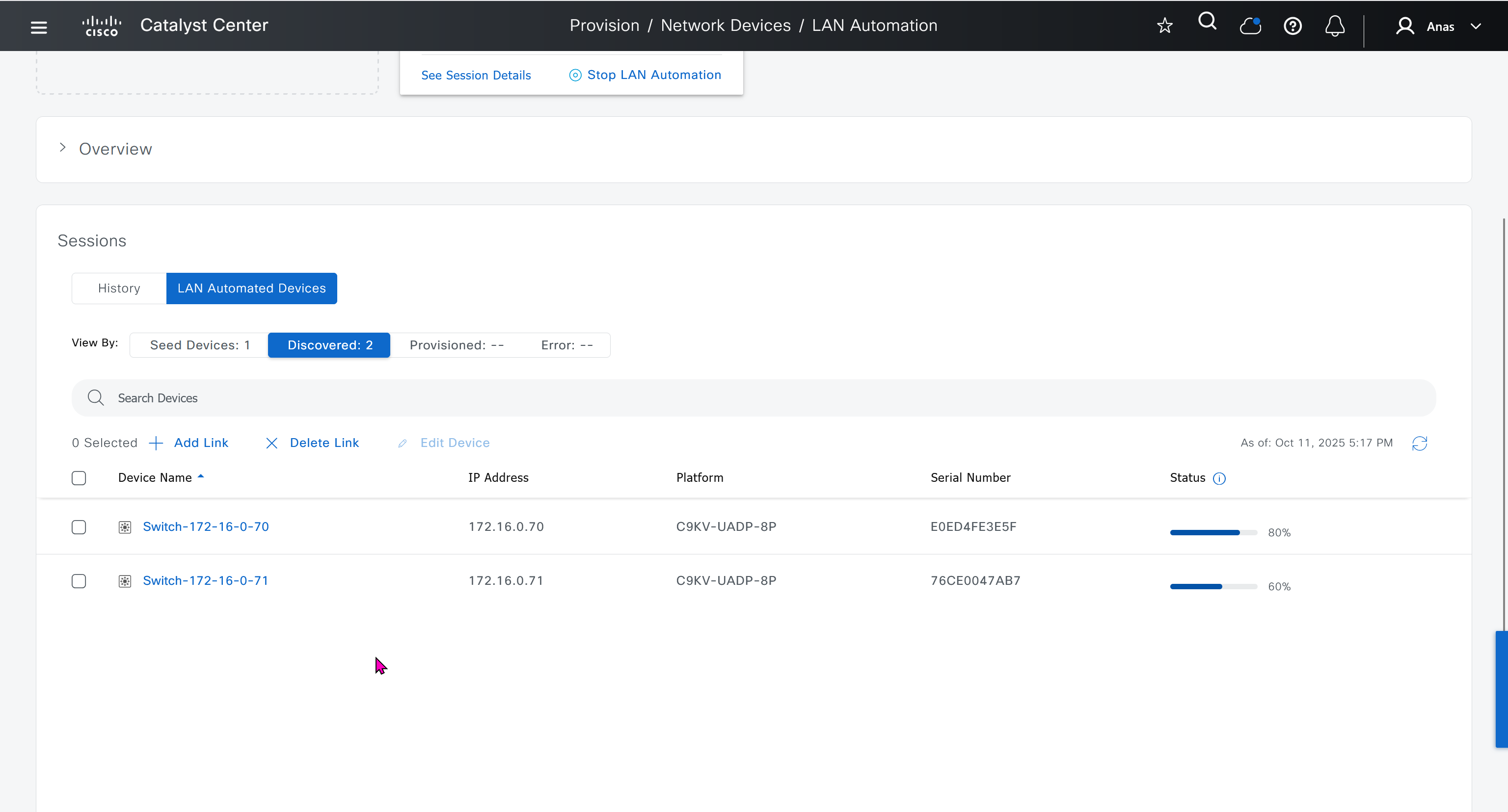


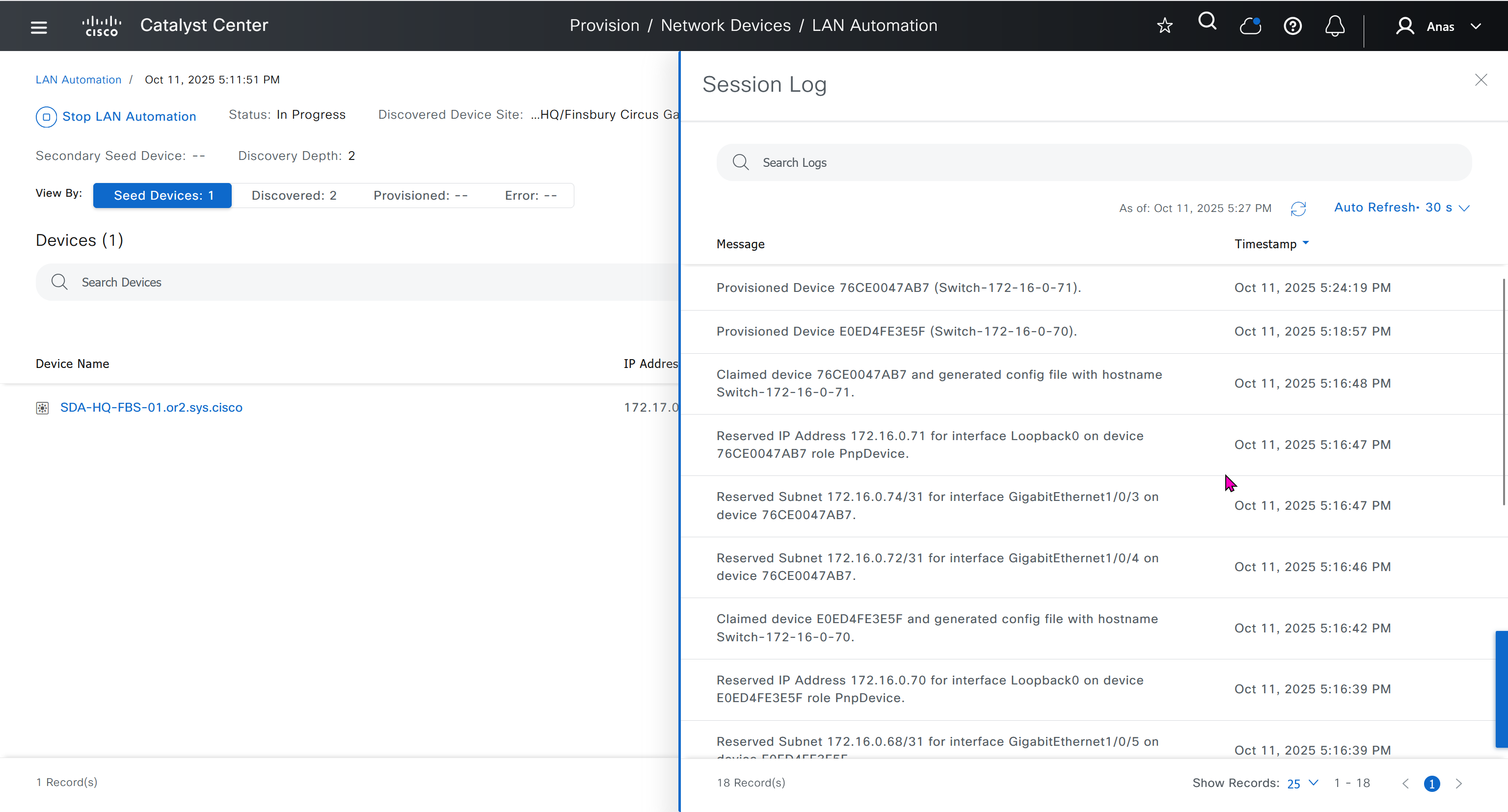
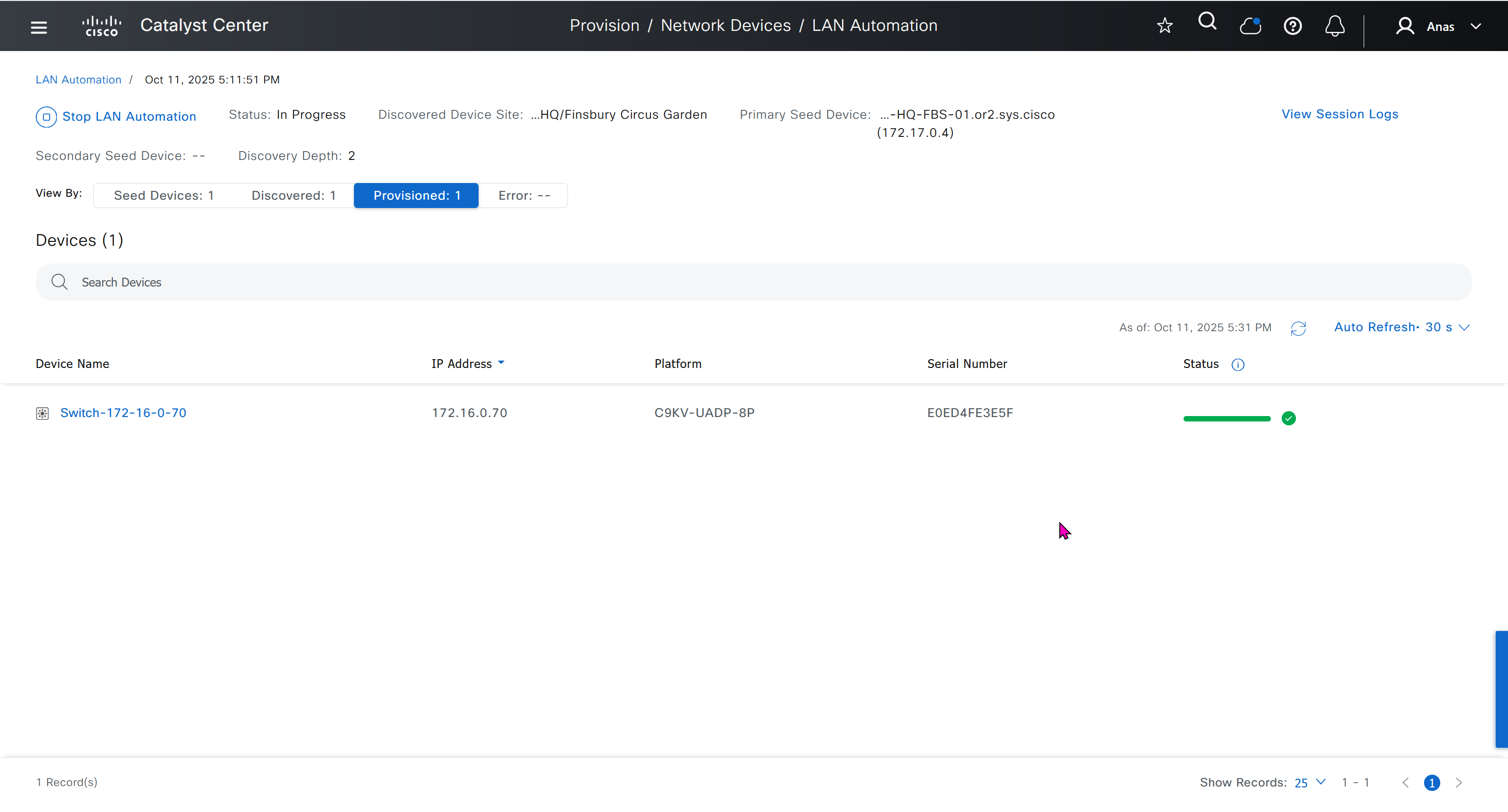
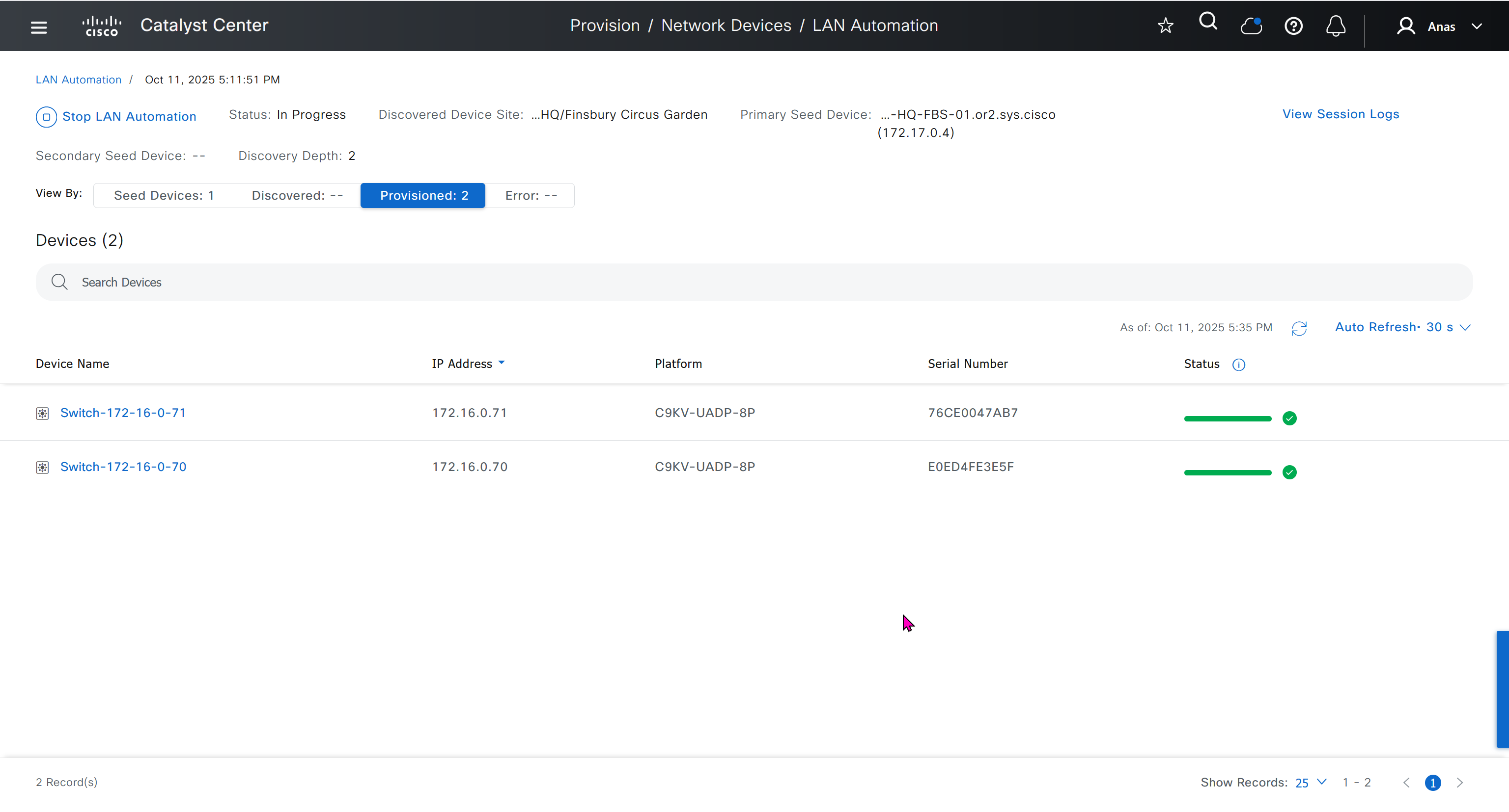
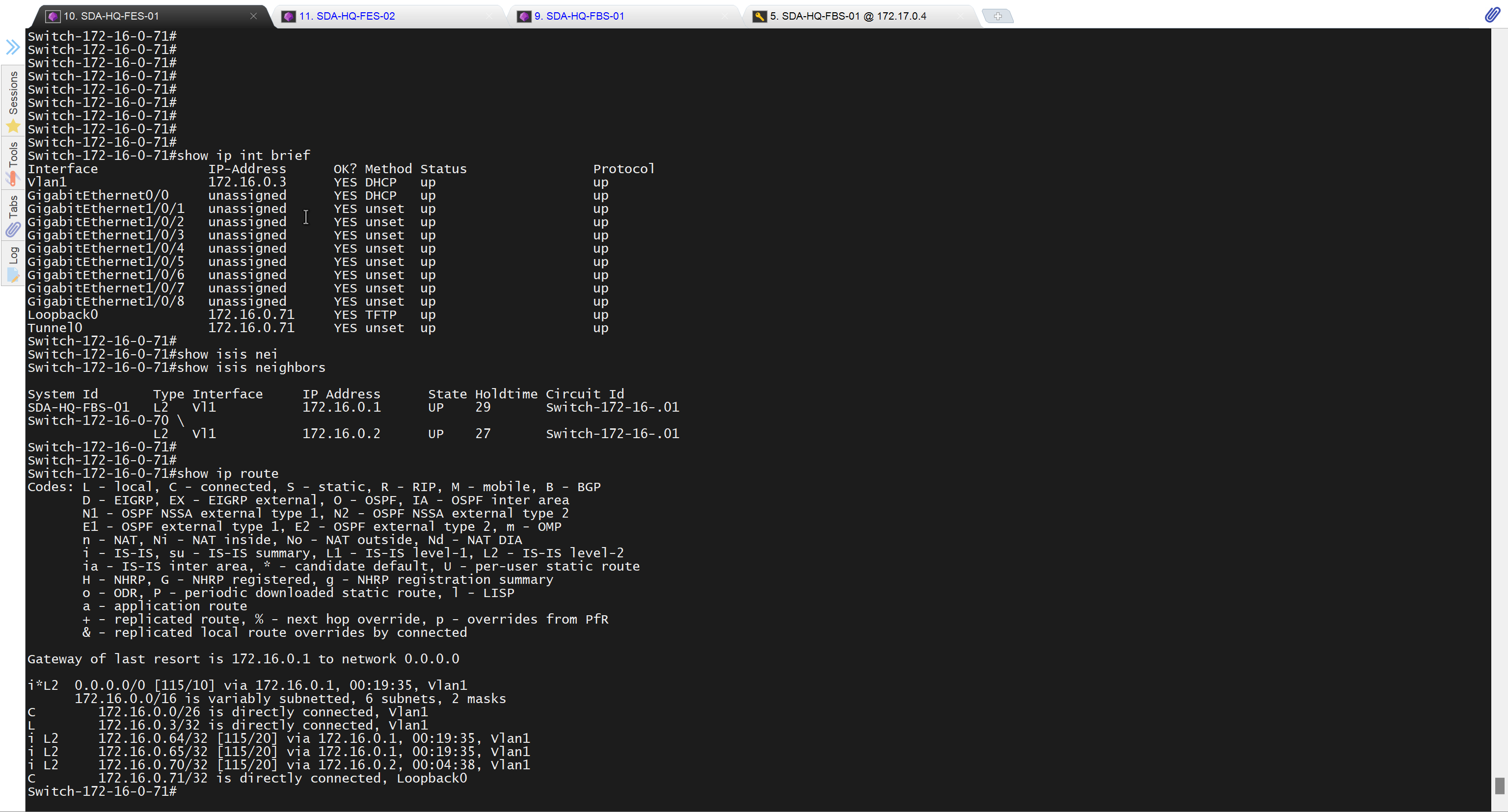

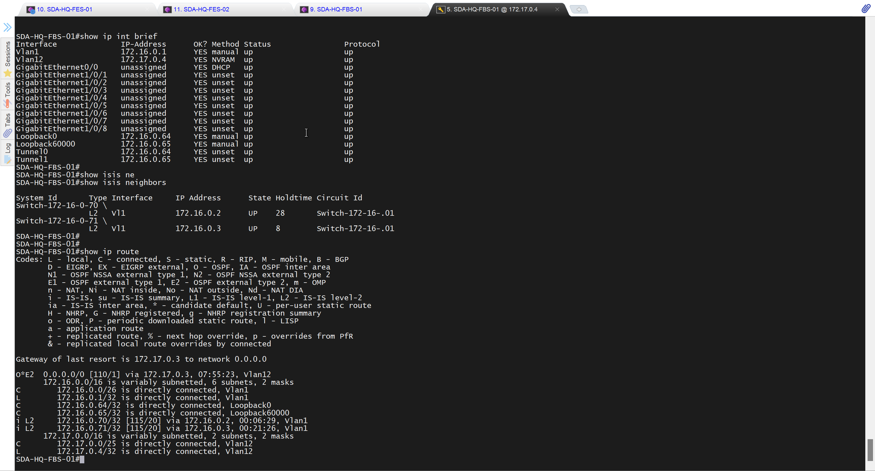

It takes long time to stop LAN automation
When the LAN automation process stops,
the discovery phase ends, and all point-to-point links between the seed and discovered devices and between the discovered devices (maximum of two hops) are converted to Layer 3.


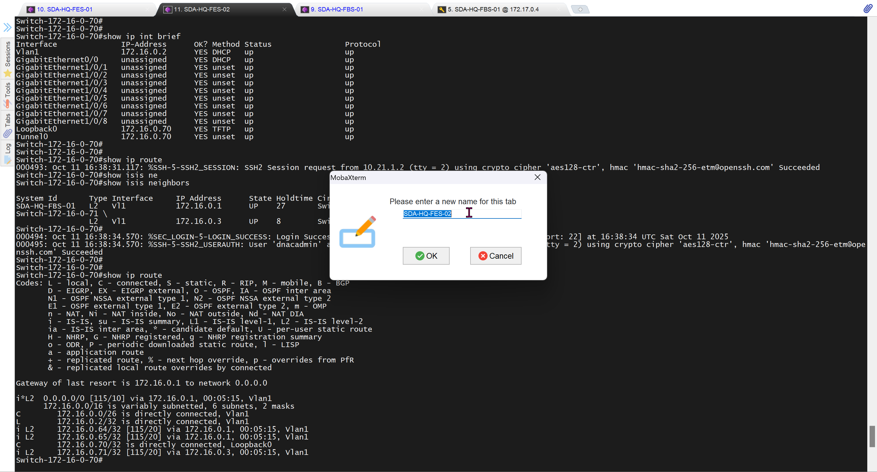
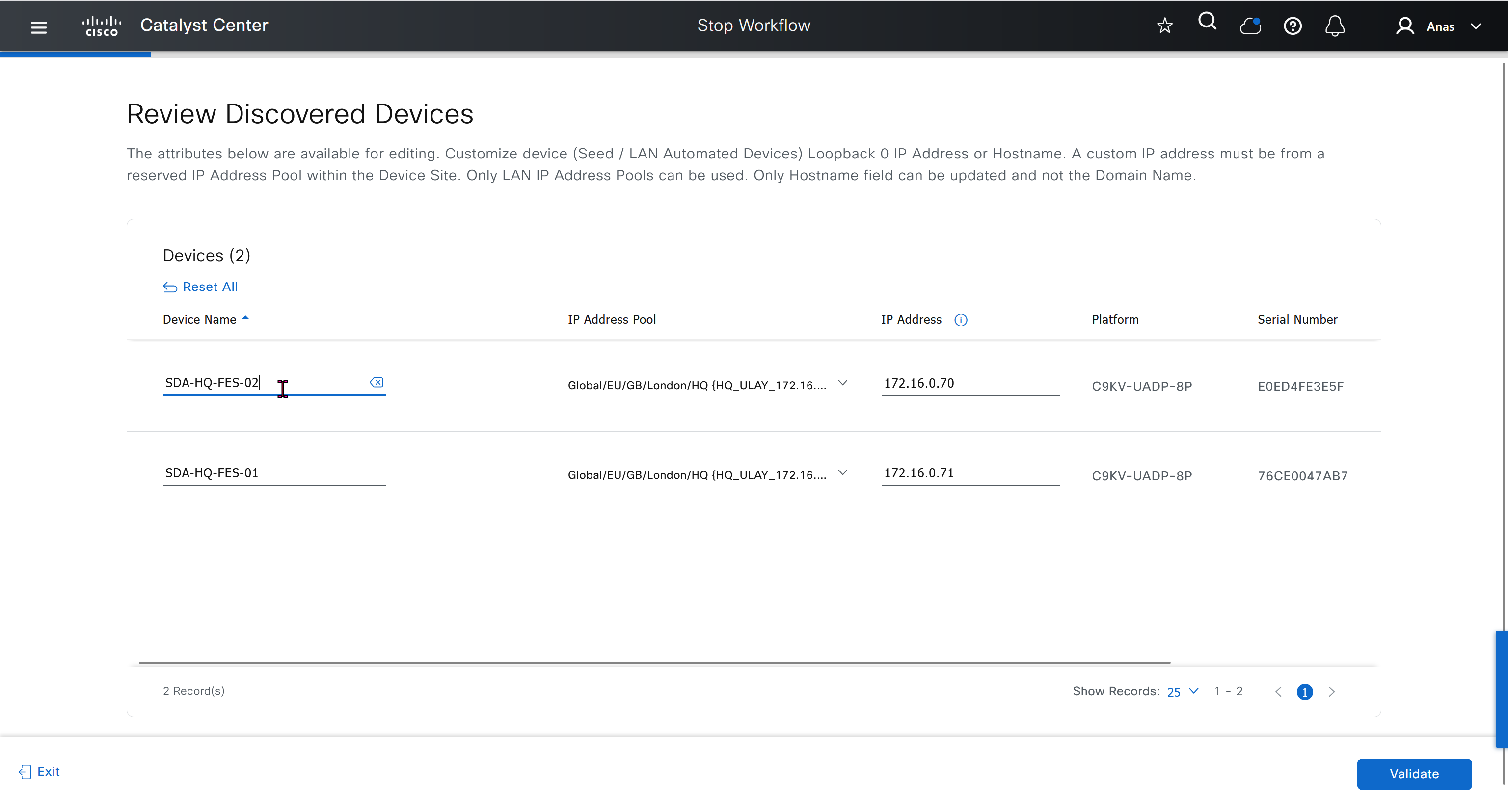


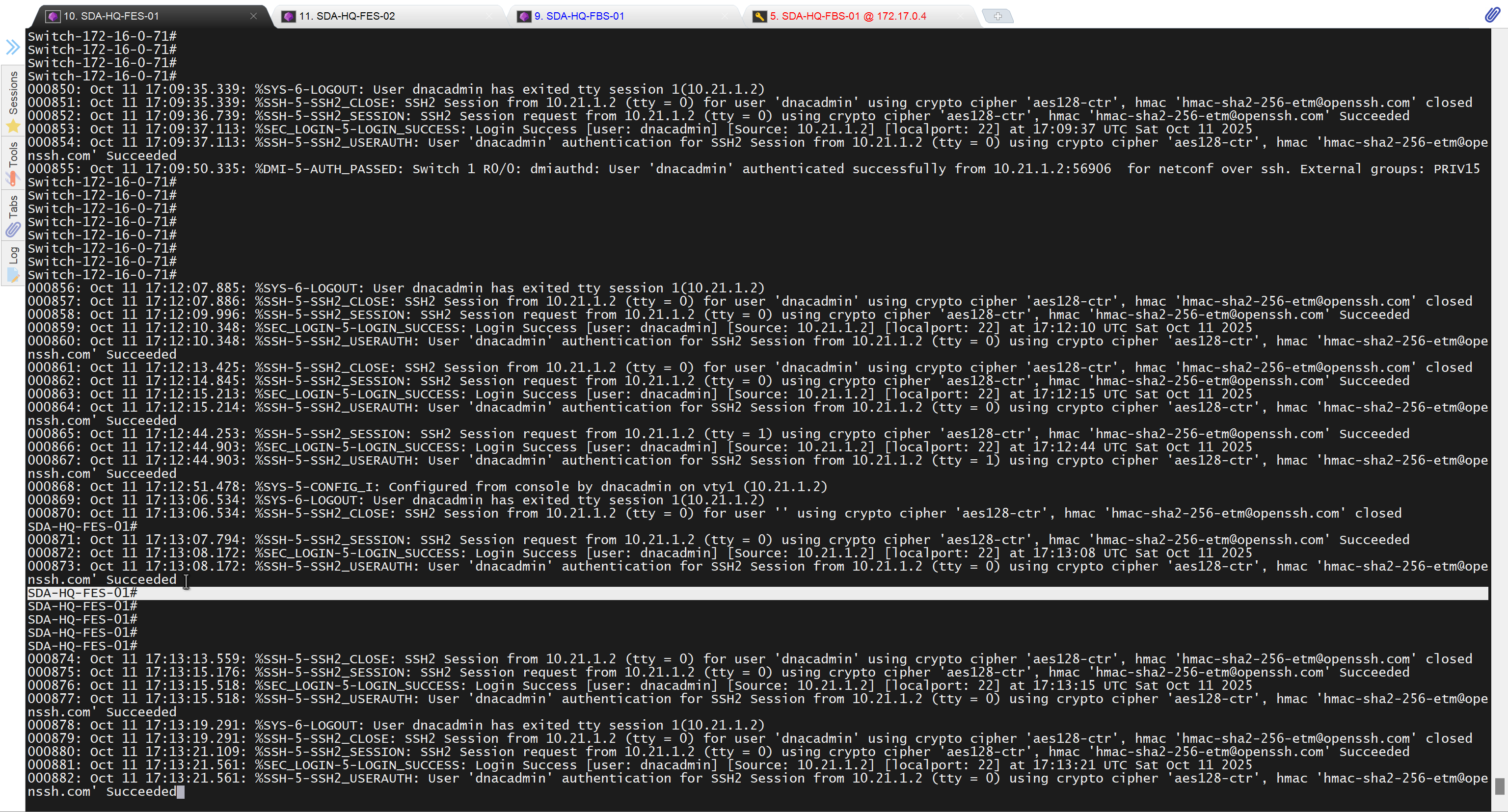
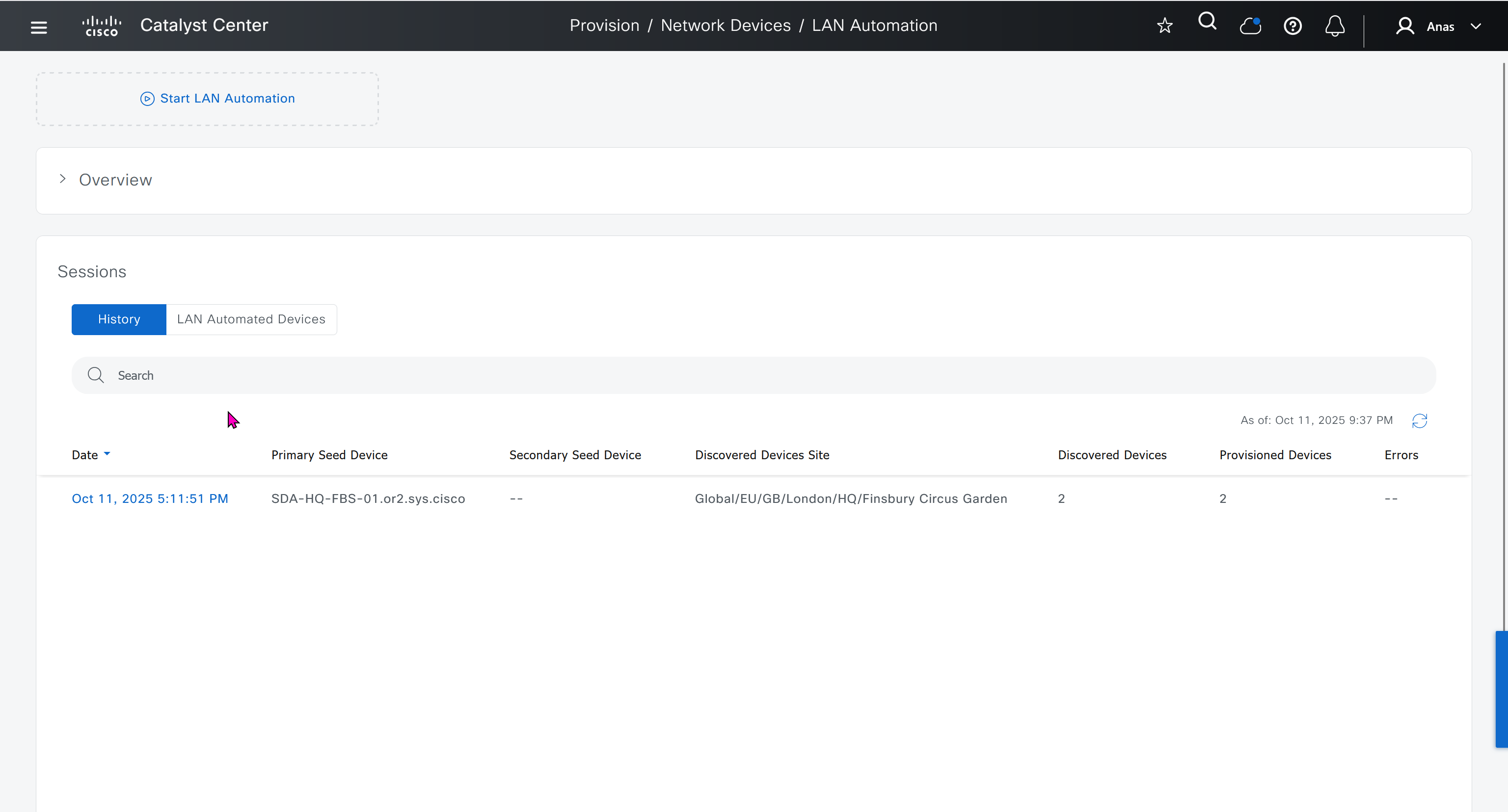

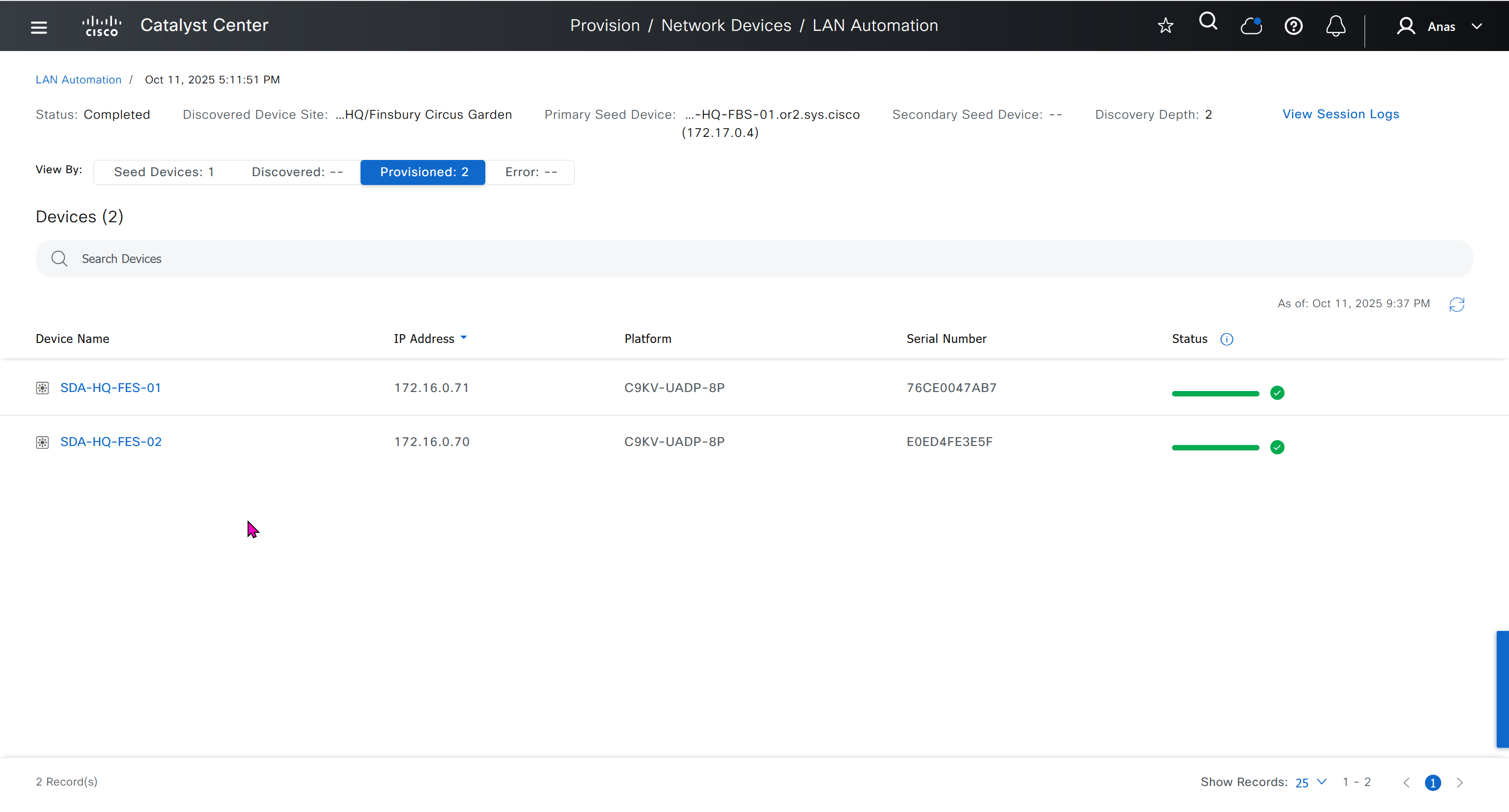
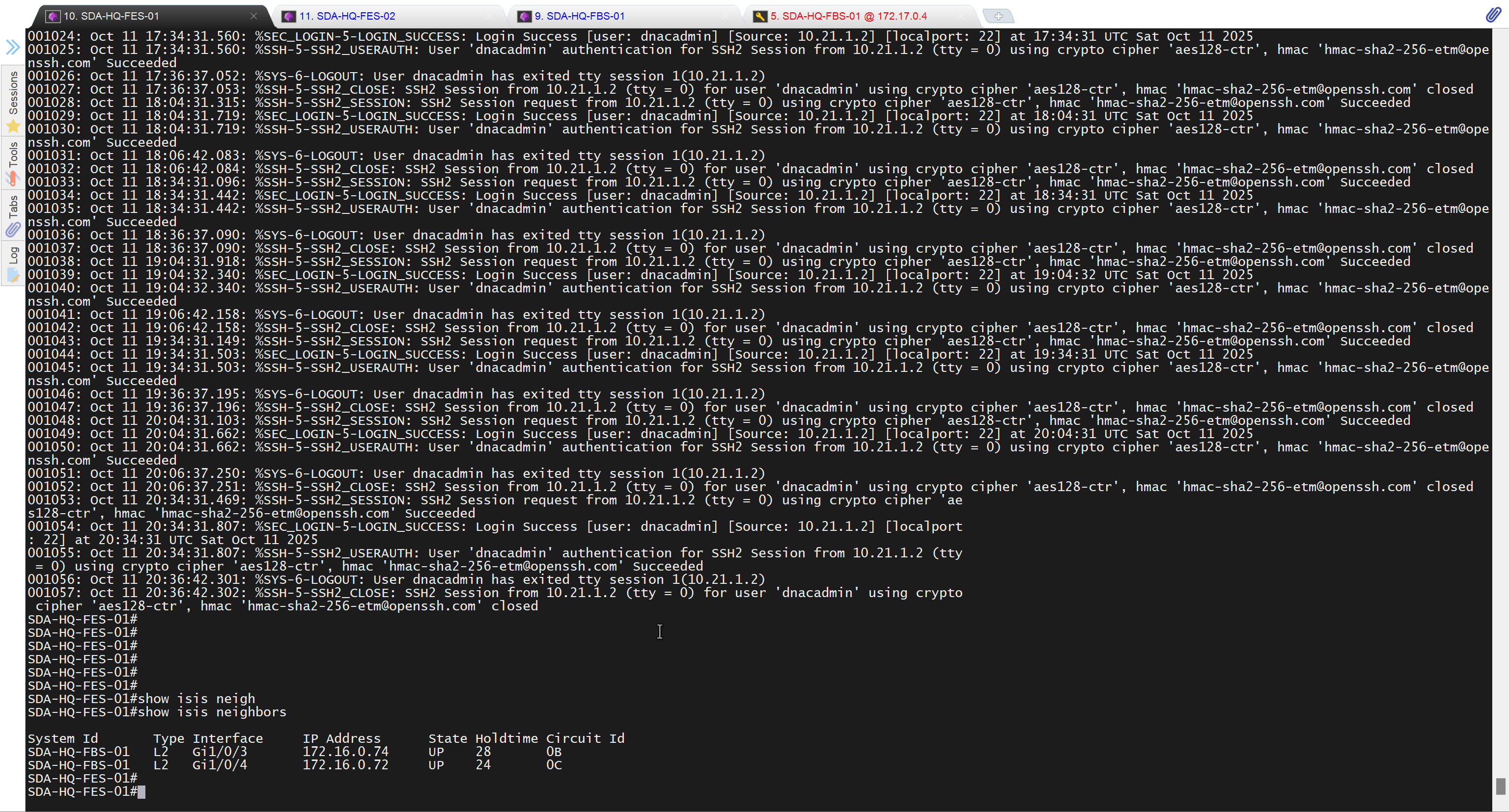

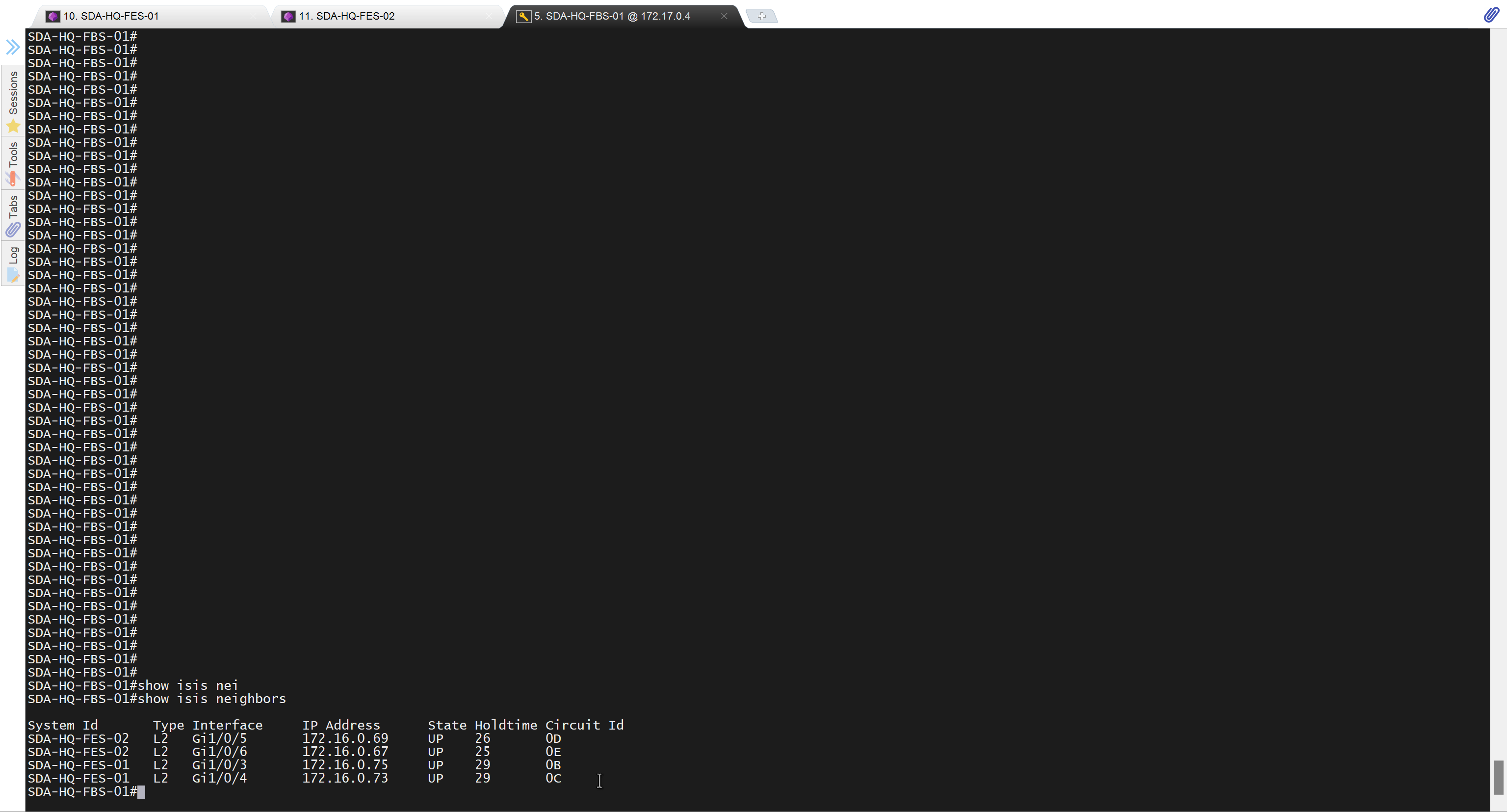
Add a static route for LAN pool on DNAC through Enterprise facing interface
Skipped but complete it for CCIE LAB
next post
SDA LM3 – Topology & Software Image Management
Videos
Topology & Software Image Management

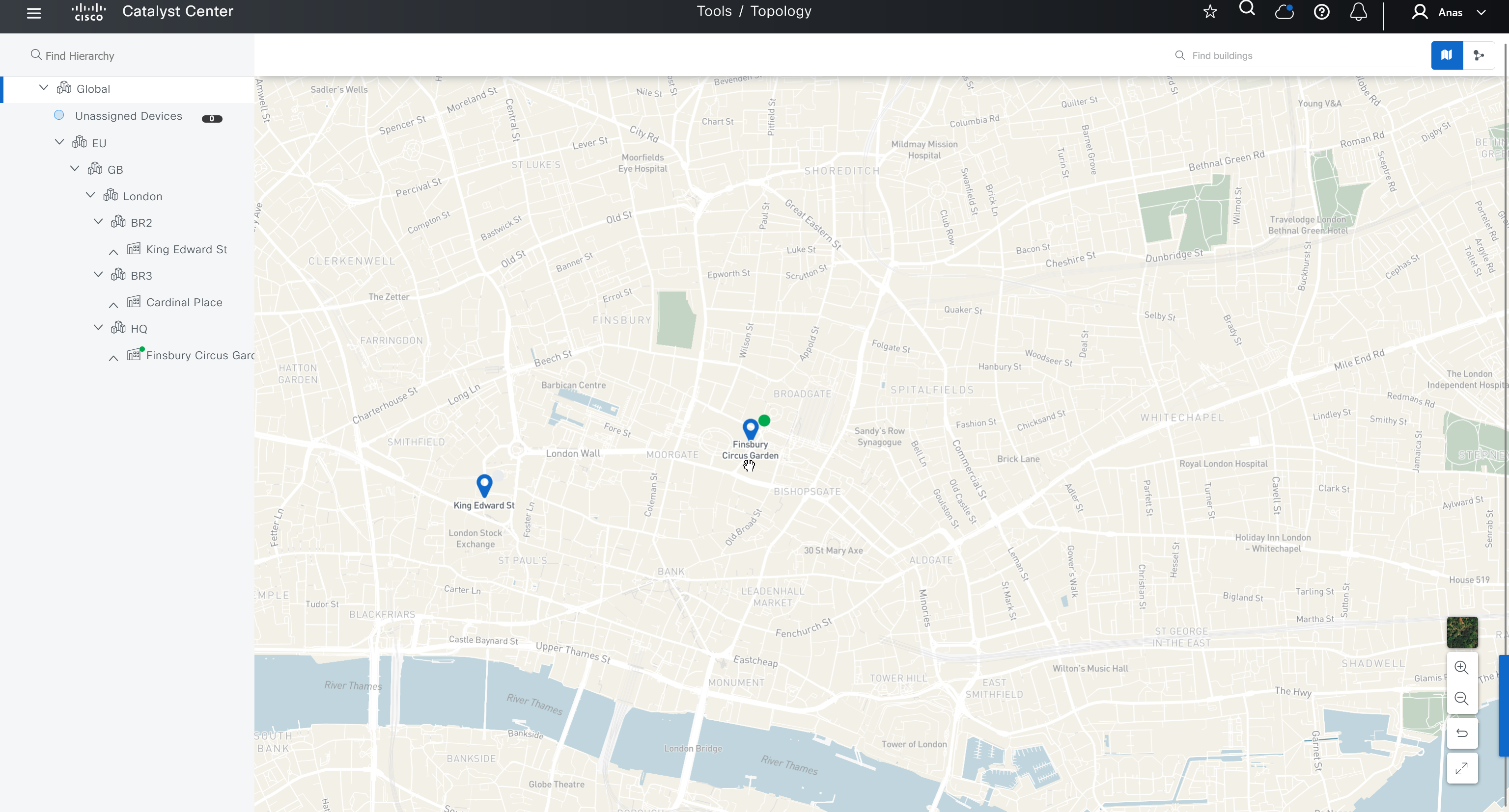


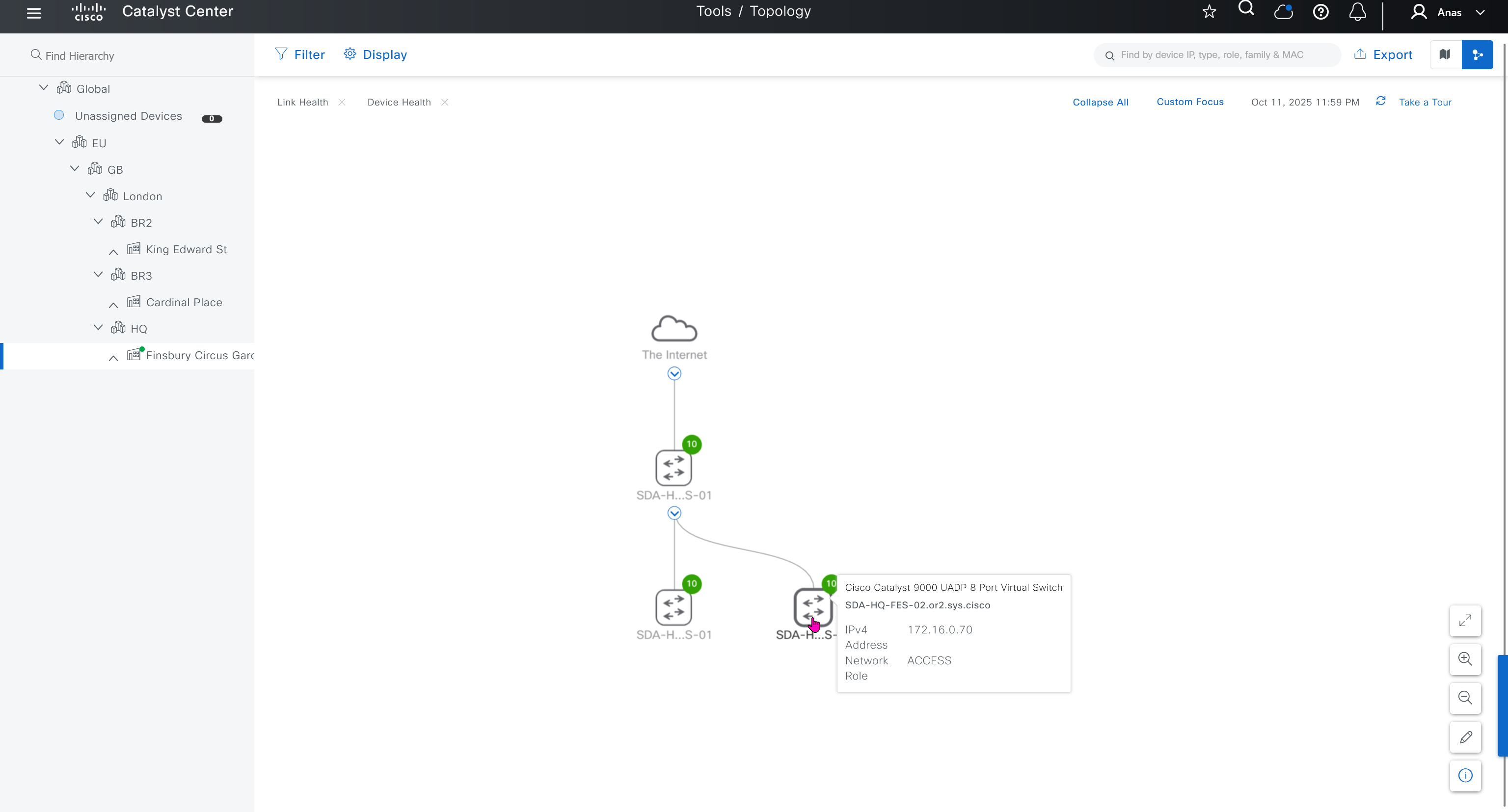
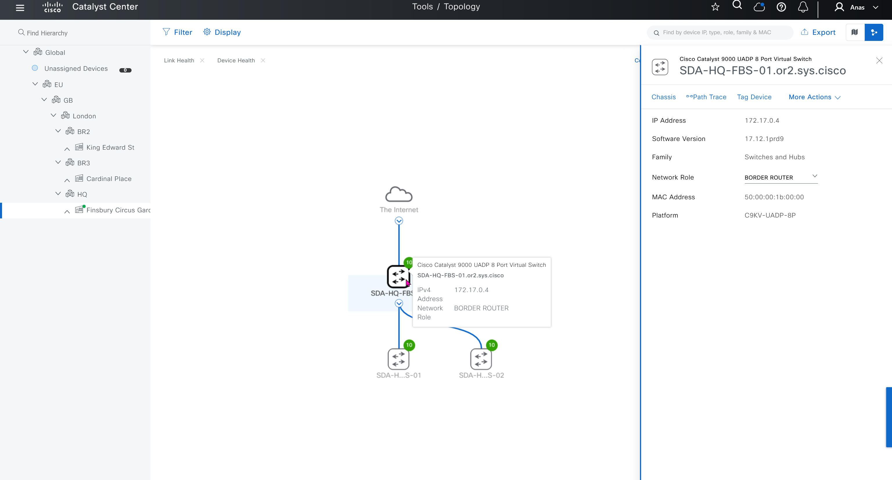
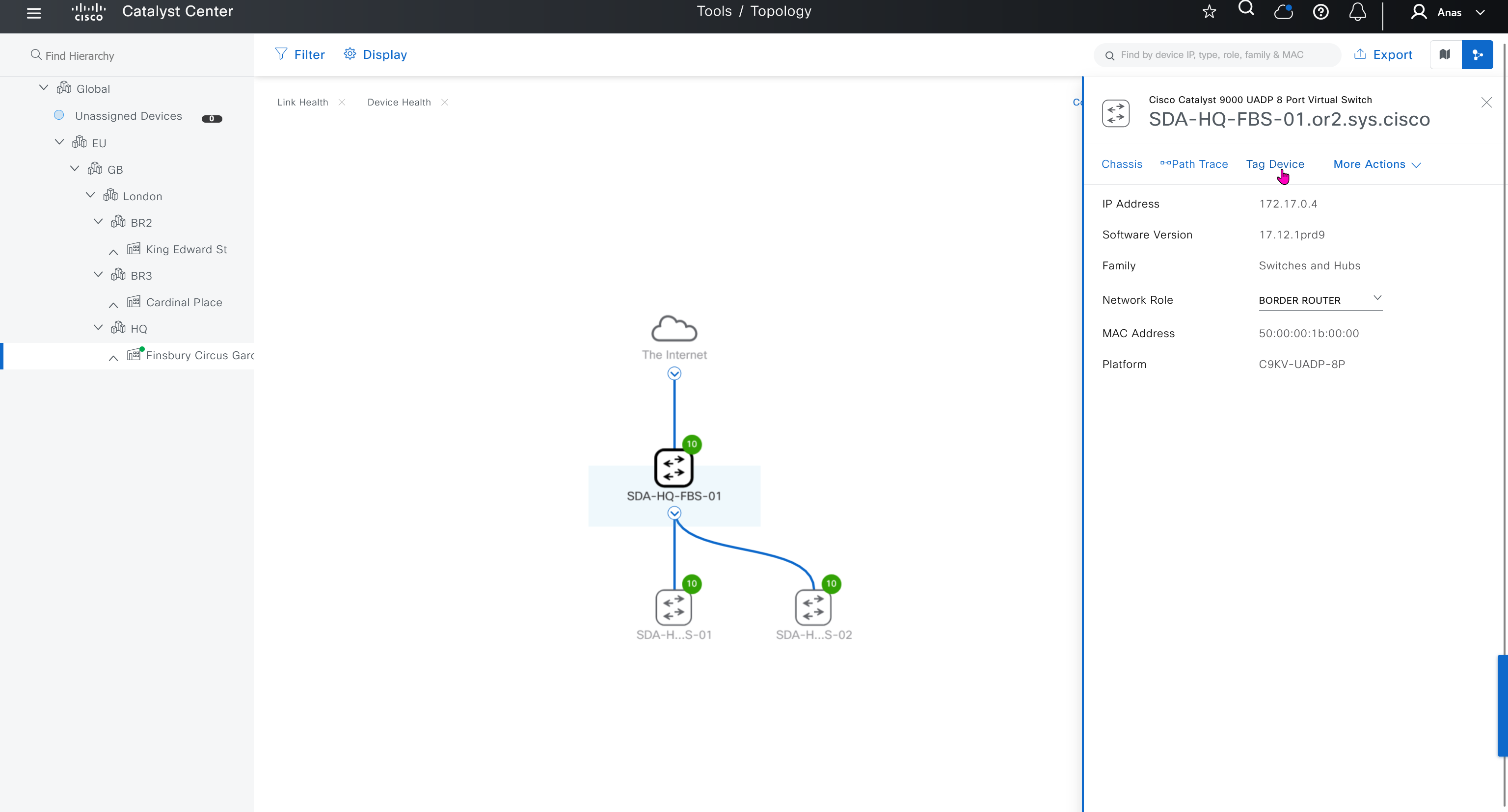
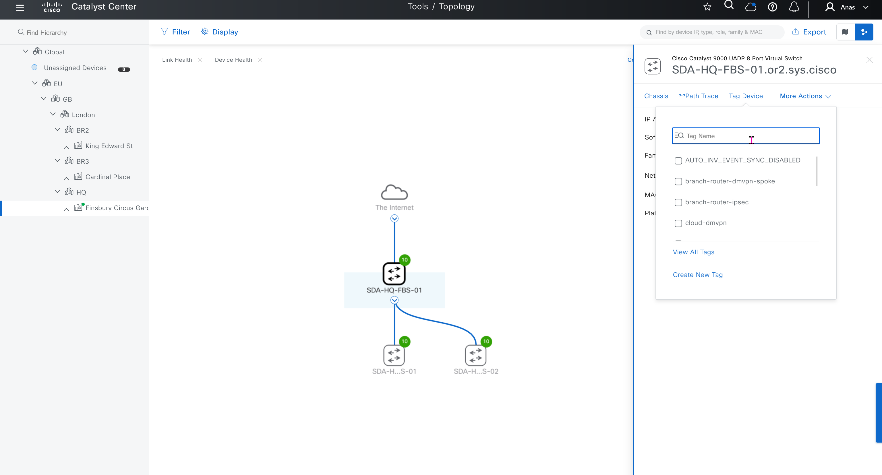
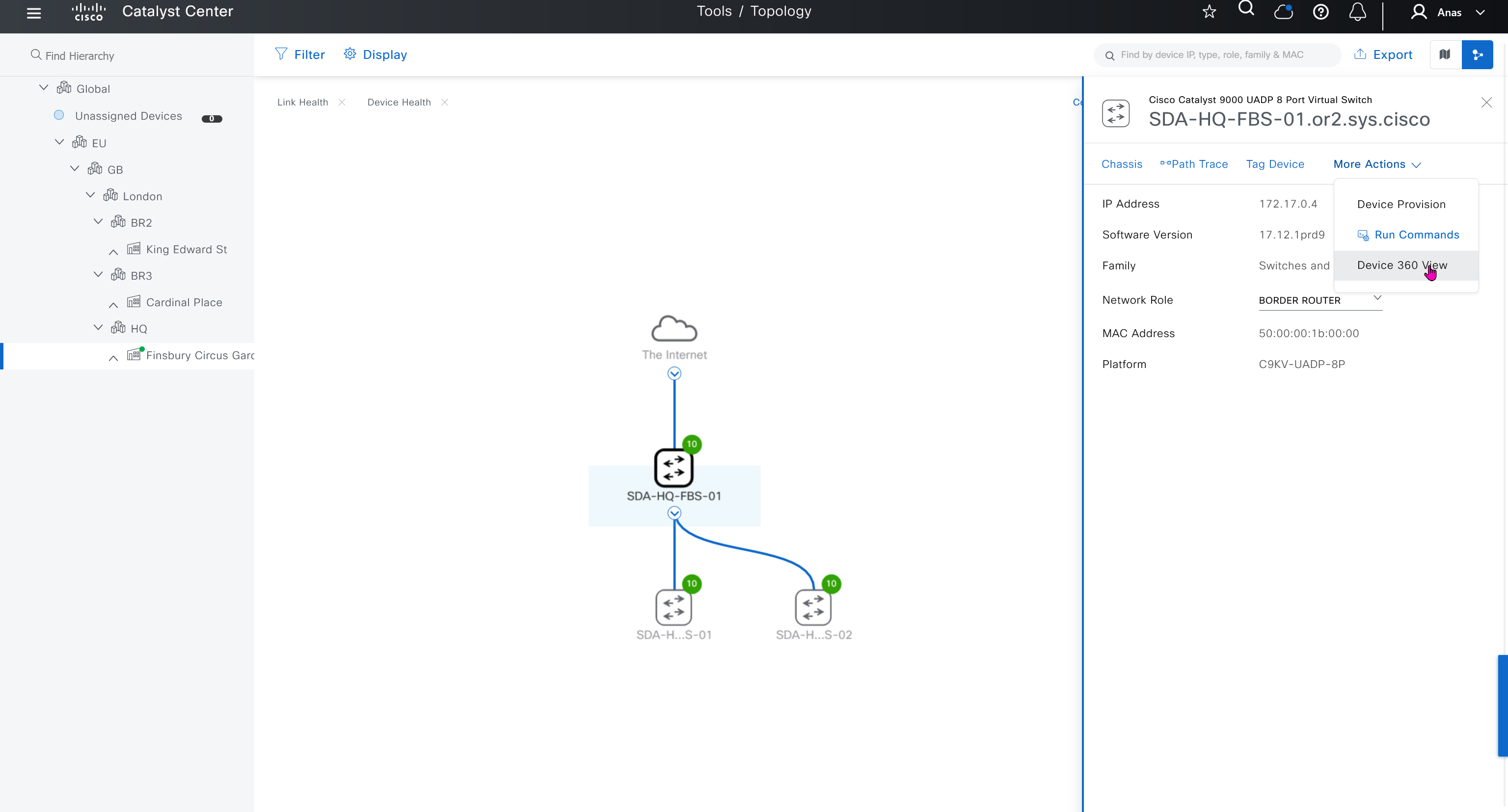
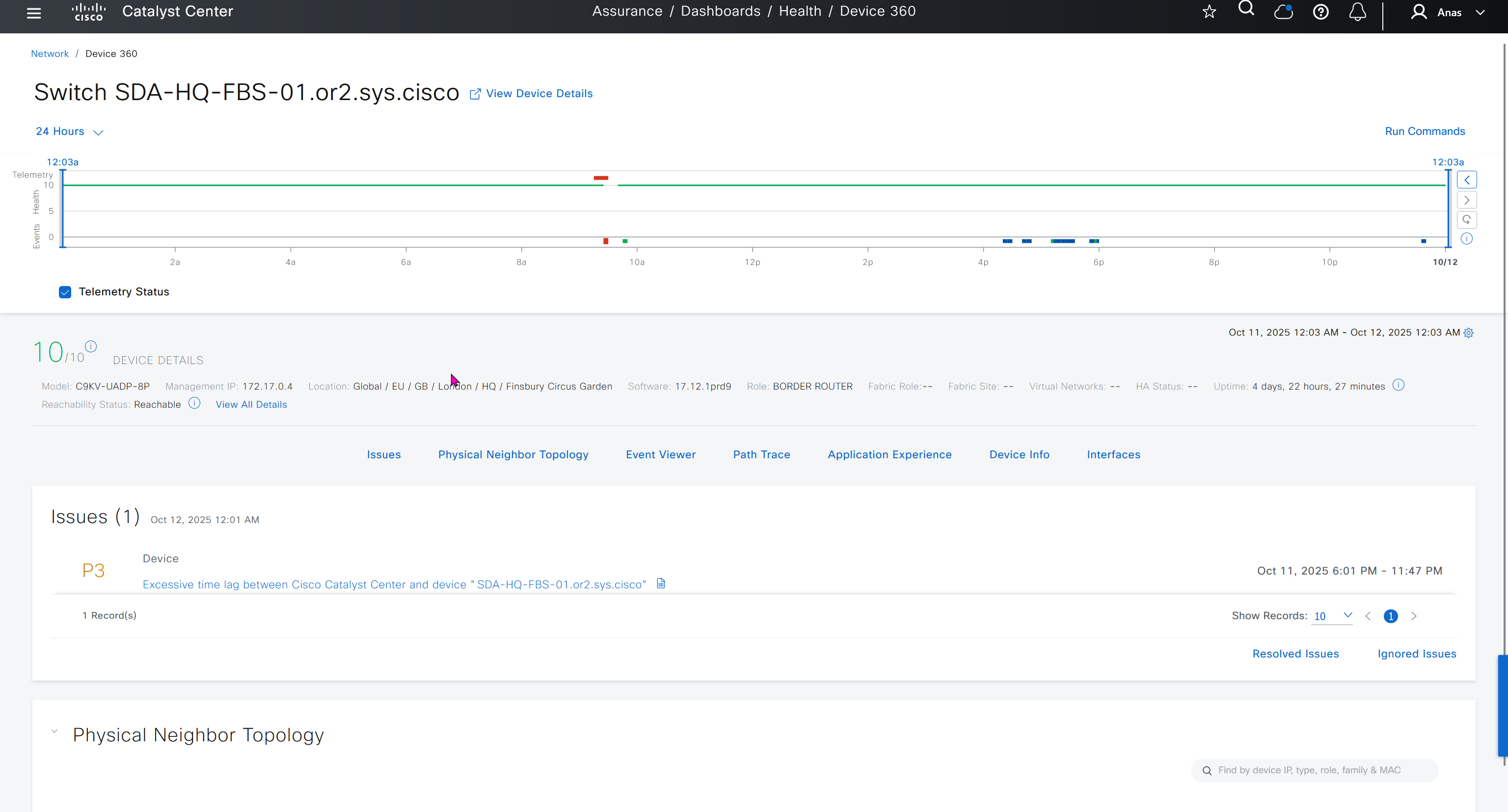


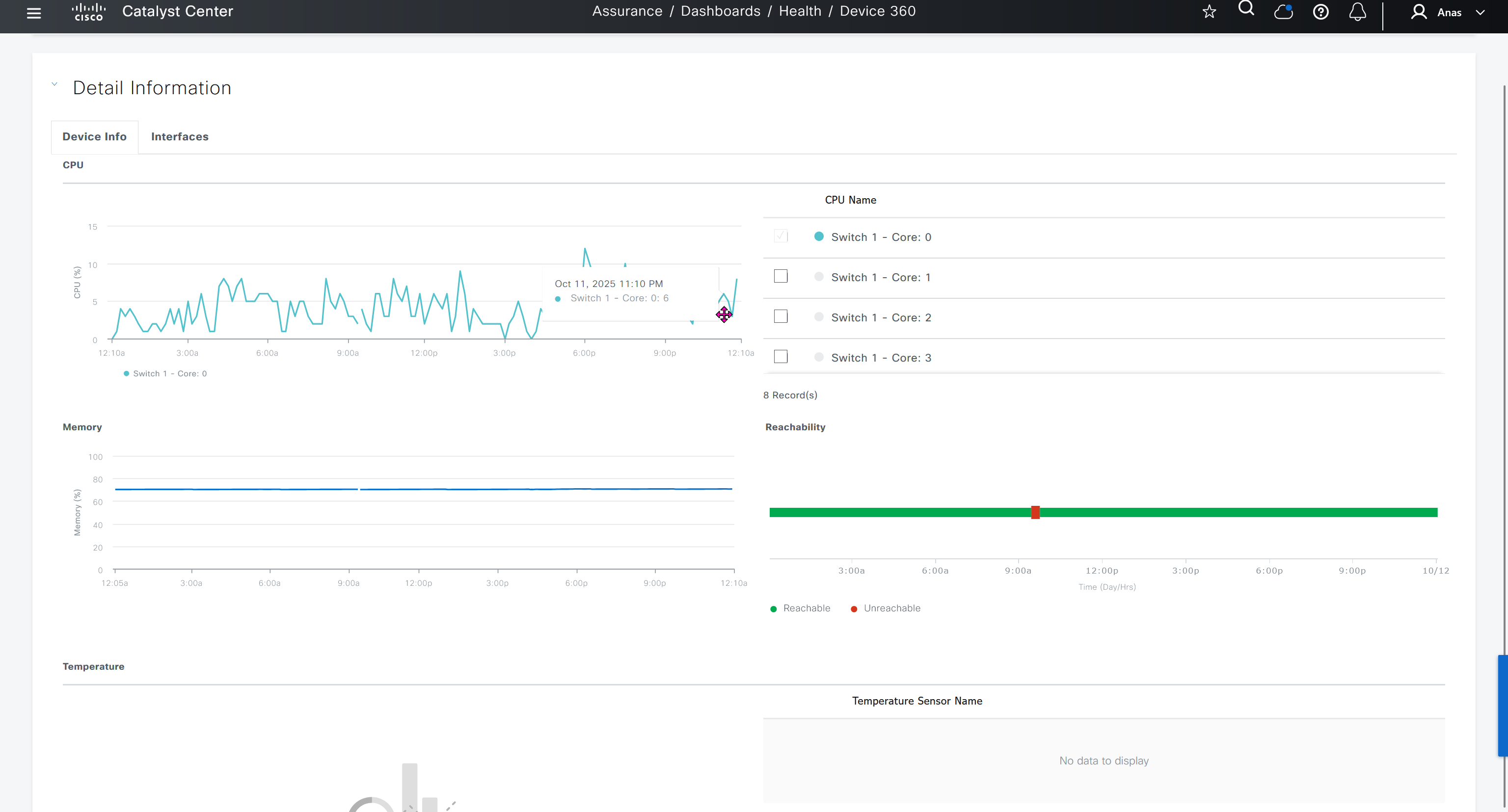
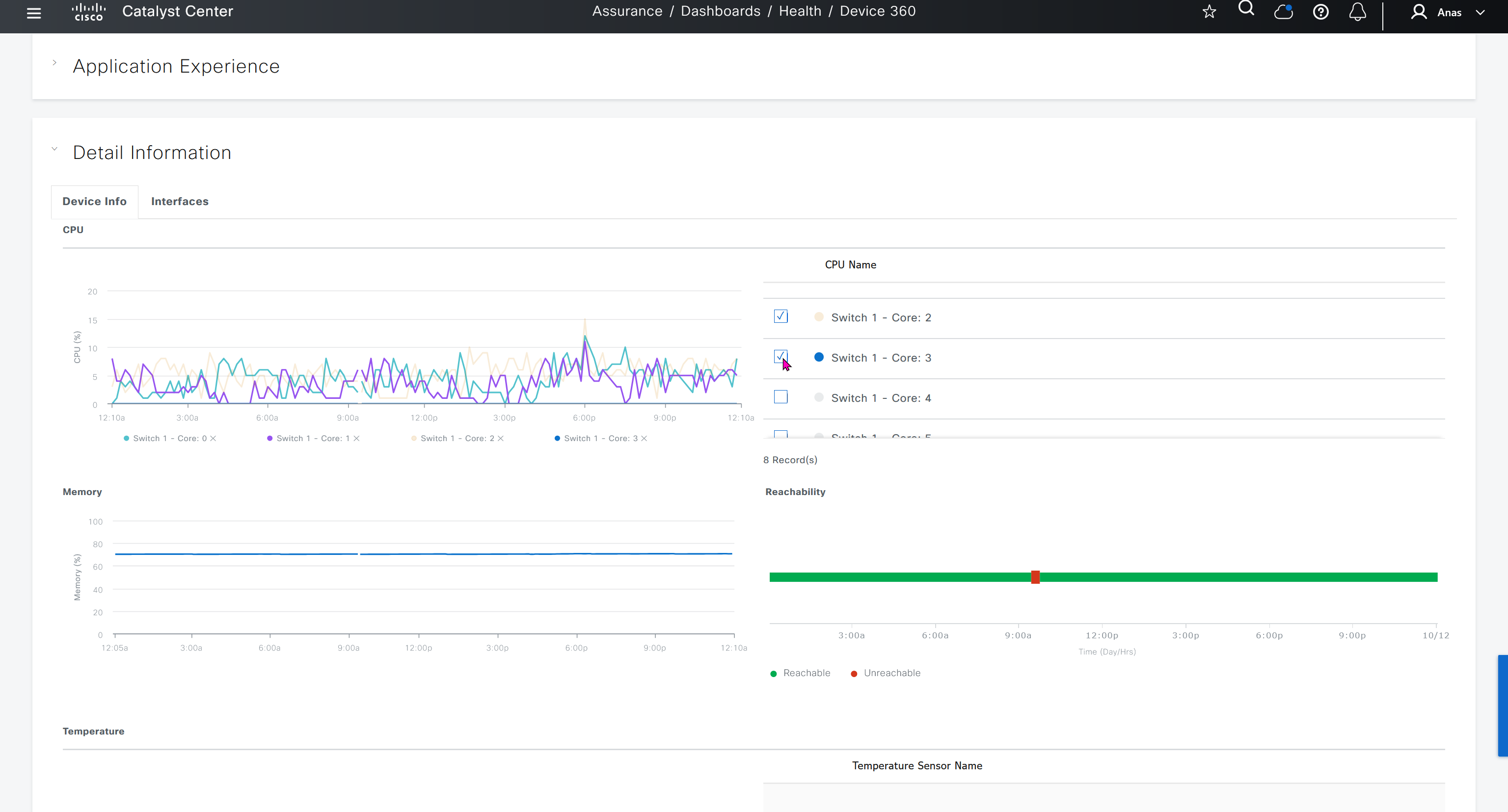
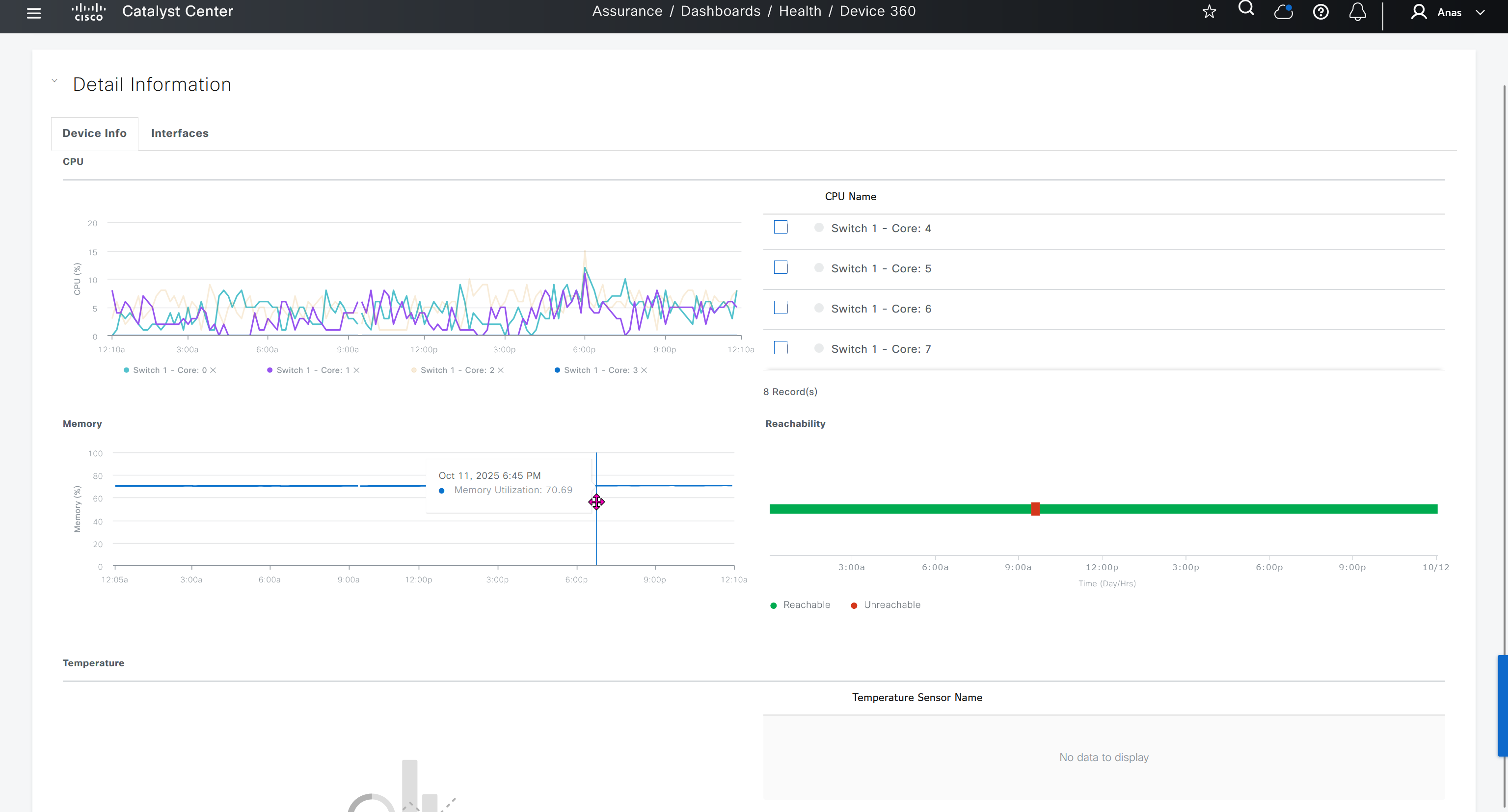
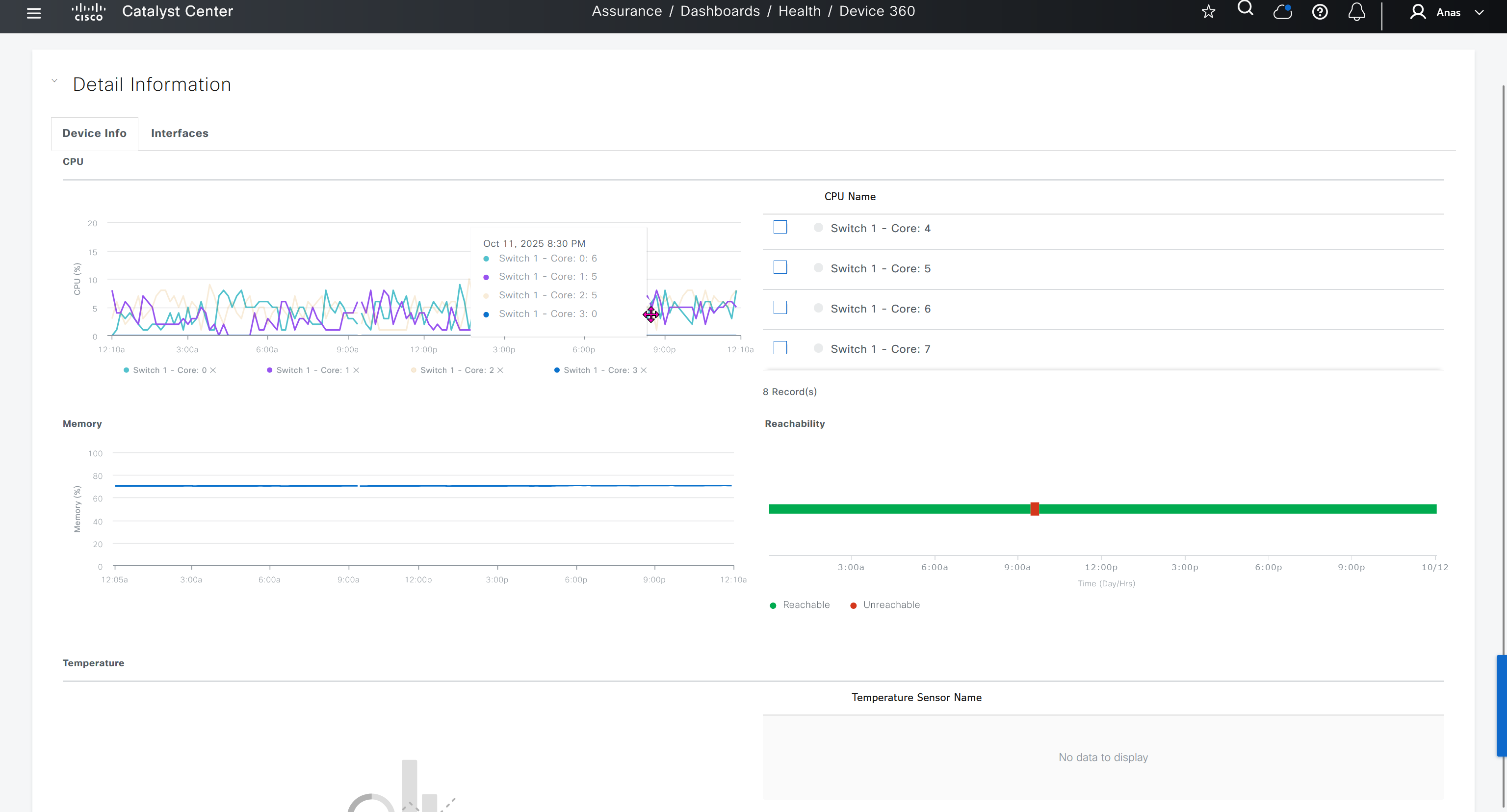
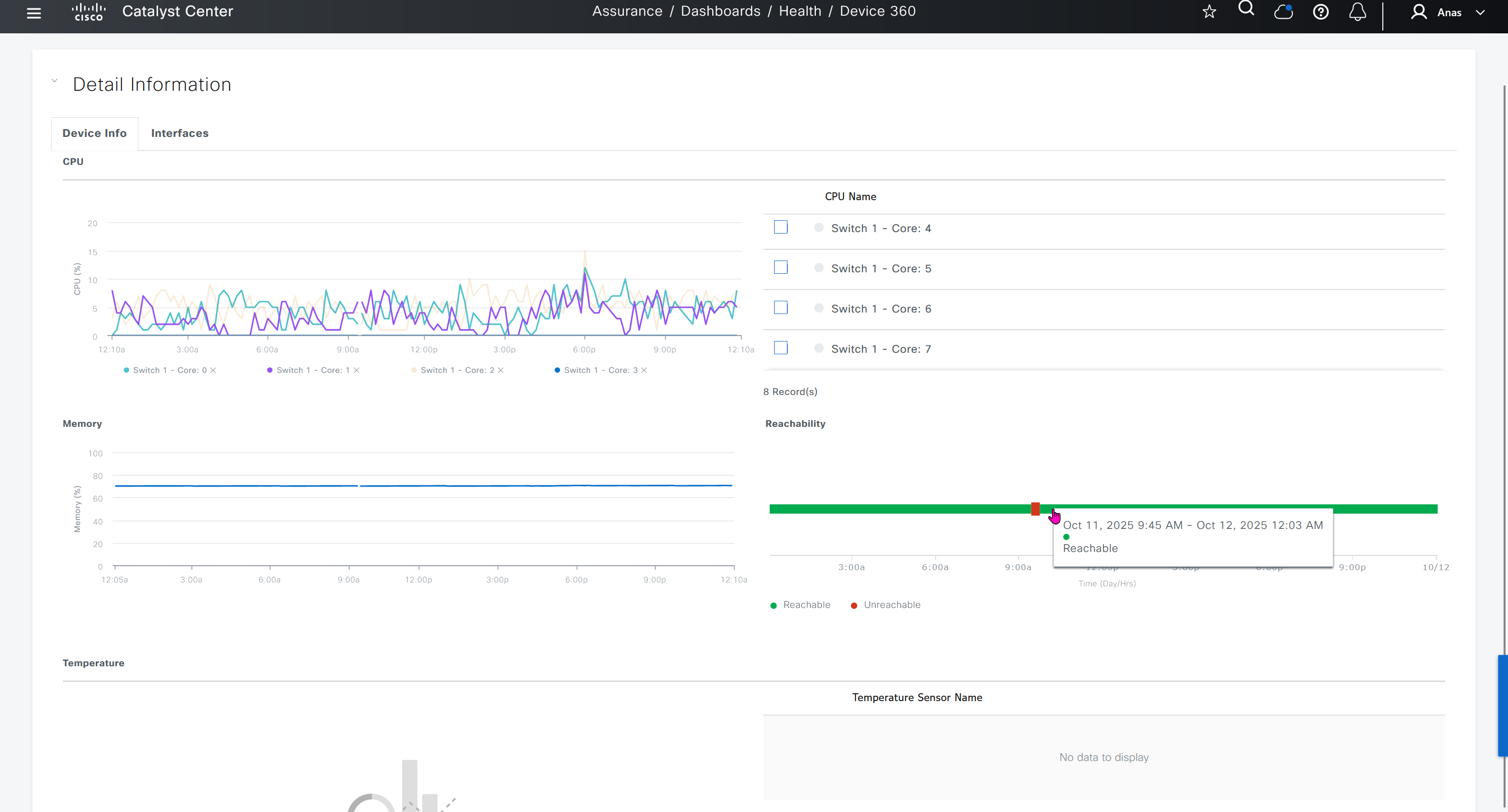
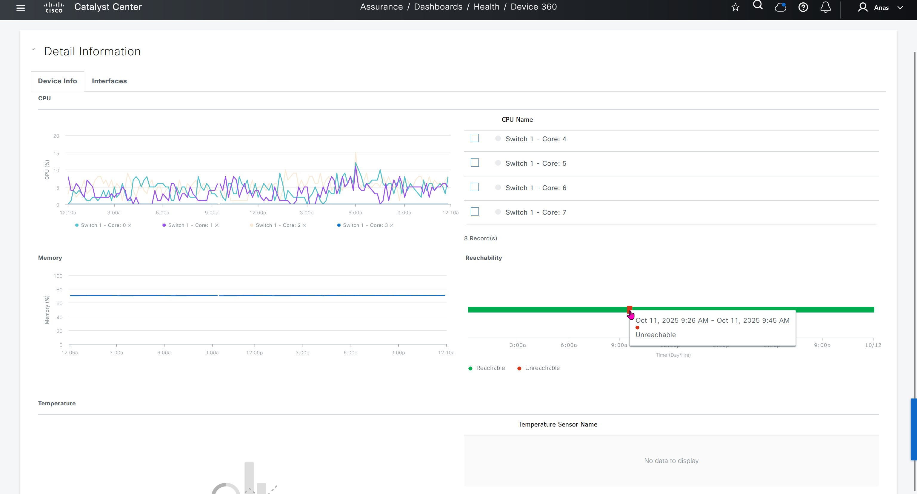
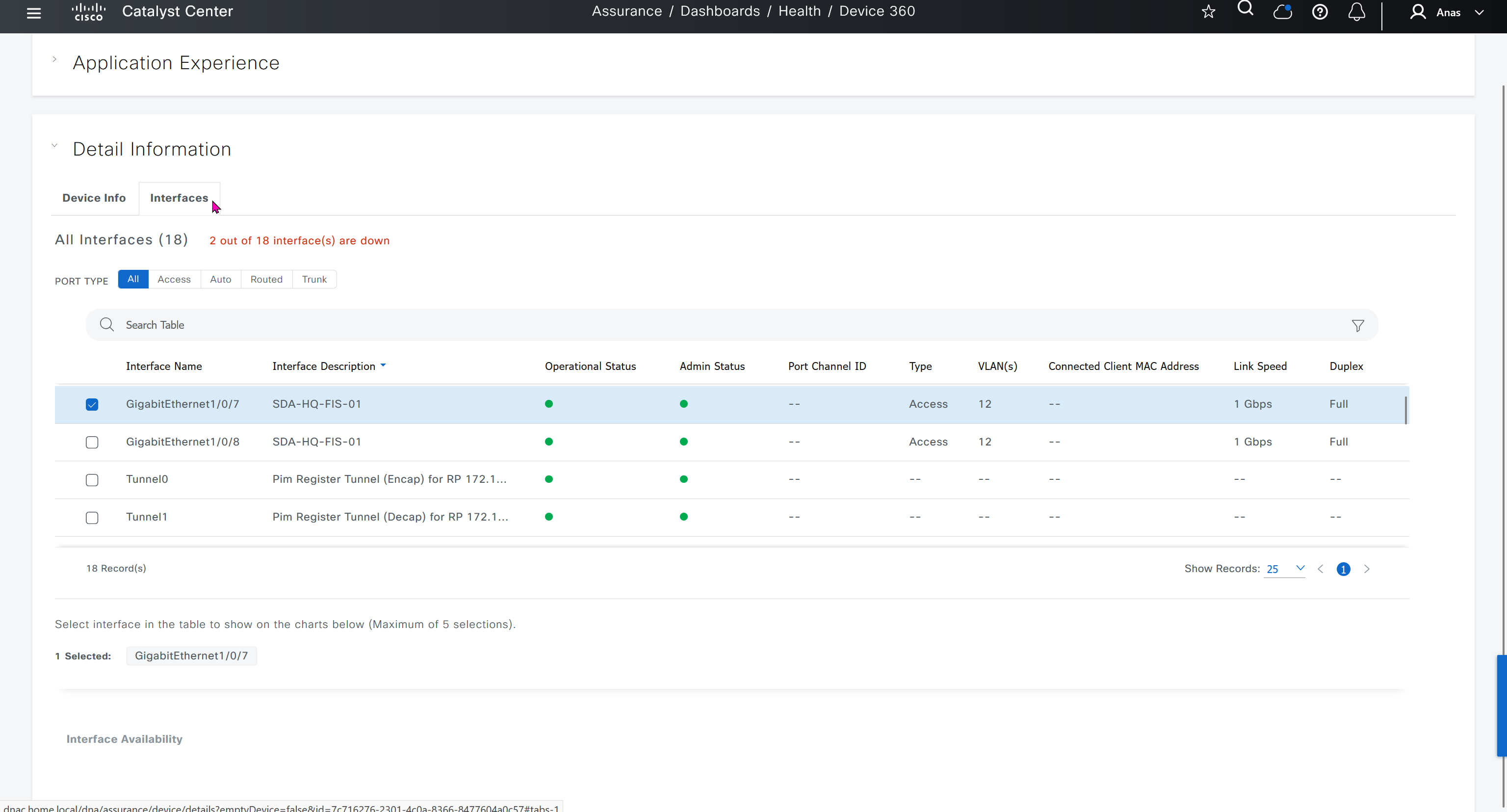
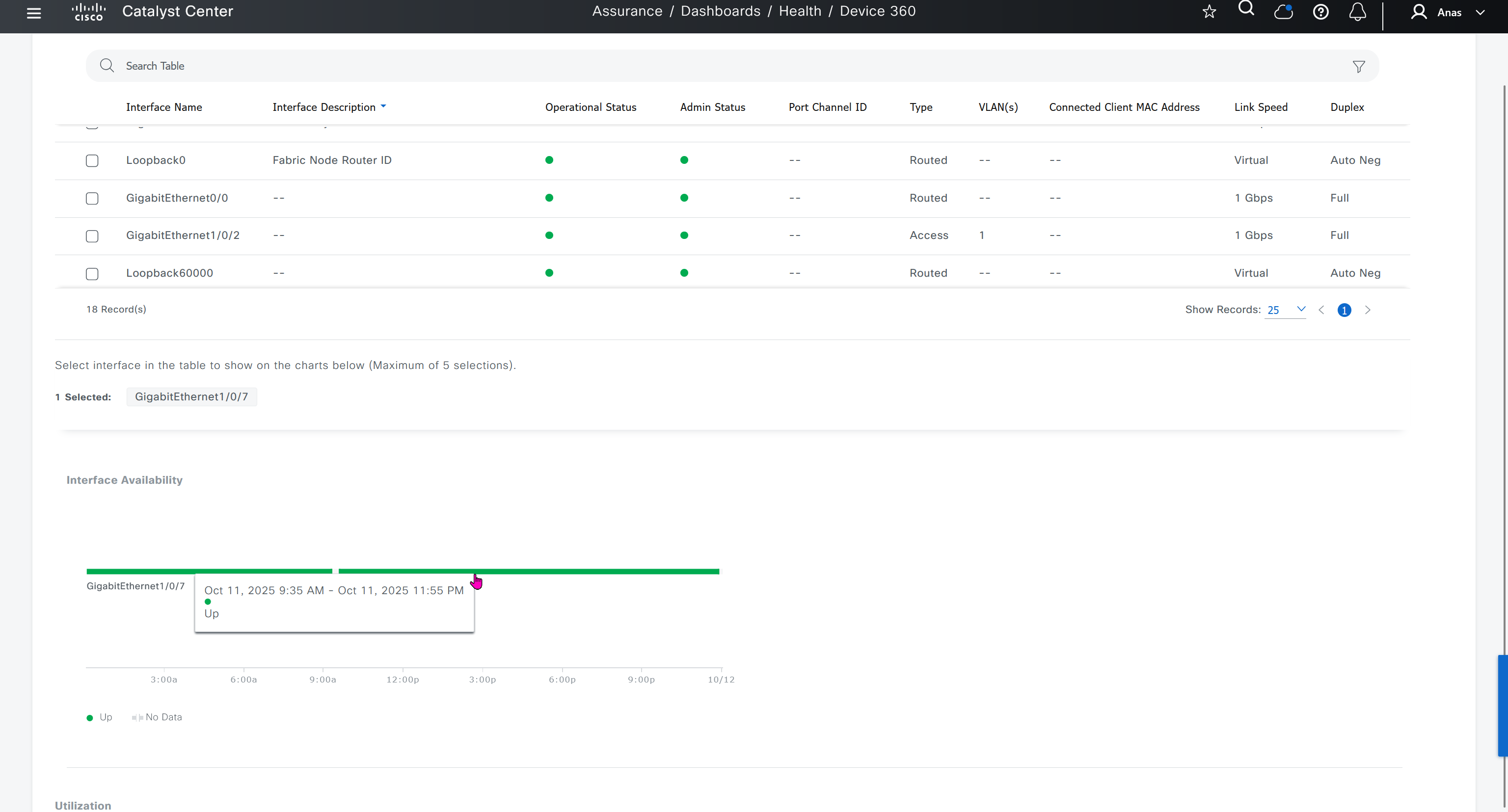
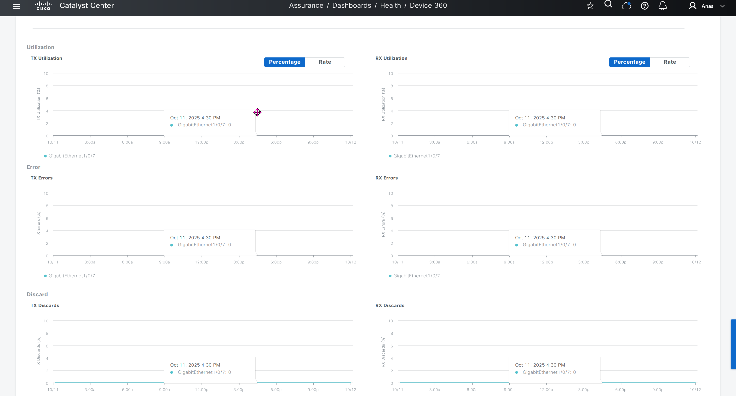
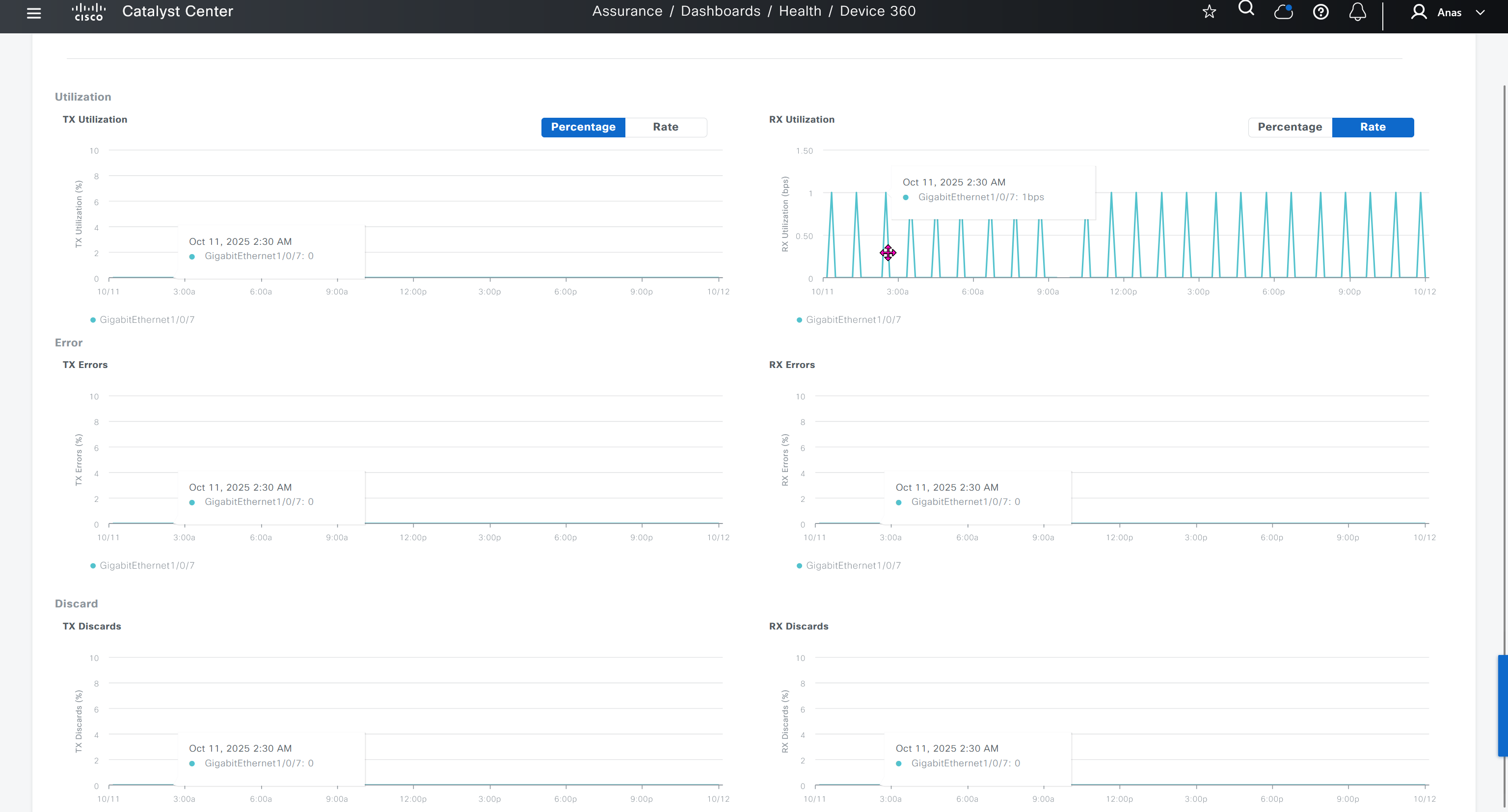
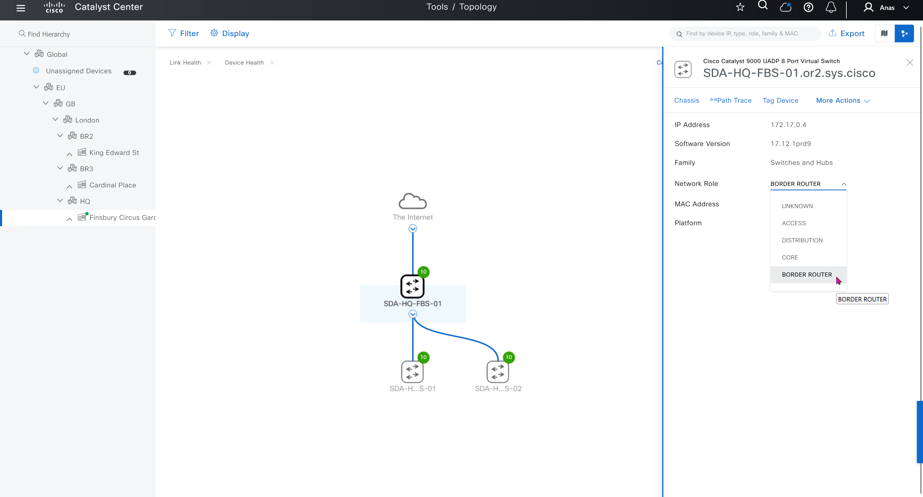


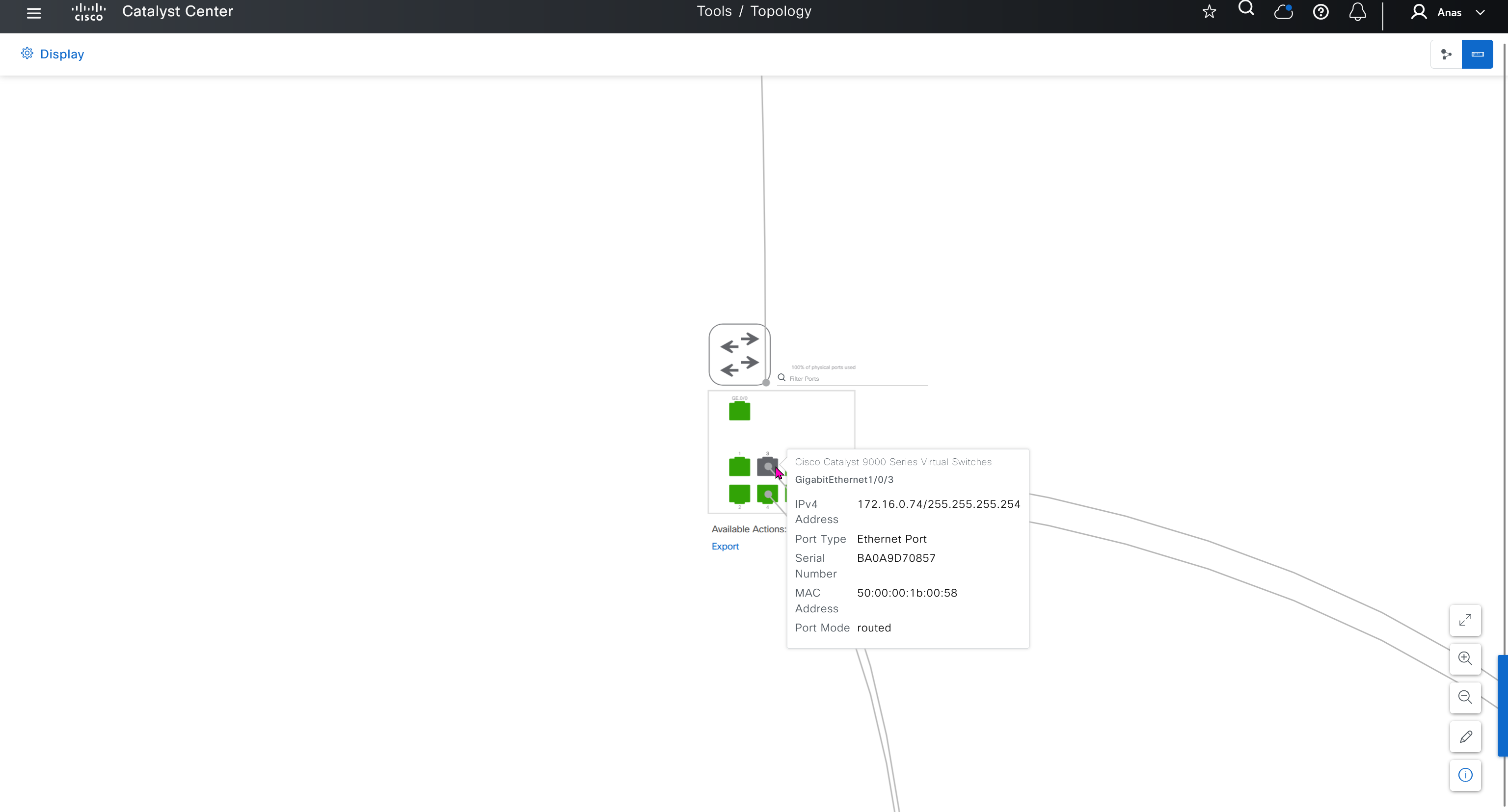
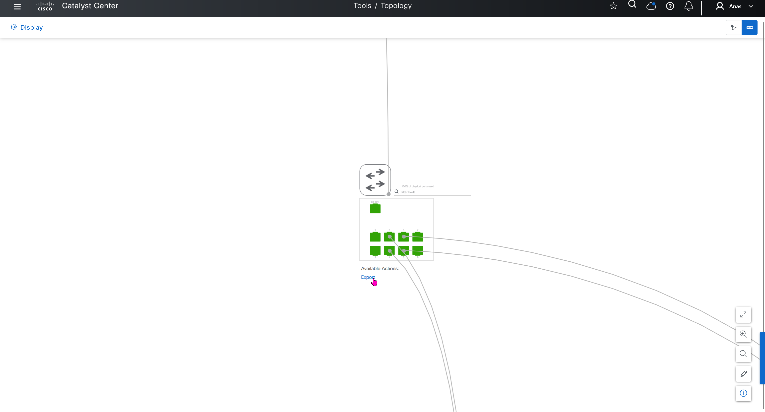
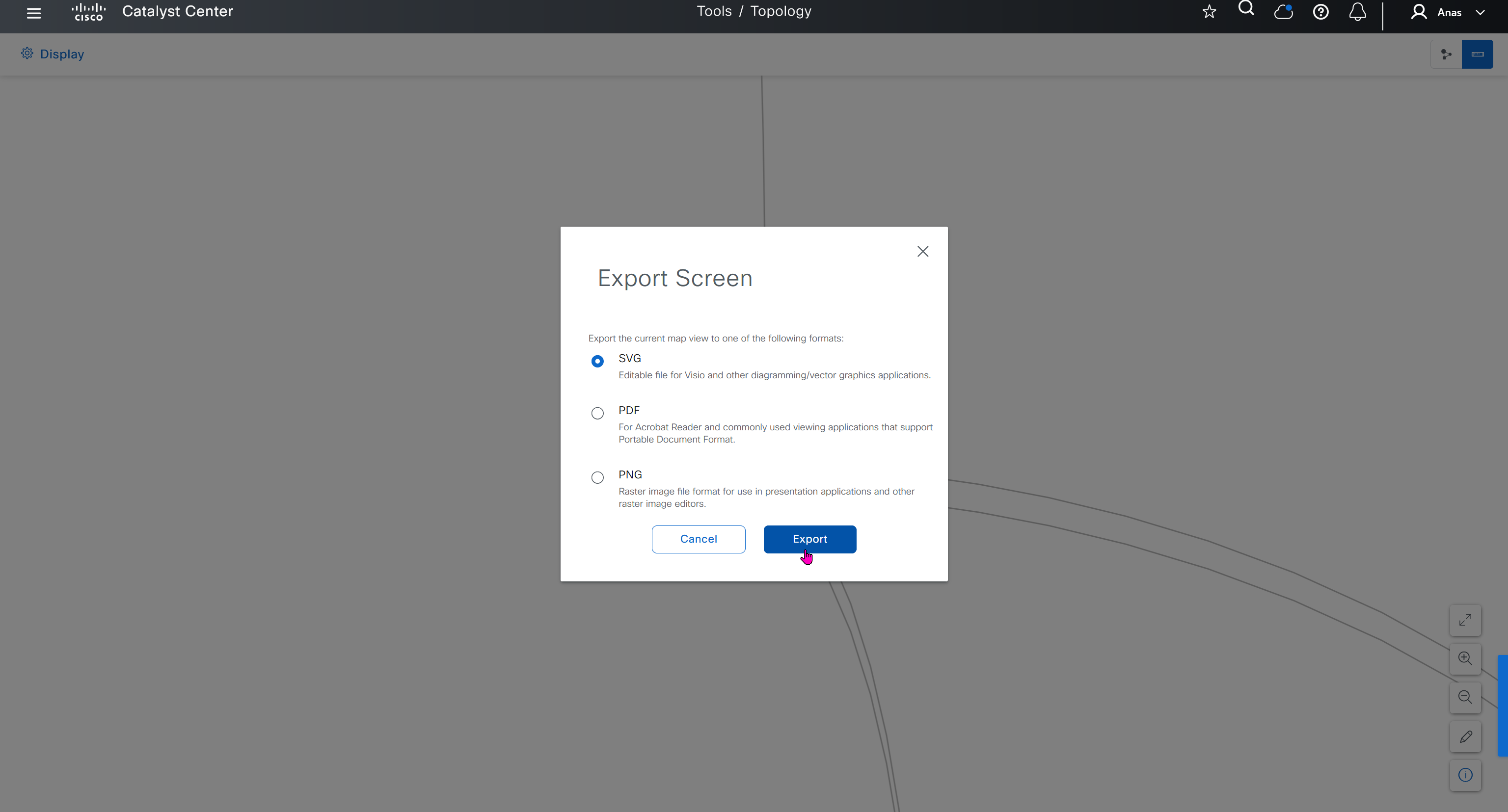
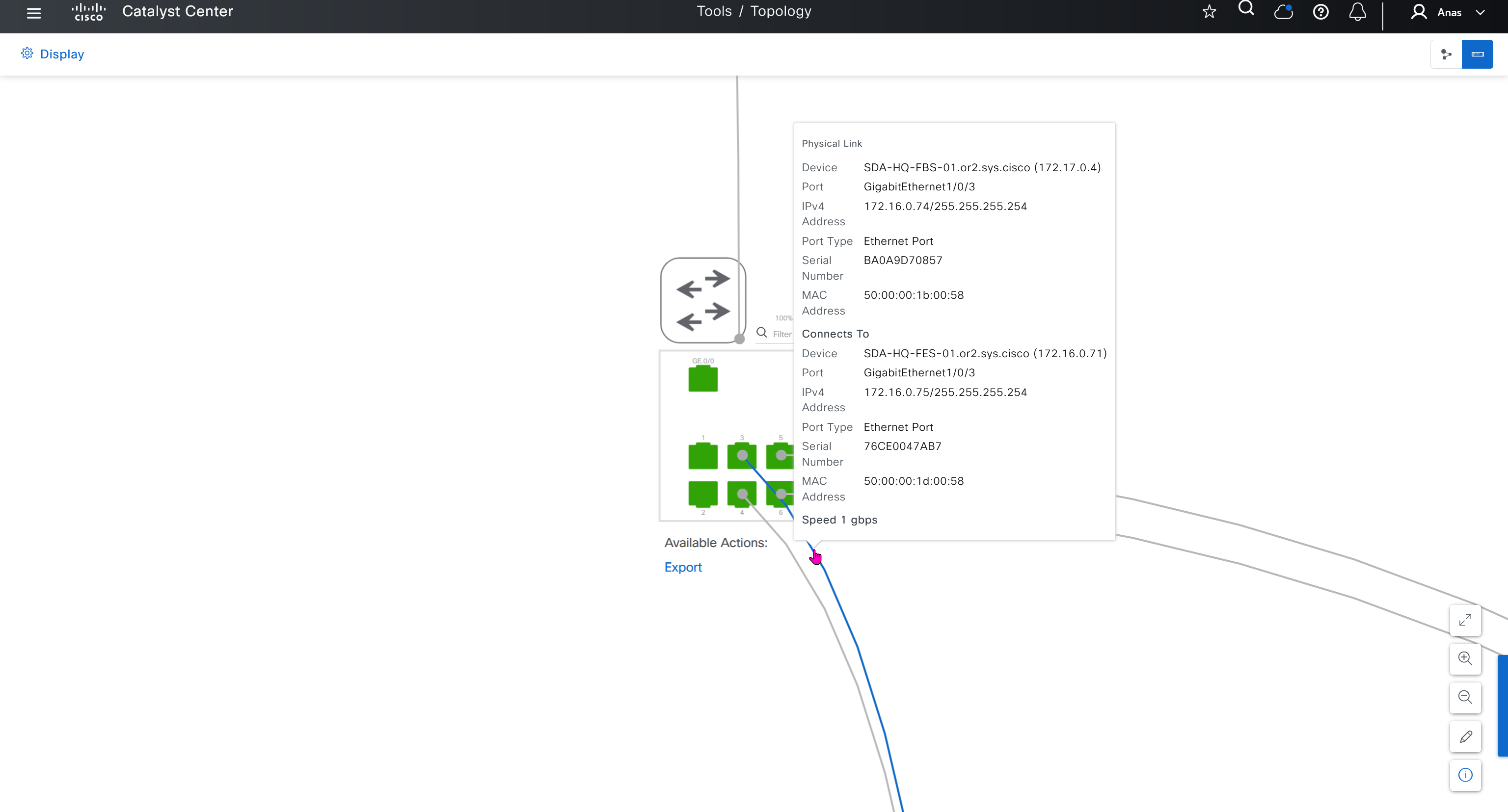
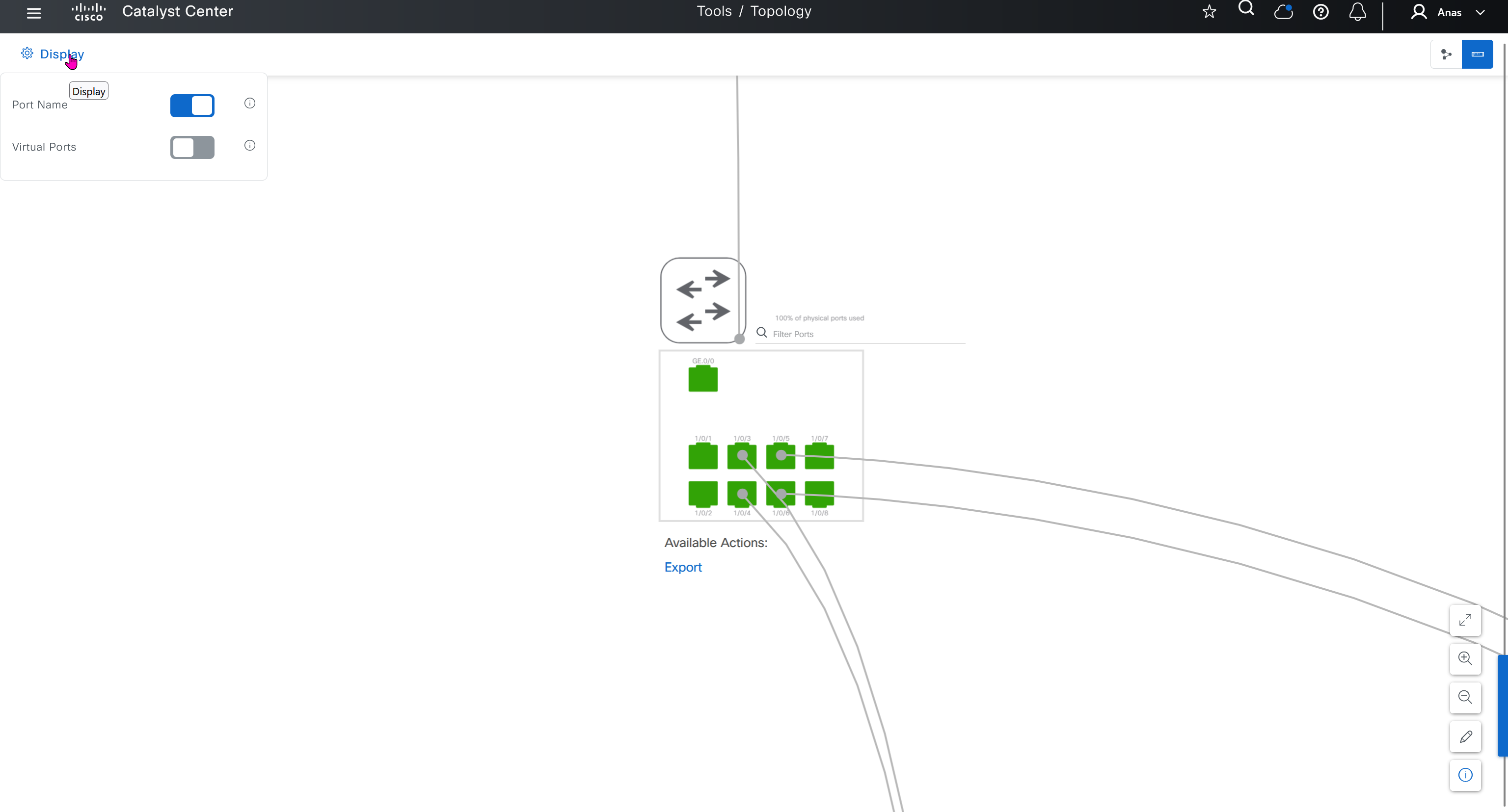
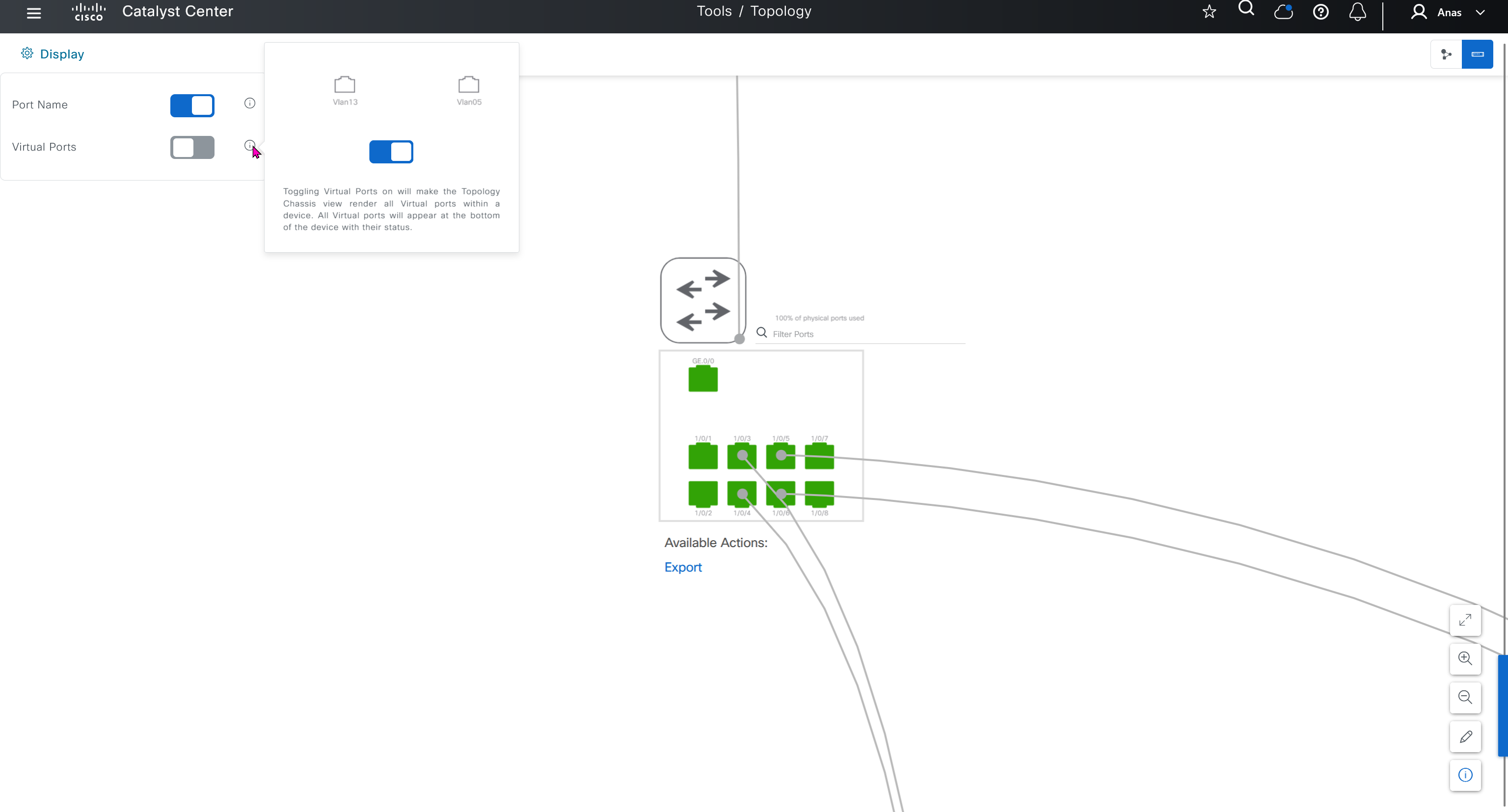
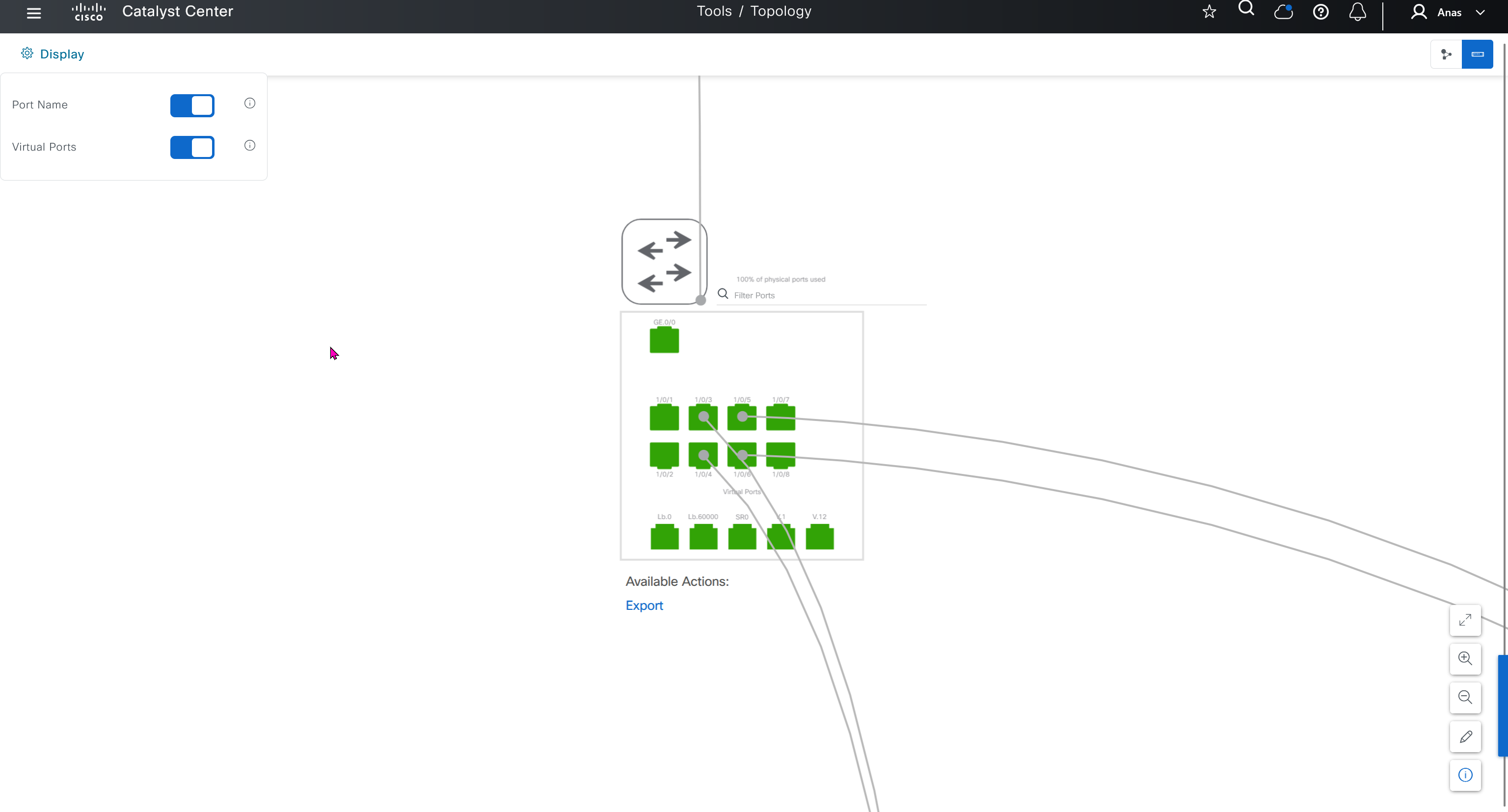
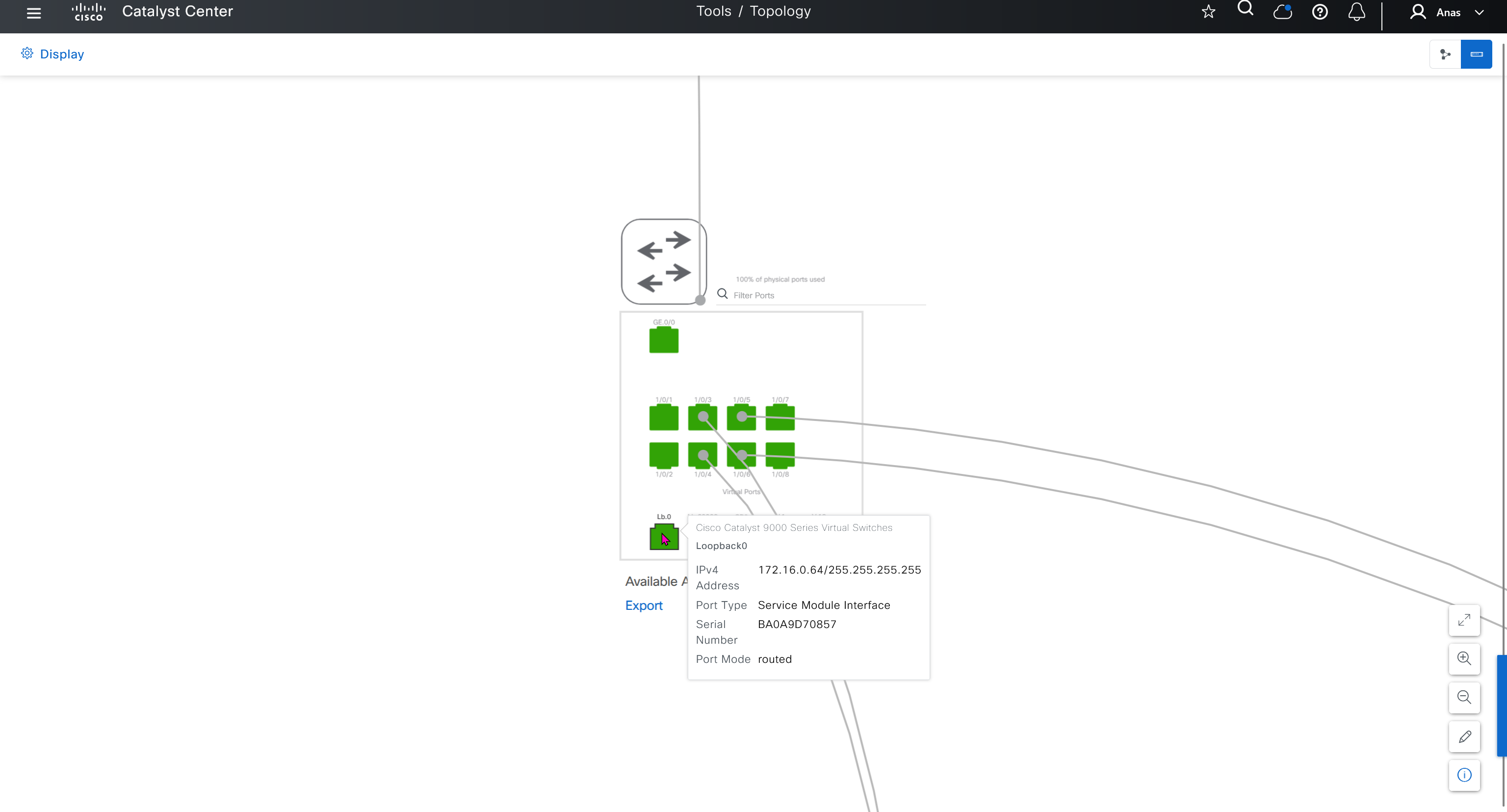
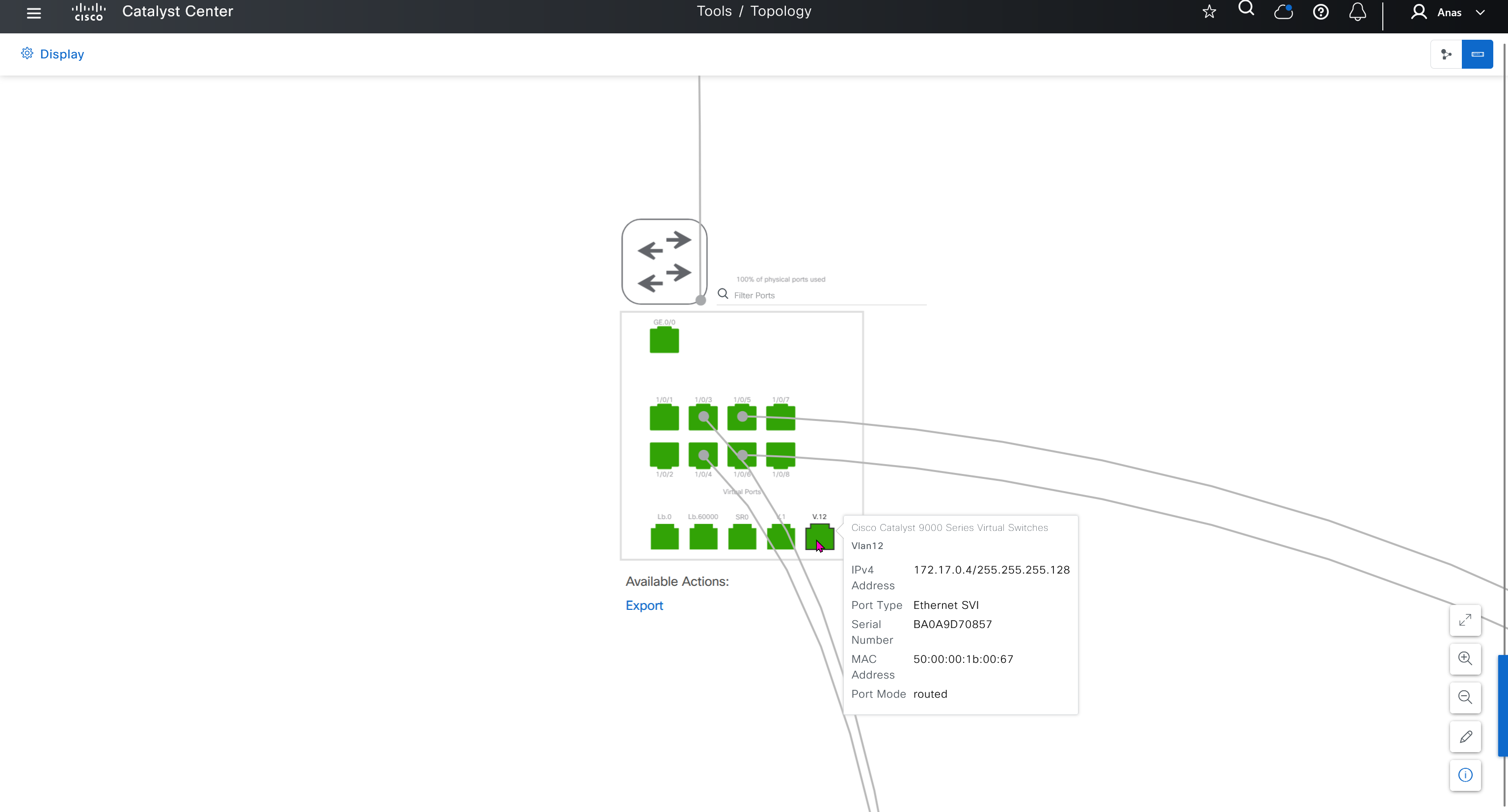

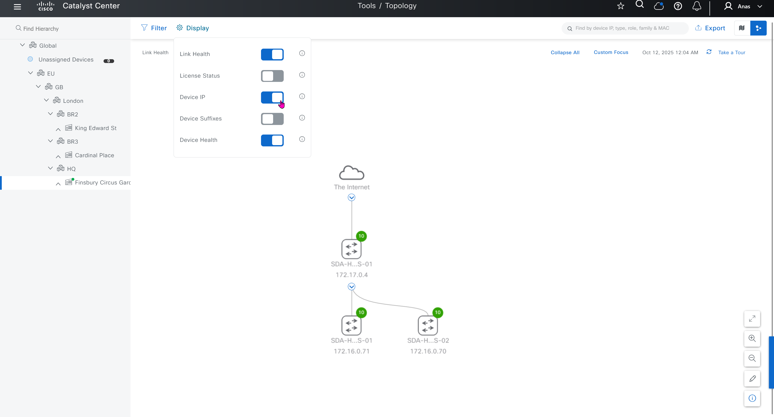
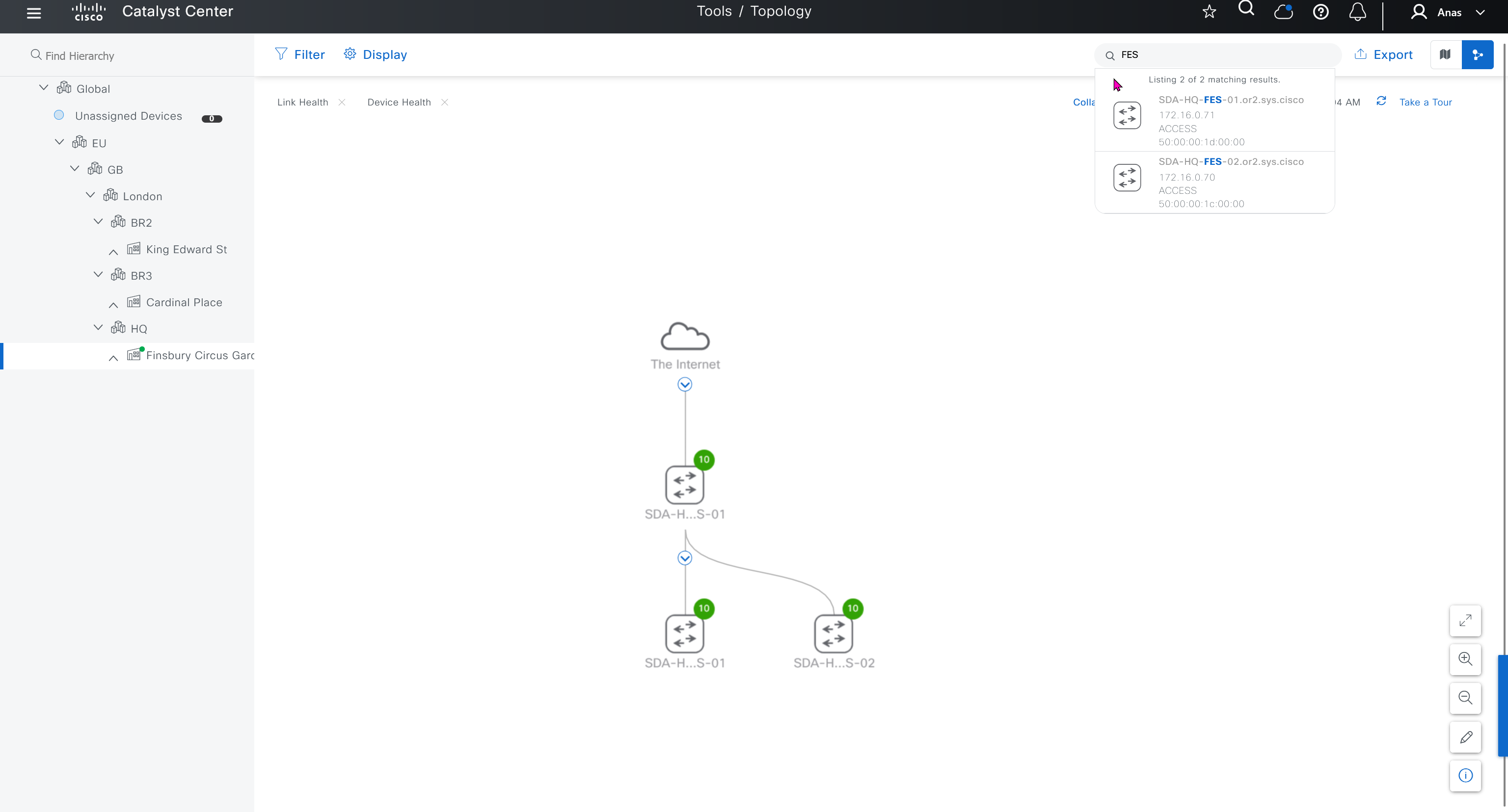

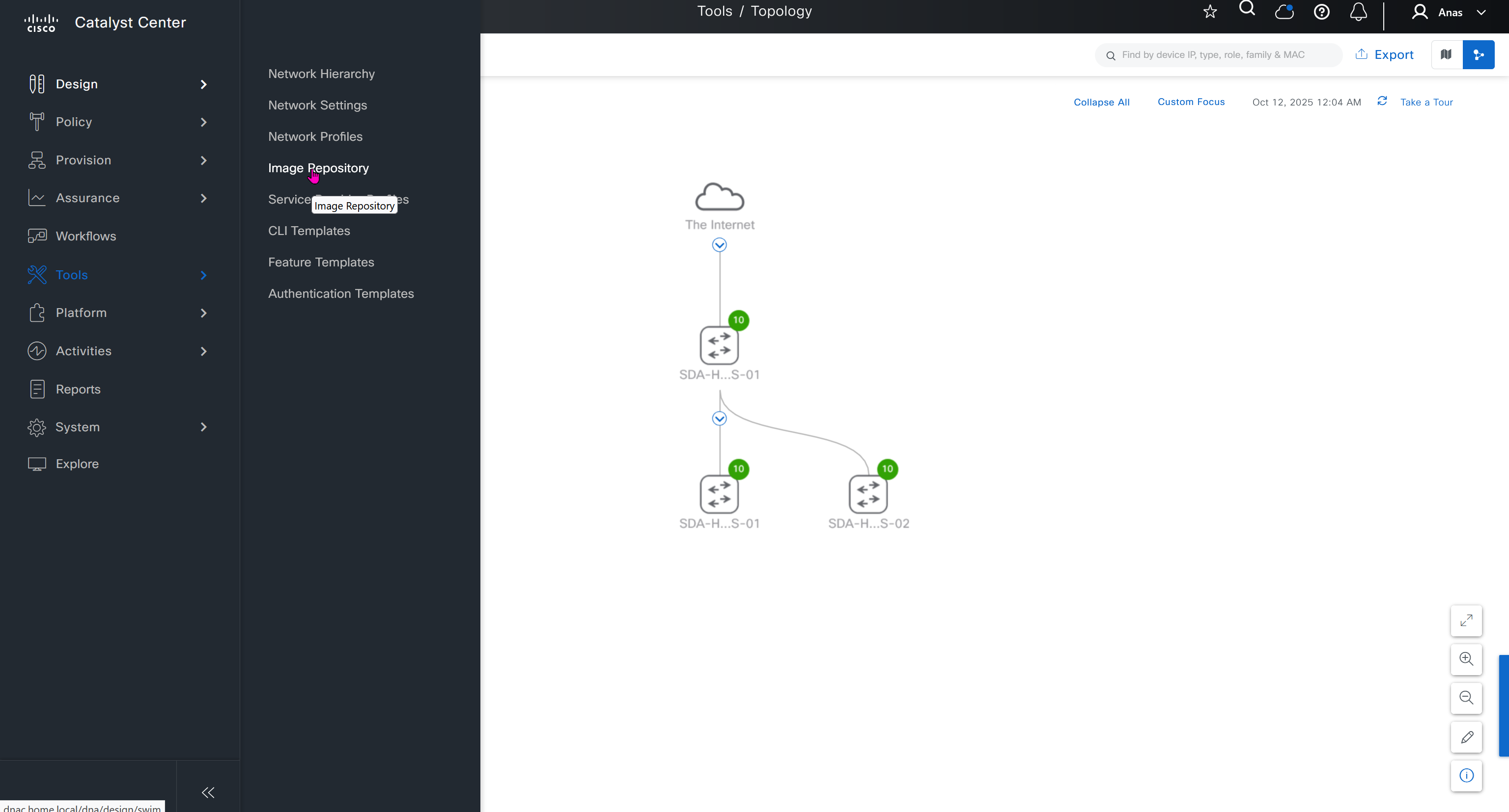
SWIM – Software Image Management

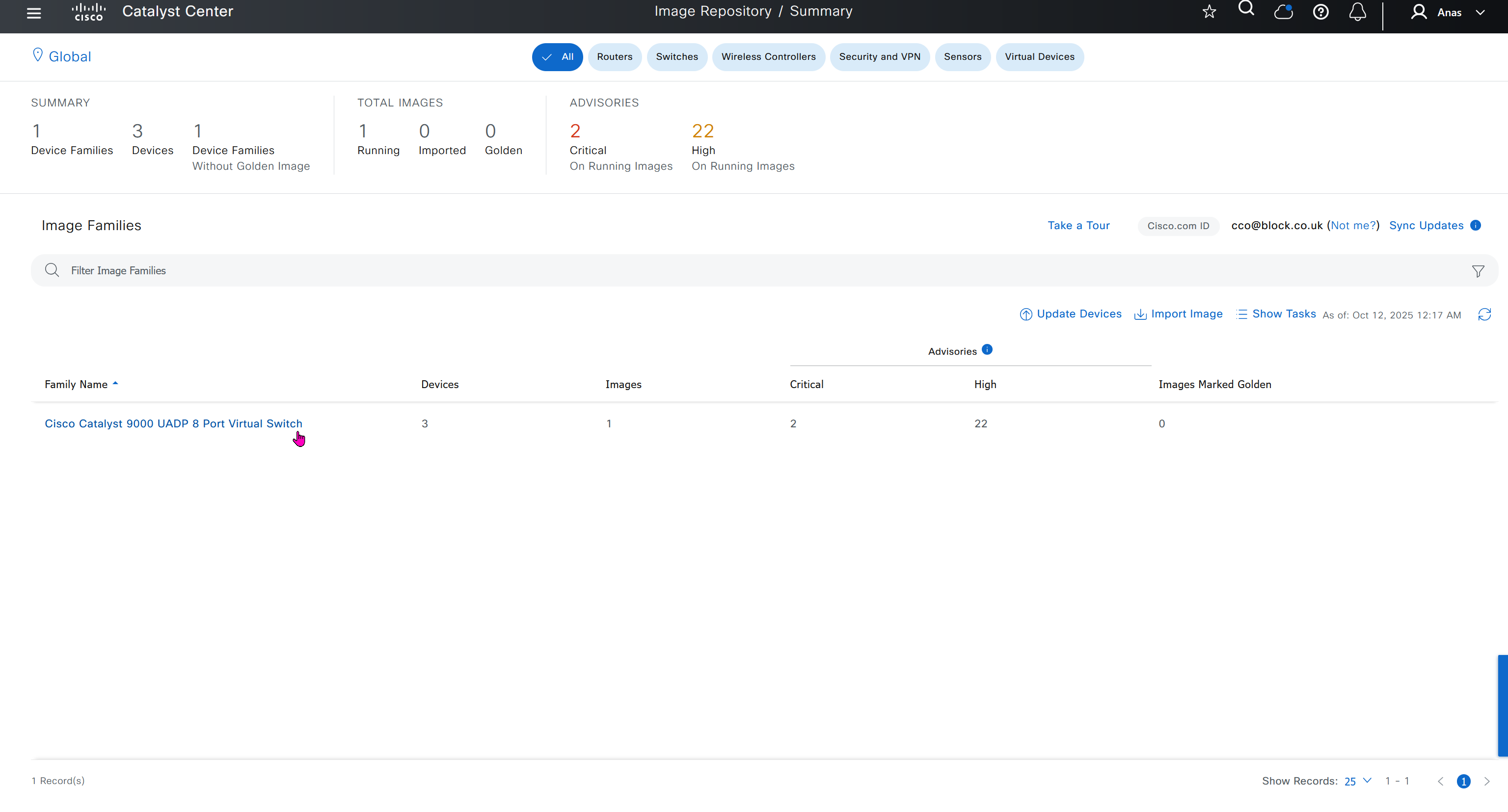
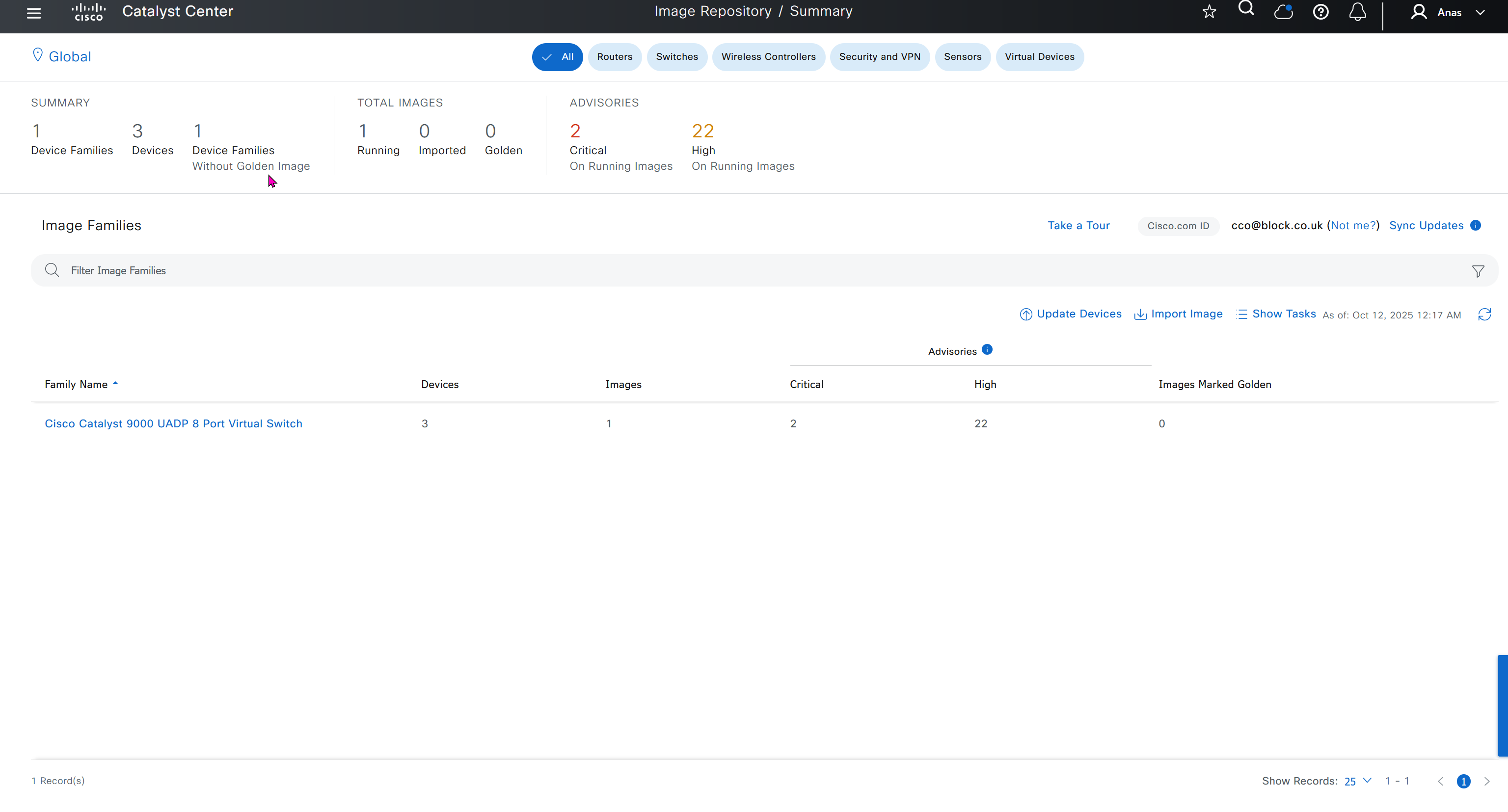
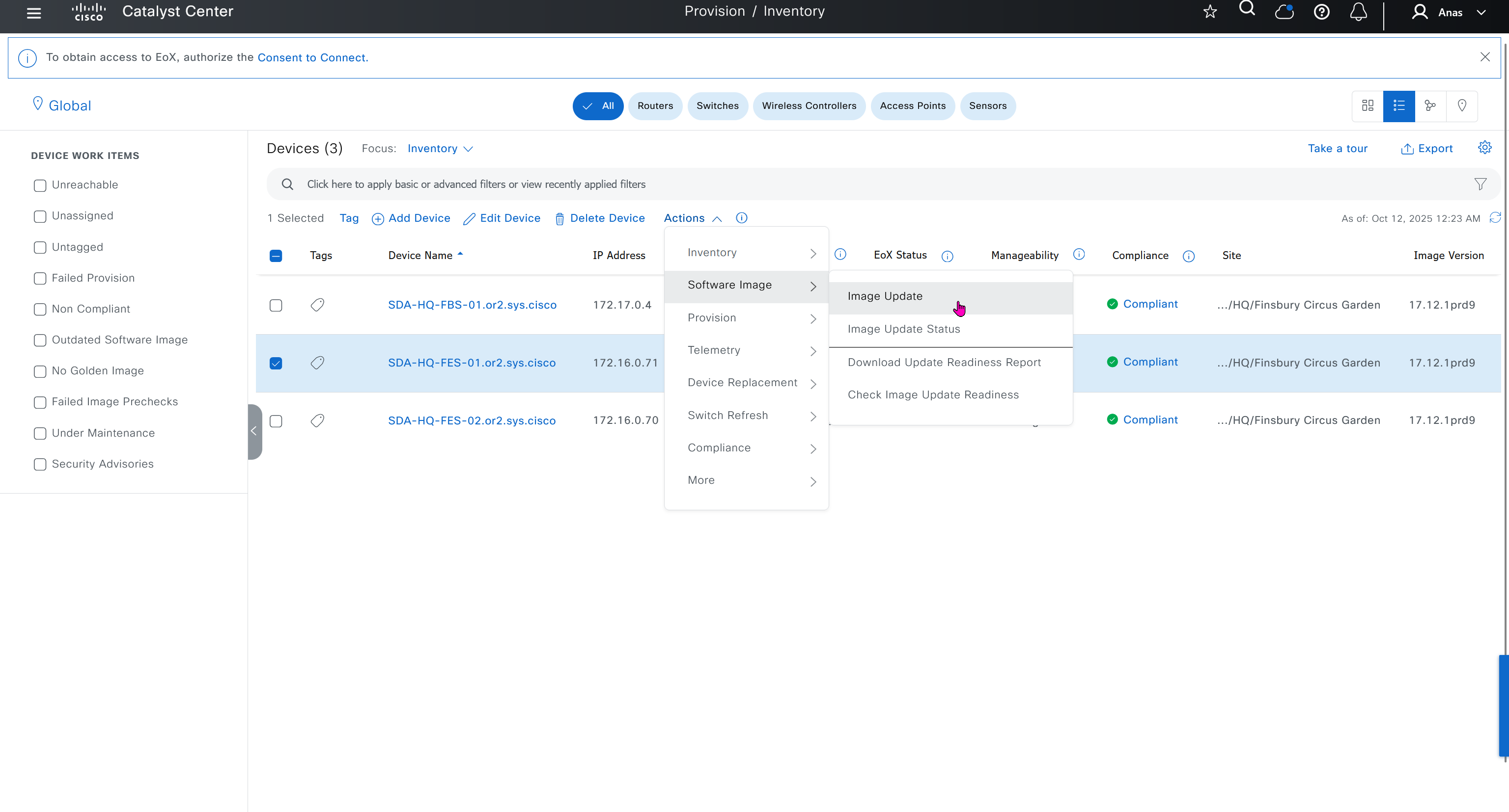
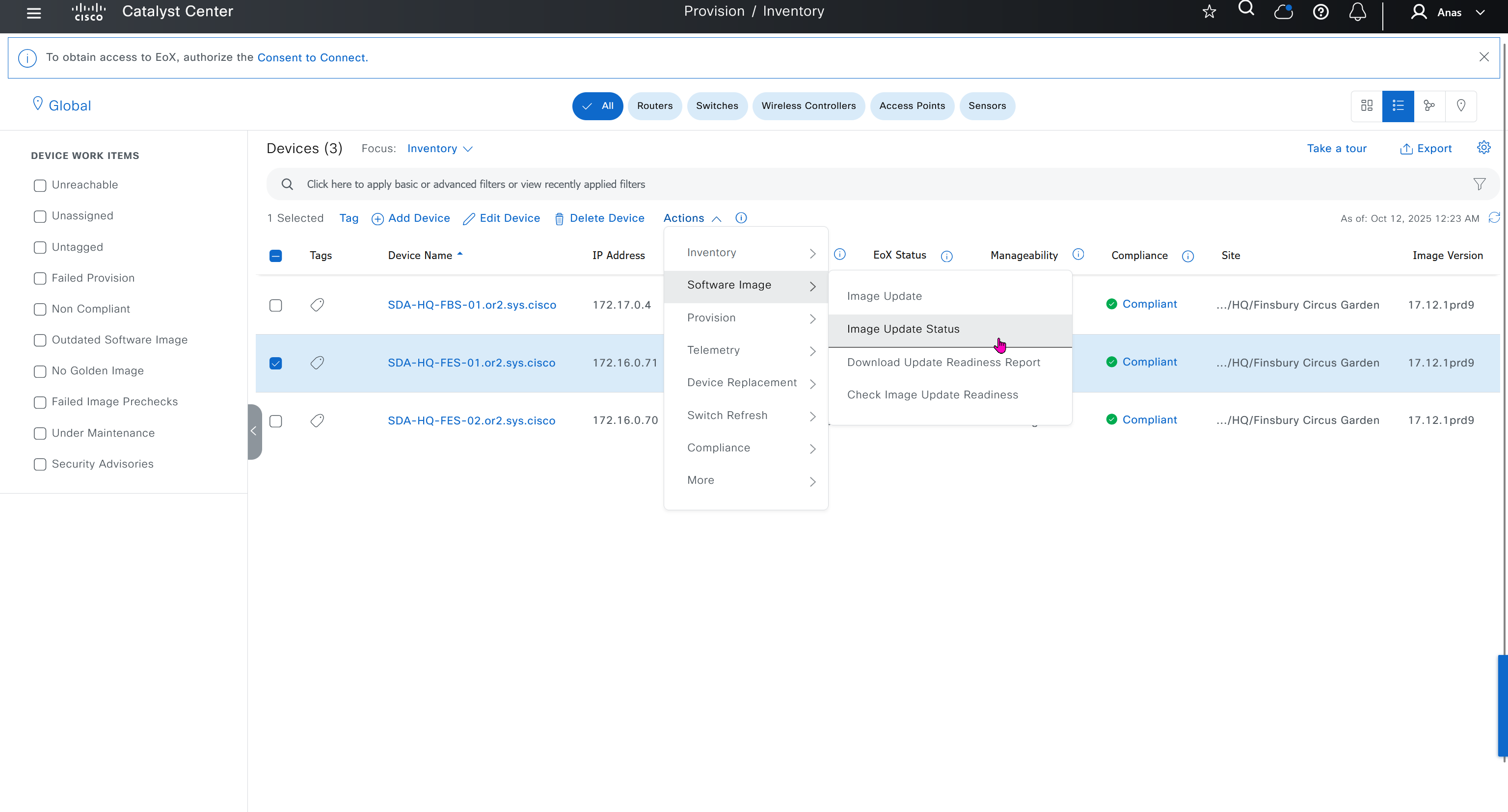


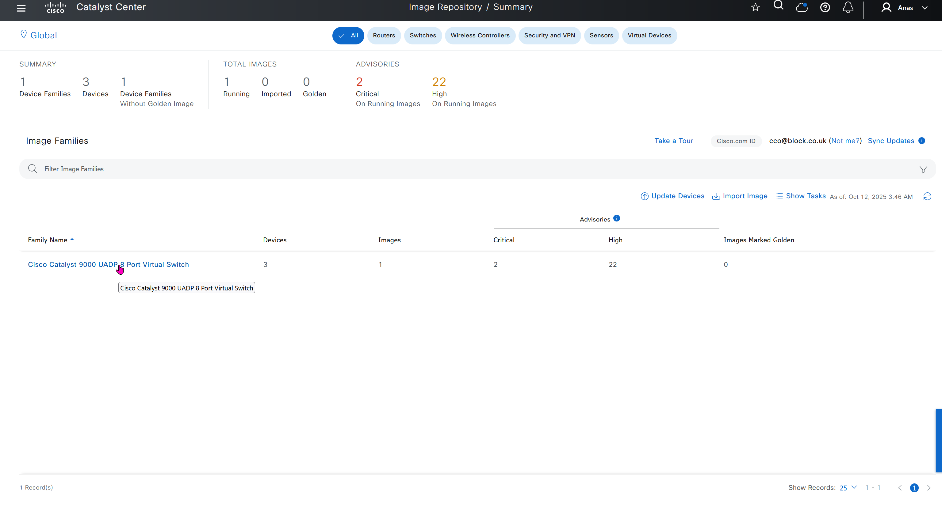
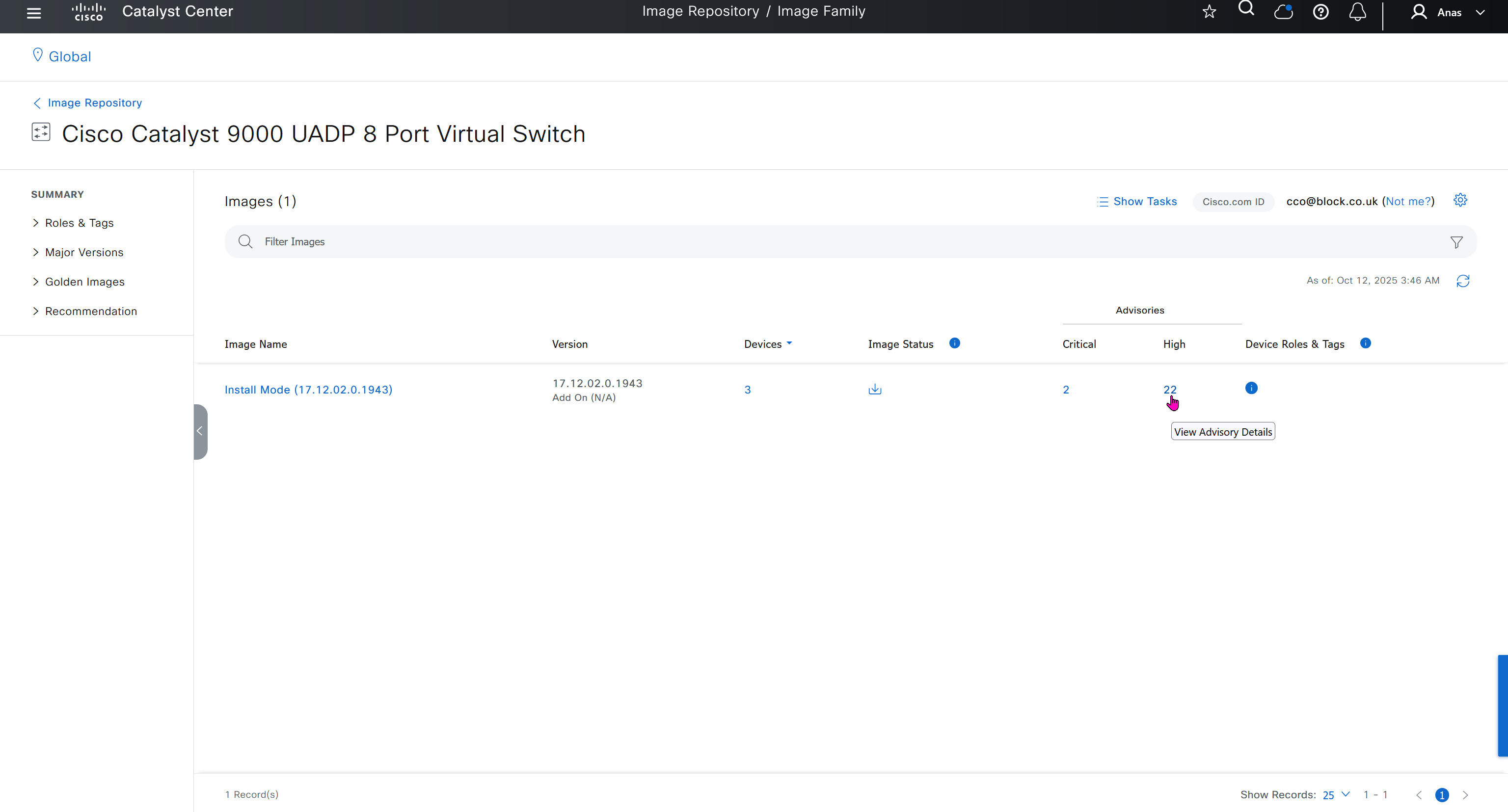


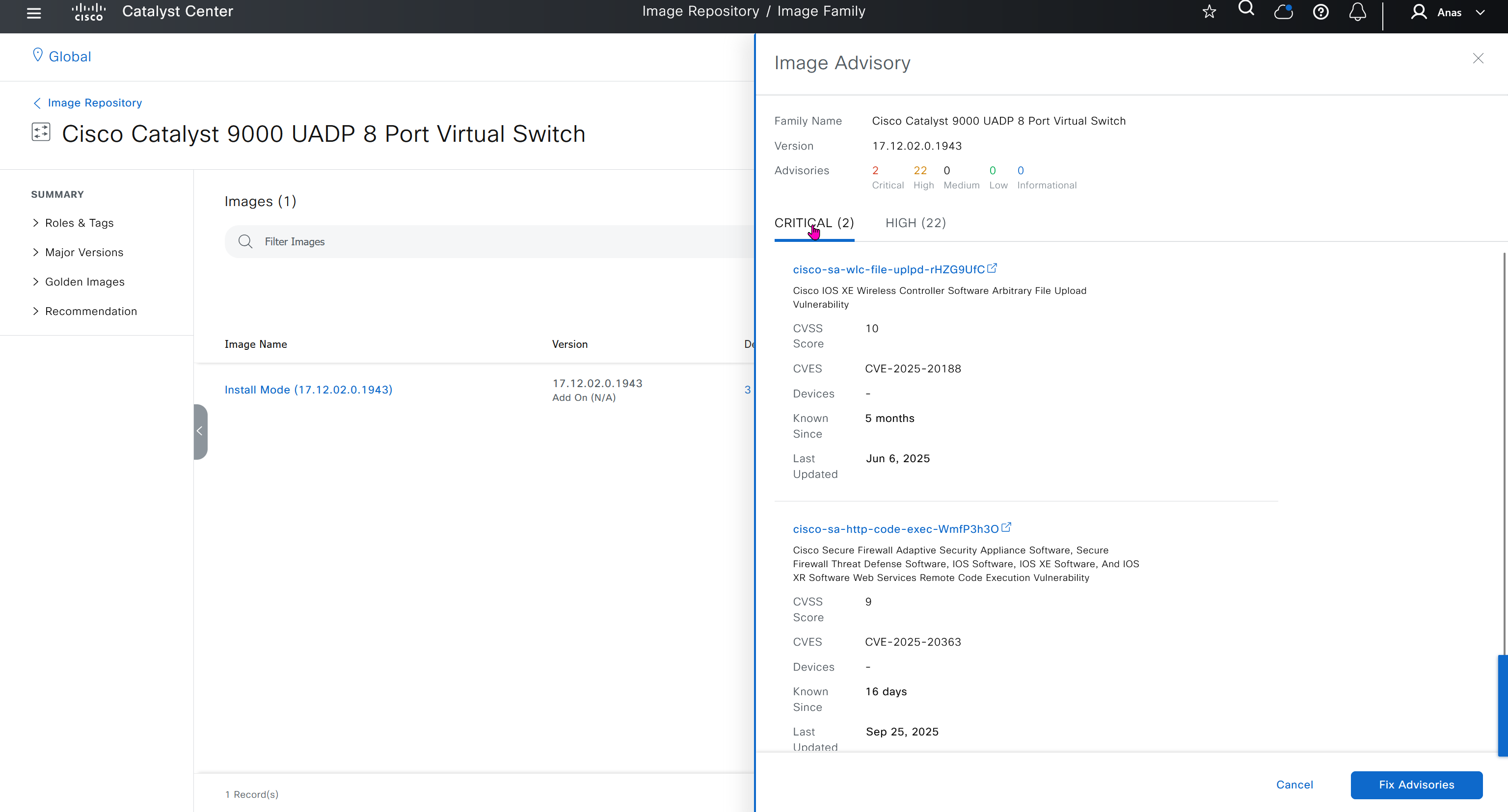
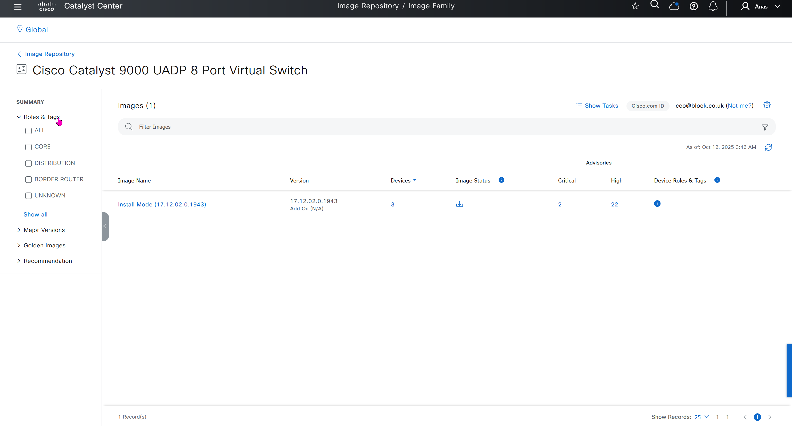
you can only start tagging devices one you have uploaded the image, because we have virtual C9Kv images there is no .bin or .smu images available for them, from ths point on we will have screenshots from lab minutes
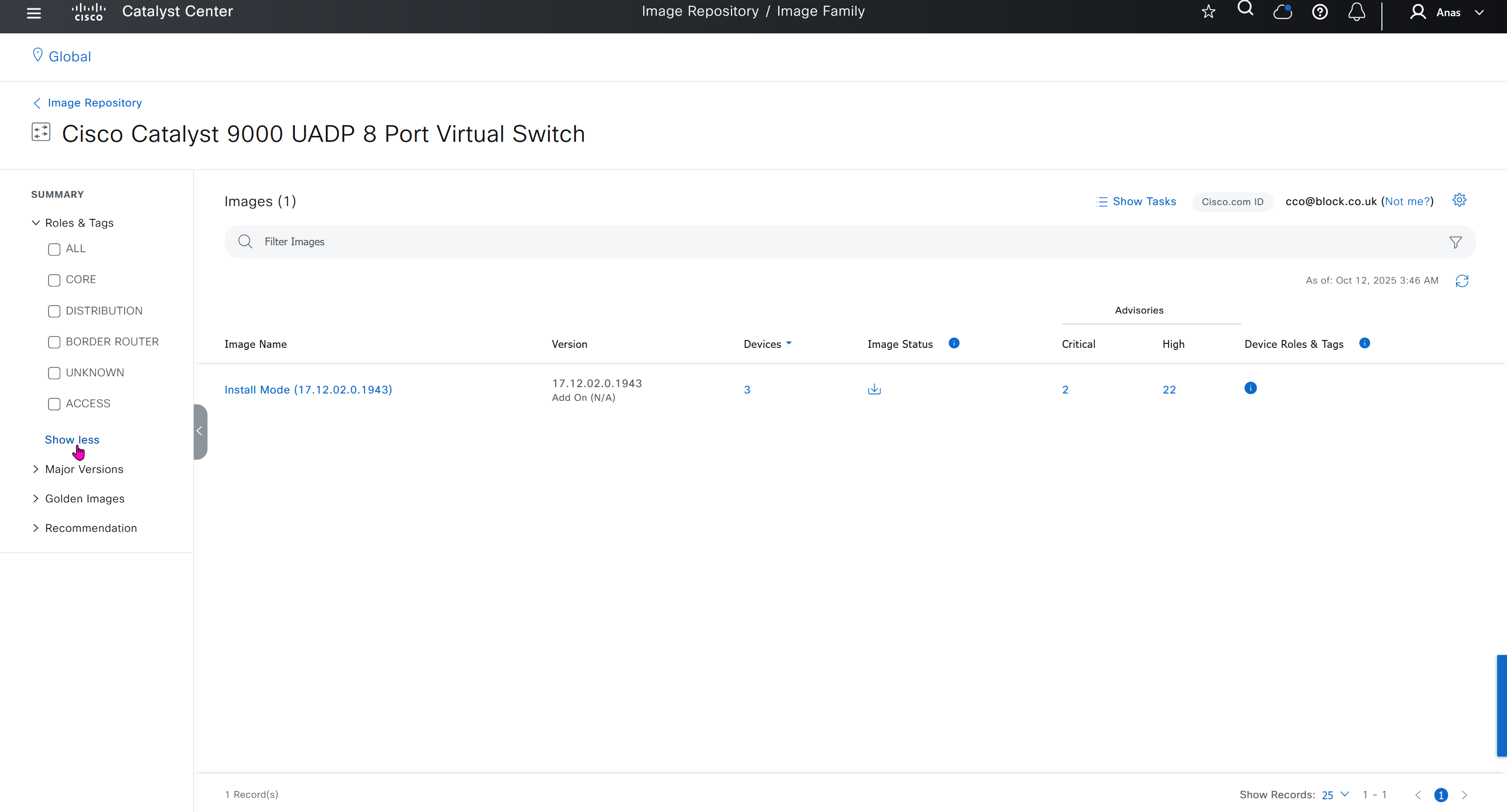
One image can be marked as golden image per device type either at the global level or at the site level, then any device that is not running that golden image will be marked as out of compliance
DNAC also supports auto clean up where it cleans up older image files
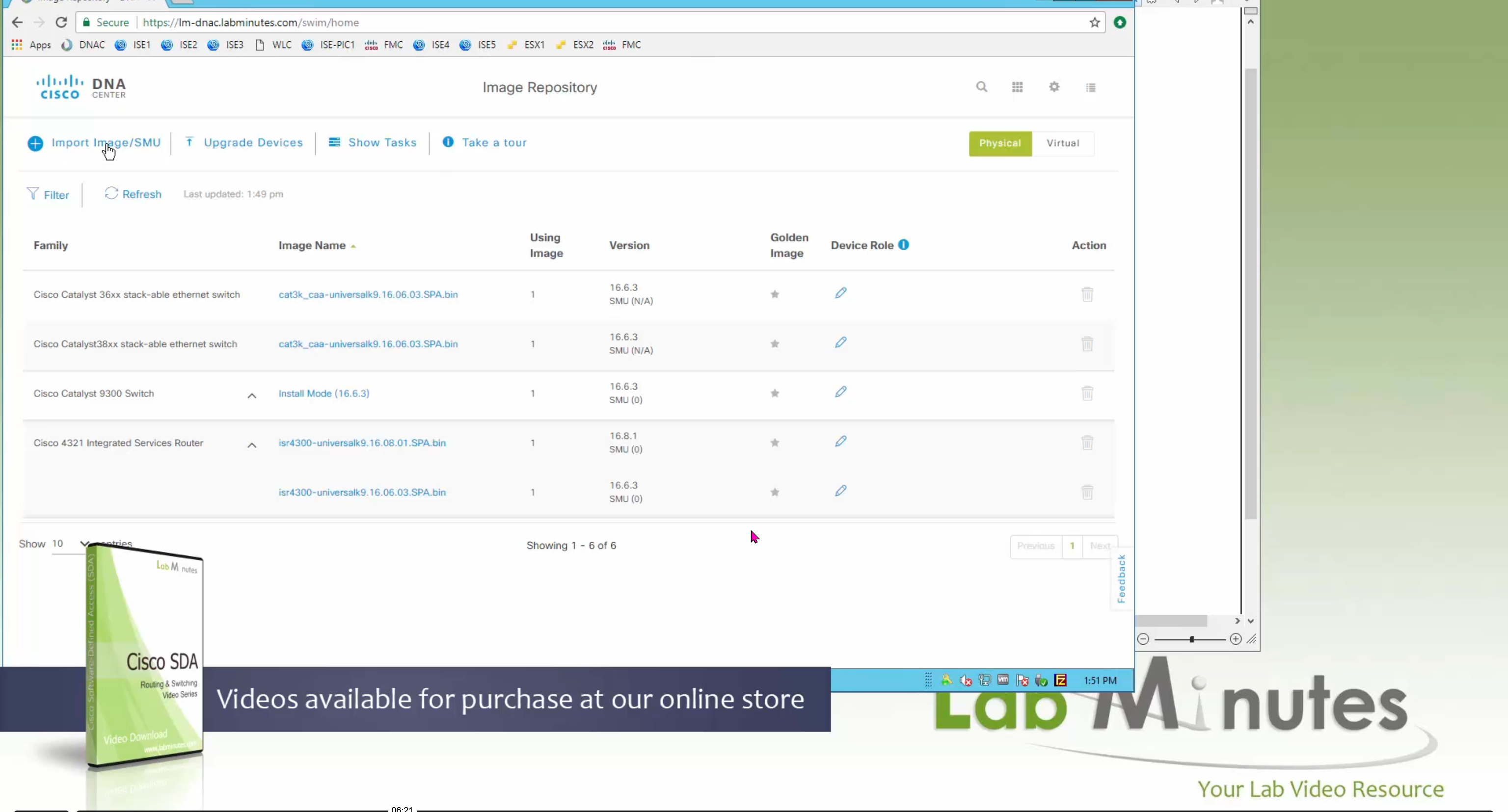
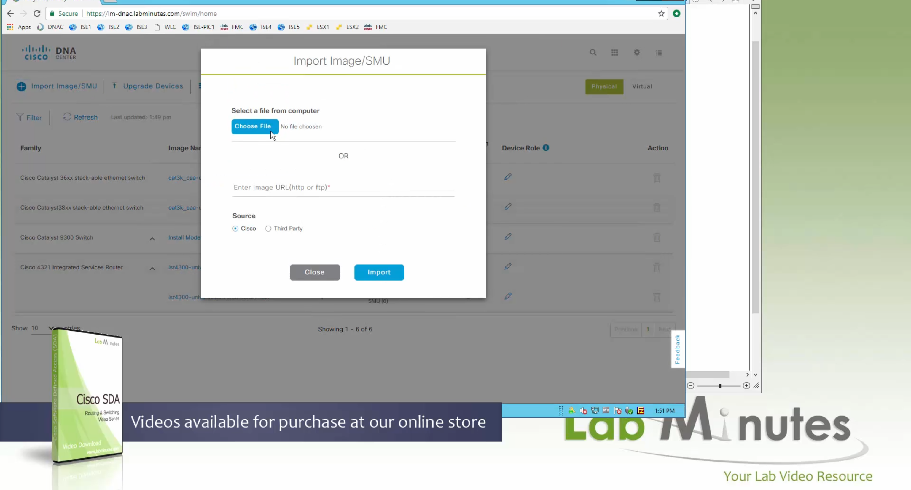
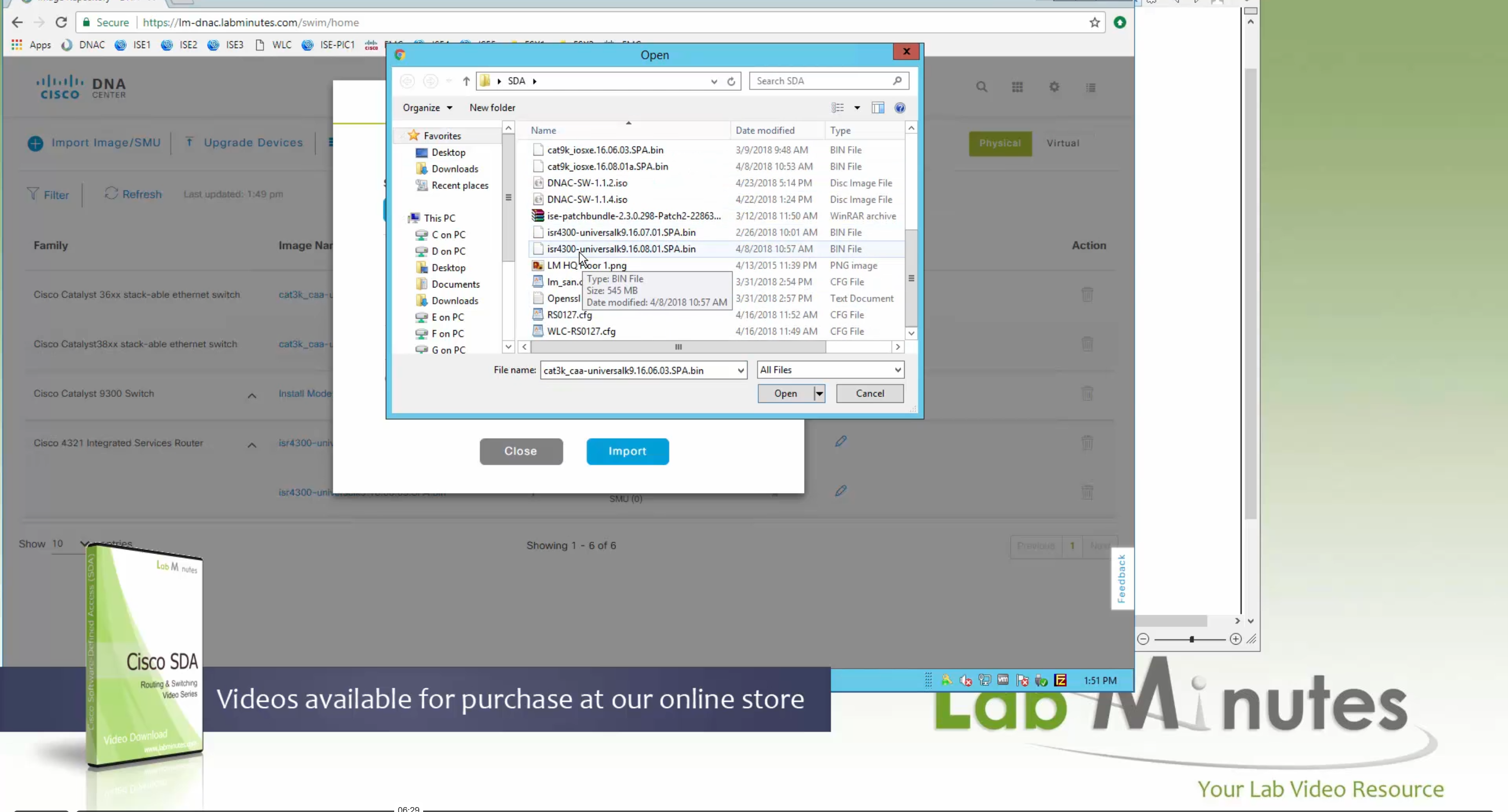

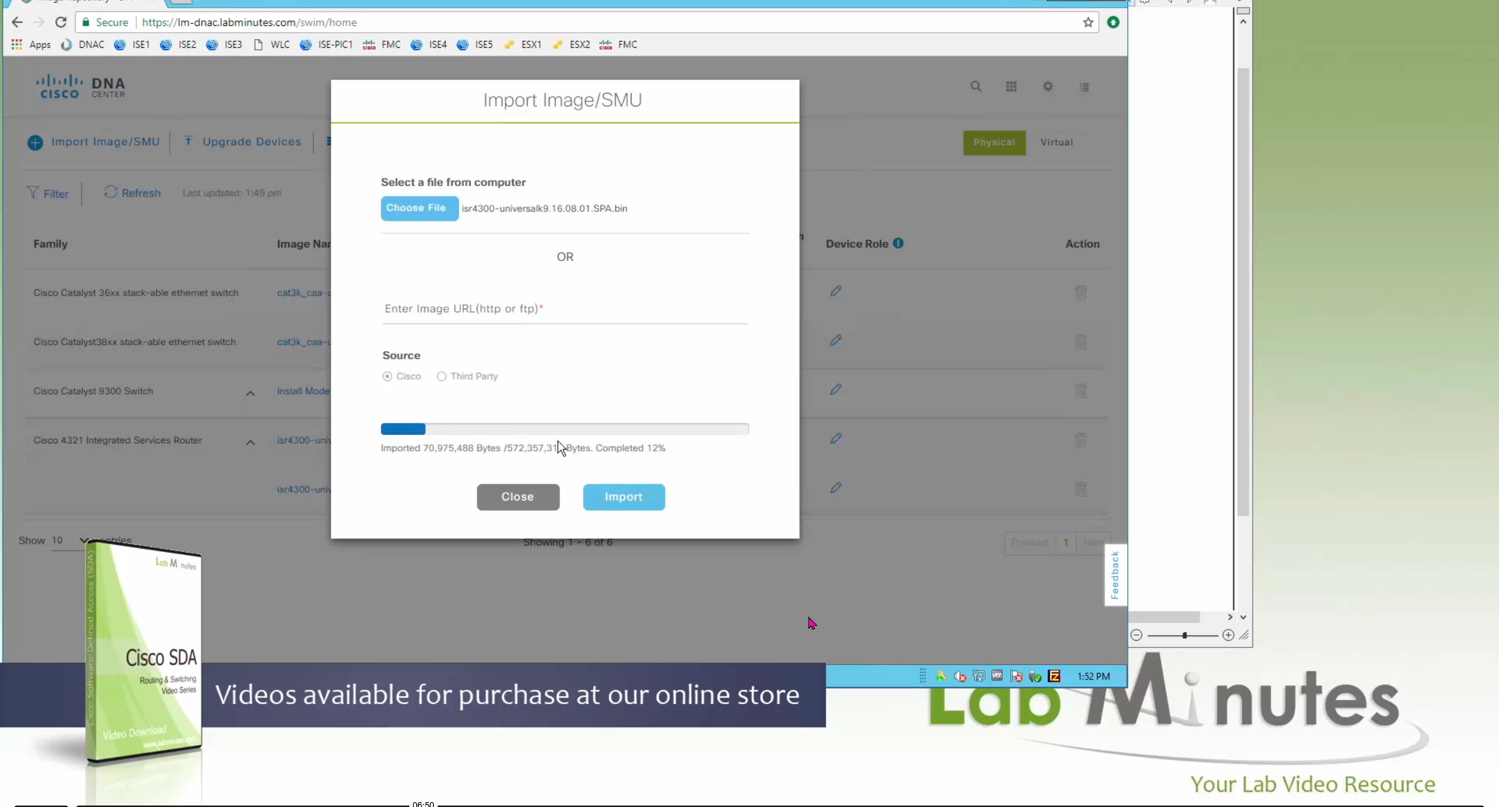
Using image column and version column with (Latest) means that these are the latest images, these images with (Latest) are being displayed from cisco.com and we can click on star icon to make them golden image
Making image golden enforces that image on that hardware model
Same thing can be repeated for different chassis or hardware types, their recommended Latest images can be marked as golden images
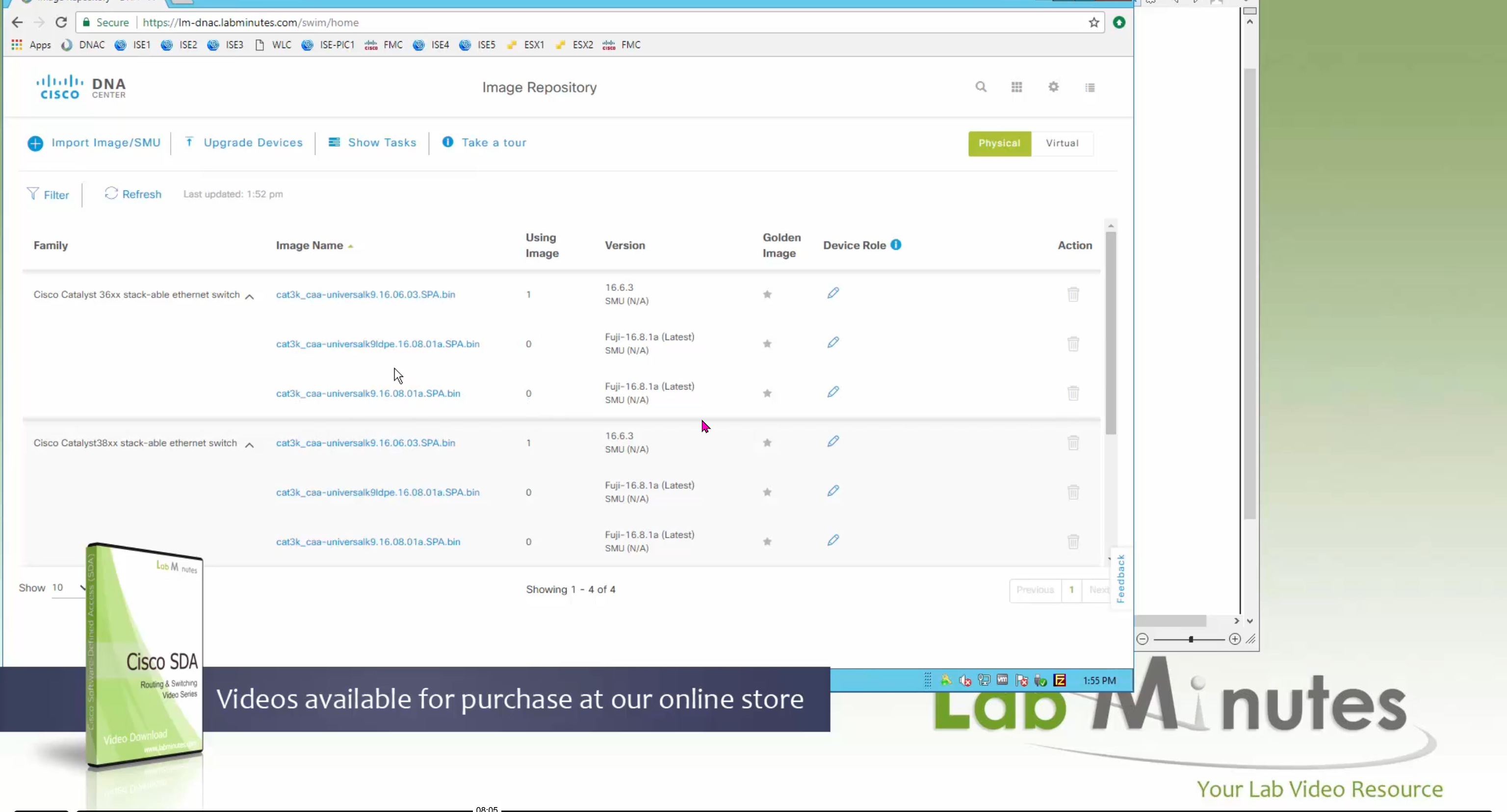
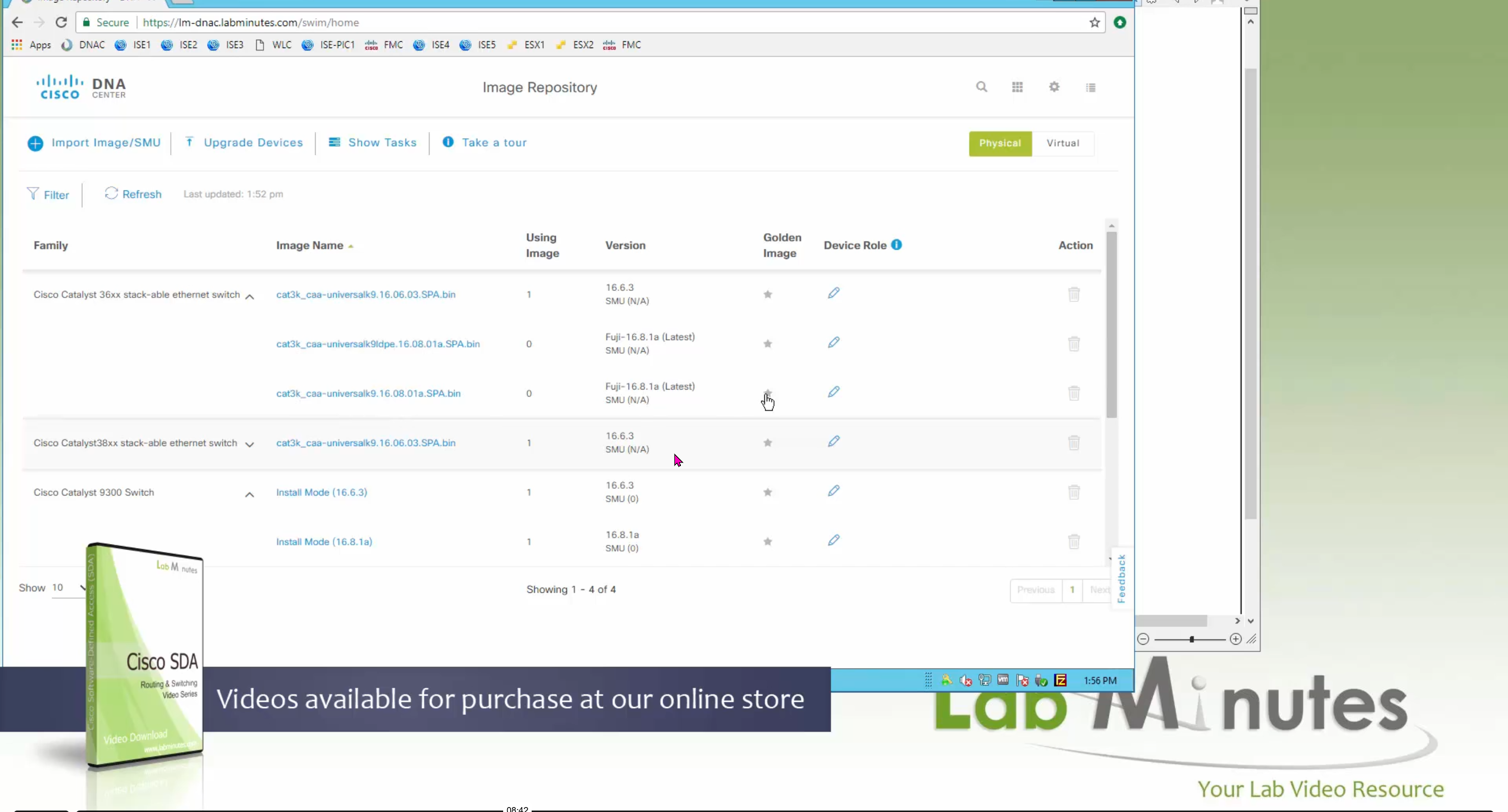
bundle mode images can be pulled from device and made golen image while for install mode we cannot pull from device and mark the image as golden image, instead we can either download from Cisco.com using gui or import image from file

Small “Verified” shows up next to image that shows that DNAC has downloaded the image, clicking that image makes it golden pretty fast because image is already on the DNAC server


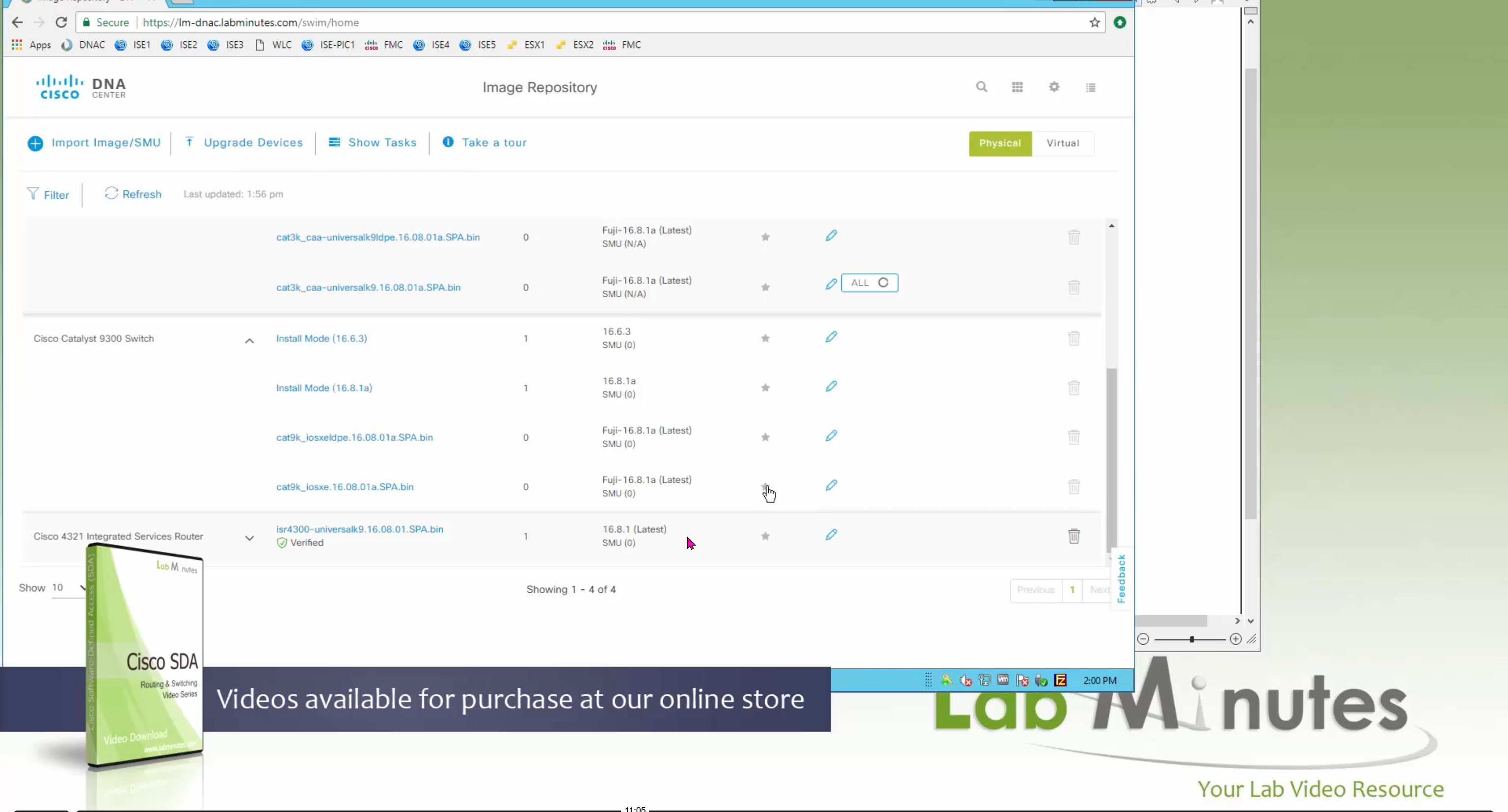


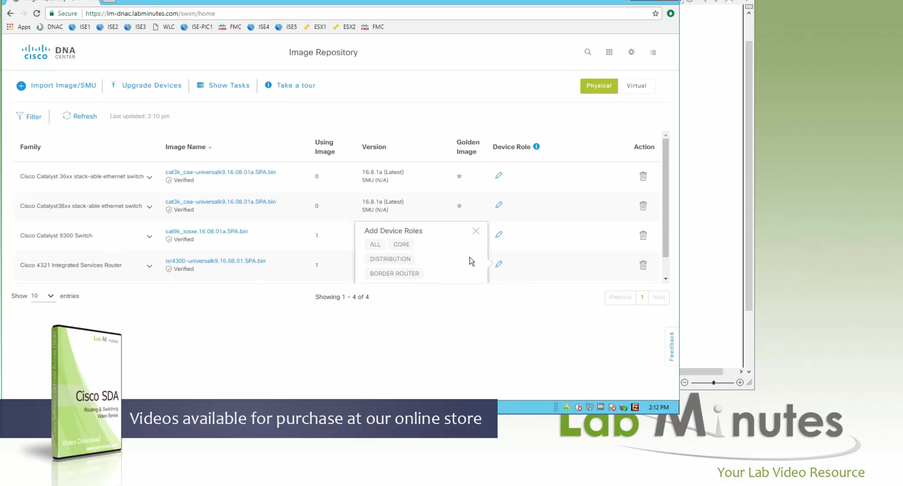
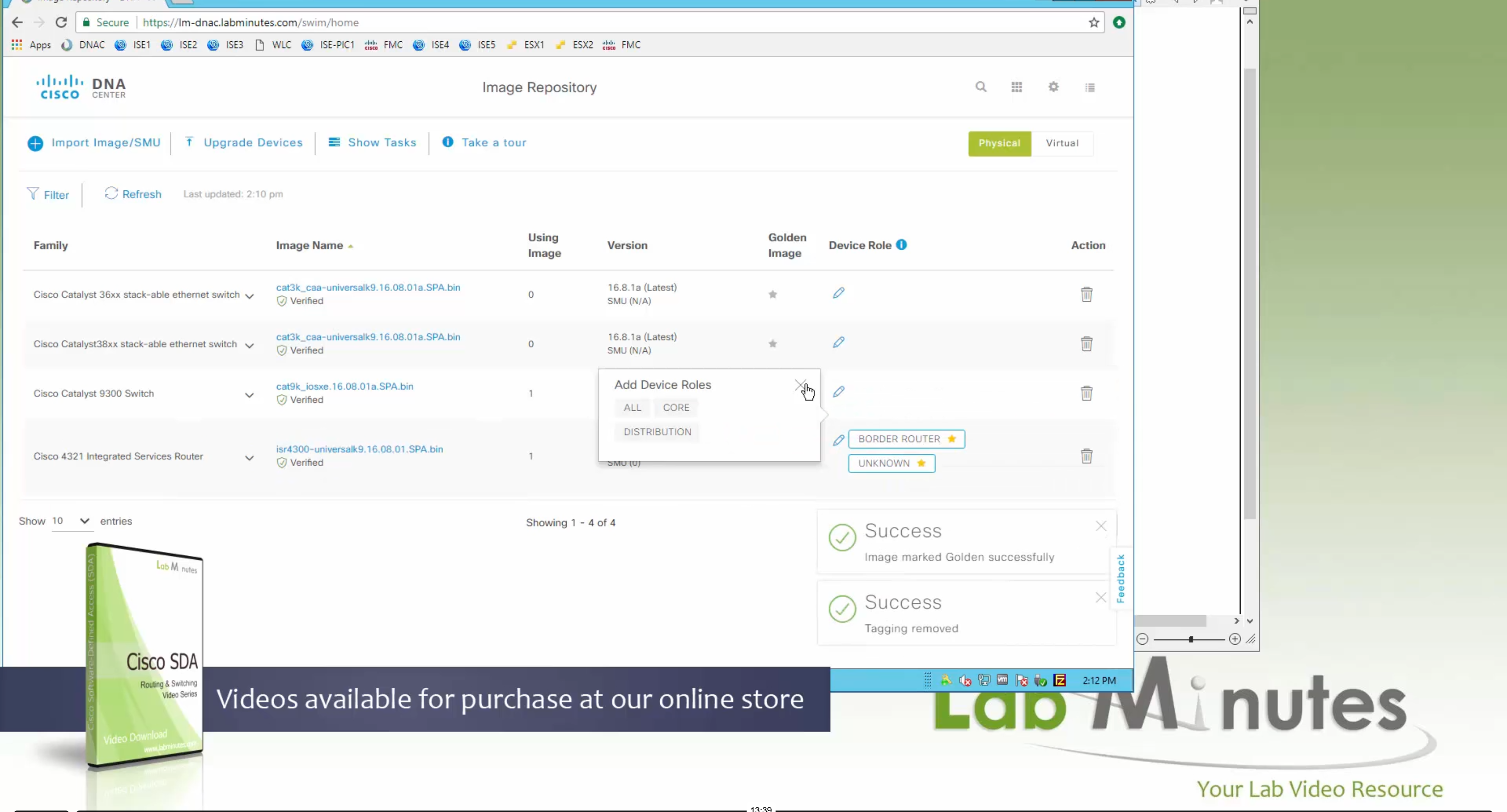
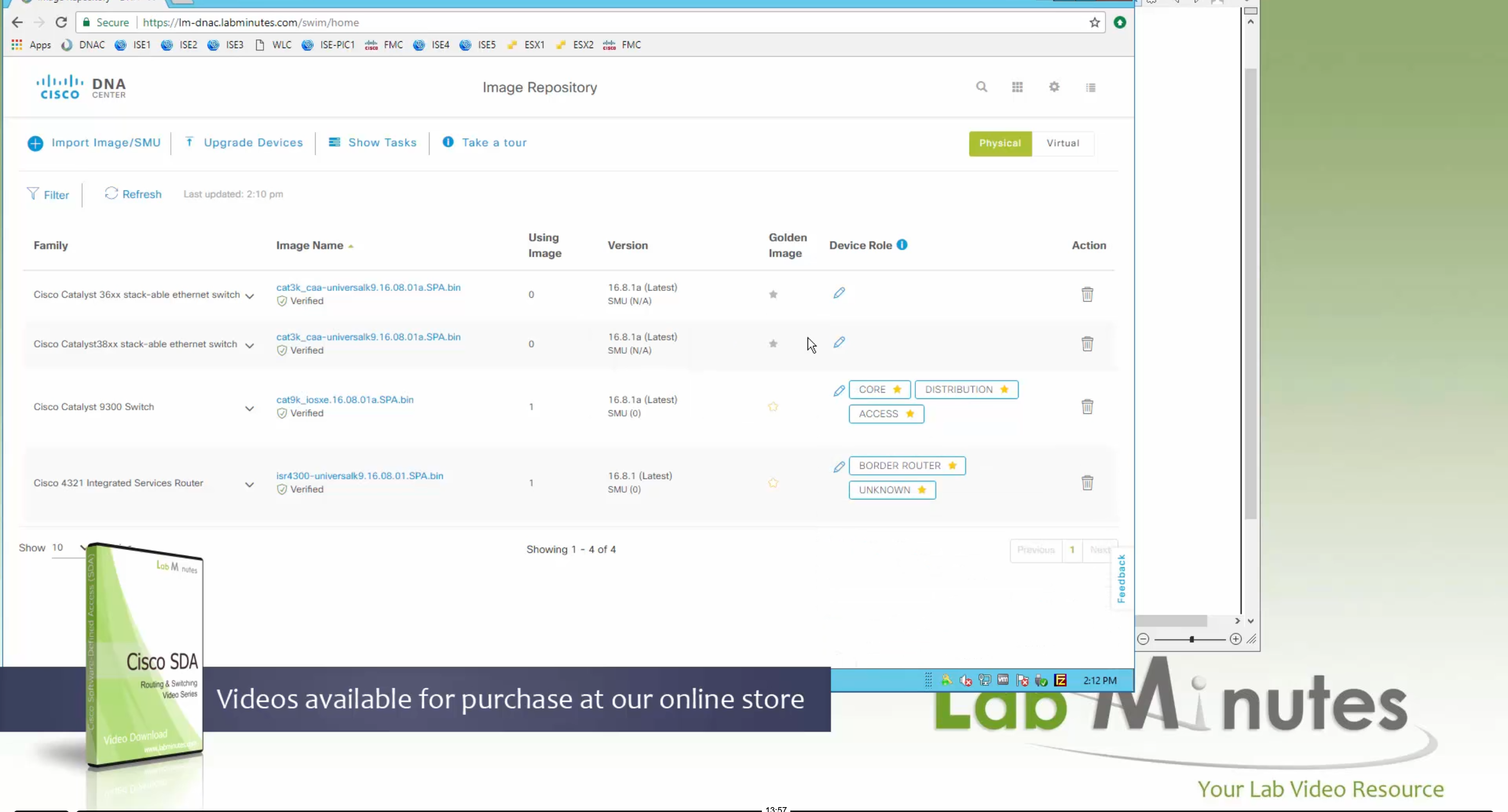

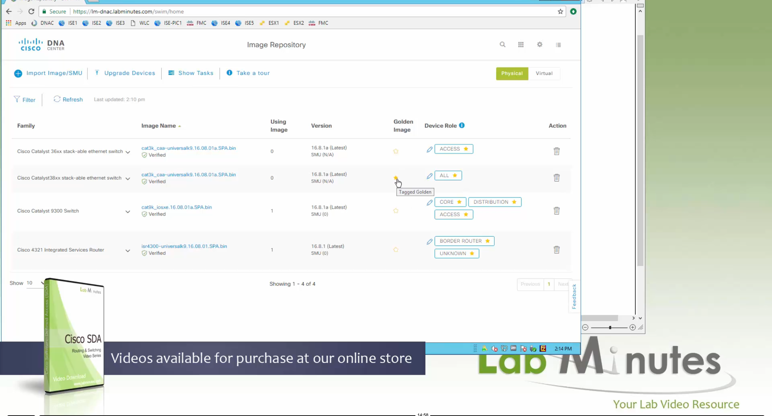
Now making an image golden makes it same for all devices of same hardware model same across different “Roles” and all locations (Globally) and sometimes you may not want that, you can click on edit icon in device role column and set golden image per hardware model per device role, such as all “C9300” / “Access” to have a specific image or you can even have golden image per hardware model per role per location – but first you must remove the golden image from global level and then set it on site level, there is no concept of override here, either set at global level or set at all sites independently
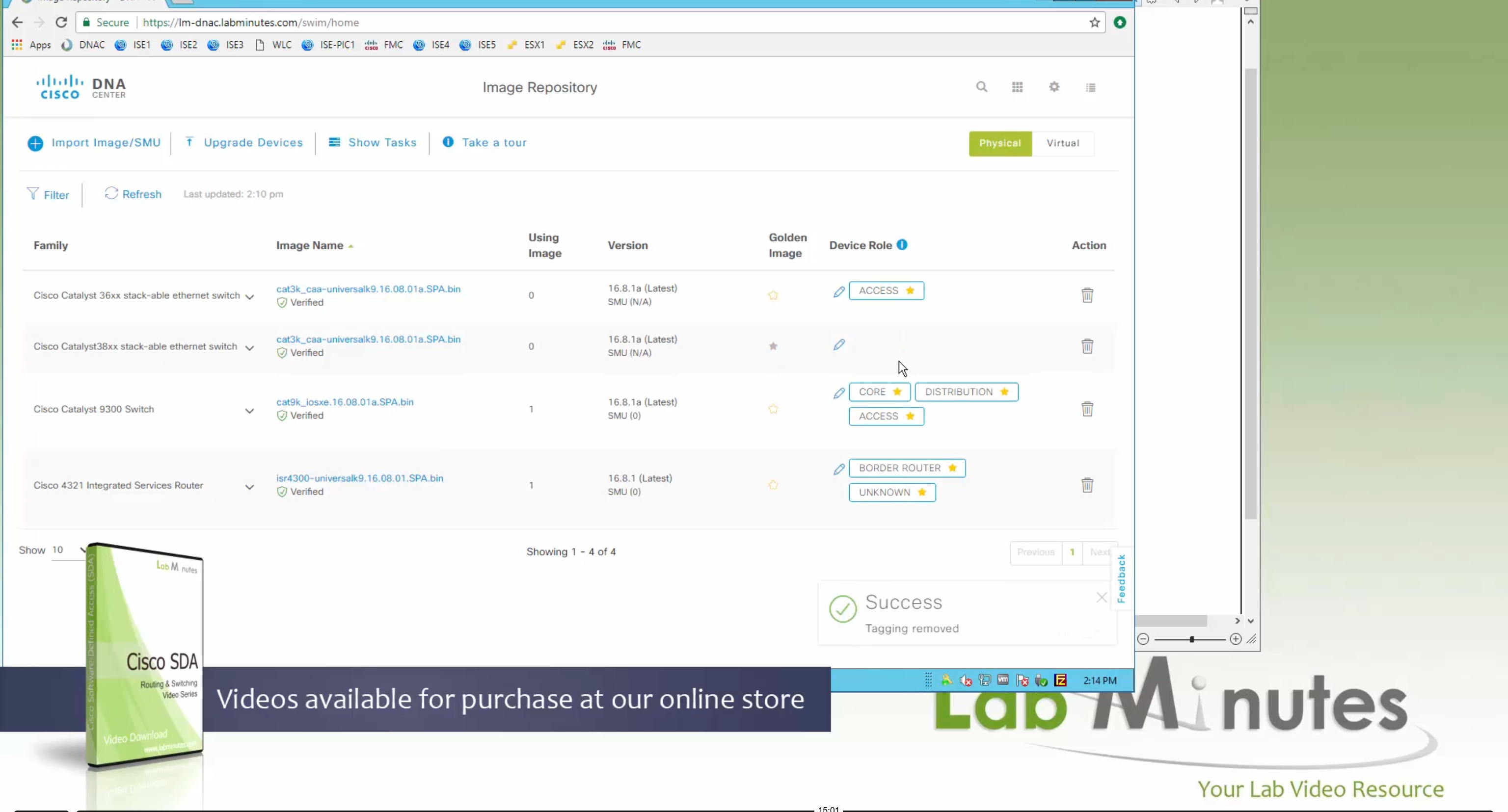


Next step is to see which devices are not in compliance and upgrade them in provision > OS image column


DNAC validates Flash, RAM and Reboot required


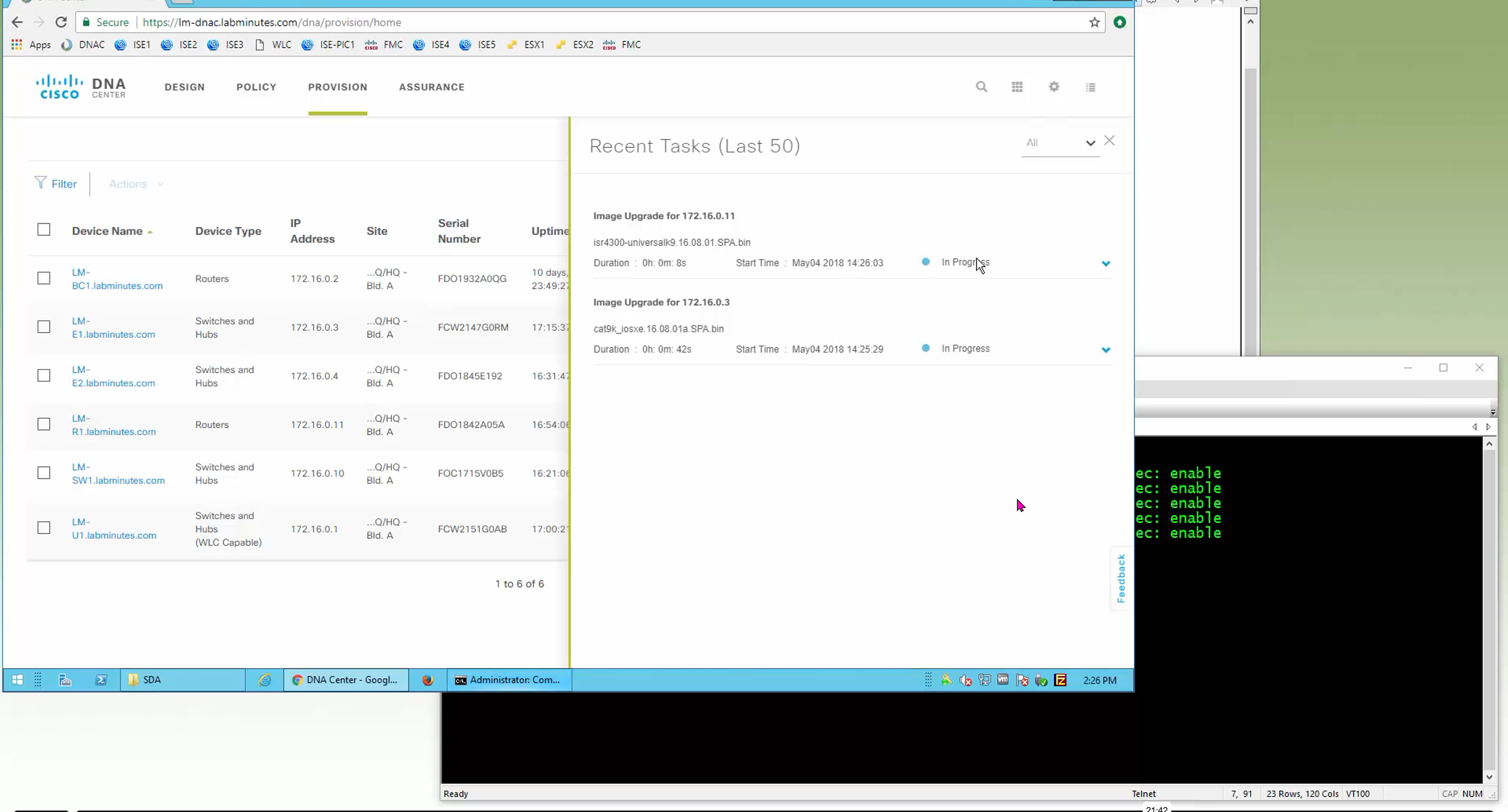

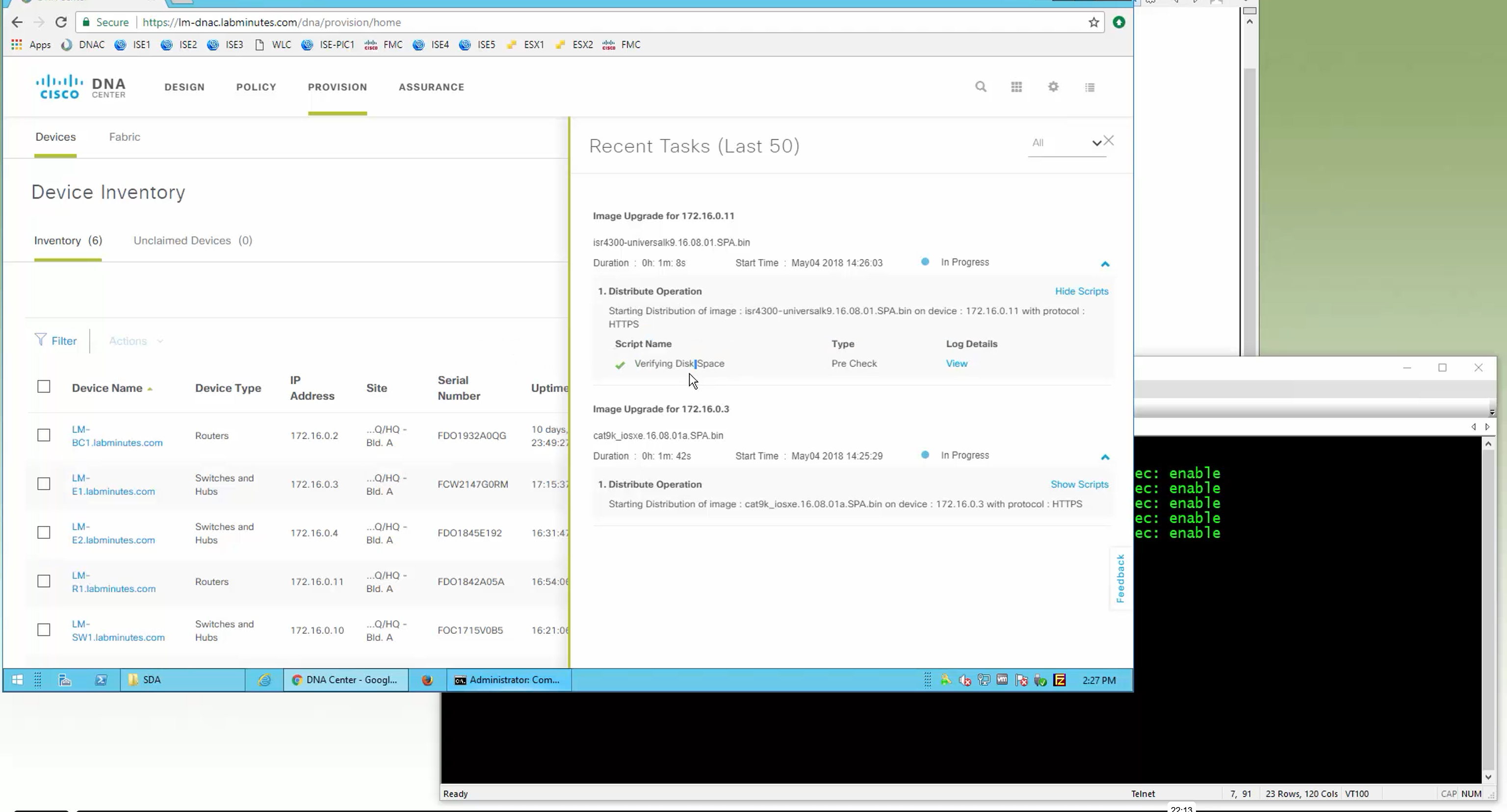

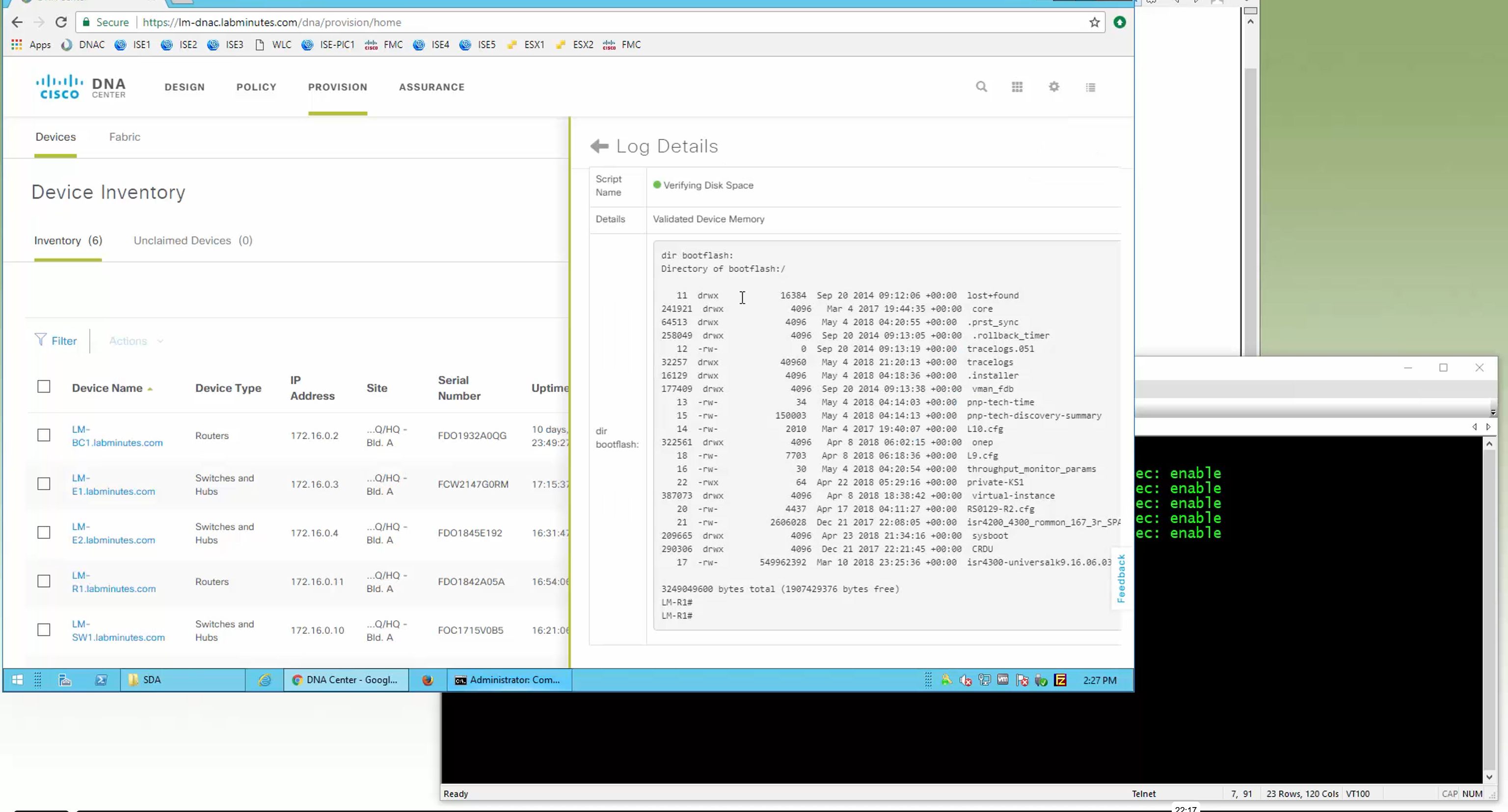
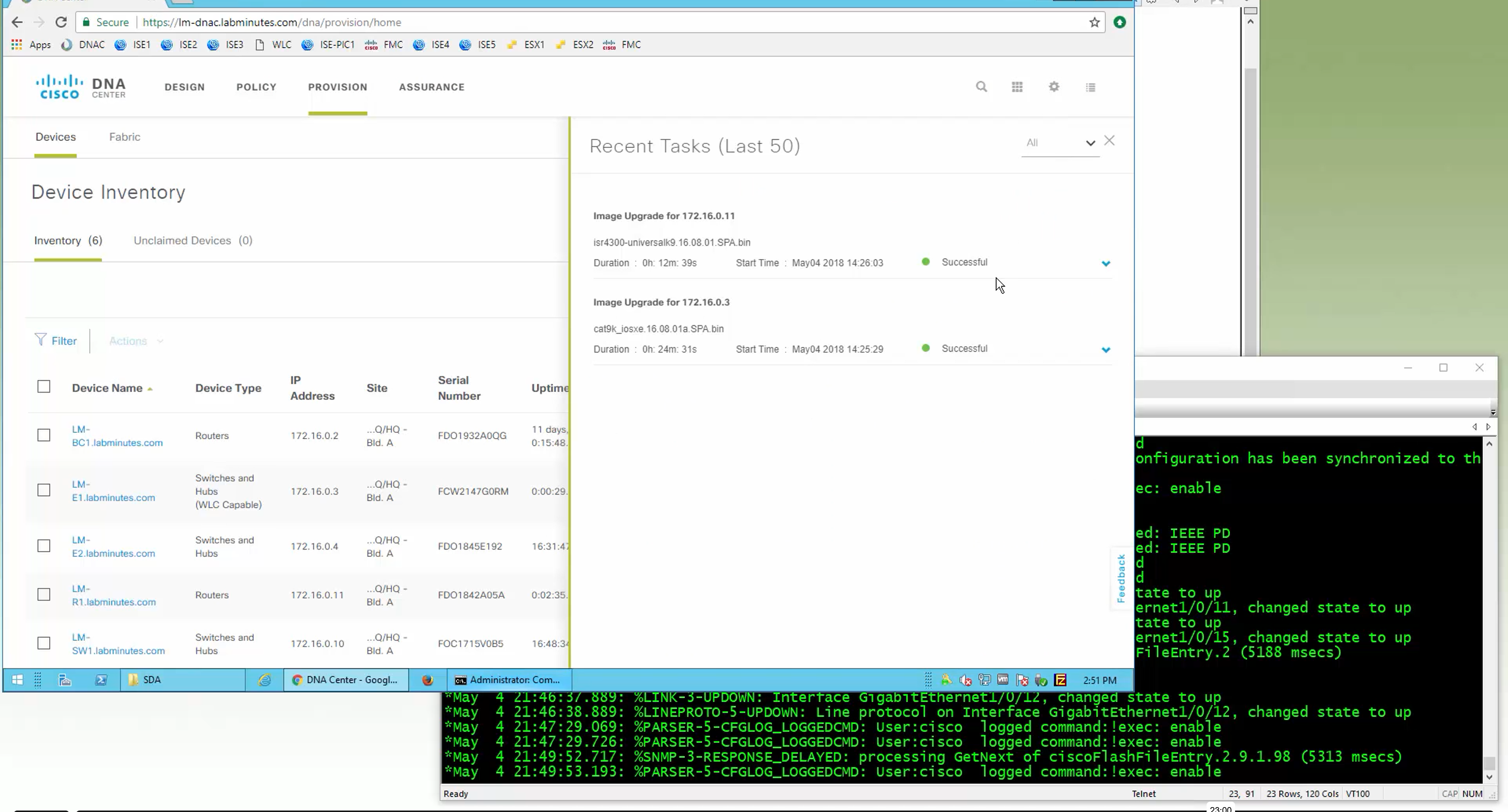
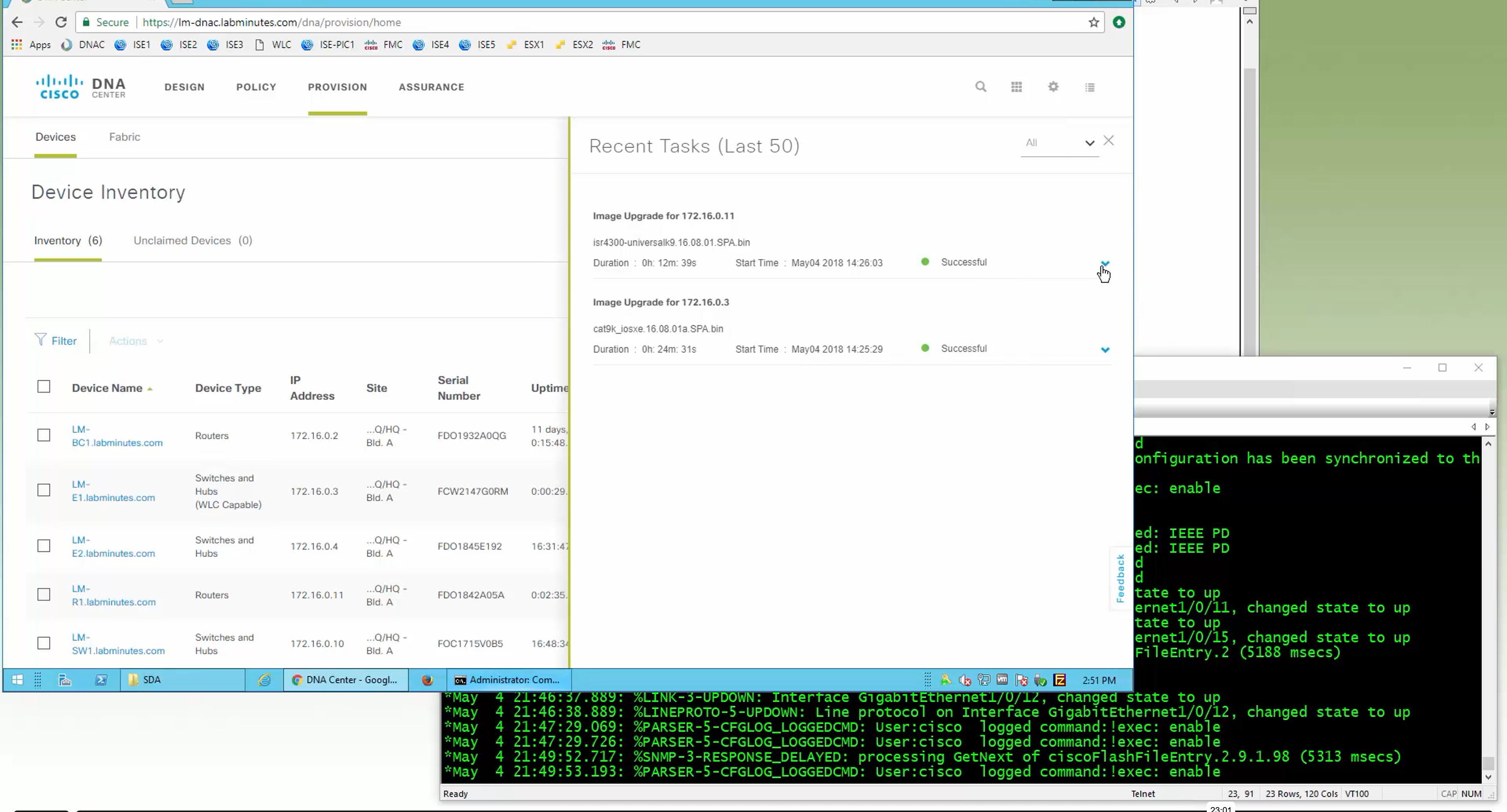

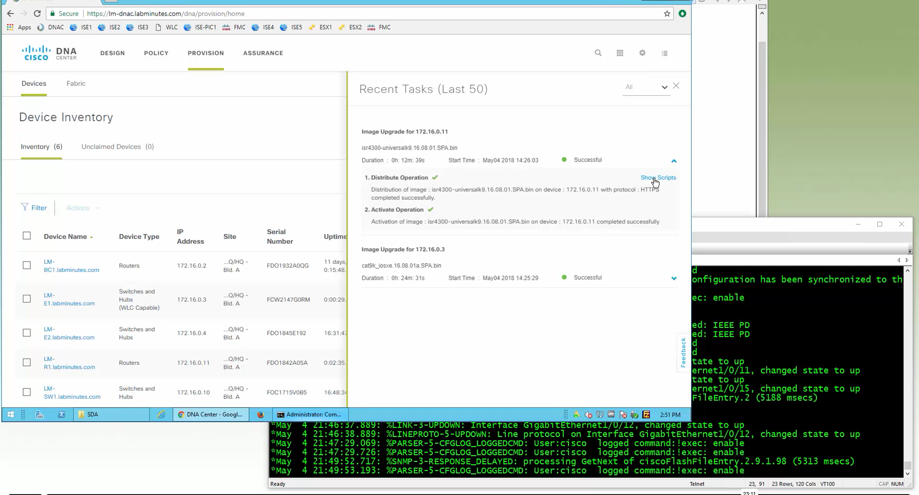

SMU(0) means that there is no SMU for this image version

one big improvement in version 2.1 is that you can download image from local server instead of DNAC over the WAN
“Provision > provision device” pushes the remaining config as config assigned during assignment of device to site is not full config, full config is deployed when device is provisioned
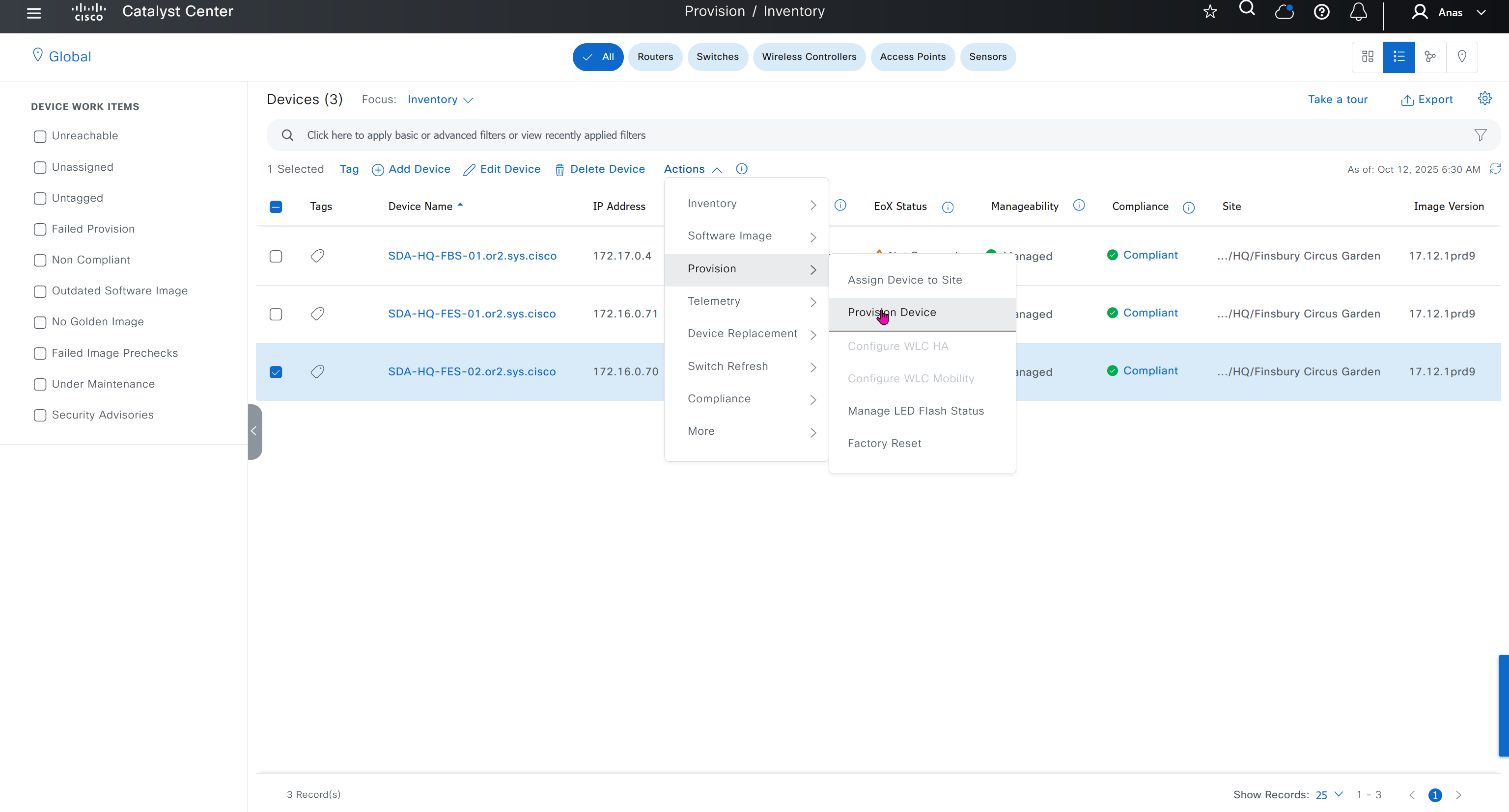
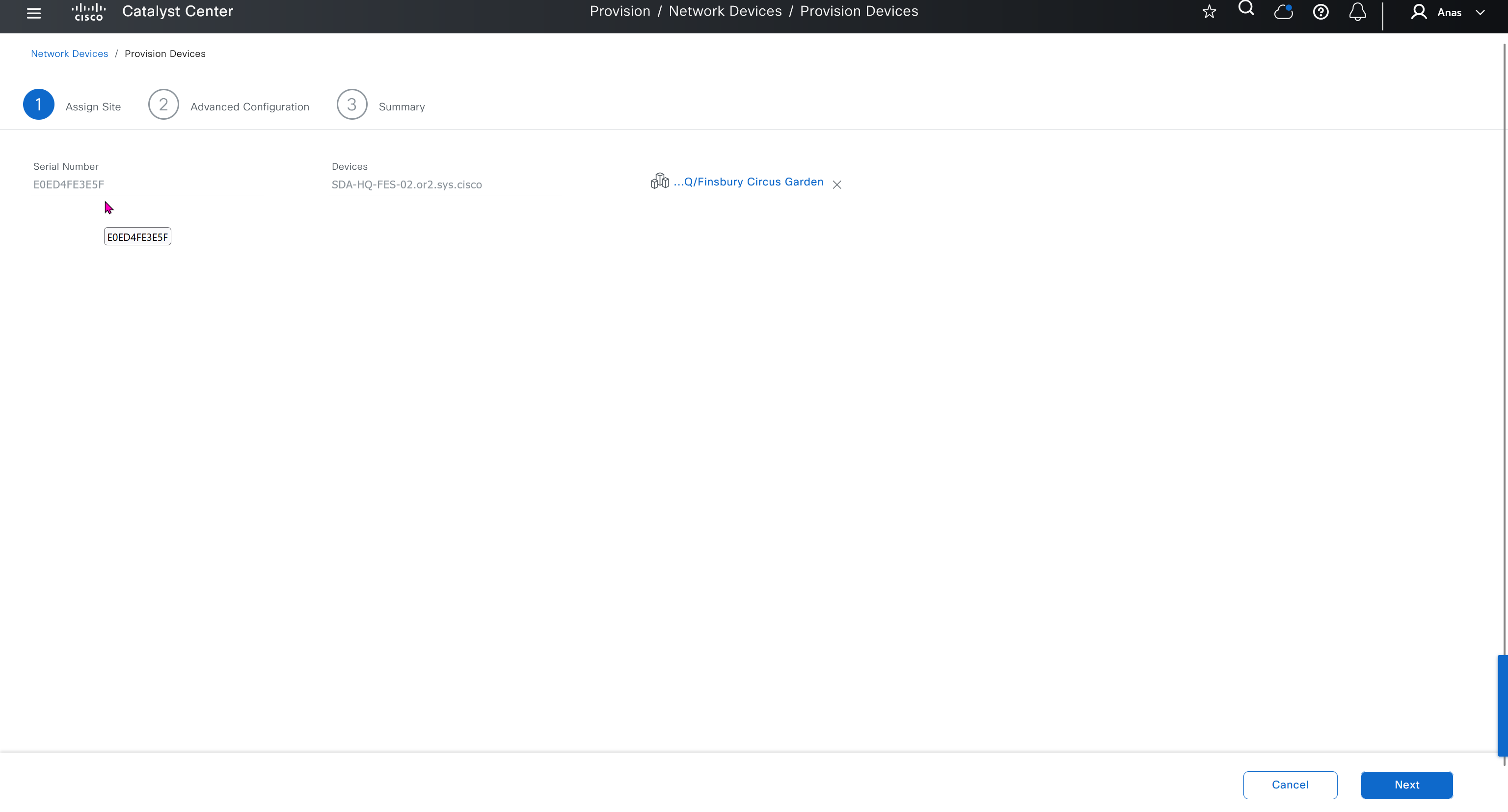
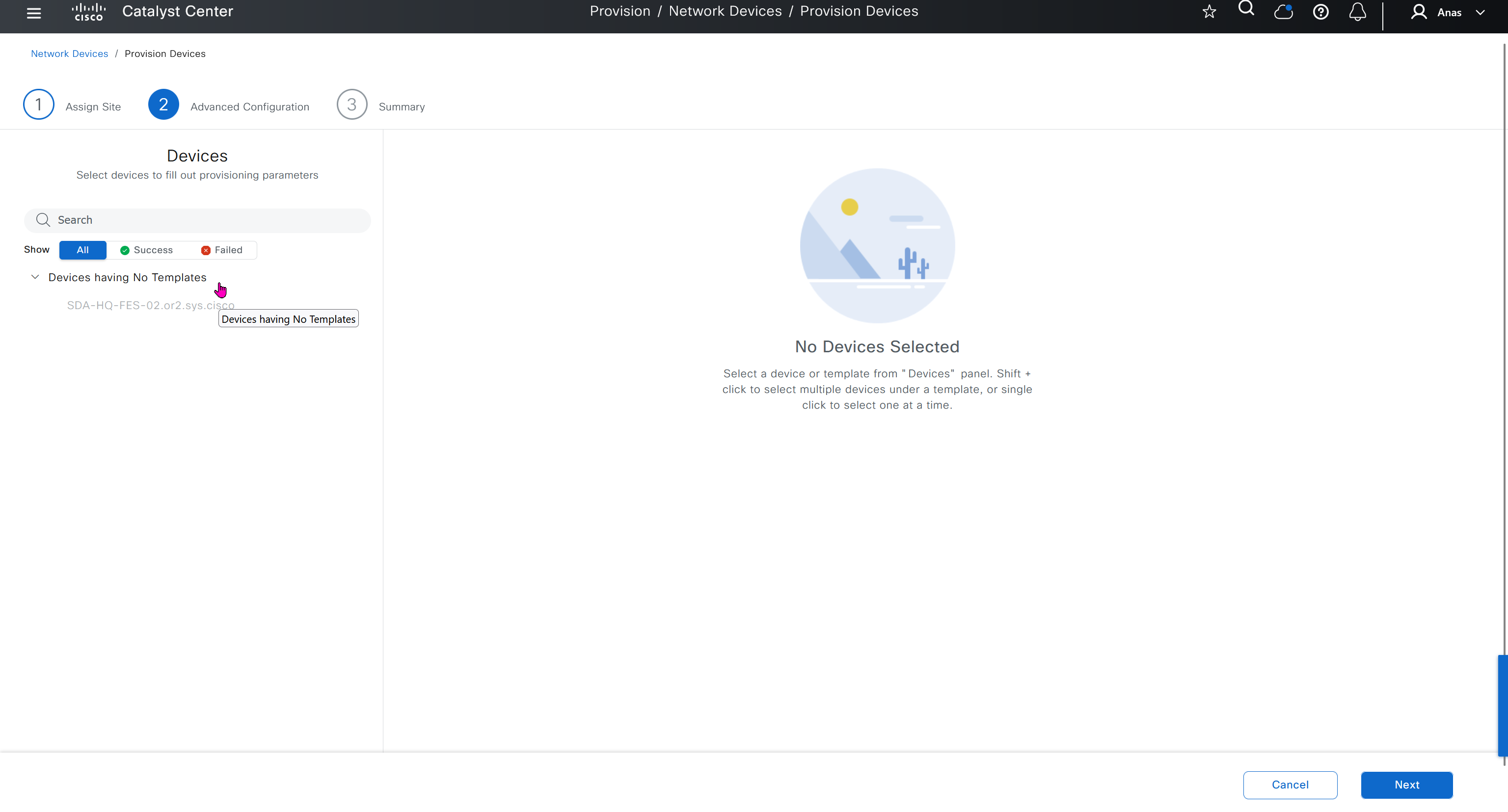
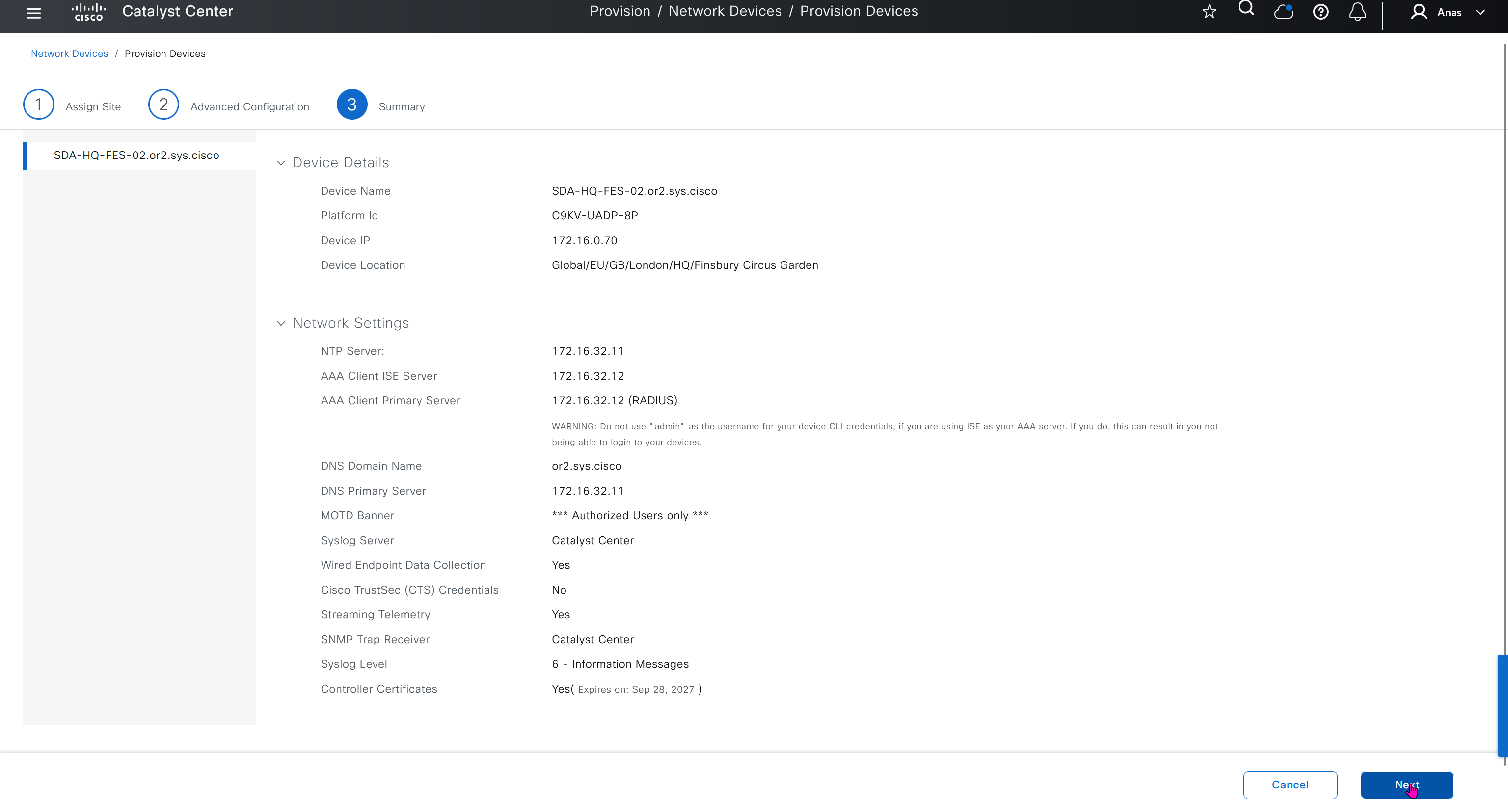
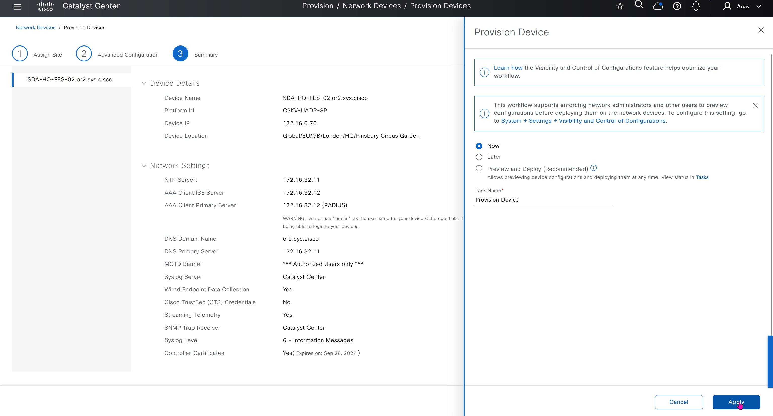

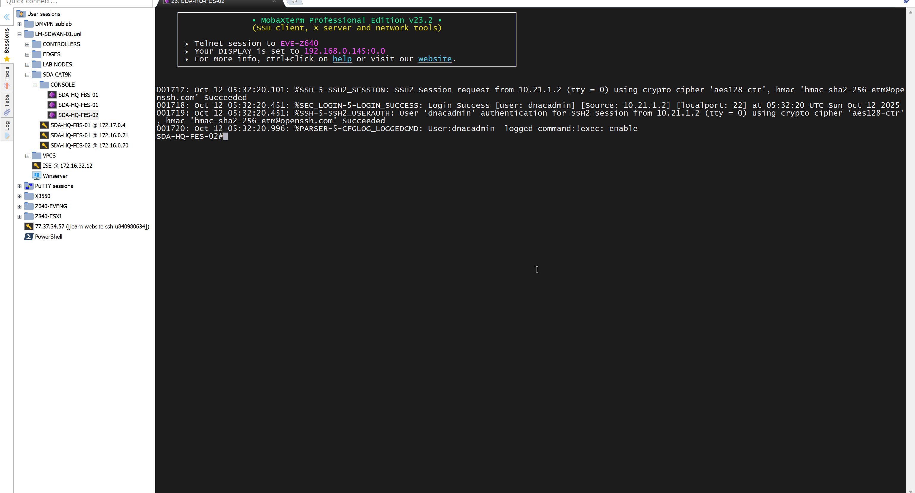
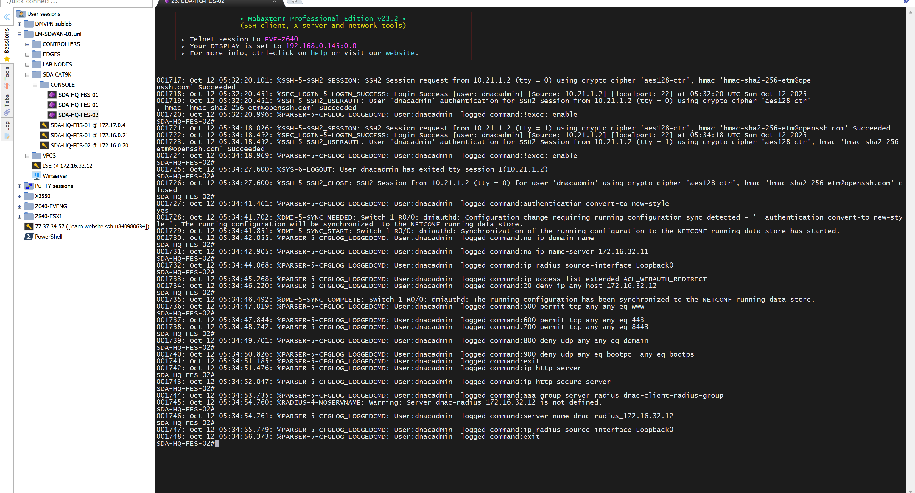
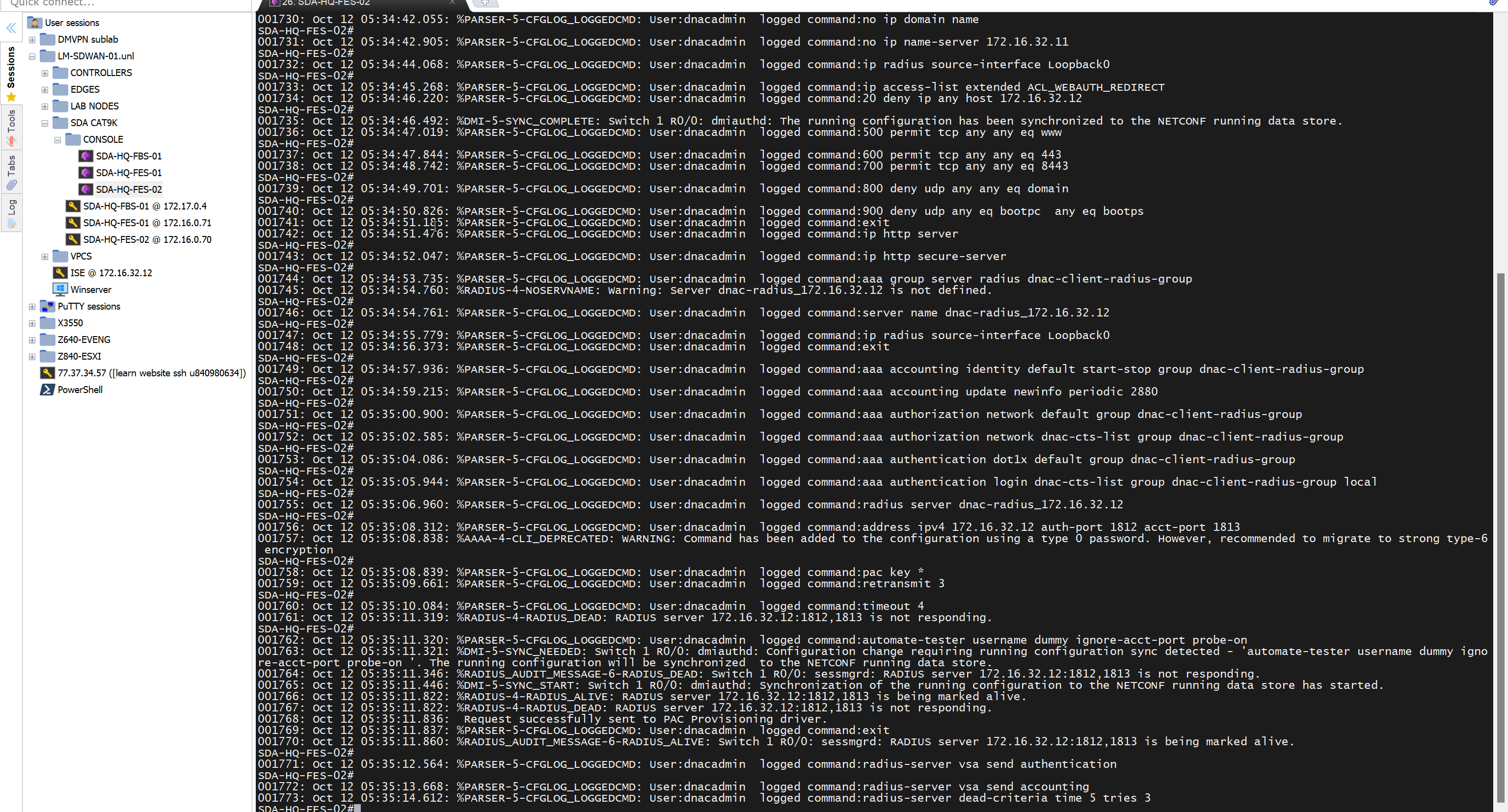
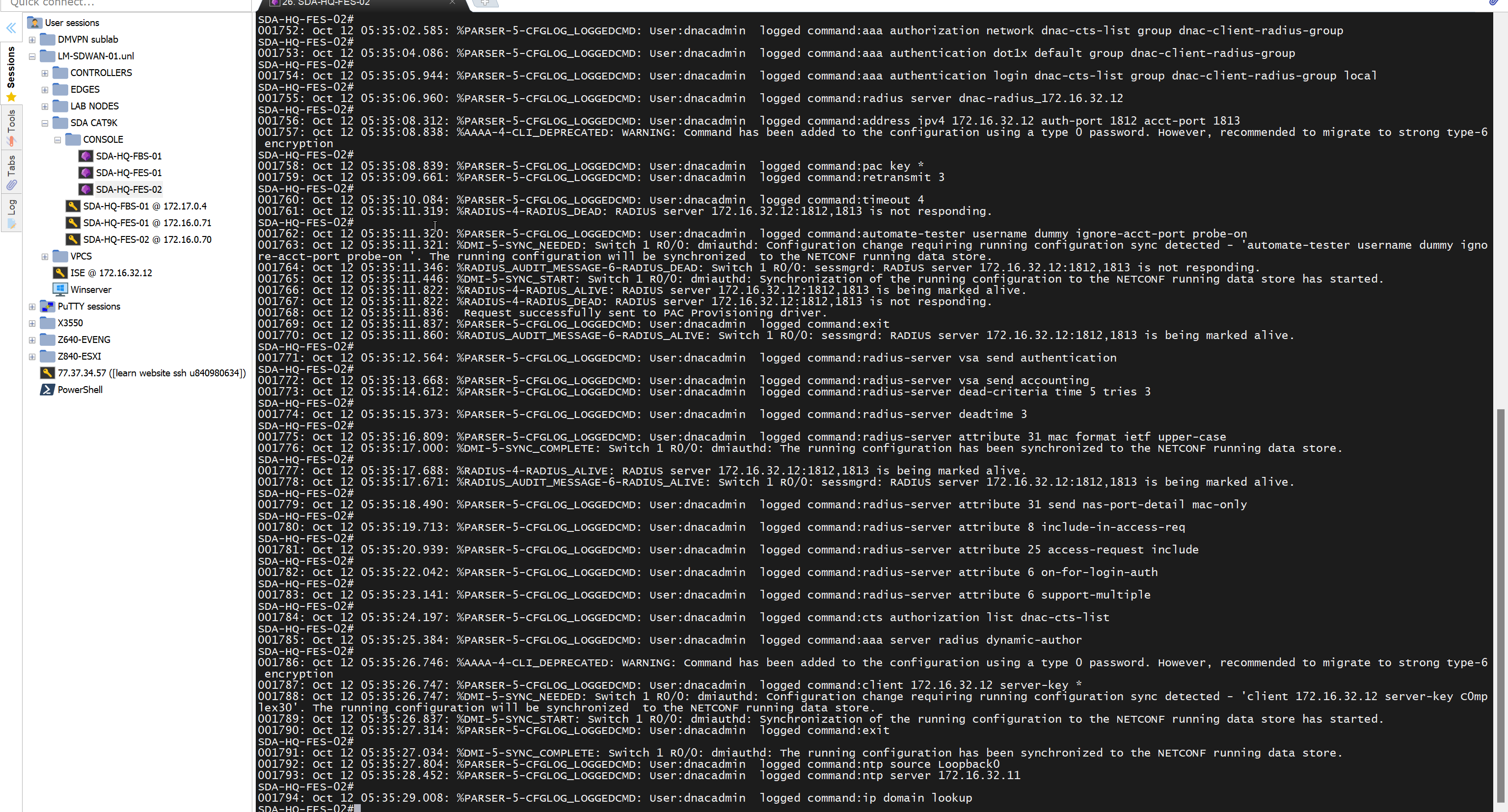
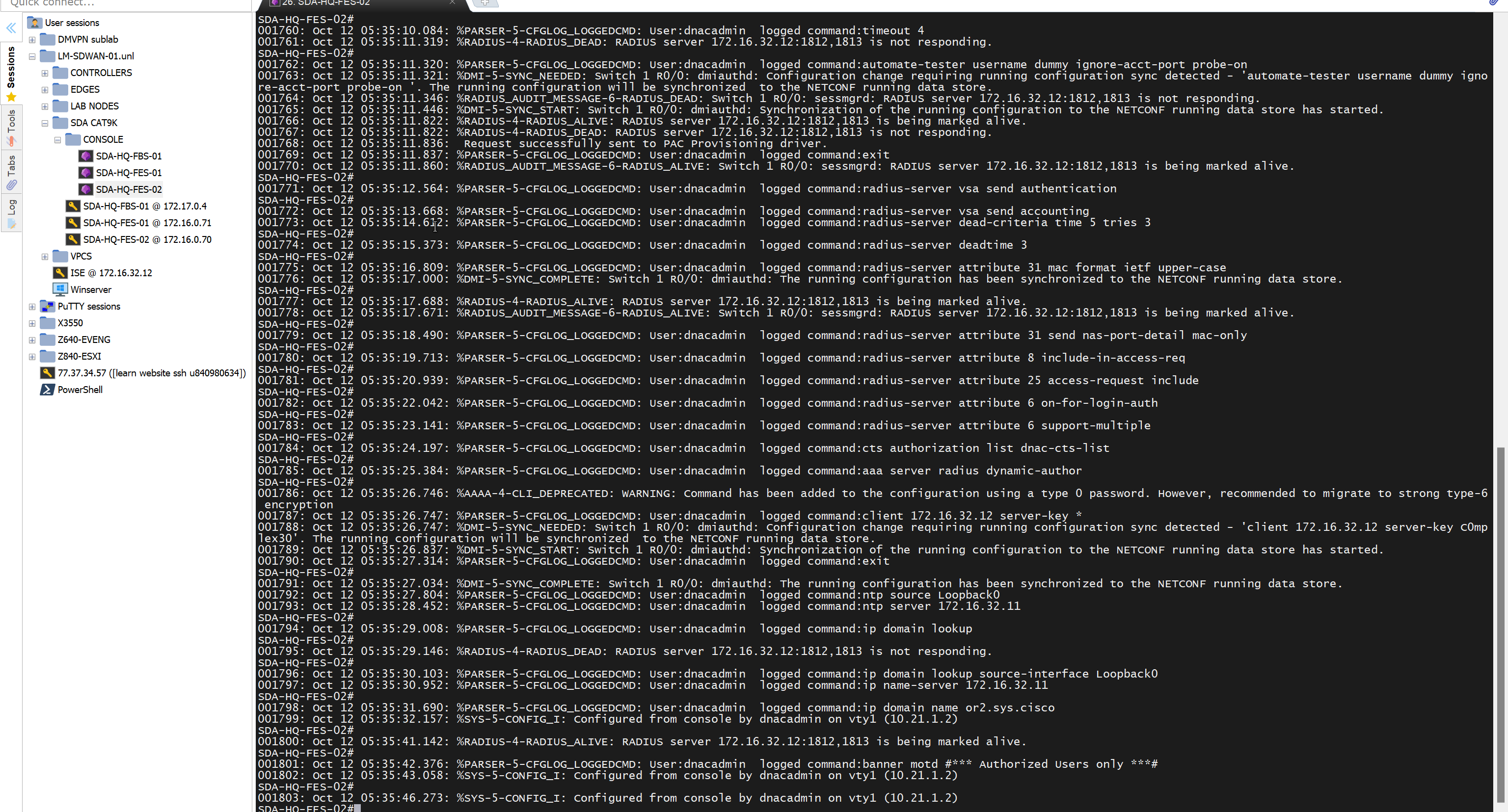
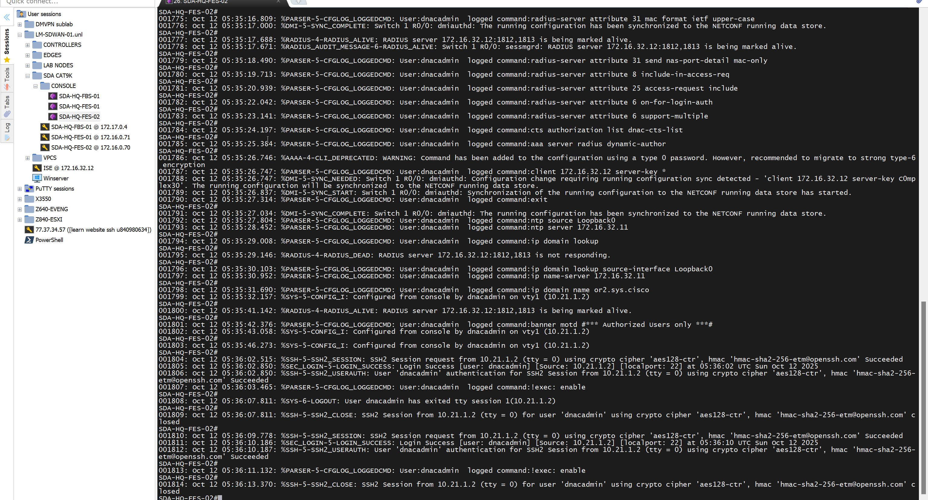
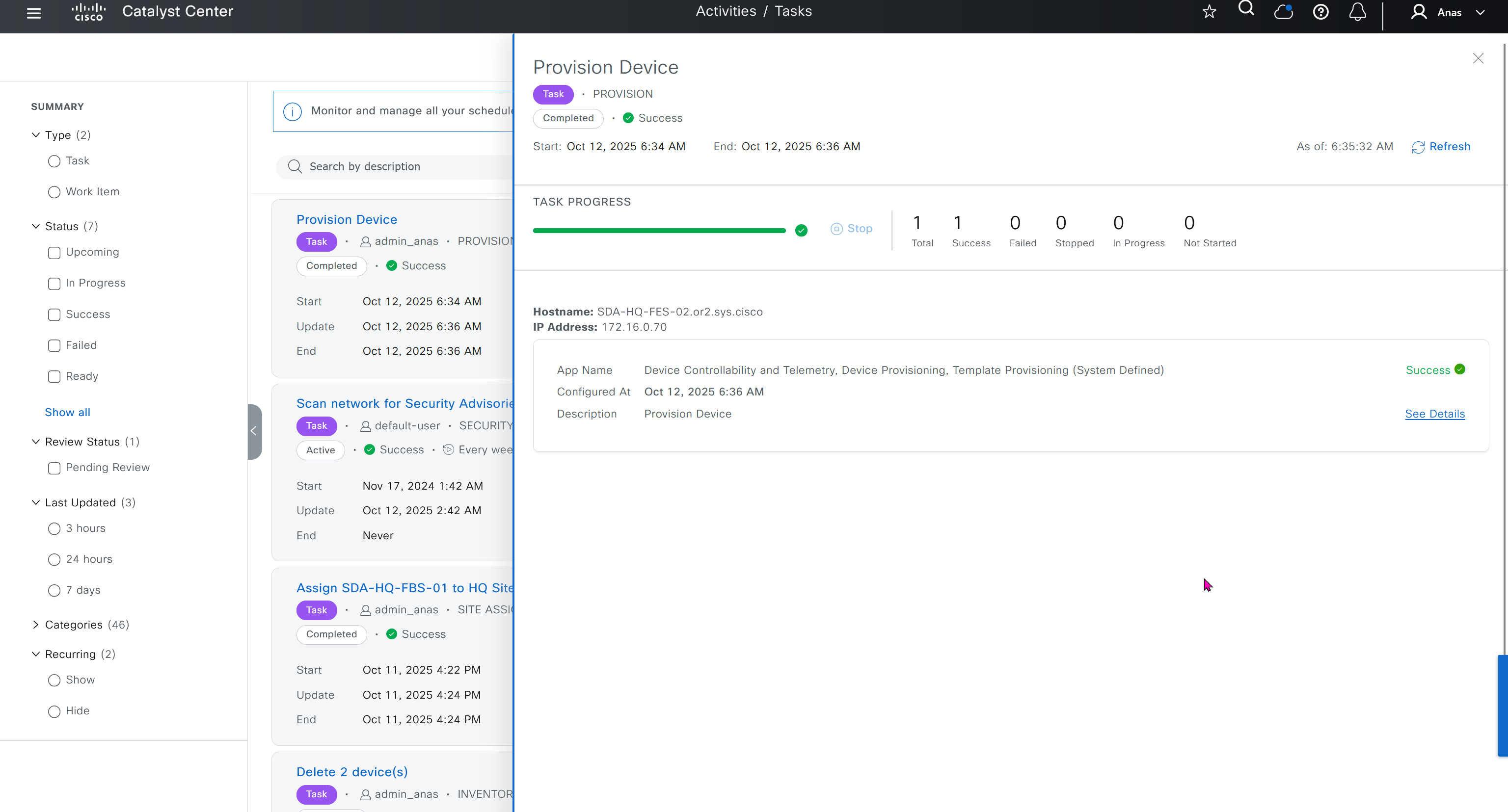
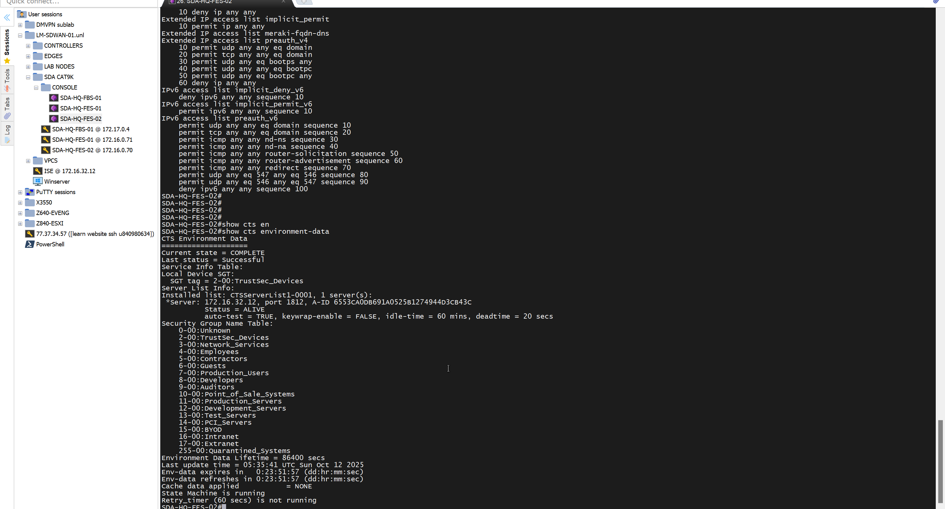
Mark for replacement is when we have to RMA the device
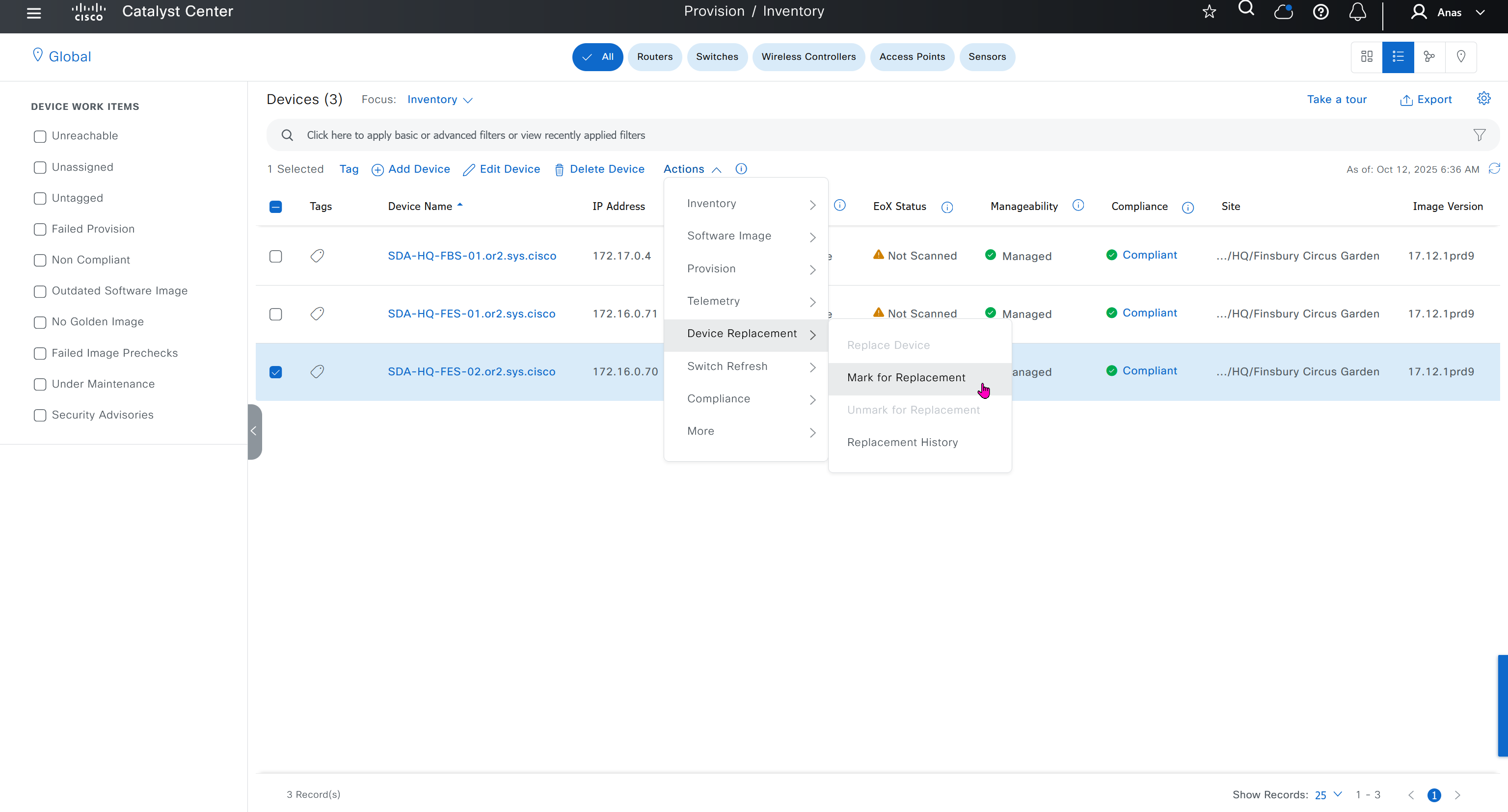
Compliance > Run Compliance, this is manual trigger of the compliance and checks if device has golden image and if startup-config is same running-config etc
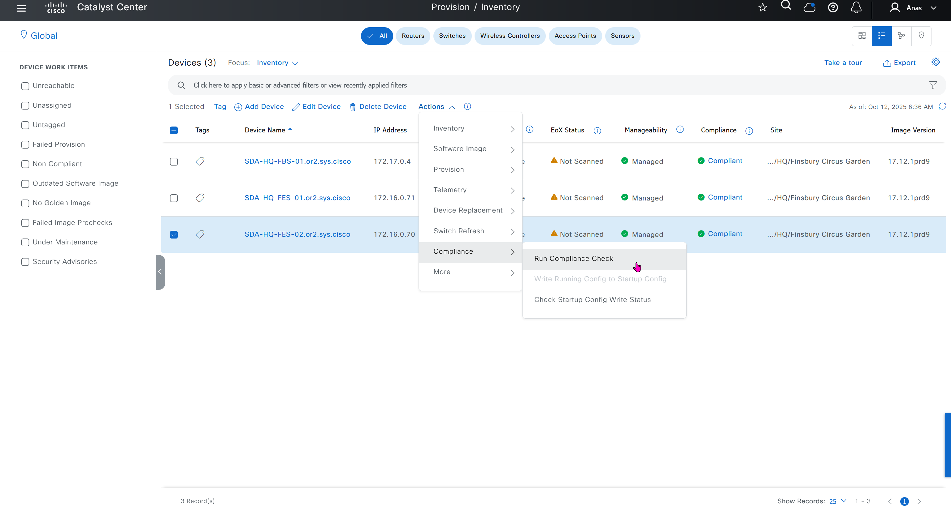
As devices are discovered in DNAC, it is also added in ISE
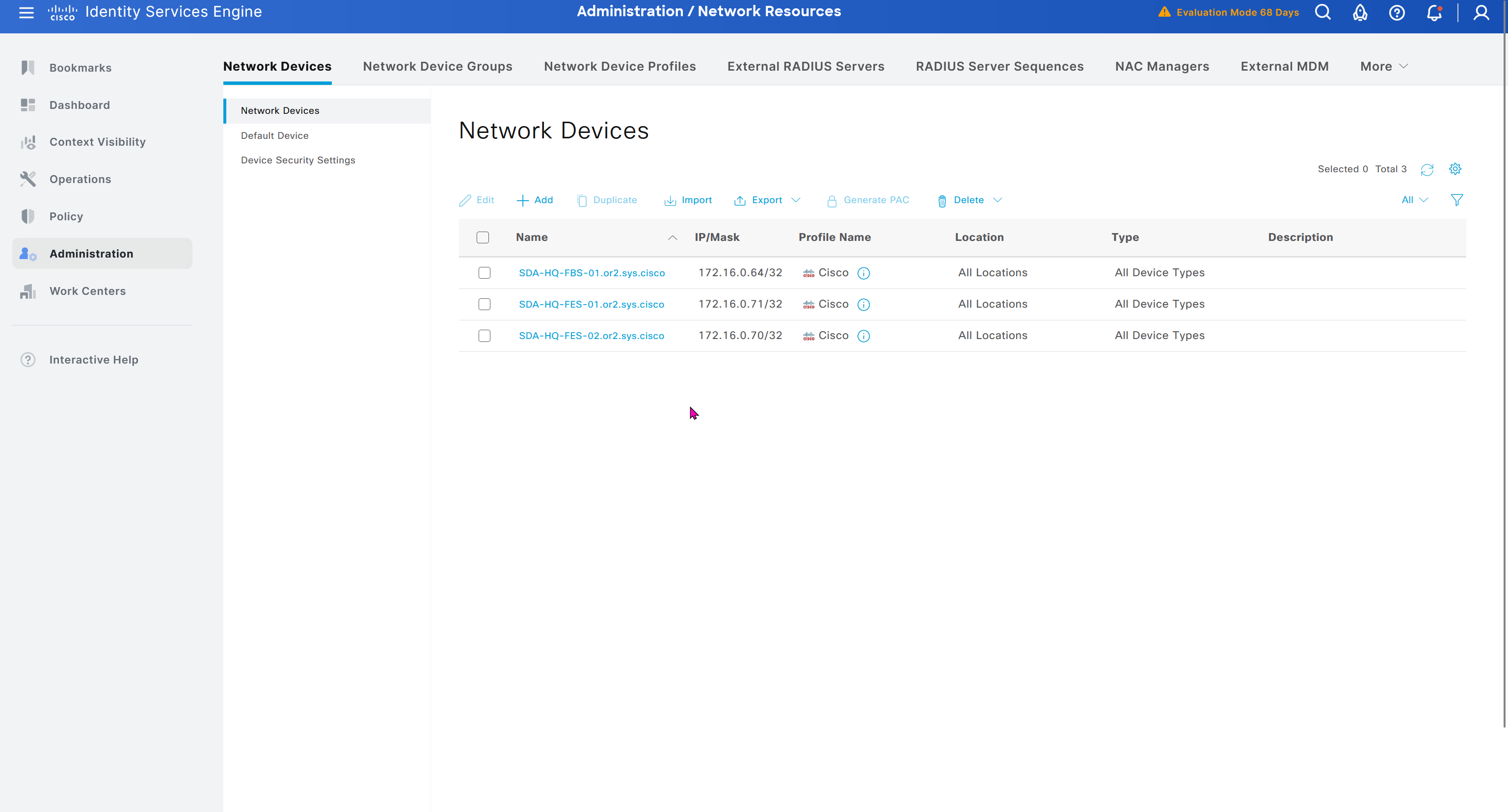
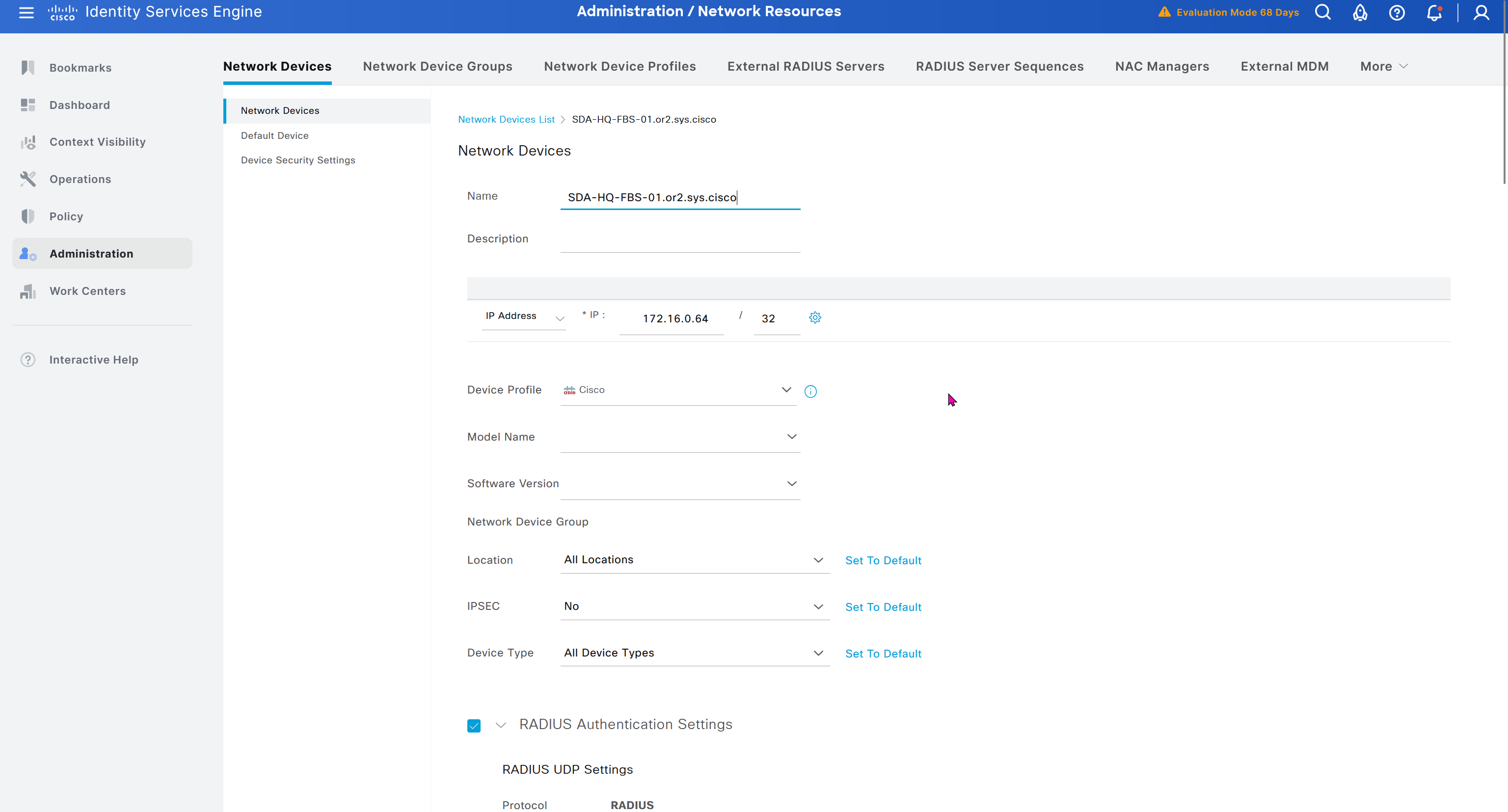
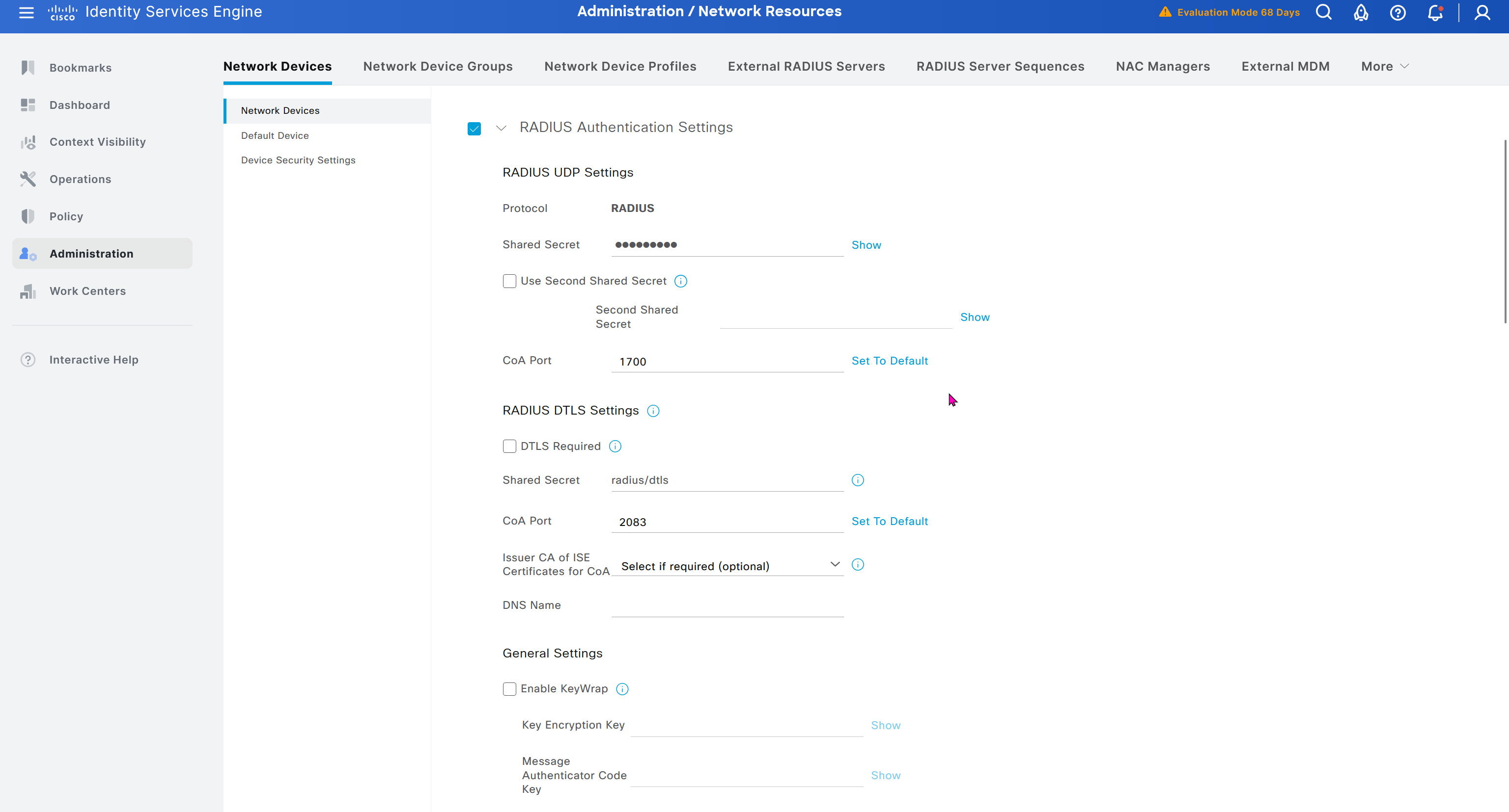

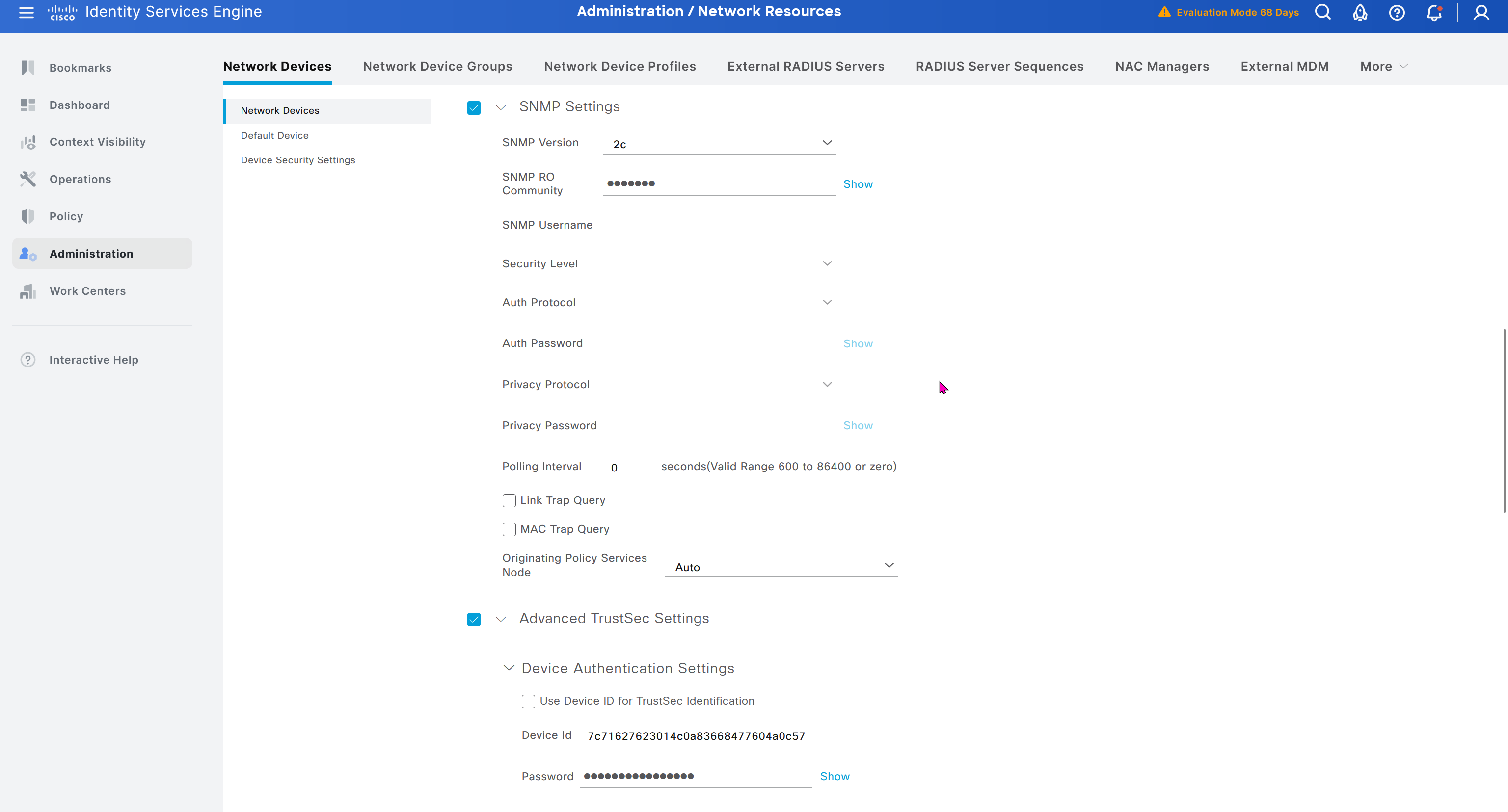
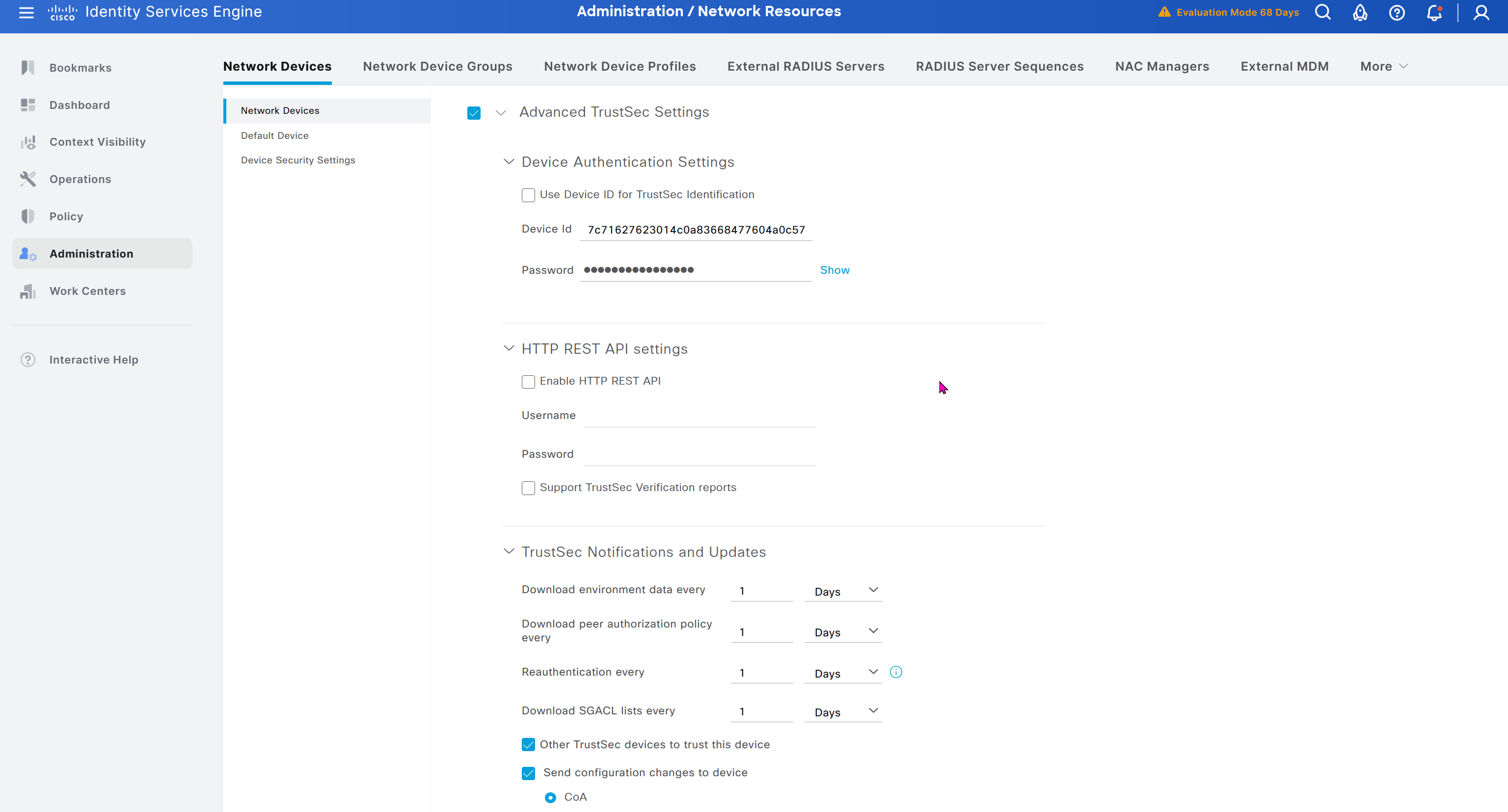
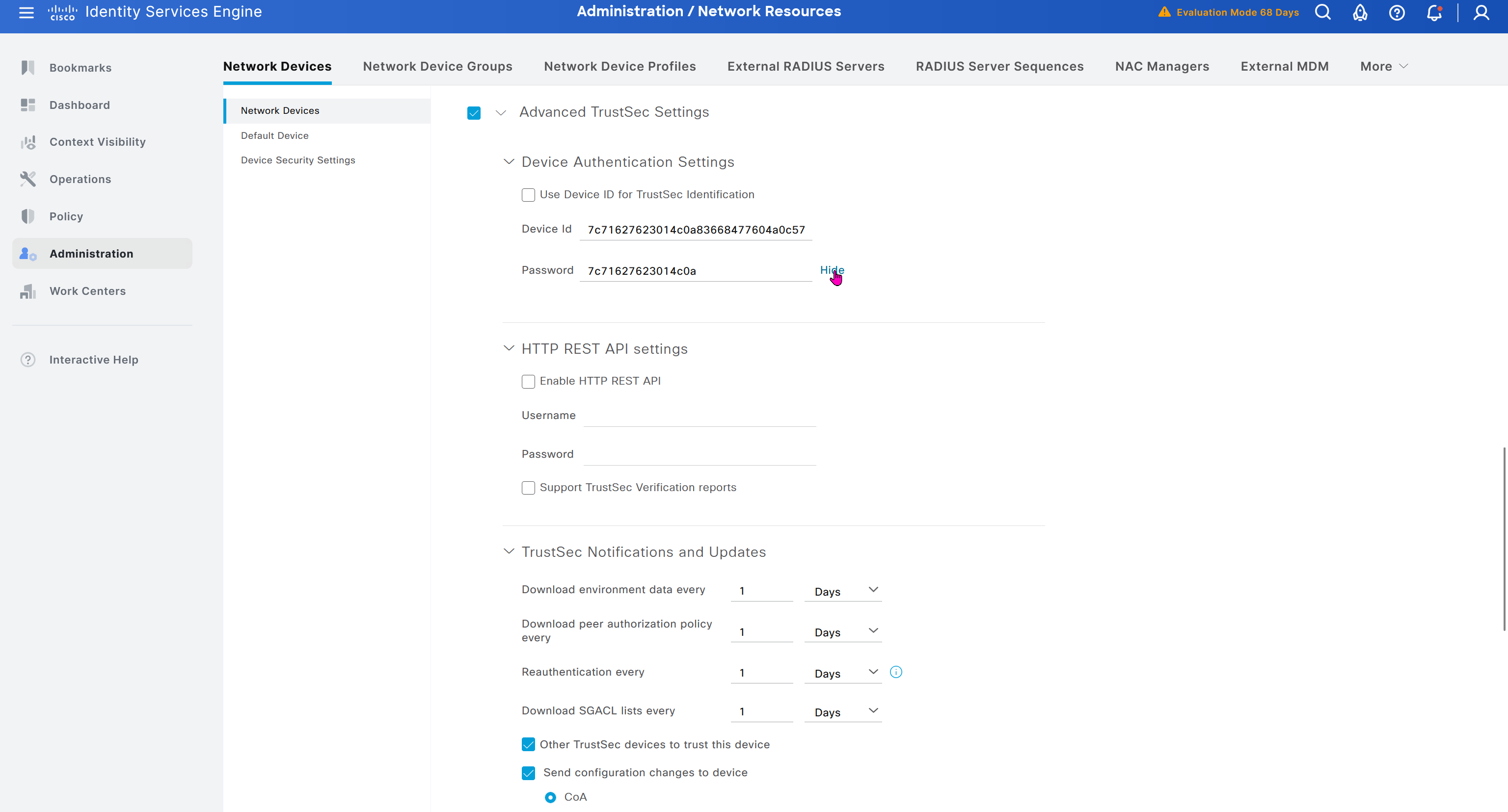

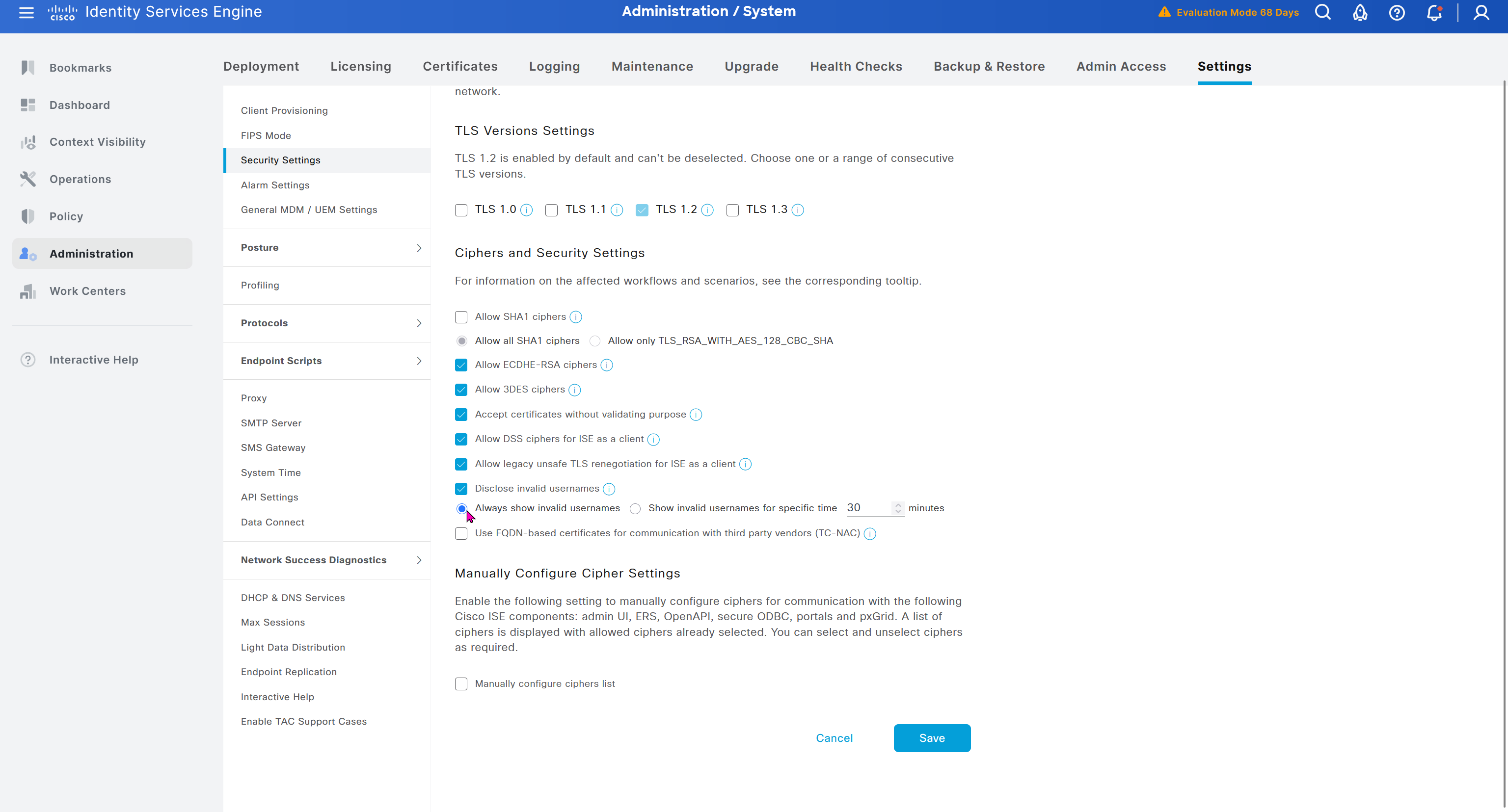
In ISE live logs we can see entries for devices authenticating to ISE for Trust Sec Device authentication
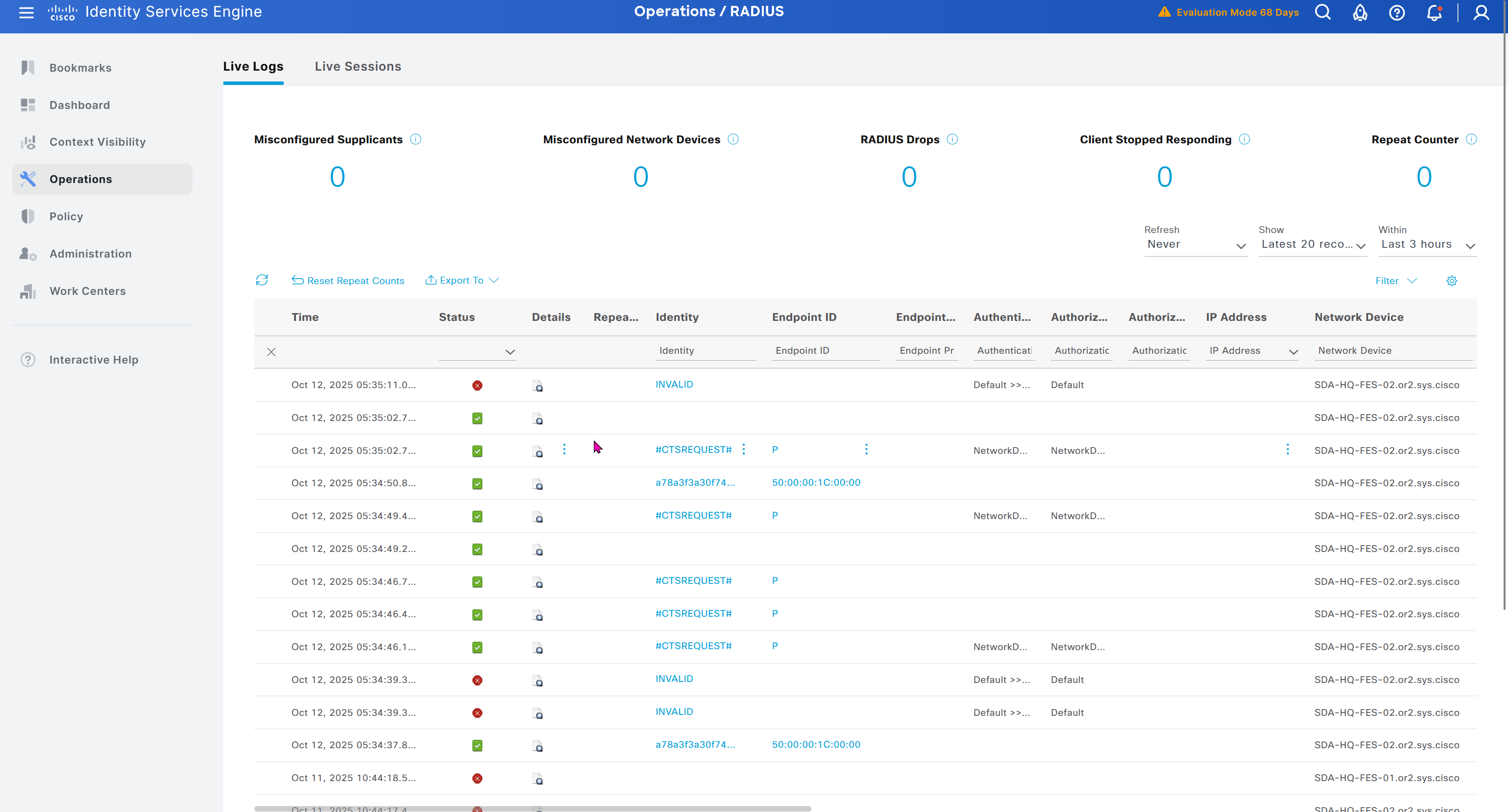
next post
SDA LM4 – DNAC Web Interface
Videos
Introduction to UI
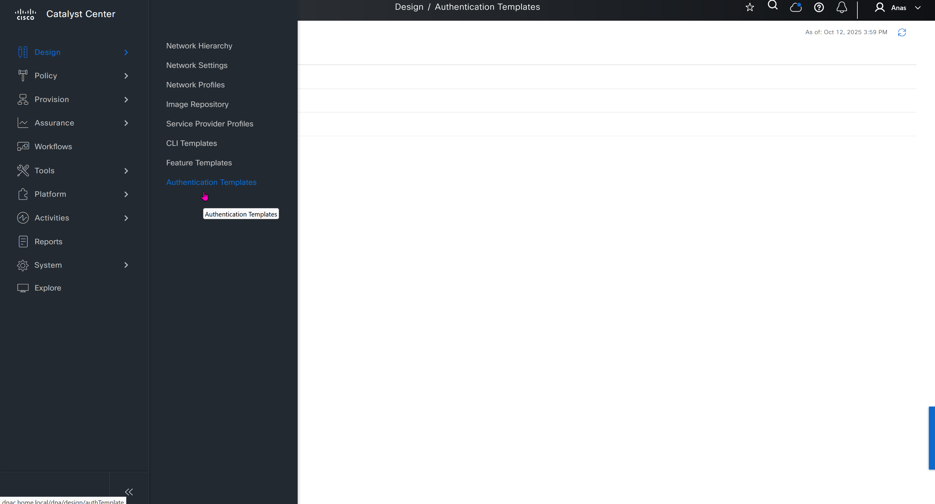
You can modify these authentication templates but cannot define more
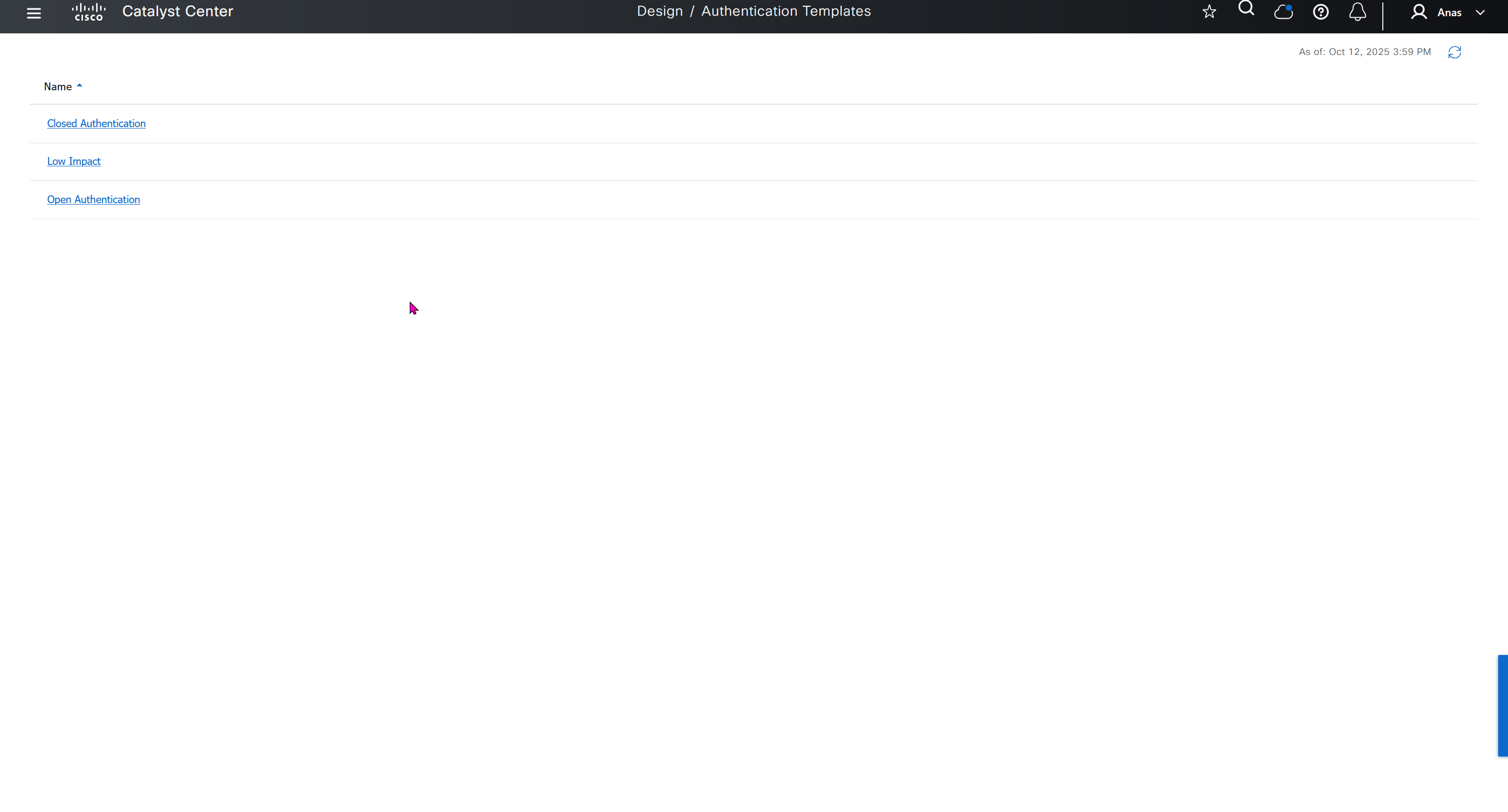
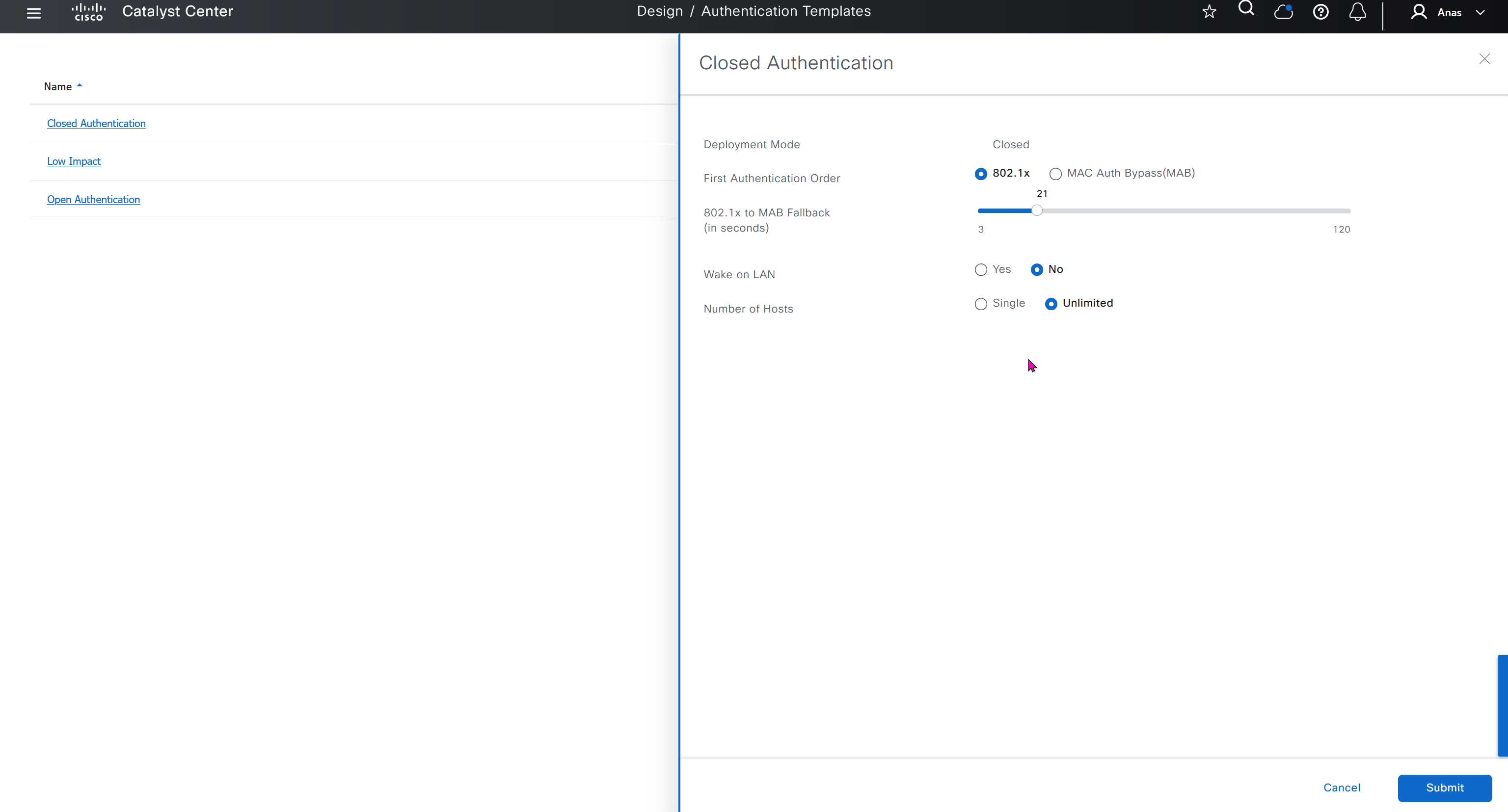
If you want to define different SSID in europe or you want different ISE server for europe then use hierarchy and go to site specific level and override
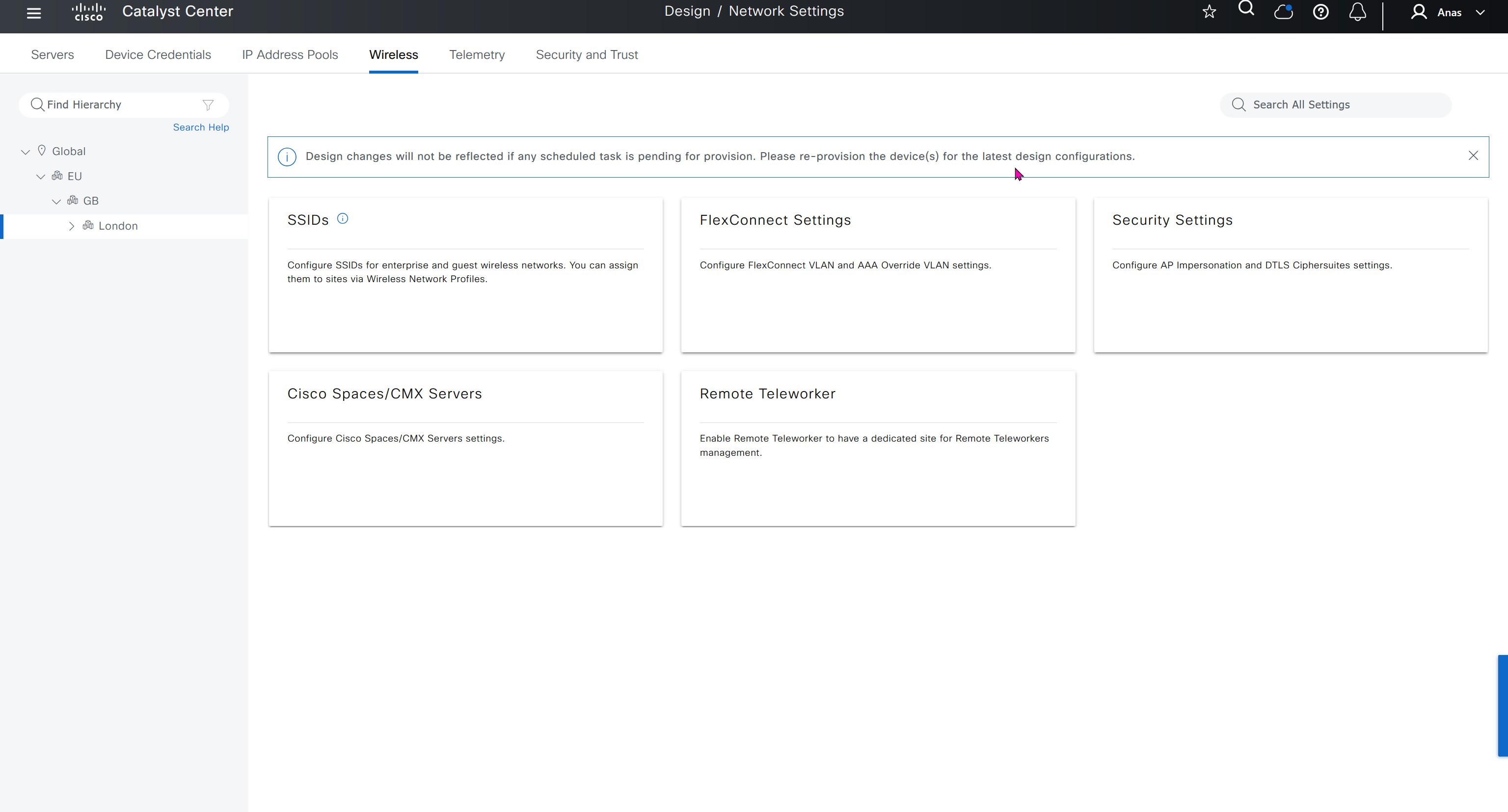


IP based access control is used when you create non fabric based wireless and this is a very specific use, if we dont use non-fabric wireless then we will not have to touch this page
AI Endpoint Analytics
With new DNAC, AI Endpoint Analytics was introduced and this leverages AI capabilities in cloud and uses deep packet inspection in Catalyst 9K infrastructure to “identify types of endpoints” – this information can then be fed to ISE and can then be used as part of endpoint authentication, this provides additional network packet level context along side the profiling probes that ISE performs on its own and that information is communicated to ISE using PXGrid
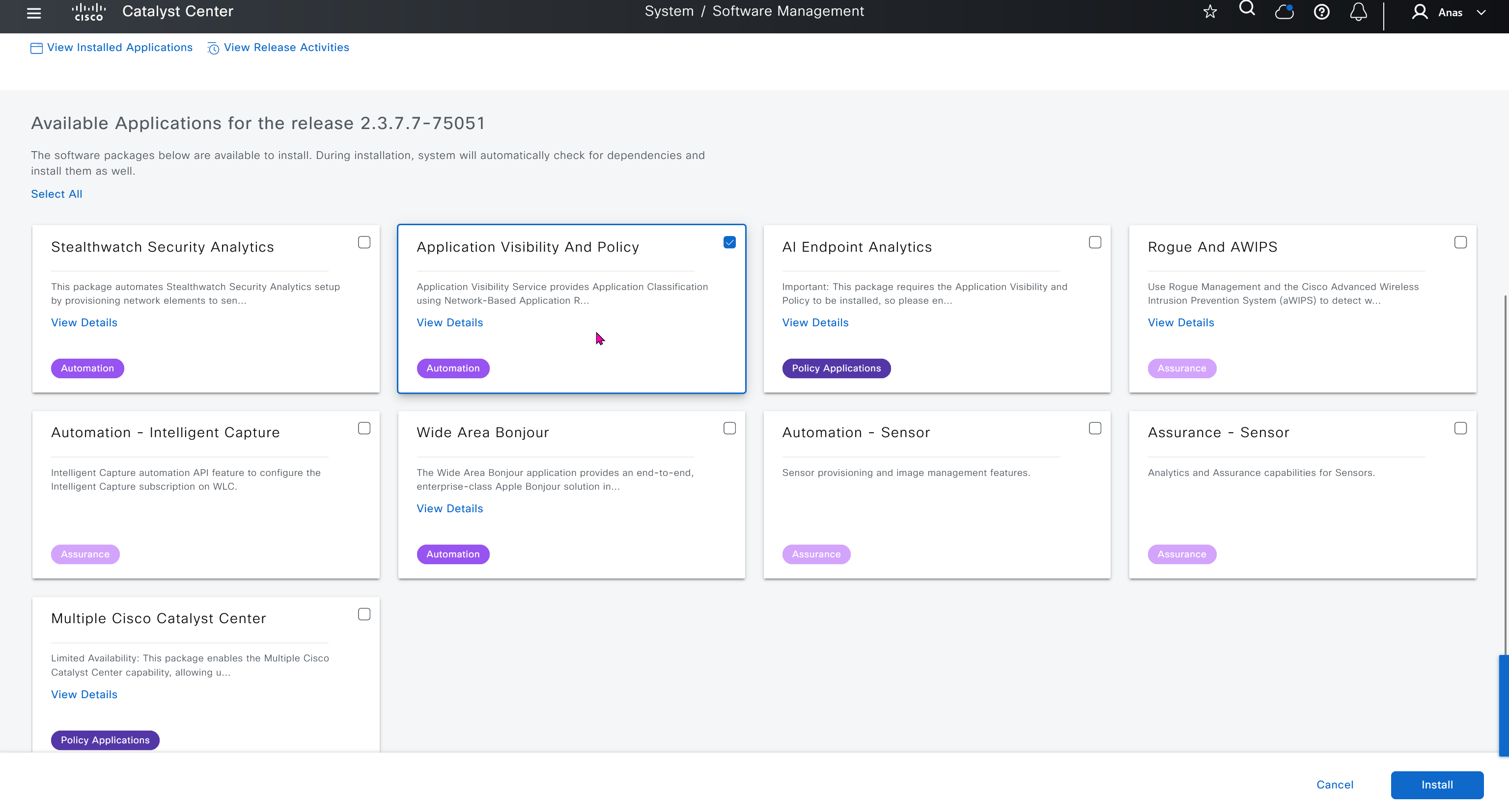
Application policies is the feature that was known as Easy QoS and it allows you to deploy QoS end to end in your network, for more details checkout RS0122 – SDA Application Policy (EasyQoS)
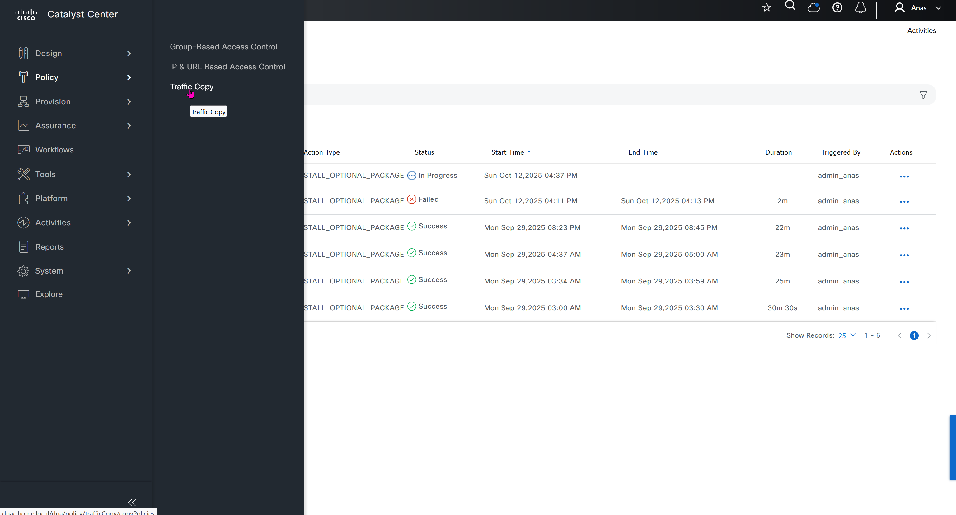
Traffic Copy is the way to span traffic from Fabric to a remote destination and this is part of SGT, as you can capture traffic between specific contracts or tags
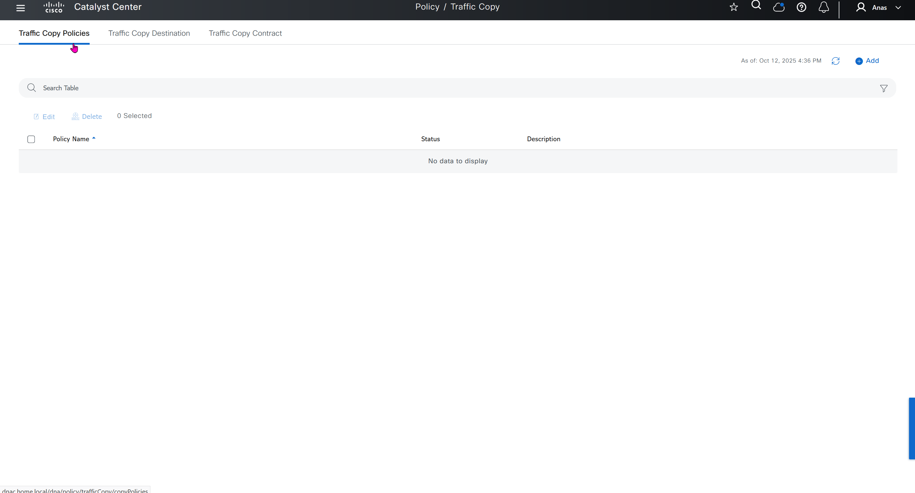
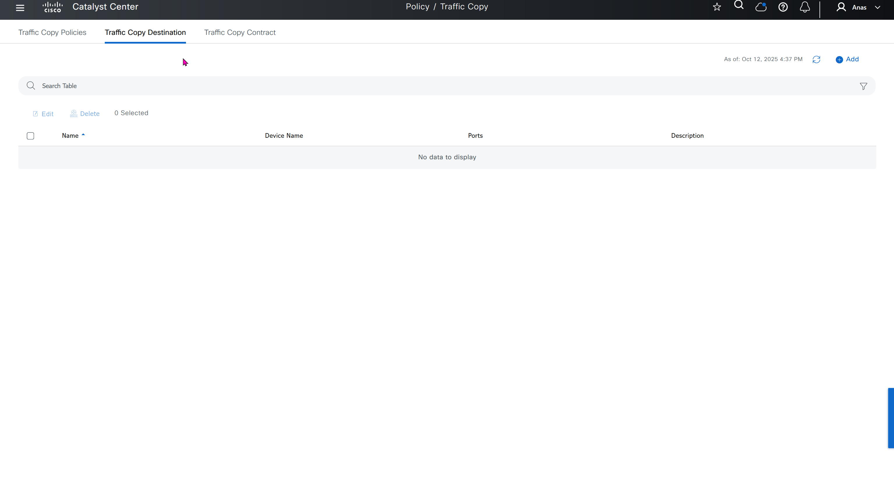
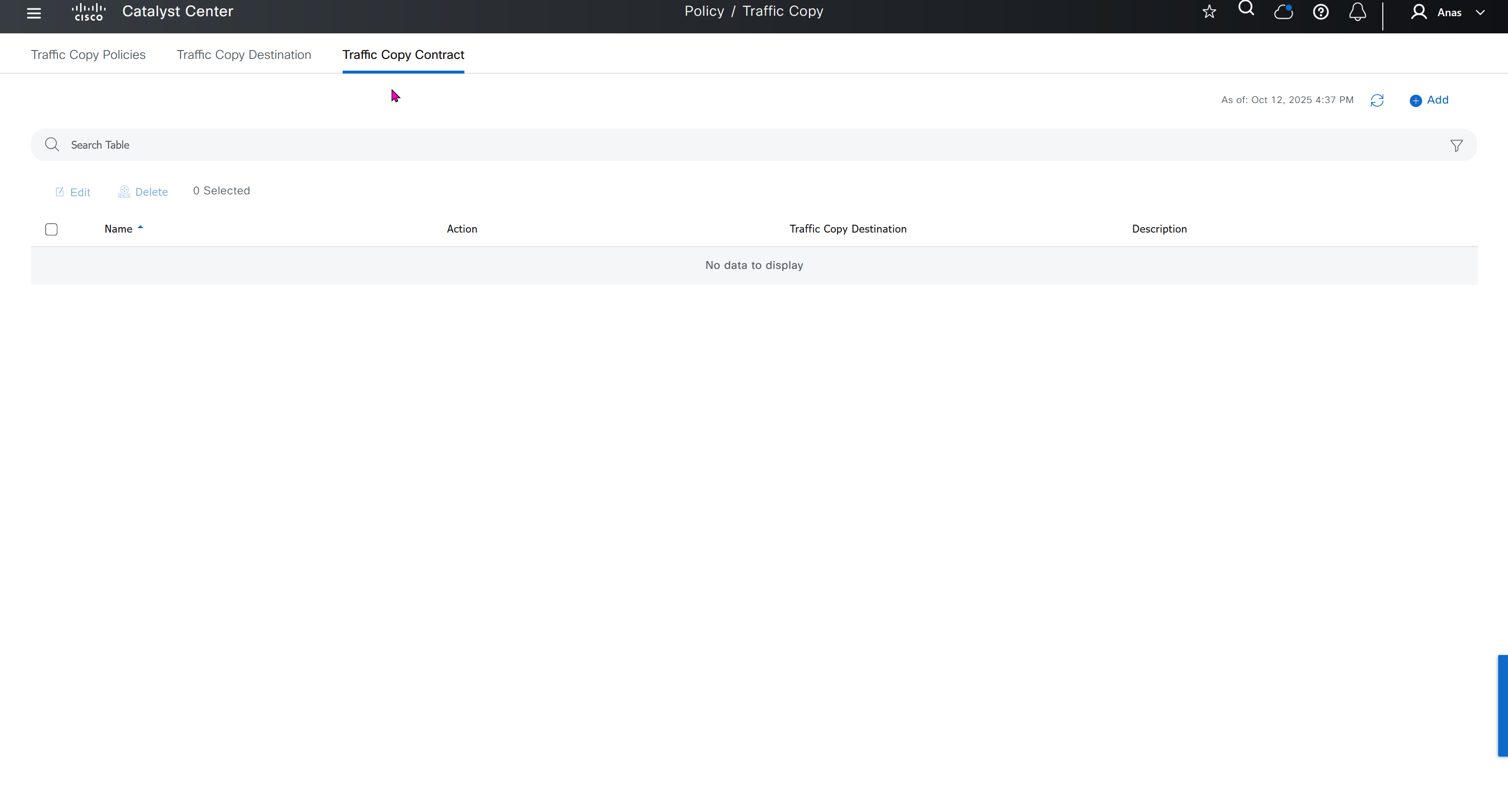
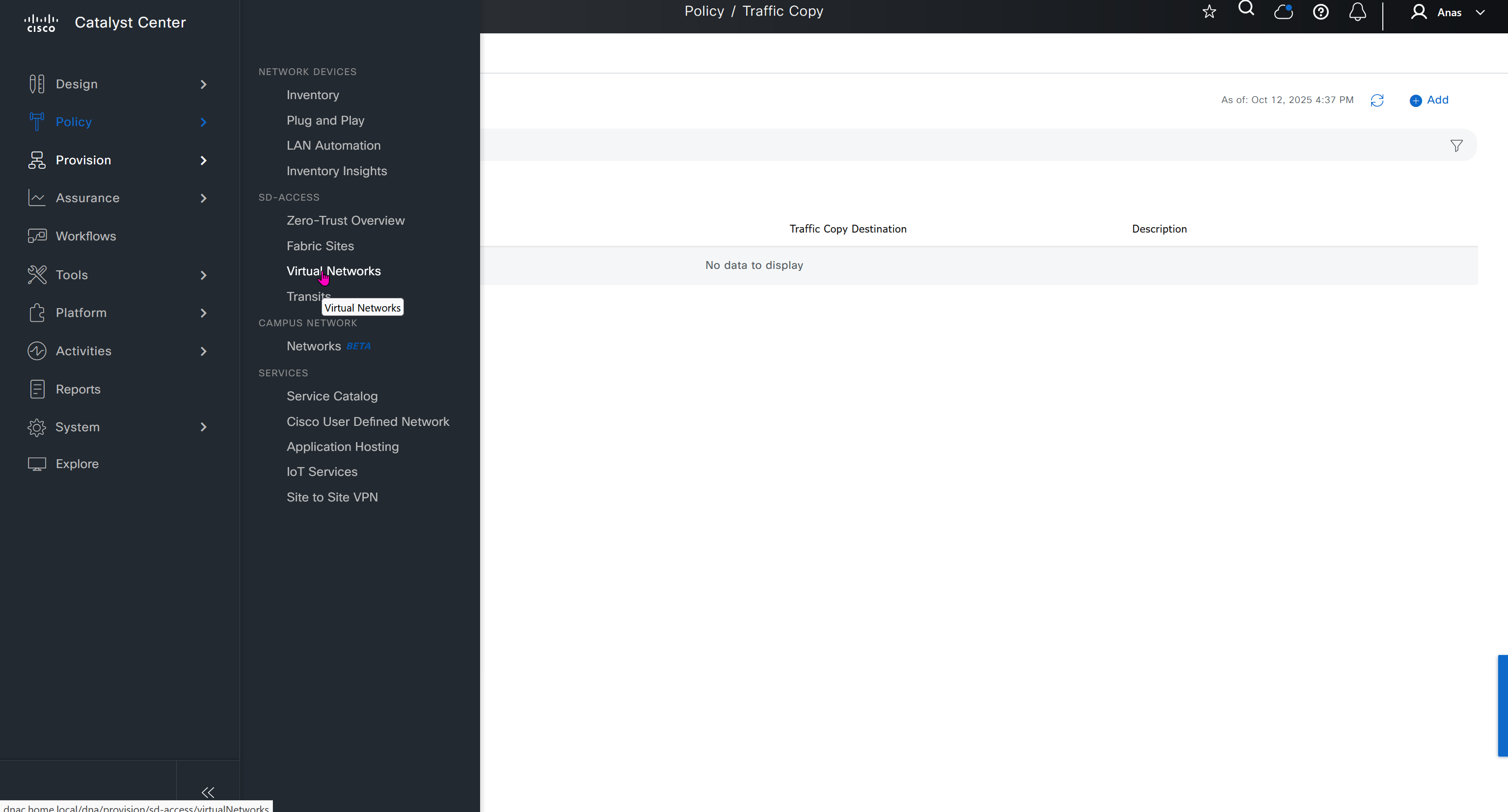
Finally Virtual networks which are essentially VRFs and separate different (virtual) fabric on same network
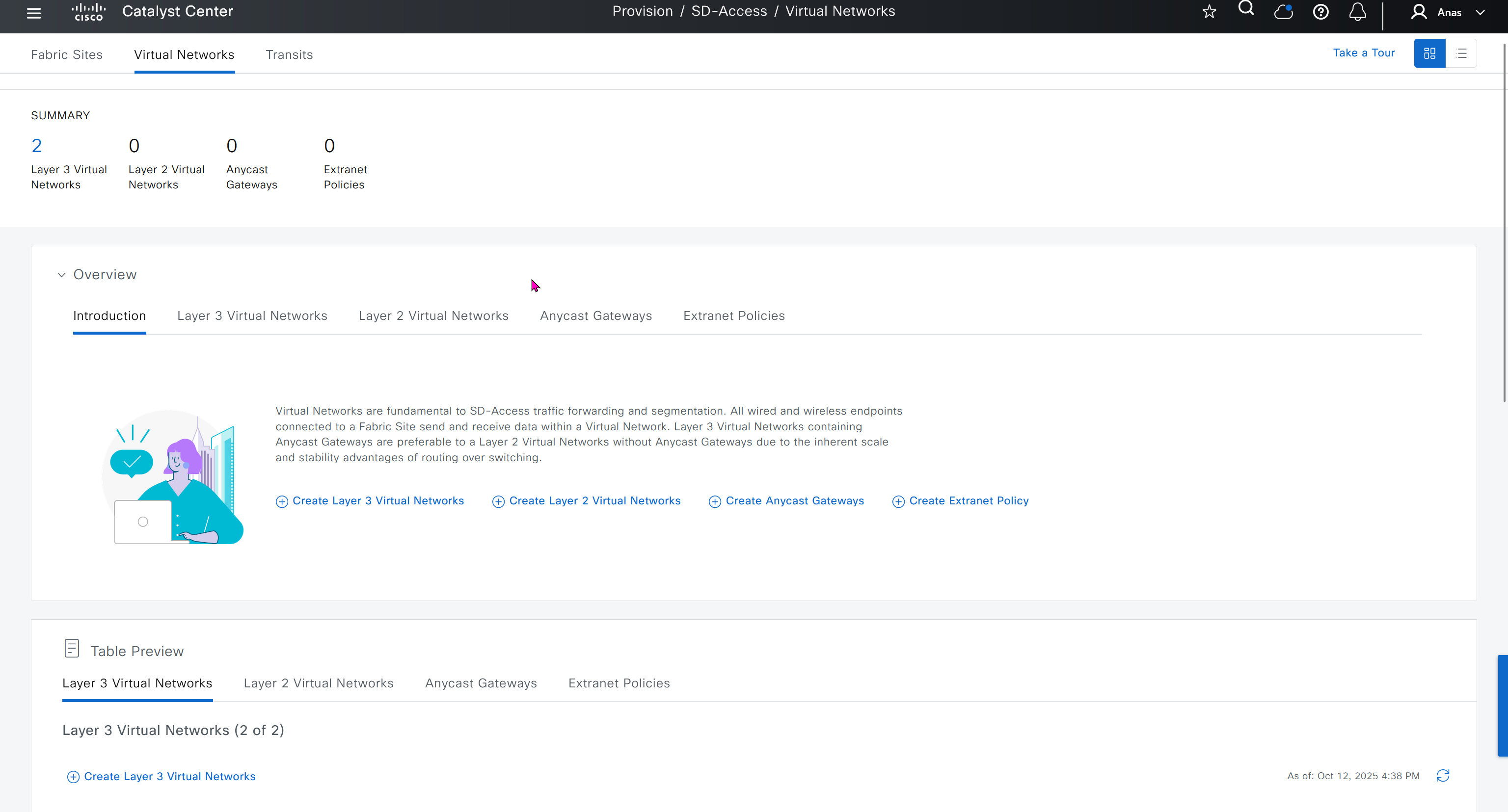
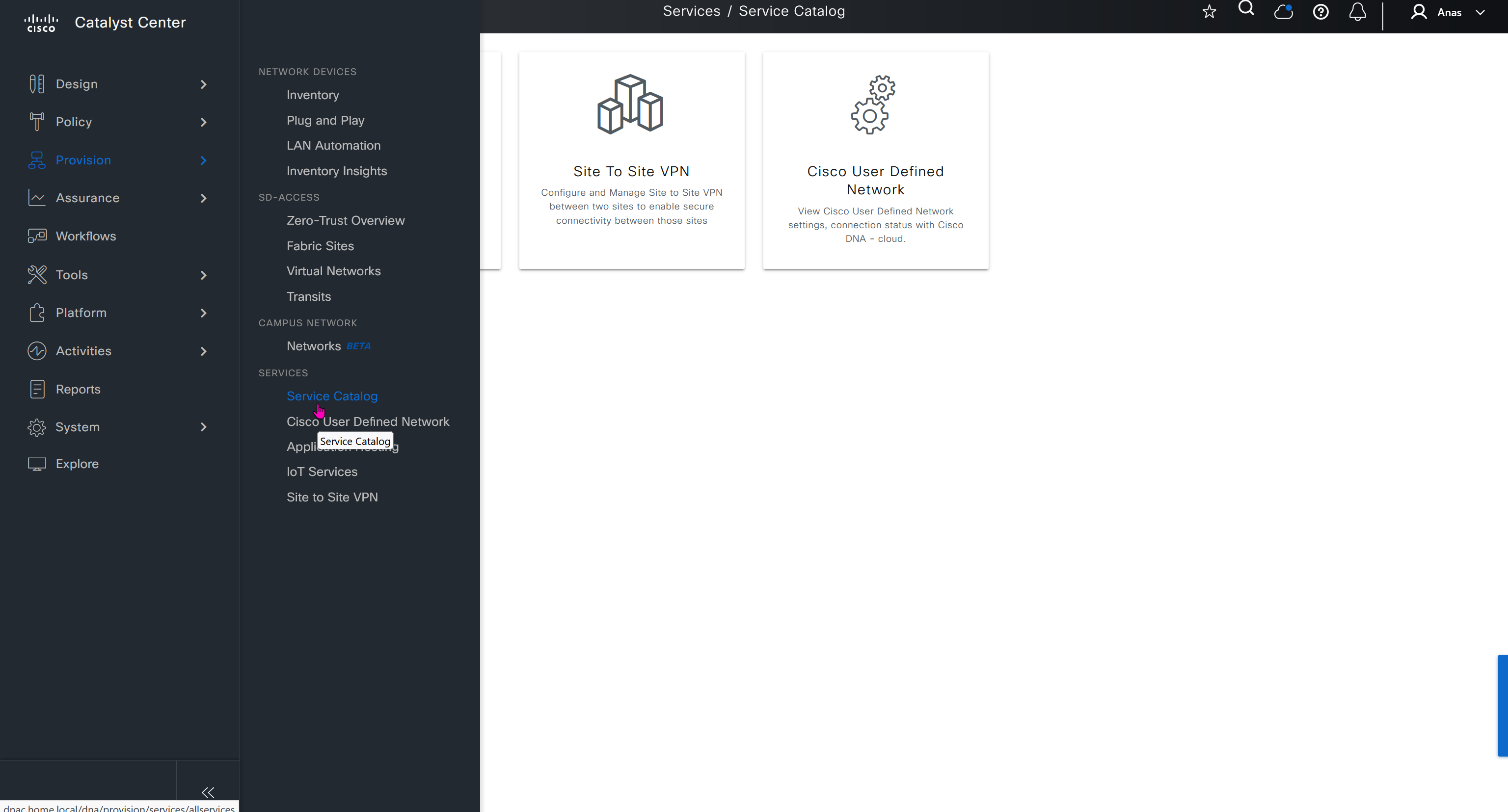
Service catalog, these are different services that are offered
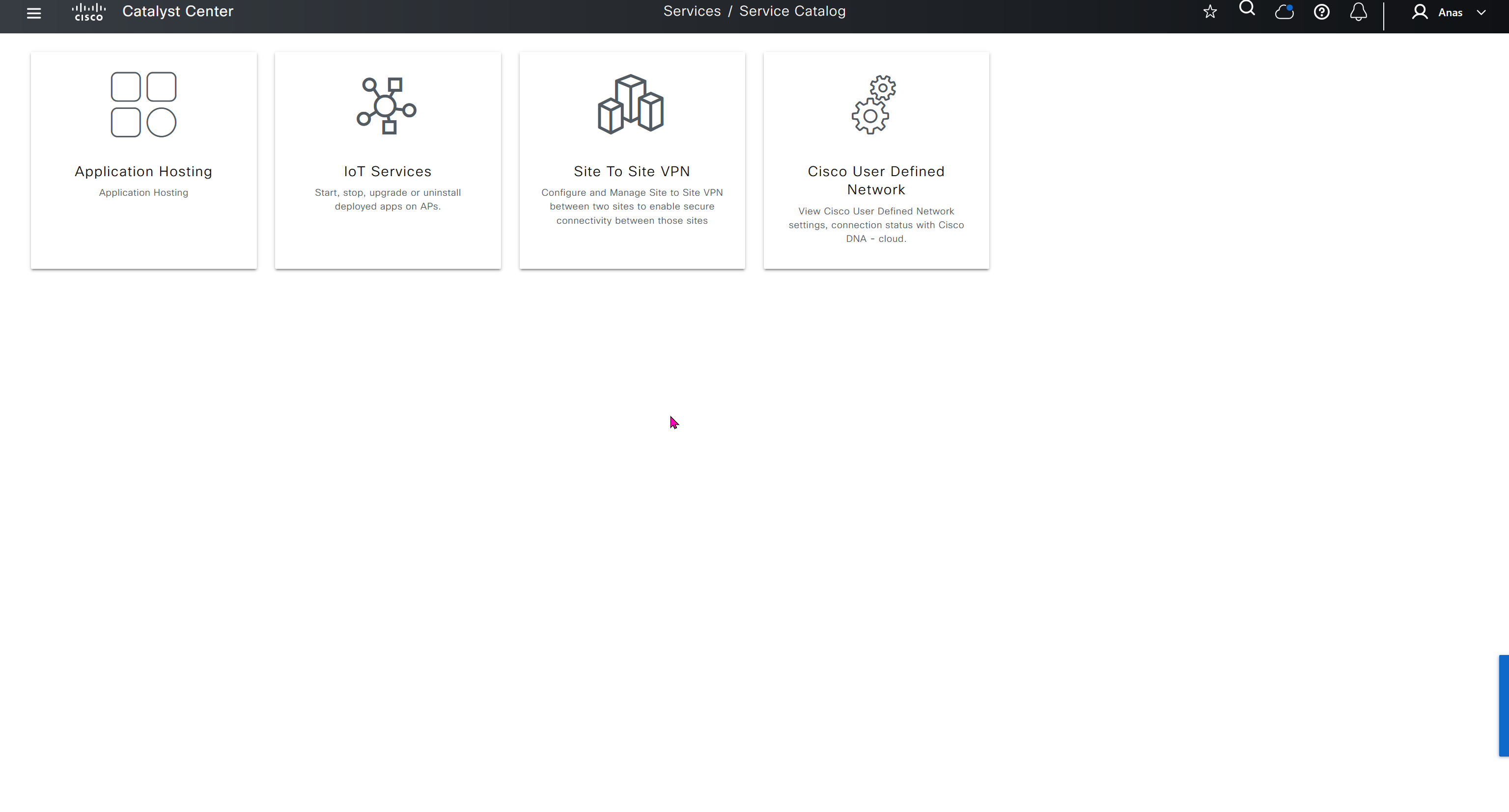
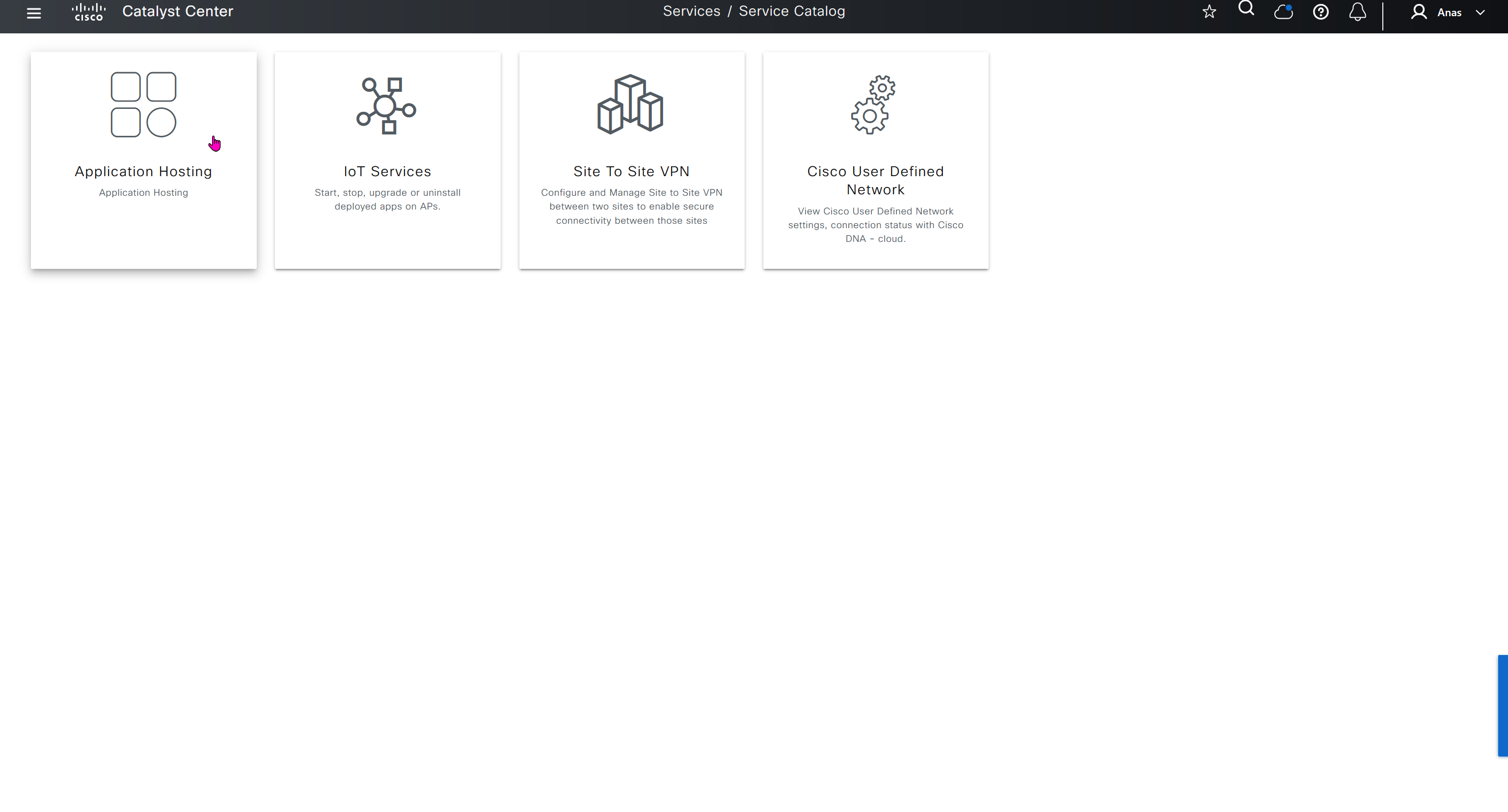

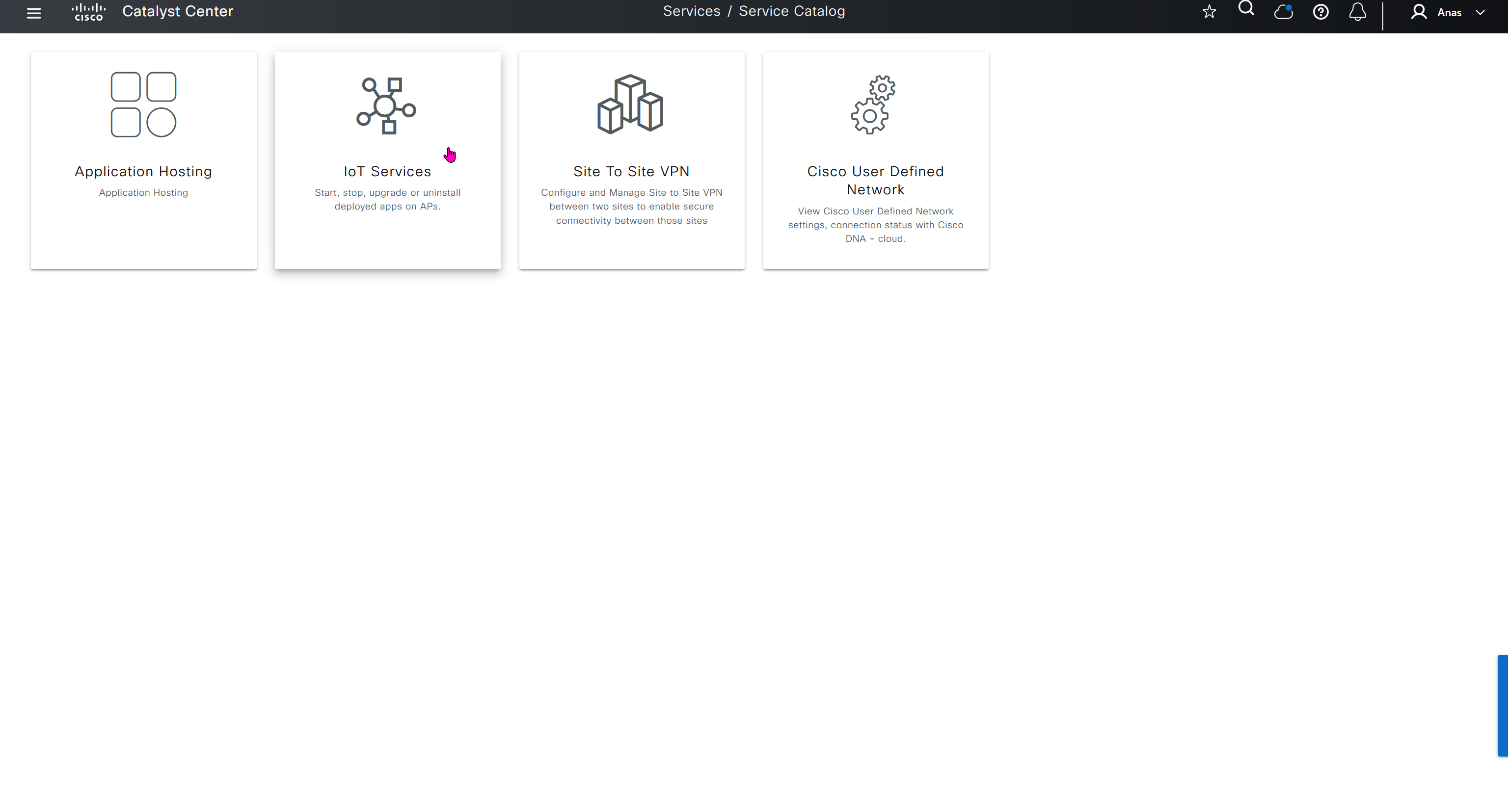
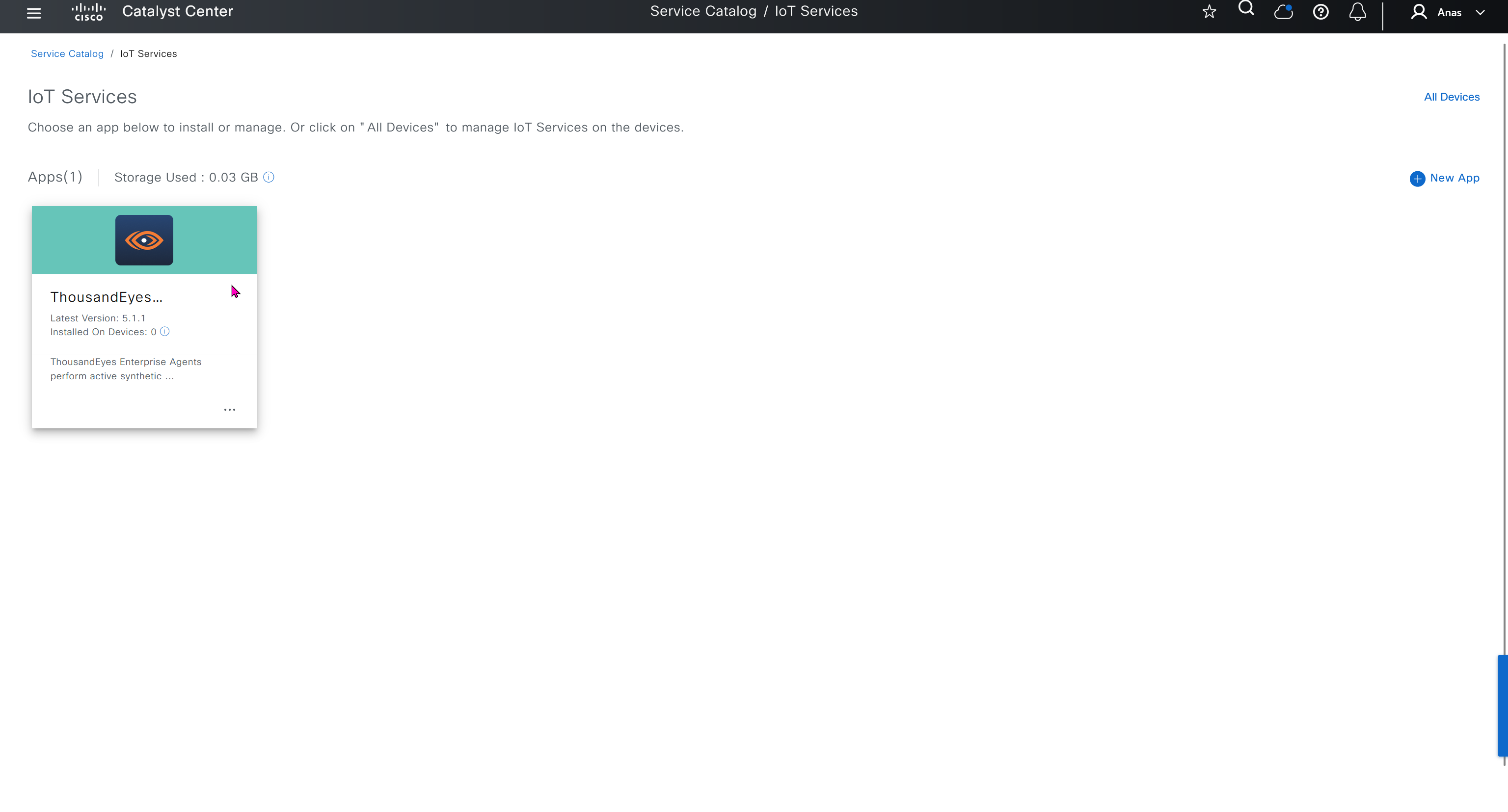
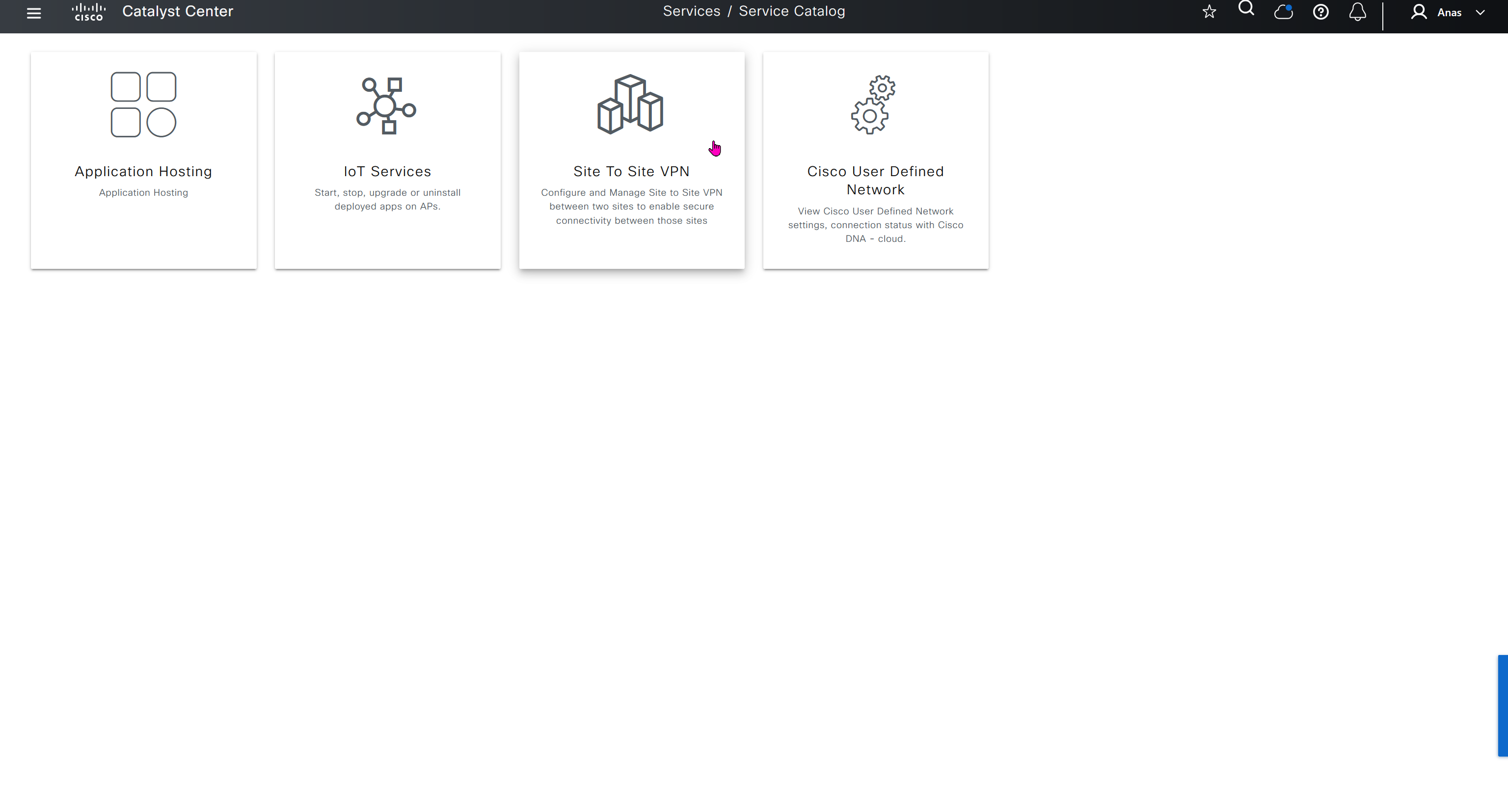
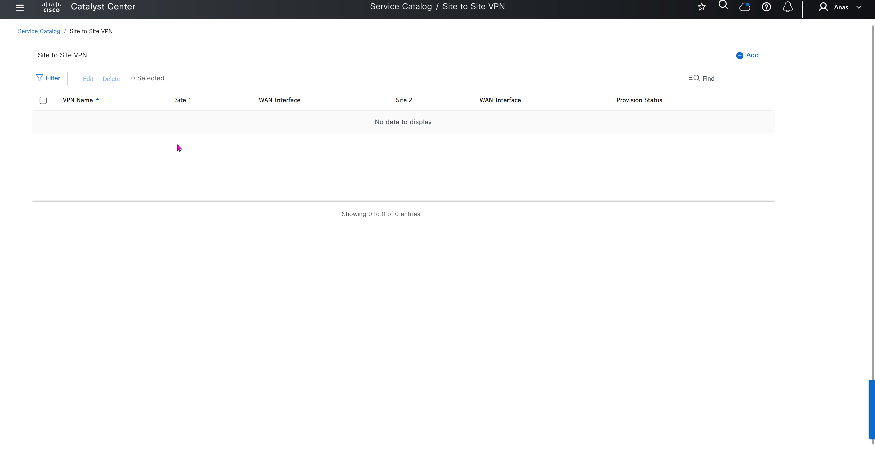
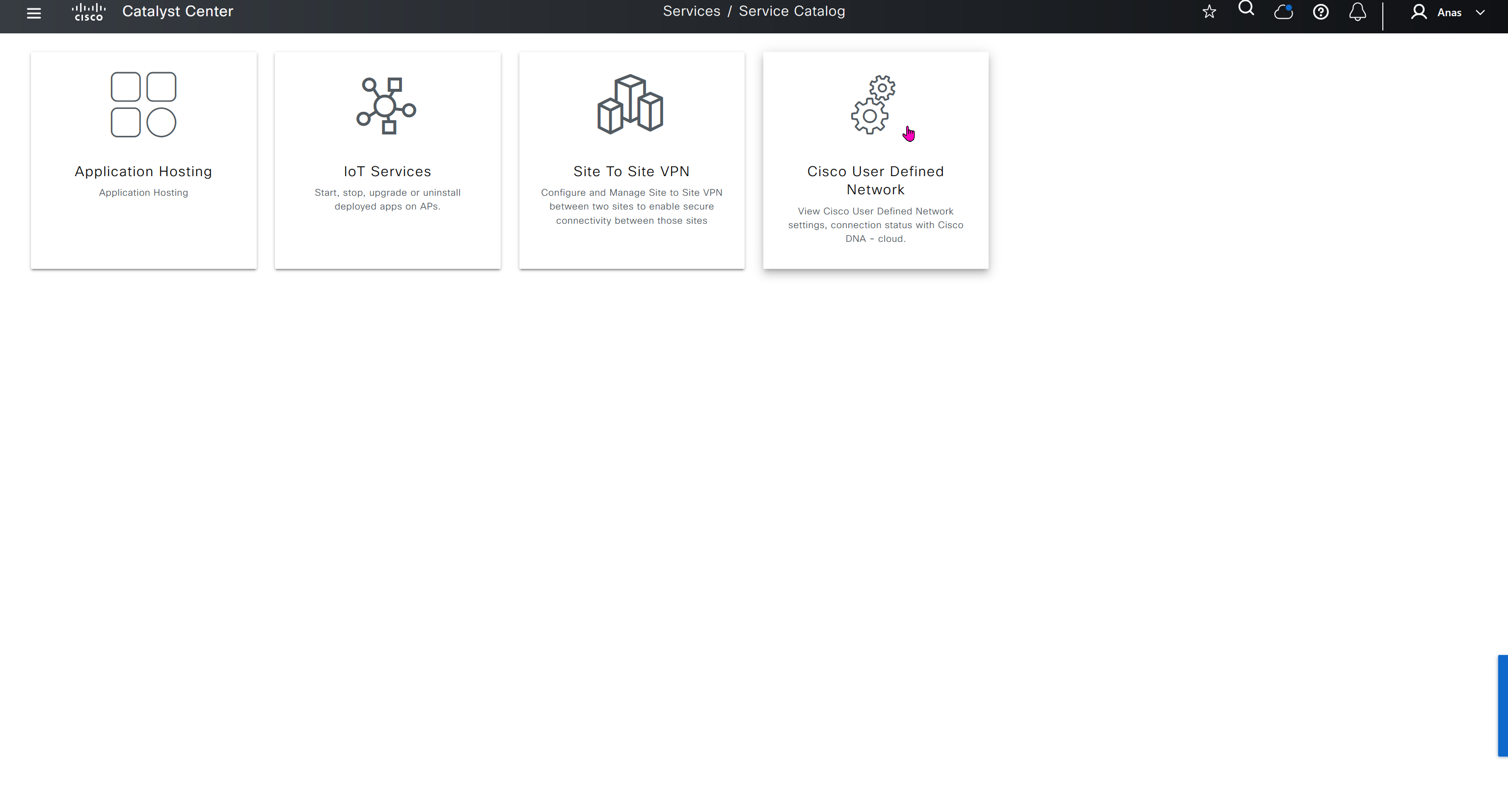
User defined network is a cool concept as it allows users to create personal network on top of shared infrastructure, users can then register their personal devices using an app and also invite other users into that network using same app and these networks are like bubbles
These 4 services are also listed under the services section of provision tab
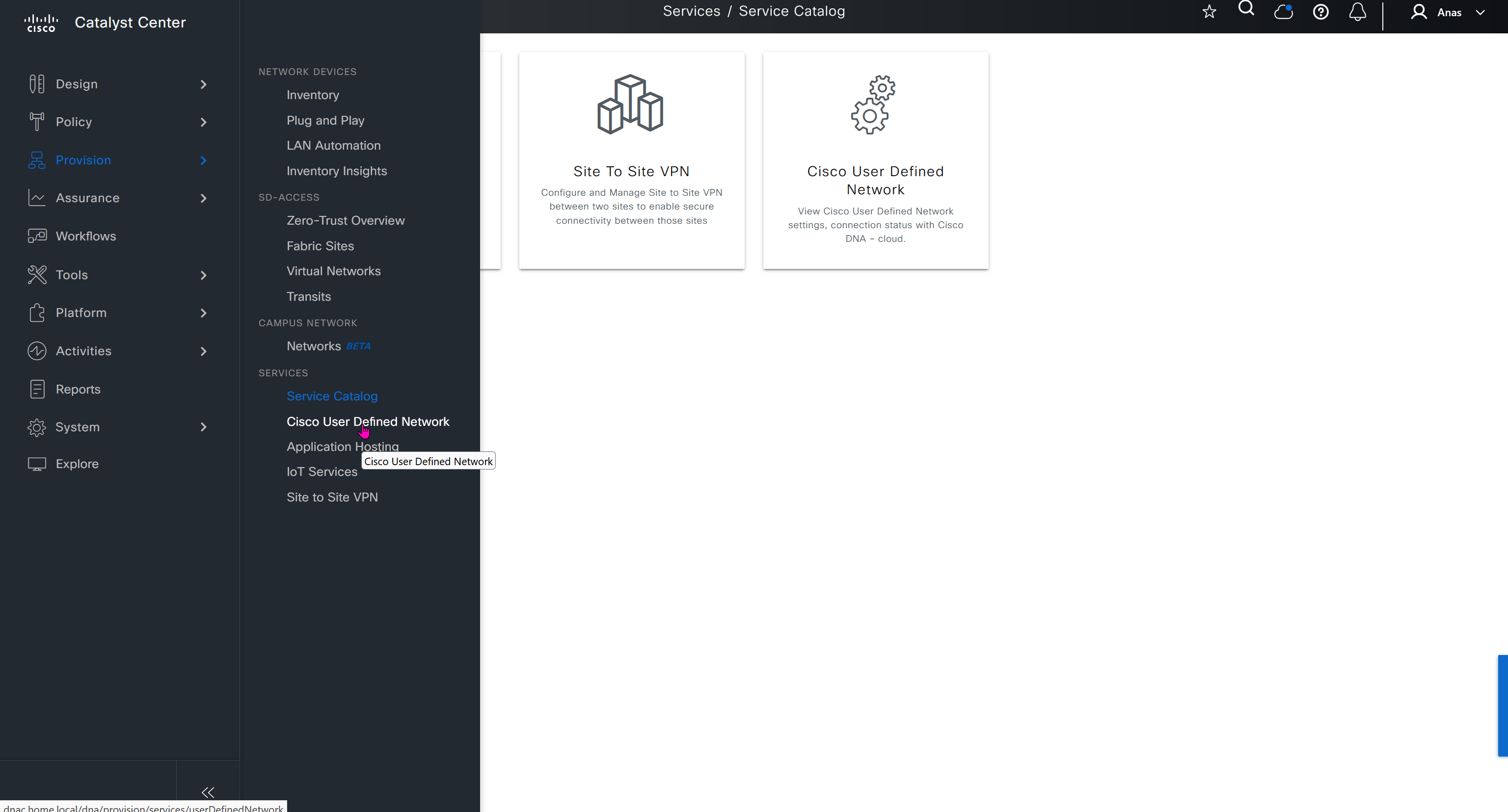
Assurance does not just measures health and experience of network devices but also includes clients and helps us measure client’s experience on the network also and it does not stay at client but its scope one level more deep into application as well

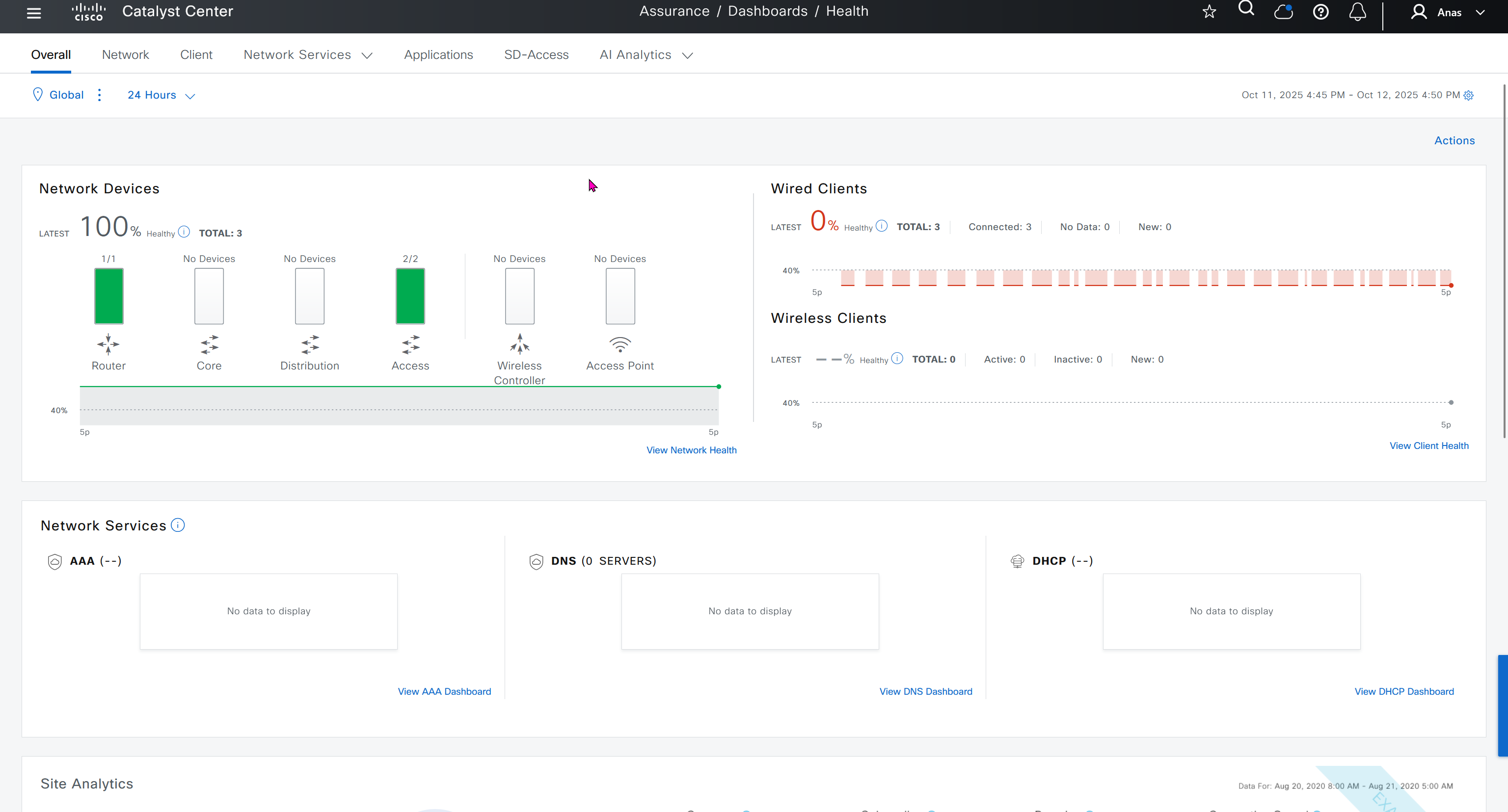


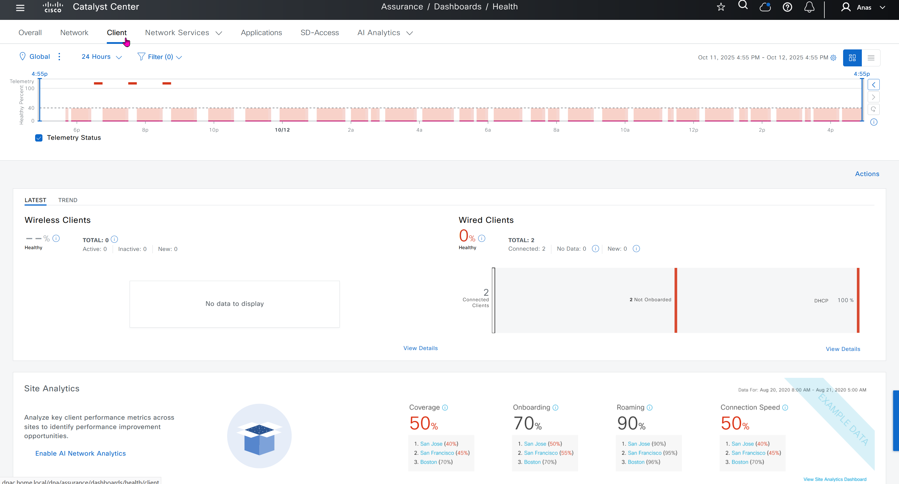
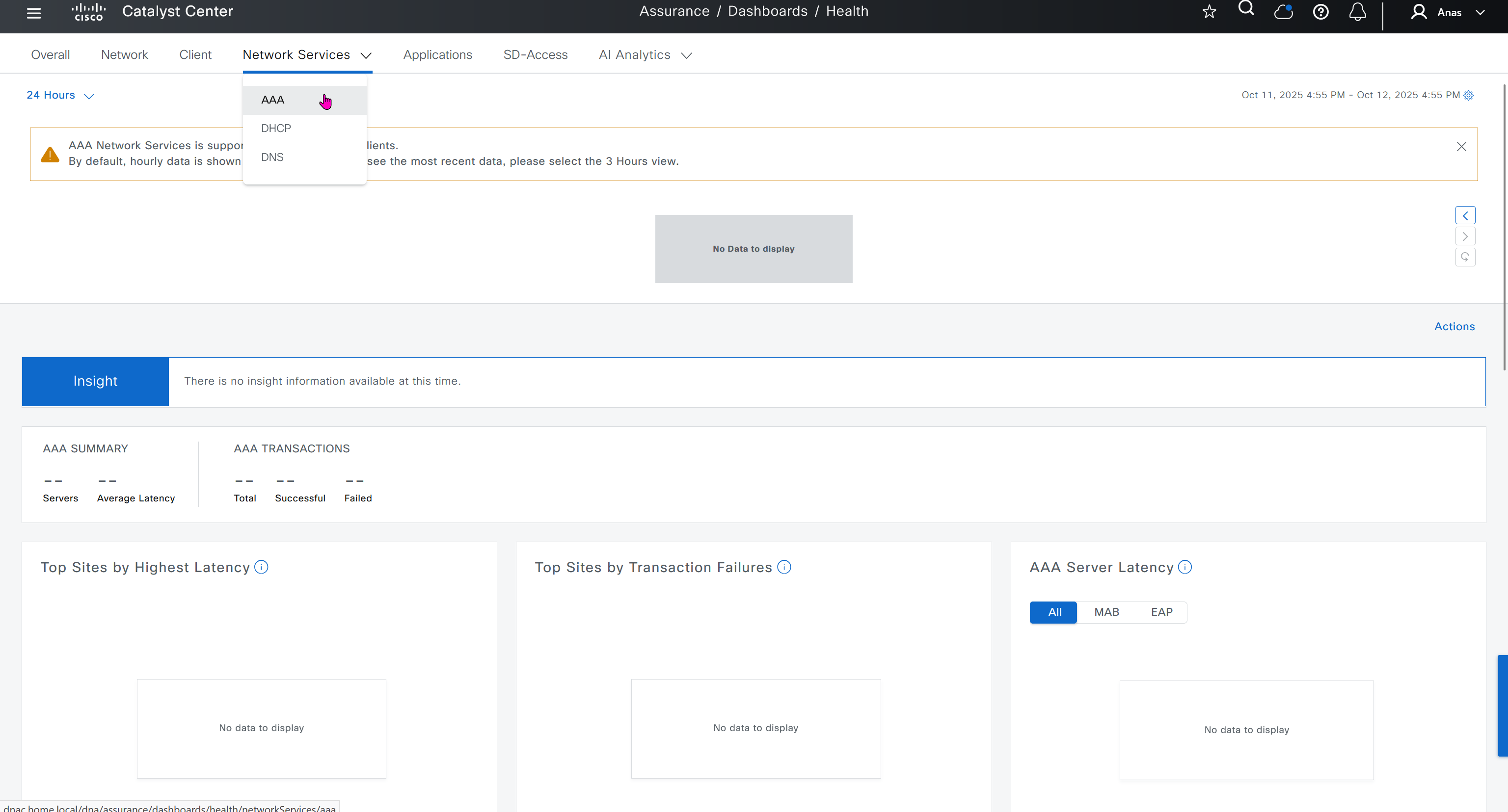
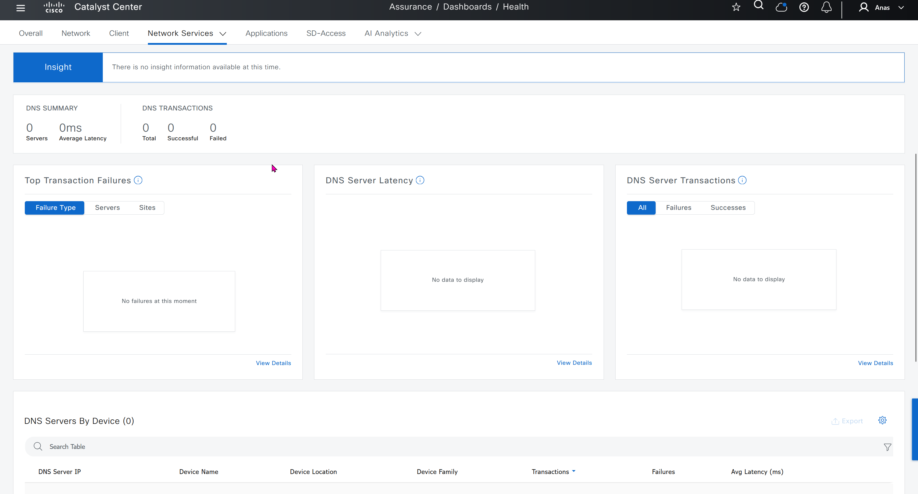


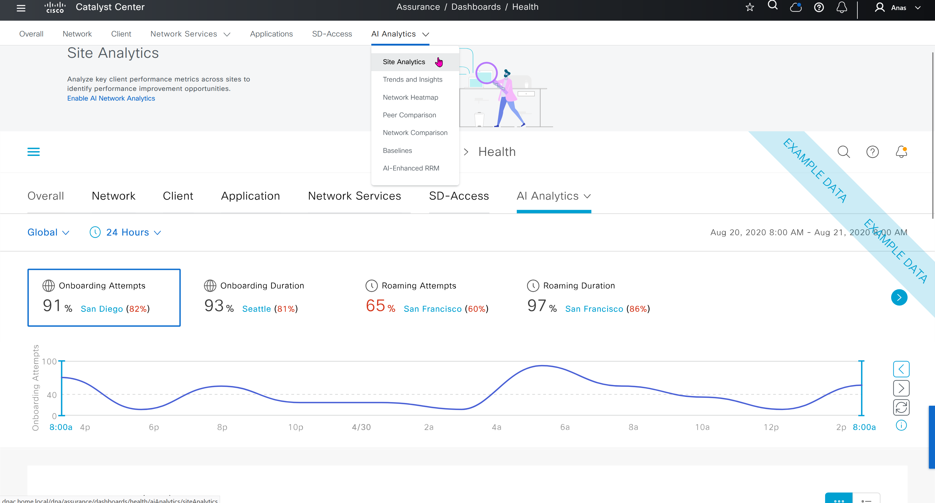
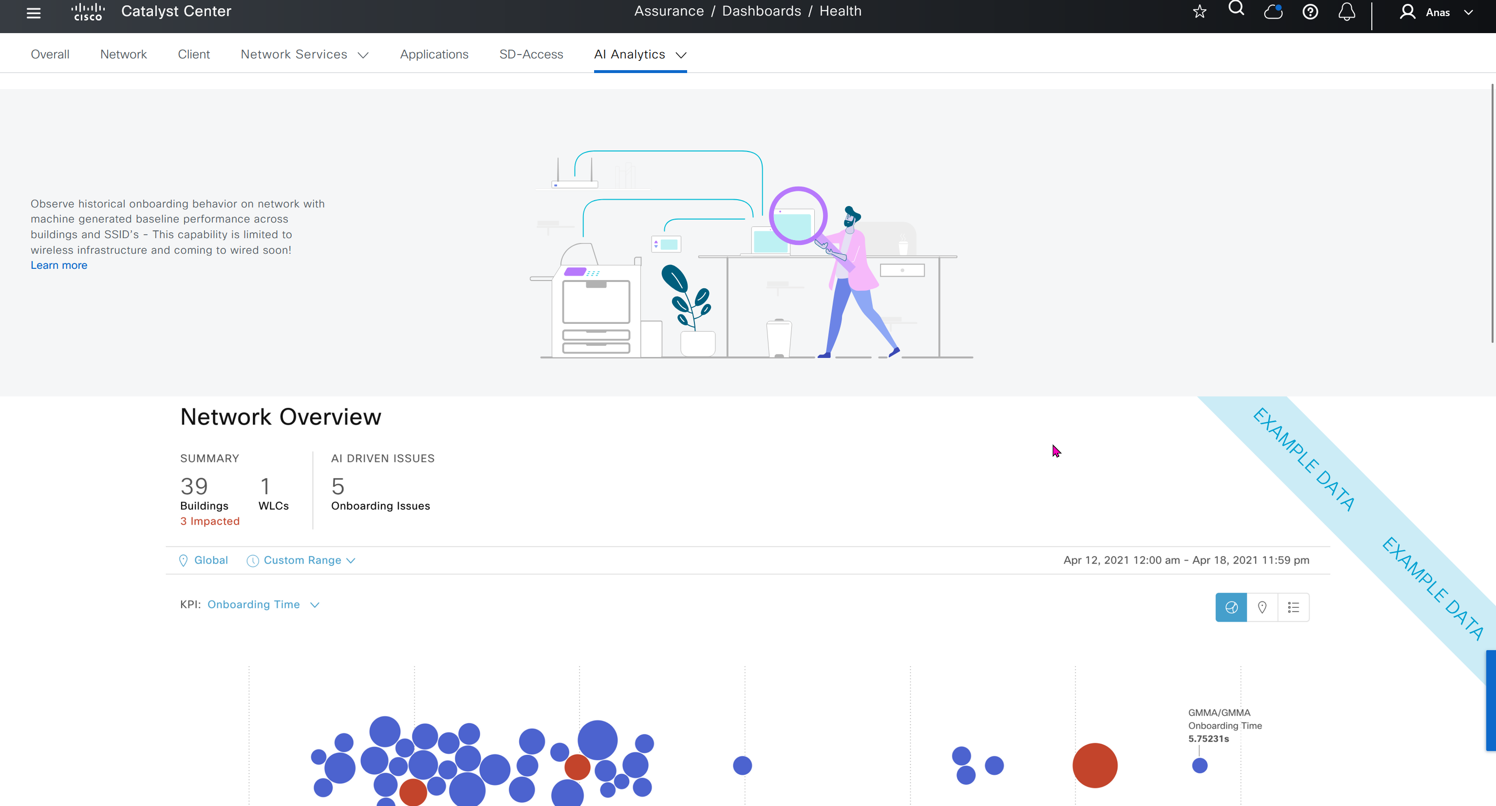
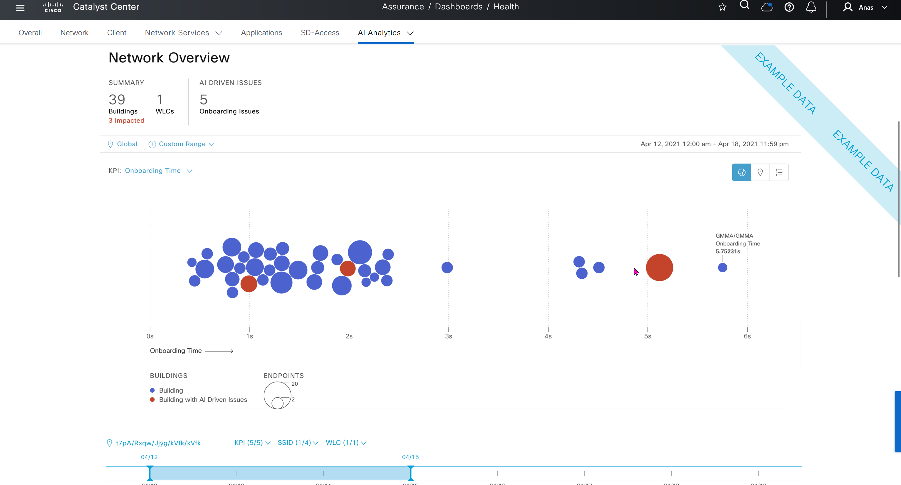
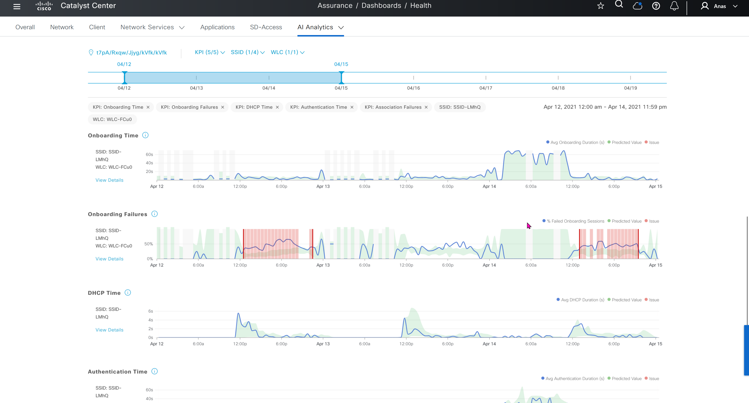
Events are for both Network devices and also for the clients, these are any events that happen in the network for network devices and its connected clients
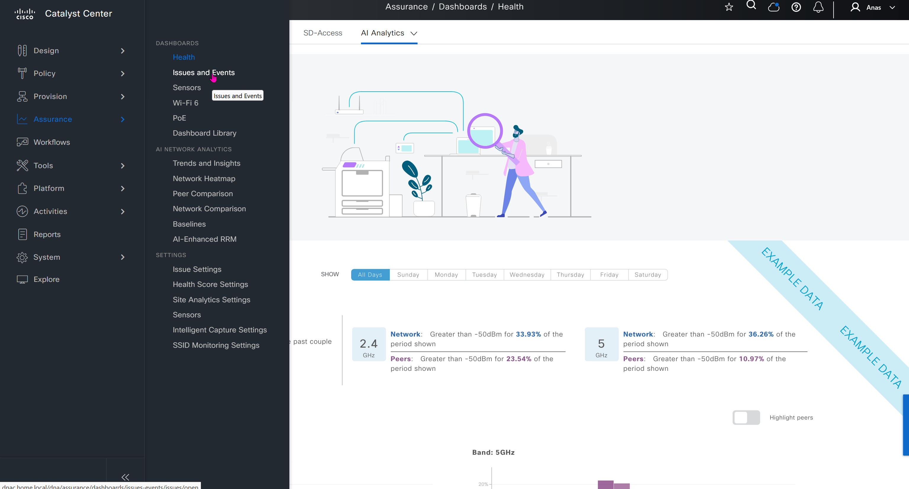
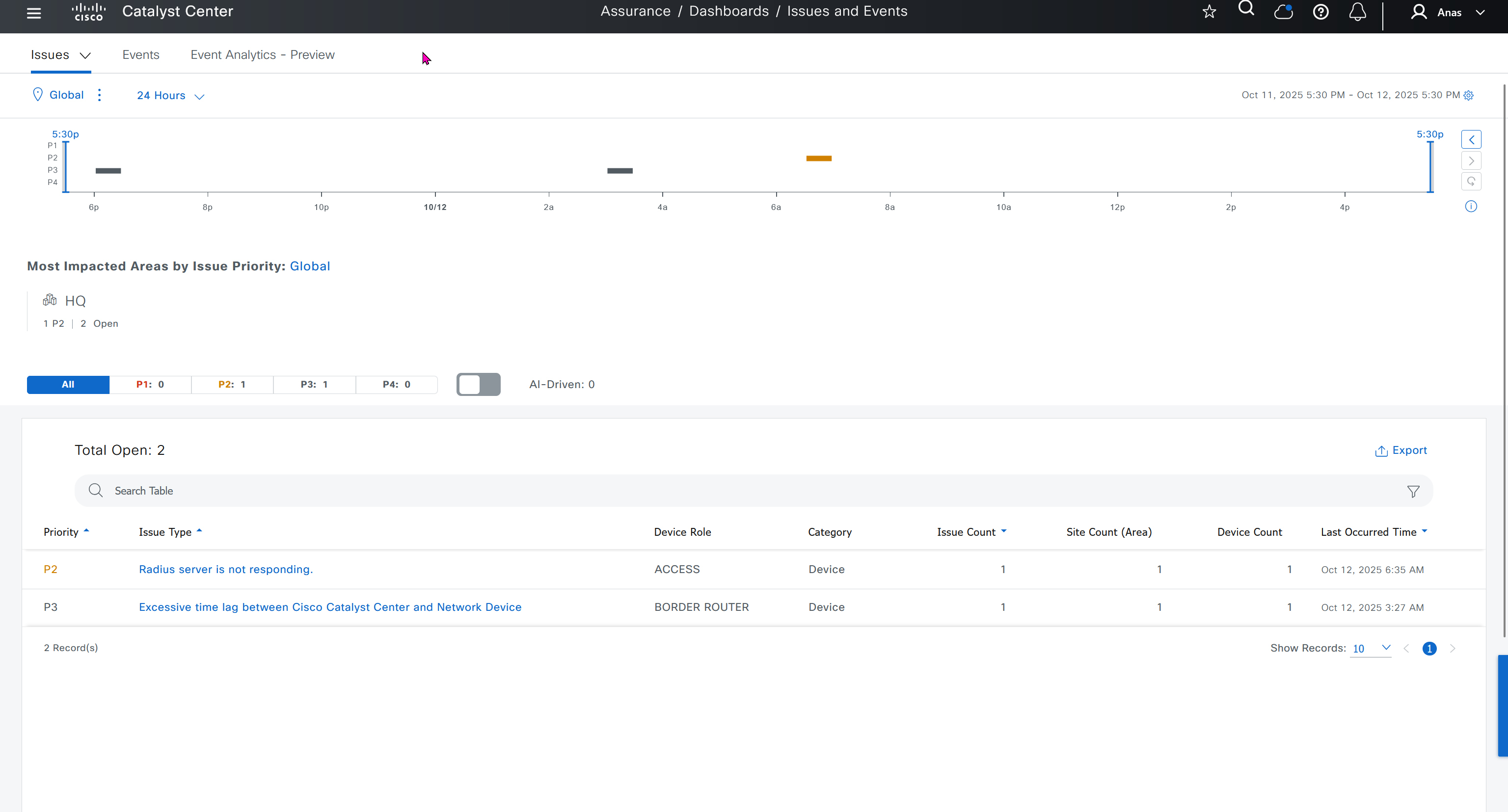
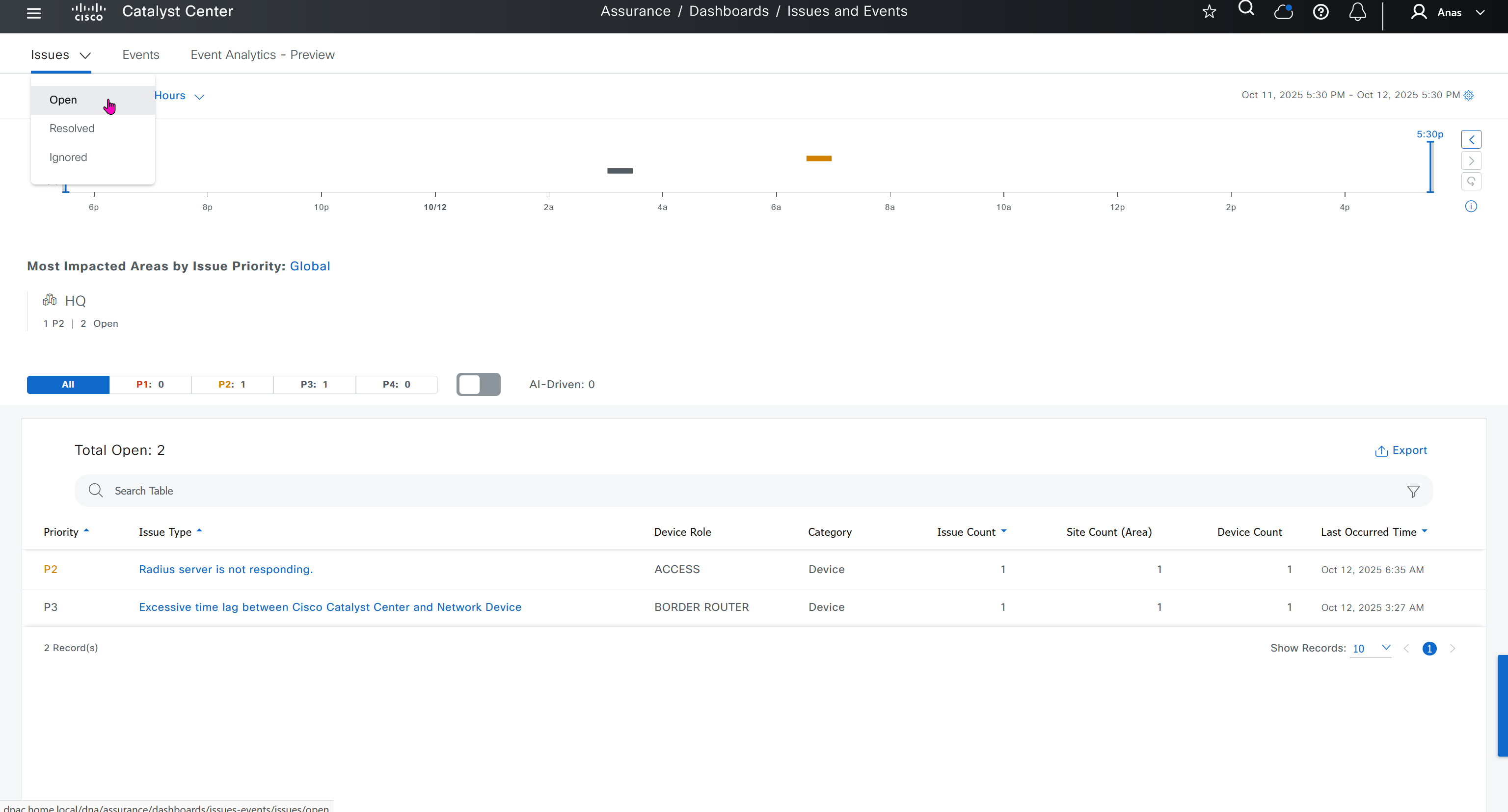
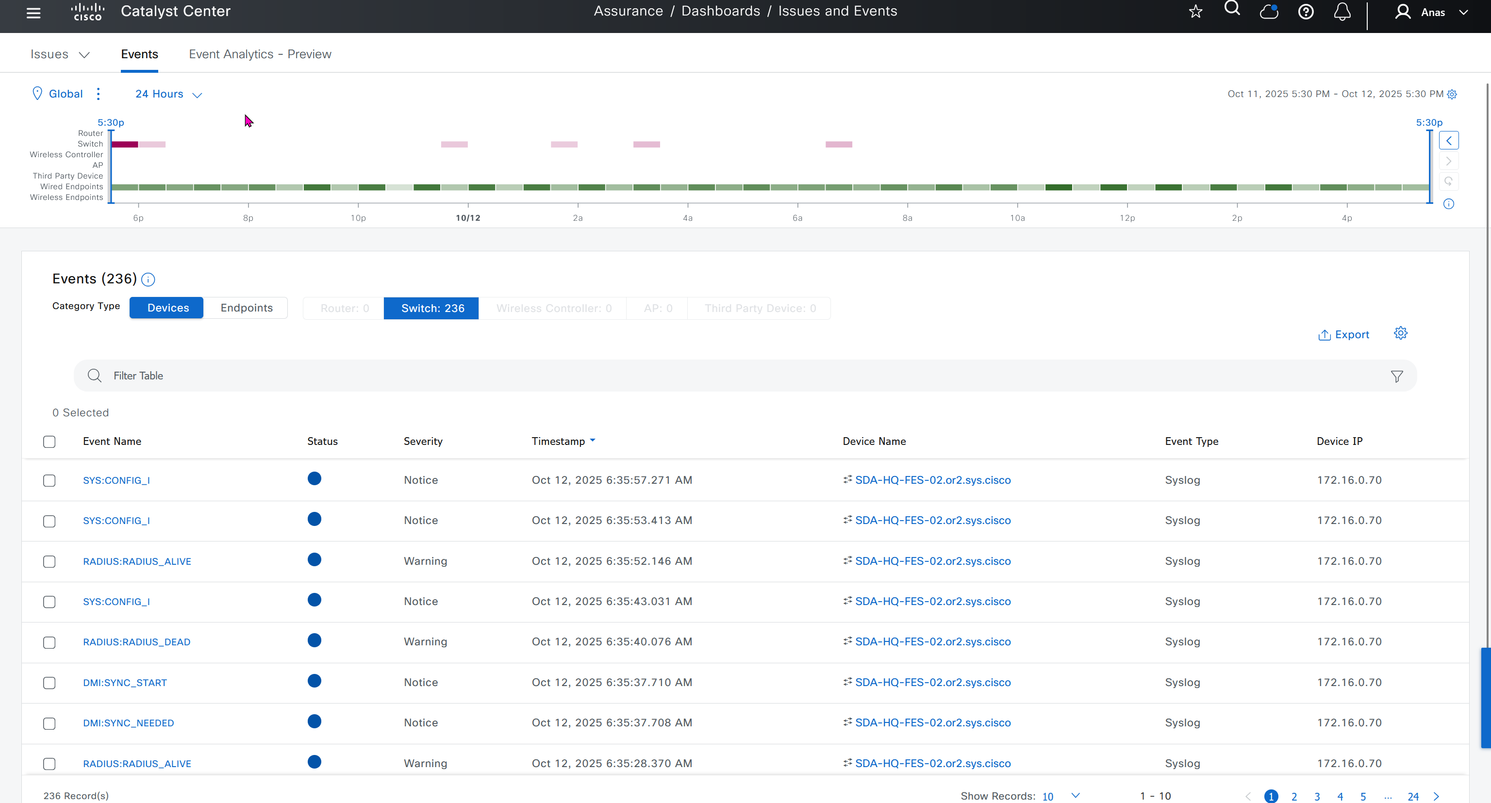

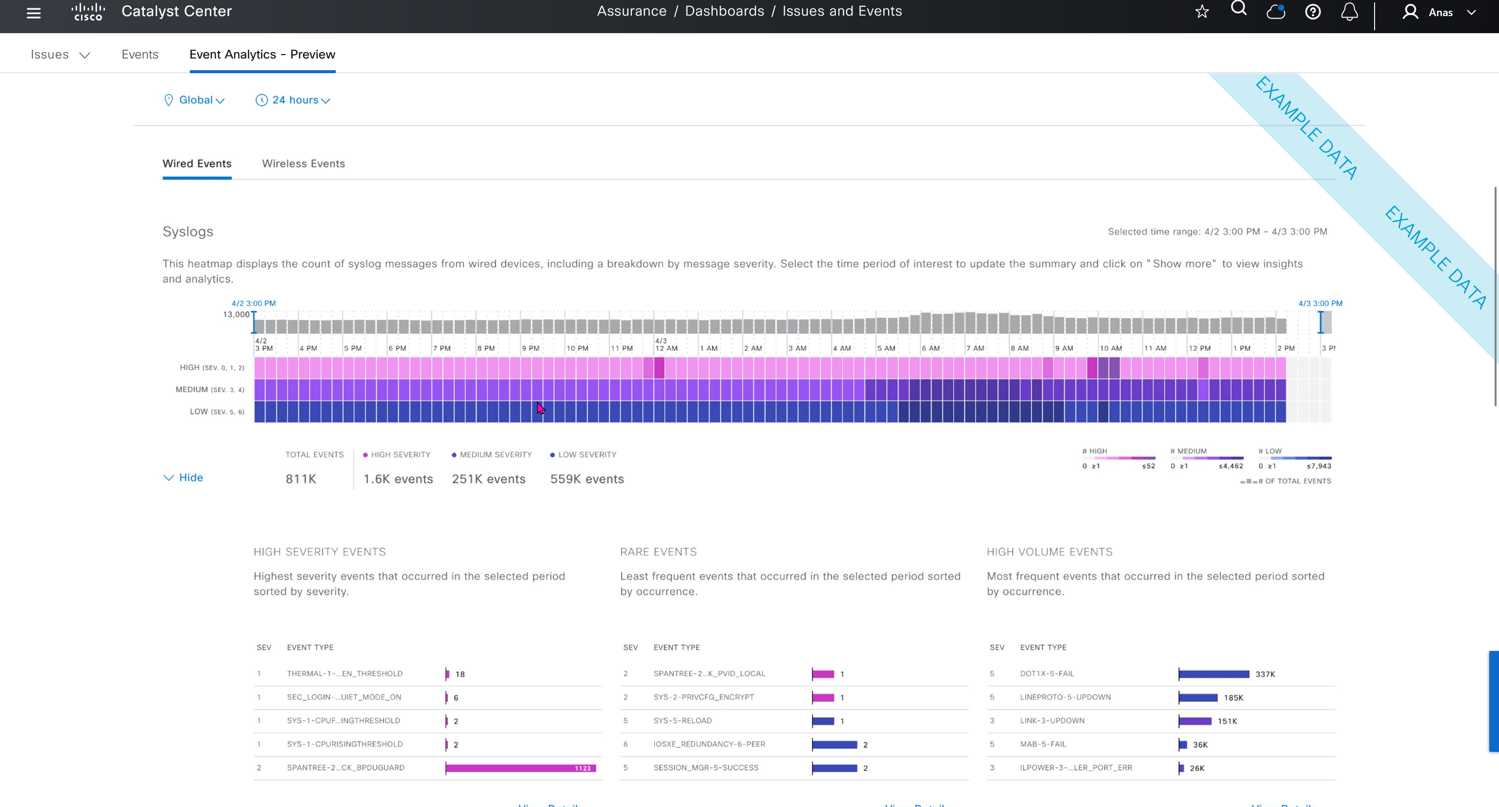
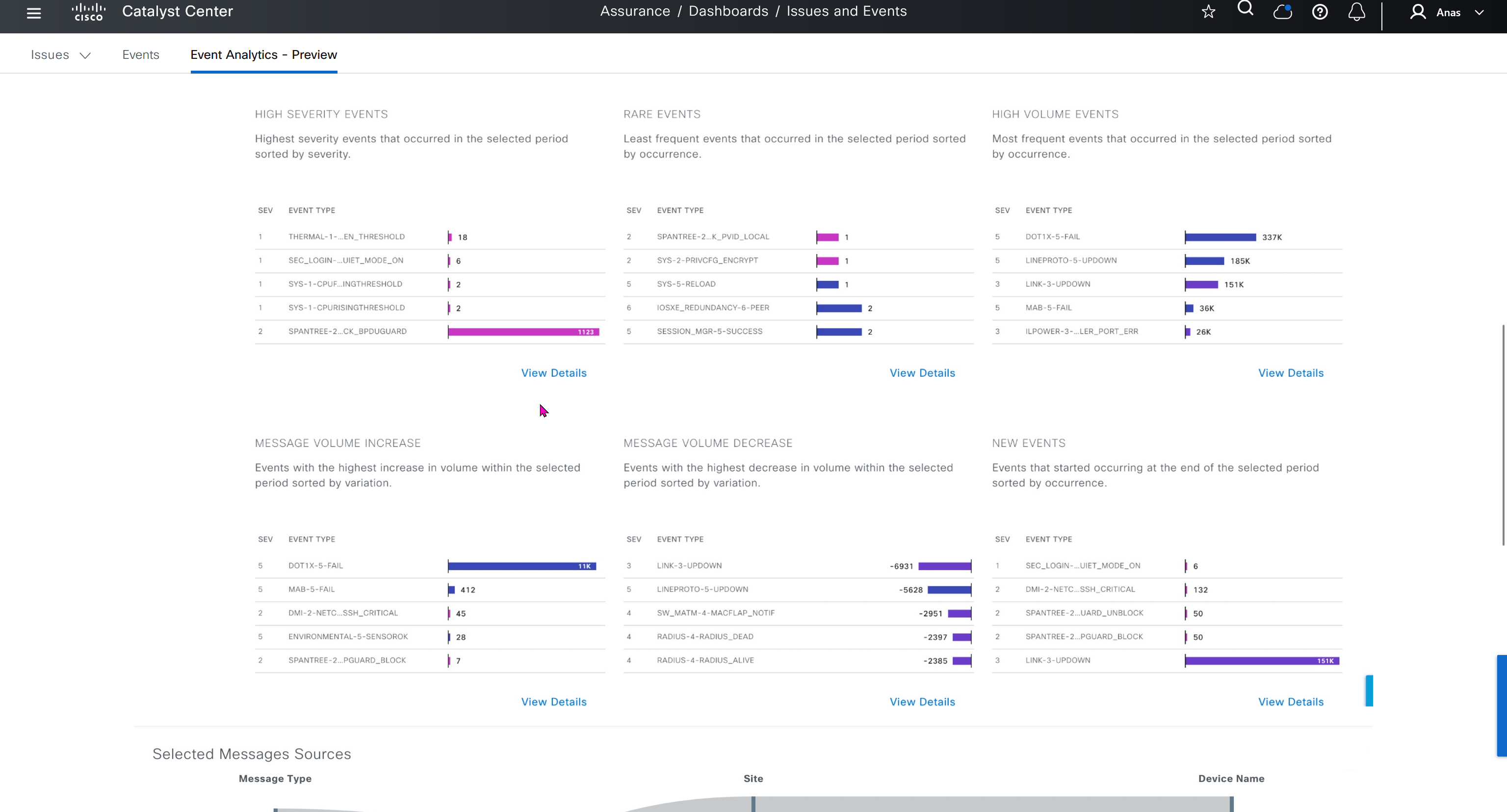
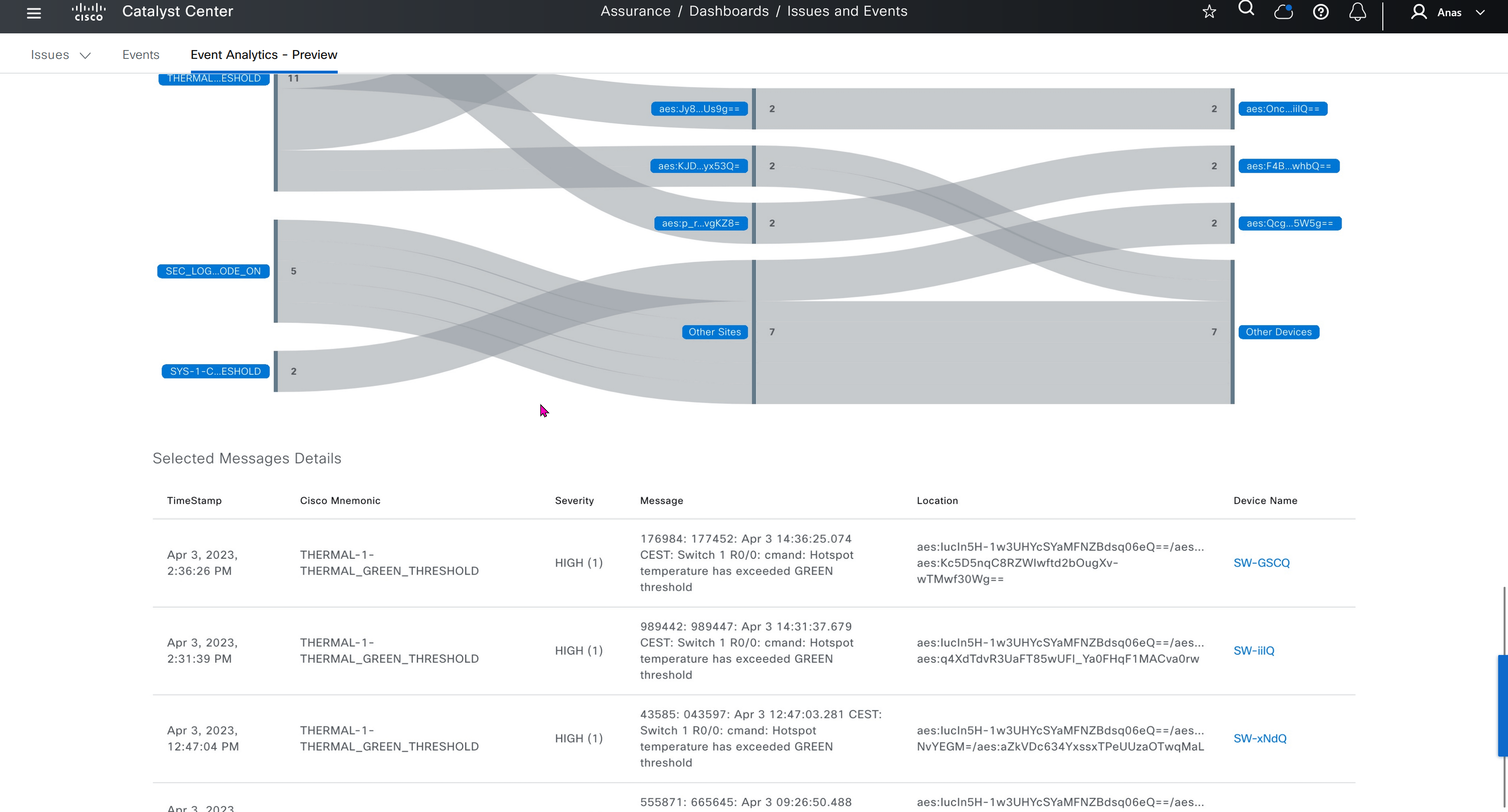
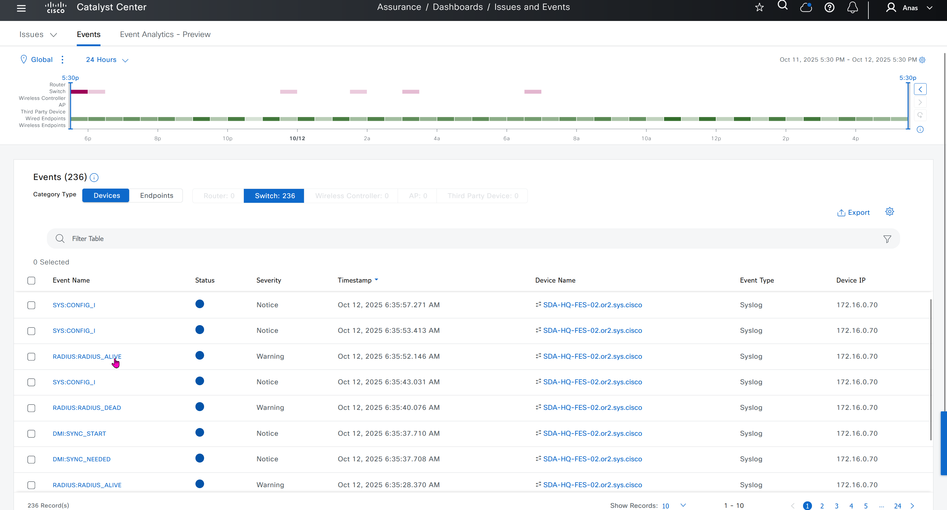
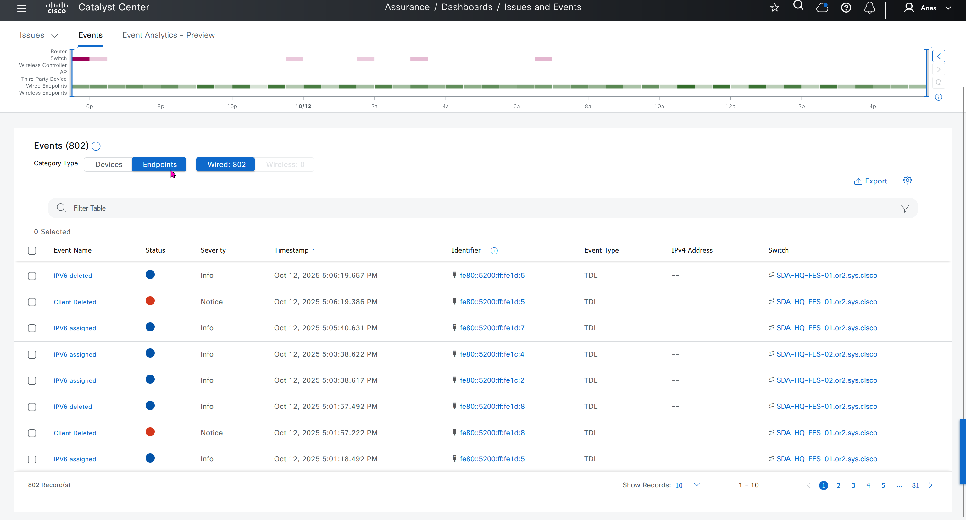
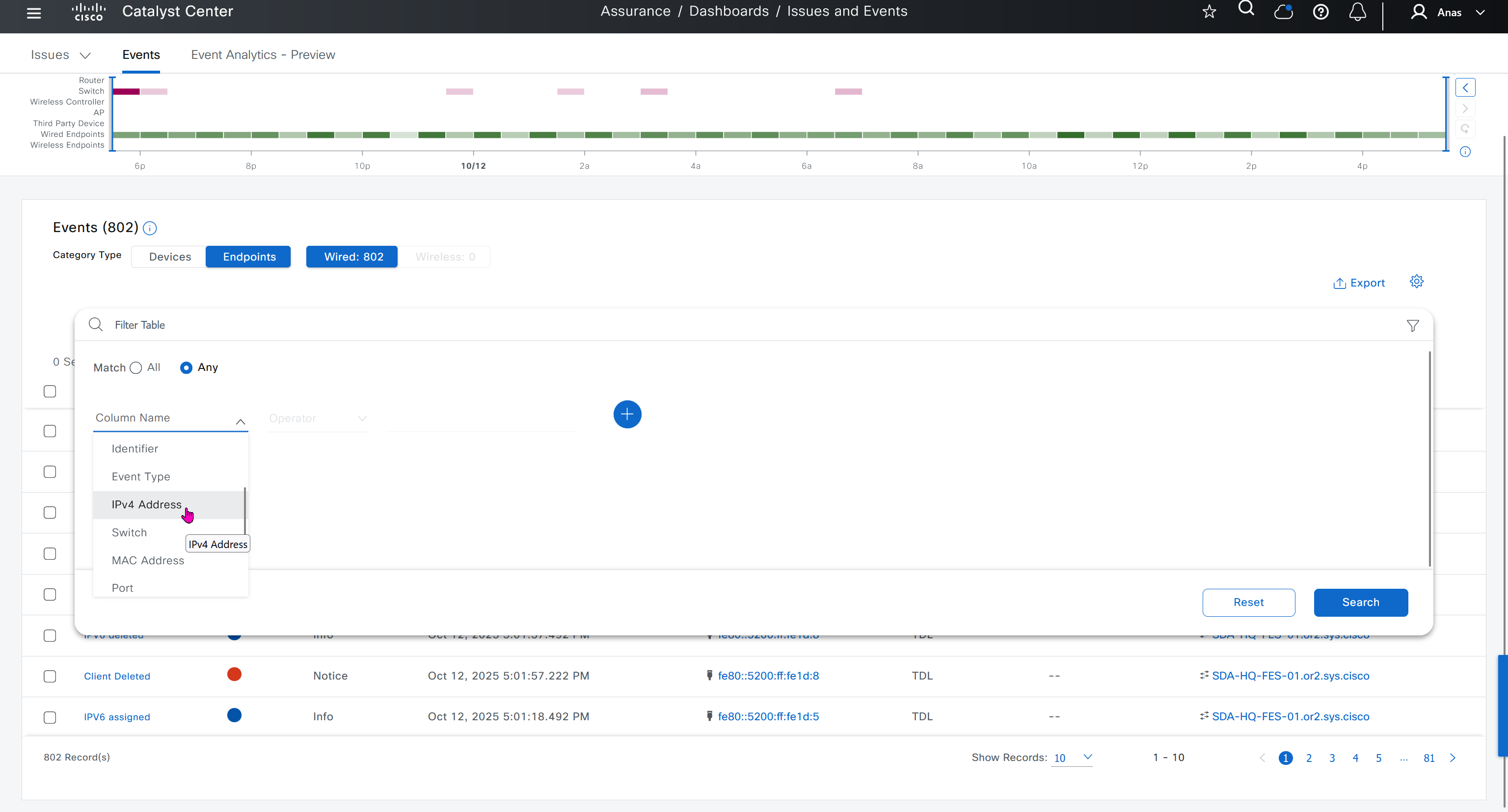
DNAC offers dedicated sensors that can perform series of tests to gauge performance from client perspective. These wireless sensors join network as wireless device and these can either be dedicated sensors or an AP can also be converted to a wireless sensor
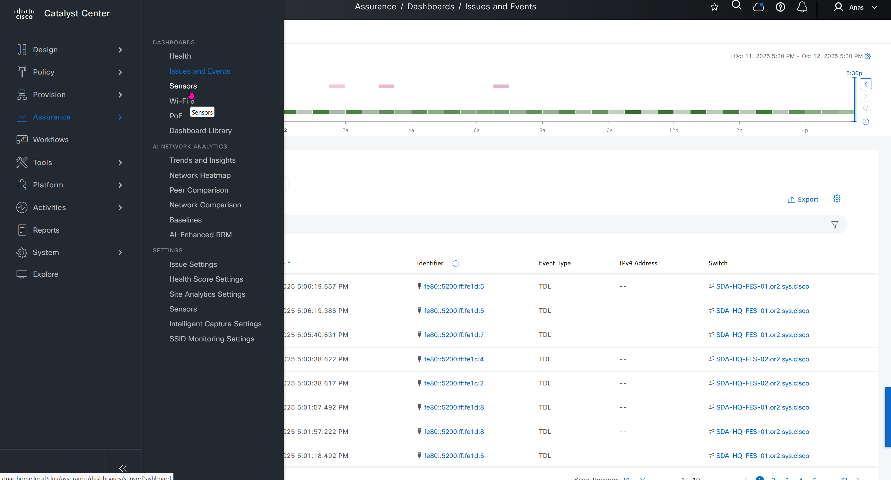


Wi-Fi6 section is for Wi-Fi6 readiness assessment which shows us the percentage of AP and clients that are capable of Wi-Fi6, if large number of clients support Wi-Fi6 then we can think about more APs to be deployed that support Wi-Fi6
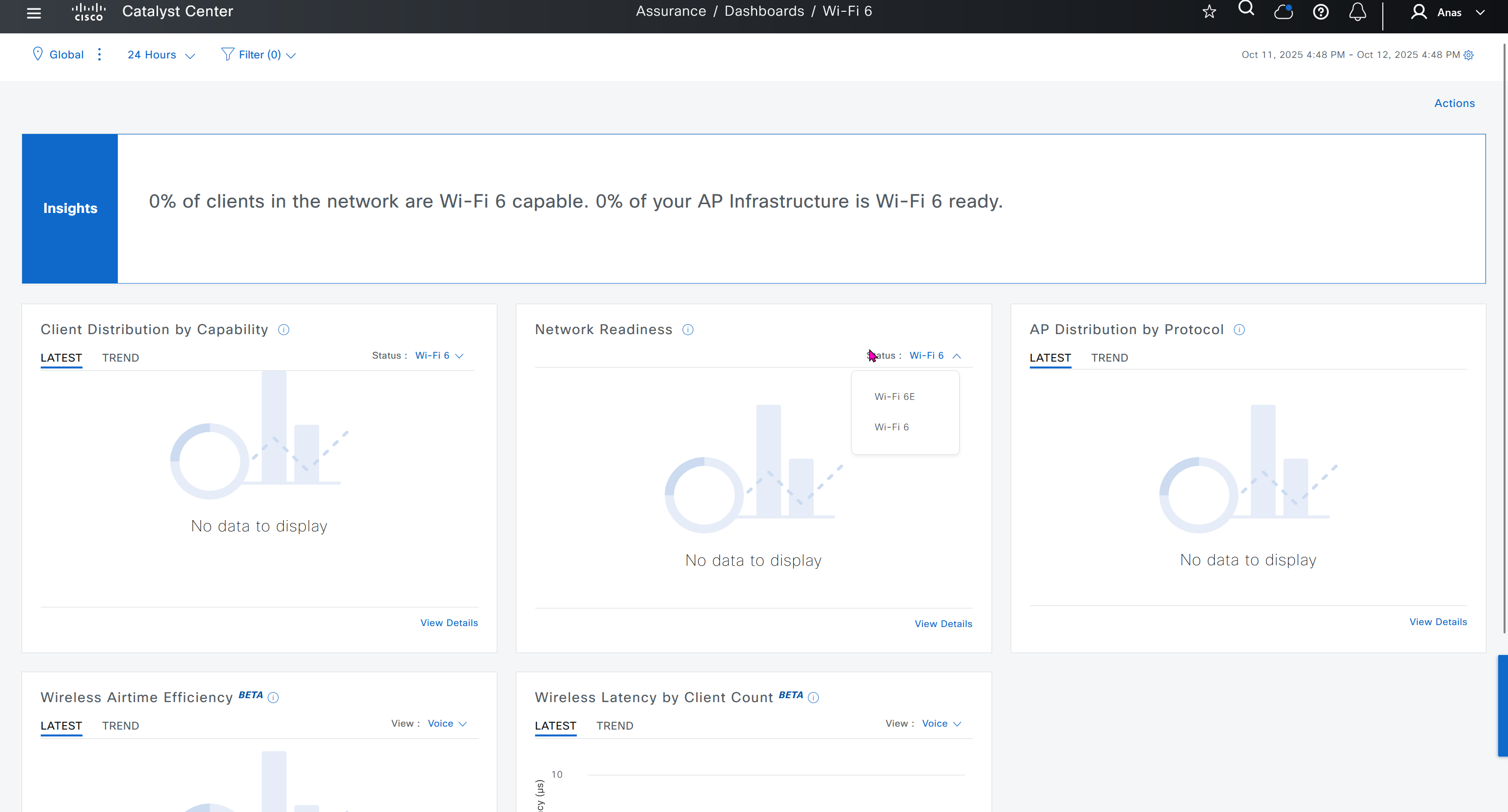
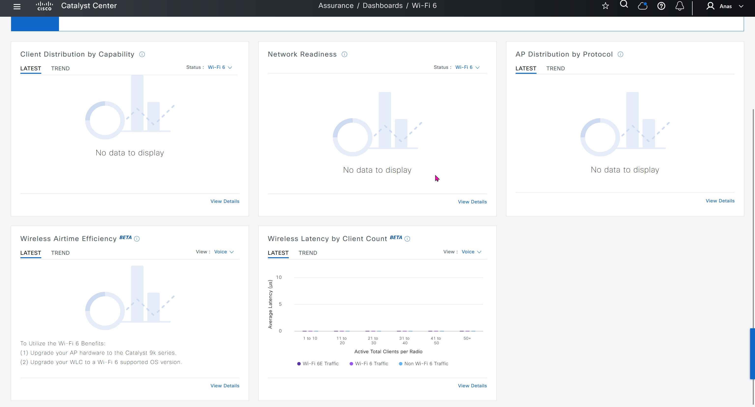


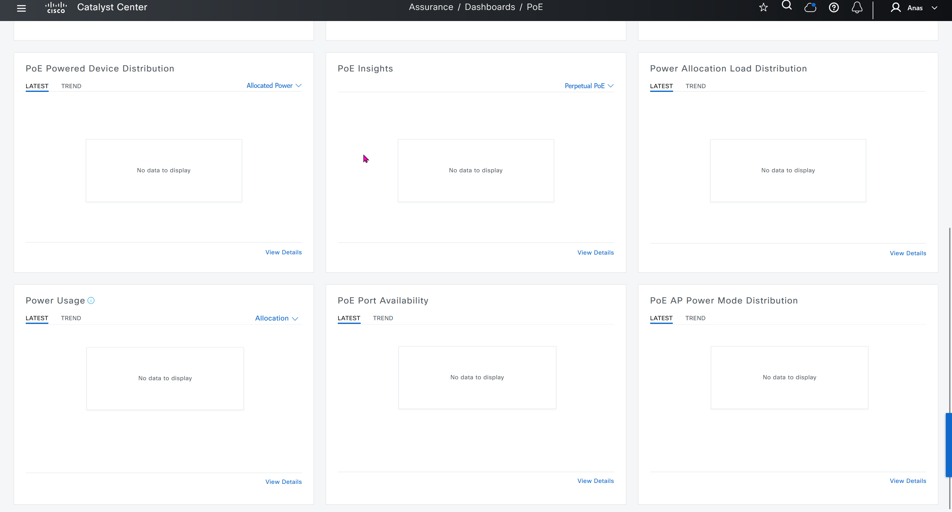
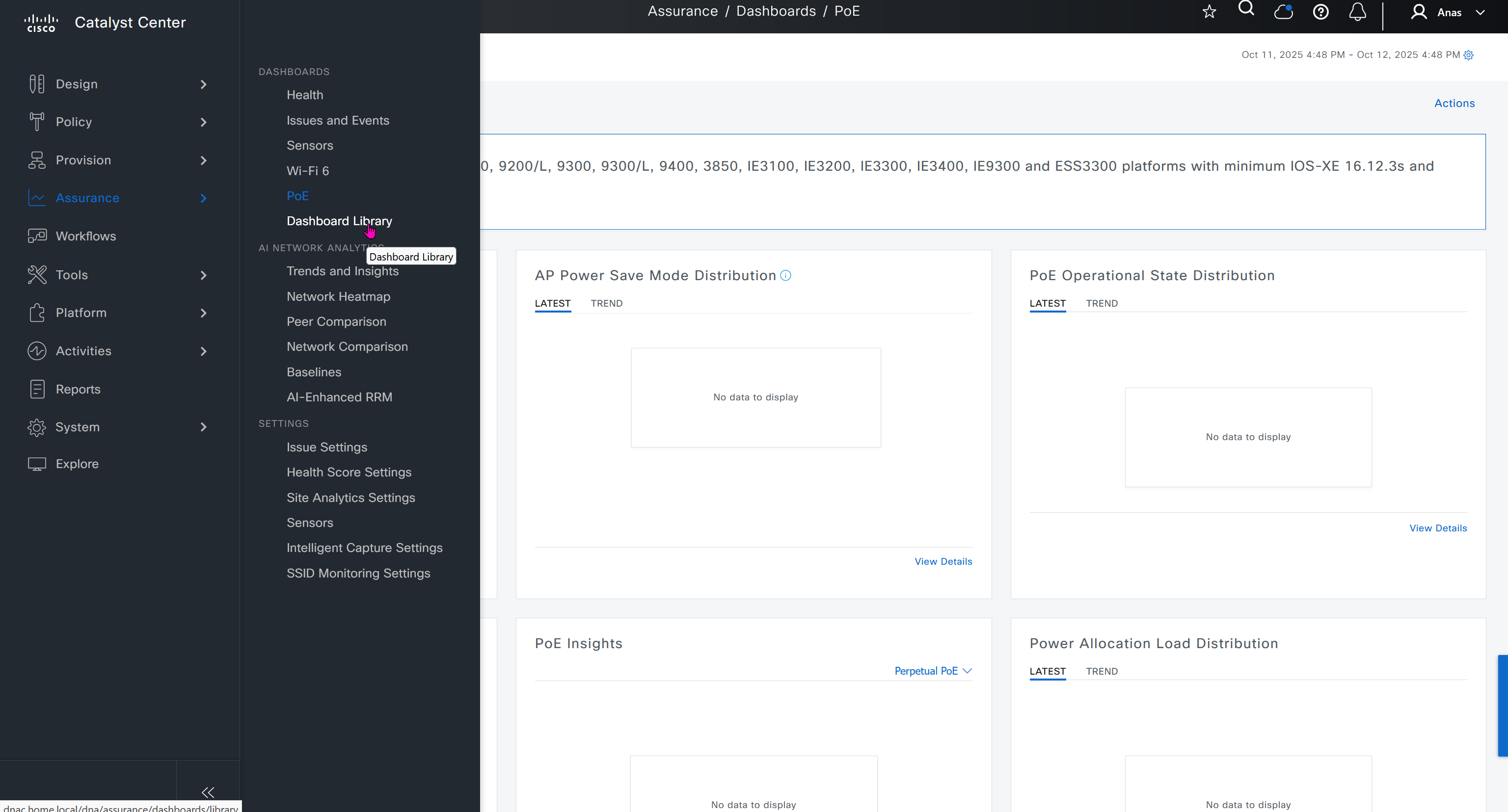
Dashboard Library is where we can create our own dashboards
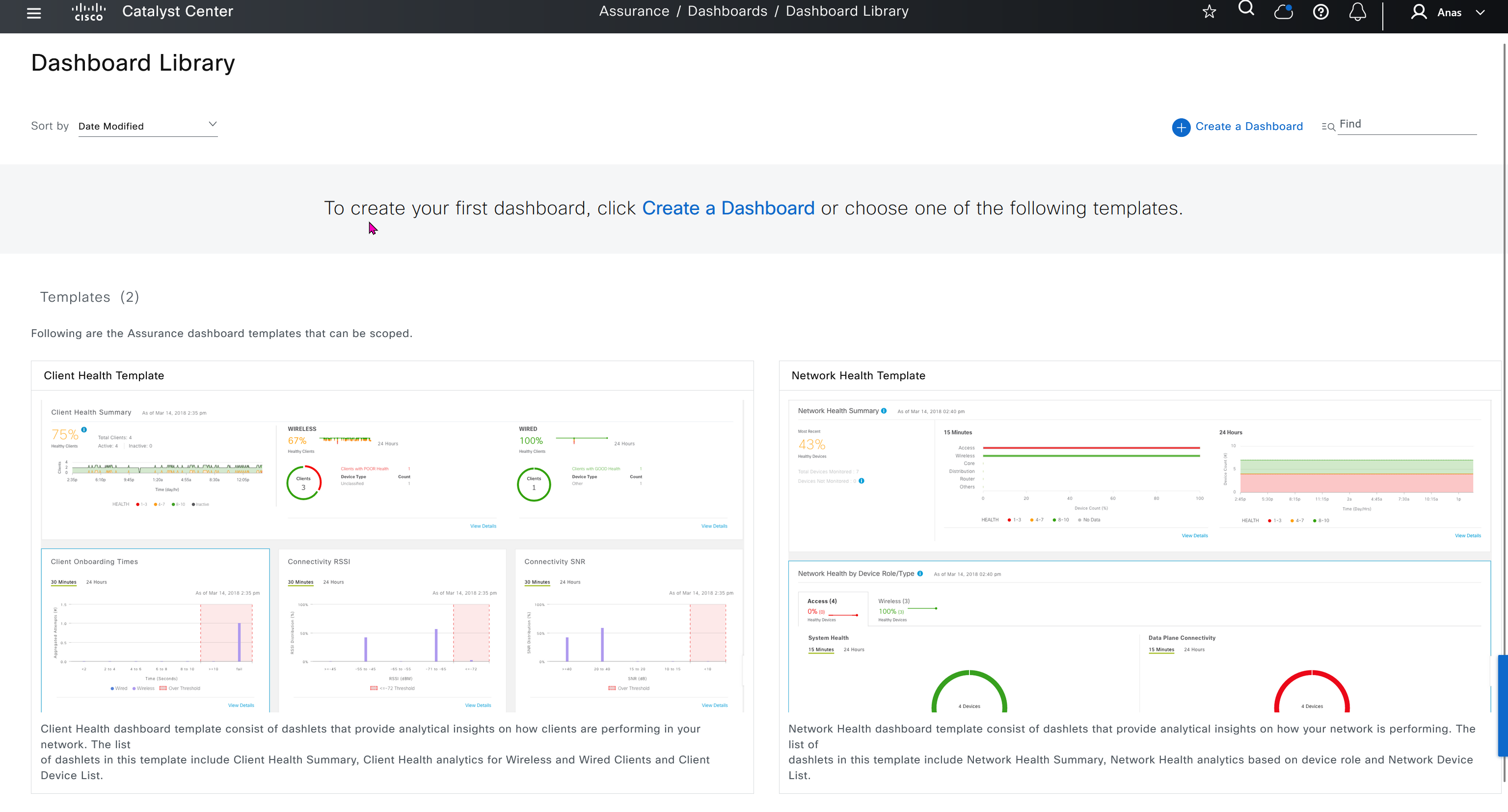
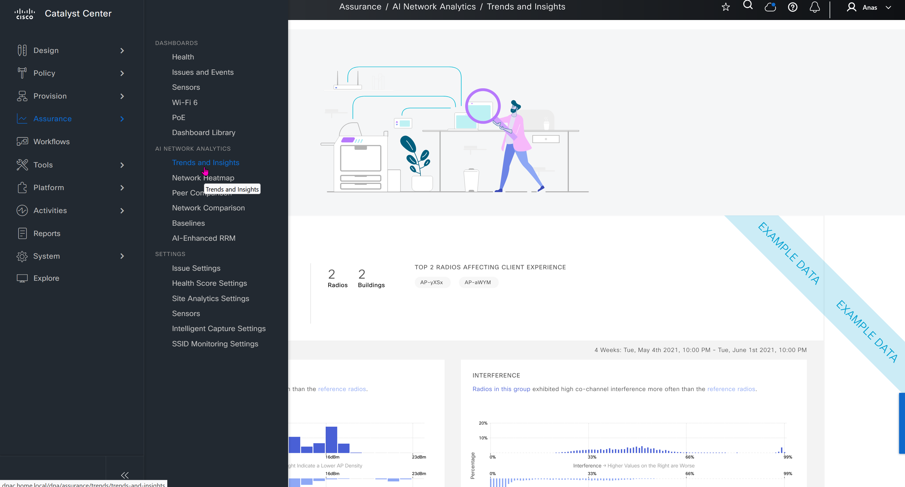
This Trends and Insights leverage AI in Cloud and Machine learning to spot issues in network,
Trends and Insights deals with deviation in capacity and performance
Site comparison shows us how one site compares to another, as in some cases one site can perform worse than the others


Issue settings is where we can control what issues such as P1 and P2 can be raised by DNAC such as Assurance > Issues & Events, we can enable or disable some of these issues if they are not important to us, we can also change priority on them

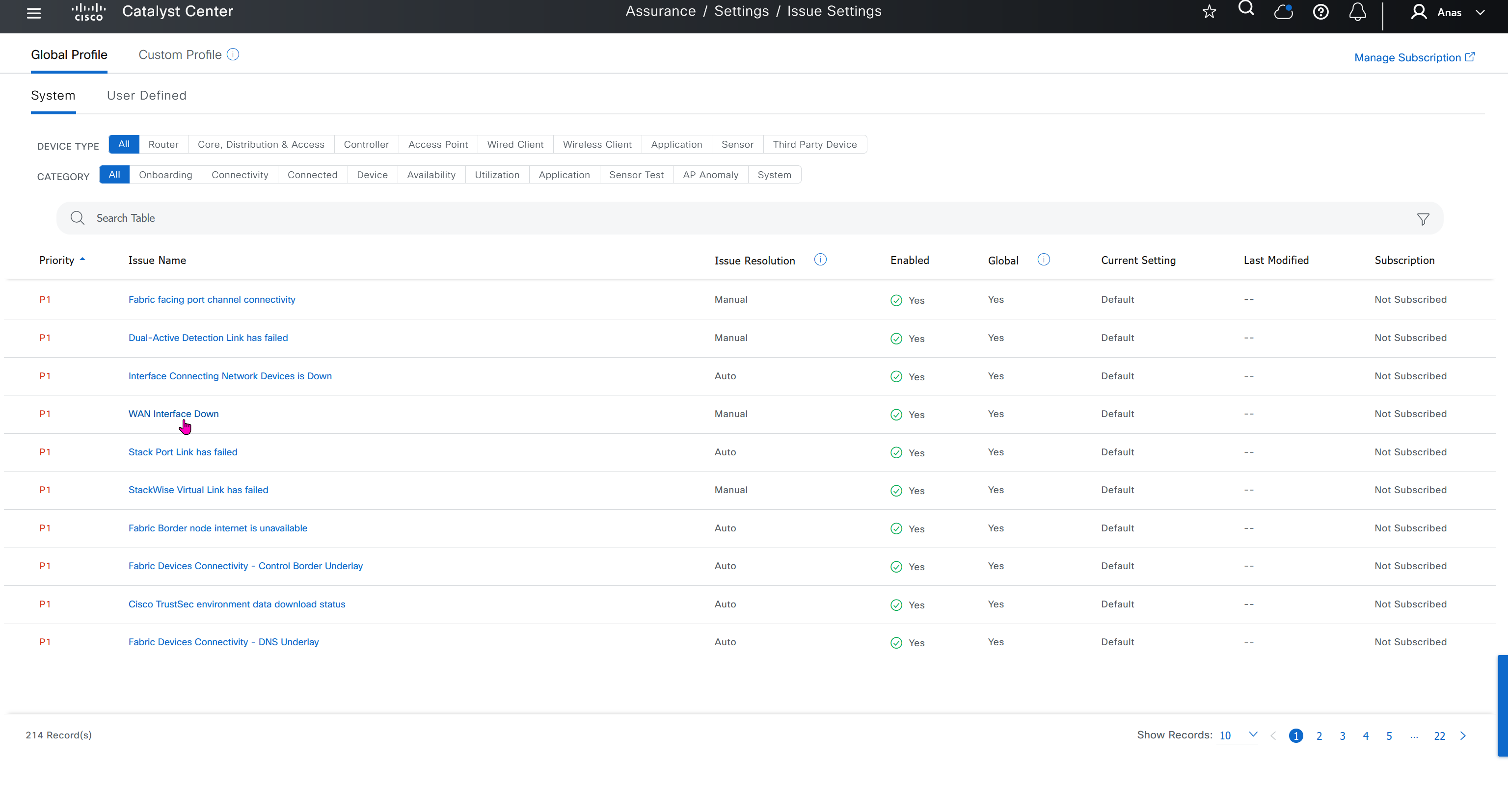
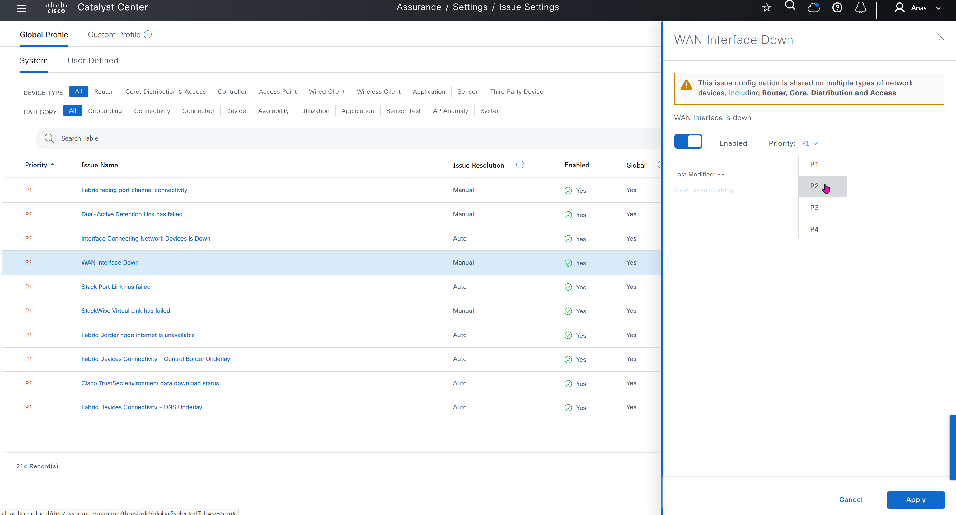
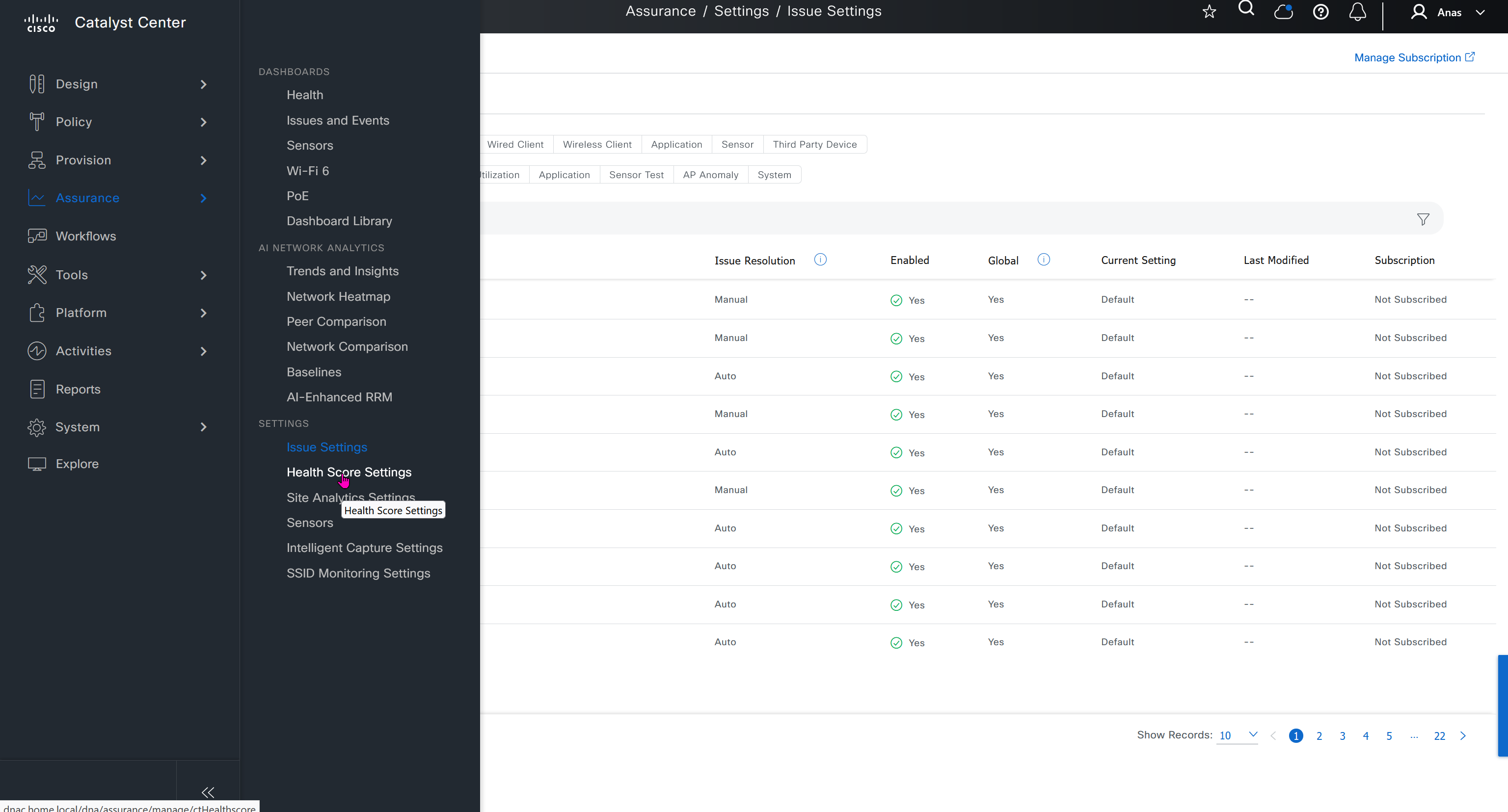
Health score is where you can turn on or off on what is included in determining device health score, these health score threshold values can be modified as well

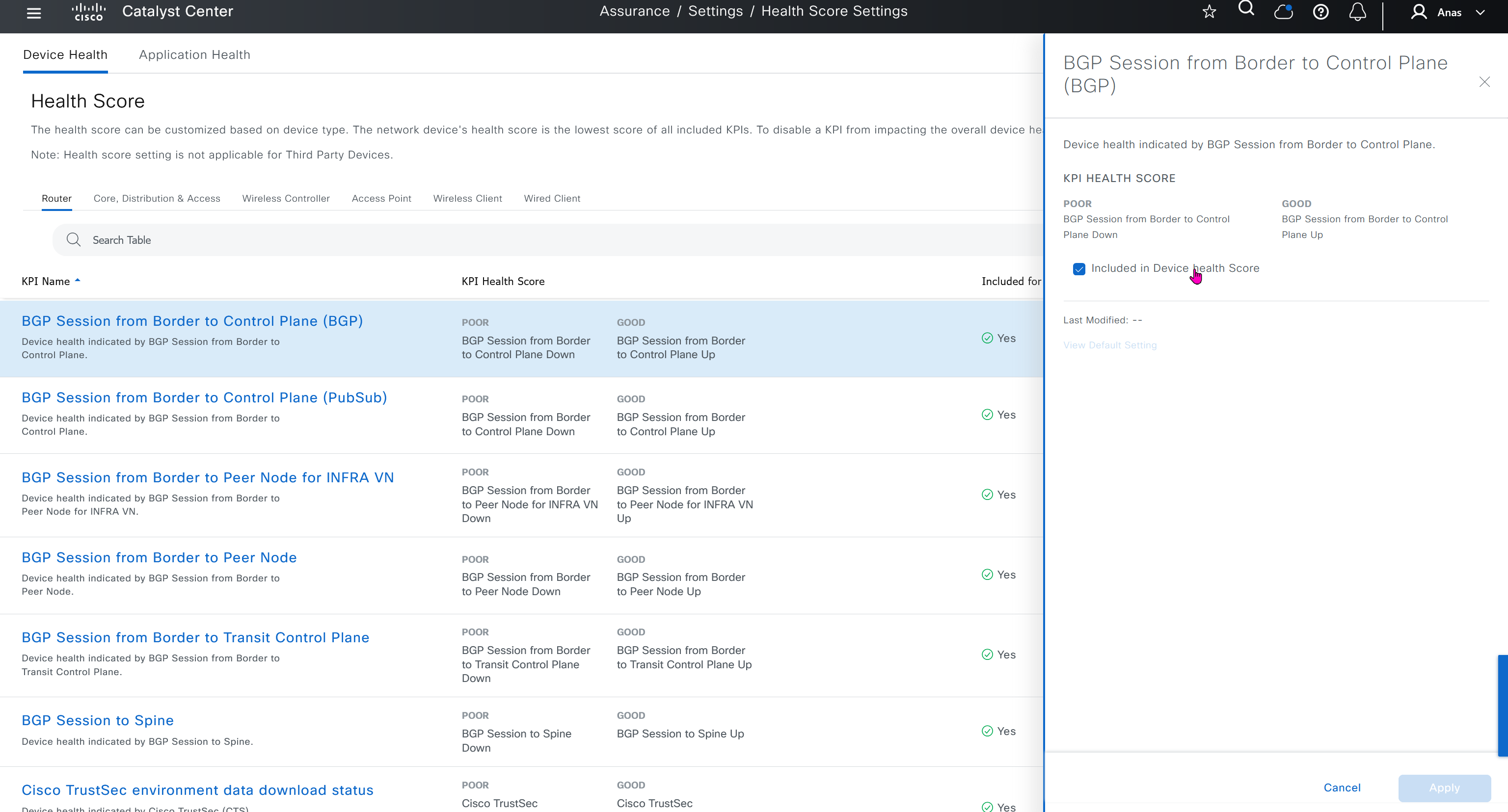


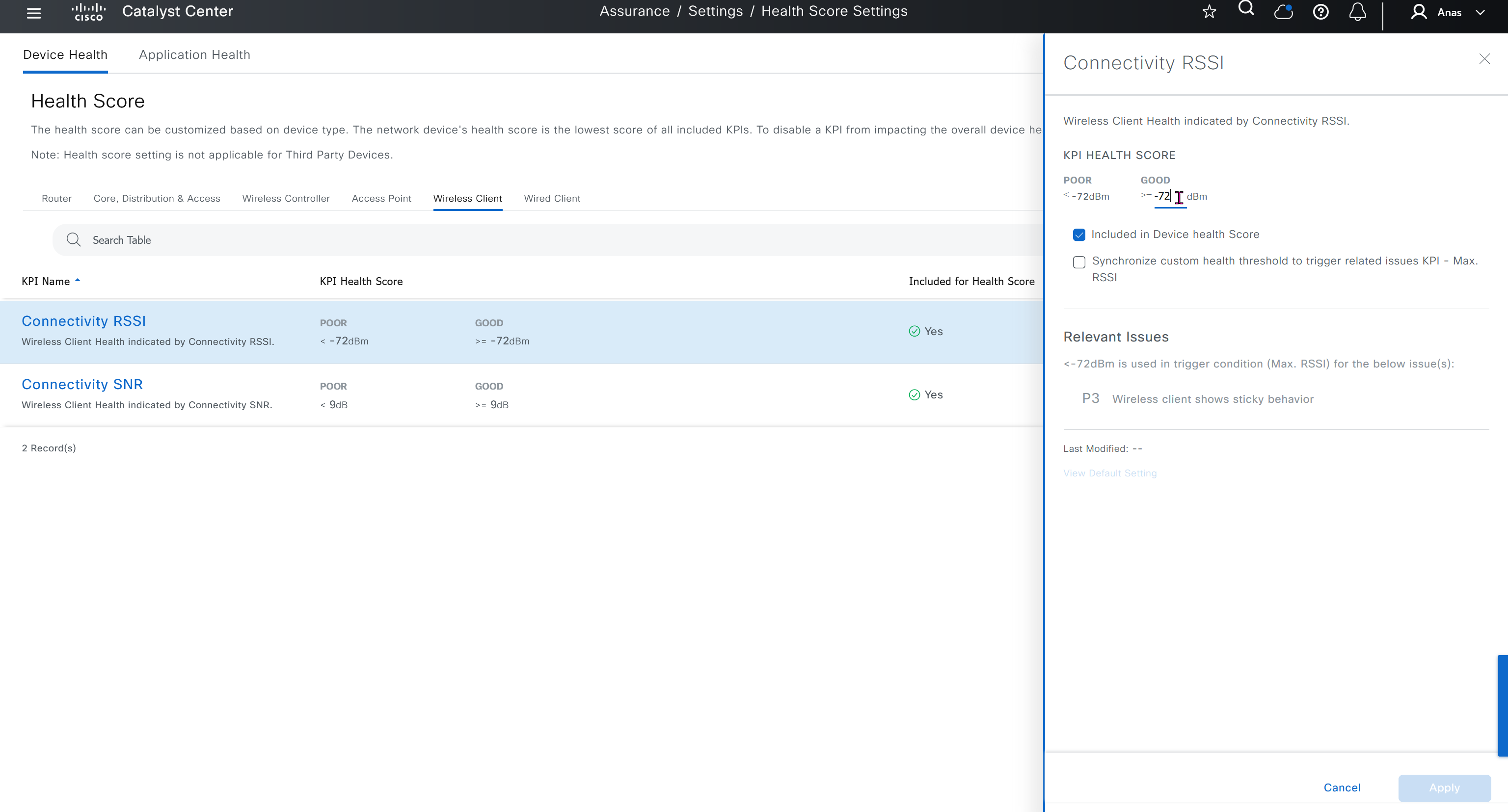

Sensor section here we define test settings such as ping, HTTPs, association test etc
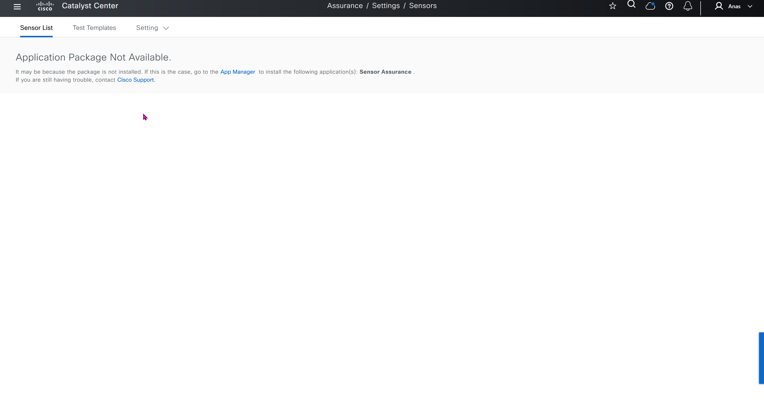
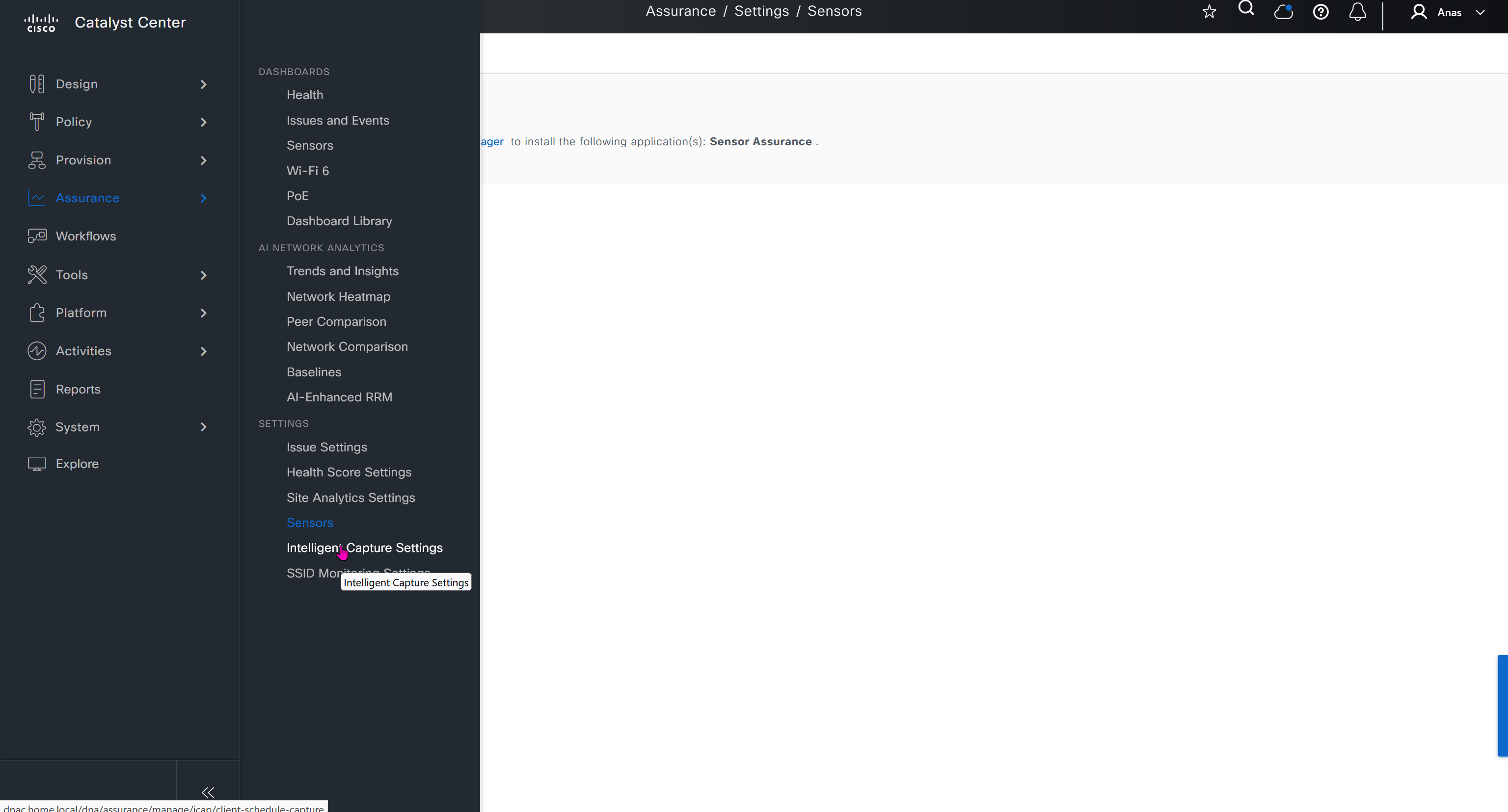
Intelligent capture is where you define how and when you want your AP to perform capture of client traffic
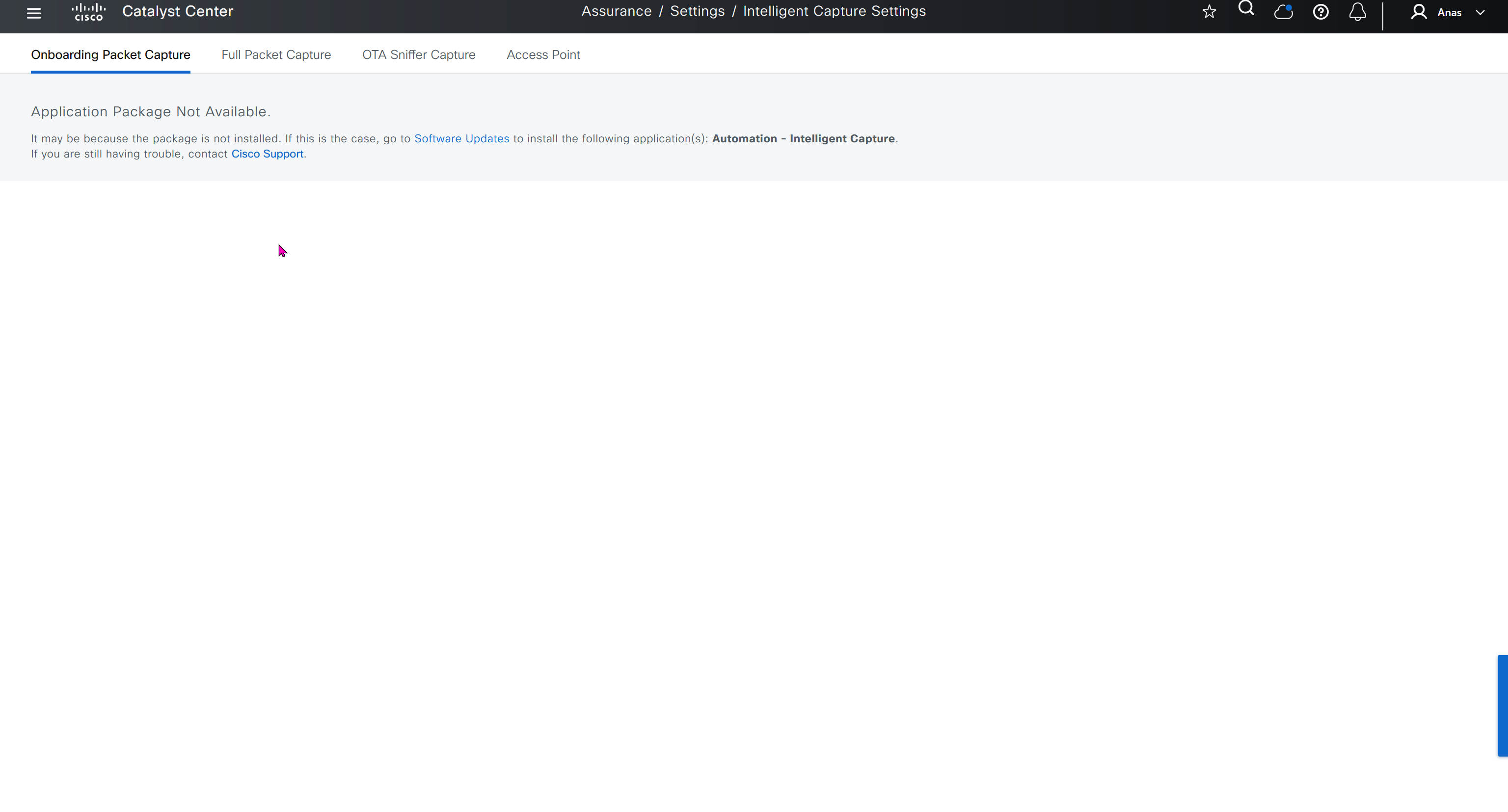
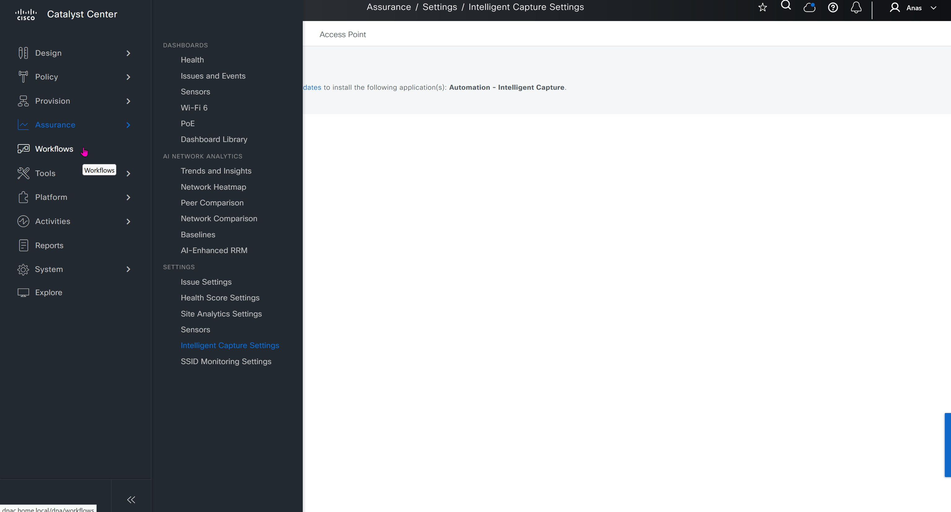
Workflows make things easy for us as they are guided configuration wizards that help us configure things easily and quickly without making mistakes
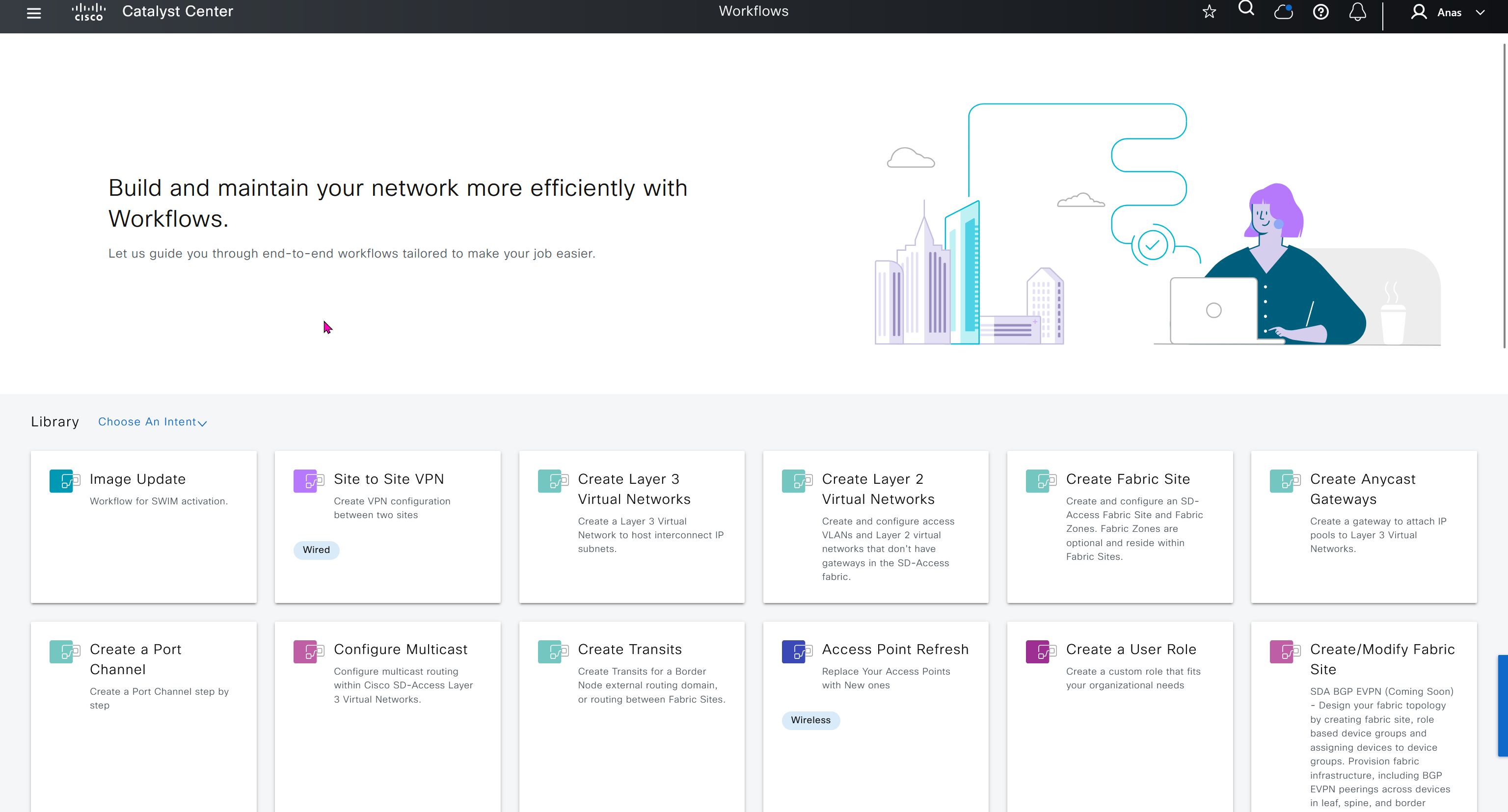
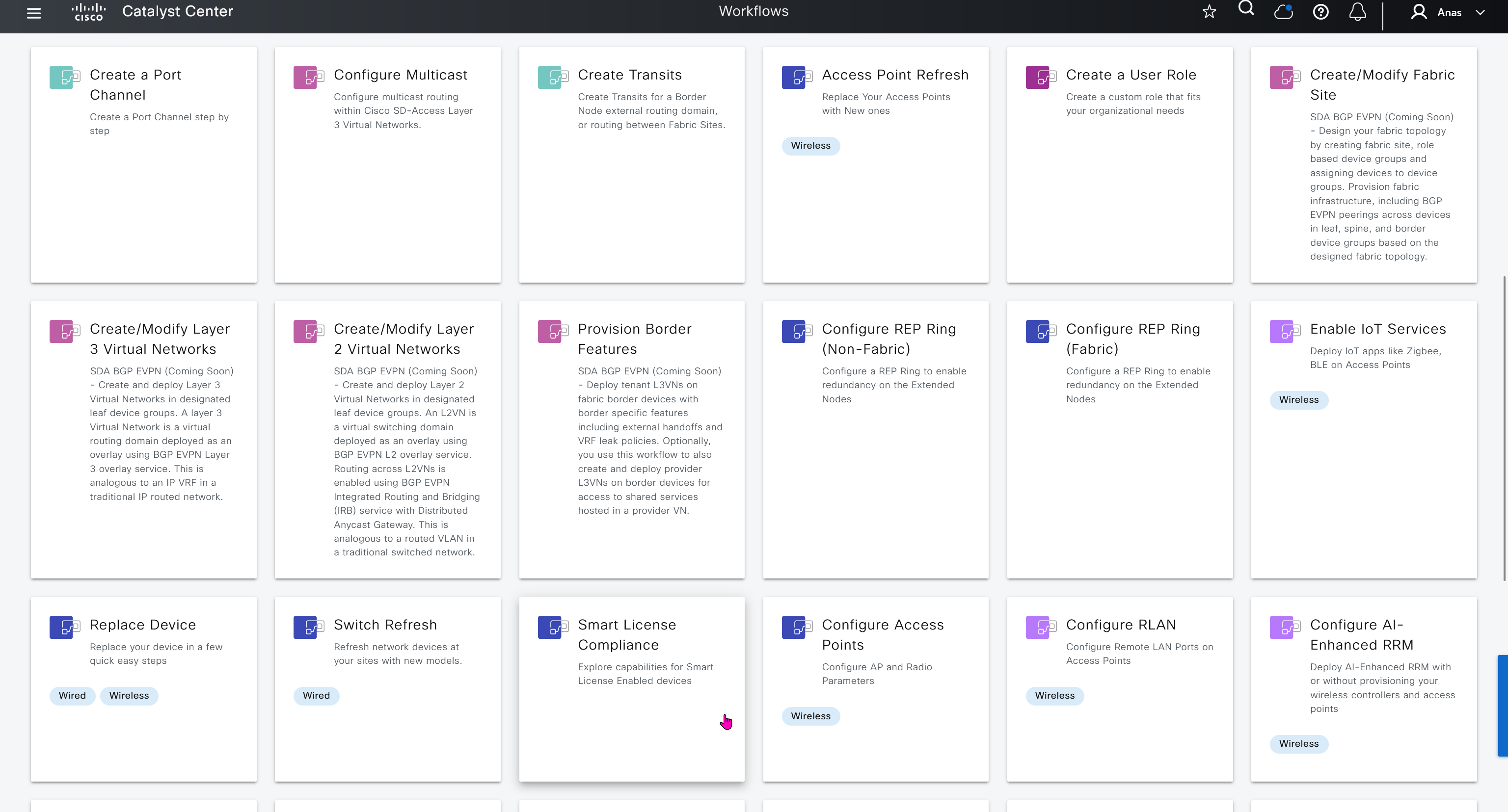
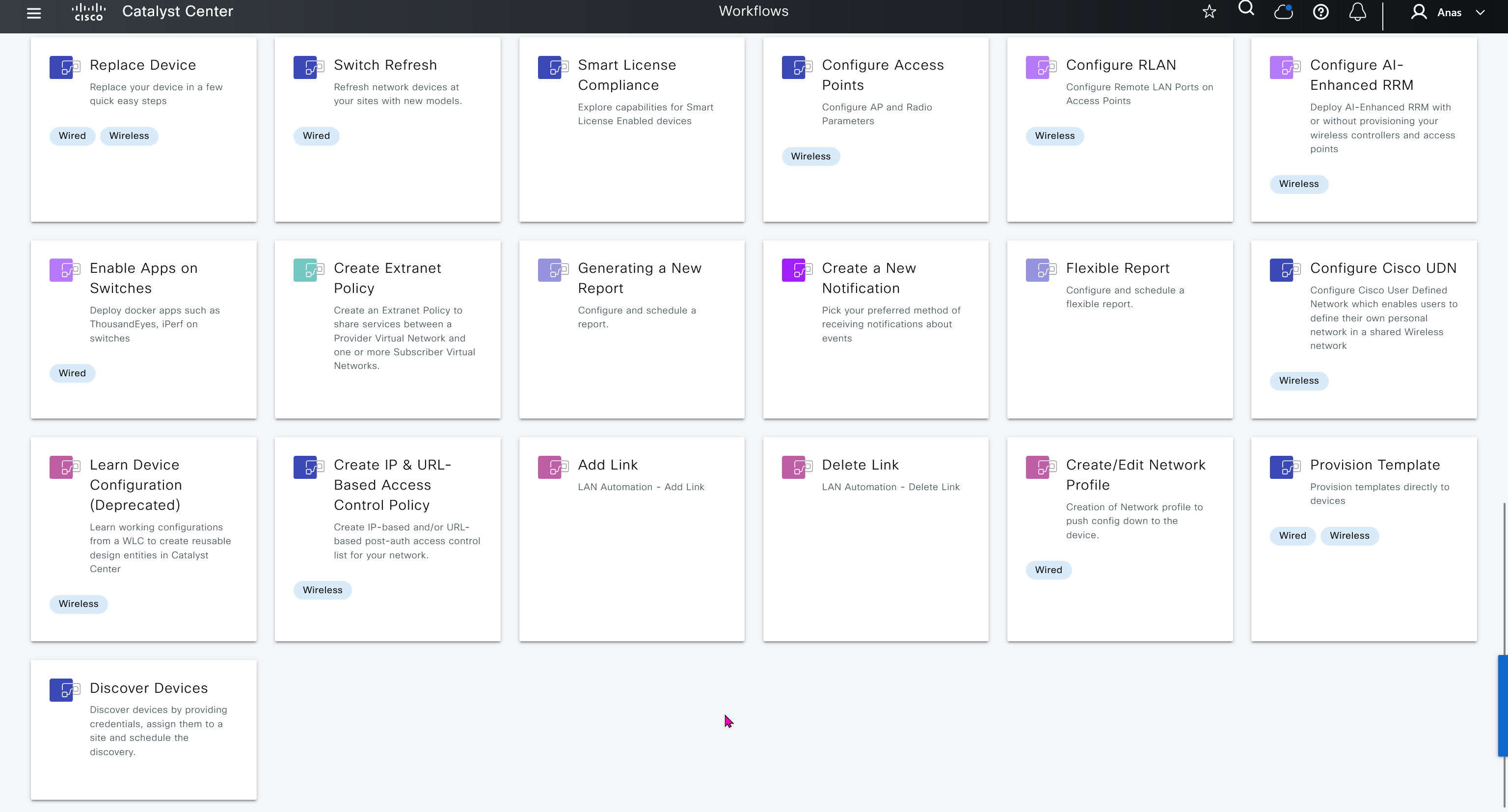
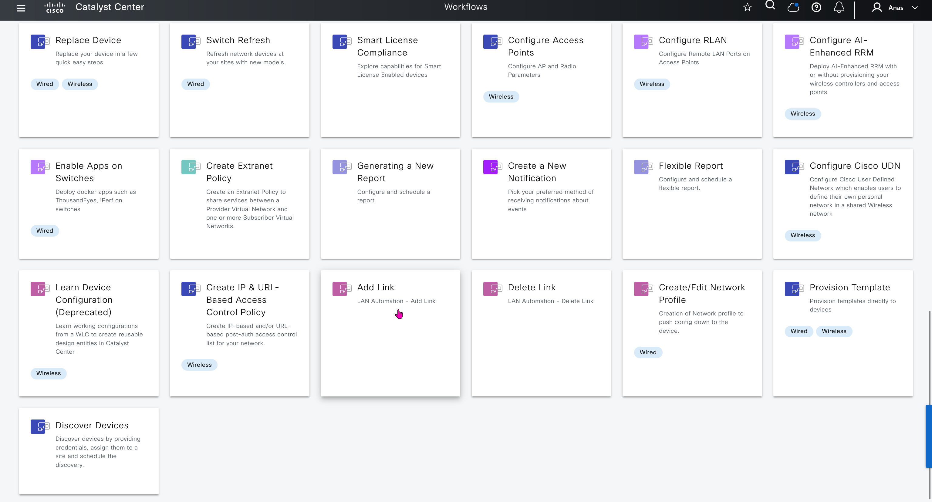


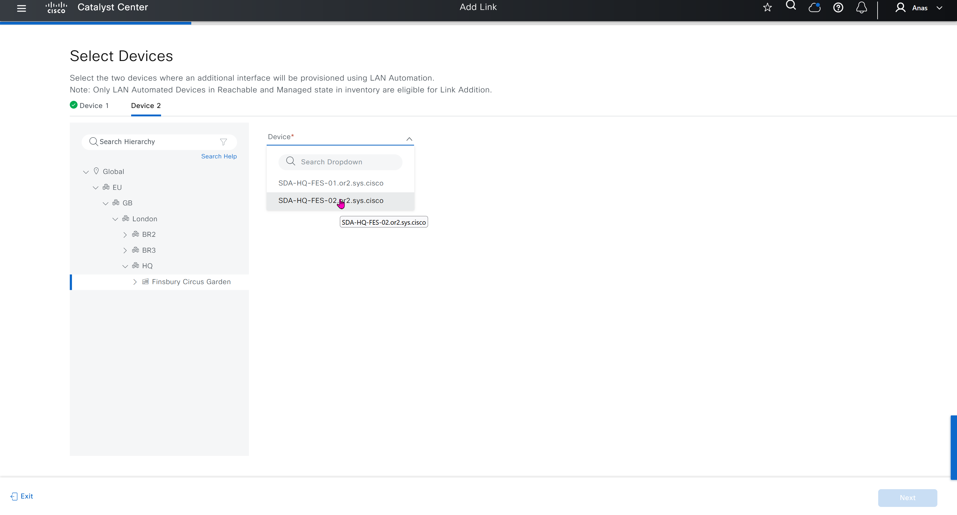
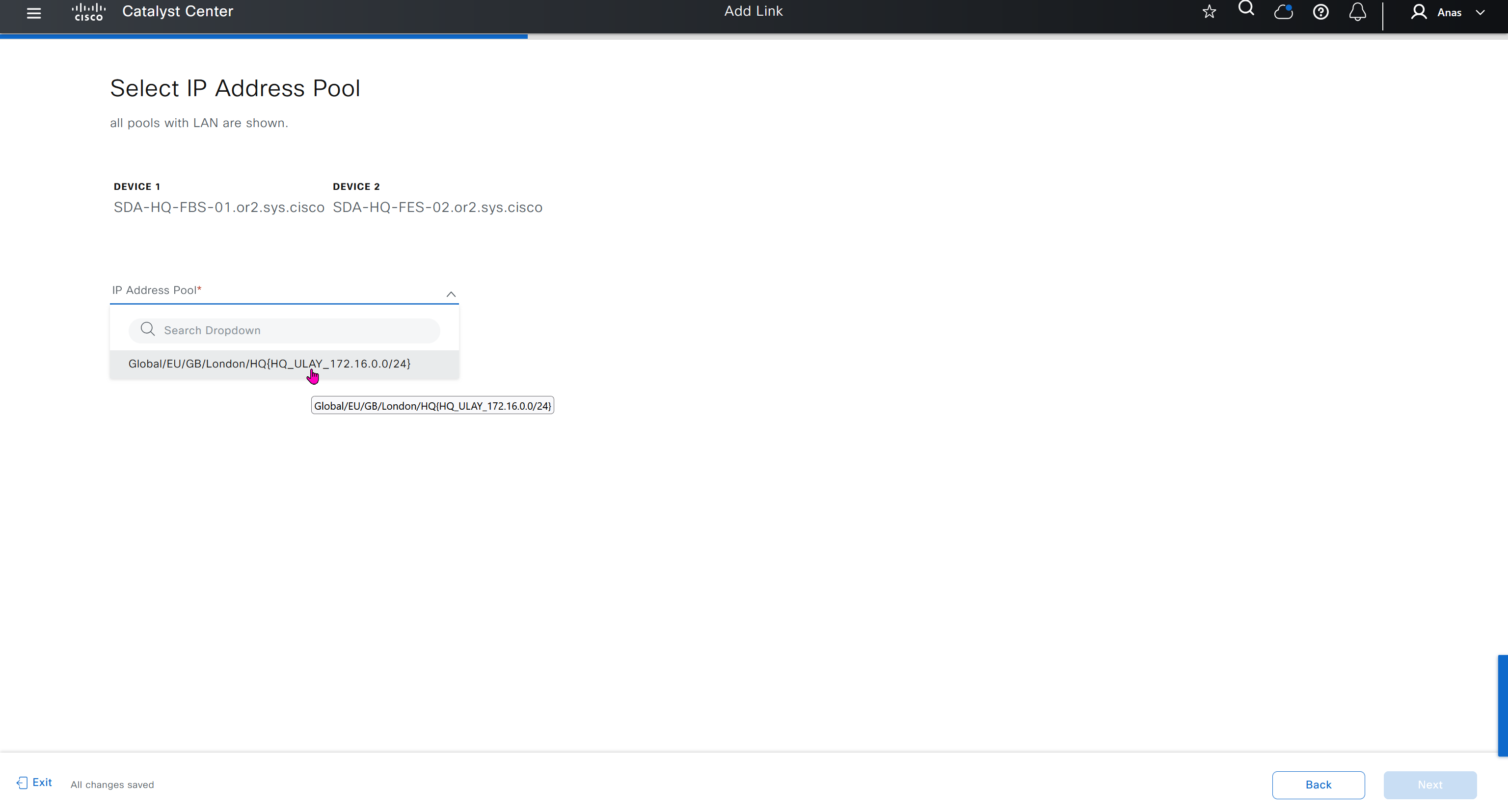


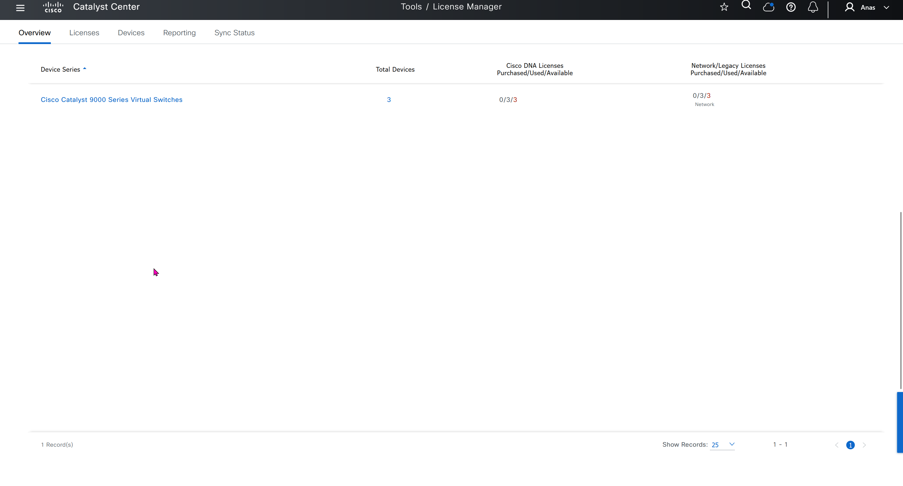
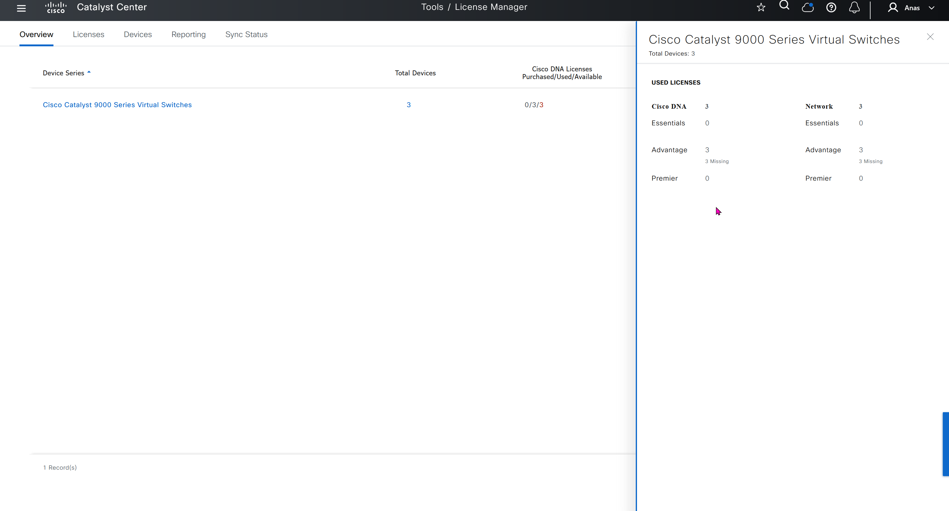
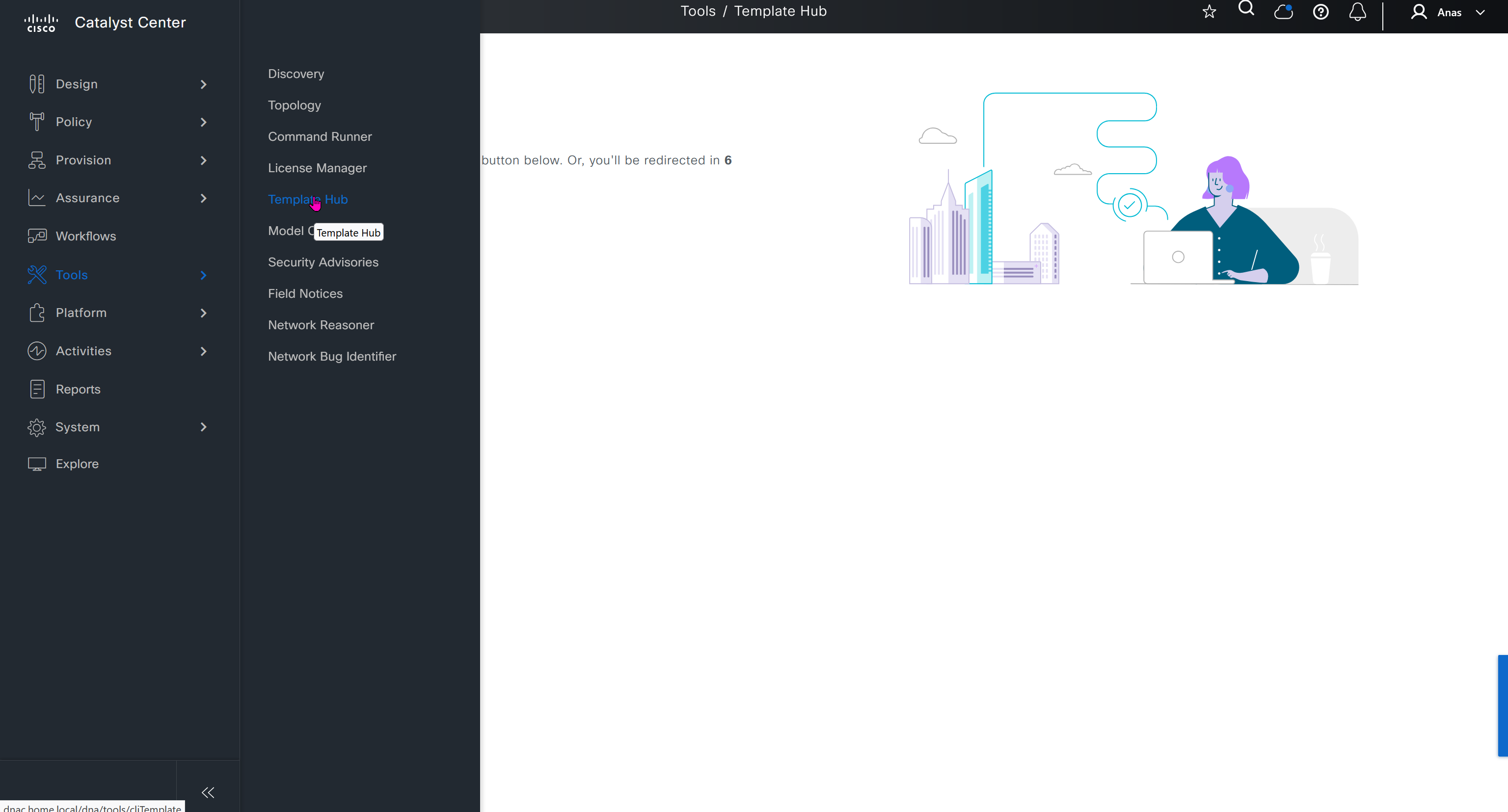
CLI templates is where we create templates, when it is time to apply template then we apply them using Network profiles

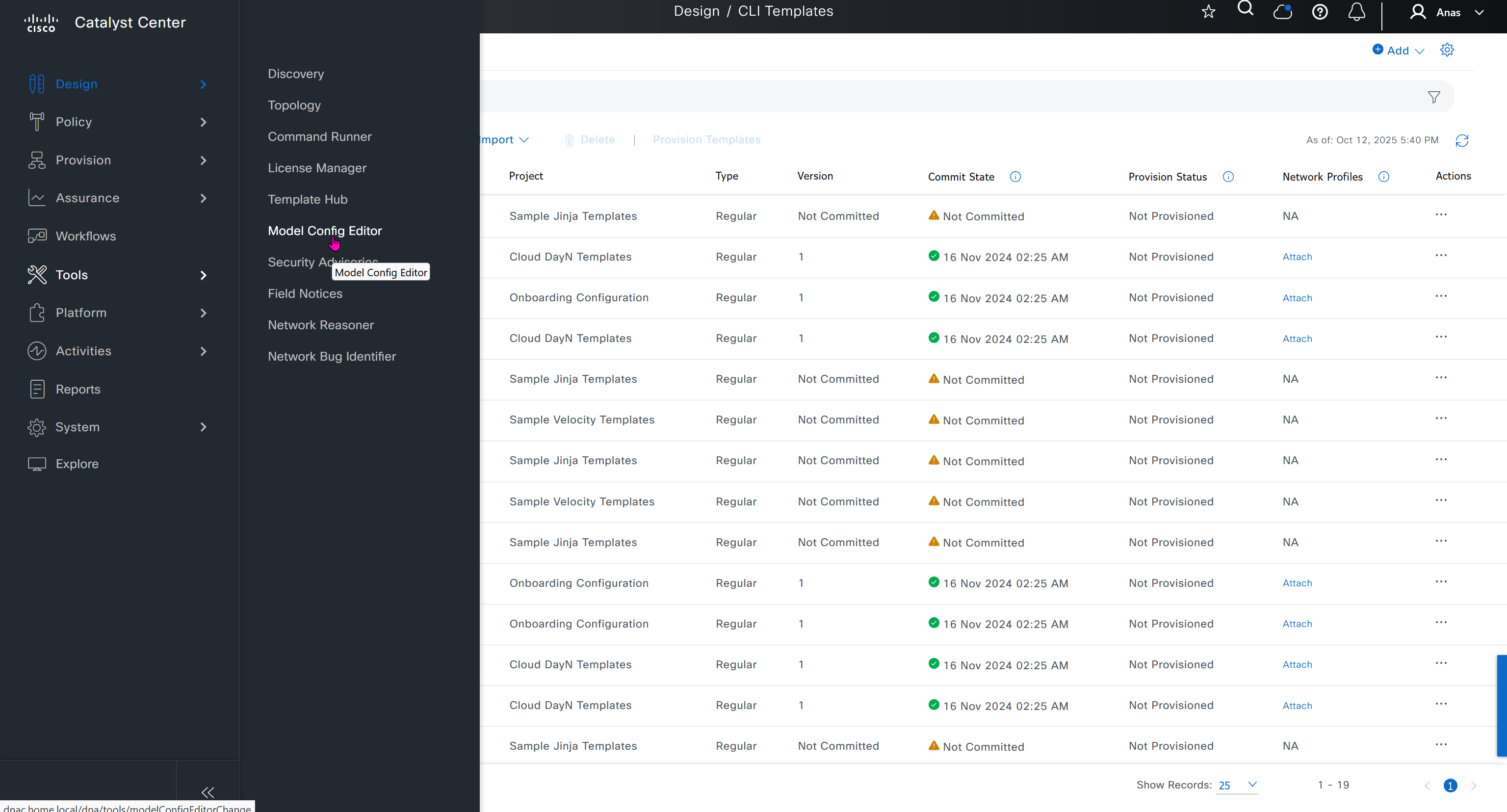
Feature templates are graphical UI based configuration unlike CLI template and they dictate best practice rather than manual CLI based templates, this makes configuration like Meraki but we only have this wireless at the moment
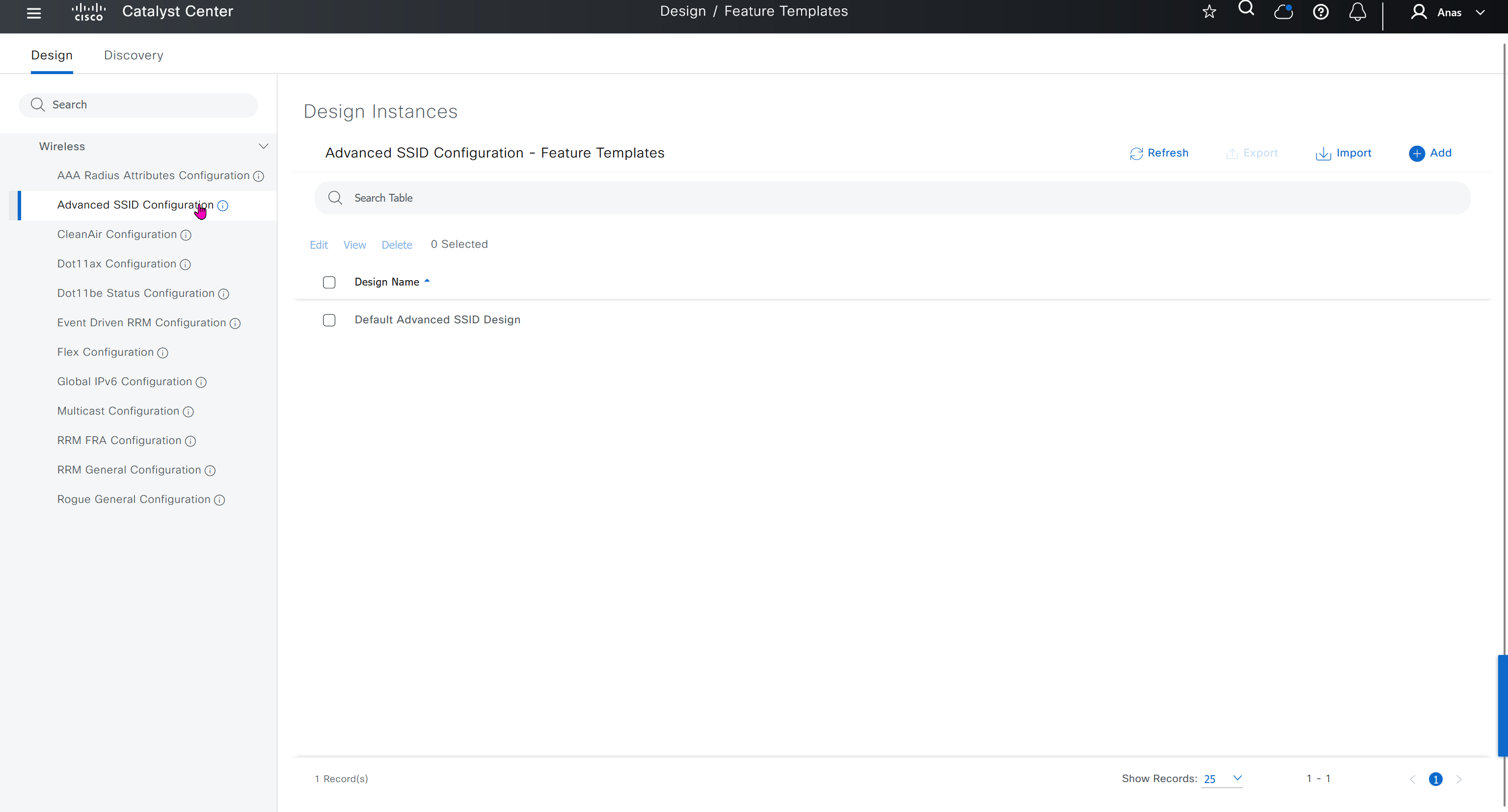
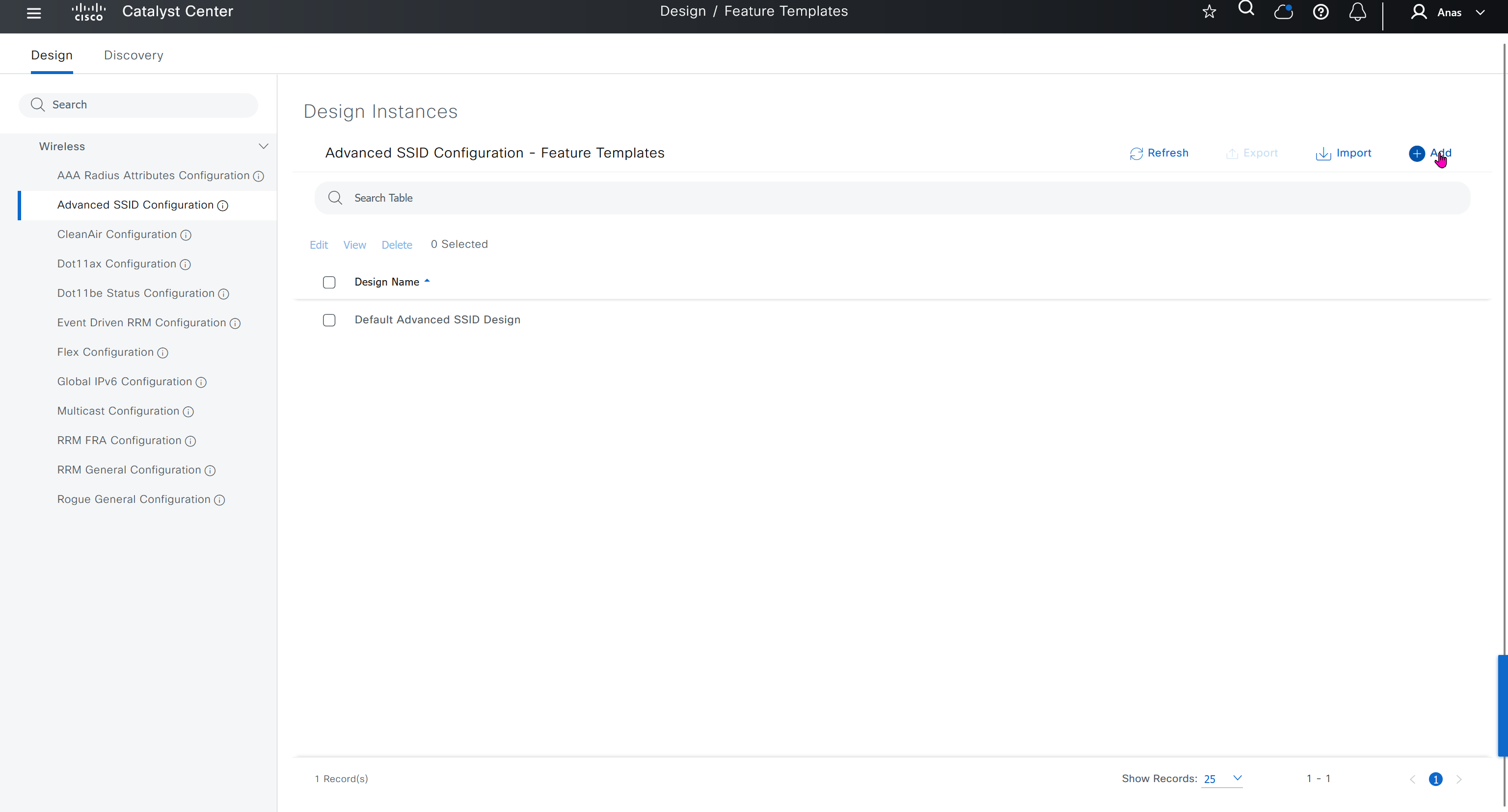
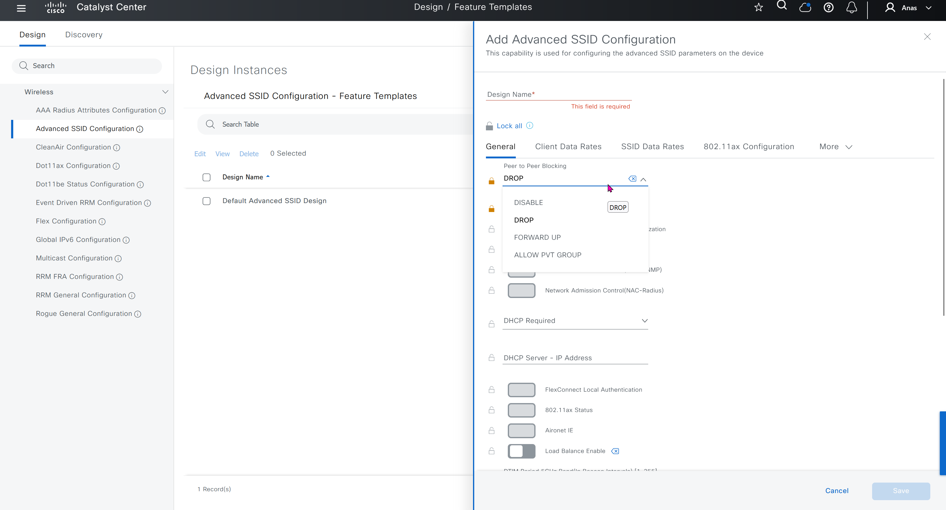
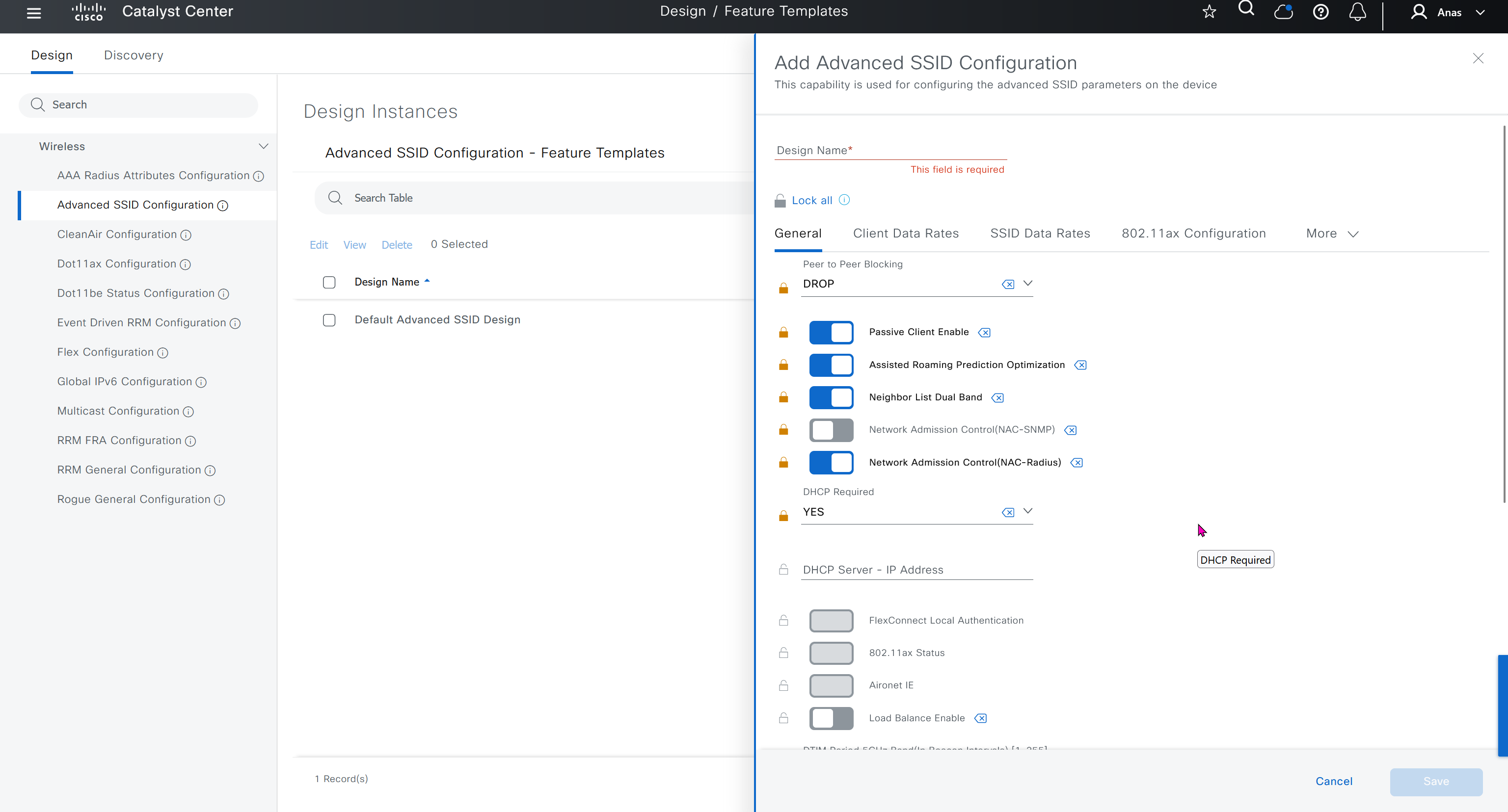
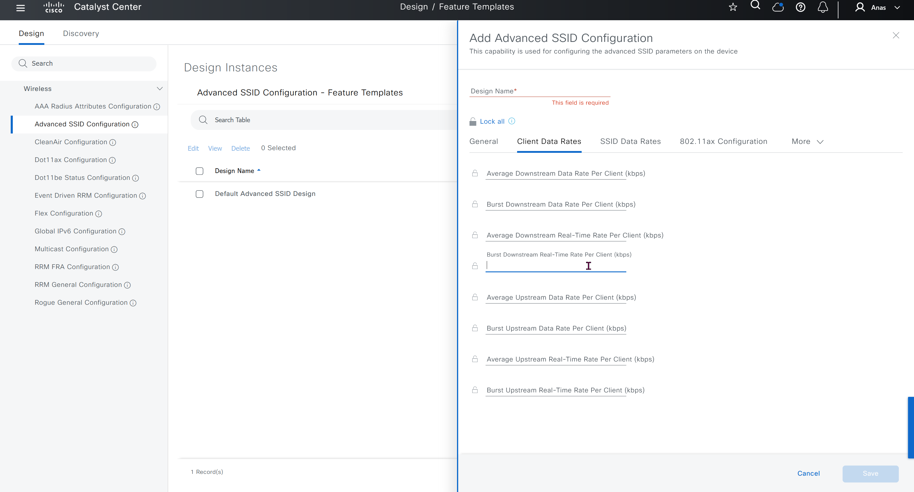
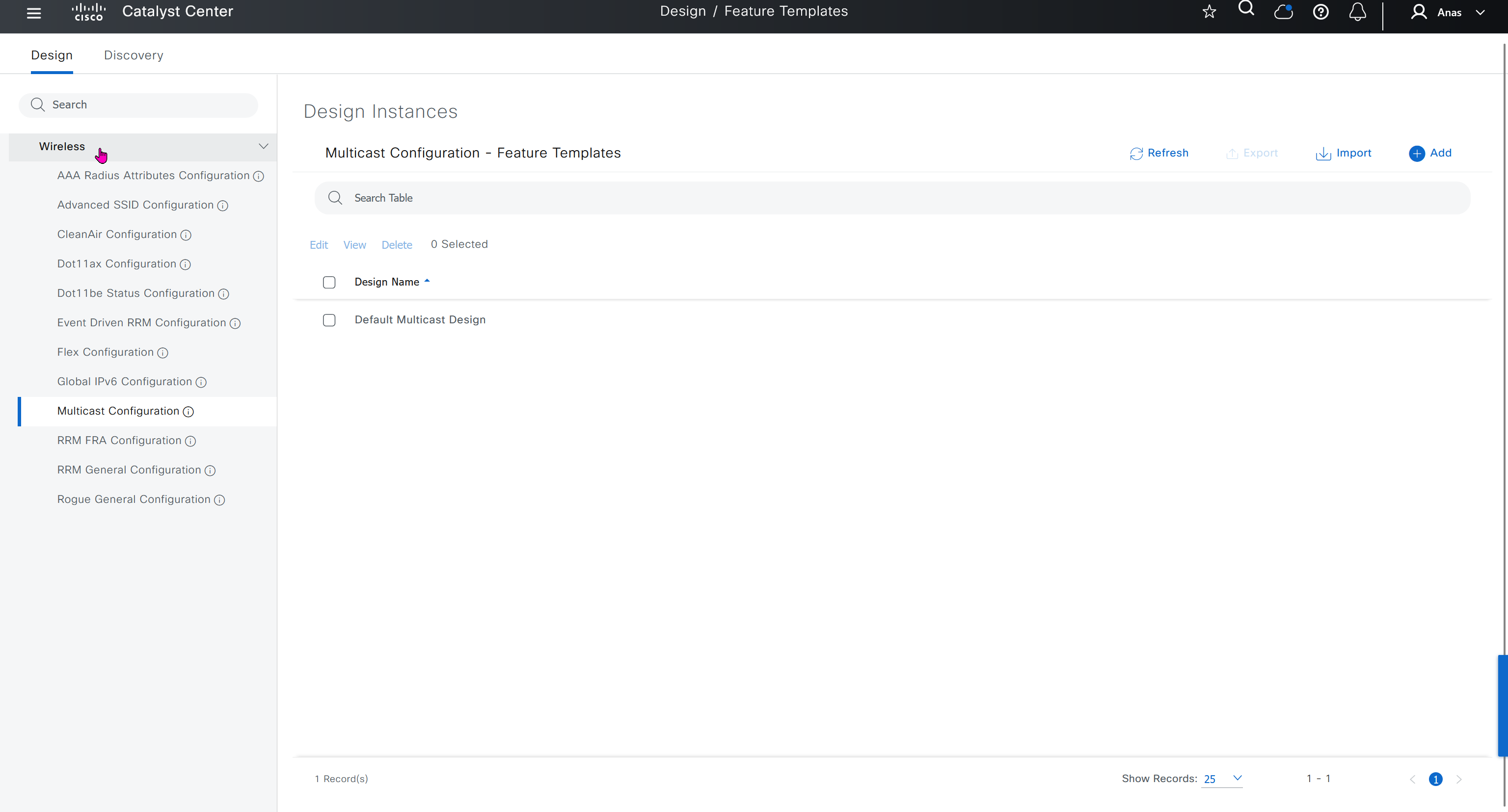

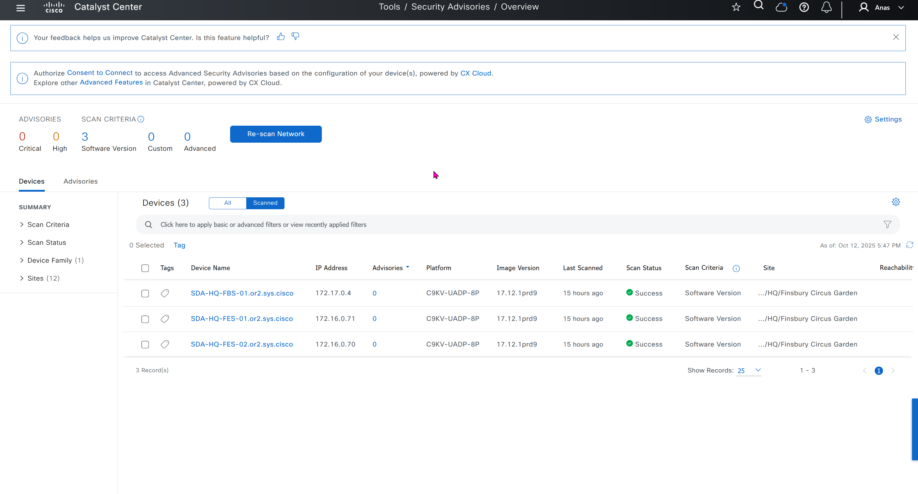
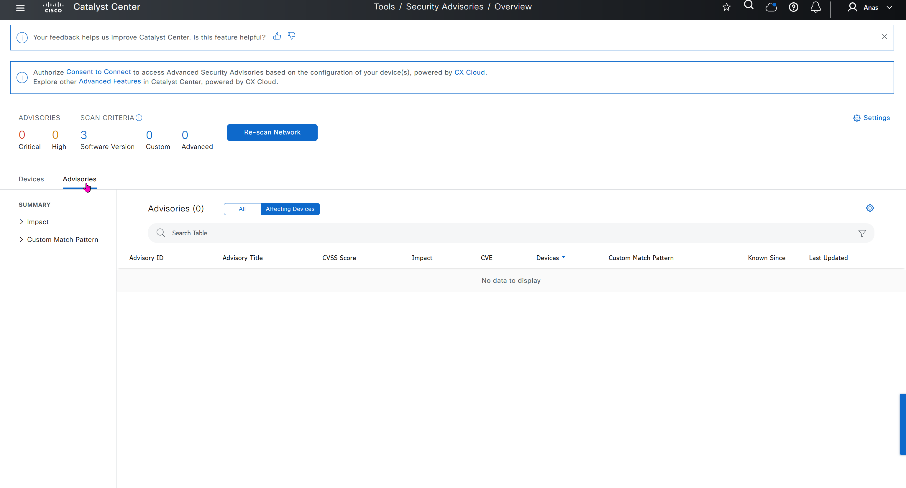
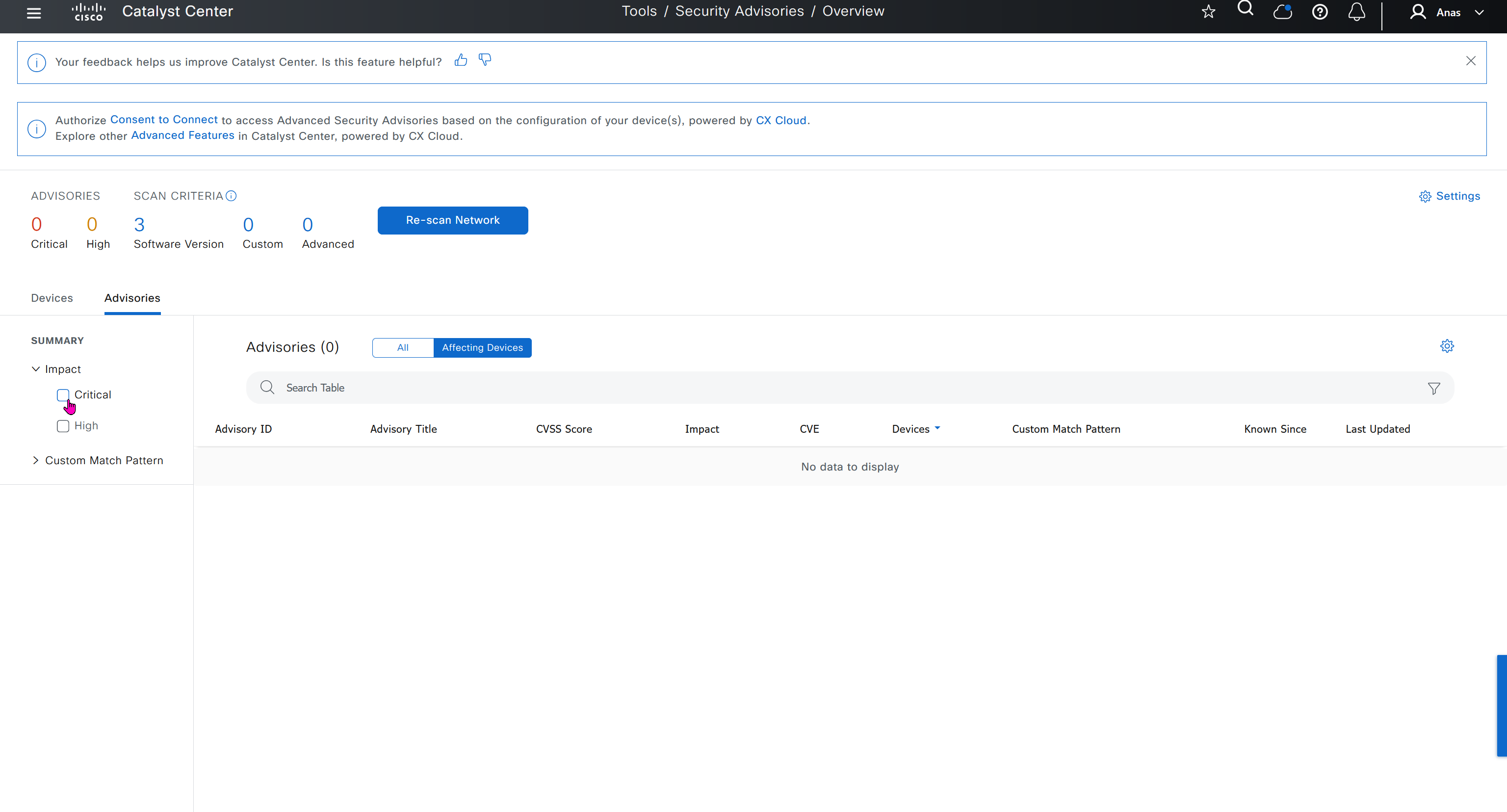
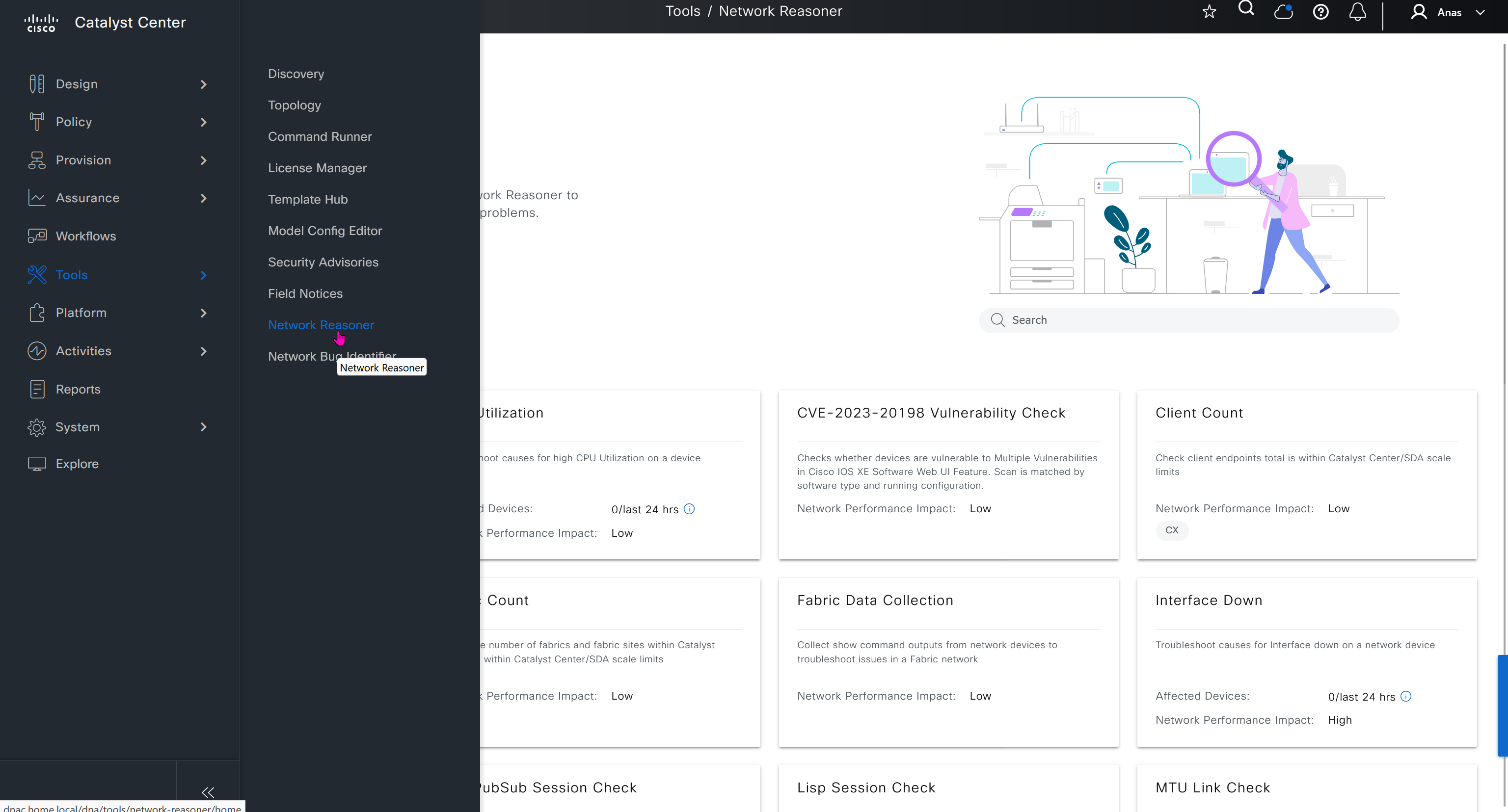
Network reasoner helps troubleshoot offered issues in Network reasoner dashboard

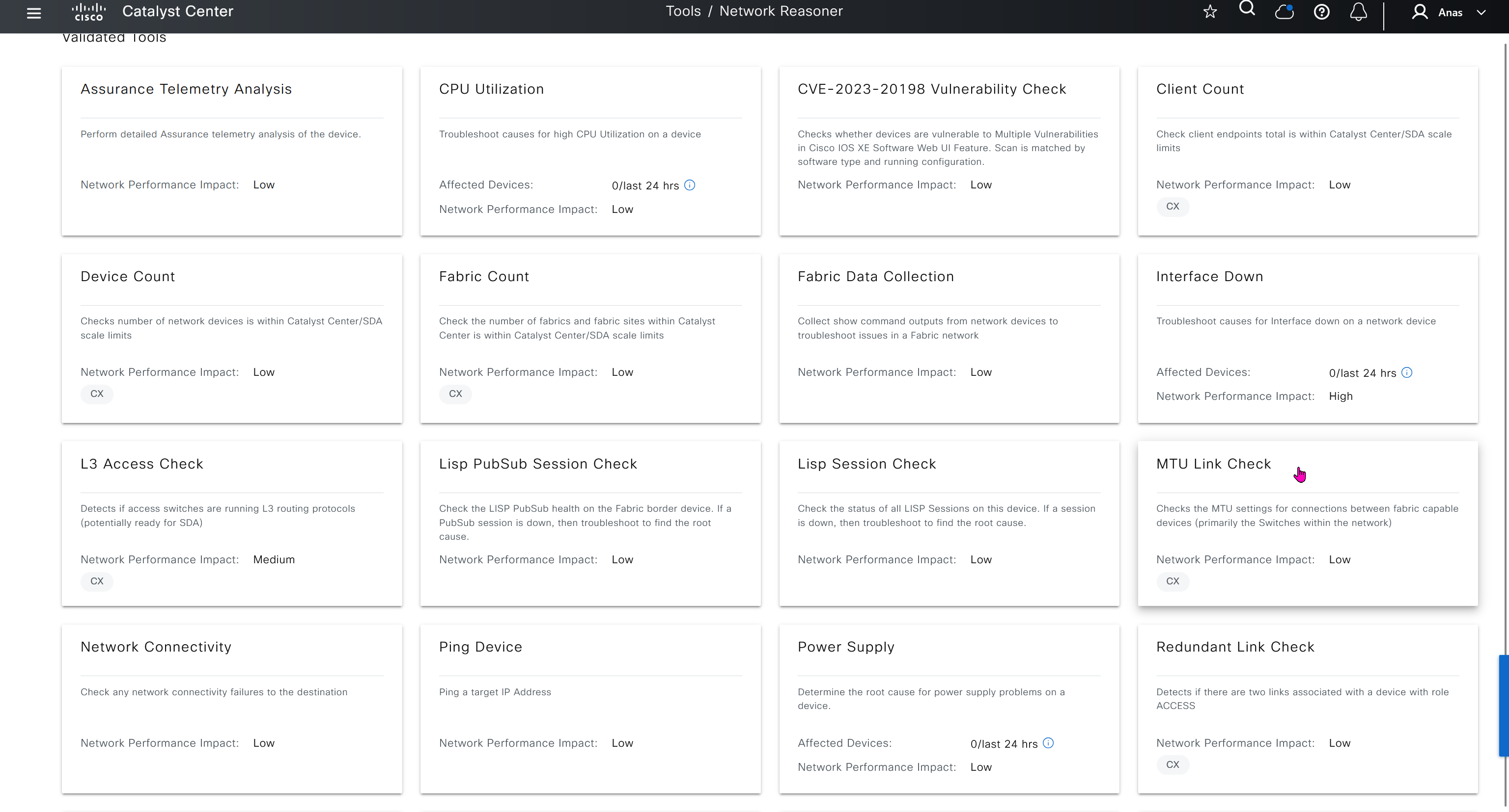
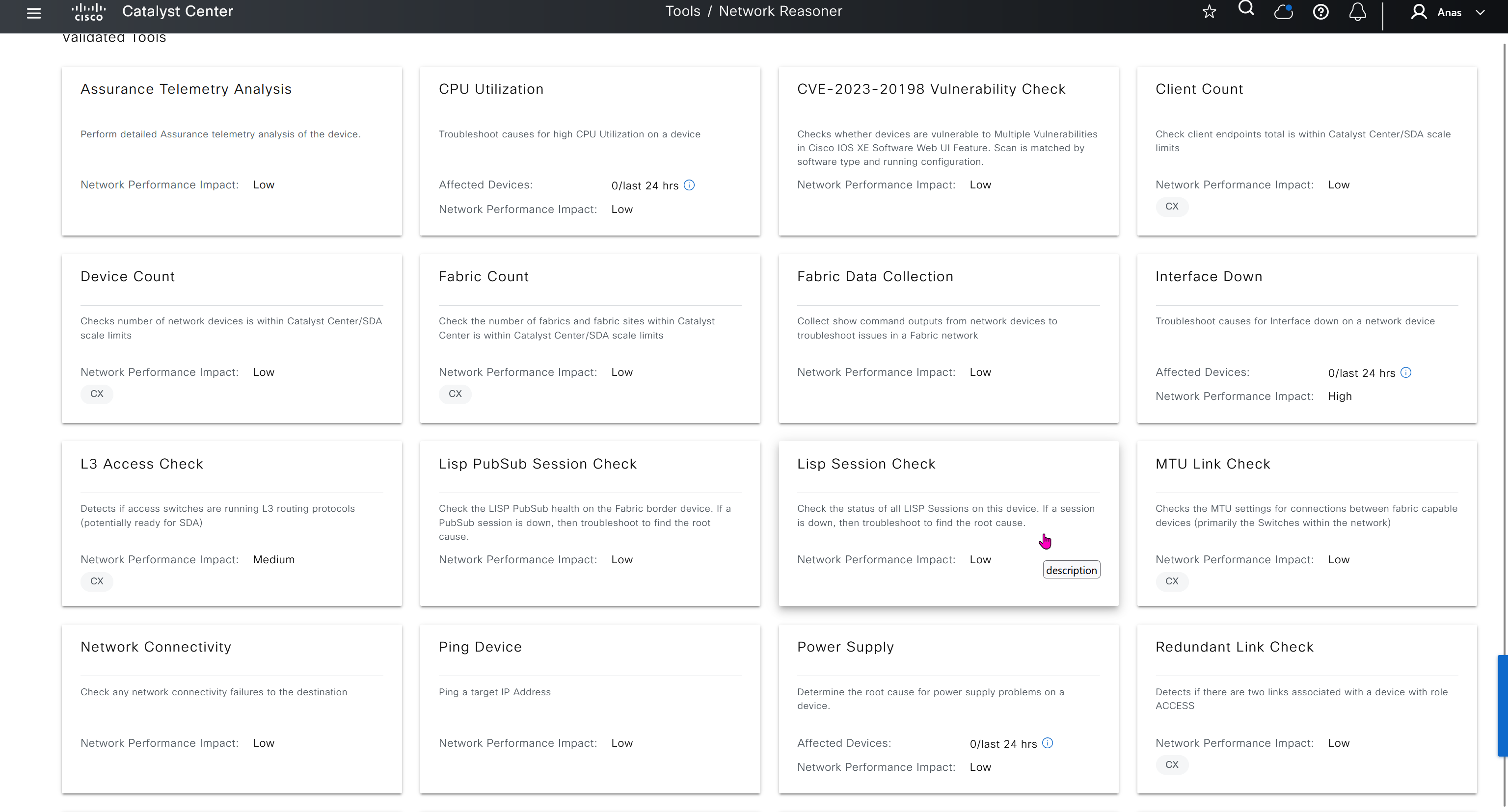
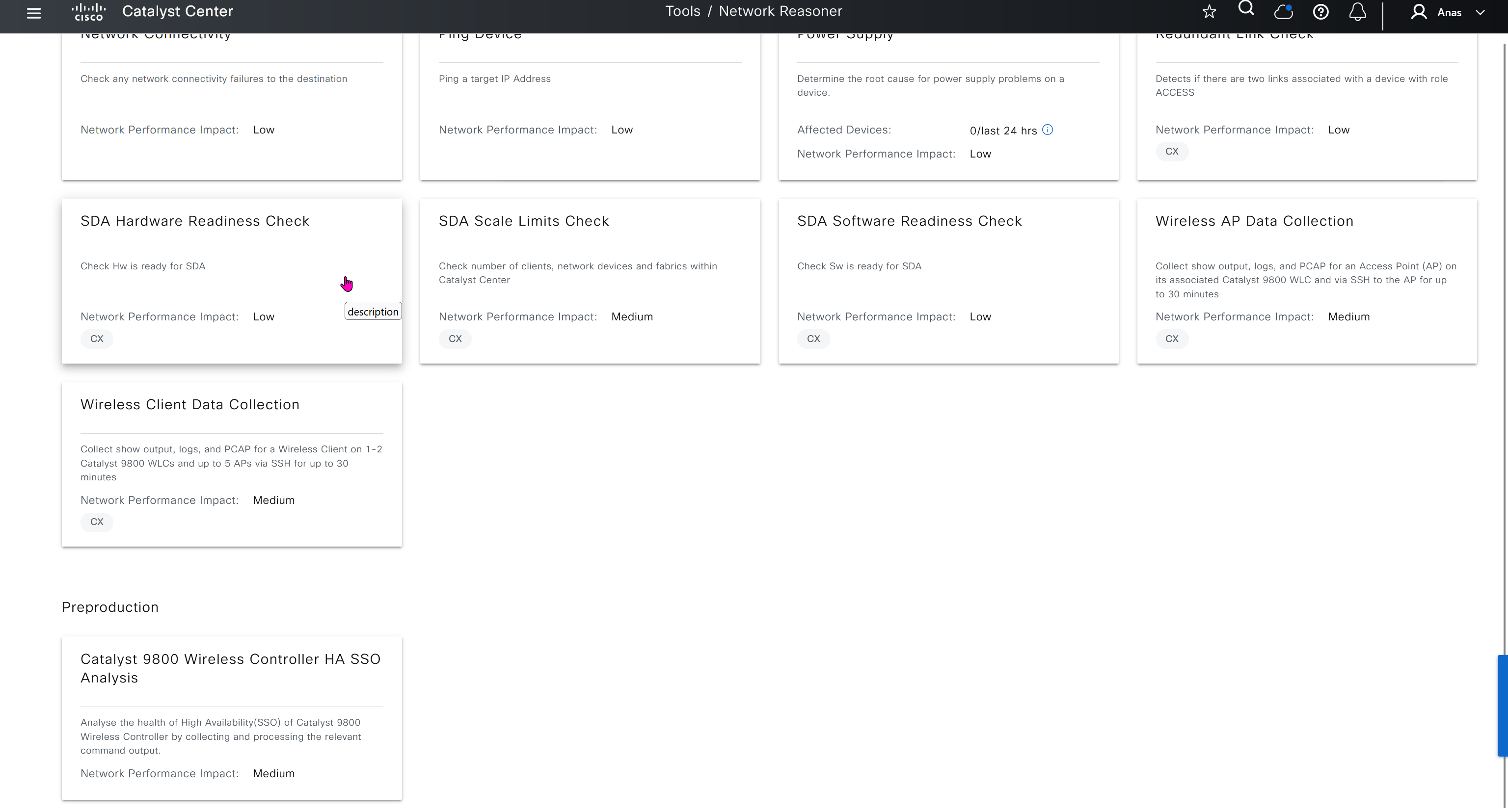
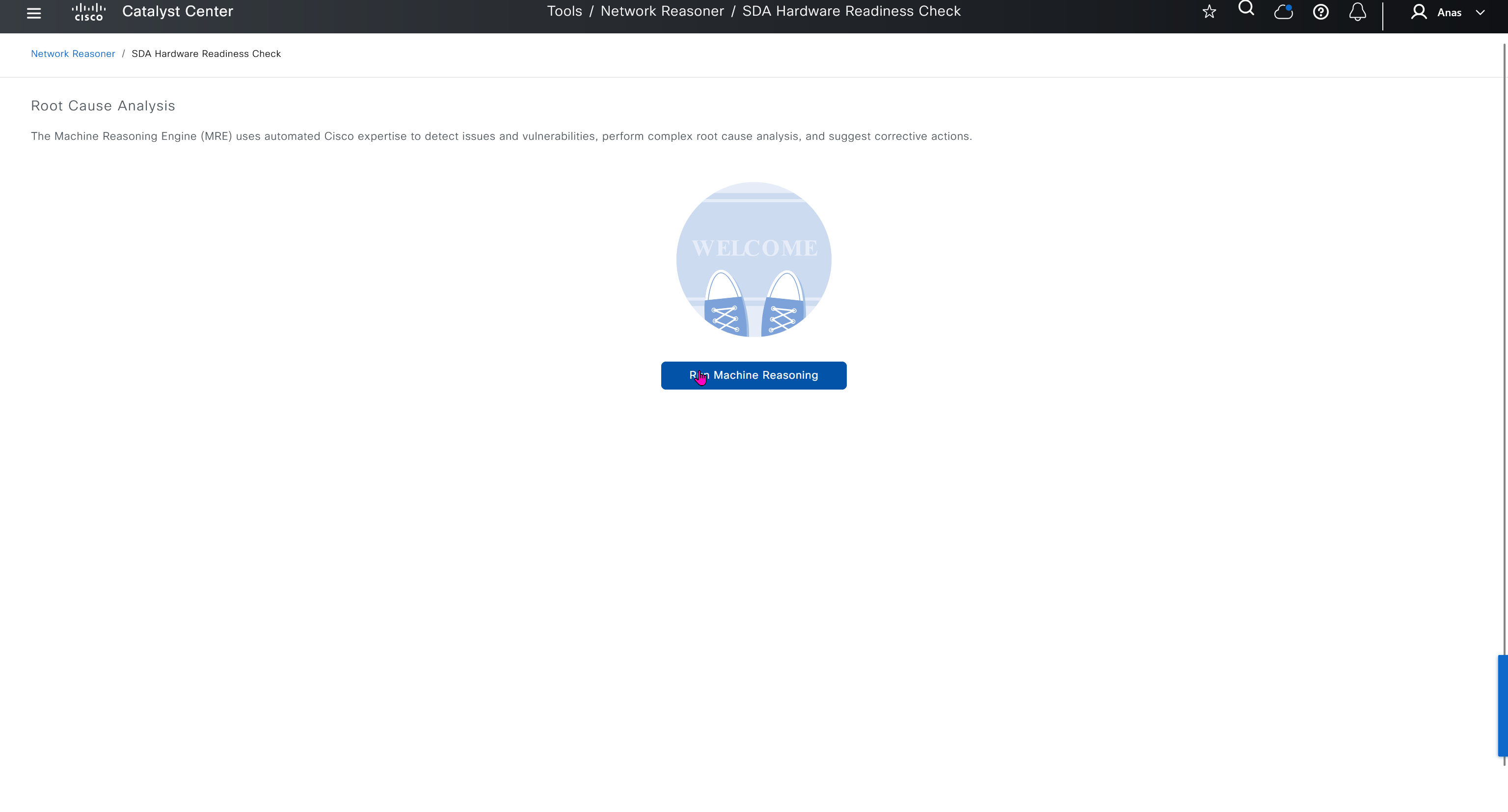
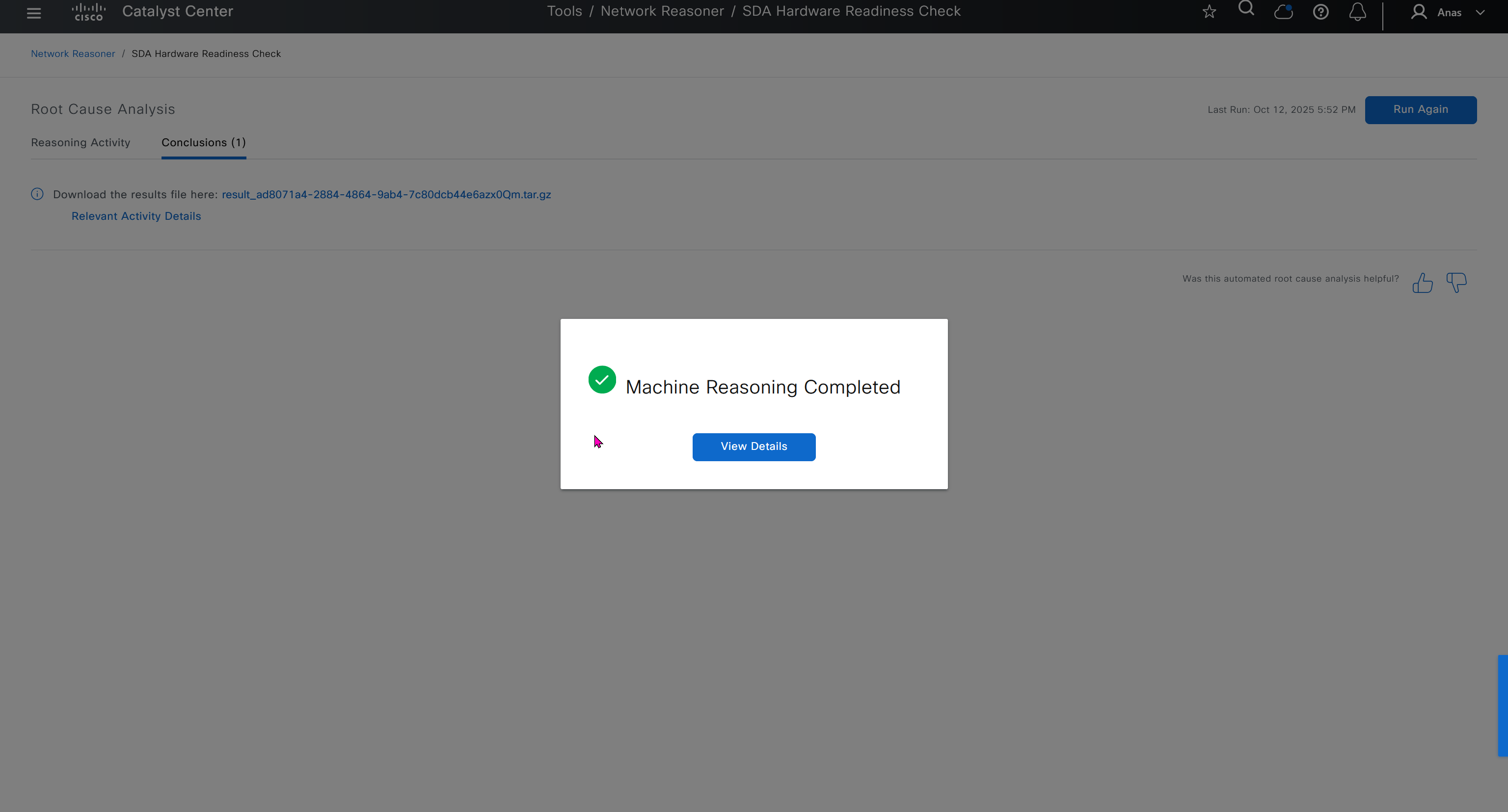
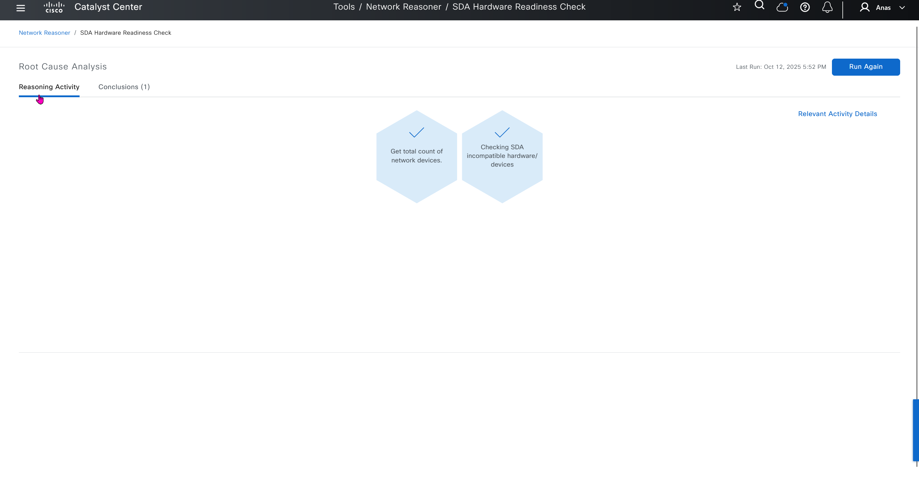
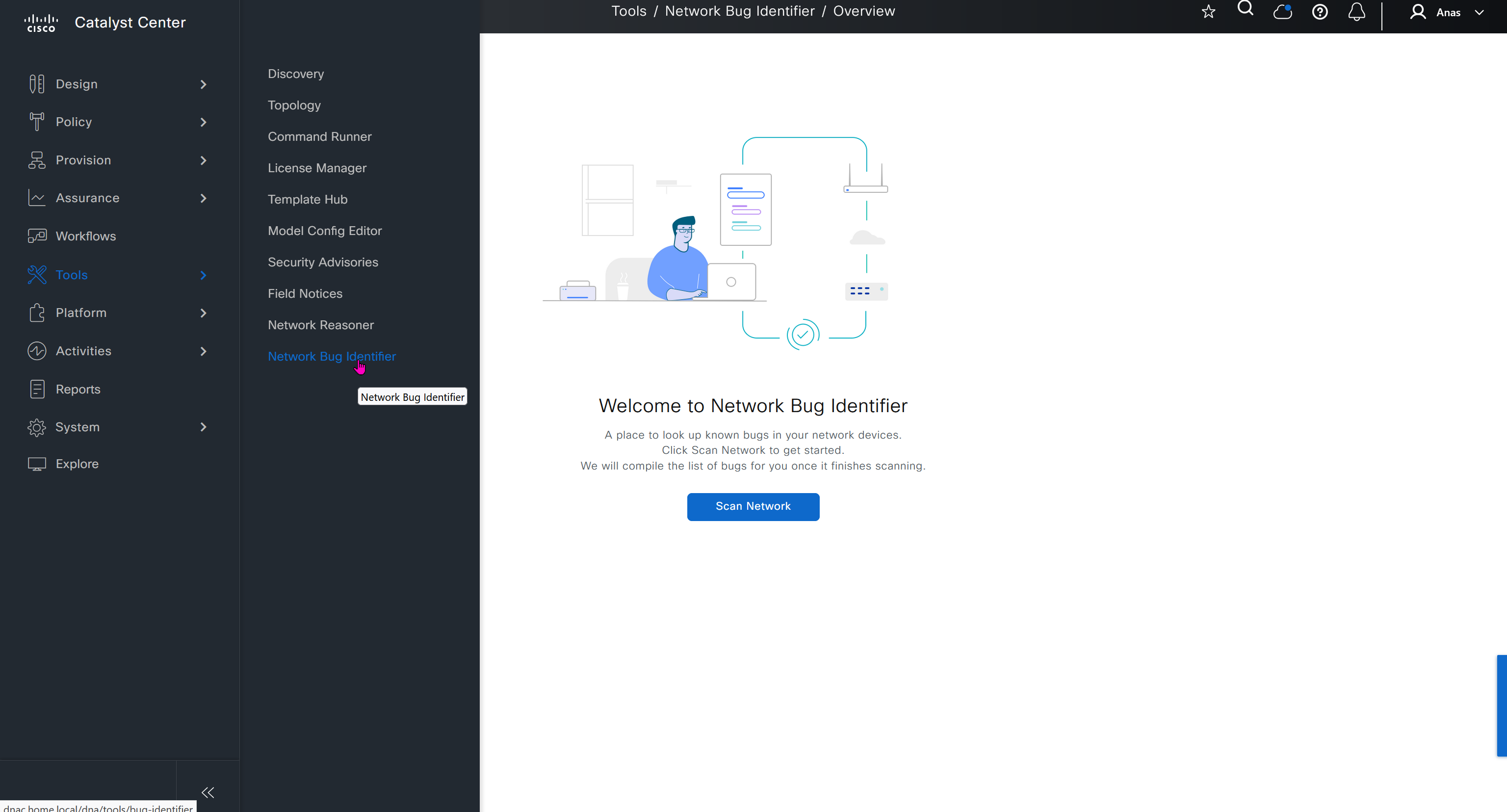
Platform section allows us to use DNAC API for automation and API interaction, it is also used to install device packs for non Cisco devices and also 3rd Party integration such as service now

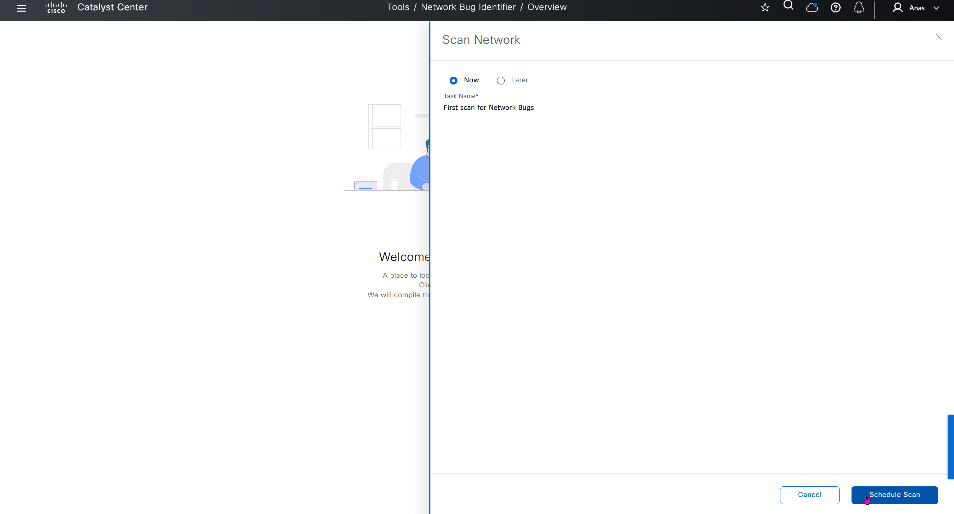
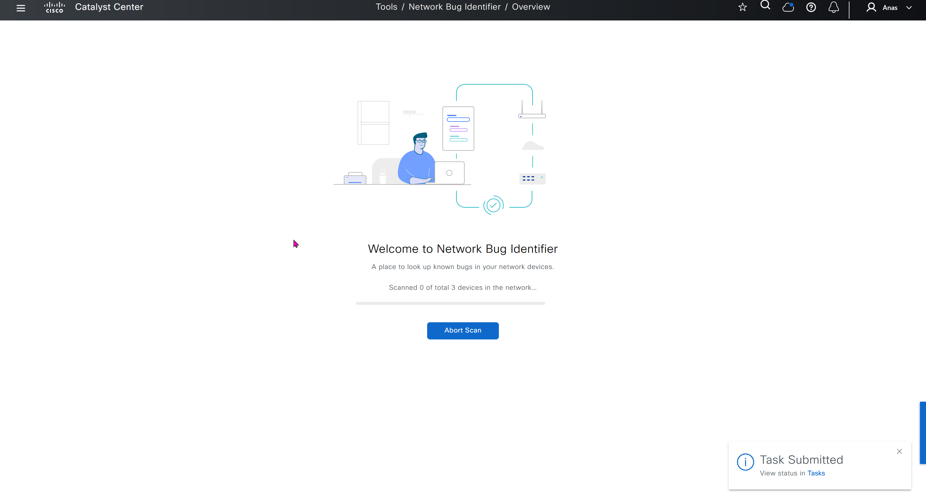


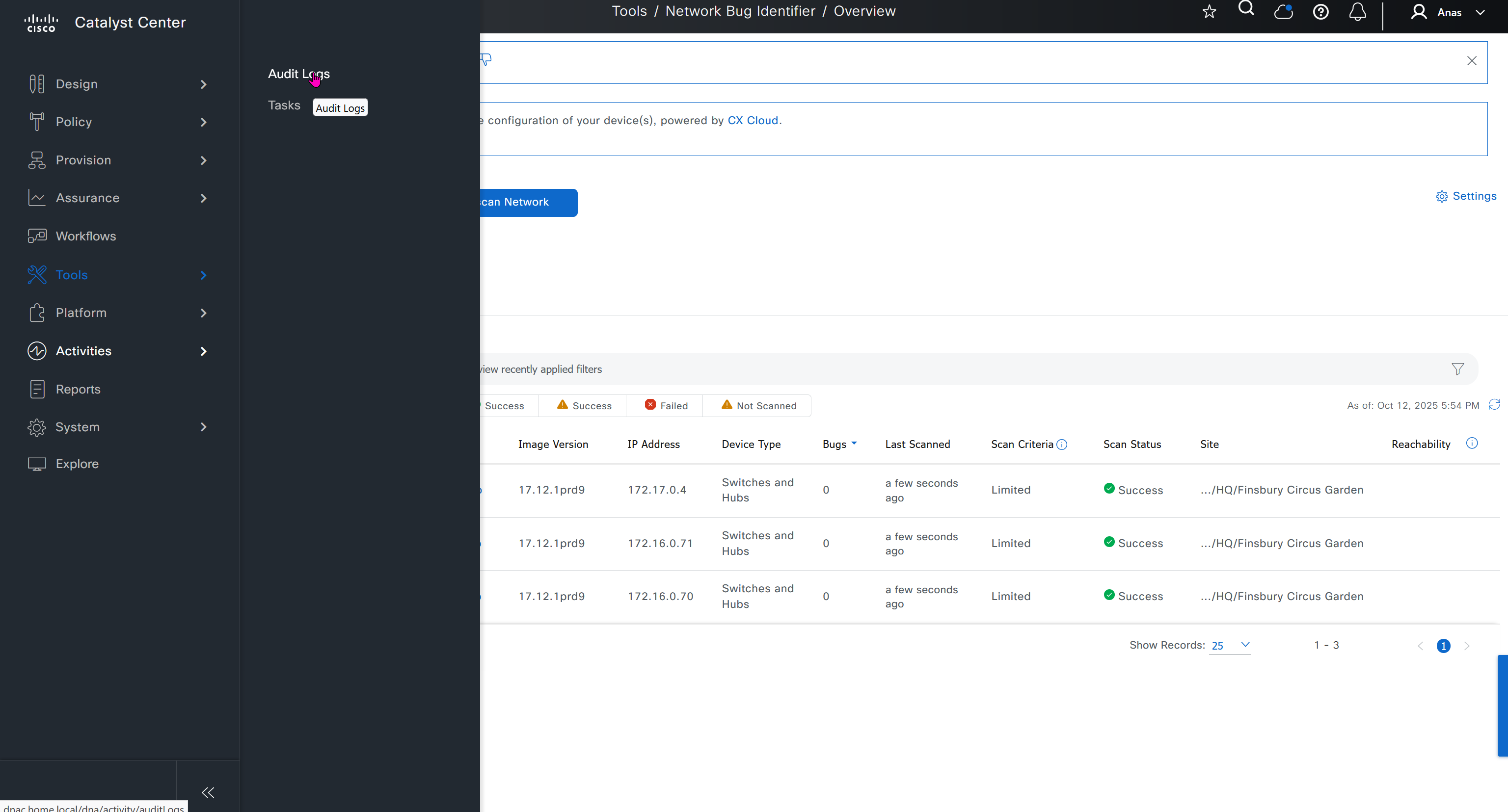
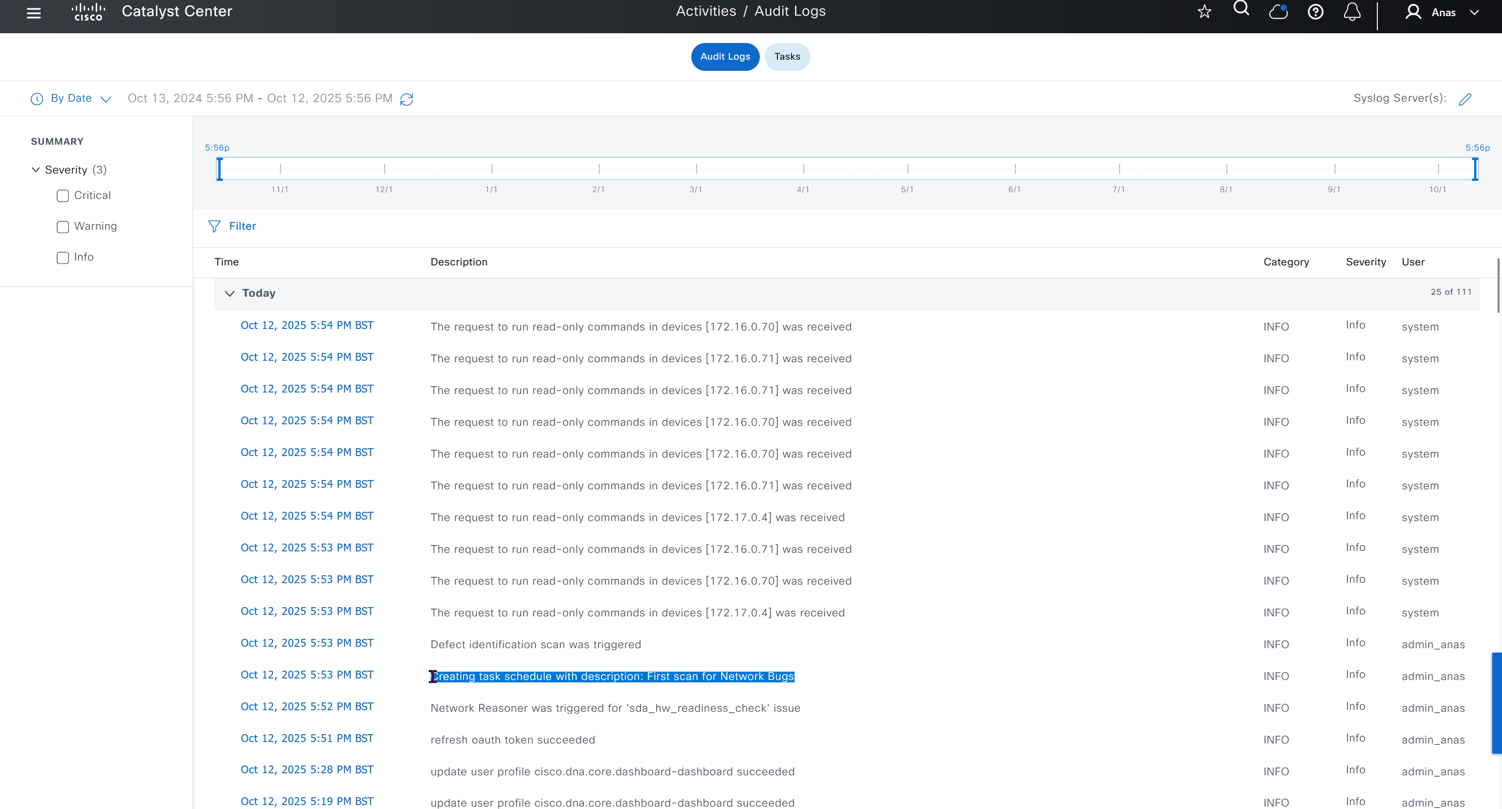


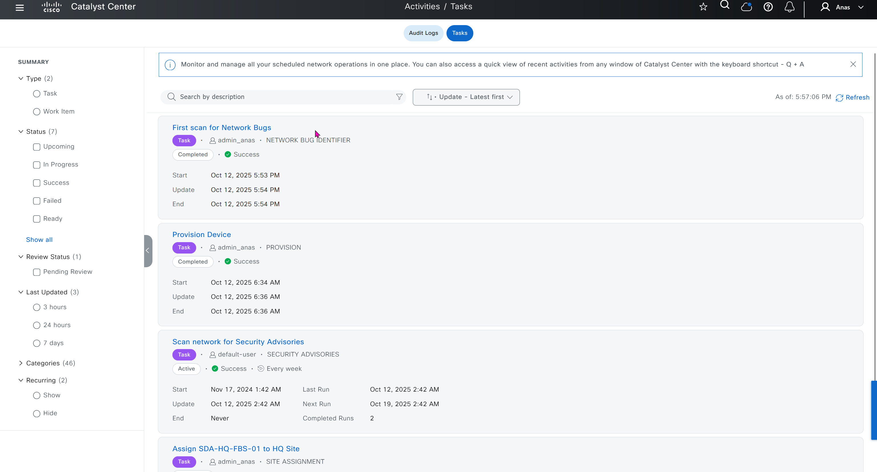
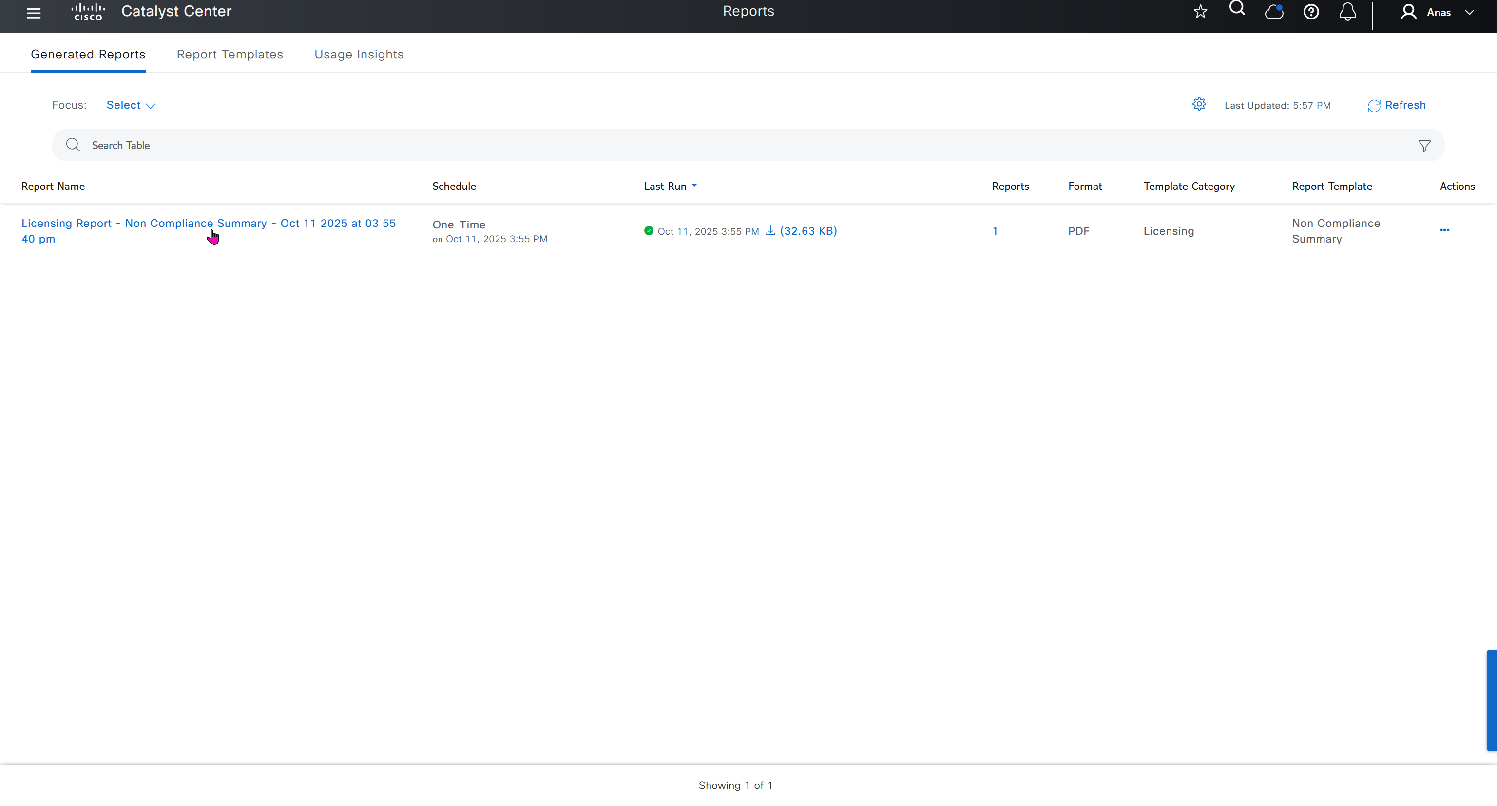

DNAC comes with report templates
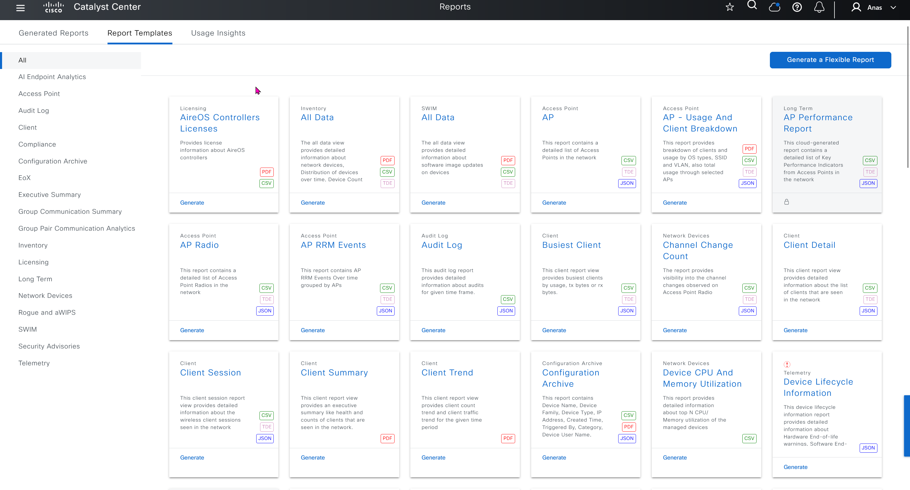
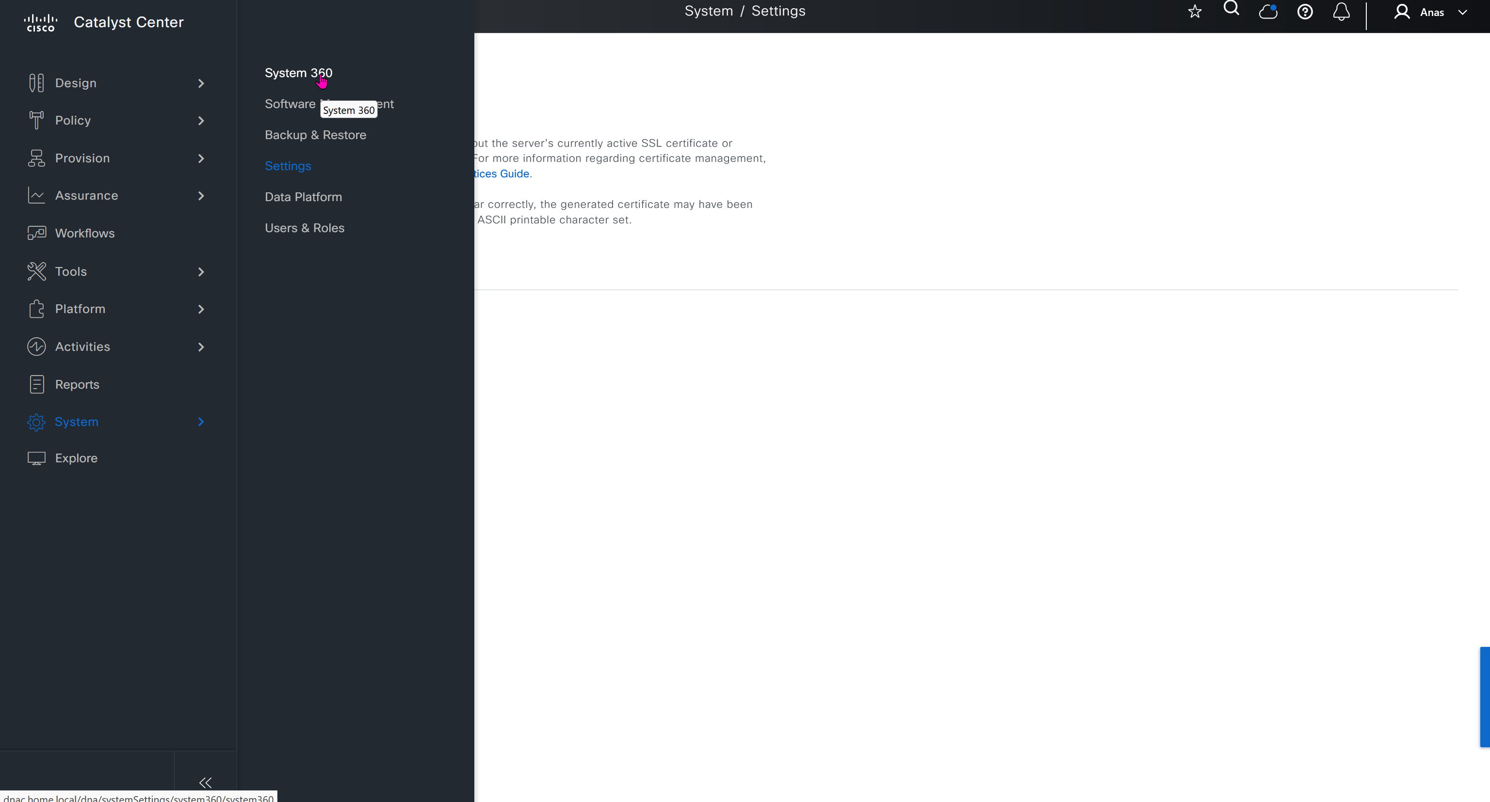
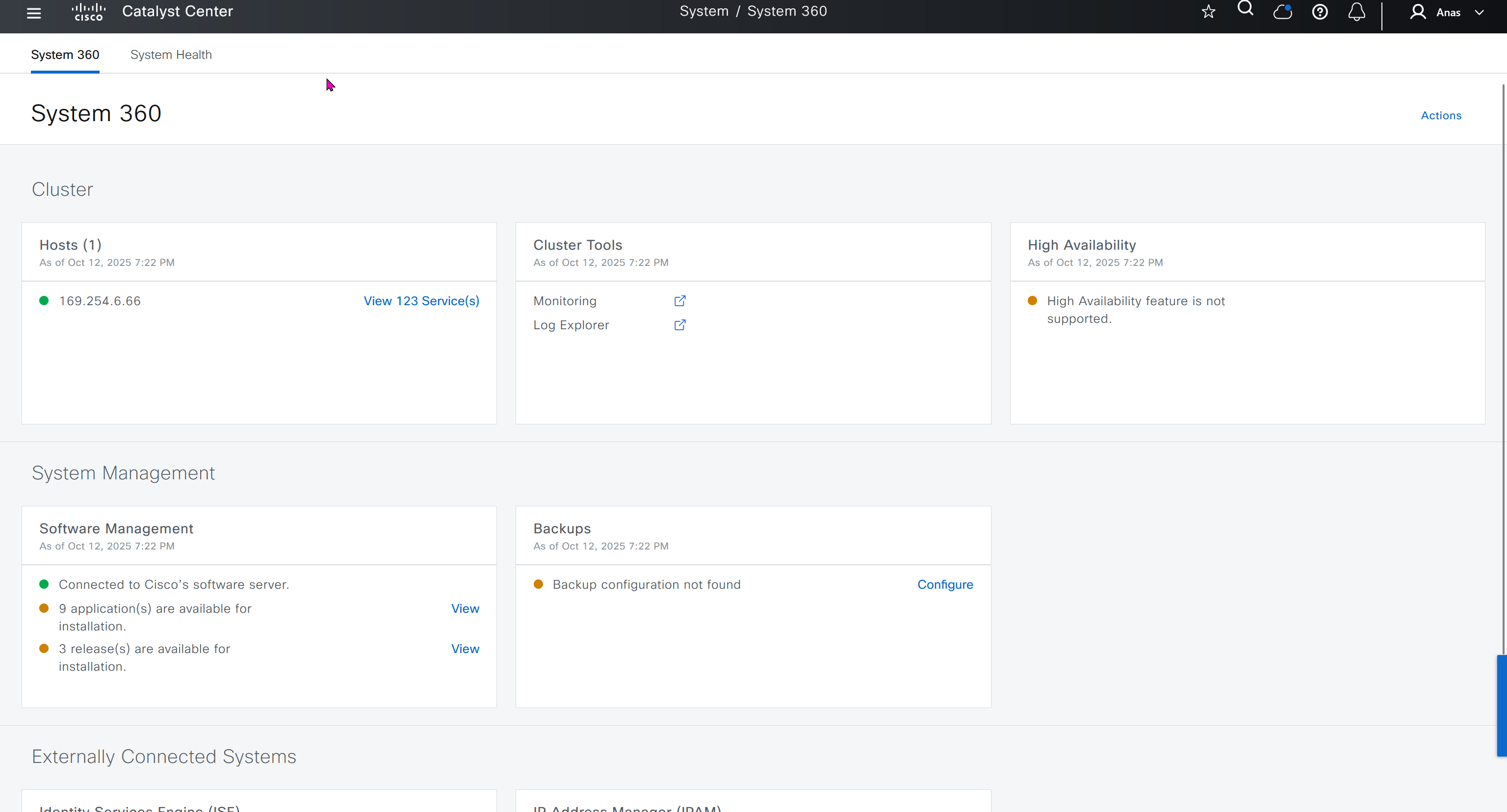
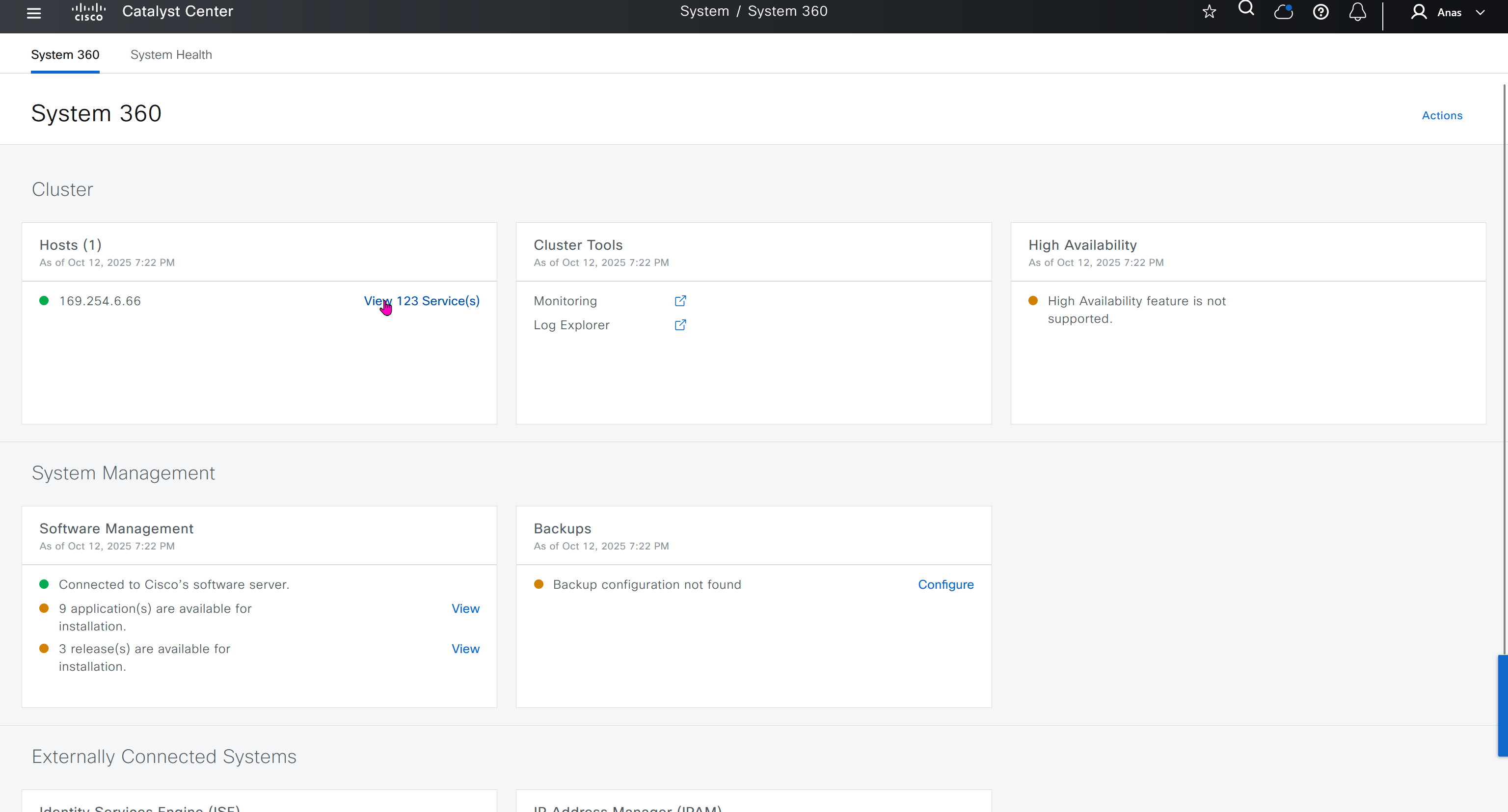
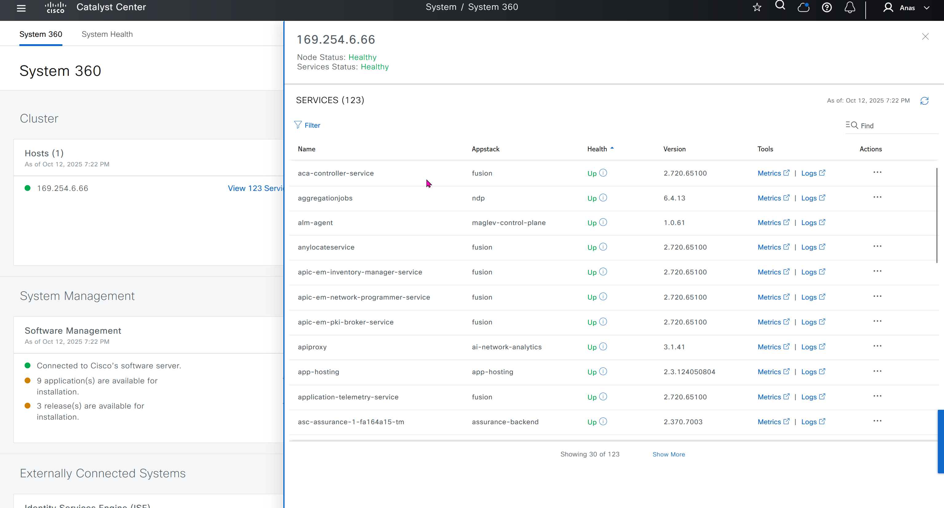
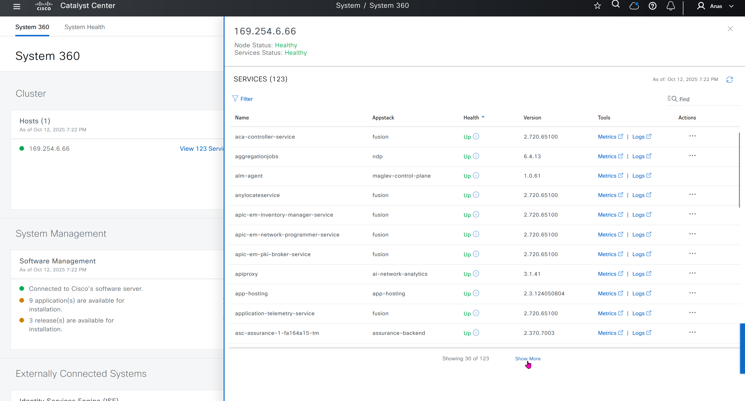

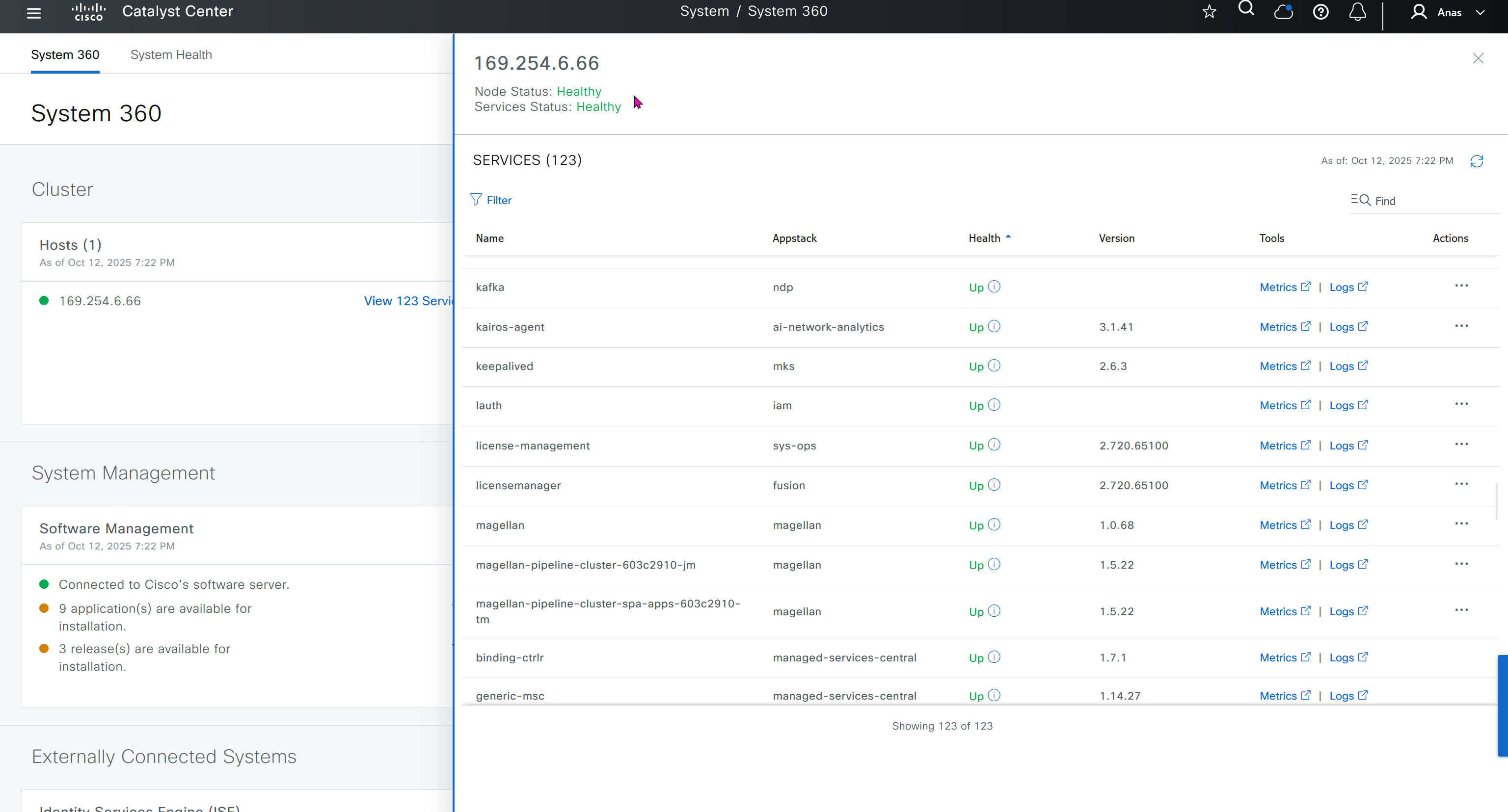
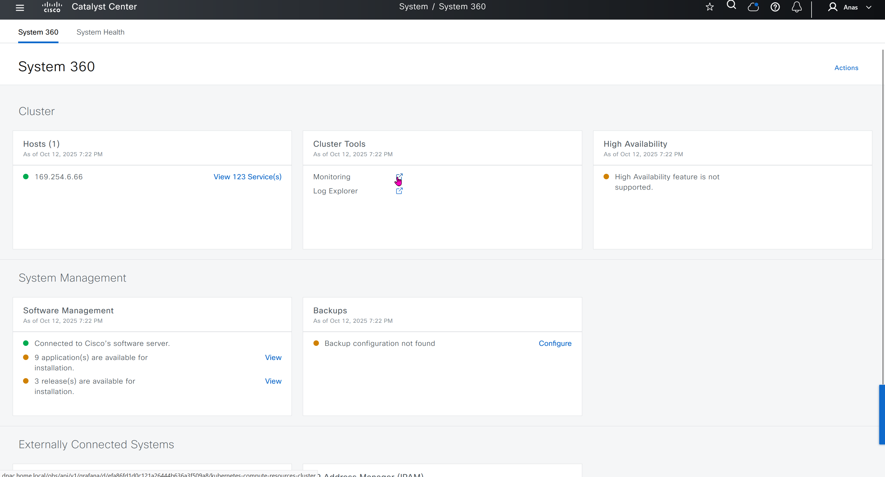


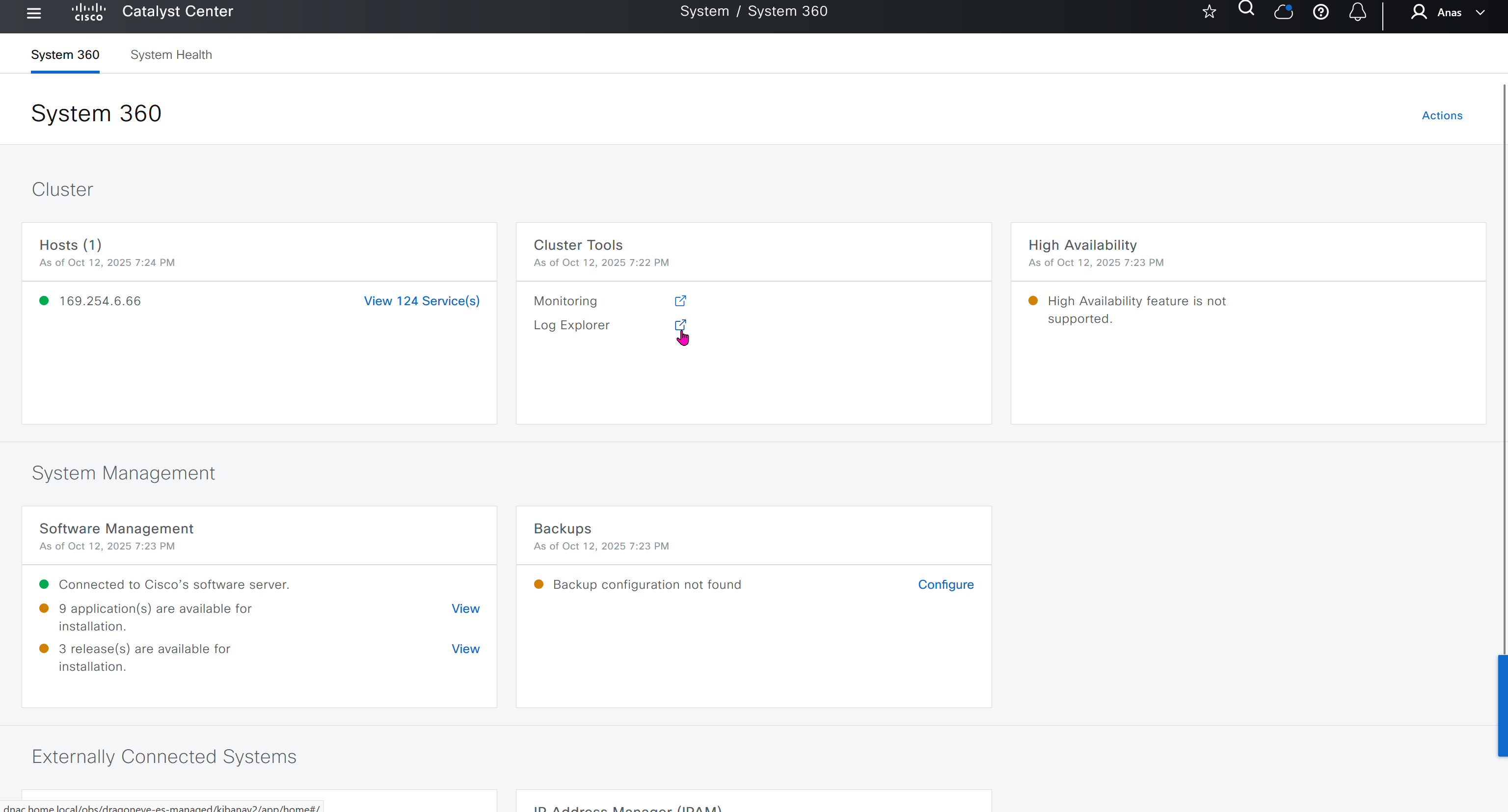
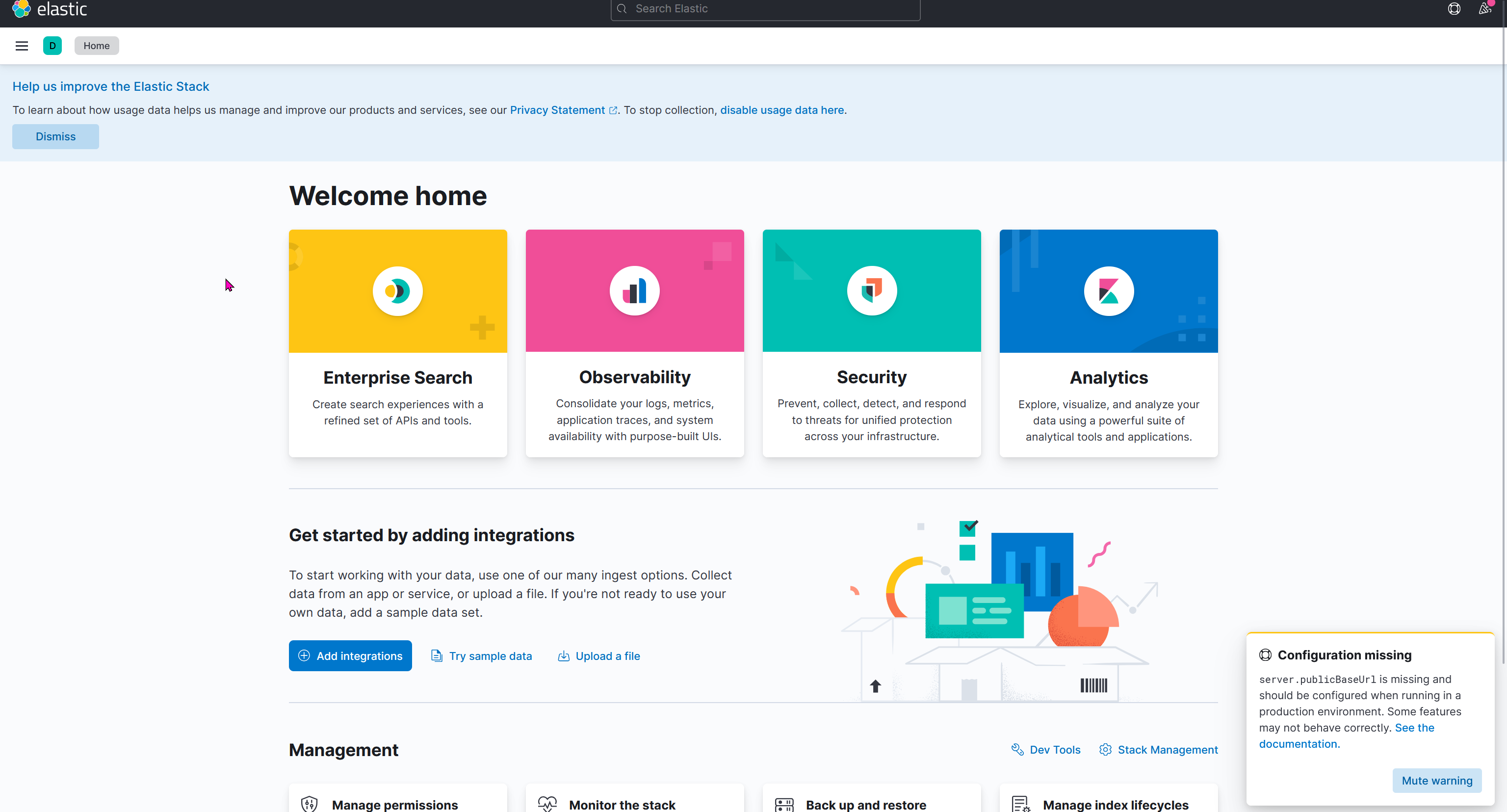


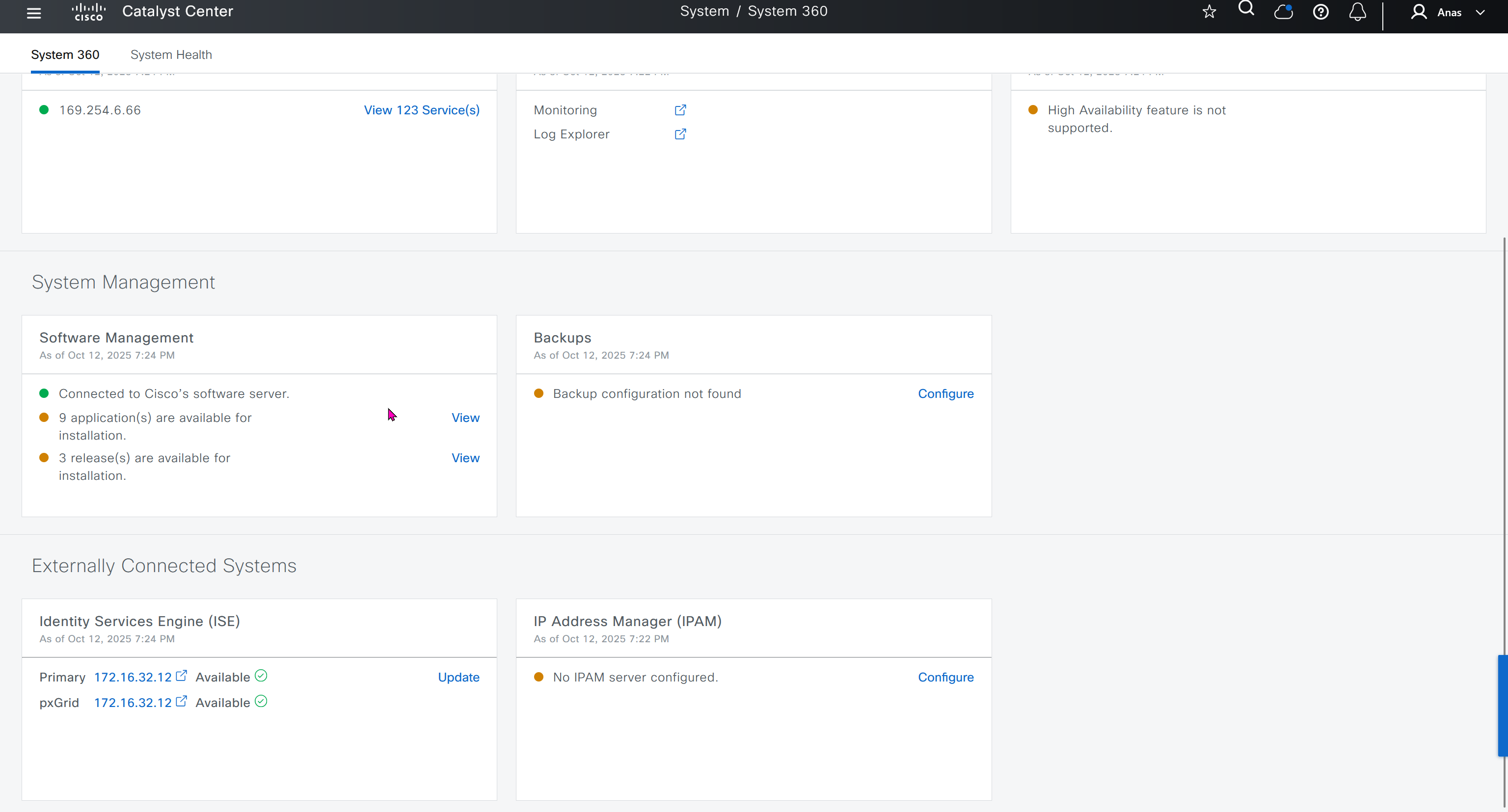

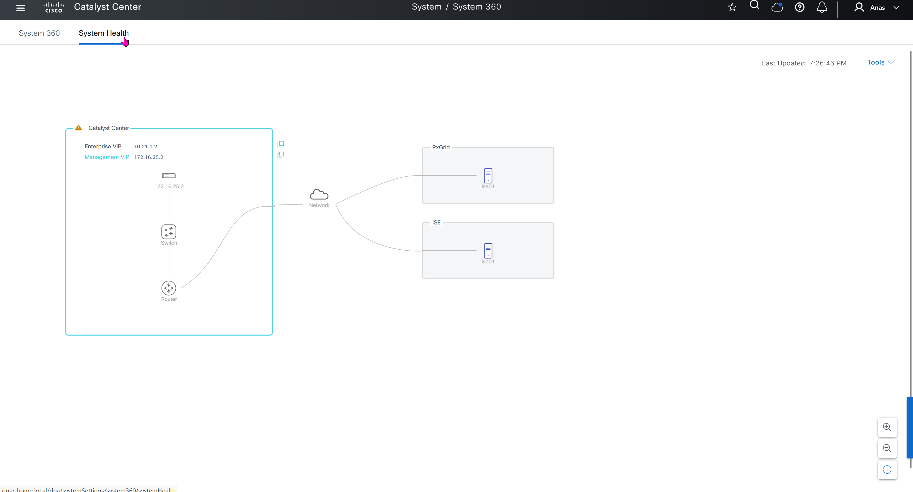

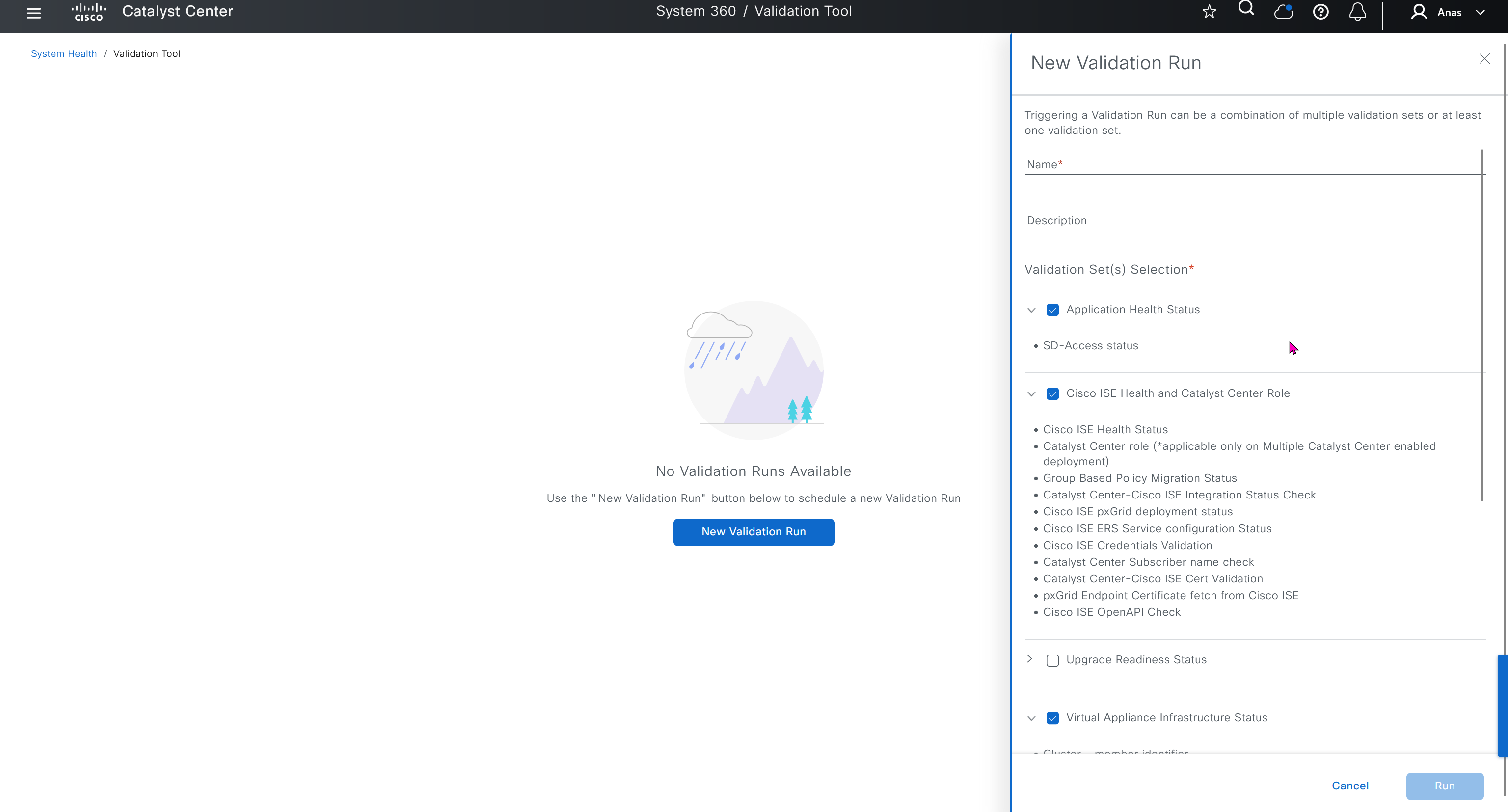
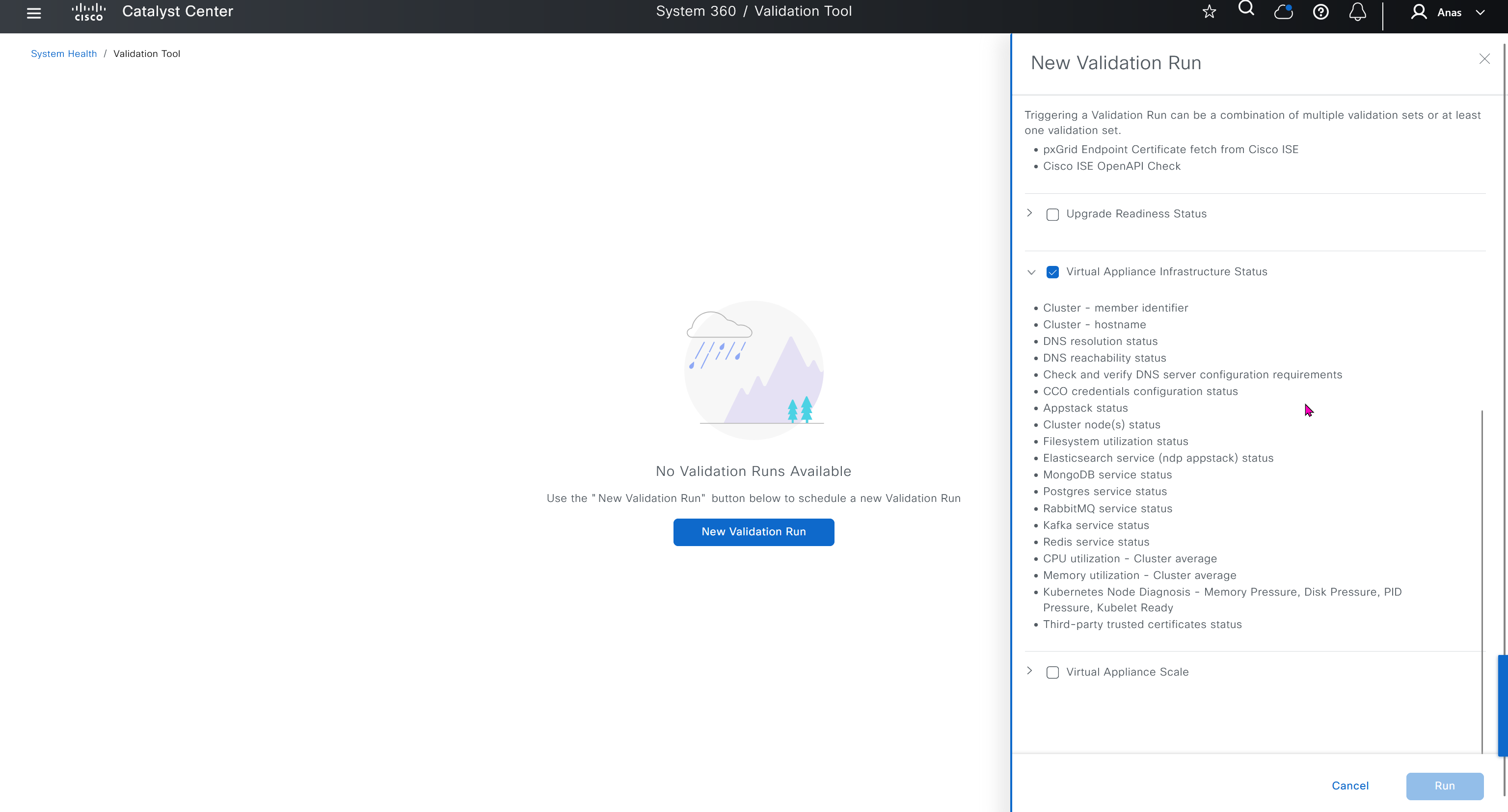
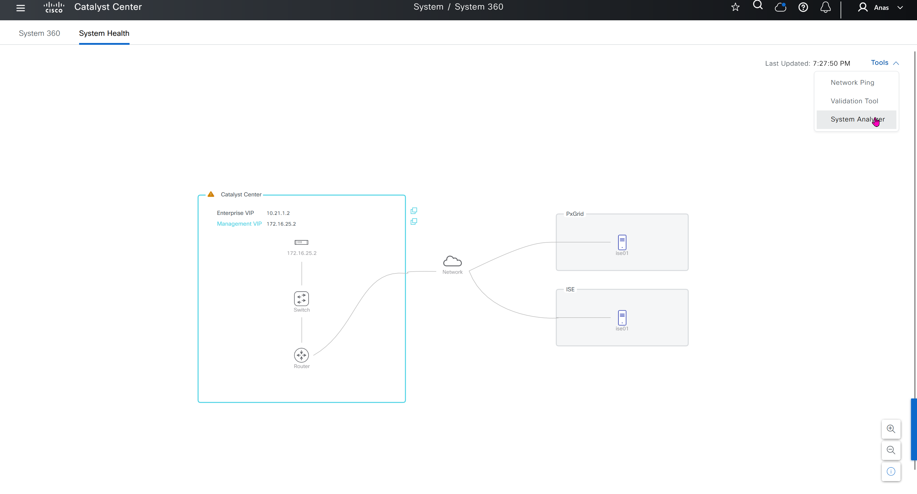

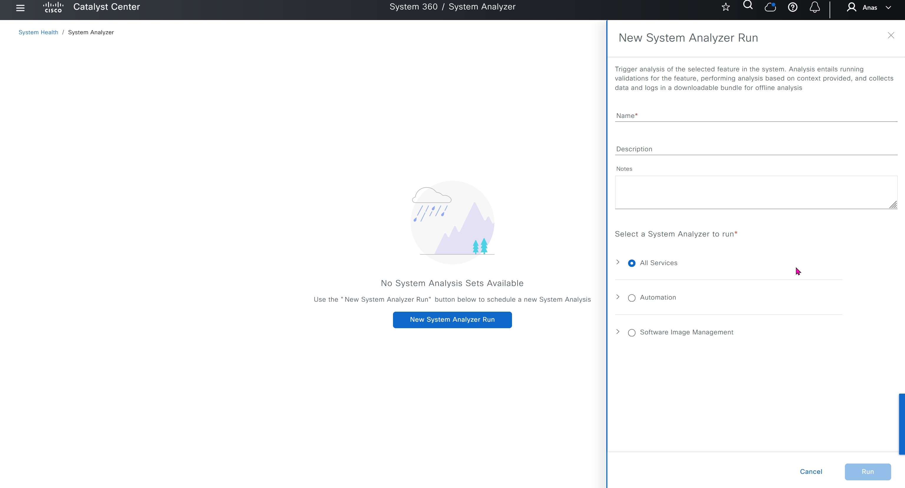
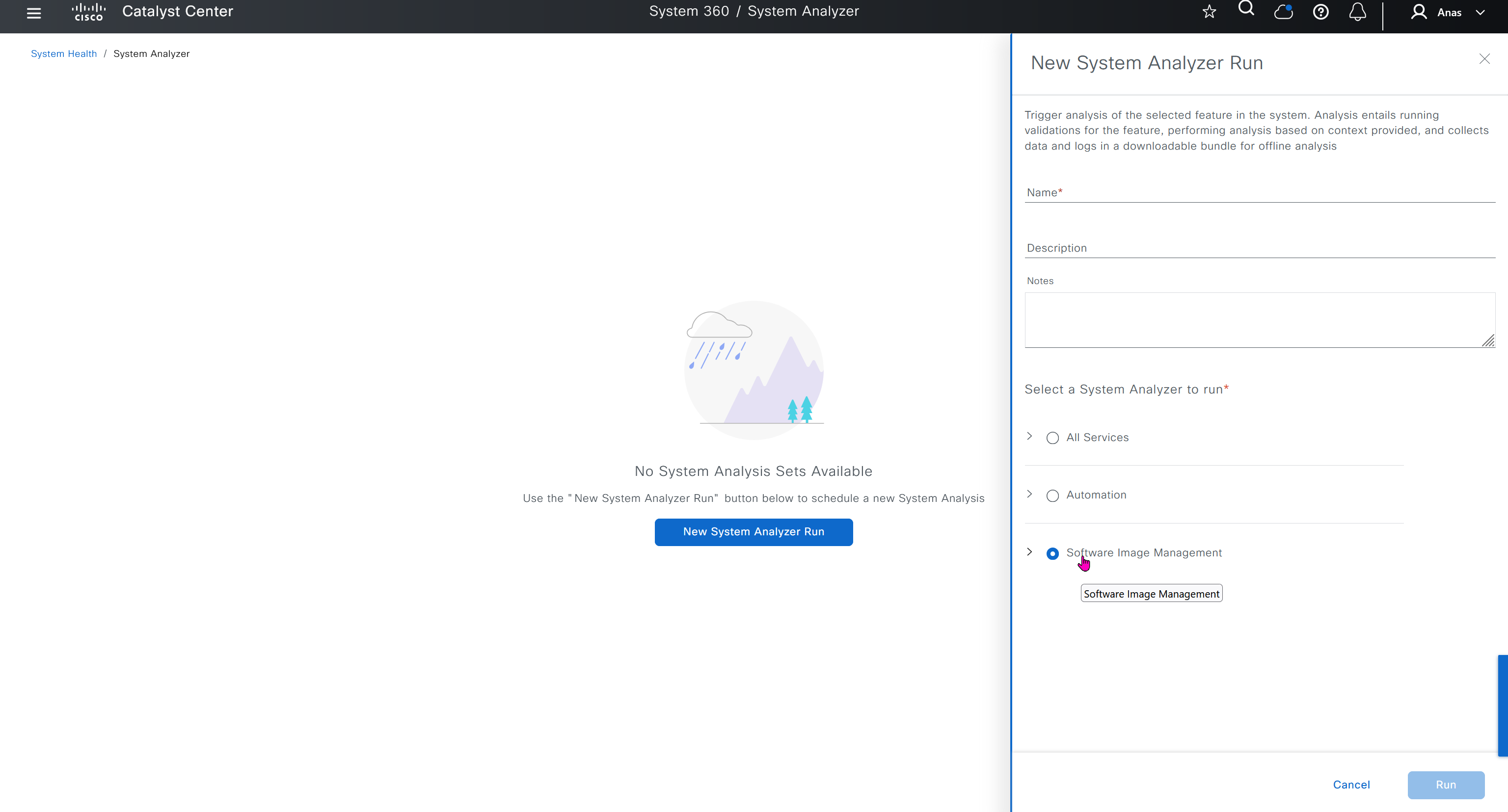
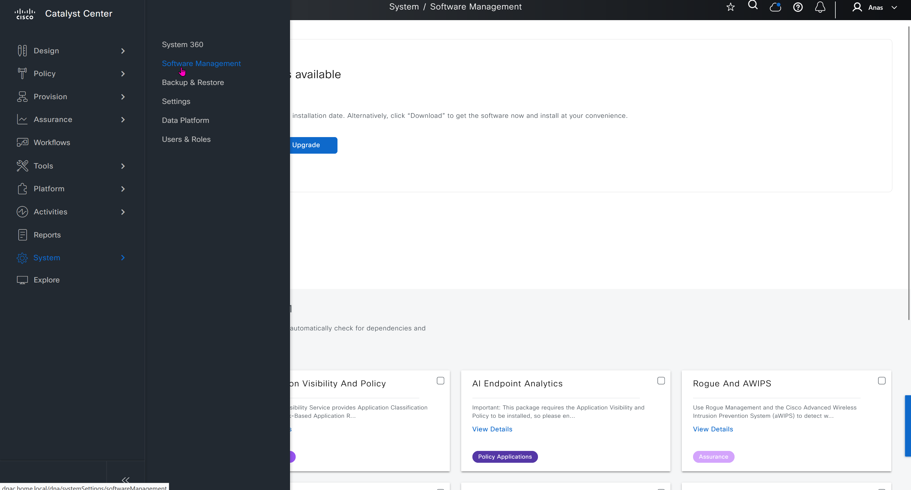

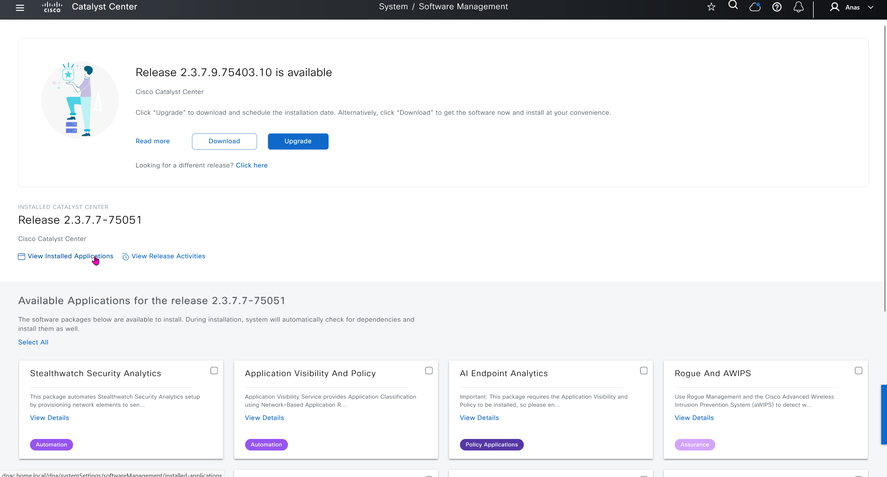
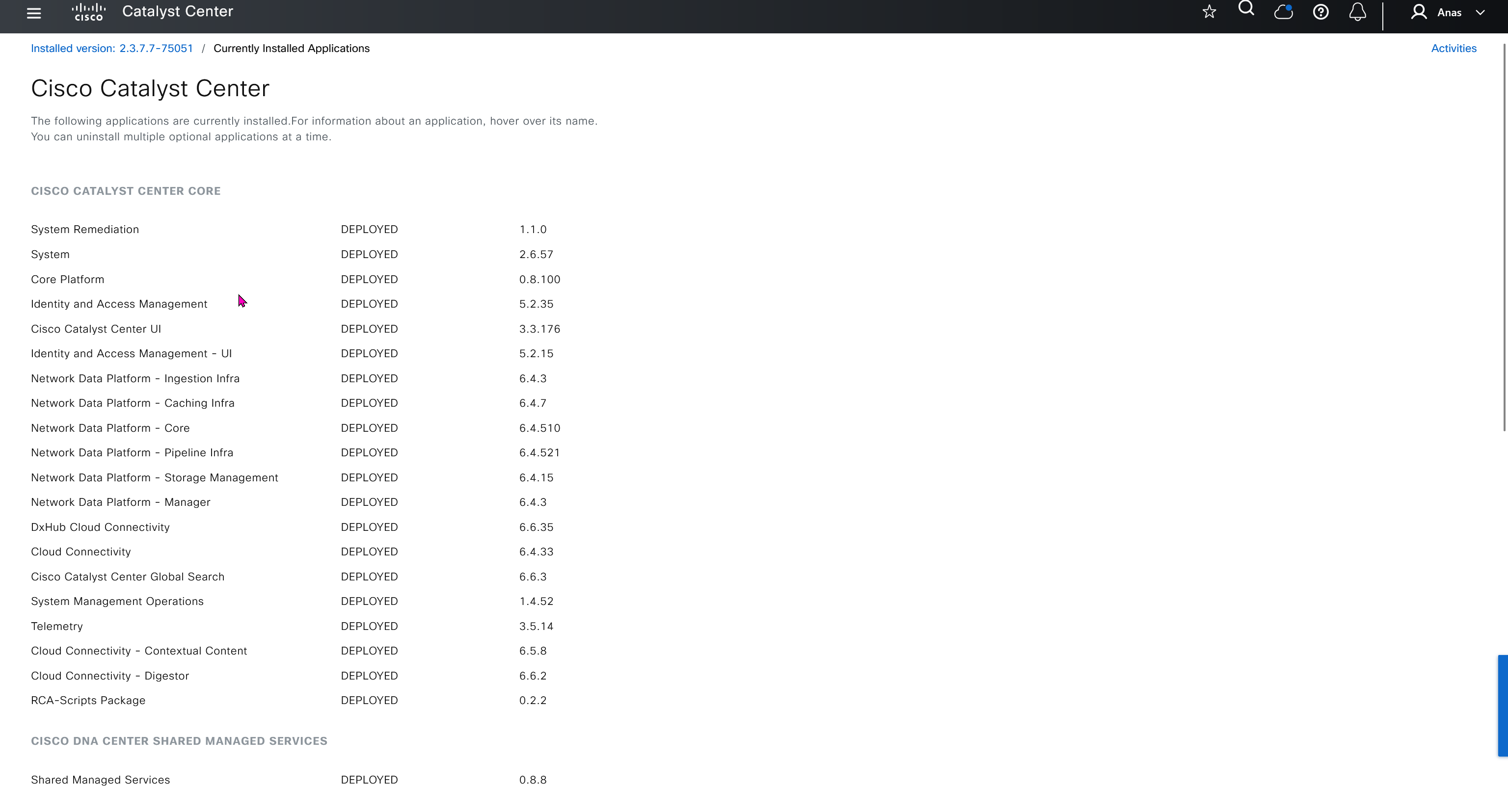
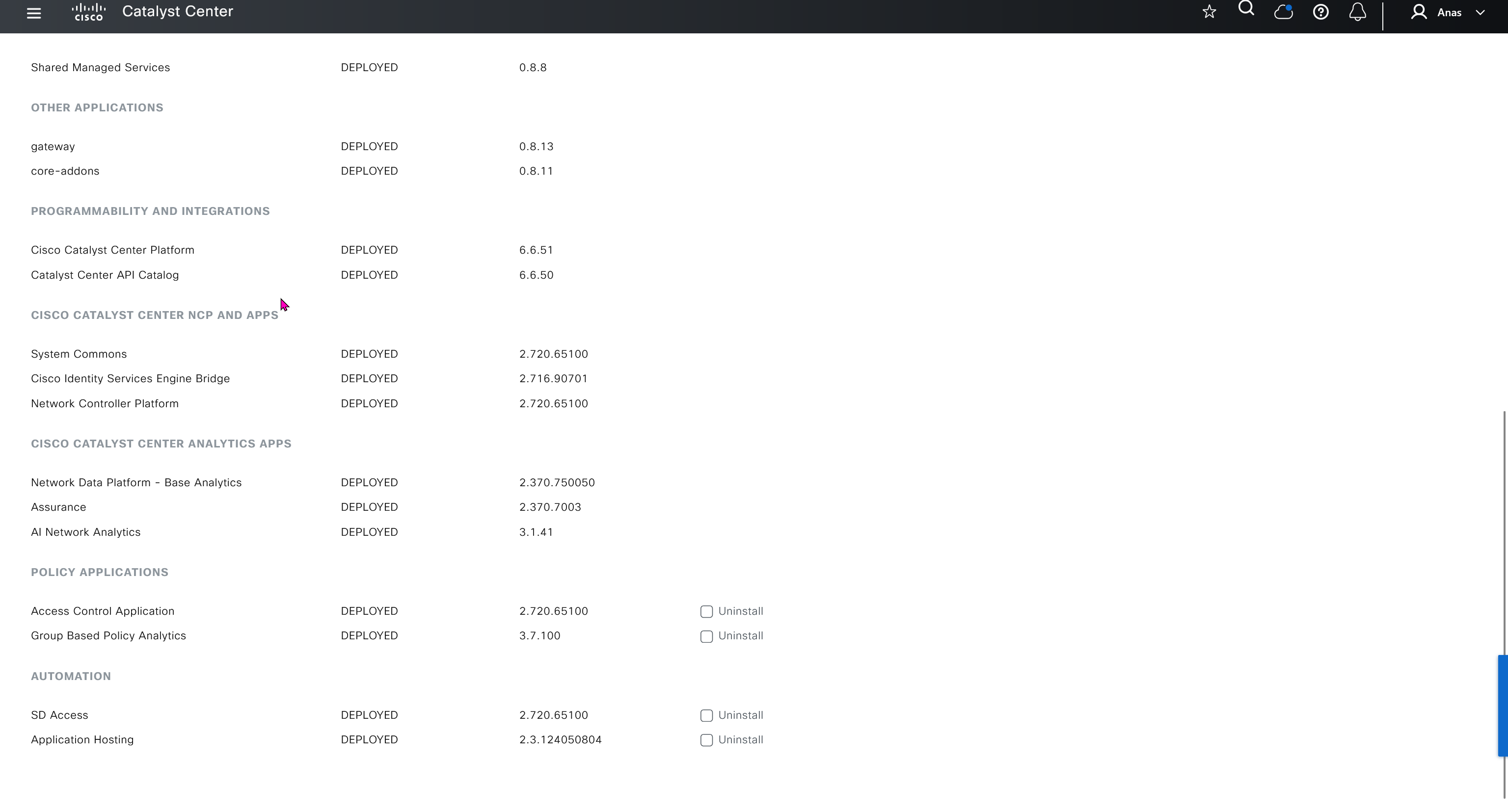
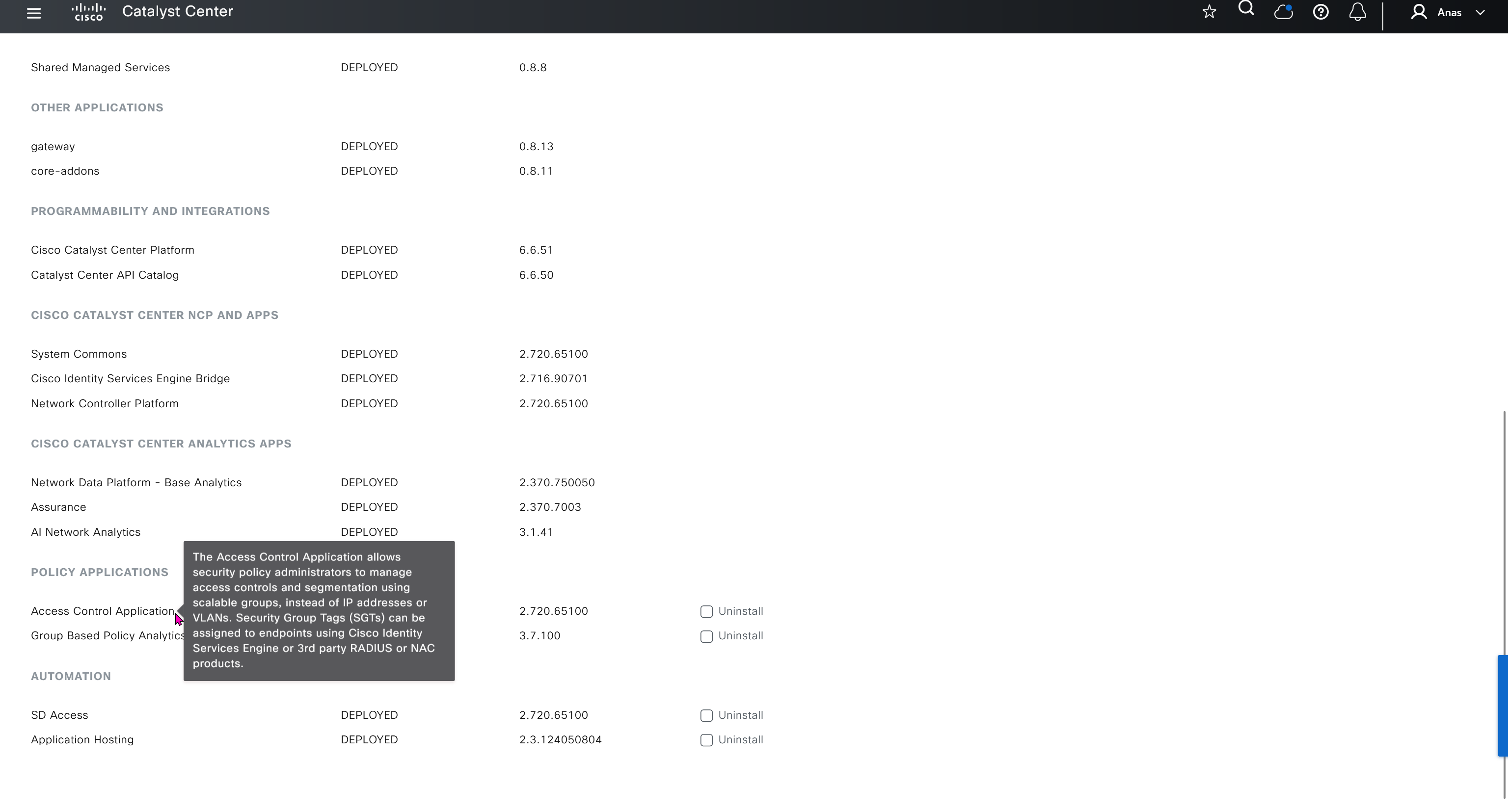
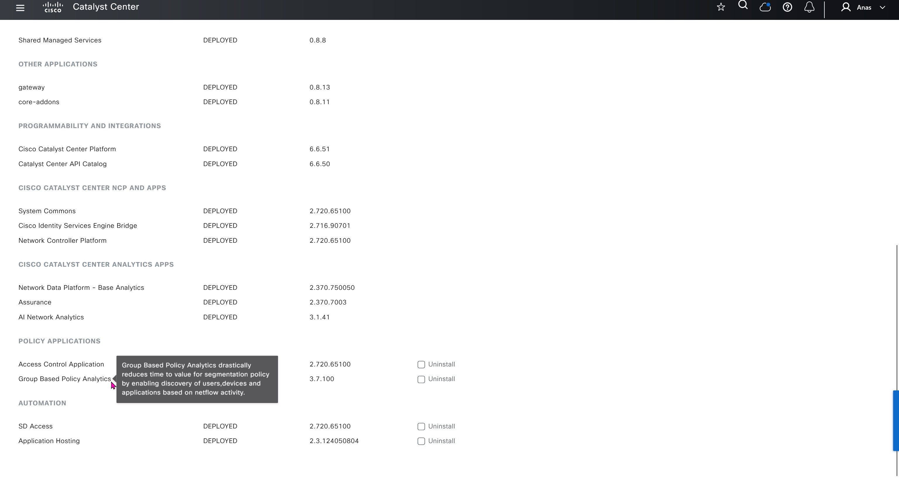


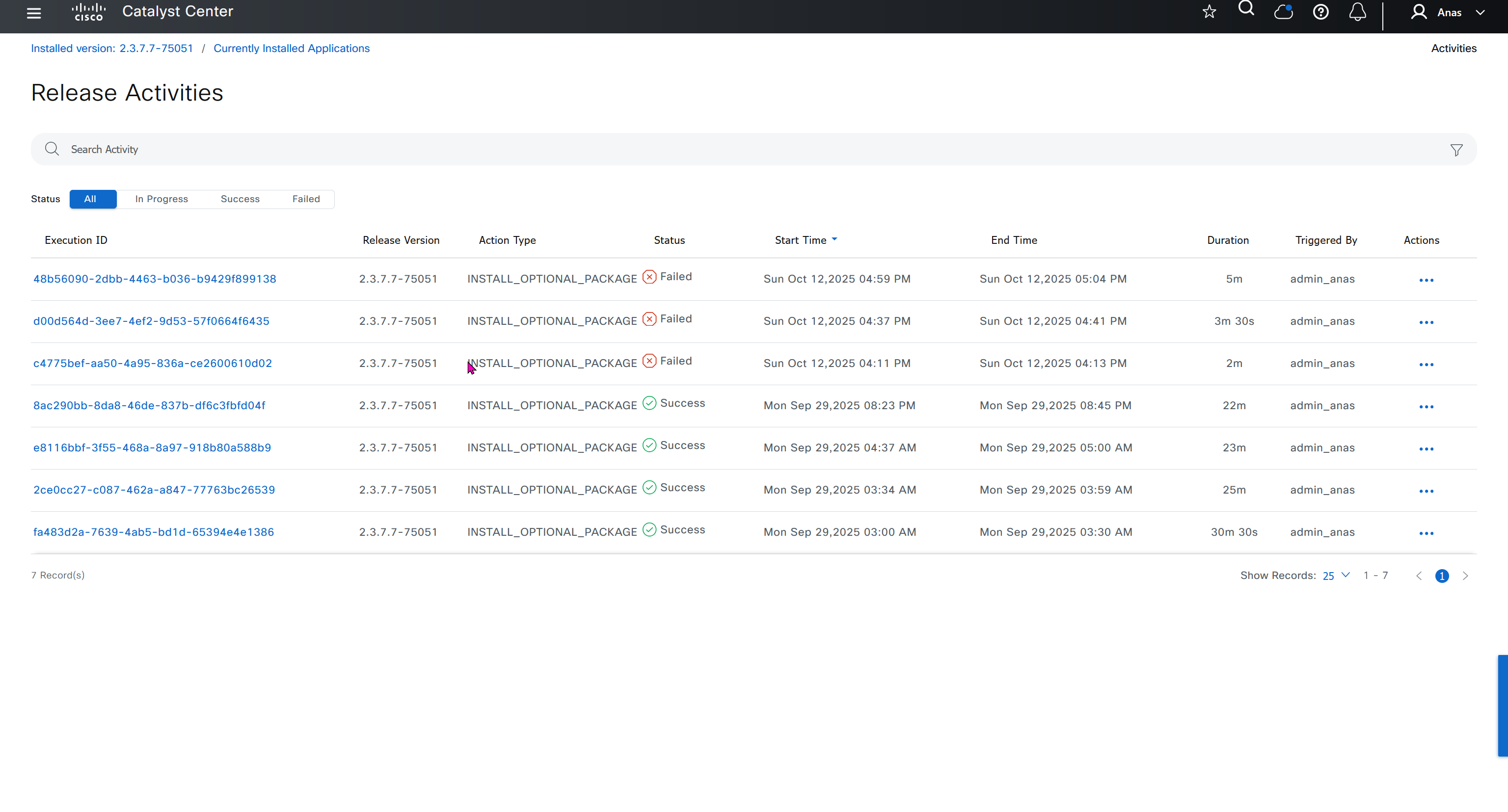
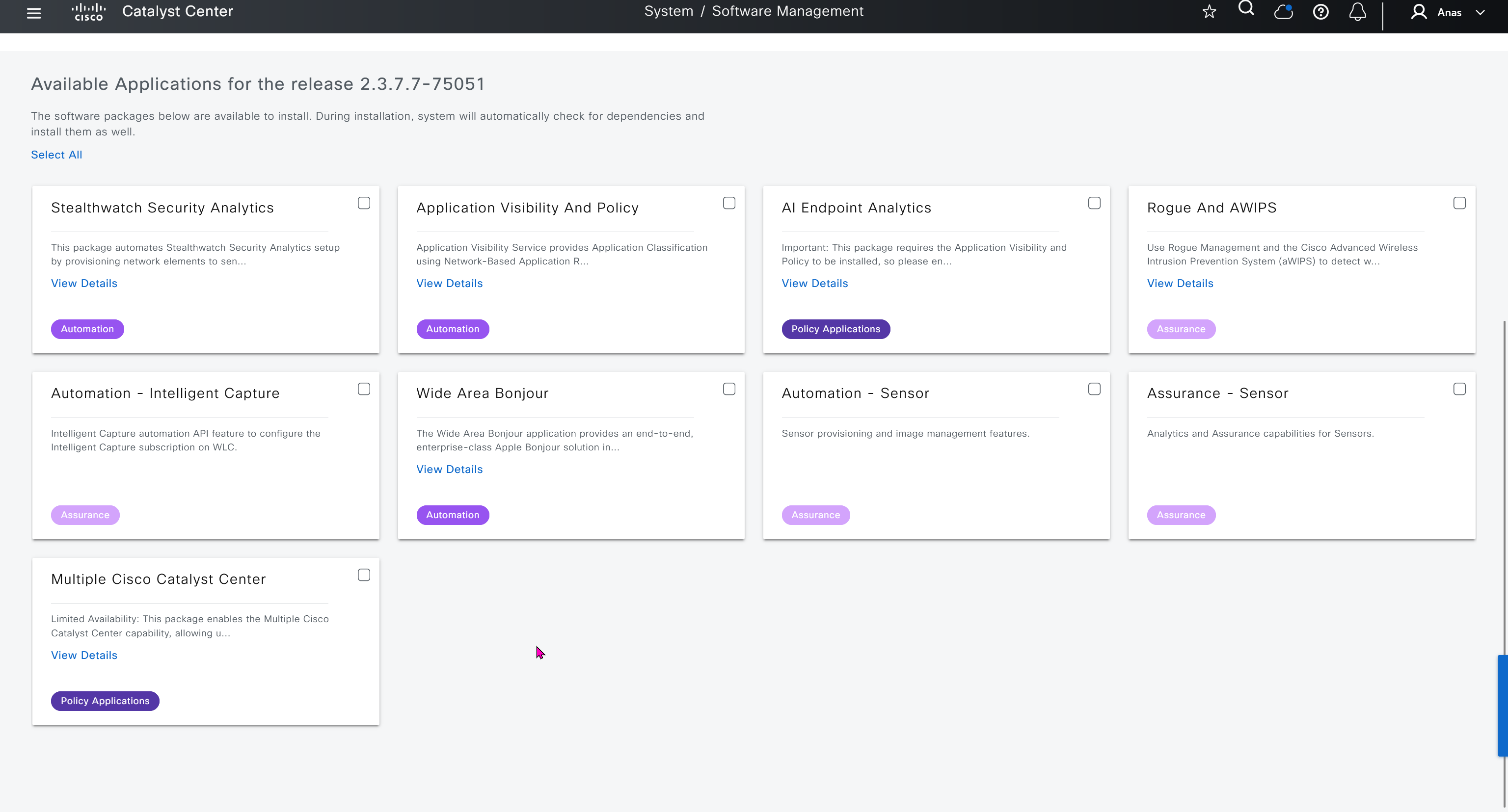
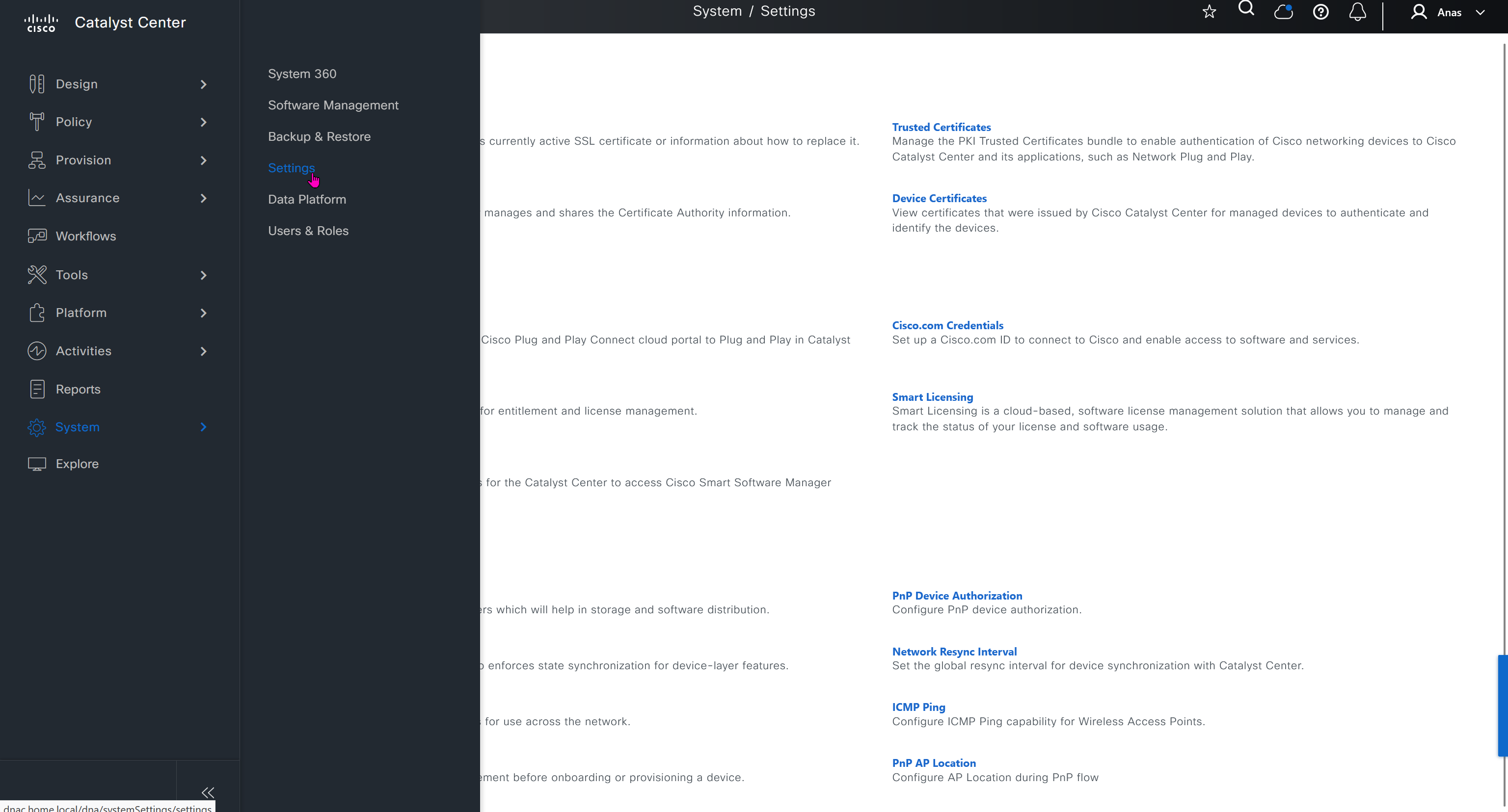
Cisco.com Credentials
Cisco credentials is the same credentials we entered after changing password for DNAC admin on first time login
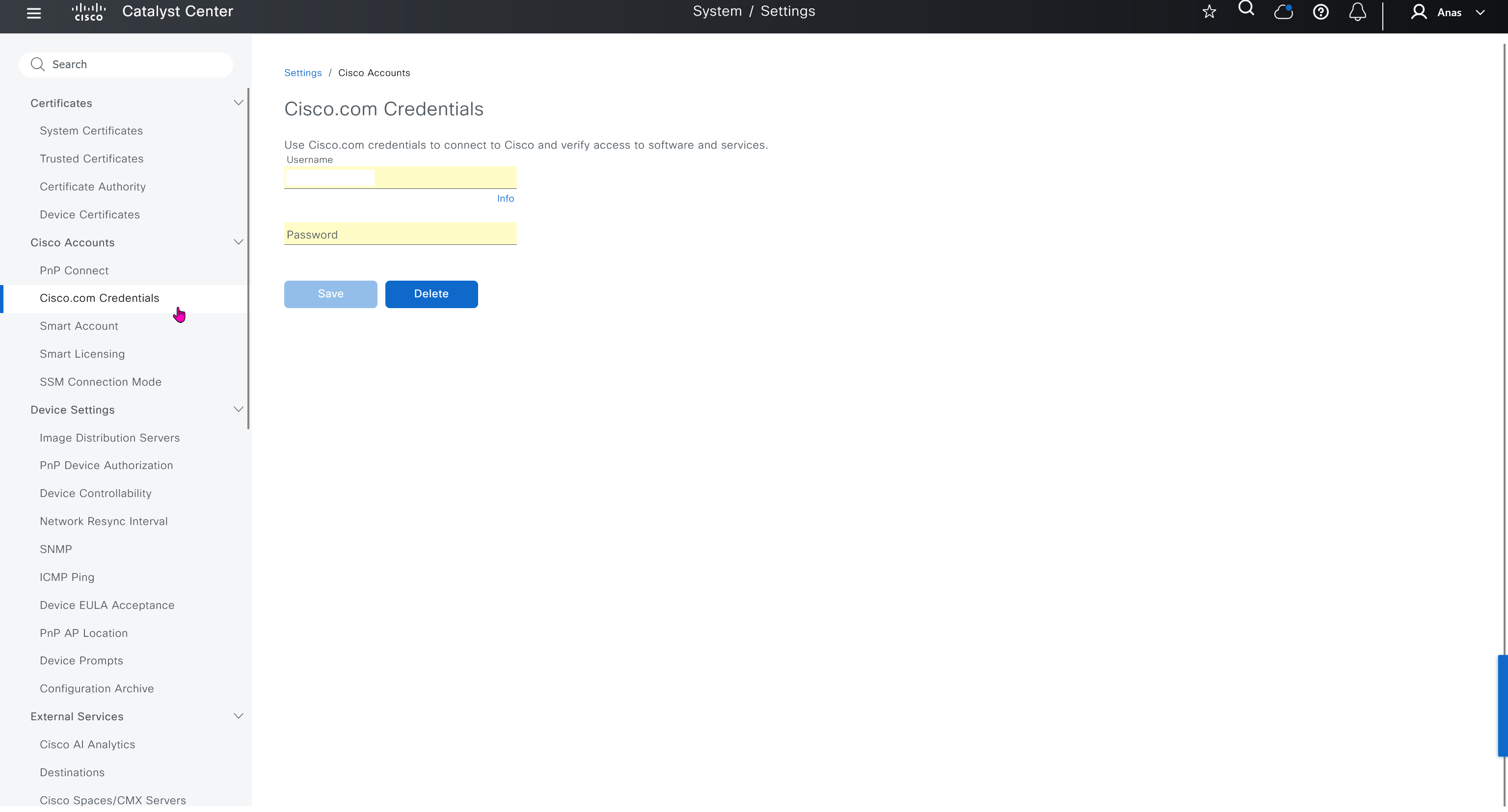
PnP Connect
PnP connect lets you sync your devices from internet based Cisco’s PnP to DNAC directly, this is used for onboarding routers and switches using PnP in Cloud
Cisco Plug and Play (PnP) Connect is a cloud-based onboarding service that helps you automatically provision new Cisco network devices (switches, routers, access points, etc.) with Cisco DNA Center — no manual configuration or console access needed similar to SDWAN or Meraki onboarding
When a new Cisco device boots up:
- It connects to the PnP Cloud portal.
- The PnP Cloud checks the device’s serial number.
- The device is matched to your DNA Center project.
- The device is redirected to your DNA Center for zero-touch provisioning.
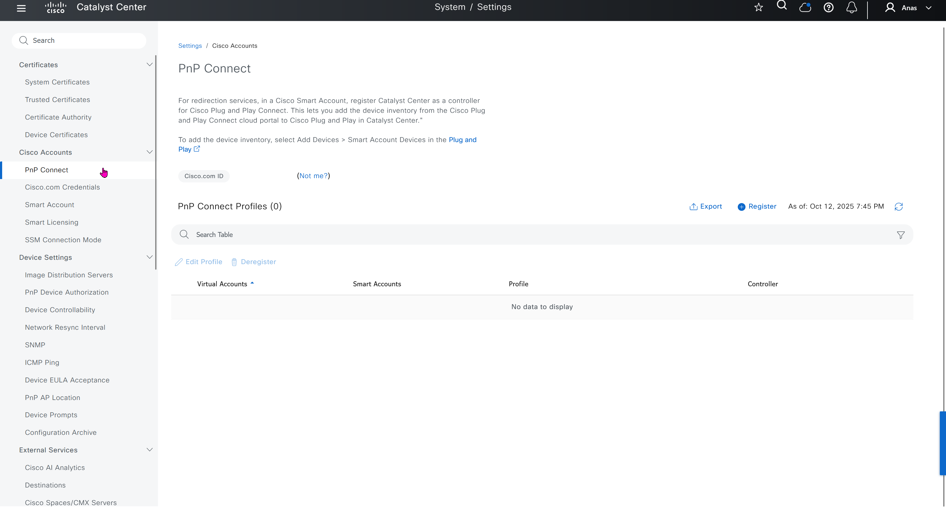
Smart account
“Auto register smart license enabled devices” allows devices to register to selectable “Virtual account inside the Smart account”

Smart Licensing
Smart account defined earlier is used in Smart licensing section, register a smart account and virtual account to have DNAC licensed and in compliance state
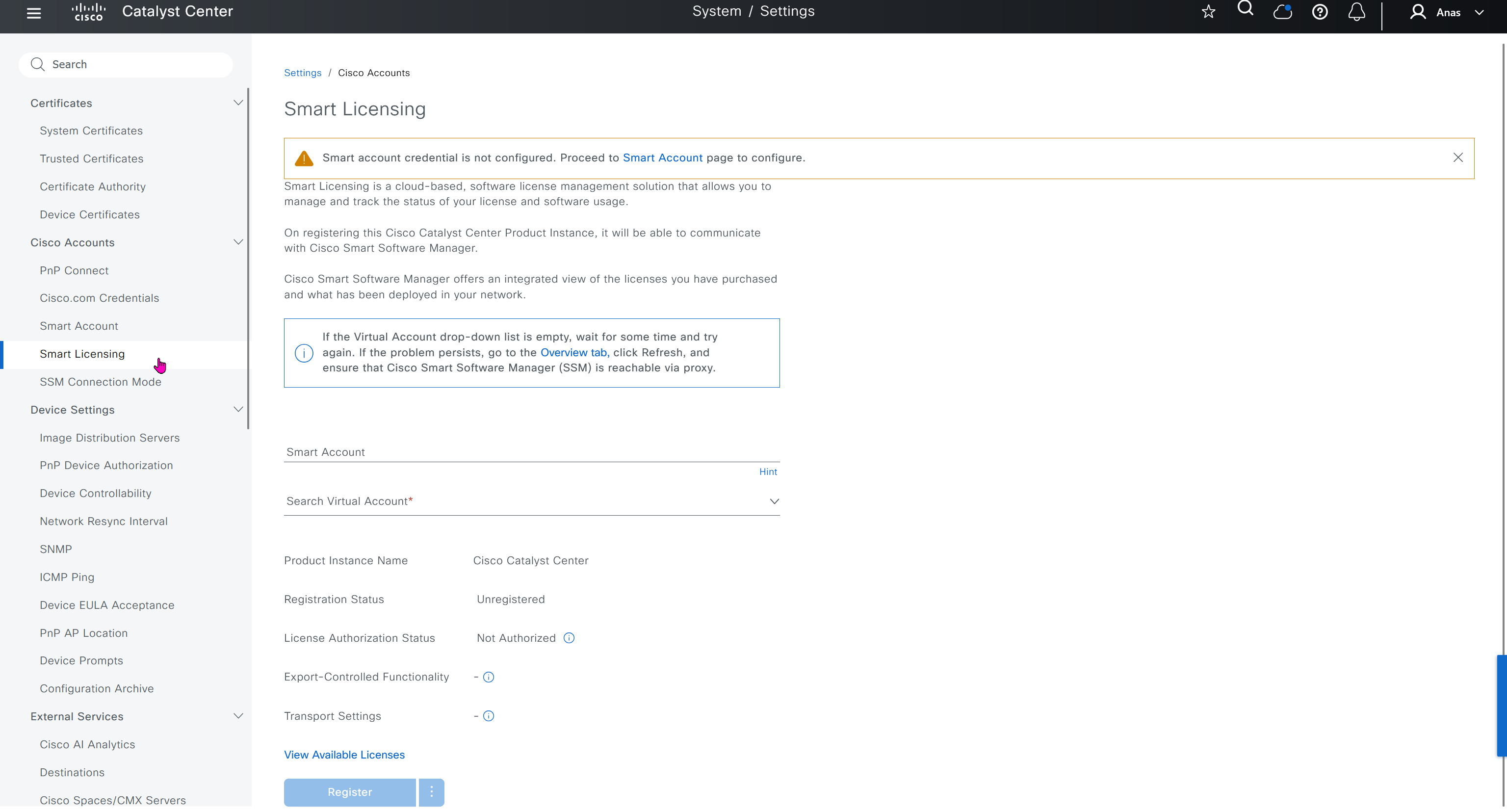
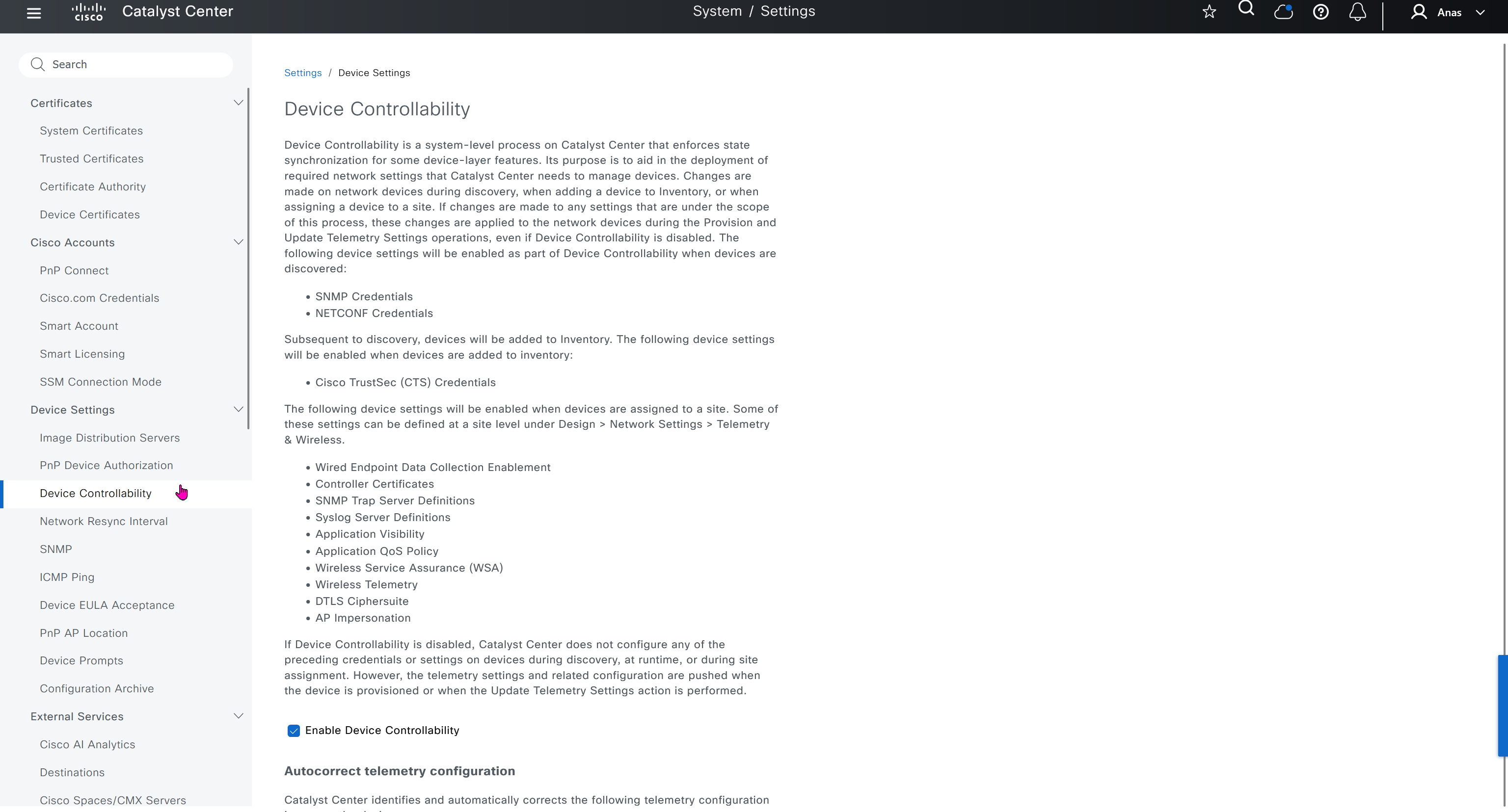
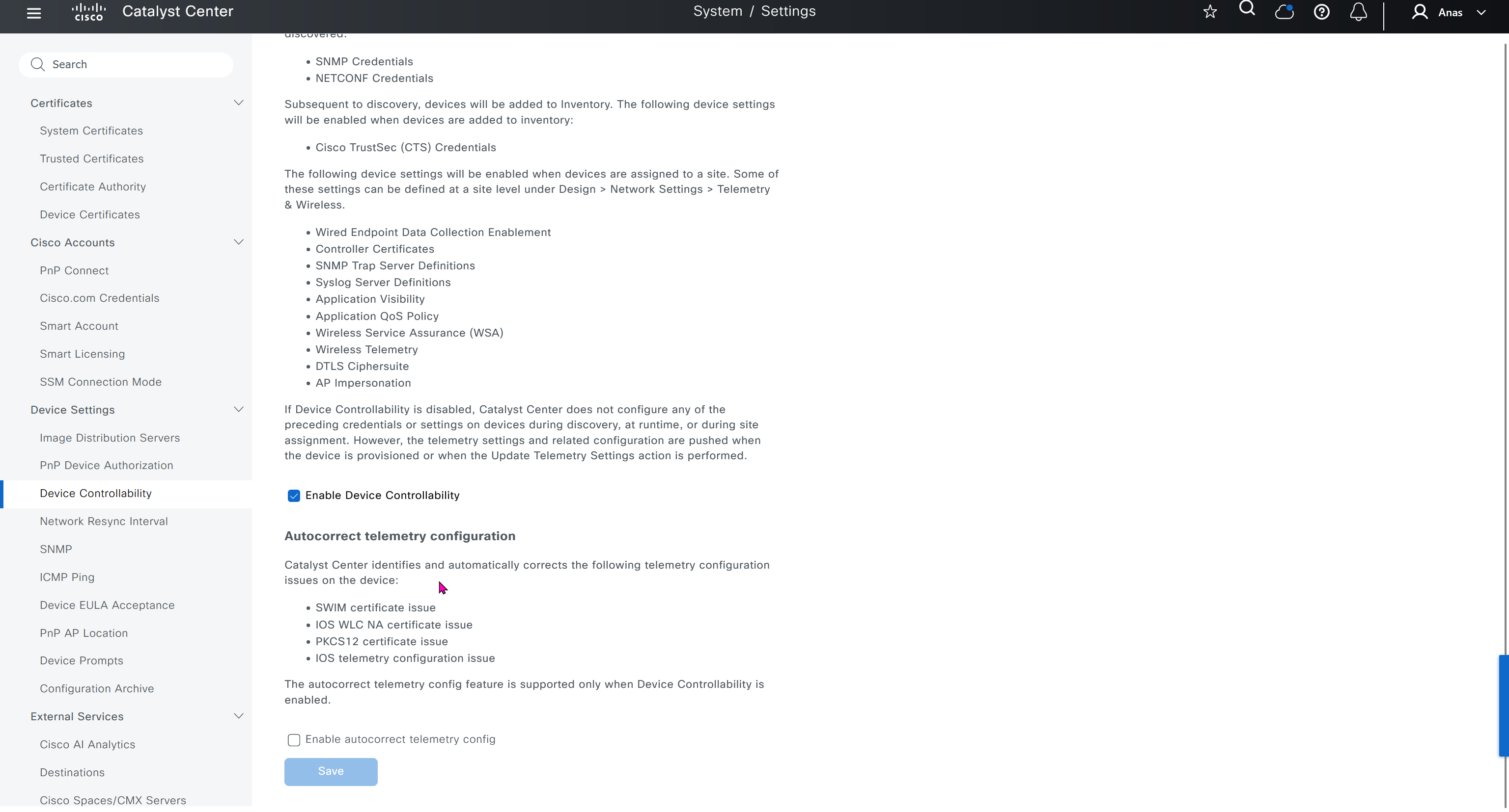
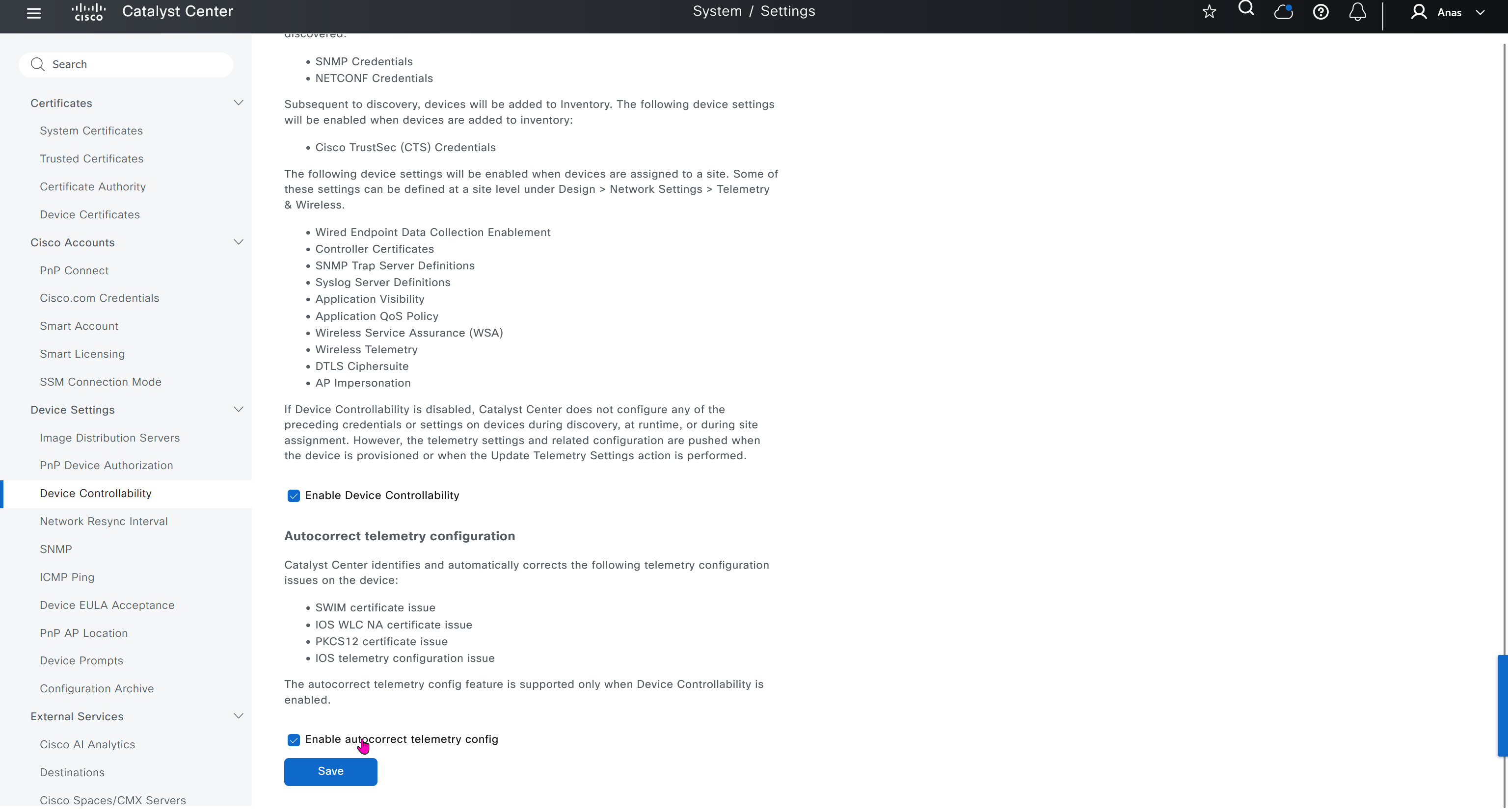
Device EULA Acceptance
For LAB I will not accept as not sure what might be the impact on CCO account against licenses
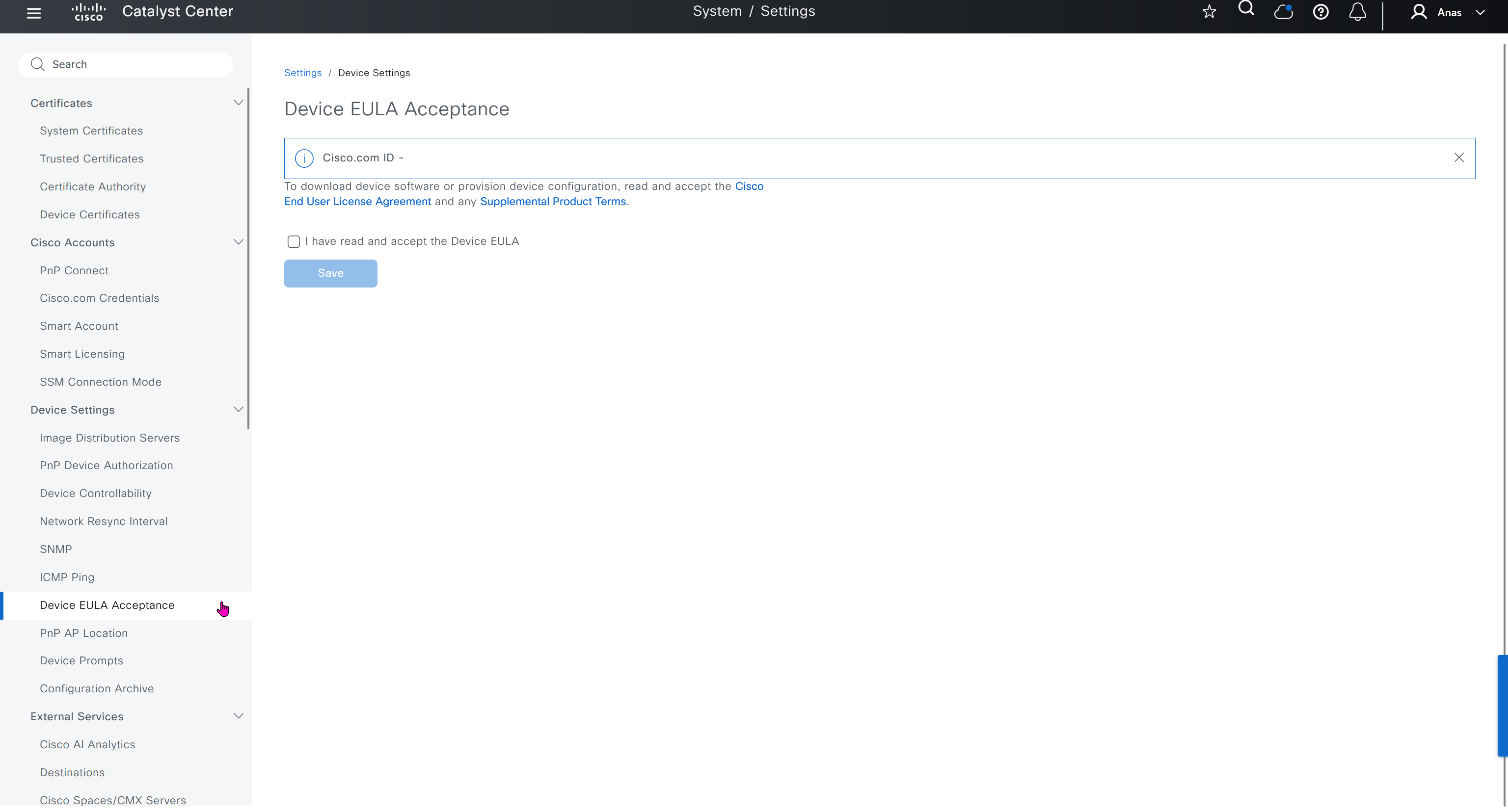
Image Distribution Servers
10.21.1.2 (LOCAL) is DNAC itself, but we can define other image distribution servers not to burden the WAN
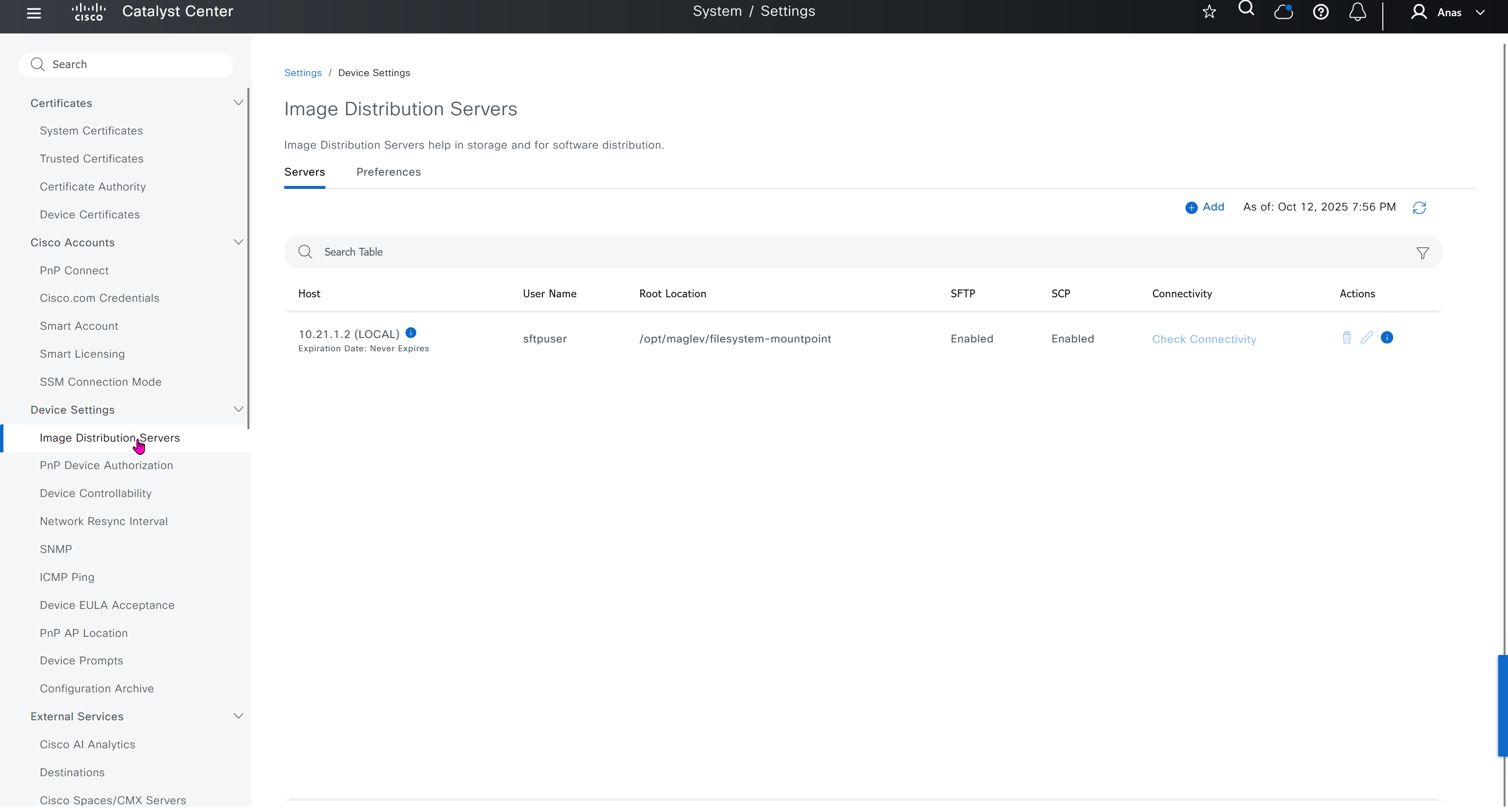
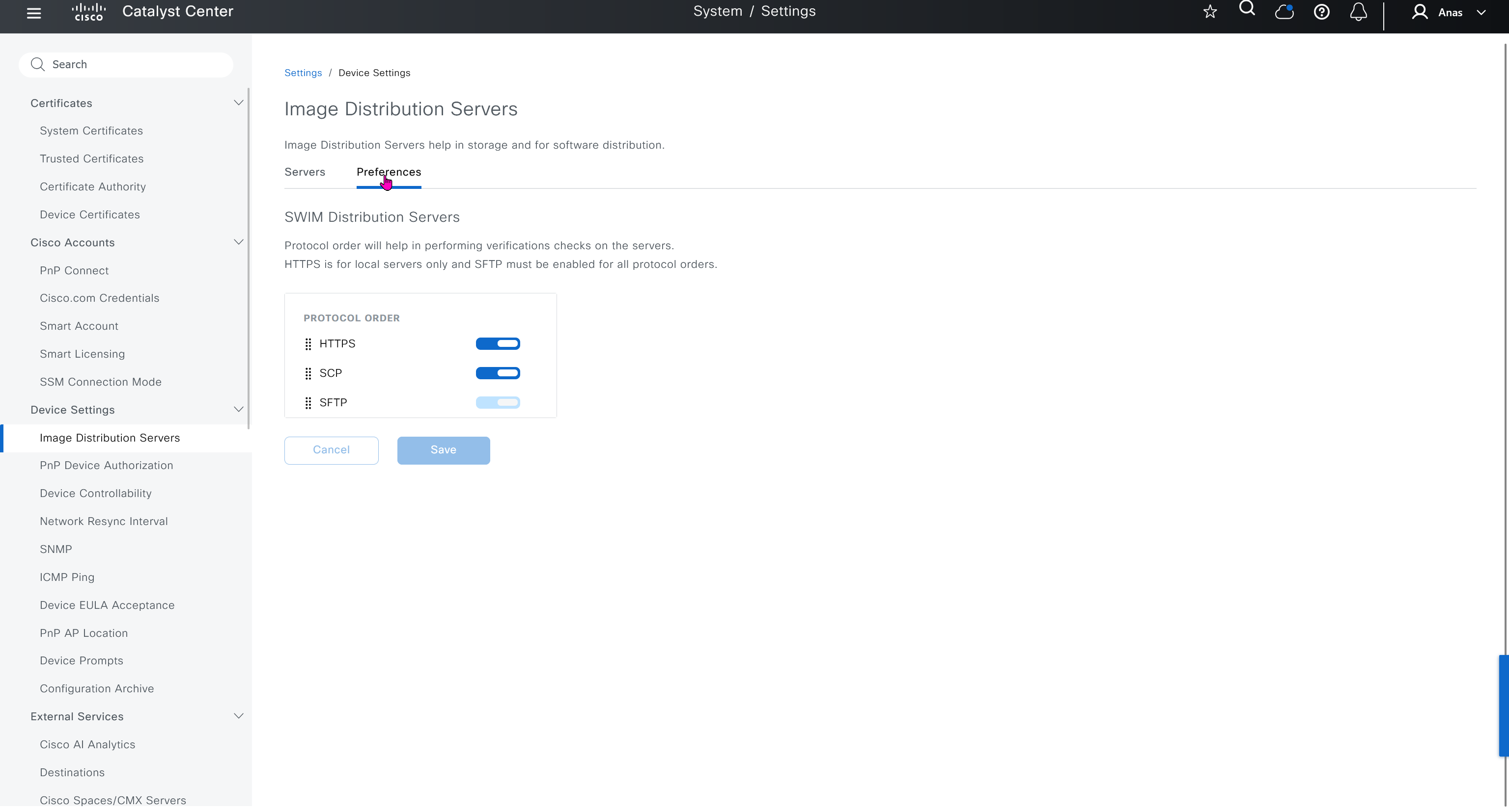
Network Resync Interval
This is how often DNAC syncs with network devices, default is 24 hours

SNMP
is timeouts and retires

Authentication and Policy Servers
defined ISE servers
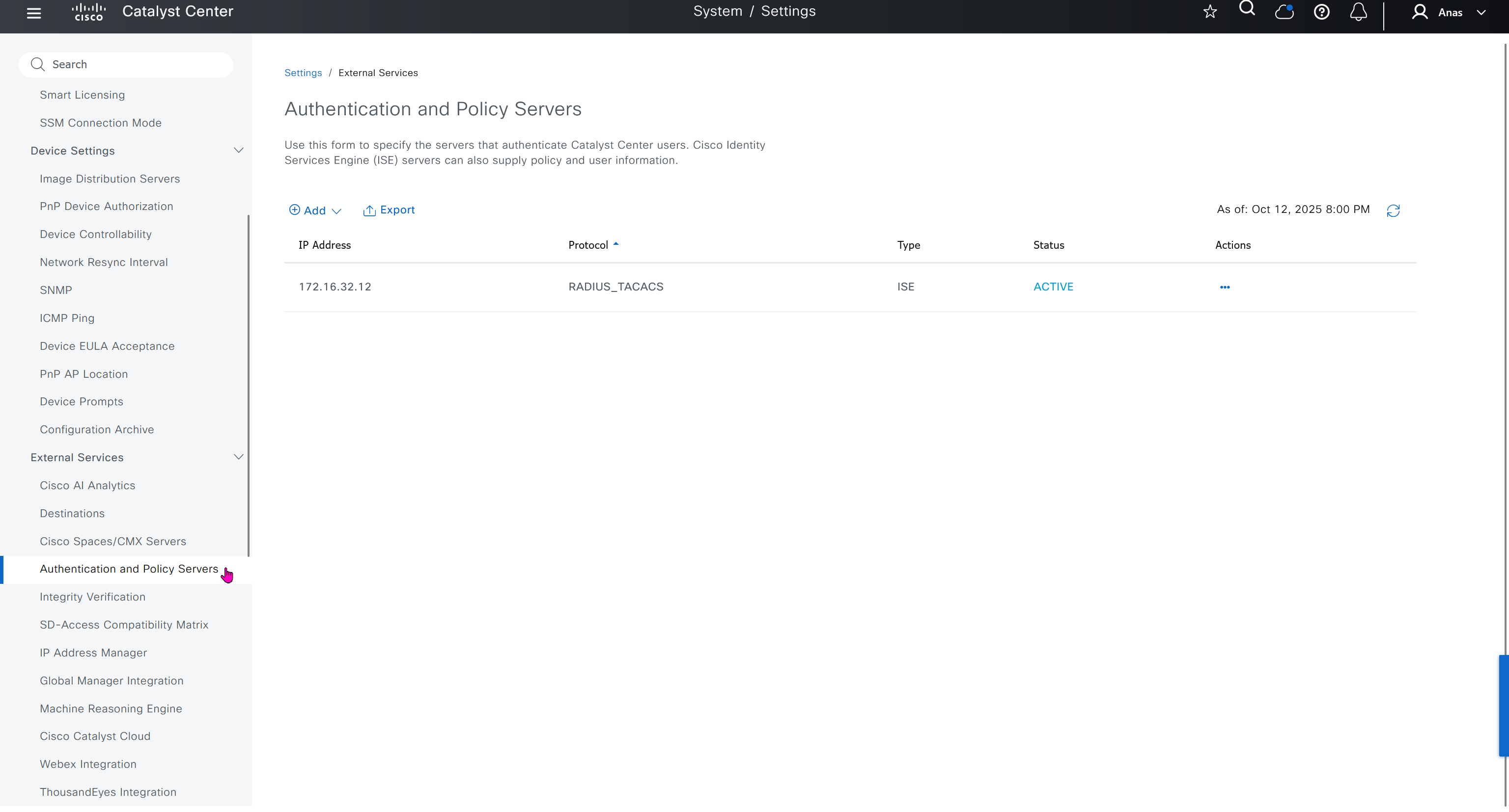
Cisco AI Analytics
This is where you configure AI analytics
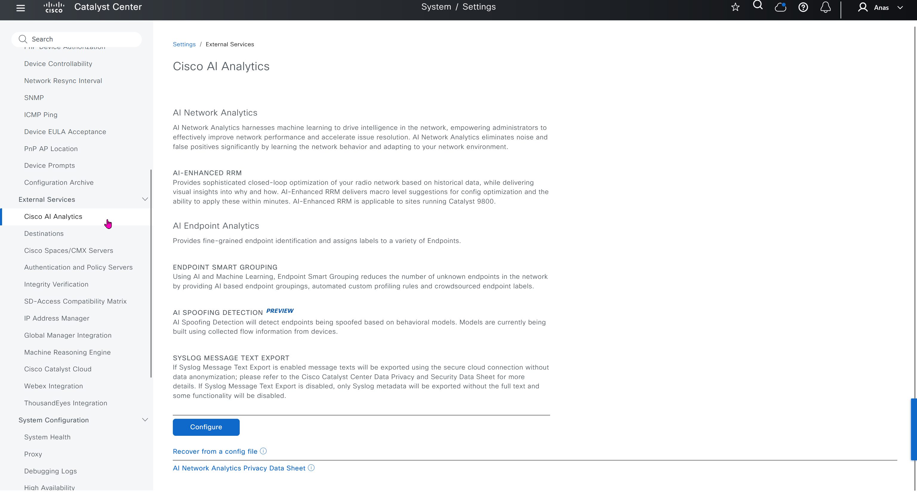
Destinations
This is to deliver event notifications when events happen on DNAC
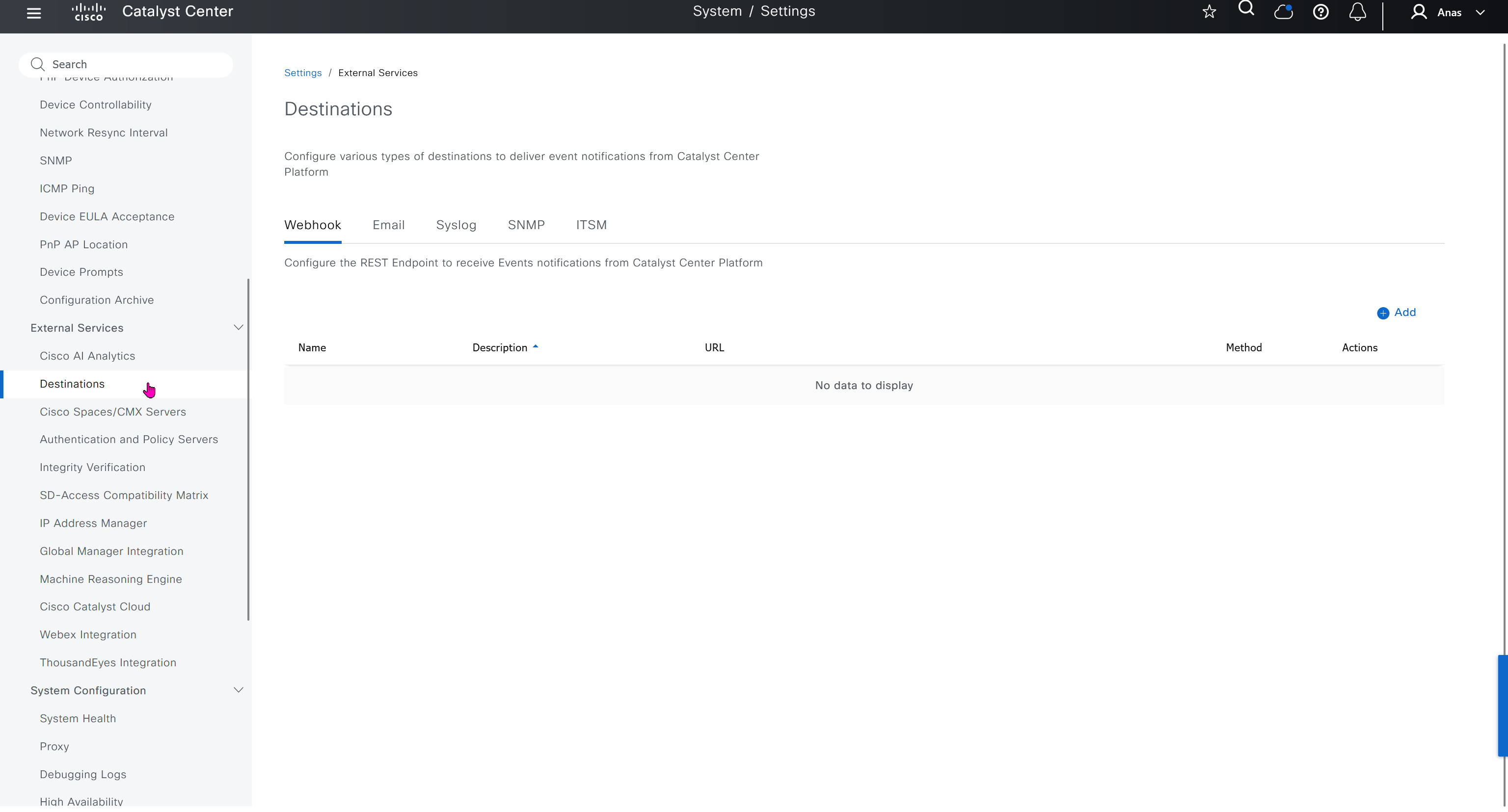
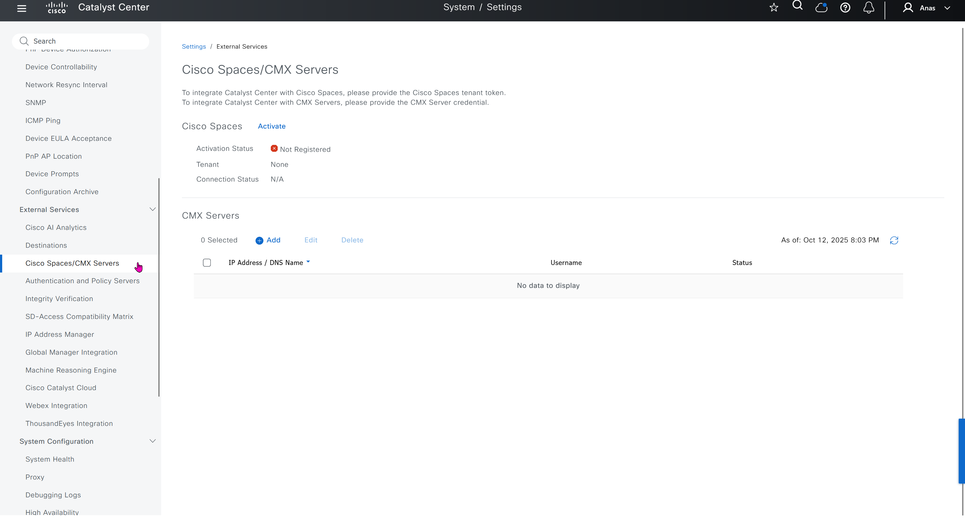
Integrity Verification
Checks if device is compromised on software, hardware level using Known Good Values KGV file from Cisco, which also requires updates from Cisco
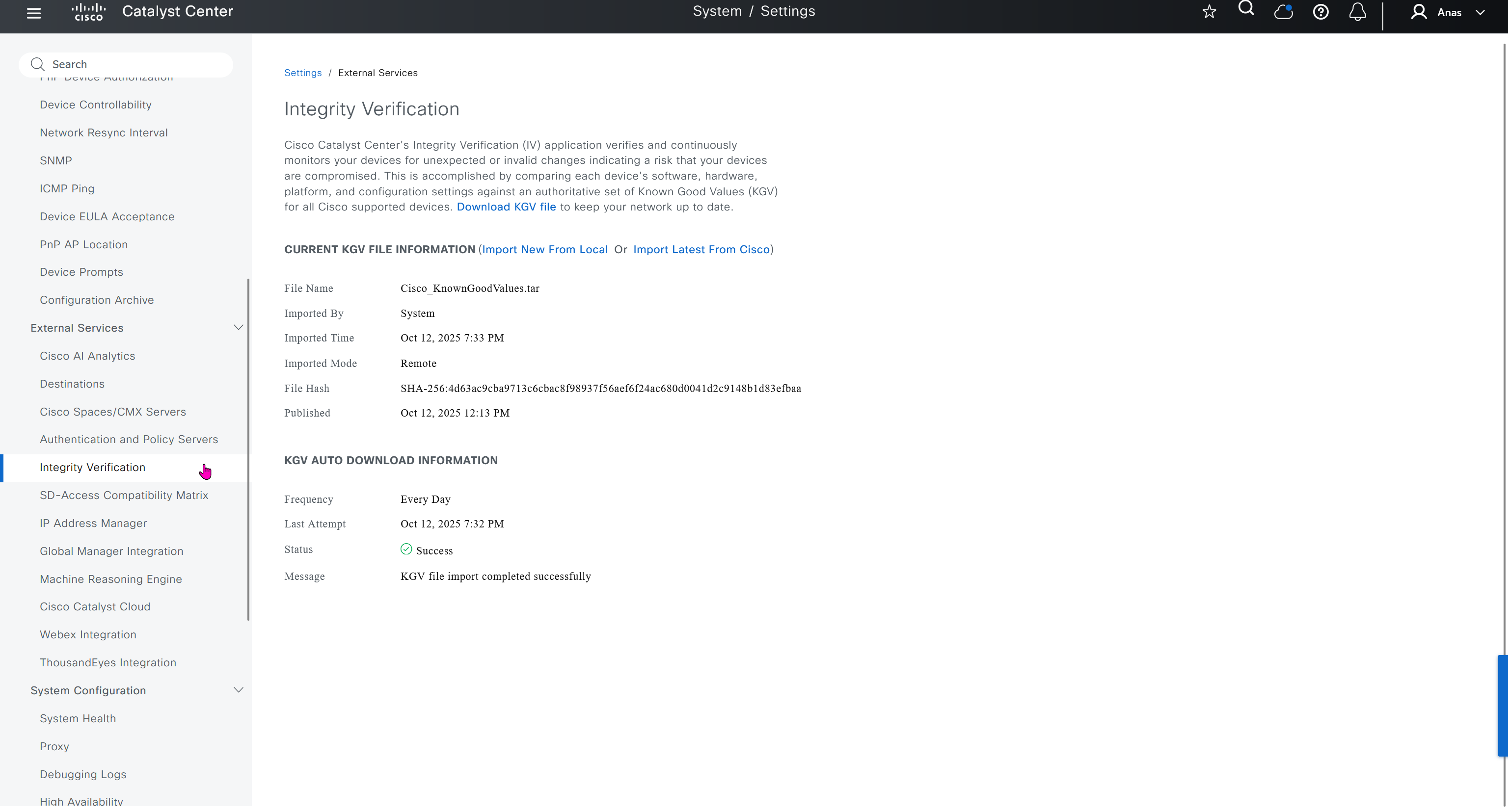
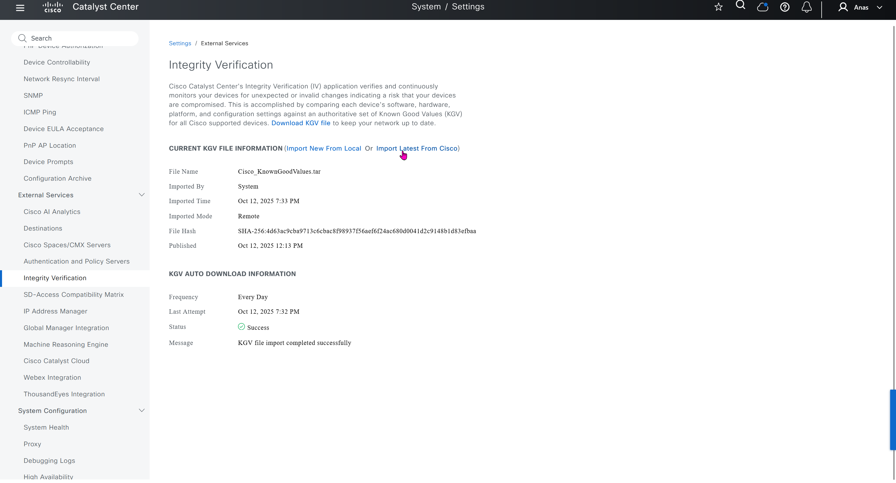
IP Address Manager
This is integration with IPAM
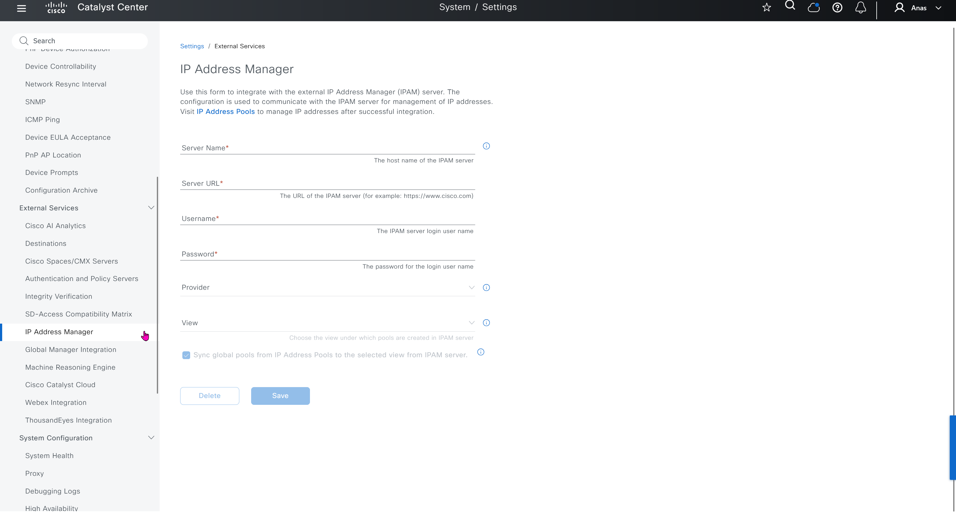
Machine Reasoning Engine
Download and keep upto date Cisco’s latest machine learned troubleshooting and reasoning database, make sure it is set to auto update


Debugging Logs
This is to debug logs for DNAC itself, specify a syslog server
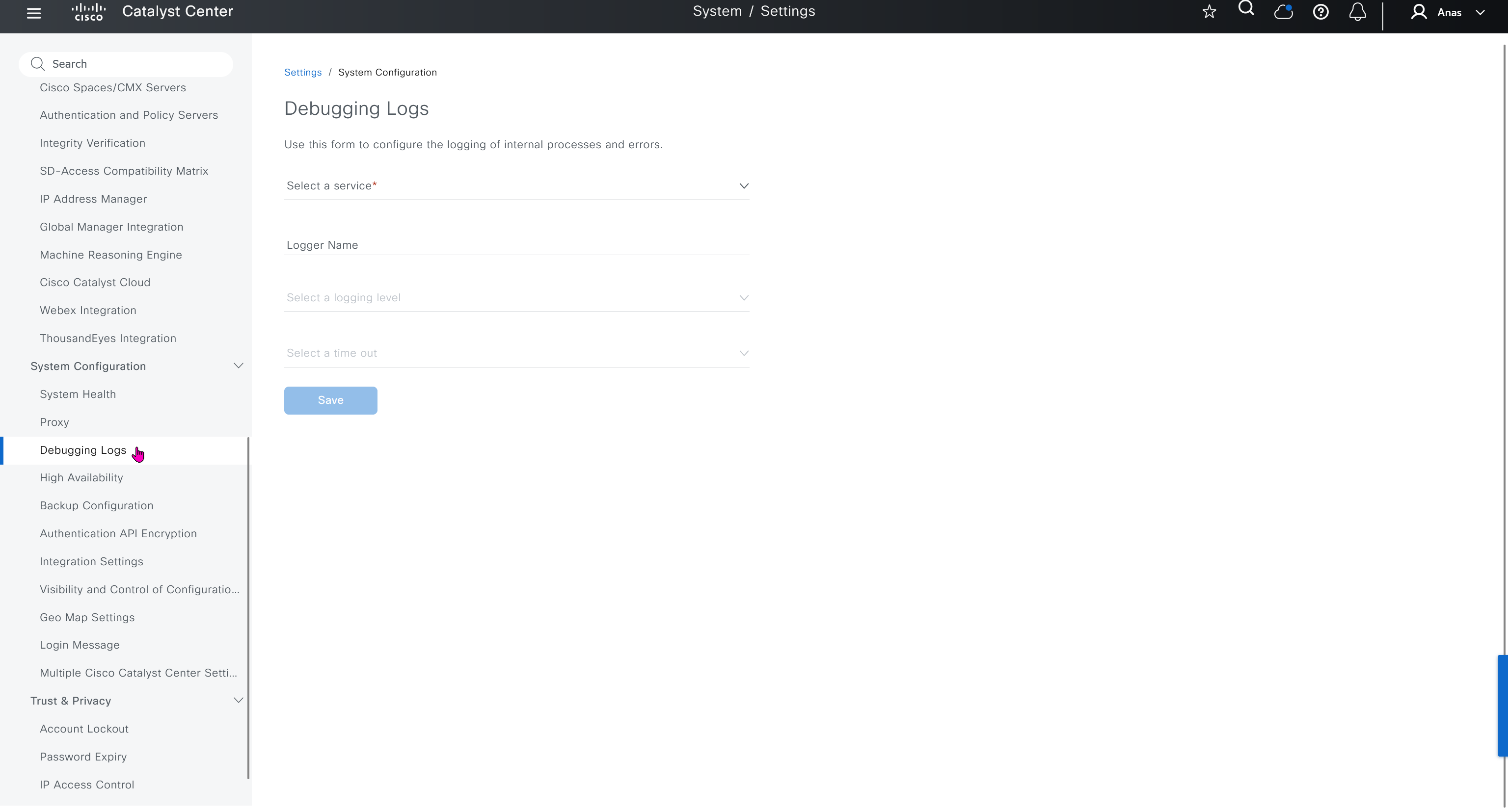
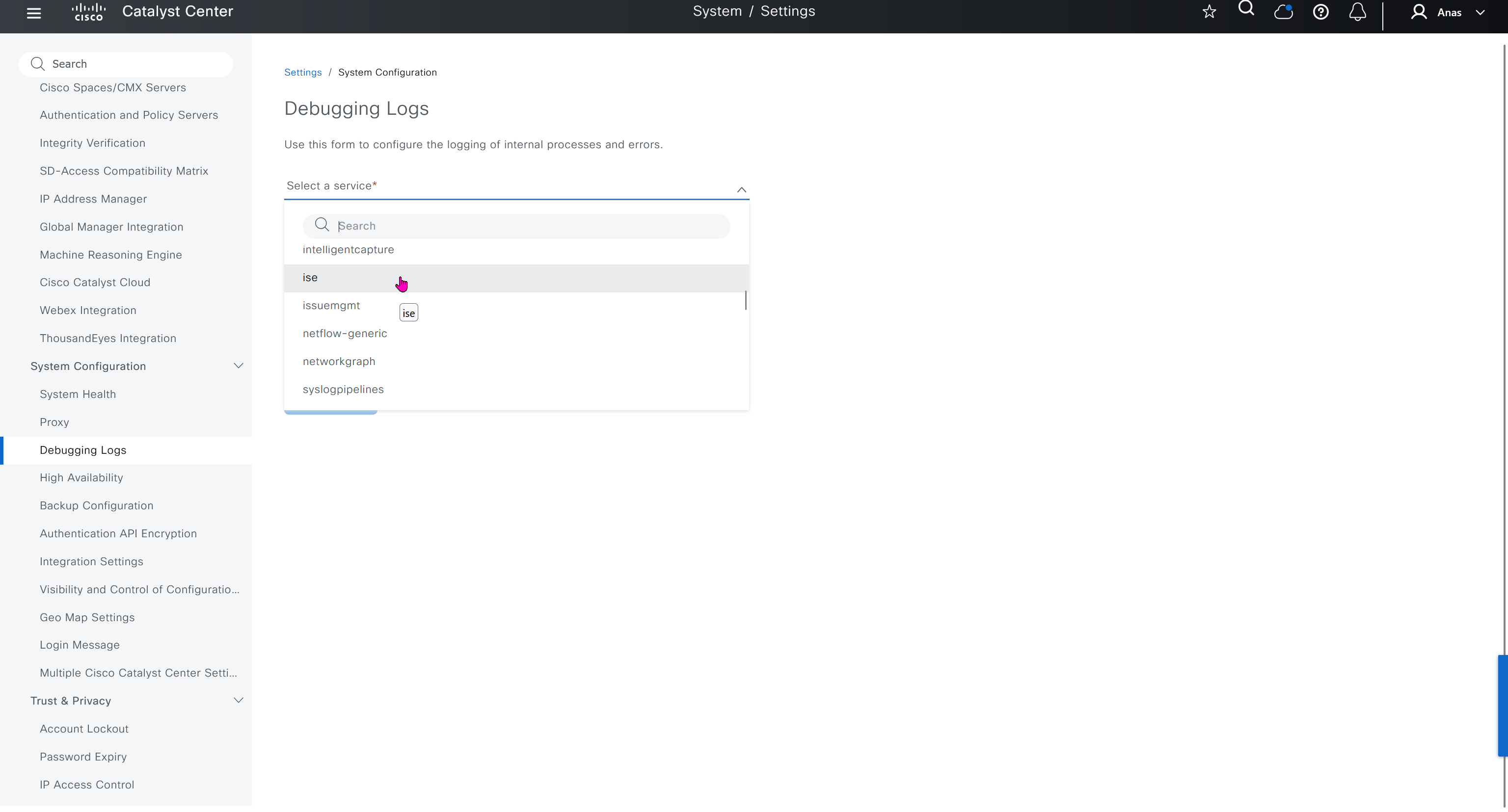
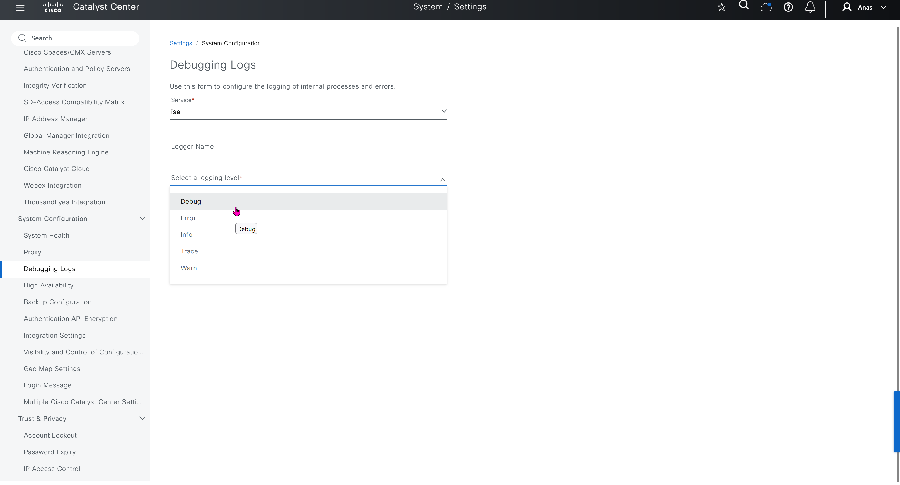
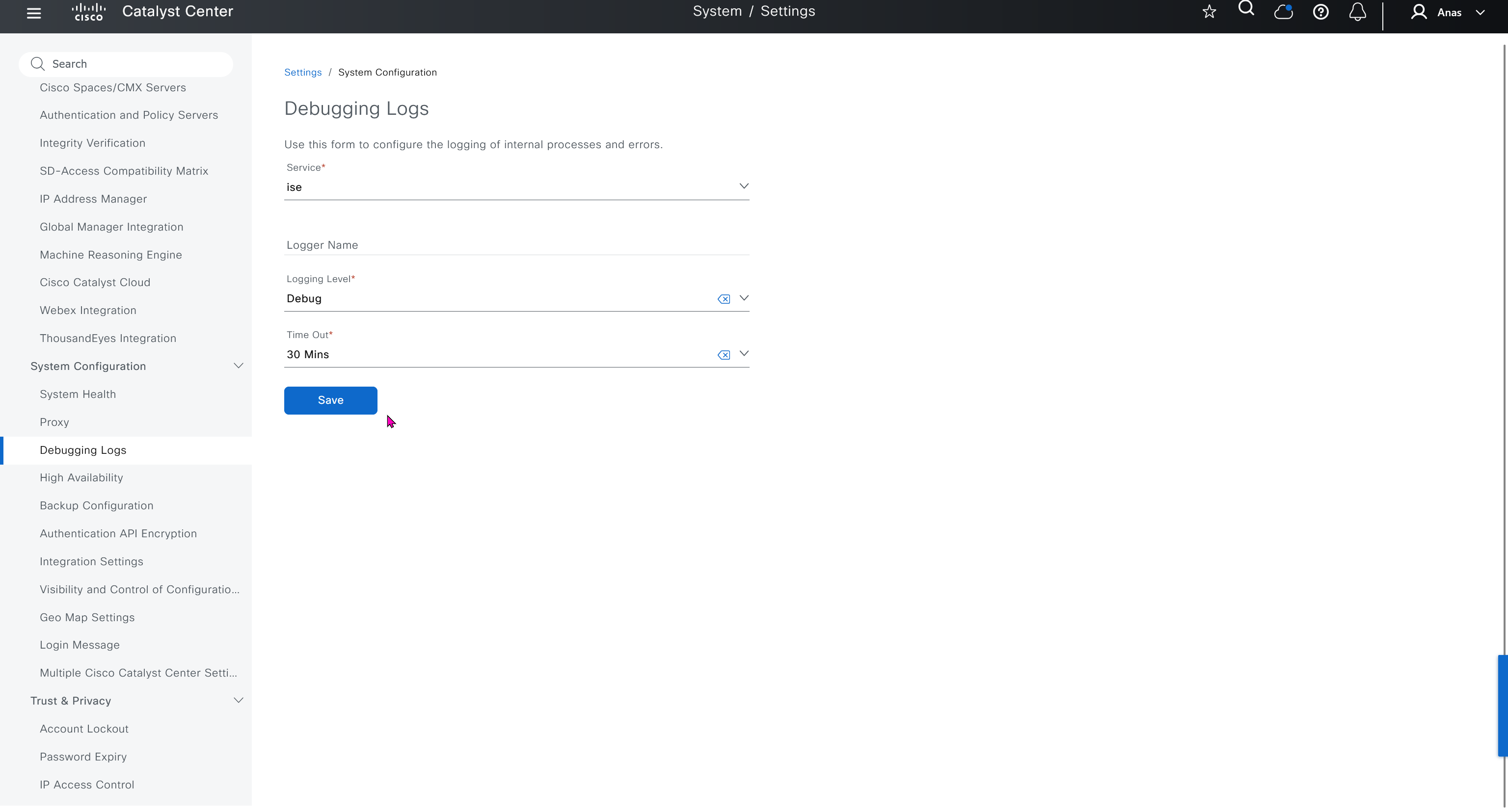


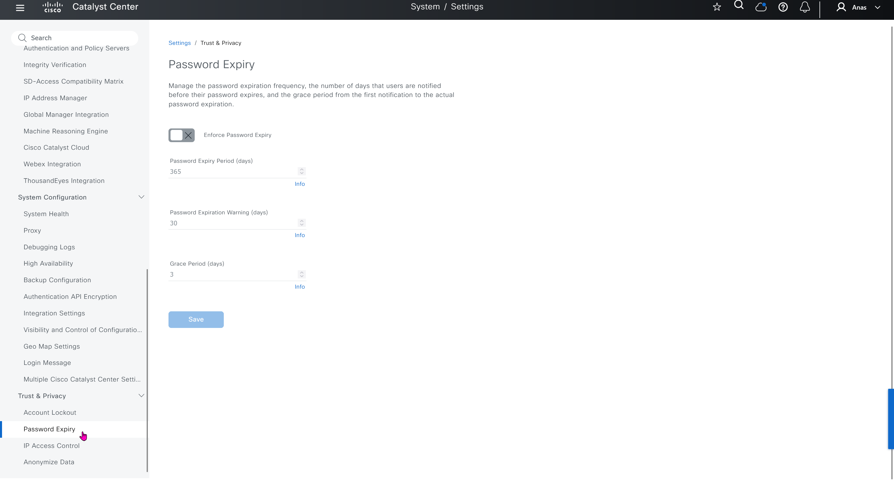
Search
Search in DNAC is amazing and you can search clients by MAC address or IP address / track clients with Client 360 link in search result and even search IP pools
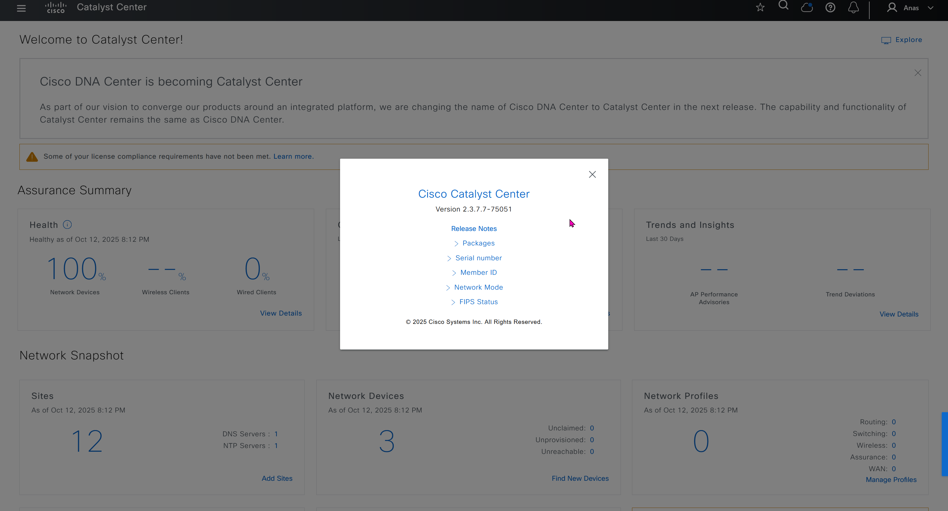
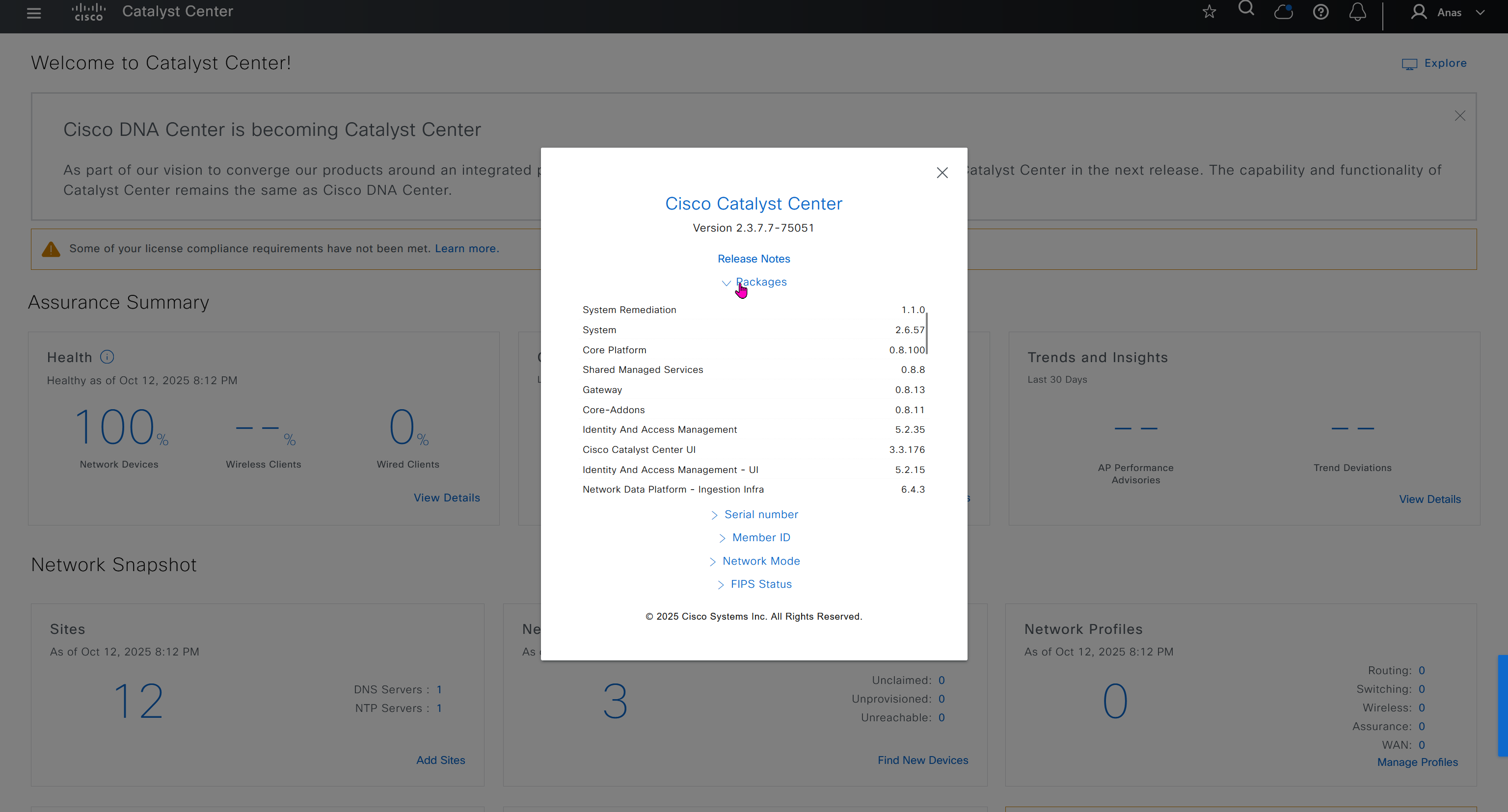
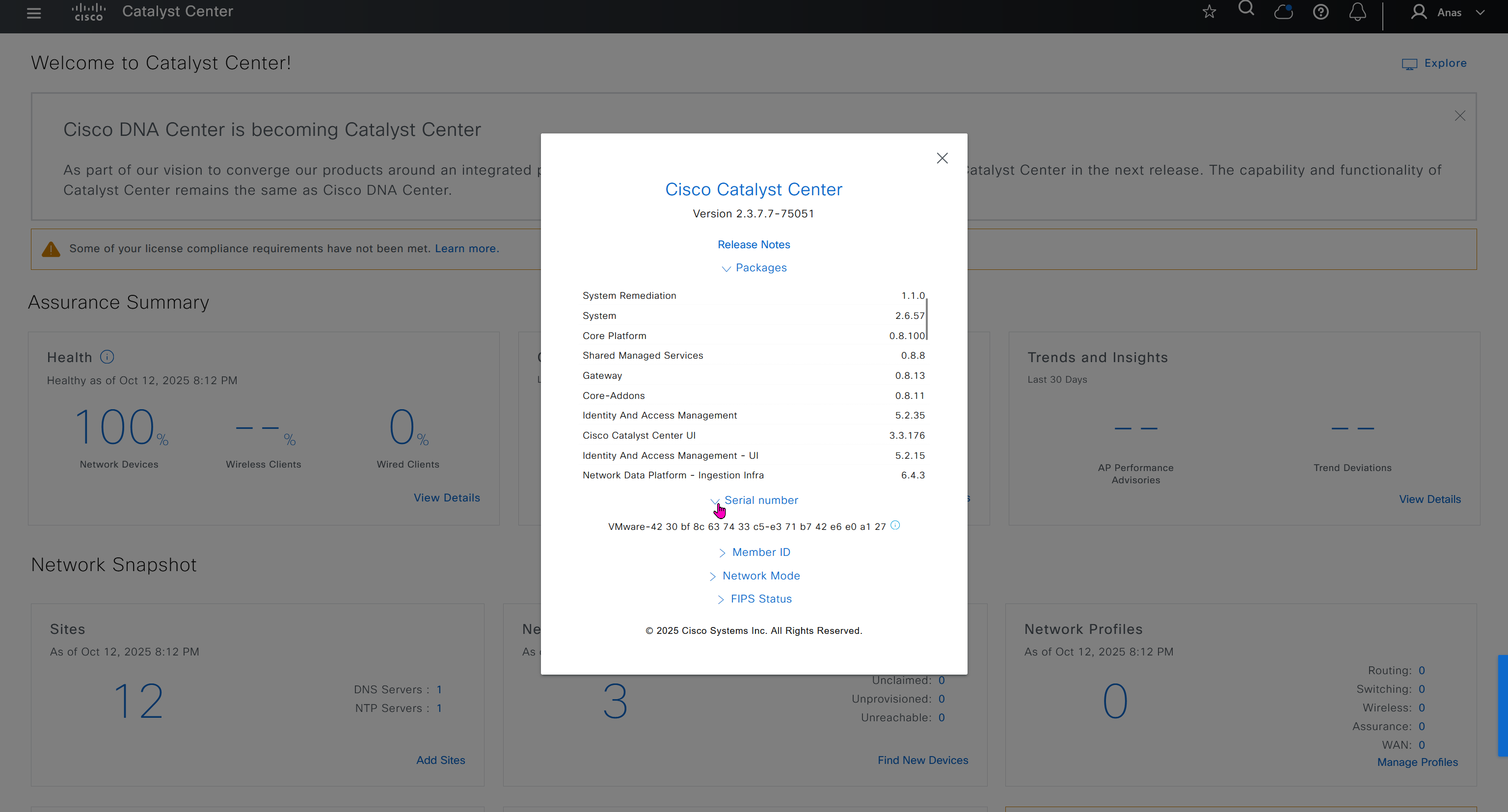
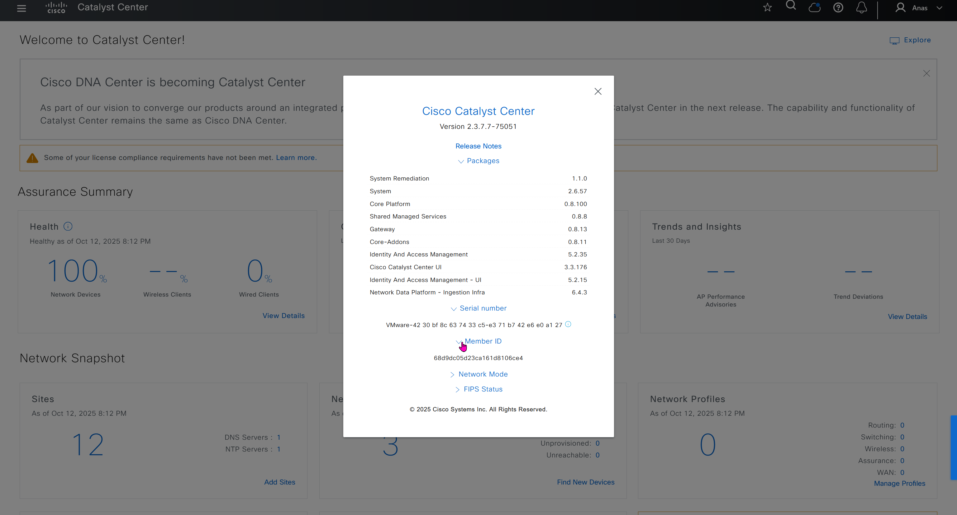
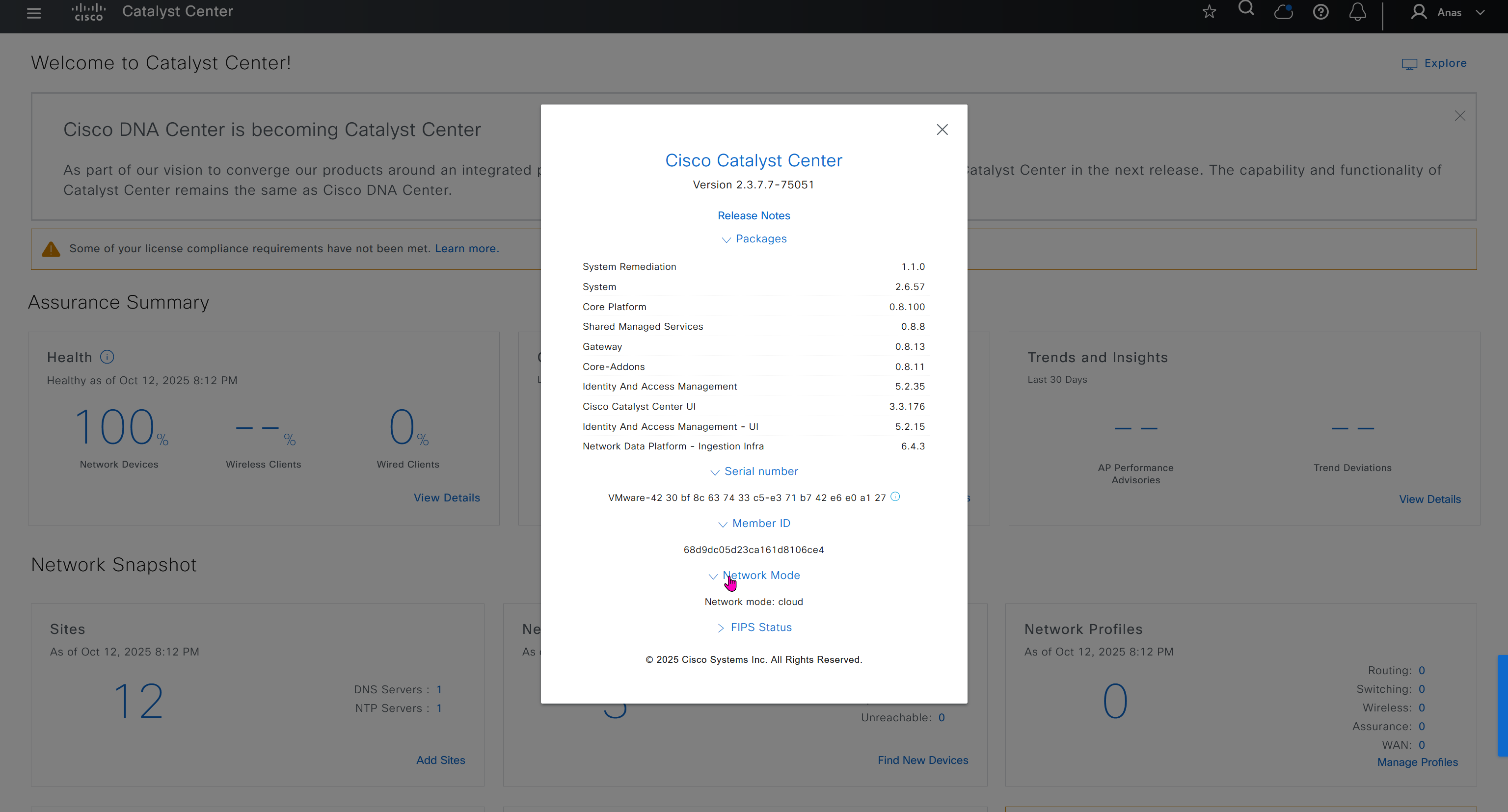
API Reference
This comes handy when you are working with API
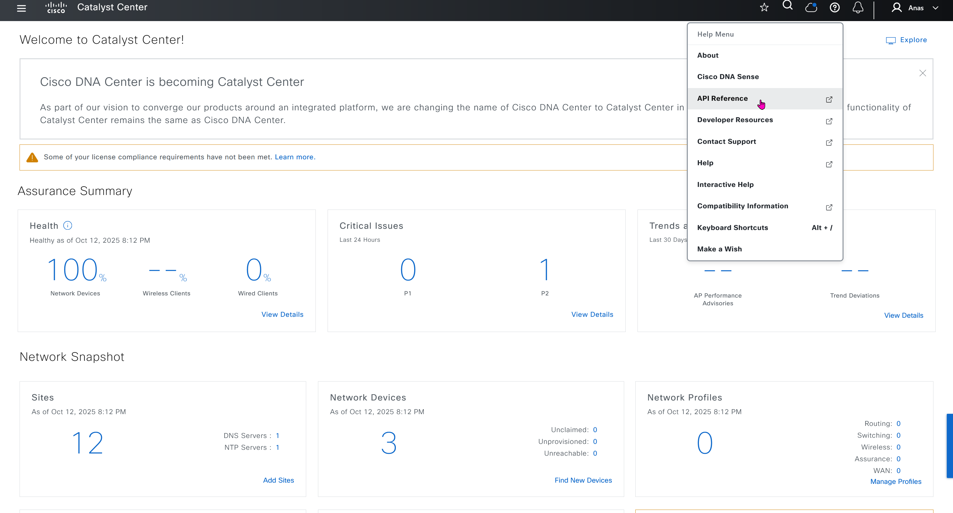
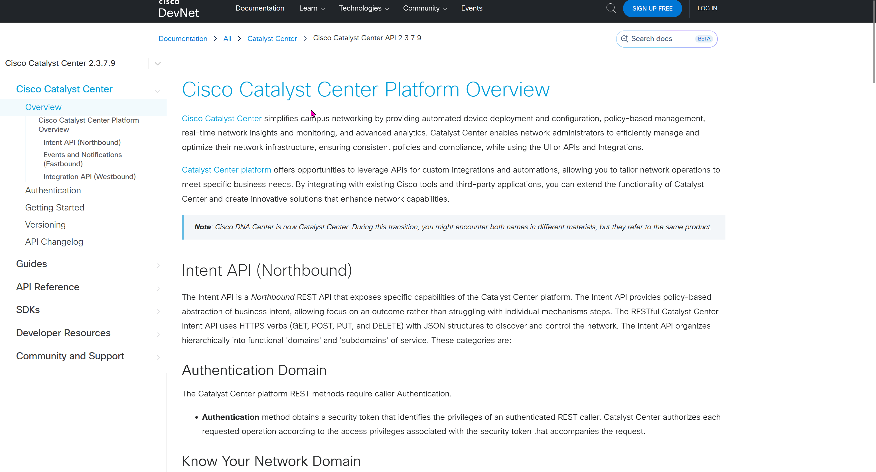
next post
SDA LM5 – SDA Fabric Virtual Networks
Videos
SDA Fabric Virtual Networks
Fabric Site
Fabric Site contains its own components such as border node, control node, access switches and Wireless controllers – imagine a typical site or building or campus that has network components
A fabric site can span multiple building but only over a high speed, low latency network and not WAN connection
Transit Network
Transit Network either connects multiple Fabric Sites together or connects a Fabric site to an external network
and there are different types of transit networks which will be discussed
Fabric Domain
Fabric Domain is made up of one or more Fabric Sites
Geographic distance between buildings and location decides the fabric site’s boundary
Type of WAN decides the Transit Network type
Depending on the version of SDA and cisco documentation, fabric site can only be so big and scale, if fabric site is bigger than what is supported by SDA, then you will have to break up the single fabric site into 2 Fabric sites
So make sure to check scalability number in Cisco documentation
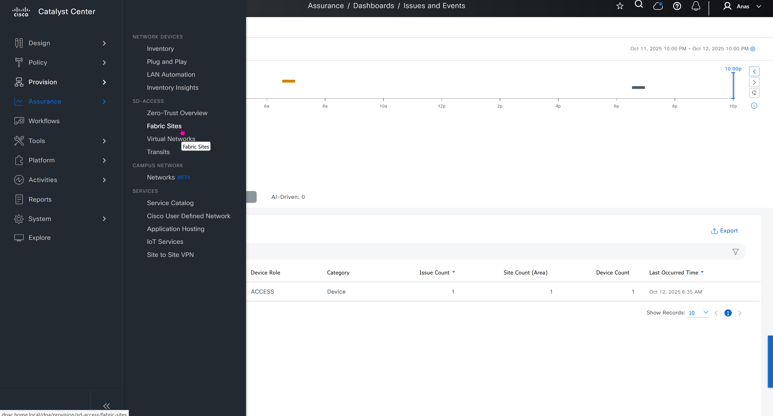
Make sure you have all devices that will be part of the fabric already discovered, reachable, managed and synced and LAN Automated, preferable compliant also

- Second most important thing is that, make sure that your edge devices do not have a route to DNAC via their default route and must have a specific route, I learned this the hard way
SDA-HQ-FES-01#show ip route 10.21.1.2
% Network not in table
SDA-HQ-FBS-01
conf t
ip route 10.21.1.0 255.255.255.0 172.17.0.3
!
router isis
redistribute static ipSDA-HQ-FES-01#show ip route 10.21.1.2
Routing entry for 10.21.1.0/24
Known via "isis", distance 115, metric 10, type level-2
Redistributing via isis
Last update from 172.16.0.72 on GigabitEthernet1/0/4, 00:00:05 ago
Routing Descriptor Blocks:
* 172.16.0.74, from 172.16.0.64, 00:00:05 ago, via GigabitEthernet1/0/3
Route metric is 10, traffic share count is 1
172.16.0.72, from 172.16.0.64, 00:00:05 ago, via GigabitEthernet1/0/4
Route metric is 10, traffic share count is 1SDA-HQ-FES-01#ping 10.21.1.2
Type escape sequence to abort.
Sending 5, 100-byte ICMP Echos to 10.21.1.2, timeout is 2 seconds:
!!!!!
Success rate is 100 percent (5/5), round-trip min/avg/max = 114/131/164 msSDA-HQ-FES-01#ping 10.21.1.2 source loopback 0
Type escape sequence to abort.
Sending 5, 100-byte ICMP Echos to 10.21.1.2, timeout is 2 seconds:
Packet sent with a source address of 172.16.0.71
!!!!!
Success rate is 100 percent (5/5), round-trip min/avg/max = 111/122/134 ms
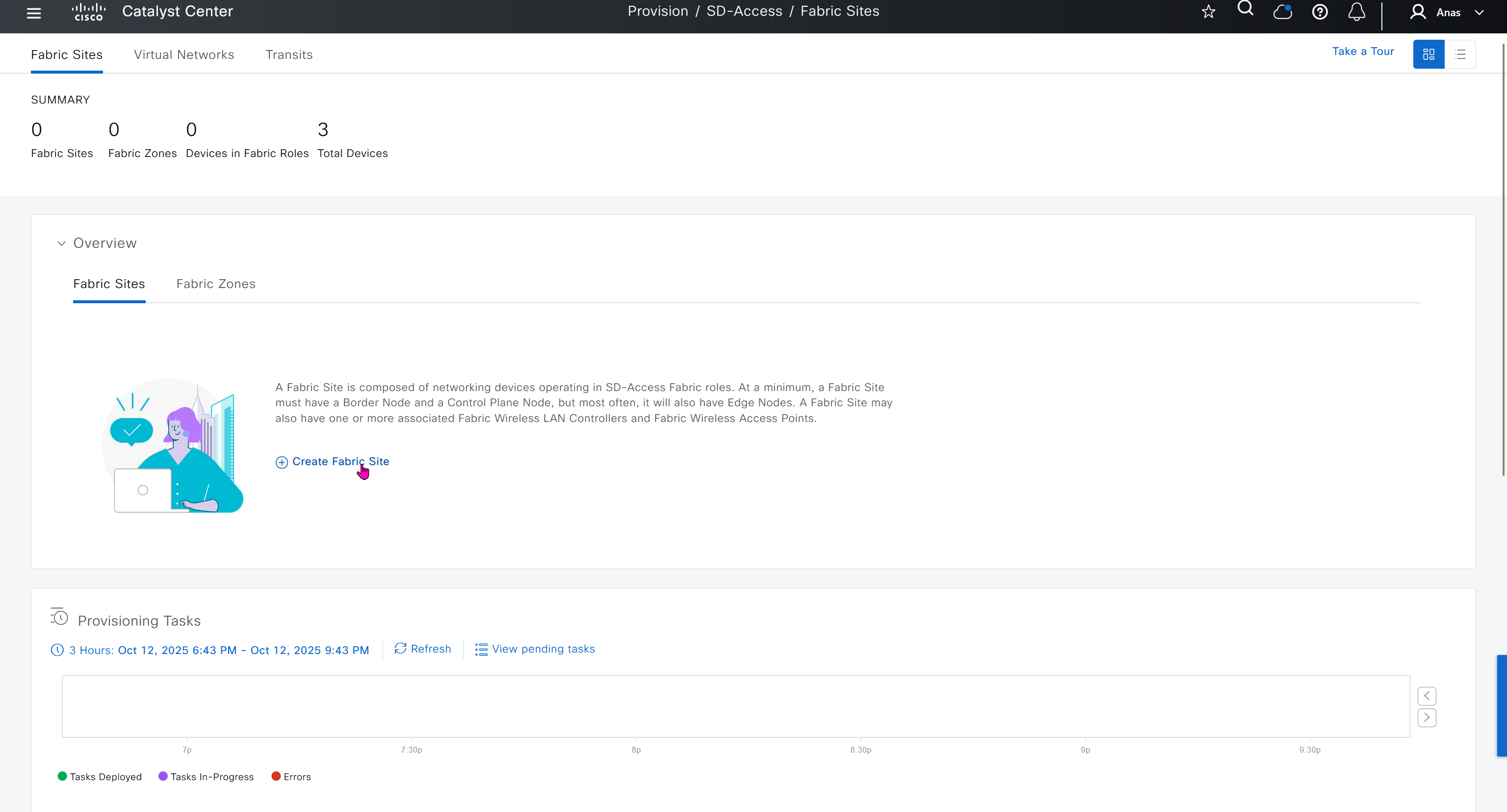
DNAC comes with default LAN fabric
We can either choose to use this or create a new fabric
We should always create a new fabric and not use the default
next post
SDA list all mac addresses under a specific VLAN/LISP instances
On All FES switches run this command to collect the LISP instances
show lisp instance-id * ethernet database | include VlanThen on FBS check all the mac addresses under specific VLAN / LISP Instance
show lisp instance-id 8191 ethernet servernext post
Device Telemetry issue
WLC telemtry issue
provision > inventory > select WLCs >
actions > telemtry > update telem settings > check the push config button > deploy
show telemetry internal connectionnext post
dot1x, mab, authenitcation, access-session commands
Command
authentication periodicEnables periodic reauthentication of connected devices.
-The switch forces the endpoint to re-authenticate at regular intervals.
-Helps ensure that access permissions stay valid.
-The interval is usually controlled by the RADIUS server (or another timer setting).
Example use case:
If a device changes security posture (e.g., antivirus disabled), access can be revoked after reauthentication.
authentication timer reauthenticate serverTells the switch to use the reauthentication interval provided by the RADIUS server instead of a locally configured timer.
Common when using Cisco ISE.
Ensures centralized control of session refresh timing.
access-session inherit disable interface-template-stickyPrevents the port from inheriting sticky interface-template settings after authentication.
Why useful
Avoids persistent policy settings staying applied after the session ends.
access-session inherit disable autoconfStops automatic inheritance of autoconfiguration session settings.
Why useful
Gives tighter manual control over authentication behaviour on the interface.
access-session port-control autoSets the port to automatic authentication mode.
Meaning:
Port starts unauthorized
Device must authenticate
Access granted only after successful authentication
This is the standard mode for secure access ports.
Other possible modes (for reference):
| Mode | Behaviour |
|---|---|
| auto | Authenticate before allowing access |
| force-authorized | Always allow access |
| force-unauthorized | Always block access |
mabEnables MAC Authentication Bypass for devices without supplicant
Used when a device does NOT support 802.1X, such as:
printers
IP phones
IoT devices
cameras
Instead of credentials, the switch sends the MAC address to the RADIUS server for authentication.
Typical workflow:
Switch tries 802.1X
If no response → fallback to MAB
MAC checked in RADIUS database
dot1x pae authenticator| Role | Device |
|---|---|
| Supplicant | Client device |
| Authenticator | Switch |
| Authentication server | RADIUS / ISE |
Configures the switch port as an 802.1X authenticator.
This command enables the switch to perform authentication enforcement.
dot1x timeout tx-period 5Sets the interval between EAP request transmissions to 5 seconds.
0 sec → request sent
5 sec → request sent again
10 sec → request sent again
This controls the gap between attempts.
dot1x timeout supp-timeout 5Sets how long the switch waits for a supplicant response before retrying.
Example:
If client doesn’t respond in 5 seconds → retry
dot1x max-req 3Maximum number of authentication request retries sent to the supplicant.
After 3 failures:
Switch may fall back to MAB (if enabled).
Retries up to 3 times If no response → tries MAB
dot1x max-reauth-req 3Maximum number of retries during reauthentication attempts.
If exceeded:
Session may be terminated or fallback triggered depending on policy.
Putting timers together
Switch sends request
Waits 5 seconds (supp-timeout)
Retry after 5 seconds gap (tx-period)
Repeat up to 3 times (max-req)
tx-period – How often I ask – this will be continuous process when port comes up
supp-timeout – How long I wait – this is what triggers retries
Retries are controlled by max-req, and the spacing between retries is controlled by tx-period.
supp-timeout only controls how long the switch waits for a response after sending each request. supp-timeout simply marks the device as having no supplicant
dot1x timeout supp-timeout 3
dot1x timeout tx-period 10
dot1x max-req 3
t=0 send request
t=3 no reply → supp-timeout expires
t=10 next retry sent (tx-period controls this)
t=13 no reply → supp-timeout expires
t=20 next retry sent
t=23 no reply → supp-timeout expires
STOP (max-req reached)
more…
coming soon
next post
SDA Operations / tshoot
SDA Operations / tshoot
LISP vs BGP in Cisco SDA
In Software-Defined Access:
LISP = fabric internal control plane 🧠
(endpoint location + VXLAN tunnel resolution)
BGP = external route exchange 🌍
(connect fabric to outside networks)
They operate in different routing domains but meet at the border node.
BGP runs only at the border node.
Purpose:
- learn external prefixes from fusion routers / upstream
- advertise fabric prefixes outward
- exchange routes between border nodes (iBGP)
Then how is LISP pub sub deployment in SDA different?
Cisco SDA uses a modified LISP publish–subscribe (pub-sub) model, which changes how mappings are distributed, not what LISP does.
Traditional LISP:
Edge nodes ask the control plane for mappings when needed (Map-Request).
SDA LISP pub-sub:
Edge nodes subscribe to mappings, and the control plane pushes updates automatically.
So SDA reduces lookup latency and improves scale ⚡
Classical LISP control-plane behaviour (pull model)
Host A → Host B
Edge node doesn't know B
→ sends Map-Request to control plane
→ receives Map-Reply
→ builds VXLAN tunnel
→ forwards traffic
SDA LISP publish–subscribe model
Edge node registers endpoints
↓
Control plane stores mappings
↓
Other edge nodes subscribe to updates
↓
Mappings pushed proactively
So instead of:
request → reply
you get:
subscribe → push updates automatically
Much faster convergence and fewer queries.
What exactly gets published?
When an endpoint appears:
Host joins fabric
↓
Edge node registers endpoint to Control Plane Node
↓
Control Plane Node distributes mapping to subscribers
Endpoint mappings in its VN (primary subscription)
Example:
If Edge-1 participates in:
VN = Corp
it subscribes to:
All Corp endpoint location updates
So when a device appears anywhere in the Corp VN:
10.10.20.5 → Edge-3 loopback
the Control Plane Node pushes that mapping to Edge-1.
Edge-1 now already knows where that endpoint lives.
No lookup required later.
What triggers subscription updates
Control Plane Node pushes updates when:
New endpoint appears
Host joins fabric
Endpoint roams
Edge changes
Endpoint disappears
Host disconnects
External prefix changes
New route learned via border node
Border nodes also subscribe
Border nodes subscribe too.
They receive:
Internal endpoint mappings
so they know how to forward inbound traffic from:
Fusion router → fabric endpoint
without querying first.
But does it not cause scalability issues and that is why map-request and map-reply model were used if you are learning / pulling all hosts in a VN?
At first glance, pushing all endpoint mappings to all edge nodes in a VN sounds like it would break scalability. That’s exactly why classical LISP used Map-Request / Map-Reply (pull) instead of flooding mappings everywhere.
But Cisco SDA does NOT push all mappings to all edges. It uses a selective pub-sub model, not a full broadcast subscription model.
Here’s how scalability is preserved.
The key clarification
SDA does not mean:
Every edge node learns every endpoint in the VN
Instead it means:
Edge nodes subscribe only to mappings they are likely to need
The control plane node performs selective distribution.
Edges subscribe to:
Local VN mappings (selectively)
Not the entire VN database.
Instead:
- active mappings
- relevant mappings
- recently used mappings
- mobility-related mappings
The control plane node tracks interest dynamically.
Example with numbers (realistic campus)
Suppose:
Fabric size = 10,000 endpoints
Edges = 40
Endpoints per edge ≈ 250
Each edge typically knows:
its own endpoints
+
active remote peers
+
border mappings
NOT:
all 10,000 endpoints
Another hidden scaling mechanism: map-cache still exists
Even in SDA pub-sub mode:
Edge nodes still maintain a map-cache.
So behaviour is actually hybrid:
Push updates when relevant
Pull mappings when unknown
Cache results locally
This keeps control-plane chatter low.
Host-A talked to Edge-1 and Edge-2
Host-A disconnected
→ notify Edge-1 and notify Edge-2
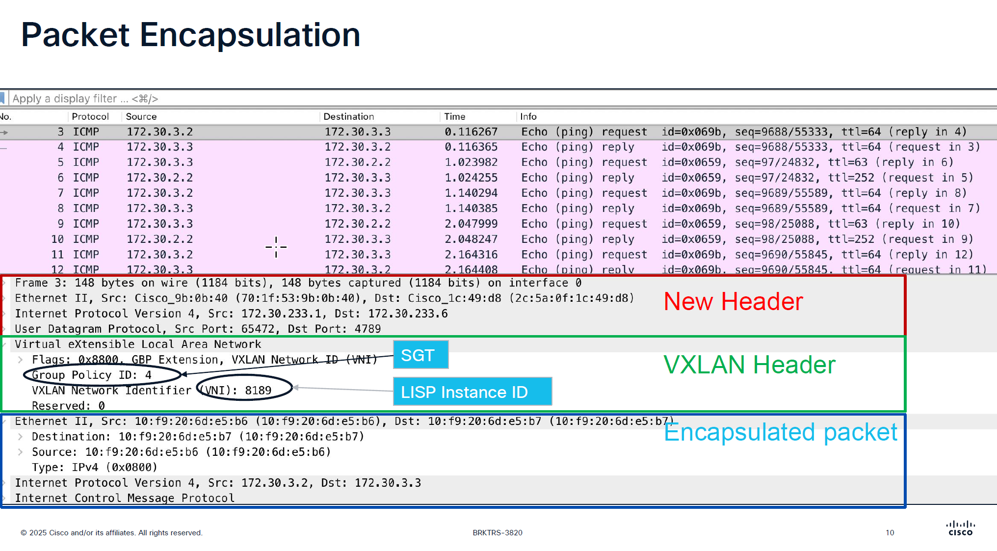
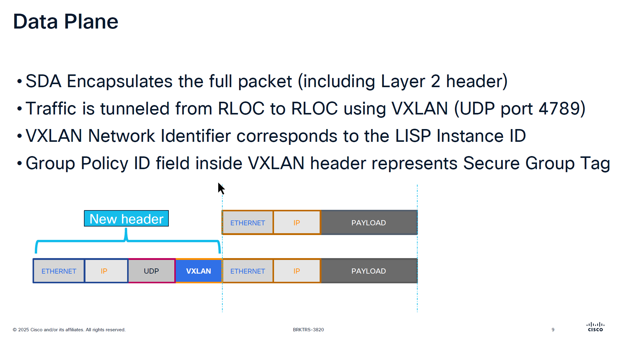
VXLAN looks like an “application” in above picture
Destination Port used by VXLAN is UDP 4’789
Cisco could have used source UDP 4789 to destination UDP 4789 but they wanted the possibility of load balancing through the underlay network that is why Cisco uses random source port because if everything is using same path then we are wasting bandwidth in thet network
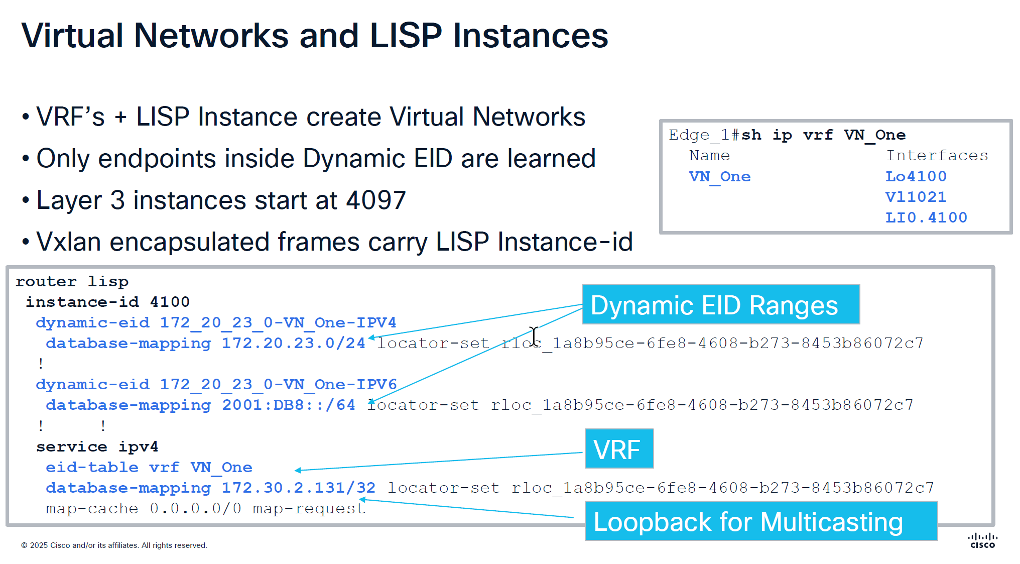
Any endpoint that is connected and is picked up by device tracking and it is in this subnet then it is registered in LISP
but anything outside of this range will still be learned in device tracking but not learned in LISP and will not be advertised out by FBS because security wise anything could connect and get advertised out of the fabric, these endpoints will still be able to speak to devices connected on same switch, but not through fabric
In every VRF a loopback is created dynamically and that loopback is not in underlay but on the overlay, and is used for multicasting and it is shown in above screenshot as “Loopback for Multicasting”
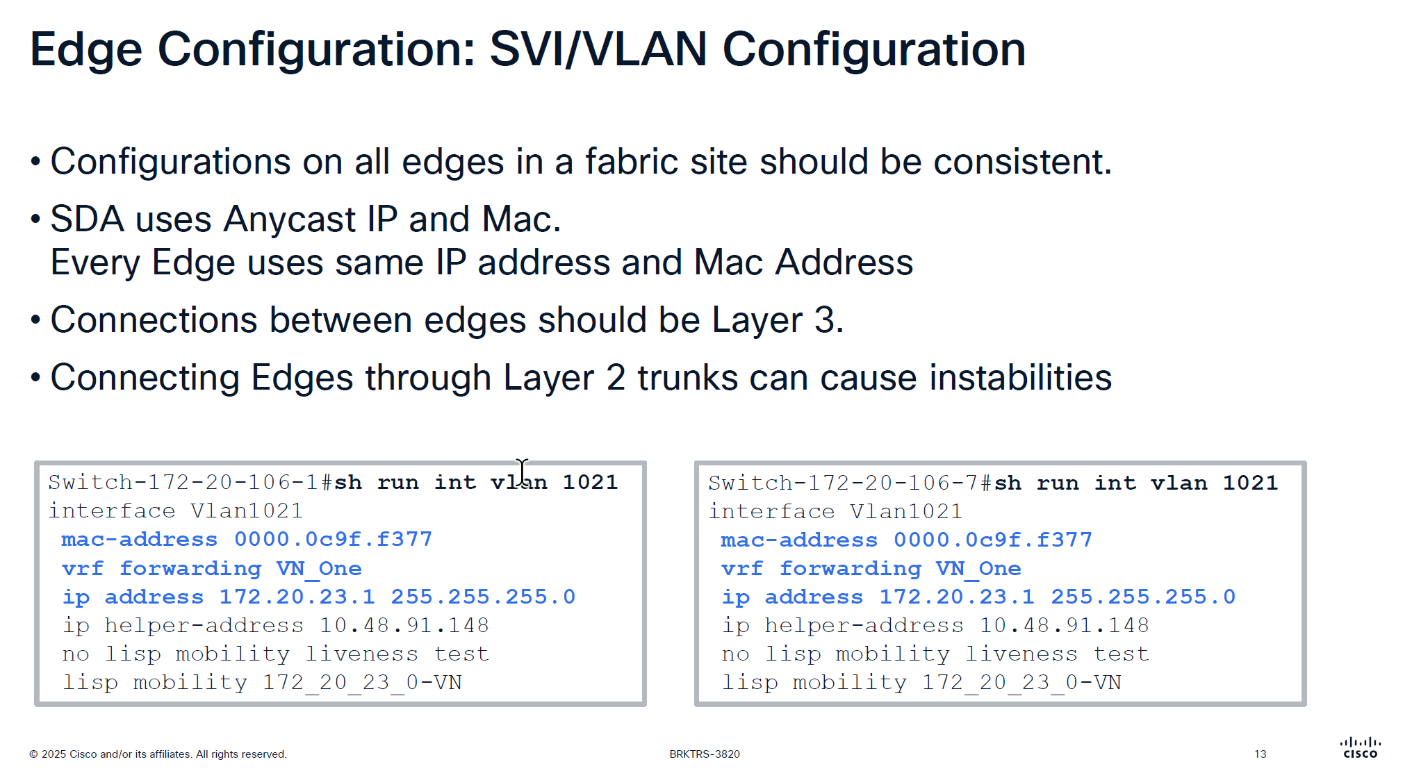
Because we have same Anycast IP and same mac address on all edge devices and because of that we should never connect 2 edges together via a layer 2 trunk, if we do then we will see all sorts of instabilities
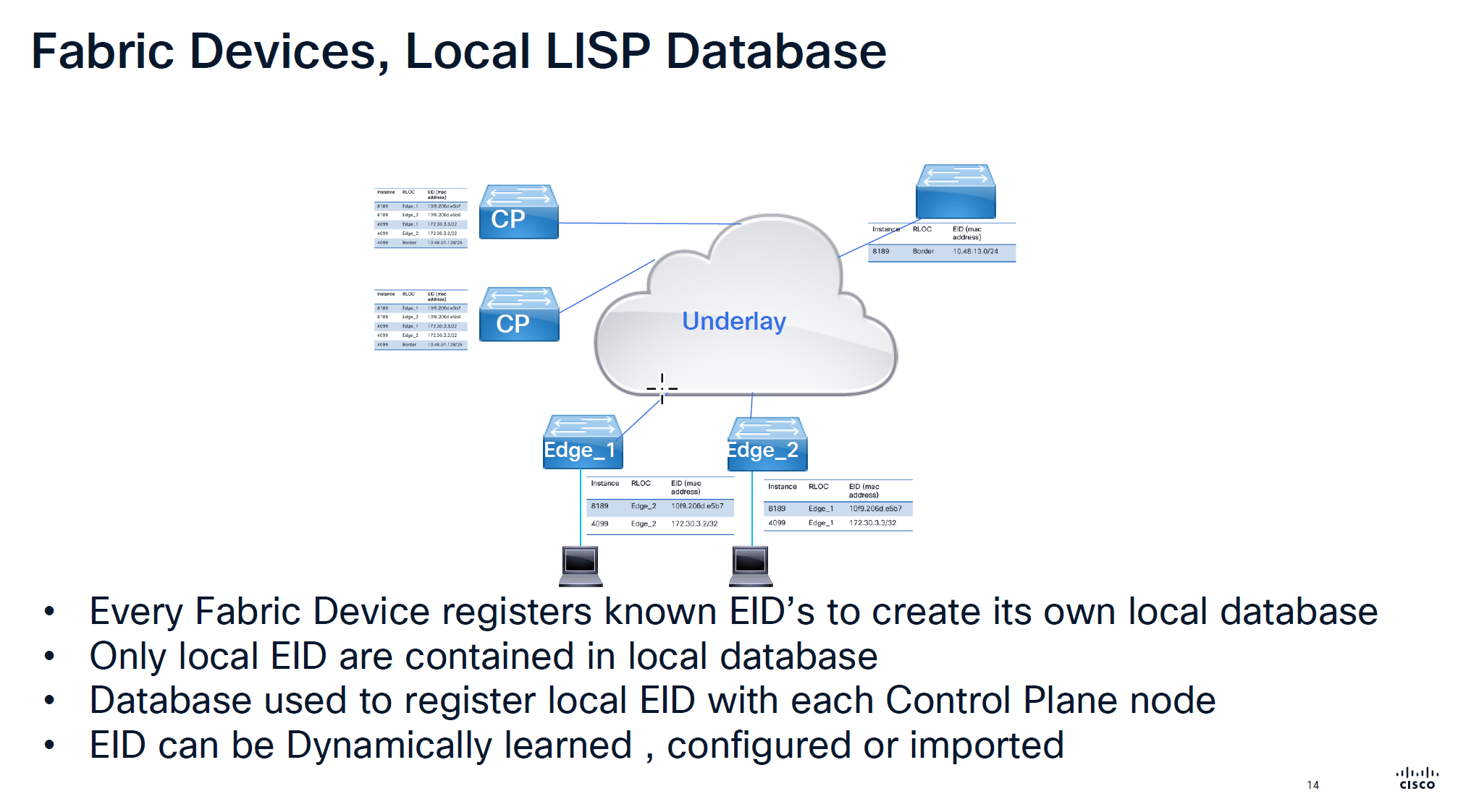
Local Database is built on the edge switch for both IPv4 instance and ethernet instance and the eid learned from local database are registered to the control plane
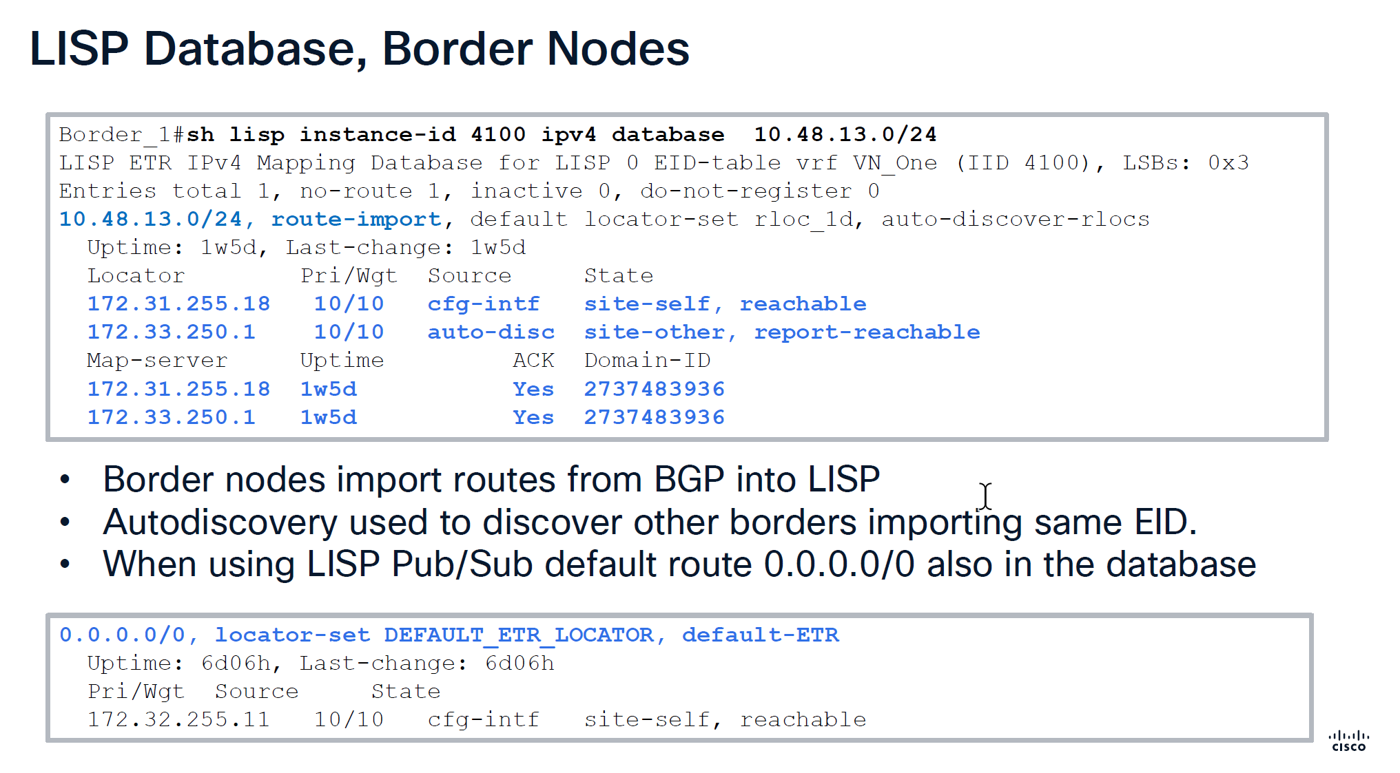
Route import tells us how it came into border node,
It then tells us about the locators it knows about
172.31.255.18 is itself marked as “cfg-intf”
and 172.33.250.1 is other border node known through “auto-disc”
Make sure that control plane has actually acknowledged
With LISP Pub/Sub comes with a ‘dynamic default border’ feature that works if we have advertisesed 0.0.0.0/0 into border per VN > then it is put into LISP database and that is how it becomes default ETR for all of the fabric
With LISP BGP we select the nodes as ‘default border’ but because there is no default route tracking or no default route, in case border node looses routes to uplink, traffic gets blackholed
With ‘dynamic default border’ if default route is not present then it will not be put into LISP and if it is not in the LISP then that device will not be used as default border
During troubleshooting with LISP pub sub, if you see fabric cannot get out and if default route is not present in LISP then that is the issue, in that case check if 0.0.0.0 is on the border node
Below we can see Map-server column having same address as border which means control and border are colocated on same node and it also shows ACK, telling us that it has registered these prefixes and sent ACK back to border saying that it has registered this prefix, if we dont see ACK then it means that there is some issue in border and control communication, either key mismatch and packets were sent to control but it was not accepted
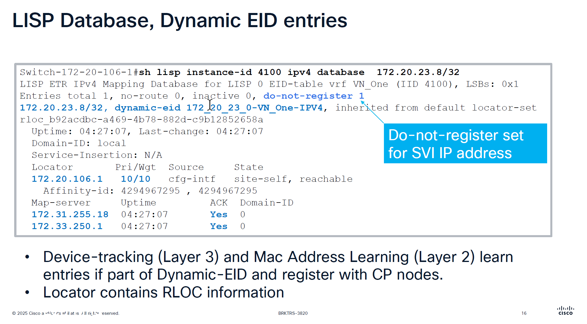
This is edge node that is saying that this endpoint EID has matched this dyanmic EID range and state is ‘site-self’ which means I regsitered it and also tells which map servers or control plane nodes it has been registered and ACK was received for the registeration
This do not register is set for SVI IP because it is anycast IP that is available on all edge nodes
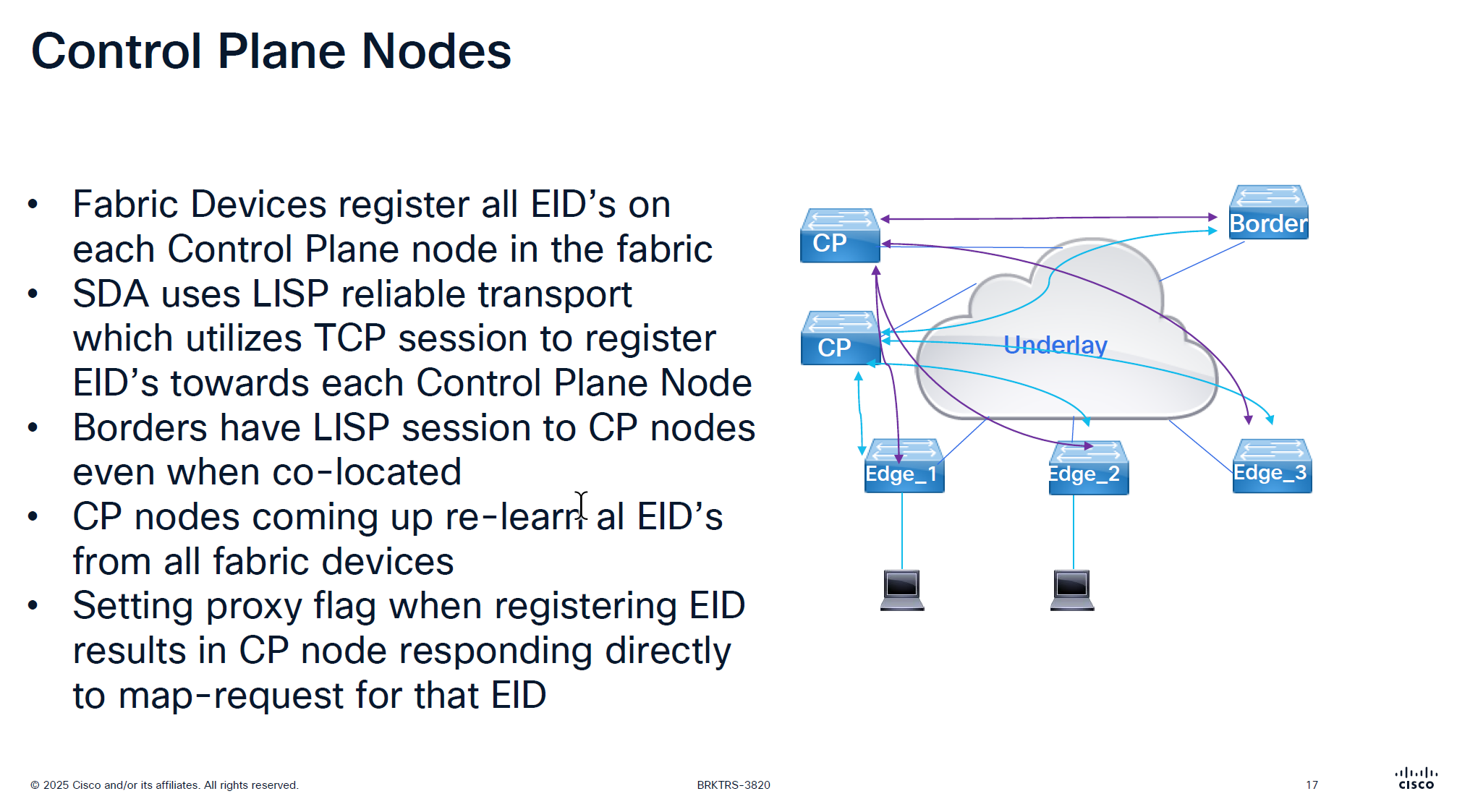
There is no communication between the control plane node, if a control plane node goes down and then comes backup then it has to relearn all the EID from all the edge nodes, CP nodes do not sync with one another , so typically when network is stable it can give the illusion that they are synced due to equal number of EID on both but CP nodes do not talk to one another
map request and map reply
map request is not a request to map an entry or register but it is a query to get a reply from control plane node
Last point is saying that in traditional LISP, Map server only responds to the edge that registered the endpoint, but in SDA version of LISP, map server responds to query from anyone by setting the proxy flag on registration time
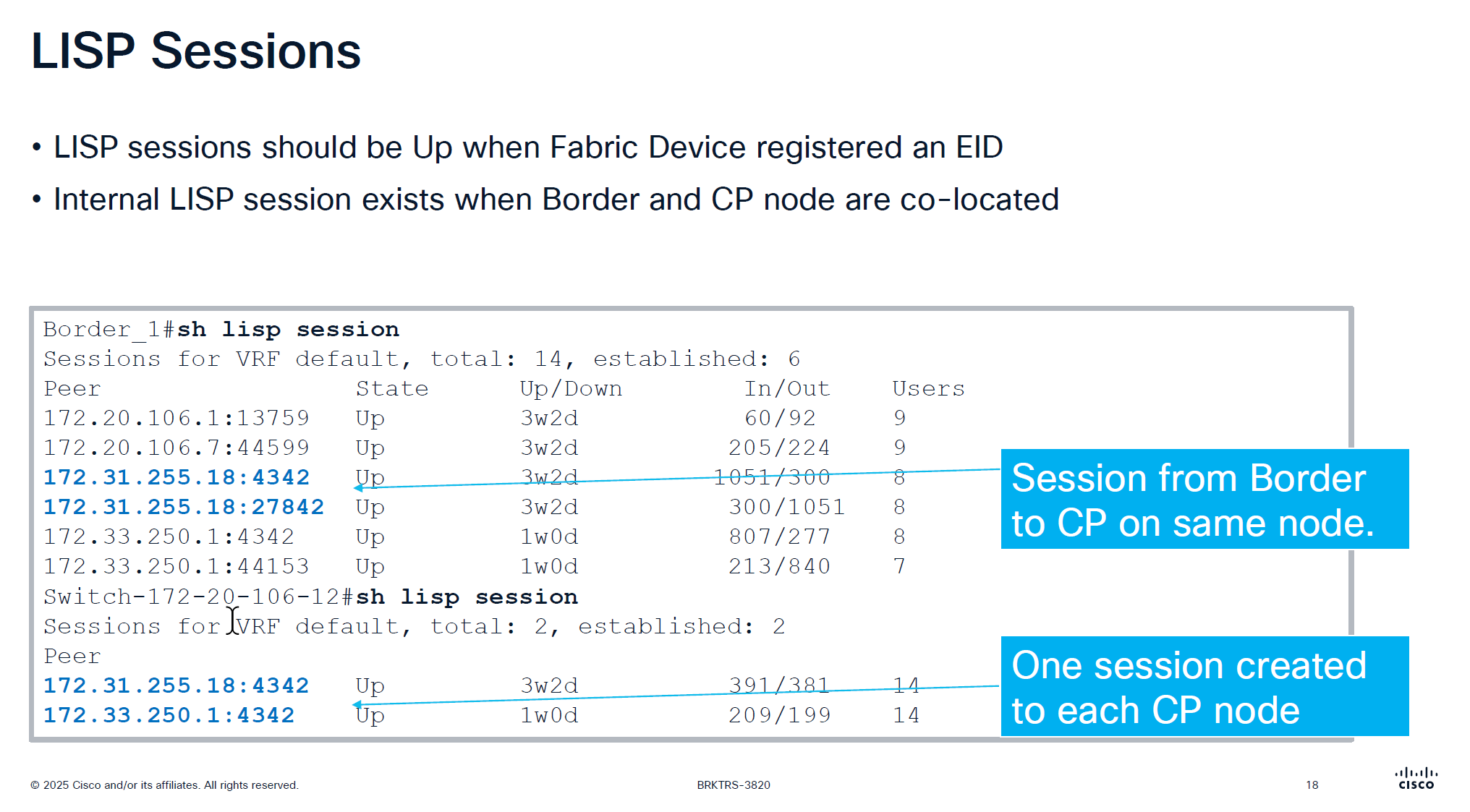
CP and border still make connections to one another if they are colocated on same box
So in LISP sessions you will see it establishing LISP sessions from itself to itself
On the edge node you will see LISP sessions based on number of control plane nodes you have
Users column is not actual user but how many instance IDs are using it
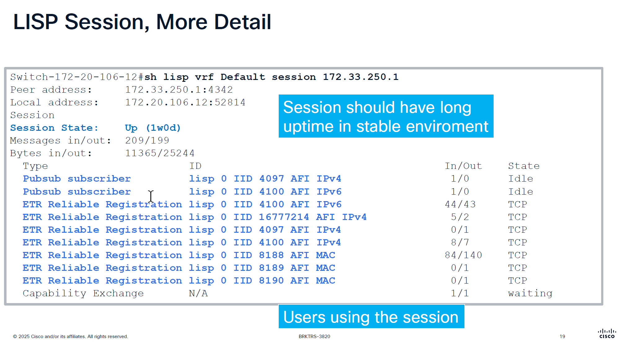
Checking detailed command shows us the LISP instances using the LISP session
make sure that your session up time is big and if it is small then it indicates some sort of network instability and network issues
This command actually shows us that there are LISP instances exchanging information with Control plane node and not just TCP session on port 4342 that is up
That message at the bottom that is “Capability Echange” means that there is a session trying to establish but there is something wrong like key exchange and state is also in “waiting”
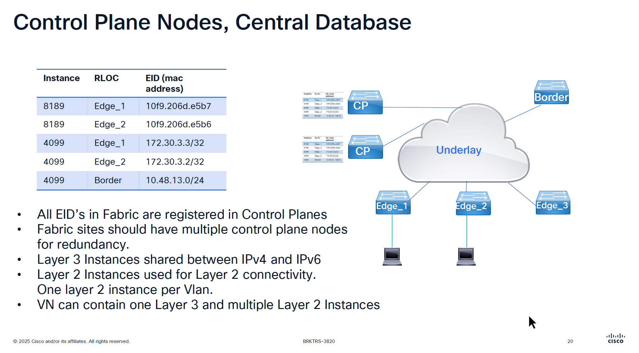
For IPv4 the instance ID start from 4097 and up
for Ethernet instance ID it starts from 8189 and layer 2 instances are used for Layer 2 connectivity and it creates one layer 2 instances per vlan
One VN is one Layer 3 instance and multiple Layer 2 instances
If there are 2 devices in one IP pool across different edges then they will use Layer 2 instance
if 2 devices are on different IP pool or 2 different subnets then they will speak using Layer 3 instance
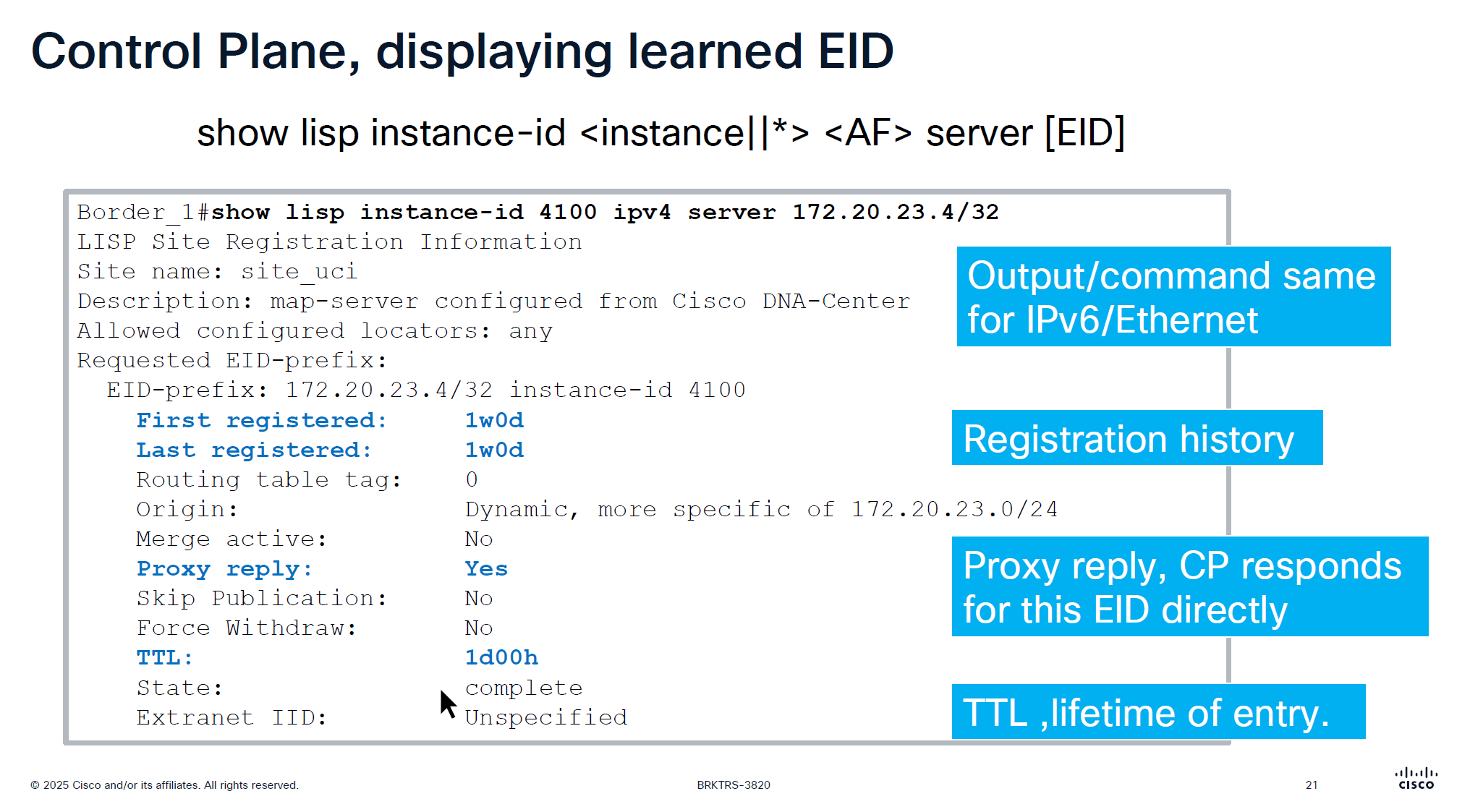
When you see “server” keyword that means we are asking control plane node
This is imporant command to troubleshoot endpoint and LISP registration, it shows when it first registered and when it last regsitered
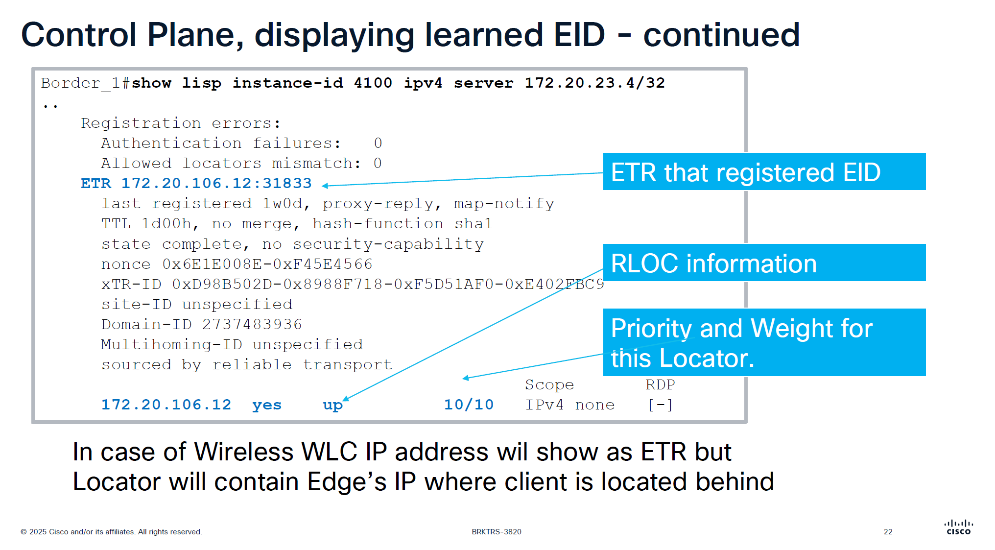
This is output from border node and it is showing ETR as edge node behind which this endpoint lives
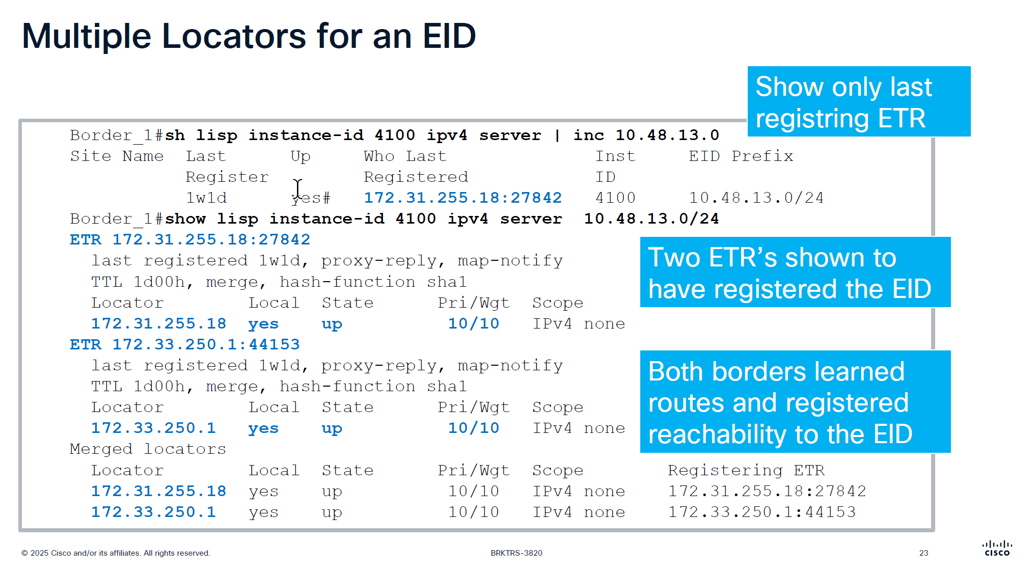
only server command will show us last registering ETR
server command with prefix will show us the ETRs (borders) that are registering that prefix and notice that because of priority/weight of 10/10
LISP priority uses lowest priority number as preferred
If RLOC1 has Priority 1 and RLOC2 has Priority 10, all traffic goes to RLOC1 (Active/Standby)
if both RLOC have priority of 10, then it means both routes will be used in loadbalancing fashion then weights are considered, how much traffic will be sent if priorities are same
If both RLOCs have the same priority (e.g., 10), they are considered equal, and traffic is distributed based on weight.
Weight is used for traffic engineering when multiple paths have the same priority.
It specifies the percentage of traffic a particular RLOC should receive relative to other RLOCs in the same priority group.
If weight is set to 0 on an RLOC then no traffic is load balanced to it, unless it is the last one left
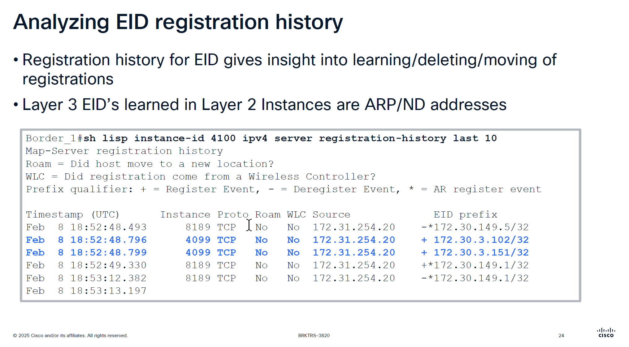
Very important command for troubleshooting for a client, may be it got disconnected or roamed or what not
Notice that first entry that is L3 /32 address being registered inside Layer 2 instance that is ARP regsitration and not the real registration that is also regsitered inside Layer 2 instances
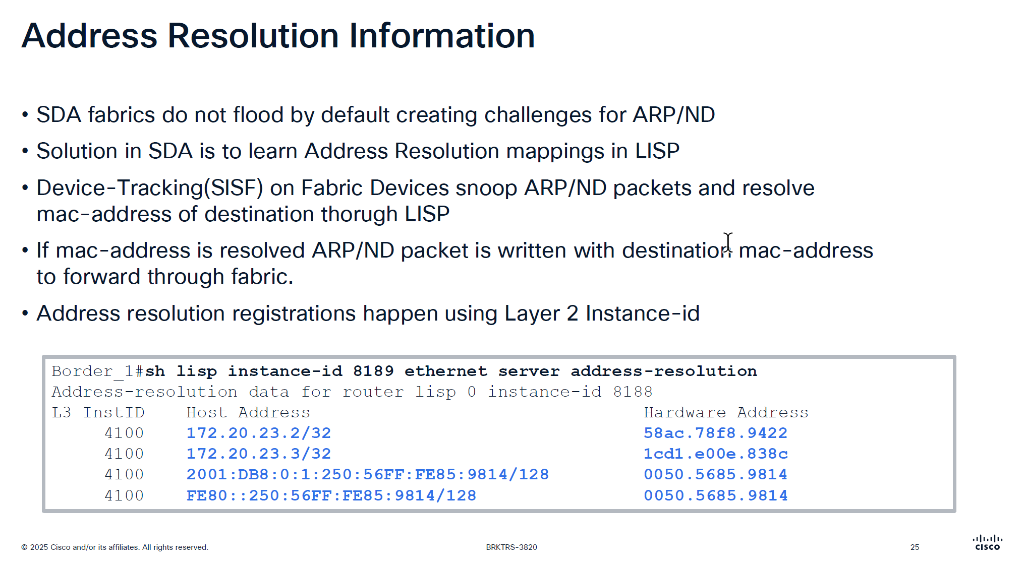
Above command is “server address-resolution” on “Layer 2 instance” on “control node”
Due to VXLAN we can only unicast the packets and broadcasting is not supported unless flooding is enabled on the VLAN but for ARP to specifically work there is a special support in order to get the ARP working, switches snoop the ARP packets for destination inside the ARP message but dont actually flood them yet
LISP then asks for control pane for that destination IP from ARP and control responds with layer 2 mac address corresponding to that L3 address (from device tracking)
then LISP simply rewrites or replaces the broadcast address with the MAC address it received from control plane
this ARP packet is now able to be sent over the unicast over the VXLAN tunnel using Layer 2 instance
This is why silent devices are hard to troubleshoot and do not work over the fabric, this is because they do not produce any traffic and simply want to receive traffic, this makes it hard for device tracking and in turn fabric to not work for those devices
edges nodes have multiple probes going on to speak to those silent devices but there are some devices which are ultra silent and dont even respond to those probes
This command helps in troubleshooting those scenarios because if ARP is not working over fabric then communication will not work
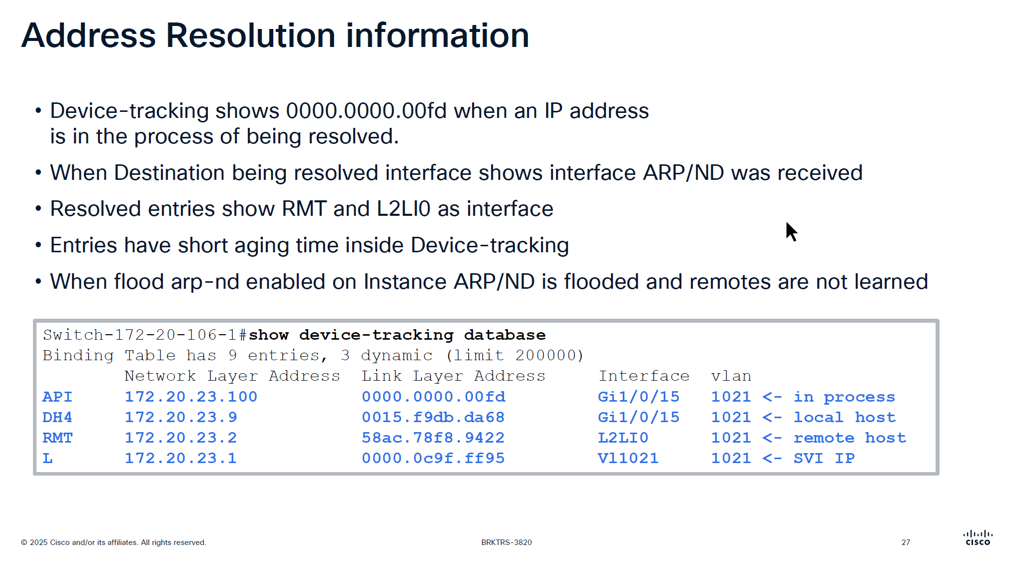
This someone pinging 172.20.23.100 and it arrived on Gi1/0/15
If you see entry for API with mac 0000.0000.00fd in command “show device-tracking database” then it means that ARP packet arrived on the edge node but did not have response from Control node over LISP yet and waiting to be resolved to convert ARP broadcast into unicast
After this resolution completes entry becomes “RMT” (which I guess means remote) with L2LI0 as interface
Because device tracking timers age quickly, this process of ARP resolution might be happening again
Important to note that unicast ARP is received on the remote device and sometimes some IoT devices in testing showed that does not like unicast ARP and only respond to broadcast ARP so in that case we will have to enable the Flooding over the VLAN
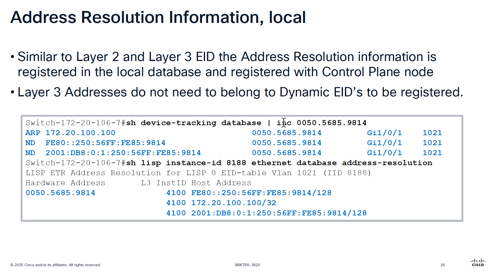
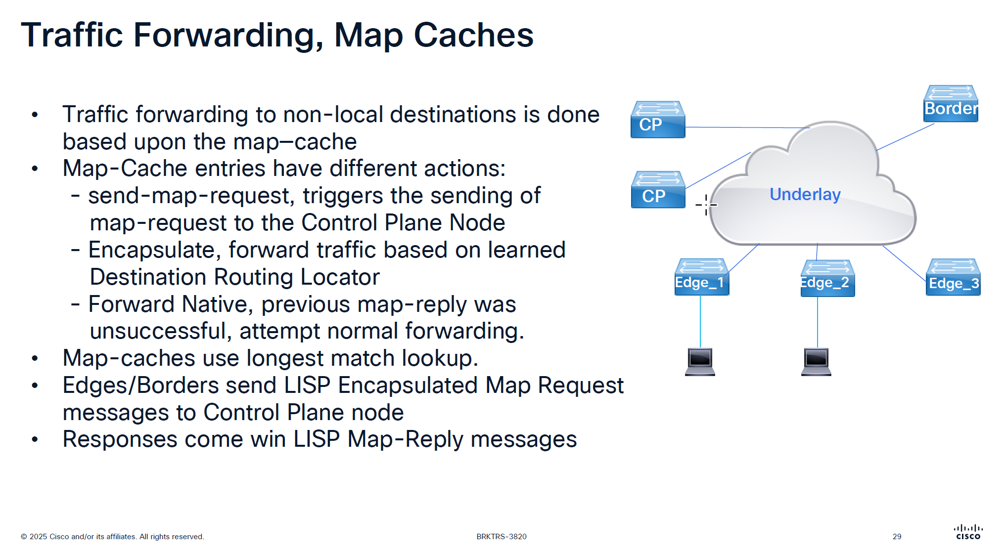
It is no good to speak to control plane about every packet we get
That is why edge node has map-cache to cache the RLOC received for an endpoint for 24 hours
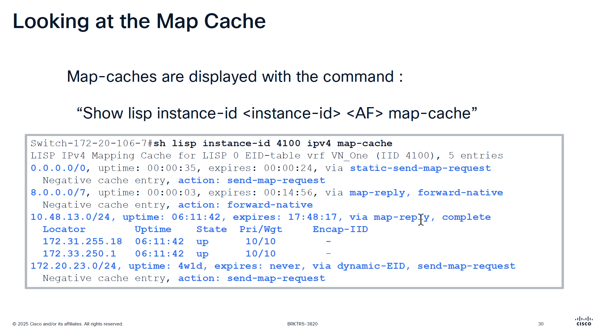
See action
The reason it is 0.0.0.0/0 has action send-map-request because even if we have default border or even dynamic default border we need to still ask control plane node as there might be a better path for destination
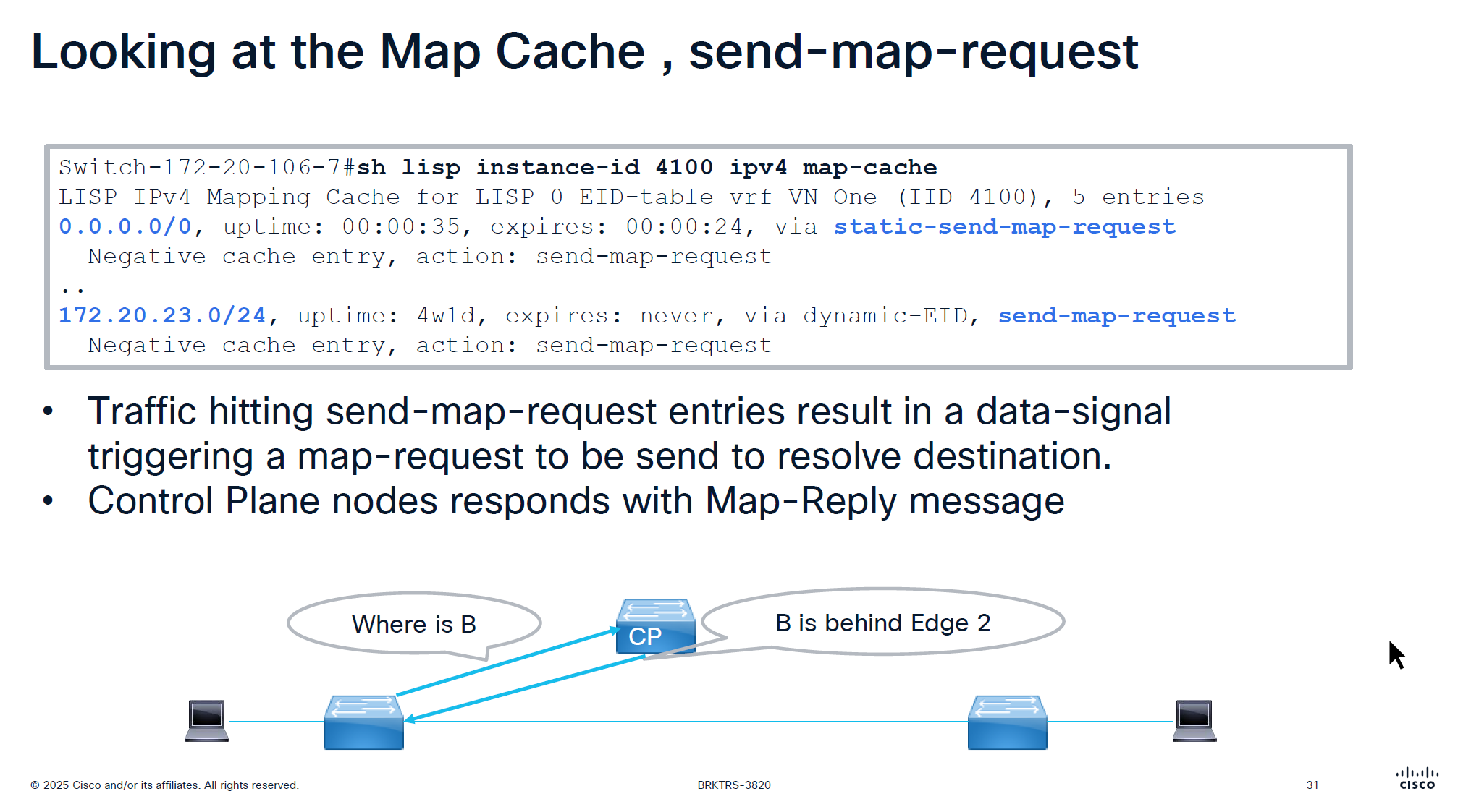
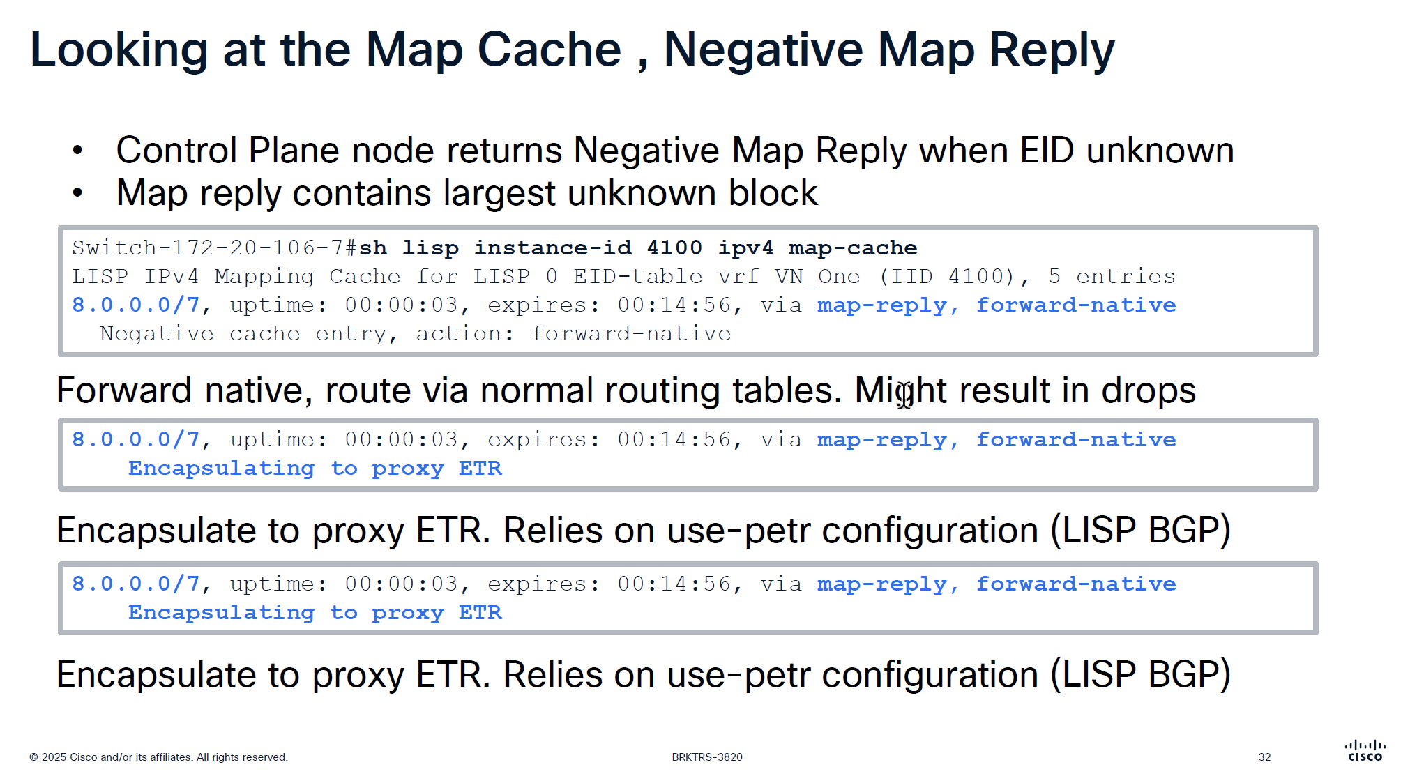
On each edge node in order to reduce queries to control plane node a few “negative” map-cache entries are added in advance with forward native action, forward native on border means to use routing table and not LISP which can have ISIS , OSPF , BGP or static entry for any routes falling under this range but for edge nodes forward-native means connection will be dropped as there is no other means other than LISP
This is done in weird blocks of 0.0.0.0/5 and 8.0.0.0/7 to tell that I dont have routes for those but I have default route 0.0.0.0 and other prefixes we learned from outside fusion world
This is only there for “expires” time which is 15 minutes, the whole function of map-cache is to not consult control node, so this entry means that for those unknonwn destinations do not ask or reach control plane but as this entry expires, edge can reach out to the control plane node instead try to use the routing table (action: forward-native)
0.0.0.0/0, uptime: 1y29w, expires: never, via static-send-map-request
  Encapsulating to proxy ETR
0.0.0.0/5, uptime: 00:00:34, expires: 00:14:25, via map-reply, forward-native
  Encapsulating to proxy ETR
! 0.0.0.1 - 7.255.255.255
8.0.0.0/7, uptime: 38w5d, expires: 00:04:38, via map-reply, forward-native
  Encapsulating to proxy ETR
! 8.0.0.1 - 9.255.255.254
10.16.101.0/24, uptime: 1y29w, expires: never, via dynamic-EID, send-map-request
  Encapsulating to proxy ETR
10.64.0.0/11, uptime: 38w5d, expires: 00:05:08, via map-reply, forward-native
  Encapsulating to proxy ETR
10.116.2.0/24, uptime: 1y29w, expires: never, via dynamic-EID, send-map-request
  Encapsulating to proxy ETR
10.116.3.0/24, uptime: 1y29w, expires: never, via dynamic-EID, send-map-request
  Encapsulating to proxy ETR
10.116.4.0/24, uptime: 1y29w, expires: never, via dynamic-EID, send-map-request
  Encapsulating to proxy ETR
Above slide is little bit wrong
For LISP Pub Sub deployment we see “Negative cache entry, action: forward-native” but for LISP BGP deloyment we see “Encapsulating to proxy ETR” but see below
8.0.0.0/7, uptime: 38w5d, expires: 00:13:47, via map-reply, forward-native
  Sources: map-reply
  State: forward-native, last modified: 38w5d, map-source: 172.20.239.124
  Active, Packets out: 1535384(884381184 bytes), counters are not accurate (~ 00:00:35 ago)
  Encapsulating to proxy ETR
it will use the normal routing table (no VXLAN/LISP encapsulation) because the entry is forward-native, even though a proxy ETR (172.20.239.124) is listed
This line can appear in map-cache entries when:
- the prefix is learned via map-reply
- a proxy ETR exists – A Proxy ETR (PETR) in Cisco LISP / SD-Access is typically the Default Border Node, not the Internal Border Node
A Proxy ETR is used when a fabric device needs to send traffic to destinations outside the LISP mapping system (for example: internet prefixes like 8.0.0.0/7).
Instead of dropping the packet (because no mapping exists), the fabric edge or border node:
➡ encapsulates the packet
➡ sends it to the PETR
➡ PETR forwards it toward external networks using normal routing
So PETR acts like an exit gateway for unknown/non-fabric destinations.
the state field of forward-native overrides it and tells to use RIB/FB
Cisco explains proxy-ETR usage like this:
When a destination EID is not reachable via the mapping system, a proxy ETR can be used for encapsulation, But only when the map-cache entry is in encapsulating state.
State Meaning forward-native use RIB/FIB encapsulating or complete send to ETR negative drop incomplete awaiting mapping
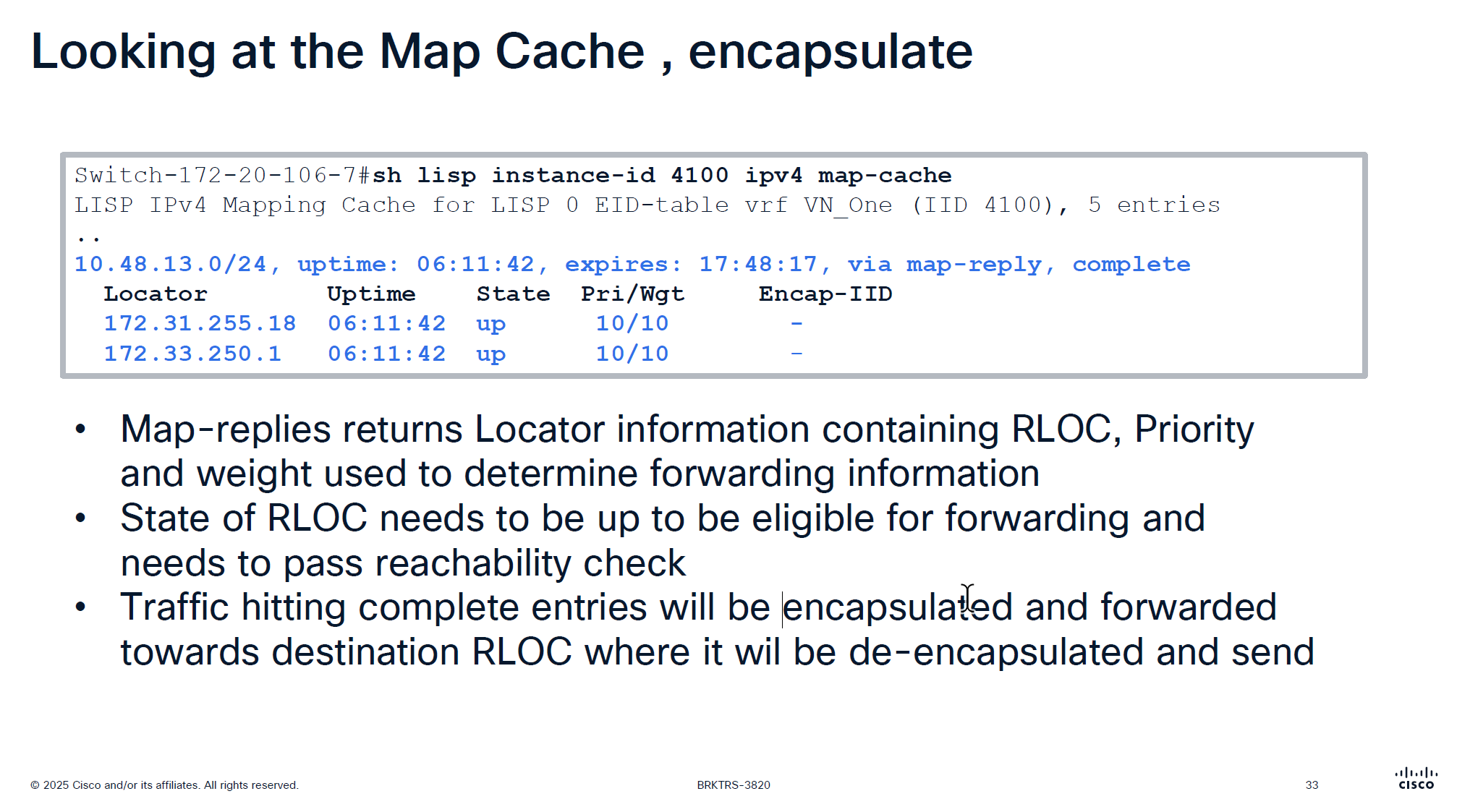
Because this is a subnet 10.48.13.0/24 behind a border, we see 2 borders
Whenever we see Pri/Wgt of 10 and 10 on both borders then it means we are load balancing at VXLAN level, like half flows are sent to one border and half flows are sent to another border and it is not gauranteed that VXLAN UDP packets to 172.31.255.18 are taking a single path through network always and not getting load balanced, even these VXLAN tunnel packets are also load balanced
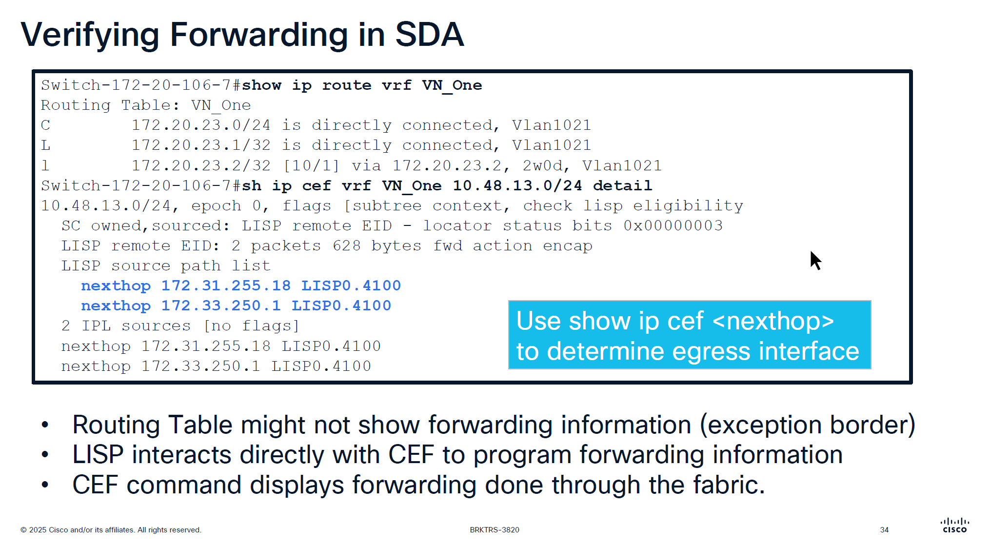
showing ip route in vrf will not show much except on border nodes but on the edge device there is no default route and no other routing present other than LISP VXLAN and fabric stuff
But if we check CEF there is more info because LISP -> CEF directly talks to CEF
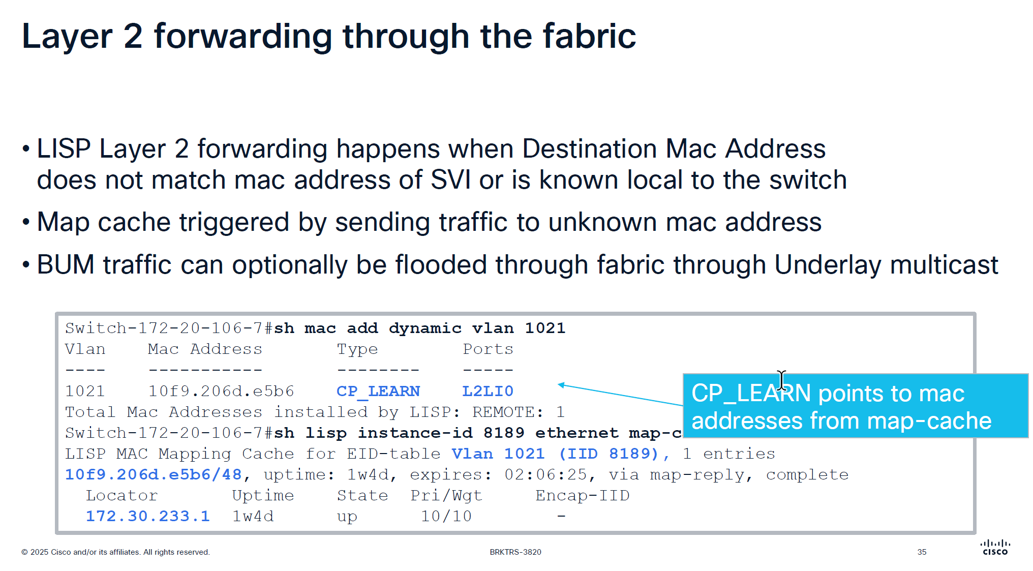
Layer 2 forwarding ia s bit different in fabric
Entry for dynamic MAC learning on edge shows CP_LEARN via L2LI0 tells that this MAC belongs to this vlan on a different edge node
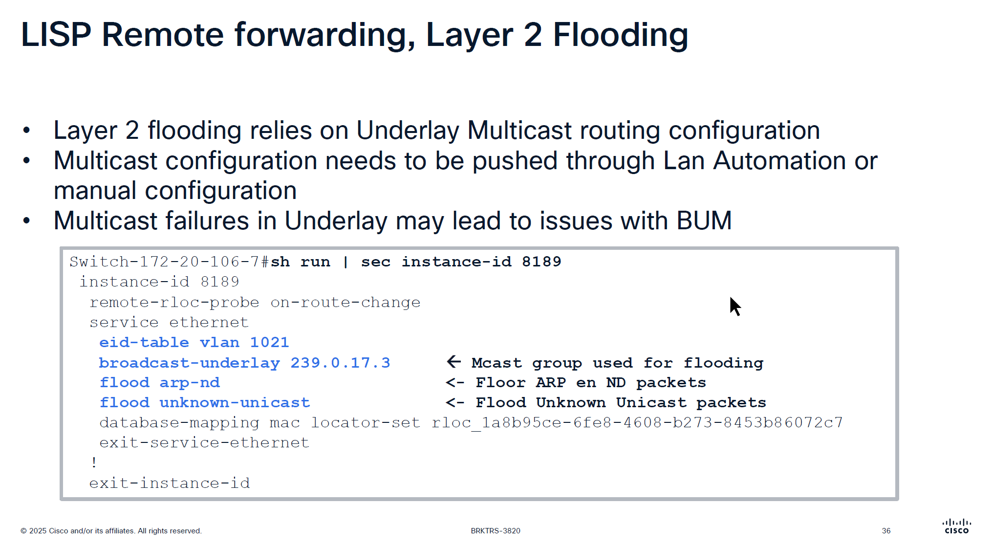
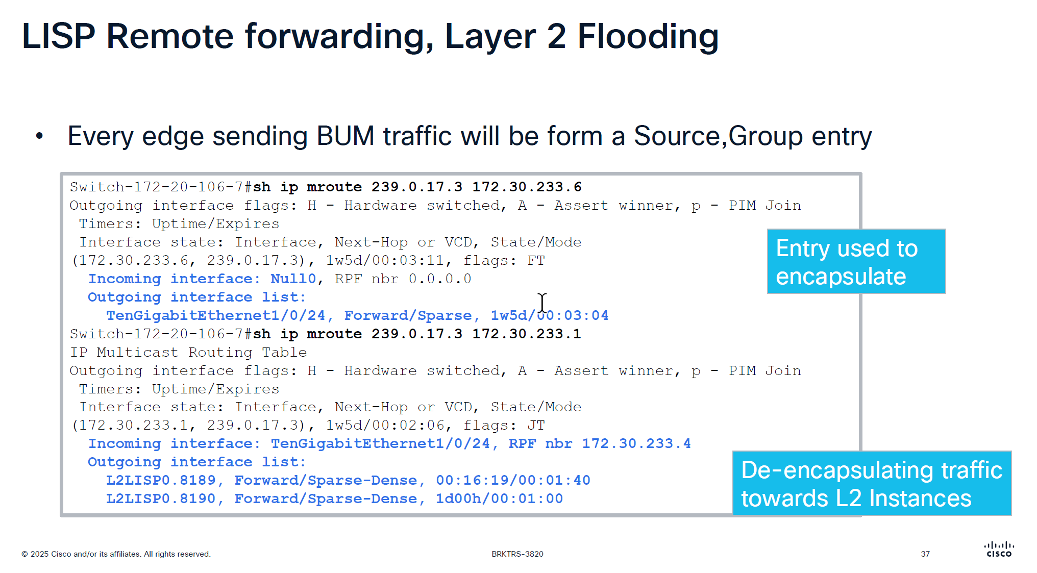
For layer 2 flooding to work on a vlan, the underlay multcasting needs to work
If LAN automation is used, it sets up the underlay multicast
Every edge device shows up as source for a multicast group
We can see the 2 instances that are receiving the multicast traffic (flooded traffic)
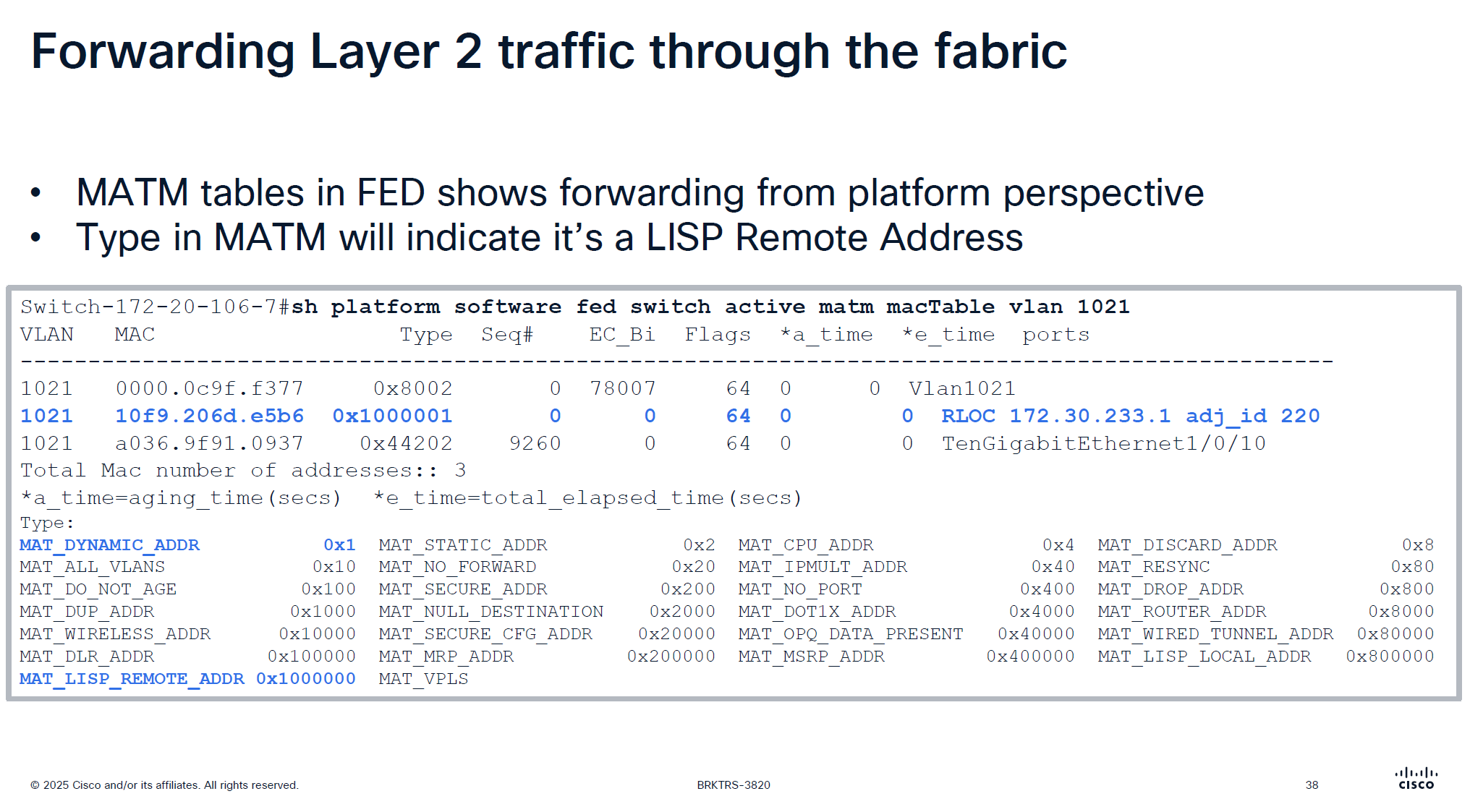
This is to verify if LISP is programming stuff correctly in hardware and this is where MATM comes in
MATM is CEF equivalent in layer 2

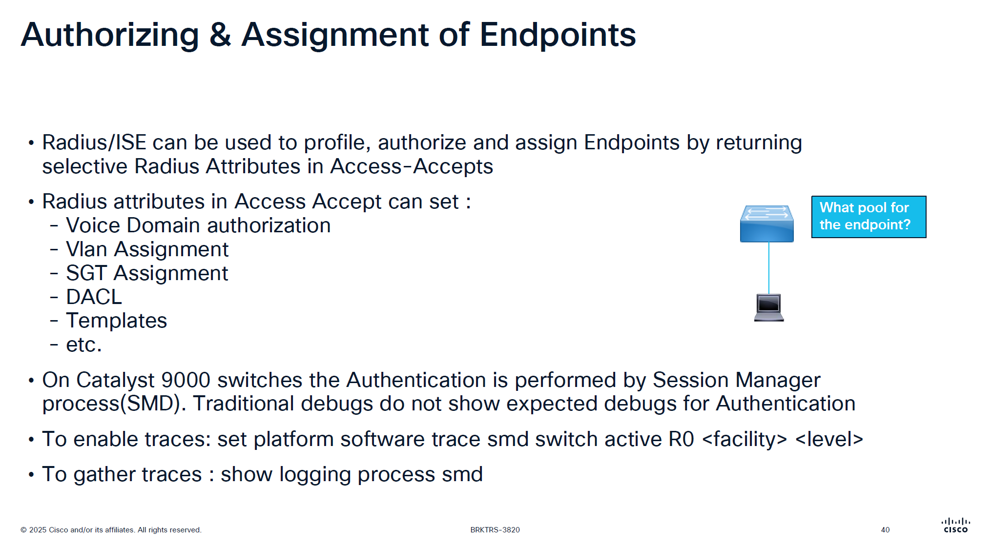
traditionally we could debug dot1x, debug authentication and debug radius etc but now we cannot do that, SMD sits as a seperate process outside of the iosd so we need to follow show logging <process> <name> format
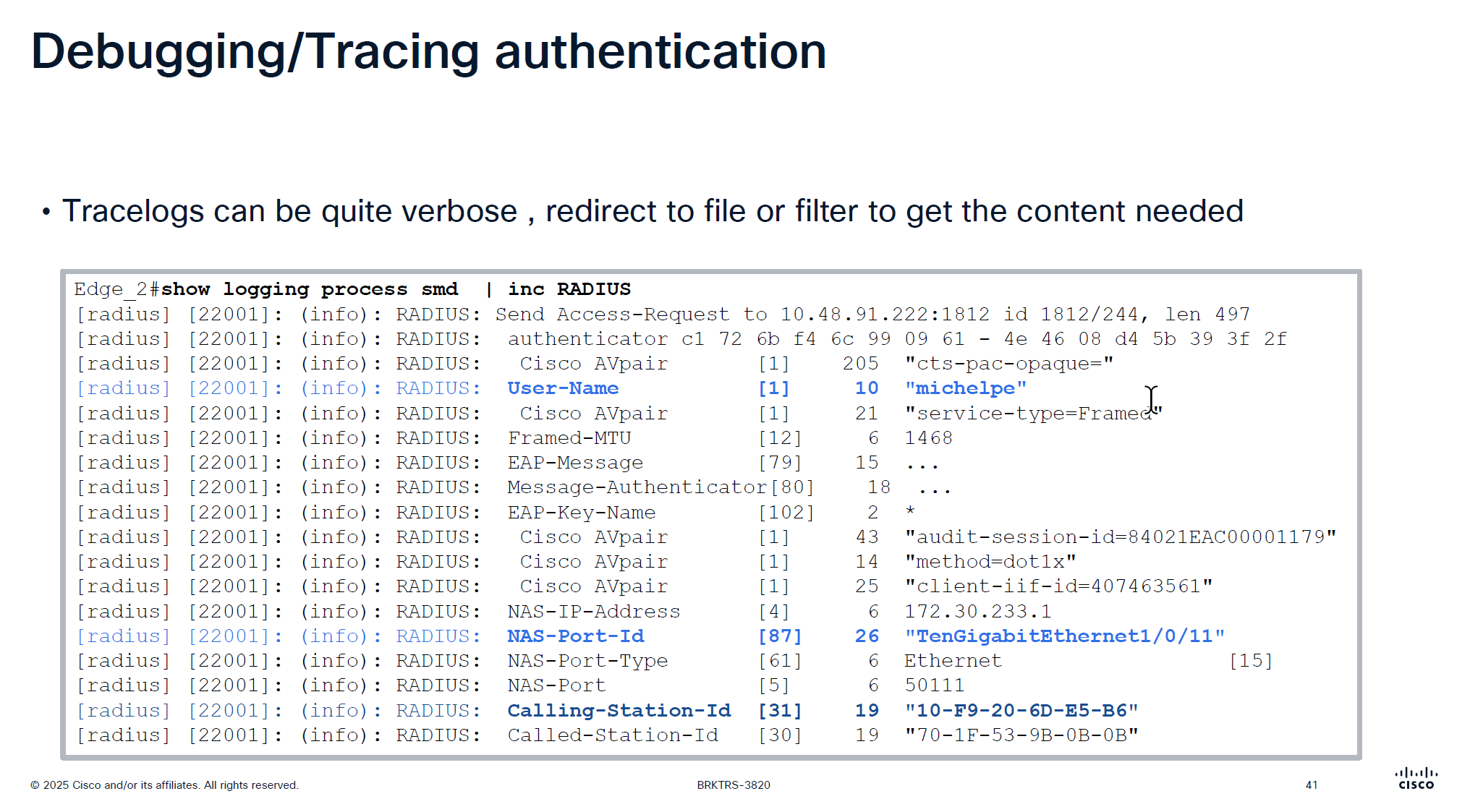
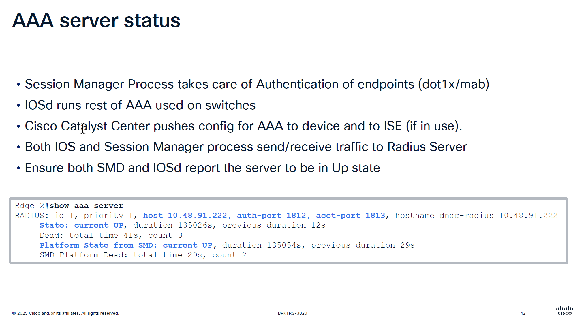
It is very important that RADIUS is up from SMD state as well
in some cases IOS thinks RADIUS server is up, but if it is down for SMD then it will not communicate with RADIUS server and it is waiting on keepalive timer to try again
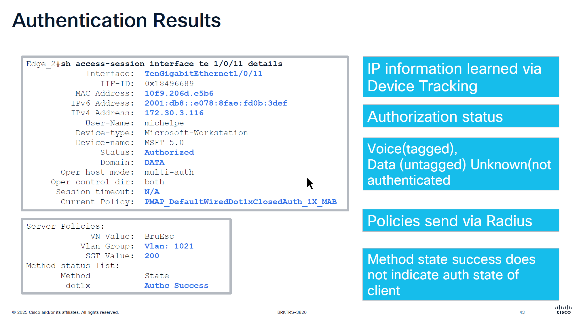
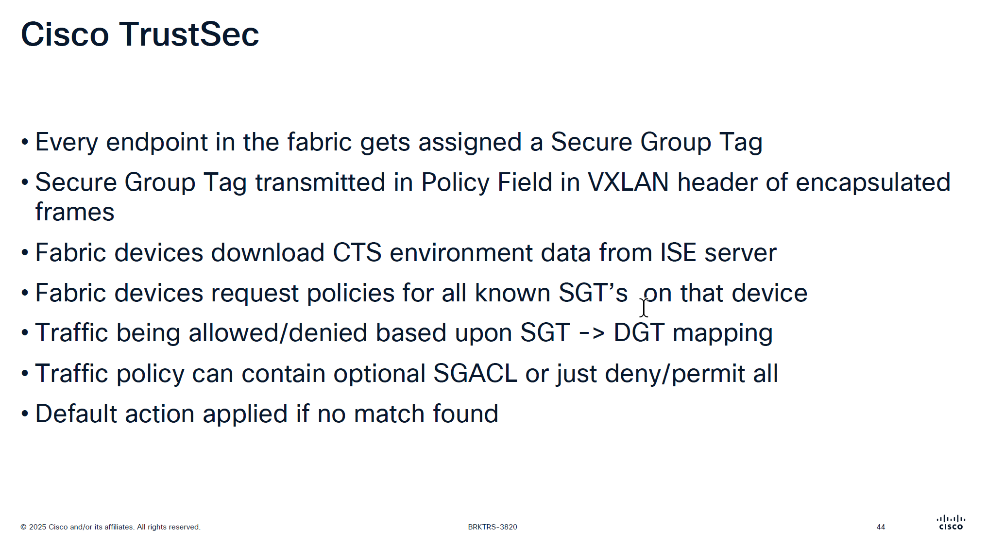
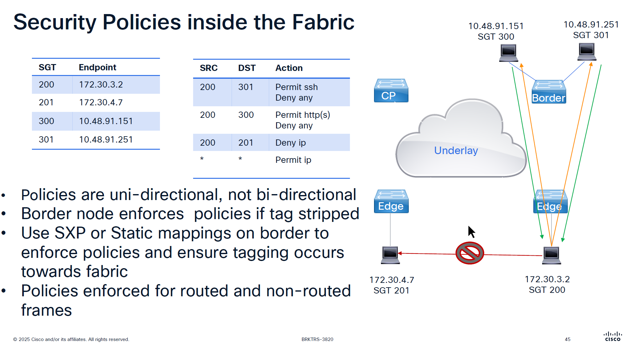
more…
coming soon
next post
SDA SGT
SGT BRKSEC-3690 – PDF
SGT BRKSEC-3690 – Notes
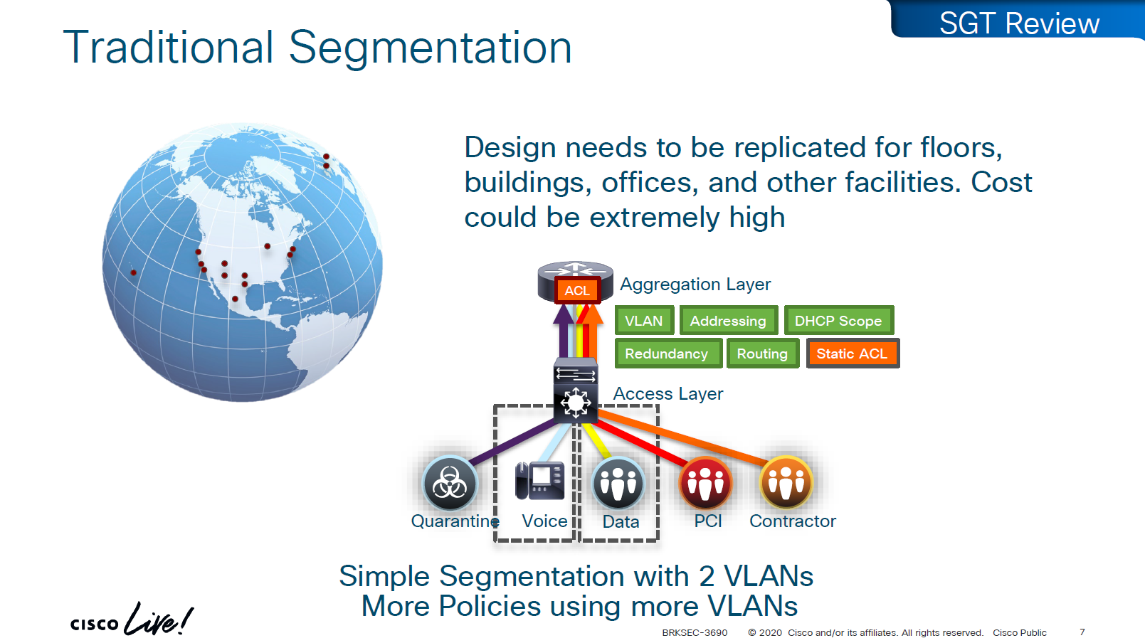
A Security Group Tag is a 16-bit label attached to traffic to identify the security group or role of the source (e.g., Employees, Guests, IoT Devices).
SGTs are used in Cisco TrustSec / SD-Access environments to create role-based access control policies that don’t rely on IP addresses.
SGT is not just used for SGACL or filtering only, because it is a tag on IP packet, this is also being used Policy based routing and also QoS – QoS based on SGT
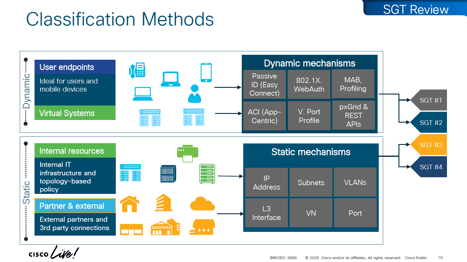
There are 2 ways of classifying the devices in an SGT group
- Dynamic
- ISE
- 802.1x
- MAB, profiling
- pxGrid, Rest API
- ACI
- ISE
- Static
- IP address
- Subnets
- VLANs
- L3 interface
- VN
- Port
Traffic or packets are classified and tagged on ingress into the network which is access layer and filter on the egress of the network
Because classification and tagging on ingress of the network and filtering on egress of the network, it is very important to have tags pushed or transport the tags to all devices on the network
There are 2 ways to do that,
No packet tagging, but use control plane, using SXP (Scalable Group Exchange) protocol to teach foreign devices about the IP to SGT over TCP control plane
This way frame or packet has not been modified or tag is not added in the IP header, and target device also understood the tag that applies to that traffic.
SXP can be activated on a headend only that makes drop or allow policy decisions, it does not have to be applied on all intermediate nodes in the topology hop by hop unlike QoS that requires every hop to do QoS enforcement.
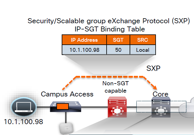
other one is inline tagging
with inline tagging we also have some encryption options such as IPSec or MACsec to prevent people from messing with tags
By default you can go from SXP to inline tagging
to go from inline tagging to SXP you must enable SGT caching
All firewall vendors like Firepower, Checkpoint, Fortigate and Palo Alto, do support pxGrid based implementation for SXP, pxGrid is a publisher and subscriber model where publisher can push information down to subscribers for different topics and one topic can be SXP protocol that has a table that contains IP address to SGT tag mapping
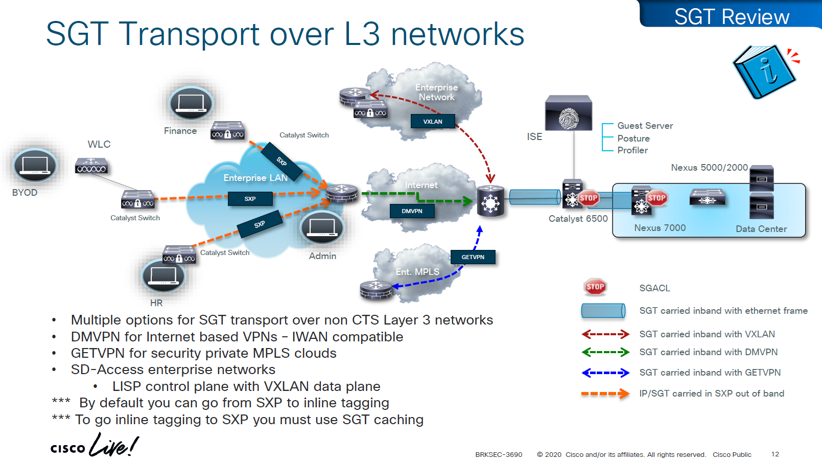
SXP can be activated on a headend only that makes drop or allow policy decisions, it does not have to be applied on all intermediate nodes in the topology hop by hop unlike QoS that requires every hop to do QoS enforcement.
End to end SGT work flow
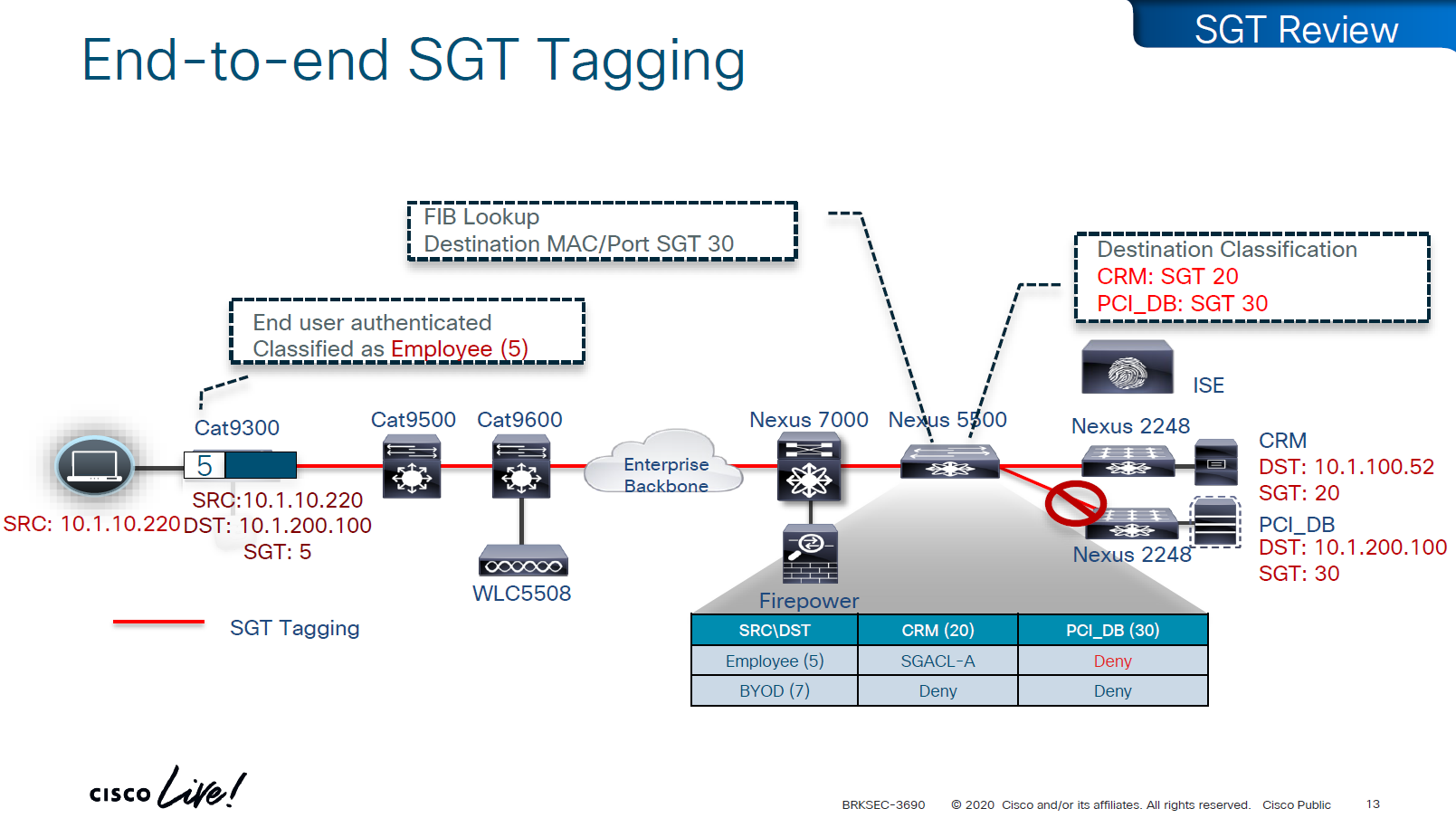
Filtering with SGTs is always done on egress or last switch where destination is connected,
this is because we do not want to overload our access layer switches with all policies and track of all devices connected on the network ahead of it
This optimizes and keeps memory size smaller for small devices,
Access or ingress will only add tag to the traffic and send,
it is the destination switch after it has received the packet,
checks the SGT on the packet – if not on packet, derive SGT from the SXP learned IP to SGT table.
Find out the mac / destination port + the SGT assigned to host on that port – if not assigned on port derive from SXP learned IP to SGT table for that IP
then egress switch will take a policy decision and drop or allow based on policy,
Switches in aggregation or core can be set to look at the destination IP and determine the SGT from SXP learned IP to SGT tag before sending packet out towards destination, this is to drop traffic in core rather than egress
on destination egress or core a log is generated for all deny or drops, if all switches in network point to central logging server, these logs can tell us about the dropped traffic

This shows the policy matrix and how switches that have hosts with certain SGT only pull “columns” from matrix for those hosts only, as soon as a host is connected that has a new SGT, policy column for that SGT is downloaded on the switch, this is very on demand like fashion where switch does not have to download all the policies of the policy matrix and be light weight
Be careful of platform support for SGT when implementing to make sure that platform does support trustsec for all actions such as Classification, Propagation and Enforcement
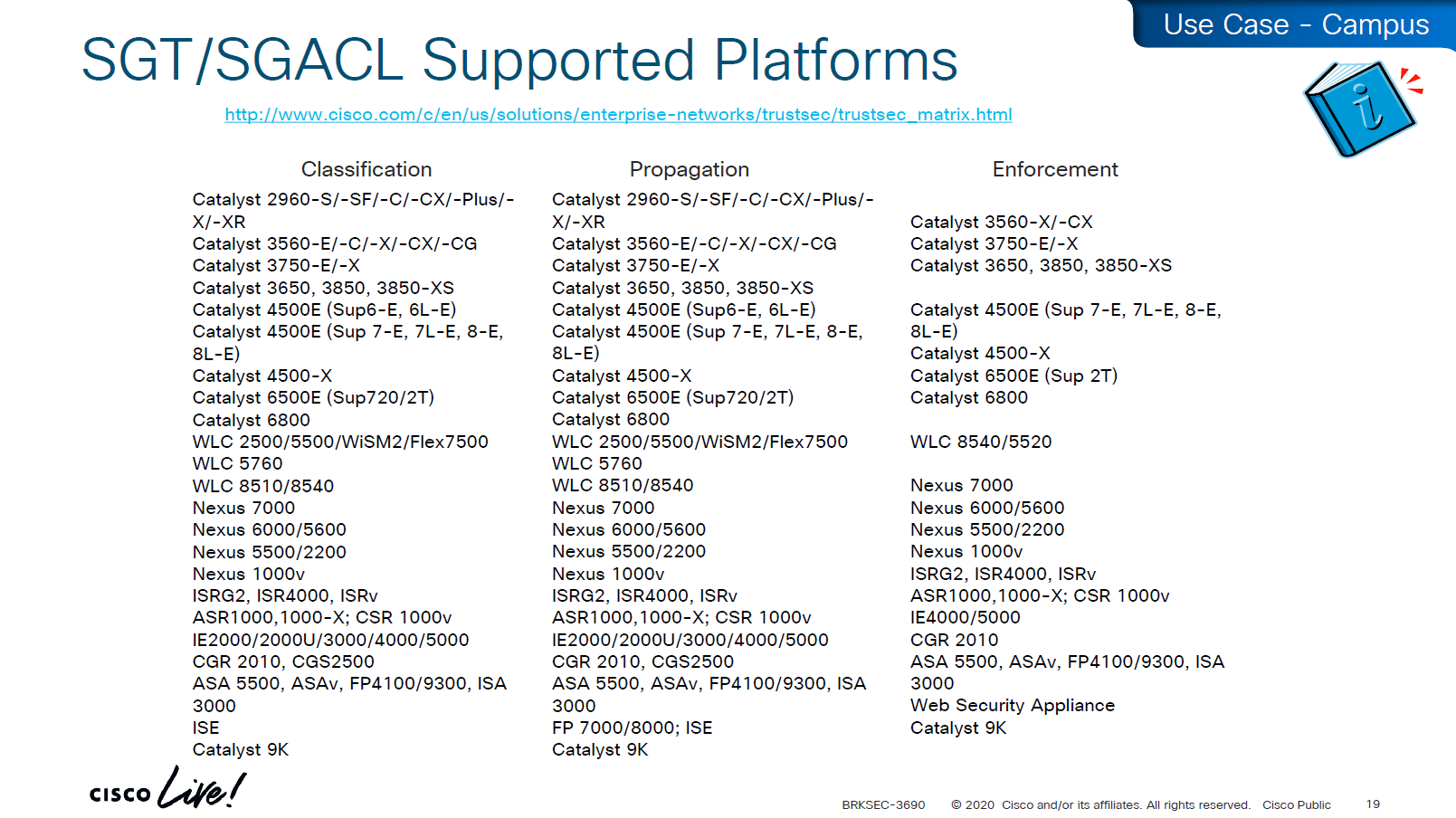

on 3850 as a client we are setting SXP peer (almost like a routing peer) to send it the IP to SGT mappings (local mode)
9K is SXP receiver only using “mode local listener” instead of a speaker
Think of Speaker / local as “teacher” and listener as “learner”
show cts role-based sgt-map all details
! check mappings on 3850 switch

show cts sxp connections brief
! check peers
in above “show cts role-based sgt-map all details” – we can see the one attached host got SGT tag of 6:Full_Access and source is “LOCAL”
similarly not shown here but WLC also a client that got SGT of 3:BYOD and at the bottom we run “show cts role-based sgt-map all details” command on core C9K and we can see both tags learned from SXP (3850 and WLC). Aggregation layer is building table automatically as devices are learned from Access layer devices
Enabling SGT/SGACL Enforcement
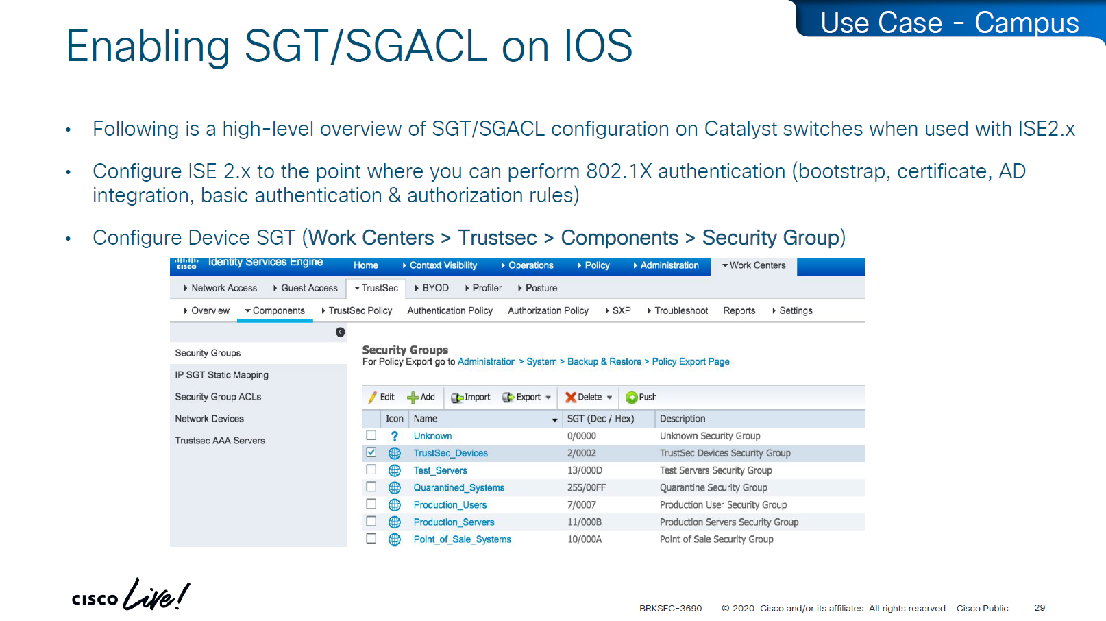
Before SGT/SGACL can be enabled on Cisco devices, make sure that SGT tag for network devices TrustSec_Devices is assigned by default to the network device and make a policy that always allows TrustSec_Devices is always allowed to speak to ISE and infrastructure, why is that needed? because there is a default rule in policy, if it is set to deny then all control plane traffic from device to ISE will be dropped
There was a case once when 2000 switches disappeared from the network, that customer did not have network device SGT like TrustSec_Devices above, they also did not have policy against it to make devices from TrustSec_Devices speak to infrastructure servers SGT, third thing is that they turned on default deny rule in policy
Do not turn on that default deny unless you are really sure that every protocol and everything has been taken care off as it will start dropping the Unknown / untagged SGT traffic as well
Unknown SGT refers to the default tag used when a packet, user, or device does not have a valid SGT assigned. In Cisco TrustSec, this value is typically SGT = 0 and is considered unclassified or unauthenticated traffic. Whenever Unknown SGT of 0 is seen on traffic or host, it means following:
-The client is not authenticated via 802.1X/MAB/web-auth
-Even if authenticated from ISE, there was no SGT in Auth Z results from ISE
-The TrustSec policy mapping isn’t configured
Most TrustSec deployments deny or restrict traffic with Unknown SGT:
- Best practice: Block or isolate Unknown to → Protected traffic in policy matrix
- Allow Unknown to → Internet (e.g., guest networks) in policy matrix
Assign TrustSec_Device to network devices

SGT CTS “peer authentication” between ISE and Device is done through EAP-FAST as PAC file is downloaded on the Network device, PAC which is used in case you want password less certificate like authentication without having certificates. This is called PAC bootstrapping, this is used to download policies, SGACLs and SGT tags then later SXP is used to send or download the SGT to IP mapping separately.

look at send from ISE PSN and test connection button
If there are large number of policy changes, having CLI access from ISE is much faster and better at times, for example there was a customer with 200 x 200 policy matric, it took almost 4 hours to finish the update, it was changed to CLI for all devices and all updates completed in 30 mins, if it is small incremental updates, RADIUS CoA is fine
This device ID is the hostname of the device and password corresponds to command
cts credential id DEVICE-ID password PASSWORD! this is done in non config , enable mode
device>cts credentials id <DEVICE-ID> password <PASSWORD>
show cts credentials
show cts environment-data
show cts role-based permissionsSetting long timers make sure policy is refreshed on devices annually and also only when there is an explicit change in policy

Why the pac key appears under the radius-server host command?
Even though the PAC is used for TrustSec (CTS/NDAC) and not for normal RADIUS authentication, the PAC is delivered through RADIUS using cisco’ vendor attribute, PAC exchange is not a standard RADIUS authentication — it is a special RADIUS message (Cisco-vendor attribute) used only for TrustSec device bootstrapping that is why it is configured under RADIUS server configuration block along with RADIUS shared secret.
cts authorization list <AUTHZ_List_Name> is the list of ISE RADIUS nodes that are running TrustSec
Why Cisco did it this way
Cisco chose to reuse the RADIUS channel rather than invent a new protocol:
- RADIUS is already required for 802.1X authentications
- Switches already have reachability to ISE
- The PAC exchange can ride over the same transport (UDP 1812/1645)
So the PAC bootstrap process piggybacks on RADIUS → therefore, the PAC key configuration lives inside the radius-server settings.
Full configuration of ISE RADIUS Servers with PAC
! Enable AAA
aaa new-model

! Define ISE as a RADIUS server (auth/acct) and include the PAC bootstrap secret
radius server ISE1
 address ipv4 10.10.10.10 auth-port 1812 acct-port 1813
 key RADIUS_SHARED_SECRET
 pac key RADIUS_PAC_SECRET
!

! send vsa or vendor attributes in RADIUS authentication request
radius-server vsa send authentication

! (Optional) put servers into a group and set a source interface
aaa group server radius ISE-GRP
 server name ISE1
 ip radius source-interface Vlan10

! CTS/NDAC: define the authorization list used for policy download only (not tags - tags are pulled before SGACL or policy is pulled) - as clients connect with new SGT , more policy columns are pulled
cts authorization list CTS-AUTHZ

! 802.1X + CTS use the RADIUS group
aaa authentication dot1x default group ISE-GRP
aaa authorization network CTS-AUTHZ group ISE-GRP
! aaa authorization network command is usually used to allow on network or authorize audience or entity authenticated through network ports and this config says that authorized list of server (which are allowed to make CLI or COA changes) will be downloaded from ISE-GRP

! which makes it look like this

aaa authorization network ( CTS-AUTHZ ) group ISE-GRP
aaa authorization network ( cts authorization list ) group ISE-GRP

! Define credentials for EAP-FAST I-ID, these are configured under enable mode and not in config mode
cts credential id DEVICE-ID password PASSWORD

! enable 802.1x on system level
dot1x system-auth-control
! enable CTS enforcement
cts role-based enforcement
SXP does not carry SGACL policies.
SXP only carries IP-to-SGT mappings
SGACL policy travels via DTLS tunnel established using PAC.
Policy matrix is translated or converted into bunch of SGACLs and then sent out to devices
Sequence and use of PAC:
1. Authenticate the switch to ISE for TrustSec
2. Receive the PAC credential
3. Establish a secure, encrypted control channel DTLS for SGACL policy download
It is sent through the PAC → NDAC → Secure DTLS Trust Tunnel that is established after the PAC is provisioned
Switch proves identity to ISE to download PAC -> RADIUS
Policy download (SGACLs and SGT tags – “TrustSec Bootstrapping”) -> PAC established DTLS (UDP)
IP-to-SGT sharing between devices -> SXP (TCP)


First thing to notice in this output is the Local Device SGT that is assigned to network device, any control plane communication from this device will be assigned SGT
Then coming below we can see 3 TrustSec ISE servers are set as servers for downloading SGT tags and SGACL policy (but not SGT to IP mappings which are downloaded over SXP)

We define more tags in ISE, in above picture we can see ACI EPGs (contracts) defined as tags and this is through automation , automatically created through API
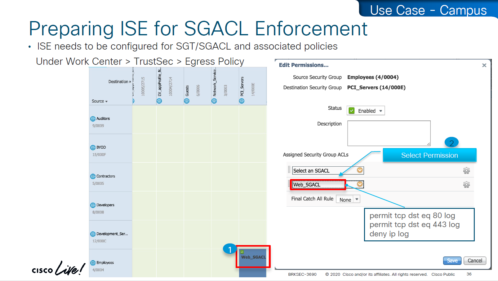
These are stateless ACLs unlike firewalls, this is exact filtering as described ACEs
but best thing about these ACEs is there are no IP addresses
One thing to notice in above screenshot is ability to define multiple ACLs in a single cell of the policy matrix but this is turned off by default as it is not supported by all devices yet because WLCs and Nexus only support single ACL for an SGT and DGT filtering
Only IOS XE switches are supporting multiple ACL per cell

above we can see manual IP to SGT map, which can also be pushed from ISE via CLI or from ISE via SXP
Even if switch has policy matrix table downloaded, and switch also has all the SGT tags, switch will not enforce on traffic unless command is “cts role-based enforcement” is defined
Second command allows us to enable on per VLAN, this is very significant because we can enable SGT enforcement incrementally on VLANs
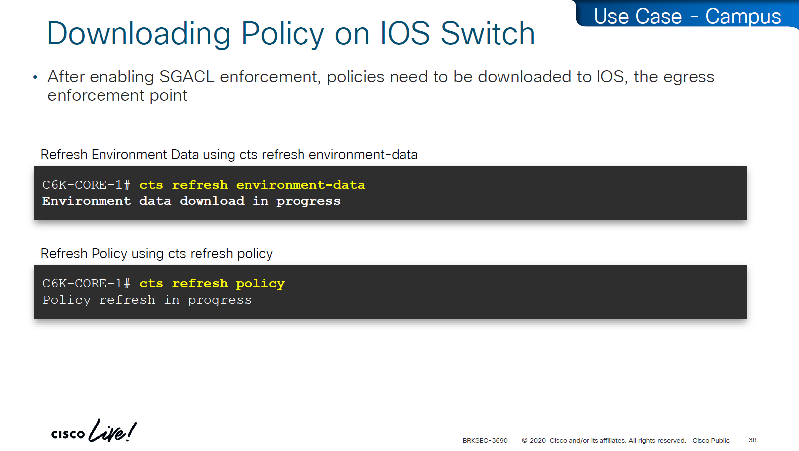
environment data is SGT tags
policy is the policy matrix

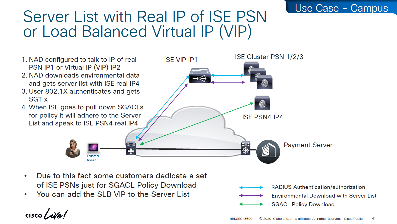
As we can see that RADIUS flow is different
“Environmental Data download + Server list” is different flow before SGACL policy is downloaded
SGACL policy download is from the server list, server list was fetched with environment data

This was done because in peak times when RADIUS servers are busy it can be too much load to download the SGACL policy over same ISE PSN nodes and it is better to download over dedicated ISE TrustSec PSN nodes

in above screen shots dynamic author (RADIUS servers allowed to do CoA) are defined
-PAN should be defined for SGT related flows
-PSNs should be configured for 802.1x / MAB
In older versions of ISE, clicking on Deploy is not enough, there is a confirmation icon on top that needs to be click and confirm, only then ISE notifies all switches that there is a change and download the new policy

There is a policy validation button that runs this command “show cts role-based permissions” and validates that ISE has same policy as devices and if there is any mismatch or issue then an Alarm is generated from ISE


SGACL denies will show as log, and you will see that logging hits are shown as well which means that if there are a lot of logs then number of hits accumulated will be reported under logging_interval_hits and log will be generated, but in some cases auditor will come in and say that they need to see a log for every drop and allow, and at that point we need to understand that this is a switch and not the firewall, with SGACL enforcement it is not possible to get log for every hit

show cts role-based counters
! shows * to * default rule
! also shows from and to columns
! SGACL is done in hardware, unless needs punting
! for example TCAM or hardware is full, log in the end of ACE , makes SW counter increment otherwise concentrate on HW-Denied and HW-Permitted columns
Software denies and software permits are for to the box traffic or traffic destined for the switch, including the DHCP and ARP permits will also increment the Software counters, SGACL enforcement is in hardware
One of the examples of confusion with ping is that people test access control by pinging the switch SVI and say why is the hardware counter not increasing, it will be denied in software SW-Denied, the thing with SVI ping is that it is going up through software control plane to the CPU and then responding (punted to CPU)

Wireless APs do “enforcement” with SGACLs

TrustSec implementation in wireless does follow the same principal of tagging on ingress and filtering on egress (APs)
APs do the filtering also on egress in wireless to wireless communication, that confuses people as they see SGACL download on WLC but they do not see permit or deny logs in WLC CLI, it makes sense to check the WLC but enforcement for wireless to wireless traffic is being done on AP for scaling reasons otherwise WLC will be overwhelmed as WLC can do enforcement for wireless to wired communication
Ingress AP will tag the packet and send it across the WLC over CAPWAP due to central switching and egress AP will do the lookup for SGT of the destination client using client table and perform policy enforcement based on that
Skipped Nexus 7000 SGT Considerations

Common issues


SGT trustsec relies on IP device tracking
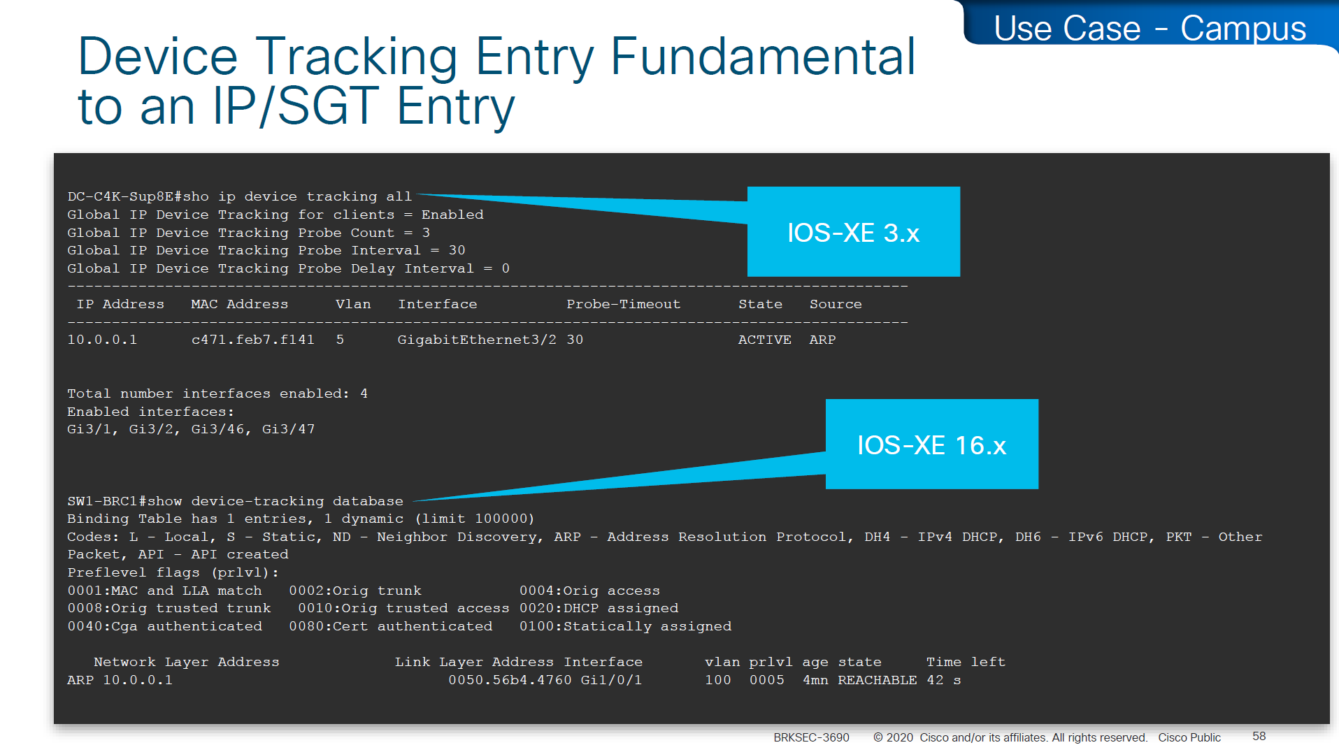
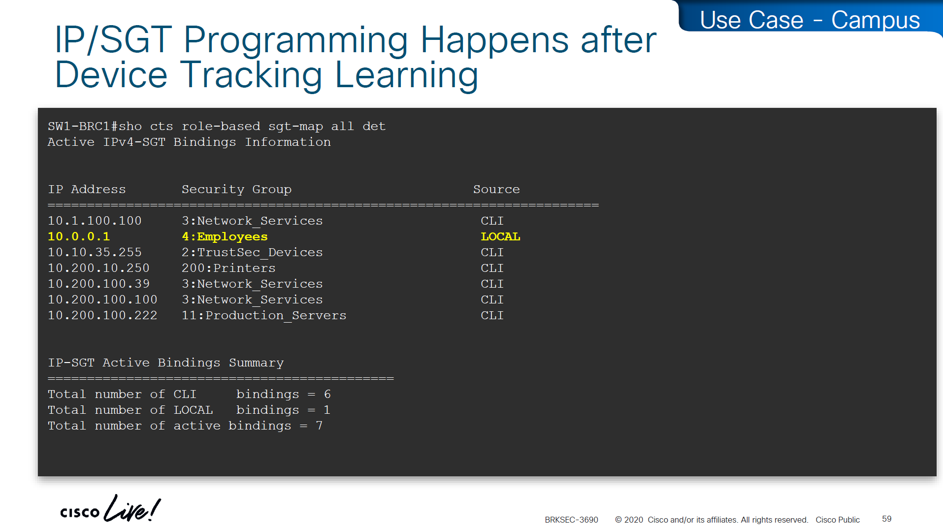
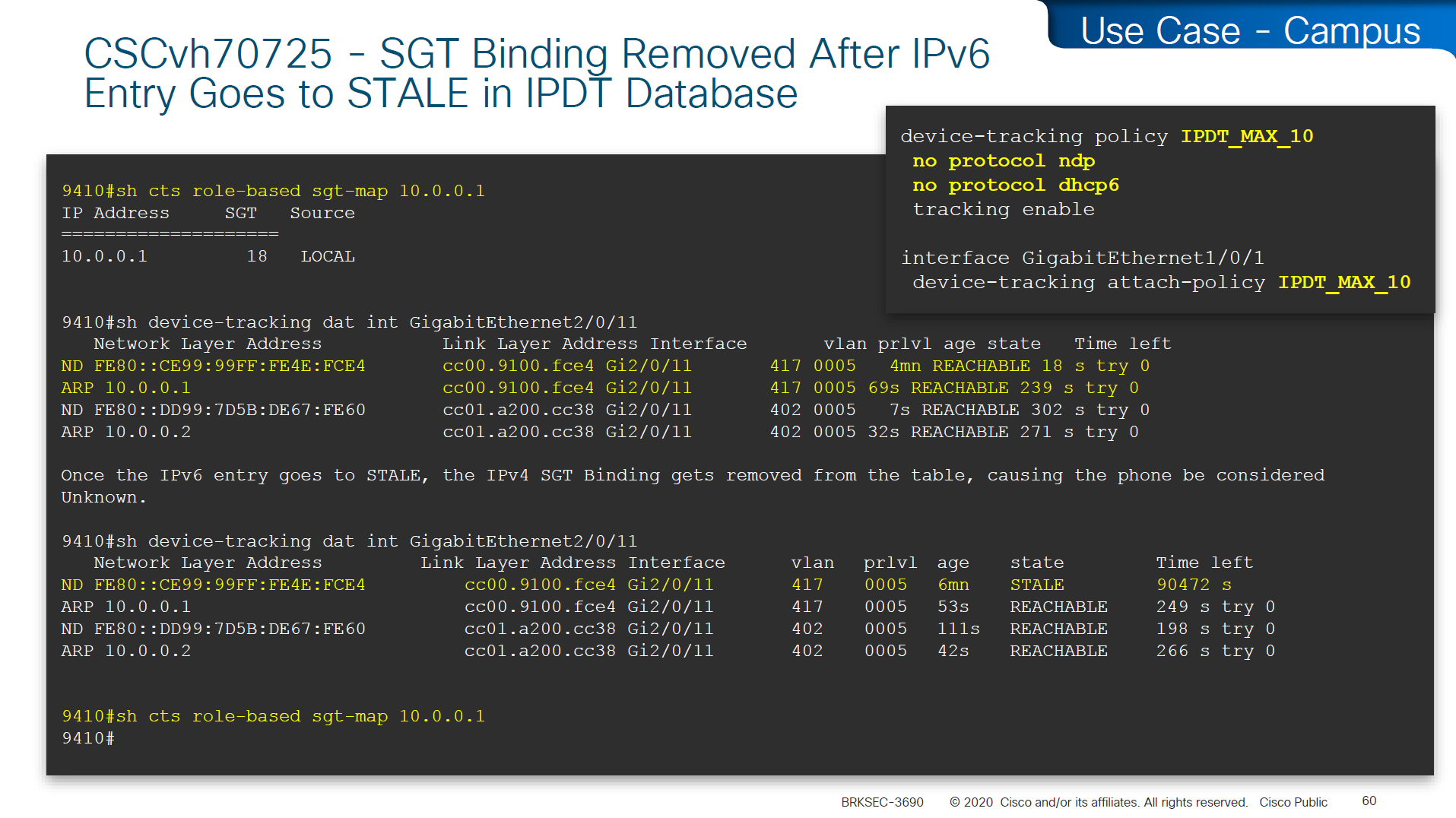
In case you have SGT disappearing from host, then check if this bug is in effect and usually happens on older unpatched code, the workaround was to turn off ndp (which is IPv6 ARP mechanism) tracking from IP device tracking and also turn off dhcpv6 tracking
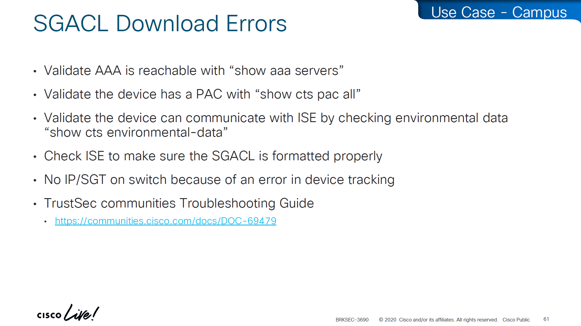
in case SGACL download is not happening we need to check following:
Make sure pac is present
show cts pac allMake sure AAA servers are marked alive
show aaa servers Make sure device can reach ISE
show cts environment-dataCheck ISE to make sure SGACL is formatted properly
Make sure there are no errors in device-tracking as whole solutions rides on device-tracking to work
Sometimes bad implementation of SDWAN can cause fragmentation of large packets and sometimes that can cause ISE to device download of SGACL of DTLS (PAC based) to break for large packets causing “partial download”, that is why it is so important to first test for fragmentation over greenfield or brownfield deployment and also test large elephant connections with large packets – on the side note large elephant connections over IPSec based tunnels are heavy on platform’s ability to encrypt large traffic
So if you see partial download of SGACL, then always check for fragmentation issue, because by default for this pac based DTLS connections DF bit is set and routers from all vendors do not like DF bit
Software Defined Access (SD – Access) – SGT/VXLAN
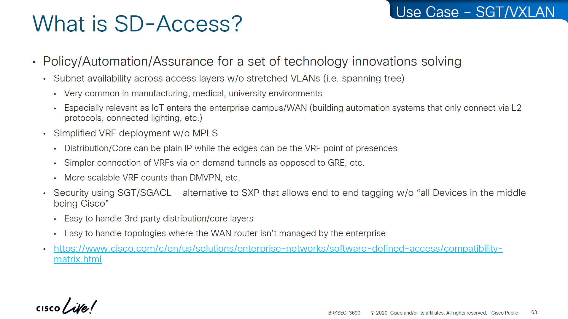
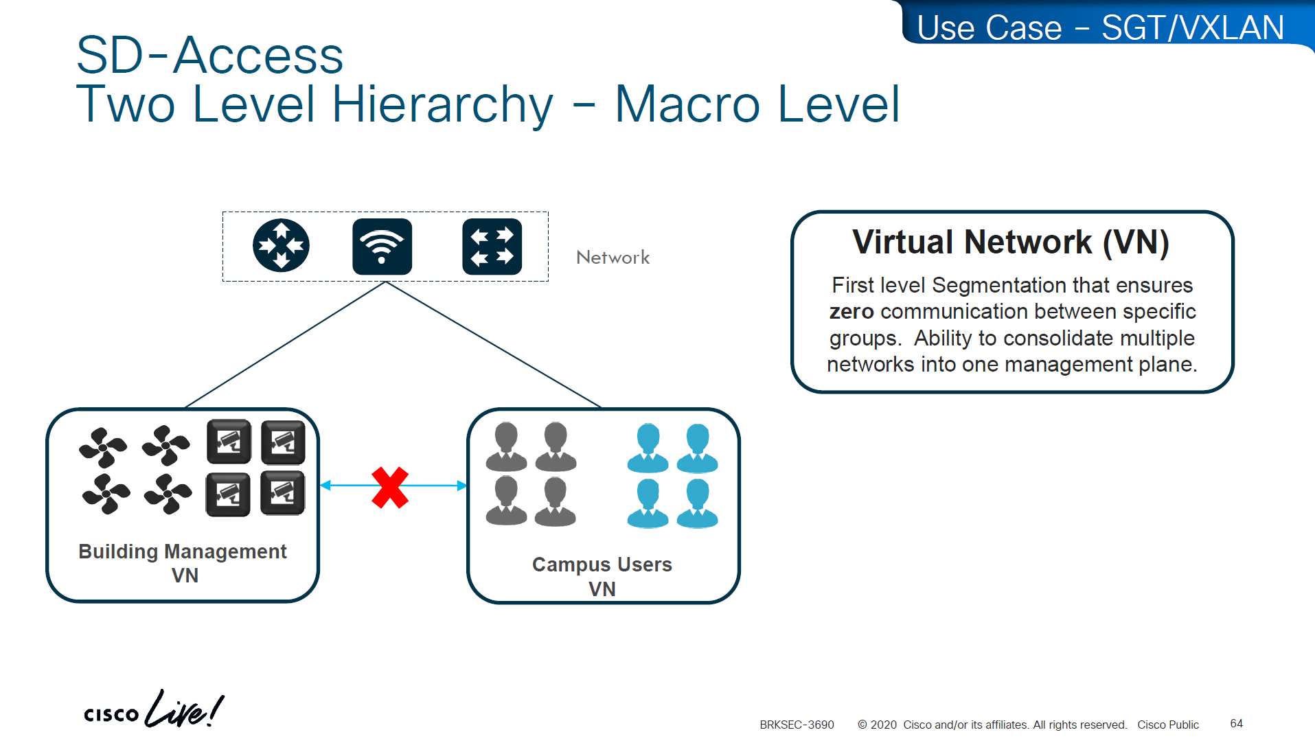
These SDA VNs are VRFs but these are campus wide VRFs,
Macro Level segmentation is devices of different management domains go in their own VN
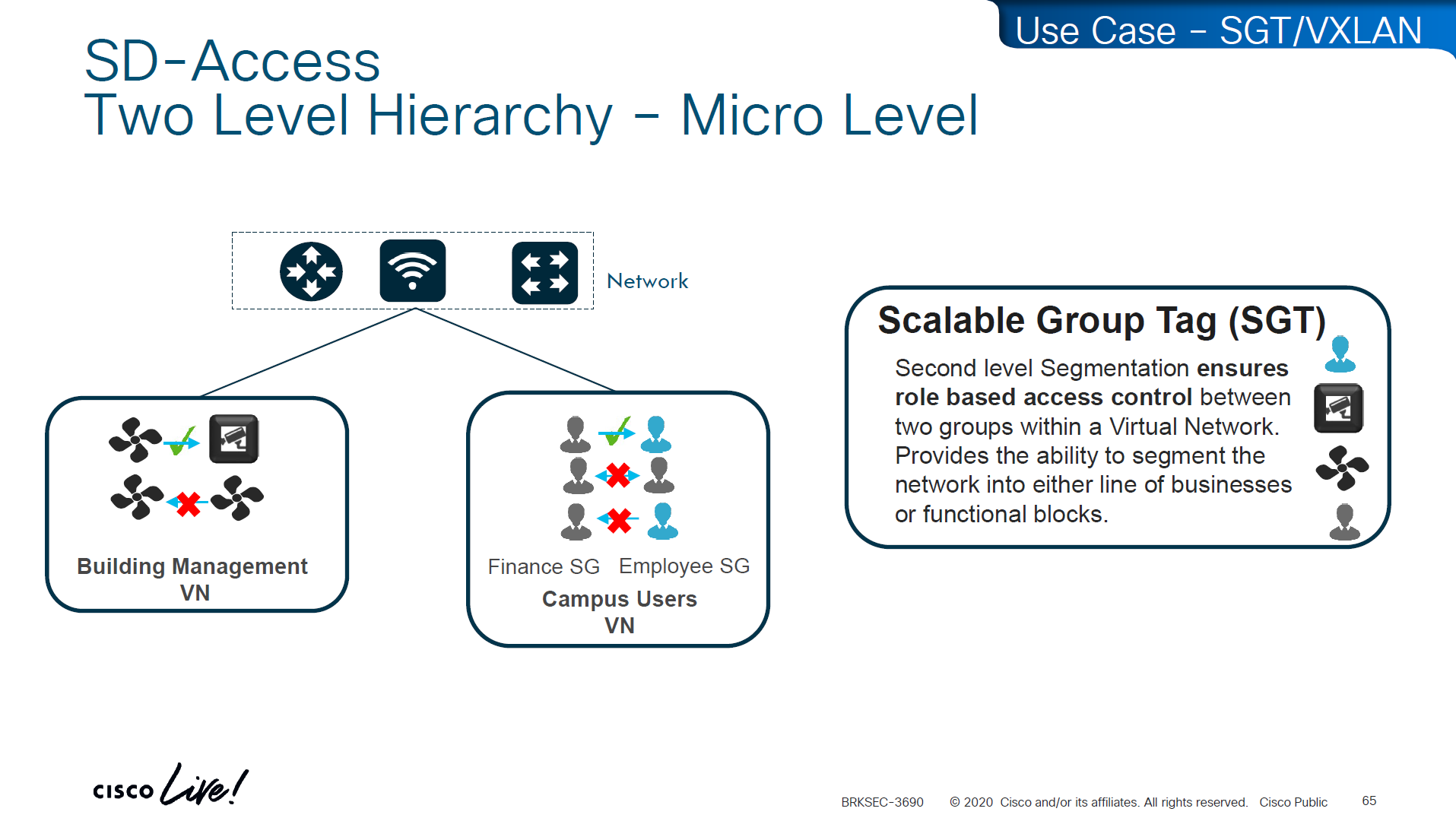
Micro Segmentation is used for access control within the VN
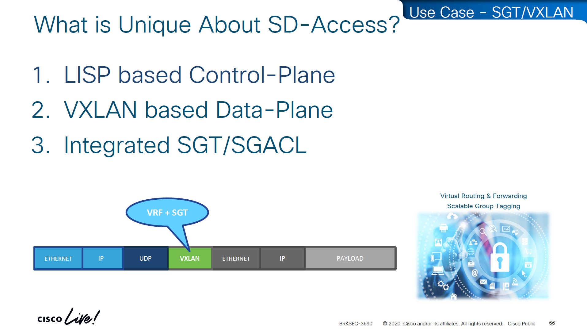
LISP is another great optimization at the access layer and it reduces or optimizes the routes by only installing /32 host routes on access layer switch to which its connected hosts are initiating connections to and from, access layer no longer needs to maintain the large routing tables, LISP installs routes in VRFed routing table of access switches
VXLAN is carried inside UDP just like an layer 7 application and VXLAN carriers the whole original ethernet frame and not just IP packet
VN and SGT are carried inside the VXLAN header
The SGT (Security Group Tag) is not added to the original inner IP packet.
It is carried only in the VXLAN header as metadata, and in order to use SGT capabilities outside of the network with Cisco gear we can use TrustSec which uses SXP and with other vendors we can use PXGrid

Policy matrix is created on DNAC and then pushed to ISE , ISE then pushes the SGT environment data (SGT Tags and Trusted Server list) over TCP, SGACL using NDAC over PAC based DTLS and then finally IP to SGT mapping on border nodes using TCP SXP


ACL or contracts are defined in badge color cells

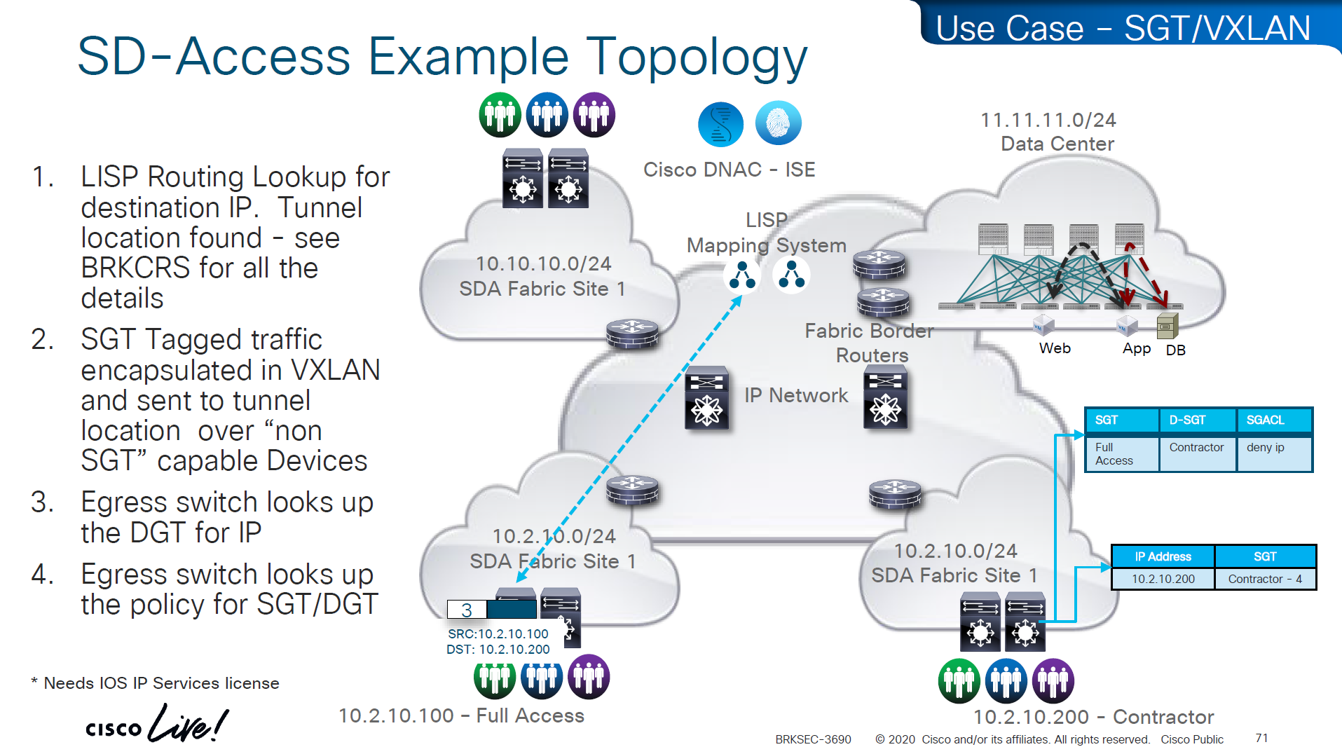
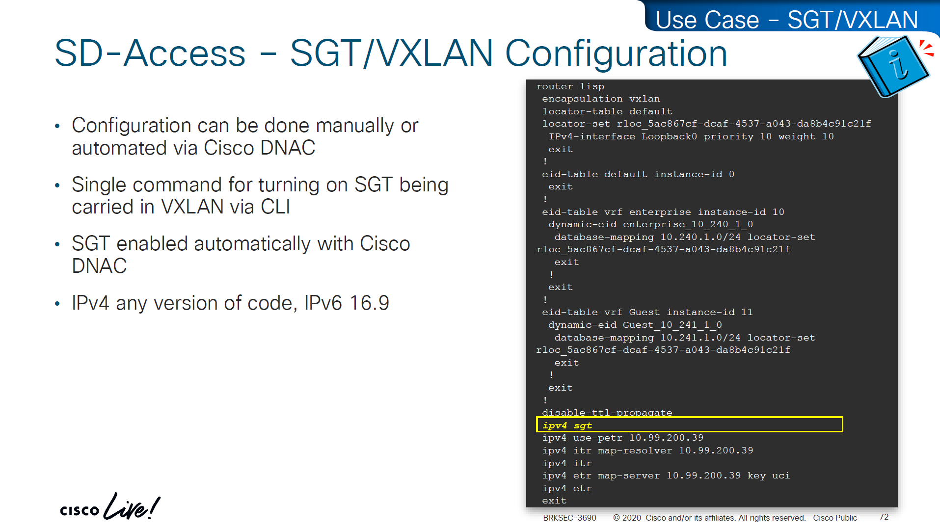
This is how it is enabled inside LISP
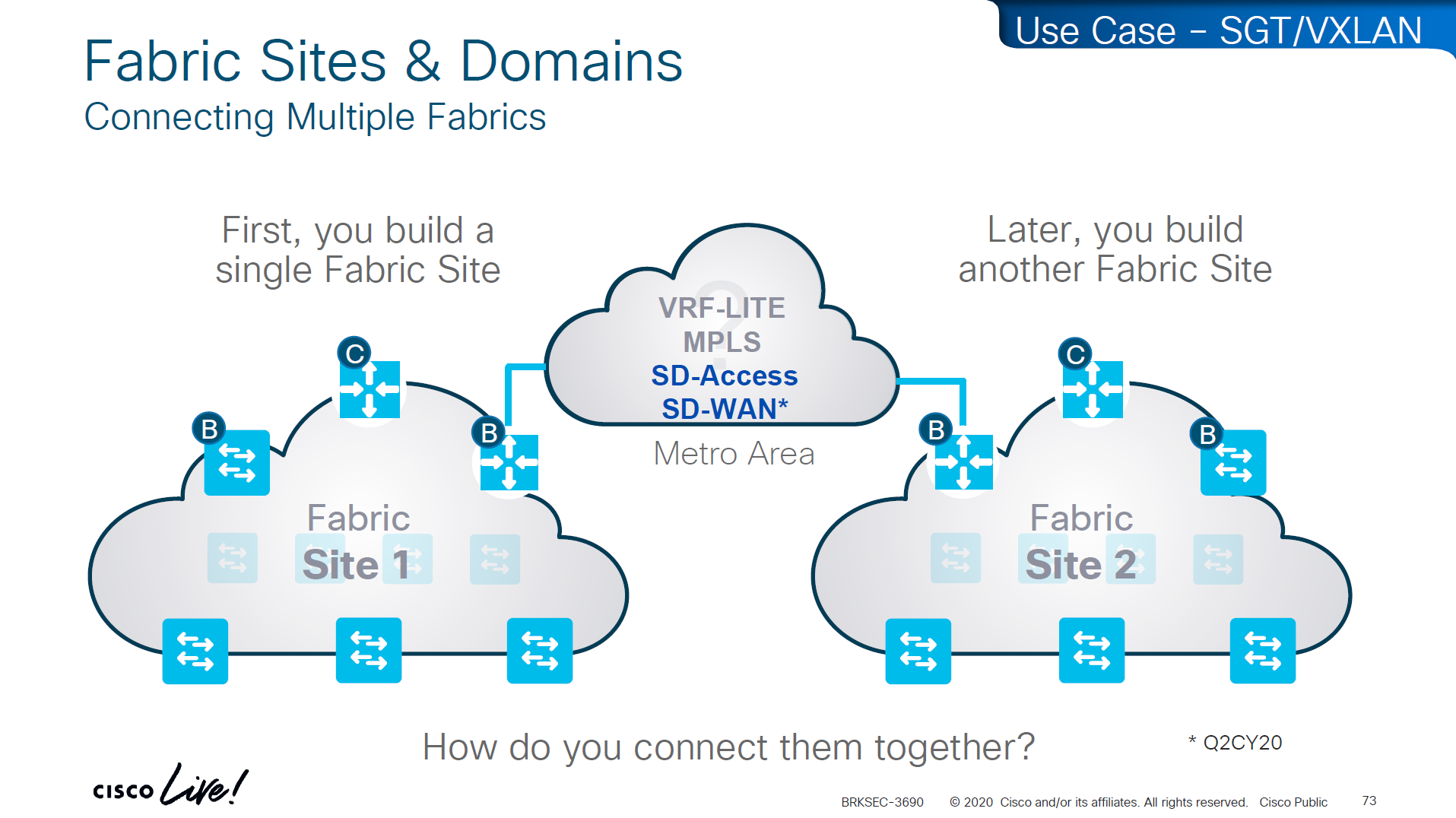
If we have SD Access transit or SDWAN, we can carry SGT to other fabric sites

SDA transit uses LISP as control plane between borders of both fabric sites
and then on data plane we have VXLAN header that crosses between fabric sites
but in order to accommodate the VXLAN header we will need 1588 or better 1600 MTU
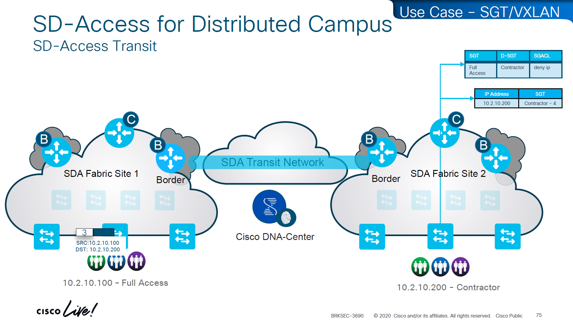
Skipped Firewall Integration with SD-Access
Skipped Meraki and 3rdParty Interop

Use Case Review -WAN


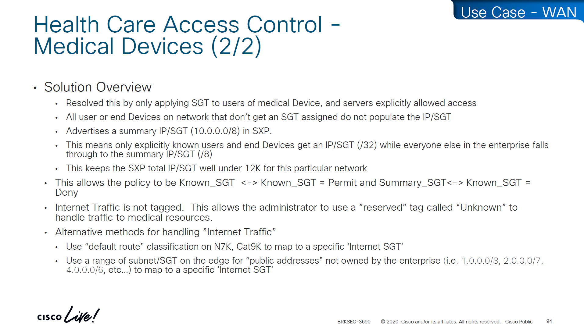
-medical devices and servers are assigned SGT and allowed to speak to one another
-Summary SGT of 10.0.0.0/8 in SXP for all users and devices in 10.0.0.0/8 space and this keeps the SGT under 12K
-Create a Policy Matrix that has Known_SGT <-> Known_SGT permit
-Create a Policy Matrix that has Known_SGT <-> Summary_SGT deny
-For Internet traffic default route is tagged as Internet_SGT
-above Internet_SGT leaves reserved tag called Unknown to handle traffic for medical devices that are not tagged
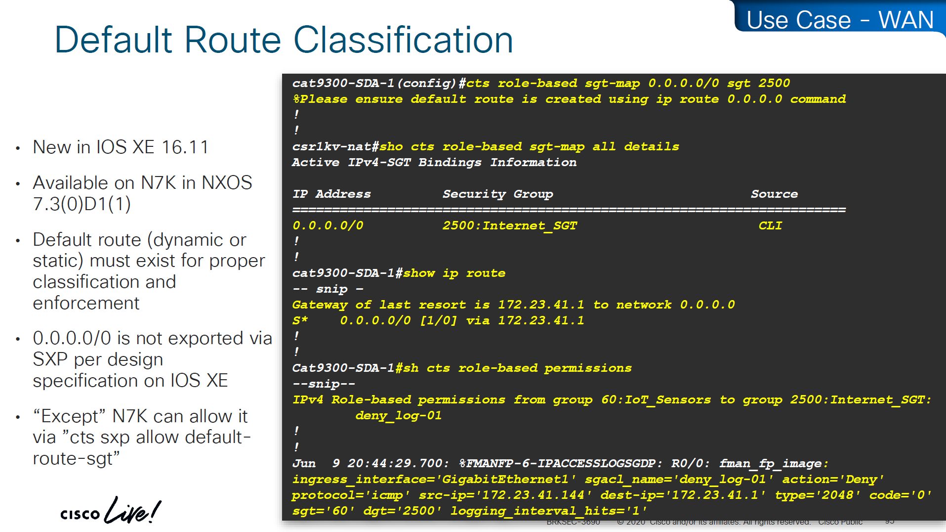
SXP Reflector Like Design

in above SXP connections, if one device speaks (has a speaker role) IP to SGT mapping then on the other end if there is a listener it will listen and learn the IP to SGT mapping and if a device listens (has a listener role) then on SXP connection it can learn IP to SGT mapping from a speaker
once a new mapping of IP to SGT is learned by aggregation Listener, it “speaks” those mapping to all the listeners

Above shows Medical_device <-> Medical_server allow
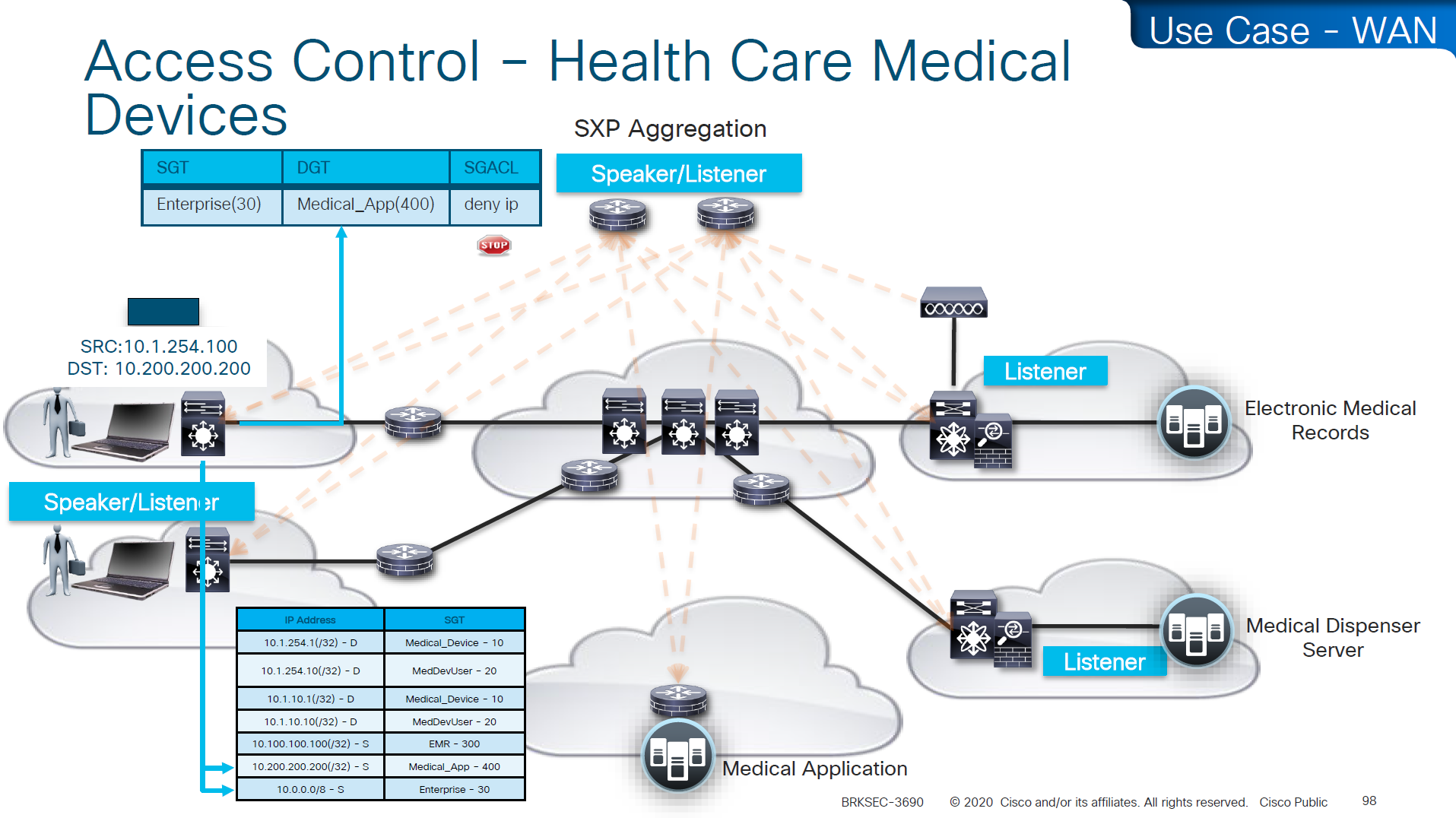
Above example is the source on 10.0.0.0 network that has fallen on 10.0.0.0/8 SGT of Enterprise and is trying to speak to Medical_device and by policy that is denied

cts manual – tells the router interface to assign sgt manually to traffic over this interface
policy static sgt 2 trusted – All traffic that enters or exits this interface is tagged with SGT = 2
“Trusted” means this interface accepts incoming SGT tags from the peer without overwriting them. If the link partner already sends SGT-tagged frames, the ASR1K trusts them instead of stripping or replacing them.
no cts role-based enforcement – on the router interface or layer 3 interfaces which are in the middle of the path, we have to turn off any kind of enforcement in order to avoid dropping any traffic , Because the ASR1K in this use case is only tagging packets, not enforcing access control. This keeps the device acting as a TrustSec transit / tagging device rather than a policy enforcement point.
cts manual
policy static sgt 2 trusted
no cts role-based enforcement
so above config achieves – tag outgoing traffic, trust the tag from connected device for incoming traffic and disable enforcement because this is a transit node and not access layer policy point

show platform hardware fed switch active fwd-asic resource tcam utilization

! Max Values column
! Used Values

! first value is IP "/" second value is SGT

! "Directly or indirectly connected routes"
! for 9300 10K limit officially for both IP and SGT combined

! "Security Access Control Entries" are number of ACEs

! "SGT_DGT" is number of cells from Policy Matrix
This healthcare provider hit the scale limit of SGT on access layer so they moved the enforcement point on routers as router hardware has much more scale
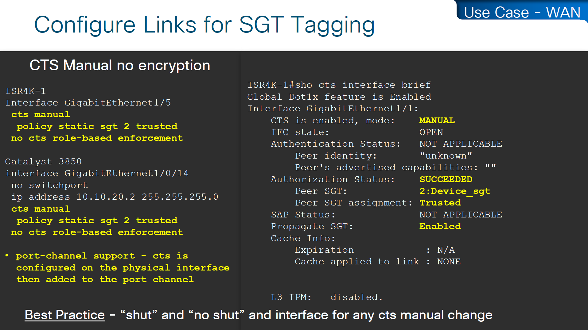
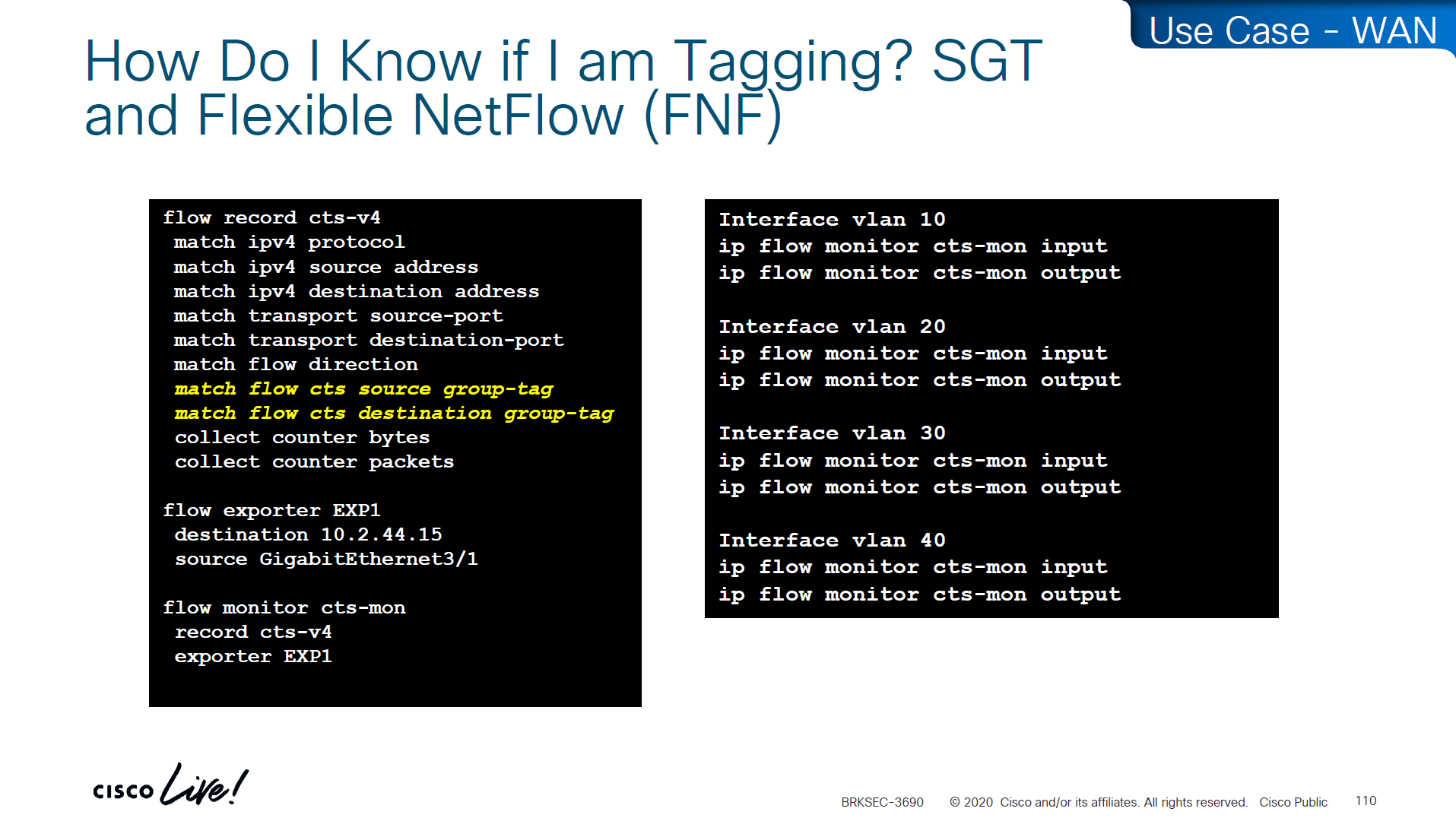
If you want to know that you are tagging traffic, simply turn on netflow with cts with above commands and even if you dont export that flow anywhere, we can see local cache , great for tshoot
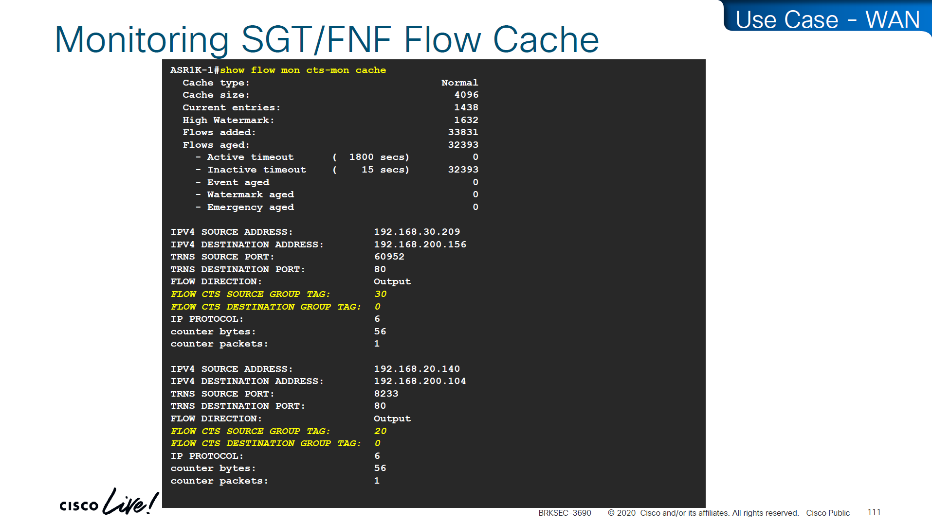
use this command to see the tagging info
show flow mon cts-mon cacheyou will see that in above output we see destination tag as 0, because we are running this command on ingress or access layer where there is no info about destination host or its assigned SGT

Stealthwatch has ability to specify source and destination tag

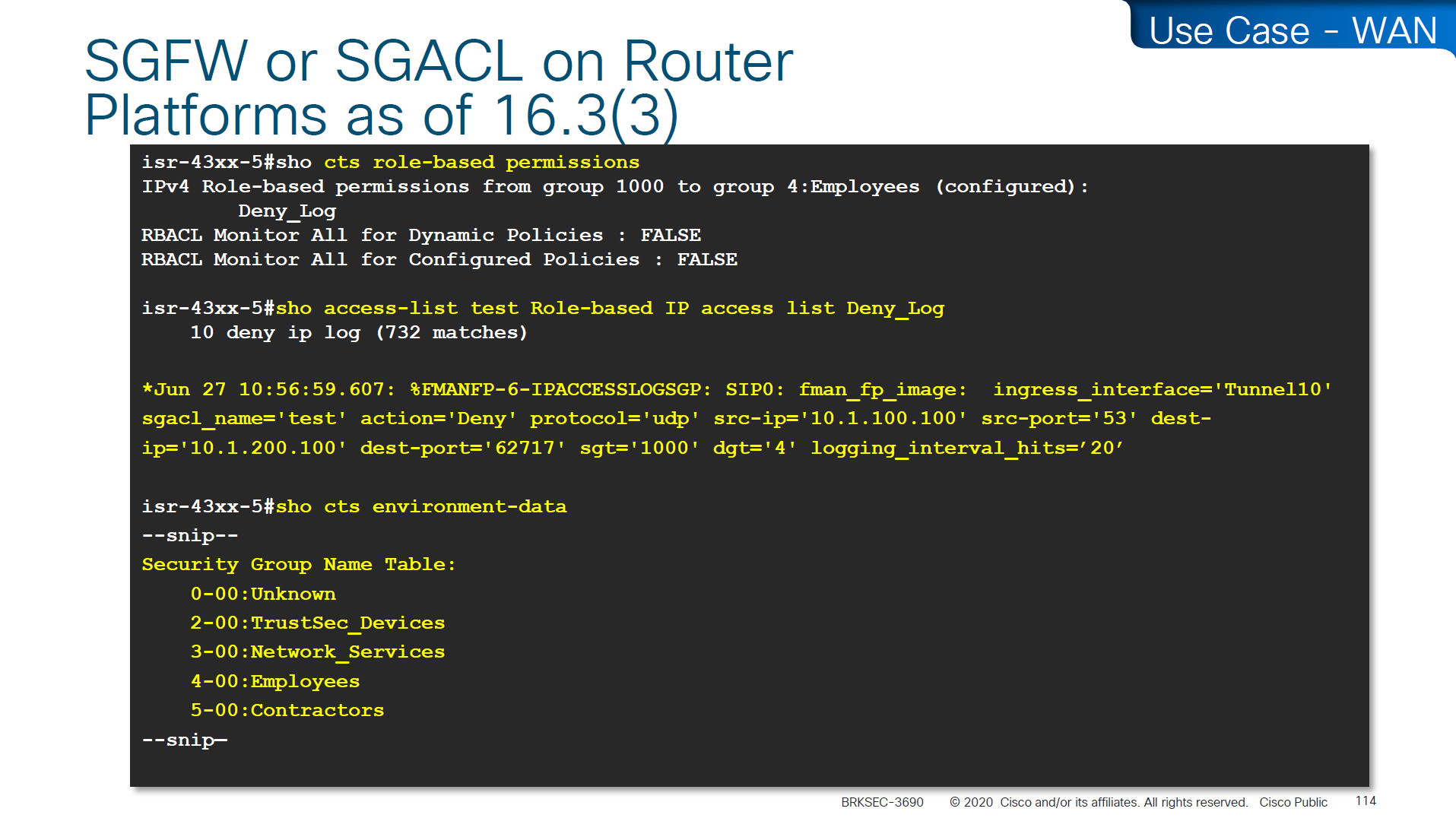

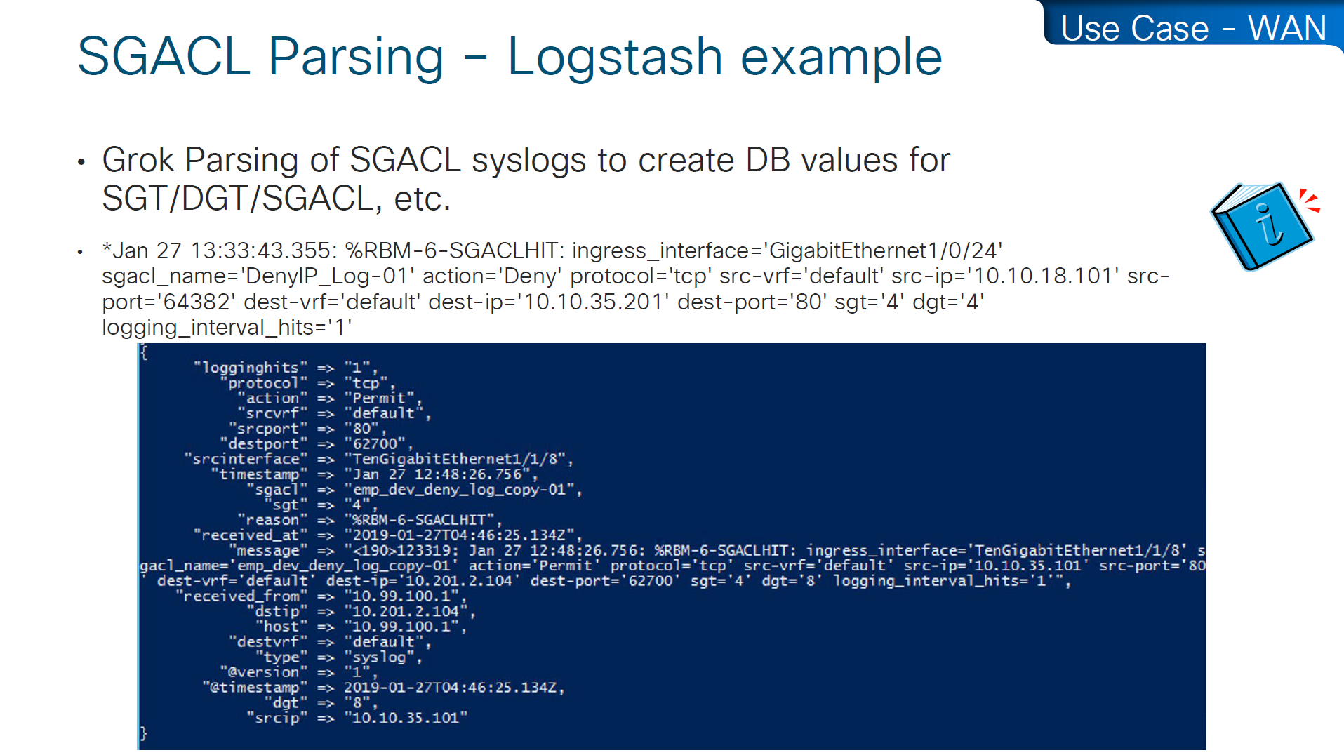
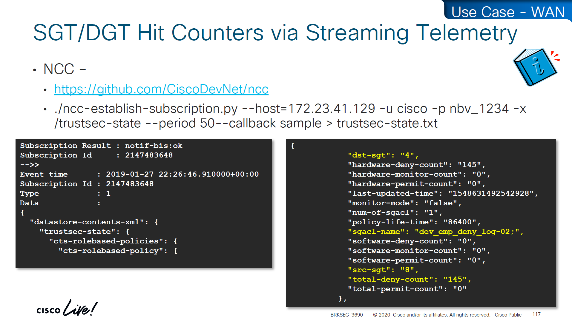

Skipped DMVPN SGT tagging
Skipped SGT/ACI
Skipped Cloud
SGT commands
! on ingress or access
cts sxp enable
cts sxp connection peer 10.1.44.1 source 10.1.11.44 password default mode local

! on core where we just learn from access as listener
cts sxp enable
cts sxp default password cisco123

! peering with Cat3K
cts sxp connection peer 10.1.11.44 source 10.1.44.1 password default mode local listener hold-time 0 0

! peering with WLC
cts sxp connection peer 10.1.33.24 source 10.1.44.1 password default mode local listener hold-time 0 0

! check IP to SGT table
show cts role-based sgt-map all details

! check SXP connection on on core
show cts sxp connections brief

----------------------------------------------


! Enable AAA
aaa new-model

! Define ISE as a RADIUS server (auth/acct) and include the PAC bootstrap secret
radius server ISE1
 address ipv4 10.10.10.10 auth-port 1812 acct-port 1813
 key RADIUS_SHARED_SECRET
 pac key RADIUS_PAC_SECRET
!

! send vsa or vendor attributes in RADIUS authentication request
radius-server vsa send authentication

 key RADIUS_SHARED_SECRET
 pac key RADIUS_PAC_SECRET
!

! send vsa or vendor attributes in RADIUS authentication request
radius-server vsa send authentication

! (Optional) put servers into a group and set a source interface
aaa group server radius ISE-GRP
 server name ISE1
 ip radius source-interface Vlan10

! CTS/NDAC: define the authorization list used for policy download only (not tags - tags are pulled before SGACL or policy is pulled) - as clients connect with new SGT , more policy columns are pulled
cts authorization list CTS-AUTHZ

! 802.1X + CTS use the RADIUS group
aaa authentication dot1x default group ISE-GRP
aaa authorization network CTS-AUTHZ group ISE-GRP
! aaa authorization network command is usually used to allow on network or authorize audience or entity authenticated through network ports and this config says that authorized list of server (which are allowed to make CLI or COA changes) will be downloaded from ISE-GRP

! which makes it look like this

aaa authorization network ( CTS-AUTHZ ) group ISE-GRP
aaa authorization network ( cts authorization list ) group ISE-GRP

! Define credentials for EAP-FAST I-ID, these are configured under enable mode and not in config mode
cts credential id DEVICE-ID password PASSWORD

! enable 802.1x on system level
dot1x system-auth-control
! enable CTS enforcement
cts role-based enforcement

----------------------------------------------

show cts environment-data
! shows local device SGT
! shows servers that are authorized list servers
! shows downloaded SGT tags on devices

----------------------------------------------

! define SGT for local servers connected to switch
cts role-based sgt-map 192.168.31.1 sgt 100
cts role-based sgt-map 192.168.32.0/24 sgt 20
cts role-based sgt-map 10.x.x.0 sgt 30

! tag default route to Internet_SGT
! This is incase you want to use Unknown tag for something else
! for default route tag, the device must have defafult route either as a static or dynamic for this tagging to work
! this allows us to do something like Medical_devices <-> Internet_SGT deny
cts role-based sgt-map 0.0.0.0/0 sgt 2500


! enableing SGT enformcement globaly
cts role-based enforcement

! or on specific vlans for slow rollout
cts role-based enforcement vlan-list 40

----------------------------------------------

! download or refresh SGT tags
cts refresh environment-data

! download or refresh SGACLs or policy
cts refresh policy

----------------------------------------------

show cts role-based permissions
! shows SGACLs

show cts policy sgt 4
! shows SGT and its related policies in detail

show ip access-list

show cts role-based counters
! shows * to * default rule
! also shows from and to columns
! SGACL is done in hardware, unless needs punting
! for example TCAM or hardware is full, log in the end of ACE or to the box traffic such as Trust_Devices SGT, makes SW counter increment otherwise concentrate on HW-Denied and HW-Permitted columns

----------------------------------------------

show device-tracking database

show cts role-based sgt-map 10.0.0.1

show device-tracking database interface gig2/0/11

----------------------------------------------

! If SGACL download errors happen

show aaa servers
! make sure AAA servers are marked alive

show cts pac all
! make sure pac is present

show cts environment-data
! check if device can communicate with ISE

----------------------------------------------

router(config)#interface Ten1/1/1
cts manual
policy static sgt 2 trusted
no cts role-based enforcement
! tag outgoing traffic,
! trust the tag from connected device for incoming traffic
! disable enforcement because this is a transit node and not access layer policy point

show cts interface brief

----------------------------------------------

show platform hardware fed switch active fwd-asic resource tcam utilization

! Max Values column
! Used Values

! first value is IP "/" second value is SGT

! "Directly or indirectly connected routes"
! for 9300 10K limit officially for both IP and SGT combined

! "Security Access Control Entries" are number of ACEs

! "SGT_DGT" is number of cells from Policy Matrix

----------------------------------------------

flow record cts-v4
  match ipv4 protocol
  match ipv4 source address
  match ipv4 destination address
  match transport source-port
  match transport destination-port
  match flow direction
  match flow cts source group-tag <<<<
  match flow cts destination group-tag <<<<
  collect counter bytes
  collect counter packets

flow exporter EXP1
  destination 10.1.1.1
  source Gig1

flow monitor cts-mon
  record cts-v4
  exporter EXP1

interface vlan 10
  ip flow monitor cts-mon input
  ip flow monitor cts-mon output

show flow mon cts-mon cache