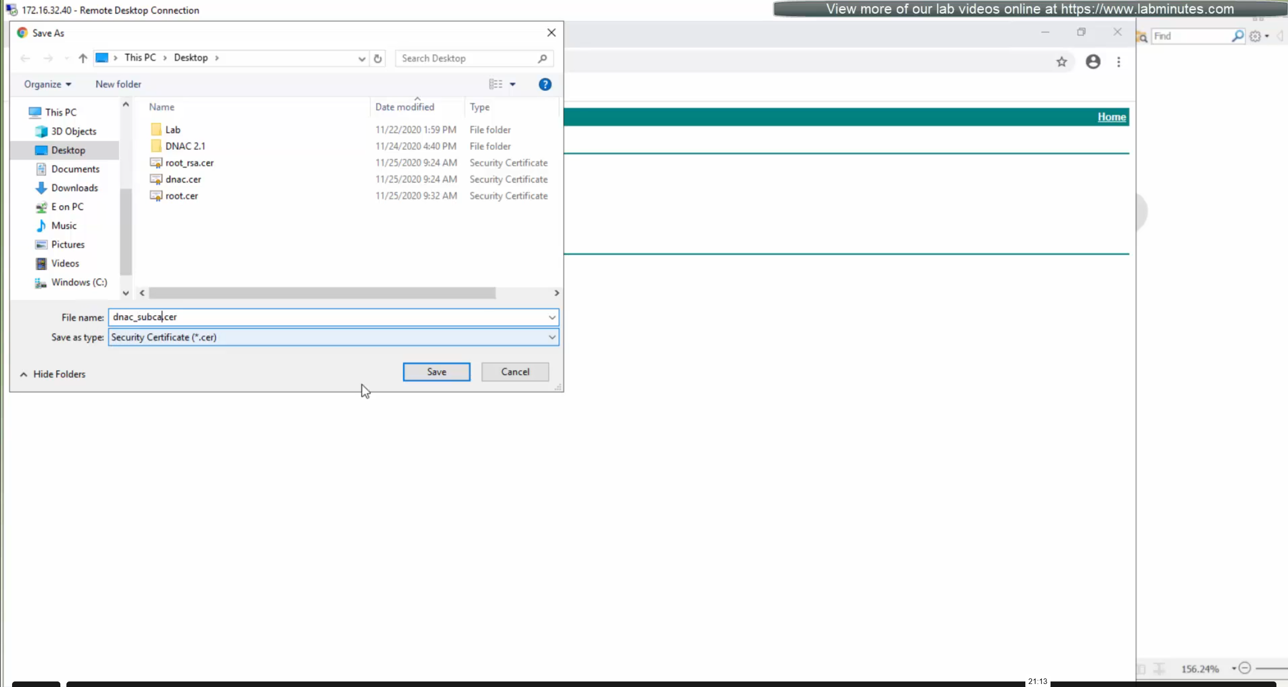
⊹ CCIE ⊹
SDA Home LAB Deployment
SDA LISP Roles
ITR – Ingress Tunnel Router – devices which accepts traffic from the client and looks at transmitting to the destination.
ETR – Egress Tunnel Router – device which transmits traffic to the client, this is where destination client is attached.
These above roles of LISP would be on Fabric Edge node.
Example of Ping (I am omitting the full lookup against Map Resolver and RLOC etc):
Client A —> Switch A (ITR) —> Switch B (ETR) —> Client B
Reply:
Client A <— Switch A (ETR) <— Switch B (ITR) <— Client B
If a node has both roles ITR and ETR, that Fabric Edge switch is referenced as xTR
(P – Proxy) PITR and PETR would be the Border node which communicates with destinations outside the fabric, Similarly to the last example, one border node can have both roles and can be referenced as PxTR.
Traffic example: Client A —> Switch A (ITR) — Border A (PITR) —> Server A
Reply: Client A <— Switch A (ETR) <— Border A (PETR) <— Server A
If you look Proxy Egress tunnel router is actually inbound from the endpoint’s perspective and inbound means back in the direction of Fabric site and similarly Proxy Ingress Tunnel router is packet entering the fabric from endpoint
ESXI and VCenter Deployment
-: Z840 :-
Upgrade BIOS
Factory Reset BIOS
set controller mode to AHCI from RAID
enable Intel VTd under System Security section
-: ESXI DEPLOYMENT :-
VMware-VMvisor-Installer-7.0.0-15843807.x86_64
ESXi 7.0 keys
JJ2WR-25L9P-H71A8-6J20P-C0K3F
ESXI01.home.local
192.168.0.10
root
C0mplex30-
-: VCENTER DEPLOYMENT :-
Create following entries in host file
192.168.0.10 esxi01.home.local <<<<
192.168.0.11 vcenter.home.local <<<< This is checked from local machine when running VCSA setup to install vcenter, this check is different from vcenter A and PTR record lookup by installer, that is why DNS server on Windows server 2016 is needed
Bring up a winserver 2016 instance in eveng metal and configure DNS server on it
VMware-VCSA-all-7.0.0-16386292.iso
vCenter 7 keys
406DK-FWHEH-075K8-XAC06-0JH08
VCENTER.home.local
192.168.0.11
root
C0mplex30-
administrator@vsphere.local
C0mplex30-
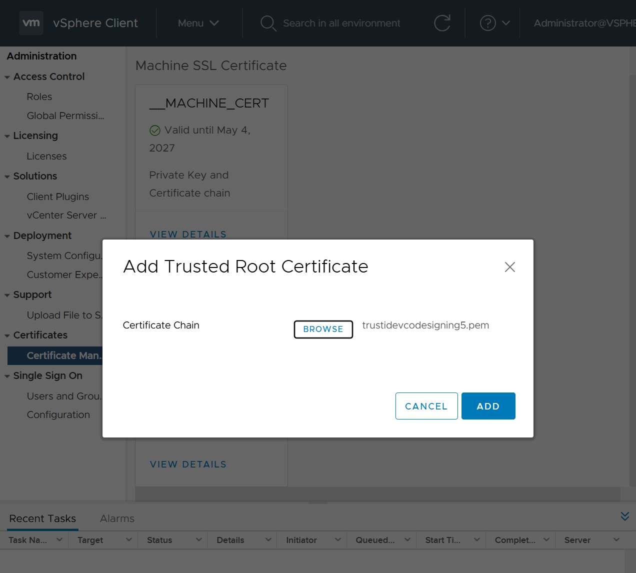
Import vcenter Certificates in Installation station
Because we are deploying appliance through VA launcher script, we need to import certificates of vcenter into local computer trusted root certificate’s store, go to https://vCenter_FQDN/certs/download.zip, download ZIP and extract all the certs and import them


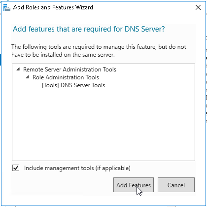
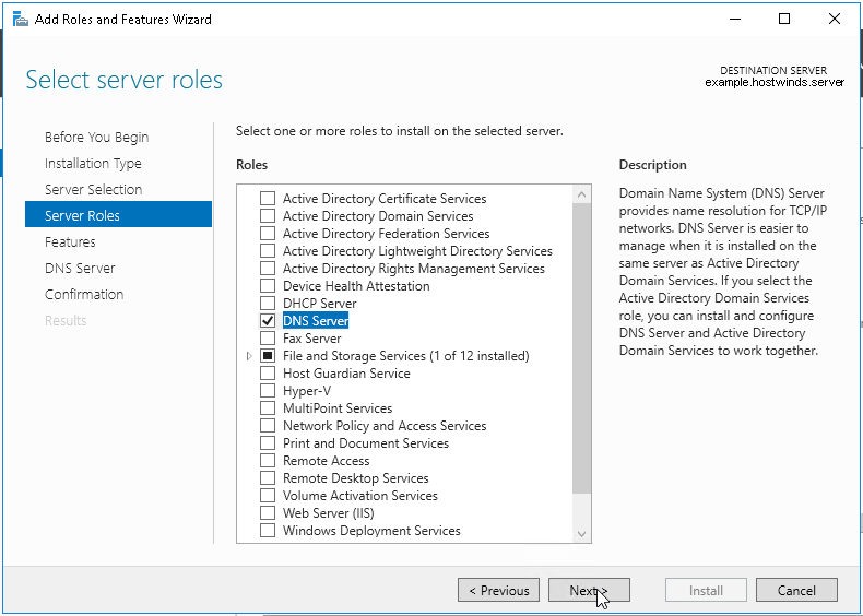
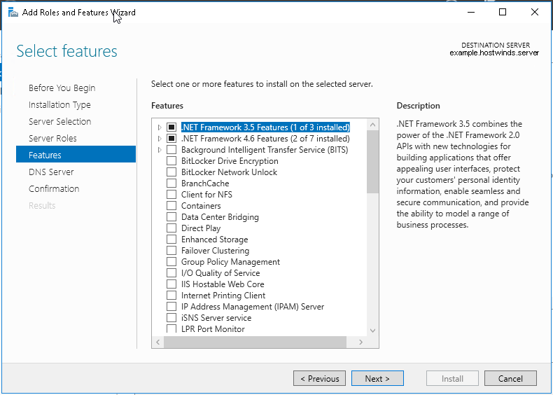
Windows Server DNS deployment

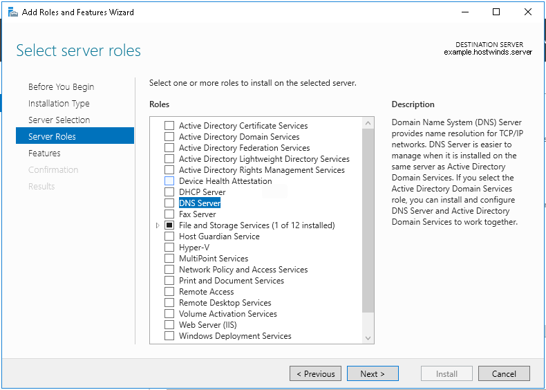

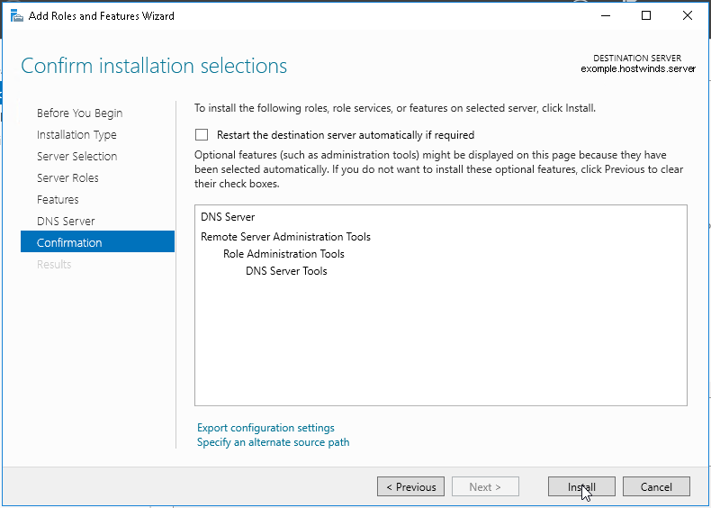
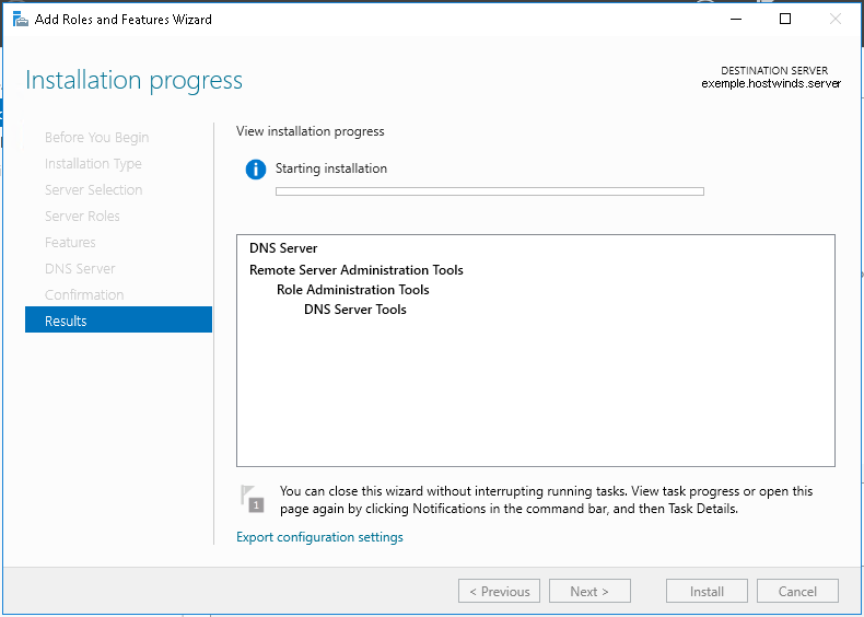
configure forward zone
configure reverse zone
create A record
vcenter.home.local 192.168.0.11
dnac.home.local 10.21.1.2
Windows 10 and VYOS deployment
Windows 10 VM
Create Windows 10 VM for VYOS deployment validation and internet access check
2 vCPUs
5GB RAM
25GB disk
admin/Test123
Pet name
dnac
City born in
dnac
City parents met
dnac
Assign only 192.168.0.200/24 and do not assign gateway 192.168.0.1
Disable IPv6 on the Windows VM interface
connect VM’s interface in vcenter
Go to Network folder and join the network
Share Downloads folder
copy wub and debloater to downloads folder
once all done then put network interface in DHCP again
VYOS deployment
2 CPUs
RAM 2 GB
4 GB Disk
! Install open-vm-tools on VY OS gateway

vyos@vy-gateway:~$ sudo vim /etc/apt/sources.list

! press esc to make sure we are in normal mode
! press i to go in insert mode

! enter first line
deb http://deb.debian.org/debian bullseye main contrib

! press escape
! enter ":wq"

vyos@vy-gateway:~$ sudo cat /etc/apt/sources.list
deb http://deb.debian.org/debian bullseye main contrib

! Update failed because of no DNS resolution
vyos@vy-gateway:~$ sudo apt update
Ign:1 http://deb.debian.org/debian bullseye InRelease
Ign:1 http://deb.debian.org/debian bullseye InRelease
Ign:1 http://deb.debian.org/debian bullseye InRelease
Err:1 http://deb.debian.org/debian bullseye InRelease
  System error resolving 'deb.debian.org:http' - getaddrinfo (16: Device or resource busy)
Reading package lists... Done
Building dependency tree... Done
Reading state information... Done
All packages are up to date.
W: Failed to fetch http://deb.debian.org/debian/dists/bullseye/InRelease  System error resolving 'deb.debian.org:http' - getaddrinfo (16: Device or resource busy)
W: Some index files failed to download. They have been ignored, or old ones used instead.

vyos@vy-gateway:~$ sudo bash

root@vy-gateway:/home/vyos# sudo bash -c 'cat > /etc/resolv.conf <<EOF
nameserver 8.8.8.8
nameserver 1.1.1.1
EOF'

root@vy-gateway:/home/vyos# cat /etc/resolv.conf
nameserver 8.8.8.8
nameserver 1.1.1.1

root@vy-gateway:/home/vyos# apt update
Get:1 http://deb.debian.org/debian bullseye InRelease [75.1 kB]
Get:2 http://deb.debian.org/debian bullseye/main amd64 Packages [8,066 kB]
Get:3 http://deb.debian.org/debian bullseye/main Translation-en [6,235 kB]
Get:4 http://deb.debian.org/debian bullseye/contrib amd64 Packages [50.4 kB]
Get:5 http://deb.debian.org/debian bullseye/contrib Translation-en [46.9 kB]
Fetched 14.5 MB in 4s (4,084 kB/s)
Reading package lists... Done
Building dependency tree... Done
Reading state information... Done
8 packages can be upgraded. Run 'apt list --upgradable' to see them.

! install should work now
root@vy-gateway:/home/vyos# apt install -y open-vm-tools
Reading package lists... Done
Building dependency tree... Done
Reading state information... Done
The following additional packages will be installed:
  libdrm-common libdrm2 libmspack0 libssl1.1 libxmlsec1 libxmlsec1-openssl
  libxslt1.1
Suggested packages:
  open-vm-tools-desktop cloud-init
Recommended packages:
  zerofree
The following NEW packages will be installed:
  libdrm-common libdrm2 libmspack0 libssl1.1 libxmlsec1 libxmlsec1-openssl
  libxslt1.1 open-vm-tools
0 upgraded, 8 newly installed, 0 to remove and 8 not upgraded.
Need to get 2,793 kB of archives.
After this operation, 8,598 kB of additional disk space will be used.
Get:1 http://deb.debian.org/debian bullseye/main amd64 libdrm-common all 2.4.104-1 [14.9 kB]
Get:2 http://deb.debian.org/debian bullseye/main amd64 libdrm2 amd64 2.4.104-1 [41.5 kB]
Get:3 http://deb.debian.org/debian bullseye/main amd64 libmspack0 amd64 0.10.1-2 [50.3 kB]
Get:4 http://deb.debian.org/debian bullseye/main amd64 libssl1.1 amd64 1.1.1w-0+deb11u1 [1,566 kB]
Get:5 http://deb.debian.org/debian bullseye/main amd64 libxslt1.1 amd64 1.1.34-4+deb11u1 [240 kB]
Get:6 http://deb.debian.org/debian bullseye/main amd64 libxmlsec1 amd64 1.2.31-1 [149 kB]
Get:7 http://deb.debian.org/debian bullseye/main amd64 libxmlsec1-openssl amd64 1.2.31-1 [100.0 kB]
Get:8 http://deb.debian.org/debian bullseye/main amd64 open-vm-tools amd64 2:11.2.5-2+deb11u3 [632 kB]
Fetched 2,793 kB in 0s (10.4 MB/s)
Preconfiguring packages ...
Selecting previously unselected package libdrm-common.
(Reading database ... 84389 files and directories currently installed.)
Preparing to unpack .../0-libdrm-common_2.4.104-1_all.deb ...
Unpacking libdrm-common (2.4.104-1) ...
Selecting previously unselected package libdrm2:amd64.
Preparing to unpack .../1-libdrm2_2.4.104-1_amd64.deb ...
Unpacking libdrm2:amd64 (2.4.104-1) ...
Selecting previously unselected package libmspack0:amd64.
Preparing to unpack .../2-libmspack0_0.10.1-2_amd64.deb ...
Unpacking libmspack0:amd64 (0.10.1-2) ...
Selecting previously unselected package libssl1.1:amd64.
Preparing to unpack .../3-libssl1.1_1.1.1w-0+deb11u1_amd64.deb ...
Unpacking libssl1.1:amd64 (1.1.1w-0+deb11u1) ...
Selecting previously unselected package libxslt1.1:amd64.
Preparing to unpack .../4-libxslt1.1_1.1.34-4+deb11u1_amd64.deb ...
Unpacking libxslt1.1:amd64 (1.1.34-4+deb11u1) ...
Selecting previously unselected package libxmlsec1:amd64.
Preparing to unpack .../5-libxmlsec1_1.2.31-1_amd64.deb ...
Unpacking libxmlsec1:amd64 (1.2.31-1) ...
Selecting previously unselected package libxmlsec1-openssl:amd64.
Preparing to unpack .../6-libxmlsec1-openssl_1.2.31-1_amd64.deb ...
Unpacking libxmlsec1-openssl:amd64 (1.2.31-1) ...
Selecting previously unselected package open-vm-tools.
Preparing to unpack .../7-open-vm-tools_2%3a11.2.5-2+deb11u3_amd64.deb ...
Unpacking open-vm-tools (2:11.2.5-2+deb11u3) ...
Setting up libssl1.1:amd64 (1.1.1w-0+deb11u1) ...
Setting up libmspack0:amd64 (0.10.1-2) ...
Setting up libxslt1.1:amd64 (1.1.34-4+deb11u1) ...
Setting up libxmlsec1:amd64 (1.2.31-1) ...
Setting up libdrm-common (2.4.104-1) ...
Setting up libxmlsec1-openssl:amd64 (1.2.31-1) ...
Setting up libdrm2:amd64 (2.4.104-1) ...
Setting up open-vm-tools (2:11.2.5-2+deb11u3) ...
Created symlink /etc/systemd/system/vmtoolsd.service → /lib/systemd/system/open-vm-tools.service.
Created symlink /etc/systemd/system/multi-user.target.wants/open-vm-tools.service → /lib/systemd/system/open-vm-tools.service.
Created symlink /etc/systemd/system/open-vm-tools.service.requires/vgauth.service → /lib/systemd/system/vgauth.service.
Processing triggers for libc-bin (2.36-9+deb12u10) ...
localepurge: Disk space freed:      0 KiB in /usr/share/locale
localepurge: Disk space freed:      0 KiB in /usr/share/man
localepurge: Disk space freed:      0 KiB in /usr/share/aptitude
localepurge: Disk space freed:      0 KiB in /usr/share/vim/vim90/lang

Total disk space freed by localepurge: 0 KiB

root@vy-gateway:/home/vyos#
vyos/C0mplex30
Install from live image
install image
show configuration
show configuration commands

configure
set interfaces ethernet eth0 address '192.168.0.12/24'
set interfaces ethernet eth0 description 'home'

set interfaces ethernet eth1 address '172.16.25.1/24'
set interfaces ethernet eth1 description 'mgmt'

set interfaces ethernet eth2 address '10.21.1.1/24'
set interfaces ethernet eth2 description 'data'


show interface ethernet
show interface ethernet eth0
show interface ethernet eth0 physical

set protocols static route 0.0.0.0/0 next-hop 192.168.0.1 distance '1'
set service ssh port '22'
set system host-name 'vy-gateway'

commit
save
vcenter
edit host and create a new standard switch and call it mgmt
edit host and create a new standard switch and call it data
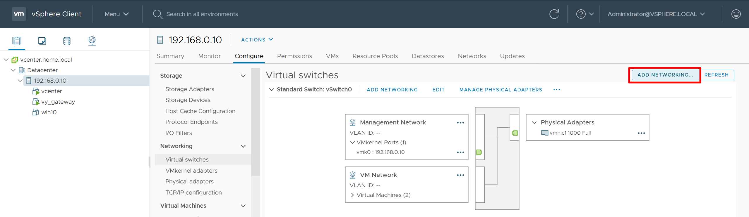
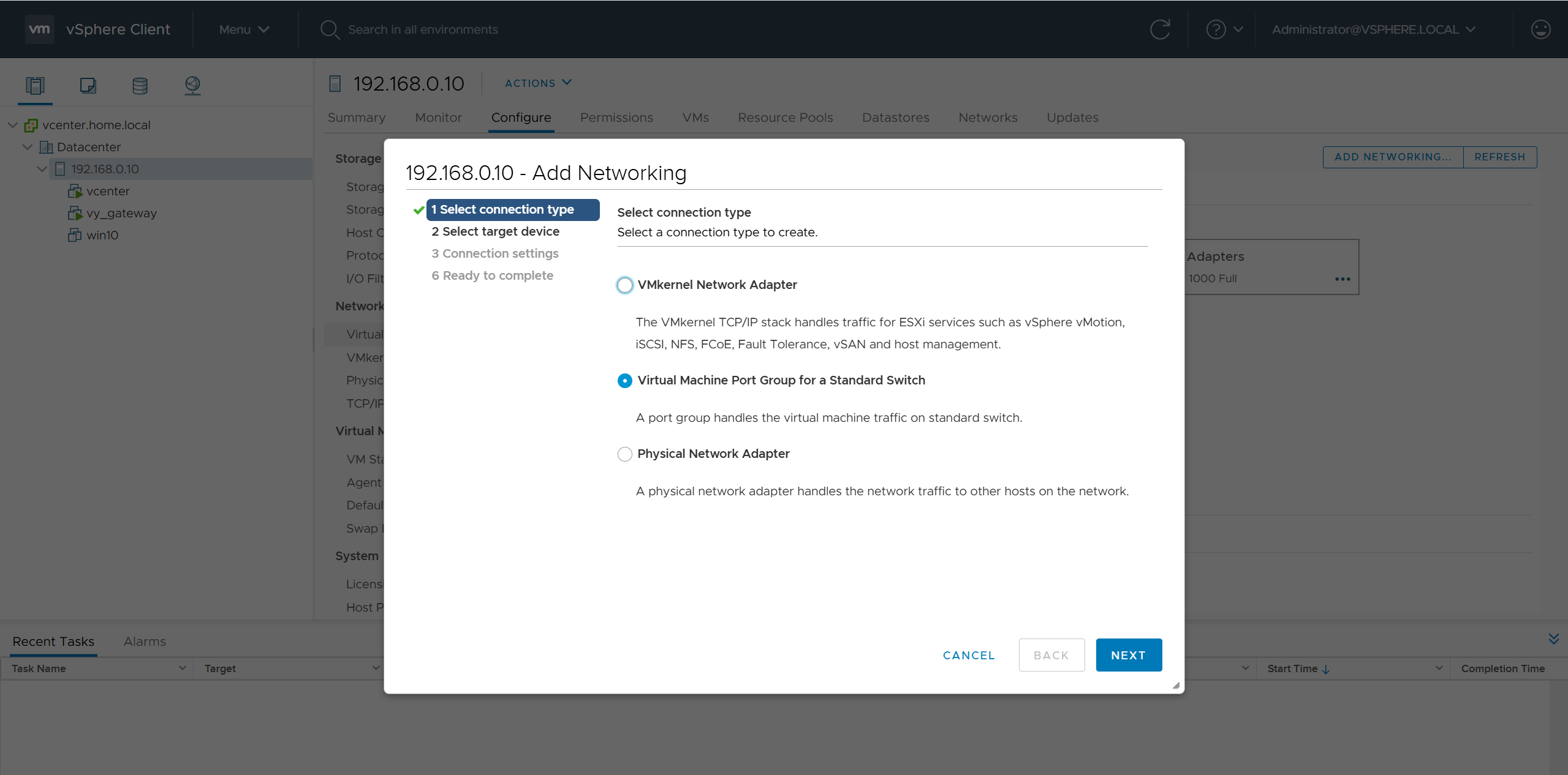
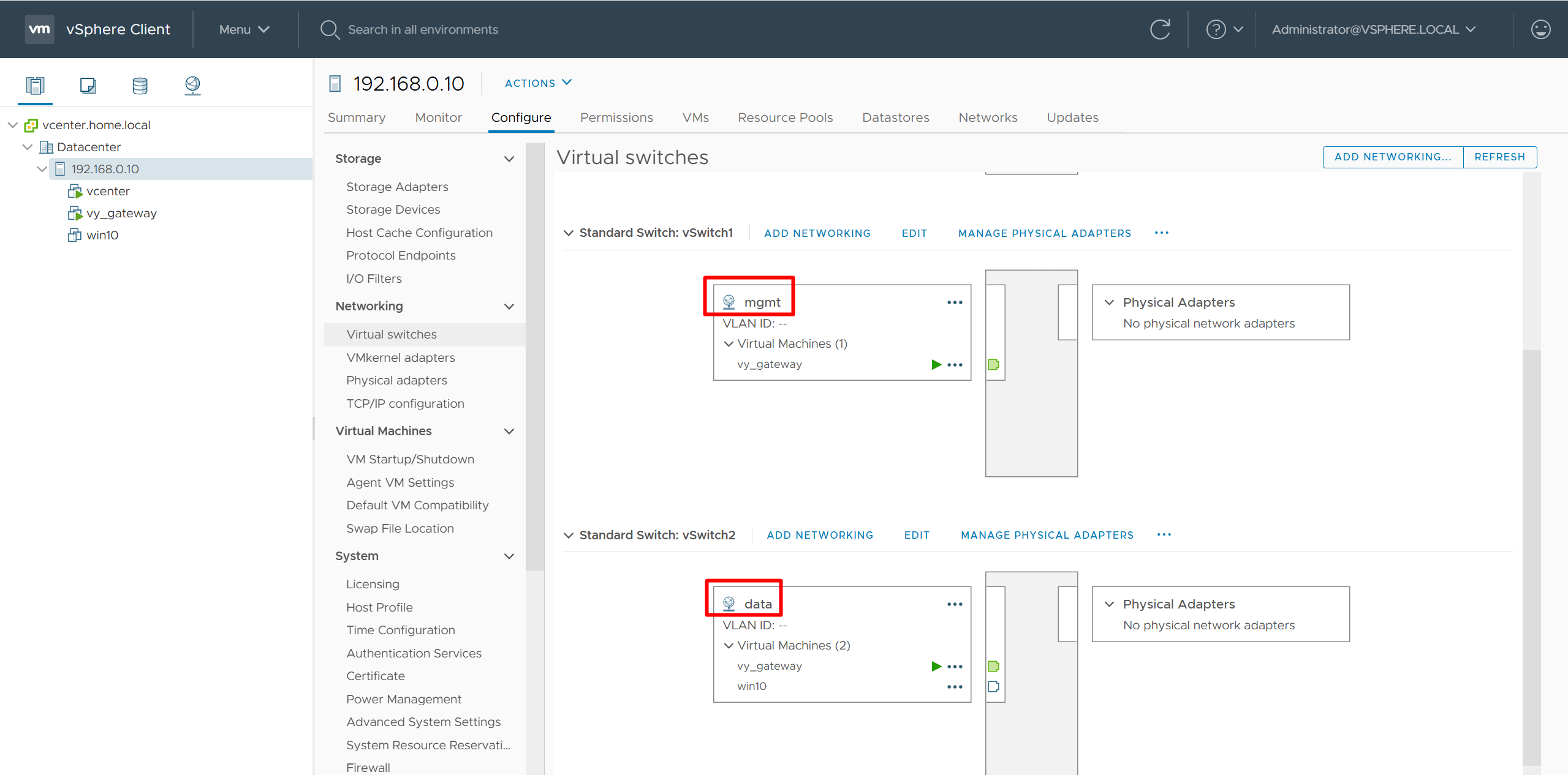
add 2nd interface for vy-gateway into mgmt
add 3rd interface for vy-gateway into data

home router
Add routes for networks 10.21.1.0/24 and 172.16.25.0/24

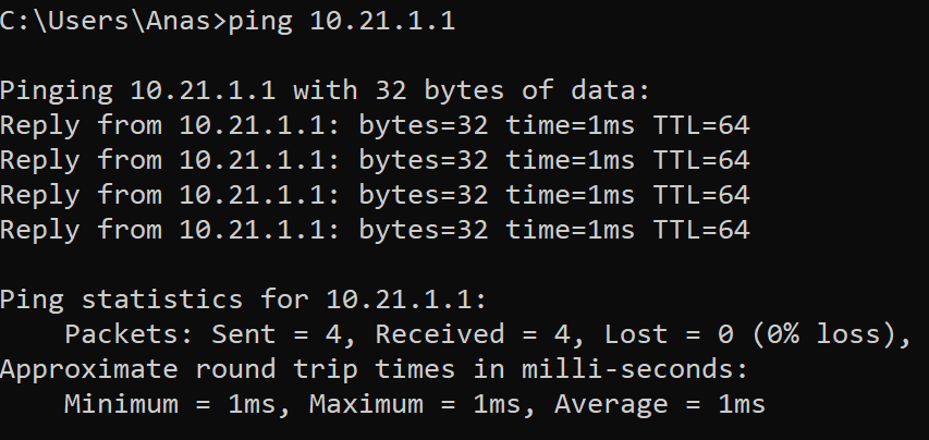
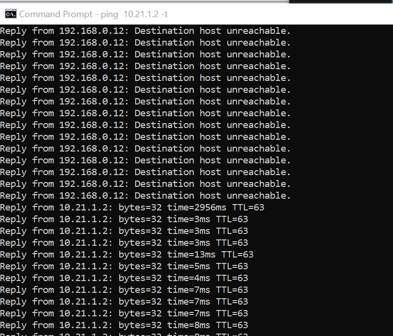
vyos routing is reachable
Cisco Catalyst Center 2.3.7.x on ESXi Deployment – Part 1
Virtual Machine Minimum Requirements
| Feature | Description |
|---|---|
| Virtualization platform and hypervisor | VMware vSphere (which includes ESXi and vCenter Server) 7.0.x or later, including all patches. |
| Processors | Intel Xeon Scalable server processor (Cascade Lake or newer) or AMD EPYC Gen2 with 2.1 GHz or better clock speed.32 vCPUs with 64-GHz reservation must be dedicated to the VM. |
| Memory | 256-GB DRAM with 256-GB reservation must be dedicated to the VM. |
| Storage | 3-TB solid-state drive (SSD).If you plan to create backups of your virtual appliance, also reserve additional datastore space. For information, see “Backup Server Requirements” in the Cisco Catalyst Center on ESXi Administrator Guide. |
| I/O Bandwidth | 180 MB/sec. |
| Input/output operations per second (IOPS) rate | 2000-2500, with less than 5 ms of I/O completion latency. |
| Latency | Catalyst Center on ESXi to network device connectivity: 200 ms. |
Scale numbers are different
for example maximum number of devices supported in non-fabric deployment is 1000 and maximum number of devices in fabric deployment is 2000, for more info
https://www.cisco.com/c/en/us/td/docs/cloud-systems-management/network-automation-and-management/catalyst-center/catalyst-center-va/esxi/2-3-7/deployment-guide/b_cisco_catalyst_center_237x_on_esxi_deployment_guide.html
Cisco Catalyst Assurance uses near real-time streaming analytics, which requires heavy resource usage. When operating Catalyst Center on ESXi close to maximum scale, this functionality may be impacted by uncontrolled external events, such as host resource oversubscriptions and edge use cases that result in a resource usage spike. A number of things can indicate that these events are taking place, such as slow performance, data processing gaps, high I/O latency, and a CPU readiness percentage that’s higher than normal.
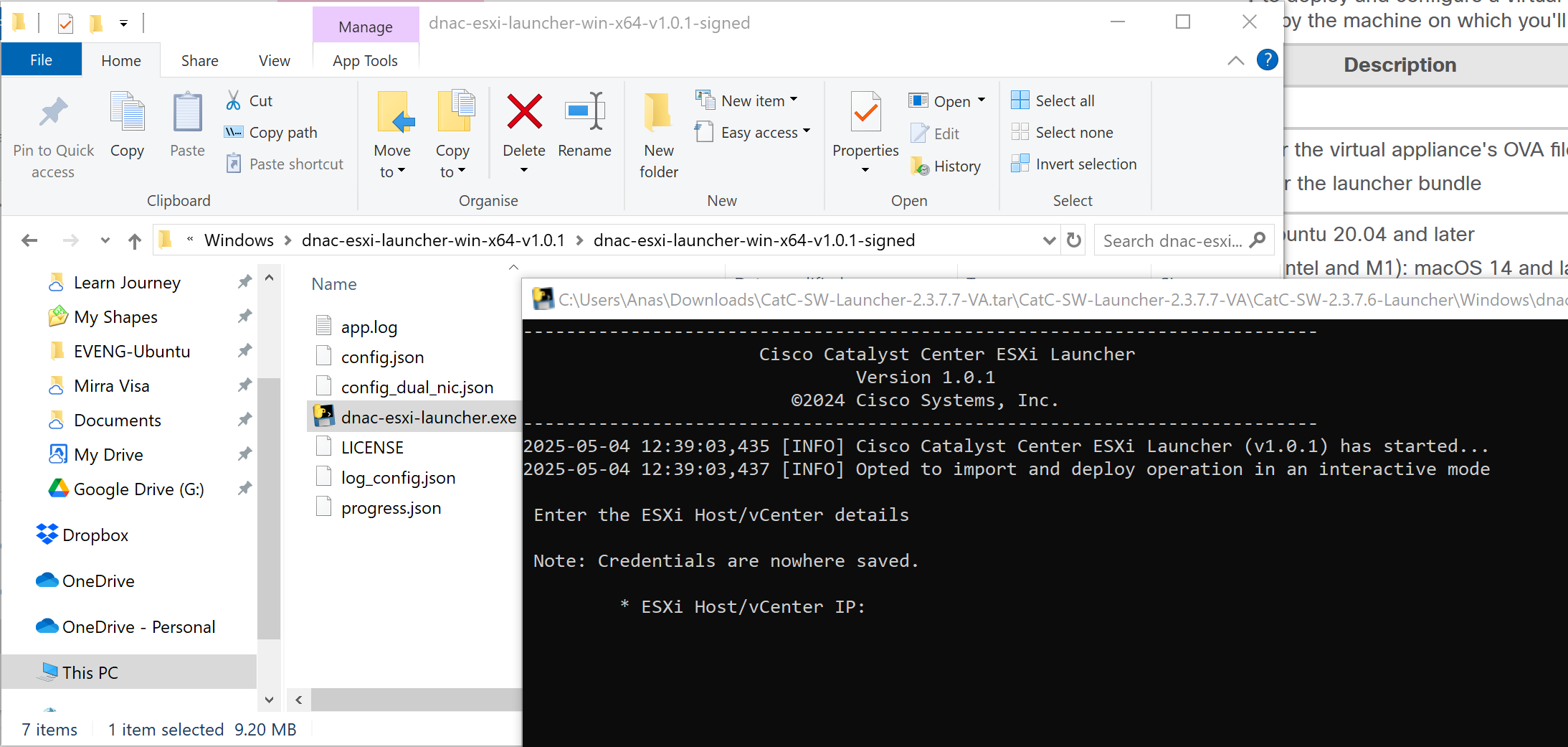
Catalyst Center VM can be deployed using Catalyst Center VA Launcher
Import the IdenTrust Certificate Chain
The Catalyst Center on ESXi OVA file is signed with an IdenTrust CA certificate, which is not included in VMware’s default truststore. As a result, the Deploy OVF Template wizard’s Review details page will indicate that you are using an invalid certificate while completing the wizard. You can prevent this by importing the IdenTrust certificate chain to the host or cluster on which you want to deploy the OVA file.

Cat center requires access to following URLs during install
| In order to… | …Catalyst Center on ESXi must access these URLs and FQDNs |
|---|---|
| Download updates to the system and application package software; submit user feedback to the product team. | Recommended: *.ciscoconnectdna.com:4431Customers who want to avoid wildcards can specify these URLs instead:https://www.ciscoconnectdna.comhttps://cdn.ciscoconnectdna.comhttps://registry.ciscoconnectdna.comhttps://registry-cdn.ciscoconnectdna.com |
| Catalyst Center on ESXi update package. | https://*.ciscoconnectdna.com/**.cloudfront.net*.tesseractcloud.com |
| Smart Account and SWIM software downloads. | https://apx.cisco.comhttps://cloudsso.cisco.com/as/token.oauth2https://*.cisco.com/*https://download-ssc.cisco.com/ |
| Authenticate with the cloud domain. | https://dnaservices.cisco.com |
| Integrate with ThousandEyes. | *.awsglobalaccelerator.comapi.thousandeyes.com |
| Manage Cisco Enterprise Network Function Virtualization Infrastructure Software (NFVIS) devices. | *.amazonaws.com |
| Collect product telemetry. | https://data.pendo.io |
| Allow API calls to enable access to Cisco CX Cloud Success Tracks. Otherwise, the enhancements made to extended configuration-based scanning for the Security Advisories, Bug Identifier, and EOX features that Machine Reasoning Engine (MRE) supports will not operate as expected. | https://api-cx.cisco.com |
| Integrate with Webex. | http://analytics.webexapis.comhttps://webexapis.com |
| User feedback. | https://dnacenter.uservoice.com |
| Integrate with Cisco Meraki. | Recommended: *.meraki.com:443Customers who want to avoid wildcards can specify these URLs instead:dashboard.meraki.com:443api.meraki.com:443n63.meraki.com:443 |
| Check SSL/TLS certificate revocation status using OCSP/CRL. | http://validation.identrust.com/crl/hydrantidcao1.crlhttp://commercial.ocsp.identrust.comNote These URLs should be reachable both directly and through the proxy server that’s configured for Catalyst Center. |
| Allow Cisco authorized specialists to collect troubleshooting data when Catalyst Center on ESXi Remote Support functionality is enabled. | wss://prod.radkit-cloud.cisco.com:443 |
| Integrate with cisco.com and Cisco Smart Licensing. | *.cisco.com:443Customers who want to avoid wildcards can specify these URLs instead:software.cisco.comcloudsso.cisco.comcloudsso1.cisco.comcloudsso2.cisco.comapiconsole.cisco.comapi.cisco.comapx.cisco.comsso.cisco.comapmx-prod1-vip.cisco.comapmx-prod2-vip.cisco.comtools.cisco.comtools1.cisco.comtools2.cisco.comsmartreceiver.cisco.com |
| Connect to the Network-Based Application Recognition (NBAR) cloud. | prod.sdavc-cloud-api.com:443 |
| Render accurate information in site and location maps. | www.mapbox.com*.tiles.mapbox.com/* :443. For a proxy, the destination is *.tiles.mapbox.com/* |
| For Cisco AI Network Analytics data collection, configure your network or HTTP proxy to allow outbound HTTPS (TCP 443) access to the cloud hosts. | https://api.use1.prd.kairos.ciscolabs.com (US East Region)https://api.euc1.prd.kairos.ciscolabs.com (EU Central Region) |
| Access a menu of interactive help flows that let you complete specific tasks from the GUI. | https://ec.walkme.com |
| Access the licensing service. | https://swapi.cisco.com |
| Integrate with Cisco Spaces. | https://dnaspaces.iohttps://dnaspaces.euhttps://ciscospaces.sg |
ciscoconnectdna.com is a cisco domain
Windows server NTP server
https://www.domat-int.com/en/how-to-configure-a-local-ntp-server
https://docs.litmus.io/litmusedge/product-features/system/network/configure-dns-ntp-servers/configure-local-ntp-server
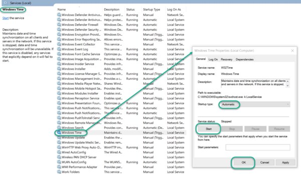
Configure the Windows Time Service
In the File Explorer, navigate to: Control Panel\System and Security\Administrative Tools
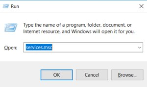
Double-click Services. This same task can be completed by entering services.msc in the Windows Run dialog (Windows Key + R).
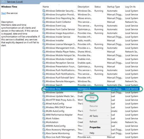
In the Services list, right-click on Windows Time and click Stop.
Note: The Windows Time service may already be stopped. In this case, skip this step and go to the next step to Update the Windows Registry
Update the Windows Registry to Create a Local NTP Service
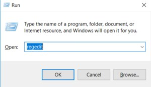
Launch Windows Run (Windows Key + R).
Enter regedit and click OK.
Navigate to the registry key: Computer\HKEY_LOCAL_MACHINE\SYSTEM\CurrentControlSet\Services\W32Time\Parameters
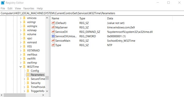
If you do not see LocalNTP REG_DWORD in the list, create it using the following steps.
Right-click in the Registry Editor, select New, select DWORD and enter LocalNTP (note that this name is case sensitive).
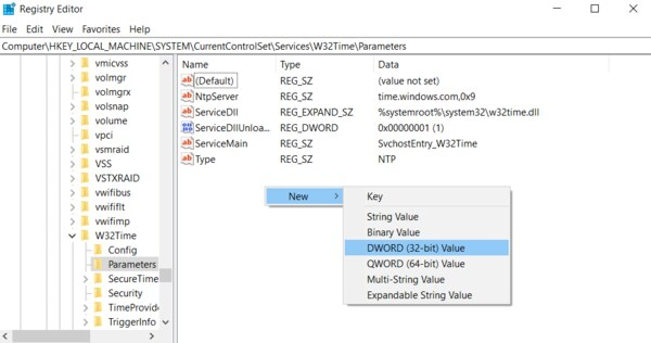
Double-click LocalNTP, change the Value data to 1, select a Base of Hexadecimal , and click OK.
Do not close the Registry Editor because it is used in the following steps.
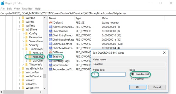
Update the Windows Registry to Configure the Time Provider
Navigate to the registry key: Computer\HKEY_LOCAL_MACHINE\SYSTEM\CurrentControlSet\Services\W32Time\TimeProviders
Select NtpServer, double-click Enabled, change the Value Data to 1, select a Base of Hexadecimal and click OK.
Do not close the Registry Editor because it is used in the following steps.
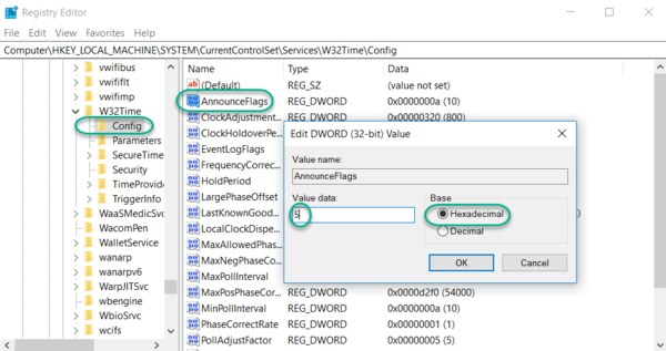
Update the Windows Registry to Configure the Announce Flags
Navigate to the registry key: Computer\HKEY_LOCAL_MACHINE\SYSTEM\CurrentControlSet\Services\W32Time\Config
Double-click AnnounceFlags, change the Value data to 5, select a Base of Hexadecimal, and click OK.
Close the Registry Editor.
Start the Local Windows NTP Time Service
In the File Explorer, navigate to: Control Panel\System and Security\Administrative Tools
Double-click Services.
In the Services list, right-click on Windows Time and configure the following settings:
Startup type: Automatic
Service Status: Start
OK
Finally, enable UDP port 123 on the Windows firewall for incoming connections.
In Search find Firewall in Windows Defender…
Go to Incoming rules
In the right column, select New rule…
Select the rule Port
Enter UDP port 123 and click Next
Select Allow connection and click Next
Select all domains
Enter the rule name, e.g. Local NTP server, and click Finish.
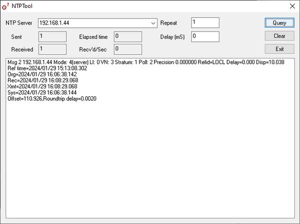
The local NTP Time Server configuration is now complete. You now can synchronize the time of other computers and devices on your local network.
To test the server functionality from another PC (e.g. a service notebook) use for example the NTP Server Test Tool:
https://www.ntp-time-server.com/ntp-software/ntp-server-tool.html
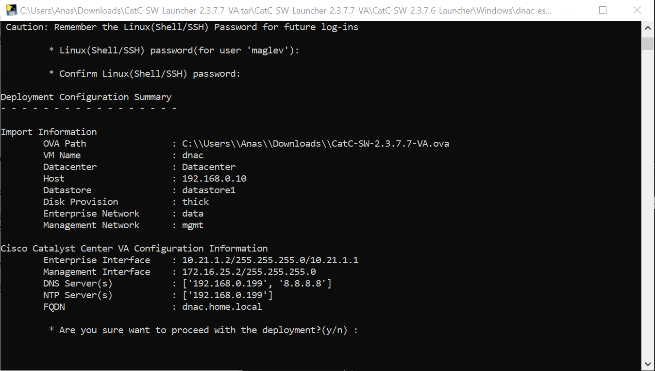
DNAC deployment

C:\\Users\\Anas\\Downloads\\CatC-SW-2.3.7.7-VA.ova
Add 2 backslashes for OVA path to escape it
vcenter.home.local
administrator@vsphere.local
C0mplex30-
C:\\Users\\Anas\\Desktop\\CatC-SW-2.3.7.7-VA.ova

dnac
thick
2

data
mgmt

10.21.1.2
255.255.255.0
10.21.1.1

Mgmt interface:
172.16.25.2
255.255.255.0

DNS
172.16.32.11

NTP
172.16.32.11

dnac.home.local
maglev
C0mplex30


maglev will load containers
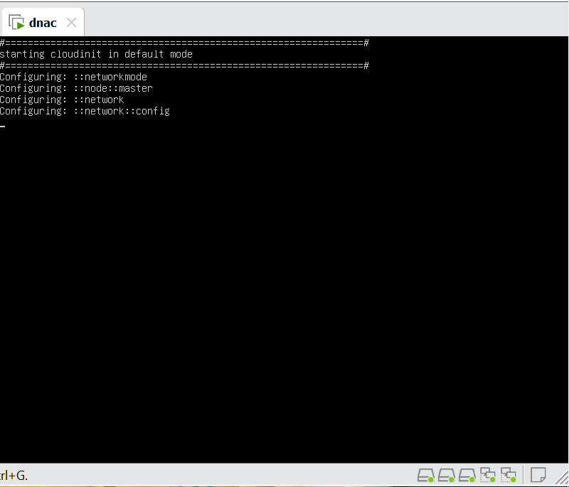


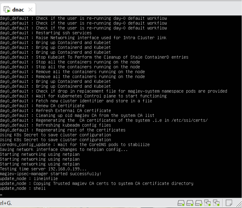
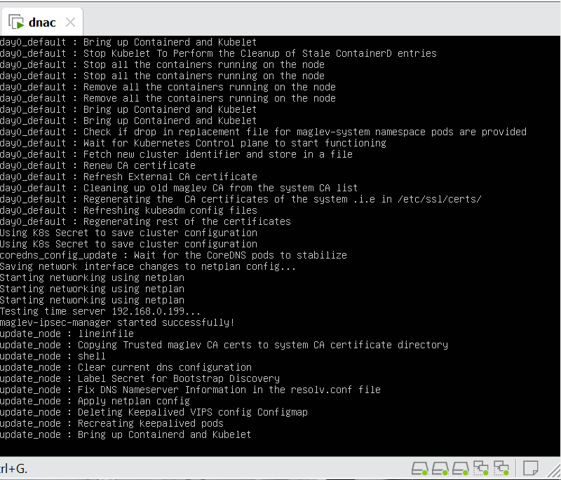
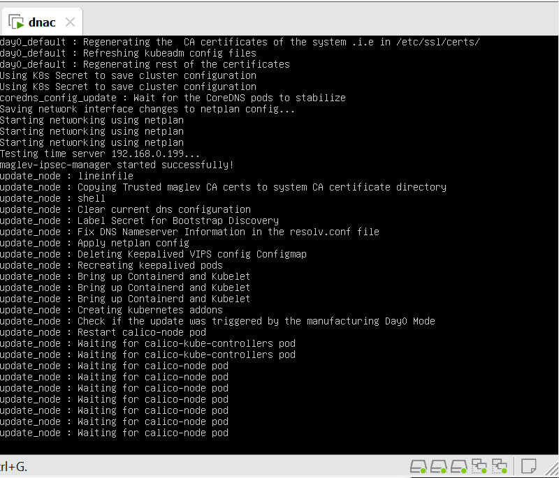
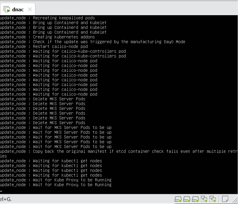
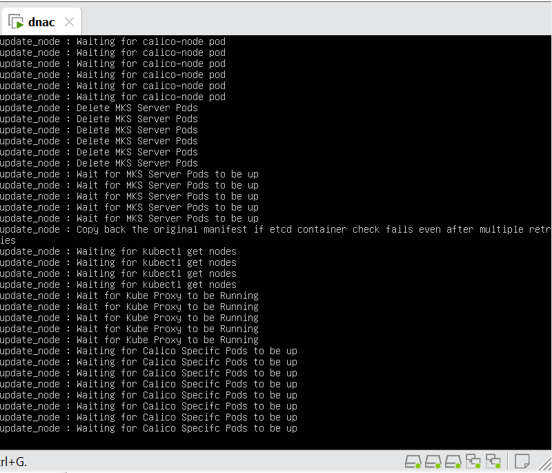
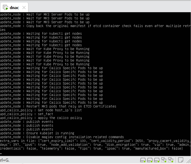

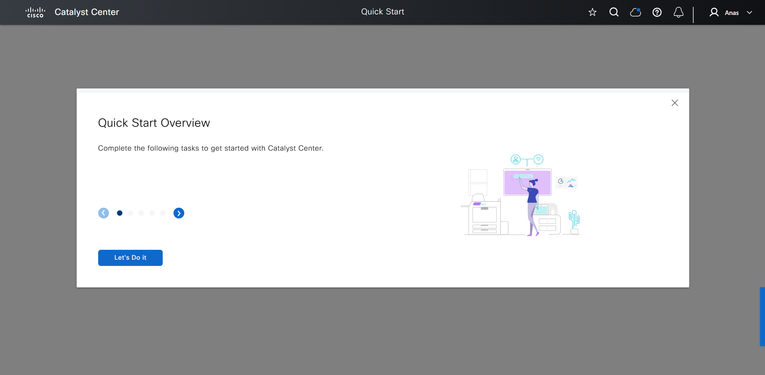
wait 30 mins before GUI shows up
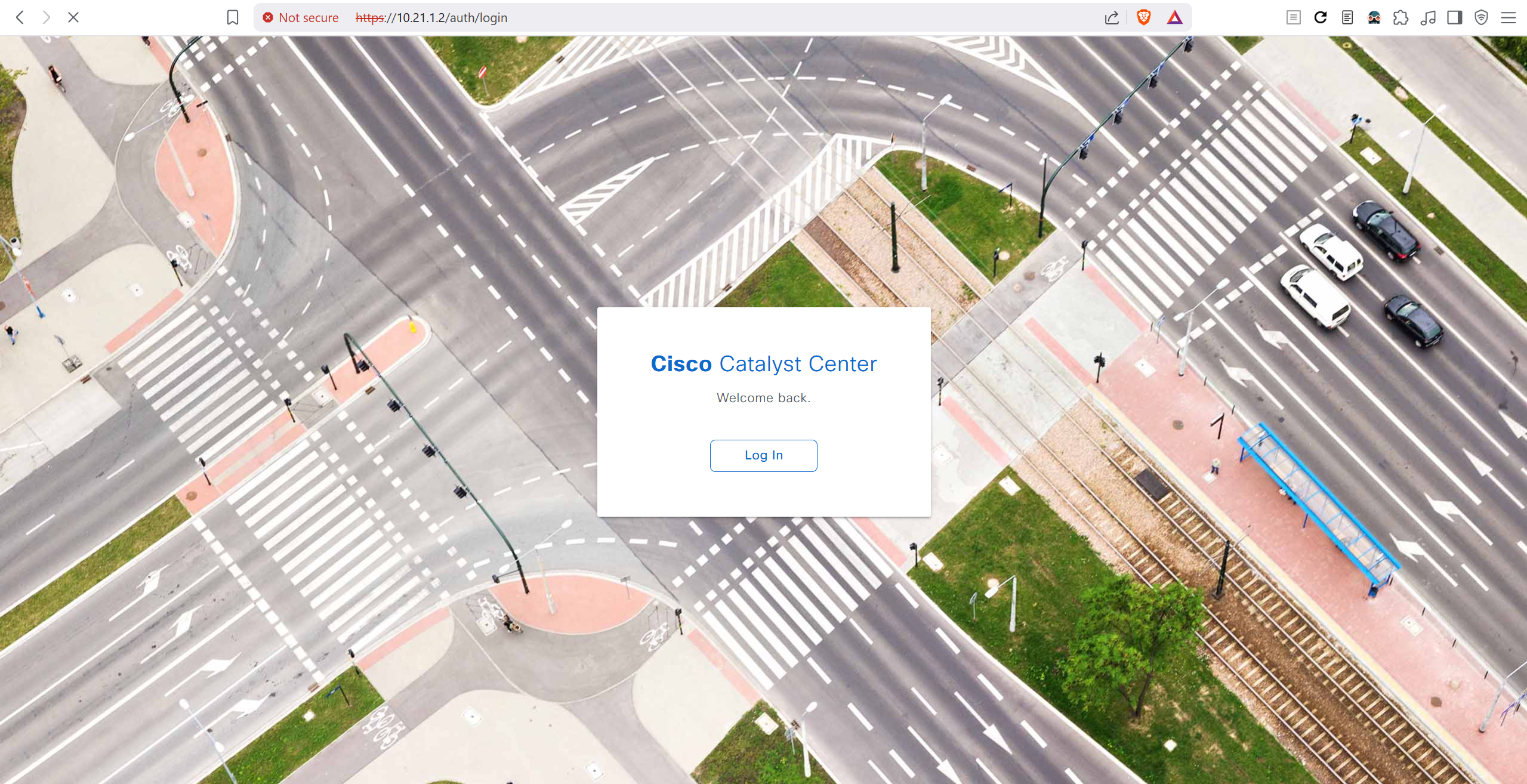
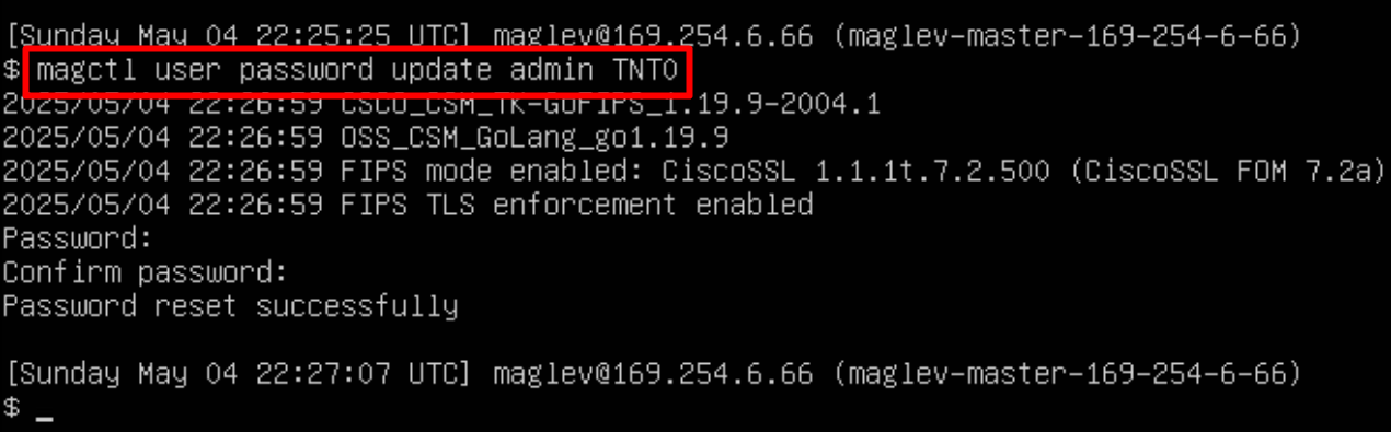
In case unable to login
Login to CLI as maglev on VM’s console and reset password for admin
Logins
Default GUI login admin/maglev1@3
Login to create account admin_anas/C0mplex30
SSH login on port 2222 maglev/C0mplex30
DNAC VM Console login maglev/C0mplex30
Initial Login

provide user here that will be super admin such as admin_anas
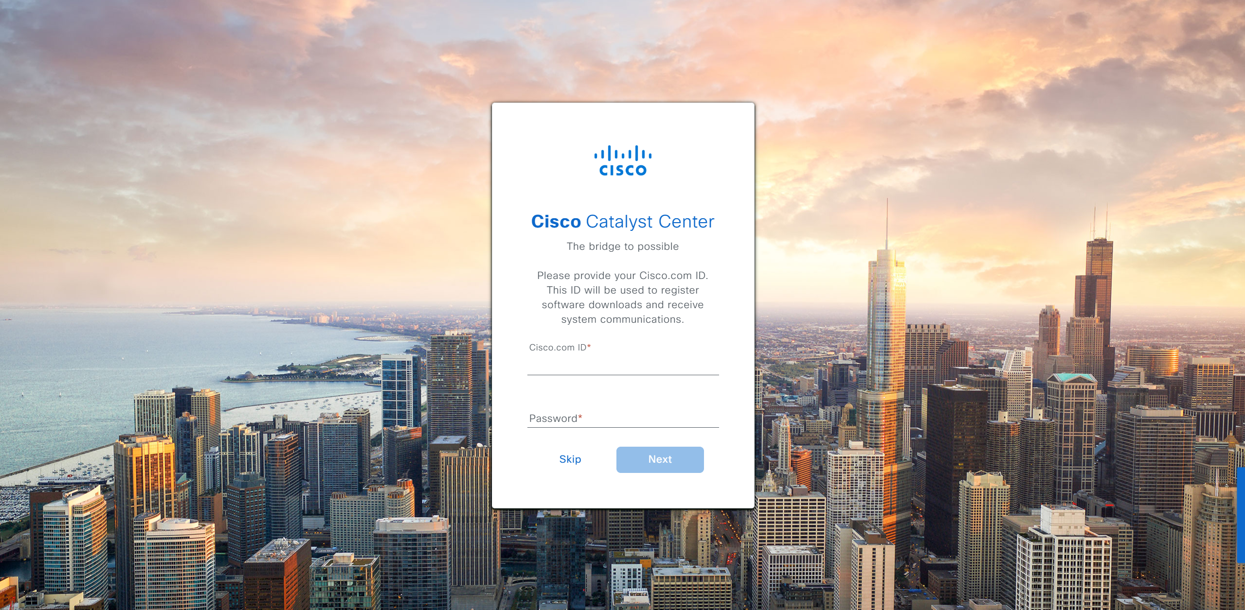
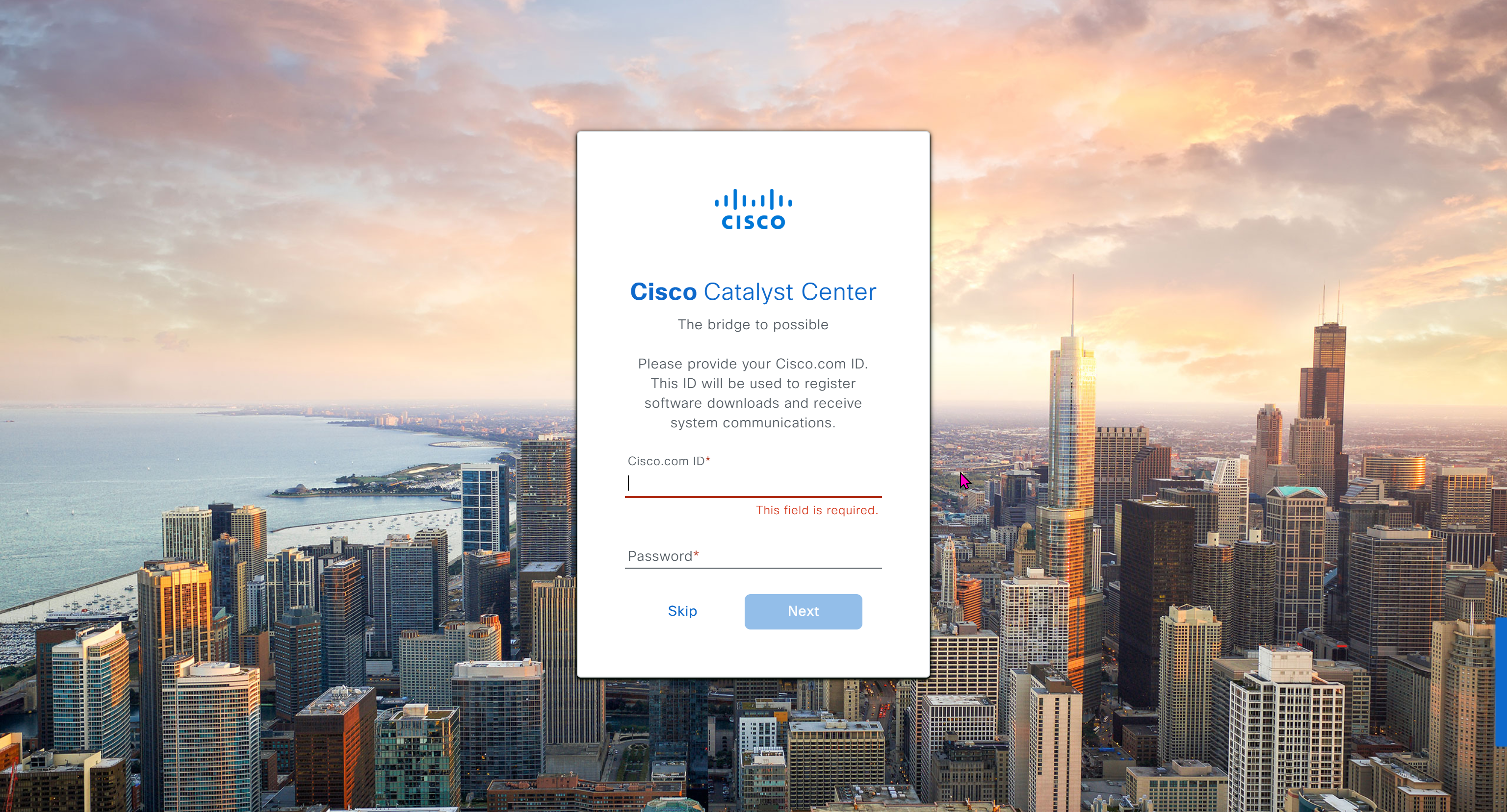
provide your cco in email and not personal email
admin_anas/C0mplex30
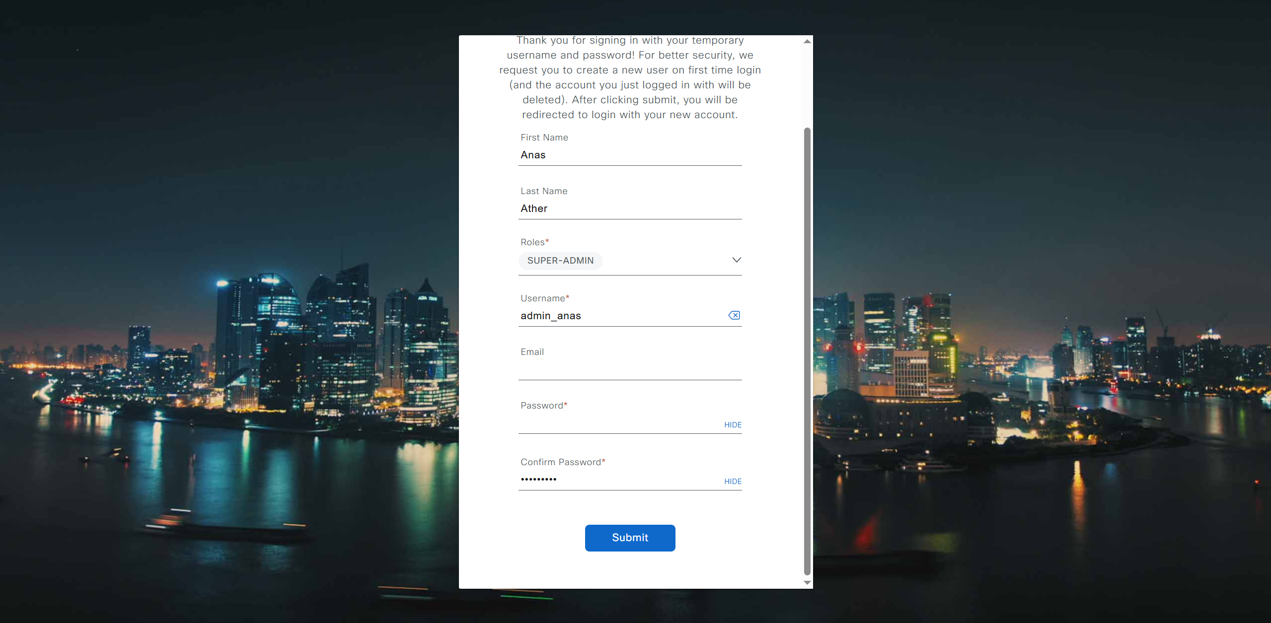
provide company’s CCO details here that has contract and active cco – this is very important otherwise packages will not work


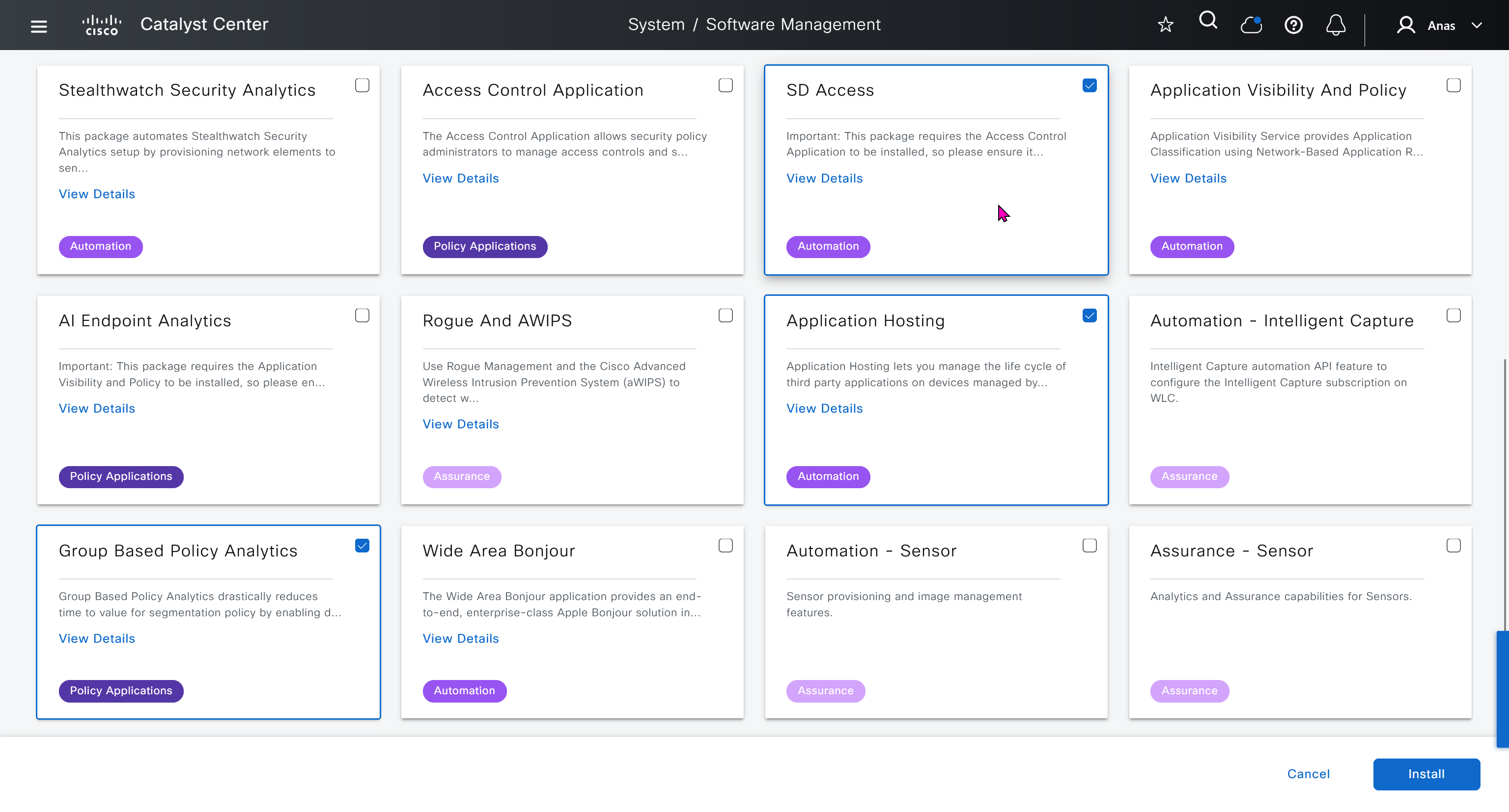
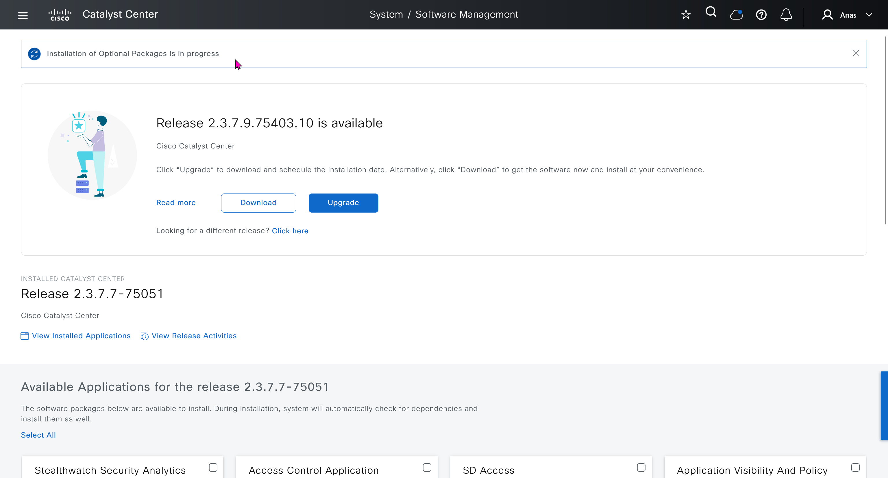
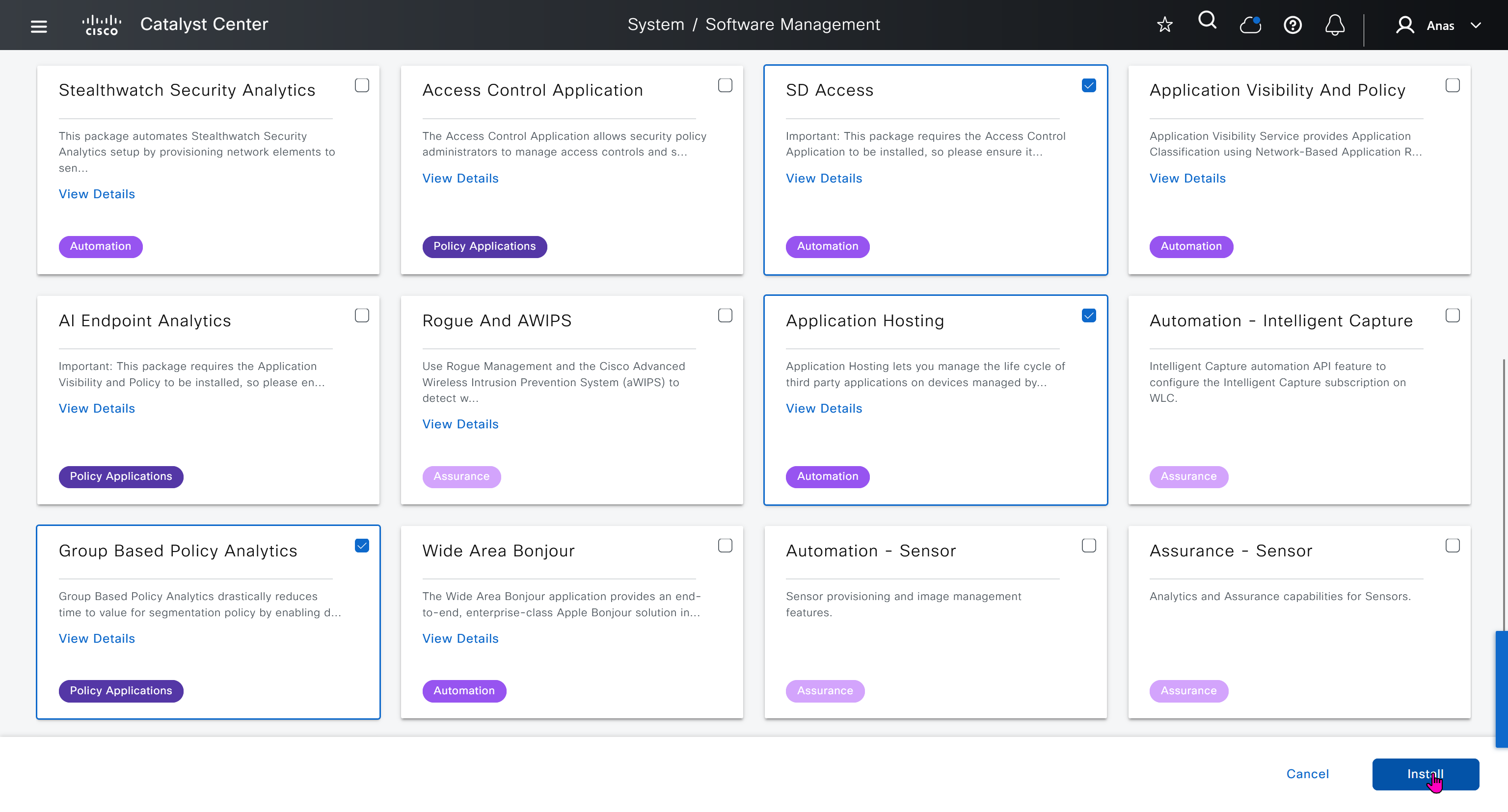
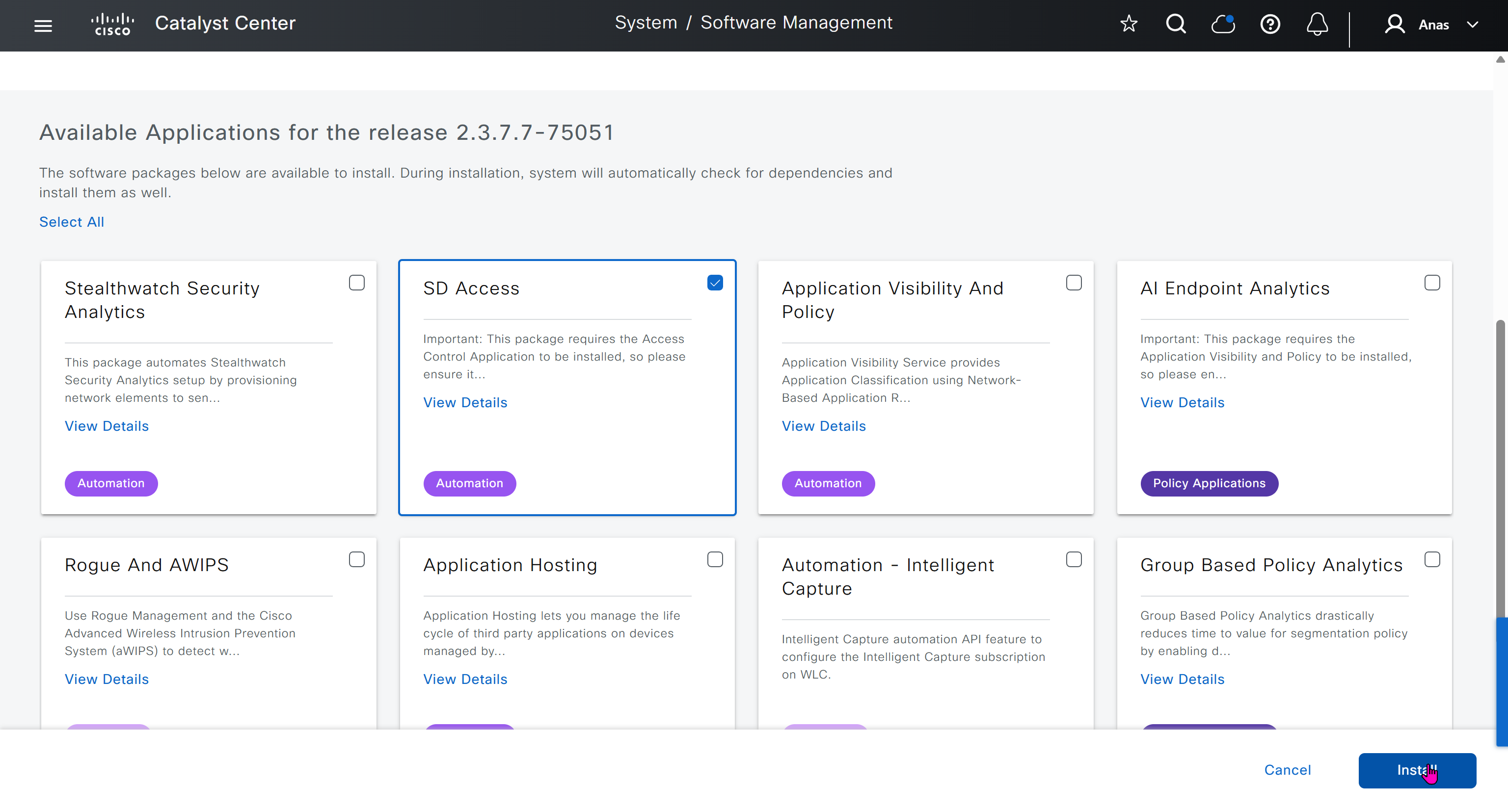
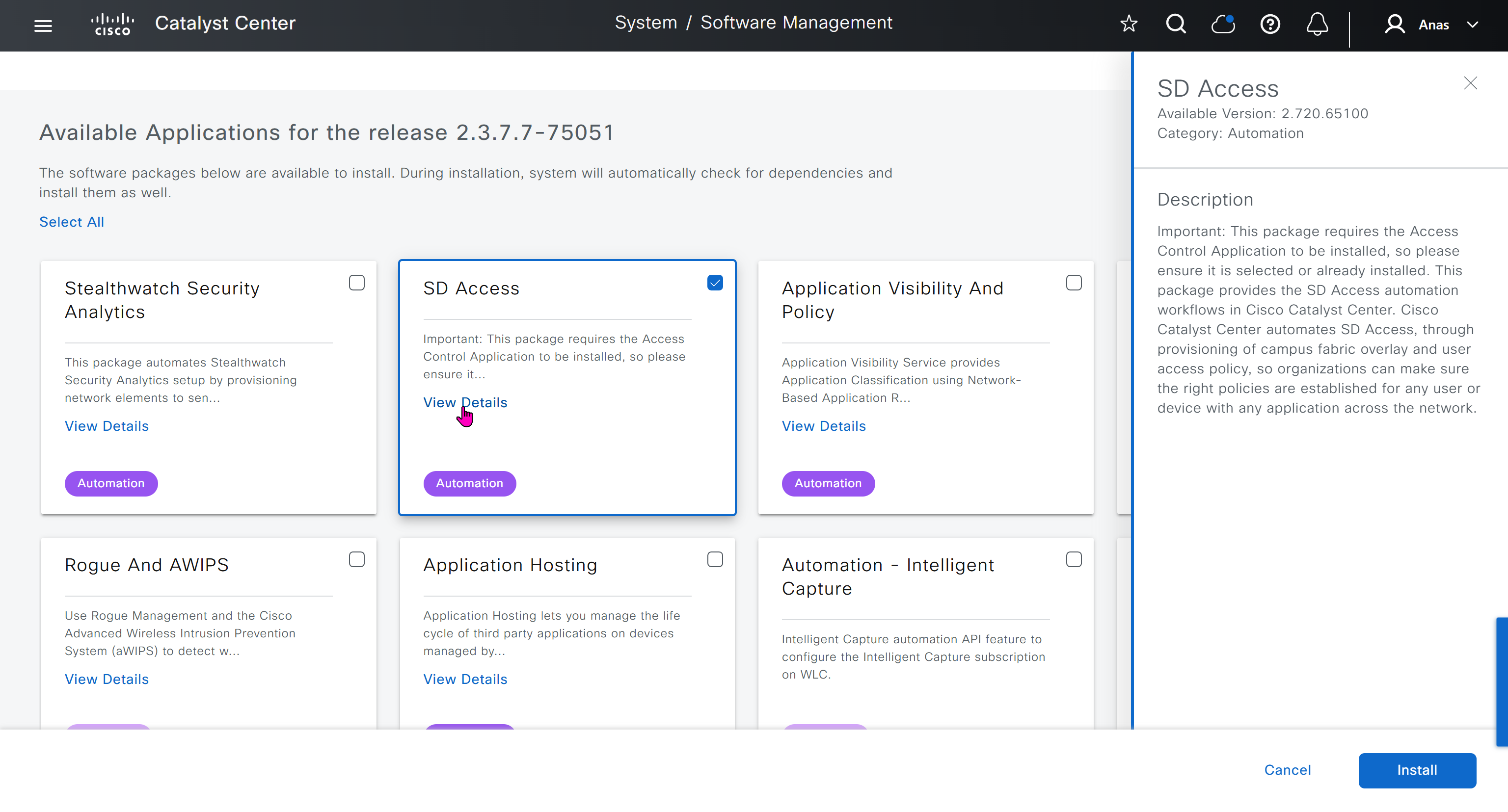
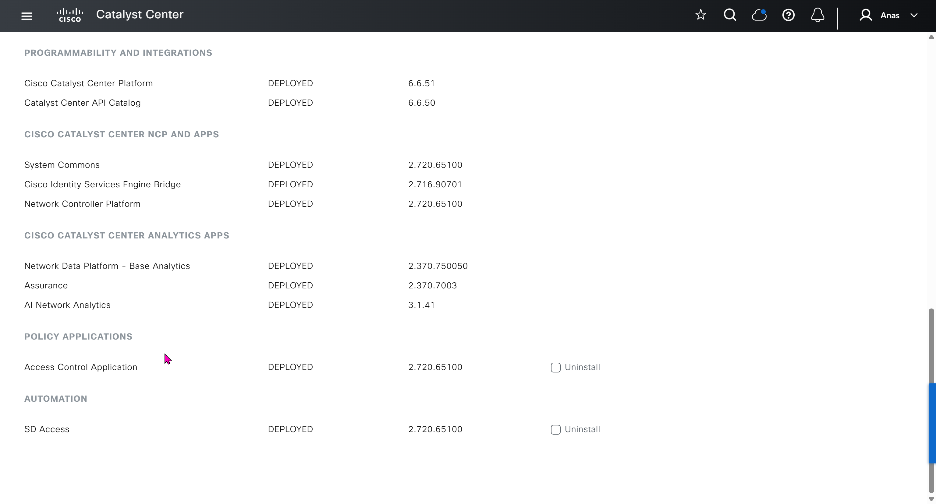
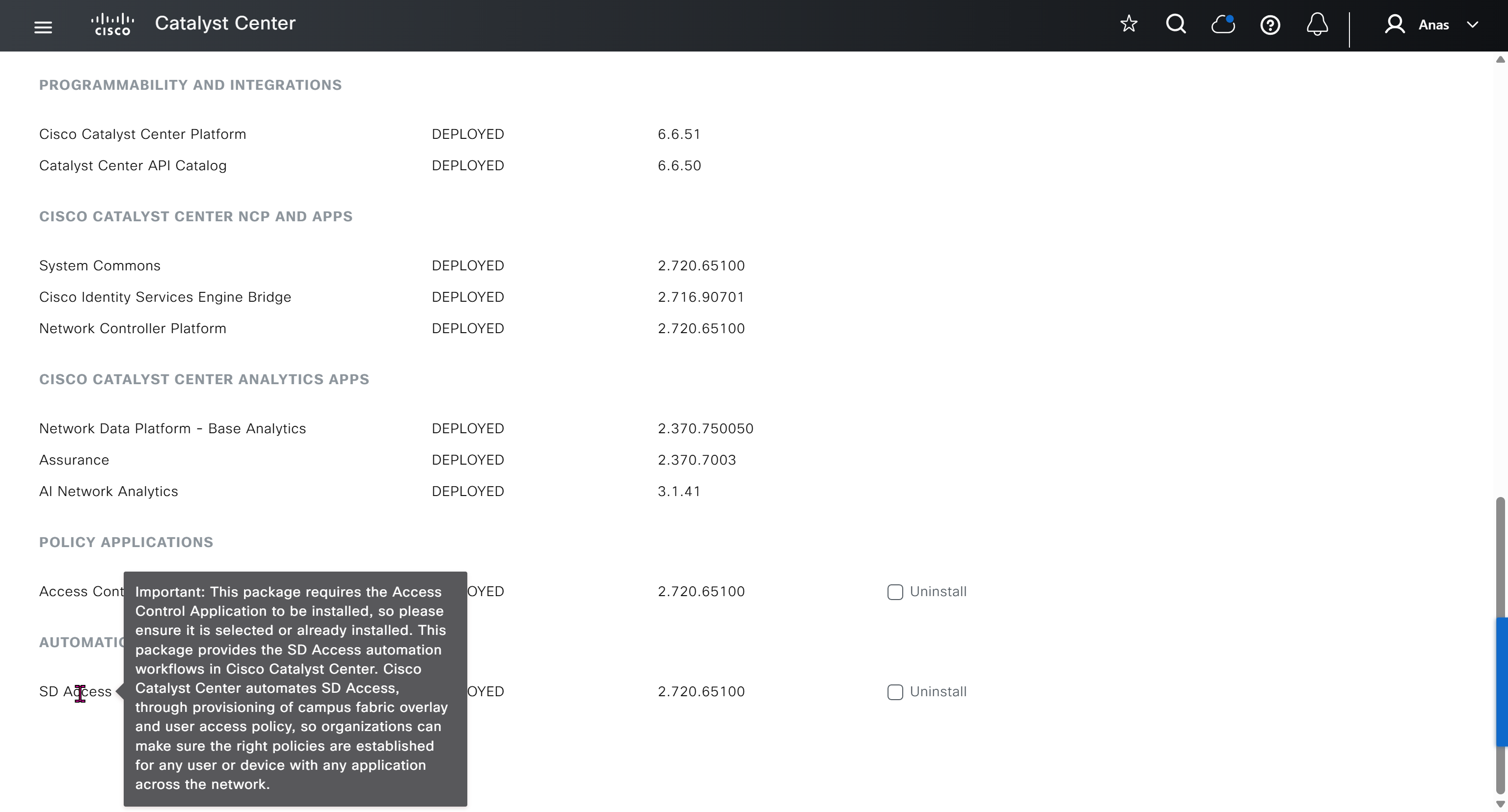
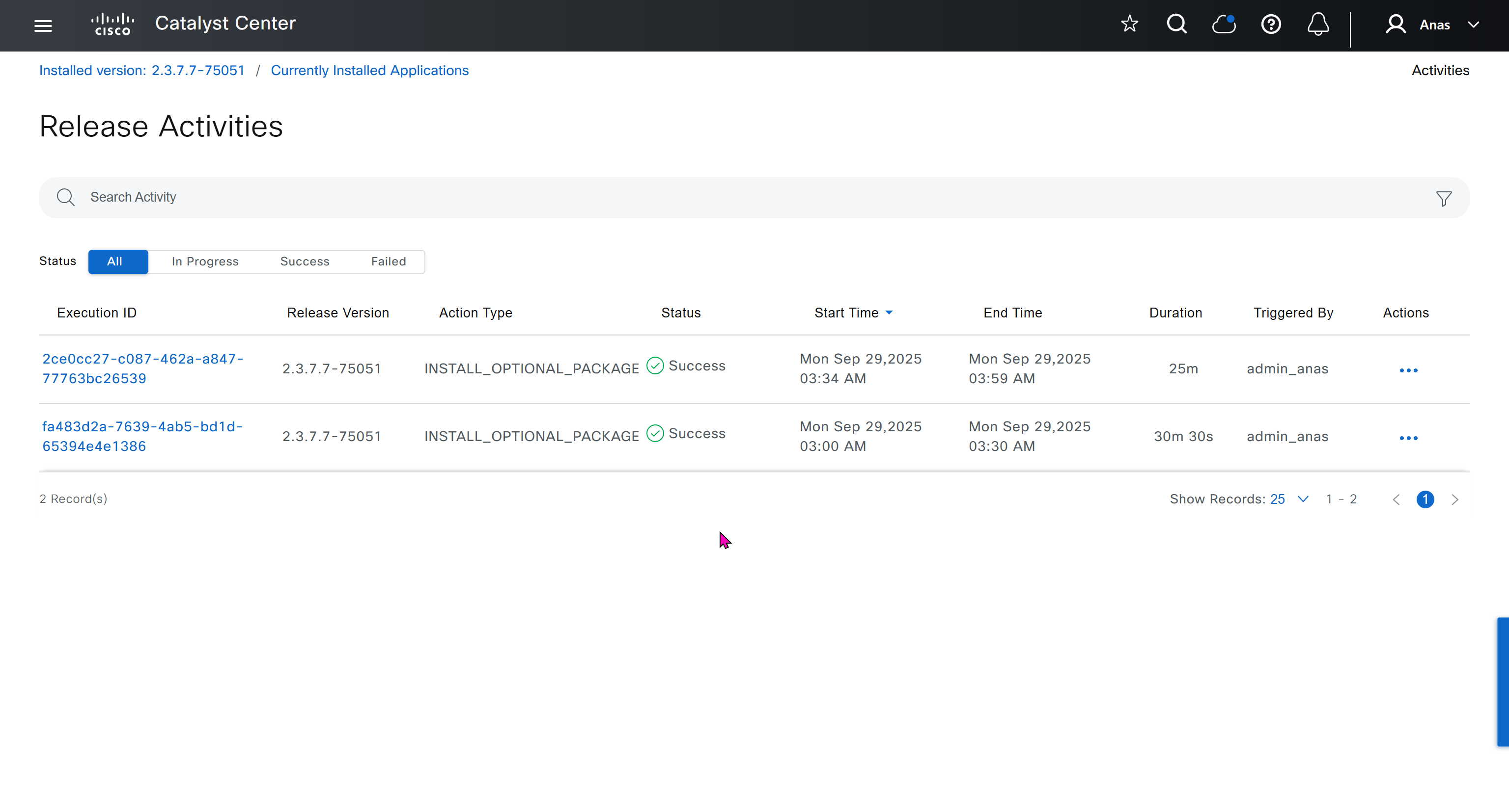
With new build make sure DNAC has internet access, go ahead and download the applications packages which are needed for SGT and SDA, Cisco has divided these features into applications or packages and with fresh install / build download these packages
- Download these packages
- Turn off the VM
- Take Snapshot with exact date and time
- Turn off time syncing of VM with ESXI
- ESXI add NTP server same as Windows Server
- Windows Server move back time on server when it is time to restore the VM
- When restore cut off internet access to DNAC


Here do not use personal email instead use email from company’s cco


on next deployment also download below modules also
Sensor Assurance
AI Endpoint Analytics
Application Visibility and Policy (EasyQoS)

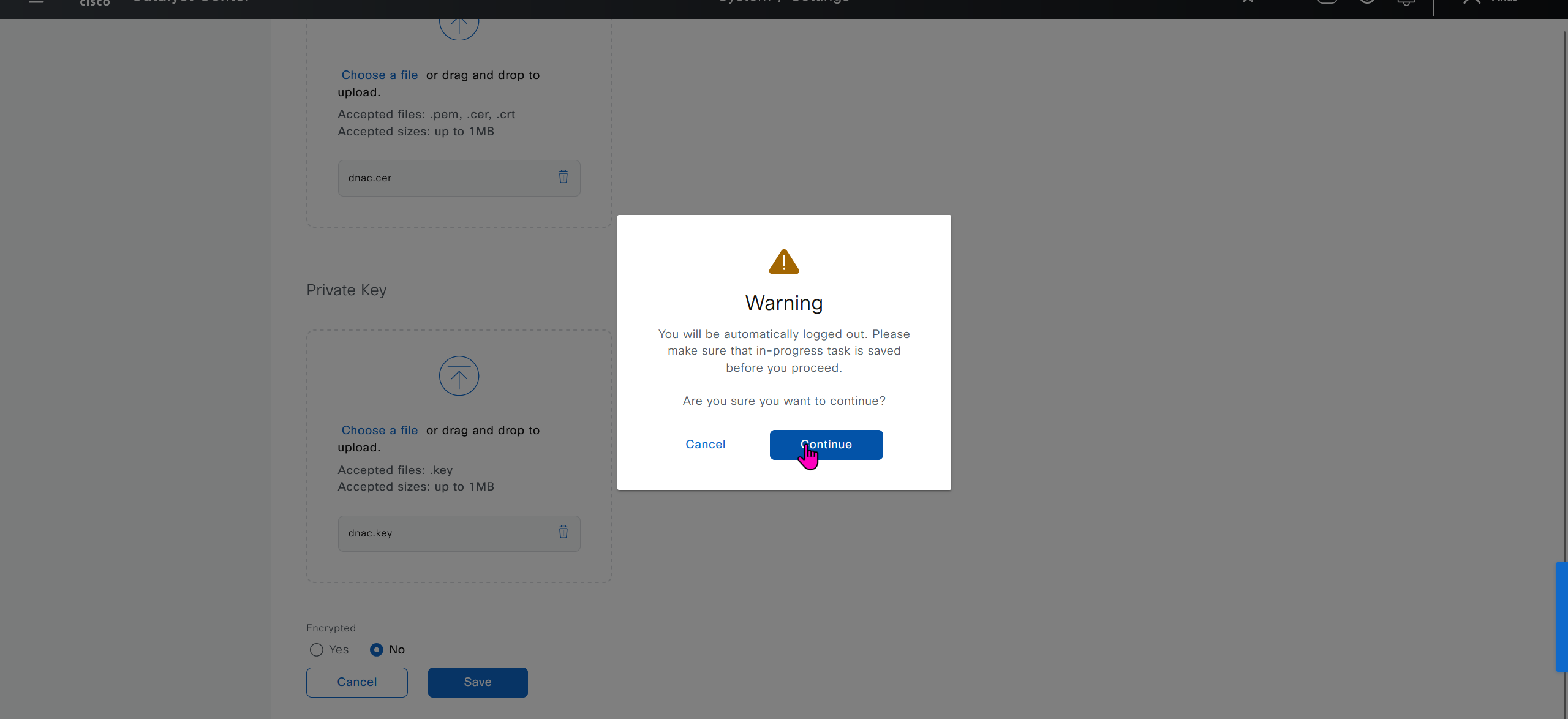
Only after these steps, add certificate to DNAC
Further configuration and ISE integration
Graceful shutdown DNAC
! Cat center shutdown
$ shutdown

! VYOS shutdown
sudo bash
shutdown -h now

! vcenter shutdown
Gracefully shutdown from esxi
SDA Links
https://www.cisco.com/c/en/us/td/docs/cloud-systems-management/network-automation-and-management/catalyst-center/catalyst-center-va/esxi/2-3-7/deployment-guide/b_cisco_catalyst_center_237x_on_esxi_deployment_guide.html#configure-a-virtual-appliance-using-the-interactive-cc-va-launcher
https://www.cisco.com/c/en/us/td/docs/solutions/CVD/Campus/SD-Access-Distributed-Campus-Deployment-Guide-2019JUL.html
https://www.cisco.com/c/dam/en/us/td/docs/solutions/CVD/Campus/sda-fabric-deploy-2019oct.pdf
https://www.cisco.com/c/en/us/td/docs/solutions/CVD/Campus/cisco-sda-design-guide.html
https://www.cisco.com/c/dam/en/us/td/docs/solutions/CVD/Campus/CVD-Software-Defined-Access-Segmentation-Design-Guide-2018MAY.pdf
next post
To learn
Configuring Static Route Tracking using IP SLA (Basic)
https://www.firewall.cx/cisco/cisco-routers/cisco-router-ipsla-basic.html
Firepower NGFW Multi-Instance Performance on 4100 and 9300 Series Appliances v1.08
https://www.cisco.com/c/en/us/products/collateral/security/firewalls/white-paper-c11-744750.html
Cisco Secure Firewall Management Center Device Configuration Guide, 7.6: Multi-Instance Mode
https://www.cisco.com/c/en/us/td/docs/security/secure-firewall/management-center/device-config/760/management-center-device-config-76/ha-scale-multi-instance.html#khoklhkl-chassis-management-interface
IP CEF commands
https://chatgpt.com/c/69b712af-1508-8384-94b3-02a432618ef8
Client Connect Timeout and RADIUS server communication
https://chatgpt.com/c/69b40b8f-b704-838d-9294-3a4374183cc8
Stack communication down and Simplex
https://chatgpt.com/c/69a19611-3f40-8387-91dc-20c3ba7be6b1
DNASpaces
https://runbooks.ciscospaces.io/docs/
Troubleshoot LISP VXLAN traffic
https://www.cisco.com/c/en/us/support/docs/troubleshooting/220361-troubleshoot-lisp-vxlan-fabric-issues.html#toc-hId–1207536077
SDA blog
https://www.theasciiconstruct.com/blog/category/sda/page/2/
TrustSec Cat9300/9400 Specific Troubleshooting Information
https://community.cisco.com/t5/security-knowledge-base/trustsec-cat9300-9400-specific-troubleshooting-information/ta-p/3700261
SDA border node and control plane node
https://chatgpt.com/c/69c98b67-f4d0-8396-abd1-b8b952a4d2d6
IP Multicast: PIM Configuration Guide
https://www.cisco.com/c/en/us/td/docs/ios-xml/ios/ipmulti_pim/configuration/xe-16/imc-pim-xe-16-book/imc-verify.html
Dynamic Routing Protocol – Routing Table Cisco ACI
https://community.cisco.com/t5/application-centric-infrastructure/dynamic-routing-protocol-routing-table-cisco-aci/td-p/4264627
ACI Fabric L3Out White Paper
https://www.cisco.com/c/en/us/solutions/collateral/data-center-virtualization/application-centric-infrastructure/guide-c07-743150.html
Cisco ACI CLI Commands “Cheat Sheet”
https://community.cisco.com/t5/data-center-and-cloud-knowledge-base/cisco-aci-cli-commands-quot-cheat-sheet-quot/ta-p/3145799
Cisco Catalyst Center Foundations | CCFND
https://u.cisco.com/paths/cisco-catalyst-center-foundations-10291
FTD static IP SGT mapping
https://integratingit.wordpress.com/2020/04/24/ftd-static-ip-sgt-mapping/
Troubleshoot Stack of Cat9k Switches Missing Standby Role
https://www.cisco.com/c/en/us/support/docs/switches/catalyst-9500-series-switches/223096-troubleshoot-stack-of-cat9k-switches.html
Mac-address ACL question
https://community.cisco.com/t5/switching/mac-address-acl-question/td-p/1133228
Cisco SD-Access Fabric Troubleshooting Guide
https://www.cisco.com/c/en/us/td/docs/cloud-systems-management/network-automation-and-management/dna-center/tech_notes/sda_fabric_troubleshooting/b_cisco_sda_fabric_troubleshooting_guide.html
next post
Multicast – Suresh
Multicast traffic is sent using UDP
Concept of OIL / OIF and Incoming interfaces are that the routers in the path should only forward the stream if there are interested receivers downstream. If no one has joined the multicast group on a given path, the routers should not send traffic that way
When a switch sees Broadcast MAC address of FF:FF:FF:FF:FF:FF, it knows the frame is a broadcast and floods it out of all ports in the same VLAN, “except the port it was received on”.
Multicast handling
If routers see destination address is a multicast address, routers treat it as multicast traffic and not like unicast traffic
Similarly if switches look at the ethernet frame and detect it to be multicast mac address then they treat it differently
Multicast IP address is never used as source address and it is always used as destination address, source IP will be the unicast IP address of the sender.
Simiarly the destination MAC on layer 2 will be a Multicast MAC address starting with “01:00:5E”
Multicast ranges
224.0.0.0 to 224.0.0.255 – Reserved for local network control traffic and TTL of 1
232.0.0.0 to 232.255.255.255 – Reserved for Source Specific Multicast (SSM).
239.0.0.0 to 239.255.255.255 – These addresses are meant to be used inside an organization
Multicast Forwarding with PIM-DM first
PIM-SM has mandtory requirement for RP so to keep things simple we will start learning from PIM-DM first, even though we never deploy PIM-DM due to high control plane footprint
Source starts sending traffic to a multicast IP address
Any number of receivers can choose to subscribe to that group
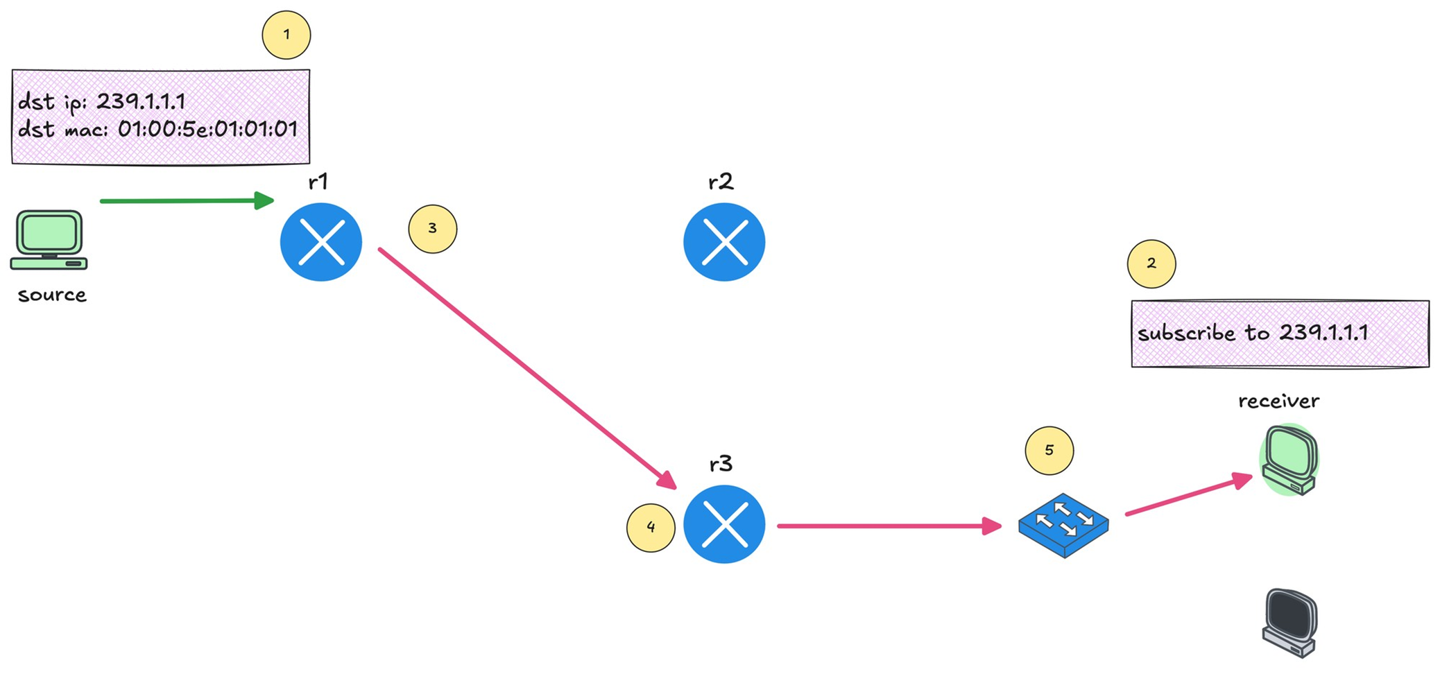
You can see that r1 forwards the multicast traffic toward r3 because there is an interested receiver behind it.
Multicast Reverse Path Forwarding (RPF)
This is required to prevent duplicate packets arriving,
RPF checks “source IP address” of that packet in unicast routing table
If multicast packet arrive on the interface it would use to reach the source?’ If the answer is yes, the RPF check passes, and that multicast traffic is accepted
If the packet arrived on any other interface, the RPF check fails, and the packet is dropped
IGMP – Internet Group Management Protocol
IGMP (Layer 2) playes key role in multicast on LHR and FHR’s LAN side
Switches have to perform IGMP snooping
Part of IGMP also runs on host
Host uses IGMP to signal their interest in multicast traffic
Host sends IGMP Membership Report, also known as an IGMP join to the multicast group address
if PIM neighborship is established on LHR then (PIM-DM will start forwarding traffic right away) in case of PIM-SM LHR will send join towards RP
IGMPv1 is the original version. It allows hosts to join a multicast group but does not support leaving a group explicitly, Routers rely on timeouts to figure out when receivers are no longer interested
IGMPv2 improves on this by adding an explicit leave message.
IGMPv3 adds support for Source Specific Multicast. With IGMPv3, receivers can specify not only the multicast group they want to join, but also which source they want to receive traffic from
IGMPv2
IGMP messages are carried inside IP packets using IP protocol number 2, IP because it is the router that initiates using General Membership query / Group specific query and also the Membership report or IGMP join has to come from end host inside IP
They are always sent with a TTL of 1
IGMPv2 General Membership query
As soon as PIM is enabled on router interface, IGMP is also enabled automatically
Router immediately starts sending IGMP General Membership Queries with source as the interface IP and destination is 224.0.0.1 (All hosts)
The router periodically sends IGMP General Membership Queries to check if receivers are still interested. As long as reports continue to arrive, the router keeps forwarding the multicast stream.
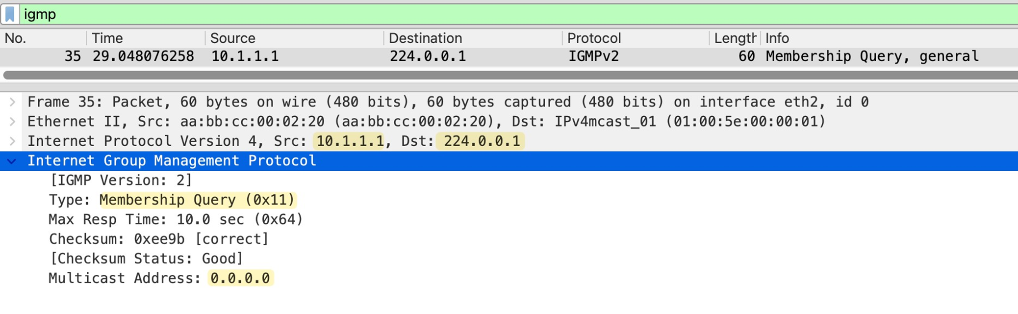
in General Membership Query multicast address is set to 0.0.0.0
As a result all the hosts still interested in even one Multicast group will respond with IGMP Membership report or IGMP join with their randomzied Max response time among themselves
Host whose max response timer expires first, responds to the General Membership query with an IGMP membership or IGMP Join to 239.1.1.1 and other host also see that because they are also listning for 239.1.1.1, If those other hosts are listening for same group and see that IGMP join then they do not send their membership report and suppress it
This report suppression mechanism is to keep IGMP traffic low, otherwise hundreds of hosts can respond at the same time or different times and burden the router’s CPU
IGMPv2 Join or IGMPv2 Membership Report
Host sends Memership report to the Multicast group address and not to 224.0.0.2 or 224.0.0.13

IGMP Leave Message
When a host no longer wants to receive a multicast stream, it sends an IGMP Leave Group message
The source IP of this message is the unicast IP of the host, and the destination IP is the all routers multicast address 224.0.0.2.
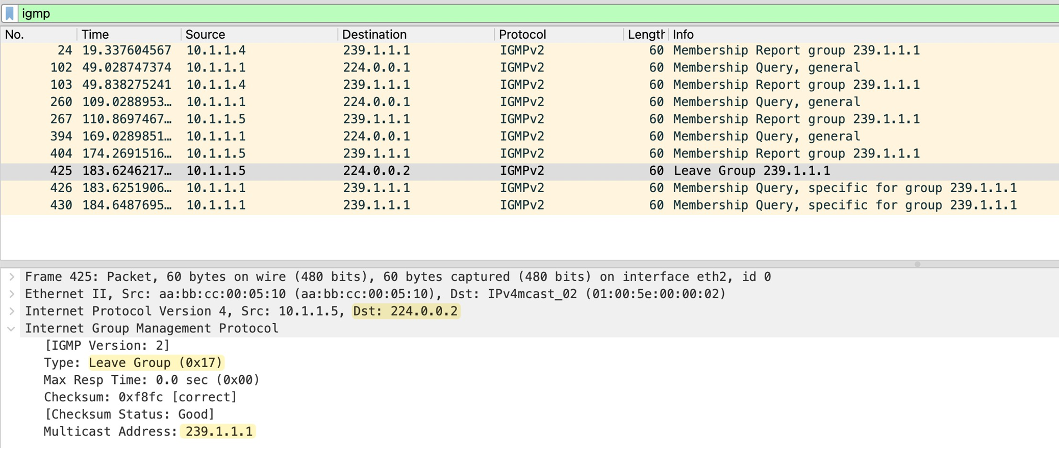
The router sends two group-specific queries, one second apart, and if no membership report is received within 0.5 seconds after the last query, the router removes the multicast group from that interface.
IGMP Snooping
Switch gleans or snoops into the IGMP exchange between router and the hosts to map the Multicast group to ports mapping, this whole mechanism exists because of the way switch performs forwarding using source based learning, once a mac is learned by switch, frames with that destination address it is not flooded but unicasted according to mac table on switch
But multicast mac address is never used as source address so its entry is never built
By default, the switch has no idea which ports actually have interested receivers, so the safest option is to flood multicast traffic out of all ports in the VLAN which is very ineffecient subjecting all connected hosts to the multicast traffic.
When IGMP snooping is enabled, It watches for IGMP membership reports from receivers and notes which ports those reports came in on
From this, the switch builds a table that maps multicast groups to specific switch ports
When multicast traffic starts flowing, the switch no longer floods it everywhere. Instead, it forwards the multicast frames only out of the ports where it has seen joins for that multicast group. Ports with no interested receivers do not get the traffic
Switch also learns which port is connected to the routers by listening on IGMP and PIM messages
The switch also listens for IGMP leave messages. When a receiver leaves a group, the switch updates its table and stops forwarding multicast traffic to that port
IGMP Behvaiour deviation from standard
Remember earlier we talked about how, when a router sends an IGMP query, only one receiver replies due to the report suppression mechanism. This behaviour creates a challenge for the switch.
With this approach, sometimes the switch would not know which ports actually have active receivers for the multicast group, and it would have no way to build an accurate multicast forwarding table.
Switch changes the beahviour and forwards the first IGMP membership report toward the router, but it does not flood that report to other hosts. This way other receivers on different ports get delay timers expire and then send their own reports. The switch sees these reports locally and learns that there are multiple interested ports for the same multicast group even though only one report was forwarded upstream to the router.
Similarly, when the switch receives an IGMP Leave message on a port, the switch only forwards a leave message to the router when the leaving host is actually last host
For example, if two receivers are joined to the same multicast group and one of them sends a leave, the switch does not forward that leave to the router. Only when the last receiver leaves does the switch forward the leave message upstream.
Also worth mentioning that when the switch receives IGMP leave message on a port, it does not immediately assume that there are no receivers left on that port. It sends an IGMP query out of that same port to check if there are any other interested receivers. This is important in cases where multiple hosts exist behind a single port or when that port connects to another switch.
If you enable IGMP immediate leave, the switch skips this verification step and removes the port from the multicast group as soon as it sees the leave message.
Using Cisco routers as hosts for Multicast send and Multicast receive
no ip routing
ip default-gateway x.x.x.x
Basic PIM-DM configuration
no ip pim autorp
!
ip multicast-routing
!
interface Ethernet0/1
 description r1 -> sender
 ip address 10.1.0.1 255.255.255.0
 ip pim dense-mode
!
interface Ethernet0/2
 description r1 -> [receiver_01,receiver_02]
 ip address 10.1.1.1 255.255.255.0
 ip pim dense-mode
!
As soon as we enable PIM, IGMPv2 is automatically enabled on those interfaces.
The router immediately starts sending IGMP General Membership Query messages out of the interfaces, effectively asking, ’Is there any interested receiver on this segment?’
You can check the
-IGMP enabled
-Timers like 60 seconds query interval
-10 seconds max response time
-IGMP querier router
-Multicast designated router
-R1 is the only router on the segments
r1#show ip igmp interface
!
Ethernet0/1 is up, line protocol is up
 Internet address is 10.1.0.1/24
 IGMP is enabled on interface
 Current IGMP host version is 2
 Current IGMP router version is 2
 IGMP query interval is 60 seconds
 IGMP configured query interval is 60 seconds
 IGMP robustness-variable is 2
 IGMP querier timeout is 120 seconds
 IGMP configured querier timeout is 120 seconds
 IGMP max query response time is 10 seconds
 Last member query count is 2
 Last member query response interval is 1000 ms
 Inbound IGMP access group is not set
 IGMP activity: 0 joins, 0 leaves
 Multicast routing is enabled on interface
 Multicast TTL threshold is 0
 Multicast designated router (DR) is 10.1.0.1 (this system)
 IGMP querying router is 10.1.0.1 (this system)
 No multicast groups joined by this system
!
Ethernet0/2 is up, line protocol is up
 Internet address is 10.1.1.1/24
 IGMP is enabled on interface
 Current IGMP host version is 2
 Current IGMP router version is 2
 IGMP query interval is 60 seconds
 IGMP configured query interval is 60 seconds
 IGMP robustness-variable is 2
 IGMP querier timeout is 120 seconds
 IGMP configured querier timeout is 120 seconds
 IGMP max query response time is 10 seconds
 Last member query count is 2
 Last member query response interval is 1000 ms
 Inbound IGMP access group is not set
 IGMP activity: 0 joins, 0 leaves
 Multicast routing is enabled on interface
 Multicast TTL threshold is 0
 Multicast designated router (DR) is 10.1.1.1 (this system)
 IGMP querying router is 10.1.1.1 (this system)
 No multicast groups joined by this system
IGMP Snooping Switch Configuration
Debugs
debug ip igmpnext post
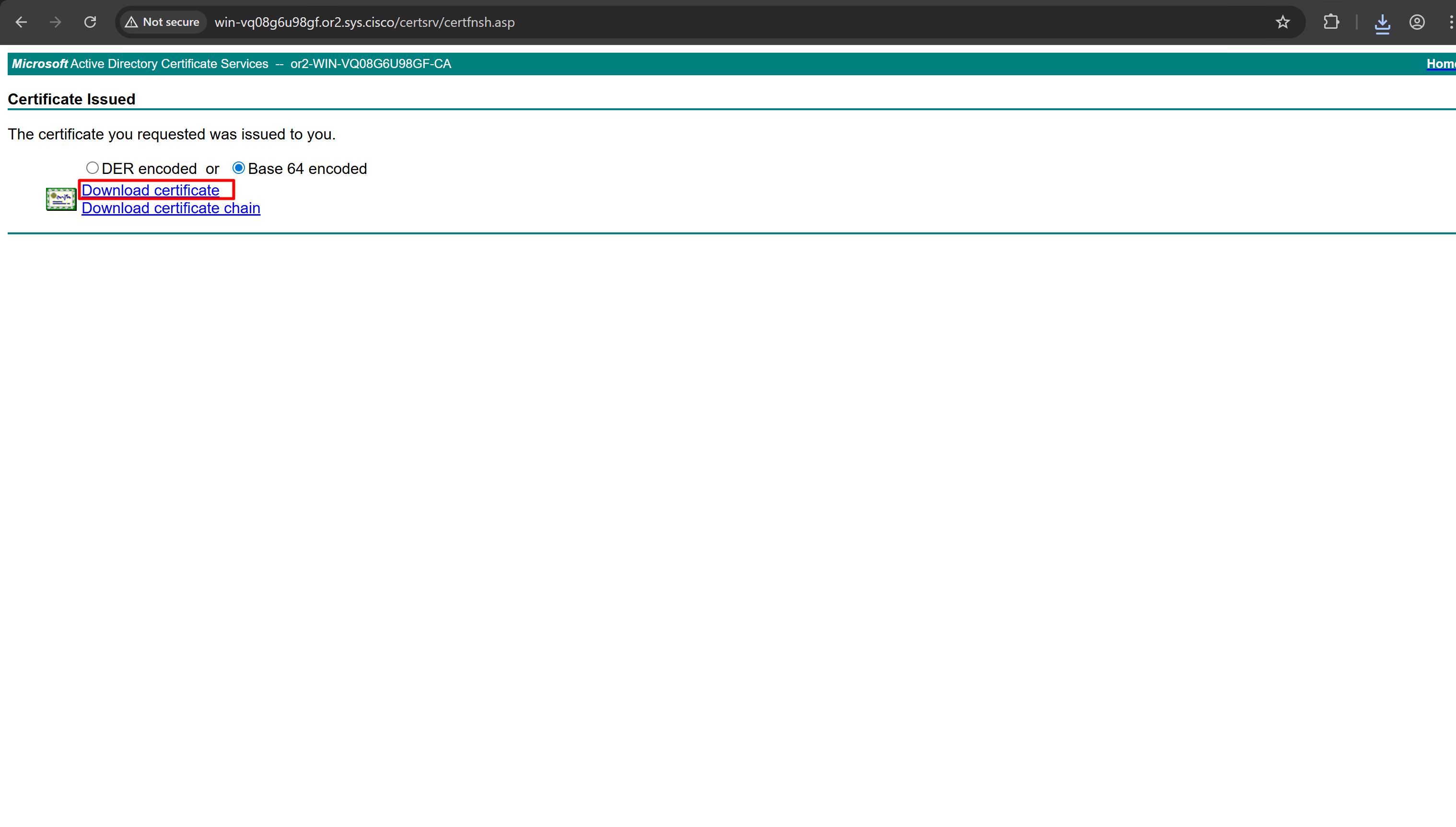
ISE Certificate lab
ISE Certificate lab
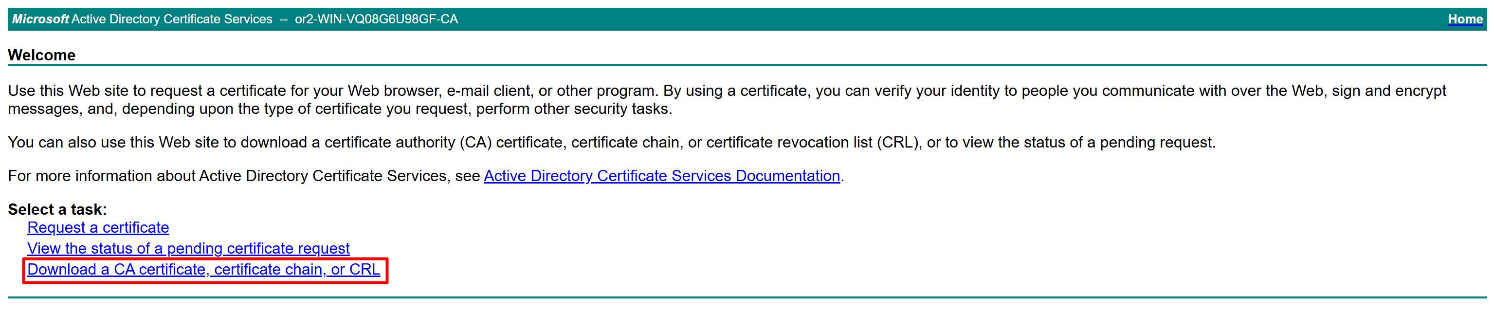
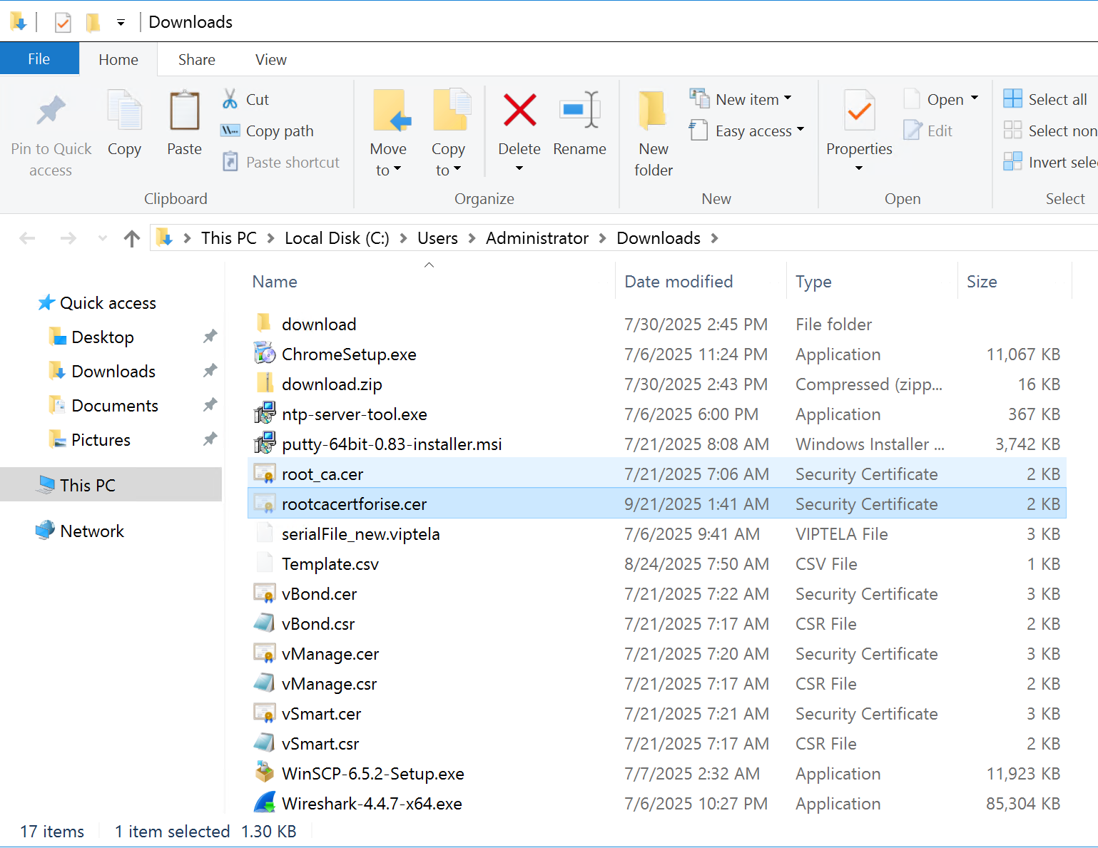
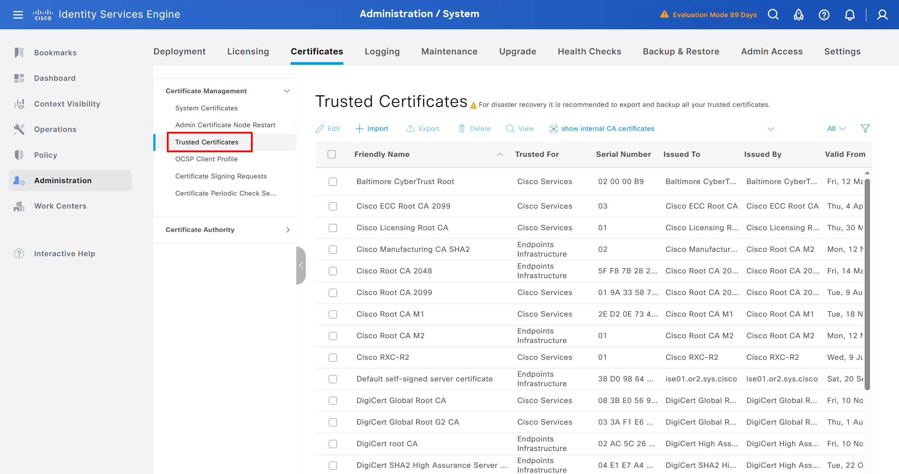
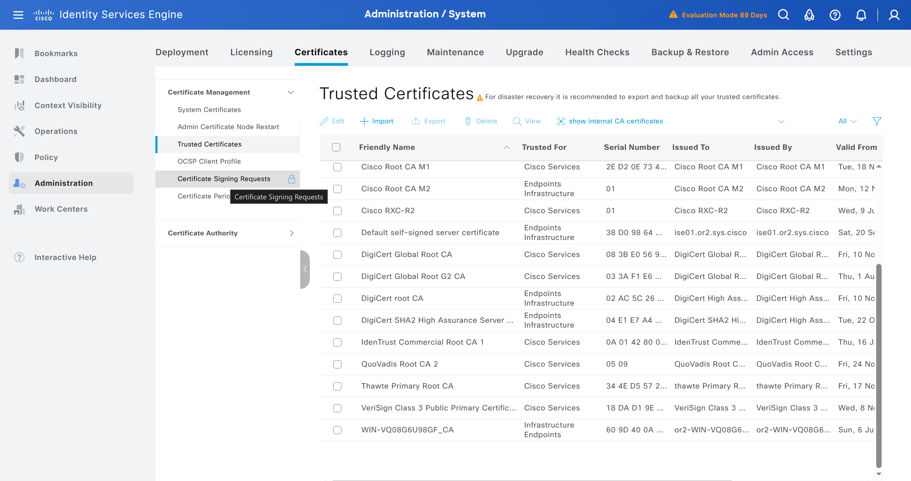
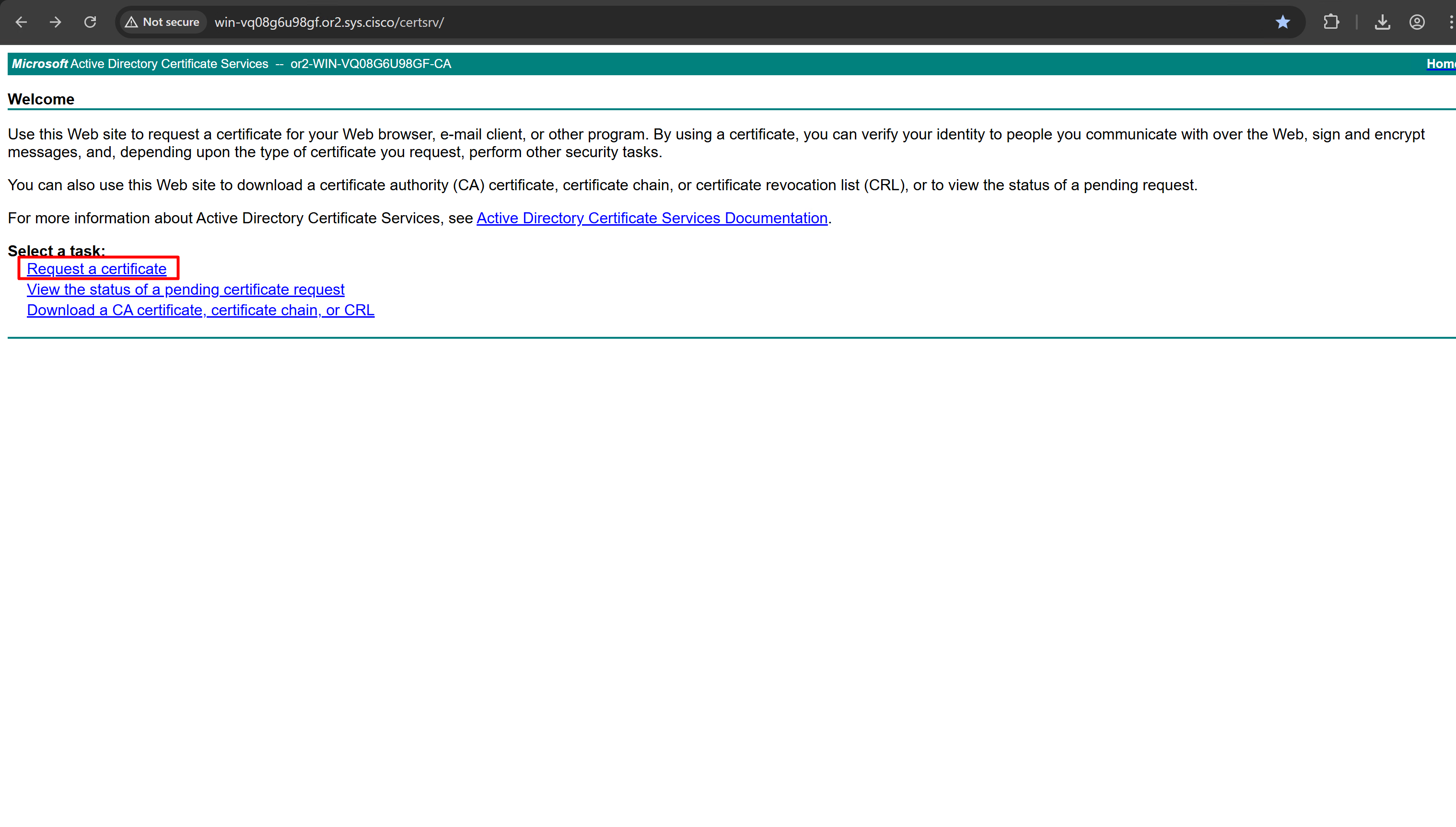
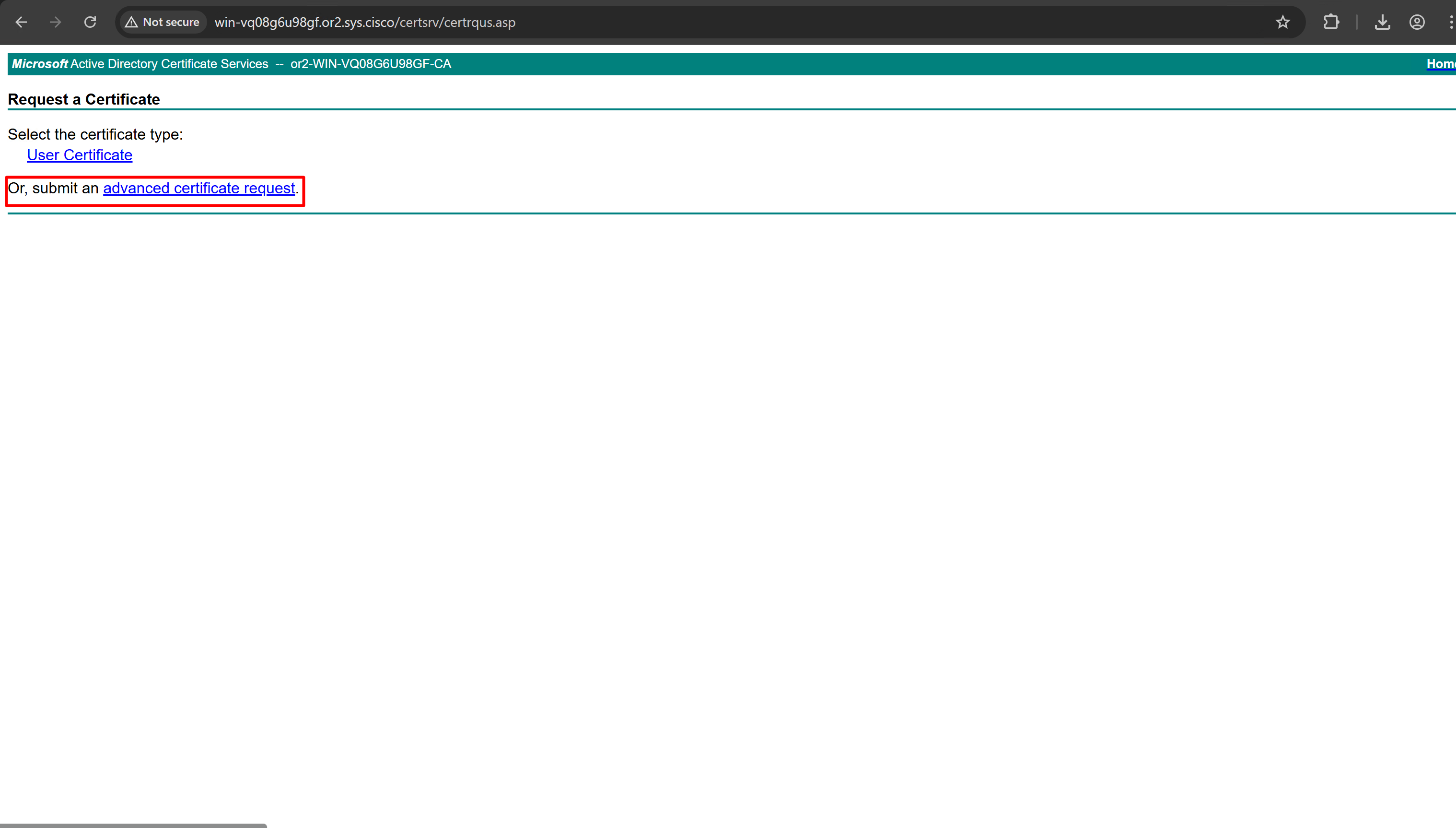
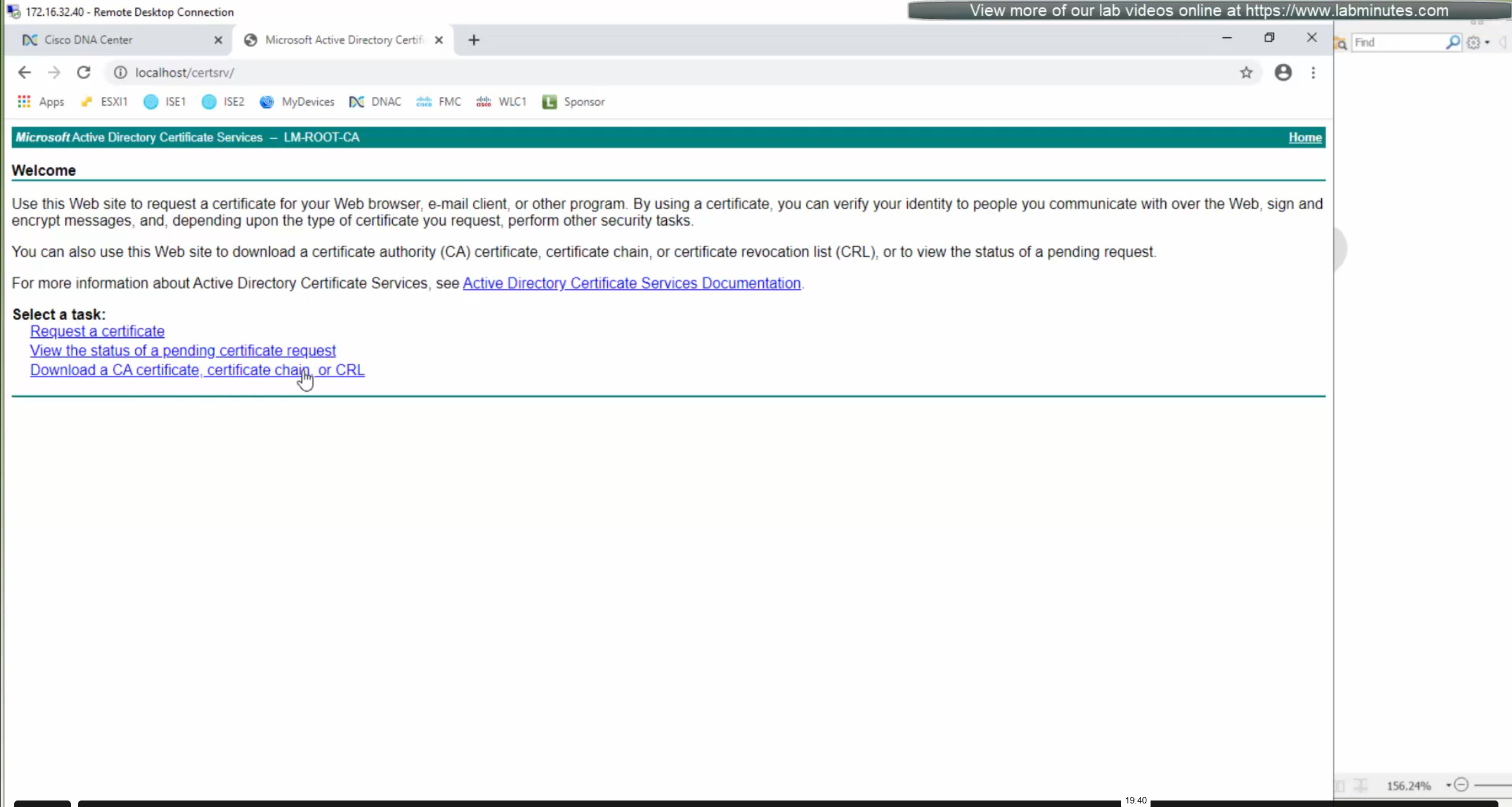
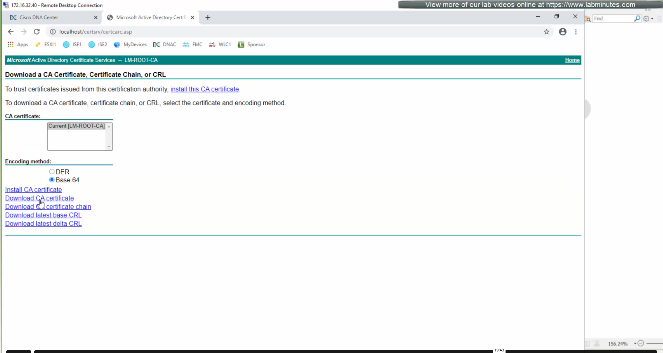
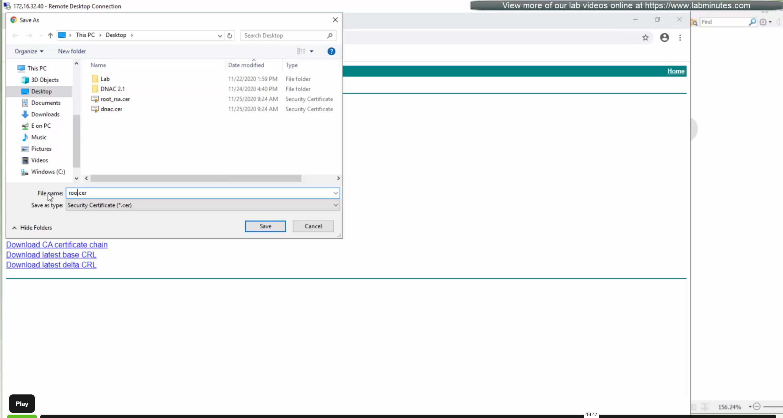
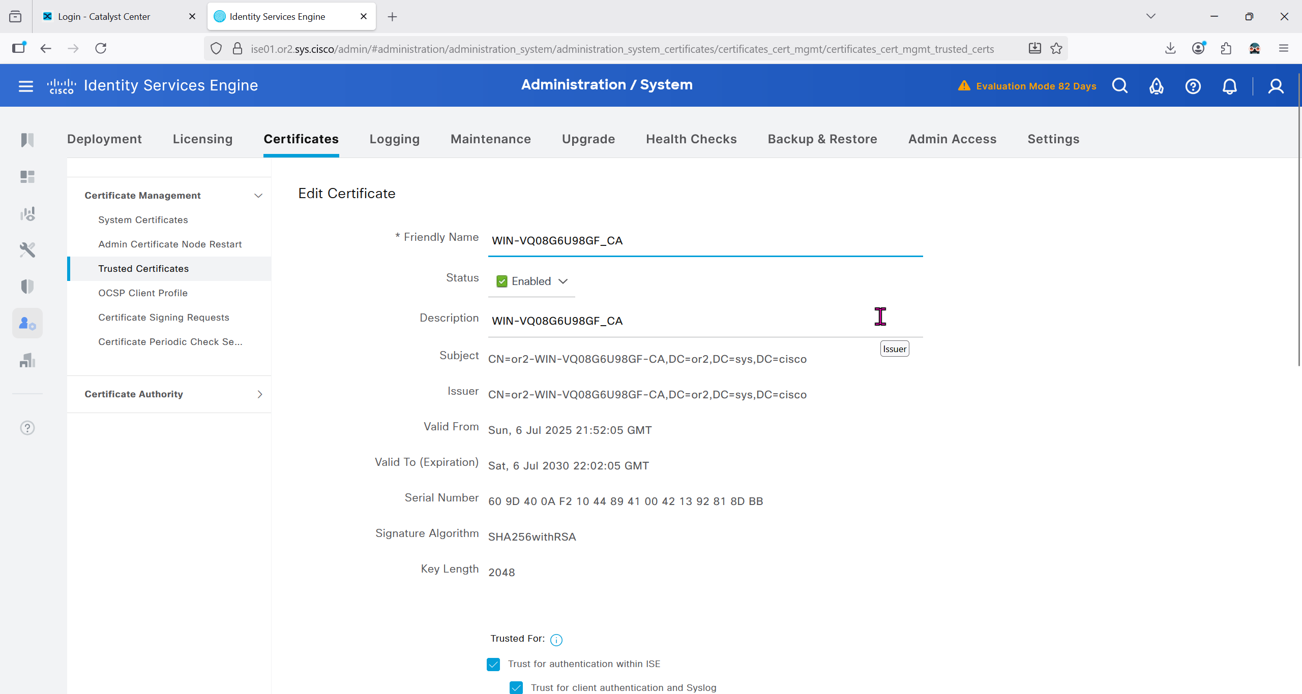
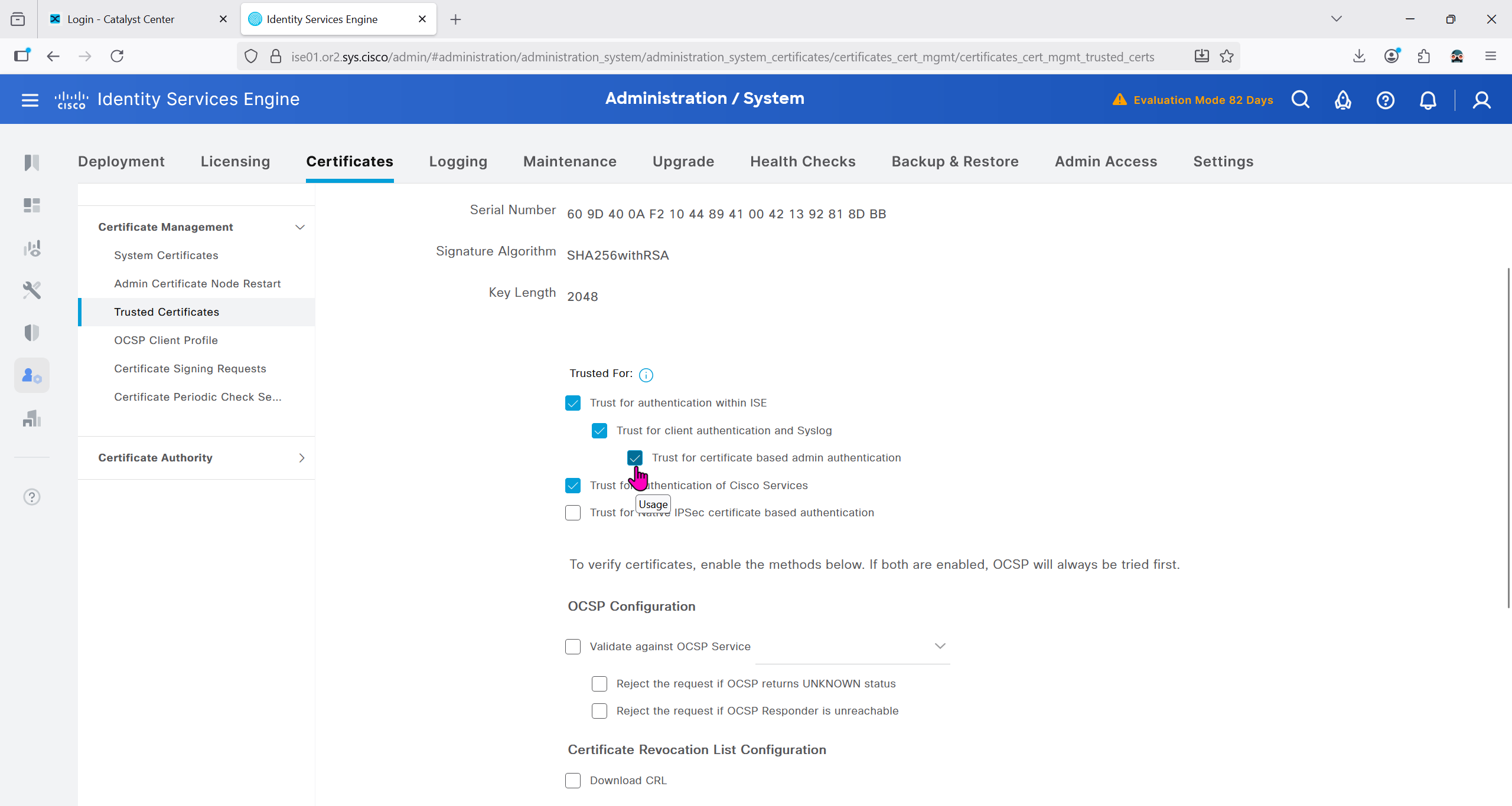
Download CA certificate and upload it to the Trusted store of ISE
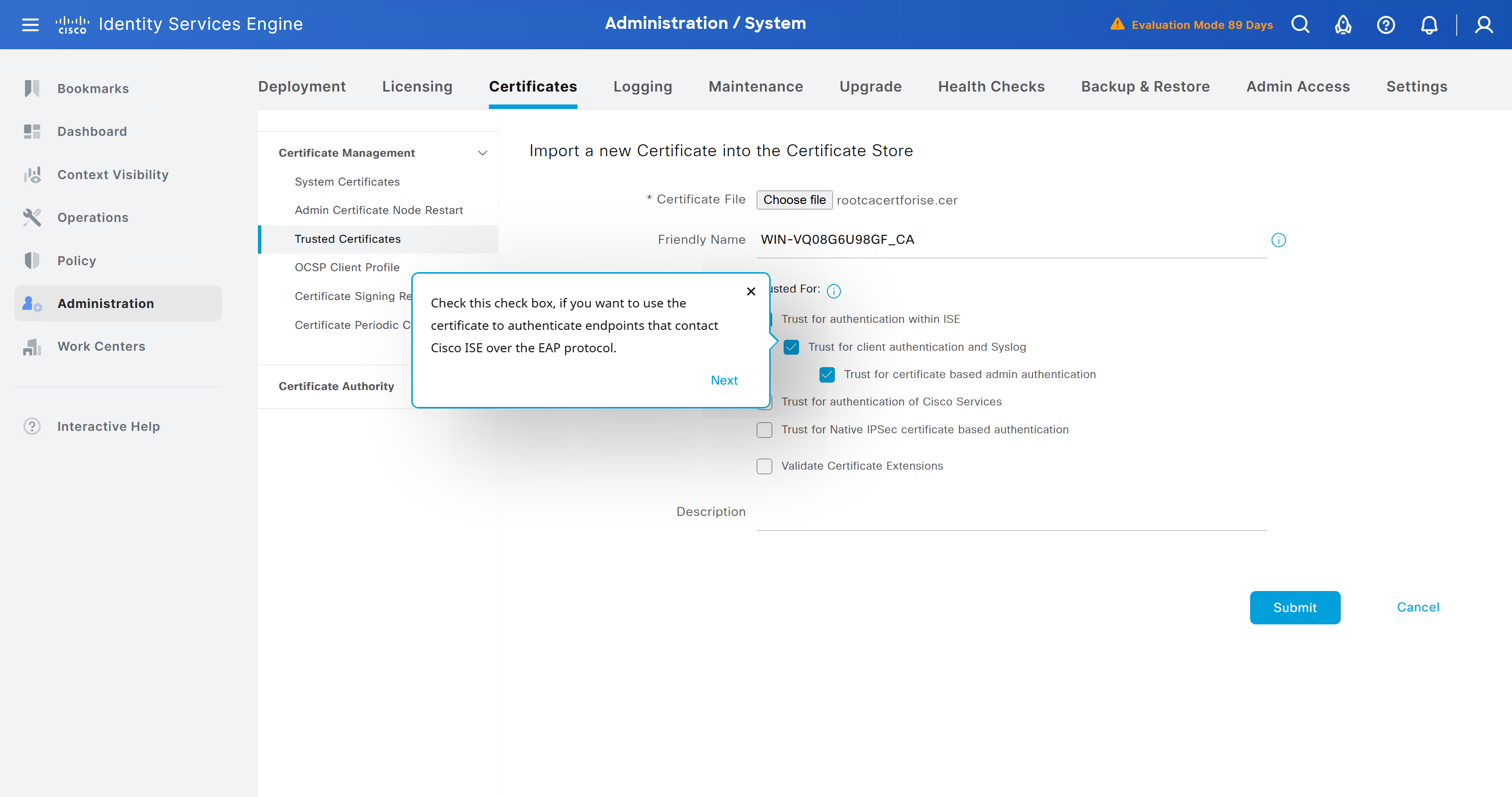
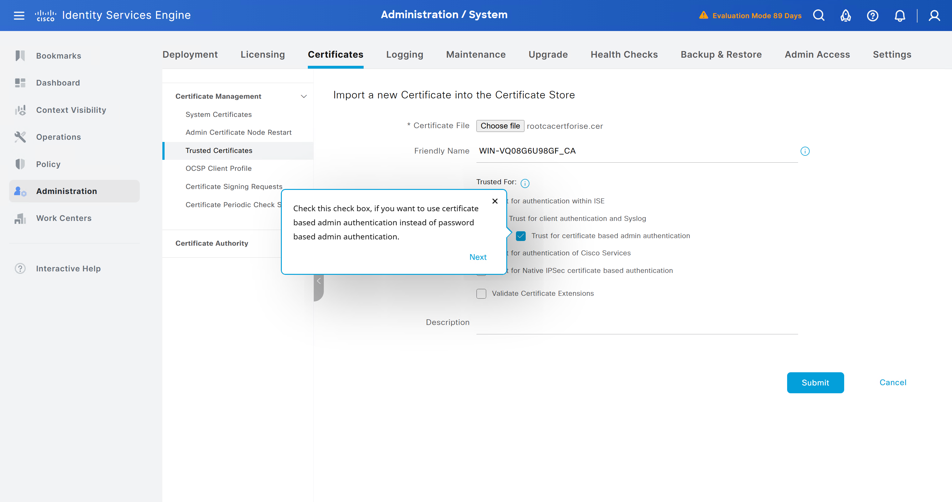
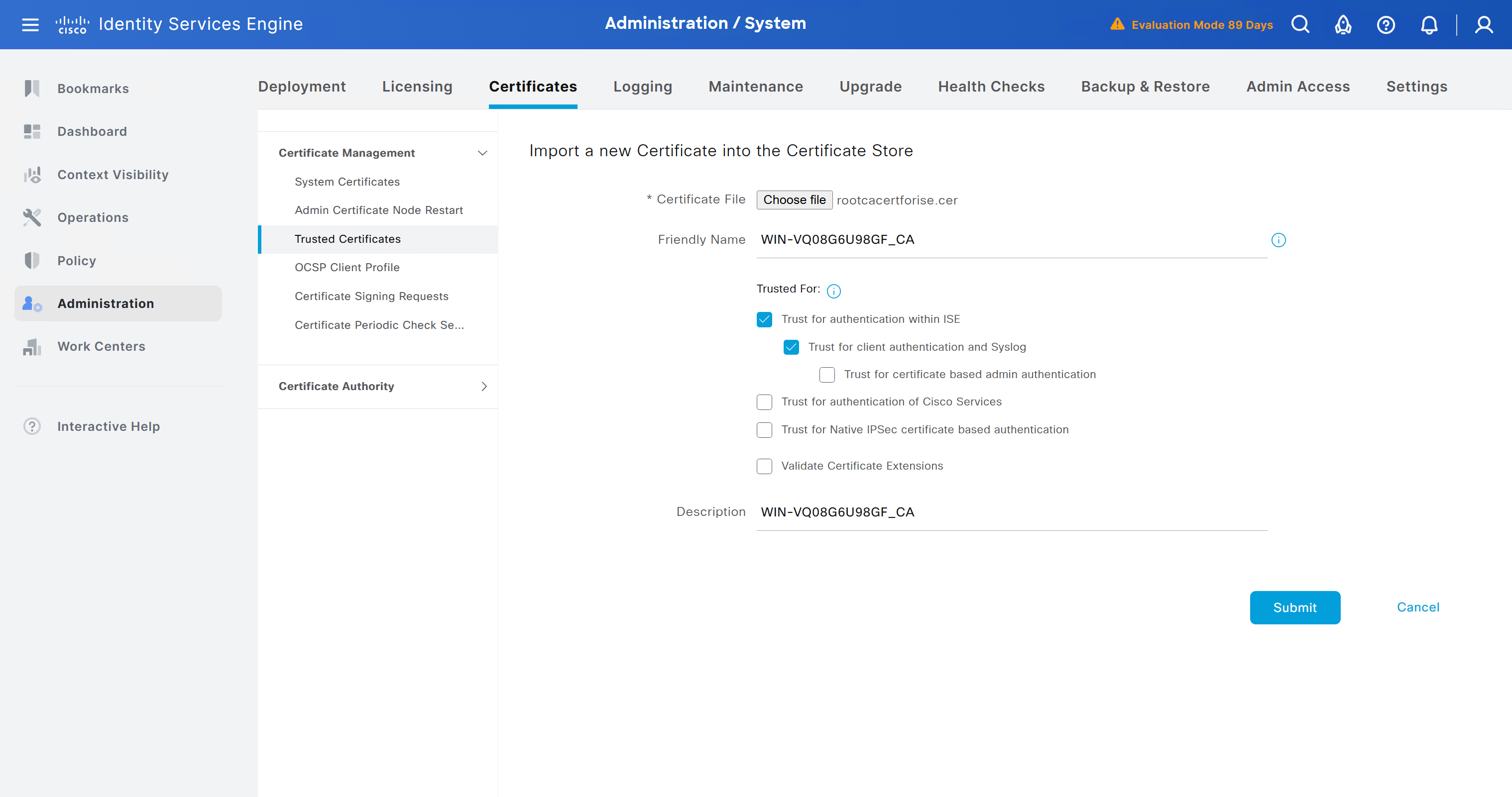
We will select this option “Trust for client authentication and Syslog” as certificate presented to ISE during EAP TLS 802.1x authentication will be certificates issued by this same CA
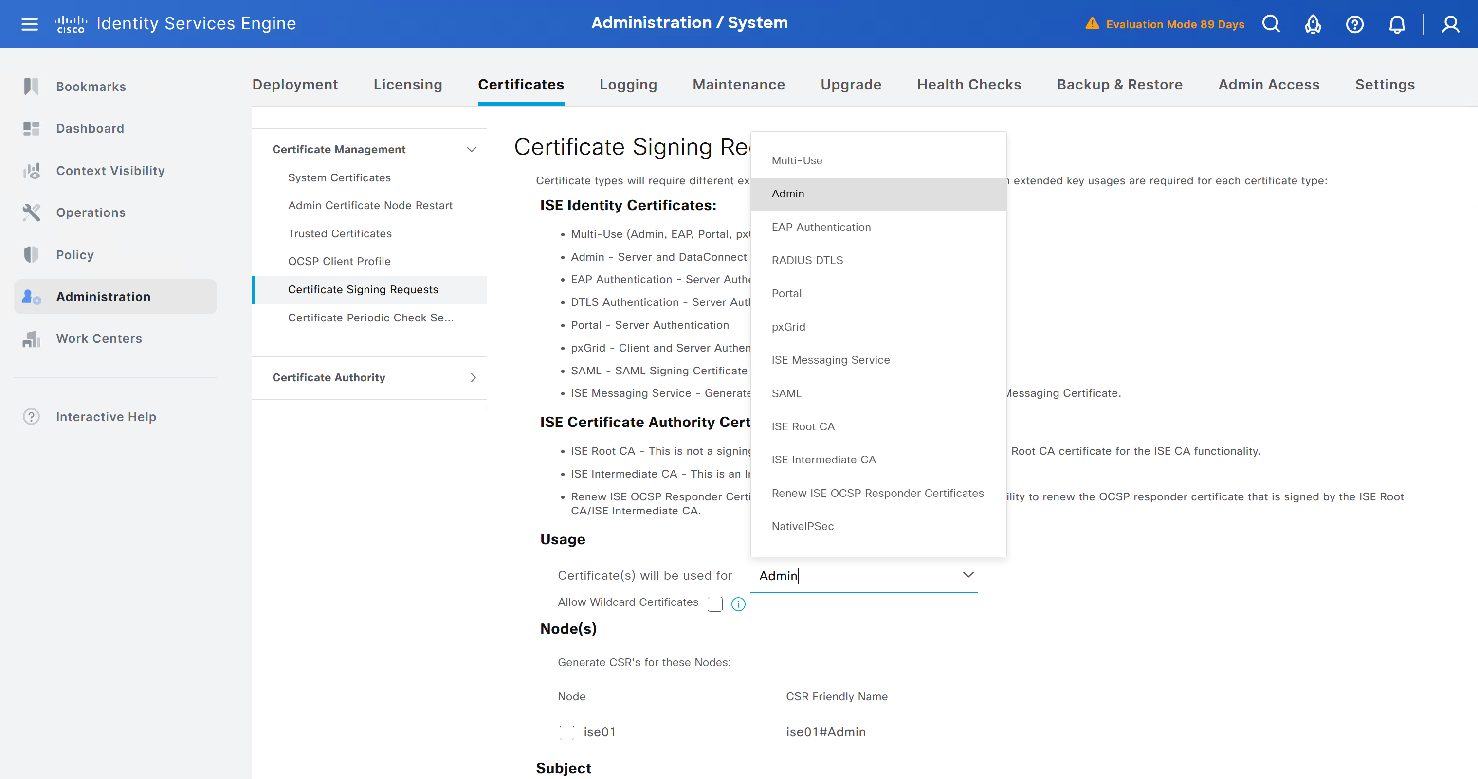
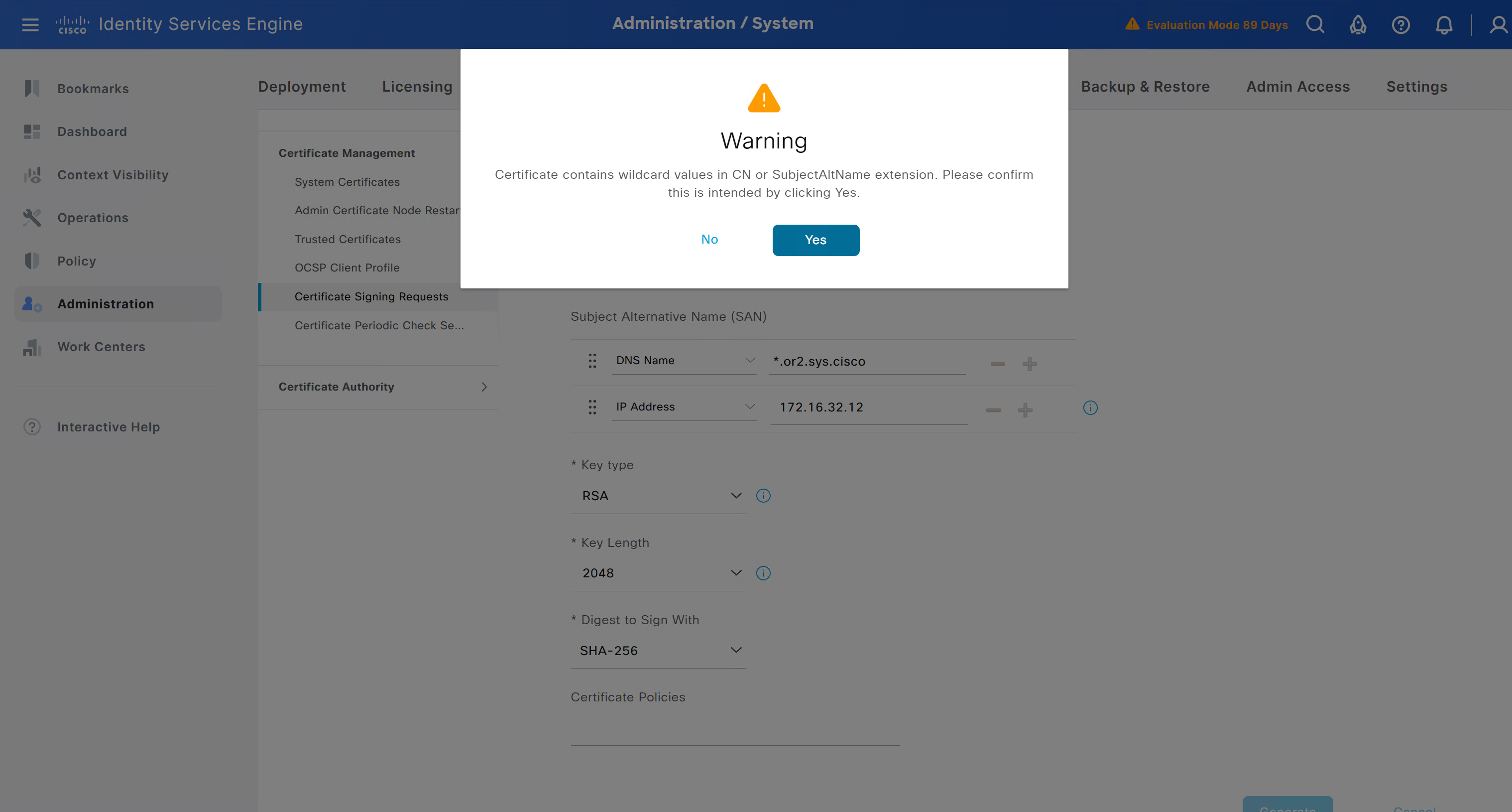
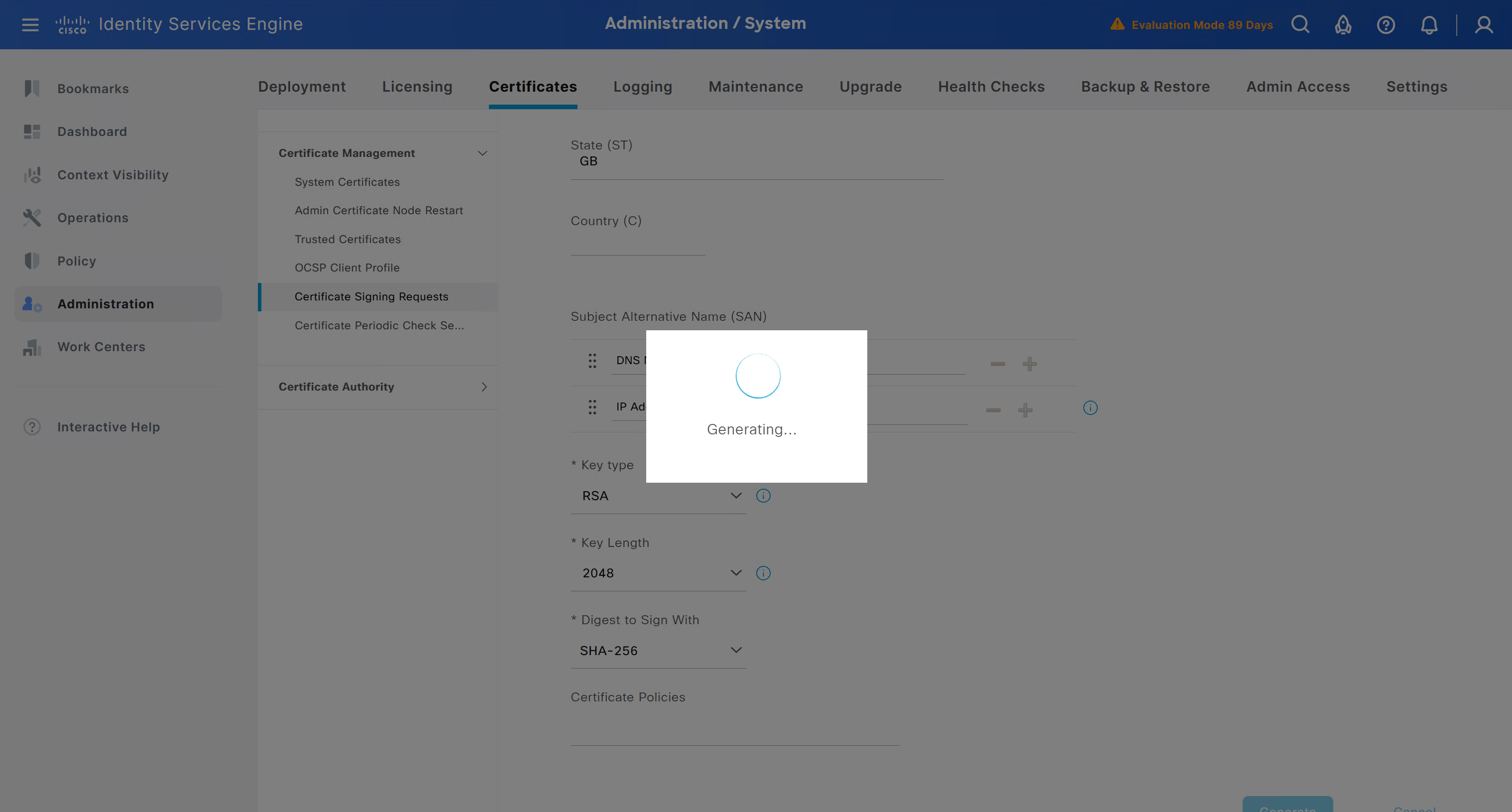
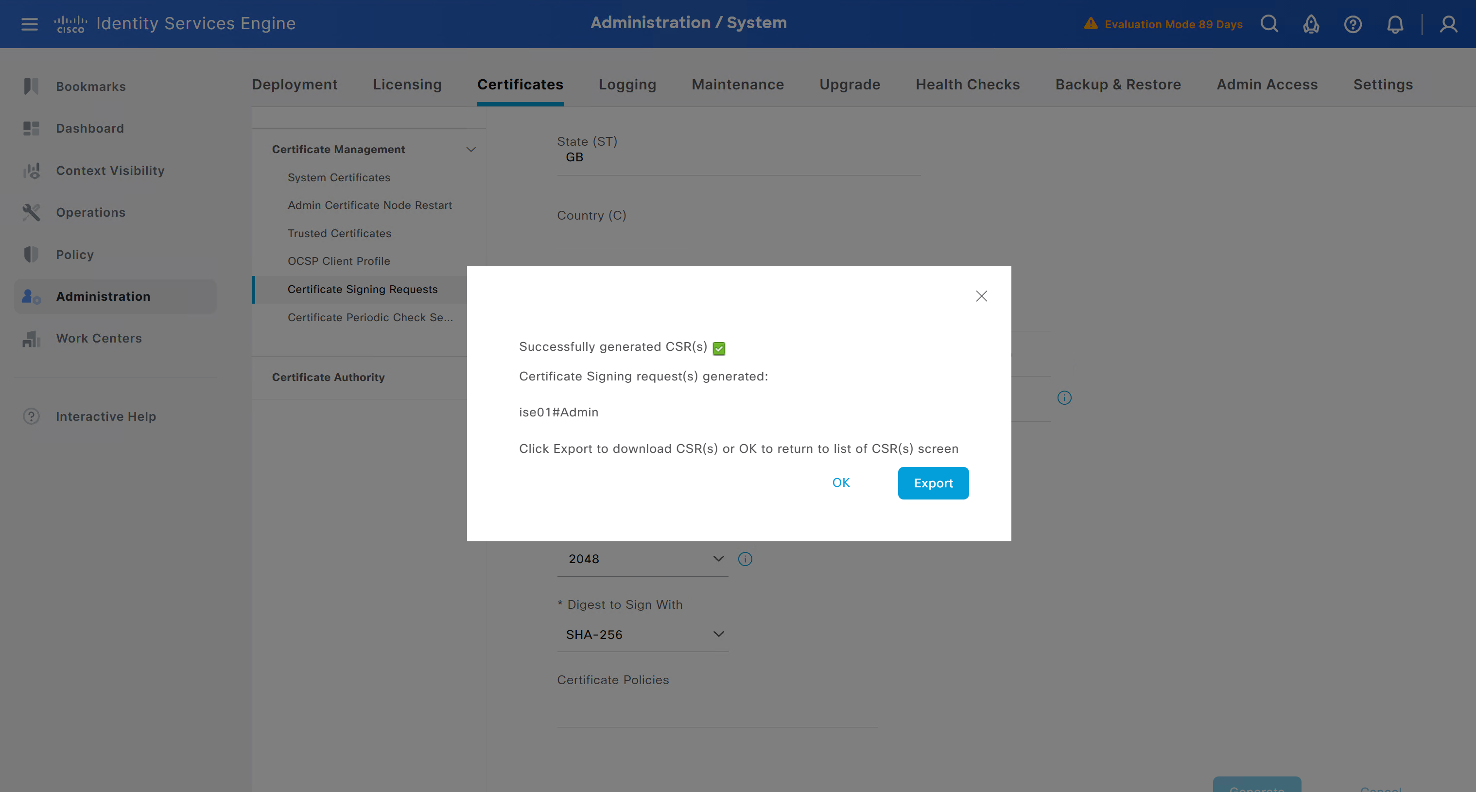
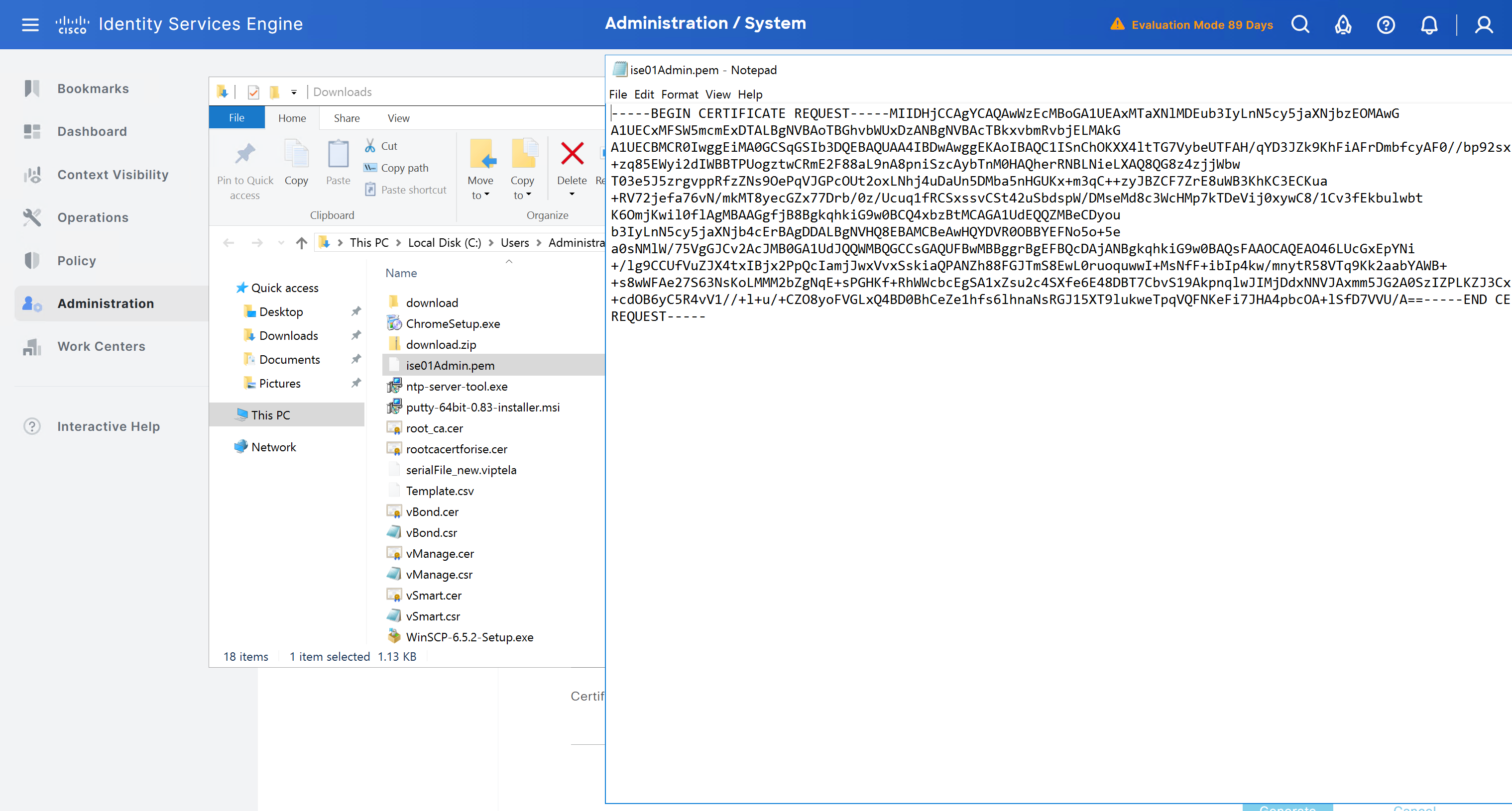
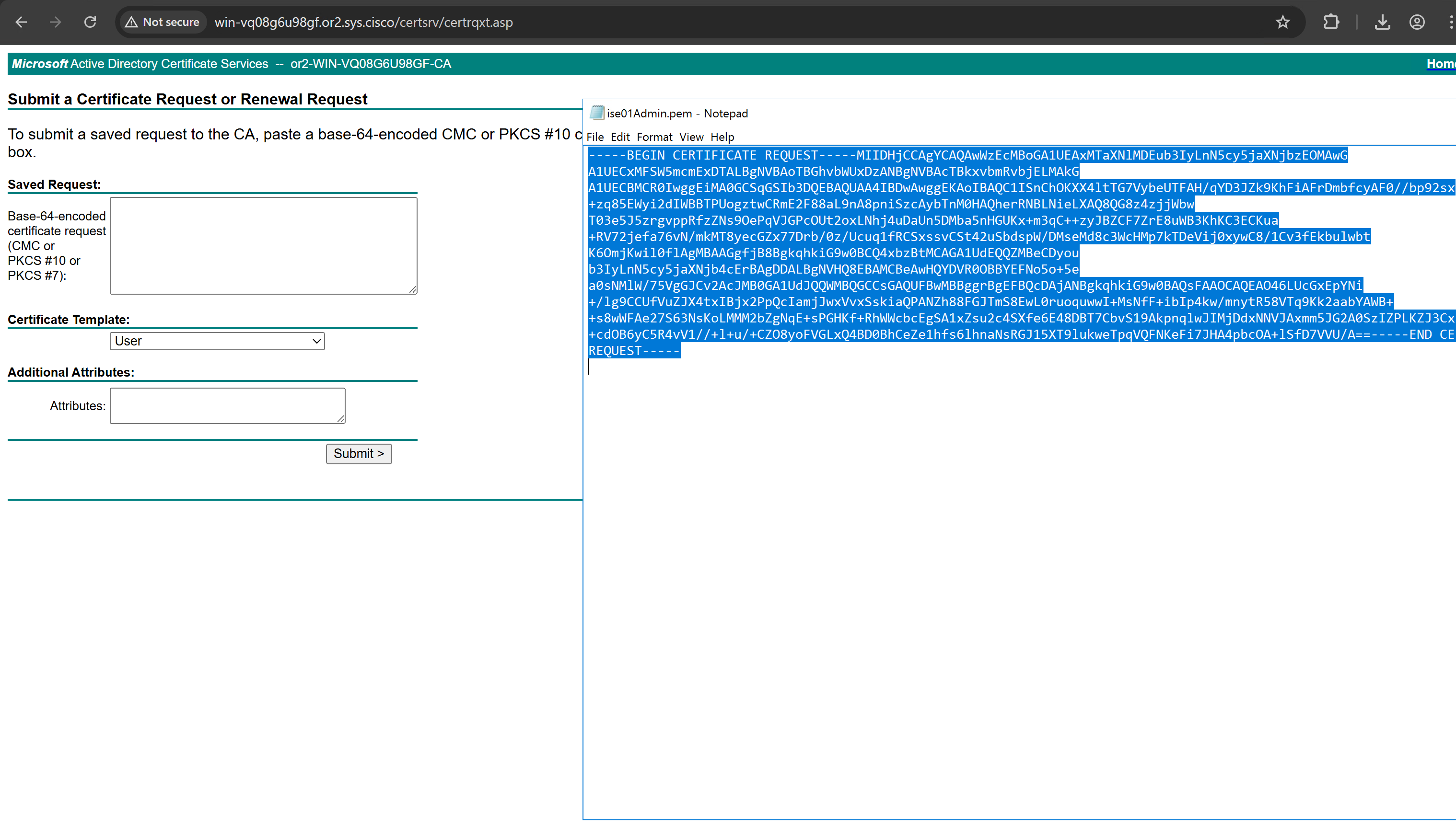
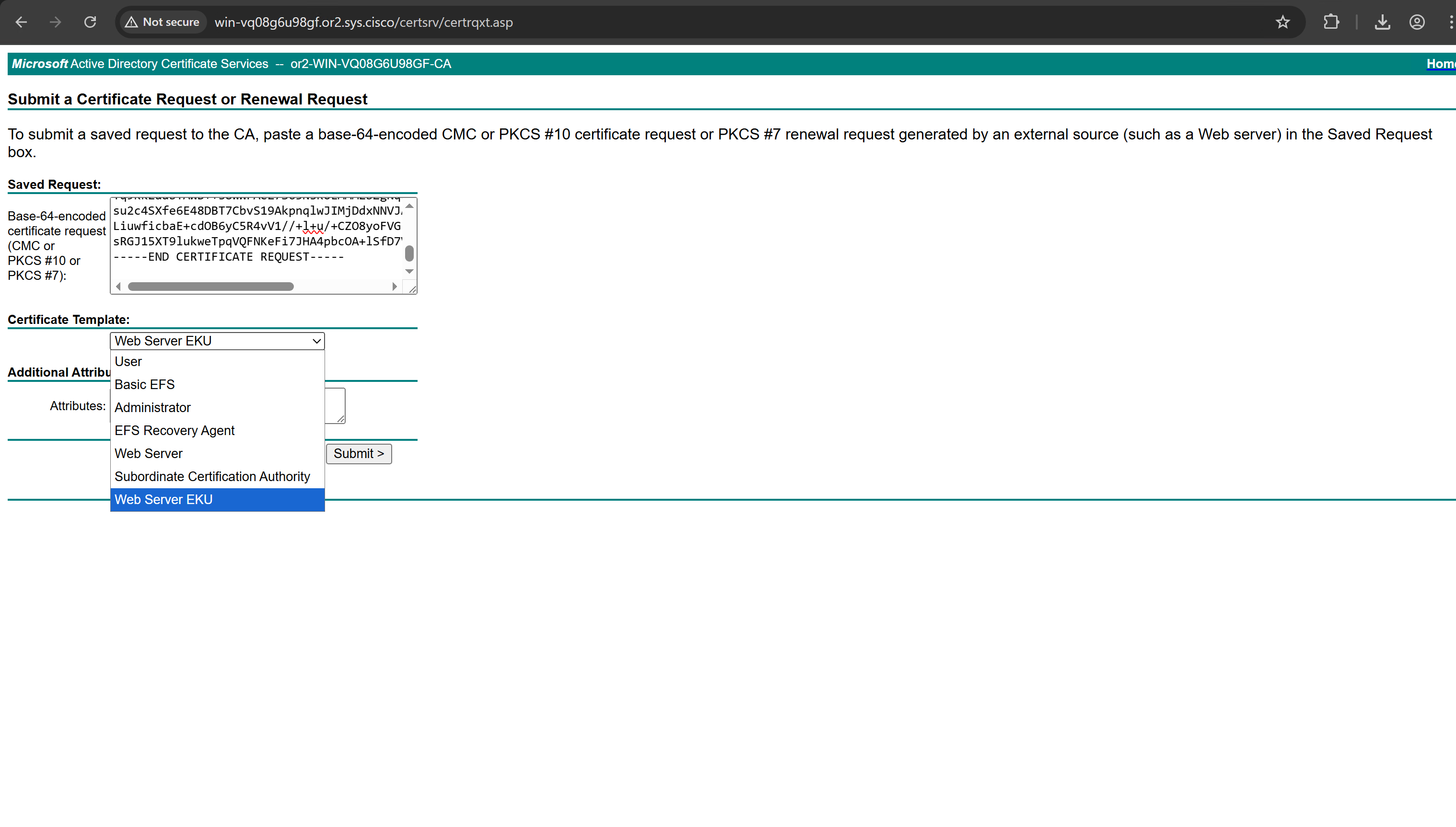
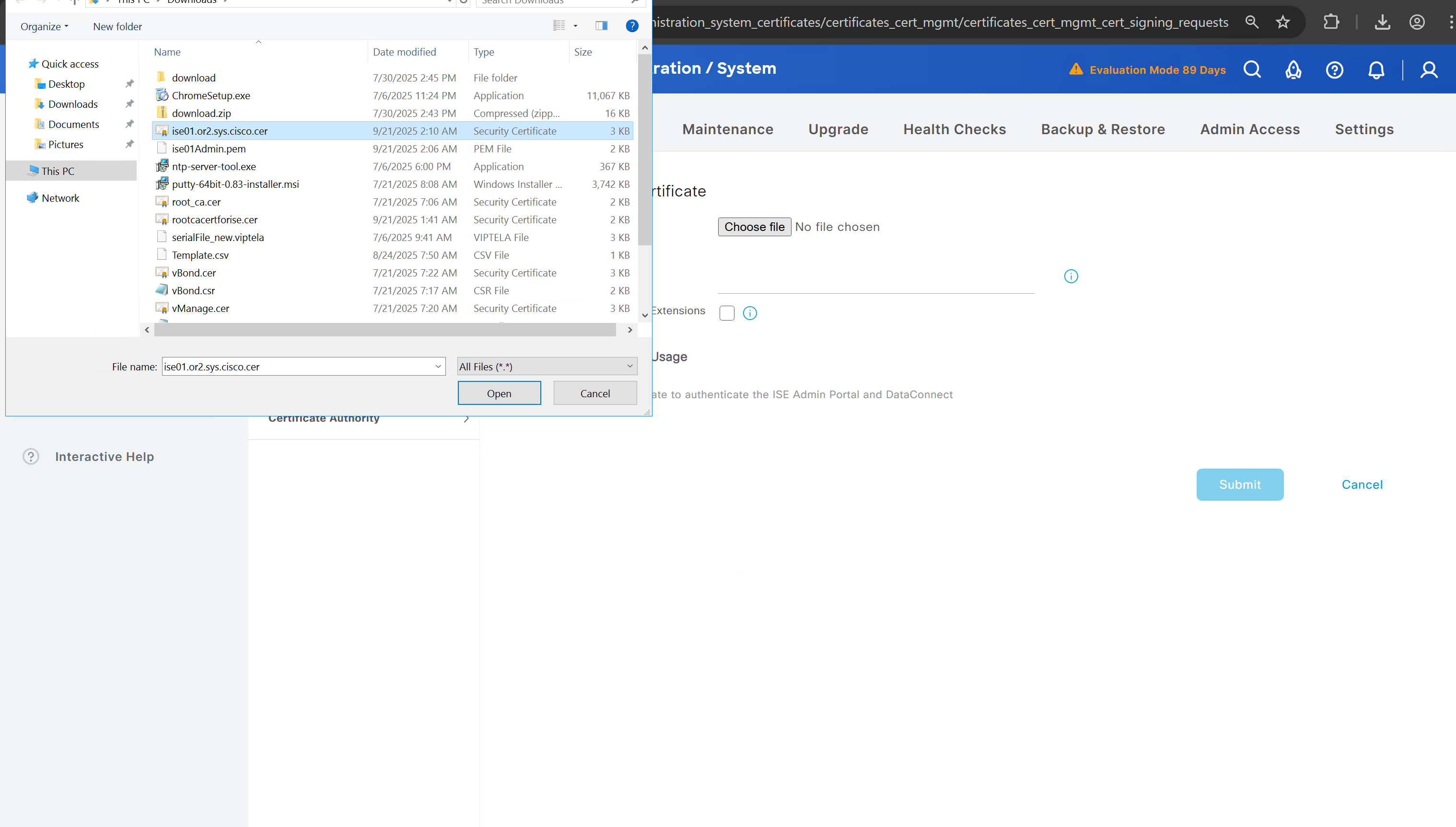
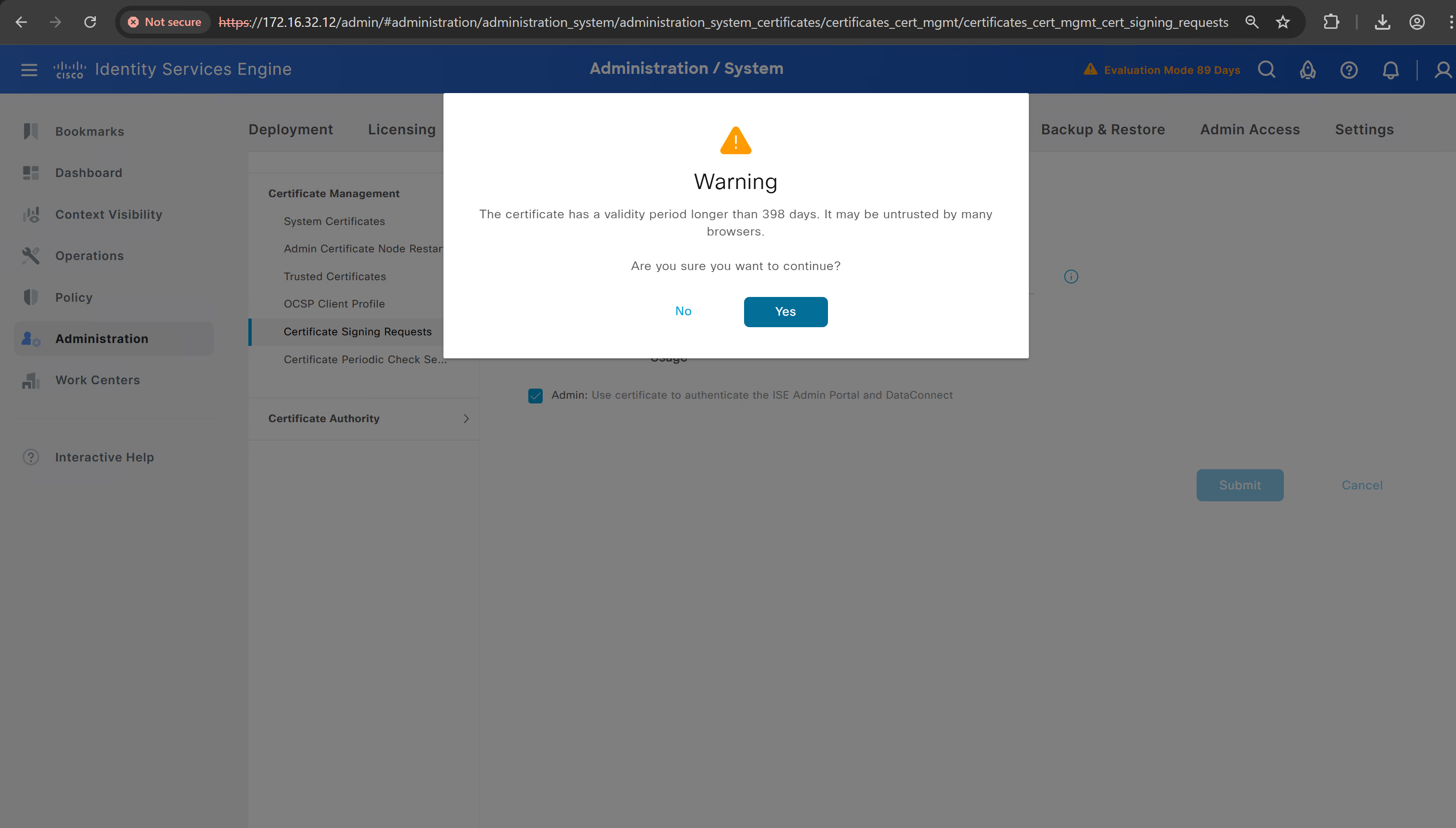
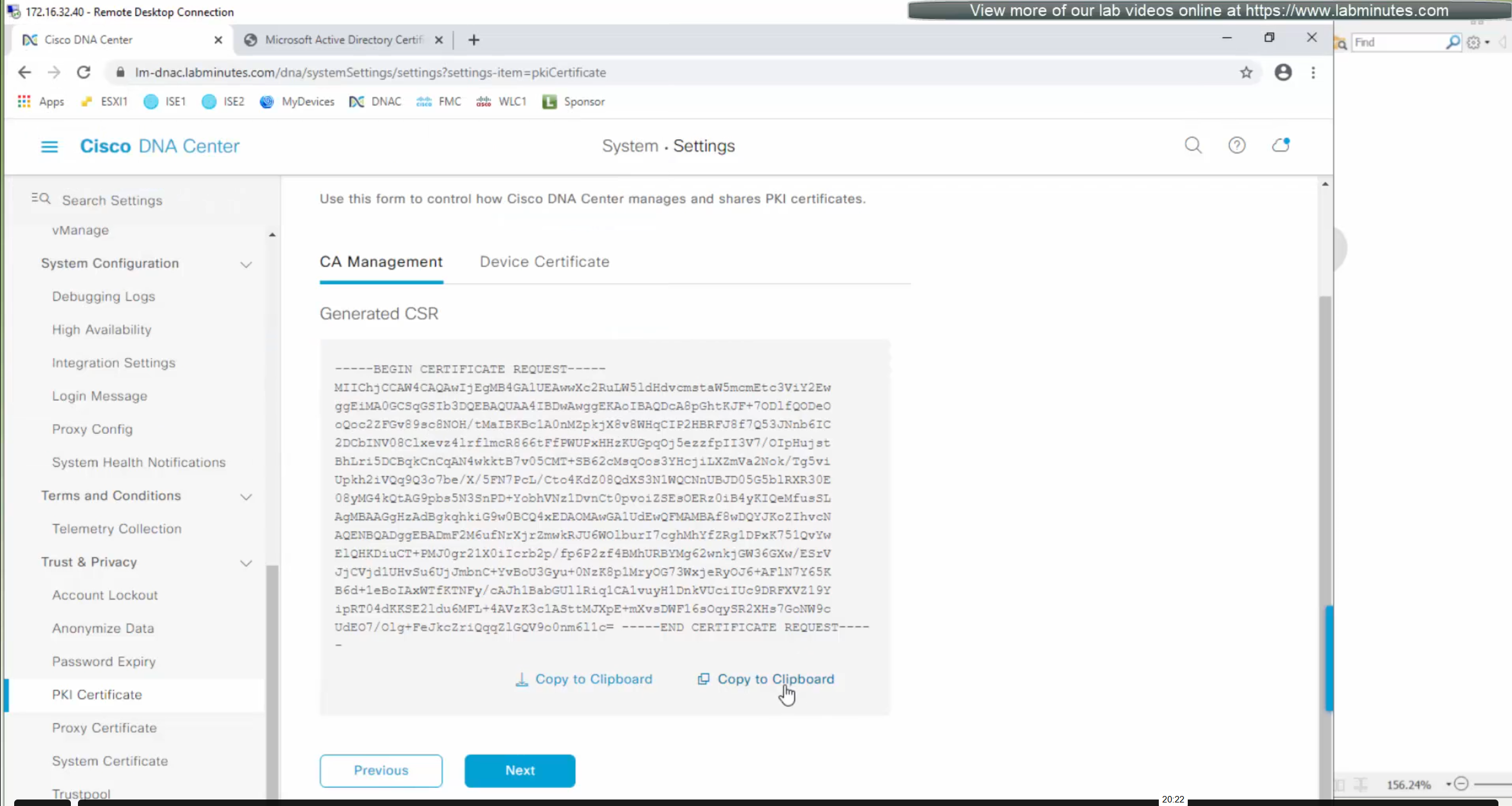
Create CSR for Admin usage
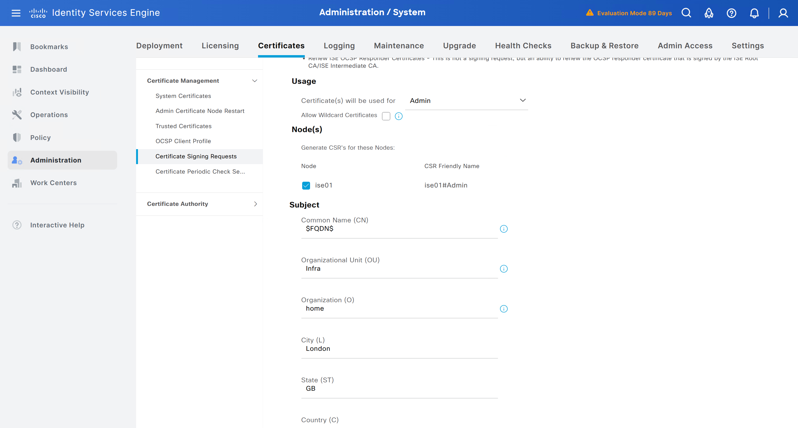
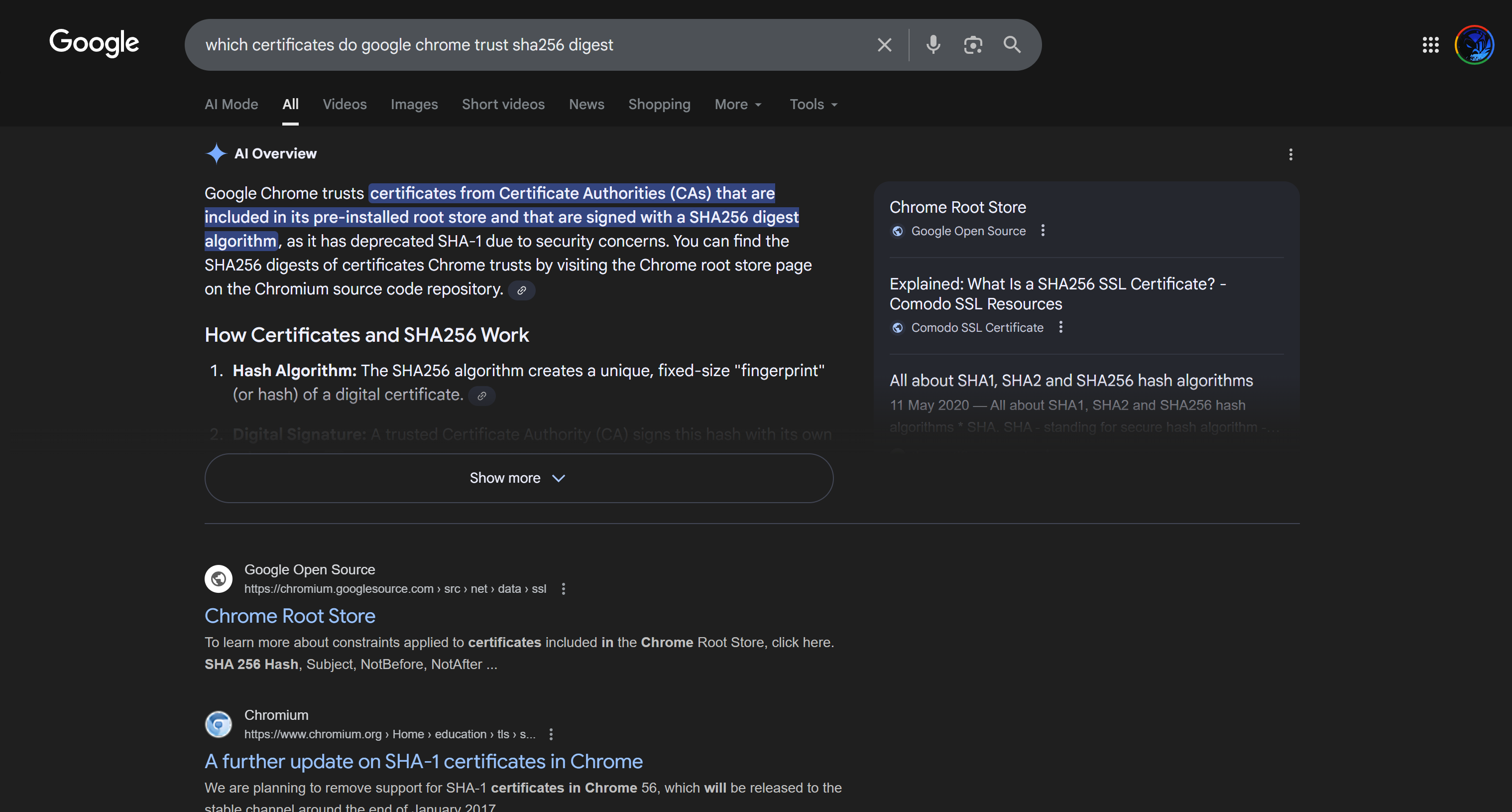
enter DNS Name as $FQDN$
and also enter second DNS name as wildcard with remaining domain name *.or2.sys.cisco
and also add the SAN entry of type IP address with value of 172.16.32.12
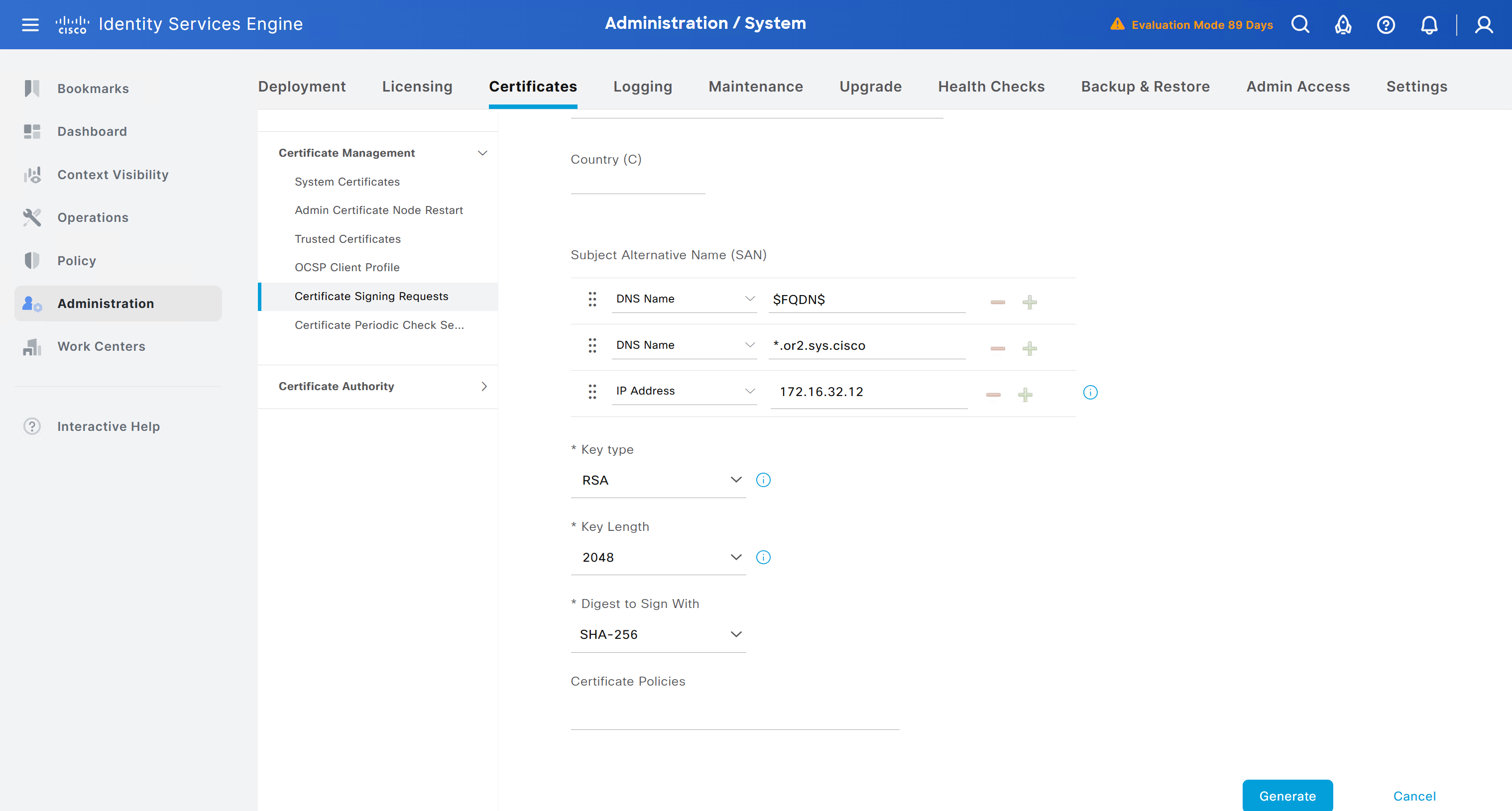
ISE gave this error
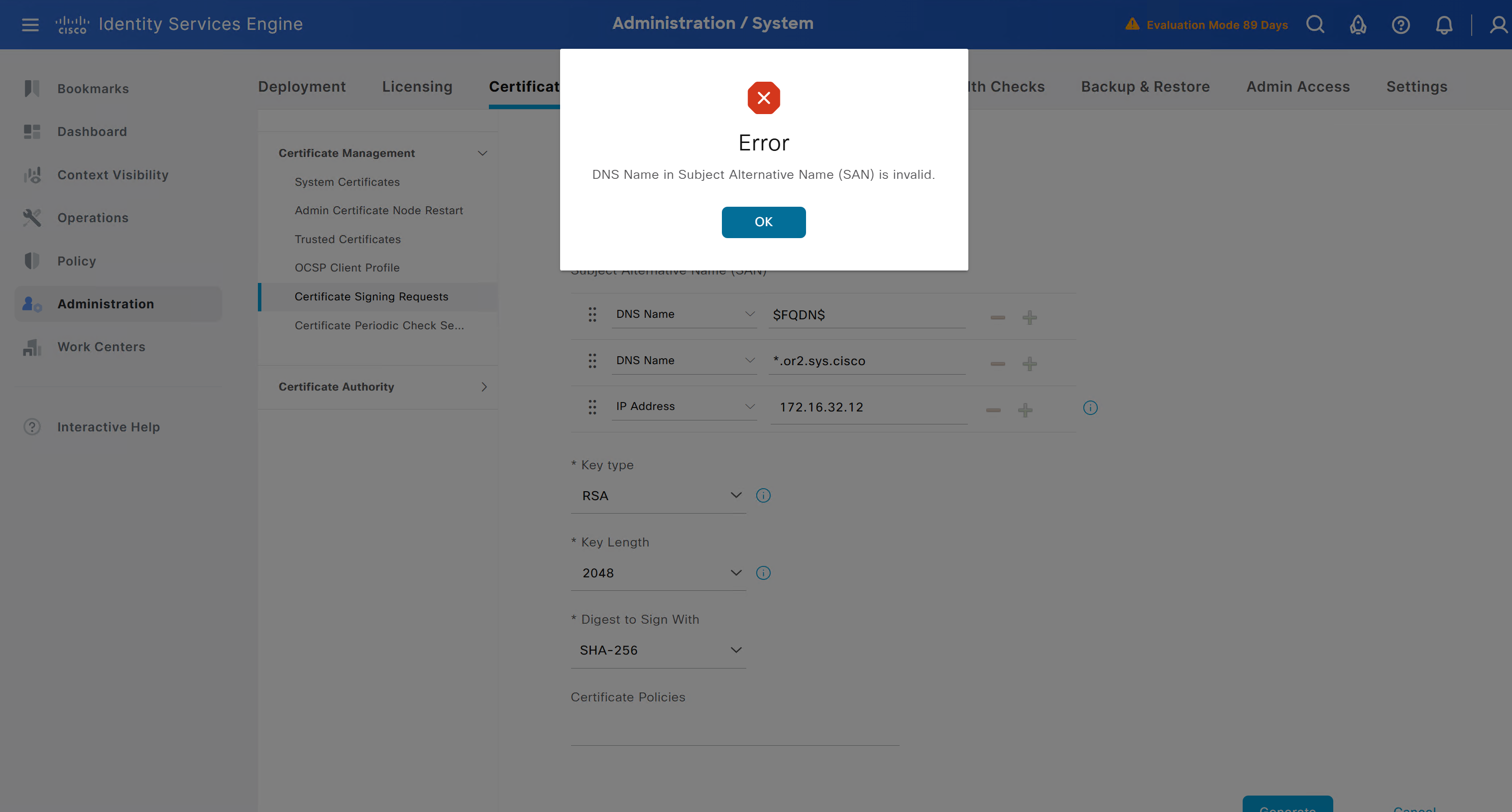
So I removed first entry of $FQDN$
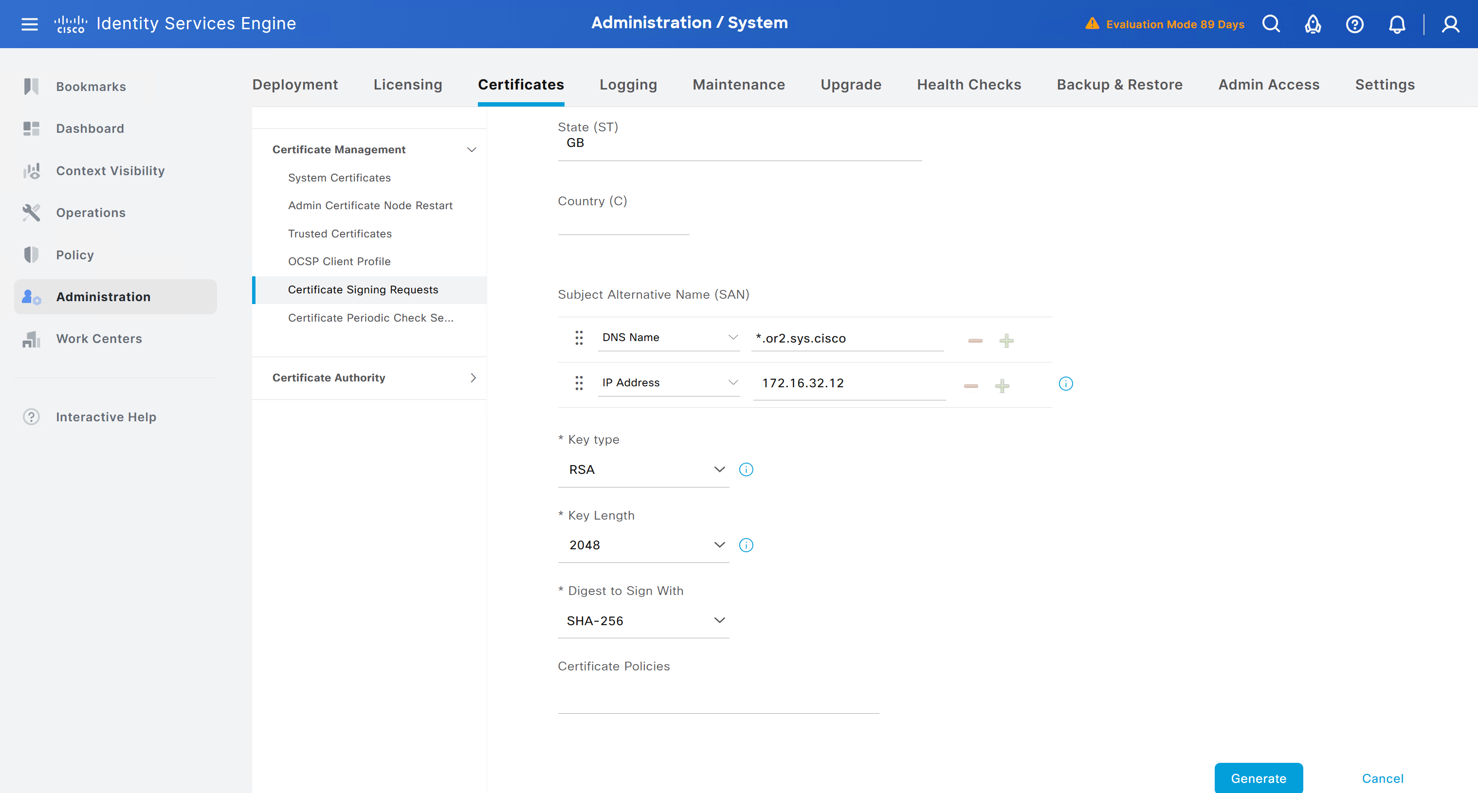
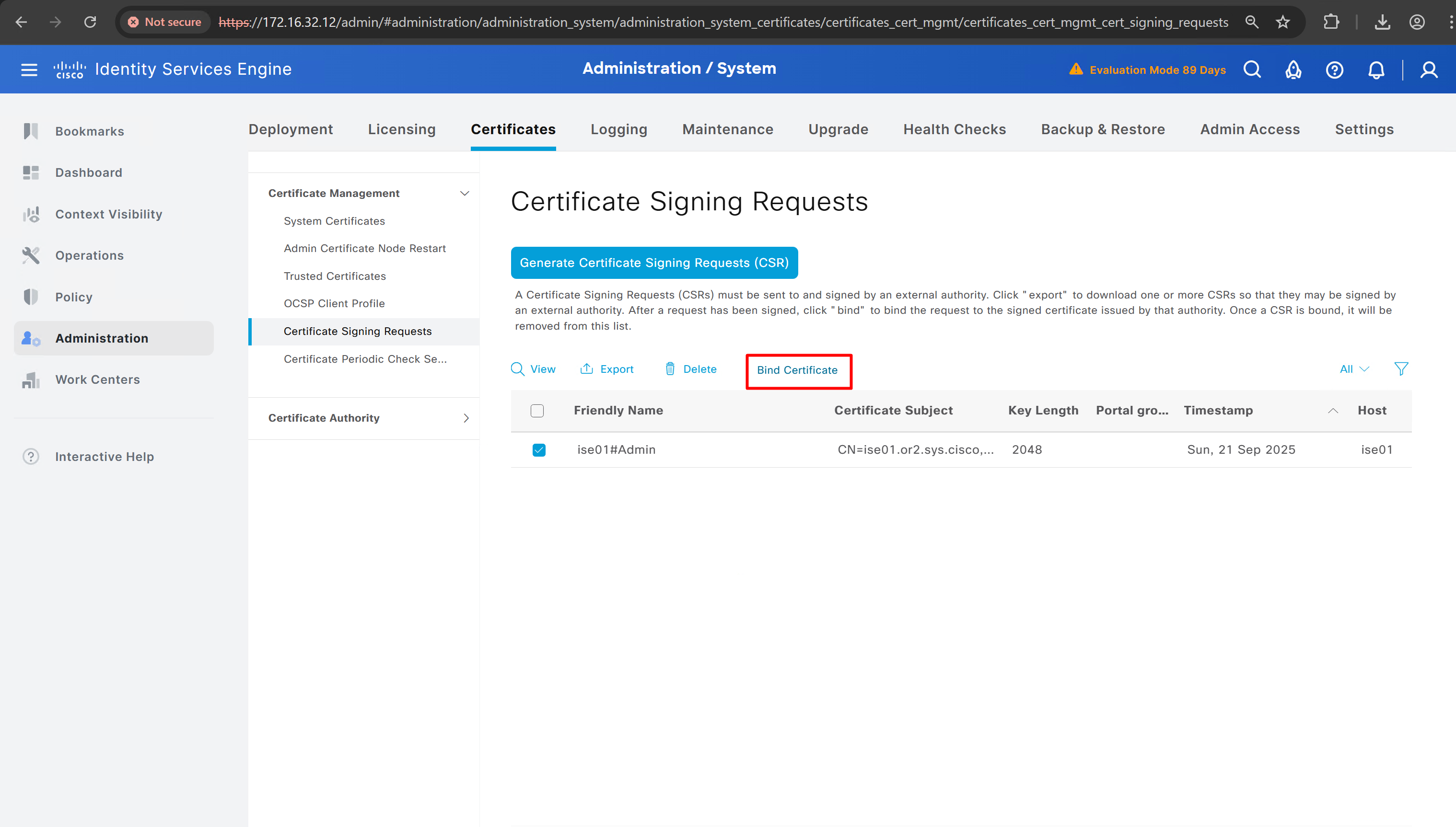
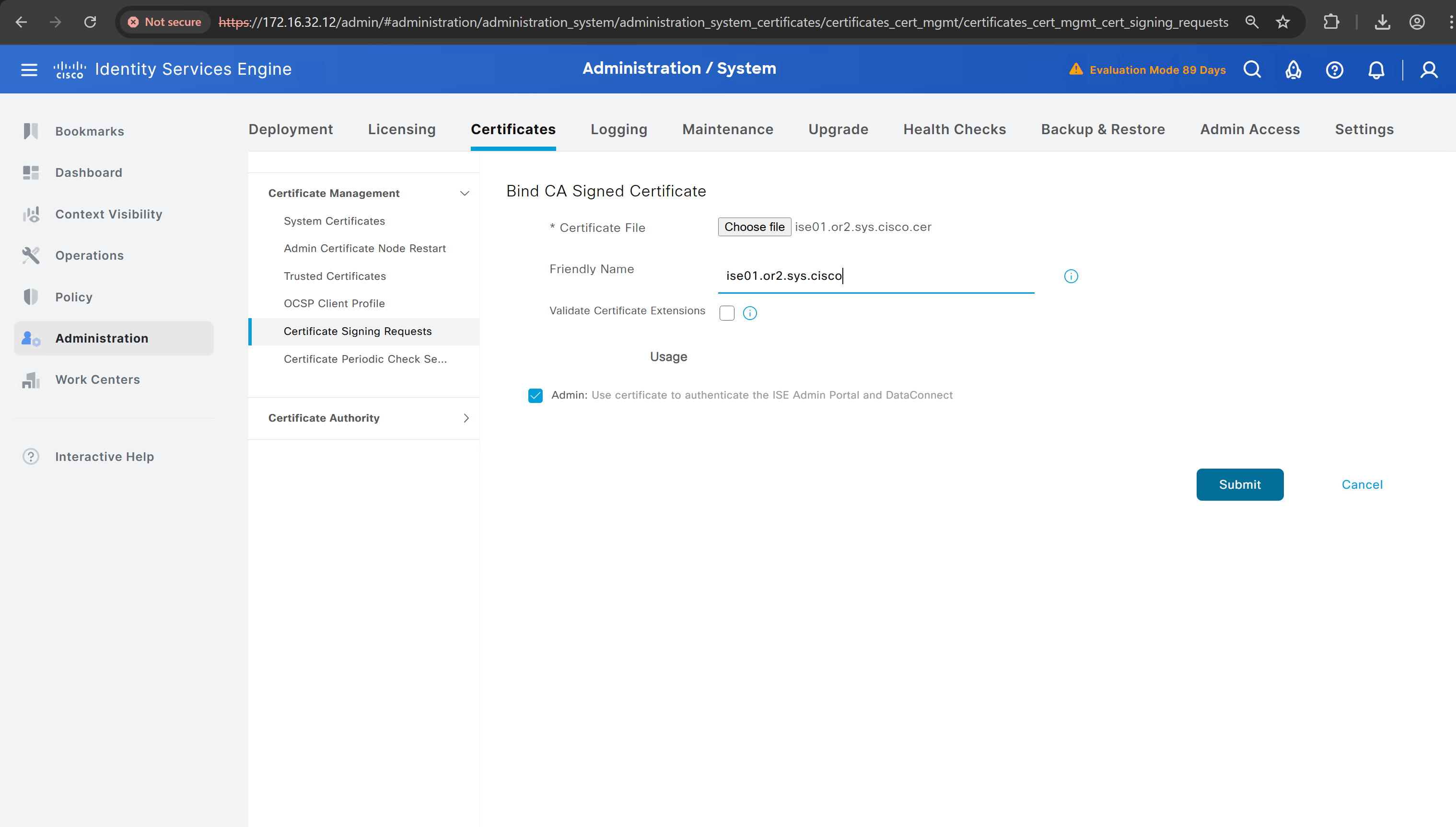
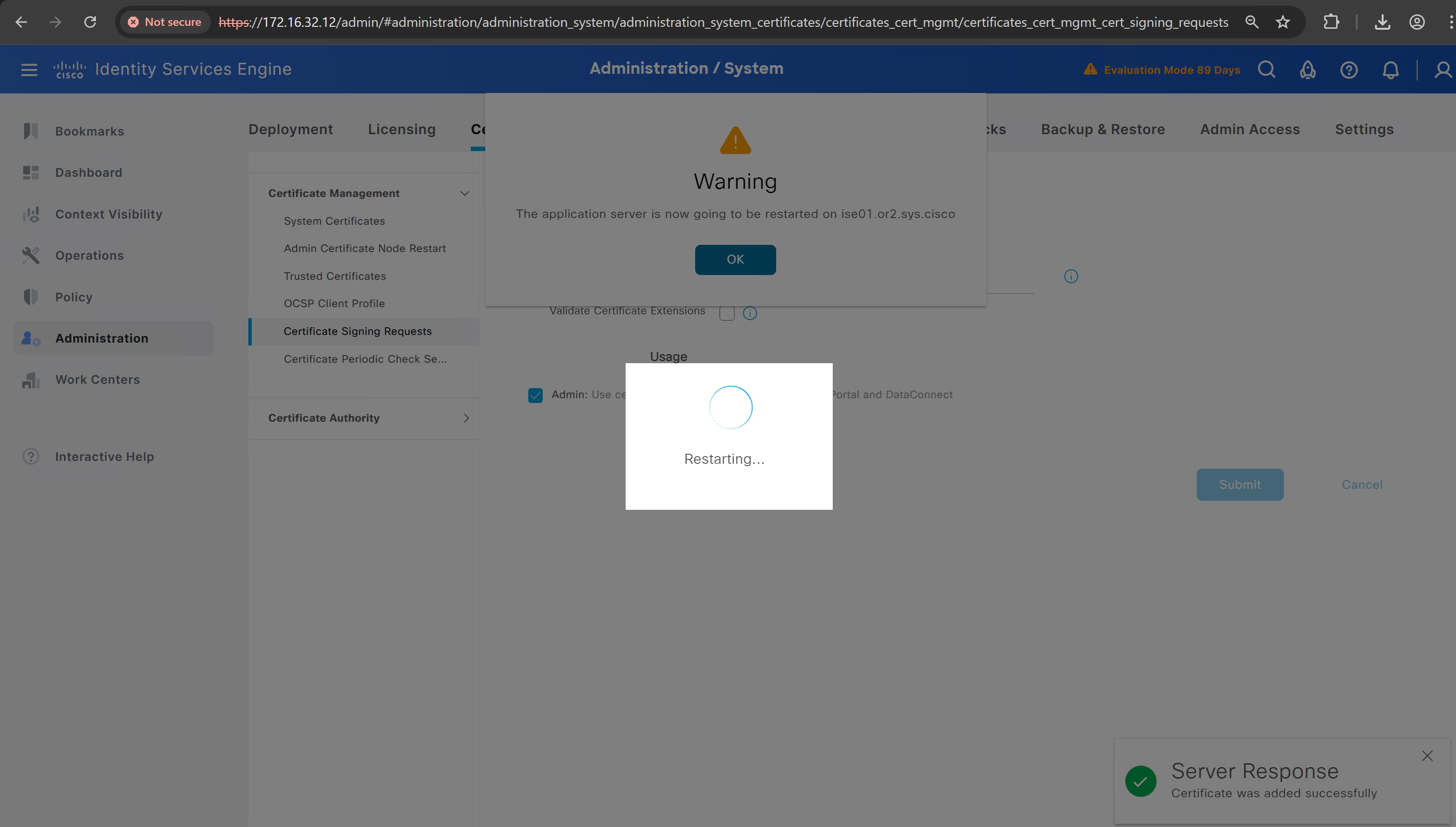
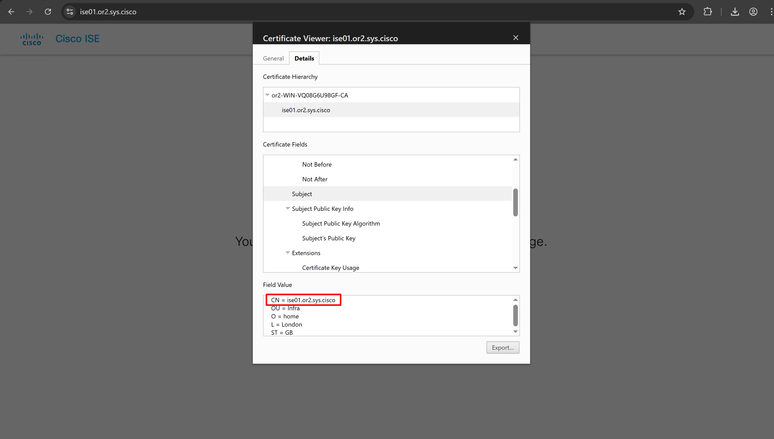
it is trusted now in browser if we access it on its FQDN
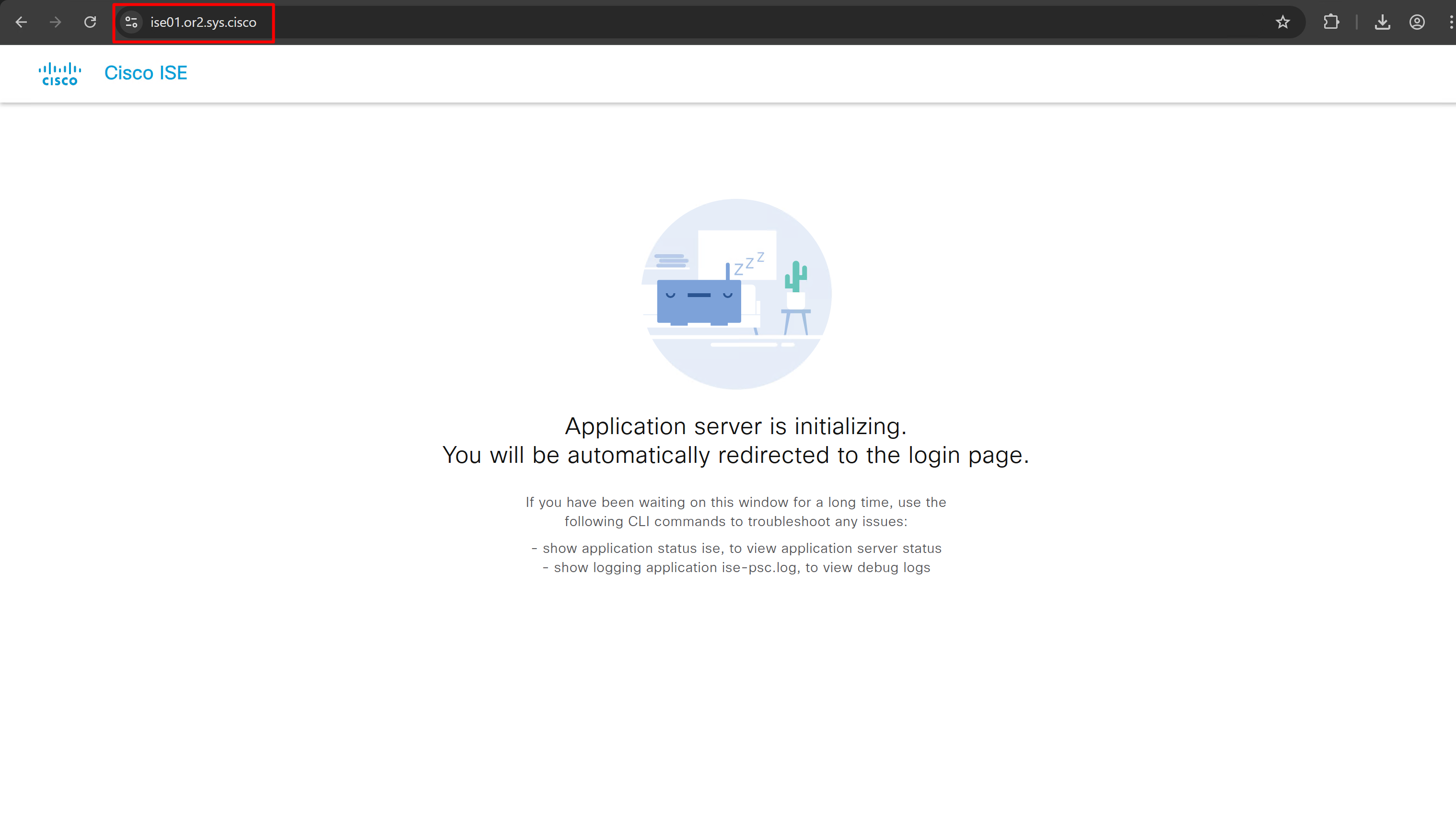
CN is the FQDN of the ISE
more…
coming soon
next post
Enable logging of commands by DNAC
Configuration
conf t
!
! Enable the archive feature
archive
 log config
  logging enable
  notify syslog contenttype plaintext
  hidekeys
!
! Optional: Set up where the archived configs are stored
 path flash:config-archive
 write-memory
!
end
!
! Ensure syslog logging is enabled (optional but recommended)
conf t

logging buffered 64000
service timestamps log datetime msec
!
end
write mem
next post
SDA LM 1 – Initial Configuration & Setup
Videos
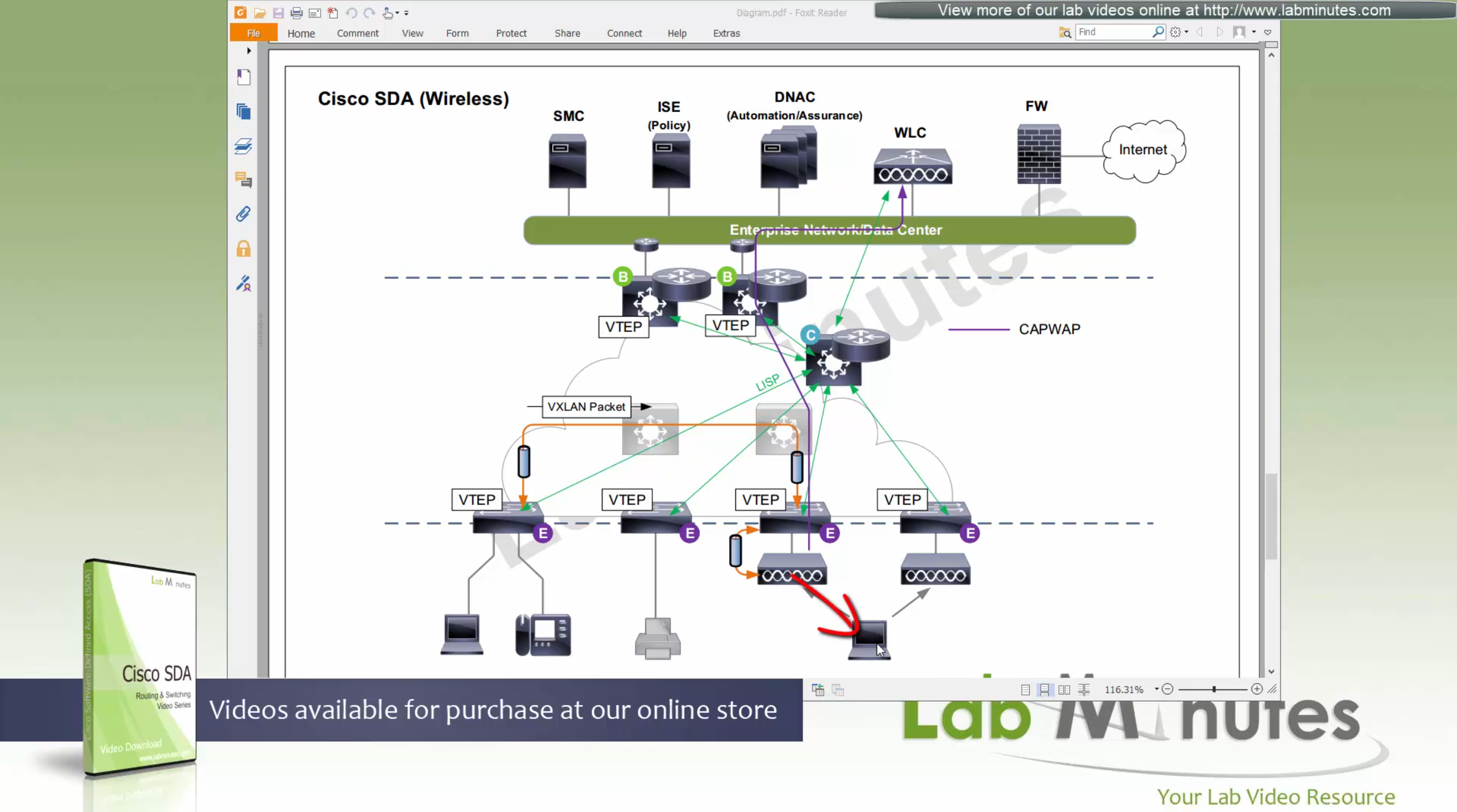
SDA – LISP and Routing introduction
Fabric spans from border nodes
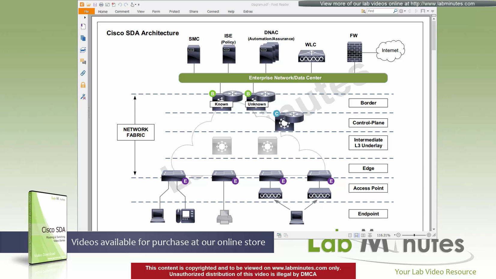
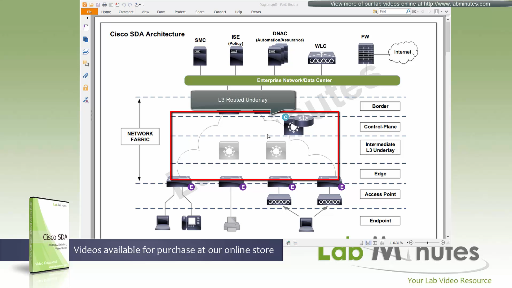
VXLAN (tunnel packets) routed across the point to point L3 (underlay)
Edge and border run L3 eliminating L2
Underlay routing is only there for mostly learning loopbacks of switches in fabric
Client data can be vlan tagged or untagged
Edge switches receive data from clients, if destination is on another switch in the fabric
or in an outside world (via border)
then VXLAN encapsulation (tunnel) is created to other switch or border node
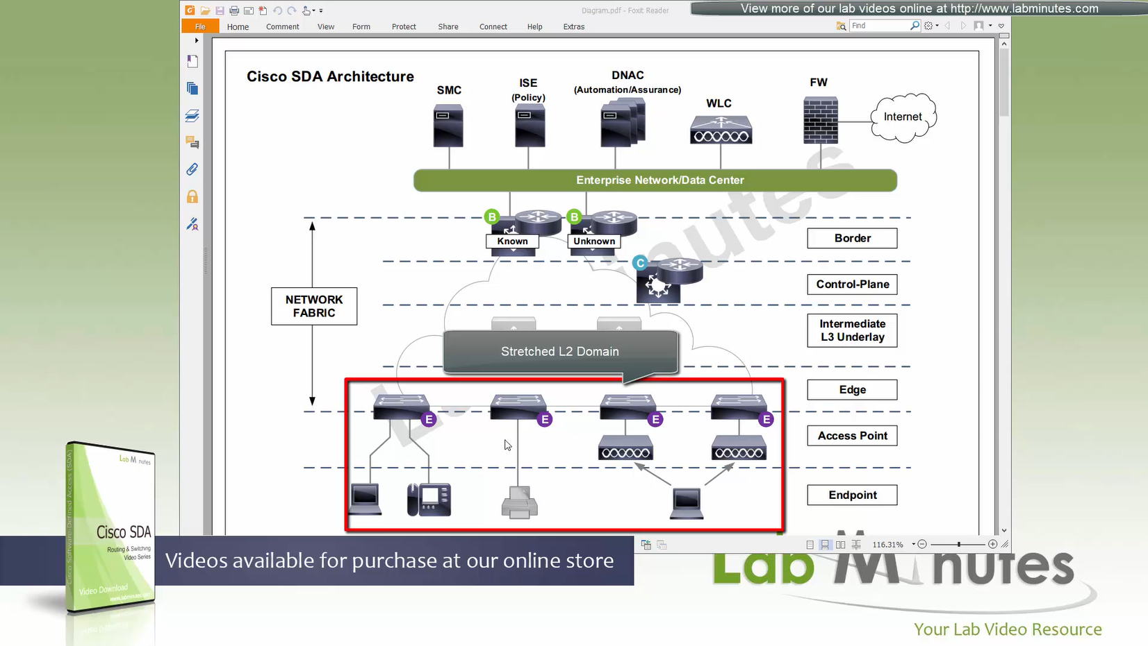
Client can roam from one location to another keeping their original IP address and L2 domain due to “stretched” subnets,
Same subnets (SVIs and also vlans) are available in all edge switches for both wired and wireless
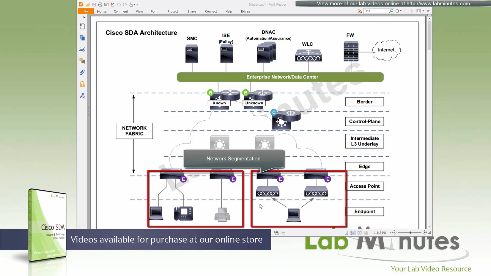
Network segmentation (different virtual networks) or Micro segmentation (using SGT tags and TrustSec)
You can also have “Fabric” enabled WLC and AP,
this makes wireless clients consistent policy wise in DNAC same as wired clients policies
Edge nodes detect the endpoints and updates the control plane about these endpoints
Edge nodes are also responsible for VXLAN encapsulation and decapsulation
Control plane node is the brains of the Fabric and provides “Endpoint to Location mapping” to the edge nodes and border nodes using LISP
Control plane node(s) is LISP Map Server and LISP Map Resolver
VXLAN can carry both Layer 2 frames and also Layer 3 packets
Border node and control plane node should be deployed in pair (2x) to have redundancy in the network
Fabric border node – acts as a gateway to fabric world
Network traffic will need to leave via the fabric border node to access the rest of the enterprise network and internet
Border node peers with external “Fusion” router and advertise Fabric -> fusion and also redistribute external networks -> fabric.
Any external routes learned will be registered with control plane so that those external destinations are registered in LISP
Because edge nodes only follow LISP routing and not any other routing protocol
Control plane is consulted if any packets need to leave for destination other than local switch
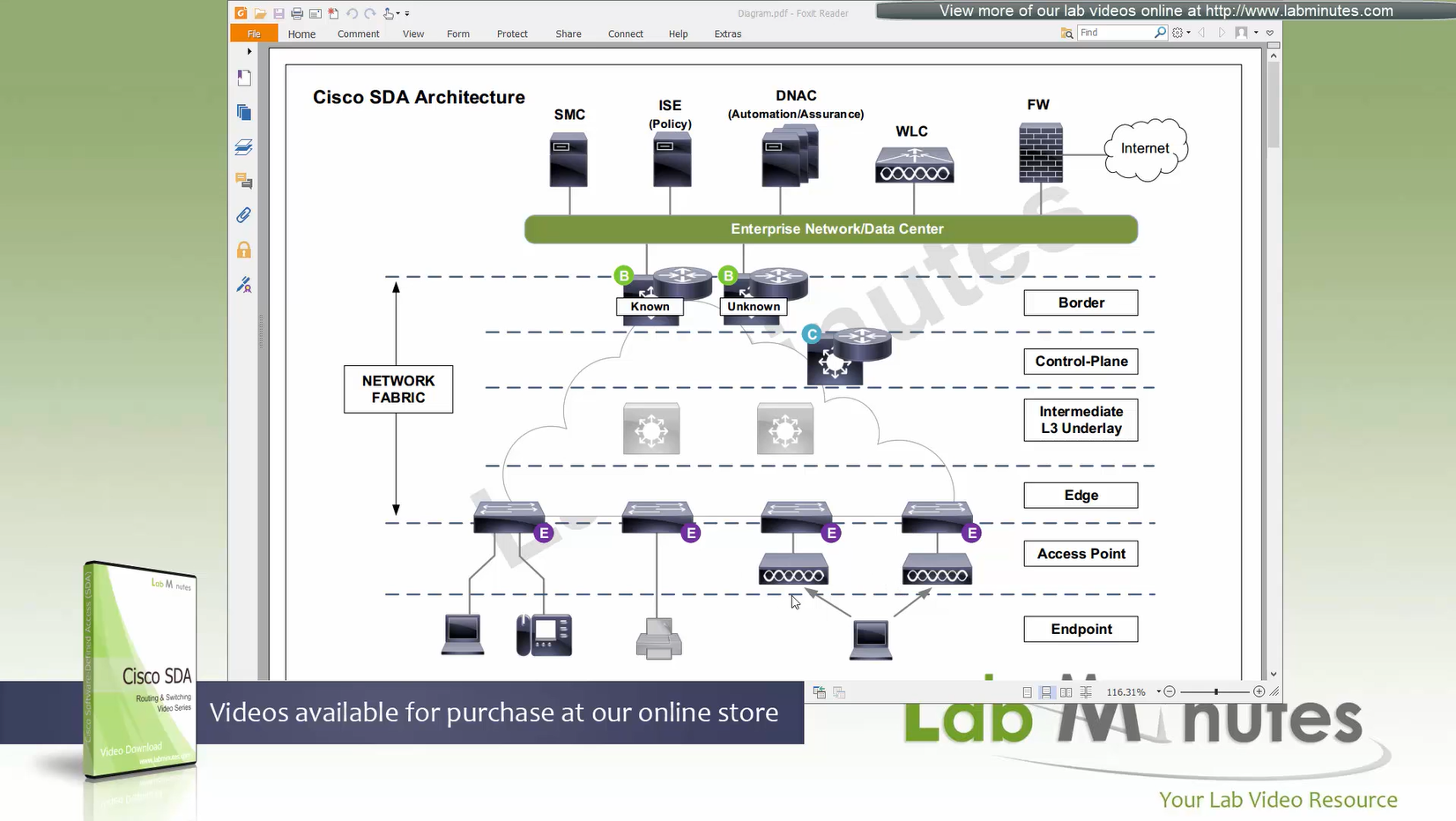
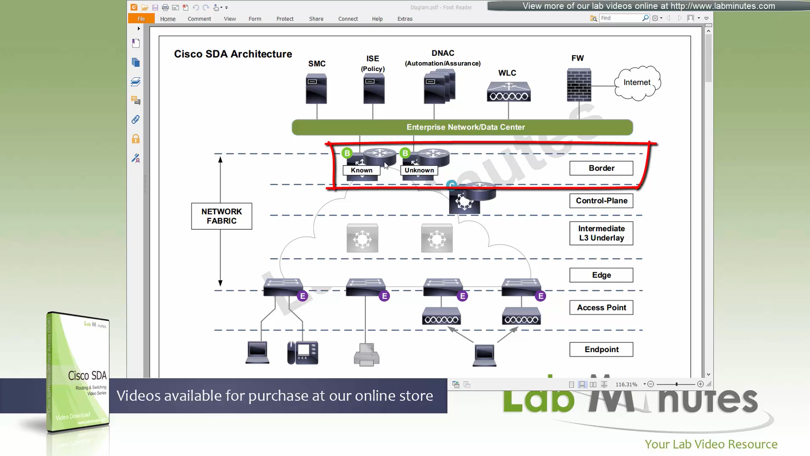
There are 2 types of border nodes
1. Known Border Node
2. “Default Border Node”
Known Border node is for destinations that are known subnets
Second type of border node is that deals with unknown routes and is also called Default Border
Traffic is encapsulated to Default Border if LISP has no entry in control plane and control plane responds back with Default Border
Both Known Border and Unknown Border can live on same device or two different devices
but sometimes in diagrams they are shown to be 2 different devices
- control plane node
- border node
- known border node
- default border node
Intermediate Underlay device:
Intermediate Underlay devices need to be able to support the “Jumbo frame” and use ISIS
Cisco recommends this intermediate devices to participate ISIS (shortest path) with redundant links
there should be no spanning-tree or layer 2 in the Fabric.
Underlay Intermediate device aggregate all the access edge nodes into something and then connect into border switch or router
Direct connections to border are supported but should not be done for larger site due to scalability issues
Fabric mode WLCs still manages the AP and maintains client connection information via CAPWAP control channel
Fabric mode WLC reports to control plane node and lets it know about the client
Communicates associations and communicates roaming to control plane
Controller sits outside of the fabric and APs sit inside the fabric directly connected to edge nodes
WLC can be connected outside the fabric as long as it has reachability to the border and control and APs
Fabric mode AP
(Data tunnel) they will not send data to WLC for it to be centrally switched but exit data locally on the fabric via VXLAN tunnel > edge switch
Fabric AP participates in VXLAN encapsulation
however they maintain CAPWAP tunnel (Control tunnel only) to the WLC at the same time,
This allows wireless clients to be treated within the same system and policies of the fabric.
Control: AP <–CAPWAP CONTROL–> WLC
Control: WLC <–LISP–> Control node
Data: AP <–VXLAN–> Edge node
AP must connect to edge node “directly”, there should be no switches in between AP and Edge node
WLC sits outside the fabric or Fabric border node and APs sits directly under the edge nodes
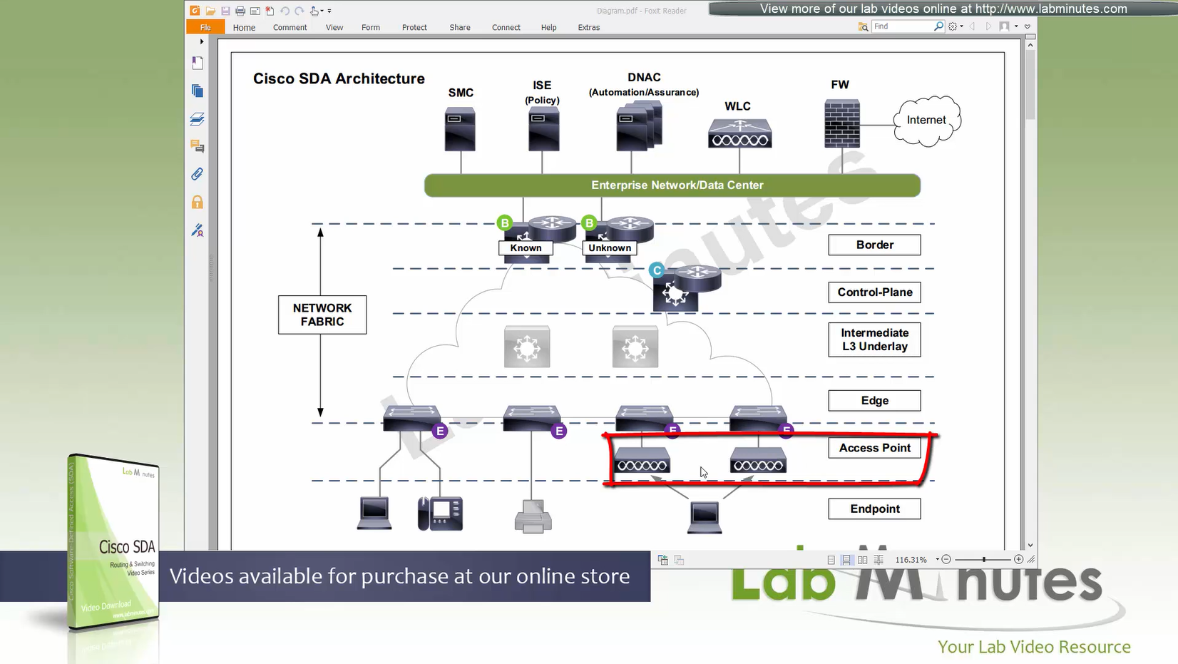
because Access points connect to edge nodes directly clients are connected like
Client <–Wireless–> AP <–VXLAN–> Edge node
DNAC
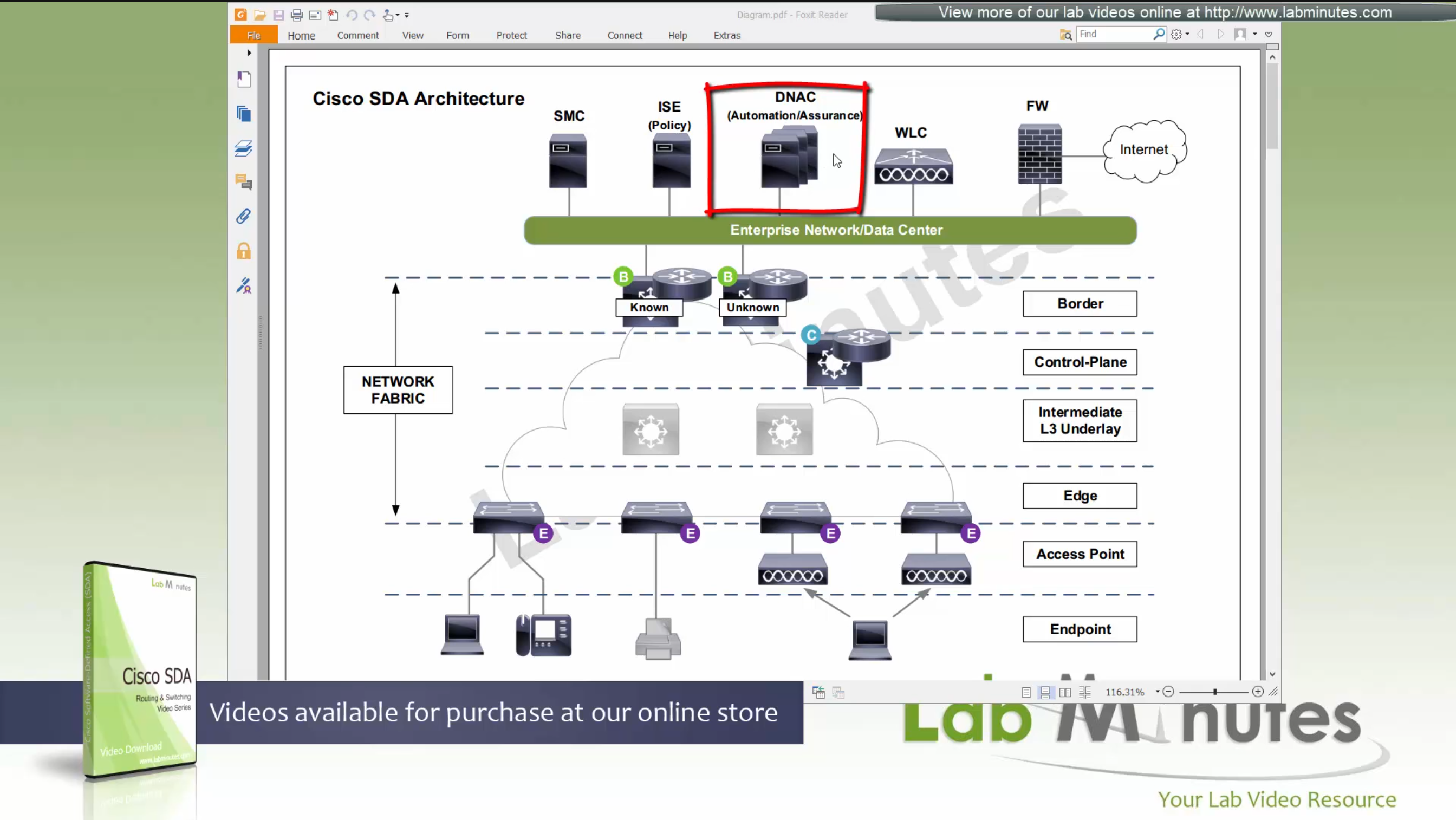
ISE maintains the security policy and contains Authentication / Authorization policy and also TrustSec related components
DNAC uses APIs to push configuration to ISE for SGT but ISE is separately managed
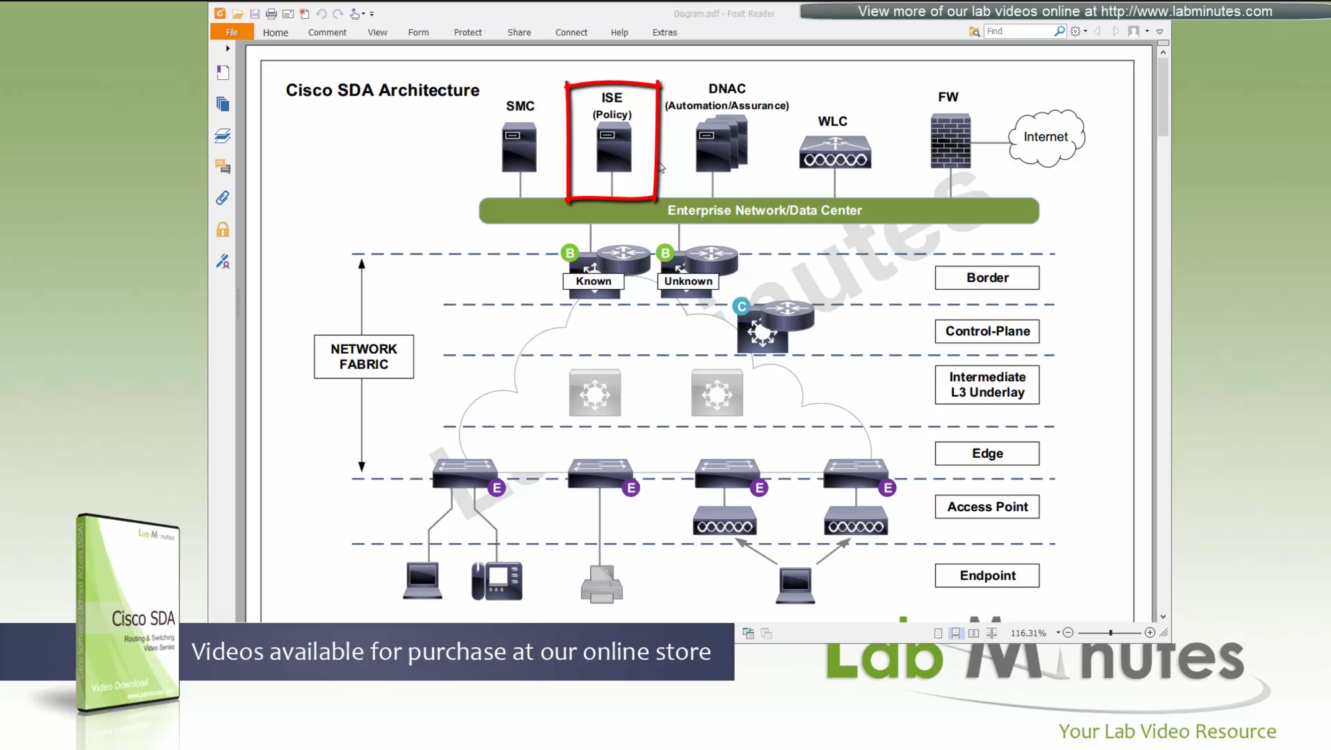
Management loosing network such as DNAC will keep the data forwarding and not cause outage
One thing to keep in mind is that we need to have high speed LAN like access between all fabric nodes and DNAC, that is why DNAC cannot be spanned across WAN, all Fabrics must have high speed access to DNAC
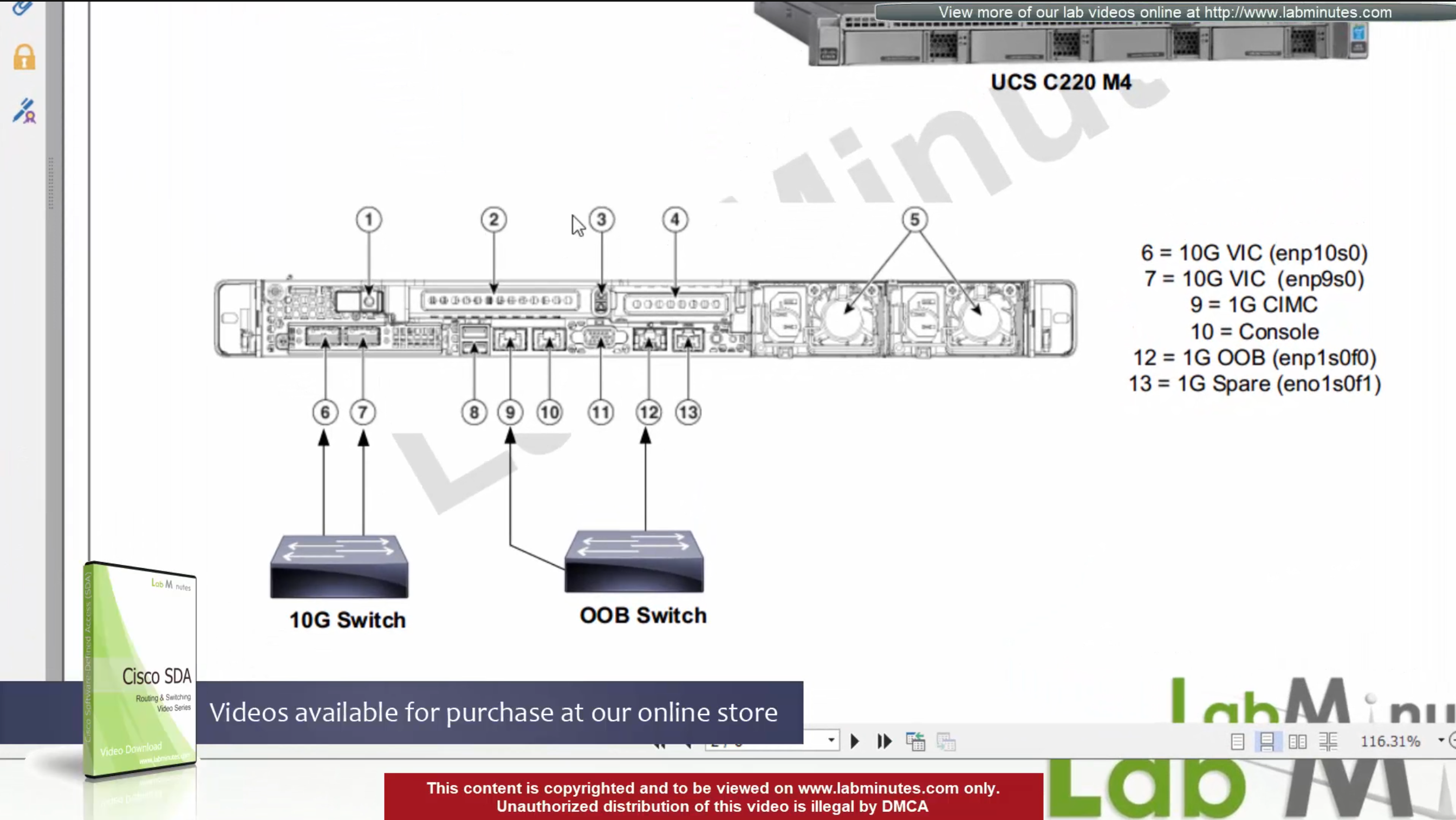
DNAC is available as C220-M4 which is same C series server as APIC for ACI
It is always recommended by Cisco to deploy DNAC in cluster of 3
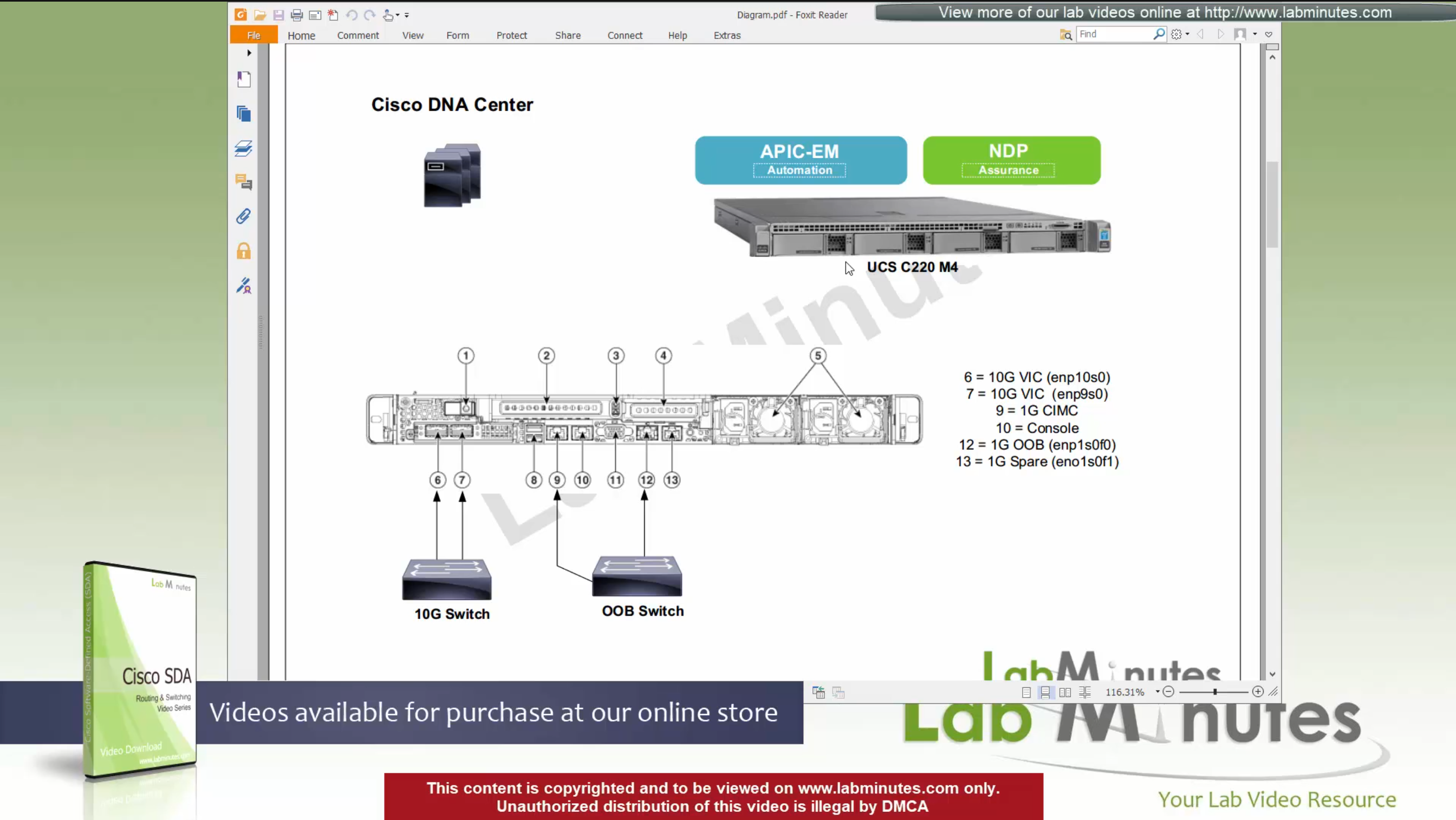
For connectivity DNAC has 2x (redundant) 10G VIC Cards – Data interfaces for fabric facing communication
It is not mandatory to configure the OOB interface for management connections
Data port IP can also be used for management
unlike ACI, where GUI and SSH must strictly be done via OOB IP
CIMC interface – Server interface for KVM and firmware upgrades
Console interface – in case network connectivity is lost
OOB Mgmt interface – optional for HTTP and SSH
it is recommended so we have another path for accessing the GUI and SSH
There are 2 engines running on DNAC,
APIC-EM
NDP
There is 3rd engine called policy engine but it does not run on DNAC but on ISE
APIC-EM shares a lot of features with APIC and helps with Network topology discovery, software management and upgrades aspect etc, APIC-EM is also responsible for the network automation
NDP stands for Network Data Platform
NDP takes care of the, “monitoring”, “telemetry”, “assurance” and “data analytics”, This is like Solarwinds NPM
NDP is more with Analysis and alerting
while the APIC-EM is like NCM for pushing changes and making changes
In NDP Assurance comes from the fact that it goes one level deep and it not just relies on polling from network devices for system stats and health but it also gets the Client’s connectivity monitored from client and their experience perspective
Client connection stats and connection health and client experience is one of the big things, and it is client connectivity that “assures” that network is working because clients are live and using the network, so instead of SLA on the box, client data traversing the network is a better testament that network is working or not
NDP also has “machine learning” elements
DNAC Assurance or NDP collects data from various sources, once data is received, Assurance engine does correlation and provide bigger picture pieced together to reveal issues which administrators are either not aware or know before
SDA is not fully supported by all switches / routers
Some devices have some features supported
Others fully support all the features.
This sheet can be found on google, Y and N in column have been added, older hardware possibly cannot support those features
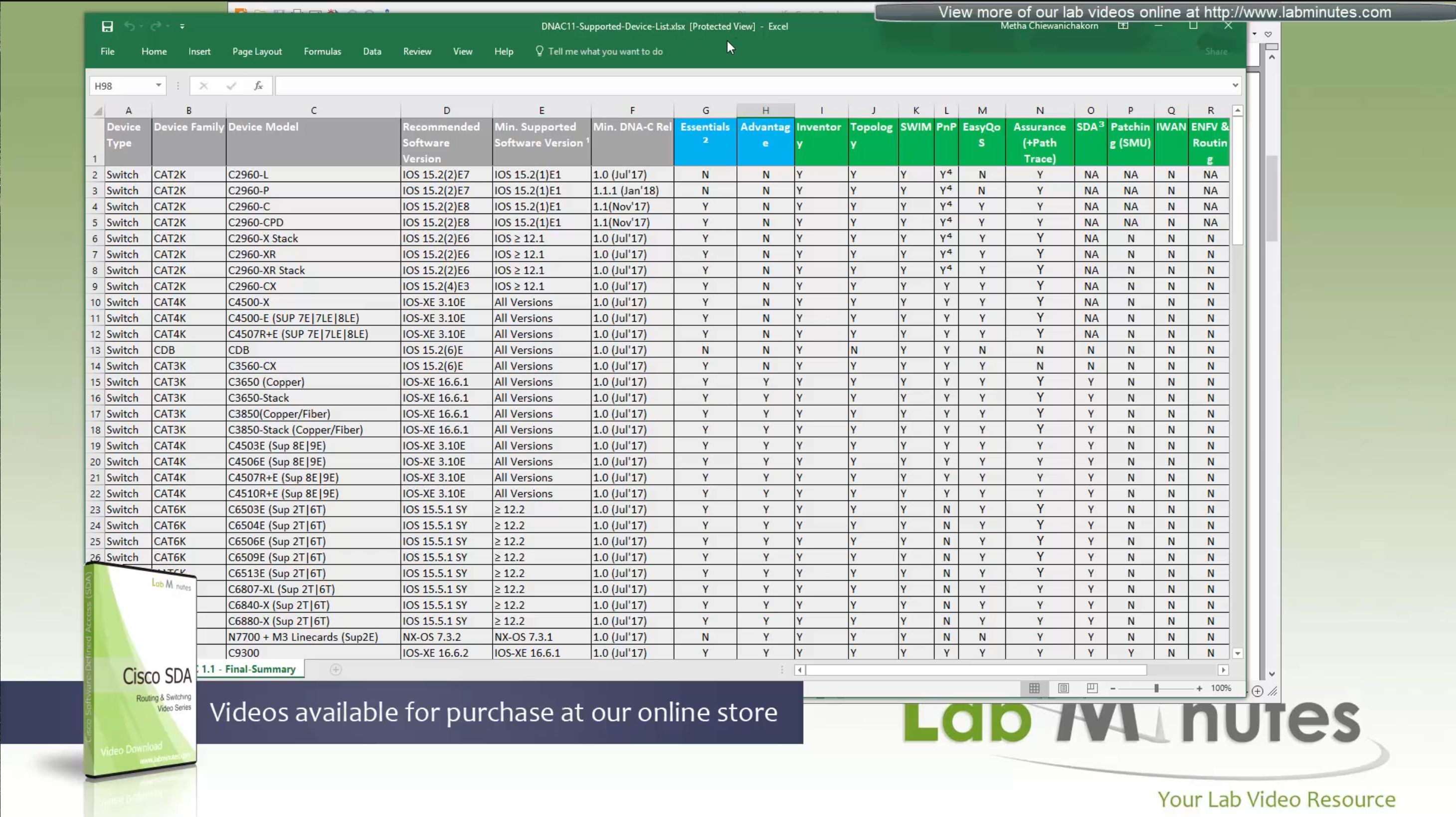
We can see that very first switch that can do SDA is 3650 Copper
Some cisco models can be the edge nodes only but not the border node or control node.
So make sure that we order right kind of hardware before deployment.
Cat 9k will support most of the SDA features
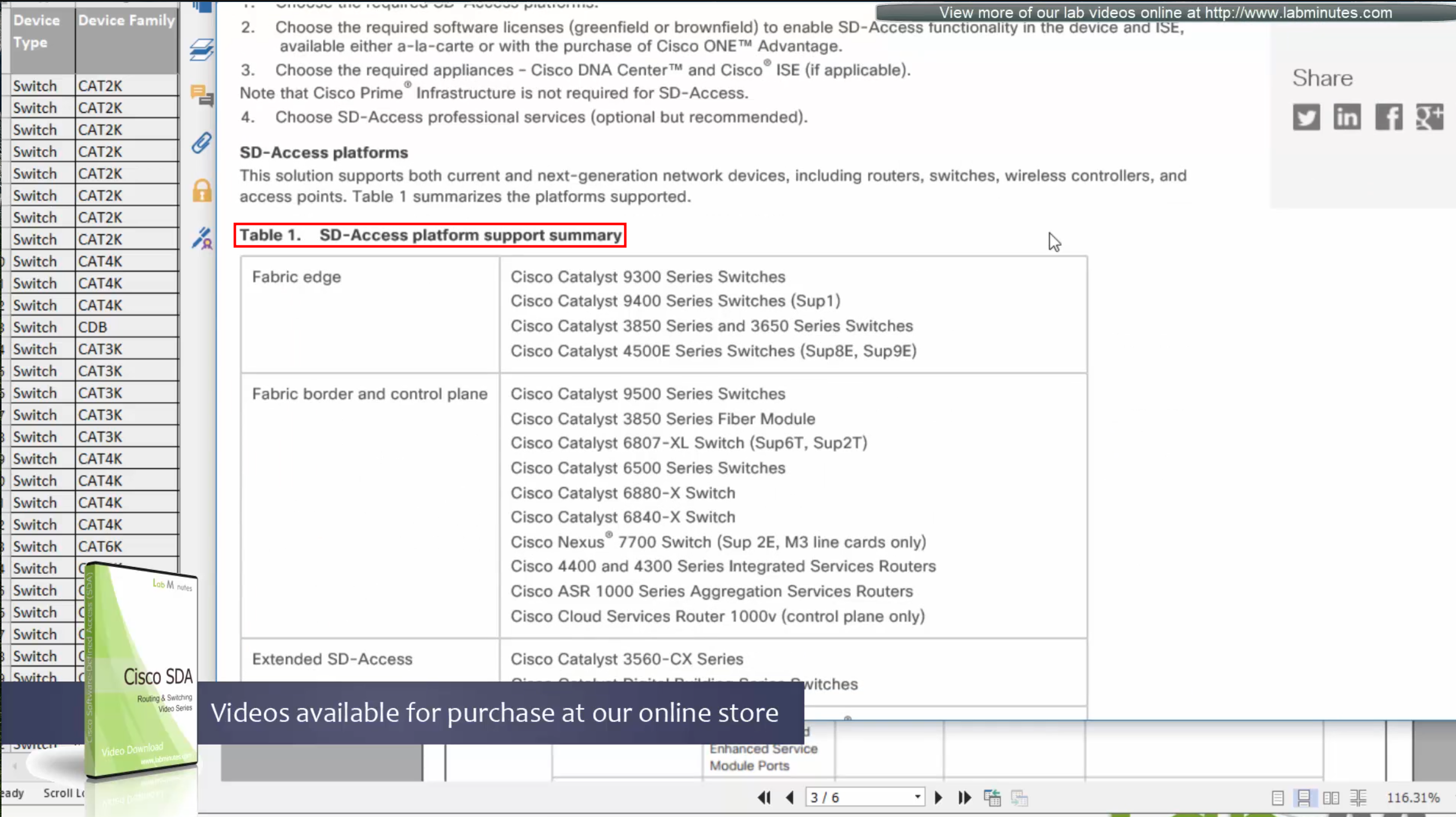
This list also includes routers, as routers are also supported in SDA for Border and control nodes but do not deploy anything outside of Validated designs in CVD
Similarly there are WLCs that are validated for SDA, be sure to check SDA hardware sheet
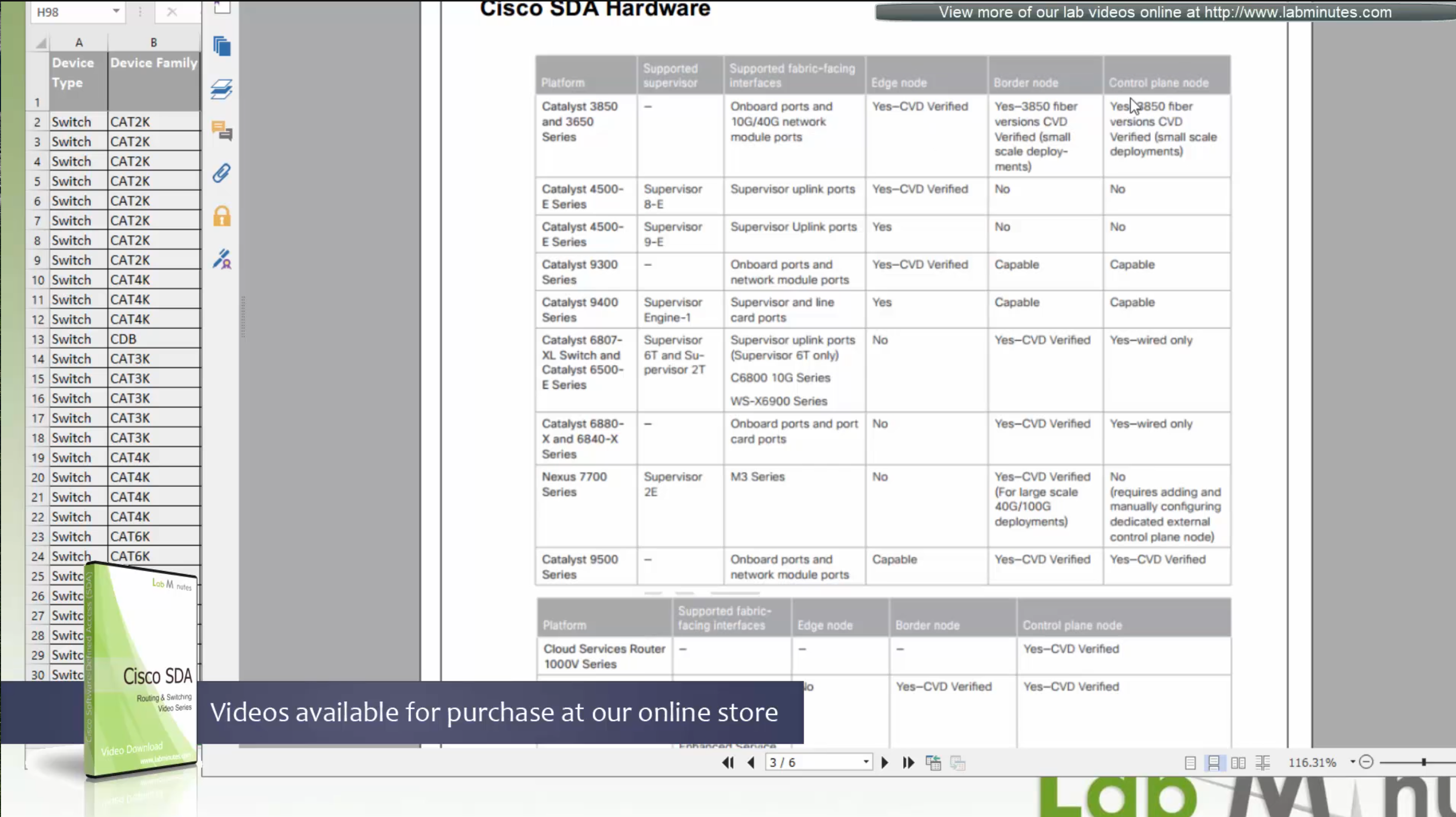
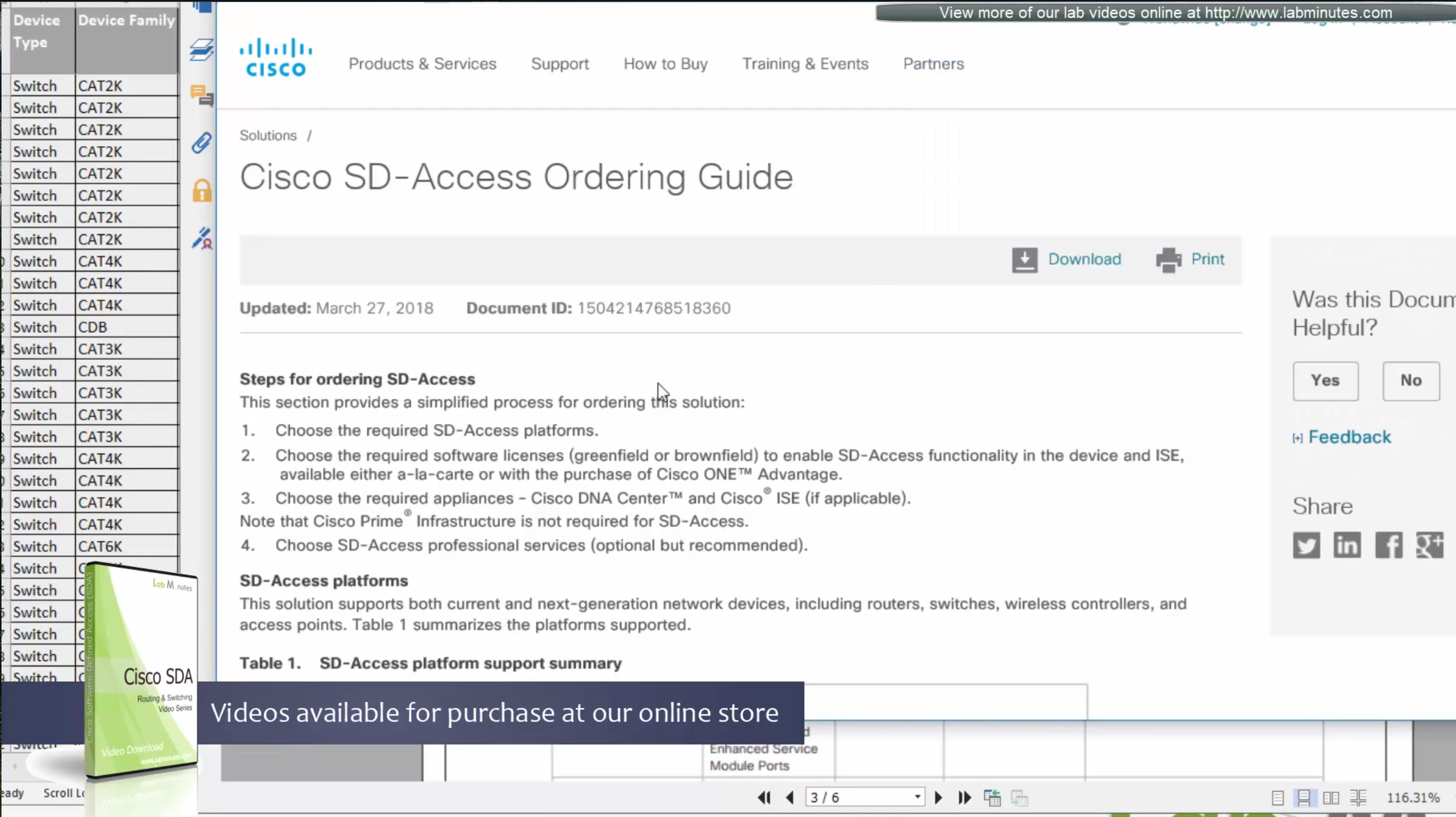
Always consult “ordering guide” for new deployments
Fabric is consistent across the network and is not different unlike legacy network which can have different networks between switches because of inconsistent configuration. Fabric on the other hand is consistent from L2 and L3 perspective.
All the underlay network is going to see is UDP packets


Fabric edge nodes tell the control plane about new endpoint
by snooping the ARP response and DHCP offer packets (device tracking on edge),
information told to control pane includes “MAC addresses”, “IP addresses”, “port connected to”, “Liveliness” (to see if host is there or not) and “VNI host belongs to” (VNI is equivalent of the VLAN in VXLAN world).
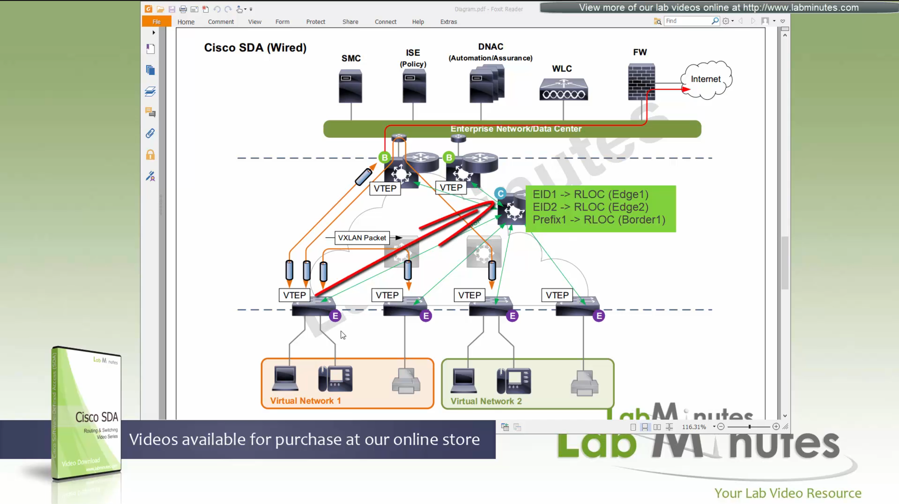
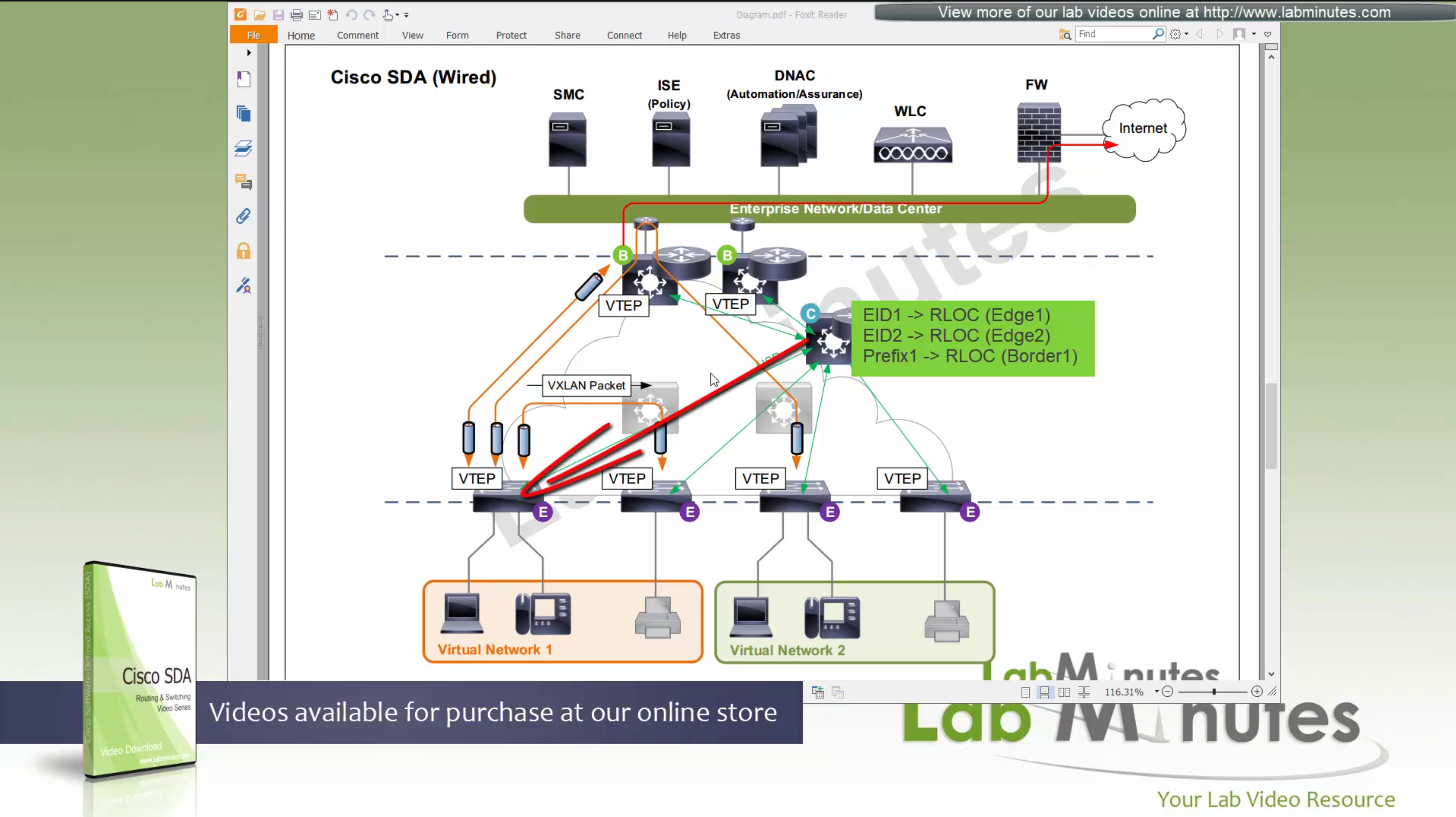
Edge node sends a “MAP register” message to control node
Control node creates an EID (Endpoint identifier) to RLOC (Routing locator) entry is created in database
VTEP and RLOC refers to same thing, the loopback IP address on the switch

Border node does the same thing the edge nodes do with control node
but instead of registering Endpoint IDs it has prefixes to register
prefixes it learns from Fusion for external networks (outside of fabric) as prefixes to Control node.

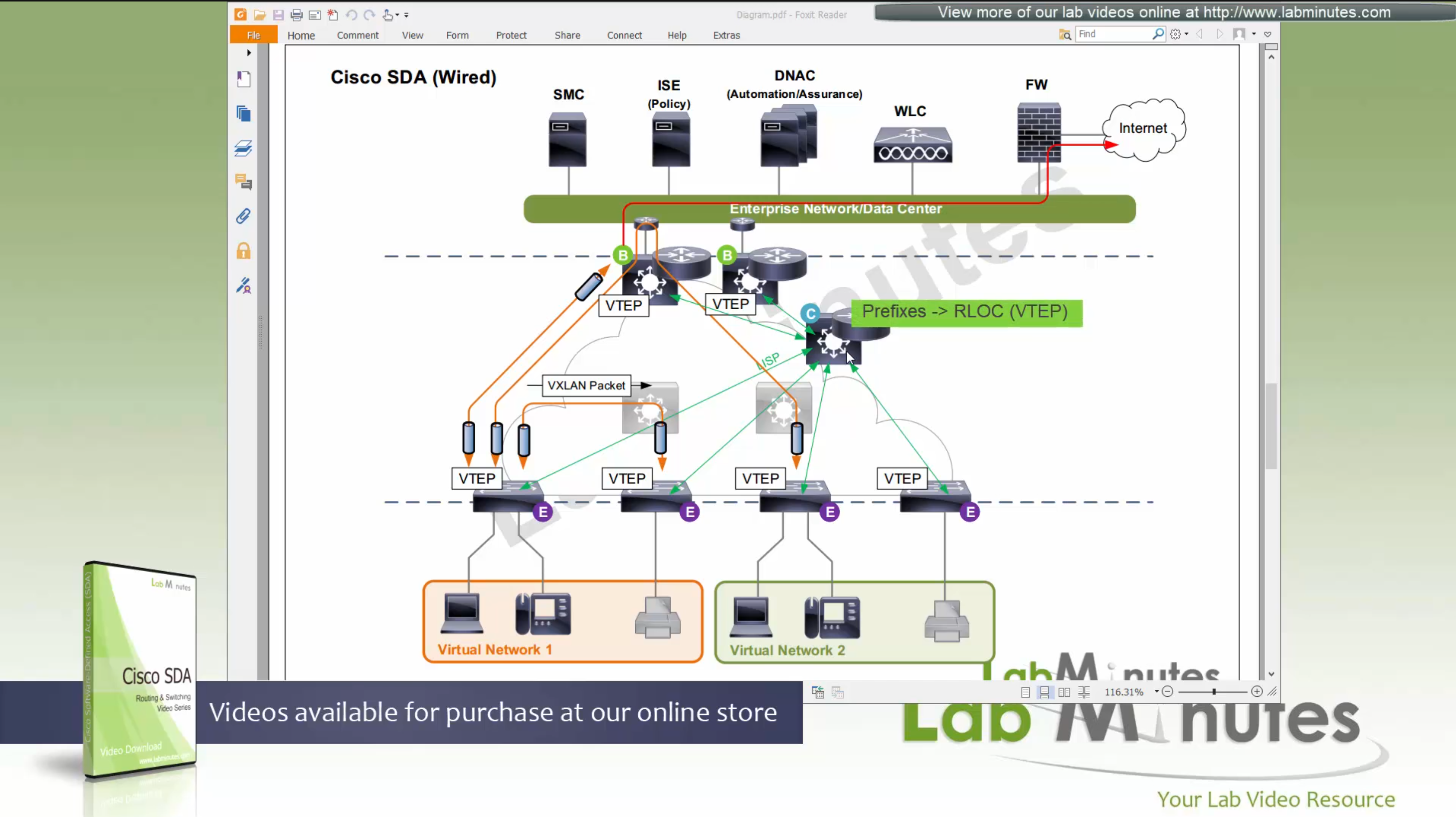
Control plane node not only maintains the EID but also the prefixes
border node needs to be redundant

Caching: border or edge node then caches in a local cache that RLOC entry for future use
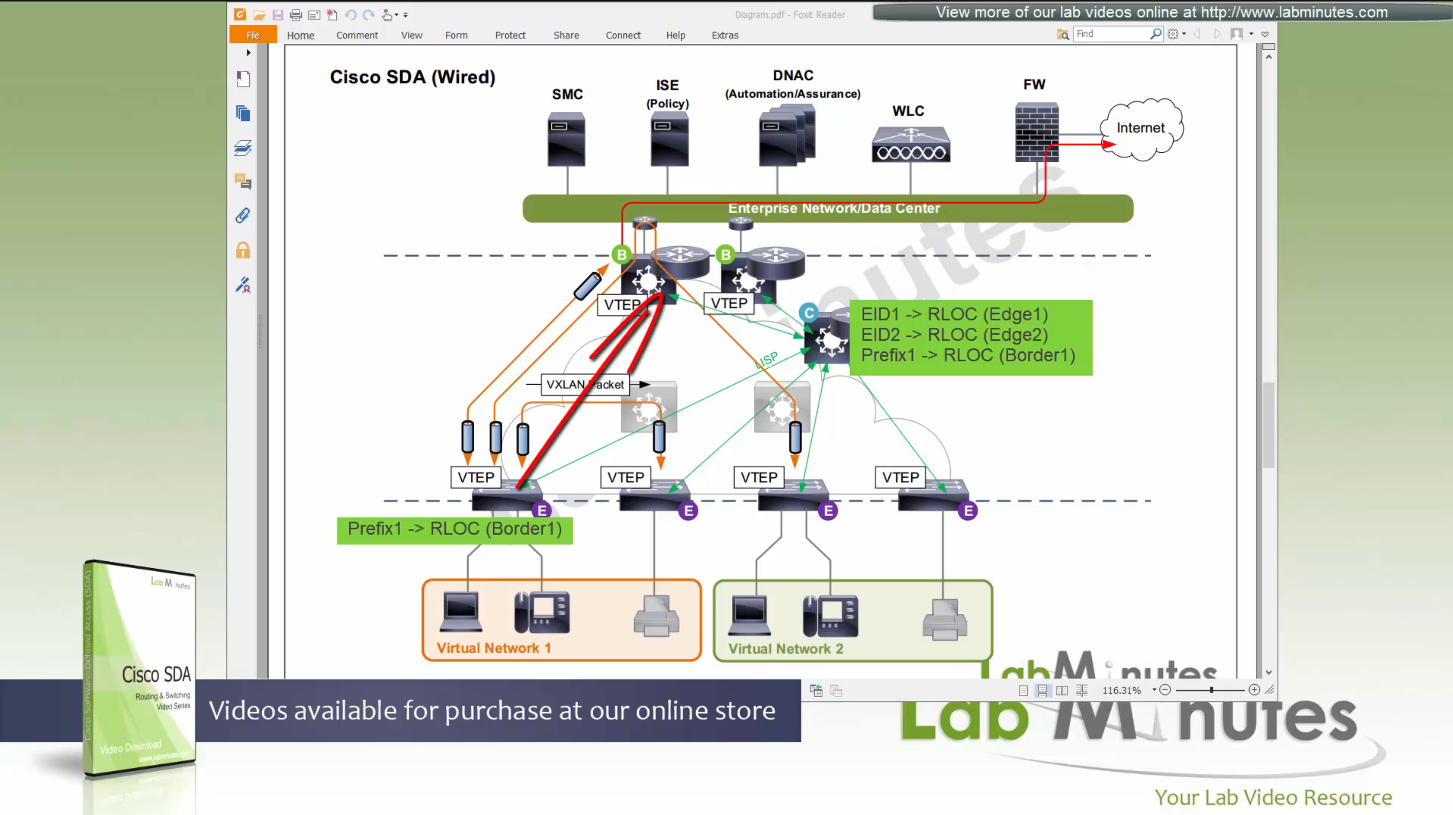
because edge and border receives or caches the RLOC entries on need to basis
it keeps their routing table or FIB small and this translates to scalability,
Remember that edges only use LISP and not routing table
Edge nodes have Anycast gateway which makes SVI available on all the edge and border nodes
These SVIs also have same MAC addresses so when client roams from one node to another, it is seamless
These SVI anycast gateways exist on both Border nodes and also on edge nodes
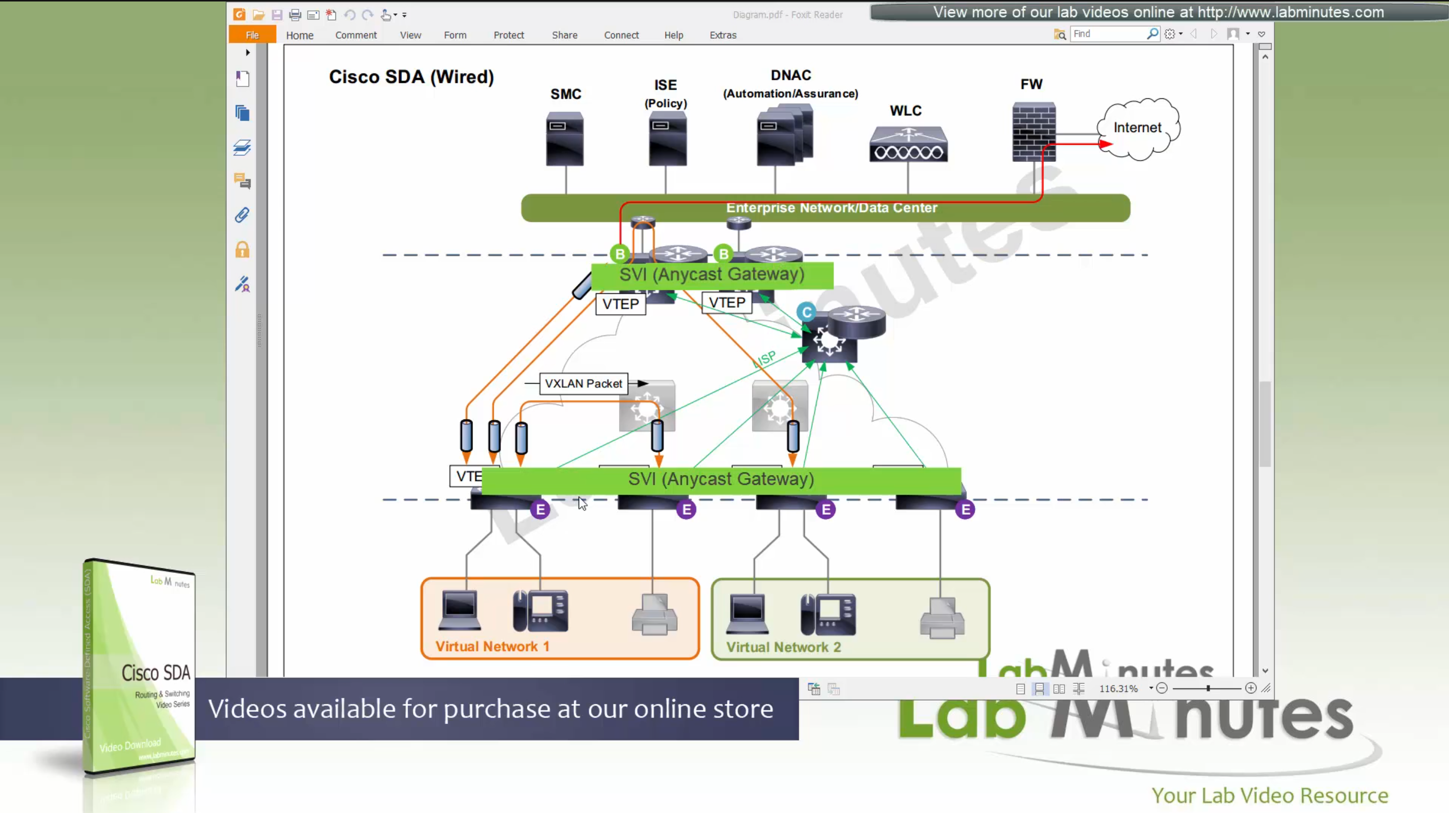
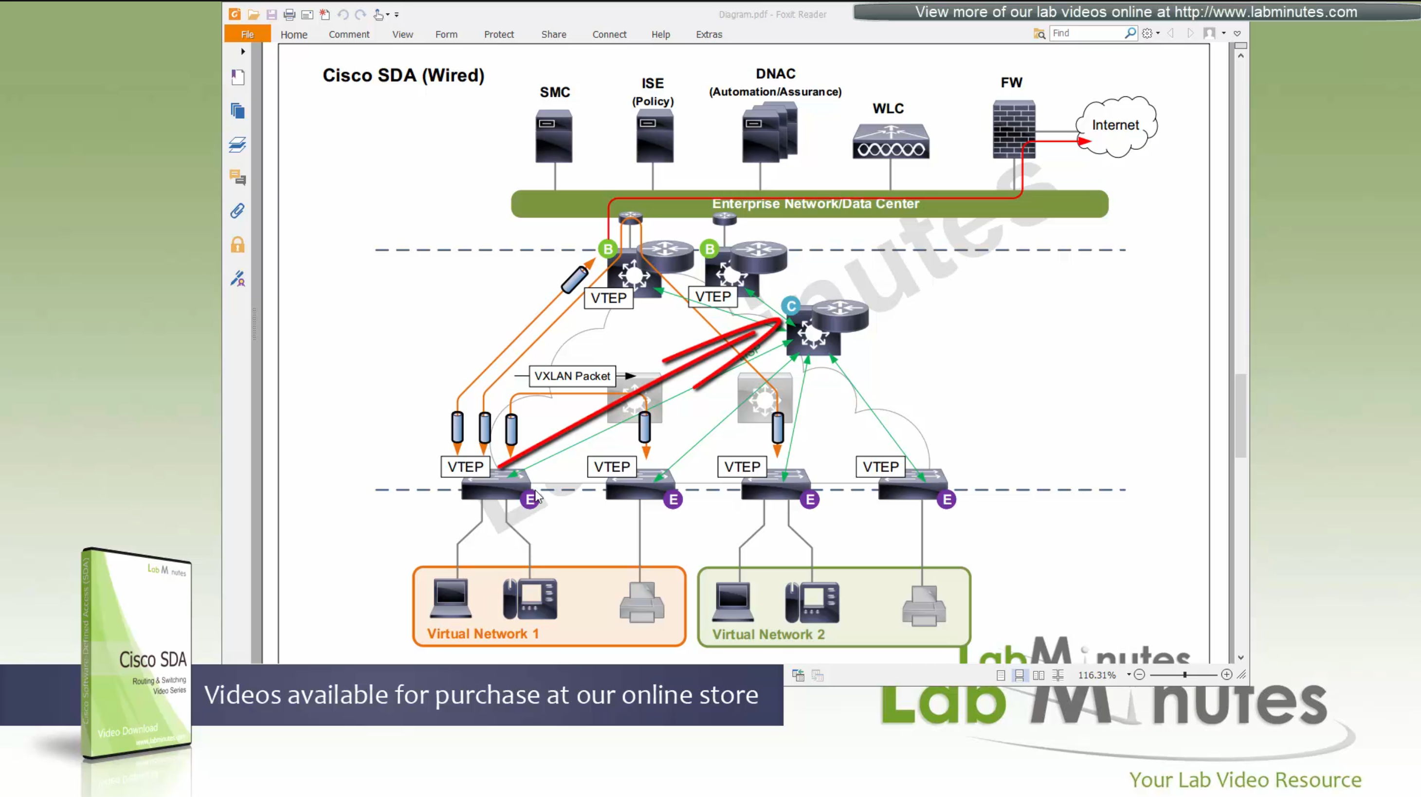
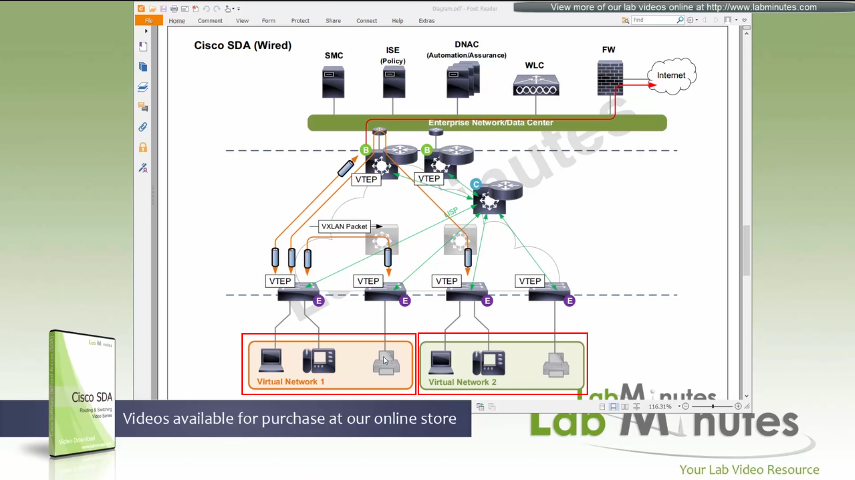
Here we have two different virtual networks or VRFs
Scenario 1: Packet stays on same switch
In this scenario packet does not leave the switch and is switched from one port to another and that makes it fastest, if you have low latency requirement where even couple of milliseconds of latency such as 2 ms or latency of VXLAN packetization and encapsulation is not tolerable then place the hosts on same switch
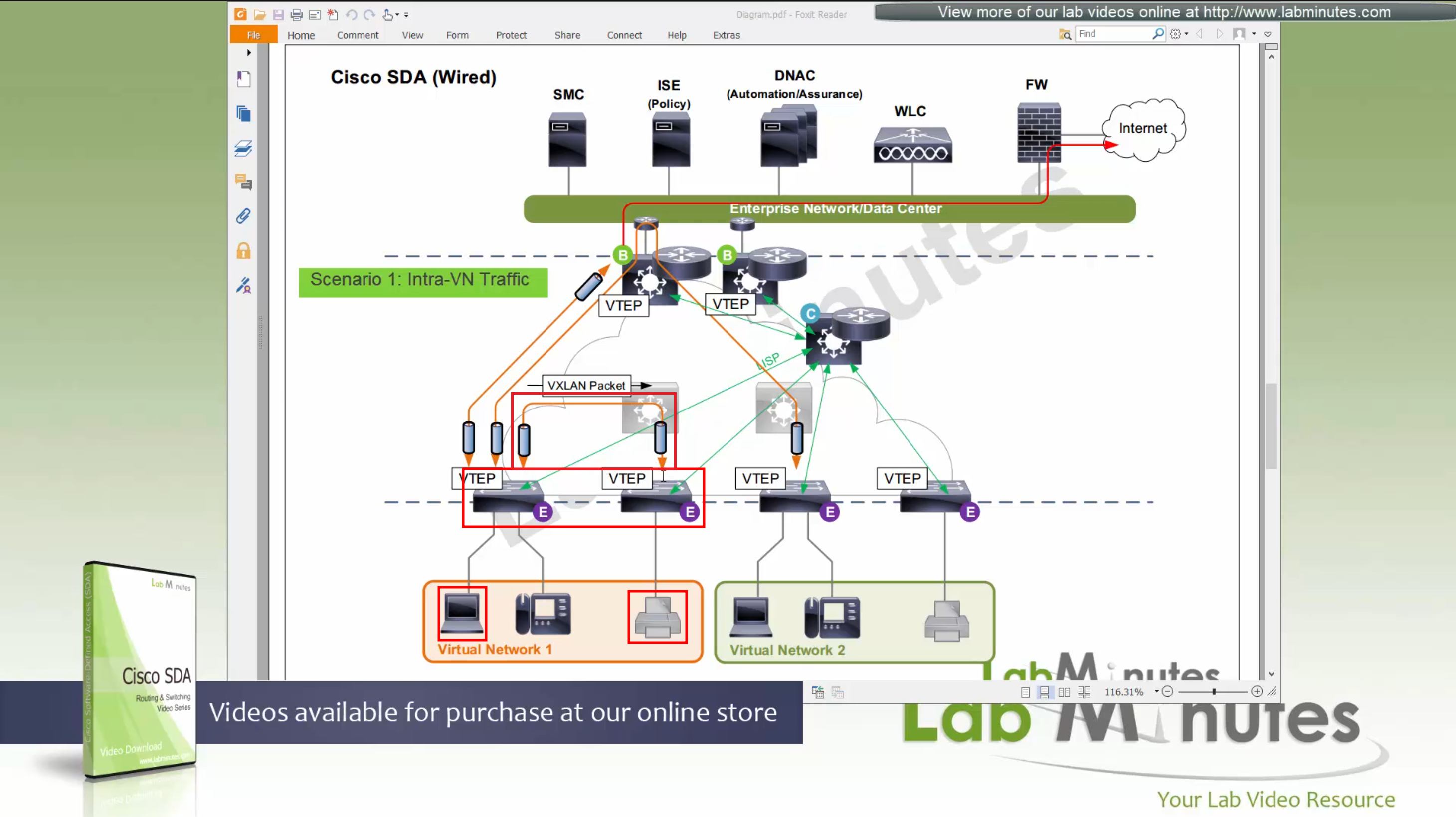
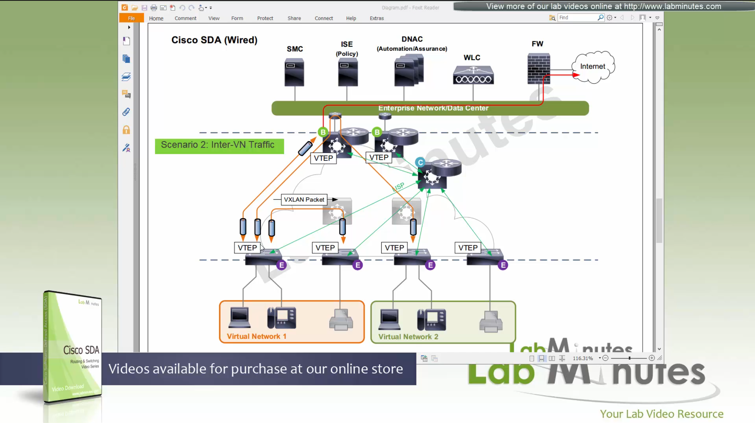
Scenario 2: Packet stays within the Fabric, IntraVN (same VN) traffic
When PC needs to communicate to the printer,
it speaks to control node (because printer is on another edge node)
obtains RLOC for that edge node where printer is attached,
it will create a vxlan packet with correct L2 VNI tag, and correct outer L3 RLOC destination IP address
and insert original IP packet into it as a payload
send it out to the underlay to deliver.
Underlay will deliver
As seen in diagram, this VXLAN flow will not touch border node
As these VXLAN packets reach Intermediate Nodes,
because loopbacks being advertised in ISIS (shortest paths for loopbacks) VXLAN packets will be switched from “edge node to Intermediate node to edge node” Triangle: Edge <–> Intermediate <–> Edge
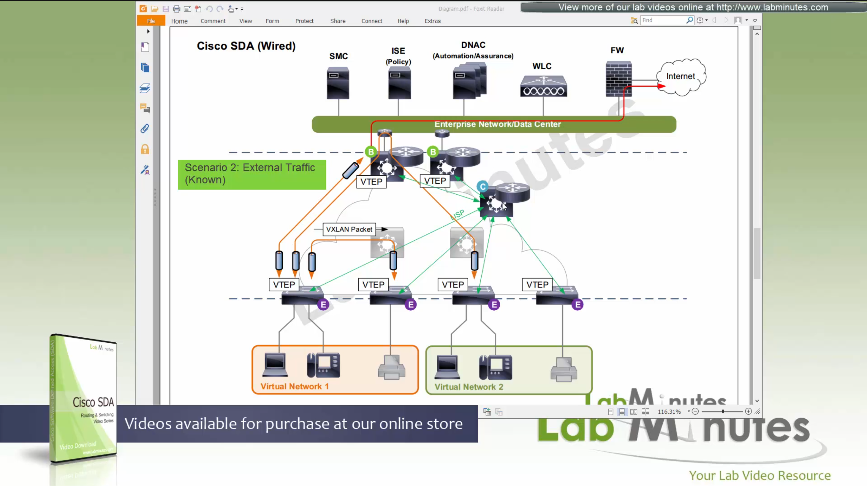
Scenario 3: Packet destined for “Known” external network outside the fabric.
Edge node inquires the control plane for destination
Control plane returns the RLOC of the border node that registered the prefix
then edge sends the packet to border node,
it will create a vxlan packet with L2 VNI tag, outer IP header will have RLOC destination IP address
and insert original IP packet into it
send it out to the underlay to deliver.
Underlay will deliver vxlan packets to the border node
border node will “decapsulate and deliver it out to the external network”
Packets will flow from edge node to intermediate node to border node and then fusion node to get to external networks
Edge <–> Intermediate <–> Border <–> Fusion <–> External destinations
Scenario 4: Packet destined for “Unknown” external network outside the fabric.
Edge node inquires the control plane for destination
Control plane returns the RLOC of the Default Border Node
then edge sends the packet to default border node
it will create a vxlan packet with L2 VNI tag, outer IP header will have RLOC destination IP address
and insert original IP packet into it
send it out to the underlay to deliver.
Underlay will deliver vxlan packets to the border node
border node will “decapsulate and deliver it out to the external network”
Packets will flow from edge node to intermediate node to border node and then fusion node to get to external networks
Edge <–> Intermediate <–> Border <–> Fusion <–> External destinations

Scenario 5: Packet destined for another Virtual Network, InterVN (to another VN) traffic
This scenario applies when host in Virtual Network 1 needs to communicate with host inside Virtual Network 2 below, queries will still happen as in previous scenarios with control plane
Now this gets a bit trickier in these notes because this is an old video for an old release when SDA did not allow route leaking inside the Fabric, so that meant that packets will be routed all the way out of the fabric to the fusion router and fusion router will route it towards other virtual network making packet route back into the fabric, because border node cannot be routing “between” different Virtual Networks, and for this to work fusion router also needs one “transit” sub-interface per Virtual Network or VRF
Obviously this is not optimal as InterVN traffic will face more delays than IntraVN traffic and fusion router is also single point of failure
AP maintains the CAPWAP to WLC but it is only for CAPWAP control connection, data is locally switched to the edge node over the mini VXLAN tunnel.
This VXLAN tunnel between Fabric mode AP and edge is only between AP and edge that are directly connected, it does not extend from AP to remote edge switches
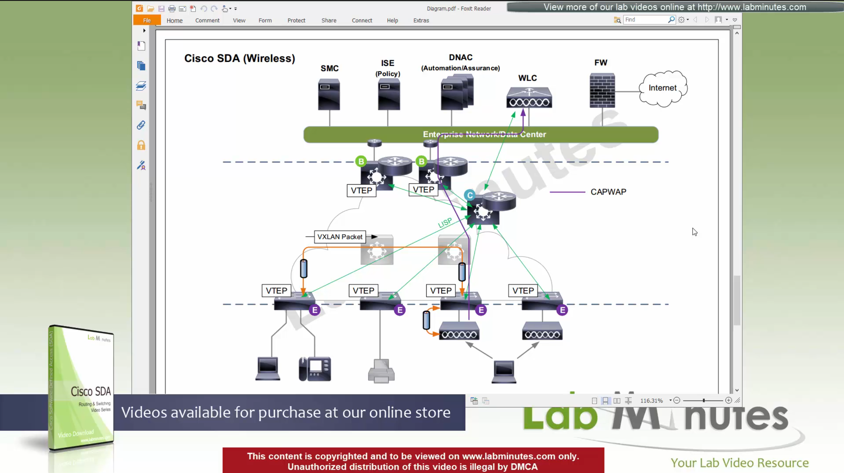
Client will associate and authenticate with the SSID, obtain IP address

“WLC will do MAP register with control plane node” and tell control plane node about the client as EID and which AP it belongs to (just like it does same for switchport)
When wired client needs to communicate with the wireless client

edge node of the wired client will obtains the RLOC from control plane and make tunnel to the edge switch where wireless client’s AP is connected
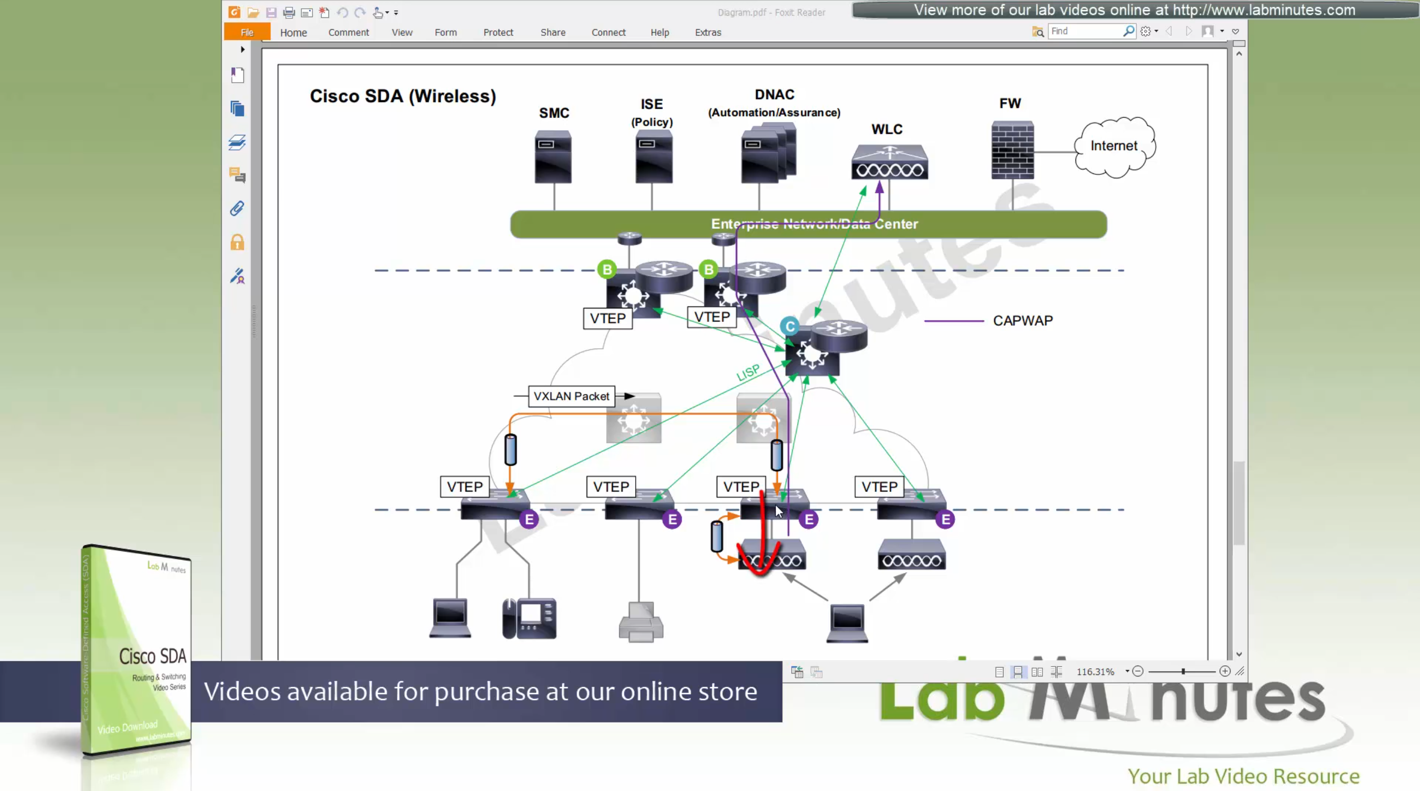
once edge node de-encapsulates the VXLAN tunnel, it checks and sees that mac address of the wireless client is behind that mini VXLAN tunnel, so it will re-encapsulate the traffic and send that to AP and vice versa in reverse
The reason for AP mini VXLAN is so that AP can inform the switch of the correct VNI the client belongs to
This is the mechanism that keeps consistency from the wired world for VNI
Making wireless clients seem like just like wired clients policy and monitoring wise
SGT are tagged on the VXLAN packets themselves
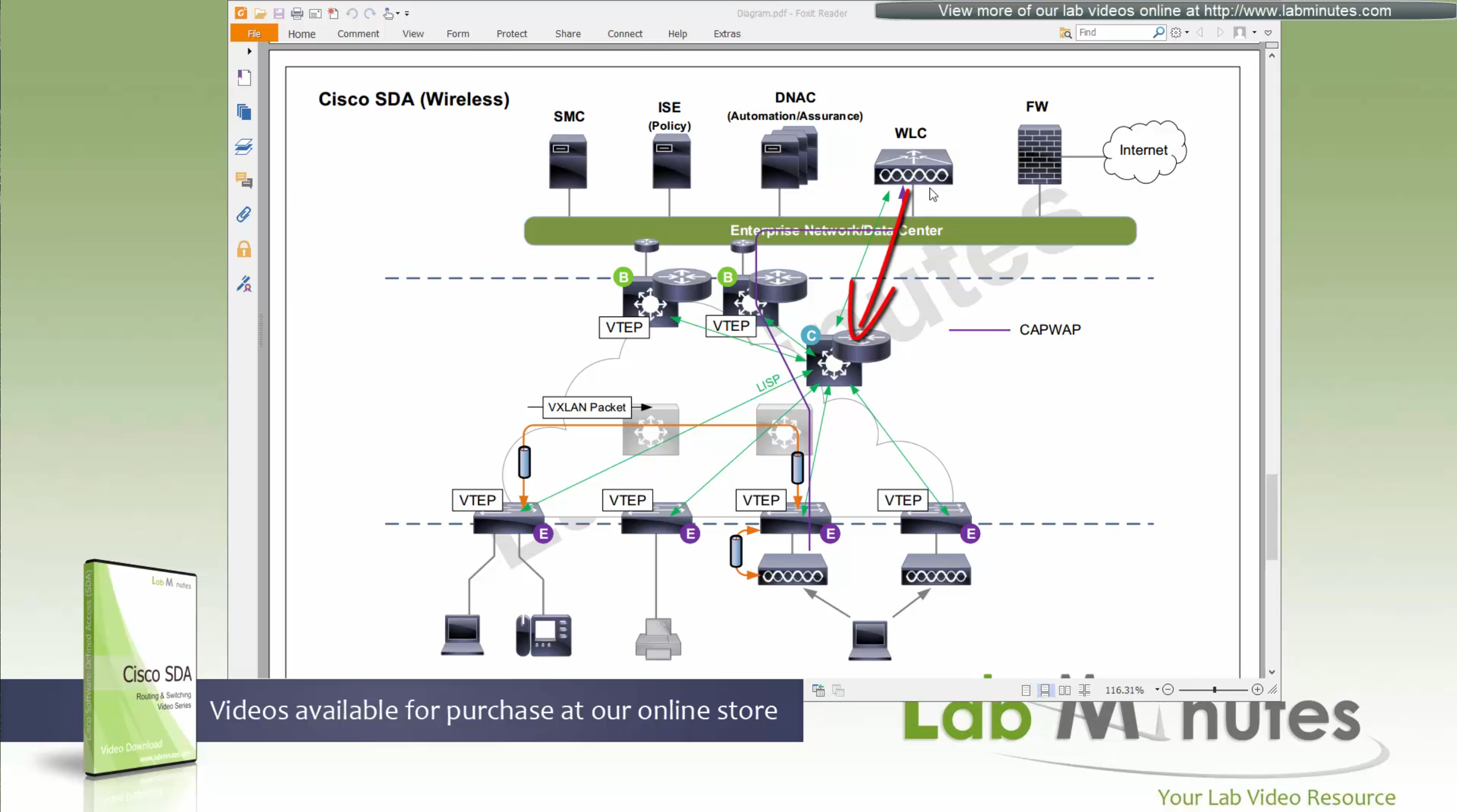
When user roams from one AP on one edge switch to another AP on another edge switch
WLC will be informed about the roam by the roamed to and from APs
WLC will inform the control plane also and control plane will update the entry’s RLOC to be the new edge switch whose new AP client has roamed to
While in Fabric, WLC and APs can still be connected to the Fabric but operate in “Legacy mode” which is also called “over the top” setup, in which data from AP is sent in CAPWAP (Data tunnel) to WLC and WLC switches the traffic out
There is also a low latency requirement of 20ms between the WLC and AP so keep in mind that APs have to stay somewhat close to the controller in the campus setup
Licensing
DNA Essential gives most of the feature set of the APIC-EM
DNA Advantage gives most of the features in Assurance and NDP + SDA
SDA is only available with DNA Advantage license
Cisco offers a license called One Advantage that offers DNA + ISE + Stealthwatch all in one license

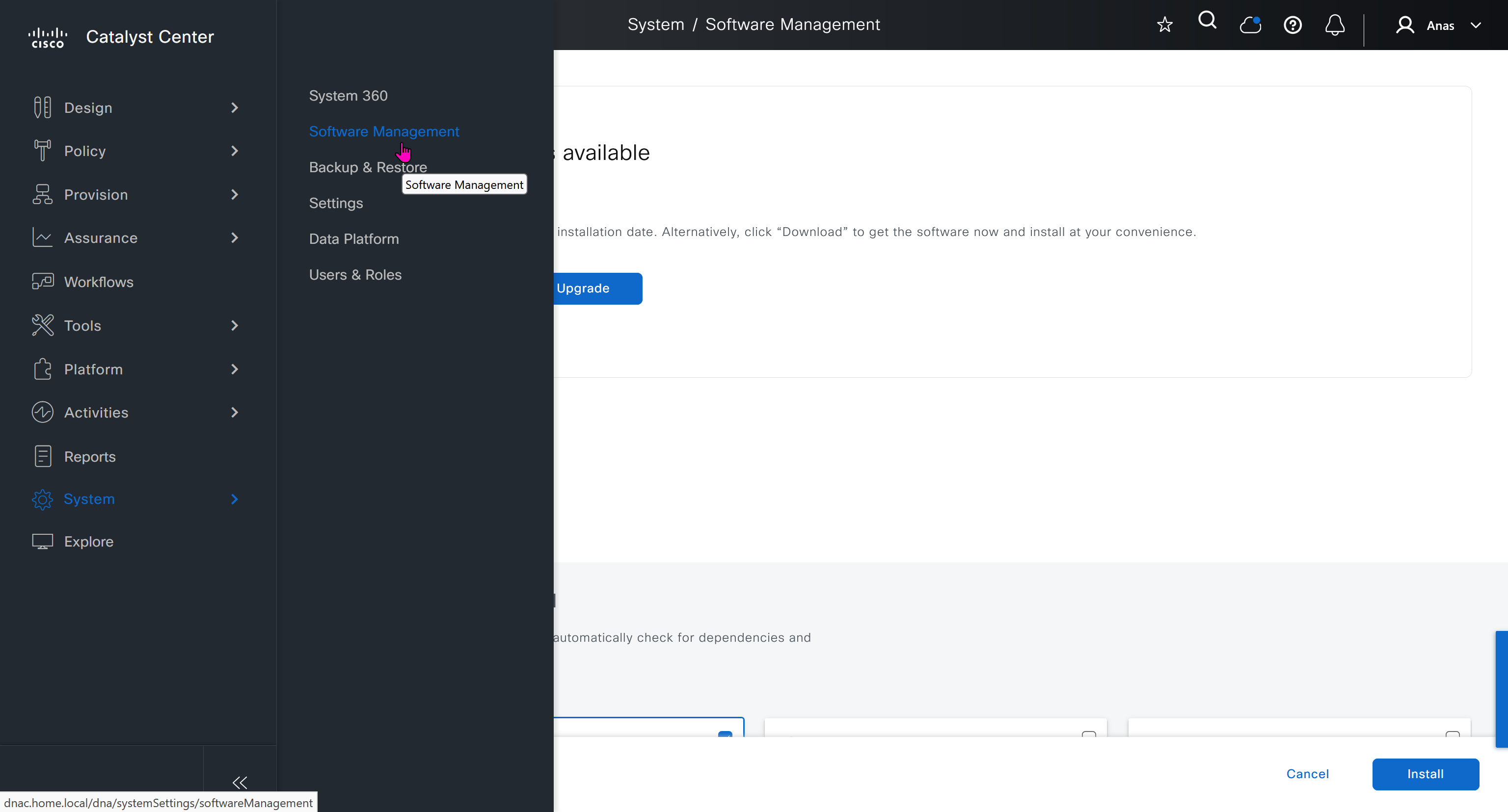
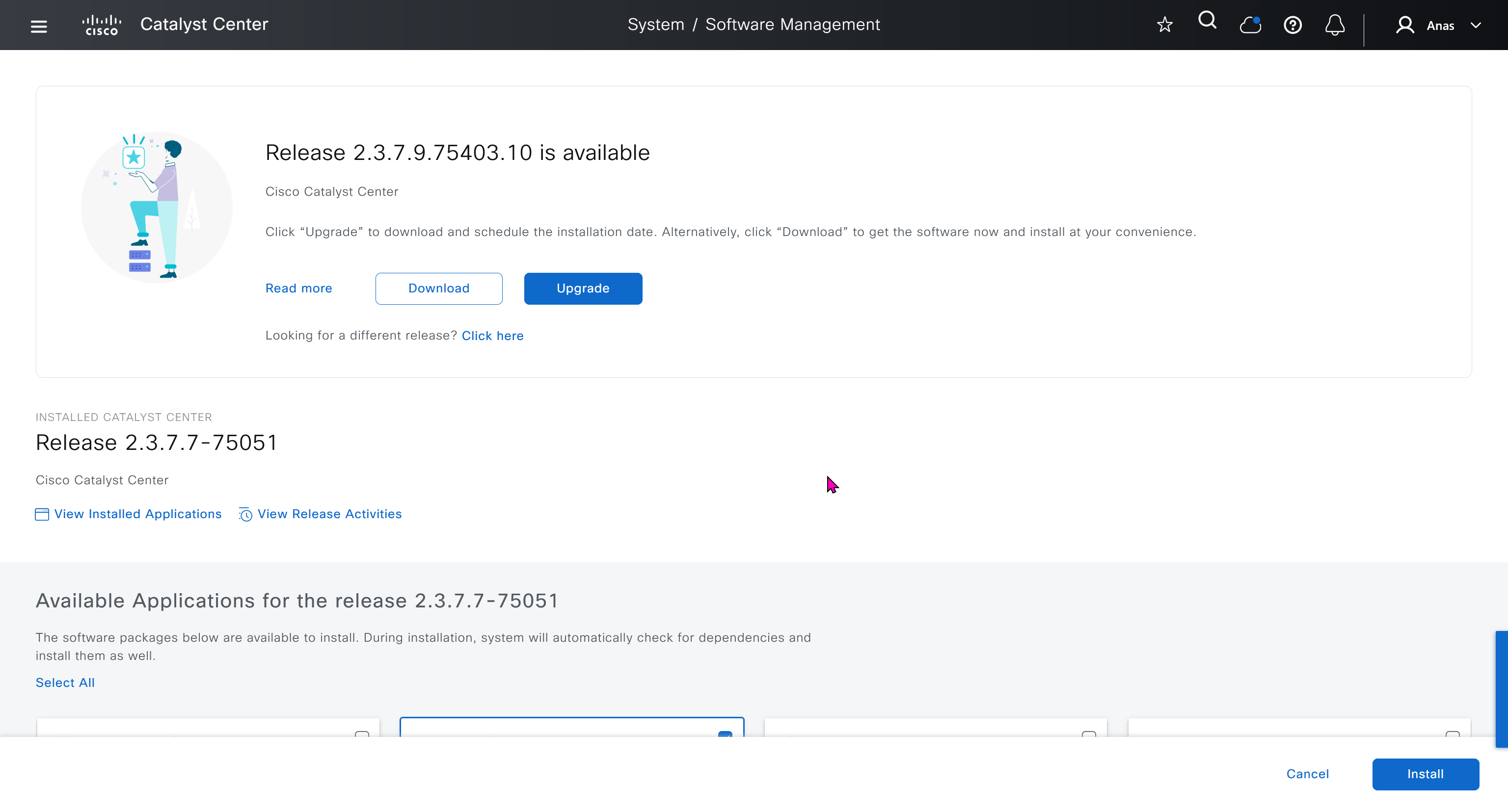
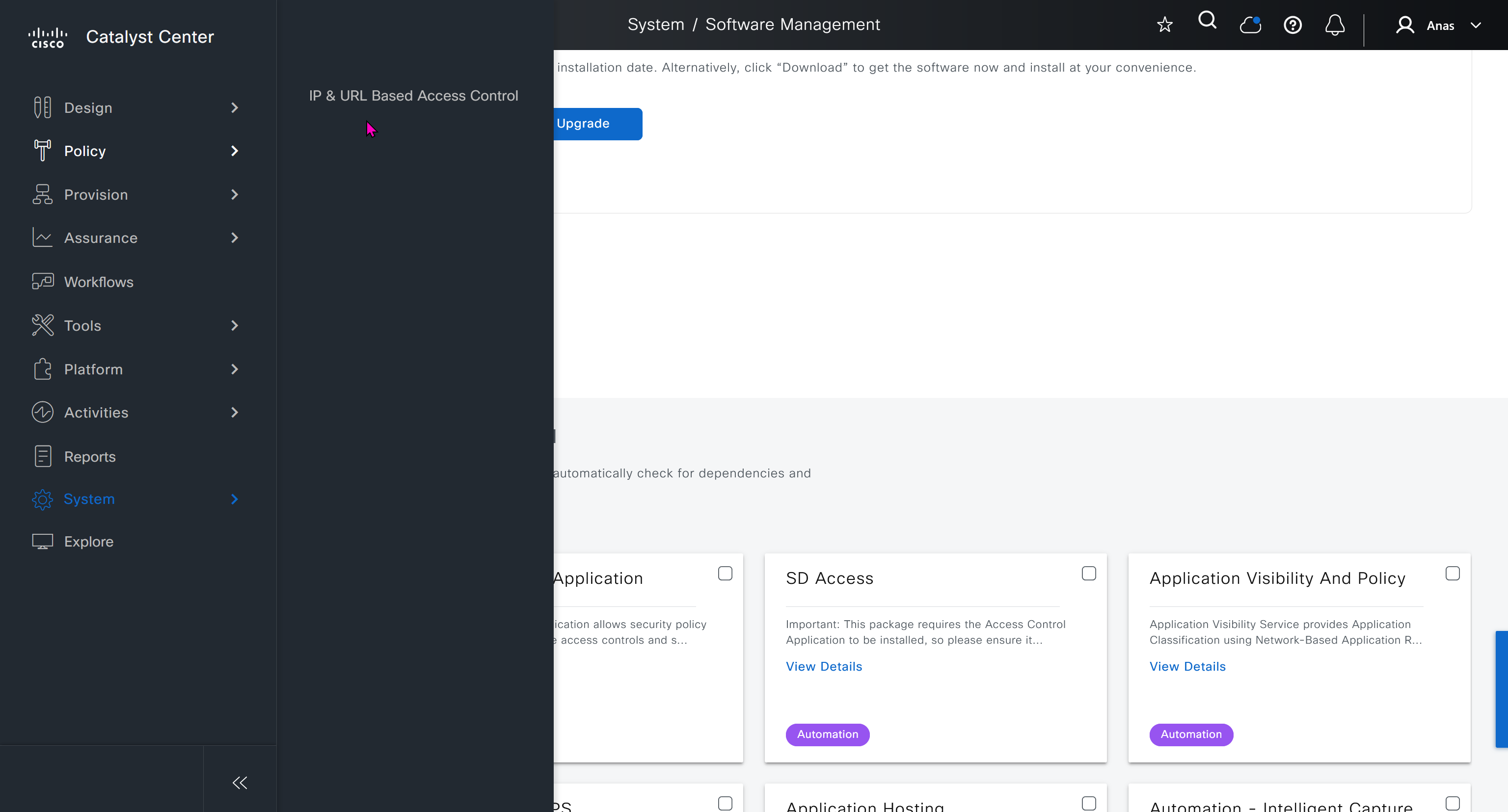
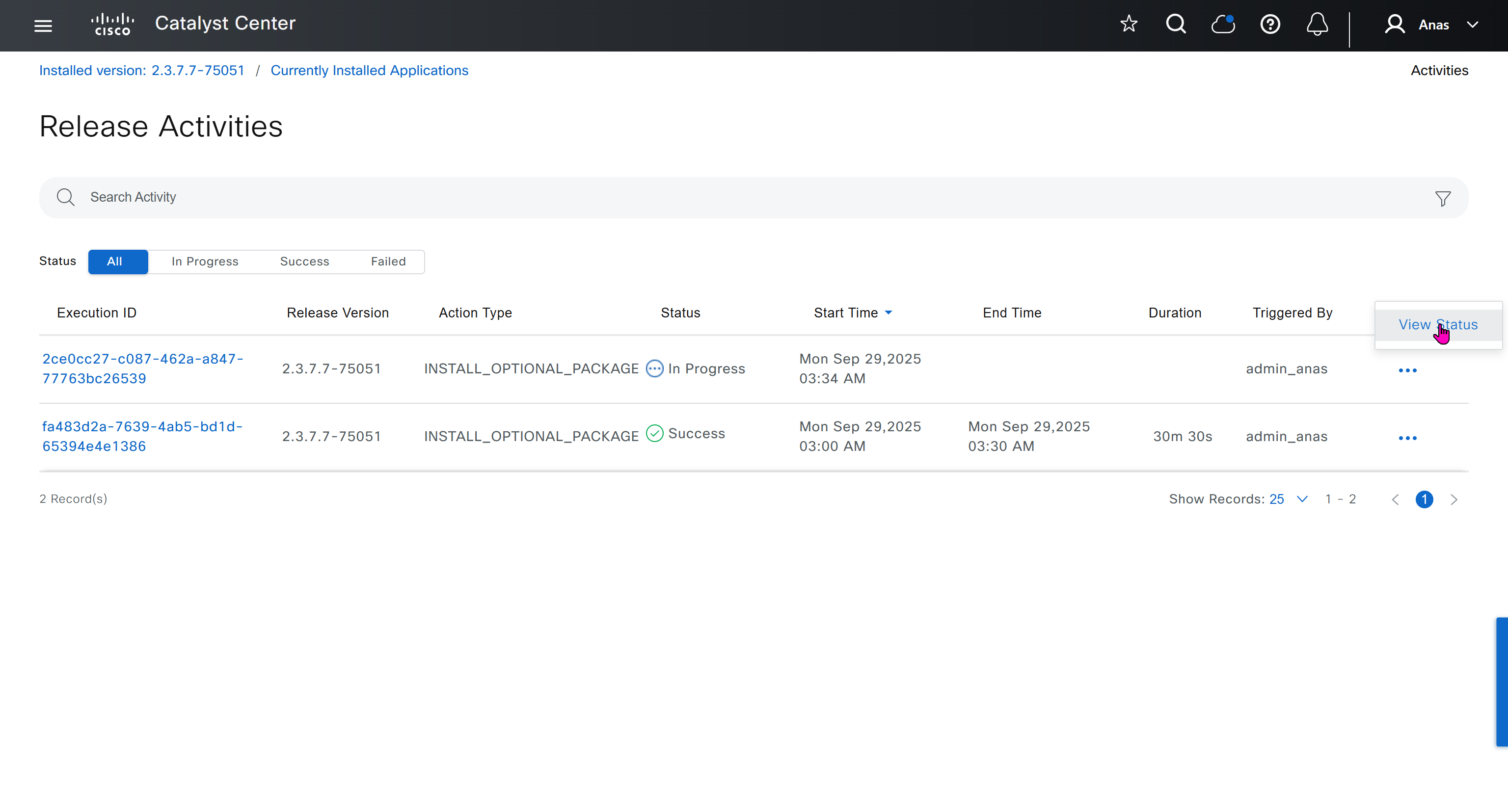
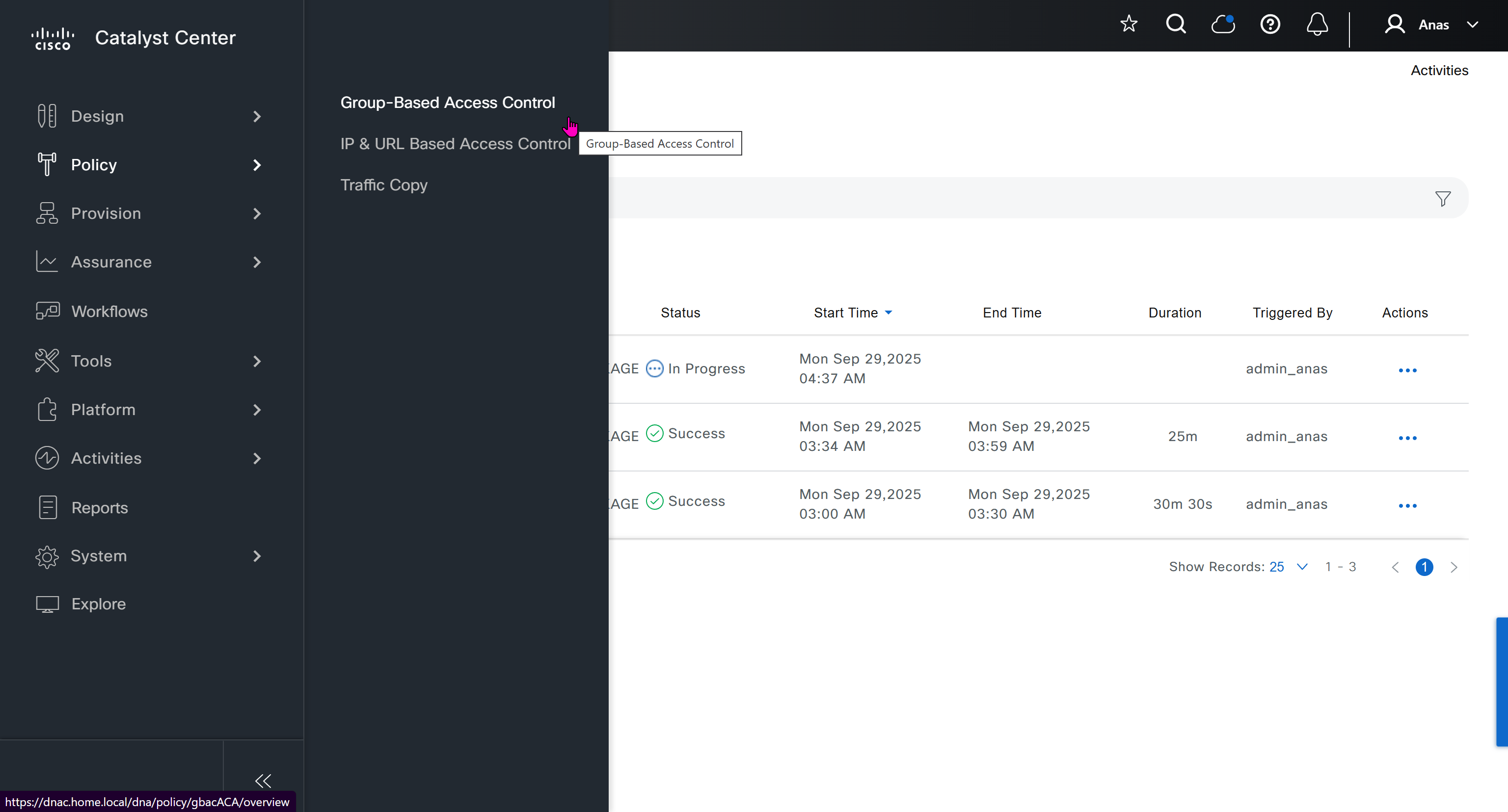
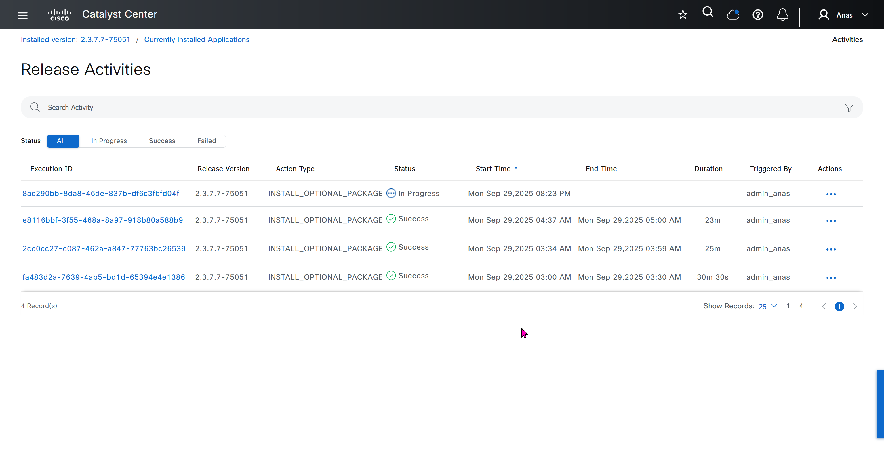
Right after installation of DNAC and first GUI login we need to quickly download the packages or software apps which are GBAC Group Based Acccess Control ( SGT / SXP / ISE ) and also SDA package to enable SDA in DNAC. Cisco does not readily ship the DNAC with ova or iso, SDA and a lot of other modules need to be downloaded using below very specific settings


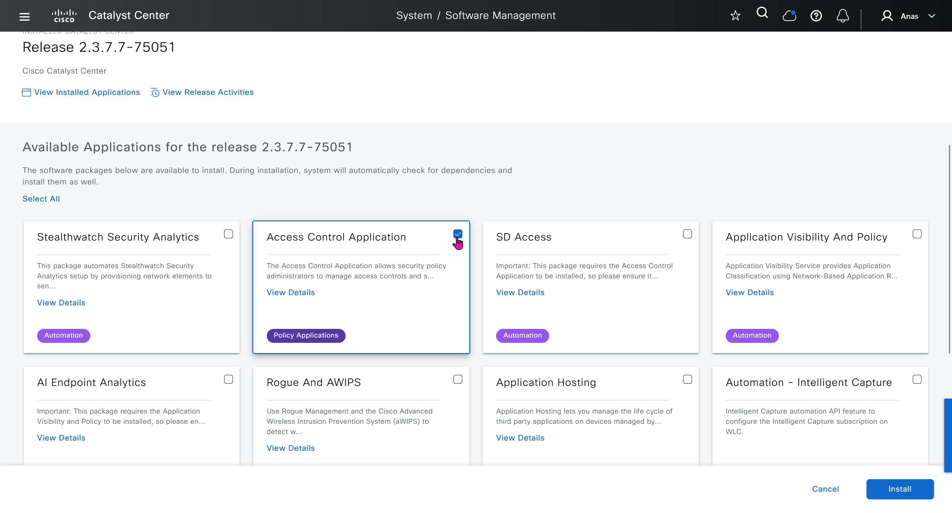
Group Based Access Control is not there and needs to be downloaded


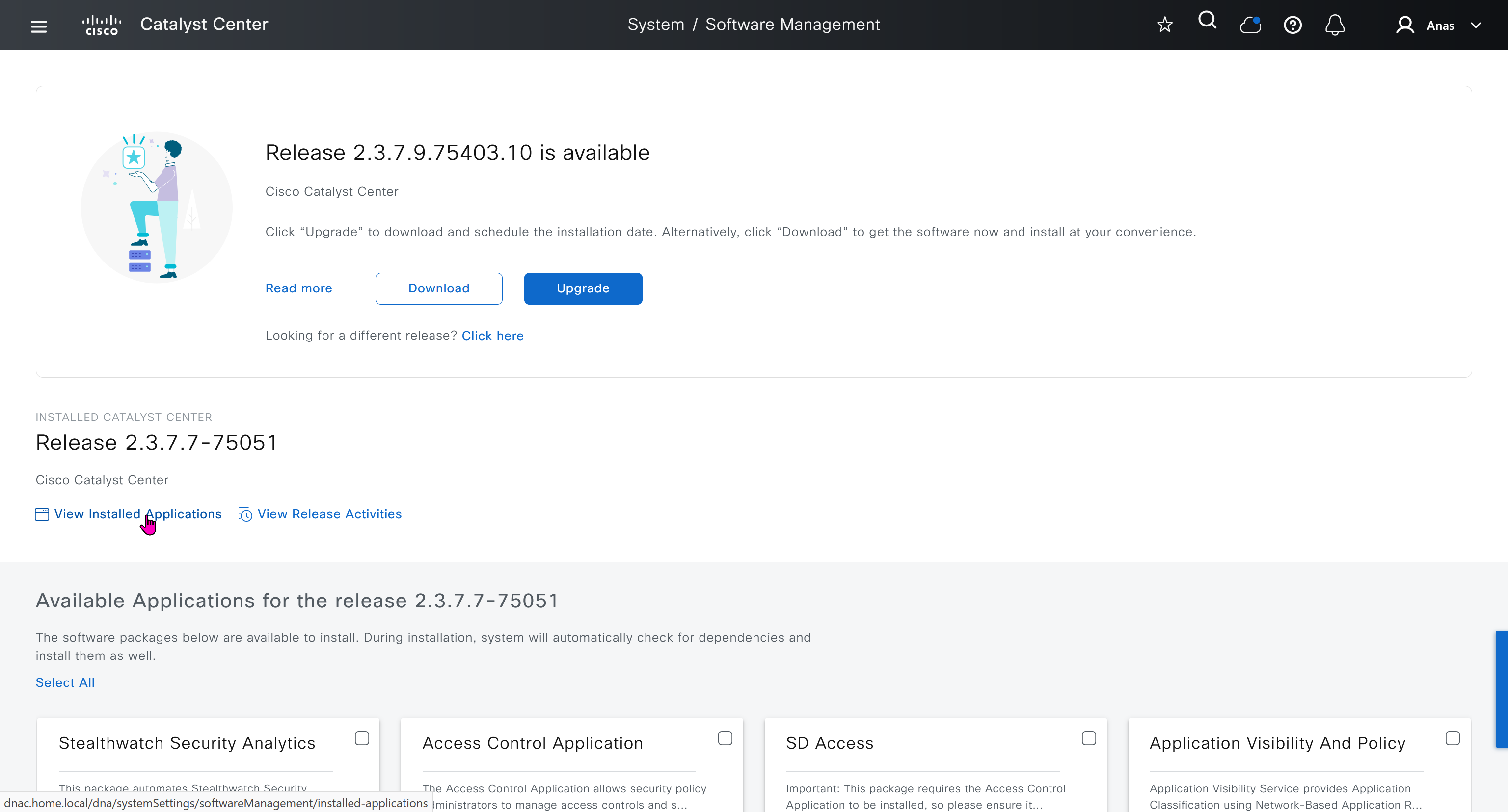

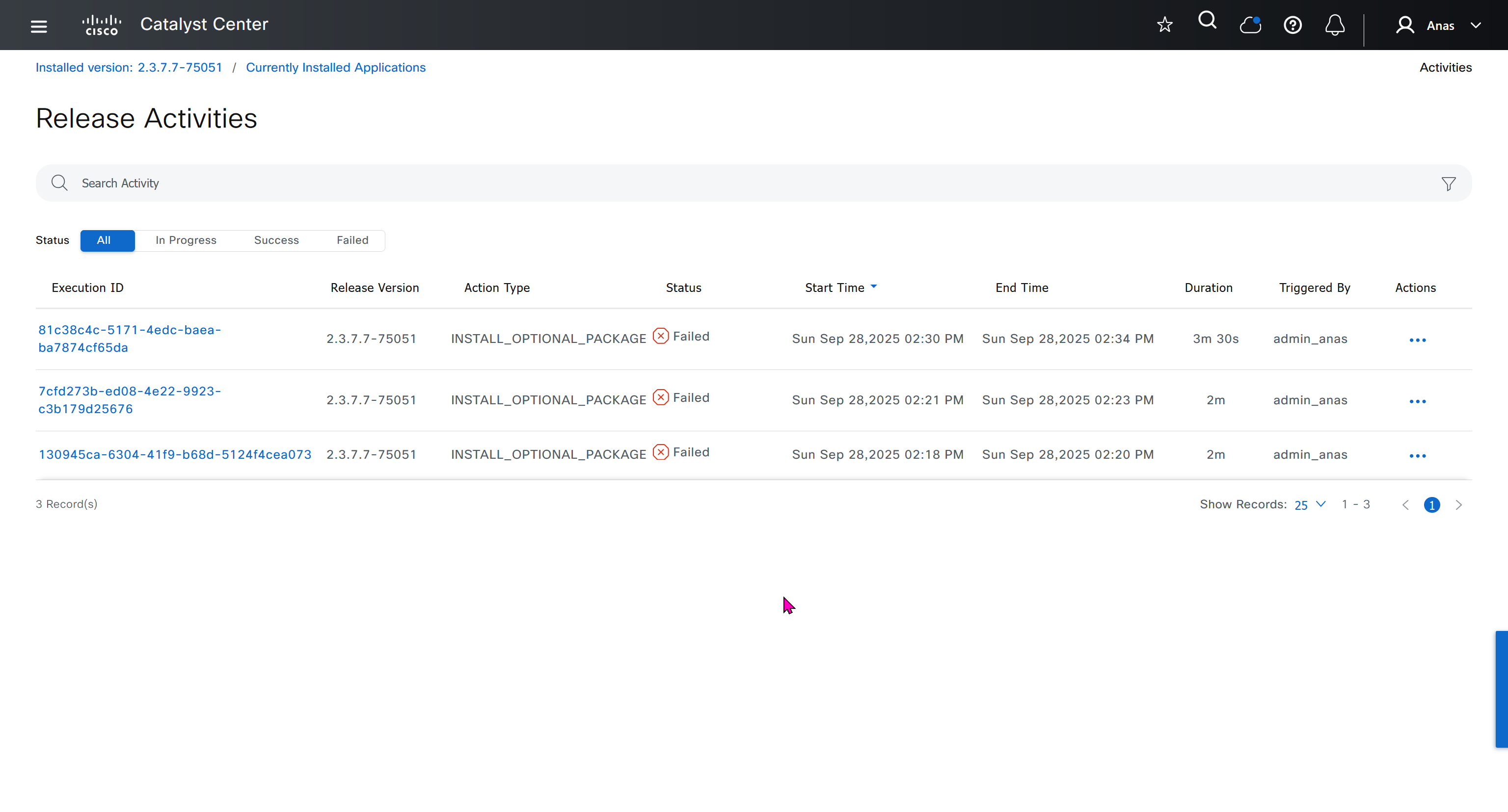
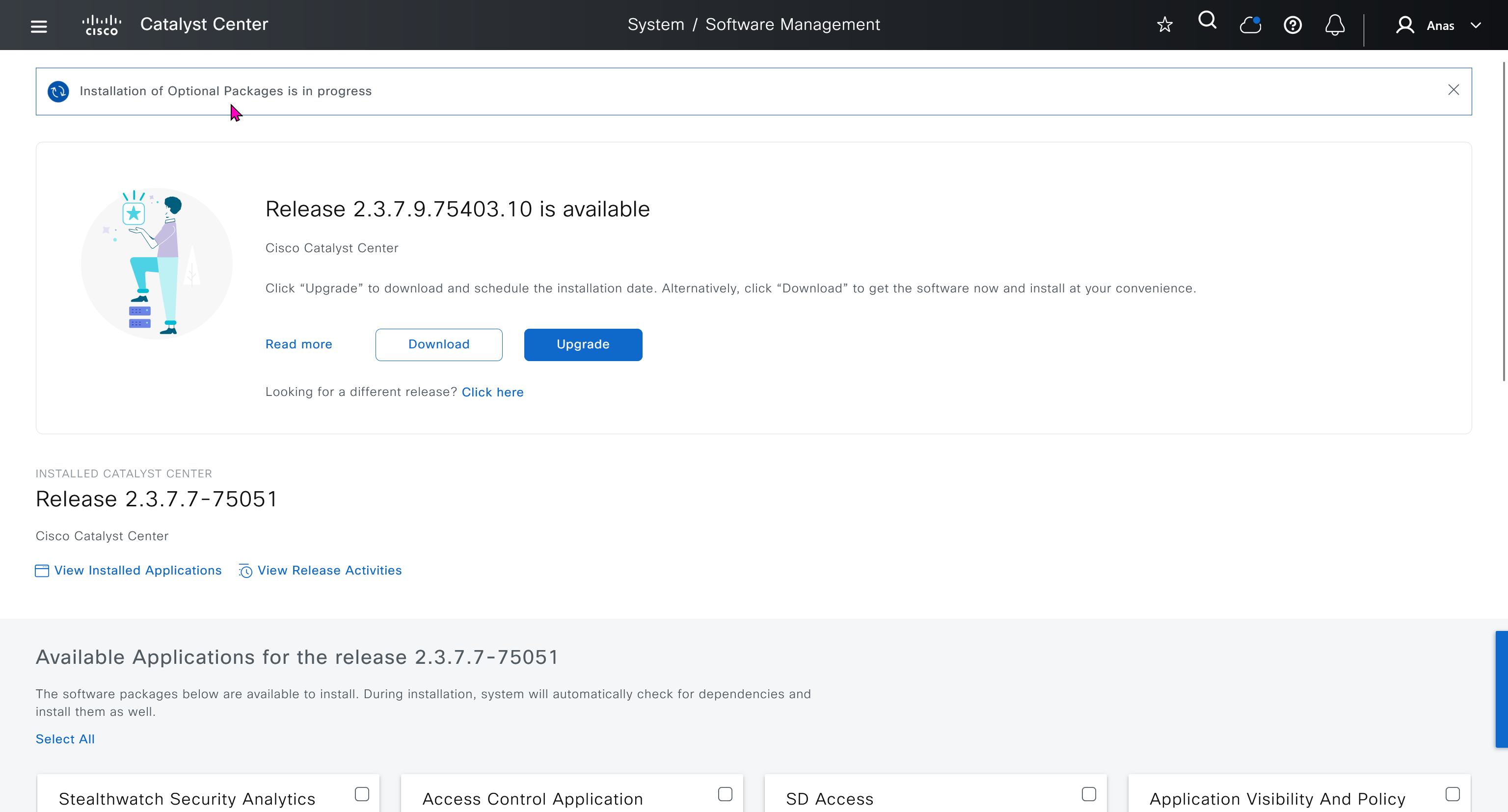
Installation kept failing at download stage

I had to remove the VM as there was something wrong and when new dnac was installed, one thing I did is I added the company’s cco information here but not in the smart licensing, dont add to the smart licensing section instead add at the beginning on first GUI login

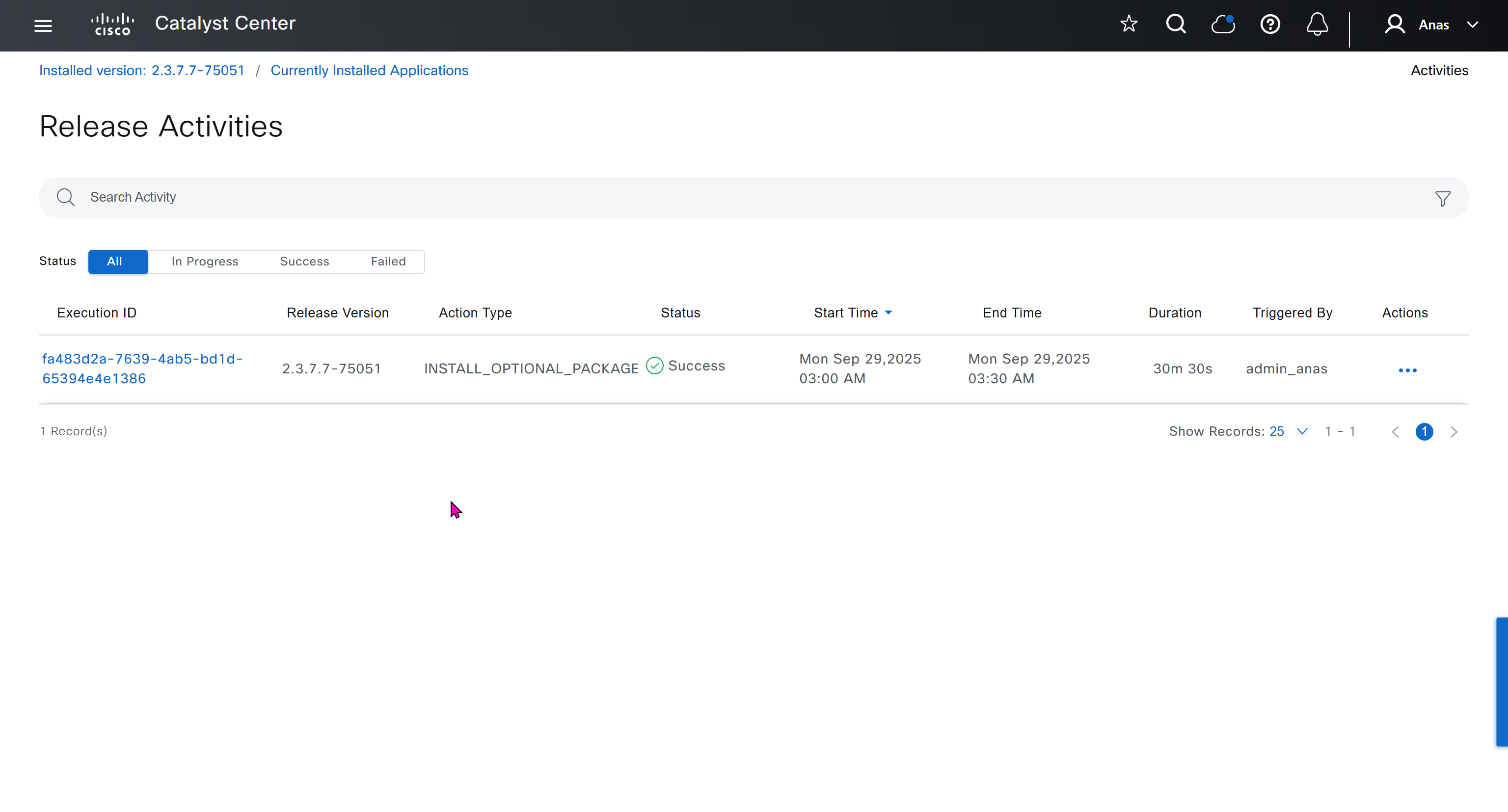

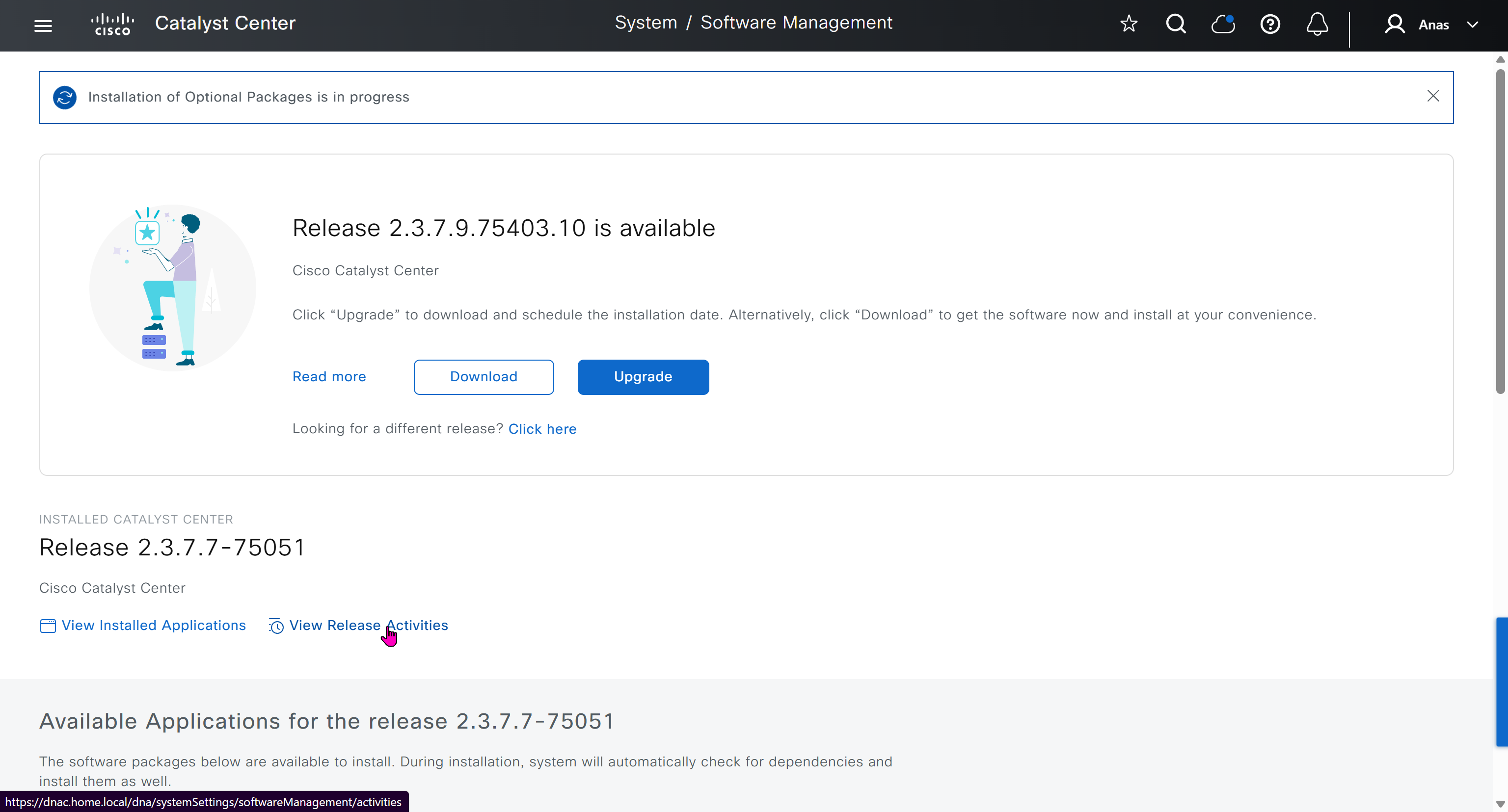

Finally it installed well
now Group Based Access Control GBAC is showing in menu now

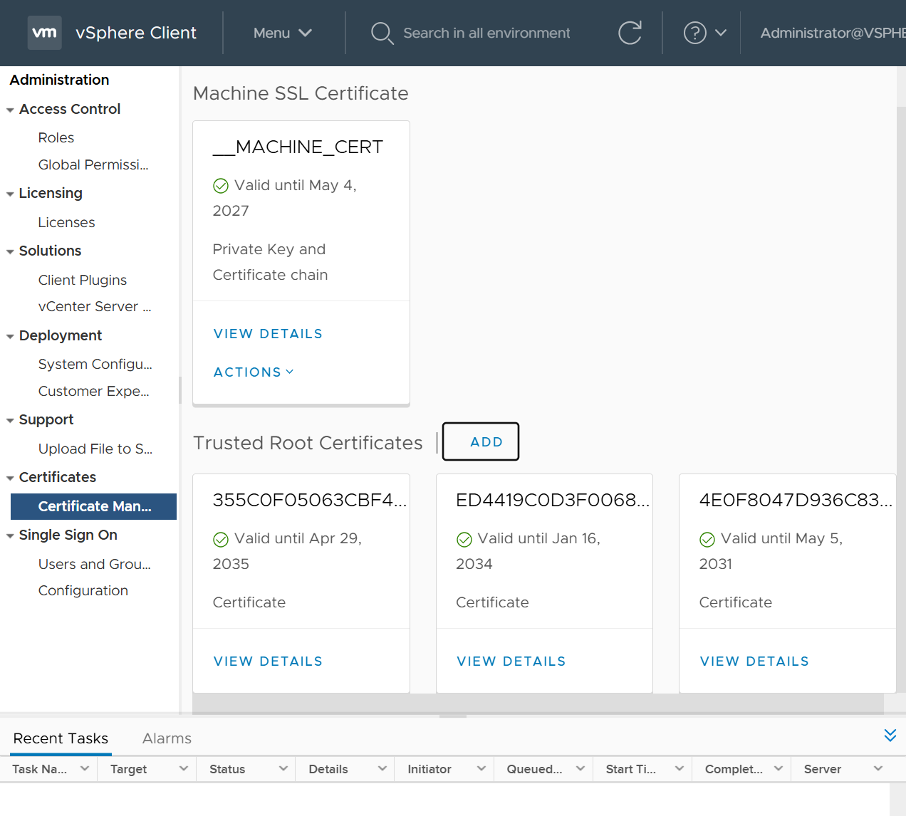
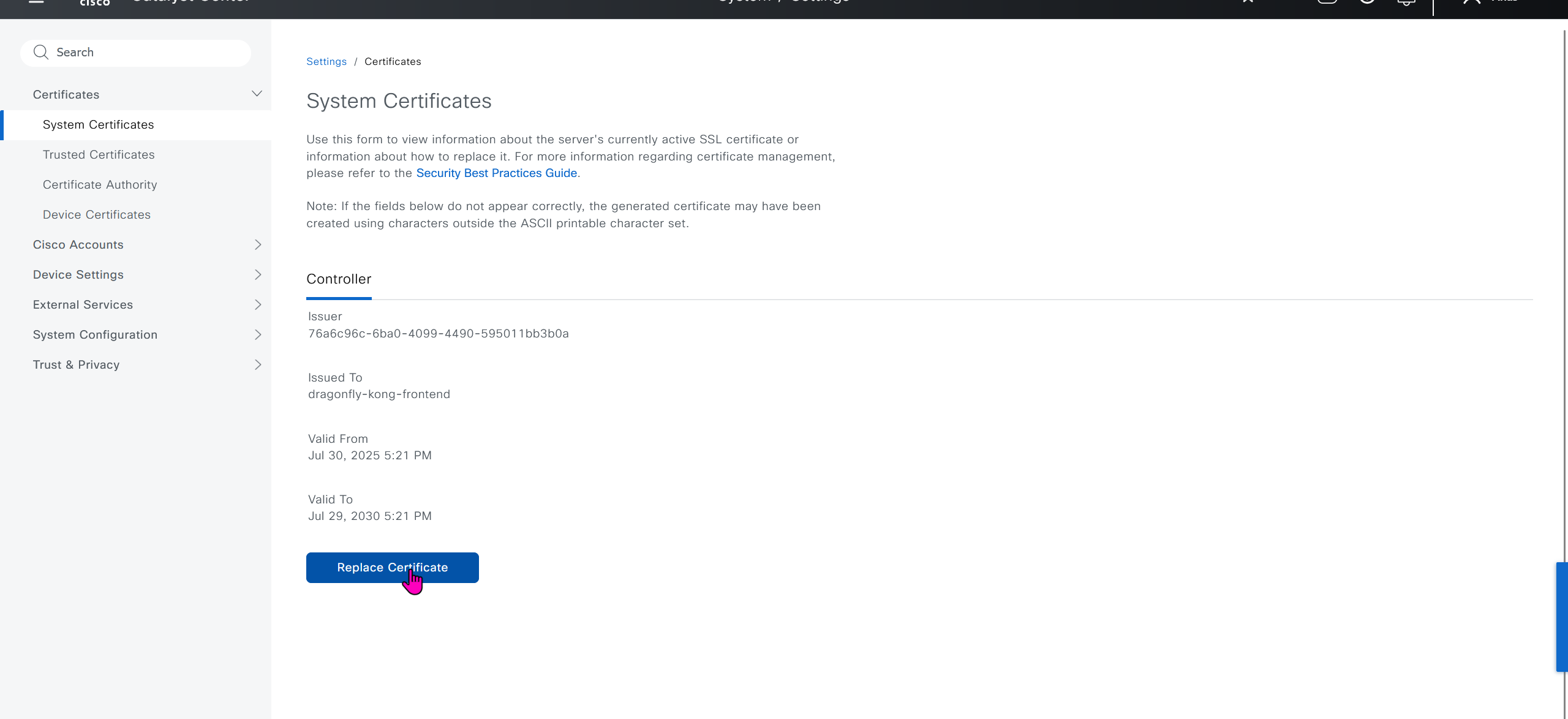
We will take a look at installing certificate as ISE needs to be integrated, and for that we need to take information from default certificate’s information, common name is the name that we provided during the initial installation of DNAC

If we look at subject alternative names we can see a lot of SAN entries, these SAN entries contain IP addresses as well and one of those IP addresses will be of the VIP in case we have multiple DNAC appliances

Enhanced Key Usage: Server Authentication, Client Authentication as this is used for ISE PX Grid integration

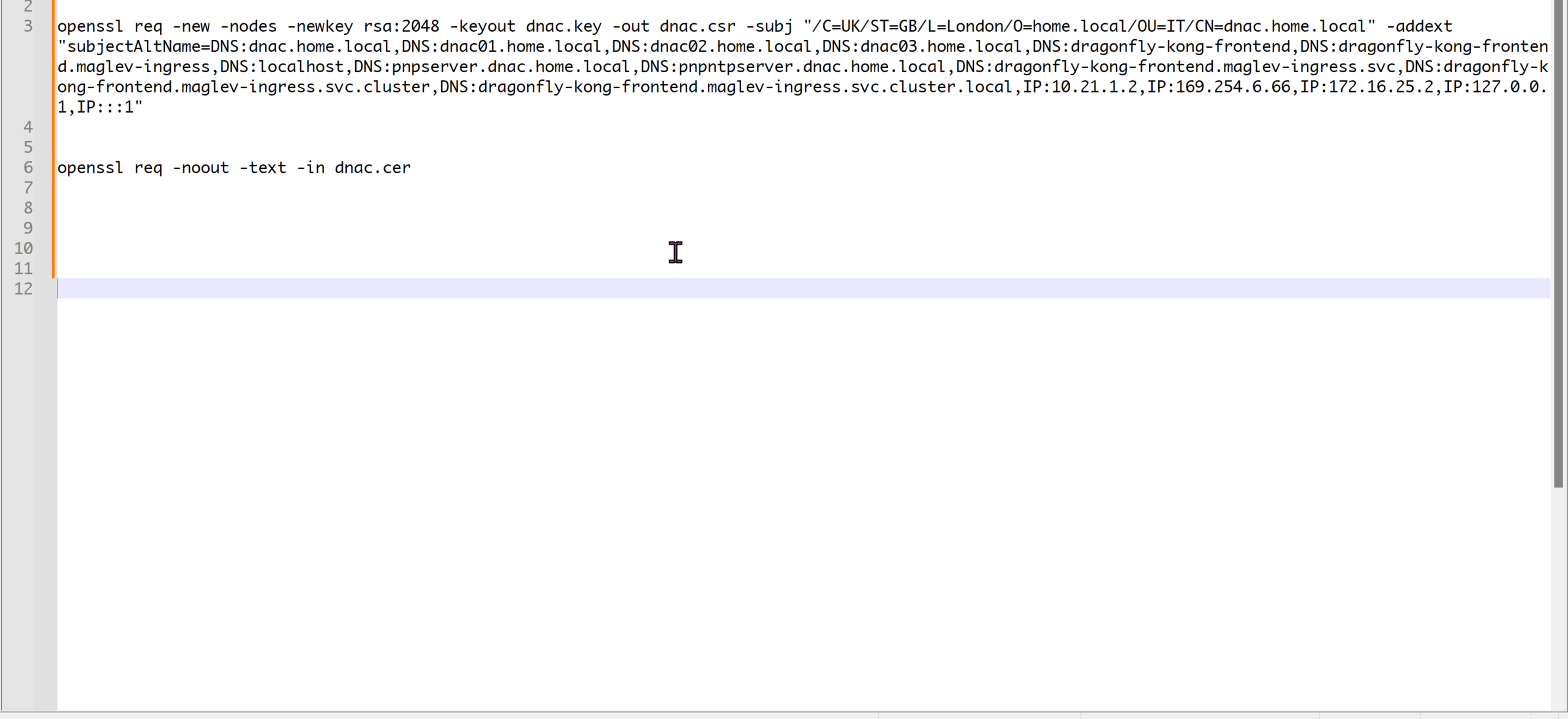
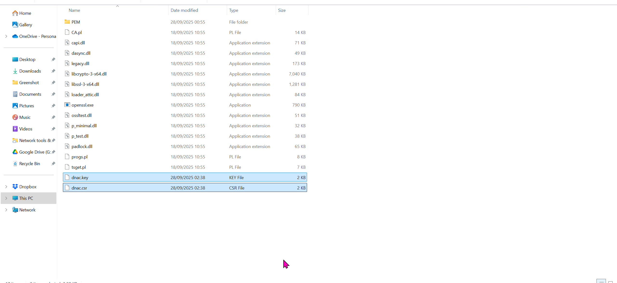
We will have to install the OpenSSL for Windows
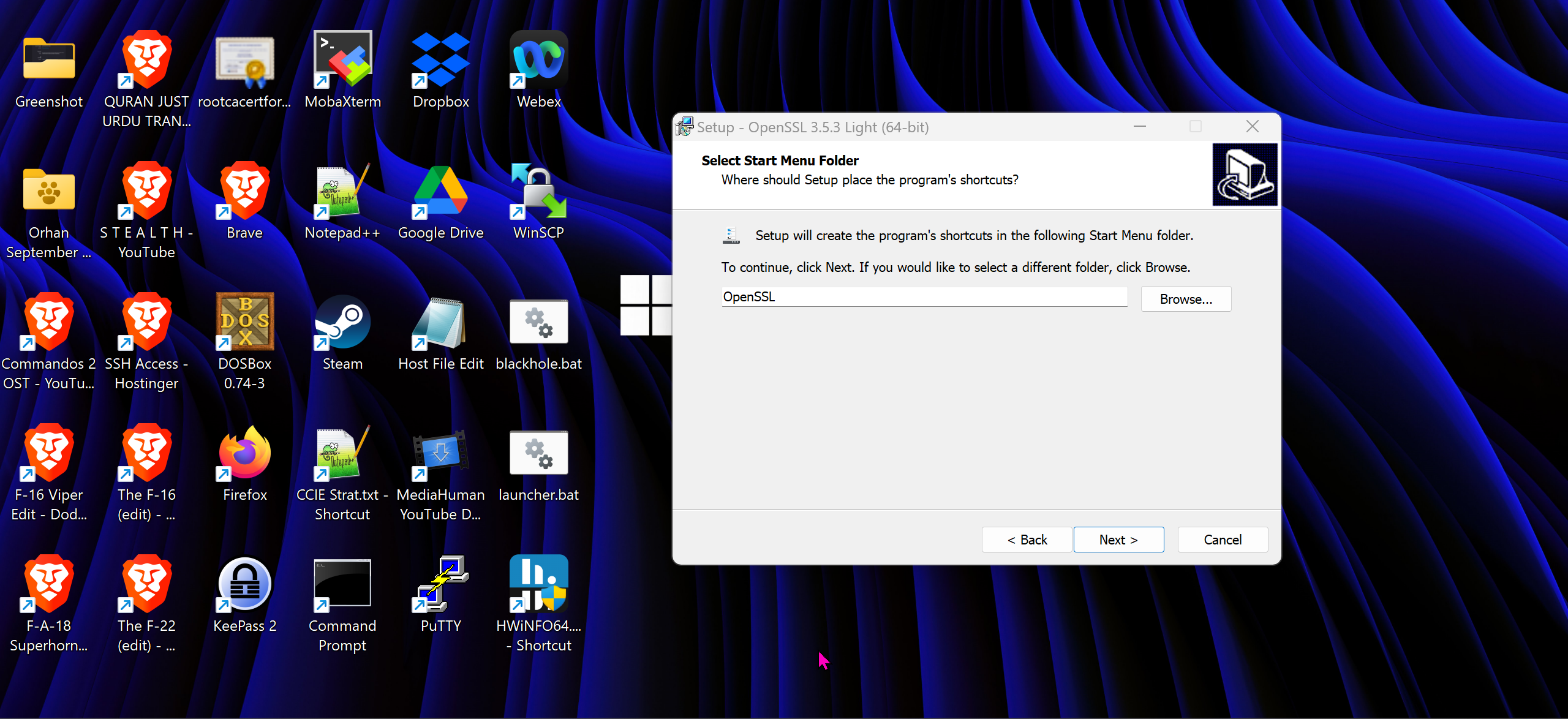
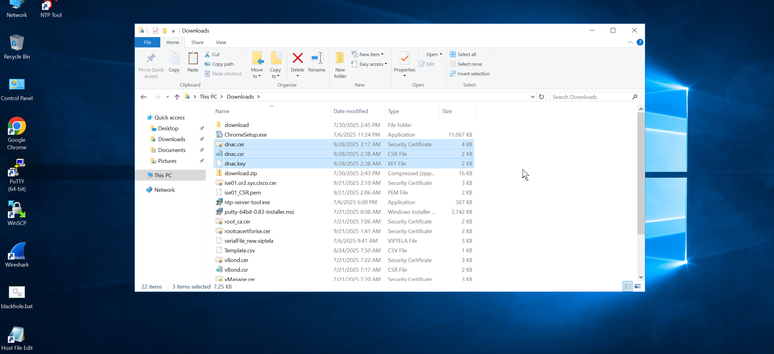
cd C:\Program Files\OpenSSL-Win64\binopenssl req -new -nodes -newkey rsa:2048 -keyout dnac.key -out dnac.csr -subj "/C=UK/ST=GB/L=London/O=home.local/OU=IT/CN=dnac.home.local" -addext "subjectAltName=DNS:dnac.home.local,DNS:dnac01.home.local,DNS:dnac02.home.local,DNS:dnac03.home.local,DNS:dragonfly-kong-frontend,DNS:dragonfly-kong-frontend.maglev-ingress,DNS:localhost,DNS:pnpserver.dnac.home.local,DNS:pnpntpserver.dnac.home.local,DNS:dragonfly-kong-frontend.maglev-ingress.svc,DNS:dragonfly-kong-frontend.maglev-ingress.svc.cluster,DNS:dragonfly-kong-frontend.maglev-ingress.svc.cluster.local,IP:10.21.1.2,IP:169.254.6.66,IP:172.16.25.2,IP:127.0.0.1,IP:::1"openssl req -noout -text -in dnac.cercd C:\Program Files\OpenSSL-Win64\bin
openssl req -new -nodes -newkey rsa:2048 -keyout dnac.key -out dnac.csr -subj "/C=UK/ST=GB/L=London/O=Cisco-DNA/OU=IT/CN=dragonfly-kong-frontend" -addext "subjectAltName=DNS:dnac.home.local, DNS:dragonfly-kong-frontend, DNS:dragonfly-kong-frontend.maglev-ingress, DNS:localhost, DNS:dragonfly-kong-frontend.maglev-ingress.svc, DNS:dragonfly-kong-frontend.maglev-ingress.svc.cluster, DNS:dragonfly-kong-frontend.maglev-ingress.svc.cluster.local, IP:10.21.1.2, IP:127.0.0.1, IP:::1"
openssl req -noout -text -in dnac.cerWe have added those lines
Make sure that Data and OOB IP addresses are added including all Data and OOB IP addresses from clusters too


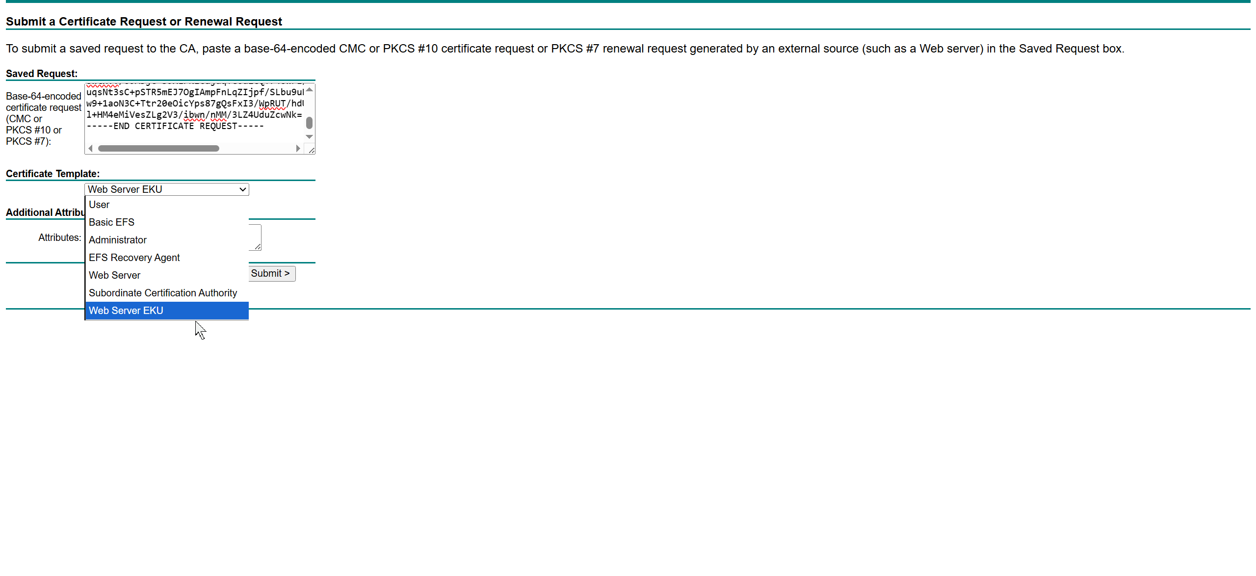
This Web Server EKU as Extended Key Usage has Client Authentication
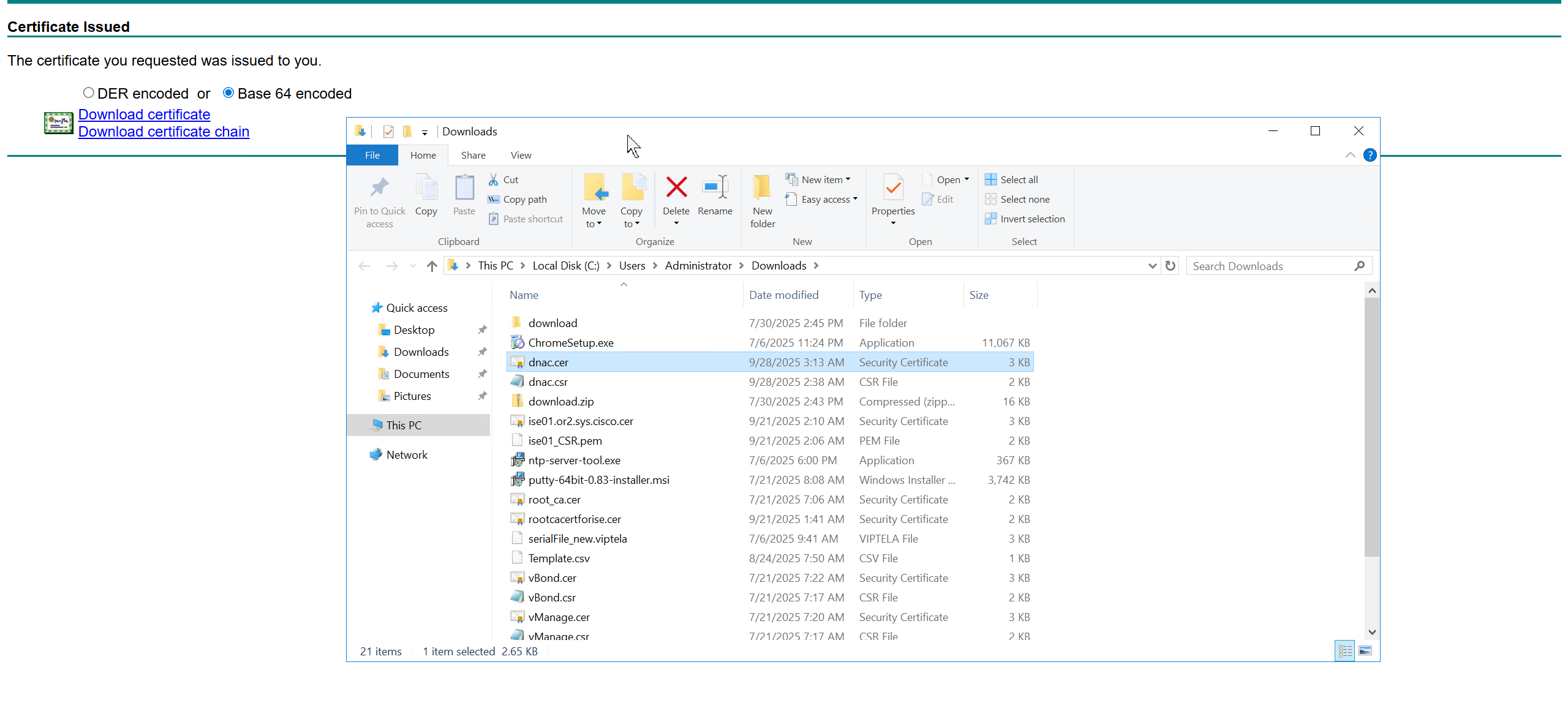
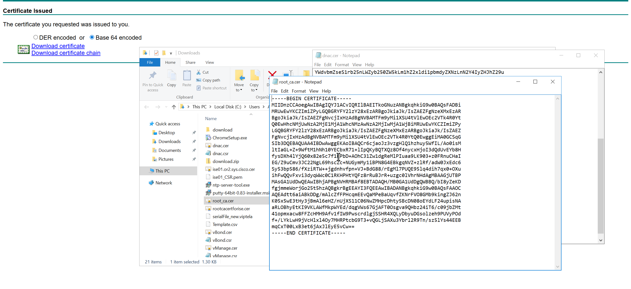

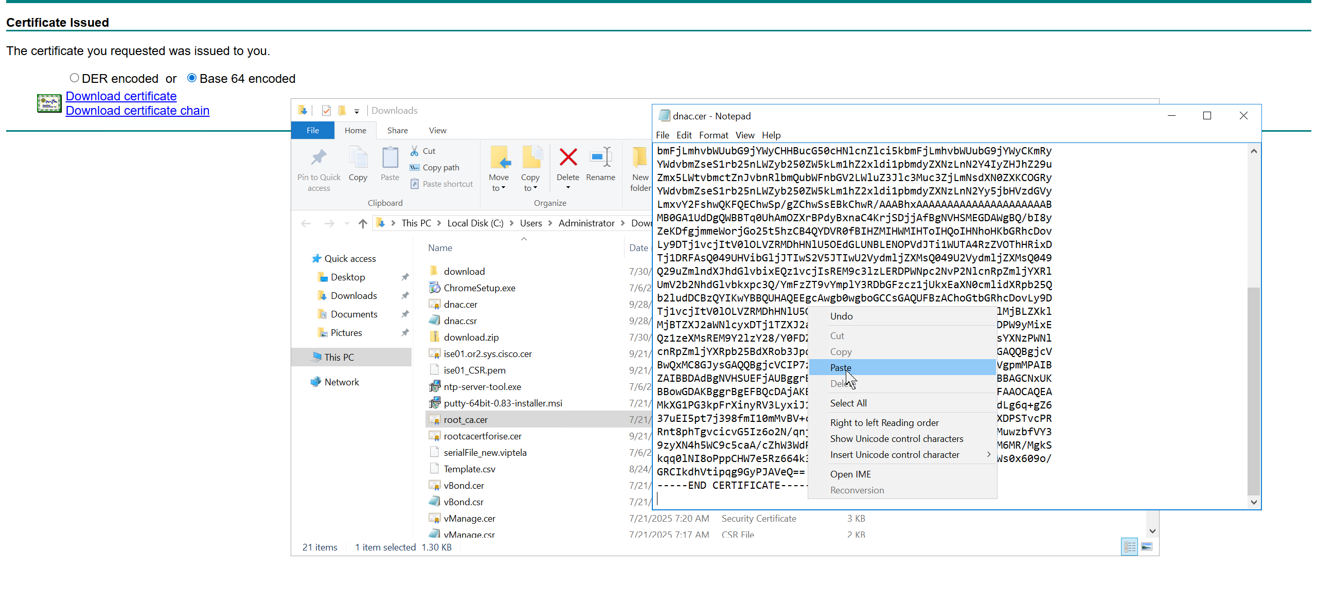
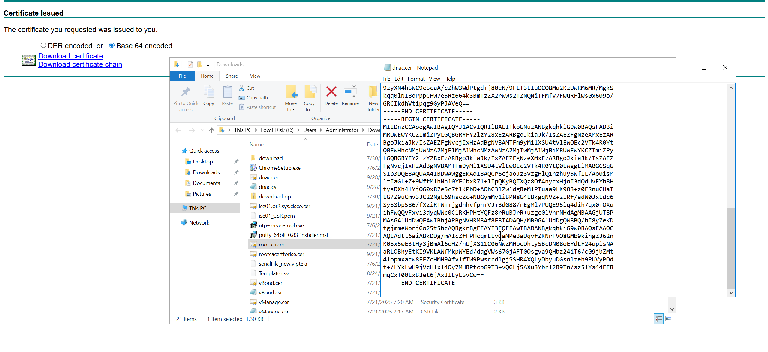
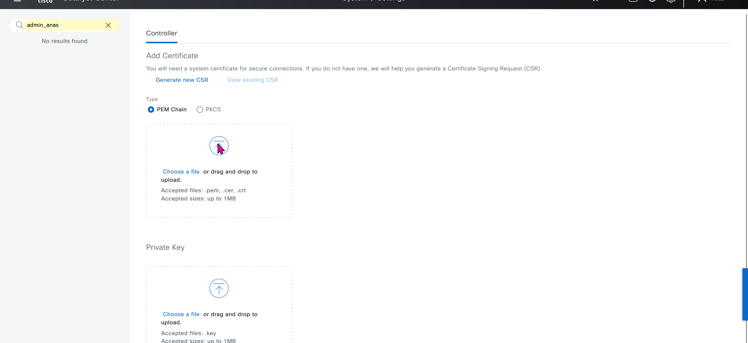
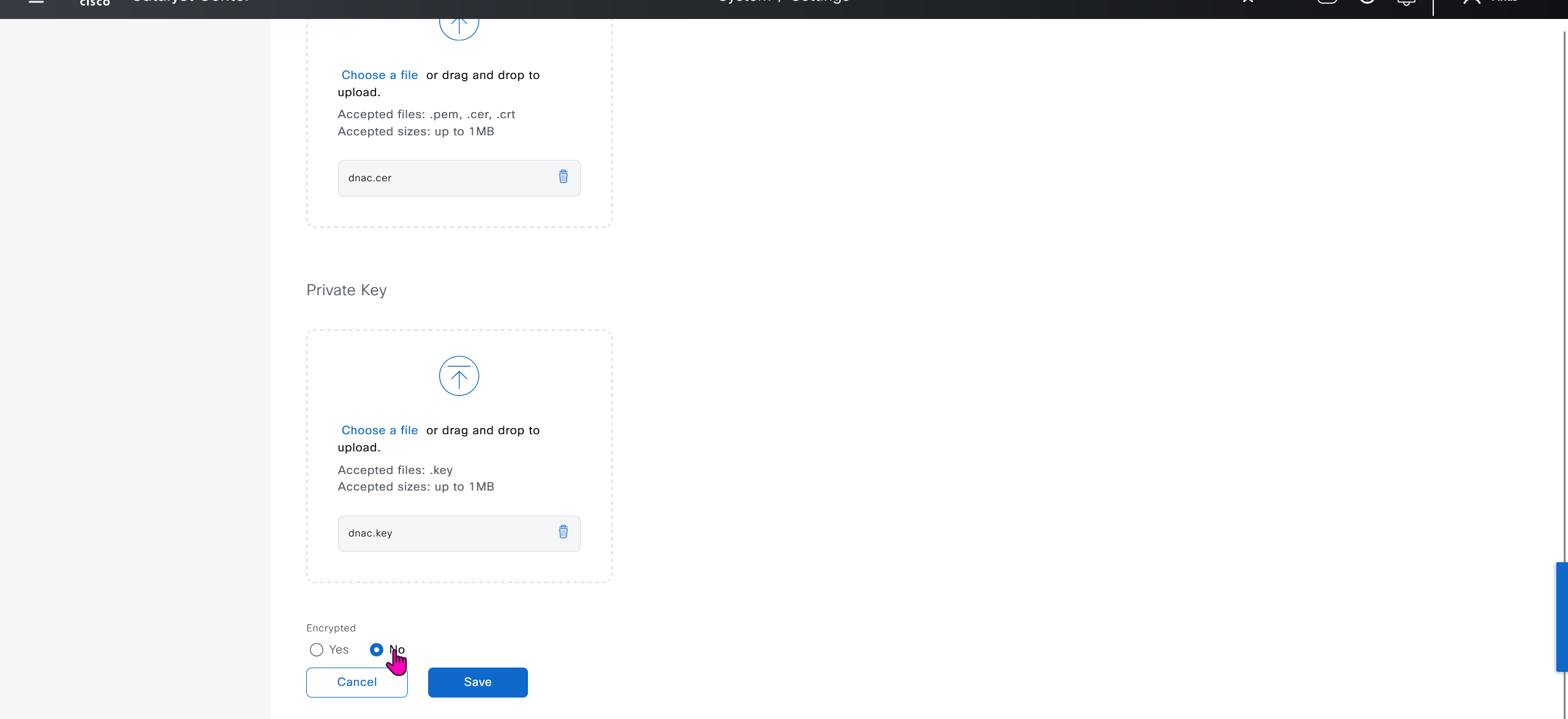
We will append the root ca certificate (because identity cert comes first) in this notepad file and combine it for DNAC, in case you have any intermediate CA certificates then add them as well in the middle of identity and root ca certificate


DNAC also issues certificates to devices which get added to it, and by default DNAC acts as the internal root ca but we can add our enterprise root ca or windows root ca too and this decision should be made right at the beginning before adding devices in DNAC or SDA fabric but once enterprise root ca is added we cannot convert this setting back to internal CA, usually we leave DNAC as the root ca for those devices

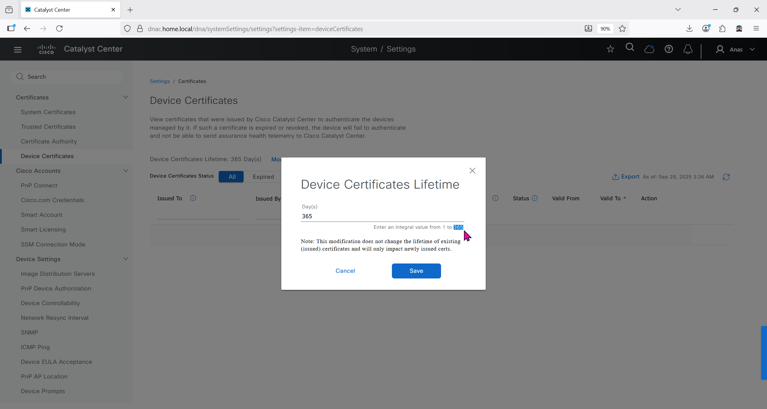
We can control the period for certificate’s validity
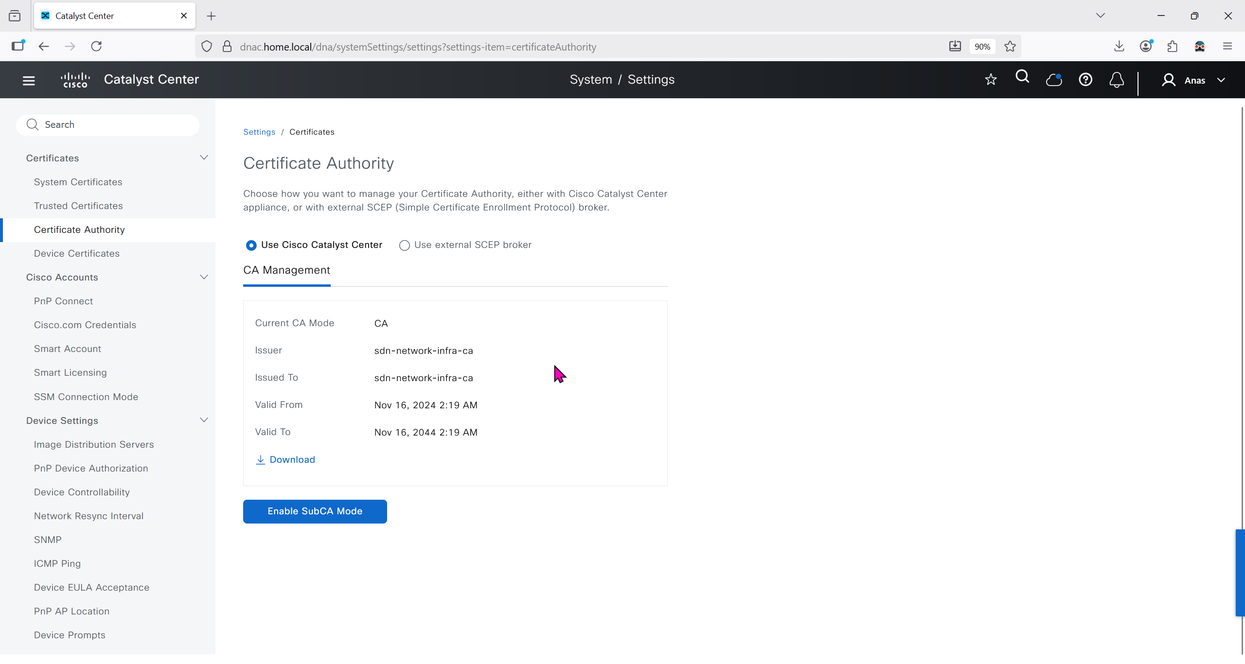
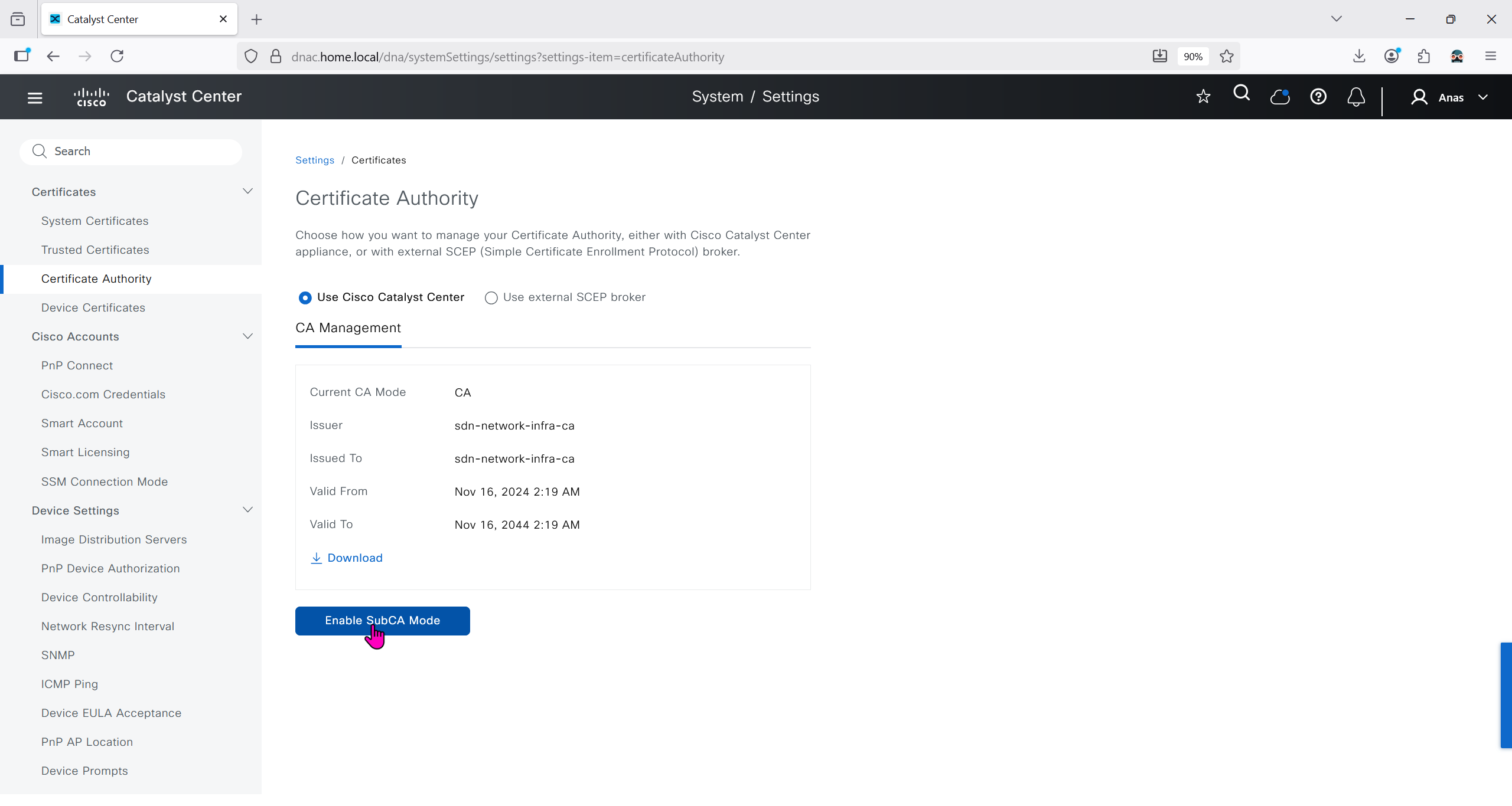
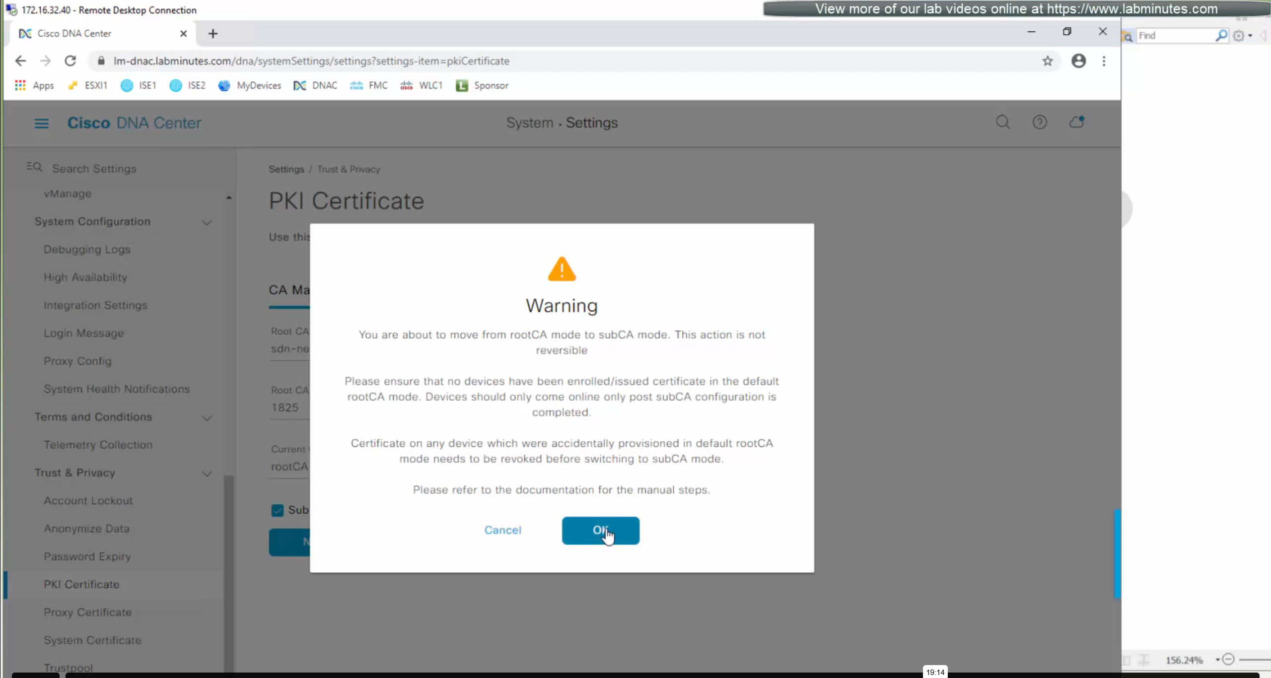
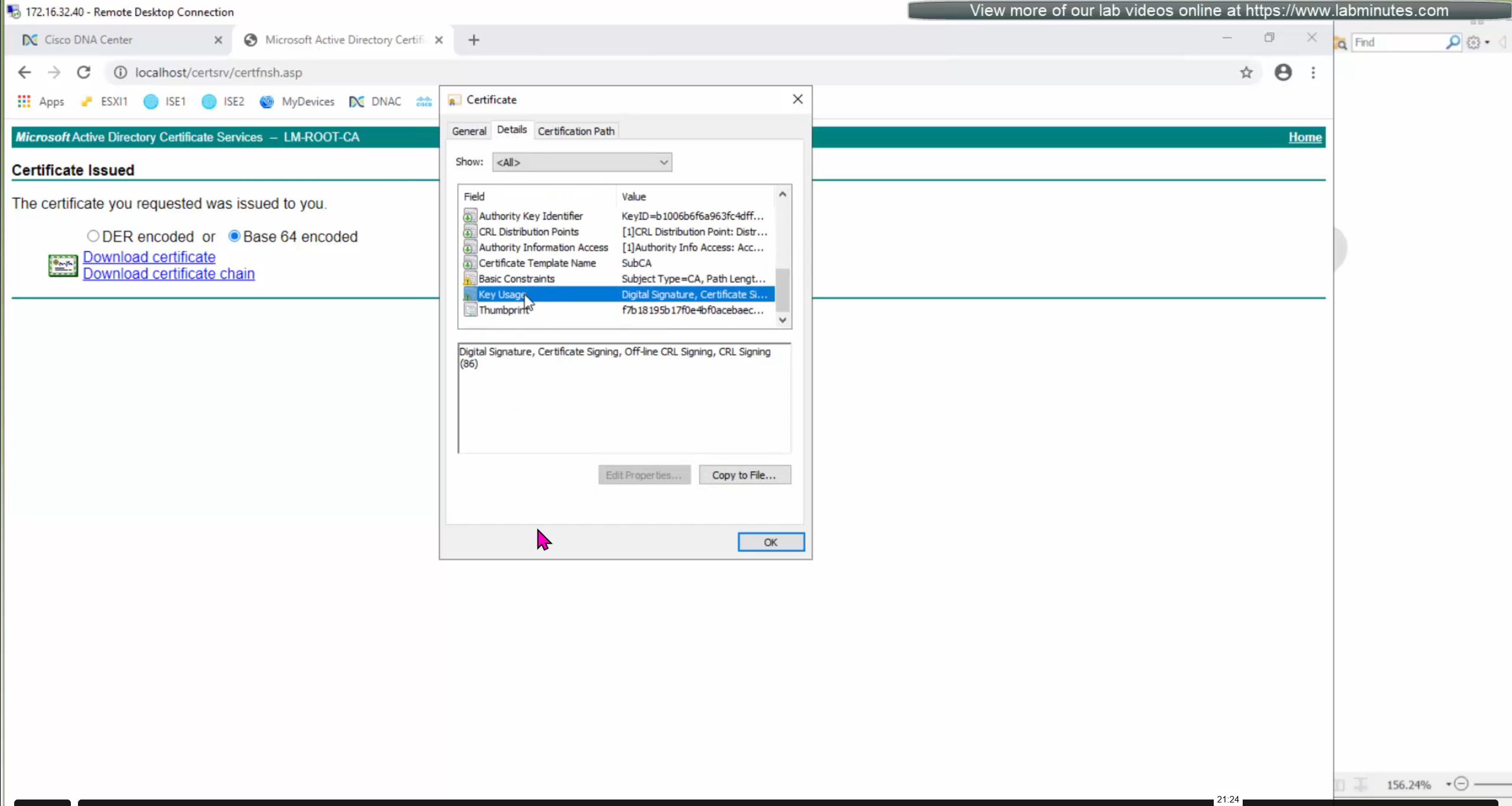
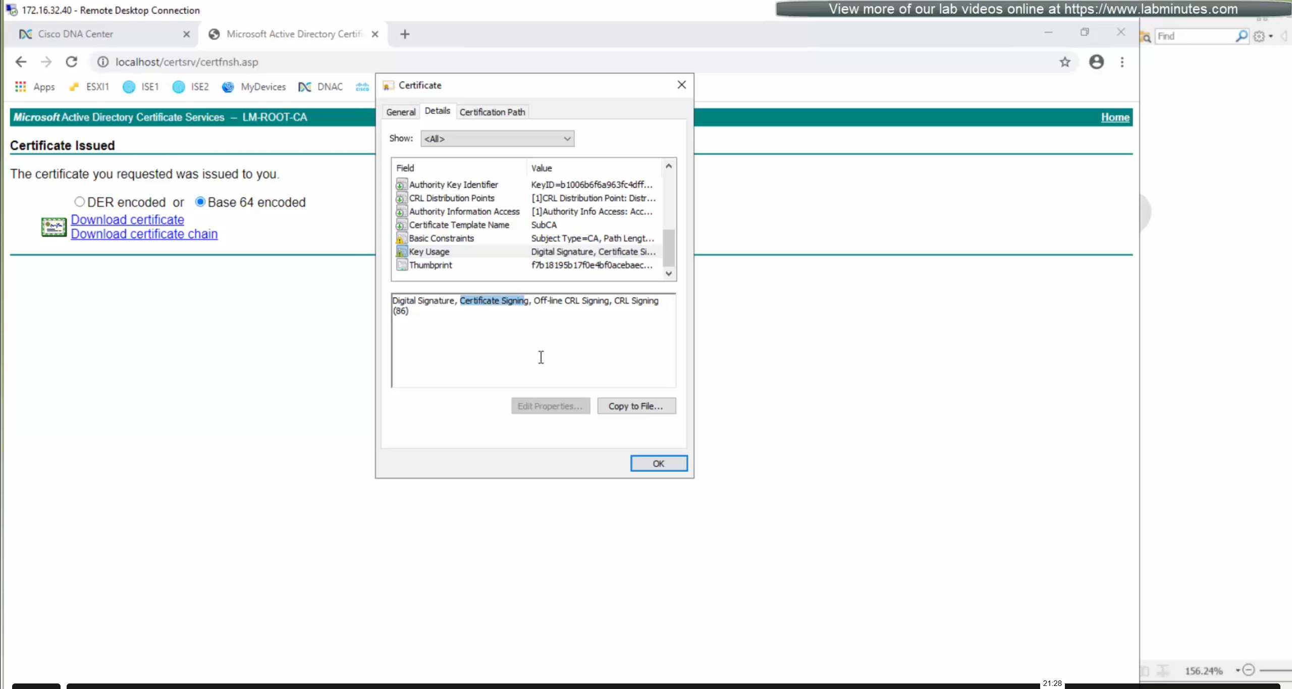
We will just click on option to enable SubCA mode but will not enable it just to see the message from DNAC
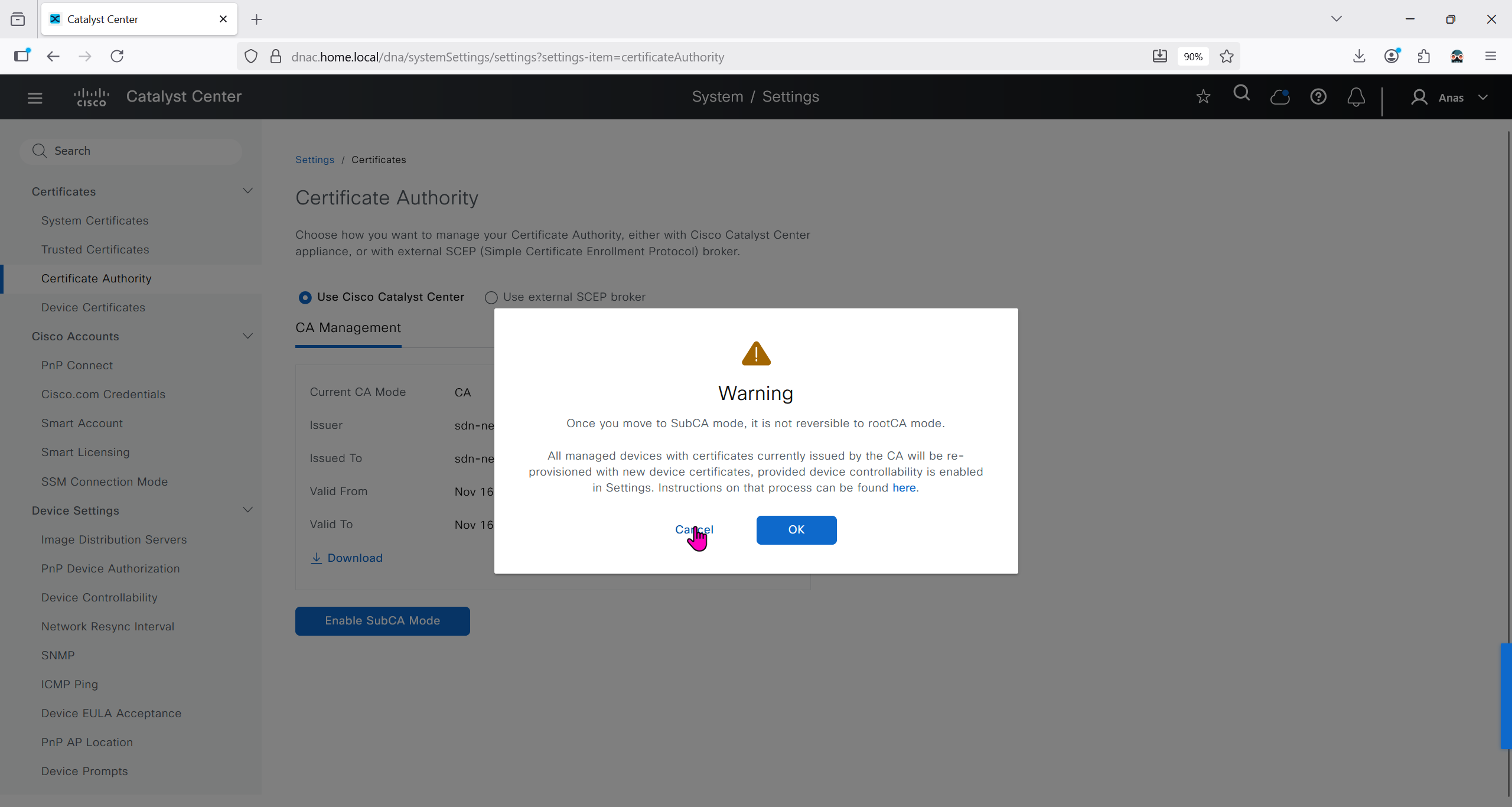
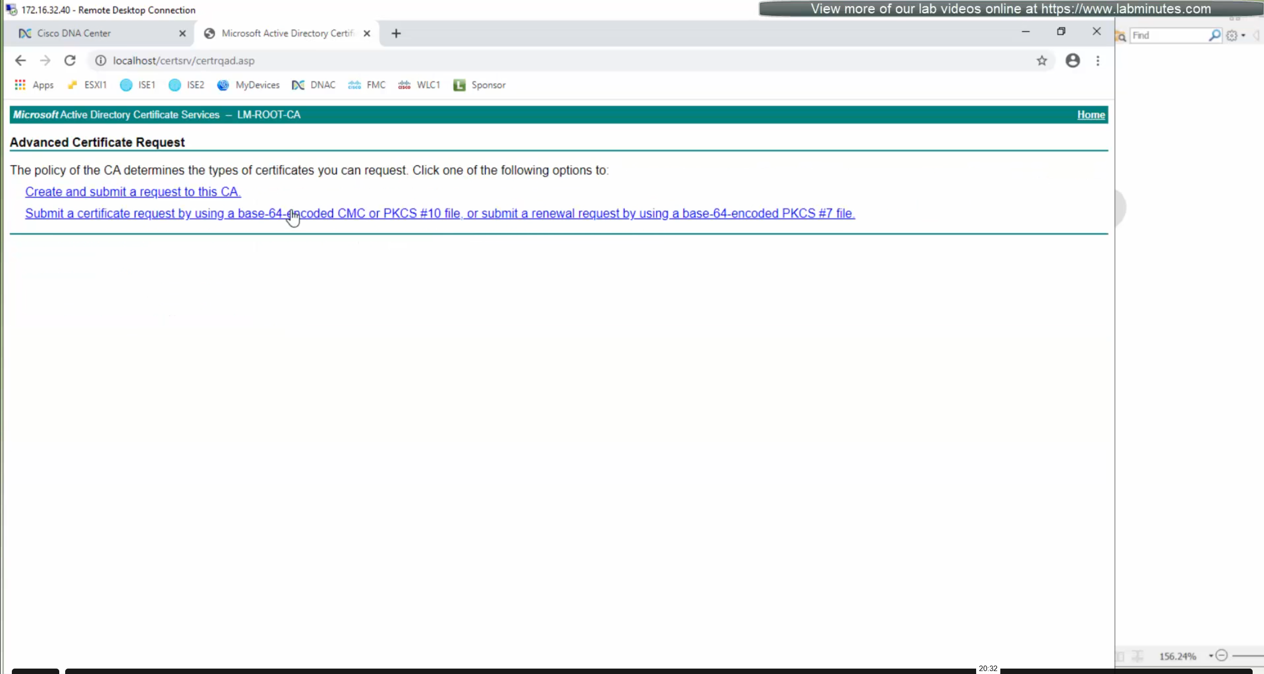
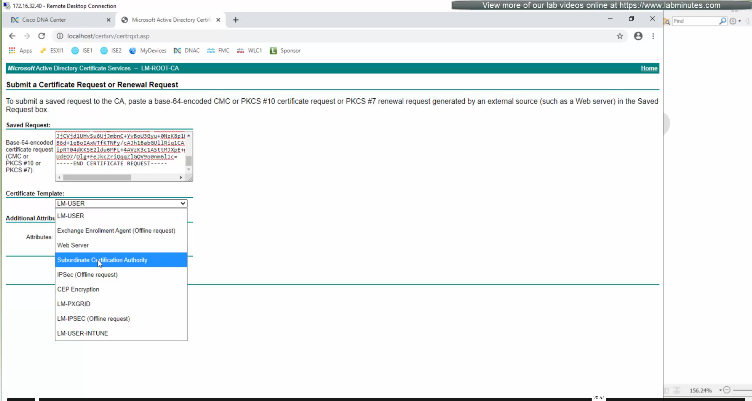
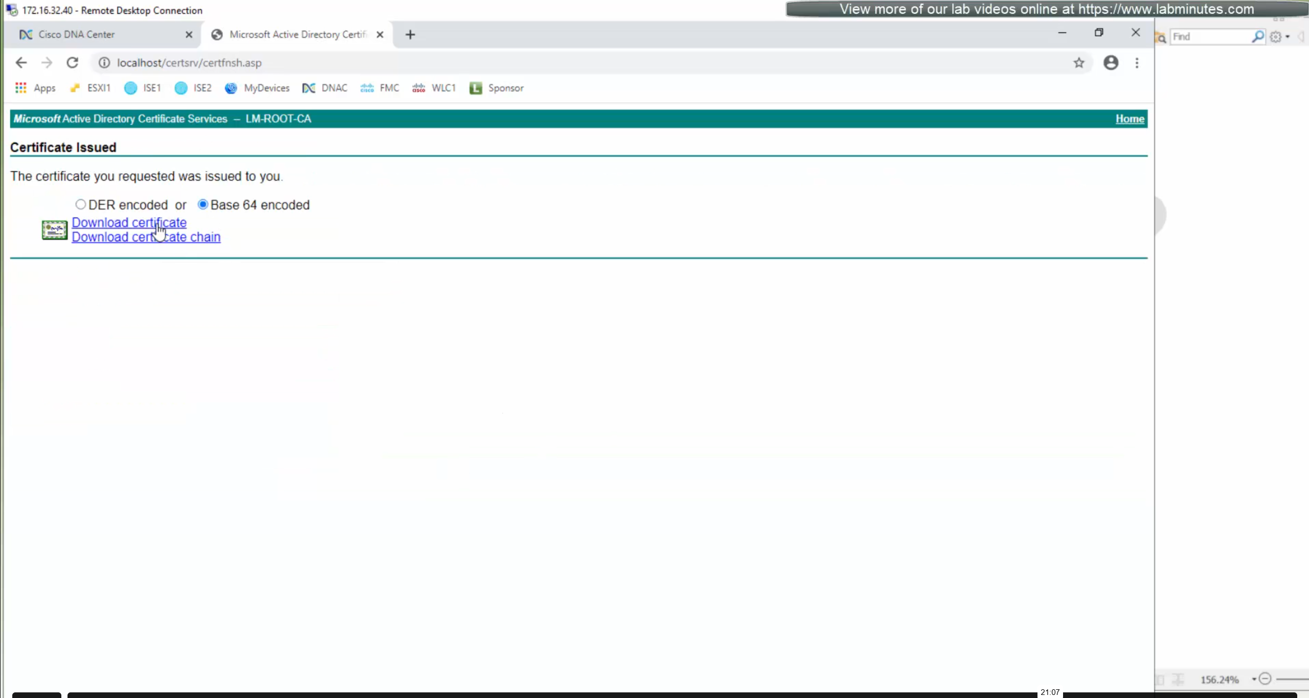
But if we were to enable it then following will be the steps


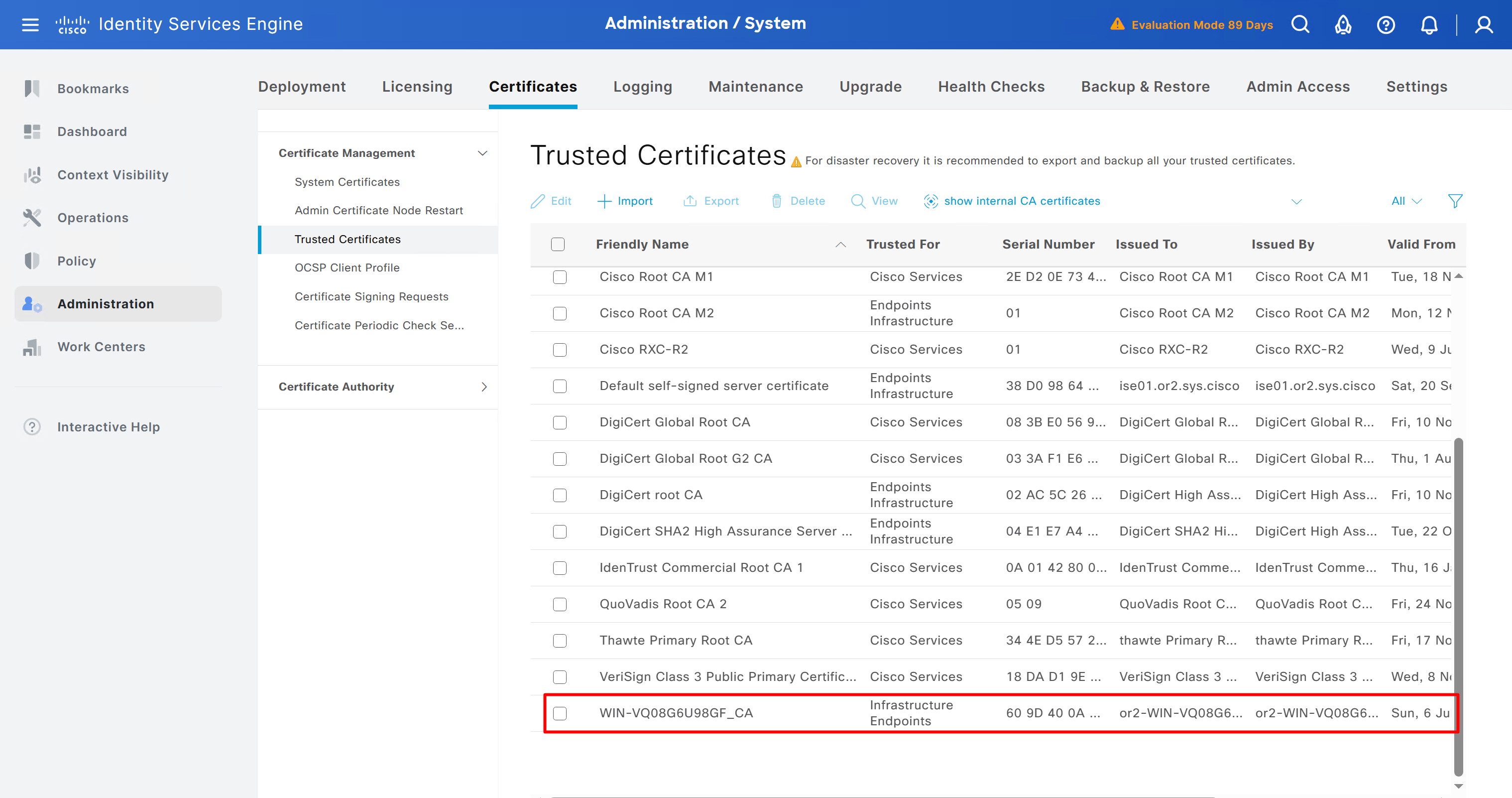
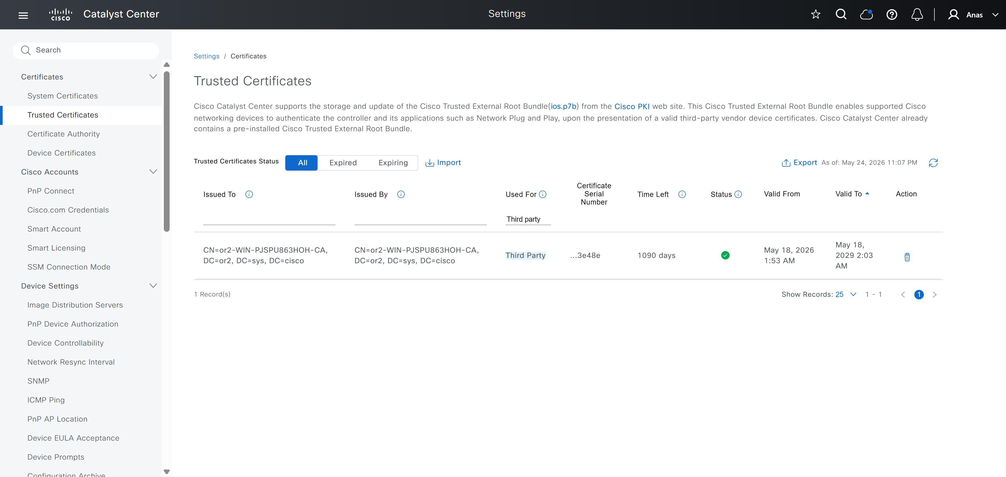
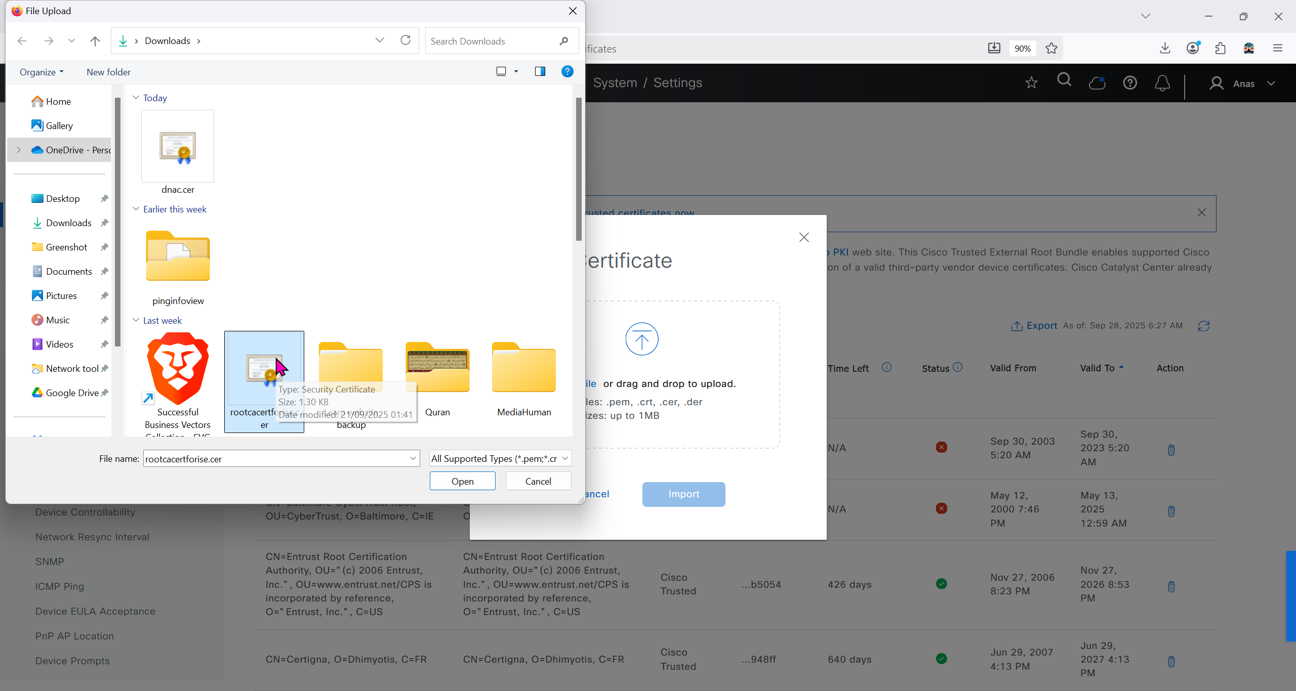
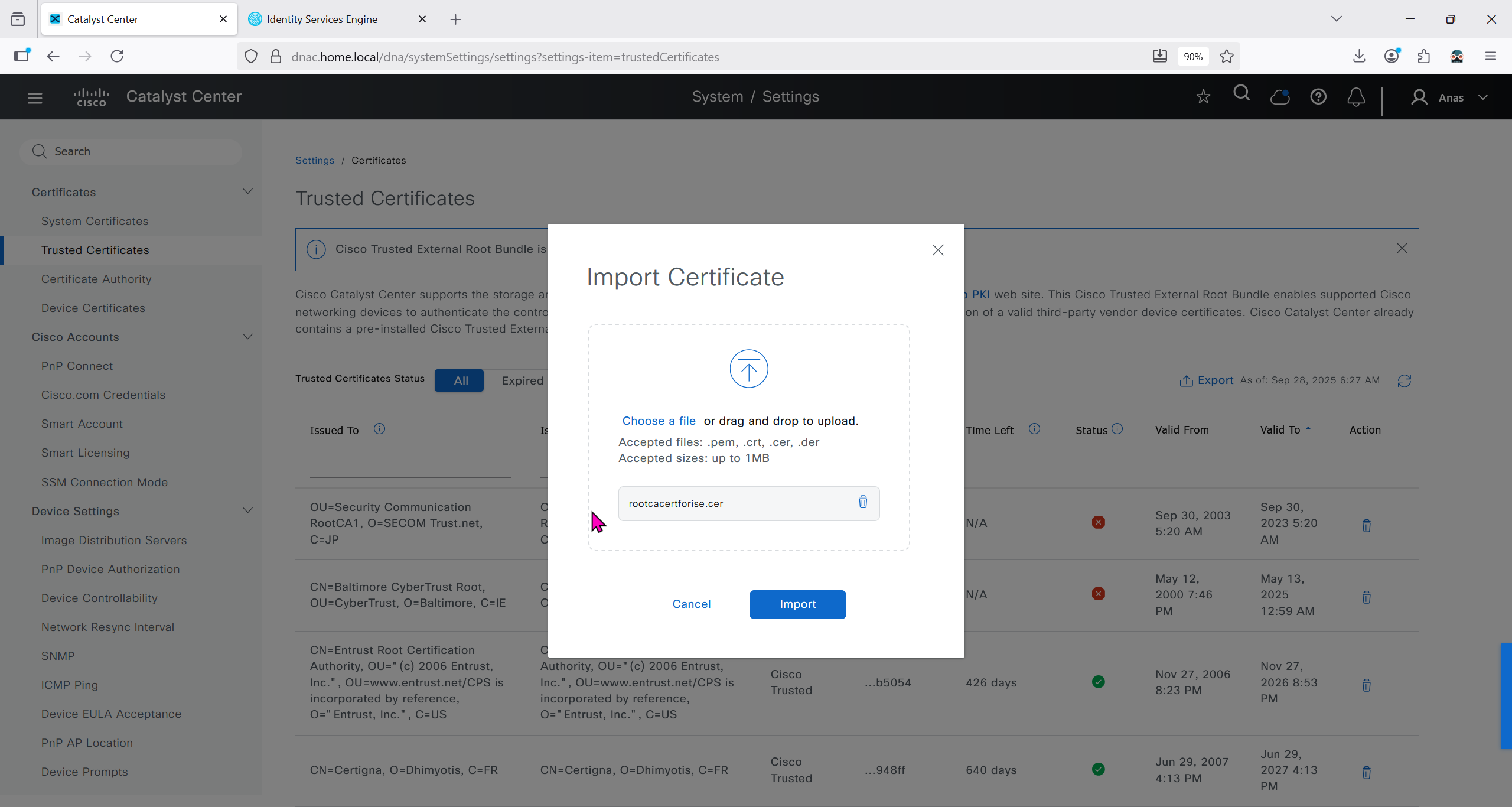
Checking imported CA certificate in Trusted Certificates section
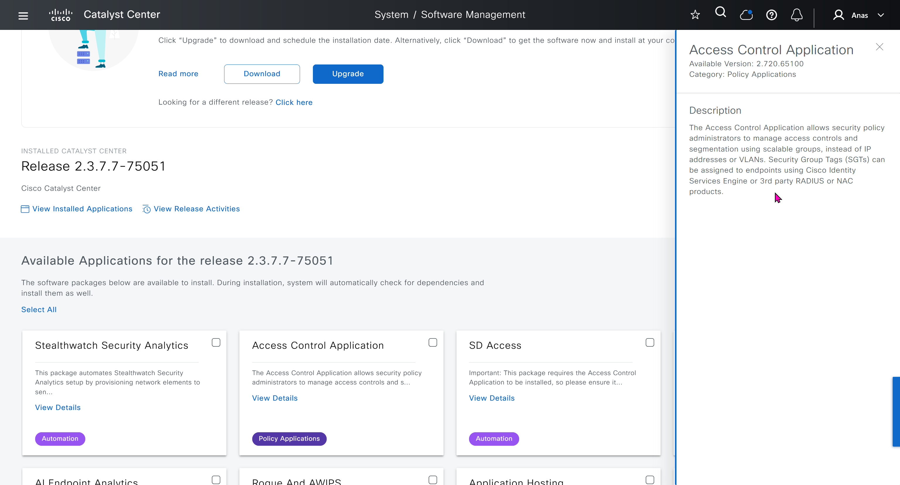
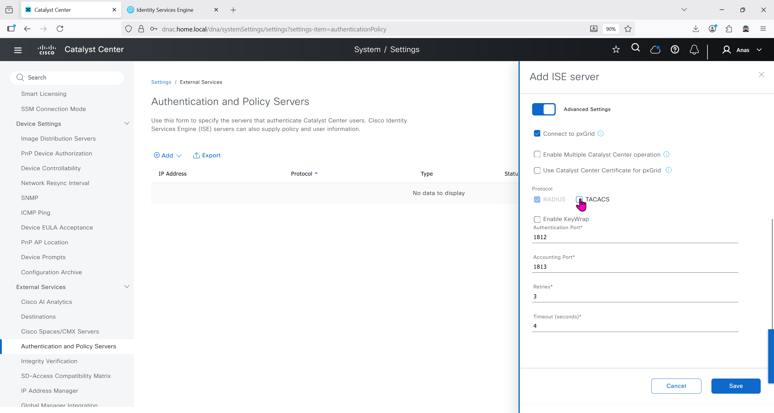
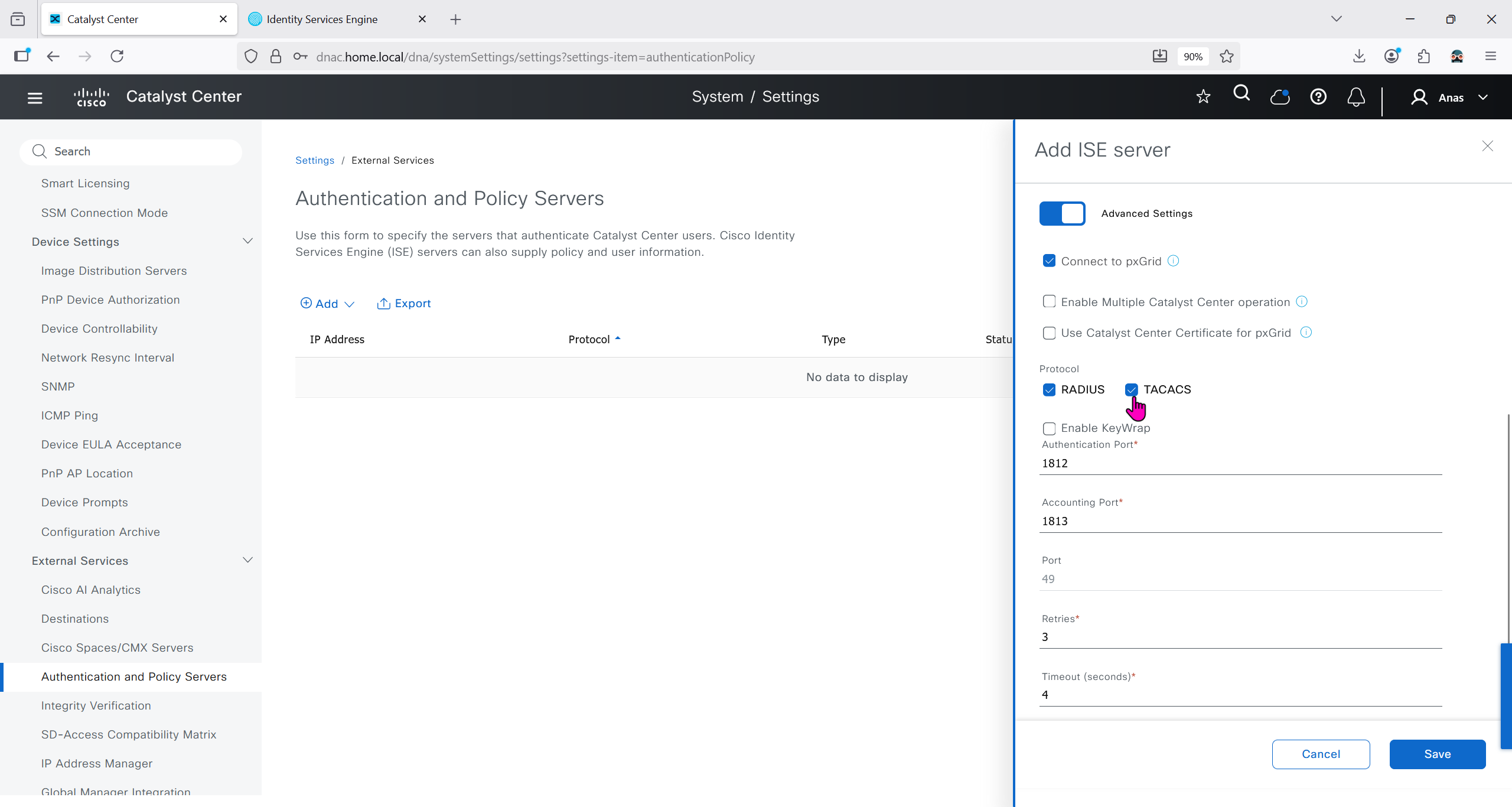
ISE is part of the SDA architecture by using RADIUS (Policy Server with mab and dot1x), TACACS and PXGrid
We need to have dot1x and mab authentication and
authorization configured in ISE
It used to be that ISE should not have TrustSec configuration configured, as config from DNAC will overwrite the existing config
If you bypass Cisco DNA Center and manually modify an SGACL directly inside ISE, the systems will fall out of sync. Cisco DNA Center will not automatically inherit changes made locally on ISE, creating a configuration mismatch until a manual resynchronisation or re-integration is performed
After integration, DNAC continues to poll ISE in order to keep trustsec configuration in sync
Integration between DNAC and ISE is very version specific so make sure you check documentation to see which version of ISE will integrate with which version of DNAC
Make sure that DNAC can reach ISE on ssh, and it is very important that GUI and CLI credentials are same
Also make sure that our ISE certificate has SAN entries for ISE IP and FQDN in ISE certificate


Make sure that when DNAC’s cert is presented it is trusted by ISE, for that we will have to upload the root CA cert
Download CA certificate and upload it to the Trusted store of ISE
We will select this option “Trust for client authentication and Syslog” as certificate presented to ISE during EAP TLS 802.1x authentication will be certificates issued by this same CA
Create CSR for Admin usage
enter DNS Name as $FQDN$
and also enter second DNS name as wildcard with remaining domain name *.or2.sys.cisco
and also add the SAN entry of type IP address with value of 172.16.32.12
ISE gave this error
So I removed first entry of $FQDN$
it is trusted now in browser if we access it on its FQDN
CN is the FQDN of the ISE


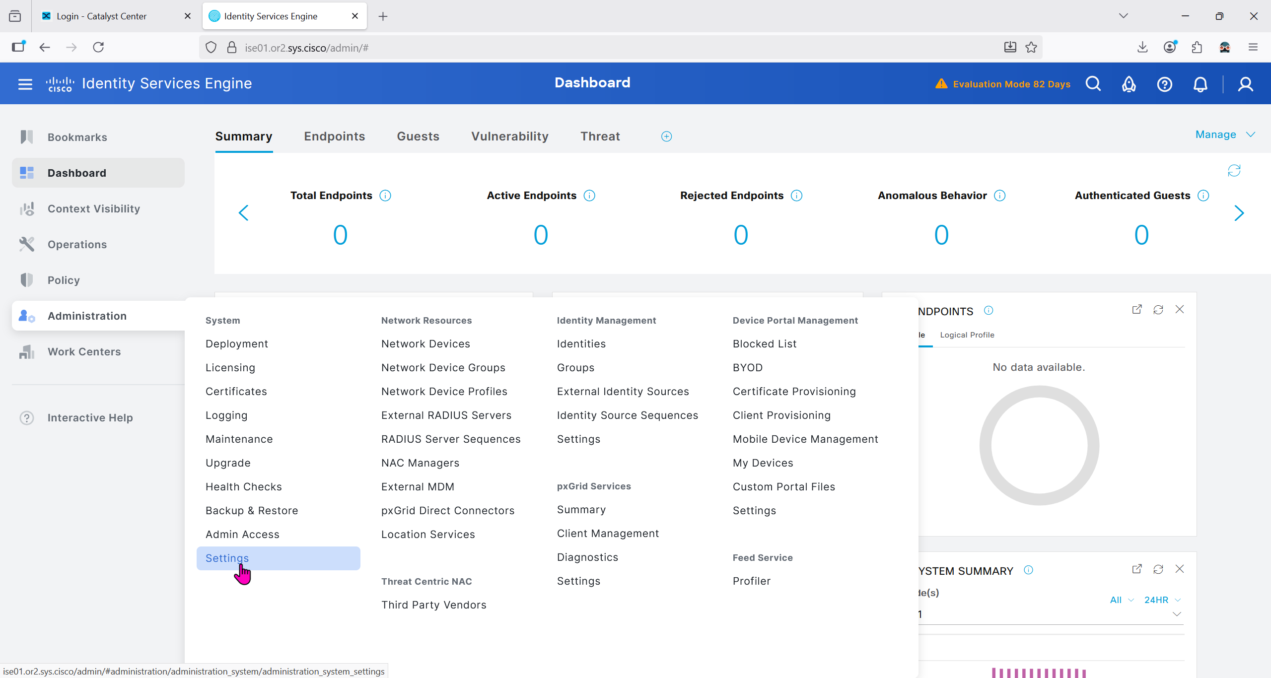
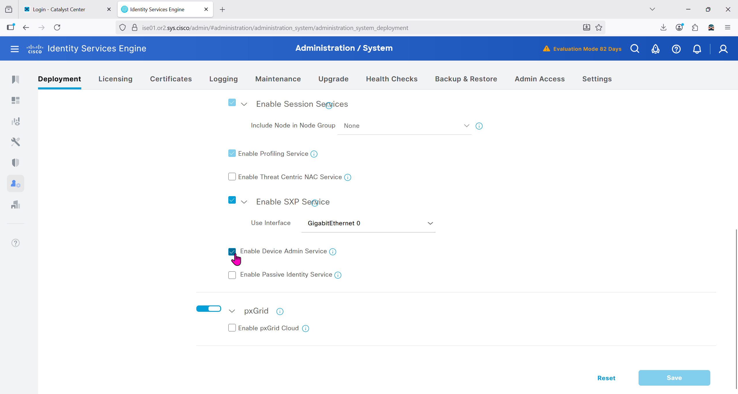
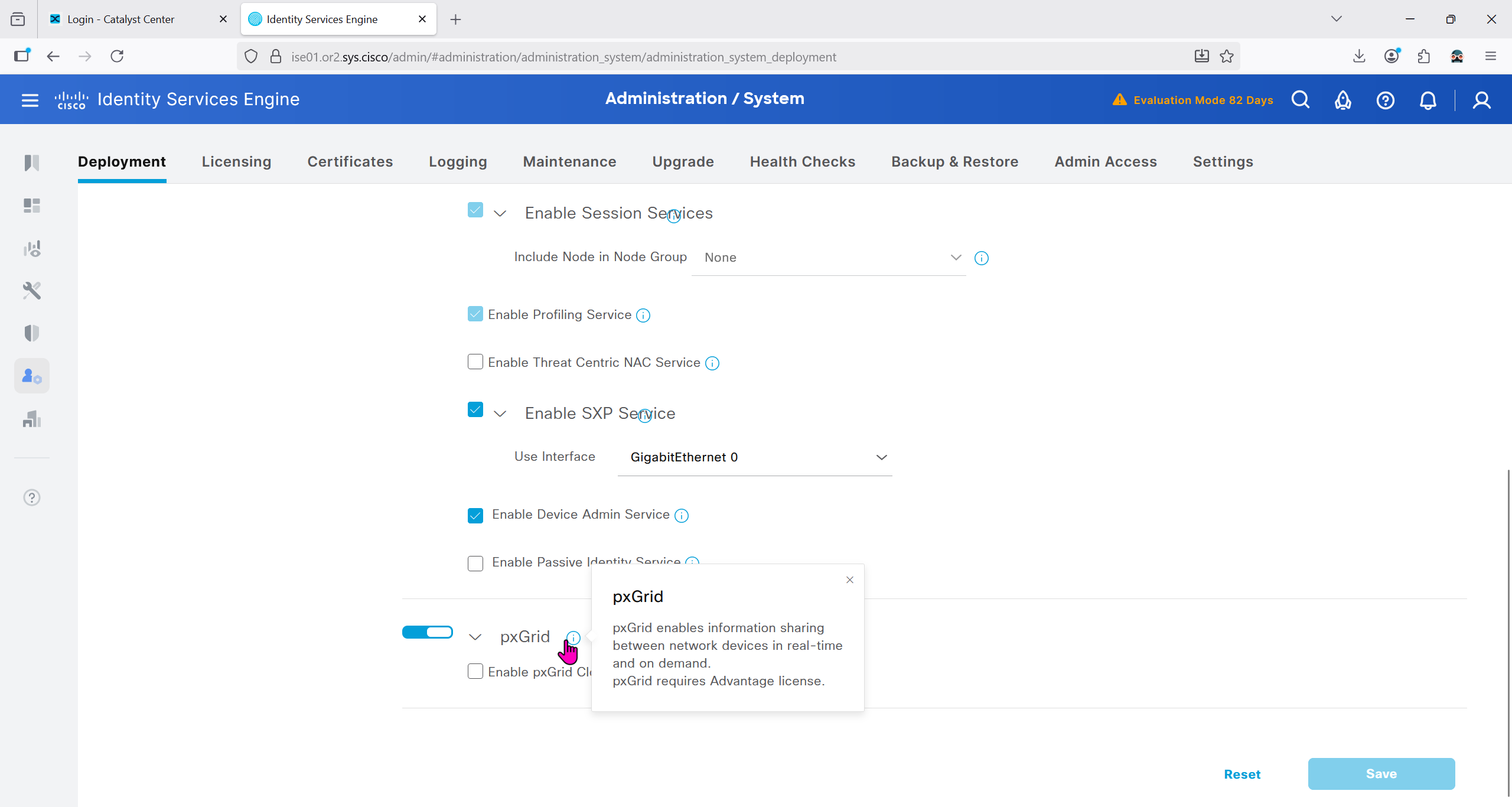
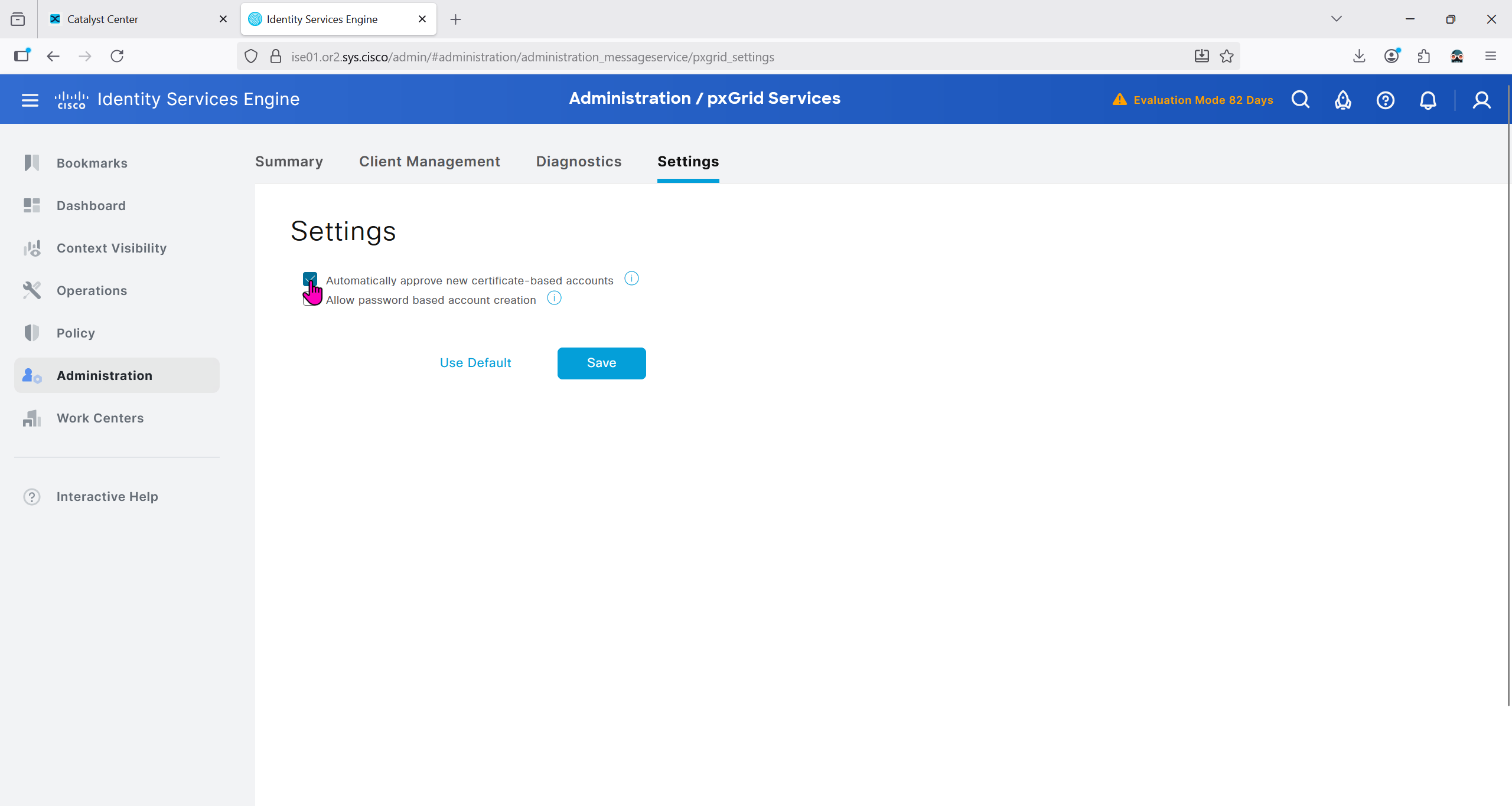
Because DNAC uses API to communicate with ISE, ERS needs to be enabled
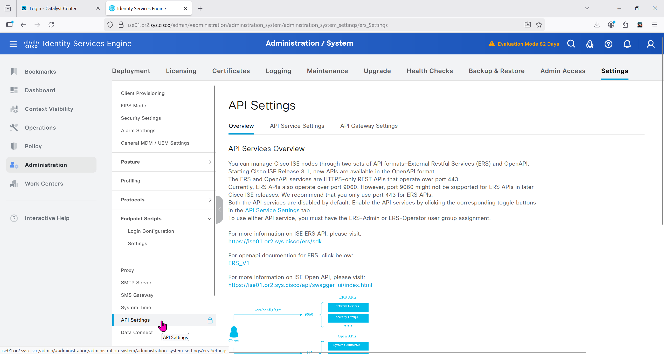


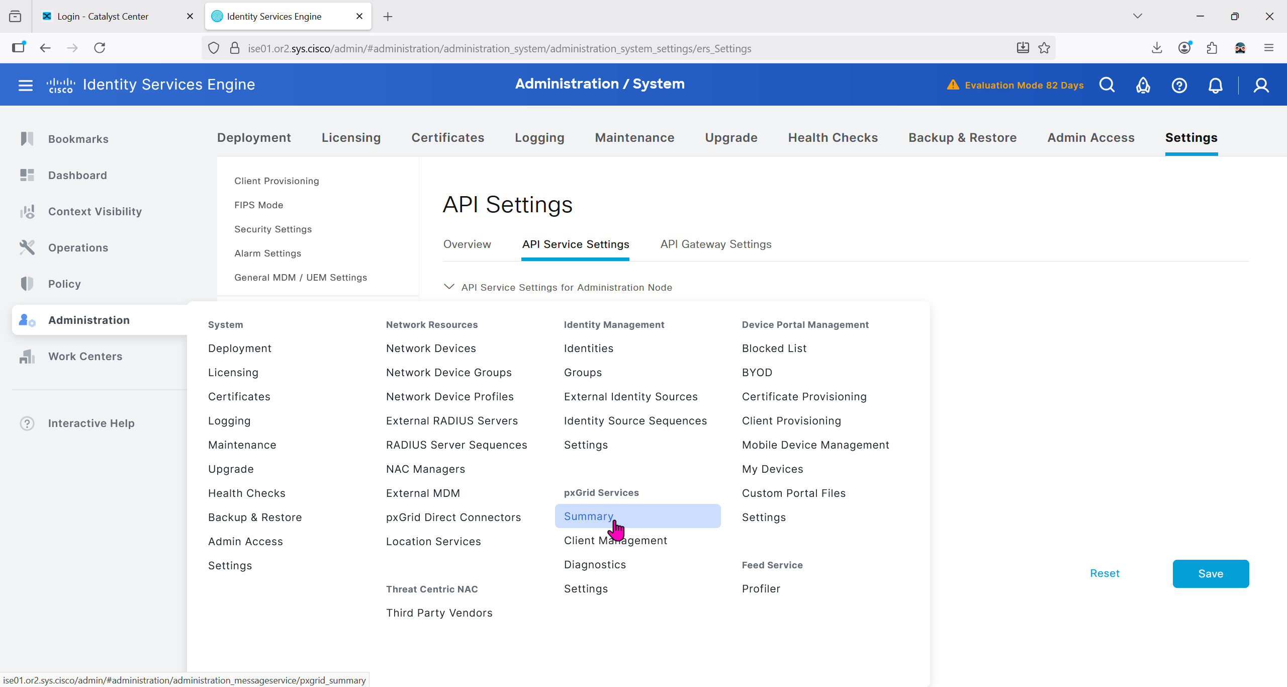
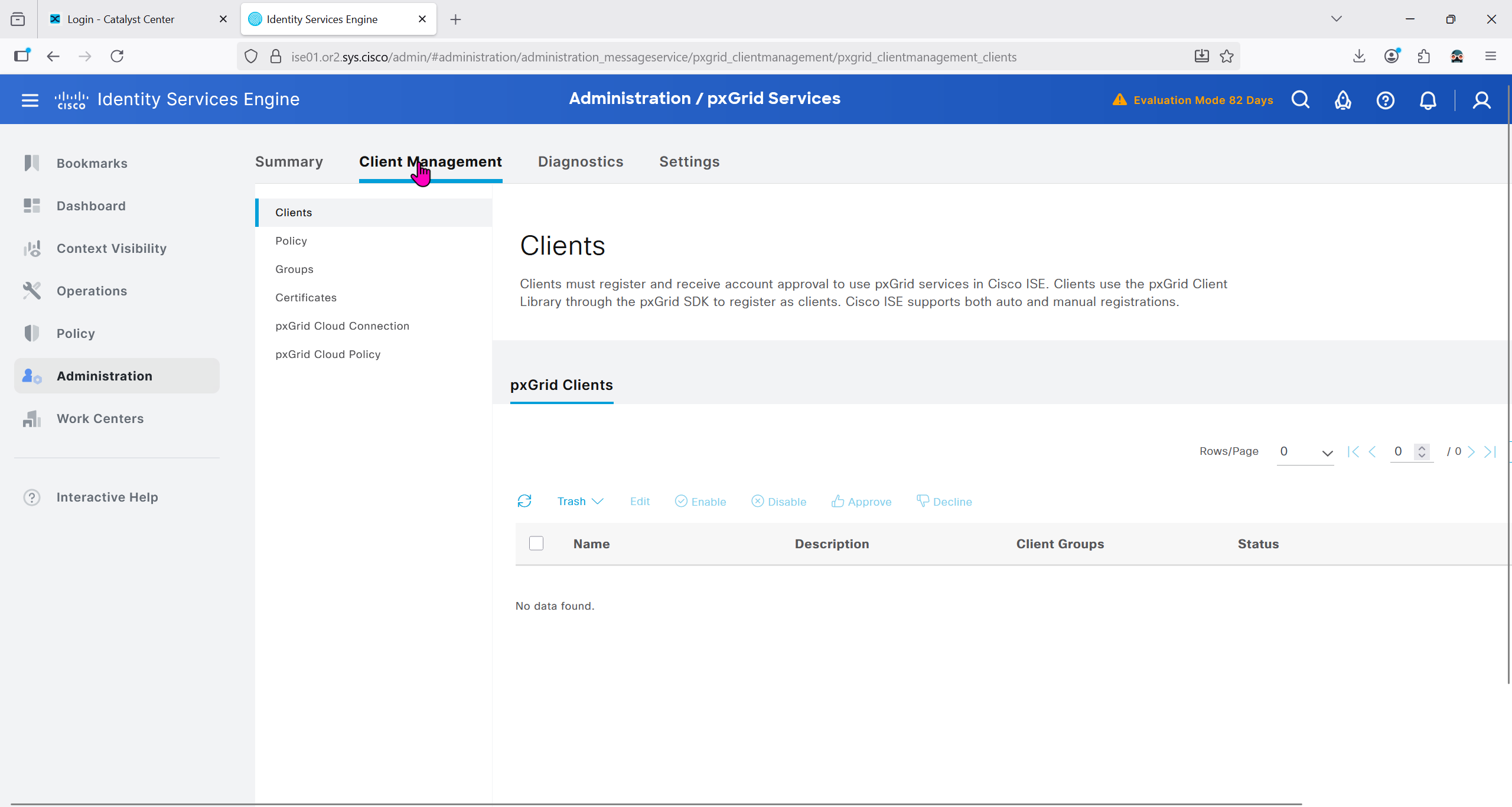
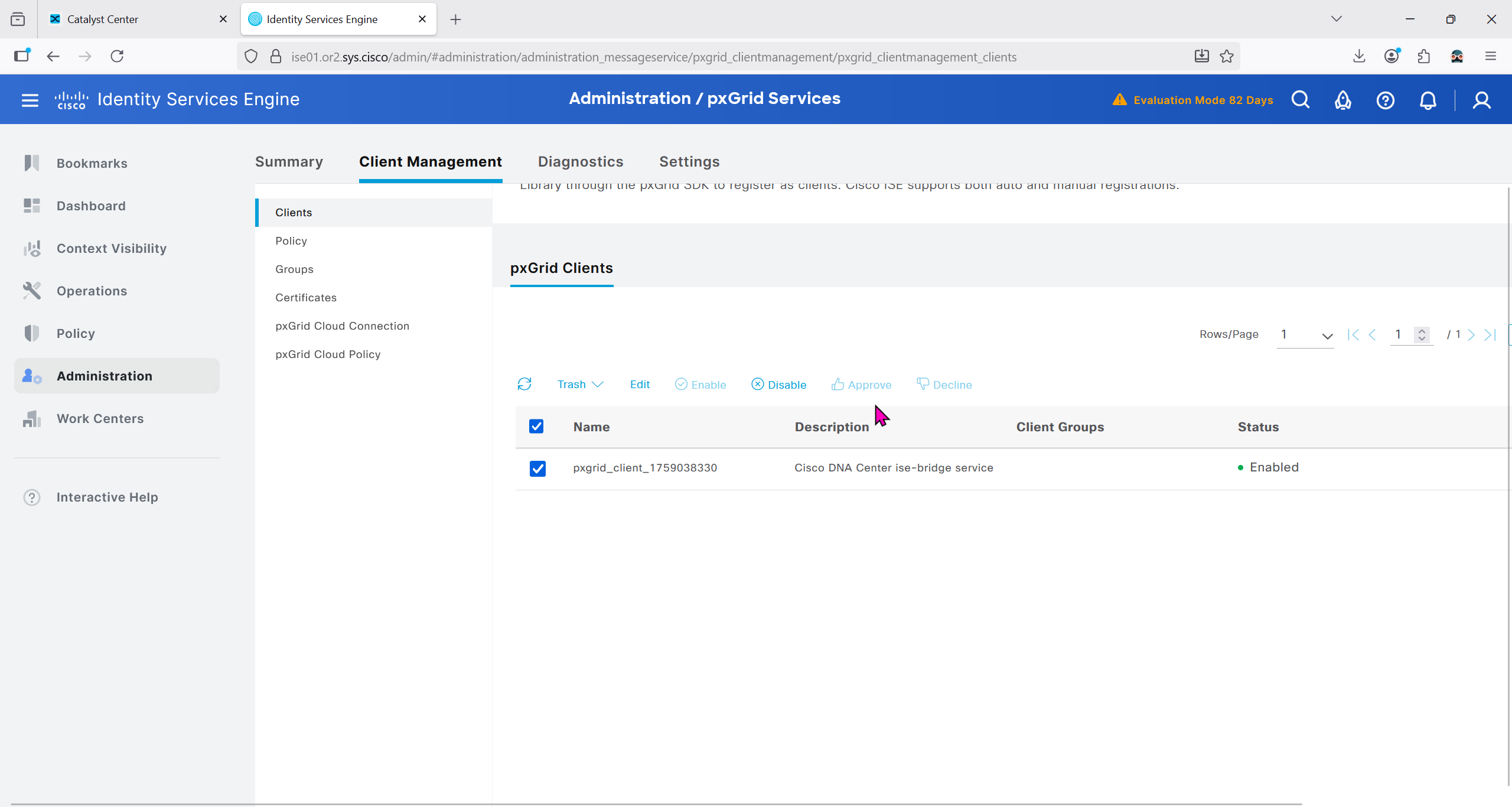
Make sure PXgrid service is running
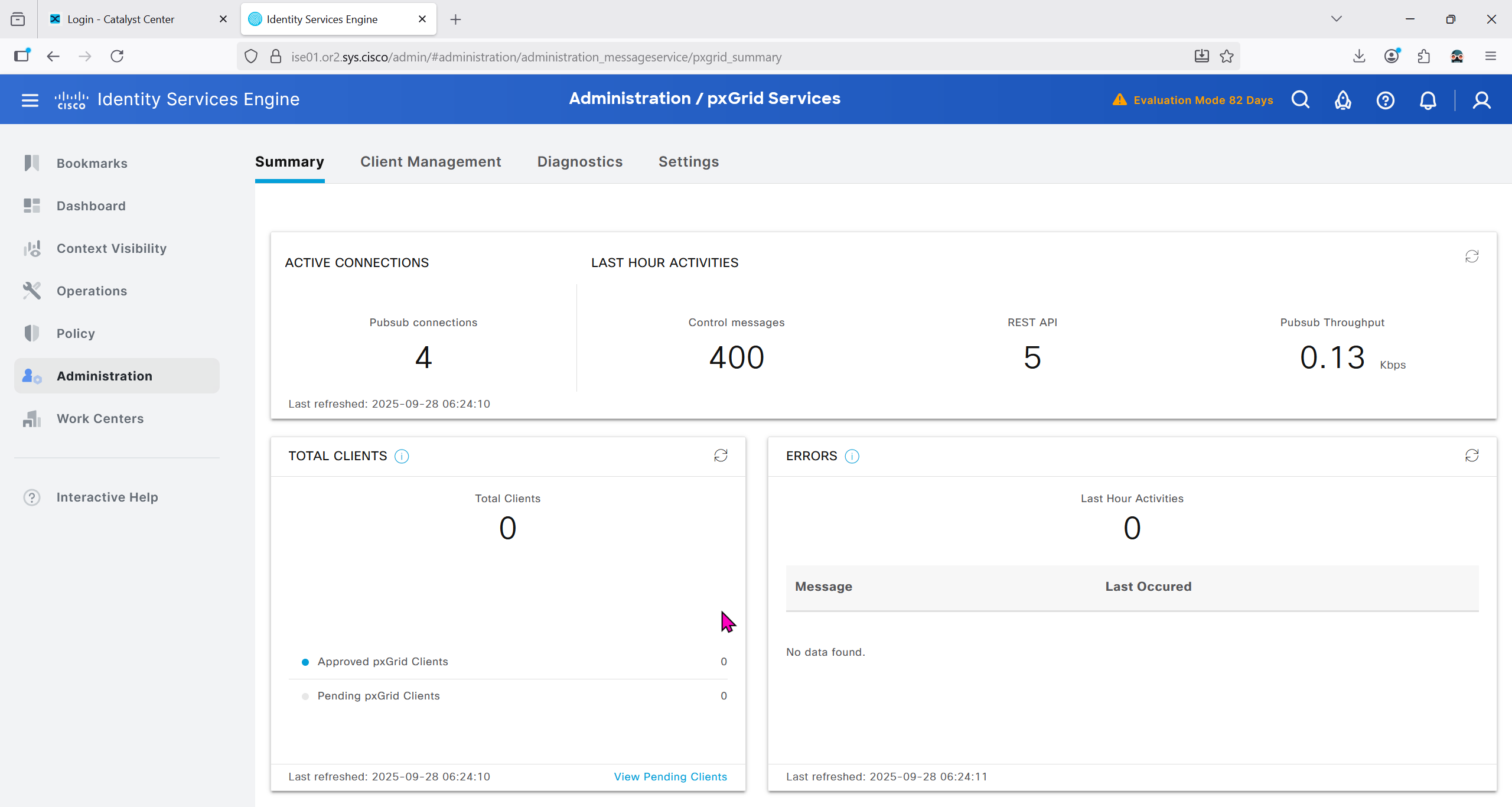
Currently in Client management we do not have any PXgrid clients yet
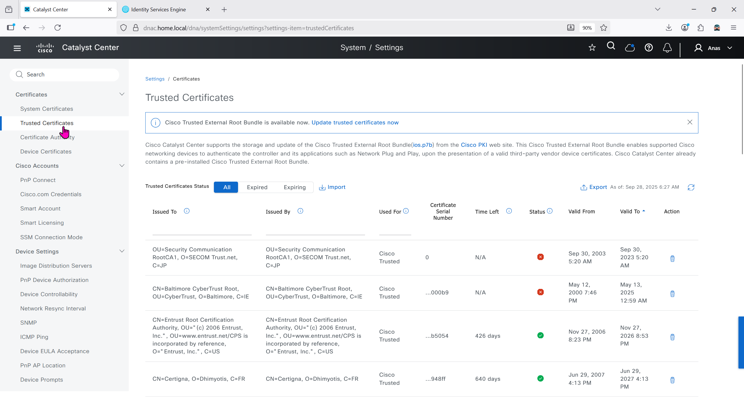
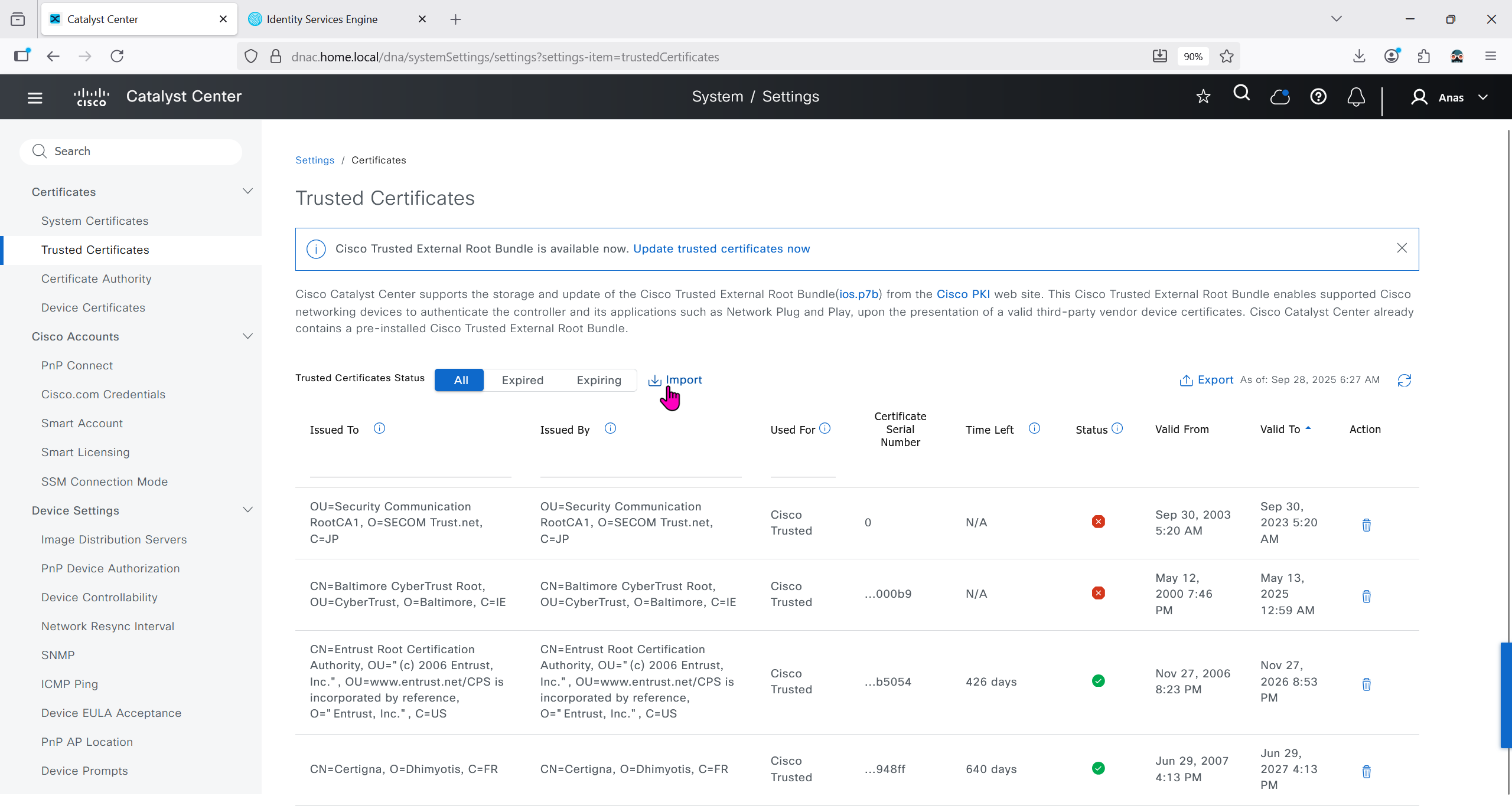
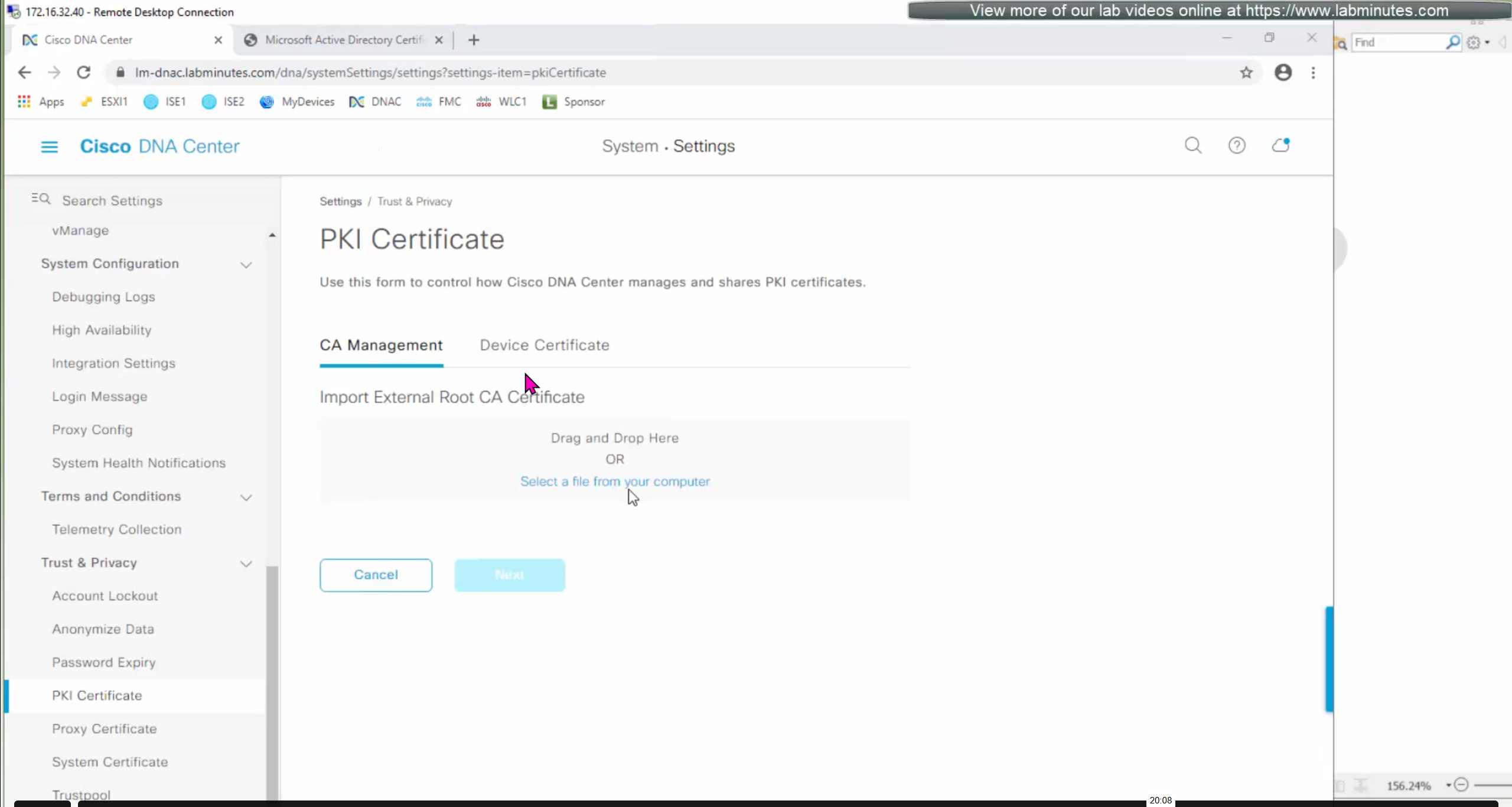
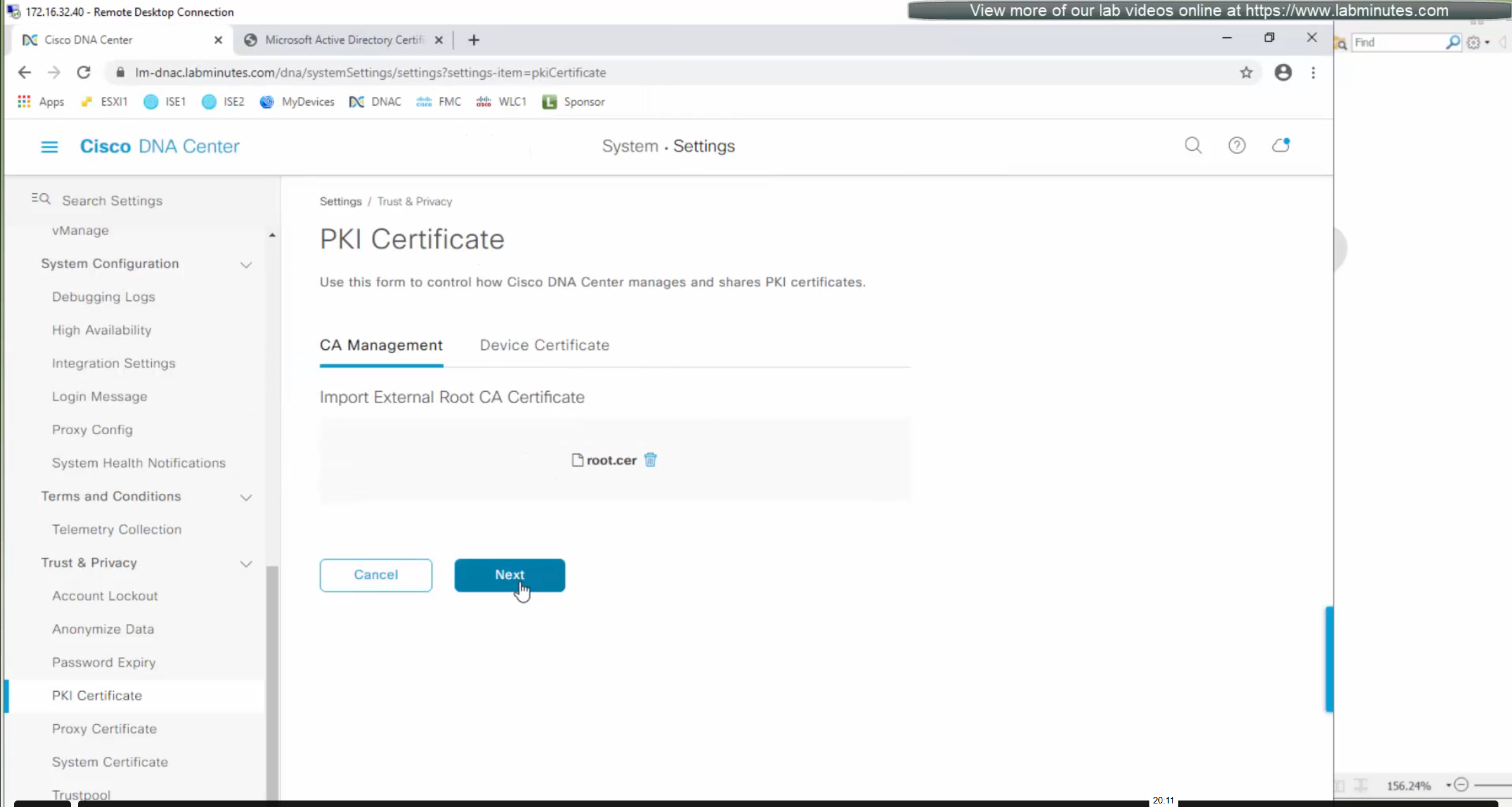
We will import the root ca cert in dnac so it can trust the certificate presented by ISE

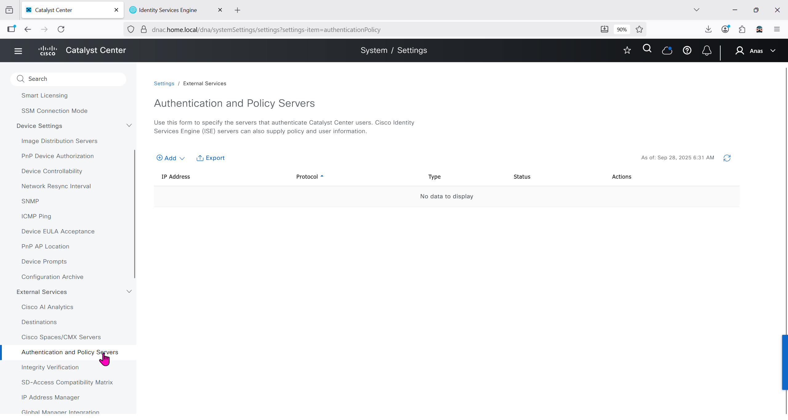
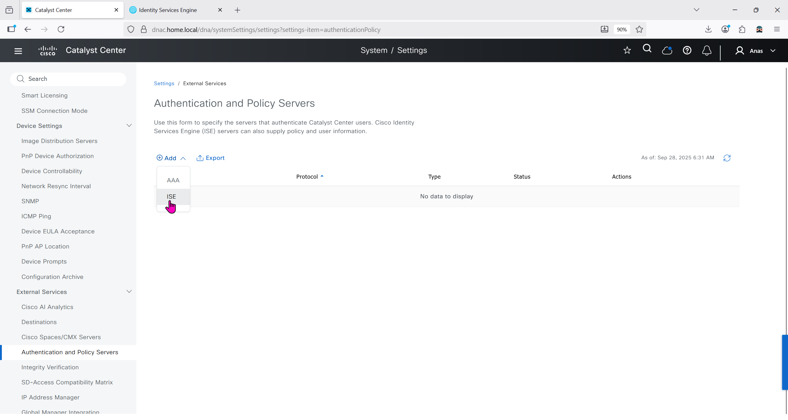
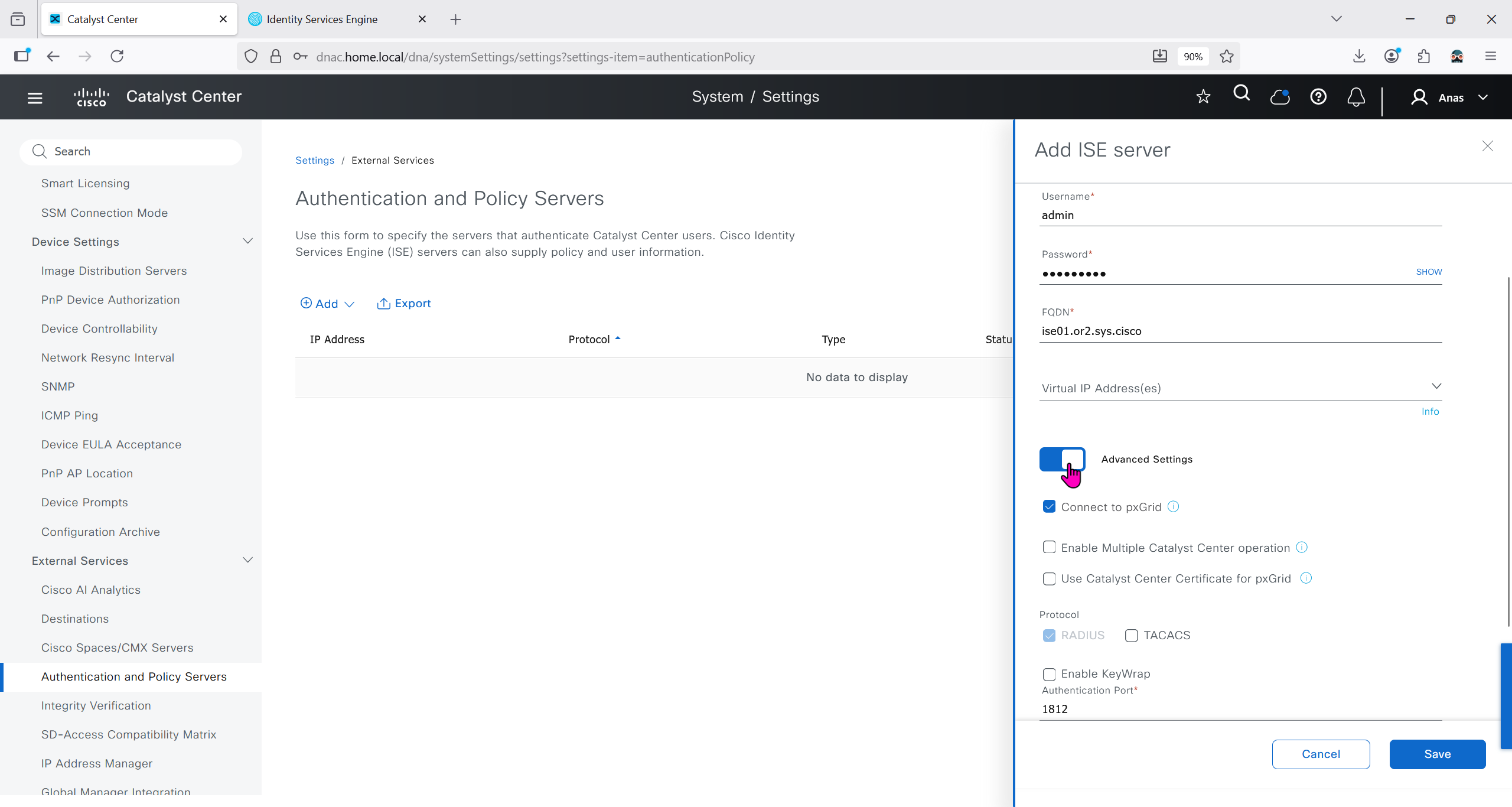
Make sure dnac can reach ise 172.16.32.12

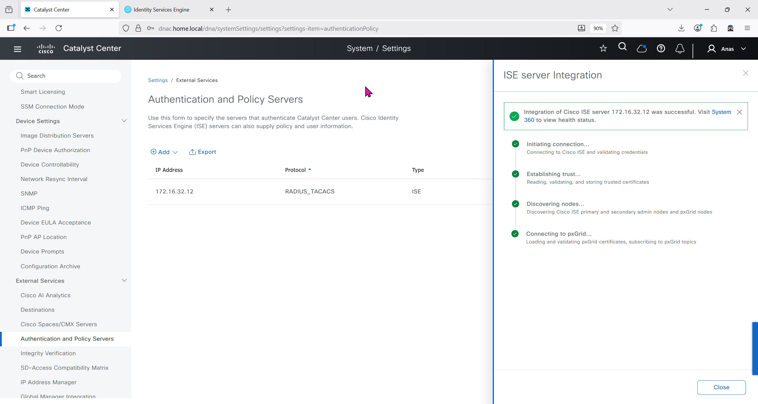
Add ISE server 172.16.32.12 and this shared secret is the secret that will be used on catalyst devices which are added to dnac
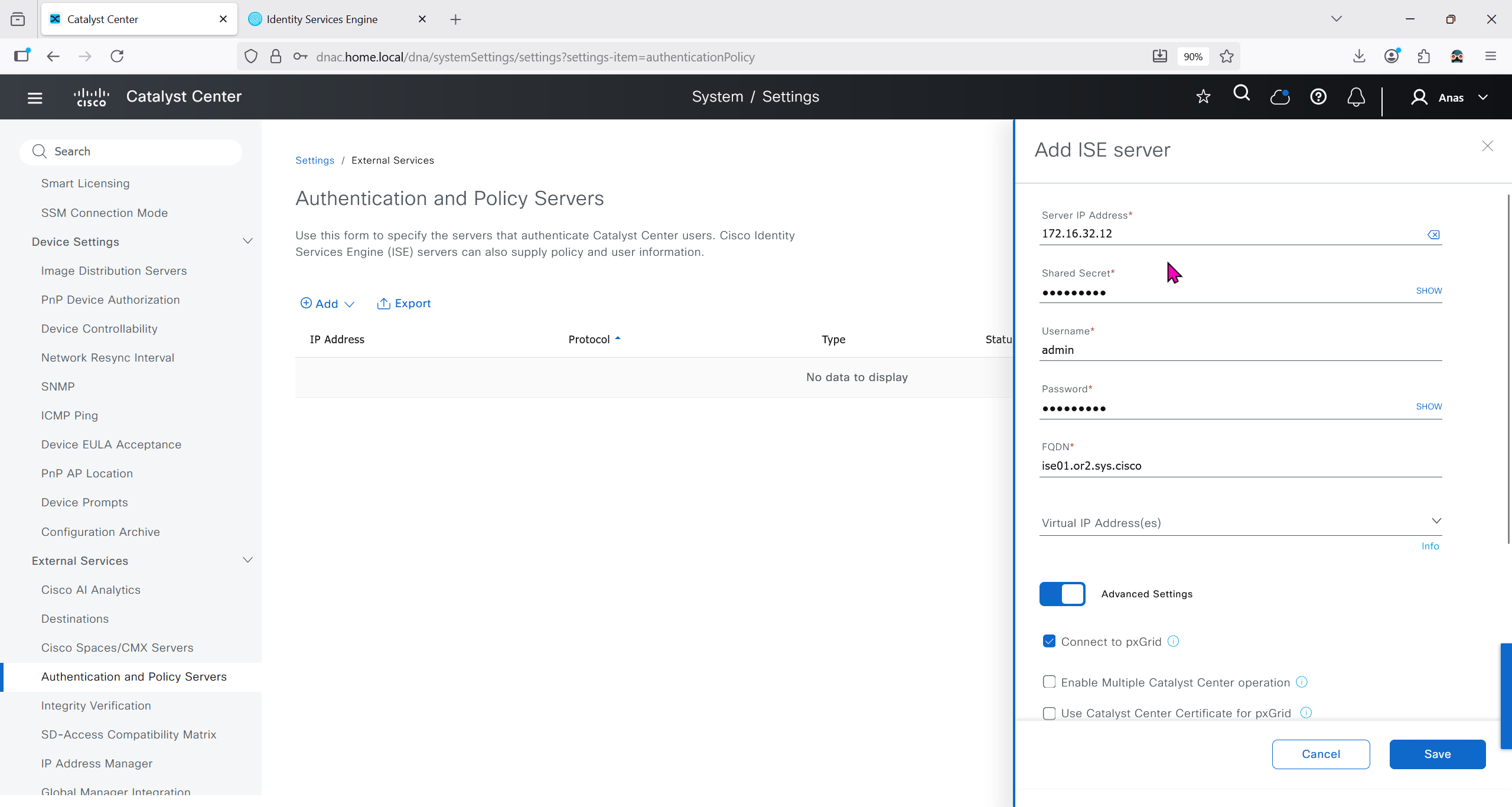

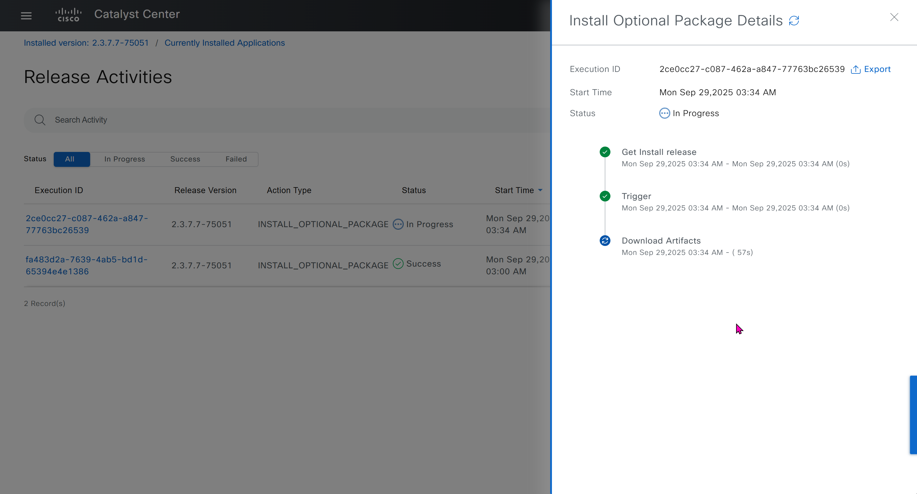
It should say IN PROGRESS and then it should move on to ACTIVE
In ISE we will check Administration > pxgrid > summary for 1 client that is dnac

in pxgrid > client management, if dnac is showing pending then approve it


We should have installed Group based policy analytics, which we will do now
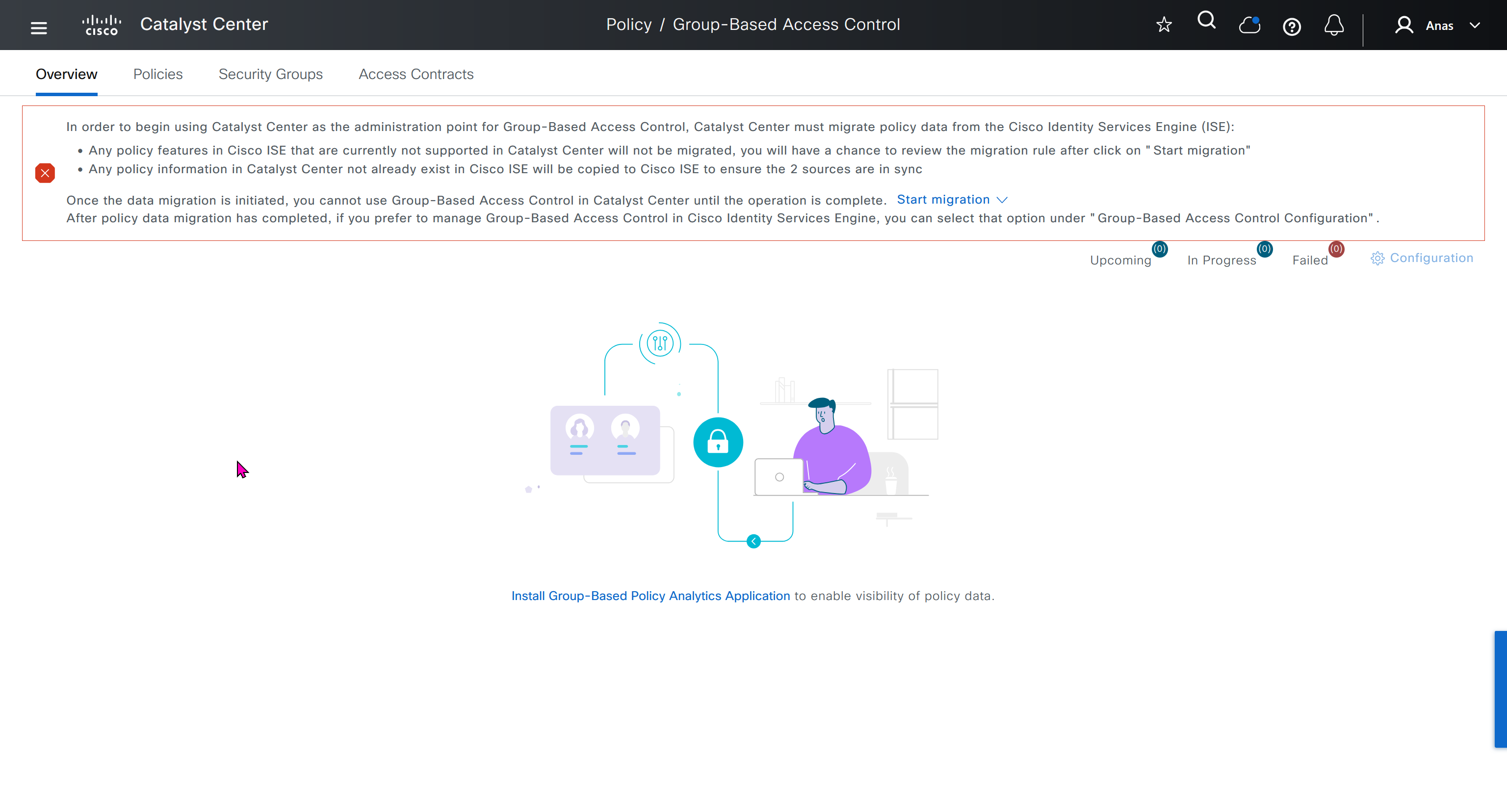

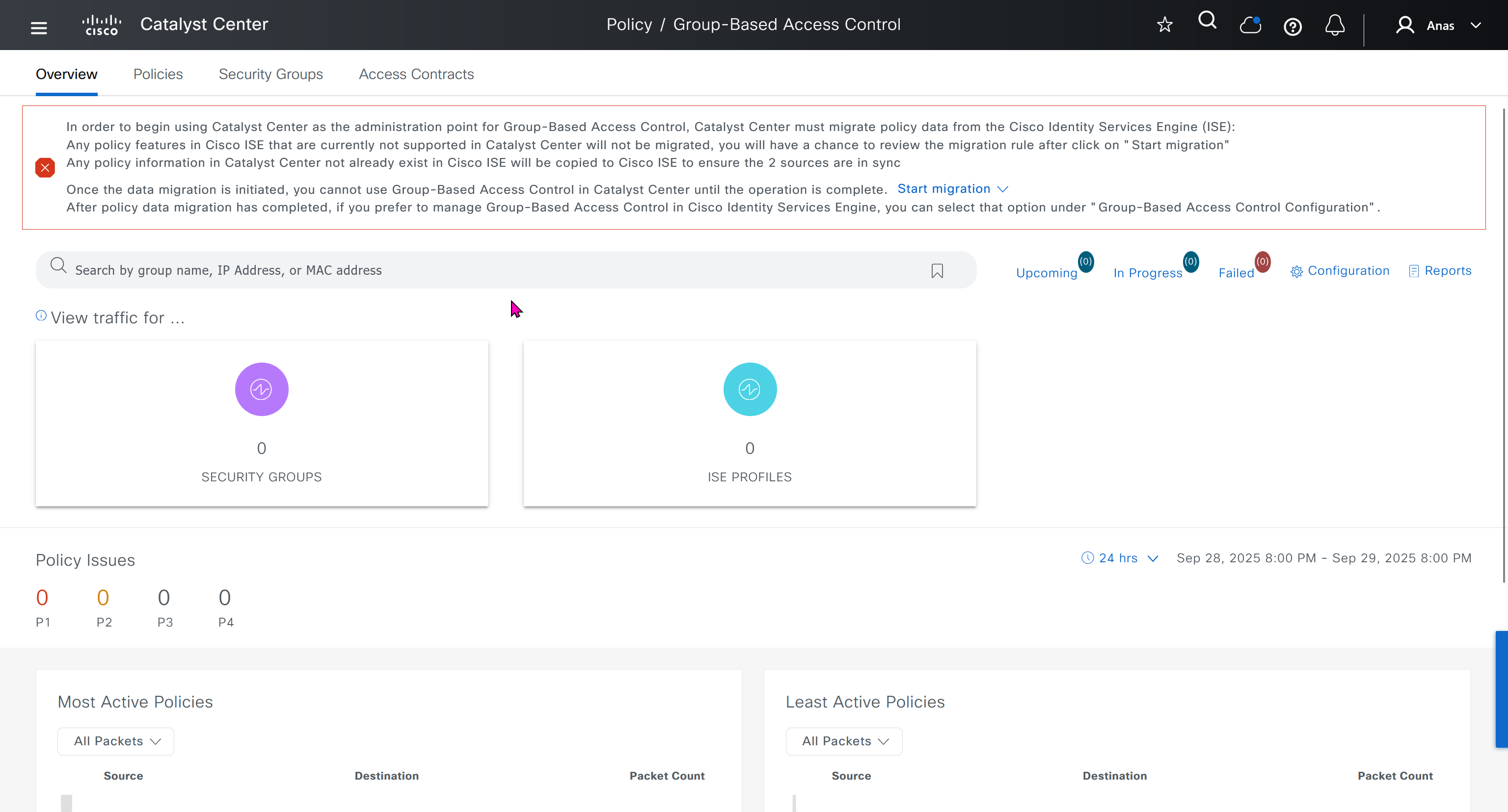
This message basically says to config sync between DNAC and ISE and use DNAC as the administration point for GBAC policy
In order to begin using Catalyst Center as the administration point for Group-Based Access Control, Catalyst Center must migrate policy data from the Cisco Identity Services Engine (ISE):
Any policy features in Cisco ISE that are currently not supported in Catalyst Center will not be migrated, you will have a chance to review the migration rule after click on "Start migration"
Any policy information in Catalyst Center not already exist in Cisco ISE will be copied to Cisco ISE to ensure the 2 sources are in sync
Once the data migration is initiated, you cannot use Group-Based Access Control in Catalyst Center until the operation is complete.
Start migration
After policy data migration has completed, if you prefer to manage Group-Based Access Control in Cisco Identity Services Engine, you can select that option under “Group-Based Access Control Configuration”.
We need to click on Start migration, Backup is recommended because this is a 2 way sync and configuration in ISE will also change if there is pre existing config in DNAC
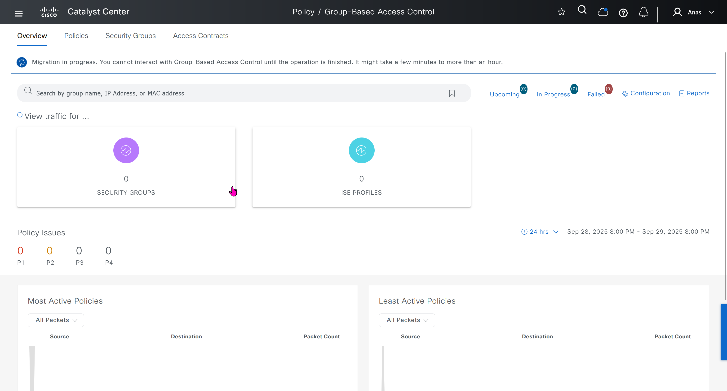
After migration DNAC has become the policy administration point and all changes should be made in ISE
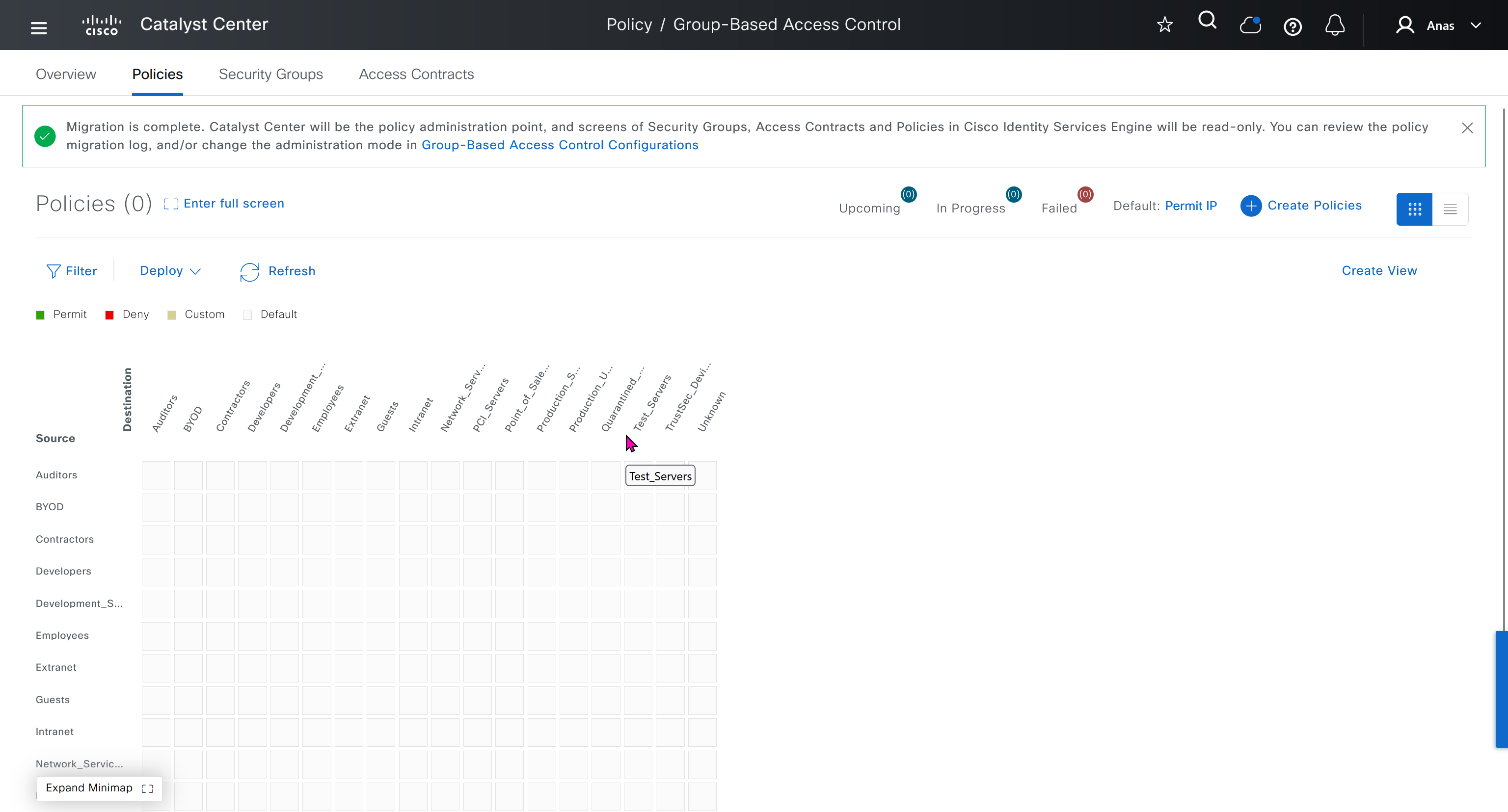
“Migration is complete. Catalyst Center will be the policy administration point, and screens of Security Groups, Access Contracts and Policies in Cisco Identity Services Engine will be read-only. You can review the policy migration log, and/or change the administration mode in Group-Based Access Control Configurations”
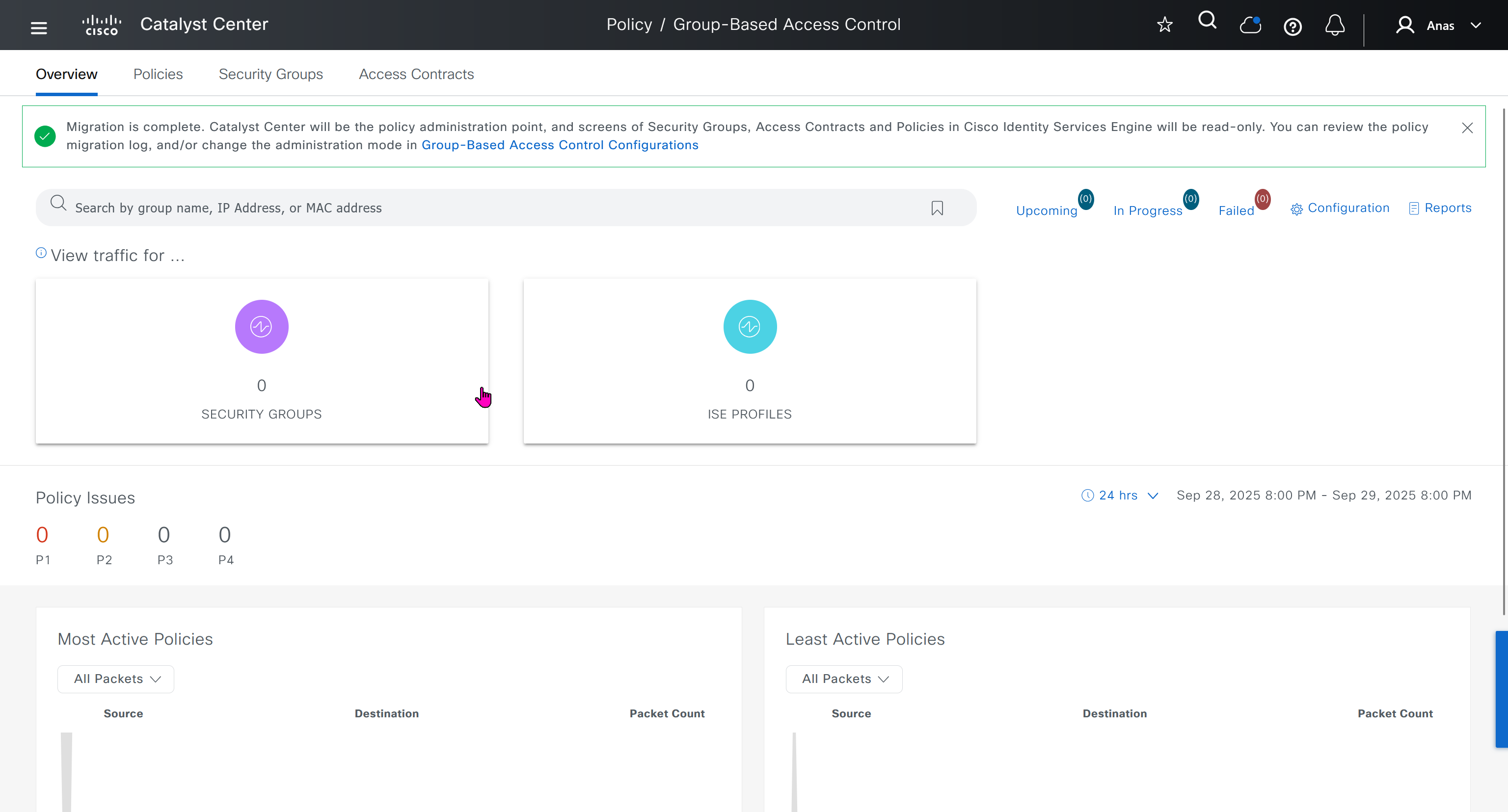
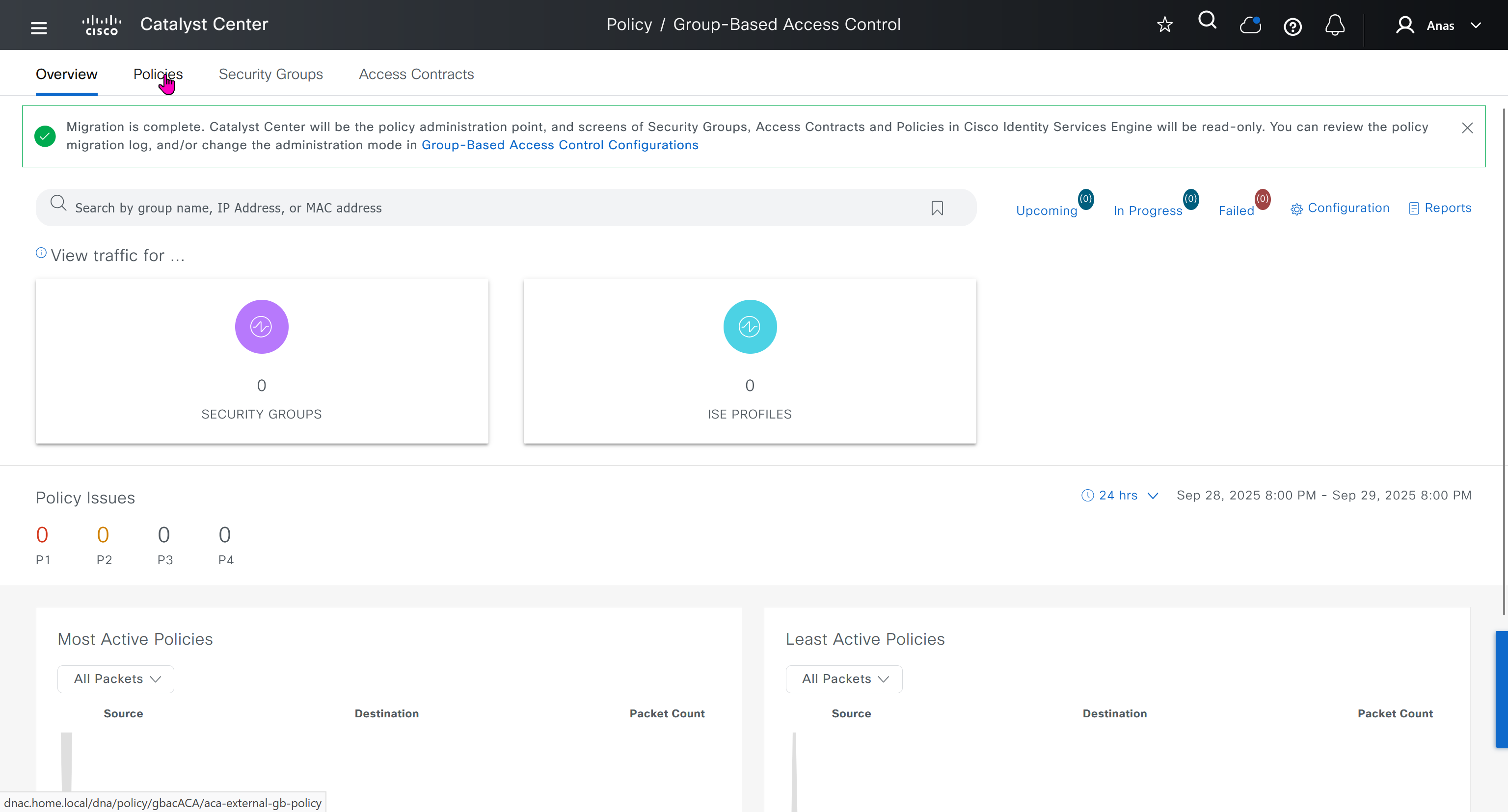
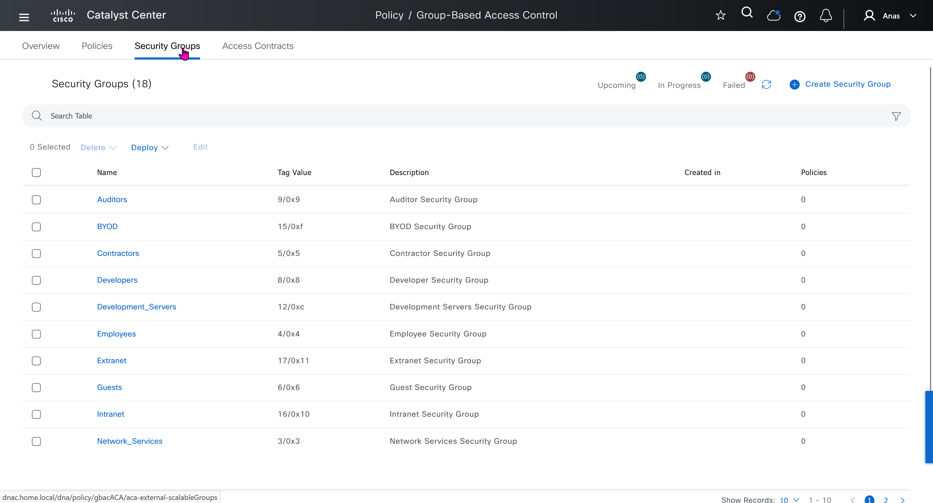
All these security groups have been downloaded into DNAC and any future configuration changes you make in DNAC will be reflected in ISE


next post
SDA LM 2 – Network Design
Videos
Network Design
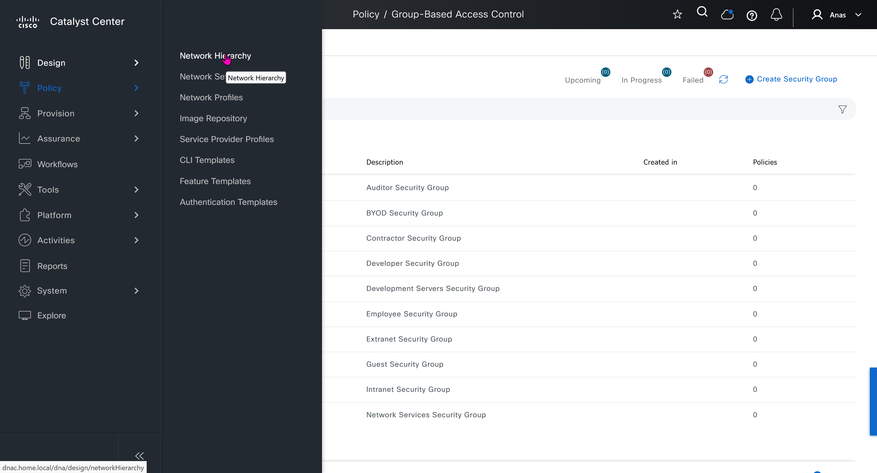
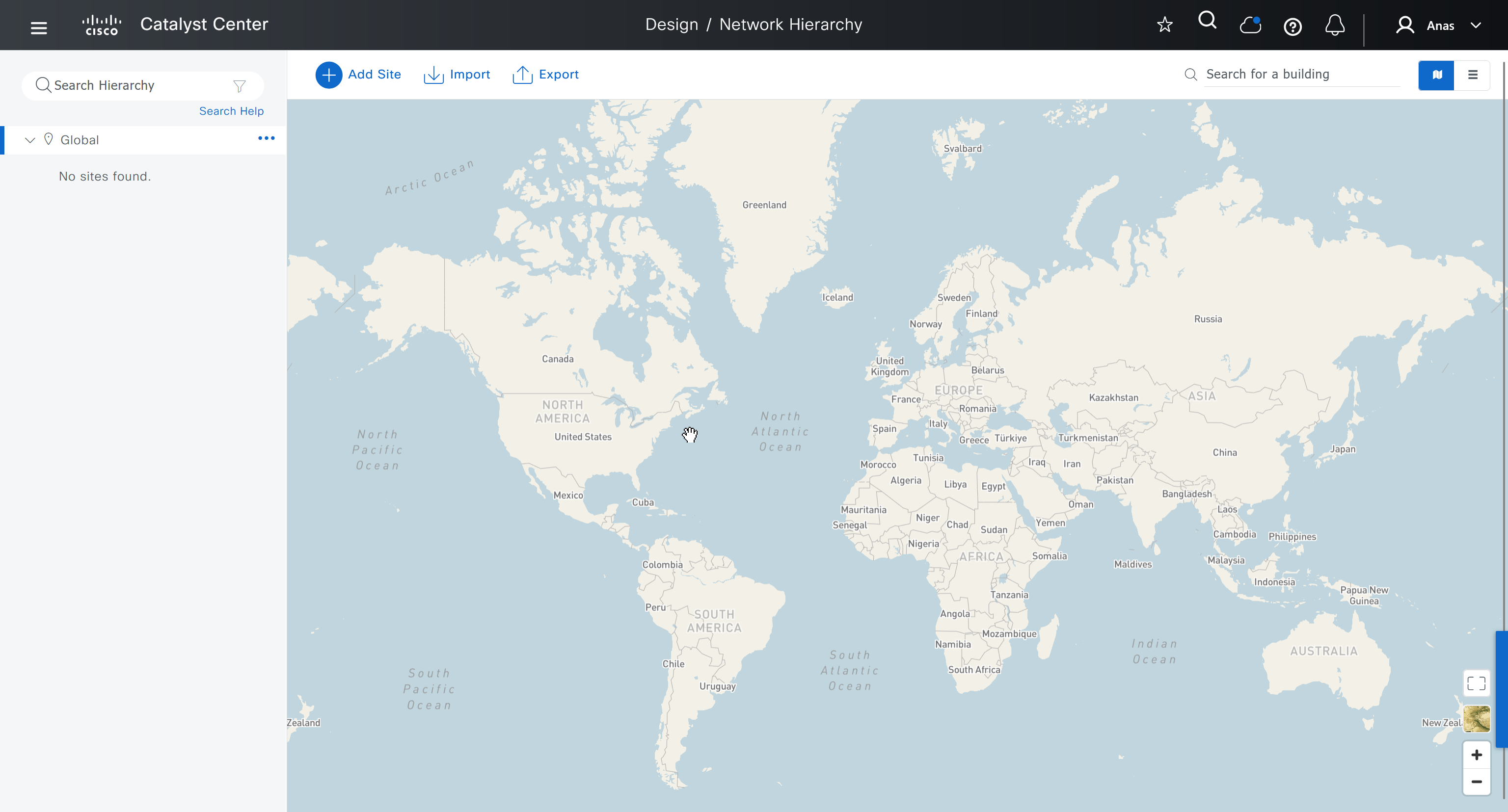
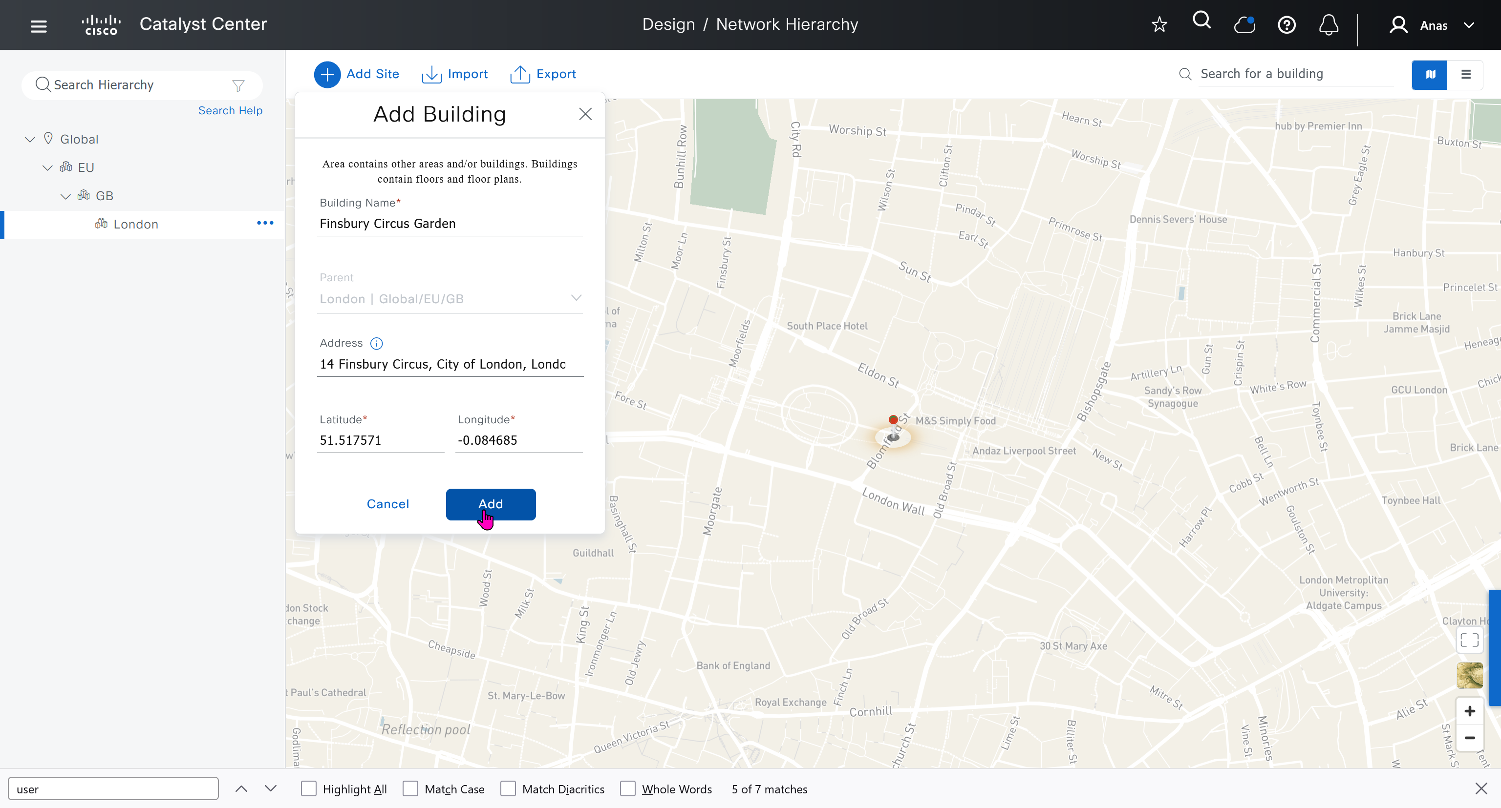
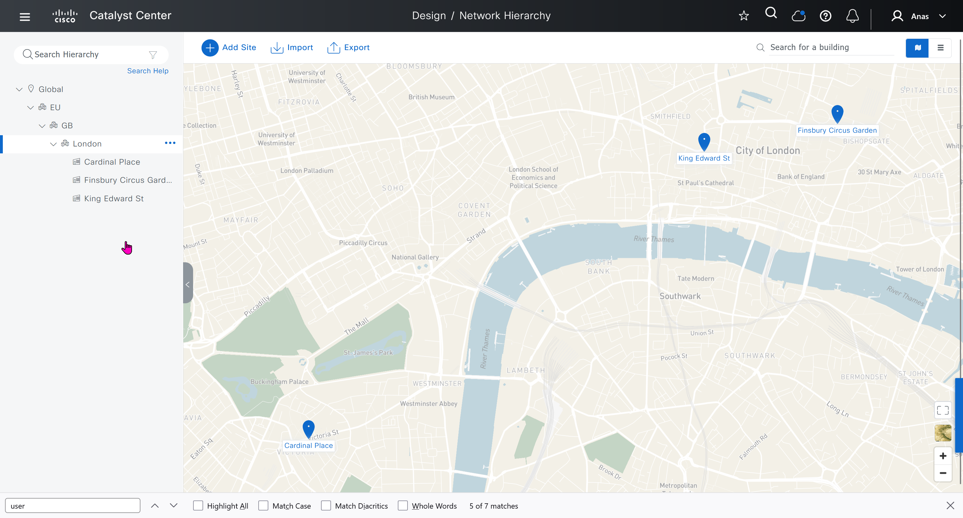
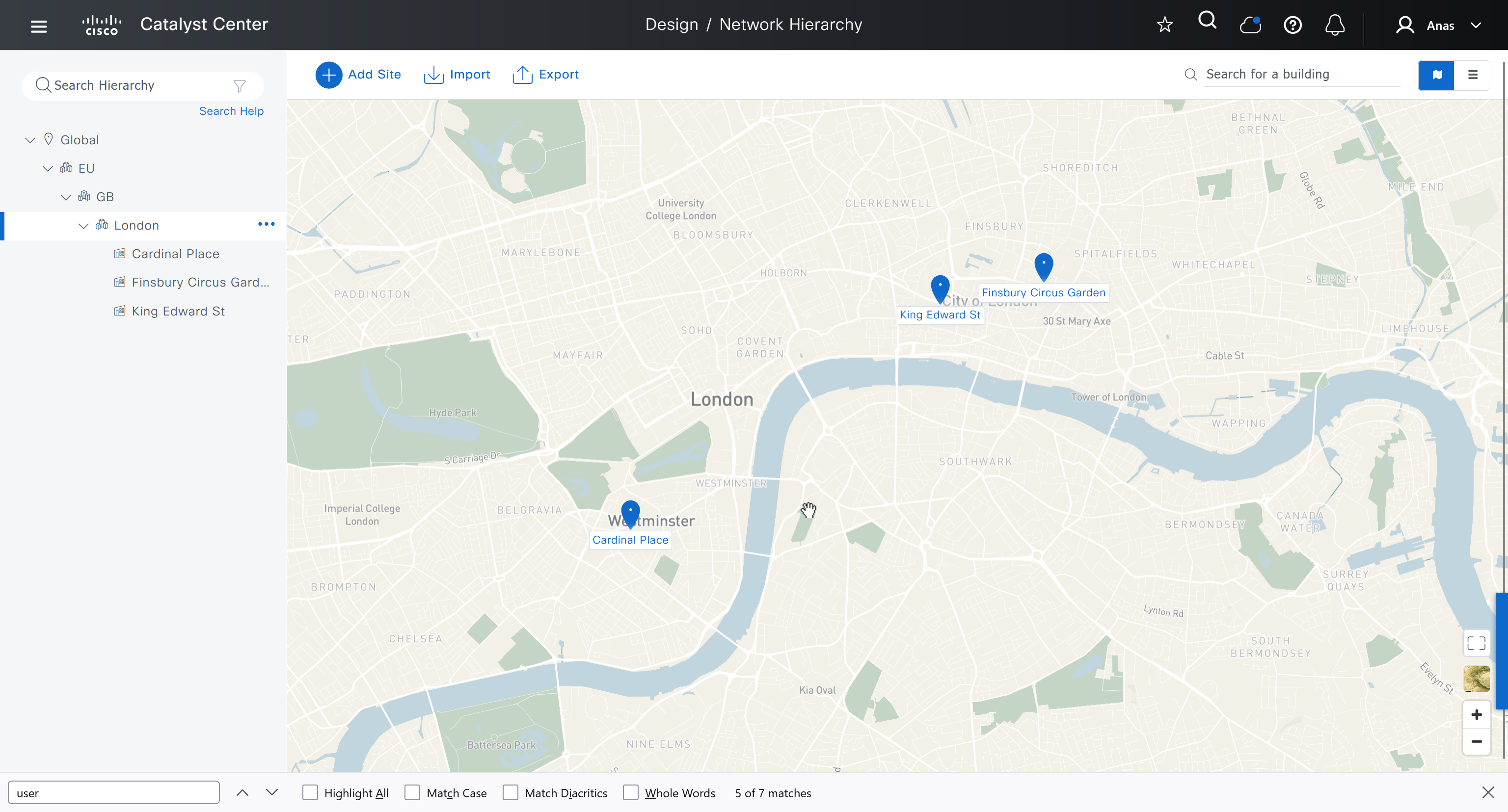
An area represents the geographical location such as country, city or campus (regardless of the size of area), next level is building which represents physical structure, there cannot be buidling inside a building
Cisco recommends the hierarchy as Continent > Country > City > Campus > Buildings
This is how you are on safe side and covered for any future locations and changes with flexibility built in as it can difficult to adjust the hierarchy later on once everything is configured
For example, today you are domestic but tomorrow you might go international and open new offices in new country / continent

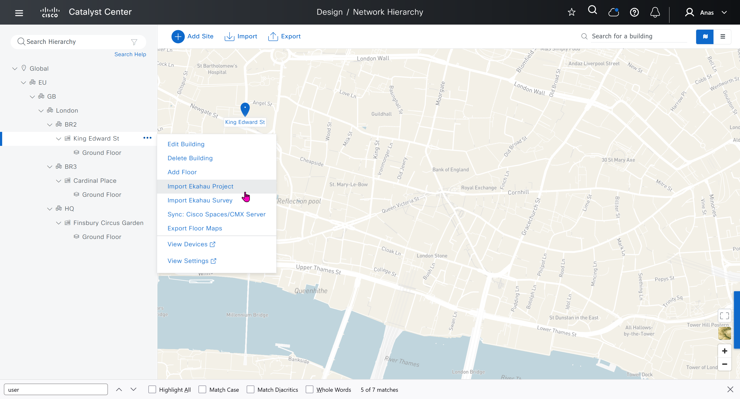
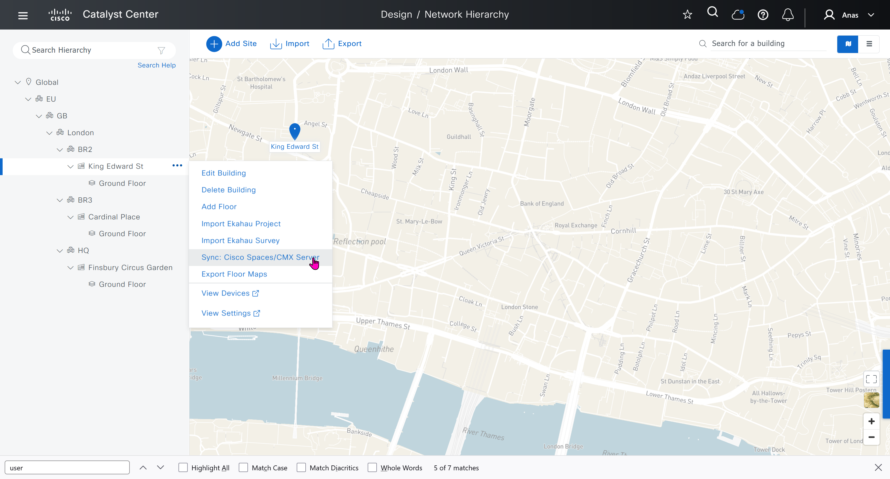
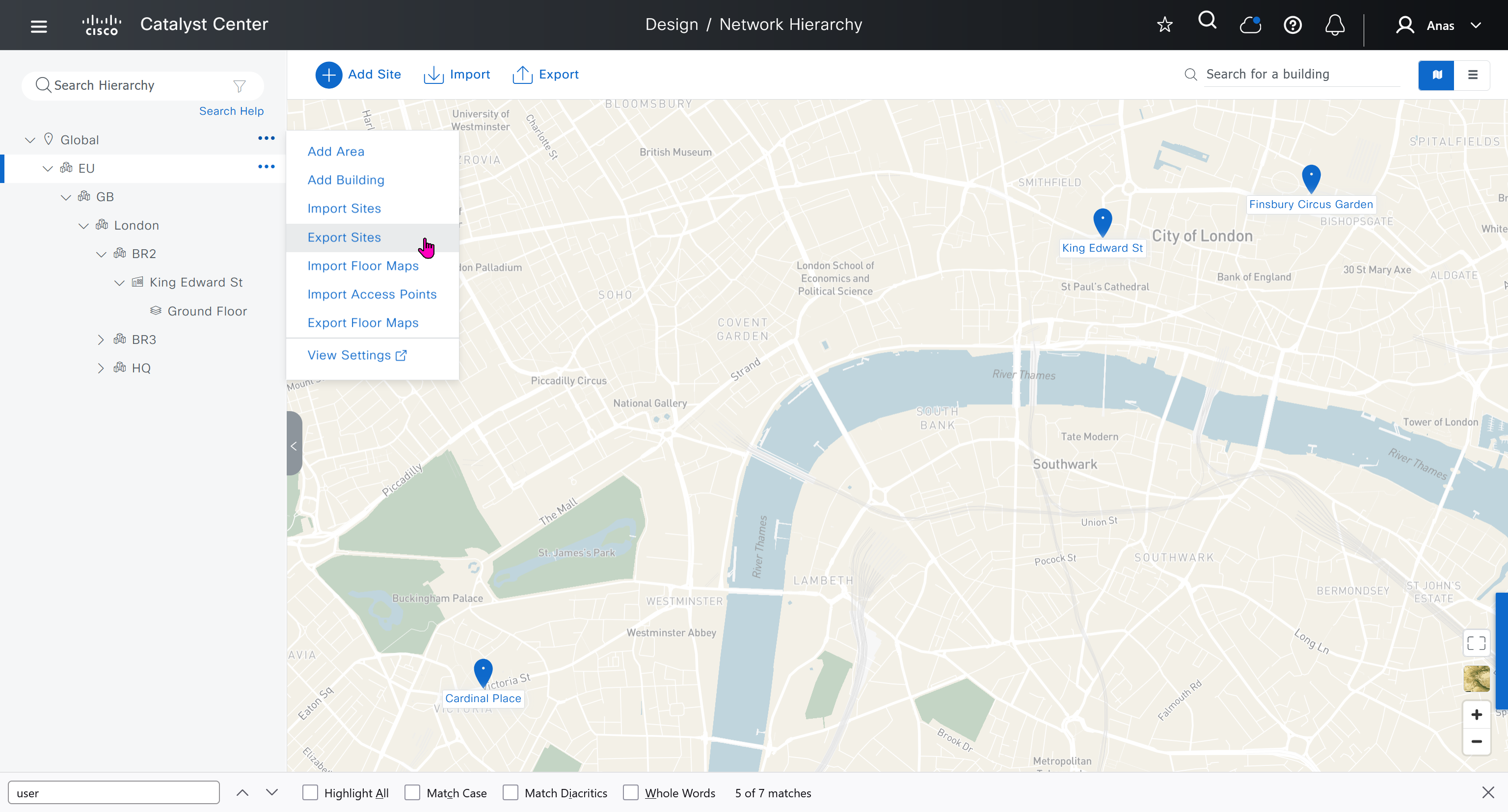
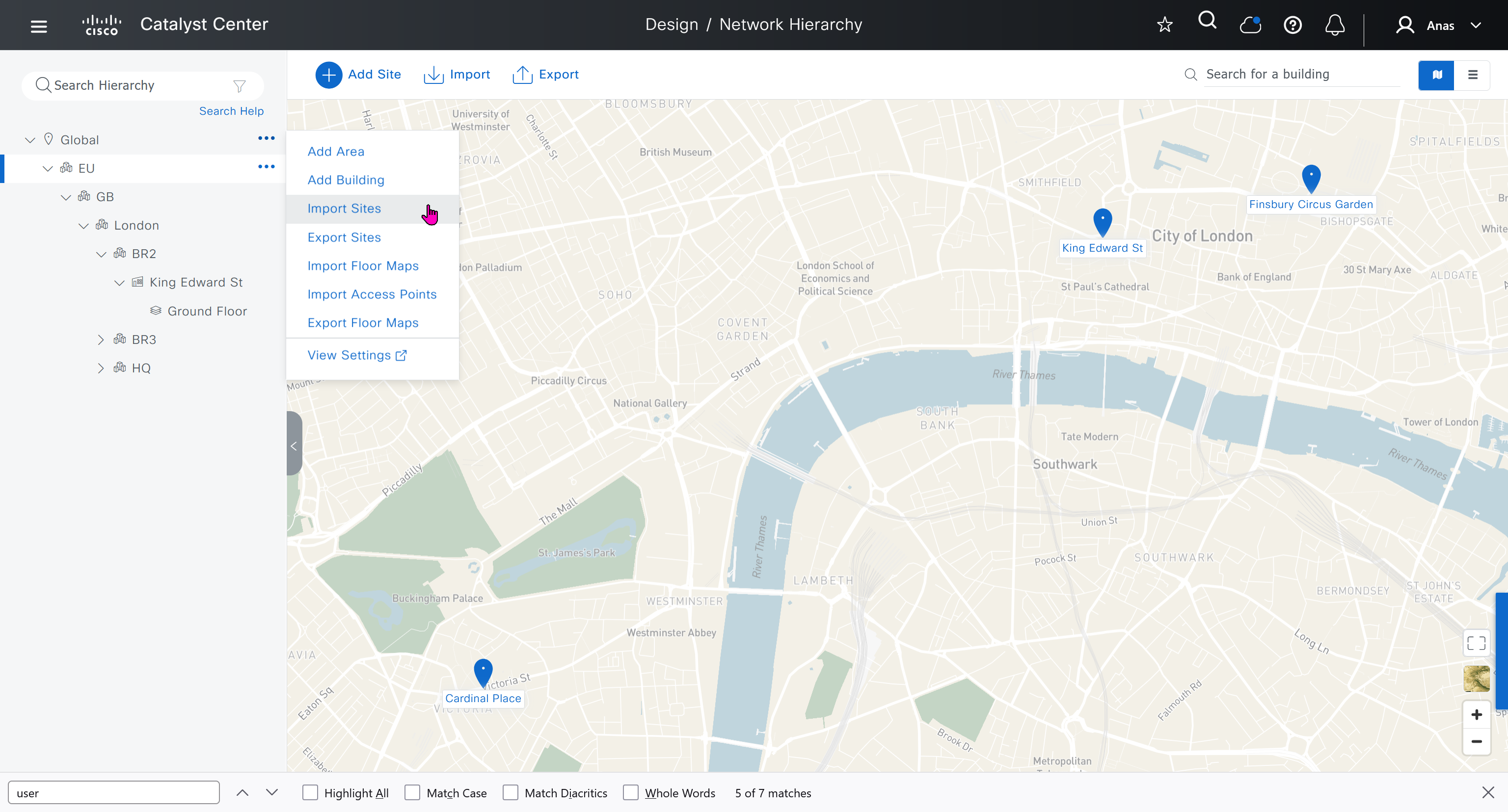
We will create 3 sites in EU > GB > London
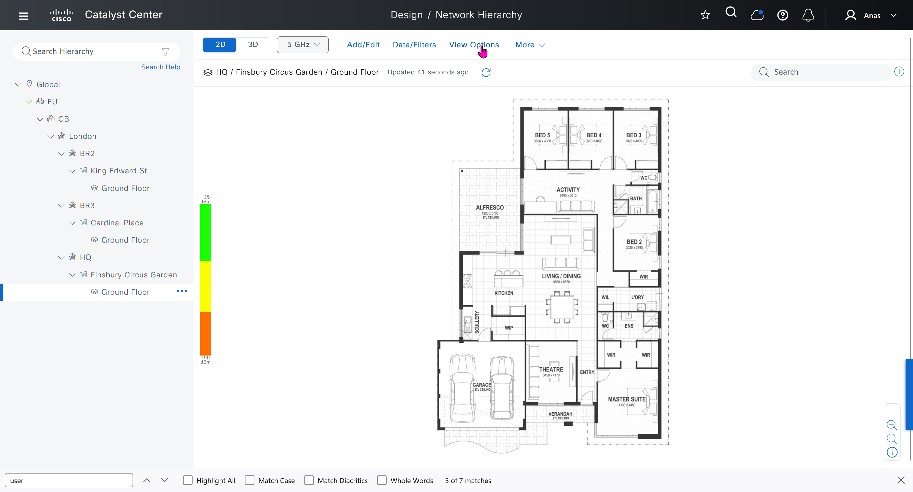
- Finsbury Circus Garden, 14 Finsbury Circus, London EC2M 7EB
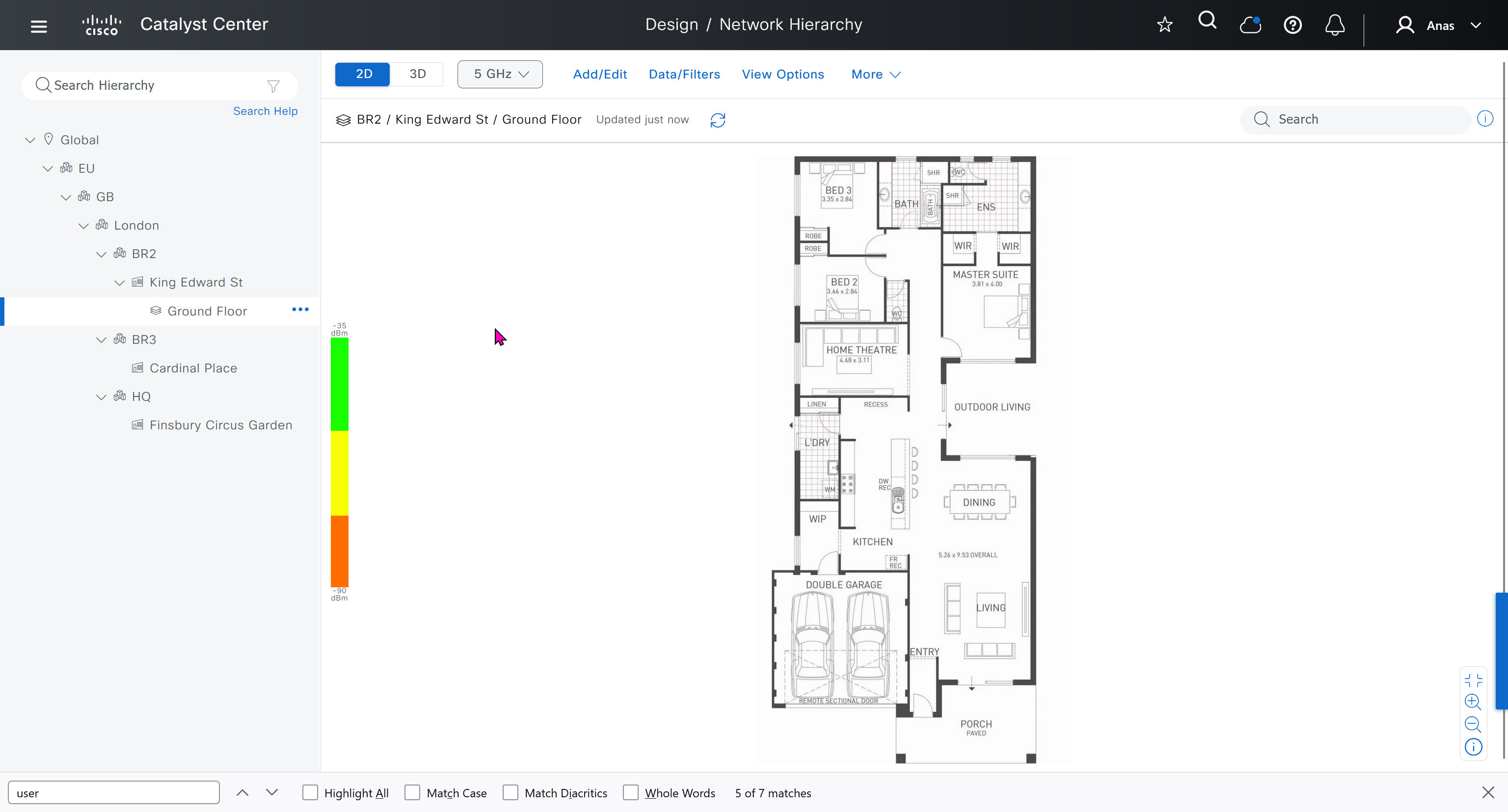
- 7 King Edward St, London EC1A 1HQ
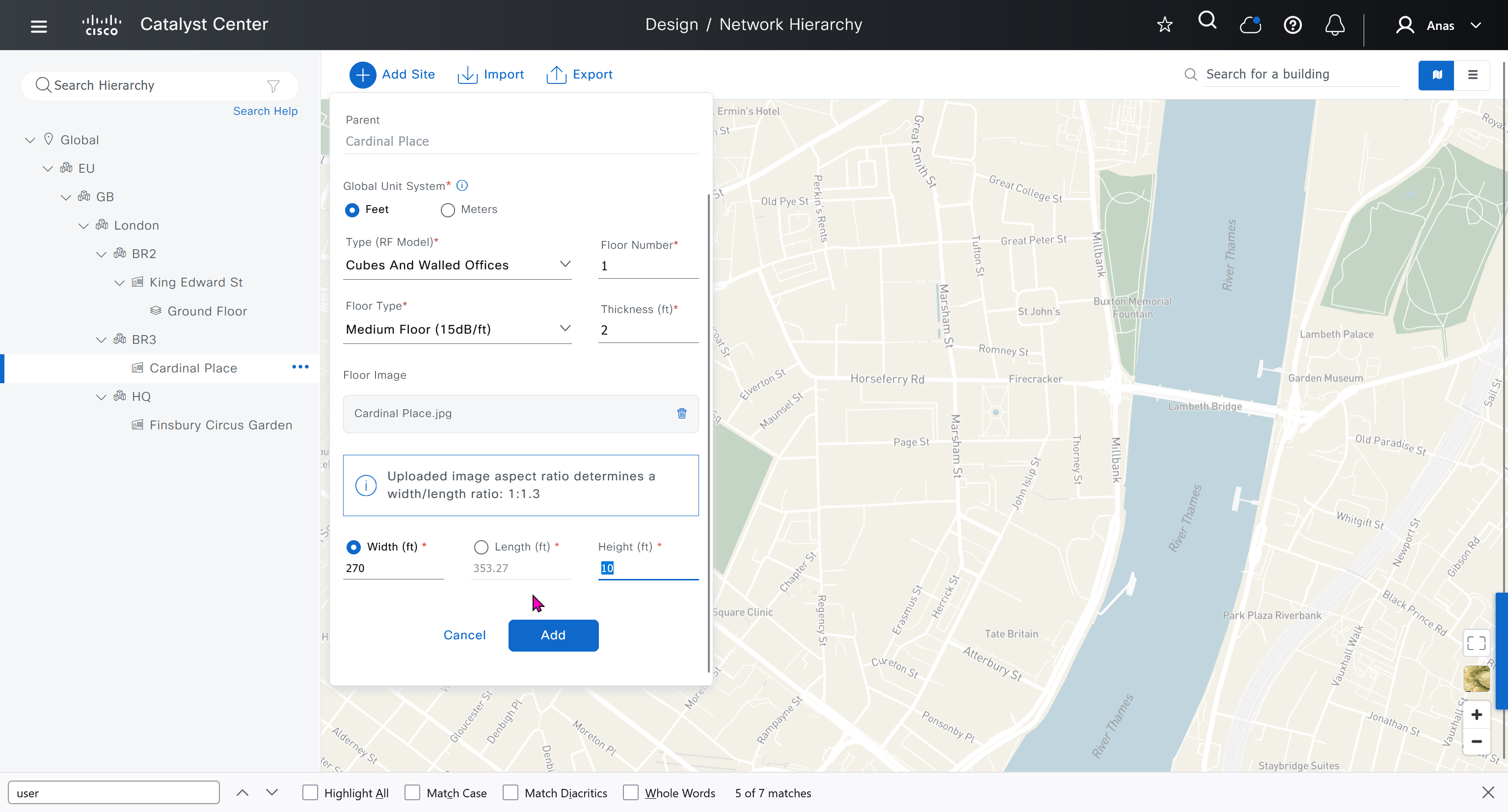
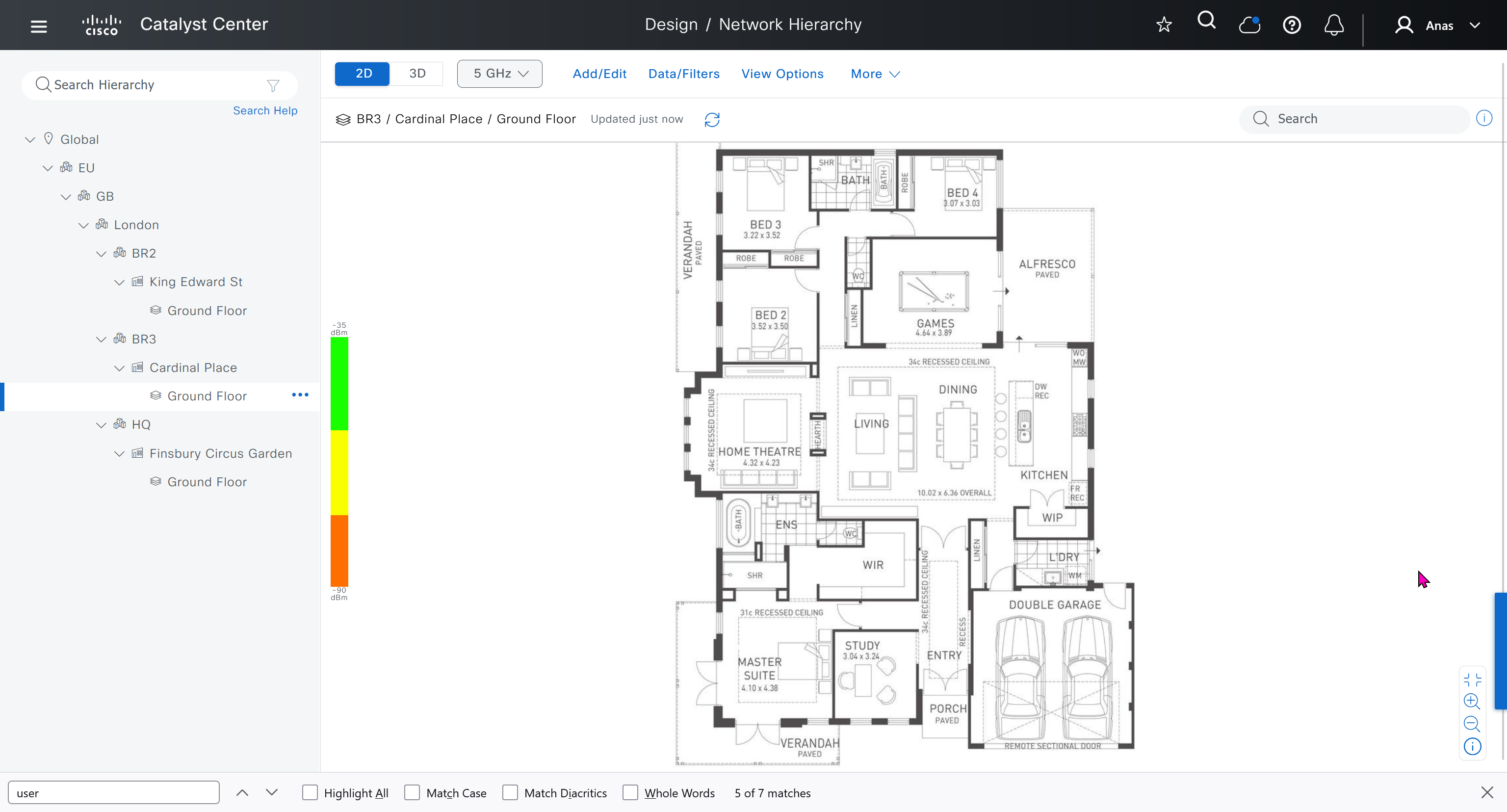
- Cardinal Place, 84 Victoria St, London SW1E 5JL

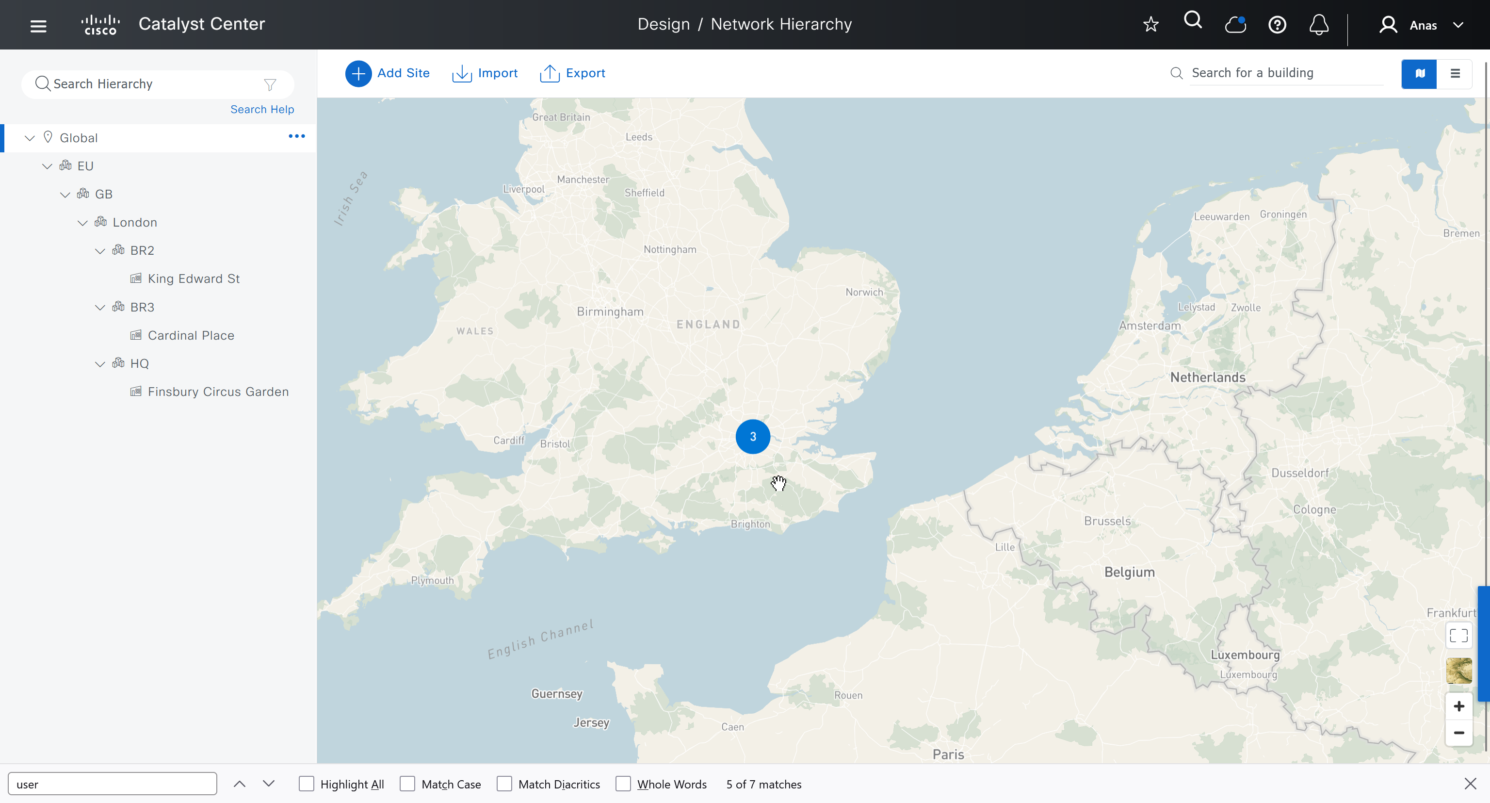
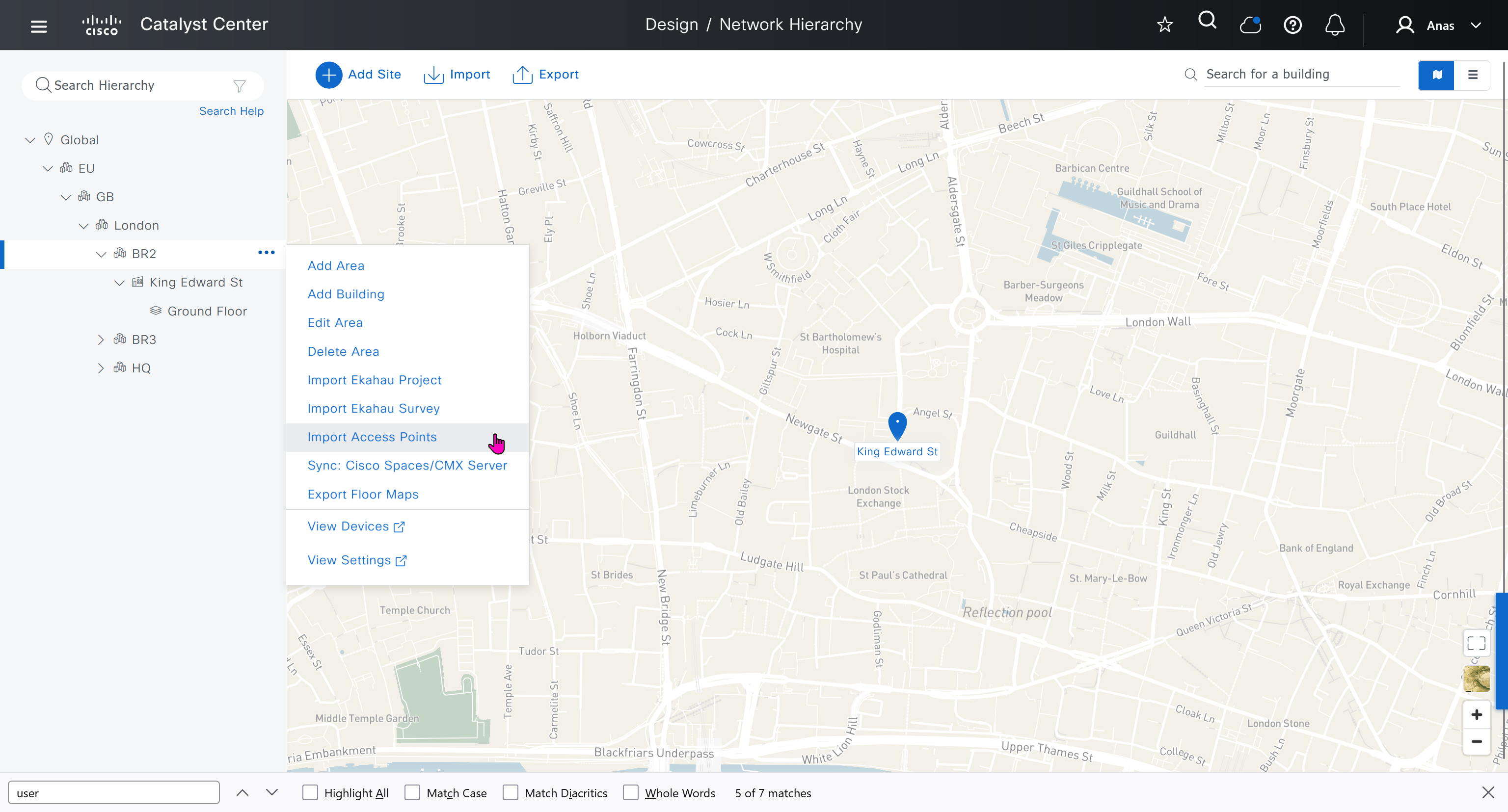
We should add HQ, BR2 and BR3

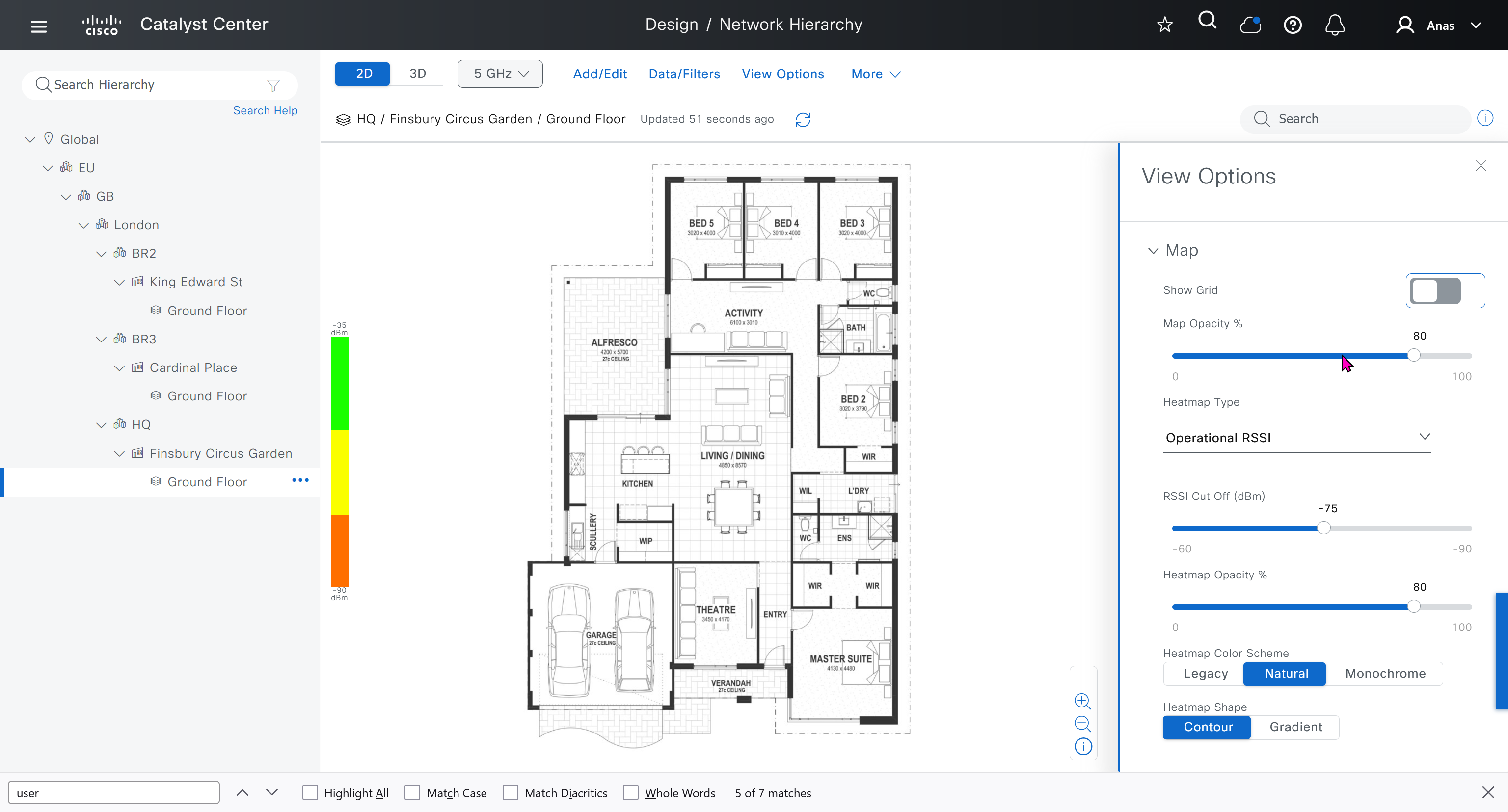
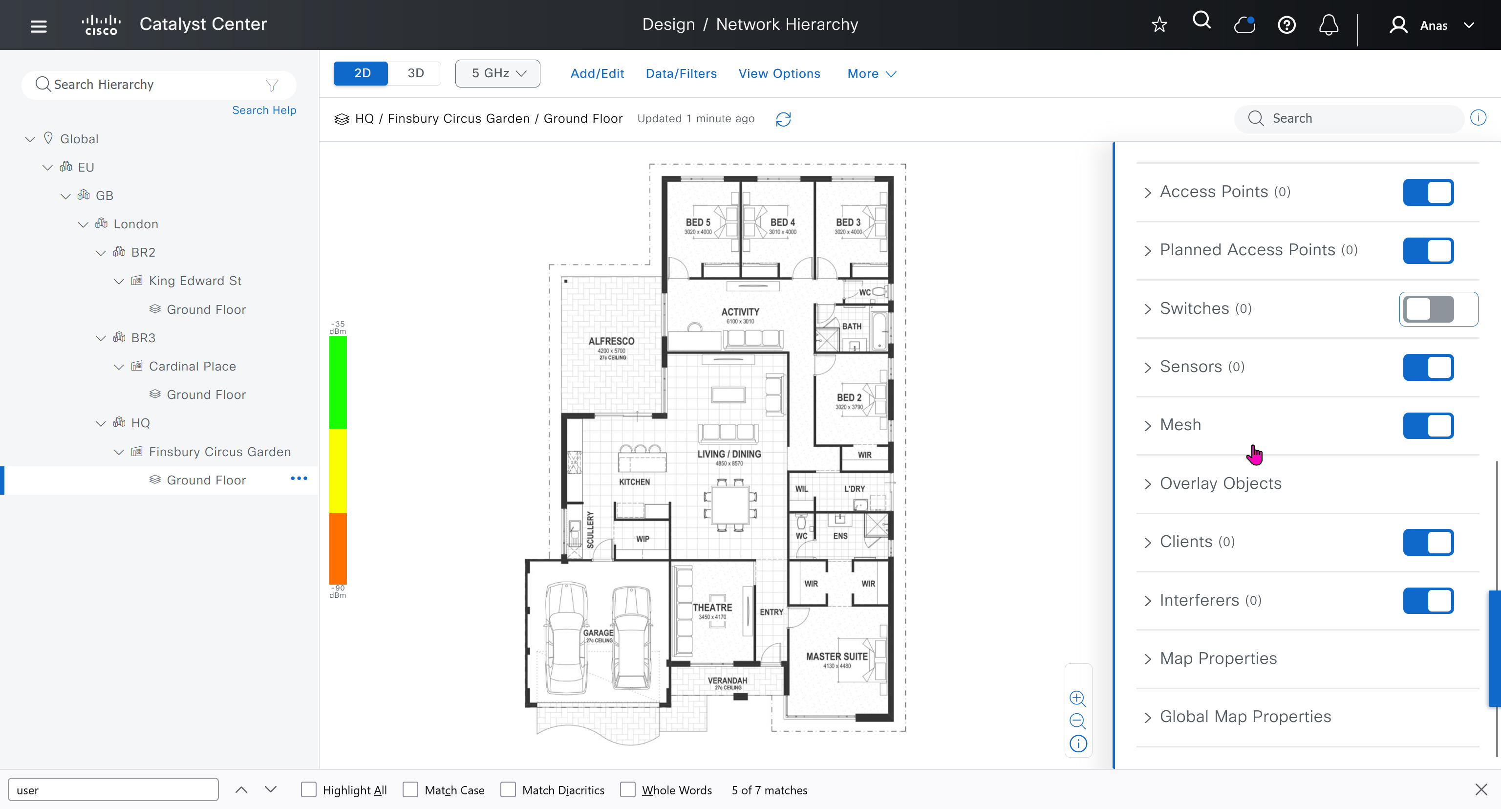
We can add floors and floors are mostly used for placing wireless access points but for SDA we can add ground floor, if customer had prime we can import APs on floor plans already from prime
for RF model on the floor just stick with default of “Cubes And Walled Offices”
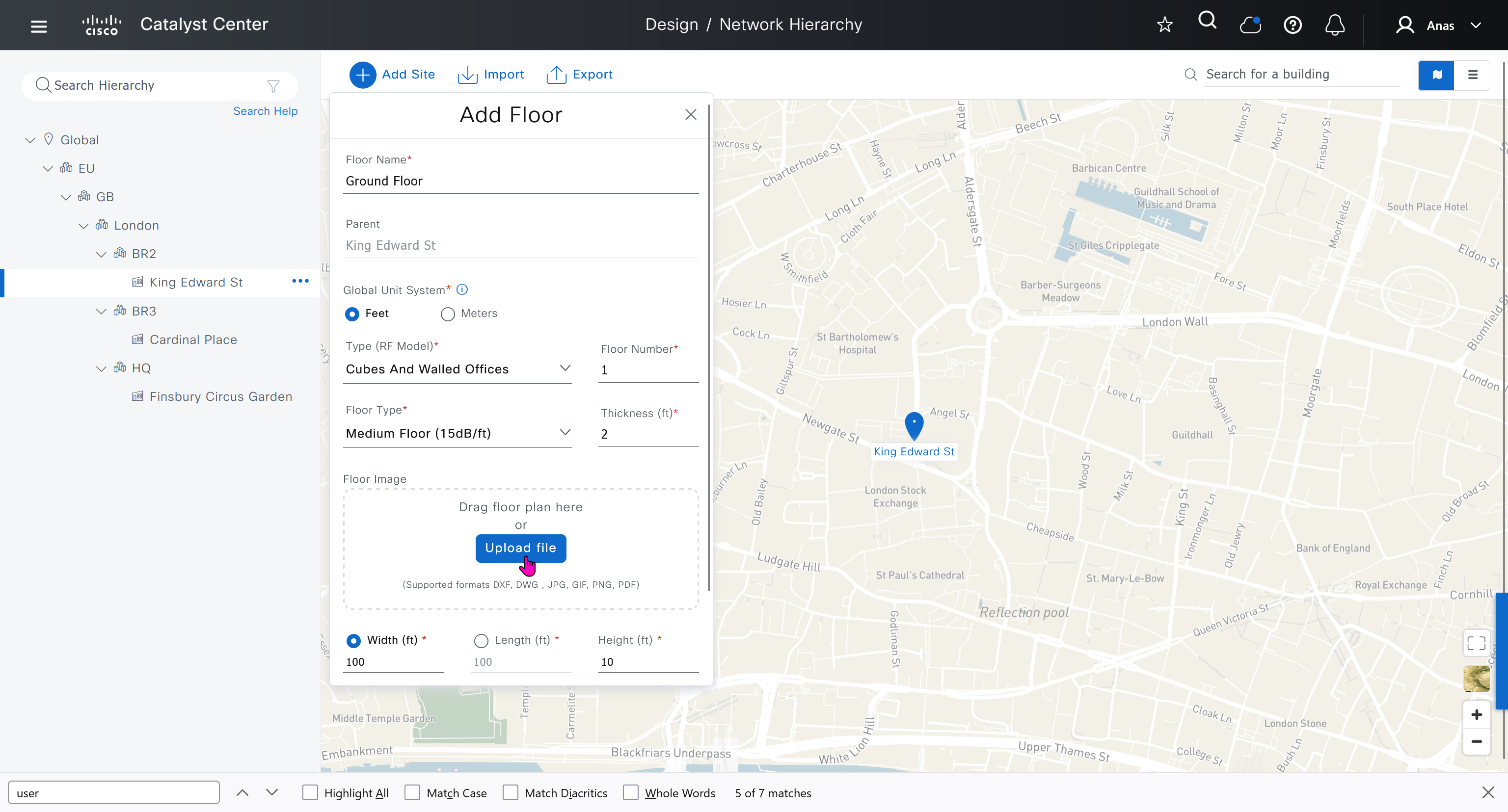
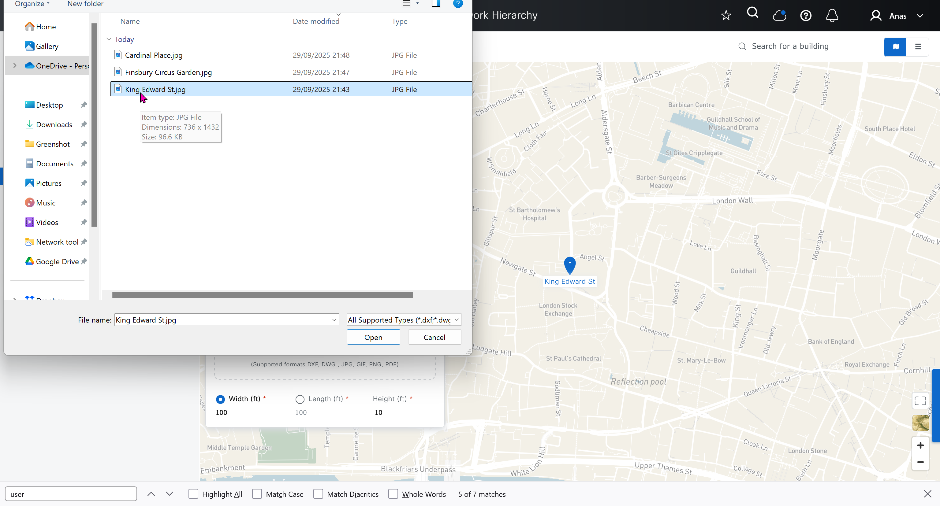
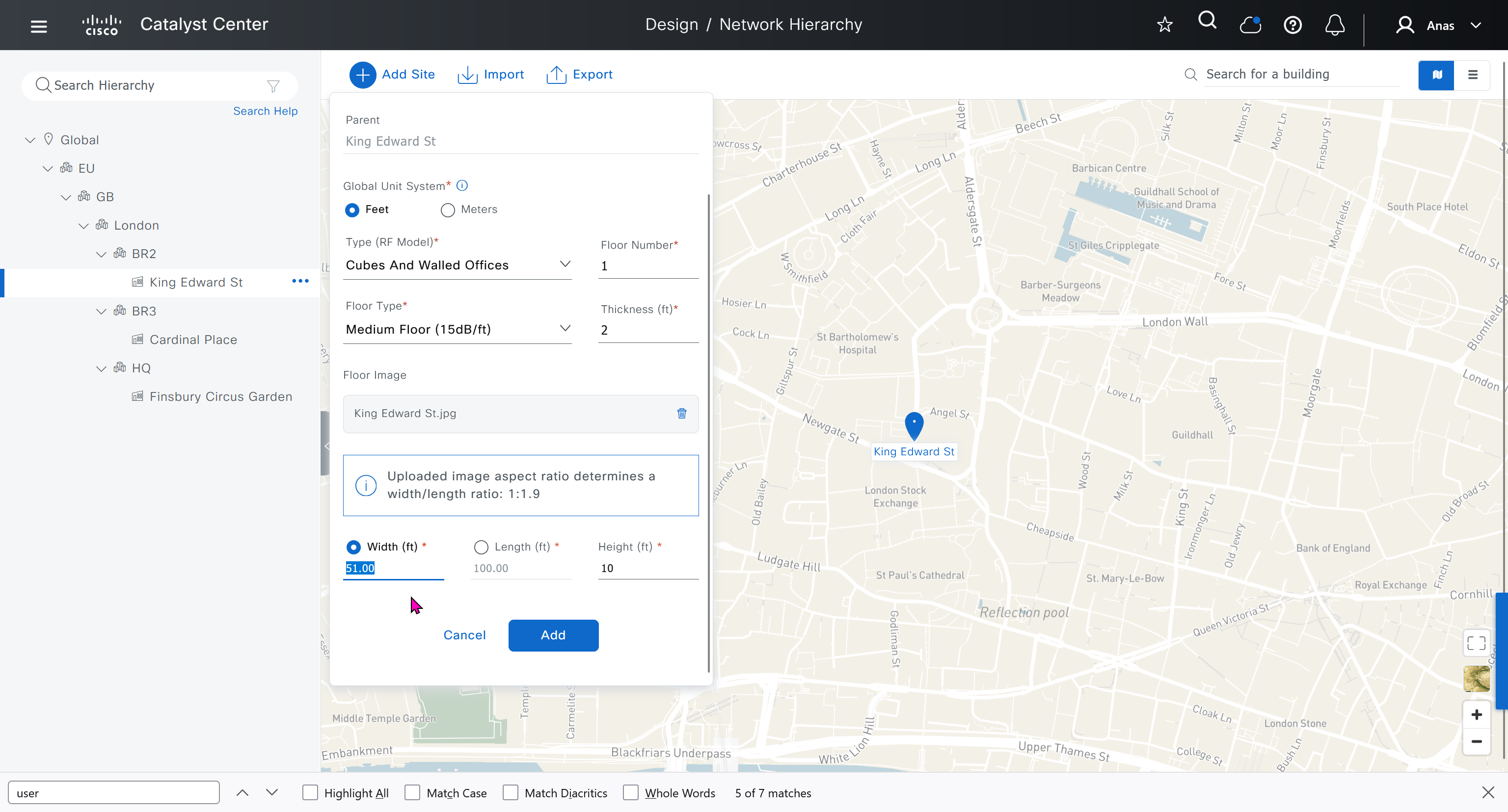
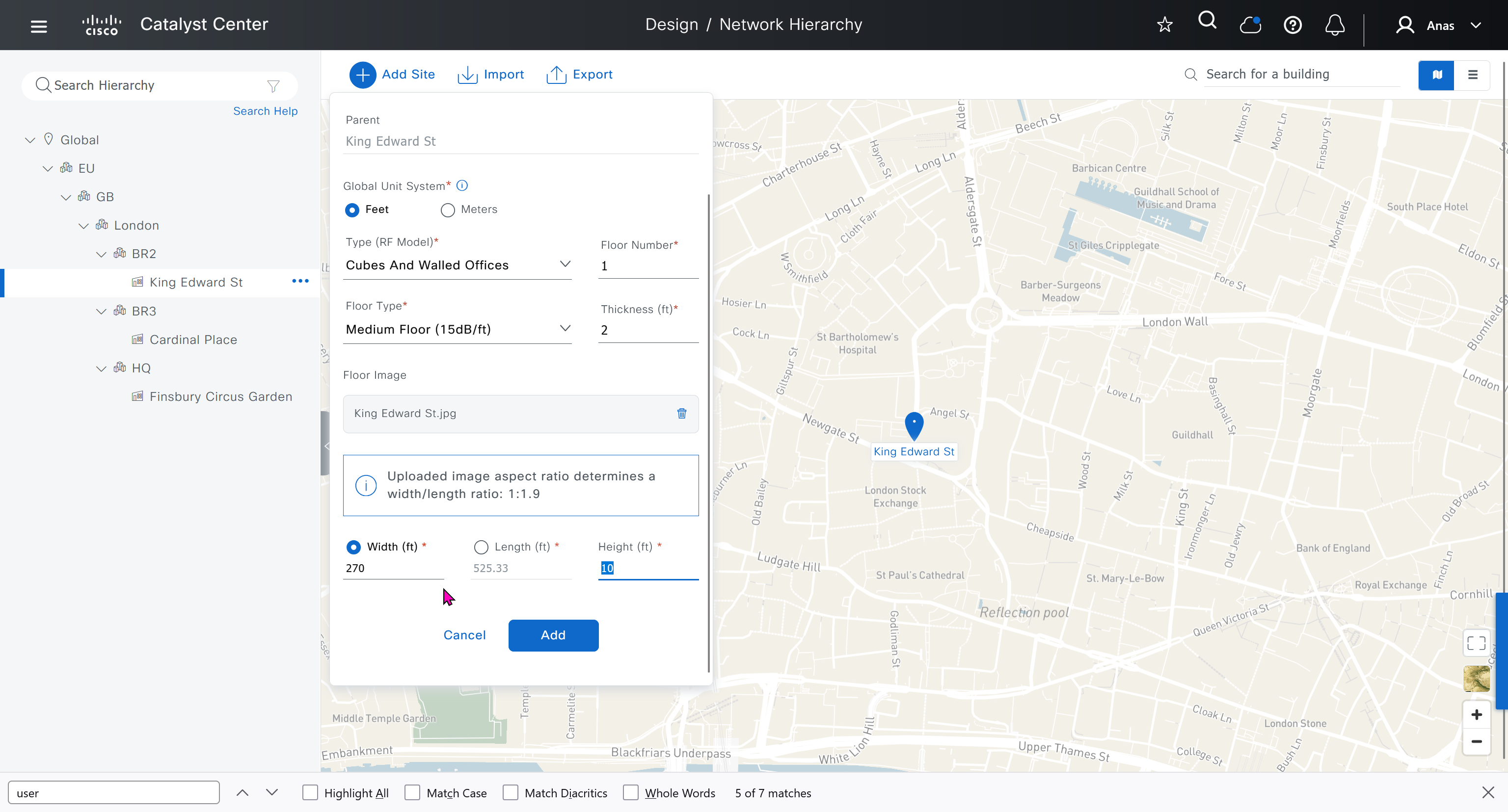
see that when I changed width, dnac maintained the aspect ratio from the image I uploaded


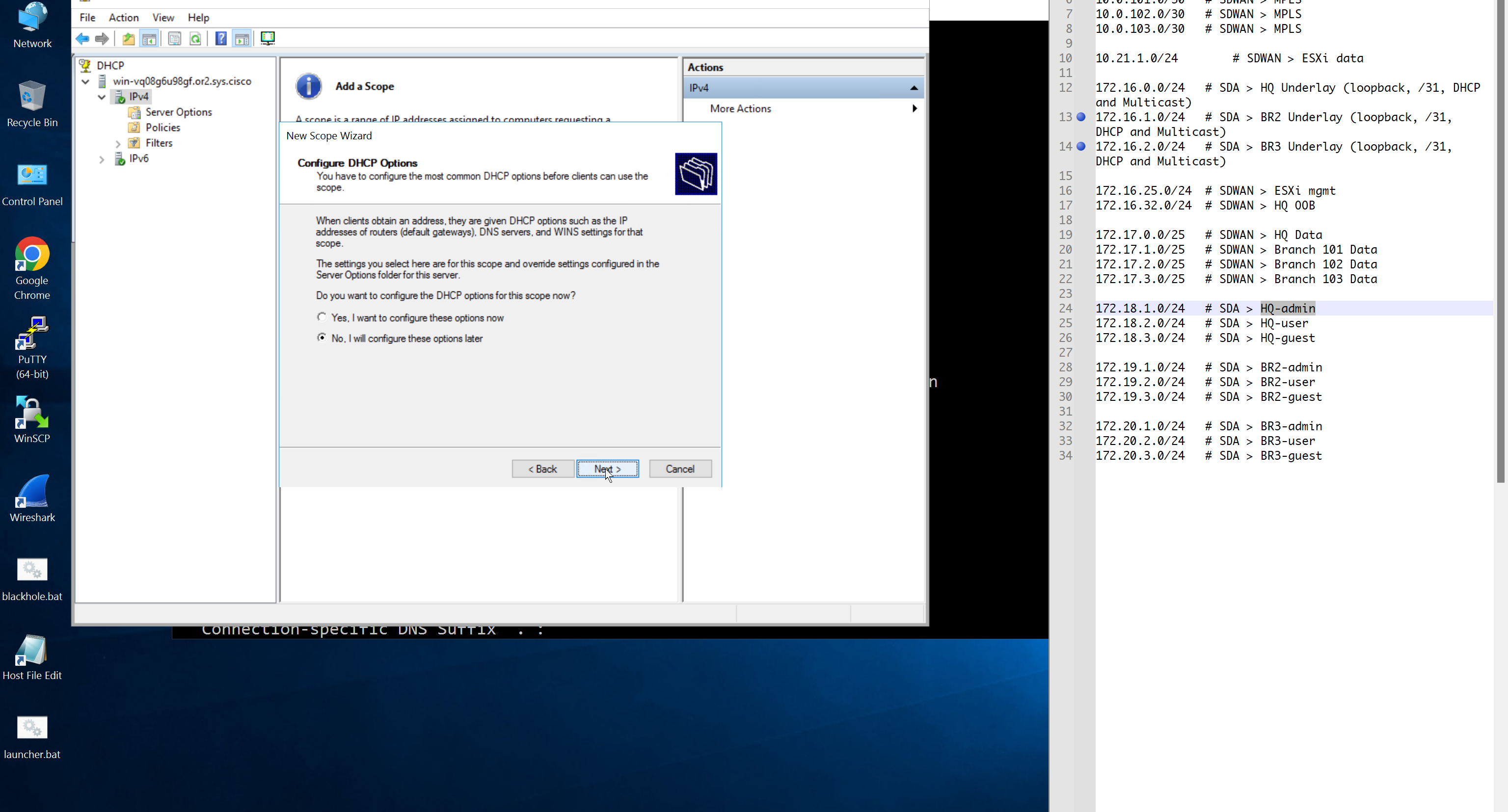
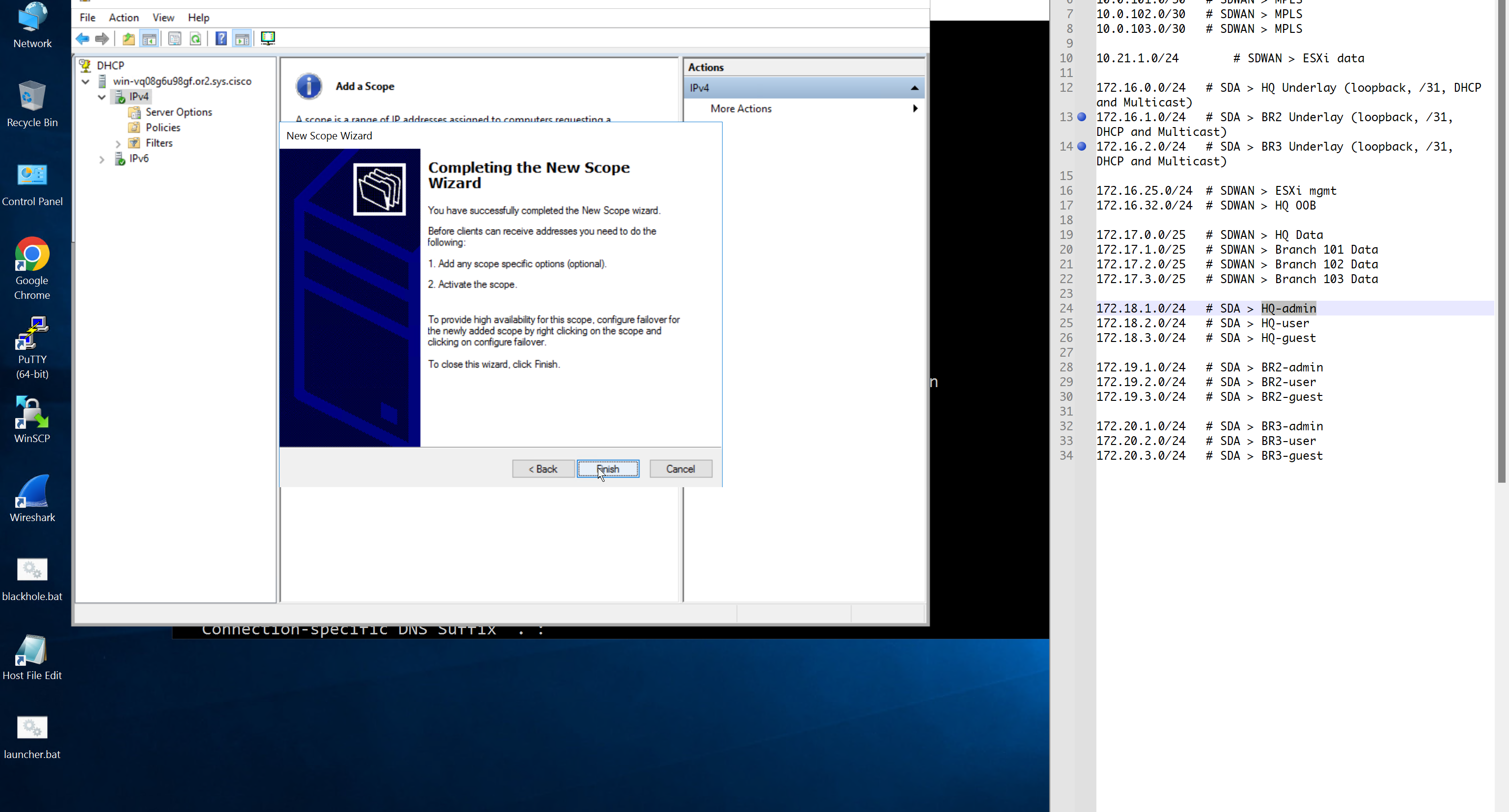
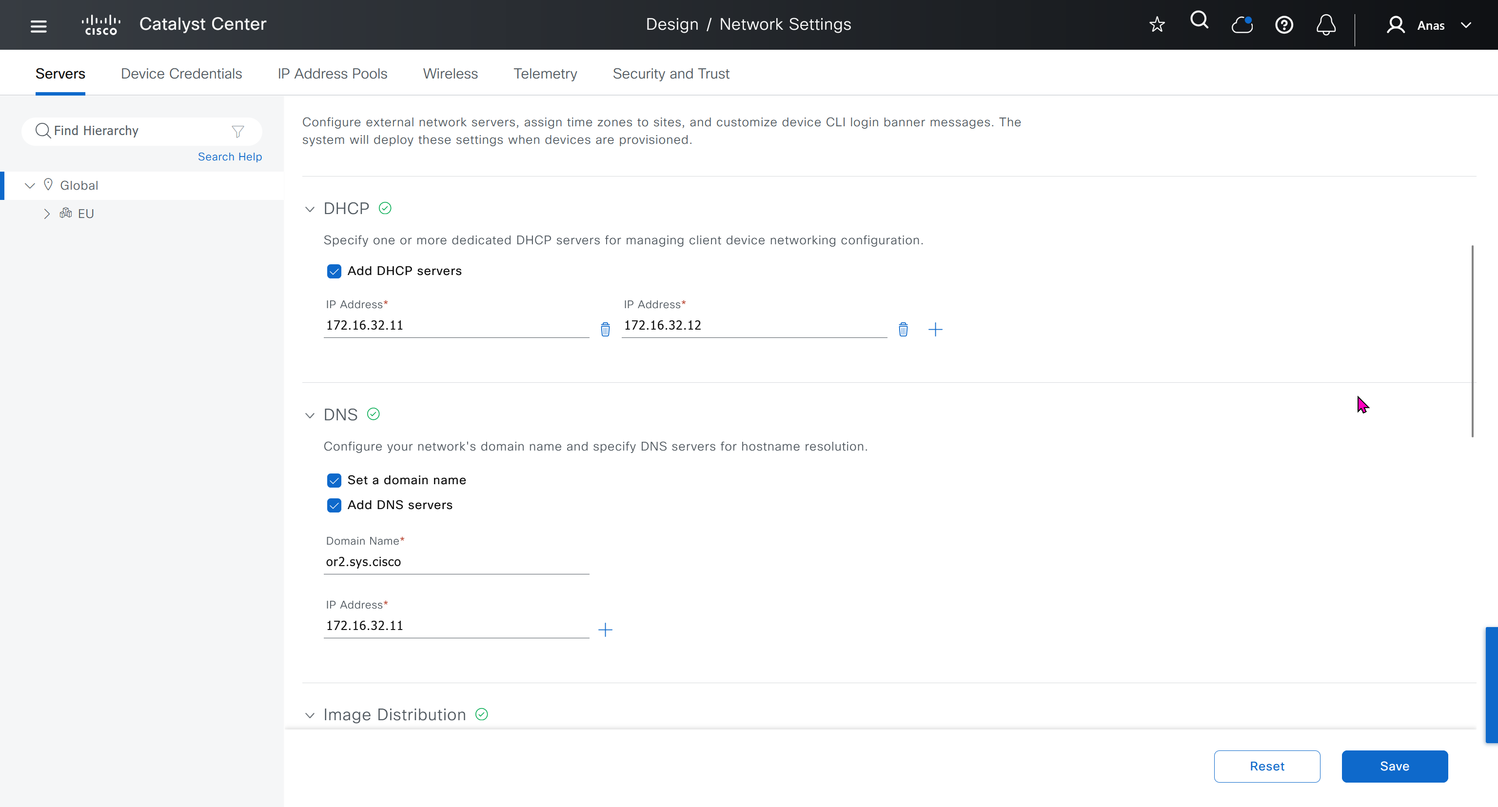
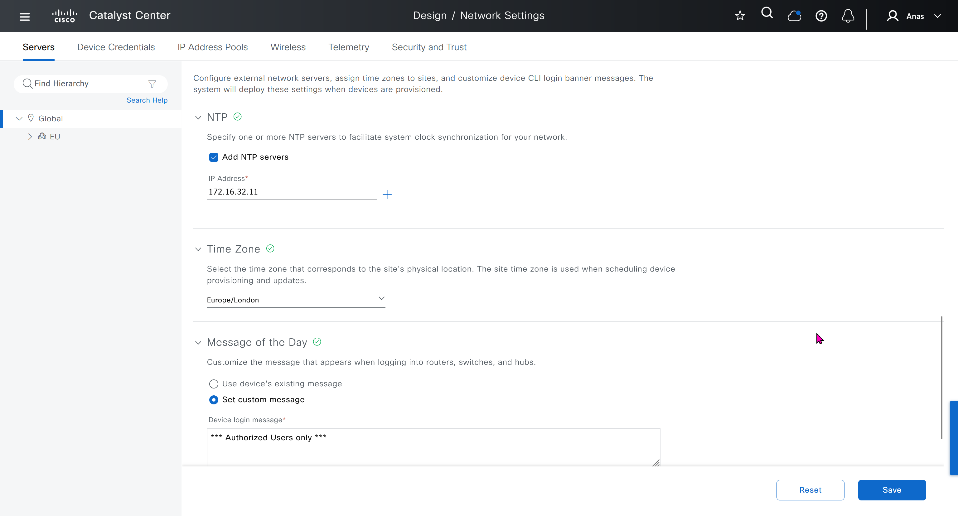
Network contains common settings similar to what DHCP contains but more such as AAA server, DHCP server, DNS server, Image Distribution (used to download the Catalyst IOS XE image), NTP server, Time Zone and Message of the day but looking at it feels like that this configuration is for the switches because this is the configuration that will be pushed to devices as they get provisioned into DNAC
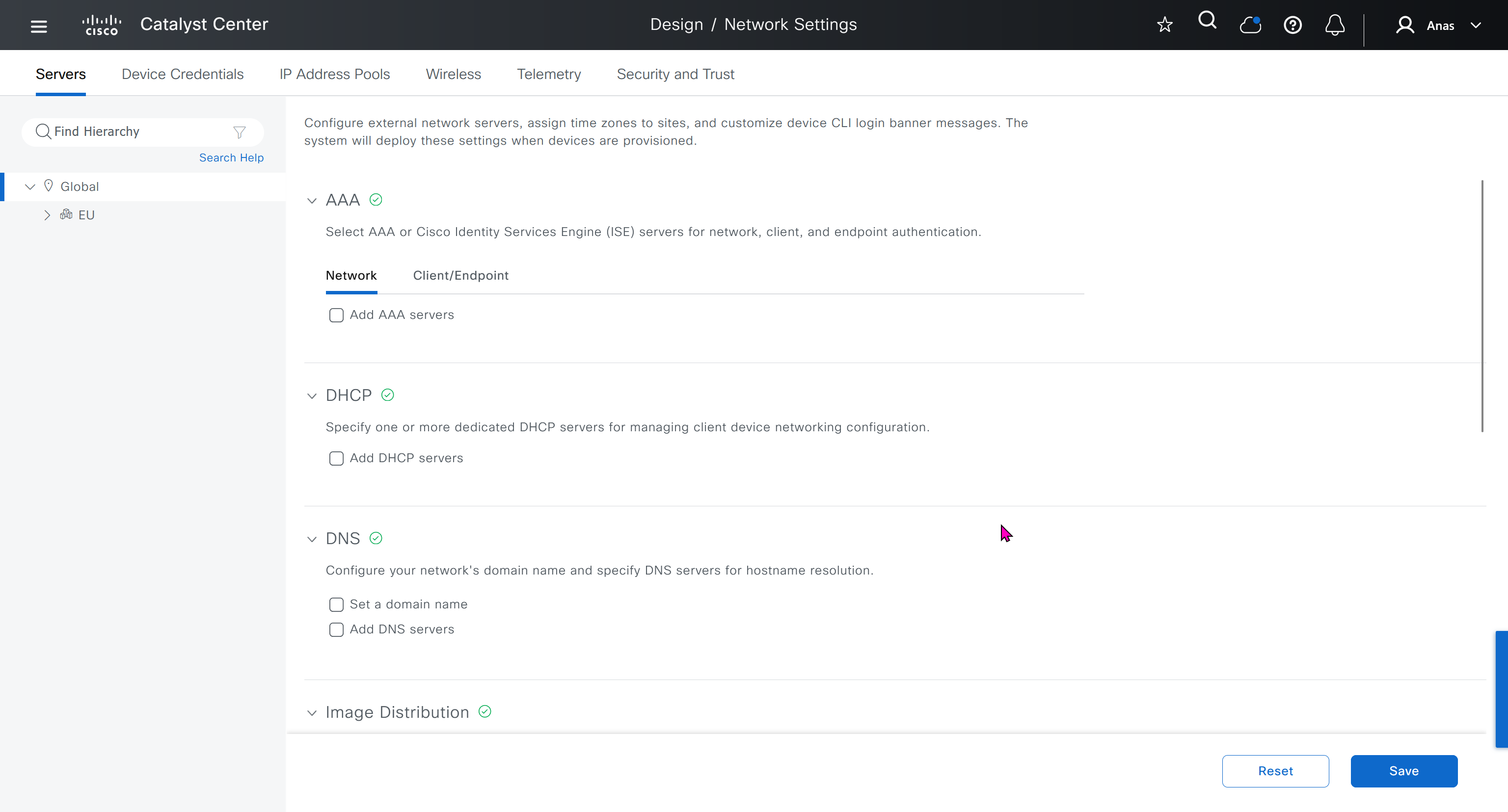
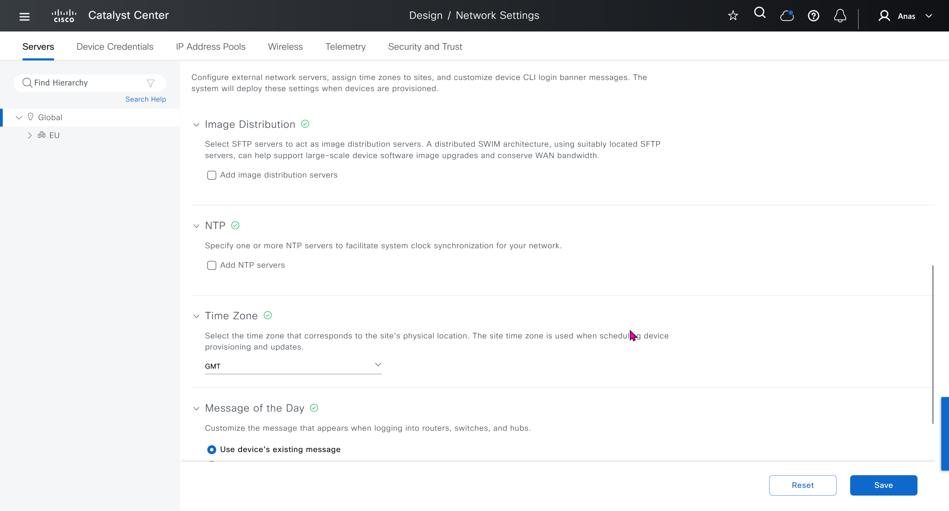
In DHCP servers section we will also specify ISE IP address because it is one of the ways for ISE to perform profiling based on DHCP request from device
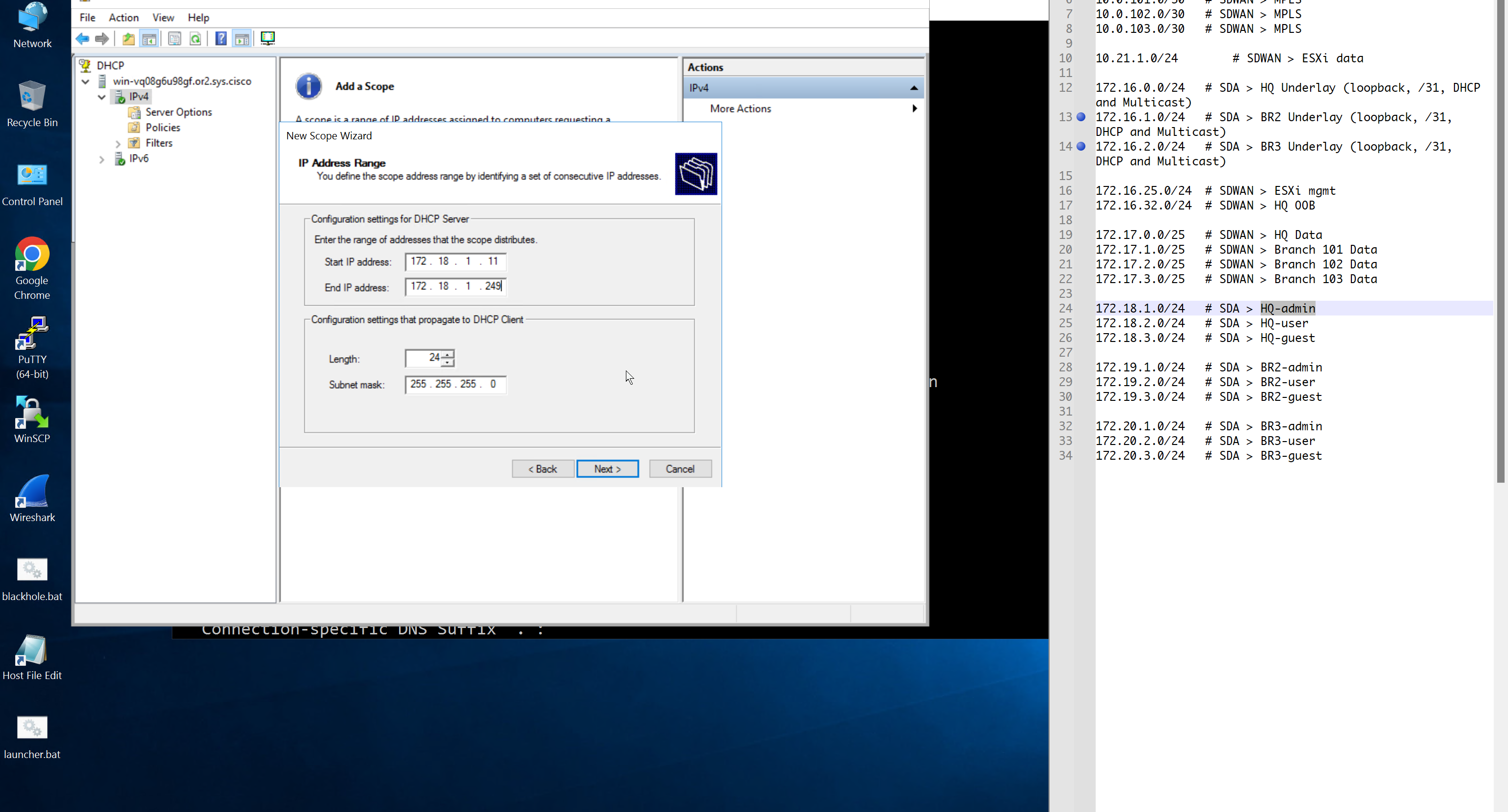
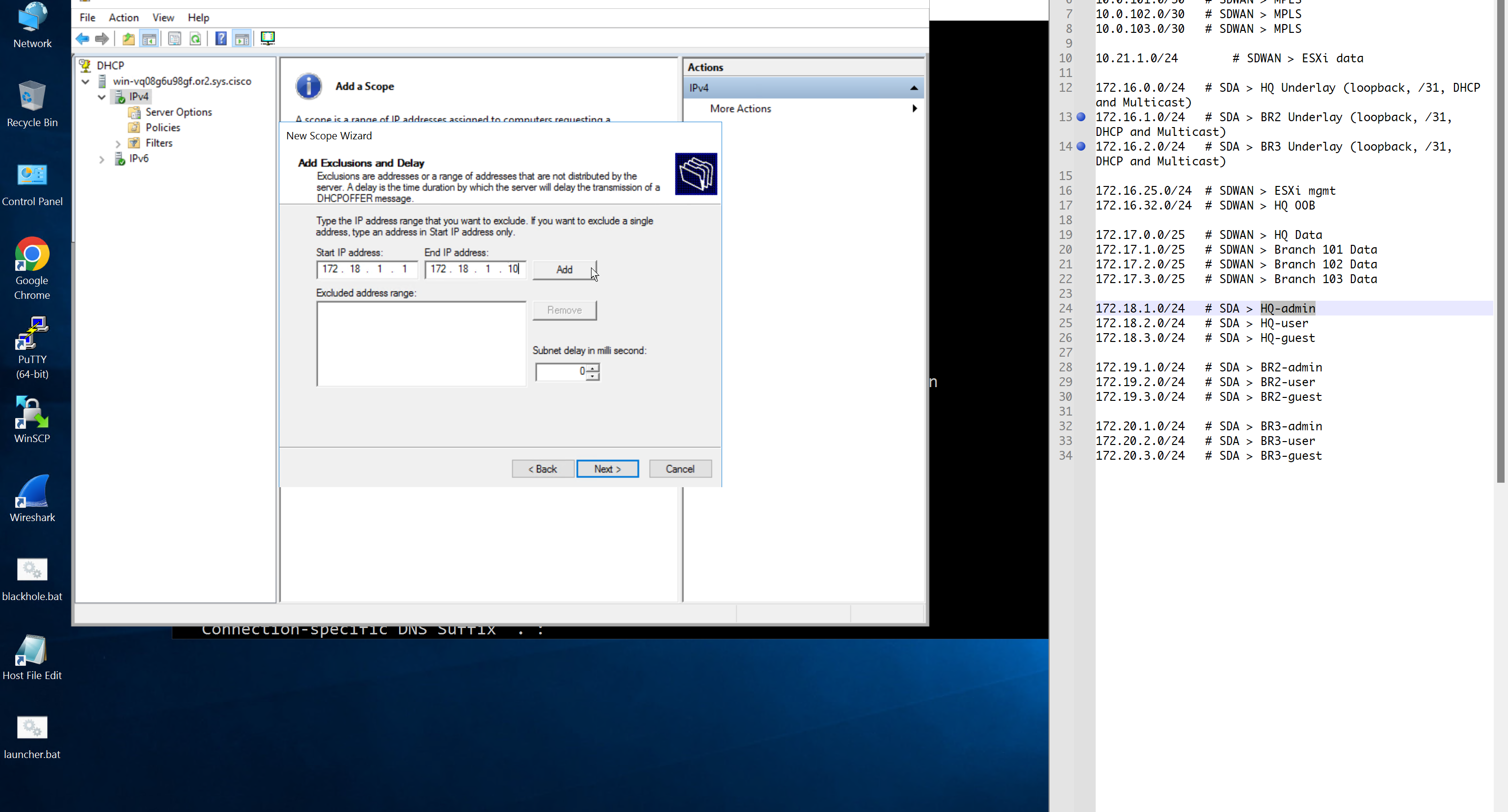
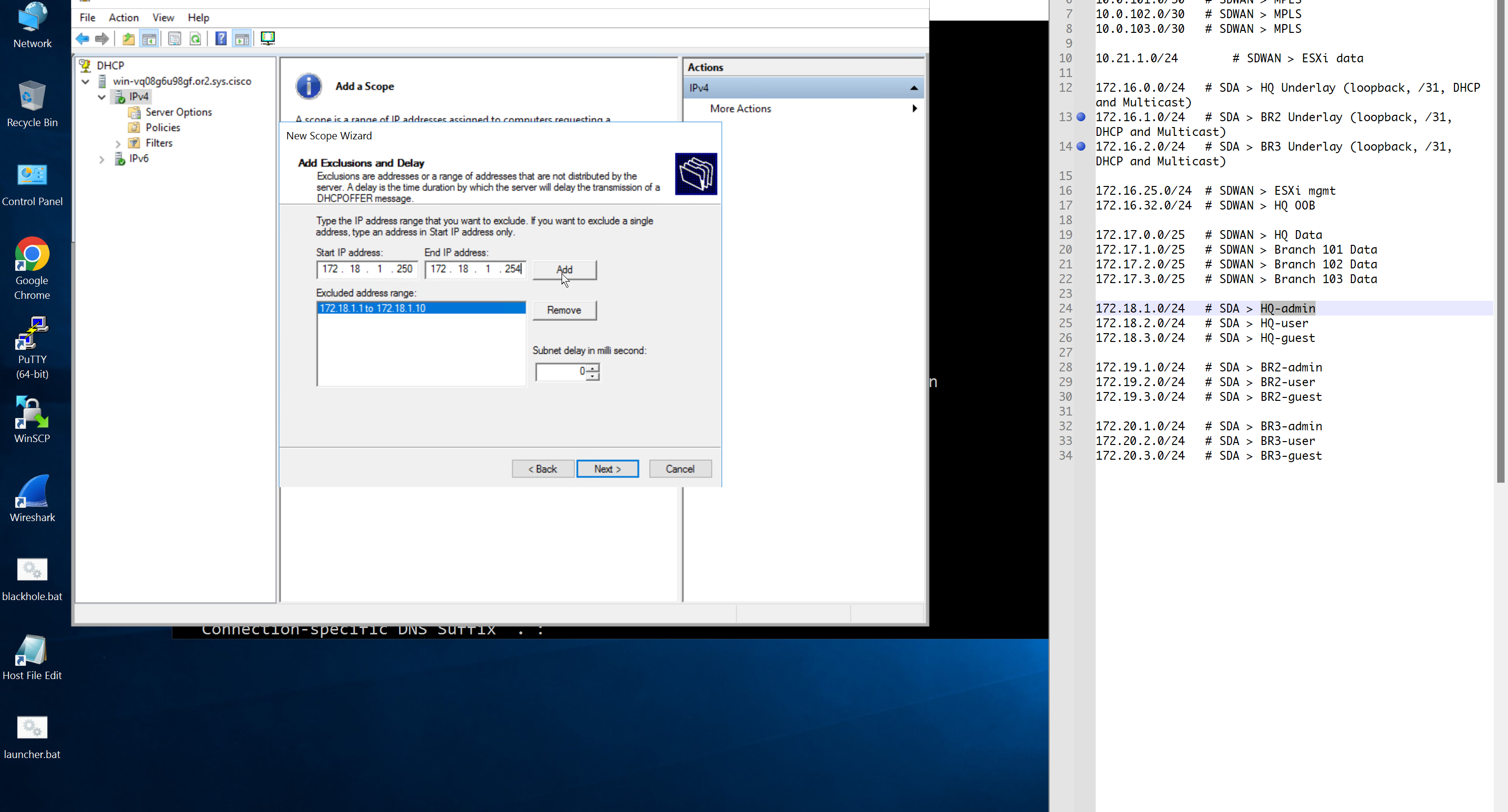
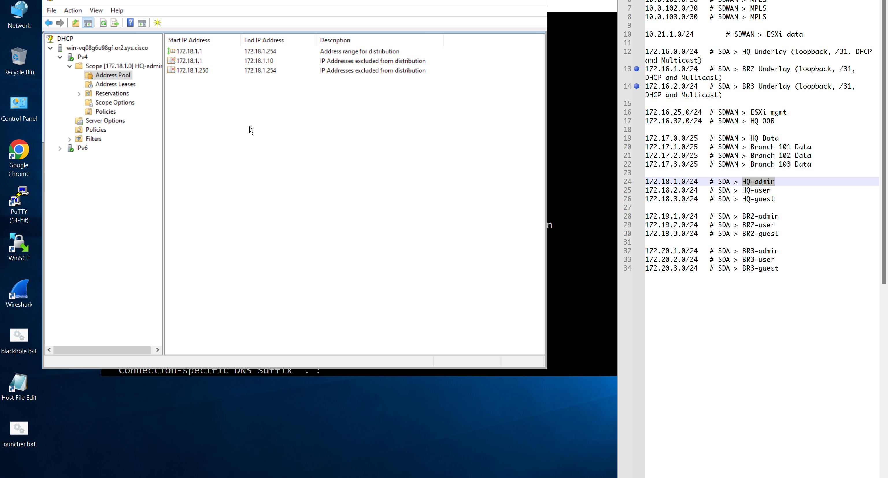
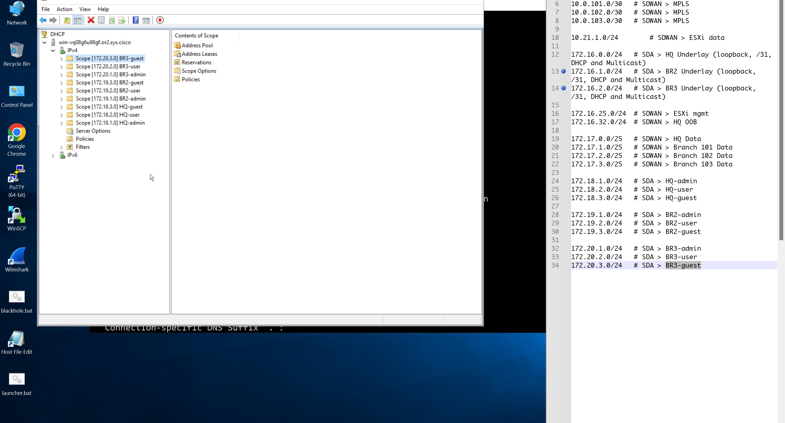
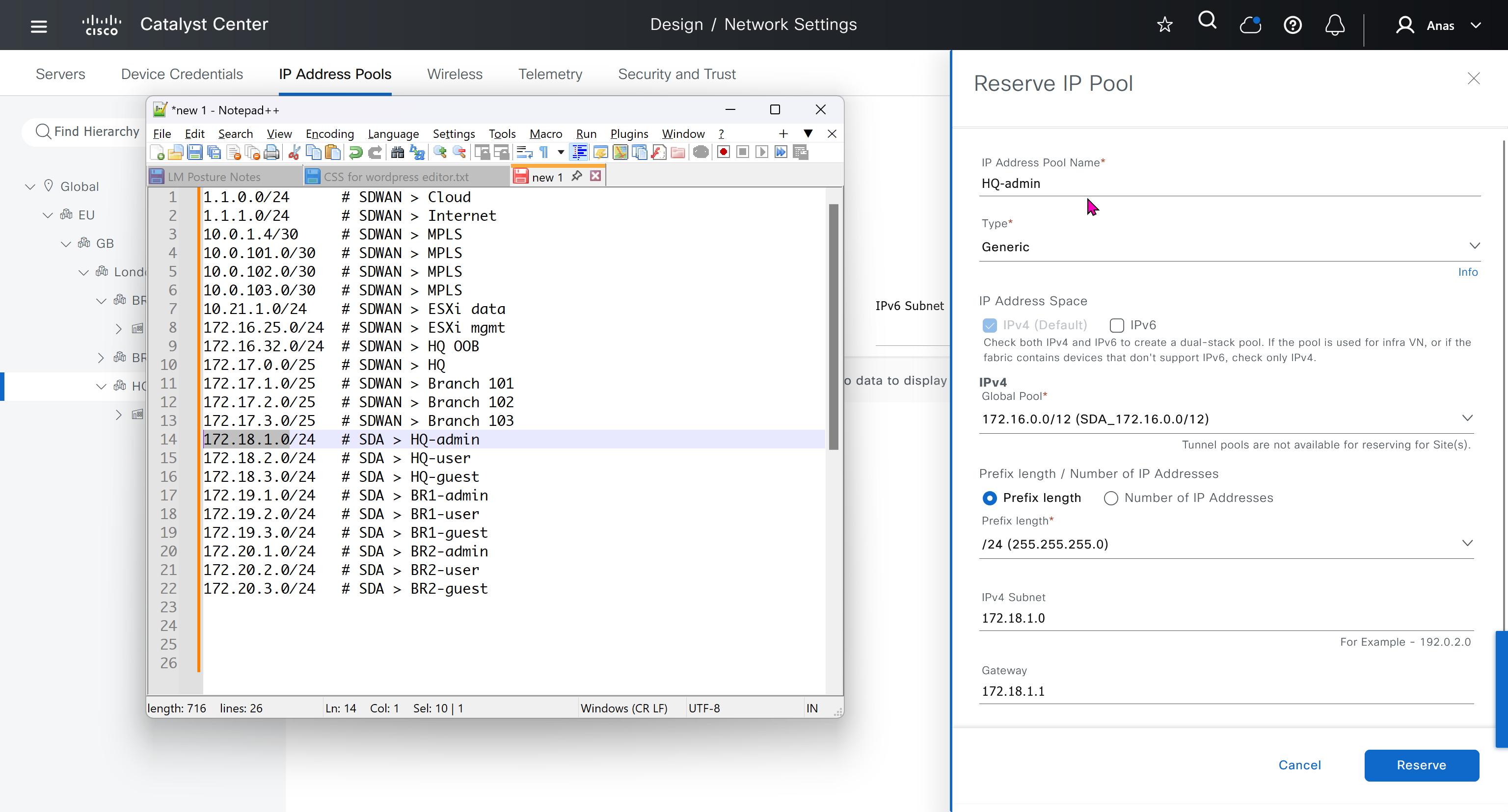
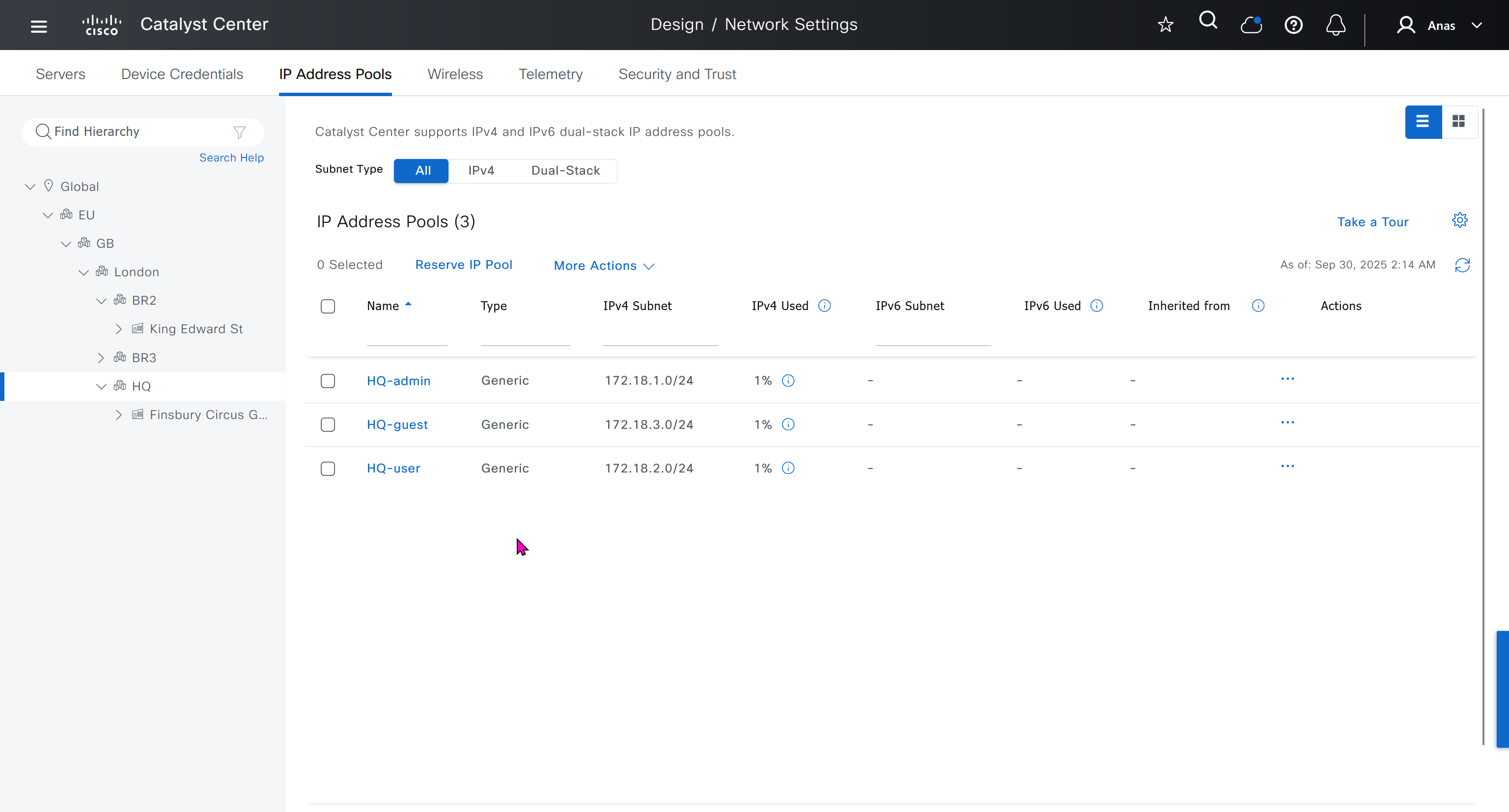
Create DHCP scopes as shown below


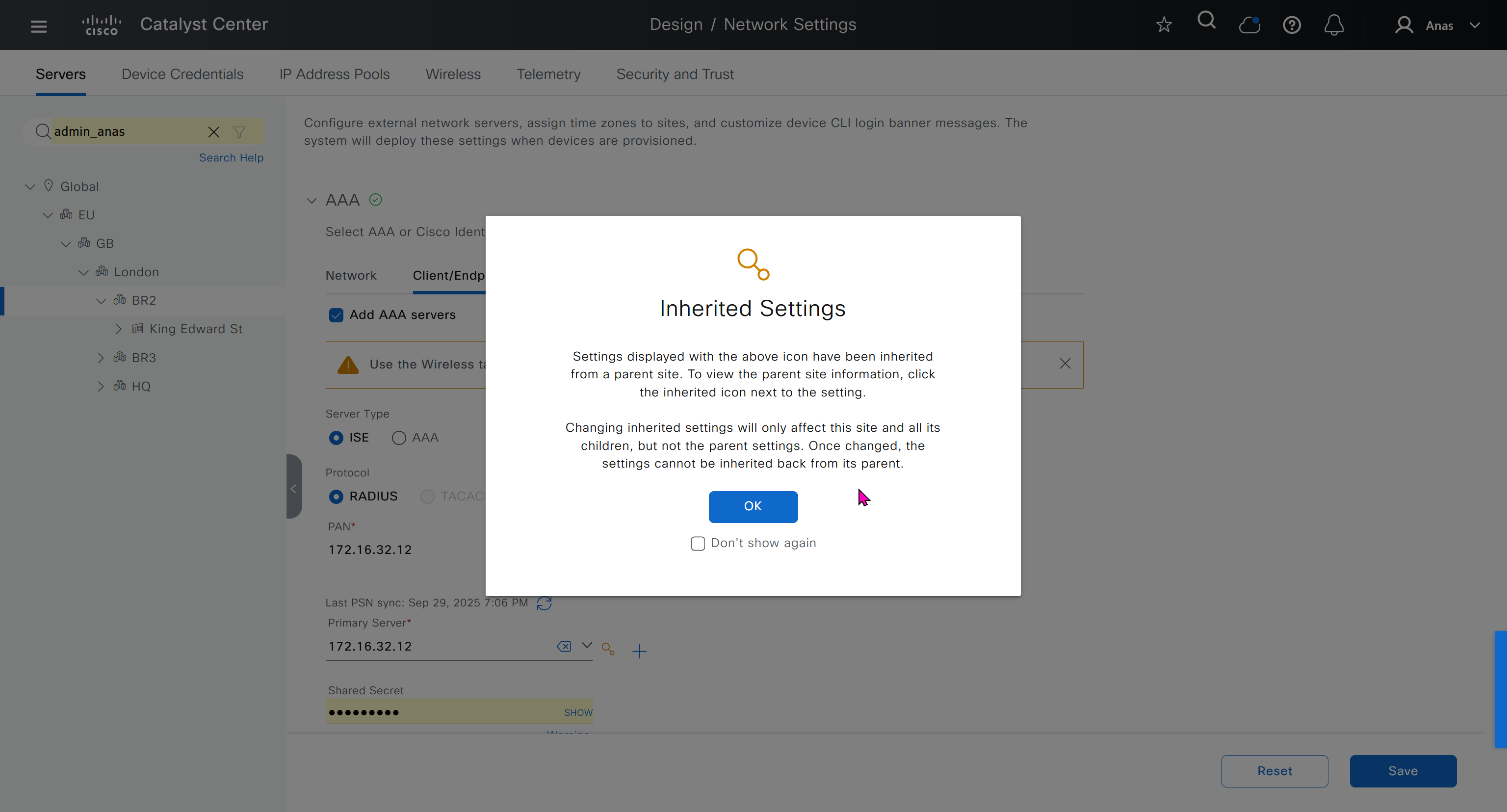
AAA “Network” is for network device administration
and AAA “Client/Endpoint” is 802.1x, we will only configure 802.1x for now


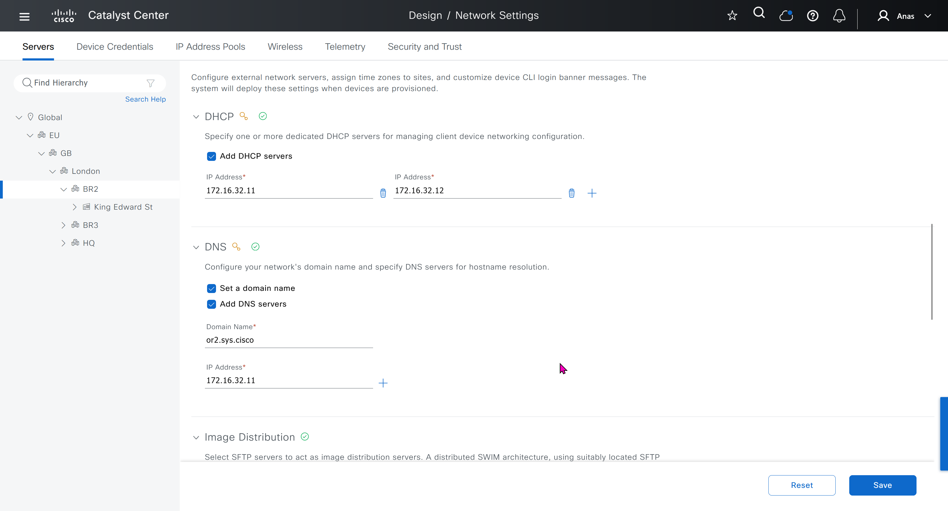
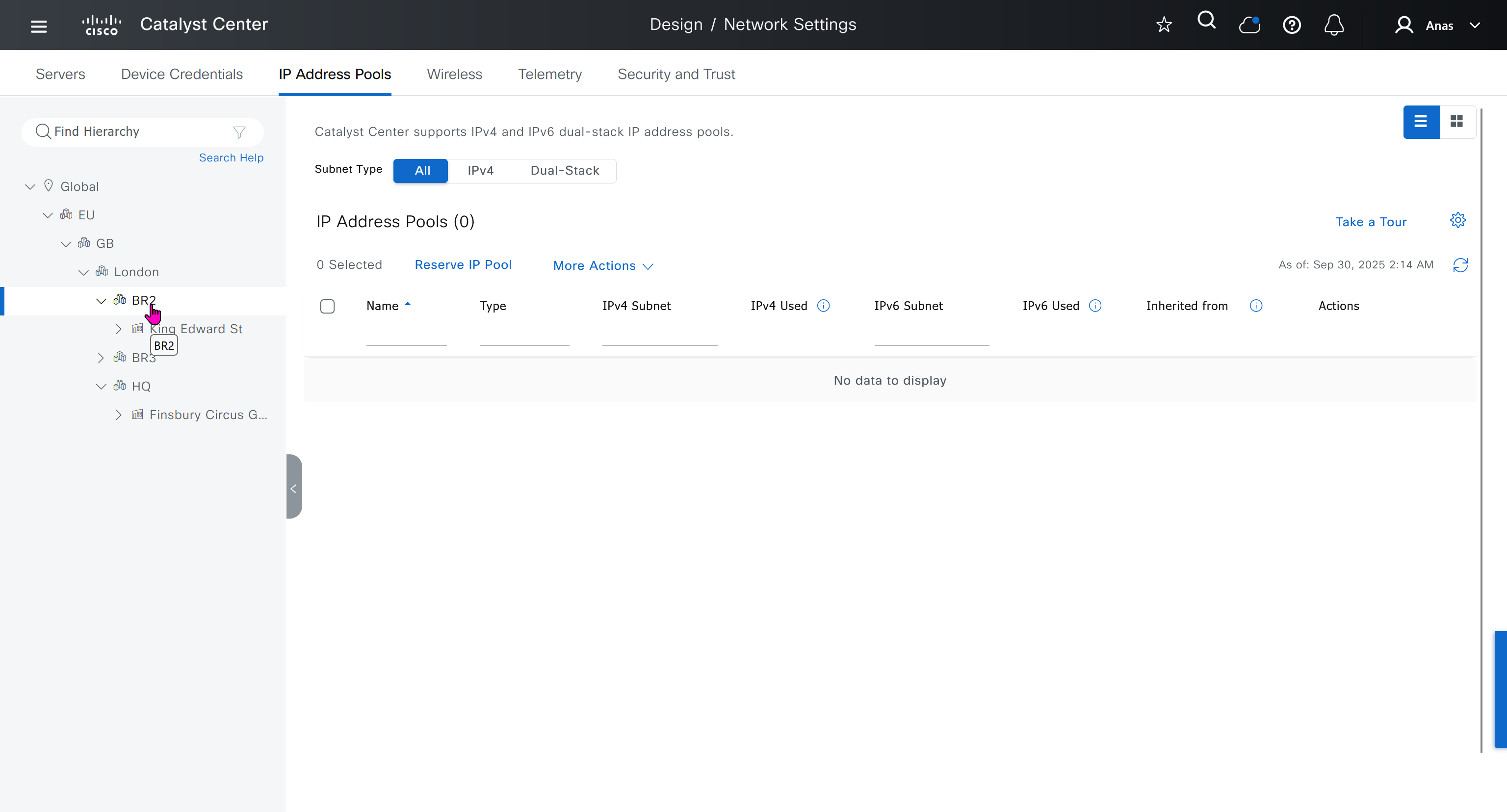
When we click on lower network in hierarchy, for first time we see this symbol which when used in GUI means that configuration is being inherited but they can be overwritten on lower levels


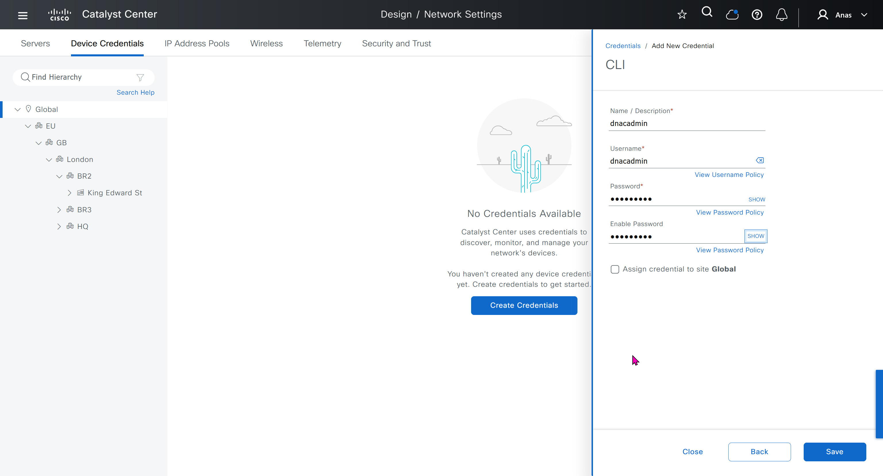
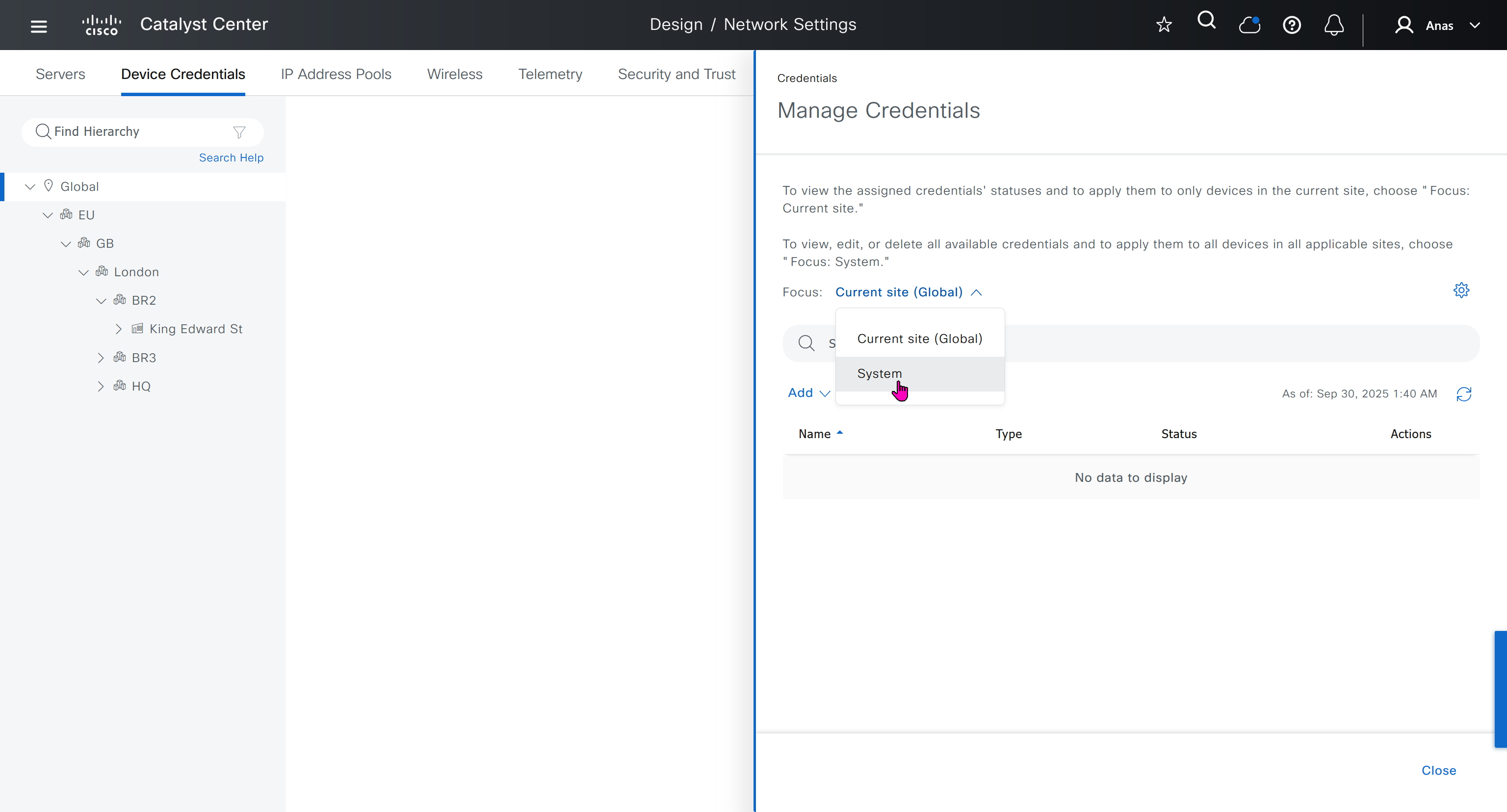
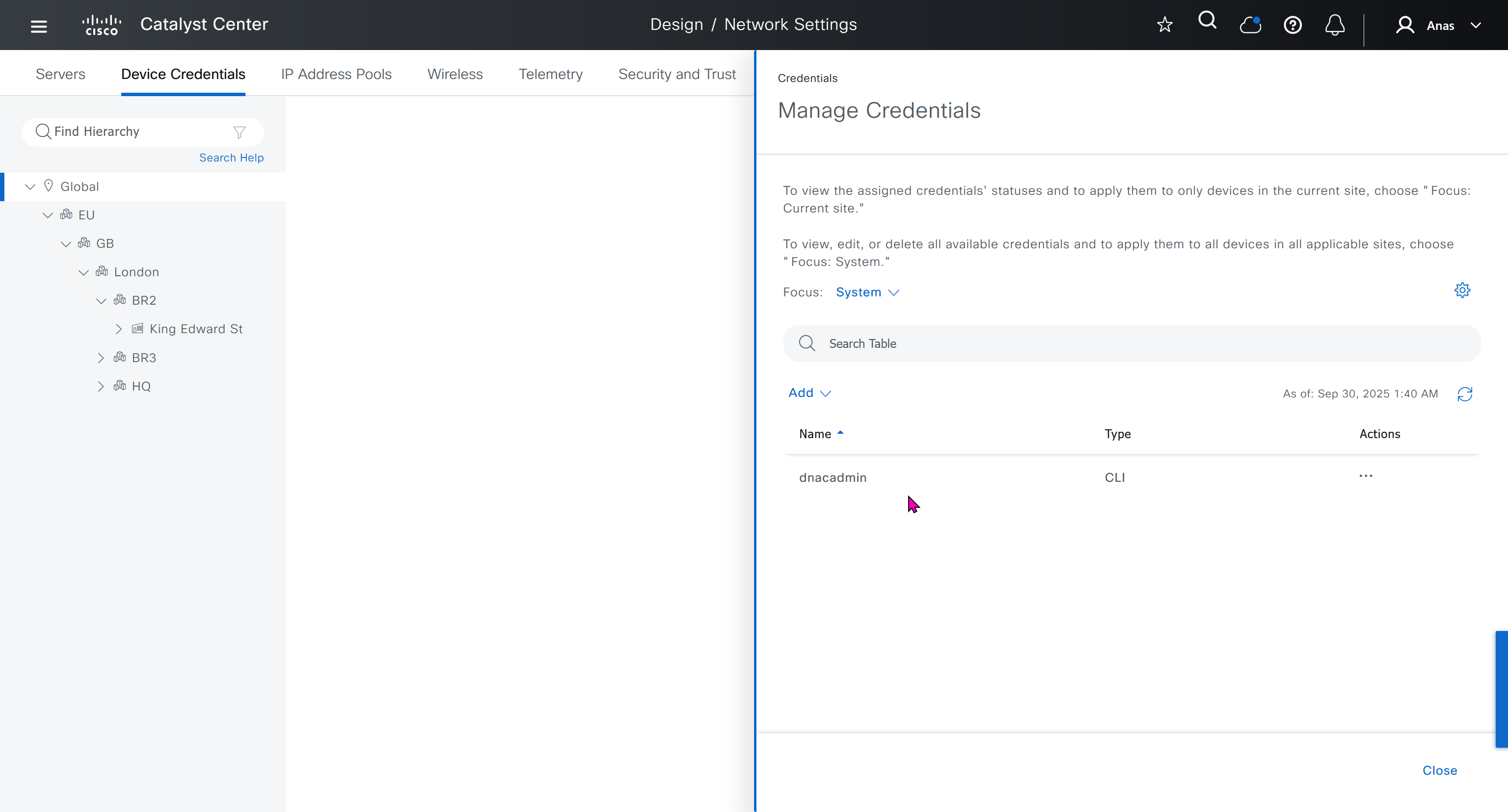
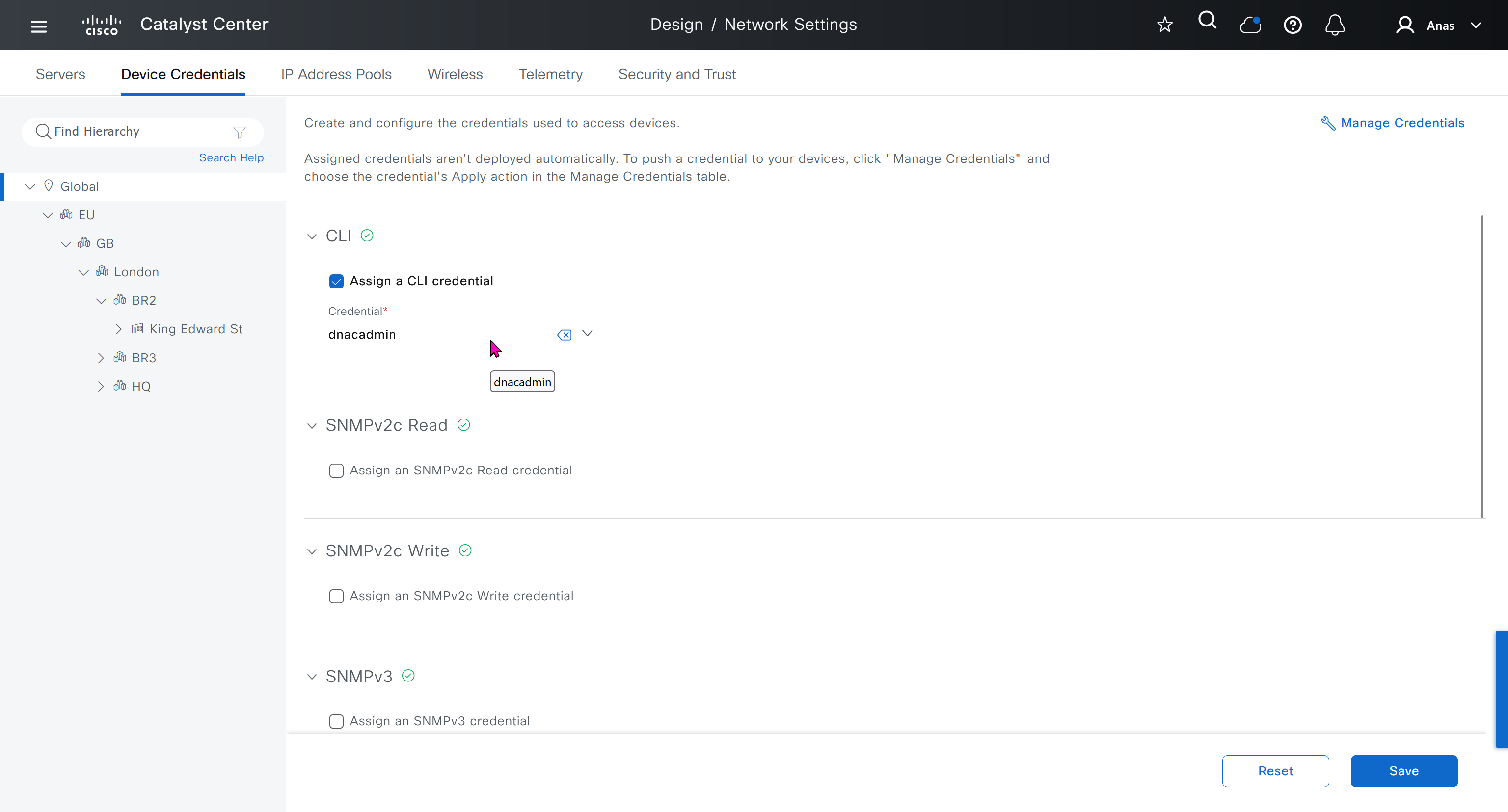
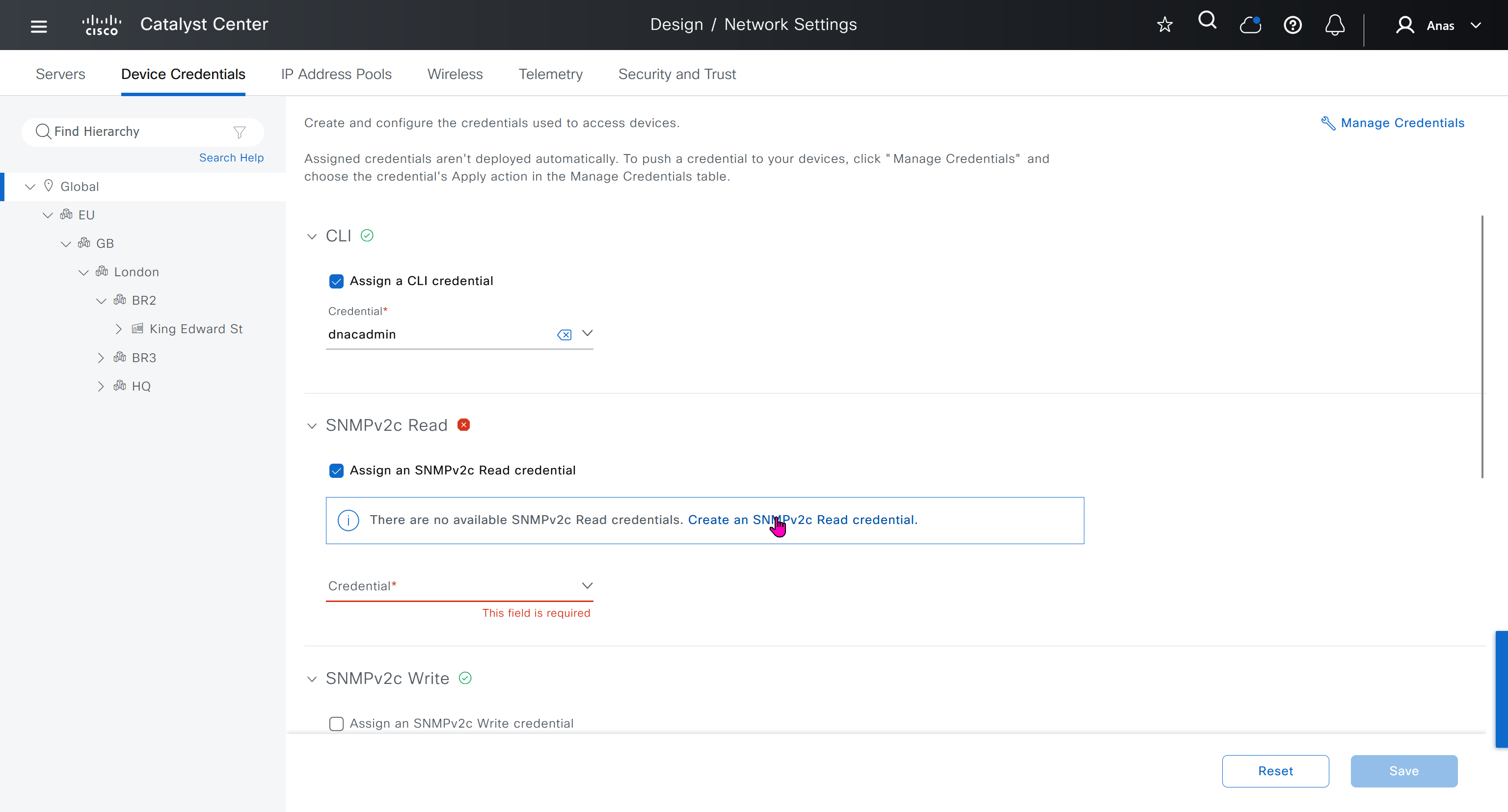
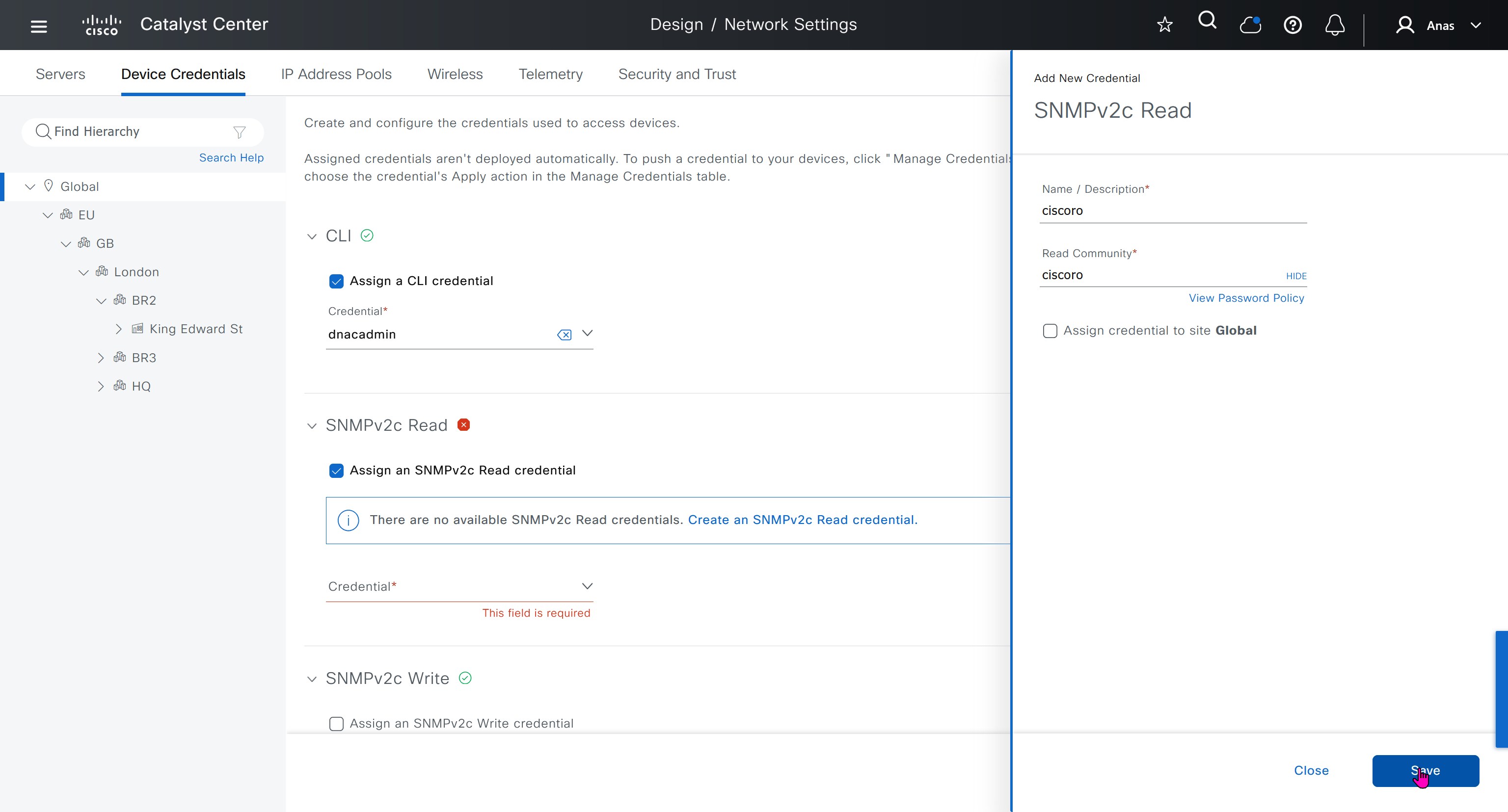
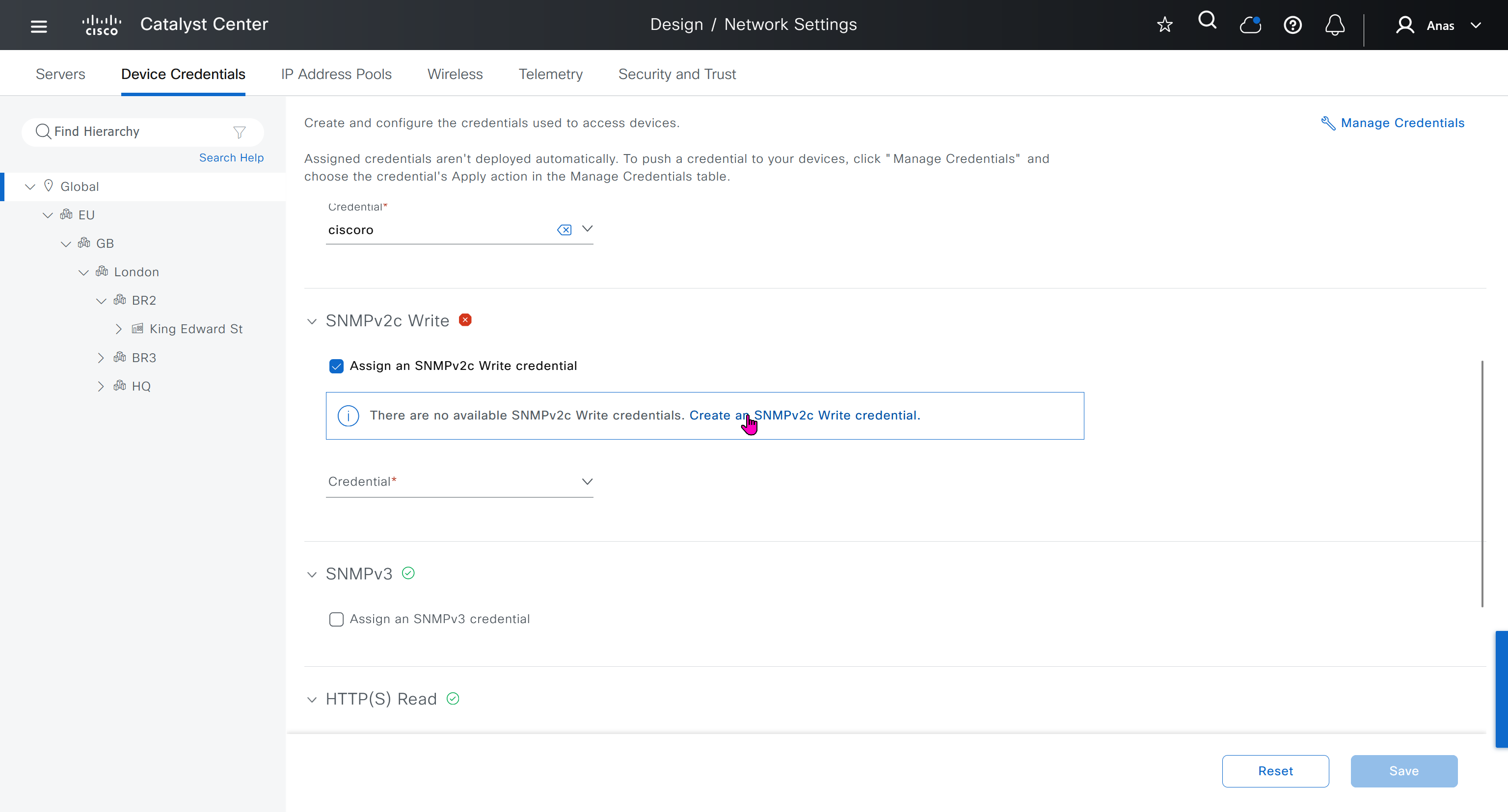
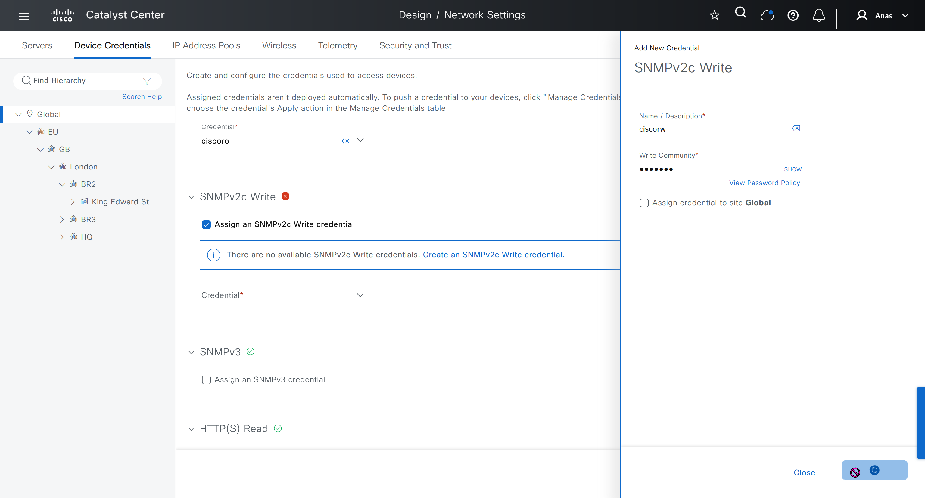
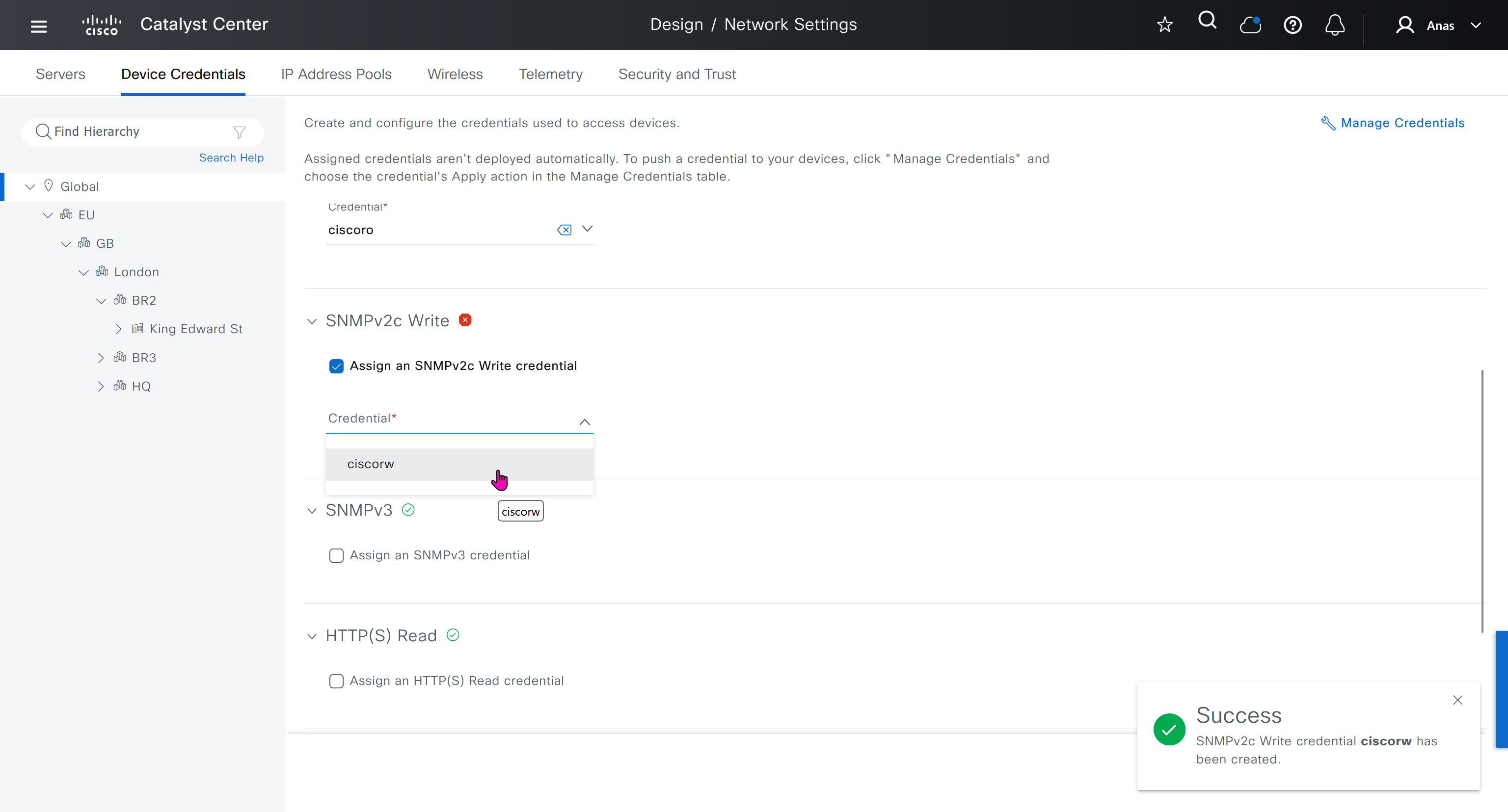
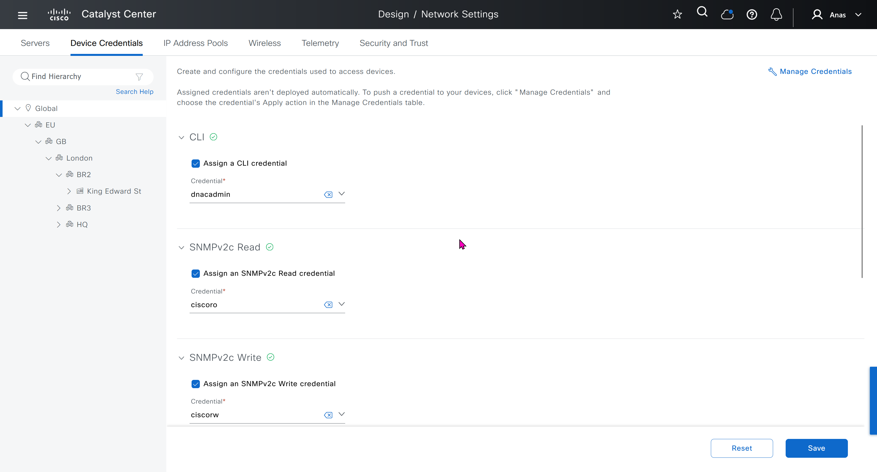
Device credentials is where we feed DNAC with device login details for SSH, SNMPv3 and HTTPS (usually not used

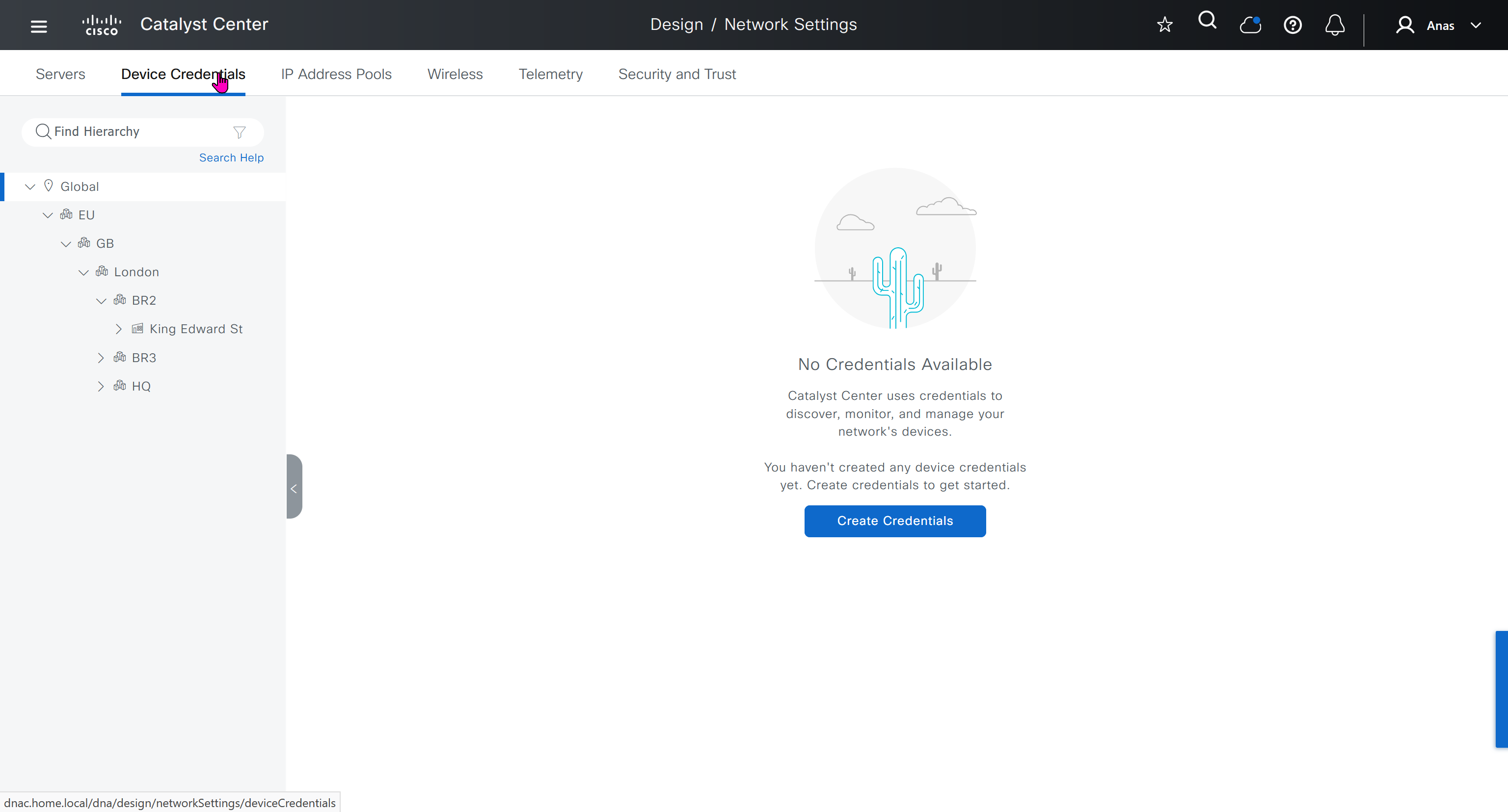
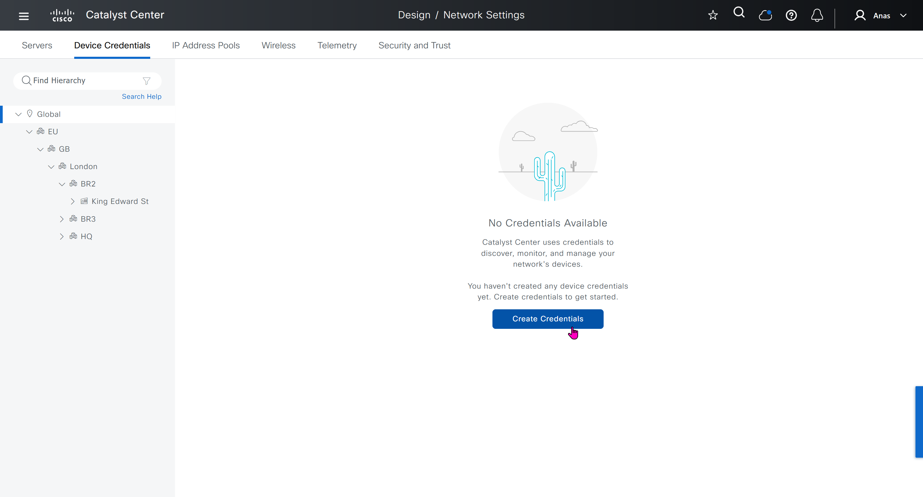
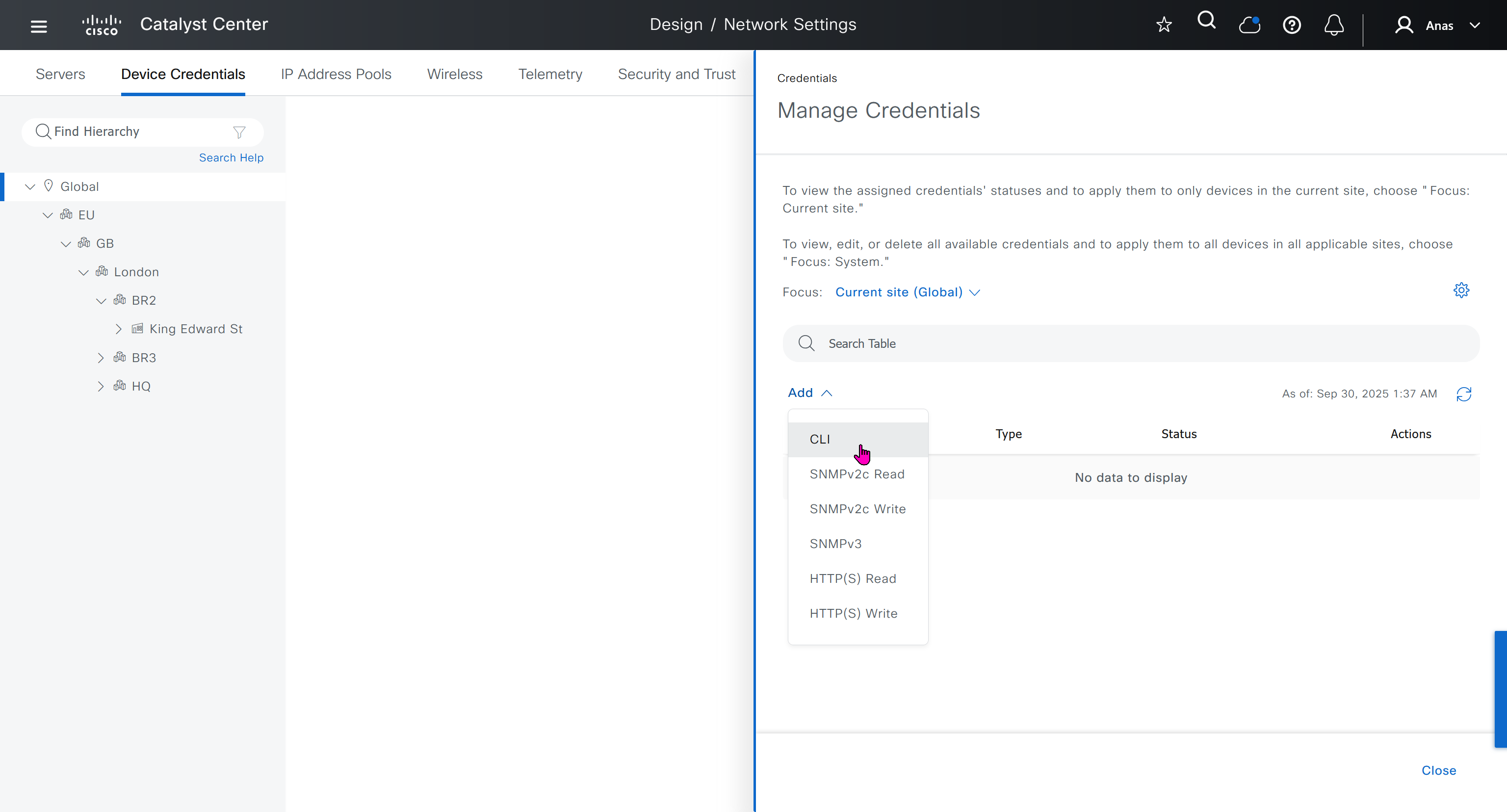
for dnac credentials, try not to use admin as it can cause conflict instead use dnacadmin
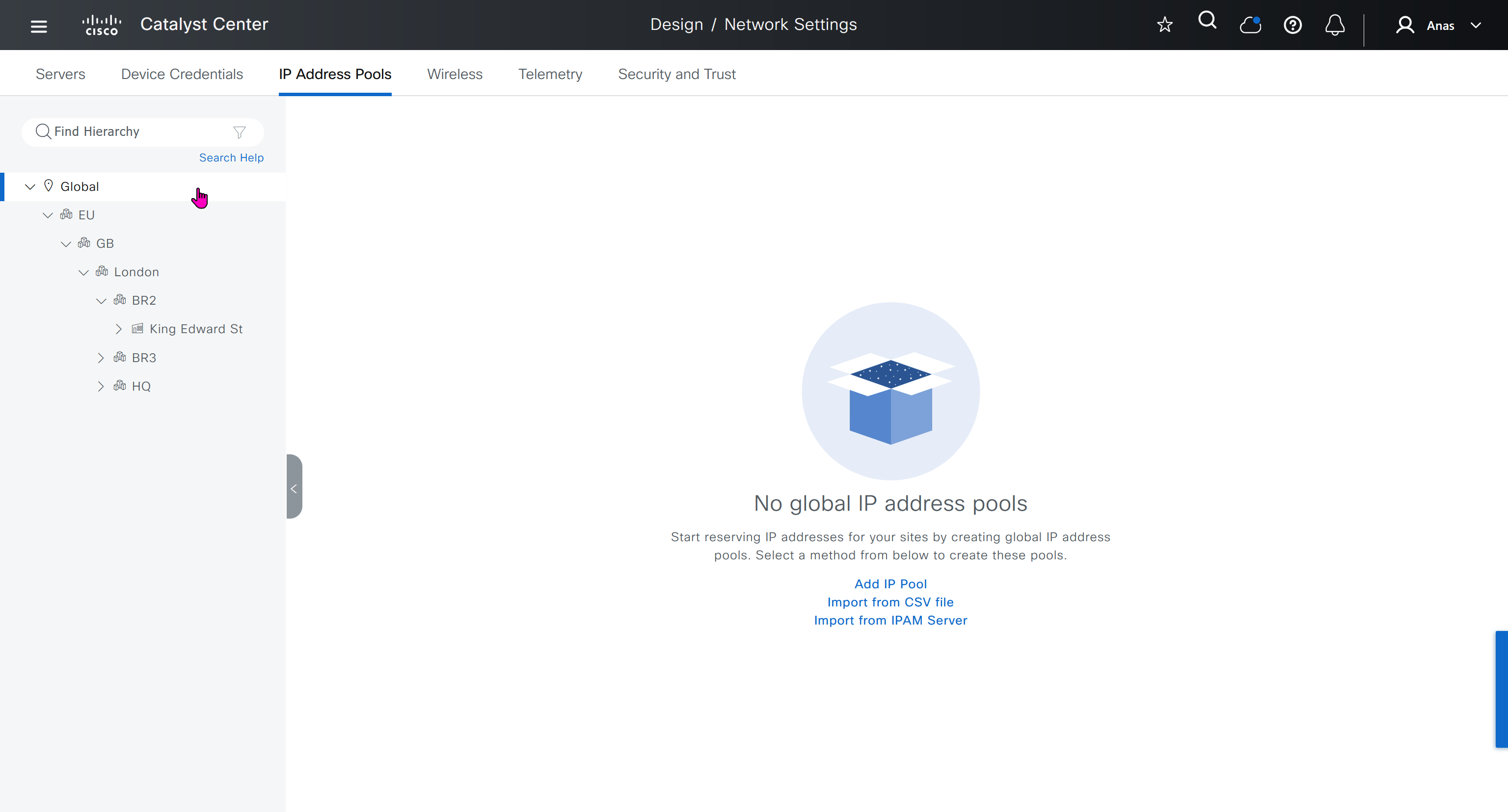
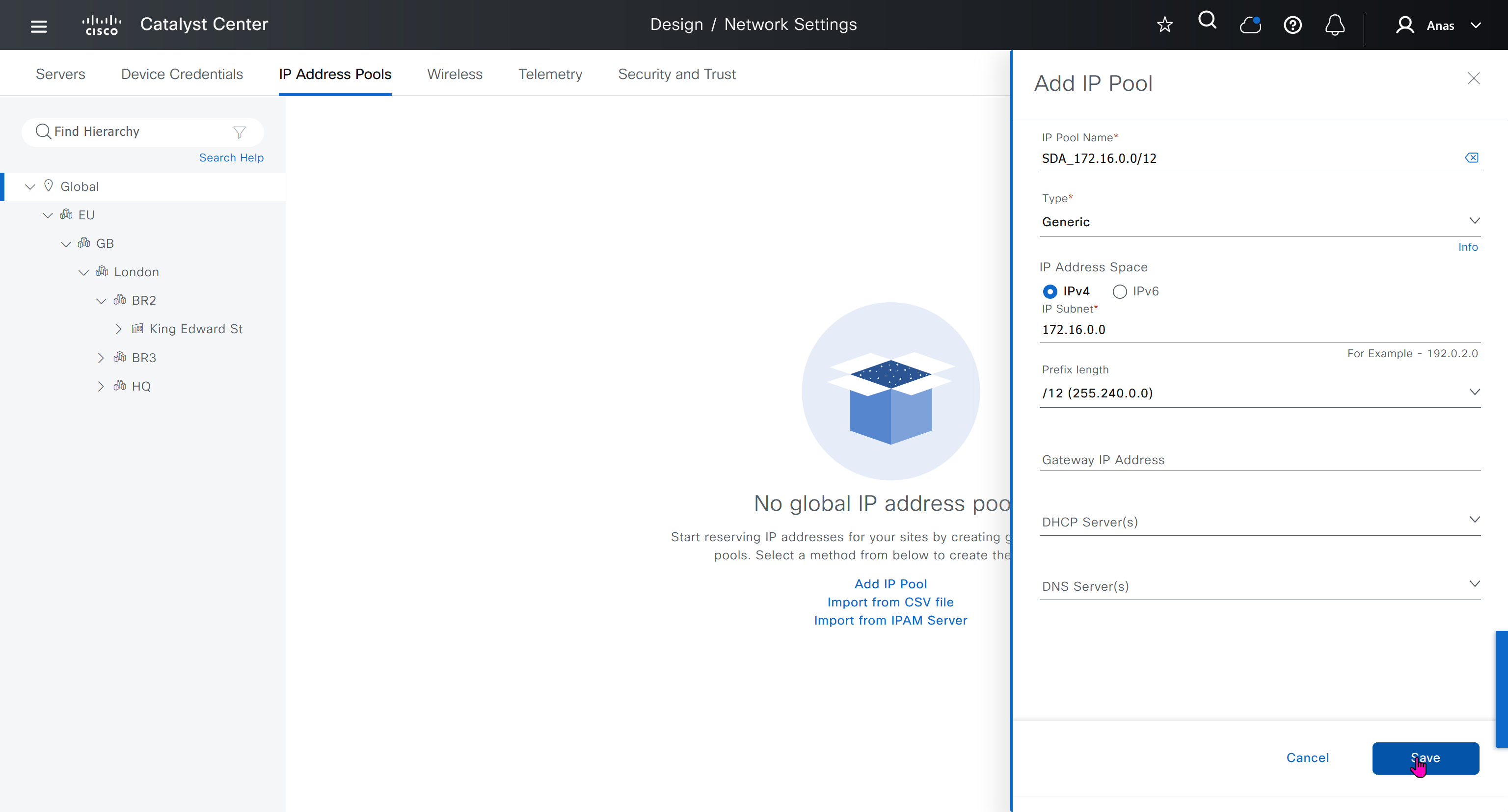
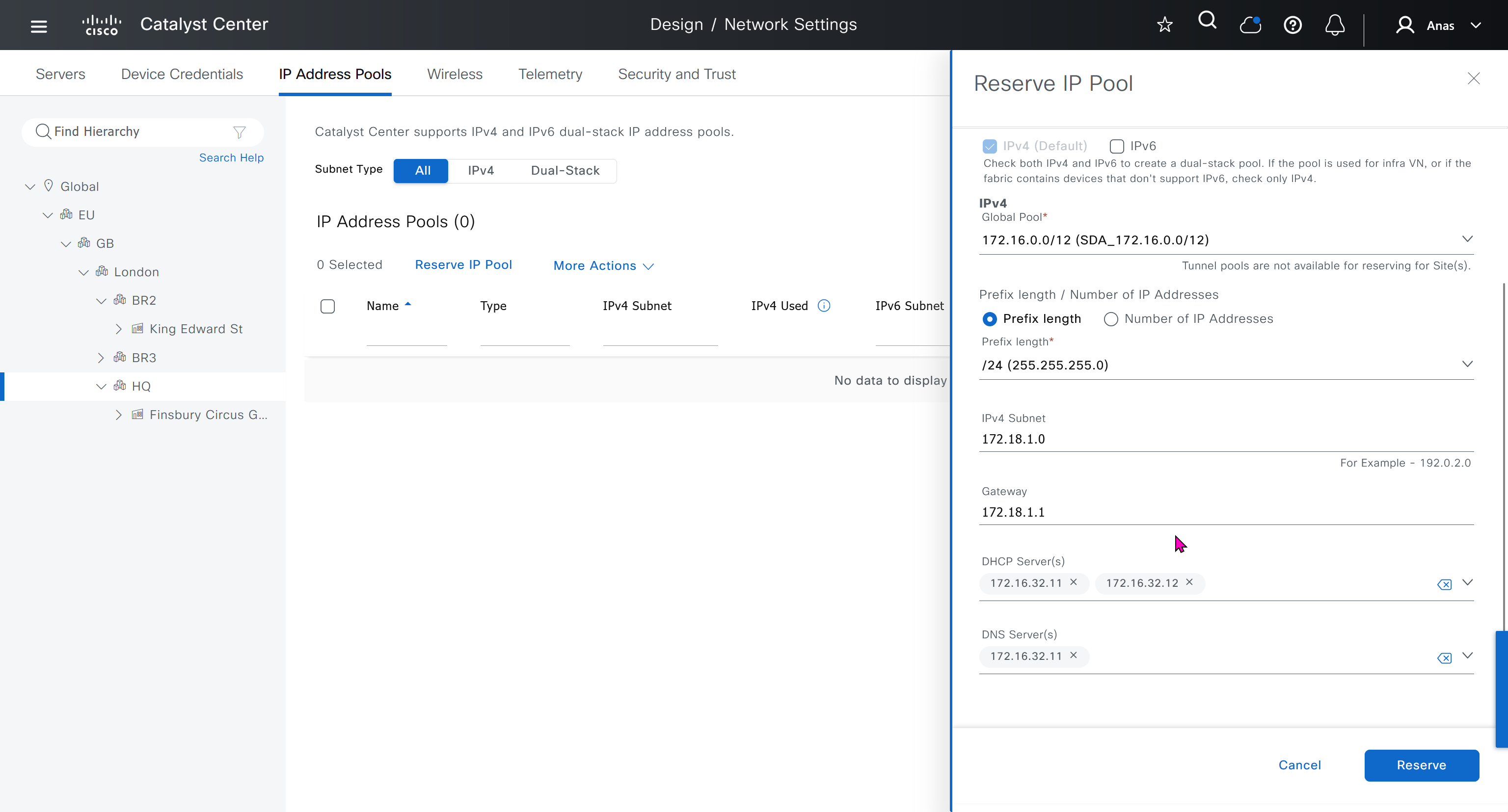
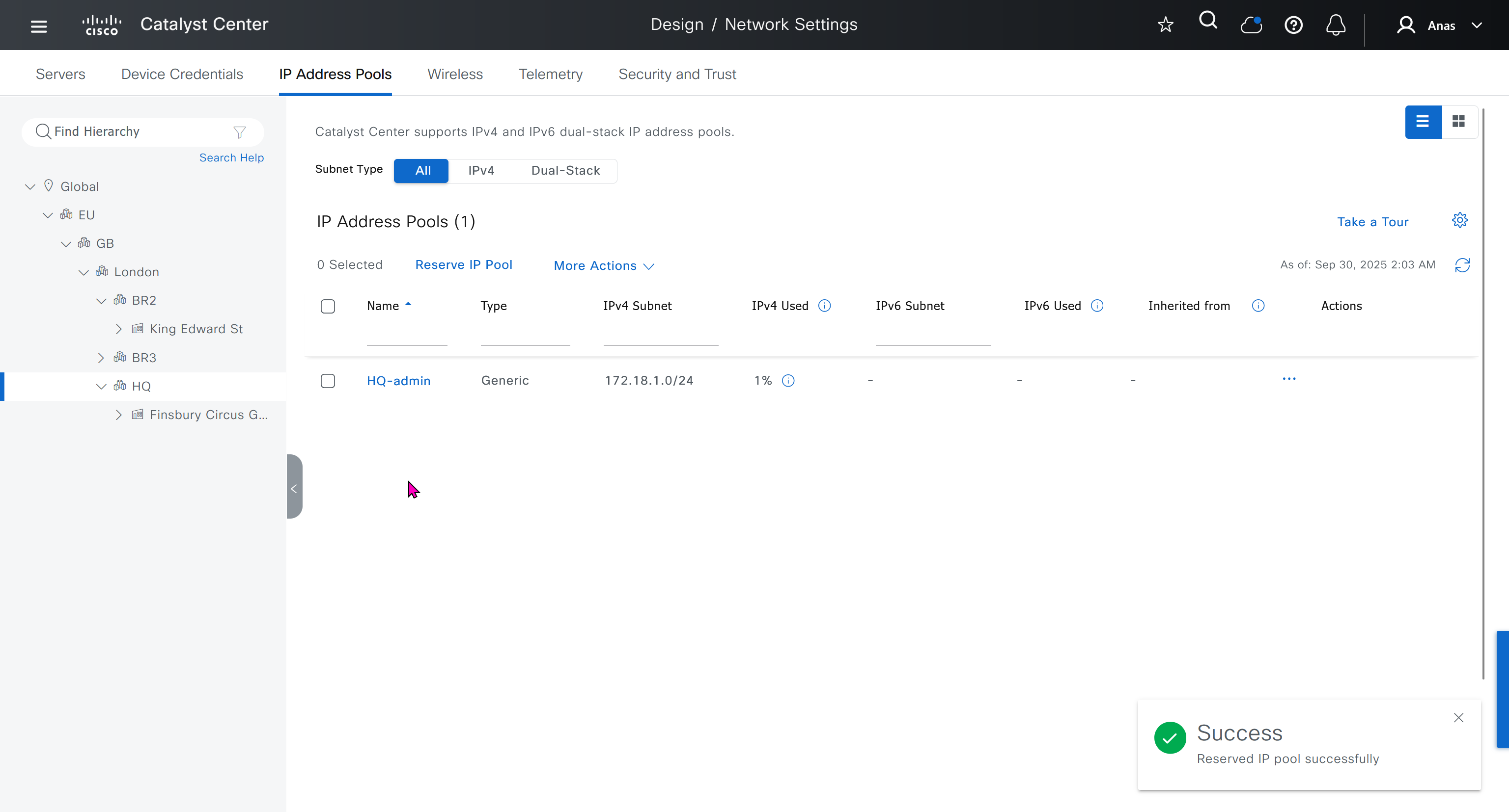
IP address pool is where you define all the subnets that we need to deploy all across SDA, make sure to reserve the supernet at global level
Make sure that we carefully plan and deploy subnets because once it becomes part of SDA, it can be hard to remove it
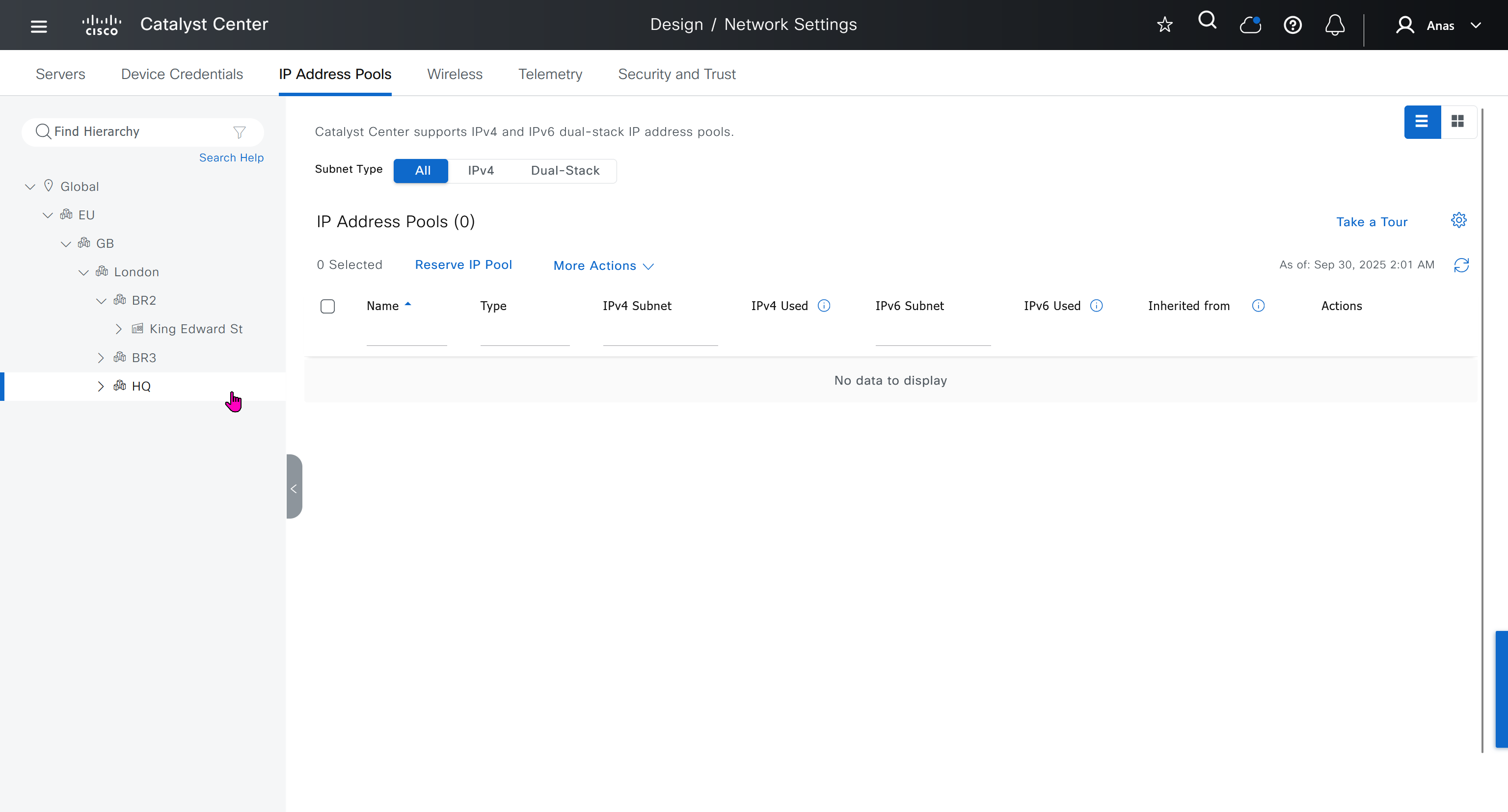
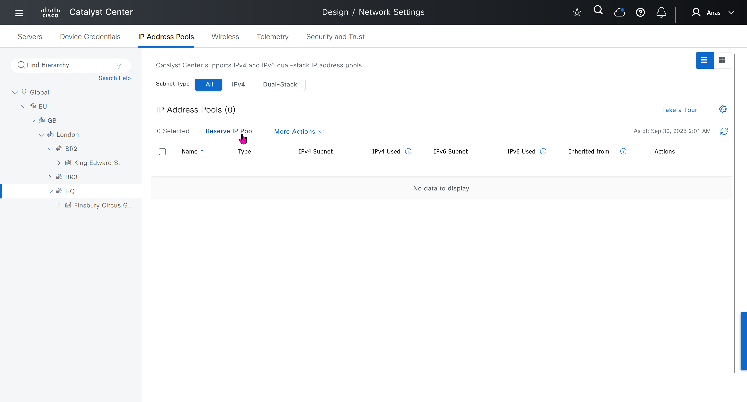
You can only create IP pools at the global level, Add button is only available at global level and at lower hierarchy you simply reserve IP pools for use
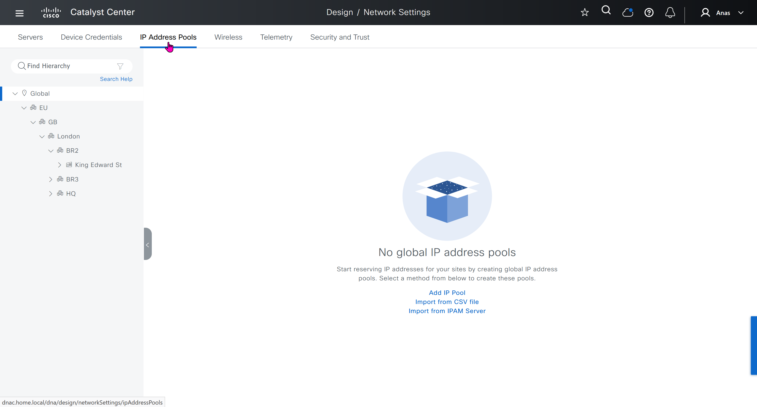
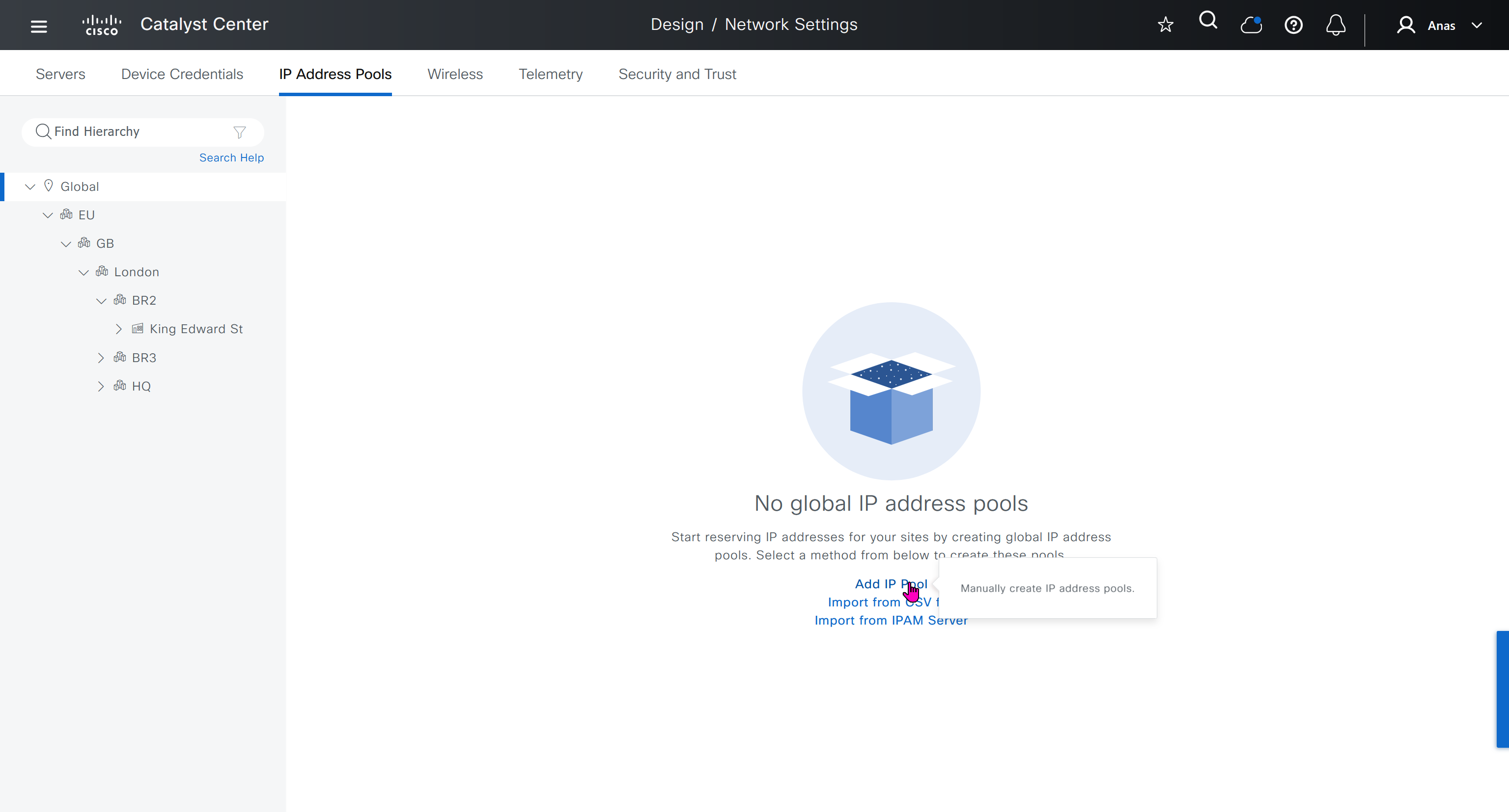
IP address pool type for SDA will be “generic”
When defining IP address pools at Global level then we don’t need to define the gateway IP address, DHCP server and DNS server


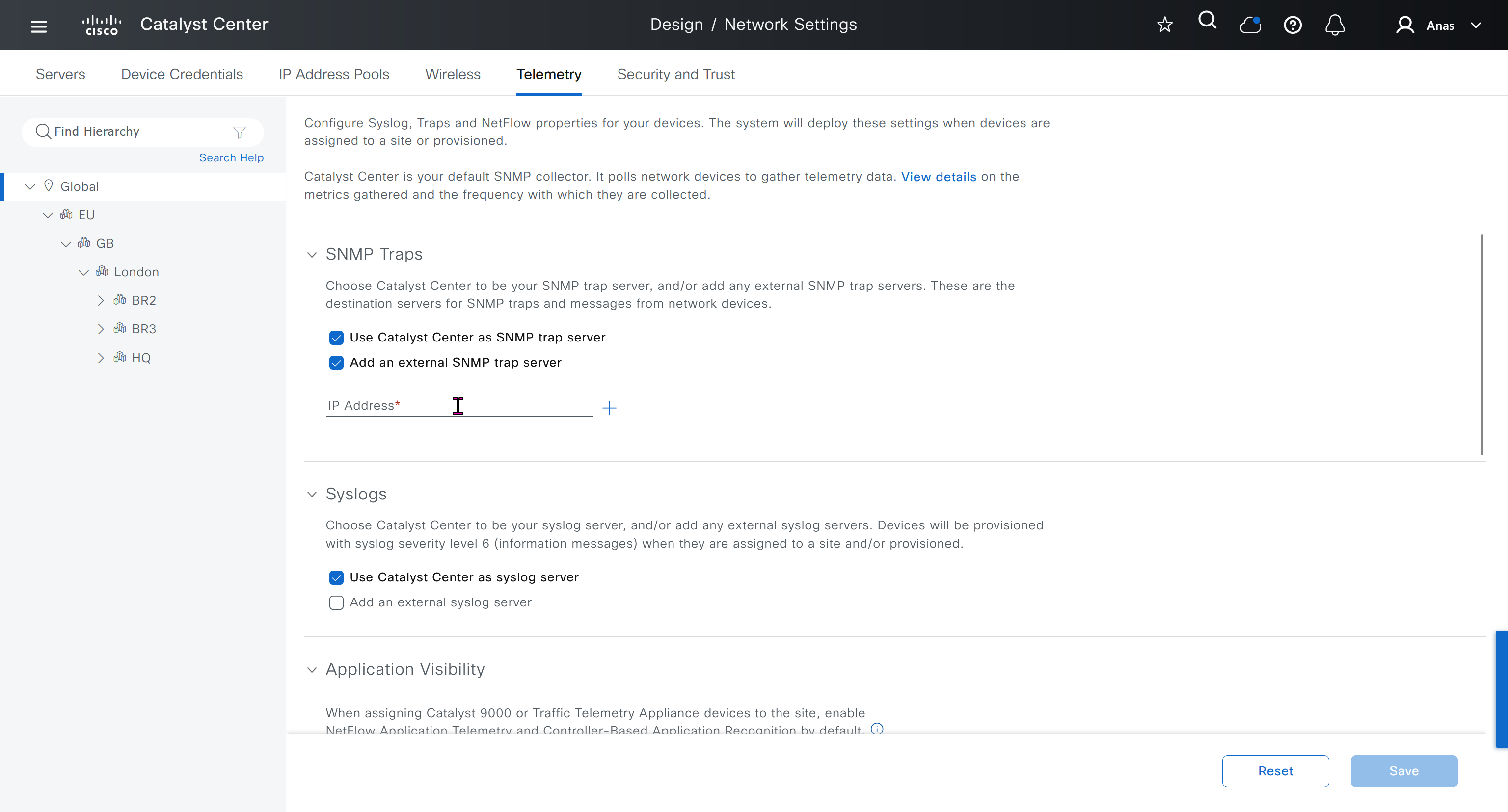
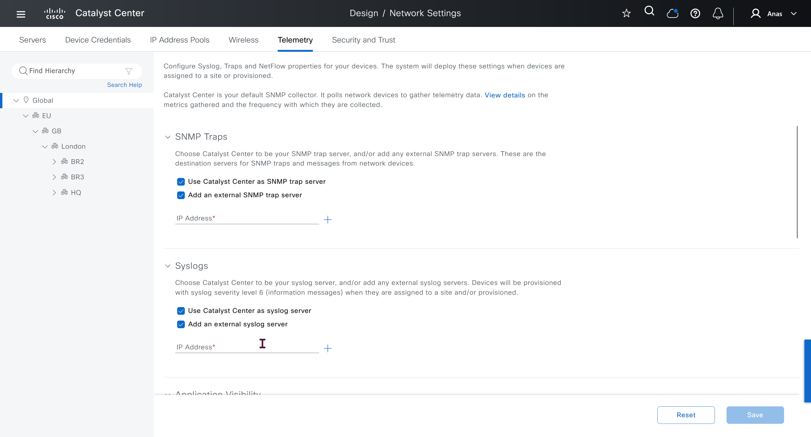
Telemetry section is where DNAC configured devices to uses SNMP, netflow and syslog to send telemetry information to DNAC
A lot of telemetry is being confirmed or supported by SNMP, netflow and syslog
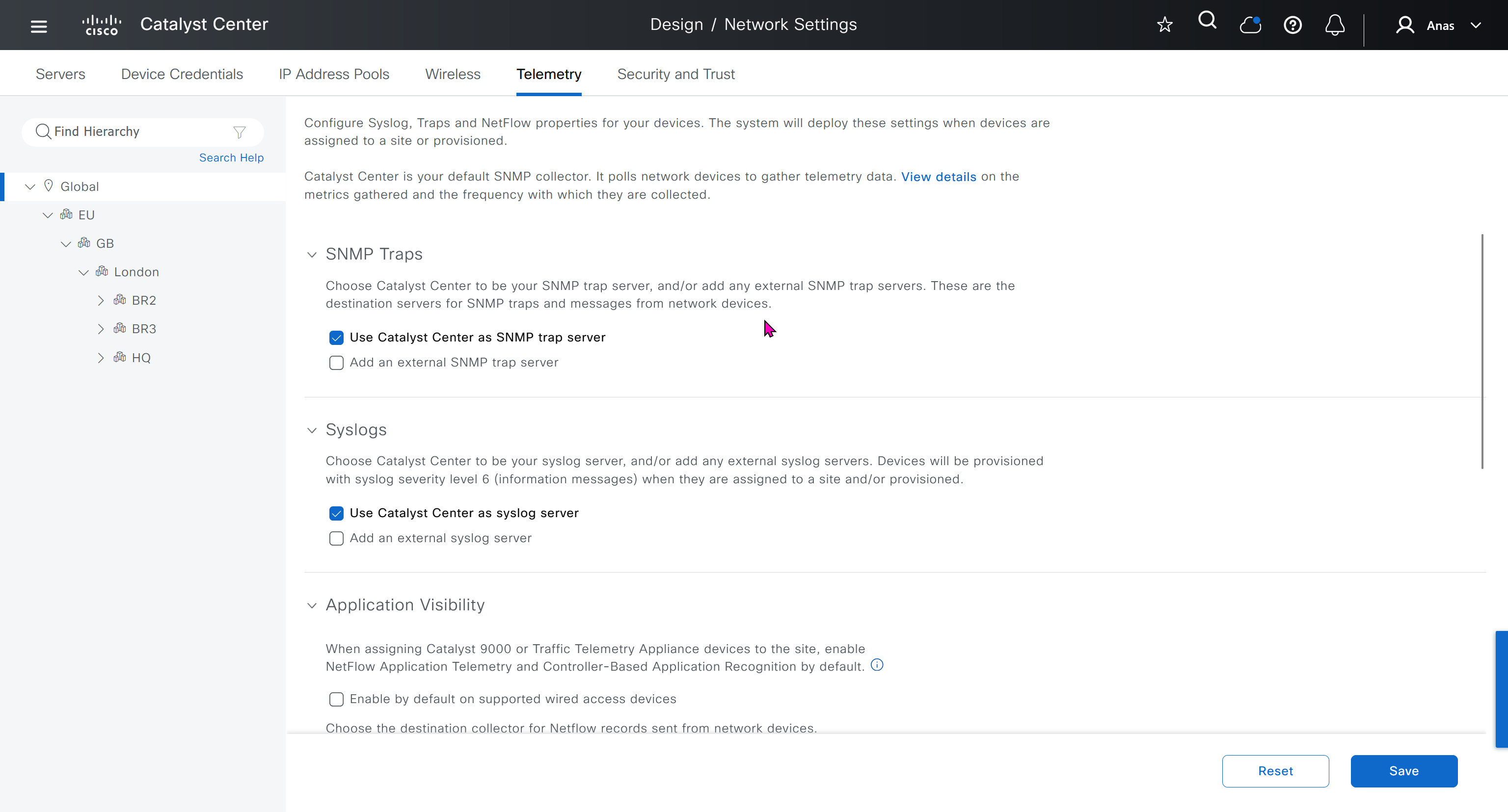

While configuring the Telemetry section, there are options to configure DNAC as SNMP Trap server, Syslog server and netflow collector also but under all these option there is an option also by dnac to configure other syslog and snmp trap server if desired such as SolarWinds
conf t
license boot level network-advantage addon dna-advantage
end
write memory
reload

conf t
!
snmp-server community ciscoro RO
snmp-server community ciscorw RW
!
aaa new-model
!
aaa authentication login default local
aaa authorization exec default local
!
aaa session-id common
!
ip routing
!
license boot level network-advantage addon dna-advantage
!
system mtu 8978
!
enable secret 9 $9$WsbGbEnlY7ZnOE$8Y5qUmOgCatKFC2M/Kpmov7Dbd08QBhQlA8nlOXjnfA
!
username cisco privilege 15 secret 9 $9$K2c68lctCCR3v.$SgFneM9tcIGiIKFFsAsZDcBT/DX0ty2rJ01pQSVW5LU
username dnacadmin privilege 15 secret 9 $9$ss2NT8jXdGqUGU$QVfZV.IgKGnzd8GNy5oCLpfZvamjwuusTVNBK61XPMQ
!
interface GigabitEthernet1/0/x
description SDA-HQ-FXX-01
switchport access vlan 12
!
interface GigabitEthernet1/0/x
description SDA-HQ-FXX-01
switchport access vlan 12
!
interface Vlan1
no ip address
!
interface Vlan12
ip address 172.17.0.x 255.255.255.128
ip ospf mtu-ignore
!
router ospf 100
router-id 172.17.0.x
network 172.17.0.0 0.0.0.127 area 0
!
snmp-server community ciscoro RO
snmp-server community ciscorw RW
!
alias router show do show
alias interface show do show
alias configure show do show
!
line vty 0 98
privilege level 15
transport input ssh
!
netconf-yang
end
write mem
HQ-SW config !!! old LAB
HQ-SW#show run
Building configuration...

Current configuration : 3914 bytes
!
! Last configuration change at 03:22:03 UTC Mon Oct 6 2025
!
version 15.2
service timestamps debug datetime msec
service timestamps log datetime msec
no service password-encryption
service compress-config
!
hostname HQ-SW
!
boot-start-marker
boot-end-marker
!
!
!
username cisco privilege 15 secret 5 $1$SACq$2ExGwHsqUe3mKfho1B3AQ1
no aaa new-model
!
!
!
!
!
!
!
!
ip cef
no ipv6 cef
!
!
!
spanning-tree mode pvst
spanning-tree extend system-id
!
vlan internal allocation policy ascending
!
!
!
!
!
!
!
!
!
!
!
!
!
!
interface GigabitEthernet0/0
 description INTERNET
 no switchport
 ip address 1.1.1.11 255.255.255.0
 negotiation auto
!
interface GigabitEthernet0/1
 description WINSERVER
 media-type rj45
 negotiation auto
!
interface GigabitEthernet0/2
 description home.local network
 switchport access vlan 11
 media-type rj45
 negotiation auto
!
interface GigabitEthernet0/3
 description ISE01
 media-type rj45
 negotiation auto
!
interface GigabitEthernet1/0
 description SDA-HQ-FBS-01 HQ-DATA
 switchport access vlan 12
 switchport mode access
 media-type rj45
 negotiation auto
!
interface GigabitEthernet1/1
 media-type rj45
 negotiation auto
!
interface GigabitEthernet1/2
 media-type rj45
 negotiation auto
!
interface GigabitEthernet1/3
 media-type rj45
 negotiation auto
!
interface Vlan1
 description HQ-OOB network
 ip address 172.16.32.1 255.255.255.0
!
interface Vlan11
 description home.local network
 ip address 192.168.0.15 255.255.255.0
!
interface Vlan12
 ip address 172.17.0.3 255.255.255.128
 ip ospf mtu-ignore
!
router ospf 100
 router-id 172.17.0.3
 network 172.17.0.0 0.0.0.127 area 0
 default-information originate
!
ip forward-protocol nd
!
no ip http server
no ip http secure-server
!
ip route 0.0.0.0 0.0.0.0 192.168.0.1
ip route 1.1.0.0 255.255.255.0 1.1.1.250
ip route 10.21.1.0 255.255.255.0 192.168.0.12
ip route 172.16.25.0 255.255.255.0 192.168.0.12
!
!
!
!
!
control-plane
!
banner exec ^CCC
**************************************************************************
* IOSv is strictly limited to use for evaluation, demonstration and IOS  *
* education. IOSv is provided as-is and is not supported by Cisco's      *
* Technical Advisory Center. Any use or disclosure, in whole or in part, *
* of the IOSv Software or Documentation to any third party for any       *
* purposes is expressly prohibited except as otherwise authorized by     *
* Cisco in writing.                                                      *
**************************************************************************^C
banner incoming ^CCC
**************************************************************************
* IOSv is strictly limited to use for evaluation, demonstration and IOS  *
* education. IOSv is provided as-is and is not supported by Cisco's      *
* Technical Advisory Center. Any use or disclosure, in whole or in part, *
* of the IOSv Software or Documentation to any third party for any       *
* purposes is expressly prohibited except as otherwise authorized by     *
* Cisco in writing.                                                      *
**************************************************************************^C
banner login ^CCC
**************************************************************************
* IOSv is strictly limited to use for evaluation, demonstration and IOS  *
* education. IOSv is provided as-is and is not supported by Cisco's      *
* Technical Advisory Center. Any use or disclosure, in whole or in part, *
* of the IOSv Software or Documentation to any third party for any       *
* purposes is expressly prohibited except as otherwise authorized by     *
* Cisco in writing.                                                      *
**************************************************************************^C
alias router show do show
alias interface show do show
alias configure show do show
!
line con 0
line aux 0
line vty 0 4
 login
!
!
netconf-yang
end
SDA-HQ-FBS-01 config
SDA-HQ-FBS-01#show run
Building configuration...

Current configuration : 8301 bytes
!
! Last configuration change at 03:40:18 UTC Mon Oct 6 2025
!
version 17.12
service timestamps debug datetime msec
service timestamps log datetime msec
platform punt-keepalive disable-kernel-core
!
hostname SDA-HQ-FBS-01
!
!
vrf definition Mgmt-vrf
 !
 address-family ipv4
 exit-address-family
 !
 address-family ipv6
 exit-address-family
!
aaa new-model
!
!
aaa authentication login default local
aaa authorization exec default local
!
!
aaa session-id common
switch 1 provision c9kv-uadp-8p
!
!
!
!
ip routing
!
!
!
!
!
!
!
!
login on-success log
vtp version 1
!
!
!
!
!
!
!
!
crypto pki trustpoint SLA-TrustPoint
 enrollment pkcs12
 revocation-check crl
 hash sha256
!
crypto pki trustpoint TP-self-signed-2070352050
 enrollment selfsigned
 subject-name cn=IOS-Self-Signed-Certificate-2070352050
 revocation-check none
 rsakeypair TP-self-signed-2070352050
 hash sha256
!
!
crypto pki certificate chain SLA-TrustPoint
 certificate ca 01
  30820321 30820209 A0030201 02020101 300D0609 2A864886 F70D0101 0B050030
  32310E30 0C060355 040A1305 43697363 6F312030 1E060355 04031317 43697363
  6F204C69 63656E73 696E6720 526F6F74 20434130 1E170D31 33303533 30313934
  3834375A 170D3338 30353330 31393438 34375A30 32310E30 0C060355 040A1305
  43697363 6F312030 1E060355 04031317 43697363 6F204C69 63656E73 696E6720
  526F6F74 20434130 82012230 0D06092A 864886F7 0D010101 05000382 010F0030
  82010A02 82010100 A6BCBD96 131E05F7 145EA72C 2CD686E6 17222EA1 F1EFF64D
  CBB4C798 212AA147 C655D8D7 9471380D 8711441E 1AAF071A 9CAE6388 8A38E520
  1C394D78 462EF239 C659F715 B98C0A59 5BBB5CBD 0CFEBEA3 700A8BF7 D8F256EE
  4AA4E80D DB6FD1C9 60B1FD18 FFC69C96 6FA68957 A2617DE7 104FDC5F EA2956AC
  7390A3EB 2B5436AD C847A2C5 DAB553EB 69A9A535 58E9F3E3 C0BD23CF 58BD7188
  68E69491 20F320E7 948E71D7 AE3BCC84 F10684C7 4BC8E00F 539BA42B 42C68BB7
  C7479096 B4CB2D62 EA2F505D C7B062A4 6811D95B E8250FC4 5D5D5FB8 8F27D191
  C55F0D76 61F9A4CD 3D992327 A8BB03BD 4E6D7069 7CBADF8B DF5F4368 95135E44
  DFC7C6CF 04DD7FD1 02030100 01A34230 40300E06 03551D0F 0101FF04 04030201
  06300F06 03551D13 0101FF04 05300301 01FF301D 0603551D 0E041604 1449DC85
  4B3D31E5 1B3E6A17 606AF333 3D3B4C73 E8300D06 092A8648 86F70D01 010B0500
  03820101 00507F24 D3932A66 86025D9F E838AE5C 6D4DF6B0 49631C78 240DA905
  604EDCDE FF4FED2B 77FC460E CD636FDB DD44681E 3A5673AB 9093D3B1 6C9E3D8B
  D98987BF E40CBD9E 1AECA0C2 2189BB5C 8FA85686 CD98B646 5575B146 8DFC66A8
  467A3DF4 4D565700 6ADF0F0D CF835015 3C04FF7C 21E878AC 11BA9CD2 55A9232C
  7CA7B7E6 C1AF74F6 152E99B7 B1FCF9BB E973DE7F 5BDDEB86 C71E3B49 1765308B
  5FB0DA06 B92AFE7F 494E8A9E 07B85737 F3A58BE1 1A48A229 C37C1E69 39F08678
  80DDCD16 D6BACECA EEBC7CF9 8428787B 35202CDC 60E4616A B623CDBD 230E3AFB
  418616A9 4093E049 4D10AB75 27E86F73 932E35B5 8862FDAE 0275156F 719BB2F0
  D697DF7F 28
        quit
crypto pki certificate chain TP-self-signed-2070352050
 certificate self-signed 01
  30820330 30820218 A0030201 02020101 300D0609 2A864886 F70D0101 0B050030
  31312F30 2D060355 04030C26 494F532D 53656C66 2D536967 6E65642D 43657274
  69666963 6174652D 32303730 33353230 3530301E 170D3235 30393231 32313439
  32315A17 0D333530 39323132 31343932 315A3031 312F302D 06035504 030C2649
  4F532D53 656C662D 5369676E 65642D43 65727469 66696361 74652D32 30373033
  35323035 30308201 22300D06 092A8648 86F70D01 01010500 0382010F 00308201
  0A028201 0100BE6B 15431B3C C2F339F8 E68ED232 38C6D054 26256330 1860898B
  3427C857 6F821274 0C5B8B21 D2B908B2 71205F22 E9E2D9EF CCCEF719 CB65D798
  620546BE 724EFEE4 B7D9026F E94D9B0C A1B7755C 33C13A5B 5803DE7F DABC513B
  17181601 AE98D442 44694CF2 57D1505F 3A119649 E0F7C524 A2C544D1 8C986BC2
  89C8FAF7 0E72811A AC4FDC69 D0A4DE17 BE69A40F F83E5BFD B16E894B 18830516
  06726E02 3E6F1A7F 3A202286 600059F0 CF9EC6A8 420946BD A0F70AFF CE386017
  44CB8032 55B22C27 E240440C 39D3EEF3 B887DF4B ECECD738 76C531B7 DC43AC1F
  38AAE8C1 A12B5574 0DCA1A63 88E12E80 62411882 573FBF7A 85DD348B 425A477E
  9AF7DAB7 D9EF0203 010001A3 53305130 1D060355 1D0E0416 0414864F 5DC3AA3D
  570D29AC 614578D3 7BCFD3AF 76D5301F 0603551D 23041830 16801486 4F5DC3AA
  3D570D29 AC614578 D37BCFD3 AF76D530 0F060355 1D130101 FF040530 030101FF
  300D0609 2A864886 F70D0101 0B050003 82010100 3037A0B0 4EE53529 F17F5DAF
  A4B8BF4C 1B0B63D3 2F5785E9 4A2FFE10 46890D5C 3A50C253 6AF15B6F 13FA2AC8
  EBF67CBD CFA8D7AE 756B2596 B554A972 40F4E277 98310DC0 9EA3EB9A B8CCD9BE
  C5332F30 4C6A7F5B D76CF4DF 69E29977 745B232E EC606EB5 CD6CA542 A425C5CC
  D307EE95 FBF9FE6A F0561077 83079168 0DEA031B 00D4D850 EFED9136 607A5F2F
  FB848029 6C2457A0 1AD24EBB A915E9DE F0F4BFD5 DA125681 55183EE5 D62333F9
  97EA23F6 F2925C1E 440888B7 34A5F17D 66245CF7 3D4C53EB 1E364B3F 9861630D
  31F4E67F 05F58704 E4D4238D 539144CC 70F0A6AB F51BAFE9 F47D3E14 72AABFB8
  F44C060A BE7D007B DA1DF7FB B73C8E9D 1B24F792
        quit
!
!
license boot level network-advantage addon dna-advantage
memory free low-watermark processor 74862
!
system mtu 8978
diagnostic bootup level minimal
!
spanning-tree mode rapid-pvst
spanning-tree extend system-id
!
!
!
enable secret 9 $9$WsbGbEnlY7ZnOE$8Y5qUmOgCatKFC2M/Kpmov7Dbd08QBhQlA8nlOXjnfA
!
username cisco privilege 15 secret 9 $9$K2c68lctCCR3v.$SgFneM9tcIGiIKFFsAsZDcBT/DX0ty2rJ01pQSVW5LU
username dnacadmin privilege 15 secret 9 $9$ss2NT8jXdGqUGU$QVfZV.IgKGnzd8GNy5oCLpfZvamjwuusTVNBK61XPMQ
!
redundancy
 mode sso
!
!
!
!
!
!
class-map match-any system-cpp-police-topology-control
  description Topology control
class-map match-any system-cpp-police-sw-forward
  description Sw forwarding, L2 LVX data, LOGGING
class-map match-any system-cpp-default
  description EWLC control, EWLC data, Inter FED
class-map match-any system-cpp-police-sys-data
  description Learning cache ovfl, High Rate App, Exception, EGR Exception, NFL SAMPLED DATA, RPF Failed
class-map match-any system-cpp-police-punt-webauth
  description Punt Webauth
class-map match-any system-cpp-police-l2lvx-control
  description L2 LVX control packets
class-map match-any system-cpp-police-forus
  description Forus Address resolution and Forus traffic
class-map match-any system-cpp-police-multicast-end-station
  description MCAST END STATION
class-map match-any system-cpp-police-multicast
  description Transit Traffic and MCAST Data
class-map match-any system-cpp-police-l2-control
  description L2 control
class-map match-any system-cpp-police-dot1x-auth
  description DOT1X Auth
class-map match-any system-cpp-police-data
  description ICMP redirect, ICMP_GEN and BROADCAST
class-map match-any system-cpp-police-stackwise-virt-control
  description Stackwise Virtual
class-map match-any non-client-nrt-class
class-map match-any system-cpp-police-routing-control
  description Routing control and Low Latency
class-map match-any system-cpp-police-protocol-snooping
  description Protocol snooping
class-map match-any system-cpp-police-dhcp-snooping
  description DHCP snooping
class-map match-any system-cpp-police-system-critical
  description System Critical and Gold Pkt
!
policy-map system-cpp-policy
!
!
!
!
!
!
!
!
!
!
!
!
interface Loopback0
 no ip address
!
interface GigabitEthernet0/0
 vrf forwarding Mgmt-vrf
 ip address dhcp
 negotiation auto
!
interface GigabitEthernet1/0/1
 description HQ-SW
 switchport access vlan 12
!
interface GigabitEthernet1/0/2
!
interface GigabitEthernet1/0/3
!
interface GigabitEthernet1/0/4
!
interface GigabitEthernet1/0/5
!
interface GigabitEthernet1/0/6
!
interface GigabitEthernet1/0/7
 description SDA-HQ-FIS-01
 switchport access vlan 12
!
interface GigabitEthernet1/0/8
 description SDA-HQ-FIS-01
 switchport access vlan 12
!
interface Vlan1
 no ip address
!
interface Vlan12
 ip address 172.17.0.4 255.255.255.128
 ip ospf mtu-ignore
!
router ospf 100
 router-id 172.17.0.4
 network 172.17.0.0 0.0.0.127 area 0
!
ip forward-protocol nd
ip tcp mss 1280
ip tcp window-size 212000
ip http server
ip http authentication local
ip http secure-server
ip ssh bulk-mode 131072
!
!
!
!
snmp-server community ciscoro RO
snmp-server community ciscorw RW
!
!
!
!
control-plane
 service-policy input system-cpp-policy
!
!
alias router show do show
alias interface show do show
alias configure show do show
!
line con 0
 stopbits 1
line vty 0 4
 privilege level 15
 transport input ssh
line vty 5 98
 privilege level 15
 transport input ssh
!
!
!
!
!
!
!
netconf-yang
end
SDA-HQ-FES-01 config !!! old LAB
SDA-HQ-FES-01#show run
Building configuration...

Current configuration : 8213 bytes
!
! Last configuration change at 03:42:50 UTC Mon Oct 6 2025
!
version 17.12
service timestamps debug datetime msec
service timestamps log datetime msec
platform punt-keepalive disable-kernel-core
!
hostname SDA-HQ-FES-01
!
!
vrf definition Mgmt-vrf
 !
 address-family ipv4
 exit-address-family
 !
 address-family ipv6
 exit-address-family
!
aaa new-model
!
!
aaa authentication login default local
aaa authorization exec default local
!
!
aaa session-id common
switch 1 provision c9kv-uadp-8p
!
!
!
!
ip routing
!
!
!
!
!
!
!
!
login on-success log
vtp version 1
!
!
!
!
!
!
!
!
crypto pki trustpoint SLA-TrustPoint
 enrollment pkcs12
 revocation-check crl
 hash sha256
!
crypto pki trustpoint TP-self-signed-4128105830
 enrollment selfsigned
 subject-name cn=IOS-Self-Signed-Certificate-4128105830
 revocation-check none
 rsakeypair TP-self-signed-4128105830
 hash sha256
!
!
crypto pki certificate chain SLA-TrustPoint
 certificate ca 01
  30820321 30820209 A0030201 02020101 300D0609 2A864886 F70D0101 0B050030
  32310E30 0C060355 040A1305 43697363 6F312030 1E060355 04031317 43697363
  6F204C69 63656E73 696E6720 526F6F74 20434130 1E170D31 33303533 30313934
  3834375A 170D3338 30353330 31393438 34375A30 32310E30 0C060355 040A1305
  43697363 6F312030 1E060355 04031317 43697363 6F204C69 63656E73 696E6720
  526F6F74 20434130 82012230 0D06092A 864886F7 0D010101 05000382 010F0030
  82010A02 82010100 A6BCBD96 131E05F7 145EA72C 2CD686E6 17222EA1 F1EFF64D
  CBB4C798 212AA147 C655D8D7 9471380D 8711441E 1AAF071A 9CAE6388 8A38E520
  1C394D78 462EF239 C659F715 B98C0A59 5BBB5CBD 0CFEBEA3 700A8BF7 D8F256EE
  4AA4E80D DB6FD1C9 60B1FD18 FFC69C96 6FA68957 A2617DE7 104FDC5F EA2956AC
  7390A3EB 2B5436AD C847A2C5 DAB553EB 69A9A535 58E9F3E3 C0BD23CF 58BD7188
  68E69491 20F320E7 948E71D7 AE3BCC84 F10684C7 4BC8E00F 539BA42B 42C68BB7
  C7479096 B4CB2D62 EA2F505D C7B062A4 6811D95B E8250FC4 5D5D5FB8 8F27D191
  C55F0D76 61F9A4CD 3D992327 A8BB03BD 4E6D7069 7CBADF8B DF5F4368 95135E44
  DFC7C6CF 04DD7FD1 02030100 01A34230 40300E06 03551D0F 0101FF04 04030201
  06300F06 03551D13 0101FF04 05300301 01FF301D 0603551D 0E041604 1449DC85
  4B3D31E5 1B3E6A17 606AF333 3D3B4C73 E8300D06 092A8648 86F70D01 010B0500
  03820101 00507F24 D3932A66 86025D9F E838AE5C 6D4DF6B0 49631C78 240DA905
  604EDCDE FF4FED2B 77FC460E CD636FDB DD44681E 3A5673AB 9093D3B1 6C9E3D8B
  D98987BF E40CBD9E 1AECA0C2 2189BB5C 8FA85686 CD98B646 5575B146 8DFC66A8
  467A3DF4 4D565700 6ADF0F0D CF835015 3C04FF7C 21E878AC 11BA9CD2 55A9232C
  7CA7B7E6 C1AF74F6 152E99B7 B1FCF9BB E973DE7F 5BDDEB86 C71E3B49 1765308B
  5FB0DA06 B92AFE7F 494E8A9E 07B85737 F3A58BE1 1A48A229 C37C1E69 39F08678
  80DDCD16 D6BACECA EEBC7CF9 8428787B 35202CDC 60E4616A B623CDBD 230E3AFB
  418616A9 4093E049 4D10AB75 27E86F73 932E35B5 8862FDAE 0275156F 719BB2F0
  D697DF7F 28
        quit
crypto pki certificate chain TP-self-signed-4128105830
 certificate self-signed 01
  30820330 30820218 A0030201 02020101 300D0609 2A864886 F70D0101 0B050030
  31312F30 2D060355 04030C26 494F532D 53656C66 2D536967 6E65642D 43657274
  69666963 6174652D 34313238 31303538 3330301E 170D3235 31303035 31393137
  30325A17 0D333531 30303531 39313730 325A3031 312F302D 06035504 030C2649
  4F532D53 656C662D 5369676E 65642D43 65727469 66696361 74652D34 31323831
  30353833 30308201 22300D06 092A8648 86F70D01 01010500 0382010F 00308201
  0A028201 0100B7B2 70B7BDF4 91177742 63220480 4899E262 C48CF80E B97F5343
  5BC116D2 EFE21CC5 7B2C5BDA 8A2A1397 D1BEE9BF 8EB1BF36 82F1AC35 C87B876D
  B59424B1 E20EEE3C 1C0B2AC9 B769A6C9 2704BE3F F6C0C75C 2815086C 917819AA
  82EF8509 92B044E2 48CA015B B7703328 A60A9DFF 27475FE8 C868CF1E 33037F41
  F6B54D71 BB26B172 BB07764C 0805B093 DA0B75CD 0FC332B8 9E421DEB 10EF4640
  E43766A7 32B8ACF5 8031B253 26AF5CFB 33520DCA 0E30F1E5 C9A63627 34440ACB
  3F0368DD 0B0E3F3A BE744597 4820D2B1 2AF9D788 606318A6 7FCD560B E6DA777B
  1EF3CE00 F1B9A366 B6D1D54A AD0388E2 DA333E0D 647E6CCB FF102702 917725FF
  2F63BDC2 6DF30203 010001A3 53305130 1D060355 1D0E0416 0414B90C B90FAFDA
  1F2782DC 146CA7D0 8D14E721 EF83301F 0603551D 23041830 168014B9 0CB90FAF
  DA1F2782 DC146CA7 D08D14E7 21EF8330 0F060355 1D130101 FF040530 030101FF
  300D0609 2A864886 F70D0101 0B050003 82010100 2C21E6F0 C64F7362 5B29B2FB
  B45BCA4D 6A8E2C8E E5EFA844 7D8FC72C 274D3DA4 012F8940 464A1DE5 EA3D0E0D
  37D92810 DC75FD6B 7160B76A 4FD75857 2DC18727 E2CFCB55 AA43C8E2 5A9AF302
  FABFEF84 BC3D5CD1 4A2AB3AC D42FD4D6 5F588A68 B8F0788B 75634E4F 37F5D64B
  33E533F5 79B81E64 D9232BBE 5F7CBB1A 7AF088CA 0BB04ADB 332680A1 E23F22A7
  4F39F12F 82A0D7F3 D00F451E 5A247ABB E333C470 3C0A67D9 3D6DD9A3 554A51B8
  DA59EEFD 621970F5 4958AB38 92CECECF 7AF08EE2 803B5F2B 3FB7195D BA49B4E0
  4EB859F8 366D1A48 74B86593 6812A3E2 27683CA0 7C7045ED FD45961A C888D693
  D75AF59C E28965D3 B2B7931B 3CD50C73 1E0D378A
        quit
!
!
license boot level network-advantage addon dna-advantage
memory free low-watermark processor 74862
!
system mtu 8978
diagnostic bootup level minimal
!
spanning-tree mode rapid-pvst
spanning-tree extend system-id
!
!
!
enable secret 9 $9$WsbGbEnlY7ZnOE$8Y5qUmOgCatKFC2M/Kpmov7Dbd08QBhQlA8nlOXjnfA
!
username cisco privilege 15 secret 9 $9$K2c68lctCCR3v.$SgFneM9tcIGiIKFFsAsZDcBT/DX0ty2rJ01pQSVW5LU
username dnacadmin privilege 15 secret 9 $9$ss2NT8jXdGqUGU$QVfZV.IgKGnzd8GNy5oCLpfZvamjwuusTVNBK61XPMQ
!
redundancy
 mode sso
!
!
!
!
!
!
class-map match-any system-cpp-police-topology-control
  description Topology control
class-map match-any system-cpp-police-sw-forward
  description Sw forwarding, L2 LVX data, LOGGING
class-map match-any system-cpp-default
  description EWLC control, EWLC data, Inter FED
class-map match-any system-cpp-police-sys-data
  description Learning cache ovfl, High Rate App, Exception, EGR Exception, NFL SAMPLED DATA, RPF Failed
class-map match-any system-cpp-police-punt-webauth
  description Punt Webauth
class-map match-any system-cpp-police-l2lvx-control
  description L2 LVX control packets
class-map match-any system-cpp-police-forus
  description Forus Address resolution and Forus traffic
class-map match-any system-cpp-police-multicast-end-station
  description MCAST END STATION
class-map match-any system-cpp-police-multicast
  description Transit Traffic and MCAST Data
class-map match-any system-cpp-police-l2-control
  description L2 control
class-map match-any system-cpp-police-dot1x-auth
  description DOT1X Auth
class-map match-any system-cpp-police-data
  description ICMP redirect, ICMP_GEN and BROADCAST
class-map match-any system-cpp-police-stackwise-virt-control
  description Stackwise Virtual
class-map match-any non-client-nrt-class
class-map match-any system-cpp-police-routing-control
  description Routing control and Low Latency
class-map match-any system-cpp-police-protocol-snooping
  description Protocol snooping
class-map match-any system-cpp-police-dhcp-snooping
  description DHCP snooping
class-map match-any system-cpp-police-system-critical
  description System Critical and Gold Pkt
!
policy-map system-cpp-policy
!
!
!
!
!
!
!
!
!
!
!
!
interface GigabitEthernet0/0
 vrf forwarding Mgmt-vrf
 ip address dhcp
 negotiation auto
!
interface GigabitEthernet1/0/1
!
interface GigabitEthernet1/0/2
!
interface GigabitEthernet1/0/3
!
interface GigabitEthernet1/0/4
!
interface GigabitEthernet1/0/5
 description SDA-HQ-FIS-01
 switchport access vlan 12
!
interface GigabitEthernet1/0/6
 description SDA-HQ-FIS-01
 switchport access vlan 12
!
interface GigabitEthernet1/0/7
!
interface GigabitEthernet1/0/8
!
interface Vlan1
 no ip address
!
interface Vlan12
 ip address 172.17.0.6 255.255.255.128
 ip ospf mtu-ignore
!
router ospf 100
 router-id 172.17.0.6
 network 172.17.0.0 0.0.0.127 area 0
!
ip forward-protocol nd
ip tcp mss 1280
ip tcp window-size 212000
ip http server
ip http authentication local
ip http secure-server
ip ssh bulk-mode 131072
!
!
!
!
snmp-server community ciscoro RO
snmp-server community ciscorw RW
!
!
!
!
control-plane
 service-policy input system-cpp-policy
!
!
alias router show do show
alias interface show do show
alias configure show do show
!
line con 0
 stopbits 1
line vty 0 4
 privilege level 15
 transport input ssh
line vty 5 98
 privilege level 15
 transport input ssh
!
!
!
!
!
!
!
netconf-yang
end
SDA-HQ-FIS-01 config !!! old LAB
SDA-HQ-FIS-01#show run
Building configuration...

Current configuration : 8321 bytes
!
! Last configuration change at 03:43:50 UTC Mon Oct 6 2025
!
version 17.12
service timestamps debug datetime msec
service timestamps log datetime msec
platform punt-keepalive disable-kernel-core
!
hostname SDA-HQ-FIS-01
!
!
vrf definition Mgmt-vrf
 !
 address-family ipv4
 exit-address-family
 !
 address-family ipv6
 exit-address-family
!
aaa new-model
!
!
aaa authentication login default local
aaa authorization exec default local
!
!
aaa session-id common
switch 1 provision c9kv-uadp-8p
!
!
!
!
ip routing
!
!
!
!
!
!
!
!
login on-success log
vtp version 1
!
!
!
!
!
!
!
!
crypto pki trustpoint SLA-TrustPoint
 enrollment pkcs12
 revocation-check crl
 hash sha256
!
crypto pki trustpoint TP-self-signed-3709873604
 enrollment selfsigned
 subject-name cn=IOS-Self-Signed-Certificate-3709873604
 revocation-check none
 rsakeypair TP-self-signed-3709873604
 hash sha256
!
!
crypto pki certificate chain SLA-TrustPoint
 certificate ca 01
  30820321 30820209 A0030201 02020101 300D0609 2A864886 F70D0101 0B050030
  32310E30 0C060355 040A1305 43697363 6F312030 1E060355 04031317 43697363
  6F204C69 63656E73 696E6720 526F6F74 20434130 1E170D31 33303533 30313934
  3834375A 170D3338 30353330 31393438 34375A30 32310E30 0C060355 040A1305
  43697363 6F312030 1E060355 04031317 43697363 6F204C69 63656E73 696E6720
  526F6F74 20434130 82012230 0D06092A 864886F7 0D010101 05000382 010F0030
  82010A02 82010100 A6BCBD96 131E05F7 145EA72C 2CD686E6 17222EA1 F1EFF64D
  CBB4C798 212AA147 C655D8D7 9471380D 8711441E 1AAF071A 9CAE6388 8A38E520
  1C394D78 462EF239 C659F715 B98C0A59 5BBB5CBD 0CFEBEA3 700A8BF7 D8F256EE
  4AA4E80D DB6FD1C9 60B1FD18 FFC69C96 6FA68957 A2617DE7 104FDC5F EA2956AC
  7390A3EB 2B5436AD C847A2C5 DAB553EB 69A9A535 58E9F3E3 C0BD23CF 58BD7188
  68E69491 20F320E7 948E71D7 AE3BCC84 F10684C7 4BC8E00F 539BA42B 42C68BB7
  C7479096 B4CB2D62 EA2F505D C7B062A4 6811D95B E8250FC4 5D5D5FB8 8F27D191
  C55F0D76 61F9A4CD 3D992327 A8BB03BD 4E6D7069 7CBADF8B DF5F4368 95135E44
  DFC7C6CF 04DD7FD1 02030100 01A34230 40300E06 03551D0F 0101FF04 04030201
  06300F06 03551D13 0101FF04 05300301 01FF301D 0603551D 0E041604 1449DC85
  4B3D31E5 1B3E6A17 606AF333 3D3B4C73 E8300D06 092A8648 86F70D01 010B0500
  03820101 00507F24 D3932A66 86025D9F E838AE5C 6D4DF6B0 49631C78 240DA905
  604EDCDE FF4FED2B 77FC460E CD636FDB DD44681E 3A5673AB 9093D3B1 6C9E3D8B
  D98987BF E40CBD9E 1AECA0C2 2189BB5C 8FA85686 CD98B646 5575B146 8DFC66A8
  467A3DF4 4D565700 6ADF0F0D CF835015 3C04FF7C 21E878AC 11BA9CD2 55A9232C
  7CA7B7E6 C1AF74F6 152E99B7 B1FCF9BB E973DE7F 5BDDEB86 C71E3B49 1765308B
  5FB0DA06 B92AFE7F 494E8A9E 07B85737 F3A58BE1 1A48A229 C37C1E69 39F08678
  80DDCD16 D6BACECA EEBC7CF9 8428787B 35202CDC 60E4616A B623CDBD 230E3AFB
  418616A9 4093E049 4D10AB75 27E86F73 932E35B5 8862FDAE 0275156F 719BB2F0
  D697DF7F 28
        quit
crypto pki certificate chain TP-self-signed-3709873604
 certificate self-signed 01
  30820330 30820218 A0030201 02020101 300D0609 2A864886 F70D0101 0B050030
  31312F30 2D060355 04030C26 494F532D 53656C66 2D536967 6E65642D 43657274
  69666963 6174652D 33373039 38373336 3034301E 170D3235 31303035 31393137
  31335A17 0D333531 30303531 39313731 335A3031 312F302D 06035504 030C2649
  4F532D53 656C662D 5369676E 65642D43 65727469 66696361 74652D33 37303938
  37333630 34308201 22300D06 092A8648 86F70D01 01010500 0382010F 00308201
  0A028201 0100C759 F84AFB37 54B78EFF 9273D1C3 0D6C5070 A83E4D91 FCF8D23C
  448032EA 06A19825 5079D281 48A6864B B52DD90F 3B8D38FD A94746E0 2F704FE5
  9AEB1C6E 2641C6DE 7D8410A4 E9A7C403 F3C81746 2E68527D 3B7AD8DA 2CD42017
  5605E8A7 2F2A9F7B 9BDCC916 A305847B 10338575 99FCB13B C698BC10 0040FC1B
  008AC100 0CBE486E 2A3674F6 C3C29501 3225EB05 20948377 C5FB1B80 30B7C775
  059FC53D 43CDA2BC 4551028A C92B19AE 26A16499 2D95D48E 7BDD5B2B 499E9825
  A3355A37 BC1A0581 E5FAD1CD 9D71ED1F 394DCE1F 48BBB3B8 4B077745 385FE76D
  F2B90AC7 9F048D9E 29B83A57 022FBA37 4BADD628 D7DA69BA 9172BEDE 7518F3BB
  2E7878D3 A31F0203 010001A3 53305130 1D060355 1D0E0416 0414021D 7AFCBB5E
  378C9A0F 5864A7C3 A633ABE1 4517301F 0603551D 23041830 16801402 1D7AFCBB
  5E378C9A 0F5864A7 C3A633AB E1451730 0F060355 1D130101 FF040530 030101FF
  300D0609 2A864886 F70D0101 0B050003 82010100 95998C49 0D9ABEC9 1E1B1DE8
  54C08FCE 536685EB 9E3E8B44 FC13DDA4 658DD6D8 662DF08A 41749F88 891194E9
  AF06D23D 0980F173 4DDA2F20 3BC6751F 4BF45821 6C4071BE 9F9B24EA 47B224EB
  6E22FDA9 7B57181E 54691EFD DB0EC11D CBB42446 E4728F57 CA901250 A7C69207
  36DEDB9A 4B377903 92FC2684 AF2EAC79 5E45EB4C 29F8F083 77099D29 3877C84D
  CC7A28D8 2C1E8B2F 4E1361EE 2ABA2D60 A6DD101F 12560715 29439D98 AA1F3167
  404629FA D6CB1F8F 5A5A4C6E 181178BF 9500A404 1F3D13C8 22FE5BEA 8E8F247E
  BBCAE461 365EA67E DFF2F9F1 97AD52D2 8269E54F B4E63F25 797C2720 258F8505
  4ACCE8A9 6CC78BDA 532508B4 9D74C3A0 BE6F2A7B
        quit
!
!
license boot level network-advantage addon dna-advantage
memory free low-watermark processor 74862
!
system mtu 8978
diagnostic bootup level minimal
!
spanning-tree mode rapid-pvst
spanning-tree extend system-id
!
!
!
enable secret 9 $9$WsbGbEnlY7ZnOE$8Y5qUmOgCatKFC2M/Kpmov7Dbd08QBhQlA8nlOXjnfA
!
username cisco privilege 15 secret 9 $9$K2c68lctCCR3v.$SgFneM9tcIGiIKFFsAsZDcBT/DX0ty2rJ01pQSVW5LU
username dnacadmin privilege 15 secret 9 $9$ss2NT8jXdGqUGU$QVfZV.IgKGnzd8GNy5oCLpfZvamjwuusTVNBK61XPMQ
!
redundancy
 mode sso
!
!
!
!
!
!
class-map match-any system-cpp-police-topology-control
  description Topology control
class-map match-any system-cpp-police-sw-forward
  description Sw forwarding, L2 LVX data, LOGGING
class-map match-any system-cpp-default
  description EWLC control, EWLC data, Inter FED
class-map match-any system-cpp-police-sys-data
  description Learning cache ovfl, High Rate App, Exception, EGR Exception, NFL SAMPLED DATA, RPF Failed
class-map match-any system-cpp-police-punt-webauth
  description Punt Webauth
class-map match-any system-cpp-police-l2lvx-control
  description L2 LVX control packets
class-map match-any system-cpp-police-forus
  description Forus Address resolution and Forus traffic
class-map match-any system-cpp-police-multicast-end-station
  description MCAST END STATION
class-map match-any system-cpp-police-multicast
  description Transit Traffic and MCAST Data
class-map match-any system-cpp-police-l2-control
  description L2 control
class-map match-any system-cpp-police-dot1x-auth
  description DOT1X Auth
class-map match-any system-cpp-police-data
  description ICMP redirect, ICMP_GEN and BROADCAST
class-map match-any system-cpp-police-stackwise-virt-control
  description Stackwise Virtual
class-map match-any non-client-nrt-class
class-map match-any system-cpp-police-routing-control
  description Routing control and Low Latency
class-map match-any system-cpp-police-protocol-snooping
  description Protocol snooping
class-map match-any system-cpp-police-dhcp-snooping
  description DHCP snooping
class-map match-any system-cpp-police-system-critical
  description System Critical and Gold Pkt
!
policy-map system-cpp-policy
!
!
!
!
!
!
!
!
!
!
!
!
interface GigabitEthernet0/0
 vrf forwarding Mgmt-vrf
 ip address dhcp
 negotiation auto
!
interface GigabitEthernet1/0/1
!
interface GigabitEthernet1/0/2
!
interface GigabitEthernet1/0/3
!
interface GigabitEthernet1/0/4
!
interface GigabitEthernet1/0/5
 description SDA-HQ-FIS-01
 switchport access vlan 12
!
interface GigabitEthernet1/0/6
 description SDA-HQ-FIS-01
 switchport access vlan 12
!
interface GigabitEthernet1/0/7
 description SDA-HQ-FBS-01
 switchport access vlan 12
!
interface GigabitEthernet1/0/8
 description SDA-HQ-FBS-01
 switchport access vlan 12
!
interface Vlan1
 no ip address
!
interface Vlan12
 ip address 172.17.0.5 255.255.255.128
 ip ospf mtu-ignore
!
router ospf 100
 router-id 172.17.0.5
 network 172.17.0.0 0.0.0.127 area 0
!
ip forward-protocol nd
ip tcp mss 1280
ip tcp window-size 212000
ip http server
ip http authentication local
ip http secure-server
ip ssh bulk-mode 131072
!
!
!
!
snmp-server community ciscoro RO
snmp-server community ciscorw RW
!
!
!
!
control-plane
 service-policy input system-cpp-policy
!
!
alias router show do show
alias interface show do show
alias configure show do show
!
line con 0
 stopbits 1
line vty 0 4
 privilege level 15
 transport input ssh
line vty 5 98
 privilege level 15
 transport input ssh
!
!
!
!
!
!
!
netconf-yang
end
show netconf-yang statusNew LAB configuration for Seed plumbing
Dedicating last of 6 hosts subnet for Seed device uplink plumbing
10.22.255.248/29 255.255.255.248
10.22.255.249 – 10.22.255.254
! 1005-EFS-01

interface range Ethernet0/1 - 2
 switchport access vlan 10
 switchport mode access


interface Vlan10
 ip address 10.22.255.249 255.255.255.248
 ip ospf 1 area 0

do write mem

! ping DNAC and see if response comes

ping 10.21.1.2 source vlan 10
! 1005-FBS-01
vlan 10
exit
interface Vlan10
ip address 10.22.255.250 255.255.255.248
exit
interface range Gi1/0/1
switchport access vlan 10
switchport mode access
ip route 0.0.0.0 0.0.0.0 10.22.255.249
! add the route for DNAC
! because LAN automation sometimes removes the default route
! and this can affect the underlay routing to DNAC as well
ip route 10.21.1.2 255.255.255.255 10.22.255.249
do write mem! 1005-FBS-02
vlan 10
exit
interface Vlan10
ip address 10.22.255.251 255.255.255.248
exit
interface range Gi1/0/1
switchport access vlan 10
switchport mode access
ip route 0.0.0.0 0.0.0.0 10.22.255.249
! add the route for DNAC
! because LAN automation sometimes removes the default route
! and this can affect the underlay routing to DNAC as well
ip route 10.21.1.2 255.255.255.255 10.22.255.249
do write mem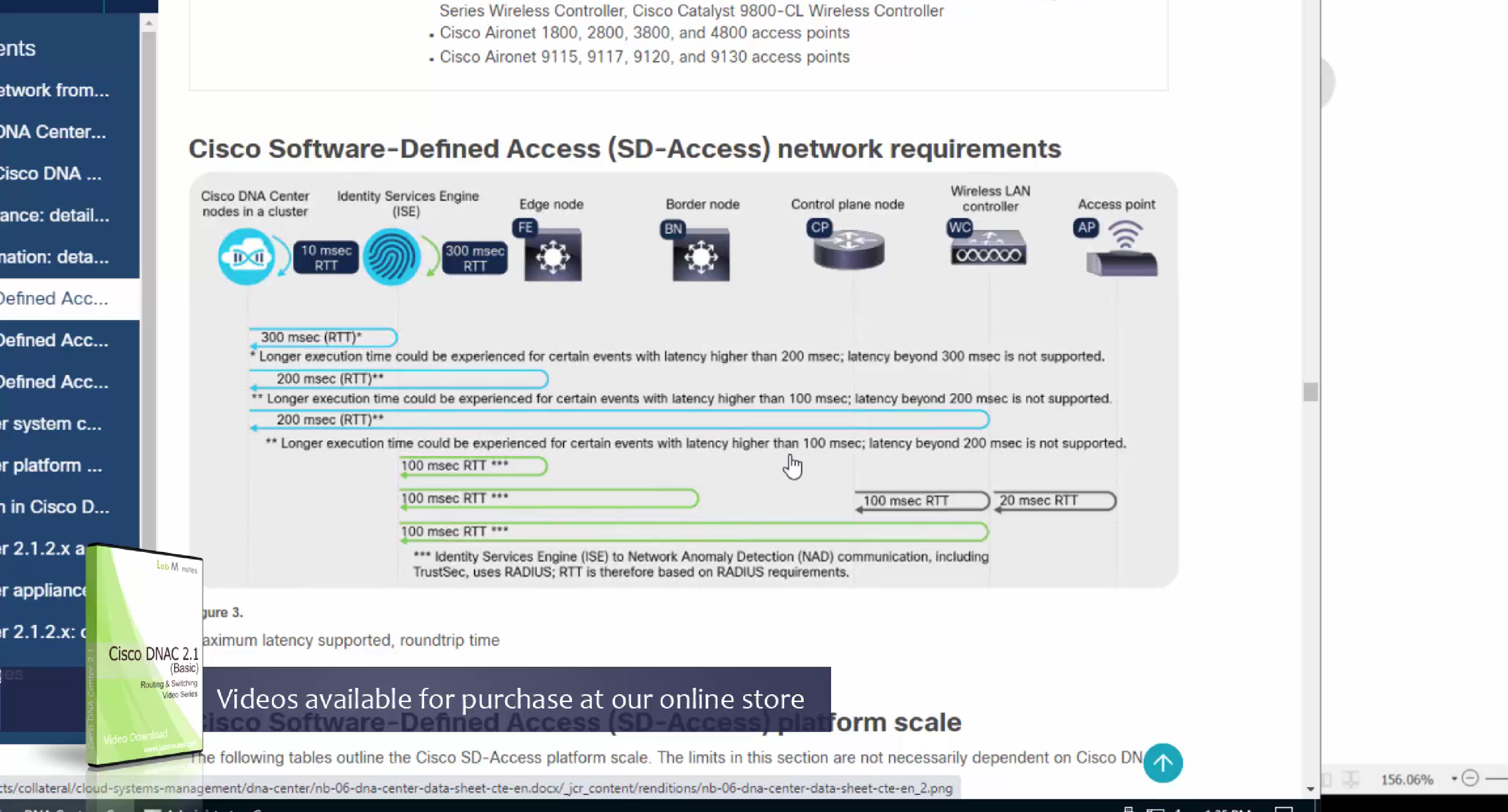
one very important point to keep in mind is that we need is the latency requirements for SDA between DNAC and devices is 100ms and 200ms is kind of pushing
From ISE we only have 100ms to play with anyway
latency requirement between WLC and AP is 20ms
Within the cluster of DNAC (which includes ISE as policy node) needs to be 10 msec
another requirement is that all devices be configured with SSH access with credentials that were configured in DNAC with full access and not just enable prompt
Device controllability during discovery means that configuration changes will be done during inventory / discovery or when device is associated to site, it is enabled by default
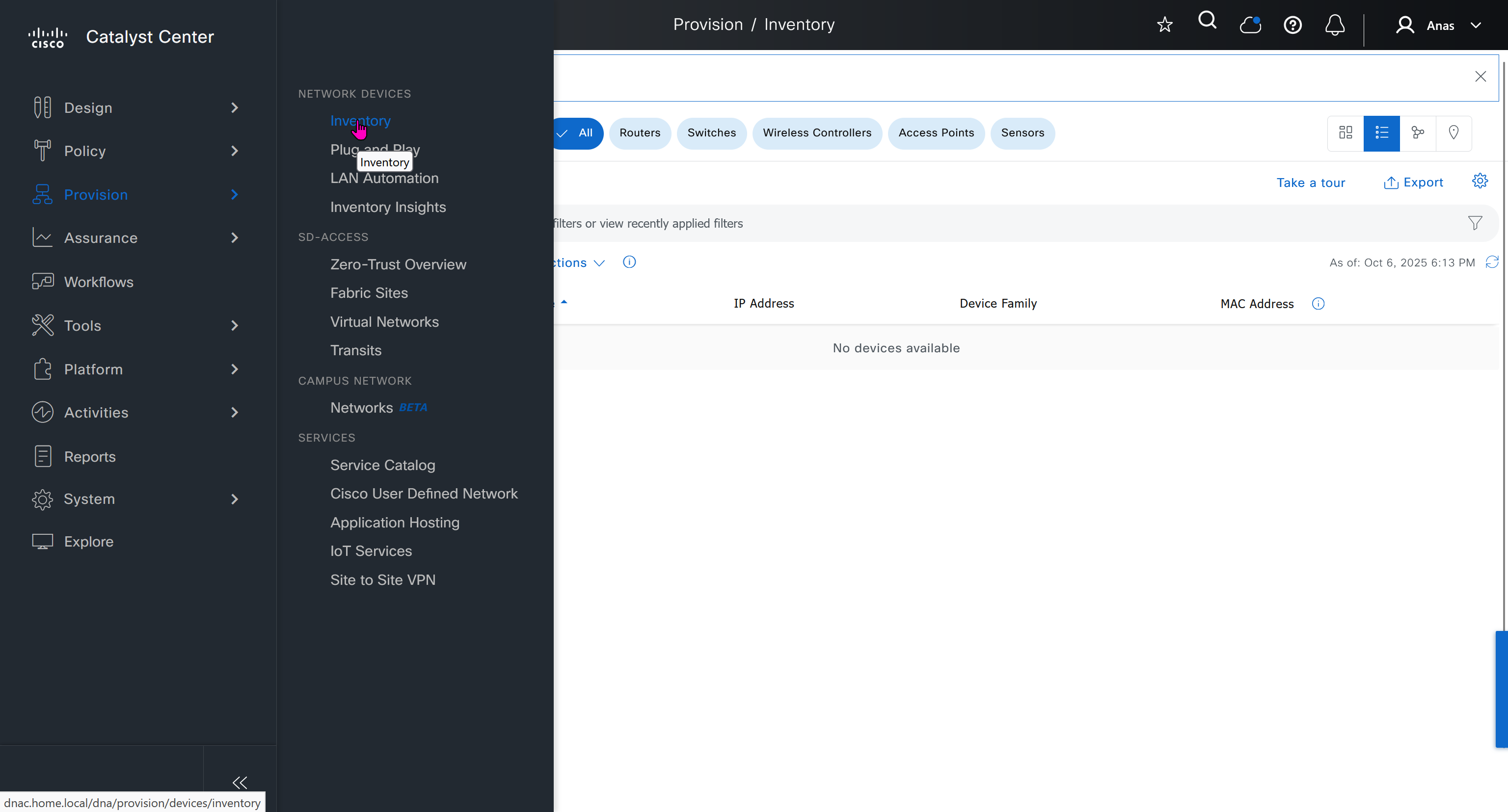
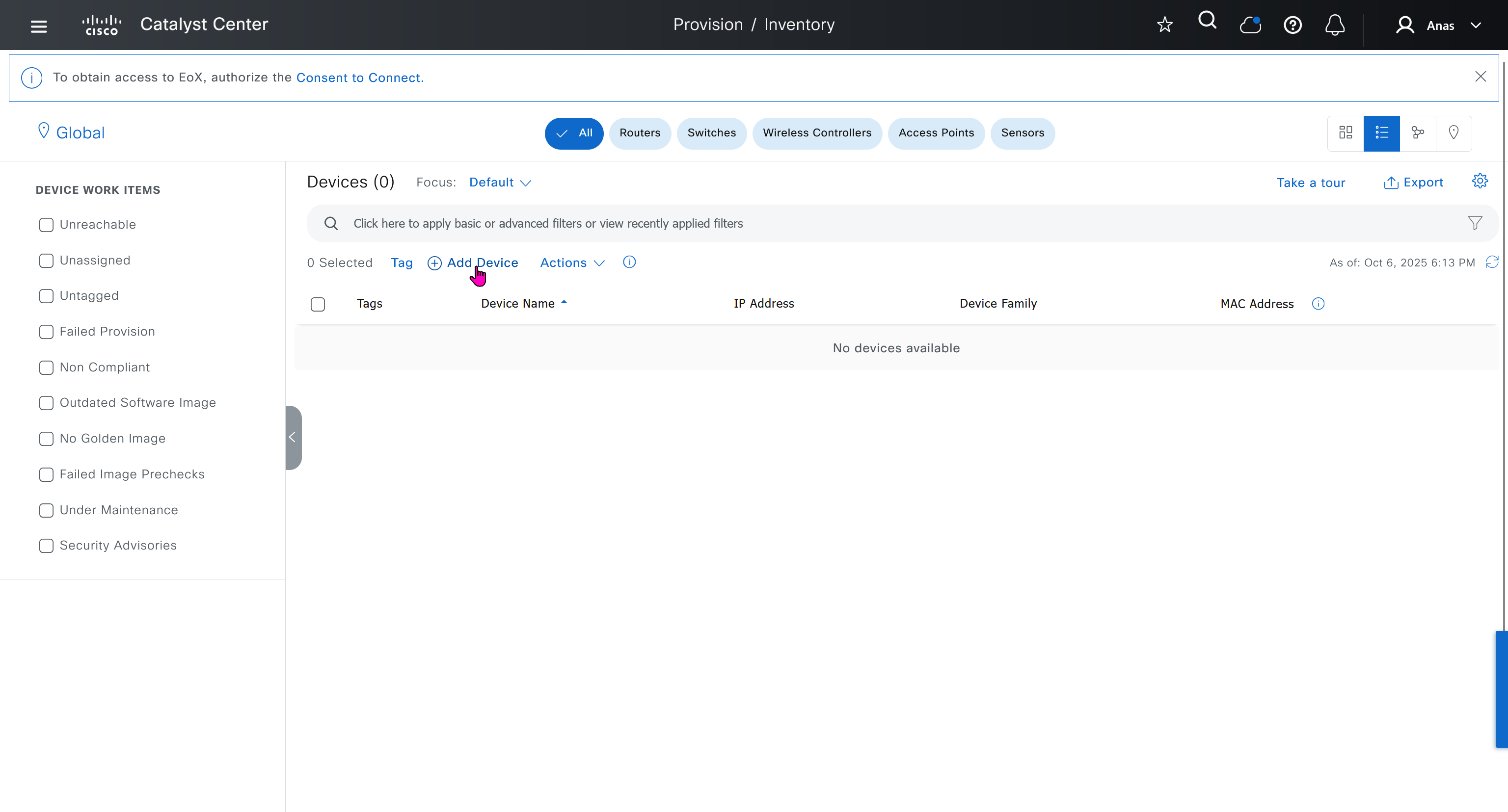
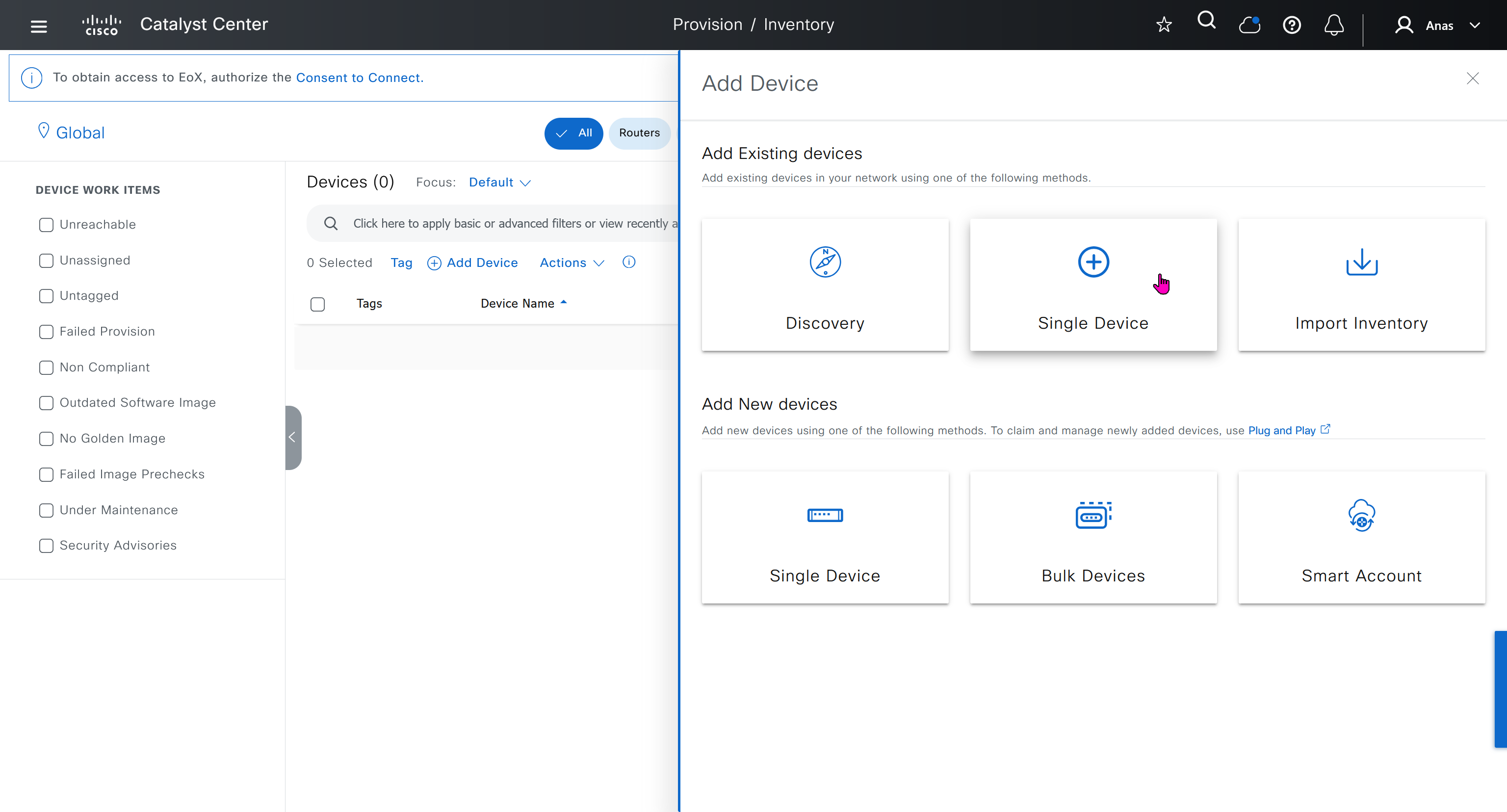
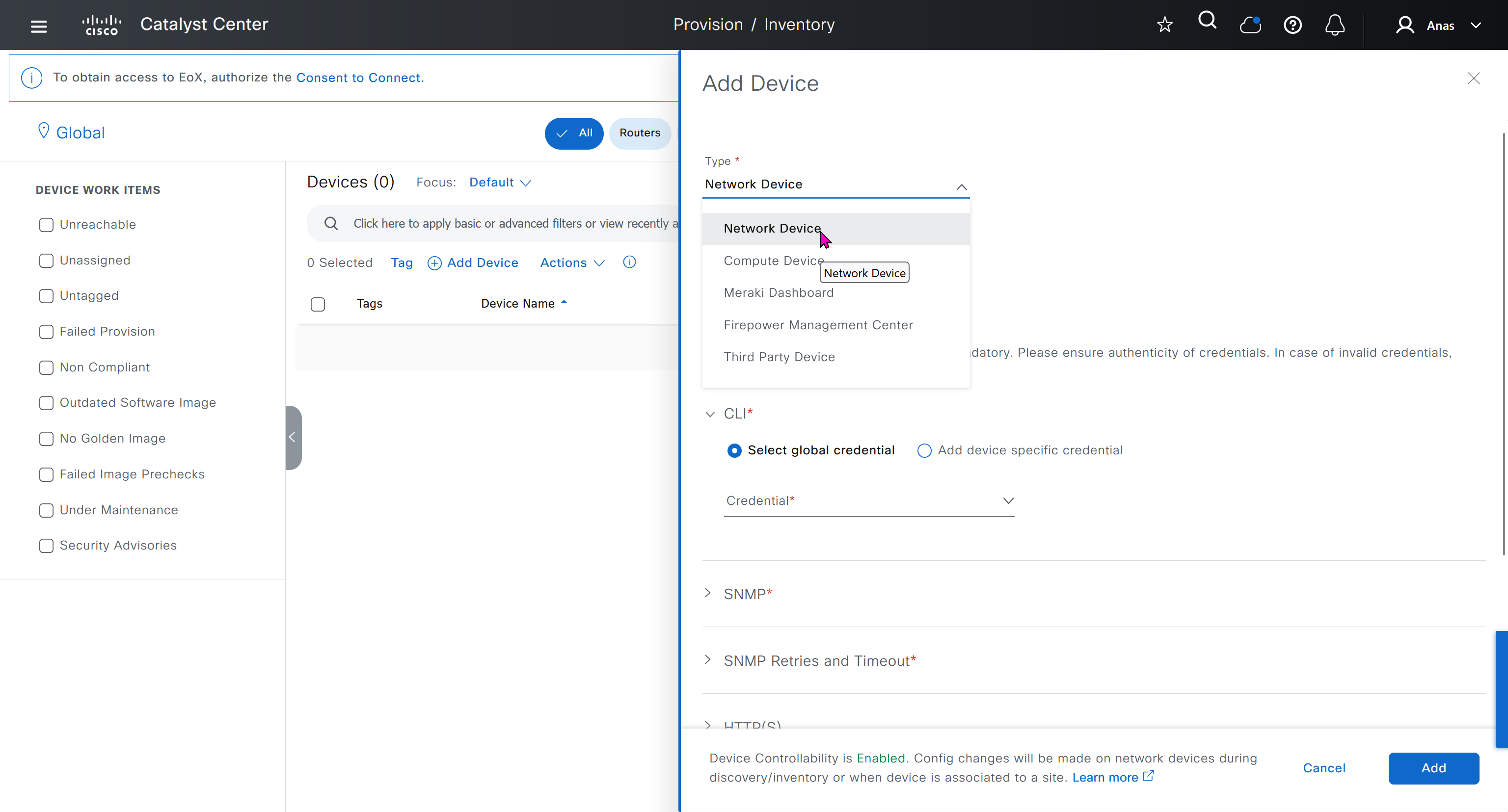
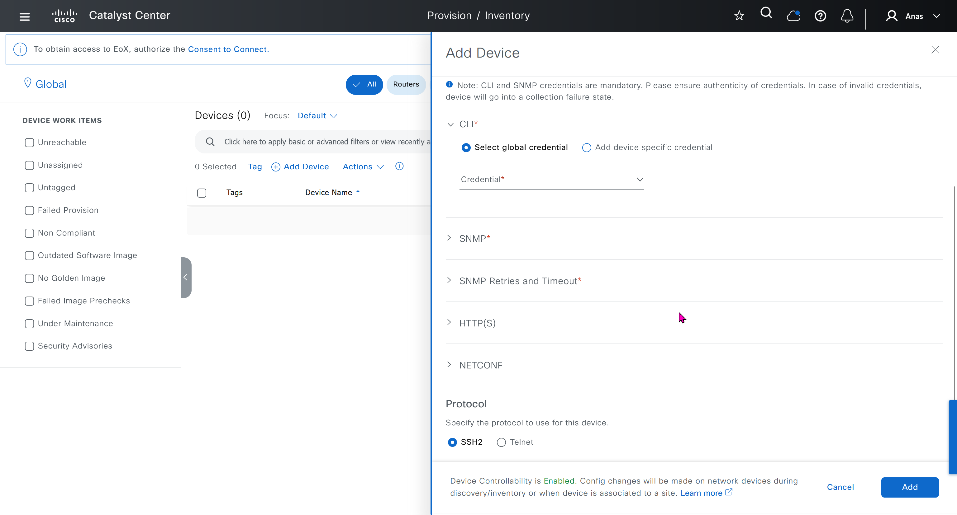

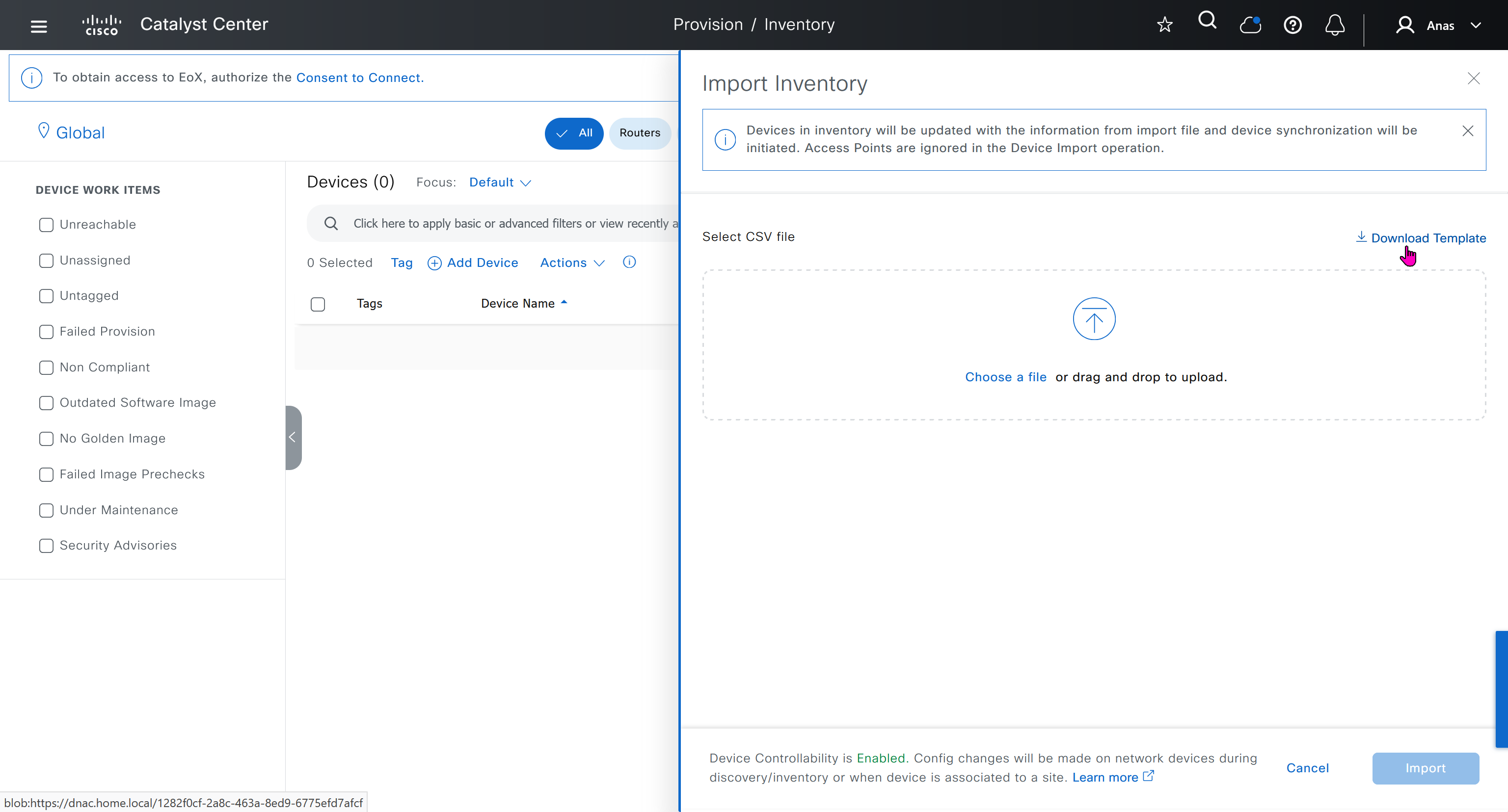

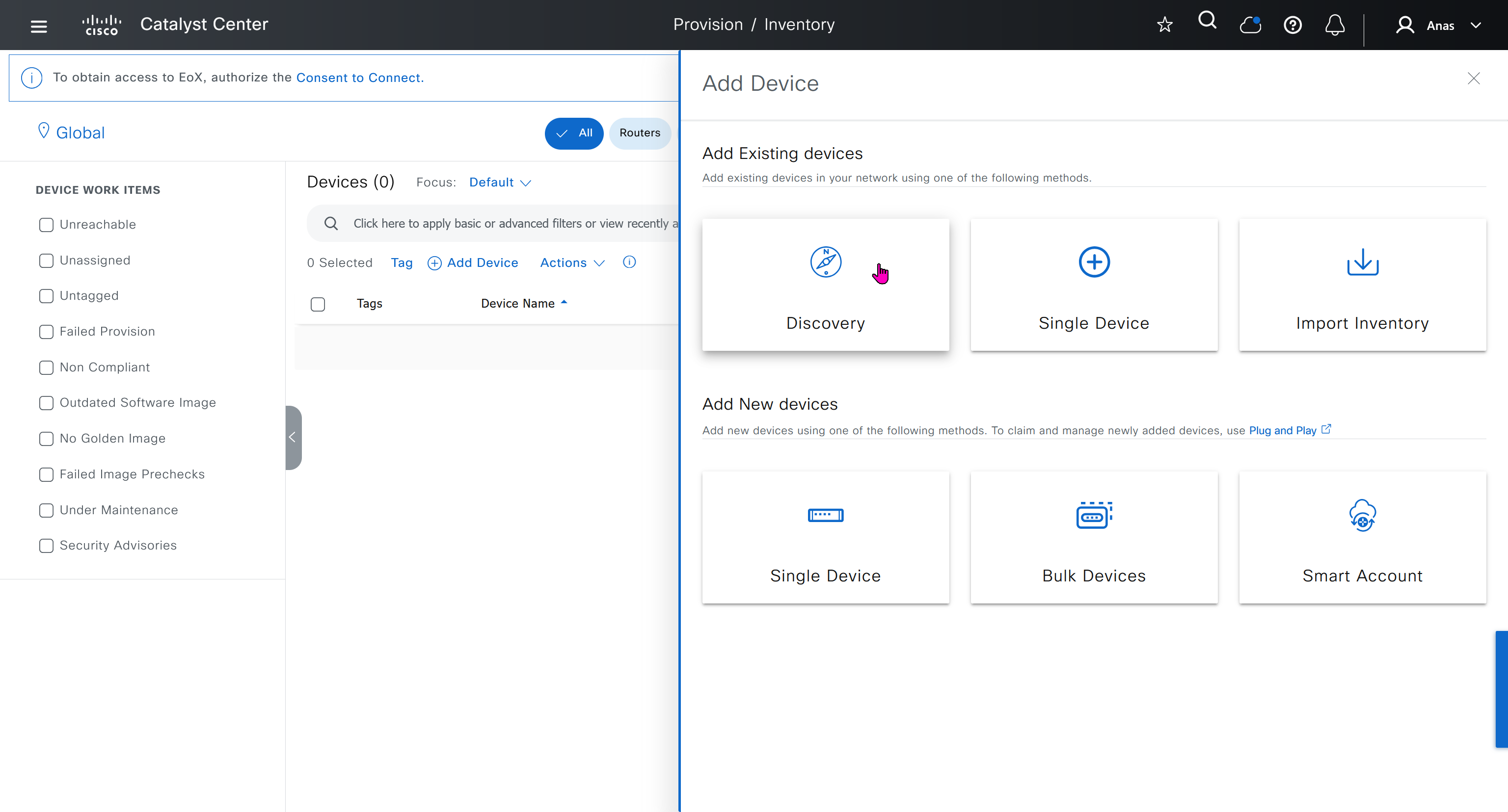
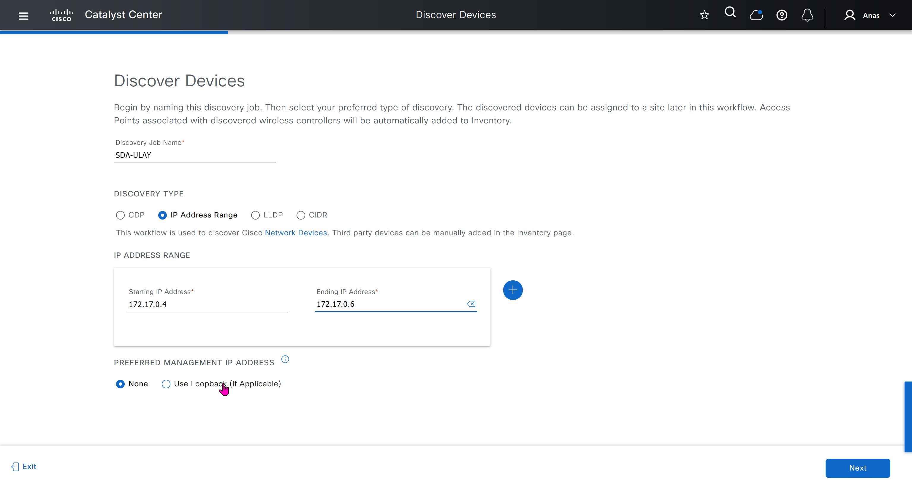
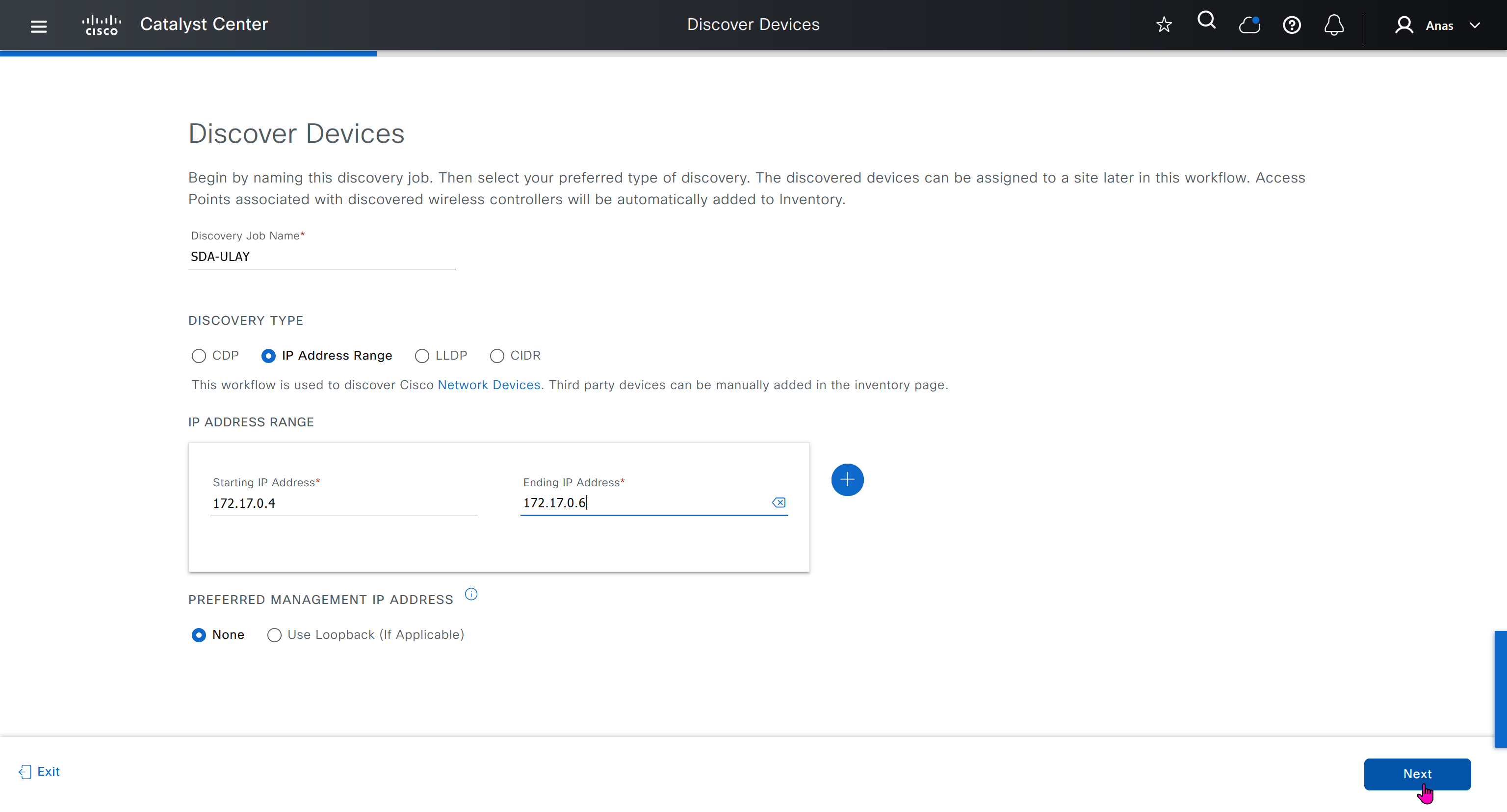

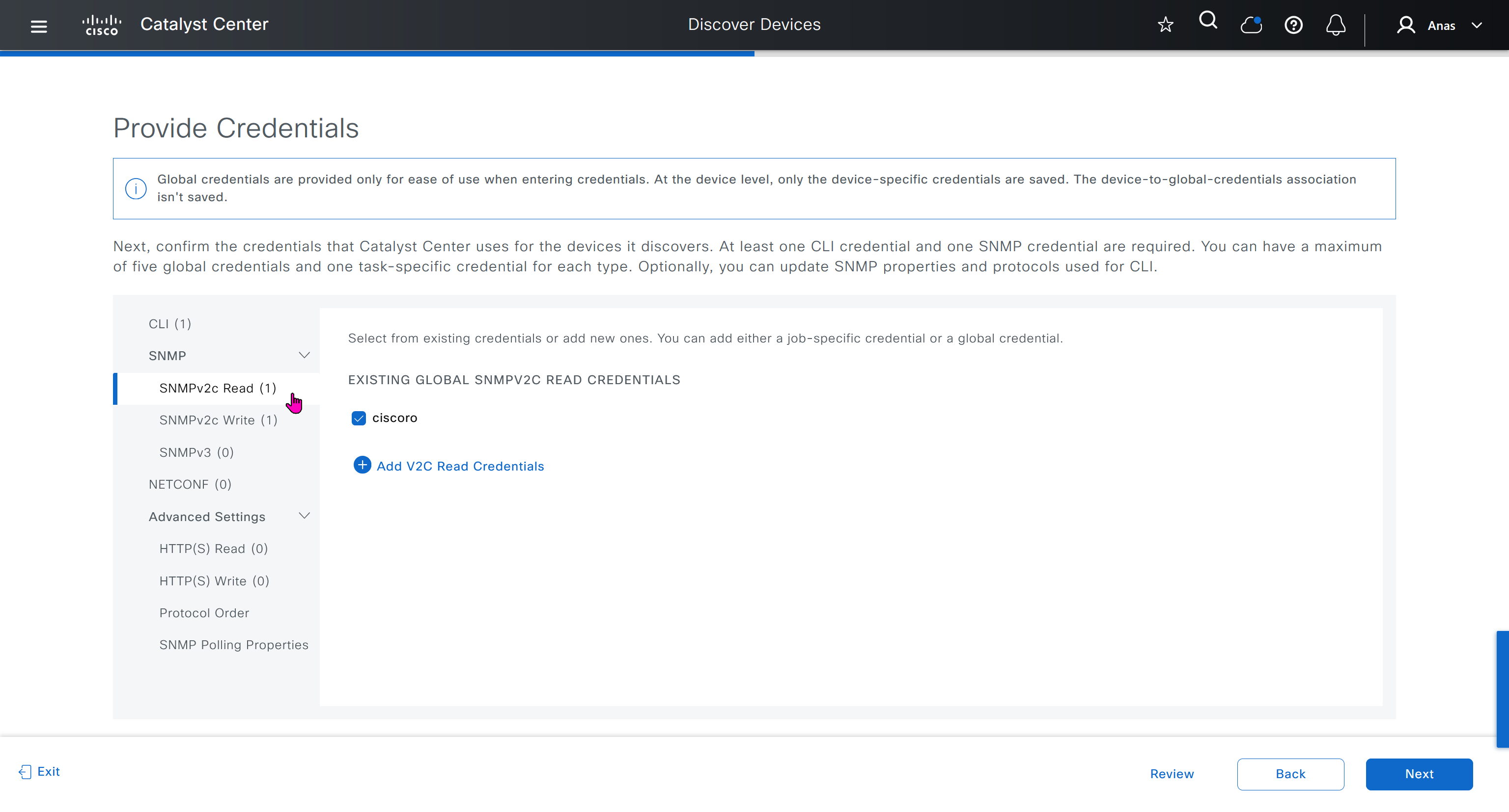


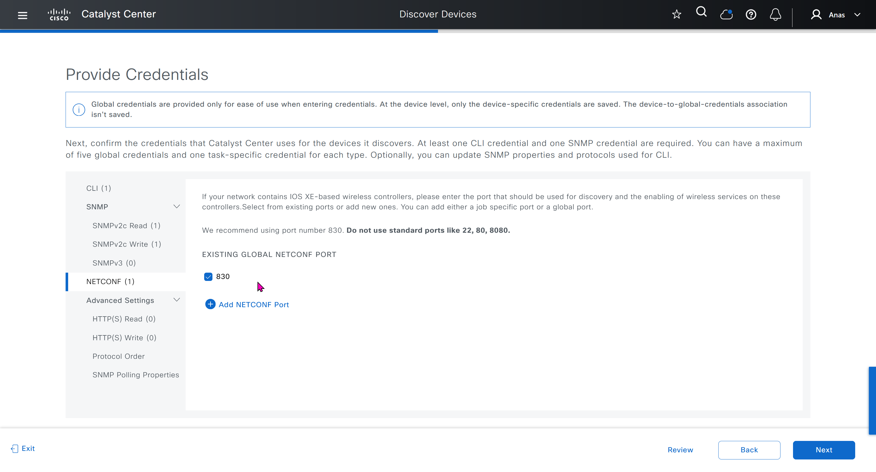
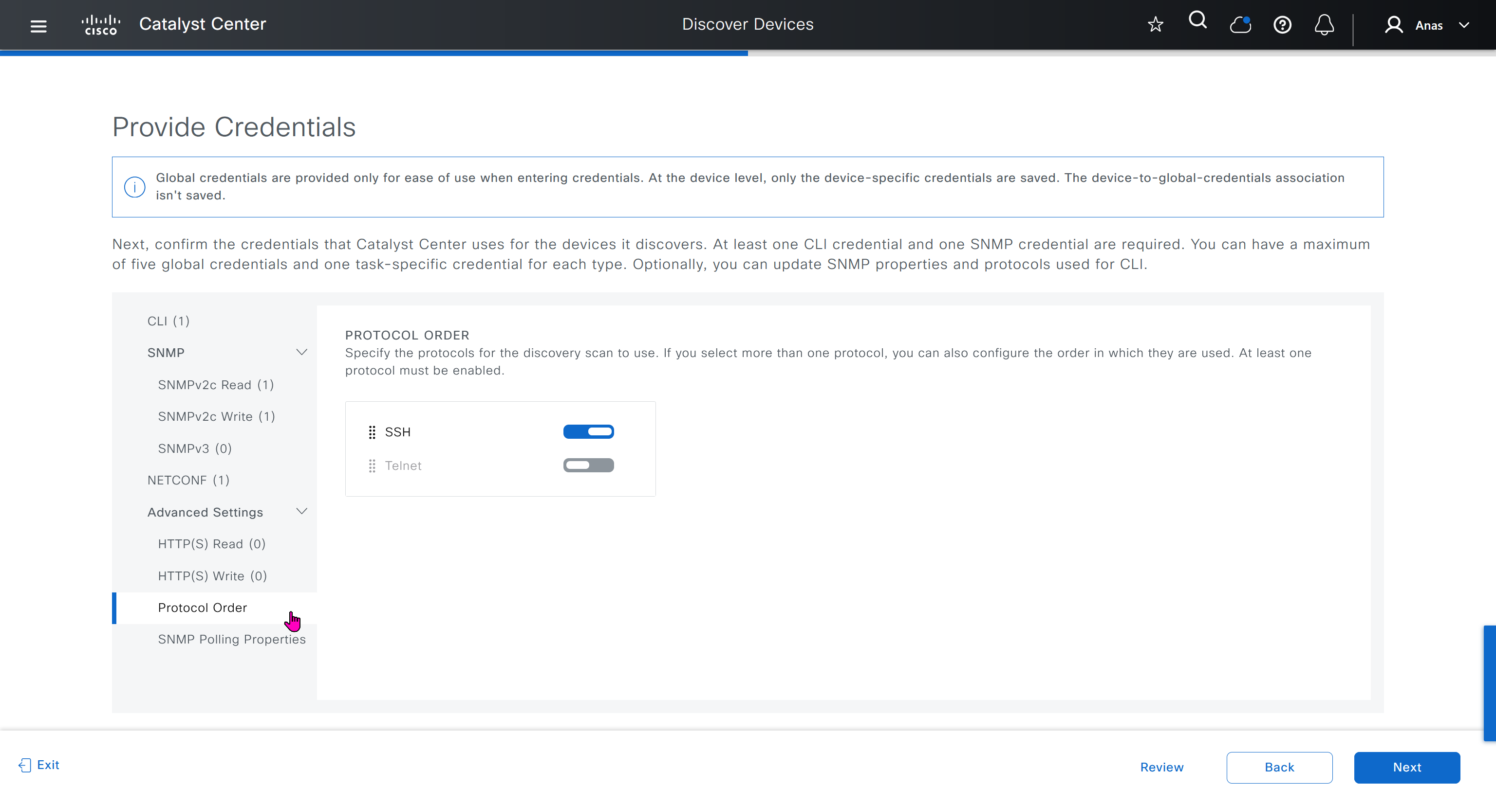
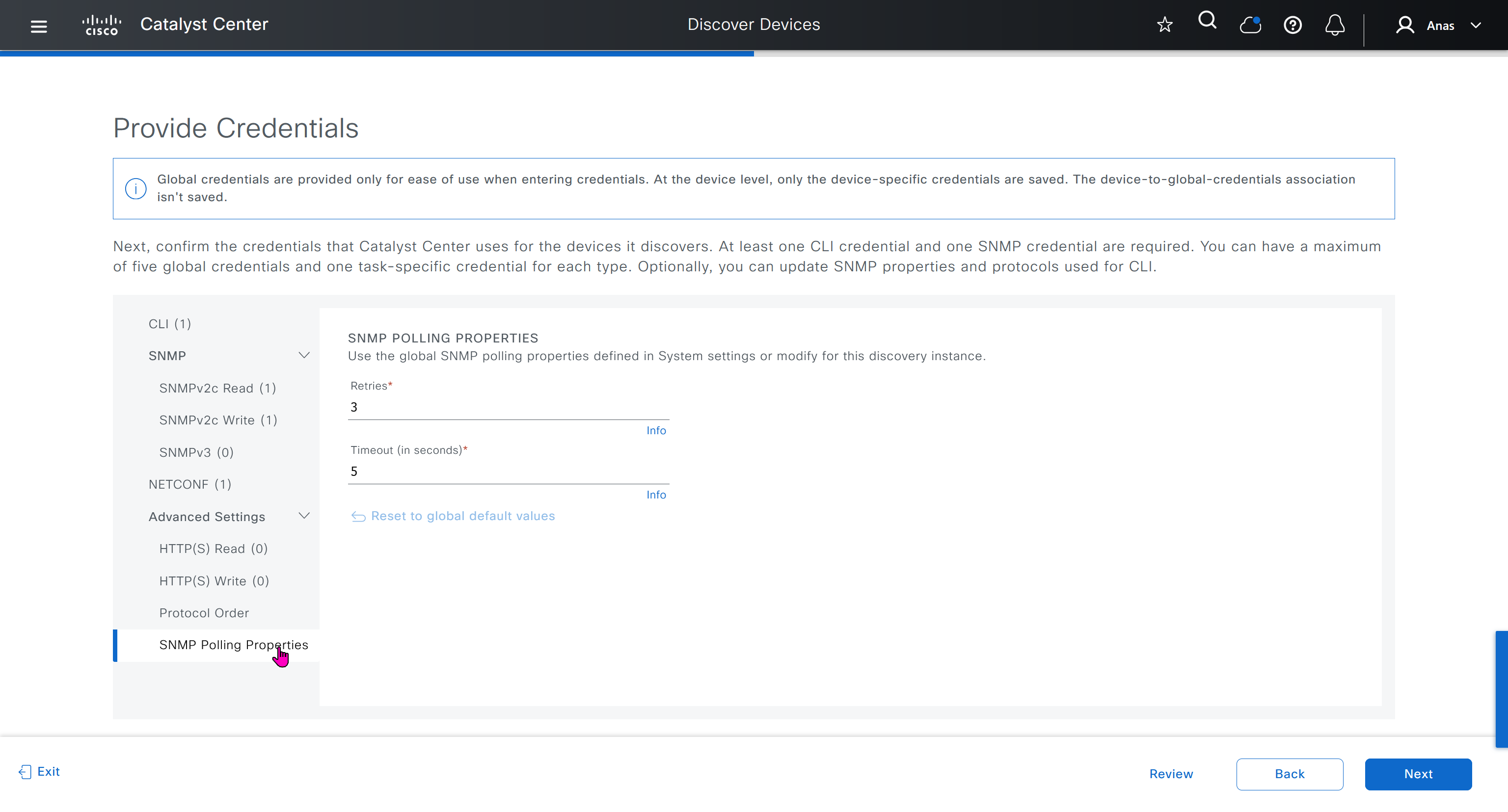
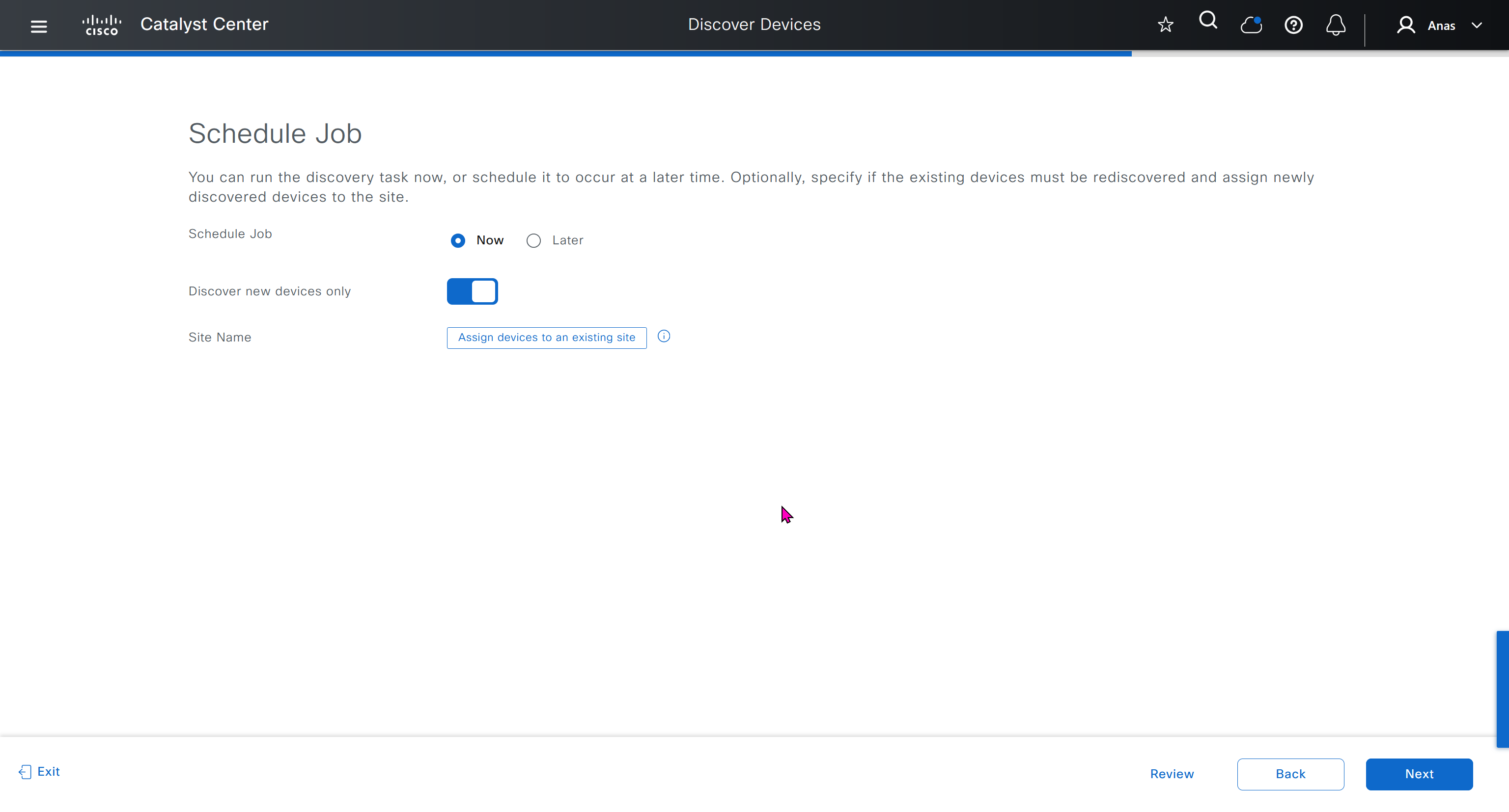

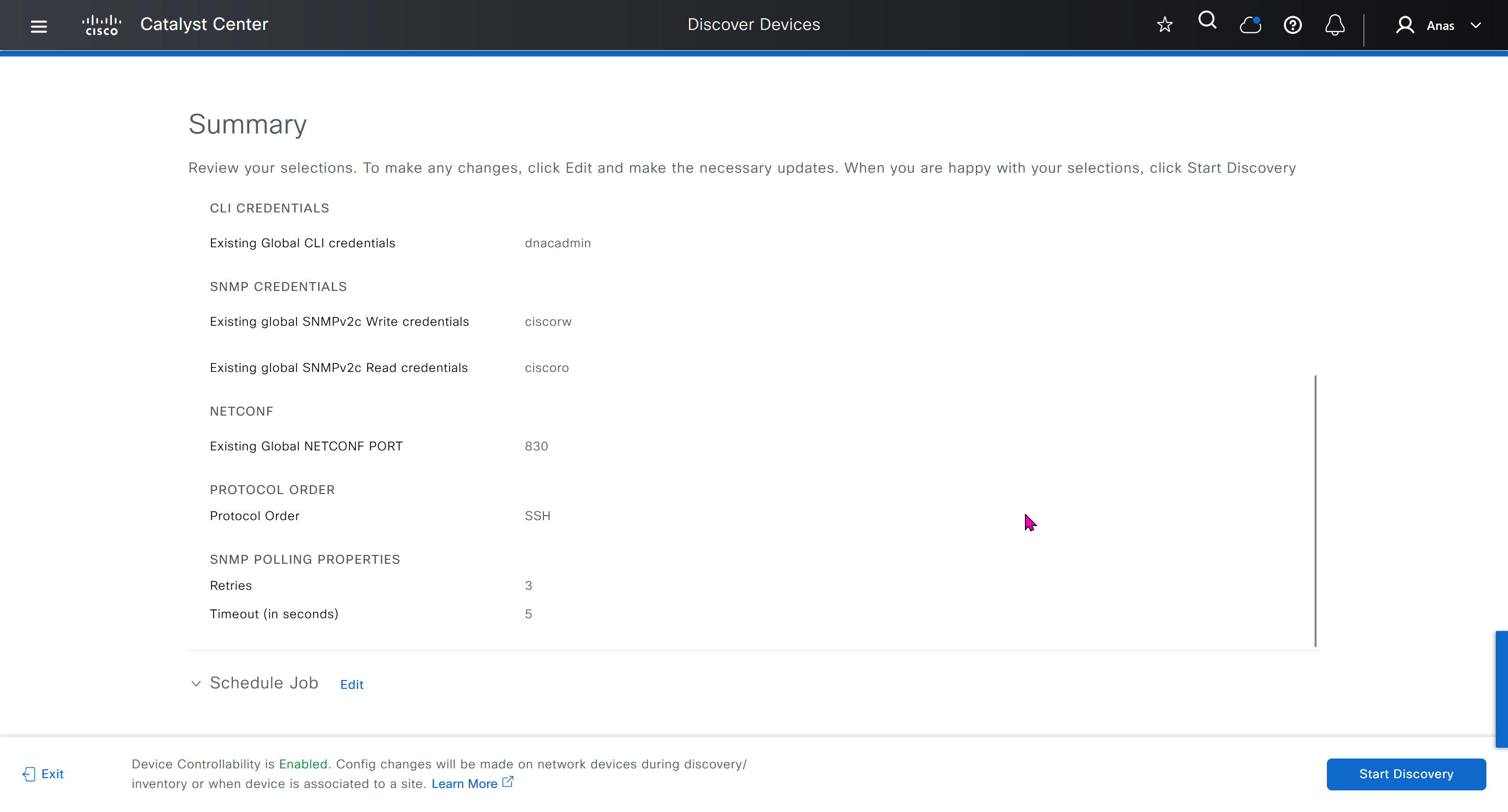
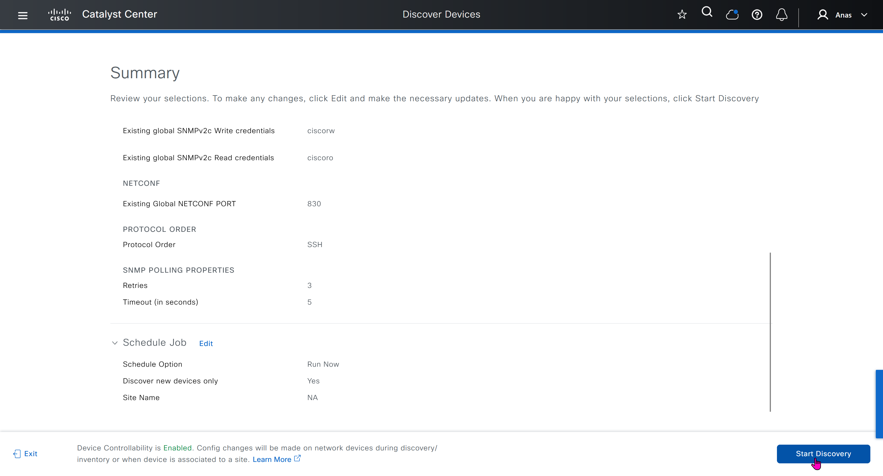
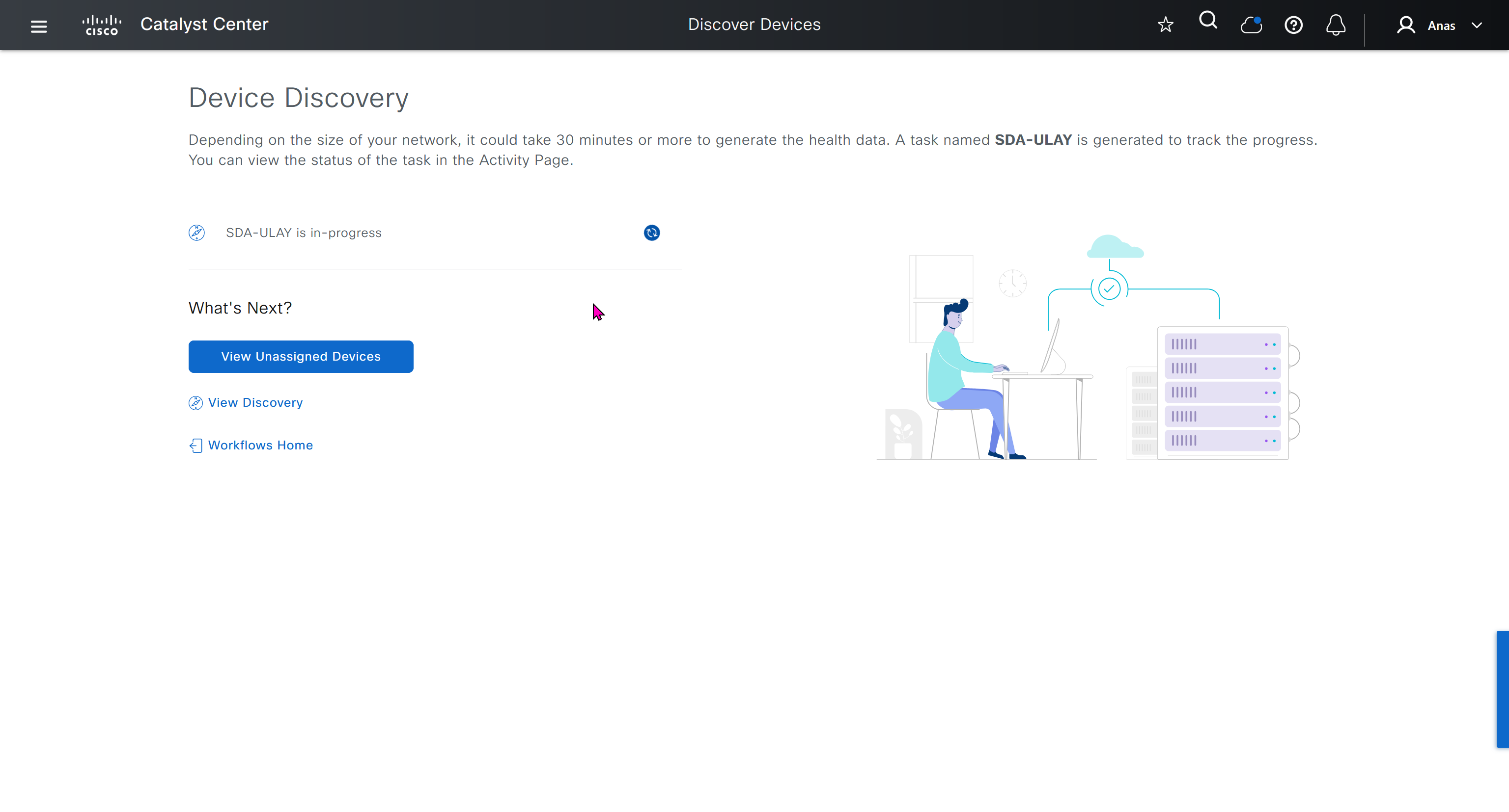
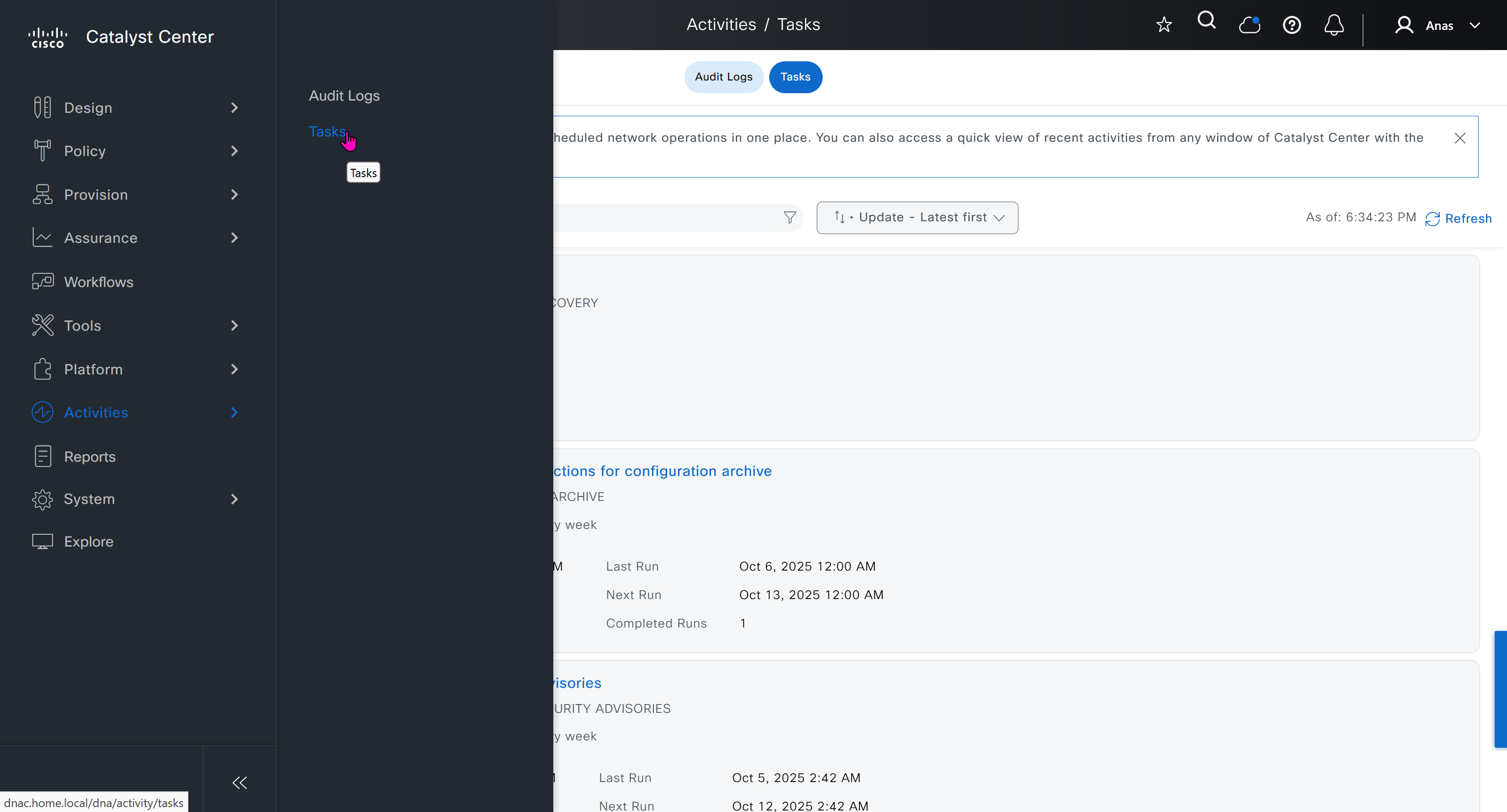
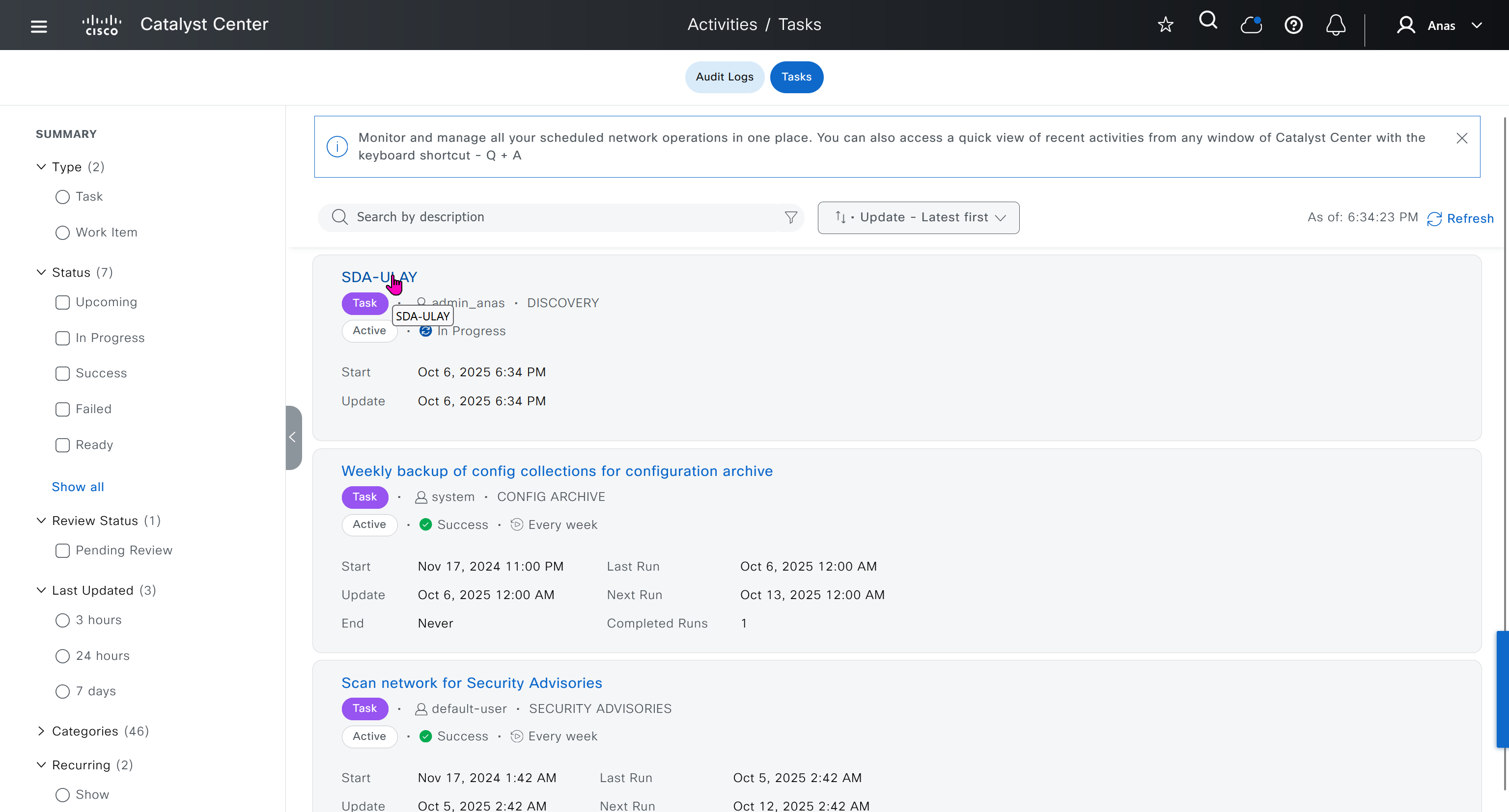

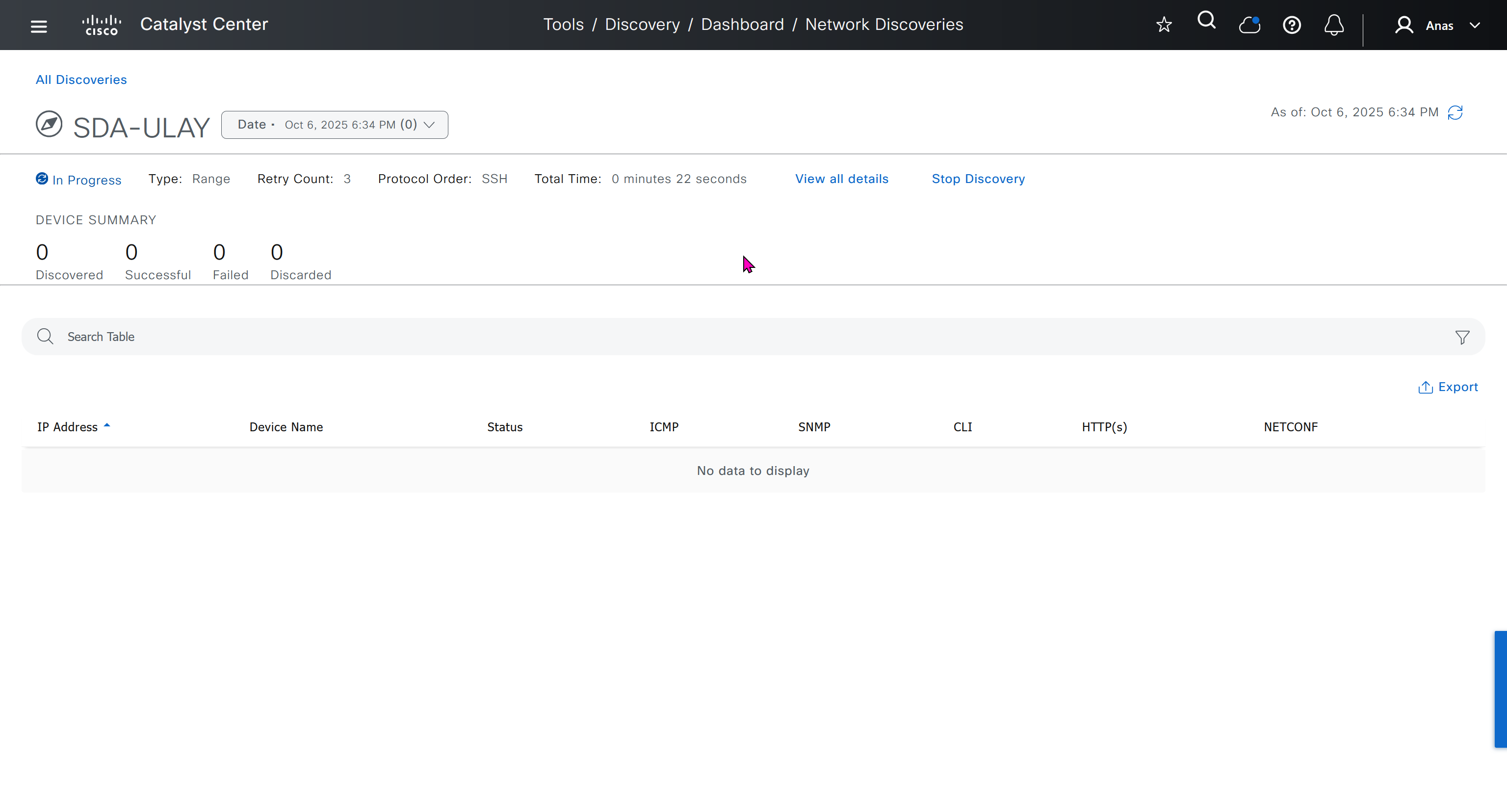
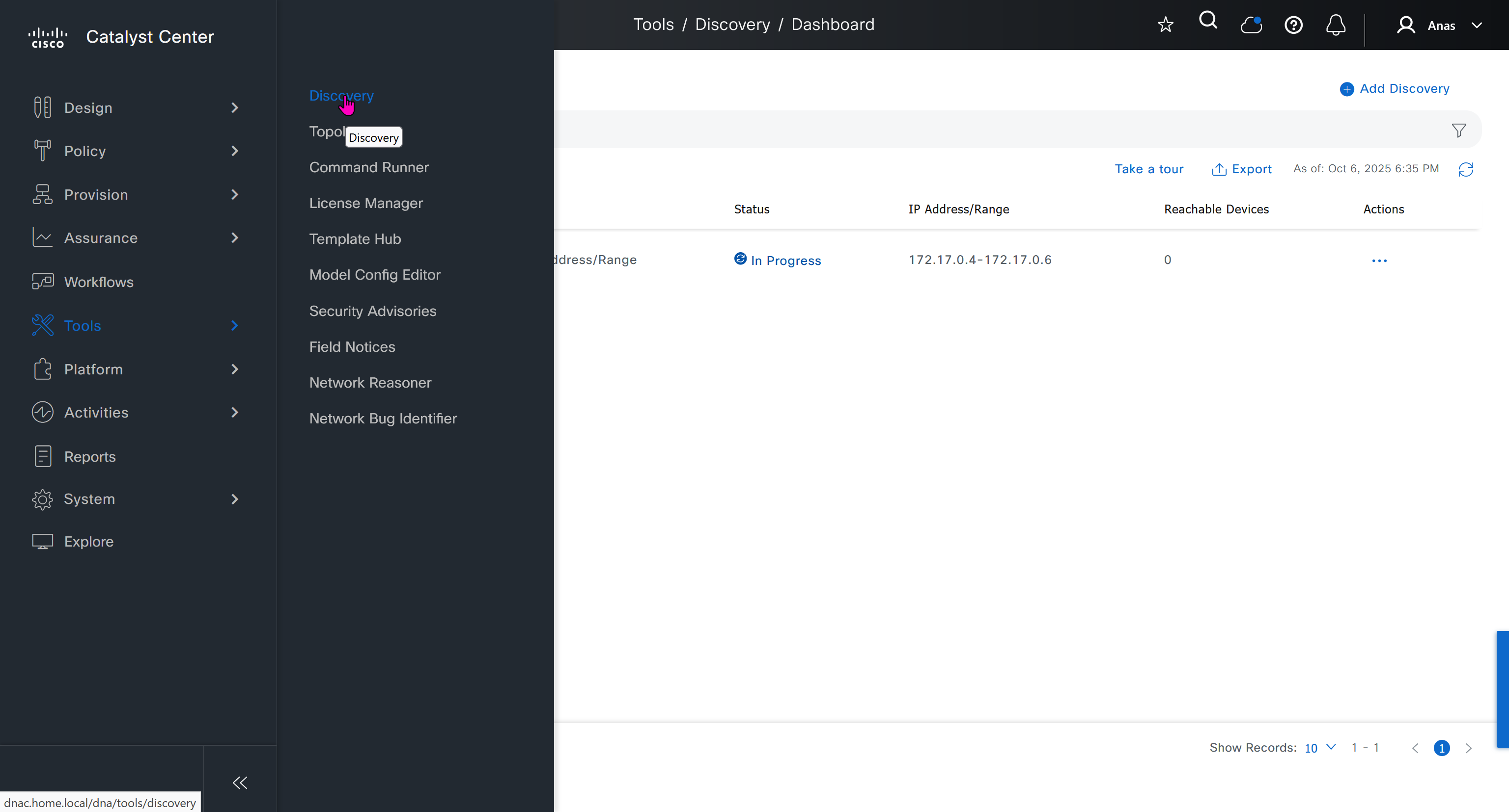
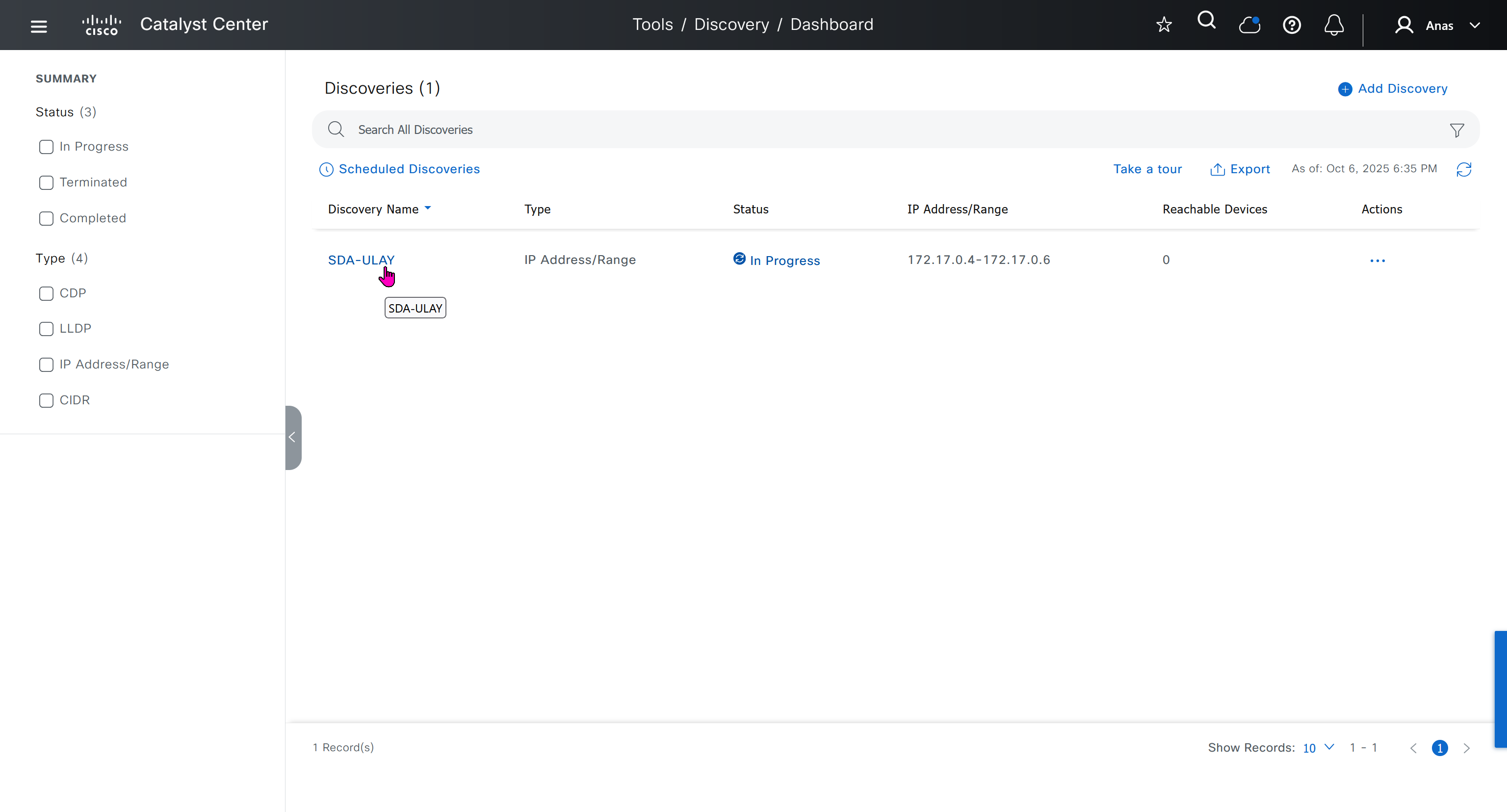
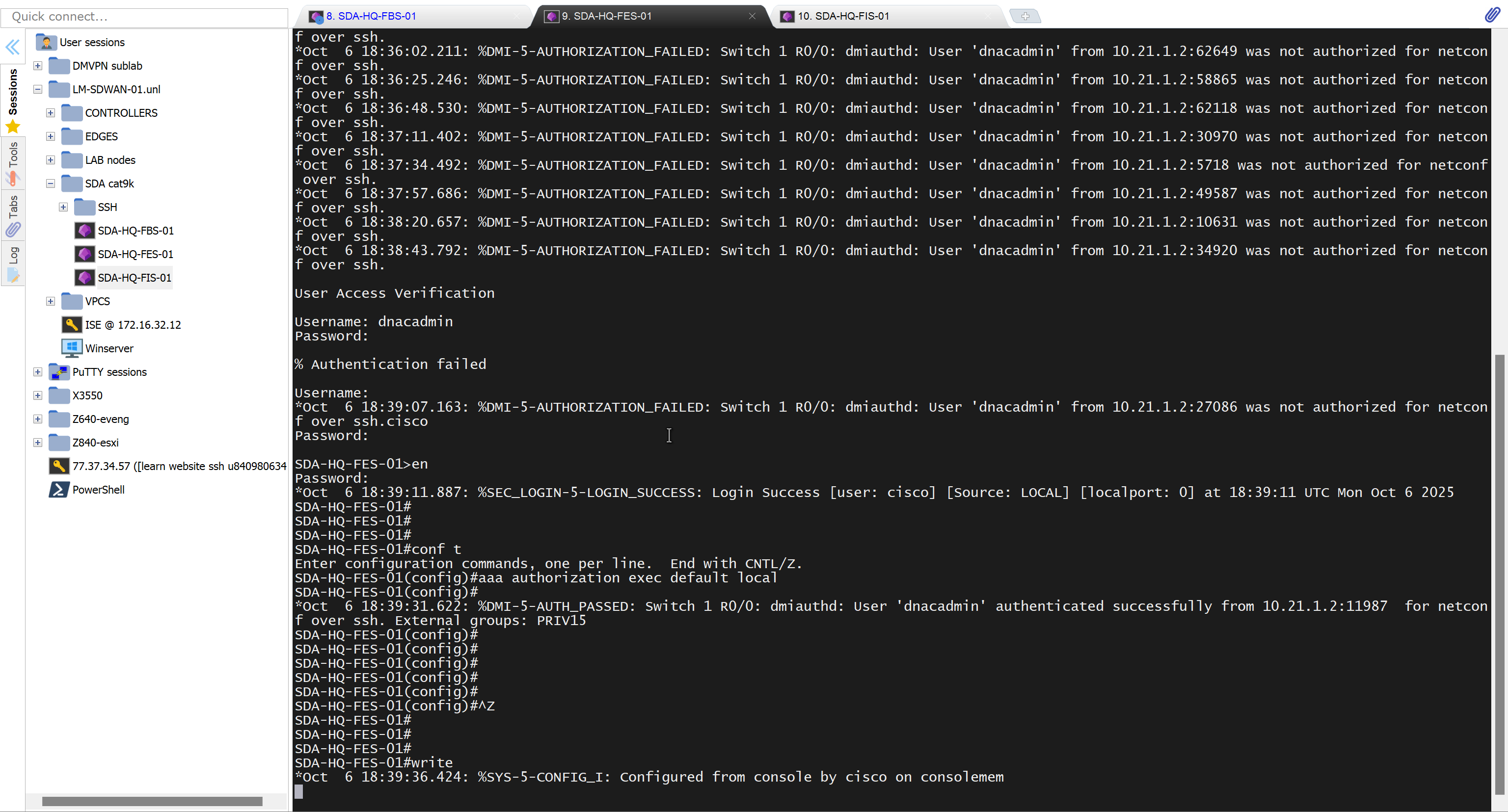

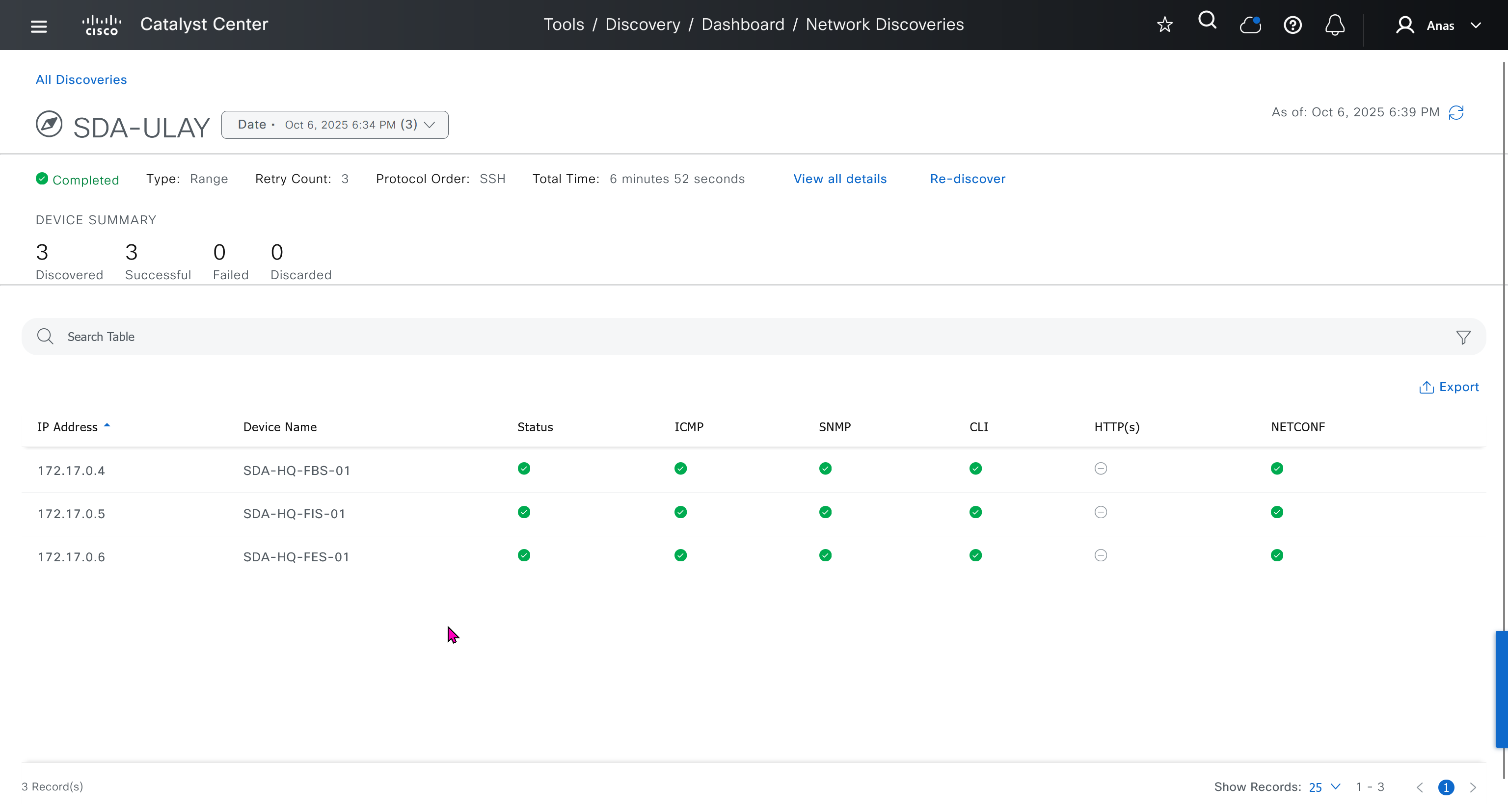

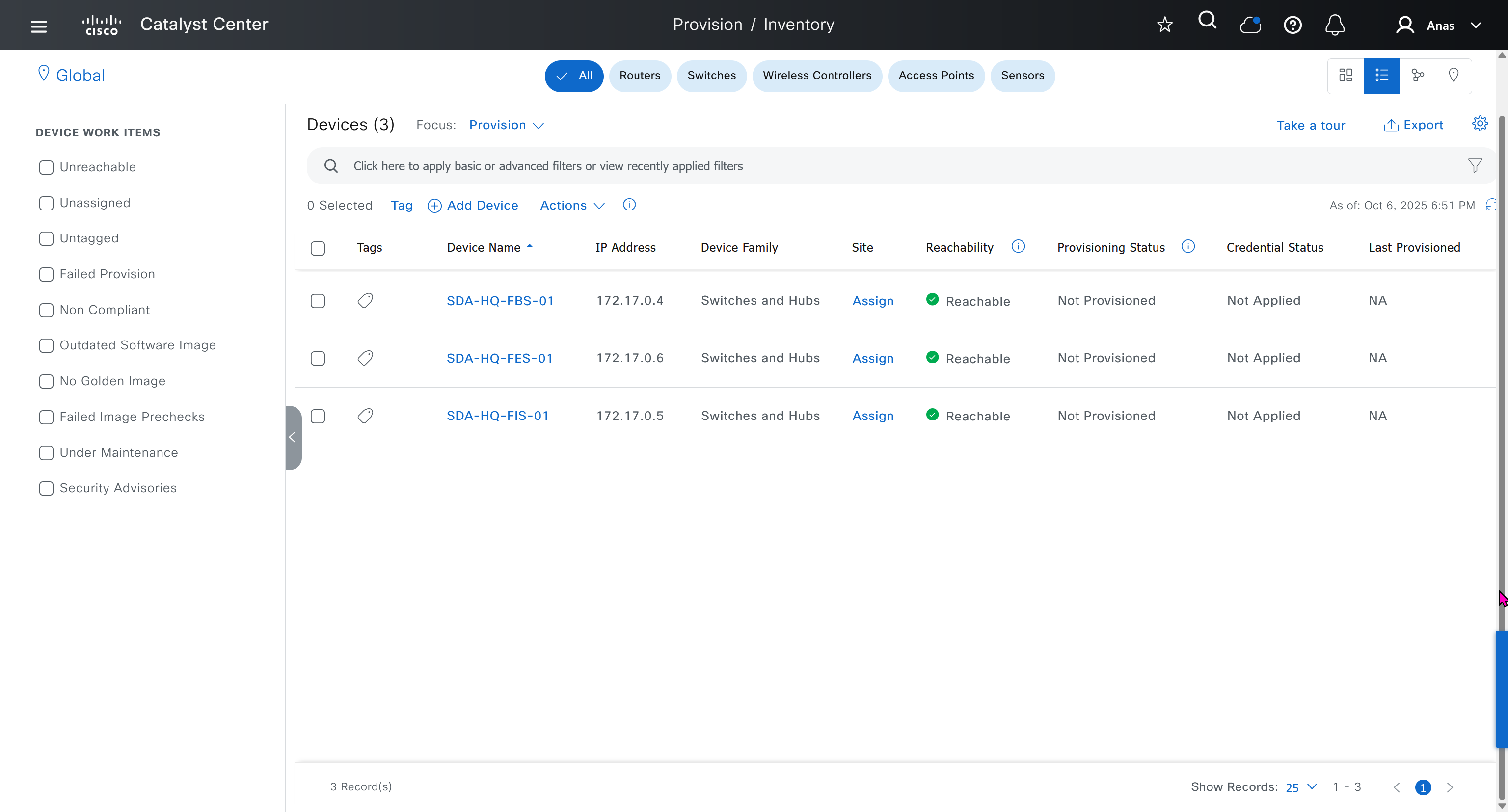
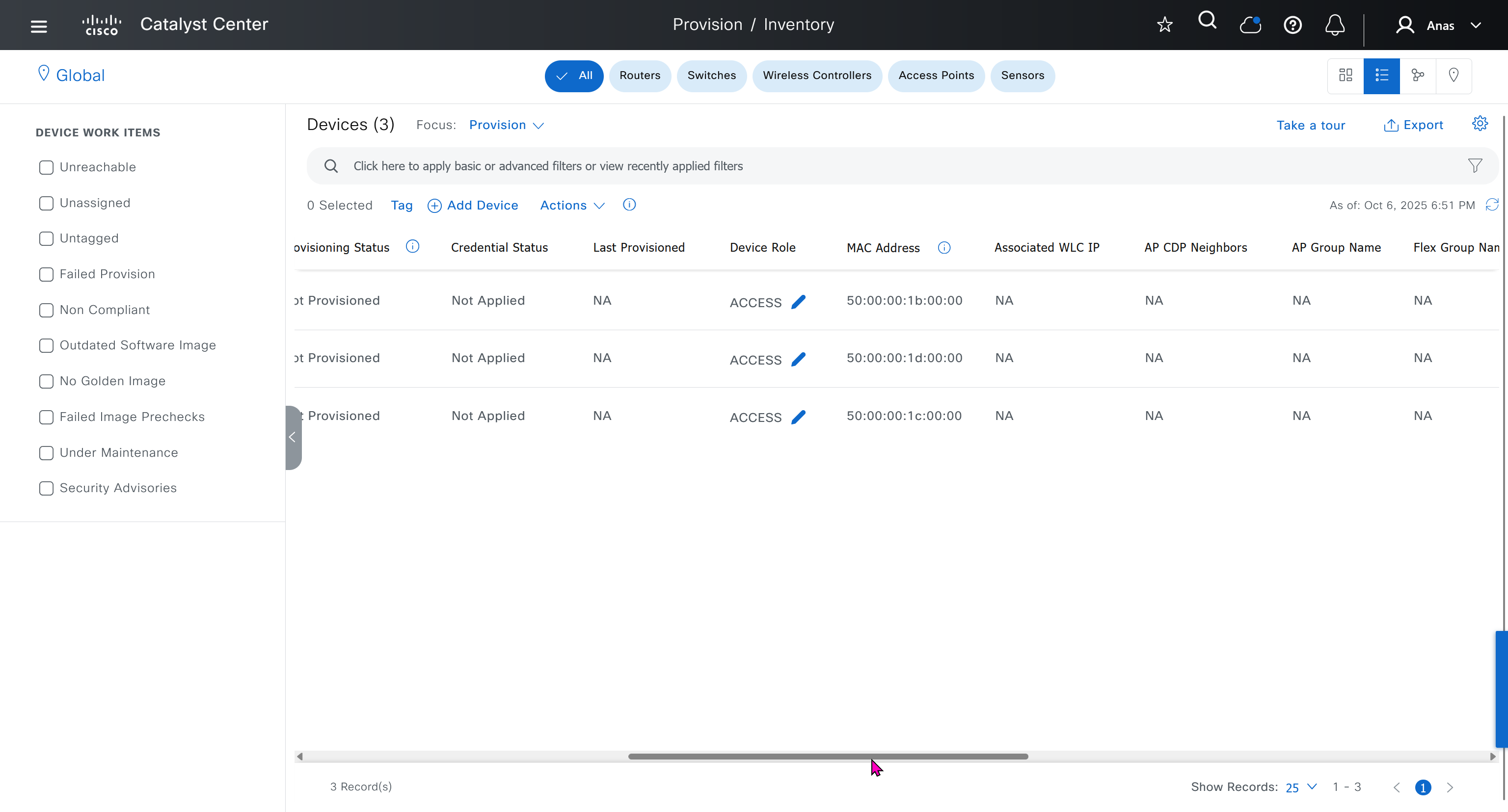
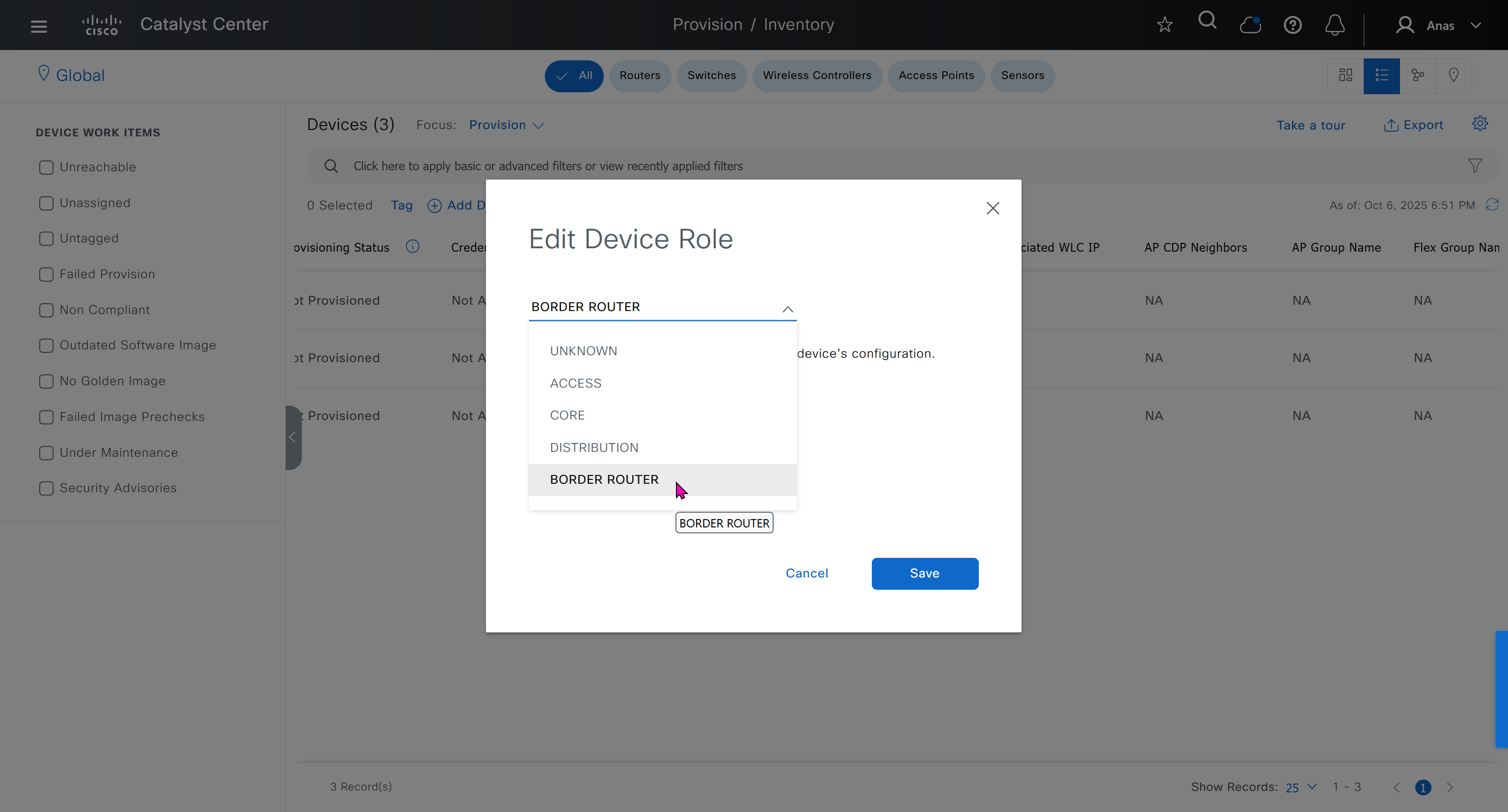
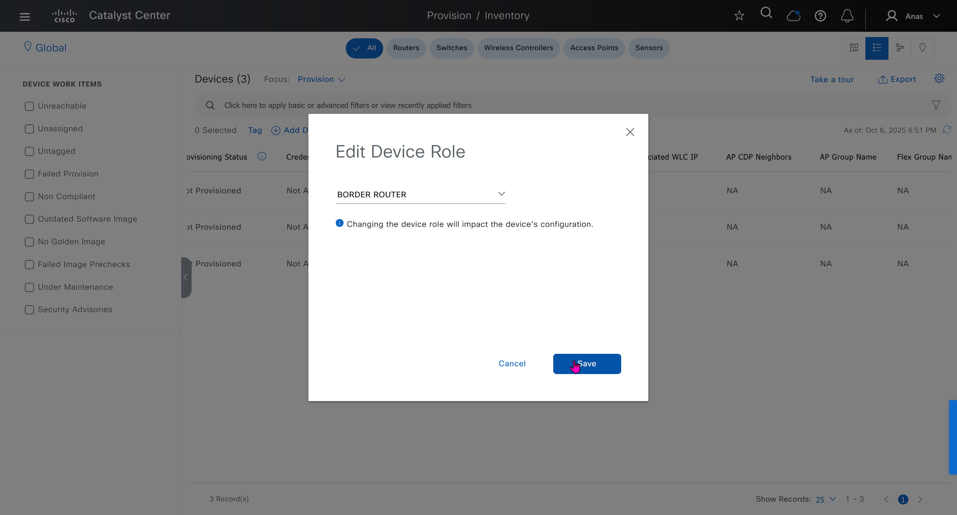
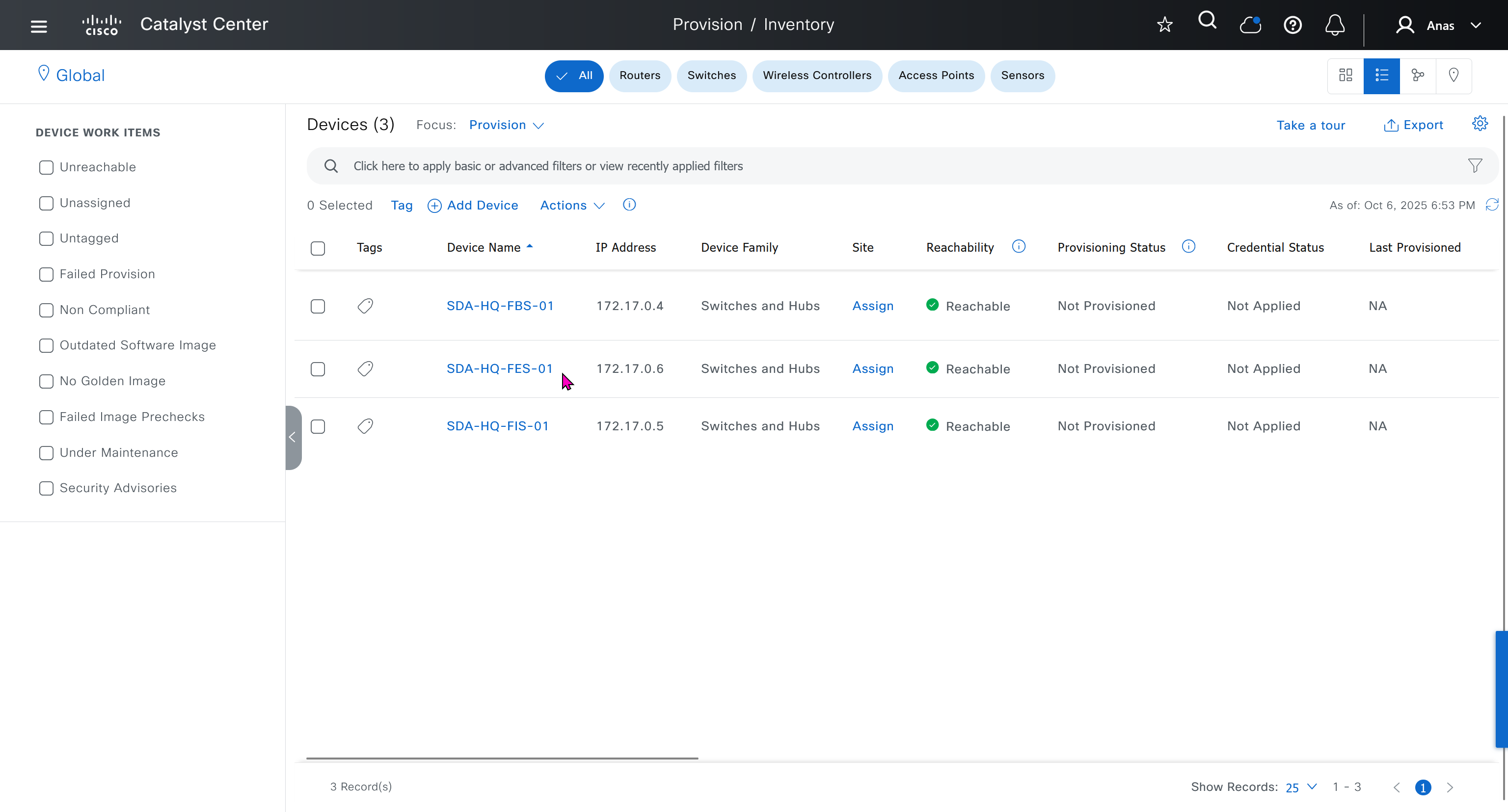


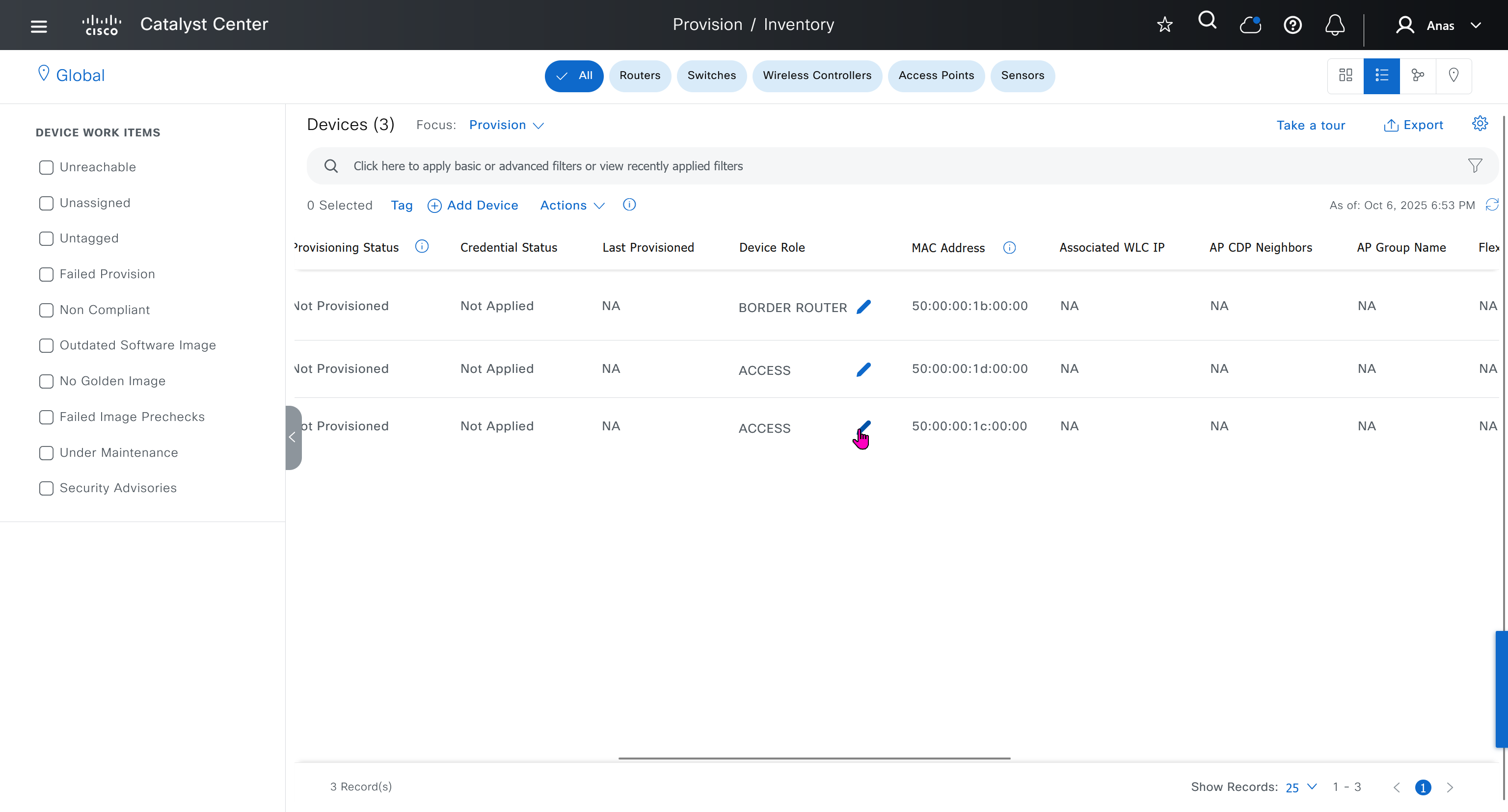

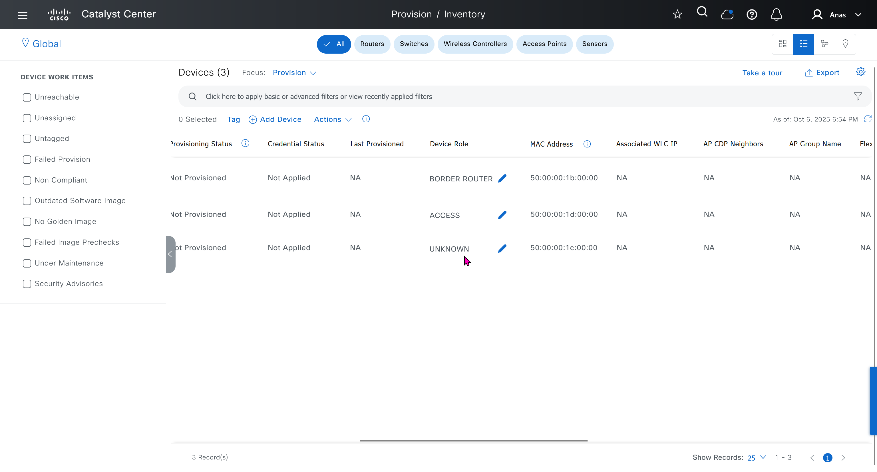
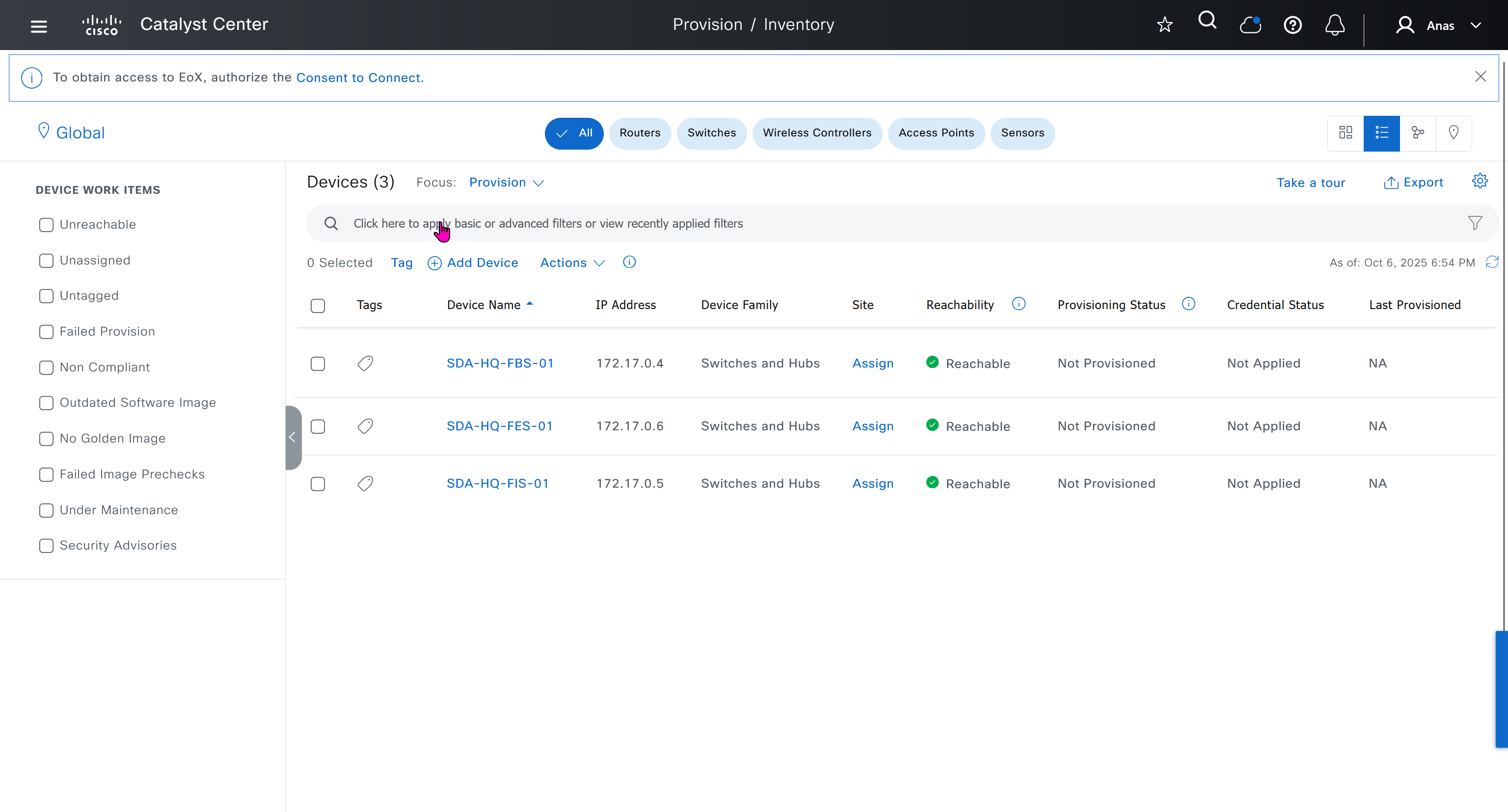
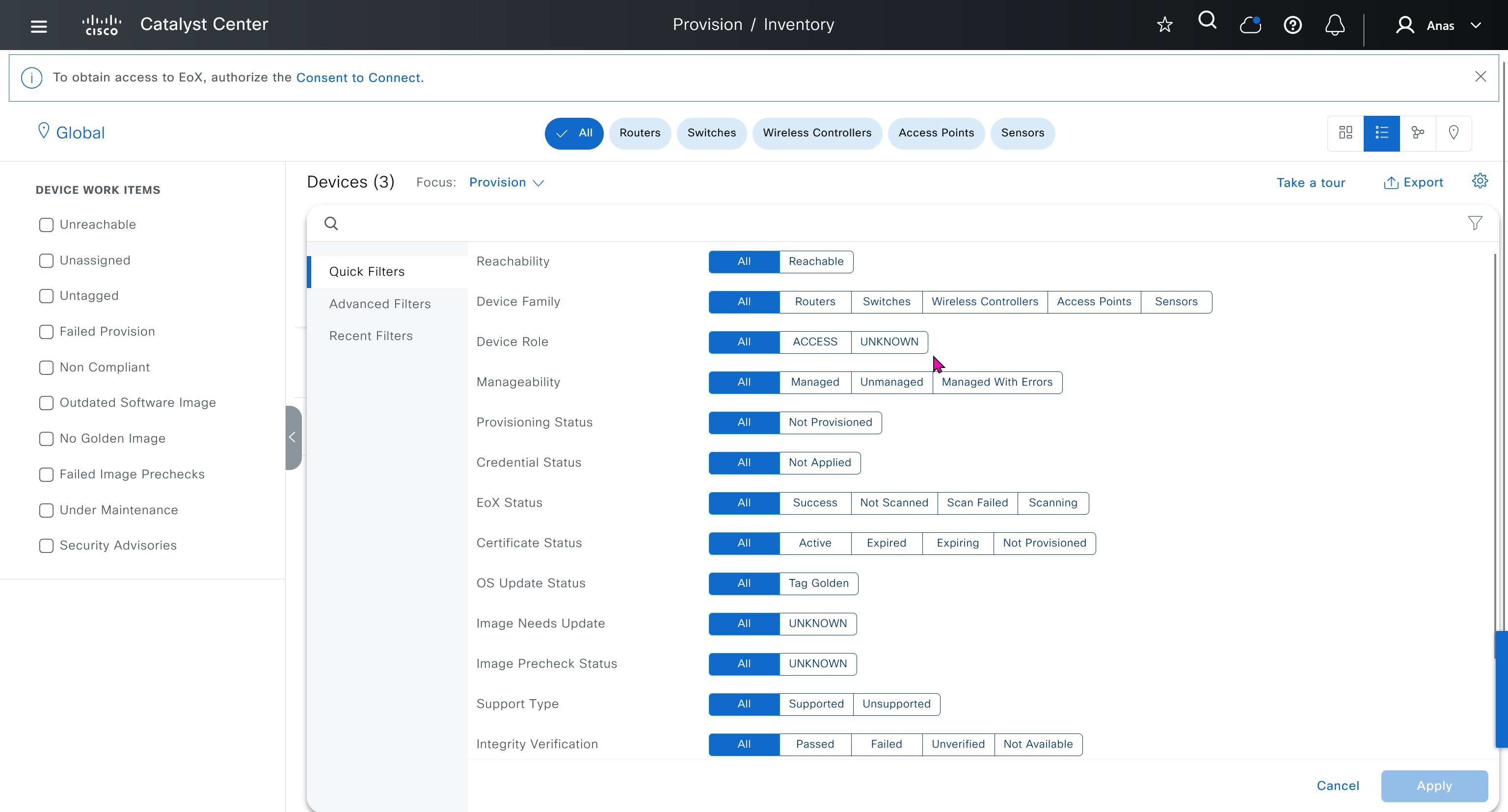
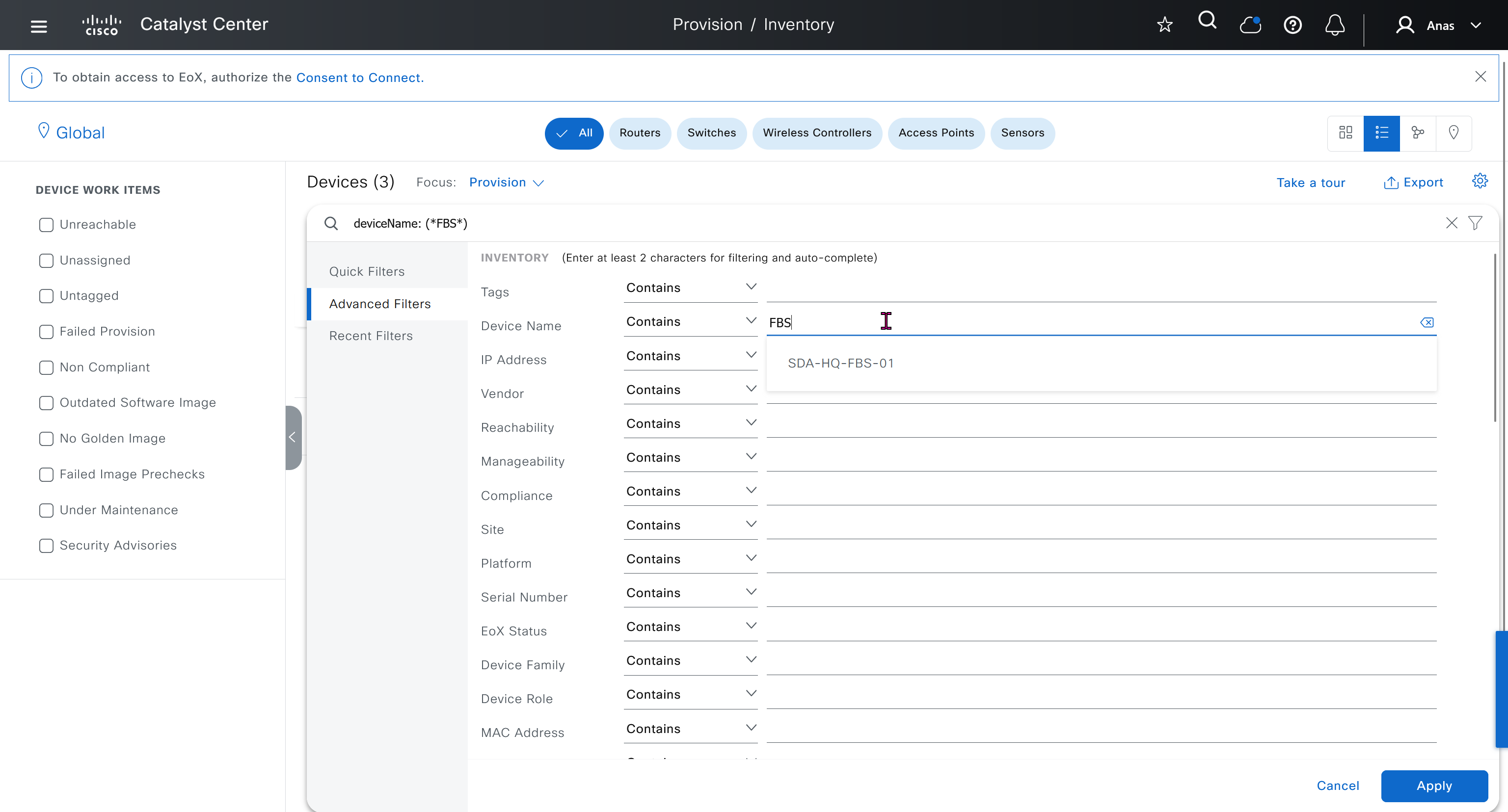

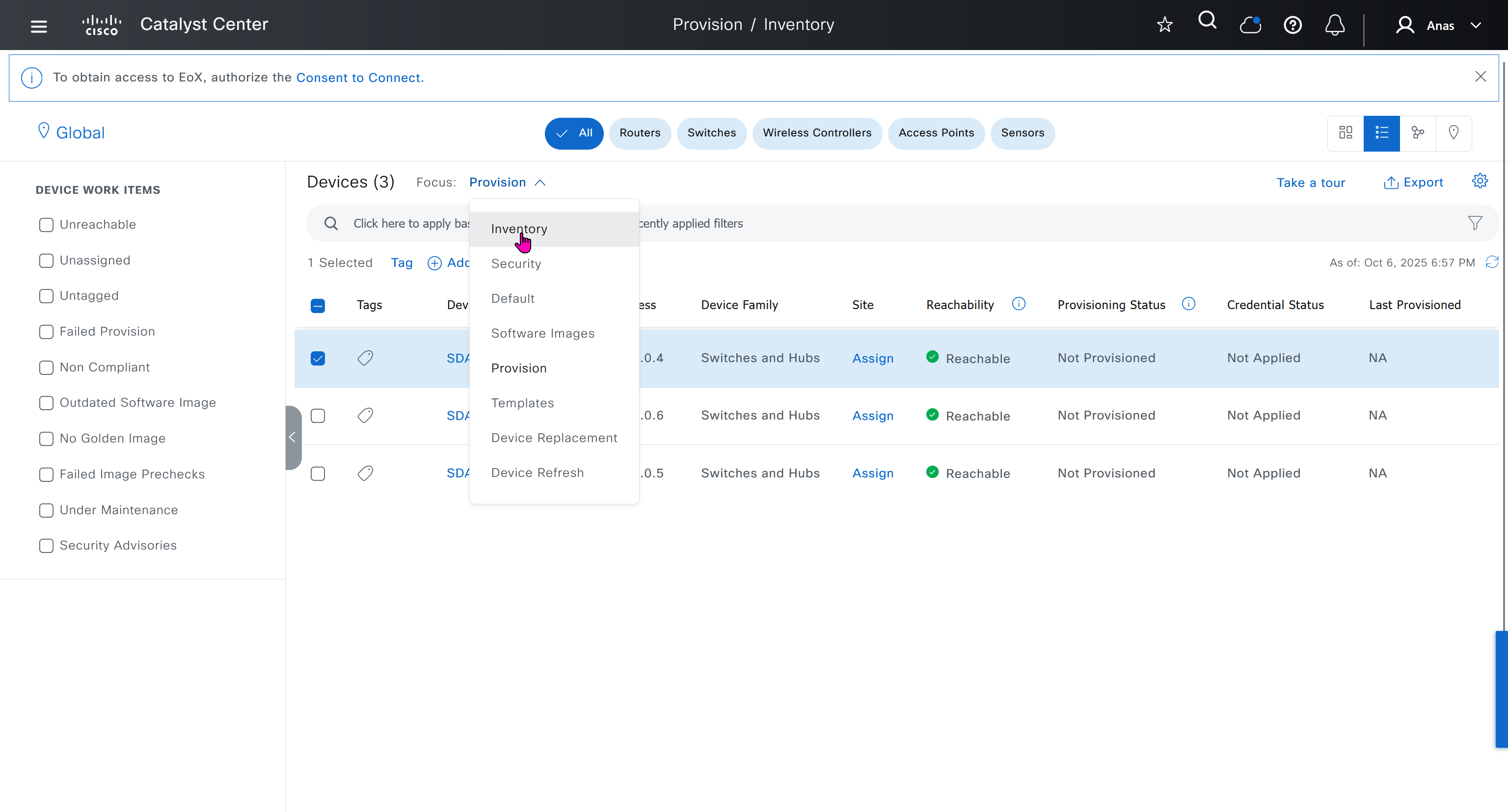
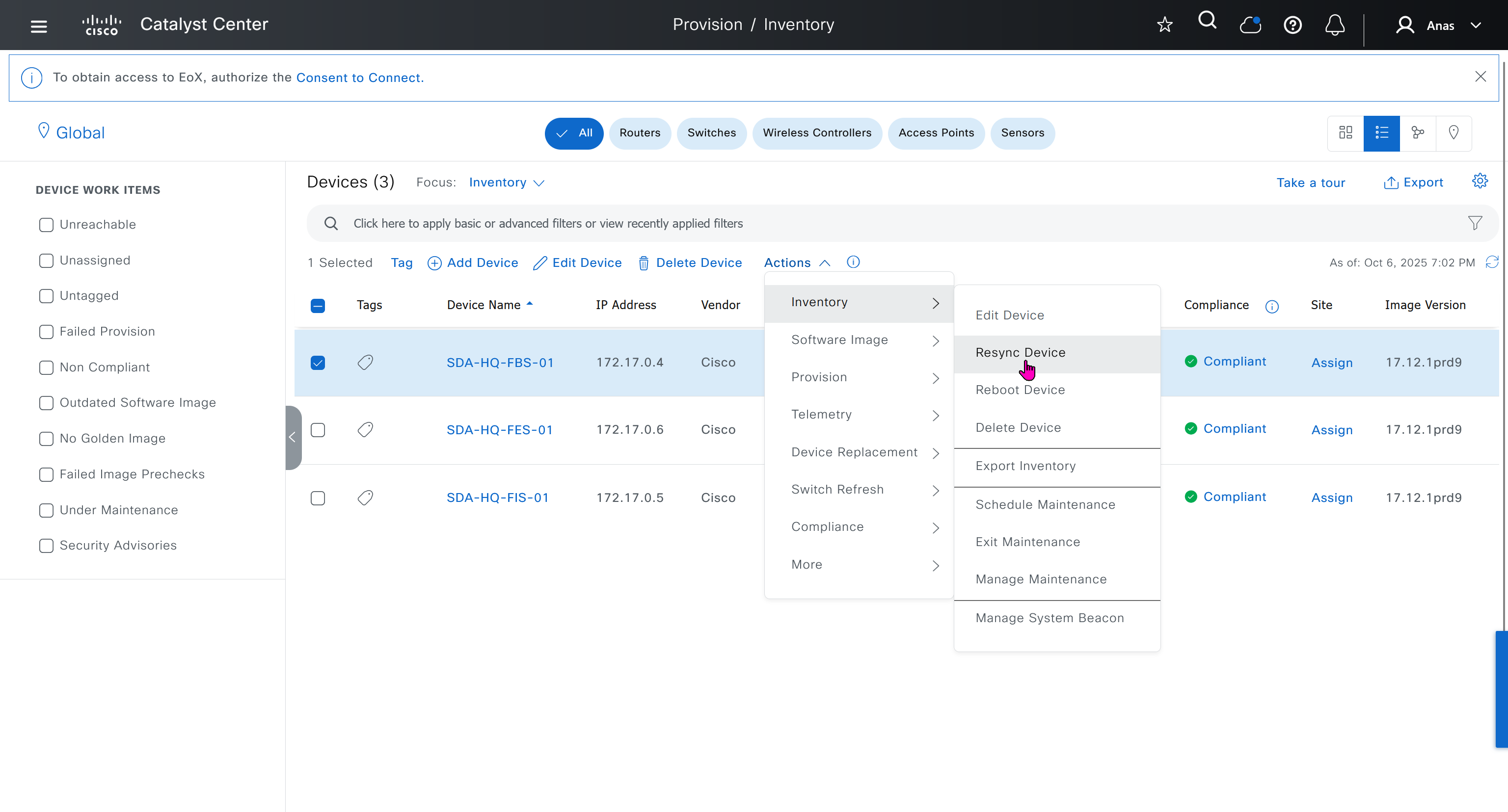

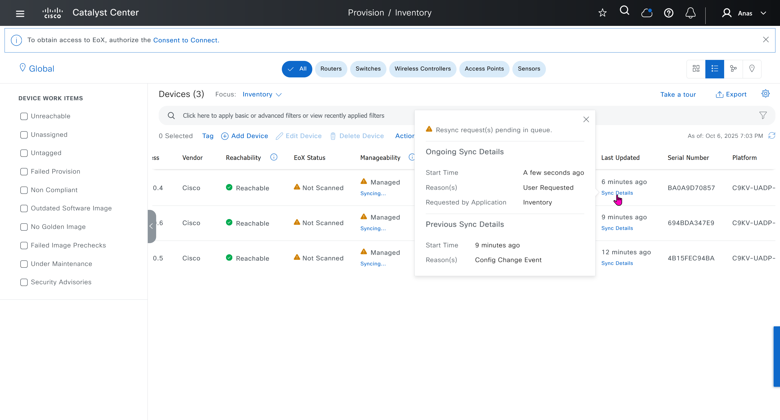
next post
SDA LAN Automation
LAN Automation Deployment
LAN automation
-simplifies underlay deployment
-eliminates manual, repetitive configuration
-establishes a standard, error-free underlay network.
Cisco LAN automation provides:
Zero-touch provisioning: Network devices are
-dynamically discovered
-onboarded
from their factory default state
Redundancy bult in, Automation
Seed device
Pre-deployed device and initial point through which LAN automation discovers and onboards new downstream switches
Uses Plug and Play (PnP)
One seed device can do the job but two can be deployed
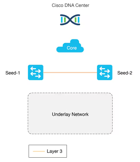
PnP agents
The PnP agent is a Cisco Catalyst switch with factory default settings or candidate switches
The switch uses 0 day communication to communicate with Catalyst Center (PnP server)
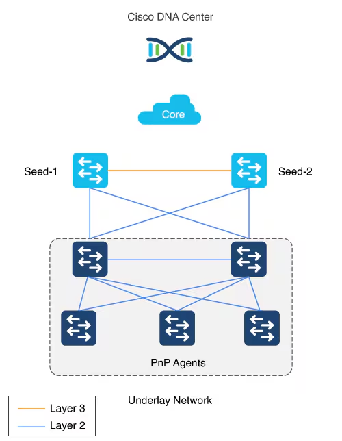
LAN automation in Catalyst Center supports a maximum of two hops from the initial automation boundary point device. Any additional network devices beyond two hops might be discovered but cannot be automated
Given that seed devices are core switches from the three tier model:
- Scenario 1: You have a three-tier network and you want to LAN “automate distribution and access layer switches”, both distribution- and access-layer switches will be discovered and LAN automated.
- Scenario 2: You have a three-tier network and you want to LAN automate distribution and access-layer switches.
You already LAN automated the distribution layer.
You decide to add access-layer switches later to your network at a later date (this is the difference from Scenario 1) and you want to LAN automate these switches. “Because the distribution switches are already LAN automated and links converted to “Layer 3”, Tier 1 or core switches cannot be used as the seed. You must choose distribution as the seed in this scenario“.
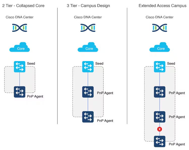
Multistep LAN automation for large topologies: First pass
Large topologies are brought up by performing LAN automation multiple times. During the first pass, core devices are chosen as seed devices to bring up the “distribution” switches as new devices.
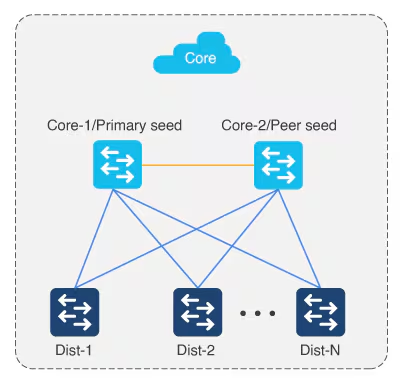
Multistep LAN automation for large topologies: Second pass with first group
During the second pass, two of the distribution switches act as seed devices to bring up the edge devices as new devices. All new devices in this session must connect directly to the two distribution switches that act as new seed devices.
Repeat this process for the remaining set of distribution switches laterally, two at a time (in pair).
There can be two tiers of devices below the seeds.
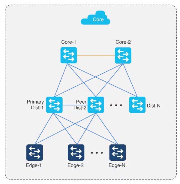
Perform stacking before hand
Layer 3 link configuration after LAN Automation
After all devices are added to the Catalyst Center inventory, you can stop the LAN automation session on the GUI to begin the Layer 3 link configuration process.
If you accidentally stop the LAN automation process before all PnP devices are added to the Catalyst Center inventory, You must bring the in-progress devices to the factory-default state in order to do LAN automation again.
Catalyst Center Release 2.3.5 and later provide the support for day-n link configurations (add and delete link). For more information, see Create a link between interfaces.
Supported switches for each role at different layers
Site planning
Use the Catalyst Center Design feature to create the required sites, buildings, and floors.
Create a global pool in DNAC, reserve IP Pool specific per site
Different types of IP address assignments used:
- DHCP (temporary, later claimed back or unreserved)
- P2P L3 /31 links
- Loopbacks
- Underlay multicast IP
Temporary DHCP pool so new device can get IP and speak to DNAC
Temporary DHCP pool so new device can get IP and speak to DNAC, but after that when DNAC is able to login (IP reachability) it will change and assign different IP addresses
One part of the IP pool per site, is reserved for a temporary DHCP server,
this DHCP server runs on DNAC itself and seed devices are used as relay to relay DHCP request from PnP agent or new switch without IP towards DNAC,
Temporary DHCP on Catalyst Center leases IP addresses from this temporary DHCP subpool.
Those IPs allow the new device to:
- Boot up with a valid IP address.
- Contact Catalyst Center over the network.
- Be discovered and provisioned automatically
Once the LAN automation session is finished:
- The DHCP service stops.
- The temporary subpool is released.
- All those IP addresses go back to the main LAN pool.
- The switches now have permanent IPs assigned by the automation process (usually from a different IP pool).
The size of this pool depends on the size of the parent LAN pool. For example, if the parent pool is 192.168.10.0/”24″, a /”26″ subpool is allocated for the DHCP server, Therefore, a /”24″ pool reserves /”26″ 64 hosts
We can think of this temporary DHCP pool size with the + 2 rule
A /23 pool reserves /”25″ 128 hosts, a /22 pool reserves /24 256 hosts, and larger pools reserve (max) 512 IP addresses for the DHCP server, it steps up in this way and max pool size is 512 addresses for even bigger parent pools
for example initial blocks of 192.168.10.0/24 can be used since site is not operational and LAN automation is being run to deploy the site, once LAN automation is complete these chunks are released back in order for them to be reserved in site and used
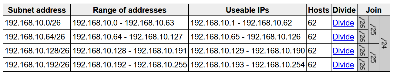
To start LAN automation, the pool size must be at least /25, which reserves a /27 pool or 32 IP addresses for the DHCP pool.
This IP pool is reserved temporarily for the duration of the LAN automation discovery session. After the LAN automation discovery session completes, the DHCP pool is released, and the IPs are returned to the LAN pool
IP pool for loopback and /31 interswitch links
Another part of the IP pool is reserved internally with a size of fixed size /27. This pool is for allocating single IPs for Loopback0 and Loopback60000 always. IPs for point-to-point L3 /31 links are allocated from this pool also, if this pool is exhausted a new /27 pool is created for allocating IPs
This pool remain throughout the process and are not allowed to be removed.
Due to this allocation logic, the IP pool usage in IPAM counts these pools as allocated unlike pools used for DHCP which are released back in parent pool
Each of the devices discovered via LAN automation gets a unique /31 per interface for point-to-point connection, and a unique /32 for Loopback0 and the underlay multicast.
Single Site vs Shared IP pool (overlaps between sites)
When a dedicated (single) IP pool is used to build the underlay networks, each device discovered via LAN automation gets a unique /31 per interface for point-to-point connection, and a unique /32 for Loopback0 and the underlay multicast.
A link overlapping IP pool (only for /31 interswitch links) or shared IP pool is used to optimize the IPv4 addressing in the underlay network by allowing overlapping /31 IP addresses for a multisite deployment. Hosts in different sites can get duplicate IP addresses on the /31 links. The /31s in the underlay are not advertised outside of the fabric site and hence there is no need for them to be unique. However, the /32 loopback needs to be unique to every device, and should be advertised to the global routing table to identify the device in the entire network.
IP pool roles
The LAN IP pool can have these two roles:
- Link Overlapping IP Pool: This pool role is optional for a LAN automation session. If provided, the allocation of IP addresses is only on the /31 point-to-point Layer 3 links, and can be same through out different sites, hence overlapping is in the name.
- Main IP Pool (Principal IP Address Pool in Catalyst Center Release 2.3.5 and later): This pool role is mandatory for every LAN automation session. This is the pool that is used for all management-related IP addressing such as loopbacks, multicast, and DHCP. If the Link Overlapping IP Pool is not provided, then the Main IP Pool is the default fallback pool for the /31 Layer 3 links IP addressing also.
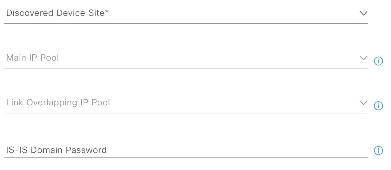
Configuration on seed devices
- Enter hostname
hostname 1005-FBS-01
- Ensure that the system MTU (maximum transmission unit) value is at least 9100 or jumbo frame –
show sys mtusystem mtu 8978
- Enable DNA advantage license and reload
license boot level network-advantage addon dna-advantagereload- Extra step for FES and FIS after all of the above is done
pnpa service reset no-prompt- so they are reset back to pnp autoinstall on vlan 1 after license install and do not follow below process for FIS or FES, this is only for Seed node or FBS
- Turn on IP routing on the seed devices.
ip routing
- Enable CLI credentials from DNAC
username admin privilege 15 secret *********
- Correct the enable secret with relaxed secret
enable secret *********
- Enable SNMP strings from DNAC
snmp-server community *********
- Enable SSH
ip ssh version 2crypto key generate rsa modulus 2048 label 1005-FBS-01line vty 0 98transport input ssh
- Enable local authentication
aaa new-modelaaa authentication login default localaaa authorization exec default local
- Enable netconf-yang
netconf-yang
- Enable privilege level 15 on vty lines
line vty 0 98privilege level 15
ip name-server 1.0.0.11ip domain name home.local- Set console login to privilege exec mode
line console 0privilege level 15
hostname 1005-FXXXX
system mtu 8978
license boot level network-advantage addon dna-advantage
reload

! for all except FBS or FIB
pnpa service reset no-prompt

ip routing
username admin privilege 15 secret C0mplex30
enable secret C0mplex30

snmp-server community C0mplex30

ip ssh version 2
crypto key generate rsa modulus 2048 label 1005-FXXXX
line vty 0 98
transport input ssh telnet

aaa new-model
aaa authentication login default local
aaa authorization exec default local

netconf-yang

line vty 0 98
privilege level 15

ip name-server 1.0.0.11
ip domain name home.local

line console 0
privilege level 15
conf t
!
! Enable the archive feature
archive
log config
logging enable
notify syslog contenttype plaintext
hidekeys
!
! Optional: Set up where the archived configs are stored
path flash:config-archive
write-memory
!
end
!
! Ensure syslog logging is enabled (optional but recommended)
conf t
logging buffered 64000
service timestamps log datetime msec
!
end
write mem Should I connect links between FBS switches even though they connect to EFS upstream?
Underlay Routing and Path Redundancy
If one of your border switches loses its direct physical uplink to the Fusion switch, it needs an alternative route to reach the rest of the network. A direct physical link between 1005-FBS-01 and 1005-FBS-02 allows underlay routing protocols (like IS-IS or OSPF) to quickly reroute traffic through the adjacent border node without traffic being dropped.
Preventing Packet Blackholing (The Overlay Risk)
In the SDA overlay, traffic is tunneled between Routing Locators (RLOCs)—which are bound to the Loopback 0 interfaces of your fabric devices.
- If a border switch’s uplink to the Fusion switch fails, its
Loopback 0interface (RLOC) remains up and reachable from inside the fabric. - The Fabric Edge nodes will continue sending north-bound traffic to that failed border.
- Without a direct link between the borders to pass that traffic over to the surviving node, the isolated border will have no path out to the Fusion layer, resulting in black-holed traffic.
2. How to Connect and Configure Them
Depending on how you are provisioning your lab in Cisco Catalyst Center (formerly DNAC), you have two options for the cross-link:
Option A: Standard Underlay Routed Link (Recommended)
You configure a direct Layer 3 routed link (or a Layer 3 EtherChannel) between FBS-01 and FBS-02.
- Underlay: Include this link in your underlay routing configuration so RLOCs can talk to each other across it.
- Overlay Handoff: You will configure iBGP neighbor relationships between the two border switches for every Virtual Network (VN/VRF) as well as the Global Routing Table (GRT). This ensures that if one border loses its external eBGP path to the Fusion switch, it learns the external routes from its twin border via iBGP.
Option B: LAN Automation
If you are using LAN Automation in Catalyst Center to discover and build your underlay, Catalyst Center will automatically detect this cross-link, configure it as a Layer 3 routed point-to-point link, and add it to the IS-IS routing process.
Summary Checklist for Your Lab
- 🟢 Physical/Virtual Topology: Draw/connect a link directly between
1005-FBS-01and1005-FBS-02. - 🟢 Underlay: Ensure the link is routed and participating in your underlay IGP.
- 🟢 Control Plane Handoff: Ensure you have eBGP running from each border to the Fusion switch, and iBGP running over the cross-link between the borders for your VRFs.
For a deeper dive into the configuration mechanics and why this architecture prevents traffic disruptions, you can watch this SD-Access Fabric Border Design Video https://www.youtube.com/watch?v=-0l8Wq-8FsI. This video provides an excellent visual walkthrough of border-to-fusion design considerations and demonstrates how lacking full-mesh/cross-links can lead to packet blackholing in a lab environment
IP address allocation in Catalyst Center Release 2.3.7.x and later
In Catalyst Center Release 2.3.7.x and later, IP address allocation from LAN pool is based on IP address range instead of subnet allocation. This approach helps in minimizing the issue of IP address loss during subnet creation and in effective management of the IP addresses. Instead of creating a subnet, IP address range is blocked for both DHCP pool allocation and IP address assignment for point-to-point links, loopback, and multicast.
LAN Automation Example
Imagine you want to LAN automate 10 devices in a site using the same pool, where each device has one link to the primary seed and another link to the secondary.
Consider a 192.168.199.0/24 as an example pool. When LAN automation starts,
a first /26 pool is reserved for the DHCP addresses. In this example, 192.168.199.”1″ to 192.168.199.”63″ are reserved and assigned to VLAN 1 for the 10 devices.
Next, a “/27” pool is reserved for loopback addresses.
If there is no shared IP pool, then this pool is used for point-to-point links as well.
Because there are 10 devices with two links each, a total of 40 IP addresses are reserved for point-to-point links,
40 addresses because each switch needs 4 IP addressess (2 assigned on switch’s uplinks itself and 1 assigned on primary seed device and 1 assigned on peer seed device)
In total, 60 IP addresses are reserved for the 10 devices: 10 for each VLAN 1, 10 for each loopback, and 40 for the point-to-point links between devices and seeds.
After LAN automation stops, the VLAN 1 IP addresses are released back to the pool
We recommend that you use the default interfaces connected to PnP agents.
If the peer seed device has IP interfaces configured on the interfaces connecting to PnP agents,
those links are not configured.
Default the interfaces connecting to agents and perform an inventory synchronization on the peer seed device. LAN automation works only when the ports are Layer 2. The ports on the Cisco Catalyst 6000 Series Switches are Layer 3 by default. Convert the ports to Layer 2 before starting LAN automation.
LAN automation configures loopback on the seed devices if they are not configured.
If you change configuration on the seed devices before running LAN automation, synchronize the seed devices with the Catalyst Center inventory.
If you plan to run multiple discovery sessions to onboard devices across different buildings and floors connected to the same seed devices, we recommend that you block the ports for PnP agents that do not participate in the upcoming discovery session yet.
For example, imagine seed devices in Building-23 connected to PnP agents on Floor-1 and Floor-2. Floor-1 devices are connected on interfaces Gig 1/0/10 through Gig 1/0/15. Floor-2 devices are connected on interfaces Gig 1/0/16 through Gig 1/0/20. For the discovery session on Floor-1, we recommend that you shut down ports connected to Gig 1/0/16 through Gig 1/0/20. Otherwise, the PnP agents connected to Floor-2 might also get DHCP IPs from the server running on the primary seed device. Because these interfaces aren’t selected for the discovery session, they remain as stale entries in the PnP database. When you run the discovery session for Floor-2, the discovery doesn’t function correctly until these devices are deleted from the PnP application and write erase/reloaded. Therefore, we recommend that you shut down other discovery interfaces
For Catalyst Center Release 1.2.8 and earlier, if clients are connected to a switch being discovered, they may contend for DHCP IP and exhaust the pool, causing LAN automation to fail. Therefore, we recommend that you connect the client after LAN automation is complete. but that is for older DNAC versions
This endpoint/client integration restriction does not apply to Catalyst Center Release 1.2.10 and later. Clients can remain connected while the switch is undergoing LAN automation.
on the edge nodes add license and then reset pnpa so pnp wizard becomes active after putting license
otherwise LAN Automation commands will fail as there is no dna-advantage
license boot level network-advantage addon dna-advantage
end
write mem
reload pnpa service reset no-promptSteps for LAN Automation
- Default the interfaces connected to agents and perform an inventory synchronization on the peer seed device
- LAN automation configures loopback on the seed devices if they are not configured.
- If you change configuration on the seed devices before running LAN automation, synchronize the seed devices with the Catalyst Center inventory.
- Add Site > Add Area
- Add Site > Add Building
- Add Site > Add Floor
- Design > Network Settings > Device Credentials
- Manage Credentials
- CLI
- SNMPV2C Read
- Netconf
- Create an underlay pool that is not used any where in the network
See how the gateway address is set 172.16.0.1 and you ask why is that needed?
This is the address that will be assigned to FBS on vlan 1 interface (which is removed later on once LAN automation ends)
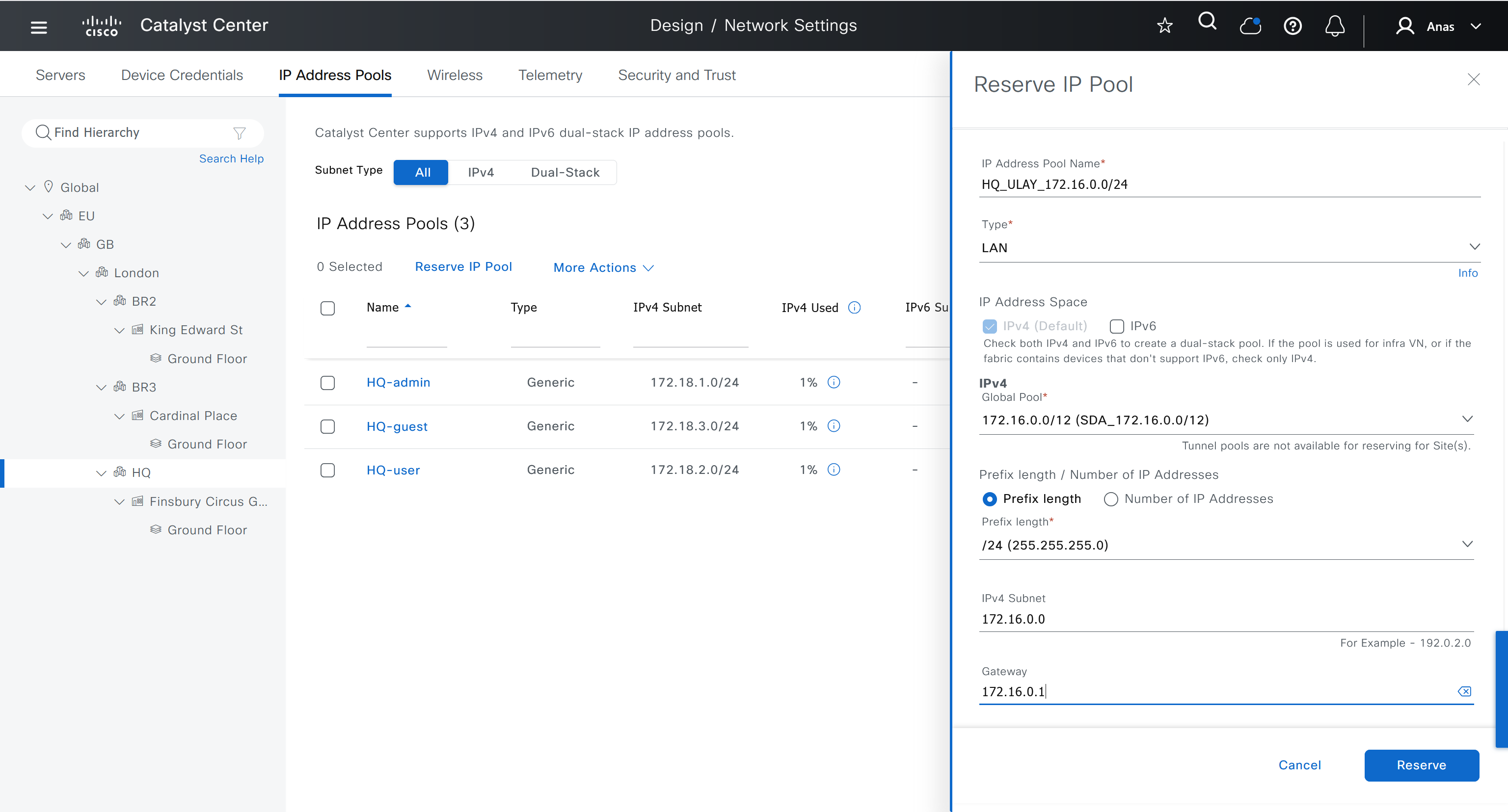
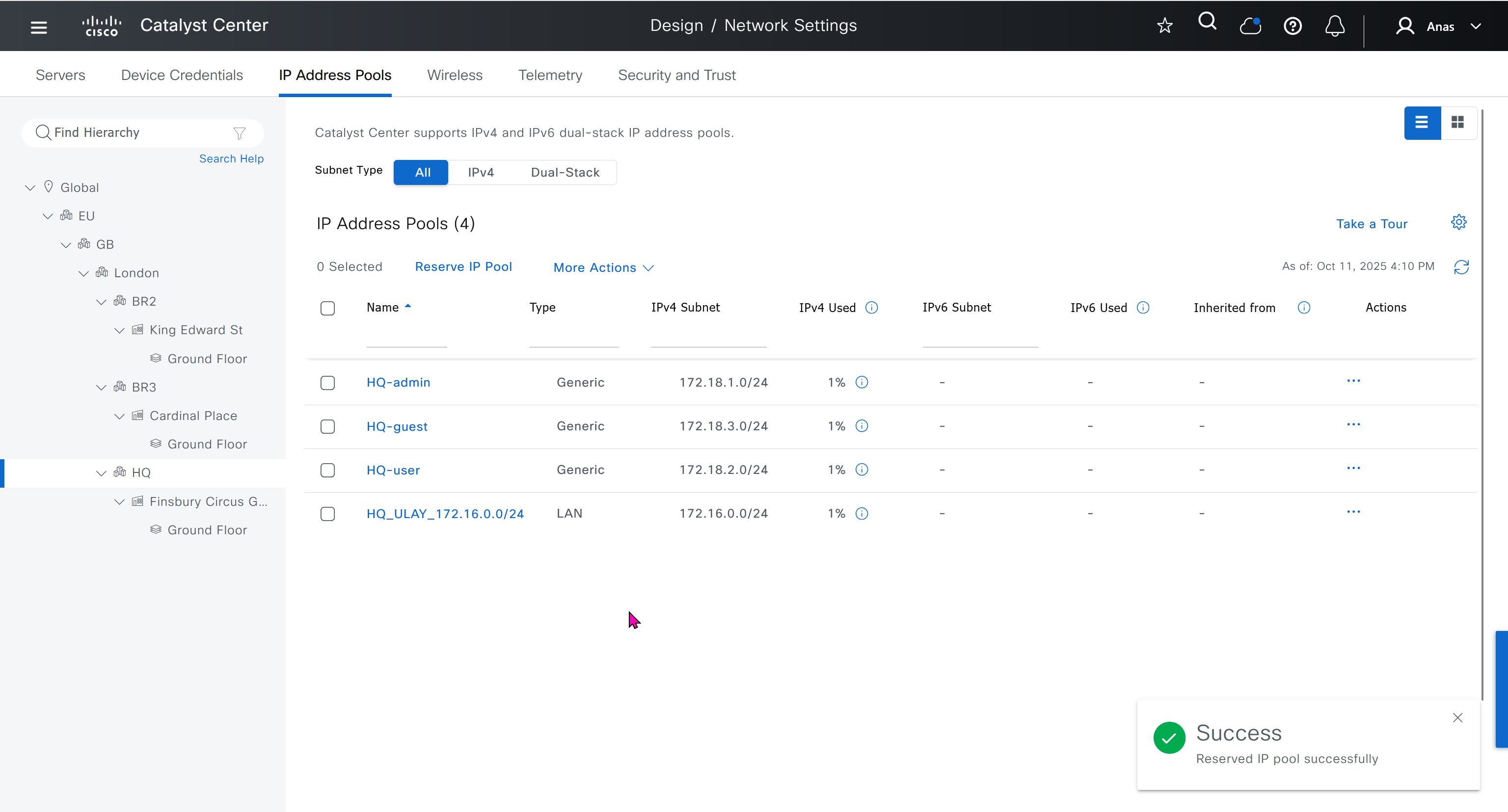
- Discover seed devices with discovery
- Make sure that discovered devices are in Reachable + Managed state
- Actions > Provision > Assign Device to Site to assign the device to a site.
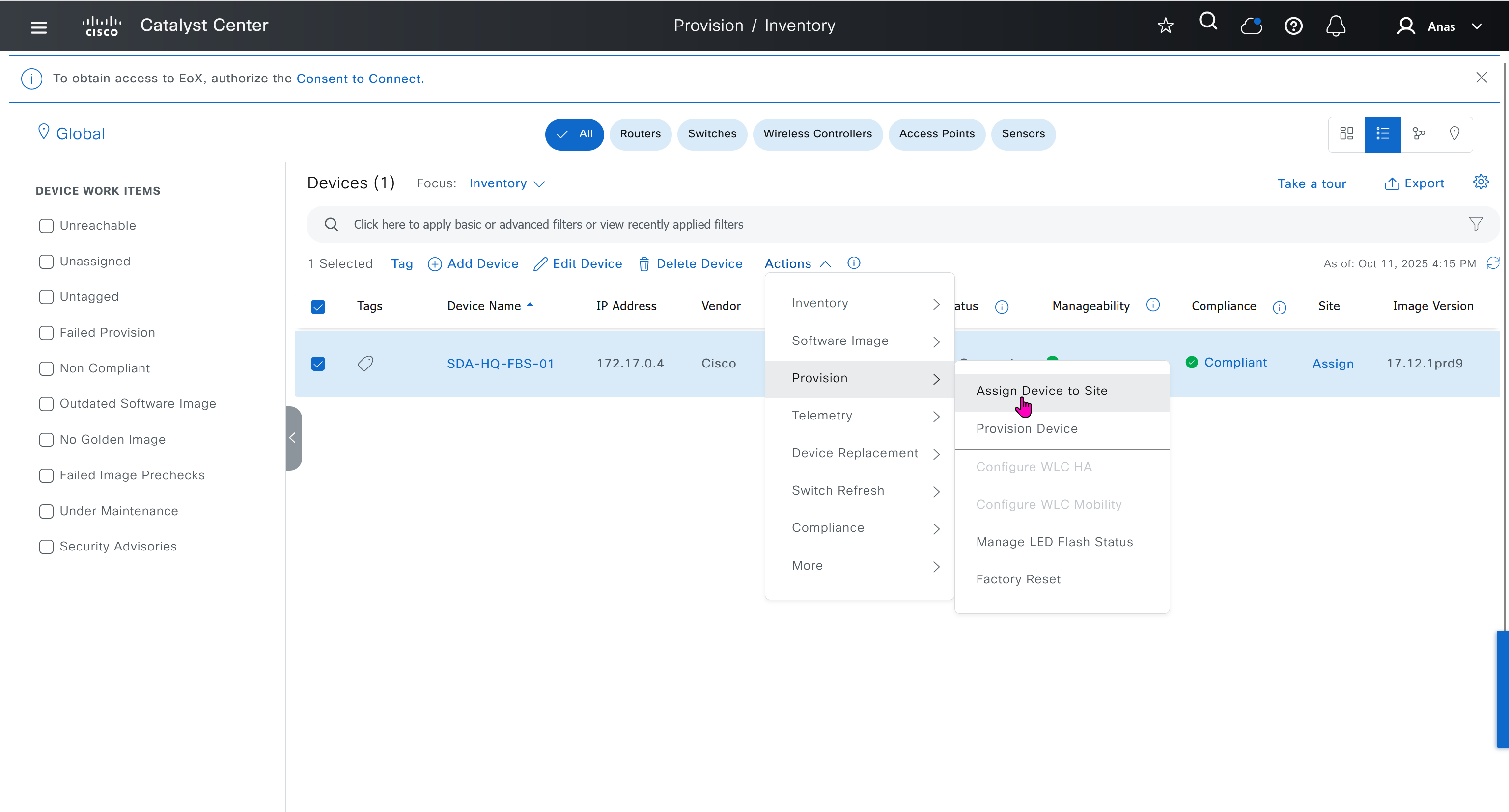
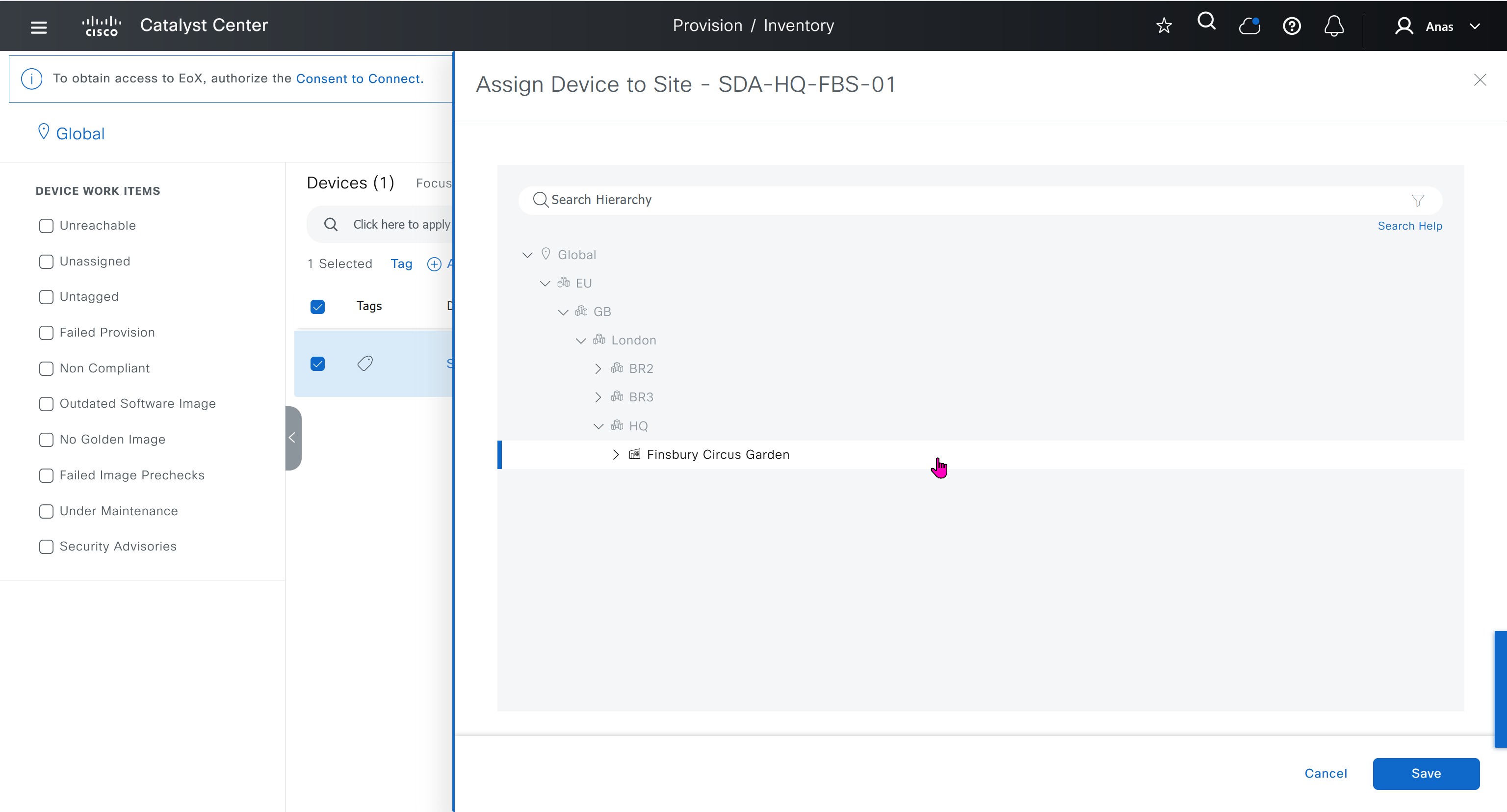

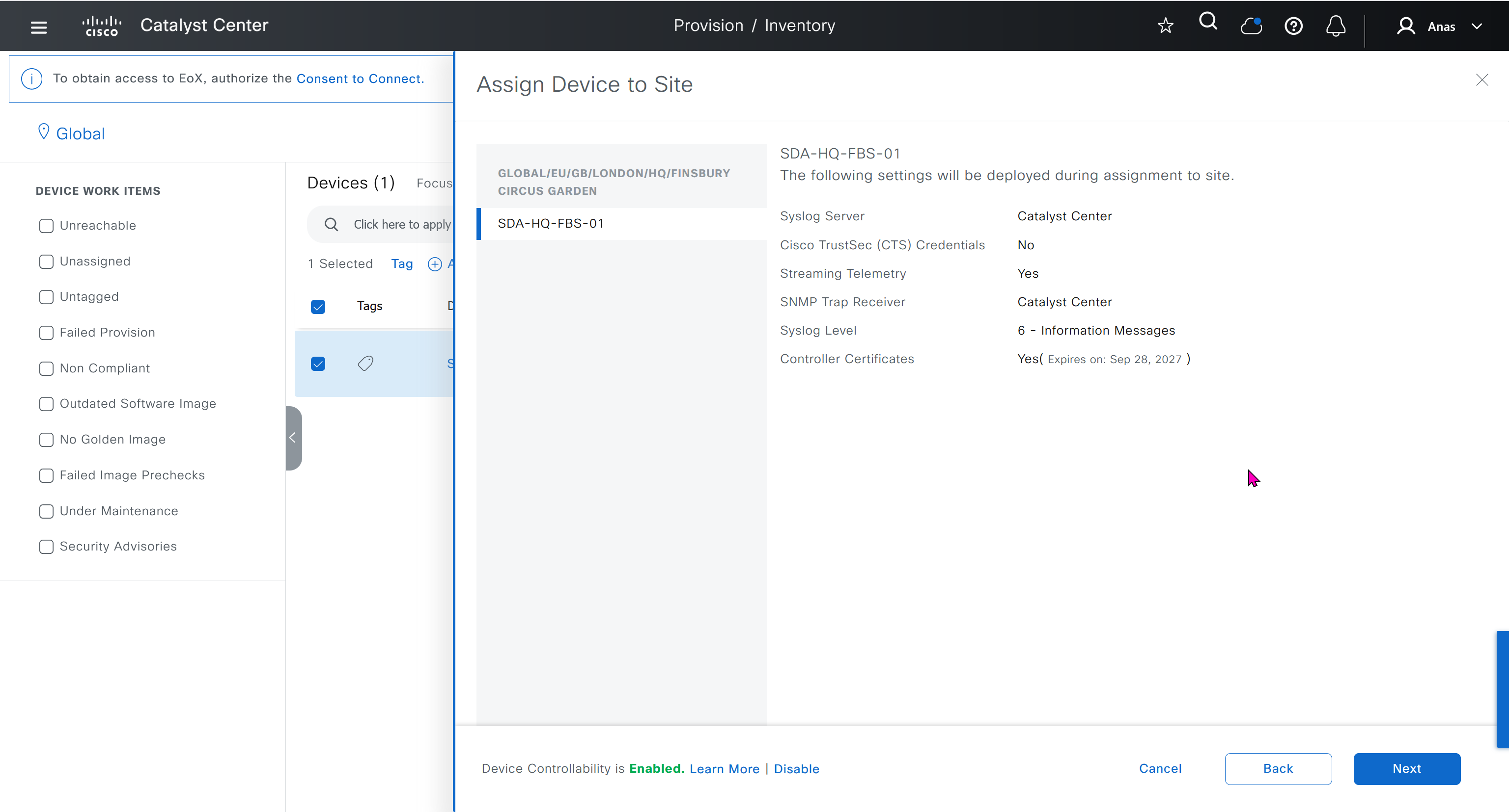


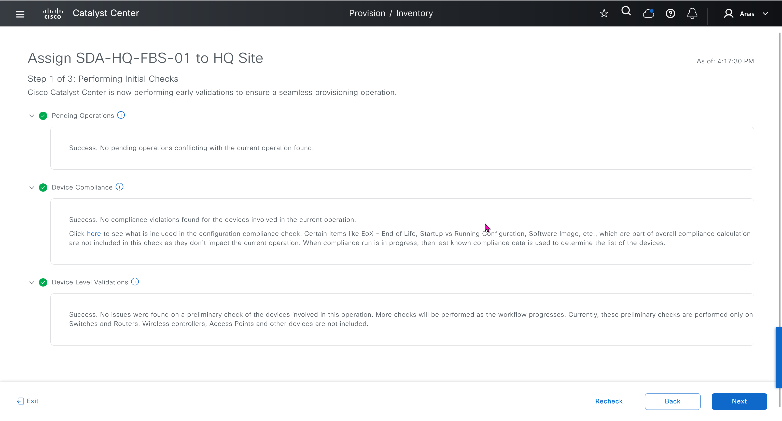
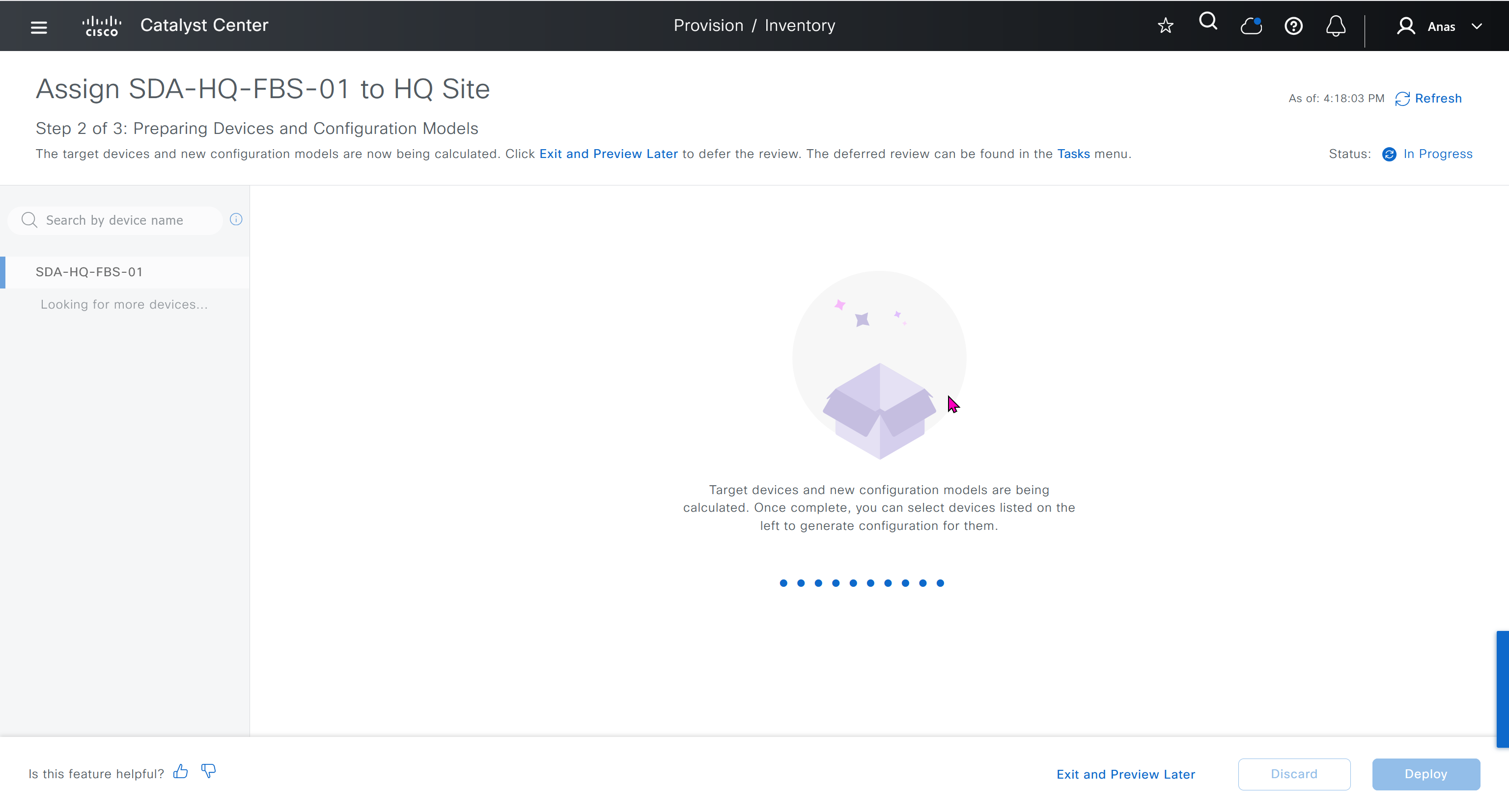
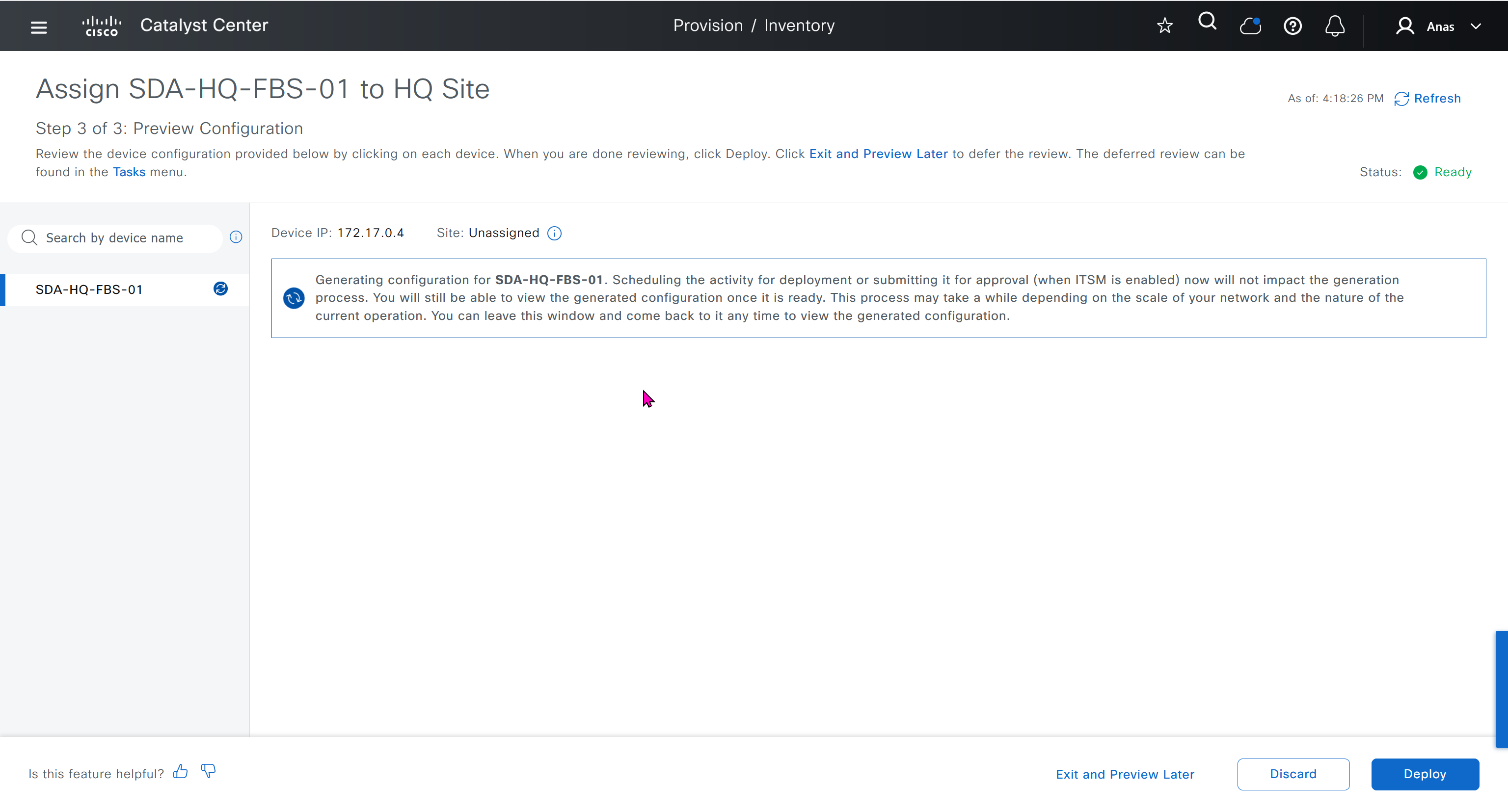
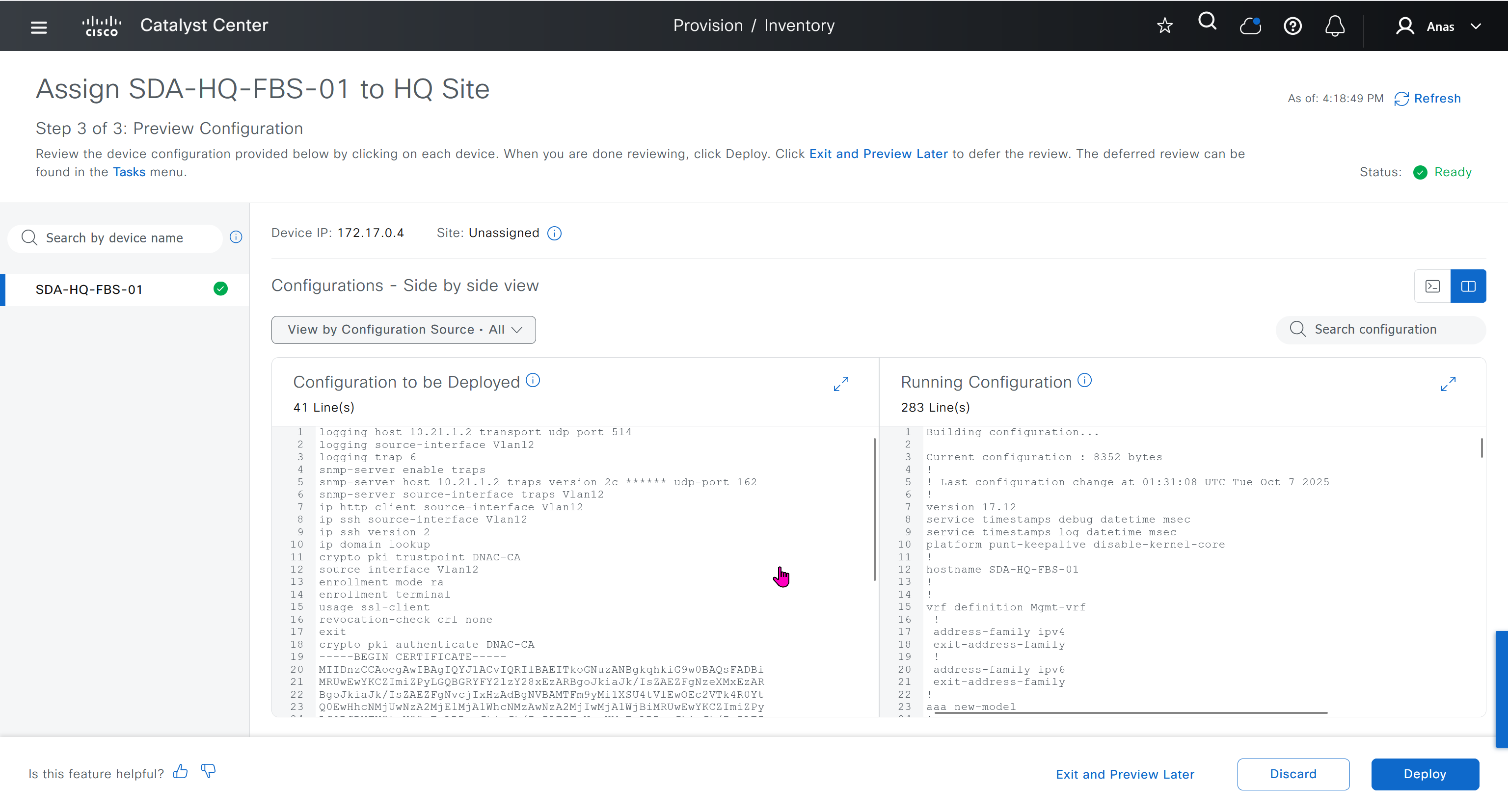

This is the configuration that will go on the seed device after only adding it to the site
Old LAB config Push Upon Site Assignment
logging host 10.21.1.2 transport udp port 514
logging source-interface Vlan12
logging trap 6
snmp-server enable traps
snmp-server host 10.21.1.2 traps version 2c ****** udp-port 162
snmp-server source-interface traps Vlan12
ip http client source-interface Vlan12
ip ssh source-interface Vlan12
ip ssh version 2
ip domain lookup
crypto pki trustpoint DNAC-CA
source interface Vlan12
enrollment mode ra
enrollment terminal
usage ssl-client
revocation-check crl none
exit
crypto pki authenticate DNAC-CA
-----BEGIN CERTIFICATE-----
MIIDnzCCAoegAwIBAgIQYJ1ACvIQRIlBAEITkoGNuzANBgkqhkiG9w0BAQsFADBi
MRUwEwYKCZImiZPyLGQBGRYFY2lzY28xEzARBgoJkiaJk/IsZAEZFgNzeXMxEzAR
BgoJkiaJk/IsZAEZFgNvcjIxHzAdBgNVBAMTFm9yMi1XSU4tVlEwOEc2VTk4R0Yt
Q0EwHhcNMjUwNzA2MjE1MjA1WhcNMzAwNzA2MjIwMjA1WjBiMRUwEwYKCZImiZPy
LGQBGRYFY2lzY28xEzARBgoJkiaJk/IsZAEZFgNzeXMxEzARBgoJkiaJk/IsZAEZ
FgNvcjIxHzAdBgNVBAMTFm9yMi1XSU4tVlEwOEc2VTk4R0YtQ0EwggEiMA0GCSqG
SIb3DQEBAQUAA4IBDwAwggEKAoIBAQCr6cjaoJz3vzgHlQ1hzhuy5WfIL/Ao0isM
ltIaGL+Z+9WftM1hNh10YECbxR71+lIpQKyBQTXQz8Of4nycxHjoI3dQdUvEYb8H
fysDXh4lYjQ60x82e5c7f1KPbD+AOhC31Zw1dgReMlPIuaa9LK903+z0FRnuCHaI
EG/Z9uCmv3JC22NgL69hscZc+NUGymMy1iBPN8G4EBkgqNVZ+zlRf/adW0JxEdc6
Sy53bp586/fXziRTW++jgdnhvfpn+VJ+BdG88/rEgMl7PUQE95lq4dih7qx0+OXu
ihFwQQvFxvi3dyqWWc0C1RKHPHtYQFz8rRuBJrR+uzgc0lVhrNHdAgMBAAGjUTBP
MAsGA1UdDwQEAwIBhjAPBgNVHRMBAf8EBTADAQH/MB0GA1UdDgQWBBQ/bI8yZeKD
fgjmmeWorjGo25t5hzAQBgkrBgEEAYI3FQEEAwIBADANBgkqhkiG9w0BAQsFAAOC
AQEAdtt6aiABkDDg/mAlcZfFPHcqmEEvQaMPeBaUqvfZKNrFVO8GMb9kingZJ62n
K05x5wE3tHy3jBmAl6eHZ/nUjXS11C06NwZMHpcDhty5BcDN08oEYdLF24upisNA
aRLOBhyEtKI9VKLAWfMkpWYEd/dqgVWs67GjAFT0Osgva9QHbz24iT6/c09jbZMt
41opmxacw8FFZcHMH9Afv1fIW9PwscrdlgjSSHR4XQLyDbyuDGsolzeh9PUVyPOd
f+/LYkLwH9jVcHlxl4Oy7MHRPtcbG9T3+vQGLjSAXu3Ybrl2R9Tn/sz5lYs44EEB
mqCxT00LxB3et6jAxJlEyE5vCw==
-----END CERTIFICATE-----
do cts credentials id 7c71627623014c0a83668477604a0c57 password ******New LAB config Push Upon Site Assignment
sxsxsxsx
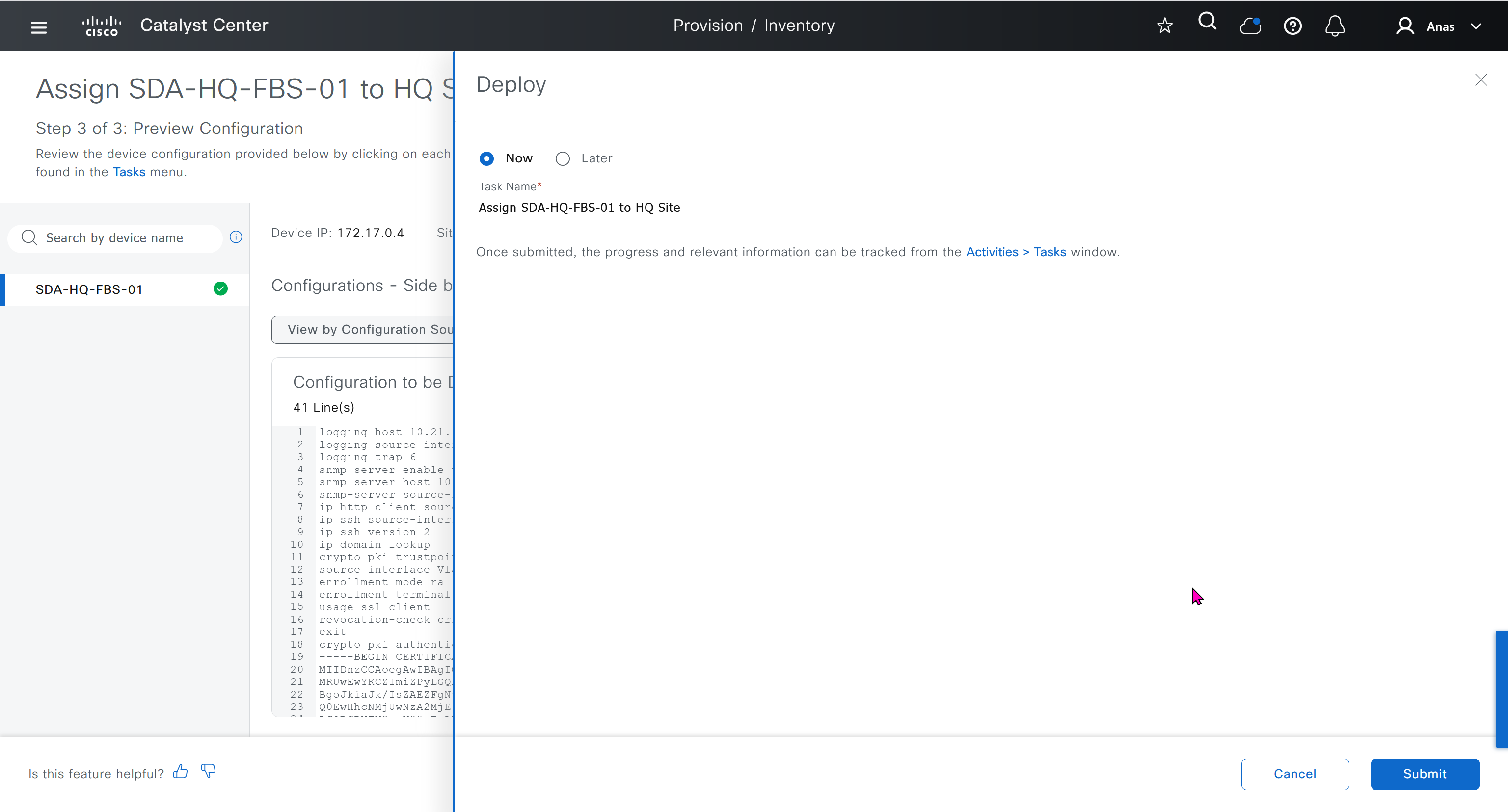
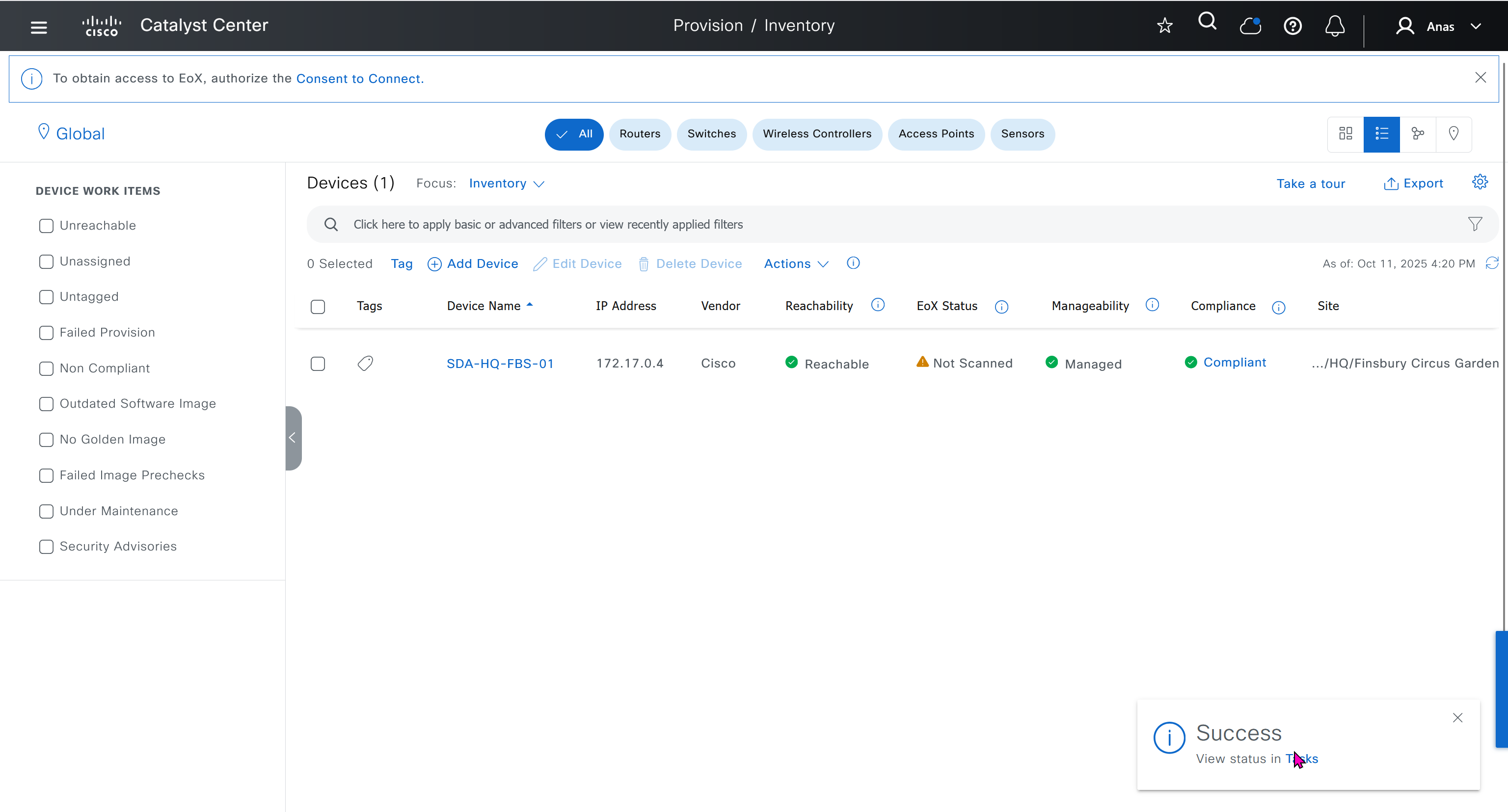
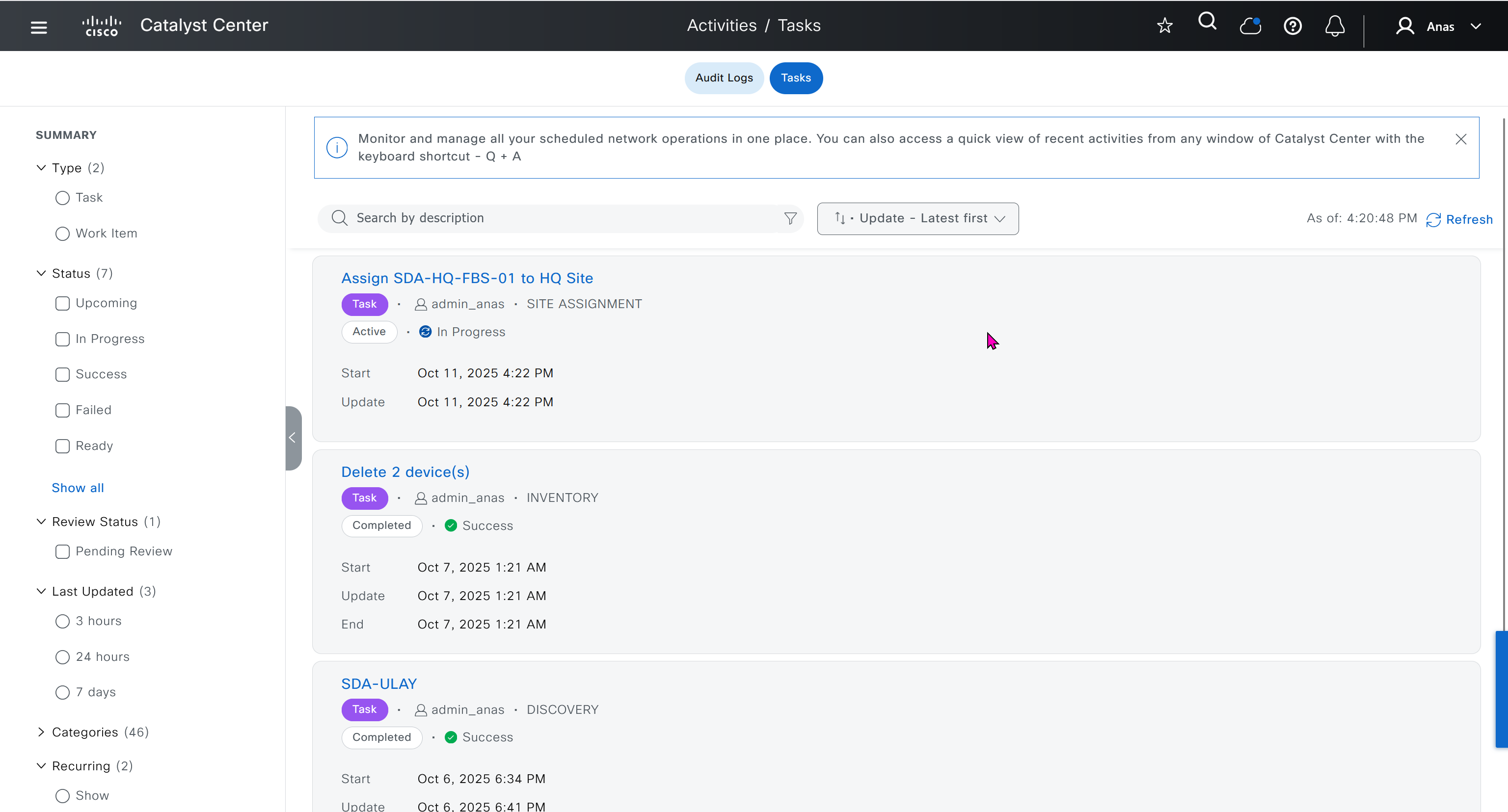
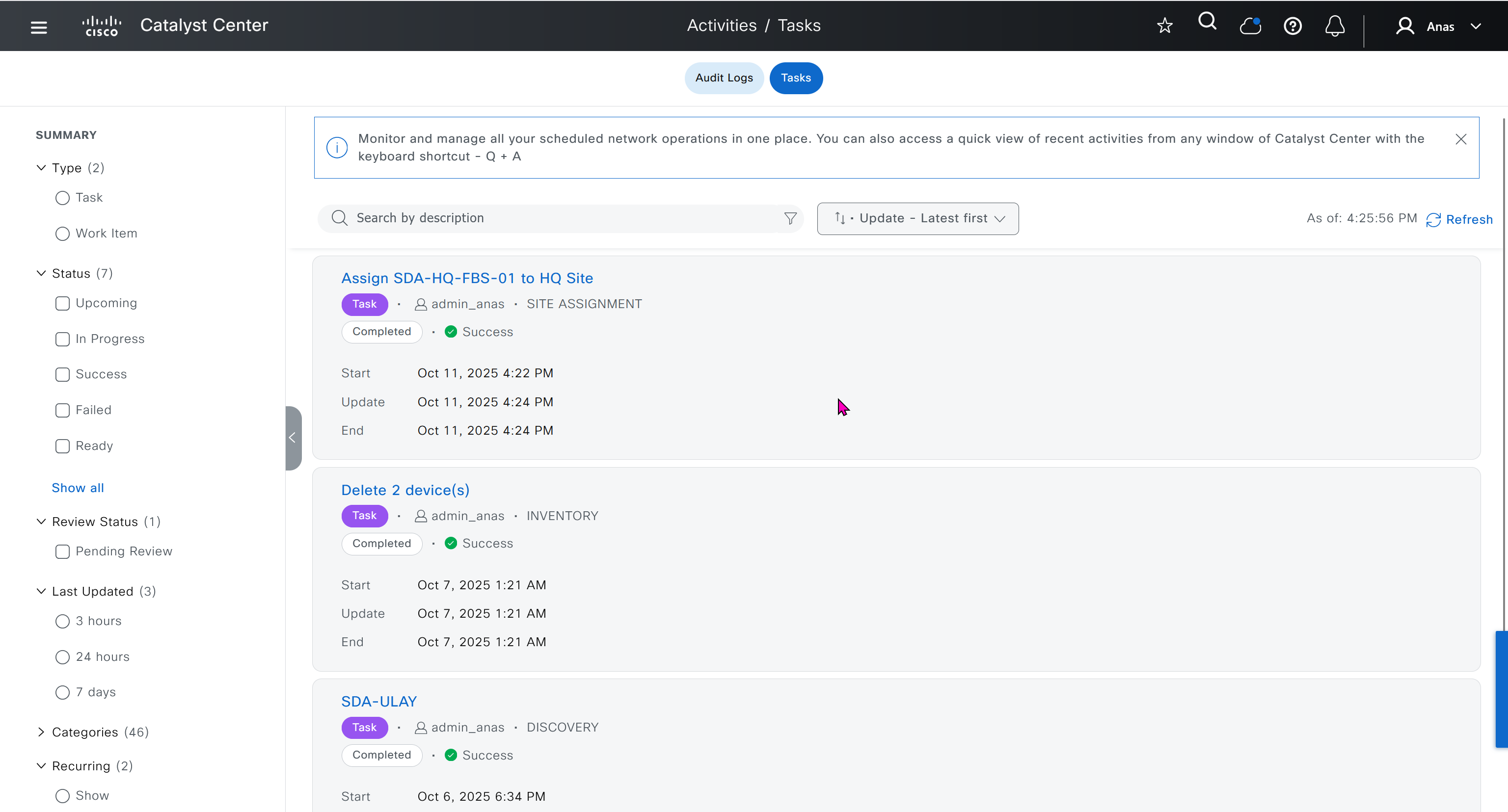
SDA-HQ-FBS-01# conf t
SDA-HQ-FBS-01# ! for reachability testing only
SDA-HQ-FBS-01# interface vlan 1
SDA-HQ-FBS-01# ip address 172.16.0.1 255.255.255.0
SDA-HQ-FBS-01# end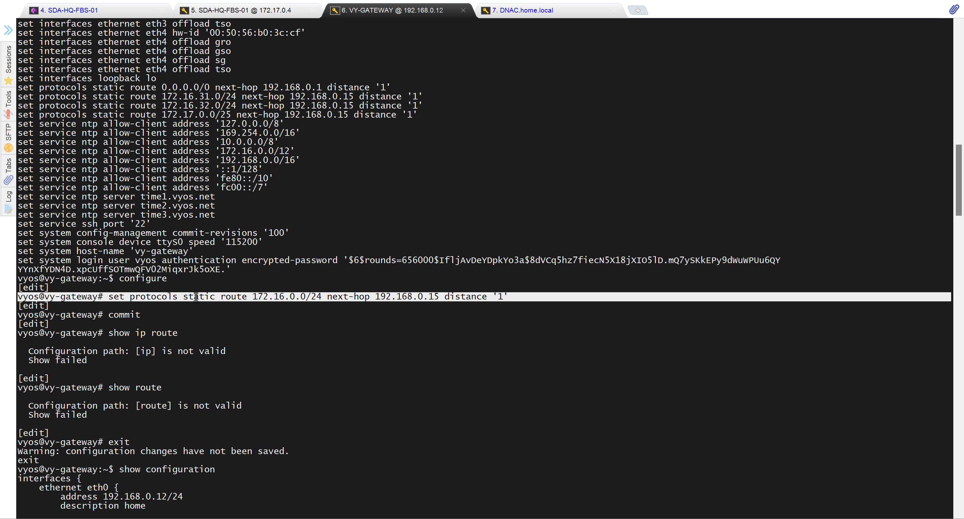
unable to reach
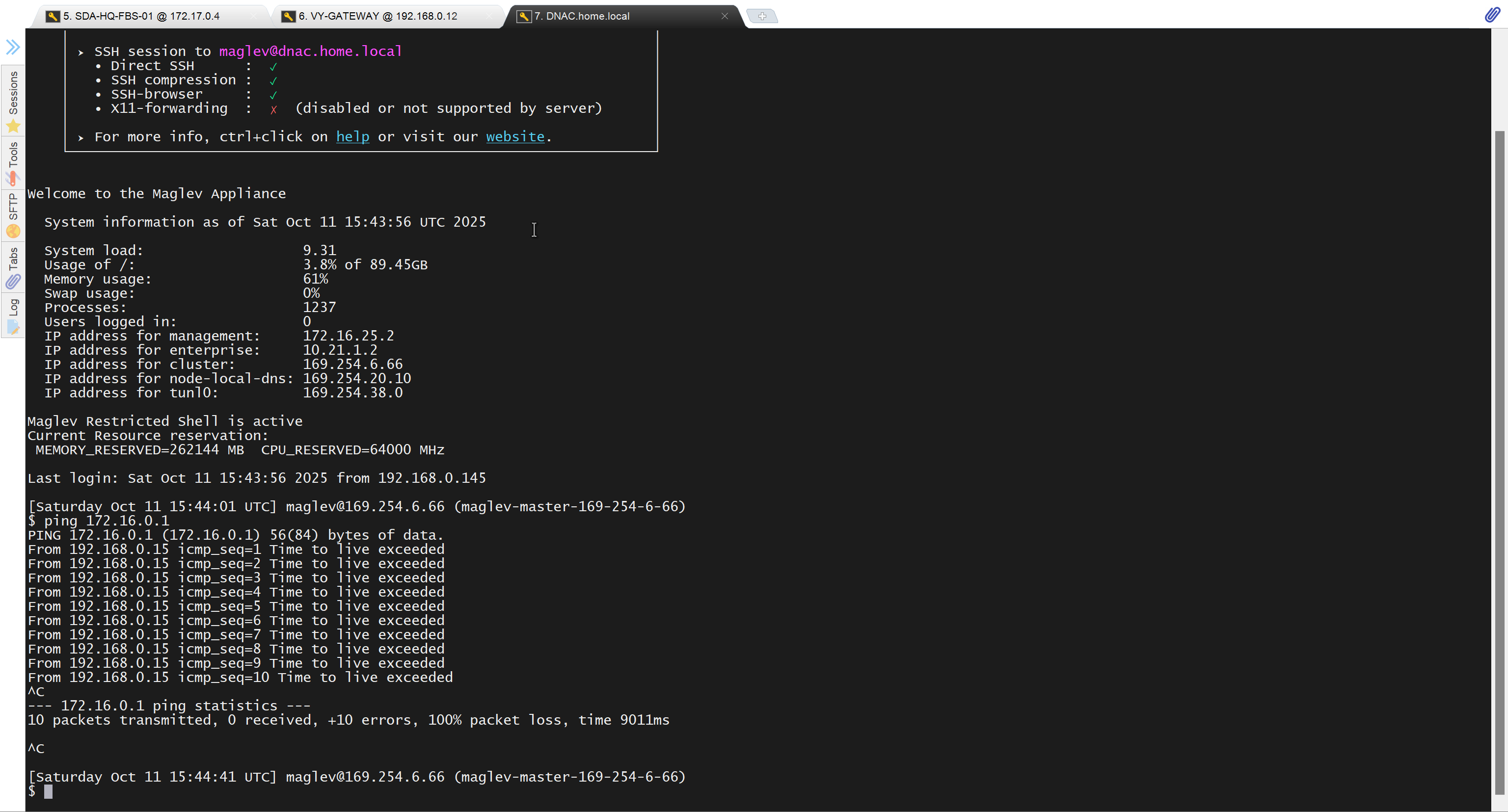
because missing route on HQ-SW in lab
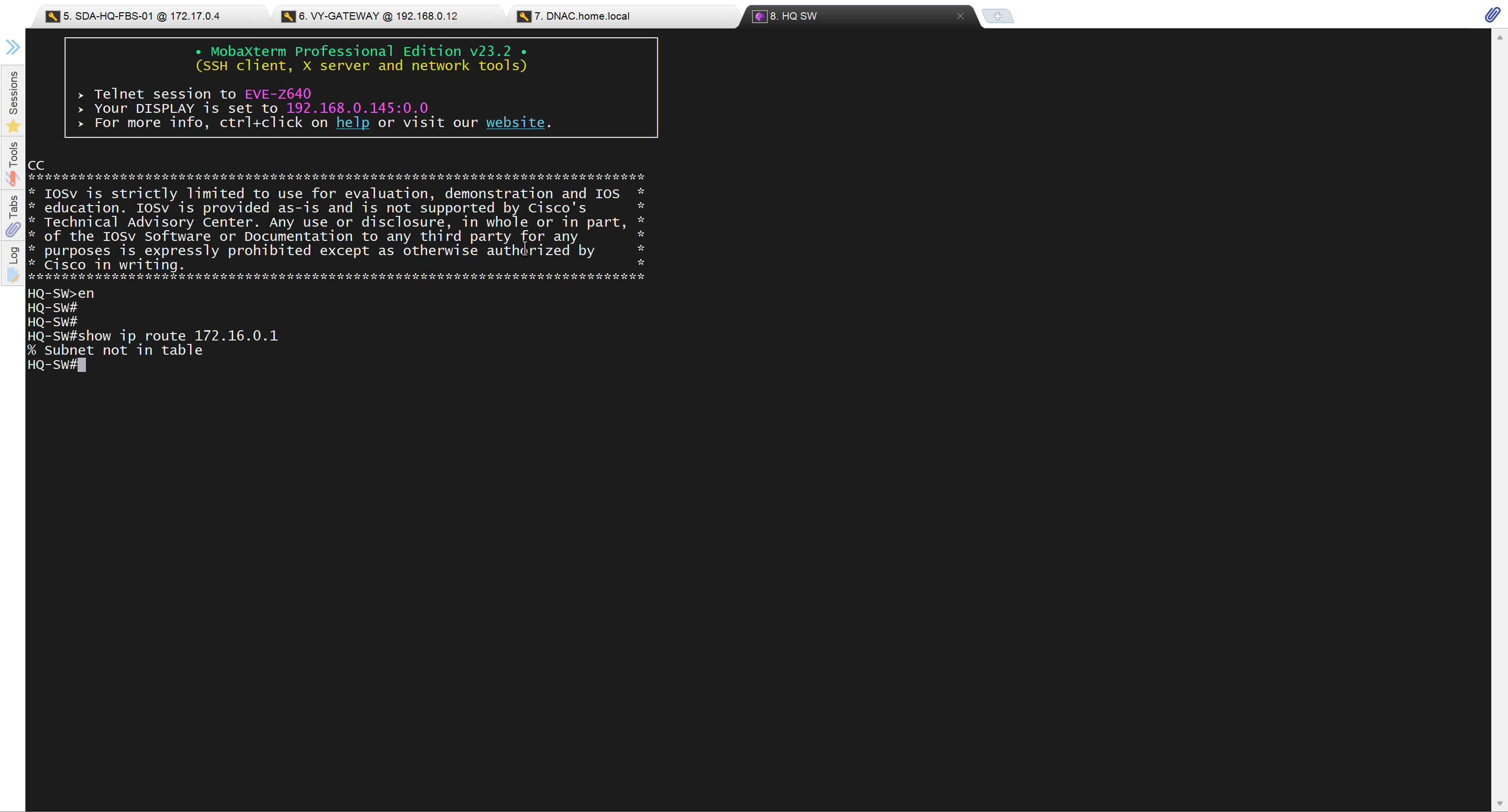
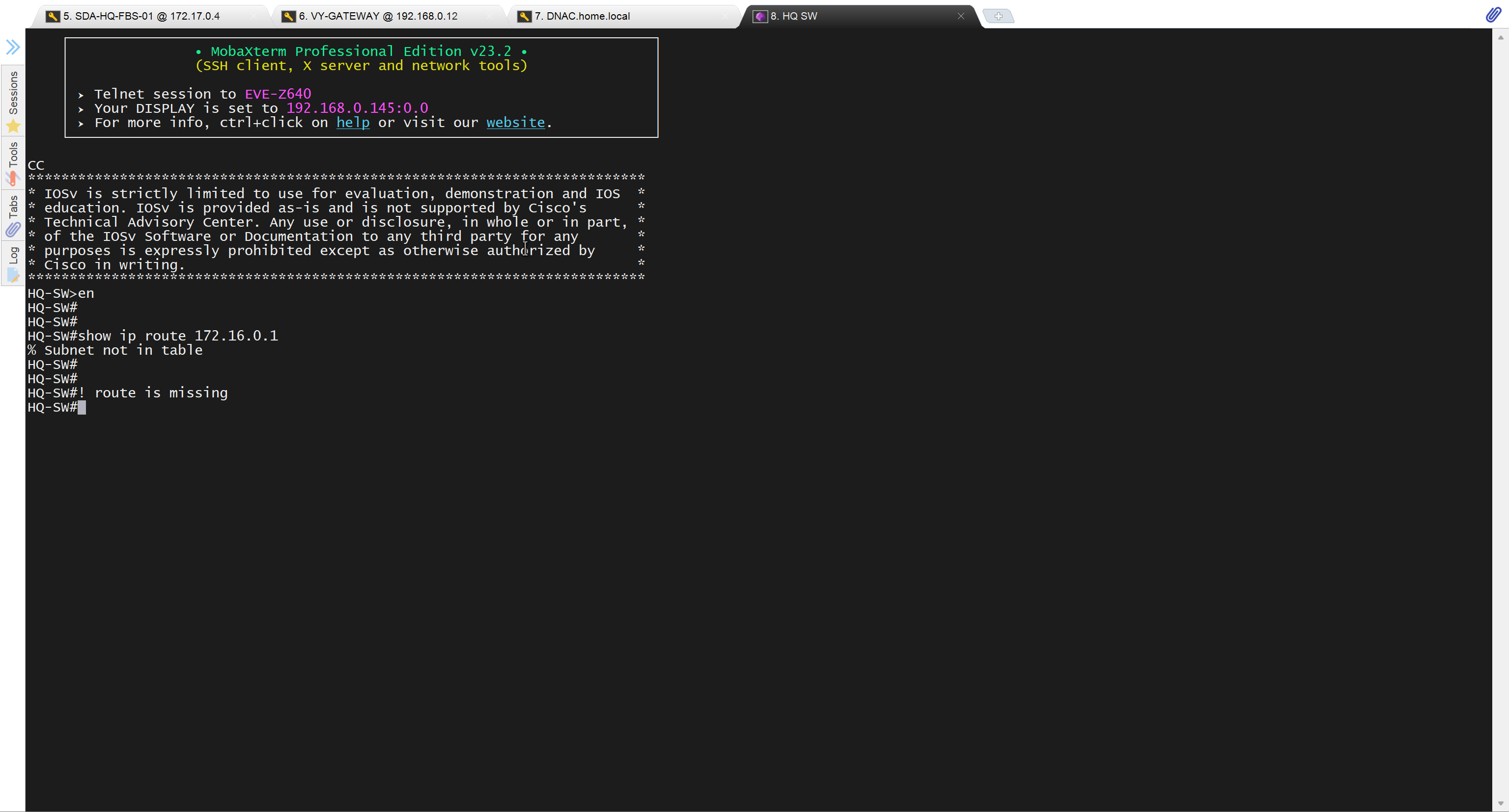
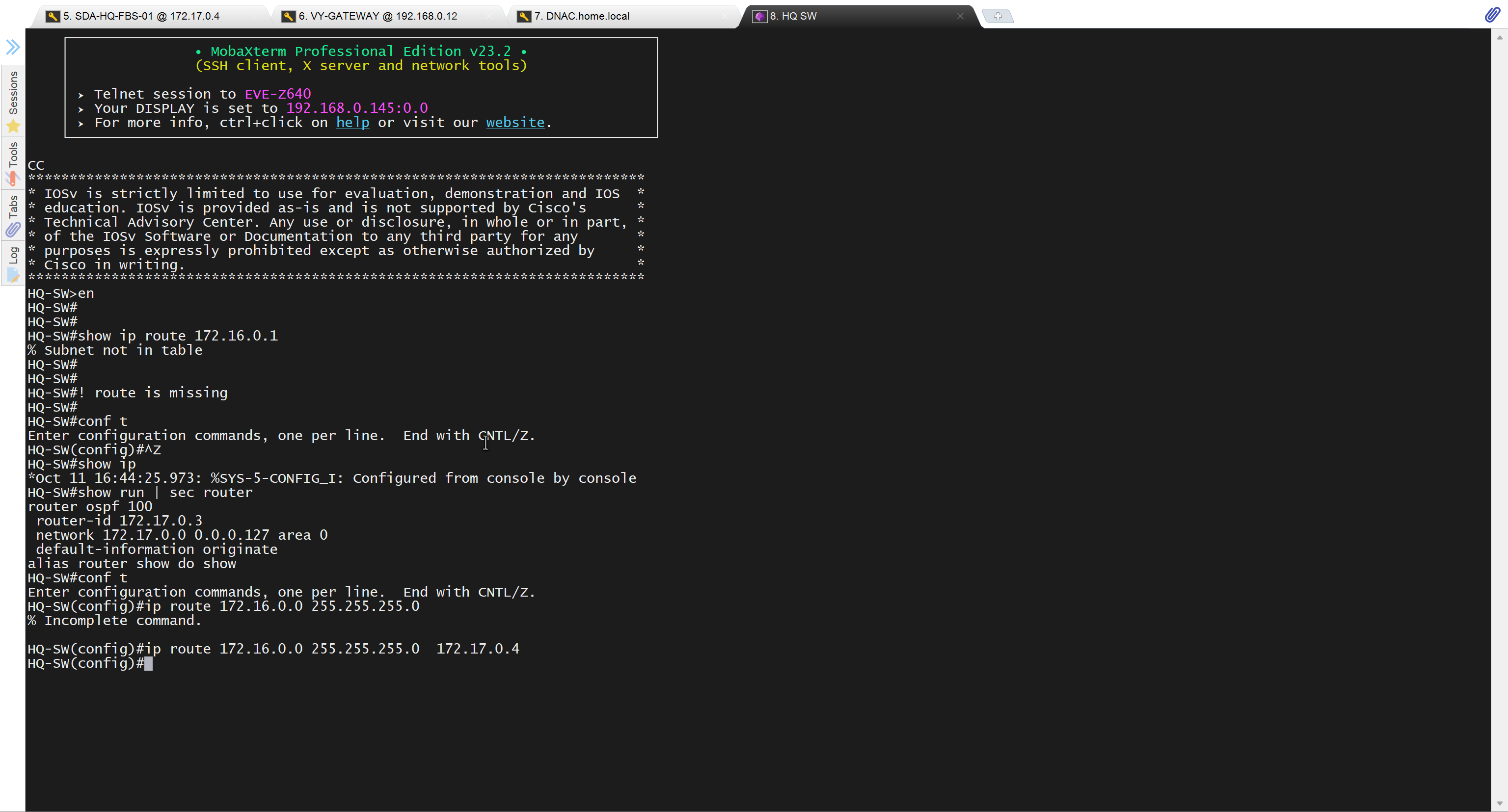
after adding route now we can reach
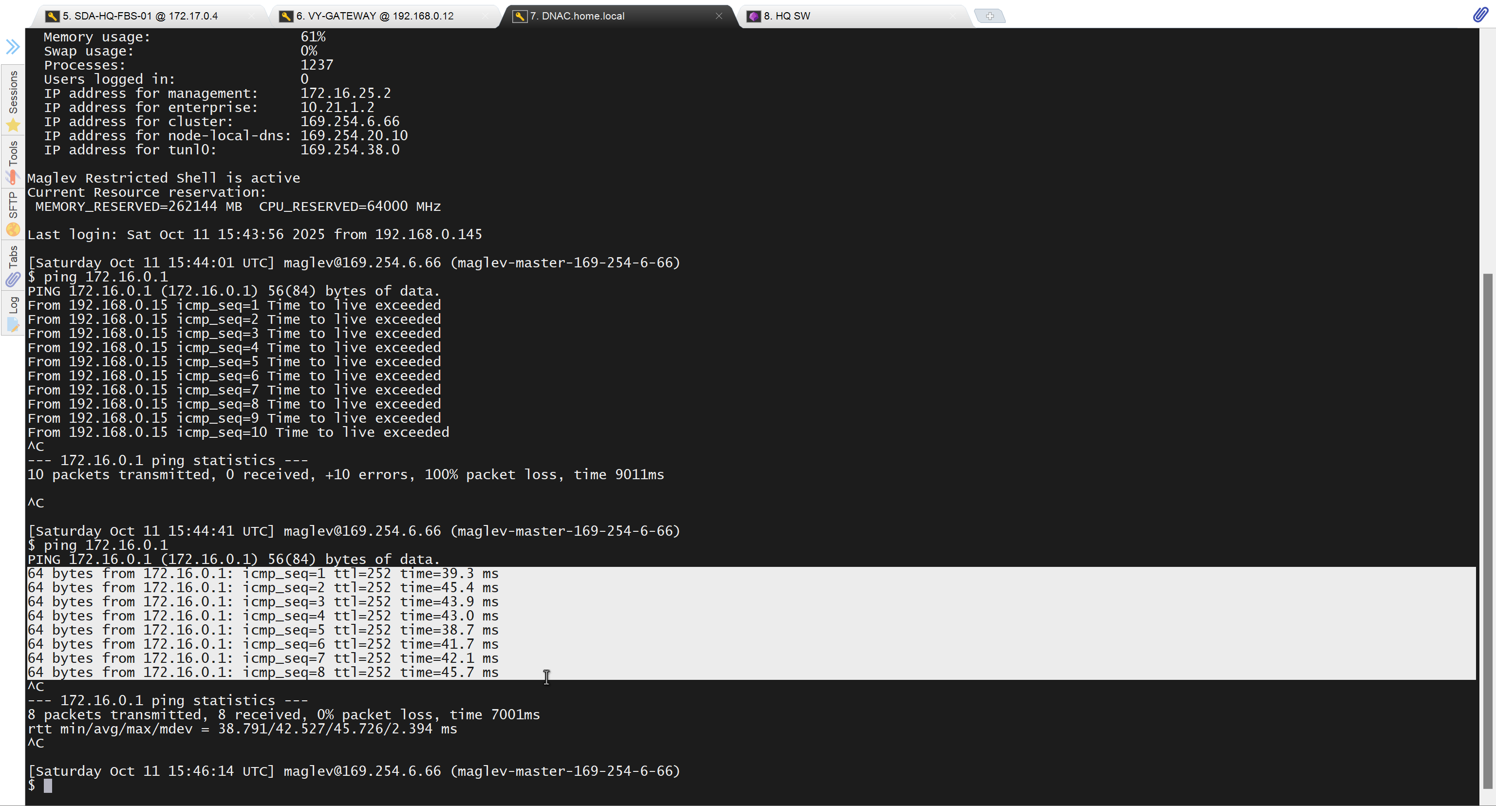
because it was only for testing, we will now remove it
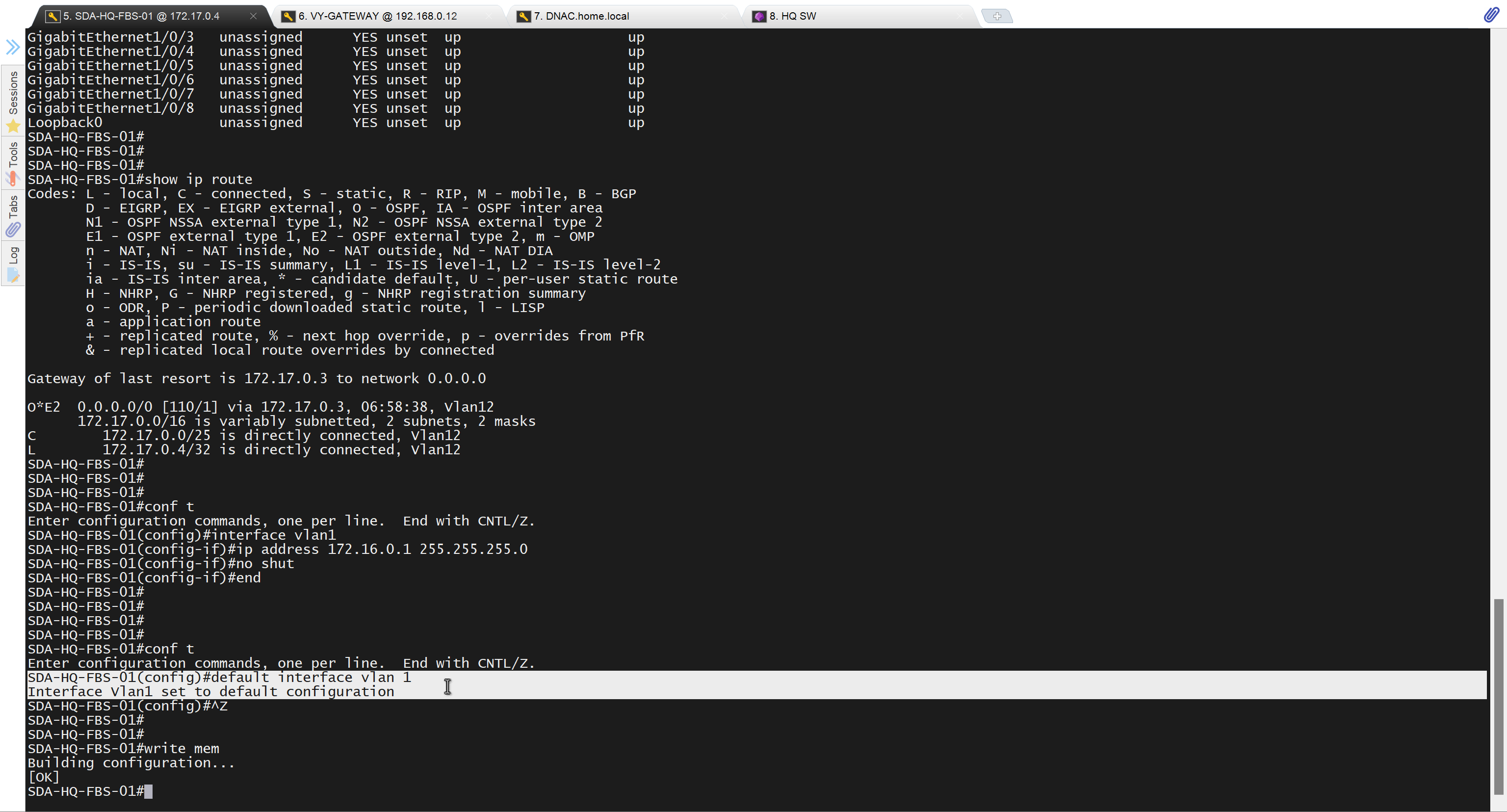
Now lets LAN Automate
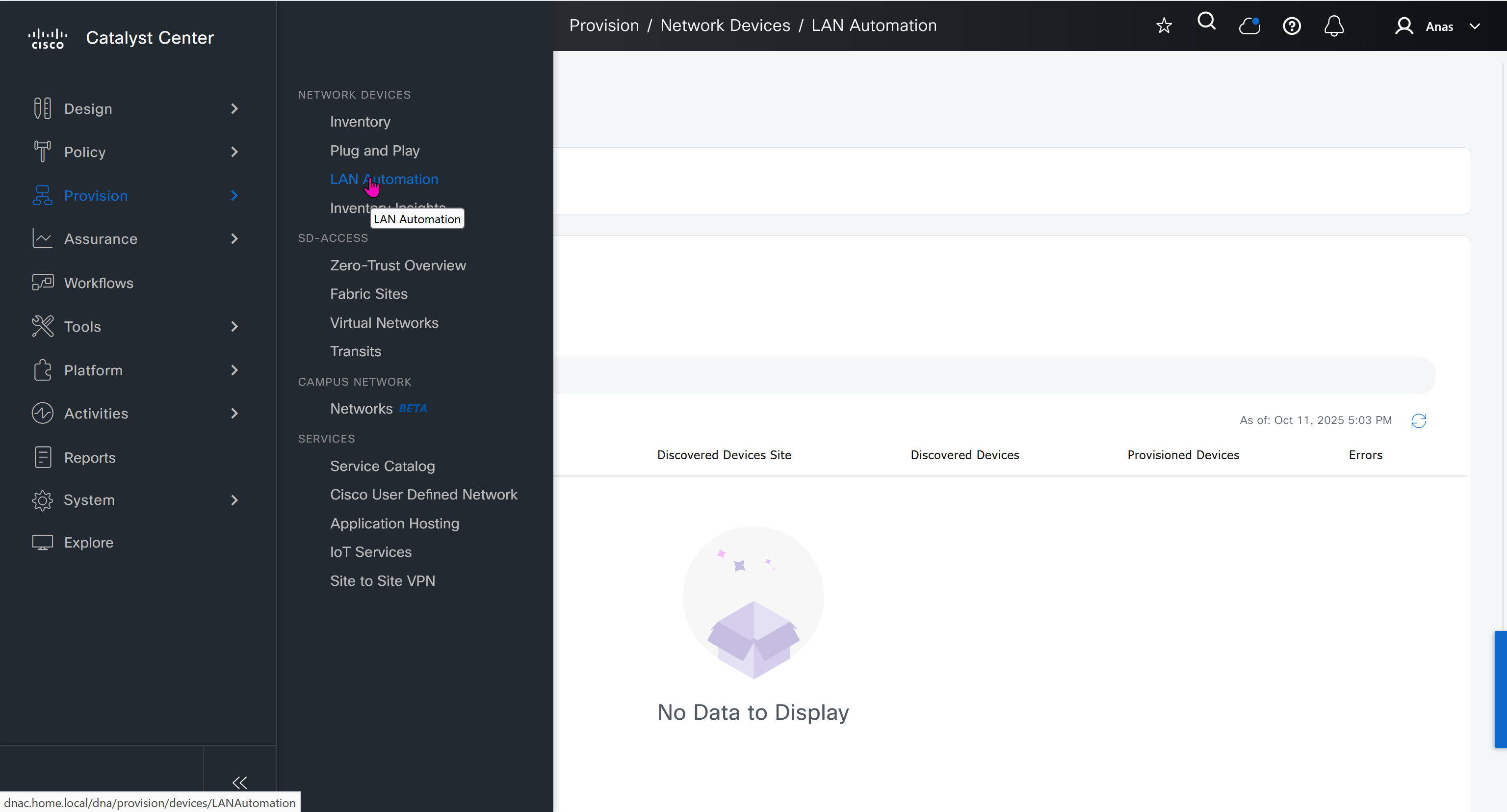
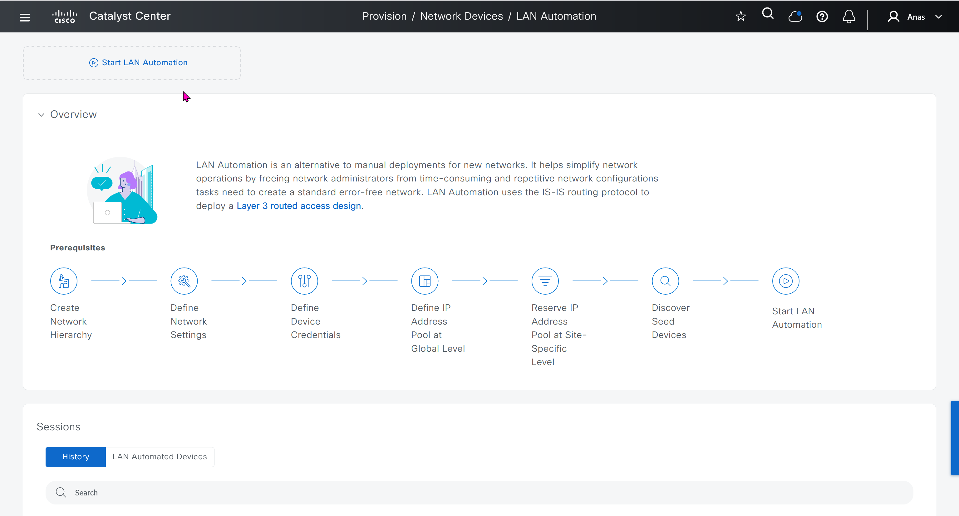
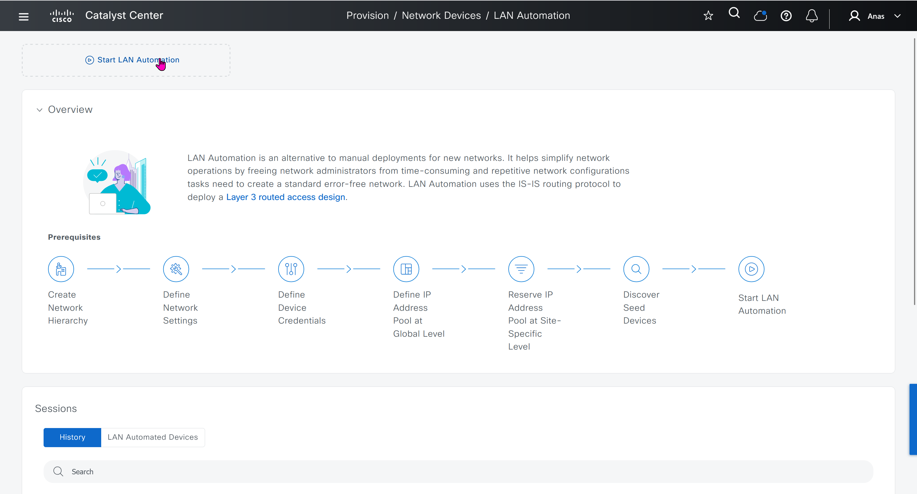
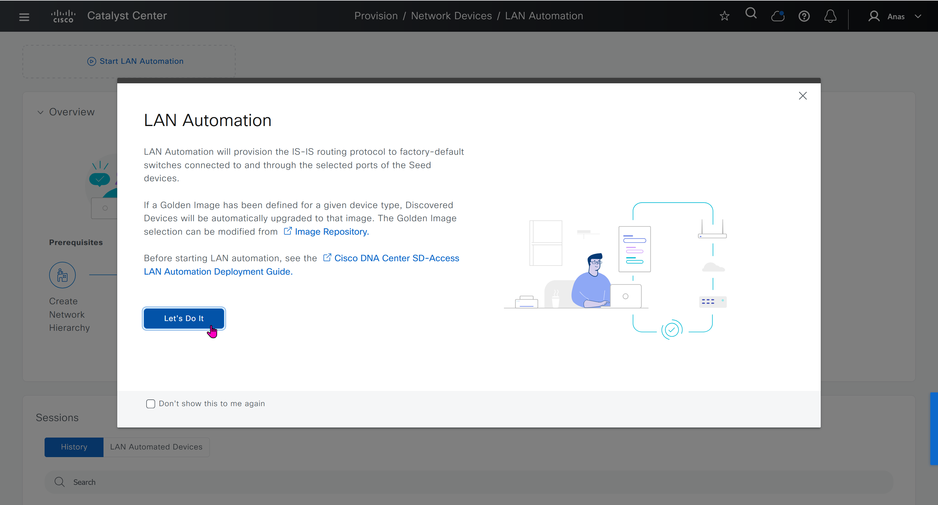
When LAN automation starts, Catalyst Center
pushes the loopback and IS-IS configuration to the primary and peer seed devices and the temporary configuration to the primary seed device
Catalyst Center Release 2.3.3 and later support is-type level-2-only as part of IS-IS configurations.
discovers new devices.
upgrades the device software image and pushes the configuration to discovered devices.
The image is updated only if a golden image is marked for that switch type in Catalyst Center under Design > Image repository.
When LAN automation starts, the temporary configuration is pushed to the primary seed device. This allows the device to discover and onboard the PnP agent. Next, the PnP agent image is upgraded and basic configurations such as loopback address, system MTU, and IP routing are pushed to the PnP agent.
- on PnP agent, Do not press Yes or No. Leave the device in the same state.
- Allow extra time to make sure that all members in the stack are up. Do not start LAN automation until all switches are up.
- LAN automation always begins on the active switch. When all switches in a stack are booted together, the switch with the lowest MAC address (assuming no switch priority is configured) becomes active. The switch with the second lowest MAC address becomes the standby, and so on. Some customers require the first switch to always be active. In this case, if all the switches are booted together and the first switch does not have the lowest MAC address, it does not become the active switch. To ensure that the first switch is active, boot the switches in a staggered manner: boot Switch 1; after 120 seconds, boot Switch 2, and so on. This approach ensures that the switch becomes active in the correct order—Switch 1 is active, Switch 2 is standby, and so on. However, after a reload, the order may change because switches obtain their role based on their MAC address.
- To make sure that the switches maintain their order after reload, it is a good practice to assign switch priorities to ensure that the switches always come up in the same order. The highest priority is 15. During LAN automation, the priority of active switch is set to 15 by default. The priority of other switches is not altered. When priorities are assigned, they take precedence over the switch MAC address. Assigning switch priorities does not change the NVRAM configuration. The values are written to ROMMON and persist after reload or write erase. Refer to this sample code:
3850_edge_2#switch 1 priority ? <1-15> Switch Priority 3850_edge_2#switch 1 priority 14 WARNING: Changing the switch priority may result in a configuration change for that switch. Do you want to continue?[y/n]? [yes]: y- You might have to clean up the switch after assigning priorities using “
pnpa service reset no-prompt“ - Connect PnP agents directly to seed devices. Do not connect PnP agents to any other network (for example, even the management network)
Interface Selection
consider four directly connected PnP agents: device 1 is connected through Gig1/0/10, device 2 through Gig 1/0/11, device 3 through Gig 1/0/12, and device 4 through Gig 1/0/13. If you choose Gig 1/0/11 and Gig 1/0/12 as discovery interfaces, LAN automation discovers only device 1 and device 2. If device 3 and device 4 try to initiate the PnP flow, LAN automation filters them because they connect through unselected interface.
You can also choose interfaces between the primary seed and the peer seed to configure with Layer 3 links. If there are multiple interfaces between the primary and peer seeds, you can choose to configure any set of these interfaces with Layer 3 links. If no interfaces are chosen, they aren’t configured with Layer 3 links.
You can reuse the same LAN pool for multiple LAN automation sessions. For example, you can run a discovery session to find the initial set of devices. After the session completes, you can provide the same IP pool for subsequent LAN automation sessions. Similarly, you can choose a different LAN pool for other discovery sessions. Make sure the LAN pool you select has enough capacity.
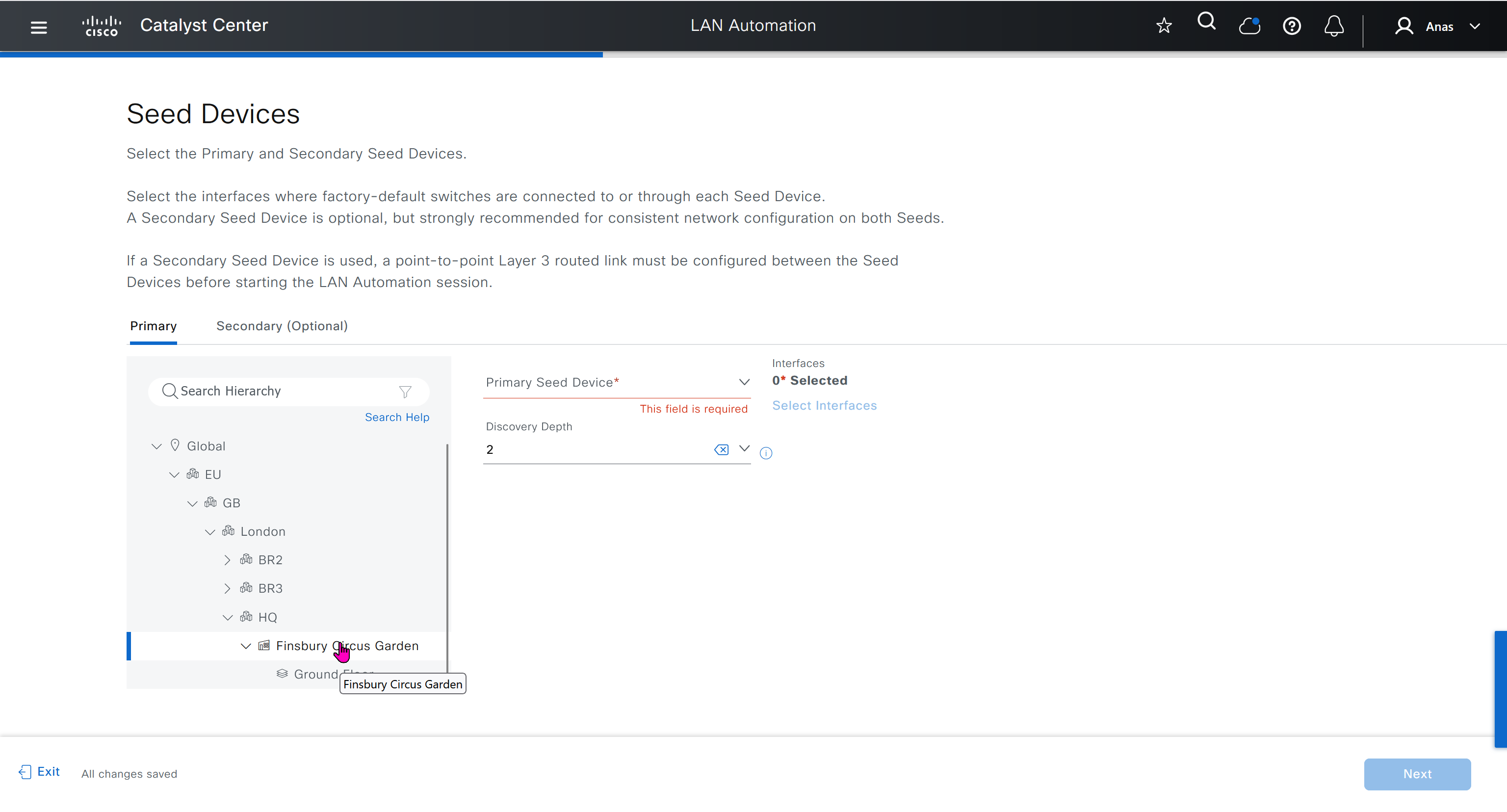
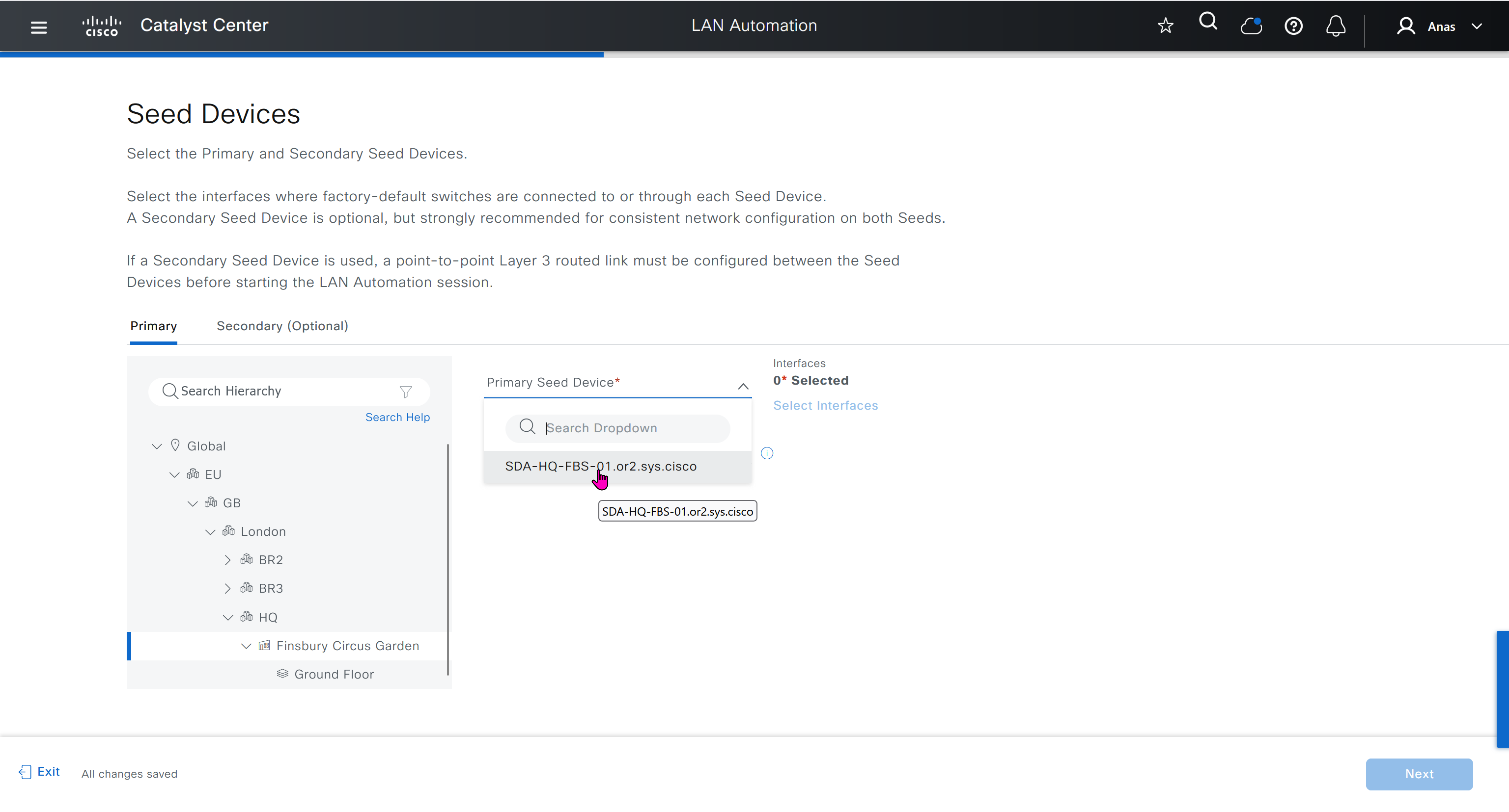
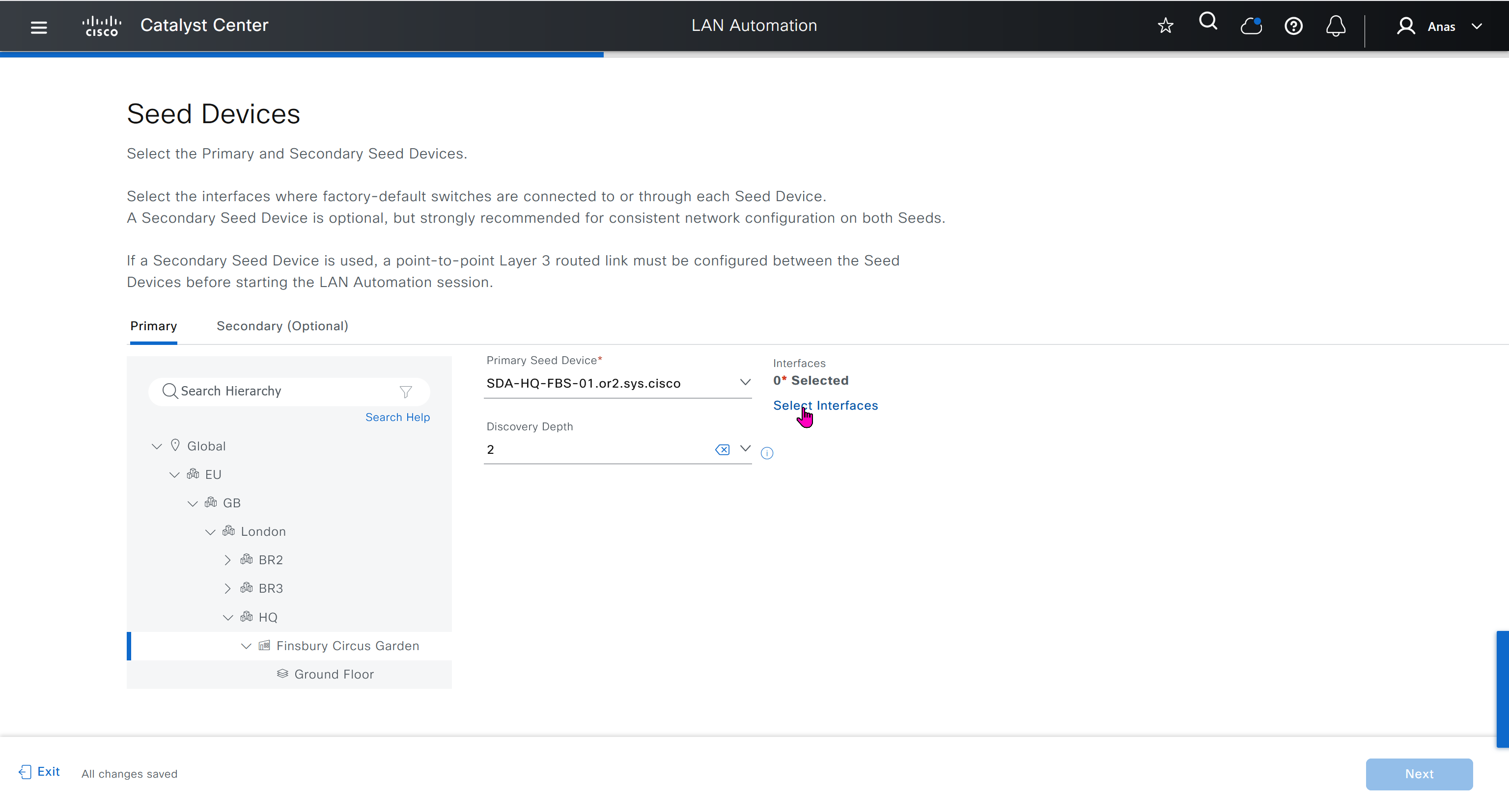

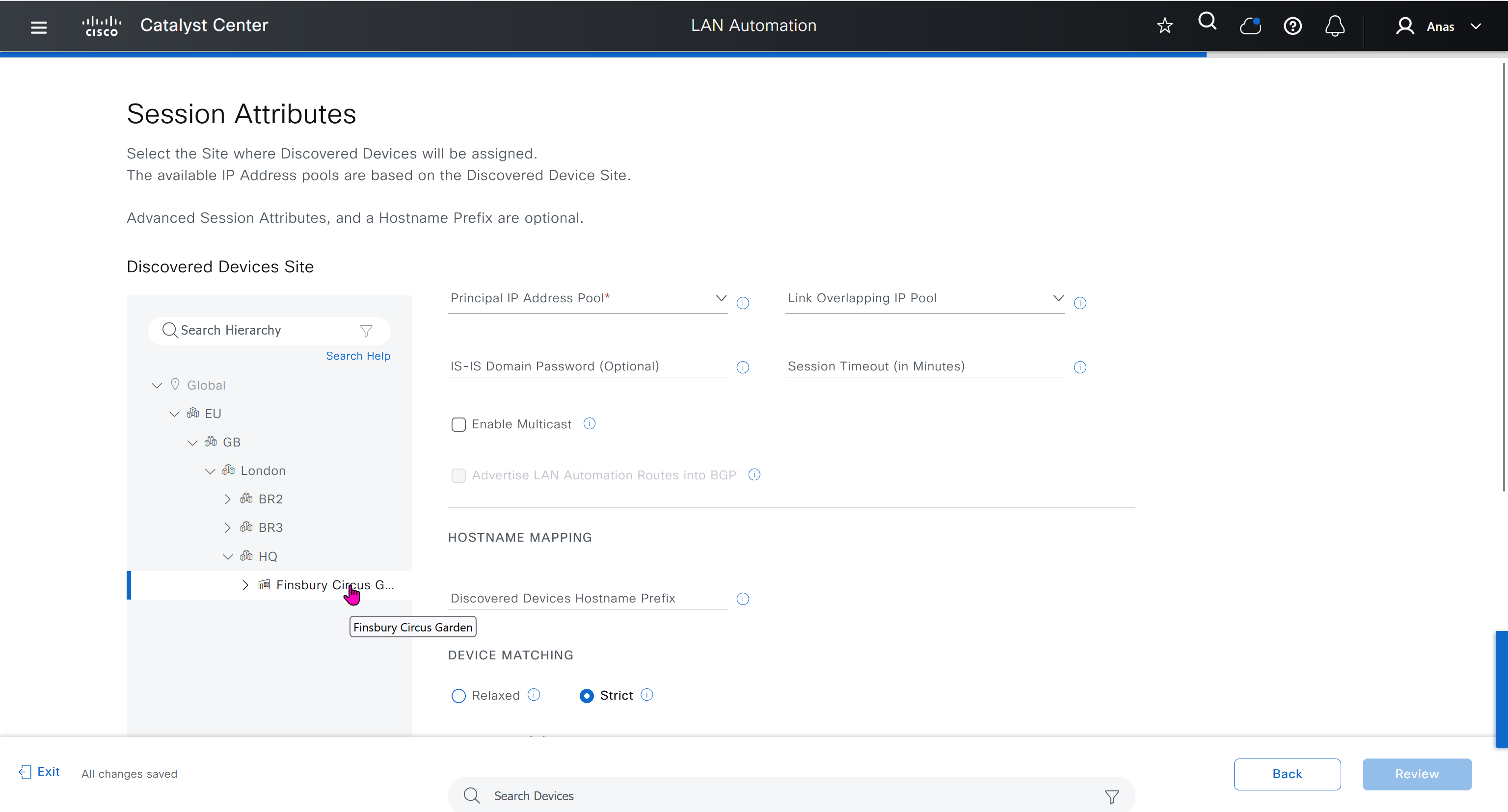
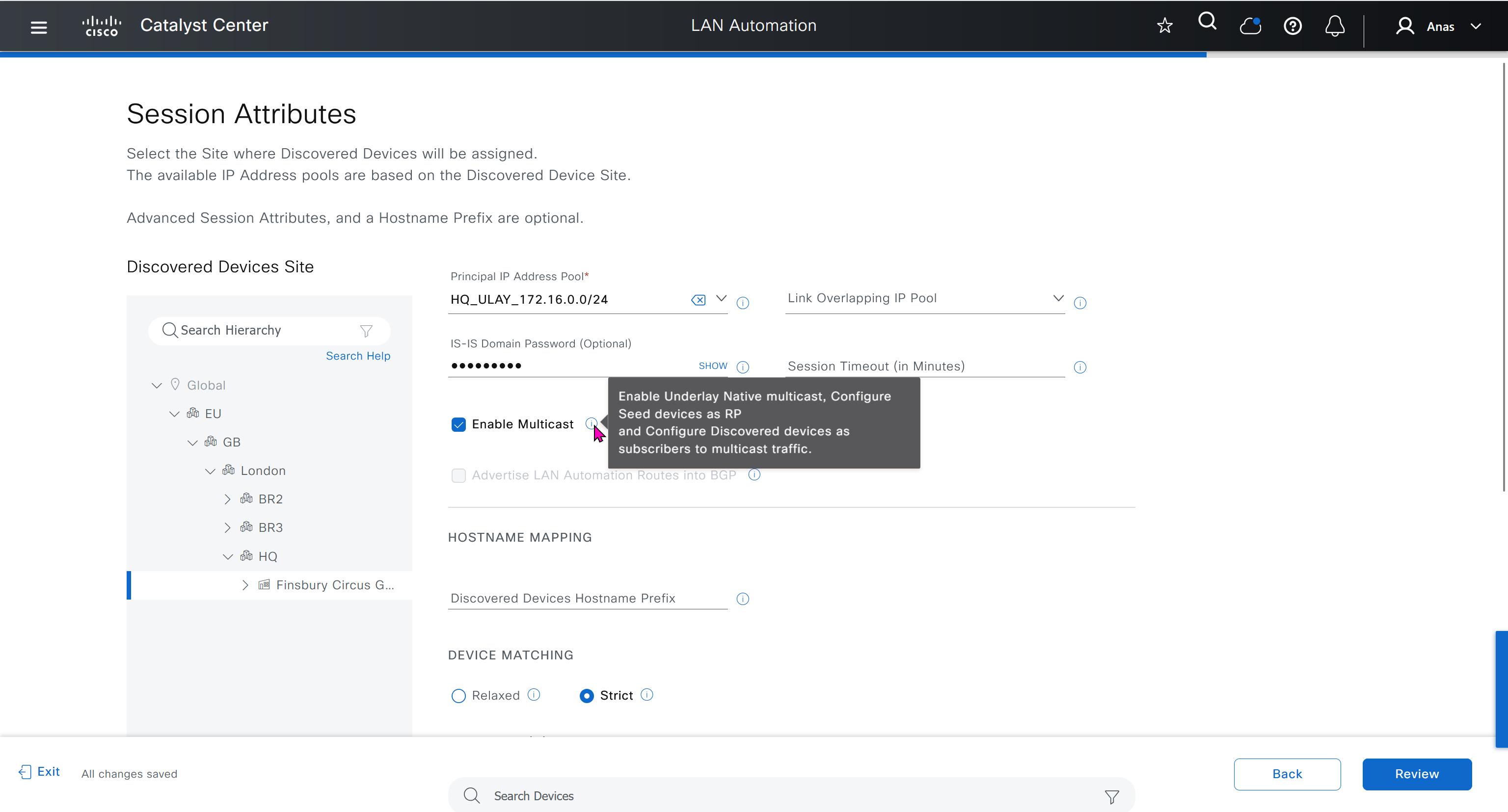


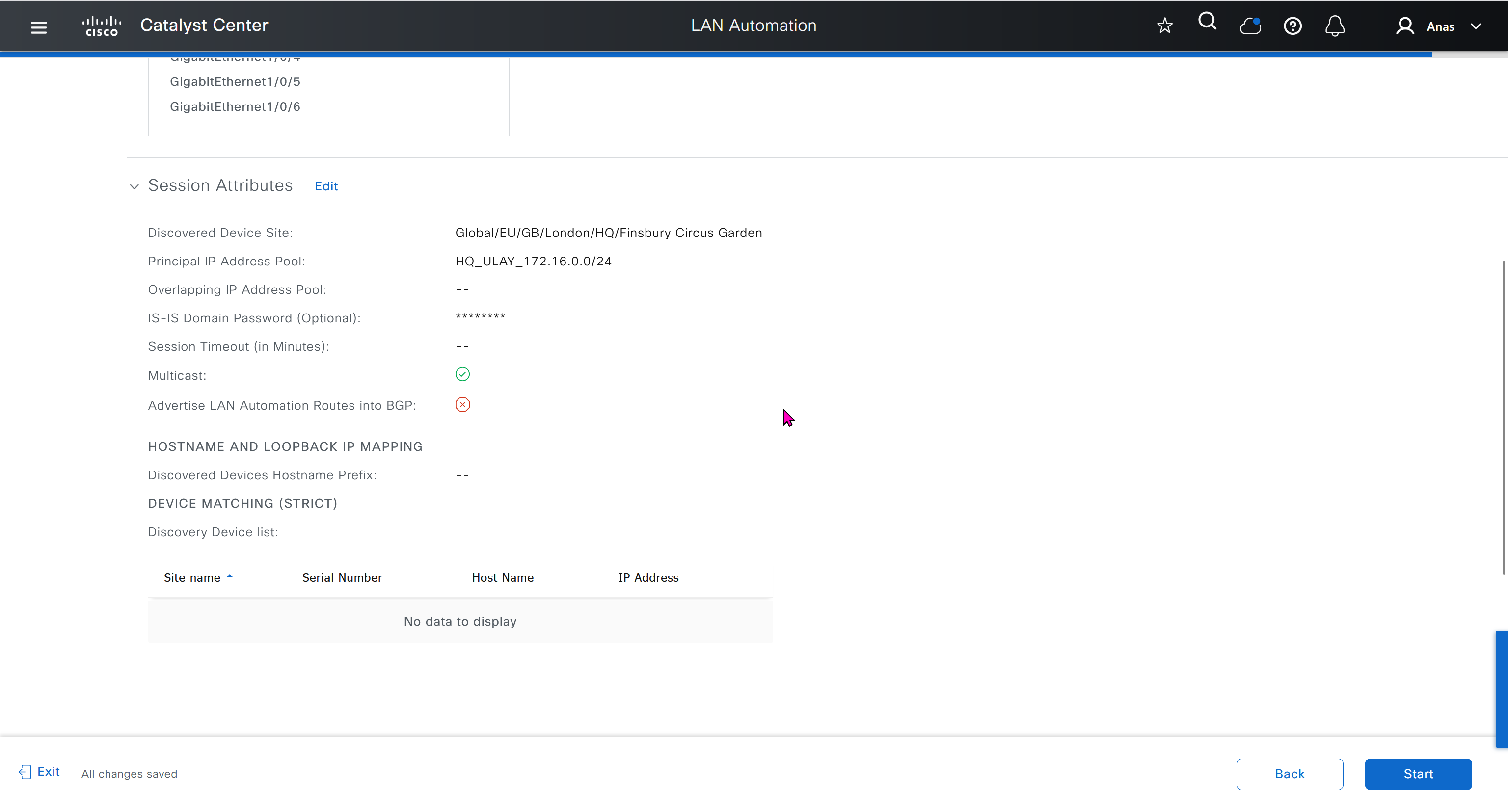
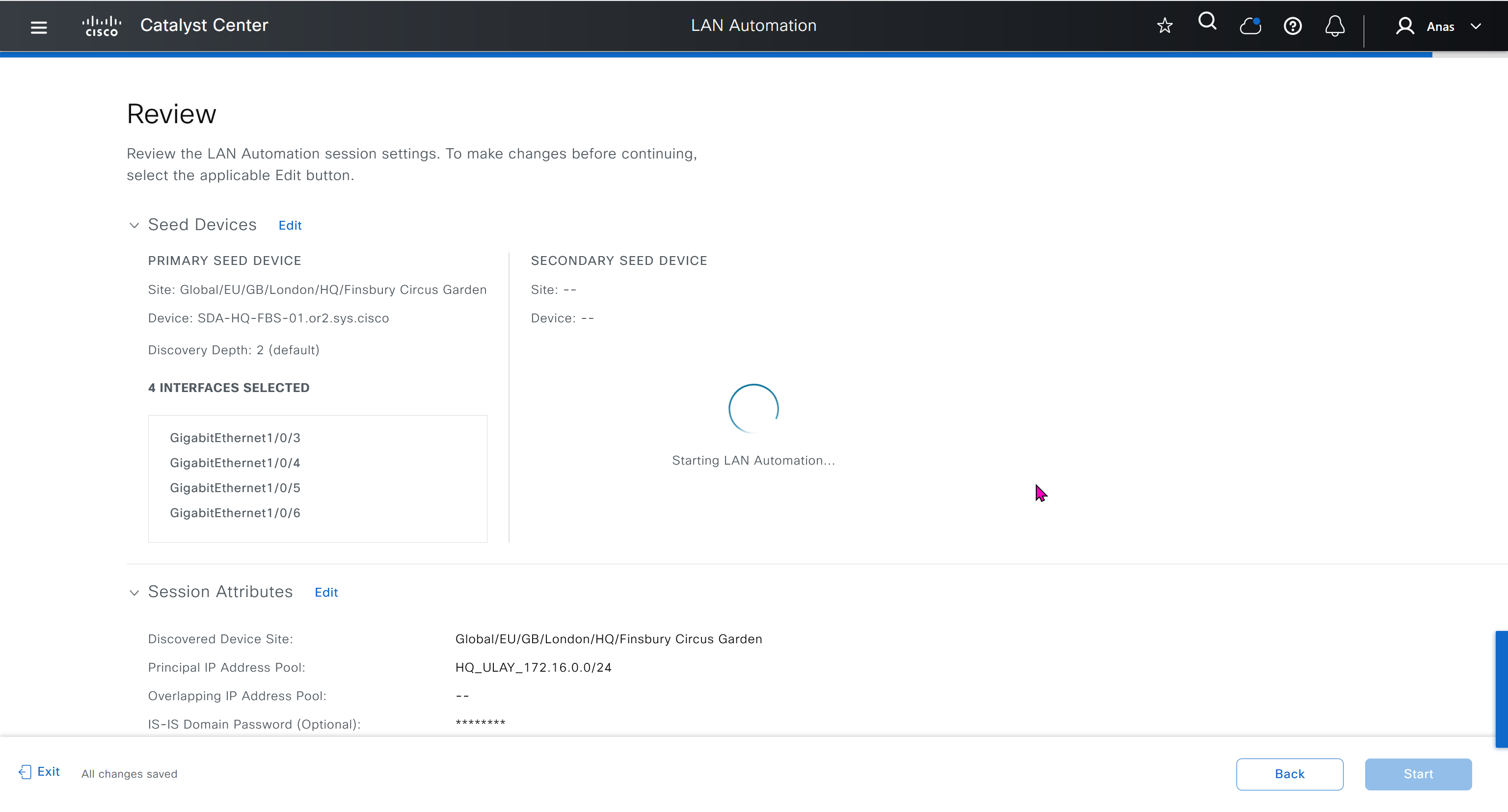
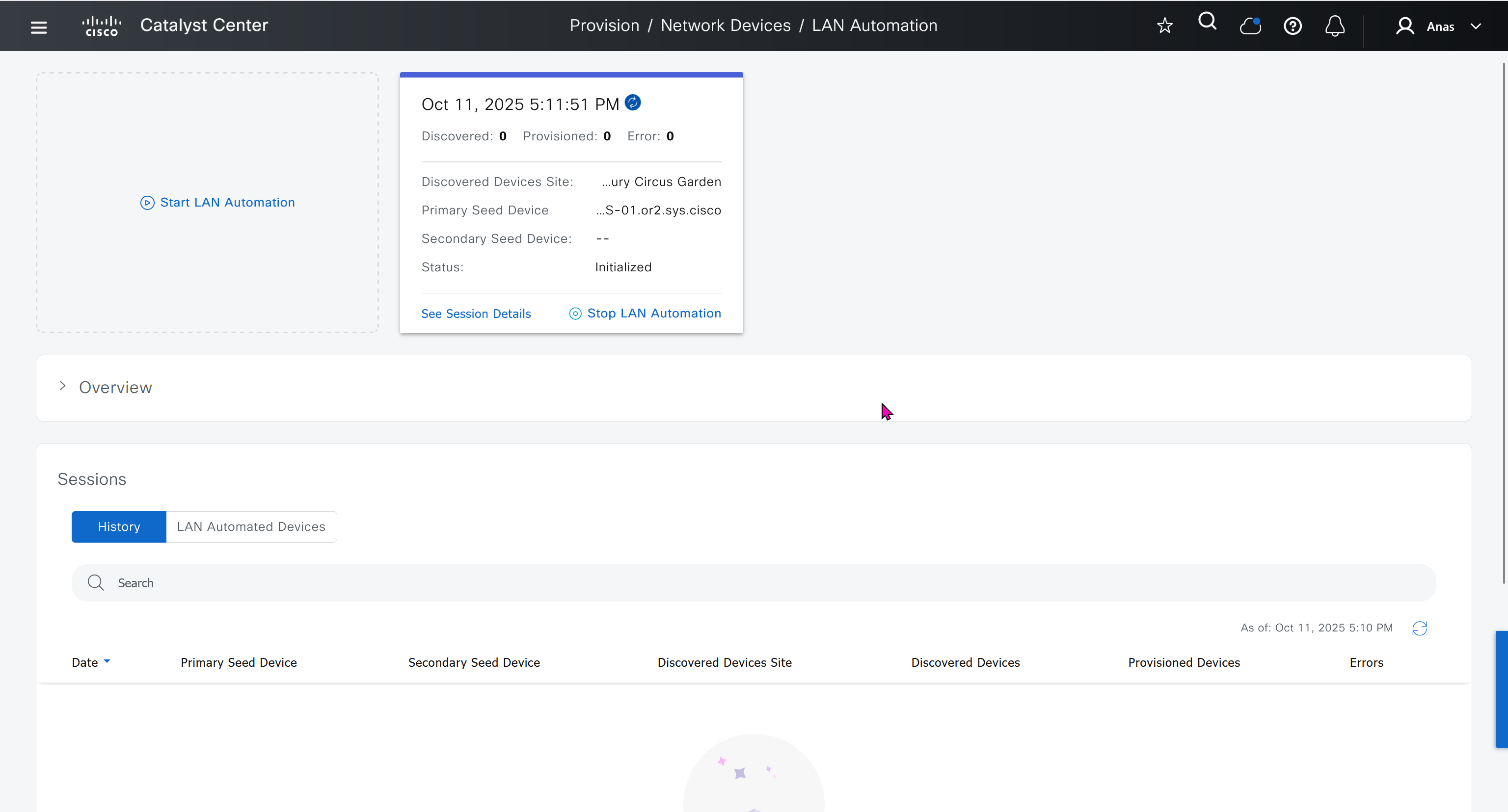
in order to catch all commands pushed by LAN automation to switches add below config and sync with DNAC
conf t
!
! Enable the archive feature
archive
 log config
  logging enable
  notify syslog contenttype plaintext
  hidekeys
!
! Optional: Set up where the archived configs are stored
 path flash:config-archive
 write-memory
!
end
!
! Ensure syslog logging is enabled (optional but recommended)
conf t

logging buffered 64000
service timestamps log datetime msec
!
end
write mem who
show user
! to see if DNAC is logged in and running commands
! to see commands
show logg | inc CFGLOG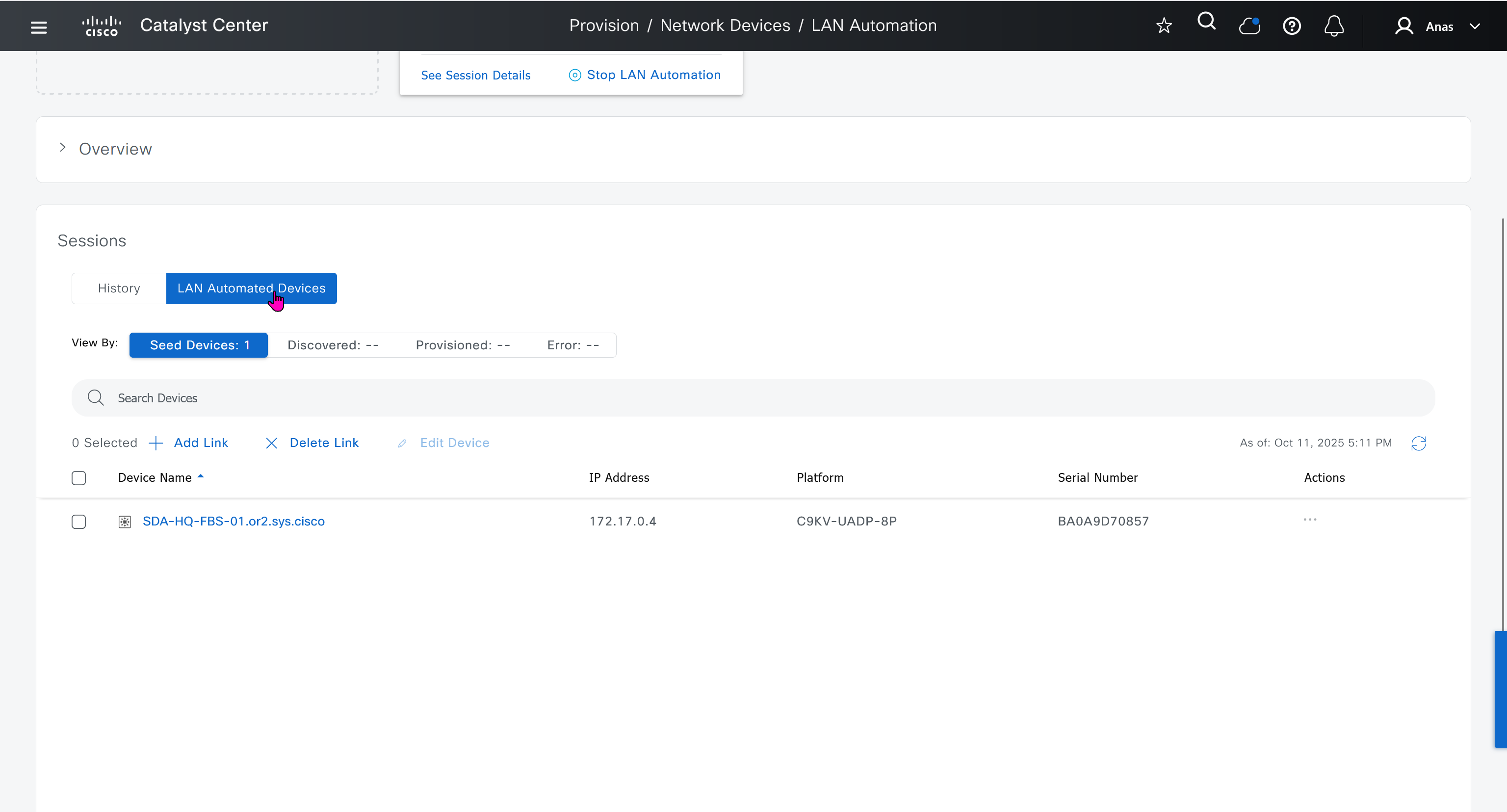
- Quickly as confiiguration is being deployed, intervene and remove using “no” following part of the configuration from “all” switches / routers
- router isis
net 49.0000.280e.ab15.fa02.00
is-type level-2-only
domain-password C0mplex30
metric-style wide
log-adjacency-changes
nsf ietf
bfd all-interfaces
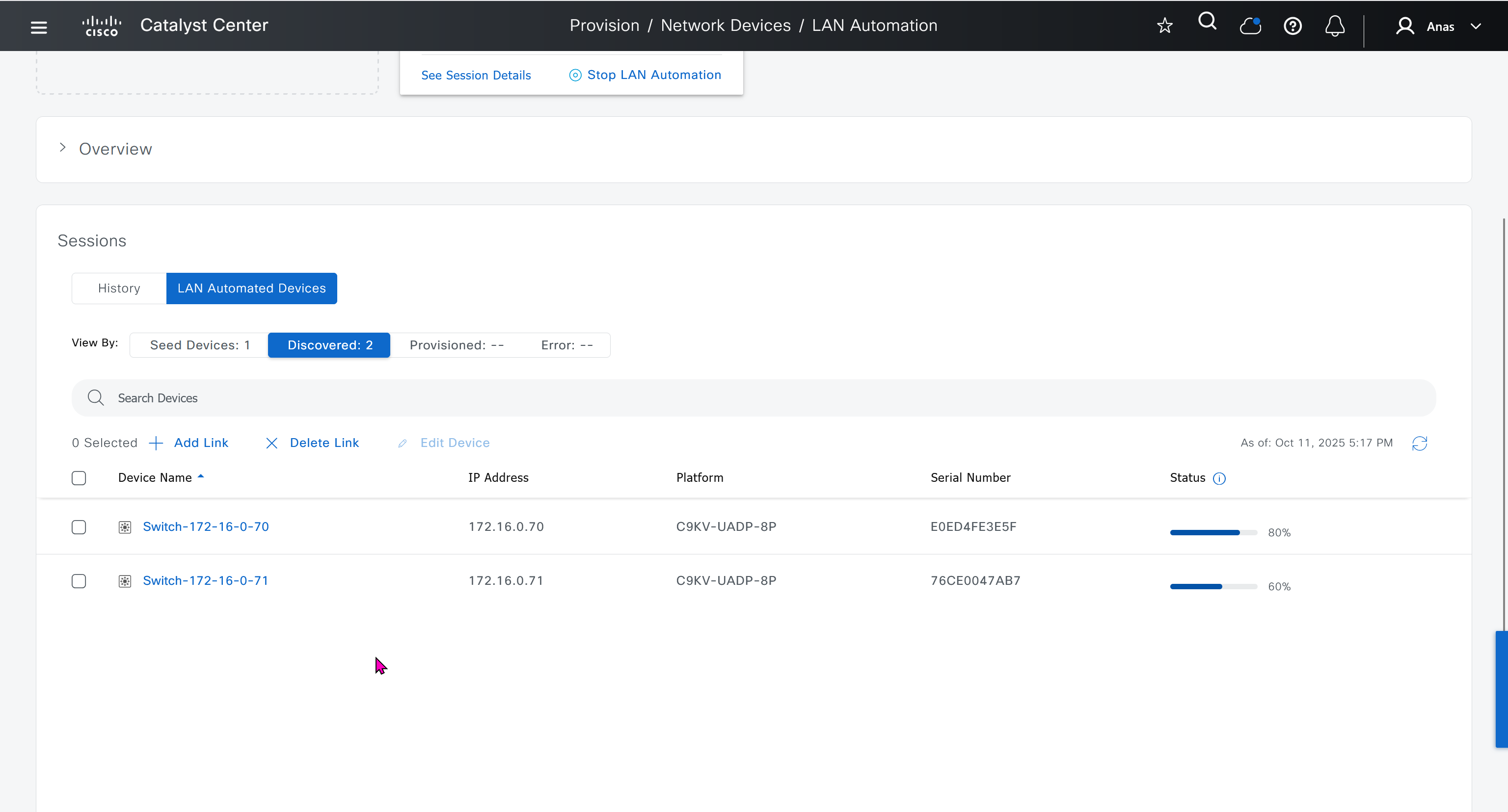


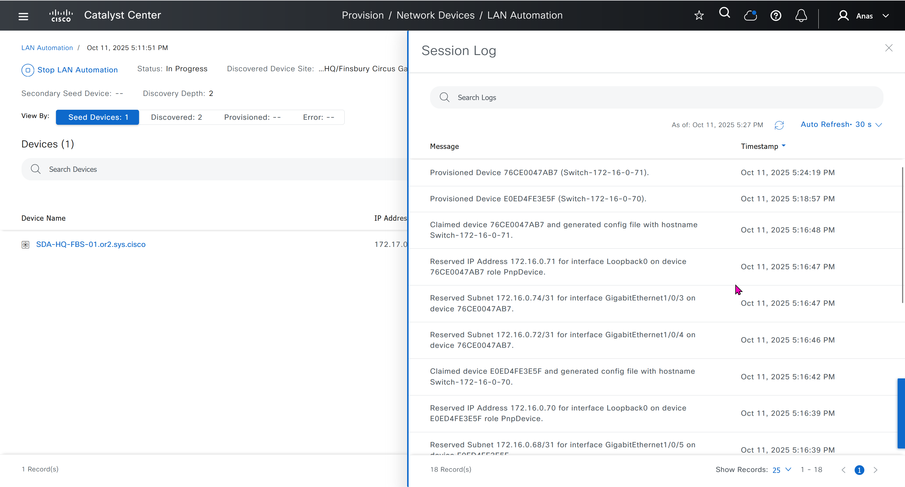
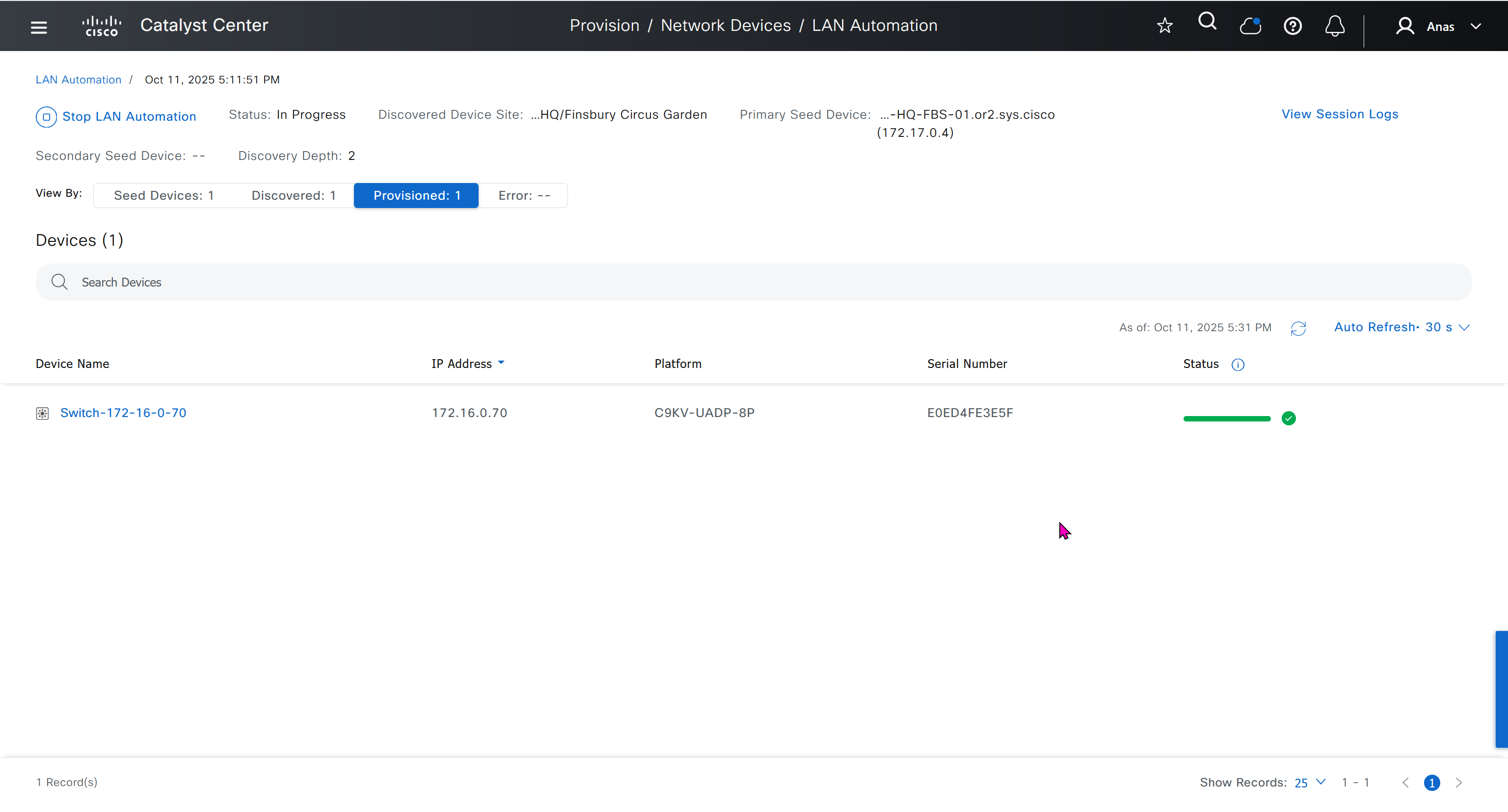
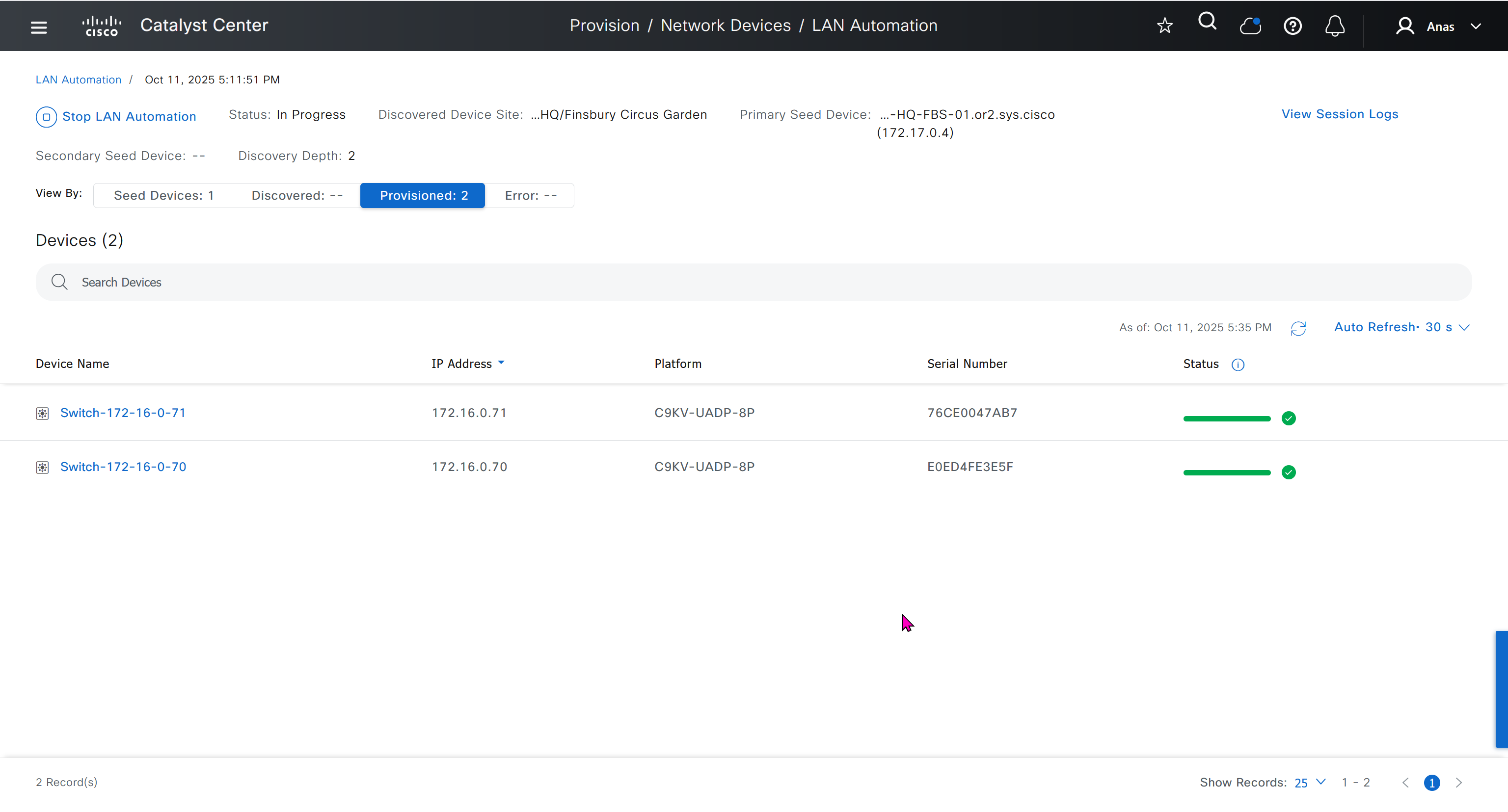
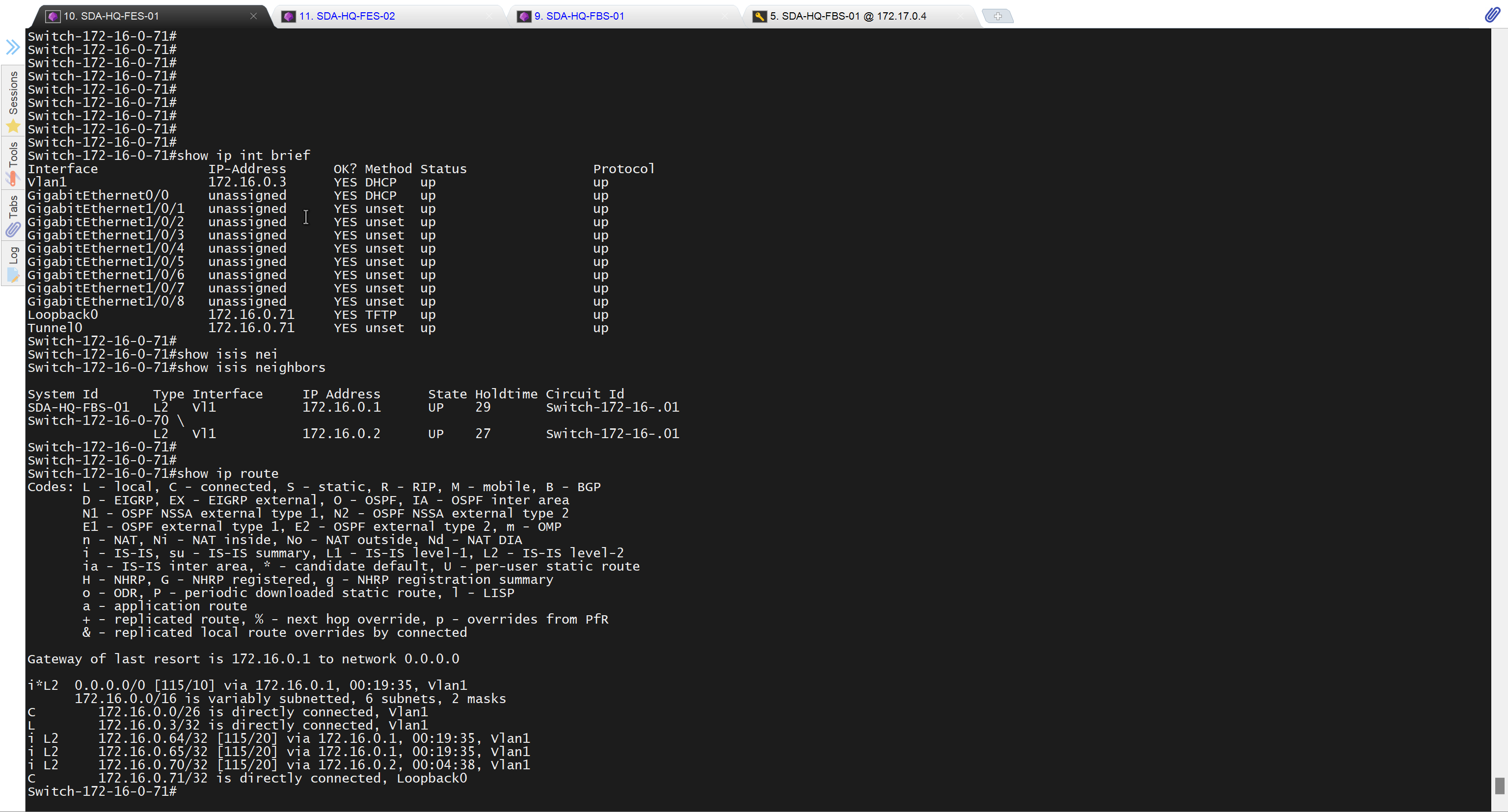

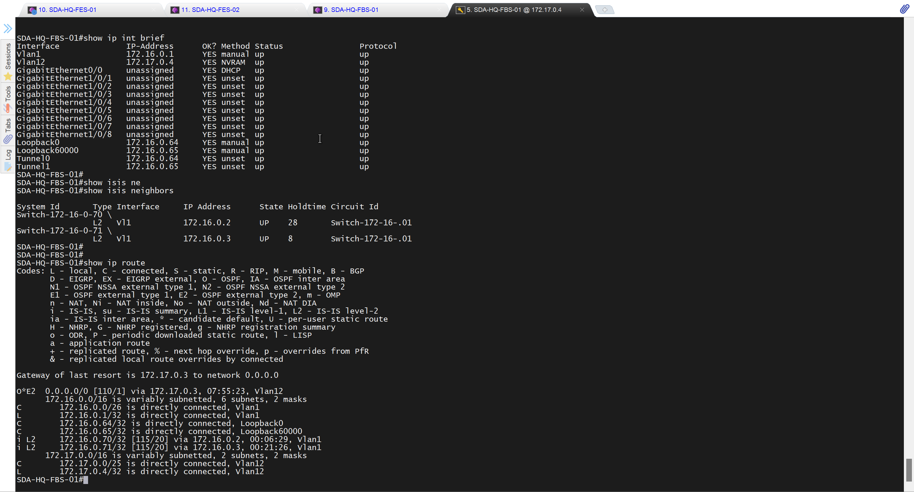

It takes long time to stop LAN automation
When the LAN automation process stops,
the discovery phase ends, and all point-to-point links between the seed and discovered devices and between the discovered devices (maximum of two hops) are converted to Layer 3.


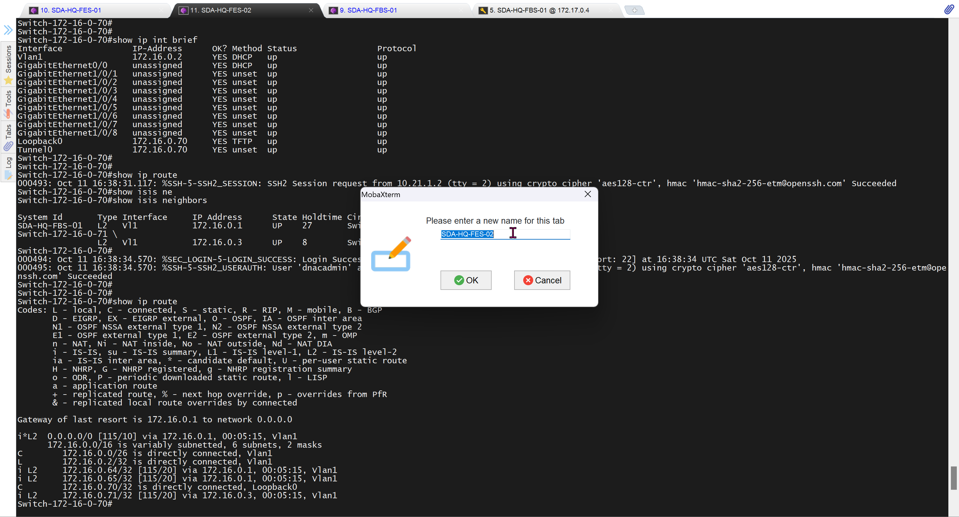
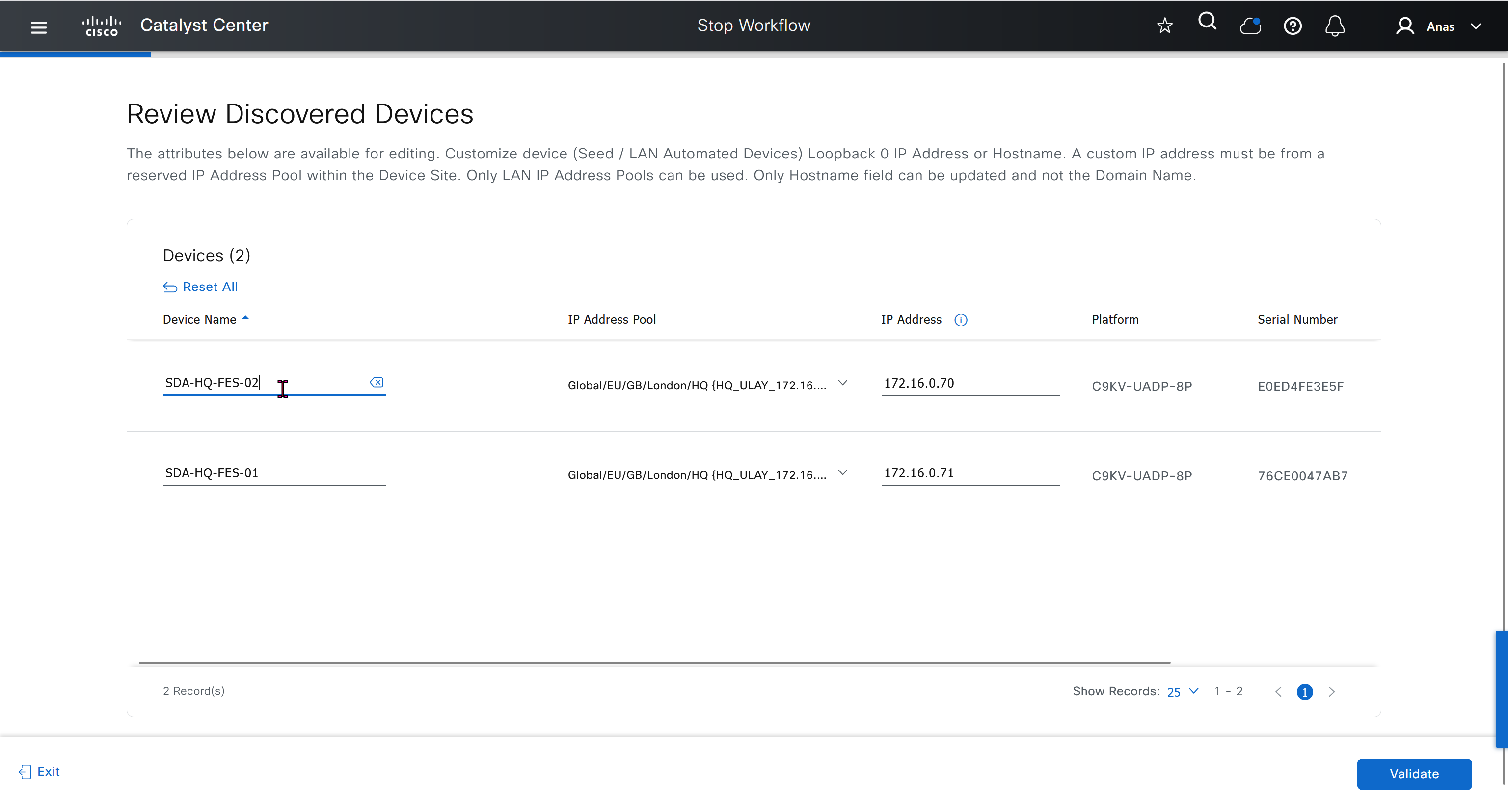


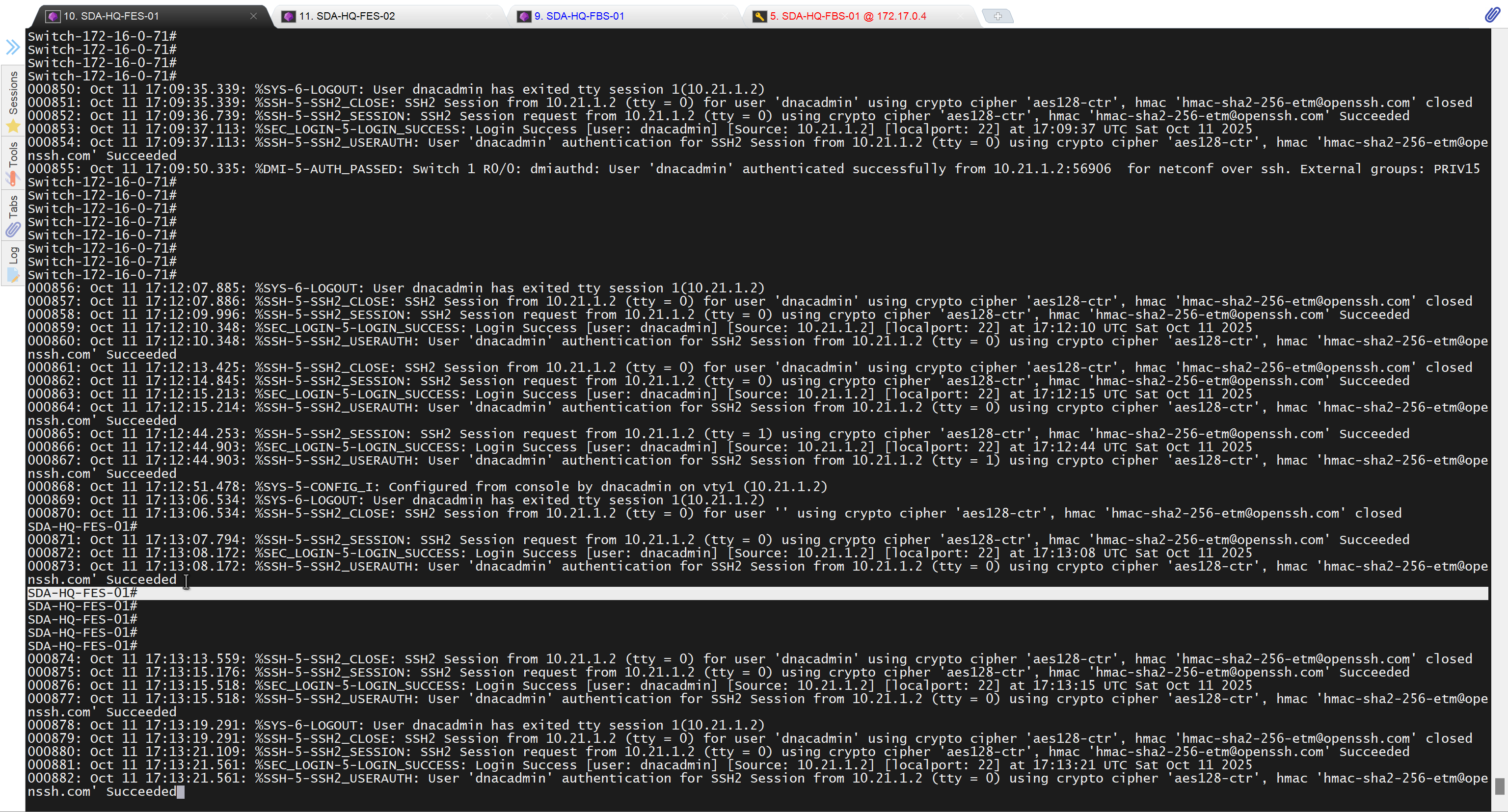
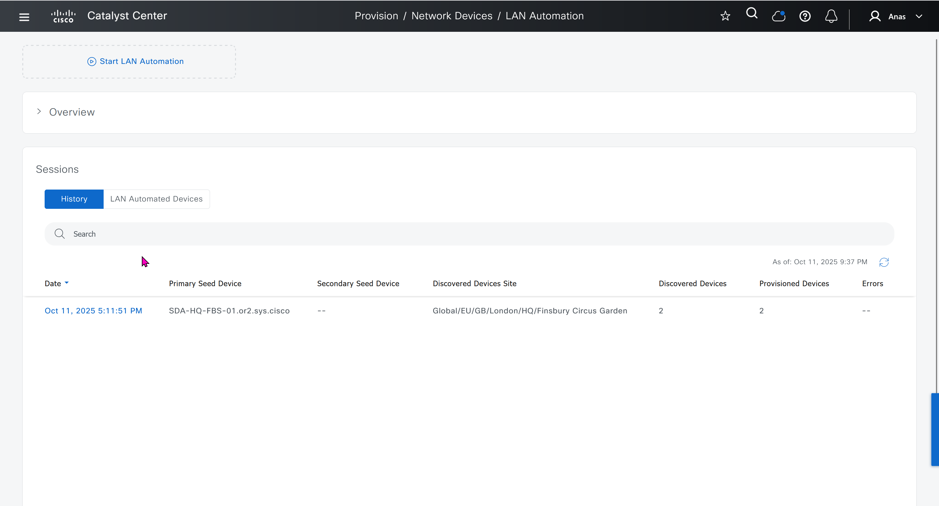

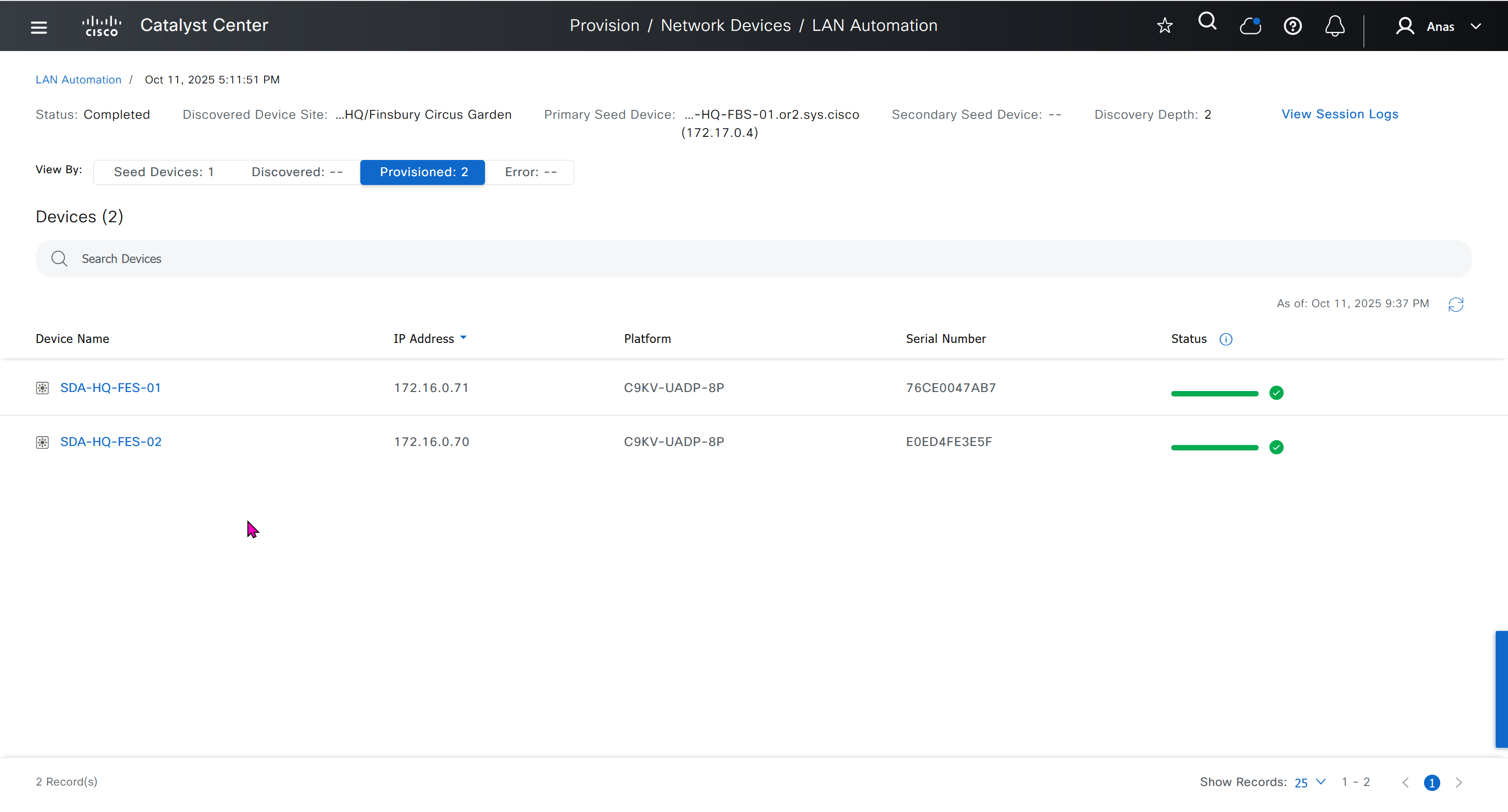
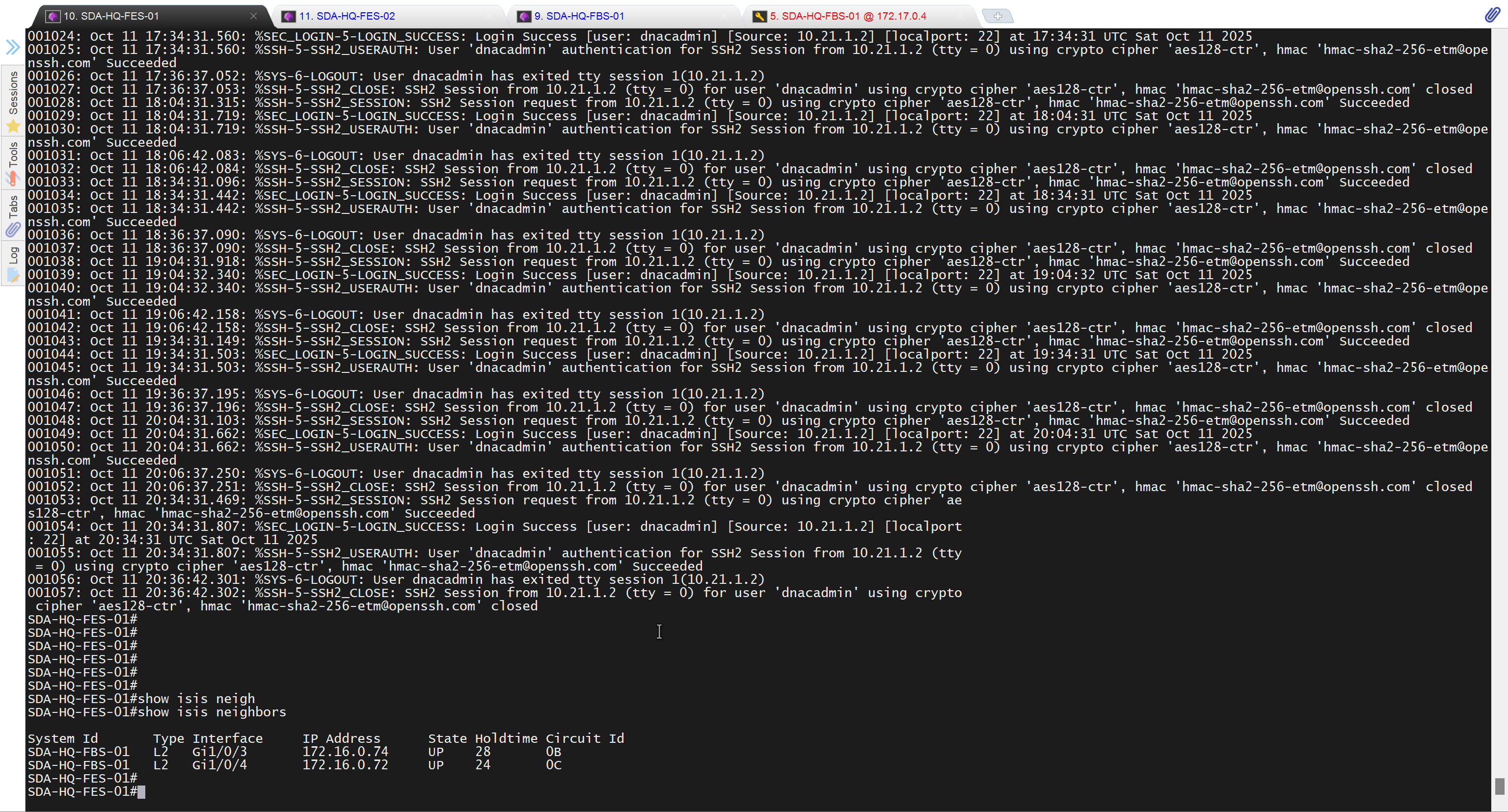

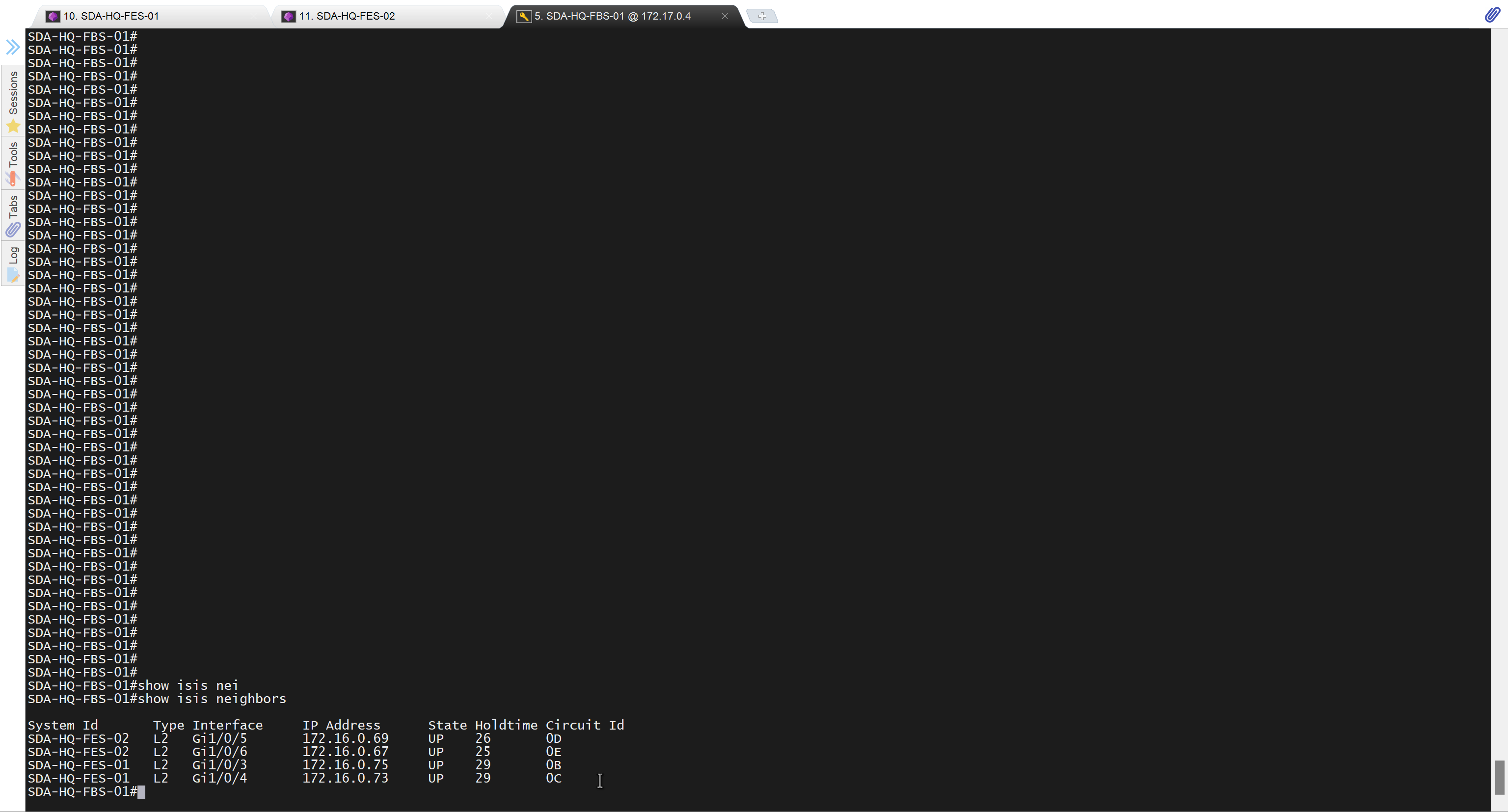
Add a static route for LAN pool on DNAC through Enterprise facing interface
Skipped but complete it for CCIE LAB
next post
CCIE MPLS
Multi Protocol Label Switching is a technology to deliver IP
Forwarding of data packets is via labels – MPLS enabled routers do not look into IP header to forward packets
MPLS is known as OSI layer 2.5 – Label info is inserted between Data link and Network layer and this is sometimes called shim header

MPLS works over most “Layer 2 technologies” such as ATM, FR, PPP, POS, Ethernet
Network infrastructure convergence – MPLS enabled network allows to carry different kind of traffic (IPv4, IPv6, Layer2 frames) across single network infrastructure
No need to have BGP enabled on all routers – Very important for scaling networks – because MPLS forwarding is done via labels, we do not need to keep all destination IP addresses in routing tables
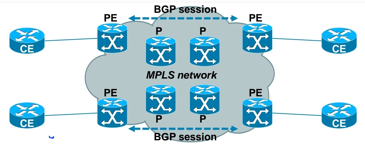
– Allows use of overlapping IPv4 address space
– Allows optimal traffic flow
Traffic engineering
– Preffered path is least cost path determined by IGP
– Basic idea is to use links in network infrastructure efficiently
– MPLS needs to be able to provide mechanism to divert traffic to other links beside preffered path
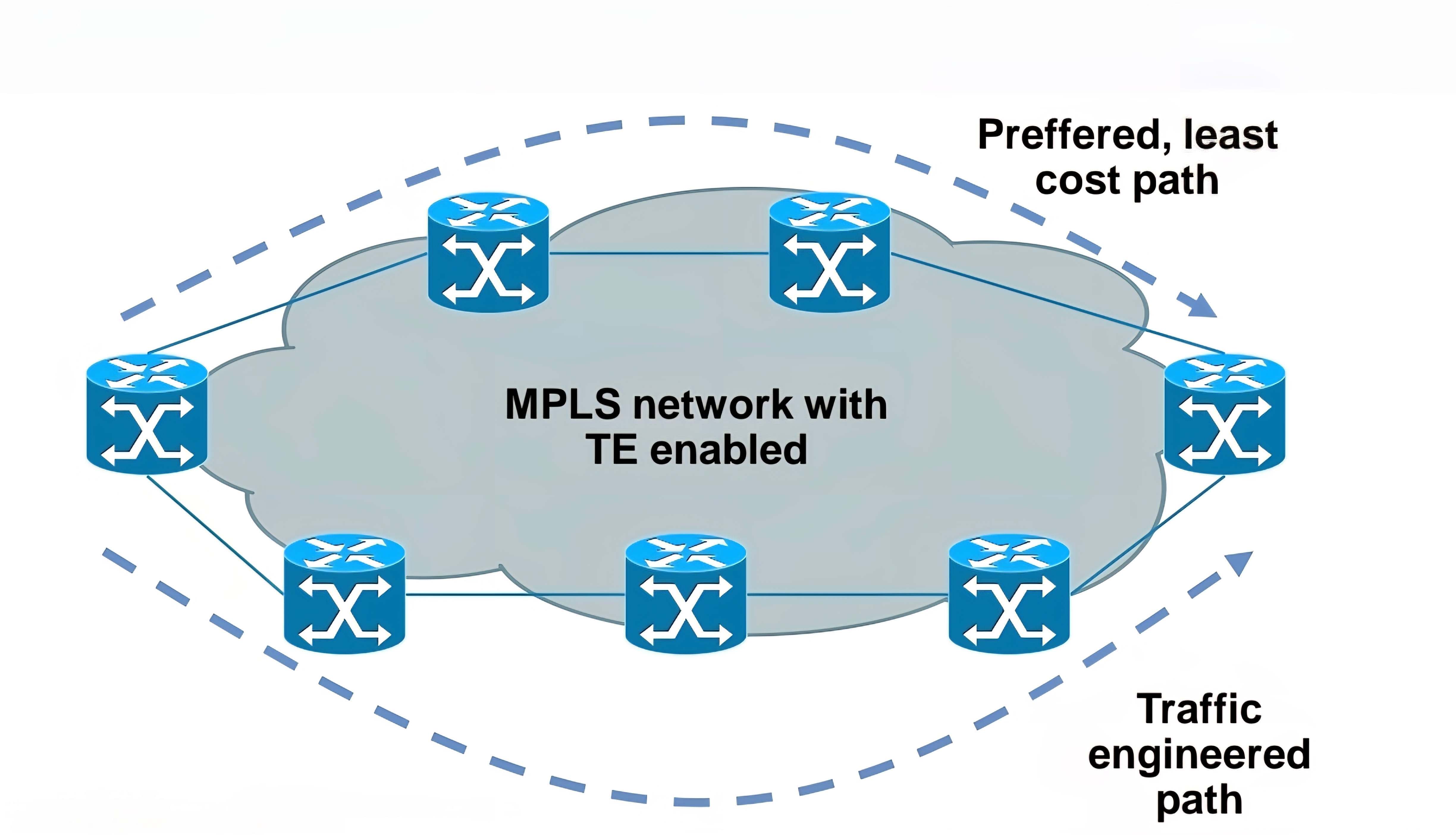
Main building blocks of MPLS:
Label – 32 bit value inserted between Layer 2 and Layer 3
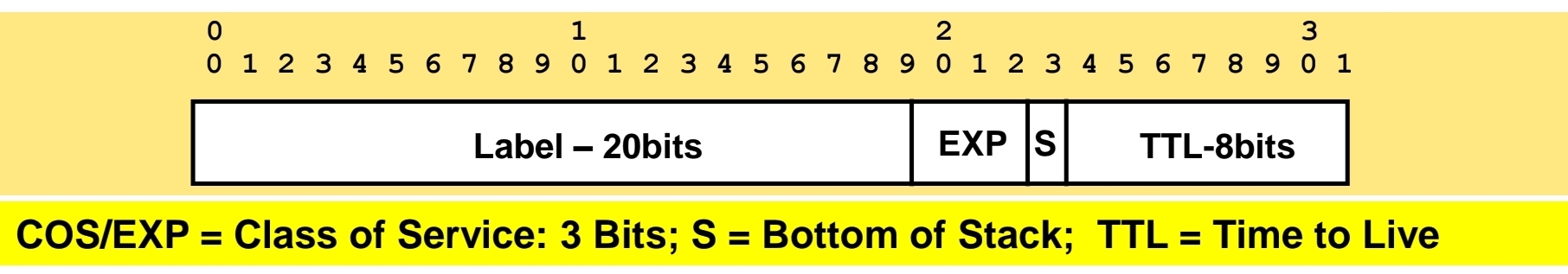
LSR – Label Switch Router (eg. PE, P)
LSP – Label Switched Path
IGP – Interior Gateway Protocol
LDP – Label Distribution Protocol
LIB, LFIB – Label Information Base, Label Forwarding Information Base
MP-BGP, RSVP – Protocols for MPLS VPN and MPLS TE

Egress LSR not always performs label disposition – PHP (Penultimate Hop Popping) signaled via implicit null label (LDP advertising MPLS label of value three)
Penultimate Hop Popping (PHP) is a feature in MPLS (Multiprotocol Label Switching) where the second-to-last router (the penultimate hop) removes (or pops) the MPLS label before forwarding the packet to the final router. This improves efficiency and reduces workload on the last router.
Assigning and distributing MPLS labels Each LSR needs to run IGP to learn IP prefixes (eg. neighbor loopbacks, BGP next hops)
Each LSR then forms “LDP neighborship” between its directly connected LSR
Once LDP neighborship is formed, each LSR uses LDP to “assign labels to IP prefixes” it knows about – each LSR does this independently and advertises its labels to its LDP neighbors
LDP is standards based – RFC 3035 and RFC 3036
LDP uses UDP for session discovery and neighbor discovery (port 646 and destination IP 224.0.0.2)
LDP uses TCP (port 646 and destination IP of its LDP peer) for rest of the messages (label advertisement, label withdrawal, session maintenance, session teardown)
Forwarding MPLS packets – which label to use?
RIB stores IP prefixes, LIB stores MPLS labels
LFIB is created from both RIB and LIB and used to forward MPLS tagged packets
Example for LSR in bottom picture:
– RIB has 1.1.1.1/32 learned via IGP over e0/0 interface
– LIB has label “L” for prefix 1.1.1.1/32 learned from its LDP peer
– LFIB has: “to forward packet to 1.1.1.1/32, use label L and send packet using peer LDP nexthop over e0/0 interface”
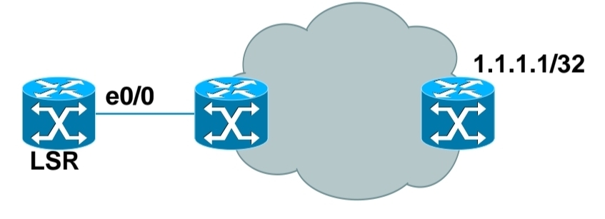
Label stacking
Labeling does not make forwarding of packets faster
Label stacking is the primary use of MPLS that enables use of MPLS L2 and L3 VPNs, traffic engineering and other services
Most used examples of label stacking:
– 2 labels for MPLS VPN – bottom label indicates which VPN this packet belongs to, outer is used by core LSRs for packet forwarding
– 3 labels for MPLS TE – the most upper label is used to indicate which TE tunnel to forward this packet
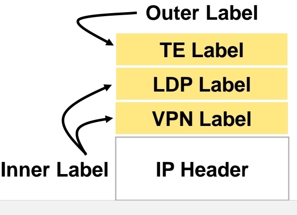
Use of MPLS to build Layer 3 VPN
MPLS VPN is set of sites that communicate with each other – these sites can be connected to MPLS infrastructure at various PE routers
Each site is identified by its own VRF (Virtual Routing and Forwarding), by default communication between VRF is not allowed
Each PE router assigns distinct MPLS label for each VRF it communicates with other PE routers – this label is not assigned by LDP, but by MP-BGP
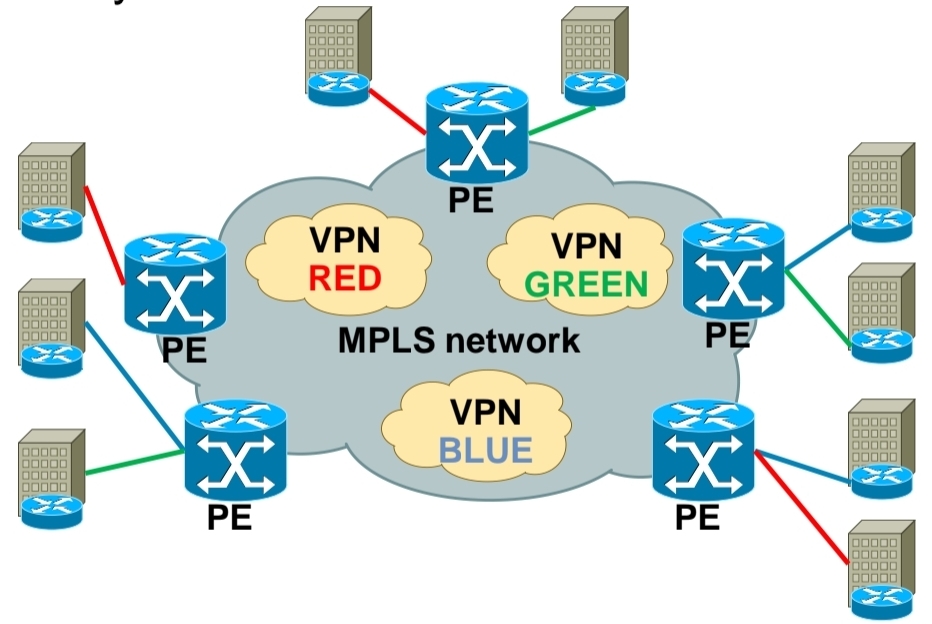
RD (Route Distinguisher) is attached to each IP prefix exchanged in VPN to make them unique – RD + prefix = VPN prefix
RD allows to use overlapping IP addresses among VPNs
RD length is 64 bits and is in format X:Y, where X is usually Autonomous System Number or IP address – usually one RD is assigned per customer
RT (Route Target) governs which VPN prefixes are allowed to be imported or exported out of particular VPN
Route Targets
In MPLS Layer 3 VPNs, a Route Target (RT) is a special extended BGP attribute used to control which VPN routes are imported and exported between PE (Provider Edge) routers.
In an MPLS VPN network:Multiple customers share the same provider backbone.Each customer has a separate routing table called a VRF (Virtual Routing and Forwarding).Routes must be kept isolated between customers.The Route Target ensures that:Only the correct VPN routes are shared between the correct VRFs.Customer A’s routes are not accidentally sent to Customer B.
Each VRF has:
Export Route Target defined
Import Route Target defined
A PE router learns a route from a customer. It adds a Route Target (RT) to that route.The route is advertised via MP-BGP to other PE routers. Other PE routers check: If the route’s RT matches their import RT, If yes → route is installed in the VRF, If no → route is ignored
Customer A has two sites:
Site 1 connected to PE1
Site 2 connected to PE2
Both VRFs are configured with:
Export RT: 100:1
Import RT: 100:1,
Result: PE1 exports routes with RT 100:1, PE2 imports routes with RT 100:1, Both sites can communicate. If another customer uses RT 200:1, their routes stay completely separate.
In order to bring L3 VPN into life, you need to exchange both RD and RT – this is done by MP-BGP
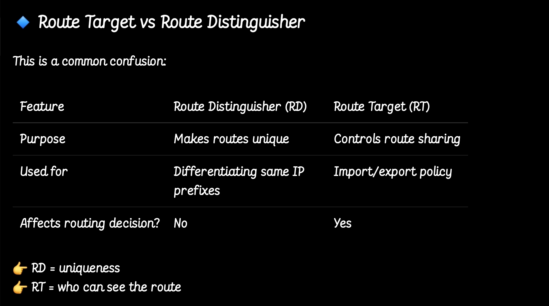
so the functions have been seperated
MPLS Layer 3 VPN Intranet for customer in VPN RED
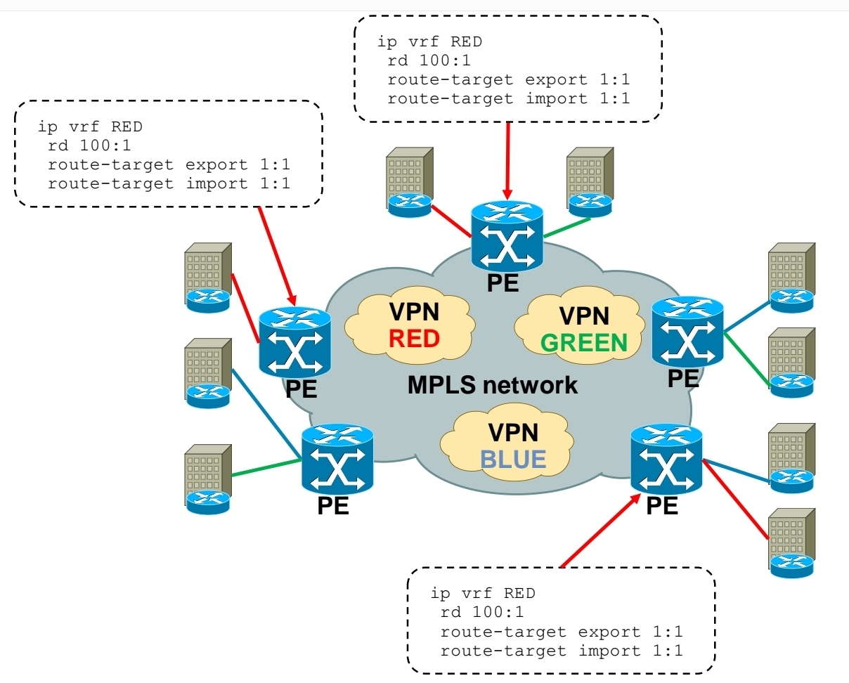
MPLS Layer 3 VPN Intranet for customer in VPN GREEN

MPLS Layer 3 VPN Intranet for customer in VPN BLUE
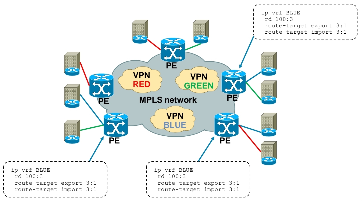
MPLS Layer 3 VPN Extranet between customer VPN RED and VPN BLUE
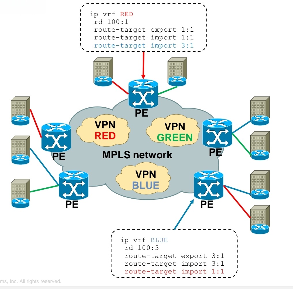
Using RT you create Intranet or Extranet
– Intranet – different sites of “same” VPN can communicate
– Extranet – different sites of “different” VPNs can communicate
Exchanging RD, RT and VPN label over MPLS network
-Each PE router forms iBGP session with other PE router
-Over this iBGP sessions, PE routers exchange VPN prefixes
-Each VPN prefix is exchanged with its associated RT and VPN label – RT is for importing routes into VRF RIB, VPN label is for actual packet forwarding
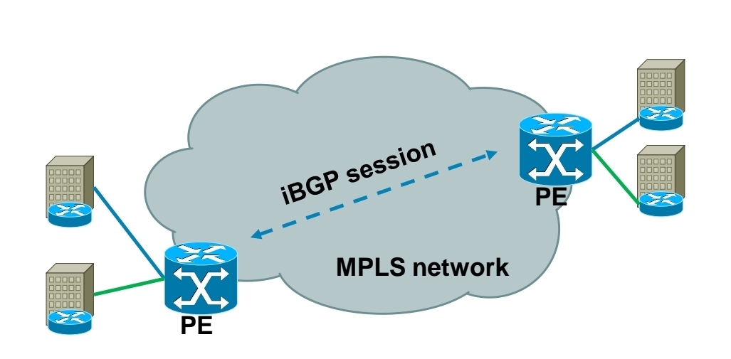
Packet forwarding with MPLS Layer 3 VPN
-IGP label is assigned by LDP
-VPN label is assigned by MP-BGP
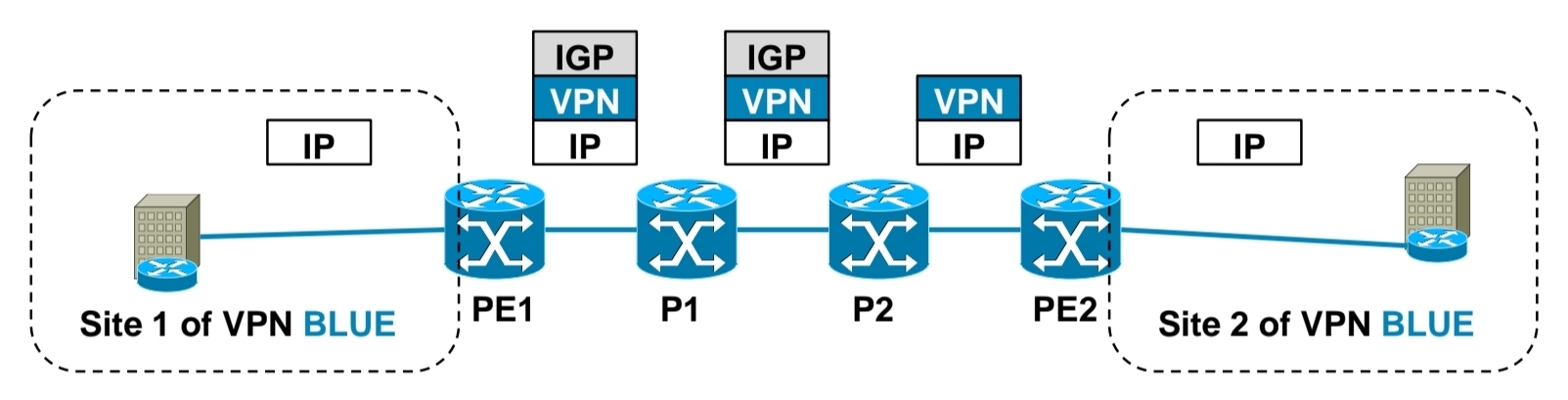
1.) PE1 receives IP packet on VRF interface assigned to site 1 of VPN BLUE.
2.) PE1 looks up VPN and IGP label, imposes these both labels as label stack to IP packet and forwards it to MPLS network. IGP label is known based on iBGP next hop, which is IP address of PE2.
3.) P1 router swaps IGP label based on its LFIB table.
4.) P2 removes IGP label due to PHP, but does not touch VPN label.
5.) PE2 router receives IP packet with VPN label, which it uses to select correct outgoing VPN site
6.) PE2 then strips off VPN label, makes lookup in its VRF RIB for particular VPN site to get the outgoing interface to send received packet to
Exchanging routing information between CE and PE routers
– Static routing
– RIP
– EIGRP
– OSPF
– IS-IS
– eBGP

Basic MPLS L3 VPN config
1.) Configuring core LSR for MPLS switching

2.) Configuring edge LSR for MPLS switching
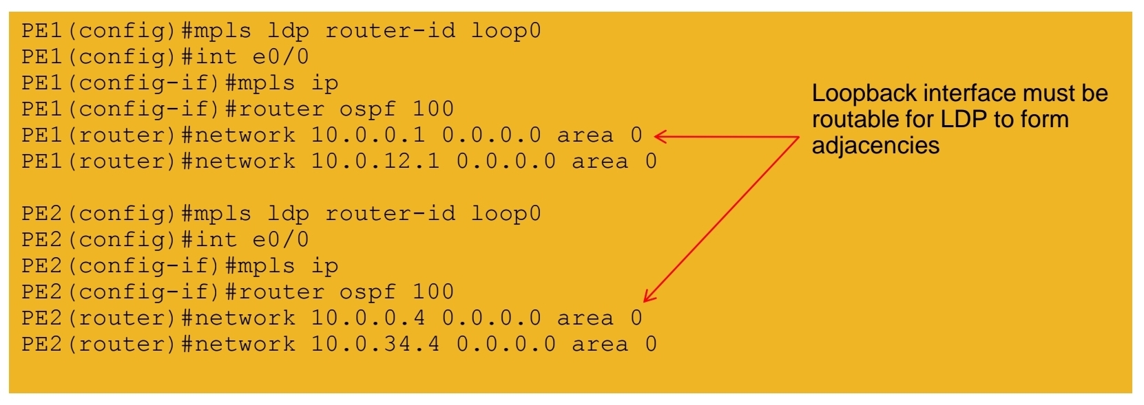
3a.) Configuring edge LSR PE1 for MPLS L3 VPN

3b.) Configuring edge LSR PE1 for MPLS L3 VPN

4a.) Configuring edge LSR PE2 for MPLS L3 VPN

4b.) Configuring edge LSR PE2 for MPLS L3 VPN

5.) Configuring CE-PE connectivity on CE1 and CE2
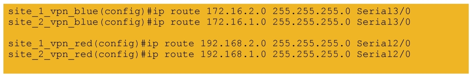
MPLS L3 VPN verification
1.) IGP peerings formed in core
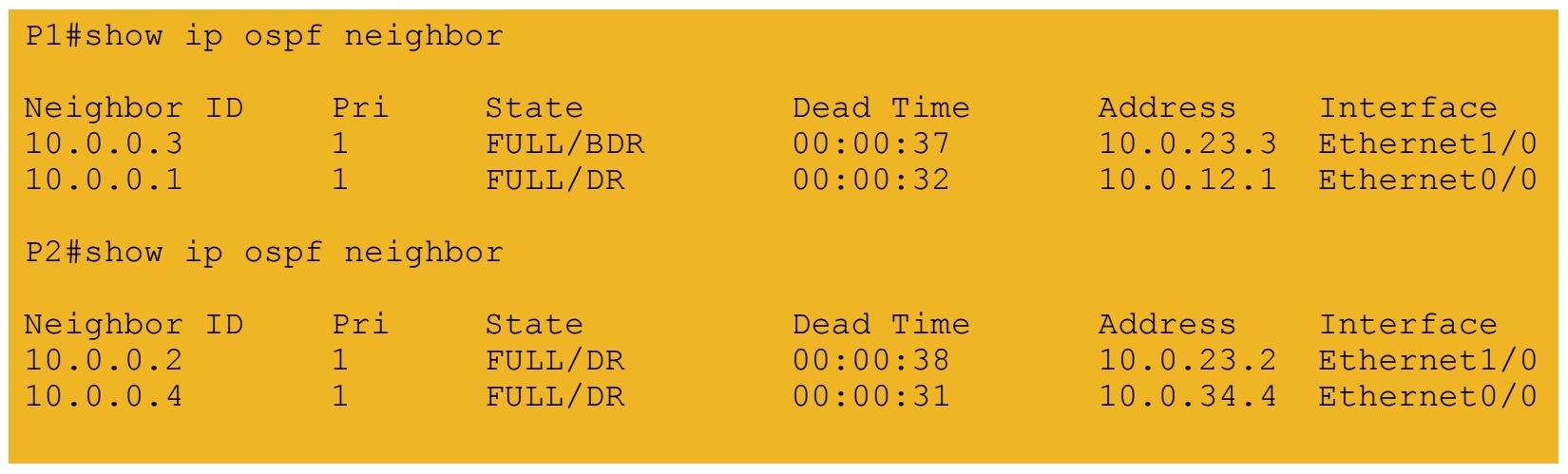
2.) MPLS LDP peerings formed in core
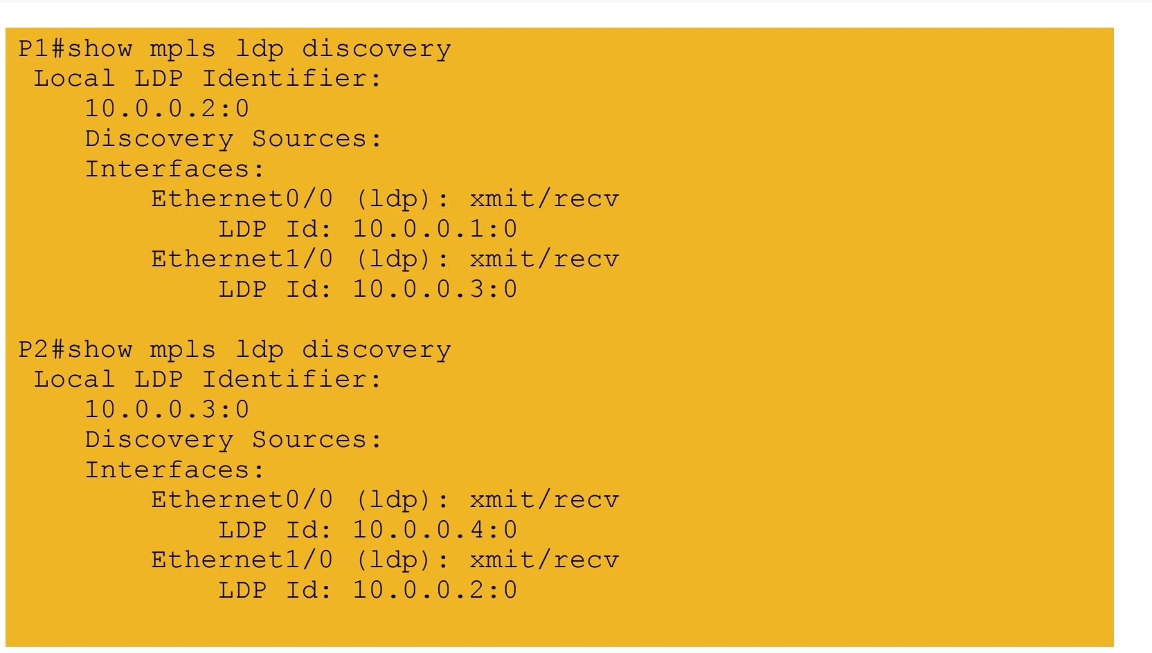
3.) VRF tables and interfaces defined on PE routers
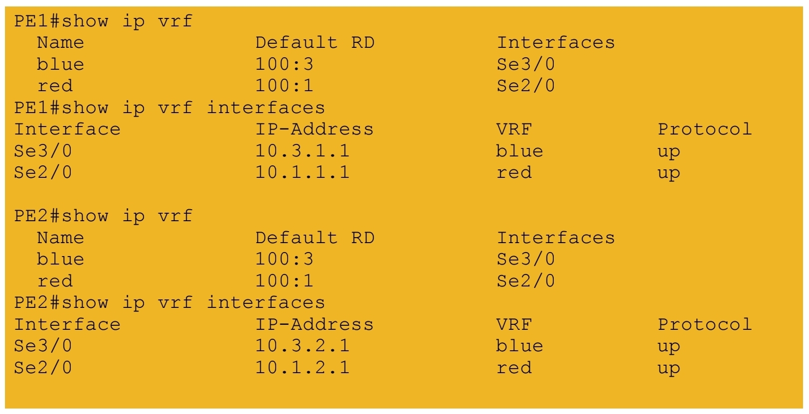
4.) iBGP session formed between PE routers
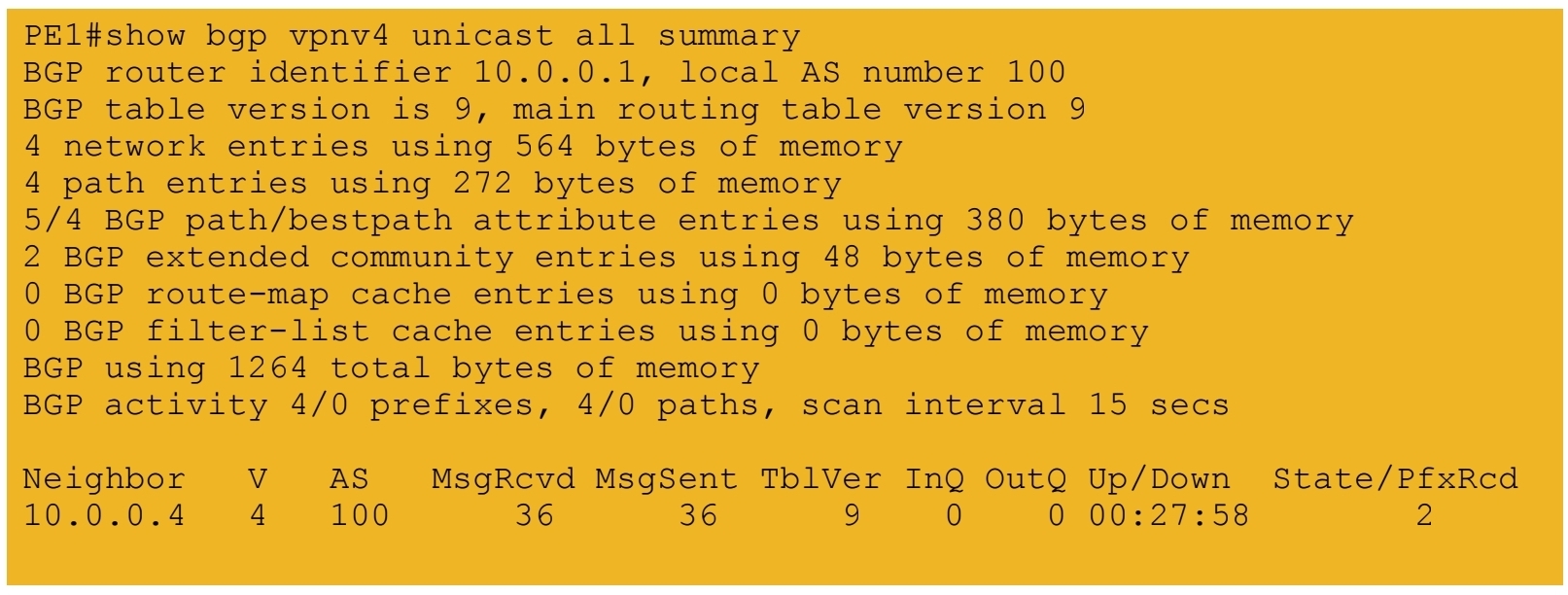
5a.) IGP labels assigned by LDP – path from PE1 to PE2
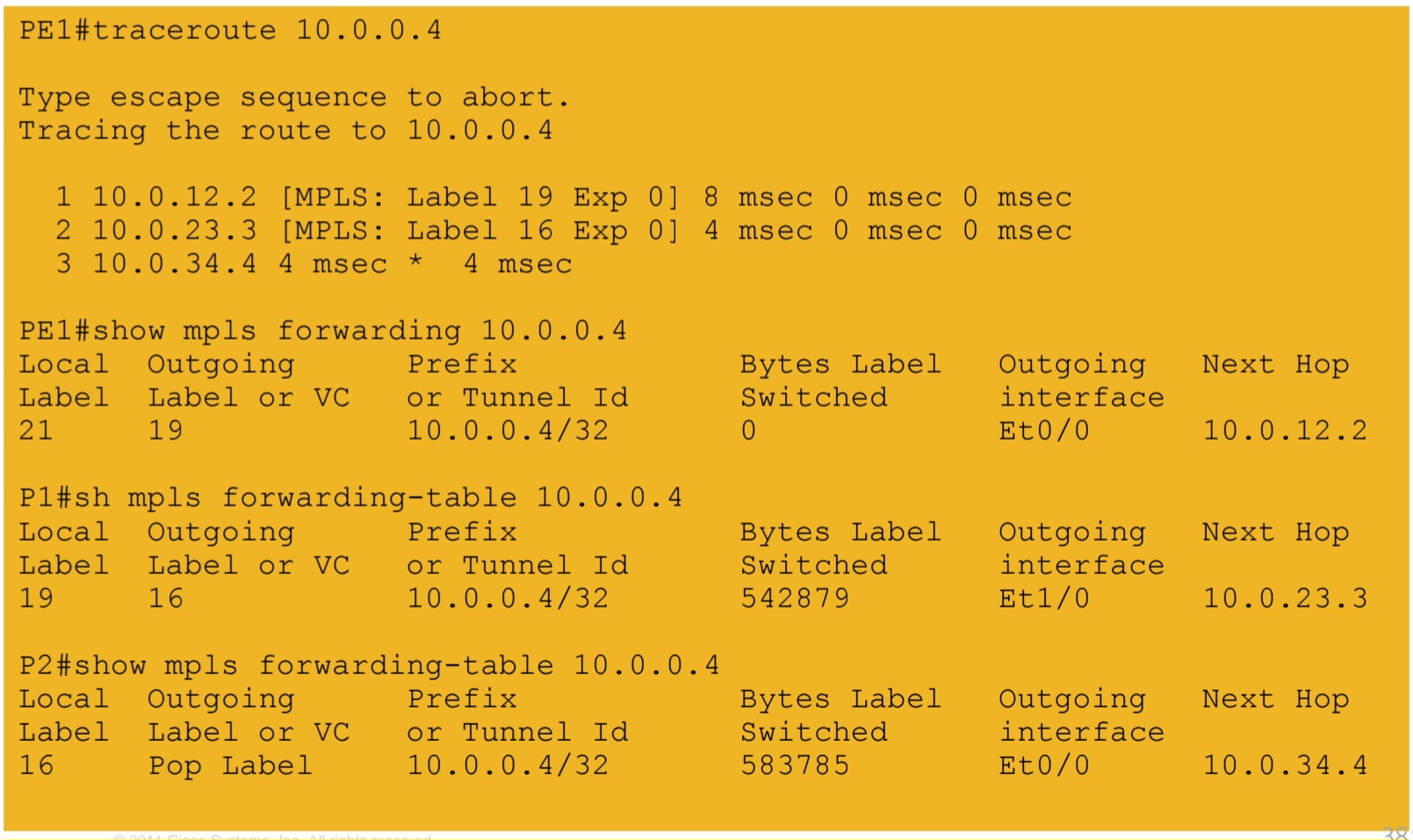
5b.) IGP labels assigned by LDP – path from PE2 to PE1
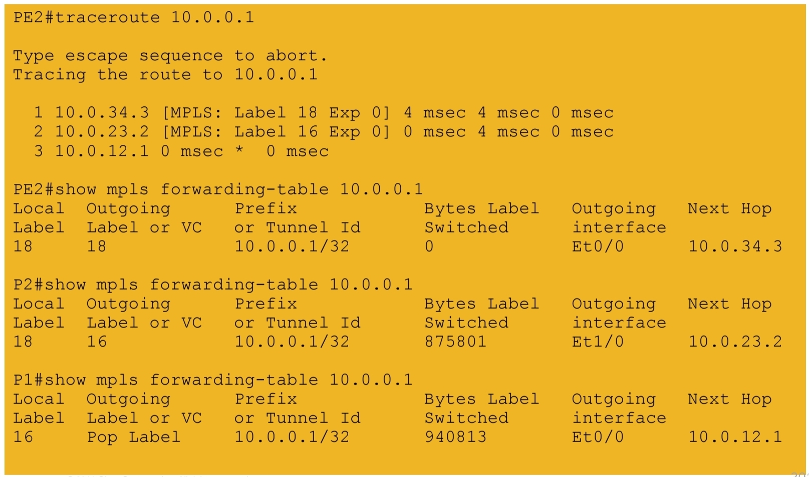
6.) VPN labels assigned by BGP

7a.) End-to-end connectivity between VPN RED sites
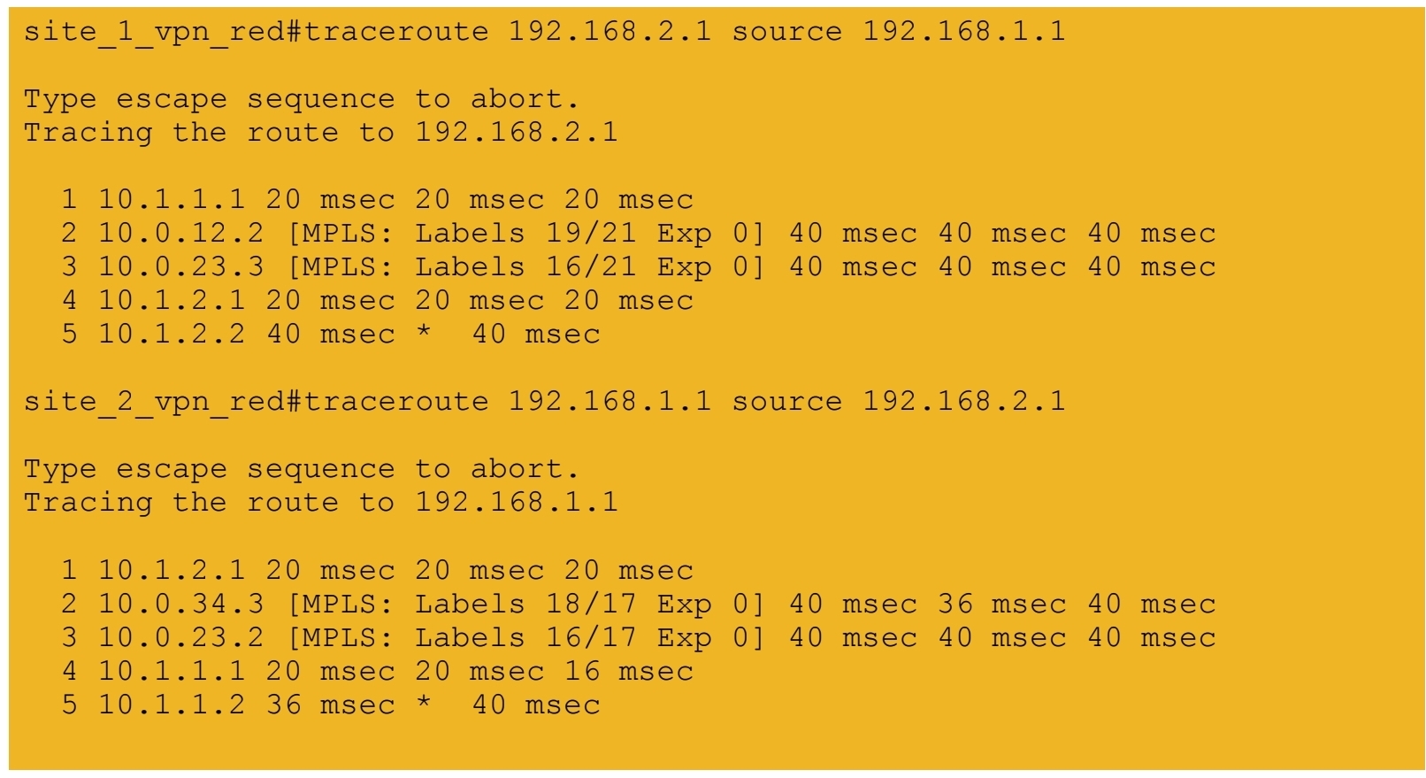
7b.) End-to-end connectivity between VPN BLUE sites
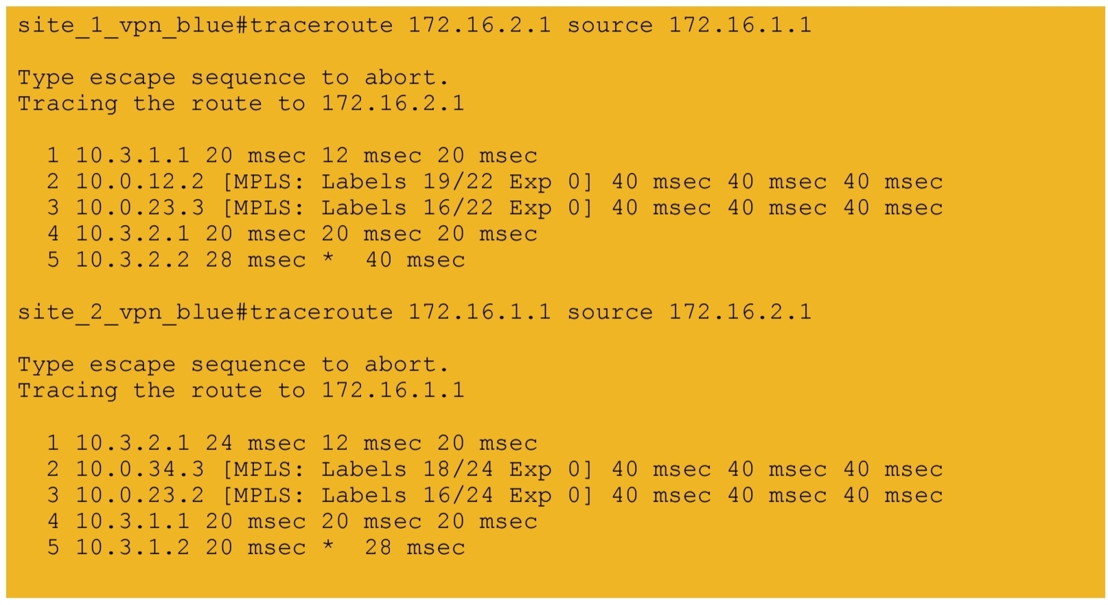
next post
CCIE Design
IP Headers
Protocol: This field is 8 bits in length. It indicates the upper-layer protocol. The Internet Assigned Numbers Authority (IANA) is responsible for assigning IP protocol values. Table 1-2 shows some key protocol numbers. You can find a full list

Header Checksum: This field is 16 bits in length. The checksum does not include the data portion of the packet in the calculation. The checksum is verified and recomputed at each point the IP header is processed (on end clients)
Padding: This field is variable in length. It ensures that the IP header ends on a 32-bit boundary.
Header Length: This field is 4 bits in length. It indicates the length of the header in 32-bit words (4 bytes) so that the beginning of the data can be found in the IP header. The minimum value for a valid header is 5 (0101) for five 32-bit words.
Total Length: This field is 16 bits in length. It represents the length of the datagram, or packet, in bytes, including the header and data. The maximum length of an IP packet can be 216 − 1 = 65,535 bytes. Routers use this field to determine whether fragmentation is necessary by comparing the total length with the outgoing MTU.
Identification: This field is 16 bits in length. It is a unique identifier that denotes fragments for reassembly into an original IP packet.
Flags: This field is 3 bits in length. It indicates whether the packet can be fragmented and whether more fragments follow. Bit 0 is reserved and set to 0. Bit 1 indicates May Fragment (0) or Do Not Fragment (1). Bit 2 indicates Last Fragment (0) or More Fragments to Follow (1).
Fragment Offset: This field is 13 bits in length. It indicates (in bytes) where in the packet this fragment belongs. The first fragment has an offset of 0.
ToS (Type of Service): This field is 8 bits in length. Quality of service (QoS) parameters such as IP precedence and DSCP are found in this field. (These concepts are explained later in this chapter.)
The ToS field of the IP header is used to specify QoS parameters. Routers and Layer 3 switches look at the ToS field to apply policies, such as priority, to IP packets based on the markings. An example is a router prioritizing time-sensitive IP packets over regular data traffic such as web or email, which is not time sensitive.
DSCP
DSCP has 2’6 = 64 levels of classification, which is significantly higher than the eight levels of the IP precedence bits
backward compatible with IP precedence
Defines three sets of PHBs: Class Selector (CS), Assured Forwarding (AF), and Expedited Forwarding (EF).
CS PHB set is for DSCP values that are compatible with IP precedence bits
The AF PHB set is used for queuing and congestion avoidance.
The EF PHB set is used for premium service
IPv4 Fragmentation
Although the maximum length of an IP packet is 65,535 bytes, most of the common lower-layer protocols do not support such large MTUs. For example, the MTU for Ethernet is approximately 1518 bytes. When the IP layer receives a packet to send, it first queries the outgoing interface to get its MTU. If the packet’s size is greater than the interface’s MTU, the layer fragments the packet.
When a packet is fragmented, it is not reassembled until it reaches the destination IP layer. The destination IP layer performs the reassembly
Any router in the path can fragment a packet, and any router in the path can fragment a fragmented packet again, and these kind of double fragmentation can cause unrecoverable packets on destination
Each fragment receives its own IP header and identifier, and it is routed independently from other packets. Routers and Layer 3 switches in the path do not reassemble the fragments. The destination host performs the reassembly and places the fragments in the correct order by looking at the Identification and Fragment Offset fields.
If one or more fragments are lost, the entire packet must be retransmitted. Retransmission is the responsibility of a higher-layer protocol (such as TCP). Also, you can set the Flags field in the IP header to Do Not Fragment; in this case, the packet is discarded if the outgoing MTU is smaller than the packet like full drop or like an ACL drop
IPv4 Addressing
Classes A, B, and C are unicast IP addresses, meaning that the destination is a single host. IP Class D addresses are multicast addresses, which are sent to multiple hosts
Class A address range 1.0.0.0 to 126.0.0.0. Networks 0 and 127 are reserved. For example, 127.0.0.1 is reserved for the local host or host loopback.
Class B addresses range from 128 (10000000) to 191 (10111111) in the first byte. Network numbers assigned to companies or other organizations are from 128.0.0.0 to 191.255.0.0
As with Class A addresses, having a segment with more than 65,000 hosts broadcasting will surely not work; you resolve this issue with subnetting.
Class C addresses range from 192 (11000000) to 223 (11011111) in the first byte. Network numbers assigned to companies are from 192.0.0.0 to 223.255.255.0.
254 IP addresses for host assignment per Class C network
Class D addresses range from 224 (11100000) to 239 (11101111) in the first byte. Network numbers assigned to multicast groups range from 224.0.0.1 to 239.255.255.255
These addresses do not have a host or network part. Some multicast addresses are already assigned; for example, routers running EIGRP use 224.0.0.10
Class E addresses range from 240 (11110000) to 254 (11111110) in the first byte. These addresses are reserved for experimental networks. Network 255 is reserved for the broadcast address, such as 255.255.255.255

Networks 0.0.0.0 and 127.0.0.0 are reserved as special-use addresses
Large organizations can use network 10.0.0.0/8 to assign address space throughout the enterprise. Midsize organizations can use one of the Class B private networks 172.16.0.0/16 through 172.31.0.0/16 for IP addresses. The smaller Class C addresses, which begin with 192.168, can be used by corporations and are commonly used in home routers.
NAT
NAT performs a many-to-one translation which is usally from many private addresses to one public address, the process is called Port Address Translation (PAT) because different port numbers identify translations
It is called port based translation because source ports are also translated because a source port might be used by one host inside network , at the same time same port could also be used by another host, for second host using a same port will translate to a different source port on the public side
Router or firewall performing translation keeps track of translation in a translation table This translation record is just like connection table and also times out if connection becomes idle. Some applications also send packets out at interval to keep the NAT entry alive , in The absence of data traffic
source addresses for outgoing IP packets are converted to globally unique IP addresses

NAT has several forms
Static NAT: Host is manually / statically assigned an external address, making that host avaiable to the external world when coming outside to inside and also allows host going out with that static address from inside to outside
Dynamic NAT: Dynamically maps a private IP address to a registered IP address from a pool (group) of registered addresses. The are two types of dynamic NAT
Overloading: Maps multiple unregistered or private IP addresses to a single registered IP address by using different ports. This is also known as PAT, single-address NAT. The number of PAT translations are limited by maximum of 65,535 internal hosts via PAT.
Overlapping: Overlapping networks result when you have overlapping subnets in two different locations. Overlapping networks also result when two companies, merge. These two networks need to communicate, preferably without having to readdress all their devices.
- Inside local address: The real IP address of the device that resides in the internal network. This address is used in the stub domain.
- Inside global address: The translated IP address of the device that resides in the internal network. This address is used in the public network.
- Outside global address: The real IP address of a device that resides in the Internet, outside the stub domain.
- Outside local address: The translated IP address of the device that resides in the Internet. This address is used inside the stub domain.
Different types of NAT
Static NAT
Commonly used to assign a network device with an internal private IP address a unique public address so that it can be accessed from the Internet.
Dynamic NAT
Dynamically maps an unregistered or private IP address to a registered IP address from a pool (group) of registered addresses.
PAT
Maps multiple unregistered or private IP addresses to a single registered IP address by using different ports.
Inside local address
The real IP address of a device that resides in the internal network. This address is used in the stub domain.
Inside global address
The translated IP address of the device that resides in the internal network. This address is used in the public network.
Outside global address
The real IP address of a device that resides on the Internet, outside the stub domain.
Outside local address
The translated IP address of a device that resides on the Internet. This address is used inside the stub domain.
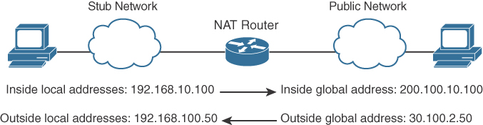
IPv4 Address Subnets
Multicast addresses do not use subnet masks
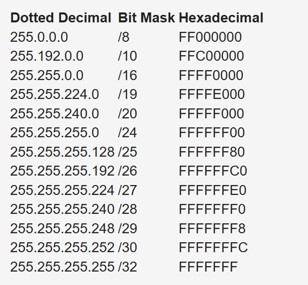
IP Address Subnet Design Example
The development of an IP address plan or IP address subnet design is an important concept for a network designer. You should be capable of creating an IP address plan based on many factors, including the following:
-Number of locations
-Number of devices per location
-IP addressing requirements for each individual location or building
-Number of devices to be supported in each comms room
-Site requirements, including VoIP devices, wireless LAN, and video
Subnetting for a small company. Suppose the company has 200 hosts and is assigned the Class C network 195.10.1.0/24. The 200 hosts need to be in six different LANs.
You can subnet the Class C network using the mask 255.255.255.224
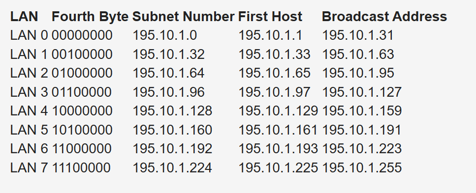
Deriving number of networks from default networks
Variable-length subnet masking (VLSM) is a process used to divide a network into subnets of various sizes to prevent wasting IP addresses. If a Class C network uses 255.255.255.240 as a subnet mask, 16 subnets are available, each with 14 IP addresses
Class B network 130.20.0.0/16. Using a /20 mask produces 16 subnetworks,
The loopback address is a single IP address with a 32-bit mask. In the previous example, network 130.20.75.0/24 could provide 256 loopback addresses for network devices, starting with 130.20.75.0/32 and ending with 130.20.75.255/32.
Global companies divide this address space into continental regions for the Americas, Europe/Middle East, Africa, and Asia/Pacific. An example is shown in Table 1-25, where the address space has been divided into four major blocks:
10.0.0.0 to 10.63.0.0 is reserved.
10.64.0.0 to 10.127.0.0 is for the Americas.
10.128.0.0 to 10.191.0.0 is for Europe, Middle East, and Africa.
10.192.0.0 to 10.254.0.0 is for Asia Pacific.
Subnets to be assign for data, voice, wireless, and management VLANs. Table 1-26 shows an example. The large site is allocated network 10.64.16.0/20. The first four /24 subnets are assigned for data VLANs, the second four /24 subnets are assigned for voice VLANs, and the third four /24 subnets are assigned for wireless VLANs. Other subnets are used for router and switch interfaces, point-to-point links, and network management devices.
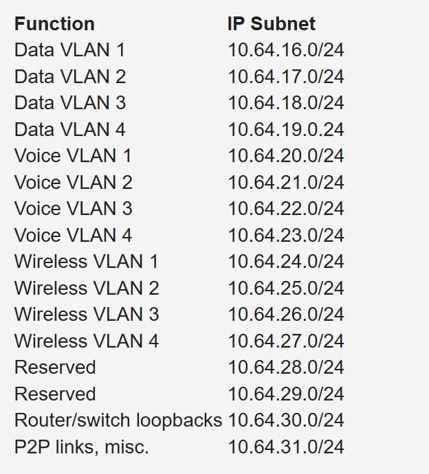
When assigning subnets for a site or perhaps a floor of a building, do not assign subnets that are too small. You want to assign subnets that allow for growth
For example, if a floor has a requirement for 50 users, do you assign a /26 subnet (which allows 62 addressable nodes)? Or do you assign a /25 subnet, which allows up to 126 nodes?
Assigning a subnet that is too large will prevent you from having other subnets for IPT and video conferencing.
The company might make an acquisition of another company. Although a new address design would be the cleanest solution, the recommendation is to avoid re-addressing of networks. Here are some other options:
- If you use 10.0.0.0/8 as your network, use the other private IP addresses for the additions.
- Use NAT as a workaround.
Performing Route Summarization
As a network designer, you will want to allocate IPv4 address space to allow for route summarization. Large networks can grow quickly from 500 routes to 1000 and higher. Route summarization reduces the size of the routing table
Planning for a Hierarchical IP Address Network
When IPv4 addressing for a companywide network, recommended practice dictates that you allocate contiguous address blocks to regions of the network. Hierarchical IPv4 addressing enables summarization, which makes the network easier to manage and troubleshoot.
Network subnets cannot be aggregated because /24 subnets from many different networks are deployed in different areas of the network. For example, subnets under 10.10.0.0/16 are deployed in Asia (10.10.4.0/24), the Americas (10.10.6.0/24), and Europe (10.10.8.0/24). The same occurs with networks 10.70.0.0/16 and 10.128.0.0/16. This lack of summarization in the network increases the size of the routing table, making it less efficient. It also makes it harder for network engineers to troubleshoot because it is not obvious in which part of the world a particular subnet is located.
Network That Is Not Summarized
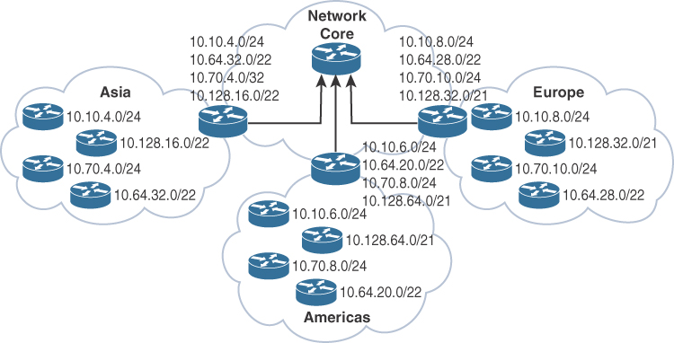
By contrast, Figure 1-6 shows a network that allocates a high-level block to each region:
10.0.0.0/18 for Asia Pacific networks
10.64.0.0/18 for Americas networks 10.128.0.0/18 for European/Middle East networks
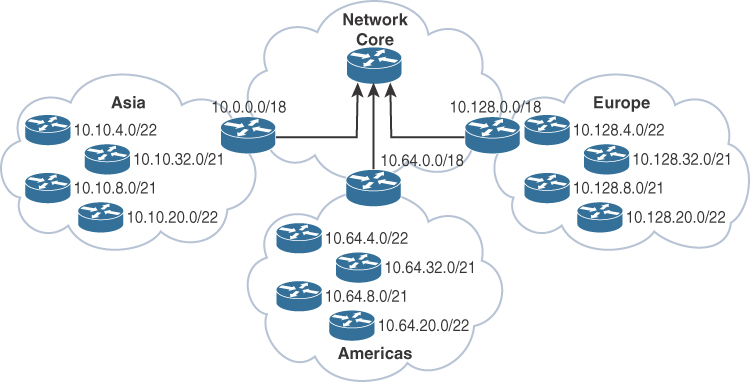
This solution provides for summarization of regional networks at area borders and improves control over the growth of the routing table.
Here are some examples of standards:
Use .1 or .254 (in the last octet) as the default gateway of the subnet.
Match the VLAN ID number with the third octet of an IP address. (For example, the IP subnet 10.10.150.0/25 is assigned to VLAN 150.)
Reserve .1 to .15 of a subnet for static assignments and .16 to .239 for the DHCP pool.
Allocate /24 subnets for user devices (such as laptops and PCs).
Allocate a parallel /24 subset for VoIP devices (IP phones).
Allocate subnets for access control systems and video conferencing systems.
Reserve subnets for future use.
Use /30 subnets for point-to-point links.
Use /32 for loopback addresses.
Allocate subnets for remote access and network management.
Case Study: IP Address Subnet Allocation
Consider a company that has users in several buildings in a campus network. Building A has four floors, and building B has two floors

the building’s Layer 3 switches will be connected via a dual-fiber link between switch A and switch B. Both switches will connect to the WAN router R1. Assume that you have been allocated network 10.10.0.0/17 for this campus and that IP phones will be used.

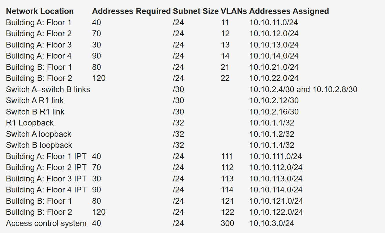
Notice that the VLAN number matches the third octet of the IP subnet. The second floor is assigned VLAN 12 and IP subnet 10.10.12.0/24. For building B, VLAN numbers in the 20s are used, with floor 1 having a VLAN of 21 assigned with IP subnet 10.10.21.0/24.
VLANs for IP telephony (IPT) are similar to data VLANs, with the correlation of using numbers in the 100s. For example, floor 1 of building A uses VLAN 11 for data and VLAN 111 for voice, and the corresponding IP subnets are 10.10.11.0/24 (data) and 10.10.111.0.24 (voice). This is repeated for all floors.
This solution uses /30 subnets for point-to-point links from the 10.10.2.0/24 subnet. Loopback addresses are taken from the 10.10.1.0/24 network starting with 10.10.1.1/32 for the WAN router. Subnet 10.10.3.0/24 is reserved for the building access control system.
BOOTP and DHCP
The BOOTP server port is UDP port 67. The client port is UDP port 68
DHCP is extension of BOOTP that is why the behavior is exactly same with enhancements in DHCP but BOOTP requires that you build a MAC address–to–IP address table on the server. You must obtain every device’s MAC address, which is a time-consuming effort.
That is DHCP was introduced with “lease” function for any client / mac address
DHCP not just provides network address but also delivers configuration parameters to hosts
An IP address is assigned as follows:
Step 1. The client sends a DHCPDISCOVER message to the local network using a 255.255.255.255 broadcast.
Step 2. DHCP relay agents (routers and switches) can forward the DHCPDISCOVER message to the DHCP server in another subnet.
Step 3. The server sends a DHCPOFFER message to respond to the client, offering IP address, lease expiration, and other DHCP option information.
Step 4. Using DHCPREQUEST, the client can request additional options or an extension on its lease of an IP address. This message also confirms that the client is accepting the DHCP offer.
Step 5. The server sends a DHCPACK (acknowledgment) message that confirms the lease and contains all the pertinent IP configuration parameters.
Step 6. If the server is out of addresses or determines that the client request is invalid, it sends a DHCPNAK message to the client.
ARP
When ARP response is received it is cached as well in the ARP table , listing IP addresses with MAC addresses
ARP is a broadcast and ARP request contains the sender’s IP and MAC address and the target IP address. That is why ARP response is unicast
All nodes in the broadcast domain receive the ARP request and process it.
ARP request is always a broadcast and ARP response is always a unicast

next post
CCIE Lessons
Hold Timer
Hold means keep holding on to info as long as hold time is not 0, the moment it reaches 0, all things related to that neighbor is dropped and
neighbors are also told to withdraw
next post
CCIE Interface Errors
Checking Interface Errors
show interface Gi1/0/1
show interface counters errors
show policy-map interface gi1/0/1
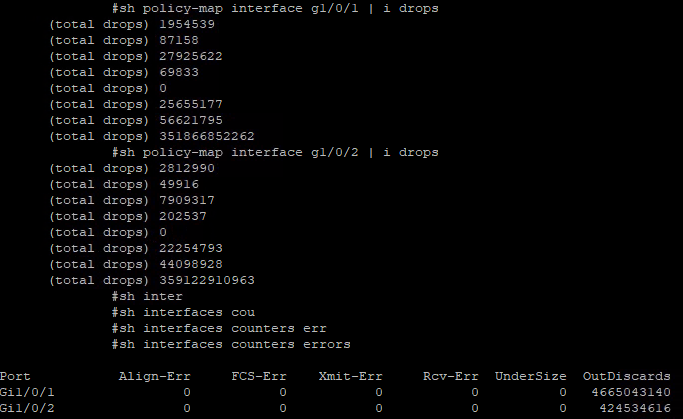
next post
CCIE PMTUD
PMTUD
Although the maximum length of an IPv4 datagram is 65535, most transmission links enforce a smaller maximum packet length limit, called an MTU. The MTU size can even differ from link to link
IPv4 fragmentation breaks a datagram into pieces that are reassembled later on the end station , broken by network devices but assembled later on end device
Some headers in IPv4 header that are of significance are “do not fragment” DF bit, fragment offset fields, along with “more fragments” (MF)
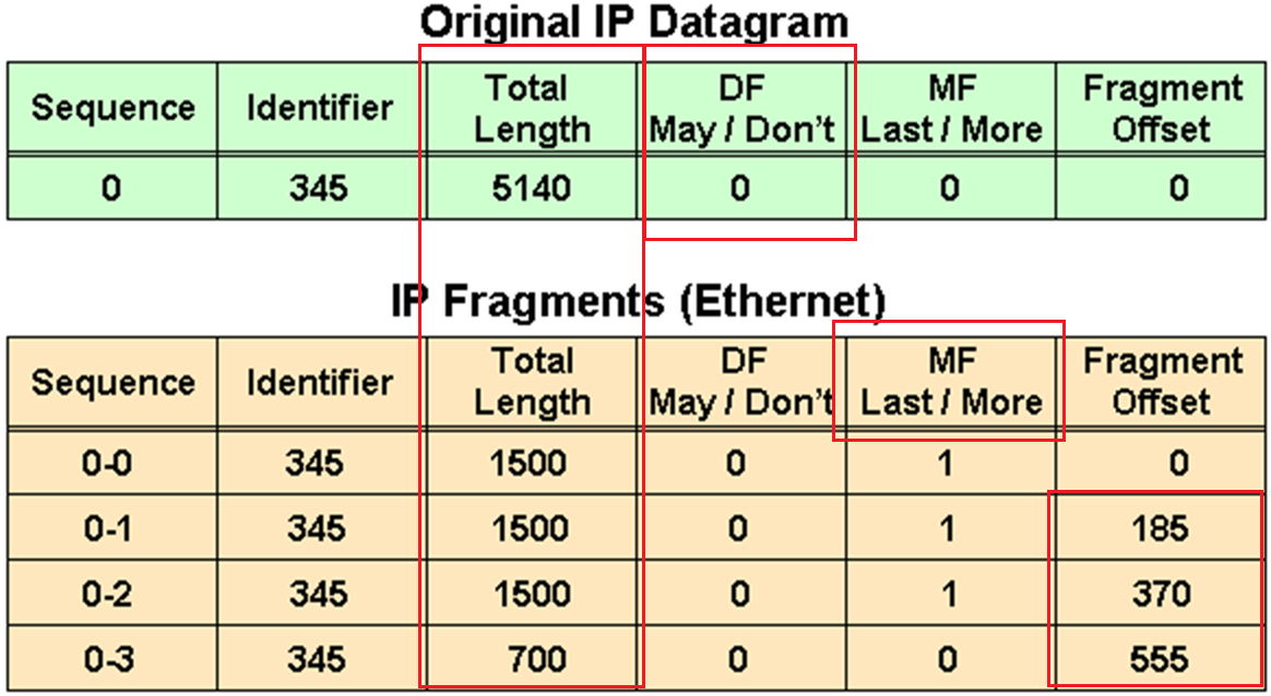
in above figure because DF bit or Do not fragment is not set that is why IP packet was fragmented and not discarded upon the need for fragmentation, determines whether or not a packet is “allowed” to be fragmented.
Identifier is the identifier of the packet, which helps receiver make sure it is assembling the same packet back
offset
The fragment offset is 13 bits and indicates where a fragment belongs in the original IPv4 datagram. This value is a multiple of 8 bytes, like a puzzle where the puzzle fits in the IPv4 packet to make it whole or complete,
The second fragment has an offset of 185 (185 x 8 = 1480); the data portion of this fragment starts 1480 bytes into the original IPv4 datagram,
The third fragment has an offset of 370 (370 x 8 = 2960); the data portion of this fragment starts 2960 bytes into the original IPv4 datagram.
The fourth fragment has an offset of 555 (555 x 8 = 4440), which means that the data portion of this fragment starts 4440 bytes into the original IPv4 datagram.
It is only when the last fragment is received that the size of the original IPv4 datagram can be determined.
Issues with IPv4 Fragmentation
IPv4 fragmentation results in a small increase in CPU and memory overhead to fragment an IPv4 datagram. This is true for the sender and for a router in the path between a sender and a receiver.
The creation of fragments involves the creation of fragment headers and copies the original datagram into the fragments.
Fragmentation causes more overhead for the receiver when reassembling the fragments because the receiver must allocate memory for the arriving fragments and coalesce them back into one datagram after all of the fragments are received.
Reassembly on a host is not considered a problem because the host has the time and memory resources to devote to this task.
Reassembly, however, is inefficient on a router or firewall whose primary job is to forward packets as quickly as possible.
A router is not designed to hold on to packets for any length of time.
A router that does the reassembly chooses the largest buffer available (18K), because it has no way to determine the size of the original IPv4 packet until the last fragment is received.
Another fragmentation issue involves how dropped fragments are handled.
If one fragment of an IPv4 datagram is dropped, then the entire original IPv4 datagram must be present and it is also fragmented.
This is seen with Network File System (NFS). NFS has a read and write block size of 8192.
Therefore, a NFS IPv4/UDP datagram is approximately 8500 bytes (which includes NFS, UDP, and IPv4 headers).
A sending station connected to an Ethernet (MTU 1500) has to fragment the 8500-byte datagram into six (6) pieces; Five (5) 1500 byte fragments and one (1) 1100 byte fragment.
If any of the six fragments are dropped because of a congested link, the complete original datagram has to be retransmitted. This results in six more fragments to be created.
If this link drops one in six packets, then no NFS data are transferred over this link
Firewalls that filter or manipulate packets based on Layer 4 (L4) through Layer 7 (L7) information have trouble processing IPv4 fragments correctly
If the IPv4 fragments are out of order, a firewall blocks the non-initial fragments because they do not carry the information that match the packet filter.
Firewalls nowadays should virtually reassemble packets (which does not actually reassembles packets but only locally in its memory to be able to inspect packet)
PMTUD
TCP MSS addresses fragmentation at the two endpoints of a TCP connection, but it does not handle cases where there is a smaller MTU link in the middle between these two endpoints and UDP traffic.
PMTUD is a mechanism to dynamically determine the true lowest MTU (Maximum Transmission Unit) on the path between a sender and a receiver
If PMTUD is enabled on a host, all TCP and UDP packets from the host have the DF bit set.
so that intermediate routers won’t fragment but if there is a need for fragmentation and network devices drop the packet but still let the sender know that fragmentation is needed
PMTUD Steps
A host sends an IPv4 packet (or a TCP/UDP segment) with the DF bit set.
That packet traverses the network toward its destination. At some point there may be a link with smaller MTU than the packet size.
When a router along the path encounters a packet that it cannot forward without fragmentation (because the packet size > the outgoing link’s MTU) and the packet has the DF bit set, then:
- The router drops the packet.
- The router sends an ICMP “Destination Unreachable – fragmentation needed and DF set” (Type 3, Code 4) message back to the sender. This ICMP message includes the MTU of the next‐hop link in the “unused” field if the router supports it (per RFC 1191). If intermediate routers don’t support including the MTU in the ICMP message or the host ignores the message, then the path MTU may not be found correctly
The sender receives that ICMP message and then reduces its packet size (or the MSS for TCP) for that destination, using the newly discovered path MTU value.
The host updates its send size and retries with smaller size, now the packet goes through successfully. A host records the MTU value for a destination because it creates a host (/32) entry in its routing table with this MTU value.
Because the path can change for same destination on internetwork, PMTUD is an ongoing process: if things change, new ICMP messages may cause further reductions.
For PMTUD to work properly, the ICMP “fragmentation needed” messages must actually reach the sender. If those ICMP messages are blocked by firewalls, routers, or filtered, PMTUD will fail silently
On Cisco routers the command tunnel path-mtu‐discovery (when applied to the tunnel interface) allows the router to participate in PMTUD for encapsulated traffic, to copy DF bit from inner to outer packet, and to dynamically adjust the tunnel MTU
With Cisco routers and switches we can perform extended ping to determine the biggest size possible through the path
ping
Protocol [ip]:
Target IP address: 172.31.176.164
Repeat count [5]:
Datagram size [100]:
Timeout in seconds [2]:
Extended commands [n]: y
Ingress ping [n]:
Source address or interface:
DSCP Value [0]:
Type of service [0]:
Set DF bit in IP header? [no]: y
Validate reply data? [no]:
Data pattern [0x0000ABCD]:
Loose, Strict, Record, Timestamp, Verbose[none]: V
Loose, Strict, Record, Timestamp, Verbose[V]:
Sweep range of sizes [n]: y
Sweep min size [36]: 1400
Sweep max size [20000]: 1600
Sweep interval [1]:
Type escape sequence to abort.
Sending 1005, [1400..1600]-byte ICMP Echos to 172.31.176.164, timeout is 2 seconds:
Packet sent with the DF bit set
Reply to request 0 (7 ms) (size 1400)
Reply to request 1 (10 ms) (size 1401)
Reply to request 2 (8 ms) (size 1402)
Reply to request 3 (7 ms) (size 1403)
Reply to request 4 (4 ms) (size 1404)
Reply to request 5 (4 ms) (size 1405)
Reply to request 6 (3 ms) (size 1406)
Reply to request 7 (4 ms) (size 1407)
Reply to request 8 (4 ms) (size 1408)
Reply to request 9 (4 ms) (size 1409)
Reply to request 10 (5 ms) (size 1410)
Reply to request 11 (6 ms) (size 1411)
Reply to request 12 (3 ms) (size 1412)
Reply to request 13 (4 ms) (size 1413)
Reply to request 14 (3 ms) (size 1414)
Reply to request 15 (3 ms) (size 1415)
Reply to request 16 (5 ms) (size 1416)
Reply to request 17 (3 ms) (size 1417)
Reply to request 18 (3 ms) (size 1418)
Reply to request 19 (3 ms) (size 1419)
Reply to request 20 (5 ms) (size 1420)
Reply to request 21 (7 ms) (size 1421)
Reply to request 22 (3 ms) (size 1422)
Reply to request 23 (3 ms) (size 1423)
Reply to request 24 (4 ms) (size 1424)
Reply to request 25 (6 ms) (size 1425)
Reply to request 26 (4 ms) (size 1426)
Reply to request 27 (3 ms) (size 1427)
Reply to request 28 (4 ms) (size 1428)
Reply to request 29 (3 ms) (size 1429)
Reply to request 30 (4 ms) (size 1430)
Reply to request 31 (4 ms) (size 1431)
Reply to request 32 (3 ms) (size 1432)
Reply to request 33 (3 ms) (size 1433)
Reply to request 34 (4 ms) (size 1434)
Unreachable from 172.31.203.21, maximum MTU 1434 (size 1435)
Request 36 timed out (size 1436)
Request 37 timed out (size 1437)
Request 38 timed out (size 1438)
Request 39 timed out (size 1439)
Request 40 timed out (size 1440)
Request 41 timed out (size 1441)
Unreachable from 172.31.203.21, maximum MTU 1434 (size 1442)
Request 43 timed out (size 1443)
Unreachable from 172.31.203.21, maximum MTU 1434 (size 1444)
Request 45 timed out (size 1445)
Unreachable from 172.31.203.21, maximum MTU 1434 (size 1446)
Request 47 timed out (size 1447)
Unreachable from 172.31.203.21, maximum MTU 1434 (size 1448)
Request 49 timed out (size 1449)
Unreachable from 172.31.203.21, maximum MTU 1434 (size 1450)
Request 51 timed out (size 1451)
Success rate is 67 percent (35/52), round-trip min/avg/max = 3/4/10 ms
but this is also possible with windows, although windows does not increment automatically
ping 8.8.8.8 -f -l 1500-f → Sets the DF (Don’t Fragment) bit.
-l <size> → Sets the ICMP payload packet size.
If network or firewall in path is not filtering ICMP packets returning from remote device then on CLI and packet capture we should see
Packet needs to be fragmented but DF set.So, if ping -f -l works at 1472 bytes, then the actual Path MTU is:
1472 + 28 = 1500 bytesIf we are using powershell then
$target = "8.8.8.8"
for ($size=1300; $size -le 2000; $size+=10) {
    Write-Host "Testing $size bytes"
    ping $target -f -l $size -n 1 | findstr /i "fragment"
}

Read-Host "Press Enter to exit..."
To test PMTUD in real-life:
ping <destination> -f -l 1472
If it passes → Path MTU is likely 1500.
If not → lower the size until it passes.
Further reading: https://www.cisco.com/c/en/us/support/docs/ip/generic-routing-encapsulation-gre/25885-pmtud-ipfrag.html
next post
CCIE IPv6
IPv6
IPv6 address is made up of two parts.
The first 64 bits usually represent the subnet prefix, and the last 64 bits usually represent the address assigned to interface.
2001:db8:a:a::/64 is subnet or prefix
Network interface can have the address
2001:db8:a:a::1 where the last 64 bits, which are ::1
Hosts on this network can have ::10 and ::20 etc and all devices in this network are configured with default gateway 2001:db8:a:a::1
C:\PC1>ipconfig

Windows IP Configuration

Ethernet adapter Local Area Connection:

 Connection-specific DNS Suffix . :
 IPv6 Address. . . . . . . . . . .: 2001:db8:a:a::10
 Link-local IPv6 Address . . . . .: fe80::a00:27ff:fe5d:6d6%11 <<<<<<<
 IPv4 Address. . . . . . . . . . .: 10.1.1.10
 Subnet Mask . . . . . . . . . . .: 255.255.255.192
 Default Gateway . . . . . . . . .: 2001:db8:a:a::1
                                           10.1.1.1
Link-local address fe80::a00:27ff:fe5d:6d6 and the global unicast address 2001:db8:a:a::10 (statically configured).
Notice the %11 at the end of the link-local address. This is the interface identification number, and it is needed so that the system knows which interface to send the packets out of; keep in mind that you can have multiple interfaces on the same device with the same link-local address assigned to them.
EUI-64
EUI-64 helps with auto configuring unique IP addresses in IPv6 world because of how big the IPv6 addresses are
allows your end devices to automatically assign their own global unicast and link-local addresses
EUI-64 takes the client’s MAC address
Splits the 48 bits MAC address in half, and inserts the hex values FFFE in the middle.
In addition, it takes the seventh bit from the left and flips it. So, if it is a 1, it becomes a 0, and if it is a 0, it becomes a 1.
fe80 :: a00:27ff:fe5d:6d6
  |            |
  |            |
network bit    |
               |
           host bits
Looking at the host bits in address 0a00:27ff:fe5d:06d6
we can see this is an EUI-64 address because it has FFFE in it
For example MAC address is 08-00-27-5D-06-D6
Split it in half and add FFFE in the middle to get 08-00-27-FF-FE-5D-06-D6
08 is hex and in binary it is 000010″0″0.
The seventh bit from left is a 0, so make it a 1. Now you have 000010″1″0 – convert to hex it becomes 0a
making it 0A00:27FF:FE5D:06D6 in address fe80::a00:27ff:fe5d:6d6
By default, routers use EUI-64 when generating the interface portion of the link-local address of an interface
if you want to use EUI-64 for a statically configured global unicast address, use the eui-64 keyword at the end of the ipv6 address
interface gigabitEthernet 0/0
ipv6 address 2001:db8:a:a::/64 eui-64
IPv6 SLAAC, Stateful DHCPv6, and Stateless DHCPv6
Manually assigning IP addresses is not a scalable option with IPv6, you have three dynamic options
1. Stateless address autoconfiguration (SLAAC)
2. Stateful DHCPv6
3. stateless DHCPv6.
SLAAC
SLAAC is designed to enable a device to configure its own IPv6 address, prefix, and default gateway without a DHCPv6 server
Windows PCs automatically have SLAAC enabled and generate their own IPv6 addresses and can only be seen in ipconfig /all
C:\PC1>ipconfig /all

Windows IP Configuration

 Host Name . . . . . . . . . . . .: PC1
 Primary Dns Suffix . . . . . . . :
 Node Type . . . . . . . . . . . .: Broadcast
 IP Routing Enabled. . . . . . . .: No
 WINS Proxy Enabled. . . . . . . .: No

Ethernet adapter Local Area Connection:


 Connection-specific DNS Suffix . : SWITCH.local
 Description . . . . . . . . . . .: Intel(R) PRO/1000 MT Desktop Adapter
 Physical Address. . . . . . . . .: 08-00-27-5D-06-D6
 DHCP Enabled. . . . . . . . . . .: Yes
 Autoconfiguration Enabled . . . .: Yes <<<<<<<
 IPv6 Address. . . . . . . . . . .: 2001:db8::a00:27ff:fe5d:6d6(Preferred)
 Link-local IPv6 Address . . . . .: fe80::a00:27ff:fe5d:6d6%11(Preferred)
IPv4 Address. . . . . . . . . . . : 10.1.1.10(Preferred)
 Subnet Mask . . . . . . . . . . .: 255.255.255.192
When a Windows PC and router interface are enabled for SLAAC, they send a Router Solicitation (RS) message to the all-routers multicast address (ff02::2) to ask if any routers are on local link. Router then sends a Router Advertisement (RA) that identifies following:
The network prefix(es) used on that link (e.g., 2001:db8:1:1::/64),
Flags indicating whether to use SLAAC or DHCPv6,
The router’s lifetime as a default gateway,
And other configuration details.
The PC uses the prefix from the RA and combines it with its own interface identifier (often based on MAC address or a random value) to form a full IPv6 global unicast address.
RA’s source address (the router’s link-local address, usually starting with fe80::) is used by the host as the next-hop (default gateway).
In IPv6, all routers must have a link-local address on each interface, and hosts use that address as the default gateway.
To verify an IPv6 address generated by SLAAC on a router interface, use the show ipv6 interface command
However, note that this occurs only if IPv6 unicast routing was not enabled on the router and, as a result, the router is acting as an end device, that is why next hop router’s link local address is listed as default router.
RA are only generated by default only if
1. Router interface is enabled for IPv6
2. IPv6 unicast routing is enabled
3. RAs are not being suppressed on the interface
4. Make sure that the router interface has a /64 prefix by using the show ipv6 interface command, SLAAC works only if the router is using a /64 prefix
In addition, if you have more than one router on a subnet generating RAs, which can happen with redundant gateways, the clients learn about multiple default gateways from the RAs as shown below
C:\PC1># ipconfig

Windows IP Configuration

Ethernet adapter Local Area Connection:

 Connection-specific DNS Suffix . :
 IPv6 Address. . . . . . . . . . .: 2001:db8:a:a:a00:27ff:fe5d:6d6
 Link-local IPv6 Address . . . . .: fe80::a00:27ff:fe5d:6d6%11
 IPv4 Address. . . . . . . . . . .: 10.1.1.10
 Subnet Mask . . . . . . . . . . .: 255.255.255.192
 Default Gateway . . . . . . . . .: fe80::c80b:eff:fe3c:8%11 <<<<<<<
                                    fe80::c80a:eff:fe3c:8%11 <<<<<<<
                                    10.1.1.1
Stateful DHCPv6
Although a device is able to determine its IPv6 address, prefix, and default gateway using SLAAC, there is not much else the devices can obtain. In a modern network, the devices may also need information such as Network Time Protocol (NTP) server information, domain name information, DNS server information
Use a DHCPv6 server.
Cisco routers and switches can act as DHCPv6 servers, but for their interface to be able to hand out v6 IP addresses using configured pool we must enable interface command “ipv6 dhcp server [pool-name]
If you are troubleshooting an issue where clients are not receiving IPv6 addressing information or where they are receiving wrong IPv6 addressing information from a router or multilayer switch acting as a DHCPv6 server, check the interface and make sure it was associated with the correct pool.
Stateless DHCPv6
Stateless DHCPv6 is a combination of SLAAC and DHCPv6. With stateless DHCPv6, clients use a router’s RA to automatically determine the IPv6 address, prefix, and default gateway. Included in the RA is a flag that tells the client to get other non-addressing information from a DHCPv6 server, such as the address of a DNS server etc
To accomplish this, ensure that the ipv6 nd other-config-flag interface configuration command is enabled
This ensures that the RA informs the client that it must contact a DHCPv6 server for other information
DHCPv6 Operation
DHCPv6 has a four-step negotiation process, like IPv4. However, DHCPv6 uses the following messages:
SOLICIT
xxx
ADVERTISE
xxx
REQUEST
xxx
REPLY
xxx
next post
STP
STP
Redundancy requires that we connect second link between switches
but that is loop – this is where spanning tree steps in disables one side of the link / interface to remove the loop
One indication of loop is that mac shows up behind different ports which it should not
Layer 2 looped frames do not have TTL mechanism so if looped they keep going around and it grinds network equipment to halt
STP works by first making switches aware by sending and receiving BPDUs to one another rather than silence or dark network
STP selects one switch in the network as a root switch and a tree is built from this root switch’s perspective by simply stretching STP network down from that root switch
STP has multiple versions:
- 802.1D, which is the original specification
- Per-VLAN Spanning Tree (PVST)
- Per-VLAN Spanning Tree Plus (PVST+)
- ———————————————
- 802.1W Rapid Spanning Tree Protocol (RSTP)
- 802.1S Multiple Spanning Tree Protocol (MST)
Cisco switches can operate in PVST+, RSTP, and MST modes.
All three of these modes are backward compatible with 802.1D.
Original version of STP only ensures Loop free topology in one VLAN
802.1D Port States
Disabled: The port is in an administratively off position (that is, shut down).
Blocking:
The switch port is enabled
but the port is not forwarding any traffic to ensure that a loop is not created.
The switch does not modify the MAC address table.
Special: Port can only receive BPDUs
Listening:
The switch port has transitioned from a blocking state
Port can now send or receive BPDUs.
It still cannot forward any other network traffic.
The duration of the state correlates to the STP forwarding time.
Special: Port can send and receive BPDUs
Learning:
The switch port can add MAC entries in MAC address table from network traffic that it receives.
The switch still does not forward any other network traffic besides BPDUs.
The duration of the state correlates to the STP forwarding time. The next port state is forwarding.
Special: Port can send and receive BPDU but can also do mac learning on port (learn is in the name)
Forwarding:
The switch port can forward all network traffic and can update the MAC address table as expected.
This is the final state for a switch port to forward network traffic.
Special: only forwarding actually forwards traffic (forward is in the name)
Broken:
The switch has detected a configuration or an operational problem on a port that can have major effects.
The port discards packets as long as the problem continues to exist.
If timers are left to defaults 802.1D takes about 30 seconds for a port to transition from Blocking to Forwarding state
802.1D Port Types
Root port (RP):
A network port that connects to the root bridge or an upstream switch that leads to root switch in the spanning-tree topology.
There should be only one root port per VLAN on a switch.
Designated port (DP):
A network port that receives and forwards BPDU frames to other switches.
Designated ports provide connectivity to downstream devices and switches or Drives away from root
There should be only one active designated port on a link.
Blocking port: A network port that is not forwarding traffic because of STP calculations.
Several key terms are related to STP:
Root bridge:
The root bridge has all ports are in a forwarding state and non blocking
This switch is considered the top of the spanning tree for all path calculations by other switches.
All ports on the root bridge are categorized as designated ports.
Bridge protocol data unit (BPDU):
This network packet is used for network switches to identify each other and notify of changes in the topology.
A BPDU uses the destination MAC address 01:80:c2:00:00:00. There are two types of BPDUs:
- Configuration BPDU:
This BPDU is used to identify the root bridge, root ports, designated ports, and blocking ports. The configuration BPDU consists of the following fields:
– STP type
– root path cost
– root bridge identifier
– local bridge identifier
– max age
– hello time
– forward delay - Topology change notification (TCN) BPDU:
This BPDU is used to communicate changes in the Layer 2 topology to other switches. It is explained in greater detail later in the chapter. - Root path cost: This is the combined cost toward the root switch.
- System priority:
This 4-bit value indicates the desire for a switch to be root bridge.
The default value is 32,768. - System ID extension:
This 12-bit value indicates the VLAN (12 bits because VLAN ID is 12 bit) that the BPDU belongs to because BPDU are generated per vlan or BPDU can belong to only one VLAN.
The system priority (root making value) and system ID extension (VLAN) are combined as part of the switch’s identification of a bridge - Root bridge identifier:
Root bridge’s system MAC address + system ID extension + system priority of the root bridge - Local bridge identifier:
System MAC address + system ID extension + system priority of the local bridge. - Max age:
This is the maximum length of time that a bridge port stores its BPDU information.
The default value is 20 seconds (10x the default hello time) but can be configured with the command spanning-tree vlan vlan-id max-age maxage.
If a switch loses contact with the BPDU’s source, switch keeps that the BPDU information on interface till Max Age timer counts down.
Max age timer counts down when there is an indirect failure and not the interface down event - Hello time:
This is the time interval that a BPDU is advertised out of a port.
The default value is 2 seconds, but the value can be configured to 1 to 10 seconds with the command spanning-tree vlan vlan-id hello-time hello-time. - Forward delay:
The name is actually Forwarding Delay
This is the amount of time that a port stays in a listening and learning state (where it does not forward traffic).
The default value is 15 seconds, but the value can be changed to a value of 4 to 30 seconds with the command spanning-tree vlan vlan-id forward-time forward-time.
STP cost is assigned on interface and root path cost is calculated by adding cumulative cost to reach root
Long mode and short mode
Original default costs were set for different speeds upto only 20 Gbps but as networking has advanced 10 Gbps has become common.
Another method, called long mode, uses a 32-bit value and uses a reference speed of 20 Tbps
The original method, known as short mode, has been the default for most switches, but has been transitioning to long mode based on specific platform and OS versions.
| Link Speed | Short-Mode STP Cost | Long-Mode STP Cost |
|---|---|---|
| 10 Mbps | 100 | 2,000,000 |
| 100 Mbps | 19 | 200,000 |
| 1 Gbps | 4 | 20,000 |
| 10 Gbps | 2 | 2000 |
| 20 Gbps | 1 | 1000 |
| 100 Gbps | 1 | 200 |
| 1 Tbps | 1 | 20 |
| 10 Tbps | 1 | 2 |
Devices can be configured with the long-mode interface cost with the command spanning-tree pathcost method long. The entire Layer 2 topology should use the same setting for every device in the environment to ensure a consistent topology. Before you enable this setting in an environment, it is important to conduct an audit to ensure that the setting will work.
1. Elect Root Bridge, starts with I am root
As switch boots it wants to find root bridge, and starts by assuming that it itself is root
uses the local bridge identifier as the root bridge identifier
listens for BPDUs coming from all the ports for neighbors
If the neighbor’s configuration BPDU is inferior to its own BPDU, the switch ignores that BPDU
If the neighbor’s configuration BPDU is better than its own BPDU
the switch updates its BPDUs to include the new better root bridge + new root path cost.
This process continues until all switches in a topology have identified the root bridge switch.

STP favours the switch with lowest priority inside the bridge ID
If priority is same then switch with lower system MAC address wins
Generally, older switches have a lower MAC address and are considered more preferable
but configuration changes in priority should be made for optimal placement of the root bridge
show spanning-tree root to display the root bridge
SW1# show spanning-tree root
                                            Root    Hello Max Fwd
Vlan                   Root ID            Cost    Time  Age Dly  Root Port
---------------- -------------------- --------- ----- --- ---  ------------
VLAN0001         32769 0062.ec9d.c500         0    2   20  15
VLAN0010         32778 0062.ec9d.c500         0    2   20  15
VLAN0020         32788 0062.ec9d.c500         0    2   20  15
VLAN0099         32867 0062.ec9d.c500         0    2   20  15
this command is like a snapshot or view of root for all VLANs
there can be different root switches for some VLANs, it is not mandatory to one root for all VLANs
When a switch generates the BPDUs, the root path cost includes only the calculated metric to the root and does not include the cost of the port that the BPDU is advertised out of
The receiving switch adds the port cost for its interface on which the BPDU was received with the value of the root path cost in the BPDU and that is the value switch thinks to reach the root is
The root path cost is always zero on the root bridge
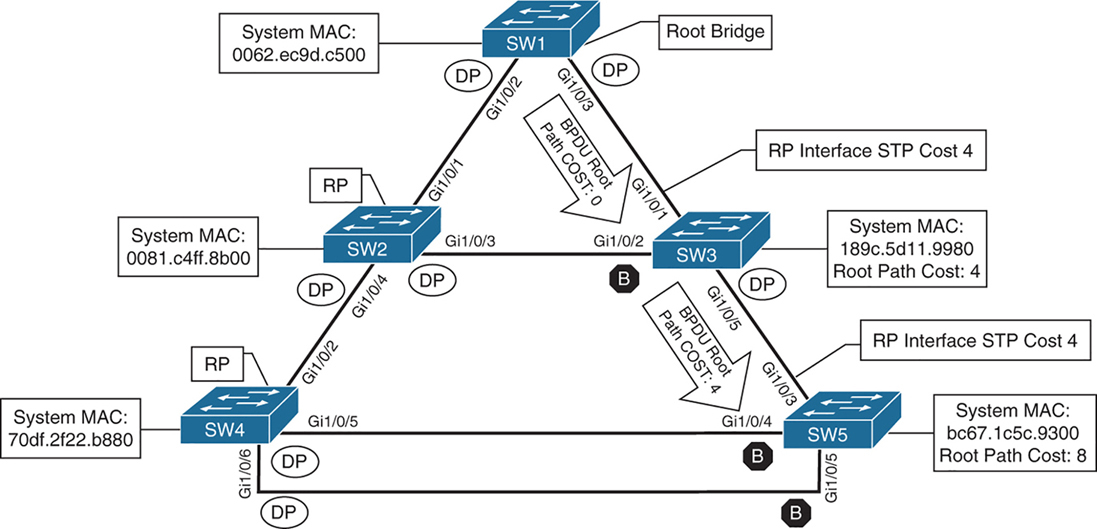
cost on those links is 4 because of 1 gig links (short mode)
SW2# show spanning-tree root
                                            Root    Hello Max Fwd
Vlan                   Root ID            Cost    Time  Age Dly  Root Port
---------------- -------------------- --------- ----- --- ---  ------------
VLAN0001         32769 0062.ec9d.c500         4    2   20  15  Gi1/0/1
VLAN0010         32778 0062.ec9d.c500         4    2   20  15  Gi1/0/1
VLAN0020         32788 0062.ec9d.c500         4    2   20  15  Gi1/0/1
VLAN0099         32867 0062.ec9d.c500         4    2   20  15  Gi1/0/1
SW3# show spanning-tree root
Root Hello Max Fwd
Vlan Root ID Cost Time Age Dly Root Port
---------------- -------------------- --------- ----- --- --- ------------
VLAN0001 32769 0062.ec9d.c500 4 2 20 15 Gi1/0/1
VLAN0010 32778 0062.ec9d.c500 4 2 20 15 Gi1/0/1
VLAN0020 32788 0062.ec9d.c500 4 2 20 15 Gi1/0/1
VLAN0099 32867 0062.ec9d.c500 4 2 20 15 Gi1/0/1Locating Root “Ports”
After the switches have identified the root bridge, they must determine their root port (RP).
Only the root bridge continues to advertise configuration BPDUs out all of its ports. The switch compares the BPDU information received on its port to identify the RP.
The RP is selected using the following logic , only moves to next step when there is a tie
This step is interface centric because we are selecting a root “port”
- The interface associated to lowest path cost is more preferred.
- The interface associated to the lowest system priority of the “advertising switch” is preferred next.
- The interface associated to the lowest system MAC address of the advertising switch is preferred next.
- When multiple links are associated to the same switch, the lowest port priority from the advertising switch is preferred.
- When multiple links are associated to the same switch, the lower port number from the advertising switch is preferred.
Locating Blocked / Designated Switch “Ports”
Root for a VLAN is elected
Root ports are elected
Now next is Designated ports / blocking ports between 2 non-root switches needs to be decided
one of those switch’s “designated ports” must be set to a blocking state to prevent a forwarding loop
- The interface is a designated port and must not be considered an RP.
- The switch with the lower path cost to the root bridge forwards packets, and the one with the higher path cost blocks. If they tie, they move on to the next step.
- The system priority of the local switch is compared to the system priority of the remote switch. The local port is moved to a blocking state if the remote system priority is lower than that of the local switch. If they tie, they move on to the next step.
- The system MAC address of the local switch is compared to the system MAC address of the remote switch. The local designated port is moved to a blocking state if the remote system MAC address is lower than that of the local switch.
- When multiple links are associated to the same switch, the lowest port priority from the advertising switch is preferred.
- When multiple links are associated to the same switch, the lower port number from the advertising switch is preferred.
SW1# show spanning-tree vlan 1

VLAN0001
  Spanning tree enabled protocol rstp
! This section displays the relevant information for the STP root bridge
  Root ID    Priority    32769
              Address     0062.ec9d.c500
              This bridge is the root
              Hello Time   2 sec  Max Age 20 sec  Forward Delay 15 sec
! This section displays the relevant information for the Local STP bridge
  Bridge ID  Priority    32769  (priority 32768 sys-id-ext 1)
               Address     0062.ec9d.c500
               Hello Time   2 sec  Max Age 20 sec  Forward Delay 15 sec
               Aging Time  300 sec

Interface           Role Sts Cost      Prio.Nbr Type
------------------- ---- --- --------- -------- --------------------------------
Gi1/0/2             Desg FWD 4          128.2    P2p
Gi1/0/3             Desg FWD 4          128.3    P2p
Gi1/0/14            Desg FWD 4          128.14   P2p Edge
If the Type field includes *TYPE_Inc -, this indicates a port configuration mismatch between this switch and the switch it is connected to, it is seen when port mode is mixed Access and Trunk between switches
These port types are expected on Catalyst switches:
P2p
P2p is point-to-point link only, i.e.:
- The port connects directly to a switch or router device on full-duplex Ethernet link
Why it matters in STP:
- STP can converge faster on point-to-point links
- Rapid STP (RSTP) can move these ports to forwarding almost immediately when safe
P2p Edge
- A point-to-point link
- AND an edge port (connected to an end device)
This is essentially PortFast
What STP assumes:
- No risk of loops
- The device is not a switch
- The port can go to Forwarding immediately
Typical devices on P2p Edge ports:
- PCs
- Servers
- Printers
- IP phones
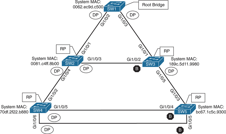
Ports that are blocked go in BLK state
Alternate port is the alternate port to reach root in an event Gi1/0/1 fails
All the ports on SW2 are in a forwarding state, but port Gi1/0/2 on SW3 is in a blocking (BLK) state.
SW3’s Gi1/0/2 port has also been designated as an alternate port to reach the root in the event that the Gi1/0/1 connection fails.
SW3’s Gi1/0/2 port rather than SW2’s Gi1/0/3 port was placed into a blocking state is that SW2’s system MAC address (0081.c4ff.8b00) is lower than SW3’s system MAC address (189c.5d11.9980).
SW2# show spanning-tree vlan 1


VLAN0001
  Spanning tree enabled protocol rstp
  Root ID    Priority    32769
              Address     0062.ec9d.c500
              Cost         4
              Port         1 (GigabitEthernet1/0/1)
              Hello Time   2 sec  Max Age 20 sec  Forward Delay 15 sec

  Bridge ID  Priority    32769  (priority 32768 sys-id-ext 1)
               Address     0081.c4ff.8b00
               Hello Time   2 sec  Max Age 20 sec  Forward Delay 15 sec
               Aging Time  300 sec

Interface           Role Sts Cost      Prio.Nbr Type
------------------- ---- --- --------- -------- --------------------------------
Gi1/0/1             Root FWD 4          128.1    P2p
Gi1/0/3             Desg FWD 4          128.3    P2p
Gi1/0/4             Desg FWD 4          128.4    P2p
SW3# show spanning-tree vlan 1
VLAN0001
Spanning tree enabled protocol rstp
! This section displays the relevant information for the STP root bridge
Root ID Priority 32769
Address 0062.ec9d.c500
Cost 4
Port 1 (GigabitEthernet1/0/1)
Hello Time 2 sec Max Age 20 sec Forward Delay 15 se
! This section displays the relevant information for the Local STP bridge
Bridge ID Priority 32769 (priority 32768 sys-id-ext 1)
Address 189c.5d11.9980
Hello Time 2 sec Max Age 20 sec Forward Delay 15 sec
Aging Time 300 sec
Interface Role Sts Cost Prio.Nbr Type
------------------- ---- --- --------- -------- --------------------------------
Gi1/0/1 Root FWD 4 128.1 P2p
Gi1/0/2 Altn BLK 4 128.2 P2p
Gi1/0/5 Desg FWD 4 128.5 P2pshow spanning-tree interface interface-id [detail]
shows STP state for only the specified interface.
The detail keyword provides
1. port cost
2. port priority
3. number of transitions
4. link type
5. count of BPDUs sent or received for every VLAN supported on that interface.
show spanning-tree vlan x
shows where that vlan spans to on current switch
SW3# show spanning-tree interface gi1/0/1

Vlan                Role Sts Cost      Prio.Nbr Type
------------------- ---- --- --------- -------- --------------------------------
VLAN0001            Root FWD 4         128.1    P2p
VLAN0010            Root FWD 4         128.1    P2p
VLAN0020            Root FWD 4         128.1    P2p
VLAN0099            Root FWD 4         128.1    P2p
SW3# show spanning-tree interface gi1/0/1 detail
! Output omitted for brevity
Port 1 (GigabitEthernet1/0/1) of VLAN0001 is root forwarding
Port path cost 4, Port priority 128, Port Identifier 128.1.
Designated root has priority 32769, address 0062.ec9d.c500
Designated bridge has priority 32769, address 0062.ec9d.c500
Designated port id is 128.3, designated path cost 0
Timers: message age 16, forward delay 0, hold 0
Number of transitions to forwarding state: 1
Link type is point-to-point by default
BPDU: sent 15, received 45908
Port 1 (GigabitEthernet1/0/1) of VLAN0010 is root forwarding
Port path cost 4, Port priority 128, Port Identifier 128.1.
Designated root has priority 32778, address 0062.ec9d.c500
Designated bridge has priority 32778, address 0062.ec9d.c500
Designated port id is 128.3, designated path cost 0
Timers: message age 15, forward delay 0, hold 0
Number of transitions to forwarding state: 1
Link type is point-to-point by default
MAC BPDU: sent 15, received 22957
..STP Topology Changes
Configuration BPDUs always flow from the root bridge toward the edge switches
However, changes in the topology (for example, switch failure, link failure, or links becoming active) have an impact on “all” the switches in the Layer 2 topology.
The switch that detects a fault sends a topology change notification (TCN) BPDU toward the root bridge, out its RP.
If an upstream switch receives the TCN, it sends out an acknowledgment and forwards the TCN out its RP to the root bridge.
By default, a switch ages out MAC entries after 300 seconds (5 minutes)
When STP detects a topology change (link up/down, port role change):
The switch temporarily reduces the MAC aging time
Upon receipt of the TCN, the root bridge creates a new configuration BPDU with the Topology Change flag set, and it is then flooded to all the switches. When a switch receives a configuration BPDU with the Topology Change flag set, all switches change their MAC address timer to the forwarding delay timer (with a default of 15 seconds). This flushes out MAC addresses for devices that have not communicated in that 15-second window but maintains MAC addresses for devices that are actively communicating.
However, a side effect of flushing the MAC address table is that it temporarily increases the unknown unicast flooding while it is rebuilt. Remember that this can impact hosts because of their CSMA/CD behavior.
The MAC address timer is then reset to normal (300 seconds) after the 2 configuration BPDU are seen
“I’ve now seen two consecutive consistent BPDUs — the topology is stable again.”
Because these TCNs are generated on per VLAN basis, as a side effect that VLAN’s mac table mac entry retainer time will be reduced creating rebroadcasting of unknown unicast for MAC address relearning by the switch on that VLAN.
As the number of hosts (without portfast) increases, the more likely TCN generation is to occur and the more hosts that are impacted by the broadcasts. Topology changes should be checked as part of the troubleshooting process. Portfast stops generation of TCN and reduce the generation of TCNs.
Topology changes are seen with the command show spanning-tree [vlan vlan-id] detail on a switch.
The output of this command shows the topology change count and time since the last change has occurred.
A sudden or continuous increase in TCNs indicates a potential problem and should be investigated further for flapping ports or events on a connected switch.
SW1# show spanning-tree vlan 10 detail

 VLAN0010 is executing the rstp compatible Spanning Tree protocol
 Bridge Identifier has priority 32768, sysid 10, address 0062.ec9d.c500
 Configured hello time 2, max age 20, forward delay 15, transmit hold-count 6
 We are the root of the spanning tree
 Topology change flag not set, detected flag not set
 Number of topology changes 42 last change occurred 01:02:09 ago
           from GigabitEthernet1/0/2
 Times: hold 1, topology change 35, notification 2
         hello 2, max age 20, forward delay 15
 Timers: hello 0, topology change 0, notification 0, aging 300
The process of determining why TCNs are occurring involves finding a port that is flapping and it does not have portfast enabled, if it is connected to another switch then trace port on another switch but in same VLAN
Direct Link Failures of blocking segment- traffic impact
When a port goes down STP process is aware of that “direct link” failure

In below scenario link between SW2 and SW3 goes down
SW2 Gi1/0/3 is DP and SW3 Gi1/0/2 Blocking
This link going down will not impact traffic as both switches transmit traffic through SW1 and because of this direct link blocking between SW2 and SW3, SW2 learns all the MAC addresses behind SW3 via SW1 and SW3 learns all the MAC addresses behind SW2 via SW1
Blocked ports cannot send data and do not receive Data, also do not send BPDU but can receive BPDU only
switches also do not learn MAC on blocked ports
but designated port can send and receive data but in this case SW2’s Designated port will never forward out of Gi1/0/3 because no MAC has been learned through that port so even though designated port can send data, it will never send it because traffic outflow is dictated by MAC address learning
Dont forget about TCN generated from P2p port going down, both SW2 and SW3 will advertise a TCN toward the root switch, which results in the Layer 2 topology flushing its MAC address table.
Direct Link Failures – Loss of root – traffic impact 30 seconds for 802.1D

In the second scenario, the link between SW1 and SW3 fails.
Network traffic to and from SW1 to SW3 and Network traffic to and from SW2 -> SW1 -> SW3 and SW3 -> SW1 -> SW2 will be affected because of blocking segment between SW2 and SW3, all traffic between SW2 and SW3 goes via SW1 but because link between SW1 and SW3 is down , Layer 2 network will have to reconverge with the help of STP
– SW1 detects a link failure on its Gi1/0/3 interface.
– SW3 detects a link failure on its Gi1/0/1 interface and SW3 does not use max age timer on its Gi1/0/1
1. TCNs from all switches to root but no way to send in this scenario so switch will wait:
– Normally, SW1 would generate a TCN flag out its root port, but it itself is a root bridge, so it does not. SW1 will wait for a TCN from non root switches
– At this point, SW3 would attempt to send a TCN toward the root switch to notify it of a topology change; however, its root port is down, and its only other port that is connected to this layer 2 network is in blocking mode , so SW3 will wait for this port to come out of blocking mode but it will still send TCN once the port is out of blocking mode
2. Affected interfaces remove their best BPDU (root / root port) and activate alternative port as BPDUs from root are still coming in another (blocking) port:
– SW3 removes its best BPDU (was root port as best only comes on root port) without waiting for max age timer on its Gi1/0/1 interface because it is now in a down state.
– SW2 was always receiving BPDU from SW1 and relaying it to SW3
– because root port was lost SW3 must look for a new root port
– SW3 never lost access to root as it was receiving BPDUs on its Gi1/0/2 in Blocked state
– because BPDU are coming on blocking port Gi1/0/2 of SW3, and SW3 detects that this root is reachable over Gi1/0/2 Blocking port so it transitions to listening and then learning
3. TCN can now reach root
– once SW3 bring its port Gi1/0/2 to forwarding state then TCN is dispatched towards root from Gi1/0/2
– SW1 advertises a configuration BPDU with the Topology Change flag out of all its ports. It keeps TC set for the topology change period (commonly Max Age + Forward Delay = 35s by default).
– This BPDU is received and relayed to all switches in the environment , SW2 receives it and relays it to SW3
4. Non root switches reduce their MAC address age timer to forward delay
– These switches then reduce the MAC address age timer to the forward delay timer to flush out older MAC entries.
– If other switches were connected to SW1, they would receive a configuration BPDU with the Topology Change flag set also for all the VLANs on trunk port. These packets have an impact for all switches in the same Layer 2 domain.
The total convergence time for SW3 is 30 seconds: 15 seconds for the listening state and 15 seconds for the learning state before SW3’s Gi1/0/2 can be made the RP.
Direct Link Failure Scenario 3
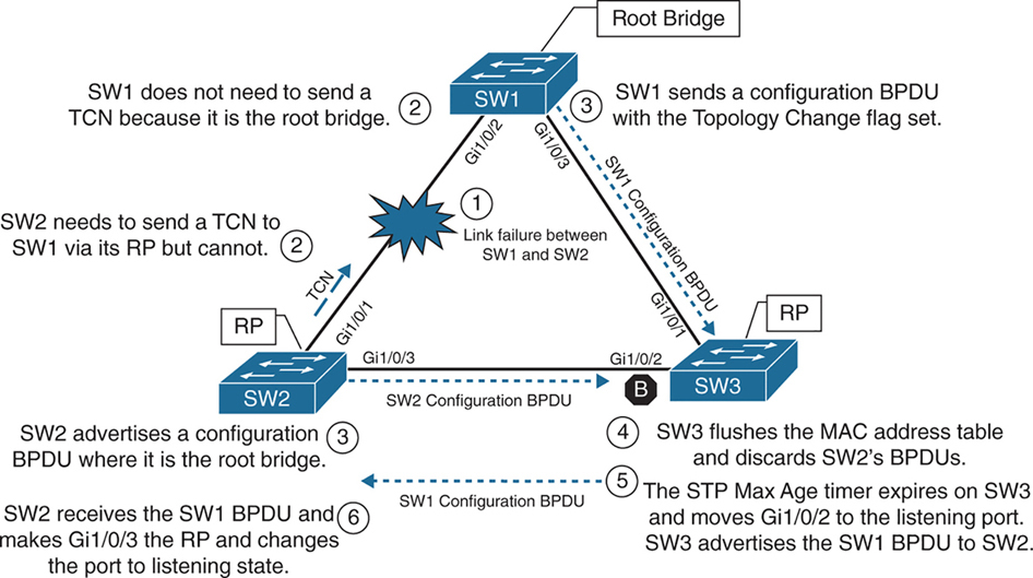
In the third scenario, the link between SW1 and SW2 fails
Network traffic from SW1 or SW3 toward SW2 is impacted because SW3’s Gi1/0/2 port is in a blocking state.
SW1 detects a link failure on its Gi1/0/2 interface.
SW2 detects a link failure on its Gi1/0/1 interface and SW3 does not use max age timer on its Gi1/0/1
1. TCNs from all switches to root but no way to send in this scenario so switch will wait:
– Normally SW1 would generate a TCN flag out its root port, but it is the root bridge, so it does not as root does not do that. SW1 would advertise a TCN if it were not the root bridge.
– At this point, SW2 would attempt to send send TCN towards the root switch to notify it of a topology change however its root port is down and unable to do as its RP port is down so it will wait for path to root to resolve and then send TCN
2. Affected interfaces remove their best BPDU and best BPDU (root) via different interface as BPDU are not coming on Desgnated port due to adjacent port is blocking:
– SW2 removes its best BPDU (was root port as best only comes on root port) without waiting for max age timer on its Gi1/0/1 interface because it is now in a down state.
– because root port was lost SW2 must look for a new root port
– but because the local port facing SW3 is Designated port and port on SW3 is blocking as blocking port does not send BPDUs but only receives BPDU, visibility or path to root is lost
3. Declaring itself root because of remote blocking port and then receiving and loosing root election
– SW2 will declare itself root and generate its own BPDU and send it to SW3
– SW3 receives SW2’s inferior BPDUs and discards them as it is still receiving superior BPDUs from SW1
– Because this BPDU from SW2 was not accepted this leads to expiry of max age timer on Gi1/0/2 of SW3 and transitions from blocking to listening state. SW3 can now forward the next configuration BPDU it receives from SW1 to SW2.
– SW2 receives SW1’s configuration BPDU via SW3 and recognizes it as superior. It marks its Gi1/0/3 interface as the root port and transitions it to the listening state.
4. TCN can now reach root
– once SW2 bring its port Gi1/0/2 to forwarding state then TCN is dispatched towards root from Gi1/0/2
– SW1 advertises a configuration BPDU with the Topology Change flag out of all its ports. It keeps TC set for the topology change period (commonly Max Age + Forward Delay = 35s by default).
– This BPDU is received and relayed to all switches in the environment , SW3 receives it and relays it to SW2
5. Non root switches reduce their MAC address age timer to forward delay
– These switches then reduce the MAC address age timer to the forward delay timer to flush out older MAC entries.
– If other switches were connected to SW1, they would receive a configuration BPDU with the Topology Change flag set also for all the VLANs on trunk port. These packets have an impact for all switches in the same Layer 2 domain.
The total convergence time for SW2 is 50 seconds: 20 seconds for the Max Age timer on SW3, 15 seconds for the listening state on SW2, and 15 seconds for the learning state.
Indirect Failures
In some scenarios involving signalling over WAN, switch do not see direct interface failures, but WAN signalling is not present while the interface is up and this is where hello and max age timer comes in
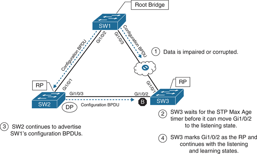
– An event occurs that impairs or corrupts data on the link. SW1 and SW3 still report a link up condition.
– SW3 stops receiving configuration BPDUs on its RP, SW3’s max age timer expires and removes the best BPDU after max age expiry
– because SW3 lost path to root it will have to find the path to root through another best path (lowest cost to root) and that is next port that is Gi1/0/2 in blocking port
– SW3 transitions Gi1/0/2 from blocking to listening state
– SW2 continues to advertise SW1’s configuration BPDUs toward SW3
– SW3 receives SW1’s configuration BPDU via SW2 on its Gi1/0/2 interface. This port is now marked as the RP
The total time for reconvergence on SW3 is 50 seconds: 20 seconds for the Max Age timer on SW3, 15 seconds for the listening state on SW3, and 15 seconds for the learning state on SW3.
Rapid Spanning Tree Protocol
Although 802.1D did a decent job of preventing Layer 2 forwarding loops, it was not designed to support multiple VLANs, also for traffic engineering requirements such as blocking one link for half vlans and blocking another link for other half of vlans for load balancing and equally utilising both uplinks
Cisco also created other versions like PVST and PVST+ which were Cisco proprietary
but standard versions that are compatible with other vendors such as RSTP and MST should be used in production
RSTP (802.1W) Port States
RSTP reduces the number of port states to three:
Discarding: Blocking, This state combines the traditional STP states disabled, blocking, and listening.
Learning: The switch port modifies the MAC address table with any network traffic it receives. The switch still does not forward any other network traffic besides BPDUs.
Forwarding: The switch port forwards all network traffic and updates the MAC address table as expected. This is the final state for a switch port to forward network traffic.
RSTP relies on handshake with a switch connected on the other end, If a handshake does not occur, the other device is assumed to be non-RSTP compatible and for backwards compatibility the port defaults to regular 802.1D behavior
RSTP (802.1W) Port Roles
RSTP defines the following port roles:
Root port (RP): A network port that connects to the root switch or an upstream switch in the spanning-tree topology. There should be only one root port per VLAN on a switch.
Designated port (DP): A network port that receives and forwards frames to other switches. Designated ports provide connectivity to downstream devices and switches. There should be only one active designated port on a link. Designated port drives packets away from root
Alternate port:
A network port that provides alternate connectivity toward the root switch “through a different switch”.
It does not forward traffic, So if the main (active) path to the root switch fails, the alternate port can take over.
Backup port:
These are very rare because this port is only seen when a switch connects with 2 links into hub or shared segment , a backup port is kept blocked to prevent loops, one link going to hub becomes Designated port and second link becomes backup port (blocks traffic)
RSTP (802.1W) Port Types
RSTP defines three types of ports that are used for building the STP topology:
Edge port: A port at the edge of the network where hosts connect to the Layer 2 topology with one interface and “cannot form a loop”. These ports directly correlate to ports that have the STP portfast feature enabled.
Non-Edge port: A port that has received a BPDU.
Point-to-point port: Any port that connects to another RSTP switch with full duplex. “Full-duplex links do not permit more than two devices on a network segment, so determining whether a link is full duplex is the fastest way to check the feasibility of being connected to a switch”.
Multi-access Layer 2 devices such as hubs can connect only at half duplex. If a port can connect only via half duplex, it must operate under traditional 802.1D forwarding states.
Building the RSTP Topology
With RSTP, switches exchange handshakes with other RSTP switches to transition through the following STP states and it is faster this way
When two switches first connect, they establish a bidirectional handshake across the shared link to identify the root bridge.
This is straightforward for an environment with only two switches; however, large environments require greater logic
RSTP uses a synchronization process to add a switch to the RSTP topology, The synchronization process starts when two switches (such as SW1 and SW2) are first connected. The process proceeds as follows:
– As the first two switches connect to each other, they verify that they are connected with a point-to-point link by checking the full-duplex status.
– They establish a handshake with each other to advertise a proposal (in configuration BPDUs) that their interface should be the DP for that segment.
– There can be only one DP per segment, so each switch identifies whether it is the superior or inferior switch, using the same logic as in 802.1D for the system identifier (that is, the lowest priority and then the lowest MAC address). Using the MAC addresses from figure, SW1 (0062.ec9d.c500) is the superior switch to SW2 (0081.c4ff.8b00).

– The inferior switch (SW2) recognizes that it is inferior and marks its local port (Gi1/0/1) as the RP. At that same time, it moves all non-edge ports to a discarding state. At this point in time, the switch has stopped all local switching for non-edge ports.
– The inferior switch (SW2) sends an agreement (configuration BPDU) to the root bridge (SW1), which signifies to the root bridge that synchronization is occurring on that switch.
– The inferior switch (SW2) moves its RP (Gi1/0/1) to a forwarding state. The superior switch moves its DP (Gi1/0/2) to a forwarding state too.
– The inferior switch (SW2) repeats the process for any downstream switches connected to it.
RSTP Convergence
The RSTP convergence process can occur quickly. RSTP ages out the port information after it has not received hellos in three consecutive cycles. Using default timers, the Max Age would take 20 seconds, but RSTP requires only 6 seconds. And thanks to the new synchronization, ports can transition from discarding to forwarding in an extremely low amount of time.
If a downstream switch fails to acknowledge the proposal, the RSTP switch must default to 802.1D behaviors to prevent a forwarding loop.
STP Topology Tuning
A properly designed network places the root bridge on a specific switch and influences which ports should be designated ports (forwarding state) and which ports should be alternate ports (that is, discarding state) based on hardware platform and topology.
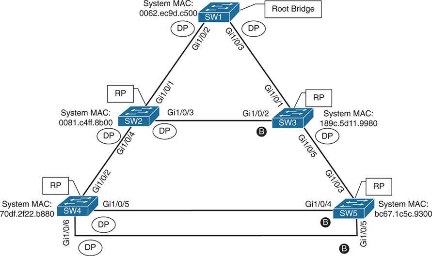
Ideally, the root bridge is placed on a core switch, and a “secondary” root bridge is designated.
Root bridge placement is accomplished by “lowering” the system priority on the root bridge to the lowest value possible,
raising the secondary root bridge to a value slightly higher than that of the root bridge,
and (ideally) increasing the system priority on all other switches unless you plan to keep switches on default priority.
By increasing non root switch priority and lowering switch priority for root and secondary root switches, it is made sure that when a new non-configured switch is connected to topology, it does not take over as root.
The priority is set with either of the following commands:
spanning-tree vlan vlan-id priority priority: The priority is a value between 0 and 61,440, in increments of 4096.
spanning-tree vlan vlan-id root {primary | secondary} [diameter diameter]: This command executes a script that sets the priority numerically, along with the potential for timers if the diameter keyword is used. The primary keyword sets the priority to 24,576, and the secondary keyword sets the priority to 28,672.
If a different switch has a priority of 24,576 (or lower) and is more preferred when the command spanning-tree vlan vlan-id root {primary | secondary} is executed, the script has logic to lower the priority to a lower value in an attempt to make it the root bridge, this is possible because current root is in BPDU and along with that system ID or name contains system priority value and system mac address
The optional diameter command makes it possible to tune the Spanning Tree Protocol (STP) convergence and modifies the timers; it should reference the maximum number of Layer 2 hops between a switch that is maximum hops away and the root bridge.
The timers do not need to be modified on other switches because they are carried throughout the topology through the root bridge’s bridge protocol data units (BPDUs) as you only configure timers in one place, you only change timers on root bridge
All the other switches automatically learn those timer values, because the root bridge advertises them inside its BPDUs, which are sent throughout the Layer 2 network. So there’s no need to manually configure timers on every switch. When other switches receive the root’s BPDUs:
– They propagate those same values further downstream
– They adopt the root’s timer values
The root bridge generates the “authoritative” BPDUs
These BPDUs include:
- Hello time
- Max age
- Forward delay (used for learning state)
! Verification of SW1 Priority before modifying the priority
SW1# show spanning-tree vlan 1
VLAN0001
  Spanning tree enabled protocol rstp
  Root ID    Priority    32769
               Address     0062.ec9d.c500
               This bridge is the root
               Hello Time   2 sec  Max Age 20 sec  Forward Delay 15 sec
  Bridge ID  Priority    32769  (priority 32768 sys-id-ext 1)
               Address     0062.ec9d.c500
               Hello Time   2 sec  Max Age 20 sec  Forward Delay 15 sec
               Aging Time  300 sec
! Configuring the SW1 priority as primary root for VLAN 1
SW1(config)# spanning-tree vlan 1 root primary! Verification of SW1 Priority after modifying the priority
SW1# show spanning-tree vlan 1
VLAN0001
Spanning tree enabled protocol rstp
Root ID Priority 24577 <<<
Address 0062.ec9d.c500
This bridge is the root
Hello Time 2 sec Max Age 20 sec Forward Delay 15 sec
Bridge ID Priority 24577 (priority 24576 sys-id-ext 1) <<<
Address 0062.ec9d.c500
Hello Time 2 sec Max Age 20 sec Forward Delay 15 sec
Aging Time 300 sec
Interface Role Sts Cost Prio.Nbr Type
------------------- ---- --- --------- -------- --------------------------------
Gi1/0/2 Desg FWD 4 128.2 P2p
Gi1/0/3 Desg FWD 4 128.3 P2p
Gi1/0/14 Desg FWD 4 128.14 P2p! Configuring the SW2 priority as secondary root for VLAN 1
SW2(config)# spanning-tree vlan 1 root secondarySW2# show spanning-tree vlan 1
VLAN0001
Spanning tree enabled protocol rstp
Root ID Priority 24577 <<<
Address 0062.ec9d.c500
Cost 4
Port 1 (GigabitEthernet1/0/1)
Hello Time 2 sec Max Age 20 sec Forward Delay 15 sec
Bridge ID Priority 28673 (priority 28672 sys-id-ext 1) <<<
Address 0081.c4ff.8b00
Hello Time 2 sec Max Age 20 sec Forward Delay 15 sec
Aging Time 300 sec
Interface Role Sts Cost Prio.Nbr Type
------------------- ---- --- --------- -------- --------------------------------
Gi1/0/1 Root FWD 4 128.1 P2p
Gi1/0/3 Desg FWD 4 128.3 P2p
Gi1/0/4 Desg FWD 4 128.4 P2pThe best way to prevent erroneous devices from taking over the STP root role is to set the priority to 0 for the primary root switch and to 4096 for the secondary root switch. “In addition, root guard should be used”
Modifying STP Root Port and Blocked Switch Port Locations
Cost calculation method forces how we implement cost on interface, The receiving switch adds the port cost for the interface on which the BPDU was received in conjunction with the value of the root path cost in the BPDU.

SW1 advertises its BPDUs to SW3 with a root path cost of 0.
SW3 receives the BPDU and adds its STP port cost of 4 to the root path cost in the BPDU (0), resulting in a value of 4.
SW3 then advertises the BPDU toward SW5 with a root path cost of 4, to which SW5 then adds its STP port cost of 4.
SW5 therefore reports a root path cost of 8 to reach the root bridge via SW3.
SW1# show spanning-tree vlan 1
! Output omitted for brevity
VLAN0001

  Root ID    Priority    32769
               Address     0062.ec9d.c500
               This bridge is the root
..
Interface           Role Sts Cost      Prio.Nbr Type
------------------- ---- --- --------- -------- --------------------------------
Gi1/0/2             Desg FWD 4         128.2    P2p
Gi1/0/3             Desg FWD 4         128.3    P2p
SW3# show spanning-tree vlan 1
! Output omitted for brevity
VLAN0001
Root ID Priority 32769
Address 0062.ec9d.c500
Cost 4
Port 1 (GigabitEthernet1/0/1)
..
Interface Role Sts Cost Prio.Nbr Type
------------------- ---- --- --------- -------- --------------------------------
Gi1/0/1 Root FWD 4 128.1 P2p
Gi1/0/2 Altn BLK 4 128.2 P2p
Gi1/0/5 Desg FWD 4 128.5 P2pSW5# show spanning-tree vlan 1
! Output omitted for brevity
VLAN0001
Root ID Priority 32769
Address 0062.ec9d.c500
Cost 8
Port 3 (GigabitEthernet1/0/3)
..
Interface Role Sts Cost Prio.Nbr Type
------------------- ---- --- --------- -------- --------------------------------
Gi1/0/3 Root FWD 4 128.3 P2p
Gi1/0/4 Altn BLK 4 128.4 P2p
Gi1/0/5 Altn BLK 4 128.5 P2pYou can lower a path that is currently an alternate port while making it designated,
or you can raise the cost on a port that is designated to turn it into a blocking port
The spanning-tree command modifies the cost for all VLANs unless the optional vlan keyword is used to specify a VLAN
SW3# conf t
SW3(config)# interface gi1/0/1
SW3(config-if)# spanning-tree cost 1
SW3# show spanning-tree vlan 1
! Output omitted for brevity
VLAN0001
Root ID Priority 32769
Address 0062.ec9d.c500
Cost 1
Port 1 (GigabitEthernet1/0/1)
Bridge ID Priority 32769 (priority 32768 sys-id-ext 1)
Address 189c.5d11.9980
..
Interface Role Sts Cost Prio.Nbr Type
------------------- ---- --- --------- -------- --------------------------------
Gi1/0/1 Root FWD 1 128.1 P2p
Gi1/0/2 Desg FWD 4 128.2 P2p
Gi1/0/5 Desg FWD 4 128.5 P2pSW2# show spanning-tree vlan 1
! Output omitted for brevity
VLAN0001
Root ID Priority 32769
Address 0062.ec9d.c500
Cost 4
Port 1 (GigabitEthernet1/0/1)
Bridge ID Priority 32769 (priority 32768 sys-id-ext 1)
Address 0081.c4ff.8b00
..
Interface Role Sts Cost Prio.Nbr Type
------------------- ---- --- --------- -------- --------------------------------
Gi1/0/1 Root FWD 4 128.1 P2p
Gi1/0/3 Altn BLK 4 128.3 P2p
Gi1/0/4 Desg FWD 4 128.4 P2pModifying STP Port Priority
STP port priority impacts which port is an alternate port when multiple links are used between same switches. Remember that system ID and port cost are the same, so the next check is port priority, followed by the port number. “Both the port priority and port number are controlled by the upstream switch”, because it is closer to the root bridge.
You can modify the port priority on SW4’s Gi1/0/6 (toward SW5’s Gi1/0/5 interface) with the command spanning-tree [vlan vlan-id] port-priority priority. The optional vlan keyword allows you to change the priority on a VLAN-by-VLAN basis
SW4# configure terminal
Enter configuration commands, one per line. End with CNTL/Z.
SW4(config)# interface gi1/0/6
SW4(config-if)# spanning-tree port-priority 64
Additional STP Protection Mechanisms
The following scenarios are common for Layer 2 forwarding loops:
- STP disabled on a switch
- A misconfigured load balancer that transmits traffic out multiple ports with the same MAC address
- A misconfigured virtual switch that bridges two physical ports (Virtual switches typically do not participate in STP.)
- End users using a dumb network switch or hub
Catalyst switches detect a MAC address that is flapping between interfaces and notify via syslog with the MAC address of the host, VLAN, where MAC is flapping
12:40:30.044: %SW_MATM-4-MACFLAP_NOTIF: Host 70df.2f22.b8c7 in vlan 1 is flapping
 between port Gi1/0/3 and port Gi1/0/2
Root Guard
Root Guard prevents a configured port from becoming a “root port”
it “is configured on designated port” facing switches that should never become root
Root guard prevents a downstream switch (often misconfigured or rogue) from becoming a root bridge in a topology
Root guard places a port in a root inconsistent state for interfaces or vlan that receives a “superior BPDU” when root guard is configured
Interfaces in root inconsistent state cannot forward traffic out of this port,
root guard does not block port permanently but it only blocks when superior BPDU are received
“I received a superior BPDU on this port, but I’m not allowed to accept it as the root path.”
Prevents an unauthorized or misconfigured switch from becoming the root bridge
How it recovers
Once the superior BPDU stops, the port:
– Automatically leaves root inconsistent
– Returns to normal forwarding (no manual reset needed)
! configure on designated port that is facing "down stream"
spanning-tree guard root
root guard should be configured on SW2’s Gi1/0/4 port toward SW4
root guard should be configured on SW3’s Gi1/0/5 port toward SW5
this configuration prevents SW4 and SW5 from becoming root
but still allows SW2 to maintain connectivity to SW1 via SW3 if link between SW2 and SW1 goes down
but if link between SW2 and SW3 also goes down then it will not work even if alternate path via SW4 exists, it will not work
Root Guard protects you from an “unexpected root” on that port, but the trade-off is that it can also kill an otherwise-valid backup path.
STP Portfast
Portfast as name suggests brings port up faster by skipping learning (listening also if not RSTP)
Portfast also stops generation of TCN when port goes down
Portfast is configured on host , access ports only
Portfast allows traffic forwarding immediately, this is useful for DHCP and PXE boot ports
If BPDU is received on portfast enabled port then portfast “functionality” is removed from port and it progressed through learning (and listening if not RSTP) states
! portfast on interface
interface gig 1/0/1
spanning-tree portfast

! enable globally
spanning-tree portfast default
If portfast needs to be disabled on a specific port when portfast is enabled globally, you can configure interface
spanning-tree portfast disableThis removes portfast from the port
Sometimes you will see portfast enabled on a trunk port but this should only be the case when a “single” port is connected to a server
spanning-tree portfast trunkenabling portfast on an interface changes port to RSTP port type to “Edge port – P2p Edge”
SW1(config)# interface gigabitEthernet 1/0/13
SW1(config-if)# switchport mode access
SW1(config-if)# switchport access vlan 10
SW1(config-if)# spanning-tree portfast
SW1# show spanning-tree vlan 10
! Output omitted for brevity
VLAN0010
Interface Role Sts Cost Prio.Nbr Type
------------------- ---- --- --------- -------- --------------------------------
Gi1/0/2 Desg FWD 4 128.2 P2p
Gi1/0/3 Desg FWD 4 128.3 P2p
Gi1/0/13 Desg FWD 4 128.13 P2p EdgeSW1# show spanning-tree interface gi1/0/13 detail
Port 13 (GigabitEthernet1/0/13) of VLAN0010 is designated forwarding
Port path cost 4, Port priority 128, Port Identifier 128.13.
Designated root has priority 32778, address 0062.ec9d.c500
Designated bridge has priority 32778, address 0062.ec9d.c500
Designated port id is 128.13, designated path cost 0
Timers: message age 0, forward delay 0, hold 0
Number of transitions to forwarding state: 1
The port is in the portfast mode <<<
Link type is point-to-point by default
BPDU: sent 23103, received 0SW2# conf t
Enter configuration commands, one per line. End with CNTL/Z.
SW2(config)# spanning-tree portfast default
%Warning: this command enables portfast by default on all interfaces. You
should now disable portfast explicitly on switched ports leading to hubs,
switches and bridges as they may create temporary bridging loops.
SW2(config)# interface gi1/0/8
SW2(config-if)# spanning-tree portfast disableBPDU Guard
Remember that Guard is placed outside to stop things coming in, not going out
so remember that BPDU Guard is always to stop from receiving or entering of BPDU
BPDU guard is a safety mechanism that places ports configured with STP portfast into an ErrDisabled state upon receipt of a BPDU
Err-disabled port is “disabled” or in shutdown like state
This ensures that loop cannot be accidentally created if a switch is connected because just configuring portfast is not enough, switche removes portfast functionality from port as BPDU is received on port even though it shows in configuration, you have to look at the show spanning-tree interface detail command to see it
BPDU guard is typically configured with all host-facing ports that are enabled with portfast.
! BPDU guard is enabled globally on all STP portfast ports
spanning-tree portfast bpduguard default

! but can be disabled on specific port if enabled globally
spanning-tree bpduguard disable

! enabling on a single port
spanning-tree bpduguard enable
SW1# configure terminal
Enter configuration commands, one per line. End with CNTL/Z.
SW1(config)# spanning-tree portfast bpduguard default
SW1(config)# interface gi1/0/8
SW1(config-if)# spanning-tree bpduguard disableSW1# show spanning-tree interface gi1/0/7 detail
Port 7 (GigabitEthernet1/0/7) of VLAN0010 is designated forwarding
Port path cost 4, Port priority 128, Port Identifier 128.7.
Designated root has priority 32778, address 0062.ec9d.c500
Designated bridge has priority 32778, address 0062.ec9d.c500
Designated port id is 128.7, designated path cost 0
Timers: message age 0, forward delay 0, hold 0
Number of transitions to forwarding state: 1
The port is in the portfast mode
Link type is point-to-point by default
Bpdu guard is enabled by default <<<
BPDU: sent 23386, received 0SW1# show spanning-tree interface gi1/0/8 detail
Port 8 (GigabitEthernet1/0/8) of VLAN0010 is designated forwarding
Port path cost 4, Port priority 128, Port Identifier 128.8.
Designated root has priority 32778, address 0062.ec9d.c500
Designated bridge has priority 32778, address 0062.ec9d.c500
Designated port id is 128.8, designated path cost 0
Timers: message age 0, forward delay 0, hold 0
Number of transitions to forwarding state: 1
The port is in the portfast mode by default
Link type is point-to-point by default
BPDU: sent 23388, received 0syslog messages are generated when a BPDU is received on a BPDU guard–enabled port. The port is then placed into an ErrDisabled state, as shown with the command show interfaces status
12:47:02.069: %SPANTREE-2-BLOCK_BPDUGUARD: Received BPDU on port GigabitEthernet1/0/2 with BPDU Guard enabled. Disabling port.
12:47:02.076: %PM-4-ERR_DISABLE: bpduguard error detected on Gi1/0/2, putting Gi1/0/2 in err-disable state
12:47:03.079: %LINEPROTO-5-UPDOWN: Line protocol on Interface GigabitEthernet1/0/2, changed state to down
12:47:04.082: %LINK-3-UPDOWN: Interface GigabitEthernet1/0/2, changed state to down
SW1# show interfaces status
Port Name Status Vlan Duplex Speed Type
Gi1/0/1 notconnect 1 auto auto 10/100/1000BaseTX
Gi1/0/2 SW2 Gi1/0/1 err-disabled 1 auto auto 10/100/1000BaseTX <<<
Gi1/0/3 SW3 Gi1/0/1 connected trunk a-full a-1000 10/100/1000BaseTXBy default, ports that are put in the ErrDisabled state because of BPDU guard do not automatically restore themselves, reason is for administrators to be notified of a switch connecting to an access port that is only meant to connect hosts
But Error Recovery service can be used to reactivate ports that are shut down for a specific problem reducing manual work using command errdisable recovery cause bpduguard and interval can be configured using errdisable recovery interval time-seconds , this time controls how long a port stays in err state before it is shut and unshut to bring it up by switch itself
SW1# configure terminal
Enter configuration commands, one per line. End with CNTL/Z.
SW1(config)# errdisable recovery cause bpduguard
SW1# show errdisable recovery
! Output omitted for brevity
ErrDisable Reason Timer Status
----------------- --------------
arp-inspection Disabled
bpduguard Enabled
..
Recovery command: "clear Disabled
Timer interval: 300 seconds
Interfaces that will be enabled at the next timeout:
Interface Errdisable reason Time left(sec)
--------- ----------------- --------------
Gi1/0/2 bpduguard 295! Syslog output from BPDU recovery. The port will be recovered, and then
! triggered again because the port is still receiving BPDUs.
SW1#
01:02:08.122: %PM-4-ERR_RECOVER: Attempting to recover from bpduguard err-disable
state on Gi1/0/2
01:02:10.699: %SPANTREE-2-BLOCK_BPDUGUARD: Received BPDU on port Gigabit
Ethernet1/0/2 with BPDU Guard enabled. Disabling port.
01:02:10.699: %PM-4-ERR_DISABLE: bpduguard error detected on Gi1/0/2, putting
Gi1/0/2 in err-disable stateError Recovery service operates every 300 seconds (5 minutes). This can be changed to a value of 30 to 86,400 seconds with the global configuration command errdisable recovery interval time.
BPDU Filter
BPDU Filter is something that stops sending and receiving of BPDUs
BPDU filter blocks BPDUs from being transmitted out a port.
BPDU filter means Don’t participate in STP on this port.
BPDU filter can be enabled globally or on a specific interface.
The global BPDU filter configuration uses the command spanning-tree portfast bpdufilter default.
The interface-specific BPDU filter is enabled with the interface configuration command spanning-tree bpdufilter enable.
If BPDU filter is enabled on a portfast enabled port, the behavior changes depending on the configuration:
- If BPDU filter is enabled globally using command
spanning-tree portfast bpdufilter default- Cisco does not blindly stop sending BPDUs forever on all interfaces Instead, it does a “safety probe.” , The port initially sends ~10–12 BPDUs to ask “Is there another switch out there?”
- If no BPDU is received back
- The port assumes it’s an end device
- BPDU filtering kicks in
- STP is effectively disabled on that port
- —————————————
- If a BPDU is received
- switch thinks there is another switch connected
- STP logic turns back on for that port
- Now because there is a switch connected and a BPDU is received
- Switch must decide which switch is superior:
- to decide which port will be designated and which port will be blocking on that segment
Global BPDU filter is “safe-ish”:
- It allows PortFast convenience
- But auto-recovers STP if a switch is accidentally plugged in
Enabling interface level BPDU filter is dangerous unless you know the topology and you know what you are doing interface gi1/0/1
spanning-tree bpdufilter enable
– No safety check
– No listening
– STP is completely disabled, no sending of BPDUs and no receiving of BPDUs
– Easy way to create a loop
Be careful with the deployment of BPDU filter because it could cause problems. Most network designs do not require BPDU filter, which adds an unnecessary level of complexity and also introduces risk.
after BPDU filter is enabled on the Gi1/0/2 interface prohibiting any BPDUs from being sent or received
! SW1 was enabled with BPDU filter only on port Gi1/0/2
SW1# show spanning-tree interface gi1/0/2 detail | in BPDU|Bpdu|Ethernet
 Port 2 (GigabitEthernet1/0/2) of VLAN0001 is designated forwarding
    Bpdu filter is enabled
    BPDU: sent 113, received 84 <<<
SW1# show spanning-tree interface gi1/0/2 detail | in BPDU|Bpdu|Ethernet
 Port 2 (GigabitEthernet1/0/2) of VLAN0001 is designated forwarding
    Bpdu filter is enabled
 BPDU: sent 113, received 84   <<< same
! SW2 was enabled with BPDU filter globally
SW2# show spanning-tree interface gi1/0/2 detail | in BPDU|Bpdu|Ethernet
Port 1 (GigabitEthernet1/0/2) of VLAN0001 is designated forwarding
BPDU: sent 56, received 5
SW2# show spanning-tree interface gi1/0/2 detail | in BPDU|Bpdu|Ethernet
Port 1 (GigabitEthernet1/0/2) of VLAN0001 is designated forwarding
BPDU: sent 58, received 5 <<< probes sentProblems with Unidirectional Links
Fiber-optic cables consist of strands of glass/plastic with one strand that transmits and one strand that receives and order is opposite on remote side. Networks that rely on fibre optics can sometimes encounter unidirectional traffic if one strand breaks so it feels like one site is sending and other site is receiving but there is no return traffic
If tx is bad and rx is good, interface will show as up but BPDUs are not able to be transmitted, and the downstream switch eventually times out the existing root port and identifies a different port as the root port. Traffic is then received on the new root port of remote switch and also forwarded out of the working tx strand that is still working of the former root port of remote switch, thereby creating a forwarding loop
A couple solutions can resolve this scenario:
- STP loop guard
- Unidirectional Link Detection
STP Loop Guard
STP loop guard prevents any “alternative” (candidate root) or “root ports” from becoming designated ports. Loop guard places the original port in a “loop inconsistent” state while BPDUs are not being received on remote switch on root or alternate ports. When BPDU transmission starts again on that interface, the port recovers and begins to transition through the STP states again.
Loop guard is enabled globally by using the command spanning-tree loopguard default, or it can be enabled on an interface basis with the interface command spanning-tree guard loop. It is important to note that loop guard should not be enabled on portfast-enabled ports (because it directly conflicts with the root/alternate port logic).
SW2# config t
SW2(config)# interface gi1/0/1
SW2(config-if)# spanning-tree guard loop
! Placing BPDU filter on SW2’s RP (Gi1/0/1) triggers loop guard.
SW2(config-if)# interface gi1/0/1
SW2(config-if)# spanning-tree bpdufilter enable
01:42:35.051: %SPANTREE-2-LOOPGUARD_BLOCK: Loop guard blocking port Gigabit
    Ethernet1/0/1 on VLAN0001
SW2# show spanning-tree vlan 1 | b Interface
Interface Role Sts Cost Prio.Nbr Type
------------------- ---- --- --------- -------- --------------------
Gi1/0/1 Root BKN*4 128.1 P2p *LOOP_Inc
Gi1/0/3 Root FWD 4 128.3 P2p
Gi1/0/4 Desg FWD 4 128.4 P2pPorts in an inconsistent state and does not forward any traffic.
Inconsistent ports are viewed with the command show spanning-tree inconsistentports
SW2# show spanning-tree inconsistentports

Name                    Interface                Inconsistency
-------------------- ------------------------ ------------------
VLAN0001             GigabitEthernet1/0/1     Loop Inconsistent
VLAN0010             GigabitEthernet1/0/1     Loop Inconsistent
VLAN0020             GigabitEthernet1/0/1     Loop Inconsistent
VLAN0099             GigabitEthernet1/0/1     Loop Inconsistent

Number of inconsistent ports (segments) in the system : 4
Unidirectional Link Detection
Unidirectional Link Detection (UDLD) allows for the bidirectional monitoring of fiber-optic cables.
UDLD operates by transmitting UDLD packets to a neighbor device that includes the system ID and port ID of the interface transmitting the UDLD packet. The receiving device then repeats that information, including its system ID and port ID, back to the originating device. The process continues indefinitely.
UDLD must be enabled on the remote switch as well. After it is configured, the status of UDLD neighborship can be verified with the command show udld neighbors, neighbor information because like CDP system ID is exchanged. You can view more detailed information with the command show udld interface-id.
UDLD operates in two different modes:
- Normal: In normal mode, if a frame is not acknowledged, the link is considered undetermined and the port remains active – almost useless
- Aggressive: In aggressive mode, when a frame is not acknowledged, the switch sends another eight packets in 1-second intervals. If those packets are not acknowledged, the port is placed into an error state.
UDLD is enabled globally with the command udld enable [aggressive].
This command enables UDLD on any small form-factor pluggable (SFP)–based port.
UDLD can be disabled on a specific SFP port with the interface configuration command udld port disable.
UDLD recovery can be enabled with the command udld recovery [interval time], where the optional interval keyword allows for the timer to be modified from the default value of 5 minutes.
UDLD can be enabled on a port-by-port basis with the interface configuration command udld port [aggressive], where the optional aggressive keyword places the ports in UDLD aggressive mode.
SW1# conf t
Enter configuration commands, one per line. End with CNTL/Z.
SW1(config)# udld enable
SW1# show udld neighbors
Port Device Name Device ID Port ID Neighbor State
---- ----------- --------- ------- --------------
Te1/1/3 081C4FF8B0 1 Te1/1/3 Bidirectional <<<SW1# show udld Te1/1/3
Interface Te1/1/3
---
Port enable administrative configuration setting: Follows device default
Port enable operational state: Enabled
Current bidirectional state: Bidirectional
Current operational state: Advertisement - Single neighbor detected
Message interval: 15000 ms
Time out interval: 5000 ms
Port fast-hello configuration setting: Disabled
Port fast-hello interval: 0 ms
Port fast-hello operational state: Disabled
Neighbor fast-hello configuration setting: Disabled
Neighbor fast-hello interval: Unknown
Entry 1
---
Expiration time: 41300 ms
Cache Device index: 1
Current neighbor state: Bidirectional
Device ID: 081C4FF8B0
Port ID: Te1/1/3
Neighbor echo 1 device: 062EC9DC50
Neighbor echo 1 port: Te1/1/3
TLV Message interval: 15 sec
No TLV fast-hello interval
TLV Time out interval: 5
TLV CDP Device name: SW2next post
MST
MST
In moden networks usually there is less reliance on Layer 2 / spanning tree, and there is no need for load balancing of VLANs, modern networks either use port-channels or Layer 3 networking down to access layer, MST is used to fulfil the requirement of stopping loops in case something is connected by mistake
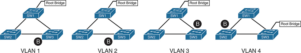
4 different VLANs , 4 different topologies and 4 different STP instances
If number of vlans increase to 10 then switch CPU will need to maintain 10 different STP instances and 10 different topologies
Not only that, switch must listen for BPDUs of every VLAN and topology changes can cause TCN and config BPDU with topology change flag
MST provides a blended approach by mapping one or multiple VLANs onto a single STP tree, called an MST instance (MSTI).

VLANs 1 and 2 correlate to one MSTI, VLAN 3 to a second MSTI, and VLAN 4 to a third MSTI.
A grouping of MST switches with the same high-level configuration is known as an MST region.
MST region appear as a single virtual switch to external switches as part of a compatibility mechanism
How MST topology is perceived outside of MST region
Everything inside the MST region looks like one virtual switch to the outside world
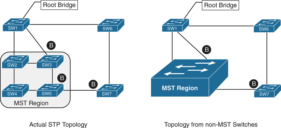
Above we can see that SW3 is blocking port to Root, which is not normal, if it was normal STP, it would become root port and not discarding, and instead it blocking port would be on SW2 – SW3 segment
For switches inside the MST region calculate STP internally
For outside switches they pretend to be a single switch
MST Instances (MSTIs)
MST uses a special STP instance called the internal spanning tree (IST), which is always the first instance, instance 0. The IST runs on all switch port interfaces for switches in the MST region, regardless of the VLANs associated with the ports.
Additional information about other MSTIs is included (nested) in the IST BPDU that is transmitted throughout the MST region. That single IST BPDU carries information for all MSTIs running
This enables the MST to advertise only one set of BPDUs, minimizing STP traffic regardless of the number of instances while providing the necessary information to calculate the STP for other MSTIs.
The number of MST instances varies by platform, but platform should support at least 16 instances allowing 15 different topologies, The IST is always instance 0, so instances 1 to 15 can support other VLANs
There is not a special name for instances 1 to 15; they are simply known as MSTIs.
MST Configuration
SW1(config)# spanning-tree mode mst
! change mode to MST

SW1(config)# spanning-tree mst 0 root primary
! The primary keyword sets the priority to 24,576, and
! the secondary keyword sets the priority to 28,672

SW1(config)# spanning-tree mst 1 root primary
SW1(config)# spanning-tree mst 2 root primary
! or set the system priority manually instead of root
! primary or root secondary keywords
! spanning-tree mst 2 priority 16384

SW1(config)# spanning-tree mst configuration
! enter MST configuration submode

SW1(config-mst)# name ENTERPRISE_CORE
! define MST region name, it must match on all switches
! in the region

SW1(config-mst)# revision 2
! this MST version number must match on all switches
! in an MST Region, By default, a region name is an empty
! string

! Associate vlans to MST instances, by default all vlans
! are associated to MST 0 instance, for varying topologies
! assign vlans to different instances
SW1(config-mst)# instance 1 vlan 10,20
SW1(config-mst)# instance 2 vlan 99
The command show spanning-tree mst configuration provides a quick verification of the MST configuration on a switch
Notice that MST instance 0 contains all the VLANs except for VLANs 10, 20, and 99, regardless of whether those VLANs are configured on the switch
MST instance 1 contains VLAN 10 and 20, and MST instance 2 contains only VLAN 99.
SW2# show spanning-tree mst configuration
Name      [ENTERPRISE_CORE]
Revision  2     Instances configured 3

Instance  Vlans mapped
--------  ---------------------------------------------------------------------
0         1-9,11-19,21-98,100-4094
1         10,20
2         99
MST Verification
The relevant spanning tree information can be obtained with the command show spanning-tree. However, the VLAN numbers are not shown and the MST instance is provided instead.
In addition, the priority value for a switch is the MST instance plus the switch priority (not the vlan number + switch priority)
SW1# show spanning-tree
! Output omitted for brevity
! Spanning Tree information for Instance 0 (All VLANs but 10,20, and 99)
MST0
  Spanning tree enabled protocol mstp
  Root ID    Priority    24576
               Address     0062.ec9d.c500
               This bridge is the root
               Hello Time   2 sec  Max Age 20 sec  Forward Delay 15 sec

  Bridge ID  Priority    24576  (priority 24576 sys-id-ext 0)
               Address     0062.ec9d.c500
               Hello Time   2 sec  Max Age 20 sec  Forward Delay 15 sec

Interface           Role Sts Cost      Prio.Nbr Type
------------------- ---- --- --------- -------- --------------------------------
Gi1/0/2             Desg FWD 20000     128.2    P2p
Gi1/0/3             Desg FWD 20000     128.3    P2p

! Spanning Tree information for Instance 1 (VLANs 10 and 20)
MST1
  Spanning tree enabled protocol mstp
  Root ID Priority 24577
            Address     0062.ec9d.c500
            This bridge is the root
            Hello Time   2 sec  Max Age 20 sec  Forward Delay 15 sec

  Bridge ID  Priority    24577  (priority 24576 sys-id-ext 1)
               Address     0062.ec9d.c500
               Hello Time   2 sec  Max Age 20 sec  Forward Delay 15 sec

Interface           Role Sts Cost      Prio.Nbr Type
------------------- ---- --- --------- -------- --------------------------------
Gi1/0/2             Desg FWD 20000      128.2    P2p
Gi1/0/3             Desg FWD 20000      128.3    P2p
! Spanning Tree information for Instance 2 (VLAN 99)  >>> instead of 24576 + 99
MST2                                                  >>> it is 24576 + 2
  Spanning tree enabled protocol mstp
  Root ID    Priority    24578
              Address     0062.ec9d.c500
              This bridge is the root
              Hello Time   2 sec  Max Age 20 sec  Forward Delay 15 sec

  Bridge ID  Priority    24578  (priority 24576 sys-id-ext 2)
               Address     0062.ec9d.c500
               Hello Time   2 sec  Max Age 20 sec  Forward Delay 15 sec

Interface           Role Sts Cost       Prio.Nbr Type
------------------- ---- --- --------- -------- --------------------------------
Gi1/0/2             Desg FWD 20000      128.2    P2p
Gi1/0/3             Desg FWD 20000      128.3    P2p
A consolidated view of the MST topology table is displayed with the command show spanning-tree mst [instance-number].
The optional instance-number can be included to restrict the output to a specific instance.
SW1# show spanning-tree mst
! Output omitted for brevity
##### MST0    vlans mapped:   1-9,11-19,21-98,100-4094
Bridge         address 0062.ec9d.c500  priority      0     (24576 sysid 0)
Root           this switch for the CIST
Operational   hello time 2 , forward delay 15, max age 20, txholdcount 6
Configured    hello time 2 , forward delay 15, max age 20, max hops    20

Interface                        Role Sts Cost      Prio.Nbr Type
----------------                 ---- --- --------- -------- ------------------------
Gi1/0/2                          Desg FWD 20000     128.2    P2p
Gi1/0/3                          Desg FWD 20000     128.3    P2p
##### MST1    vlans mapped:   10,20
Bridge         address 0062.ec9d.c500  priority      24577 (24576 sysid 1)
Root            this switch for MST1

Interface                        Role Sts Cost      Prio.Nbr Type
----------------                 ---- --- --------- -------- ------------------------
Gi1/0/2                          Desg FWD 20000     128.2    P2p
Gi1/0/3                          Desg FWD 20000     128.3    P2p

##### MST2    vlans mapped:   99
Bridge         address 0062.ec9d.c500  priority      24578 (24576 sysid 2)
Root           this switch for MST2

Interface                        Role Sts Cost      Prio.Nbr Type
----------------                 ---- --- --------- -------- ------------------------
Gi1/0/2                          Desg FWD 20000     128.2     P2p
Gi1/0/3                          Desg FWD 20000     128.3     P2p
SW2# show spanning-tree mst interface gigabitEthernet 1/0/1
GigabitEthernet1/0/1 of MST0 is root forwarding
Edge port: no (default) port guard : none (default)
Link type: point-to-point (auto) bpdu filter: disable (default)
Boundary : internal bpdu guard : disable (default)
Bpdus sent 17, received 217
Instance Role Sts Cost Prio.Nbr Vlans mapped
-------- ---- --- --------- -------- -------------------------------
0 Root FWD 20000 128.1 1-9,11-19,21-98,100-4094
1 Root FWD 20000 128.1 10,20
2 Root FWD 20000 128.1 99MST Tuning
MST supports the port cost and port priority
The interface configuration command spanning-tree mst instance-number cost cost sets the interface cost
SW3# show spanning-tree mst 0
! Output omitted for brevity
Interface                        Role Sts Cost      Prio.Nbr Type
----------------                 ---- --- --------- -------- --------------------
Gi1/0/1                          Root FWD 20000      128.1    P2p
Gi1/0/2                          Altn BLK 20000      128.2    P2p
Gi1/0/5                          Desg FWD 20000      128.5    P2p
SW3# configure term
Enter configuration commands, one per line. End with CNTL/Z.
SW3(config)# interface gi1/0/1
SW3(config-if)# spanning-tree mst 0 cost 1SW3# show spanning-tree mst 0
! Output omitted for brevity
Interface Role Sts Cost Prio.Nbr Type
---------------- ---- --- --------- -------- ---------------------
Gi1/0/1 Root FWD 1 128.1 P2p
Gi1/0/2 Desg FWD 20000 128.2 P2p
Gi1/0/5 Desg FWD 20000 128.5 P2pThe interface configuration command spanning-tree mst instance-number port-priority priority sets the interface priority.
SW4# show spanning-tree mst 0
! Output omitted for brevity
##### MST0    vlans mapped:   1-9,11-19,21-98,100-4094
Interface                        Role Sts Cost      Prio.Nbr Type
----------------                 ---- --- --------- -------- --------------------
Gi1/0/2                          Root FWD 20000     128.2     P2p
Gi1/0/5                          Desg FWD 20000     128.5     P2p
Gi1/0/6                          Desg FWD 20000     128.6     P2p
SW4# configure term
Enter configuration commands, one per line. End with CNTL/Z.
SW4(config)# interface gi1/0/5
SW4(config-if)# spanning-tree mst 0 port-priority 64SW4# show spanning-tree mst 0
! Output omitted for brevity
##### MST0 vlans mapped: 1-9,11-19,21-98,100-4094
Interface Role Sts Cost Prio.Nbr Type
---------------- ---- --- --------- -------- --------------------
Gi1/0/2 Root FWD 20000 128.2 P2p
Gi1/0/5 Desg FWD 20000 64.5 P2p
Gi1/0/6 Desg FWD 20000 128.6 P2pCommon MST Misconfigurations
Network engineers should be aware of two common misconfigurations within the MST region:
- VLAN assignment to the IST
- Trunk link pruning
VLAN Assignment to the IST
Remember that the IST operates across all links in the MST region, regardless of the VLAN assigned to the actual port.
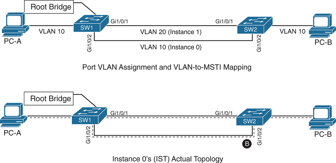
SW1 and SW2 contain two network links between them allowing VLAN 10 and VLAN 20
Gi1/0/1 and Gi1/0/2 are not trunks but they are access ports with VLANs 10 and 20 assigned
VLAN 10 is assigned to the IST, and VLAN 20 is assigned to MSTI 1
Looking at above diagram it looks like that traffic from PC 1 on VLAN 10 will traverse over the Gi1/0/2 but no, traffic will actually be blocked, we need to correct this using:
– port priority
– move VLAN 10 to MSTI 1, the switches will build a topology based on the links in use by that MST
– allow vlans on all interfaces – Trunk , configure both Gi1/0/1 and Gi1/0/2 as trunks on SW1 and SW2
The IST (Instance 0) runs over all physical links inside the MST region — regardless of VLAN assignment.
IST topology is calculated
SW1 is the root bridge
All SW1 ports = Designated Ports (DPs)
SW2 must block one of its links to prevent a loop
The IST sees:
- Two parallel physical links
- Same cost
- Same root
So one must block, even if:
- One link is “for VLAN 10”
- The other is “for VLAN 20”
To IST, they’re just two paths to same switch
Trunk Link Pruning

A network engineer made a mistake and has pruned VLANs on the trunk links between SW1 to SW2 and SW1 to SW3 to help load balance traffic.
Shortly after implementing the change, users attached to SW1 and SW3 cannot talk to the servers on SW2. The reason is that although the VLANs on the trunk links have changed, the MSTI topology has not.
You pruned VLAN 10 on one trunk but pruned VLAN 20 on a different trunk
the MST topology stays the same, but the VLAN forwarding paths no longer match it.
So rules for pruning vlans with MST are as follow:
– Never prune VLANs inconsistently if they belong to the same MST instance (MSTI).
– On any given trunk link, either allow all VLANs in an MSTI, or prune all of them together.
When configuring trunk pruning in MST:
- Think in MSTIs, not individual VLANs
- Prune per MST instance, not per VLAN
- If VLANs share an MSTI → they must travel together
MST Region Boundary
Externally, an MST region must look like one spanning-tree instance, This is non-negotiable — it’s how MST scales.
A PVST+ switch expects every VLAN has its own spanning tree
So a PVST+ switch sends:
- A BPDU for VLAN 1
- A BPDU for VLAN 10
- A BPDU for VLAN 20
- etc.
MST cannot accept per-VLAN information so MST must ignore VLAN-specific topology from outside. MST has to ask: If I can only believe ONE BPDU from outside, which one do I choose VLAN 1
Not because VLAN 1 is special logically, but because:
- VLAN 1 always exists
- VLAN 1 cannot be deleted
- VLAN 1 is guaranteed to be present end-to-end
So VLAN 1 becomes the anchor VLAN.
The IST (Instance 0) is:
“The single spanning tree that also represents the MST region to the outside world.”
When an MST switch hears PVST+ BPDUs:
- It hears many BPDUs (VLAN 1, 10, 20…)
- It must pick exactly one
- It picks VLAN 1
- That BPDU becomes the IST’s view of the outside world
But what about the other VLANs? (your natural next question) for PVST+ > MST and MST > PVST+
for MST > PVST+ , PVST+ expects a BPDU per VLAN.
So MST does this trick:
- Take the IST BPDU
- Copy it
- Send it back as:
- “VLAN 10 BPDU”
- “VLAN 20 BPDU”
- etc.
This is PVST Simulation.
The PVST simulation mechanism sends out PVST+ (and also includes RPVST) BPDUs (one for each VLAN), using the information from the IST.
for PVST+ > MST it is not needed, as long as VLAN 1’s BPDU helps in all the functions reliant on BPDU and contains
– STP type
– root path cost
– root bridge identifier
– local bridge identifier
– max age
– hello time
– forward delay
The mental model that usually makes it click
Think of MST like a company spokesperson:
- Inside the company: many departments (MSTIs)
- Outside the company: one voice
- VLAN 1 is the spokesperson’s microphone
An MST region boundary is any port that connects to a switch that is in a different MST region or that connects to 802.1D or 802.1W BPDUs.
There are two design considerations when integrating an MST region with a PVST+/RPVST environment: The MST region is the root bridge, or the MST region is not a root bridge for any VLAN. These scenarios are explained in the following sections.
MST Region as the Root Bridge

Shows the IST instance as the root bridge for all VLANs. SW1 and SW2 advertise multiple superior BPDUs for each VLAN toward SW3, which is operating as a PVST+ switch. SW3 is responsible for blocking ports
Making the MST region the root bridge ensures that Blocking does not take place on MST region or virtual switch, avoiding block on MST is the goal
MST Region Not a Root Bridge for Any VLAN
In this scenario, the MST region boundary ports can only block or forward for “all VLANs” together. Remember that only the VLAN 1 PVST BPDU is used for the IST and that the IST BPDU is a one-to-many translation of IST BPDUs to all PVST BPDUs. There is not an option to load balance traffic because the IST instance must remain consistent.
If an MST switch detects a better BPDU for a specific VLAN on a boundary port, the switch will use BPDU guard to block this port. The port will then be placed into a root inconsistent state. Although this may isolate downstream switches, it is done to ensure a loop-free topology; this is called the PVST simulation check.
next post
DMVPN
DMVPN
DMVPN provides full mesh broadcast network type connectivity over WAN transport by using mGRE or multipoint GRE, as a result we get sites on spokes with direct spoke to spoke to communication that is on top secured with IPSec encryption, popular because of ease of configuration and scalability
Before we get into DMVPN, we need to know GRE well
With DMVPN, spokes have to register to hub just like SIP phone registers to the SIP server
Generic Routing Encapsulation (GRE) Tunnels
GRE not just provides connectivity for IP but also legacy and nowadays nonrouteble protocols like DECnet, Systems Network Architecture SNA and IPX
Running protocols over VPN was a big issue due to VPN being point to point and networks had to be designed around the point to point topologies but routing protocols function well over broadcast like topologies , mGRE resolves that problem
Additional header is added when packets travel over the GRE tunnel
GRE tunnels support IPv4 or IPv6 addresses as an overlay or transport network.
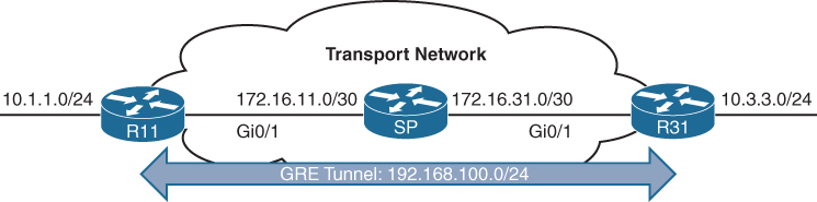
GRE creates a virtual network or overlay network over a real physical underlay network
In the routing tables of participating routers R11 and R31 , 10.1.1.0/24 is behind 192.168.0.11 and 10.3.3.0/24 is behind 192.168.0.31 , The Transport side or WAN side routing table does not have 192.168.0.0/16 network range , and that is how when tunnels are up those stub networks are accessible, and if tunnels are not up then they are not accessible
interface Tunnel100
! create tunnel interface


 bandwidth 4000
 ! Virtual interfaces do not have the concept of latency
 ! and need to have a reference bandwidth configured so that
 ! routing protocols that use bandwidth for best-path calculation
 ! can make intelligent decisions
 ! measured and configured in kilo bits
 ! Bandwidth is also used for quality of service (QoS) configuration
 ! on the interface


 ip address 192.168.100.11 255.255.255.0
 ! GRE tunnel needs IP as it is just like any other interface
 ! this is overlay IP


 ip mtu 1400
 ! reduce the mtu for tunnel interface
 ! exact added size differs based on tunnel type and encryption used
 ! min 24 bytes to 77 bytes


 keepalive 5 3
 ! The default timer is 10 seconds and three retries
 ! Tunnel interfaces are GRE point-to-point (P2P) by default,
 ! and the line protocol enters an up state when the router detects
 ! that a route to the tunnel destination exists in the routing
 ! table. If the tunnel destination is not in the routing table,
 ! the tunnel interface (line protocol) enters a down state.
 ! What if there is a problem on remote end and remote router is down
 ! By default, GRE tunnels stay “up” as long as the interface is configured
 ! and tunnel destination is in routing table
 ! Tunnel keepalives ensure that bidirectional communication exists
 ! between tunnel endpoints to keep the line protocol up


 tunnel source GigabitEthernet0/1
 ! tunnel's source interface is used for encapsulation and decapsulation
 ! tunnel source also accepts IP address as well
 ! tunnel source can be physical or loopback interface


tunnel destination 172.16.31.1
! tunnel's destination is where GRE sends packets or terminates tunnel
! for mGRE this is not defined but dynamically provided | Tunnel Type | Tunnel Header Size |
|---|---|
| GRE without IPsec | 24 bytes |
| DES/3DES IPsec (transport mode) | 18–25 bytes |
| DES/3DES IPsec (tunnel mode) | 38–45 bytes |
| GRE/DMVPN + DES/3DES | 42–49 bytes |
| GRE/DMVPN + AES + SHA-1 | 62–77 bytes |
GRE Sample Configuration
R11
interface Tunnel100
 bandwidth 4000
 ip address 192.168.100.11 255.255.255.0
 ip mtu 1400
 keepalive 5 3
 tunnel source GigabitEthernet0/1
tunnel destination 172.16.31.1
!
router eigrp GRE-OVERLAY
 address-family ipv4 unicast autonomous-system 100
  topology base
  exit-af-topology
  network 10.0.0.0
  network 192.168.100.0
 exit-address-family
R31
interface Tunnel100
bandwidth 4000
ip address 192.168.100.31 255.255.255.0
ip mtu 1400
keepalive 5 3
tunnel source GigabitEthernet0/1
tunnel destination 172.16.11.1
!
router eigrp GRE-OVERLAY
address-family ipv4 unicast autonomous-system 100
topology base
exit-af-topology
network 10.0.0.0
network 192.168.100.0
exit-address-familyR11# show interface tunnel 100
! Output omitted for brevity
Tunnel100 is up, line protocol is up
Hardware is Tunnel
Internet address is 192.168.100.1/24
MTU 17916 bytes, BW 400 Kbit/sec, DLY 50000 usec,
reliability 255/255, txload 1/255, rxload 1/255
Encapsulation TUNNEL, loopback not set
Keepalive set (5 sec), retries 3
Tunnel source 172.16.11.1 (GigabitEthernet0/1), destination 172.16.31.1
Tunnel Subblocks:
src-track:
Tunnel100 source tracking subblock associated with GigabitEthernet0/1
Set of tunnels with source GigabitEthernet0/1, 1 member (includes
iterators), on interface <OK>
Tunnel protocol/transport GRE/IP
Key disabled, sequencing disabled
Checksumming of packets disabled
Tunnel TTL 255, Fast tunneling enabled
Tunnel transport MTU 1476 bytes
Tunnel transmit bandwidth 8000 (kbps)
Tunnel receive bandwidth 8000 (kbps)
Last input 00:00:02, output 00:00:02, output hang neverR11# show ip route
! Output omitted for brevity
Codes: L - local, C - connected, S - static, R - RIP, M - mobile, B - BGP
D - EIGRP, EX - EIGRP external, O - OSPF, IA - OSPF inter area
Gateway of last resort is not set
10.0.0.0/8 is variably subnetted, 3 subnets, 2 masks
C 10.1.1.0/24 is directly connected, GigabitEthernet0/2
D 10.3.3.0/24 [90/38912000] via 192.168.100.31, 00:03:35, Tunnel100 <<<
172.16.0.0/16 is variably subnetted, 3 subnets, 2 masks
C 172.16.11.0/30 is directly connected, GigabitEthernet0/1
R 172.16.31.0/30 [120/1] via 172.16.11.2, 00:00:03, GigabitEthernet0/1
192.168.100.0/24 is variably subnetted, 2 subnets, 2 masks
C 192.168.100.0/24 is directly connected, Tunnel100 <<<Verifying that 10.3.3.3 network is reachable via Tunnel 100 (192.168.100.0/24)
R11# traceroute 10.3.3.3 source 10.1.1.1
Tracing the route to 10.3.3.3
  1 192.168.100.31 1 msec * 0 msec
Notice that from R11’s perspective, the network is only one hop away. The traceroute does not display all the hops in the underlay
In the same fashion, the packet’s time to live (TTL) is encapsulated as part of the payload. The original TTL decreases by only one for the GRE tunnel, regardless of the number of hops in the transport network.
Route recursion issue in GRE
Route recursion happens when a router tries to resolve the underlay next hop of a GRE tunnel destination using the tunnel itself, creating a logical loop, in order to prevent this we need to “not advertise” the underlay networks through GRE peering.
This scenario can occur when routing protocol is turned on all interfaces without care (regardless of passive default command)
This includes GRE tunnel destination’s subnet in the routing protocol
That route must be reachable via a physical interface
If the route to the tunnel destination disappears → GRE goes down
Sequence of events to failure
Step 1: Normal Operation
- Tunnel destination is reachable via the physical interface
- GRE tunnel comes UP
- IGP advertises routes over the tunnel
Step 2: IGP Learns a “Better” Route
- IGP learns the tunnel destination IP via the GRE tunnel
- This route has:
- Lower metric
- Or preferred administrative distance
Step 3: Recursive Dependency
- Router now thinks: “To reach the GRE destination, use the tunnel”
- But the tunnel itself requires reachability to that destination
Tunnel depends on itself
What Happens Next?
- GRE tunnel goes DOWN
- IGP adjacency over tunnel goes DOWN
- Physical-path route reappears
- Tunnel comes UP
- Loop repeats
Result:
- Tunnel flapping
- IGP instability
- High CPU
- Intermittent packet loss
Next Hop Resolution Protocol (NHRP)
NHC refers to DMVPN Spoke
NHS refers to DMVPN Hub
NHRP is just like ARP but for non-broadcast multi-access (NBMA) WAN networks such as Frame Relay and ATM networks
NHRP is a client/server protocol that allows devices to register themselves. NHRP next-hop servers (NHSs) are responsible for registering addresses or networks, and replying to any queries received by next-hop clients (NHCs).
NHC can reach NHS and ask for of underlay and overlay IP for a specific “network”
NHCs are statically configured with the IP addresses of the hubs (NHSs) so that they can register their overlay (tunnel IP) and NBMA (underlay) IP addresses with the hubs
NHRP Message Types
| Message Type | Description |
|---|---|
| Registration | Registration NHRP messages are sent by the NHC (spoke) toward the NHS (hub). The NHC (spoke) also specifies the amount of time that the registration should be maintained by the NHS (hub) |
| Resolution | Resolution NHRP messages provide the address resolution to remote spoke. Resolution reply provides underlay and overlay IP address for a remote network. |
| Redirect | This allows Hub to notify the spoke that a specific network can be reached by using a more optimal path (spoke-to-spoke tunnel). Redirect NHRP messages are essential component of DMVPN Phase 3 spoke to spoke to work. |
| Purge | Purge NHRP messages are sent to remove a cached NHRP entry. Purge messages notify routers of change. A purge is typically sent by a Hub to spoke to indicate that the mapping for an address/network that it answered is not valid anymore |
| Error | Error messages are used to notify the sender of an NHRP packet that an error has occurred. |
Dynamic Multipoint VPN (DMVPN)
Zero-touch provisioning:
It is considered a zero-touch technology because no configuration is needed on the DMVPN hub routers as new spokes are added to the DMVPN network
Spoke-to-spoke tunnels:
DMVPN provides full-mesh connectivity.
Dynamic spoke-to-spoke tunnels are created as needed and torn down when no longer needed.
There is no packet loss while building dynamic on-demand spoke-to-spoke tunnels “after the initial spoke-to-hub tunnels are established”.
Multiprotocol support: DMVPN can use IPv4, IPv6, and MPLS as either the overlay or underlay network protocol.
Multicast support: DMVPN allows multicast traffic to flow on the tunnel interfaces.
Adaptable connectivity:
DMVPN routers can establish connectivity behind Network Address Translation (NAT).
Spoke routers can use dynamic IP addressing such as Dynamic Host Configuration Protocol (DHCP).
A spoke site initiates a persistent VPN connection to the hub router.
Network traffic between spoke sites does not have to travel through the hubs.
DMVPN then dynamically builds a VPN tunnel between spoke sites on an as-needed basis. This allows network traffic, such as voice over IP (VoIP), to take a direct path, which reduces delay and jitter without consuming bandwidth at the hub site.
DMVPN was released in three phases, each phase built on the previous one with additional functions. DMVPN spokes can use DHCP or static addressing for the transport and overlay networks.
Next-hop preservation
interface Tunnel0
 ip summary-address eigrp 100 10.1.0.0 255.255.0.0
Summarization is used on hub router in DMVPN design to reduce the routing table size in hub because a lot of sites report / advertise a lot of subnets per site and can increase the size of routing table on hub
but problem occurs when summary is configured, next hop is changed to summarising router which is normal in any summarization and in DMVPN and instead of spoke to spoke communication it becomes spoke to hub to spoke communication
NHRP shortcut
A dynamically created, “more-specific” route pushed by hub (phase 3) installed by NHRP that changes the next hop from the hub to the destination spoke, allowing direct spoke-to-spoke forwarding.
That creates a shortcut tunnel between spokes
NHRP Shortcuts are
Dynamic → created on demand
More specific → overrides a summary route
Installed in the routing table → not just a cache
Changes the next hop → from hub → spoke
Enables direct tunnels → spoke-to-spokehence Phase 2 + summarisation = hub-and-spoke forwarding only
Phase 1: Spoke-to-Hub
DMVPN Phase 1, the first DMVPN implementation
VPN tunnels are created only between spoke and hub sites.
Traffic between spokes must traverse the hub to reach any other spoke.
Phase 2: Spoke-to-Spoke
DMVPN Phase 2 allows spoke-to-spoke
but DMVPN Phase 2 does not support spoke-to-spoke communication between different DMVPN networks (multilevel hierarchical DMVPN).
DMVPN spoke to spoke communication breaks when hub summarizes routes because Spokes do not know which spoke owns which subnet and cannot build NHRP shortcut and traffic must go via spoke → hub → spoke
Spoke-to-spoke still technically exists, but is never used
Same thing happens in hierarchical DMVPN because regional hubs summarize routes upward and global hub only sees big summary routes so even if local region’s hub is not using summarization, remote region’s routes are summarized so spoke to spoke (in different region) communication in DMVPN Phase 2 breaks
Phase 3 fixes exactly this problem.
Phase 3: Hierarchical Tree Spoke-to-Spoke
DMVPN Phase 3 fixes above problem and refines spoke-to-spoke connectivity by adding below NHRP messages by adding two NHRP messages:
1. Redirect message
2. Shortcut message
Step-by-step Phase 3 traffic flow
Spoke A sends traffic to Spoke B
Routing table says:
10.1.2.0/24 → HUB (summary route)
Actual Data Packet reaches the hub
Hub sees:
- “This traffic should go spoke-to-spoke”
- Sends NHRP Redirect back to Spoke A: “You should talk directly to Spoke B for network x”
Spoke A sends NHRP Resolution Request for network x
“I am trying to reach this network x”
“Tell me which tunnel endpoint owns it”
NHRP Resolution Request
-----------------------
Requested Protocol Address: 10.1.2.0/24
Source NBMA Address: Spoke A public IP
Source Tunnel Address: 172.16.0.2
so the hub responds
“That network lives behind Spoke B.
Here is its tunnel IP and public IP.”
NHRP Resolution Reply
--------------------
Destination Protocol Address: 10.1.2.0/24
Destination Tunnel Address: 172.16.0.3
Destination NBMA Address: 203.0.113.22
NHRP installs above shortcut route and saves it in NHRP cache
- More specific than the summary
- Overrides the hub route
Spoke A now builds a direct GRE/IPsec tunnel to Spoke B and data packets now go directly from spoke to spoke
so summary route still exists for scale of HUB router memory but NHRP injects more-specific routes dynamically, More specific routes override summaries
Difference in Phase 2 and Phase 3 DMVPN with multilevel hierarchical topologies
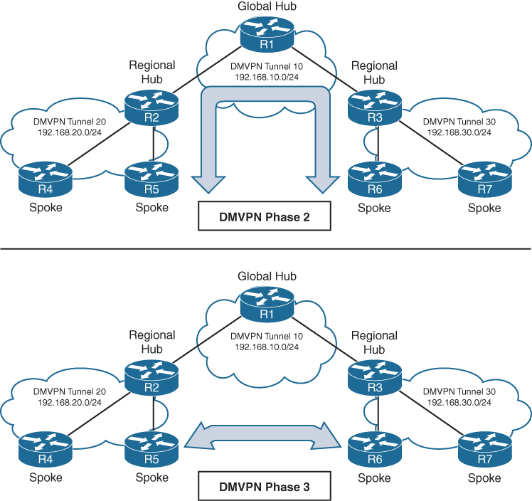
Connectivity between DMVPN tunnels 20 and 30 is established by DMVPN tunnel 10
All three DMVPN tunnels use the same DMVPN tunnel ID, even though they use different tunnel interfaces
For Phase 2 DMVPN tunnels, traffic from R5 must flow to the hub R2, where it is sent to R3 and then back down to R6
For Phase 3 DMVPN tunnels, a spoke-to-spoke tunnel is established between R5 and R6, and the two routers can communicate directly.
Each DMVPN phase has its own specific configuration. Intermixing DMVPN phases on the same tunnel network is not recommended. If you need to support multiple DMVPN phases for a migration, a second DMVPN network (subnet and tunnel interface) should be used.
DMVPN Configuration

DMVPN Hub Configuration
R11-Hub
interface Tunnel100


 bandwidth 4000
 ! Virtual interfaces do not have the concept of latency
 ! and need to have a reference bandwidth configured so that
 ! routing protocols that use bandwidth for best-path calculation
 ! can make intelligent decisions
 ! measured and configured in kilo bits
 ! Bandwidth is also used for quality of service (QoS) configuration
 ! on the interface


 ip address 192.168.100.11 255.255.255.0
 ! allocate an overlay IP address


 ip mtu 1400
 ! set ip mtu to 1400 , typical value for DMVPN to account for additional
 ! encapsulation


 ip nhrp map multicast dynamic
 ! Good to enable multicast support for NHRP
 ! NHRP just like subnets can also provide mapping of overlay IP
 ! + underlay IP for multicast addresses , To support multicast
 ! or routing protocols that use multicast, enable this on DMVPN hub
 ! routers


 ip nhrp network-id 100
 ! Enable NHRP on tunnel and assign unique network identity
 ! this NHRP network ID is not used in any negotiation but
 ! It is recommended that the NHRP network ID match on all
 ! routers participating in the same DMVPN network.
 ! It is used by local router to identify the DMVPN cloud
 ! because multiple tunnel interfaces can belong to the same
 ! DMVPN cloud


 ip nhrp redirect
 ! Enable Phase 3 or NHRP redirect function on DMVPN network


 ip tcp adjust-mss 1360
 ! to influence the TCP MSS negotiation in 3 WAY handshake
 ! for TCP packets visible on tunnel which they are even in
 ! case of TLS, typical value is 1360 to accommodate the 20
 ! bytes for IP + 20 bytes for TCP header


 tunnel source GigabitEthernet0/1
 ! this can be logical interface like loopback
 ! QoS problems can occur with the use of loopback interfaces
 ! when there are multiple paths in the forwarding table to the
 ! decapsulating router. The same problems occur automatically
 ! with port channels, which are not recommended at the time of
 ! this writing.


 tunnel mode gre multipoint
 ! configure tunnel as mGRE tunnel


 tunnel key 100
 ! Optionally use tunnel key in case multiple tunnel interfaces
 ! use same source interface , Tunnel keys, if configured, must
 ! match for a DMVPN tunnel to be established between two routers
 ! the tunnel key adds 4 bytes to the DMVPN header. The tunnel key
 ! is configured with the command tunnel key 0-4294967295
 ! If the tunnel key is defined on the hub router, it must be defined
 ! on all the spoke routers.
Note that mGRE tunnels do not support the option for using a keepalive. Keepalive is only logically possible when there is a single endpoint on other end, but in mGRE we have multiple endpoints
There is no technical correlation between the NHRP network ID and the tunnel interface number; however, keeping them the same helps from an operational support standpoint.
DMVPN Spoke Configuration for DMVPN Phase 1 (Point-to-Point)
The configuration of DMVPN Phase 1 spokes is similar to the configuration for a hub router except two differences:
- You do not use an mGRE tunnel. Instead, you specify the tunnel destination (because communication has to come back to hub)
- The NHRP mapping points to at least one active NHS
R31-Spoke (Single NHRP Command Configuration)

interface Tunnel100
 bandwidth 4000
 ! Virtual interfaces do not have the concept of latency
 ! and need to have a reference bandwidth configured so that
 ! routing protocols that use bandwidth for best-path calculation
 ! can make intelligent decisions
 ! measured and configured in kilo bits
 ! Bandwidth is also used for quality of service (QoS) configuration
 ! on the interface


 ip address 192.168.100.31 255.255.255.0
 ! assign overlay IP address to the Spoke


 ip mtu 1400


 ip nhrp network-id 100


 ip nhrp nhs 192.168.100.11 nbma 172.16.11.1 multicast
 ! define the DMVPN HUB or NHS, more can be added
 ! multicast keyword provides multicast mapping functions
 ! in NHRP and is required to support the following routing
 ! protocols: RIP, EIGRP, and Open Shortest Path First (OSPF)


 ip tcp adjust-mss 1360
 tunnel source GigabitEthernet0/1


 tunnel destination 172.16.11.1
 ! tunnel destination is DMVPN HUB underlay address


 tunnel key 100
R41-Spoke (Multiple NHRP Commands Configuration)
! NHS with MAP commands
interface Tunnel100
bandwidth 4000
ip address 192.168.100.41 255.255.255.0
ip mtu 1400
ip nhrp map 192.168.100.11 172.16.11.1
ip nhrp map multicast 172.16.11.1
ip nhrp network-id 100
ip nhrp nhs 192.168.100.11
ip tcp adjust-mss 1360
tunnel source GigabitEthernet0/1
tunnel destination 172.16.11.1
tunnel key 100Viewing DMVPN Tunnel Status
Tunnel states, in order of establishment:
- INTF: The line protocol of the DMVPN tunnel is down.
- IKE: DMVPN tunnels configured with IPsec have not yet established an IKE session.
- Ipsec: An IKE session has been established, but an Ipsec security association (SA) has not yet been established.
- NHRP: The DMVPN spoke router has not yet successfully registered.
- Up: The DMVPN spoke router has registered with the DMVPN hub and received an ACK (positive registration reply) from the hub.
R31-Spoke# show dmvpn
! Output omitted for brevity
Interface: Tunnel100, IPv4 NHRP Details
Type:Spoke, NHRP Peers:1,

# Ent  Peer NBMA Addr Peer Tunnel Add State  UpDn Tm Attrb
 ----- --------------- --------------- ----- -------- -----
     1 172.16.11.1       192.168.100.11    UP 00:05:26     S >>> static because NHS was defined
R41-Spoke# show dmvpn
! Output omitted for brevity
Interface: Tunnel100, IPv4 NHRP Details
Type:Spoke, NHRP Peers:1,

# Ent  Peer NBMA Addr Peer Tunnel Add State  UpDn Tm Attrb
 ----- --------------- --------------- ----- -------- -----
     1 172.16.11.1       192.168.100.11    UP  00:05:26    S >>> static because NHS was defined
R11-Hub# show dmvpn
Legend: Attrb ◊–S - Static,–D - Dynamic,–I - Incomplete
          –N - NATed,–L - Local,–X - No Socket
           –1 - Route Installed, –2 - Nexthop-override
          –C - CTS Capable
           # Ent --> Number of NHRP entries with same NBMA peer
           NHS Status: E --> Expecting Replies, R --> Responding, W --> Waiting
           UpDn Time --> Up or Down Time for a Tunn==

Interface: Tunnel100, IPv4 NHRP Details
Type:Hub, NHRP Peers:2,

 # Ent  Peer NBMA Addr Peer Tunnel Add State  UpDn Tm Attrb
 ----- --------------- --------------- ----- -------- -----
     1 172.16.31.1       192.168.100.31   UP 00:05:26     D
     1 172.16.41.1       192.168.100.41   UP 00:05:26     D

>>> D ! Dynamic because HUB learned spoke
with detail keyword
R11-Hub# show dmvpn detail
Legend: Attrb --> S - Static, D - Dynamic, I - Incomplete
           N - NATed, L - Local, X - No Socket
           T1 - Route Installed, T2 - Nexthop-override
           C - CTS Capable
           # Ent --> Number of NHRP entries with same NBMA peer
           NHS Status: E --> Expecting Replies, R --> Responding, W --> Waiting
           UpDn Time --> Up or Down Time for a Tunnel
==========================================================================

Interface Tunnel100 is up/up, Addr. is 192.168.100.11, VRF ""
    Tunnel Src./Dest. addr: 172.16.11.1/MGRE, Tunnel VRF ""
    Protocol/Transport: "multi-GRE/IP"", Protect ""
    Interface State Control: Disabled
    nhrp event-publisher : Disabled
Type:Hub, Total NBMA Peers (v4/v6): 2

# Ent  Peer NBMA Addr Peer Tunnel Add State  UpDn Tm Attrb    Target Network
----- --------------- --------------- ----- -------- ----- -----------------

    1 172.16.31.1        192.168.100.31    UP 00:01:05     D  192.168.100.31/32
    1 172.16.41.1        192.168.100.41    UP 00:01:06     D  192.168.100.41/32
R31-Spoke# show dmvpn detail
! Output omitted for brevity

Interface Tunnel100 is up/up, Addr. is 192.168.100.31, VRF ""
  Tunnel Src./Dest. addr: 172.16.31.1/172.16.11.1, Tunnel VRF ""
  Protocol/Transport: "GRE/IP", Protect ""
  Interface State Control: Disabled
  nhrp event-publisher : Disabled
IPv4 NHS:
192.168.100.11 RE NBMA Address: 172.16.11.1 priority = 0 cluster = 0
Type:Spoke, Total NBMA Peers (v4/v6): 1

# Ent  Peer NBMA Addr Peer Tunnel Add State  UpDn Tm Attrb    Target Ne
----- --------------- --------------- ----- -------- ----- ------------
    1 172.16.11.1        192.168.100.11    UP 00:00:28     S  192.168.100
R41-Spoke# show dmvpn detail
! Output omitted for brevity
Interface Tunnel100 is up/up, Addr. is 192.168.100.41, VRF ""
Tunnel Src./Dest. addr: 172.16.41.1/172.16.11.1, Tunnel VRF " "
Protocol/Transport: "GRE/IP", Protect ""
Interface State Control: Disabled
nhrp event-publisher : Disabled
IPv4 NHS:
192.168.100.11 RE NBMA Address: 172.16.11.1 priority = 0 cluster = 0
Type:Spoke, Total NBMA Peers (v4/v6): 1
# Ent Peer NBMA Addr Peer Tunnel Add State UpDn Tm Attrb Target Network
----- --------------- --------------- ----- -------- ----- -----------------
1 172.16.11.1 192.168.100.11 UP 00:02:00 S 192.168.100.11/32Viewing the NHRP Cache
NHRP cache very similar to ARP cache contains information returned by hub such as network entry with overlay and underlay IP of spokes , interface it was received on + expiry time (dynamic entries expire)
| NHRP Mapping Entry | Description |
|---|---|
| static | An entry created statically on a DMVPN interface, this is seen on DMVPN Spokes |
| dynamic | An entry created dynamically. This is seen on DMVPN Hub |
| incomplete | A Cisco router means the router knows it needs a mapping, but the resolution process has not finished yet. This is just like an “Incomplete” ARP entry NHRP (Next Hop Resolution Protocol) is commonly used in DMVPN to map: Tunnel IP address → NBMA (physical/WAN) IP address Routers cache these mappings in the NHRP table. An NHRP entry marked INCOMPLETE indicates: The router has initiated an NHRP resolution request, but has not yet received a valid reply. So: The router does not yet know the NBMA address The mapping cannot be used for forwarding traffic The entry is temporary – usually is seen on HUB when request sent, no reply received and this can be when destination spoke is down , not registered or has incorrect configuration – also happens when NHRP replies are being blocked by ACL, Firewall, NAT Router# show ip nhrp 10.10.10.2/32 via 10.10.10.2 Tunnel0 created 00:00:12, incompleteAn incomplete entry prevents repetitive NHRP requests for the same entry. Eventually this will time out and permit another NHRP resolution request for the same network. A healthy entry eventually changes to Dynamic or Static |
| local | Just like ARP’s local meaning that this overlay IP and underlay IP is on the router interface itself , Cisco routers automatically install a local NHRP entry so that router can correctly identify itself as an NHRP participantR1# show ip nhrp 10.0.0.1/32 via 10.0.0.1 Tunnel0 created 00:12:33, expire never Type: local, Flags: authoritative |
| (no-socket) | Mapping entries that do not have associated IPsec sockets and where encryption is not triggered. |
| NBMA address | Nonbroadcast multi-access address, or the transport IP address where the entry was received. |
NHRP message flags specify attributes of an NHRP cache entry
| NHRP Message Flag | Description |
|---|---|
| used | Indicates that this NHRP mapping entry was used to forward data packets within the past “60” seconds. |
| implicit | Indicates that the NHRP mapping entry was learned implicitly. Examples of such entries are the source mapping information gleaned from an NHRP resolution request received by the local router or from an NHRP resolution packet forwarded “through” the router. |
| unique | Indicates that this remote NHRP mapping entry must be unique and that it cannot be overwritten with an entry that has the same tunnel IP address but a different NBMA address. |
| router | Indicates that this NHRP mapping entry is from a remote “router” that provides access to a network or “host” behind the remote router. |
| rib | NHRP has injected a host route into the IP routing table This is not learned via a routing protocol (EIGRP/OSPF/BGP), but directly installed by NHRP show ip nhrp10.10.10.2/32 via 172.16.1.2 Flags: unique, dynamic, ribThis rib flag means this entry is installed in routing table show ip route 10.10.10.2Routing entry for 10.10.10.2/32 Known via "nhrp", distance 250, metric 0Why is AD 250 important? Makes sure routing protocols win Prevents NHRP from overriding real routing decisions NHRP routes are fallback / shortcut routes but because these are longest or most specific routes they always override When will you see RIB flag set? You’ll see RIB when: DMVPN Phase 2 or 3 is active NHRP resolution succeeds Spoke learns another spoke’s NBMA address Traffic triggers a shortcut |
| nho | When NHO is set, the spoke is telling the hub: “Do NOT override the next-hop with yourself when replying to NHRP resolution requests.” The hub does not insert itself as the next hop This allows direct spoke-to-spoke tunnels to form Without NHO Traffic between spokes is forced through the hub Hub becomes the next hop No dynamic spoke-to-spoke tunnels With NHO (normal DMVPN behavior) Hub returns the real NBMA address of the destination spoke Spokes build direct GRE/IPsec tunnels Enables Phase 2 / Phase 3 DMVPN |
| nhop | The nhop flag tells that this is valid next-hop for forwarding traffic |
R11-Hub# show ip nhrp
192.168.100.31/32 via 192.168.100.31
  Tunnel100 created 23:04:04, expire 01:37:26
  Type: dynamic, Flags: unique registered used nhop
  NBMA address: 172.16.31.1
192.168.100.41/32 via 192.168.100.41
  Tunnel100 created 23:04:00, expire 01:37:42
  Type: dynamic, Flags: unique registered used nhop
  NBMA address: 172.16.41.1
R31-Spoke# show ip nhrp
192.168.100.11/32 via 192.168.100.11
Tunnel100 created 23:02:53, never expire
Type: static, Flags:
NBMA address: 172.16.11.1R41-Spoke# show ip nhrp
192.168.100.11/32 via 192.168.100.11
Tunnel100 created 23:02:53, never expire
Type: static, Flags:
NBMA address: 172.16.11.1show ip nhrp “brief”
some information such as the used and nhop NHRP message flags are not shown with brief keyword
R11-Hub# show ip nhrp brief
****************************************************************************
    NOTE: Link-Local, No-socket and Incomplete entries are not displayed
****************************************************************************
Legend: Type --> S - Static, D - Dynamic
         Flags --> u - unique, r - registered, e - temporary, c - claimed
         a - authoritative, t - route
============================================================================
Intf     NextHop Address                                    NBMA Address
         Target Network                              T/Flag
-------- ------------------------------------------- ------ ----------------

Tu100    192.168.100.31                                     172.16.31.1
         192.168.100.31/32                           D/ur
Tu100    192.168.100.41                                     172.16.41.1
         192.168.100.41/32                           D/ur
R31-Spoke# show ip nhrp brief
! Output omitted for brevity
Intf NextHop Address NBMA Address
Target Network T/Flag
-------- ------------------------------------------- ------ ----------------
Tu100 192.168.100.11 172.16.11.1
192.168.100.11/32 S/R41-Spoke# show ip nhrp brief
! Output omitted for brevity
Intf NextHop Address NBMA Address
Target Network T/Flag
-------- ------------------------------------------- ------ ----------------
Tu100 192.168.100.11 172.16.11.1
192.168.100.11/32 S/The optional detail keyword provides a list of routers that submitted NHRP resolution requests and their request IDs.
Routing Table
Notice that the next-hop address between spoke routers is 192.168.100.11 (R11).
R11-Hub# show ip route
! Output omitted for brevity
Codes: L - local,   C - connected, S - static, R - RIP, M - mobile, B - BGP
         D - EIGRP, EX - EIGRP external, O - OSPF, IA - OSPF inter area

Gateway of last resort is 172.16.11.2 to network 0.0.0.0

S*    0.0.0.0/0 [1/0] via 172.16.11.2
      10.0.0.0/8 is variably subnetted, 4 subnets, 2 masks
C        10.1.1.0/24 is directly connected, GigabitEthernet0/2
D        10.3.3.0/24 [90/27392000] via 192.168.100.31, 23:03:53, Tunnel100
D        10.4.4.0/24 [90/27392000] via 192.168.100.41, 23:03:28, Tunnel100
      172.16.0.0/16 is variably subnetted, 2 subnets, 2 masks
C        172.16.11.0/30 is directly connected, GigabitEthernet0/1
      192.168.100.0/24 is variably subnetted, 2 subnets, 2 masks
C        192.168.100.0/24 is directly connected, Tunnel100
R31-Spoke# show ip route
! Output omitted for brevity
Gateway of last resort is 172.16.31.2 to network 0.0.0.0
S* 0.0.0.0/0 [1/0] via 172.16.31.2
10.0.0.0/8 is variably subnetted, 4 subnets, 2 masks
D 10.1.1.0/24 [90/26885120] via 192.168.100.11, 23:04:48, Tunnel100
C 10.3.3.0/24 is directly connected, GigabitEthernet0/2
D 10.4.4.0/24 [90/52992000] via 192.168.100.11, 23:04:23, Tunnel100
172.16.0.0/16 is variably subnetted, 2 subnets, 2 masks
C 172.16.31.0/30 is directly connected, GigabitEthernet0/1
192.168.100.0/24 is variably subnetted, 2 subnets, 2 masks
C 192.168.100.0/24 is directly connected, Tunnel100R41-Spoke# show ip route
! Output omitted for brevity
Gateway of last resort is 172.16.41.2 to network 0.0.0.0
S* 0.0.0.0/0 [1/0] via 172.16.41.2
10.0.0.0/8 is variably subnetted, 4 subnets, 2 masks
D 10.1.1.0/24 [90/26885120] via 192.168.100.11, 23:05:01, Tunnel100
D 10.3.3.0/24 [90/52992000] via 192.168.100.11, 23:05:01, Tunnel100
C 10.4.4.0/24 is directly connected, GigabitEthernet0/2
172.16.0.0/16 is variably subnetted, 2 subnets, 2 masks
C 172.16.41.0/24 is directly connected, GigabitEthernet0/1
192.168.100.0/24 is variably subnetted, 2 subnets, 2 masks
C 192.168.100.0/24 is directly connected, Tunnel100Traceroute
Traceroute shows that data from R31 to R41 will go through R11.
R31-Spoke# traceroute 10.4.4.1 source 10.3.3.1
Tracing the route to 10.4.4.1
  1 192.168.100.11 0 msec 0 msec 1 msec
  2 192.168.100.41 1 msec * 1 msec
DMVPN Configuration for Phase 3 DMVPN (Multipoint)
Phase 3 DMVPN configuration for the hub router adds the interface parameter command ip nhrp redirect on the hub router
This command checks the flow of packets on the tunnel interface and sends a redirect message to the source spoke router when it detects Hub router being used as transit, this is done by detecting for hairpinning
Hairpinning means that traffic is received and sent out an interface in the same cloud (identified by the NHRP network ID) , For instance, hairpinning occurs when packets come in and go out the same tunnel interface.
The Phase 3 DMVPN configuration for spoke routers uses the mGRE tunnel interface and uses the command ip nhrp shortcut on the tunnel interface.
R11-Hub
interface Tunnel100
 bandwidth 4000
 ip address 192.168.100.11 255.255.255.0
 ip mtu 1400
 ip nhrp map multicast dynamic
 ip nhrp network-id 100
 ip nhrp redirect <<<
 ip tcp adjust-mss 1360
 tunnel source GigabitEthernet0/1
 tunnel mode gre multipoint
 tunnel key 100
R31-Spoke
interface Tunnel100
bandwidth 4000
ip address 192.168.100.31 255.255.255.0
ip mtu 1400
ip nhrp network-id 100
ip nhrp nhs 192.168.100.11 nbma 172.16.11.1 multicast
ip nhrp shortcut <<<
ip tcp adjust-mss 1360
tunnel source GigabitEthernet0/1
tunnel mode gre multipoint
tunnel key 100R41-Spoke
interface Tunnel100
bandwidth 4000
ip address 192.168.100.41 255.255.255.0
ip mtu 1400
ip nhrp network-id 100
ip nhrp nhs 192.168.100.11 nbma 172.16.11.1 multicast
ip nhrp shortcut <<<
ip tcp adjust-mss 1360
tunnel source GigabitEthernet0/1
tunnel mode gre multipoint
tunnel key 100IP NHRP Authentication
NHRP includes an authentication capability, but this authentication is weak because the password is stored in plaintext. Most network administrators use NHRP authentication as a method to ensure that two different tunnels do not accidentally form. You enable NHRP authentication by using the interface parameter command ip nhrp authentication password.
Unique IP NHRP Registration
When Spoke regsiters with hub it adds the unique flag that forces DMVPN NHRP to keep overlay / protocol address and NBMA address unique for a spoke and same as the time of registration, If an NHC client or spoke attempts to register with the NHS using a different NBMA address while the previous entry has not expired yet, the registration process fails.
lets demonstrate this concept by disabling the DMVPN tunnel interface, changing the IP address on the transport interface, and reenabling the DMVPN tunnel interface. Notice that the DMVPN hub denies the NHRP registration because the protocol address is registered to a different NBMA address.
R31-Spoke(config)# interface tunnel 100
R31-Spoke(config-if)# shutdown
00:17:48.910: %DUAL-5-NBRCHANGE: EIGRP-IPv4 100: Neighbor 192.168.100.11
        (Tunnel100) is down: interface down
00:17:50.910: %LINEPROTO-5-UPDOWN: Line protocol on Interface Tunnel100,
     changed state to down
00:17:50.910: %LINK-5-CHANGED: Interface Tunnel100, changed state to
     administratively down
R31-Spoke(config-if)# interface GigabitEthernet0/1
R31-Spoke(config-if)# ip address 172.16.31.31 255.255.255.0
R31-Spoke(config-if)# interface tunnel 100
R31-Spoke(config-if)# no shutdown
00:18:21.011: %NHRP-3-PAKREPLY: Receive Registration Reply packet with error -
    unique address registered already(14)
00:18:22.010: %LINEPROTO-5-UPDOWN: Line protocol on Interface Tunnel100, changed
    state to up
This can cause problems for sites with transport interfaces that connect using DHCP, where they could be assigned different IP addresses before the NHRP cache times out. If a router loses connectivity and is assigned a different IP address, because of its age, it cannot register with the NHS router until that router’s entry is flushed from the NHRP cache.
The interface parameter command ip nhrp registration no-unique stops routers from placing the unique NHRP message flag in registration request packets sent to the NHS. This allows clients to reconnect to the NHS even if the NBMA address changes. This should be enabled on all DHCP-enabled spoke interfaces. However, placing this on all spoke tunnel interfaces keeps the configuration consistent for all tunnel interfaces and simplifies verification of settings from an operational perspective.
The NHC (spoke) has to register with this flag for this change to take effect on the NHS.
This can either happens during the normal NHRP expiration timers
or can be accelerated by resetting the tunnel interface on the spoke before change of transport IP
Spoke-to-Spoke Communication
In DMVPN Phase 1, the spoke devices rely on the configured tunnel destination to identify where to send the encapsulated packets. Phase 3 DMVPN uses mGRE tunnels and thereby relies on NHRP redirect and resolution request messages to identify the NBMA addresses for any destination networks
R31 initiates a traceroute to R41. Notice that the first packet travels across R11 (hub), but by the time a second stream of packets is sent, the spoke-to-spoke tunnel has been initialized so that traffic flows directly between R31 and R41 on the transport and overlay networks.
! Initial Packet Flow
R31-Spoke# traceroute 10.4.4.1 source 10.3.3.1
Tracing the route to 10.4.4.1
  1 192.168.100.11 5 msec 1 msec 0 msec <- This is the Hub Router (R11-Hub)
  2 192.168.100.41 5 msec * 1 msec
! Packetflow after Spoke-to-Spoke Tunnel is Established
R31-Spoke# traceroute 10.4.4.1 source 10.3.3.1
Tracing the route to 10.4.4.1
1 192.168.100.41 1 msec * 0 msecForming Spoke-to-Spoke Tunnels
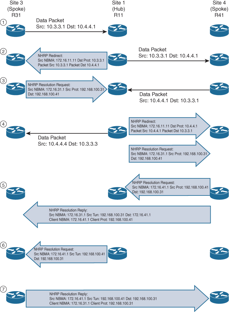
Step 1. R31 performs a route lookup for 10.4.4.1 and finds the entry 10.4.4.0/24 with the next-hop IP address 192.168.100.11 through hub. R31 encapsulates the packet destined for 10.4.4.1 and forwards it to R11 out the tunnel 100 interface.
Step 2. R11 receives the packet from R31 and performs a route lookup for the packet destined for 10.4.4.1. R11 locates the 10.4.4.0/24 network with the next-hop IP address 192.168.100.41. R11 checks the NHRP cache and locates the entry for the 192.168.100.41/32 address. R11 forwards the packet to R41, using the NBMA IP address 172.16.41.1, found in the NHRP cache.
The packet is then forwarded out the same tunnel interface (same network id / DMVPN cloud) and hub detects this as hairpinning.
R11 has ip nhrp redirect configured on the tunnel interface and recognizes that the packet received from R31 hairpinned out of the tunnel interface. R11 sends an NHRP redirect to R31, indicating the packet source 10.3.3.1 and destination 10.4.4.1. The NHRP redirect indicates to R31 that the traffic is using a suboptimal path.
Step 3. R31 receives the NHRP redirect and sends an NHRP resolution request to R11 for the 10.4.4.1 address. Inside the NHRP resolution request, R31 provides its protocol (tunnel IP) address, 192.168.100.31, and source NBMA address, 172.16.31.1. R41 performs a route lookup for 10.3.3.1 and finds the entry 10.3.3.0/24 with the next-hop IP address 192.168.100.11. R41 encapsulates the packet destined for 10.4.4.1 and forwards it to R11 out the tunnel 100 interface.
Step 4. R11 receives the packet from R41 and performs a route lookup for the packet destined for 10.3.3.1. R11 locates the 10.3.3.0/24 network with the next-hop IP address 192.168.100.31. R11 checks the NHRP cache and locates an entry for 192.168.100.31/32. R11 forwards the packet to R31, using the NBMA IP address 172.16.31.1, found in the NHRP cache. The packet is then forwarded out the same tunnel interface. R11 has ip nhrp redirect configured on the tunnel interface and recognizes that the packet received from R41 hairpinned out the tunnel interface. R11 sends an NHRP redirect to R41, indicating the packet source 10.4.4.1 and destination 10.3.3.1 The NHRP redirect indicates to R41 that the traffic is using a suboptimal path. R11 forwards R31’s NHRP resolution requests for the 10.4.4.1 address.
Step 5. R41 sends an NHRP resolution request to R11 for the 10.3.3.1 address and provides its protocol (tunnel IP) address, 192.168.100.41, and source NBMA address, 172.16.41.1. R41 sends an NHRP resolution reply directly to R31, using the source information from R31’s NHRP resolution request. The NHRP resolution reply contains the original source information in R31’s NHRP resolution request as a method of verification and contains the client protocol address of 192.168.100.41 and the client NBMA address 172.16.41.1. (If IPsec protection is configured, the IPsec tunnel is set up before the NHRP reply is sent.)
Note
The NHRP reply is for the entire subnet rather than the specified host address.
Step 6. R11 forwards R41’s NHRP resolution requests for the 192.168.100.31 and 10.4.4.1 entries.
Step 7. R31 sends an NHRP resolution reply directly to R41, using the source information from R41’s NHRP resolution request. The NHRP resolution reply contains the original source information in R41’s NHRP resolution request as a method of verification and contains the client protocol address 192.168.100.31 and the client NBMA address 172.16.31.1. (Again, if IPsec protection is configured, the tunnel is set up before the NHRP reply is sent back in the other direction.)
A spoke-to-spoke DMVPN tunnel is established in both directions after step 7 is complete. This allows traffic to flow across the spoke-to-spoke tunnel instead of traversing the hub router.
shows the status of DMVPN tunnels on R31 and R41, where there are two new spoke-to-spoke tunnels (highlighted). The DLX entries represent the local (no-socket) routes. The original tunnel to R11 remains a static tunnel.
R31-Spoke# show dmvpn detail
Legend: Attrb --> S - Static, D - Dynamic, I - Incomplete
           N - NATed, L - Local, X - No Socket
          T1 - Route Installed, T2 - Nexthop-override
          C - CTS Capable
         # Ent --> Number of NHRP entries with same NBMA peer
         NHS Status: E --> Expecting Replies, R --> Responding, W --> Waiting
         UpDn Time --> Up or Down Time for a Tunnel
============================================================================
Interface Tunnel100 is up/up, Addr. is 192.168.100.31, VRF ""
      Src./Dest. addr: 172.16.31.1/MGRE, Tunnel VRF ""
     Protocol/Transport: "multi-GRE/IP", Protect ""
     Interface State Control: Disabled
     nhrp event-publisher : Disabled

IPv4 NHS:
192.168.100.11 RE NBMA Address: 172.16.11.1 priority = 0 cluster = 0
Type:Spoke, Total NBMA Peers (v4/v6): 3

# Ent  Peer NBMA Addr Peer Tunnel Add State  UpDn Tm Attrb    Target Network
----- --------------- --------------- ----- -------- ----- -----------------
    1 172.16.31.1      192.168.100.31    UP 00:00:10   DLX        10.3.3.0/24
    2 172.16.41.1      192.168.100.41    UP 00:00:10   DT2   10.4.4.0/24
      172.16.41.1      192.168.100.41    UP 00:00:10   DT1   192.168.100.41/32
    1 172.16.11.1      192.168.100.11    UP 00:00:51     S    192.168.100.11/32
R41-Spoke# show dmvpn detail
! Output omitted for brevity
IPv4 NHS:
192.168.100.11 RE NBMA Address: 172.16.11.1 priority = 0 cluster = 0
Type:Spoke, Total NBMA Peers (v4/v6): 3
# Ent Peer NBMA Addr Peer Tunnel Add State UpDn Tm Attrb Target Network
----- --------------- --------------- ----- -------- ----- -----------------
2 172.16.31.1 192.168.100.31 UP 00:00:34 DT2 10.3.3.0/24
172.16.31.1 192.168.100.31 UP 00:00:34 DT1 192.168.100.31/32
1 172.16.41.1 192.168.100.41 UP 00:00:34 DLX 10.4.4.0/24
1 172.16.11.1 192.168.100.11 UP 00:01:15 S 192.168.100.11/32show ip nhrp detail to view NHRP cache for R31 and R41. Notice the NHRP mappings router, rib, nho, and nhop. The flag rib nho indicates that the router has found an identical route in the routing table that belongs to a different protocol. NHRP has overridden the other protocol’s next-hop entry for the network by installing a next-hop shortcut in the routing table. The flag rib nhop indicates that the router has an explicit method to reach the tunnel IP address using an NBMA address and has an associated route installed in the routing table.
NHRP Mapping with Spoke-to-Hub Traffic
uses the optional detail keyword for viewing the NHRP cache information. The 10.3.3.0/24 entry on R31 and the 10.4.4.0/24 entry on R41 display a list of devices to which the router responded to resolution request packets and the request ID that they received.
R31-Spoke# show ip nhrp detail
10.3.3.0/24 via 192.168.100.31
   Tunnel100 created 00:01:44, expire 01:58:15
   Type: dynamic, Flags: router unique local
   NBMA address: 172.16.31.1
   Preference: 255
    (no-socket)
   Requester: 192.168.100.41 Request ID: 3
10.4.4.0/24 via 192.168.100.41
   Tunnel100 created 00:01:44, expire 01:58:15
   Type: dynamic, Flags: router rib nho
   NBMA address: 172.16.41.1
   Preference: 255
192.168.100.11/32 via 192.168.100.11
   Tunnel100 created 10:43:18, never expire
   Type: static, Flags: used
   NBMA address: 172.16.11.1
   Preference: 255
192.168.100.41/32 via 192.168.100.41
   Tunnel100 created 00:01:45, expire 01:58:15
   Type: dynamic, Flags: router used nhop rib
   NBMA address: 172.16.41.1
   Preference: 255
R41-Spoke# show ip nhrp detail
10.3.3.0/24 via 192.168.100.31
Tunnel100 created 00:02:04, expire 01:57:55
Type: dynamic, Flags: router rib nho
NBMA address: 172.16.31.1
Preference: 255
10.4.4.0/24 via 192.168.100.41
Tunnel100 created 00:02:04, expire 01:57:55
Type: dynamic, Flags: router unique local
NBMA address: 172.16.41.1
Preference: 255
(no-socket)
Requester: 192.168.100.31 Request ID: 3
192.168.100.11/32 via 192.168.100.11
Tunnel100 created 10:43:42, never expire
Type: static, Flags: used
NBMA address: 172.16.11.1
Preference: 255
192.168.100.31/32 via 192.168.100.31
Tunnel100 created 00:02:04, expire 01:57:55
Type: dynamic, Flags: router used nhop rib
NBMA address: 172.16.31.1 Preference: 255DMVPN 2
DMVPN (Dynamic Multipoint Virtual Private Network) is a hub-and-spoke technology for site-to-site sites, the great advantage of DMVPN is scalability and direct spoke to spoke communication
DMVPN, we actually configure the tunnel interfaces as multipoint interfaces so that we can talk to multiple routers using the same tunnel interface, reducing the configuration and increasing the scale over point-to-point tunnels.
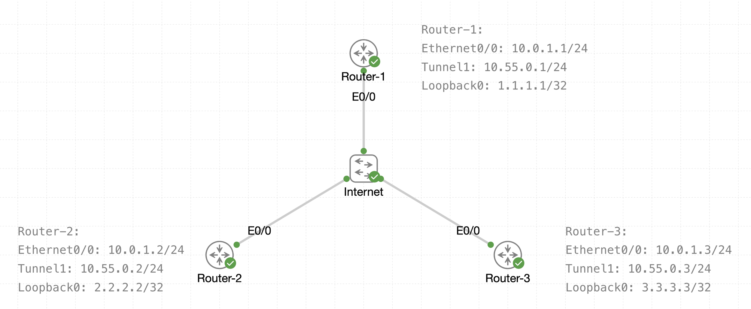
See that there is a transport IP addressing
Then there is overlay network over WAN (transport) that is multipoint GRE acting as a broadcast network, we can tell the broadcast nature by looking at Tunnel 1 Addressing
The default tunnel-type on Cisco routers is a GRE point-to-point. GRE is about as simple as a protocol gets.
next post
EIGRP
EIGRP
EIGRP is distance vector routing protocol
Initially it was Cisco proprietary protocol, but it was released to the Internet Engineering Task Force (IETF)
EIGRP uses a diffusing update algorithm (DUAL) to learn loop free paths
DUAL also keeps loop-free backup paths for fast convergence
A lot of older protocols used hop count for path selection but that does not take into account link speed and total delay, EIGRP adds logic to the route-selection algorithm to use factors other than hop count alone
EIGRP uses ASN per process (ASN/Process)
Routers within the same domain must use the same metric calculation formula and exchange routes only with members of the same autonomous system (AS), if routing needs to be presented between 2 different EIGRP ASN / Process then router in the middle will need to redistribute between 2 ASN / Processes
For example R3 that is attached to 2 different ASN on 2 different processes does not transfer routes learned from one autonomous system into a different autonomous system
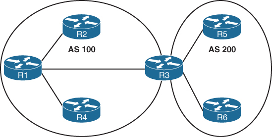
Current implementations of EIGRP support only IPv4 and IPv6.
EIGRP Terminology
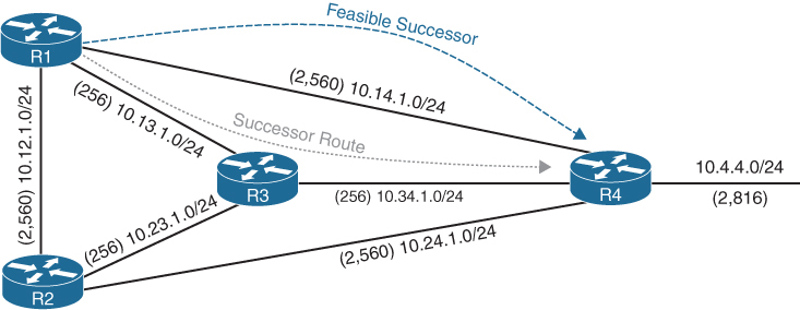
Successor route
The route with the lowest path metric to reach a destination.
The successor route for R1 to reach 10.4.4.0/24 on R4 is R1→R3→R4.
Successor
The first next-hop router for the successor route. R1’s successor for 10.4.4.0/24 is R3.
Feasible distance (FD)
The metric value for the lowest path metric to reach a destination. The feasible distance is calculated locally using the formula
The FD calculated by R1 for the 10.4.4.0/24 destination network is 3328 (that is, 256 + 256 + 2816).
Reported distance (RD)
Distance reported by a router to reach a destination. The reported distance value is the feasible distance of the advertising router.
R3 advertises the 10.4.4.0/24 destination network to R1 and R2 with an RD of 3072 (2816 + 256).
R4 advertises the 10.4.4.0/24 destination network to R1, R2, and R3 with an RD of 2816.
Feasibility condition
For a route to be considered a backup route, the RD received for that route must be less than the FD calculated locally. This logic guarantees a loop-free path.
Feasible successor
Installed in the topology table only
Acts as a loop-free backup path
A route that satisfies the feasibility condition is maintained as a backup route. The feasibility condition ensures that the backup route is loop free.
The route R1→R4 is the feasible successor because the RD of 2816 is lower than the FD of 3328 for the R1→R3→R4 path.
Topology Table
EIGRP contains a topology table
The topology table contains all the network prefixes advertised within an EIGRP autonomous system including backup paths and not just contains metric per prefix but hop count also
Values used to calculate the metric BDRLM (Bandwidth , Delay , Reliability , Load , MTU)
show ip eigrp topology ! shows successor and feasible successor
!
show ip eigrp topology [all-links]
! shows successor and feasible successor all-links keyword shows the paths that did not pass the feasibility condition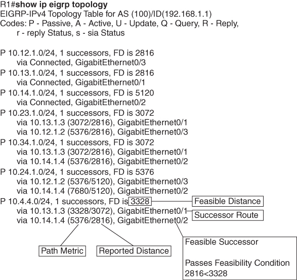
Prefix 10.4.4.0/24 has cost or FD of 3328 for best path or successor route
Successor route’s next hop router is called successor
second path that is feasible successor has RD of 2816 which is lower than FD of successor route, it passes the feasibility condition and is installed in topology table
The 10.4.4.0/24 route is passive (P), which means the topology is stable. During a topology change, routes go into an active (A) state when computing a new path.
EIGRP Neighbors
EIGRP neighbors exchange the entire routing table when forming an adjacency, and they advertise incremental updates only as topology changes occur within a network and no periodic updates
Inter-Router Communication
EIGRP uses IP protocol number (88)
uses multicast packets where possible to reduce bandwidth consumed on the links; it uses unicast packets when necessary
EIGRP uses Reliable Transport Protocol (RTP) to ensure that packets are delivered instead of TCP
A sequence number is included in each EIGRP packet. The sequence value zero does not require a response from the receiving EIGRP router; all other values require an ACK packet that includes the original sequence number
All update, query and reply packets are deemed reliable
hello and ACK packets do not require acknowledgment
If the originating router does not receive an ACK packet from the neighbor before the retransmit timeout expires, it notifies the non-acknowledging router to stop processing its multicast packets
Communication between routers is done with multicast using the group address 224.0.0.10 or the MAC address 01:00:5e:00:00:0a when possible
| Opcode Value | Packet Type | Function |
|---|---|---|
| 1 | Update | Used to transmit routing and reachability information with other EIGRP neighbors |
| 2 | Request | Used to get specific information from one or more neighbors |
| 3 | Query | Sent out to search for another path during convergence |
| 4 | Reply | Sent in response to a query packet |
| 5 | Hello | Used for discovery of EIGRP neighbors and for detecting when a neighbor is no longer available |
Forming EIGRP Neighbors
Hello messages are exchanged to become neighbors
The following parameters must match for the two routers to become neighbors:
- Metric formula K values
- Primary subnet matches
- Autonomous system number (ASN) matches
- Authentication parameters
EIGRP Configuration Modes
EIGRP configuration modes: classic mode and named mode.
EIGRP Named Mode
EIGRP named mode provides a hierarchical configuration and stores settings in three subsections:
- Address Family: This submode contains settings that are relevant to the global EIGRP AS operations, such as selection of network interfaces, EIGRP K values, logging settings, and stub settings.
- Interface: This submode contains settings that are relevant to the interface, such as hello advertisement interval, split-horizon, authentication, and summary route advertisements. In actuality, there are two methods of the EIGRP interface section’s configuration. Commands can be assigned to a specific interface or to a default interface, in which case those settings are placed on all EIGRP-enabled interfaces. If there is a conflict between the default interface and a specific interface, the specific interface takes priority over the default interface.
- Topology: This submode contains settings regarding the EIGRP topology database and how routes are presented to the router’s RIB. This section also contains route redistribution and administrative distance settings.
EIGRP named configuration makes it possible to run multiple instances under the same EIGRP process
Step 1. Initialize the EIGRP process by using the command router eigrp process-name. (If a number is used for process-name, the number does not correlate to the autonomous system number.)
Step 2. Initialize the EIGRP instance for the appropriate address family with the command address-family {IPv4 | IPv6} {unicast | vrf vrf-name} autonomous-system as-number.
Step 3. Enable EIGRP on interfaces by using the command network network wildcard-mask.
EIGRP Network Statement
Network statement enrolls interfaces in EIGRP and sends hellos on those interfaces
If wildcard is omitted then any interfaces that fall under the classful boundary are added in EIGRP, secondary networks are not added, if we want secondary networks in EIGRP then they need to be redistributed
router eigrp 1
    network 10.0.0.10 0.0.0.0
    network 10.0.0.0 0.0.0.255
    network 10.0.0.0 0.255.255.255
    network 0.0.0.0 255.255.255.255 ! enable on all interfaces
Named configuration
R2 (Named Mode Configuration)
interface Loopback0
 ip address 192.168.2.2 255.255.255.255
!
interface GigabitEthernet0/1
    ip address 10.12.1.2 255.255.255.0
!
interface GigabitEthernet0/2
    ip address 10.22.22.2 255.255.255.0
!
router eigrp EIGRP-NAMED
 address-family ipv4 unicast autonomous-system 100
  network 0.0.0.0 255.255.255.255
R2# show run | section router eigrp
router eigrp EIGRP-NAMED
!
address-family ipv4 unicast autonomous-system 100
!
topology base
exit-af-topology
network 0.0.0.0
exit-address-family The EIGRP interface submode configurations contain the command af-interface interface-id or af-interface default
router eigrp MY-EIGRP
 address-family ipv4 unicast autonomous-system 100
  network 10.0.0.0 0.0.0.255

  af-interface default
   passive-interface
   hello-interval 5
   hold-time 15
  exit-af-interface

  af-interface GigabitEthernet0/0
   no passive-interface
   bandwidth-percent 50
  exit-af-interface

  af-interface GigabitEthernet0/1
   no passive-interface
   authentication mode md5
   authentication key-chain EIGRP_KEYS
  exit-af-interface
 exit-address-family
show ip eigrp interfaces [{interface-id [detail] | detail}]R1# show ip eigrp interfaces
EIGRP-IPv4 Interfaces for AS(100)
Xmit Queue PeerQ Mean Pacing Time Multicast Pending
Interface Peers Un/Reliable Un/Reliable SRTT Un/Reliable Flow Timer Routes
Gi0/2 0 0/0 0/0 0 0/0 0 0
Gi0/1 1 0/0 0/0 10 0/0 50 0
Lo0 0 0/0 0/0 0 0/0 0 0R2# show ip eigrp interfaces gi0/1 detail
EIGRP-IPv4 VR(EIGRP-NAMED) Address-Family Interfaces for AS(100)
Xmit Queue PeerQ Mean Pacing Time Multicast Pending
Interface Peers Un/Reliable Un/Reliable SRTT Un/Reliable Flow Timer Routes
Gi0/1 1 0/0 0/0 1583 0/0 7912 0
Hello-interval is 5, Hold-time is 15
Split-horizon is enabled
Next xmit serial <none>
Packetized sent/expedited: 2/0
Hello's sent/expedited: 186/2
Un/reliable mcasts: 0/2 Un/reliable ucasts: 2/2
Mcast exceptions: 0 CR packets: 0 ACKs suppressed: 0
Retransmissions sent: 1 Out-of-sequence rcvd: 0
Topology-ids on interface - 0
Authentication mode is not set
Topologies advertised on this interface: base
Topologies not advertised on this interface:Fields explaination
Xmt Queue – Un/Reliable
Number of unreliable/reliable packets remaining in the transmit queue. The value zero is an indication of a stable network.
Mean SRTT
Average time for a packet to be sent and a received from neighbor in milliseconds.
Pending Routes
Number of routes in the transmit queue that need to be sent.
R1# show ip eigrp neighbors
EIGRP-IPv4 Neighbors for AS(100)
H   Address                 Interface              Hold Uptime   SRTT   RTO  Q  Seq
                                                   (sec)         (ms)       Cnt Num
0   10.12.1.2               Gi0/1                    13 00:18:31   10   100  0  3
Fields explaination
RTO
Timeout for retransmission (waiting for ACK)
Q Cnt
Number of packets (update/query/reply) in queue for sending
Seq Num
Sequence number that was last “received” from this router
show ip route eigrpR1# show ip route eigrp
Codes: L - local, C - connected, S - static, R - RIP, M - mobile, B - BGP
D - EIGRP, EX - EIGRP external, O - OSPF, IA - OSPF inter area
N1 - OSPF NSSA external type 1, N2 - OSPF NSSA external type 2
E1 - OSPF external type 1, E2 - OSPF external type 2
i - IS-IS, su - IS-IS summary, L1 - IS-IS level-1, L2 - IS-IS level-2
ia - IS-IS inter area, * - candidate default, U - per-user static route
o - ODR, P - periodic downloaded static route, H - NHRP, l - LISP
a - application route
+ - replicated route, % - next hop override, p - overrides from PfR
Gateway of last resort is not set
10.0.0.0/8 is variably subnetted, 5 subnets, 2 masks
D 10.22.22.0/24 [90/3072] via 10.12.1.2, 00:19:25, GigabitEthernet0/1
192.168.2.0/32 is subnetted, 1 subnets
D 192.168.2.2 [90/2848] via 10.12.1.2, 00:19:25, GigabitEthernet0/1R2# show ip route eigrp
! Output omitted for brevity
Gateway of last resort is not set
10.0.0.0/8 is variably subnetted, 5 subnets, 2 masks
D 10.11.11.0/24 [90/15360] via 10.12.1.1, 00:20:34, GigabitEthernet0/1
192.168.1.0/32 is subnetted, 1 subnets
D 192.168.1.1 [90/2570240] via 10.12.1.1, 00:20:34, GigabitEthernet0/1EIGRP routes have administrative distance (AD) of 90 and are indicated in the routing table with a D
External EIGRP routes have an AD of 170 and are indicated in the routing table with D EX
The metrics for R2’s routes are different from the metrics from R1’s routes. This is because R1’s classic EIGRP mode uses classic metrics, and R2’s named mode uses “wide metrics” “by default”
Router ID
The router ID (RID) is a 32-bit number that uniquely identifies an EIGRP router and is used as a loop-prevention mechanism. The RID can be set dynamically, which is the default, or manually.
The algorithm for dynamically choosing the EIGRP RID uses the highest IPv4 address of any up loopback interfaces. If there are not any up loopback interfaces, the highest IPv4 address of any active up physical interfaces becomes the RID when the EIGRP process initializes.
R1(config)# router eigrp 100
R1(config-router)# eigrp router-id 192.168.1.1

R2(config)# router eigrp EIGRP-NAMED
R2(config-router)# address-family ipv4 unicast autonomous-system 100
R2(config-router-af)# eigrp router-id 192.168.2.2
Passive Interfaces
Some network topologies must advertise a network segment into EIGRP but need to prevent neighbors because it stops sending hello and process received hellos
for example, when advertising access layer networks in a campus topology.
R1# configure terminal
Enter configuration commands, one per line.  End with CNTL/Z.
R1(config)# router eigrp 100
R1(config-router)# passive-interface gi0/2
R1(config)# router eigrp 100
R1(config-router)# passive-interface default
04:22:52.031: %DUAL-5-NBRCHANGE: EIGRP-IPv4 100: Neighbor 10.12.1.2
(GigabitEthernet0/1) is down: interface passive
R1(config-router)# no passive-interface gi0/1
*May 10 04:22:56.179: %DUAL-5-NBRCHANGE: EIGRP-IPv4 100: Neighbor 10.12.1.2
(GigabitEthernet0/1) is up: new adjacencyFor a named mode configuration, you place the passive-interface state on af-interface default for all EIGRP interfaces or on a specific interface with the af-interfaceinterface-id
R2# configure terminal
Enter configuration commands, one per line.  End with CNTL/Z.
R2(config)# router eigrp EIGRP-NAMED
R2(config-router)# address-family ipv4 unicast autonomous-system 100
R2(config-router-af)# af-interface gi0/2
R2(config-router-af-interface)# passive-interface
R2(config)# router eigrp EIGRP-NAMED
R2(config-router)# address-family ipv4 unicast autonomous-system 100
R2(config-router-af)# af-interface default
R2(config-router-af-interface)# passive-interface
04:28:30.366: %DUAL-5-NBRCHANGE: EIGRP-IPv4 100: Neighbor 10.12.1.1
(GigabitEthernet0/1) is down: interface passiveex
R2(config-router-af-interface)# exit-af-interface
R2(config-router-af)# af-interface gi0/1
R2(config-router-af-interface)# no passive-interface
R2(config-router-af-interface)# exit-af-interface
*May 10 04:28:40.219: %DUAL-5-NBRCHANGE: EIGRP-IPv4 100: Neighbor 10.12.1.1
(GigabitEthernet0/1) is up: new adjacencyR2# show run | section router eigrp
router eigrp EIGRP-NAMED
!
address-family ipv4 unicast autonomous-system 100
!
af-interface default
passive-interface
exit-af-interface
!
af-interface GigabitEthernet0/1
no passive-interface
exit-af-interface
!
topology base
exit-af-topology
network 0.0.0.0
exit-address-familyA passive interface does not appear in the output of the command show ip eigrp interfaces even though it was enabled but appears under “show ip protocols” command as passive. Connected networks for passive interfaces are still added to the EIGRP topology table so that they are advertised to neighbors.
show ip protocols command also shows K values set for EIGRP, RID and information such as interfaces enabled for EIGRP, passive interfaces and neighbors
R1# show ip protocols
! Output omitted for brevity
Routing Protocol is "eigrp 100"
  Outgoing update filter list for all interfaces is not set
  Incoming update filter list for all interfaces is not set
  Default networks flagged in outgoing updates
  Default networks accepted from incoming updates
  EIGRP-IPv4 Protocol for AS(100)
    Metric weight K1=1, K2=0, K3=1, K4=0, K5=0
    Soft SIA disabled
    NSF-aware route hold timer is 240
    Router-ID: 192.168.1.1
    Topology : 0 (base)
      Active Timer: 3 min
      Distance: internal 90 external 170
      Maximum path: 4
      Maximum hopcount 100
      Maximum metric variance 1

  Automatic Summarization: disabled
  Maximum path: 4
  Routing for Networks:
    10.11.11.1/32
    10.12.1.1/32
    192.168.1.1/32
  Passive Interface(s):
    GigabitEthernet0/2
    Loopback0
  Routing Information Sources:
    Gateway         Distance      Last Update
    10.12.1.2             90      00:21:35
  Distance: internal 90 external 170
Authentication
Hash is a one way function and cannot be reversed or decrypted
A password on an EIGRP router is hashed and sent with EIGRP packet
once it is received on neighbor, neighbor also hashes its password and then compare it with received hash, if both has match then packet is accepted and if they do not match then EIGRP packet is discarded
Keychain Configuration
Keychain creation is accomplished with the following steps:
Step 1. Create the keychain by using the command key chain key-chain-name.
Step 2. Identify the key sequence by using the command key key-number, where key-number can be anything from 0 to 2147483647.
Step 3. Specify the preshared password by using the command key-string password.
classic configuration, authentication must be enabled on the interface
R1(config)# key chain EIGRPKEY
R1(config-keychain)# key 2
R1(config-keychain-key)# key-string CISCO
R1(config)# interface gi0/1
R1(config-if)# ip authentication mode eigrp 100 md5
R1(config-if)# ip authentication key-chain eigrp 100 EIGRPKEY
The named mode configuration places the configurations under the EIGRP interface submode
R2(config)# key chain EIGRPKEY
R2(config-keychain)# key 2
R2(config-keychain-key)# key-string CISCO
R2(config-keychain-key)# router eigrp EIGRP-NAMED
R2(config-router)# address-family ipv4 unicast autonomous-system 100
R2(config-router-af)# af-interface default
R2(config-router-af-interface)# authentication mode md5
R2(config-router-af-interface)# authentication key-chain EIGRPKEY
R1# show key chain
Key-chain EIGRPKEY:
key 2 -- text "CISCO"
accept lifetime (always valid) - (always valid) [valid now]
send lifetime (always valid) - (always valid) [valid now]R1# show ip eigrp interface detail
EIGRP-IPv4 Interfaces for AS(100)
Xmit Queue PeerQ Mean Pacing Time Multicast Pending
Interface Peers Un/Reliable Un/Reliable SRTT Un/Reliable Flow Timer Routes
Gi0/1 0 0/0 0/0 0 0/0 50 0
Hello-interval is 5, Hold-time is 15
Split-horizon is enabled
Next xmit serial <none>
Packetized sent/expedited: 10/1
Hello's sent/expedited: 673/12
Un/reliable mcasts: 0/9 Un/reliable ucasts: 6/19
Mcast exceptions: 0 CR packets: 0 ACKs suppressed: 0
Retransmissions sent: 16 Out-of-sequence rcvd: 1
Topology-ids on interface - 0
Authentication mode is md5, key-chain is "EIGRPKEY"Path Metric Calculation
Metric calculation uses bandwidth and delay by default but can include interface load and reliability, too


A common misconception is that the K values directly apply to bandwidth, load, delay, or reliability; this is not accurate. For example, K1 and K2 both reference bandwidth (BW).
BW represents the slowest link in the path in Kbps
Delay is the total measure of delay in the path, measured in tens of microseconds (μs).
By default, K1 and K3 each has a value of 1, and K2, K4, and K5 are all set to 0

The EIGRP update packet includes path attributes associated with each prefix. The EIGRP path attributes can include hop count, cumulative delay, minimum bandwidth link speed, and RD. The attributes are updated each hop along the way

Notice that the hop count increments, minimum bandwidth decreases, total delay increases, and the RD changes with each EIGRP update.
Default EIGRP Interface Metrics for Classic Metrics
| Interface Type | Link Speed (Kbps) | Delay | Metric |
|---|---|---|---|
| Serial | 64 | 20,000 μs | 40,512,000 |
| T1 | 1544 | 20,000 μs | 2,170,031 |
| Ethernet | 10,000 | 1000 μs | 281,600 |
| FastEthernet | 100,000 | 100 μs | 28,160 |
| GigabitEthernet | 1,000,000 | 10 μs | 2816 |
| TenGigabitEthernet | 10,000,000 | 10 μs | 512 |
R1# show ip eigrp topology 10.4.4.0/24
! Output omitted for brevity
EIGRP-IPv4 Topology Entry for AS(100)/ID(10.14.1.1) for 10.4.4.0/24
  State is Passive, Query origin flag is 1, 1 Successor(s), FD is 3328
  Descriptor Blocks:
  10.13.1.3 (GigabitEthernet0/1), from 10.13.1.3, Send flag is 0x0
      Composite metric is (3328/3072), route is Internal
      Vector metric:
        Minimum bandwidth is 1000000 Kbit
        Total delay is 30 microseconds
        Reliability is 252/255
        Load is 1/255
        Minimum MTU is 1500
        Hop count is 2
        Originating router is 10.34.1.4
  10.14.1.4 (GigabitEthernet0/2), from 10.14.1.4, Send flag is 0x0
      Composite metric is (5376/2816), route is Internal
     Vector metric:
        Minimum bandwidth is 1000000 Kbit
        Total delay is 110 microseconds
        Reliability is 255/255
        Load is 1/255
        Minimum MTU is 1500
        Hop count is 1
        Originating router is 10.34.1.4
Wide Metrics
there is not a differentiation between an 11 Gbps interface and a 20 Gbps interface.
10 GigabitEthernet:
Scaled Bandwidth = 10,000,000 / 10,000,000
Scaled Delay = 10 / 10
Composite Metric = 1 + 1 * 256 = 512
11 GigabitEthernet:
Scaled Bandwidth = 10,000,000 / 11,000,000
Scaled Delay = 10 / 10
Composite Metric = 0 + 1 * 256 = 25620 GigabitEthernet:
Scaled Bandwidth = 10,000,000 / 20,000,000
Scaled Delay = 10 / 10
Composite Metric = 0 + 1 * 256 = 256EIGRP includes support for a second set of metrics, known as wide metrics, that addresses the issue of scalability with higher-capacity interfaces.
The interface delay varies from router to router, depending on the following logic:
- If the interface’s delay was specifically set, the value is converted to picoseconds. Interface delay is always configured in tens of microseconds and is multiplied by 107 for picosecond conversion.
- If the interface’s bandwidth was specifically set, the interface delay is configured using the classic default delay, converted to picoseconds. The configured bandwidth is not considered when determining the interface delay. If delay was configured, this step is ignored.
- If the interface supports speeds of 1 Gbps or less and does not contain bandwidth or delay configuration, the delay is the classic default delay, converted to picoseconds.
- If the interface supports speeds over 1 Gbps and does not contain bandwidth or delay configuration, the interface delay is calculated by 1013/interface bandwidth.
R1# show ip protocols | include AS|K
  EIGRP-IPv4 Protocol for AS(100)
    Metric weight K1=1, K2=0, K3=1, K4=0, K5=0
R2# show ip protocols | include AS|K
EIGRP-IPv4 VR(EIGRP-NAMED) Address-Family Protocol for AS(100)
Metric weight K1=1, K2=0, K3=1, K4=0, K5=0 K6=0 <<<Existence of K6 proves use of named EIGRP
Metric Backward Compatibility
EIGRP wide metrics were designed with backward compatibility in mind. EIGRP wide metrics set K1 and K3 to a value of 1 and set K2, K4, K5, and K6 to 0, which allows backward compatibility because the K value metrics match with classic metrics. As long as K1 through K5 are the same and K6 is not set, the two metric styles allow adjacency between routers.
Using a mixture of classic metric and wide metric devices could lead to suboptimal routing, so it is best to keep all devices operating with the same metric style.
Why set delay and not bandwidth
Bandwidth modification with the interface parameter command bandwidth bandwidth has a similar effect on the metric calculation formula but can impact other routing protocols, such as OSPF, at the same time. Modifying the interface delay only impacts EIGRP.
R1# show interfaces gigabitEthernet 0/1 | i DLY
  MTU 1500 bytes, BW 1000000 Kbit/sec, DLY 10 usec,
R2# show interfaces gigabitEthernet 0/1 | i DLY
MTU 1500 bytes, BW 1000000 Kbit/sec, DLY 10 usec,show interface interface-id. The output displays the EIGRP interface delay, in microseconds
R1# configure terminal
R1(config)# interface gi0/1
R1(config-if)# delay 100
R1(config-if)# do show interface Gigabit0/1 | i DLY
  MTU 1500 bytes, BW 1000000 Kbit/sec, DLY 1000 usec,
Custom K Values
K values for the path metric formula are set with the command metric weights TOS K1 K2 K3 K4 K5 [K6] under the EIGRP process. TOS always has a value of 0, and K6 is used for named mode configurations.
To ensure consistent routing logic in an EIGRP autonomous system, the K values must match between EIGRP neighbors to form an adjacency and exchange routes. The K values are included as part of the EIGRP hello packet.
Load Balancing
EIGRP allows multiple successor routes (with the same metric) to be installed into the RIB called ECMP, the default maximum ECMP setting is four routes
R1# show run | section router eigrp
router eigrp 100
 maximum-paths 6
 network 0.0.0.0
R2# show run | section router eigrp
router eigrp EIGRP-NAMED
!
address-family ipv4 unicast autonomous-system 100
!
topology base
maximum-paths 6
exit-af-topology
network 0.0.0.0
eigrp router-id 192.168.2.2
exit-address-familyUnequal Cost Load Balancing
EIGRP supports unequal-cost load balancing, which allows installation of both successor routes and feasible successors into the EIGRP RIB. To use unequal-cost load balancing change EIGRP’s variance multiplier.
Variance Value is Feasible distance (FD) for a route multiplied by the EIGRP variance multiplier
Any feasible successor’s FD with a metric below the EIGRP variance up to the maximum number of ECMP routes value is installed into the RIB
There is a way to find exact variance to use
Dividing the feasible successor metric by the successor route metric provides the variance multiplier.
The variance multiplier is a whole number, and any remainders should always round up.


the minimum EIGRP variance multiplier can be calculated so that the direct path from R1 to R4 can be installed into the RIB. The FD for the successor route is 3328, and the FD for the feasible successor is 5376. The formula provides a value of about 1.6 and is always rounded up to the nearest whole number to provide an EIGRP variance multiplier of 2

R1 (Classic Configuration)
router eigrp 100
 variance 2
 network 0.0.0.0
R1 (Named Mode Configuration)
router eigrp EIGRP-NAMED
!
address-family ipv4 unicast autonomous-system 100
!
topology base
variance 2
exit-af-topology
network 0.0.0.0
exit-address-familyR1# show ip route eigrp | begin Gateway
Gateway of last resort is not set
10.0.0.0/8 is variably subnetted, 10 subnets, 2 masks
D 10.4.4.0/24 [90/5376] via 10.14.1.4, 00:00:03, GigabitEthernet0/2
[90/3328] via 10.13.1.3, 00:00:03, GigabitEthernet0/1R1# show ip route 10.4.4.0
Routing entry for 10.4.4.0/24
Known via "eigrp 100", distance 90, metric 3328, type internal
Redistributing via eigrp 100
Last update from 10.13.1.3 on GigabitEthernet0/1, 00:00:35 ago
Routing Descriptor Blocks:
* 10.14.1.4, from 10.14.1.4, 00:00:35 ago, via GigabitEthernet0/2
Route metric is 5376, traffic share count is 149
Total delay is 110 microseconds, minimum bandwidth is 1000000 Kbit
Reliability 255/255, minimum MTU 1500 bytes
Loading 1/255, Hops 1
10.13.1.3, from 10.13.1.3, 00:00:35 ago, via GigabitEthernet0/1
Route metric is 3328, traffic share count is 240
Total delay is 30 microseconds, minimum bandwidth is 1000000 Kbit
Reliability 254/255, minimum MTU 1500 bytes
Loading 1/255, Hops 2Traffic share count is a ratio used for load-sharing
This means traffic is load-balanced unequally:
So traffic is split roughly as:
- ~62% via 10.13.1.3
- ~38% via 10.14.1.4
The better path always gets more traffic.
To get equal traffic share counts the metrics must be equal
Once variance is configured, traffic sharing is automatic