CCIE MPLS
Multi Protocol Label Switching is a technology to deliver IP
Forwarding of data packets is via labels – MPLS enabled routers do not look into IP header to forward packets
MPLS is known as OSI layer 2.5 – Label info is inserted between Data link and Network layer and this is sometimes called shim header

MPLS works over most “Layer 2 technologies” such as ATM, FR, PPP, POS, Ethernet
Network infrastructure convergence – MPLS enabled network allows to carry different kind of traffic (IPv4, IPv6, Layer2 frames) across single network infrastructure
No need to have BGP enabled on all routers – Very important for scaling networks – because MPLS forwarding is done via labels, we do not need to keep all destination IP addresses in routing tables
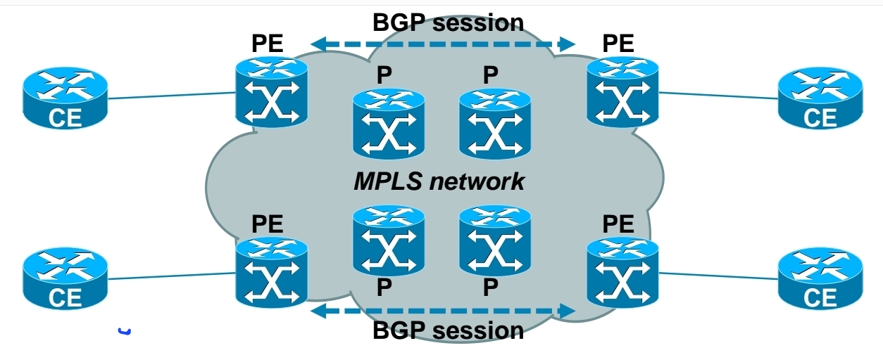
– Allows use of overlapping IPv4 address space
– Allows optimal traffic flow
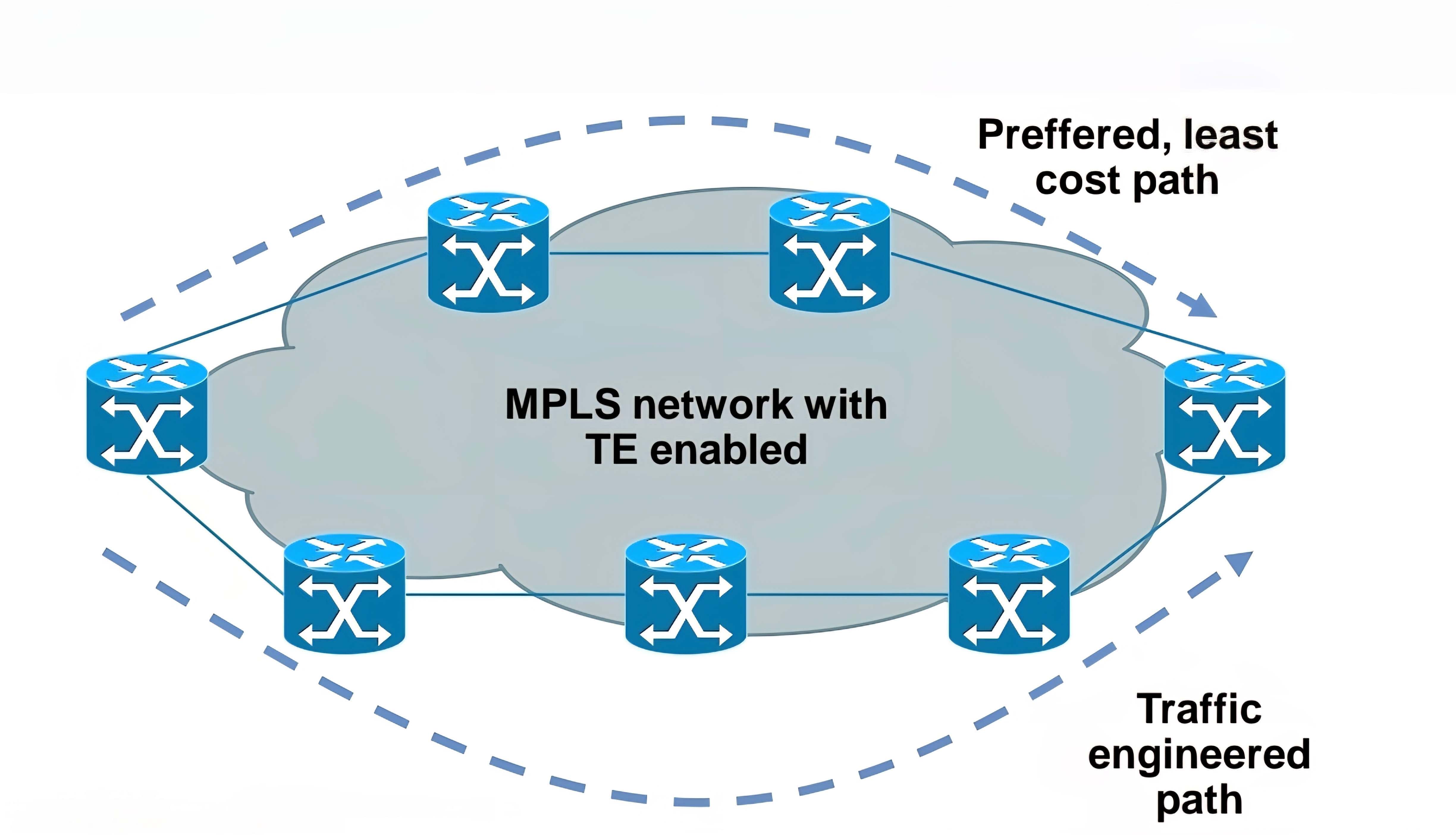
Traffic engineering
– Preffered path is least cost path determined by IGP
– Basic idea is to use links in network infrastructure efficiently
– MPLS needs to be able to provide mechanism to divert traffic to other links beside preffered path
Main building blocks of MPLS:
Label – 32 bit value inserted between Layer 2 and Layer 3

LSR – Label Switch Router (eg. PE, P)
LSP – Label Switched Path
IGP – Interior Gateway Protocol
LDP – Label Distribution Protocol
LIB, LFIB – Label Information Base, Label Forwarding Information Base
MP-BGP, RSVP – Protocols for MPLS VPN and MPLS TE

Egress LSR not always performs label disposition – PHP (Penultimate Hop Popping) signaled via implicit null label (LDP advertising MPLS label of value three)
Penultimate Hop Popping (PHP) is a feature in MPLS (Multiprotocol Label Switching) where the second-to-last router (the penultimate hop) removes (or pops) the MPLS label before forwarding the packet to the final router. This improves efficiency and reduces workload on the last router.
Assigning and distributing MPLS labels Each LSR needs to run IGP to learn IP prefixes (eg. neighbor loopbacks, BGP next hops)
Each LSR then forms “LDP neighborship” between its directly connected LSR
Once LDP neighborship is formed, each LSR uses LDP to “assign labels to IP prefixes” it knows about – each LSR does this independently and advertises its labels to its LDP neighbors
LDP is standards based – RFC 3035 and RFC 3036
LDP uses UDP for session discovery and neighbor discovery (port 646 and destination IP 224.0.0.2)
LDP uses TCP (port 646 and destination IP of its LDP peer) for rest of the messages (label advertisement, label withdrawal, session maintenance, session teardown)
Forwarding MPLS packets – which label to use?
RIB stores IP prefixes, LIB stores MPLS labels
LFIB is created from both RIB and LIB and used to forward MPLS tagged packets
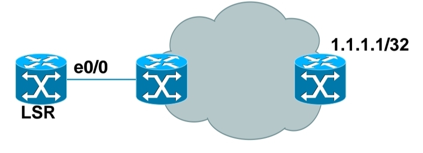
Example for LSR in bottom picture:
– RIB has 1.1.1.1/32 learned via IGP over e0/0 interface
– LIB has label “L” for prefix 1.1.1.1/32 learned from its LDP peer
– LFIB has: “to forward packet to 1.1.1.1/32, use label L and send packet using peer LDP nexthop over e0/0 interface”
Label stacking
Labeling does not make forwarding of packets faster
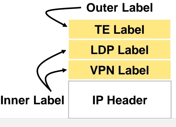
Label stacking is the primary use of MPLS that enables use of MPLS L2 and L3 VPNs, traffic engineering and other services
Most used examples of label stacking:
– 2 labels for MPLS VPN – bottom label indicates which VPN this packet belongs to, outer is used by core LSRs for packet forwarding
– 3 labels for MPLS TE – the most upper label is used to indicate which TE tunnel to forward this packet
Use of MPLS to build Layer 3 VPN
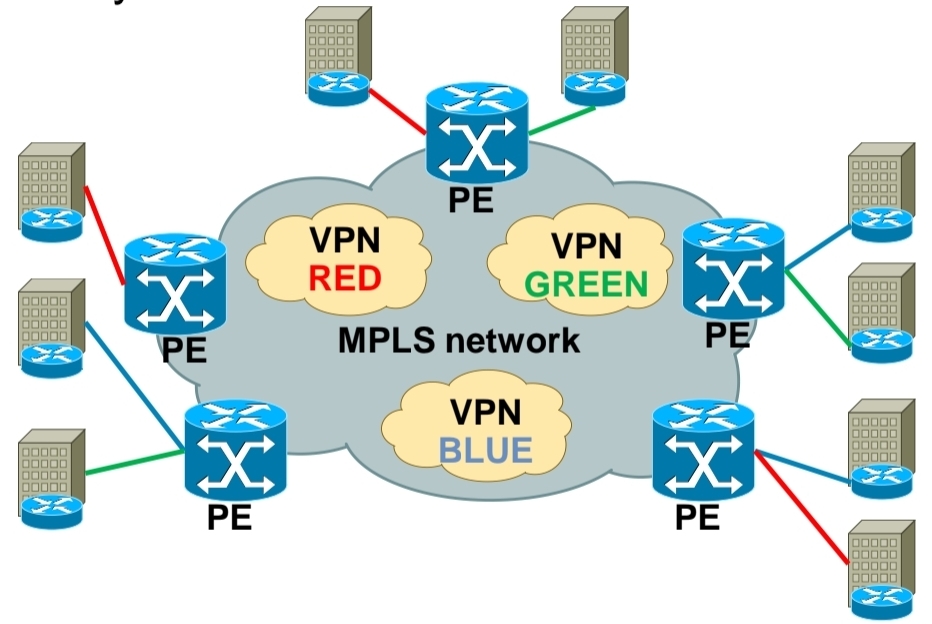
MPLS VPN is set of sites that communicate with each other – these sites can be connected to MPLS infrastructure at various PE routers
Each site is identified by its own VRF (Virtual Routing and Forwarding), by default communication between VRF is not allowed
Each PE router assigns distinct MPLS label for each VRF it communicates with other PE routers – this label is not assigned by LDP, but by MP-BGP
Why is there a need for RD and RT?
Is the BGP session not based on VRFs between the PEs?
Where in path do they play their roles?
There is usually one MP-iBGP session between PE routers (using the global routing table), and all VPN routes for all customers are carried over that single session.
The misconception is:
“Don’t the PE routers have separate BGP sessions for each VRF?”
No. They don’t.
Without RD and RT, Imagine this topology
Customer A

Site1 ------ PE1 ===== P ===== PE2 ------ Site2

VRF: BLUE
Site 2 Network: 10.1.1.0/24
PE1 learns 10.1.1.0/24
Now imagine another customer.
Customer B

Site1 ------ PE3 ===== P ===== PE2 ------ Site2

VRF: RED
Site 2 Network: 10.1.1.0/24
Both customers use 10.1.1.0/24
BGP cannot carry two identical prefixes., best path will end up selecting one 10.1.1.0/24 to be best and erase (non-best path) the other It only sees 10.1.1.0/24 Which customer? it has no idea that is why RD is needed
What RD does?
PE1 converts 10.1.1.0/24 into 65000:100:10.1.1.0/24
PE3 converts 10.1.1.0/24 into 65000:200:10.1.1.0/24
Now BGP sees
65000:100:10.1.1.0/24
65000:200:10.1.1.0/24
These are different VPNv4 routes.
So the RD’s only purpose is:
Make otherwise identical prefixes unique inside MP-BGP.
Nothing more.
It does not decide who receives the route.
Then why RT?
Now imagine PE2 receives both routes.
It now has
65000:100:10.1.1.0/24
65000:200:10.1.1.0/24
How does PE2 know
- which goes into BLUE VRF?
- which goes into RED VRF?
The RD doesn’t help, The RD only made them unique.
This is where the RT comes in.
Suppose
Customer A
Export RT = 100:100
Customer B
Export RT = 200:200
The advertisements become
65000:100:10.1.1.0/24
RT = 100:100
and
65000:200:10.1.1.0/24
RT = 200:200
RT is carried inside BGP
PE2 checks each VRF.
BLUE VRF
Import RT 100:100RED VRF
Import RT 200:200Result
Route RT 100:100
↓

Imported into BLUE only
Route RT 200:200
↓
Imported into RED onlySo RT is simply a tag telling PEs:
“This route belongs to this VPN.”
RD (Route Distinguisher) is literally attached to each IP prefix learned by bgp and it makes them unique – RD + prefix = VPN prefix
RD allows to use overlapping IP addresses for different customers
RD length is 64 bits and is in format X:Y, where X is usually Autonomous System Number or IP address – usually one RD is assigned per customer
RT (Route Target) governs which VPN prefixes are allowed to be imported or exported out of particular VPN
Route Targets
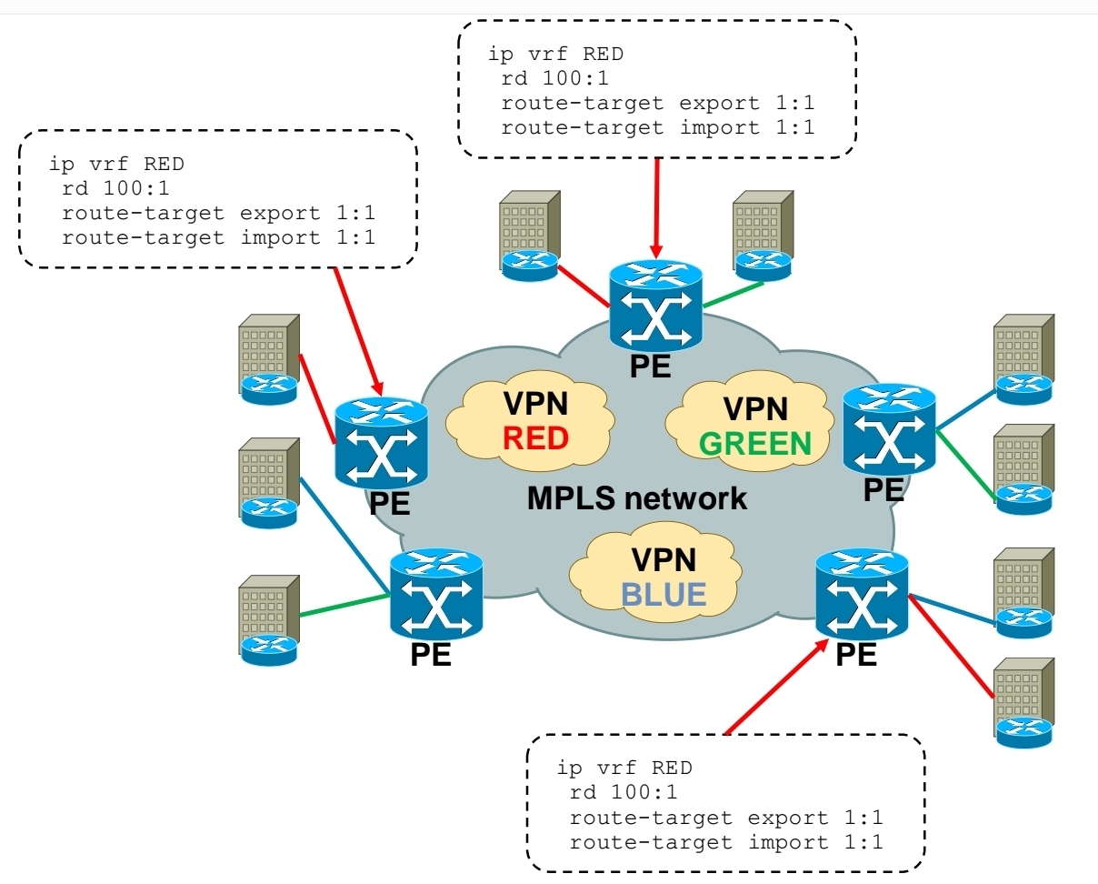
Each VRF has:
Export Route Target defined
Import Route Target defined
A PE router learns a route from a customer. It adds a Route Target (RT) to that route.The route is advertised via MP-BGP to other PE routers. Other PE routers check: If the route’s RT matches their import RT, If yes → route is installed in the VRF, If no → route is ignored
Customer A has two sites:
Site 1 connected to PE1
Site 2 connected to PE2
Both VRFs are configured with:
Export RT: 100:1
Import RT: 100:1,
Result: PE1 exports routes with RT 100:1, PE2 imports routes with RT 100:1, Both sites can communicate. If another customer uses RT 200:1, their routes stay completely separate.
In order to bring L3 VPN into life, you need to exchange both RD and RT – this is done by MP-BGP
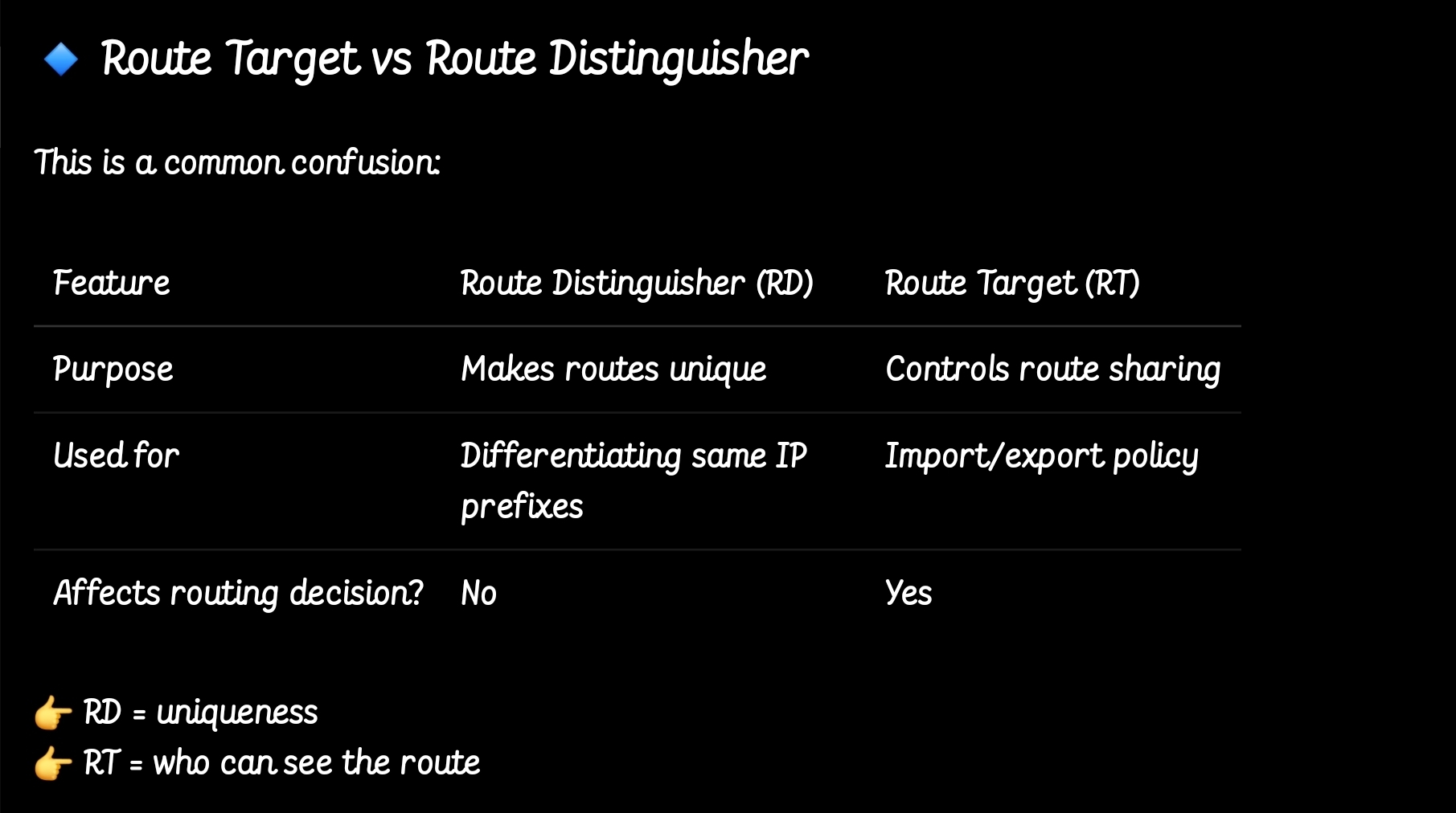
so the functions have been seperated
MPLS Layer 3 VPN Intranet for customer in VPN RED
MPLS Layer 3 VPN Intranet for customer in VPN GREEN

MPLS Layer 3 VPN Intranet for customer in VPN BLUE
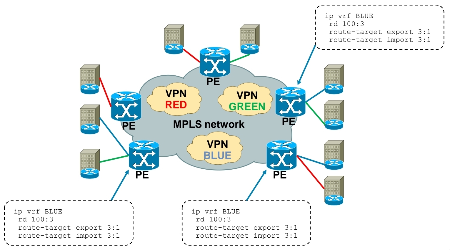
MPLS Layer 3 VPN Extranet between customer VPN RED and VPN BLUE
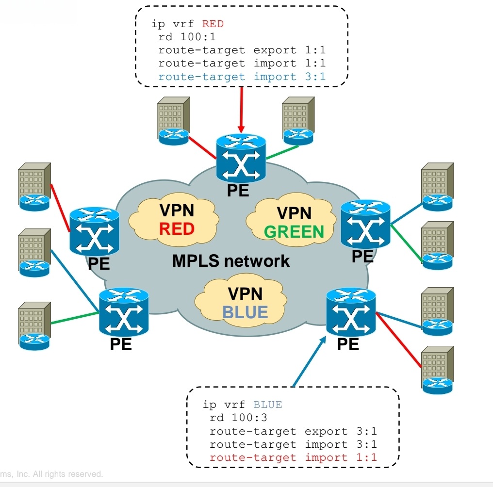
Using RT you create Intranet or Extranet
– Intranet – different sites of “same” VPN can communicate
– Extranet – different sites of “different” VPNs can communicate
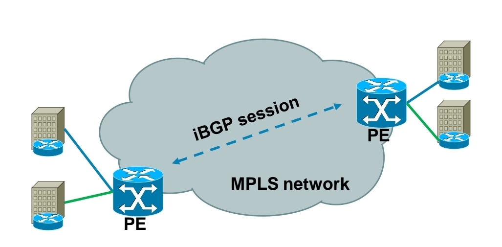
Exchanging RD, RT and VPN label over MPLS network
-Each PE router forms iBGP session with other PE router
-Over this iBGP sessions, PE routers exchange VPN prefixes
-Each VPN prefix is exchanged with its associated RT and VPN label – RT is for importing routes into VRF RIB, VPN label is for actual packet forwarding
Packet forwarding with MPLS Layer 3 VPN
-IGP label is assigned by LDP
-VPN label is assigned by MP-BGP
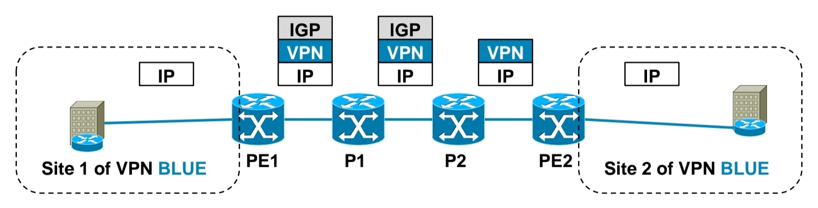
1.) PE1 receives IP packet on VRF interface assigned to site 1 of VPN BLUE.
2.) PE1 looks up VPN and IGP label, imposes these both labels as label stack to IP packet and forwards it to MPLS network. IGP label is known based on iBGP next hop, which is IP address of PE2.
3.) P1 router swaps IGP label based on its LFIB table.
4.) P2 removes IGP label due to PHP, but does not touch VPN label.
5.) PE2 router receives IP packet with VPN label, which it uses to select correct outgoing VPN site
6.) PE2 then strips off VPN label, makes lookup in its VRF RIB for particular VPN site to get the outgoing interface to send received packet to
Exchanging routing information between CE and PE routers
– Static routing
– RIP
– EIGRP
– OSPF
– IS-IS
– eBGP

Basic MPLS L3 VPN config
1.) Configuring core LSR for MPLS switching

2.) Configuring edge LSR for MPLS switching
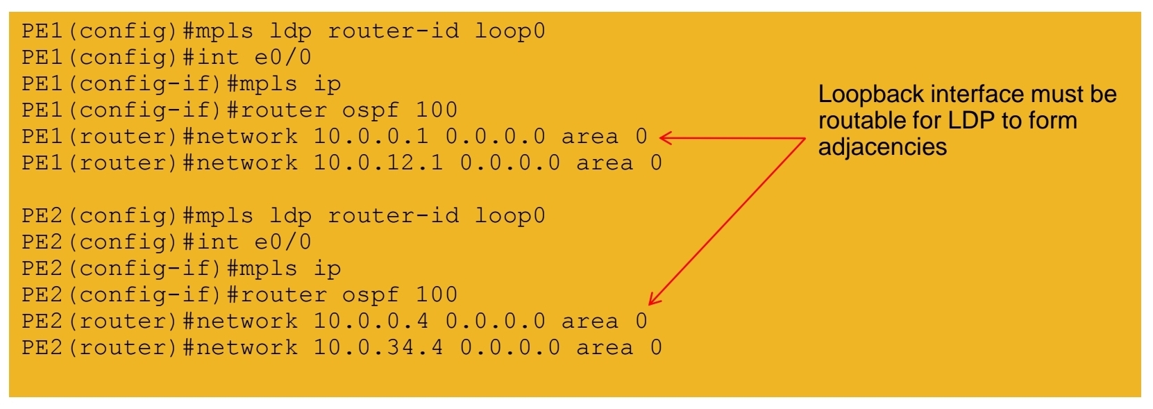
3a.) Configuring edge LSR PE1 for MPLS L3 VPN

3b.) Configuring edge LSR PE1 for MPLS L3 VPN

4a.) Configuring edge LSR PE2 for MPLS L3 VPN

4b.) Configuring edge LSR PE2 for MPLS L3 VPN

5.) Configuring CE-PE connectivity on CE1 and CE2

MPLS L3 VPN verification
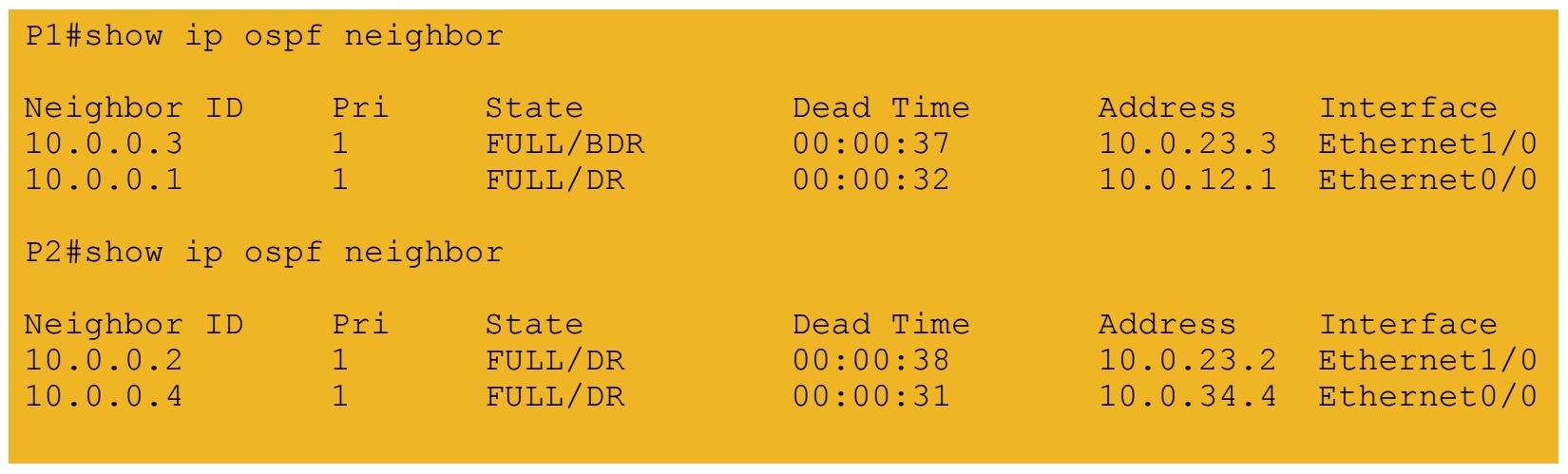
1.) IGP peerings formed in core
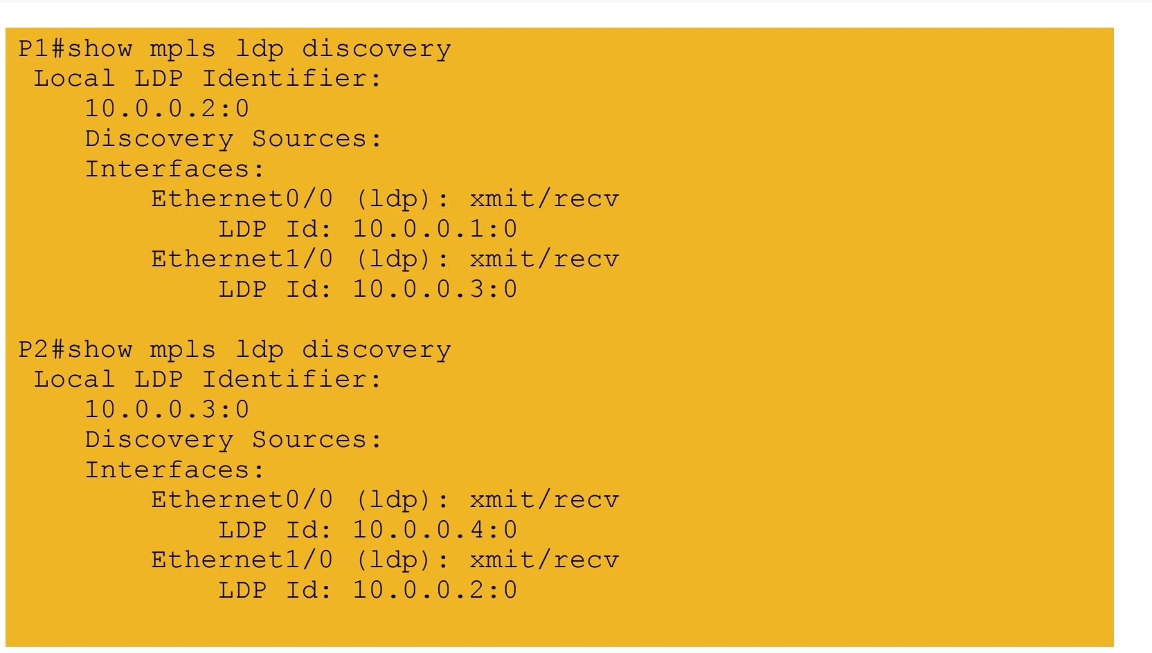
2.) MPLS LDP peerings formed in core
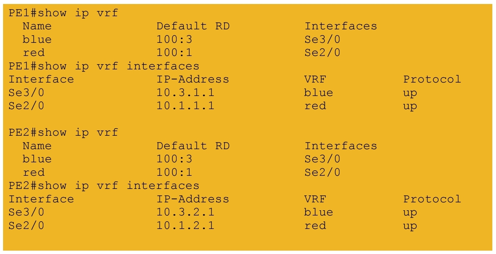
3.) VRF tables and interfaces defined on PE routers
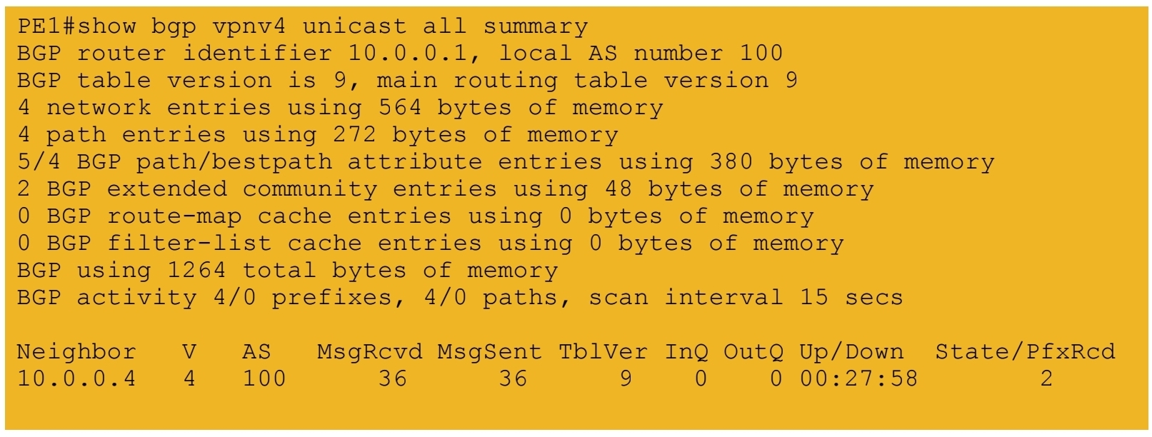
4.) iBGP session formed between PE routers
5a.) IGP labels assigned by LDP – path from PE1 to PE2
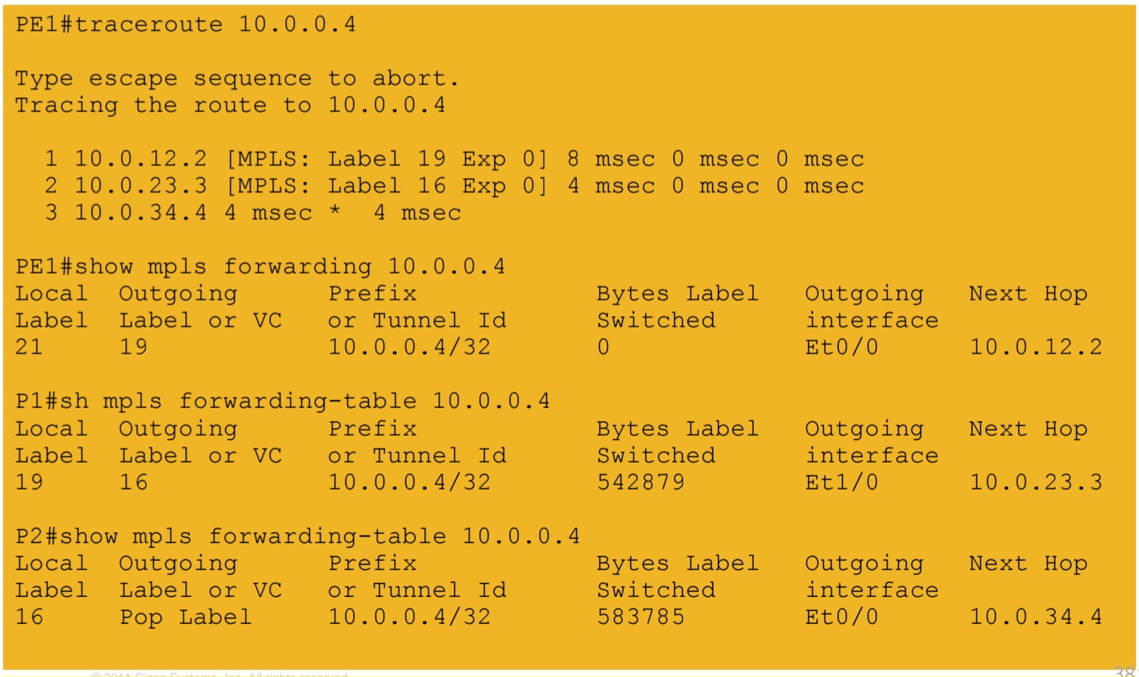
5b.) IGP labels assigned by LDP – path from PE2 to PE1
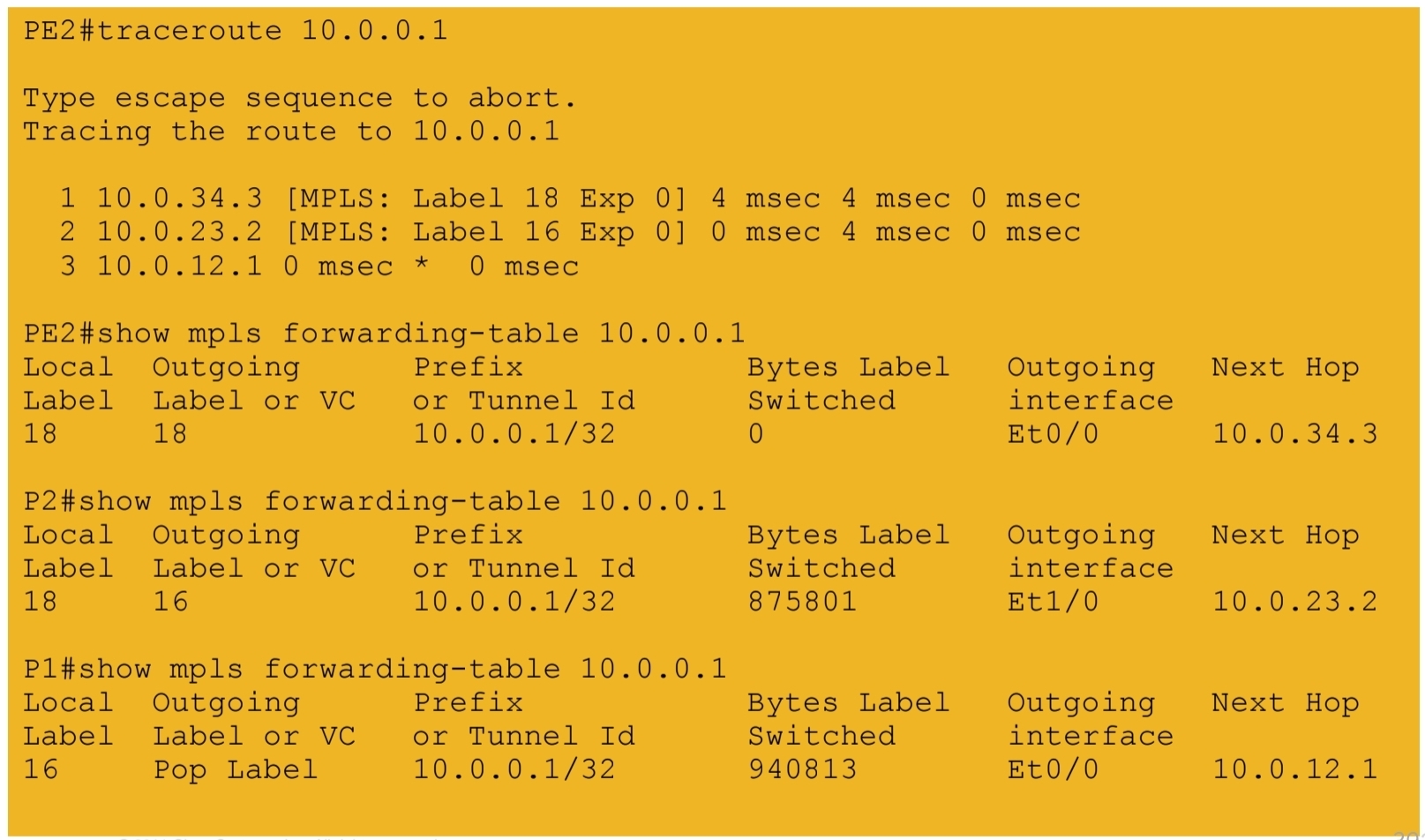
6.) VPN labels assigned by BGP

7a.) End-to-end connectivity between VPN RED sites
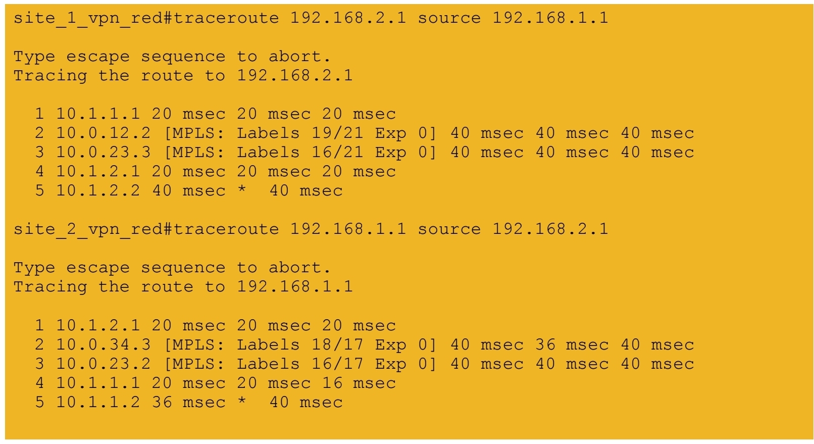
7b.) End-to-end connectivity between VPN BLUE sites
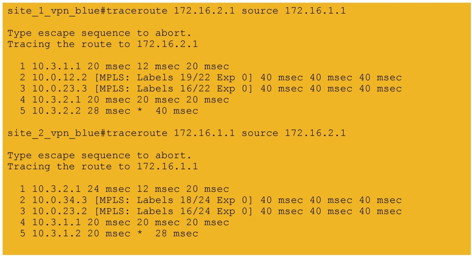
Leave a Reply