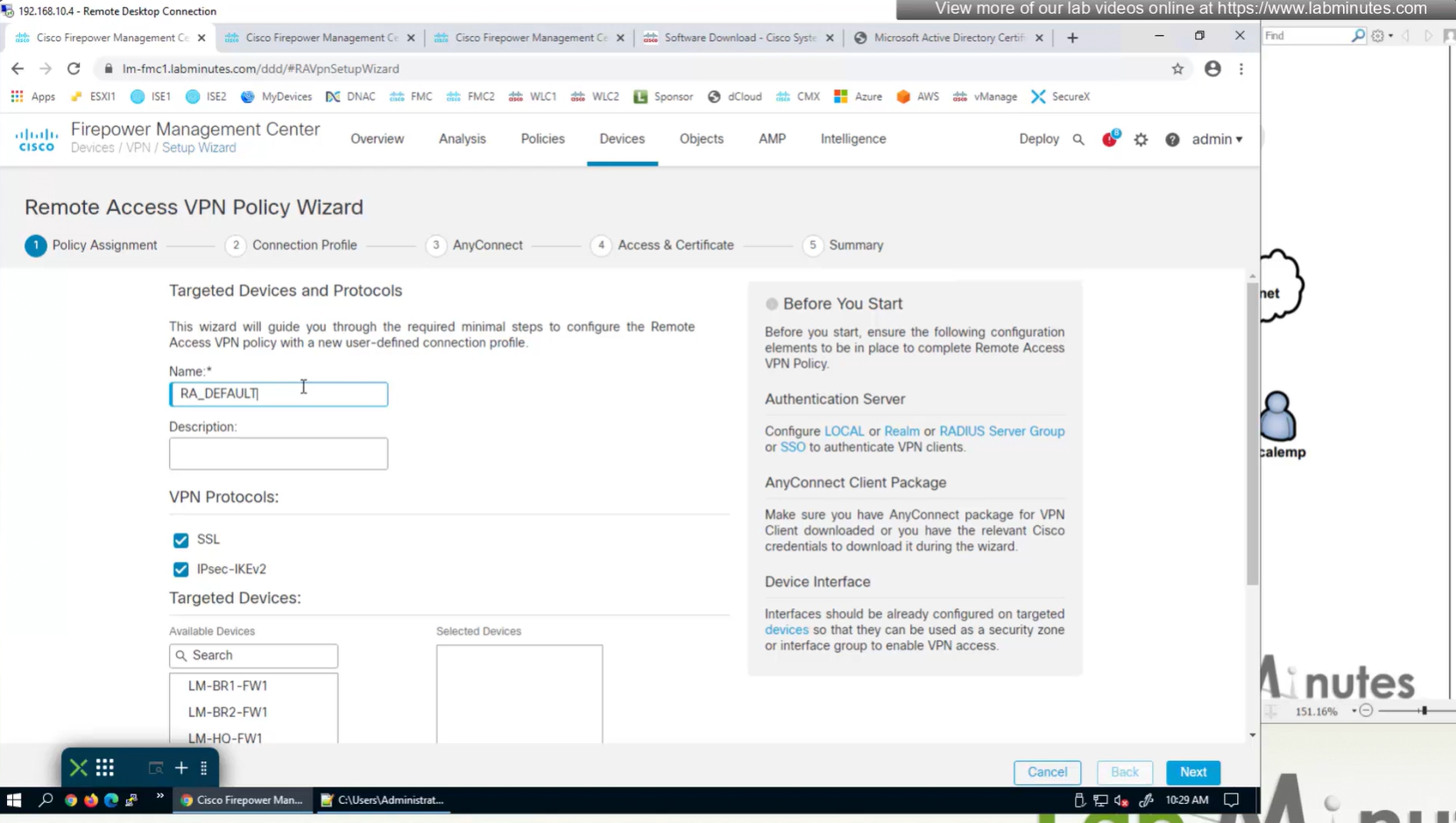
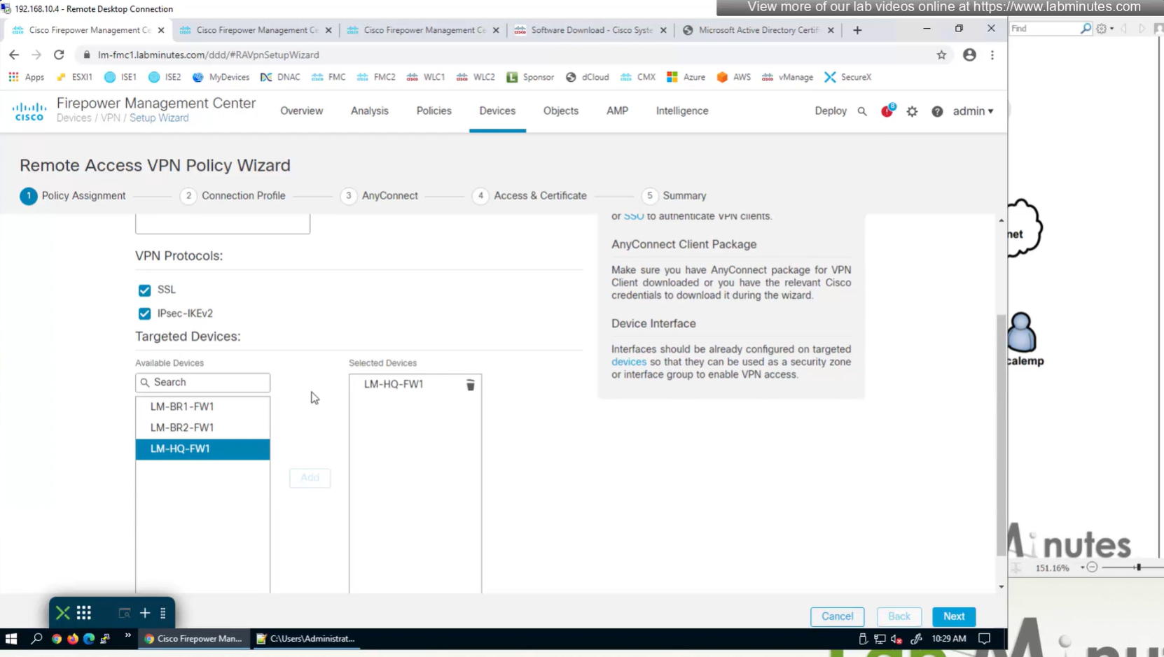
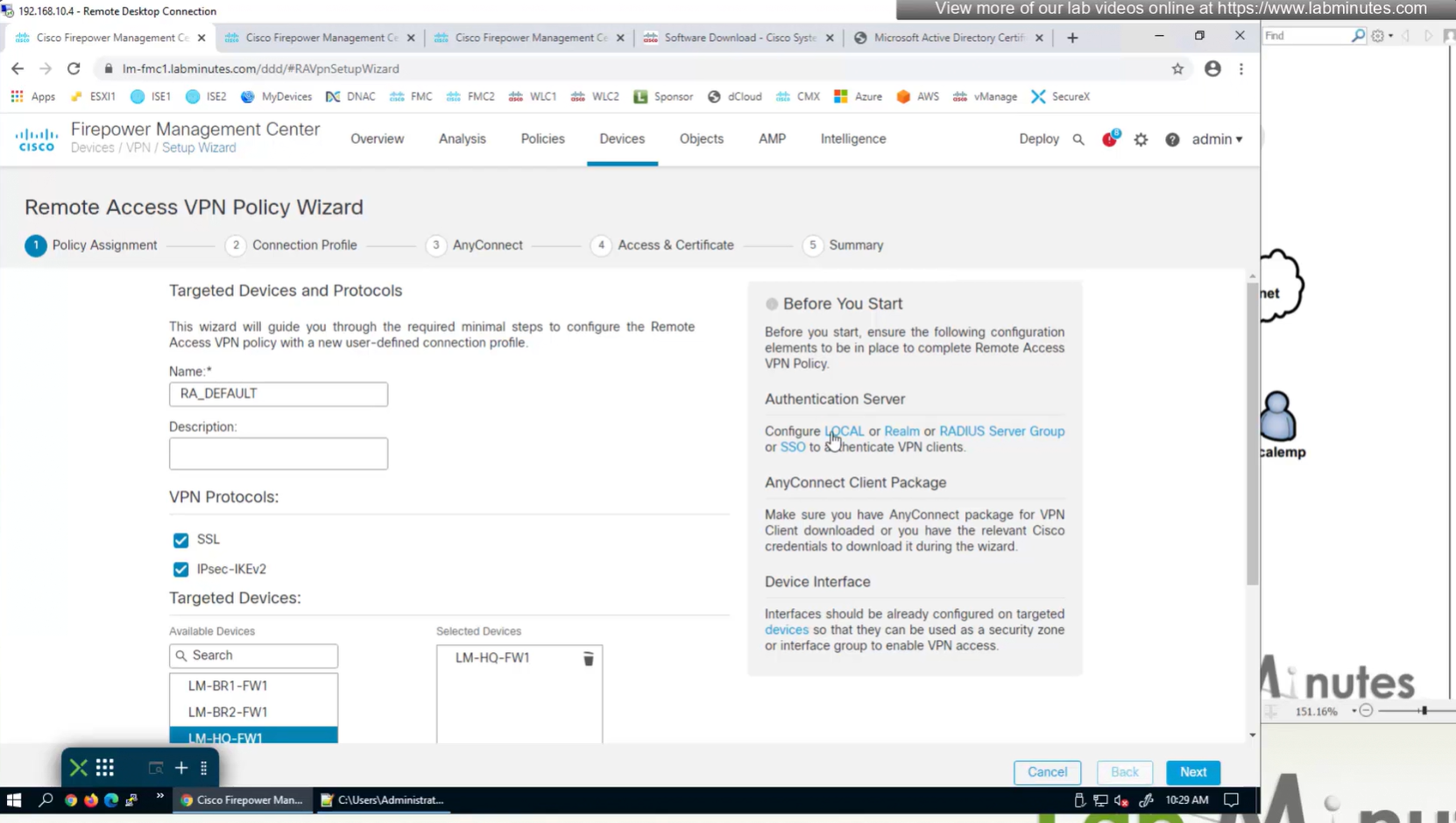
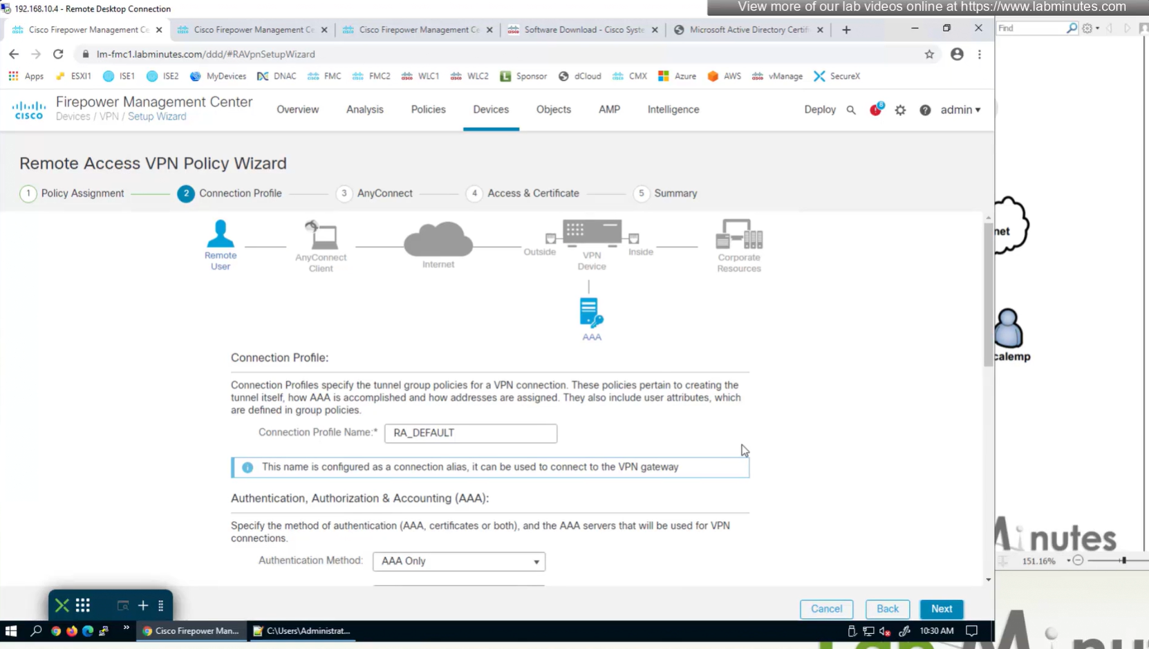
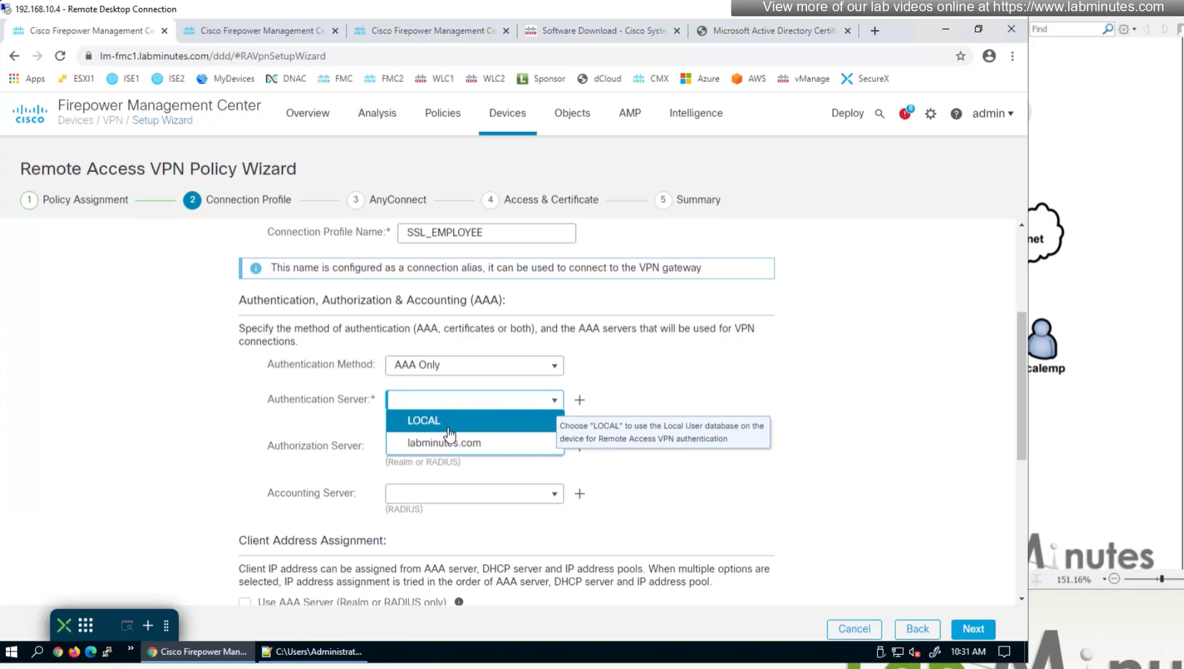
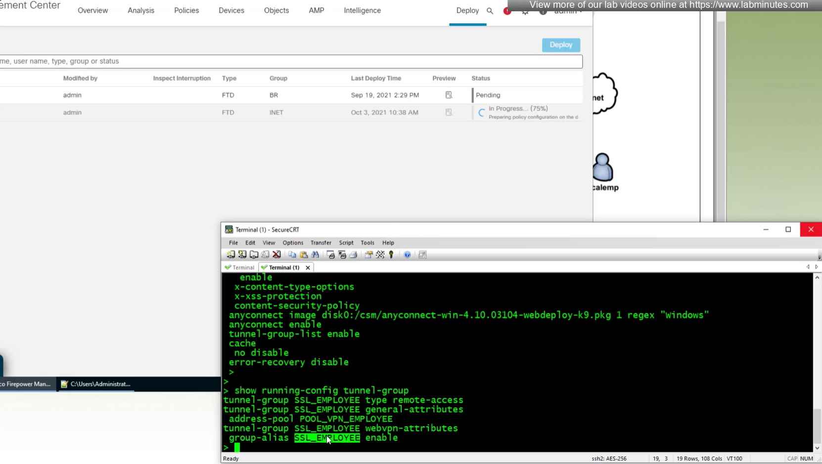
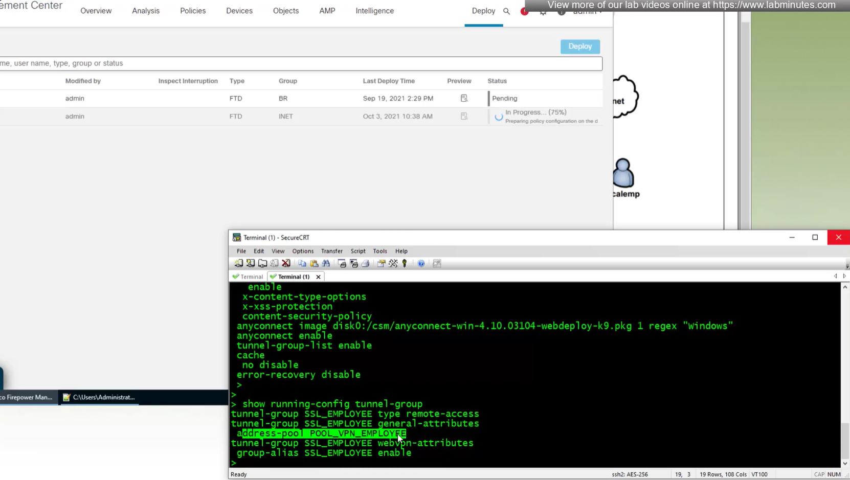
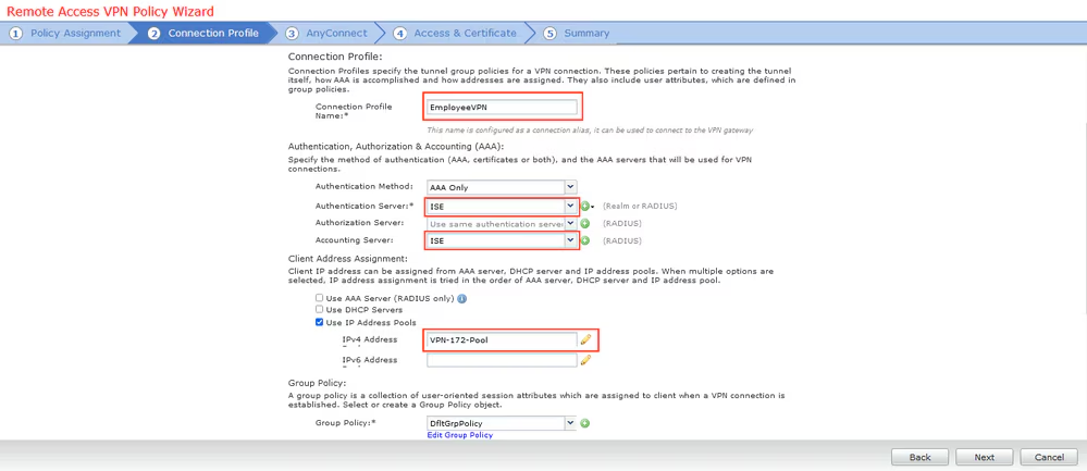
Connection profile is basically a tunnel group – tunnel group controls user realated information such as
1. How is user authenticated 2. Which group policies apply to user aka which settings apply to user 3. Addressing and routing related such as (e.g. split tunneling, DNS, IP pools) are used , What resources the user can reach.
A tunnel group in AnyConnect is the front door to the VPN. It decides who you are, how you log in, and which rules (policies) you inherit. The group policy behind it is like the house rules once you’re inside. Group policy can also be thought of policy for different groups of users that is why address assignment can also be assigned in group policy, for example Employees vs Contractors.
There are remote access tunnel groups and there are also L2L tunnel groups as well
There are default tunnel groups
DefaultRAGroup → For remote-access connections without a specified group. DefaultL2LGroup → For site-to-site VPN connections without a specified group. These act as “catch-all” settings if no other tunnel group matches.
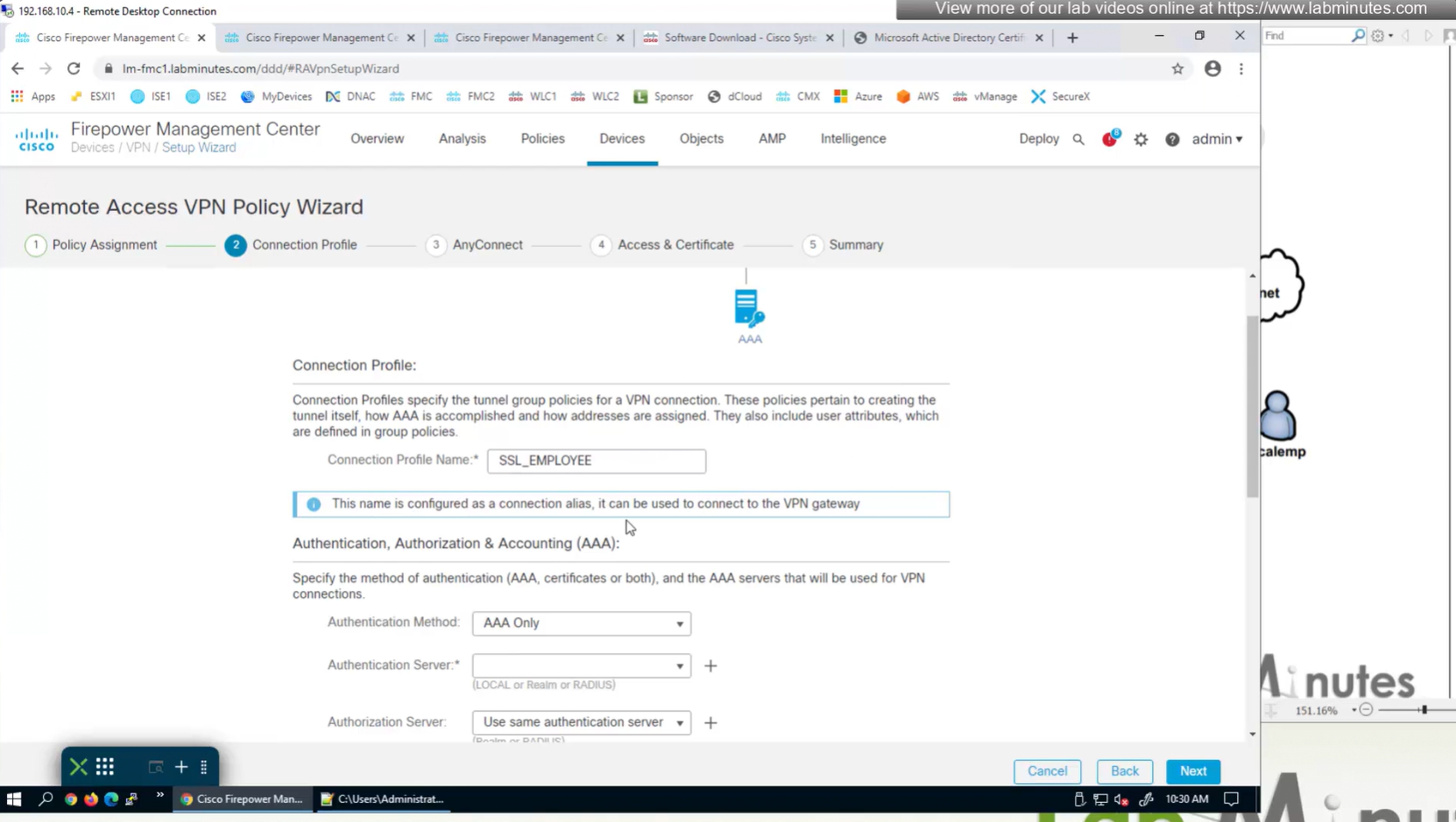
If user connects to URL on anyconnect https://vpn.company.com/employees “employees” is called a group URL (or alias), and it maps to a tunnel group
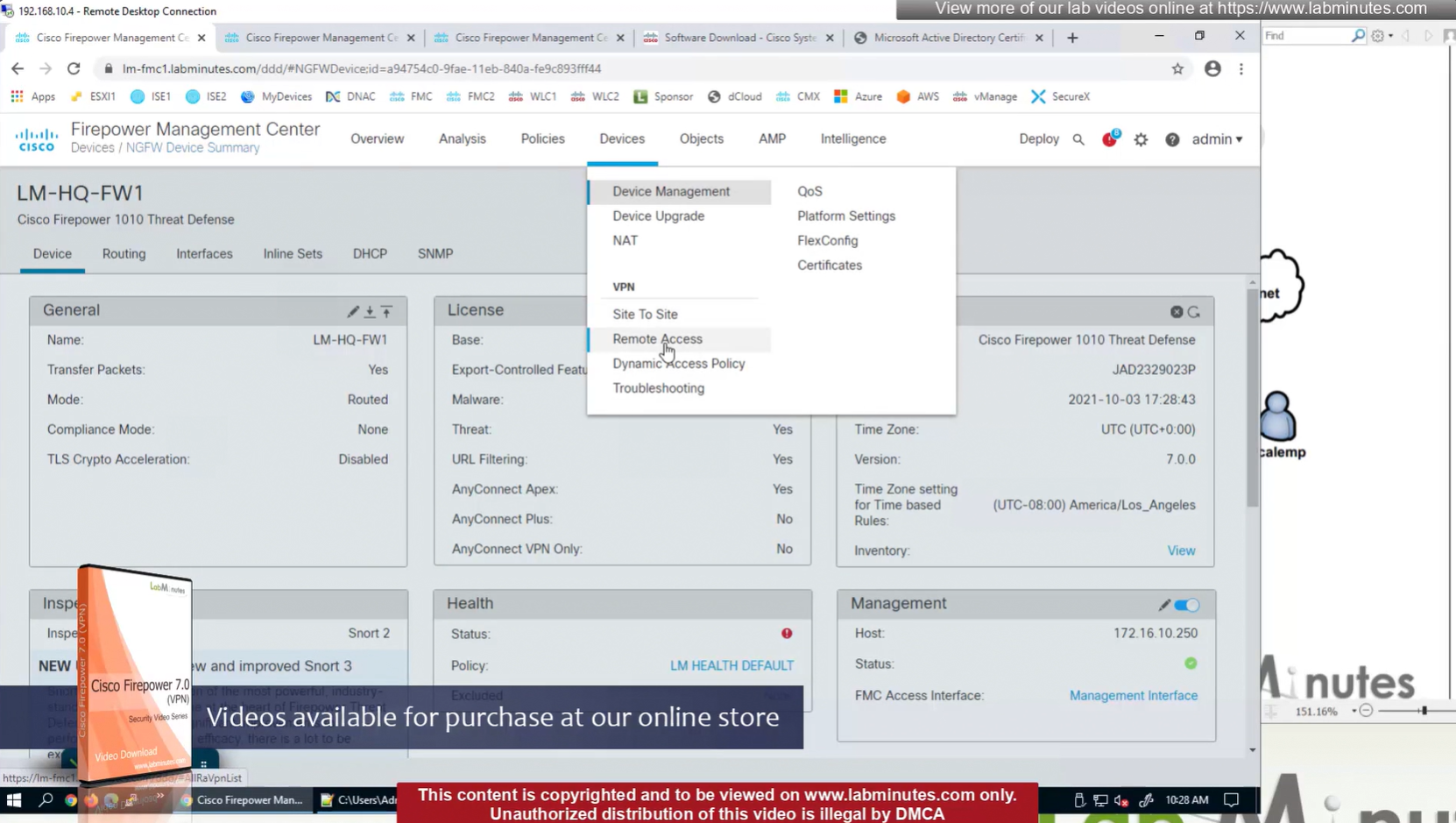
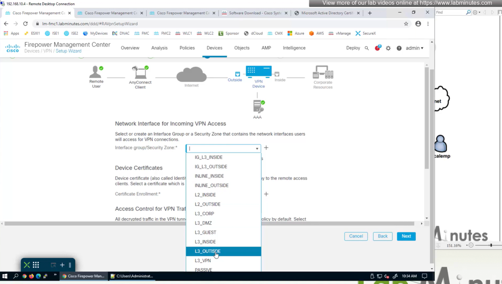
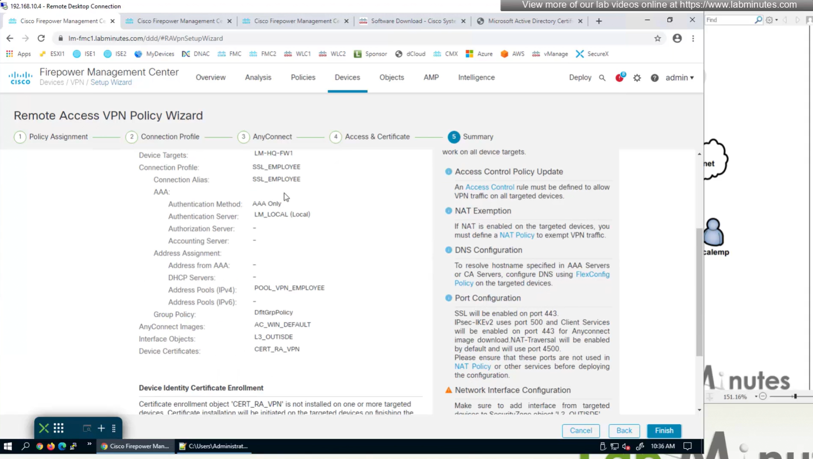
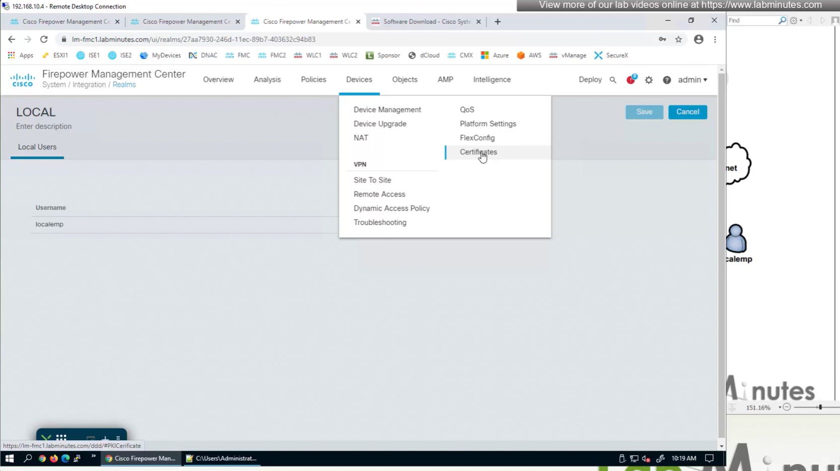
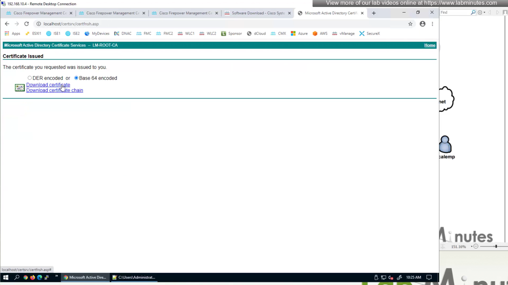
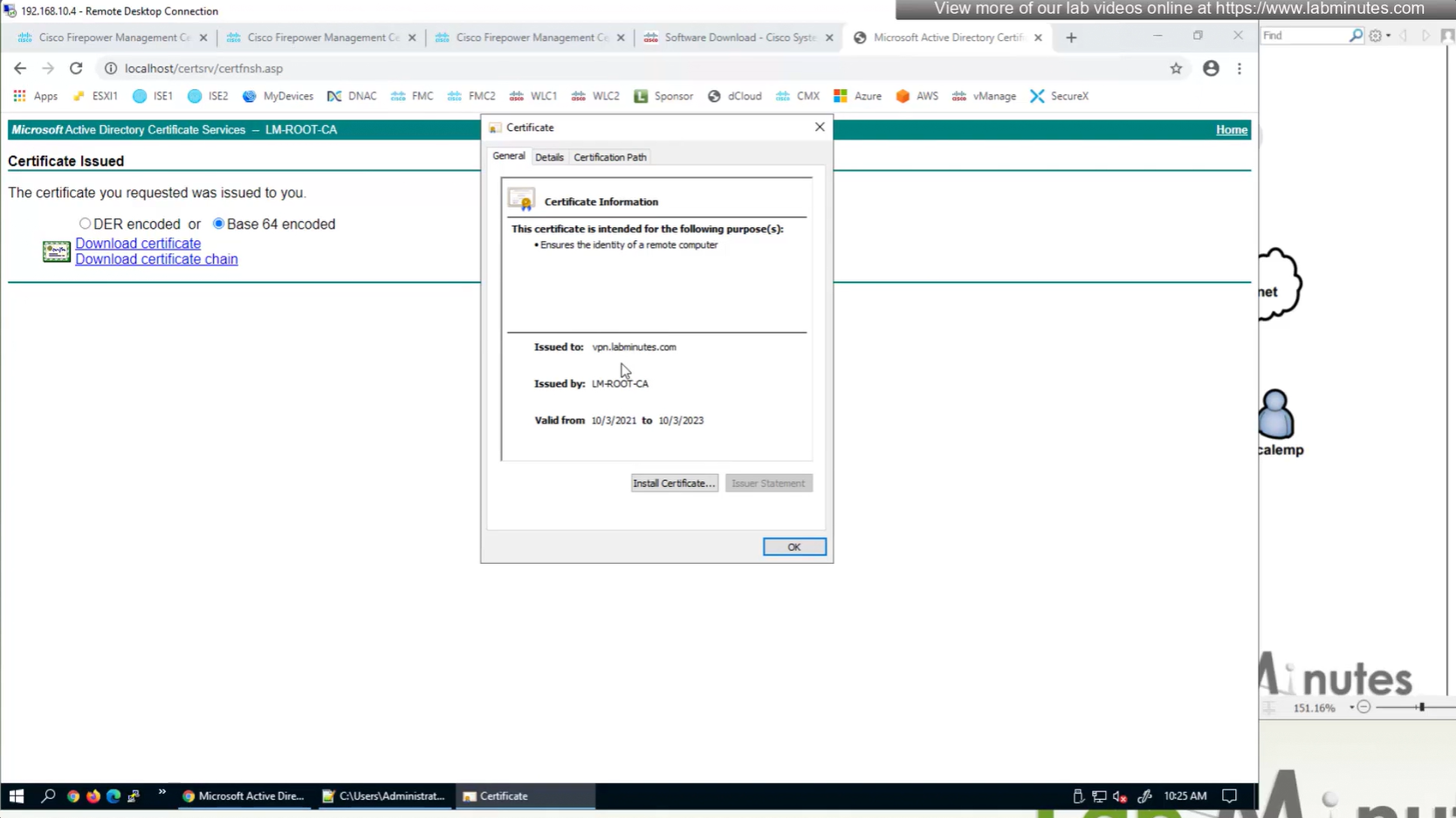
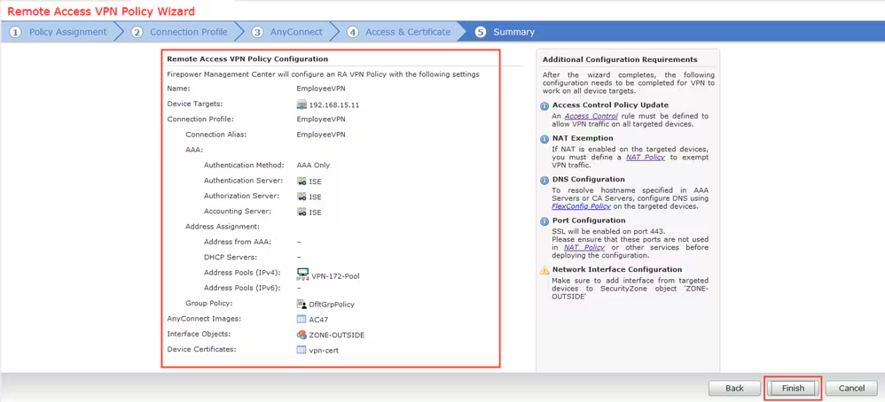
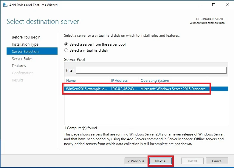
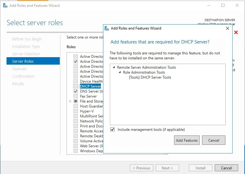
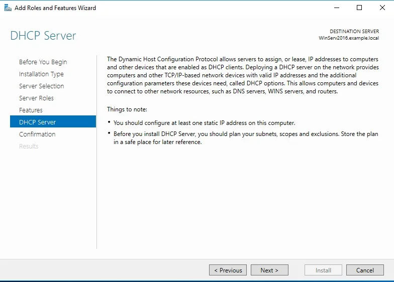
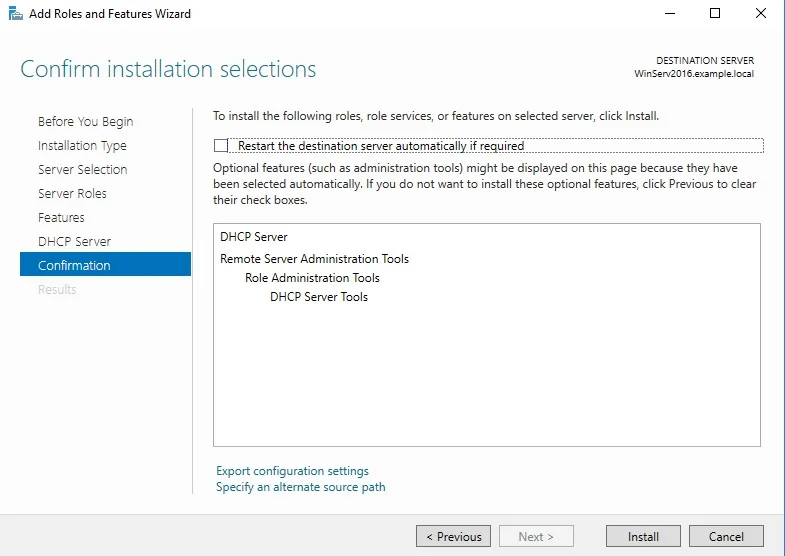
Select certificate to add on the outside interface
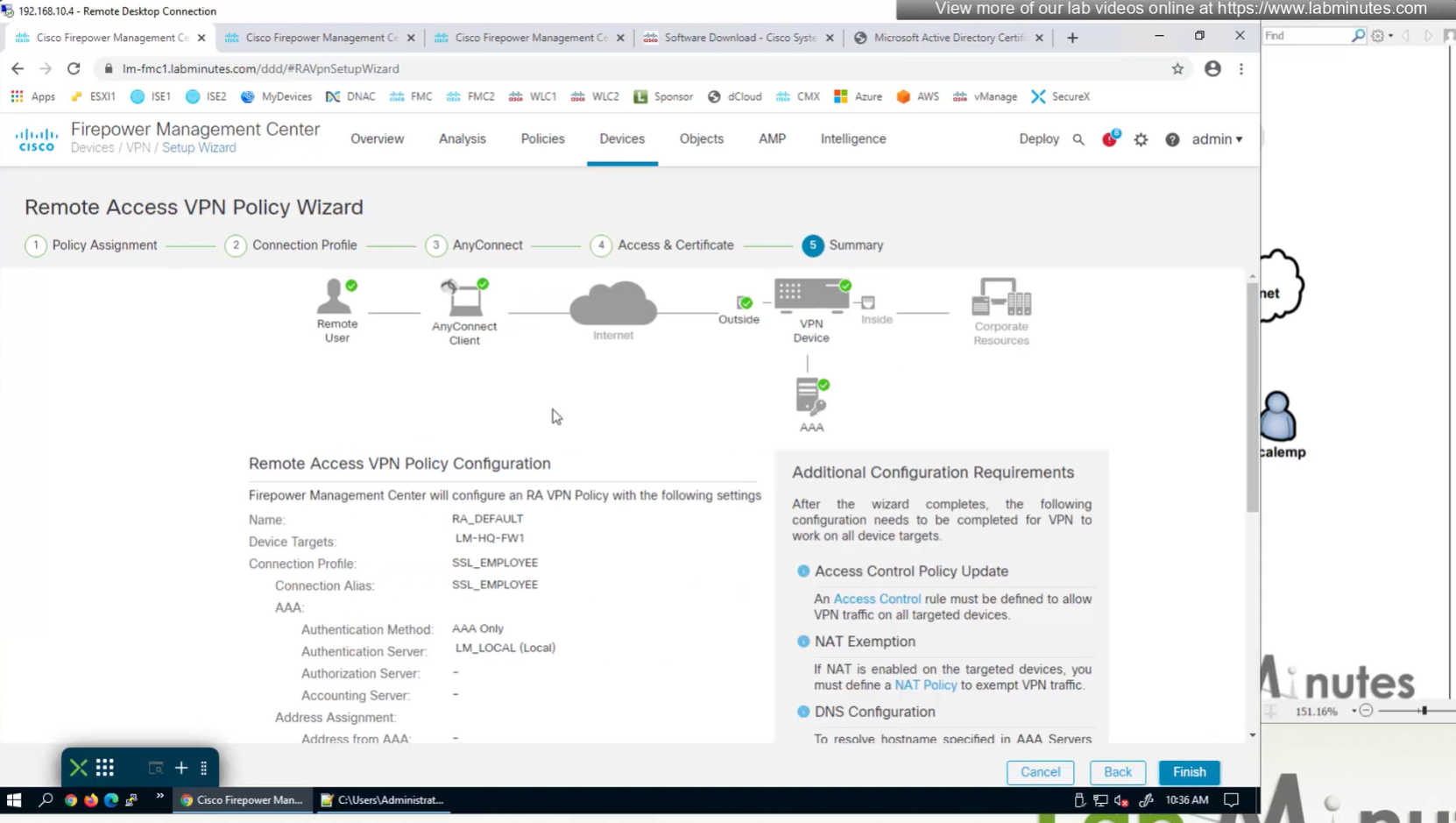
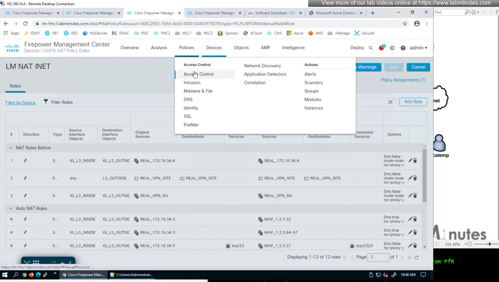
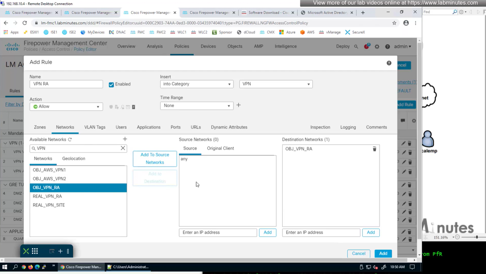
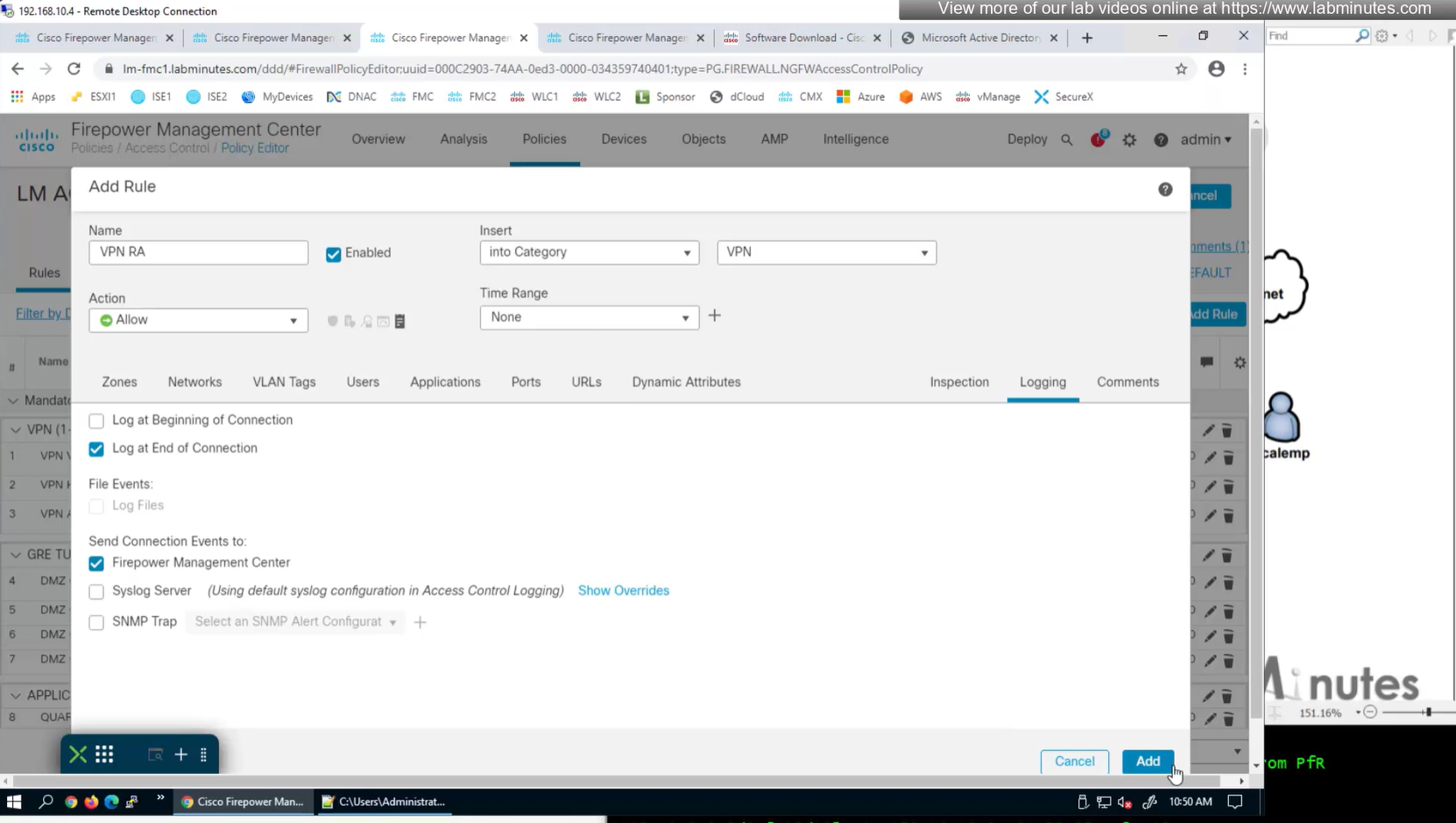
Access Control Policy is needed to allow remote user’s traffic towards enterprise
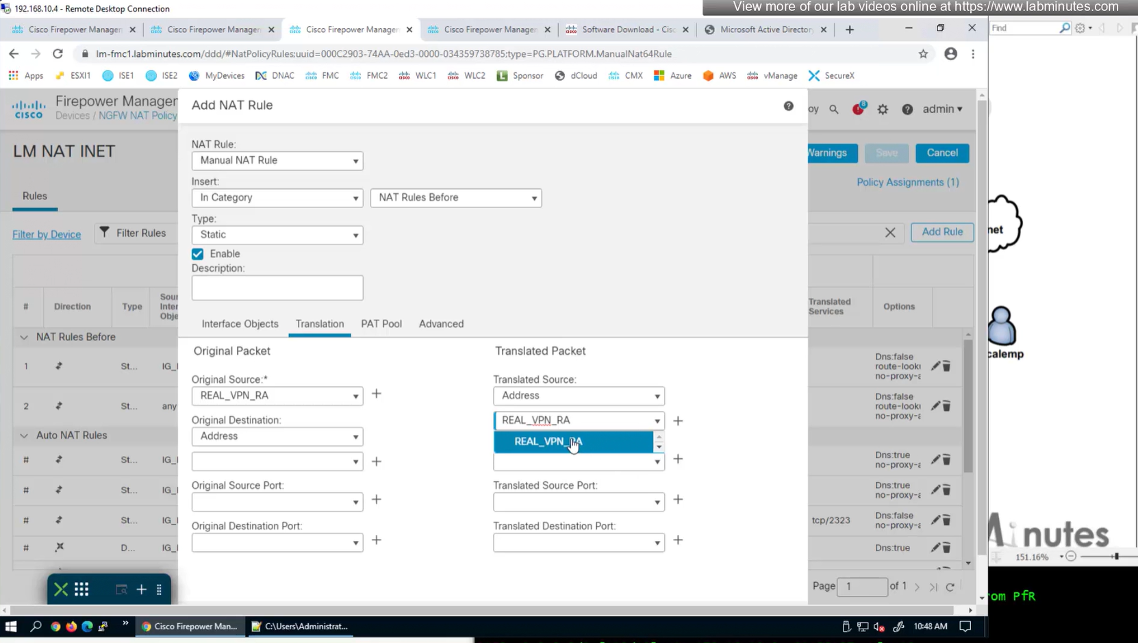
NAT exemption is needed in case there is NAT policy applied on remote access firewall
SSL will be enabled on port 443, IPSec IKEV2 uses port 500, NAT-T will be enabled by default which will use port 4500
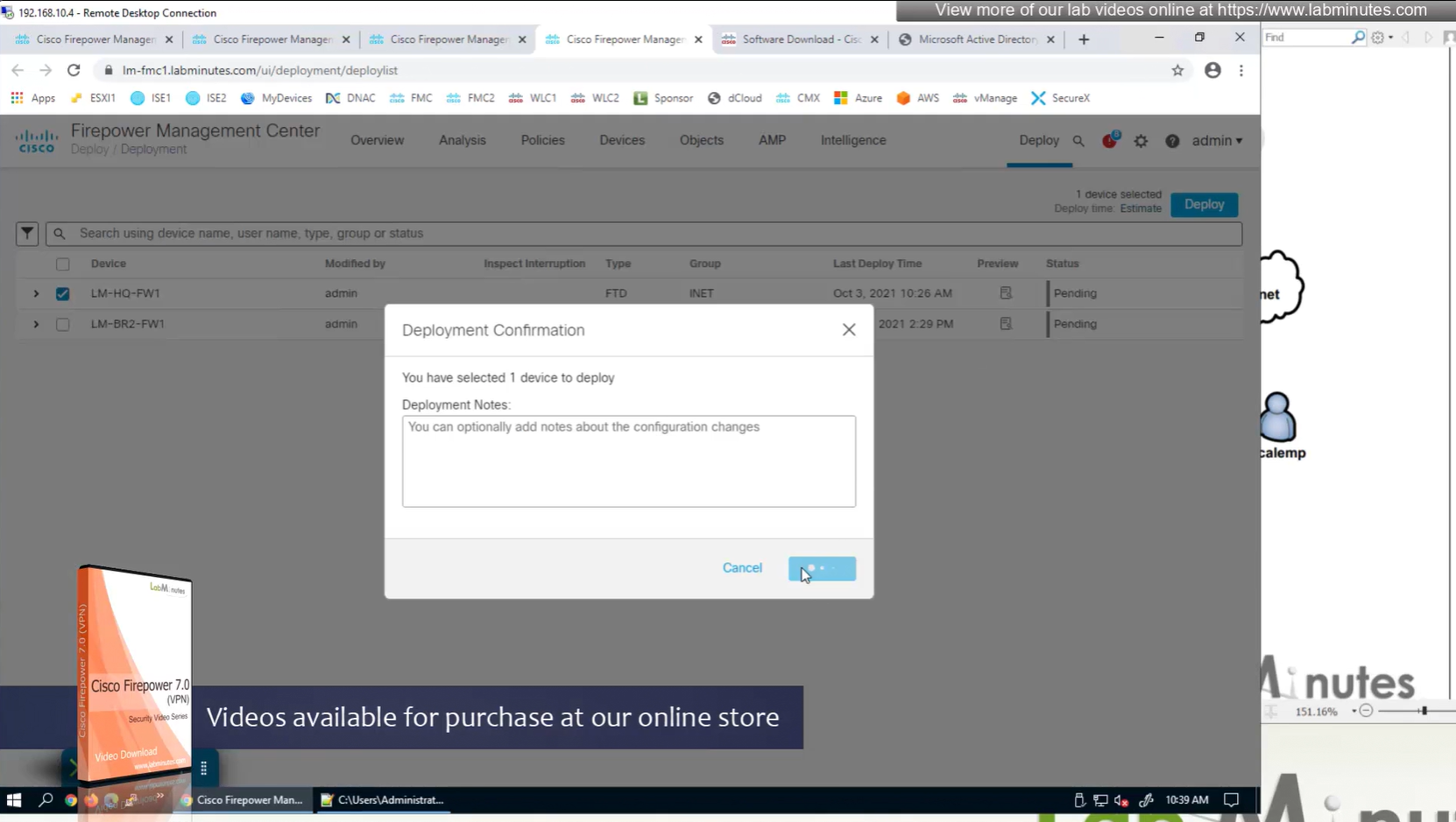
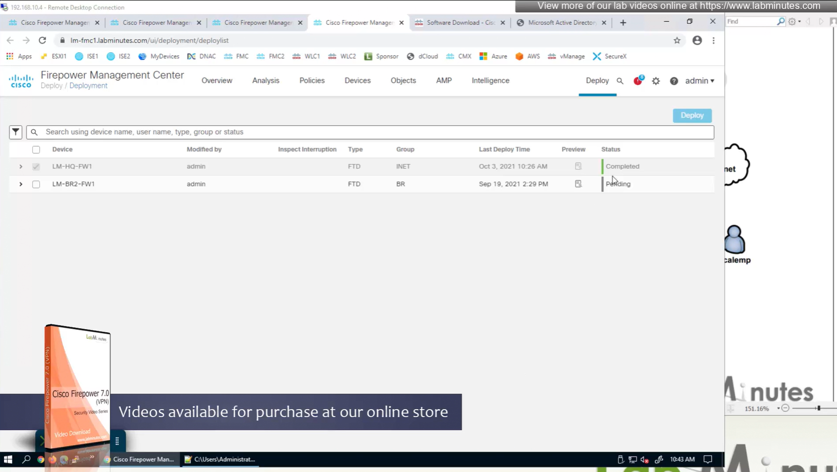
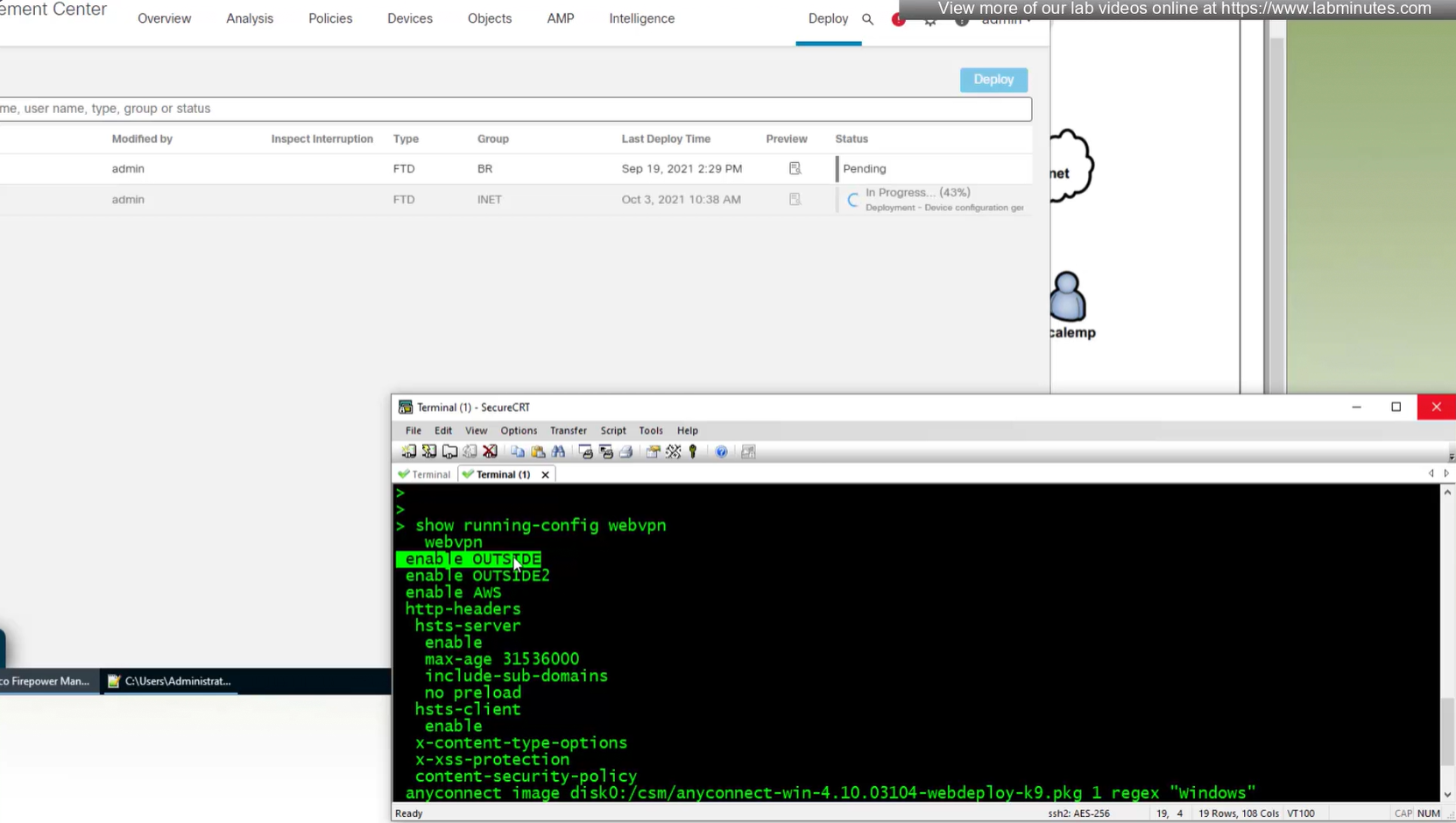
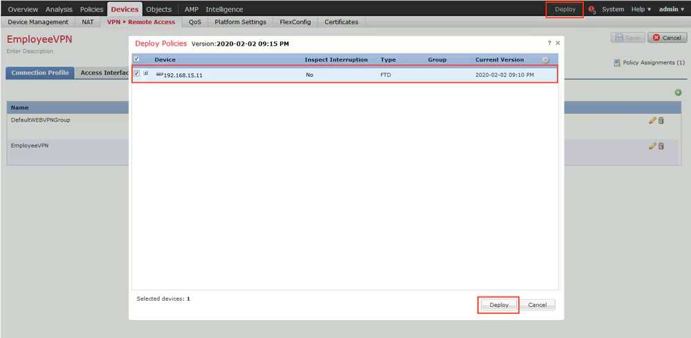
Now we will deploy to make sure that there is no error
Make sure to advertise the anyconnect address pool in routing so enterprise can reach remote clients
We also need to exempt the traffic as we dont want the traffic going to or coming from remote clients to be NATed, a static NAT will do the job
Select do not proxy ARP and also select perform route lookup for destination interface (to avoid NAT divert)
2x outside interfaces are here because because outside interface group
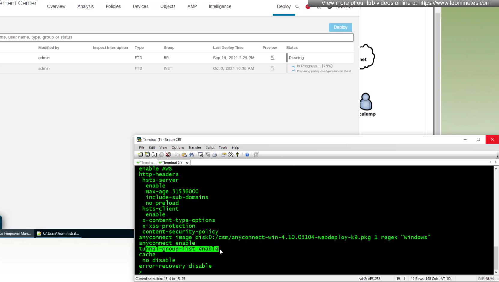
show running-config webvpn
default config that is part of the anyconnect vpn
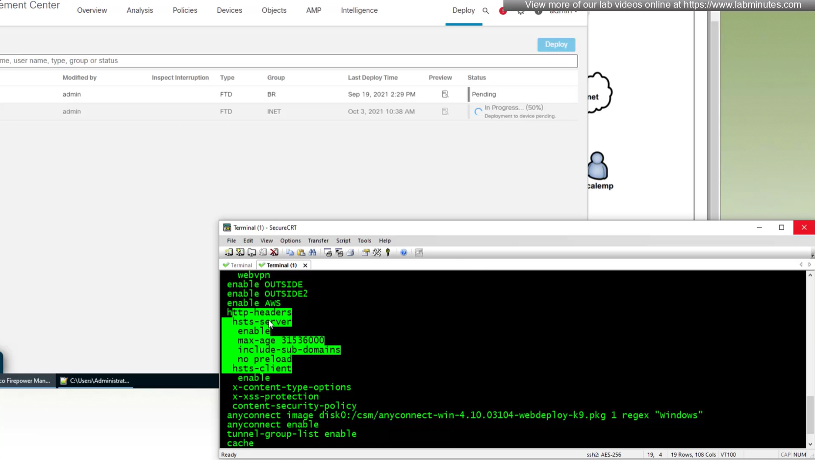
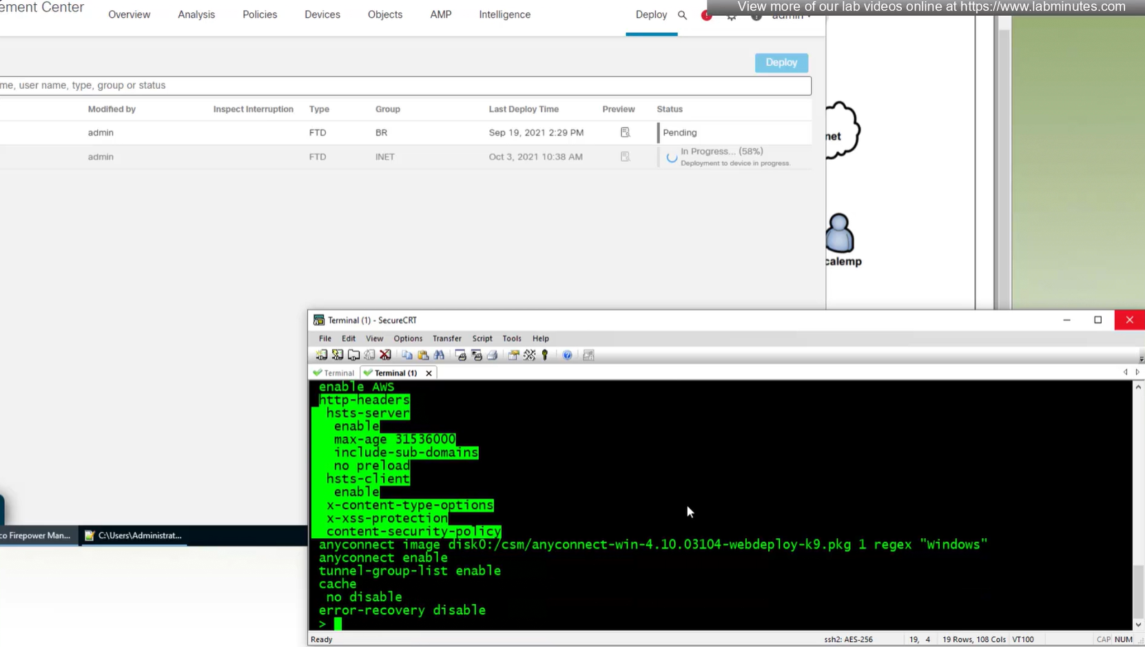
some additional HTTP headers
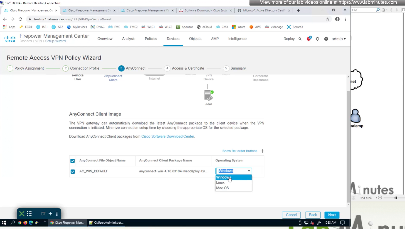
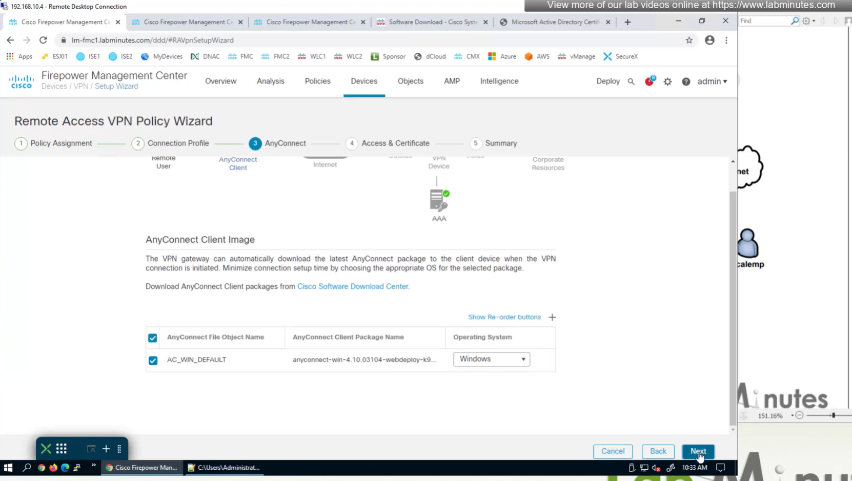
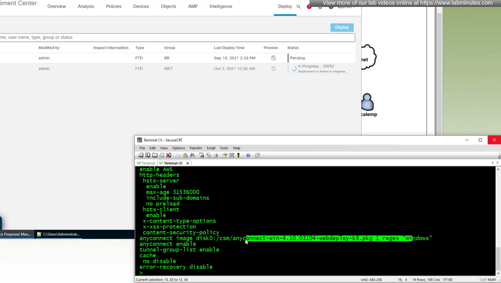
Anyconnect image
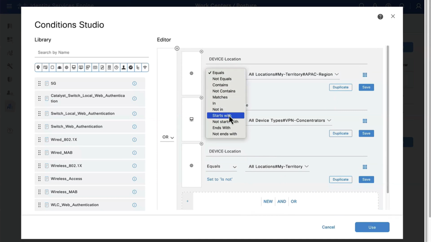
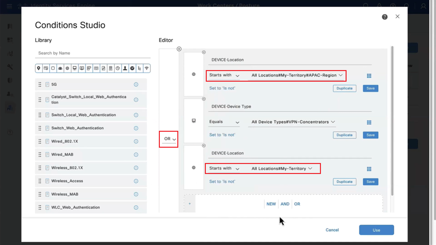
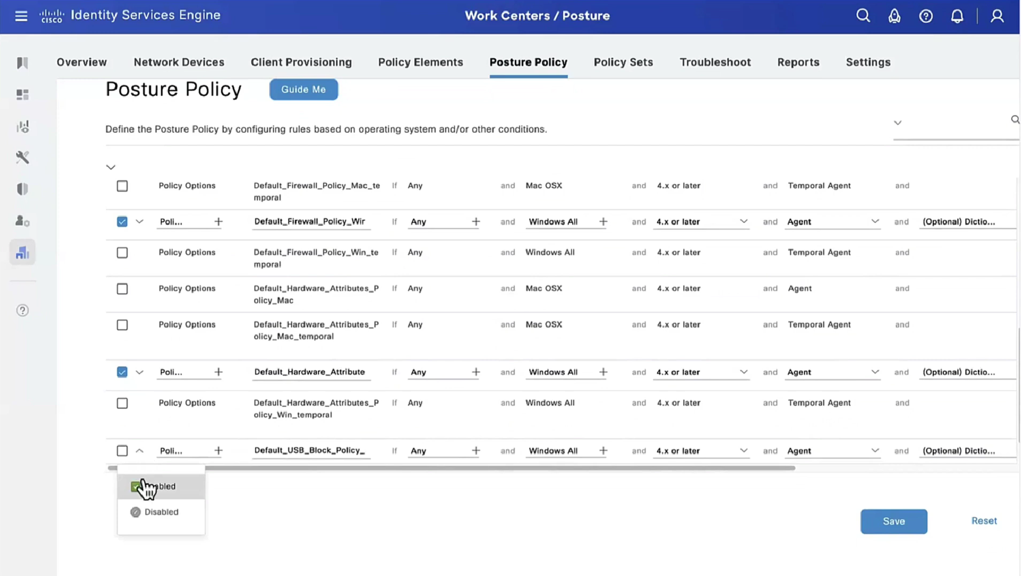
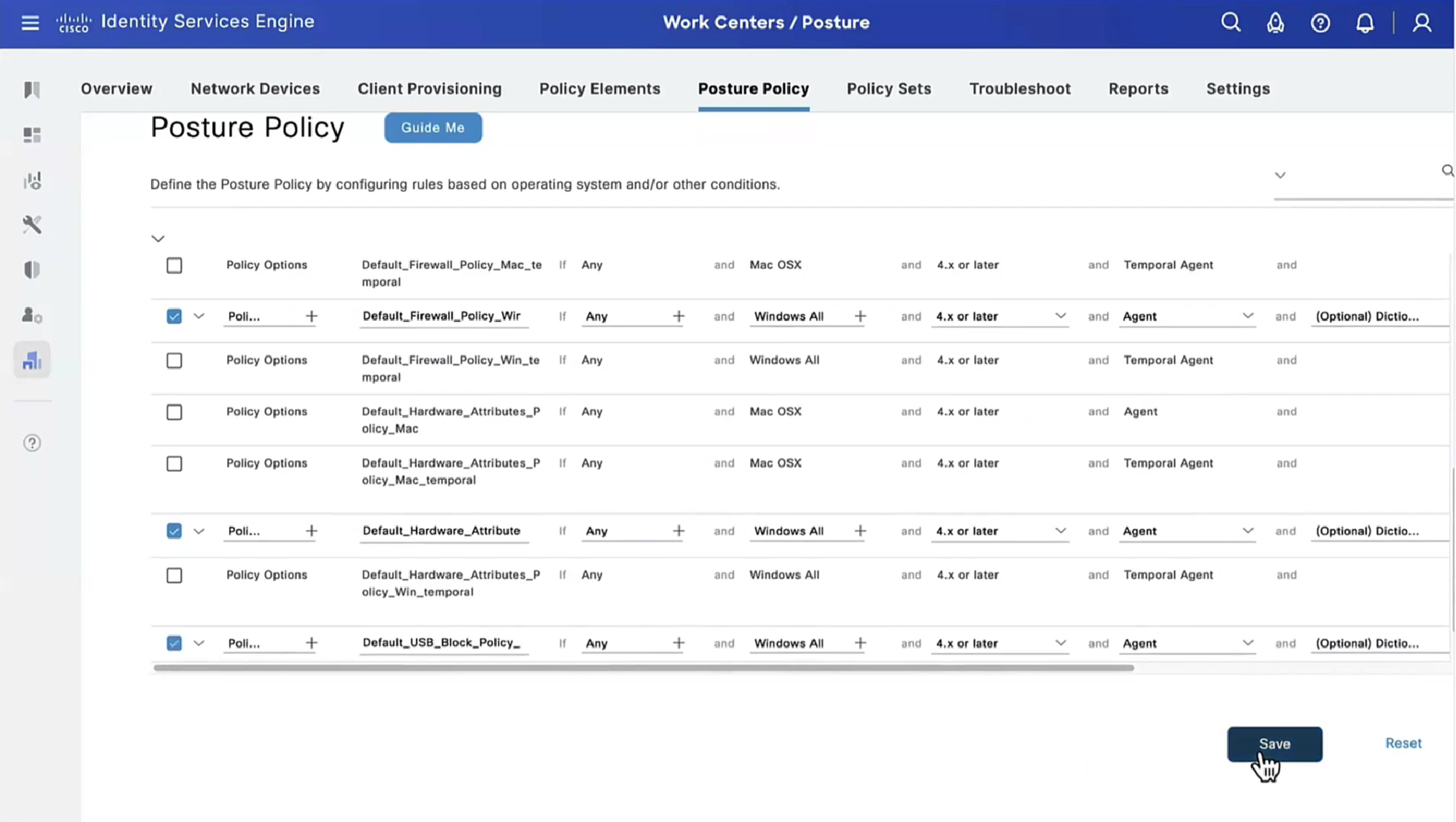
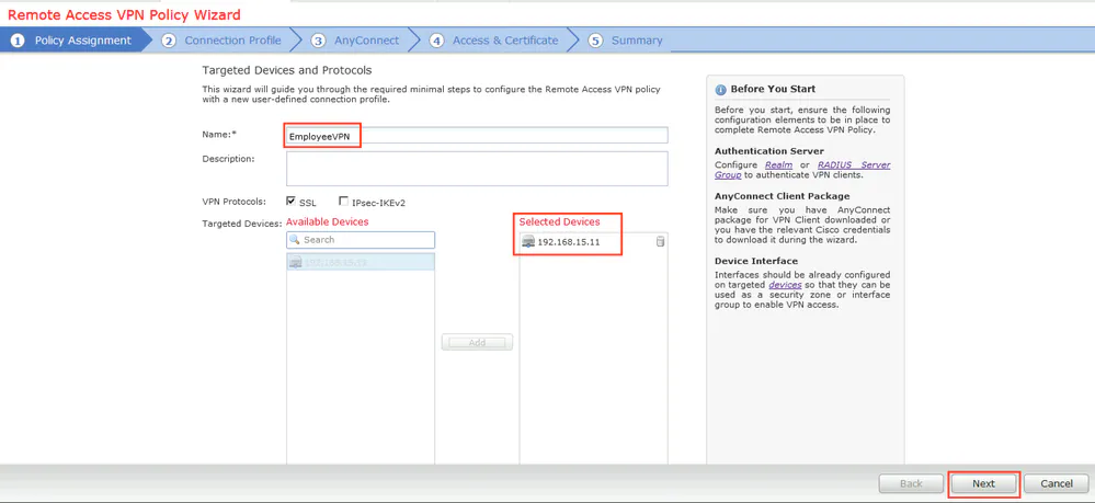
When you configure multiple tunnel groups (also known as connection profiles) on an ASA, users connecting via VPN (like AnyConnect or IPsec) may need to pick which one to use.
By default, the ASA won’t show users a drop-down list of available tunnel groups at the login screen. Instead, they’d have to know and type in the group name.
The command:
tunnel-group-list enable
enables the display of the tunnel group (connection profile) list on the VPN login page.
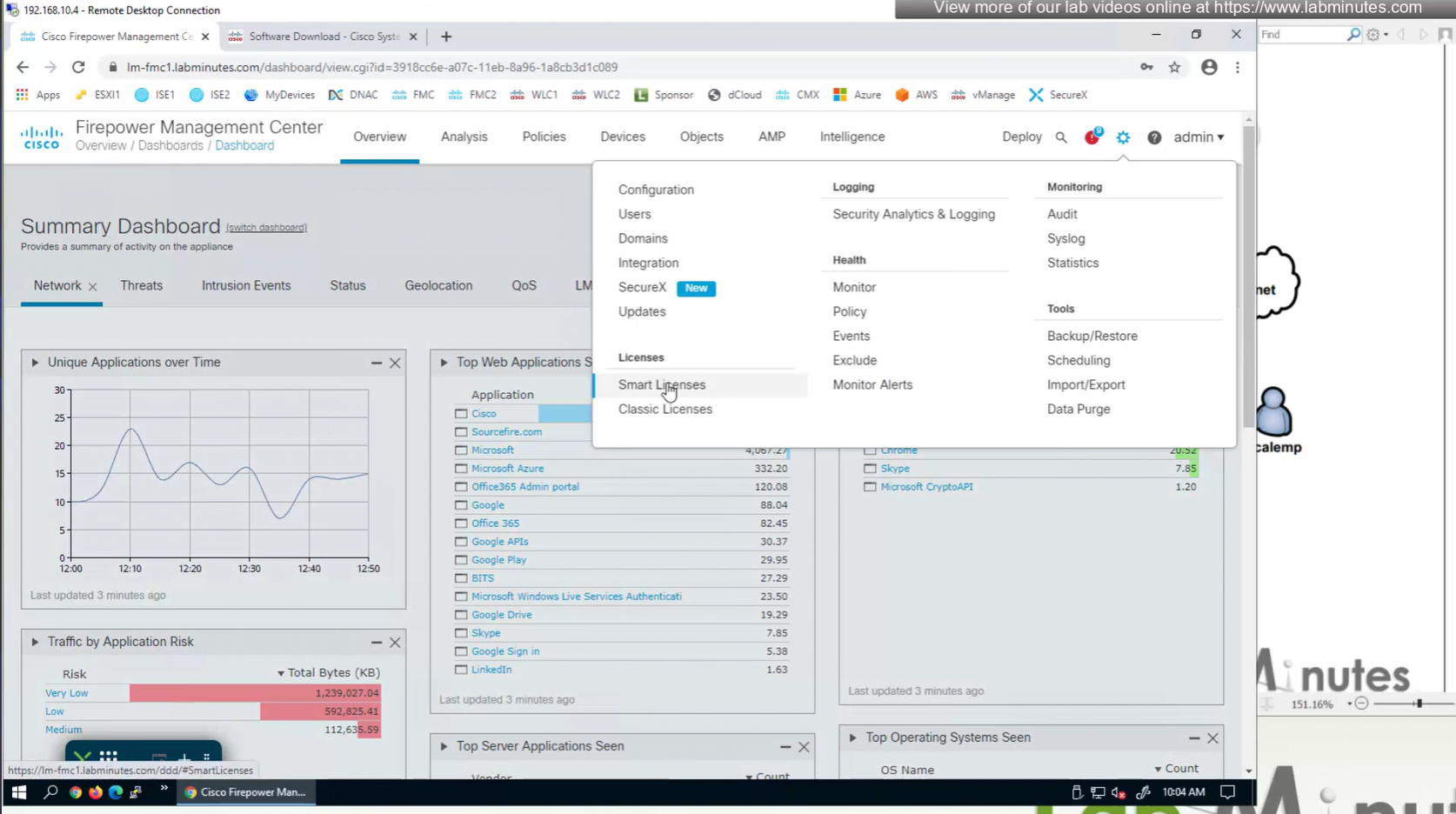
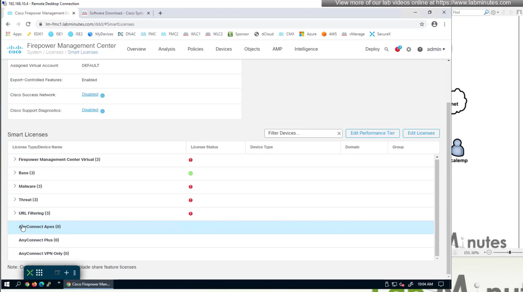
There are different anyconnect licenses and we need to make sure we have right kind of licenses and also make sure that they are synced to our smart account as FMC will be pulling them from Smart licensing.
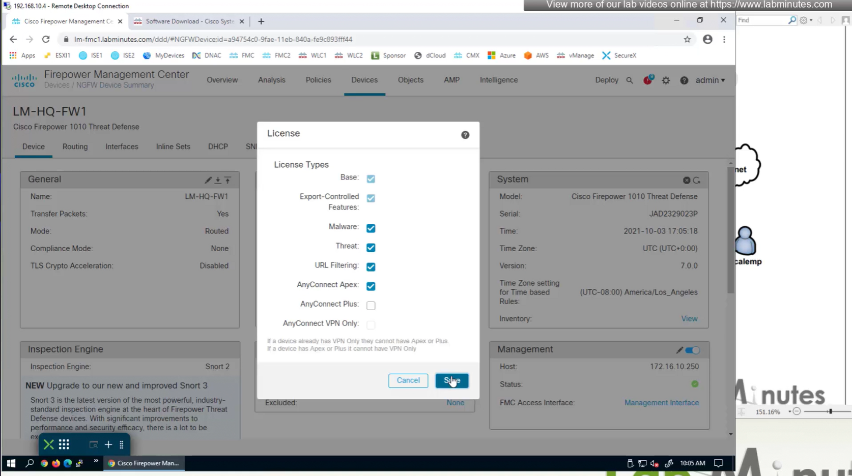
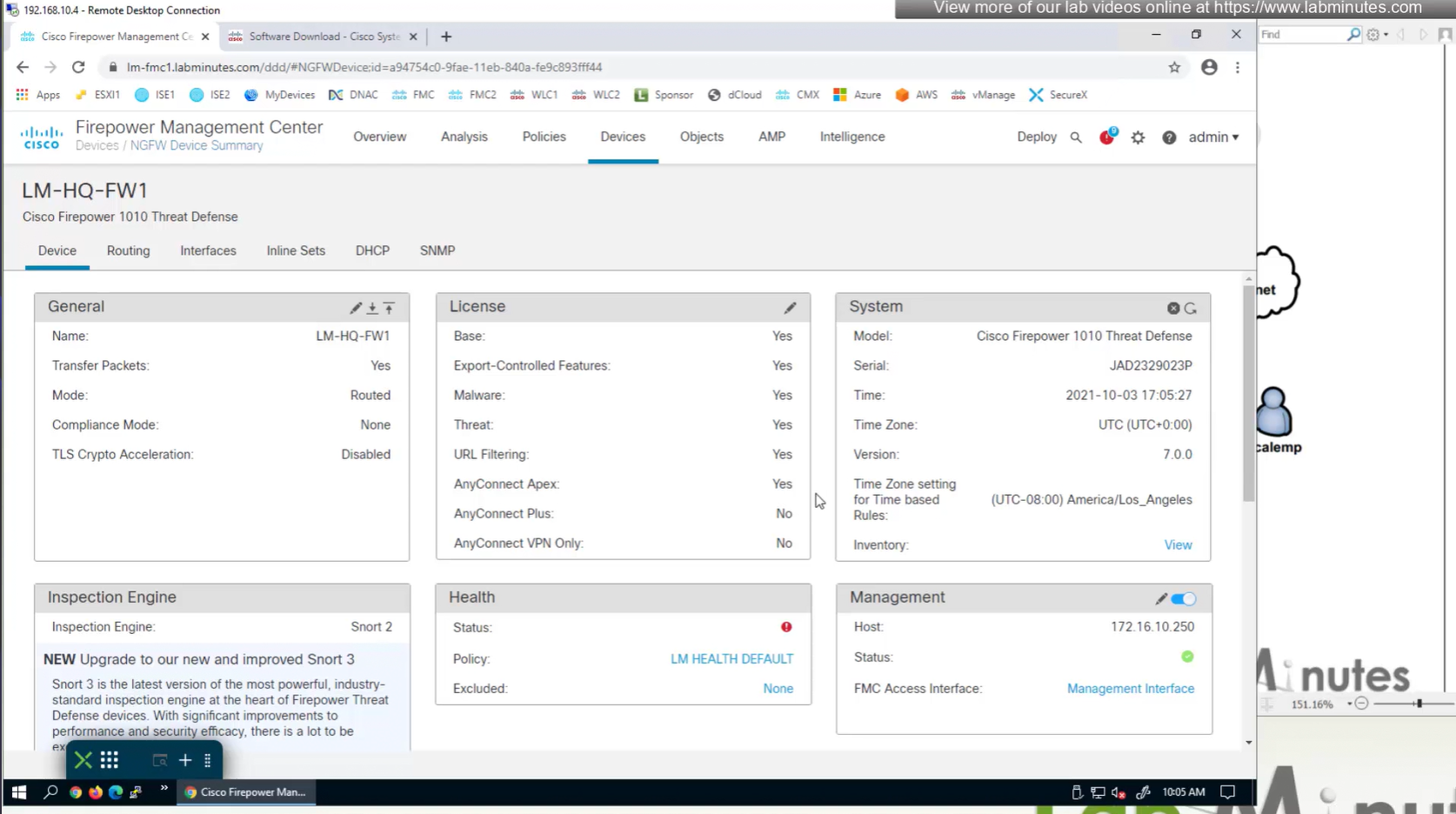
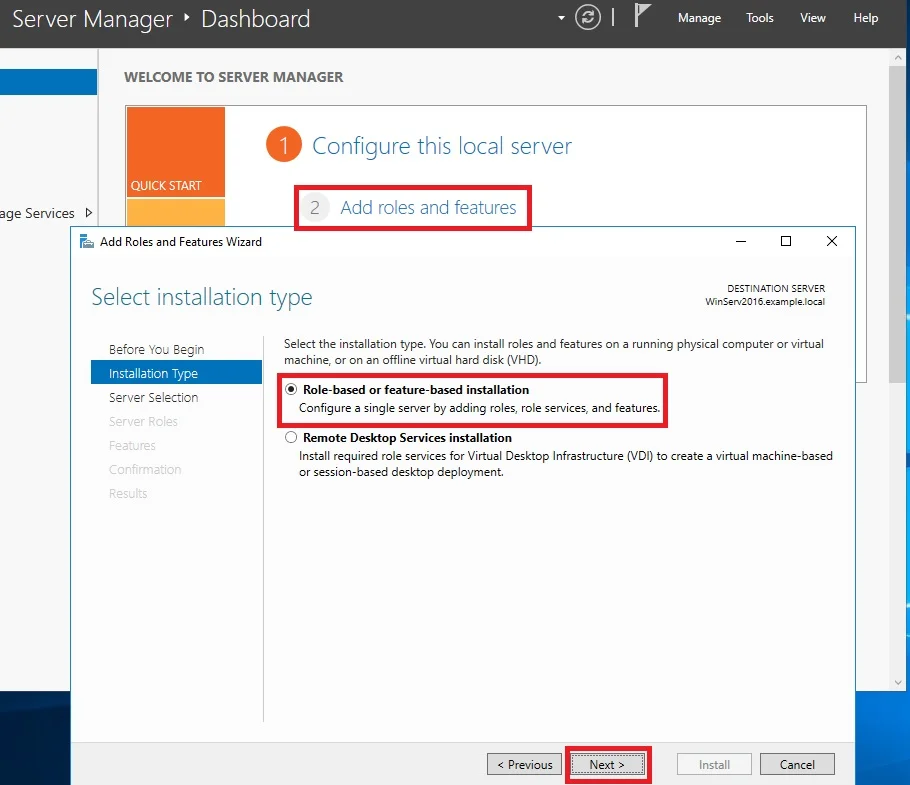
Edit the device and add Anyconnect license on remote access VPN firewall
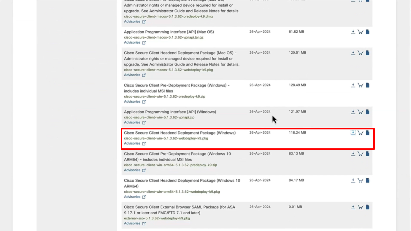
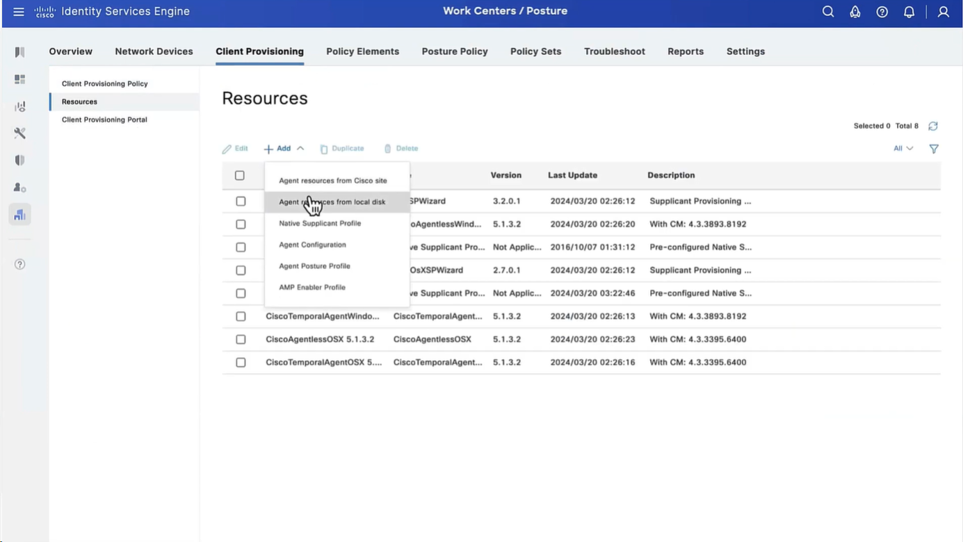
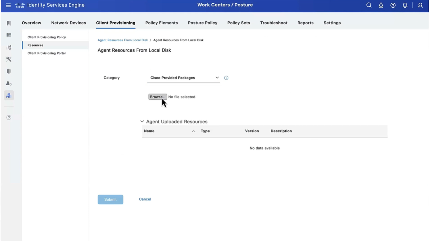
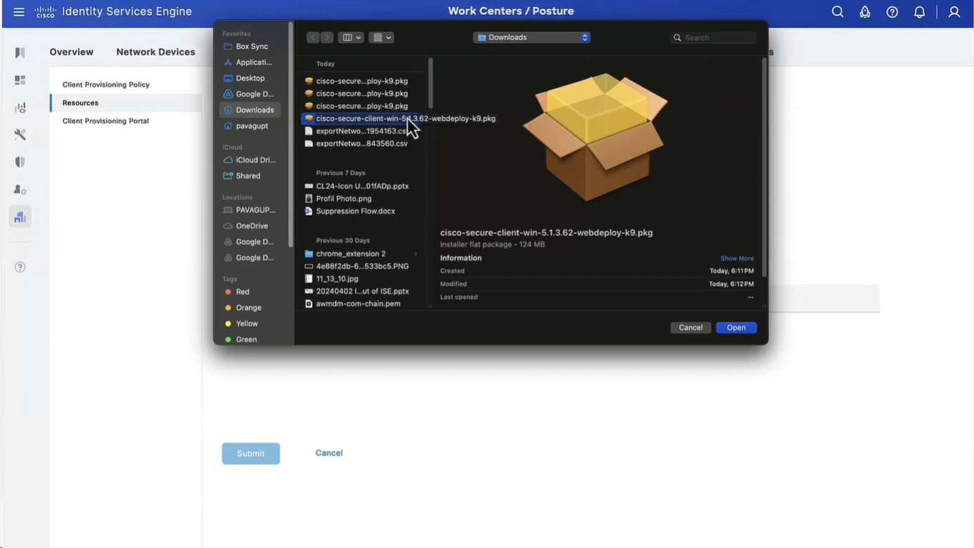
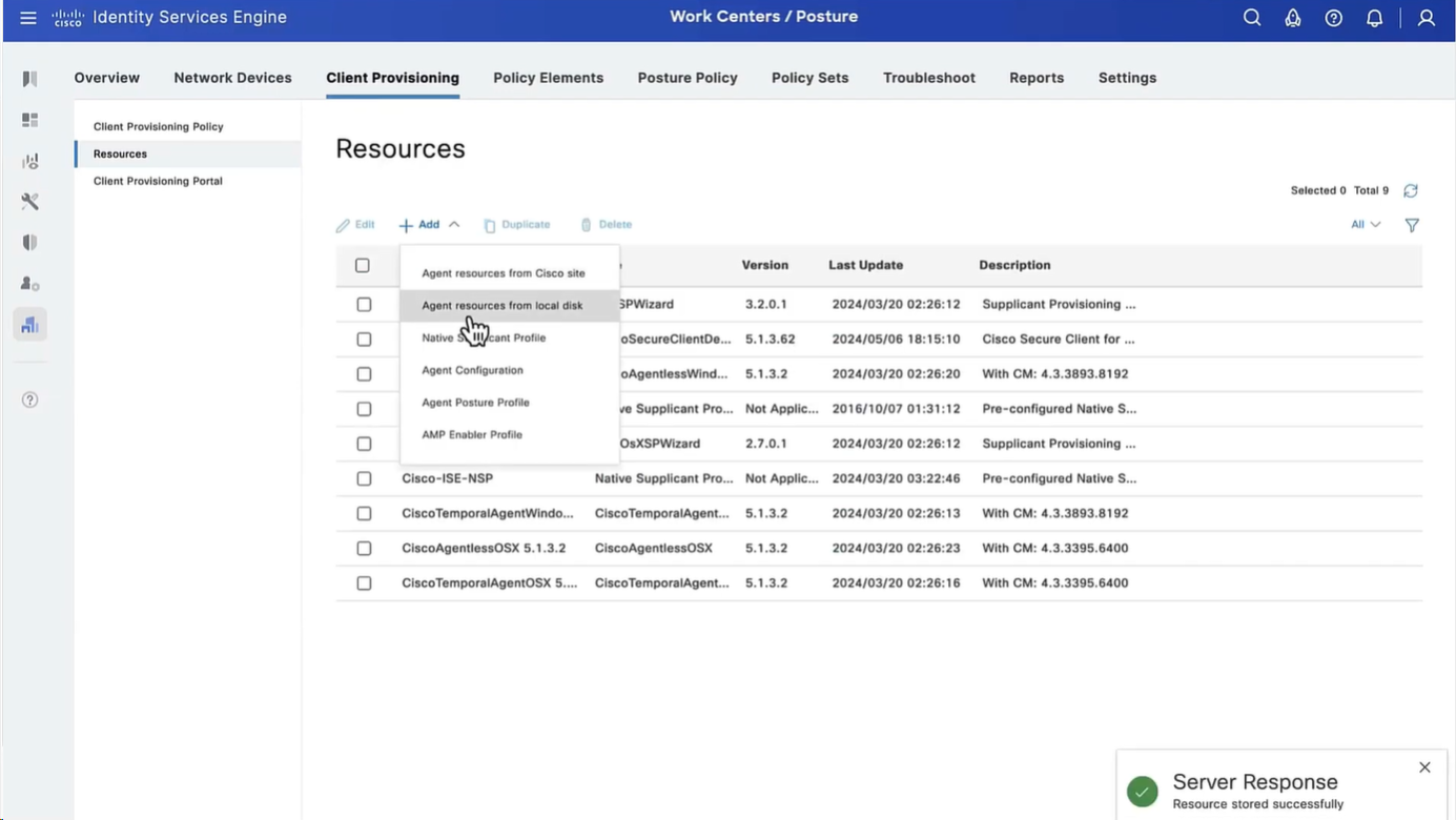
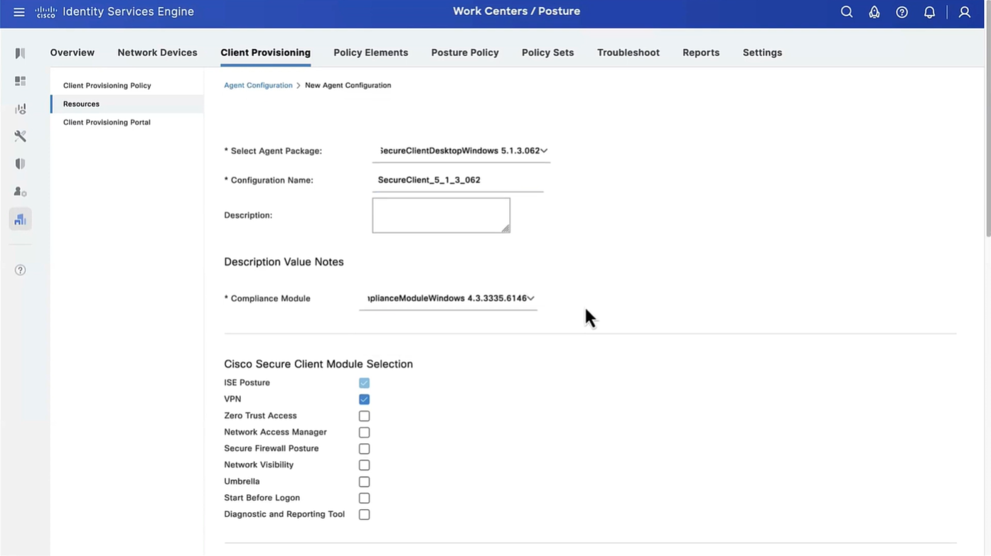
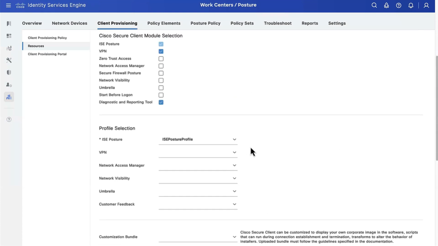
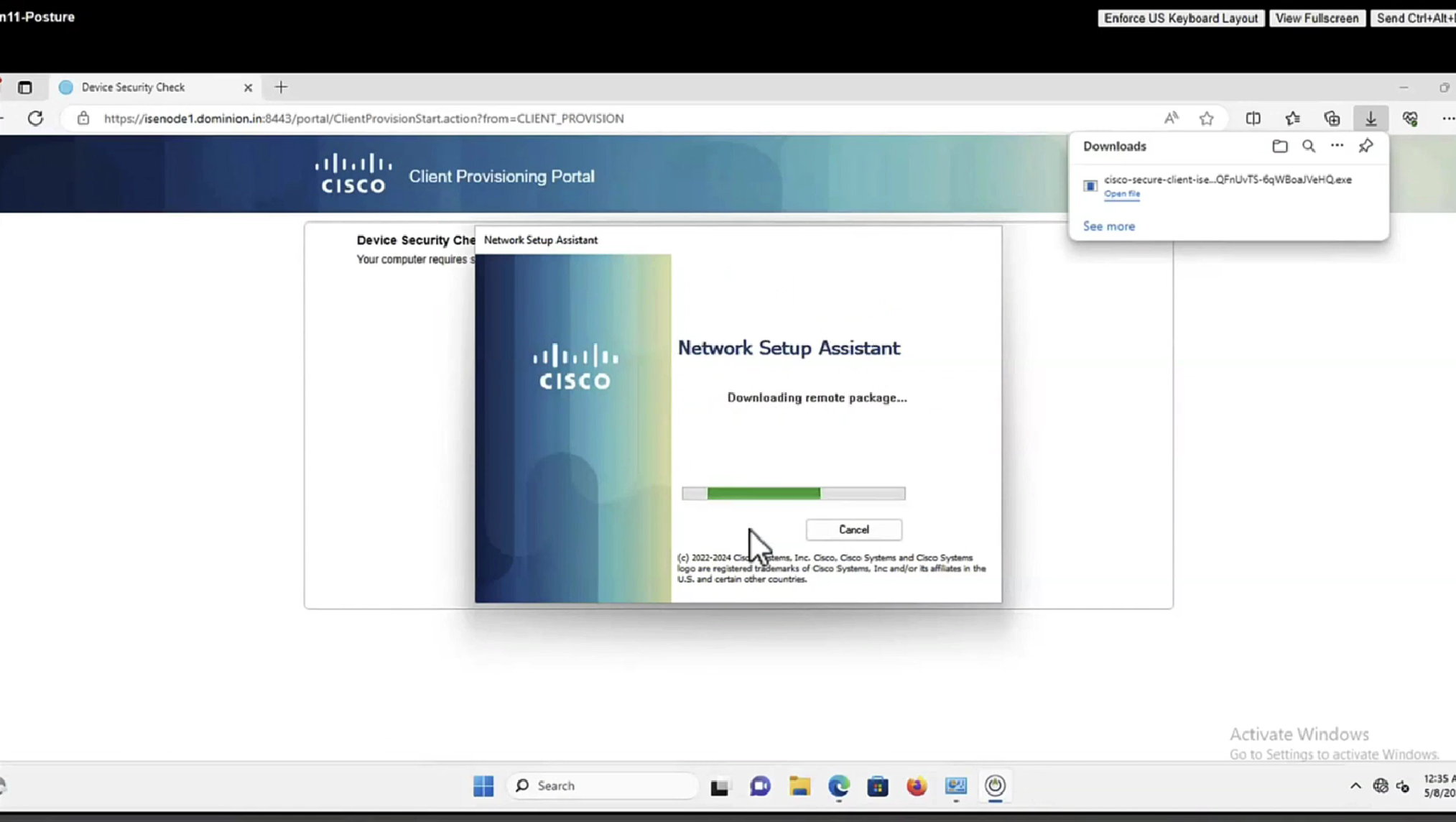
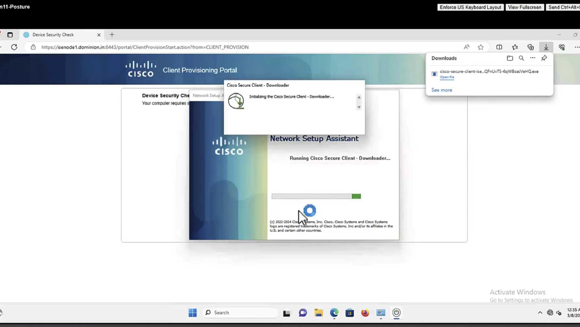
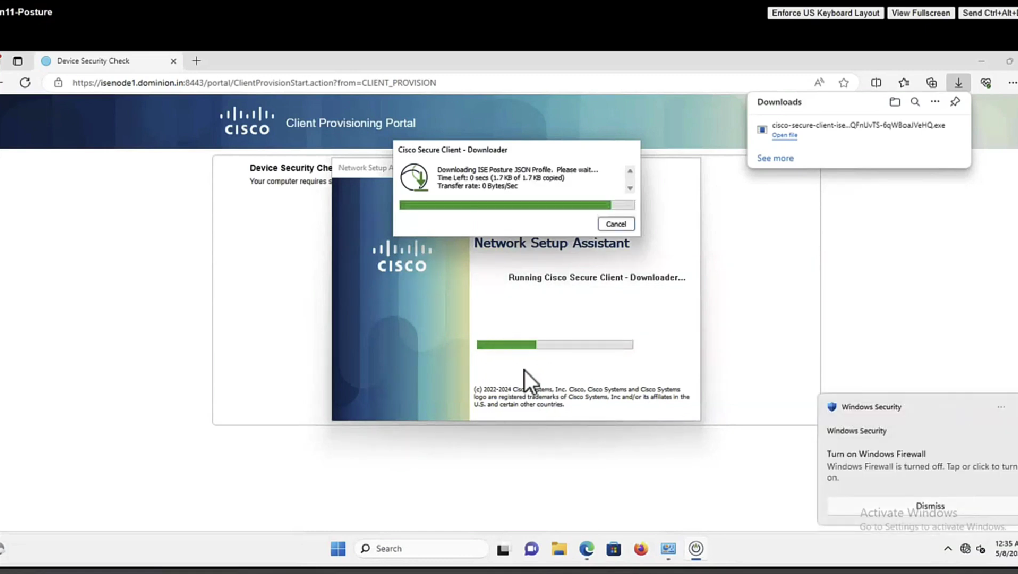
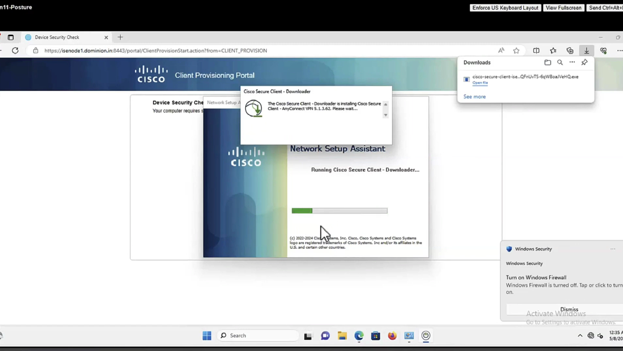
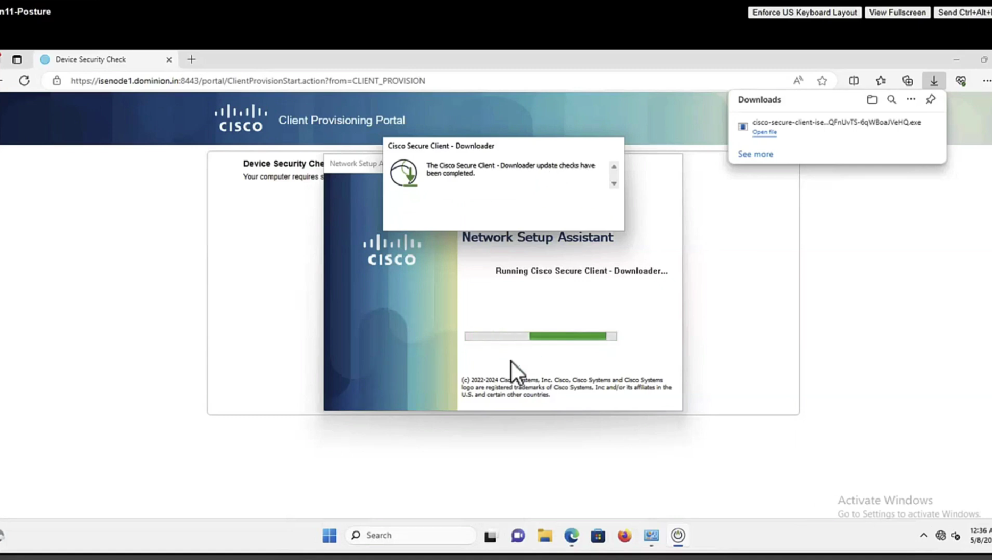
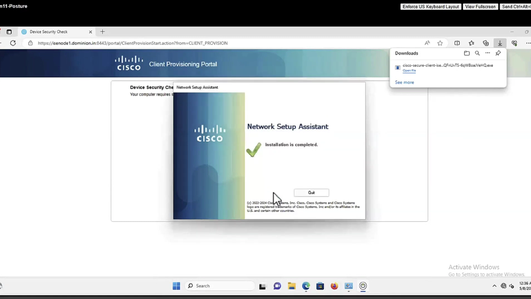
Manual deployment means that you will be installing anyconnect manually or distribute it through software distribution system
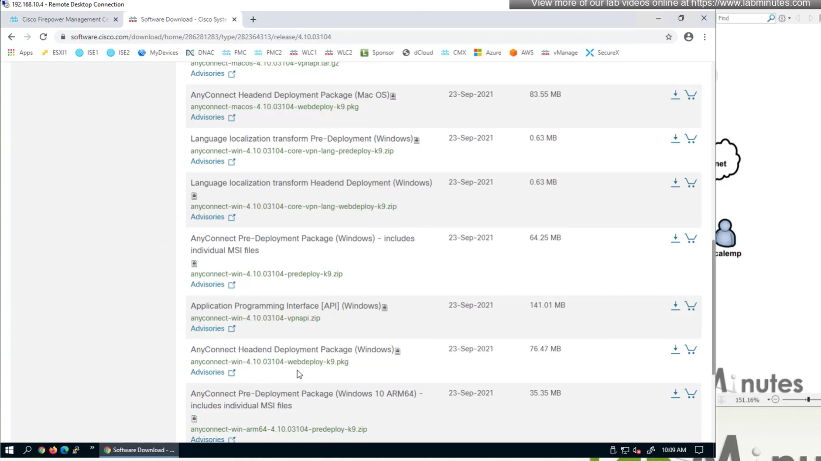
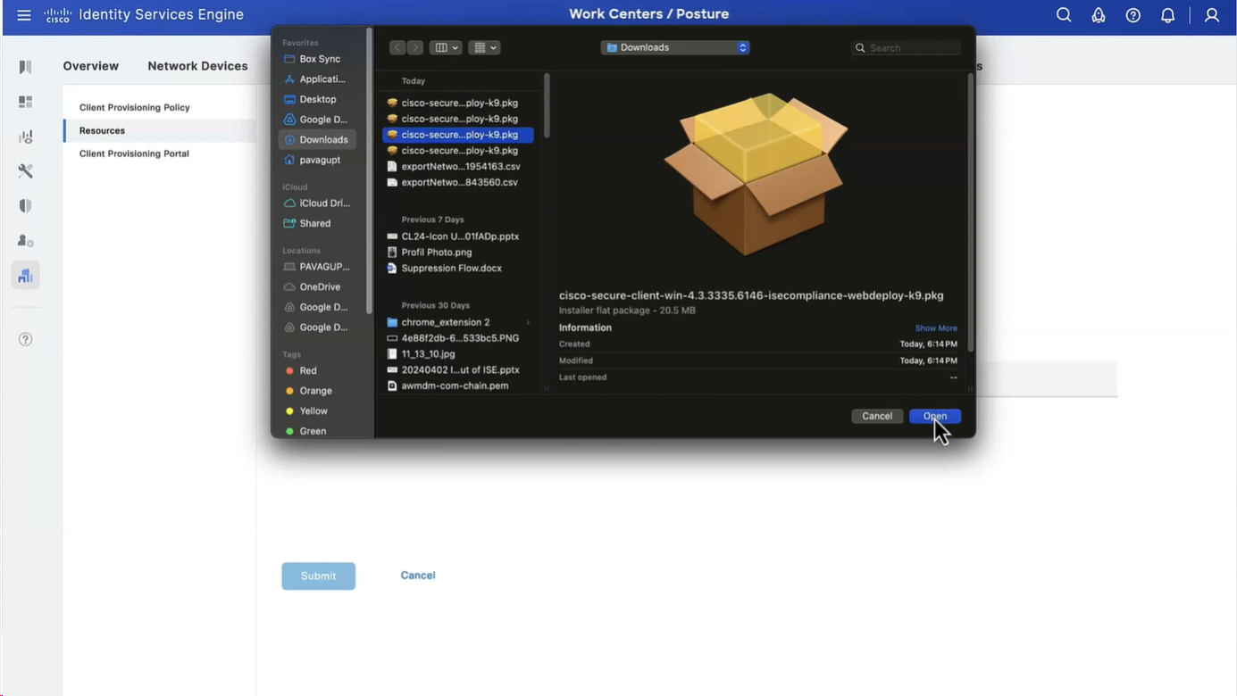
Headend package means that user will be allowed to download and install anyconnect if client does not have it already
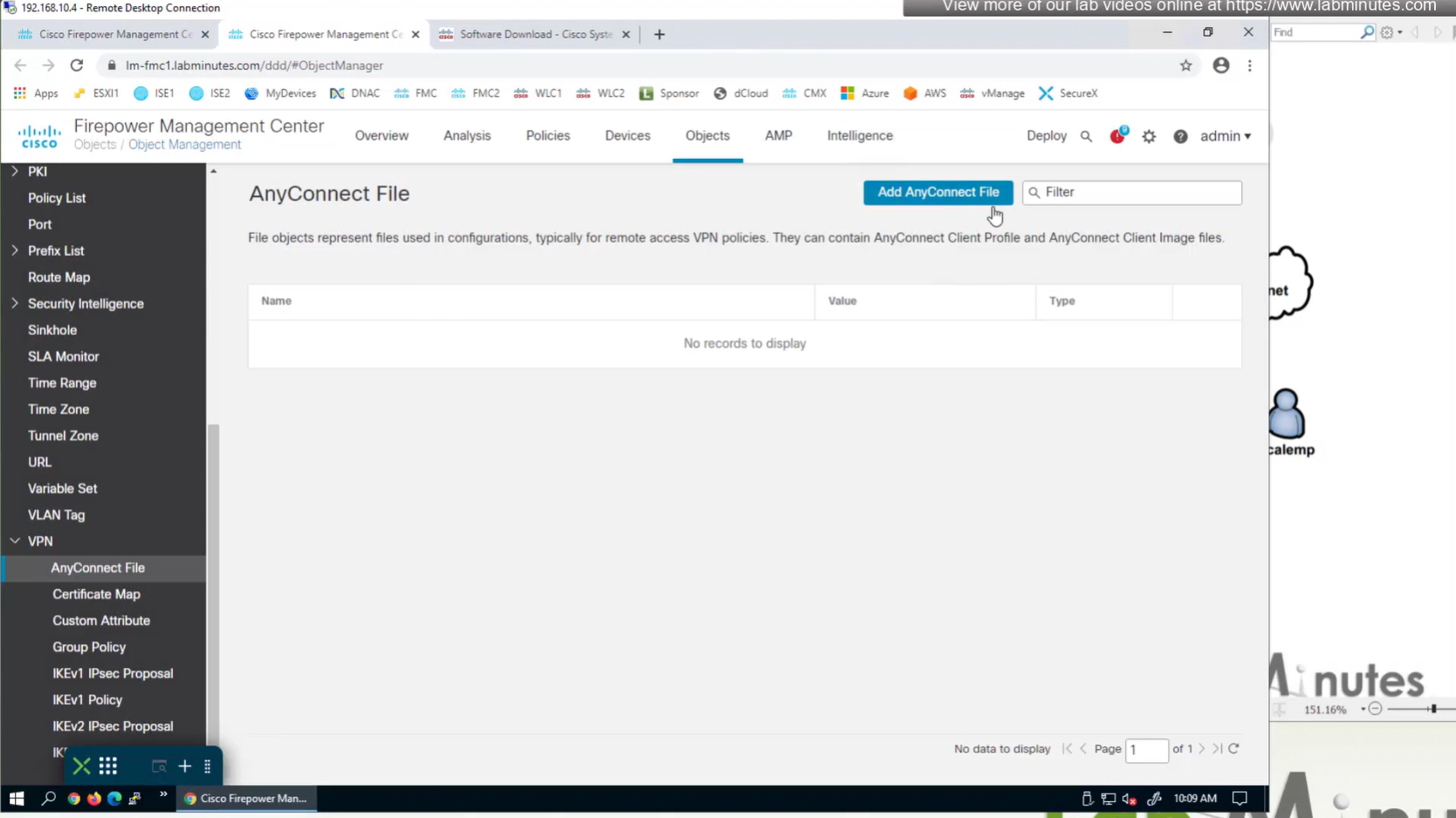
Objects
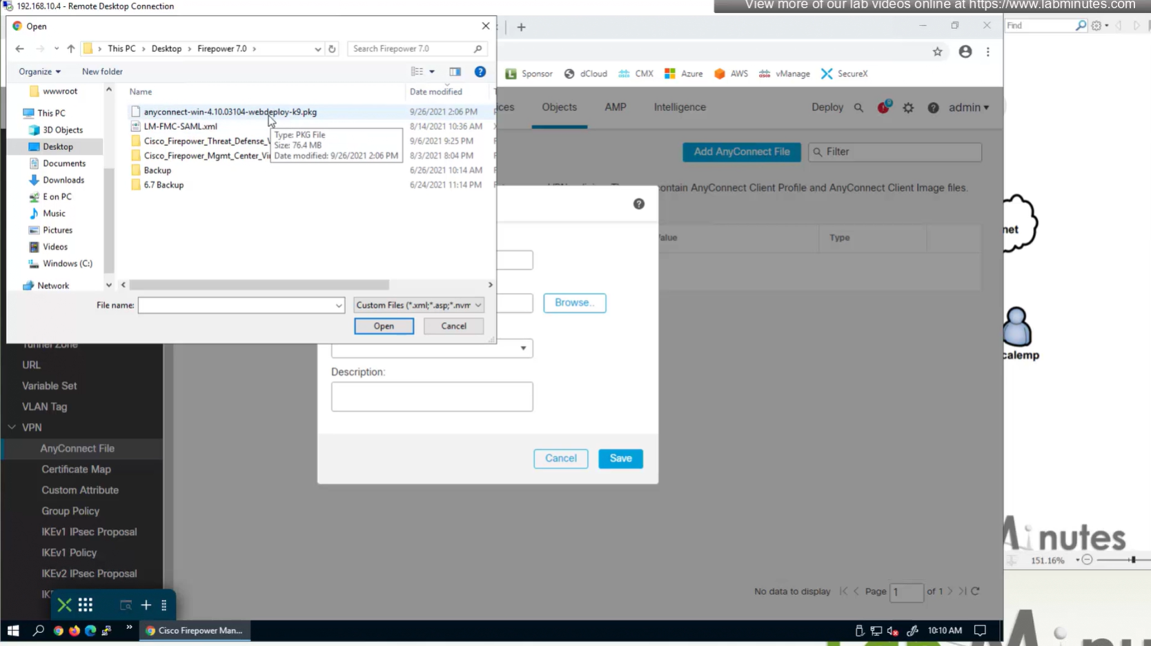
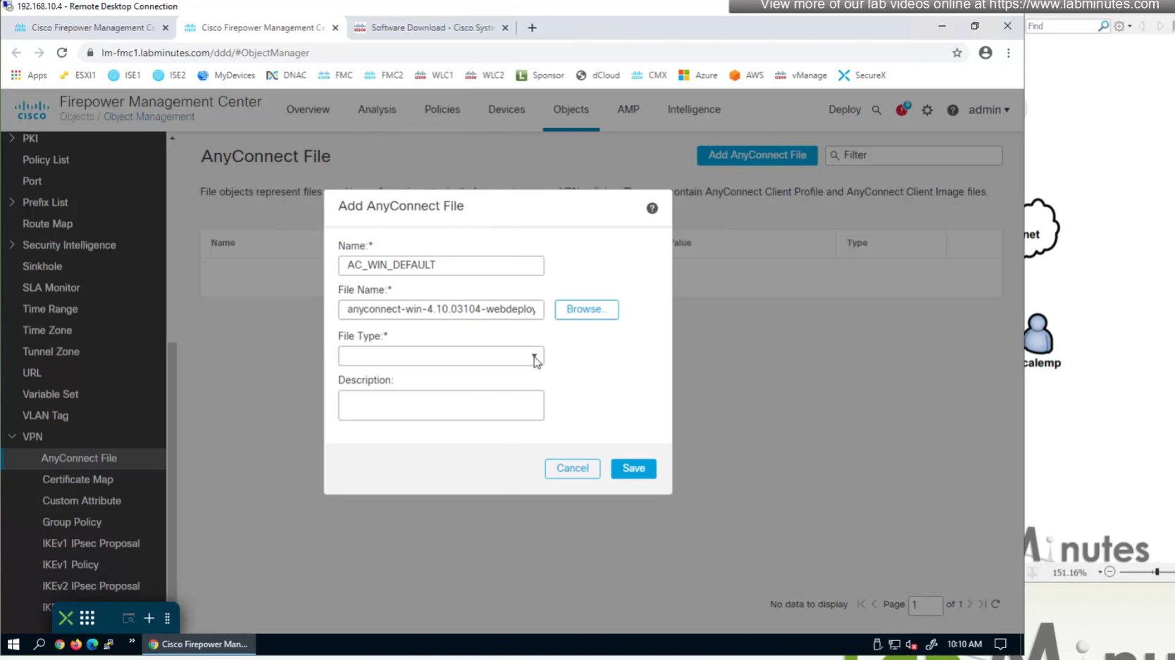
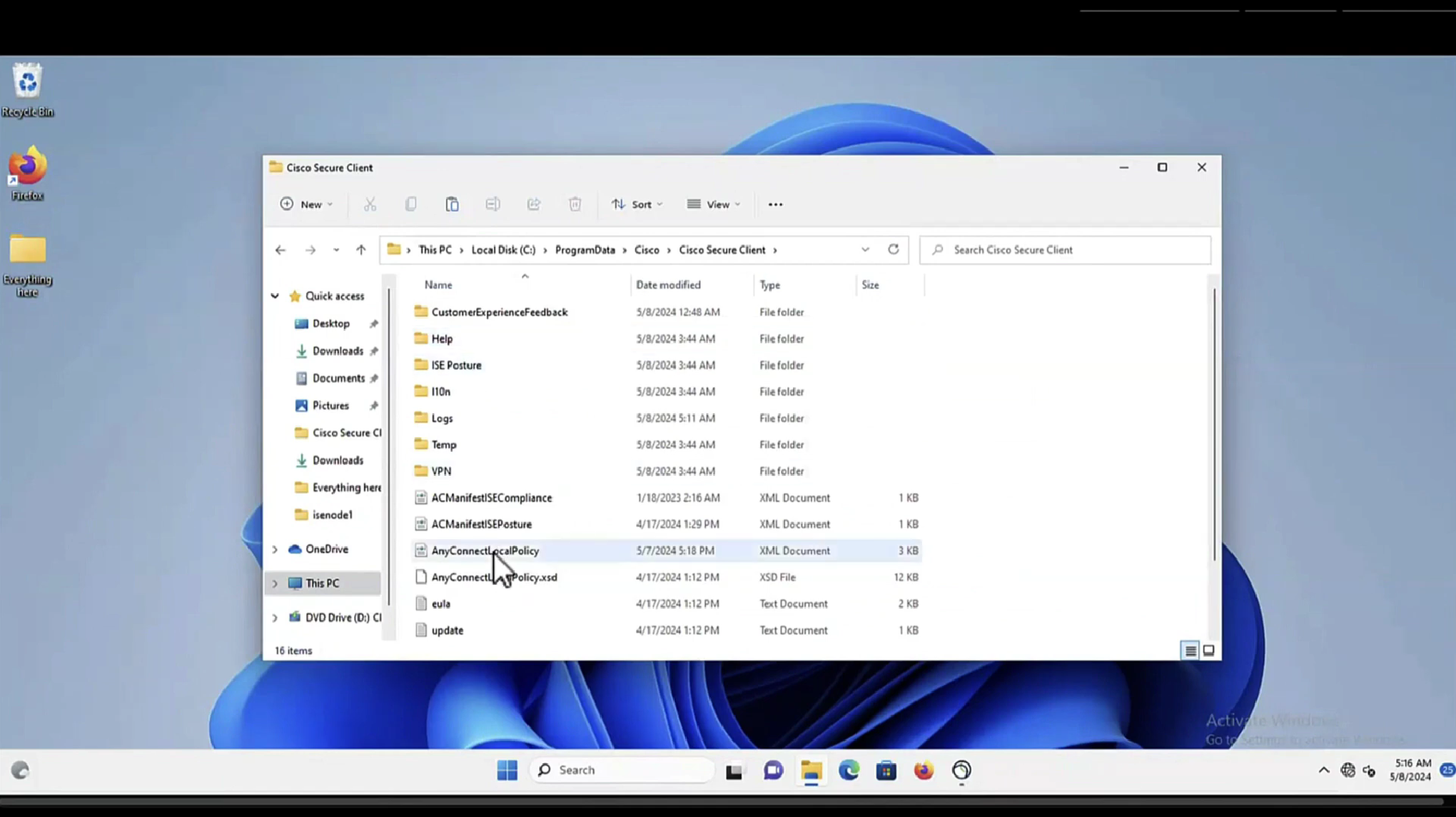
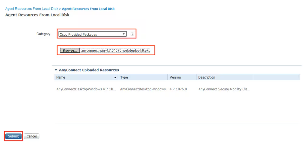
In Objects > Anyconnect file
Upload the headend package
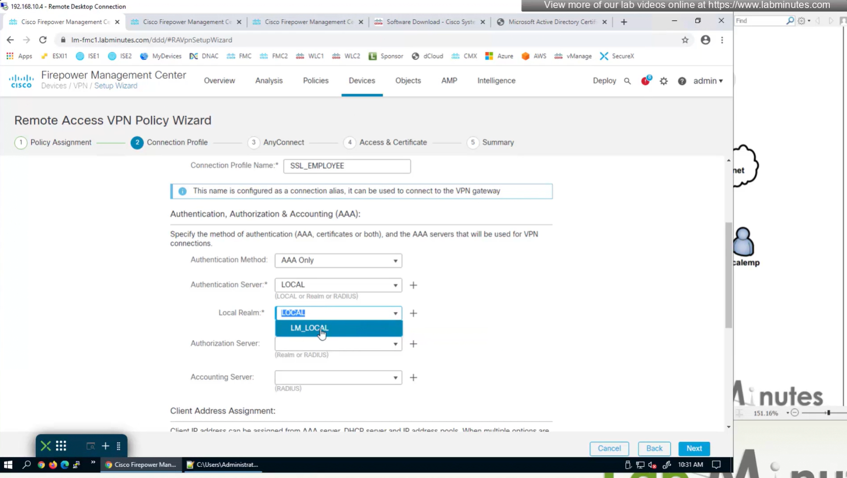
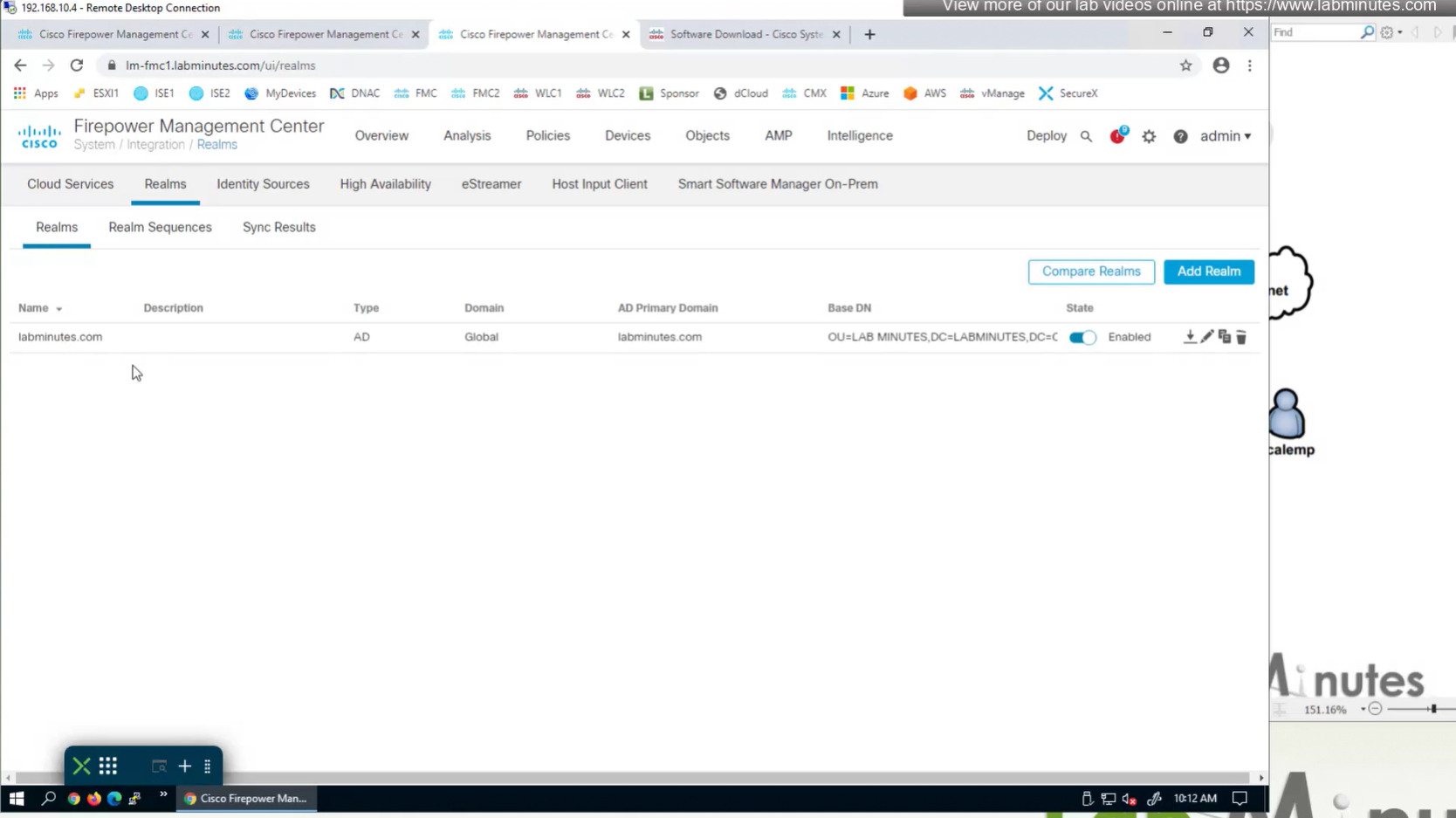
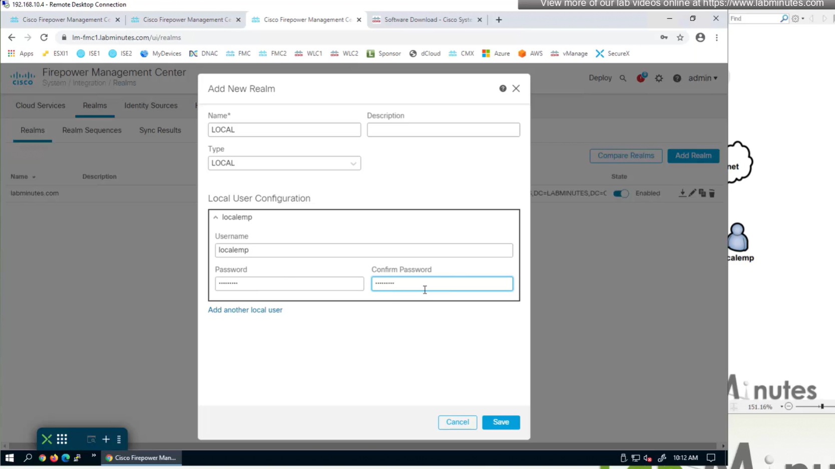
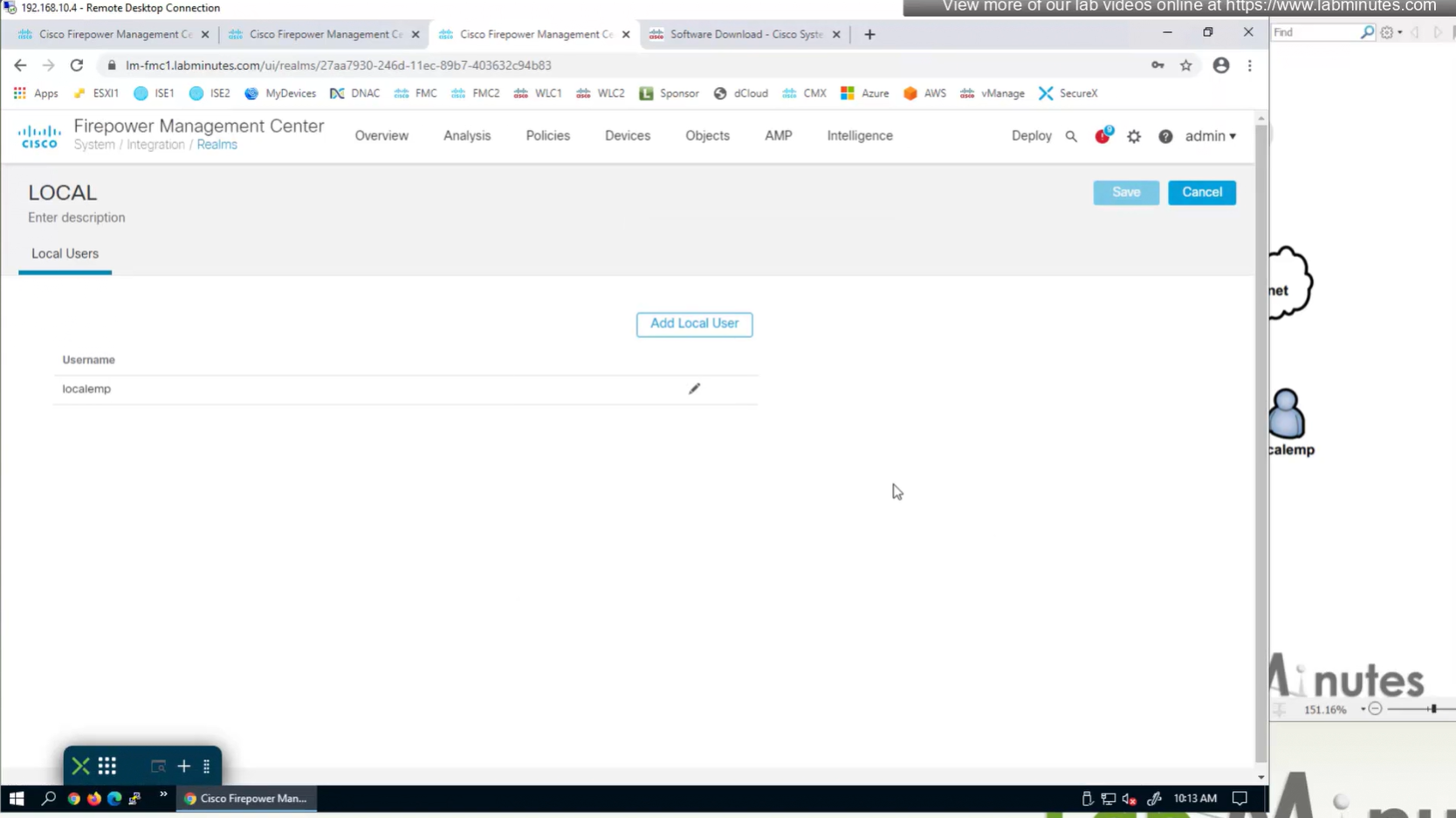
Create local user in Integration > Realm > Local > Local user
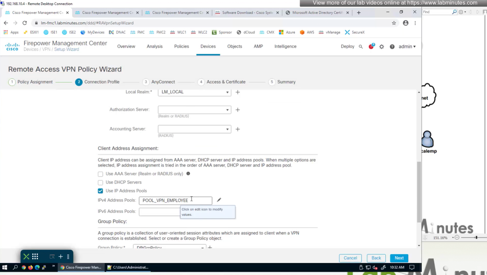
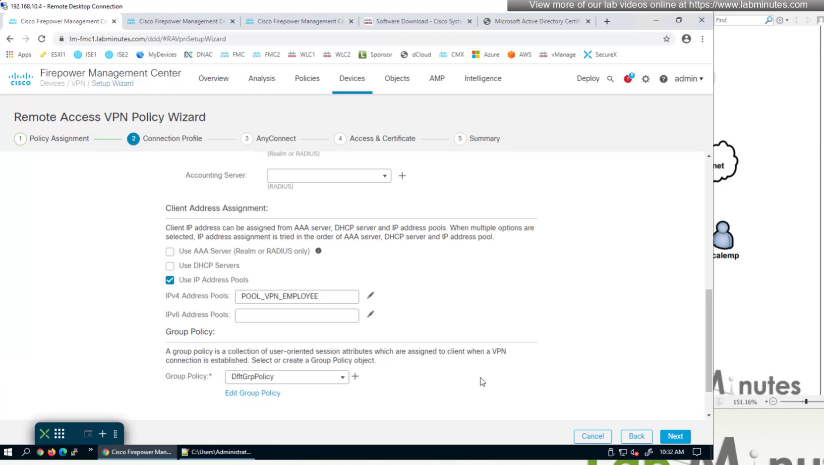
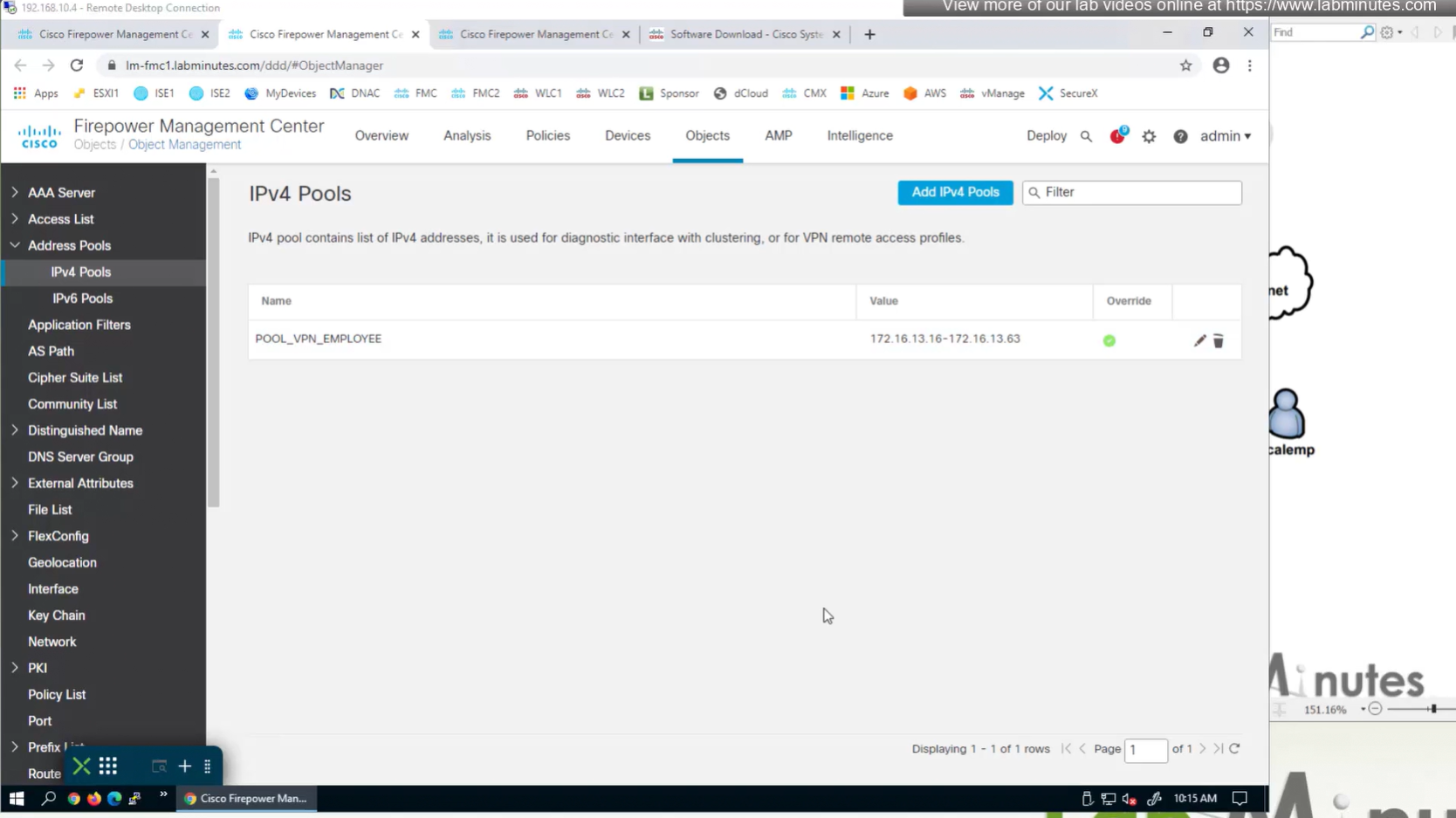
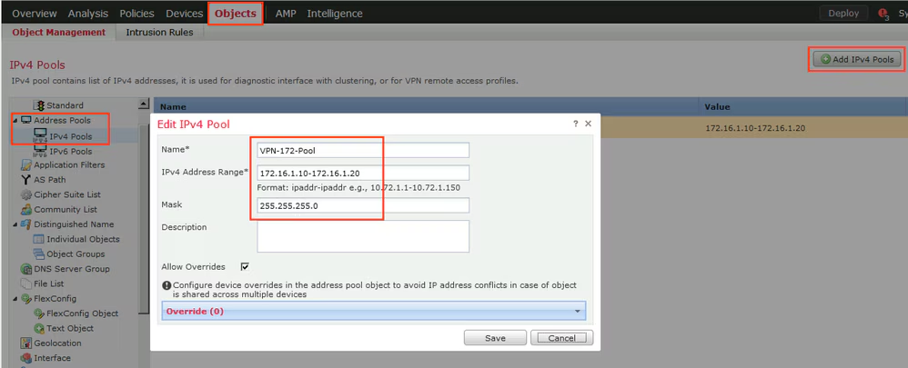
Objects > Address Pools > IPv4 Pools
Allow overrides mean that same “object” can be used on different firewalls but can have different value per firewall but object can be same
Client pool cannot be just network object but it is object type IPv4 Pool
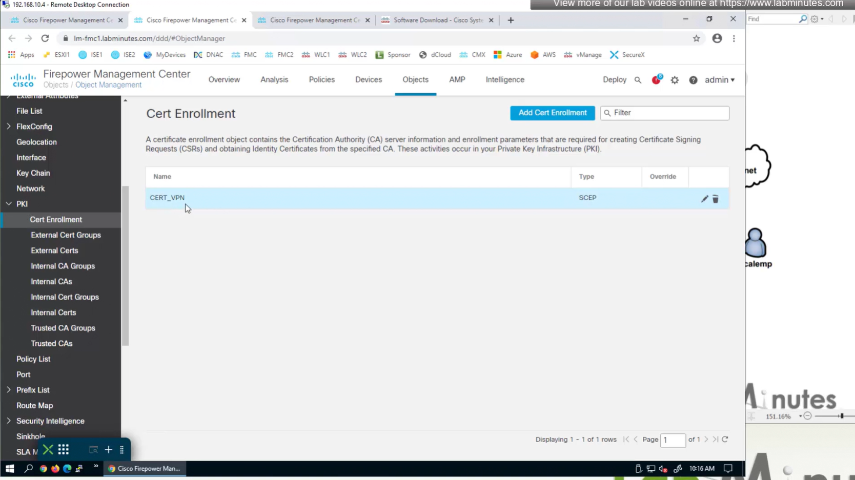
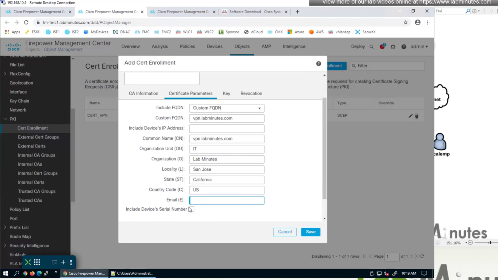
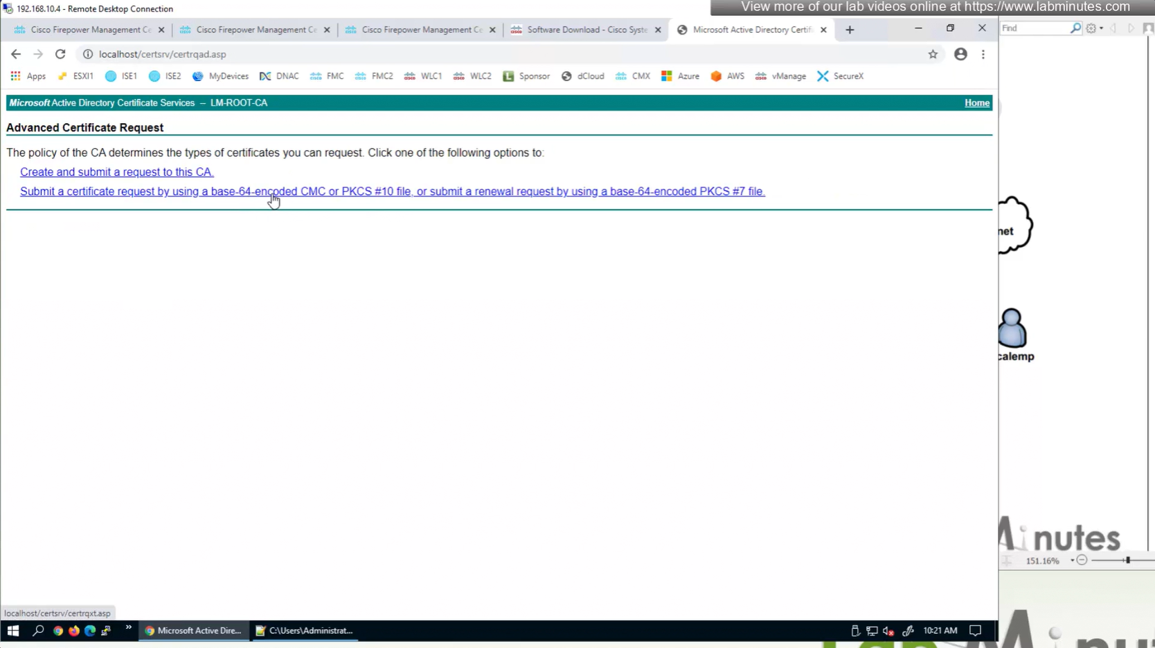
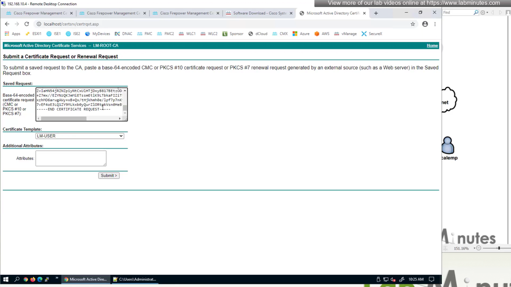
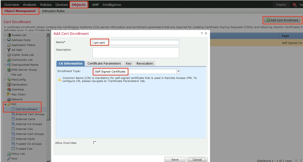
Objects > Cert Enrollment
Cert Enrollment means Firewall obtaining cert and that process requires root CA cert information also
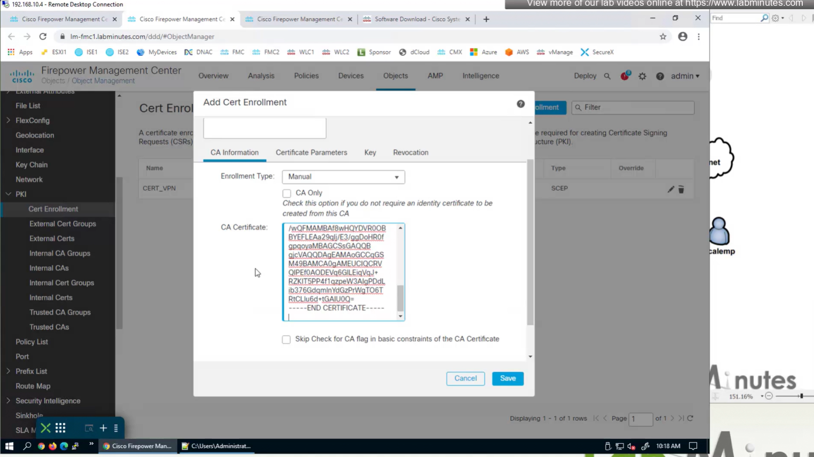
Certificate enrollment in Firepower is about securely obtaining a trusted certificate from a CA but here instead of SCEP we are doing manual certificate for firewall
Change from SCEP to Manual
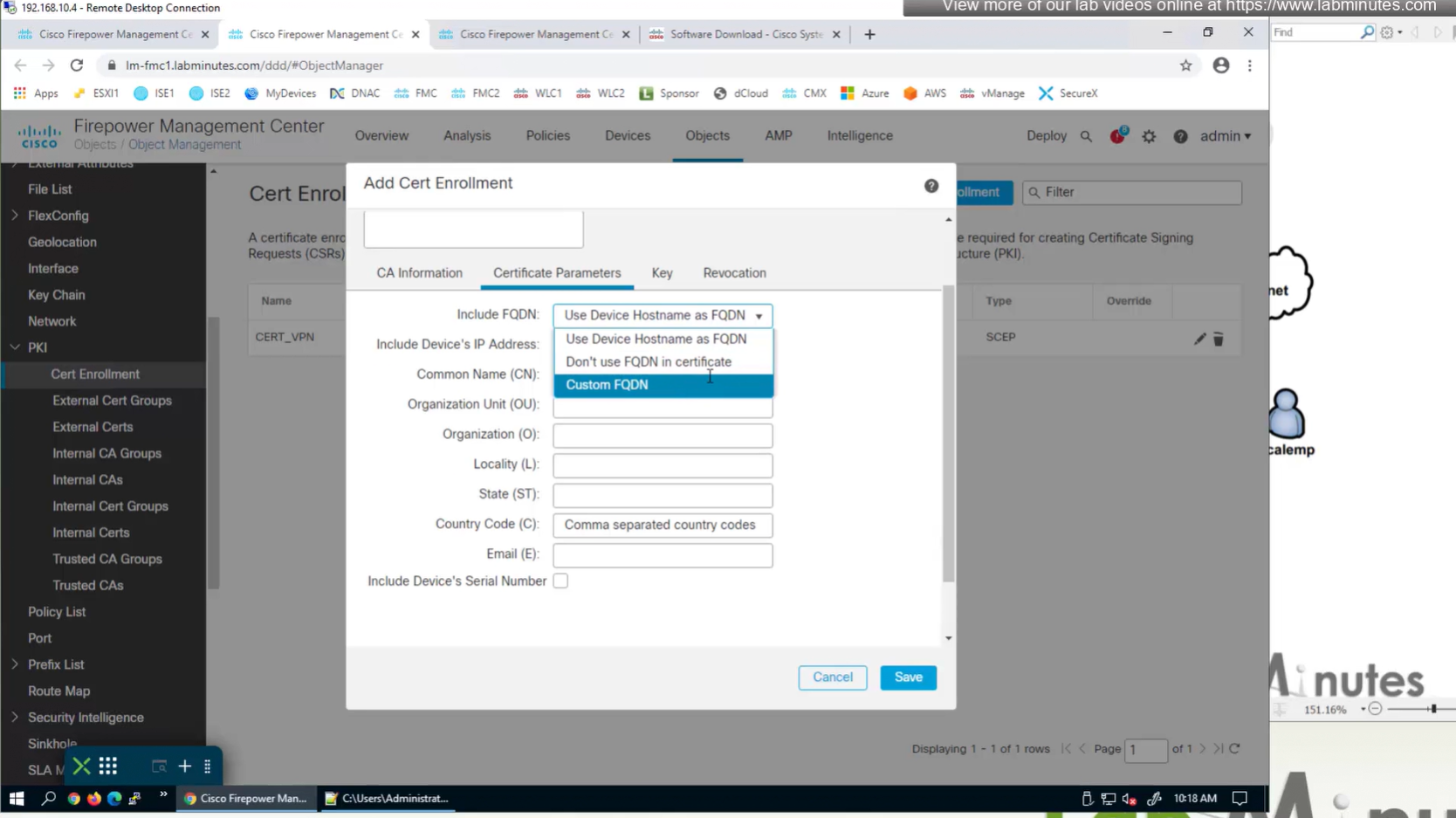
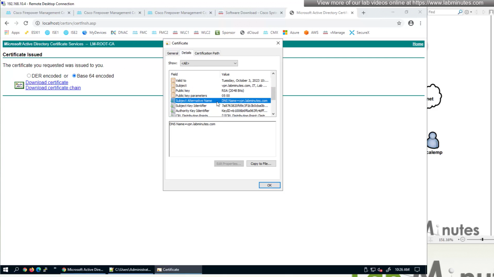
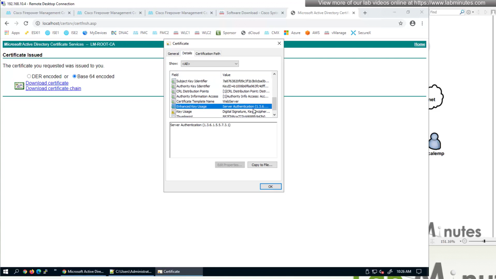
Change to Custom FQDN
Objects >
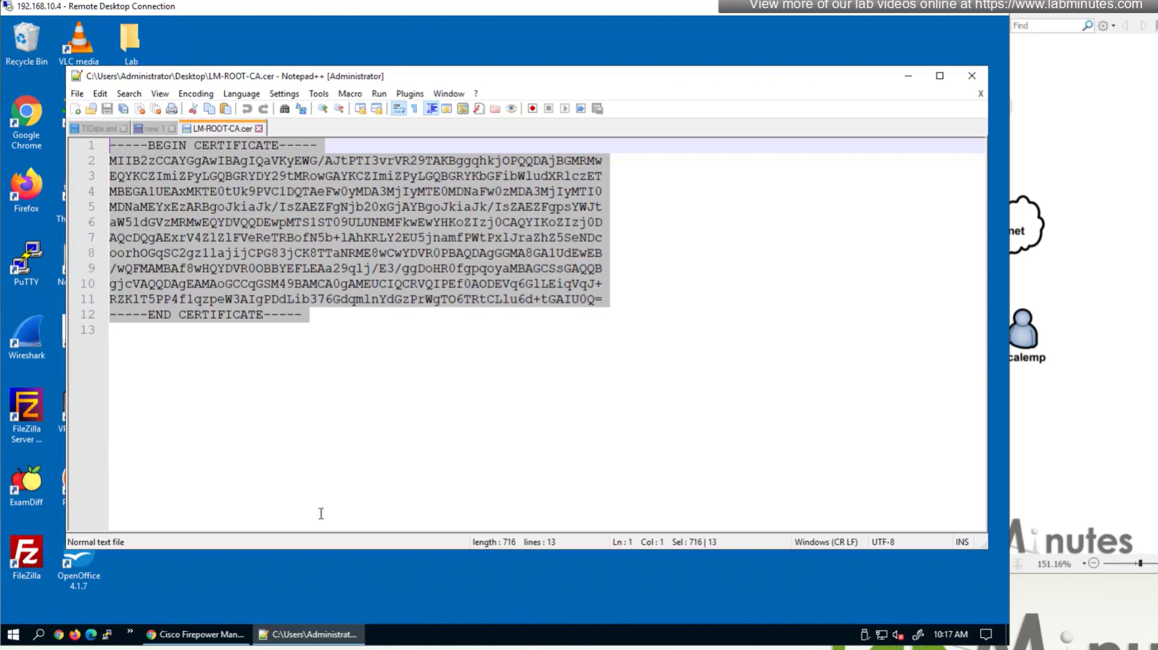
Anyconnect file Local Realm + local user IPv4 Address Pool Cert Enrolment (Root CA Server cert + CSR)
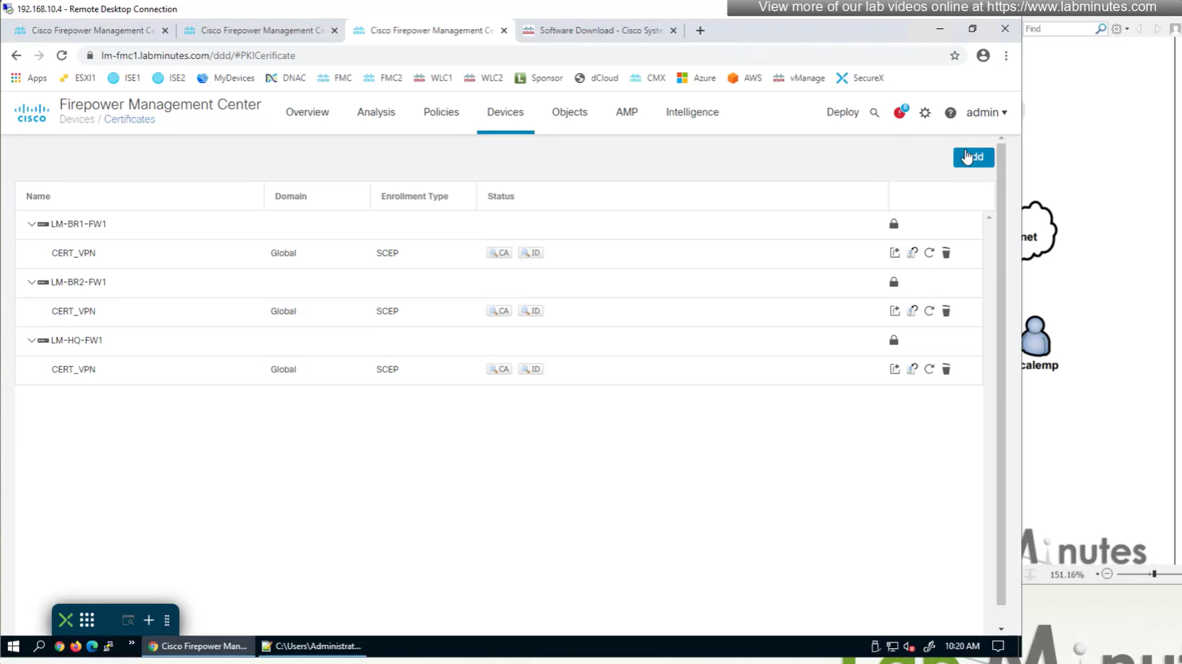
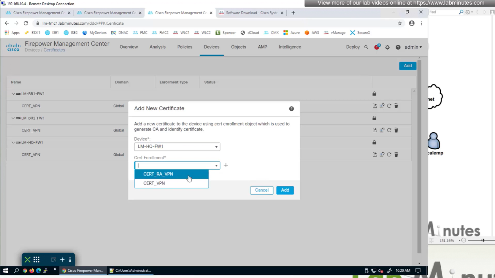
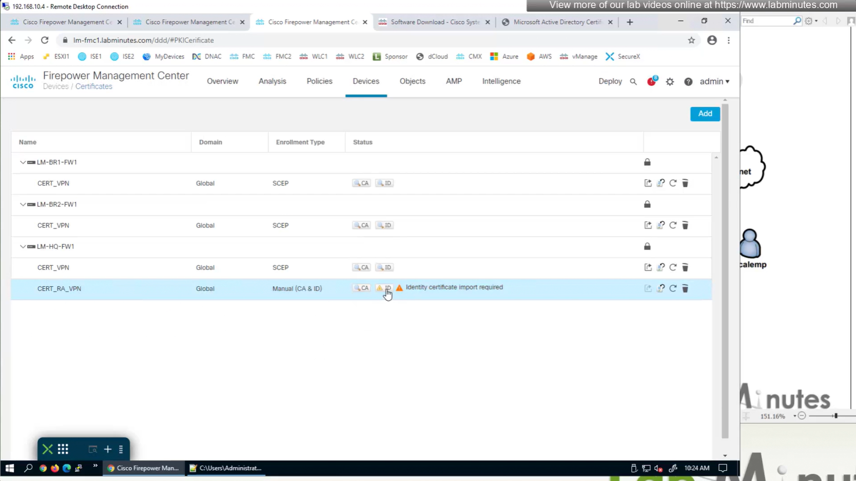
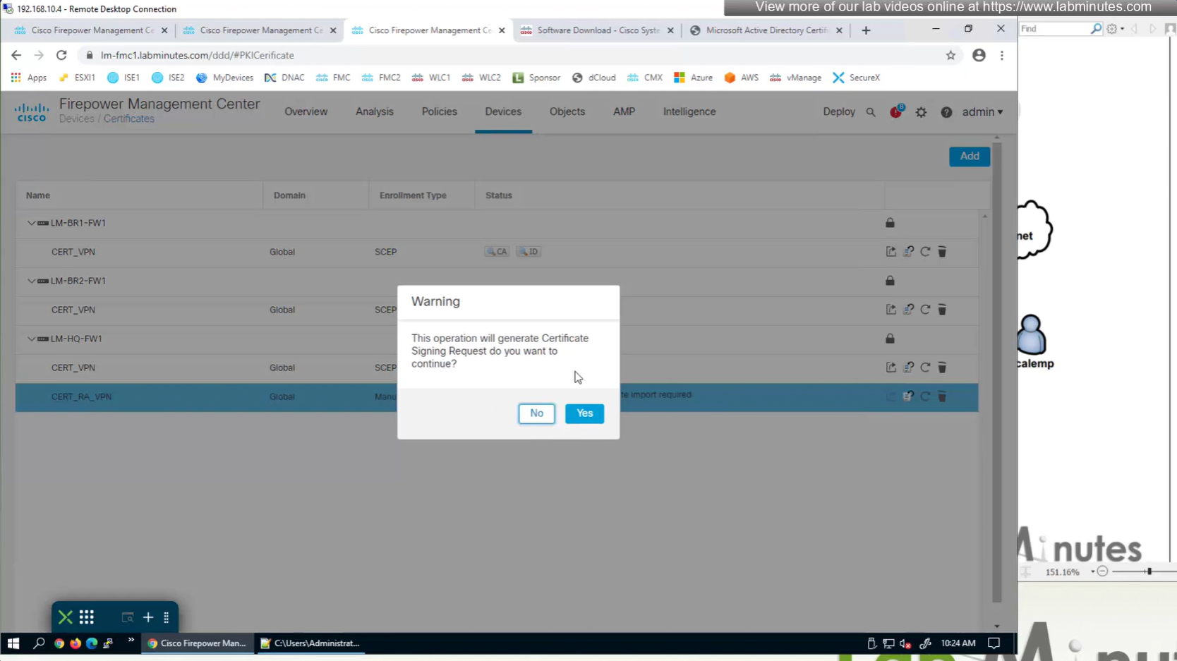
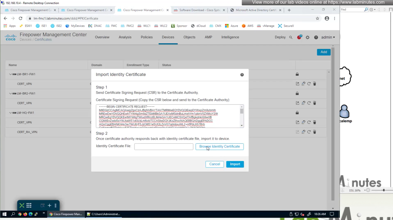
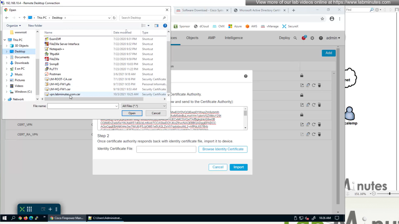
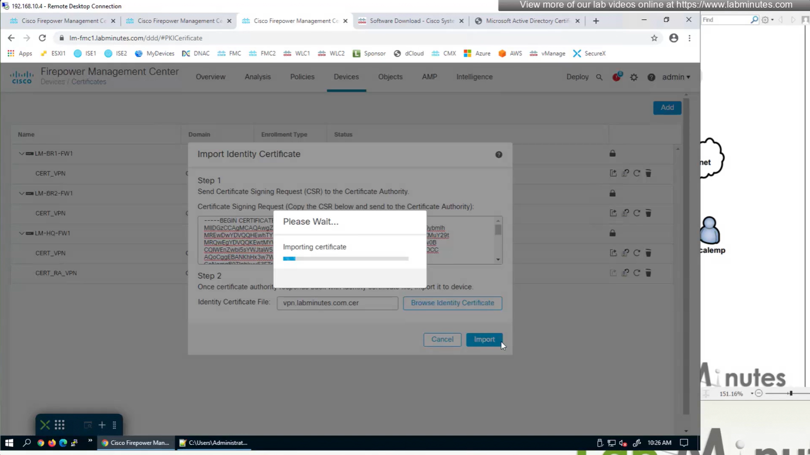
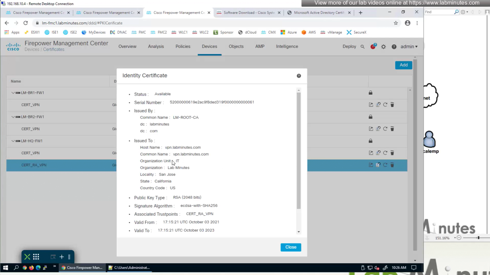
Install Cert on firewall
Here we combine the Root CA cert and CSR parameters defined earlier and pin it to the firewall – and FMC then installs cert on the firewall along with Root CA cert
Trustpoint is like a trust store on devices
This root CA must be trusted by all Clients or present in their trust store
Even in the presence of 10G links or 100G links we still need QoS since we could have 100Mbps internet link
Some oversubscribed topologies have a need for QoS (just in case all servers start transmitting at the same time)
QoS only works when there is congestion at times of the day, if your network is congested all the time then you need to increase more bandwidth
2 types of QoS models
Best Effort – FIFO queuing , first packet that comes into the router is the first packet that will exit the [queue + interface] without any preferential treatment in a straight line
DiffServ – means “differentiated” “services” which means different treatment for different services
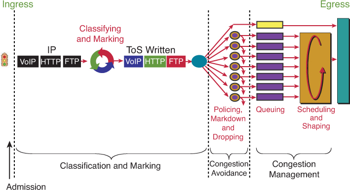
QoS Tools
Classification and Marking (tagging at IPv4 level) Congestion Avoidance via Policing / Dropping (it is best to “avoid” first by cutting) Congestion Management via Queueing | Scheduling | Shaping (delaying only as cutting / policing has been done earlier) – at this stage you can only manage as avoidance was earlier (tried to avoid but can only manage now)
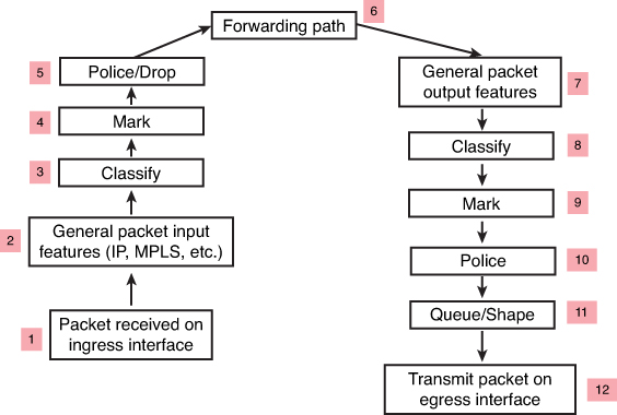
Classification may happen on ingress (3) and egress (8) in the packet path but classification should be done as close to the source on ingress
but sometimes the attributes for classification are not known until the exit interface has been chosen. This is true for locally generated packets and even some transit packets, If exit interface has service policy applied and that interface is chosen based on destination IP and routing table, Classify on Egress (8) is for those scenarios
Similarly, a packet may be marked on ingress (4), but perhaps requires to be re-marked on egress (9). For example, a policer may re-mark a nonconforming packet on egress rather than drop it—the fact that the packet is nonconforming is not known until the packet reaches the egress interface (where non conformance is determined by filling up queues and congestion) that has service policy applied and that interface is chosen based on destination IP and routing table, Mark on Egress (9) is for those scenarios
Classification and Marking
We want to save on processing for all nodes in the network and classify only once and best way to do is for edge nodes to classify once but tag or mark for it to be used forever through the network All other tools in the list also use marked packets such as queueing , congestion avoidance and policing / shaping etc
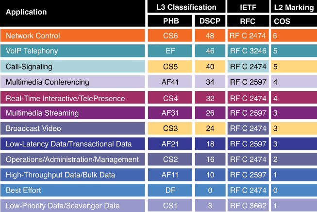
IPv4 packet carries an 8-bit Type of Service (ToS) byte
IPv6 header carries an 8-bit Traffic Class field
first 3 bits in both IPv4 and IPv6 are for IP Presedence
DSCP first 6 bits offer a maximum of 64 possible classes of service
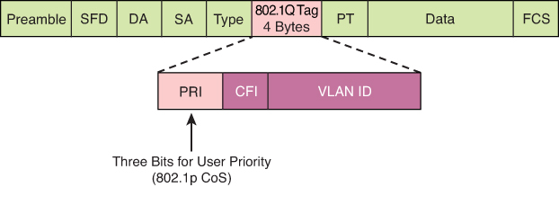
There is also layer 2 marking called Ethernet 802.1p CoS bits
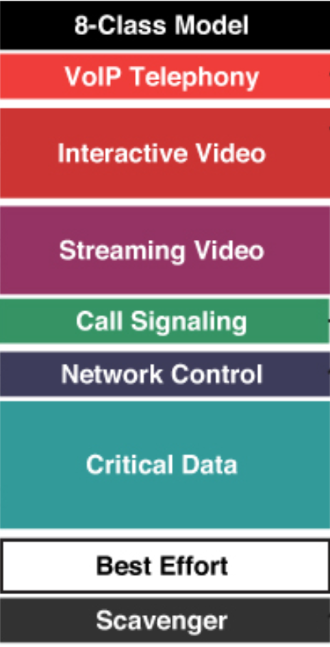
General marking guidance
but in reality only 8 classes traffic model is implemented instead of 12 shown above
Marking can be new marking or even remarking such as marking down the class of non conforming or violating traffic
Class-based marking occurs after classification of the packet (in other words, set happens after the match criteria). Therefore, if used on an output policy, the packet marking applied can be used by the next-hop node to classify the packet but cannot be used on this node for classification purposes. However, if class-based marking is used on an ingress interface (blindly without going through match purely based on interface the traffic is coming from) as an input policy, the marking applied to the packet can be used on the same device on its egress interface for classification purposes.
On output policies both classification and marking can happen before or after tunnel encapsulation, depending on where the service policy is attached. Therefore, if a policy is attached to a GRE or IPsec tunnel interface, the marking is applied to the original inner packet header. However, if the policy is attached to the physical interface, only the tunnel header (the outer header) is marked, and the inner packet header is left unchanged.
CoS is usually used at Ethernet Layer 2 frames, contains 3 bits and can only be done at trunk, it makes sense to have it only on trunk since trunk is the only place where multiple VLANs traffic aggregate and compete from one another
CS is a term used to indicate a 3-bit subset of DSCP values; it designates the same 3 bits of the field as IP Precedence, but the interpretation of the field values maps to the per-hop behaviors as per the RFCs defining 6-bit DSCPs.
DSCP is a set of values, based on a 6-bit width
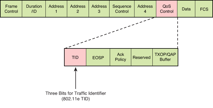
TID is a term used to indicate a 3-bit field in the QoS Control field of the 802.11 WiFi MAC frame. The 8 values of this field correspond to eight user priorities (UPs). TID is typically used for wireless Ethernet connections, and CoS is used for wired Ethernet connections
Trust Boundary
A trust boundary is a network location where packet markings are not accepted and are rewritten
In an enterprise campus network, the trust boundary is almost always at the edge switch
For example, a user computer set up to mark all traffic at DSCP EF will be ignored by the access switch at the trust boundary, and the traffic is inspected and re-marked according to enterprise QoS policies implemented on the switch.
Video traffic comes in a wide array of different traffic types belonging to applications that may be extremely high priority and delay sensitive (such as immersive Cisco TelePresence traffic) to unwanted Scavenger class traffic (nonorganization entertainment videos, such as YouTube) that in many cases may be dropped outright.
IEEE 802.11 specification, which provides a means for wireless devices to request traffic in different access categories with different markings (which are usually on the untrusted side of the network trust boundary and so raises the question of whether the trust boundary for wireless devices could, or should, be extended to the wireless device under certain circumstances).
L2 Frame
Ethernet frames can be marked with their relative importance at Layer 2 by setting the 802.1p user priority bits (CoS) of the 802.1Q
Wireless Ethernet frames can be marked at Layer 2 by setting the 802.11 WiFi Traffic Identifier (TID) field with in the QoS Control field
GRE , IPSec
The marking field from the inner header might or might not be copied automatically to the outer header. If not, explicit CLI must be used to mark the outer header. Methods to achieve this include the qos pre-classify CLI on the tunnel interface
l2tp tos reflect CLI can also be used on L2TP tunnels. L2TPv3 is widely used to transport L2 frames over IP networks.
MPLS
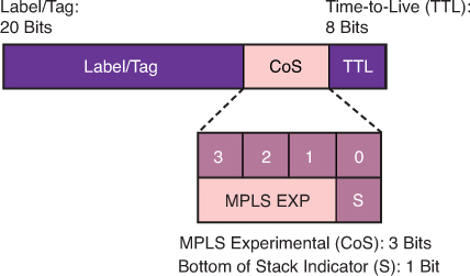
4-bit CoS field – 3 bits MPLS EXP (Experimental) bits and 1 bit Bottom of Stack Indicator
In MPLS tunneling scenarios, there can be multiple MPLS headers on a packet. The set mpls experimental imposition command sets a value on all labels on the packet, and the set mpls experimental topmost command sets a specific value only on the outermost label.
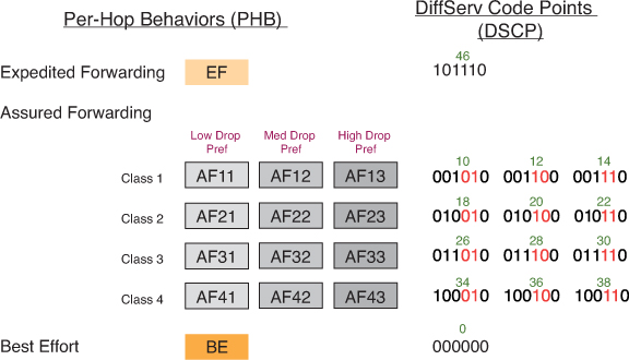
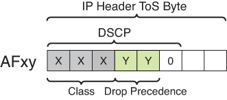
DSCP PHBs: Best-Effort (BE or DSCP 0), Assured Forwarding (AFxy), Expedited Forwarding (EF) and Class-Selector (CSx) code points
Class-Selector (CSx) code points have been defined to be backward compatible with IP precedence. (In other words, CS1 through CS7 are identical to IP precedence values 1 through 7
The first digit denotes the “AF class” and can range from 1 through 4. The second digit refers to the level of drop preference within each AF class and can range from 1 (lowest drop preference) to 3 (highest drop preference).
For example, during periods of congestion (on an RFC 2597-compliant node), AF33 would statistically be dropped more often than AF32, which, in turn, would be dropped more often than AF31
NBAR
NBAR is a L4–L7 deep-packet inspection classifier triggered by the match protocol in class-map It is a more CPU-intensive than classifiers that match traffic by markings (DSCPs), addresses, or ACLs.
identifying application layer protocols by matching them against a Protocol Description Language Module (PDLM)
PDLM definitions are modular, and new ones can be added to a system without requiring a Cisco IOS upgrade.
Two modes of operation that NBAR offers:
Passive mode: Discovers and provides real-time statistics on applications per interface or protocol and gives bidirectional statistics such as bit rate (bps), packet, and byte counts
Active mode: Classifies applications for the purpose of marking the traffic so that QoS policies can be applied.
Router# show run
interface fastethernet 0/0
  ip nbar protocol-discovery

! NBAR used as a classifier
Router# show run
class-map match-any MY-VIDEO
  match protocol cuseeme
  match protocol h323
  match protocol rtp video

-----------------------------------------------------

class-map match-any ERP
   match protocol sqlnet
   match protocol ftp
   match protocol telnet
class-map match-any AUDIO-VIDEO
   match protocol http mime "*/audio/*"
   match protocol http mime "*/video/*"
class-map match-any WEB-IMAGES
   match protocol http url "*.gif"
   match protocol http url "*.jpg|*.jpeg"

-----------------------------------------------------

match protocol h323 ! identifies all H.323 voice traffic
match protocol rtp [audio | video | payload-type payload-string]
Sequence of classes within a policy map
Sequence of classes within a policy map is significant
packet is examined against each subsequent class within a policy map until a match is found. When found, the examination process terminates, and no further classes are checked. If no matches are found, the packet ends up in the default class (because policy map is applied on the interface and every policy map has class class-default section)
class-map match-all FAX-RELAY
  match dscp ef
class-map match-all VOICE
  match protocol rtp audio
!
policy-map VOICE-AND-FAX
class FAX-RELAY
  priority 64
  police cir 64000
class VOICE
  priority 216
  police cir 216000
No traffic would ever show against the VOICE class because both voice and fax-relay traffic would match on DSCP EF and would therefore be assigned to the FAX-RELAY class, to fix it we will need to reverse the order of classes inside policy map
service-policy command also specifies whether the policies should be applied to ingress or egress traffic on this interface using keywords input and output.
the two subinterfaces are collectively allowing 22K of traffic, which in turn is shaped to 20K throughput, on the main interface to maintain an aggregate throughput not to exceed 20K and shave off the extra 2Kbps.
! Definitions for sub-interface GE1.1
policy-map CHILD1
  class VOICE1
    priority 3000
  class VIDEO1
    bandwidth 5000
policy-map PARENT1
  class class-default
    shape average 15000
    service-policy CHILD1
!
! Definitions for sub-interface GE1.2
policy-map CHILD2
  class VOICE2
    priority 1500
  class VIDEO2
    bandwidth 2500
policy-map PARENT2
  class class-default
    shape average 7000
    service-policy CHILD2
!
! Definitions for the main interface
policy-map AGGREGATE
  class class-default
    shape average 20000
!
interface ge 1/1.1
  service-policy output PARENT1
interface ge 1/1.2
  service-policy output PARENT2
interface ge 1/1
  service-policy output AGGREGATE
PARENT1 policy: Shapes all traffic on GE1.1 to an average of 15 Mbps. Within that shaped pipe, it applies the CHILD1 policy, enforcing priority for voice and bandwidth for video.
AGGREGATE policy: Shapes the whole physical interface GE1/1 to 20 Mbps total. This ensures the combined traffic from both sub-interfaces (GE1.1 + GE1.2) cannot exceed 20 Mbps.
all traffic at the interface level being shaped overall to 20K (policy-map AGGREGATE), while voice traffic within that rate is guaranteed to get a minimum of 3K or 1.5K of bandwidth
Marking conversion with table map
You can build a conversion table with the table-map CLI and then reference the table in a set command to do the translation
Any values not explicitly defined in a “to-from” relationship are set to the default value
If the default value is omitted from the table, the content of the packet header is left unchanged.
In this example, the DSCP value will be set according to the CoS value defined in the table
table-map MAP1
  map from 0 to 0
  map from 2 to 1
  default 3
!
policy-map POLICY1
  class traffic1
    set dscp cos table MAP1
Congestion Avoidance
Congestion avoidance aims to control traffic before it enters the queueing phase. Congestion should be avoided at all cost because it can cause TCP global sync for all TCP connection flows simultaneously
dropping and marking the packet, are applied before the packet enters a queue for egress scheduling
“bandwidth,” “police,” and “shape”
Bandwidth
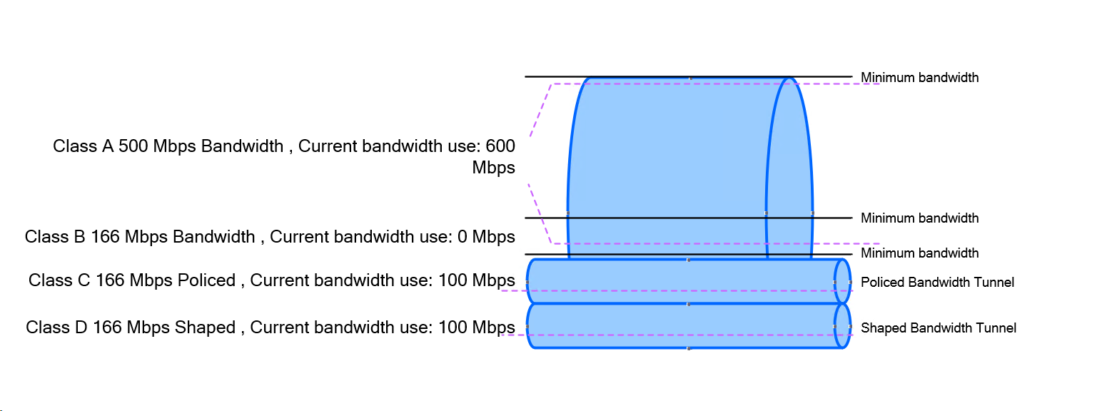
The bandwidth command is used to assign “minimum bandwidth” to a traffic class during congestion times. Just like a rubber “band” can be stretched and then it comes back to its original size, This is how a class can use positively more bandwidth or minimum of defined bandwidth (under congestion)
It is often used in conjunction with the Low Latency Queueing (LLQ) or Class-Based Weighted Fair Queueing (CBWFQ) to assign different classes different bandwidths. Assigning predictable bandwidth or chunks of interface speed to classes is much better way to handle the times of congestion
bandwidth {value in kbps}
bandwidth 2000 (This allocates 2000 kbps to the class.)
Police
The policecommand is used to force traffic to a rate limit regardless of congestion or not. Police command and shape command are applied all the time regardless if congestion is happening or not
Traffic of class where policing is applied can use less or equal to rate specified in police command It is used to control the “max” speed a traffic can use often used to hard rate limit certain class. Remember this from Police on highway, they make public drivers conform to max speeds defined, if a driver exceeds that speed, police stops or gives ticket to that person
Policing drops or marks packets that exceed the specified rate, traffic exceeding the specified rate is either dropped or remarked for lower marking
police {rate in bps} [burst-normal in bytes] [burst-max in bytes] [conform-action transmit] [exceed-action drop] [violate-action {drop | remark}]
police 1000000 20000 20000 conform-action transmit exceed-action drop (This limits the traffic to 1 Mbps, with a normal burst of 20,000 bytes and a maximum burst of 20,000 bytes. Conforming packets are transmitted, while exceeding packets are dropped.)
Shape
The shape command (traffic shaping) is used to buffer and smooth out bursts of traffic to a specified rate regardless of the congestion or not. Like police command, it also has a reducing function, It is used to ensure that traffic rate is controlled, and used in scenarios where you want to rate limit traffic to a rate but also not drop any traffic instead delay it.
Shaping delays excess packets by storing them in a queue , buffer and releasing them at a controlled rate. This helps in smoothing traffic flows and prevents sudden bursts that could overwhelm network devices.
shape average {rate in bps} [burst-size in bytes] [excess-burst-size in bytes]
Example: shape average 1000000 20000 20000 (This shapes the traffic to an average rate of 1 Mbps, with a burst size of 20,000 bytes and an excess burst size of 20,000 bytes.)
Key Differences:
Bandwidth vs. Police:
bandwidth reserves a minimum guaranteed bandwidth, ensuring that a class gets its share of the link capacity even under congestion.
police enforces a maximum rate, dropping or marking packets that exceed this rate.
Police vs Shape:
police drops or marks packets that exceed the specified rate, providing a hard limit. shape smooths out bursts of traffic instead of dropping packets, sending traffic at a controlled rate.
Policers are also often deployed at egress to control bandwidth used (or allocated) to a particular class of traffic, because such a decision often cannot be made until the packets reach the egress interface.
Shapers are commonly used on enterprise-to-service-provider links (on the enterprise egress side) to ensure that traffic destined for the service provider (SP) does not exceeds a contracted rate
Policer and Tail drop
When traffic exceeds the policed pipe, it does not expand the pipe but instead excess traffic / rate stays at the tail of the pipe and that is why it is called tail drop
A policer does tail drop, which describes an action that drops every packet that exceeds the given rate, until the traffic drops below the rate
Tail drop can have adverse effects on TCP retransmission methods and cause TCP global sync. Another mechanism of dropping packets is random dropping, which proactively drop packets before the queue is full to signal TCP flows to slow down inside the queue, known as random early detection (RED) and weighted RED (WRED). These methods work more effectively with TCP retransmission logic, but they are not policing/shaping tools. RED and WRED which are part of queue management / congestion avoidance (sometimes described as “intelligent dropping” inside the queue)
Instead of waiting for the queue to fill up and then tail-drop, RED/WRED randomly drop packets early, which prevents global synchronization and keeps throughput smoother.
Policing and RED/WRED can be applied on same service policy on interface but they work at different stages of packet handling, so you need to be clear how they interact.
Policing action will be taken as shown in above diagram since Congestion Avoidance takes place first and that controls the rate but for some reason if queue starts to fill up due to any other reason (since back pressure is on due to constant rate coming through policer) then WRED will activate
police command for tail drop and random-detect for WRED
They don’t “conflict,” but the policer acts first. If the policer already drops excess traffic, less traffic even reaches the queue, so WRED might do little and in production networks only should be implemented, unless there are complaints about TCP Global Sync, then honestly pipe should be increased rather than implementation of WRED
More common combo = shaping + WRED (because shaping delays bursts, then WRED handles congestion gracefully inside the queue).
policer when drops packets, it does “tail drop” on queues, it sounds like a queueing function (congestion management) but it is not, it is part of policer and it is general drop of traffic that simply exceeds the rate or pipe
When a traffic rate is exceeded, a policer can take one of two actions:
Drop the traffic
Re-mark
Section: Random Detect example with remark , mark down
re-marking (or markdown) should be done according to standards-based defined in Per Hop Behavior PHB – Assured Forwarding (AF) for example: excess traffic arriving as AFx1 should be marked down to AFx2 (or AFx3, whenever dual-rate policing is supported)
Then when traffic reaches the queue (congestion management), queue should be configured with (DSCP)-based WRED, WRED policy should be to drop AFx3 (statistically) more aggressively than AFx2, which in turn should be dropped (statistically) more aggressively than AFx1.
! ---- Classify AF queues (typical) ----
class-map match-any AF1
match dscp af11 af12 af13
class-map match-any AF2
match dscp af21 af22 af23
class-map match-any AF3
match dscp af31 af32 af33
class-map match-any AF4
match dscp af41 af42 af43
! ---- Policy with WRED tuned by drop precedence ----
policy-map WAN-OUT
class AF1
bandwidth percent 10
random-detect dscp-based
! AF13 (x3) most aggressive
random-detect dscp af13 20 40 5
! AF12 (x2) medium aggressive
random-detect dscp af12 30 55 7
! AF11 (x1) least aggressive
random-detect dscp af11 40 70 10
class AF2
bandwidth percent 10
random-detect dscp-based
random-detect dscp af23 20 40 5
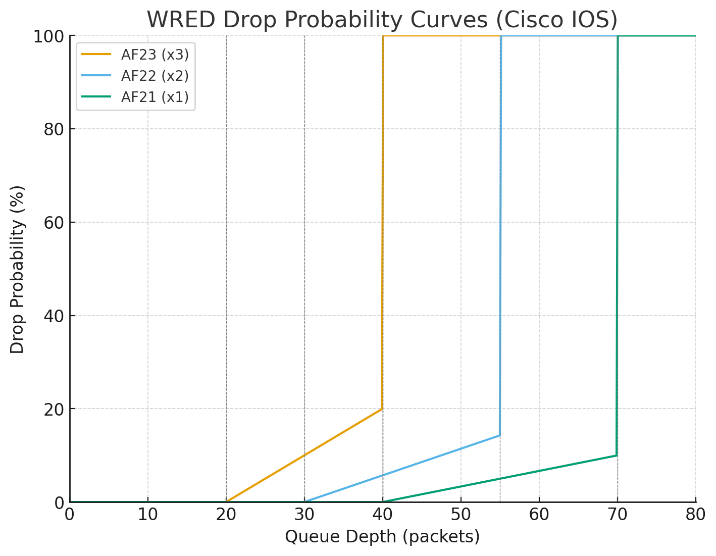
random-detect dscp <DSCP-value> <min-threshold> <max-threshold> <mark-prob-denominator>
random-detect dscp af23
This tells the router to apply DSCP-based WRED to packets marked AF23.
Each DSCP value can have its own drop profile.
<min-threshold> → 20
This is the queue depth (in packets) at which WRED starts dropping probabilistically.
At queue length below 20 packets, no drops occur for AF23.
<max-threshold> → 40
This is the queue depth at which WRED reaches 100% drop probability for AF23.
At 40 packets or more, all AF23 packets are dropped.
<mark-prob-denominator> → 5
This controls the slope of the drop curve between min and max threshold (as seen in chart below).
Drop probability = 1 / denominator at max-threshold
Here: 1/5 = 20% max probability (at threshold just below 40).
So queue depth
at 20 → 0% drop chance,
at 30 → ~10% drop chance,
at 39 → ~20% drop chance,
at ≥40 → 100% drop.
AF23 (x3): min 20, max 40, denom 5 → starts dropping early, ramps quickly → Most aggressive (drops at shallow queue depth).
AF22 (x2): min 30, max 55, denom 7 → later start, gentler slope → Medium aggressive.
AF21 (x1): min 40, max 70, denom 10 → starts dropping late, gentlest slope → Least aggressive (protected).
random-detect dscp af22 30 55 7
random-detect dscp af21 40 70 10
class AF3
bandwidth percent 10
random-detect dscp-based
random-detect dscp af33 20 40 5
random-detect dscp af32 30 55 7
random-detect dscp af31 40 70 10
class AF4
bandwidth percent 10
random-detect dscp-based
random-detect dscp af43 20 40 5
random-detect dscp af42 30 55 7
random-detect dscp af41 40 70 10
class class-default
fair-queue
random-detect
! Apply to the egress interface
interface GigabitEthernet0/0
service-policy output WAN-OUT
✅ So: AFx3 packets hit drop earliest and hardest, AFx2 later/softer, AFx1 latest and mildest. This all happening in a single queue and this queue contains multiple packets with AF21 , AF22 and AF23 packets and as queue if filling up they are all getting dropped in progression but AF23 will start dropping early and hard before AF21 starts dropping
See how drop probability gets lower and lower (AF21 at 10%) before 100% drop, as this is design intention to have AF21 suffer from only 10% of total packets drop before queue that has multiple packets made up of AF23 , AF22 and AF21 hits queue size of 70
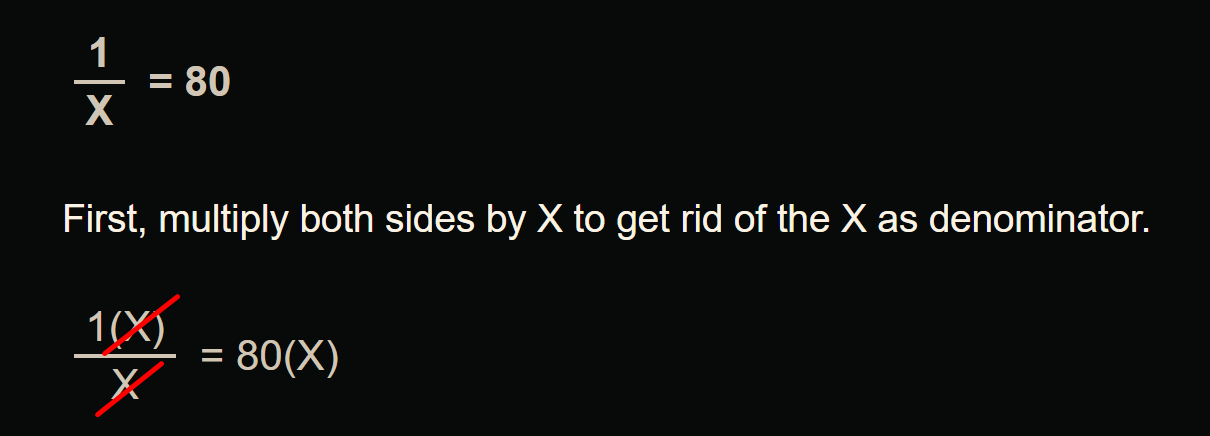
What if we want drop probability to be 80%?
1 / 80 = 0.0125
0.0125 * 100 = 1.25
If we enter 1.25 that will not be accepted by cisco command line and it only allows us whole numbers
If we want increase in drop probability we can use 2 which will give us sharp drop of 50%
Token Bucket Algorithms
Token bucket algorithms are metering engines that keep track of how much traffic can be sent
One token permits a single unit (usually a bit, but can be a byte) of traffic to be sent
New Tokens equal to “CIR” are granted usually every second
For example, if the CIR is set to 8000 bps, 8000 tokens are placed in a bucket at the beginning of the time period. Each time a 1 bit of traffic passes “policer”, the bucket is checked for tokens -> If there are tokens in the bucket, the traffic is viewed as conforming to the rate and the typical action is to send the traffic. -> One token is removed from the bucket for each bit of traffic passed. -> If there are no tokens, any additional offered traffic is viewed to exceed the rate, and the exceed action is taken, which is typically either to re-mark or drop the traffic.
At the end of the second, there might be unused tokens. The handling of unused tokens is a key differentiator among policers
Rate limit using TDM
With TDM, when a rate limit (or CIR) is imposed on an interface, the traffic bits are pinned to subsecond milliseconds – 1 thousandth of a second units
This multiple subsecond time slices are combined into larger interval called “Tc”
For example, if an 8-Kbps CIR is imposed on a 64-Kbps link, traffic can be sent for an interval of 125 ms (64,000 bps / 8000 bits). We just divided the total rate of the link with desired rate 64000 / 8000 = 8, and 8th of a second is 125 ms and that 125 ms will be our Tc value.
The entire amount allowed by the CIR (8000 bits) could theoretically be sent at once, but then the algorithm would have to wait 875 ms before it could send any more data
Therefore, to smooth out the allowed flow over each second, traffic is released on the link in smaller bursts called committed burst “Bc” which can be sent per Tc interval
Below illustration only shows scenarios for different Tc times and not Tc of 125 ms
It is not necessary for device to keep sending during whole of Tc, instead device can send for some duration of Tc but send whole of Bc and wait for next Tc interval as shown in last example of Bc = 1000 in illustration above
token bucket algorithm is as follows: Bc = CIR * Tc (Bits = Rate * Time)
Cisco IOS Software does not allow the explicit definition of the interval (Tc). Instead, it takes the CIR and Bc values as arguments
From a practical perspective, when implementing networks, Tc should not exceed 125 ms. Shorter intervals can be configured and are necessary to limit jitter in real-time traffic, but longer intervals are not practical for most networks because the interpacket delay becomes too large
so we can drive down the value of Tc from 125 ms to 62.5 ms (half) using below
Bc = CIR * Tc (Bits = Rate * Time) using this formula we can figure out or set the Tc
for Tc of 125 ms
CIR or total rate 64000 bits/sec * Tc 125 ms = 8000000 8000000 / 1000 ms or 1 sec for result in seconds = 8000 -> Bc ( 64000 * 125 ) / 1000 = 8000 -> Bc
for Tc of 62.5 ms
( 64000 * 62.5 ) / 1000 = 4000 -> Bc
Types of Policers
There are different variations of policing algorithms, including the following:
The original policers implemented use a single-rate, two-color model with
A single rate and single token bucket algorithm
Traffic identified as one of two states (or colors): conforming to or exceeding the CIR. Marking or dropping actions are performed on each of the two states of traffic
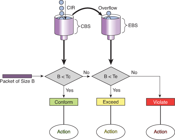
Single-Rate Three-Color Policers
An improvement on single-rate two-color policer algorithm
Traffic identified as one of three states (or colors): conforming to, exceeding or “violating” the CIR.
First part operates just like the single-rate two-color system But if there are any tokens left over in the bucket after each time period, these are placed in the second bucket to be used as credits later for temporary bursts that might exceed the CIR
Tokens placed in this second bucket are called the excess burst (Be). Be is the maximum number of bits that can exceed the Bc burst size.
With this two token-bucket mechanism, traffic can be identified in three states (or three colors) as follows:
Conform: Traffic within the CIR—usually sent (optionally re-marked)
Exceed: Traffic within the excess burst allowance above CIR—can be dropped, or re-marked and sent
Violate: Traffic beyond the excess burst—usually dropped (optionally re-marked and transmitted)
CIR: Committed information rate, the policed rate
CBS: Committed burst size, the maximum size of the first token bucket
EBS: Excess burst size, the maximum size of the second token bucket
Tc: Token count of CBS, the number of tokens in the CBS bucket (Do not confuse the term Tc here with the earlier use of Tc in the context of time but this Tc is only used for diagram below)
Te: Token count of EBS, the instantaneous number of tokens left in the EBS bucket
Single-rate three-color policer’s tolerance of temporary bursts results in fewer TCP retransmissions and is therefore more efficient for bandwidth utilization. It is a highly suitable tool for marking according to RFC 2597 AF classes, which have three “colors” (or drop preferences) defined per class (AFx1, AFx2, and AFx3). Using a three-color policer generally makes sense only if the actions taken for each color differ. If the actions for two or more colors are the same, a simpler policer (and therefore a simpler QoS policy) is more suitable to implement, making the network easier to maintain.
! -----------------------------
! Classify traffic (examples)
! -----------------------------
ip access-list extended AF1-TRAFFIC
  remark <<< define your AF1 class traffic here >>>
  permit ip 10.1.0.0 0.0.255.255 any

ip access-list extended AF2-TRAFFIC
  remark <<< define your AF2 class traffic here >>>
  permit ip 10.2.0.0 0.0.255.255 any

ip access-list extended AF3-TRAFFIC
  remark <<< define your AF3 class traffic here >>>
  permit ip 10.3.0.0 0.0.255.255 any

class-map match-any CLASS-AF1
  match access-group name AF1-TRAFFIC
class-map match-any CLASS-AF2
  match access-group name AF2-TRAFFIC
class-map match-any CLASS-AF3
  match access-group name AF3-TRAFFIC

! ---------------------------------------------------------
! Single-rate three-color policer per AF class
! - Adjust CIR/Bc/Be to your needs (bps / bytes).
! - Typical starting point: Be ≈ 2*Bc
! ---------------------------------------------------------
policy-map POLICE-AF
  class CLASS-AF1
    ! Example: 10 Mbps CIR, Bc/Be placeholders
    police cir 10000000 bc 312500 be 625000 \
      conform-action set-dscp-transmit af11 \
      exceed-action  set-dscp-transmit af12 \
      violate-action drop

  class CLASS-AF2
    ! Example: 5 Mbps CIR
    police cir 5000000 bc 156250 be 312500 \
      conform-action set-dscp-transmit af21 \
      exceed-action  set-dscp-transmit af22 \
      violate-action drop

  class CLASS-AF3
    ! Example: 2 Mbps CIR
    police cir 2000000 bc 62500 be 125000 \
      conform-action set-dscp-transmit af31 \
      exceed-action  set-dscp-transmit af32 \
      violate-action drop

  class class-default
    set dscp default

! ---------------------------------------
! Apply the policy (ingress or egress)
! ---------------------------------------
interface GigabitEthernet0/0
  description WAN-Uplink
  service-policy output POLICE-AF
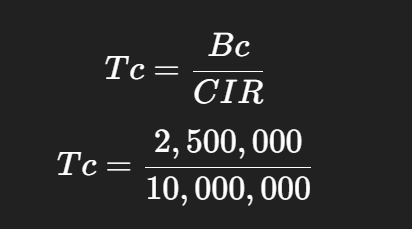
police cir 10000000 bc 312500 be 625000 -> in order to find its Tc
This Bc of 312500 is not optimal as it results in 250 ms
Bc = CIR * Tc
10000000 bits * 125 ms = 1250000000 / 1000 ms = 1250000 bits of Bc
for command line we will convert it to bytes 1250000 / 8 = 156,250 bytes
police cir 10000000 bc 156250 be 312500
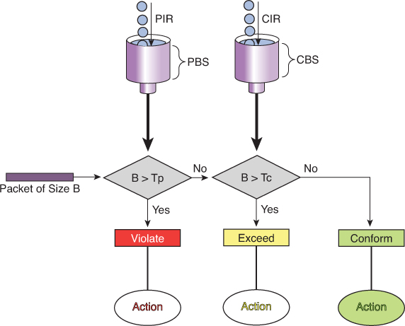
Dual-Rate Three-Color Policers
The single-rate three-color marker/policer was a significant improvement for policers—it made allowance for temporary traffic bursts
the two-rate three-color marker/policer allows for a sustainable excess burst (negating the need to accumulate credits to accommodate temporary bursts) and allows for different actions for the traffic exceeding the different burst values.
This policer addresses the peak information rate (PIR), which is unpredictable in the RFC 2697 model two-rate three-color marker/policer. Furthermore, the two-rate three-color marker/policer allows for a sustainable excess burst (negating the need to accumulate credits to accommodate temporary bursts) and allows for different actions for the traffic exceeding the different burst values.
The dual-rate three-color marker/policer uses the following definitions parameters to meter the traffic stream:
PIR: Peak information rate, the maximum rate that traffic ever is allowed
PBS: Peak burst size, the maximum size of the first token bucket
CIR: Committed information rate, the policed rate
CBS: Committed burst size, the maximum size of the second token bucket
Tp: Token count of PBS, the instantaneous number of tokens left in the PBS bucket
Tc: Token count of CBS, the instantaneous number of tokens left in the CBS bucket
B: Byte size of offered packet
Policing Logic
First check against PIR (Peak Bucket):
If B > Tp (packet size larger than available tokens in PBS) → Violate (red).
Packet is non-conformant and marked/dropped depending on policy.
Otherwise, move to next step.
Then check against CIR (Committed Bucket):
If B > Tc (packet size larger than tokens in CBS) → Exceed (yellow).
Packet is considered “in excess traffic” but not outright violation.
Otherwise → Conform (green).
Actions
Violate (Red): Drop or heavily penalize traffic.
Exceed (Yellow): Forward, but mark as lower-priority (may be dropped if congestion occurs).
Conform (Green): Forward as guaranteed/priority traffic.
! Class-map: match the traffic you want to police
class-map match-any APP-TRAFFIC
 match access-group 101
! or DSCP/ACL/etc.

policy-map POLICE-TRTCM
 class APP-TRAFFIC
  police cir 1000000 bc 10000 pir 2000000 be 20000 \
    conform-action transmit \
    exceed-action set-dscp-transmit cs1 \
    violate-action drop
!
! Apply inbound (or outbound if supported)
interface GigabitEthernet0/0/0
 description Ingress toward core
 service-policy input POLICE-TRTCM
CoPP is a feature that allows the configuration of QoS policers to rate-limit the traffic destined to the main CPU of the switch/router. Such CoPP policers serve to protect the control plane of the switch/router from DoS attacks and reconnaissance activity in order to protect the CPU and control plane running as CPU processes
! Single-rate policer
policy-map POLICY1
  class C1
    police cir 1000000 conform-action transmit exceed-action drop
!
! Dual-rate policer
policy-map POLICY2
  class C2
    police cir 500000 bc 10000 pir 1000000 be 10000 conform-action
    transmit exceed-action set-prec-transmit 2 violate-action drop
!
! Percentage-based policing
policy-map POLICY3
   class C3
     police cir percent 20 bc 300 ms be 400 ms pir percent 40
     conform-action set-cos-inner-transmit 3
Summary
Policing happens before packets enter the output queue.
A policer enforces a traffic contract (rate/committed burst).
Packets that exceed the configured rate are either dropped (default) or remarked (e.g. to a lower priority).
This happens regardless of whether there is congestion or not.
Congestion occurs after packets have entered the interface output queue.
Congestion management mechanisms (like Weighted Fair Queuing, Priority Queuing, CBWFQ, LLQ, etc.) decide which packets get queued and transmitted.
If a queue overflows (due to congestion), packets are dropped from that queue.
This can happen even for traffic that has already been policed — if the queue fills, traffic is dropped.
Hierarchical Policing
it might be desirable to limit all TCP traffic to 10 Mbps, while at the same time limiting FTP traffic (a subset of TCP traffic) to no more than 1.5 Mbps. To achieve this nested policing requirement, hierarchical policing can be used with up to three levels.
policy-map FTP-POLICER
  class FTP
   police cir 1500000
     conform-action transmit
     exceed-action  drop
!
 policy-map TCP-POLICER
  class TCP
   police cir 10000000
     conform-action transmit
     exceed-action  drop
     service-policy FTP-POLICER
!
interface ge 1/1
  service-policy output TCP-POLICER
Percentage-Based Policing
Most networks contain a wide array of interfaces with different bandwidths. If it is desirable to have an overall network policy in which, for example, FTP traffic is not to exceed 10 percent of the bandwidth on any interface, percentage-based policing can be used.
CIR and PIR values can be specified with percent, but not the burst sizes; the burst sizes are configured in units of milliseconds. If the CIR is configured in percent, the PIR also must be
When the service policy is attached to an interface, the CIR (and PIR, if configured) is determined as a percentage of the interface bandwidth. If the interface bandwidth is changed, the CIR and PIR values and burst sizes are automatically recalculated using the new interface bandwidth value
For subinterfaces, the bandwidth of the main interface is used for the calculation
If the percent feature is used in a second- or third-level policy, the bandwidth of the lower-level policy statement is determined by the configuration of the higher or parent level
LLQ is a policer and not bandwidth
LLQ mechanism “priority” contains an implicit policer and LLQ gives strict transmission priority to real-time traffic, and by doing so it introduces the possibility of starving lower-priority traffic. To prevent this situation, the LLQ mechanism polices traffic to the bandwidth specified in the priority statement by indiscriminately tail-dropping traffic exceeding the configured rate
priority statement can be specified with an absolute bandwidth or by using a percentage.
Control Plane Policing
CoPP allows the configuration of QoS policers to rate-limit the traffic handled by the main CPU of the switch. These policers serve to protect the control plane of the switch/router from DoS attacks and reconnaissance activity. With CoPP, QoS policies are configured to permit, block, or rate-limit packets destined to the main CPU. For example, if a large amount of multicast traffic is introduced into the network with a Time To Live (TTL) of 1, this traffic would force the switch to decrement the TTL, and thereby force the control plane to send an ICMP (Internet Control Message Protocol) error message. If enough of these events happened, the CPU would not be able to process them all, and the node would be effectively taken out of service
CoPP can protect a node against this type of attack
Shaper
Continue from file:///G:/My%20Drive/Learn%20Journey/2_QoS/Book%20HTMLs/End-to-End%20QoS%20Network%20Design%20Quality%20of%20Service%20for%20Rich-Media%20&%20Cloud%20Networks,%20Second%20Edition/online%20version/Chapter%204.%20Policing,%20Shaping,%20and%20Markdown%20Tools.html
“Traffic Shaping Tools”
! PRACTICE
! This class map relies on packets with marking already applied
class-map match-any REALTIME
  match dscp ef       ! Matches VoIP bearer traffic
  match dscp cs5      ! Matches Broadcast Video traffic
  match dscp cs4      ! Matches Realtime-Interactive traffic
!
class-map match-any CONTROL
  match dscp cs6      ! Matches Network-Control traffic
  match dscp cs3      ! Matches Voice/Video Signaling traffic
  match dscp cs2      ! Matches Network Management traffic
!
class-map match-any CRITICAL-DATA
  match dscp af41 af42 af43  ! Matches Multimedia Conf. on AF4
  match dscp af31 af32 af33  ! Matches Multimedia Streaming on AF3
  match dscp af21 af22 af23  ! Matches Transactional Data on AF2
  match dscp af11 af12 af13  ! Matches Bulk Data on AF1
!
policy-map WAN-EDGE-4-CLASS
  class REALTIME
    priority percent 33      ! 33% LLQ for REALTIME class
  class CONTROL
    bandwidth percent 7      ! 7% CBWFQ for CONTROL class
  class CRITICAL-DATA
    bandwidth percent 35     ! 35% CBWFQ for CRITICAL-DATA class
    fair-queue               ! Fair-queuing on CRITICAL-DATA
    random-detect dscp-based ! DSCP-based WRED on CRITICAL-DATA
  class class-default
    bandwidth percent 25     ! 25% CBWFQ for default class
    fair-queue               ! fair-queuing on default class
    random-detect dscp-based ! DSCP-based WRED on default class
!
interface serial 1/0/0
  service-policy output WAN-EDGE-4-CLASS

-----------------------------------------------------

class-map markings
  match dscp af41 af42 af43
!
class-map mac-address
  match destination-address mac 00:00:00:00:00:00
!
class-map ftp
  match protocol ftp

-----------------------------------------------------

policy-map SET-DSCP
  class DSCP-AF31
    set dscp af31

-----------------------------------------------------

class-map match-any TRAFFICTYPE1
  match <criteria1>
  match <criteria2>
class-map match-all TRAFFICTYPE2
  match <criteria3>
  match <criteria4>
class-map TRAFFICTYPE3
  match not <criteria5>

! reusing previously defined class
class-map DETAILS
  match <criteria6>
class-map HIGHER-LEVEL
  match class-map DETAILS
  match <criteria7>

-----------------------------------------------------

! police set actions for remarking
Router(config)# policy-map CB-POLICING
Router(config-pmap)# class FOO
Router(config-pmap-c)# police 8000 conform-action ?
  drop                 drop packet
  exceed-action        action when rate is within conform and
                       conform + exceed burst
  set-clp-transmit             set atm clp and send it
  set-discard-class-transmit   set discard-class and send it
  set-dscp-transmit            set dscp and send it
  set-frde-transmit            set FR DE and send it
  set-mpls-exp-imposition-transmit  set exp at tag imposition
                                    and send it
  set-mpls-exp-topmost-transmit     set exp on topmost label
                                    and send it
  set-prec-transmit            rewrite packet precedence
                               and send it
  set-qos-transmit             set qos-group and send it
  transmit                     transmit packet
When you configure multiple DSCP values on the same line, like this:
match dscp af41 af42 af43
This is treated as a logical OR within that line.
match-any → logical OR The packet only needs to match one of the listed conditions to be considered a match.
match-all → logical AND The packet must satisfy all of the listed conditions at the same time to be considered a match. The default logical operator (if unspecified) is match-all.
match not will select inverse traffic
Note that class map and policy map names are case sensitive. Thus, class-map type1 is different from class-map Type1, which is different from class-map TYPE1. Class map names and cases must match exactly the class names specified in policy maps.
Unclassified traffic (traffic that does not meet the match criteria specified in the explicit traffic classes) is treated as belonging to the implicit default class.
specifying a policy map for “class-default” is optional, and if not specified, default class traffic has no QoS features assigned
default class traffic has no QoS features assigned, receives best-effort treatment, and can use all bandwidth not allotted or needed by the classes explicitly specified in the configuration – so if a lot of bandwidth is left on link then this class wins, if there is a less bandwidth left on the link then this class default traffic is looser
The default treatment for unclassified traffic with no QoS features enabled is a first-in, first-out (FIFO) queue with tail drop (which treats all traffic equally and simply drops packets when the output queue is full).
priority queuing, fair queuing are queueing treatments called priority queuing and fair queuing priority command allocates bandwidth and also sets queuing treatment of priority as well, any traffic that has priority applied is sent out as soon as received, “skips to the front of the queue and scheduled first over anything else”
Queueing
Queueing types FIFO, CBWFQ and LLQ
Queue is a memory or buffer allocated on the interface and queue is always there on an interface, it only comes into play (holds packet to wait) when packets are coming into router faster than it can send them out or dispatch them out of egress interface
queue or buffer is a limited memory that can fill up and overflow and if we try to put a packet into this overflowing queue, packet will be dropped
A brilliant solution is to make sub queues or smaller queues carved out of that one big queue so queue for best effort overflows it does not effect the voip traffic, only best effort packets will be denied or dropped while traffic for all other services keep working
Cisco recommends no more than 11 sub queues
If all traffic is dropped due to single queue for all services – TCP global Sync
TCP has sliding window, which means that TCP can gradually start skipping the acknowledgements as time passes and this window or set or number of segments start to increase till one ack is missed and TCP thinks that there is no accountability for what was sent and what was received (from remote end) so it shrinks that window down
random-detect
random-detect command enables Weighted Random Early Detection (WRED) on a queue. It monitors the average queue depth.
If the queue starts filling: Below the minimum threshold → no packets dropped. Between min and max thresholds → packets are randomly dropped with increasing probability. Above the maximum threshold → all packets are dropped (tail drop).
This prevents global synchronization of TCP flows and smooths congestion
See Section: Random Detect example with remark , mark down for config example and explanation
fair-queue (queueing)
fair-queue command is one of the older queueing mechanisms in IOS, before CBWFQ and LLQ became standard
Fair Queueing (FQ) = A congestion management method that automatically creates separate queues per flow (based on source/destination IP and port), Used mainly on slow links (≤ 2 Mbps)
The router then services each queue in a round-robin fashion, so no single flow (e.g. a big FTP transfer) can dominate the link
Cisco recommends CBWFQ/LLQ instead of fair-queue on modern WANs
Host A → Host B
Edge node doesn't know B
→ sends Map-Request to control plane
→ receives Map-Reply
→ builds VXLAN tunnel
→ forwards traffic
SDA LISP publish–subscribe model
Edge node registers endpoints
↓
Control plane stores mappings
↓
Other edge nodes subscribe to updates
↓
Mappings pushed proactively
So instead of:
request → reply
you get:
subscribe → push updates automatically
Much faster convergence and fewer queries.
What exactly gets published?
When an endpoint appears:
Host joins fabric
↓
Edge node registers endpoint to Control Plane Node
↓
Control Plane Node distributes mapping to subscribers
Endpoint mappings in its VN (primary subscription)
Example:
If Edge-1 participates in:
VN = Corp
it subscribes to:
All Corp endpoint location updates
So when a device appears anywhere in the Corp VN:
10.10.20.5 → Edge-3 loopback
the Control Plane Node pushes that mapping to Edge-1.
Edge-1 now already knows where that endpoint lives.
No lookup required later.
What triggers subscription updates
Control Plane Node pushes updates when:
New endpoint appears
Host joins fabric
Endpoint roams
Edge changes
Endpoint disappears
Host disconnects
External prefix changes
New route learned via border node
Border nodes also subscribe
Border nodes subscribe too.
They receive:
Internal endpoint mappings
so they know how to forward inbound traffic from:
Fusion router → fabric endpoint
without querying first.
But does it not cause scalability issues and that is why map-request and map-reply model were used if you are learning / pulling all hosts in a VN?
At first glance, pushing all endpoint mappings to all edge nodes in a VN sounds like it would break scalability. That’s exactly why classical LISP used Map-Request / Map-Reply (pull) instead of flooding mappings everywhere.
But Cisco SDA does NOT push all mappings to all edges. It uses a selective pub-sub model, not a full broadcast subscription model.
Here’s how scalability is preserved.
The key clarification
SDA does not mean:
Every edge node learns every endpoint in the VN
Instead it means:
Edge nodes subscribe only to mappings they are likely to need
The control plane node performs selective distribution.
Edges subscribe to:
Local VN mappings (selectively)
Not the entire VN database.
Instead:
active mappings
relevant mappings
recently used mappings
mobility-related mappings
The control plane node tracks interest dynamically.
its own endpoints
+
active remote peers
+
border mappings
NOT:
all 10,000 endpoints
Another hidden scaling mechanism: map-cache still exists
Even in SDA pub-sub mode:
Edge nodes still maintain a map-cache.
So behaviour is actually hybrid:
Push updates when relevant
Pull mappings when unknown
Cache results locally
This keeps control-plane chatter low.
Host-A talked to Edge-1 and Edge-2 Host-A disconnected → notify Edge-1 and notify Edge-2
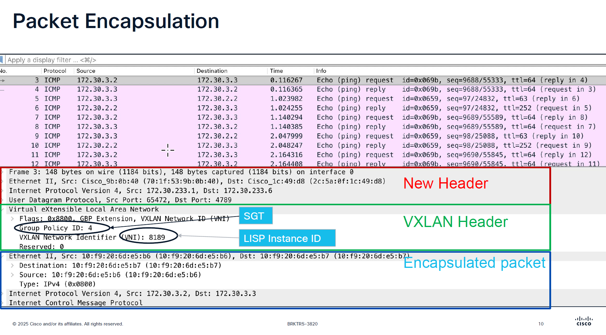
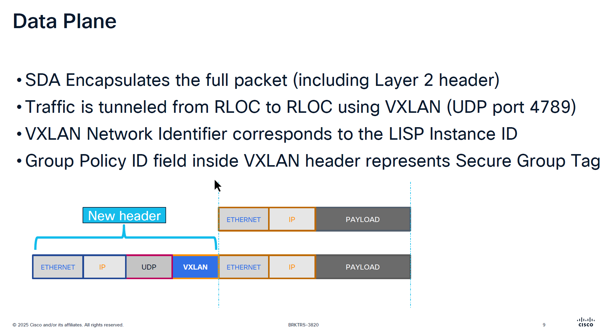
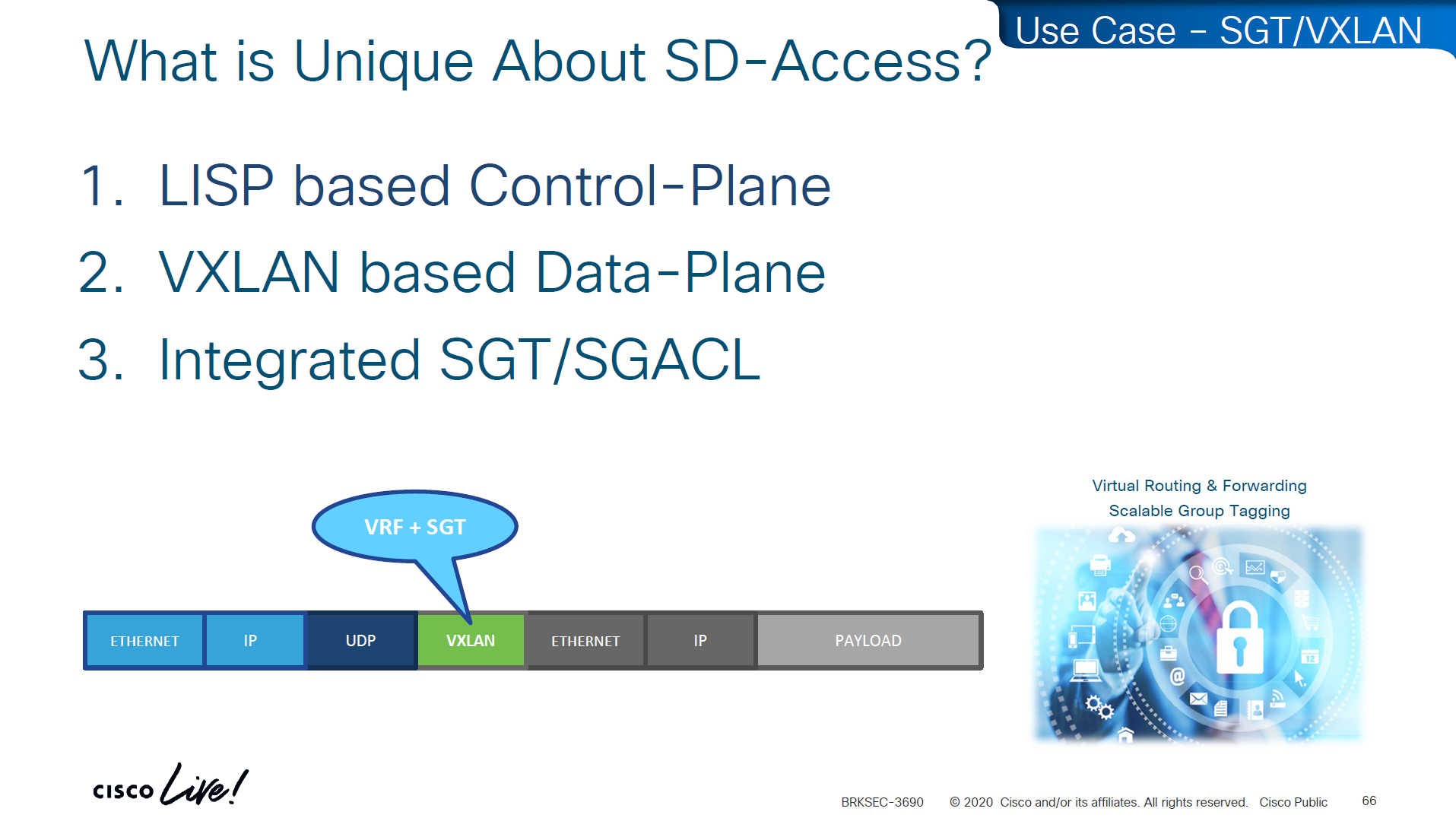
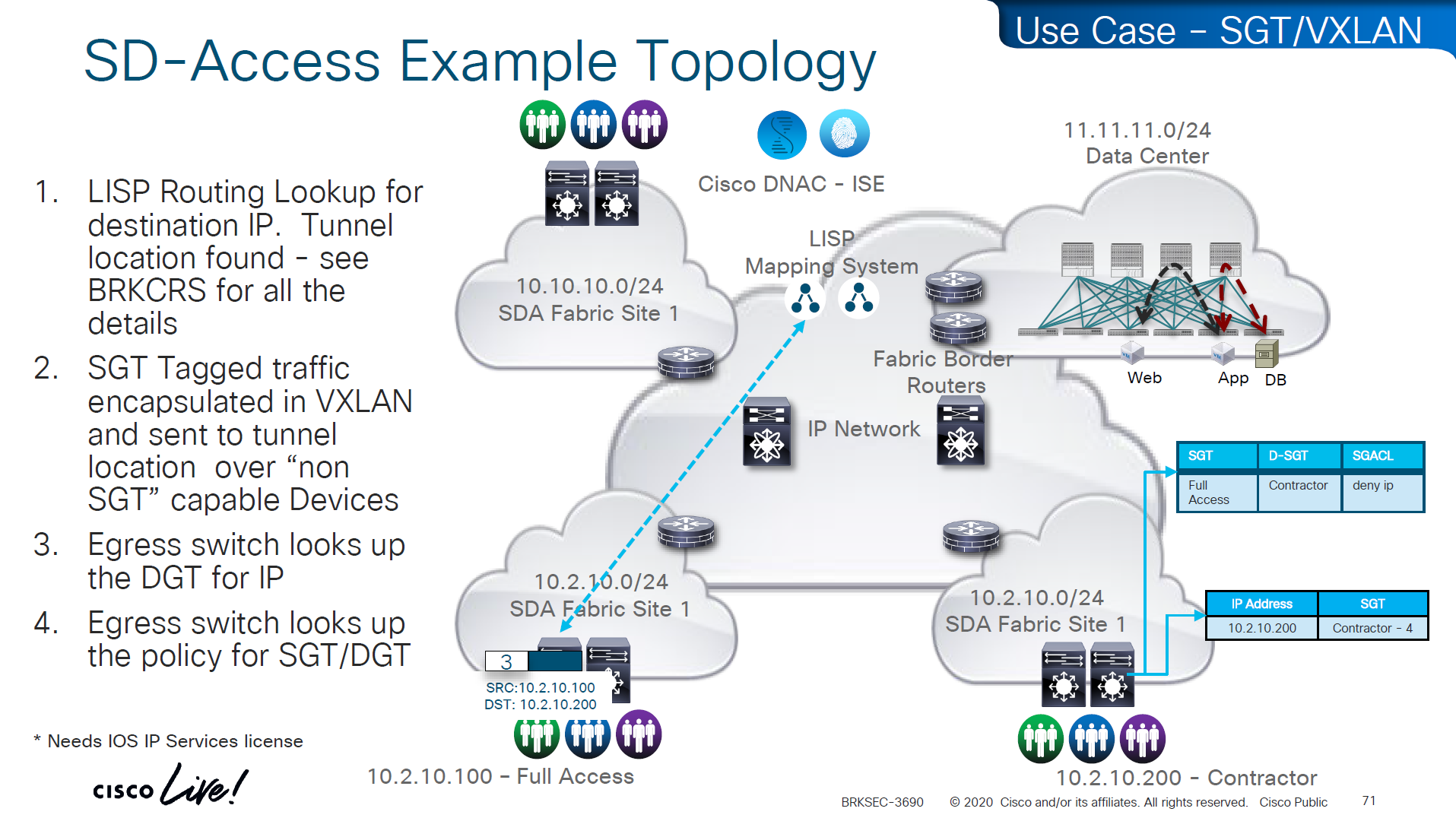
VXLAN looks like an “application” in above picture
Destination Port used by VXLAN is UDP 4’789 Cisco could have used source UDP 4789 to destination UDP 4789 but they wanted the possibility of load balancing through the underlay network that is why Cisco uses random source port because if everything is using same path then we are wasting bandwidth in thet network
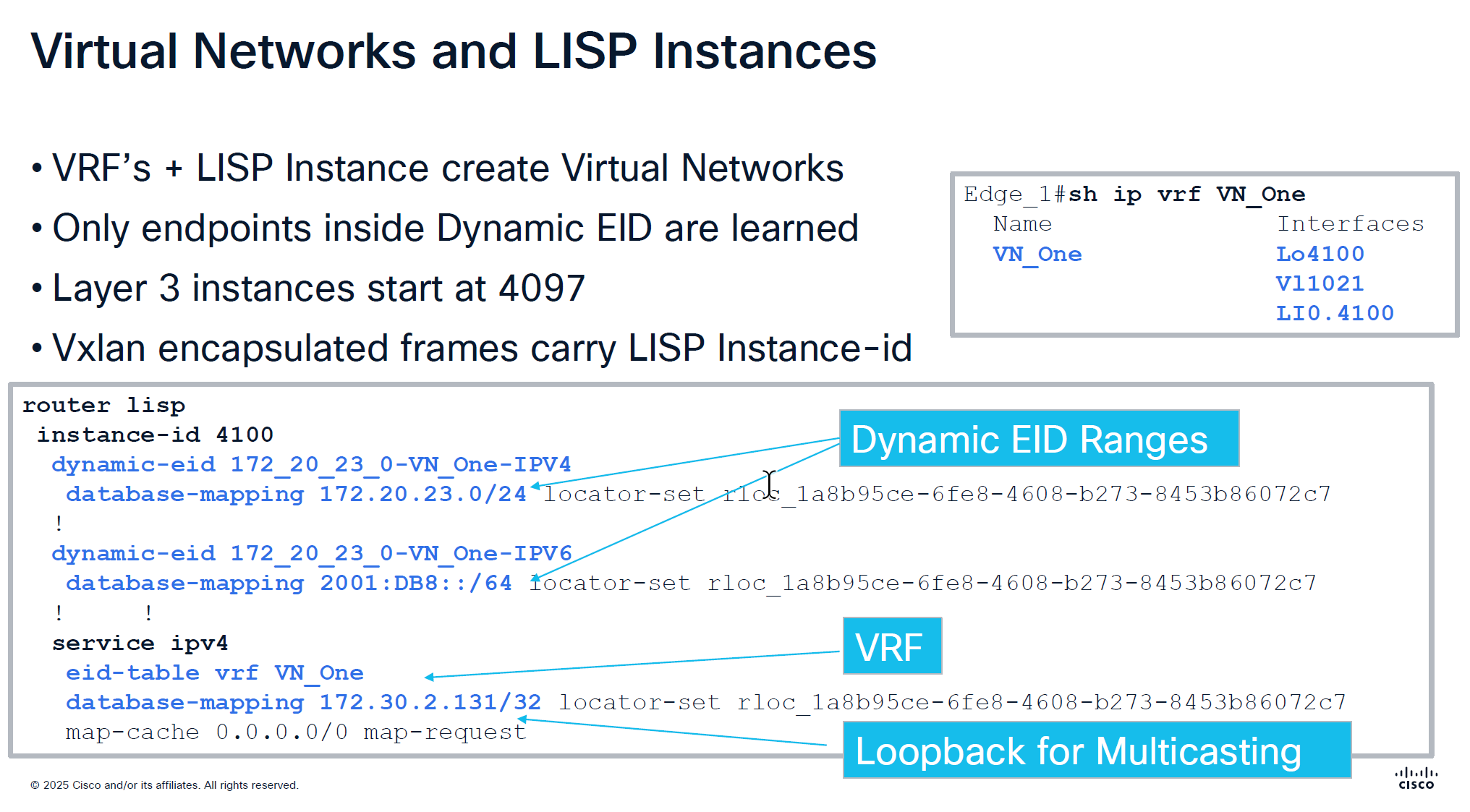
Any endpoint that is connected and is picked up by device tracking and it is in this subnet then it is registered in LISP but anything outside of this range will still be learned in device tracking but not learned in LISP and will not be advertised out by FBS because security wise anything could connect and get advertised out of the fabric, these endpoints will still be able to speak to devices connected on same switch, but not through fabric
In every VRF a loopback is created dynamically and that loopback is not in underlay but on the overlay, and is used for multicasting and it is shown in above screenshot as “Loopback for Multicasting”
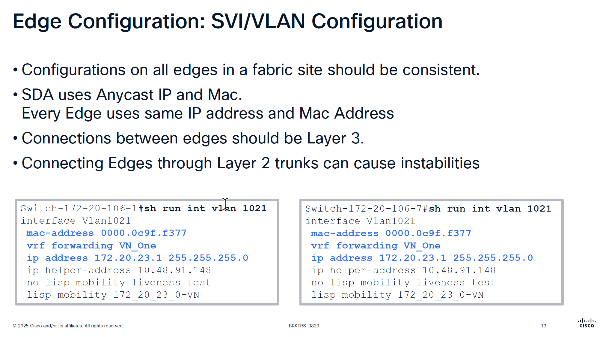
Because we have same Anycast IP and same mac address on all edge devices and because of that we should never connect 2 edges together via a layer 2 trunk, if we do then we will see all sorts of instabilities
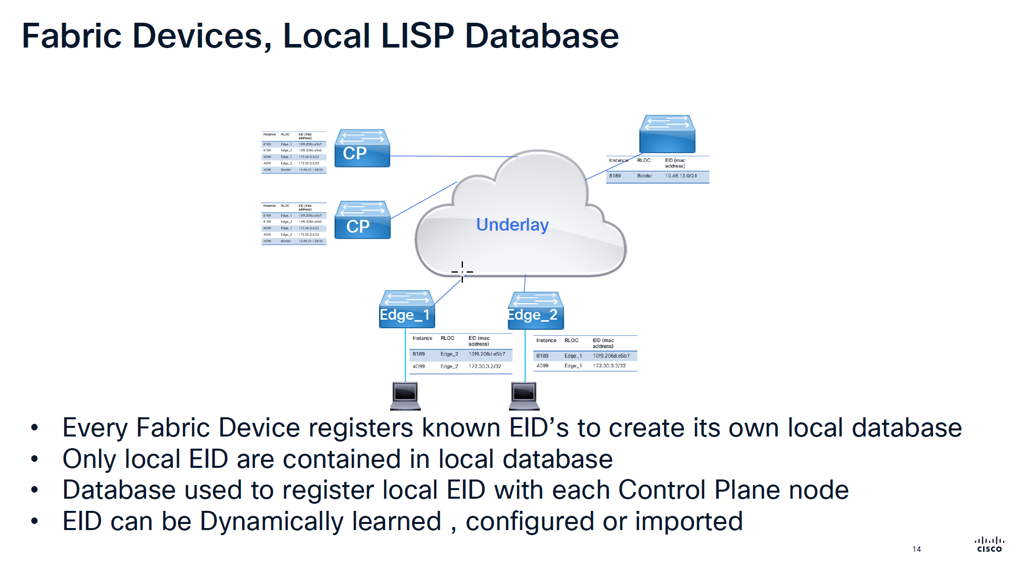
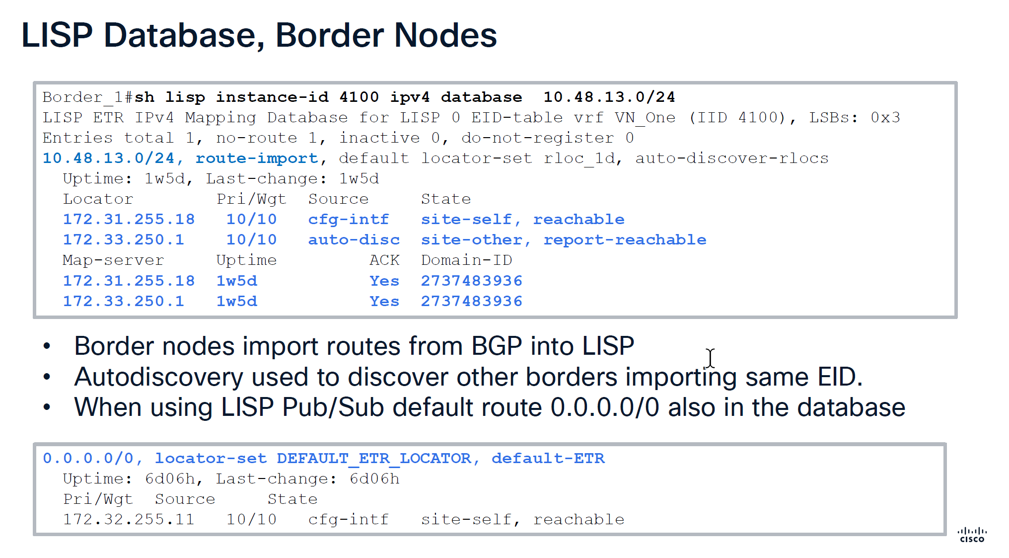
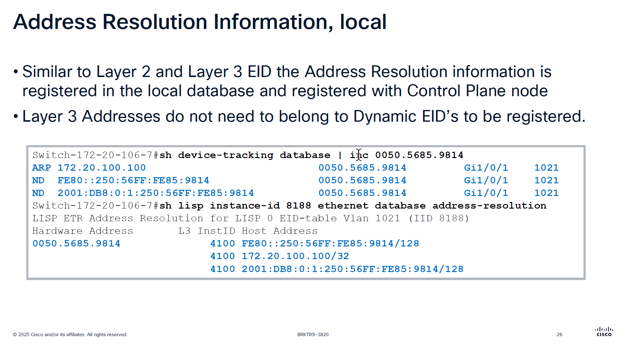
Local Database is built on the edge switch for both IPv4 instance and ethernet instance and the eid learned from local database are registered to the control plane
Route import tells us how it came into border node, It then tells us about the locators it knows about 172.31.255.18 is itself marked as “cfg-intf” and 172.33.250.1 is other border node known through “auto-disc”
Make sure that control plane has actually acknowledged
With LISP Pub/Sub comes with a ‘dynamic default border’ feature that works if we have advertisesed 0.0.0.0/0 into border per VN > then it is put into LISP database and that is how it becomes default ETR for all of the fabric
With LISP BGP we select the nodes as ‘default border’ but because there is no default route tracking or no default route, in case border node looses routes to uplink, traffic gets blackholed
With ‘dynamic default border’ if default route is not present then it will not be put into LISP and if it is not in the LISP then that device will not be used as default border
During troubleshooting with LISP pub sub, if you see fabric cannot get out and if default route is not present in LISP then that is the issue, in that case check if 0.0.0.0 is on the border node
Below we can see Map-server column having same address as border which means control and border are colocated on same node and it also shows ACK, telling us that it has registered these prefixes and sent ACK back to border saying that it has registered this prefix, if we dont see ACK then it means that there is some issue in border and control communication, either key mismatch and packets were sent to control but it was not accepted
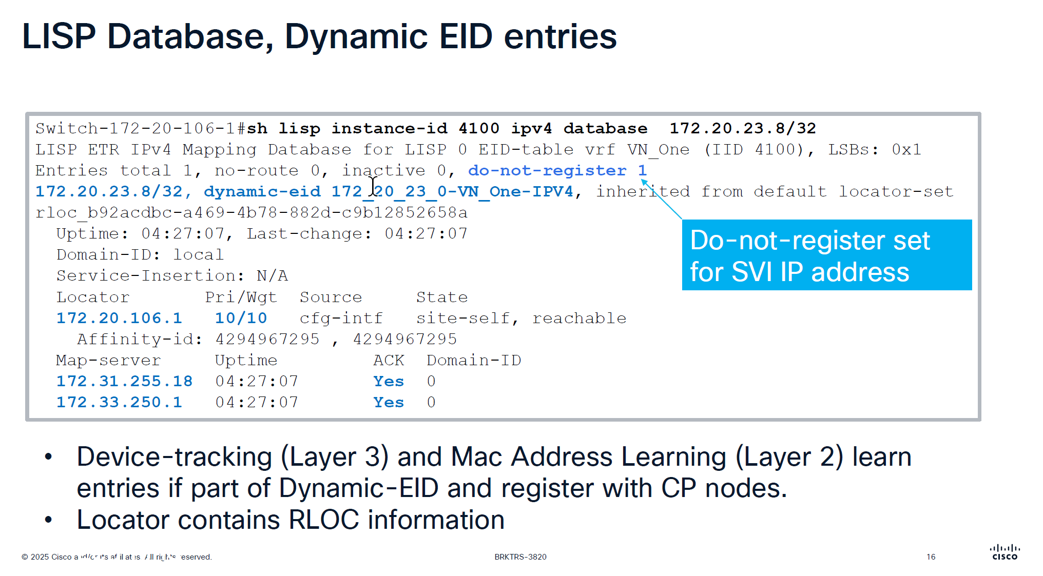
This is edge node that is saying that this endpoint EID has matched this dyanmic EID range and state is ‘site-self’ which means I regsitered it and also tells which map servers or control plane nodes it has been registered and ACK was received for the registeration
This do not register is set for SVI IP because it is anycast IP that is available on all edge nodes
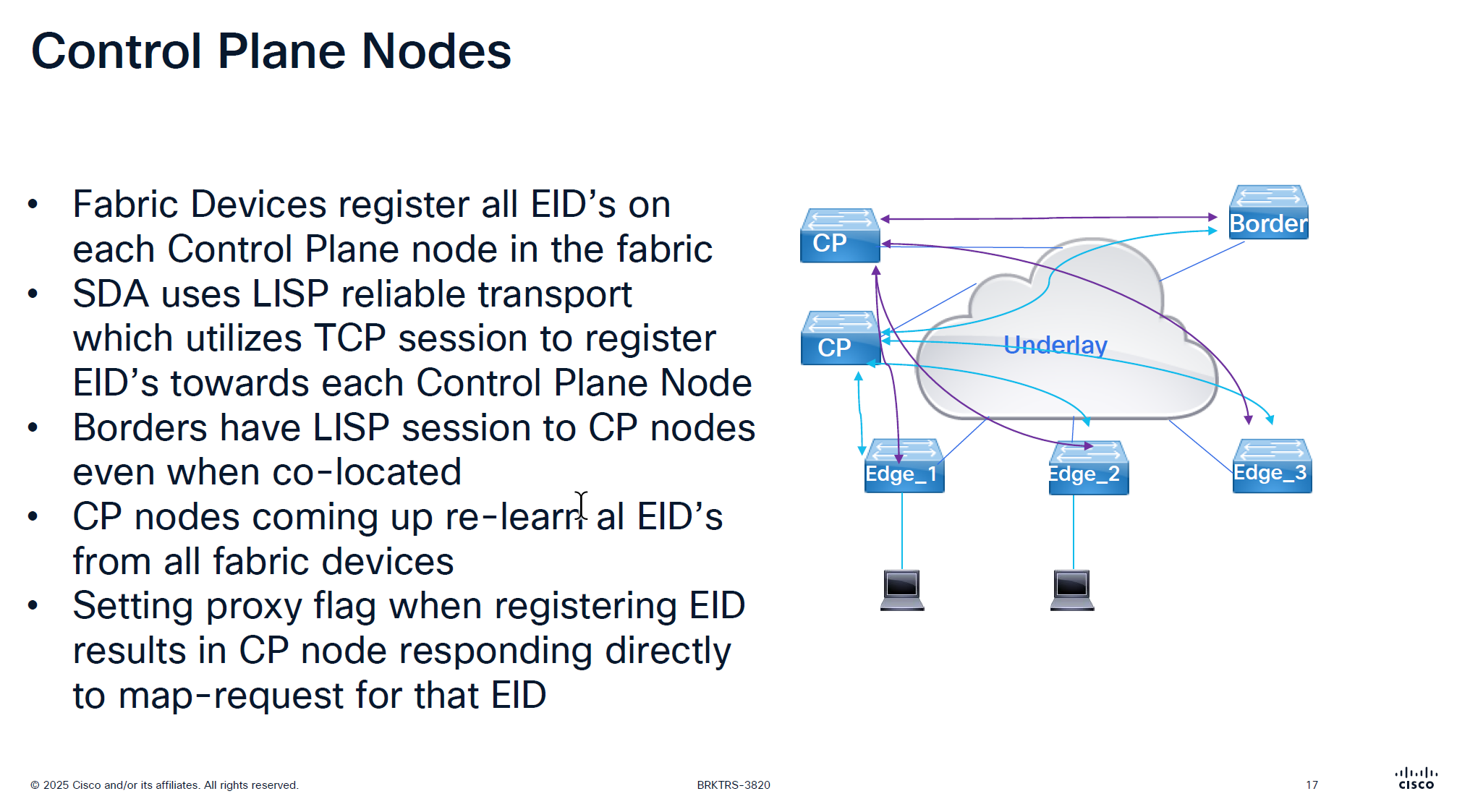
There is no communication between the control plane node, if a control plane node goes down and then comes backup then it has to relearn all the EID from all the edge nodes, CP nodes do not sync with one another , so typically when network is stable it can give the illusion that they are synced due to equal number of EID on both but CP nodes do not talk to one another
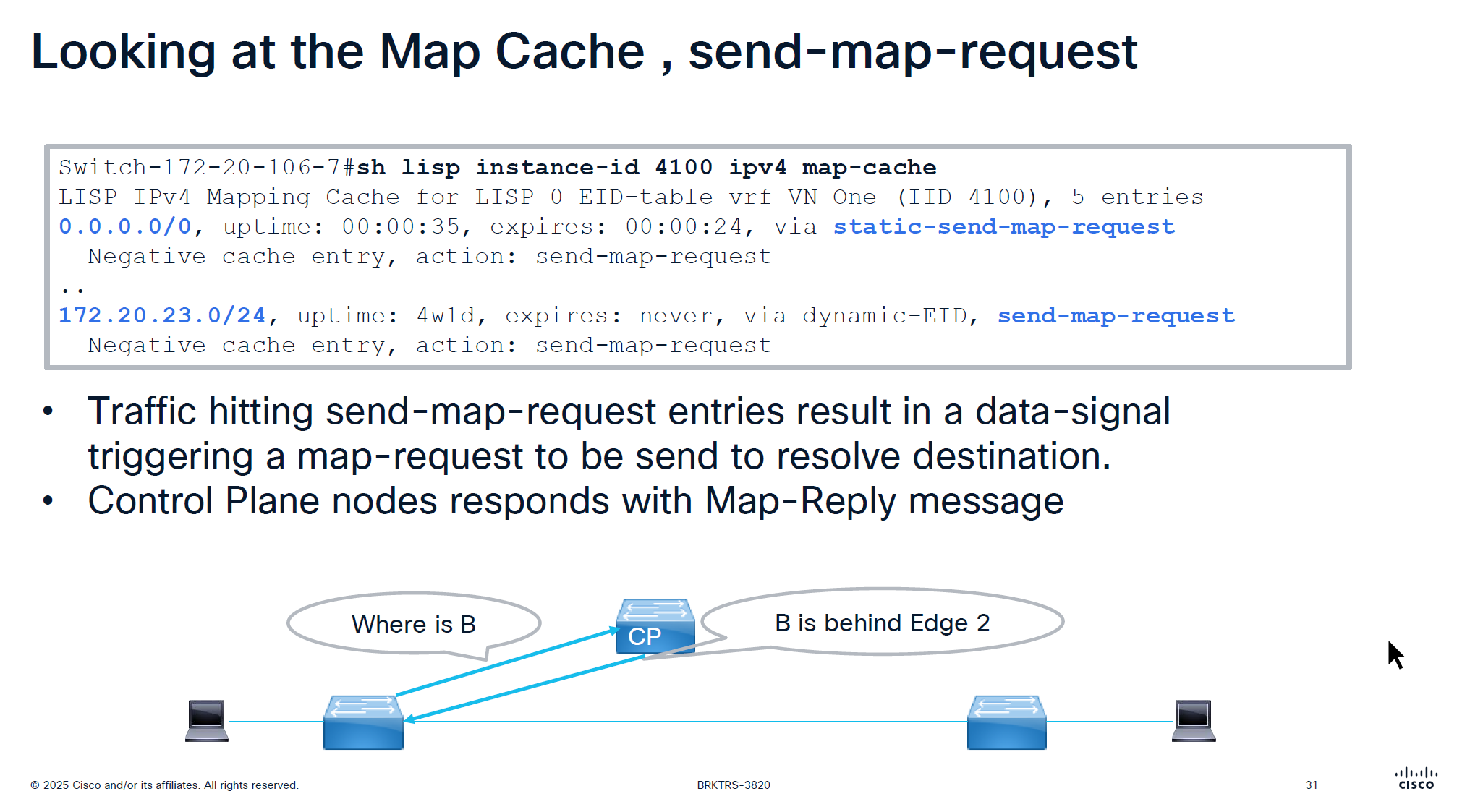
map request and map reply map request is not a request to map an entry or register but it is a query to get a reply from control plane node
Last point is saying that in traditional LISP, Map server only responds to the edge that registered the endpoint, but in SDA version of LISP, map server responds to query from anyone by setting the proxy flag on registration time
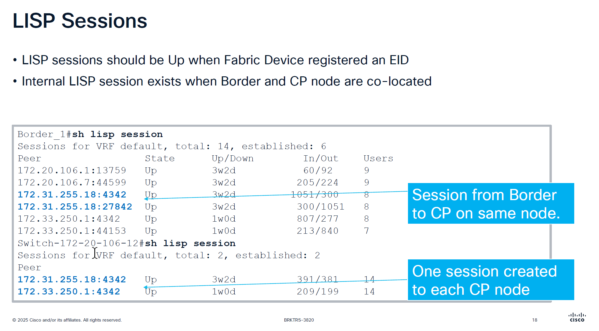
CP and border still make connections to one another if they are colocated on same box So in LISP sessions you will see it establishing LISP sessions from itself to itself
On the edge node you will see LISP sessions based on number of control plane nodes you have
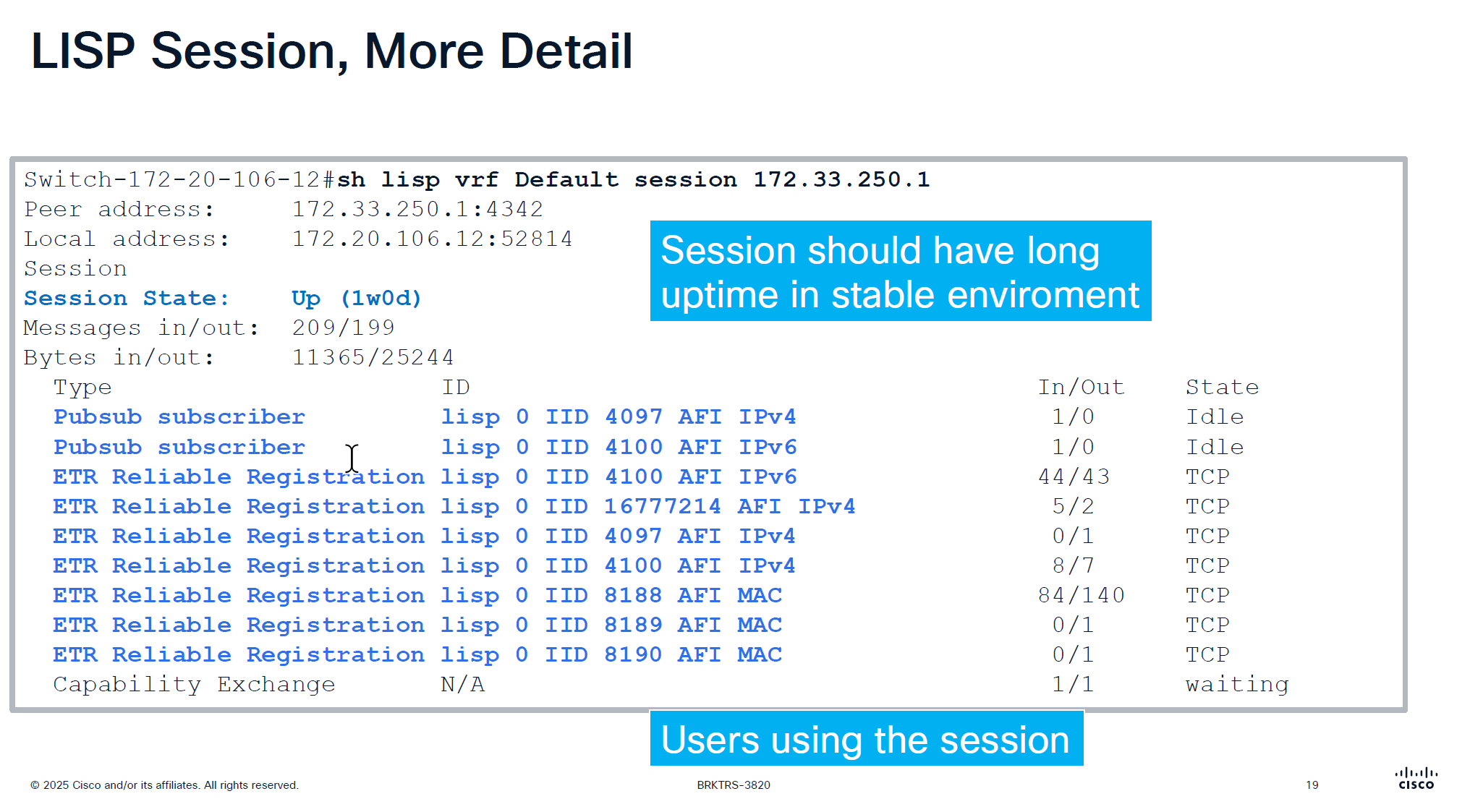
Users column is not actual user but how many instance IDs are using it
Checking detailed command shows us the LISP instances using the LISP session
make sure that your session up time is big and if it is small then it indicates some sort of network instability and network issues
This command actually shows us that there are LISP instances exchanging information with Control plane node and not just TCP session on port 4342 that is up
That message at the bottom that is “Capability Echange” means that there is a session trying to establish but there is something wrong like key exchange and state is also in “waiting”
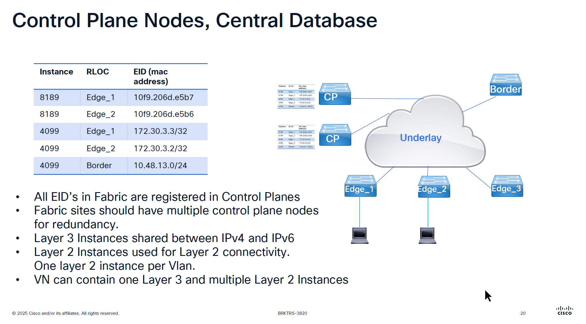
For IPv4 the instance ID start from 4097 and up for Ethernet instance ID it starts from 8189 and layer 2 instances are used for Layer 2 connectivity and it creates one layer 2 instances per vlan
One VN is one Layer 3 instance and multiple Layer 2 instances
If there are 2 devices in one IP pool across different edges then they will use Layer 2 instance if 2 devices are on different IP pool or 2 different subnets then they will speak using Layer 3 instance
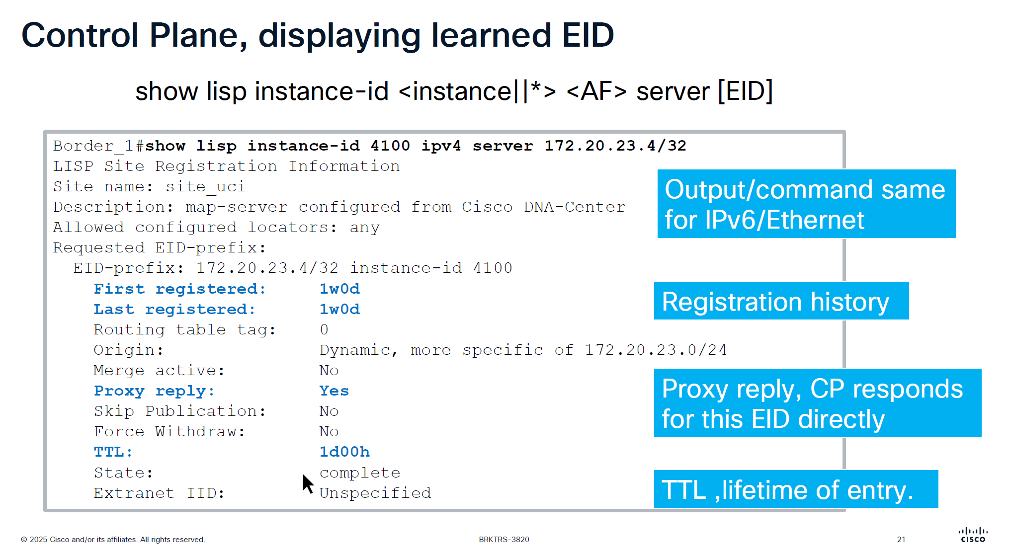
When you see “server” keyword that means we are asking control plane node
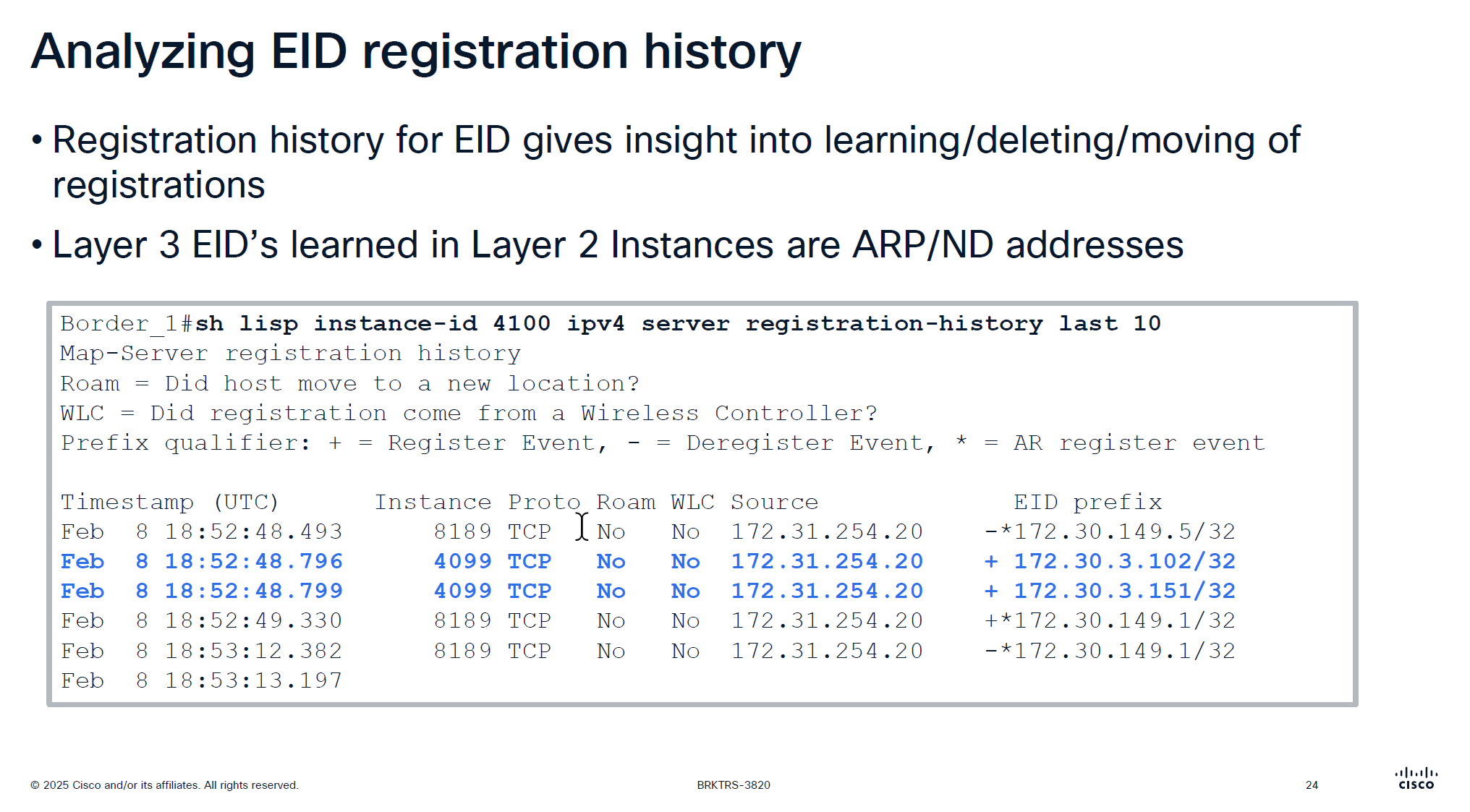
This is imporant command to troubleshoot endpoint and LISP registration, it shows when it first registered and when it last regsitered
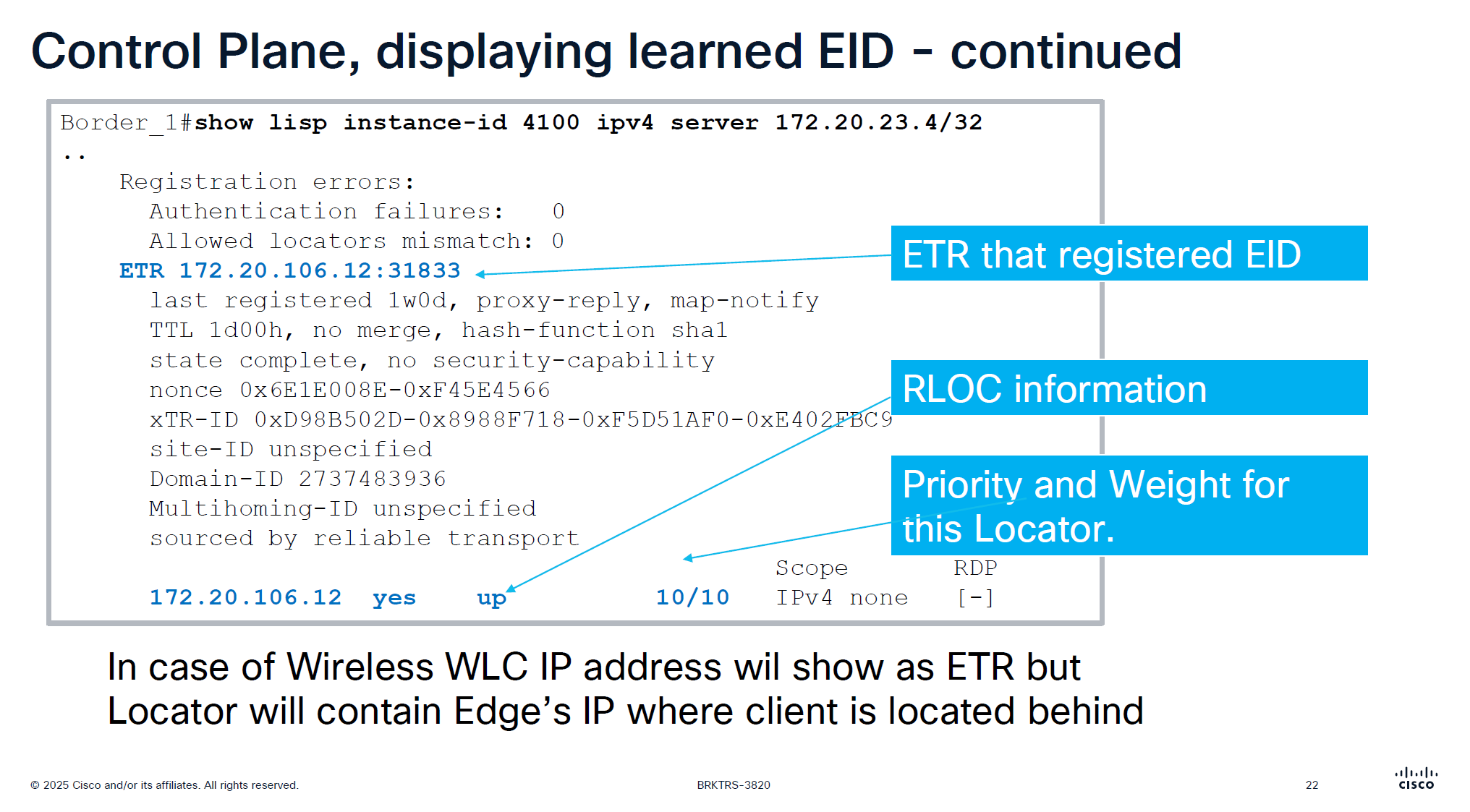
This is output from border node and it is showing ETR as edge node behind which this endpoint lives
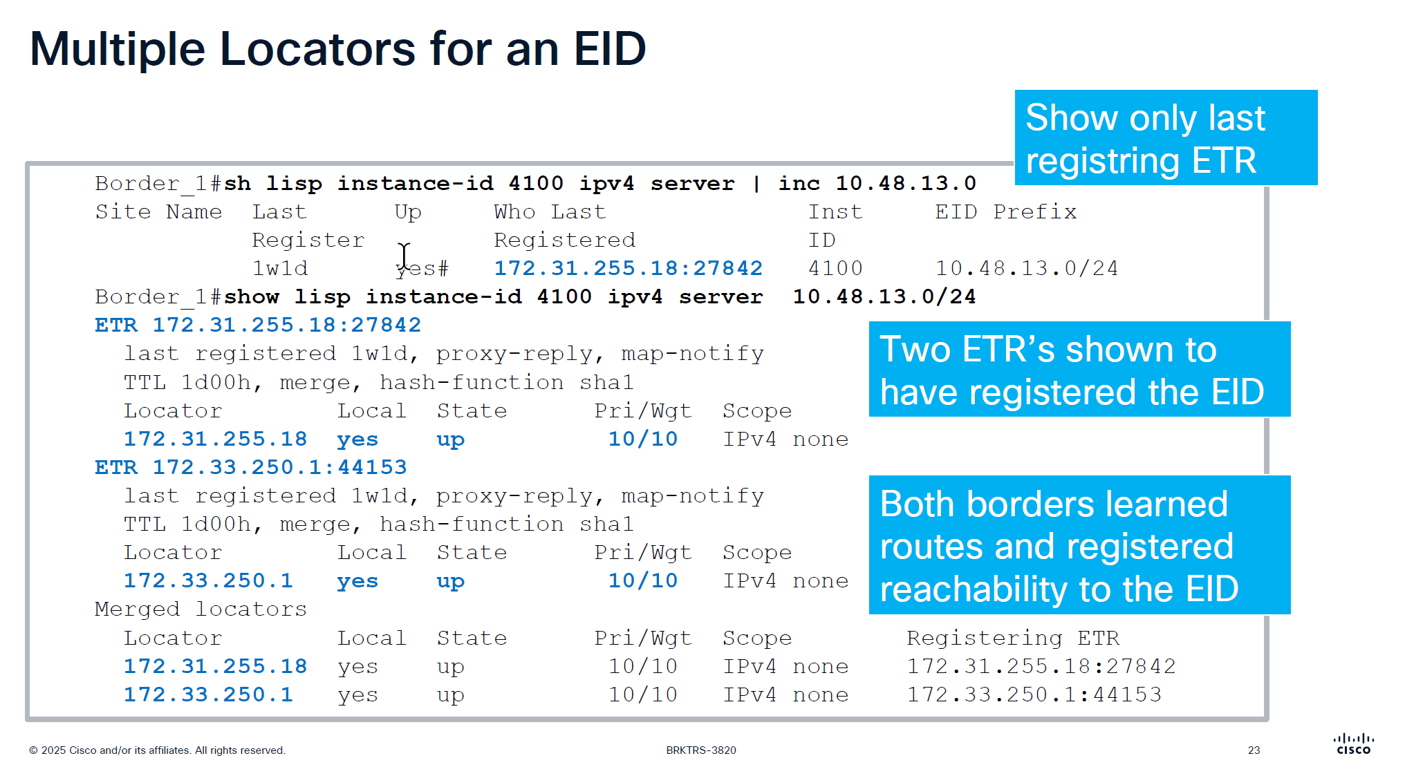
only server command will show us last registering ETR
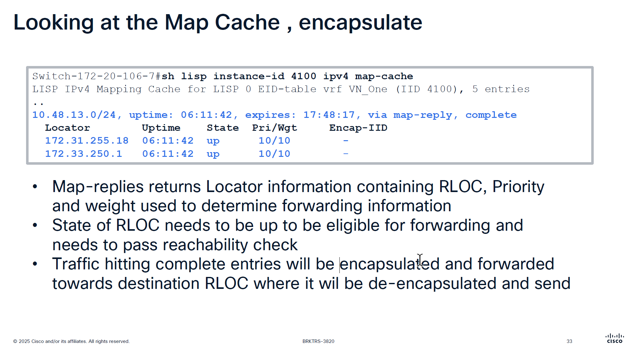
server command with prefix will show us the ETRs (borders) that are registering that prefix and notice that because of priority/weight of 10/10
LISP priority uses lowest priority number as preferred If RLOC1 has Priority 1 and RLOC2 has Priority 10, all traffic goes to RLOC1 (Active/Standby) if both RLOC have priority of 10, then it means both routes will be used in loadbalancing fashion then weights are considered, how much traffic will be sent if priorities are same
If both RLOCs have the same priority (e.g., 10), they are considered equal, and traffic is distributed based on weight.
Weight is used for traffic engineering when multiple paths have the same priority. It specifies the percentage of traffic a particular RLOC should receive relative to other RLOCs in the same priority group.
If weight is set to 0 on an RLOC then no traffic is load balanced to it, unless it is the last one left
Very important command for troubleshooting for a client, may be it got disconnected or roamed or what not
Notice that first entry that is L3 /32 address being registered inside Layer 2 instance that is ARP regsitration and not the real registration that is also regsitered inside Layer 2 instances
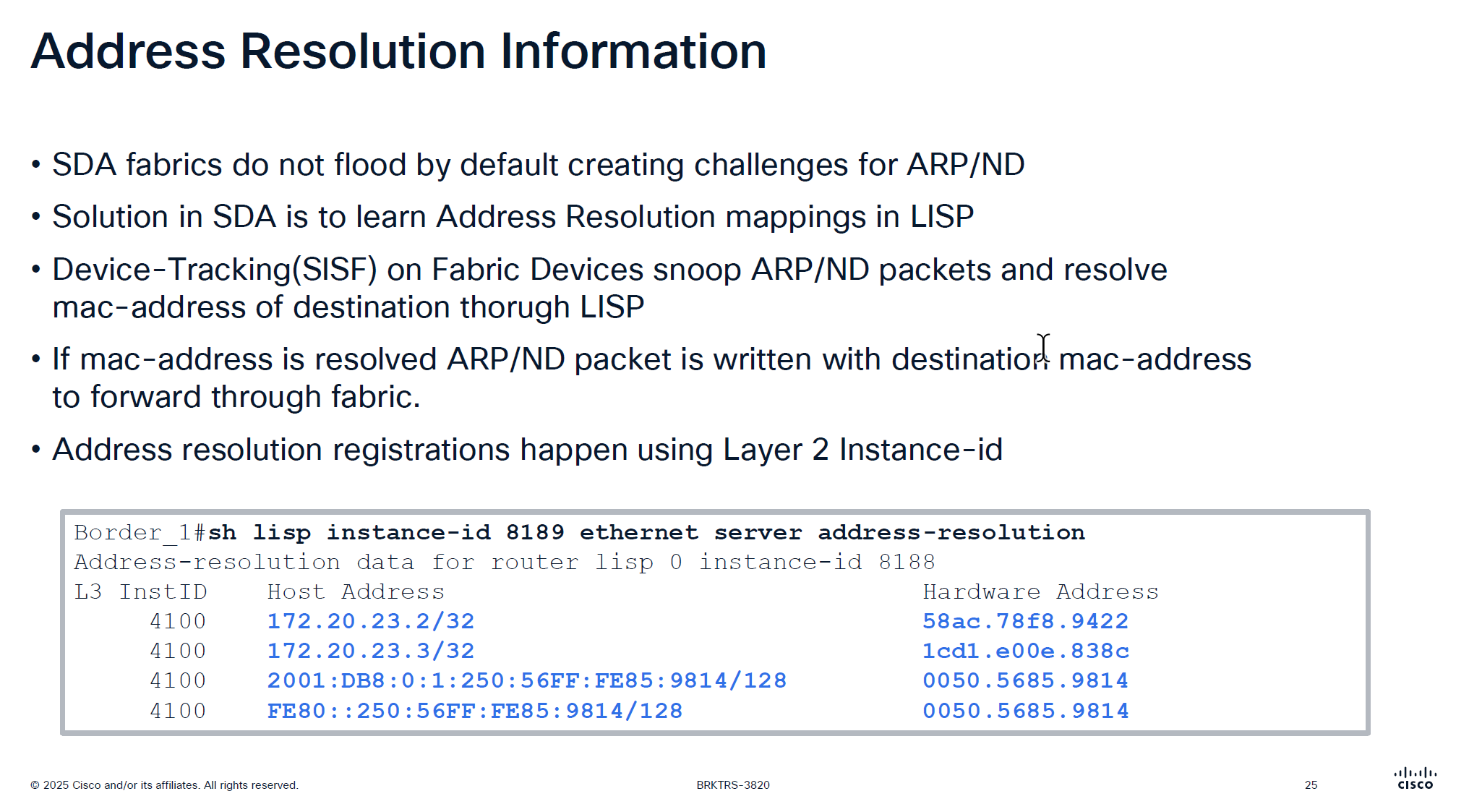
Above command is “server address-resolution” on “Layer 2 instance” on “control node”
Due to VXLAN we can only unicast the packets and broadcasting is not supported unless flooding is enabled on the VLAN but for ARP to specifically work there is a special support in order to get the ARP working, switches snoop the ARP packets for destination inside the ARP message but dont actually flood them yet
LISP then asks for control pane for that destination IP from ARP and control responds with layer 2 mac address corresponding to that L3 address (from device tracking)
then LISP simply rewrites or replaces the broadcast address with the MAC address it received from control plane
this ARP packet is now able to be sent over the unicast over the VXLAN tunnel using Layer 2 instance
This is why silent devices are hard to troubleshoot and do not work over the fabric, this is because they do not produce any traffic and simply want to receive traffic, this makes it hard for device tracking and in turn fabric to not work for those devices
edges nodes have multiple probes going on to speak to those silent devices but there are some devices which are ultra silent and dont even respond to those probes
This command helps in troubleshooting those scenarios because if ARP is not working over fabric then communication will not work
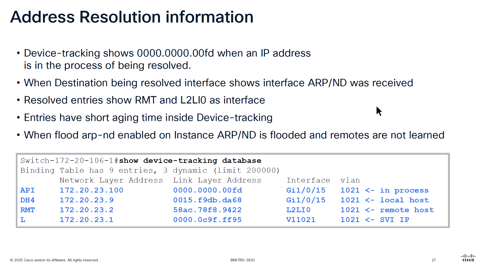
This someone pinging 172.20.23.100 and it arrived on Gi1/0/15
If you see entry for API with mac 0000.0000.00fd in command “show device-tracking database” then it means that ARP packet arrived on the edge node but did not have response from Control node over LISP yet and waiting to be resolved to convert ARP broadcast into unicast
After this resolution completes entry becomes “RMT” (which I guess means remote) with L2LI0 as interface
Because device tracking timers age quickly, this process of ARP resolution might be happening again
Important to note that unicast ARP is received on the remote device and sometimes some IoT devices in testing showed that does not like unicast ARP and only respond to broadcast ARP so in that case we will have to enable the Flooding over the VLAN
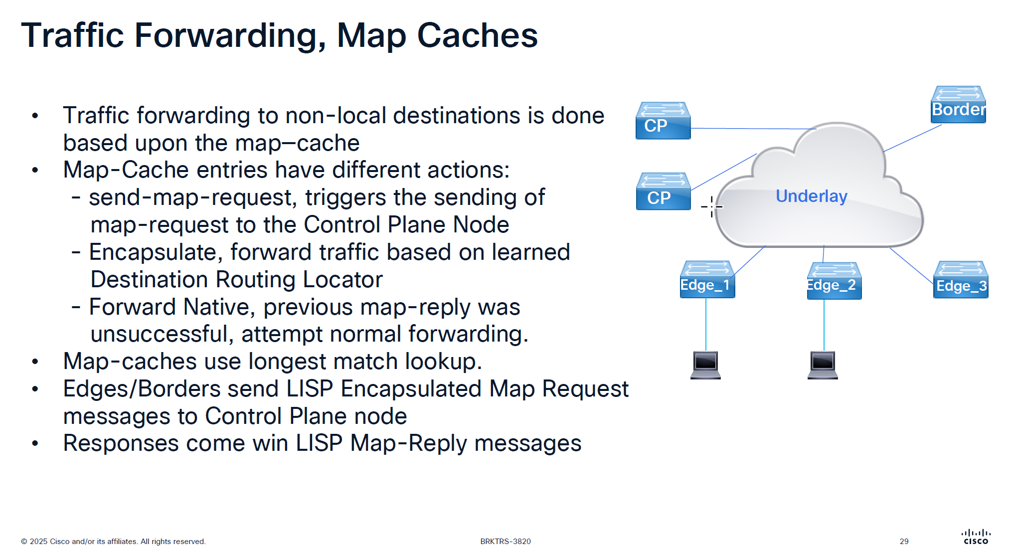
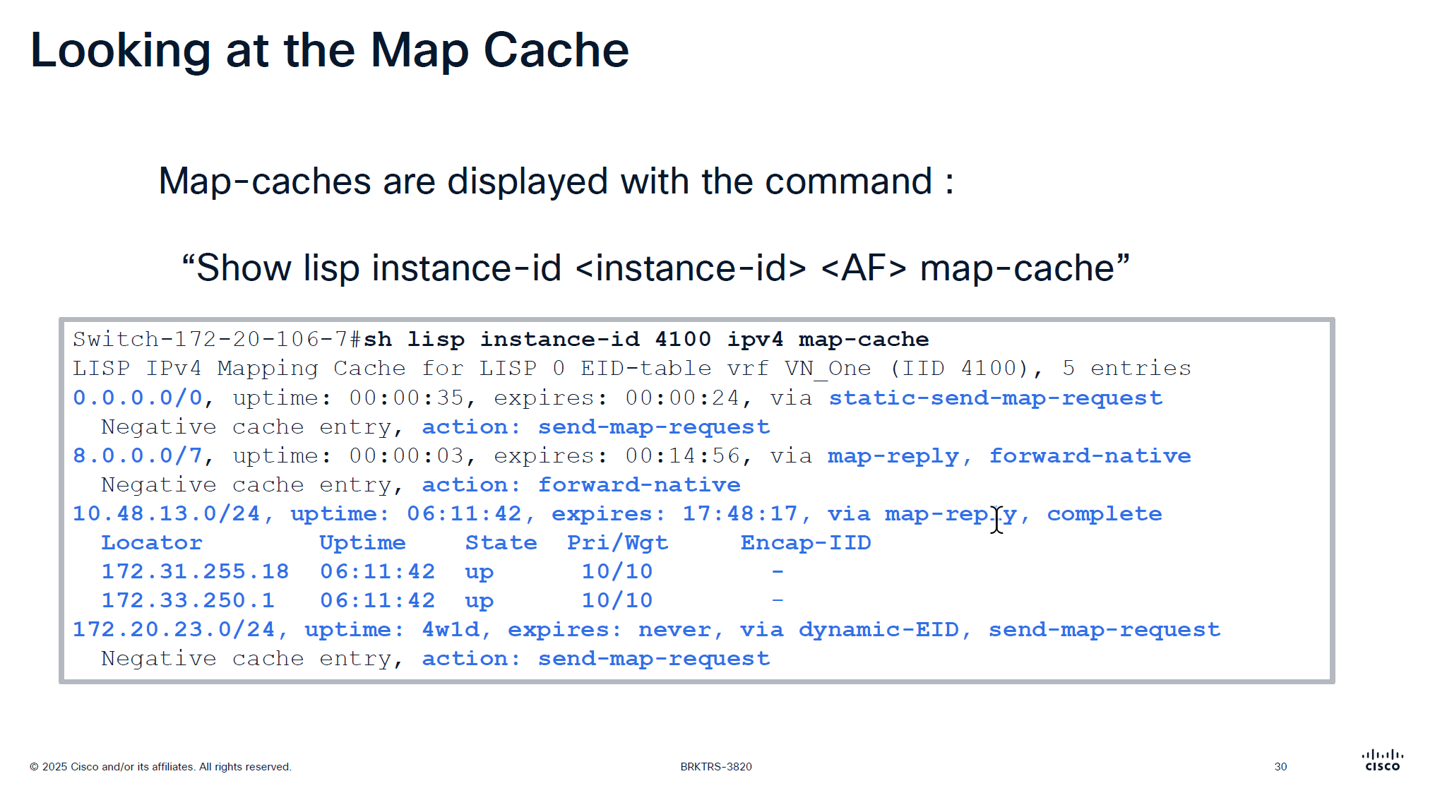
It is no good to speak to control plane about every packet we get That is why edge node has map-cache to cache the RLOC received for an endpoint for 24 hours
See action The reason it is 0.0.0.0/0 has action send-map-request because even if we have default border or even dynamic default border we need to still ask control plane node as there might be a better path for destination
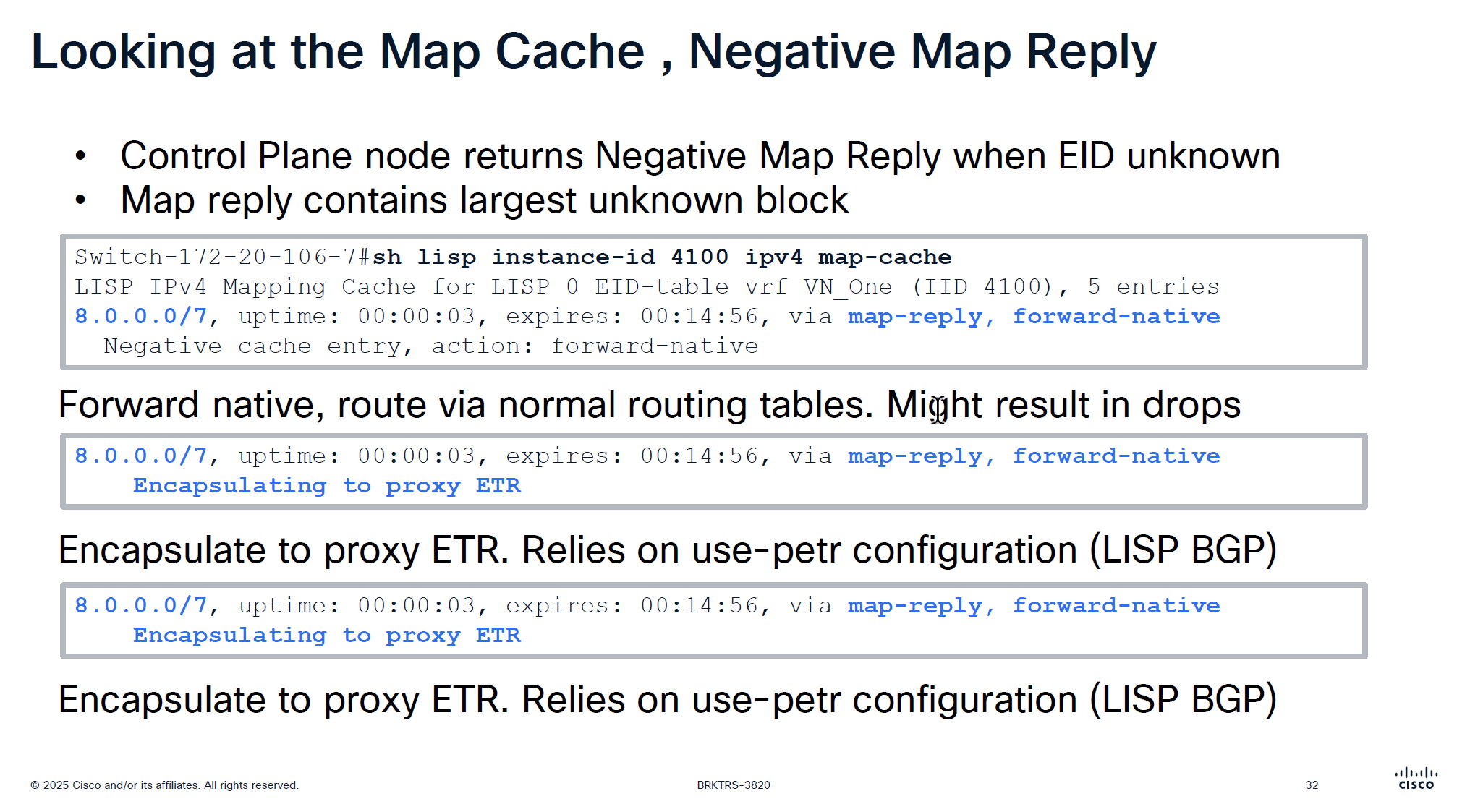
On each edge node in order to reduce queries to control plane node a few “negative” map-cache entries are added in advance with forward native action, forward native on border means to use routing table and not LISP which can have ISIS , OSPF , BGP or static entry for any routes falling under this range but for edge nodes forward-native means connection will be dropped as there is no other means other than LISP
This is done in weird blocks of 0.0.0.0/5 and 8.0.0.0/7 to tell that I dont have routes for those but I have default route 0.0.0.0 and other prefixes we learned from outside fusion world
This is only there for “expires” time which is 15 minutes, the whole function of map-cache is to not consult control node, so this entry means that for those unknonwn destinations do not ask or reach control plane but as this entry expires, edge can reach out to the control plane node instead try to use the routing table (action: forward-native)
0.0.0.0/0, uptime: 1y29w, expires: never, via static-send-map-request
Encapsulating to proxy ETR
0.0.0.0/5, uptime: 00:00:34, expires: 00:14:25, via map-reply, forward-native
Encapsulating to proxy ETR
! 0.0.0.1 - 7.255.255.2558.0.0.0/7, uptime: 38w5d, expires: 00:04:38, via map-reply, forward-native
Encapsulating to proxy ETR
! 8.0.0.1 - 9.255.255.254
10.16.101.0/24, uptime: 1y29w, expires: never, via dynamic-EID, send-map-request
Encapsulating to proxy ETR
10.64.0.0/11, uptime: 38w5d, expires: 00:05:08, via map-reply, forward-native
Encapsulating to proxy ETR
10.116.2.0/24, uptime: 1y29w, expires: never, via dynamic-EID, send-map-request
Encapsulating to proxy ETR
10.116.3.0/24, uptime: 1y29w, expires: never, via dynamic-EID, send-map-request
Encapsulating to proxy ETR
10.116.4.0/24, uptime: 1y29w, expires: never, via dynamic-EID, send-map-request
Encapsulating to proxy ETR
Above slide is little bit wrong
For LISP Pub Sub deployment we see “Negative cache entry, action: forward-native” but for LISP BGP deloyment we see “Encapsulating to proxy ETR” but see below
8.0.0.0/7, uptime: 38w5d, expires: 00:13:47, via map-reply, forward-native
  Sources: map-reply
  State: forward-native, last modified: 38w5d, map-source: 172.20.239.124
  Active, Packets out: 1535384(884381184 bytes), counters are not accurate (~ 00:00:35 ago)
  Encapsulating to proxy ETR
it will use the normal routing table (no VXLAN/LISP encapsulation) because the entry is forward-native, even though a proxy ETR (172.20.239.124) is listed
This line can appear in map-cache entries when:
the prefix is learned via map-reply
a proxy ETR exists – A Proxy ETR (PETR) in Cisco LISP / SD-Access is typically the Default Border Node, not the Internal Border Node
A Proxy ETR is used when a fabric device needs to send traffic to destinations outside the LISP mapping system (for example: internet prefixes like 8.0.0.0/7).
Instead of dropping the packet (because no mapping exists), the fabric edge or border node:
➡ encapsulates the packet ➡ sends it to the PETR ➡ PETR forwards it toward external networks using normal routing
So PETR acts like an exit gateway for unknown/non-fabric destinations.
the state field of forward-native overrides it and tells to use RIB/FB
Cisco explains proxy-ETR usage like this:
When a destination EID is not reachable via the mapping system, a proxy ETR can be used for encapsulation, But only when the map-cache entry is in encapsulating state.
State
Meaning
forward-native
use RIB/FIB
encapsulating or complete
send to ETR
negative
drop
incomplete
awaiting mapping
Because this is a subnet 10.48.13.0/24 behind a border, we see 2 borders
Whenever we see Pri/Wgt of 10 and 10 on both borders then it means we are load balancing at VXLAN level, like half flows are sent to one border and half flows are sent to another border and it is not gauranteed that VXLAN UDP packets to 172.31.255.18 are taking a single path through network always and not getting load balanced, even these VXLAN tunnel packets are also load balanced
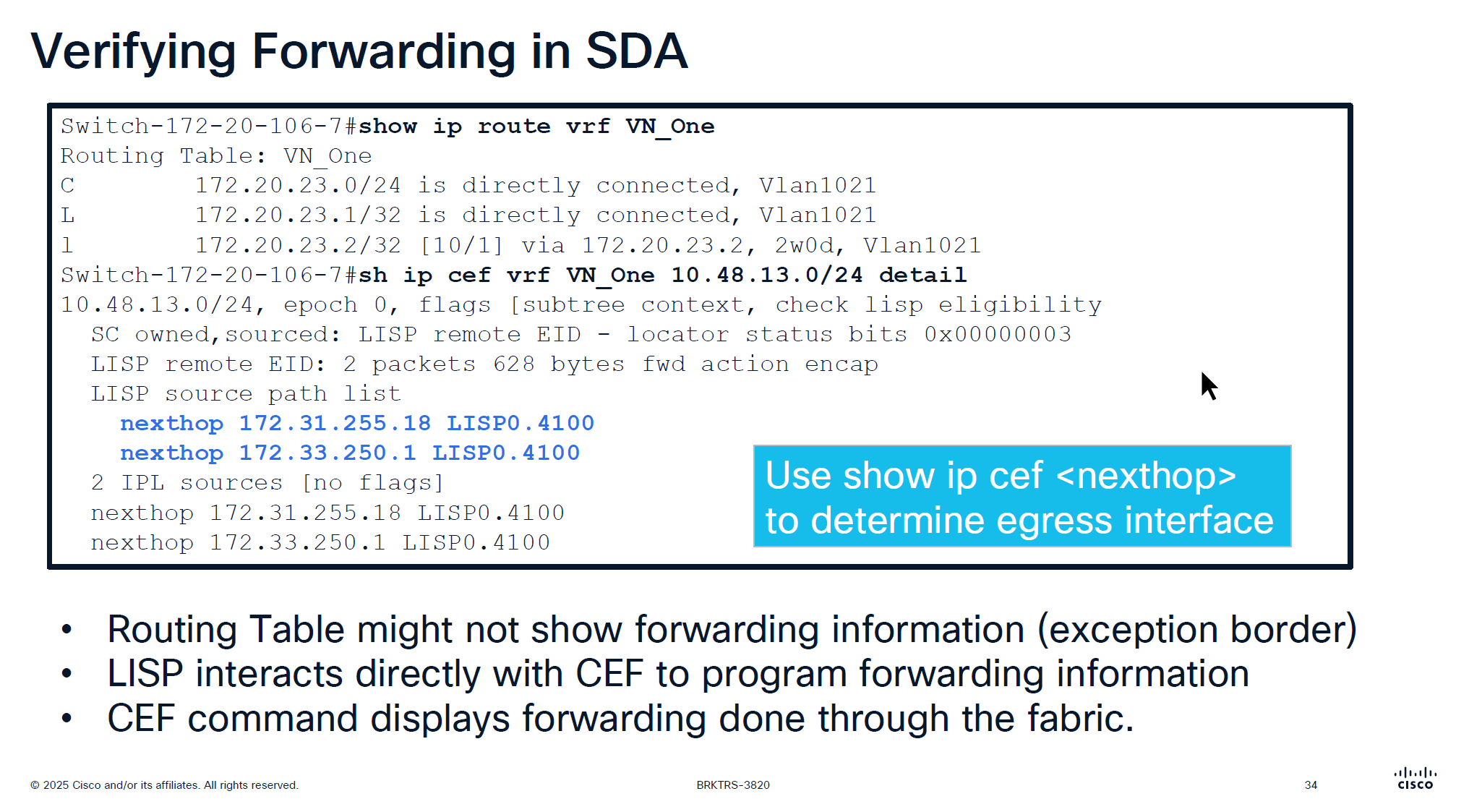
showing ip route in vrf will not show much except on border nodes but on the edge device there is no default route and no other routing present other than LISP VXLAN and fabric stuff But if we check CEF there is more info because LISP -> CEF directly talks to CEF
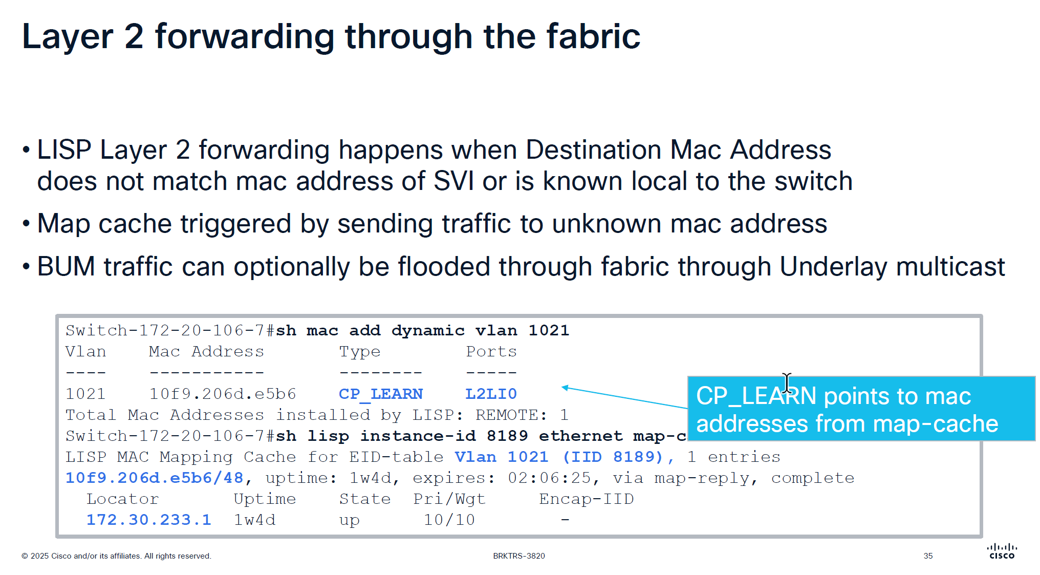
Layer 2 forwarding ia s bit different in fabric Entry for dynamic MAC learning on edge shows CP_LEARN via L2LI0 tells that this MAC belongs to this vlan on a different edge node
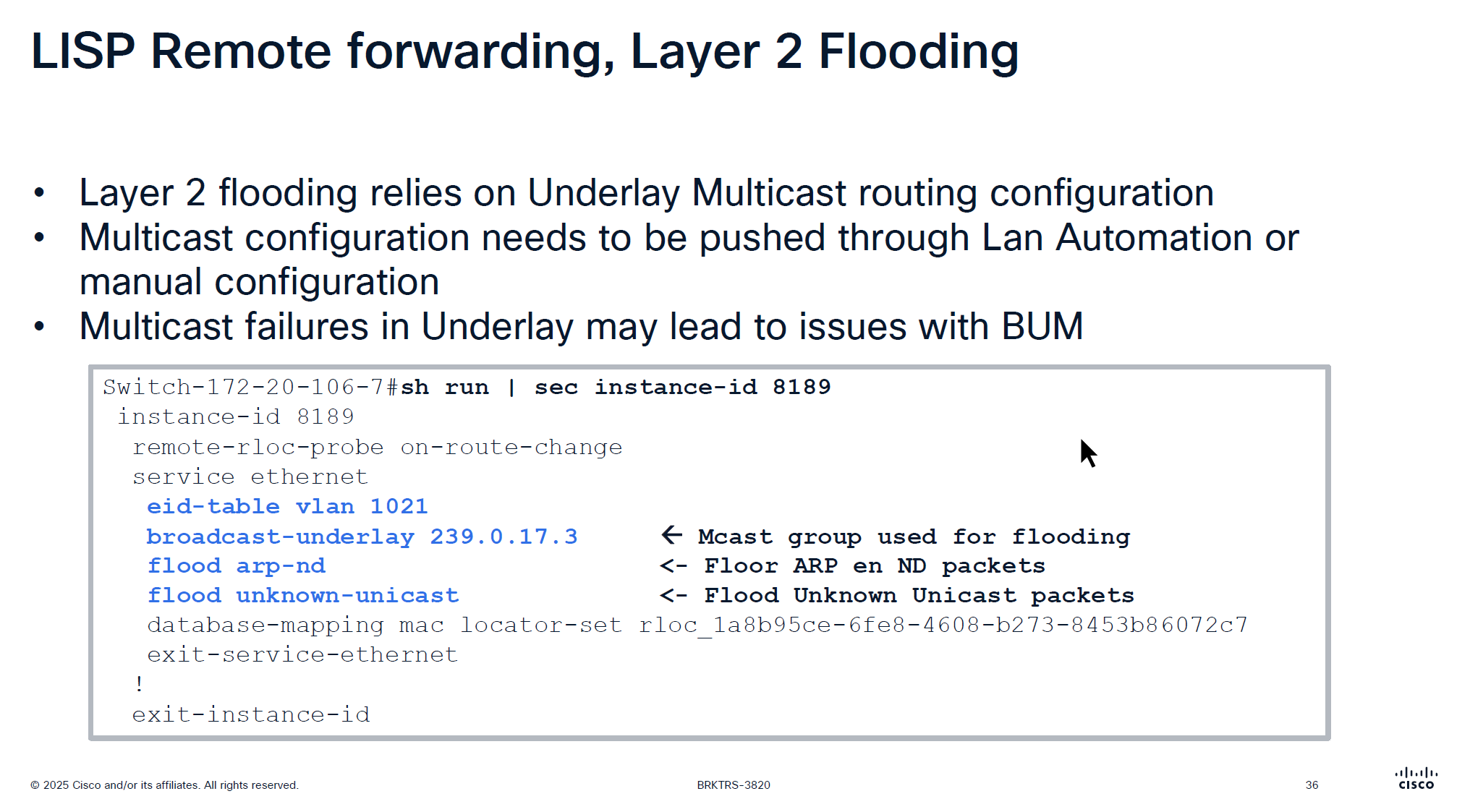
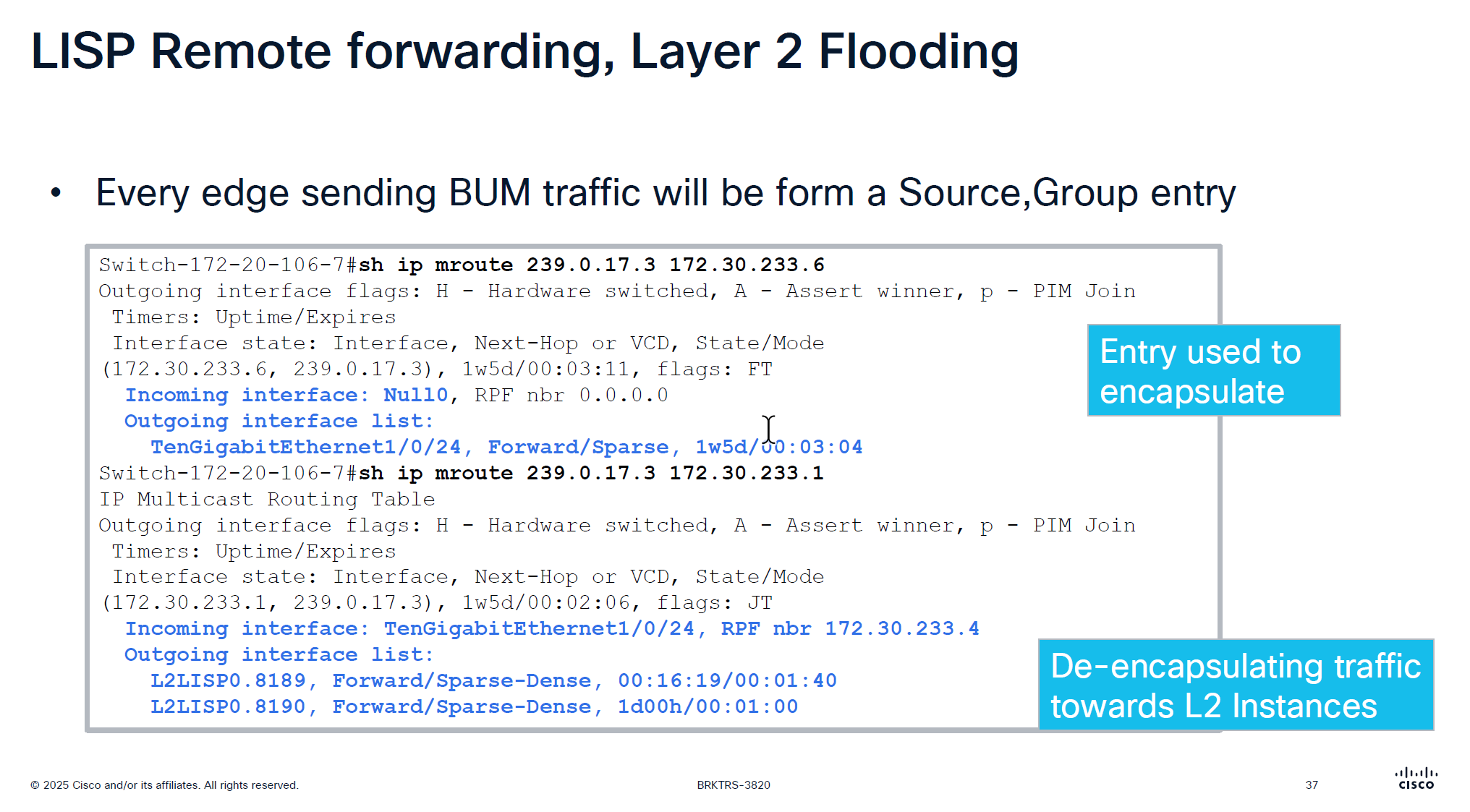
For layer 2 flooding to work on a vlan, the underlay multcasting needs to work If LAN automation is used, it sets up the underlay multicast Every edge device shows up as source for a multicast group
We can see the 2 instances that are receiving the multicast traffic (flooded traffic)
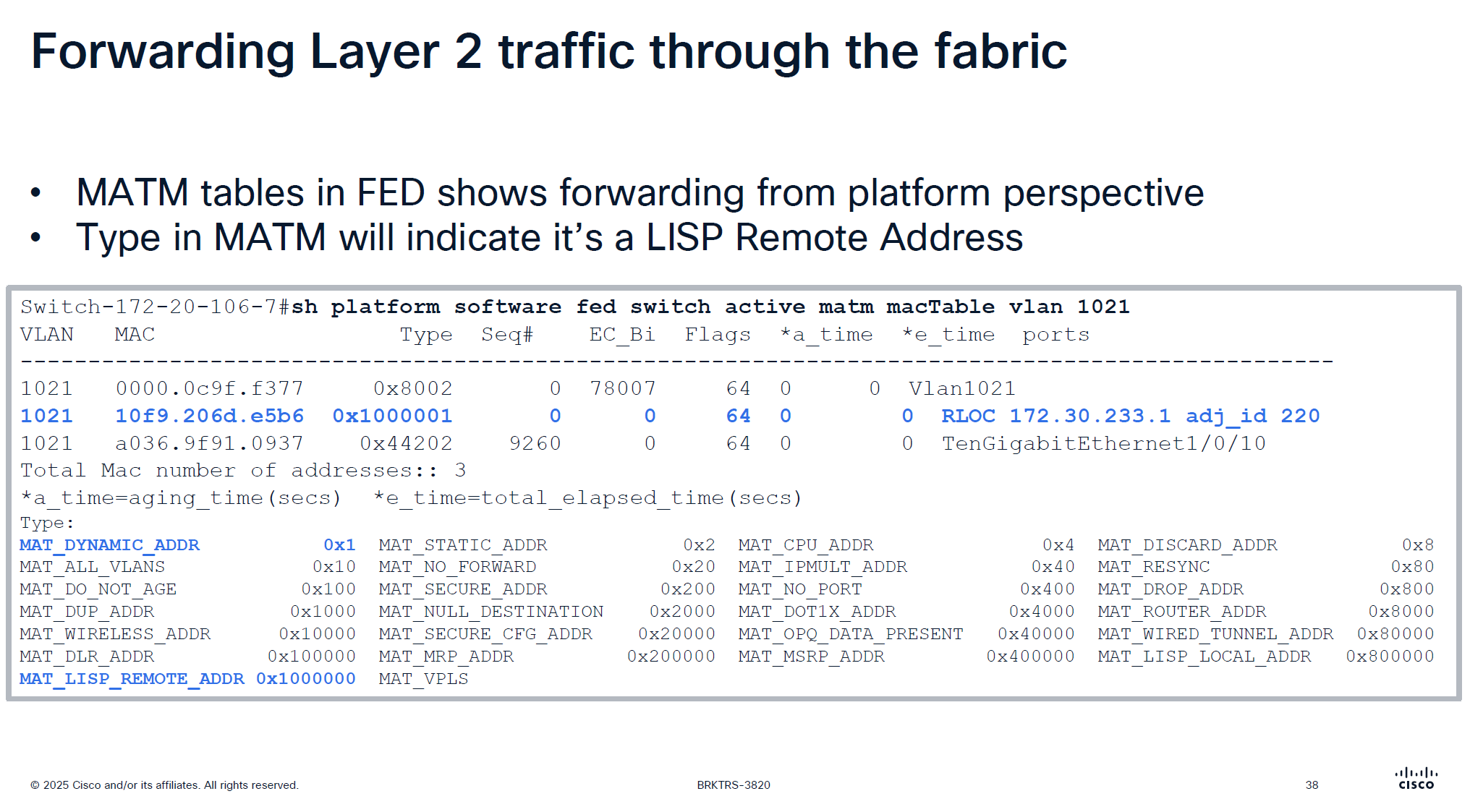
This is to verify if LISP is programming stuff correctly in hardware and this is where MATM comes in MATM is CEF equivalent in layer 2
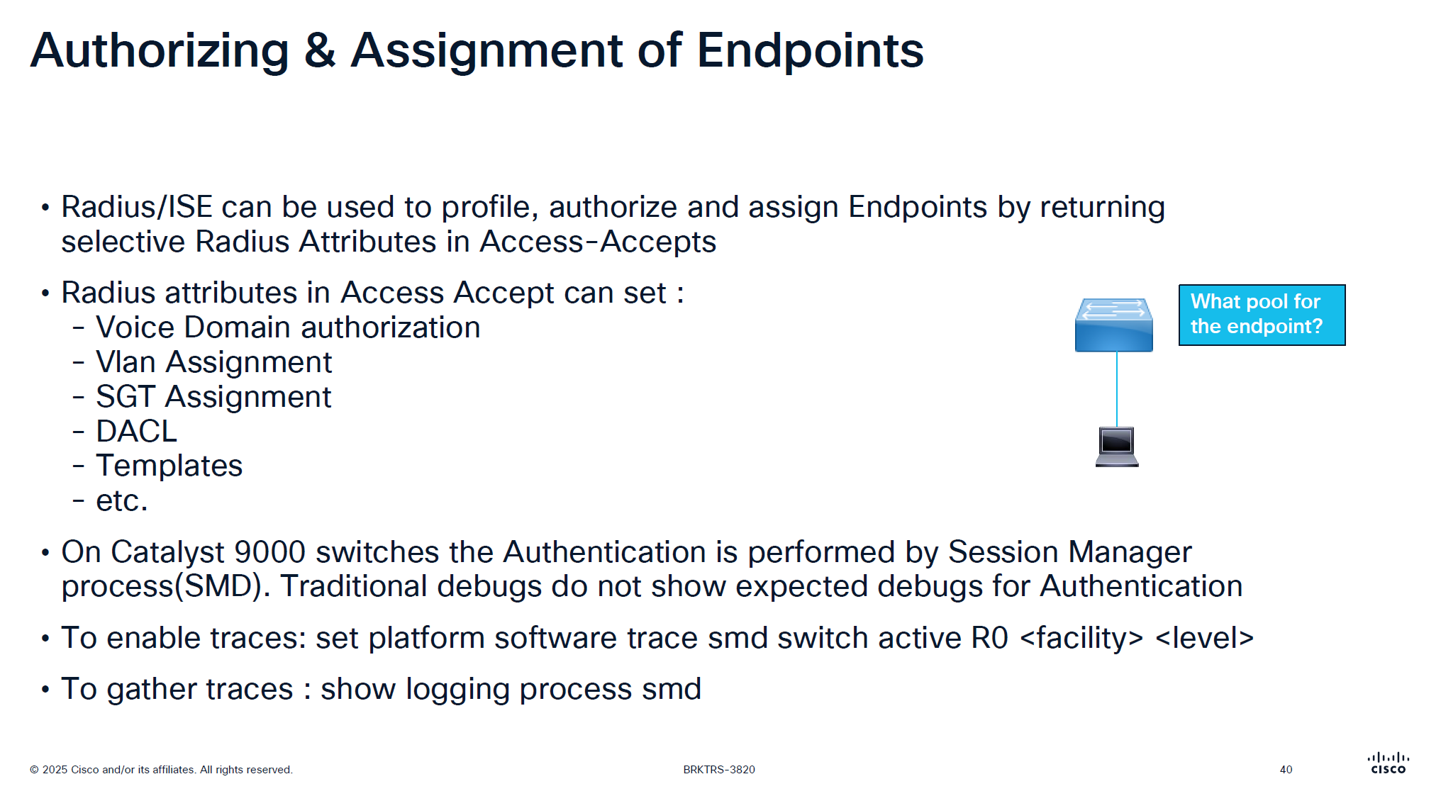
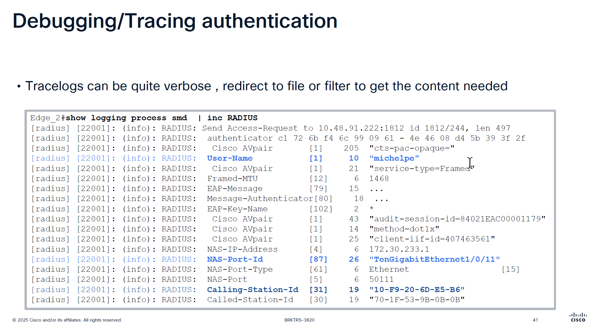
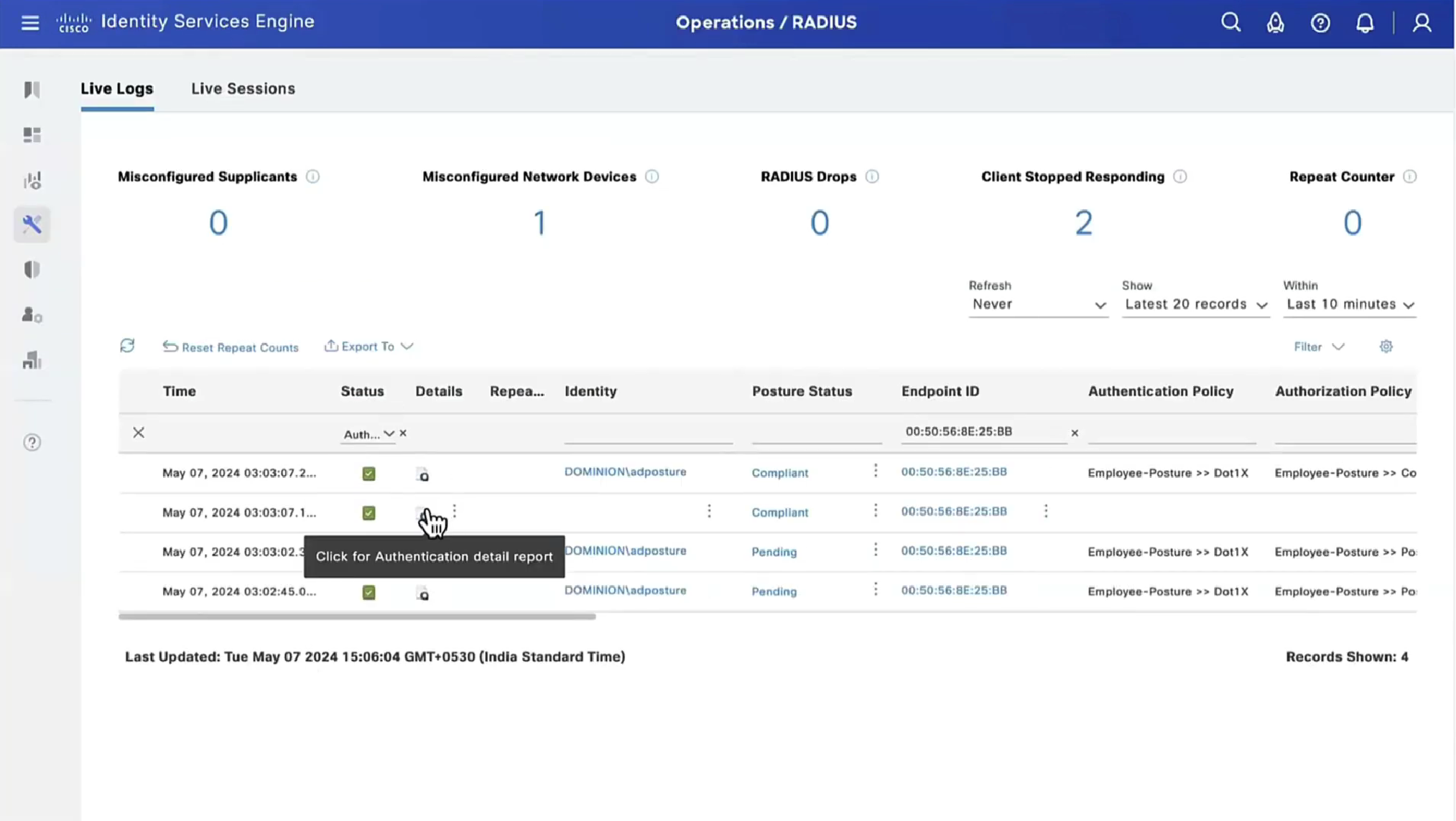
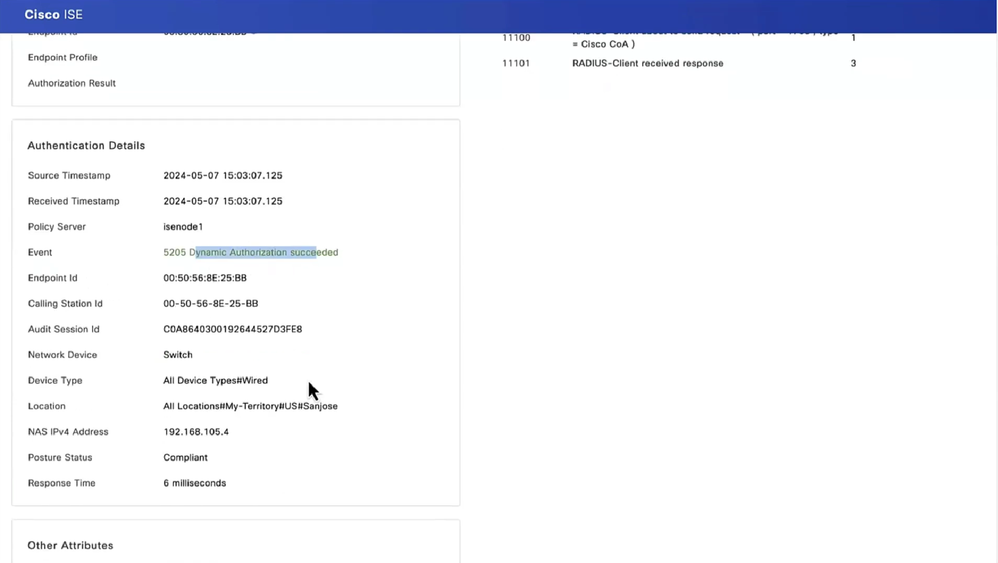
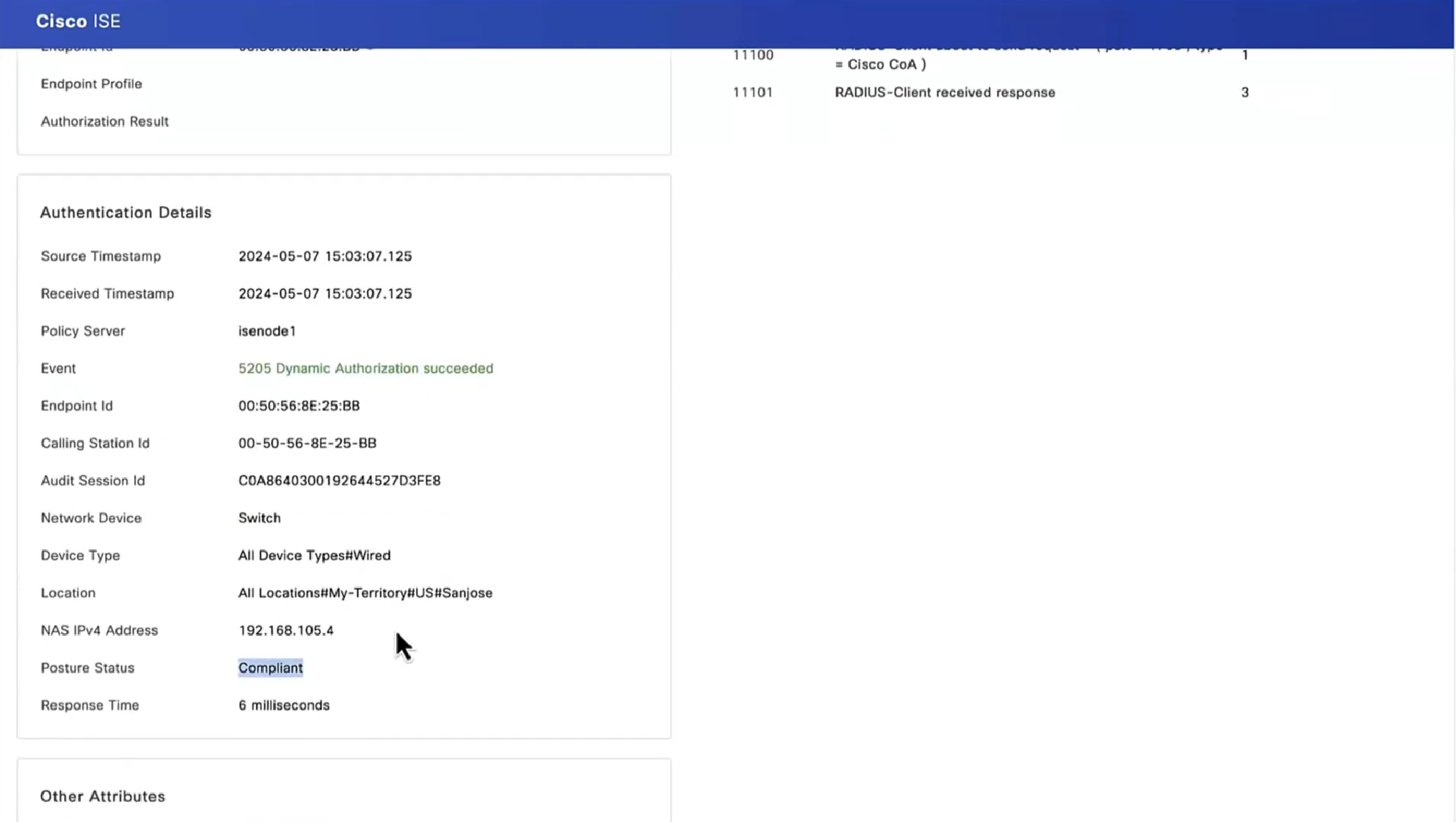
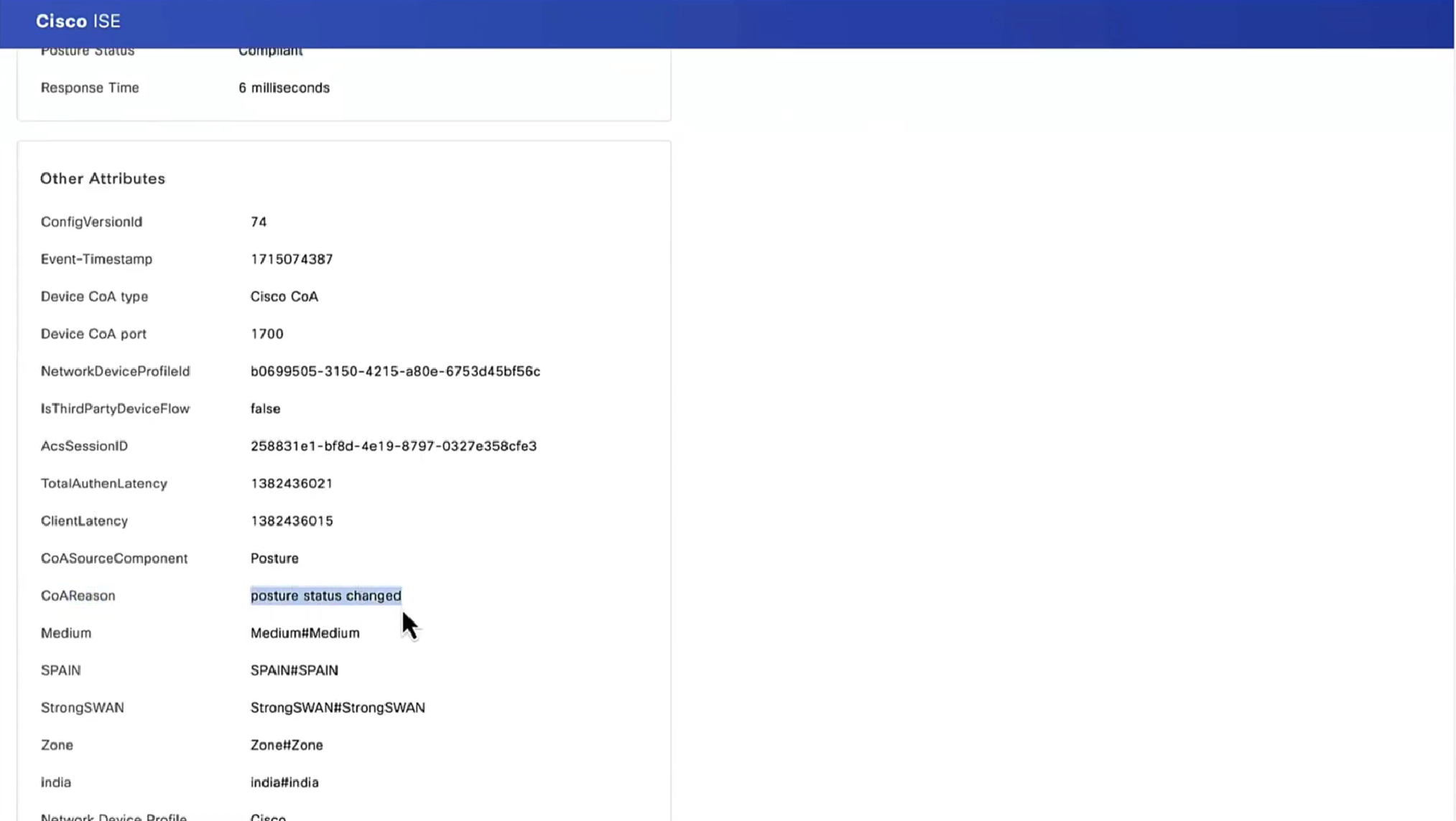
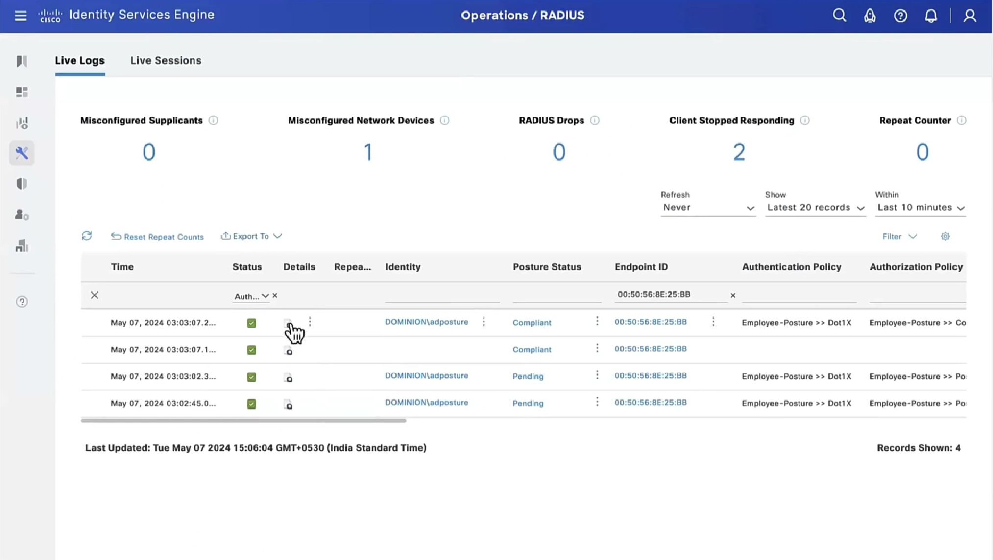
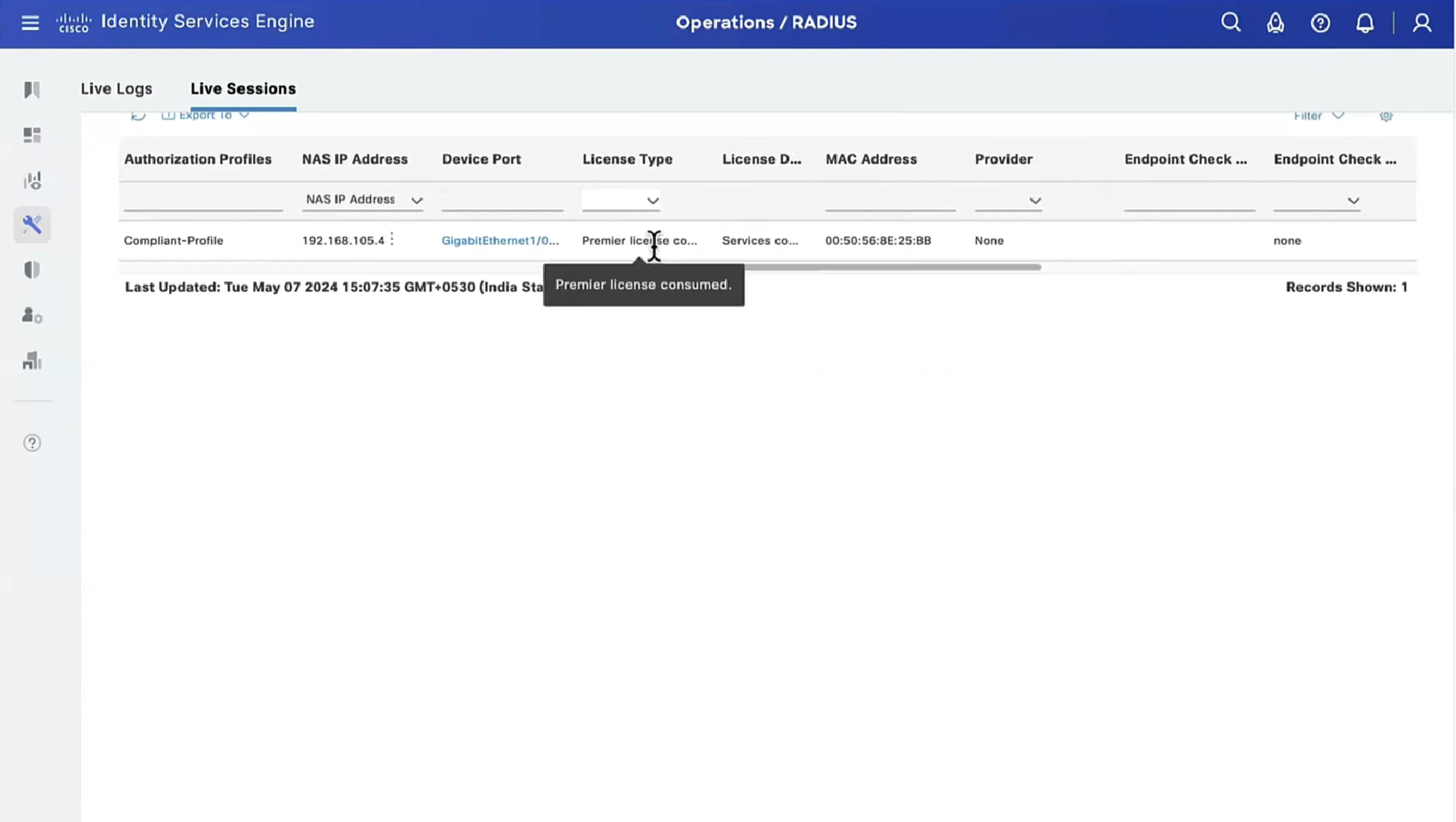
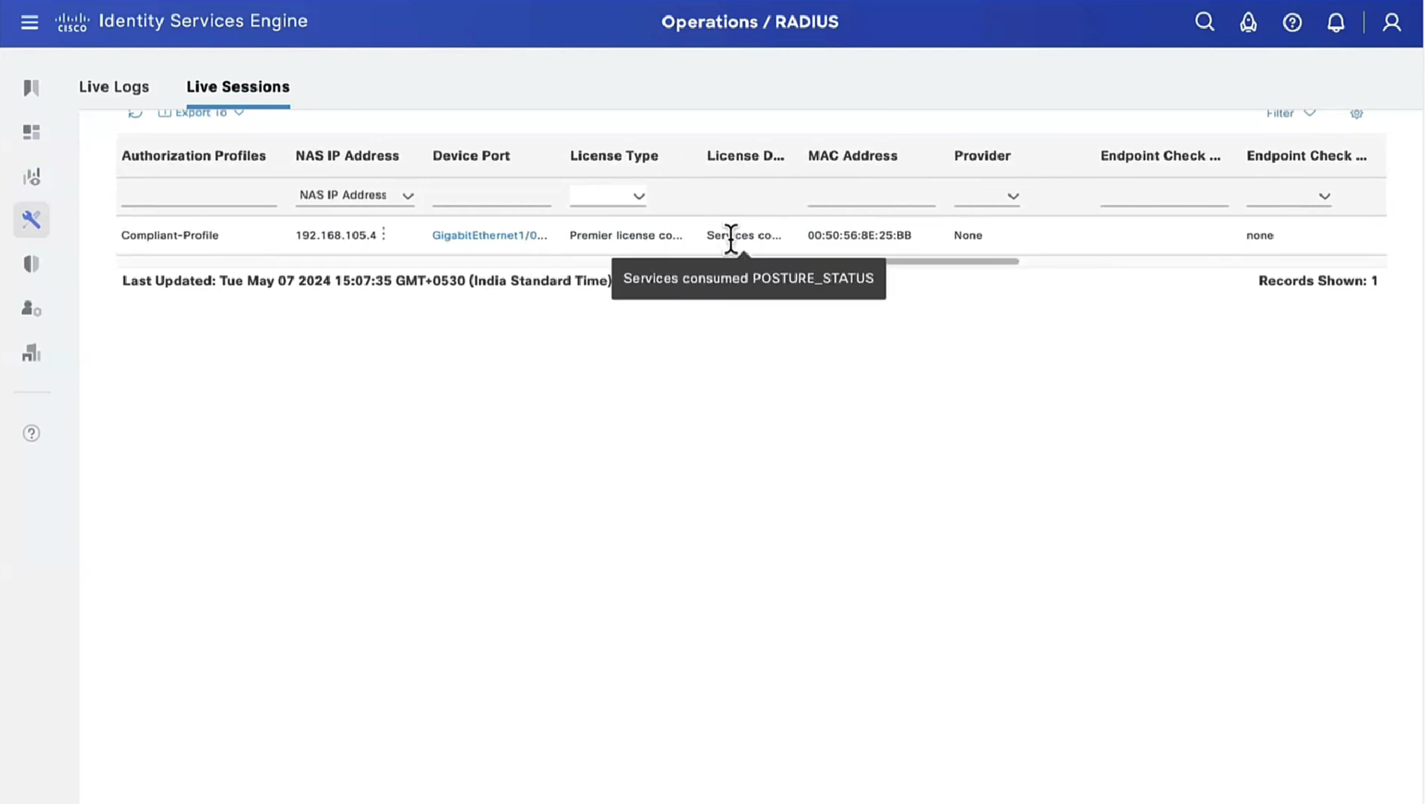
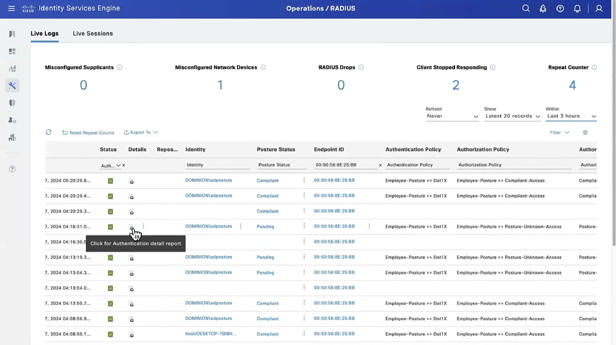
traditionally we could debug dot1x, debug authentication and debug radius etc but now we cannot do that, SMD sits as a seperate process outside of the iosd so we need to follow show logging <process> <name> format
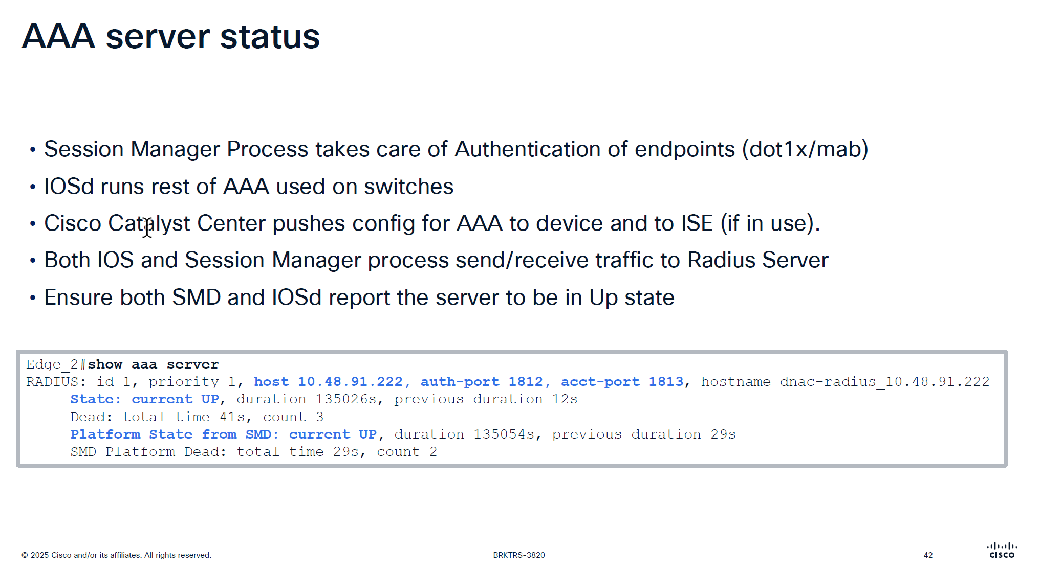
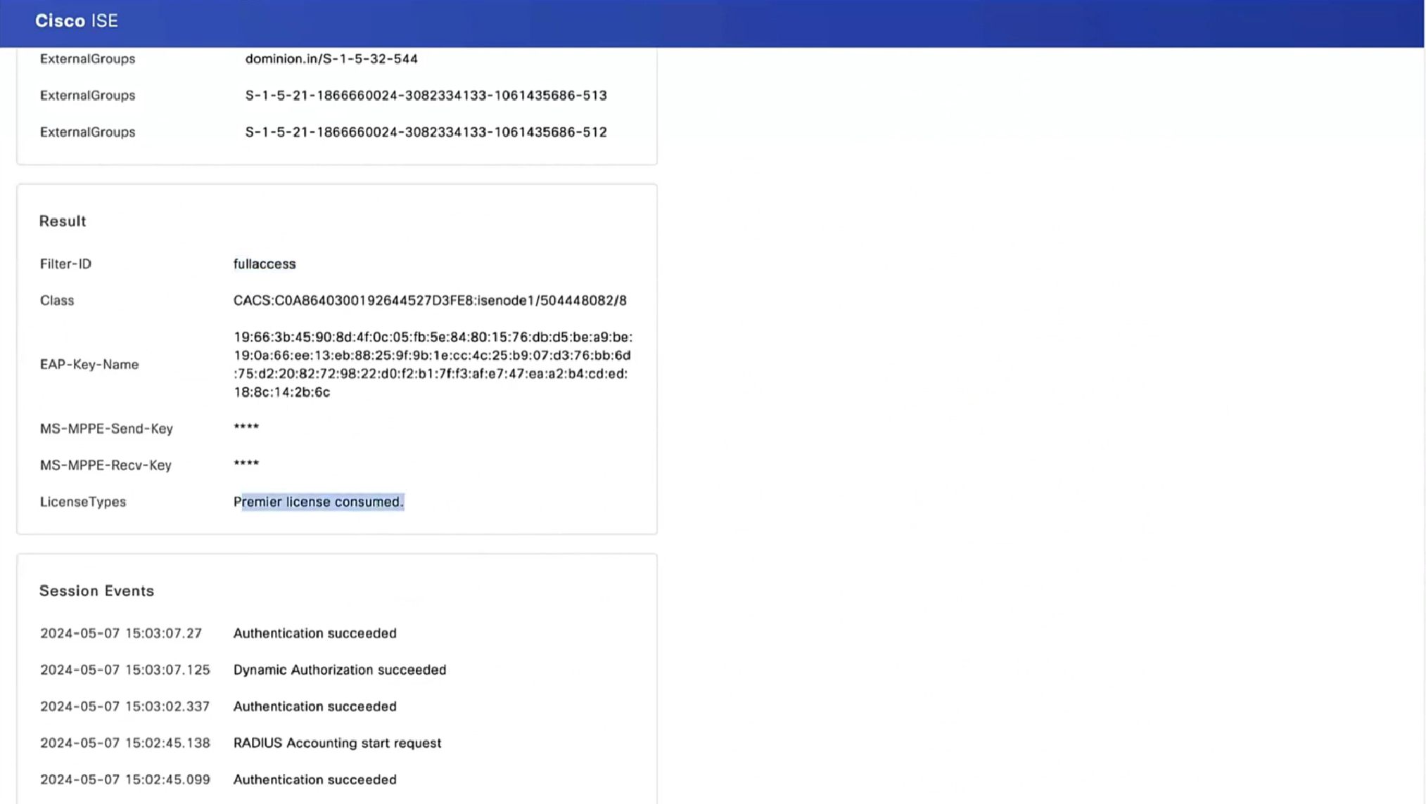
It is very important that RADIUS is up from SMD state as well in some cases IOS thinks RADIUS server is up, but if it is down for SMD then it will not communicate with RADIUS server and it is waiting on keepalive timer to try again
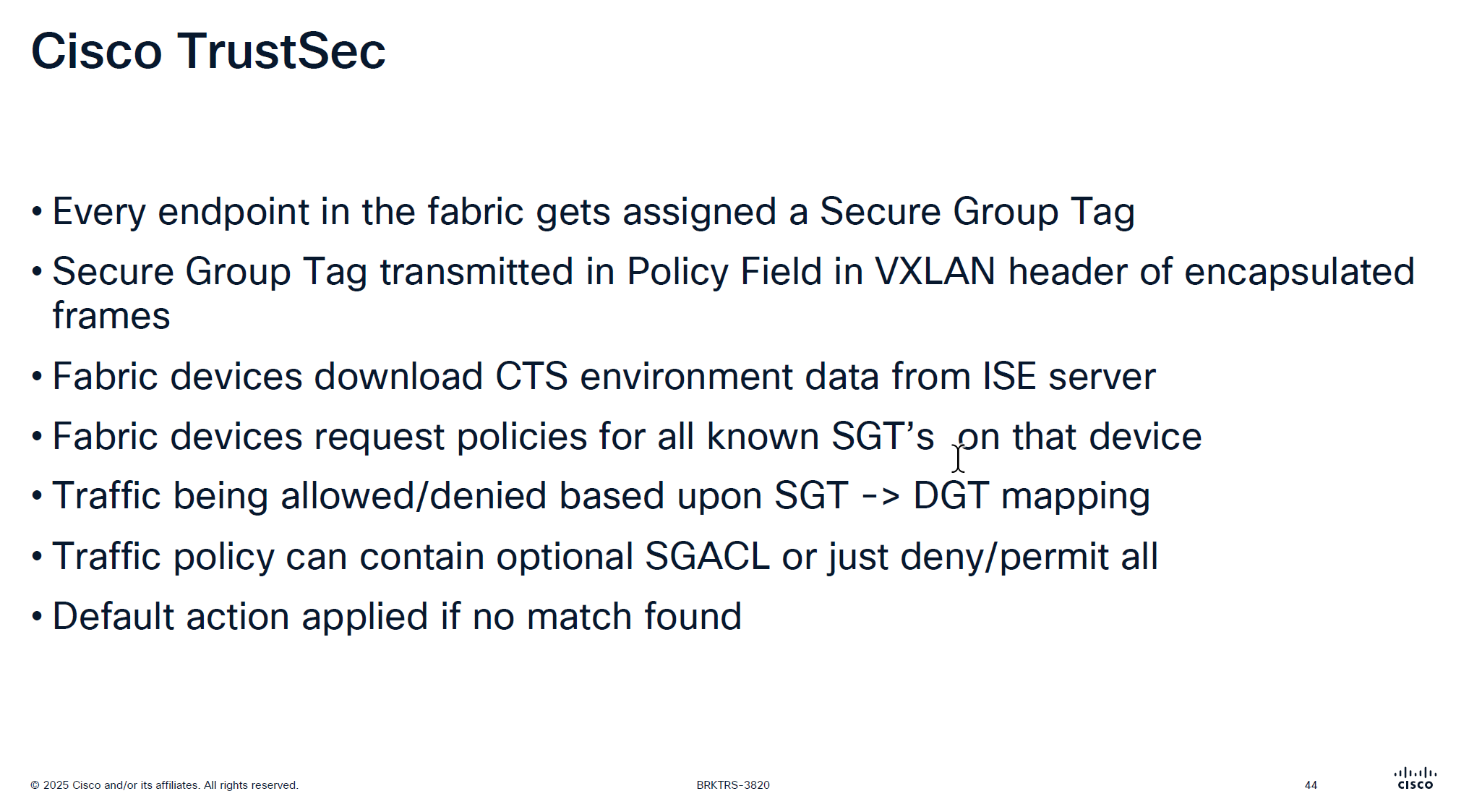
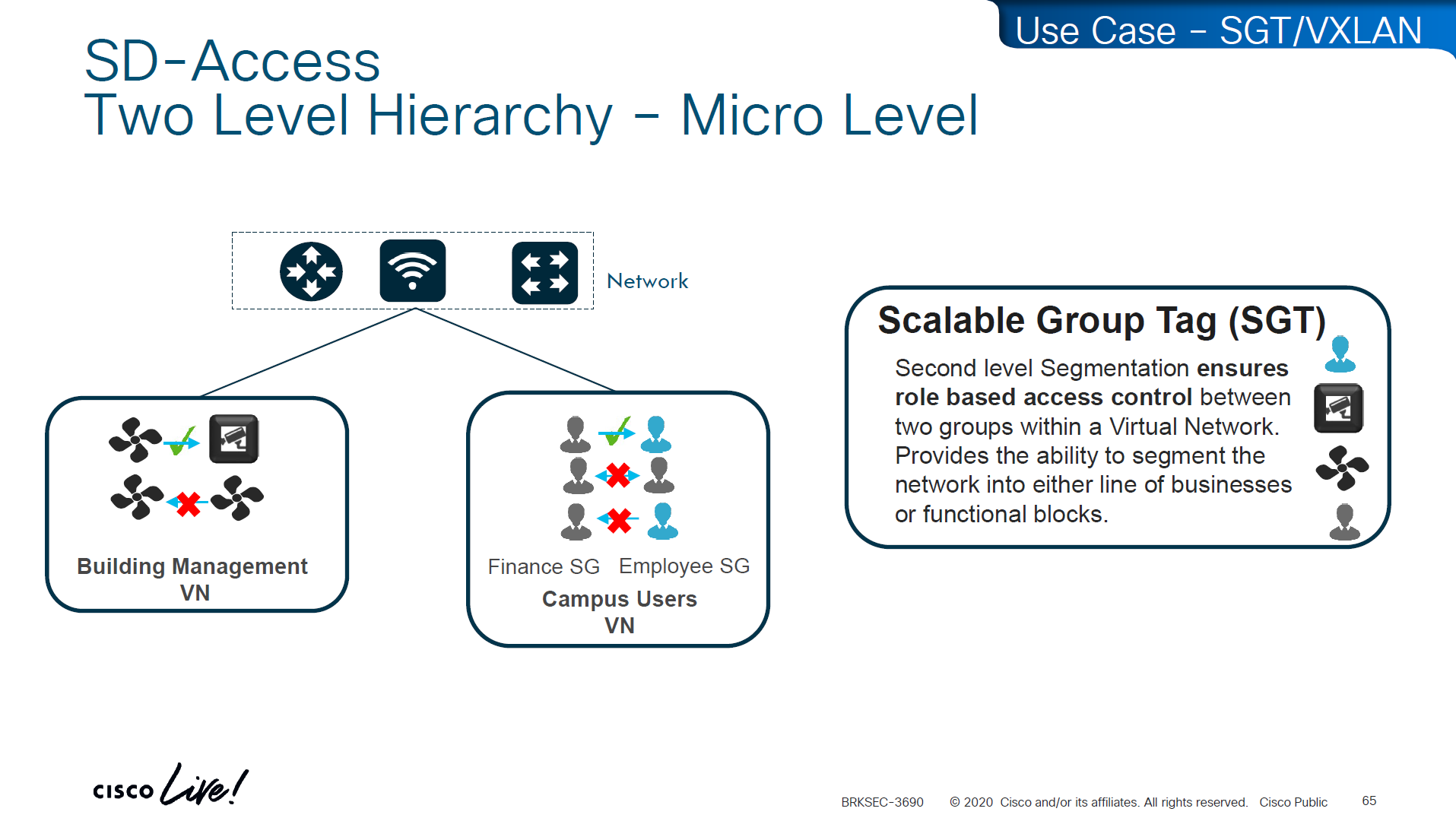
A Security Group Tag is a 16-bit label attached to traffic to identify the security group or role of the source (e.g., Employees, Guests, IoT Devices). SGTs are used in Cisco TrustSec / SD-Access environments to create role-based access control policies that don’t rely on IP addresses.
SGT is not just used for SGACL or filtering only, because it is a tag on IP packet, this is also being used Policy based routing and also QoS – QoS based on SGT
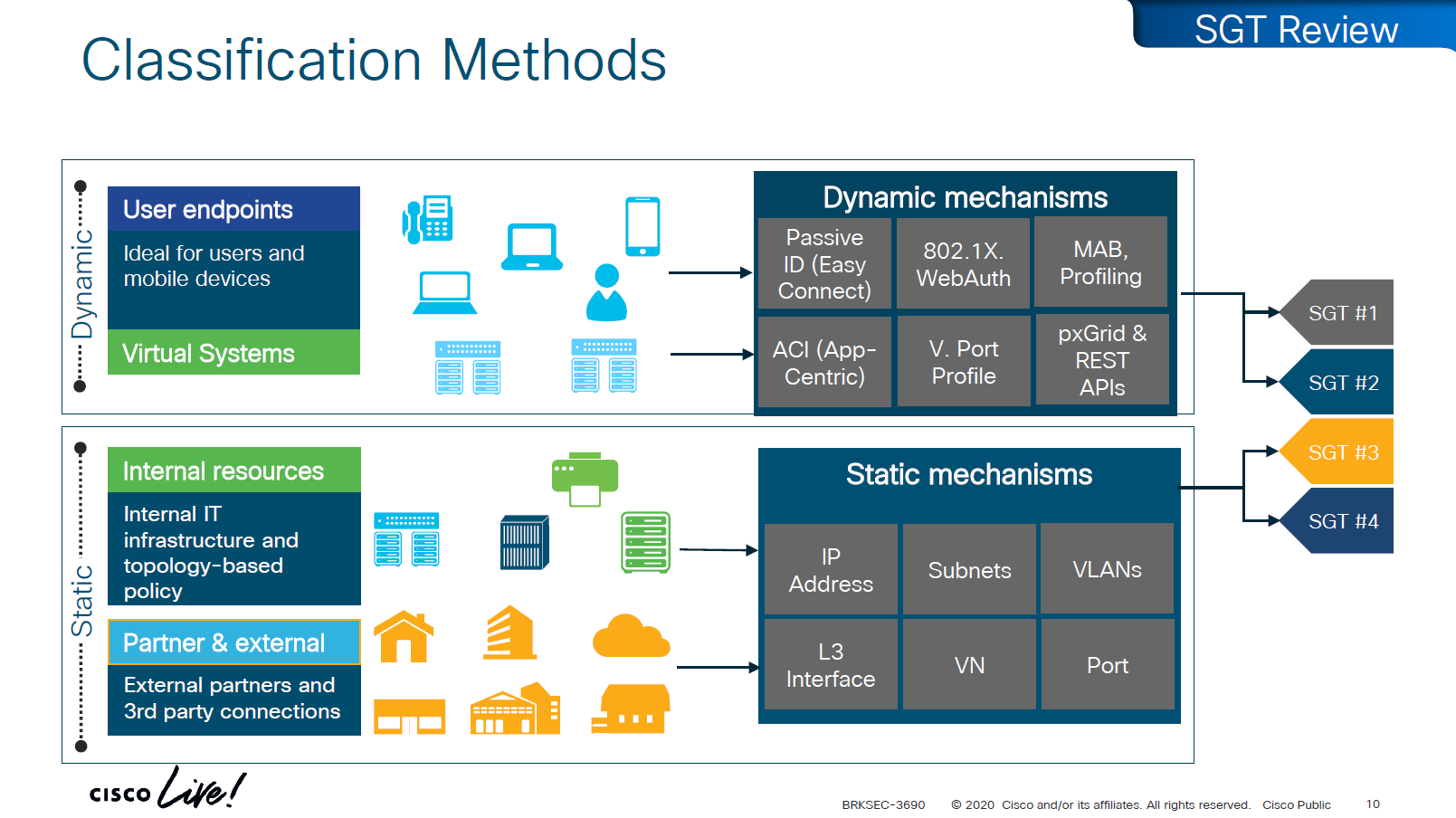
There are 2 ways of classifying the devices in an SGT group
Dynamic
ISE
802.1x
MAB, profiling
pxGrid, Rest API
ACI
Static
IP address
Subnets
VLANs
L3 interface
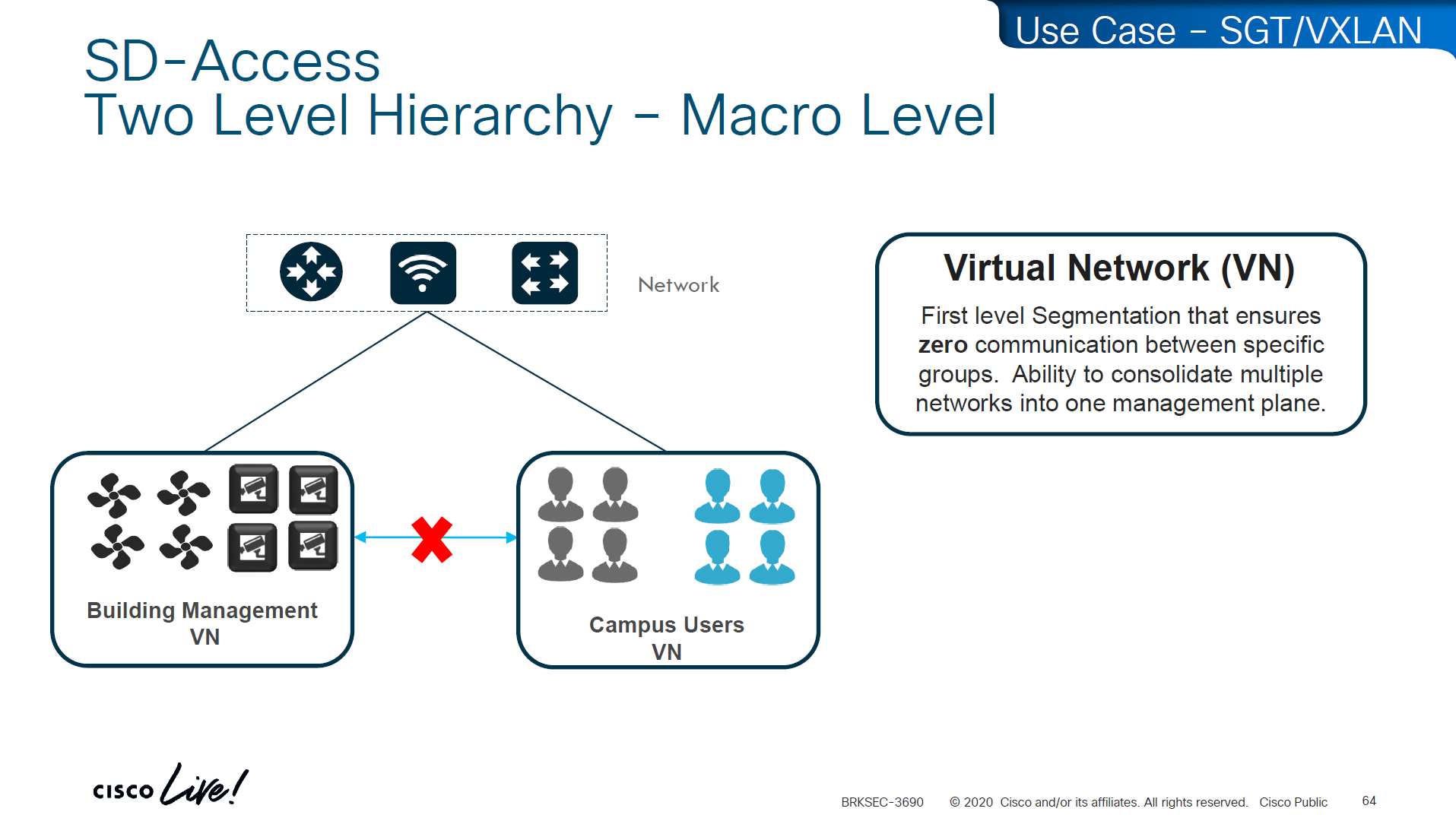
VN
Port
Traffic or packets are classified and tagged on ingress into the network which is access layer and filter on the egress of the network
Because classification and tagging on ingress of the network and filtering on egress of the network, it is very important to have tags pushed or transport the tags to all devices on the network
There are 2 ways to do that,
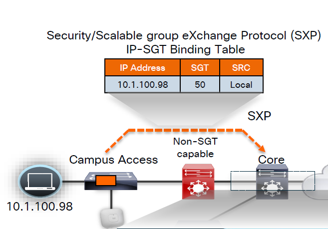
No packet tagging, but use control plane, using SXP (Scalable Group Exchange) protocol to teach foreign devices about the IP to SGT over TCP control plane This way frame or packet has not been modified or tag is not added in the IP header, and target device also understood the tag that applies to that traffic.
SXP can be activated on a headend only that makes drop or allow policy decisions, it does not have to be applied on all intermediate nodes in the topology hop by hop unlike QoS that requires every hop to do QoS enforcement.
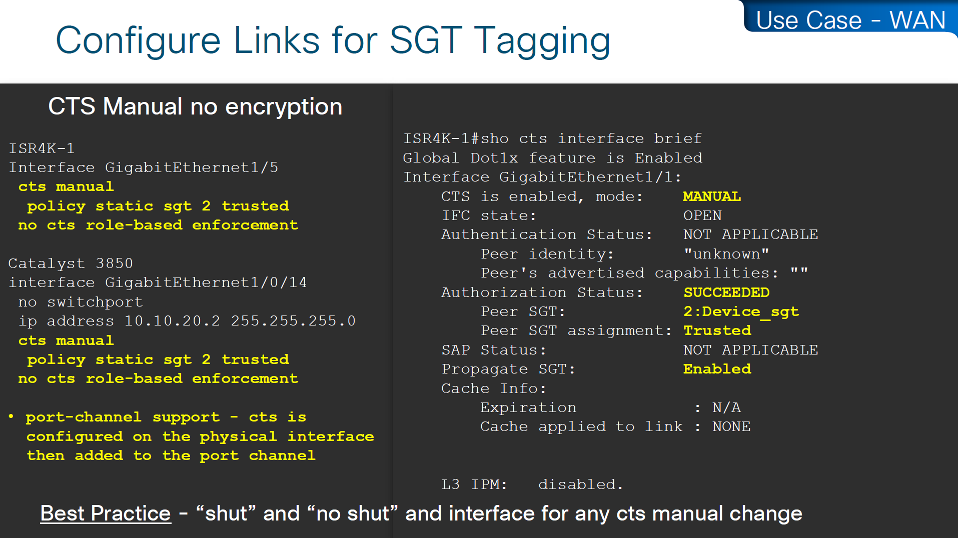
other one is inline tagging
with inline tagging we also have some encryption options such as IPSec or MACsec to prevent people from messing with tags
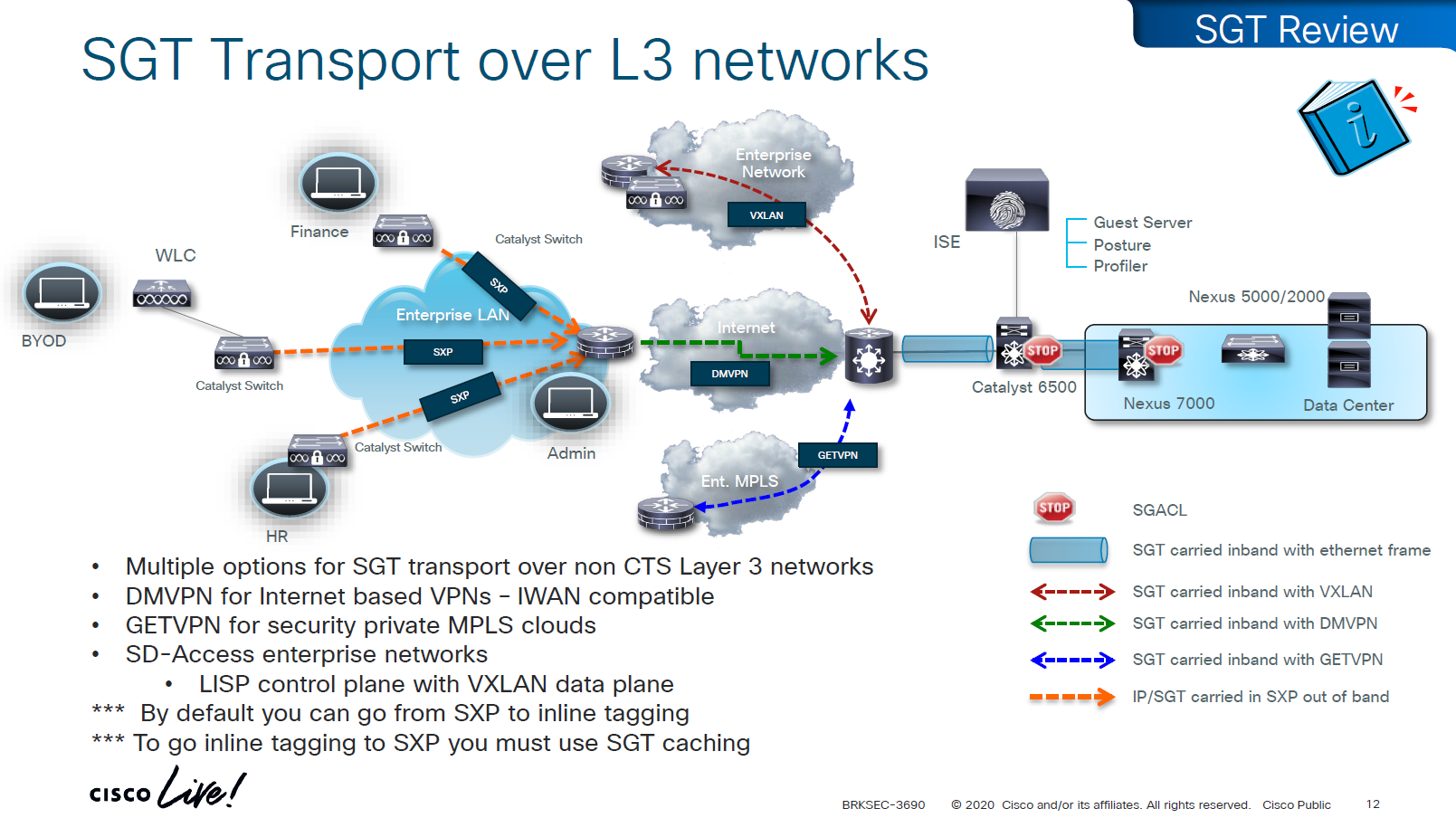
By default you can go from SXP to inline tagging to go from inline tagging to SXP you must enable SGT caching
All firewall vendors like Firepower, Checkpoint, Fortigate and Palo Alto, do support pxGrid based implementation for SXP, pxGrid is a publisher and subscriber model where publisher can push information down to subscribers for different topics and one topic can be SXP protocol that has a table that contains IP address to SGT tag mapping
SXP can be activated on a headend only that makes drop or allow policy decisions, it does not have to be applied on all intermediate nodes in the topology hop by hop unlike QoS that requires every hop to do QoS enforcement.
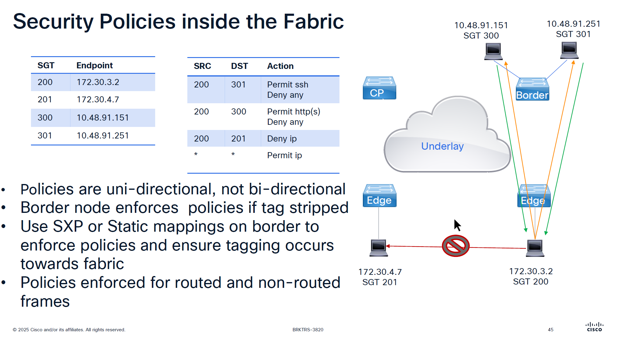
End to end SGT work flow
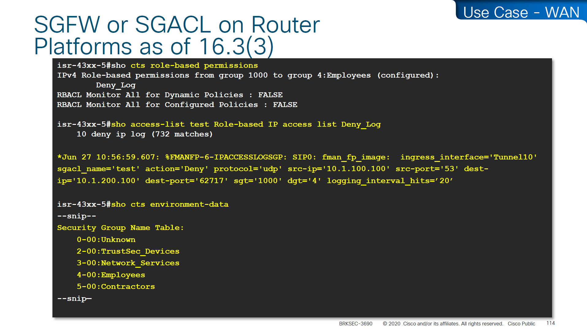
Filtering with SGTs is always done on egress or last switch where destination is connected, this is because we do not want to overload our access layer switches with all policies and track of all devices connected on the network ahead of it
This optimizes and keeps memory size smaller for small devices,
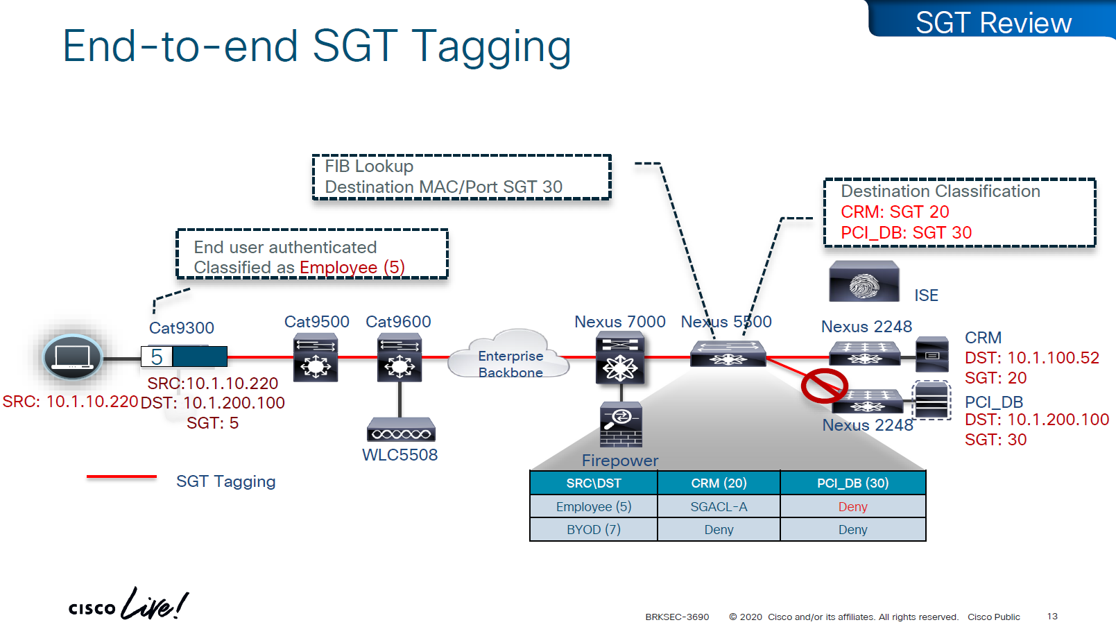
Access or ingress will only add tag to the traffic and send, it is the destination switch after it has received the packet, checks the SGT on the packet – if not on packet, derive SGT from the SXP learned IP to SGT table. Find out the mac / destination port + the SGT assigned to host on that port – if not assigned on port derive from SXP learned IP to SGT table for that IP then egress switch will take a policy decision and drop or allow based on policy,
Switches in aggregation or core can be set to look at the destination IP and determine the SGT from SXP learned IP to SGT tag before sending packet out towards destination, this is to drop traffic in core rather than egress
on destination egress or core a log is generated for all deny or drops, if all switches in network point to central logging server, these logs can tell us about the dropped traffic
This shows the policy matrix and how switches that have hosts with certain SGT only pull “columns” from matrix for those hosts only, as soon as a host is connected that has a new SGT, policy column for that SGT is downloaded on the switch, this is very on demand like fashion where switch does not have to download all the policies of the policy matrix and be light weight
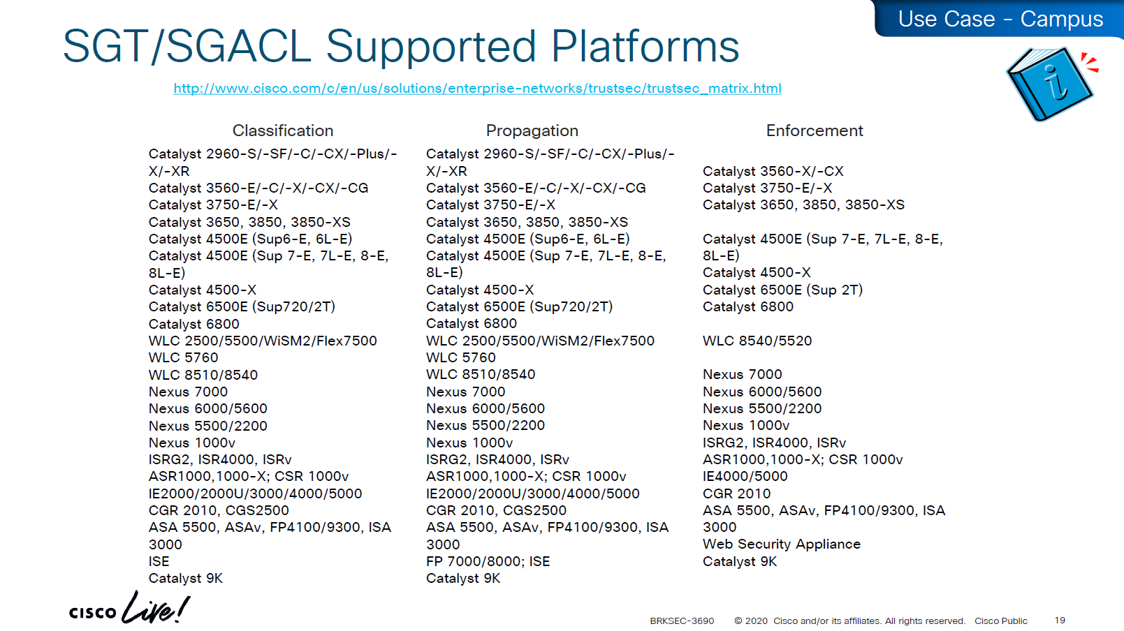
Be careful of platform support for SGT when implementing to make sure that platform does support trustsec for all actions such as Classification, Propagation and Enforcement
on 3850 as a client we are setting SXP peer (almost like a routing peer) to send it the IP to SGT mappings (local mode)
9K is SXP receiver only using “mode local listener” instead of a speaker
Think of Speaker / local as “teacher” and listener as “learner”
show cts role-based sgt-map all details
! check mappings on 3850 switch

show cts sxp connections brief
! check peers
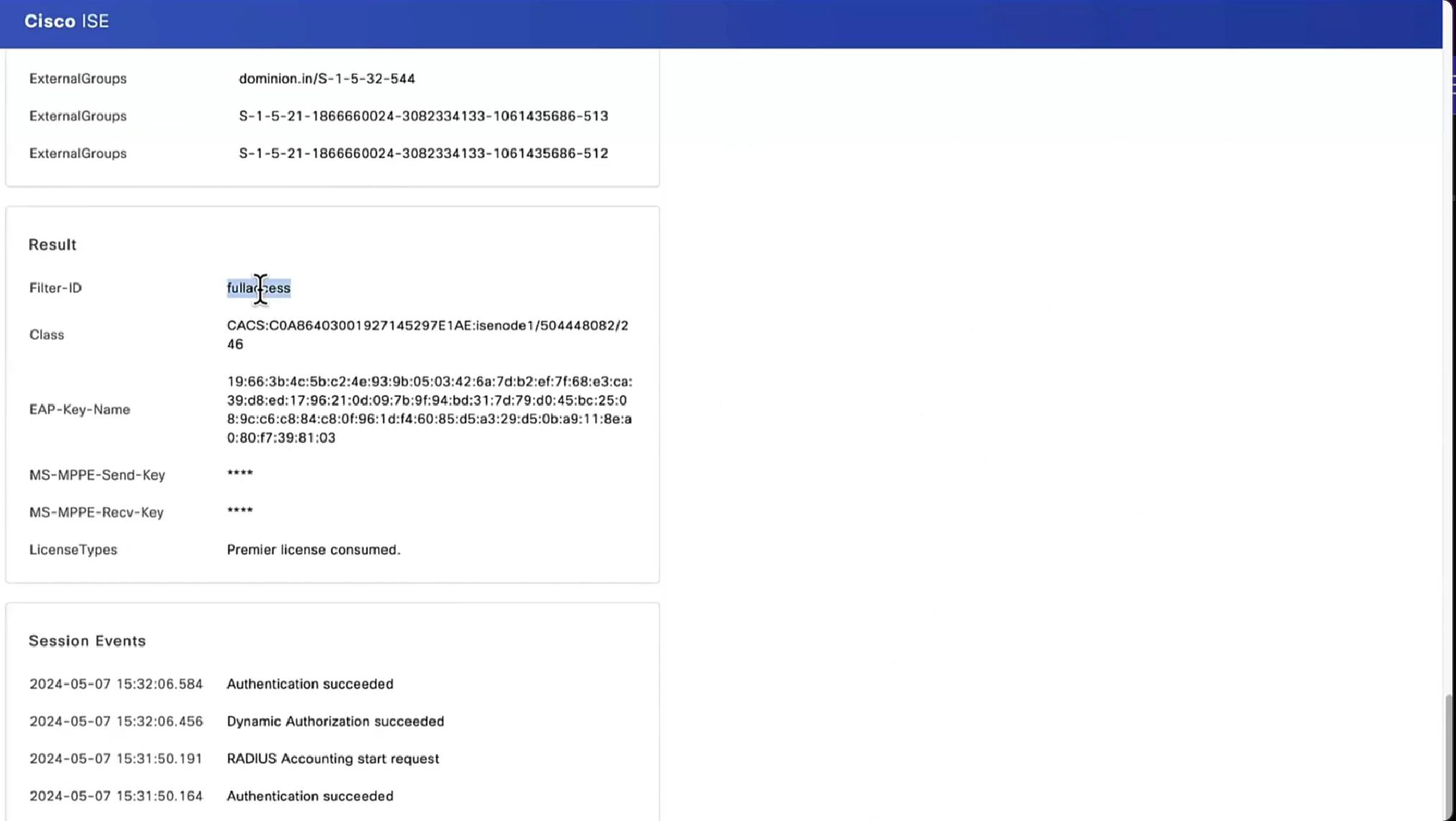
in above “show cts role-based sgt-map all details” – we can see the one attached host got SGT tag of 6:Full_Access and source is “LOCAL” similarly not shown here but WLC also a client that got SGT of 3:BYOD and at the bottom we run “show cts role-based sgt-map all details” command on core C9K and we can see both tags learned from SXP (3850 and WLC). Aggregation layer is building table automatically as devices are learned from Access layer devices
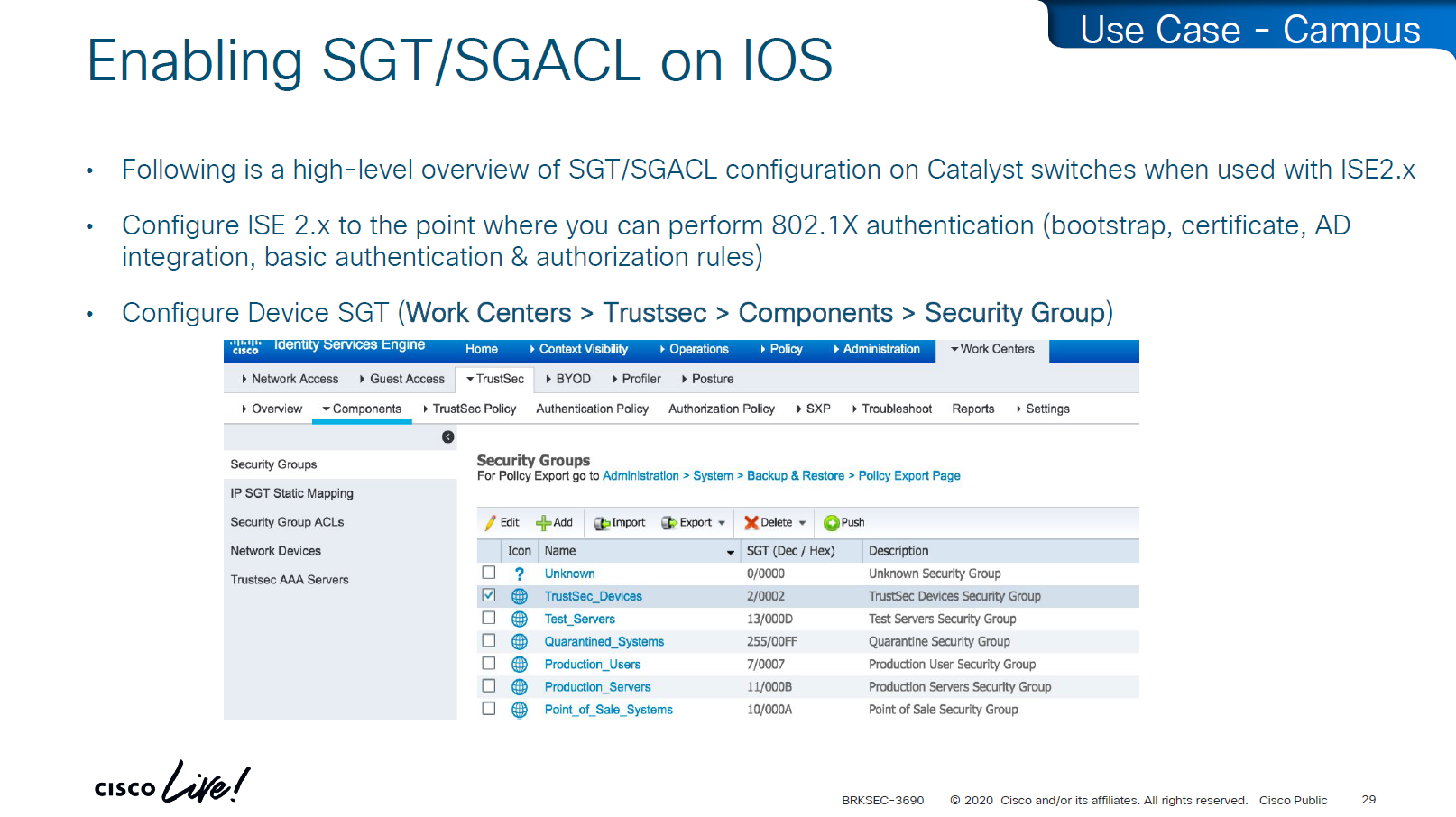
Enabling SGT/SGACL Enforcement
Before SGT/SGACL can be enabled on Cisco devices, make sure that SGT tag for network devices TrustSec_Devices is assigned by default to the network device and make a policy that always allows TrustSec_Devices is always allowed to speak to ISE and infrastructure, why is that needed? because there is a default rule in policy, if it is set to deny then all control plane traffic from device to ISE will be dropped
There was a case once when 2000 switches disappeared from the network, that customer did not have network device SGT like TrustSec_Devices above, they also did not have policy against it to make devices from TrustSec_Devices speak to infrastructure servers SGT, third thing is that they turned on default deny rule in policy
Do not turn on that default deny unless you are really sure that every protocol and everything has been taken care off as it will start dropping the Unknown / untagged SGT traffic as well
Unknown SGT refers to the default tag used when a packet, user, or device does not have a valid SGT assigned. In Cisco TrustSec, this value is typically SGT = 0 and is considered unclassified or unauthenticated traffic. Whenever Unknown SGT of 0 is seen on traffic or host, it means following:
-The client is not authenticated via 802.1X/MAB/web-auth -Even if authenticated from ISE, there was no SGT in Auth Z results from ISE -The TrustSec policy mapping isn’t configured
Most TrustSec deployments deny or restrict traffic with Unknown SGT:
Best practice: Block or isolate Unknown to → Protected traffic in policy matrix
Allow Unknown to → Internet (e.g., guest networks) in policy matrix
Assign TrustSec_Device to network devices
SGT CTS “peer authentication” between ISE and Device is done through EAP-FAST as PAC file is downloaded on the Network device, PAC which is used in case you want password less certificate like authentication without having certificates. This is called PAC bootstrapping, this is used to download policies, SGACLs and SGT tags then later SXP is used to send or download the SGT to IP mapping separately.
look at send from ISE PSN and test connection button
If there are large number of policy changes, having CLI access from ISE is much faster and better at times, for example there was a customer with 200 x 200 policy matric, it took almost 4 hours to finish the update, it was changed to CLI for all devices and all updates completed in 30 mins, if it is small incremental updates, RADIUS CoA is fine
This device ID is the hostname of the device and password corresponds to command
cts credential id DEVICE-ID password PASSWORD
! this is done in non config , enable mode
device>cts credentials id <DEVICE-ID> password <PASSWORD>
show cts credentials
show cts environment-data
show cts role-based permissions
Setting long timers make sure policy is refreshed on devices annually and also only when there is an explicit change in policy
Why the pac key appears under the radius-server host command? Even though the PAC is used for TrustSec (CTS/NDAC) and not for normal RADIUS authentication, the PAC is delivered through RADIUS using cisco’ vendor attribute, PAC exchange is not a standard RADIUS authentication — it is a special RADIUS message (Cisco-vendor attribute) used only for TrustSec device bootstrapping that is why it is configured under RADIUS server configuration block along with RADIUS shared secret.
cts authorization list <AUTHZ_List_Name> is the list of ISE RADIUS nodes that are running TrustSec
Why Cisco did it this way
Cisco chose to reuse the RADIUS channel rather than invent a new protocol:
RADIUS is already required for 802.1X authentications
Switches already have reachability to ISE
The PAC exchange can ride over the same transport (UDP 1812/1645)
So the PAC bootstrap process piggybacks on RADIUS → therefore, the PAC key configuration lives inside the radius-server settings.
Full configuration of ISE RADIUS Servers with PAC
! Enable AAA
aaa new-model

! Define ISE as a RADIUS server (auth/acct) and include the PAC bootstrap secret
radius server ISE1
 address ipv4 10.10.10.10 auth-port 1812 acct-port 1813
 key RADIUS_SHARED_SECRET
 pac key RADIUS_PAC_SECRET
!

! send vsa or vendor attributes in RADIUS authentication request
radius-server vsa send authentication

! (Optional) put servers into a group and set a source interface
aaa group server radius ISE-GRP
 server name ISE1
 ip radius source-interface Vlan10

! CTS/NDAC: define the authorization list used for policy download only (not tags - tags are pulled before SGACL or policy is pulled) - as clients connect with new SGT , more policy columns are pulled
cts authorization list CTS-AUTHZ

! 802.1X + CTS use the RADIUS group
aaa authentication dot1x default group ISE-GRP
aaa authorization network CTS-AUTHZ group ISE-GRP
! aaa authorization network command is usually used to allow on network or authorize audience or entity authenticated through network ports and this config says that authorized list of server (which are allowed to make CLI or COA changes) will be downloaded from ISE-GRP

! which makes it look like this

aaa authorization network ( CTS-AUTHZ ) group ISE-GRP
aaa authorization network ( cts authorization list ) group ISE-GRP

! Define credentials for EAP-FAST I-ID, these are configured under enable mode and not in config mode
cts credential id DEVICE-ID password PASSWORD

! enable 802.1x on system level
dot1x system-auth-control
! enable CTS enforcement
cts role-based enforcement
SXP does not carry SGACL policies.
SXP only carries IP-to-SGT mappings
SGACL policy travels via DTLS tunnel established using PAC.
Policy matrix is translated or converted into bunch of SGACLs and then sent out to devices
Sequence and use of PAC: 1. Authenticate the switch to ISE for TrustSec 2. Receive the PAC credential 3. Establish a secure, encrypted control channel DTLS for SGACL policy download
It is sent through the PAC → NDAC → Secure DTLS Trust Tunnel that is established after the PAC is provisioned
Switch proves identity to ISE to download PAC -> RADIUS Policy download (SGACLs and SGT tags – “TrustSec Bootstrapping”) -> PAC established DTLS (UDP) IP-to-SGT sharing between devices -> SXP (TCP)
First thing to notice in this output is the Local Device SGT that is assigned to network device, any control plane communication from this device will be assigned SGT
Then coming below we can see 3 TrustSec ISE servers are set as servers for downloading SGT tags and SGACL policy (but not SGT to IP mappings which are downloaded over SXP)
We define more tags in ISE, in above picture we can see ACI EPGs (contracts) defined as tags and this is through automation , automatically created through API
These are stateless ACLs unlike firewalls, this is exact filtering as described ACEs but best thing about these ACEs is there are no IP addresses
One thing to notice in above screenshot is ability to define multiple ACLs in a single cell of the policy matrix but this is turned off by default as it is not supported by all devices yet because WLCs and Nexus only support single ACL for an SGT and DGT filtering
Only IOS XE switches are supporting multiple ACL per cell
above we can see manual IP to SGT map, which can also be pushed from ISE via CLI or from ISE via SXP
Even if switch has policy matrix table downloaded, and switch also has all the SGT tags, switch will not enforce on traffic unless command is “cts role-based enforcement” is defined Second command allows us to enable on per VLAN, this is very significant because we can enable SGT enforcement incrementally on VLANs
environment data is SGT tags policy is the policy matrix
As we can see that RADIUS flow is different “Environmental Data download + Server list” is different flow before SGACL policy is downloaded SGACL policy download is from the server list, server list was fetched with environment data
This was done because in peak times when RADIUS servers are busy it can be too much load to download the SGACL policy over same ISE PSN nodes and it is better to download over dedicated ISE TrustSec PSN nodes
in above screen shots dynamic author (RADIUS servers allowed to do CoA) are defined -PAN should be defined for SGT related flows -PSNs should be configured for 802.1x / MAB
In older versions of ISE, clicking on Deploy is not enough, there is a confirmation icon on top that needs to be click and confirm, only then ISE notifies all switches that there is a change and download the new policy
There is a policy validation button that runs this command “show cts role-based permissions” and validates that ISE has same policy as devices and if there is any mismatch or issue then an Alarm is generated from ISE
SGACL denies will show as log, and you will see that logging hits are shown as well which means that if there are a lot of logs then number of hits accumulated will be reported under logging_interval_hits and log will be generated, but in some cases auditor will come in and say that they need to see a log for every drop and allow, and at that point we need to understand that this is a switch and not the firewall, with SGACL enforcement it is not possible to get log for every hit
show cts role-based counters
! shows * to * default rule
! also shows from and to columns
! SGACL is done in hardware, unless needs punting
! for example TCAM or hardware is full, log in the end of ACE , makes SW counter increment otherwise concentrate on HW-Denied and HW-Permitted columns
Software denies and software permits are for to the box traffic or traffic destined for the switch, including the DHCP and ARP permits will also increment the Software counters, SGACL enforcement is in hardware
One of the examples of confusion with ping is that people test access control by pinging the switch SVI and say why is the hardware counter not increasing, it will be denied in software SW-Denied, the thing with SVI ping is that it is going up through software control plane to the CPU and then responding (punted to CPU)
Wireless APs do “enforcement” with SGACLs
TrustSec implementation in wireless does follow the same principal of tagging on ingress and filtering on egress (APs) APs do the filtering also on egress in wireless to wireless communication, that confuses people as they see SGACL download on WLC but they do not see permit or deny logs in WLC CLI, it makes sense to check the WLC but enforcement for wireless to wireless traffic is being done on AP for scaling reasons otherwise WLC will be overwhelmed as WLC can do enforcement for wireless to wired communication
Ingress AP will tag the packet and send it across the WLC over CAPWAP due to central switching and egress AP will do the lookup for SGT of the destination client using client table and perform policy enforcement based on that
Skipped Nexus 7000 SGT Considerations
Common issues
SGT trustsec relies on IP device tracking
In case you have SGT disappearing from host, then check if this bug is in effect and usually happens on older unpatched code, the workaround was to turn off ndp (which is IPv6 ARP mechanism) tracking from IP device tracking and also turn off dhcpv6 tracking
in case SGACL download is not happening we need to check following:
Make sure pac is present
show cts pac all
Make sure AAA servers are marked alive
show aaa servers
Make sure device can reach ISE
show cts environment-data
Check ISE to make sure SGACL is formatted properly
Make sure there are no errors in device-tracking as whole solutions rides on device-tracking to work
Sometimes bad implementation of SDWAN can cause fragmentation of large packets and sometimes that can cause ISE to device download of SGACL of DTLS (PAC based) to break for large packets causing “partial download”, that is why it is so important to first test for fragmentation over greenfield or brownfield deployment and also test large elephant connections with large packets – on the side note large elephant connections over IPSec based tunnels are heavy on platform’s ability to encrypt large traffic
So if you see partial download of SGACL, then always check for fragmentation issue, because by default for this pac based DTLS connections DF bit is set and routers from all vendors do not like DF bit
Software Defined Access (SD – Access) – SGT/VXLAN
These SDA VNs are VRFs but these are campus wide VRFs,
Macro Level segmentation is devices of different management domains go in their own VN
Micro Segmentation is used for access control within the VN
LISP is another great optimization at the access layer and it reduces or optimizes the routes by only installing /32 host routes on access layer switch to which its connected hosts are initiating connections to and from, access layer no longer needs to maintain the large routing tables, LISP installs routes in VRFed routing table of access switches
VXLAN is carried inside UDP just like an layer 7 application and VXLAN carriers the whole original ethernet frame and not just IP packet
VN and SGT are carried inside the VXLAN header The SGT (Security Group Tag) is not added to the original inner IP packet. It is carried only in the VXLAN header as metadata, and in order to use SGT capabilities outside of the network with Cisco gear we can use TrustSec which uses SXP and with other vendors we can use PXGrid
Policy matrix is created on DNAC and then pushed to ISE , ISE then pushes the SGT environment data (SGT Tags and Trusted Server list) over TCP, SGACL using NDAC over PAC based DTLS and then finally IP to SGT mapping on border nodes using TCP SXP
ACL or contracts are defined in badge color cells
This is how it is enabled inside LISP
If we have SD Access transit or SDWAN, we can carry SGT to other fabric sites
SDA transit uses LISP as control plane between borders of both fabric sites and then on data plane we have VXLAN header that crosses between fabric sites but in order to accommodate the VXLAN header we will need 1588 or better 1600 MTU
Skipped Firewall Integration with SD-Access
Skipped Meraki and 3rdParty Interop
Use Case Review -WAN
-medical devices and servers are assigned SGT and allowed to speak to one another -Summary SGT of 10.0.0.0/8 in SXP for all users and devices in 10.0.0.0/8 space and this keeps the SGT under 12K -Create a Policy Matrix that has Known_SGT <-> Known_SGT permit -Create a Policy Matrix that has Known_SGT <-> Summary_SGT deny -For Internet traffic default route is tagged as Internet_SGT -above Internet_SGT leaves reserved tag called Unknown to handle traffic for medical devices that are not tagged
SXP Reflector Like Design
in above SXP connections, if one device speaks (has a speaker role) IP to SGT mapping then on the other end if there is a listener it will listen and learn the IP to SGT mapping and if a device listens (has a listener role) then on SXP connection it can learn IP to SGT mapping from a speaker
once a new mapping of IP to SGT is learned by aggregation Listener, it “speaks” those mapping to all the listeners
Above example is the source on 10.0.0.0 network that has fallen on 10.0.0.0/8 SGT of Enterprise and is trying to speak to Medical_device and by policy that is denied
cts manual – tells the router interface to assign sgt manually to traffic over this interface
policy static sgt 2 trusted – All traffic that enters or exits this interface is tagged with SGT = 2 “Trusted” means this interface accepts incoming SGT tags from the peer without overwriting them. If the link partner already sends SGT-tagged frames, the ASR1K trusts them instead of stripping or replacing them.
no cts role-based enforcement – on the router interface or layer 3 interfaces which are in the middle of the path, we have to turn off any kind of enforcement in order to avoid dropping any traffic , Because the ASR1K in this use case is only tagging packets, not enforcing access control. This keeps the device acting as a TrustSec transit / tagging device rather than a policy enforcement point.
so above config achieves – tag outgoing traffic, trust the tag from connected device for incoming traffic and disable enforcement because this is a transit node and not access layer policy point
show platform hardware fed switch active fwd-asic resource tcam utilization
! Max Values column
! Used Values
! first value is IP "/" second value is SGT
! "Directly or indirectly connected routes"
! for 9300 10K limit officially for both IP and SGT combined
! "Security Access Control Entries" are number of ACEs
! "SGT_DGT" is number of cells from Policy Matrix
This healthcare provider hit the scale limit of SGT on access layer so they moved the enforcement point on routers as router hardware has much more scale
If you want to know that you are tagging traffic, simply turn on netflow with cts with above commands and even if you dont export that flow anywhere, we can see local cache , great for tshoot
use this command to see the tagging info
show flow mon cts-mon cache
you will see that in above output we see destination tag as 0, because we are running this command on ingress or access layer where there is no info about destination host or its assigned SGT
Stealthwatch has ability to specify source and destination tag
Skipped DMVPN SGT tagging
Skipped SGT/ACI
Skipped Cloud
SGT commands
! on ingress or access
cts sxp enable
cts sxp connection peer 10.1.44.1 source 10.1.11.44 password default mode local
! on core where we just learn from access as listener
cts sxp enable
cts sxp default password cisco123
! peering with Cat3K
cts sxp connection peer 10.1.11.44 source 10.1.44.1 password default mode local listener hold-time 0 0
! peering with WLC
cts sxp connection peer 10.1.33.24 source 10.1.44.1 password default mode local listener hold-time 0 0
! check IP to SGT table
show cts role-based sgt-map all details
! check SXP connection on on core
show cts sxp connections brief
----------------------------------------------
! Enable AAA
aaa new-model
! Define ISE as a RADIUS server (auth/acct) and include the PAC bootstrap secret
radius server ISE1
address ipv4 10.10.10.10 auth-port 1812 acct-port 1813
key RADIUS_SHARED_SECRET
pac key RADIUS_PAC_SECRET
!
! send vsa or vendor attributes in RADIUS authentication request
radius-server vsa send authentication
key RADIUS_SHARED_SECRET
pac key RADIUS_PAC_SECRET
!
! send vsa or vendor attributes in RADIUS authentication request
radius-server vsa send authentication
! (Optional) put servers into a group and set a source interface
aaa group server radius ISE-GRP
server name ISE1
ip radius source-interface Vlan10
! CTS/NDAC: define the authorization list used for policy download only (not tags - tags are pulled before SGACL or policy is pulled) - as clients connect with new SGT , more policy columns are pulled
cts authorization list CTS-AUTHZ
! 802.1X + CTS use the RADIUS group
aaa authentication dot1x default group ISE-GRP
aaa authorization network CTS-AUTHZ group ISE-GRP
! aaa authorization network command is usually used to allow on network or authorize audience or entity authenticated through network ports and this config says that authorized list of server (which are allowed to make CLI or COA changes) will be downloaded from ISE-GRP
! which makes it look like this
aaa authorization network ( CTS-AUTHZ ) group ISE-GRP
aaa authorization network ( cts authorization list ) group ISE-GRP
! Define credentials for EAP-FAST I-ID, these are configured under enable mode and not in config mode
cts credential id DEVICE-ID password PASSWORD
! enable 802.1x on system level
dot1x system-auth-control
! enable CTS enforcement
cts role-based enforcement
----------------------------------------------
show cts environment-data
! shows local device SGT
! shows servers that are authorized list servers
! shows downloaded SGT tags on devices
----------------------------------------------
! define SGT for local servers connected to switch
cts role-based sgt-map 192.168.31.1 sgt 100
cts role-based sgt-map 192.168.32.0/24 sgt 20
cts role-based sgt-map 10.x.x.0 sgt 30
! tag default route to Internet_SGT
! This is incase you want to use Unknown tag for something else
! for default route tag, the device must have defafult route either as a static or dynamic for this tagging to work
! this allows us to do something like Medical_devices <-> Internet_SGT deny
cts role-based sgt-map 0.0.0.0/0 sgt 2500
! enableing SGT enformcement globaly
cts role-based enforcement
! or on specific vlans for slow rollout
cts role-based enforcement vlan-list 40
----------------------------------------------
! download or refresh SGT tags
cts refresh environment-data
! download or refresh SGACLs or policy
cts refresh policy
----------------------------------------------
show cts role-based permissions
! shows SGACLs
show cts policy sgt 4
! shows SGT and its related policies in detail
show ip access-list
show cts role-based counters
! shows * to * default rule
! also shows from and to columns
! SGACL is done in hardware, unless needs punting
! for example TCAM or hardware is full, log in the end of ACE or to the box traffic such as Trust_Devices SGT, makes SW counter increment otherwise concentrate on HW-Denied and HW-Permitted columns
----------------------------------------------
show device-tracking database
show cts role-based sgt-map 10.0.0.1
show device-tracking database interface gig2/0/11
----------------------------------------------
! If SGACL download errors happen
show aaa servers
! make sure AAA servers are marked alive
show cts pac all
! make sure pac is present
show cts environment-data
! check if device can communicate with ISE
----------------------------------------------
router(config)#interface Ten1/1/1
cts manual
policy static sgt 2 trusted
no cts role-based enforcement
! tag outgoing traffic,
! trust the tag from connected device for incoming traffic
! disable enforcement because this is a transit node and not access layer policy point
show cts interface brief
----------------------------------------------
show platform hardware fed switch active fwd-asic resource tcam utilization

! Max Values column
! Used Values

! first value is IP "/" second value is SGT

! "Directly or indirectly connected routes"
! for 9300 10K limit officially for both IP and SGT combined

! "Security Access Control Entries" are number of ACEs

! "SGT_DGT" is number of cells from Policy Matrix
----------------------------------------------
flow record cts-v4
match ipv4 protocol
match ipv4 source address
match ipv4 destination address
match transport source-port
match transport destination-port
match flow direction
match flow cts source group-tag <<<<
match flow cts destination group-tag <<<<
collect counter bytes
collect counter packets
flow exporter EXP1
destination 10.1.1.1
source Gig1
flow monitor cts-mon
record cts-v4
exporter EXP1
interface vlan 10
ip flow monitor cts-mon input
ip flow monitor cts-mon output
show flow mon cts-mon cache
but not all checks are supported in all operating systems
Anti-Spyware, and Anti-Virus have been replaced with Anti-Malware and use of compound has been replaced with Patch Management
Remediation
Checks are different from Remediation
Different types of Agents and their capabilities
Modes of access
Policy set must be configured with rules that treat devices at first to be in Posture=Unknown, Devices can access over wired, wireless or VPN
“Posture request” is made by Anyconnect client “Posture policies” are sent to Anyconnect client “Posture report” is sent back to PSN based on the policies (checks) that were sent earlier PSN determines the posture status to be “Compliant” or “Non-Compliant” and delivers via CoA
Posture Configuration Sequence
We need to add as much information about NAD as possible in ISE
Configure
Configure Network Device Groups
Import network devices
As you can see all devices have location and type defined correctly
Configure Posture Updates
Offline updates are only for air gapped ISE deployments
Set posture updates
It took 6 minutes to update Support charts
for now we will use these Global default settings for posture, we will deepdive into these settings later
Workflow
It is vital for Anyconnect client to contact or discover the PSN that Authenticated the 802.1x (initially with limited access) in order to download the posture policies from that PSN and then later send it the report, it should not be any PSN, it has to be the PSN that client previously authenticated with and Agent Discovery process helps with that – so anyconnect authenticates and downloads the policies from the same PSN
Agent Discovery can be redirection based or redirectionless
Right after agent discovery process and it finds the right PSN then Anyconnect client if there is an update on that PSN then it will be updated
Download Windows Headend deployment pkg file
Also download the complaince modules needed
Category “Cisco Provided Packages”
We will upload the Cisco Secure Client
Now upload the compliance module
Now before we can configure Agent Configuration we need Agent Posture profile
we will deep dive into these option later, for now we will configure bare minimum with defaults but add this server name that agent is allowed to connect to, usually domain name with wildcard works
Configure Agent Configuration
Agent configuration is where it is all tied together This agent configuration is then called in Client provisioning policy, such as if Operating System (Windows) & Conditions (such as x) then Results = this agent configuration (which contains Agent Client + Compliance module + Client modules that will be installed from this Agent Client + ISE posture profile [ which are agent settings such as Enable Rescan button , Call home list , discovery agents ] )
Save
Now we need to go to Client Provisioning Policy and change default Windows policy to point to Agent configuration (that married everything together)
This is same Agent configiuration that was defined earlier with image and Agent Posture Profile etc
Above logic is, All NADs in AIPAC region , or VPN firewalls , or All NADs from My Territoray as it is OR conditions with “Starts with”
Wired and Wireless 802.1x (from all the above NADs defined in policy set level)
This initial redirect ACL is defined on the switch
Cisco Agent discovery is a process where agent discovers the PSN that originally authenticated the client and this is only relevant if Agent is already deployed on your machine. These discovery processes are of 2 types:
Redirection based
Redirection-less
All these probes are done in parallel at the same time and intention is to get Redirected to the PSN that originally authenticated the client
Redirection here is very similar to how guest wifi portal is looking for port 80 traffic in order to intercept, NAD also wants to intercept port 80 traffic and NAD sends out the redirect URL containing session id, this session id was inserted by NAD, Client picks this URL and dials that URL of ISE with session id and when request lands on ISE session id is used to find the existing session from DB, in response to this posture request, posture policies or new client is updated (if client has been updated)
Probes 1, 2, 3 are port 80 traffic expecting to be intercepted by NAD and NAD to send redirect URL and ACL (from authorization profile)
NAD Inserts the session ID (because NAD builds clients and their session IDs for authenticated clients) but PSN inserts the hostname or IP of the PSN inside URL
When client redirects or goes to URL with that session id as “posture request” (https based), ISE picks up session ID and thinks there is no need to reauthenticate as session is already there and then proceeds to send “posture policies” back to client
Probe 4 uses ConnectionData.xml which is not redirect containing session id in URL but instead direct approach on URL of the ISE in ConnectionData.xml which means that client must have authenticated and postured before. If things go to probe 4 then PSN will have to lookup active session using IP and MAC just like an analyst checks for a user’s session in ISE
Discovery host if configured will be tried first, if it does not respond then by default Anyconnect sends discovery probes on port 80 to all ISE PSN nodes, this option “Discovery Backup Server List” can be configured to limit the PSNs to send these discovery probes, this option has a reduction function
Stage 2 which is second scenario has probe 1 and probe 2, first probe 1 is done and if probe 1 fails then probe 2 is initiated Stage 2 is used in “redirectionless”, we can have a “call home” list that allows us to set a specific static PSN to contact, that PSN will then look for session owner PSN, session owner then responds to the client for posturing exchange (not URL with session id)
Probe 2 means that client’s ConnectionData.xml will be used to check last PSNs and use one of the PSN, that PSN will also look for session owner PSN and session owner responds to the client for posturing exchange (not lookup using ip and mac) like stage 1
Redirection-less is superior in terms of end user experience because every time user connects they are not redirected to the portal and user does not have to see the portal each time posturing takes place – This is specially good in case Agent is already deployed on endpoints like most corporate do
After agent discovery comes actual posture exchange
Cisco agent validates and sends it back in a report form back to the posture PSN Posture status of the client then changes from unknown to compliant , compliant to non-compliant or non-compliant to compliant, PSN then sends COA RADIUS that contains new attributes from Authorization policy to NAD such as access-accept and complaint ACL that allows network access , in order to allow access
This PC does not have agent deployed
Whenever machine connects to the network (and posture settings is configured to posture on every network connect) client goes to this client provisioning portal
Deployment of agent through software distribution systems like SCCM etc does not require all of this redirect
you can have a situation where ISE thinks that endpoint is compliant but endpoint might be in non-compliant state, this is why “Posture State Synchronization Interval” needs to be set to 60 seconds, because states can be out of sync that is why “synchronisaton”
Enable and disable network adapter so Cisco Secure Client can get new posture profile that we configured and you can see that scan again button is now available as new posture profile was downloaded
lets remove URL redirect from the Posture-Unknown-Access Authorization profile (redirectionless mode)
Keeping of ACL initial in Posture-Unknown-Access Authorization profile
From live sessions we will terminate session
Here now stage 2 discovery process is in play
Notice there was no redirect
Notice there is no URL redirect in result
We have not even configured any posture policies yet
If we run report Posture Assessment by Endpoint
Notice in report that Posture policy details section is empty, when agent is requesting posturing policies, they are being delivered empty
Lets “turn on” first default posture policy This policy retrieves the applications installed on endpoint just for visibility
Second one we are turning on is to know if firewall is enabled on endpoint or not (because windows firewall can be disabled)
Third policy we are turning on retrieves hardware attributes on the endpoint just for visibility
Fourth policy is to know if there is any USB plugged in or not
we purposefully disabled windows firewall for scope domain network
it detected that firewall is not enabled and it automatically enabled it (remediated it)
Posture Policy Details section shows 2 policies “Passed” even though we configured 4 policies, that is because 2 of them were only for visibility
Condition + its remediation are coupled together just like sickness and its remedy are
There are conditions and then there are their remediations ( condition <> remediation )
Those conditions and their remediations are mapped to requirements and those requirements are specified in Posture Policy There can be multiple conditions in a requirement with one remediation, and when there are multiple conditions “in a requirement” then we have options “No condition succeed” , “any conditions succeed” , “all conditions succeed” matching with “and” , “or” , “none operator”
Similarly requirements can be “Mandatory” , “Optional” , “Audit” , which can be remembered from phrase “Mandatory Requirements” Mandatory has to be remediated otherwise client is non-compliant Optional requirement can be skipped by the end user Audit mode requirement does not even notify the end user but only flags in ISE
and Policy can be “enabled or disabled”
A combination of a condition x remediation -> requirement applies to and is only for one policy
or multiple conditions with one remediation can be part of a single requirement because of “No” condition succeed , “any” conditions succeed , “all” conditions succeed with and , or , none operator
Script based condition can do powershell scripts in order to check something custom
See how requirements for this policy when selected can be put into audit mode
We will make this requirement optional
You will see, because we made Disk encryption “policy”‘s requirement to optional, user can actually skip it
In message history section we can look at actions from agent
This file AnyConnectLocalPolicy.xml contains SHA-256 fingerprints and these need to present in this file in order for script based conditions to run, These fingerprints are from certificates of the PSNs, and these have to be added here manually, unfortunately this cannot be done from ISE and has to be done manually, each PSNs fingerprints from certificates need to be added in this file through software distribution systems
If you don’t have that fingerprint configured in AnyConnectLocalPolicy.xml then these script based conditions will not be successful
Report – Posture Assessment by Condition is important to see how many clients are failing which conditions as in a corporate environment you want to know how many endpoints need fix
This filter gets applied as we click on compliance numbers on dashboard
Applications installed on endpoint
If you have 3rd party NAD in network, it must support URL redirection with session ID and CoA
“These settings will be used if there is no profile under client provisioning policy”
whatever is defined in Agent profile, that overtakes these settings in Global profile if no agent profile is assigned in client provisioning policy then these global setting will apply
now it shows 15 minutes
As part of the remediation, demo.txt file is allowed to download and as it downloads, posture becomes compliant
By default and as shown in Global Settings, client goes through posture assessment as soon as it connects to the network
However there is an option to give out lease in days to the client so it does not posture every time it connects to the network
Perform posture assessment every time a user connects to the network: Select this option to initiate posture assessment every time the user connects to network
Perform posture assessment every n days: Select this option to initiate posture assessment after the specified number of days even if the client is already postured Compliant.
Cache Last Known Posture Compliant Status: Check this check box for Cisco ISE to cache the result of posture assessment. By default, this field is disabled.
Last Known Posture Compliant Status: This setting only applies if you have checked Cache Last Known Posture Compliant Status. Cisco ISE caches the result of posture assessment for the amount of time specified in this field. Valid values are from 1 to 30 days, or from 1 to 720 hours, or from 1 to 43200 minutes – this acts as kind of a posture bypass for reconnecting client after number of days – idea is that once client is back on network (wired / wireless / vpn) it can posture again instead of facing remediation out of the gate
enable Session ID
2 times compliant because once client becomes client on ISE it issues a log and once a COA is issued to NAD, final log is left when client is actually given access as a result of compliance from COA
now configure posture lease
The thing about lease is that ISE and agent will completely skip the posture evaluation when lease is configured if client has postured once on the network
You can scan again and again and it will just connect
With Flexible grace period, user is not locked or stuck in posture non-compliant access, instead from end user experience perspective they still get some chance
on each posture policy level we can define grace period for each policy
among those X , Y and Z, the one that is longest will get applied
and here is the catch, grace period will only apply if the previous state option “Cache Last Known Posture Compliant Status” and “Last Known Posture Compliant State” are enabled and client’s last posture state is remembered and within the defined days
Periodic Reassessment For Periodic Reassessment we will disable the posture lease as posture lease stops posture reassessment
Reassessment enforcement type action is action to take if non-compliance is detected upon reassessment if set to continue then user will continue with access to network
in the logs we can see the PRA action as a column
Check message column to see if it says Received reassessment report or posture report, if reassessment report is shown then it means that client got reassessed by PRA interval
1. The remote user uses Cisco Anyconnect for VPN access to the FTD. 2. The FTD sends a RADIUS Access-Request for that user to the ISE. 3. That request hits the policy named FTD-VPN-Posture-Unknown on the ISE. The ISE sends a RADIUS Access-Accept with three attributes:
cisco-av-pair = url-redirect-acl=fyusifovredirect – This is the Access Control List (ACL) name that is defined locally on the FTD, which decides the traffic that is redirected.
DACL = PERMIT_ALL_IPV4_TRAFFIC – downloadable ACL; This attribute is optional. In this scenario, all traffic is permitted in DACL)
4. If DACL is sent, RADIUS Access-Request/Access-Accept is exchanged in order to download content of the DACL 5. When the traffic from the VPN user matches the locally-defined ACL, it is redirected to ISE Client Provisioning Portal. ISE provisions AnyConnect Posture Module and Compliance Module. 6. After the agent is installed on the client machine, it automatically searches for ISE with probes. When ISE is detected successfully, posture requirements are checked on the endpoint. In this example, the agent checks for any installed anti-malware software. Then it sends a posture report to the ISE. 7. When ISE receives the posture report from the agent, ISE changes Posture Status for this session and triggers RADIUS CoA type Push with new attributes. This time, the posture status is known and another rule is hit.
If the user is compliant, then a DACL name that permits full access is sent.
If the user is non-compliant, then a DACL name that permits limited access is sent.
8. The FTD removes the redirection. FTD sends Access-Request in order to download DACL from the ISE. The specific DACL is attached to the VPN session.
Step 1. Create Network Object Group for ISE and Remediation Servers (if any). Navigate to Objects > Object Management > Network.
Step 2. Create Redirect ACL. Navigate to Objects > Object Management > Access List > Extended. Click Add Extended Access List and provide the name of Redirect ACL. This name must be the same as in the ISE authorization result.
Step 3. Add Redirect ACL Entries. Click the Add button. Block traffic to DNS, ISE, and to the remediation servers to exclude them from redirection. Allow the rest of the traffic, this triggers redirection (ACL entries could be more specific if needed).
Step 4. Add ISE PSN node/nodes. Navigate to Objects > Object Management > RADIUS Server Group. Click Add RADIUS Server Group, then provide name, enable check all checkboxes and click the plus icon.
Step 5. In the opened window, provide ISE PSN IP address, RADIUS Key, select Specific Interface and select interface from which ISE is reachable (this interface is used as a source of RADIUS traffic) then select Redirect ACL which was configured previously.
Step 6. Create Address Pool for VPN users. Navigate to Objects > Object Management > Address Pools > IPv4 Pools. Click Add IPv4 Pools and fill the in details.
Step 7. Create AnyConnect package. Navigate to Objects > Object Management > VPN > AnyConnect File. Click Add AnyConnect File, provide the package name, download the package from Cisco Software Download and select Anyconnect Client Image File Type.
Step 8. Navigate to Certificate Objects > Object Management > PKI > Cert Enrollment. Click Add Cert Enrollment, provide name, choose Self Signed Certificate in Enrollment Type. Click the Certificate Parameters tab and provide CN.
Step 9. Launch Remote Access VPN wizard. Navigate to Devices > VPN > Remote Access and click Add.
Step 10. Provide the name, check SSL as VPN Protocol, choose FTD which is used as VPN concentrator and click Next.
Step 11. Provide Connection Profile name, select Authentication/Accounting Servers, select the address pool which was configured previously and click Next.
Note: Do not select the authorization server. It triggers two Access Requests for a single user (once with the user password and the second time with password cisco).
Step 12. Select AnyConnect package that was configured previously and click Next.
Step 13. Select interface from which VPN traffic is expected, select Certificate Enrollment that was configured previously and click Next.
Step 14. Check the summary page and click Finish.
Step 15. Deploy configuration to FTD. Click Deploy and select FTD that is used as a VPN concentrator.
Step 1. Run Posture Updates. Navigate to Administration > System > Settings > Posture > Updates.
Step 2. Upload Compliance Module. Navigate to Policy > Policy Elements > Results > Client Provisioning > Resources. Click Add and select Agent resources from Cisco site
Step 3. Download AnyConnect from Cisco Software Download, then upload it to ISE. Navigate to Policy > Policy Elements > Results > Client Provisioning > Resources.
Click Add and select Agent Resources From Local Disk. Choose Cisco Provided Packages under Category, select AnyConnect package from local disk and click Submit.
Step 4. Create AnyConnect Posture Profile. Navigate to Policy > Policy Elements > Results > Client Provisioning > Resources.
Click Add and select AnyConnect Posture Profile. Fill in the name and Posture Protocol.
Under *Server name rules put * and put any dummy IP address under Discovery host.
Step 5. Navigate to Policy > Policy Elements > Results > Client Provisioning > Resources and create AnyConnect Configuration. Click Add and select AnyConnect Configuration. Select AnyConnect Package, provide Configuration Name, select Compliance Module, check Diagnostic and Reporting Tool, select Posture Profile and click Save.
Step 6. Navigate to Policy > Client Provisioning and create Client Provisioning Policy. Click Edit and then select Insert Rule Above, provide name, select OS, and choose AnyConnect Configuration that was created in the previous step.
Step 7. Create Posture Condition under Policy > Policy Elements > Conditions > Posture > Anti-Malware Condition. In this example, predefined “ANY_am_win_inst” is used.
Step 8. Navigate to Policy > Policy Elements > Results > Posture > Remediation Actions and create Posture Remediation. In this example, it is skipped. Remediation Action can be a Text Message. Step 9. Navigate to Policy > Policy Elements > Results > Posture > Requirements and create Posture Requirements. Predefined requirement Any_AM_Installation_Win is used.
Step 10. Create Posture Policies under Policies > Posture. Default posture policy for any AntiMalware Check for Windows OS is used.
Step 11. Navigate to Policy > Policy Elements > Results > Authorization > Downlodable ACLS and create DACLs for different posture statuses.
In this example:
Posture Unknown DACL – allows traffic to DNS, PSN and HTTP and HTTPS traffic.
Posture NonCompliant DACL – denies access to Private Subnets and allow only internet traffic.
Permit All DACL – allows all traffic for Posture Compliant Status.
Step 12. Create three Authorization Profiles for Posture Unknown, Posture NonCompliant and Posture Compliant statuses. In order to do so, navigate to Policy > Policy Elements > Results > Authorization > Authorization Profiles. In the Posture Unknown profile, select Posture Unknown DACL, check Web Redirection, select Client Provisioning, provide Redirect ACL name (that is configured on FTD) and select the portal.
In the Posture NonCompliant profile, select DACL in order to limit access to the network.
In the Posture Compliant profile, select DACL in order to allow full access to the network.
Step 13. Create Authorization Policies under Policy > Policy Sets > Default > Authorization Policy. As condition Posture Status and VNP TunnelGroup Name is used.
Verify
Use this section in order to confirm that your configuration works properly.
On ISE, the first verification step is RADIUS Live Log. Navigate to Operations > RADIUS Live Log. Here, user Alice is connected and the expected authorization policy is selected.
Authorization policy FTD-VPN-Posture-Unknown is matched and as result, FTD-VPN-Profile is sent to FTD.
Posture Status Pending.
The Result section shows which attributes are sent to FTD.
On FTD, in order to verify VPN connection, SSH to the box, execute system support diagnostic-cli and then show vpn-sessiondb detail anyconnect. From this output, verify that attributes sent from ISE are applied for this VPN session.
fyusifov-ftd-64# show vpn-sessiondb detail anyconnect

Session Type: AnyConnect Detailed

Username     : alice@training.example.com
Index        : 12
Assigned IP  : 172.16.1.10            Public IP    : 10.229.16.169
Protocol     : AnyConnect-Parent SSL-Tunnel DTLS-Tunnel
License      : AnyConnect Premium
Encryption   : AnyConnect-Parent: (1)none  SSL-Tunnel: (1)AES-GCM-256  DTLS-Tunnel: (1)AES256
Hashing      : AnyConnect-Parent: (1)none  SSL-Tunnel: (1)SHA384  DTLS-Tunnel: (1)SHA1
Bytes Tx     : 15326                  Bytes Rx     : 13362
Pkts Tx      : 10                     Pkts Rx      : 49
Pkts Tx Drop : 0                      Pkts Rx Drop : 0
Group Policy : DfltGrpPolicy          Tunnel Group : EmployeeVPN
Login Time   : 07:13:30 UTC Mon Feb 3 2020
Duration     : 0h:06m:43s
Inactivity   : 0h:00m:00s
VLAN Mapping : N/A                    VLAN         : none
Audt Sess ID : 000000000000c0005e37c81a
Security Grp : none                   Tunnel Zone  : 0

AnyConnect-Parent Tunnels: 1
SSL-Tunnel Tunnels: 1
DTLS-Tunnel Tunnels: 1

AnyConnect-Parent:
  Tunnel ID    : 12.1
  Public IP    : 10.229.16.169
  Encryption   : none                   Hashing      : none
  TCP Src Port : 56491                  TCP Dst Port : 443
  Auth Mode    : userPassword
  Idle Time Out: 30 Minutes             Idle TO Left : 23 Minutes
  Client OS    : win
  Client OS Ver: 10.0.18363
  Client Type  : AnyConnect
  Client Ver   : Cisco AnyConnect VPN Agent for Windows 4.7.01076
  Bytes Tx     : 7663                   Bytes Rx     : 0
  Pkts Tx      : 5                      Pkts Rx      : 0
  Pkts Tx Drop : 0                      Pkts Rx Drop : 0

SSL-Tunnel:
  Tunnel ID    : 12.2
  Assigned IP  : 172.16.1.10            Public IP    : 10.229.16.169
  Encryption   : AES-GCM-256            Hashing      : SHA384
  Ciphersuite  : ECDHE-RSA-AES256-GCM-SHA384
  Encapsulation: TLSv1.2                TCP Src Port : 56495
  TCP Dst Port : 443                    Auth Mode    : userPassword
  Idle Time Out: 30 Minutes             Idle TO Left : 23 Minutes
  Client OS    : Windows
  Client Type  : SSL VPN Client
  Client Ver   : Cisco AnyConnect VPN Agent for Windows 4.7.01076
  Bytes Tx     : 7663                   Bytes Rx     : 592
  Pkts Tx      : 5                      Pkts Rx      : 7
  Pkts Tx Drop : 0                      Pkts Rx Drop : 0
  Filter Name  : #ACSACL#-IP-PostureUnknown-5e37414d

DTLS-Tunnel:
  Tunnel ID    : 12.3
  Assigned IP  : 172.16.1.10            Public IP    : 10.229.16.169
  Encryption   : AES256                 Hashing      : SHA1
  Ciphersuite  : DHE-RSA-AES256-SHA
  Encapsulation: DTLSv1.0               UDP Src Port : 59396
  UDP Dst Port : 443                    Auth Mode    : userPassword
  Idle Time Out: 30 Minutes             Idle TO Left : 29 Minutes
  Client OS    : Windows
  Client Type  : DTLS VPN Client
  Client Ver   : Cisco AnyConnect VPN Agent for Windows 4.7.01076
  Bytes Tx     : 0                      Bytes Rx     : 12770
  Pkts Tx      : 0                      Pkts Rx      : 42
  Pkts Tx Drop : 0                      Pkts Rx Drop : 0
  Filter Name  : #ACSACL#-IP-PostureUnknown-5e37414d

ISE Posture:
  Redirect URL : https://fyusifov-26-3.example.com:8443/portal/gateway?sessionId=000000000000c0005e37c81a&portal=27b1bc...
  Redirect ACL : fyusifovredirect
Client Provisioning policies can be verified. Navigate to Operations > Reports > Endpoints and Users > Client Provisioning.
Posture Report sent from AnyConnect can be checked. Navigate to Operations > Reports > Endpoints and Users > Posture Assessment by Endpoint.
In order to see more details on the posture report, click Details.
After the report is received on ISE, posture status is updated. In this example, posture status is compliant and CoA Push is triggered with a new set of attributes.
Verify on FTD that new Redirect ACL and Redirect URL are removed for VPN session and PermitAll DACL is applied.
fyusifov-ftd-64# show vpn-sessiondb detail anyconnect

Session Type: AnyConnect Detailed

Username     : alice@training.example.com
Index        : 14
Assigned IP  : 172.16.1.10            Public IP    : 10.55.218.19
Protocol     : AnyConnect-Parent SSL-Tunnel DTLS-Tunnel
License      : AnyConnect Premium
Encryption   : AnyConnect-Parent: (1)none  SSL-Tunnel: (1)AES-GCM-256  DTLS-Tunnel: (1)AES256
Hashing      : AnyConnect-Parent: (1)none  SSL-Tunnel: (1)SHA384  DTLS-Tunnel: (1)SHA1
Bytes Tx     : 53990                  Bytes Rx     : 23808
Pkts Tx      : 73                     Pkts Rx      : 120
Pkts Tx Drop : 0                      Pkts Rx Drop : 0
Group Policy : DfltGrpPolicy          Tunnel Group : EmployeeVPN
Login Time   : 16:58:26 UTC Mon Feb 3 2020
Duration     : 0h:02m:24s
Inactivity   : 0h:00m:00s
VLAN Mapping : N/A                    VLAN         : none
Audt Sess ID : 000000000000e0005e385132
Security Grp : none                   Tunnel Zone  : 0

AnyConnect-Parent Tunnels: 1
SSL-Tunnel Tunnels: 1
DTLS-Tunnel Tunnels: 1

AnyConnect-Parent:
  Tunnel ID    : 14.1
  Public IP    : 10.55.218.19
  Encryption   : none                   Hashing      : none
  TCP Src Port : 51965                  TCP Dst Port : 443
  Auth Mode    : userPassword
  Idle Time Out: 30 Minutes             Idle TO Left : 27 Minutes
  Client OS    : win
  Client OS Ver: 10.0.18363
  Client Type  : AnyConnect
  Client Ver   : Cisco AnyConnect VPN Agent for Windows 4.7.01076
  Bytes Tx     : 7663                   Bytes Rx     : 0
  Pkts Tx      : 5                      Pkts Rx      : 0
  Pkts Tx Drop : 0                      Pkts Rx Drop : 0

SSL-Tunnel:
  Tunnel ID    : 14.2
  Assigned IP  : 172.16.1.10            Public IP    : 10.55.218.19
  Encryption   : AES-GCM-256            Hashing      : SHA384
  Ciphersuite  : ECDHE-RSA-AES256-GCM-SHA384
  Encapsulation: TLSv1.2                TCP Src Port : 51970
  TCP Dst Port : 443                    Auth Mode    : userPassword
  Idle Time Out: 30 Minutes             Idle TO Left : 27 Minutes
  Client OS    : Windows
  Client Type  : SSL VPN Client
  Client Ver   : Cisco AnyConnect VPN Agent for Windows 4.7.01076
  Bytes Tx     : 7715                   Bytes Rx     : 10157
  Pkts Tx      : 6                      Pkts Rx      : 33
  Pkts Tx Drop : 0                      Pkts Rx Drop : 0
  Filter Name  : #ACSACL#-IP-PermitAll-5e384dc0

DTLS-Tunnel:
  Tunnel ID    : 14.3
  Assigned IP  : 172.16.1.10            Public IP    : 10.55.218.19
  Encryption   : AES256                 Hashing      : SHA1
  Ciphersuite  : DHE-RSA-AES256-SHA
  Encapsulation: DTLSv1.0               UDP Src Port : 51536
  UDP Dst Port : 443                    Auth Mode    : userPassword
  Idle Time Out: 30 Minutes             Idle TO Left : 28 Minutes
  Client OS    : Windows
  Client Type  : DTLS VPN Client
  Client Ver   : Cisco AnyConnect VPN Agent for Windows 4.7.01076
  Bytes Tx     : 38612                  Bytes Rx     : 13651
  Pkts Tx      : 62                     Pkts Rx      : 87
  Pkts Tx Drop : 0                      Pkts Rx Drop : 0
  Filter Name  : #ACSACL#-IP-PermitAll-5e384dc0
Troubleshoot
Spilt Tunnel
One of the common issues, when there is a spit tunnel is configured. In this example, default Group Policy is used, which tunnels all traffic. In case if only specific traffic is tunnelled, then AnyConnect probes (enroll.cisco.com and discovery host) must go through the tunnel in addition to traffic to ISE and other internal resources.
In order to check the tunnel policy on FMC, first, check which Group Policy is used for VPN connection. Navigate to Devices > VPN Remote Access.
Then, navigate to Objects > Object Management > VPN > Group Policy and click on Group Policy configured for VPN.
Identity NAT
Another common issue, when VPN users’ return traffic gets translated with the use of incorrect NAT entry. In order to fix this issue, Identity NAT must be created in an appropriate order.
First, check NAT rules for this device. Navigate to Devices > NAT and then click Add Rule to create a new rule.
In the opened window, under the Interface Objects tab, select Security Zones. In this example, NAT entry is created from ZONE-INSIDE to ZONE-OUTSIDE.
Under the Translation tab, select original and translated packet details. As it is Identity NAT, source and destination are kept unchanged:
Under the Advanced tab, check checkboxes as shown in this image:
mkdir /opt/unetlab/addons/qemu/ise-3.3.0-430.SPA/
cd /opt/unetlab/addons/qemu/ise-3.3.0-430.SPA/
mv Cisco-ISE-3.3.0.430.SPA.x86_64.iso cdrom.iso
/opt/qemu/bin/qemu-img create -f qcow2 virtioa.qcow2 200G


Create new LAB in the EVE and add new ISE node, Connect it to management switch. Settings for ISE node are: CPU x4, RAM x16384M, 1 xEthernet. Console VNC, during install first time.
Start ISE node and when setup prompt appears, shutdown ISE node.

Commit created image for further use

Get lab id from Lab details

! EVE CLI: Convert image from lab tmp folder to defaults image location. In the command below is used lab ID (above) and as we added on lab single node, node ID is 1. ISE image foldername match what we created before. Number 0 in the line below is user POD number. Admin pod is 0.

cd /opt/unetlab/tmp/0/74b3a1cc-bfd0-4a29-8d28-941daa450499/1/
qemu-img commit virtioa.qcow2

rm -f /opt/unetlab/addons/qemu/ise-3.3.0-430.SPA/cdrom.iso

/opt/unetlab/wrappers/unl_wrapper -a fixpermissions

! Advanced instructions on how to make your image smaller in size (sparsify&compress). RECOMMENDED !

cd /opt/unetlab/addons/qemu/ise-3.3.0-430.SPA/
virt-sparsify  --compress virtioa.qcow2 compressedvirtioa.qcow2
mv virtioa.qcow2 orig.qcow2
mv compressedvirtioa.qcow2 virtioa.qcow2
! if everything looks good then delete the original qcow2 image
rm orig.qcow2
vsmart -
show omp routes
show omp route 192.168.33.0/24 | nomore

show license all 				> to check HSEC
show platform hardware throughput level 	> throughput levels licensed

show sdwan system 				> cli managed or vmanage managed
show sdwan control local-properties		> certificate installed and token should be invalid
show sdwan control connection-history		> what error code generated
show sdwan control connections			> DTLS tunnels with SDWAN manager, controller and orches
show sdwan running—config			> useful to check config and creating CLI template
show sdwan bfd sessions				> check IPSEC tunnels to other TLOCs
show omp routes					> omp routes
show sdwan omp routes 				> omp routes
show ip route vrf * 				> all sdwan and global routing table
show interface gig1				> check the service vpn interface
show interface gig2				> check the transport interface
show interface Tunn1				> check tunnel interface

show policy service-path vpn 1 interface Gi0/2 source-ip 192.168.33.1 dest-ip 192.168.44.1 protocol 1
show policy service-path vpn 1 interface Gi0/2 source-ip 192.168.33.1 dest-ip 192.168.44.1 protocol 1 all
show sdwan tunnel statistics

show processes cpu sorted

show platform hardware qfp active statistics drop
! drop statistics
! 'platform hardware' -> means ASIC
! 'qfp' -> means Quantum Flow Processor , This is Cisco’s hardware chip that processes packets at very high speed
! 'statistics' -> Counters and performance numbers
! 'drop' -> Packets that were discarded instead of being forwarded

show sdwan config-pull history
                            PROCESS
INDEX  TIMESTAMP            NAME         TOTAL TIME      RESULT   FAIL REASON
----------------------------------------------------------------------------------
1      2025-04-30 12:13:18  pycfg-26502  0:00:02.547027  success  -
2      2025-06-10 21:06:49  pycfg-17134  0:00:02.381984  success  -
3      2025-06-10 21:13:47  pycfg-24614  0:00:02.234331  success  -
4      2025-06-10 21:18:11  pycfg-29603  0:00:02.265134  success  -
5      2025-06-10 21:31:13  pycfg-16327  0:00:02.295202  success  -
6      2025-06-10 21:49:19  pycfg-1014   0:00:04.337417  failure  commit-failure
7      2025-06-10 21:51:40  pycfg-3698   0:00:06.398463  success  -
8      2025-06-10 21:57:49  pycfg-10648  0:00:06.921389  success  -
9      2025-06-10 21:59:22  pycfg-13383  0:00:02.373731  success  -
10     2025-06-10 22:02:32  pycfg-22890  0:00:07.149522  success  -
11     2025-06-10 22:08:22  pycfg-29622  0:00:36.597725  success  -
12     2025-06-11 22:38:01  pycfg-13695  0:00:07.507785  success  -
13     2025-06-11 23:06:07  pycfg-14473  0:00:07.382631  success  -
14     2025-06-11 23:26:44  pycfg-4645   0:00:02.468943  success  -
BGP Best Path Selection
N
WLLA
OMNI
MAR-CL N

N for Valid Next hop
W for Weight - Highest because heavier weight,
      if same between 2 different paths to same destination then move on

L for Local Preference - Highest preference because one is preferred 'over' the other
      if same between 2 different paths to same destination then move on

L for Locally originated perferred over learned from peers (both local pref and this has local) in its name
      Cisco achieves this by assigning weight of 32768 to locally originated routes
      If no locally originated prefix exists in the BGP table for the paths being compared

A for AS Path - shortest is preferred - to keep latency low
      If same AS Path between 2 different paths to same destination then move on

O for Origin - this refers to origin codes, i for IGP and ? For incomplete / redistributed
       i or IGP is preferred over ? or incomplete
      if same between 2 different paths to same destination then move on

M for MED, lowest MED or lowest cost is preferred,
This check is only done if the first hop AS is identical in the paths being compared
      (can be changed), If the first hop AS is different
      or the MED is identical is same between 2 different paths to same destination
      then move to next

N for Neighbor type - ibgp or ebgp, routes learned from ebgp are preferred over ibgp
      if all paths were learned from the same type of peer, move on to next

I for IGP Metric, The path with the lower IGP metric of next hop address is preferred
      If the IGP metrics are identical on different paths to same destination then move on

M for Multipathing, if configured lets BGP keep 2 or more best paths as second best and ends here
      and so on, if multipathing is not allowed (default) then move on

A for Age - when routes are learned from ebgp peer, route that was learned first (oldest / most aged)
      wins, logic is that the longer a route has been in the BGP Table, the more stable
      that path must be, This does not apply to iBGP routes
      if Age is same on different paths to same destination then move on

R for Router ID, Prefer the path that is learned from the peer with the lower BGP Router-ID.
      Usually this is a tie breaker and algorithm stops here because no 2 routers in BGP network should have
      same Router IDs, If 2 different paths with same destination have same RID (that can only happen if 2x
      routes are coming from same neighbor and that is also because this peer has multipath on) then move on

CL for Cluster List Length, The path with the minimum Cluster List Length
      is preferred. (This only comes into play in BGP Route-Reflector environments)
      If the Cluster List Length is identical, move on

N for Nieghbor address, This is the catch-all rule in the best path selection process
      Path with lower neighbor address will be preferrred You cannot configure multiple
      neighbors with the same IP address, so it is impossible for this step to result in a tie
! ping command without -I flag will ping from mgmt interface
ping 8.8.8.8

! ping using -I flag from data interface

! ping dest_IP -I source_IP
ping 8.8.8.8 -I 10.11.10.1

------------------------------------

! enter bash
bash
run util bash

------------------------------------

! TMSH commands
! enter tmsh mode
tmsh

------------------------------------

! view full running config
show running-config all-properties recursive

------------------------------------

! show management IP
list sys management-ip

------------------------------------

! interfaces, vlans and routes
show net interface
show net route
show net vlan

------------------------------------

! system hardware and model number
show sys hardware

------------------------------------

! License
show sys license

------------------------------------

! create a ucs archive
tmsh save sys ucs /var/tmp/UPGRADE_`date “+%Y%m%d”`.ucs

------------------------------------

! perform failover from command line, make current node standby
run sys failover standby ! execute from active node

------------------------------------

! CPU and memory live stats
tmstat

------------------------------------

! show virtual servers
list ltm virtual | less

------------------------------------


! show connections from external clients and to the nodes
show sys connection

! Understanding command options

cs-client-addr:cs-client-port ----> cs-server-addr:cs-server-port   [ VIP ]--[ F5 ]--[ Self/SNAT IP ]   ss-client-addr:ss-client-port ----> ss-server-addr:ss-server-port

! Client side: client side, usually public addresses abreviated as 'cs'
! Server side: These are outgoing connections initiated by the BIG-IP as the proxy, abbreviated as 'ss'

! If you want to see all connections for a specific client's public IP address
show sys connection cs-client-addr 1.1.1.1

! If you want to see all connections to a specific virutal server then
show sys connection cs-server-addr 10.1.1.1 cs-server-port 443

! If you want to see all connections from a specific SNAT address then
show sys connection ss-client-addr 192.168.2.2

! If you want to see all connections to a specific real server which was load balanced to
show sys connection ss-server-addr 172.16.29.1
! or
show sys connection ss-server-addr 172.16.29.1 ss-server-port 443

! for detailed output per connection
show sys connection all-properties

! details for connections from a specific client IP address
show /sys connection cs-client-addr 2.2.2.2 all-properties

! delete all connections initiated from a specific client IP
delete /sys connection cs-client-addr 2.2.2.2

! delete all connections, be careful
delete /sys connection

------------------------------------

! show persistence records
show ltm persistence persist-records

------------------------------------

! F5 Upgrade commands when GUI Breaks

! find large files and delete those files
find / -size +300000000c

! start installation from GUI because it breaks after installation starts

! monitor the progress of software upgrades
watch -n 10 tmsh show sys software status

! when GUI was reachable before change started
! record which is the current volume
! and which is the destination volume

cpcfg --source=HD1.1 HD1.3
info: Getting configuration from HD1.1
info: Copying configuration to HD1.3
info: Applying configuration to HD1.3

tmsh reboot volume HD1.3
The system will be rebooted momentarily

Broadcast message from systemd-journald@CCSLO-EDGE-F5-A.vdipod.local (Fri 2024-04-12 23:11:59 BST):

overdog[5161]: 01140043:0: Ha feature software_update reboot requested.

after booting up into new location

switchboot -l

! if it still shows old boot location
switchboot -b HD1.3

! reboot if not already in that partition
reboot

------------------------------------

! Tcpdump

! view all traffic on internal vlan
tcpdump -i internal

! view traffic on all interfaces, be careful
tcpdump -i 0.0

! tcp flags and arguments
-n disables the name resolution
-nn double n will not only just disable the name resolution but also port / service name resolution
-w capture packets in a file
host - shows all the packets to and from a specific IP
src host - shows all packets from a specific source IP
dst host - shows all packets to a specific destination IP
port
src port
dst port
and
-s also called snaplen can let you specify how much of bytes to capture per packet
-s 0 will capture full packet
-c limit the number of packets to capture
-v captures and displays verbose output about traffic and tcp parameters
-vv increases verbosity
-vvv increases verbosity even more
-i interface:<noise level+p [full traffic flow[> such as -i 0.0:nnn
--n captures low details
--nn captures low and medium details
--nnn captures low, medium and high details
--p allows you to capture both sides of the connection in CS and SS world

tcpdump -ni 0.0 -w /var/tmp/capture.pcapng

! -n , no name resolution
! -i 0.0 , capture on all interfaces

tcpdump -ni 0.0 host 10.90.100.1 and port 80 -w /var/tmp/capture.pcapng

! -n , no name resolution
! -i 0.0 , capture on all interfaces
! -s200 , only capture first 200 bytes as capture is going to run for long time unattended

tcpdump -ni 0.0 -s200 host 10.90.100.1 and port 80 -w /var/tmp/capture.pcapng

! -nn , no IP and port name resolution
! -i 0.0 , capture on all interfaces
! -s200 , only capture first 200 bytes as capture is going to run for long time unattended
! -c2000 , stop capture after 2000th packet is captured

tcpdump -nni 0.0 -s200 -c2000 host 10.90.100.1 and port 80 -w /var/tmp/capture.pcapng

! stop capture
ctrl + c

! if tcpdump is running in another session which is locked and not accessible
! then kill tcpdump process

killall tcpdump

! capture all legs of the connection from client <-> VIP and from self IP <-> Pool member in a single capture - full traffic flow end to end using option p on the interface

client <--> VIP and Self IP <--->Pool Members

tcpdump -nni 0.0:nnnp -s400 -c 10000 -w /var/tmp/capture.pcap host 10.0.0.1 and port 443

-nni 0.0 means capture on all interfaces and vlans with no ip to name and port to service name resolution
:nnnp means capture traffic at highest levels of debugs and p means capture data in both directions end to end of the load balancing
-s400 means only capture first 400 bytes of per packet
-c 10000 means stop captures once 10,000 packets have been captured
-w means save packet capture

------------------------------------

! check APM logs for authenitcation issues (Jupiter)

tail -f /var/log/apm
If you have two BIG-IP devices only, you can create either an active-standby or an active-active
With more than two devices, you can create a configuration in which multiple devices are active
device group
device group is a collection of BIG-IP devices that trust each other, can sync and fail over
x
x
x
x
Certificate signing authority
A certificate signing authority can sign x509 certificates for another BIG-IP device that is in the local trust domain already. In a standard redundant system configuration of two BIG-IP devices, both devices are usually certificate signing authority devices. For security reasons, F5 Networks recommends you limit the number of authority devices in a local trust domain to as few as possible
Peer authorities
Peer authority is another device in the local trust domain that can sign certificates if the certificate signing authority is not available. In a standard redundant system configuration of two BIG-IP devices, each device is typically a peer authority for the other.
Subordinate non-authorities
A subordinate device cannot sign a certificate for another device. Subordinate devices provide an additional level of security because in the case where the security of an authority device in a trust domain is compromised, the risk of compromise is minimized for any subordinate device. Designating devices as subordinate devices is recommended for device groups with many member devices, where the risk of compromise is high.
Certificate and Device discovery
Each device in a device group has a x509 certificate installed on it that the device uses to authenticate itself to the other devices in the group, exchange of device properties such as device serial number, IP address and certificate, is known as device discovery. If a device joins a trust domain that already contains three trust domain members, the device exchanges device properties with the three other domain members. The device then has a total of four sets of device properties defined on it: its own device properties, plus the device properties of each peer.
Establishing device trust
To configure the local trust domain to include all three devices, you can simply log into device Bigip_1 and add devices Bigip_2 and Bigip_3 to the local trust domain; there is no need to repeat this process on devices
Traffic group failover
On failover, traffic_group_1 becomes active on another device in the Sync-Failover device group
You can also control the way that the BIG-IP chooses a target failover device. This control is especially useful when a device group contains heterogeneous hardware platforms that differ in load capacity. you can ensure that when failover occurs, the system will choose the device with the most available resource to process the application traffic
Device groups and local trust domain
You can use a Sync-Failover device group in a variety of ways. This sample configuration shows two separate Sync-Failover device groups in the local trust domain.
Device group A Prior to failover, only Bigip1 processes traffic for application A. This means that Bigip1 and Bigip2 synchronize their configurations, and Bigip1 fails over to Bigip2 if Bigip1 becomes unavailable. Bigip1 cannot fail over to Bigip3 or Bigip4 because those devices are in a separate device group.
Device group B Bigip3 normally processes traffic for application B. This means that Bigip3 and Bigip4 synchronize their configurations, and Bigip3 fails over to Bigip4 if Bigip3 becomes unavailable. Bigip3 cannot fail over to Bigip1 or Bigip2 because those devices are in a separate device group.
Each traffic group on a device includes application-specific floating IP addresses as its members. Typical traffic group members are: floating self IP addresses, virtual addresses, NAT or SNAT translation addresses, and IP addresses associated with an iApp application service. When a device with active traffic groups becomes unavailable, the active traffic groups become active on other device in the device group. This ensures that application traffic processing continues with little to no interruption
What triggers failover?
The BIG-IP system initiates failover of a traffic group according to any of several events that you define. These events fall into these categories:
System fail-safe
With system fail-safe, the BIG-IP system monitors various hardware components, as well as the heartbeat of various system services. You can configure the system to initiate failover whenever it detects a heartbeat failure.
Gateway fail-safe
With gateway fail-safe, the BIG-IP system monitors traffic between an active BIG-IP® system in a device group and a pool containing a gateway router. You can configure the system to initiate failover whenever some number of gateway routers in a pool of routers becomes unreachable.
VLAN fail-safe
With VLAN fail-safe, the BIG-IP system monitors network traffic going through a specified VLAN. You can configure the system to initiate failover whenever the system detects a loss of traffic on the VLAN and the fail-safe timeout period has elapsed.
HA groups
With an HA group, the BIG-IP system monitors the availability of resources for a specific traffic group. Examples of resources are trunk links, pool members, and VIPRION® cluster members. If resource levels fall below a user-defined level, the system triggers failover.
Auto-failback
When you enable auto-failback, a traffic group that has failed over to another device fails back to a preferred device when that device is available. If you do not enable auto-failback for a traffic group, and the traffic group fails over to another device, the traffic group remains active on that device until that device becomes unavailable.
About pre-configured traffic groups
Each new BIG-IP® device comes with two pre-configured traffic groups:
traffic-group-1
A floating traffic group that initially contains any floating self IP addresses that you create on the device. If the device that this traffic group is active on goes down, the traffic group goes active on another device in the device group.
traffic-group-local-only
A non-floating traffic group that contains the static self IP addresses that you configure for VLANs internal and external. This traffic group never fails over to another device.
Configuration
Prerequisites
You must meet the following prerequisites to use this procedure:
You have configured the following configuration elements on all BIG-IP devices:
Network components, such as VLANs, Self IP addresses, and routes.
Administrative components, such as network time protocol (NTP), the management IP address, and licensing.
Each BIG-IP device that will be part of the device group has a device certificate installed on it.
Forcing the system offline
You should force the new BIG-IP system offline to ensure that it does not become active until after it is added to the device group and the configuration is synchronized from the other device(s) in the device group:
Select OK to confirm.
Log in to the Configuration utility.
Go to Device Management > Devices.
Select the host name of the local device.
Select Force Offline.
Configuring the ConfigSync and failover IP addresses
Before creating the device group, you should configure the ConfigSync and failover IP addresses for each BIG-IP system in the device group. The ConfigSync address is the IP address that the system uses when synchronizing configuration with peer devices, and the failover address is the IP address that the system uses for network failover. As a best practice, F5 recommends selecting both the management address and a Traffic Management Microkernel (TMM) network address to use for network failover.
To configure the ConfigSync and failover addresses, perform the following procedure:
Note: You must enable network failover for high availability (HA) configurations (device groups with two or more active traffic groups).
Impact of procedure: Performing the following procedure should not have a negative impact on your system.
Log in to the Configuration utility.
Go to Device Management > Devices.
Select the host name of the local device.
Select the ConfigSync tab.
For Local Address, select the self IP address that you want to use for synchronization.
Select Update.
Select the Failover Network tab.
Select Add.
For Address, select the self IP address you want to use for failover, for Port, type the port you want to use, and then select Repeat.
Select the management address, type 1026 for Port, then select Finished.
Select Finished.
Repeat these steps for each BIG-IP system you want to add to the device group.
Adding a device to the local trust domain
When a BIG-IP device joins the local trust domain, it establishes a trust relationship with peer BIG-IP devices that are members of the same trust domain. For example, if you are creating a device group with four members, you must log in to one of the devices and join the other devices to that system’s local trust domain. The devices can then exchange their device properties and device connectivity information.
Impact of procedure: Performing the following procedure should not have a negative impact on your system.
Log in to the Configuration utility of a device that will be part of the device group.
Go to Device Management > Device Trust > Local Domain.
Select the Device Trust Members tab.
Select Add.
For Device Type, select either Peer or Subordinate, as appropriate.
Type the management IP address, administrator user name, and administrator password for the remote BIG-IP device, and then select Retrieve Device Information.
Verify that the certificate is correct, and then select Device Certificate Matches.
Verify that the remote device name is correct, and then select Add Device.
Repeat these steps for each BIG-IP system to be added to the local trust domain.
Creating a device group
After you’ve added all members to the same local trust domain, you can create a new device group. The device group type can be either Sync-Failover or Sync-Only.
Creating a Sync-Failover device group
A Sync-failover device group contains devices that synchronize configuration data and fail over to one another when the active device becomes unavailable. To create a Sync-Failover device group, perform the following procedure:
Impact of procedure: Performing the following procedure should not have a negative impact on your system.
Log in to the Configuration utility.
Go to Device Management > Device Groups.
Select Create.
Enter the name for the device group.
For Group Type, select Sync-Failover.
Under Configuration, in the Available list, select the name(s) of the members that you want to add to the device group and move them to the Includes list.
For Sync Type, select the appropriate synchronization type. The default is Manual with Incremental Sync.Note: For more information on ConfigSync type options, see Managing Configuration Synchronization in BIG-IP Device Service Clustering Administration. For information about how to locate F5 product manuals, refer to K98133564: Tips for searching AskF5 and finding product documentation.
Confirm the group settings, and then select Finished.
If path is not specified then default path for UCS archives is /var/local/ucs
Archives that you locate in a directory other than the default directory do not appear in the list of available archives
F5 recommends that you include the BIG-IP host name and current time stamp as part of the file name
bash
ls -laps /var/local/ucs
tmsh
save sys ucs CHANGE_14_AUGUST_2024 passphrase C0mplex30
quit
ls -laps /var/local/ucs
tmsh list /sys ucs
If it fails with the message “Error: Bad encryption password.” then it means below bug is being hit Bug ID 791365 (f5.com), workaround is to create another admin account such as adm_[firstname] with permissions of “Resource Administrator” and tmsh as shell, log in to CLI from that user and then perform above steps and it should work