SD-Access LAN Automation Deployment
LAN Automation Deployment
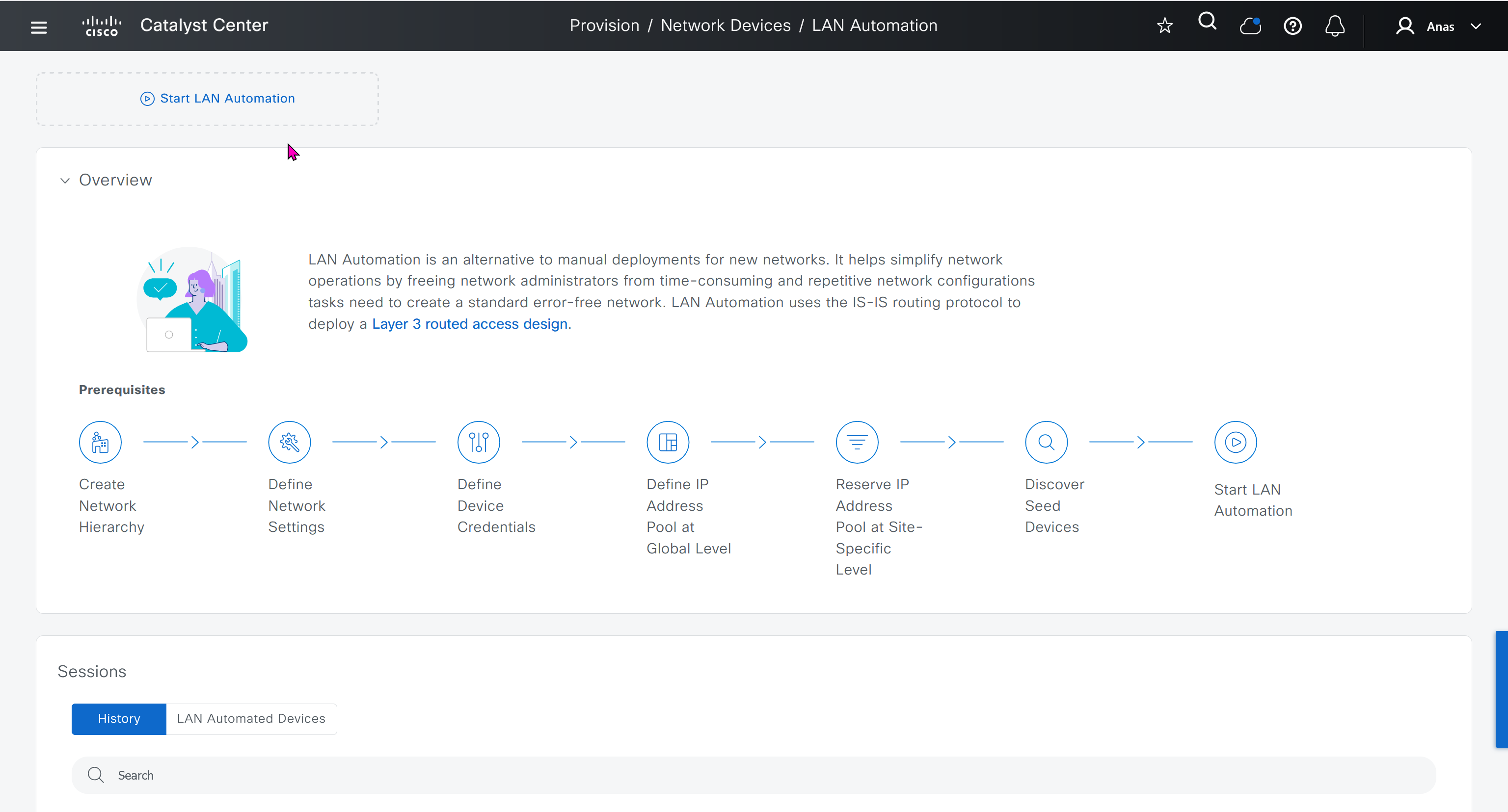
LAN automation is a network management process that
simplifies underlay deployment
eliminates manual, repetitive network configuration tasks, and
establishes a standard, error-free underlay network.
Cisco LAN automation provides:
Zero-touch provisioning: Network devices are dynamically discovered (CLI controlled), onboarded, and automated from their factory default state to fully integrated and configured state (templates can be configured since CLI controlled) in the network.
Dynamically build end-to-end routing topologies.
Cisco LAN automation enables redundancy and automates best practices to ensure resiliency during planned or unplanned network outages.
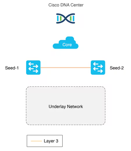
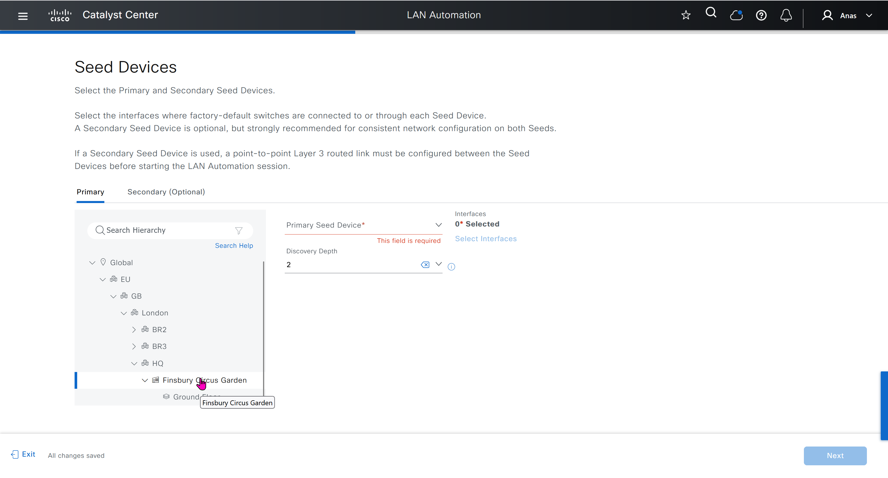
Seed device
Pre-deployed device and initial point through which LAN automation discovers and onboards new switches downstream
The seed device can run technologies such as Plug and Play (PnP) and zero-touch provisioning or configured manually.
Device discovery happens only on the primary seed device interfaces. One seed device can do the job but two can be deployed
PnP agent
The PnP agent is a Cisco Catalyst switch with factory default settings
The switch uses 0 day communication to communicate with Catalyst Center (PnP server)
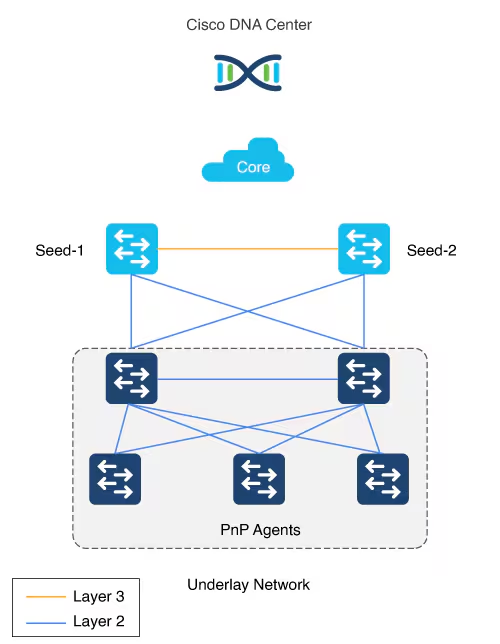
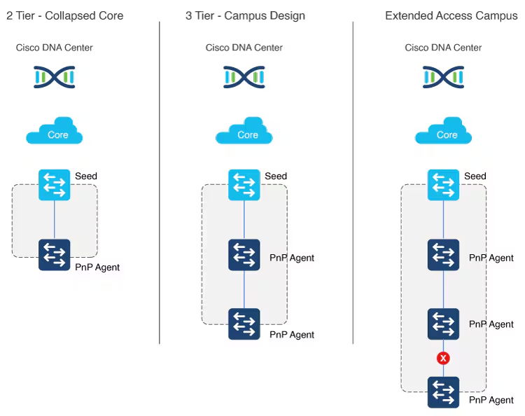
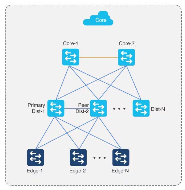
LAN automation in Catalyst Center supports a maximum of two hops from the initial automation boundary point device. Any additional network devices beyond two hops might be discovered but cannot be automated, Given that seed devices are core switches from the three tier model:
- Scenario 1: You have a three-tier network and you want to LAN “automate distribution and access layer switches”, both distribution- and access-layer switches will be discovered and LAN automated.
- Scenario 2: You have a three-tier network and you want to LAN automate distribution and access-layer switches. You already LAN automated the distribution layer. Later, you add access-layer switches to your network and you want to LAN automate these switches. “Because the distribution switches are already LAN automated and links converted to Layer 3, Tier 1 or core switches cannot be used as the seed. You must choose distribution as the seed in this scenario“.
Multistep LAN automation for large topologies: First pass
Large topologies are brought up by performing LAN automation multiple times. During the first pass, core devices are chosen as seed devices to bring up the “distribution” switches as new devices.
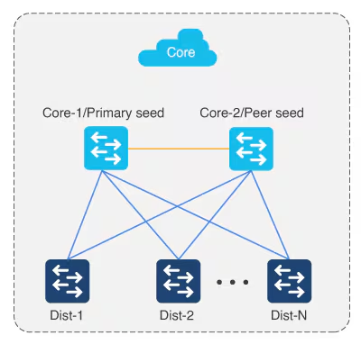
Multistep LAN automation for large topologies: Second pass with first group
During the second pass, two of the distribution switches act as seed devices to bring up the edge devices as new devices. All new devices in this session must connect directly to the two distribution switches that act as new seed devices. Repeat this process for the remaining set of distribution switches, two at a time (in pair).
Connect uplinks from edges to the primary and peer distribution switches only.
Always connect new devices to the primary seed device. Connection to the peer seed device is optional.
There can be two tiers of devices below the seeds.
Perform stacking before hand
Layer 3 link configuration after LAN Automation
After all devices are added to the Catalyst Center inventory, you can stop the LAN automation session on the GUI to begin the Layer 3 link configuration process.
If you accidentally stop the LAN automation process before all PnP devices are added to the Catalyst Center inventory, You must bring the in-progress devices to the factory-default state in order to do LAN automation again.
Catalyst Center Release 2.3.5 and later provide the support for day-n link configurations (add and delete link). For more information, see Create a link between interfaces.
Supported switches for each role at different layers
Site planning
Use the Catalyst Center Design feature to create the required sites, buildings, and floors.
Create a global pool in DNAC, reserve IP Pool specific per site
Different types of IP address assignments used:
- Temporary DHCP pool assigns IP to factory default pnp agents or new switches
- /31 L3 interswitch links
- Loopback IP
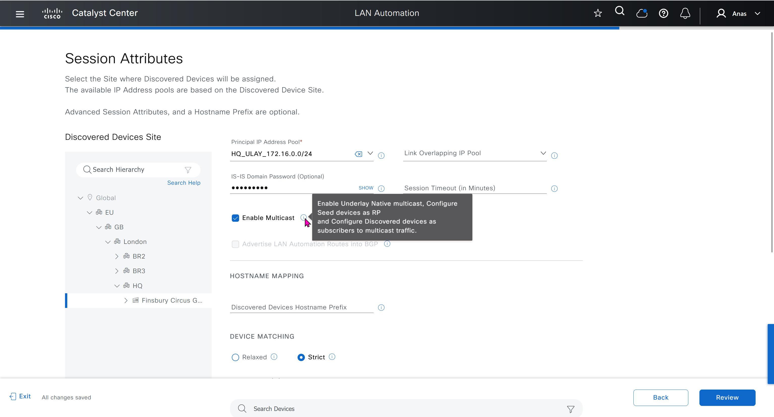
- Underlay multicast IP
Temporary DHCP pool so new device can get IP and speak to DNAC
One part of the IP pool per site, is reserved for a temporary DHCP server,
this DHCP server runs on DNAC itself and seed devices are used as relay to relay DHCP request from PnP agent or new switch without IP towards DNAC,
Temporary DHCP server (running on Catalyst Center) leases IP addresses from this temporary DHCP subpool.
Those IPs allow the new device to:
- Boot up with a valid IP address.
- Contact Catalyst Center over the network.
- Be discovered and provisioned automatically
Once the LAN automation session is finished:
- The DHCP service stops.
- The temporary subpool is released.
- All those IP addresses go back to the main LAN pool.
- The switches now have permanent IPs assigned by the automation process (usually from a different IP pool).
The size of this pool depends on the size of the parent LAN pool. For example, if the parent pool is 192.168.10.0/”24″, a /”26″ subpool is allocated for the DHCP server, Therefore, a /”24″ pool reserves /”26″ 64 hosts so we can think of this temporary DHCP pool size with the -2 rule
A /23 pool reserves /”25″ 128 hosts, a /22 pool reserves /24 256 hosts, and larger pools reserve (max) 512 IP addresses for the DHCP server, it steps up in this way and max pool size is 512 addresses for even bigger parent pools
for example initial blocks of 192.168.10.0/24 can be used since site is not operational and LAN automation is being run to deploy the site, once LAN automation is complete these chunks are released back in order for them to be reserved in site and used
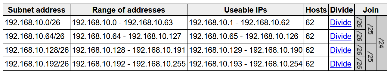
To start LAN automation, the pool size must be atleast /25, which reserves a /27 pool or 32 IP addresses for the DHCP pool.
This IP pool is reserved temporarily for the duration of the LAN automation discovery session. After the LAN automation discovery session completes, the DHCP pool is released, and the IPs are returned to the LAN pool
IP pool for loopback and /31 interswitch links
Another part of the IP pool is reserved internally with a subpool of fixed size /27. This subpool is for allocating single IPs for Loopback0 and Loopback60000 always. Also, two consecutive IPs for point-to-point L3 /31 links are allocated from this subpool also, if this pool is exhausted a new /27 subpool is created for allocating IPs
the subpools remain throughout the process and are not allowed to be removed. Due to this internal subpool allocation logic, the IP pool usage in IPAM counts the subpools as allocated.
When a dedicated (single) IP pool is used to build the underlay networks, each of the devices discovered via LAN automation gets a unique /31 per interface for point-to-point connection, and a unique /32 for Loopback0 and the underlay multicast.
Single Site vs Shared IP pool (overlaps between sites)
When a dedicated (single) IP pool is used to build the underlay networks, each device discovered via LAN automation gets a unique /31 per interface for point-to-point connection, and a unique /32 for Loopback0 and the underlay multicast.
A link overlapping IP pool (only for /31 interswitch links) or shared IP pool is used to optimize the IPv4 addressing in the underlay network by allowing overlapping /31 IP addresses for a multisite deployment. Hosts in different sites can get duplicate IP addresses on the /31 links. The /31s in the underlay are not advertised outside of the fabric site and hence there is no need for them to be unique. However, the /32 loopback needs to be unique to every device, and should be advertised to the global routing table to identify the device in the entire network.
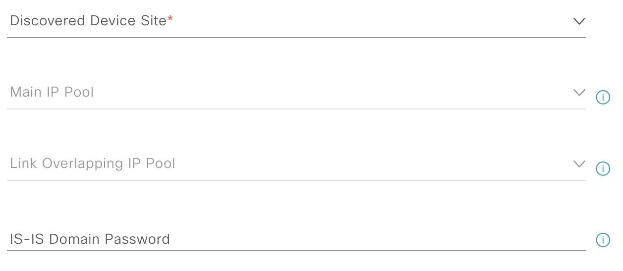
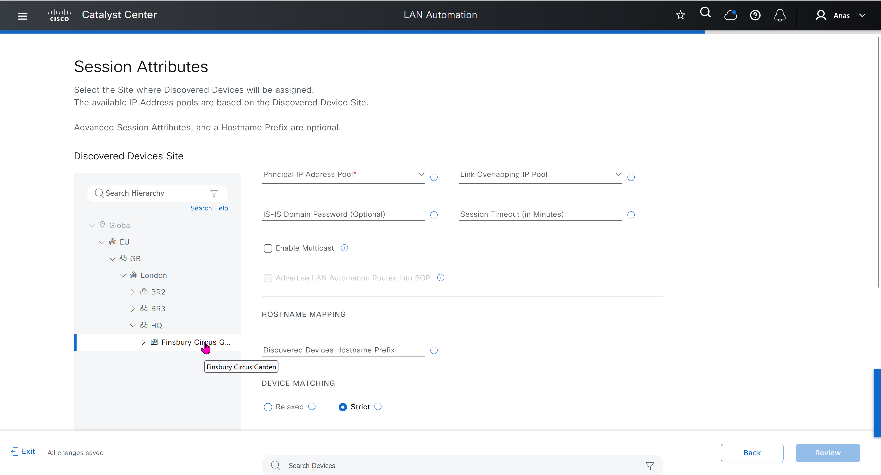
IP pool roles
The LAN IP pool can have these two roles:
- Link Overlapping IP Pool: This pool role is optional for a LAN automation session. If provided, the allocation of IP addresses is only on the /31 point-to-point Layer 3 links, and can be same through out different sites, hence overlapping is in the name.
- Main IP Pool (Principal IP Address Pool in Catalyst Center Release 2.3.5 and later): This pool role is mandatory for every LAN automation session. This is the pool that is used for all management-related IP addressing such as loopbacks, multicast, and DHCP. If the Link Overlapping IP Pool is not provided, then the Main IP Pool is the default fallback pool for the /31 Layer 3 links IP addressing also.
Configuration on seed devices
- Ensure that the system MTU (maximum transmission unit) value is at least 9100 or jumbo frame –
show sys mtu - Turn on IP routing on the seed devices.
- Enable DNA advantage license
- Enable CLI credentials from DNAC
- Enable SNMP strings from DNAC
- Enable ssh
- Enable local authentication
- Enable netconf-yang
- Enable privilege level 15 on vty lines
- ip name-server 172.16.32.11
- ip domain name or2.sys.cisco
IP address allocation in Catalyst Center Release 2.3.7.x and later
In Catalyst Center Release 2.3.7.x and later, IP address allocation from LAN pool is based on IP address range instead of subnet allocation. This approach helps in minimizing the issue of IP address loss during subnet creation and in effective management of the IP addresses. Instead of creating a subnet, IP address range is blocked for both DHCP pool allocation and IP address assignment for point-to-point links, loopback, and multicast.
LAN Automation Example
Imagine you want to LAN automate 10 devices in a site using the same pool, where each device has one link to the primary seed and another link to the secondary.
Consider a 192.168.199.0/24 as an example pool. When LAN automation starts,
a first /26 pool is reserved for the DHCP addresses. In this example, 192.168.199.”1″ to 192.168.199.”63″ are reserved and assigned to VLAN 1 for the 10 devices.
Next, a “/27” pool is reserved for loopback addresses.
If there is no shared IP pool, then this pool is used for point-to-point links as well.
Because there are 10 devices with two links each, a total of 40 IP addresses are reserved for point-to-point links,
40 addresses because each switch needs 4 IP addressess (2 assigned on switch’s uplinks itself and 1 assigned on primary seed device and 1 assigned on peer seed device)
In total, 60 IP addresses are reserved for the 10 devices: 10 for each VLAN 1, 10 for each loopback, and 40 for the point-to-point links between devices and seeds.
After LAN automation stops, the VLAN 1 IP addresses are released back to the pool
We recommend that you use the default interfaces connected to PnP agents. If the peer seed device has IP interfaces configured on the interfaces connected to PnP agents, those links are not configured. Default the interfaces connected to ono agents and perform an inventory synchronization on the peer seed device. LAN automation works only when the ports are Layer 2. The ports on the Cisco Catalyst 6000 Series Switches are Layer 3 by default. Convert the ports to Layer 2 before starting LAN automation.
LAN automation configures loopback on the seed devices if they are not configured.
If you change configuration on the seed devices before running LAN automation, synchronize the seed devices with the Catalyst Center inventory.
If you plan to run multiple discovery sessions to onboard devices across different buildings and floors connected to the same seed devices, we recommend that you block the ports for PnP agents that do not participate in the upcoming discovery session yet.
For example, imagine seed devices in Building-23 connected to PnP agents on Floor-1 and Floor-2. Floor-1 devices are connected on interfaces Gig 1/0/10 through Gig 1/0/15. Floor-2 devices are connected on interfaces Gig 1/0/16 through Gig 1/0/20. For the discovery session on Floor-1, we recommend that you shut down ports connected to Gig 1/0/16 through Gig 1/0/20. Otherwise, the PnP agents connected to Floor-2 might also get DHCP IPs from the server running on the primary seed device. Because these interfaces aren’t selected for the discovery session, they remain as stale entries in the PnP database. When you run the discovery session for Floor-2, the discovery doesn’t function correctly until these devices are deleted from the PnP application and write erase/reloaded. Therefore, we recommend that you shut down other discovery interfaces
For Catalyst Center Release 1.2.8 and earlier, if clients are connected to a switch being discovered, they may contend for DHCP IP and exhaust the pool, causing LAN automation to fail. Therefore, we recommend that you connect the client after LAN automation is complete. but that is for older DNAC versions
This endpoint/client integration restriction does not apply to Catalyst Center Release 1.2.10 and later. Clients can remain connected while the switch is undergoing LAN automation.
on the edge nodes add license and then reset pnpa so pnp wizard becomes active after putting license
otherwise LAN Automation commands will fail as there is no dna-advantage
license boot level network-advantage addon dna-advantage
end
write mem
reload
pnpa service reset no-promptSteps for LAN Automation
- Default the interfaces connected to agents and perform an inventory synchronization on the peer seed device
- LAN automation configures loopback on the seed devices if they are not configured.
- If you change configuration on the seed devices before running LAN automation, synchronize the seed devices with the Catalyst Center inventory.
- Add Site > Add Area
- Add Site > Add Building
- Add Site > Add Floor
- Design > Network Settings > Device Credentials
- Manage Credentials
- CLI
- SNMPV2C Read
- Netconf
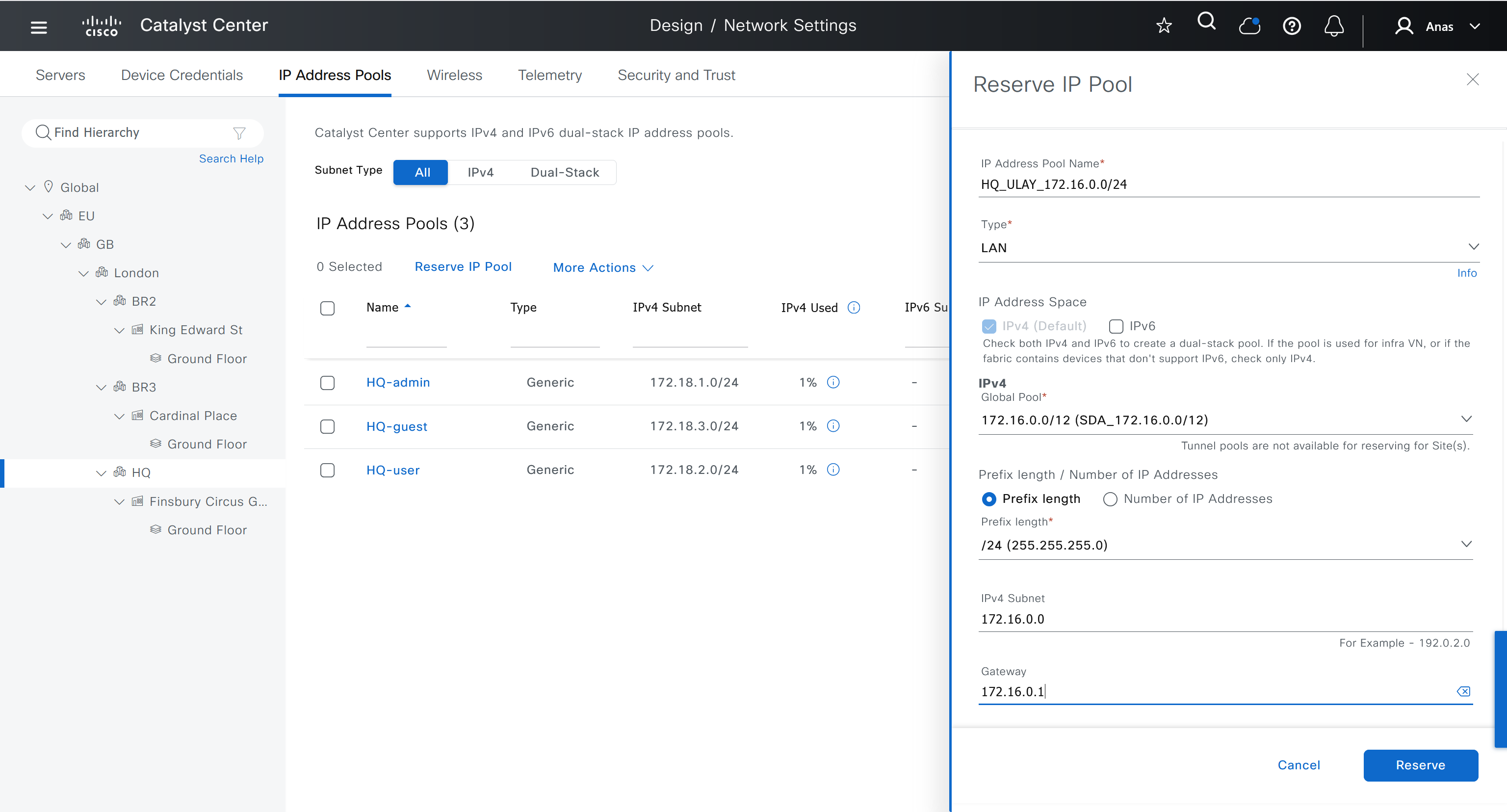
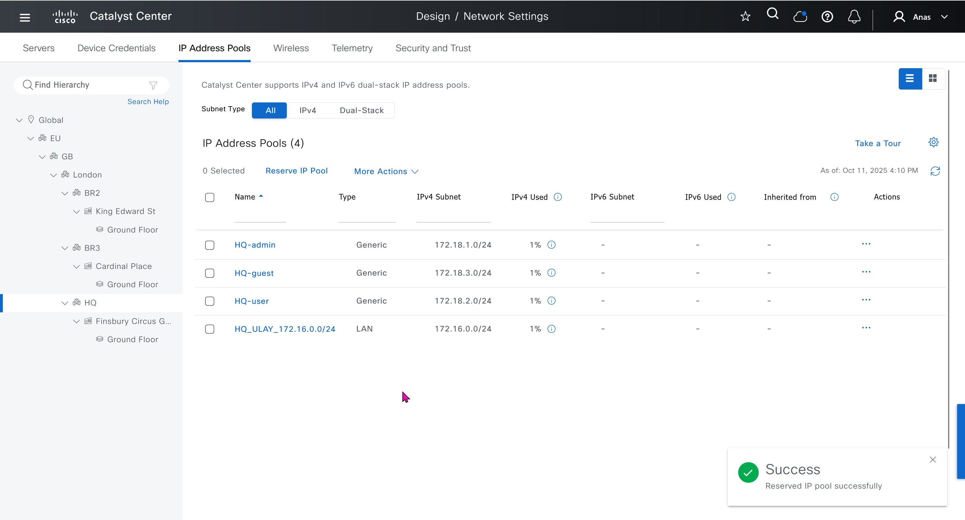
- Create an underlay pool that is not used any where in the network
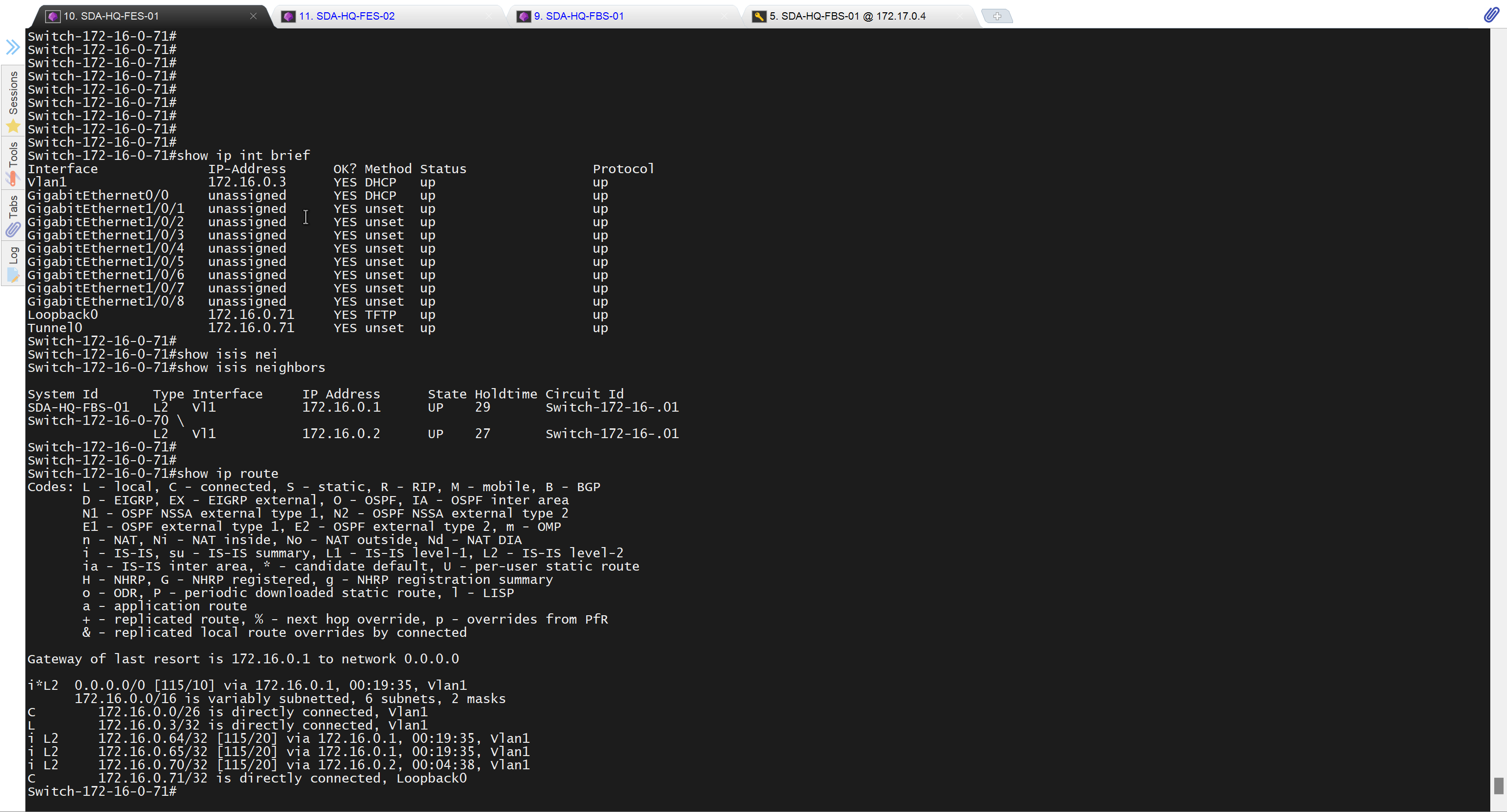
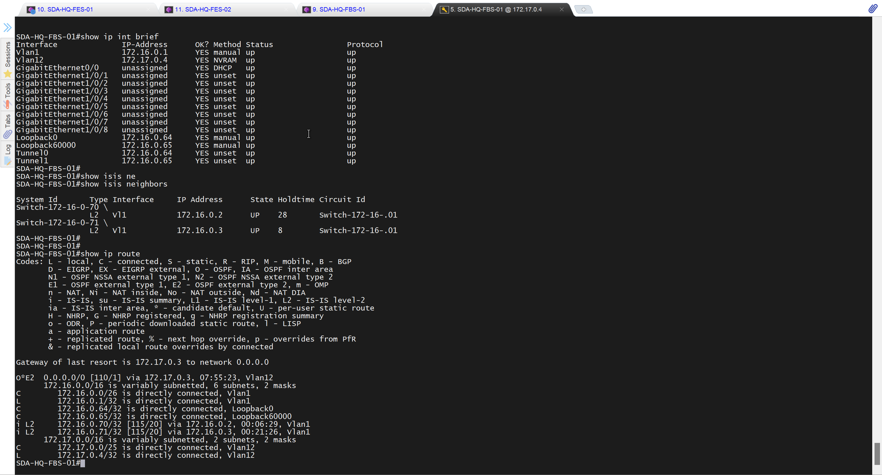
See how the gateway address is set 172.16.0.1 and you ask why is that needed?
This is the address that will be assigned to FBS on vlan 1 interface (which is removed later on once LAN automation ends)
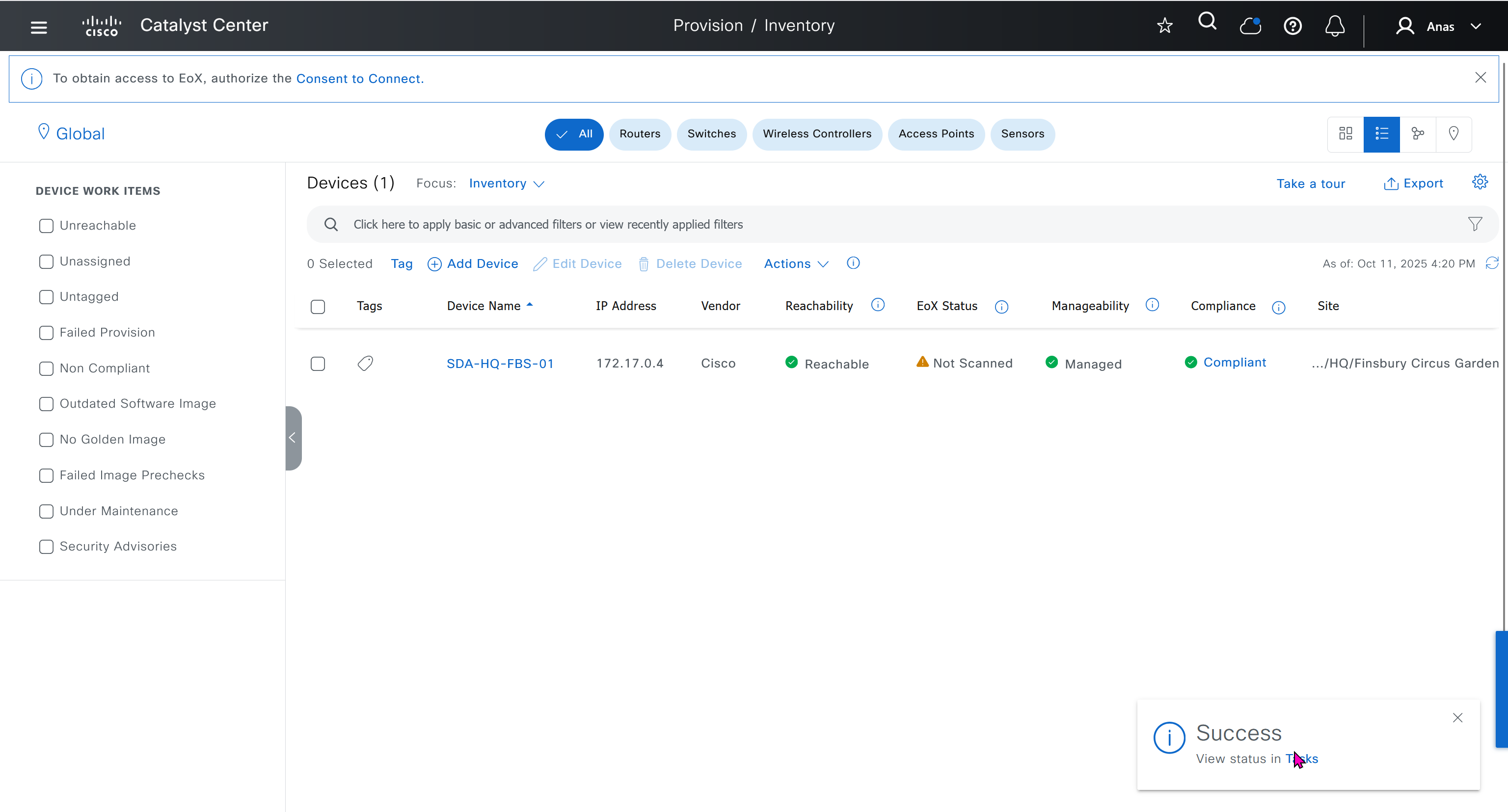
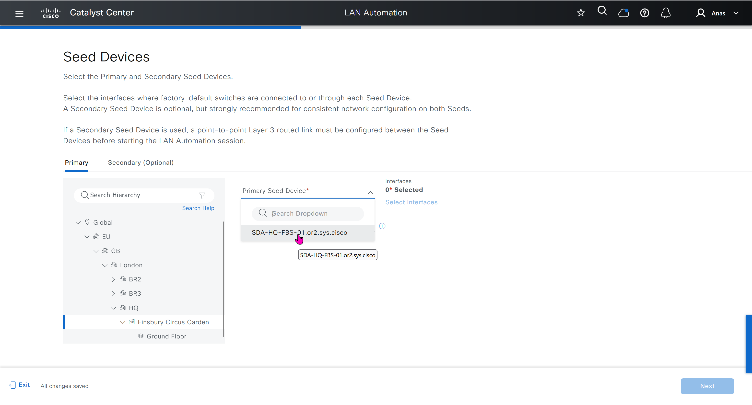
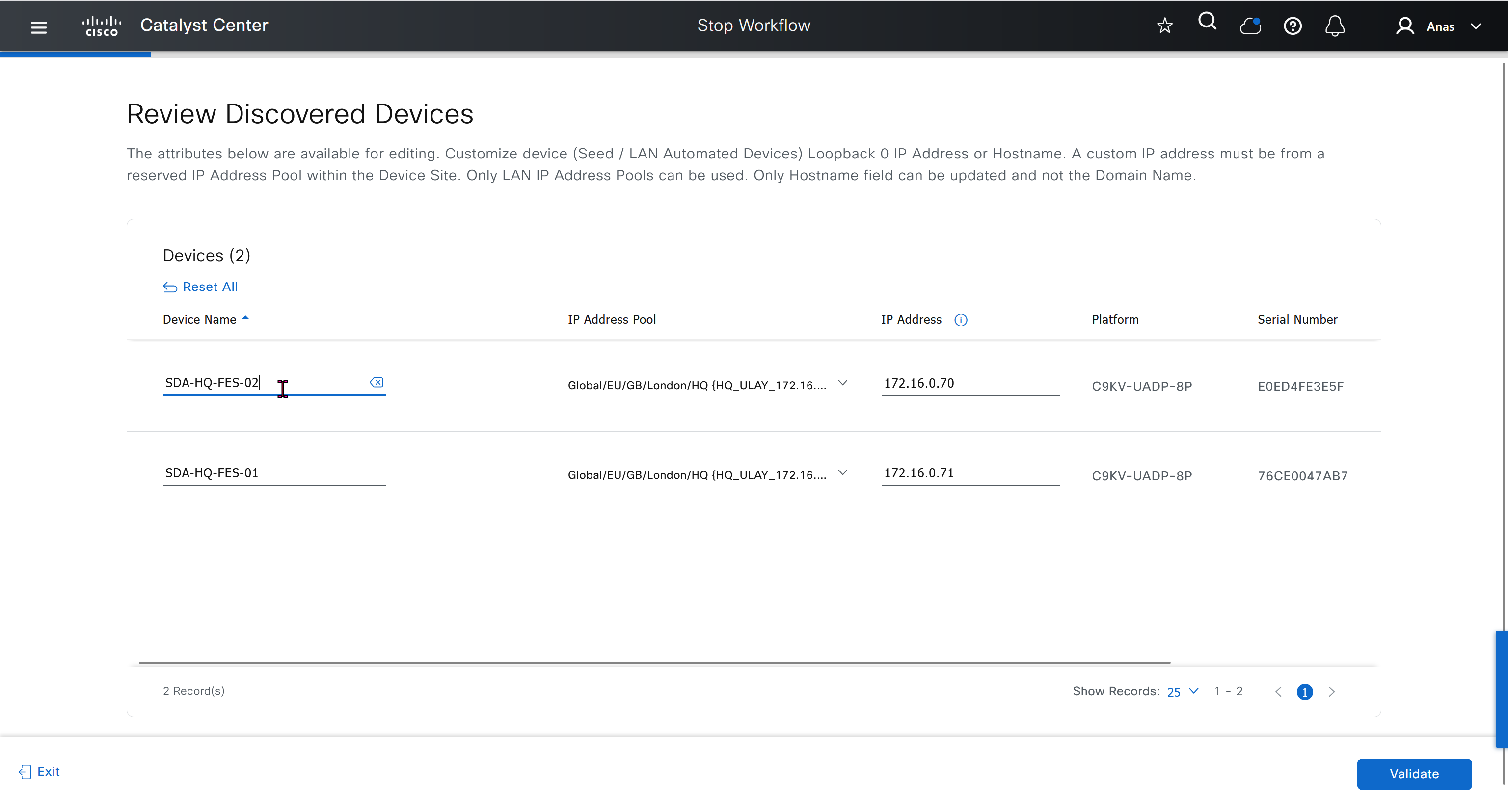
- Discover seed devices with discovery
- Make sure that discovered devices are in Reachable + Managed state
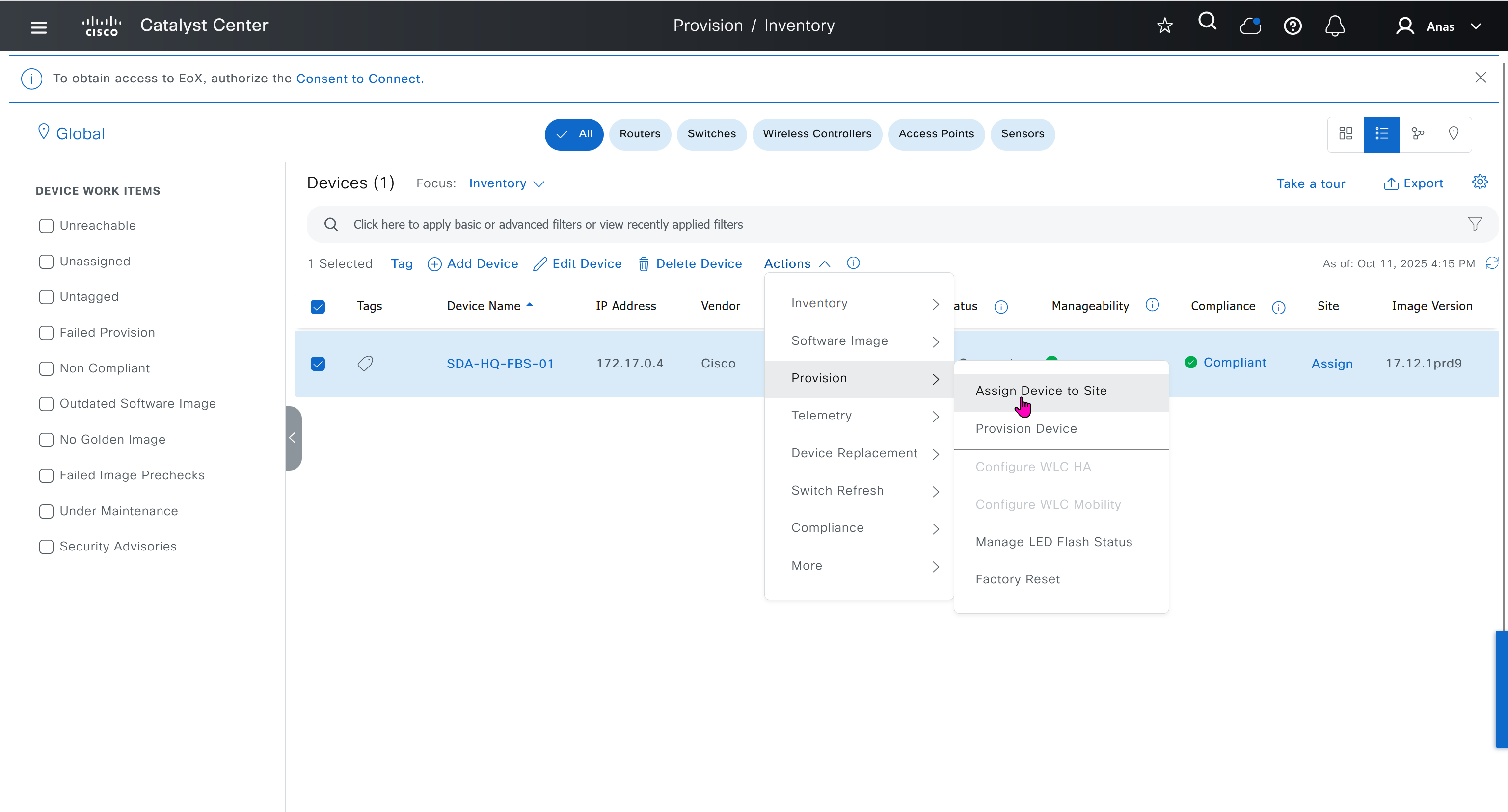
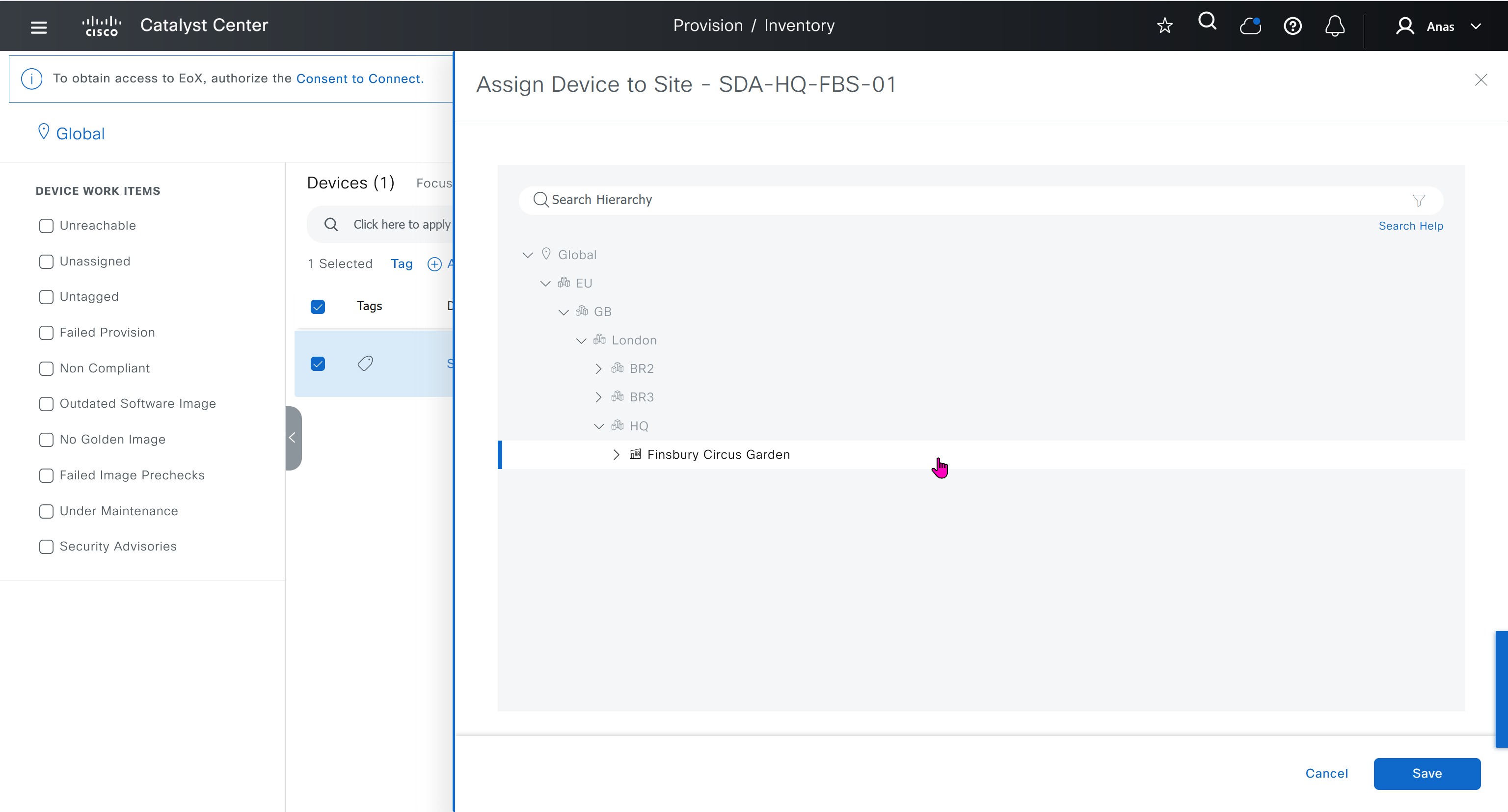
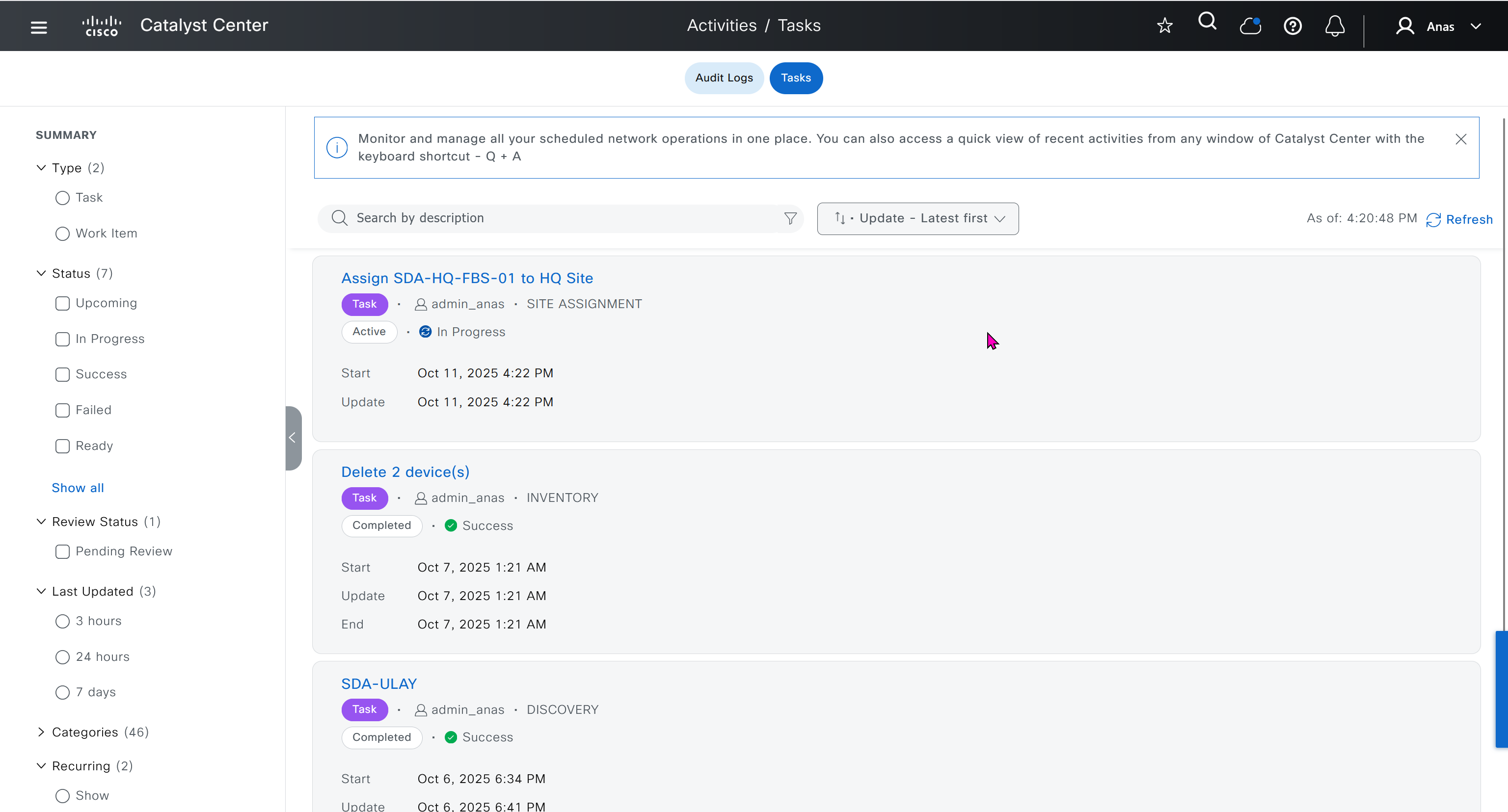
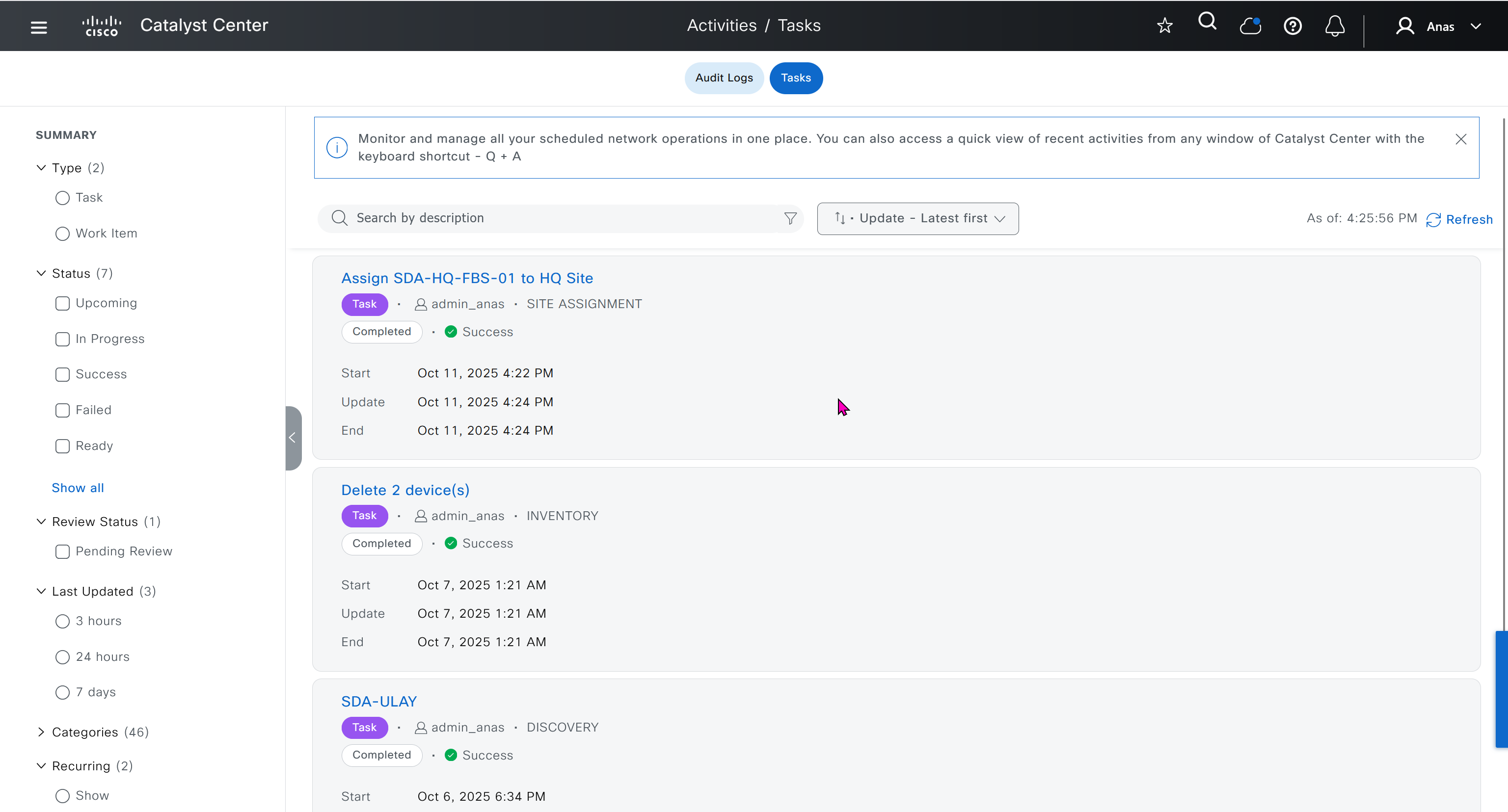
- Actions > Provision > Assign Device to Site to assign the device to a site.

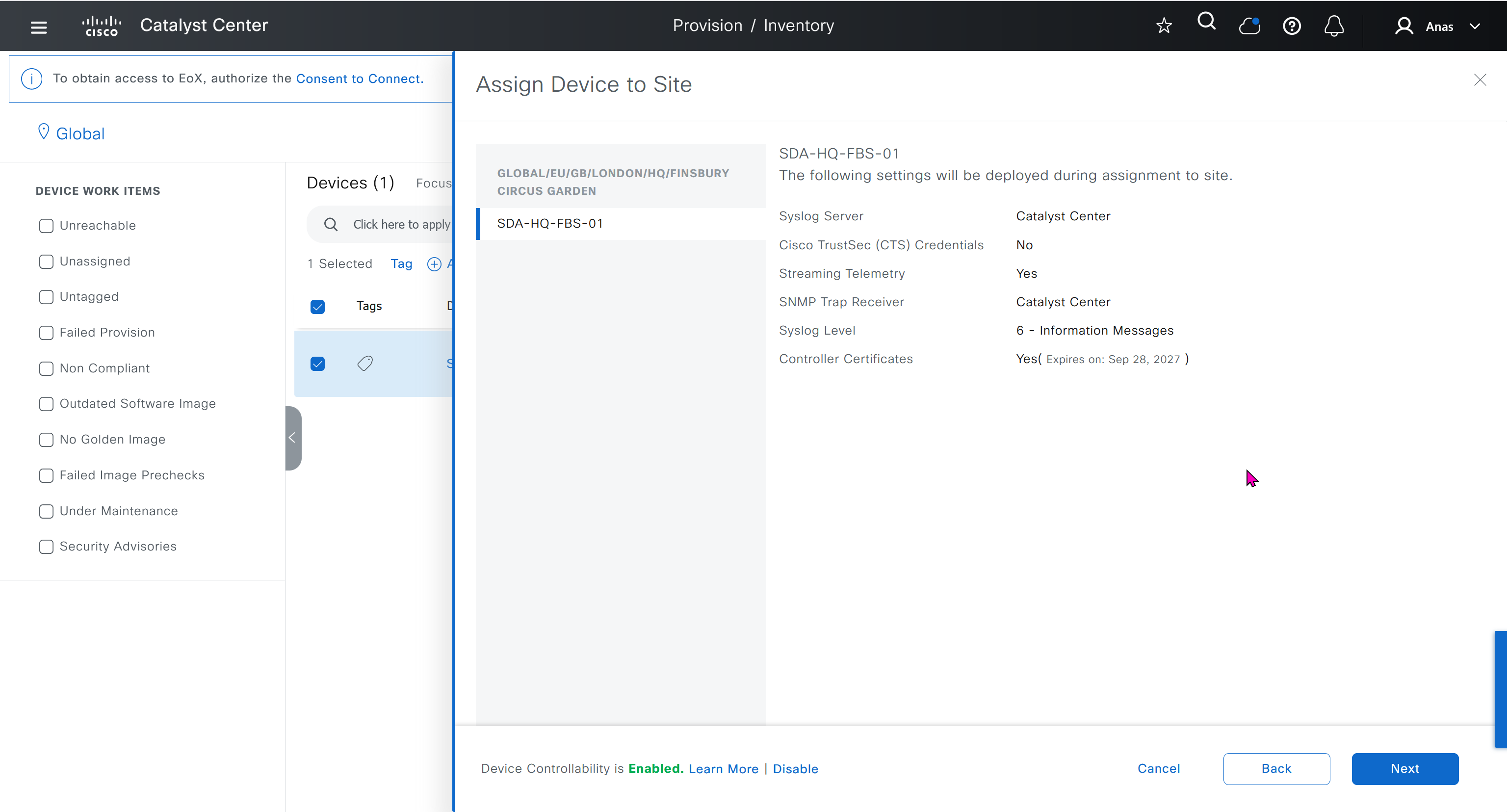


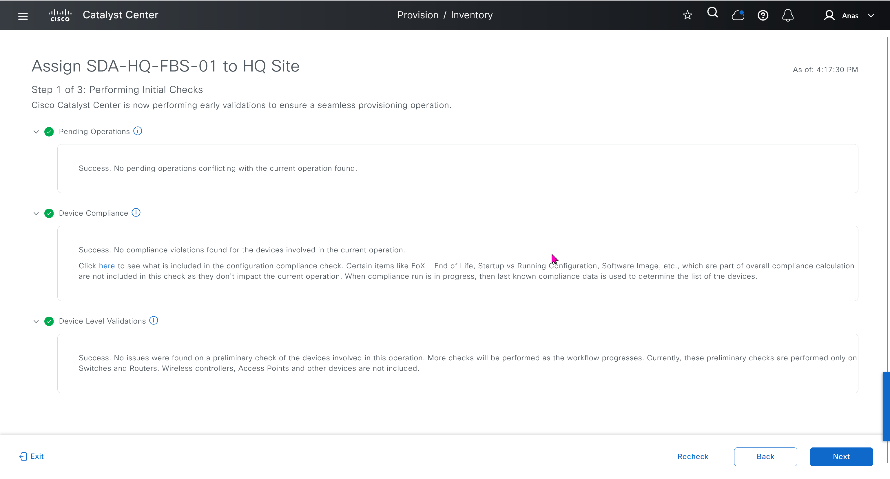
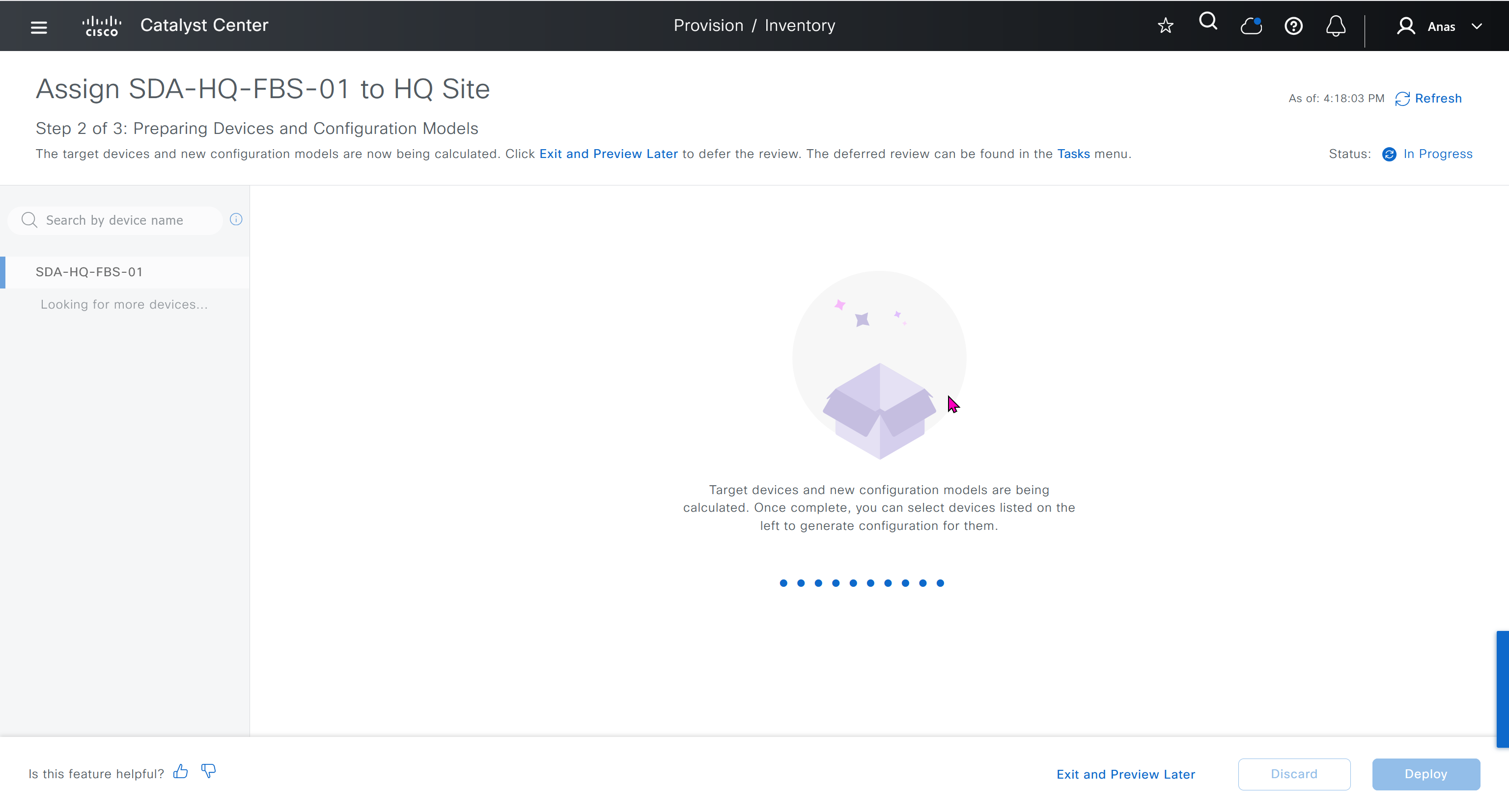
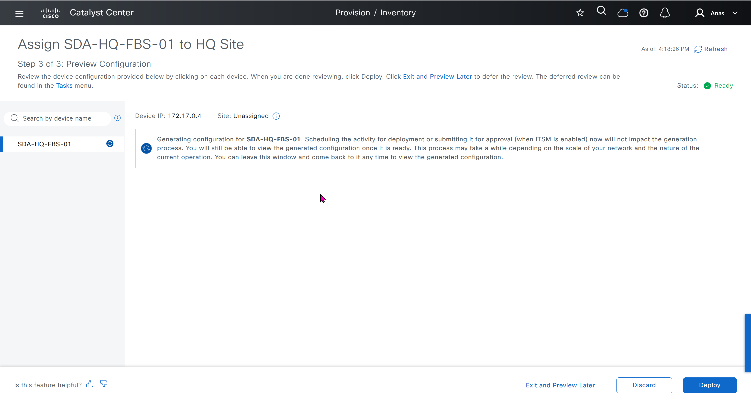
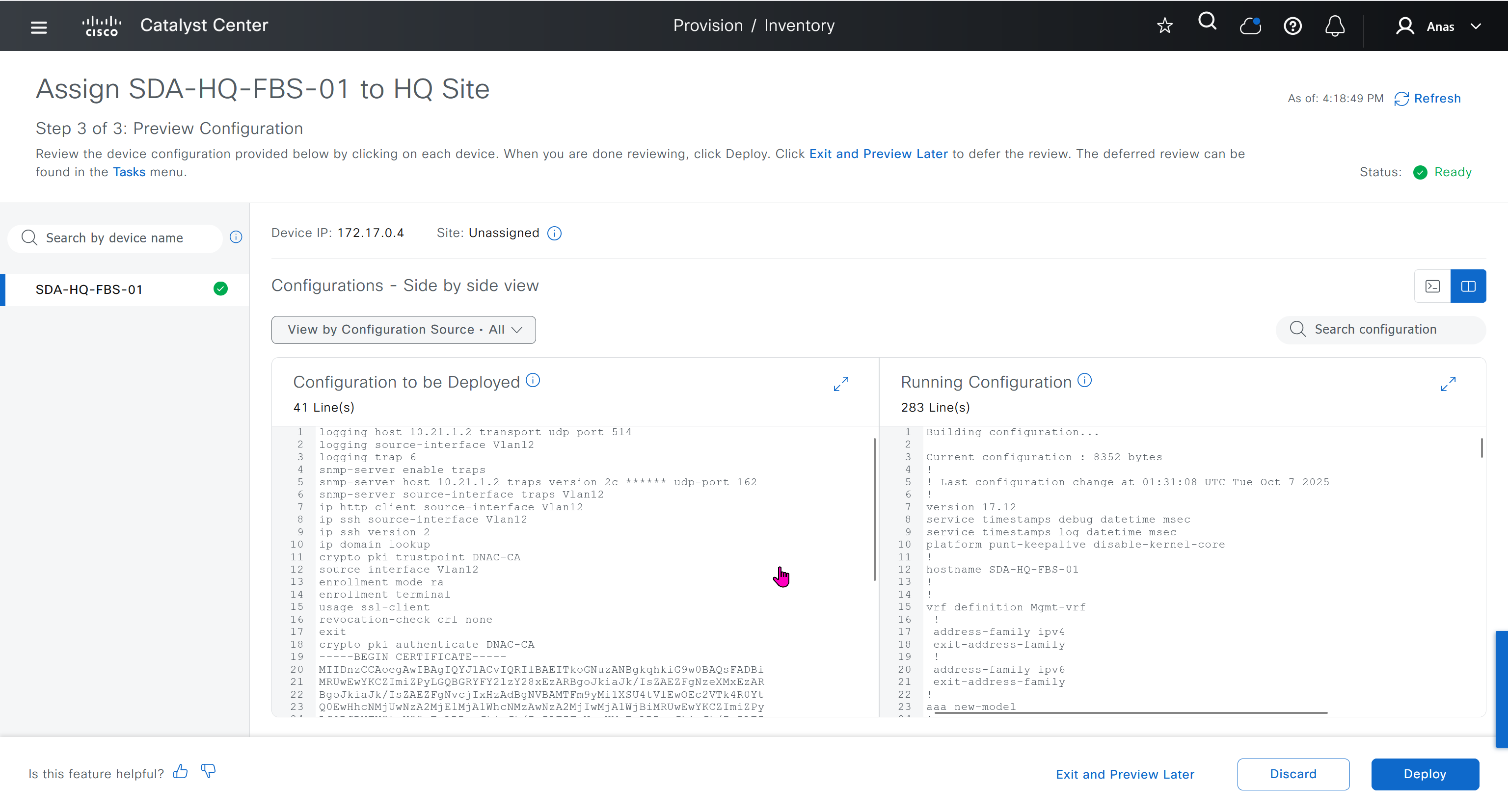

This is the configuration that will go on the seed device after only addign it to the site
logging host 10.21.1.2 transport udp port 514
logging source-interface Vlan12
logging trap 6
snmp-server enable traps
snmp-server host 10.21.1.2 traps version 2c ****** udp-port 162
snmp-server source-interface traps Vlan12
ip http client source-interface Vlan12
ip ssh source-interface Vlan12
ip ssh version 2
ip domain lookup
crypto pki trustpoint DNAC-CA
source interface Vlan12
enrollment mode ra
enrollment terminal
usage ssl-client
revocation-check crl none
exit
crypto pki authenticate DNAC-CA
-----BEGIN CERTIFICATE-----
MIIDnzCCAoegAwIBAgIQYJ1ACvIQRIlBAEITkoGNuzANBgkqhkiG9w0BAQsFADBi
MRUwEwYKCZImiZPyLGQBGRYFY2lzY28xEzARBgoJkiaJk/IsZAEZFgNzeXMxEzAR
BgoJkiaJk/IsZAEZFgNvcjIxHzAdBgNVBAMTFm9yMi1XSU4tVlEwOEc2VTk4R0Yt
Q0EwHhcNMjUwNzA2MjE1MjA1WhcNMzAwNzA2MjIwMjA1WjBiMRUwEwYKCZImiZPy
LGQBGRYFY2lzY28xEzARBgoJkiaJk/IsZAEZFgNzeXMxEzARBgoJkiaJk/IsZAEZ
FgNvcjIxHzAdBgNVBAMTFm9yMi1XSU4tVlEwOEc2VTk4R0YtQ0EwggEiMA0GCSqG
SIb3DQEBAQUAA4IBDwAwggEKAoIBAQCr6cjaoJz3vzgHlQ1hzhuy5WfIL/Ao0isM
ltIaGL+Z+9WftM1hNh10YECbxR71+lIpQKyBQTXQz8Of4nycxHjoI3dQdUvEYb8H
fysDXh4lYjQ60x82e5c7f1KPbD+AOhC31Zw1dgReMlPIuaa9LK903+z0FRnuCHaI
EG/Z9uCmv3JC22NgL69hscZc+NUGymMy1iBPN8G4EBkgqNVZ+zlRf/adW0JxEdc6
Sy53bp586/fXziRTW++jgdnhvfpn+VJ+BdG88/rEgMl7PUQE95lq4dih7qx0+OXu
ihFwQQvFxvi3dyqWWc0C1RKHPHtYQFz8rRuBJrR+uzgc0lVhrNHdAgMBAAGjUTBP
MAsGA1UdDwQEAwIBhjAPBgNVHRMBAf8EBTADAQH/MB0GA1UdDgQWBBQ/bI8yZeKD
fgjmmeWorjGo25t5hzAQBgkrBgEEAYI3FQEEAwIBADANBgkqhkiG9w0BAQsFAAOC
AQEAdtt6aiABkDDg/mAlcZfFPHcqmEEvQaMPeBaUqvfZKNrFVO8GMb9kingZJ62n
K05x5wE3tHy3jBmAl6eHZ/nUjXS11C06NwZMHpcDhty5BcDN08oEYdLF24upisNA
aRLOBhyEtKI9VKLAWfMkpWYEd/dqgVWs67GjAFT0Osgva9QHbz24iT6/c09jbZMt
41opmxacw8FFZcHMH9Afv1fIW9PwscrdlgjSSHR4XQLyDbyuDGsolzeh9PUVyPOd
f+/LYkLwH9jVcHlxl4Oy7MHRPtcbG9T3+vQGLjSAXu3Ybrl2R9Tn/sz5lYs44EEB
mqCxT00LxB3et6jAxJlEyE5vCw==
-----END CERTIFICATE-----
do cts credentials id 7c71627623014c0a83668477604a0c57 password ******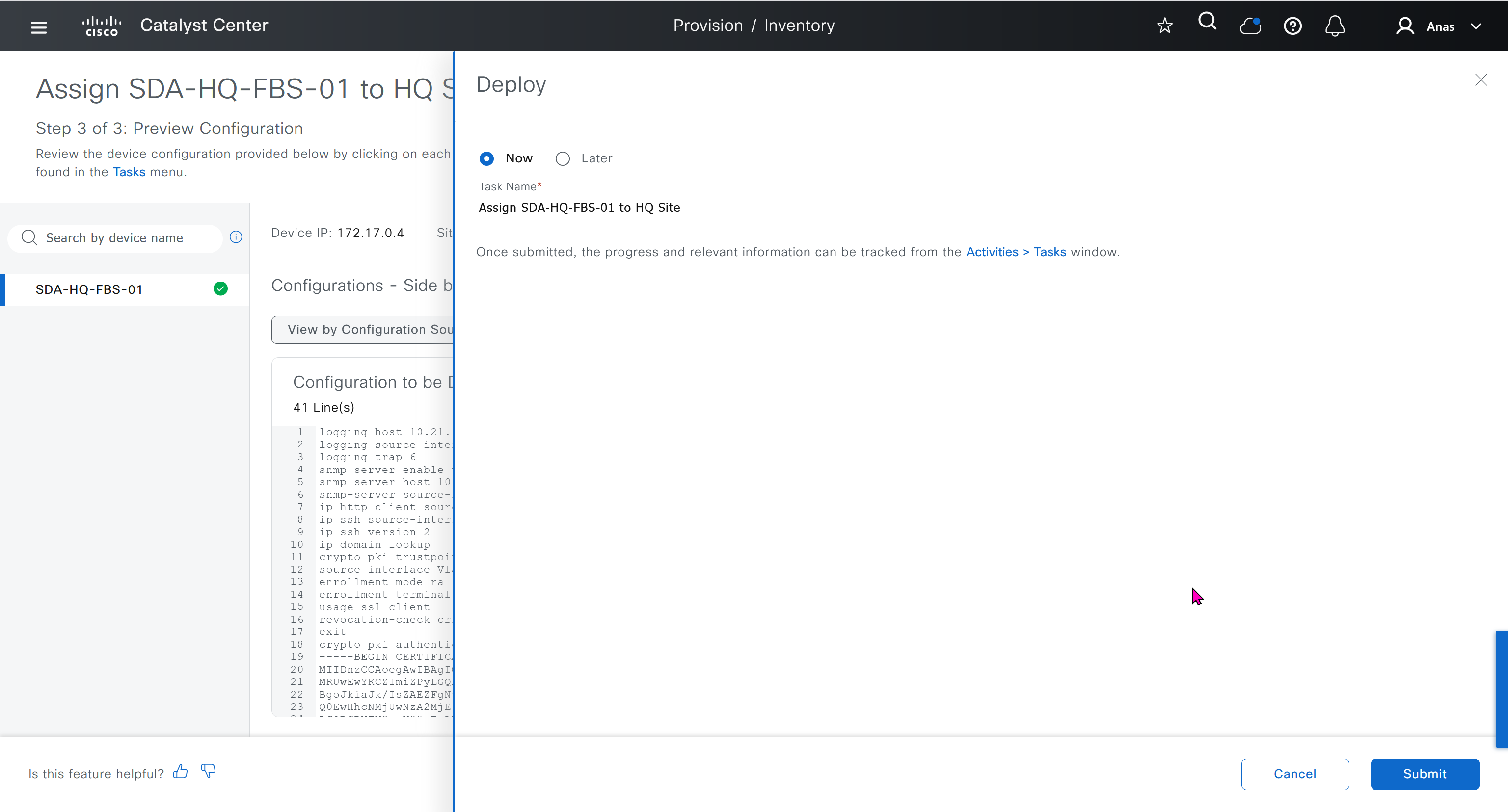
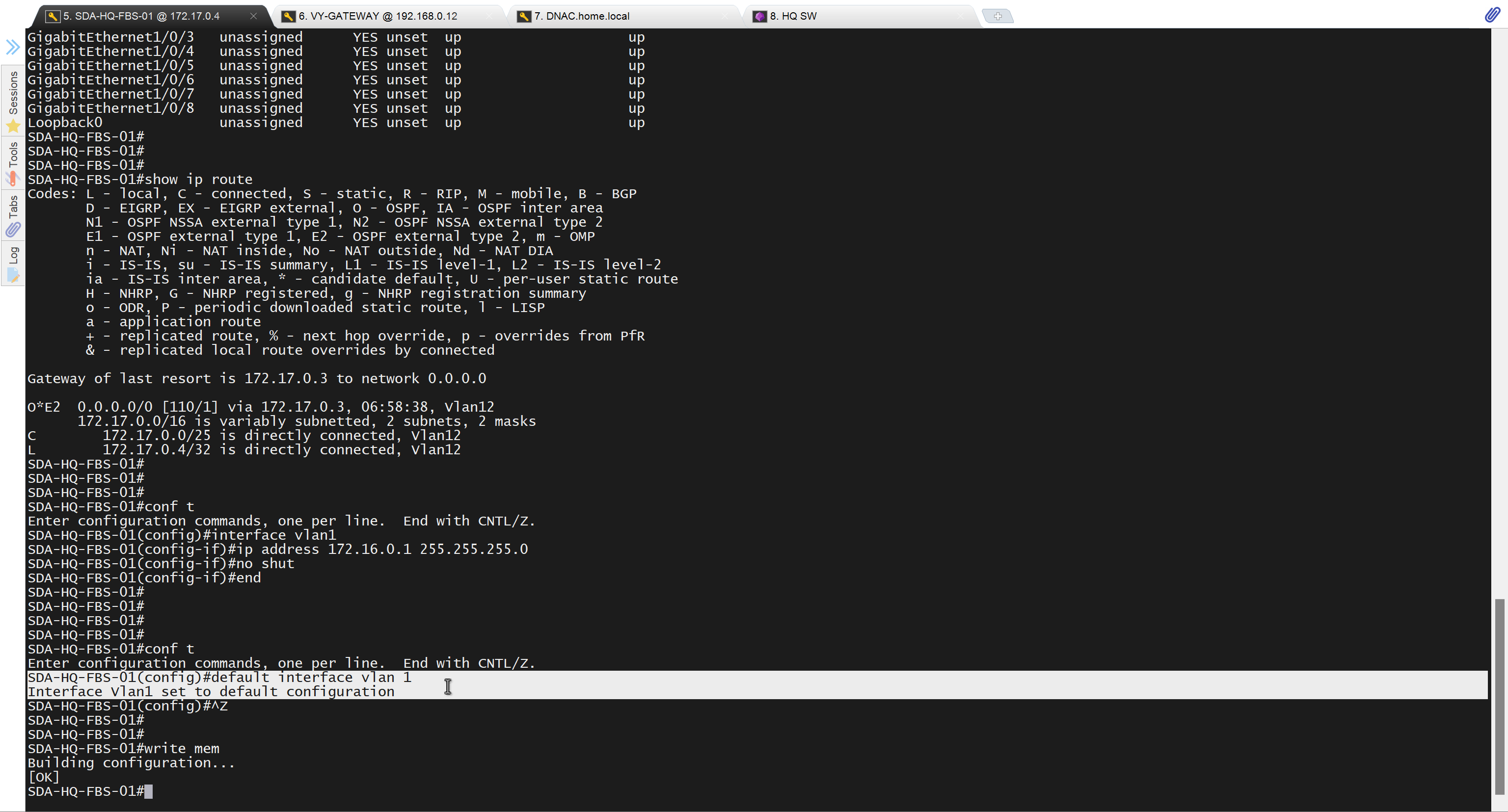
SDA-HQ-FBS-01# conf t
SDA-HQ-FBS-01# ! for reachability testing only
SDA-HQ-FBS-01# interface vlan 1
SDA-HQ-FBS-01# ip address 172.16.0.1 255.255.255.0
SDA-HQ-FBS-01# end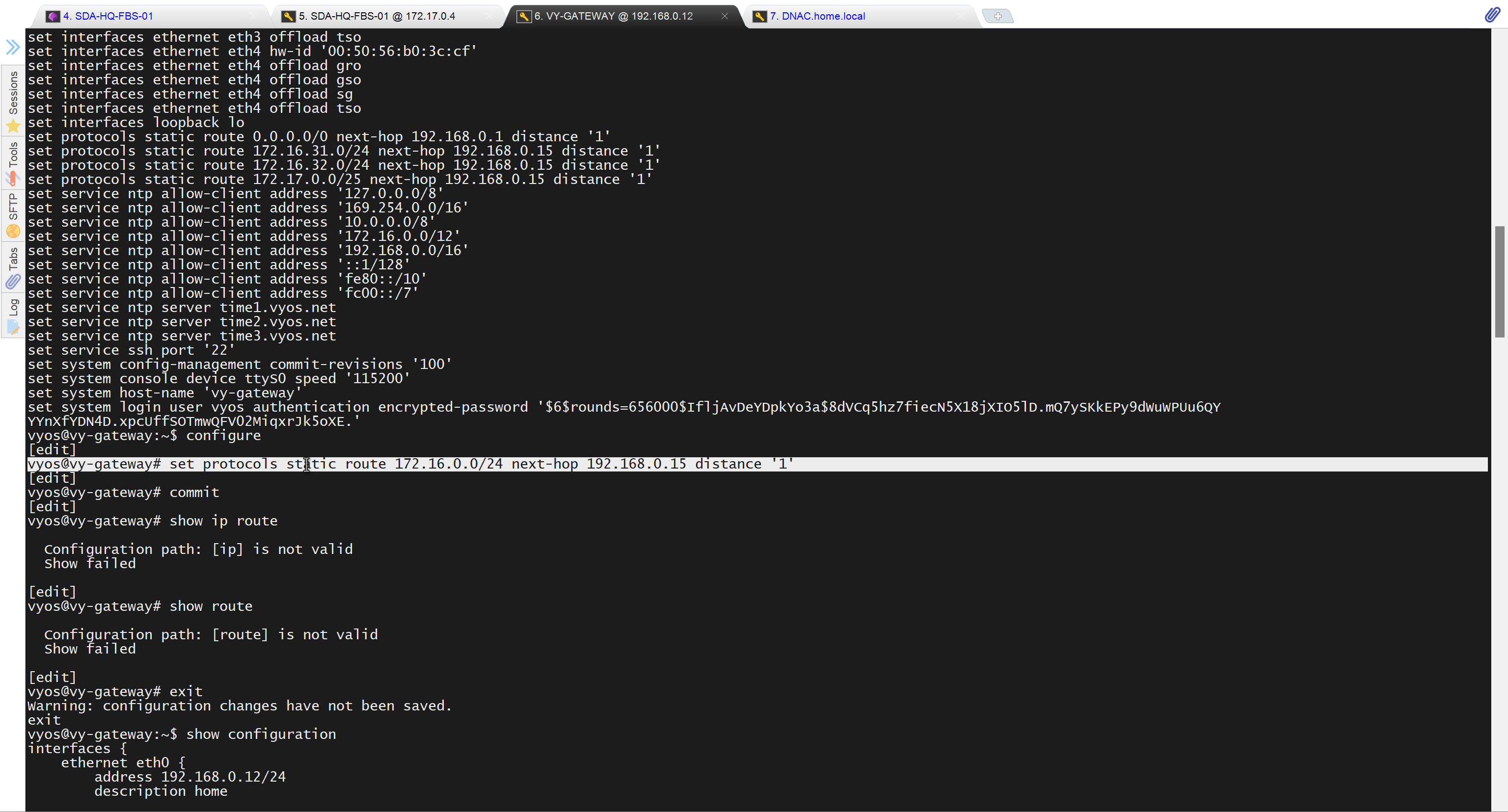
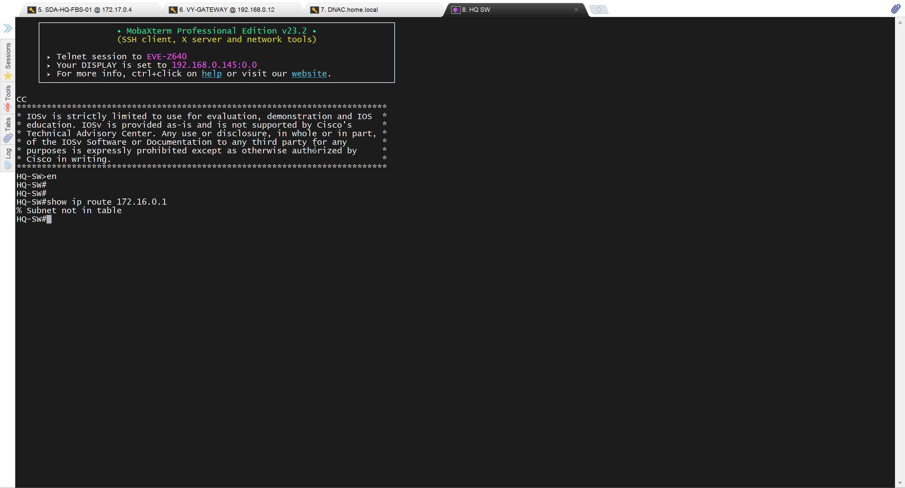
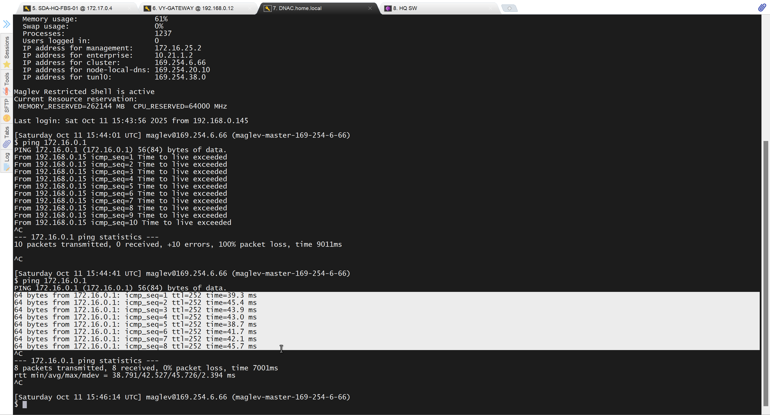
unable to reach
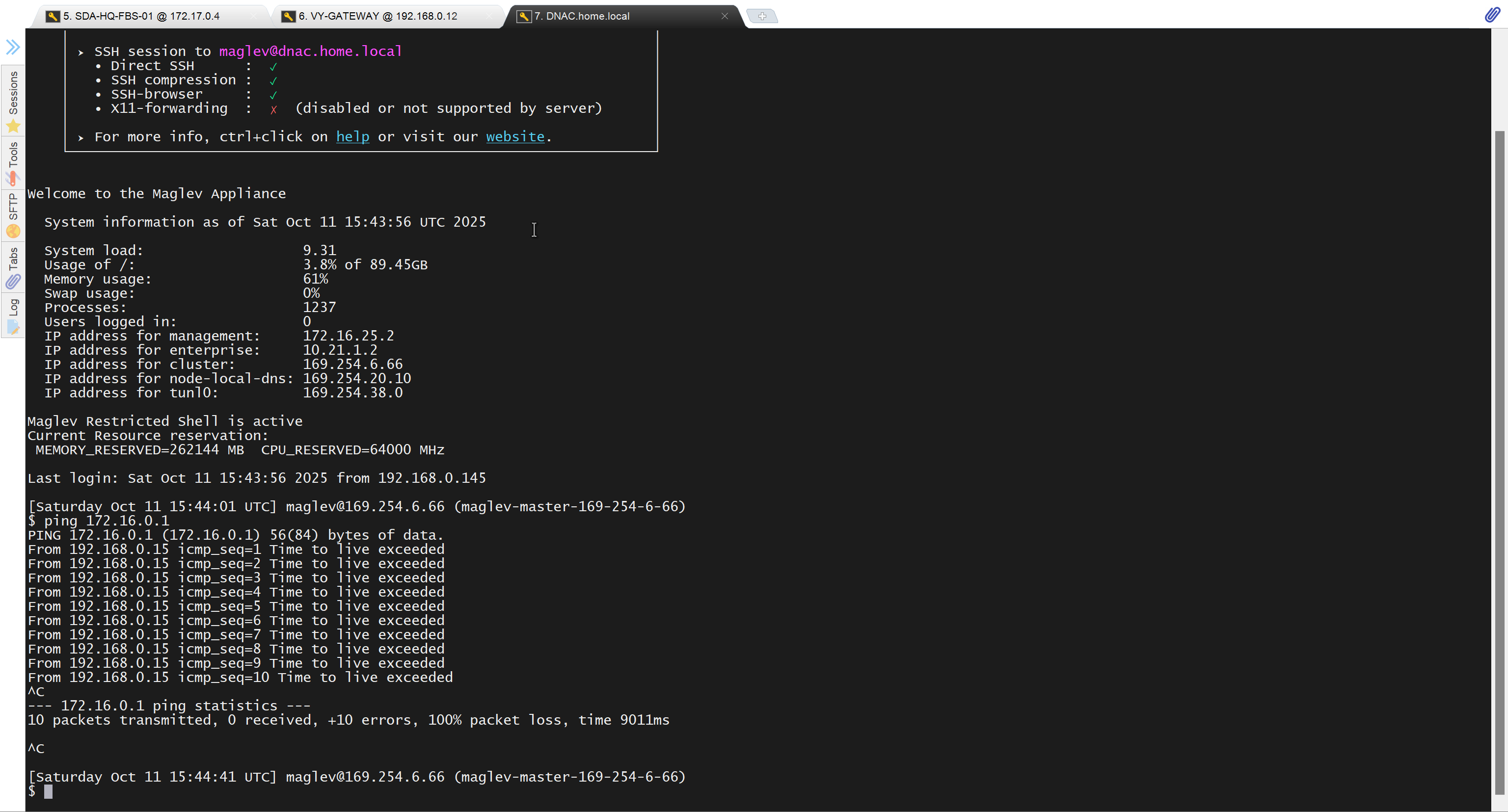
because missing route on HQ-SW in lab
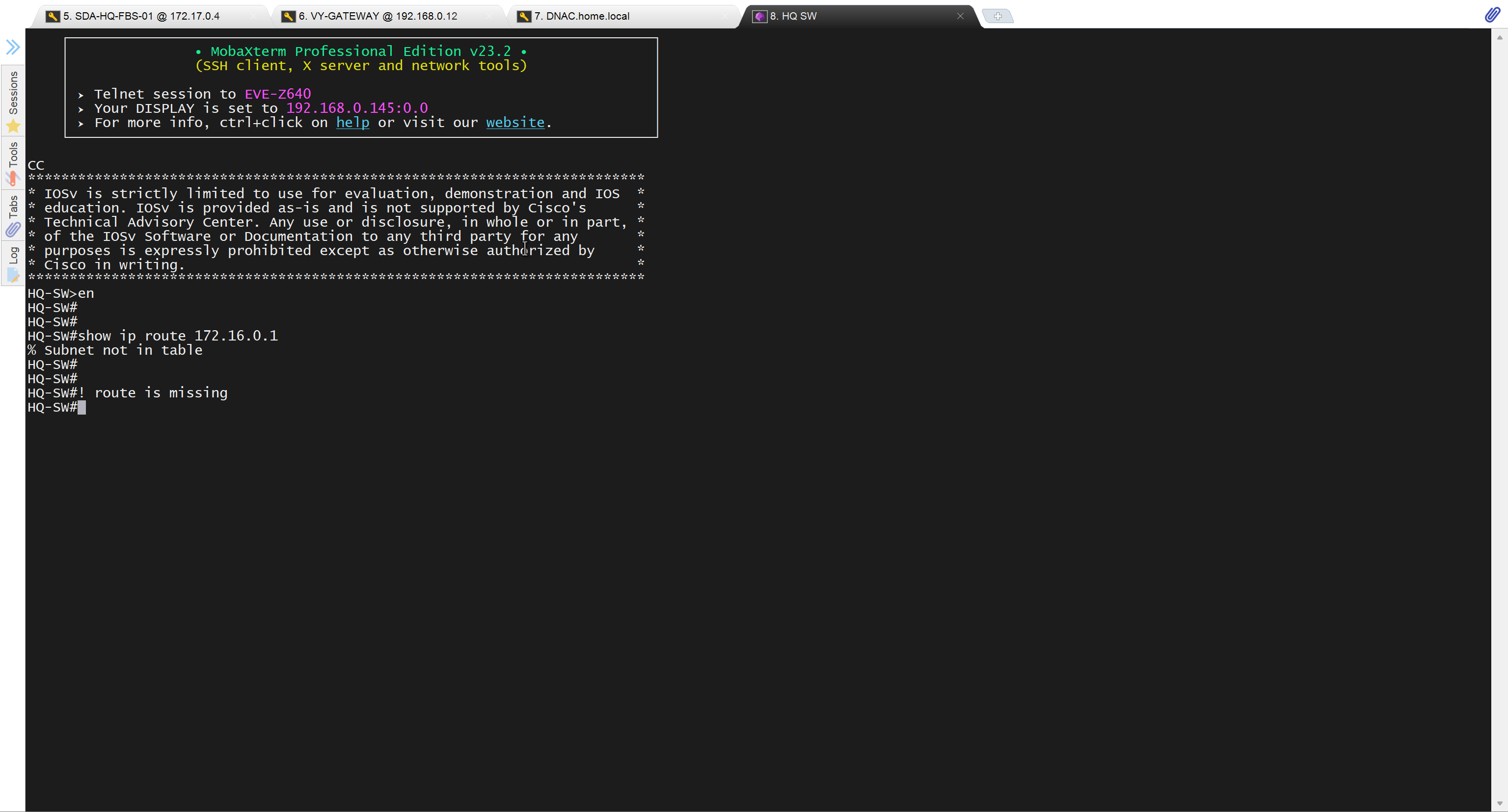
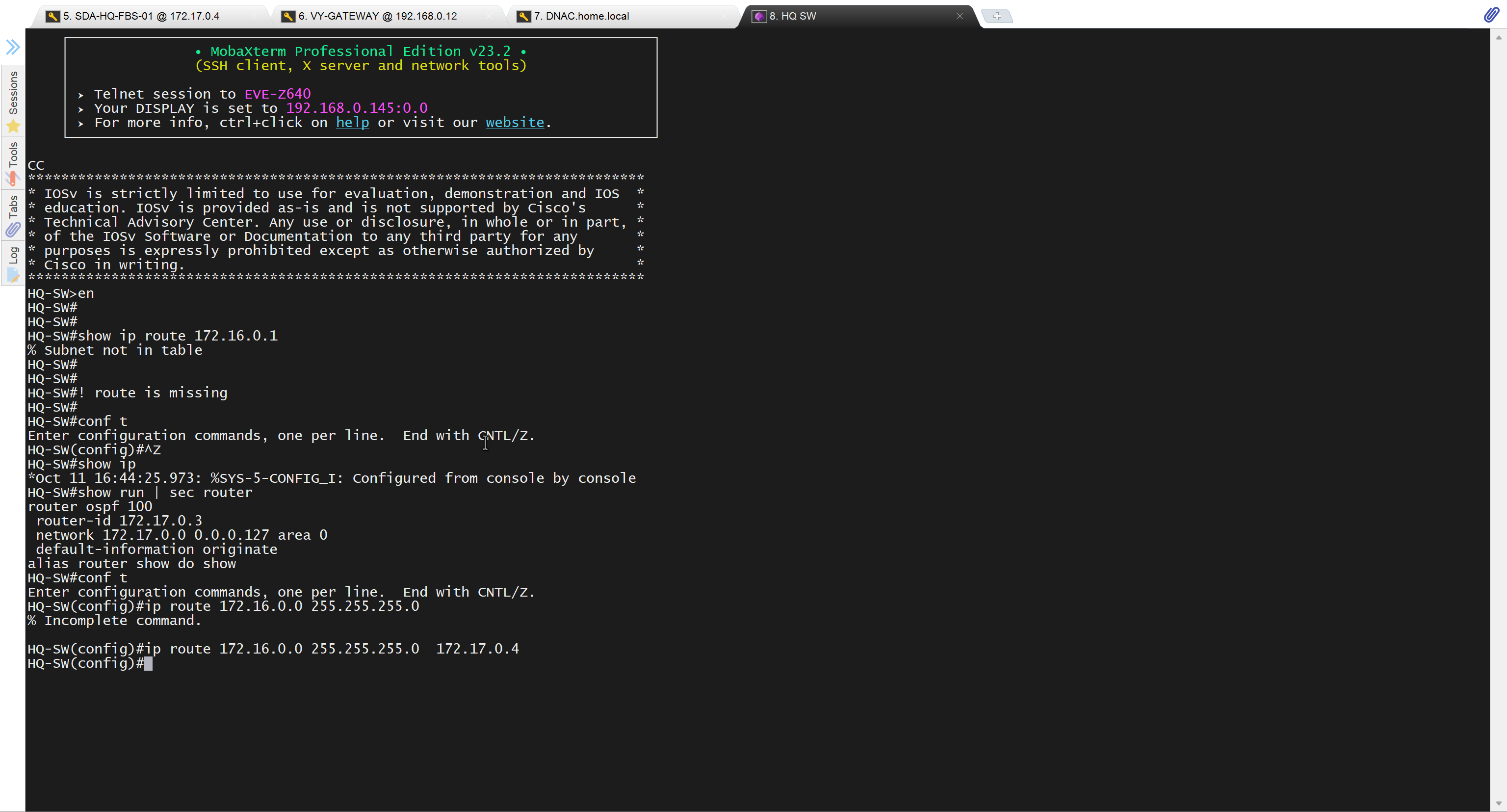
after adding route now we can reach
because it was only for testing, we will now remove it
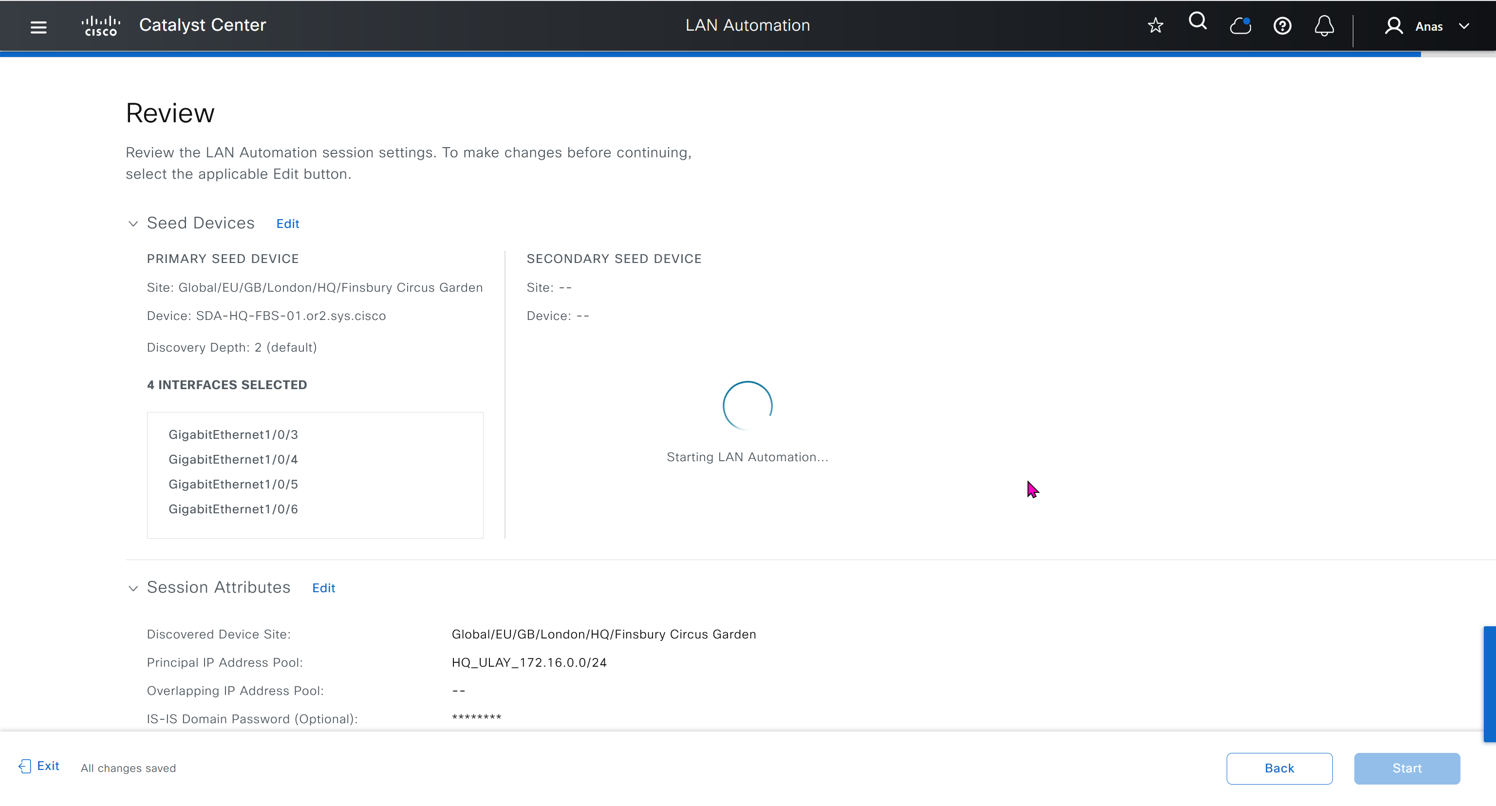
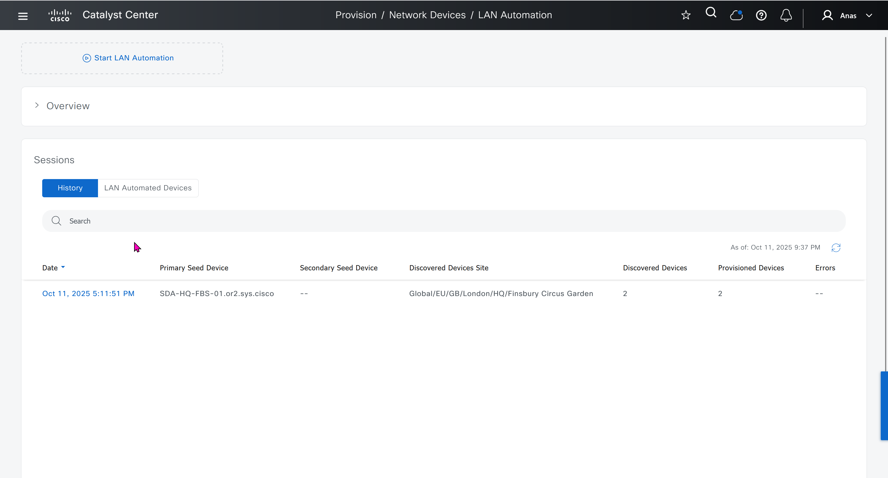
Now lets LAN Automate
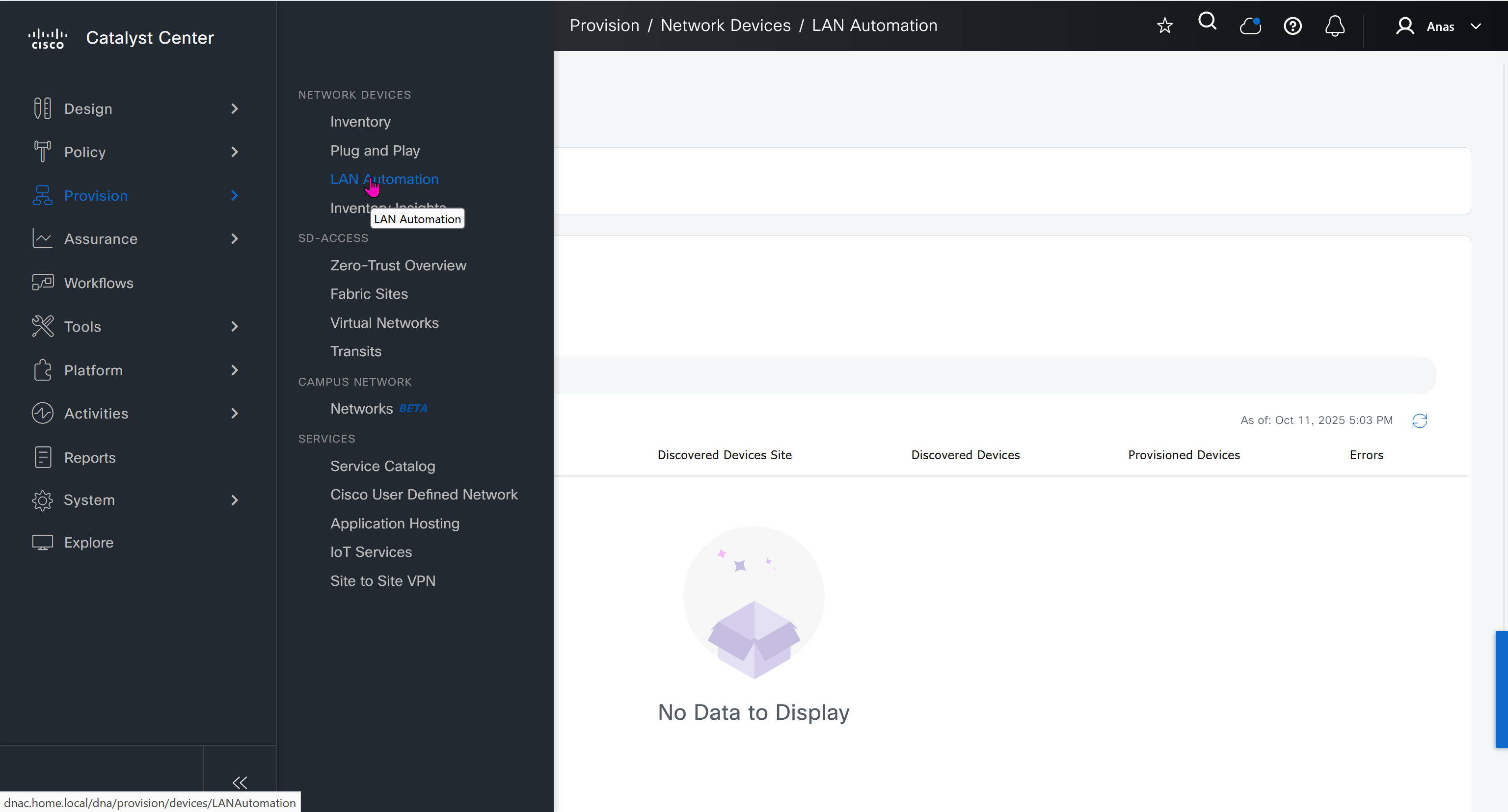
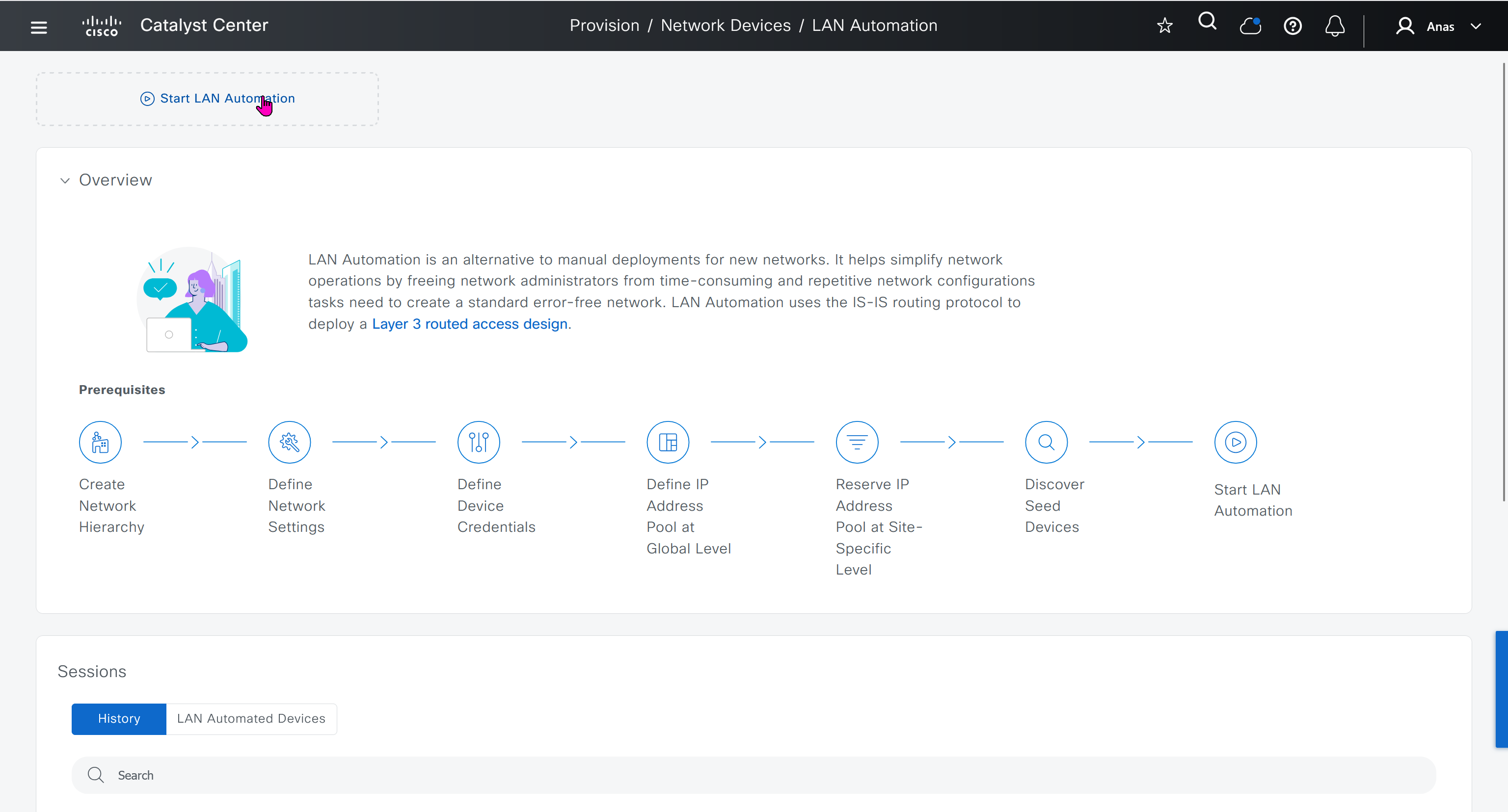
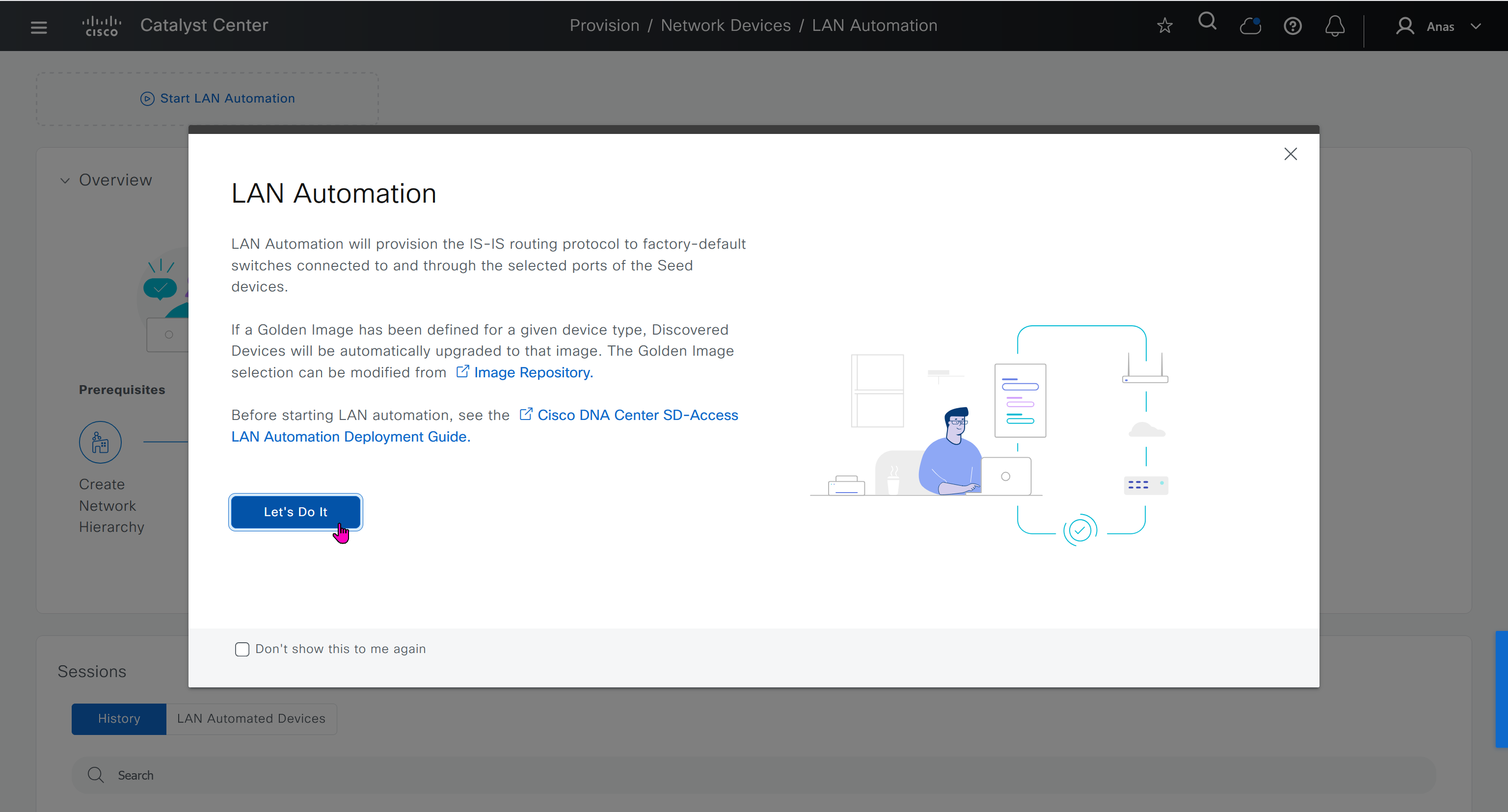
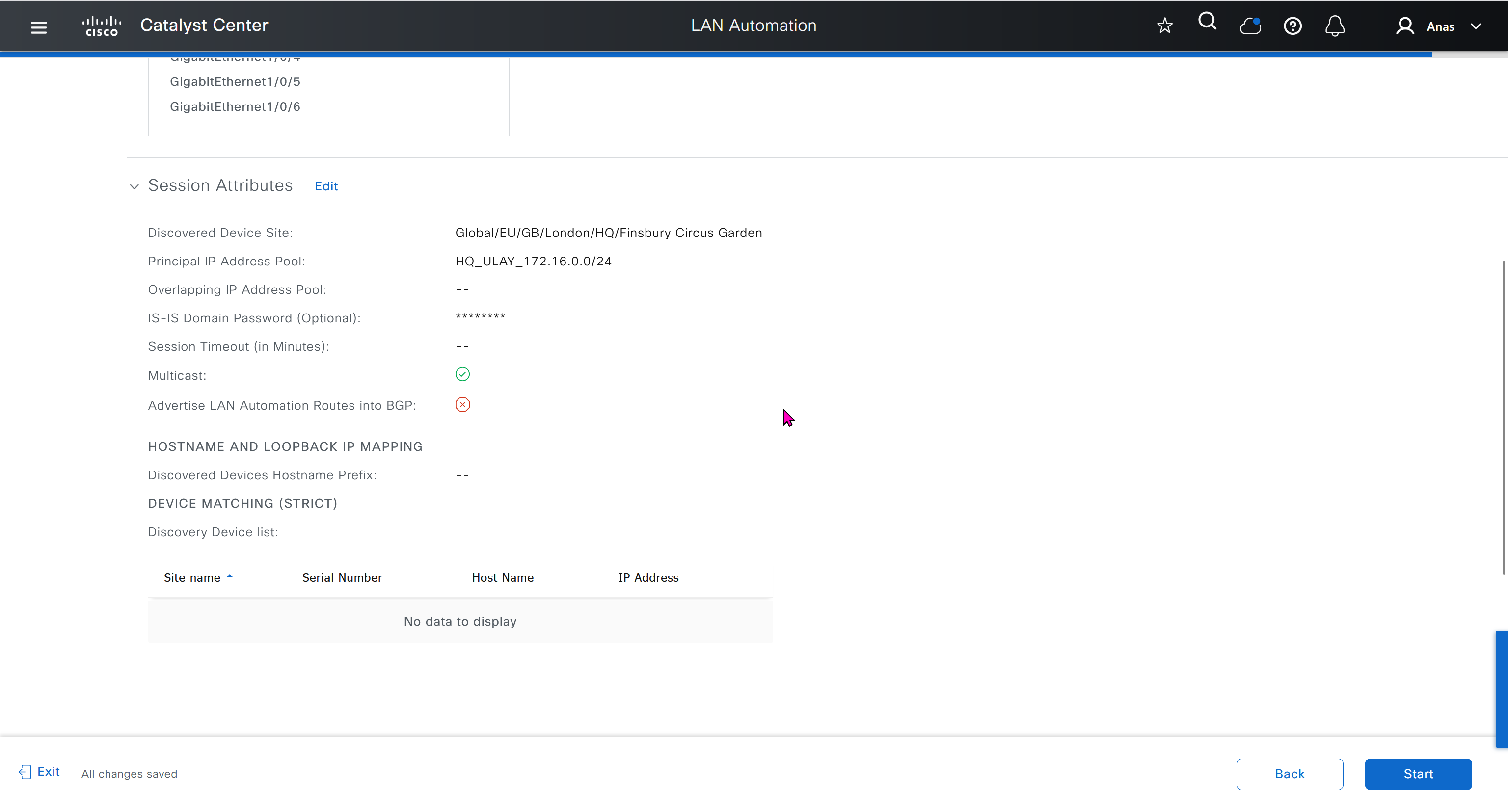
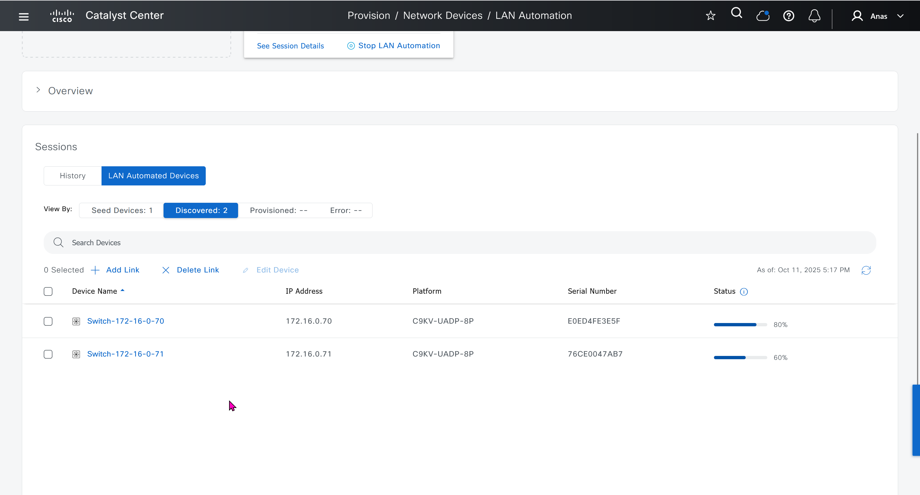
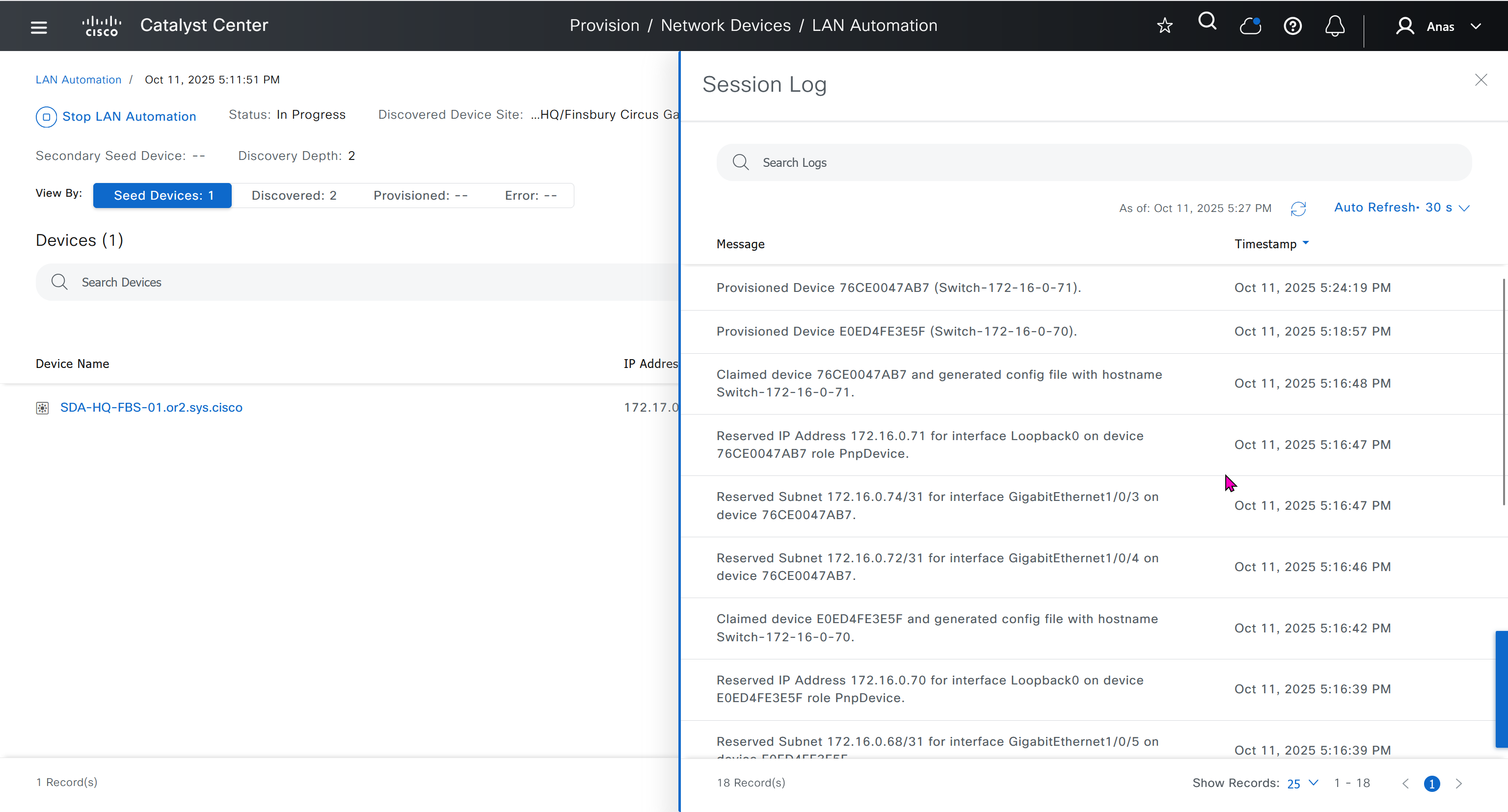
When LAN automation starts, Catalyst Center
pushes the loopback and IS-IS configuration to the primary and peer seed devices and the temporary configuration to the primary seed device
Catalyst Center Release 2.3.3 and later support is-type level-2-only as part of IS-IS configurations.
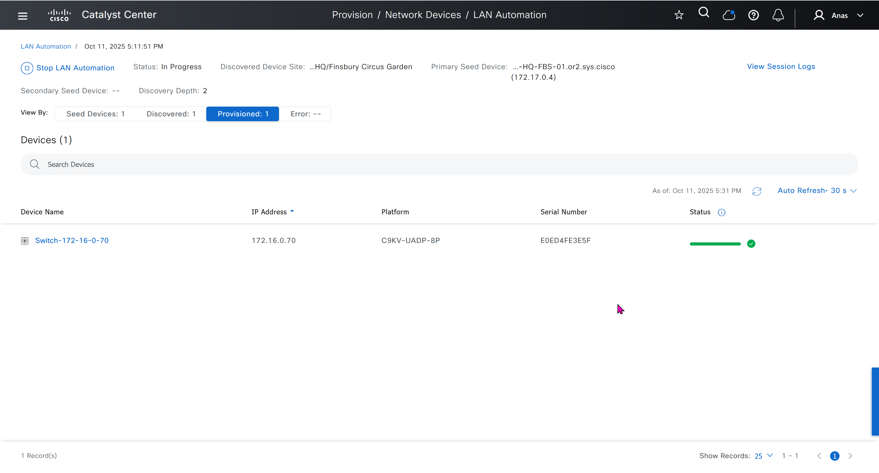
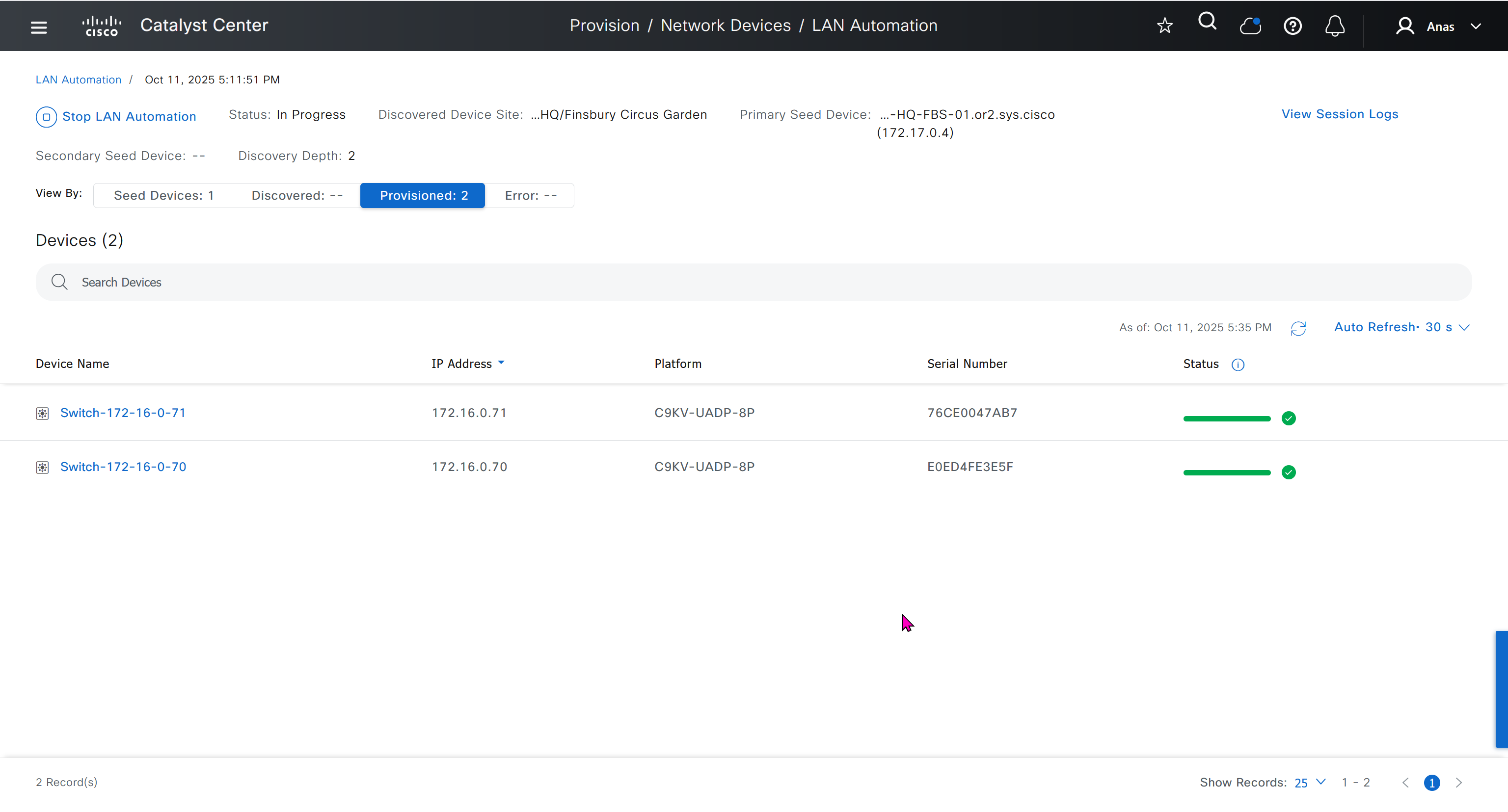
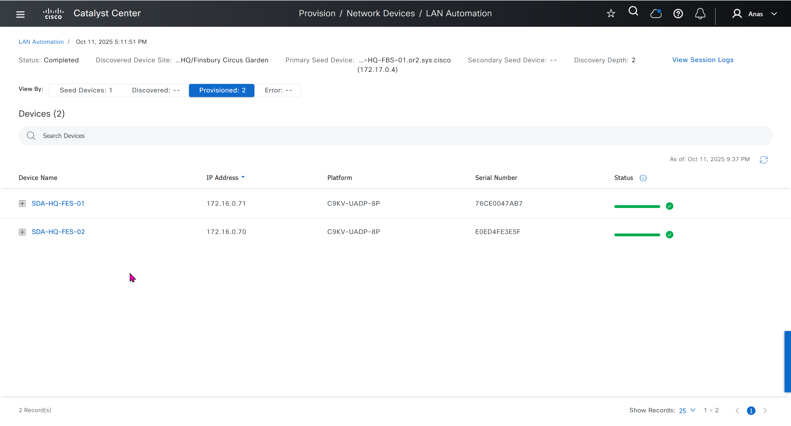
discovers new devices.
upgrades the device software image and pushes the configuration to discovered devices.
The image is updated only if a golden image is marked for that switch type in Catalyst Center under Design > Image repository.
When LAN automation starts, the temporary configuration is pushed to the primary seed device. This allows the device to discover and onboard the PnP agent. Next, the PnP agent image is upgraded and basic configurations such as loopback address, system MTU, and IP routing are pushed to the PnP agent.
- on PnP agent, Do not press Yes or No. Leave the device in the same state.
- Allow extra time to make sure that all members in the stack are up. Do not start LAN automation until all switches are up.
- LAN automation always begins on the active switch. When all switches in a stack are booted together, the switch with the lowest MAC address (assuming no switch priority is configured) becomes active. The switch with the second lowest MAC address becomes the standby, and so on. Some customers require the first switch to always be active. In this case, if all the switches are booted together and the first switch does not have the lowest MAC address, it does not become the active switch. To ensure that the first switch is active, boot the switches in a staggered manner: boot Switch 1; after 120 seconds, boot Switch 2, and so on. This approach ensures that the switch becomes active in the correct order—Switch 1 is active, Switch 2 is standby, and so on. However, after a reload, the order may change because switches obtain their role based on their MAC address.
- To make sure that the switches maintain their order after reload, it is a good practice to assign switch priorities to ensure that the switches always come up in the same order. The highest priority is 15. During LAN automation, the priority of active switch is set to 15 by default. The priority of other switches is not altered. When priorities are assigned, they take precedence over the switch MAC address. Assigning switch priorities does not change the NVRAM configuration. The values are written to ROMMON and persist after reload or write erase. Refer to this sample code:
3850_edge_2#switch 1 priority ? <1-15> Switch Priority 3850_edge_2#switch 1 priority 14 WARNING: Changing the switch priority may result in a configuration change for that switch. Do you want to continue?[y/n]? [yes]: y- You might have to clean up the switch after assigning priorities using “
pnpa service reset no-prompt“ - Connect PnP agents directly to seed devices. Do not connect PnP agents to any other network (for example, even the management network)
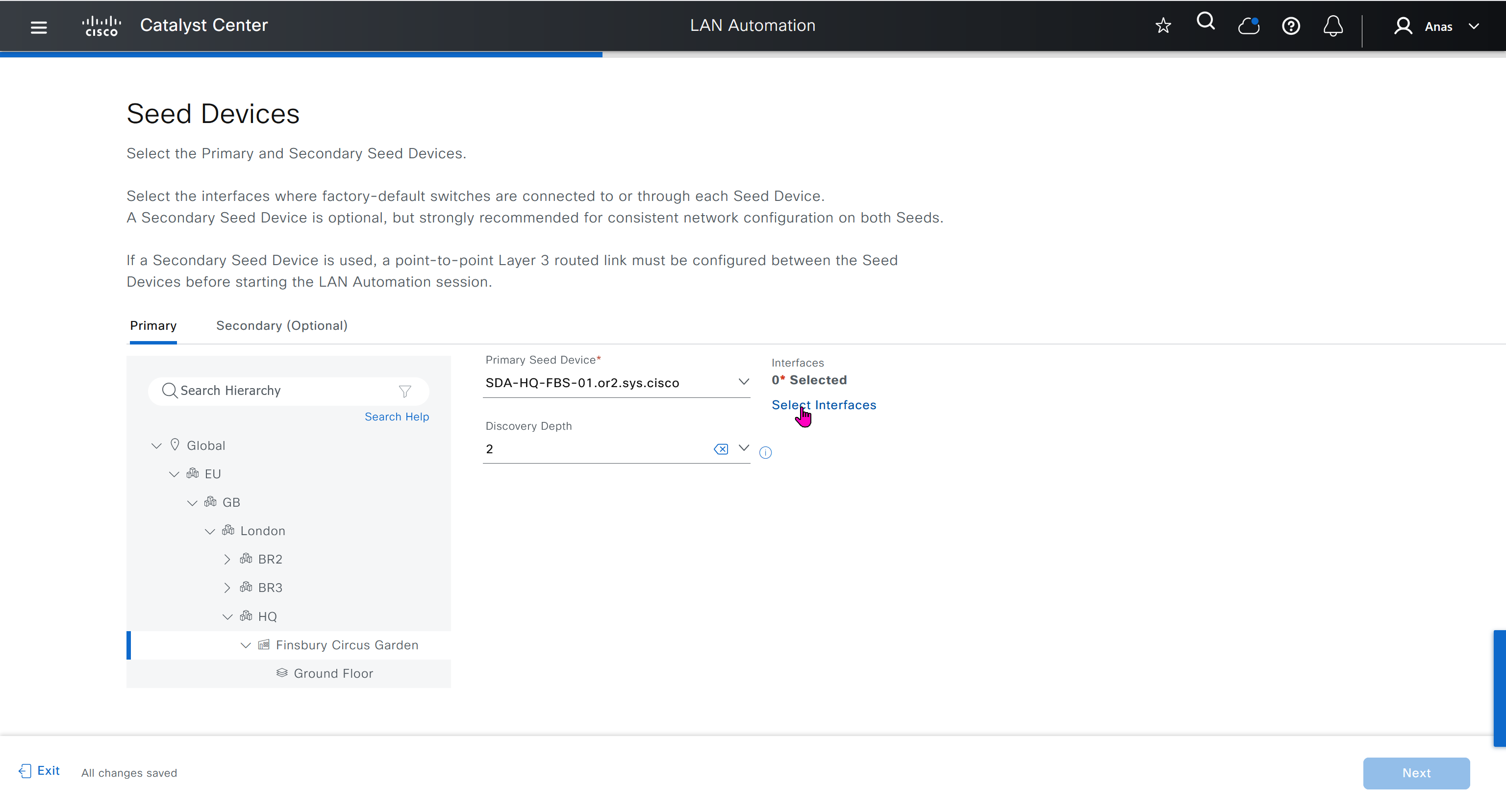
Interface Selection
consider four directly connected PnP agents: device 1 is connected through Gig1/0/10, device 2 through Gig 1/0/11, device 3 through Gig 1/0/12, and device 4 through Gig 1/0/13. If you choose Gig 1/0/11 and Gig 1/0/12 as discovery interfaces, LAN automation discovers only device 1 and device 2. If device 3 and device 4 try to initiate the PnP flow, LAN automation filters them because they connect through unselected interface.
You can also choose interfaces between the primary seed and the peer seed to configure with Layer 3 links. If there are multiple interfaces between the primary and peer seeds, you can choose to configure any set of these interfaces with Layer 3 links. If no interfaces are chosen, they aren’t configured with Layer 3 links.
You can reuse the same LAN pool for multiple LAN automation sessions. For example, you can run a discovery session to find the initial set of devices. After the session completes, you can provide the same IP pool for subsequent LAN automation sessions. Similarly, you can choose a different LAN pool for other discovery sessions. Make sure the LAN pool you select has enough capacity.


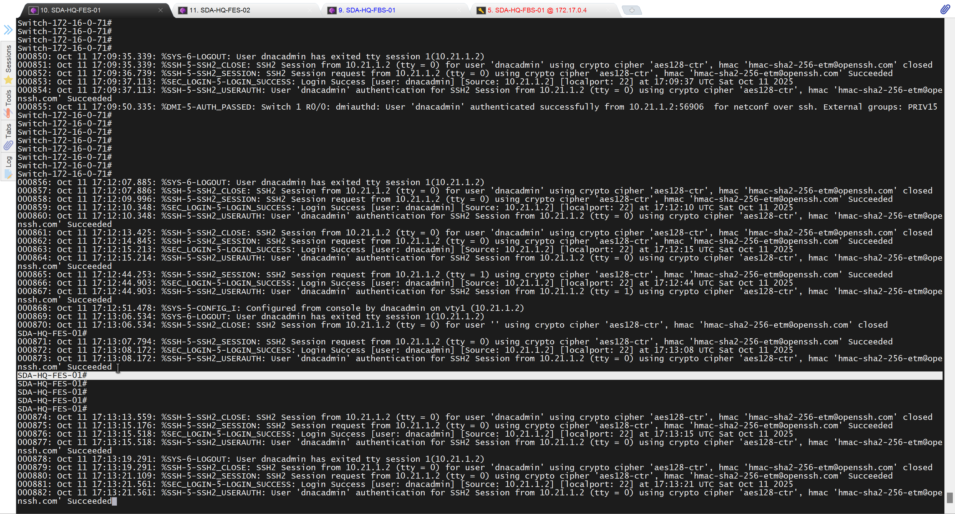
in order to catch all commands pushed by LAN automation to switches add below config and sync with DNAC
conf t
!
! Enable the archive feature
archive
 log config
  logging enable
  notify syslog contenttype plaintext
  hidekeys
!
! Optional: Set up where the archived configs are stored
 path flash:config-archive
 write-memory
!
end
!
! Ensure syslog logging is enabled (optional but recommended)
conf t

logging buffered 64000
service timestamps log datetime msec
!
end
write mem
who
show user
! to see if DNAC is logged in and running commands
! to see commands
show logg | inc CFGLOG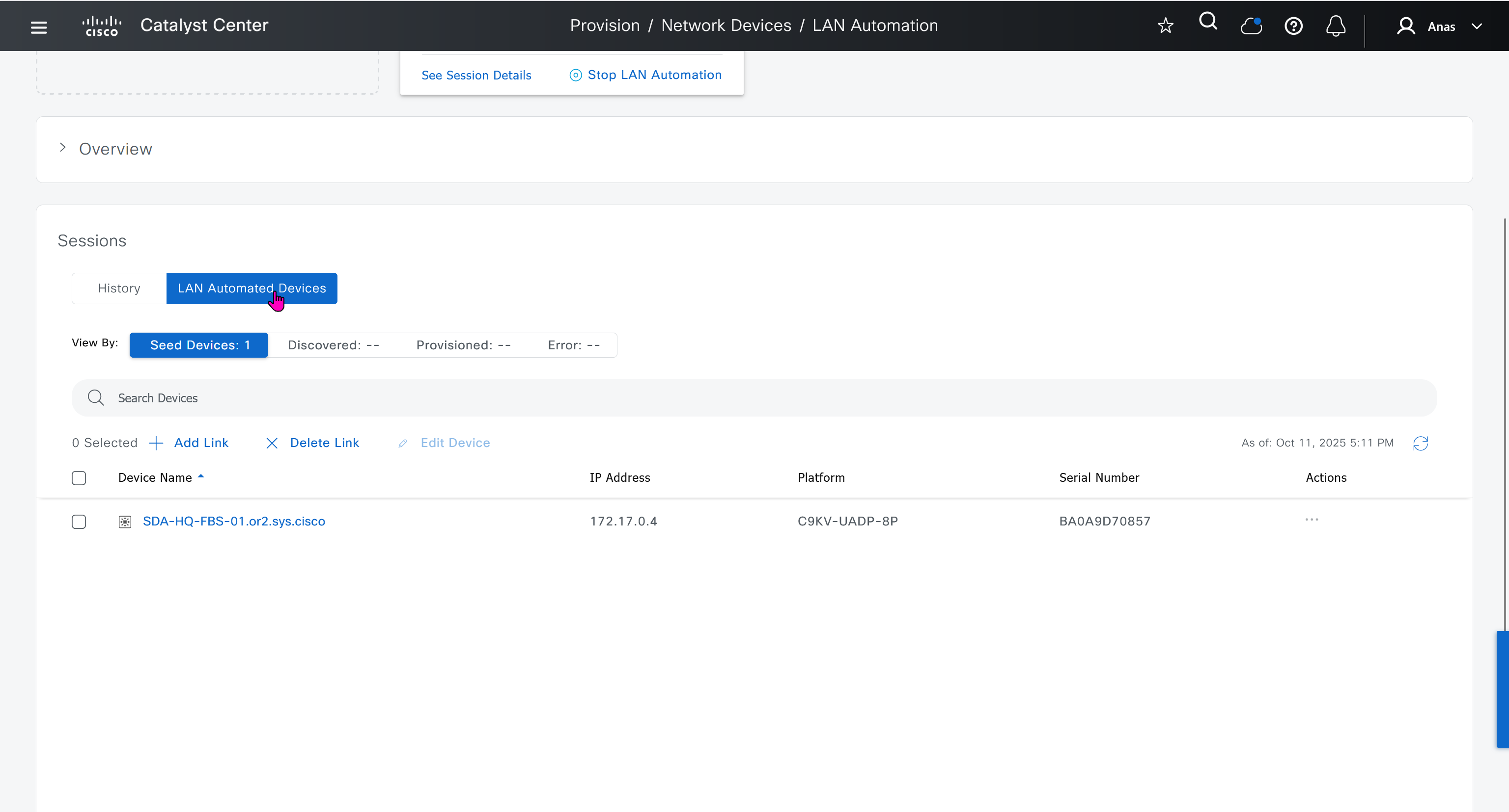
- Quickly as confiiguration is being deployed, intervene and remove using “no” following part of the configuration from “all” switches / routers
- router isis
net 49.0000.280e.ab15.fa02.00
is-type level-2-only
domain-password C0mplex30
metric-style wide
log-adjacency-changes
nsf ietf
bfd all-interfaces


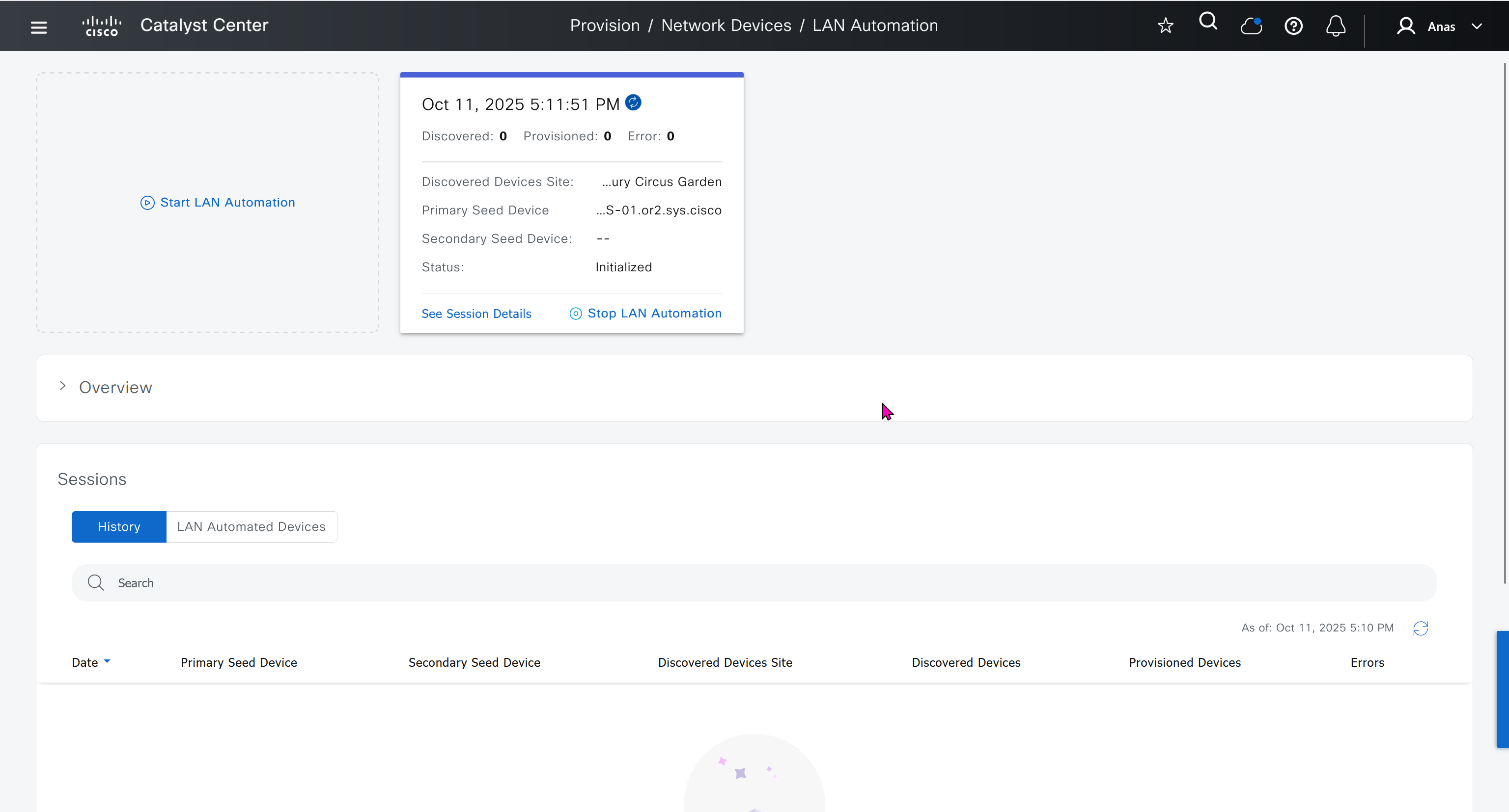
It takes long time to stop LAN automation
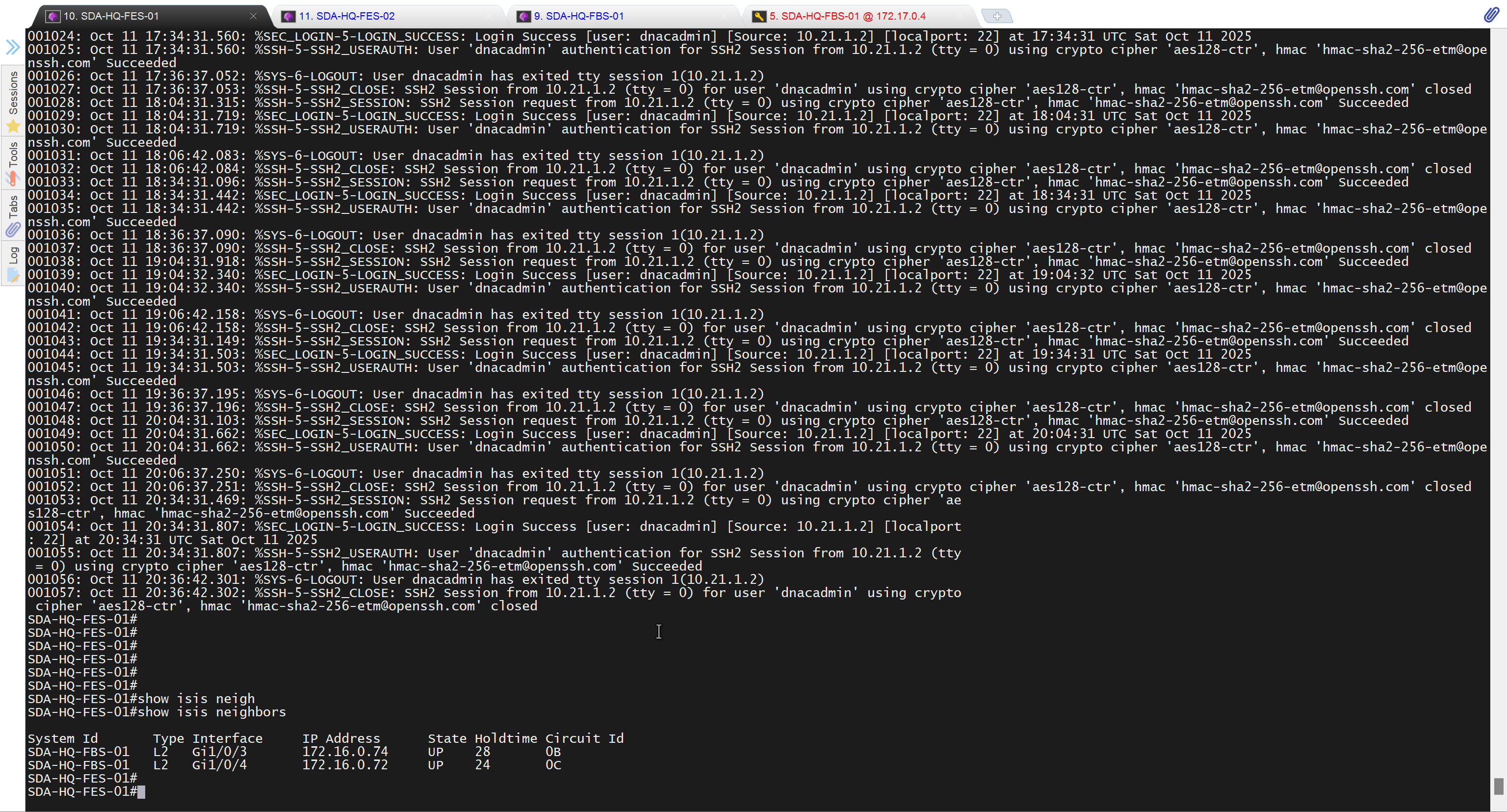
When the LAN automation process stops,
the discovery phase ends, and all point-to-point links between the seed and discovered devices and between the discovered devices (maximum of two hops) are converted to Layer 3.


Add a static route for LAN pool on DNAC through Enterprise facing interface
Skipped but complete it for CCIE LAB