⊹ CCIE ⊹
CCIE MPLS
Multi Protocol Label Switching is a technology to deliver IP
Forwarding of data packets is via labels – MPLS enabled routers do not look into IP header to forward packets
MPLS is known as OSI layer 2.5 – Label info is inserted between Data link and Network layer and this is sometimes called shim header

MPLS works over most “Layer 2 technologies” such as ATM, FR, PPP, POS, Ethernet
Network infrastructure convergence – MPLS enabled network allows to carry different kind of traffic (IPv4, IPv6, Layer2 frames) across single network infrastructure
No need to have BGP enabled on all routers – Very important for scaling networks – because MPLS forwarding is done via labels, we do not need to keep all destination IP addresses in routing tables
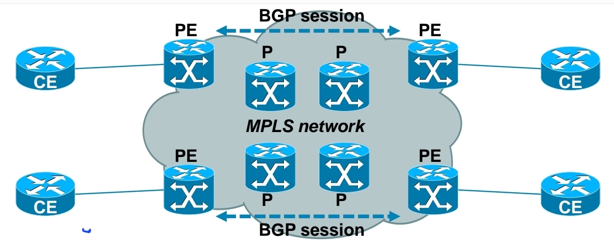
– Allows use of overlapping IPv4 address space
– Allows optimal traffic flow
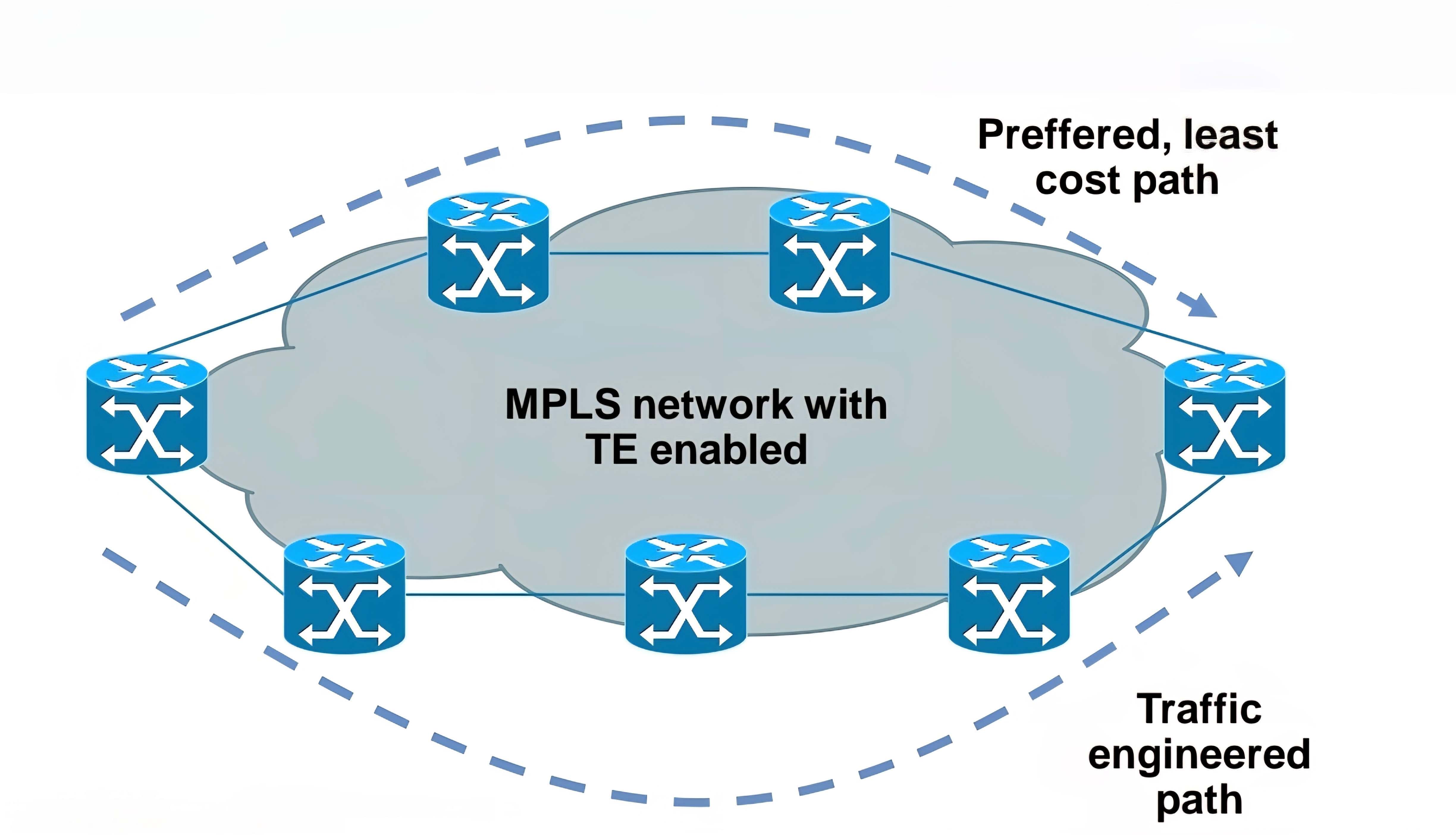
Traffic engineering
– Preffered path is least cost path determined by IGP
– Basic idea is to use links in network infrastructure efficiently
– MPLS needs to be able to provide mechanism to divert traffic to other links beside preffered path
Main building blocks of MPLS:
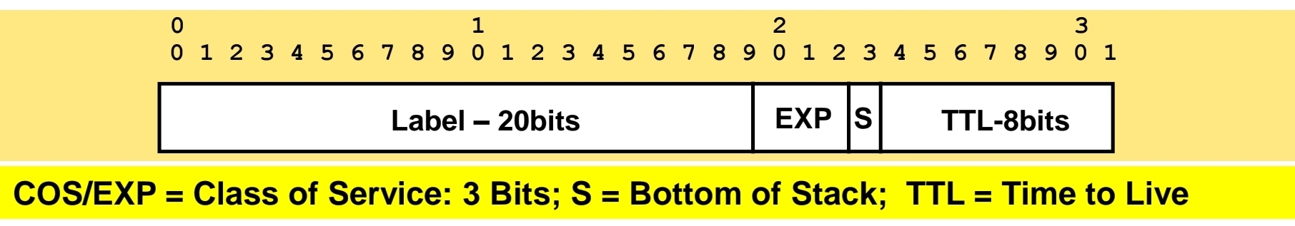
Label – 32 bit value inserted between Layer 2 and Layer 3
LSR – Label Switch Router (eg. PE, P)
LSP – Label Switched Path
IGP – Interior Gateway Protocol
LDP – Label Distribution Protocol
LIB, LFIB – Label Information Base, Label Forwarding Information Base
MP-BGP, RSVP – Protocols for MPLS VPN and MPLS TE

Egress LSR not always performs label disposition – PHP (Penultimate Hop Popping) signaled via implicit null label (LDP advertising MPLS label of value three)
Penultimate Hop Popping (PHP) is a feature in MPLS (Multiprotocol Label Switching) where the second-to-last router (the penultimate hop) removes (or pops) the MPLS label before forwarding the packet to the final router. This improves efficiency and reduces workload on the last router.
Assigning and distributing MPLS labels Each LSR needs to run IGP to learn IP prefixes (eg. neighbor loopbacks, BGP next hops)
Each LSR then forms “LDP neighborship” between its directly connected LSR
Once LDP neighborship is formed, each LSR uses LDP to “assign labels to IP prefixes” it knows about – each LSR does this independently and advertises its labels to its LDP neighbors
LDP is standards based – RFC 3035 and RFC 3036
LDP uses UDP for session discovery and neighbor discovery (port 646 and destination IP 224.0.0.2)
LDP uses TCP (port 646 and destination IP of its LDP peer) for rest of the messages (label advertisement, label withdrawal, session maintenance, session teardown)
Forwarding MPLS packets – which label to use?
RIB stores IP prefixes, LIB stores MPLS labels
LFIB is created from both RIB and LIB and used to forward MPLS tagged packets
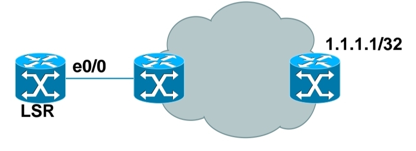
Example for LSR in bottom picture:
– RIB has 1.1.1.1/32 learned via IGP over e0/0 interface
– LIB has label “L” for prefix 1.1.1.1/32 learned from its LDP peer
– LFIB has: “to forward packet to 1.1.1.1/32, use label L and send packet using peer LDP nexthop over e0/0 interface”
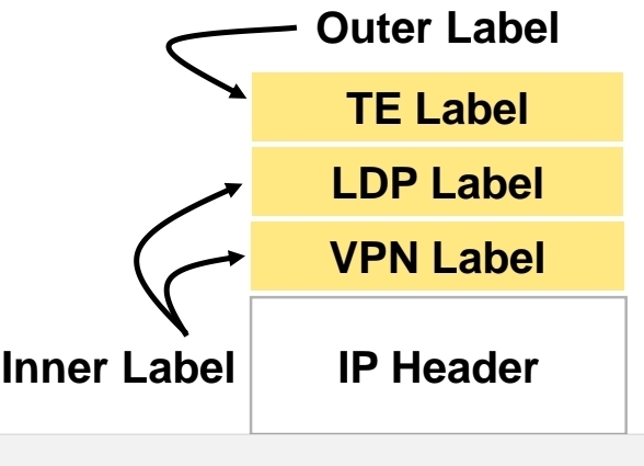
Label stacking
Labeling does not make forwarding of packets faster
Label stacking is the primary use of MPLS that enables use of MPLS L2 and L3 VPNs, traffic engineering and other services
Most used examples of label stacking:
– 2 labels for MPLS VPN – bottom label indicates which VPN this packet belongs to, outer is used by core LSRs for packet forwarding
– 3 labels for MPLS TE – the most upper label is used to indicate which TE tunnel to forward this packet
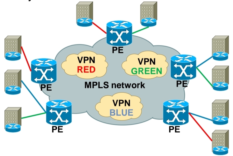
Use of MPLS to build Layer 3 VPN
MPLS VPN is set of sites that communicate with each other – these sites can be connected to MPLS infrastructure at various PE routers
Each site is identified by its own VRF (Virtual Routing and Forwarding), by default communication between VRF is not allowed
Each PE router assigns distinct MPLS label for each VRF it communicates with other PE routers – this label is not assigned by LDP, but by MP-BGP
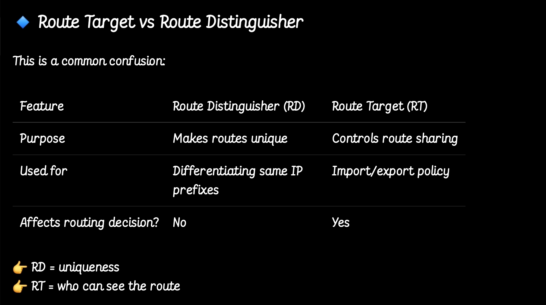
RD (Route Distinguisher) is attached to each IP prefix exchanged in VPN to make them unique – RD + prefix = VPN prefix
RD allows to use overlapping IP addresses among VPNs
RD length is 64 bits and is in format X:Y, where X is usually Autonomous System Number or IP address – usually one RD is assigned per customer
RT (Route Target) governs which VPN prefixes are allowed to be imported or exported out of particular VPN
Route Targets
In MPLS Layer 3 VPNs, a Route Target (RT) is a special extended BGP attribute used to control which VPN routes are imported and exported between PE (Provider Edge) routers.
In an MPLS VPN network:Multiple customers share the same provider backbone.Each customer has a separate routing table called a VRF (Virtual Routing and Forwarding).Routes must be kept isolated between customers.The Route Target ensures that:Only the correct VPN routes are shared between the correct VRFs.Customer A’s routes are not accidentally sent to Customer B.
Each VRF has:
Export Route Target defined
Import Route Target defined
A PE router learns a route from a customer. It adds a Route Target (RT) to that route.The route is advertised via MP-BGP to other PE routers. Other PE routers check: If the route’s RT matches their import RT, If yes → route is installed in the VRF, If no → route is ignored
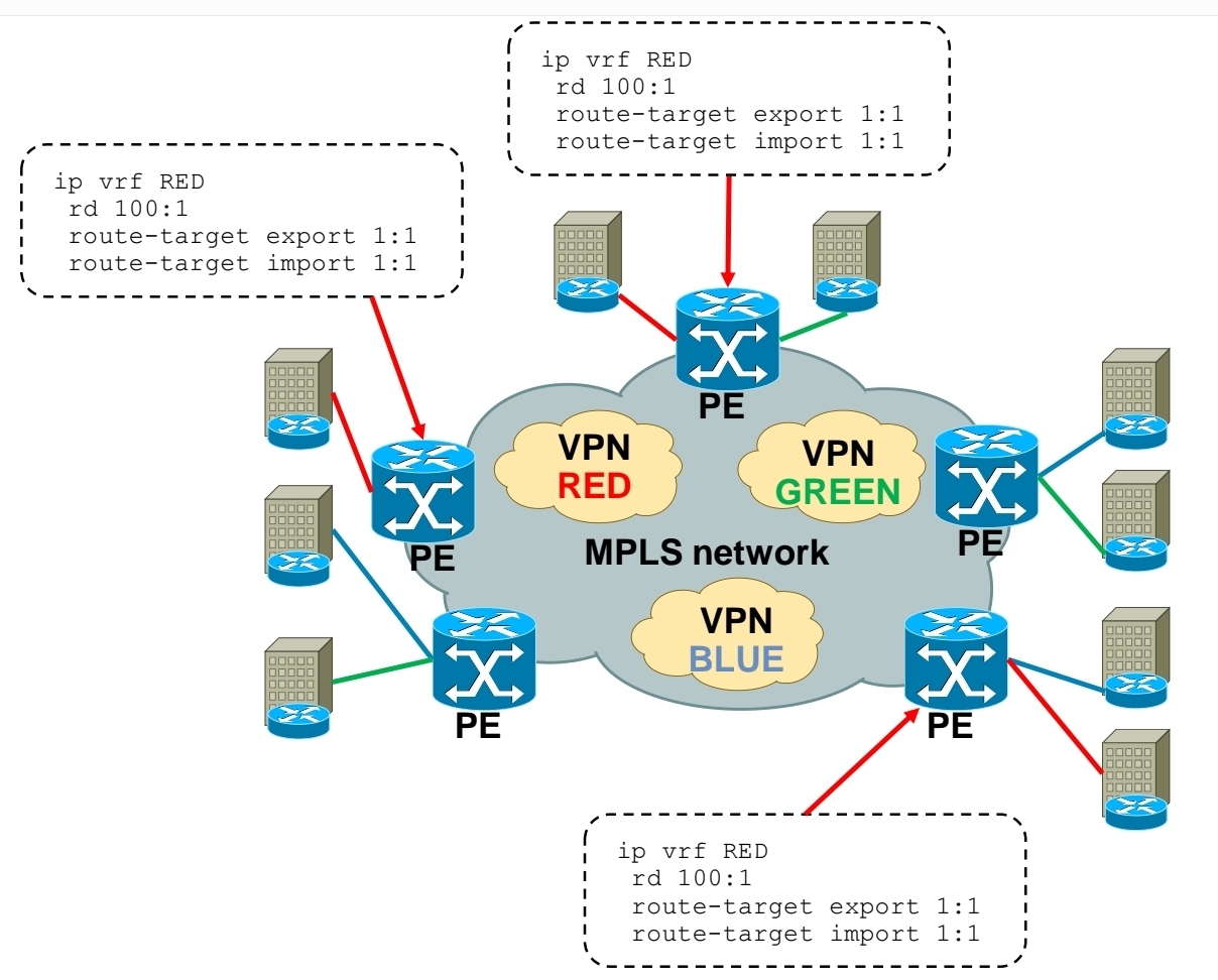
Customer A has two sites:
Site 1 connected to PE1
Site 2 connected to PE2
Both VRFs are configured with:
Export RT: 100:1
Import RT: 100:1,
Result: PE1 exports routes with RT 100:1, PE2 imports routes with RT 100:1, Both sites can communicate. If another customer uses RT 200:1, their routes stay completely separate.
In order to bring L3 VPN into life, you need to exchange both RD and RT – this is done by MP-BGP
so the functions have been seperated
MPLS Layer 3 VPN Intranet for customer in VPN RED
MPLS Layer 3 VPN Intranet for customer in VPN GREEN

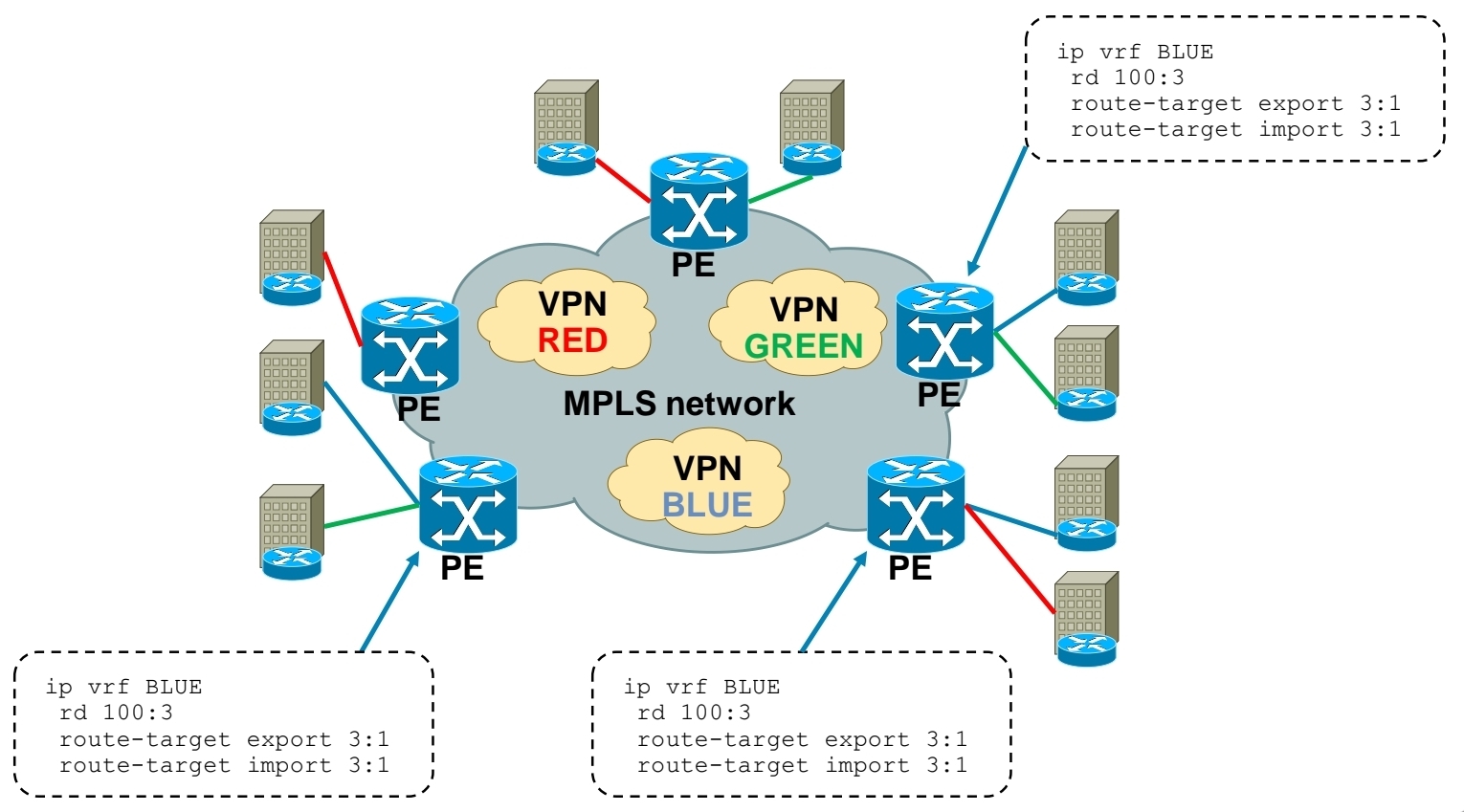
MPLS Layer 3 VPN Intranet for customer in VPN BLUE
MPLS Layer 3 VPN Extranet between customer VPN RED and VPN BLUE
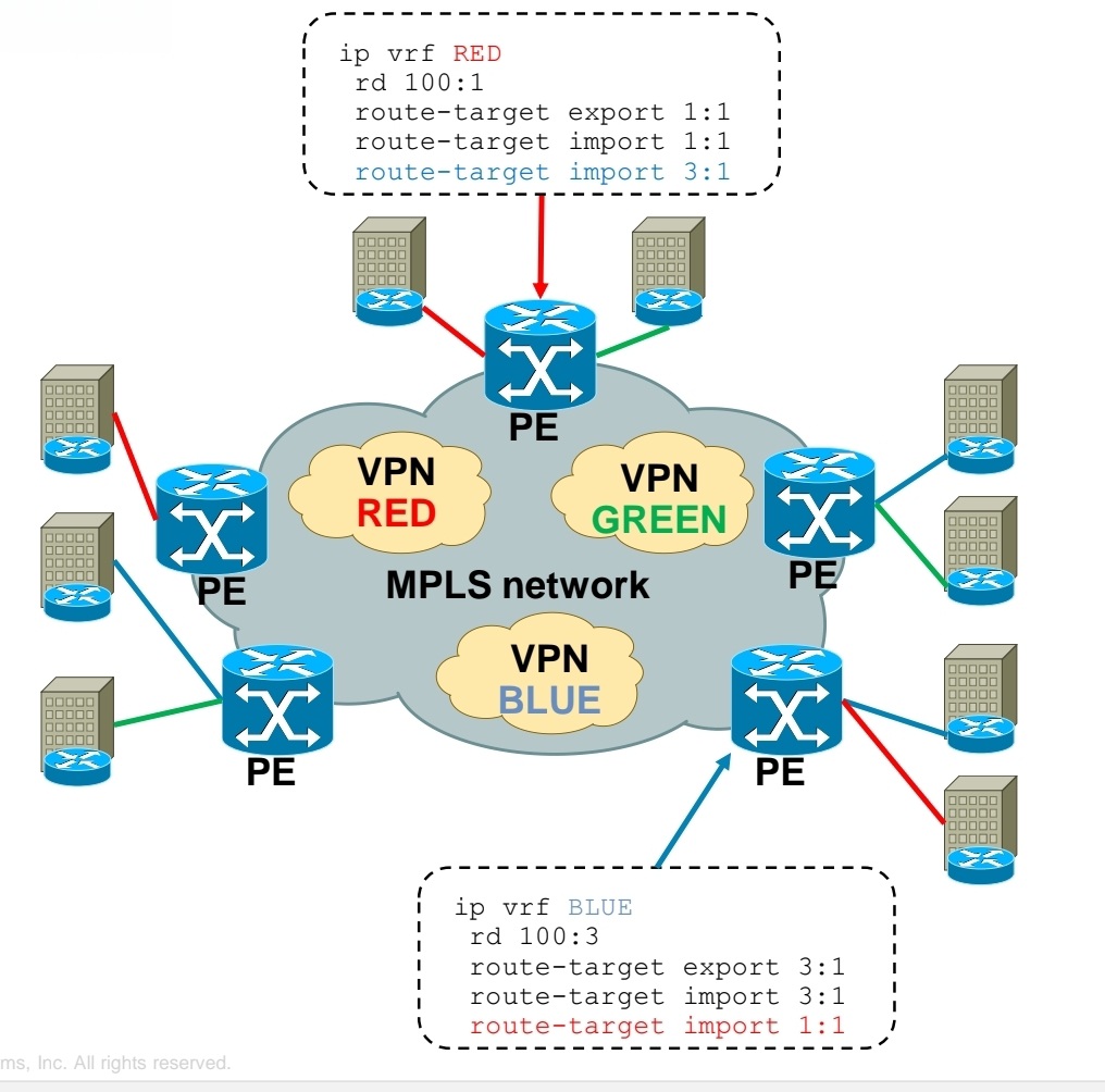
Using RT you create Intranet or Extranet
– Intranet – different sites of “same” VPN can communicate
– Extranet – different sites of “different” VPNs can communicate
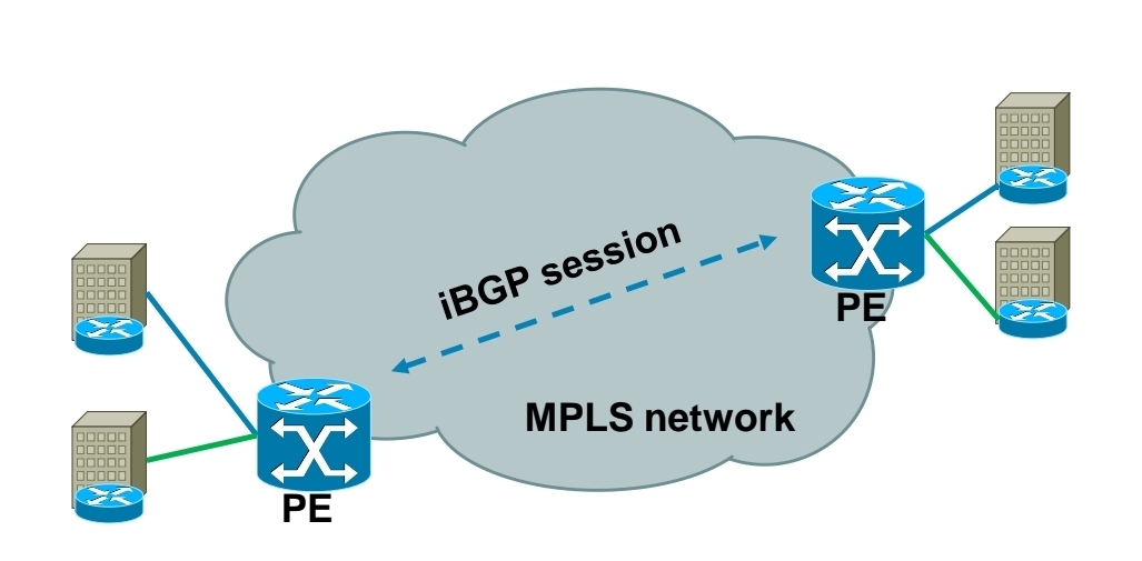
Exchanging RD, RT and VPN label over MPLS network
-Each PE router forms iBGP session with other PE router
-Over this iBGP sessions, PE routers exchange VPN prefixes
-Each VPN prefix is exchanged with its associated RT and VPN label – RT is for importing routes into VRF RIB, VPN label is for actual packet forwarding
Packet forwarding with MPLS Layer 3 VPN
-IGP label is assigned by LDP
-VPN label is assigned by MP-BGP
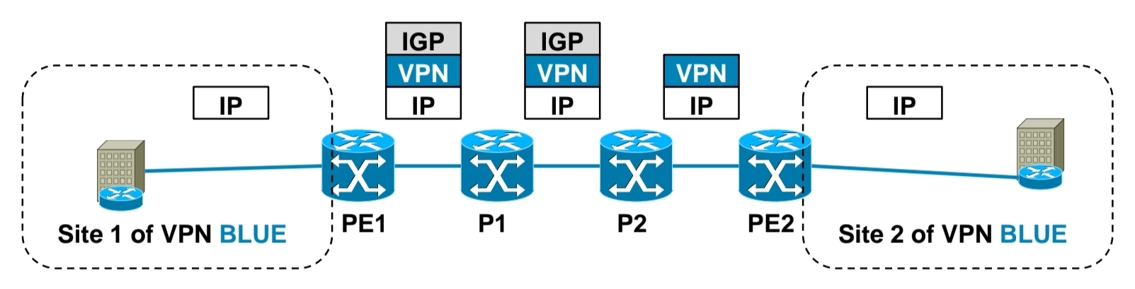
1.) PE1 receives IP packet on VRF interface assigned to site 1 of VPN BLUE.
2.) PE1 looks up VPN and IGP label, imposes these both labels as label stack to IP packet and forwards it to MPLS network. IGP label is known based on iBGP next hop, which is IP address of PE2.
3.) P1 router swaps IGP label based on its LFIB table.
4.) P2 removes IGP label due to PHP, but does not touch VPN label.
5.) PE2 router receives IP packet with VPN label, which it uses to select correct outgoing VPN site
6.) PE2 then strips off VPN label, makes lookup in its VRF RIB for particular VPN site to get the outgoing interface to send received packet to
Exchanging routing information between CE and PE routers
– Static routing
– RIP
– EIGRP
– OSPF
– IS-IS
– eBGP

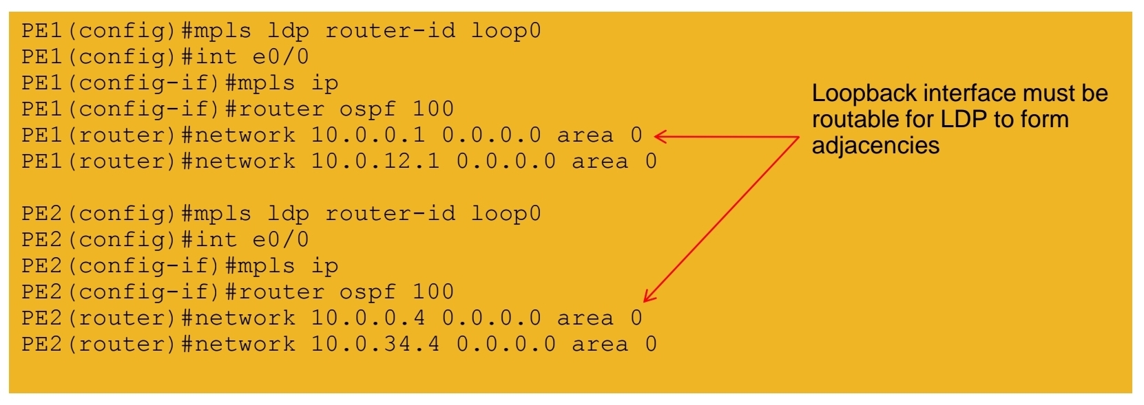
Basic MPLS L3 VPN config
1.) Configuring core LSR for MPLS switching

2.) Configuring edge LSR for MPLS switching
3a.) Configuring edge LSR PE1 for MPLS L3 VPN

3b.) Configuring edge LSR PE1 for MPLS L3 VPN

4a.) Configuring edge LSR PE2 for MPLS L3 VPN

4b.) Configuring edge LSR PE2 for MPLS L3 VPN

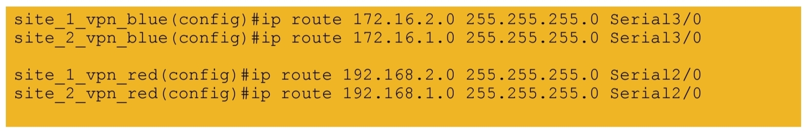
5.) Configuring CE-PE connectivity on CE1 and CE2
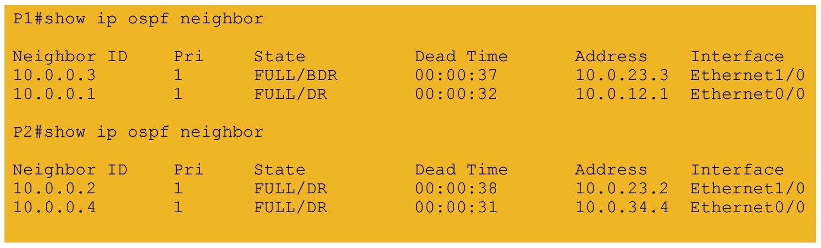
MPLS L3 VPN verification
1.) IGP peerings formed in core
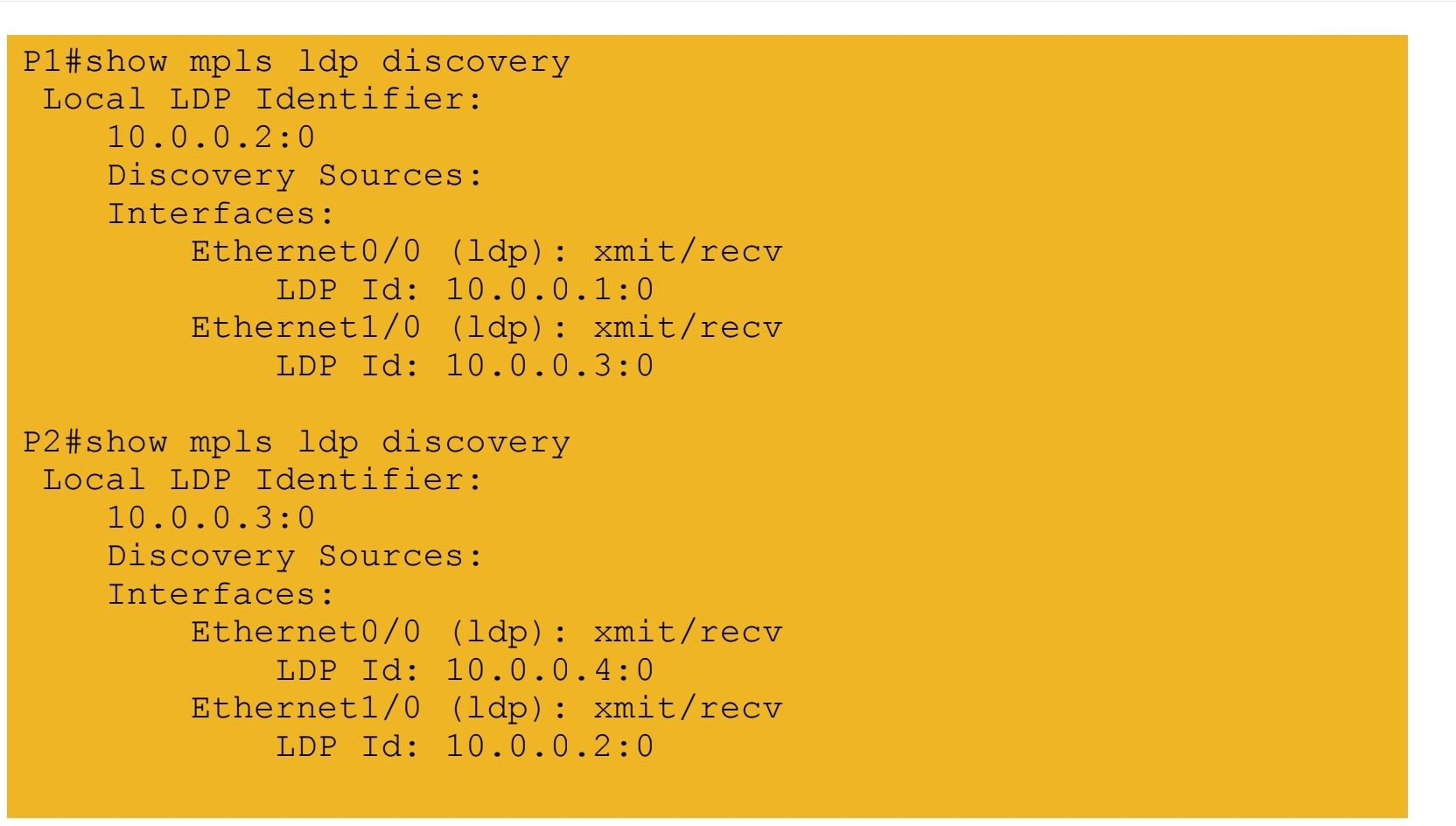
2.) MPLS LDP peerings formed in core
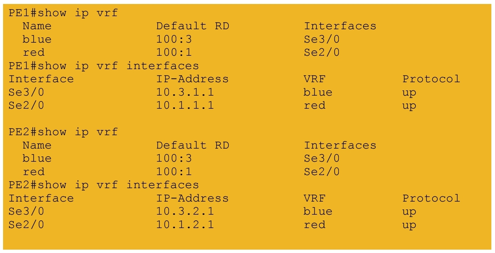
3.) VRF tables and interfaces defined on PE routers
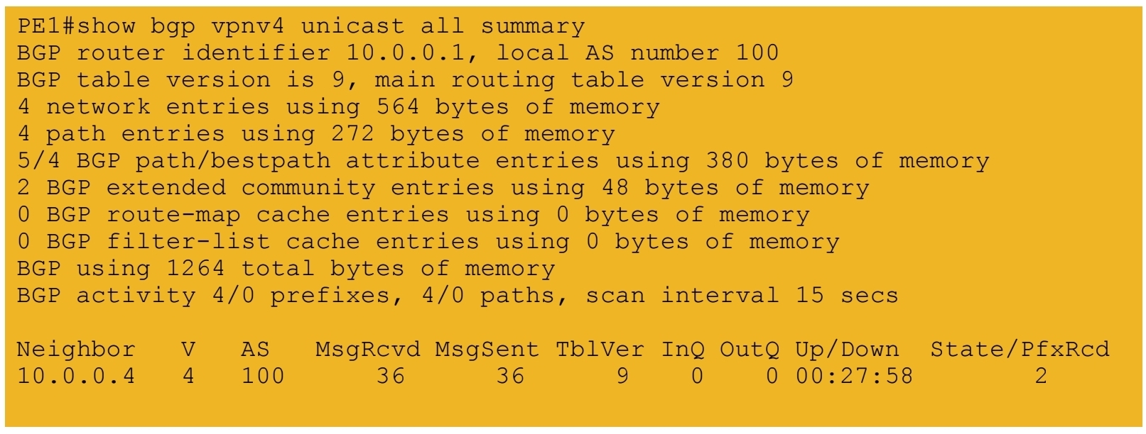
4.) iBGP session formed between PE routers
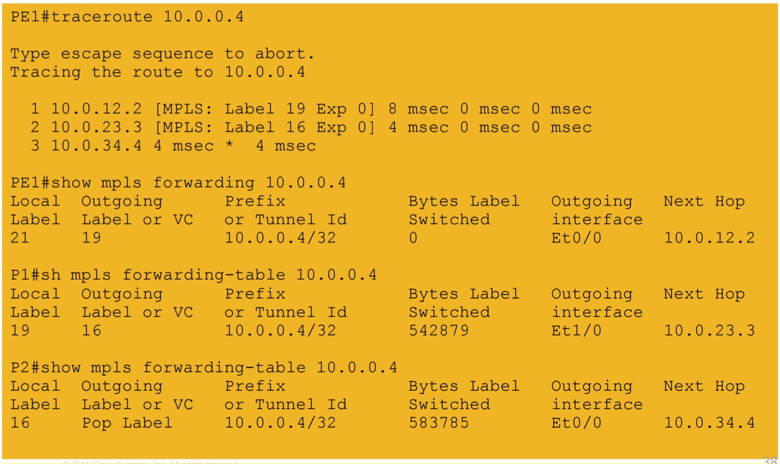
5a.) IGP labels assigned by LDP – path from PE1 to PE2
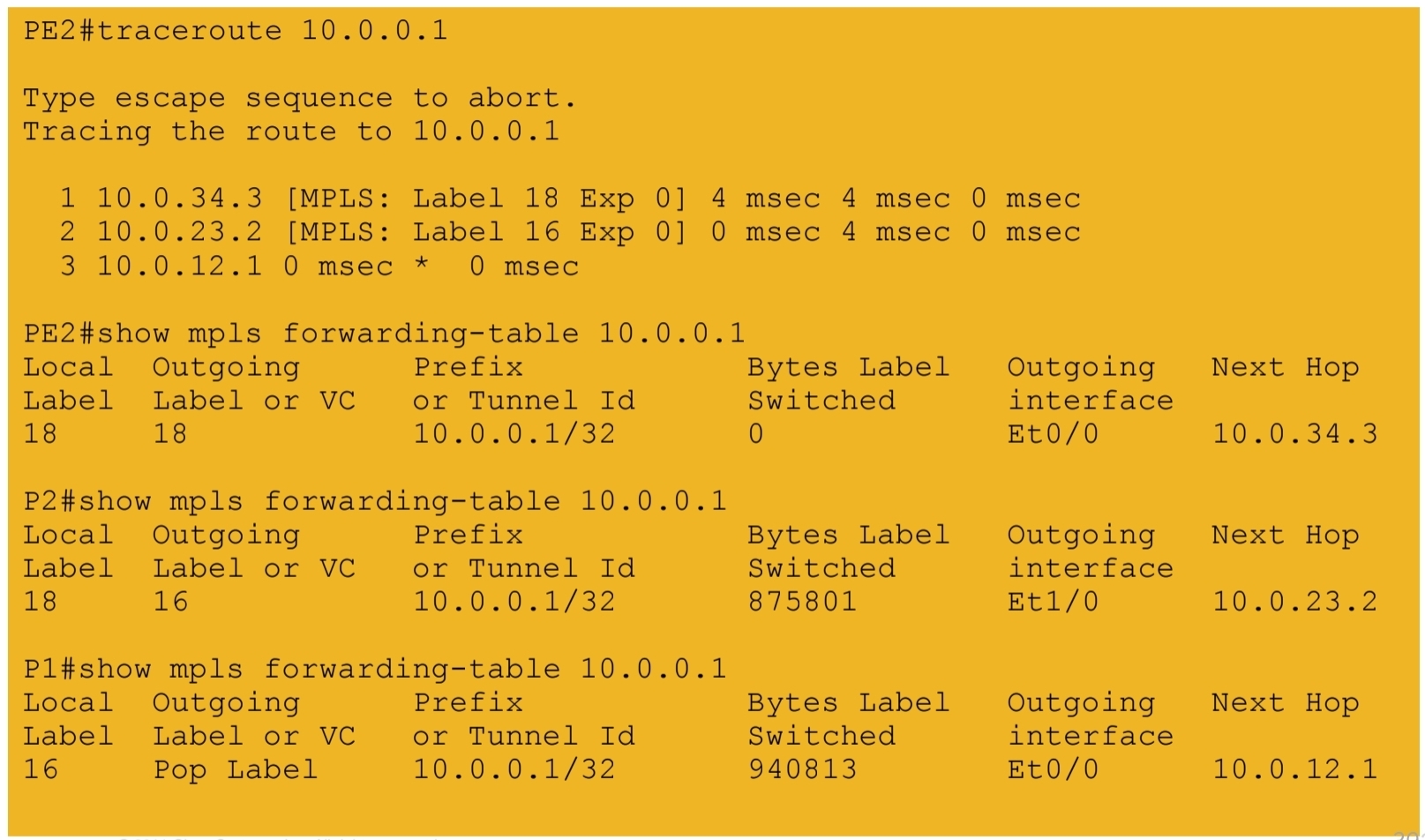
5b.) IGP labels assigned by LDP – path from PE2 to PE1
6.) VPN labels assigned by BGP

7a.) End-to-end connectivity between VPN RED sites
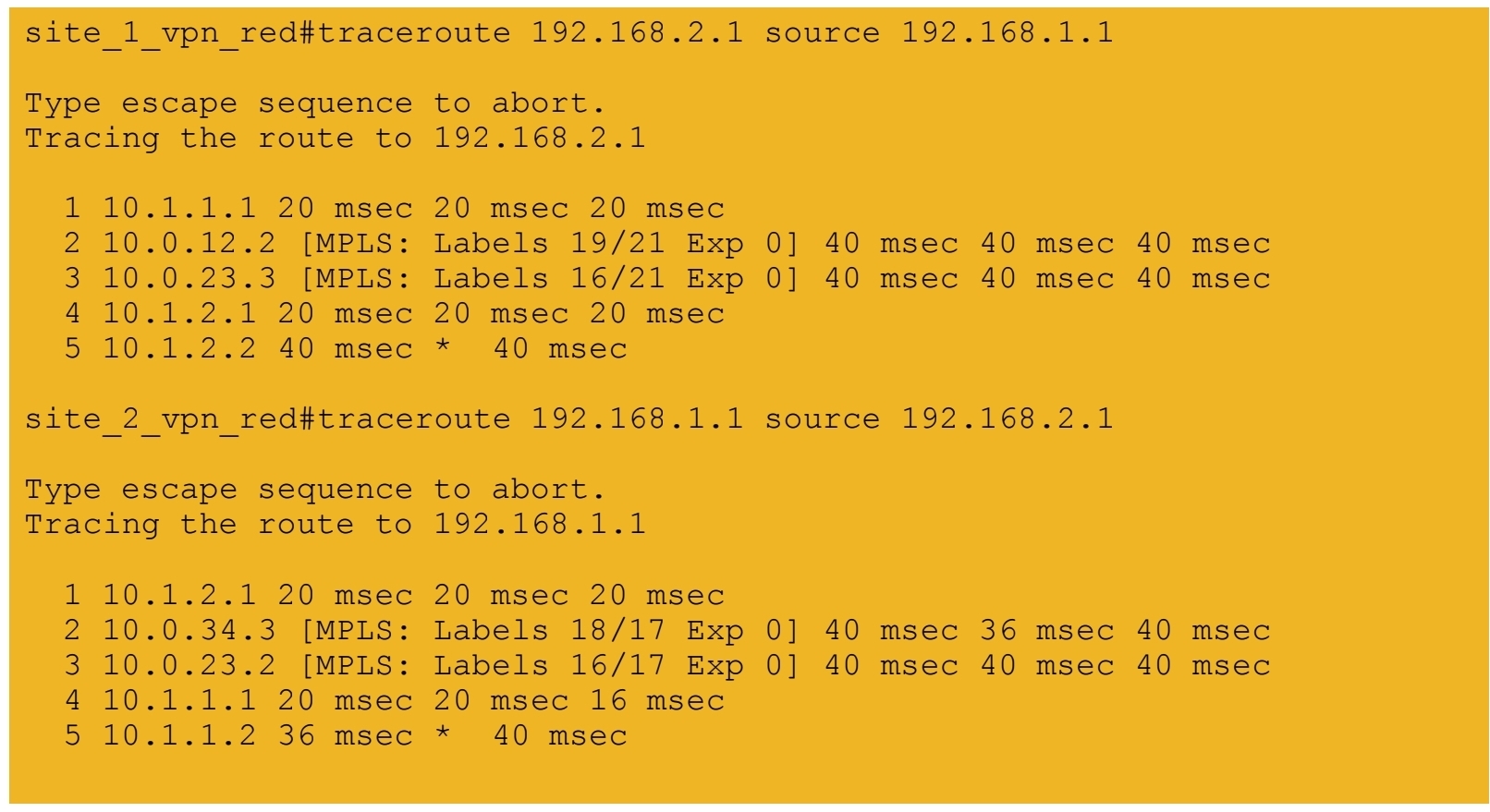
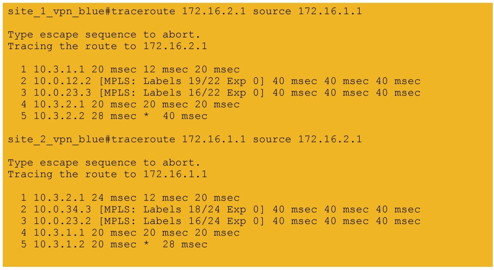
7b.) End-to-end connectivity between VPN BLUE sites
next post
CCIE Design
IP Headers
Protocol: This field is 8 bits in length. It indicates the upper-layer protocol. The Internet Assigned Numbers Authority (IANA) is responsible for assigning IP protocol values. Table 1-2 shows some key protocol numbers. You can find a full list

Header Checksum: This field is 16 bits in length. The checksum does not include the data portion of the packet in the calculation. The checksum is verified and recomputed at each point the IP header is processed (on end clients)
Padding: This field is variable in length. It ensures that the IP header ends on a 32-bit boundary.
Header Length: This field is 4 bits in length. It indicates the length of the header in 32-bit words (4 bytes) so that the beginning of the data can be found in the IP header. The minimum value for a valid header is 5 (0101) for five 32-bit words.
Total Length: This field is 16 bits in length. It represents the length of the datagram, or packet, in bytes, including the header and data. The maximum length of an IP packet can be 216 − 1 = 65,535 bytes. Routers use this field to determine whether fragmentation is necessary by comparing the total length with the outgoing MTU.
Identification: This field is 16 bits in length. It is a unique identifier that denotes fragments for reassembly into an original IP packet.
Flags: This field is 3 bits in length. It indicates whether the packet can be fragmented and whether more fragments follow. Bit 0 is reserved and set to 0. Bit 1 indicates May Fragment (0) or Do Not Fragment (1). Bit 2 indicates Last Fragment (0) or More Fragments to Follow (1).
Fragment Offset: This field is 13 bits in length. It indicates (in bytes) where in the packet this fragment belongs. The first fragment has an offset of 0.
ToS (Type of Service): This field is 8 bits in length. Quality of service (QoS) parameters such as IP precedence and DSCP are found in this field. (These concepts are explained later in this chapter.)
The ToS field of the IP header is used to specify QoS parameters. Routers and Layer 3 switches look at the ToS field to apply policies, such as priority, to IP packets based on the markings. An example is a router prioritizing time-sensitive IP packets over regular data traffic such as web or email, which is not time sensitive.
DSCP
DSCP has 2’6 = 64 levels of classification, which is significantly higher than the eight levels of the IP precedence bits
backward compatible with IP precedence
Defines three sets of PHBs: Class Selector (CS), Assured Forwarding (AF), and Expedited Forwarding (EF).
CS PHB set is for DSCP values that are compatible with IP precedence bits
The AF PHB set is used for queuing and congestion avoidance.
The EF PHB set is used for premium service
IPv4 Fragmentation
Although the maximum length of an IP packet is 65,535 bytes, most of the common lower-layer protocols do not support such large MTUs. For example, the MTU for Ethernet is approximately 1518 bytes. When the IP layer receives a packet to send, it first queries the outgoing interface to get its MTU. If the packet’s size is greater than the interface’s MTU, the layer fragments the packet.
When a packet is fragmented, it is not reassembled until it reaches the destination IP layer. The destination IP layer performs the reassembly
Any router in the path can fragment a packet, and any router in the path can fragment a fragmented packet again, and these kind of double fragmentation can cause unrecoverable packets on destination
Each fragment receives its own IP header and identifier, and it is routed independently from other packets. Routers and Layer 3 switches in the path do not reassemble the fragments. The destination host performs the reassembly and places the fragments in the correct order by looking at the Identification and Fragment Offset fields.
If one or more fragments are lost, the entire packet must be retransmitted. Retransmission is the responsibility of a higher-layer protocol (such as TCP). Also, you can set the Flags field in the IP header to Do Not Fragment; in this case, the packet is discarded if the outgoing MTU is smaller than the packet like full drop or like an ACL drop
IPv4 Addressing
Classes A, B, and C are unicast IP addresses, meaning that the destination is a single host. IP Class D addresses are multicast addresses, which are sent to multiple hosts
Class A address range 1.0.0.0 to 126.0.0.0. Networks 0 and 127 are reserved. For example, 127.0.0.1 is reserved for the local host or host loopback.
Class B addresses range from 128 (10000000) to 191 (10111111) in the first byte. Network numbers assigned to companies or other organizations are from 128.0.0.0 to 191.255.0.0
As with Class A addresses, having a segment with more than 65,000 hosts broadcasting will surely not work; you resolve this issue with subnetting.
Class C addresses range from 192 (11000000) to 223 (11011111) in the first byte. Network numbers assigned to companies are from 192.0.0.0 to 223.255.255.0.
254 IP addresses for host assignment per Class C network
Class D addresses range from 224 (11100000) to 239 (11101111) in the first byte. Network numbers assigned to multicast groups range from 224.0.0.1 to 239.255.255.255
These addresses do not have a host or network part. Some multicast addresses are already assigned; for example, routers running EIGRP use 224.0.0.10
Class E addresses range from 240 (11110000) to 254 (11111110) in the first byte. These addresses are reserved for experimental networks. Network 255 is reserved for the broadcast address, such as 255.255.255.255

Networks 0.0.0.0 and 127.0.0.0 are reserved as special-use addresses
Large organizations can use network 10.0.0.0/8 to assign address space throughout the enterprise. Midsize organizations can use one of the Class B private networks 172.16.0.0/16 through 172.31.0.0/16 for IP addresses. The smaller Class C addresses, which begin with 192.168, can be used by corporations and are commonly used in home routers.
NAT
NAT performs a many-to-one translation which is usally from many private addresses to one public address, the process is called Port Address Translation (PAT) because different port numbers identify translations
It is called port based translation because source ports are also translated because a source port might be used by one host inside network , at the same time same port could also be used by another host, for second host using a same port will translate to a different source port on the public side
Router or firewall performing translation keeps track of translation in a translation table This translation record is just like connection table and also times out if connection becomes idle. Some applications also send packets out at interval to keep the NAT entry alive , in The absence of data traffic
source addresses for outgoing IP packets are converted to globally unique IP addresses

NAT has several forms
Static NAT: Host is manually / statically assigned an external address, making that host avaiable to the external world when coming outside to inside and also allows host going out with that static address from inside to outside
Dynamic NAT: Dynamically maps a private IP address to a registered IP address from a pool (group) of registered addresses. The are two types of dynamic NAT
Overloading: Maps multiple unregistered or private IP addresses to a single registered IP address by using different ports. This is also known as PAT, single-address NAT. The number of PAT translations are limited by maximum of 65,535 internal hosts via PAT.
Overlapping: Overlapping networks result when you have overlapping subnets in two different locations. Overlapping networks also result when two companies, merge. These two networks need to communicate, preferably without having to readdress all their devices.
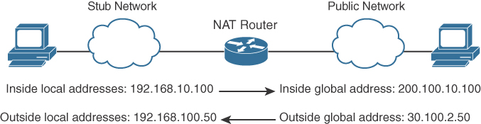
- Inside local address: The real IP address of the device that resides in the internal network. This address is used in the stub domain.
- Inside global address: The translated IP address of the device that resides in the internal network. This address is used in the public network.
- Outside global address: The real IP address of a device that resides in the Internet, outside the stub domain.
- Outside local address: The translated IP address of the device that resides in the Internet. This address is used inside the stub domain.
Different types of NAT
Static NAT
Commonly used to assign a network device with an internal private IP address a unique public address so that it can be accessed from the Internet.
Dynamic NAT
Dynamically maps an unregistered or private IP address to a registered IP address from a pool (group) of registered addresses.
PAT
Maps multiple unregistered or private IP addresses to a single registered IP address by using different ports.
Inside local address
The real IP address of a device that resides in the internal network. This address is used in the stub domain.
Inside global address
The translated IP address of the device that resides in the internal network. This address is used in the public network.
Outside global address
The real IP address of a device that resides on the Internet, outside the stub domain.
Outside local address
The translated IP address of a device that resides on the Internet. This address is used inside the stub domain.
IPv4 Address Subnets
Multicast addresses do not use subnet masks
IP Address Subnet Design Example
The development of an IP address plan or IP address subnet design is an important concept for a network designer. You should be capable of creating an IP address plan based on many factors, including the following:
-Number of locations
-Number of devices per location
-IP addressing requirements for each individual location or building
-Number of devices to be supported in each comms room
-Site requirements, including VoIP devices, wireless LAN, and video
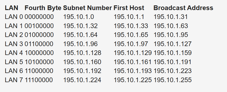
Subnetting for a small company. Suppose the company has 200 hosts and is assigned the Class C network 195.10.1.0/24. The 200 hosts need to be in six different LANs.
You can subnet the Class C network using the mask 255.255.255.224
Deriving number of networks from default networks
Variable-length subnet masking (VLSM) is a process used to divide a network into subnets of various sizes to prevent wasting IP addresses. If a Class C network uses 255.255.255.240 as a subnet mask, 16 subnets are available, each with 14 IP addresses
Class B network 130.20.0.0/16. Using a /20 mask produces 16 subnetworks,
The loopback address is a single IP address with a 32-bit mask. In the previous example, network 130.20.75.0/24 could provide 256 loopback addresses for network devices, starting with 130.20.75.0/32 and ending with 130.20.75.255/32.
Global companies divide this address space into continental regions for the Americas, Europe/Middle East, Africa, and Asia/Pacific. An example is shown in Table 1-25, where the address space has been divided into four major blocks:
10.0.0.0 to 10.63.0.0 is reserved.
10.64.0.0 to 10.127.0.0 is for the Americas.
10.128.0.0 to 10.191.0.0 is for Europe, Middle East, and Africa.
10.192.0.0 to 10.254.0.0 is for Asia Pacific.
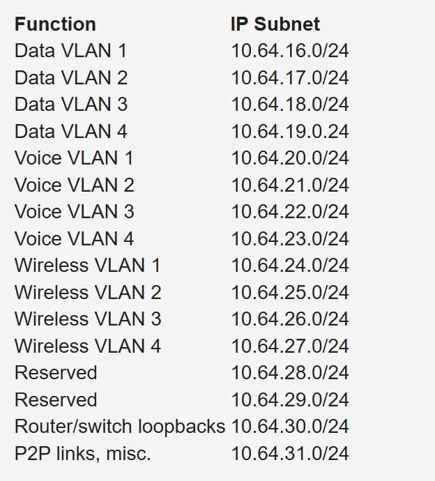
Subnets to be assign for data, voice, wireless, and management VLANs. Table 1-26 shows an example. The large site is allocated network 10.64.16.0/20. The first four /24 subnets are assigned for data VLANs, the second four /24 subnets are assigned for voice VLANs, and the third four /24 subnets are assigned for wireless VLANs. Other subnets are used for router and switch interfaces, point-to-point links, and network management devices.
When assigning subnets for a site or perhaps a floor of a building, do not assign subnets that are too small. You want to assign subnets that allow for growth
For example, if a floor has a requirement for 50 users, do you assign a /26 subnet (which allows 62 addressable nodes)? Or do you assign a /25 subnet, which allows up to 126 nodes?
Assigning a subnet that is too large will prevent you from having other subnets for IPT and video conferencing.
The company might make an acquisition of another company. Although a new address design would be the cleanest solution, the recommendation is to avoid re-addressing of networks. Here are some other options:
- If you use 10.0.0.0/8 as your network, use the other private IP addresses for the additions.
- Use NAT as a workaround.
Performing Route Summarization
As a network designer, you will want to allocate IPv4 address space to allow for route summarization. Large networks can grow quickly from 500 routes to 1000 and higher. Route summarization reduces the size of the routing table
Planning for a Hierarchical IP Address Network
When IPv4 addressing for a companywide network, recommended practice dictates that you allocate contiguous address blocks to regions of the network. Hierarchical IPv4 addressing enables summarization, which makes the network easier to manage and troubleshoot.
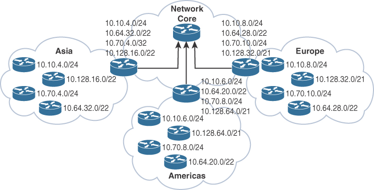
Network subnets cannot be aggregated because /24 subnets from many different networks are deployed in different areas of the network. For example, subnets under 10.10.0.0/16 are deployed in Asia (10.10.4.0/24), the Americas (10.10.6.0/24), and Europe (10.10.8.0/24). The same occurs with networks 10.70.0.0/16 and 10.128.0.0/16. This lack of summarization in the network increases the size of the routing table, making it less efficient. It also makes it harder for network engineers to troubleshoot because it is not obvious in which part of the world a particular subnet is located.
Network That Is Not Summarized
By contrast, Figure 1-6 shows a network that allocates a high-level block to each region:
10.0.0.0/18 for Asia Pacific networks
10.64.0.0/18 for Americas networks 10.128.0.0/18 for European/Middle East networks
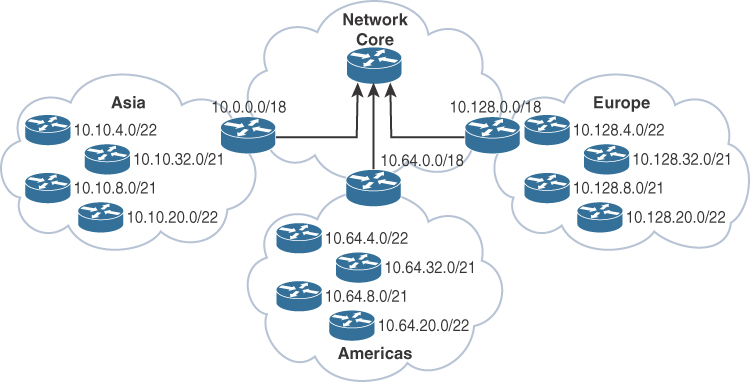
This solution provides for summarization of regional networks at area borders and improves control over the growth of the routing table.
Here are some examples of standards:
Use .1 or .254 (in the last octet) as the default gateway of the subnet.
Match the VLAN ID number with the third octet of an IP address. (For example, the IP subnet 10.10.150.0/25 is assigned to VLAN 150.)
Reserve .1 to .15 of a subnet for static assignments and .16 to .239 for the DHCP pool.
Allocate /24 subnets for user devices (such as laptops and PCs).
Allocate a parallel /24 subset for VoIP devices (IP phones).
Allocate subnets for access control systems and video conferencing systems.
Reserve subnets for future use.
Use /30 subnets for point-to-point links.
Use /32 for loopback addresses.
Allocate subnets for remote access and network management.
Case Study: IP Address Subnet Allocation
Consider a company that has users in several buildings in a campus network. Building A has four floors, and building B has two floors

the building’s Layer 3 switches will be connected via a dual-fiber link between switch A and switch B. Both switches will connect to the WAN router R1. Assume that you have been allocated network 10.10.0.0/17 for this campus and that IP phones will be used.

Notice that the VLAN number matches the third octet of the IP subnet. The second floor is assigned VLAN 12 and IP subnet 10.10.12.0/24. For building B, VLAN numbers in the 20s are used, with floor 1 having a VLAN of 21 assigned with IP subnet 10.10.21.0/24.
VLANs for IP telephony (IPT) are similar to data VLANs, with the correlation of using numbers in the 100s. For example, floor 1 of building A uses VLAN 11 for data and VLAN 111 for voice, and the corresponding IP subnets are 10.10.11.0/24 (data) and 10.10.111.0.24 (voice). This is repeated for all floors.
This solution uses /30 subnets for point-to-point links from the 10.10.2.0/24 subnet. Loopback addresses are taken from the 10.10.1.0/24 network starting with 10.10.1.1/32 for the WAN router. Subnet 10.10.3.0/24 is reserved for the building access control system.
BOOTP and DHCP
The BOOTP server port is UDP port 67. The client port is UDP port 68
DHCP is extension of BOOTP that is why the behavior is exactly same with enhancements in DHCP but BOOTP requires that you build a MAC address–to–IP address table on the server. You must obtain every device’s MAC address, which is a time-consuming effort.
That is DHCP was introduced with “lease” function for any client / mac address
DHCP not just provides network address but also delivers configuration parameters to hosts
An IP address is assigned as follows:
Step 1. The client sends a DHCPDISCOVER message to the local network using a 255.255.255.255 broadcast.
Step 2. DHCP relay agents (routers and switches) can forward the DHCPDISCOVER message to the DHCP server in another subnet.
Step 3. The server sends a DHCPOFFER message to respond to the client, offering IP address, lease expiration, and other DHCP option information.
Step 4. Using DHCPREQUEST, the client can request additional options or an extension on its lease of an IP address. This message also confirms that the client is accepting the DHCP offer.
Step 5. The server sends a DHCPACK (acknowledgment) message that confirms the lease and contains all the pertinent IP configuration parameters.
Step 6. If the server is out of addresses or determines that the client request is invalid, it sends a DHCPNAK message to the client.
ARP
When ARP response is received it is cached as well in the ARP table , listing IP addresses with MAC addresses
ARP is a broadcast and ARP request contains the sender’s IP and MAC address and the target IP address. That is why ARP response is unicast
All nodes in the broadcast domain receive the ARP request and process it.
ARP request is always a broadcast and ARP response is always a unicast

next post
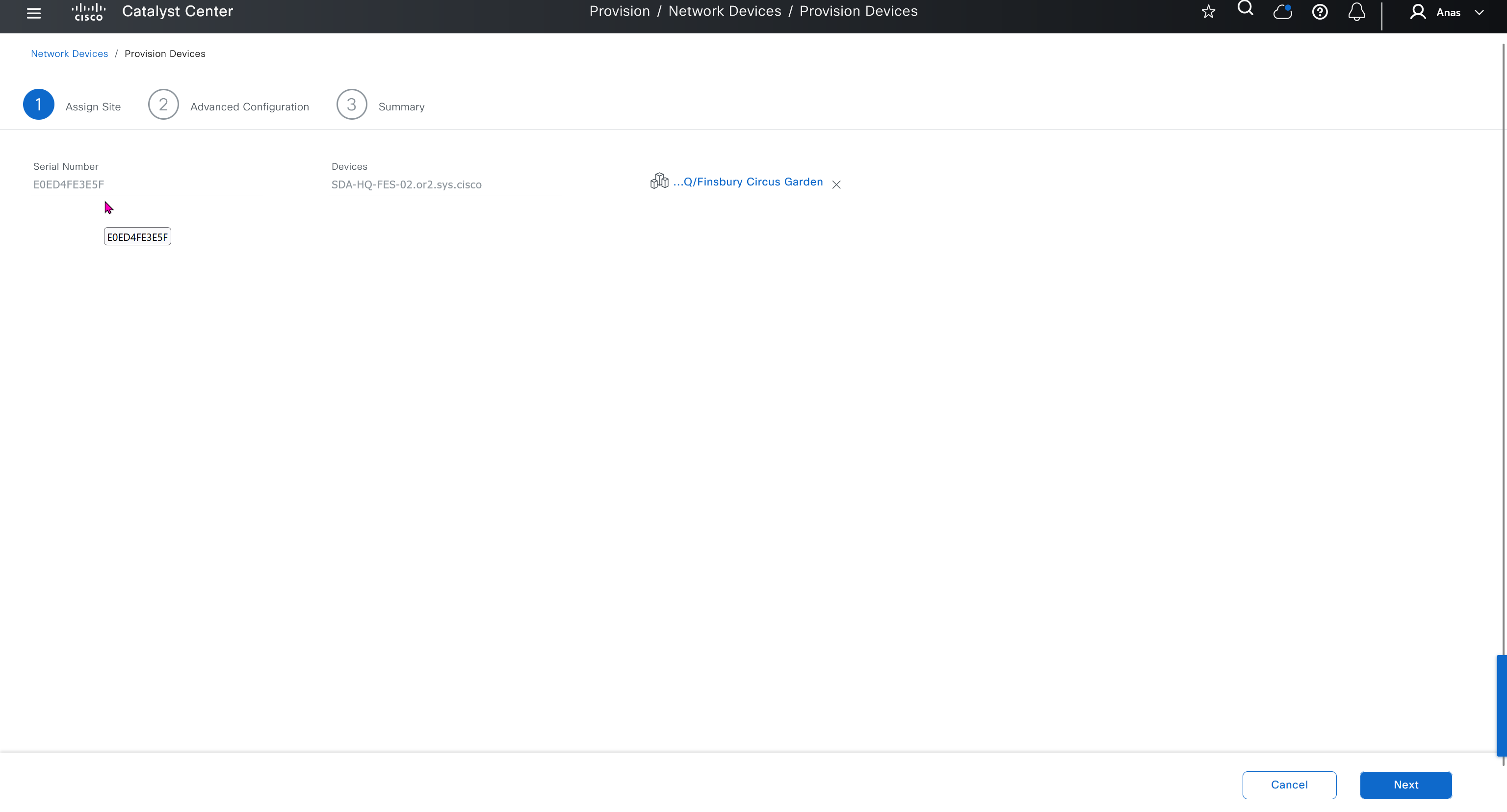
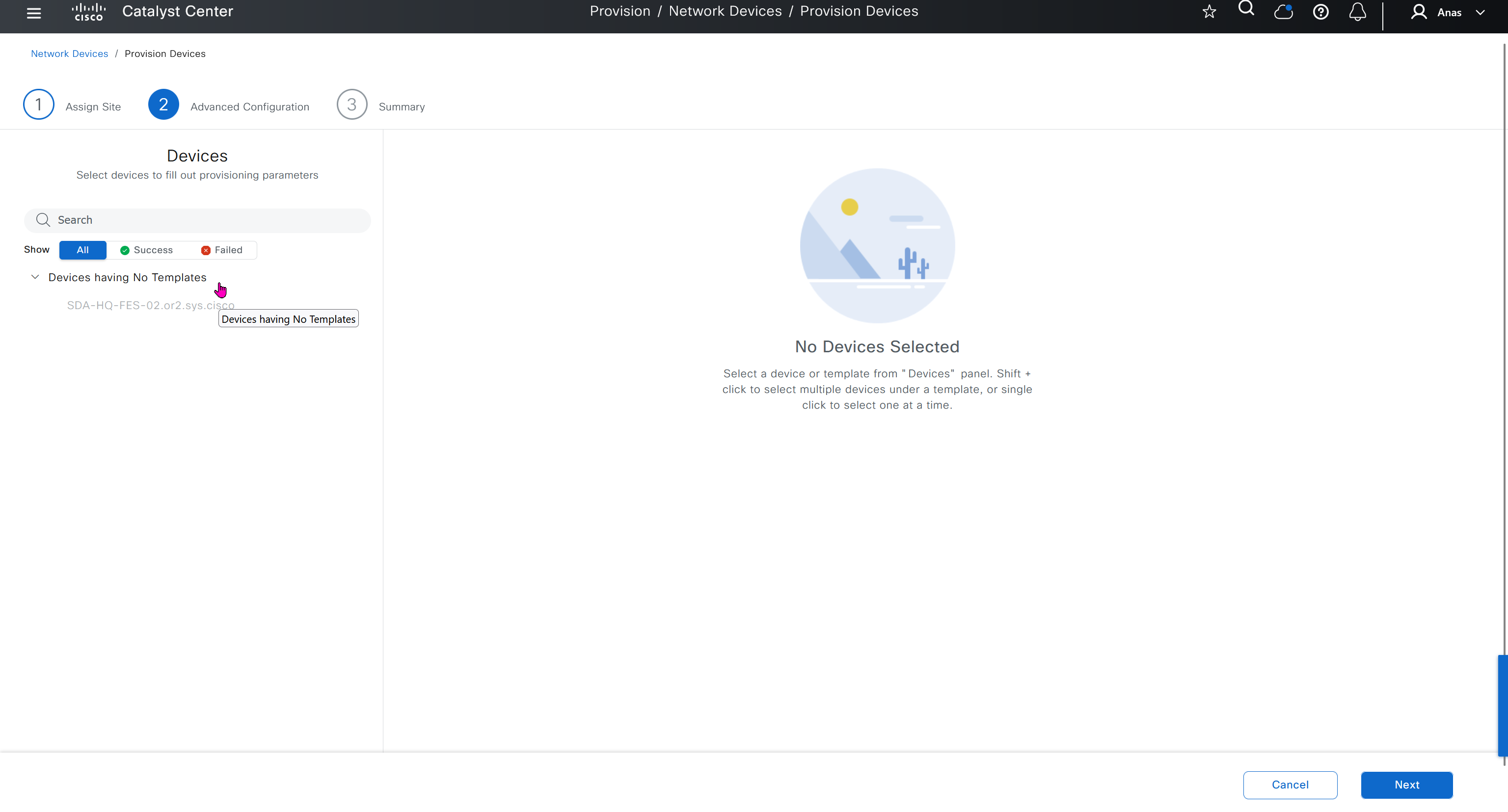
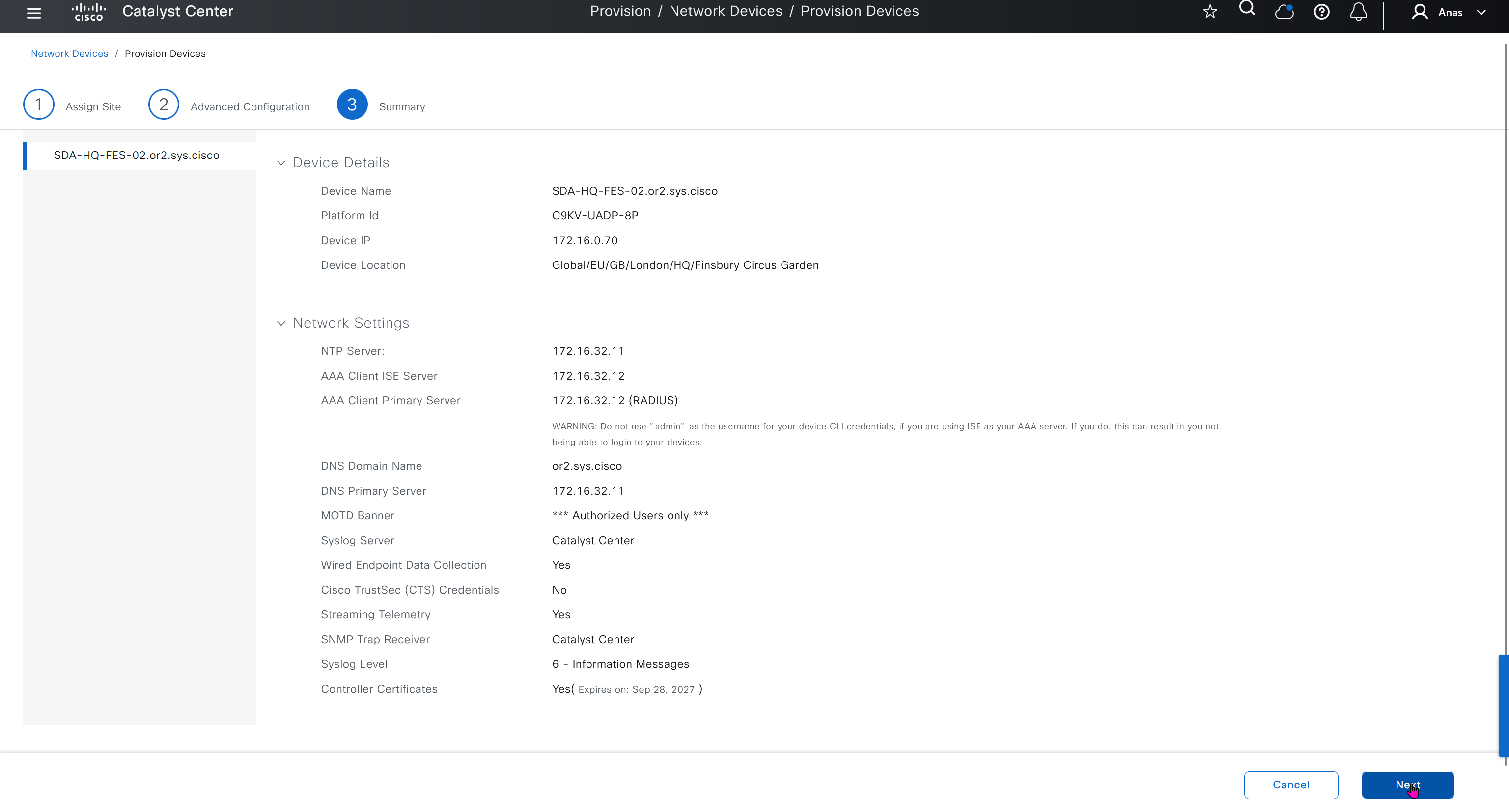
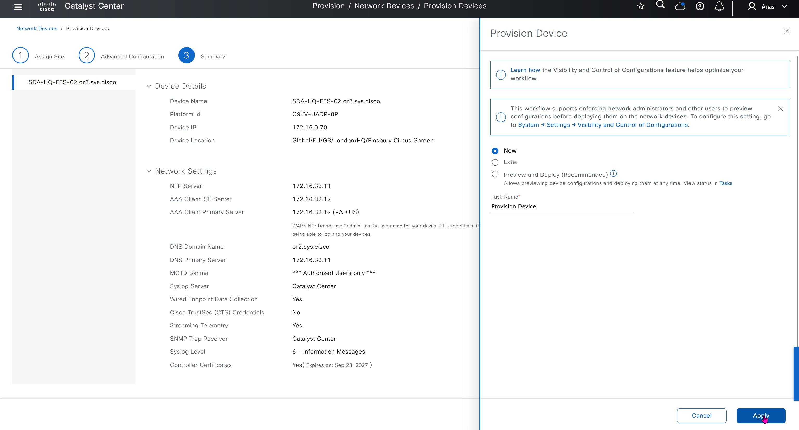
SDA LM3 – Topology & Software Image Management
Videos
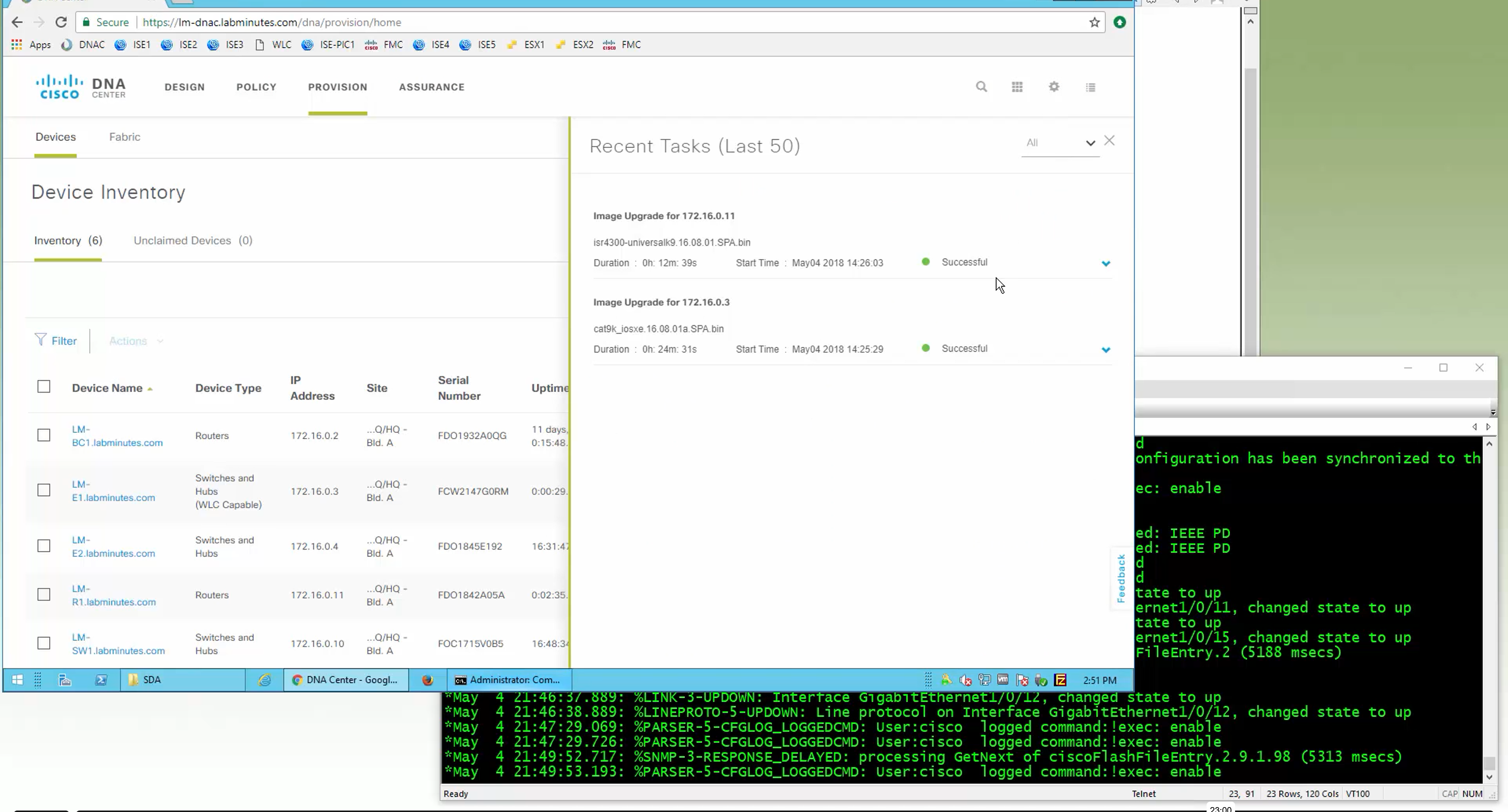
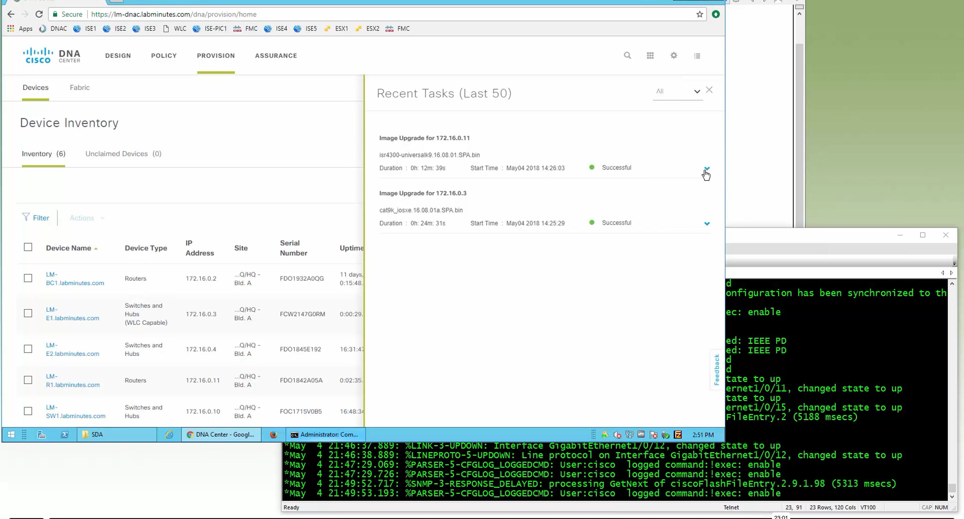
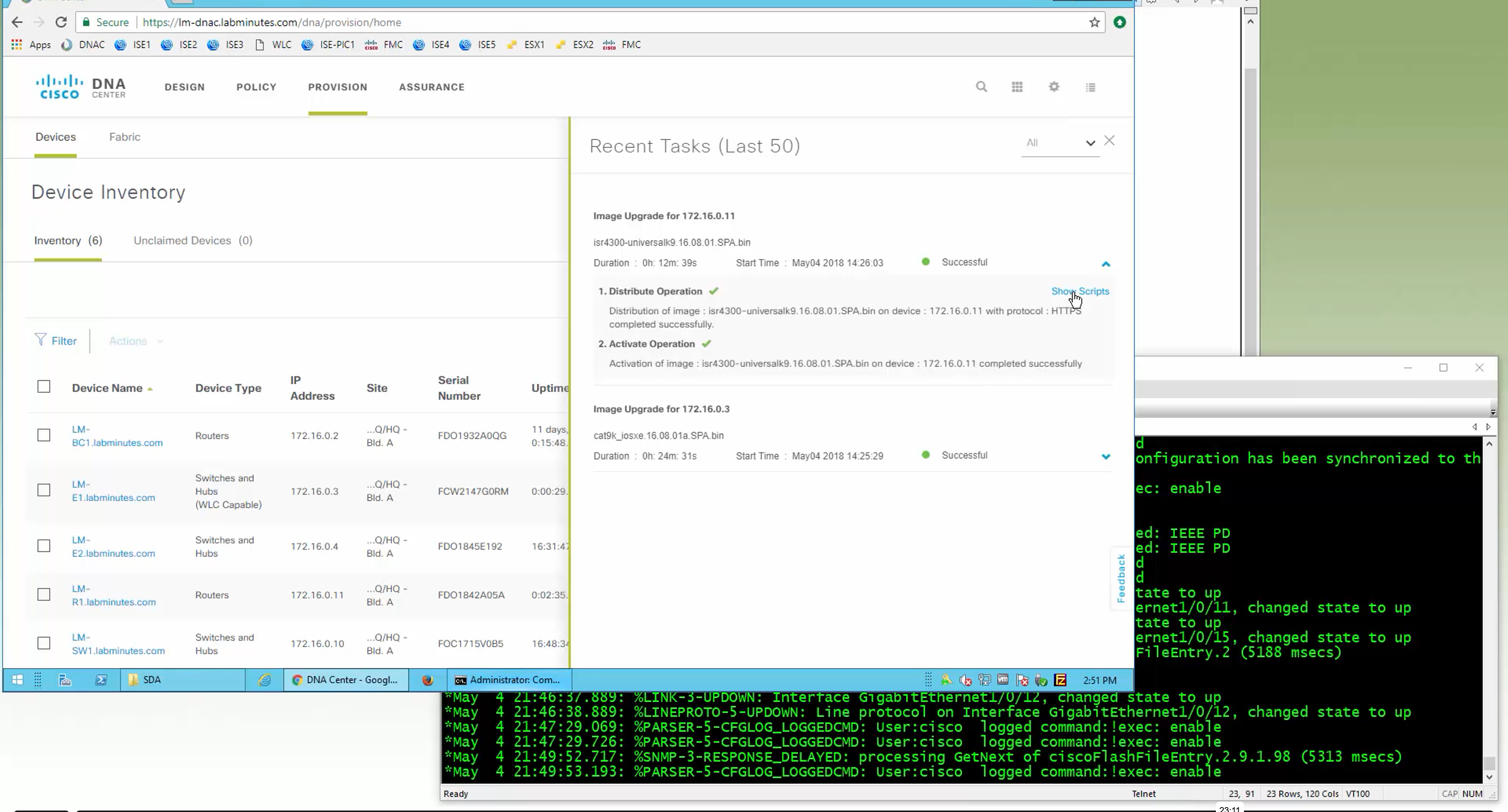
Topology & Software Image Management


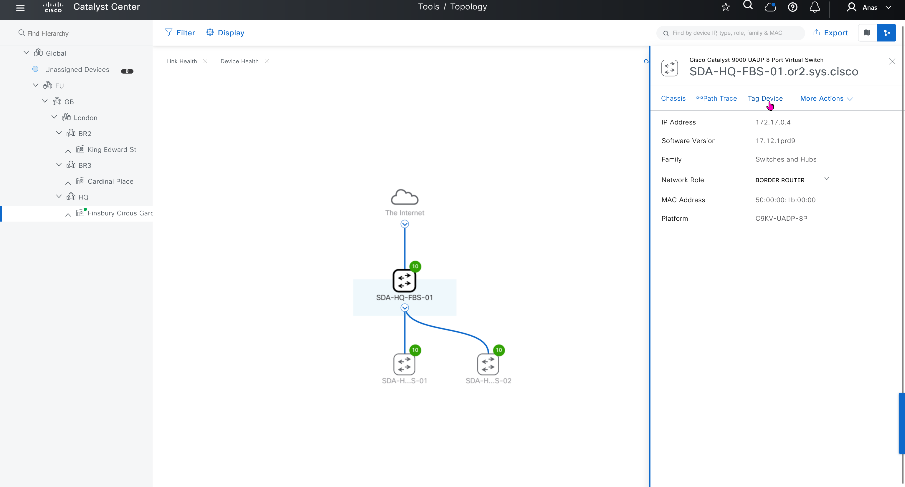


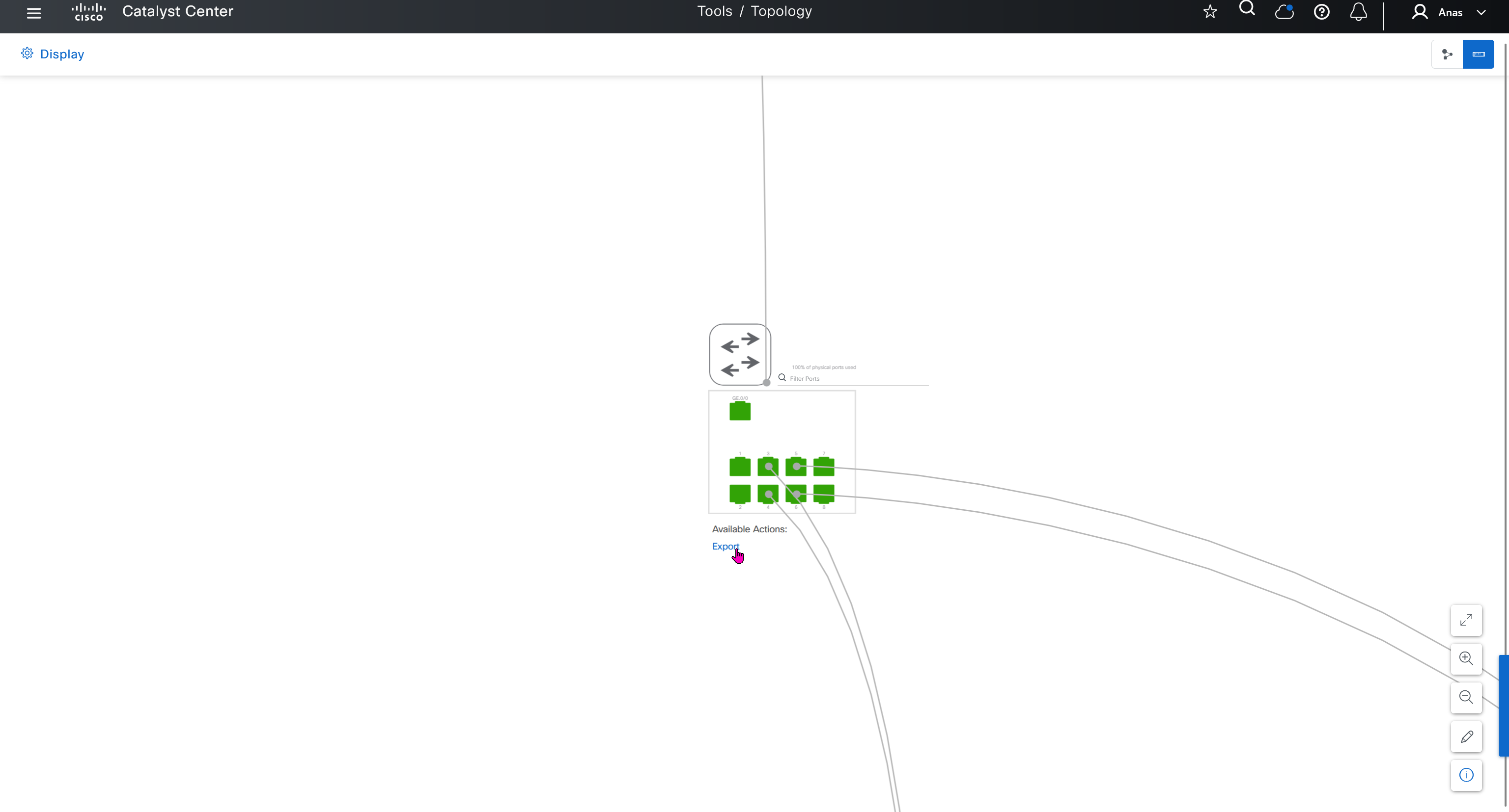
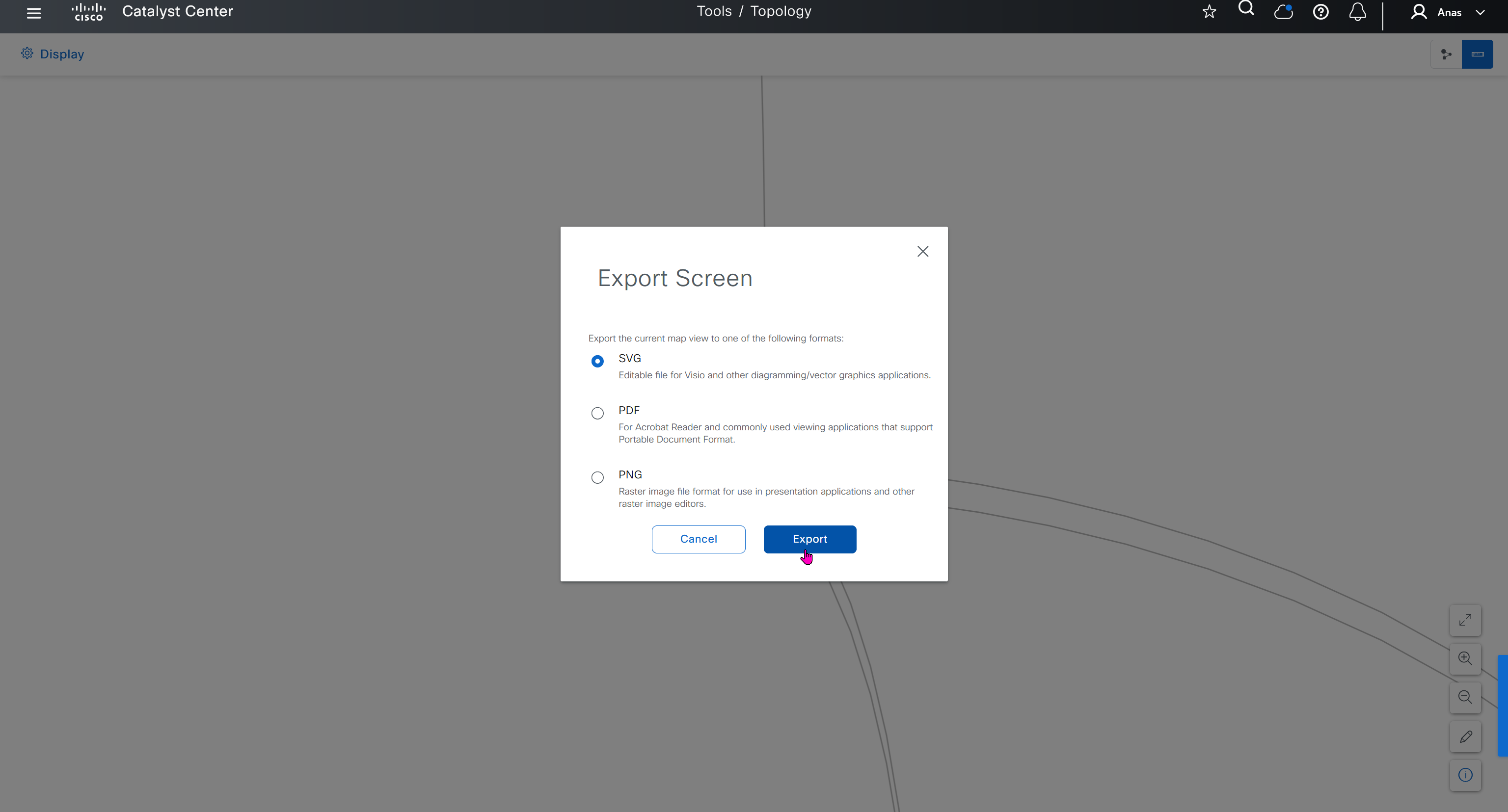
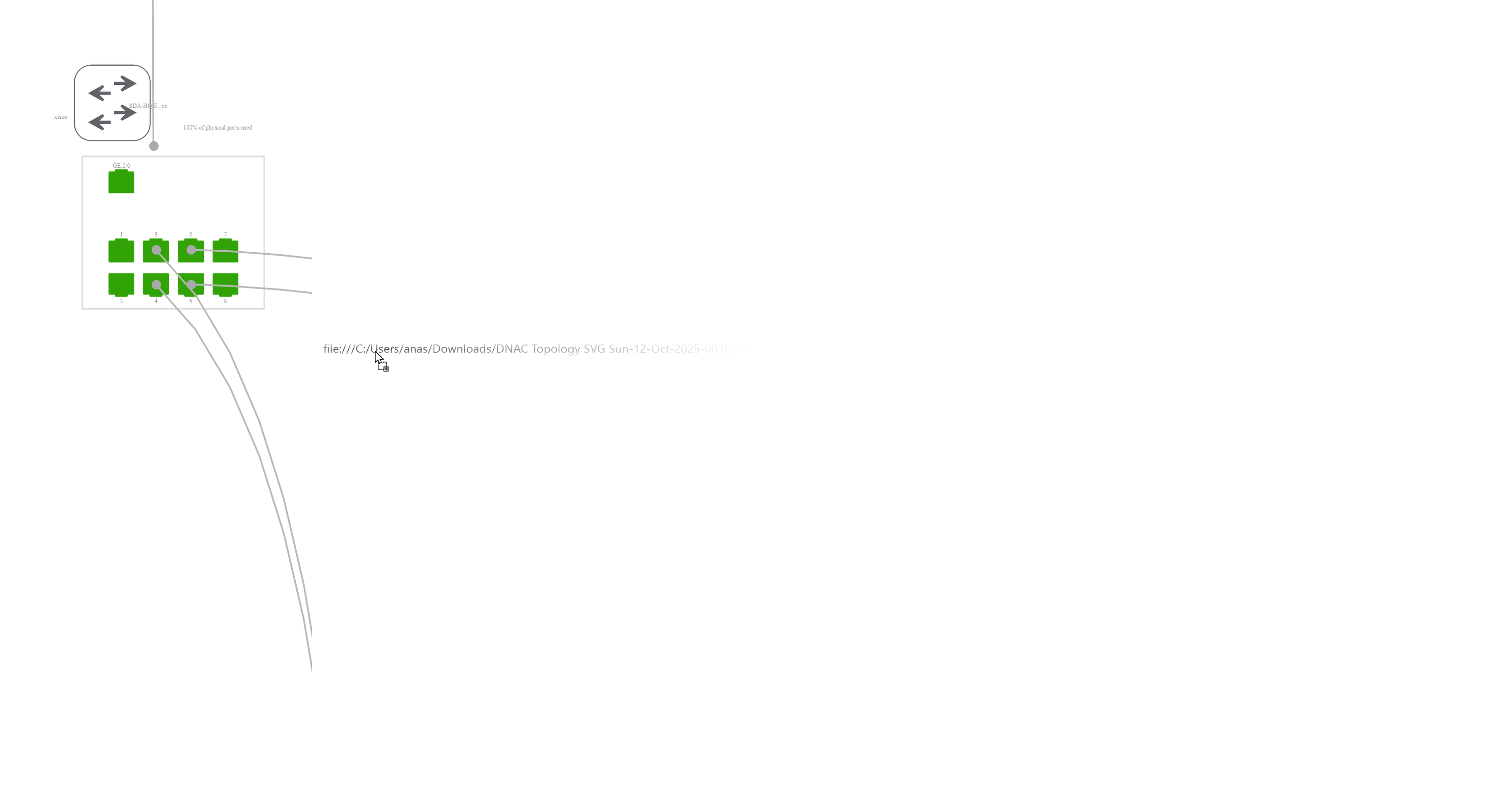
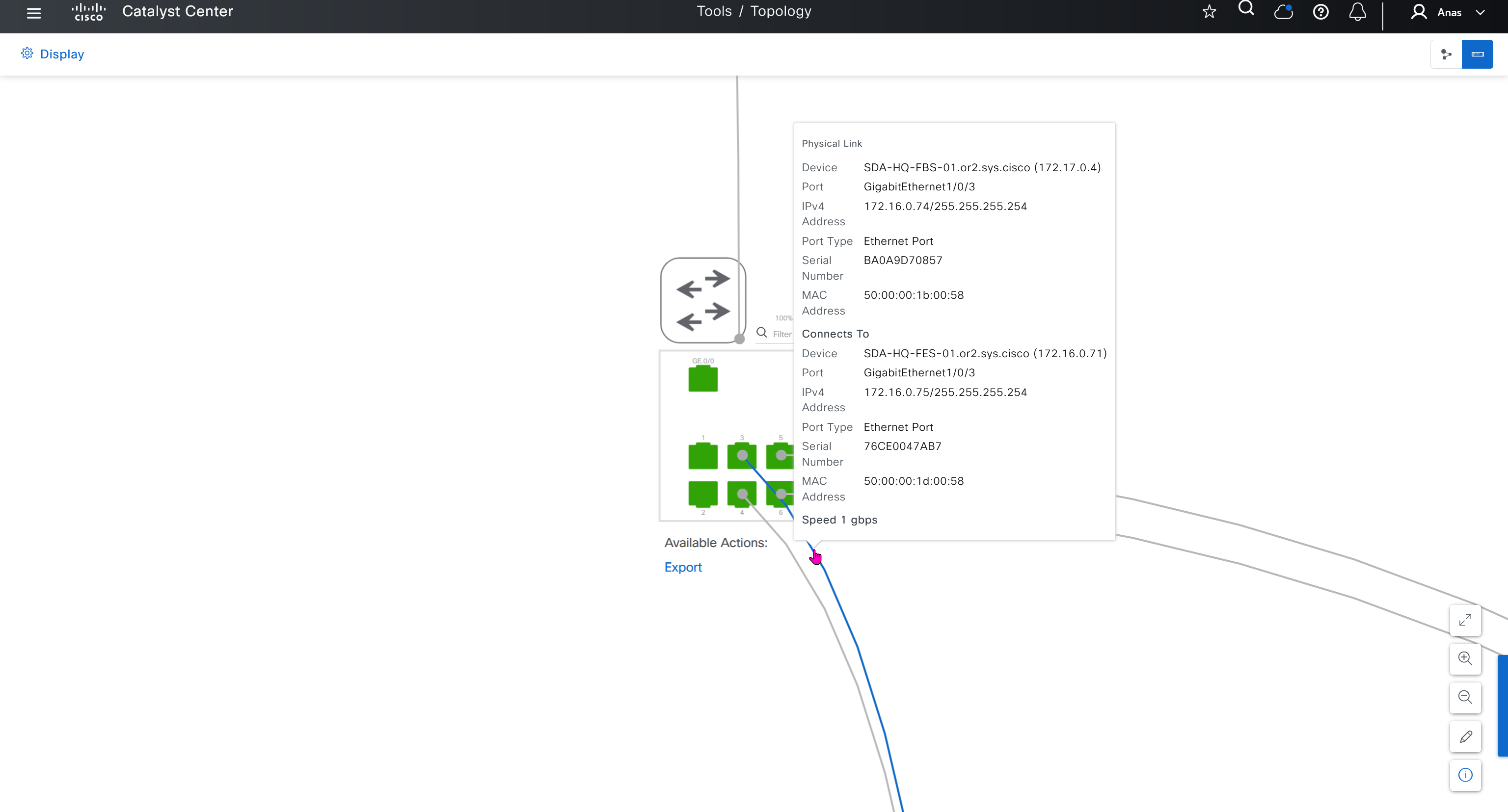
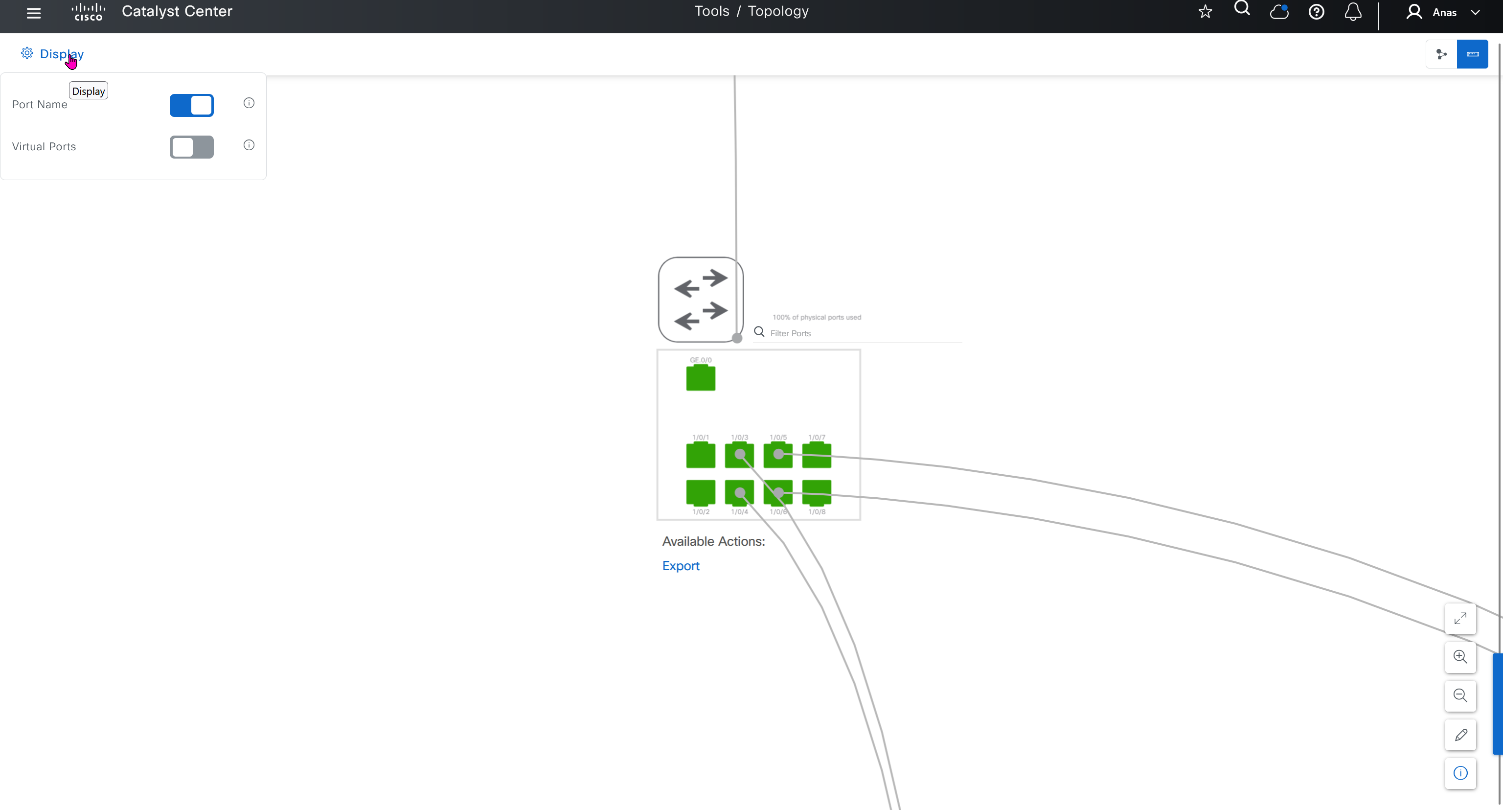
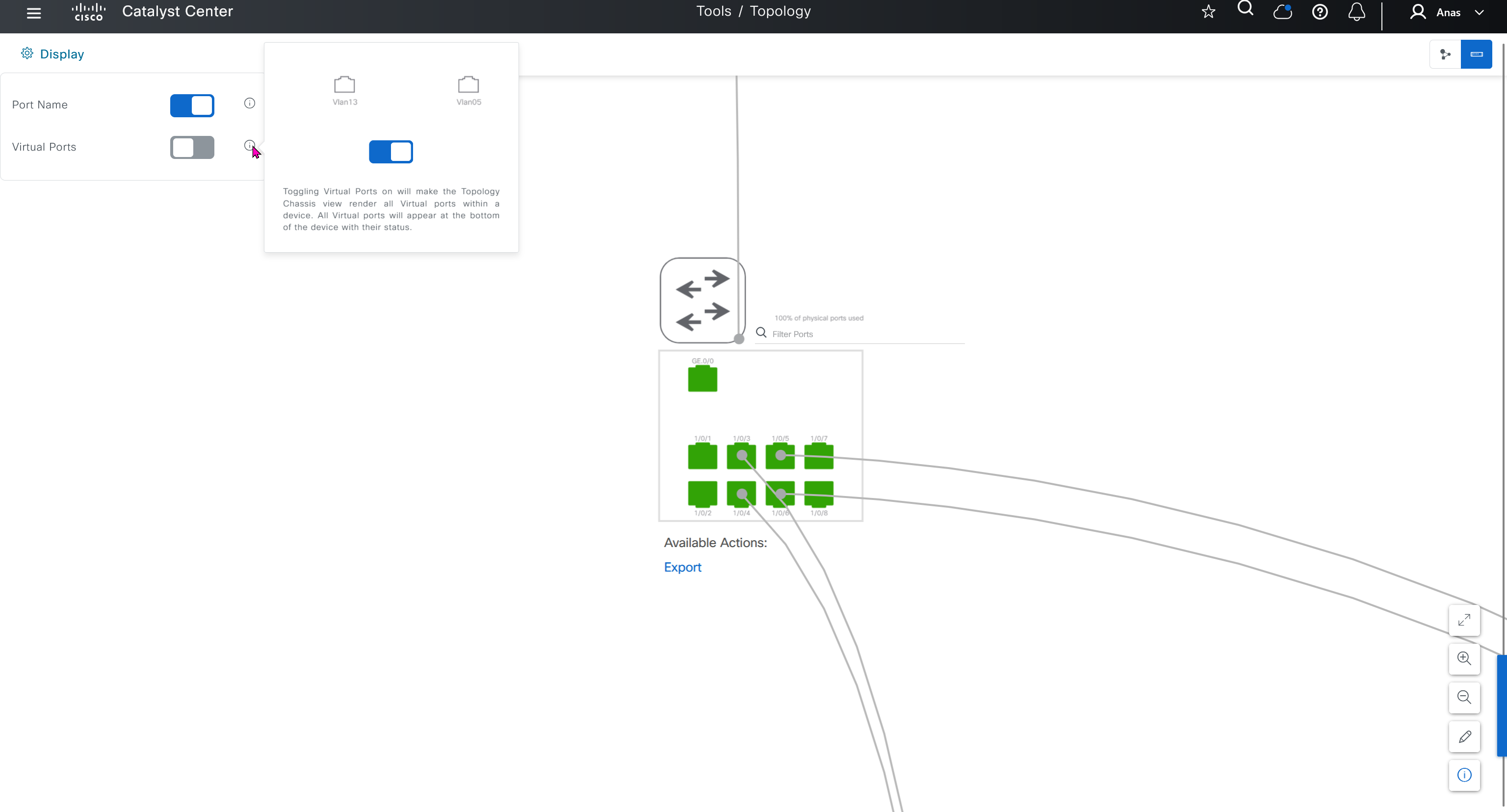
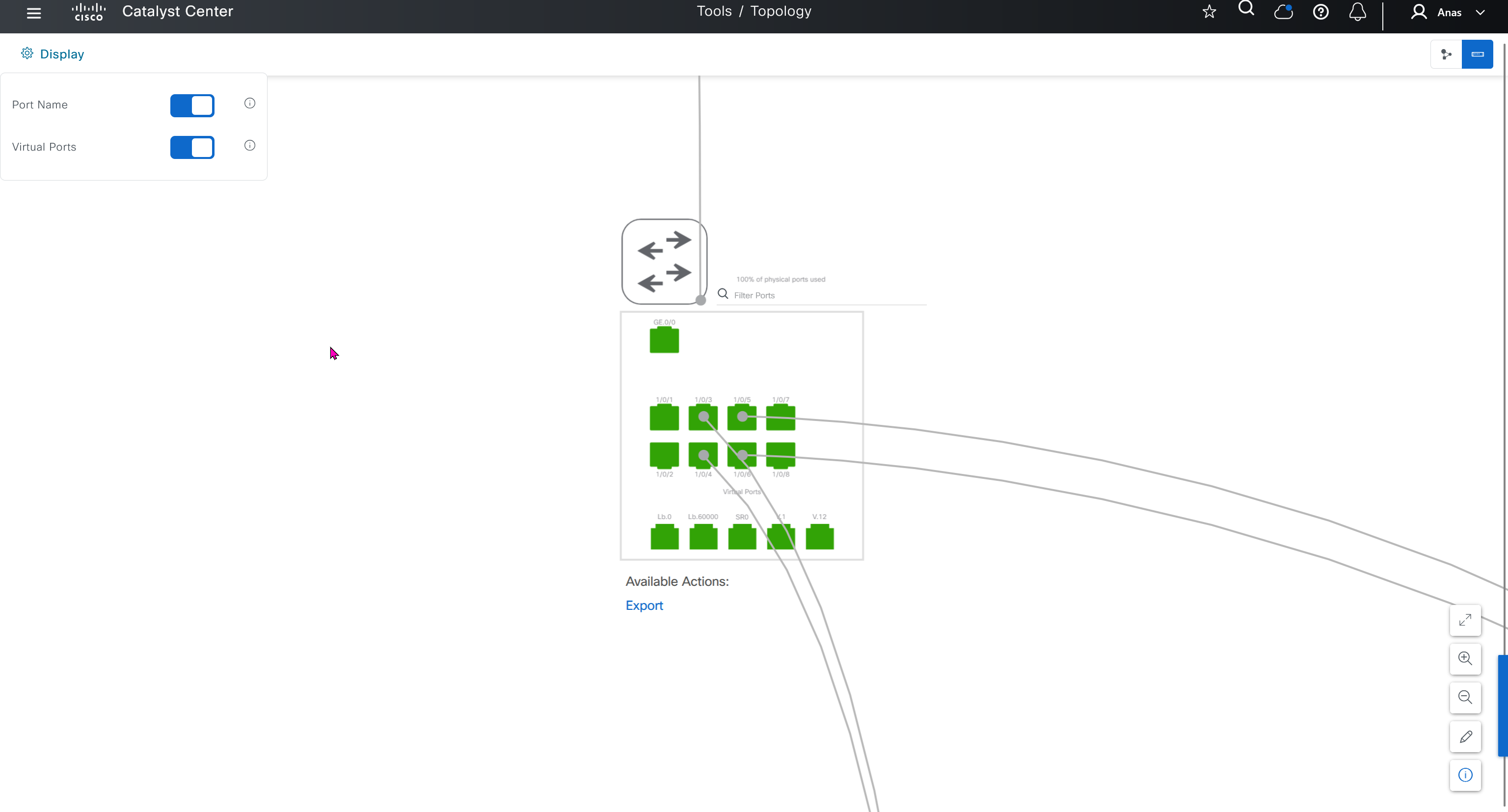
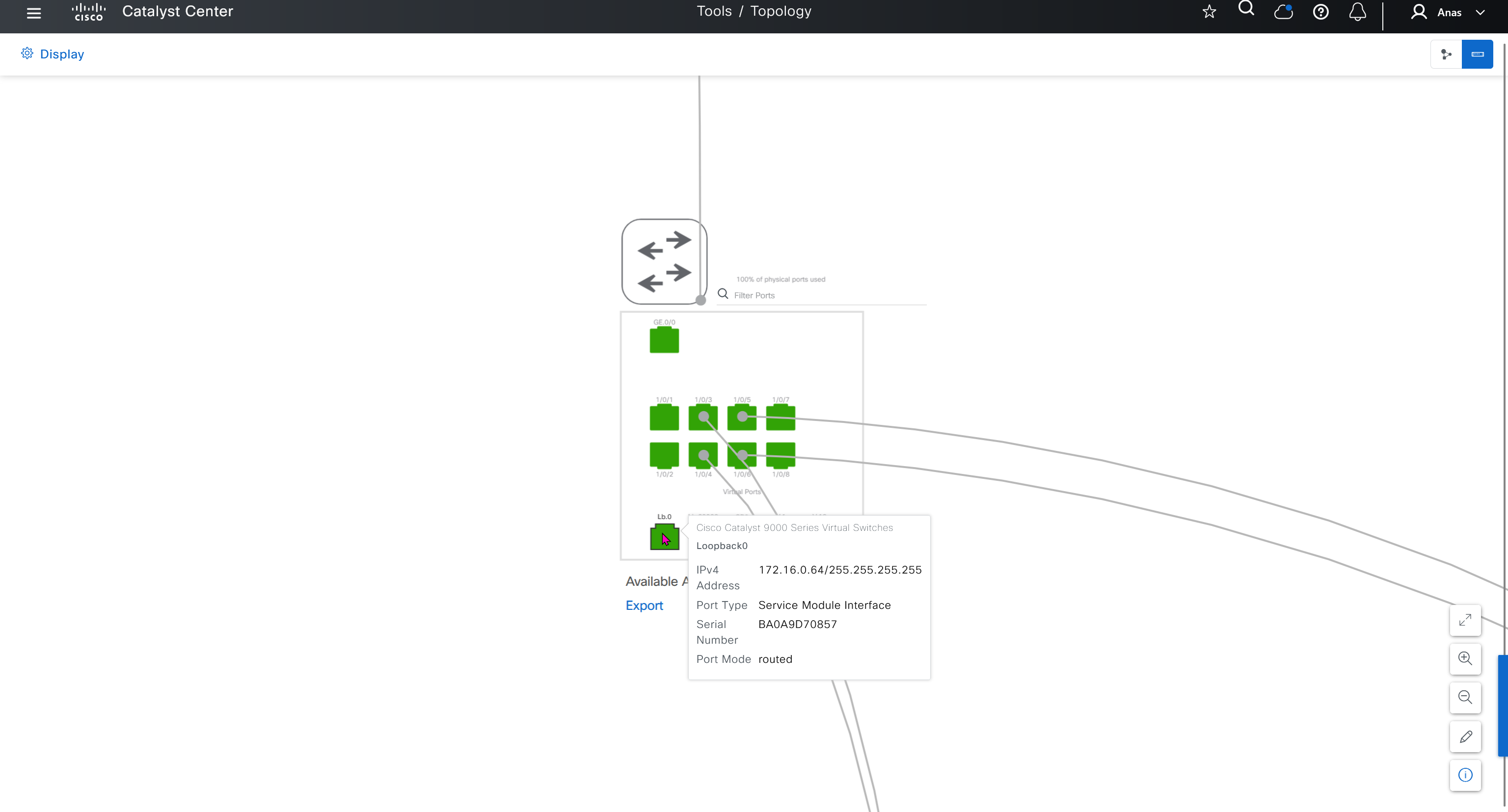
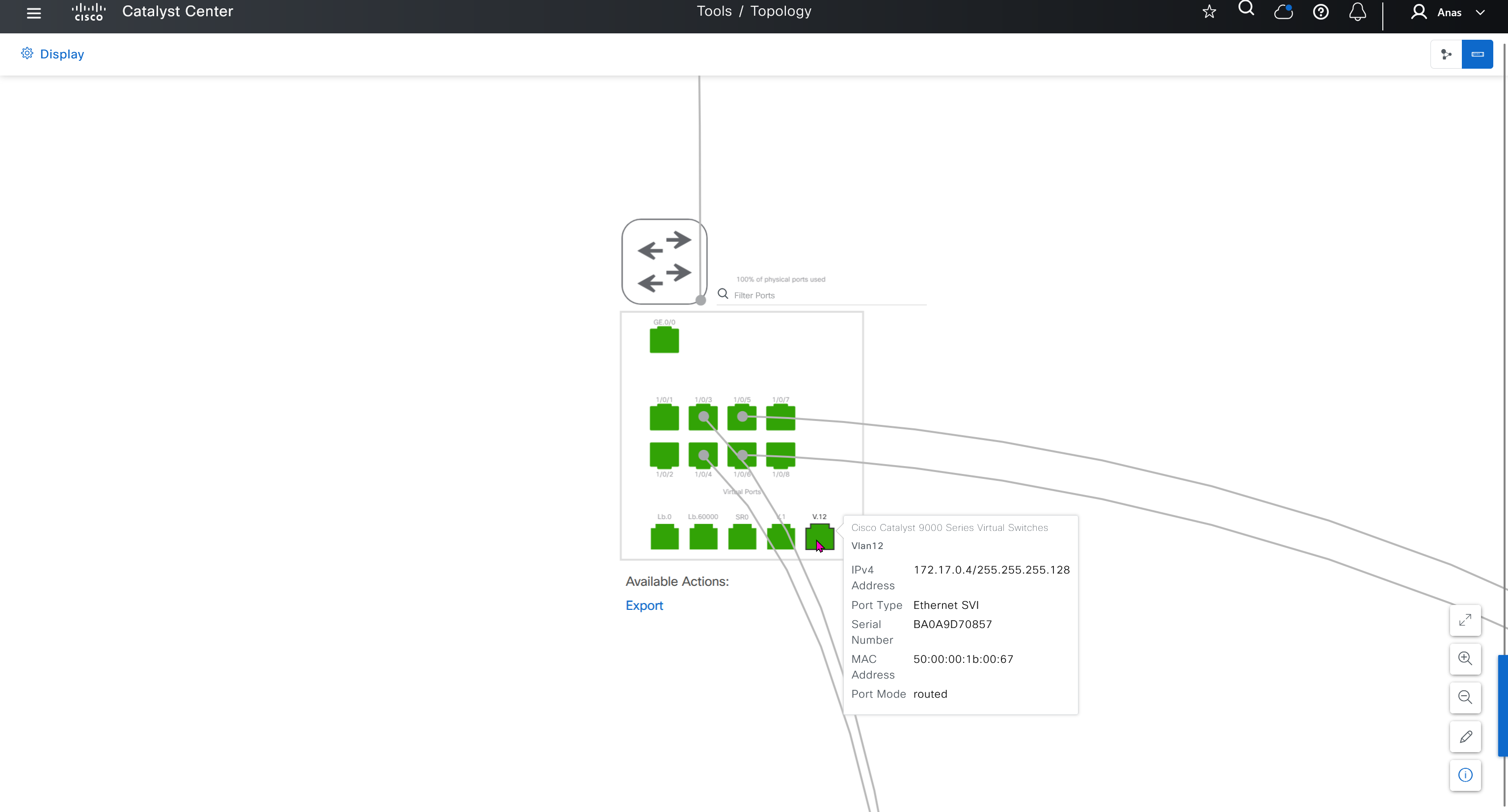

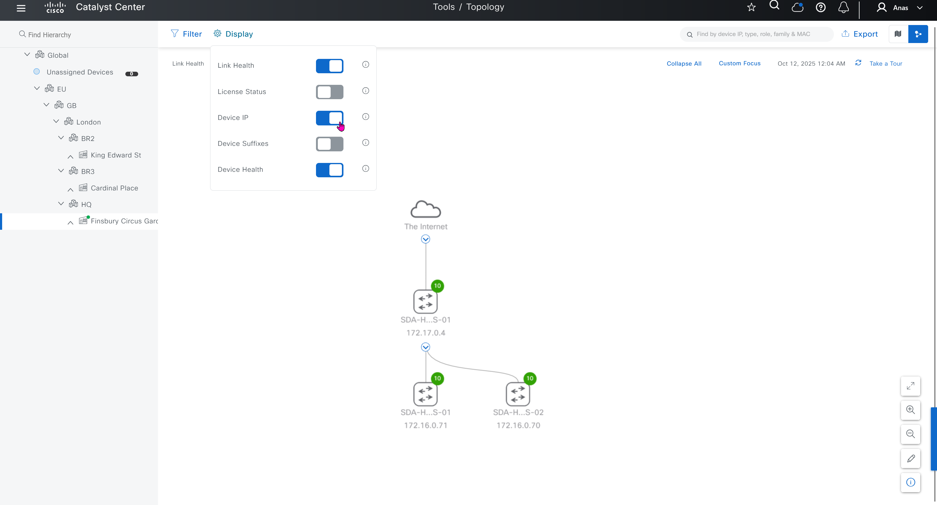

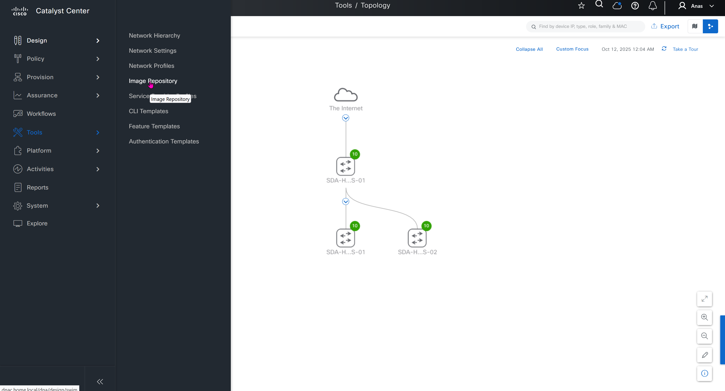
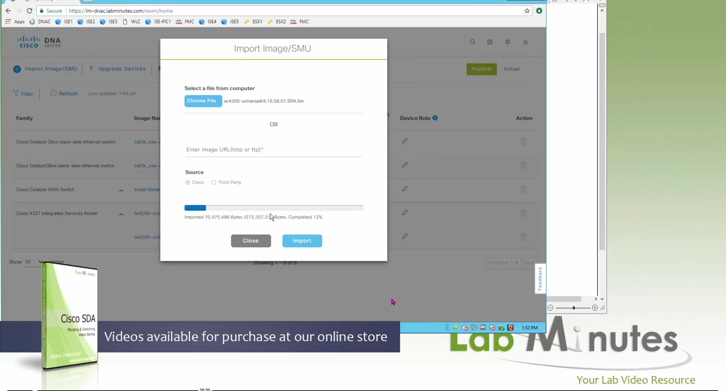
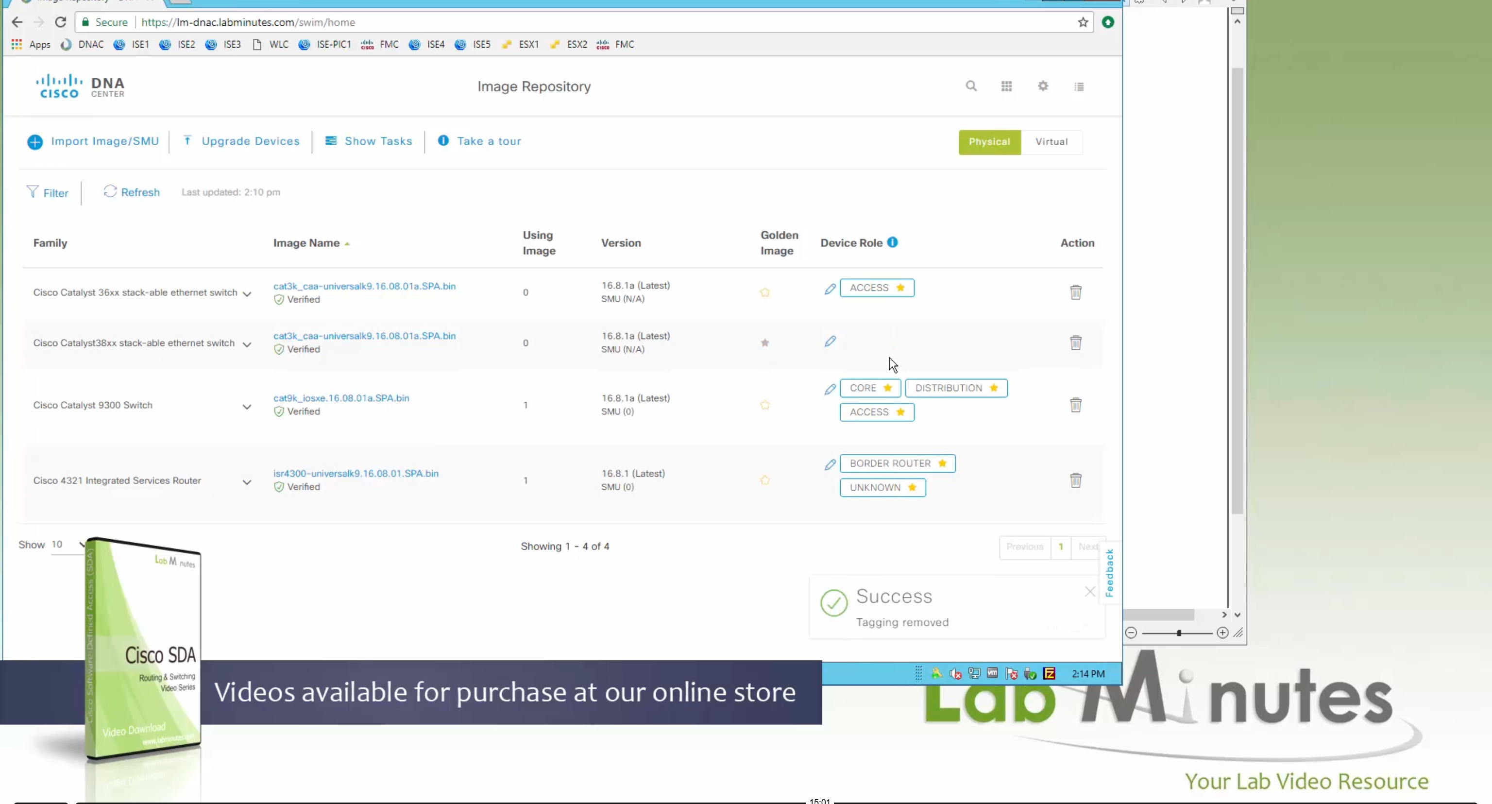
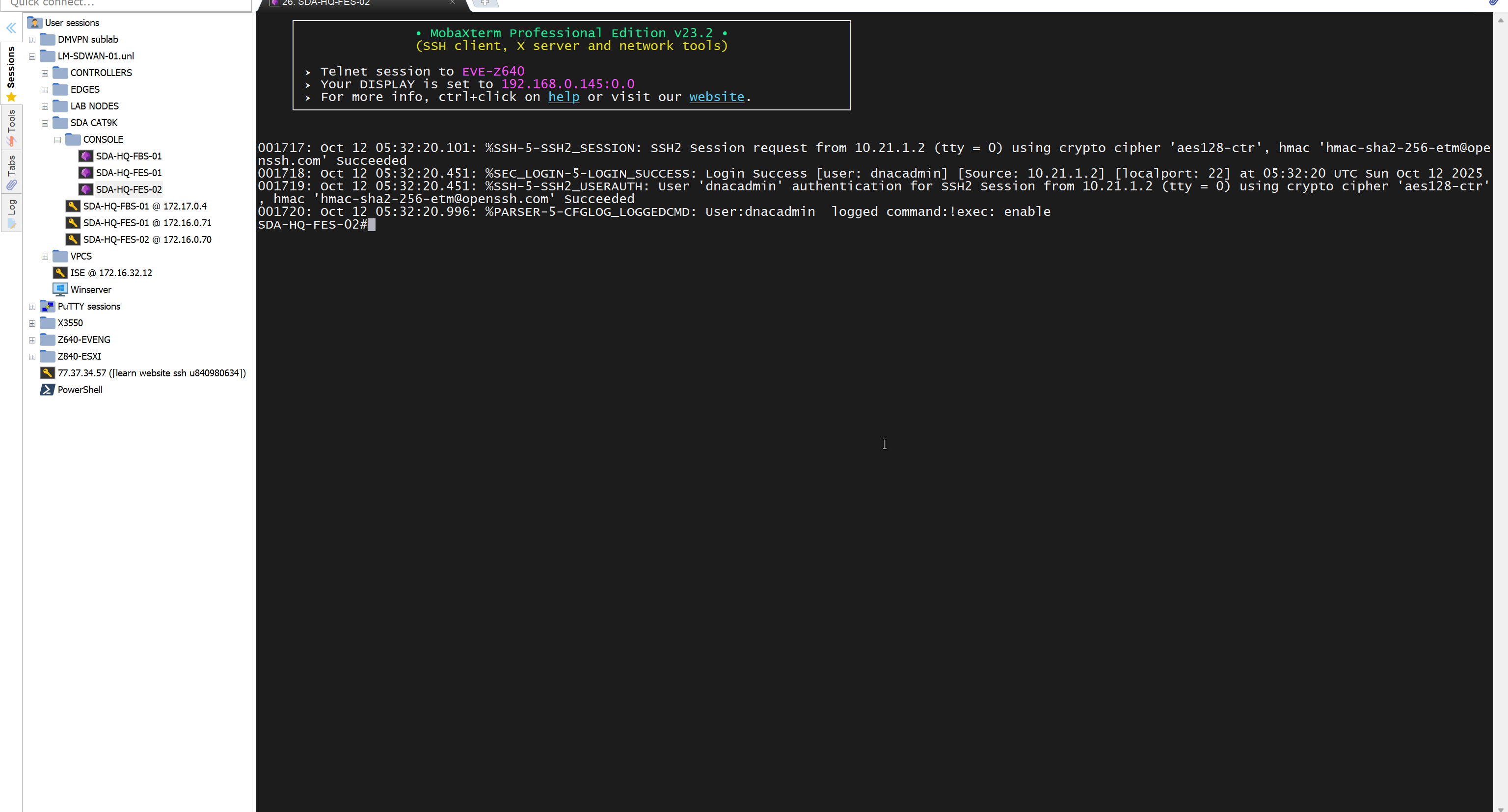
SWIM – Software Image Management

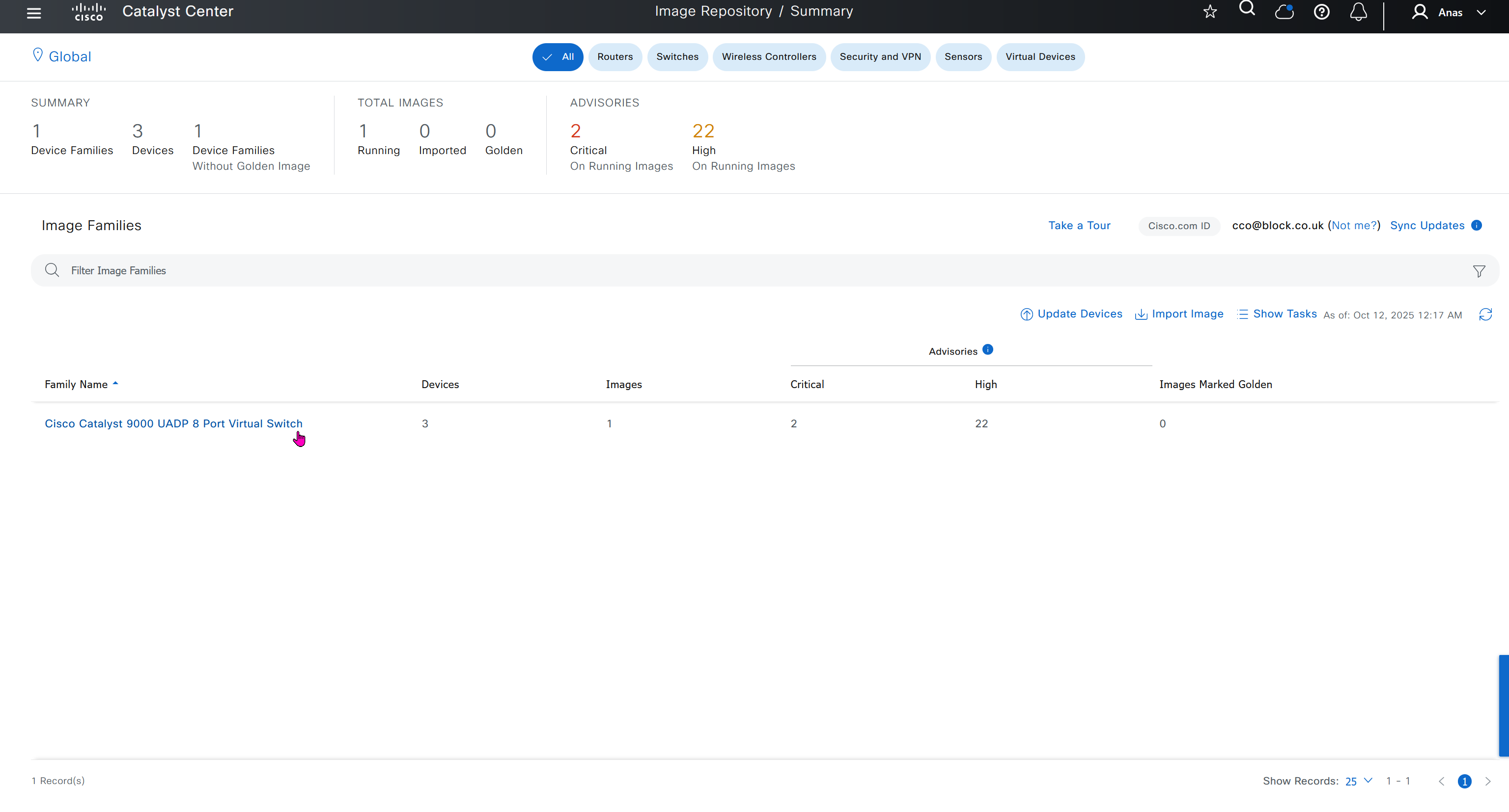


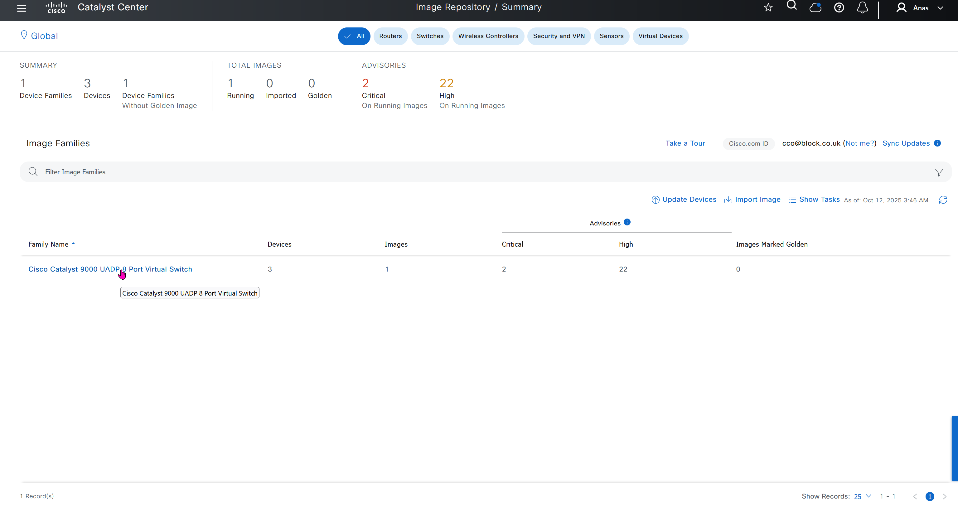


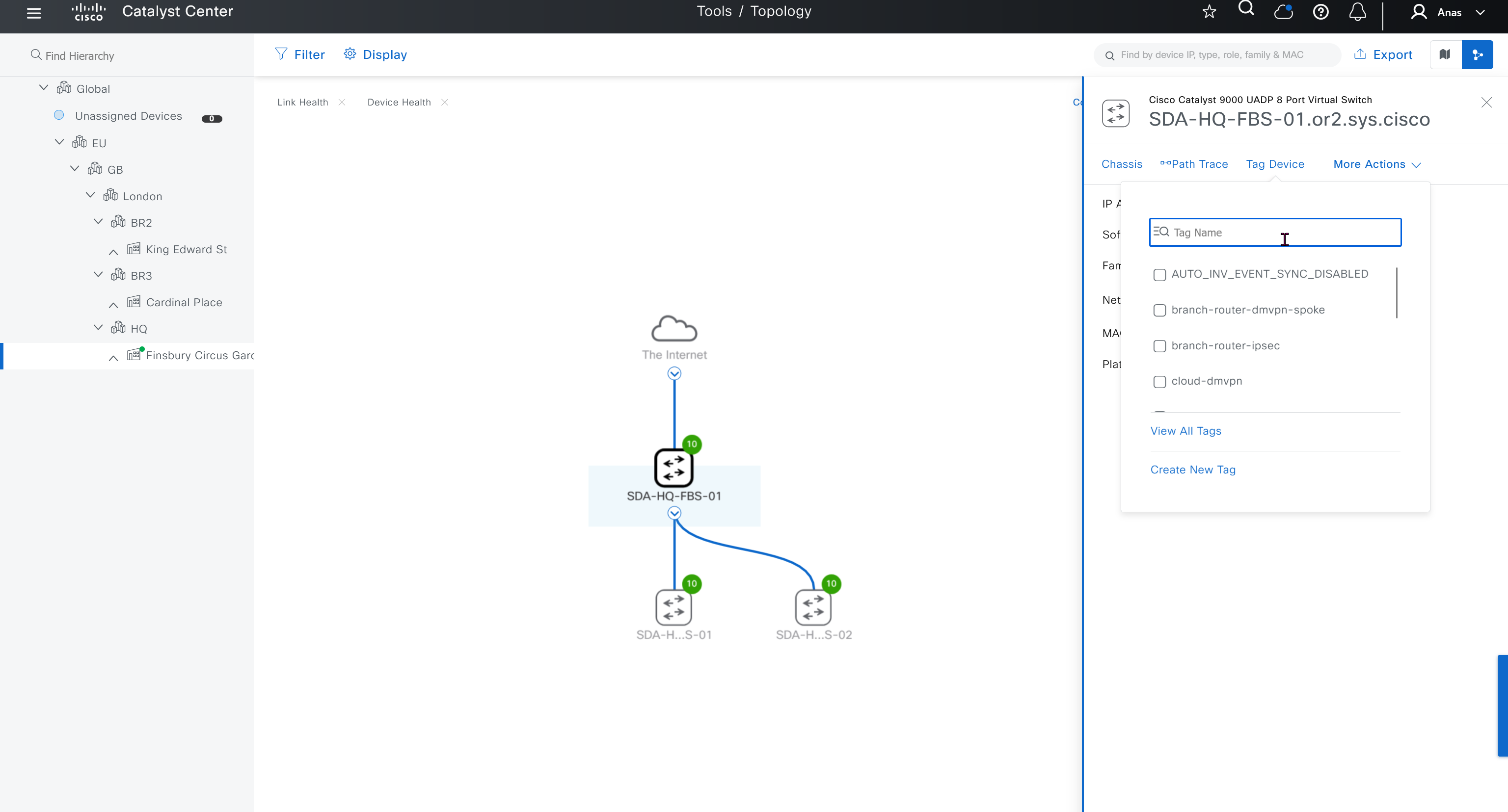
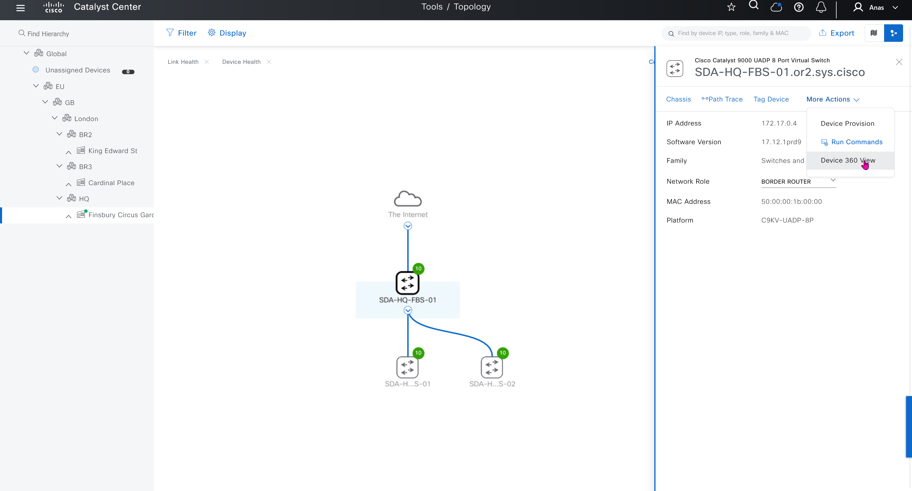
you can only start tagging devices one you have uploaded the image, because we have virtual C9Kv images there is no .bin or .smu images available for them, from ths point on we will have screenshots from lab minutes
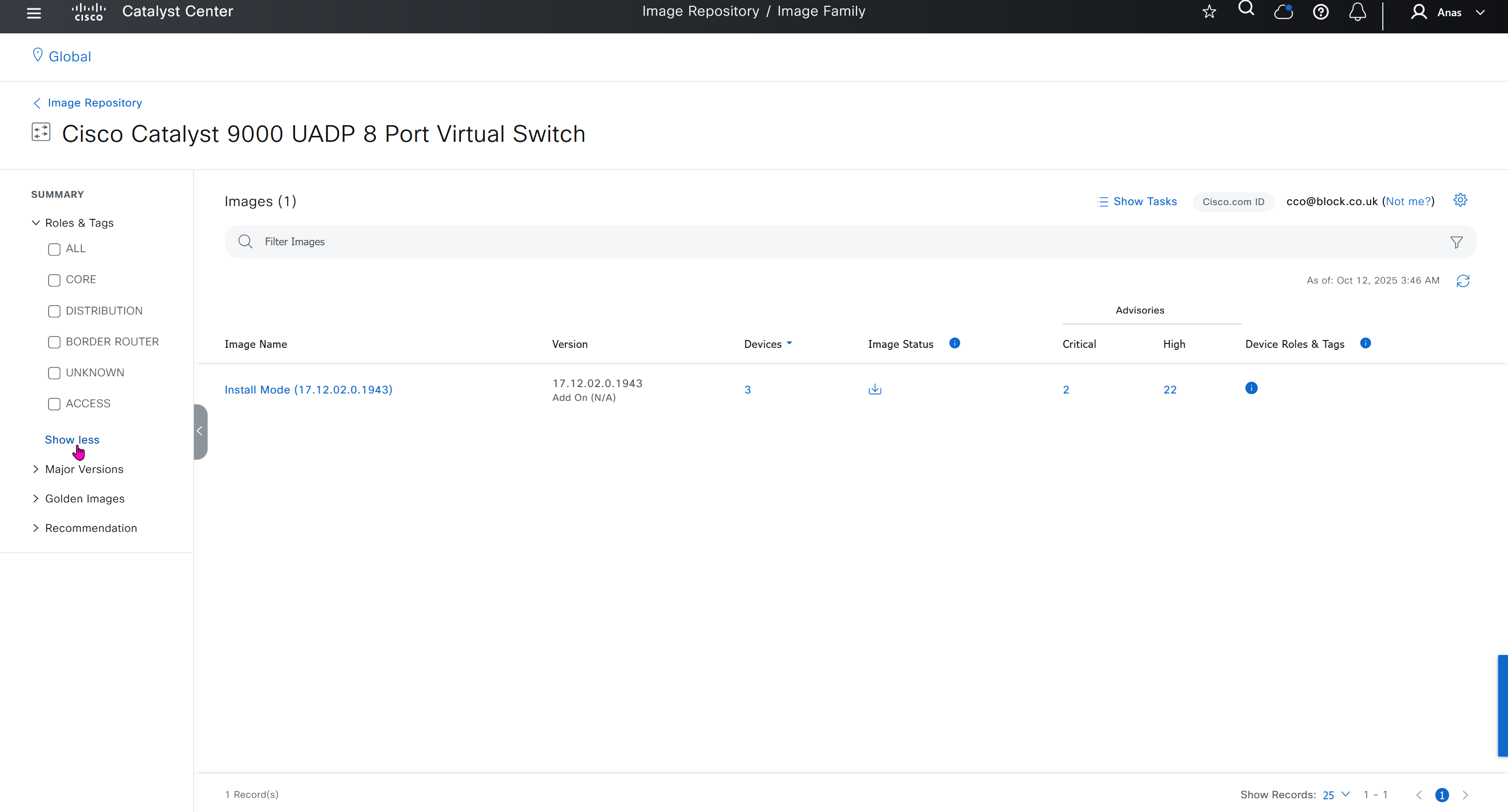
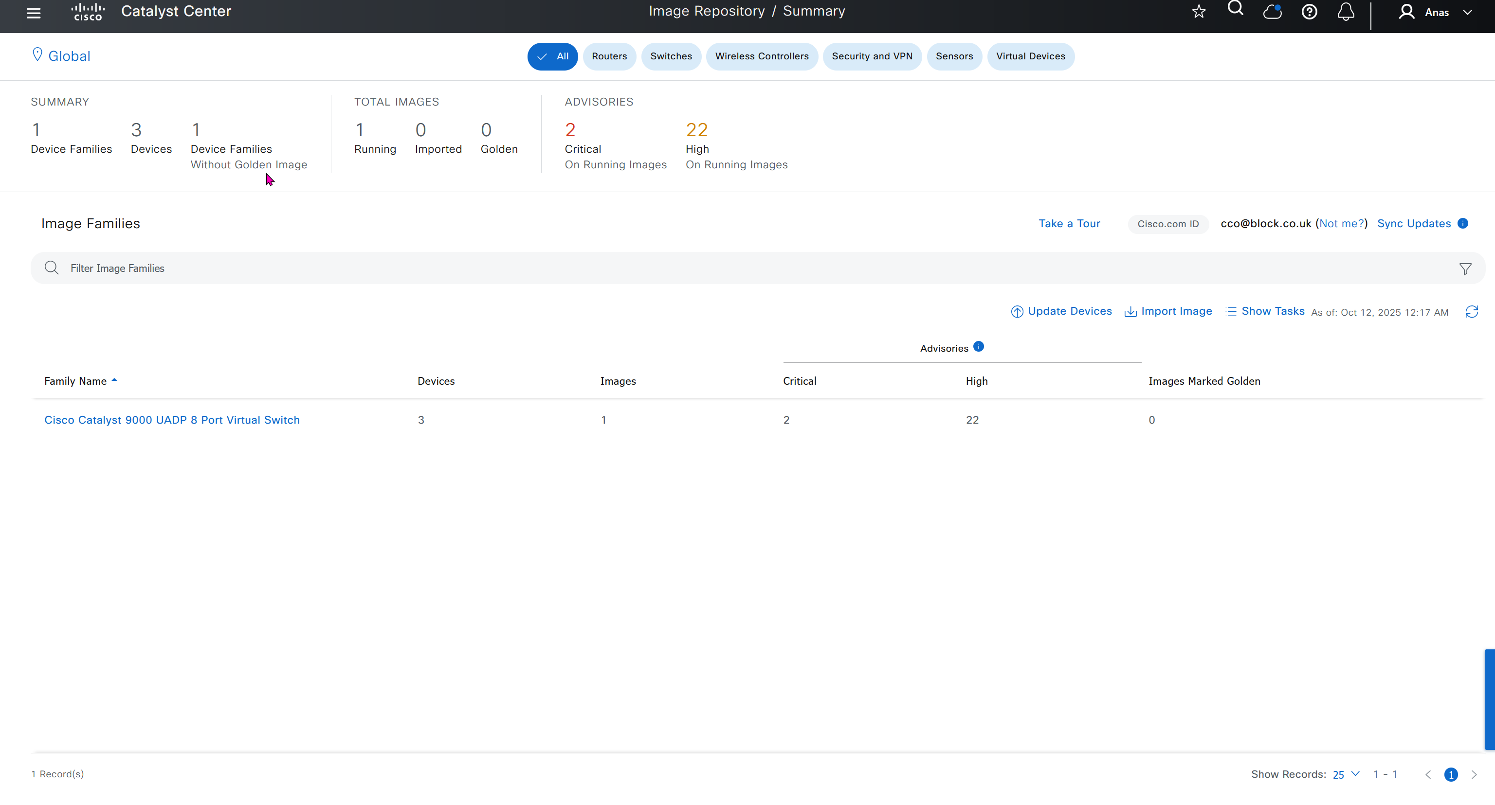
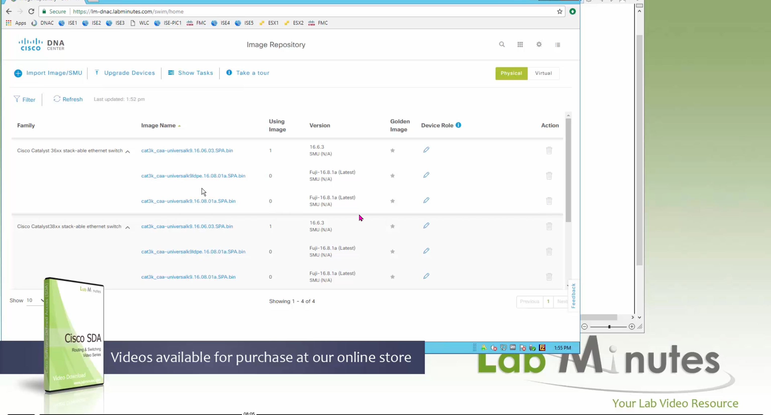
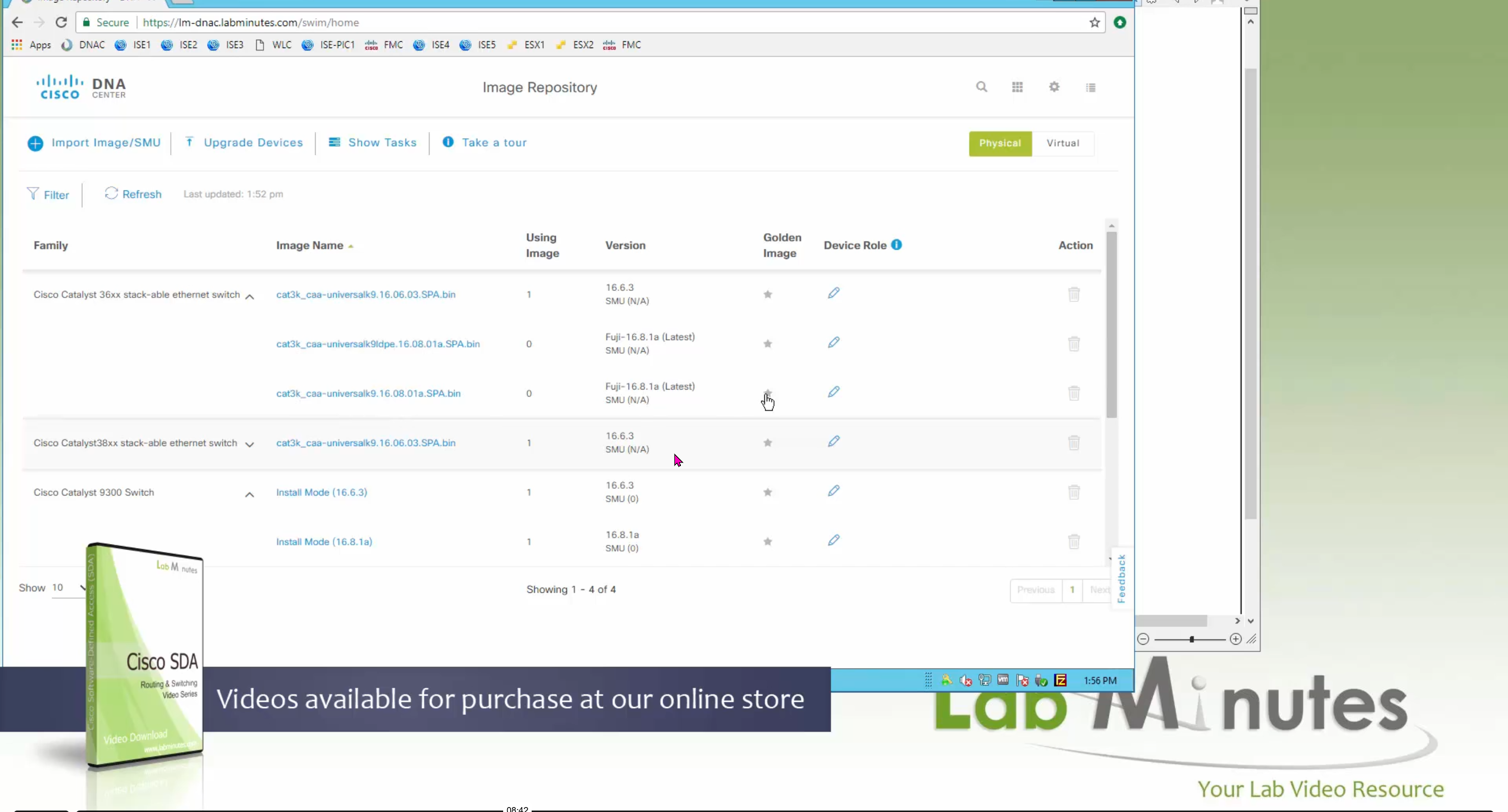
One image can be marked as golden image per device type either at the global level or at the site level, then any device that is not running that golden image will be marked as out of compliance
DNAC also supports auto clean up where it cleans up older image files
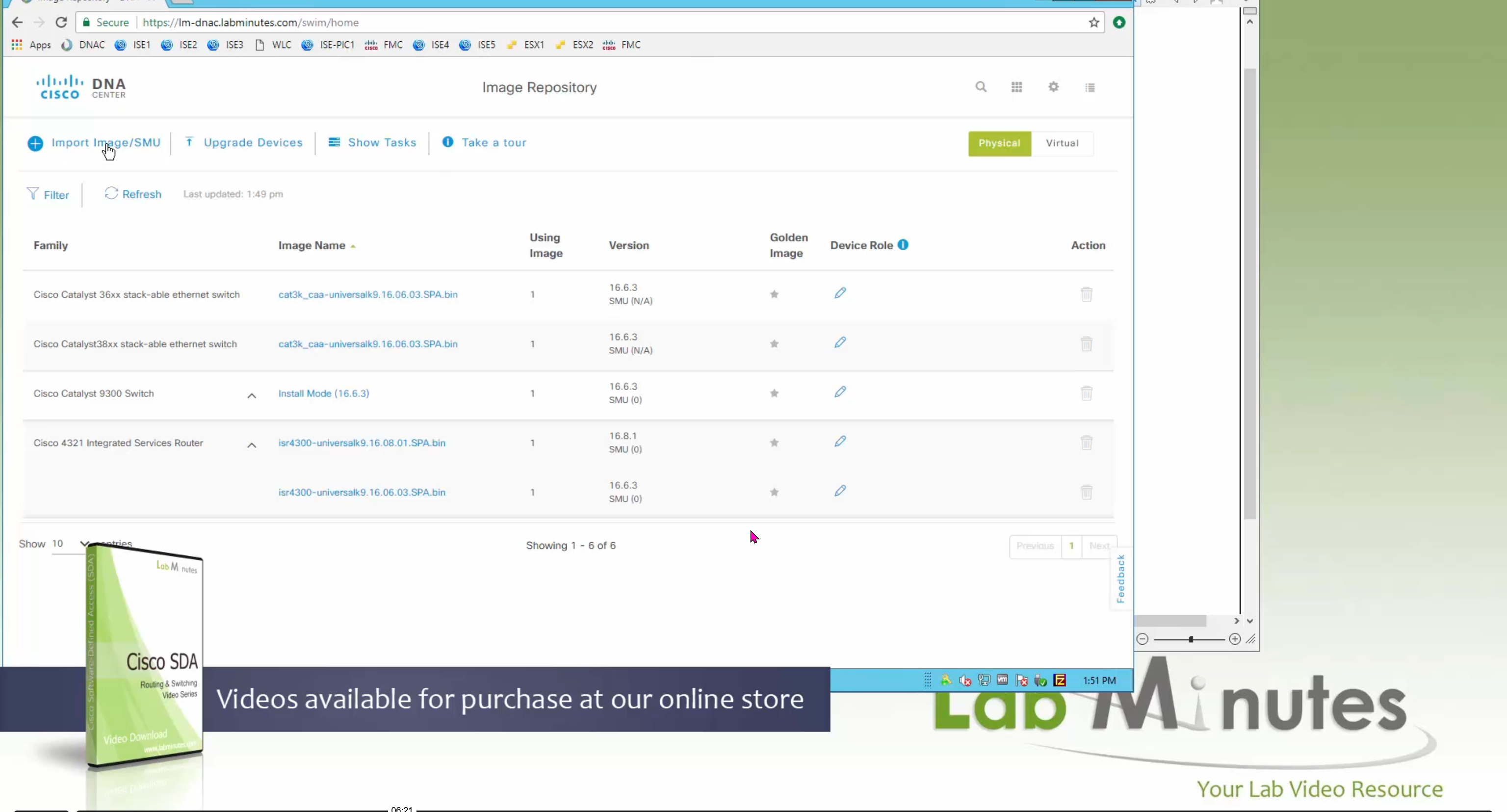

Using image column and version column with (Latest) means that these are the latest images, these images with (Latest) are being displayed from cisco.com and we can click on star icon to make them golden image
Making image golden enforces that image on that hardware model
Same thing can be repeated for different chassis or hardware types, their recommended Latest images can be marked as golden images
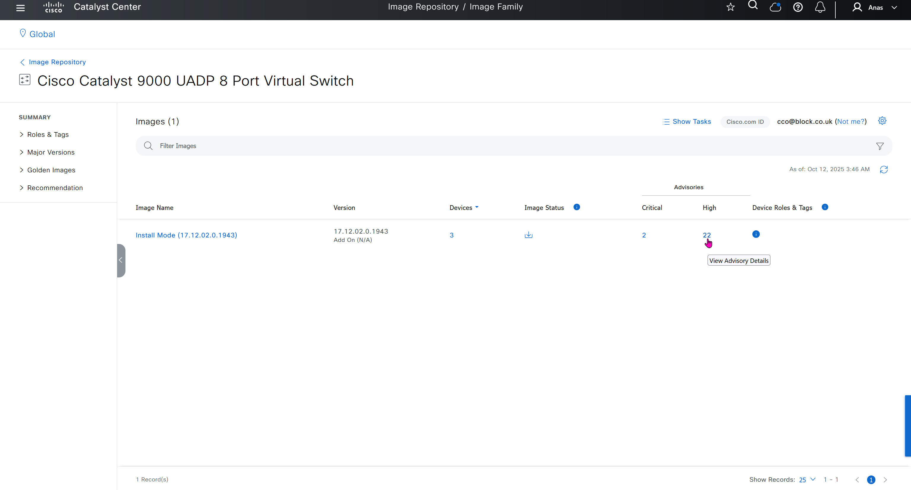
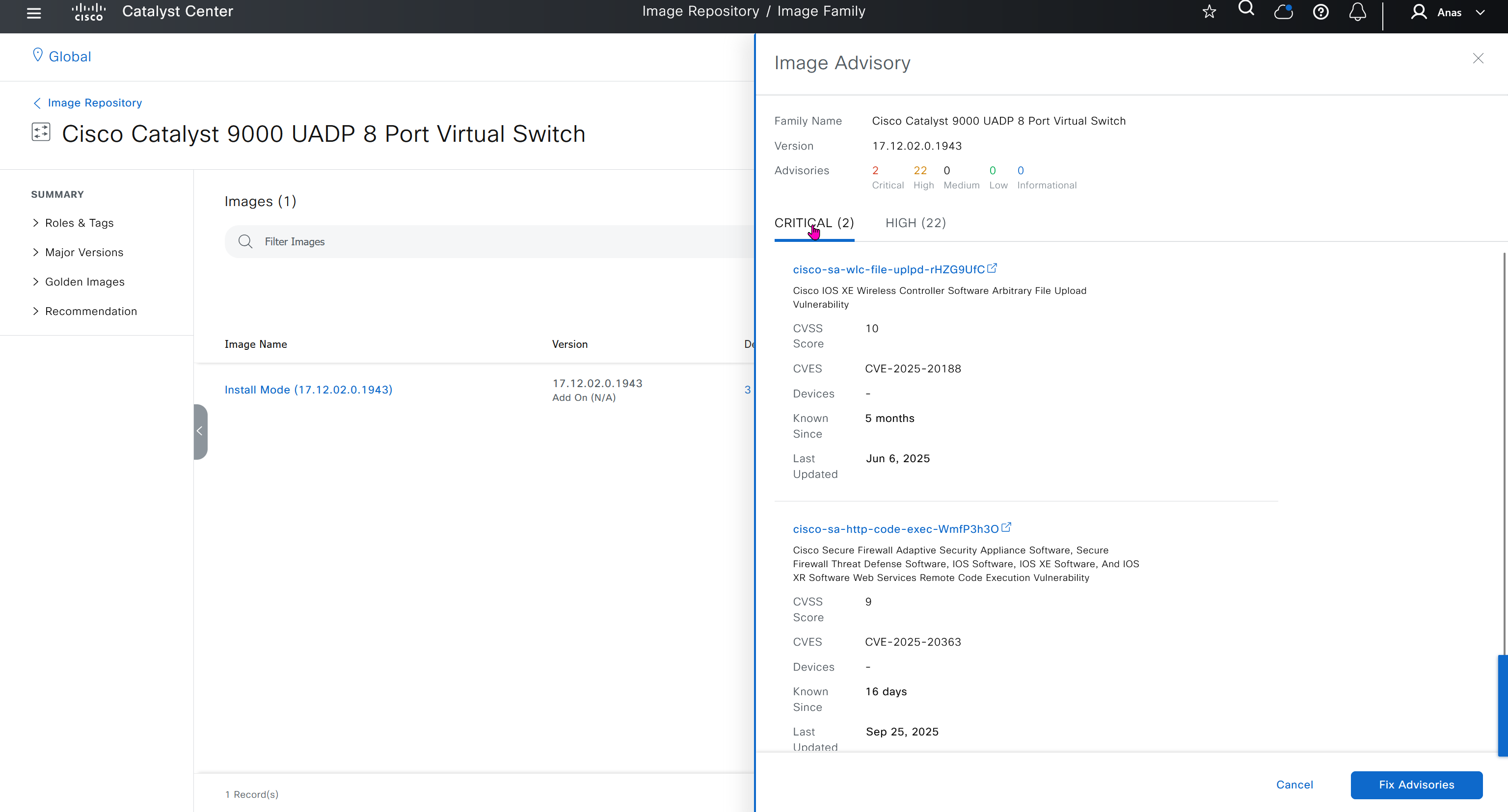
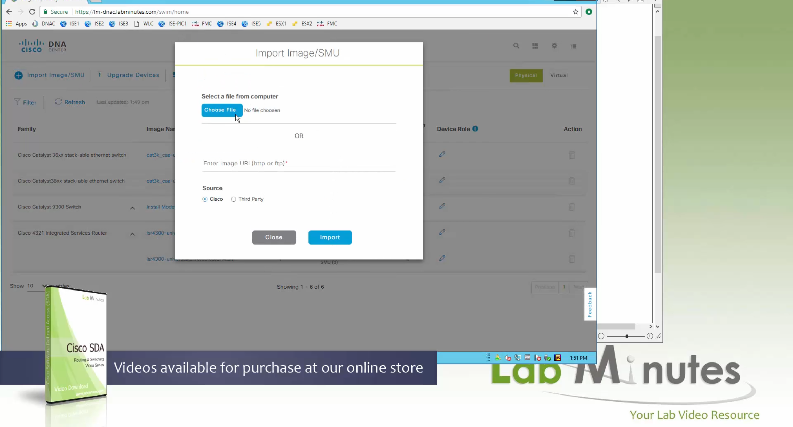
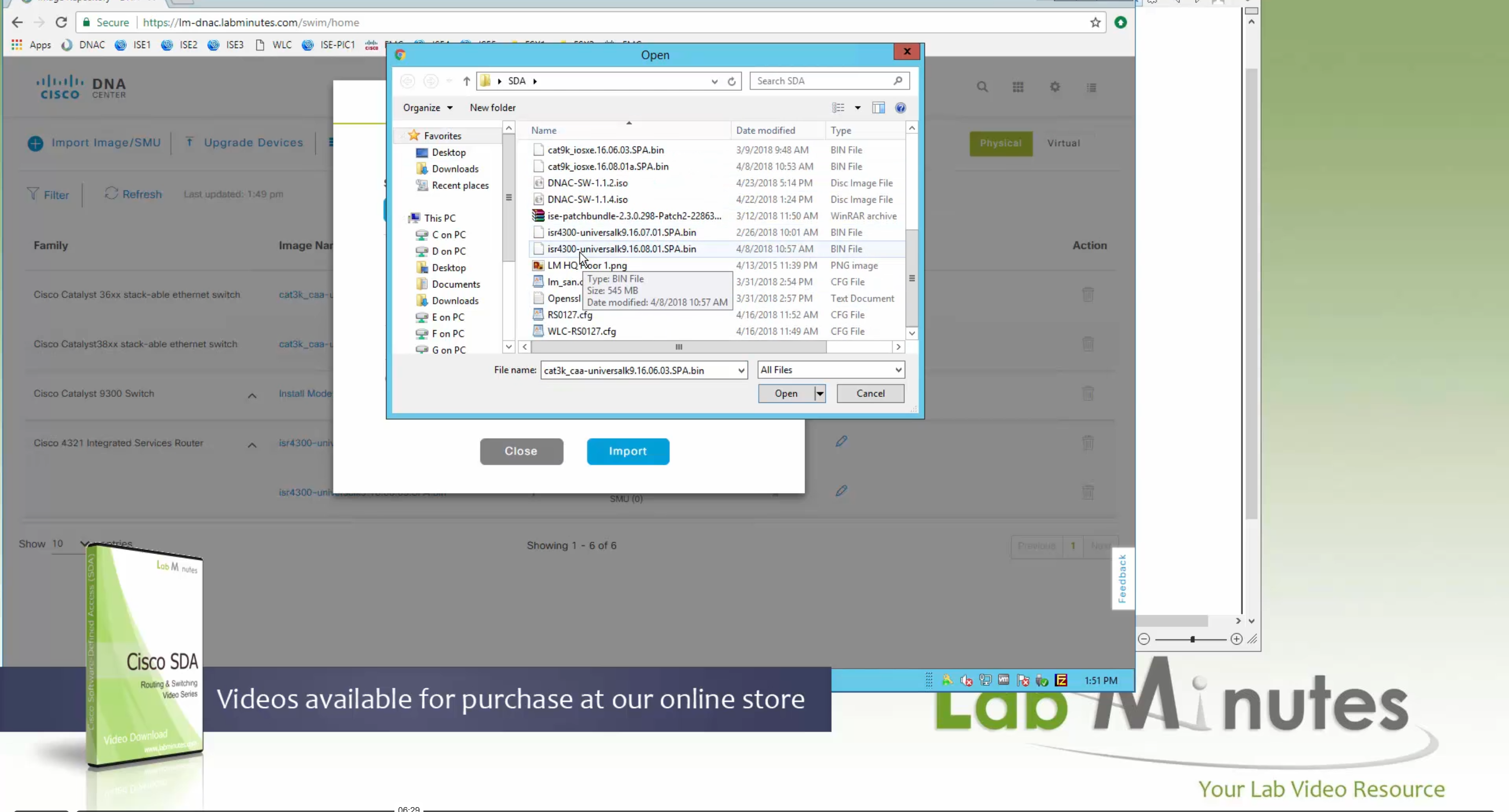
bundle mode images can be pulled from device and made golen image while for install mode we cannot pull from device and mark the image as golden image, instead we can either download from Cisco.com using gui or import image from file

Small “Verified” shows up next to image that shows that DNAC has downloaded the image, clicking that image makes it golden pretty fast because image is already on the DNAC server


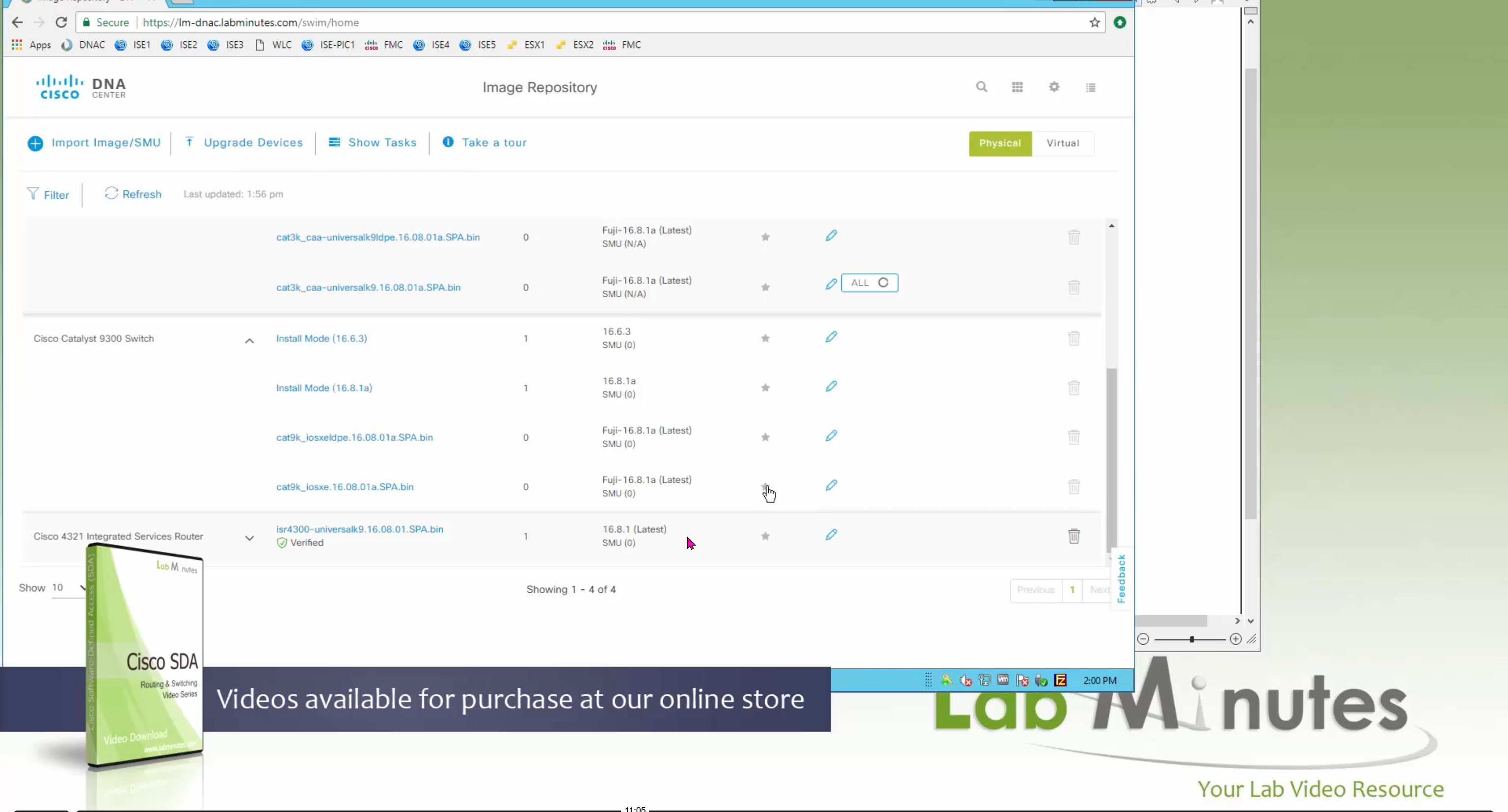


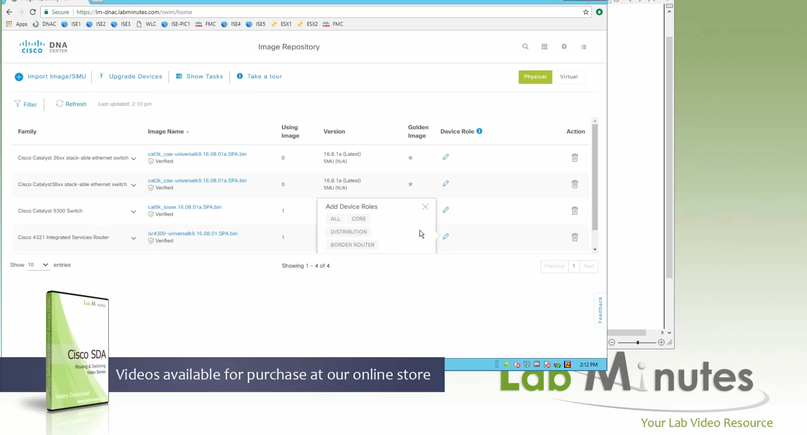
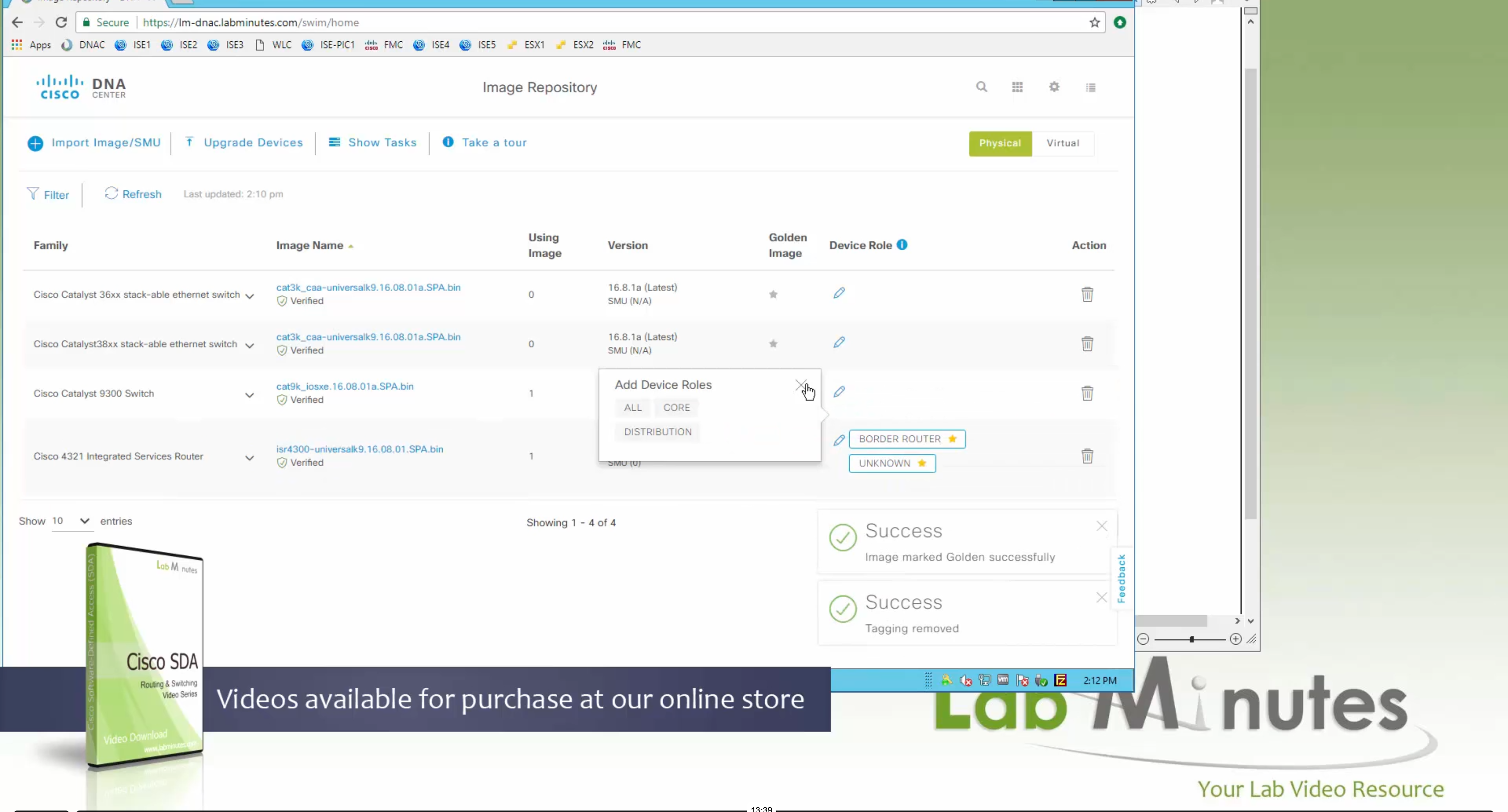
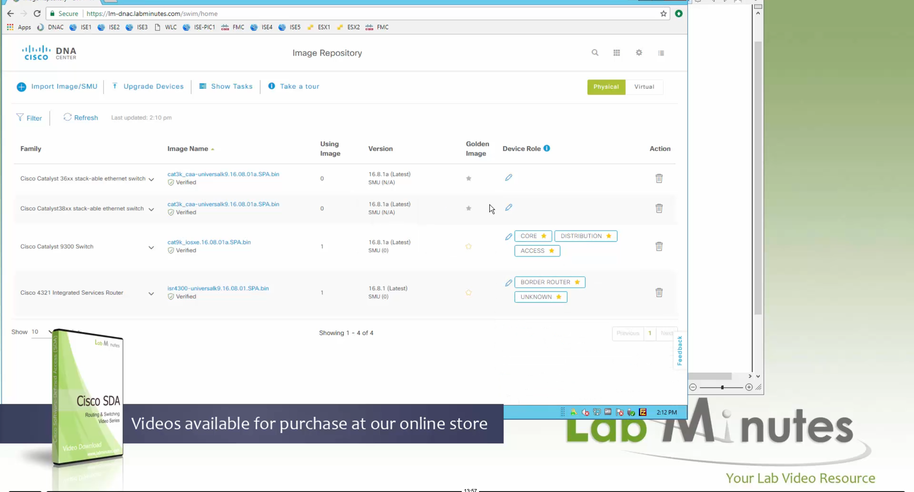

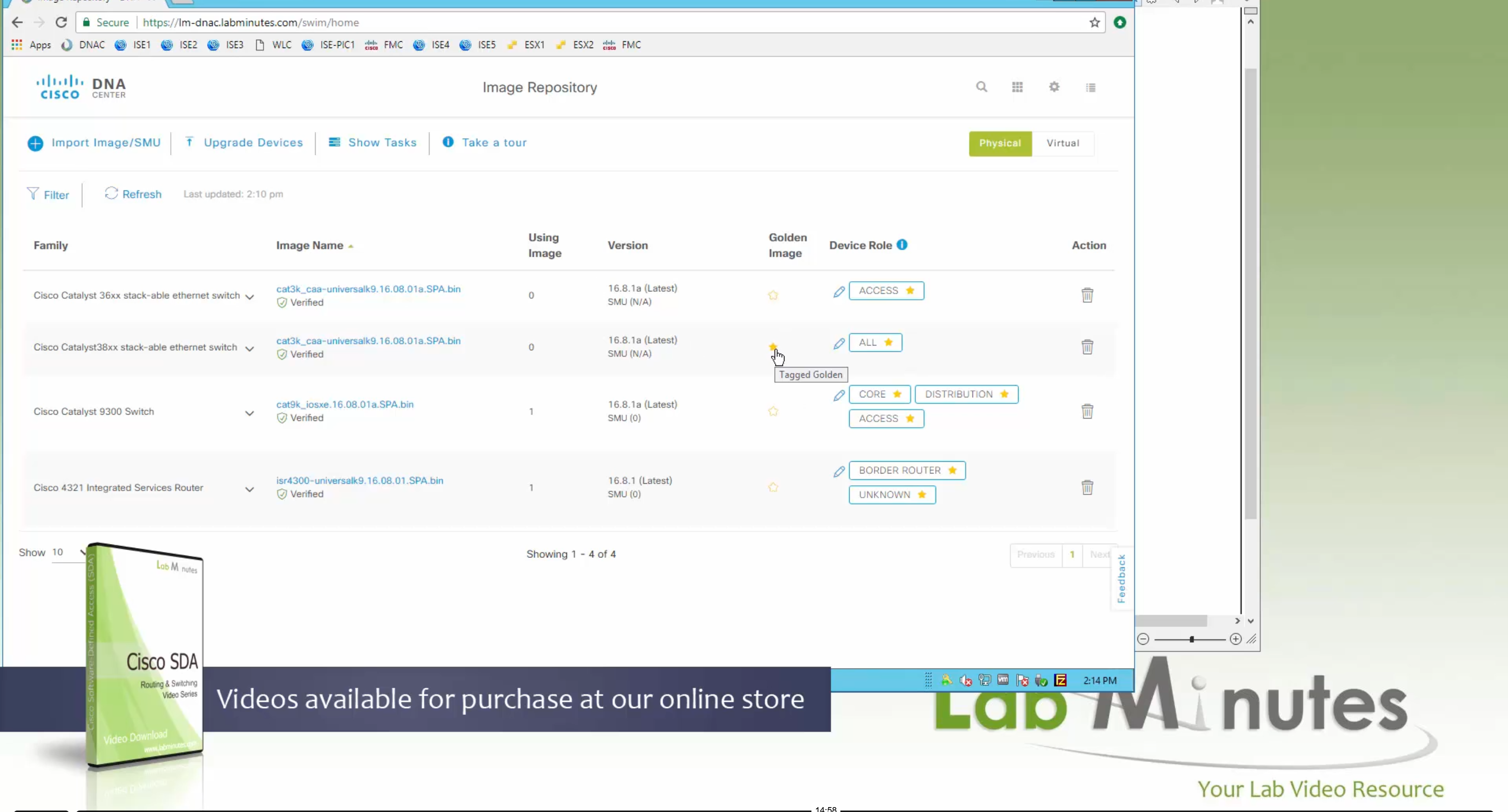
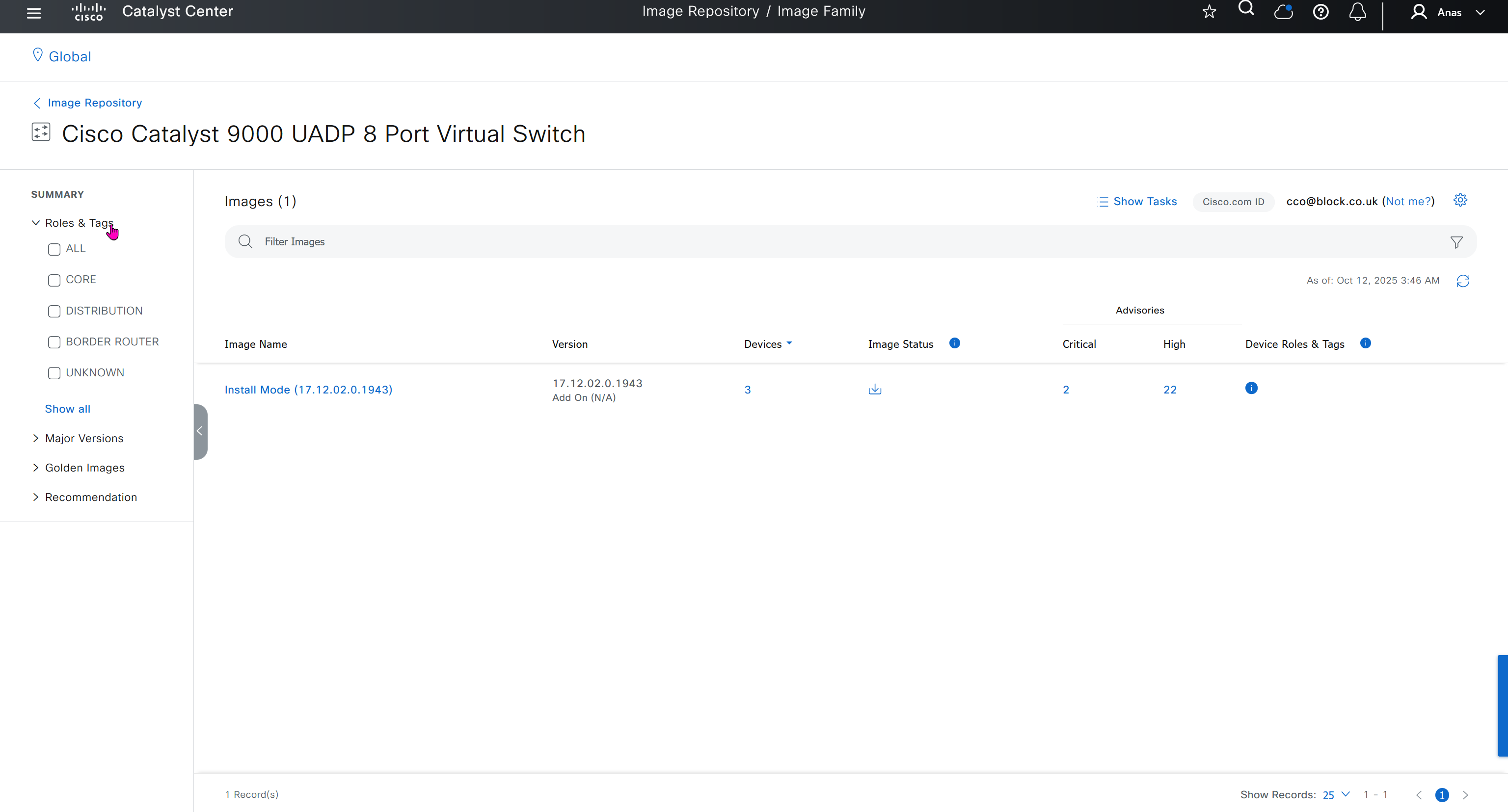
Now making an image golden makes it same for all devices of same hardware model same across different “Roles” and all locations (Globally) and sometimes you may not want that, you can click on edit icon in device role column and set golden image per hardware model per device role, such as all “C9300” / “Access” to have a specific image or you can even have golden image per hardware model per role per location – but first you must remove the golden image from global level and then set it on site level, there is no concept of override here, either set at global level or set at all sites independently


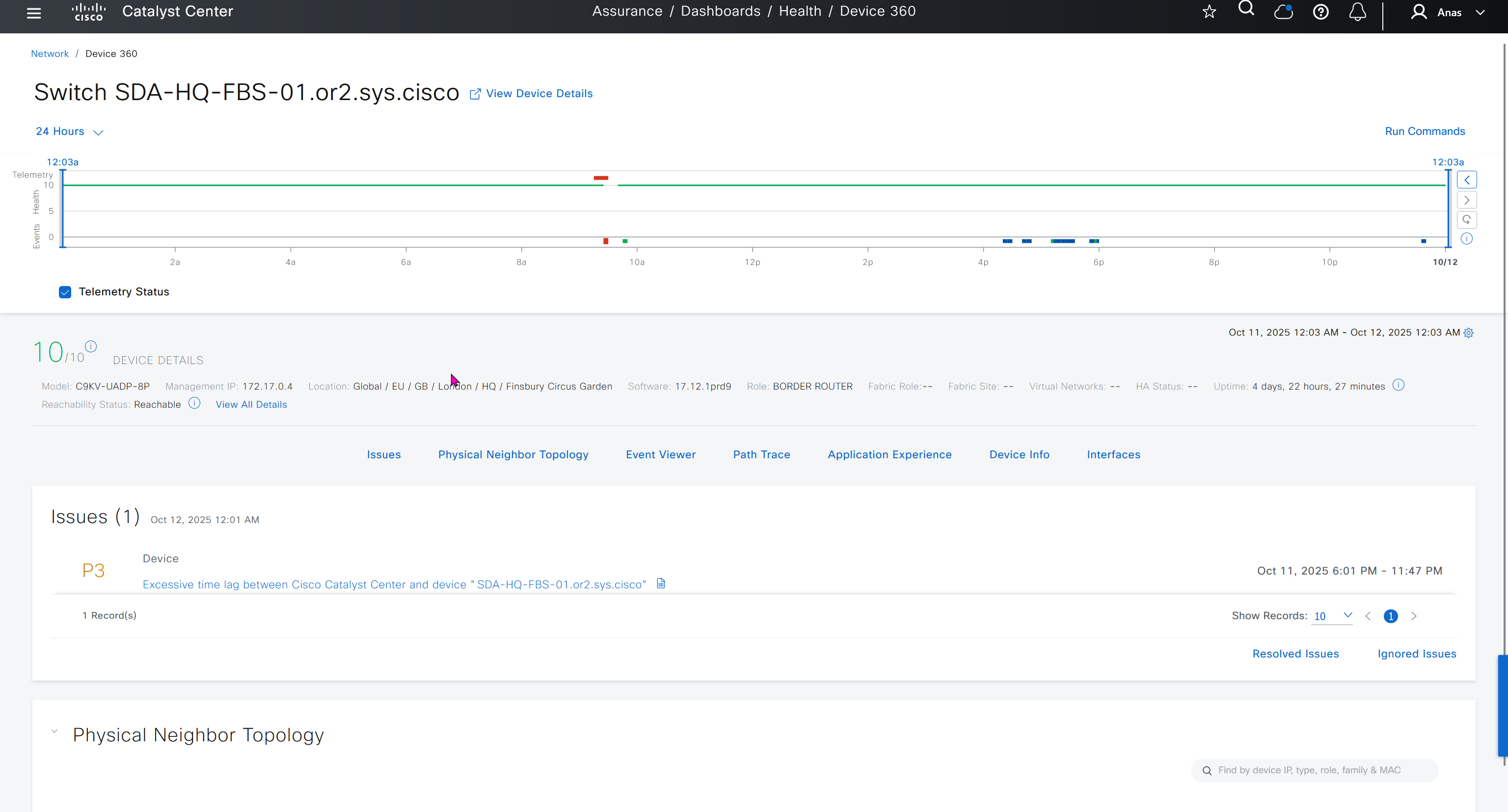
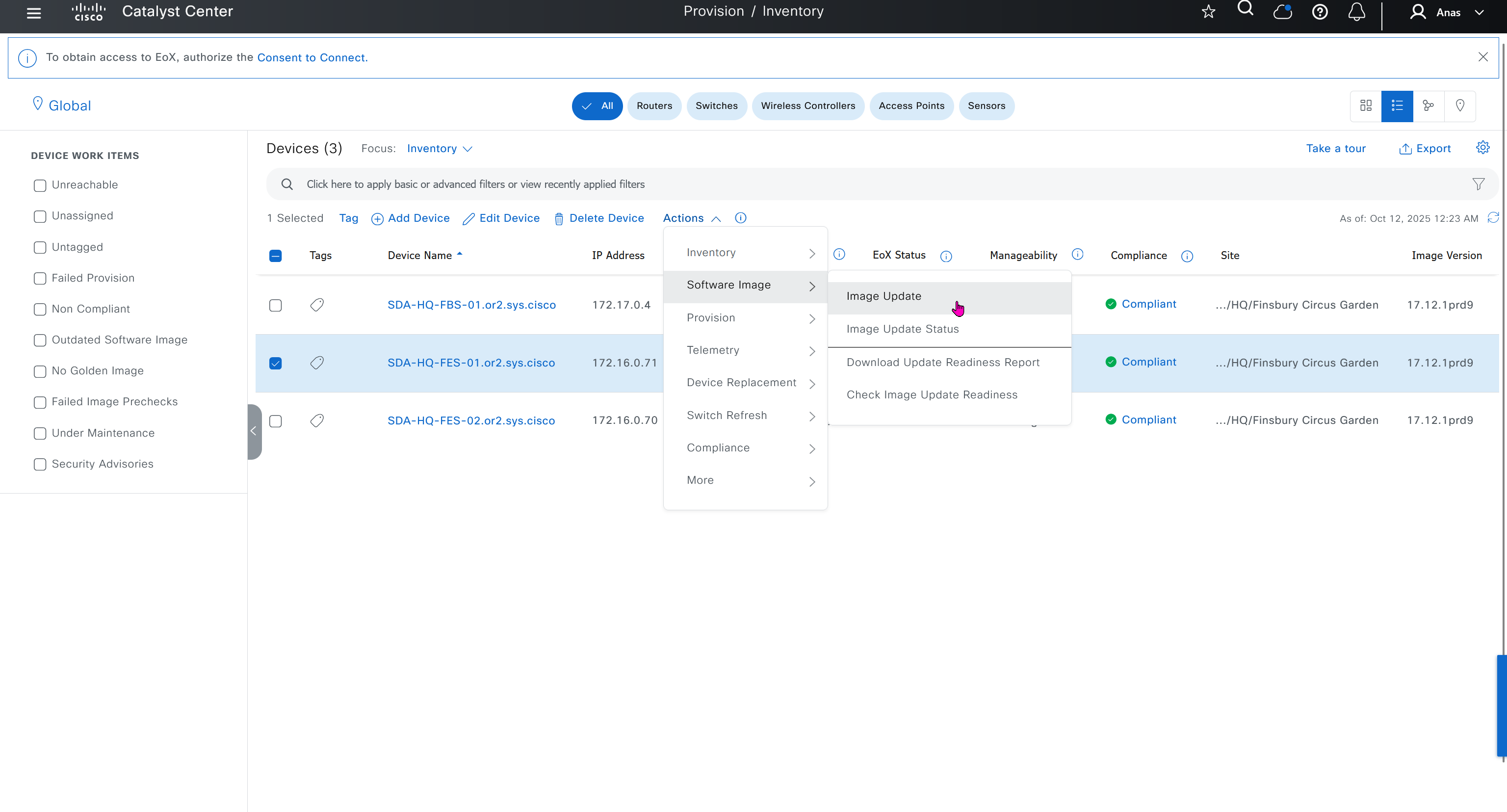
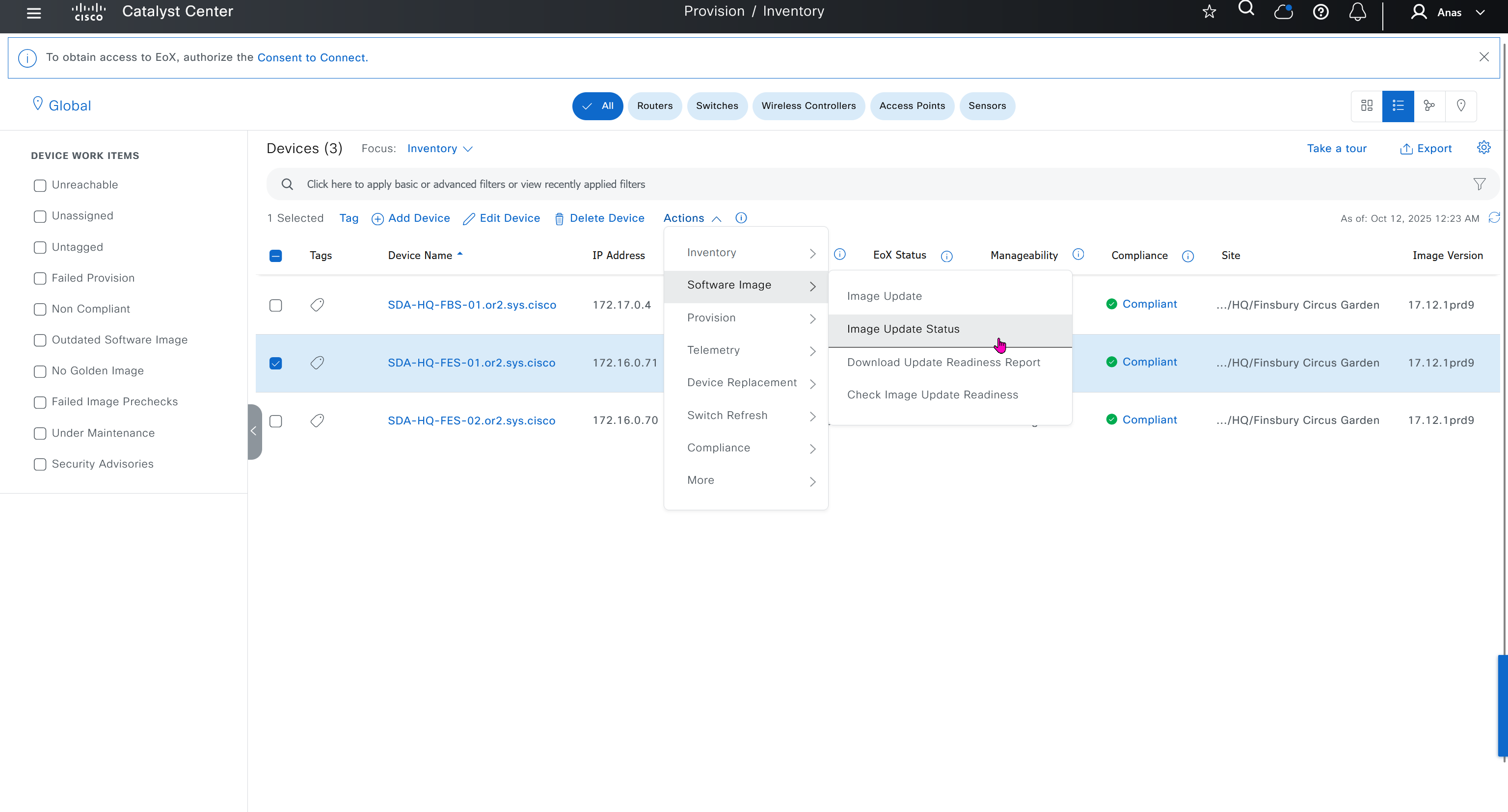
Next step is to see which devices are not in compliance and upgrade them in provision > OS image column


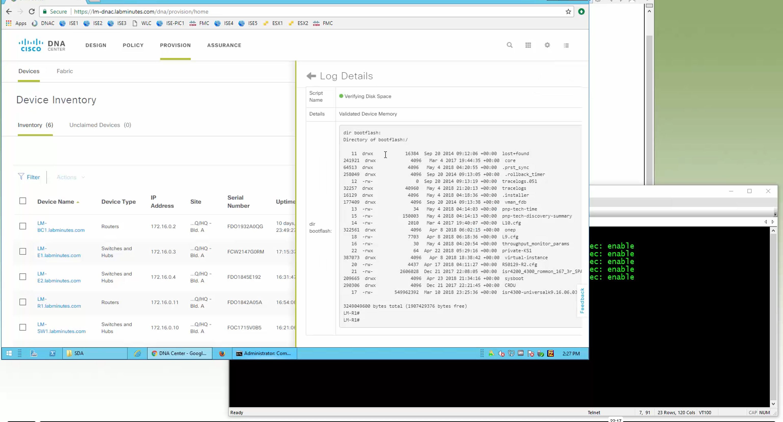
DNAC validates Flash, RAM and Reboot required


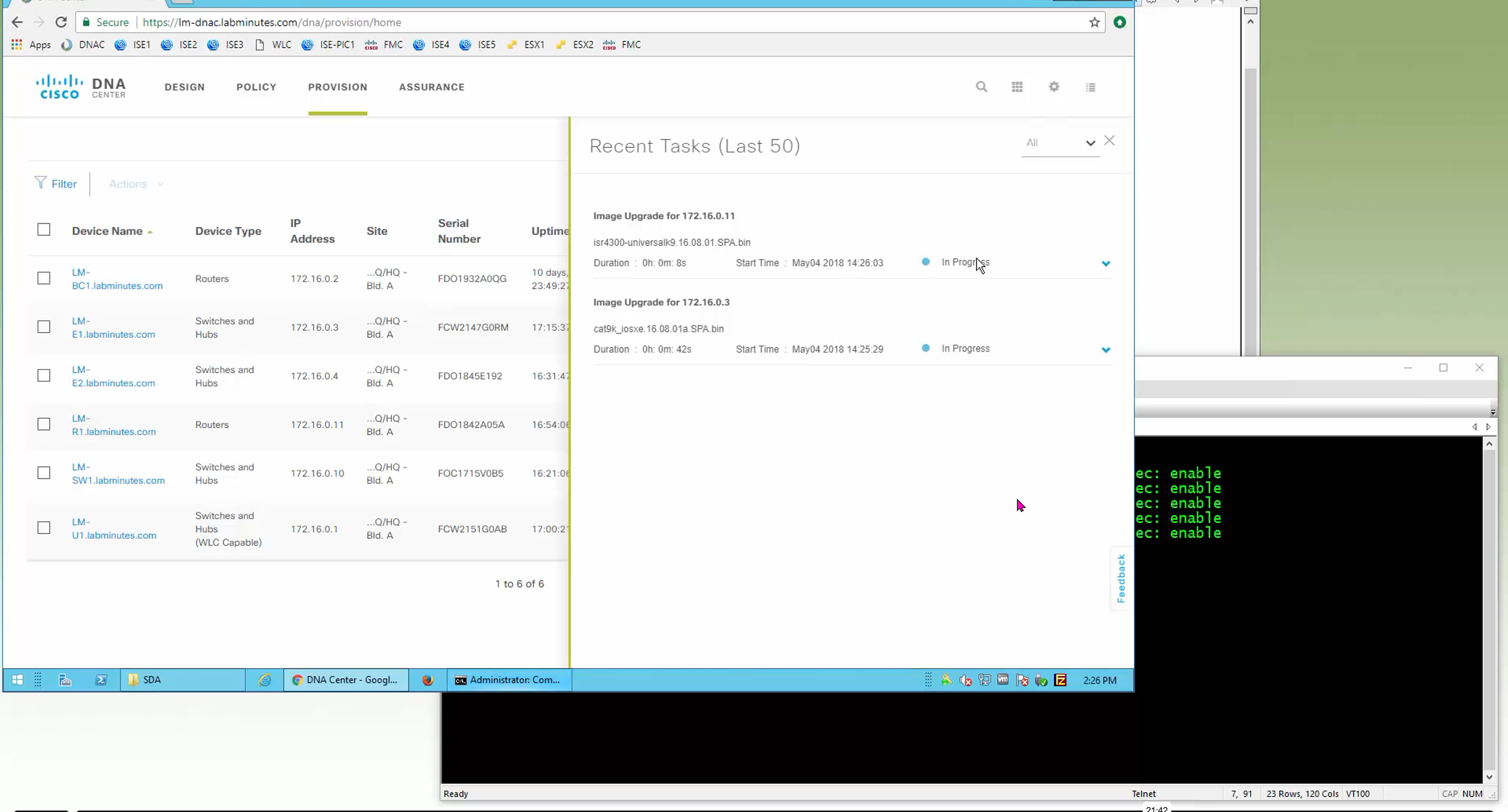

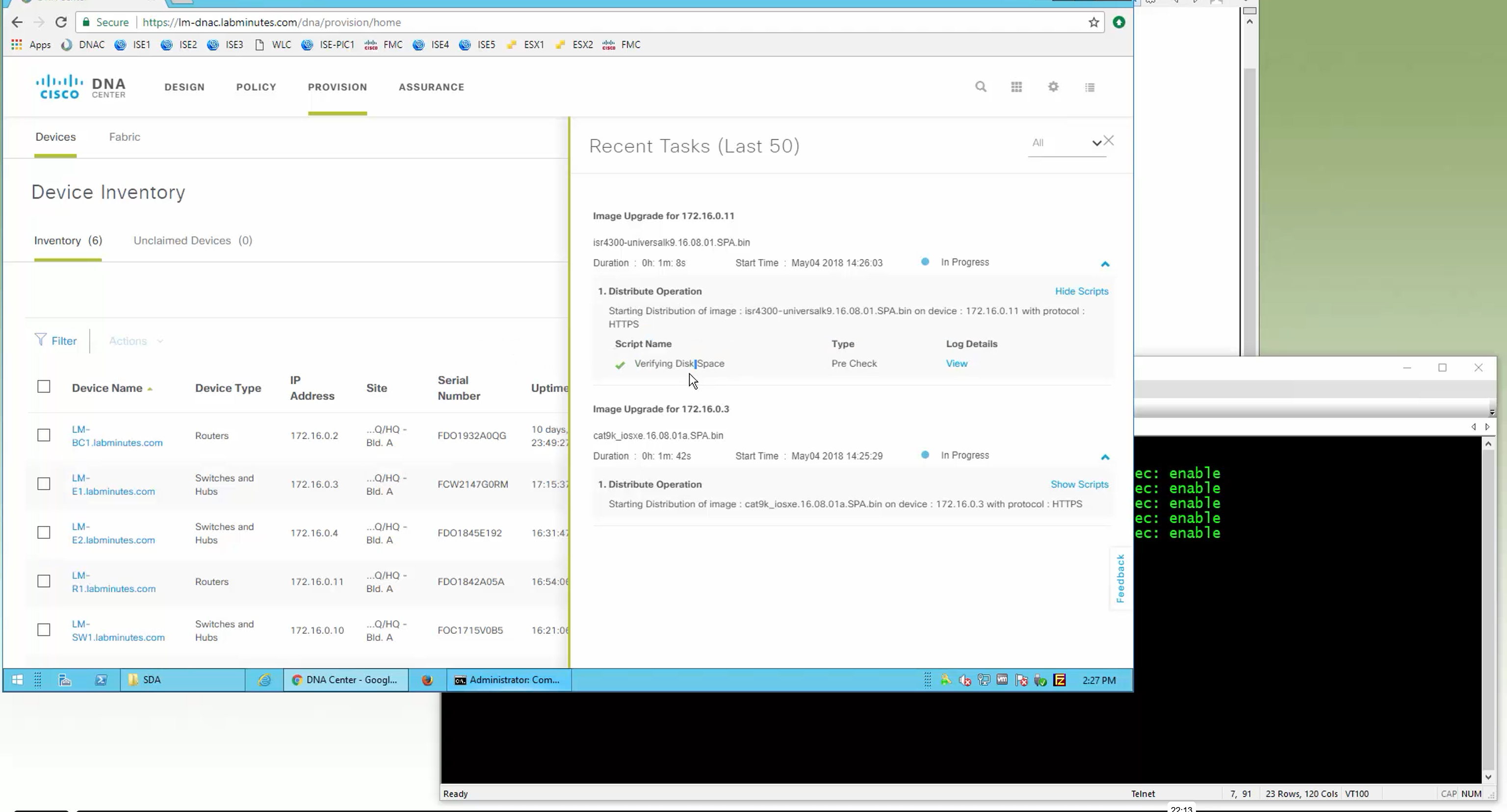


SMU(0) means that there is no SMU for this image version

one big improvement in version 2.1 is that you can download image from local server instead of DNAC over the WAN
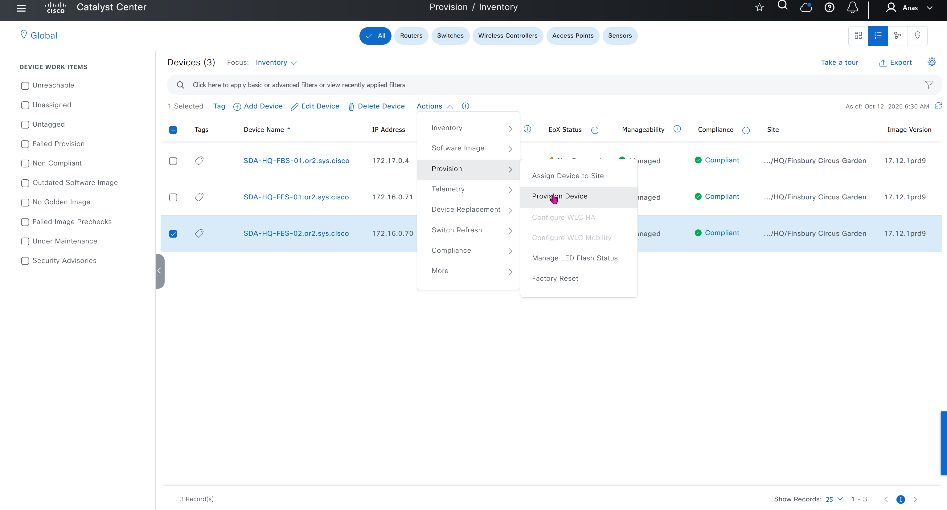
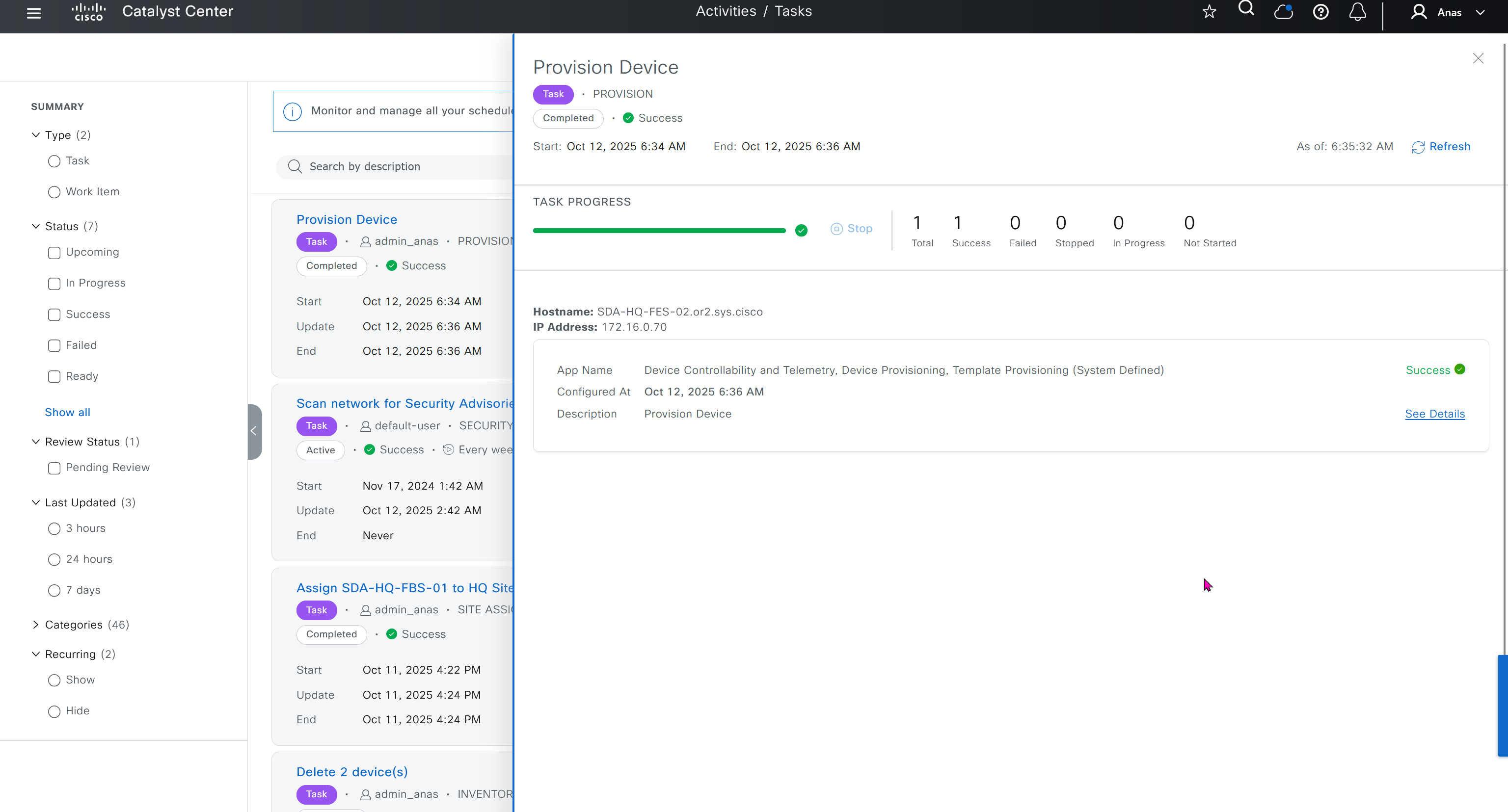
“Provision > provision device” pushes the remaining config as config assigned during assignment of device to site is not full config, full config is deployed when device is provisioned

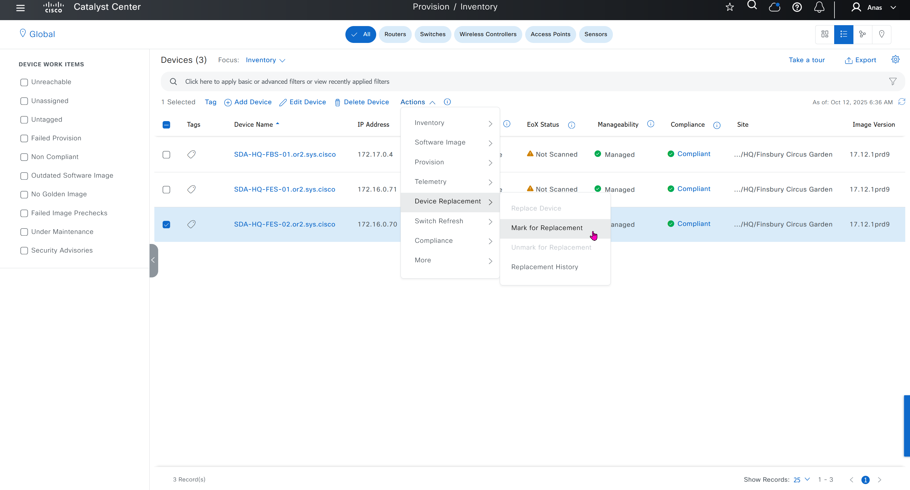
Mark for replacement is when we have to RMA the device
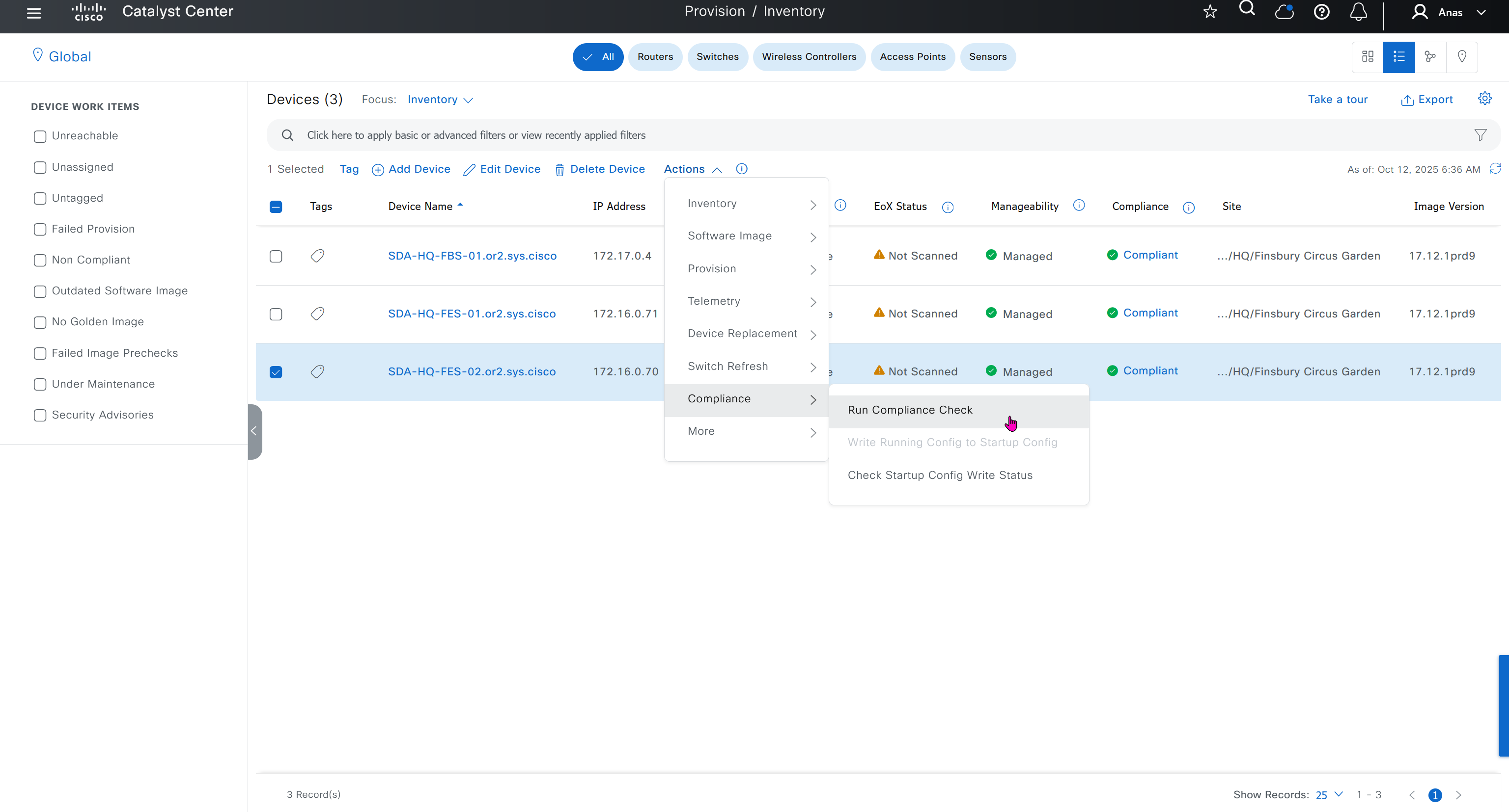
Compliance > Run Compliance, this is manual trigger of the compliance and checks if device has golden image and if startup-config is same running-config etc
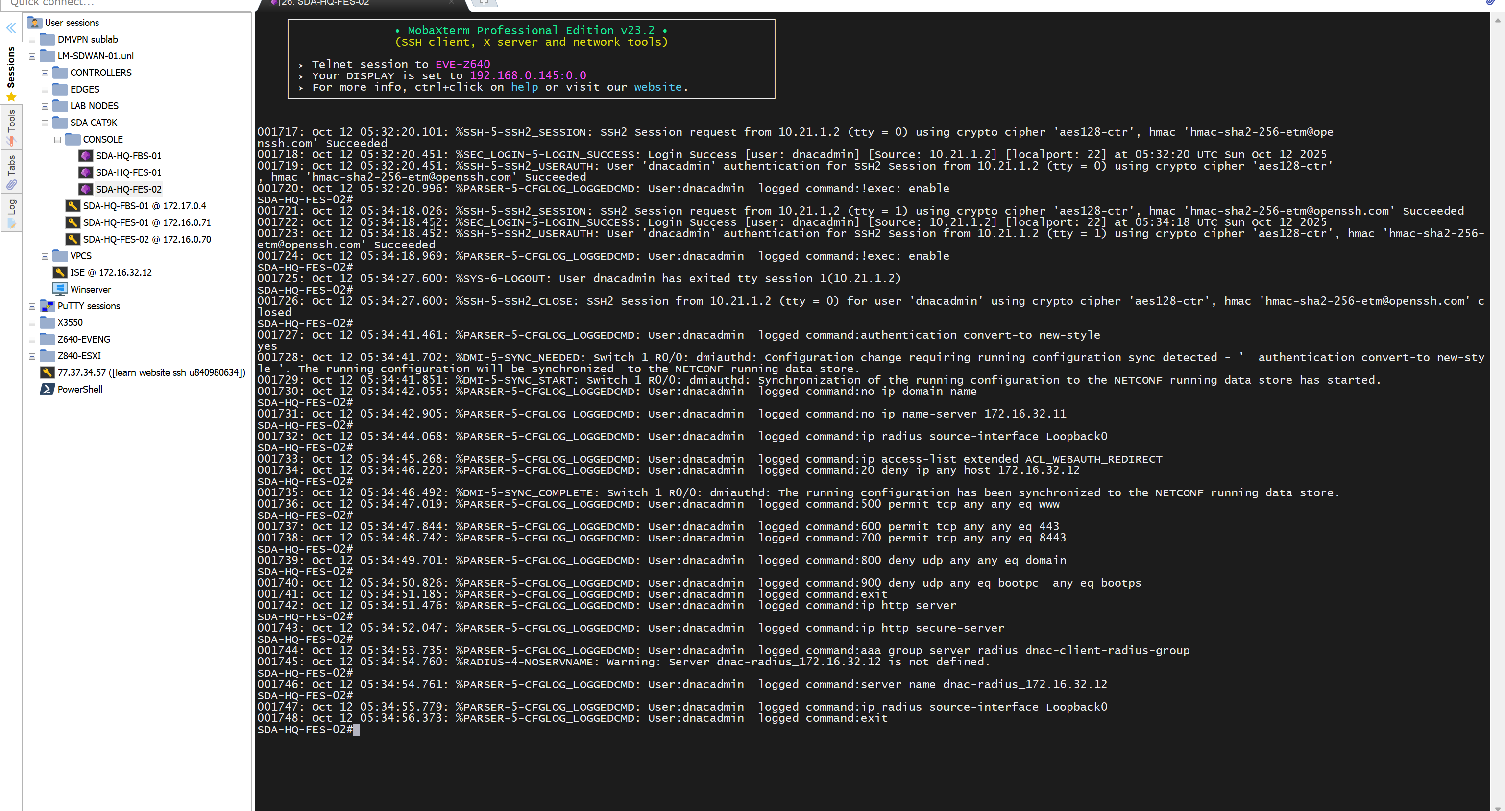
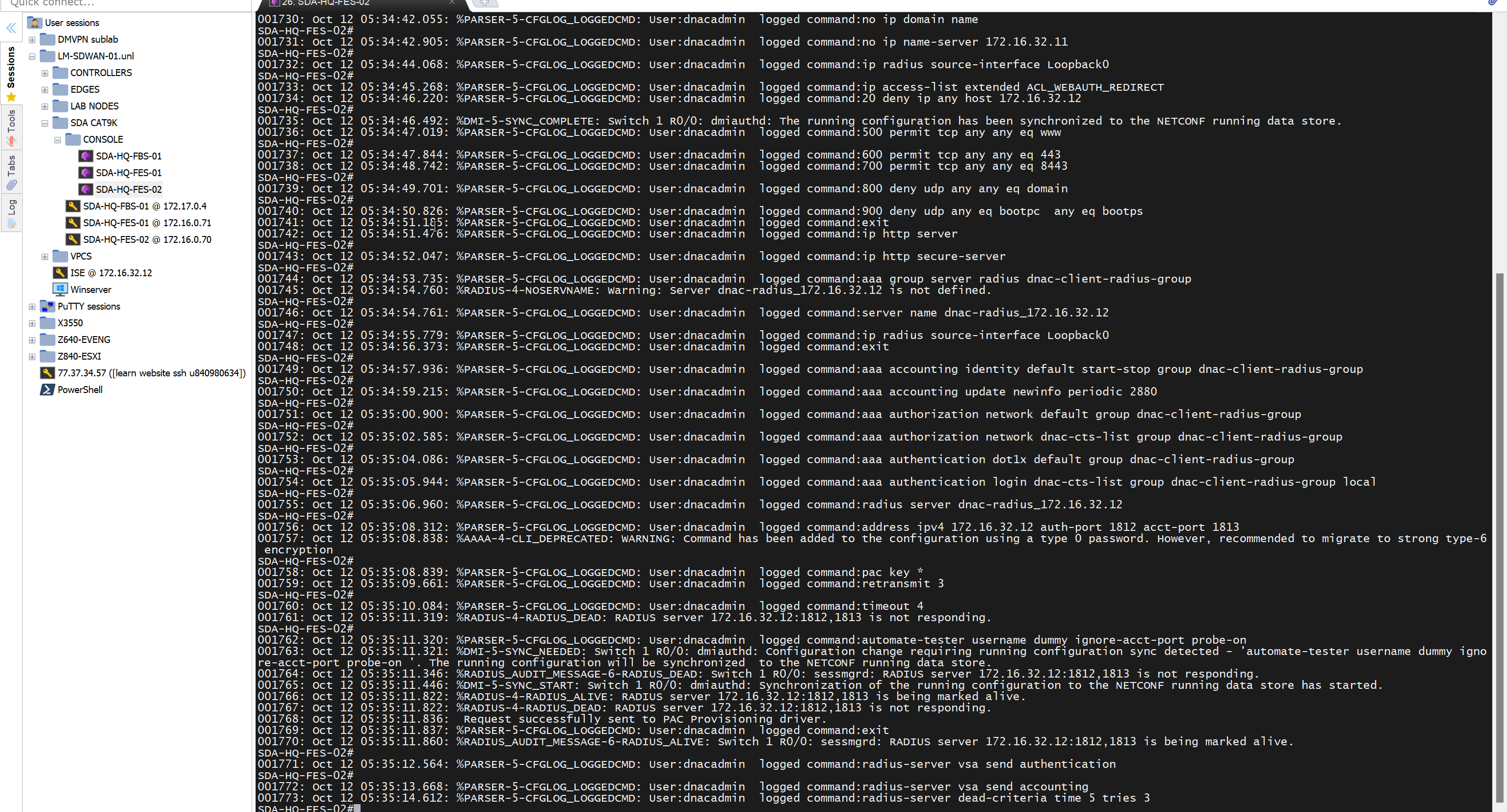
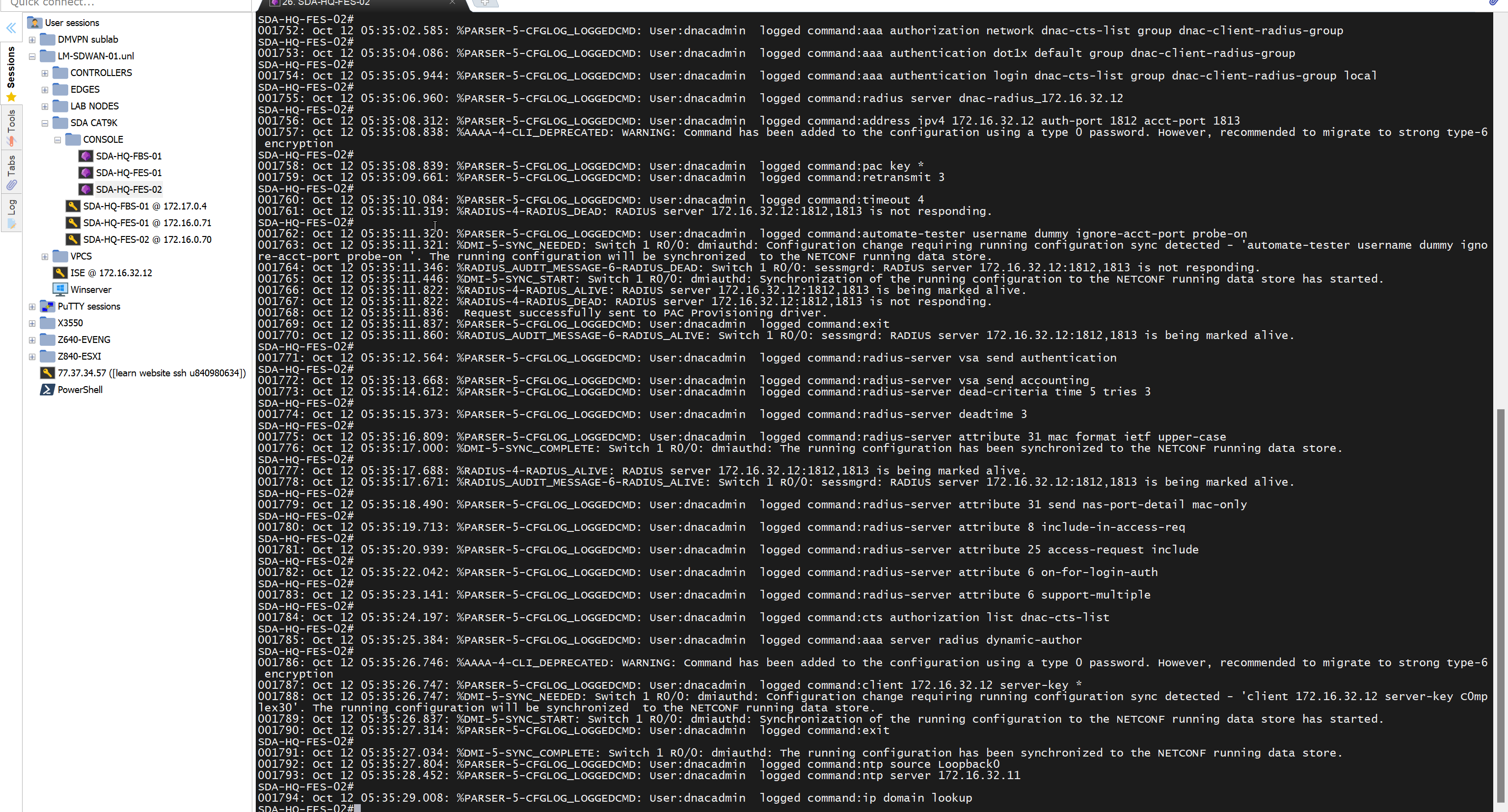
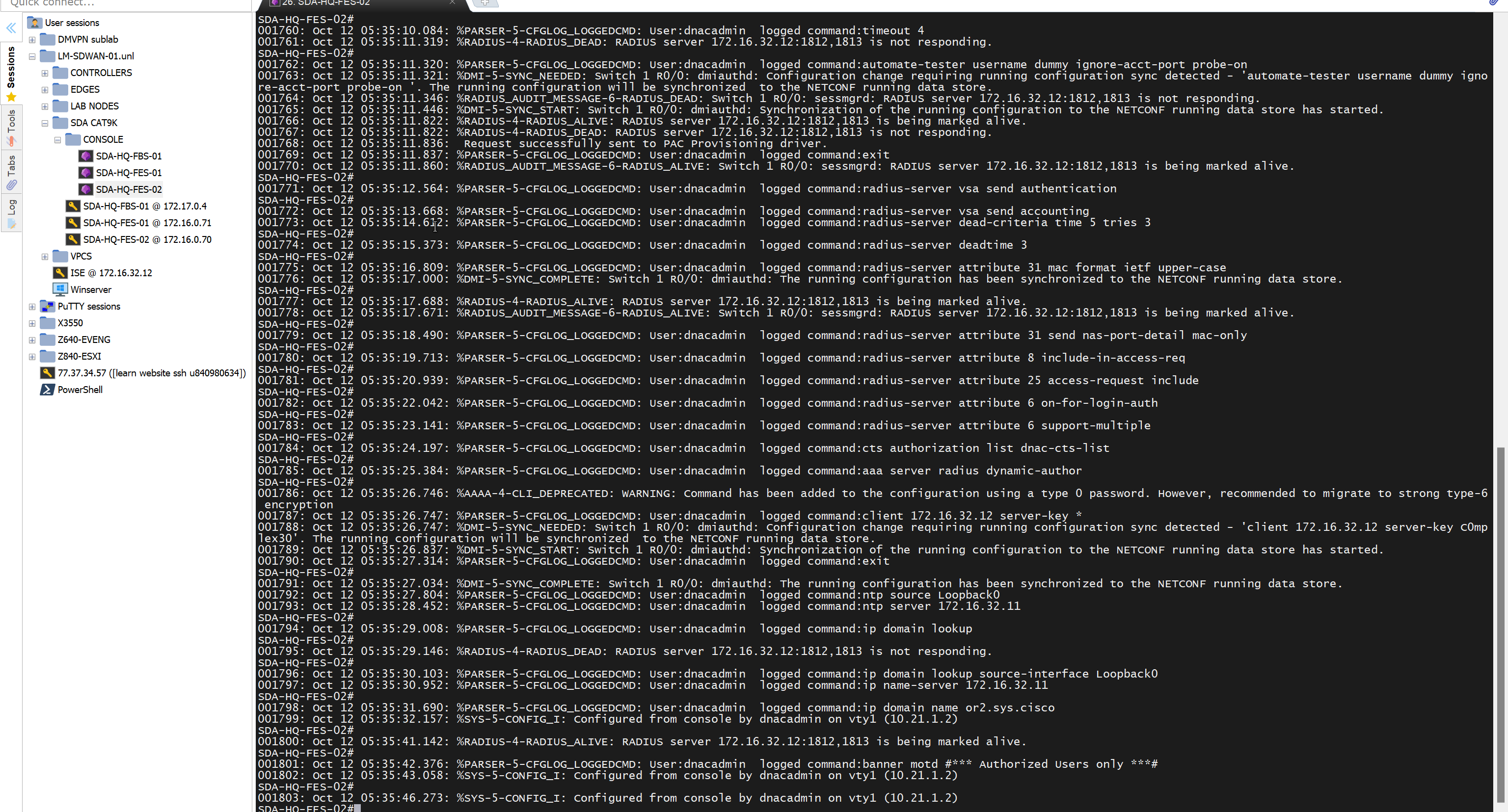
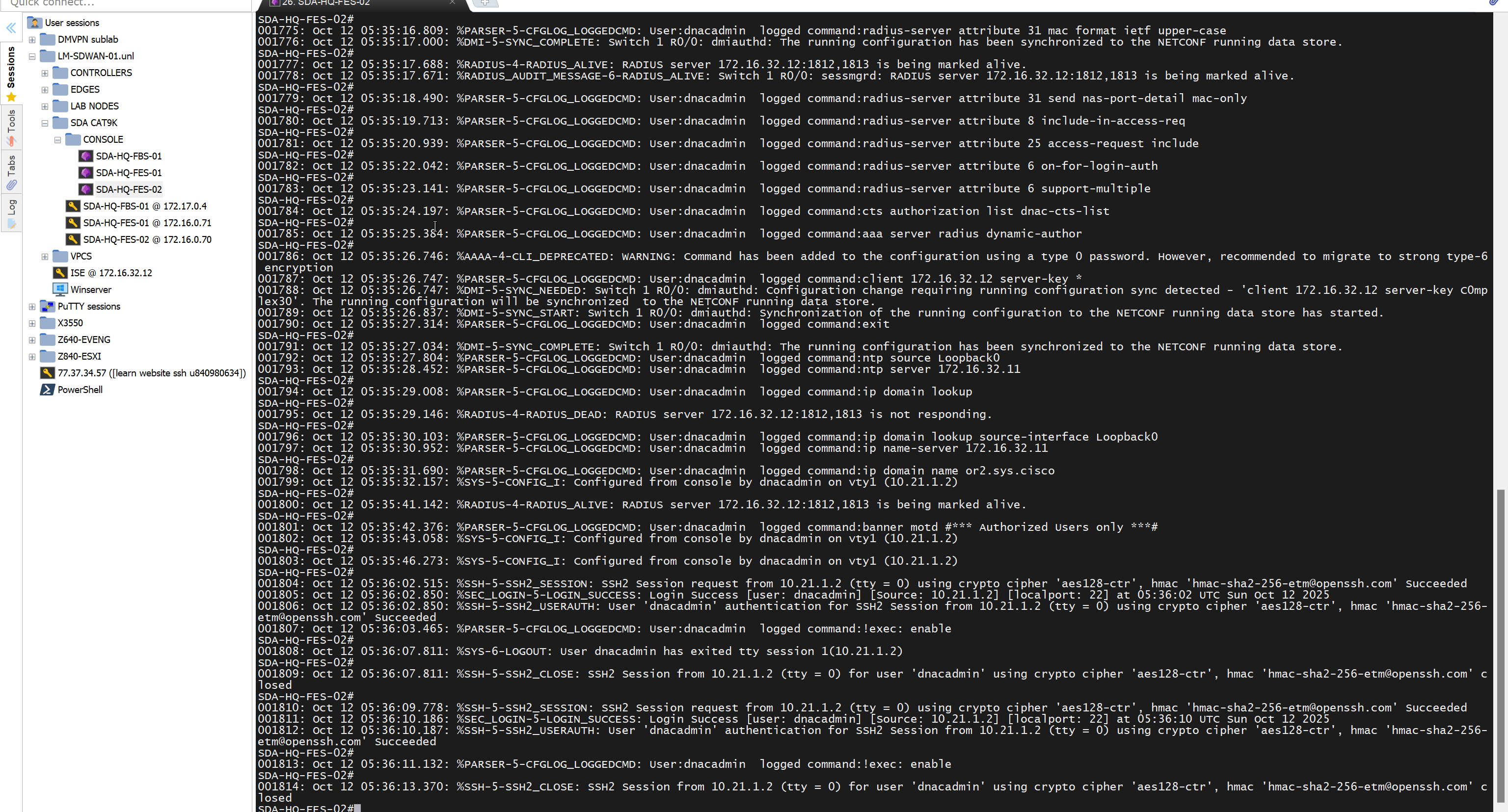
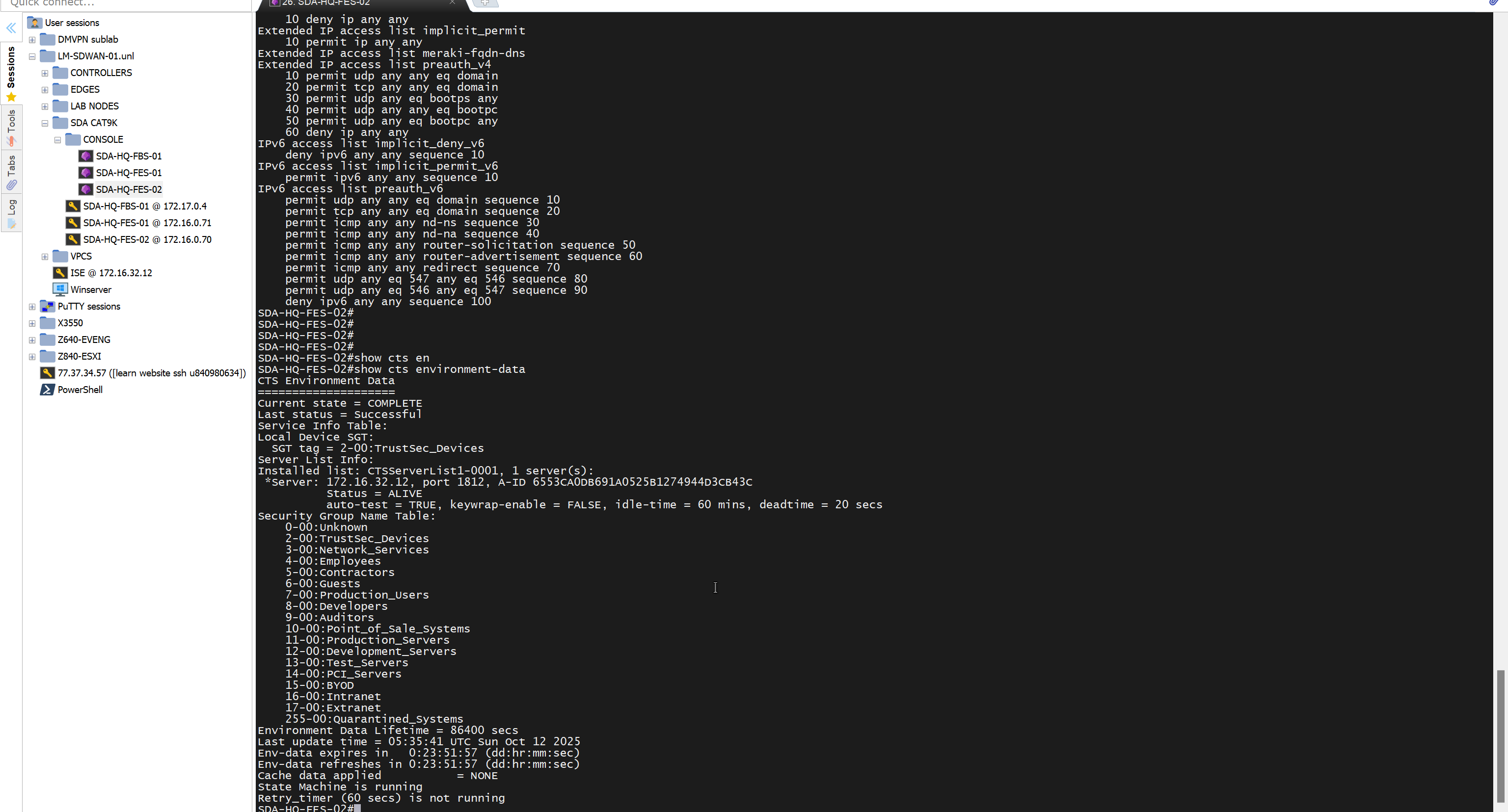
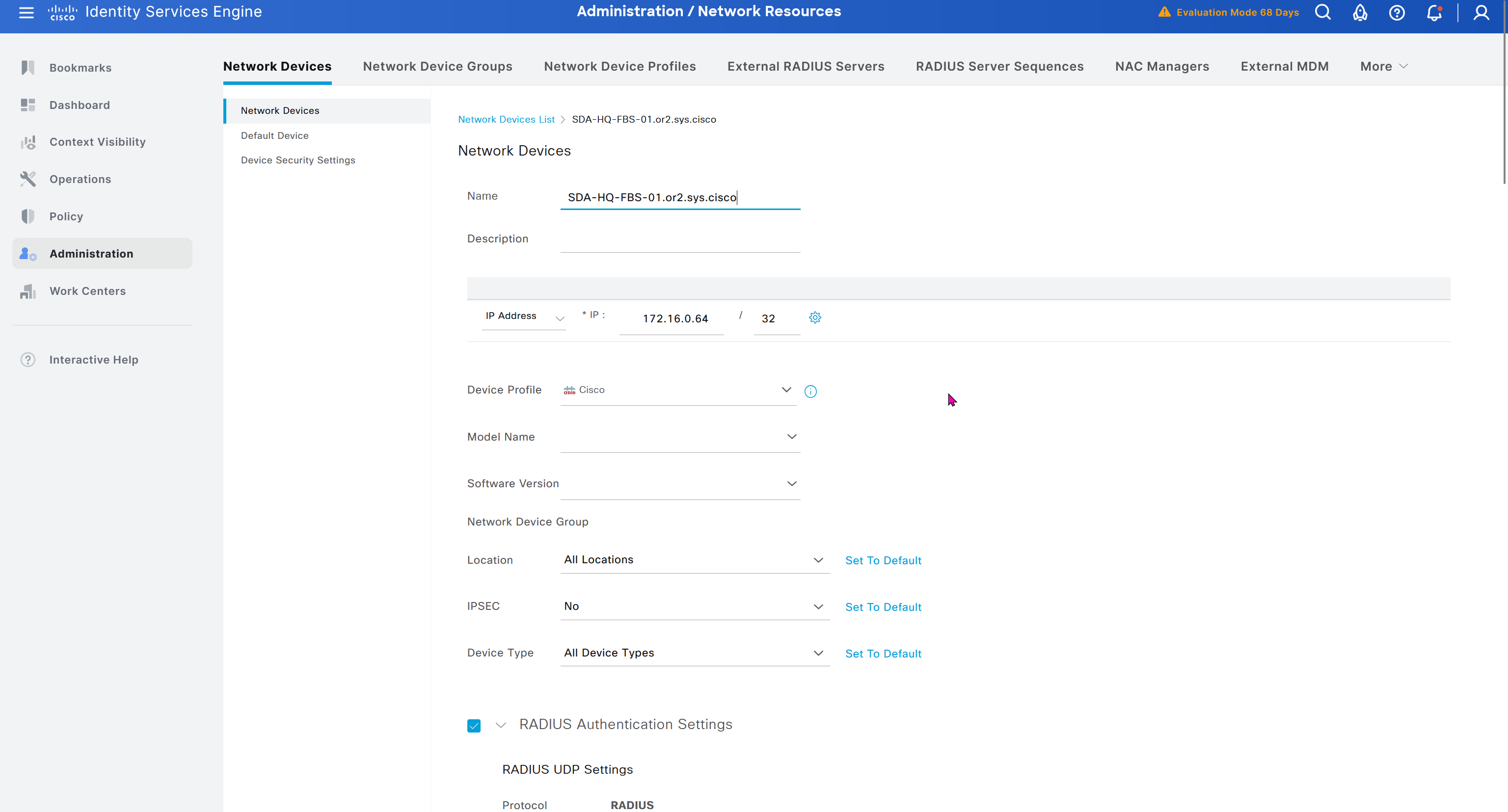
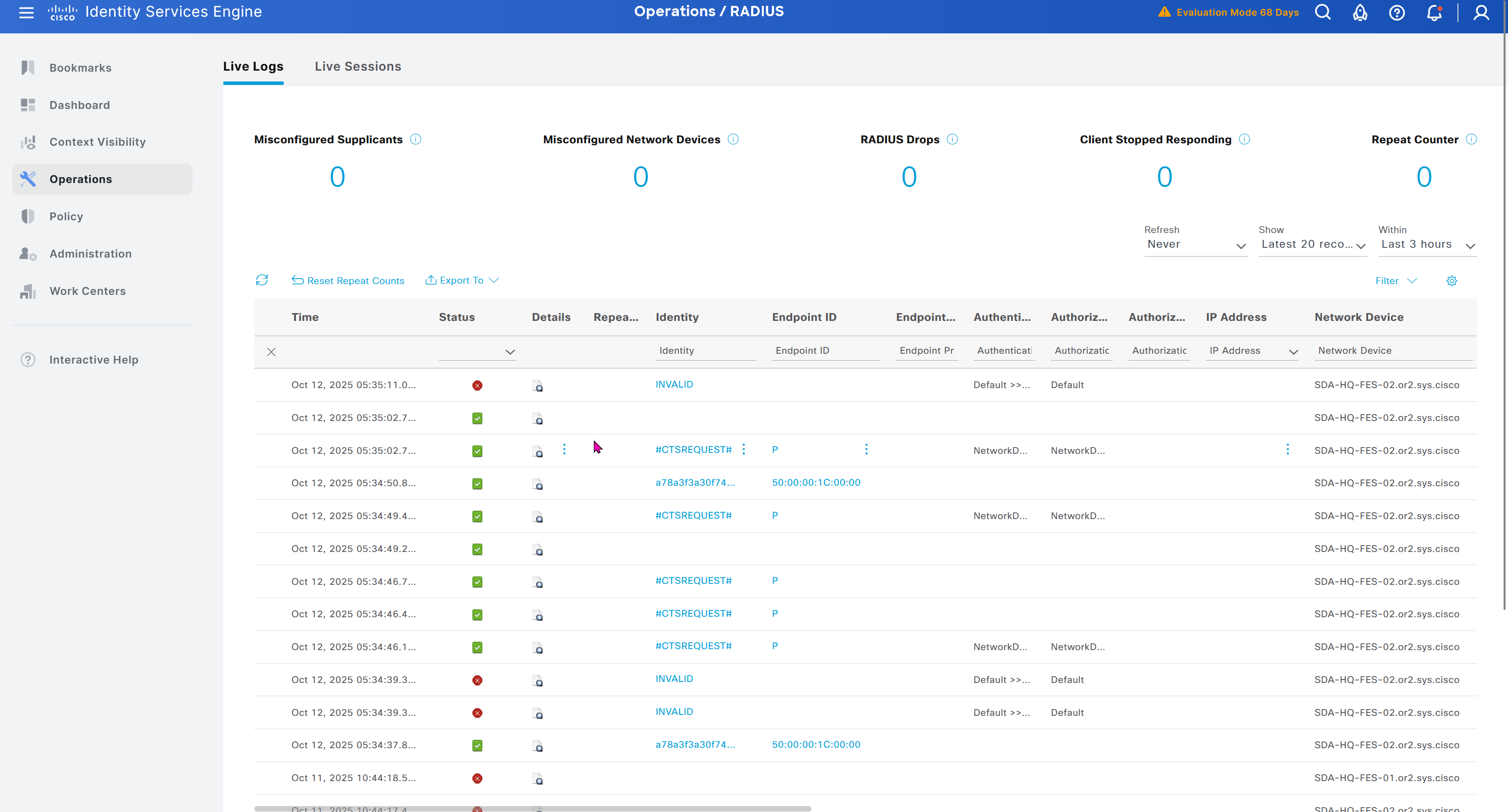
As devices are discovered in DNAC, it is also added in ISE
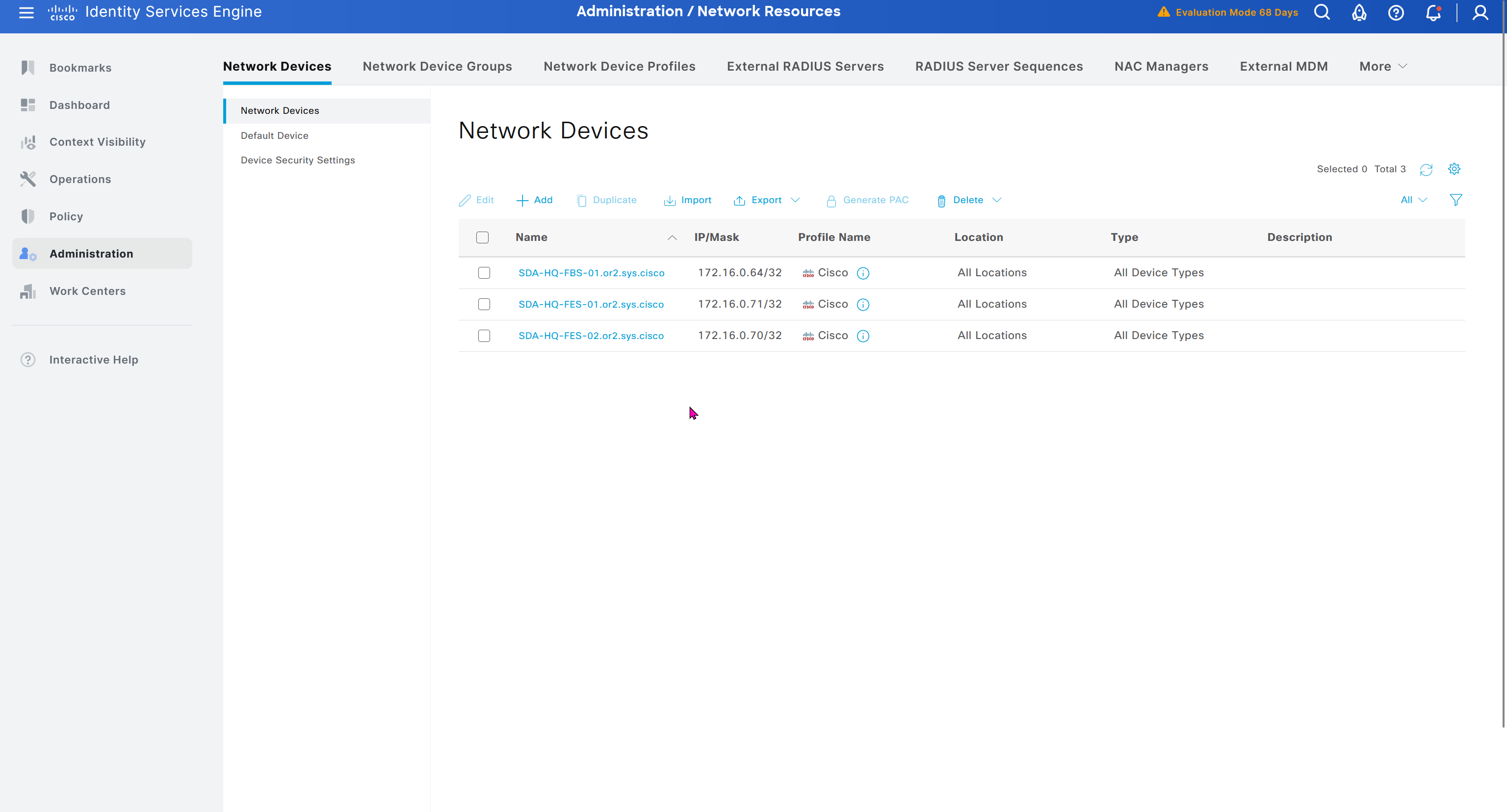
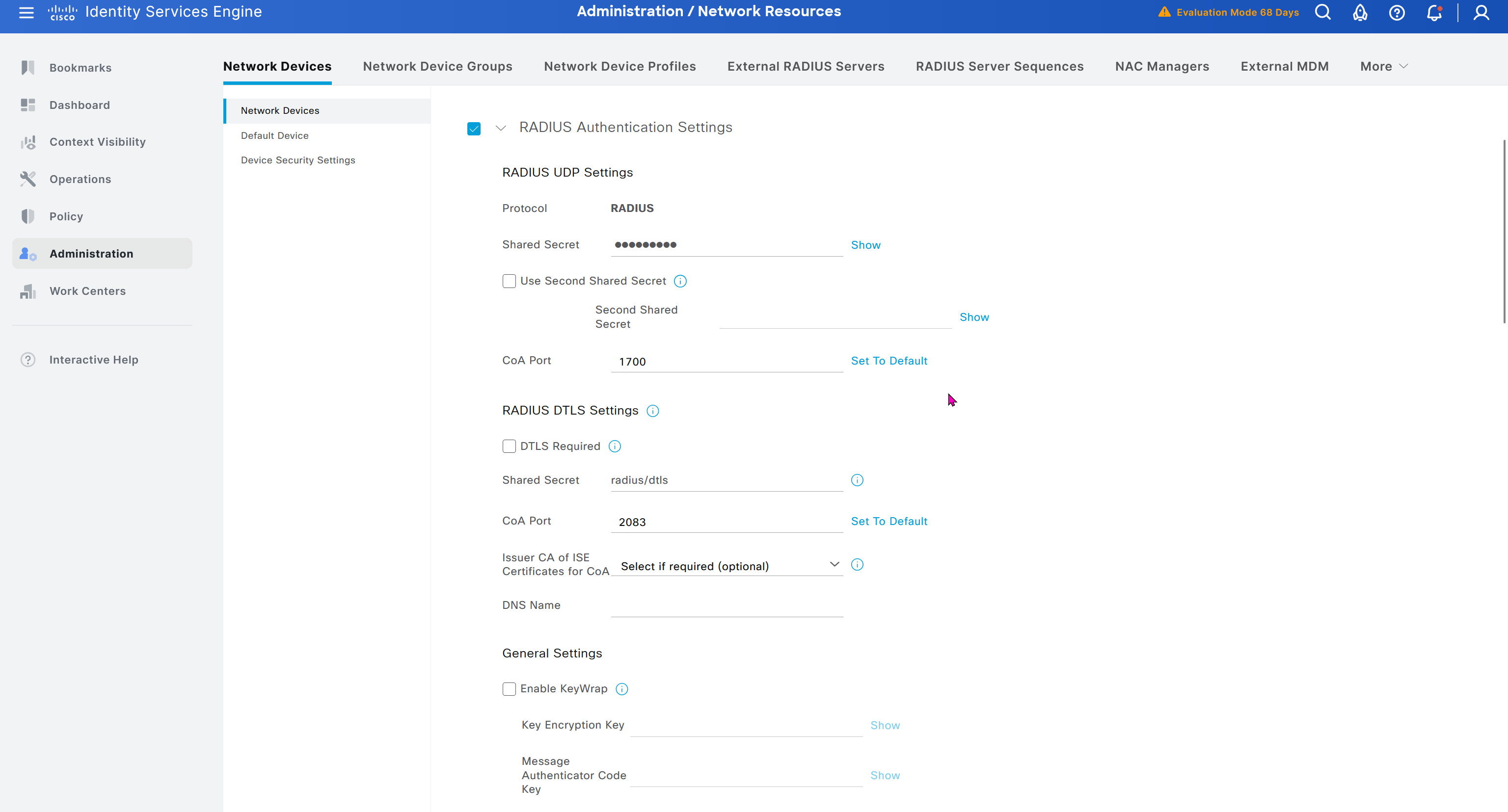

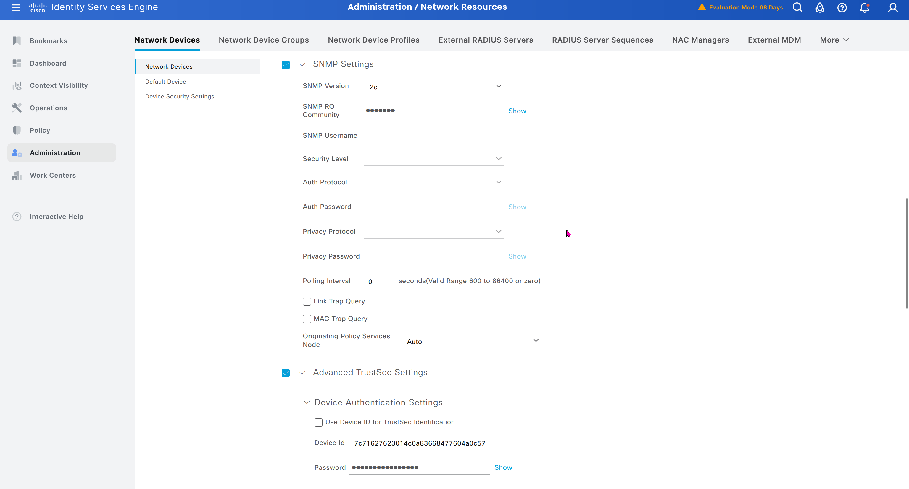
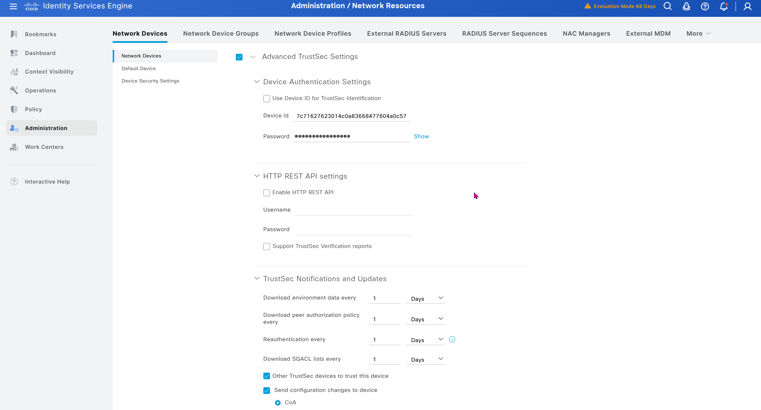
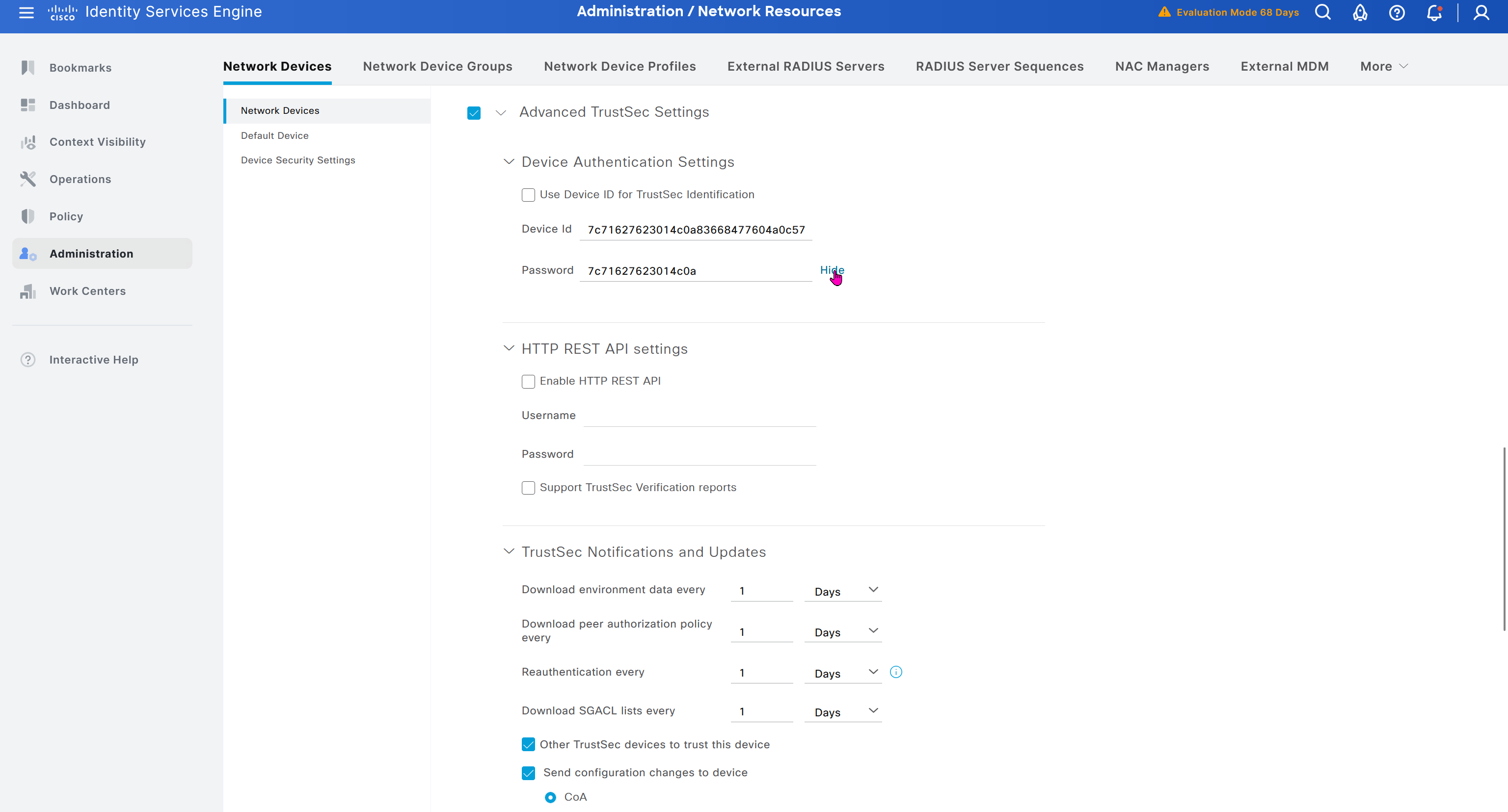

In ISE live logs we can see entries for devices authenticating to ISE for Trust Sec Device authentication
next post
CCIE Lessons
Hold Timer
Hold means keep holding on to info as long as hold time is not 0, the moment it reaches 0, all things related to that neighbor is dropped and
neighbors are also told to withdraw
next post
CCIE Interface Errors
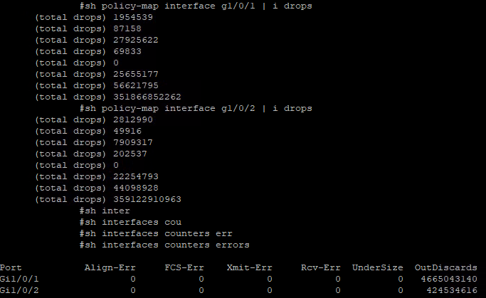
Checking Interface Errors
show interface Gi1/0/1
show interface counters errors
show policy-map interface gi1/0/1
next post
CCIE PMTUD
PMTUD
Although the maximum length of an IPv4 datagram is 65535, most transmission links enforce a smaller maximum packet length limit, called an MTU. The MTU size can even differ from link to link
IPv4 fragmentation breaks a datagram into pieces that are reassembled later on the end station , broken by network devices but assembled later on end device
Some headers in IPv4 header that are of significance are “do not fragment” DF bit, fragment offset fields, along with “more fragments” (MF)
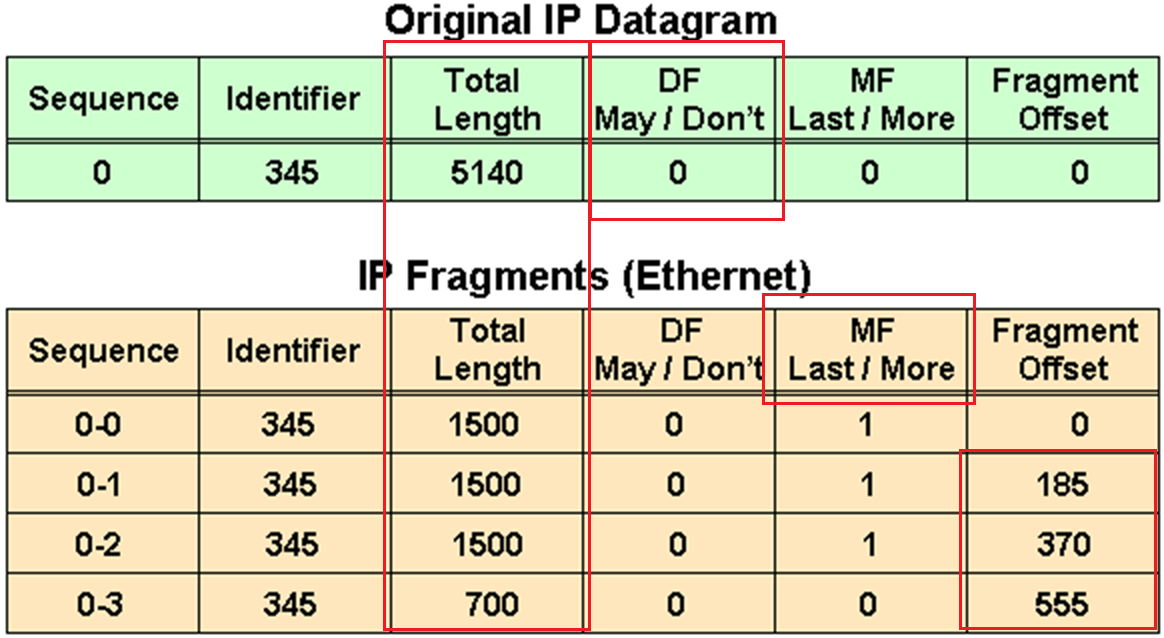
in above figure because DF bit or Do not fragment is not set that is why IP packet was fragmented and not discarded upon the need for fragmentation, determines whether or not a packet is “allowed” to be fragmented.
Identifier is the identifier of the packet, which helps receiver make sure it is assembling the same packet back
offset
The fragment offset is 13 bits and indicates where a fragment belongs in the original IPv4 datagram. This value is a multiple of 8 bytes, like a puzzle where the puzzle fits in the IPv4 packet to make it whole or complete,
The second fragment has an offset of 185 (185 x 8 = 1480); the data portion of this fragment starts 1480 bytes into the original IPv4 datagram,
The third fragment has an offset of 370 (370 x 8 = 2960); the data portion of this fragment starts 2960 bytes into the original IPv4 datagram.
The fourth fragment has an offset of 555 (555 x 8 = 4440), which means that the data portion of this fragment starts 4440 bytes into the original IPv4 datagram.
It is only when the last fragment is received that the size of the original IPv4 datagram can be determined.
Issues with IPv4 Fragmentation
IPv4 fragmentation results in a small increase in CPU and memory overhead to fragment an IPv4 datagram. This is true for the sender and for a router in the path between a sender and a receiver.
The creation of fragments involves the creation of fragment headers and copies the original datagram into the fragments.
Fragmentation causes more overhead for the receiver when reassembling the fragments because the receiver must allocate memory for the arriving fragments and coalesce them back into one datagram after all of the fragments are received.
Reassembly on a host is not considered a problem because the host has the time and memory resources to devote to this task.
Reassembly, however, is inefficient on a router or firewall whose primary job is to forward packets as quickly as possible.
A router is not designed to hold on to packets for any length of time.
A router that does the reassembly chooses the largest buffer available (18K), because it has no way to determine the size of the original IPv4 packet until the last fragment is received.
Another fragmentation issue involves how dropped fragments are handled.
If one fragment of an IPv4 datagram is dropped, then the entire original IPv4 datagram must be present and it is also fragmented.
This is seen with Network File System (NFS). NFS has a read and write block size of 8192.
Therefore, a NFS IPv4/UDP datagram is approximately 8500 bytes (which includes NFS, UDP, and IPv4 headers).
A sending station connected to an Ethernet (MTU 1500) has to fragment the 8500-byte datagram into six (6) pieces; Five (5) 1500 byte fragments and one (1) 1100 byte fragment.
If any of the six fragments are dropped because of a congested link, the complete original datagram has to be retransmitted. This results in six more fragments to be created.
If this link drops one in six packets, then no NFS data are transferred over this link
Firewalls that filter or manipulate packets based on Layer 4 (L4) through Layer 7 (L7) information have trouble processing IPv4 fragments correctly
If the IPv4 fragments are out of order, a firewall blocks the non-initial fragments because they do not carry the information that match the packet filter.
Firewalls nowadays should virtually reassemble packets (which does not actually reassembles packets but only locally in its memory to be able to inspect packet)
PMTUD
TCP MSS addresses fragmentation at the two endpoints of a TCP connection, but it does not handle cases where there is a smaller MTU link in the middle between these two endpoints and UDP traffic.
PMTUD is a mechanism to dynamically determine the true lowest MTU (Maximum Transmission Unit) on the path between a sender and a receiver
If PMTUD is enabled on a host, all TCP and UDP packets from the host have the DF bit set.
so that intermediate routers won’t fragment but if there is a need for fragmentation and network devices drop the packet but still let the sender know that fragmentation is needed
PMTUD Steps
A host sends an IPv4 packet (or a TCP/UDP segment) with the DF bit set.
That packet traverses the network toward its destination. At some point there may be a link with smaller MTU than the packet size.
When a router along the path encounters a packet that it cannot forward without fragmentation (because the packet size > the outgoing link’s MTU) and the packet has the DF bit set, then:
- The router drops the packet.
- The router sends an ICMP “Destination Unreachable – fragmentation needed and DF set” (Type 3, Code 4) message back to the sender. This ICMP message includes the MTU of the next‐hop link in the “unused” field if the router supports it (per RFC 1191). If intermediate routers don’t support including the MTU in the ICMP message or the host ignores the message, then the path MTU may not be found correctly
The sender receives that ICMP message and then reduces its packet size (or the MSS for TCP) for that destination, using the newly discovered path MTU value.
The host updates its send size and retries with smaller size, now the packet goes through successfully. A host records the MTU value for a destination because it creates a host (/32) entry in its routing table with this MTU value.
Because the path can change for same destination on internetwork, PMTUD is an ongoing process: if things change, new ICMP messages may cause further reductions.
For PMTUD to work properly, the ICMP “fragmentation needed” messages must actually reach the sender. If those ICMP messages are blocked by firewalls, routers, or filtered, PMTUD will fail silently
On Cisco routers the command tunnel path-mtu‐discovery (when applied to the tunnel interface) allows the router to participate in PMTUD for encapsulated traffic, to copy DF bit from inner to outer packet, and to dynamically adjust the tunnel MTU
With Cisco routers and switches we can perform extended ping to determine the biggest size possible through the path
ping
Protocol [ip]:
Target IP address: 172.31.176.164
Repeat count [5]:
Datagram size [100]:
Timeout in seconds [2]:
Extended commands [n]: y
Ingress ping [n]:
Source address or interface:
DSCP Value [0]:
Type of service [0]:
Set DF bit in IP header? [no]: y
Validate reply data? [no]:
Data pattern [0x0000ABCD]:
Loose, Strict, Record, Timestamp, Verbose[none]: V
Loose, Strict, Record, Timestamp, Verbose[V]:
Sweep range of sizes [n]: y
Sweep min size [36]: 1400
Sweep max size [20000]: 1600
Sweep interval [1]:
Type escape sequence to abort.
Sending 1005, [1400..1600]-byte ICMP Echos to 172.31.176.164, timeout is 2 seconds:
Packet sent with the DF bit set
Reply to request 0 (7 ms) (size 1400)
Reply to request 1 (10 ms) (size 1401)
Reply to request 2 (8 ms) (size 1402)
Reply to request 3 (7 ms) (size 1403)
Reply to request 4 (4 ms) (size 1404)
Reply to request 5 (4 ms) (size 1405)
Reply to request 6 (3 ms) (size 1406)
Reply to request 7 (4 ms) (size 1407)
Reply to request 8 (4 ms) (size 1408)
Reply to request 9 (4 ms) (size 1409)
Reply to request 10 (5 ms) (size 1410)
Reply to request 11 (6 ms) (size 1411)
Reply to request 12 (3 ms) (size 1412)
Reply to request 13 (4 ms) (size 1413)
Reply to request 14 (3 ms) (size 1414)
Reply to request 15 (3 ms) (size 1415)
Reply to request 16 (5 ms) (size 1416)
Reply to request 17 (3 ms) (size 1417)
Reply to request 18 (3 ms) (size 1418)
Reply to request 19 (3 ms) (size 1419)
Reply to request 20 (5 ms) (size 1420)
Reply to request 21 (7 ms) (size 1421)
Reply to request 22 (3 ms) (size 1422)
Reply to request 23 (3 ms) (size 1423)
Reply to request 24 (4 ms) (size 1424)
Reply to request 25 (6 ms) (size 1425)
Reply to request 26 (4 ms) (size 1426)
Reply to request 27 (3 ms) (size 1427)
Reply to request 28 (4 ms) (size 1428)
Reply to request 29 (3 ms) (size 1429)
Reply to request 30 (4 ms) (size 1430)
Reply to request 31 (4 ms) (size 1431)
Reply to request 32 (3 ms) (size 1432)
Reply to request 33 (3 ms) (size 1433)
Reply to request 34 (4 ms) (size 1434)
Unreachable from 172.31.203.21, maximum MTU 1434 (size 1435)
Request 36 timed out (size 1436)
Request 37 timed out (size 1437)
Request 38 timed out (size 1438)
Request 39 timed out (size 1439)
Request 40 timed out (size 1440)
Request 41 timed out (size 1441)
Unreachable from 172.31.203.21, maximum MTU 1434 (size 1442)
Request 43 timed out (size 1443)
Unreachable from 172.31.203.21, maximum MTU 1434 (size 1444)
Request 45 timed out (size 1445)
Unreachable from 172.31.203.21, maximum MTU 1434 (size 1446)
Request 47 timed out (size 1447)
Unreachable from 172.31.203.21, maximum MTU 1434 (size 1448)
Request 49 timed out (size 1449)
Unreachable from 172.31.203.21, maximum MTU 1434 (size 1450)
Request 51 timed out (size 1451)
Success rate is 67 percent (35/52), round-trip min/avg/max = 3/4/10 ms
but this is also possible with windows, although windows does not increment automatically
ping 8.8.8.8 -f -l 1500-f → Sets the DF (Don’t Fragment) bit.
-l <size> → Sets the ICMP payload packet size.
If network or firewall in path is not filtering ICMP packets returning from remote device then on CLI and packet capture we should see
Packet needs to be fragmented but DF set.So, if ping -f -l works at 1472 bytes, then the actual Path MTU is:
1472 + 28 = 1500 bytesIf we are using powershell then
$target = "8.8.8.8"
for ($size=1300; $size -le 2000; $size+=10) {
    Write-Host "Testing $size bytes"
    ping $target -f -l $size -n 1 | findstr /i "fragment"
}

Read-Host "Press Enter to exit..."
To test PMTUD in real-life:
ping <destination> -f -l 1472
If it passes → Path MTU is likely 1500.
If not → lower the size until it passes.
Further reading: https://www.cisco.com/c/en/us/support/docs/ip/generic-routing-encapsulation-gre/25885-pmtud-ipfrag.html
next post
CCIE IPv6
IPv6
IPv6 address is made up of two parts.
The first 64 bits usually represent the subnet prefix, and the last 64 bits usually represent the address assigned to interface.
2001:db8:a:a::/64 is subnet or prefix
Network interface can have the address
2001:db8:a:a::1 where the last 64 bits, which are ::1
Hosts on this network can have ::10 and ::20 etc and all devices in this network are configured with default gateway 2001:db8:a:a::1
C:\PC1>ipconfig

Windows IP Configuration

Ethernet adapter Local Area Connection:

 Connection-specific DNS Suffix . :
 IPv6 Address. . . . . . . . . . .: 2001:db8:a:a::10
 Link-local IPv6 Address . . . . .: fe80::a00:27ff:fe5d:6d6%11 <<<<<<<
 IPv4 Address. . . . . . . . . . .: 10.1.1.10
 Subnet Mask . . . . . . . . . . .: 255.255.255.192
 Default Gateway . . . . . . . . .: 2001:db8:a:a::1
                                           10.1.1.1
Link-local address fe80::a00:27ff:fe5d:6d6 and the global unicast address 2001:db8:a:a::10 (statically configured).
Notice the %11 at the end of the link-local address. This is the interface identification number, and it is needed so that the system knows which interface to send the packets out of; keep in mind that you can have multiple interfaces on the same device with the same link-local address assigned to them.
EUI-64
EUI-64 helps with auto configuring unique IP addresses in IPv6 world because of how big the IPv6 addresses are
allows your end devices to automatically assign their own global unicast and link-local addresses
EUI-64 takes the client’s MAC address
Splits the 48 bits MAC address in half, and inserts the hex values FFFE in the middle.
In addition, it takes the seventh bit from the left and flips it. So, if it is a 1, it becomes a 0, and if it is a 0, it becomes a 1.
fe80 :: a00:27ff:fe5d:6d6
  |            |
  |            |
network bit    |
               |
           host bits
Looking at the host bits in address 0a00:27ff:fe5d:06d6
we can see this is an EUI-64 address because it has FFFE in it
For example MAC address is 08-00-27-5D-06-D6
Split it in half and add FFFE in the middle to get 08-00-27-FF-FE-5D-06-D6
08 is hex and in binary it is 000010″0″0.
The seventh bit from left is a 0, so make it a 1. Now you have 000010″1″0 – convert to hex it becomes 0a
making it 0A00:27FF:FE5D:06D6 in address fe80::a00:27ff:fe5d:6d6
By default, routers use EUI-64 when generating the interface portion of the link-local address of an interface
if you want to use EUI-64 for a statically configured global unicast address, use the eui-64 keyword at the end of the ipv6 address
interface gigabitEthernet 0/0
ipv6 address 2001:db8:a:a::/64 eui-64
IPv6 SLAAC, Stateful DHCPv6, and Stateless DHCPv6
Manually assigning IP addresses is not a scalable option with IPv6, you have three dynamic options
1. Stateless address autoconfiguration (SLAAC)
2. Stateful DHCPv6
3. stateless DHCPv6.
SLAAC
SLAAC is designed to enable a device to configure its own IPv6 address, prefix, and default gateway without a DHCPv6 server
Windows PCs automatically have SLAAC enabled and generate their own IPv6 addresses and can only be seen in ipconfig /all
C:\PC1>ipconfig /all

Windows IP Configuration

 Host Name . . . . . . . . . . . .: PC1
 Primary Dns Suffix . . . . . . . :
 Node Type . . . . . . . . . . . .: Broadcast
 IP Routing Enabled. . . . . . . .: No
 WINS Proxy Enabled. . . . . . . .: No

Ethernet adapter Local Area Connection:


 Connection-specific DNS Suffix . : SWITCH.local
 Description . . . . . . . . . . .: Intel(R) PRO/1000 MT Desktop Adapter
 Physical Address. . . . . . . . .: 08-00-27-5D-06-D6
 DHCP Enabled. . . . . . . . . . .: Yes
 Autoconfiguration Enabled . . . .: Yes <<<<<<<
 IPv6 Address. . . . . . . . . . .: 2001:db8::a00:27ff:fe5d:6d6(Preferred)
 Link-local IPv6 Address . . . . .: fe80::a00:27ff:fe5d:6d6%11(Preferred)
IPv4 Address. . . . . . . . . . . : 10.1.1.10(Preferred)
 Subnet Mask . . . . . . . . . . .: 255.255.255.192
When a Windows PC and router interface are enabled for SLAAC, they send a Router Solicitation (RS) message to the all-routers multicast address (ff02::2) to ask if any routers are on local link. Router then sends a Router Advertisement (RA) that identifies following:
The network prefix(es) used on that link (e.g., 2001:db8:1:1::/64),
Flags indicating whether to use SLAAC or DHCPv6,
The router’s lifetime as a default gateway,
And other configuration details.
The PC uses the prefix from the RA and combines it with its own interface identifier (often based on MAC address or a random value) to form a full IPv6 global unicast address.
RA’s source address (the router’s link-local address, usually starting with fe80::) is used by the host as the next-hop (default gateway).
In IPv6, all routers must have a link-local address on each interface, and hosts use that address as the default gateway.
To verify an IPv6 address generated by SLAAC on a router interface, use the show ipv6 interface command
However, note that this occurs only if IPv6 unicast routing was not enabled on the router and, as a result, the router is acting as an end device, that is why next hop router’s link local address is listed as default router.
RA are only generated by default only if
1. Router interface is enabled for IPv6
2. IPv6 unicast routing is enabled
3. RAs are not being suppressed on the interface
4. Make sure that the router interface has a /64 prefix by using the show ipv6 interface command, SLAAC works only if the router is using a /64 prefix
In addition, if you have more than one router on a subnet generating RAs, which can happen with redundant gateways, the clients learn about multiple default gateways from the RAs as shown below
C:\PC1># ipconfig

Windows IP Configuration

Ethernet adapter Local Area Connection:

 Connection-specific DNS Suffix . :
 IPv6 Address. . . . . . . . . . .: 2001:db8:a:a:a00:27ff:fe5d:6d6
 Link-local IPv6 Address . . . . .: fe80::a00:27ff:fe5d:6d6%11
 IPv4 Address. . . . . . . . . . .: 10.1.1.10
 Subnet Mask . . . . . . . . . . .: 255.255.255.192
 Default Gateway . . . . . . . . .: fe80::c80b:eff:fe3c:8%11 <<<<<<<
                                    fe80::c80a:eff:fe3c:8%11 <<<<<<<
                                    10.1.1.1
Stateful DHCPv6
Although a device is able to determine its IPv6 address, prefix, and default gateway using SLAAC, there is not much else the devices can obtain. In a modern network, the devices may also need information such as Network Time Protocol (NTP) server information, domain name information, DNS server information
Use a DHCPv6 server.
Cisco routers and switches can act as DHCPv6 servers, but for their interface to be able to hand out v6 IP addresses using configured pool we must enable interface command “ipv6 dhcp server [pool-name]
If you are troubleshooting an issue where clients are not receiving IPv6 addressing information or where they are receiving wrong IPv6 addressing information from a router or multilayer switch acting as a DHCPv6 server, check the interface and make sure it was associated with the correct pool.
Stateless DHCPv6
Stateless DHCPv6 is a combination of SLAAC and DHCPv6. With stateless DHCPv6, clients use a router’s RA to automatically determine the IPv6 address, prefix, and default gateway. Included in the RA is a flag that tells the client to get other non-addressing information from a DHCPv6 server, such as the address of a DNS server etc
To accomplish this, ensure that the ipv6 nd other-config-flag interface configuration command is enabled
This ensures that the RA informs the client that it must contact a DHCPv6 server for other information
DHCPv6 Operation
DHCPv6 has a four-step negotiation process, like IPv4. However, DHCPv6 uses the following messages:
SOLICIT
xxx
ADVERTISE
xxx
REQUEST
xxx
REPLY
xxx
next post
STP
STP
Redundancy requires that we connect second link between switches
but that is loop – this is where spanning tree steps in disables one side of the link / interface to remove the loop
One indication of loop is that mac shows up behind different ports which it should not
Layer 2 looped frames do not have TTL mechanism so if looped they keep going around and it grinds network equipment to halt
STP works by first making switches aware by sending and receiving BPDUs to one another rather than silence or dark network
STP selects one switch in the network as a root switch and a tree is built from this root switch’s perspective by simply stretching STP network down from that root switch
STP has multiple versions:
- 802.1D, which is the original specification
- Per-VLAN Spanning Tree (PVST)
- Per-VLAN Spanning Tree Plus (PVST+)
- ———————————————
- 802.1W Rapid Spanning Tree Protocol (RSTP)
- 802.1S Multiple Spanning Tree Protocol (MST)
Cisco switches can operate in PVST+, RSTP, and MST modes.
All three of these modes are backward compatible with 802.1D.
Original version of STP only ensures Loop free topology in one VLAN
802.1D Port States
Disabled: The port is in an administratively off position (that is, shut down).
Blocking:
The switch port is enabled
but the port is not forwarding any traffic to ensure that a loop is not created.
The switch does not modify the MAC address table.
Special: Port can only receive BPDUs
Listening:
The switch port has transitioned from a blocking state
Port can now send or receive BPDUs.
It still cannot forward any other network traffic.
The duration of the state correlates to the STP forwarding time.
Special: Port can send and receive BPDUs
Learning:
The switch port can add MAC entries in MAC address table from network traffic that it receives.
The switch still does not forward any other network traffic besides BPDUs.
The duration of the state correlates to the STP forwarding time. The next port state is forwarding.
Special: Port can send and receive BPDU but can also do mac learning on port (learn is in the name)
Forwarding:
The switch port can forward all network traffic and can update the MAC address table as expected.
This is the final state for a switch port to forward network traffic.
Special: only forwarding actually forwards traffic (forward is in the name)
Broken:
The switch has detected a configuration or an operational problem on a port that can have major effects.
The port discards packets as long as the problem continues to exist.
If timers are left to defaults 802.1D takes about 30 seconds for a port to transition from Blocking to Forwarding state
802.1D Port Types
Root port (RP):
A network port that connects to the root bridge or an upstream switch that leads to root switch in the spanning-tree topology.
There should be only one root port per VLAN on a switch.
Designated port (DP):
A network port that receives and forwards BPDU frames to other switches.
Designated ports provide connectivity to downstream devices and switches or Drives away from root
There should be only one active designated port on a link.
Blocking port: A network port that is not forwarding traffic because of STP calculations.
Several key terms are related to STP:
Root bridge:
The root bridge has all ports are in a forwarding state and non blocking
This switch is considered the top of the spanning tree for all path calculations by other switches.
All ports on the root bridge are categorized as designated ports.
Bridge protocol data unit (BPDU):
This network packet is used for network switches to identify each other and notify of changes in the topology.
A BPDU uses the destination MAC address 01:80:c2:00:00:00. There are two types of BPDUs:
- Configuration BPDU:
This BPDU is used to identify the root bridge, root ports, designated ports, and blocking ports. The configuration BPDU consists of the following fields:
– STP type
– root path cost
– root bridge identifier
– local bridge identifier
– max age
– hello time
– forward delay - Topology change notification (TCN) BPDU:
This BPDU is used to communicate changes in the Layer 2 topology to other switches. It is explained in greater detail later in the chapter. - Root path cost: This is the combined cost toward the root switch.
- System priority:
This 4-bit value indicates the desire for a switch to be root bridge.
The default value is 32,768. - System ID extension:
This 12-bit value indicates the VLAN (12 bits because VLAN ID is 12 bit) that the BPDU belongs to because BPDU are generated per vlan or BPDU can belong to only one VLAN.
The system priority (root making value) and system ID extension (VLAN) are combined as part of the switch’s identification of a bridge - Root bridge identifier:
Root bridge’s system MAC address + system ID extension + system priority of the root bridge - Local bridge identifier:
System MAC address + system ID extension + system priority of the local bridge. - Max age:
This is the maximum length of time that a bridge port stores its BPDU information.
The default value is 20 seconds (10x the default hello time) but can be configured with the command spanning-tree vlan vlan-id max-age maxage.
If a switch loses contact with the BPDU’s source, switch keeps that the BPDU information on interface till Max Age timer counts down.
Max age timer counts down when there is an indirect failure and not the interface down event - Hello time:
This is the time interval that a BPDU is advertised out of a port.
The default value is 2 seconds, but the value can be configured to 1 to 10 seconds with the command spanning-tree vlan vlan-id hello-time hello-time. - Forward delay:
The name is actually Forwarding Delay
This is the amount of time that a port stays in a listening and learning state (where it does not forward traffic).
The default value is 15 seconds, but the value can be changed to a value of 4 to 30 seconds with the command spanning-tree vlan vlan-id forward-time forward-time.
STP cost is assigned on interface and root path cost is calculated by adding cumulative cost to reach root
Long mode and short mode
Original default costs were set for different speeds upto only 20 Gbps but as networking has advanced 10 Gbps has become common.
Another method, called long mode, uses a 32-bit value and uses a reference speed of 20 Tbps
The original method, known as short mode, has been the default for most switches, but has been transitioning to long mode based on specific platform and OS versions.
| Link Speed | Short-Mode STP Cost | Long-Mode STP Cost |
|---|---|---|
| 10 Mbps | 100 | 2,000,000 |
| 100 Mbps | 19 | 200,000 |
| 1 Gbps | 4 | 20,000 |
| 10 Gbps | 2 | 2000 |
| 20 Gbps | 1 | 1000 |
| 100 Gbps | 1 | 200 |
| 1 Tbps | 1 | 20 |
| 10 Tbps | 1 | 2 |
Devices can be configured with the long-mode interface cost with the command spanning-tree pathcost method long. The entire Layer 2 topology should use the same setting for every device in the environment to ensure a consistent topology. Before you enable this setting in an environment, it is important to conduct an audit to ensure that the setting will work.
1. Elect Root Bridge, starts with I am root
As switch boots it wants to find root bridge, and starts by assuming that it itself is root
uses the local bridge identifier as the root bridge identifier
listens for BPDUs coming from all the ports for neighbors
If the neighbor’s configuration BPDU is inferior to its own BPDU, the switch ignores that BPDU
If the neighbor’s configuration BPDU is better than its own BPDU
the switch updates its BPDUs to include the new better root bridge + new root path cost.
This process continues until all switches in a topology have identified the root bridge switch.

STP favours the switch with lowest priority inside the bridge ID
If priority is same then switch with lower system MAC address wins
Generally, older switches have a lower MAC address and are considered more preferable
but configuration changes in priority should be made for optimal placement of the root bridge
show spanning-tree root to display the root bridge
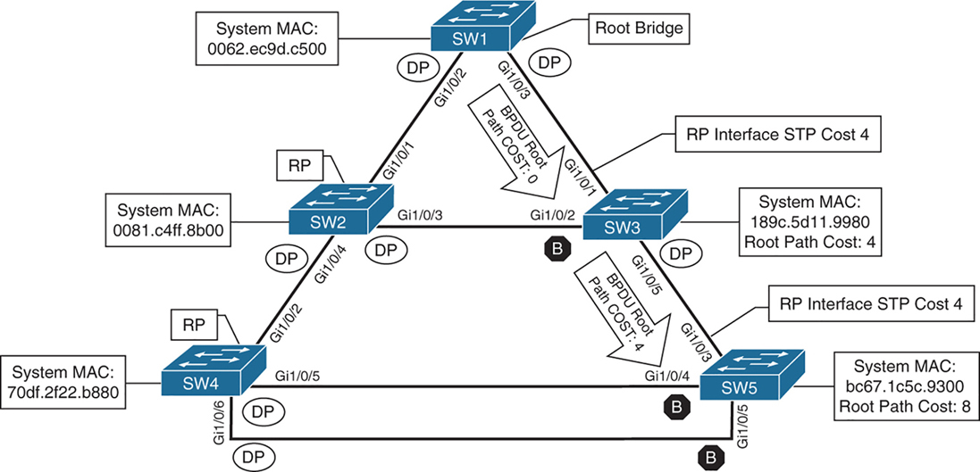
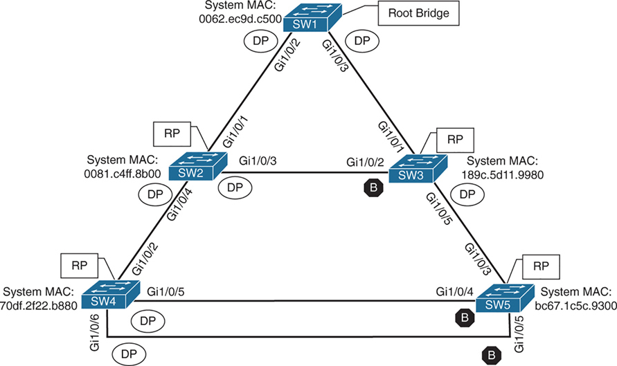
SW1# show spanning-tree root
                                            Root    Hello Max Fwd
Vlan                   Root ID            Cost    Time  Age Dly  Root Port
---------------- -------------------- --------- ----- --- ---  ------------
VLAN0001         32769 0062.ec9d.c500         0    2   20  15
VLAN0010         32778 0062.ec9d.c500         0    2   20  15
VLAN0020         32788 0062.ec9d.c500         0    2   20  15
VLAN0099         32867 0062.ec9d.c500         0    2   20  15
this command is like a snapshot or view of root for all VLANs
there can be different root switches for some VLANs, it is not mandatory to one root for all VLANs
When a switch generates the BPDUs, the root path cost includes only the calculated metric to the root and does not include the cost of the port that the BPDU is advertised out of
The receiving switch adds the port cost for its interface on which the BPDU was received with the value of the root path cost in the BPDU and that is the value switch thinks to reach the root is
The root path cost is always zero on the root bridge
cost on those links is 4 because of 1 gig links (short mode)
SW2# show spanning-tree root
                                            Root    Hello Max Fwd
Vlan                   Root ID            Cost    Time  Age Dly  Root Port
---------------- -------------------- --------- ----- --- ---  ------------
VLAN0001         32769 0062.ec9d.c500         4    2   20  15  Gi1/0/1
VLAN0010         32778 0062.ec9d.c500         4    2   20  15  Gi1/0/1
VLAN0020         32788 0062.ec9d.c500         4    2   20  15  Gi1/0/1
VLAN0099         32867 0062.ec9d.c500         4    2   20  15  Gi1/0/1
SW3# show spanning-tree root
Root Hello Max Fwd
Vlan Root ID Cost Time Age Dly Root Port
---------------- -------------------- --------- ----- --- --- ------------
VLAN0001 32769 0062.ec9d.c500 4 2 20 15 Gi1/0/1
VLAN0010 32778 0062.ec9d.c500 4 2 20 15 Gi1/0/1
VLAN0020 32788 0062.ec9d.c500 4 2 20 15 Gi1/0/1
VLAN0099 32867 0062.ec9d.c500 4 2 20 15 Gi1/0/1Locating Root “Ports“
After the switches have identified the root bridge, they must determine their root port (RP).
Only the root bridge continues to advertise configuration BPDUs out all of its ports. The switch compares the BPDU information received on its port to identify the RP.
The RP is selected using the following logic , only moves to next step when there is a tie
This step is interface centric because we are selecting a root “port”
- The interface associated to lowest path cost is more preferred.
- The interface associated to the lowest system priority of the “advertising switch” is preferred next.
- The interface associated to the lowest system MAC address of the advertising switch is preferred next.
- When multiple links are associated to the same switch, the lowest port priority from the advertising switch is preferred.
- When multiple links are associated to the same switch, the lower port number from the advertising switch is preferred.
Locating Blocked / Designated Switch “Ports“
Root for a VLAN is elected
Root ports are elected
Now next is Designated ports / blocking ports between 2 non-root switches needs to be decided
one of those switch’s “designated ports” must be set to a blocking state to prevent a forwarding loop
- The interface is a designated port and must not be considered an RP.
- The switch with the lower path cost to the root bridge forwards packets, and the one with the higher path cost blocks. If they tie, they move on to the next step.
- The system priority of the local switch is compared to the system priority of the remote switch. The local port is moved to a blocking state if the remote system priority is lower than that of the local switch. If they tie, they move on to the next step.
- The system MAC address of the local switch is compared to the system MAC address of the remote switch. The local designated port is moved to a blocking state if the remote system MAC address is lower than that of the local switch.
- When multiple links are associated to the same switch, the lowest port priority from the advertising switch is preferred.
- When multiple links are associated to the same switch, the lower port number from the advertising switch is preferred.
SW1# show spanning-tree vlan 1

VLAN0001
  Spanning tree enabled protocol rstp
! This section displays the relevant information for the STP root bridge
  Root ID    Priority    32769
              Address     0062.ec9d.c500
              This bridge is the root
              Hello Time   2 sec  Max Age 20 sec  Forward Delay 15 sec
! This section displays the relevant information for the Local STP bridge
  Bridge ID  Priority    32769  (priority 32768 sys-id-ext 1)
               Address     0062.ec9d.c500
               Hello Time   2 sec  Max Age 20 sec  Forward Delay 15 sec
               Aging Time  300 sec

Interface           Role Sts Cost      Prio.Nbr Type
------------------- ---- --- --------- -------- --------------------------------
Gi1/0/2             Desg FWD 4          128.2    P2p
Gi1/0/3             Desg FWD 4          128.3    P2p
Gi1/0/14            Desg FWD 4          128.14   P2p Edge
If the Type field includes *TYPE_Inc -, this indicates a port configuration mismatch between this switch and the switch it is connected to, it is seen when port mode is mixed Access and Trunk between switches
These port types are expected on Catalyst switches:
P2p
P2p is point-to-point link only, i.e.:
- The port connects directly to a switch or router device on full-duplex Ethernet link
Why it matters in STP:
- STP can converge faster on point-to-point links
- Rapid STP (RSTP) can move these ports to forwarding almost immediately when safe
P2p Edge
- A point-to-point link
- AND an edge port (connected to an end device)
This is essentially PortFast
What STP assumes:
- No risk of loops
- The device is not a switch
- The port can go to Forwarding immediately
Typical devices on P2p Edge ports:
- PCs
- Servers
- Printers
- IP phones
Ports that are blocked go in BLK state
Alternate port is the alternate port to reach root in an event Gi1/0/1 fails
All the ports on SW2 are in a forwarding state, but port Gi1/0/2 on SW3 is in a blocking (BLK) state.
SW3’s Gi1/0/2 port has also been designated as an alternate port to reach the root in the event that the Gi1/0/1 connection fails.
SW3’s Gi1/0/2 port rather than SW2’s Gi1/0/3 port was placed into a blocking state is that SW2’s system MAC address (0081.c4ff.8b00) is lower than SW3’s system MAC address (189c.5d11.9980).
SW2# show spanning-tree vlan 1


VLAN0001
  Spanning tree enabled protocol rstp
  Root ID    Priority    32769
              Address     0062.ec9d.c500
              Cost         4
              Port         1 (GigabitEthernet1/0/1)
              Hello Time   2 sec  Max Age 20 sec  Forward Delay 15 sec

  Bridge ID  Priority    32769  (priority 32768 sys-id-ext 1)
               Address     0081.c4ff.8b00
               Hello Time   2 sec  Max Age 20 sec  Forward Delay 15 sec
               Aging Time  300 sec

Interface           Role Sts Cost      Prio.Nbr Type
------------------- ---- --- --------- -------- --------------------------------
Gi1/0/1             Root FWD 4          128.1    P2p
Gi1/0/3             Desg FWD 4          128.3    P2p
Gi1/0/4             Desg FWD 4          128.4    P2p
SW3# show spanning-tree vlan 1
VLAN0001
Spanning tree enabled protocol rstp
! This section displays the relevant information for the STP root bridge
Root ID Priority 32769
Address 0062.ec9d.c500
Cost 4
Port 1 (GigabitEthernet1/0/1)
Hello Time 2 sec Max Age 20 sec Forward Delay 15 se
! This section displays the relevant information for the Local STP bridge
Bridge ID Priority 32769 (priority 32768 sys-id-ext 1)
Address 189c.5d11.9980
Hello Time 2 sec Max Age 20 sec Forward Delay 15 sec
Aging Time 300 sec
Interface Role Sts Cost Prio.Nbr Type
------------------- ---- --- --------- -------- --------------------------------
Gi1/0/1 Root FWD 4 128.1 P2p
Gi1/0/2 Altn BLK 4 128.2 P2p
Gi1/0/5 Desg FWD 4 128.5 P2pshow spanning-tree interface interface-id [detail]
shows STP state for only the specified interface.
The detail keyword provides
1. port cost
2. port priority
3. number of transitions
4. link type
5. count of BPDUs sent or received for every VLAN supported on that interface.
show spanning-tree vlan x
shows where that vlan spans to on current switch
SW3# show spanning-tree interface gi1/0/1

Vlan                Role Sts Cost      Prio.Nbr Type
------------------- ---- --- --------- -------- --------------------------------
VLAN0001            Root FWD 4         128.1    P2p
VLAN0010            Root FWD 4         128.1    P2p
VLAN0020            Root FWD 4         128.1    P2p
VLAN0099            Root FWD 4         128.1    P2p
SW3# show spanning-tree interface gi1/0/1 detail
! Output omitted for brevity
Port 1 (GigabitEthernet1/0/1) of VLAN0001 is root forwarding
Port path cost 4, Port priority 128, Port Identifier 128.1.
Designated root has priority 32769, address 0062.ec9d.c500
Designated bridge has priority 32769, address 0062.ec9d.c500
Designated port id is 128.3, designated path cost 0
Timers: message age 16, forward delay 0, hold 0
Number of transitions to forwarding state: 1
Link type is point-to-point by default
BPDU: sent 15, received 45908
Port 1 (GigabitEthernet1/0/1) of VLAN0010 is root forwarding
Port path cost 4, Port priority 128, Port Identifier 128.1.
Designated root has priority 32778, address 0062.ec9d.c500
Designated bridge has priority 32778, address 0062.ec9d.c500
Designated port id is 128.3, designated path cost 0
Timers: message age 15, forward delay 0, hold 0
Number of transitions to forwarding state: 1
Link type is point-to-point by default
MAC BPDU: sent 15, received 22957
..STP Topology Changes
Configuration BPDUs always flow from the root bridge toward the edge switches
However, changes in the topology (for example, switch failure, link failure, or links becoming active) have an impact on “all” the switches in the Layer 2 topology.
The switch that detects a fault sends a topology change notification (TCN) BPDU toward the root bridge, out its RP.
If an upstream switch receives the TCN, it sends out an acknowledgment and forwards the TCN out its RP to the root bridge.
By default, a switch ages out MAC entries after 300 seconds (5 minutes)
When STP detects a topology change (link up/down, port role change):
The switch temporarily reduces the MAC aging time
Upon receipt of the TCN, the root bridge creates a new configuration BPDU with the Topology Change flag set, and it is then flooded to all the switches. When a switch receives a configuration BPDU with the Topology Change flag set, all switches change their MAC address timer to the forwarding delay timer (with a default of 15 seconds). This flushes out MAC addresses for devices that have not communicated in that 15-second window but maintains MAC addresses for devices that are actively communicating.
However, a side effect of flushing the MAC address table is that it temporarily increases the unknown unicast flooding while it is rebuilt. Remember that this can impact hosts because of their CSMA/CD behavior.
The MAC address timer is then reset to normal (300 seconds) after the 2 configuration BPDU are seen
“I’ve now seen two consecutive consistent BPDUs — the topology is stable again.”
Because these TCNs are generated on per VLAN basis, as a side effect that VLAN’s mac table mac entry retainer time will be reduced creating rebroadcasting of unknown unicast for MAC address relearning by the switch on that VLAN.
As the number of hosts (without portfast) increases, the more likely TCN generation is to occur and the more hosts that are impacted by the broadcasts. Topology changes should be checked as part of the troubleshooting process. Portfast stops generation of TCN and reduce the generation of TCNs.
Topology changes are seen with the command show spanning-tree [vlan vlan-id] detail on a switch.
The output of this command shows the topology change count and time since the last change has occurred.
A sudden or continuous increase in TCNs indicates a potential problem and should be investigated further for flapping ports or events on a connected switch.
SW1# show spanning-tree vlan 10 detail

 VLAN0010 is executing the rstp compatible Spanning Tree protocol
 Bridge Identifier has priority 32768, sysid 10, address 0062.ec9d.c500
 Configured hello time 2, max age 20, forward delay 15, transmit hold-count 6
 We are the root of the spanning tree
 Topology change flag not set, detected flag not set
 Number of topology changes 42 last change occurred 01:02:09 ago
           from GigabitEthernet1/0/2
 Times: hold 1, topology change 35, notification 2
         hello 2, max age 20, forward delay 15
 Timers: hello 0, topology change 0, notification 0, aging 300
The process of determining why TCNs are occurring involves finding a port that is flapping and it does not have portfast enabled, if it is connected to another switch then trace port on another switch but in same VLAN
Direct Link Failures of blocking segment- traffic impact
When a port goes down STP process is aware of that “direct link” failure

In below scenario link between SW2 and SW3 goes down
SW2 Gi1/0/3 is DP and SW3 Gi1/0/2 Blocking
This link going down will not impact traffic as both switches transmit traffic through SW1 and because of this direct link blocking between SW2 and SW3, SW2 learns all the MAC addresses behind SW3 via SW1 and SW3 learns all the MAC addresses behind SW2 via SW1
Blocked ports cannot send data and do not receive Data, also do not send BPDU but can receive BPDU only
switches also do not learn MAC on blocked ports
but designated port can send and receive data but in this case SW2’s Designated port will never forward out of Gi1/0/3 because no MAC has been learned through that port so even though designated port can send data, it will never send it because traffic outflow is dictated by MAC address learning
Dont forget about TCN generated from P2p port going down, both SW2 and SW3 will advertise a TCN toward the root switch, which results in the Layer 2 topology flushing its MAC address table.
Direct Link Failures – Loss of root – traffic impact 30 seconds for 802.1D

In the second scenario, the link between SW1 and SW3 fails.
Network traffic to and from SW1 to SW3 and Network traffic to and from SW2 -> SW1 -> SW3 and SW3 -> SW1 -> SW2 will be affected because of blocking segment between SW2 and SW3, all traffic between SW2 and SW3 goes via SW1 but because link between SW1 and SW3 is down , Layer 2 network will have to reconverge with the help of STP
– SW1 detects a link failure on its Gi1/0/3 interface.
– SW3 detects a link failure on its Gi1/0/1 interface and SW3 does not use max age timer on its Gi1/0/1
1. TCNs from all switches to root but no way to send in this scenario so switch will wait:
– Normally, SW1 would generate a TCN flag out its root port, but it itself is a root bridge, so it does not. SW1 will wait for a TCN from non root switches
– At this point, SW3 would attempt to send a TCN toward the root switch to notify it of a topology change; however, its root port is down, and its only other port that is connected to this layer 2 network is in blocking mode , so SW3 will wait for this port to come out of blocking mode but it will still send TCN once the port is out of blocking mode
2. Affected interfaces remove their best BPDU (root / root port) and activate alternative port as BPDUs from root are still coming in another (blocking) port:
– SW3 removes its best BPDU (was root port as best only comes on root port) without waiting for max age timer on its Gi1/0/1 interface because it is now in a down state.
– SW2 was always receiving BPDU from SW1 and relaying it to SW3
– because root port was lost SW3 must look for a new root port
– SW3 never lost access to root as it was receiving BPDUs on its Gi1/0/2 in Blocked state
– because BPDU are coming on blocking port Gi1/0/2 of SW3, and SW3 detects that this root is reachable over Gi1/0/2 Blocking port so it transitions to listening and then learning
3. TCN can now reach root
– once SW3 bring its port Gi1/0/2 to forwarding state then TCN is dispatched towards root from Gi1/0/2
– SW1 advertises a configuration BPDU with the Topology Change flag out of all its ports. It keeps TC set for the topology change period (commonly Max Age + Forward Delay = 35s by default).
– This BPDU is received and relayed to all switches in the environment , SW2 receives it and relays it to SW3
4. Non root switches reduce their MAC address age timer to forward delay
– These switches then reduce the MAC address age timer to the forward delay timer to flush out older MAC entries.
– If other switches were connected to SW1, they would receive a configuration BPDU with the Topology Change flag set also for all the VLANs on trunk port. These packets have an impact for all switches in the same Layer 2 domain.
The total convergence time for SW3 is 30 seconds: 15 seconds for the listening state and 15 seconds for the learning state before SW3’s Gi1/0/2 can be made the RP.
Direct Link Failure Scenario 3
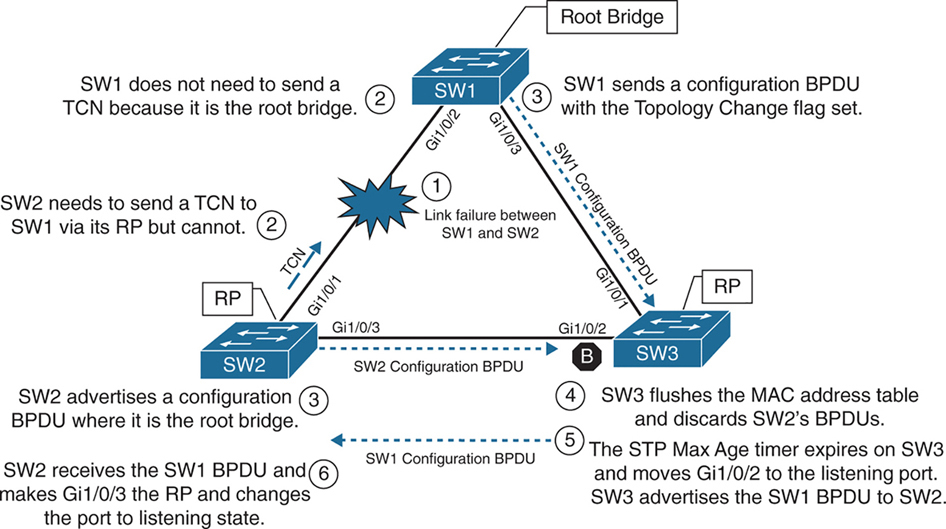
In the third scenario, the link between SW1 and SW2 fails
Network traffic from SW1 or SW3 toward SW2 is impacted because SW3’s Gi1/0/2 port is in a blocking state.
SW1 detects a link failure on its Gi1/0/2 interface.
SW2 detects a link failure on its Gi1/0/1 interface and SW3 does not use max age timer on its Gi1/0/1
1. TCNs from all switches to root but no way to send in this scenario so switch will wait:
– Normally SW1 would generate a TCN flag out its root port, but it is the root bridge, so it does not as root does not do that. SW1 would advertise a TCN if it were not the root bridge.
– At this point, SW2 would attempt to send send TCN towards the root switch to notify it of a topology change however its root port is down and unable to do as its RP port is down so it will wait for path to root to resolve and then send TCN
2. Affected interfaces remove their best BPDU and best BPDU (root) via different interface as BPDU are not coming on Desgnated port due to adjacent port is blocking:
– SW2 removes its best BPDU (was root port as best only comes on root port) without waiting for max age timer on its Gi1/0/1 interface because it is now in a down state.
– because root port was lost SW2 must look for a new root port
– but because the local port facing SW3 is Designated port and port on SW3 is blocking as blocking port does not send BPDUs but only receives BPDU, visibility or path to root is lost
3. Declaring itself root because of remote blocking port and then receiving and loosing root election
– SW2 will declare itself root and generate its own BPDU and send it to SW3
– SW3 receives SW2’s inferior BPDUs and discards them as it is still receiving superior BPDUs from SW1
– Because this BPDU from SW2 was not accepted this leads to expiry of max age timer on Gi1/0/2 of SW3 and transitions from blocking to listening state. SW3 can now forward the next configuration BPDU it receives from SW1 to SW2.
– SW2 receives SW1’s configuration BPDU via SW3 and recognizes it as superior. It marks its Gi1/0/3 interface as the root port and transitions it to the listening state.
4. TCN can now reach root
– once SW2 bring its port Gi1/0/2 to forwarding state then TCN is dispatched towards root from Gi1/0/2
– SW1 advertises a configuration BPDU with the Topology Change flag out of all its ports. It keeps TC set for the topology change period (commonly Max Age + Forward Delay = 35s by default).
– This BPDU is received and relayed to all switches in the environment , SW3 receives it and relays it to SW2
5. Non root switches reduce their MAC address age timer to forward delay
– These switches then reduce the MAC address age timer to the forward delay timer to flush out older MAC entries.
– If other switches were connected to SW1, they would receive a configuration BPDU with the Topology Change flag set also for all the VLANs on trunk port. These packets have an impact for all switches in the same Layer 2 domain.
The total convergence time for SW2 is 50 seconds: 20 seconds for the Max Age timer on SW3, 15 seconds for the listening state on SW2, and 15 seconds for the learning state.
Indirect Failures
In some scenarios involving signalling over WAN, switch do not see direct interface failures, but WAN signalling is not present while the interface is up and this is where hello and max age timer comes in
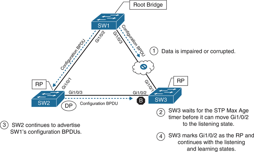
– An event occurs that impairs or corrupts data on the link. SW1 and SW3 still report a link up condition.
– SW3 stops receiving configuration BPDUs on its RP, SW3’s max age timer expires and removes the best BPDU after max age expiry
– because SW3 lost path to root it will have to find the path to root through another best path (lowest cost to root) and that is next port that is Gi1/0/2 in blocking port
– SW3 transitions Gi1/0/2 from blocking to listening state
– SW2 continues to advertise SW1’s configuration BPDUs toward SW3
– SW3 receives SW1’s configuration BPDU via SW2 on its Gi1/0/2 interface. This port is now marked as the RP
The total time for reconvergence on SW3 is 50 seconds: 20 seconds for the Max Age timer on SW3, 15 seconds for the listening state on SW3, and 15 seconds for the learning state on SW3.
Rapid Spanning Tree Protocol
Although 802.1D did a decent job of preventing Layer 2 forwarding loops, it was not designed to support multiple VLANs, also for traffic engineering requirements such as blocking one link for half vlans and blocking another link for other half of vlans for load balancing and equally utilising both uplinks
Cisco also created other versions like PVST and PVST+ which were Cisco proprietary
but standard versions that are compatible with other vendors such as RSTP and MST should be used in production
RSTP (802.1W) Port States
RSTP reduces the number of port states to three:
Discarding: Blocking, This state combines the traditional STP states disabled, blocking, and listening.
Learning: The switch port modifies the MAC address table with any network traffic it receives. The switch still does not forward any other network traffic besides BPDUs.
Forwarding: The switch port forwards all network traffic and updates the MAC address table as expected. This is the final state for a switch port to forward network traffic.
RSTP relies on handshake with a switch connected on the other end, If a handshake does not occur, the other device is assumed to be non-RSTP compatible and for backwards compatibility the port defaults to regular 802.1D behavior
RSTP (802.1W) Port Roles
RSTP defines the following port roles:
Root port (RP): A network port that connects to the root switch or an upstream switch in the spanning-tree topology. There should be only one root port per VLAN on a switch.
Designated port (DP): A network port that receives and forwards frames to other switches. Designated ports provide connectivity to downstream devices and switches. There should be only one active designated port on a link. Designated port drives packets away from root
Alternate port:
A network port that provides alternate connectivity toward the root switch “through a different switch”.
It does not forward traffic, So if the main (active) path to the root switch fails, the alternate port can take over.
Backup port:
These are very rare because this port is only seen when a switch connects with 2 links into hub or shared segment , a backup port is kept blocked to prevent loops, one link going to hub becomes Designated port and second link becomes backup port (blocks traffic)
RSTP (802.1W) Port Types
RSTP defines three types of ports that are used for building the STP topology:
Edge port: A port at the edge of the network where hosts connect to the Layer 2 topology with one interface and “cannot form a loop”. These ports directly correlate to ports that have the STP portfast feature enabled.
Non-Edge port: A port that has received a BPDU.
Point-to-point port: Any port that connects to another RSTP switch with full duplex. “Full-duplex links do not permit more than two devices on a network segment, so determining whether a link is full duplex is the fastest way to check the feasibility of being connected to a switch”.
Multi-access Layer 2 devices such as hubs can connect only at half duplex. If a port can connect only via half duplex, it must operate under traditional 802.1D forwarding states.
Building the RSTP Topology
With RSTP, switches exchange handshakes with other RSTP switches to transition through the following STP states and it is faster this way
When two switches first connect, they establish a bidirectional handshake across the shared link to identify the root bridge.
This is straightforward for an environment with only two switches; however, large environments require greater logic
RSTP uses a synchronization process to add a switch to the RSTP topology, The synchronization process starts when two switches (such as SW1 and SW2) are first connected. The process proceeds as follows:
– As the first two switches connect to each other, they verify that they are connected with a point-to-point link by checking the full-duplex status.
– They establish a handshake with each other to advertise a proposal (in configuration BPDUs) that their interface should be the DP for that segment.
– There can be only one DP per segment, so each switch identifies whether it is the superior or inferior switch, using the same logic as in 802.1D for the system identifier (that is, the lowest priority and then the lowest MAC address). Using the MAC addresses from figure, SW1 (0062.ec9d.c500) is the superior switch to SW2 (0081.c4ff.8b00).

– The inferior switch (SW2) recognizes that it is inferior and marks its local port (Gi1/0/1) as the RP. At that same time, it moves all non-edge ports to a discarding state. At this point in time, the switch has stopped all local switching for non-edge ports.
– The inferior switch (SW2) sends an agreement (configuration BPDU) to the root bridge (SW1), which signifies to the root bridge that synchronization is occurring on that switch.
– The inferior switch (SW2) moves its RP (Gi1/0/1) to a forwarding state. The superior switch moves its DP (Gi1/0/2) to a forwarding state too.
– The inferior switch (SW2) repeats the process for any downstream switches connected to it.
RSTP Convergence
The RSTP convergence process can occur quickly. RSTP ages out the port information after it has not received hellos in three consecutive cycles. Using default timers, the Max Age would take 20 seconds, but RSTP requires only 6 seconds. And thanks to the new synchronization, ports can transition from discarding to forwarding in an extremely low amount of time.
If a downstream switch fails to acknowledge the proposal, the RSTP switch must default to 802.1D behaviors to prevent a forwarding loop.
STP Topology Tuning
A properly designed network places the root bridge on a specific switch and influences which ports should be designated ports (forwarding state) and which ports should be alternate ports (that is, discarding state) based on hardware platform and topology.
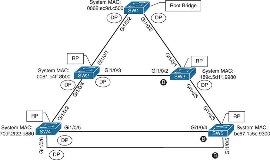
Ideally, the root bridge is placed on a core switch, and a “secondary” root bridge is designated.
Root bridge placement is accomplished by “lowering” the system priority on the root bridge to the lowest value possible,
raising the secondary root bridge to a value slightly higher than that of the root bridge,
and (ideally) increasing the system priority on all other switches unless you plan to keep switches on default priority.
By increasing non root switch priority and lowering switch priority for root and secondary root switches, it is made sure that when a new non-configured switch is connected to topology, it does not take over as root.
The priority is set with either of the following commands:
spanning-tree vlan vlan-id priority priority: The priority is a value between 0 and 61,440, in increments of 4096.
spanning-tree vlan vlan-id root {primary | secondary} [diameter diameter]: This command executes a script that sets the priority numerically, along with the potential for timers if the diameter keyword is used. The primary keyword sets the priority to 24,576, and the secondary keyword sets the priority to 28,672.
If a different switch has a priority of 24,576 (or lower) and is more preferred when the command spanning-tree vlan vlan-id root {primary | secondary} is executed, the script has logic to lower the priority to a lower value in an attempt to make it the root bridge, this is possible because current root is in BPDU and along with that system ID or name contains system priority value and system mac address
The optional diameter command makes it possible to tune the Spanning Tree Protocol (STP) convergence and modifies the timers; it should reference the maximum number of Layer 2 hops between a switch that is maximum hops away and the root bridge.
The timers do not need to be modified on other switches because they are carried throughout the topology through the root bridge’s bridge protocol data units (BPDUs) as you only configure timers in one place, you only change timers on root bridge
All the other switches automatically learn those timer values, because the root bridge advertises them inside its BPDUs, which are sent throughout the Layer 2 network. So there’s no need to manually configure timers on every switch. When other switches receive the root’s BPDUs:
– They propagate those same values further downstream
– They adopt the root’s timer values
The root bridge generates the “authoritative” BPDUs
These BPDUs include:
- Hello time
- Max age
- Forward delay (used for learning state)
! Verification of SW1 Priority before modifying the priority
SW1# show spanning-tree vlan 1
VLAN0001
  Spanning tree enabled protocol rstp
  Root ID    Priority    32769
               Address     0062.ec9d.c500
               This bridge is the root
               Hello Time   2 sec  Max Age 20 sec  Forward Delay 15 sec
  Bridge ID  Priority    32769  (priority 32768 sys-id-ext 1)
               Address     0062.ec9d.c500
               Hello Time   2 sec  Max Age 20 sec  Forward Delay 15 sec
               Aging Time  300 sec
! Configuring the SW1 priority as primary root for VLAN 1
SW1(config)# spanning-tree vlan 1 root primary! Verification of SW1 Priority after modifying the priority
SW1# show spanning-tree vlan 1
VLAN0001
Spanning tree enabled protocol rstp
Root ID Priority 24577 <<<
Address 0062.ec9d.c500
This bridge is the root
Hello Time 2 sec Max Age 20 sec Forward Delay 15 sec
Bridge ID Priority 24577 (priority 24576 sys-id-ext 1) <<<
Address 0062.ec9d.c500
Hello Time 2 sec Max Age 20 sec Forward Delay 15 sec
Aging Time 300 sec
Interface Role Sts Cost Prio.Nbr Type
------------------- ---- --- --------- -------- --------------------------------
Gi1/0/2 Desg FWD 4 128.2 P2p
Gi1/0/3 Desg FWD 4 128.3 P2p
Gi1/0/14 Desg FWD 4 128.14 P2p! Configuring the SW2 priority as secondary root for VLAN 1
SW2(config)# spanning-tree vlan 1 root secondarySW2# show spanning-tree vlan 1
VLAN0001
Spanning tree enabled protocol rstp
Root ID Priority 24577 <<<
Address 0062.ec9d.c500
Cost 4
Port 1 (GigabitEthernet1/0/1)
Hello Time 2 sec Max Age 20 sec Forward Delay 15 sec
Bridge ID Priority 28673 (priority 28672 sys-id-ext 1) <<<
Address 0081.c4ff.8b00
Hello Time 2 sec Max Age 20 sec Forward Delay 15 sec
Aging Time 300 sec
Interface Role Sts Cost Prio.Nbr Type
------------------- ---- --- --------- -------- --------------------------------
Gi1/0/1 Root FWD 4 128.1 P2p
Gi1/0/3 Desg FWD 4 128.3 P2p
Gi1/0/4 Desg FWD 4 128.4 P2pThe best way to prevent erroneous devices from taking over the STP root role is to set the priority to 0 for the primary root switch and to 4096 for the secondary root switch. “In addition, root guard should be used”
Modifying STP Root Port and Blocked Switch Port Locations
Cost calculation method forces how we implement cost on interface, The receiving switch adds the port cost for the interface on which the BPDU was received in conjunction with the value of the root path cost in the BPDU.

SW1 advertises its BPDUs to SW3 with a root path cost of 0.
SW3 receives the BPDU and adds its STP port cost of 4 to the root path cost in the BPDU (0), resulting in a value of 4.
SW3 then advertises the BPDU toward SW5 with a root path cost of 4, to which SW5 then adds its STP port cost of 4.
SW5 therefore reports a root path cost of 8 to reach the root bridge via SW3.
SW1# show spanning-tree vlan 1
! Output omitted for brevity
VLAN0001

  Root ID    Priority    32769
               Address     0062.ec9d.c500
               This bridge is the root
..
Interface           Role Sts Cost      Prio.Nbr Type
------------------- ---- --- --------- -------- --------------------------------
Gi1/0/2             Desg FWD 4         128.2    P2p
Gi1/0/3             Desg FWD 4         128.3    P2p
SW3# show spanning-tree vlan 1
! Output omitted for brevity
VLAN0001
Root ID Priority 32769
Address 0062.ec9d.c500
Cost 4
Port 1 (GigabitEthernet1/0/1)
..
Interface Role Sts Cost Prio.Nbr Type
------------------- ---- --- --------- -------- --------------------------------
Gi1/0/1 Root FWD 4 128.1 P2p
Gi1/0/2 Altn BLK 4 128.2 P2p
Gi1/0/5 Desg FWD 4 128.5 P2pSW5# show spanning-tree vlan 1
! Output omitted for brevity
VLAN0001
Root ID Priority 32769
Address 0062.ec9d.c500
Cost 8
Port 3 (GigabitEthernet1/0/3)
..
Interface Role Sts Cost Prio.Nbr Type
------------------- ---- --- --------- -------- --------------------------------
Gi1/0/3 Root FWD 4 128.3 P2p
Gi1/0/4 Altn BLK 4 128.4 P2p
Gi1/0/5 Altn BLK 4 128.5 P2pYou can lower a path that is currently an alternate port while making it designated,
or you can raise the cost on a port that is designated to turn it into a blocking port
The spanning-tree command modifies the cost for all VLANs unless the optional vlan keyword is used to specify a VLAN
SW3# conf t
SW3(config)# interface gi1/0/1
SW3(config-if)# spanning-tree cost 1
SW3# show spanning-tree vlan 1
! Output omitted for brevity
VLAN0001
Root ID Priority 32769
Address 0062.ec9d.c500
Cost 1
Port 1 (GigabitEthernet1/0/1)
Bridge ID Priority 32769 (priority 32768 sys-id-ext 1)
Address 189c.5d11.9980
..
Interface Role Sts Cost Prio.Nbr Type
------------------- ---- --- --------- -------- --------------------------------
Gi1/0/1 Root FWD 1 128.1 P2p
Gi1/0/2 Desg FWD 4 128.2 P2p
Gi1/0/5 Desg FWD 4 128.5 P2pSW2# show spanning-tree vlan 1
! Output omitted for brevity
VLAN0001
Root ID Priority 32769
Address 0062.ec9d.c500
Cost 4
Port 1 (GigabitEthernet1/0/1)
Bridge ID Priority 32769 (priority 32768 sys-id-ext 1)
Address 0081.c4ff.8b00
..
Interface Role Sts Cost Prio.Nbr Type
------------------- ---- --- --------- -------- --------------------------------
Gi1/0/1 Root FWD 4 128.1 P2p
Gi1/0/3 Altn BLK 4 128.3 P2p
Gi1/0/4 Desg FWD 4 128.4 P2pModifying STP Port Priority
STP port priority impacts which port is an alternate port when multiple links are used between same switches. Remember that system ID and port cost are the same, so the next check is port priority, followed by the port number. “Both the port priority and port number are controlled by the upstream switch”, because it is closer to the root bridge.
You can modify the port priority on SW4’s Gi1/0/6 (toward SW5’s Gi1/0/5 interface) with the command spanning-tree [vlan vlan-id] port-priority priority. The optional vlan keyword allows you to change the priority on a VLAN-by-VLAN basis
SW4# configure terminal
Enter configuration commands, one per line. End with CNTL/Z.
SW4(config)# interface gi1/0/6
SW4(config-if)# spanning-tree port-priority 64
Additional STP Protection Mechanisms
The following scenarios are common for Layer 2 forwarding loops:
- STP disabled on a switch
- A misconfigured load balancer that transmits traffic out multiple ports with the same MAC address
- A misconfigured virtual switch that bridges two physical ports (Virtual switches typically do not participate in STP.)
- End users using a dumb network switch or hub
Catalyst switches detect a MAC address that is flapping between interfaces and notify via syslog with the MAC address of the host, VLAN, where MAC is flapping
12:40:30.044: %SW_MATM-4-MACFLAP_NOTIF: Host 70df.2f22.b8c7 in vlan 1 is flapping
 between port Gi1/0/3 and port Gi1/0/2
Root Guard
Root Guard prevents a configured port from becoming a “root port”
it “is configured on designated port” facing switches that should never become root
Root guard prevents a downstream switch (often misconfigured or rogue) from becoming a root bridge in a topology
Root guard places a port in a root inconsistent state for interfaces or vlan that receives a “superior BPDU” when root guard is configured
Interfaces in root inconsistent state cannot forward traffic out of this port,
root guard does not block port permanently but it only blocks when superior BPDU are received
“I received a superior BPDU on this port, but I’m not allowed to accept it as the root path.”
Prevents an unauthorized or misconfigured switch from becoming the root bridge
How it recovers
Once the superior BPDU stops, the port:
– Automatically leaves root inconsistent
– Returns to normal forwarding (no manual reset needed)
! configure on designated port that is facing "down stream"
spanning-tree guard root
root guard should be configured on SW2’s Gi1/0/4 port toward SW4
root guard should be configured on SW3’s Gi1/0/5 port toward SW5
this configuration prevents SW4 and SW5 from becoming root
but still allows SW2 to maintain connectivity to SW1 via SW3 if link between SW2 and SW1 goes down
but if link between SW2 and SW3 also goes down then it will not work even if alternate path via SW4 exists, it will not work
Root Guard protects you from an “unexpected root” on that port, but the trade-off is that it can also kill an otherwise-valid backup path.
STP Portfast
Portfast as name suggests brings port up faster by skipping learning (listening also if not RSTP)
Portfast also stops generation of TCN when port goes down
Portfast is configured on host , access ports only
Portfast allows traffic forwarding immediately, this is useful for DHCP and PXE boot ports
If BPDU is received on portfast enabled port then portfast “functionality” is removed from port and it progressed through learning (and listening if not RSTP) states
! portfast on interface
interface gig 1/0/1
spanning-tree portfast

! enable globally
spanning-tree portfast default
If portfast needs to be disabled on a specific port when portfast is enabled globally, you can configure interface
spanning-tree portfast disableThis removes portfast from the port
Sometimes you will see portfast enabled on a trunk port but this should only be the case when a “single” port is connected to a server
spanning-tree portfast trunkenabling portfast on an interface changes port to RSTP port type to “Edge port – P2p Edge”
SW1(config)# interface gigabitEthernet 1/0/13
SW1(config-if)# switchport mode access
SW1(config-if)# switchport access vlan 10
SW1(config-if)# spanning-tree portfast
SW1# show spanning-tree vlan 10
! Output omitted for brevity
VLAN0010
Interface Role Sts Cost Prio.Nbr Type
------------------- ---- --- --------- -------- --------------------------------
Gi1/0/2 Desg FWD 4 128.2 P2p
Gi1/0/3 Desg FWD 4 128.3 P2p
Gi1/0/13 Desg FWD 4 128.13 P2p EdgeSW1# show spanning-tree interface gi1/0/13 detail
Port 13 (GigabitEthernet1/0/13) of VLAN0010 is designated forwarding
Port path cost 4, Port priority 128, Port Identifier 128.13.
Designated root has priority 32778, address 0062.ec9d.c500
Designated bridge has priority 32778, address 0062.ec9d.c500
Designated port id is 128.13, designated path cost 0
Timers: message age 0, forward delay 0, hold 0
Number of transitions to forwarding state: 1
The port is in the portfast mode <<<
Link type is point-to-point by default
BPDU: sent 23103, received 0SW2# conf t
Enter configuration commands, one per line. End with CNTL/Z.
SW2(config)# spanning-tree portfast default
%Warning: this command enables portfast by default on all interfaces. You
should now disable portfast explicitly on switched ports leading to hubs,
switches and bridges as they may create temporary bridging loops.
SW2(config)# interface gi1/0/8
SW2(config-if)# spanning-tree portfast disableBPDU Guard
Remember that Guard is placed outside to stop things coming in, not going out
so remember that BPDU Guard is always to stop from receiving or entering of BPDU
BPDU guard is a safety mechanism that places ports configured with STP portfast into an ErrDisabled state upon receipt of a BPDU
Err-disabled port is “disabled” or in shutdown like state
This ensures that loop cannot be accidentally created if a switch is connected because just configuring portfast is not enough, switche removes portfast functionality from port as BPDU is received on port even though it shows in configuration, you have to look at the show spanning-tree interface detail command to see it
BPDU guard is typically configured with all host-facing ports that are enabled with portfast.
! BPDU guard is enabled globally on all STP portfast ports
spanning-tree portfast bpduguard default

! but can be disabled on specific port if enabled globally
spanning-tree bpduguard disable

! enabling on a single port
spanning-tree bpduguard enable
SW1# configure terminal
Enter configuration commands, one per line. End with CNTL/Z.
SW1(config)# spanning-tree portfast bpduguard default
SW1(config)# interface gi1/0/8
SW1(config-if)# spanning-tree bpduguard disableSW1# show spanning-tree interface gi1/0/7 detail
Port 7 (GigabitEthernet1/0/7) of VLAN0010 is designated forwarding
Port path cost 4, Port priority 128, Port Identifier 128.7.
Designated root has priority 32778, address 0062.ec9d.c500
Designated bridge has priority 32778, address 0062.ec9d.c500
Designated port id is 128.7, designated path cost 0
Timers: message age 0, forward delay 0, hold 0
Number of transitions to forwarding state: 1
The port is in the portfast mode
Link type is point-to-point by default
Bpdu guard is enabled by default <<<
BPDU: sent 23386, received 0SW1# show spanning-tree interface gi1/0/8 detail
Port 8 (GigabitEthernet1/0/8) of VLAN0010 is designated forwarding
Port path cost 4, Port priority 128, Port Identifier 128.8.
Designated root has priority 32778, address 0062.ec9d.c500
Designated bridge has priority 32778, address 0062.ec9d.c500
Designated port id is 128.8, designated path cost 0
Timers: message age 0, forward delay 0, hold 0
Number of transitions to forwarding state: 1
The port is in the portfast mode by default
Link type is point-to-point by default
BPDU: sent 23388, received 0syslog messages are generated when a BPDU is received on a BPDU guard–enabled port. The port is then placed into an ErrDisabled state, as shown with the command show interfaces status
12:47:02.069: %SPANTREE-2-BLOCK_BPDUGUARD: Received BPDU on port GigabitEthernet1/0/2 with BPDU Guard enabled. Disabling port.
12:47:02.076: %PM-4-ERR_DISABLE: bpduguard error detected on Gi1/0/2, putting Gi1/0/2 in err-disable state
12:47:03.079: %LINEPROTO-5-UPDOWN: Line protocol on Interface GigabitEthernet1/0/2, changed state to down
12:47:04.082: %LINK-3-UPDOWN: Interface GigabitEthernet1/0/2, changed state to down
SW1# show interfaces status
Port Name Status Vlan Duplex Speed Type
Gi1/0/1 notconnect 1 auto auto 10/100/1000BaseTX
Gi1/0/2 SW2 Gi1/0/1 err-disabled 1 auto auto 10/100/1000BaseTX <<<
Gi1/0/3 SW3 Gi1/0/1 connected trunk a-full a-1000 10/100/1000BaseTXBy default, ports that are put in the ErrDisabled state because of BPDU guard do not automatically restore themselves, reason is for administrators to be notified of a switch connecting to an access port that is only meant to connect hosts
But Error Recovery service can be used to reactivate ports that are shut down for a specific problem reducing manual work using command errdisable recovery cause bpduguard and interval can be configured using errdisable recovery interval time-seconds , this time controls how long a port stays in err state before it is shut and unshut to bring it up by switch itself
SW1# configure terminal
Enter configuration commands, one per line. End with CNTL/Z.
SW1(config)# errdisable recovery cause bpduguard
SW1# show errdisable recovery
! Output omitted for brevity
ErrDisable Reason Timer Status
----------------- --------------
arp-inspection Disabled
bpduguard Enabled
..
Recovery command: "clear Disabled
Timer interval: 300 seconds
Interfaces that will be enabled at the next timeout:
Interface Errdisable reason Time left(sec)
--------- ----------------- --------------
Gi1/0/2 bpduguard 295! Syslog output from BPDU recovery. The port will be recovered, and then
! triggered again because the port is still receiving BPDUs.
SW1#
01:02:08.122: %PM-4-ERR_RECOVER: Attempting to recover from bpduguard err-disable
state on Gi1/0/2
01:02:10.699: %SPANTREE-2-BLOCK_BPDUGUARD: Received BPDU on port Gigabit
Ethernet1/0/2 with BPDU Guard enabled. Disabling port.
01:02:10.699: %PM-4-ERR_DISABLE: bpduguard error detected on Gi1/0/2, putting
Gi1/0/2 in err-disable stateError Recovery service operates every 300 seconds (5 minutes). This can be changed to a value of 30 to 86,400 seconds with the global configuration command errdisable recovery interval time.
BPDU Filter
BPDU Filter is something that stops sending and receiving of BPDUs
BPDU filter blocks BPDUs from being transmitted out a port.
BPDU filter means Don’t participate in STP on this port.
BPDU filter can be enabled globally or on a specific interface.
The global BPDU filter configuration uses the command spanning-tree portfast bpdufilter default.
The interface-specific BPDU filter is enabled with the interface configuration command spanning-tree bpdufilter enable.
If BPDU filter is enabled on a portfast enabled port, the behavior changes depending on the configuration:
- If BPDU filter is enabled globally using command
spanning-tree portfast bpdufilter default- Cisco does not blindly stop sending BPDUs forever on all interfaces Instead, it does a “safety probe.” , The port initially sends ~10–12 BPDUs to ask “Is there another switch out there?”
- If no BPDU is received back
- The port assumes it’s an end device
- BPDU filtering kicks in
- STP is effectively disabled on that port
- —————————————
- If a BPDU is received
- switch thinks there is another switch connected
- STP logic turns back on for that port
- Now because there is a switch connected and a BPDU is received
- Switch must decide which switch is superior:
- to decide which port will be designated and which port will be blocking on that segment
Global BPDU filter is “safe-ish”:
- It allows PortFast convenience
- But auto-recovers STP if a switch is accidentally plugged in
Enabling interface level BPDU filter is dangerous unless you know the topology and you know what you are doing interface gi1/0/1
spanning-tree bpdufilter enable
– No safety check
– No listening
– STP is completely disabled, no sending of BPDUs and no receiving of BPDUs
– Easy way to create a loop
Be careful with the deployment of BPDU filter because it could cause problems. Most network designs do not require BPDU filter, which adds an unnecessary level of complexity and also introduces risk.
after BPDU filter is enabled on the Gi1/0/2 interface prohibiting any BPDUs from being sent or received
! SW1 was enabled with BPDU filter only on port Gi1/0/2
SW1# show spanning-tree interface gi1/0/2 detail | in BPDU|Bpdu|Ethernet
 Port 2 (GigabitEthernet1/0/2) of VLAN0001 is designated forwarding
    Bpdu filter is enabled
    BPDU: sent 113, received 84 <<<
SW1# show spanning-tree interface gi1/0/2 detail | in BPDU|Bpdu|Ethernet
 Port 2 (GigabitEthernet1/0/2) of VLAN0001 is designated forwarding
    Bpdu filter is enabled
 BPDU: sent 113, received 84   <<< same
! SW2 was enabled with BPDU filter globally
SW2# show spanning-tree interface gi1/0/2 detail | in BPDU|Bpdu|Ethernet
Port 1 (GigabitEthernet1/0/2) of VLAN0001 is designated forwarding
BPDU: sent 56, received 5
SW2# show spanning-tree interface gi1/0/2 detail | in BPDU|Bpdu|Ethernet
Port 1 (GigabitEthernet1/0/2) of VLAN0001 is designated forwarding
BPDU: sent 58, received 5 <<< probes sentProblems with Unidirectional Links
Fiber-optic cables consist of strands of glass/plastic with one strand that transmits and one strand that receives and order is opposite on remote side. Networks that rely on fibre optics can sometimes encounter unidirectional traffic if one strand breaks so it feels like one site is sending and other site is receiving but there is no return traffic
If tx is bad and rx is good, interface will show as up but BPDUs are not able to be transmitted, and the downstream switch eventually times out the existing root port and identifies a different port as the root port. Traffic is then received on the new root port of remote switch and also forwarded out of the working tx strand that is still working of the former root port of remote switch, thereby creating a forwarding loop
A couple solutions can resolve this scenario:
- STP loop guard
- Unidirectional Link Detection
STP Loop Guard
STP loop guard prevents any “alternative” (candidate root) or “root ports” from becoming designated ports. Loop guard places the original port in a “loop inconsistent” state while BPDUs are not being received on remote switch on root or alternate ports. When BPDU transmission starts again on that interface, the port recovers and begins to transition through the STP states again.
Loop guard is enabled globally by using the command spanning-tree loopguard default, or it can be enabled on an interface basis with the interface command spanning-tree guard loop. It is important to note that loop guard should not be enabled on portfast-enabled ports (because it directly conflicts with the root/alternate port logic).
SW2# config t
SW2(config)# interface gi1/0/1
SW2(config-if)# spanning-tree guard loop
! Placing BPDU filter on SW2’s RP (Gi1/0/1) triggers loop guard.
SW2(config-if)# interface gi1/0/1
SW2(config-if)# spanning-tree bpdufilter enable
01:42:35.051: %SPANTREE-2-LOOPGUARD_BLOCK: Loop guard blocking port Gigabit
    Ethernet1/0/1 on VLAN0001
SW2# show spanning-tree vlan 1 | b Interface
Interface Role Sts Cost Prio.Nbr Type
------------------- ---- --- --------- -------- --------------------
Gi1/0/1 Root BKN*4 128.1 P2p *LOOP_Inc
Gi1/0/3 Root FWD 4 128.3 P2p
Gi1/0/4 Desg FWD 4 128.4 P2pPorts in an inconsistent state and does not forward any traffic.
Inconsistent ports are viewed with the command show spanning-tree inconsistentports
SW2# show spanning-tree inconsistentports

Name                    Interface                Inconsistency
-------------------- ------------------------ ------------------
VLAN0001             GigabitEthernet1/0/1     Loop Inconsistent
VLAN0010             GigabitEthernet1/0/1     Loop Inconsistent
VLAN0020             GigabitEthernet1/0/1     Loop Inconsistent
VLAN0099             GigabitEthernet1/0/1     Loop Inconsistent

Number of inconsistent ports (segments) in the system : 4
Unidirectional Link Detection
Unidirectional Link Detection (UDLD) allows for the bidirectional monitoring of fiber-optic cables.
UDLD operates by transmitting UDLD packets to a neighbor device that includes the system ID and port ID of the interface transmitting the UDLD packet. The receiving device then repeats that information, including its system ID and port ID, back to the originating device. The process continues indefinitely.
UDLD must be enabled on the remote switch as well. After it is configured, the status of UDLD neighborship can be verified with the command show udld neighbors, neighbor information because like CDP system ID is exchanged. You can view more detailed information with the command show udld interface-id.
UDLD operates in two different modes:
- Normal: In normal mode, if a frame is not acknowledged, the link is considered undetermined and the port remains active – almost useless
- Aggressive: In aggressive mode, when a frame is not acknowledged, the switch sends another eight packets in 1-second intervals. If those packets are not acknowledged, the port is placed into an error state.
UDLD is enabled globally with the command udld enable [aggressive].
This command enables UDLD on any small form-factor pluggable (SFP)–based port.
UDLD can be disabled on a specific SFP port with the interface configuration command udld port disable.
UDLD recovery can be enabled with the command udld recovery [interval time], where the optional interval keyword allows for the timer to be modified from the default value of 5 minutes.
UDLD can be enabled on a port-by-port basis with the interface configuration command udld port [aggressive], where the optional aggressive keyword places the ports in UDLD aggressive mode.
SW1# conf t
Enter configuration commands, one per line. End with CNTL/Z.
SW1(config)# udld enable
SW1# show udld neighbors
Port Device Name Device ID Port ID Neighbor State
---- ----------- --------- ------- --------------
Te1/1/3 081C4FF8B0 1 Te1/1/3 Bidirectional <<<SW1# show udld Te1/1/3
Interface Te1/1/3
---
Port enable administrative configuration setting: Follows device default
Port enable operational state: Enabled
Current bidirectional state: Bidirectional
Current operational state: Advertisement - Single neighbor detected
Message interval: 15000 ms
Time out interval: 5000 ms
Port fast-hello configuration setting: Disabled
Port fast-hello interval: 0 ms
Port fast-hello operational state: Disabled
Neighbor fast-hello configuration setting: Disabled
Neighbor fast-hello interval: Unknown
Entry 1
---
Expiration time: 41300 ms
Cache Device index: 1
Current neighbor state: Bidirectional
Device ID: 081C4FF8B0
Port ID: Te1/1/3
Neighbor echo 1 device: 062EC9DC50
Neighbor echo 1 port: Te1/1/3
TLV Message interval: 15 sec
No TLV fast-hello interval
TLV Time out interval: 5
TLV CDP Device name: SW2next post
MST
MST
In moden networks usually there is less reliance on Layer 2 / spanning tree, and there is no need for load balancing of VLANs, modern networks either use port-channels or Layer 3 networking down to access layer, MST is used to fulfil the requirement of stopping loops in case something is connected by mistake
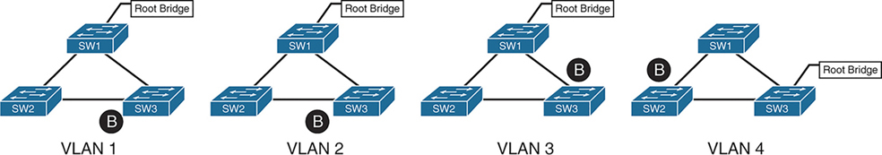
4 different VLANs , 4 different topologies and 4 different STP instances
If number of vlans increase to 10 then switch CPU will need to maintain 10 different STP instances and 10 different topologies
Not only that, switch must listen for BPDUs of every VLAN and topology changes can cause TCN and config BPDU with topology change flag
MST provides a blended approach by mapping one or multiple VLANs onto a single STP tree, called an MST instance (MSTI).

VLANs 1 and 2 correlate to one MSTI, VLAN 3 to a second MSTI, and VLAN 4 to a third MSTI.
A grouping of MST switches with the same high-level configuration is known as an MST region.
MST region appear as a single virtual switch to external switches as part of a compatibility mechanism
How MST topology is perceived outside of MST region
Everything inside the MST region looks like one virtual switch to the outside world
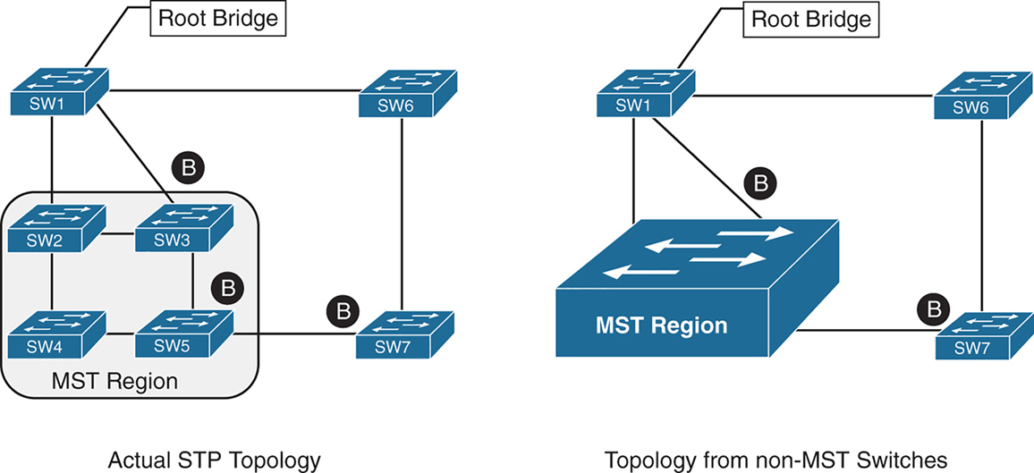
Above we can see that SW3 is blocking port to Root, which is not normal, if it was normal STP, it would become root port and not discarding, and instead it blocking port would be on SW2 – SW3 segment
For switches inside the MST region calculate STP internally
For outside switches they pretend to be a single switch
MST Instances (MSTIs)
MST uses a special STP instance called the internal spanning tree (IST), which is always the first instance, instance 0. The IST runs on all switch port interfaces for switches in the MST region, regardless of the VLANs associated with the ports.
Additional information about other MSTIs is included (nested) in the IST BPDU that is transmitted throughout the MST region. That single IST BPDU carries information for all MSTIs running
This enables the MST to advertise only one set of BPDUs, minimizing STP traffic regardless of the number of instances while providing the necessary information to calculate the STP for other MSTIs.
The number of MST instances varies by platform, but platform should support at least 16 instances allowing 15 different topologies, The IST is always instance 0, so instances 1 to 15 can support other VLANs
There is not a special name for instances 1 to 15; they are simply known as MSTIs.
MST Configuration
SW1(config)# spanning-tree mode mst
! change mode to MST

SW1(config)# spanning-tree mst 0 root primary
! The primary keyword sets the priority to 24,576, and
! the secondary keyword sets the priority to 28,672

SW1(config)# spanning-tree mst 1 root primary
SW1(config)# spanning-tree mst 2 root primary
! or set the system priority manually instead of root
! primary or root secondary keywords
! spanning-tree mst 2 priority 16384

SW1(config)# spanning-tree mst configuration
! enter MST configuration submode

SW1(config-mst)# name ENTERPRISE_CORE
! define MST region name, it must match on all switches
! in the region

SW1(config-mst)# revision 2
! this MST version number must match on all switches
! in an MST Region, By default, a region name is an empty
! string

! Associate vlans to MST instances, by default all vlans
! are associated to MST 0 instance, for varying topologies
! assign vlans to different instances
SW1(config-mst)# instance 1 vlan 10,20
SW1(config-mst)# instance 2 vlan 99
The command show spanning-tree mst configuration provides a quick verification of the MST configuration on a switch
Notice that MST instance 0 contains all the VLANs except for VLANs 10, 20, and 99, regardless of whether those VLANs are configured on the switch
MST instance 1 contains VLAN 10 and 20, and MST instance 2 contains only VLAN 99.
SW2# show spanning-tree mst configuration
Name      [ENTERPRISE_CORE]
Revision  2     Instances configured 3

Instance  Vlans mapped
--------  ---------------------------------------------------------------------
0         1-9,11-19,21-98,100-4094
1         10,20
2         99
MST Verification
The relevant spanning tree information can be obtained with the command show spanning-tree. However, the VLAN numbers are not shown and the MST instance is provided instead.
In addition, the priority value for a switch is the MST instance plus the switch priority (not the vlan number + switch priority)
SW1# show spanning-tree
! Output omitted for brevity
! Spanning Tree information for Instance 0 (All VLANs but 10,20, and 99)
MST0
  Spanning tree enabled protocol mstp
  Root ID    Priority    24576
               Address     0062.ec9d.c500
               This bridge is the root
               Hello Time   2 sec  Max Age 20 sec  Forward Delay 15 sec

  Bridge ID  Priority    24576  (priority 24576 sys-id-ext 0)
               Address     0062.ec9d.c500
               Hello Time   2 sec  Max Age 20 sec  Forward Delay 15 sec

Interface           Role Sts Cost      Prio.Nbr Type
------------------- ---- --- --------- -------- --------------------------------
Gi1/0/2             Desg FWD 20000     128.2    P2p
Gi1/0/3             Desg FWD 20000     128.3    P2p

! Spanning Tree information for Instance 1 (VLANs 10 and 20)
MST1
  Spanning tree enabled protocol mstp
  Root ID Priority 24577
            Address     0062.ec9d.c500
            This bridge is the root
            Hello Time   2 sec  Max Age 20 sec  Forward Delay 15 sec

  Bridge ID  Priority    24577  (priority 24576 sys-id-ext 1)
               Address     0062.ec9d.c500
               Hello Time   2 sec  Max Age 20 sec  Forward Delay 15 sec

Interface           Role Sts Cost      Prio.Nbr Type
------------------- ---- --- --------- -------- --------------------------------
Gi1/0/2             Desg FWD 20000      128.2    P2p
Gi1/0/3             Desg FWD 20000      128.3    P2p
! Spanning Tree information for Instance 2 (VLAN 99)  >>> instead of 24576 + 99
MST2                                                  >>> it is 24576 + 2
  Spanning tree enabled protocol mstp
  Root ID    Priority    24578
              Address     0062.ec9d.c500
              This bridge is the root
              Hello Time   2 sec  Max Age 20 sec  Forward Delay 15 sec

  Bridge ID  Priority    24578  (priority 24576 sys-id-ext 2)
               Address     0062.ec9d.c500
               Hello Time   2 sec  Max Age 20 sec  Forward Delay 15 sec

Interface           Role Sts Cost       Prio.Nbr Type
------------------- ---- --- --------- -------- --------------------------------
Gi1/0/2             Desg FWD 20000      128.2    P2p
Gi1/0/3             Desg FWD 20000      128.3    P2p
A consolidated view of the MST topology table is displayed with the command show spanning-tree mst [instance-number].
The optional instance-number can be included to restrict the output to a specific instance.
SW1# show spanning-tree mst
! Output omitted for brevity
##### MST0    vlans mapped:   1-9,11-19,21-98,100-4094
Bridge         address 0062.ec9d.c500  priority      0     (24576 sysid 0)
Root           this switch for the CIST
Operational   hello time 2 , forward delay 15, max age 20, txholdcount 6
Configured    hello time 2 , forward delay 15, max age 20, max hops    20

Interface                        Role Sts Cost      Prio.Nbr Type
----------------                 ---- --- --------- -------- ------------------------
Gi1/0/2                          Desg FWD 20000     128.2    P2p
Gi1/0/3                          Desg FWD 20000     128.3    P2p
##### MST1    vlans mapped:   10,20
Bridge         address 0062.ec9d.c500  priority      24577 (24576 sysid 1)
Root            this switch for MST1

Interface                        Role Sts Cost      Prio.Nbr Type
----------------                 ---- --- --------- -------- ------------------------
Gi1/0/2                          Desg FWD 20000     128.2    P2p
Gi1/0/3                          Desg FWD 20000     128.3    P2p

##### MST2    vlans mapped:   99
Bridge         address 0062.ec9d.c500  priority      24578 (24576 sysid 2)
Root           this switch for MST2

Interface                        Role Sts Cost      Prio.Nbr Type
----------------                 ---- --- --------- -------- ------------------------
Gi1/0/2                          Desg FWD 20000     128.2     P2p
Gi1/0/3                          Desg FWD 20000     128.3     P2p
SW2# show spanning-tree mst interface gigabitEthernet 1/0/1
GigabitEthernet1/0/1 of MST0 is root forwarding
Edge port: no (default) port guard : none (default)
Link type: point-to-point (auto) bpdu filter: disable (default)
Boundary : internal bpdu guard : disable (default)
Bpdus sent 17, received 217
Instance Role Sts Cost Prio.Nbr Vlans mapped
-------- ---- --- --------- -------- -------------------------------
0 Root FWD 20000 128.1 1-9,11-19,21-98,100-4094
1 Root FWD 20000 128.1 10,20
2 Root FWD 20000 128.1 99MST Tuning
MST supports the port cost and port priority
The interface configuration command spanning-tree mst instance-number cost cost sets the interface cost
SW3# show spanning-tree mst 0
! Output omitted for brevity
Interface                        Role Sts Cost      Prio.Nbr Type
----------------                 ---- --- --------- -------- --------------------
Gi1/0/1                          Root FWD 20000      128.1    P2p
Gi1/0/2                          Altn BLK 20000      128.2    P2p
Gi1/0/5                          Desg FWD 20000      128.5    P2p
SW3# configure term
Enter configuration commands, one per line. End with CNTL/Z.
SW3(config)# interface gi1/0/1
SW3(config-if)# spanning-tree mst 0 cost 1SW3# show spanning-tree mst 0
! Output omitted for brevity
Interface Role Sts Cost Prio.Nbr Type
---------------- ---- --- --------- -------- ---------------------
Gi1/0/1 Root FWD 1 128.1 P2p
Gi1/0/2 Desg FWD 20000 128.2 P2p
Gi1/0/5 Desg FWD 20000 128.5 P2pThe interface configuration command spanning-tree mst instance-number port-priority priority sets the interface priority.
SW4# show spanning-tree mst 0
! Output omitted for brevity
##### MST0    vlans mapped:   1-9,11-19,21-98,100-4094
Interface                        Role Sts Cost      Prio.Nbr Type
----------------                 ---- --- --------- -------- --------------------
Gi1/0/2                          Root FWD 20000     128.2     P2p
Gi1/0/5                          Desg FWD 20000     128.5     P2p
Gi1/0/6                          Desg FWD 20000     128.6     P2p
SW4# configure term
Enter configuration commands, one per line. End with CNTL/Z.
SW4(config)# interface gi1/0/5
SW4(config-if)# spanning-tree mst 0 port-priority 64SW4# show spanning-tree mst 0
! Output omitted for brevity
##### MST0 vlans mapped: 1-9,11-19,21-98,100-4094
Interface Role Sts Cost Prio.Nbr Type
---------------- ---- --- --------- -------- --------------------
Gi1/0/2 Root FWD 20000 128.2 P2p
Gi1/0/5 Desg FWD 20000 64.5 P2p
Gi1/0/6 Desg FWD 20000 128.6 P2pCommon MST Misconfigurations
Network engineers should be aware of two common misconfigurations within the MST region:
- VLAN assignment to the IST
- Trunk link pruning
VLAN Assignment to the IST
Remember that the IST operates across all links in the MST region, regardless of the VLAN assigned to the actual port.
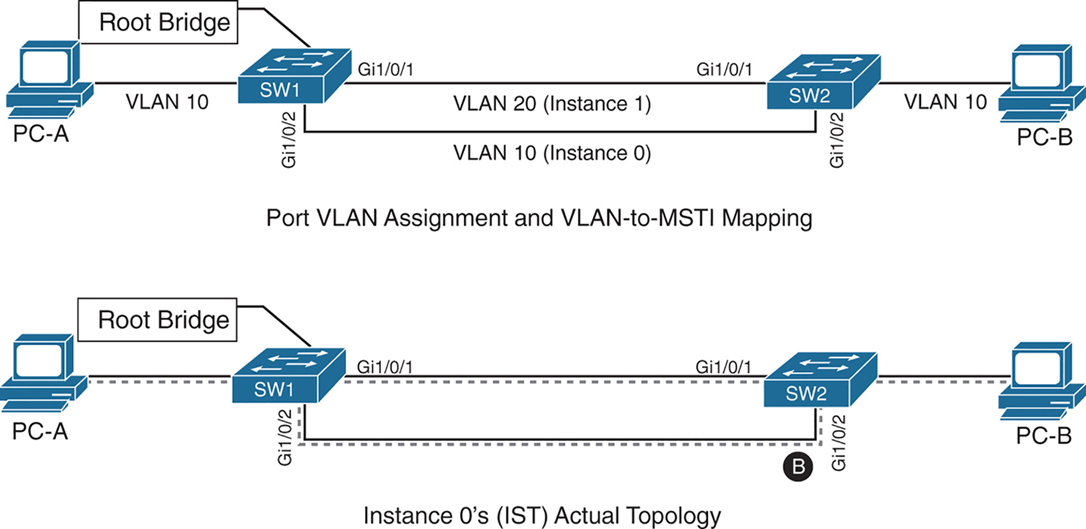
SW1 and SW2 contain two network links between them allowing VLAN 10 and VLAN 20
Gi1/0/1 and Gi1/0/2 are not trunks but they are access ports with VLANs 10 and 20 assigned
VLAN 10 is assigned to the IST, and VLAN 20 is assigned to MSTI 1
Looking at above diagram it looks like that traffic from PC 1 on VLAN 10 will traverse over the Gi1/0/2 but no, traffic will actually be blocked, we need to correct this using:
– port priority
– move VLAN 10 to MSTI 1, the switches will build a topology based on the links in use by that MST
– allow vlans on all interfaces – Trunk , configure both Gi1/0/1 and Gi1/0/2 as trunks on SW1 and SW2
The IST (Instance 0) runs over all physical links inside the MST region — regardless of VLAN assignment.
IST topology is calculated
SW1 is the root bridge
All SW1 ports = Designated Ports (DPs)
SW2 must block one of its links to prevent a loop
The IST sees:
- Two parallel physical links
- Same cost
- Same root
So one must block, even if:
- One link is “for VLAN 10”
- The other is “for VLAN 20”
To IST, they’re just two paths to same switch
Trunk Link Pruning

A network engineer made a mistake and has pruned VLANs on the trunk links between SW1 to SW2 and SW1 to SW3 to help load balance traffic.
Shortly after implementing the change, users attached to SW1 and SW3 cannot talk to the servers on SW2. The reason is that although the VLANs on the trunk links have changed, the MSTI topology has not.
You pruned VLAN 10 on one trunk but pruned VLAN 20 on a different trunk
the MST topology stays the same, but the VLAN forwarding paths no longer match it.
So rules for pruning vlans with MST are as follow:
– Never prune VLANs inconsistently if they belong to the same MST instance (MSTI).
– On any given trunk link, either allow all VLANs in an MSTI, or prune all of them together.
When configuring trunk pruning in MST:
- Think in MSTIs, not individual VLANs
- Prune per MST instance, not per VLAN
- If VLANs share an MSTI → they must travel together
MST Region Boundary
Externally, an MST region must look like one spanning-tree instance, This is non-negotiable — it’s how MST scales.
A PVST+ switch expects every VLAN has its own spanning tree
So a PVST+ switch sends:
- A BPDU for VLAN 1
- A BPDU for VLAN 10
- A BPDU for VLAN 20
- etc.
MST cannot accept per-VLAN information so MST must ignore VLAN-specific topology from outside. MST has to ask: If I can only believe ONE BPDU from outside, which one do I choose VLAN 1
Not because VLAN 1 is special logically, but because:
- VLAN 1 always exists
- VLAN 1 cannot be deleted
- VLAN 1 is guaranteed to be present end-to-end
So VLAN 1 becomes the anchor VLAN.
The IST (Instance 0) is:
“The single spanning tree that also represents the MST region to the outside world.”
When an MST switch hears PVST+ BPDUs:
- It hears many BPDUs (VLAN 1, 10, 20…)
- It must pick exactly one
- It picks VLAN 1
- That BPDU becomes the IST’s view of the outside world
But what about the other VLANs? (your natural next question) for PVST+ > MST and MST > PVST+
for MST > PVST+ , PVST+ expects a BPDU per VLAN.
So MST does this trick:
- Take the IST BPDU
- Copy it
- Send it back as:
- “VLAN 10 BPDU”
- “VLAN 20 BPDU”
- etc.
This is PVST Simulation.
The PVST simulation mechanism sends out PVST+ (and also includes RPVST) BPDUs (one for each VLAN), using the information from the IST.
for PVST+ > MST it is not needed, as long as VLAN 1’s BPDU helps in all the functions reliant on BPDU and contains
– STP type
– root path cost
– root bridge identifier
– local bridge identifier
– max age
– hello time
– forward delay
The mental model that usually makes it click
Think of MST like a company spokesperson:
- Inside the company: many departments (MSTIs)
- Outside the company: one voice
- VLAN 1 is the spokesperson’s microphone
An MST region boundary is any port that connects to a switch that is in a different MST region or that connects to 802.1D or 802.1W BPDUs.
There are two design considerations when integrating an MST region with a PVST+/RPVST environment: The MST region is the root bridge, or the MST region is not a root bridge for any VLAN. These scenarios are explained in the following sections.
MST Region as the Root Bridge

Shows the IST instance as the root bridge for all VLANs. SW1 and SW2 advertise multiple superior BPDUs for each VLAN toward SW3, which is operating as a PVST+ switch. SW3 is responsible for blocking ports
Making the MST region the root bridge ensures that Blocking does not take place on MST region or virtual switch, avoiding block on MST is the goal
MST Region Not a Root Bridge for Any VLAN
In this scenario, the MST region boundary ports can only block or forward for “all VLANs” together. Remember that only the VLAN 1 PVST BPDU is used for the IST and that the IST BPDU is a one-to-many translation of IST BPDUs to all PVST BPDUs. There is not an option to load balance traffic because the IST instance must remain consistent.
If an MST switch detects a better BPDU for a specific VLAN on a boundary port, the switch will use BPDU guard to block this port. The port will then be placed into a root inconsistent state. Although this may isolate downstream switches, it is done to ensure a loop-free topology; this is called the PVST simulation check.
next post
DMVPN
DMVPN
DMVPN provides full mesh broadcast network type connectivity over WAN transport by using mGRE or multipoint GRE, as a result we get sites on spokes with direct spoke to spoke to communication that is on top secured with IPSec encryption, popular because of ease of configuration and scalability
Before we get into DMVPN, we need to know GRE well
With DMVPN, spokes have to register to hub just like SIP phone registers to the SIP server
Generic Routing Encapsulation (GRE) Tunnels
GRE not just provides connectivity for IP but also legacy and nowadays nonrouteble protocols like DECnet, Systems Network Architecture SNA and IPX
Running protocols over VPN was a big issue due to VPN being point to point and networks had to be designed around the point to point topologies but routing protocols function well over broadcast like topologies , mGRE resolves that problem
Additional header is added when packets travel over the GRE tunnel
GRE tunnels support IPv4 or IPv6 addresses as an overlay or transport network.
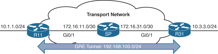
GRE creates a virtual network or overlay network over a real physical underlay network
In the routing tables of participating routers R11 and R31 , 10.1.1.0/24 is behind 192.168.0.11 and 10.3.3.0/24 is behind 192.168.0.31 , The Transport side or WAN side routing table does not have 192.168.0.0/16 network range , and that is how when tunnels are up those stub networks are accessible, and if tunnels are not up then they are not accessible
interface Tunnel100
! create tunnel interface


 bandwidth 4000
 ! Virtual interfaces do not have the concept of latency
 ! and need to have a reference bandwidth configured so that
 ! routing protocols that use bandwidth for best-path calculation
 ! can make intelligent decisions
 ! measured and configured in kilo bits
 ! Bandwidth is also used for quality of service (QoS) configuration
 ! on the interface


 ip address 192.168.100.11 255.255.255.0
 ! GRE tunnel needs IP as it is just like any other interface
 ! this is overlay IP


 ip mtu 1400
 ! reduce the mtu for tunnel interface
 ! exact added size differs based on tunnel type and encryption used
 ! min 24 bytes to 77 bytes


 keepalive 5 3
 ! The default timer is 10 seconds and three retries
 ! Tunnel interfaces are GRE point-to-point (P2P) by default,
 ! and the line protocol enters an up state when the router detects
 ! that a route to the tunnel destination exists in the routing
 ! table. If the tunnel destination is not in the routing table,
 ! the tunnel interface (line protocol) enters a down state.
 ! What if there is a problem on remote end and remote router is down
 ! By default, GRE tunnels stay “up” as long as the interface is configured
 ! and tunnel destination is in routing table
 ! Tunnel keepalives ensure that bidirectional communication exists
 ! between tunnel endpoints to keep the line protocol up


 tunnel source GigabitEthernet0/1
 ! tunnel's source interface is used for encapsulation and decapsulation
 ! tunnel source also accepts IP address as well
 ! tunnel source can be physical or loopback interface


tunnel destination 172.16.31.1
! tunnel's destination is where GRE sends packets or terminates tunnel
! for mGRE this is not defined but dynamically provided | Tunnel Type | Tunnel Header Size |
|---|---|
| GRE without IPsec | 24 bytes |
| DES/3DES IPsec (transport mode) | 18–25 bytes |
| DES/3DES IPsec (tunnel mode) | 38–45 bytes |
| GRE/DMVPN + DES/3DES | 42–49 bytes |
| GRE/DMVPN + AES + SHA-1 | 62–77 bytes |
GRE Sample Configuration
R11
interface Tunnel100
 bandwidth 4000
 ip address 192.168.100.11 255.255.255.0
 ip mtu 1400
 keepalive 5 3
 tunnel source GigabitEthernet0/1
tunnel destination 172.16.31.1
!
router eigrp GRE-OVERLAY
 address-family ipv4 unicast autonomous-system 100
  topology base
  exit-af-topology
  network 10.0.0.0
  network 192.168.100.0
 exit-address-family
R31
interface Tunnel100
bandwidth 4000
ip address 192.168.100.31 255.255.255.0
ip mtu 1400
keepalive 5 3
tunnel source GigabitEthernet0/1
tunnel destination 172.16.11.1
!
router eigrp GRE-OVERLAY
address-family ipv4 unicast autonomous-system 100
topology base
exit-af-topology
network 10.0.0.0
network 192.168.100.0
exit-address-familyR11# show interface tunnel 100
! Output omitted for brevity
Tunnel100 is up, line protocol is up
Hardware is Tunnel
Internet address is 192.168.100.1/24
MTU 17916 bytes, BW 400 Kbit/sec, DLY 50000 usec,
reliability 255/255, txload 1/255, rxload 1/255
Encapsulation TUNNEL, loopback not set
Keepalive set (5 sec), retries 3
Tunnel source 172.16.11.1 (GigabitEthernet0/1), destination 172.16.31.1
Tunnel Subblocks:
src-track:
Tunnel100 source tracking subblock associated with GigabitEthernet0/1
Set of tunnels with source GigabitEthernet0/1, 1 member (includes
iterators), on interface <OK>
Tunnel protocol/transport GRE/IP
Key disabled, sequencing disabled
Checksumming of packets disabled
Tunnel TTL 255, Fast tunneling enabled
Tunnel transport MTU 1476 bytes
Tunnel transmit bandwidth 8000 (kbps)
Tunnel receive bandwidth 8000 (kbps)
Last input 00:00:02, output 00:00:02, output hang neverR11# show ip route
! Output omitted for brevity
Codes: L - local, C - connected, S - static, R - RIP, M - mobile, B - BGP
D - EIGRP, EX - EIGRP external, O - OSPF, IA - OSPF inter area
Gateway of last resort is not set
10.0.0.0/8 is variably subnetted, 3 subnets, 2 masks
C 10.1.1.0/24 is directly connected, GigabitEthernet0/2
D 10.3.3.0/24 [90/38912000] via 192.168.100.31, 00:03:35, Tunnel100 <<<
172.16.0.0/16 is variably subnetted, 3 subnets, 2 masks
C 172.16.11.0/30 is directly connected, GigabitEthernet0/1
R 172.16.31.0/30 [120/1] via 172.16.11.2, 00:00:03, GigabitEthernet0/1
192.168.100.0/24 is variably subnetted, 2 subnets, 2 masks
C 192.168.100.0/24 is directly connected, Tunnel100 <<<Verifying that 10.3.3.3 network is reachable via Tunnel 100 (192.168.100.0/24)
R11# traceroute 10.3.3.3 source 10.1.1.1
Tracing the route to 10.3.3.3
  1 192.168.100.31 1 msec * 0 msec
Notice that from R11’s perspective, the network is only one hop away. The traceroute does not display all the hops in the underlay
In the same fashion, the packet’s time to live (TTL) is encapsulated as part of the payload. The original TTL decreases by only one for the GRE tunnel, regardless of the number of hops in the transport network.
Route recursion issue in GRE
Route recursion happens when a router tries to resolve the underlay next hop of a GRE tunnel destination using the tunnel itself, creating a logical loop, in order to prevent this we need to “not advertise” the underlay networks through GRE peering.
This scenario can occur when routing protocol is turned on all interfaces without care (regardless of passive default command)
This includes GRE tunnel destination’s subnet in the routing protocol
That route must be reachable via a physical interface
If the route to the tunnel destination disappears → GRE goes down
Sequence of events to failure
Step 1: Normal Operation
- Tunnel destination is reachable via the physical interface
- GRE tunnel comes UP
- IGP advertises routes over the tunnel
Step 2: IGP Learns a “Better” Route
- IGP learns the tunnel destination IP via the GRE tunnel
- This route has:
- Lower metric
- Or preferred administrative distance
Step 3: Recursive Dependency
- Router now thinks: “To reach the GRE destination, use the tunnel”
- But the tunnel itself requires reachability to that destination
Tunnel depends on itself
What Happens Next?
- GRE tunnel goes DOWN
- IGP adjacency over tunnel goes DOWN
- Physical-path route reappears
- Tunnel comes UP
- Loop repeats
Result:
- Tunnel flapping
- IGP instability
- High CPU
- Intermittent packet loss
Next Hop Resolution Protocol (NHRP)
NHC refers to DMVPN Spoke
NHS refers to DMVPN Hub
NHRP is just like ARP but for non-broadcast multi-access (NBMA) WAN networks such as Frame Relay and ATM networks
NHRP is a client/server protocol that allows devices to register themselves. NHRP next-hop servers (NHSs) are responsible for registering addresses or networks, and replying to any queries received by next-hop clients (NHCs).
NHC can reach NHS and ask for of underlay and overlay IP for a specific “network”
NHCs are statically configured with the IP addresses of the hubs (NHSs) so that they can register their overlay (tunnel IP) and NBMA (underlay) IP addresses with the hubs
NHRP Message Types
| Message Type | Description |
|---|---|
| Registration | Registration NHRP messages are sent by the NHC (spoke) toward the NHS (hub). The NHC (spoke) also specifies the amount of time that the registration should be maintained by the NHS (hub) |
| Resolution | Resolution NHRP messages provide the address resolution to remote spoke. Resolution reply provides underlay and overlay IP address for a remote network. |
| Redirect | This allows Hub to notify the spoke that a specific network can be reached by using a more optimal path (spoke-to-spoke tunnel). Redirect NHRP messages are essential component of DMVPN Phase 3 spoke to spoke to work. |
| Purge | Purge NHRP messages are sent to remove a cached NHRP entry. Purge messages notify routers of change. A purge is typically sent by a Hub to spoke to indicate that the mapping for an address/network that it answered is not valid anymore |
| Error | Error messages are used to notify the sender of an NHRP packet that an error has occurred. |
Dynamic Multipoint VPN (DMVPN)
Zero-touch provisioning:
It is considered a zero-touch technology because no configuration is needed on the DMVPN hub routers as new spokes are added to the DMVPN network
Spoke-to-spoke tunnels:
DMVPN provides full-mesh connectivity.
Dynamic spoke-to-spoke tunnels are created as needed and torn down when no longer needed.
There is no packet loss while building dynamic on-demand spoke-to-spoke tunnels “after the initial spoke-to-hub tunnels are established”.
Multiprotocol support: DMVPN can use IPv4, IPv6, and MPLS as either the overlay or underlay network protocol.
Multicast support: DMVPN allows multicast traffic to flow on the tunnel interfaces.
Adaptable connectivity:
DMVPN routers can establish connectivity behind Network Address Translation (NAT).
Spoke routers can use dynamic IP addressing such as Dynamic Host Configuration Protocol (DHCP).
A spoke site initiates a persistent VPN connection to the hub router.
Network traffic between spoke sites does not have to travel through the hubs.
DMVPN then dynamically builds a VPN tunnel between spoke sites on an as-needed basis. This allows network traffic, such as voice over IP (VoIP), to take a direct path, which reduces delay and jitter without consuming bandwidth at the hub site.
DMVPN was released in three phases, each phase built on the previous one with additional functions. DMVPN spokes can use DHCP or static addressing for the transport and overlay networks.
Next-hop preservation
interface Tunnel0
 ip summary-address eigrp 100 10.1.0.0 255.255.0.0
Summarization is used on hub router in DMVPN design to reduce the routing table size in hub because a lot of sites report / advertise a lot of subnets per site and can increase the size of routing table on hub
but problem occurs when summary is configured, next hop is changed to summarising router which is normal in any summarization and in DMVPN and instead of spoke to spoke communication it becomes spoke to hub to spoke communication
NHRP shortcut
A dynamically created, “more-specific” route pushed by hub (phase 3) installed by NHRP that changes the next hop from the hub to the destination spoke, allowing direct spoke-to-spoke forwarding.
That creates a shortcut tunnel between spokes
NHRP Shortcuts are
Dynamic → created on demand
More specific → overrides a summary route
Installed in the routing table → not just a cache
Changes the next hop → from hub → spoke
Enables direct tunnels → spoke-to-spokehence Phase 2 + summarisation = hub-and-spoke forwarding only
Phase 1: Spoke-to-Hub
DMVPN Phase 1, the first DMVPN implementation
VPN tunnels are created only between spoke and hub sites.
Traffic between spokes must traverse the hub to reach any other spoke.
Phase 2: Spoke-to-Spoke
DMVPN Phase 2 allows spoke-to-spoke
but DMVPN Phase 2 does not support spoke-to-spoke communication between different DMVPN networks (multilevel hierarchical DMVPN).
DMVPN spoke to spoke communication breaks when hub summarizes routes because Spokes do not know which spoke owns which subnet and cannot build NHRP shortcut and traffic must go via spoke → hub → spoke
Spoke-to-spoke still technically exists, but is never used
Same thing happens in hierarchical DMVPN because regional hubs summarize routes upward and global hub only sees big summary routes so even if local region’s hub is not using summarization, remote region’s routes are summarized so spoke to spoke (in different region) communication in DMVPN Phase 2 breaks
Phase 3 fixes exactly this problem.
Phase 3: Hierarchical Tree Spoke-to-Spoke
DMVPN Phase 3 fixes above problem and refines spoke-to-spoke connectivity by adding below NHRP messages by adding two NHRP messages:
1. Redirect message
2. Shortcut message
Step-by-step Phase 3 traffic flow
Spoke A sends traffic to Spoke B
Routing table says:
10.1.2.0/24 → HUB (summary route)
Actual Data Packet reaches the hub
Hub sees:
- “This traffic should go spoke-to-spoke”
- Sends NHRP Redirect back to Spoke A: “You should talk directly to Spoke B for network x”
Spoke A sends NHRP Resolution Request for network x
“I am trying to reach this network x”
“Tell me which tunnel endpoint owns it”
NHRP Resolution Request
-----------------------
Requested Protocol Address: 10.1.2.0/24
Source NBMA Address: Spoke A public IP
Source Tunnel Address: 172.16.0.2
so the hub responds
“That network lives behind Spoke B.
Here is its tunnel IP and public IP.”
NHRP Resolution Reply
--------------------
Destination Protocol Address: 10.1.2.0/24
Destination Tunnel Address: 172.16.0.3
Destination NBMA Address: 203.0.113.22
NHRP installs above shortcut route and saves it in NHRP cache
- More specific than the summary
- Overrides the hub route
Spoke A now builds a direct GRE/IPsec tunnel to Spoke B and data packets now go directly from spoke to spoke
so summary route still exists for scale of HUB router memory but NHRP injects more-specific routes dynamically, More specific routes override summaries
Difference in Phase 2 and Phase 3 DMVPN with multilevel hierarchical topologies
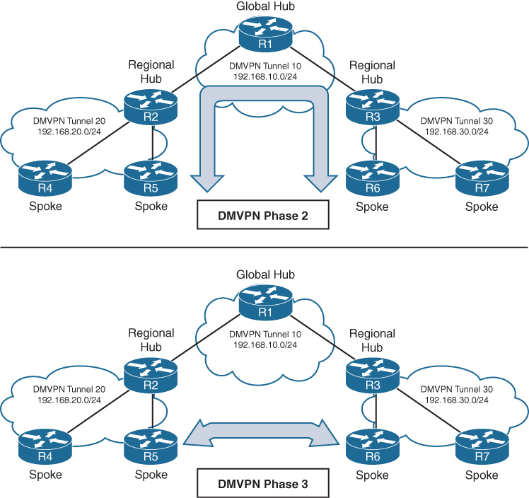
Connectivity between DMVPN tunnels 20 and 30 is established by DMVPN tunnel 10
All three DMVPN tunnels use the same DMVPN tunnel ID, even though they use different tunnel interfaces
For Phase 2 DMVPN tunnels, traffic from R5 must flow to the hub R2, where it is sent to R3 and then back down to R6
For Phase 3 DMVPN tunnels, a spoke-to-spoke tunnel is established between R5 and R6, and the two routers can communicate directly.
Each DMVPN phase has its own specific configuration. Intermixing DMVPN phases on the same tunnel network is not recommended. If you need to support multiple DMVPN phases for a migration, a second DMVPN network (subnet and tunnel interface) should be used.
DMVPN Configuration

DMVPN Hub Configuration
R11-Hub
interface Tunnel100


 bandwidth 4000
 ! Virtual interfaces do not have the concept of latency
 ! and need to have a reference bandwidth configured so that
 ! routing protocols that use bandwidth for best-path calculation
 ! can make intelligent decisions
 ! measured and configured in kilo bits
 ! Bandwidth is also used for quality of service (QoS) configuration
 ! on the interface


 ip address 192.168.100.11 255.255.255.0
 ! allocate an overlay IP address


 ip mtu 1400
 ! set ip mtu to 1400 , typical value for DMVPN to account for additional
 ! encapsulation


 ip nhrp map multicast dynamic
 ! Good to enable multicast support for NHRP
 ! NHRP just like subnets can also provide mapping of overlay IP
 ! + underlay IP for multicast addresses , To support multicast
 ! or routing protocols that use multicast, enable this on DMVPN hub
 ! routers


 ip nhrp network-id 100
 ! Enable NHRP on tunnel and assign unique network identity
 ! this NHRP network ID is not used in any negotiation but
 ! It is recommended that the NHRP network ID match on all
 ! routers participating in the same DMVPN network.
 ! It is used by local router to identify the DMVPN cloud
 ! because multiple tunnel interfaces can belong to the same
 ! DMVPN cloud


 ip nhrp redirect
 ! Enable Phase 3 or NHRP redirect function on DMVPN network


 ip tcp adjust-mss 1360
 ! to influence the TCP MSS negotiation in 3 WAY handshake
 ! for TCP packets visible on tunnel which they are even in
 ! case of TLS, typical value is 1360 to accommodate the 20
 ! bytes for IP + 20 bytes for TCP header


 tunnel source GigabitEthernet0/1
 ! this can be logical interface like loopback
 ! QoS problems can occur with the use of loopback interfaces
 ! when there are multiple paths in the forwarding table to the
 ! decapsulating router. The same problems occur automatically
 ! with port channels, which are not recommended at the time of
 ! this writing.


 tunnel mode gre multipoint
 ! configure tunnel as mGRE tunnel


 tunnel key 100
 ! Optionally use tunnel key in case multiple tunnel interfaces
 ! use same source interface , Tunnel keys, if configured, must
 ! match for a DMVPN tunnel to be established between two routers
 ! the tunnel key adds 4 bytes to the DMVPN header. The tunnel key
 ! is configured with the command tunnel key 0-4294967295
 ! If the tunnel key is defined on the hub router, it must be defined
 ! on all the spoke routers.
Note that mGRE tunnels do not support the option for using a keepalive. Keepalive is only logically possible when there is a single endpoint on other end, but in mGRE we have multiple endpoints
There is no technical correlation between the NHRP network ID and the tunnel interface number; however, keeping them the same helps from an operational support standpoint.
DMVPN Spoke Configuration for DMVPN Phase 1 (Point-to-Point)
The configuration of DMVPN Phase 1 spokes is similar to the configuration for a hub router except two differences:
- You do not use an mGRE tunnel. Instead, you specify the tunnel destination (because communication has to come back to hub)
- The NHRP mapping points to at least one active NHS
R31-Spoke (Single NHRP Command Configuration)

interface Tunnel100
 bandwidth 4000
 ! Virtual interfaces do not have the concept of latency
 ! and need to have a reference bandwidth configured so that
 ! routing protocols that use bandwidth for best-path calculation
 ! can make intelligent decisions
 ! measured and configured in kilo bits
 ! Bandwidth is also used for quality of service (QoS) configuration
 ! on the interface


 ip address 192.168.100.31 255.255.255.0
 ! assign overlay IP address to the Spoke


 ip mtu 1400


 ip nhrp network-id 100


 ip nhrp nhs 192.168.100.11 nbma 172.16.11.1 multicast
 ! define the DMVPN HUB or NHS, more can be added
 ! multicast keyword provides multicast mapping functions
 ! in NHRP and is required to support the following routing
 ! protocols: RIP, EIGRP, and Open Shortest Path First (OSPF)


 ip tcp adjust-mss 1360
 tunnel source GigabitEthernet0/1


 tunnel destination 172.16.11.1
 ! tunnel destination is DMVPN HUB underlay address


 tunnel key 100
R41-Spoke (Multiple NHRP Commands Configuration)
! NHS with MAP commands
interface Tunnel100
bandwidth 4000
ip address 192.168.100.41 255.255.255.0
ip mtu 1400
ip nhrp map 192.168.100.11 172.16.11.1
ip nhrp map multicast 172.16.11.1
ip nhrp network-id 100
ip nhrp nhs 192.168.100.11
ip tcp adjust-mss 1360
tunnel source GigabitEthernet0/1
tunnel destination 172.16.11.1
tunnel key 100Viewing DMVPN Tunnel Status
Tunnel states, in order of establishment:
- INTF: The line protocol of the DMVPN tunnel is down.
- IKE: DMVPN tunnels configured with IPsec have not yet established an IKE session.
- Ipsec: An IKE session has been established, but an Ipsec security association (SA) has not yet been established.
- NHRP: The DMVPN spoke router has not yet successfully registered.
- Up: The DMVPN spoke router has registered with the DMVPN hub and received an ACK (positive registration reply) from the hub.
R31-Spoke# show dmvpn
! Output omitted for brevity
Interface: Tunnel100, IPv4 NHRP Details
Type:Spoke, NHRP Peers:1,

# Ent  Peer NBMA Addr Peer Tunnel Add State  UpDn Tm Attrb
 ----- --------------- --------------- ----- -------- -----
     1 172.16.11.1       192.168.100.11    UP 00:05:26     S >>> static because NHS was defined
R41-Spoke# show dmvpn
! Output omitted for brevity
Interface: Tunnel100, IPv4 NHRP Details
Type:Spoke, NHRP Peers:1,

# Ent  Peer NBMA Addr Peer Tunnel Add State  UpDn Tm Attrb
 ----- --------------- --------------- ----- -------- -----
     1 172.16.11.1       192.168.100.11    UP  00:05:26    S >>> static because NHS was defined
R11-Hub# show dmvpn
Legend: Attrb ◊–S - Static,–D - Dynamic,–I - Incomplete
          –N - NATed,–L - Local,–X - No Socket
           –1 - Route Installed, –2 - Nexthop-override
          –C - CTS Capable
           # Ent --> Number of NHRP entries with same NBMA peer
           NHS Status: E --> Expecting Replies, R --> Responding, W --> Waiting
           UpDn Time --> Up or Down Time for a Tunn==

Interface: Tunnel100, IPv4 NHRP Details
Type:Hub, NHRP Peers:2,

 # Ent  Peer NBMA Addr Peer Tunnel Add State  UpDn Tm Attrb
 ----- --------------- --------------- ----- -------- -----
     1 172.16.31.1       192.168.100.31   UP 00:05:26     D
     1 172.16.41.1       192.168.100.41   UP 00:05:26     D

>>> D ! Dynamic because HUB learned spoke
with detail keyword
R11-Hub# show dmvpn detail
Legend: Attrb --> S - Static, D - Dynamic, I - Incomplete
           N - NATed, L - Local, X - No Socket
           T1 - Route Installed, T2 - Nexthop-override
           C - CTS Capable
           # Ent --> Number of NHRP entries with same NBMA peer
           NHS Status: E --> Expecting Replies, R --> Responding, W --> Waiting
           UpDn Time --> Up or Down Time for a Tunnel
==========================================================================

Interface Tunnel100 is up/up, Addr. is 192.168.100.11, VRF ""
    Tunnel Src./Dest. addr: 172.16.11.1/MGRE, Tunnel VRF ""
    Protocol/Transport: "multi-GRE/IP"", Protect ""
    Interface State Control: Disabled
    nhrp event-publisher : Disabled
Type:Hub, Total NBMA Peers (v4/v6): 2

# Ent  Peer NBMA Addr Peer Tunnel Add State  UpDn Tm Attrb    Target Network
----- --------------- --------------- ----- -------- ----- -----------------

    1 172.16.31.1        192.168.100.31    UP 00:01:05     D  192.168.100.31/32
    1 172.16.41.1        192.168.100.41    UP 00:01:06     D  192.168.100.41/32
R31-Spoke# show dmvpn detail
! Output omitted for brevity

Interface Tunnel100 is up/up, Addr. is 192.168.100.31, VRF ""
  Tunnel Src./Dest. addr: 172.16.31.1/172.16.11.1, Tunnel VRF ""
  Protocol/Transport: "GRE/IP", Protect ""
  Interface State Control: Disabled
  nhrp event-publisher : Disabled
IPv4 NHS:
192.168.100.11 RE NBMA Address: 172.16.11.1 priority = 0 cluster = 0
Type:Spoke, Total NBMA Peers (v4/v6): 1

# Ent  Peer NBMA Addr Peer Tunnel Add State  UpDn Tm Attrb    Target Ne
----- --------------- --------------- ----- -------- ----- ------------
    1 172.16.11.1        192.168.100.11    UP 00:00:28     S  192.168.100
R41-Spoke# show dmvpn detail
! Output omitted for brevity
Interface Tunnel100 is up/up, Addr. is 192.168.100.41, VRF ""
Tunnel Src./Dest. addr: 172.16.41.1/172.16.11.1, Tunnel VRF " "
Protocol/Transport: "GRE/IP", Protect ""
Interface State Control: Disabled
nhrp event-publisher : Disabled
IPv4 NHS:
192.168.100.11 RE NBMA Address: 172.16.11.1 priority = 0 cluster = 0
Type:Spoke, Total NBMA Peers (v4/v6): 1
# Ent Peer NBMA Addr Peer Tunnel Add State UpDn Tm Attrb Target Network
----- --------------- --------------- ----- -------- ----- -----------------
1 172.16.11.1 192.168.100.11 UP 00:02:00 S 192.168.100.11/32Viewing the NHRP Cache
NHRP cache very similar to ARP cache contains information returned by hub such as network entry with overlay and underlay IP of spokes , interface it was received on + expiry time (dynamic entries expire)
| NHRP Mapping Entry | Description |
|---|---|
| static | An entry created statically on a DMVPN interface, this is seen on DMVPN Spokes |
| dynamic | An entry created dynamically. This is seen on DMVPN Hub |
| incomplete | A Cisco router means the router knows it needs a mapping, but the resolution process has not finished yet. This is just like an “Incomplete” ARP entry NHRP (Next Hop Resolution Protocol) is commonly used in DMVPN to map: Tunnel IP address → NBMA (physical/WAN) IP address Routers cache these mappings in the NHRP table. An NHRP entry marked INCOMPLETE indicates: The router has initiated an NHRP resolution request, but has not yet received a valid reply. So: The router does not yet know the NBMA address The mapping cannot be used for forwarding traffic The entry is temporary – usually is seen on HUB when request sent, no reply received and this can be when destination spoke is down , not registered or has incorrect configuration – also happens when NHRP replies are being blocked by ACL, Firewall, NAT Router# show ip nhrp 10.10.10.2/32 via 10.10.10.2 Tunnel0 created 00:00:12, incompleteAn incomplete entry prevents repetitive NHRP requests for the same entry. Eventually this will time out and permit another NHRP resolution request for the same network. A healthy entry eventually changes to Dynamic or Static |
| local | Just like ARP’s local meaning that this overlay IP and underlay IP is on the router interface itself , Cisco routers automatically install a local NHRP entry so that router can correctly identify itself as an NHRP participantR1# show ip nhrp 10.0.0.1/32 via 10.0.0.1 Tunnel0 created 00:12:33, expire never Type: local, Flags: authoritative |
| (no-socket) | Mapping entries that do not have associated IPsec sockets and where encryption is not triggered. |
| NBMA address | Nonbroadcast multi-access address, or the transport IP address where the entry was received. |
NHRP message flags specify attributes of an NHRP cache entry
| NHRP Message Flag | Description |
|---|---|
| used | Indicates that this NHRP mapping entry was used to forward data packets within the past “60” seconds. |
| implicit | Indicates that the NHRP mapping entry was learned implicitly. Examples of such entries are the source mapping information gleaned from an NHRP resolution request received by the local router or from an NHRP resolution packet forwarded “through” the router. |
| unique | Indicates that this remote NHRP mapping entry must be unique and that it cannot be overwritten with an entry that has the same tunnel IP address but a different NBMA address. |
| router | Indicates that this NHRP mapping entry is from a remote “router” that provides access to a network or “host” behind the remote router. |
| rib | NHRP has injected a host route into the IP routing table This is not learned via a routing protocol (EIGRP/OSPF/BGP), but directly installed by NHRP show ip nhrp10.10.10.2/32 via 172.16.1.2 Flags: unique, dynamic, ribThis rib flag means this entry is installed in routing table show ip route 10.10.10.2Routing entry for 10.10.10.2/32 Known via "nhrp", distance 250, metric 0Why is AD 250 important? Makes sure routing protocols win Prevents NHRP from overriding real routing decisions NHRP routes are fallback / shortcut routes but because these are longest or most specific routes they always override When will you see RIB flag set? You’ll see RIB when: DMVPN Phase 2 or 3 is active NHRP resolution succeeds Spoke learns another spoke’s NBMA address Traffic triggers a shortcut |
| nho | When NHO is set, the spoke is telling the hub: “Do NOT override the next-hop with yourself when replying to NHRP resolution requests.” The hub does not insert itself as the next hop This allows direct spoke-to-spoke tunnels to form Without NHO Traffic between spokes is forced through the hub Hub becomes the next hop No dynamic spoke-to-spoke tunnels With NHO (normal DMVPN behavior) Hub returns the real NBMA address of the destination spoke Spokes build direct GRE/IPsec tunnels Enables Phase 2 / Phase 3 DMVPN |
| nhop | The nhop flag tells that this is valid next-hop for forwarding traffic |
R11-Hub# show ip nhrp
192.168.100.31/32 via 192.168.100.31
  Tunnel100 created 23:04:04, expire 01:37:26
  Type: dynamic, Flags: unique registered used nhop
  NBMA address: 172.16.31.1
192.168.100.41/32 via 192.168.100.41
  Tunnel100 created 23:04:00, expire 01:37:42
  Type: dynamic, Flags: unique registered used nhop
  NBMA address: 172.16.41.1
R31-Spoke# show ip nhrp
192.168.100.11/32 via 192.168.100.11
Tunnel100 created 23:02:53, never expire
Type: static, Flags:
NBMA address: 172.16.11.1R41-Spoke# show ip nhrp
192.168.100.11/32 via 192.168.100.11
Tunnel100 created 23:02:53, never expire
Type: static, Flags:
NBMA address: 172.16.11.1show ip nhrp “brief”
some information such as the used and nhop NHRP message flags are not shown with brief keyword
R11-Hub# show ip nhrp brief
****************************************************************************
    NOTE: Link-Local, No-socket and Incomplete entries are not displayed
****************************************************************************
Legend: Type --> S - Static, D - Dynamic
         Flags --> u - unique, r - registered, e - temporary, c - claimed
         a - authoritative, t - route
============================================================================
Intf     NextHop Address                                    NBMA Address
         Target Network                              T/Flag
-------- ------------------------------------------- ------ ----------------

Tu100    192.168.100.31                                     172.16.31.1
         192.168.100.31/32                           D/ur
Tu100    192.168.100.41                                     172.16.41.1
         192.168.100.41/32                           D/ur
R31-Spoke# show ip nhrp brief
! Output omitted for brevity
Intf NextHop Address NBMA Address
Target Network T/Flag
-------- ------------------------------------------- ------ ----------------
Tu100 192.168.100.11 172.16.11.1
192.168.100.11/32 S/R41-Spoke# show ip nhrp brief
! Output omitted for brevity
Intf NextHop Address NBMA Address
Target Network T/Flag
-------- ------------------------------------------- ------ ----------------
Tu100 192.168.100.11 172.16.11.1
192.168.100.11/32 S/The optional detail keyword provides a list of routers that submitted NHRP resolution requests and their request IDs.
Routing Table
Notice that the next-hop address between spoke routers is 192.168.100.11 (R11).
R11-Hub# show ip route
! Output omitted for brevity
Codes: L - local,   C - connected, S - static, R - RIP, M - mobile, B - BGP
         D - EIGRP, EX - EIGRP external, O - OSPF, IA - OSPF inter area

Gateway of last resort is 172.16.11.2 to network 0.0.0.0

S*    0.0.0.0/0 [1/0] via 172.16.11.2
      10.0.0.0/8 is variably subnetted, 4 subnets, 2 masks
C        10.1.1.0/24 is directly connected, GigabitEthernet0/2
D        10.3.3.0/24 [90/27392000] via 192.168.100.31, 23:03:53, Tunnel100
D        10.4.4.0/24 [90/27392000] via 192.168.100.41, 23:03:28, Tunnel100
      172.16.0.0/16 is variably subnetted, 2 subnets, 2 masks
C        172.16.11.0/30 is directly connected, GigabitEthernet0/1
      192.168.100.0/24 is variably subnetted, 2 subnets, 2 masks
C        192.168.100.0/24 is directly connected, Tunnel100
R31-Spoke# show ip route
! Output omitted for brevity
Gateway of last resort is 172.16.31.2 to network 0.0.0.0
S* 0.0.0.0/0 [1/0] via 172.16.31.2
10.0.0.0/8 is variably subnetted, 4 subnets, 2 masks
D 10.1.1.0/24 [90/26885120] via 192.168.100.11, 23:04:48, Tunnel100
C 10.3.3.0/24 is directly connected, GigabitEthernet0/2
D 10.4.4.0/24 [90/52992000] via 192.168.100.11, 23:04:23, Tunnel100
172.16.0.0/16 is variably subnetted, 2 subnets, 2 masks
C 172.16.31.0/30 is directly connected, GigabitEthernet0/1
192.168.100.0/24 is variably subnetted, 2 subnets, 2 masks
C 192.168.100.0/24 is directly connected, Tunnel100R41-Spoke# show ip route
! Output omitted for brevity
Gateway of last resort is 172.16.41.2 to network 0.0.0.0
S* 0.0.0.0/0 [1/0] via 172.16.41.2
10.0.0.0/8 is variably subnetted, 4 subnets, 2 masks
D 10.1.1.0/24 [90/26885120] via 192.168.100.11, 23:05:01, Tunnel100
D 10.3.3.0/24 [90/52992000] via 192.168.100.11, 23:05:01, Tunnel100
C 10.4.4.0/24 is directly connected, GigabitEthernet0/2
172.16.0.0/16 is variably subnetted, 2 subnets, 2 masks
C 172.16.41.0/24 is directly connected, GigabitEthernet0/1
192.168.100.0/24 is variably subnetted, 2 subnets, 2 masks
C 192.168.100.0/24 is directly connected, Tunnel100Traceroute
Traceroute shows that data from R31 to R41 will go through R11.
R31-Spoke# traceroute 10.4.4.1 source 10.3.3.1
Tracing the route to 10.4.4.1
  1 192.168.100.11 0 msec 0 msec 1 msec
  2 192.168.100.41 1 msec * 1 msec
DMVPN Configuration for Phase 3 DMVPN (Multipoint)
Phase 3 DMVPN configuration for the hub router adds the interface parameter command ip nhrp redirect on the hub router
This command checks the flow of packets on the tunnel interface and sends a redirect message to the source spoke router when it detects Hub router being used as transit, this is done by detecting for hairpinning
Hairpinning means that traffic is received and sent out an interface in the same cloud (identified by the NHRP network ID) , For instance, hairpinning occurs when packets come in and go out the same tunnel interface.
The Phase 3 DMVPN configuration for spoke routers uses the mGRE tunnel interface and uses the command ip nhrp shortcut on the tunnel interface.
R11-Hub
interface Tunnel100
 bandwidth 4000
 ip address 192.168.100.11 255.255.255.0
 ip mtu 1400
 ip nhrp map multicast dynamic
 ip nhrp network-id 100
 ip nhrp redirect <<<
 ip tcp adjust-mss 1360
 tunnel source GigabitEthernet0/1
 tunnel mode gre multipoint
 tunnel key 100
R31-Spoke
interface Tunnel100
bandwidth 4000
ip address 192.168.100.31 255.255.255.0
ip mtu 1400
ip nhrp network-id 100
ip nhrp nhs 192.168.100.11 nbma 172.16.11.1 multicast
ip nhrp shortcut <<<
ip tcp adjust-mss 1360
tunnel source GigabitEthernet0/1
tunnel mode gre multipoint
tunnel key 100R41-Spoke
interface Tunnel100
bandwidth 4000
ip address 192.168.100.41 255.255.255.0
ip mtu 1400
ip nhrp network-id 100
ip nhrp nhs 192.168.100.11 nbma 172.16.11.1 multicast
ip nhrp shortcut <<<
ip tcp adjust-mss 1360
tunnel source GigabitEthernet0/1
tunnel mode gre multipoint
tunnel key 100IP NHRP Authentication
NHRP includes an authentication capability, but this authentication is weak because the password is stored in plaintext. Most network administrators use NHRP authentication as a method to ensure that two different tunnels do not accidentally form. You enable NHRP authentication by using the interface parameter command ip nhrp authentication password.
Unique IP NHRP Registration
When Spoke regsiters with hub it adds the unique flag that forces DMVPN NHRP to keep overlay / protocol address and NBMA address unique for a spoke and same as the time of registration, If an NHC client or spoke attempts to register with the NHS using a different NBMA address while the previous entry has not expired yet, the registration process fails.
lets demonstrate this concept by disabling the DMVPN tunnel interface, changing the IP address on the transport interface, and reenabling the DMVPN tunnel interface. Notice that the DMVPN hub denies the NHRP registration because the protocol address is registered to a different NBMA address.
R31-Spoke(config)# interface tunnel 100
R31-Spoke(config-if)# shutdown
00:17:48.910: %DUAL-5-NBRCHANGE: EIGRP-IPv4 100: Neighbor 192.168.100.11
        (Tunnel100) is down: interface down
00:17:50.910: %LINEPROTO-5-UPDOWN: Line protocol on Interface Tunnel100,
     changed state to down
00:17:50.910: %LINK-5-CHANGED: Interface Tunnel100, changed state to
     administratively down
R31-Spoke(config-if)# interface GigabitEthernet0/1
R31-Spoke(config-if)# ip address 172.16.31.31 255.255.255.0
R31-Spoke(config-if)# interface tunnel 100
R31-Spoke(config-if)# no shutdown
00:18:21.011: %NHRP-3-PAKREPLY: Receive Registration Reply packet with error -
    unique address registered already(14)
00:18:22.010: %LINEPROTO-5-UPDOWN: Line protocol on Interface Tunnel100, changed
    state to up
This can cause problems for sites with transport interfaces that connect using DHCP, where they could be assigned different IP addresses before the NHRP cache times out. If a router loses connectivity and is assigned a different IP address, because of its age, it cannot register with the NHS router until that router’s entry is flushed from the NHRP cache.
The interface parameter command ip nhrp registration no-unique stops routers from placing the unique NHRP message flag in registration request packets sent to the NHS. This allows clients to reconnect to the NHS even if the NBMA address changes. This should be enabled on all DHCP-enabled spoke interfaces. However, placing this on all spoke tunnel interfaces keeps the configuration consistent for all tunnel interfaces and simplifies verification of settings from an operational perspective.
The NHC (spoke) has to register with this flag for this change to take effect on the NHS.
This can either happens during the normal NHRP expiration timers
or can be accelerated by resetting the tunnel interface on the spoke before change of transport IP
Spoke-to-Spoke Communication
In DMVPN Phase 1, the spoke devices rely on the configured tunnel destination to identify where to send the encapsulated packets. Phase 3 DMVPN uses mGRE tunnels and thereby relies on NHRP redirect and resolution request messages to identify the NBMA addresses for any destination networks
R31 initiates a traceroute to R41. Notice that the first packet travels across R11 (hub), but by the time a second stream of packets is sent, the spoke-to-spoke tunnel has been initialized so that traffic flows directly between R31 and R41 on the transport and overlay networks.
! Initial Packet Flow
R31-Spoke# traceroute 10.4.4.1 source 10.3.3.1
Tracing the route to 10.4.4.1
  1 192.168.100.11 5 msec 1 msec 0 msec <- This is the Hub Router (R11-Hub)
  2 192.168.100.41 5 msec * 1 msec
! Packetflow after Spoke-to-Spoke Tunnel is Established
R31-Spoke# traceroute 10.4.4.1 source 10.3.3.1
Tracing the route to 10.4.4.1
1 192.168.100.41 1 msec * 0 msecForming Spoke-to-Spoke Tunnels
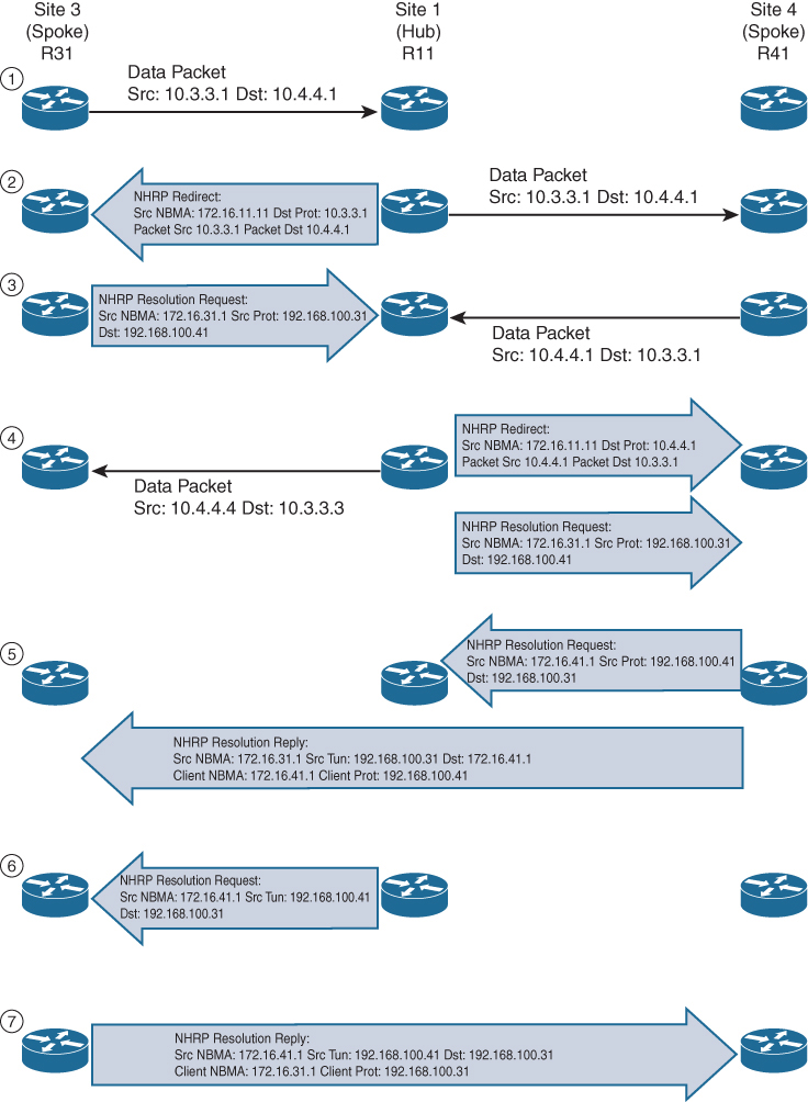
Step 1. R31 performs a route lookup for 10.4.4.1 and finds the entry 10.4.4.0/24 with the next-hop IP address 192.168.100.11 through hub. R31 encapsulates the packet destined for 10.4.4.1 and forwards it to R11 out the tunnel 100 interface.
Step 2. R11 receives the packet from R31 and performs a route lookup for the packet destined for 10.4.4.1. R11 locates the 10.4.4.0/24 network with the next-hop IP address 192.168.100.41. R11 checks the NHRP cache and locates the entry for the 192.168.100.41/32 address. R11 forwards the packet to R41, using the NBMA IP address 172.16.41.1, found in the NHRP cache.
The packet is then forwarded out the same tunnel interface (same network id / DMVPN cloud) and hub detects this as hairpinning.
R11 has ip nhrp redirect configured on the tunnel interface and recognizes that the packet received from R31 hairpinned out of the tunnel interface. R11 sends an NHRP redirect to R31, indicating the packet source 10.3.3.1 and destination 10.4.4.1. The NHRP redirect indicates to R31 that the traffic is using a suboptimal path.
Step 3. R31 receives the NHRP redirect and sends an NHRP resolution request to R11 for the 10.4.4.1 address. Inside the NHRP resolution request, R31 provides its protocol (tunnel IP) address, 192.168.100.31, and source NBMA address, 172.16.31.1. R41 performs a route lookup for 10.3.3.1 and finds the entry 10.3.3.0/24 with the next-hop IP address 192.168.100.11. R41 encapsulates the packet destined for 10.4.4.1 and forwards it to R11 out the tunnel 100 interface.
Step 4. R11 receives the packet from R41 and performs a route lookup for the packet destined for 10.3.3.1. R11 locates the 10.3.3.0/24 network with the next-hop IP address 192.168.100.31. R11 checks the NHRP cache and locates an entry for 192.168.100.31/32. R11 forwards the packet to R31, using the NBMA IP address 172.16.31.1, found in the NHRP cache. The packet is then forwarded out the same tunnel interface. R11 has ip nhrp redirect configured on the tunnel interface and recognizes that the packet received from R41 hairpinned out the tunnel interface. R11 sends an NHRP redirect to R41, indicating the packet source 10.4.4.1 and destination 10.3.3.1 The NHRP redirect indicates to R41 that the traffic is using a suboptimal path. R11 forwards R31’s NHRP resolution requests for the 10.4.4.1 address.
Step 5. R41 sends an NHRP resolution request to R11 for the 10.3.3.1 address and provides its protocol (tunnel IP) address, 192.168.100.41, and source NBMA address, 172.16.41.1. R41 sends an NHRP resolution reply directly to R31, using the source information from R31’s NHRP resolution request. The NHRP resolution reply contains the original source information in R31’s NHRP resolution request as a method of verification and contains the client protocol address of 192.168.100.41 and the client NBMA address 172.16.41.1. (If IPsec protection is configured, the IPsec tunnel is set up before the NHRP reply is sent.)
Note
The NHRP reply is for the entire subnet rather than the specified host address.
Step 6. R11 forwards R41’s NHRP resolution requests for the 192.168.100.31 and 10.4.4.1 entries.
Step 7. R31 sends an NHRP resolution reply directly to R41, using the source information from R41’s NHRP resolution request. The NHRP resolution reply contains the original source information in R41’s NHRP resolution request as a method of verification and contains the client protocol address 192.168.100.31 and the client NBMA address 172.16.31.1. (Again, if IPsec protection is configured, the tunnel is set up before the NHRP reply is sent back in the other direction.)
A spoke-to-spoke DMVPN tunnel is established in both directions after step 7 is complete. This allows traffic to flow across the spoke-to-spoke tunnel instead of traversing the hub router.
shows the status of DMVPN tunnels on R31 and R41, where there are two new spoke-to-spoke tunnels (highlighted). The DLX entries represent the local (no-socket) routes. The original tunnel to R11 remains a static tunnel.
R31-Spoke# show dmvpn detail
Legend: Attrb --> S - Static, D - Dynamic, I - Incomplete
           N - NATed, L - Local, X - No Socket
          T1 - Route Installed, T2 - Nexthop-override
          C - CTS Capable
         # Ent --> Number of NHRP entries with same NBMA peer
         NHS Status: E --> Expecting Replies, R --> Responding, W --> Waiting
         UpDn Time --> Up or Down Time for a Tunnel
============================================================================
Interface Tunnel100 is up/up, Addr. is 192.168.100.31, VRF ""
      Src./Dest. addr: 172.16.31.1/MGRE, Tunnel VRF ""
     Protocol/Transport: "multi-GRE/IP", Protect ""
     Interface State Control: Disabled
     nhrp event-publisher : Disabled

IPv4 NHS:
192.168.100.11 RE NBMA Address: 172.16.11.1 priority = 0 cluster = 0
Type:Spoke, Total NBMA Peers (v4/v6): 3

# Ent  Peer NBMA Addr Peer Tunnel Add State  UpDn Tm Attrb    Target Network
----- --------------- --------------- ----- -------- ----- -----------------
    1 172.16.31.1      192.168.100.31    UP 00:00:10   DLX        10.3.3.0/24
    2 172.16.41.1      192.168.100.41    UP 00:00:10   DT2   10.4.4.0/24
      172.16.41.1      192.168.100.41    UP 00:00:10   DT1   192.168.100.41/32
    1 172.16.11.1      192.168.100.11    UP 00:00:51     S    192.168.100.11/32
R41-Spoke# show dmvpn detail
! Output omitted for brevity
IPv4 NHS:
192.168.100.11 RE NBMA Address: 172.16.11.1 priority = 0 cluster = 0
Type:Spoke, Total NBMA Peers (v4/v6): 3
# Ent Peer NBMA Addr Peer Tunnel Add State UpDn Tm Attrb Target Network
----- --------------- --------------- ----- -------- ----- -----------------
2 172.16.31.1 192.168.100.31 UP 00:00:34 DT2 10.3.3.0/24
172.16.31.1 192.168.100.31 UP 00:00:34 DT1 192.168.100.31/32
1 172.16.41.1 192.168.100.41 UP 00:00:34 DLX 10.4.4.0/24
1 172.16.11.1 192.168.100.11 UP 00:01:15 S 192.168.100.11/32show ip nhrp detail to view NHRP cache for R31 and R41. Notice the NHRP mappings router, rib, nho, and nhop. The flag rib nho indicates that the router has found an identical route in the routing table that belongs to a different protocol. NHRP has overridden the other protocol’s next-hop entry for the network by installing a next-hop shortcut in the routing table. The flag rib nhop indicates that the router has an explicit method to reach the tunnel IP address using an NBMA address and has an associated route installed in the routing table.
NHRP Mapping with Spoke-to-Hub Traffic
uses the optional detail keyword for viewing the NHRP cache information. The 10.3.3.0/24 entry on R31 and the 10.4.4.0/24 entry on R41 display a list of devices to which the router responded to resolution request packets and the request ID that they received.
R31-Spoke# show ip nhrp detail
10.3.3.0/24 via 192.168.100.31
   Tunnel100 created 00:01:44, expire 01:58:15
   Type: dynamic, Flags: router unique local
   NBMA address: 172.16.31.1
   Preference: 255
    (no-socket)
   Requester: 192.168.100.41 Request ID: 3
10.4.4.0/24 via 192.168.100.41
   Tunnel100 created 00:01:44, expire 01:58:15
   Type: dynamic, Flags: router rib nho
   NBMA address: 172.16.41.1
   Preference: 255
192.168.100.11/32 via 192.168.100.11
   Tunnel100 created 10:43:18, never expire
   Type: static, Flags: used
   NBMA address: 172.16.11.1
   Preference: 255
192.168.100.41/32 via 192.168.100.41
   Tunnel100 created 00:01:45, expire 01:58:15
   Type: dynamic, Flags: router used nhop rib
   NBMA address: 172.16.41.1
   Preference: 255
R41-Spoke# show ip nhrp detail
10.3.3.0/24 via 192.168.100.31
Tunnel100 created 00:02:04, expire 01:57:55
Type: dynamic, Flags: router rib nho
NBMA address: 172.16.31.1
Preference: 255
10.4.4.0/24 via 192.168.100.41
Tunnel100 created 00:02:04, expire 01:57:55
Type: dynamic, Flags: router unique local
NBMA address: 172.16.41.1
Preference: 255
(no-socket)
Requester: 192.168.100.31 Request ID: 3
192.168.100.11/32 via 192.168.100.11
Tunnel100 created 10:43:42, never expire
Type: static, Flags: used
NBMA address: 172.16.11.1
Preference: 255
192.168.100.31/32 via 192.168.100.31
Tunnel100 created 00:02:04, expire 01:57:55
Type: dynamic, Flags: router used nhop rib
NBMA address: 172.16.31.1 Preference: 255DMVPN 2
DMVPN (Dynamic Multipoint Virtual Private Network) is a hub-and-spoke technology for site-to-site sites, the great advantage of DMVPN is scalability and direct spoke to spoke communication
DMVPN, we actually configure the tunnel interfaces as multipoint interfaces so that we can talk to multiple routers using the same tunnel interface, reducing the configuration and increasing the scale over point-to-point tunnels.
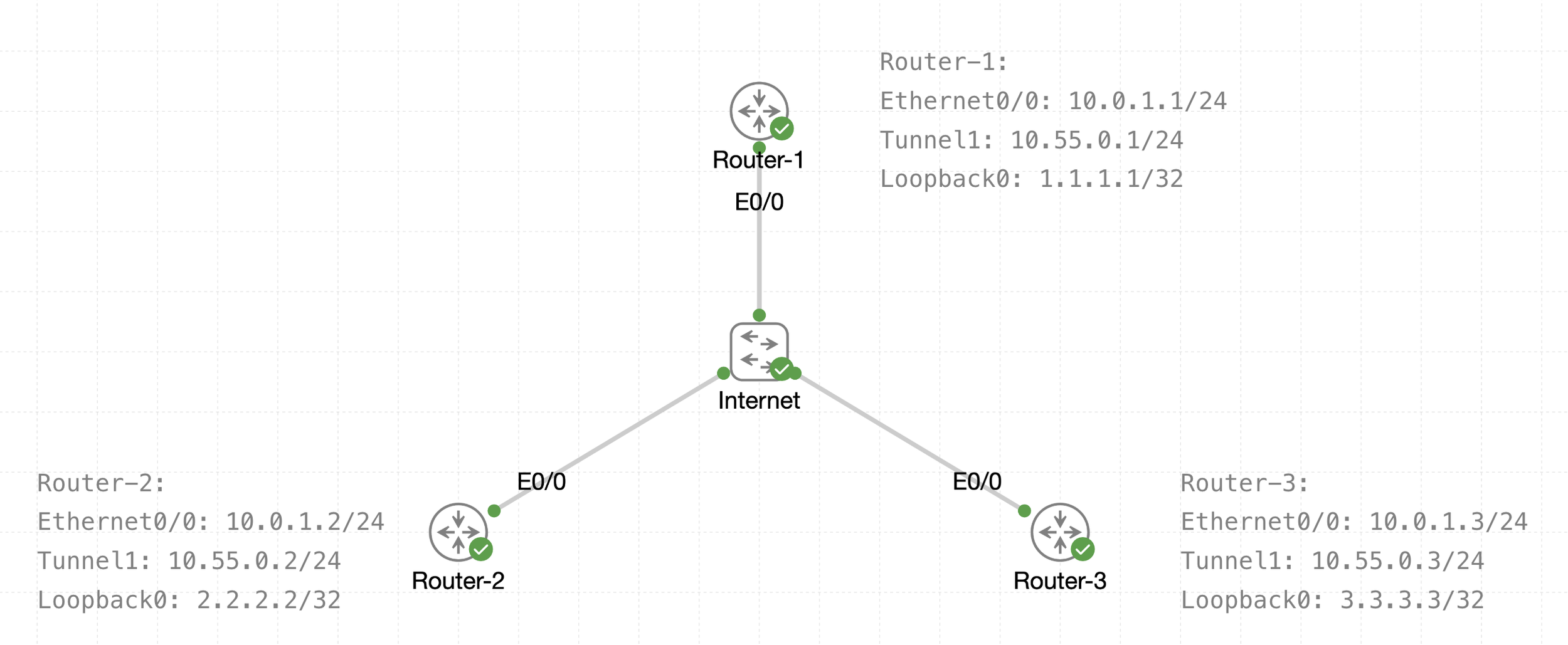
See that there is a transport IP addressing
Then there is overlay network over WAN (transport) that is multipoint GRE acting as a broadcast network, we can tell the broadcast nature by looking at Tunnel 1 Addressing
The default tunnel-type on Cisco routers is a GRE point-to-point. GRE is about as simple as a protocol gets.
next post
EIGRP
EIGRP
EIGRP is distance vector routing protocol
Initially it was Cisco proprietary protocol, but it was released to the Internet Engineering Task Force (IETF)
EIGRP uses a diffusing update algorithm (DUAL) to learn loop free paths
DUAL also keeps loop-free backup paths for fast convergence
A lot of older protocols used hop count for path selection but that does not take into account link speed and total delay, EIGRP adds logic to the route-selection algorithm to use factors other than hop count alone
EIGRP uses ASN per process (ASN/Process)
Routers within the same domain must use the same metric calculation formula and exchange routes only with members of the same autonomous system (AS), if routing needs to be presented between 2 different EIGRP ASN / Process then router in the middle will need to redistribute between 2 ASN / Processes
For example R3 that is attached to 2 different ASN on 2 different processes does not transfer routes learned from one autonomous system into a different autonomous system
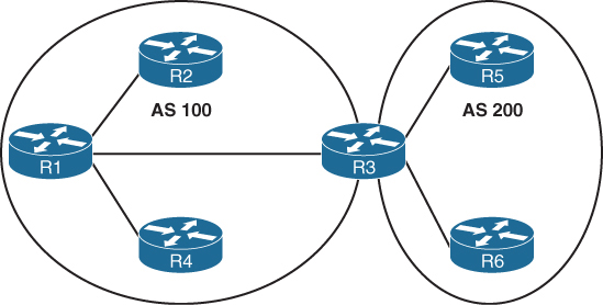
Current implementations of EIGRP support only IPv4 and IPv6.
EIGRP Terminology
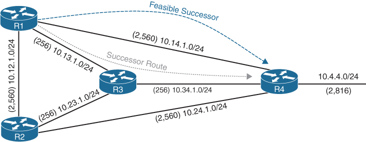
Successor route
The route with the lowest path metric to reach a destination.
The successor route for R1 to reach 10.4.4.0/24 on R4 is R1→R3→R4.
Successor
The first next-hop router for the successor route. R1’s successor for 10.4.4.0/24 is R3.
Feasible distance (FD)
The metric value for the lowest path metric to reach a destination. The feasible distance is calculated locally using the formula
The FD calculated by R1 for the 10.4.4.0/24 destination network is 3328 (that is, 256 + 256 + 2816).
Reported distance (RD)
Distance reported by a router to reach a destination. The reported distance value is the feasible distance of the advertising router.
R3 advertises the 10.4.4.0/24 destination network to R1 and R2 with an RD of 3072 (2816 + 256).
R4 advertises the 10.4.4.0/24 destination network to R1, R2, and R3 with an RD of 2816.
Feasibility condition
For a route to be considered a backup route, the RD received for that route must be less than the FD calculated locally. This logic guarantees a loop-free path.
Feasible successor
Installed in the topology table only
Acts as a loop-free backup path
A route that satisfies the feasibility condition is maintained as a backup route. The feasibility condition ensures that the backup route is loop free.
The route R1→R4 is the feasible successor because the RD of 2816 is lower than the FD of 3328 for the R1→R3→R4 path.
Topology Table
EIGRP contains a topology table
The topology table contains all the network prefixes advertised within an EIGRP autonomous system including backup paths and not just contains metric per prefix but hop count also
Values used to calculate the metric BDRLM (Bandwidth , Delay , Reliability , Load , MTU)
show ip eigrp topology ! shows successor and feasible successor
!
show ip eigrp topology [all-links]
! shows successor and feasible successor all-links keyword shows the paths that did not pass the feasibility condition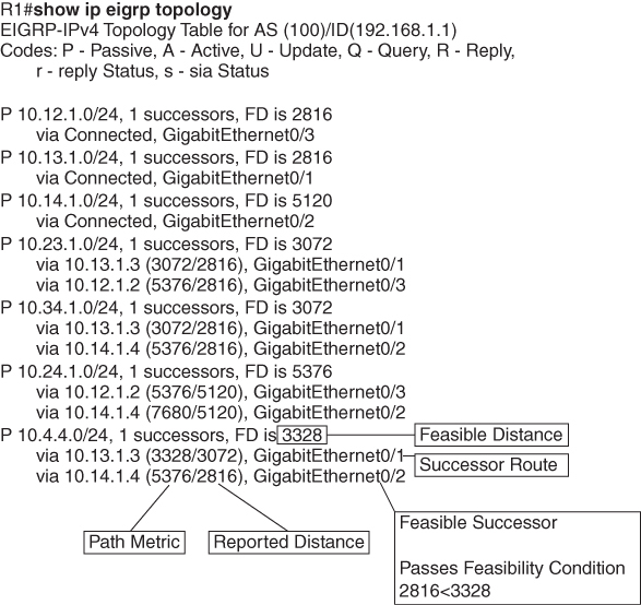
Prefix 10.4.4.0/24 has cost or FD of 3328 for best path or successor route
Successor route’s next hop router is called successor
second path that is feasible successor has RD of 2816 which is lower than FD of successor route, it passes the feasibility condition and is installed in topology table
The 10.4.4.0/24 route is passive (P), which means the topology is stable. During a topology change, routes go into an active (A) state when computing a new path.
EIGRP Neighbors
EIGRP neighbors exchange the entire routing table when forming an adjacency, and they advertise incremental updates only as topology changes occur within a network and no periodic updates
Inter-Router Communication
EIGRP uses IP protocol number (88)
uses multicast packets where possible to reduce bandwidth consumed on the links; it uses unicast packets when necessary
EIGRP uses Reliable Transport Protocol (RTP) to ensure that packets are delivered instead of TCP
A sequence number is included in each EIGRP packet. The sequence value zero does not require a response from the receiving EIGRP router; all other values require an ACK packet that includes the original sequence number
All update, query and reply packets are deemed reliable
hello and ACK packets do not require acknowledgment
If the originating router does not receive an ACK packet from the neighbor before the retransmit timeout expires, it notifies the non-acknowledging router to stop processing its multicast packets
Communication between routers is done with multicast using the group address 224.0.0.10 or the MAC address 01:00:5e:00:00:0a when possible
| Opcode Value | Packet Type | Function |
|---|---|---|
| 1 | Update | Used to transmit routing and reachability information with other EIGRP neighbors |
| 2 | Request | Used to get specific information from one or more neighbors |
| 3 | Query | Sent out to search for another path during convergence |
| 4 | Reply | Sent in response to a query packet |
| 5 | Hello | Used for discovery of EIGRP neighbors and for detecting when a neighbor is no longer available |
Forming EIGRP Neighbors
Hello messages are exchanged to become neighbors
The following parameters must match for the two routers to become neighbors:
- Metric formula K values
- Primary subnet matches
- Autonomous system number (ASN) matches
- Authentication parameters
EIGRP Configuration Modes
EIGRP configuration modes: classic mode and named mode.
EIGRP Named Mode
EIGRP named mode provides a hierarchical configuration and stores settings in three subsections:
- Address Family: This submode contains settings that are relevant to the global EIGRP AS operations, such as selection of network interfaces, EIGRP K values, logging settings, and stub settings.
- Interface: This submode contains settings that are relevant to the interface, such as hello advertisement interval, split-horizon, authentication, and summary route advertisements. In actuality, there are two methods of the EIGRP interface section’s configuration. Commands can be assigned to a specific interface or to a default interface, in which case those settings are placed on all EIGRP-enabled interfaces. If there is a conflict between the default interface and a specific interface, the specific interface takes priority over the default interface.
- Topology: This submode contains settings regarding the EIGRP topology database and how routes are presented to the router’s RIB. This section also contains route redistribution and administrative distance settings.
EIGRP named configuration makes it possible to run multiple instances under the same EIGRP process
Step 1. Initialize the EIGRP process by using the command router eigrp process-name. (If a number is used for process-name, the number does not correlate to the autonomous system number.)
Step 2. Initialize the EIGRP instance for the appropriate address family with the command address-family {IPv4 | IPv6} {unicast | vrf vrf-name} autonomous-system as-number.
Step 3. Enable EIGRP on interfaces by using the command network network wildcard-mask.
EIGRP Network Statement
Network statement enrolls interfaces in EIGRP and sends hellos on those interfaces
If wildcard is omitted then any interfaces that fall under the classful boundary are added in EIGRP, secondary networks are not added, if we want secondary networks in EIGRP then they need to be redistributed
router eigrp 1
    network 10.0.0.10 0.0.0.0
    network 10.0.0.0 0.0.0.255
    network 10.0.0.0 0.255.255.255
    network 0.0.0.0 255.255.255.255 ! enable on all interfaces
Named configuration
R2 (Named Mode Configuration)
interface Loopback0
 ip address 192.168.2.2 255.255.255.255
!
interface GigabitEthernet0/1
    ip address 10.12.1.2 255.255.255.0
!
interface GigabitEthernet0/2
    ip address 10.22.22.2 255.255.255.0
!
router eigrp EIGRP-NAMED
 address-family ipv4 unicast autonomous-system 100
  network 0.0.0.0 255.255.255.255
R2# show run | section router eigrp
router eigrp EIGRP-NAMED
!
address-family ipv4 unicast autonomous-system 100
!
topology base
exit-af-topology
network 0.0.0.0
exit-address-family The EIGRP interface submode configurations contain the command af-interface interface-id or af-interface default
router eigrp MY-EIGRP
 address-family ipv4 unicast autonomous-system 100
  network 10.0.0.0 0.0.0.255

  af-interface default
   passive-interface
   hello-interval 5
   hold-time 15
  exit-af-interface

  af-interface GigabitEthernet0/0
   no passive-interface
   bandwidth-percent 50
  exit-af-interface

  af-interface GigabitEthernet0/1
   no passive-interface
   authentication mode md5
   authentication key-chain EIGRP_KEYS
  exit-af-interface
 exit-address-family
show ip eigrp interfaces [{interface-id [detail] | detail}]R1# show ip eigrp interfaces
EIGRP-IPv4 Interfaces for AS(100)
Xmit Queue PeerQ Mean Pacing Time Multicast Pending
Interface Peers Un/Reliable Un/Reliable SRTT Un/Reliable Flow Timer Routes
Gi0/2 0 0/0 0/0 0 0/0 0 0
Gi0/1 1 0/0 0/0 10 0/0 50 0
Lo0 0 0/0 0/0 0 0/0 0 0R2# show ip eigrp interfaces gi0/1 detail
EIGRP-IPv4 VR(EIGRP-NAMED) Address-Family Interfaces for AS(100)
Xmit Queue PeerQ Mean Pacing Time Multicast Pending
Interface Peers Un/Reliable Un/Reliable SRTT Un/Reliable Flow Timer Routes
Gi0/1 1 0/0 0/0 1583 0/0 7912 0
Hello-interval is 5, Hold-time is 15
Split-horizon is enabled
Next xmit serial <none>
Packetized sent/expedited: 2/0
Hello's sent/expedited: 186/2
Un/reliable mcasts: 0/2 Un/reliable ucasts: 2/2
Mcast exceptions: 0 CR packets: 0 ACKs suppressed: 0
Retransmissions sent: 1 Out-of-sequence rcvd: 0
Topology-ids on interface - 0
Authentication mode is not set
Topologies advertised on this interface: base
Topologies not advertised on this interface:Fields explaination
Xmt Queue – Un/Reliable
Number of unreliable/reliable packets remaining in the transmit queue. The value zero is an indication of a stable network.
Mean SRTT
Average time for a packet to be sent and a received from neighbor in milliseconds.
Pending Routes
Number of routes in the transmit queue that need to be sent.
R1# show ip eigrp neighbors
EIGRP-IPv4 Neighbors for AS(100)
H   Address                 Interface              Hold Uptime   SRTT   RTO  Q  Seq
                                                   (sec)         (ms)       Cnt Num
0   10.12.1.2               Gi0/1                    13 00:18:31   10   100  0  3
Fields explaination
RTO
Timeout for retransmission (waiting for ACK)
Q Cnt
Number of packets (update/query/reply) in queue for sending
Seq Num
Sequence number that was last “received” from this router
show ip route eigrpR1# show ip route eigrp
Codes: L - local, C - connected, S - static, R - RIP, M - mobile, B - BGP
D - EIGRP, EX - EIGRP external, O - OSPF, IA - OSPF inter area
N1 - OSPF NSSA external type 1, N2 - OSPF NSSA external type 2
E1 - OSPF external type 1, E2 - OSPF external type 2
i - IS-IS, su - IS-IS summary, L1 - IS-IS level-1, L2 - IS-IS level-2
ia - IS-IS inter area, * - candidate default, U - per-user static route
o - ODR, P - periodic downloaded static route, H - NHRP, l - LISP
a - application route
+ - replicated route, % - next hop override, p - overrides from PfR
Gateway of last resort is not set
10.0.0.0/8 is variably subnetted, 5 subnets, 2 masks
D 10.22.22.0/24 [90/3072] via 10.12.1.2, 00:19:25, GigabitEthernet0/1
192.168.2.0/32 is subnetted, 1 subnets
D 192.168.2.2 [90/2848] via 10.12.1.2, 00:19:25, GigabitEthernet0/1R2# show ip route eigrp
! Output omitted for brevity
Gateway of last resort is not set
10.0.0.0/8 is variably subnetted, 5 subnets, 2 masks
D 10.11.11.0/24 [90/15360] via 10.12.1.1, 00:20:34, GigabitEthernet0/1
192.168.1.0/32 is subnetted, 1 subnets
D 192.168.1.1 [90/2570240] via 10.12.1.1, 00:20:34, GigabitEthernet0/1EIGRP routes have administrative distance (AD) of 90 and are indicated in the routing table with a D
External EIGRP routes have an AD of 170 and are indicated in the routing table with D EX
The metrics for R2’s routes are different from the metrics from R1’s routes. This is because R1’s classic EIGRP mode uses classic metrics, and R2’s named mode uses “wide metrics” “by default”
Router ID
The router ID (RID) is a 32-bit number that uniquely identifies an EIGRP router and is used as a loop-prevention mechanism. The RID can be set dynamically, which is the default, or manually.
The algorithm for dynamically choosing the EIGRP RID uses the highest IPv4 address of any up loopback interfaces. If there are not any up loopback interfaces, the highest IPv4 address of any active up physical interfaces becomes the RID when the EIGRP process initializes.
R1(config)# router eigrp 100
R1(config-router)# eigrp router-id 192.168.1.1

R2(config)# router eigrp EIGRP-NAMED
R2(config-router)# address-family ipv4 unicast autonomous-system 100
R2(config-router-af)# eigrp router-id 192.168.2.2
Passive Interfaces
Some network topologies must advertise a network segment into EIGRP but need to prevent neighbors because it stops sending hello and process received hellos
for example, when advertising access layer networks in a campus topology.
R1# configure terminal
Enter configuration commands, one per line.  End with CNTL/Z.
R1(config)# router eigrp 100
R1(config-router)# passive-interface gi0/2
R1(config)# router eigrp 100
R1(config-router)# passive-interface default
04:22:52.031: %DUAL-5-NBRCHANGE: EIGRP-IPv4 100: Neighbor 10.12.1.2
(GigabitEthernet0/1) is down: interface passive
R1(config-router)# no passive-interface gi0/1
*May 10 04:22:56.179: %DUAL-5-NBRCHANGE: EIGRP-IPv4 100: Neighbor 10.12.1.2
(GigabitEthernet0/1) is up: new adjacencyFor a named mode configuration, you place the passive-interface state on af-interface default for all EIGRP interfaces or on a specific interface with the af-interfaceinterface-id
R2# configure terminal
Enter configuration commands, one per line.  End with CNTL/Z.
R2(config)# router eigrp EIGRP-NAMED
R2(config-router)# address-family ipv4 unicast autonomous-system 100
R2(config-router-af)# af-interface gi0/2
R2(config-router-af-interface)# passive-interface
R2(config)# router eigrp EIGRP-NAMED
R2(config-router)# address-family ipv4 unicast autonomous-system 100
R2(config-router-af)# af-interface default
R2(config-router-af-interface)# passive-interface
04:28:30.366: %DUAL-5-NBRCHANGE: EIGRP-IPv4 100: Neighbor 10.12.1.1
(GigabitEthernet0/1) is down: interface passiveex
R2(config-router-af-interface)# exit-af-interface
R2(config-router-af)# af-interface gi0/1
R2(config-router-af-interface)# no passive-interface
R2(config-router-af-interface)# exit-af-interface
*May 10 04:28:40.219: %DUAL-5-NBRCHANGE: EIGRP-IPv4 100: Neighbor 10.12.1.1
(GigabitEthernet0/1) is up: new adjacencyR2# show run | section router eigrp
router eigrp EIGRP-NAMED
!
address-family ipv4 unicast autonomous-system 100
!
af-interface default
passive-interface
exit-af-interface
!
af-interface GigabitEthernet0/1
no passive-interface
exit-af-interface
!
topology base
exit-af-topology
network 0.0.0.0
exit-address-familyA passive interface does not appear in the output of the command show ip eigrp interfaces even though it was enabled but appears under “show ip protocols” command as passive. Connected networks for passive interfaces are still added to the EIGRP topology table so that they are advertised to neighbors.
show ip protocols command also shows K values set for EIGRP, RID and information such as interfaces enabled for EIGRP, passive interfaces and neighbors
R1# show ip protocols
! Output omitted for brevity
Routing Protocol is "eigrp 100"
  Outgoing update filter list for all interfaces is not set
  Incoming update filter list for all interfaces is not set
  Default networks flagged in outgoing updates
  Default networks accepted from incoming updates
  EIGRP-IPv4 Protocol for AS(100)
    Metric weight K1=1, K2=0, K3=1, K4=0, K5=0
    Soft SIA disabled
    NSF-aware route hold timer is 240
    Router-ID: 192.168.1.1
    Topology : 0 (base)
      Active Timer: 3 min
      Distance: internal 90 external 170
      Maximum path: 4
      Maximum hopcount 100
      Maximum metric variance 1

  Automatic Summarization: disabled
  Maximum path: 4
  Routing for Networks:
    10.11.11.1/32
    10.12.1.1/32
    192.168.1.1/32
  Passive Interface(s):
    GigabitEthernet0/2
    Loopback0
  Routing Information Sources:
    Gateway         Distance      Last Update
    10.12.1.2             90      00:21:35
  Distance: internal 90 external 170
Authentication
Hash is a one way function and cannot be reversed or decrypted
A password on an EIGRP router is hashed and sent with EIGRP packet
once it is received on neighbor, neighbor also hashes its password and then compare it with received hash, if both has match then packet is accepted and if they do not match then EIGRP packet is discarded
Keychain Configuration
Keychain creation is accomplished with the following steps:
Step 1. Create the keychain by using the command key chain key-chain-name.
Step 2. Identify the key sequence by using the command key key-number, where key-number can be anything from 0 to 2147483647.
Step 3. Specify the preshared password by using the command key-string password.
classic configuration, authentication must be enabled on the interface
R1(config)# key chain EIGRPKEY
R1(config-keychain)# key 2
R1(config-keychain-key)# key-string CISCO
R1(config)# interface gi0/1
R1(config-if)# ip authentication mode eigrp 100 md5
R1(config-if)# ip authentication key-chain eigrp 100 EIGRPKEY
The named mode configuration places the configurations under the EIGRP interface submode
R2(config)# key chain EIGRPKEY
R2(config-keychain)# key 2
R2(config-keychain-key)# key-string CISCO
R2(config-keychain-key)# router eigrp EIGRP-NAMED
R2(config-router)# address-family ipv4 unicast autonomous-system 100
R2(config-router-af)# af-interface default
R2(config-router-af-interface)# authentication mode md5
R2(config-router-af-interface)# authentication key-chain EIGRPKEY
R1# show key chain
Key-chain EIGRPKEY:
key 2 -- text "CISCO"
accept lifetime (always valid) - (always valid) [valid now]
send lifetime (always valid) - (always valid) [valid now]R1# show ip eigrp interface detail
EIGRP-IPv4 Interfaces for AS(100)
Xmit Queue PeerQ Mean Pacing Time Multicast Pending
Interface Peers Un/Reliable Un/Reliable SRTT Un/Reliable Flow Timer Routes
Gi0/1 0 0/0 0/0 0 0/0 50 0
Hello-interval is 5, Hold-time is 15
Split-horizon is enabled
Next xmit serial <none>
Packetized sent/expedited: 10/1
Hello's sent/expedited: 673/12
Un/reliable mcasts: 0/9 Un/reliable ucasts: 6/19
Mcast exceptions: 0 CR packets: 0 ACKs suppressed: 0
Retransmissions sent: 16 Out-of-sequence rcvd: 1
Topology-ids on interface - 0
Authentication mode is md5, key-chain is "EIGRPKEY"Path Metric Calculation
Metric calculation uses bandwidth and delay by default but can include interface load and reliability, too


A common misconception is that the K values directly apply to bandwidth, load, delay, or reliability; this is not accurate. For example, K1 and K2 both reference bandwidth (BW).
BW represents the slowest link in the path in Kbps
Delay is the total measure of delay in the path, measured in tens of microseconds (μs).
By default, K1 and K3 each has a value of 1, and K2, K4, and K5 are all set to 0

The EIGRP update packet includes path attributes associated with each prefix. The EIGRP path attributes can include hop count, cumulative delay, minimum bandwidth link speed, and RD. The attributes are updated each hop along the way

Notice that the hop count increments, minimum bandwidth decreases, total delay increases, and the RD changes with each EIGRP update.
Default EIGRP Interface Metrics for Classic Metrics
| Interface Type | Link Speed (Kbps) | Delay | Metric |
|---|---|---|---|
| Serial | 64 | 20,000 μs | 40,512,000 |
| T1 | 1544 | 20,000 μs | 2,170,031 |
| Ethernet | 10,000 | 1000 μs | 281,600 |
| FastEthernet | 100,000 | 100 μs | 28,160 |
| GigabitEthernet | 1,000,000 | 10 μs | 2816 |
| TenGigabitEthernet | 10,000,000 | 10 μs | 512 |
R1# show ip eigrp topology 10.4.4.0/24
! Output omitted for brevity
EIGRP-IPv4 Topology Entry for AS(100)/ID(10.14.1.1) for 10.4.4.0/24
  State is Passive, Query origin flag is 1, 1 Successor(s), FD is 3328
  Descriptor Blocks:
  10.13.1.3 (GigabitEthernet0/1), from 10.13.1.3, Send flag is 0x0
      Composite metric is (3328/3072), route is Internal
      Vector metric:
        Minimum bandwidth is 1000000 Kbit
        Total delay is 30 microseconds
        Reliability is 252/255
        Load is 1/255
        Minimum MTU is 1500
        Hop count is 2
        Originating router is 10.34.1.4
  10.14.1.4 (GigabitEthernet0/2), from 10.14.1.4, Send flag is 0x0
      Composite metric is (5376/2816), route is Internal
     Vector metric:
        Minimum bandwidth is 1000000 Kbit
        Total delay is 110 microseconds
        Reliability is 255/255
        Load is 1/255
        Minimum MTU is 1500
        Hop count is 1
        Originating router is 10.34.1.4
Wide Metrics
there is not a differentiation between an 11 Gbps interface and a 20 Gbps interface.
10 GigabitEthernet:
Scaled Bandwidth = 10,000,000 / 10,000,000
Scaled Delay = 10 / 10
Composite Metric = 1 + 1 * 256 = 512
11 GigabitEthernet:
Scaled Bandwidth = 10,000,000 / 11,000,000
Scaled Delay = 10 / 10
Composite Metric = 0 + 1 * 256 = 25620 GigabitEthernet:
Scaled Bandwidth = 10,000,000 / 20,000,000
Scaled Delay = 10 / 10
Composite Metric = 0 + 1 * 256 = 256EIGRP includes support for a second set of metrics, known as wide metrics, that addresses the issue of scalability with higher-capacity interfaces.
The interface delay varies from router to router, depending on the following logic:
- If the interface’s delay was specifically set, the value is converted to picoseconds. Interface delay is always configured in tens of microseconds and is multiplied by 107 for picosecond conversion.
- If the interface’s bandwidth was specifically set, the interface delay is configured using the classic default delay, converted to picoseconds. The configured bandwidth is not considered when determining the interface delay. If delay was configured, this step is ignored.
- If the interface supports speeds of 1 Gbps or less and does not contain bandwidth or delay configuration, the delay is the classic default delay, converted to picoseconds.
- If the interface supports speeds over 1 Gbps and does not contain bandwidth or delay configuration, the interface delay is calculated by 1013/interface bandwidth.
R1# show ip protocols | include AS|K
  EIGRP-IPv4 Protocol for AS(100)
    Metric weight K1=1, K2=0, K3=1, K4=0, K5=0
R2# show ip protocols | include AS|K
EIGRP-IPv4 VR(EIGRP-NAMED) Address-Family Protocol for AS(100)
Metric weight K1=1, K2=0, K3=1, K4=0, K5=0 K6=0 <<<Existence of K6 proves use of named EIGRP
Metric Backward Compatibility
EIGRP wide metrics were designed with backward compatibility in mind. EIGRP wide metrics set K1 and K3 to a value of 1 and set K2, K4, K5, and K6 to 0, which allows backward compatibility because the K value metrics match with classic metrics. As long as K1 through K5 are the same and K6 is not set, the two metric styles allow adjacency between routers.
Using a mixture of classic metric and wide metric devices could lead to suboptimal routing, so it is best to keep all devices operating with the same metric style.
Why set delay and not bandwidth
Bandwidth modification with the interface parameter command bandwidth bandwidth has a similar effect on the metric calculation formula but can impact other routing protocols, such as OSPF, at the same time. Modifying the interface delay only impacts EIGRP.
R1# show interfaces gigabitEthernet 0/1 | i DLY
  MTU 1500 bytes, BW 1000000 Kbit/sec, DLY 10 usec,
R2# show interfaces gigabitEthernet 0/1 | i DLY
MTU 1500 bytes, BW 1000000 Kbit/sec, DLY 10 usec,show interface interface-id. The output displays the EIGRP interface delay, in microseconds
R1# configure terminal
R1(config)# interface gi0/1
R1(config-if)# delay 100
R1(config-if)# do show interface Gigabit0/1 | i DLY
  MTU 1500 bytes, BW 1000000 Kbit/sec, DLY 1000 usec,
Custom K Values
K values for the path metric formula are set with the command metric weights TOS K1 K2 K3 K4 K5 [K6] under the EIGRP process. TOS always has a value of 0, and K6 is used for named mode configurations.
To ensure consistent routing logic in an EIGRP autonomous system, the K values must match between EIGRP neighbors to form an adjacency and exchange routes. The K values are included as part of the EIGRP hello packet.
Load Balancing
EIGRP allows multiple successor routes (with the same metric) to be installed into the RIB called ECMP, the default maximum ECMP setting is four routes
R1# show run | section router eigrp
router eigrp 100
 maximum-paths 6
 network 0.0.0.0
R2# show run | section router eigrp
router eigrp EIGRP-NAMED
!
address-family ipv4 unicast autonomous-system 100
!
topology base
maximum-paths 6
exit-af-topology
network 0.0.0.0
eigrp router-id 192.168.2.2
exit-address-familyUnequal Cost Load Balancing
EIGRP supports unequal-cost load balancing, which allows installation of both successor routes and feasible successors into the EIGRP RIB. To use unequal-cost load balancing change EIGRP’s variance multiplier.
Variance Value is Feasible distance (FD) for a route multiplied by the EIGRP variance multiplier
Any feasible successor’s FD with a metric below the EIGRP variance up to the maximum number of ECMP routes value is installed into the RIB
There is a way to find exact variance to use
Dividing the feasible successor metric by the successor route metric provides the variance multiplier.
The variance multiplier is a whole number, and any remainders should always round up.


the minimum EIGRP variance multiplier can be calculated so that the direct path from R1 to R4 can be installed into the RIB. The FD for the successor route is 3328, and the FD for the feasible successor is 5376. The formula provides a value of about 1.6 and is always rounded up to the nearest whole number to provide an EIGRP variance multiplier of 2

R1 (Classic Configuration)
router eigrp 100
 variance 2
 network 0.0.0.0
R1 (Named Mode Configuration)
router eigrp EIGRP-NAMED
!
address-family ipv4 unicast autonomous-system 100
!
topology base
variance 2
exit-af-topology
network 0.0.0.0
exit-address-familyR1# show ip route eigrp | begin Gateway
Gateway of last resort is not set
10.0.0.0/8 is variably subnetted, 10 subnets, 2 masks
D 10.4.4.0/24 [90/5376] via 10.14.1.4, 00:00:03, GigabitEthernet0/2
[90/3328] via 10.13.1.3, 00:00:03, GigabitEthernet0/1R1# show ip route 10.4.4.0
Routing entry for 10.4.4.0/24
Known via "eigrp 100", distance 90, metric 3328, type internal
Redistributing via eigrp 100
Last update from 10.13.1.3 on GigabitEthernet0/1, 00:00:35 ago
Routing Descriptor Blocks:
* 10.14.1.4, from 10.14.1.4, 00:00:35 ago, via GigabitEthernet0/2
Route metric is 5376, traffic share count is 149
Total delay is 110 microseconds, minimum bandwidth is 1000000 Kbit
Reliability 255/255, minimum MTU 1500 bytes
Loading 1/255, Hops 1
10.13.1.3, from 10.13.1.3, 00:00:35 ago, via GigabitEthernet0/1
Route metric is 3328, traffic share count is 240
Total delay is 30 microseconds, minimum bandwidth is 1000000 Kbit
Reliability 254/255, minimum MTU 1500 bytes
Loading 1/255, Hops 2Traffic share count is a ratio used for load-sharing
This means traffic is load-balanced unequally:
So traffic is split roughly as:
- ~62% via 10.13.1.3
- ~38% via 10.14.1.4
The better path always gets more traffic.
To get equal traffic share counts the metrics must be equal
Once variance is configured, traffic sharing is automatic
next post
Redistribution
Redistribution
Redistribution is always import feature, when redistribution is configured under a routing protocol it is importing prefixes from the protocol mentioned in redistribute “xxx” command
Only routes that are selected as best paths and installed in the global routing table (RIB) are eligible for redistribution from source protocol, this stops from redistribution of backup paths or longer routes into the protocol, because you dont want EIGRP’s feasible successors (NOT in RIB) but only successor (installed in RIB) similarly OSPF may know multiple paths but you only want the best path (shortest path) from OSPF
A route must exist in the RIB in order for it to be redistributed into the destination protocol. In essence, this provides a safety mechanism by ensuring that the route is deemed reachable by the redistributing router.
OSPF from RIB is mentioned in the path information
show ip route
O       10.13.1.0/24 [110/3] via 10.45.1.4, 00:04:27, GigabitEthernet0/0

show ip eigrp topology 10.13.1.0/24
! Output omitted for brevity
EIGRP-IPv4 Topology Entry for AS(100)/ID(10.56.1.5) for 10.13.1.0/24
   State is Passive, Query origin flag is 1, 1 Successor(s), FD is 2560000256
   Descriptor Blocks:
   10.45.1.4, from Redistributed, Send flag is 0x0
       External data:
        AS number of route is 1
        External protocol is OSPF, external metric is 3
When redistributing from a source protocol with a higher AD into a destination protocol with a lower AD, the route shown in the routing table is always that of the source protocol, its not like that now a route is redistributed in protocol of lower AD and ownership has transferred
Using a route map allows for the filtering or modification of route attributes during the injection (catch and change)
Redistribution Sources:
Static – Static routes that are present in RIB
Connected – Interfaces that are in up state only
EIGRP – Any routes in EIGRP, including EIGRP-enabled connected networks.
OSPF – Any routes in the OSPF link-state database (LSDB), including OSPF-enabled interfaces.
BGP – Any routes in the Border Gateway Protocol (BGP) Loc-RIB table learned externally. Internal BGP (iBGP) routes are not redistributed by default and require the command bgp redistribute-internal for redistribution into Interior Gateway Protocol (IGP) routing protocols.
Redistribution Is Not Transitive
When redistributing between two or more routing protocols on a single router, redistribution is not transitive. In other words, when a router redistributes protocol 1 into protocol 2, and protocol 2 redistributes into protocol 3, the routes from protocol 1 are not redistributed into protocol 3. Only routes from protocol 2 are injected into protocol 3 and not include protocol 1
Seed Metrics
Seed means default metric to start with, source protocol must provide some metrics to the destination protocols so that the destination protocol can calculate the best path for the redistributed routes, Every protocol provides a seed metric at the time of redistribution, following are the seed metric offered by protocols
| Protocol | Default Seed Metric |
|---|---|
| EIGRP | Infinity. Routes set with infinity are not installed into the EIGRP topology table. |
| OSPF | All routes are Type 2 external. Routes sourced from BGP use a seed metric of 1, and all other protocols uses a seed metric of 20. |
| BGP | Origin is set to incomplete, the multi-exit discriminator (MED) is set to the IGP metric, and the weight is set to 32,768. |
Protocol specific redistribution behavior
Every routing protocol has a unique redistribution behavior.
redistribute connected
redistribute static
redistribute eigrp as-number
redistribute ospf process-id
redistribute ospf process-id match internal  << this is match without Route map
redistribute ospf process-id match external 1 << this is match without Route map
redistribute ospf process-id match external 2 << this is match without Route map
redistribute bgp as-number
redistribute xxx route-map route-map-name
Route map “match” options
Redistribute connected route-map RM -> match interface Gixxxx
matching interface in route map applied to redistribute “connected”
router ospf 1
redistribute connected route-map RM
!
route-map RM permit 10
 match interface GigabitEthernet0/1
!
interface GigabitEthernet0/1
 ip address 10.1.1.1 255.255.255.0
Matches 10.1.1.0/24
interface on which the connected network exists
It makes sense that when connected are being considered then matching interface will introduce only interfaces in route map – this when we only selectively want to introduce few router interfaces and not all router interface because redistribute connected imports all connected interfaces on routers
redistribute static route-map RM -> match interface Gixxxx
matching interface in route-map applied on redistribute “static”
ip route 10.2.2.0 255.255.255.0 GigabitEthernet0/2match interface matches:
The outgoing interface defined in the static route
✔ This works only if the static route explicitly references an interface ❌ It will NOT match if the static route points to a next-hop IP only – so this will never be used practically
Routes learned via a routing protocol (OSPF, EIGRP, RIP, etc.)
redistribute ospf route-map RM -> match interface Gixxxx
match interface matches:
Only routes learned from OSPF neighbor on that interface
match route-type external [type-1 | type-2]
match route-type internal
match route-type local
match route-type nssa-external [type-1 | type-2]
Selects prefixes based on routing protocol characteristics:
external: External BGP, EIGRP, or OSPF
internal: Internal EIGRP or intra-area/inter-area OSPF routes
local: Locally generated BGP routes
nssa-external: NSSA external (Type 7 LSAs)
Route map set actions
| set Action | Description |
|---|---|
| set as-path prepend {as-number-pattern | last-as 1-10} | Prepends the AS_Path for the network prefix with the pattern specified or uses multiple iterations from the neighboring autonomous system. |
| set ip next-hop {ip-address | peer-address | self} | Sets the next-hop IP address for any matching prefix. BGP dynamic manipulation requires the peer-address or self keywords. |
| set local-preference 0-4294967295 | Sets the BGP PA local preference. |
| set metric {+value | –value | value}* value parameters are 0–4294967295 | Modifies the existing metric or sets the metric for a route. |
| set origin {igp | incomplete} | Sets the BGP PA origin. |
| set weight 0-65535 | Sets the BGP PA weight. |
Connected Networks
A common scenario in “service provider” networks involves the need for external Border Gateway Protocol (eBGP) peering or transit subnet to exist in the routing table of internal BGP (iBGP) routers within the autonomous system. Instead of enabling the IGP routing protocol on the external interface so that the network is installed into the routing topology, the networks could be redistributed into the Interior Gateway Protocol (IGP). Choosing not to enable a routing protocol on that link removes security concerns within the IGP.
router bgp 65100
 address-family ipv4
  redistribute connected route-map RM-LOOPBACK0
!
route-map RM-LOOPBACK0 permit 10
 match interface Loopback0
BGP
By default, BGP redistributes only eBGP routes into IGP protocols
BGP’s default behavior requires that a route have an AS_Path to redistribute into an IGP, which means only the eBGP routes are redistributed and not iBGP routes, iBGP routes were not included because it is common assumption that the IGP routing topology already has those internal ibgp like routes
BGP is designed to handle a large routing table, whereas IGPs are not. To redistribute BGP into an IGP on a router with a larger BGP table (for example, the Internet table with 800,000+ routes), you use selective route redistribution. Otherwise, the IGP can become unstable in the routing domain, which can lead to packet loss.
You can change BGP behavior so that all BGP routes are redistributed by using the BGP configuration command bgp redistribute-internal. To enable the iBGP route 192.168.3.3/32 to redistribute into OSPF, the bgp redistribute-internal command is required on R2.
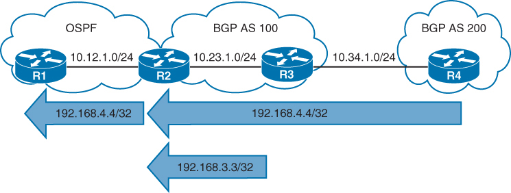
Redistributing iBGP routes into an IGP could result in routing loops. A more logical solution is to advertise the network into the IGP
EIGRP Behaviour
When EIGRP redistributes something into itself, that route is given an AD of 170 and classed as external EIGRP route and use a default seed metric of infinity.
Default seed metric of infinity (effectively “unreachable”) (prevents the route from being installed unless you manually define a metric)
The default path metric can be changed from infinity to specific values for bandwidth, load, delay, reliability, and maximum transmission unit (MTU), thereby allowing for the installation into the EIGRP topology table. Routers can set the default metric with the address family configuration command
default-metric bandwidth delay reliability load mtu
!BDRLM
The metric can also be set within a route map or at the time of redistribution with the command
redistribute source-protocol [metric bandwidth delay reliability load mtu] [route-map route-map-name]EIGRP to EIGRP redistribution (EIGRP AS X into EIGRP AS Y):
EIGRP does carry over the original EIGRP metric components
(bandwidth, delay, reliability, load, MTU)
BUT EIGRP still treats them as external routes in the receiving AS
The routes become EIGRP external (D EX) with:
AD = 170
External tag
“Original metric preserved”
Example config:
R2 mutually redistributes OSPF into EIGRP
R3 mutually redistributes BGP into EIGRP
R1 is advertising the Loopback 0 address 192.168.1.1/32
R4 is advertising the Loopback 0 address 192.168.4.4/32
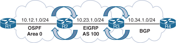
R2 uses the default-metric configuration command
both classic and named mode configurations
Using default-metric on whole process
R2 (AS Classic Configuration)
router eigrp 100
 default-metric 1000000 1 255 1 1500
 network 10.23.1.0 0.0.0.255
 redistribute ospf 1
R2 (Named Mode Configuration)
router eigrp EIGRP-NAMED
address-family ipv4 unicast autonomous-system 100
topology base
default-metric 1000000 1 255 1 1500
redistribute ospf 1
exit-af-topology
network 10.23.1.0 0.0.0.255R3 (Named Mode Configuration)
router eigrp EIGRP-NAMED
address-family ipv4 unicast autonomous-system 100
topology base
redistribute bgp 65100 metric 1000000 1 255 1 1500
exit-af-topology
network 10.23.1.0 0.0.0.255
exit-address-familyUsing route-map
You can overwrite EIGRP seed metrics by setting K values also with the route map command set metric bandwidth delay reliability load mtu. Setting the metric on a prefix-by-prefix basis during redistribution
R2
router eigrp 100
 network 10.23.1.0 0.0.0.255
 redistribute ospf 1 route-map OSPF-2-EIGRP
!
route-map OSPF-2-EIGRP permit 10
 set metric 1000000 1 255 1 1500
R2# show ip eigrp topology
EIGRP-IPv4 Topology Table for AS(100)/ID(192.168.2.2)
Codes: P - Passive, A - Active, U - Update, Q - Query, R - Reply,
       r - reply Status, s - sia Status

P 10.34.1.0/24, 1 successors, FD is 3072
         via 10.23.1.3 (3072/2816), GigabitEthernet0/1
P 192.168.4.4/32, 1 successors, FD is 3072, tag is 65200
         via 10.23.1.3 (3072/2816), GigabitEthernet0/1
P 10.12.1.0/24, 1 successors, FD is 2816
         via Redistributed (2816/0)
P 192.168.1.1/32, 1 successors, FD is 2816
         via Redistributed (2816/0)
P 10.23.1.0/24, 1 successors, FD is 2816
         via Connected, GigabitEthernet0/1
The redistributed routes are shown in the routing table with D EX and an AD of 170
R2# show ip route | begin Gateway
! Output omitted for brevity
Gateway of last resort is not set
       10.0.0.0/8 is variably subnetted, 5 subnets, 2 masks
C         10.12.1.0/24 is directly connected, GigabitEthernet0/0
C         10.23.1.0/24 is directly connected, GigabitEthernet0/1
D EX      10.34.1.0/24 [170/3072] via 10.23.1.3, 00:07:43, GigabitEthernet0/1
O         192.168.1.1 [110/2] via 10.12.1.1, 00:29:22, GigabitEthernet0/0
D EX      192.168.4.4 [170/3072] via 10.23.1.3, 00:08:49, GigabitEthernet0/1
R3# show ip route | begin Gateway
! Output omitted for brevity
D EX 10.12.1.0/24 [170/15360] via 10.23.1.2, 00:22:27, GigabitEthernet0/1
C 10.23.1.0/24 is directly connected, GigabitEthernet0/1
C 10.34.1.0/24 is directly connected, GigabitEthernet0/0
D EX 192.168.1.1 [170/15360] via 10.23.1.2, 00:22:27, GigabitEthernet0/1
B 192.168.4.4 [20/0] via 10.34.1.4, 00:13:21EIGRP-to-EIGRP Redistribution
Redistributing routes between EIGRP autonomous systems preserves the path metrics during redistribution but still classes them as EIGRP external routes
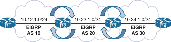
R2 mutually redistributes routes between AS 10 and AS 20
R3 mutually redistributes routes between AS 20 and AS 30
R1 advertises the Loopback 0 interface (192.168.1.1/32) into EIGRP AS 10
R4 advertises the Loopback 0 interface (192.168.4.4/32) into EIGRP AS 30
The default seed metrics do not need to be set because they are maintained between EIGRP ASs
R2 is using classic configuration mode, and R3 is using EIGRP named configuration mode.
R2
router eigrp 10
 network 10.12.1.0 0.0.0.255
 redistribute eigrp 20
router eigrp 20
 network 10.23.1.0 0.0.0.255
 redistribute eigrp 10
R3
router eigrp EIGRP-NAMED-20
address-family ipv4 unicast autonomous-system 20
topology base
redistribute eigrp 30
exit-af-topology
network 10.23.1.0 0.0.0.255
!
router eigrp EIGRP-NAMED-30
address-family ipv4 unicast autonomous-system 30
topology base
redistribute eigrp 20
exit-af-topology
network 10.34.1.0 0.0.0.255
exit-address-familyVerification of redistribution on R1 and R4
R1# show ip route eigrp | begin Gateway
Gateway of last resort is not set

      10.0.0.0/8 is variably subnetted, 4 subnets, 2 masks
D EX     10.23.1.0/24 [170/3072] via 10.12.1.2, 00:09:07, GigabitEthernet0/0
D EX     10.34.1.0/24 [170/3328] via 10.12.1.2, 00:05:48, GigabitEthernet0/0
      192.168.4.0/32 is subnetted, 1 subnets
D EX     192.168.4.4 [170/131328] via 10.12.1.2, 00:05:48, GigabitEthernet0/0
R4# show ip route eigrp | begin Gateway
Gateway of last resort is not set
10.0.0.0/8 is variably subnetted, 4 subnets, 2 masks
D EX 10.12.1.0/24 [170/3328] via 10.34.1.3, 00:07:31, GigabitEthernet0/0
D EX 10.23.1.0/24 [170/3072] via 10.34.1.3, 00:07:31, GigabitEthernet0/0
192.168.1.0/32 is subnetted, 1 subnets
D EX 192.168.1.1 [170/131328] via 10.34.1.3, 00:07:31, GigabitEthernet0/0EIGRP topology table for the route 192.168.4.4/32 in AS 10 and AS 20. The EIGRP path metrics for bandwidth, reliability, load, and delay are the same between the autonomous systems. Notice that the feasible distance (131,072) is the same for both autonomous systems, but the reported distance (RD) is 0 for AS 10 and 130,816 for AS 20. The RD was reset when it was redistributed into AS 10.
R2# show ip eigrp topology 192.168.4.4/32
! Output omitted for brevity
EIGRP-IPv4 Topology Entry for AS(10)/ID(192.168.2.2) for 192.168.4.4/32
  State is Passive, Query origin flag is 1, 1 Successor(s), FD is 131072
  Descriptor Blocks:
  10.23.1.3, from Redistributed, Send flag is 0x0
      Composite metric is (131072/0), route is External
      Vector metric:
        Minimum bandwidth is 1000000 Kbit
        Total delay is 5020 microseconds
        Reliability is 255/255
        Load is 1/255
        Minimum MTU is 1500
        Hop count is 2
        Originating router is 192.168.2.2
      External data:
        AS number of route is 20
        External protocol is EIGRP, external metric is 131072
        Administrator tag is 0 (0x00000000)
EIGRP-IPv4 Topology Entry for AS(20)/ID(192.168.2.2) for 192.168.4.4/32
  State is Passive, Query origin flag is 1, 1 Successor(s), FD is 131072
  Descriptor Blocks:
  10.23.1.3 (GigabitEthernet0/1), from 10.23.1.3, Send flag is 0x0
      Composite metric is (131072/130816), route is External
      Vector metric:
        Minimum bandwidth is 1000000 Kbit
        Total delay is 5020 microseconds
        Reliability is 255/255
        Load is 1/255
        Minimum MTU is 1500
        Hop count is 2
        Originating router is 192.168.3.3
      External data:
        AS number of route is 30
        External protocol is EIGRP, external metric is 2570240
OSPF Behaviour
The AD is set to 110 for intra-area, inter-area, and external OSPF routes. External OSPF routes are classified as Type 1 or Type 2, with Type 2 as the default setting. The seed metric is 1 for BGP-sourced routes and 20 for all other protocols
The exception is that if OSPF redistributes from another OSPF process, the path metric is transferred. The main differences between Type 1 and Type 2 external OSPF routes follow:
Type 1 routes are preferred over Type 2 routes.
The Type 1 metric equals the redistribution metric plus the total path metric to the autonomous system boundary router (ASBR). In other words, as the LSA propagates away from the originating ASBR, the metric increases.
The Type 2 metric equals only the redistribution metric. The metric is the same for the router next to the ASBR as for the router 30 hops away from the originating ASBR. If two Type 2 paths have exactly the same metric, the lower forwarding cost is preferred. This is the default external metric type used by OSPF.
For redistribution into OSPF, you use the command redistribute source-protocol [subnets] [metric metric] [metric-type {1 | 2}] [tag 0-4294967295] [route-map route-map-name].
If the optional subnets keyword is not included, only the classful networks are redistributed.
The optional tag keyword allows for a 32-bit route tag to be included on each redistributed route.
The metric and metric-type keywords can be set during redistribution.
R2 mutually redistributes EIGRP into OSPF
R3 mutually redistributes RIP into OSPF
R1 is advertising the Loopback 0 interface 192.168.1.1/32
R4 is advertising the Loopback 0 interface 192.168.4.4/32.
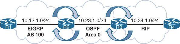
R2
router ospf 2
 router-id 192.168.2.2
 network 10.23.1.0 0.0.0.255 area 0
 redistribute eigrp 100 subnets
R3
router ospf 3
router-id 192.168.3.3
redistribute rip subnets
network 10.23.1.3 0.0.0.0 area 0Redistribution verification
R3# show ip ospf database external
! Output omitted for brevity

            OSPF Router with ID (192.168.3.3) (Process ID 2)
               Type-5 AS External Link States

  Link State ID: 10.12.1.0 (External Network Number )
  Advertising Router: 192.168.2.2
  Network Mask: /24
         Metric Type: 2 (Larger than any link state path)
         Metric: 20

  Link State ID: 10.34.1.0 (External Network Number )
  Advertising Router: 192.168.3.3
  Network Mask: /24
         Metric Type: 2 (Larger than any link state path)
         Metric: 20

  Link State ID: 192.168.1.1 (External Network Number )
  Advertising Router: 10.23.1.2
  Network Mask: /32
         Metric Type: 2 (Larger than any link state path)
         Metric: 20

  Link State ID: 192.168.4.4 (External Network Number )
  Advertising Router: 192.168.3.3
  Network Mask: /32
         Metric Type: 2 (Larger than any link state path)
         Metric: 20
R2# show ip route | begin Gateway
Gateway of last resort is not set
10.0.0.0/8 is variably subnetted, 5 subnets, 2 masks
C 10.12.1.0/24 is directly connected, GigabitEthernet0/0
C 10.23.1.0/24 is directly connected, GigabitEthernet0/1
O E2 10.34.1.0/24 [110/20] via 10.23.1.3, 00:04:44, GigabitEthernet0/1
192.168.1.0/32 is subnetted, 1 subnets
D 192.168.1.1 [90/130816] via 10.12.1.1, 00:03:56, GigabitEthernet0/0
192.168.2.0/32 is subnetted, 1 subnets
C 192.168.2.2 is directly connected, Loopback0
O E2 192.168.4.0/24 [110/20] via 10.23.1.3, 00:04:42, GigabitEthernet0/1R3# show ip route | begin Gateway
Gateway of last resort is not set
10.0.0.0/8 is variably subnetted, 5 subnets, 2 masks
O E2 10.12.1.0/24 [110/20] via 10.23.1.2, 00:05:41, GigabitEthernet0/1
C 10.23.1.0/24 is directly connected, GigabitEthernet0/1
C 10.34.1.0/24 is directly connected, GigabitEthernet0/0
192.168.1.0/32 is subnetted, 1 subnets
O E2 192.168.1.1 [110/20] via 10.23.1.2, 00:05:41, GigabitEthernet0/1
192.168.3.0/32 is subnetted, 1 subnets
C 192.168.3.3 is directly connected, Loopback0
R 192.168.4.0/24 [120/1] via 10.34.1.4, 00:00:00, GigabitEthernet0/0OSPF-to-OSPF Redistribution
Redistributing routes between OSPF processes preserves the path metric during redistribution, independent of the metric type
R2 redistributes routes between OSPF process 1 and OSPF process 2
R3 redistributes between OSPF process 2 and OSPF process 3.
R2 and R3 set the metric type to 1 during redistribution so that the path metric increments
R1 advertises the Loopback 0 interface 192.168.1.1/32 into OSPF process 1
R4 advertises the Loopback 0 interface 192.168.4.4/32 into OSPF process 3.
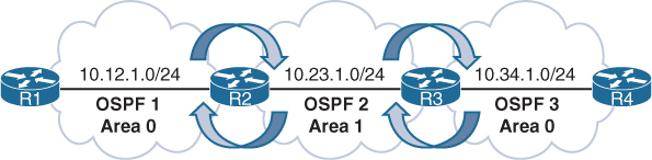
but it results in the loss of path information as the Type 1, Type 2, and Type 3 LSAs are not propagated through route redistribution, only metrics are maintained
R2# show running-config | section router ospf
router ospf 1
 redistribute ospf 2 subnets metric-type 1
 network 10.12.1.0 0.0.0.255 area 0
router ospf 2
 redistribute ospf 1 subnets metric-type 1
 network 10.23.1.0 0.0.0.255 area 1
R3# show running-config | section router ospf
router ospf 2
redistribute ospf 3 subnets metric-type 1
network 10.23.1.0 0.0.0.255 area 1
router ospf 3
redistribute ospf 2 subnets metric-type 1
network 10.34.1.0 0.0.0.255 area 0Verification on R1 and R4
R1# show ip route ospf | begin Gateway
Gateway of last resort is not set

      10.0.0.0/8 is variably subnetted, 4 subnets, 2 masks
O E1     10.23.1.0/24 [110/2] via 10.12.1.2, 00:00:21, GigabitEthernet0/0
O E1     10.34.1.0/24 [110/3] via 10.12.1.2, 00:00:21, GigabitEthernet0/0
      192.168.4.0/32 is subnetted, 1 subnets
O E1     192.168.4.4 [110/4] via 10.12.1.2, 00:00:21, GigabitEthernet0/0
R4# show ip route ospf | begin Gateway
Gateway of last resort is not set
10.0.0.0/8 is variably subnetted, 4 subnets, 2 masks
O E1 10.12.1.0/24 [110/3] via 10.34.1.3, 00:01:36, GigabitEthernet0/0
O E1 10.23.1.0/24 [110/2] via 10.34.1.3, 00:01:46, GigabitEthernet0/0
192.168.1.0/32 is subnetted, 1 subnets
O E1 192.168.1.1 [110/4] via 10.34.1.3, 02:38:49, GigabitEthernet0/0OSPF Forwarding Address
OSPF Type 5 LSAs include a field known as the forwarding address that optimizes forwarding traffic when the source uses a shared network segment
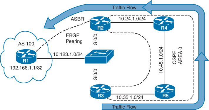
OSPF is enabled on all the links in Area 0 except for network 10.123.1.0/24
R1 forms an eBGP session with R2 (the ASBR) which then redistributes the AS 100 route 192.168.1.1/32 into the OSPF domain
R3 has direct connectivity to R1 but does not establish a BGP session with R1
ASBR is 10.123.1.2 which is the IP address that all OSPF routers forward packets to in order to reach the 192.168.1.1/32 network
Notice that the forwarding address is the default value 0.0.0.0
R3# show ip ospf database external
! Output omitted for brevity
                Type-5 AS External Link States

  Routing Bit Set on this LSA in topology Base with MTID 0
  LS Type: AS External Link
  Link State ID: 192.168.1.1 (External Network Number )
  Advertising Router: 10.123.1.2
  Network Mask: /32
        Metric Type: 2 (Larger than any link state path)
        Metric: 1
        Forward Address: 0.0.0.0
Network traffic from R3 (and R5) takes the suboptimal route R3→R5→R4→R2→R1
The optimal route would use the directly connected 10.123.1.0/24 network
R3# trace 192.168.1.1
Tracing the route to 192.168.1.1
  1 10.35.1.5  0 msec 0 msec 1 msec
  2 10.45.1.4  0 msec 0 msec 0 msec
  3 10.24.1.2  1 msec 0 msec 0 msec
  4 10.123.1.1 1 msec *  0 msec
R5# trace 192.168.1.1
Tracing the route to 192.168.1.1
1 10.45.1.4 0 msec 0 msec 0 msec
2 10.24.1.2 1 msec 0 msec 0 msec
3 10.123.1.1 1 msec * 0 msecWhen the forwarding address is 0.0.0.0, all routers forward packets to the ASBR, introducing the potential for suboptimal routing.
The OSPF forwarding address changes from 0.0.0.0 “to the next-hop IP address in the source routing protocol” when:
- OSPF is enabled on the ASBR’s interface that points to the next-hop IP address.
- That interface is not set to passive.
- That interface is a broadcast or nonbroadcast OSPF network type.
When the forwarding address is set to a value besides 0.0.0.0, the OSPF routers forward traffic only to the forwarding address.
OSPF has been enabled on R2’s and R3’s Ethernet interface connected to the 10.123.1.0/24 network,
The interface is Ethernet, which defaults to the broadcast OSPF network type, and all conditions have been met.

Type 5 LSA for the 192.168.1.1/32 network. Now that OSPF has been enabled on R2’s 10.123.1.2 interface and the interface is a broadcast network type, the forwarding address has changed from 0.0.0.0 to 10.123.1.1.
R3# show ip ospf database external
! Output omitted for brevity
                Type-5 AS External Link States1

  Options: (No TOS-capability, DC)
  LS Type: AS External Link
  Link State ID: 192.168.1.1 (External Network Number )
  Advertising Router: 10.123.1.2
  Network Mask: /32
         Metric Type: 2 (Larger than any link state path)
         Metric: 1
         Forward Address: 10.123.1.1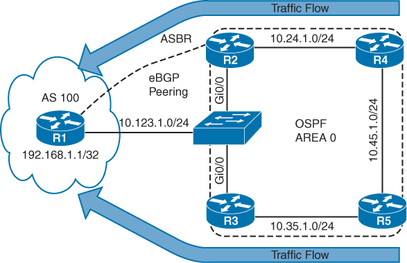
verifies that connectivity from R3 and R5 now takes the optimal path to R1 because the forwarding address has changed to 10.123.1.1.
R3# trace 192.168.1.1
Tracing the route to 192.168.1.1
  1 10.123.1.1 0 msec *  1 msec
R5# trace 192.168.1.1
Tracing the route to 192.168.1.1
1 10.35.1.3 0 msec 0 msec 1 msec
2 10.123.1.1 0 msec * 1 msecIf the Type 5 LSA forwarding address is not a default value, the address must be an intra-area or inter-area OSPF route
If the route does not exist, the LSA is ignored and is not installed into the RIB
The OSPF forwarding address optimizes forwarding toward the destination network, but return traffic is unaffected. Outbound traffic from R3 or R5 still exits at R3’s Gi0/0 interface, but return traffic is sent directly to R2.
BGP Behaviour
Redistributing routes into BGP does not require a seed metric because BGP is a path vector protocol. Redistributed routes have the following BGP attributes set.
The origin is set to incomplete.
The next-hop address is set to the IP address of the source protocol
The weight is set to 32,768
The MED is set to the path metric of the source protocol
R2 mutually redistributes between OSPF and BGP
R3 mutually redistributes between EIGRP AS 100 and BGP
R1 is advertising the Loopback 0 interface 192.168.1.1/32
R4 is advertising the Loopback 0 interface 192.168.4.4/32
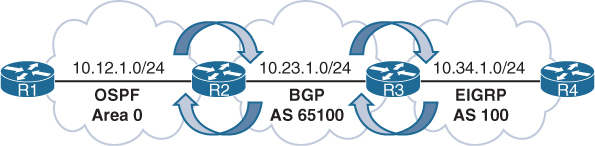
Notice that R2 and R3 have used the command bgp redistribute-internal, which allows for any iBGP learned prefixes to be redistributed into OSPF or EIGRP
R2 (Default IPv4 Address Family Enabled)
router bgp 65100
 bgp redistribute-internal
 network 10.23.1.0 mask 255.255.255.0
 redistribute ospf 1
 neighbor 10.23.1.3 remote-as 65100
R3 (Default IPv4 Address Family Disabled)
router bgp 65100
no bgp default ipv4-unicast
neighbor 10.23.1.2 remote-as 65100
!
address-family ipv4
bgp redistribute-internal
network 10.23.1.0 mask 255.255.255.0
redistribute eigrp 100
neighbor 10.23.1.2 activate
exit-address-familyVerification, notice the metric is carried over from the IGP metric during redistribution
R2# show bgp ipv4 unicast | begin Network
       Network         Next Hop           Metric LocPrf Weight Path
 *>   10.12.1.0/24     0.0.0.0                 0         32768 ?
 * i  10.23.1.0/24     10.23.1.3               0    100      0 i
 *>                    0.0.0.0                 0         32768 i
 *>i  10.34.1.0/24     10.23.1.3               0    100      0 ?
 *>   192.168.1.1/32   10.12.1.1               2         32768 ?
 *>i  192.168.4.4/32   10.34.1.4          130816    100      0 ?
Detailed BGP path information for the redistributed routes
The origin is incomplete, and the BGP metric matches the IGP metric.
R2# show bgp ipv4 unicast 192.168.1.1
! Output omitted for brevity

BGP routing table entry for 192.168.1.1/32, version 3
Paths: (1 available, best #1, table default)
  Local
    10.12.1.1 from 0.0.0.0 (192.168.2.2)
      Origin incomplete, metric 2, localpref 100, weight 32768, valid, sourced, best
R3# show bgp ipv4 unicast 192.168.4.4
BGP routing table entry for 192.168.4.4/32, version 3
Paths: (1 available, best #1, table default)
Local
10.34.1.4 from 0.0.0.0 (10.34.1.3)
Origin incomplete, metric 130816, localpref 100, weight 32768, valid, sourced,
bestRedistribution of routes from OSPF to BGP does not include OSPF external routes by default. match external [1 | 2] is required to redistribute OSPHighly available network designs use multiple points of redistribution to ensure redundancy, which increases the probability of route feedback. Route feedback can cause suboptimal routing or routing loops, but it can be resolved with the techniques explained in this chapter and in Chapter 12, “Advanced BGP.”F external routes.
Redistribution and Redundancy
Due to redundancy in networks, there are usually 2 redistirbuting points in the network, but following issues may arise
- Suboptimal routing – slow connectivity
- Routing loops – Total loss of service
Suboptimal routing
Whenever redistribution takes place, network visiblity is lost and seed metric is used as a starting point and this is not an issue when there is only one point of redistribution in the network however it can become an issue if there are 2 or more points of redistribution and it can cause sub optimal routing to the destination learned via redistribution
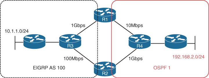
Left to right, better path to reach 192.168.2.0/24 is via R2 because via R1 we will encounter R1’s 10Mbps link which is slowest in the topology
When you perform redistribution on R1 and R2 (Internal Routers) into EIGRP, EIGRP does not know that the 10 Mbps link or the 1 Gbps link exists in the OSPF domain, in order to avoid this situation we have to add lower seed metric on R2 and higher seed metric on R1
Same Seed Metric
In case seed metric defined on R1 and R2 are same, in EIGRP AS or domain, after adding seed metric (distance vector calculation) and cost of links (1 Gbps link and 100 Mbps links), inside EIGRP AS route to 192.168.2.0/24 through R1 will win and from there I will be routed over the 10 Mbps link
You can recognize this issue in a topological diagram and also by using the traceroute command
You can solve this issue by providing lower seed metric on R2 and higher seed metric on R1
In reverse when EIGRP routes (10.1.1.0/24) are redistributed into OSPF, the redistributed routes have a default seed metric of 20 and are classified as E2 routes;
Due to E2 routes, the metric remains as 20 throughout the OSPF domain, whenever E2 are used we need to keep in mind that routes
next post
OSPF
OSPF
OSPF is a link state routing protocol, an IGP
OSPF exchanges routing information with other routers , neighbors over LSA
LSA contains information on the link state (Subnet(s) on interface(s)) and link metric (cost to reach that IP and mask)
OSPF advertises this information to neighboring routers exactly as the original advertising router advertised it, in fact the whole area gets same LSAs and it is up to individual routers to compute SPT (Shortest Path Tree [to every subnet])
Received LSAs are stored in a local database called the link-state database (LSDB).
and then local router spreads LSAs through the OSPF area, interface by interface – link local multicast to next interface’s link local multicast.
All OSPF routers run Dijkstra’s shortest path first (SPF) algorithm to construct a loop-free topology of shortest paths. OSPF dynamically detects topology changes within the network and calculates loop-free paths in a short amount of time – this is the main purpose of all the routing protocols so we dont have to add static routes through the network and OSPF brings that
Each router sees itself as the root or top of the SPF tree (SPT), and the SPT contains all network destinations within the OSPF domain. The SPT differs for each OSPF router, but the LSDB used to calculate the SPT is identical for all OSPF routers.
There seems to be some difference in connectivity to the 10.3.3.0/24 network from R1’s and R4’s SPTs. From R1’s perspective, the serial link between R3 and R4 is missing; from R4’s perspective, the Ethernet link between R1 and R3 is missing.
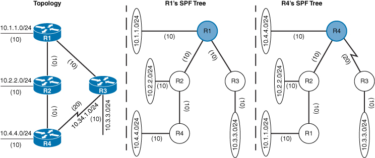
The SPTs give the illusion that no redundancy exists to the networks, but remember that an SPT shows the shortest path to reach a network and is built from the LSDB, which contains all the links for an area.
A router can run multiple OSPF processes. Each process maintains its own unique database, and routes learned in one OSPF process are not available to a different OSPF process without redistribution of routes between processes.
The OSPF process numbers are locally significant and do not have to match among routers. If OSPF process number 1 is running on one router and OSPF process number 1234 is running on another, the two routers can become neighbors.
Areas
OSPF allows scalability by using areas
Area is set at interface level
An interface can belong to only one area
All routers within the same OSPF area maintain an identical copy of the LSDB.
Inside an area:
-A full SPT calculation runs when a link flaps within the area
-With a single area, the LSDB increases in size and becomes unmanageable, as area grows, consumes more memory, and takes longer during the SPF computation process.
-With a single area, no summarization of route information occurs.
If a router has interfaces in multiple areas, the router has multiple LSDBs (one for each area)
The internal topology of one area is invisible from outside that area. Outside areas only learn the prefixes of that area, only topology is not visible (like which prefix is attached to which router), outside areas just know about the prefixes
If a topology change occurs (such as a link flap or an additional network added) within an area, all routers in the same OSPF area calculate the SPT again. Routers outside that area do perform a partial SPF calculation
Segmenting the OSPF domain into multiple areas reduces the size of the LSDB for each area, making SPT calculations faster and decreasing LSDB flooding between routers when a link flaps.
Just because a router connects to multiple OSPF areas does not mean the routes from one area will be injected into another area
Area 0 is a special area called backbone area. OSPF uses a two-tier hierarchy in which all areas must connect to the upper tier Area 0.
All areas inject routing information into Area 0
Area 0 advertises the routes into other areas
Area ID is a 32-bit field and can be formatted as decimal (0 through 4294967295) or dotted decimal (0.0.0.0 through 255.255.255.255) like IPv4
If we use decimal format on one router and dotted-decimal format on a different router, the routers will be able to form an adjacency.
ABRs
Area border routers (ABRs) are OSPF routers connected to Area 0 and another OSPF area, ABR is responsible for sending its connected Area’s routes into -> Area 0 and send all the learned routes from all areas from Area 0’s routes into its areas
Every ABR must participate in Area 0
ABRs compute an SPT for every area that they participate in
OSPF Communication
OSPF runs directly over IPv4, using protocol 89 and does not use TCP or UDP because OSPF communication never travels over distance, it stays on link local using multicast
There are two OSPF multicast addresses:
AllSPFRouters: IPv4 address 224.0.0.5, 01:00:5E:00:00:05.
AllDRouters: IPv4 address 224.0.0.6, 01:00:5E:00:00:06
Remember multicast address of OSPF using 5E, E if flipped becomes M and 5 is S so Multicast
OSPF Packet Types
| 1 | Hello | Packets are sent out periodically on all OSPF interfaces to discover new neighbors while also ensuring that existing neighbors are still online. |
| 2 | Database description (DBD or DDP) | Packets are exchanged when an OSPF adjacency is first being formed. These packets are used to describe the contents of the LSDB, Remember only describe |
| 3 | Link-state request (LSR) | When a router thinks that part of its LSDB is stale after reading the DBD, it may request a portion of a neighbor’s database by using this packet type. |
| 4 | Link-state update (LSU) | This is the “LSA” for a specific network link, and normally it is sent in direct response to an LSR. |
| 5 | Link-state acknowledgment | These packets are sent in response to the flooding of LSAs, thus making the flooding a reliable transport feature. |
Router ID
The OSPF router ID (RID) is unique and identifies router in OSPF domain as a unique participant. The OSPF RID is an essential component in building an OSPF topology. The output of some OSPF commands uses the term neighbor ID as a synonym for RID. The RID must be unique for each OSPF process in an OSPF domain and must be unique between OSPF processes on a router.
The RID is dynamically allocated by default, using the highest IP address of any up loopback interfaces. If there are no up loopback interfaces, the highest IP address of any active up physical interfaces becomes the RID when the OSPF process initializes. The OSPF process selects the RID when the OSPF process initializes, and it does not change until the process restarts. This means that the RID can change if a higher loopback address has been added and the process (or router) is restarted.
Setting a static RID helps with troubleshooting and reduces LSAs when an RID changes in an OSPF environment
OSPF Hello Packets
OSPF Hello packets discover and maintain already discovered neighbors
OSPF router sends out hello on AllSPFRouters 224.0.0.5
Information carried inside OSPF hello:
| Router ID (RID) | A unique 32-bit ID within an OSPF domain that is used to build the topology. |
| Authentication Options | A field that allows secure communication between OSPF routers to prevent malicious activity. Options are none, plaintext, or Message Digest 5 (MD5) authentication. |
| Area ID | The OSPF area that the OSPF interface belongs to. It is a 32-bit number that can be written in dotted-decimal format (0.0.1.0) or decimal (256). |
| Interface Address Mask | The network mask for the primary IP address for the interface out which the hello is sent. |
| Interface Priority | The router interface priority for DR elections. |
| Hello Interval | The time interval, in seconds, at which a router sends out hello packets on the interface. |
| Dead Interval | The time interval, in seconds, that a router waits to hear a hello from a neighbor router before it declares that router down. |
| Designated Router and Backup Designated Router | The IP address of the DR and backup DR (BDR) for that network link. |
| Active Neighbor | A list of OSPF neighbors seen on that network segment. To qualify in this neighbor list a router must have received a hello from the neighbor within the dead interval. |
See how Active neighbors and DR / BDR information is inside the hello packets
Neighbors
An OSPF neighbor is a router that shares a common OSPF-enabled network link
Discover neighbors through hello messages
An adjacent OSPF neighbor is an OSPF neighbor that has shared all the LSDB to its neighbor as opposed to 2 way
OSPF Neighbor States
| Down | Router has not yet received hello yet |
| Attempt | A state that is relevant to nonbroadcast multi-access (NBMA) networks that do not support broadcast and require neighbor configuration. This state indicates that the router is still attempting communication. |
| Init | A state in which a hello packet has been received from another router, but bidirectional communication has not been established. Remember from “in” in Init |
| 2-Way | A state in which bidirectional communication has been established. If a DR or BDR is needed, the election occurs during this state. |
| ExStart | The first state in forming an adjacency. Routers identify which router will be the primary or secondary for the LSDB synchronization. |
| Exchange | A state during which routers are exchanging link states by using DBD packets. |
| Loading | A state in which LSR packets are sent to the neighbor, asking for the more recent LSAs that have been discovered (but not received) in the Exchange state. |
| Full | A state in which neighboring routers are fully adjacent. |
Neighbor Adjacency Requirements
R – The RIDs must be unique for whole OSPF domain, To prevent errors, they should be unique for the entire OSPF routing domain.
S – The interfaces must share a common subnet. OSPF uses the interface’s primary IP address when sending out OSPF hellos. The network mask (netmask) in the hello packet is used to extract the network ID of the hello packet.
M – The interface maximum transmission unit (MTU) must match because the OSPF protocol does not support fragmentation.
A – The area ID must match for that segment.
D – The need for a DR must match for that segment.
H – OSPF hello and dead timers must match for that segment.
A – The authentication type and credentials (if any) must match for that segment.
T – Area type flags must be identical for that segment (stub, NSSA, and so on).

see step 2 and 3, init and 2 way, how the neighbor list builds up
R1# debug ip ospf adj
OSPF adjacency events debugging is on

*21:10:01.735: OSPF: Build router LSA for area 0, router ID 192.168.1.1,
 seq 0x80000001, process 1
*21:10:09.203: OSPF: 2 Way Communication to 192.168.2.2 on GigabitEthernet0/0,
 state 2WAY
*21:10:39.855: OSPF: Rcv DBD from 192.168.2.2 on GigabitEthernet0/0 seq 0x1823
 opt 0x52 flag 0x7 len 32 mtu 1500 state 2WAY

*21:10:39.855: OSPF: Nbr state is 2WAY
*21:10:41.235: OSPF: end of Wait on interface GigabitEthernet0/0
*21:10:41.235: OSPF: DR/BDR election on GigabitEthernet0/0
*21:10:41.235: OSPF: Elect BDR 192.168.2.2
*21:10:41.235: OSPF: Elect DR 192.168.2.2
*21:10:41.235: DR: 192.168.2.2 (Id) BDR: 192.168.2.2 (Id)
*21:10:41.235: OSPF: GigabitEthernet0/0 Nbr 192.168.2.2: Prepare dbase exchange
*21:10:41.235: OSPF: Send DBD to 192.168.2.2 on GigabitEthernet0/0 seq 0xFA9
 opt 0x52 flag 0x7 len 32
*21:10:44.735: OSPF: Rcv DBD from 192.168.2.2 on GigabitEthernet0/0 seq 0x1823
 opt 0x52 flag 0x7 len 32 mtu 1500 state EXSTART
*21:10:44.735: OSPF: GigabitEthernet0/0 Nbr 2.2.2.2: Summary list built, size 1
*21:10:44.735: OSPF: Send DBD to 192.168.2.2 on GigabitEthernet0/0 seq 0x1823
 opt 0x52 flag 0x2 len 52
*21:10:44.743: OSPF: Rcv DBD from 192.168.2.2 on GigabitEthernet0/0 seq 0x1824
 opt 0x52 flag 0x1 len 52 mtu 1500 state EXCHANGE
*21:10:44.743: OSPF: Exchange Done with 192.168.2.2 on GigabitEthernet0/0
*21:10:44.743: OSPF: Send LS REQ to 192.168.2.2 length 12 LSA count 1
*21:10:44.743: OSPF: Send DBD to 192.168.2.2 on GigabitEthernet0/0 seq 0x1824
 opt 0x52 flag 0x0 len 32
*21:10:44.747: OSPF: Rcv LS UPD from 192.168.2.2 on GigabitEthernet0/0 length
 76 LSA count 1
*21:10:44.747: OSPF: Synchronized with 192.168.2.2 GigabitEthernet0/0, state FULL
*21:10:44.747: %OSPF-5-ADJCHG: Process 1, Nbr 192.168.2.2 on GigabitEthernet0/0
 from LOADING to FULL, Loading Done
OSPF Configuration
Most configuration for OSPF is done under OSPF process but some configuration can be done at interface level
command ip ospf process-id area area-id [secondaries none]. This method also adds secondary connected networks to the LSDB unless the secondaries none option is used.
Making the network interface passive still adds the network segment to the LSDB but prevents the interface from forming OSPF adjacencies. A passive interface does not send out OSPF hellos and does not process any received OSPF packets.
The command passive-interface interface-id under the OSPF process makes the interface passive, and the command passive-interface default makes all interfaces passive, Then command no passive-interface interface-id is used to make interfaces non passive
Different ways of configuring OSPF
R1
router ospf 1
 router-id 192.168.1.1
 network 0.0.0.0 255.255.255.255 area 1234
R2
router ospf 1
router-id 192.168.2.2
network 10.123.1.2 0.0.0.0 area 1234
network 10.24.1.2 0.0.0.0 area 1234R3
router ospf 1
router-id 192.168.3.3
network 0.0.0.0 255.255.255.255 area 1234
passive-interface GigabitEthernet0/1R3
router ospf 1
router-id 192.168.3.3
network 0.0.0.0 255.255.255.255 area 1234
passive-interface GigabitEthernet0/1R4
router ospf 1
router-id 192.168.4.4
!
interface GigabitEthernet0/0
ip ospf 1 area 0
interface Serial1/0
ip ospf 1 area 1234R5
router ospf 1
router-id 192.168.5.5
network 10.45.1.0 0.0.0.255 area 0
network 0.0.0.0 255.255.255.255 area 56R6
router ospf 1
router-id 192.168.6.6
network 0.0.0.0 255.255.255.255 area 56R4# show ip ospf interface
GigabitEthernet0/0 is up, line protocol is up
Internet Address 10.45.1.4/24, Area 0, Attached via Interface Enable
Process ID 1, Router ID 192.168.4.4, Network Type BROADCAST, Cost: 1
Topology-MTID Cost Disabled Shutdown Topology Name
0 1 no no Base
Enabled by interface config, including secondary ip addresses
Transmit Delay is 1 sec, State BDR, Priority 1
Designated Router (ID) 192.168.5.5, Interface address 10.45.1.5
Backup Designated router (ID) 192.168.4.4, Interface address 10.45.1.4
Timer intervals configured, Hello 10, Dead 40, Wait 40, Retransmit 5
oob-resync timeout 40
Hello due in 00:00:02
..
Neighbor Count is 1, Adjacent neighbor count is 1
Adjacent with neighbor 192.168.5.5 (Designated Router)
Suppress hello for 0 neighbor(s)
Serial1/0 is up, line protocol is up
Internet Address 10.24.1.4/29, Area 1234, Attached via Interface Enable
Process ID 1, Router ID 192.168.4.4, Network Type POINT_TO_POINT, Cost: 64
Topology-MTID Cost Disabled Shutdown Topology Name
0 64 no no Base
Enabled by interface config, including secondary ip addresses
Transmit Delay is 1 sec, State POINT_TO_POINT
Timer intervals configured, Hello 10, Dead 40, Wait 40, Retransmit 5
..
Neighbor Count is 1, Adjacent neighbor count is 1
Adjacent with neighbor 192.168.2.2
Suppress hello for 0 neighbor(s)R1# show ip ospf interface brief
Interface PID Area IP Address/Mask Cost State Nbrs F/C
Gi0/0 1 1234 10.123.1.1/24 1 DROTH 2/2R2# show ip ospf interface brief
Interface PID Area IP Address/Mask Cost State Nbrs F/C
Se1/0 1 1234 10.24.1.1/29 64 P2P 1/1
Gi0/0 1 1234 10.123.1.2/24 1 BDR 2/2R3# show ip ospf interface brief
Interface PID Area IP Address/Mask Cost State Nbrs F/C
Gi0/1 1 1234 10.3.3.3/24 1 DR 0/0
Gi0/0 1 1234 10.123.1.3/24 1 DR 2/2R4# show ip ospf interface brief
Interface PID Area IP Address/Mask Cost State Nbrs F/C
Gi0/0 1 0 10.45.1.4/24 1 BDR 1/1
Se1/0 1 1234 10.24.1.4/29 64 P2P 1/1PID
The OSPF process ID associated with this interface
Nbrs F
This is neighbors that are “Fully” adjacent, The number of neighbor OSPF routers for a segment that are fully adjacent
Nbrs C
This is neighbor “Count”, The number of neighbor OSPF routers for a segment that have been detected and are in a 2-Way state
DROTHERs do not establish full adjacency with other DROTHERs.
show ip ospf neighbor [detail]
R2# show ip ospf neighbor
Neighbor ID     Pri   State           Dead Time   Address         Interface
192.168.4.4       0   FULL/ -         00:00:38    10.24.1.4       Serial1/0
192.168.1.1       1   FULL/DROTHER    00:00:37    10.123.1.1      GigabitEthernet0/0
192.168.3.3       1   FULL/DR         00:00:34    10.123.1.3      GigabitEthernet0/0
Notice that the state for R2’s S1/0 interface does not reflect a DR status with its peering with R4 (192.168.4.4) because a DR can not exist on a point-to-point link so it simply shows –
R1# show ip route ospf
! Output omitted for brevity
Codes: L - local, C - connected, S - static, R - RIP, M - mobile, B - BGP
       D - EIGRP, EX - EIGRP external, O - OSPF, IA - OSPF inter area
       N1 - OSPF NSSA external type 1, N2 - OSPF NSSA external type 2
       E1 - OSPF external type 1, E2 - OSPF external type 2
Gateway of last resort is not set

O        10.3.3.0/24 [110/2] via 10.123.1.3, 00:18:54, GigabitEthernet0/0
O        10.24.1.0/29 [110/65] via 10.123.1.2, 00:18:44, GigabitEthernet0/0
O IA     10.45.1.0/24 [110/66] via 10.123.1.2, 00:11:54, GigabitEthernet0/0
O IA     10.56.1.0/24 [110/67] via 10.123.1.2, 00:11:54, GigabitEthernet0/0
two sets of numbers are presented in brackets (for example, [110/2]). The first number is the administrative distance (AD), which is 110 by default for OSPF, and the second number is the metric
intra-area (O routes)
inter-area (O IA routes)
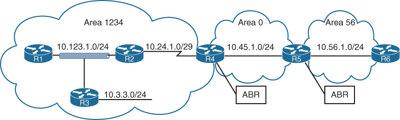
R5# show ip route ospf | begin Gateway
Gateway of last resort is not set

O IA     10.3.3.0/24 [110/67] via 10.45.1.4, 00:04:13, GigabitEthernet0/0
O IA     10.24.1.0/29 [110/65] via 10.45.1.4, 00:04:13, GigabitEthernet0/0
O IA     10.123.1.0/24 [110/66] via 10.45.1.4, 00:04:13, GigabitEthernet0/0
routing table for R5 and R6. R5 and R6 contain only inter-area routes in the OSPF routing table because intra-area routes are directly connected. Directly connected routes are not installed in routing table only because of AD competition only, these O Intra area routes will still show in OSPF LSDB
Routes that are injected into an OSPF domain through redistribution are known as external OSPF routes.
The router that redistributes prefixes into an OSPF domain, the router is called an autonomous system boundary router (ASBR)
There are 2 types of external routes:
Type 1 routes are preferred over Type 2 routes.
The Type 1 metric equals the redistribution metric plus the total path metric to the ASBR. In other words, as the LSA propagates away from the originating ASBR, the metric increases.
The Type 2 metric equals only the redistribution metric. The metric is the same for the router next to the ASBR as the router 30 hops away from the originating ASBR. This is the default external metric type used by OSPF.
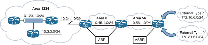
172.16.6.0/24 network is redistributed as a Type 1 route, and the 172.31.6.0/24 network is redistributed as a Type 2 route
External OSPF network routes are marked as O E1 and O E2
R1# show ip route ospf
! Output omitted for brevity
Codes: L - local, C - connected, S - static, R - RIP, M - mobile, B - BGP
       D - EIGRP, EX - EIGRP external, O - OSPF, IA - OSPF inter area
       E1 - OSPF external type 1, E2 - OSPF external type 2
Gateway of last resort is not set

O        10.3.3.0/24 [110/2] via 10.123.1.3, 23:20:25, GigabitEthernet0/0
O        10.24.1.0/29 [110/65] via 10.123.1.2, 23:20:15, GigabitEthernet0/0
O IA     10.45.1.0/24 [110/66] via 10.123.1.2, 23:13:25, GigabitEthernet0/0
O IA     10.56.1.0/24 [110/67] via 10.123.1.2, 23:13:25, GigabitEthernet0/0
O E1     172.16.6.0 [110/87] via 10.123.1.2, 00:01:00, GigabitEthernet0/0
O E2     172.31.6.0 [110/20] via 10.123.1.2, 00:01:00, GigabitEthernet0/0
R2# show ip route ospf | begin Gateway
Gateway of last resort is not set
O 10.3.3.0/24 [110/2] via 10.123.1.3, 23:24:05, GigabitEthernet0/0
O IA 10.45.1.0/24 [110/65] via 10.24.1.4, 23:17:11, Serial1/0
O IA 10.56.1.0/24 [110/66] via 10.24.1.4, 23:17:11, Serial1/0
O E1 172.16.6.0 [110/86] via 10.24.1.4, 00:04:45, Serial1/0
O E2 172.31.6.0 [110/20] via 10.24.1.4, 00:04:45, Serial1/0metric for the 172.31.6.0/24 network is the same on R1 as it is on R2, but the metric for the 172.16.6.0.0/24 network differs on two routers because Type 1 metrics include the path metric to the ASBR.
OSPF supports advertising the default route into the OSPF domain. The advertising router must have a default route in its routing table for the default route to be advertised. To advertise the default route, you use the command default-information originate [always] [metric metric-value] [metric-type type-value] underneath the OSPF process. The always optional keyword advertises the default route regardless of whether a default route exists in the RIB. In addition, the route metric can be changed with the metric metric-value option, and the metric type can be changed with the metric-type type-value option.
R1
ip route 0.0.0.0 0.0.0.0 100.64.1.2
!
router ospf 1
 network 10.0.0.0 0.255.255.255 area 0
 default-information originate
OSPF advertises the default route as an external OSPF route.
R2# show ip route | begin Gateway
Gateway of last resort is 10.12.1.1 to network 0.0.0.0

O*E2  0.0.0.0/0 [110/1] via 10.12.1.1, 00:02:56, GigabitEthernet0/1
C        10.12.1.0/24 is directly connected, GigabitEthernet0/1
C        10.23.1.0/24 is directly connected, GigabitEthernet0/2
Order of Route Preference
O — Intra-Area route
Most preferred
Best because it stays inside the same area
O IA — Inter-Area route
From another area
Preferred over all external types
N1 — NSSA External Type 1
External + internal cost
Same logic as E1 but inside NSSA
Most preferred external type
E1 — External Type 1
External + internal cost to ASBR
Preferred over type 2
N2 — NSSA External Type 2
External metric only
Treated like E2 but originates in NSSA
E2 — External Type 2
External metric only
Lowest preference
Designated Router and Backup Designated Router
Multi-access networks allow more than two routers to exist on a network segment. With OSPF when each router becomes neighbor of each router, it can flood more LSAs, we dont worry about the hellos since they are still sent to all ospf routers as they needed for 2 way neighborships, it is only the LSAs that can cause issues in n (n – 1) / 2 setup due to excessive traffic
Not just the network but having so many adjacencies per segment consumes more bandwidth, more CPU processing, and more memory to maintain each of the neighbor states.
One router on the network becomes a designated router DR and one router becomes BDR, all OSPF routers then become 2 way adjacent using hellos DROTHER but only fully adjacent with the DR and BDR by sending their full LSDB, this LSDB received by DR and BDR is then synced with all or rest of the OSPF routers, but all of this happens per subnet or per segment
DR/BDR election occurs with OSPF neighborship—specifically, during the last phase of the 2-Way neighbor state and just before the ExStart state
Router interface having OSPF priority of non-zero will attempts DR/BDR elections, if priority is 0 then that OSPF router “interface” (not the whole router) does not take part in DR/BDR elections
Default priority is 1, higher priority wins
If all OSPF routers on a multi-access segment (e.g., Ethernet) have the same priority, OSPF uses the highest Router ID (RID) as the tie-breaker to elect the DR and BDR.
Routers place their RID and also the priority inside hellos
The OSPF DR and BDR roles cannot be preempted but only upon the failure of router control plane
or
manual process restart from CLI
Wait timer
To ensure that all routers on a segment have fully initialized or booted into OS and running OSPF
OSPF initiates a wait timer when OSPF hello packets do not contain a DR/BDR router for a segment. The default value for the wait timer is the dead interval timer When the wait timer has expired, a router participates in the DR election.
The wait timer starts when OSPF first starts on an interface, so a router can still elect itself as the DR for a segment without other OSPF routers; it only waits until the wait timer expires
point-to-point link and has no DR/BDR
If all the OSPF routers have the same OSPF priority, and the next decision is to use the higher RID (and RID selection is also a per node’s local process, to find the highest IP on the loopback interfaces and if no loopback interfaces with IP, then highest IP address on the physical interfaces)
Increasing priority on one router increases its chances of becoming the DR or BDR since default priority on an OSPF interface is 1 and Remember that OSPF does not preempt the DR or BDR roles, so it might be necessary to restart the OSPF process on the current DR/BDR for the changes to take effect.
Setting an interface priority to 0 removes that interface from the DR/BDR election immediately.
OSPF Network Types
Not every transport or network is multiaccess
We have to determine the right network / media type and set OSPF network type based on that
Remember the rule for need of DR/BDR on the network, wherever B is then DR/BDR are needed such as “B”roadcast and non “B”roadcast
| Type | Description | DR/BDR Field in OSPF Hellos | Timers |
|---|---|---|---|
| Broadcast | Default setting on OSPF-enabled Ethernet links. | Yes | Hello: 10 Wait: 40 Dead: 40 |
| Nonbroadcast | Default setting on enabled OSPF Frame Relay main interface or Frame Relay multipoint sub-interfaces. | Yes | Hello: 30 Wait: 120 Dead: 120 |
| Point-to-point | Default setting on enabled OSPF Frame Relay point-to-point sub-interfaces. | No | Hello: 10Wait: 40Dead: 40 |
| Point-to-multipoint | Not enabled by default on any interface type. Interface is advertised as a host route (/32), and sets the next-hop address to the outbound interface. Primarily used for hub-and-spoke topologies. | No | Hello: 30 Wait: 120 Dead: 120 |
| Loopback | Default setting on OSPF-enabled loopback interfaces. Interface is advertised as a host route (/32). | N/A | N/A |
Broadcast
Broadcast networks are multi-access in that they are capable of connecting more than two devices, and broadcasts sent out one interface are capable of reaching all interfaces attached to that segment hence broadcast
ip ospf network broadcast overrides the automatically configured setting and statically sets an interface as an OSPF broadcast network type.
Nonbroadcast
Frame Relay, ATM, and X.25 are considered NBMA in that they can also connect more than two devices but some devices could be in different virtual circuits while in a same subnet
Virtual circuits may provide connectivity, but the topology may not be a full mesh and might only provide a hub-and-spoke topology.
Frame Relay interfaces set the OSPF network type to nonbroadcast by default. The hello protocol interval takes 30 seconds for this OSPF network type. Multiple routers can exist on a segment, so the DR functionality is used. Neighbors are statically defined with the neighbor ip-address command because multicast and broadcast functionality do not exist on this type of circuit. Configuring a static neighbor causes OSPF hellos to be sent using unicast.
command ip ospf network non-broadcast manually sets an interface as an OSPF nonbroadcast network type
R1
interface Serial 0/0
 ip address 10.12.1.1 255.255.255.252
 encapsulation frame-relay
 no frame-relay inverse-arp
 frame-relay map ip address 10.12.1.2 102
!
router ospf 1
 router-id 192.168.1.1
 neighbor 10.12.1.2
 network 0.0.0.0 255.255.255.255 area 0
R1# show ip ospf interface Serial 0/0 | include Type
Process ID 1, Router ID 192.168.1.1, Network Type
NON_BROADCAST, Cost: 64Point-to-Point Networks
Only two nodes can exist on this type of network medium, so OSPF does not waste CPU cycles on DR functionality. The hello timer is set to 10 seconds on OSPF point-to-point network types.
OSPF network type is set to point-to-point by default for serial interfaces (HDLC or PPP encapsulation), Generic Routing Encapsulation (GRE) tunnels, and point-to-point Frame Relay sub-interfaces
R1
interface serial 0/1
  ip address 10.12.1.1 255.255.255.252
!
router ospf 1
   router-id 192.168.1.1
   network 0.0.0.0 255.255.255.255 area 0
R2
interface serial 0/1
ip address 10.12.1.2 255.255.255.252
!
router ospf 1
router-id 192.168.2.2
network 0.0.0.0 255.255.255.255 area 0R1# show ip ospf interface s0/1 | include Type
Process ID 1, Router ID 192.168.1.1, Network Type POINT_TO_POINT, Cost: 64R2# show ip ospf interface s0/1 | include Type
Process ID 1, Router ID 192.168.2.2, Network Type POINT_TO_POINT, Cost: 64R1# show ip ospf neighbor
Neighbor ID Pri State Dead Time Address Interface
192.168.2.2 0 FULL/ - 00:00:36 10.12.1.2 Serial0/1Point-to-point OSPF network types do not use a DR. Notice the hyphen (-) in the State field.
Interfaces using an OSPF P2P network type form an OSPF adjacency quickly because the DR election is bypassed, and there is no wait timer. “Ethernet interfaces” that are directly connected with only two OSPF speakers in the subnet could be changed to the OSPF point-to-point network type to form adjacencies more quickly and to simplify the SPF computation
command ip ospf network point-to-point manually sets an interface as an OSPF point-to-point network type.
Point-to-Multipoint Networks
Point-to-multipoint OSPF network type supports hub-and-spoke connectivity while using the same IP subnet and is commonly found in Frame Relay and Layer 2 VPN (L2VPN) topologies.
OSPF network type point-to-multipoint is not enabled by default for any medium. It requires manual configuration. A DR is not enabled for this OSPF network type, and the hello timer is set to 30 seconds.
Interfaces set for the OSPF point-to-multipoint network type add the interface’s IP address to the OSPF LSDB as a /32 network which means that this interface address will be advertised as /32 network and will be received by neighbors as /32 and routes received on neighbors through this router and neighbors will use this /32 interface as the next hop
Why? Because OSPF wants to treat each neighbour as a separate logical link, not part of a shared network. Using /32: Removes the idea of a shared subnet.
command ip ospf network point-to-multipoint manually sets an interface as an OSPF point-to-multipoint network type
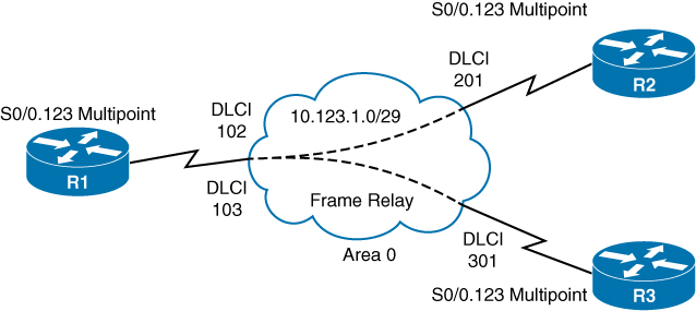
R1
interface Serial 0/0
encapsulation frame-relay
no frame-relay inverse-arp
!
interface Serial 0/0.123 multipoint
ip address 10.123.1.1 255.255.255.248
frame-relay map ip 10.123.1.2 102 broadcast
frame-relay map ip 10.123.1.3 103 broadcast
ip ospf network point-to-multipoint
!
router ospf 1
router-id 192.168.1.1
network 0.0.0.0 255.255.255.255 area 0R2
interface Serial 0/0
encapsulation frame-relay
no frame-relay inverse-arp
!
interface Serial 0/1/0/0.123 multipoint
ip address 10.123.1.2 255.255.255.248
frame-relay map ip 10.123.1.1 201 broadcast
ip ospf network point-to-multipoint
!
router ospf 1
router-id 192.168.2.2
network 0.0.0.0 255.255.255.255 area 0R3
interface Serial 0/0
encapsulation frame-relay
no frame-relay inverse-arp
!
interface Serial 0/0.123 multipoint
ip address 10.123.1.3 255.255.255.248
frame-relay map ip 10.123.1.1 301 broadcast
ip ospf network point-to-multipoint
!
router ospf 1
router-id 192.168.3.3
network 0.0.0.0 255.255.255.255 area 0R1# show ip ospf interface Serial 0/0.123 | include Type
Process ID 1, Router ID 192.168.1.1, Network Type POINT_TO_MULTIPOINT, Cost: 64R2# show ip ospf interface Serial 0/0.123 | include Type
Process ID 1, Router ID 192.168.2.2, Network Type POINT_TO_MULTIPOINT, Cost: 64R3# show ip ospf interface Serial 0/0.123 | include Type
Process ID 1, Router ID 192.168.3.3, Network Type POINT_TO_MULTIPOINT, Cost: 64Notice that all three routers are on the same subnet, but R2 and R3 do not establish an adjacency with each other.
R1# show ip ospf neighbor
Neighbor ID Pri State Dead Time Address Interface
192.168.3.3 0 FULL/ - 00:01:33 10.123.1.3 Serial0/0.123
192.168.2.2 0 FULL/ - 00:01:40 10.123.1.2 Serial0/0.123R2# show ip ospf neighbor
Neighbor ID Pri State Dead Time Address Interface
192.168.1.1 0 FULL/ - 00:01:49 10.123.1.1 Serial0/0.123R3# show ip ospf neighbor
Neighbor ID Pri State Dead Time Address Interface
192.168.1.1 0 FULL/ - 00:01:46 10.123.1.1 Serial0/0.123R1# show ip route ospf | begin Gateway
Gateway of last resort is not set
O 10.123.1.2/32 [110/64] via 10.123.1.2, 00:07:32, Serial0/0.123
O 10.123.1.3/32 [110/64] via 10.123.1.3, 00:03:58, Serial0/0.123
192.168.2.0/32 is subnetted, 1 subnets
O 192.168.2.2 [110/65] via 10.123.1.2, 00:07:32, Serial0/0.123
192.168.3.0/32 is subnetted, 1 subnets
O 192.168.3.3 [110/65] via 10.123.1.3, 00:03:58, Serial0/0.123R2# show ip route ospf | begin Gateway
Gateway of last resort is not set
O 10.123.1.1/32 [110/64] via 10.123.1.1, 00:07:17, Serial0/0.123
O 10.123.1.3/32 [110/128] via 10.123.1.1, 00:03:39, Serial0/0.123
192.168.1.0/32 is subnetted, 1 subnets
O 192.168.1.1 [110/65] via 10.123.1.1, 00:07:17, Serial0/0.123
192.168.3.0/32 is subnetted, 1 subnets
O 192.168.3.3 [110/129] via 10.123.1.1, 00:03:39, Serial0/0.123R3# show ip route ospf | begin Gateway
Gateway of last resort is not set
O 10.123.1.1/32 [110/64] via 10.123.1.1, 00:04:27, Serial0/0.123
O 10.123.1.2/32 [110/128] via 10.123.1.1, 00:04:27, Serial0/0.123
192.168.1.0/32 is subnetted, 1 subnets
O 192.168.1.1 [110/65] via 10.123.1.1, 00:04:27, Serial0/0.123
192.168.2.0/32 is subnetted, 1 subnets
O 192.168.2.2 [110/129] via 10.123.1.1, 00:04:27, Serial0/0.123Loopback Networks
OSPF network type loopback is enabled by default for loopback interfaces and can be used only on loopback interfaces, always advertised with a /32 prefix length, even if the IP address configured on the loopback interface does not have a /32 prefix length.
R1interface Loopback0
ip address 192.168.1.1 255.255.255.0
interface Serial 0/1
ip address 10.12.1.1 255.255.255.252
!
router ospf 1
router-id 192.168.1.1
network 0.0.0.0 255.255.255.255 area 0RR2’s loopback interface is set to the OSPF point-to-point network type to ensure that R2’s loopback interface advertises the network prefix 192.168.2.0/24
R2
interface Loopback0
ip address 192.168.2.2 255.255.255.0
ip ospf network point-to-point
interface Serial 0/0
ip address 10.12.1.2 255.255.255.252
!
router ospf 1
router-id 192.168.2.2
network 0.0.0.0 255.255.255.255 area 0R1# show ip ospf interface Loopback 0 | include Type
Process ID 1, Router ID 192.168.1.1, Network Type LOOPBACK, Cost: 1R2# show ip ospf interface Loopback 0 | include Type
Process ID 1, Router ID 192.168.2.2, Network Type POINT_TO_POINT, Cost: 1R1# show ip ospf database router | I Advertising|Network|Mask
Advertising Router: 192.168.1.1
Link connected to: a Stub Network
(Link ID) Network/subnet number: 192.168.1.1
(Link Data) Network Mask: 255.255.255.255
Link connected to: a Stub Network
(Link ID) Network/subnet number: 10.12.1.0
(Link Data) Network Mask: 255.255.255.0
Advertising Router: 192.168.2.2
Link connected to: a Stub Network
(Link ID) Network/subnet number: 192.168.2.0
(Link Data) Network Mask: 255.255.255.0
Link connected to: a Stub Network
(Link ID) Network/subnet number: 10.12.1.0
(Link Data) Network Mask: 255.255.255.0Design difference between P2MP and NBMA and Why use where
NBMA
Frame Relay, DMVPN, MPLS
Like Ethernet segment without broadcast
DR/BDR election due to Ethernet like segment and because of “B”
Hub can become DR
NBMA can’t do broadcast or multicast (no 224.0.0.5/6).
Hellos and LSAs must be sent using unicast to neighbours.
Neighbors must be configured manually neighbor x.x.x.x
Both P2MP and NBMA offer single subnet WAN
Configured using command ip ospf network non-broadcast
In NBMA spoke to spoke become neighbors but by default, in a typical hub-and-spoke NBMA design (like Frame Relay), spokes do not become neighbors with each other, because they cannot directly communicate unless the underlying NBMA network provides full-mesh VC connectivity.
P2MP
Frame Relay, DMVPN, MPLS
Hub-and-spoke and the spokes do not fully mesh
Can work with (broadcast command) or without broadcast (default P2MP)
P2MP (with broadcast capable media) can discover neighbours dynamically via multicast
This allows simpler configuration vs NBMA with manual config for many spokes
No DR but bunch of P2P while HUB is P2MP
For example, hub router with 20 spokes across DMVPN or MPLS, spokes never talk directly.
Neighbors are configured manually
/32 Host routes P2P links
Both P2MP and NBMA offer single subnet WAN
P2MP is used over NBMA when there is no spoke to spoke communication allowed
Failure Detection
OSPF Dead interval timer, which defaults to four times the hello timer. Upon receipt of the hello packet from a neighboring router, the OSPF dead timer resets to the initial value, and then it starts to decrement again.
If a router does not receive a hello before the OSPF dead interval timer reaches 0, the neighbor state is changed to down. The OSPF router immediately sends out the appropriate LSA, reflecting the topology change, and the SPF algorithm processes on all routers within the area.
Changing the hello timer interval modifies the default dead interval, too. The OSPF hello timer is modified with the interface configuration submode command ip ospf hello-interval 1-65,535
You can change the dead interval timer to a value between 1 and 65,535 seconds. You change the OSPF dead interval timer by using the command ip ospf dead-interval 1-65,535 under the interface configuration submode.
show ip ospf interface shows timers
R1# show ip ospf interface | i Timer|line
Loopback0 is up, line protocol is up
GigabitEthernet0/2 is up, line protocol is up
Timer intervals configured, Hello 10, Dead 40, Wait 40, Retransmit 5
GigabitEthernet0/1 is up, line protocol is up
Timer intervals configured, Hello 10, Dead 40, Wait 40, Retransmit 5Authentication
An attacker can forge OSPF packets or gain physical access to a network, manipulate the routing and take control of traffic
OSPF authentication is enabled on an interface-by-interface basis or for all interfaces in an area
You can set the password only as an interface parameter, and you must set it for every interface.
If you miss an interface, the default password is set to a null value.
OSPF supports two types of authentication:
Plaintext: This type of authentication provides little security, as anyone with access to the link can see the password by using a network sniffer.
You enable plaintext authentication for an OSPF area with the command area area-id authentication, then use the interface parameter command ip ospf authentication to set plaintext authentication only on that interface. You configure the plaintext password by using the interface parameter command ip ospf authentication-key password.
MD5 cryptographic hash: This type of authentication uses a hash, so the password is never sent out the wire. This technique is widely accepted as being the more secure mode. You enable MD5 authentication for an OSPF area by using the command area area-id authentication message-digest, and then the interface parameter command ip ospf authentication message-digest to set MD5 authentication for that interface. You configure the MD5 password with the interface parameter command ip ospf message-digest-key key-number md5 password.
MD5 authentication is a hash of the key number and password combined. If the keys do not match, the hash differs between the nodes. That is why keys much match between the nodes and this is the use of the keys
Area 12 uses plaintext authentication, and Area 0 uses MD5 authentication
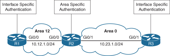
R1 and R3 use interface-based authentication
R2 uses area-specific authentication
R1
interface GigabitEthernet0/0
ip address 10.12.1.1 255.255.255.0
ip ospf authentication
ip ospf authentication-key CISCO
!
router ospf 1
network 10.12.1.0 0.0.0.255 area 12R2
interface GigabitEthernet0/0
ip address 10.12.1.2 255.255.255.0
ip ospf authentication-key CISCO
!
interface GigabitEthernet0/1
ip address 10.23.1.2 255.255.255.0
ip ospf message-digest-key 1 md5 CISCO
!
router ospf 1
area 0 authentication message-digest
area 12 authentication
network 10.12.1.0 0.0.0.255 area 12
network 10.23.1.0 0.0.0.255 area 0R3
interface GigabitEthernet0/1
ip address 10.23.1.3 255.255.255.0
ip ospf authentication message-digest
ip ospf message-digest-key 1 md5 CISCO
!
router ospf 1
network 10.23.1.0 0.0.0.255 area 0You verify the authentication settings by examining the OSPF interface without the brief option
R1# show ip ospf interface | include line|authentication|key
GigabitEthernet0/0 is up, line protocol is up
Simple password authentication enabledR2# show ip ospf interface | include line|authentication|key
GigabitEthernet0/1 is up, line protocol is up
Cryptographic authentication enabled
Youngest key id is 1
GigabitEthernet0/0 is up, line protocol is up
Simple password authentication enabledR3# show ip ospf interface | include line|authentication|key
GigabitEthernet0/1 is up, line protocol is up
Cryptographic authentication enabled
Youngest key id is 1OSPF uses six LSA types for IPv4 routing:
Type 1, router: LSAs that advertise prefixes within an area
Type 2, network: LSAs that indicate the routers attached to broadcast segment within an area
Type 3, summary: LSAs that advertise prefixes that originate from a different area
Type 4, ASBR summary: LSA used to locate the ASBR from a different area
Type 5, AS external: LSA that advertises prefixes that were redistributed in to OSPF
Type 7, NSSA external: LSA for external prefixes that were redistributed in a local NSSA area
LSA Types 1, 2, and 3 are used for building the SPF tree for intra-area and inter-area route routes.
LSA Types 4, 5, and 7 are related to external OSPF routes (that is, routes that were redistributed into the OSPF routing domain).
LSA Sequences
In OSPF, the LSA sequence number is used for versioning, and the originating router increments it each time it reoriginates (updates) the LSA
If a receiving router receives an LSA sequence that is greater than the one in the LSDB, it processes the LSA, If the LSA sequence number is lower than the one in the LSDB, the router deems the LSA old and discards it.
LSA Age and Flooding
Every local router keeps the LSA and also maintains the timer against that LSA called “age”, when LSA is first created in database, that “age” field is 0 but it start incrementing in the DB each second locally, once that age reaches 1800 seconds which is 30 mins, the originating router automatically generates a new copy of that LSA.
This is built into OSPF to keep the LSDB fresh and ensure routers don’t accidentally keep stale information forever.
Another LSA increment (over the links – inflight)
When a router forwards (floods) an LSA to a neighbour, the age increases by a small calculated delay
This accounts for:
- Link transmission delay
- Router processing time
In practice, this increment is small, but the LSA age always increases as it moves across the network.
If any LSA reaches 3600 seconds, it is considered expired or MaxAge.
If a router receives an LSA that has reached MaxAge (3600 seconds), it will reflood that LSA with LS age = 3600 to all its neighbors.
This behaviour ensures that every router, both downstream and upstream, deletes the LSA from its LSDB.
This flooding happens even if the router is not the original creator of the LSA.
Why flood the MaxAge LSA?
Because OSPF relies on synchronized LSDBs.
If one router deletes an LSA silently but others don’t, the network becomes inconsistent.
Router A (originator) publishes LSA
↓
Routers B, C, D store it
↓
LSA in Router D reaches 3600 seconds
↓
Router D floods LSA age = 3600 to neighbors (C)
↓
Router C deletes LSA, floods MaxAge to Router B
↓
Router B deletes LSA, floods MaxAge to Router A
↓
Router A deletes its own stale LSA
LSA Types
ABRs maintain a separate set of LSAs for each OSPF area
LSA Type 1: Router Link
A Type 1 LSA entry exists for each OSPF-enabled link (that is, an interface and its attached networks).
Type 1 LSAs are not advertised outside Area thus making the underlying topology in an area invisible to other areas.

R1# show ip ospf database
OSPF Router with ID (192.168.1.1) (Process ID 1)
Router Link States (Area 1234)
Link ID ADV Router Age Seq# Checksum Link count
192.168.1.1 192.168.1.1 14 0x80000006 0x009EA7 1
192.168.2.2 192.168.2.2 2020 0x80000006 0x00AD43 3
192.168.3.3 192.168.3.3 6 0x80000006 0x0056C4 2
192.168.4.4 192.168.4.4 61 0x80000005 0x007F8C 2Link ID
Identifies the object that the link connects to. It can refer to the neighboring router’s RID, the IP address of the DR’s interface, or the IP network address.
ADV Router
The OSPF router ID of the router that originated the LSA
AGE
The age of the LSA on the router on which the command is being run. Values over 1800 are expected to refresh soon.
Seq #
Sequence number for the LSA
Checksum
The checksum of the LSA to verify integrity during flooding.
Link Count
3 links → Router has three OSPF interfaces/networks it advertises.
If we explore this LSA further we will see networks mentioned inside it
This makes it functions just like a router LSA, router telling us how many links it has in a certain area
You can examine the Type 1 OSPF LSAs by using the command show ip ospf database router
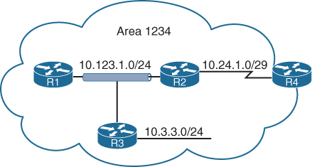
R1# show ip ospf database router
! Output omitted for brevity
OSPF Router with ID (192.168.1.1) (Process ID 1)
Router Link States (Area 1234)
LS age: 352 <<< start of LSA
Options: (No TOS-capability, DC)
LS Type: Router Links <<< Type 1 LSA
Link State ID: 192.168.1.1 <<< how it shows in sh ip ospf database
Advertising Router: 192.168.1.1
LS Seq Number: 80000014
Length: 36
Number of Links: 1
Link connected to: a Transit Network
(Link ID) Designated Router address: 10.123.1.3
(Link Data) Router Interface address: 10.123.1.1
|
No hint of the network yet
TOS 0 Metrics: 1
LS age: 381
Options: (No TOS-capability, DC)
LS Type: Router Links
Link State ID: 192.168.2.2
Advertising Router: 192.168.2.2
LS Seq Number: 80000015
Length: 60
Number of Links: 3
Link connected to: another Router (point-to-point)
(Link ID) Neighboring Router ID: 192.168.4.4
(Link Data) Router Interface address: 10.24.1.1
TOS 0 Metrics: 64
Link connected to: a Stub Network
(Link ID) Network/subnet number: 10.24.1.0
(Link Data) Network Mask: 255.255.255.248
TOS 0 Metrics: 64
Link connected to: a Transit Network
(Link ID) Designated Router address: 10.123.1.3
(Link Data) Router Interface address: 10.123.1.2
TOS 0 Metrics: 1
LS age: 226
Options: (No TOS-capability, DC)
LS Type: Router Links
Link State ID: 192.168.3.3
Advertising Router: 192.168.3.3
LS Seq Number: 80000014
Length: 48
Number of Links: 2
Link connected to: a Stub Network
(Link ID) Network/subnet number: 10.3.3.0
(Link Data) Network Mask: 255.255.255.0
TOS 0 Metrics: 1
Link connected to: a Transit Network
(Link ID) Designated Router address: 10.123.1.3
(Link Data) Router Interface address: 10.123.1.3
TOS 0 Metrics: 1
LS age: 605
Options: (No TOS-capability, DC)
LS Type: Router Links
Link State ID: 192.168.4.4
Advertising Router: 192.168.4.4
LS Seq Number: 80000013
Length: 48
Area Border Router <<< telling us that even though this
Number of Links: 2 is in our area but
this is an ABR with
one leg in our area
Link connected to: another Router (point-to-point)
(Link ID) Neighboring Router ID: 192.168.2.2
(Link Data) Router Interface address: 10.24.1.4
TOS 0 Metrics: 64
Link connected to: a Stub Network
(Link ID) Network/subnet number: 10.24.1.0
(Link Data) Network Mask: 255.255.255.248
TOS 0 Metrics: 64If a router is functioning as an ABR, an ASBR, or a virtual-link endpoint, the function is listed between the Length field and the Number of links field.

“show ip ospf database” Link ID can mean different things based the LSA type
Point-to-point link (IP address assigned)
Link type 1
Neighbor RID
Link to transit network
Link type 2
Interface address of the DR
Link to stub network
Link type 3
Network address
Virtual link
Link type 4
Neighbor RID
Transit link in router LSA shows DR and IP address facing DR
Point to point link in router LSA advertise two links
One link is the point-to-point link type that identifies the OSPF neighbor RID for that segment, and the other link is a stub network link that provides the subnet mask for that network
Stub Network in router LSA has no neighbors, Point-to-point and transit link types that did not become adjacent with another OSPF router are classified as a stub network link type
Secondary connected networks are always advertised as stub link types because OSPF adjacencies can never form on them
Just by using information from Router LSA type 1, we can build a topology
Notice that the three router links on R1, R2, and R3 (10.123.1.0) have not been directly connected yet.
Also see how topology uses Link ID and then its corresponding Link Data
R3 is elected as the DR (that is why Link ID is 10.123.1.3), and R2 is elected as the BDR
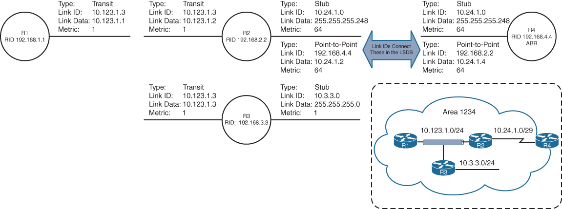
LSA Type 2: Network Link
A Type 2 LSA (network LSA) represents a multi-access network
DR always advertises the Type 2 LSA
identifies all the routers attached to that network segment.
If a DR has not been elected, a Type 2 LSA is not present in the LSDB
Type 2 LSAs are not flooded outside the originating OSPF area in an identical fashion to Type 1 LSAs.
R1# show ip ospf database
! Output omitted for brevity
OSPF Router with ID (192.168.1.1) (Process ID 1)
..
Net Link States (Area 1234)
Link ID ADV Router Age Seq# Checksum
10.123.1.3 10.192.168.3.3 1752 0x80000012 0x00ADC5Type 2 LSA that is advertised by “R3” but show command is on R1
The network mask for the subnet is included in the Type 2 LSA
R1# show ip ospf database network
OSPF Router with ID (192.168.1.1) (Process ID 1)
Net Link States (Area 1234)
LS age: 356
Options: (No TOS-capability, DC)
LS Type: Network Links
Link State ID: 10.123.1.3 (address of Designated Router)
Advertising Router: 192.168.3.3
LS Seq Number: 80000014
Checksum: 0x4DD
Length: 36
Network Mask: /24
Attached Router: 192.168.3.3
Attached Router: 192.168.1.1
Attached Router: 192.168.2.2Visualization of the Type 1 and Type 2 LSAs
When the DR changes for a network segment, a new Type 2 LSA is created, causing SPF to run again within the OSPF area.
Pseudonode because that box is considered a node in OSPF LSDB but it is not real node or router
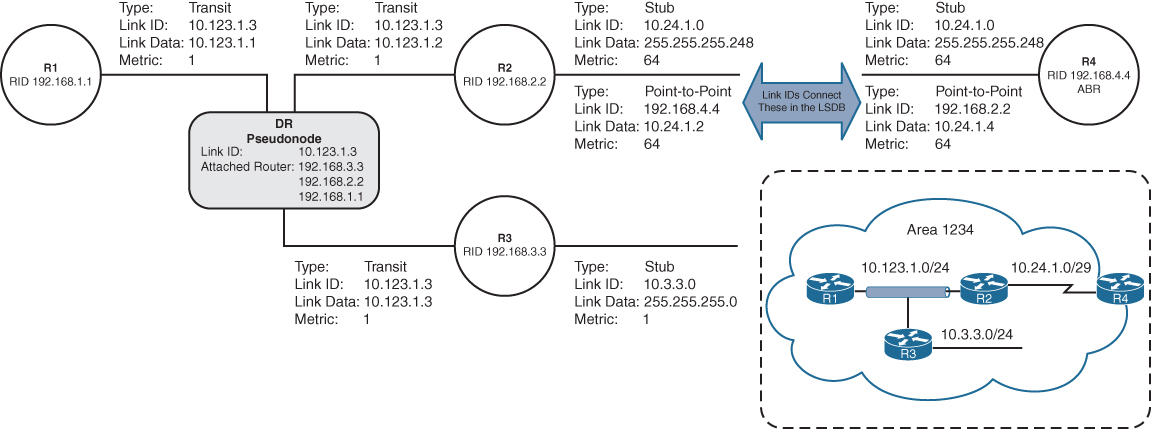
LSA Type 3: Summary Link
Type 3 LSAs (summary LSAs) represent networks from other areas. The role of the ABRs is to participate in multiple OSPF areas and ensure that these Type 1 networks are reachable from other areas
As explained earlier, ABRs do not forward Type 1 or Type 2 LSAs into other areas. When an ABR receives a Type 1 LSA, it creates an equivalent Type 3 LSA
The ABR then advertises the Type 3 LSA into other areas
If an ABR receives a Type 3 LSA from Area 0 (backbone area), it regenerates a new Type 3 LSA for the nonbackbone area and lists itself as the advertising router with the additional cost metric

Type 1 LSAs exist only in the area of origination and convert to Type 3 when they cross the ABRs (R4 and R5).
The Type 3 LSAs show up under the appropriate area where they exist in the OSPF domain. For example, the 10.56.1.0 Type 3 LSA exists only in Area 0 and Area 1234 on R4.
R4# show ip ospf database
! Output omitted for brevity
OSPF Router with ID (192.168.4.4) (Process ID 1)
..
Summary Net Link States (Area 0)
|
v
This just means that these are Type 1 LSAs of
foreign or remote areas in this area
Link ID ADV Router Age Seq# Checksum
10.3.3.0 192.168.4.4 813 0x80000013 0x00F373
10.24.1.0 192.168.4.4 813 0x80000013 0x00CE8E
10.56.1.0 192.168.5.5 591 0x80000013 0x00F181
10.123.1.0 192.168.4.4 813 0x80000013 0x005A97
..
Summary Net Link States (Area 1234)
|
v
This just means that these are Type 1 LSAs of
foreign or remote areas in this area
Link ID ADV Router Age Seq# Checksum
10.45.1.0 192.168.4.4 813 0x80000013 0x0083FC
10.56.1.0 192.168.4.4 813 0x80000013 0x00096BR5# show ip ospf database
! Output omitted for brevity
OSPF Router with ID (192.168.5.5) (Process ID 1)
..
Summary Net Link States (Area 0)
|
v
This just means that these are Type 1 LSAs of
foreign or remote areas in this area
Link ID ADV Router Age Seq# Checksum
10.3.3.0 192.168.4.4 893 0x80000013 0x00F373
10.24.1.0 192.168.4.4 893 0x80000013 0x00CE8E
10.56.1.0 192.168.5.5 668 0x80000013 0x00F181
10.123.1.0 192.168.4.4 893 0x80000013 0x005A97
..
Summary Net Link States (Area 56)
|
v
This just means that these are Type 1 LSAs of
foreign or remote areas in this area
Link ID ADV Router Age Seq# Checksum
10.3.3.0 192.168.5.5 668 0x80000013 0x00F073
10.24.1.0 192.168.5.5 668 0x80000013 0x00CB8E
10.45.1.0 192.168.5.5 668 0x80000013 0x007608
10.123.1.0 192.168.5.5 668 0x80000013 0x005797The advertising router for Type 3 LSAs is the last ABR that advertises the prefix. The metric in the Type 3 LSA uses the following logic:
- If the Type 3 LSA is created from a Type 1 LSA, it is the total path metric to reach the originating router in the Type 1 LSA.
- If the Type 3 LSA is created from a Type 3 LSA (from Area 0), it is the total path metric to the ABR plus the metric in the original Type 3 LSA
R4# show ip ospf database summary 10.56.1.0
OSPF Router with ID (192.168.4.4) (Process ID 1)
Summary Net Link States (Area 0)
LS age: 754
Options: (No TOS-capability, DC, Upward)
LS Type: Summary Links(Network)
Link State ID: 10.56.1.0 (summary Network Number)
Advertising Router: 192.168.5.5
LS Seq Number: 80000013
Checksum: 0xF181
Length: 28
Network Mask: /24
MTID: 0 Metric: 1 <<< this is in Area 0
Summary Net Link States (Area 1234)
LS age: 977
Options: (No TOS-capability, DC, Upward)
LS Type: Summary Links(Network)
Link State ID: 10.56.1.0 (summary Network Number)
Advertising Router: 192.168.4.4
LS Seq Number: 80000013
Checksum: 0x96B
Length: 28
Network Mask: /24
MTID: 0 Metric: 2 <<< when sent to non Area 0
incrementedshows the Type 3 LSA for the Area 56 prefix (10.56.1.0/24) from R4’s LSDB. R4 is an ABR, and the information is displayed for both Area 0 and Area 1234. Notice that the metric increases in Area 1234’s LSA compared to in Area 0’s LSA.
R4’s perspective of the Type 3 LSA created by ABR (R5) vs Reality visualized below
R4 does not know if the 10.56.1.0/24 network is directly attached to the ABR (R5) or if it is multiple hops away (due to area obfuscation). R4 knows that its metric to the ABR (R5) is 1 and that the Type 3 LSA already has a metric of 1, so its total path metric to reach the 10.56.1.0/24 network is 2.
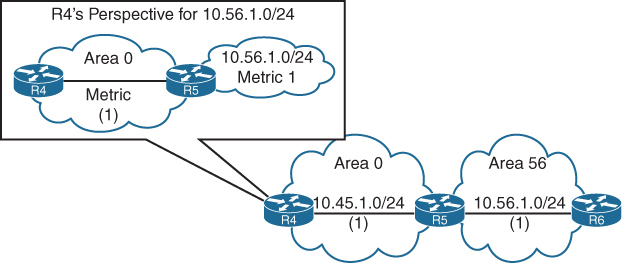
R3’s perspective of the Type 3 LSA created by the ABR (R4) for the 10.56.1.0/24 network vs reality visualised
R3 does not know if the 10.56.1.0/24 network is directly attached to the ABR (R4) or if it is multiple hops away (due to area obfuscation). R3 knows that its metric to the ABR (R4) is 65 and that the Type 3 LSA already has a metric of 2 (the metric R4 brings for network 10.56.1.0/24), so its total path metric is 67 to reach the 10.56.1.0/24 network
LSA Type 5: External Routes
When a route is redistributed into OSPF, the router is known as an autonomous system boundary router (ASBR). The external route is flooded throughout the entire OSPF domain (every area) as a Type 5 LSA (external LSAs).
Notice that the Type 5 LSA exists in all OSPF areas of the routing domain. Type 5 LSA is not regenerated unlike Type 4 instead only LSA Age is incremented
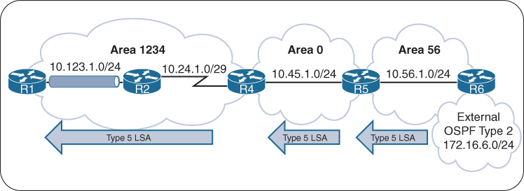
The link ID is the external network number, and the advertising router is the RID for the router originating the Type 5 LSA
R6# show ip ospf database
! Output omitted for brevity
Type-5 AS External Link States
Link ID ADV Router Age Seq# Checksum Tag
172.16.6.0 192.168.6.6 11 0x80000001 0x000866 0R6# show ip ospf database external
OSPF Router with ID (192.168.6.6) (Process ID 1)
Type-5 AS External Link States
LS age: 720
Options: (No TOS-capability, DC, Upward)
LS Type: AS External Link
Link State ID: 172.16.6.0 (External Network Number )
Advertising Router: 192.168.6.6
LS Seq Number: 8000000F
Checksum: 0xA9B0
Length: 36
Network Mask: /24
Metric Type: 2 (Larger than any link state path)
MTID: 0
Metric: 20
Forward Address: 0.0.0.0
External Route Tag: 0R1# show ip ospf database external
OSPF Router with ID (192.168.1.1) (Process ID 1)
Type-5 AS External Link States
LS age: 778
Options: (No TOS-capability, DC, Upward)
LS Type: AS External Link
Link State ID: 172.16.6.0 (External Network Number )
Advertising Router: 192.168.6.6
LS Seq Number: 8000000F
Checksum: 0xA9B0
Length: 36
Network Mask: /24
Metric Type: 2 (Larger than any link state path)
MTID: 0
Metric: 20
Forward Address: 0.0.0.0
External Route Tag: 0LSA Type 4: ASBR Summary
A Type 4 LSA (ASBR summary LSA) locates the ASBR for a Type 5 LSA
Routers examine the Type 5 LSA, check to see whether the RID is in the local area (because if in local area then cost advertised can be believed for E1), but if the ASBR is not local, a mechanism is required to locate the ASBR or measure distance to ASBR (for cases where we have 2 competing routes, which both have ASBR in remote area for which we dont have a view of)
Type 4 LSAs provide a way for routers to locate the ASBR when the ASBR is in a different area
A Type 4 LSA is created by the first ABR, and it provides a summary route strictly for the ASBR of a Type 5 LSA
The metric for a Type 4 LSA uses the following logic:
- When the Type 5 LSA crosses the first ABR (Area 0 ***ABR*** Area 56) creates a Type 4 LSA with a metric set to the total path metric to the ASBR.
- When an ABR receives a Type 4 LSA from Area 0, the ABR creates a new Type 4 LSA with a metric set to the total path metric of the first ABR (Area 1234 ***ABR*** Area 0) plus the metric to ASBR in the original Type 4 LSA, (Cost to ASBR or type 4 LSA is not added through every router’s outgoing interface)
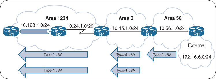
R4# show ip ospf database
! Output omitted for brevity
OSPF Router with ID (192.168.4.4) (Process ID 1)
..
Summary ASB Link States (Area 0)
Link ID ADV Router Age Seq# Checksum
192.168.6.6 192.168.5.5 930 0x8000000F 0x00EB58
..
Summary ASB Link States (Area 1234)
Link ID ADV Router Age Seq# Checksum
192.168.6.6 192.168.4.4 1153 0x8000000F 0x000342R4# show ip ospf database asbr-summary
! Output omitted for brevity
OSPF Router with ID (192.168.4.4) (Process ID 1)
Summary ASB Link States (Area 0)
LS age: 1039
Options: (No TOS-capability, DC, Upward)
LS Type: Summary Links(AS Boundary Router)
Link State ID: 192.168.6.6 (AS Boundary Router address)
Advertising Router: 192.168.5.5
Length: 28
Network Mask: /0
MTID: 0 Metric: 1
Summary ASB Link States (Area 1234)
LS age: 1262
Options: (No TOS-capability, DC, Upward)
LS Type: Summary Links(AS Boundary Router)
Link State ID: 192.168.6.6 (AS Boundary Router address)
Advertising Router: 192.168.4.4
Length: 28
Network Mask: /0
MTID: 0 Metric: 2An ABR advertises only one Type 4 LSA for every ASBR, even if the ASBR advertises thousands of Type 5 LSAs
LSA Type 7: NSSA External Summary
A Type 7 LSA (NSSA external LSA) exists only in NSSAs where route redistribution is occurring.
An ASBR sitting on the edge of an NSSA Area injects external routes as Type 7 LSAs in an NSSA
The ABR does not advertise Type 7 LSAs outside the originating NSSA but it converts the Type 7 LSA into a Type 5 LSA
If the Type 5 LSA crosses Area 0, the second ABR creates a Type 4 LSA for the Type 5 LSA

R5 injects the Type 5 LSA (only) in Area 0, which propagates to Area 1234, and R4 creates the Type 4 LSA for Area 1234 and also forwards Type 5 (only LSA age is incremented).
R5# show ip ospf database
! Output omitted for brevity
OSPF Router with ID (192.168.5.5) (Process ID 1)
..
Type-7 AS External Link States (Area 56) <<< Type 7
Link ID ADV Router Age Seq# Checksum Tag
172.16.6.0 192.168.6.6 46 0x80000001 0x00A371 0
! Notice that no Type-4 LSA has been generated. Only the Type-7 LSA for Area 56
! and the Type-5 LSA for the other areas. R5 advertises the Type-5 LSA
Type-5 AS External Link States <<< converted to Type 5
Link ID ADV Router Age Seq# Checksum Tag
172.16.6.0 192.168.5.5 38 0x80000001 0x0045DBR4# show ip ospf database
! Output omitted for brevity
OSPF Router with ID (192.168.4.4) (Process ID 1)
..
Summary ASB Link States (Area 1234) <<< Type 4
Link ID ADV Router Age Seq# Checksum
192.168.5.5 192.168.4.4 193 0x80000001 0x002A2C
Type-5 AS External Link States <<< for this Type 5
Link ID ADV Router Age Seq# Checksum Tag
172.16.6.0 192.168.5.5 176 0x80000001 0x0045DB 0R5# show ip ospf database nssa-external
OSPF Router with ID (192.168.5.5) (Process ID 1)
Type-7 AS External Link States (Area 56)
LS age: 122
Options: (No TOS-capability, Type 7/5 translation, DC, Upward)
LS Type: AS External Link
Link State ID: 172.16.6.0 (External Network Number )
Advertising Router: 192.168.6.6
LS Seq Number: 80000001
Checksum: 0xA371
Length: 36
Network Mask: /24
Metric Type: 2 (Larger than any link state path)
MTID: 0
Metric: 20
Forward Address: 10.56.1.6
External Route Tag: 0LSA Type Visualization
Notice that the Type 2 LSAs are present only on the broadcast network segments
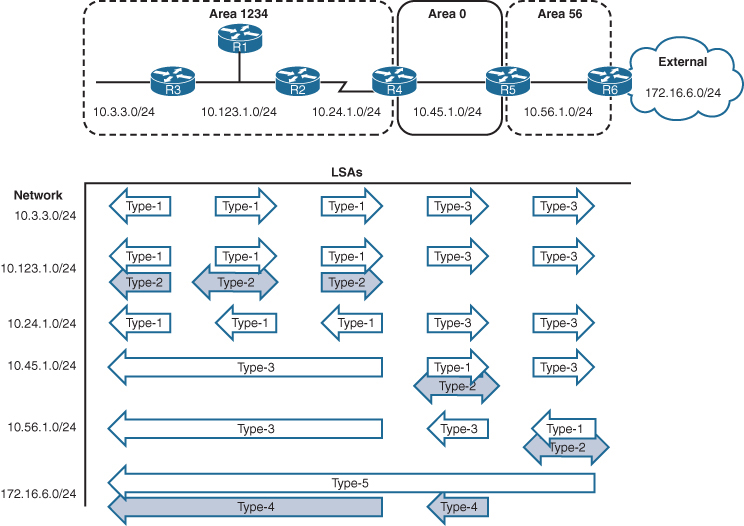
OSPF Stubby Areas
Stubby areas filter out external routes and even inter-area with some stub types – logic is to not have a massive Type 5 database on small routers, stub allows us to replace these massive type 5 in every area LSDB to be replaced with one external default route
OSPF stubby areas are identified by the area flag in the OSPF hello packet
Every router within an OSPF stubby area needs to be configured as a stub so that the routers can establish/maintain OSPF adjacencies
The following sections explain the four types of OSPF stubby areas in more detail:
- Stub areas
- Totally stubby areas
- Not-so-stubby areas (NSSAs)
- Totally NSSAs
Stub Areas
OSPF stub areas prohibit “Type 5” LSAs (external routes) and “Type 4” LSAs (ASBR summary LSAs) from entering the area at the ABR
When a Type 5 LSA reaches the ABR of a stub area, the ABR generates a default route for the stub via a Type 3 LSA
A Cisco ABR generates a default route when the area is configured as a stub and has an OSPF-enabled interface configured for Area 0

R3 and R4 before Area 34 is configured as a stub area, Notice the external 172.16.1.0/24
R3# show ip route ospf | begin Gateway
! Output omitted for brevity
Gateway of last resort is not set
O IA 10.12.1.0/24 [110/2] via 10.23.1.2, 00:01:36, GigabitEthernet0/1
O E1 172.16.1.0 [110/22] via 10.23.1.2, 00:01:36, GigabitEthernet0/1
O IA 192.168.1.1 [110/3] via 10.23.1.2, 00:01:36, GigabitEthernet0/1
O 192.168.2.2 [110/2] via 10.23.1.2, 00:01:46, GigabitEthernet0/1
O 192.168.4.4 [110/2] via 10.34.1.4, 00:01:46, GigabitEthernet0/0R4# show ip route ospf | begin Gateway
! Output omitted for brevity
Gateway of last resort is not set
O IA 10.12.1.0/24 [110/3] via 10.34.1.3, 00:00:51, GigabitEthernet0/0
O IA 10.23.1.0/24 [110/2] via 10.34.1.3, 00:00:58, GigabitEthernet0/0
O E1 172.16.1.0 [110/23] via 10.34.1.3, 00:00:46, GigabitEthernet0/0
O IA 192.168.1.1 [110/4] via 10.34.1.3, 00:00:51, GigabitEthernet0/0
O IA 192.168.2.2 [110/3] via 10.34.1.3, 00:00:58, GigabitEthernet0/0
O IA 192.168.3.3 [110/2] via 10.34.1.3, 00:00:58, GigabitEthernet0/0All routers in the stub area must be configured as stubs, or an adjacency cannot form because the area type flags in the hello packets do not match
R3# configure terminal
Enter configuration commands, one per line. End with CNTL/Z.
R3(config)# router ospf 1
R3(config-router)# area 34 stubR4# configure terminal
Enter configuration commands, one per line. End with CNTL/Z.
R4(config)# router ospf 1
R4(config-router)# area 34 stub
The routing table from R3’s perspective is not modified as it receives the Type 4 and Type 5 LSAs from Area 0, But when the Type 5 LSA (172.16.1.0/24) reaches the R3 ABR, the R3 ABR generates a default route by using a Type 3 LSA. While R4 only receives Intra Area routes, Inter-Area route and Type 3 (not Type 5) the default route
R3# show ip route ospf | begin Gateway
! Output omitted for brevity
Gateway of last resort is not set
O IA 10.12.1.0/24 [110/2] via 10.23.1.2, 00:03:10, GigabitEthernet0/1
O E1 172.16.1.0 [110/22] via 10.23.1.2, 00:03:10, GigabitEthernet0/1
O IA 192.168.1.1 [110/3] via 10.23.1.2, 00:03:10, GigabitEthernet0/1
O 192.168.2.2 [110/2] via 10.23.1.2, 00:03:10, GigabitEthernet0/1
O 192.168.4.4 [110/2] via 10.34.1.4, 00:01:57, GigabitEthernet0/0R4# show ip route ospf | begin Gateway
! Output omitted for brevity
Gateway of last resort is 10.34.1.3 to network 0.0.0.0
O*IA 0.0.0.0/0 [110/2] via 10.34.1.3, 00:02:45, GigabitEthernet0/0
O IA 10.12.1.0/24 [110/3] via 10.34.1.3, 00:02:45, GigabitEthernet0/0
O IA 10.23.1.0/24 [110/2] via 10.34.1.3, 00:02:45, GigabitEthernet0/0
O IA 192.168.1.1 [110/4] via 10.34.1.3, 00:02:45, GigabitEthernet0/0
O IA 192.168.2.2 [110/3] via 10.34.1.3, 00:02:45, GigabitEthernet0/0
O IA 192.168.3.3 [110/2] via 10.34.1.3, 00:02:45, GigabitEthernet0/0Totally Stubby Areas
An OSPF totally stubby area prohibits Type 3 LSAs (inter-area), Type 4 LSAs (ASBR summary LSAs), and Type 5 LSAs (external routes) from entering the area at the ABR
When an ABR of a totally stubby area receives a Type 3 or Type 5 LSA, the ABR generates a default route for the totally stubby area.
In fact, an ABR for a totally stubby area advertises the default route into the totally stubby area
Assigning the interface acts as the trigger for the Type 3 LSA that leads to the generation of the default route
Only intra-area and default routes should exist within a totally stubby area.
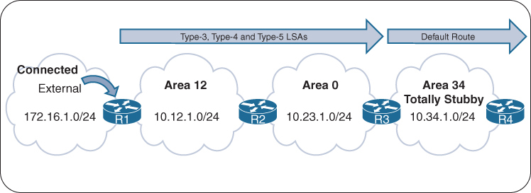
Routing Tables of R3 and R4 Before the Totally Stubby Area
R3# show ip route ospf | begin Gateway
! Output omitted for brevity
Gateway of last resort is not set
O IA 10.12.1.0/24 [110/2] via 10.23.1.2, 00:01:36, GigabitEthernet0/1
O E1 172.16.1.0 [110/22] via 10.23.1.2, 00:01:36, GigabitEthernet0/1
O IA 192.168.1.1 [110/3] via 10.23.1.2, 00:01:36, GigabitEthernet0/1
O 192.168.2.2 [110/2] via 10.23.1.2, 00:01:46, GigabitEthernet0/1
O 192.168.4.4 [110/2] via 10.34.1.4, 00:01:46, GigabitEthernet0/0R4# show ip route ospf | begin Gateway
! Output omitted for brevity
Gateway of last resort is not set
O IA 10.12.1.0/24 [110/3] via 10.34.1.3, 00:00:51, GigabitEthernet0/0
O IA 10.23.1.0/24 [110/2] via 10.34.1.3, 00:00:58, GigabitEthernet0/0
O E1 172.16.1.0 [110/23] via 10.34.1.3, 00:00:46, GigabitEthernet0/0
O IA 192.168.1.1 [110/4] via 10.34.1.3, 00:00:51, GigabitEthernet0/0
O IA 192.168.2.2 [110/3] via 10.34.1.3, 00:00:58, GigabitEthernet0/0
O IA 192.168.3.3 [110/2] via 10.34.1.3, 00:00:58, GigabitEthernet0/0ABRs of a totally stubby area have no-summary appended to the configuration, Member routers (non-ABRs) of a totally stubby area are configured the same as those in a stub area and do not need no-summary.
The command area area-id stub no-summary is configured under the OSPF process. The keyword no-summary does exactly what it states: It blocks all Type 3 (summary) LSAs going into the stub area, making it a totally stubby area.
R3# configure terminal
Enter configuration commands, one per line. End with CNTL/Z.
R3(config)# router ospf 1
R3(config-router)# area 34 stub no-summaryR4# configure terminal
Enter configuration commands, one per line. End with CNTL/Z.
R4(config)# router ospf 1
R4(config-router)# area 34 stubRouting tables for R3 and R4 after Area 34 is converted to a totally stubby area, Notice that only the default route exists on R4
The routing table on R3 has not changed at all
R3# show ip route ospf | begin Gateway
! Output omitted for brevity
Gateway of last resort is not set
O IA 10.12.1.0/24 [110/2] via 10.23.1.2, 00:02:34, GigabitEthernet0/1
O E1 172.16.1.0 [110/22] via 10.23.1.2, 00:02:34, GigabitEthernet0/1
O IA 192.168.1.1 [110/3] via 10.23.1.2, 00:02:34, GigabitEthernet0/1
O 192.168.2.2 [110/2] via 10.23.1.2, 00:02:34, GigabitEthernet0/1
O 192.168.4.4 [110/2] via 10.34.1.4, 00:03:23, GigabitEthernet0/0R4# show ip route ospf | begin Gateway
! Output omitted for brevity
Gateway of last resort is 10.34.1.3 to network 0.0.0.0
O*IA 0.0.0.0/0 [110/2] via 10.34.1.3, 00:02:24, GigabitEthernet0/0Not-So-Stubby Areas
An OSPF not-so-stubby-area (NSSA) prohibits Type 5 LSAs from entering at the ABR but allows for redistribution of external routes into the NSSA and into Area 0
As the ASBR redistributes the route into OSPF in the NSSA, the ASBR advertises the route with a Type 7 LSA instead of a Type 5 LSA. When the Type 7 LSA reaches the ABR, the ABR converts the Type 7 LSA to a Type 5 LSA
The ABR does not automatically advertise a default route into an NSSA when a Type 5 or Type 7 LSA is blocked (because it might have its own NSSA based default route so it does not do it automatically, thinking may be it is not needed)
During configuration, an option exists to advertise a default route to provide connectivity to the blocked LSAs; in addition, other techniques can be used to ensure bidirectional connectivity.

Routing tables of R1, R3, and R4 before Area 34 is converted to an NSSA
R1# show ip route ospf | section 172.31
O E1 172.31.4.0 [110/23] via 10.12.1.2, 00:00:38, GigabitEthernet0/0R3# show ip route ospf | begin Gateway
! Output omitted for brevity
Gateway of last resort is not set
O IA 10.12.1.0/24 [110/2] via 10.23.1.2, 00:01:34, GigabitEthernet0/1
O E1 172.16.1.0 [110/22] via 10.23.1.2, 00:01:34, GigabitEthernet0/1
O E1 172.31.4.0 [110/21] via 10.34.1.4, 00:01:12, GigabitEthernet0/0
O IA 192.168.1.1 [110/3] via 10.23.1.2, 00:01:34, GigabitEthernet0/1
O 192.168.2.2 [110/2] via 10.23.1.2, 00:01:34, GigabitEthernet0/1
O 192.168.4.4 [110/2] via 10.34.1.4, 00:01:12, GigabitEthernet0/0R4# show ip route ospf | begin Gateway
! Output omitted for brevity
Gateway of last resort is not set
O IA 10.12.1.0/24 [110/3] via 10.34.1.3, 00:02:28, GigabitEthernet0/0
O IA 10.23.1.0/24 [110/2] via 10.34.1.3, 00:02:28, GigabitEthernet0/0
O E1 172.16.1.0 [110/23] via 10.34.1.3, 00:02:28, GigabitEthernet0/0
O IA 192.168.1.1 [110/4] via 10.34.1.3, 00:02:28, GigabitEthernet0/0
O IA 192.168.2.2 [110/3] via 10.34.1.3, 00:02:28, GigabitEthernet0/0
O IA 192.168.3.3 [110/2] via 10.34.1.3, 00:02:28, GigabitEthernet0/0The command area area-id nssa [default-information-originate] is placed under the OSPF process on the ABR. All routers in an NSSA must be configured with the nssa option, or they do not become adjacent
A default route is not injected on the ABRs automatically for NSSAs, but the optional command default-information-originate can be appended to the configuration if a default route is needed in the NSSA.
R3# show run | section router ospf
router ospf 1
router-id 192.168.3.3
area 34 nssa default-information-originate
network 10.23.1.0 0.0.0.255 area 0
network 10.34.1.0 0.0.0.255 area 34
network 192.168.3.3 0.0.0.0 area 0R4# show run | section router ospf
router ospf 1
router-id 192.168.4.4
area 34 nssa
redistribute connected metric-type 1 subnets
network 10.34.1.0 0.0.0.255 area 34
network 192.168.4.4 0.0.0.0 area 34shows the routing tables of R3 and R4 after converting Area 34 to an NSSA
On R3, the previous external route from R1 still exists as an OSPF external Type 1 (O E1) route, and R4’s external route is now an OSPF external NSSA Type 1 (O N1) route
On R4, R1’s external route is no longer present. R3 is configured to advertise a default route, which appears as an OSPF external NSSA Type 2 (O N2) route.
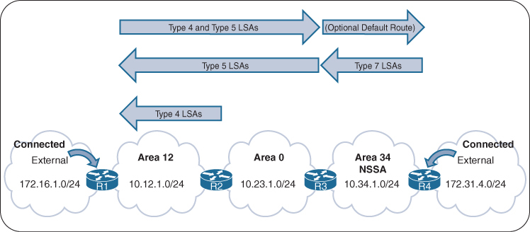
R3# show ip route ospf | begin Gateway
! Output omitted for brevity
Gateway of last resort is not set
O IA 10.12.1.0/24 [110/2] via 10.23.1.2, 00:04:13, GigabitEthernet0/1
O E1 172.16.1.0 [110/22] via 10.23.1.2, 00:04:13, GigabitEthernet0/1
O N1 172.31.4.0 [110/22] via 10.34.1.4, 00:03:53, GigabitEthernet0/0
O IA 192.168.1.1 [110/3] via 10.23.1.2, 00:04:13, GigabitEthernet0/1
O 192.168.2.2 [110/2] via 10.23.1.2, 00:04:13, GigabitEthernet0/1
O 192.168.4.4 [110/2] via 10.34.1.4, 00:03:53, GigabitEthernet0/0R4# show ip route ospf | begin Gateway
! Output omitted for brevity
Gateway of last resort is 10.34.1.3 to network 0.0.0.0
O*N2 0.0.0.0/0 [110/1] via 10.34.1.3, 00:03:13, GigabitEthernet0/0
O IA 10.12.1.0/24 [110/3] via 10.34.1.3, 00:03:23, GigabitEthernet0/0
O IA 10.23.1.0/24 [110/2] via 10.34.1.3, 00:03:23, GigabitEthernet0/0
O IA 192.168.1.1 [110/4] via 10.34.1.3, 00:03:23, GigabitEthernet0/0
O IA 192.168.2.2 [110/3] via 10.34.1.3, 00:03:23, GigabitEthernet0/0
O IA 192.168.3.3 [110/2] via 10.34.1.3, 00:03:23, GigabitEthernet0/0Totally NSSAs
Totally NSSA block Type 3 and Type 5 LSAs and still provide the capability of redistributing external networks
When the ASBR redistributes the route into OSPF, the ASBR advertises the route with a Type 7 LSA. As the Type 7 LSA reaches the ABR, the ABR converts the Type 7 LSA to a Type 5 LSA.
When an ABR for a totally NSSA receives a Type 3 LSA from the backbone, the ABR generates a default route for the totally NSSA. When an interface on the ABR is assigned to Area 0, it acts as the trigger for the Type 3 LSA that leads to the default route generation within the totally NSSA.
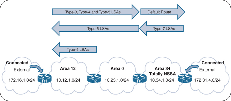
R1’s, R3s, and R4’s Routing Tables Before Area 34 Is a Totally NSSA
R1# show ip route ospf | section 172.31
172.31.0.0/24 is subnetted, 1 subnets
O E1 172.31.4.0 [110/23] via 10.12.1.2, 00:00:38, GigabitEthernet0/0R3# show ip route ospf | begin Gateway
! Output omitted for brevity
Gateway of last resort is not set
O IA 10.12.1.0/24 [110/2] via 10.23.1.2, 00:01:34, GigabitEthernet0/1
O E1 172.16.1.0 [110/22] via 10.23.1.2, 00:01:34, GigabitEthernet0/1
O E1 172.31.4.0 [110/21] via 10.34.1.4, 00:01:12, GigabitEthernet0/0
O IA 192.168.1.1 [110/3] via 10.23.1.2, 00:01:34, GigabitEthernet0/1
O 192.168.2.2 [110/2] via 10.23.1.2, 00:01:34, GigabitEthernet0/1
O 192.168.4.4 [110/2] via 10.34.1.4, 00:01:12, GigabitEthernet0/0R4# show ip route ospf | begin Gateway
! Output omitted for brevity
Gateway of last resort is not set
O IA 10.12.1.0/24 [110/3] via 10.34.1.3, 00:02:28, GigabitEthernet0/0
O IA 10.23.1.0/24 [110/2] via 10.34.1.3, 00:02:28, GigabitEthernet0/0
O E1 172.16.1.0 [110/23] via 10.34.1.3, 00:02:28, GigabitEthernet0/0
O IA 192.168.1.1 [110/4] via 10.34.1.3, 00:02:28, GigabitEthernet0/0
O IA 192.168.2.2 [110/3] via 10.34.1.3, 00:02:28, GigabitEthernet0/0
O IA 192.168.3.3 [110/2] via 10.34.1.3, 00:02:28, GigabitEthernet0/0Member routers of a totally NSSA use the same configuration as members of an NSSA and do not need no-summary, ABRs of a totally NSSA area have no-summary appended to the configuration. The command area area-id nssa no-summary is configured under the OSPF process.
R3# show run | section router ospf 1
router ospf 1
router-id 192.168.3.3
area 34 nssa no-summary
network 10.23.1.0 0.0.0.255 area 0
network 10.34.1.0 0.0.0.255 area 34
network 192.168.3.3 0.0.0.0 area 0R4# show run | section router ospf 1
router ospf 1
router-id 192.168.4.4
area 34 nssa
redistribute connected metric-type 1 subnets
network 10.34.1.0 0.0.0.255 area 34
network 192.168.4.4 0.0.0.0 area 34Routing tables of R3 and R4 after Area 34 is converted into a totally NSSA.

R3 detects R1’s redistributed route as an O E1 (Type 5 LSA) and R4’s redistributed route as an O N1 (Type 7 LSA)
R3# show ip route ospf | begin Gateway
! Output omitted for brevity
Gateway of last resort is not set
O IA 10.12.1.0/24 [110/2] via 10.23.1.2, 00:02:14, GigabitEthernet0/1
O E1 172.16.1.0 [110/22] via 10.23.1.2, 00:02:14, GigabitEthernet0/1
O N1 172.31.4.0 [110/22] via 10.34.1.4, 00:02:04, GigabitEthernet0/0
O IA 192.168.1.1 [110/3] via 10.23.1.2, 00:02:14, GigabitEthernet0/1
O 192.168.2.2 [110/2] via 10.23.1.2, 00:02:14, GigabitEthernet0/1
O 192.168.4.4 [110/2] via 10.34.1.4, 00:02:04, GigabitEthernet0/0Notice that only the default route exists on R4
R4# show ip route ospf | begin Gateway
! Output omitted for brevity
Gateway of last resort is 10.34.1.3 to network 0.0.0.0
O*IA 0.0.0.0/0 [110/2] via 10.34.1.3, 00:04:21, GigabitEthernet0/0OSPF Path Selection
OSPF executes Dijkstra’s shortest path first (SPF) algorithm to create a loop-free topology of shortest paths, All routers use same SPF algorithm and come up with their own topology of shortest paths.
Path selection prioritizes paths in the following order:
- O
- O IA
- N1
- E1
- N2
- E2
Link Costs
Router’s outgoing interface cost is used to accumulate path cost
but every interface is given its cost based on below formula

Or OSPF cost can be set manually with the command ip ospf cost 1-65535 under the interface.
Each OSPF link cost (interface cost) is stored in LSAs.
LSAs use a 16-bit field for cost → maximum value = 65,535.
But OSPF does not store the full path cost in the LSA, instead 1 – 65535 limited costs are assigned to interfaces in LSDB topology and then cumulative path cost is calculated each router when each router executes its own SPF, Therefore, the total path metric can exceed 65,535, even though each individual link cost cannot.
The default reference bandwidth is 100 Mbps due to legacy OSPF design
There is no differentiation in the link cost associated with a Fast Ethernet interface and a 10-Gigabit Ethernet interface which is bad because there is a huge difference and should be differentiated
Changing the reference bandwidth to a higher value allows for differentiation of cost between higher-speed interfaces.
Under the OSPF process, the command auto-cost reference-bandwidth bandwidth-in-mbps changes the reference bandwidth for all OSPF interfaces associated with that process.
If the reference bandwidth is changed on one router, then the reference bandwidth should be changed on all OSPF routers to ensure that SPF uses the same logic to prevent routing loops. It is a best practice to set the same reference bandwidth for all OSPF routers.
NX-OS uses a default reference cost of 40,000 Mbps
Intra-area Routes
OSPF intra-area routes (Type 1 and 2 LSAs) are always preferred over inter-area routes (Type 3 LSAs).

R1 is calculating the route to the 10.4.4.0/24 network. Instead of taking the faster Ethernet connection (R1→R2→R4), R1 takes the path across the slower serial link to R4 (R1→R3→R4) because that is the intra-area path.
R1# show ip route 10.4.4.0
Routing entry for 10.4.4.0/24
Known via "ospf 1", distance 110, metric 111, type intra area
Last update from 10.13.1.3 on GigabitEthernet0/1, 00:00:42 ago
Routing Descriptor Blocks:
* 10.13.1.3, from 10.34.1.4, 00:00:42 ago, via GigabitEthernet0/1
Route metric is 111, traffic share count is 1Inter-area Routes

R1 is computing the path to R6. R1 uses the path R1→R3→R5→R6 because its total path metric is 35 as compared to the metric of 40 for the R1→R2→R4→R6 path
External Route Selection
External routes are classified as Type 1 or Type 2. The main differences between Type 1 and Type 2 external OSPF routes are as follows:
- Type 1 routes are preferred over Type 2 routes.
- The Type 1 metric equals the redistribution metric plus the total path metric to the ASBR. In other words, as the LSA propagates away from the originating ASBR, the metric increases.
- The Type 2 metric equals only the redistribution metric. The metric is the same for the router next to the ASBR as for the router 30 hops away from the originating ASBR. This is the default external metric type that OSPF uses.
E1 and N1 External Routes
External OSPF Type 1 route calculation involves the redistribution metric plus the lowest path metric to reach the ASBR that advertised the network. Type 1 path metrics are lower for routers closer to the originating ASBR, whereas the path metric is higher for a router 10 hops away from the ASBR.
If there is a tie in the path metric, both routes are installed into the RIB. If the ASBR is in a different area, the path of the traffic must go through Area 0. An ABR does not install O E1 and O N1 routes into the RIB at the same time. O N1 is always given preference for a typical NSSA, and its presence prevents the O E1 from being installed on the ABR.
E2 and N2 External Routes
External OSPF Type 2 routes do not increment in metric, regardless of the path metric to the ASBR. If there is a tie in the redistribution metric, the router compares the metric to the ASBR that advertised the network, and the path with lower metric to ASBR wins. If there is a tie in metric to ASBR, both routes are installed into the routing table
An ABR does not install O E2 and O N2 routes into the RIB at the same time. O N2 is always given preference for a typical NSSA, and its presence prevents the O E2 from being installed on the ABR.
show ip ospf border-routersTypes of routers shown in above command
- ASBRs — Autonomous System Boundary Routers
(Routers that inject external routes into OSPF using E1/E2 LSAs) - ABRs — Area Border Routers
(Routers that connect one OSPF area to another and generate Type-3/4/5 LSAs)

172.16.0.0/24 has a metric of 20
R1→R2→R4→R6 path is 31, and the forwarding metric of the R1→R3→R5→R7 path is 30. R1 installs the R1→R3→R5→R7 path into the routing table.
R1# show ip route 172.16.0.0
Routing entry for 172.16.0.0/24
Known via "ospf 1", distance 110, metric 20, type extern 2, forward metric 30
Last update from 10.13.1.3 on GigabitEthernet0/1, 00:12:40 ago
Routing Descriptor Blocks:
* 10.13.1.3, from 192.168.7.7, 00:12:40 ago, via GigabitEthernet0/1
Route metric is 20, traffic share count is 1The logic of choosing an O Nx route over an O Ex route is defined in RFC 3101. Choosing an O Nx is the current default for IOS XE implementations. RFC 1583 prefers an O Ex route over an O Nx route. RFC 1583 path selection can be enabled with the command compatible rfc1583
Equal-Cost Multipathing
If OSPF calculates same path cost for multiple prefixes, they are all installed in the routing table. The default max ECMP paths is four. The default ECMP setting can be overwritten with the command maximum-paths maximum-paths under the OSPF process to modify the default setting.
Summarization
OSPF LSDB size can become large even after splitting OSPF into multiple areas due to large number of Type 3 LSAs and also the Type 5 LSAs
Summarization is a method of shrinking the LSDB
Newer routers have more memory and faster processors than do older ones, but because all routers have an identical copy of the LSDB, an OSPF area needs to accommodate the smallest and slowest router in that area.
Summarization of routes also helps SPF calculations run faster.
A router that has 10,000 network routes will take longer to run the SPF calculation than a router with 500 network routes. Because all routers within an area must maintain an identical copy of the LSDB
Summarization only occurs between areas on the ABRs.
Summarization can protect against the changes in prefixes outside the area for the summarized prefixes because the smaller prefixes are hidden.
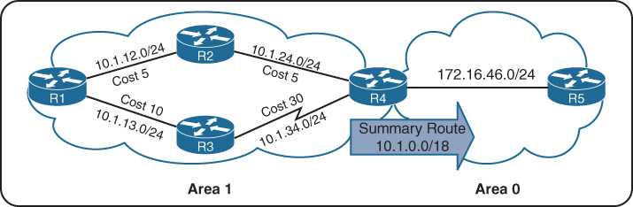
shows the networks in Area 1 being summarized at the ABR into the aggregate 10.1.0.0/18 prefix
If the 10.1.12.0/24 link fails, all the routers in Area 1 still run the SPF calculation, but routers in Area 0 are not affected because the 10.1.13.0/24 and 10.1.34.0/24 networks are not known outside Area 1.
Inter-area summarization reduces the number of Type 3 LSAs that an ABR advertises into an area when it receives Type 1 LSAs. The network summarization range is associated with a specific source area for Type 1 LSAs.
When a Type 1 LSA in the summarization range reaches the ABR from the source area, the ABR creates a Type 3 LSA for the summarized network range. The ABR suppresses the more specific Type 3 LSAs.
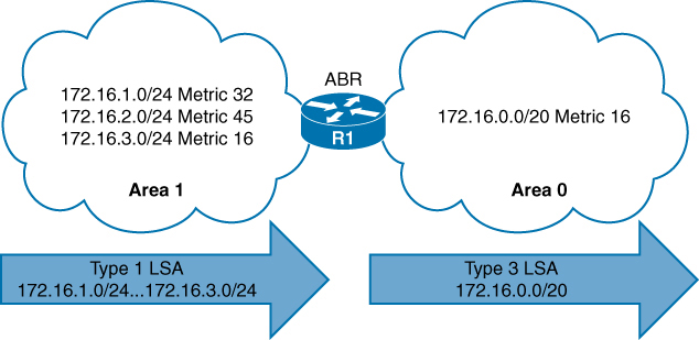
Type 1 LSAs (172.16.1.0/24, 172.16.2.0/24, and 172.16.3.0/24) being summarized into one Type 3 LSA
Summarization works only on Type 1 LSAs and is normally configured (or designed) so that summarization occurs as routes enter the backbone from nonbackbone areas Area x -> Area 0.
At the time of this writing, IOS XE routers set the default metric for the summary LSA to be the lowest metric associated with an LSA
However, the summary metric can statically be set as part of the configuration
R1 summarizes three prefixes with various path costs. The 172.16.3.0/24 prefix has the lowest metric, so that metric will be used for the summarized route.
OSPF behaves similar to Enhanced Interior Gateway Routing Protocol (EIGRP) in that it checks every prefix in the summarization range when a matching Type 1 LSA is added or removed. If a lower metric is available, the summary LSA is advertised with the newer metric; if the lowest metric is removed, a newer and higher metric is identified, and a new summary LSA is advertised with the higher metric.
Configuration of Inter-area Summarization
You define the summarization range and associated area by using the command area area-id range network subnet-mask [advertise | not-advertise] [cost metric] under the OSPF process.
The default behavior is to advertise the summary prefix, so the keyword advertise is not necessary. Appending cost metric to the command statically sets the metric on the summary route.

Routing Table Before OSPF Inter-area Route Summarization
R3# show ip route ospf | begin Gateway
Gateway of last resort is not set
O IA 10.12.1.0/24 [110/2] via 10.23.1.2, 00:02:22, GigabitEthernet0/1
O IA 172.16.1.0 [110/3] via 10.23.1.2, 00:02:12, GigabitEthernet0/1
O IA 172.16.2.0 [110/3] via 10.23.1.2, 00:02:12, GigabitEthernet0/1
O IA 172.16.3.0 [110/3] via 10.23.1.2, 00:02:12, GigabitEthernet0/1router ospf 1
router-id 192.168.2.2
area 12 range 172.16.0.0 255.255.0.0 cost 45
network 10.12.0.0 0.0.255.255 area 12
network 10.23.0.0 0.0.255.255 area 0
R2 summarizes them into a single summary route, 172.16.0.0/16 static cost of 45 is added to the summary route to reduce CPU load if any of the three networks flap.
R3’s routing table shows that smaller component routes were suppressed while summary route is being advertised
Notice in this output that the path metric is 46 whereas previously the metric for the 172.16.1.0/24 network was 3.
R3# show ip route ospf | begin Gateway
Gateway of last resort is not set
O IA 10.12.1.0/24 [110/2] via 10.23.1.2, 00:02:04, GigabitEthernet0/1
O IA 172.16.0.0/16 [110/46] via 10.23.1.2, 00:00:22, GigabitEthernet0/1The ABR performing inter-area summarization installs discard routes, which are routes to the Null0 interface that match the summarized network. Discard routes prevent routing loops where portions of the summarized network range do not have a more specific route in the RIB. The administrative distance (AD) for the OSPF summary discard route for internal networks is 110, and it is 254 for external networks.
R2# show ip route ospf | begin Gateway
Gateway of last resort is not set
O 172.16.0.0/16 is a summary, 00:03:11, Null
O 172.16.1.0/24 [110/2] via 10.12.1.1, 00:01:26, GigabitEthernet0/0
O 172.16.2.0/24 [110/2] via 10.12.1.1, 00:01:26, GigabitEthernet0/0
O 172.16.3.0/24 [110/2] via 10.12.1.1, 00:01:26, GigabitEthernet0/0External Summarization
During OSPF redistribution, external routes are redistributed into the OSPF domain as Type 5 or Type 7 LSAs (NSSA). External summarization reduces the number of external LSAs in an OSPF domain
An external summarization route is configured on the ASBR router, and a smaller component route generates a Type 5/Type 7 external summary route, and the smaller component routes in the summary route are suppressed.
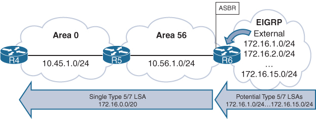
Routing Table Before External Summarization
R5# show ip route ospf | begin Gateway
! Output omitted for brevity
Gateway of last resort is not set
O IA 10.3.3.0/24 [110/67] via 10.45.1.4, 00:01:58, GigabitEthernet0/0
O IA 10.24.1.0/29 [110/65] via 10.45.1.4, 00:01:58, GigabitEthernet0/0
O IA 10.123.1.0/24 [110/66] via 10.45.1.4, 00:01:58, GigabitEthernet0/0
O E2 172.16.1.0 [110/20] via 10.56.1.6, 00:01:00, GigabitEthernet0/1
O E2 172.16.2.0 [110/20] via 10.56.1.6, 00:00:43, GigabitEthernet0/1
..
O E2 172.16.14.0 [110/20] via 10.56.1.6, 00:00:19, GigabitEthernet0/1
O E2 172.16.15.0 [110/20] via 10.56.1.6, 00:00:15, GigabitEthernet0/1R6
router ospf 1
router-id 192.168.6.6
summary-address 172.16.0.0 255.255.240.0
redistribute eigrp 1 subnets
network 10.56.1.0 0.0.0.255 area 56R5# show ip route ospf | begin Gateway
Gateway of last resort is not set
O IA 10.3.3.0/24 [110/67] via 10.45.1.4, 00:04:55, GigabitEthernet0/0
O IA 10.24.1.0/29 [110/65] via 10.45.1.4, 00:04:55, GigabitEthernet0/0
O IA 10.123.1.0/24 [110/66] via 10.45.1.4, 00:04:55, GigabitEthernet0/0
172.16.0.0/20 is subnetted, 1 subnets
O E2 172.16.0.0 [110/20] via 10.56.1.6, 00:00:02, GigabitEthernet0/1R5# show ip route 172.16.0.0 255.255.240.0
Routing entry for 172.16.0.0/20
Known via “ospf 1”, distance 110, metric 20, type extern 2, forward metric 1
Last update from 10.56.1.6 on GigabitEthernet0/1, 00:02:14 ago
Routing Descriptor Blocks:
* 10.56.1.6, from 192.168.6.6, 00:02:14 ago, via GigabitEthernet0/1
Route metric is 20, traffic share count is 1The summarizing ASBR installs a discard route to Null0 that matches the summary route as part of a loop-prevention mechanism and it will be seen on router that is doing summarization in this case R6
R6# show ip route ospf | begin Gateway
Gateway of last resort is not set
10.0.0.0/8 is variably subnetted, 6 subnets, 3 masks
O IA 10.3.3.0/24 [110/68] via 10.56.1.5, 00:08:36, GigabitEthernet0/1
O IA 10.24.1.0/29 [110/66] via 10.56.1.5, 00:08:36, GigabitEthernet0/1
O IA 10.45.1.0/24 [110/2] via 10.56.1.5, 00:08:36, GigabitEthernet0/1
O IA 10.123.1.0/24 [110/67] via 10.56.1.5, 00:08:36, GigabitEthernet0/1
172.16.0.0/16 is variably subnetted, 15 subnets, 3 masks
O 172.16.0.0/20 is a summary, 00:03:52, Null0ABRs for NSSAs act as ASBRs when a Type 7 LSA is converted to a Type 5 LSA. External summarization can be performed on ABRs only when they match this scenario.
Discontiguous Network and Virtual links
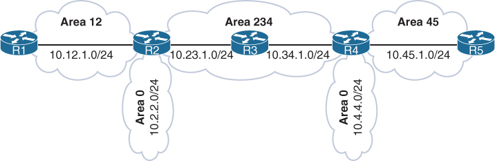
Above is a topology with mistake in design, where R2 and R4 are technically ABRs connected to Area 0 but this will not work, this is called discontiguous network. OSPF can catch this mistake because of all seeing LSDB
Most people would assume that R1 would learn about the route learned by Area 45 because R4 is an ABR. However, they would be wrong. ABRs follow three fundamental rules for creating Type 3 LSAs:
Type 1 LSAs received from an area create Type 3 LSAs into backbone area and nonbackbone areas.
Type 3 LSAs received from Area 0 are created for the nonbackbone area.
Type 3 LSAs received from a nonbackbone area are only inserted into the LSDB for the source area. An ABR does not create a Type 3 LSA for the other areas (including a segmented Area 0).
When suspect, make sure that every ABR is touching Area 0 where all other Aera 0 routers show to be part of it, In above topology only R2 will find itself in the Area 0 and also R4 will only see itself as part of Area 0
Create a detection strategy in lab and practice against that
Virtual Links
OSPF virtual links provide a method to overcome discontiguous networks
Virtual Links are not just used for discontiguous Area 0s but it is also used to connect a topology in which Area 0 <–R100–> Area 1 <–R101–> Area 2, R101 ABR is deprived of Area 0
Area 0 can be extended to remote Areas
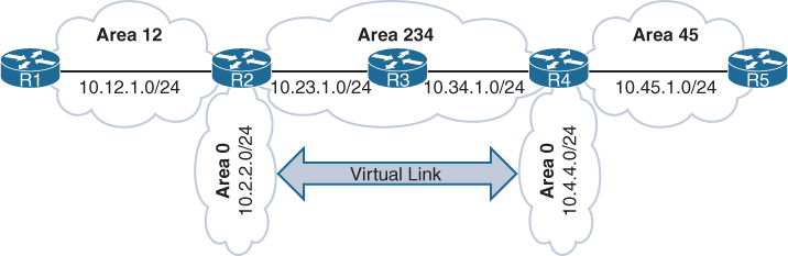
in above topology Area 12 and Area 45 were not orphaned
Area 12 , Area 0 and Area 234 kept working as R2 ABR has Area 0
Similarly Area 45 , Area 0 and Area 234 kept working as R4 ABR has Area 0
But Area 12 routes will not be learned by Area 45 and Area 45 routes will not be learned by Area 12 R2’s Area 0 and R4’s Area 0 are not same, practically preventing both from being in same Area 0
Virtual links are built between routers in the same area
The area in which the virtual link endpoints are established is known as the transit area
The virtual link can be one hop away or multiple hops away from the remote device between the ABRs
The virtual link is built using Type 1 LSAs
virtual links cannot be formed on any OSPF stubby areas
Area 234 cannot be an OSPF stub area. Or in this example Area 0 <–> Area 1 <–> Area 2 , Area 1 cannot be stub area
After Virtual Link configuration both Area 0 will become one Area 0 with 2x subnets 10.2.2.0/24 and 10.4.4.0/24 in Area 0
Think of virtual link being in Area 0, so once virtual link is established between ABRs, ABR that was not part of Area 0 will become part of Area 0 with one link in Area 0 which is virtual link
R2
router ospf 1
router-id 192.168.2.2
area 234 virtual-link 192.168.4.4 <<< like tunnel endpoint
network 10.2.2.2 0.0.0.0 area 0
network 10.12.1.2 0.0.0.0 area 12
network 10.23.1.2 0.0.0.0 area 234R4
router ospf 1
router-id 192.168.4.4
area 234 virtual-link 192.168.2.2 <<< like tunnel endpoint
network 10.4.4.4 0.0.0.0 area 0
network 10.34.1.4 0.0.0.0 area 234
network 10.45.1.4 0.0.0.0 area 45Interface cost for a virtual link cannot be set or dynamically generated as the metric for the intra-area distance between the two virtual link endpoints.
R2# show ip ospf virtual-links
Virtual Link OSPF_VL0 to router 192.168.4.4 is up
Run as demand circuit
DoNotAge LSA allowed.
Transit area 234, via interface GigabitEthernet0/1
Topology-MTID Cost Disabled Shutdown Topology Name
0 2 no no Base
Transmit Delay is 1 sec, State POINT_TO_POINT,
Timer intervals configured, Hello 10, Dead 40, Wait 40, Retransmit 5
Hello due in 00:00:01
Adjacency State FULL (Hello suppressed)
Index 1/1/3, retransmission queue length 0, number of retransmission 0
First 0x0(0)/0x0(0)/0x0(0) Next 0x0(0)/0x0(0)/0x0(0)
Last retransmission scan length is 0, maximum is 0
Last retransmission scan time is 0 msec, maximum is 0 msecR4# show ip ospf virtual-links
! Output omitted for brevity
Virtual Link OSPF_VL0 to router 192.168.2.2 is up
Run as demand circuit
DoNotAge LSA allowed.
Transit area 234, via interface GigabitEthernet0/0
Topology-MTID Cost Disabled Shutdown Topology Name
0 2 no no Base
Transmit Delay is 1 sec, State POINT_TO_POINT,
Timer intervals configured, Hello 10, Dead 40, Wait 40, Retransmit 5
Hello due in 00:00:08
Adjacency State FULL (Hello suppressed)Notice that the cost here is 2, which accounts for the metrics between R2 and R4
OSPF Virtual Link as an OSPF Interface
R4# show ip ospf interface brief
Interface PID Area IP Address/Mask Cost State Nbrs F/C
Gi0/2 1 0 10.4.4.4/24 1 DR 0/0
VL0 1 0 10.34.1.4/24 2 P2P 1/1
Lo0 1 34 192.168.4.4/32 1 DOWN 0/0
Gi0/1 1 45 10.45.1.4/24 1 BDR 1/1
Gi0/0 1 234 10.34.1.4/24 1 BDR 1/1A Virtual Link Displayed as an OSPF Neighbor
R4# show ip ospf neighbor
Neighbor ID Pri State Dead Time Address Interface
192.168.2.2 0 FULL/ - - 10.23.1.2 OSPF_VL0
192.168.5.5 1 FULL/DR 00:00:34 10.45.1.5 GigabitEthernet0/1
192.168.3.3 1 FULL/DR 00:00:38 10.34.1.3 GigabitEthernet0/0R1’s and R5’s Routing Tables After the Virtual Link Is Created
R1# show ip route ospf | begin Gateway
Gateway of last resort is not set
O IA 10.2.2.0/24 [110/2] via 10.12.1.2, 00:00:10, GigabitEthernet0/0
O IA 10.4.4.0/24 [110/4] via 10.12.1.2, 00:00:05, GigabitEthernet0/0
O IA 10.23.1.0/24 [110/2] via 10.12.1.2, 00:00:10, GigabitEthernet0/0
O IA 10.34.1.0/24 [110/3] via 10.12.1.2, 00:00:10, GigabitEthernet0/0
O IA 10.45.1.0/24 [110/4] via 10.12.1.2, 00:00:05, GigabitEthernet0/0R5# show ip route ospf | begin Gateway
Gateway of last resort is not set
O IA 10.2.2.0/24 [110/4] via 10.45.1.4, 00:00:43, GigabitEthernet0/1
O IA 10.4.4.0/24 [110/2] via 10.45.1.4, 00:01:48, GigabitEthernet0/1
O IA 10.12.1.0/24 [110/4] via 10.45.1.4, 00:00:43, GigabitEthernet0/1
O IA 10.23.1.0/24 [110/3] via 10.45.1.4, 00:01:48, GigabitEthernet0/1
O IA 10.34.1.0/24 [110/2] via 10.45.1.4, 00:01:48, GigabitEthernet0/1next post
CCIE SGT
SGT BRKSEC-3690 – PDF
SGT BRKSEC-3690 – Notes
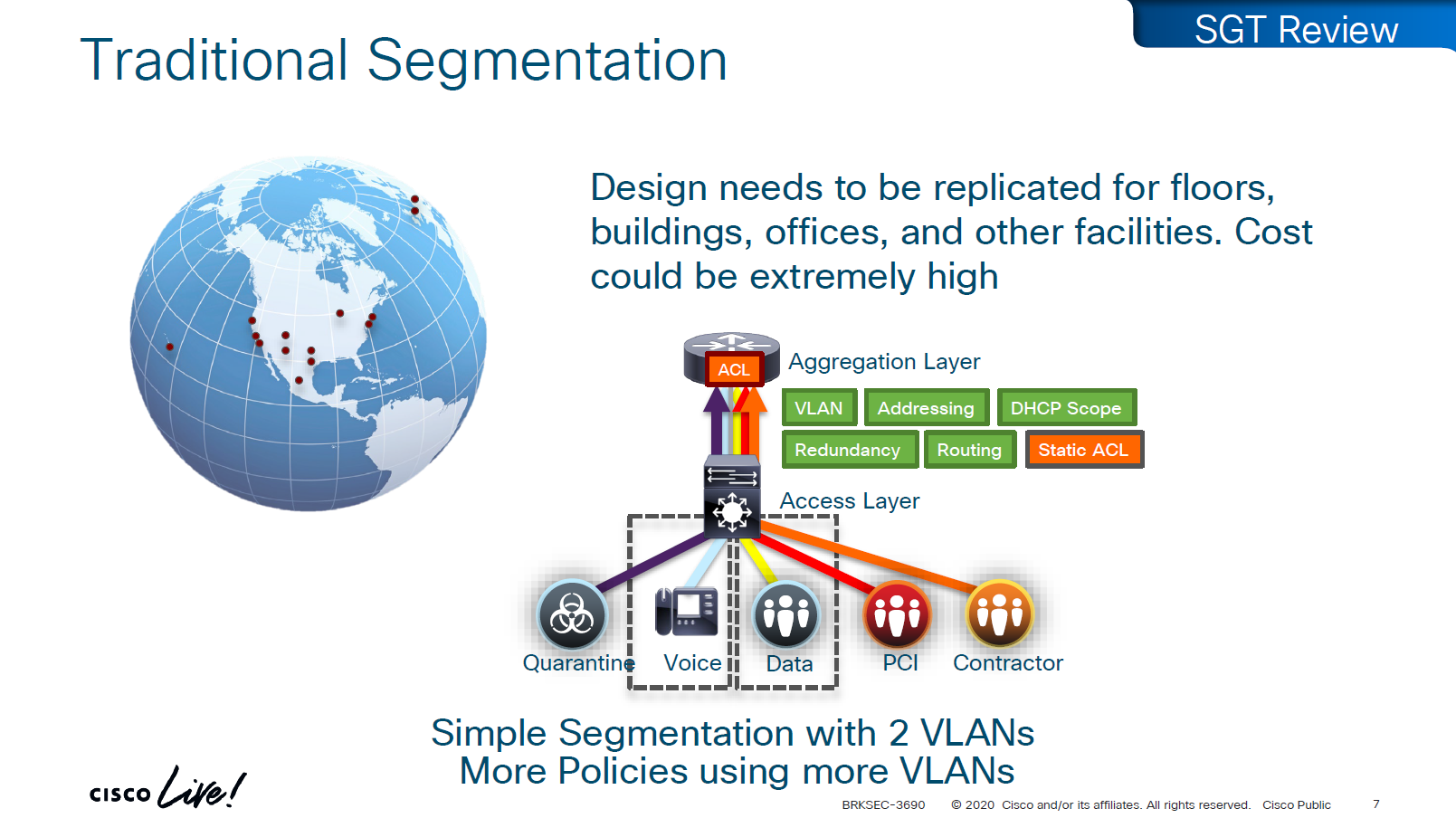
A Security Group Tag is a 16-bit label attached to traffic to identify the security group or role of the source (e.g., Employees, Guests, IoT Devices).
SGTs are used in Cisco TrustSec / SD-Access environments to create role-based access control policies that don’t rely on IP addresses.
SGT is not just used for SGACL or filtering only, because it is a tag on IP packet, this is also being used Policy based routing and also QoS – QoS based on SGT
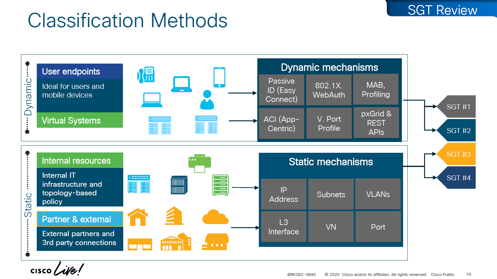
There are 2 ways of classifying the devices in an SGT group
- Dynamic
- ISE
- 802.1x
- MAB, profiling
- pxGrid, Rest API
- ACI
- ISE
- Static
- IP address
- Subnets
- VLANs
- L3 interface
- VN
- Port
Traffic or packets are classified and tagged on ingress into the network which is access layer and filter on the egress of the network
Because classification and tagging on ingress of the network and filtering on egress of the network, it is very important to have tags pushed or transport the tags to all devices on the network
There are 2 ways to do that,
No packet tagging, but use control plane, using SXP (Scalable Group Exchange) protocol to teach foreign devices about the IP to SGT over TCP control plane
This way frame or packet has not been modified or tag is not added in the IP header, and target device also understood the tag that applies to that traffic.
SXP can be activated on a headend only that makes drop or allow policy decisions, it does not have to be applied on all intermediate nodes in the topology hop by hop unlike QoS that requires every hop to do QoS enforcement.
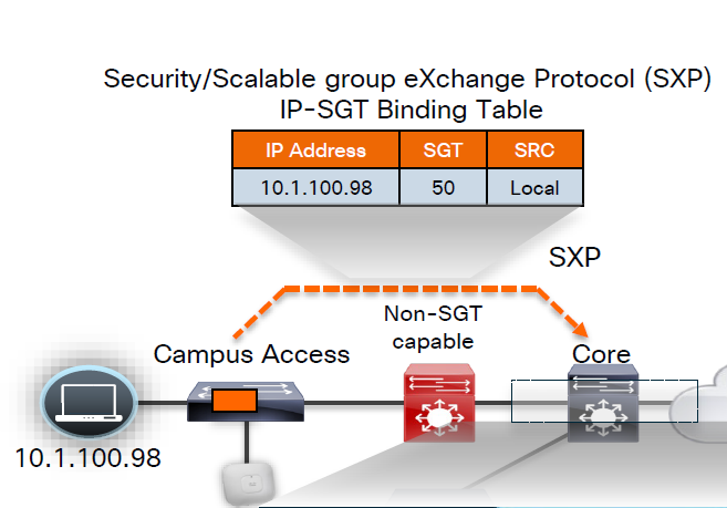
other one is inline tagging
with inline tagging we also have some encryption options such as IPSec or MACsec to prevent people from messing with tags
By default you can go from SXP to inline tagging
to go from inline tagging to SXP you must enable SGT caching
All firewall vendors like Firepower, Checkpoint, Fortigate and Palo Alto, do support pxGrid based implementation for SXP, pxGrid is a publisher and subscriber model where publisher can push information down to subscribers for different topics and one topic can be SXP protocol that has a table that contains IP address to SGT tag mapping
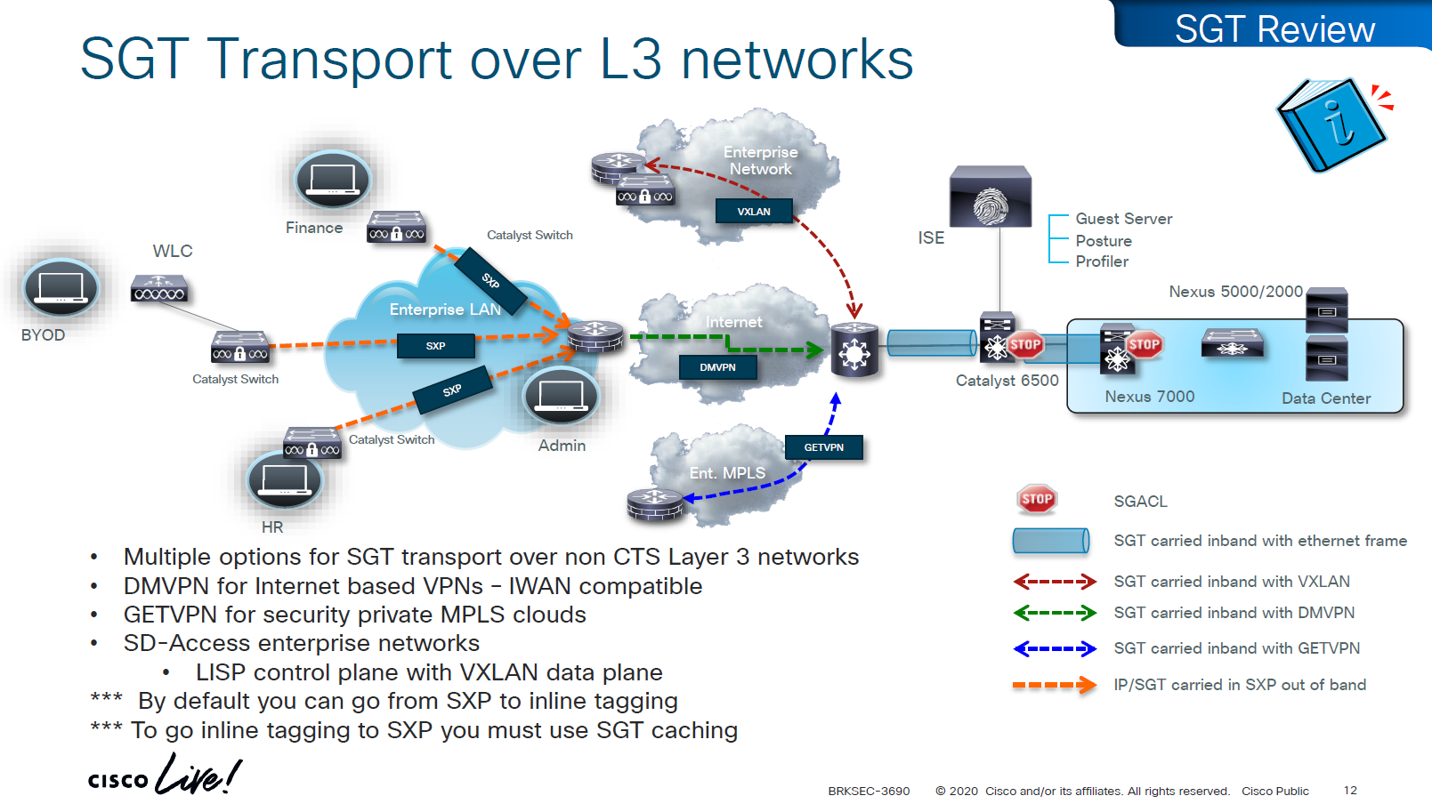
SXP can be activated on a headend only that makes drop or allow policy decisions, it does not have to be applied on all intermediate nodes in the topology hop by hop unlike QoS that requires every hop to do QoS enforcement.
End to end SGT work flow
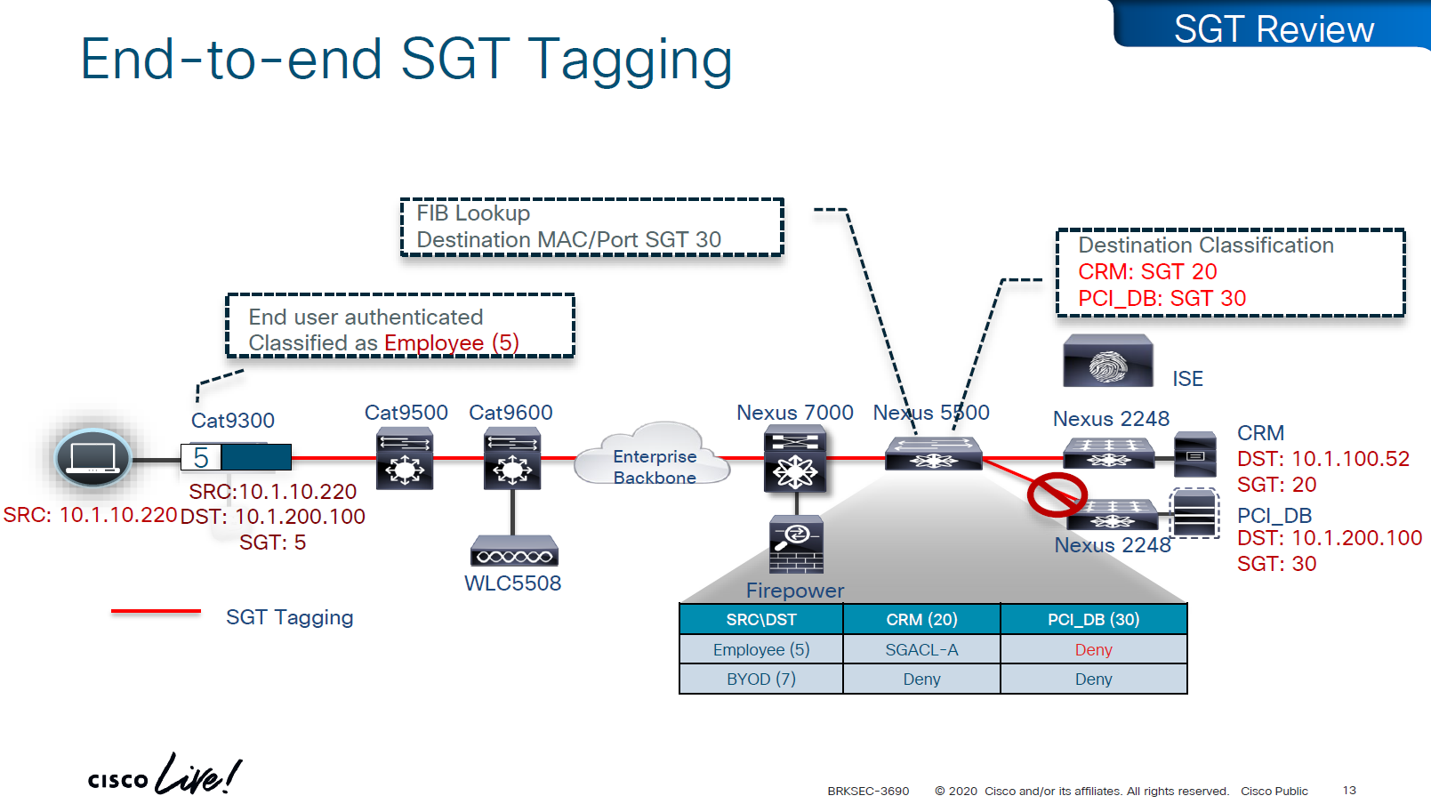
Filtering with SGTs is always done on egress or last switch where destination is connected,
this is because we do not want to overload our access layer switches with all policies and track of all devices connected on the network ahead of it
This optimizes and keeps memory size smaller for small devices,
Access or ingress will only add tag to the traffic and send,
it is the destination switch after it has received the packet,
checks the SGT on the packet – if not on packet, derive SGT from the SXP learned IP to SGT table.
Find out the mac / destination port + the SGT assigned to host on that port – if not assigned on port derive from SXP learned IP to SGT table for that IP
then egress switch will take a policy decision and drop or allow based on policy,
Switches in aggregation or core can be set to look at the destination IP and determine the SGT from SXP learned IP to SGT tag before sending packet out towards destination, this is to drop traffic in core rather than egress
on destination egress or core a log is generated for all deny or drops, if all switches in network point to central logging server, these logs can tell us about the dropped traffic

This shows the policy matrix and how switches that have hosts with certain SGT only pull “columns” from matrix for those hosts only, as soon as a host is connected that has a new SGT, policy column for that SGT is downloaded on the switch, this is very on demand like fashion where switch does not have to download all the policies of the policy matrix and be light weight
Be careful of platform support for SGT when implementing to make sure that platform does support trustsec for all actions such as Classification, Propagation and Enforcement
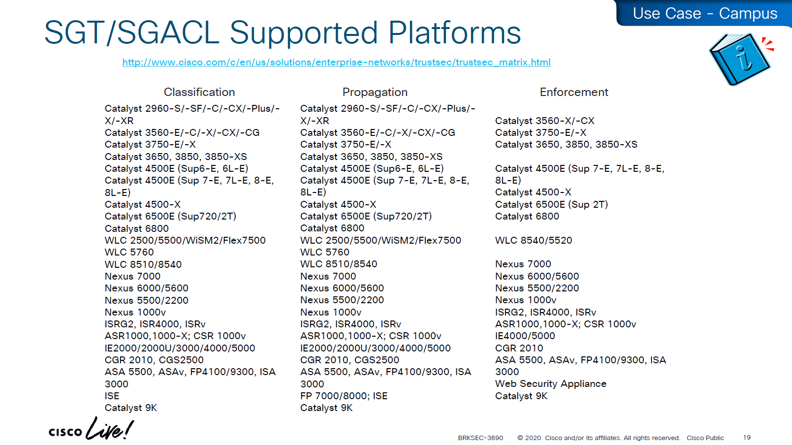

on 3850 as a client we are setting SXP peer (almost like a routing peer) to send it the IP to SGT mappings (local mode)
9K is SXP receiver only using “mode local listener” instead of a speaker
show cts role-based sgt-map all details
! check mappings on 3850 switch
show cts sxp connections brief
! check peersin above “show cts role-based sgt-map all details” – we can see the one attached host got SGT tag of 6:Full_Access and source is “LOCAL”
similarly not shown here but WLC also a client that got SGT of 3:BYOD and at the bottom we run “show cts role-based sgt-map all details” command on core C9K and we can see both tags learned from SXP (3850 and WLC). Aggregation layer is building table automatically as devices are learned from Access layer devices
Enabling SGT/SGACL Enforcement
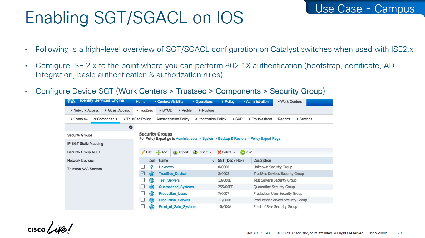
Before SGT/SGACL can be enabled on Cisco devices, make sure that SGT tag for network devices TrustSec_Devices is assigned by default to the network device and make a policy that always allows TrustSec_Devices is always allowed to speak to ISE and infrastructure, why is that needed? because there is a default rule in policy, if it is set to deny then all control plane traffic from device to ISE will be dropped
There was a case once when 2000 switches disappeared from the network, that customer did not have network device SGT like TrustSec_Devices above, they also did not have policy against it to make devices from TrustSec_Devices speak to infrastructure servers SGT, third thing is that they turned on default deny rule in policy
Do not turn on that default deny unless you are really sure that every protocol and everything has been taken care off as it will start dropping the Unknown / untagged SGT traffic as well
Unknown SGT refers to the default tag used when a packet, user, or device does not have a valid SGT assigned. In Cisco TrustSec, this value is typically SGT = 0 and is considered unclassified or unauthenticated traffic. Whenever Unknown SGT of 0 is seen on traffic or host, it means following:
-The client is not authenticated via 802.1X/MAB/web-auth
-Even if authenticated from ISE, there was no SGT in Auth Z results from ISE
-The TrustSec policy mapping isn’t configured
Most TrustSec deployments deny or restrict traffic with Unknown SGT:
- Best practice: Block or isolate Unknown to → Protected traffic in policy matrix
- Allow Unknown to → Internet (e.g., guest networks) in policy matrix
Assign TrustSec_Device to network devices

SGT CTS “peer authentication” between ISE and Device is done through EAP-FAST as PAC file is downloaded on the Network device, PAC which is used in case you want password less certificate like authentication without having certificates. This is called PAC bootstrapping, this is used to download policies, SGACLs and SGT tags then later SXP is used to send or download the SGT to IP mapping separately.

look at send from ISE PSN and test connection button
If there are large number of policy changes, having CLI access from ISE is much faster and better at times, for example there was a customer with 200 x 200 policy matric, it took almost 4 hours to finish the update, it was changed to CLI for all devices and all updates completed in 30 mins, if it is small incremental updates, RADIUS CoA is fine
This device ID is the hostname of the device and password corresponds to command
cts credential id DEVICE-ID password PASSWORD! this is done in non config , enable mode
device>cts credentials id <DEVICE-ID> password <PASSWORD>
show cts credentials
show cts environment-data
show cts role-based permissionsSetting long timers make sure policy is refreshed on devices annually and also only when there is an explicit change in policy

Why the pac key appears under the radius-server host command?
Even though the PAC is used for TrustSec (CTS/NDAC) and not for normal RADIUS authentication, the PAC is delivered through RADIUS using cisco’ vendor attribute, PAC exchange is not a standard RADIUS authentication — it is a special RADIUS message (Cisco-vendor attribute) used only for TrustSec device bootstrapping that is why it is configured under RADIUS server configuration block along with RADIUS shared secret.
cts authorization list <AUTHZ_List_Name> is the list of ISE RADIUS nodes that are running TrustSec
Why Cisco did it this way
Cisco chose to reuse the RADIUS channel rather than invent a new protocol:
- RADIUS is already required for 802.1X authentications
- Switches already have reachability to ISE
- The PAC exchange can ride over the same transport (UDP 1812/1645)
So the PAC bootstrap process piggybacks on RADIUS → therefore, the PAC key configuration lives inside the radius-server settings.
Full configuration of ISE RADIUS Servers with PAC
! Enable AAA
aaa new-model
! Define ISE as a RADIUS server (auth/acct) and include the PAC bootstrap secret
radius server ISE1
address ipv4 10.10.10.10 auth-port 1812 acct-port 1813
key RADIUS_SHARED_SECRET
pac key RADIUS_PAC_SECRET
!
! send vsa or vendor attributes in RADIUS authentication request
radius-server vsa send authentication
! (Optional) put servers into a group and set a source interface
aaa group server radius ISE-GRP
server name ISE1
ip radius source-interface Vlan10
! CTS/NDAC: define the authorization list used for policy download only (not tags - tags are pulled before SGACL or policy is pulled) - as clients connect with new SGT , more policy columns are pulled
cts authorization list CTS-AUTHZ
! 802.1X + CTS use the RADIUS group
aaa authentication dot1x default group ISE-GRP
aaa authorization network CTS-AUTHZ group ISE-GRP
! aaa authorization network command is usually used to allow on network or authorize audience or entity authenticated through network ports and this config says that authorized list of server (which are allowed to make CLI or COA changes) will be downloaded from ISE-GRP
! which makes it look like this
aaa authorization network ( CTS-AUTHZ ) group ISE-GRP
aaa authorization network ( cts authorization list ) group ISE-GRP
! Define credentials for EAP-FAST I-ID, these are configured under enable mode and not in config mode
cts credential id DEVICE-ID password PASSWORD
! enable 802.1x on system level
dot1x system-auth-control
! enable CTS enforcement
cts role-based enforcementSXP does not carry SGACL policies.
SXP only carries IP-to-SGT mappings
SGACL policy travels via DTLS tunnel established using PAC.
Policy matrix is translated or converted into bunch of SGACLs and then sent out to devices
Sequence and use of PAC:
1. Authenticate the switch to ISE for TrustSec
2. Receive the PAC credential
3. Establish a secure, encrypted control channel DTLS for SGACL policy download
It is sent through the PAC → NDAC → Secure DTLS Trust Tunnel that is established after the PAC is provisioned
Switch proves identity to ISE to download PAC -> RADIUS
Policy download (SGACLs and SGT tags – “TrustSec Bootstrapping”) -> PAC established DTLS (UDP)
IP-to-SGT sharing between devices -> SXP (TCP)


First thing to notice in this output is the Local Device SGT that is assigned to network device, any control plane communication from this device will be assigned SGT
Then coming below we can see 3 TrustSec ISE servers are set as servers for downloading SGT tags and SGACL policy (but not SGT to IP mappings which are downloaded over SXP)

We define more tags in ISE, in above picture we can see ACI EPGs (contracts) defined as tags and this is through automation , automatically created through API
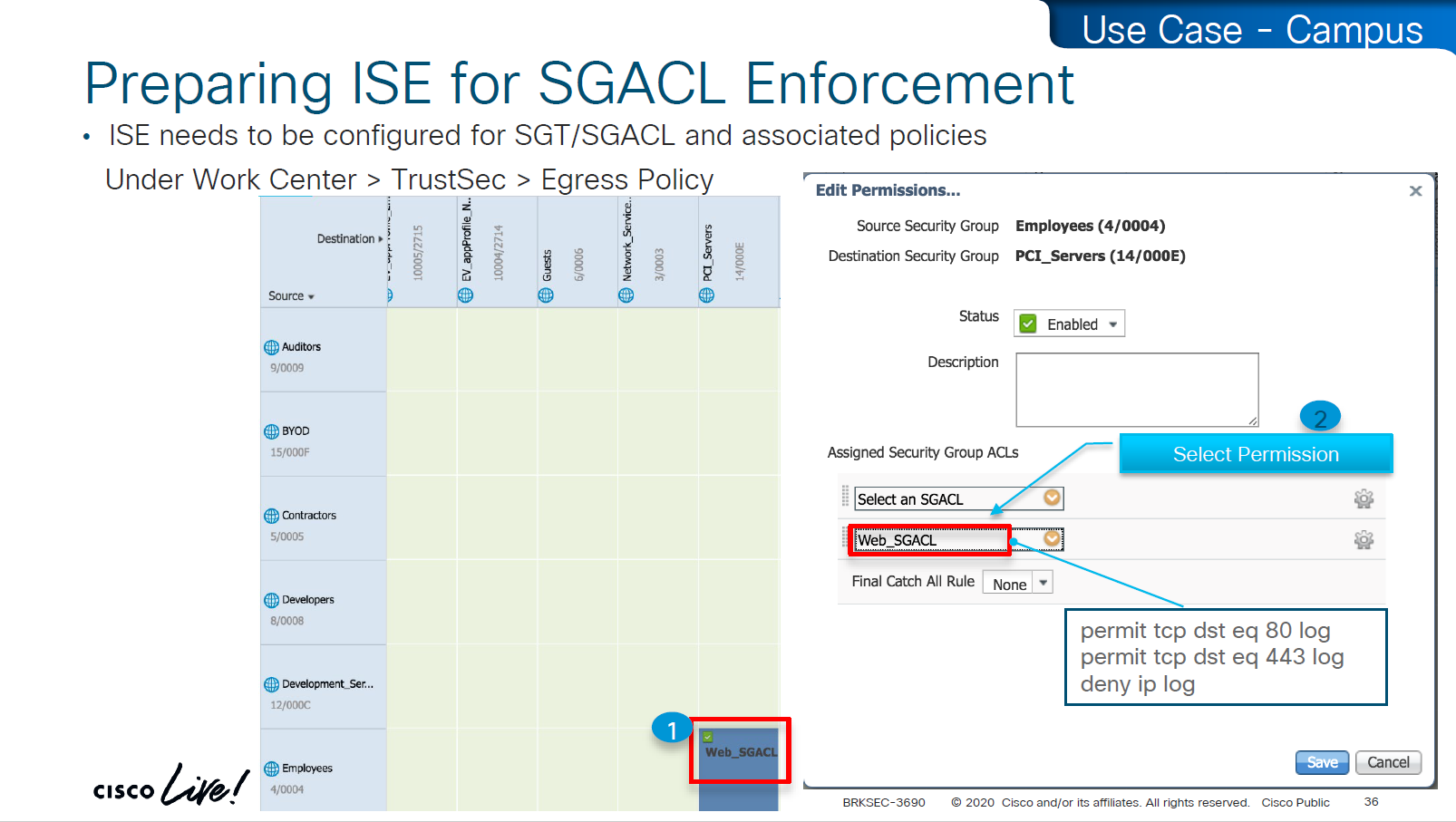
These are stateless ACLs unlike firewalls, this is exact filtering as described ACEs
but best thing about these ACEs is there are no IP addresses
One thing to notice in above screenshot is ability to define multiple ACLs in a single cell of the policy matrix but this is turned off by default as it is not supported by all devices yet because WLCs and Nexus only support single ACL for an SGT and DGT filtering
Only IOS XE switches are supporting multiple ACL per cell

above we can see manual IP to SGT map, which can also be pushed from ISE via CLI or from ISE via SXP
Even if switch has policy matrix table downloaded, and switch also has all the SGT tags, switch will not enforce on traffic unless command is “cts role-based enforcement” is defined
Second command allows us to enable on per VLAN, this is very significant because we can enable SGT enforcement incrementally on VLANs
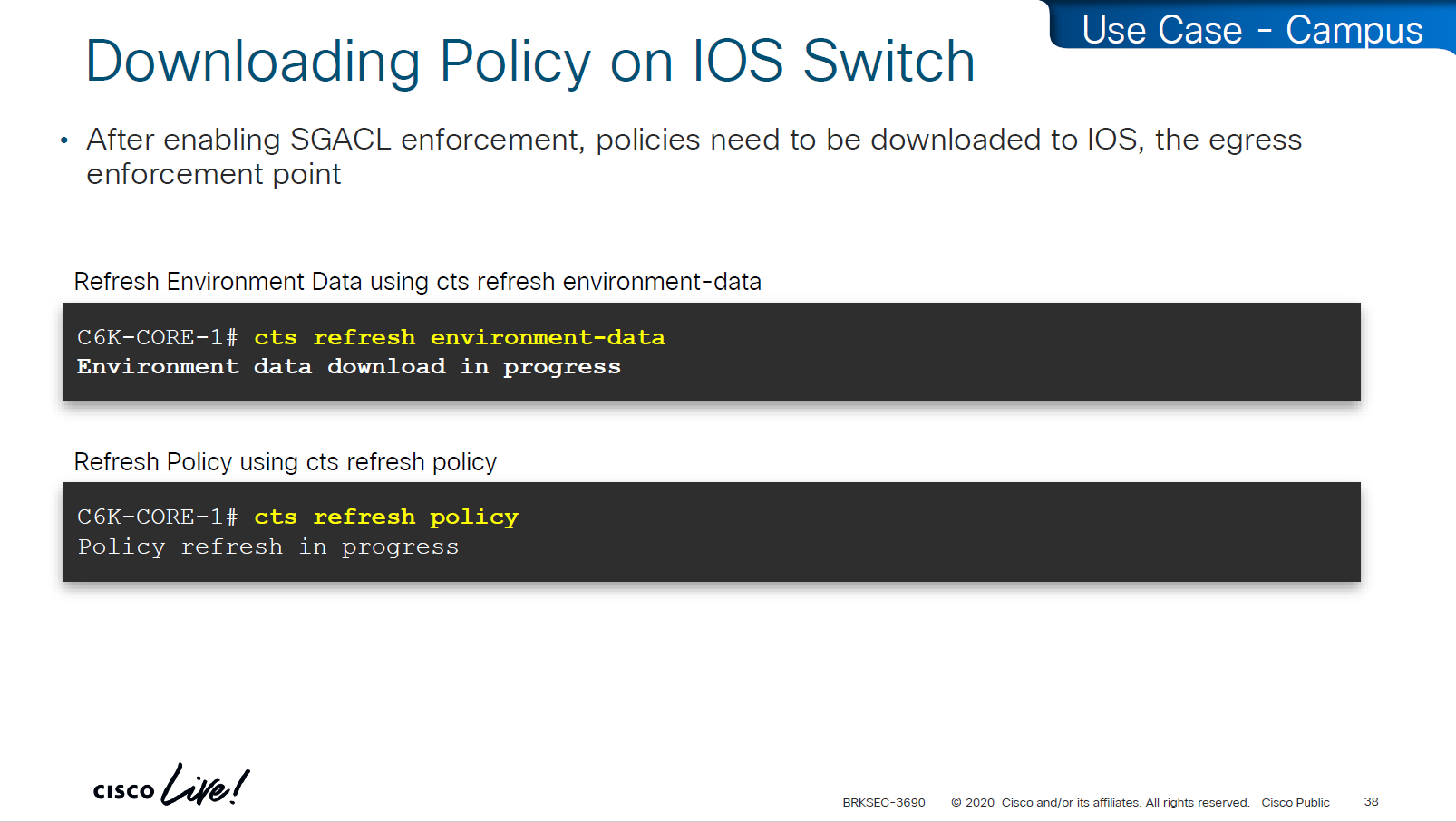
environment data is SGT tags
policy is the policy matrix

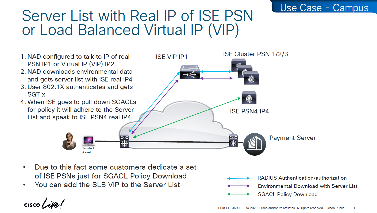
As we can see that RADIUS flow is different
“Environmental Data download + Server list” is different flow before SGACL policy is downloaded
SGACL policy download is from the server list, server list was fetched with environment data

This was done because in peak times when RADIUS servers are busy it can be too much load to download the SGACL policy over same ISE PSN nodes and it is better to download over dedicated ISE TrustSec PSN nodes

in above screen shots dynamic author (RADIUS servers allowed to do CoA) are defined
-PAN should be defined for SGT related flows
-PSNs should be configured for 802.1x / MAB
In older versions of ISE, clicking on Deploy is not enough, there is a confirmation icon on top that needs to be click and confirm, only then ISE notifies all switches that there is a change and download the new policy

There is a policy validation button that runs this command “show cts role-based permissions” and validates that ISE has same policy as devices and if there is anu mismatch or issue then an Alarm is generated from ISE


SGACL denies will show as log, and you will see that logging hits are shown as well which means that if there are a lot of logs then number of hits accumulated will be reported under logging_interval_hits and log will be generated, but in some cases auditor will come in and say that they need to see a log for every drop and allow, and at that point we need to understand that this is a switch and not the firewall, with SGACL enforcement it is not possible to get log for every hit

show cts role-based counters
! shows * to * default rule
! also shows from and to columns
! SGACL is done in hardware, unless needs punting
! for example TCAM or hardware is full, log in the end of ACE , makes SW counter increment otherwise concentrate on HW-Denied and HW-Permitted columnsSoftware denies and software permits are for to the box traffic or traffic destined for the switch, including the DHCP and ARP permits will also increment the Software counters, SGACL enforcement is in hardware
One of the examples of confusion with ping is that people test access control by pinging the switch SVI and say why is the hardware counter not increasing, it will be denied in software SW-Denied, the thing with SVI ping is that it is going up through software control plane to the CPU and then responding (punted to CPU)

Wireless APs do “enforcement” with SGACLs

TrustSec implementation in wireless does follow the same principal of tagging on ingress and filtering on egress (APs)
APs do the filtering also on egress in wireless to wireless communication, that confuses people as they see SGACL download on WLC but they do not see permit or deny logs in WLC CLI, it makes sense to check the WLC but enforcement for wireless to wireless traffic is being done on AP for scaling reasons otherwise WLC will be overwhelmed as WLC can do enforcement for wireless to wired communication
Ingress AP will tag the packet and send it across the WLC over CAPWAP due to central switching and egress AP will do the lookup for SGT of the destination client using client table and perform policy enforcement based on that
Skipped Nexus 7000 SGT Considerations

Common issues


SGT trustsec relies on IP device tracking
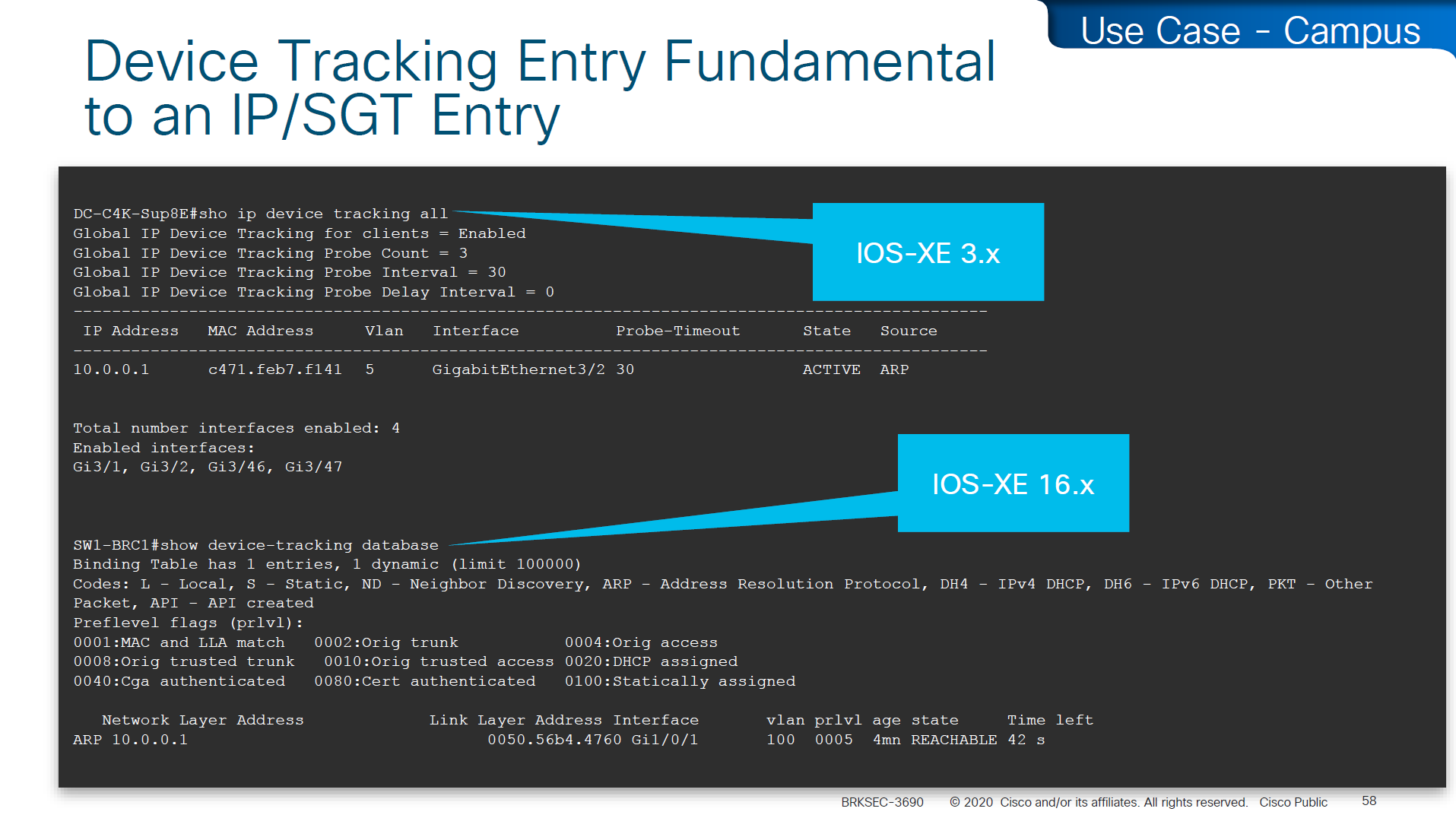
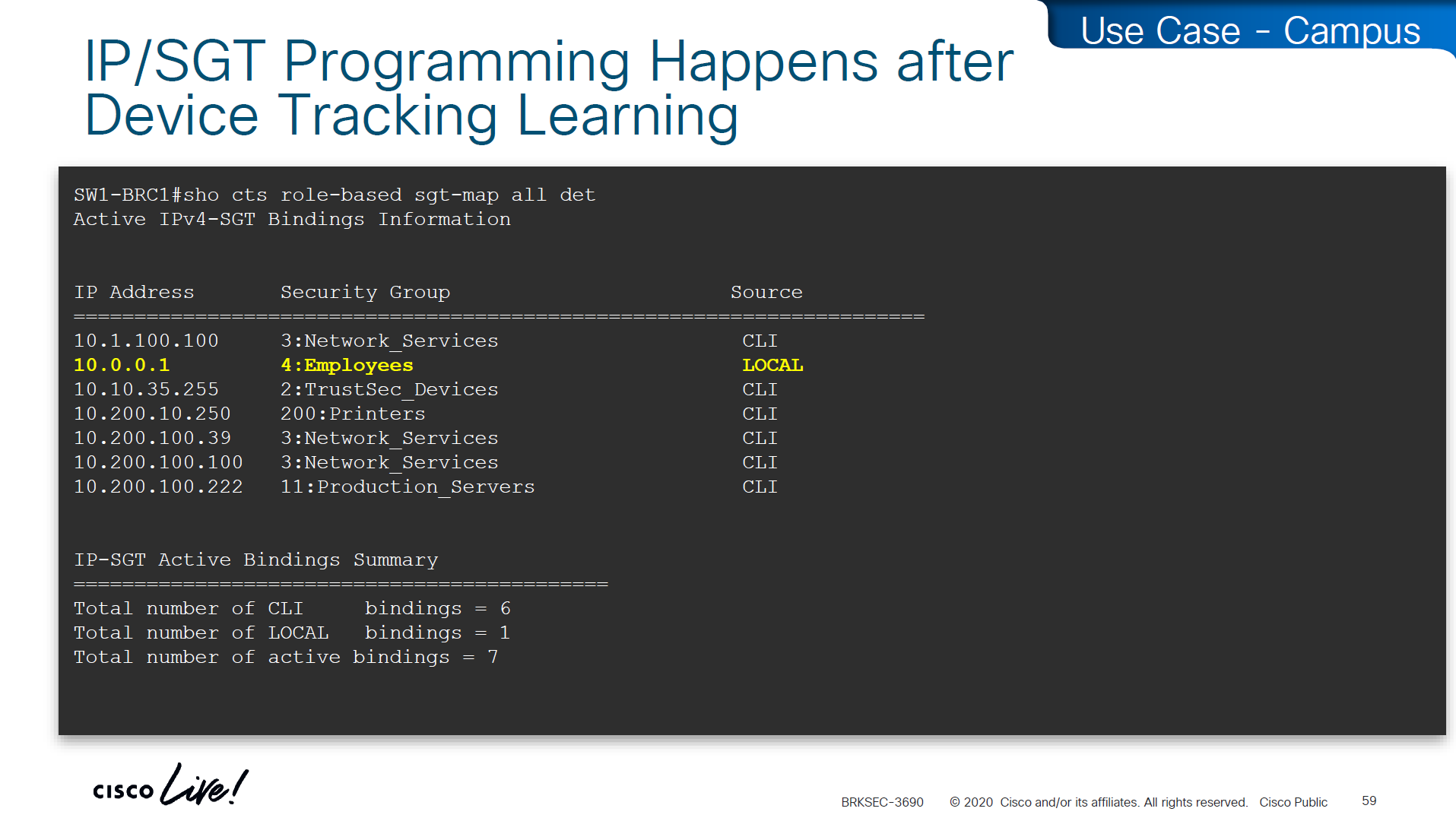
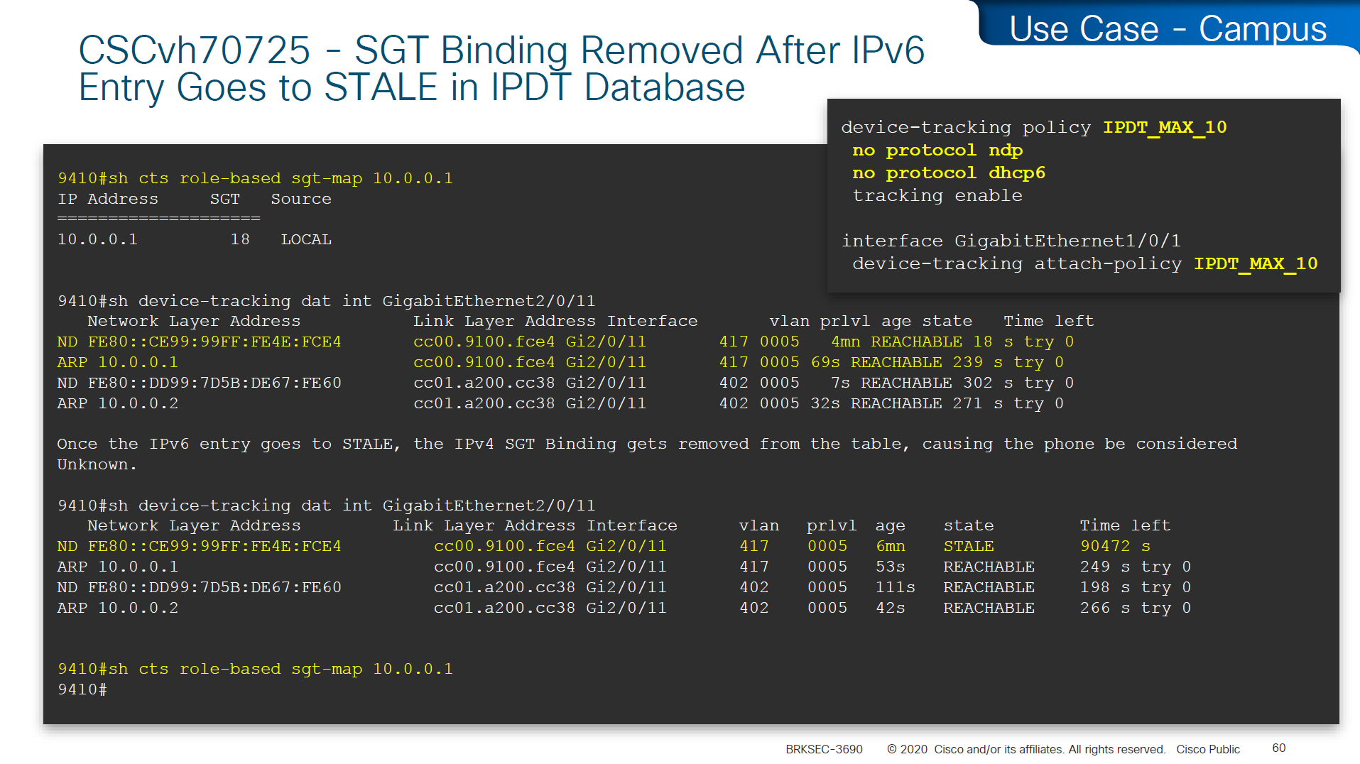
In case you have SGT disappearing from host, then check if this bug is in effect and usually happens on older unpatched code, the workaround was to turn off ndp (which is IPv6 ARP mechanism) tracking from IP device tracking and also turn off dhcpv6 tracking
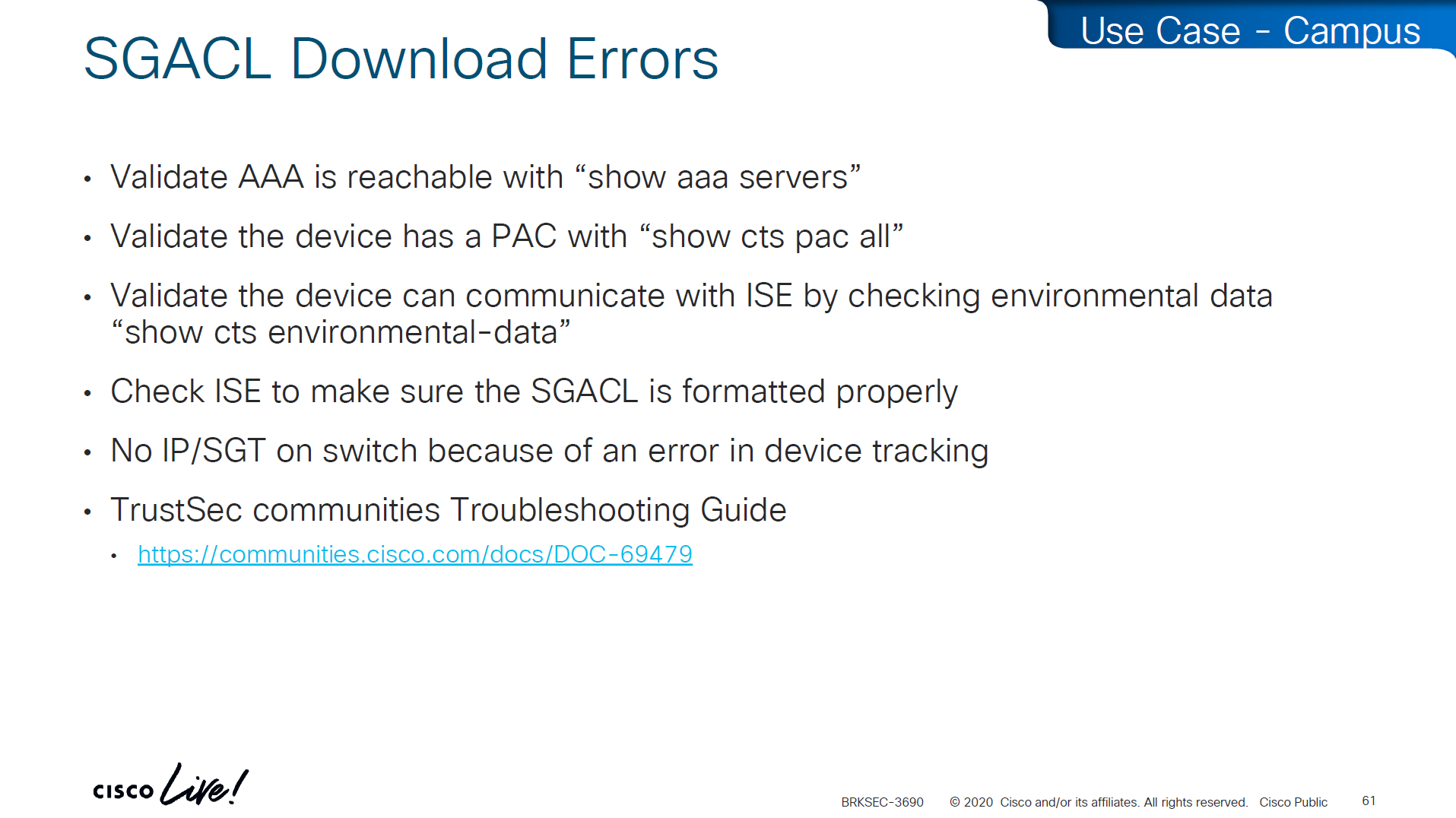
in case SGACL download is not happening we need to check following:
Make sure pac is present
show cts pac allMake sure AAA servers are marked alive
show aaa servers Make sure device can reach ISE
show cts environment-dataCheck ISE to make sure SGACL is formatted properly
Make sure there are no errors in device-tracking as whole solutions rides on device-tracking to work
Sometimes bad implementation of SDWAN can cause fragmentation of large packets and sometimes that can cause ISE to device download of SGACL of DTLS (PAC based) to break for large packets causing “partial download”, that is why it is so important to first test for fragmentation over greenfield or brownfield deployment and also test large elephant connections with large packets – on the side note large elephant connections over IPSec based tunnels are heavy on platform’s ability to encrypt large traffic
So if you see partial download of SGACL, then always check for fragmentation issue, because by default for this pac based DTLS connections DF bit is set and routers from all vendors do not like DF bit
Software Defined Access (SD – Access) – SGT/VXLAN

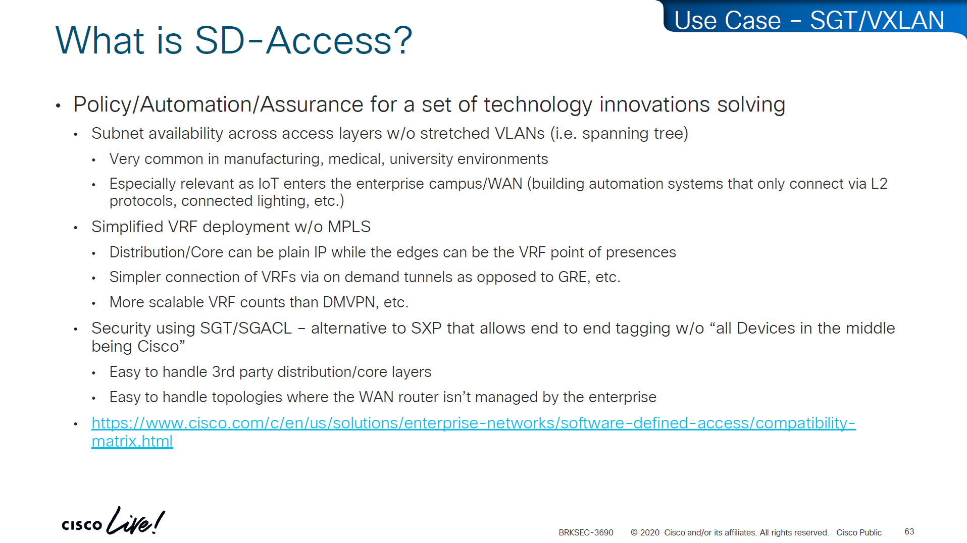
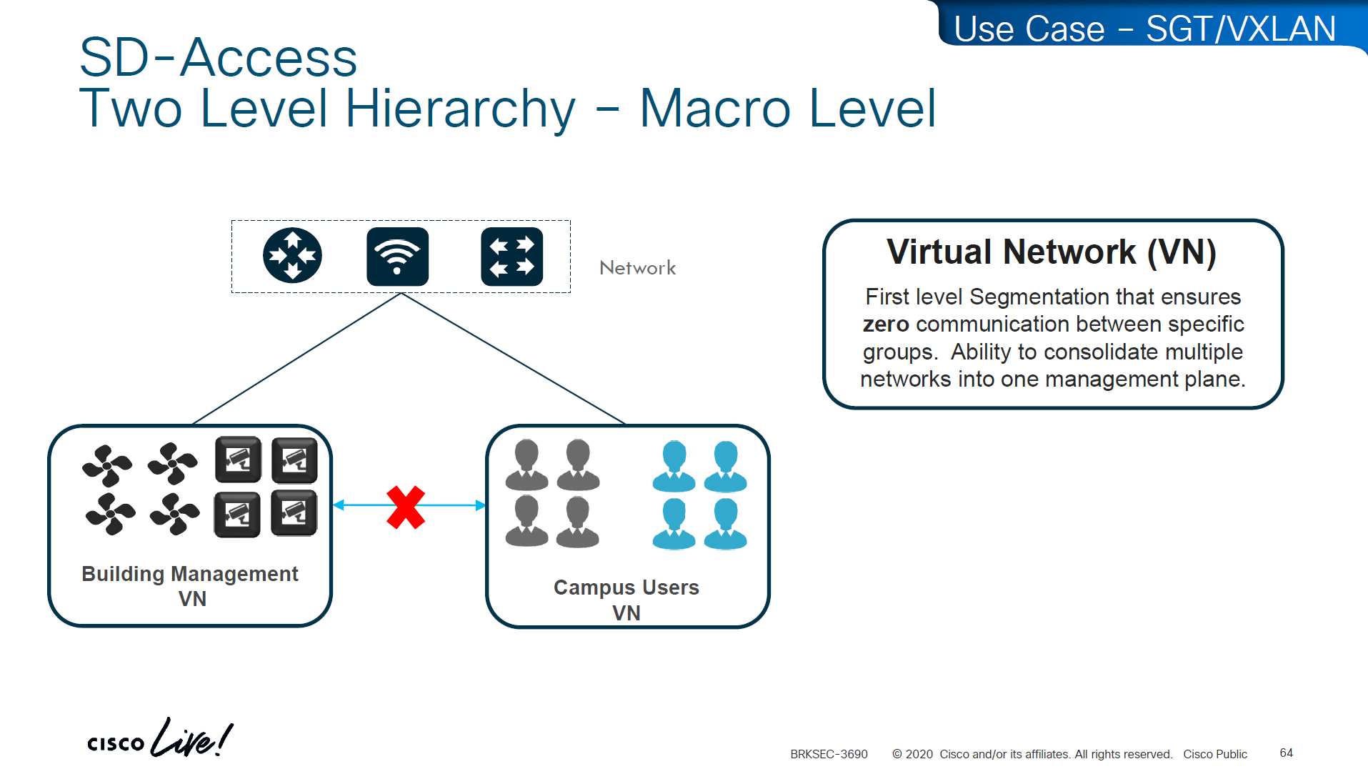
These SDA VNs are VRFs but these are campus wide VRFs,
Macro Level segmentation is devices of different management domains go in their own VN
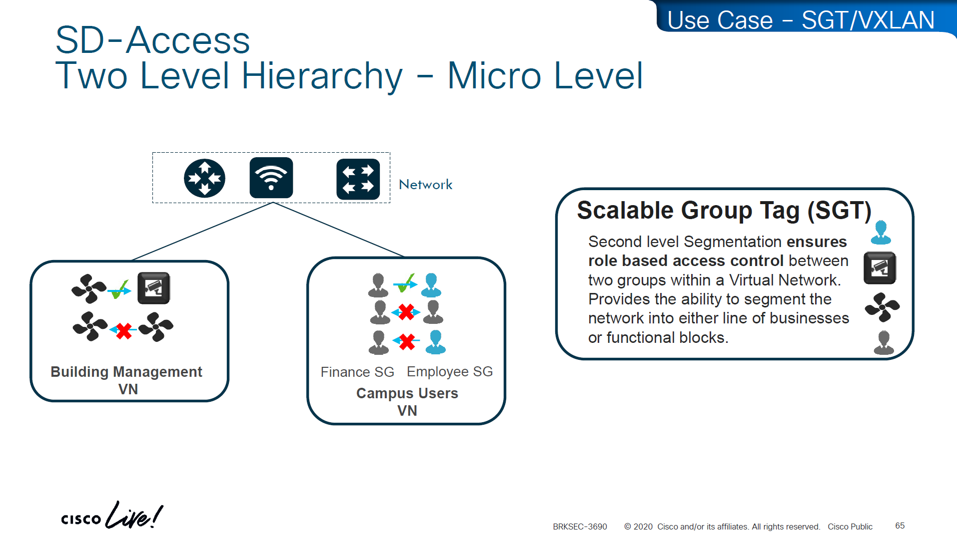
Micro Segmentation is used for access control within the VN
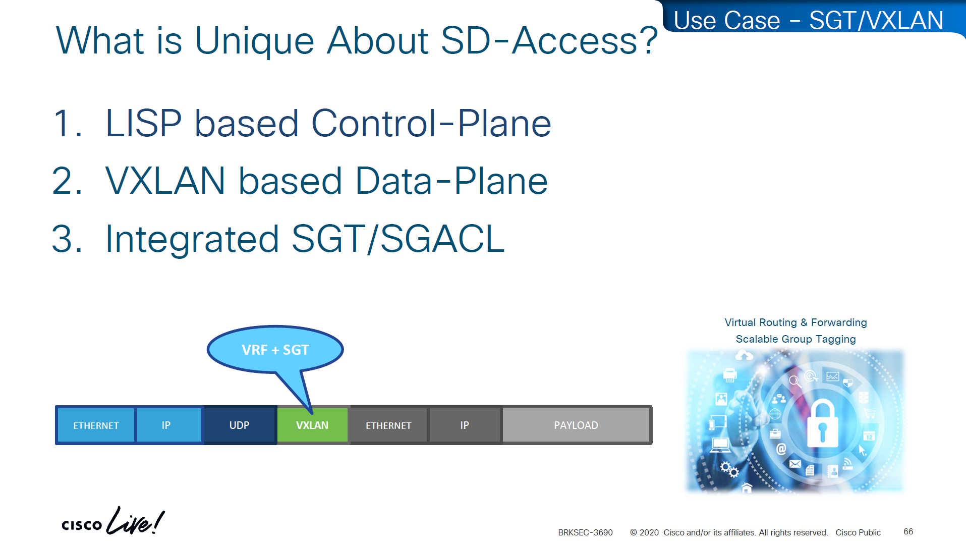
LISP is another great optimization at the access layer and it reduces or optimizes the routes by only installing /32 host routes on access layer switch to which its connected hosts are initiating connections to and from, access layer no longer needs to maintain the large routing tables, LISP installs routes in VRFed routing table of access switches
VXLAN encapsulates the whole ethernet frame, eats up or carries the whole frame and then VXLAN is carried inside UDP and then IP header and then ethernet frame
VN and SGT are carried inside the VXLAN header
The SGT (Security Group Tag) is not added to the original inner IP packet.
It is carried only in the VXLAN header as metadata, and in order to use SGT capabilities outside of the network with Cisco gear we can use TrustSec which uses SXP and with other vendors we can use PXGrid

Policy matrix is created on DNAC and then pushed to ISE , ISE then pushes the SGT environment data (SGT Tags and Trusted Server list) over TCP, SGACL using NDAC over PAC based DTLS and then finally IP to SGT mapping on border nodes using SXP?


ACL or contracts are defined in badge color cells

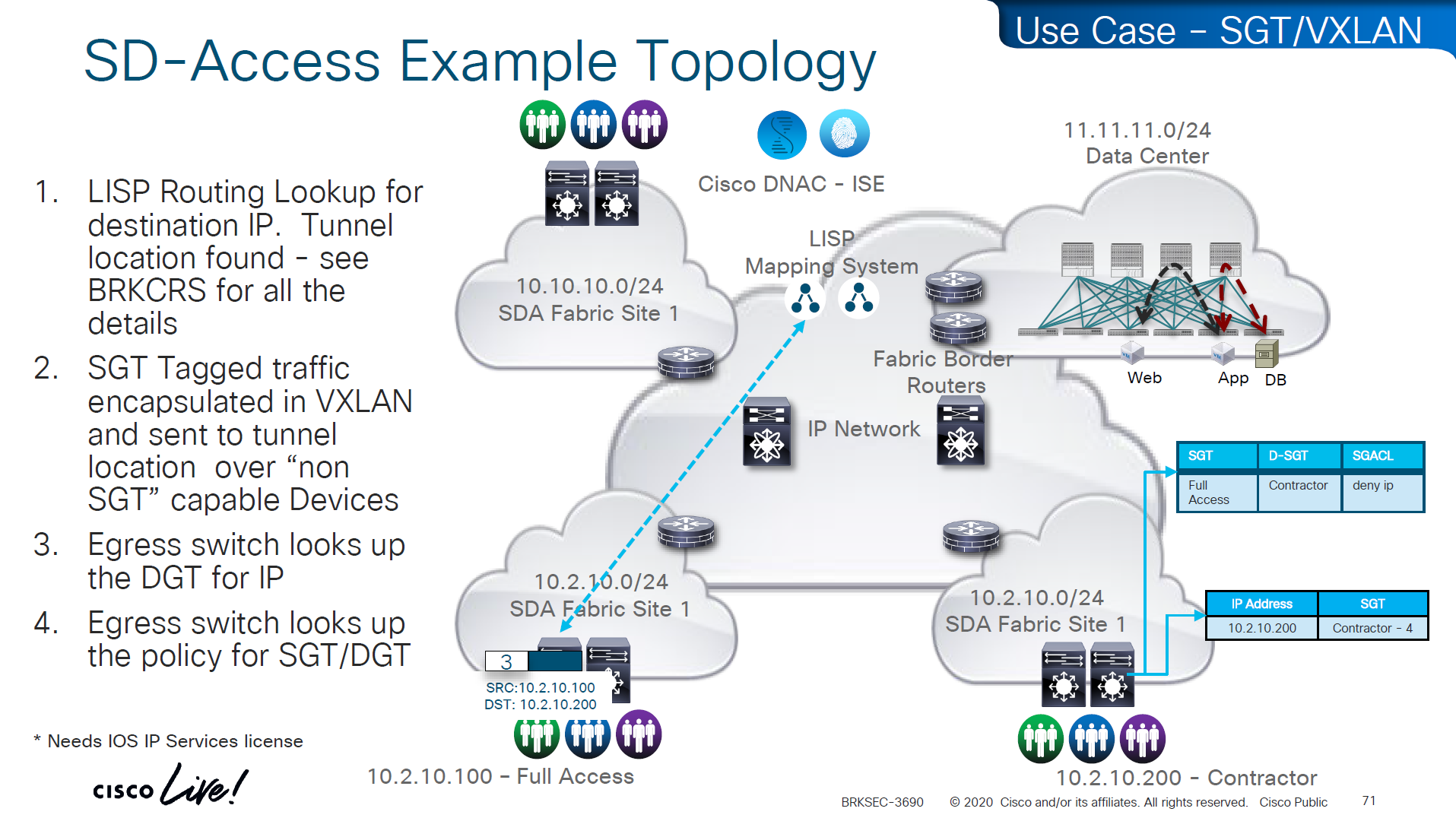
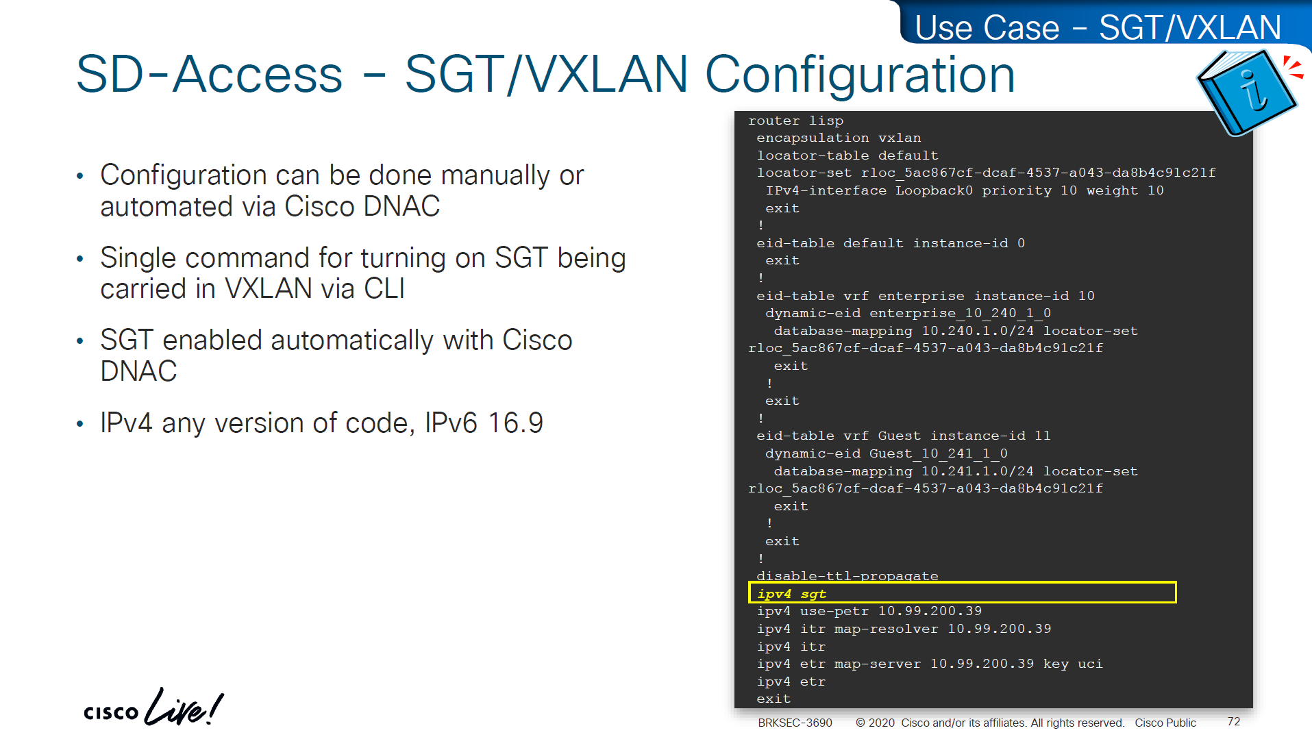
This is how it is enabled inside LISP
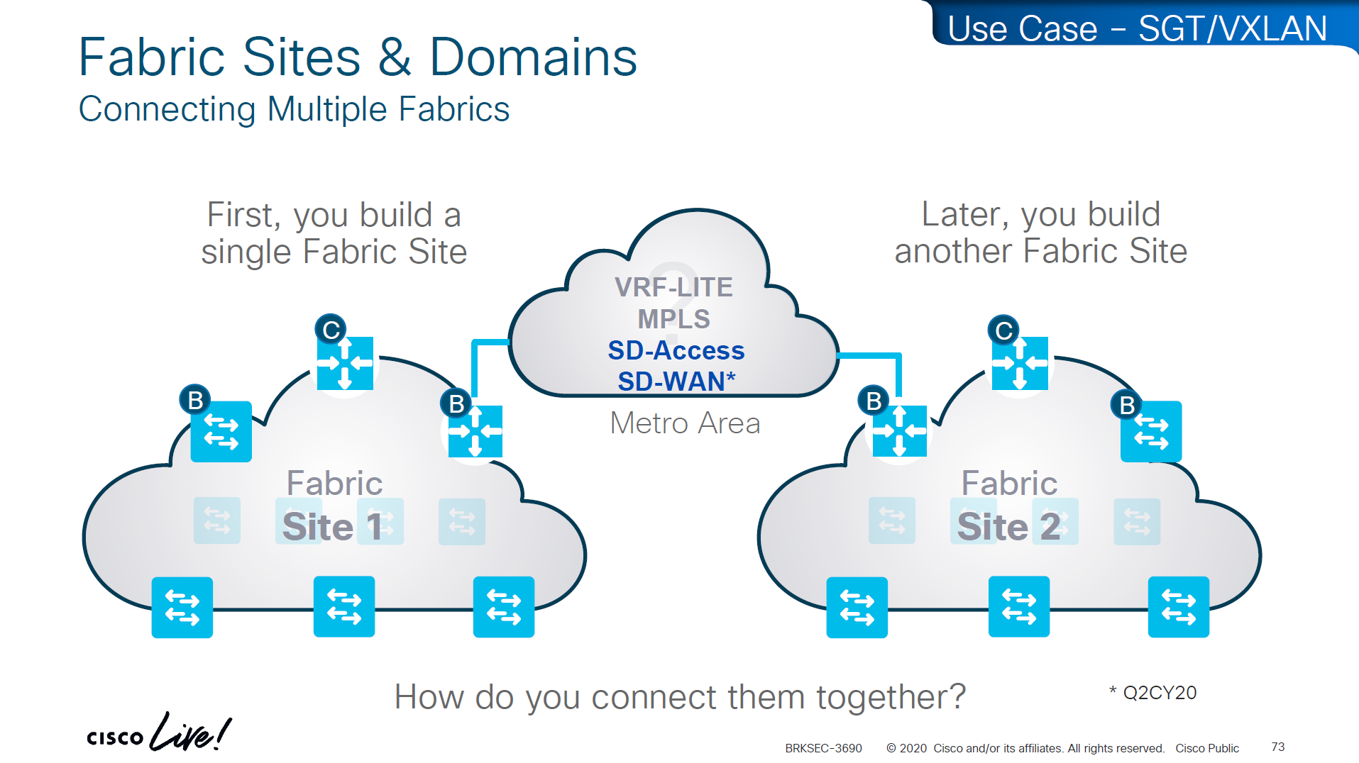
If we have SD Access transit or SDWAN, we can carry SGT to other fabric sites

SDA transit uses LISP as control plane between borders of both fabric sites
and then on data plane we have VXLAN header that crosses between fabric sites
but in order to accommodate the VXLAN header we will need 1588 or better 1600 MTU
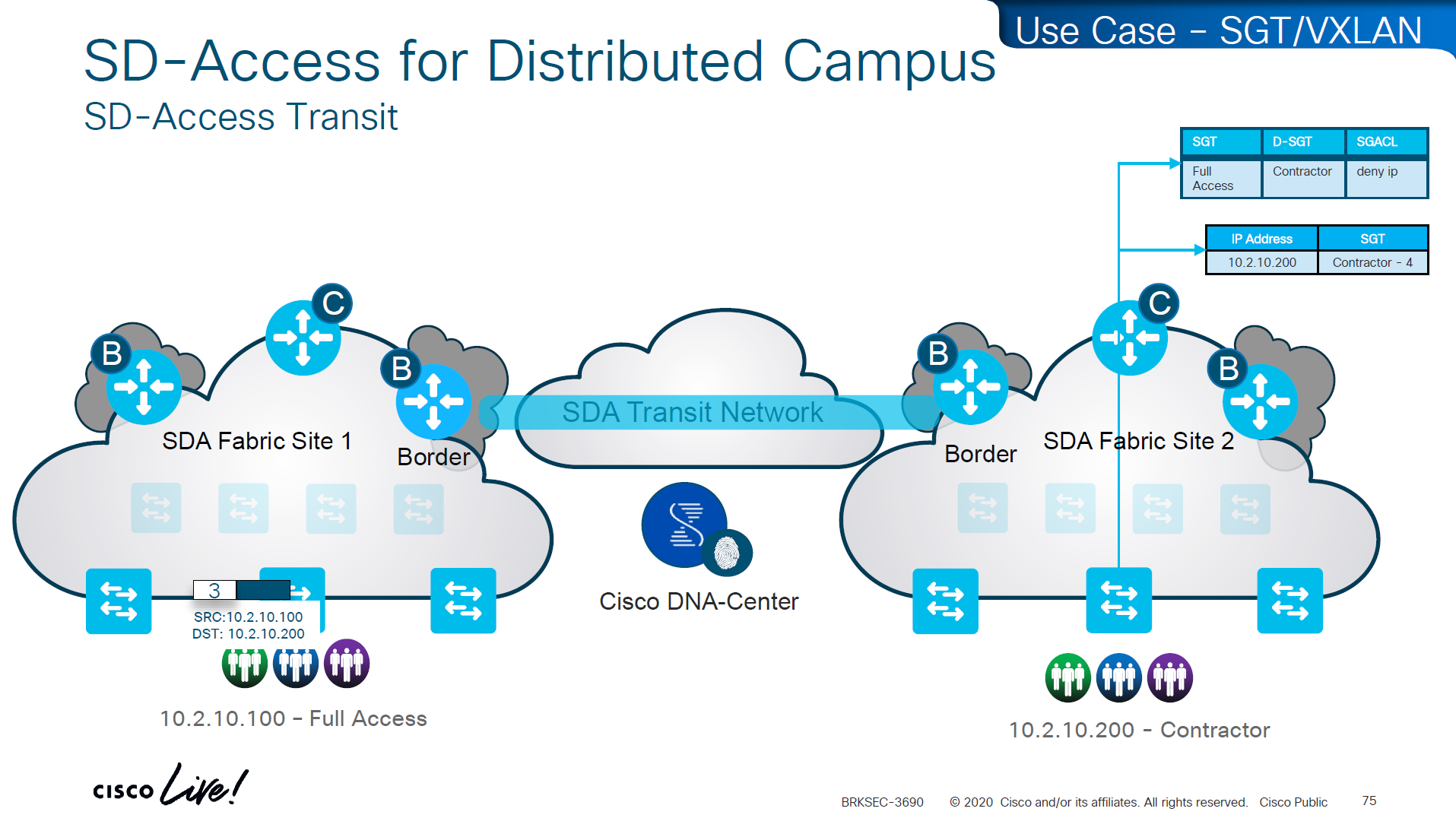
Skipped Firewall Integration with SD-Access
Skipped Meraki and 3rdParty Interop

Use Case Review -WAN


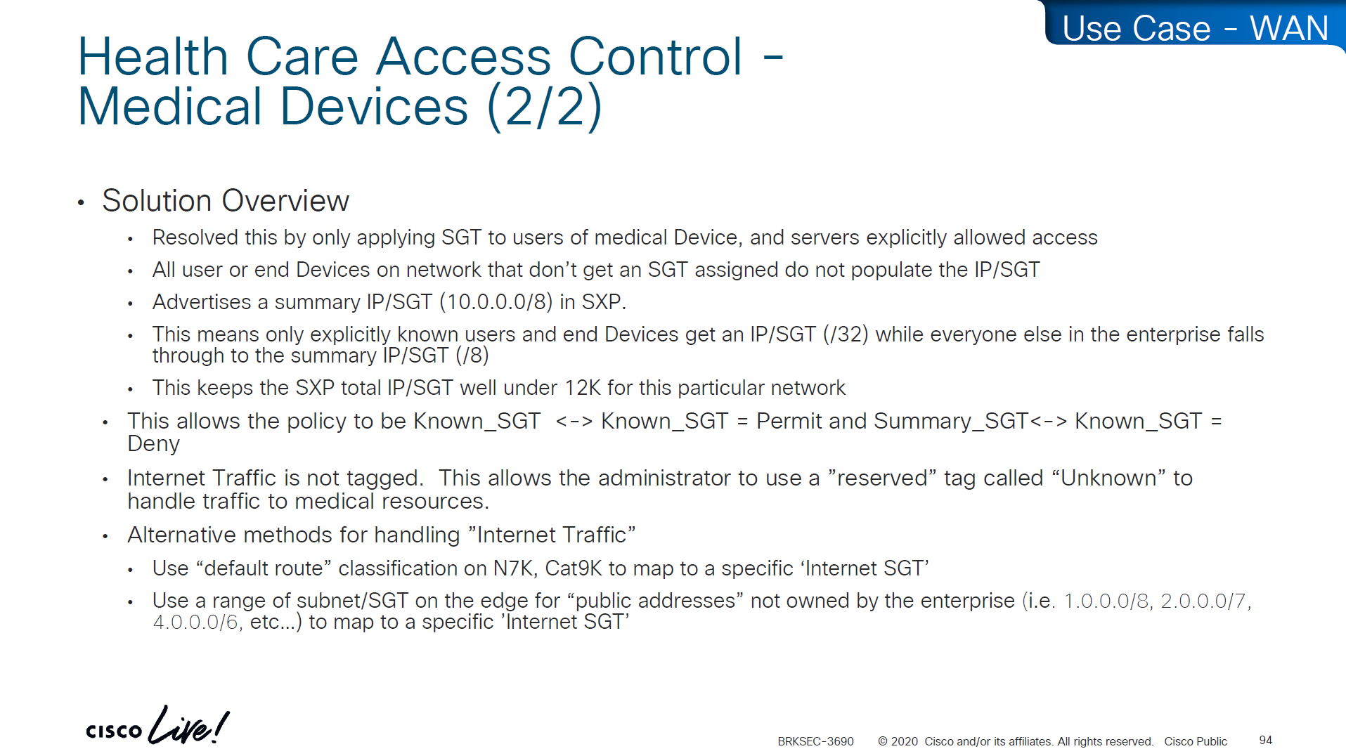
-medical devices and servers are assigned SGT and allowed to speak to one another
-Summary SGT of 10.0.0.0/8 in SXP for all users and devices in 10.0.0.0/8 space and this keeps the SGT under 12K
-Create a Policy Matrix that has Known_SGT <-> Known_SGT permit
-Create a Policy Matrix that has Known_SGT <-> Summary_SGT deny
-For Internet traffic default route is tagged as Internet_SGT
-above Internet_SGT leaves reserved tag called Unknown to handle traffic for medical devices that are not tagged
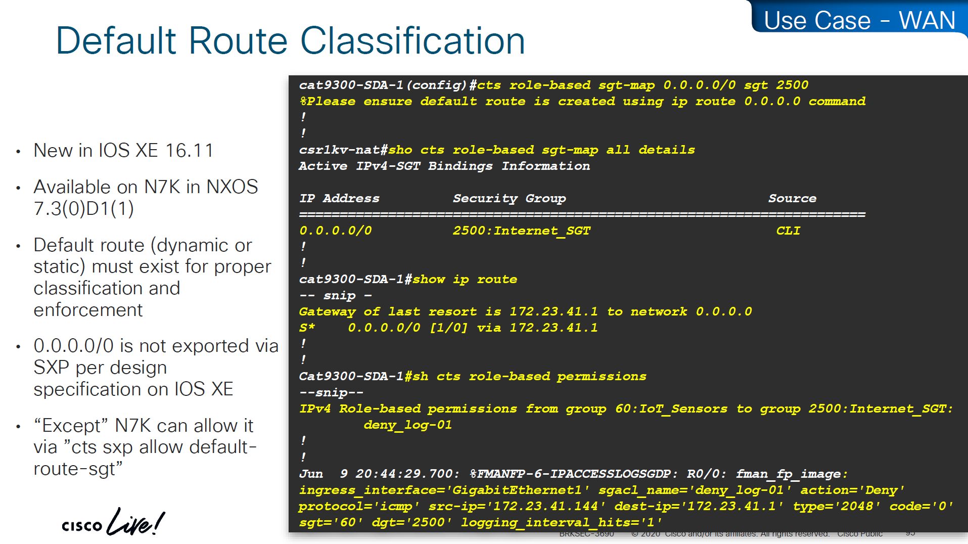
SXP Reflector Like Design

in above SXP connections, if one device speaks (has a speaker role) IP to SGT mapping then on the other end if there is a listener it will listen and learn the IP to SGT mapping and if a device listens (has a listener role) then on SXP connection it can learn IP to SGT mapping from a speaker
once a new mapping of IP to SGT is learned by aggregation Listener, it “speaks” those mapping to all the listeners

Above shows Medical_device <-> Medical_server allow
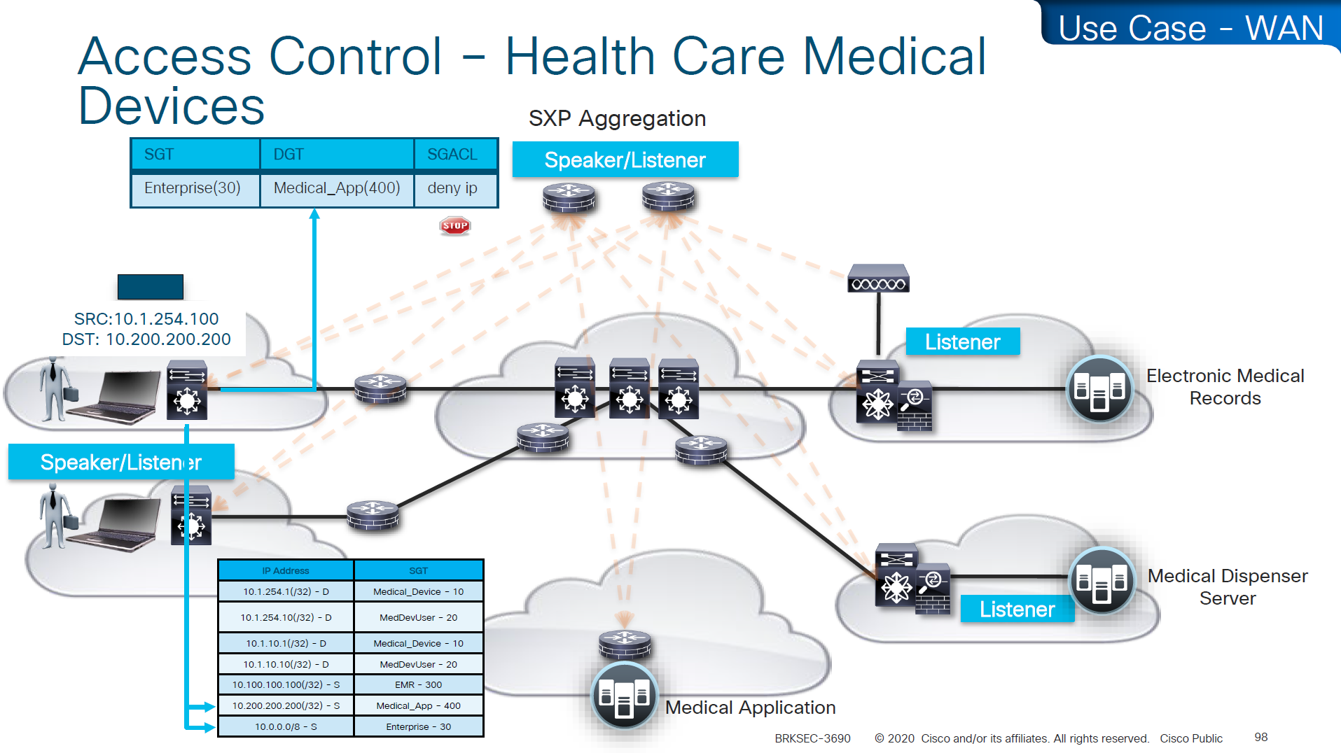
Above example is the source on 10.0.0.0 network that has fallen on 10.0.0.0/8 SGT of Enterprise and is trying to speak to Medical_device and by policy that is denied

cts manual – tells the router interface to assign sgt manually to traffic over this interface
policy static sgt 2 trusted – All traffic that enters or exits this interface is tagged with SGT = 2
“Trusted” means this interface accepts incoming SGT tags from the peer without overwriting them. If the link partner already sends SGT-tagged frames, the ASR1K trusts them instead of stripping or replacing them.
no cts role-based enforcement – on the router interface or layer 3 interfaces which are in the middle of the path, we have to turn off any kind of enforcement in order to avoid dropping any traffic , Because the ASR1K in this use case is only tagging packets, not enforcing access control. This keeps the device acting as a TrustSec transit / tagging device rather than a policy enforcement point.
cts manual
policy static sgt 2 trusted
no cts role-based enforcementso above config achieves – tag outgoing traffic, trust the tag from connected device for incoming traffic and disable enforcement because this is a transit node and not access layer policy point

show platform hardware fed switch active fwd-asic resource tcam utilization
! Max Values column
! Used Values
! first value is IP "/" second value is SGT
! "Directly or indirectly connected routes"
! for 9300 10K limit officially for both IP and SGT combined
! "Security Access Control Entries" are number of ACEs
! "SGT_DGT" is number of cells from Policy Matrix
This healthcare provider hit the scale limit of SGT on access layer so they moved the enforcement point on routers as router hardware has much more scale
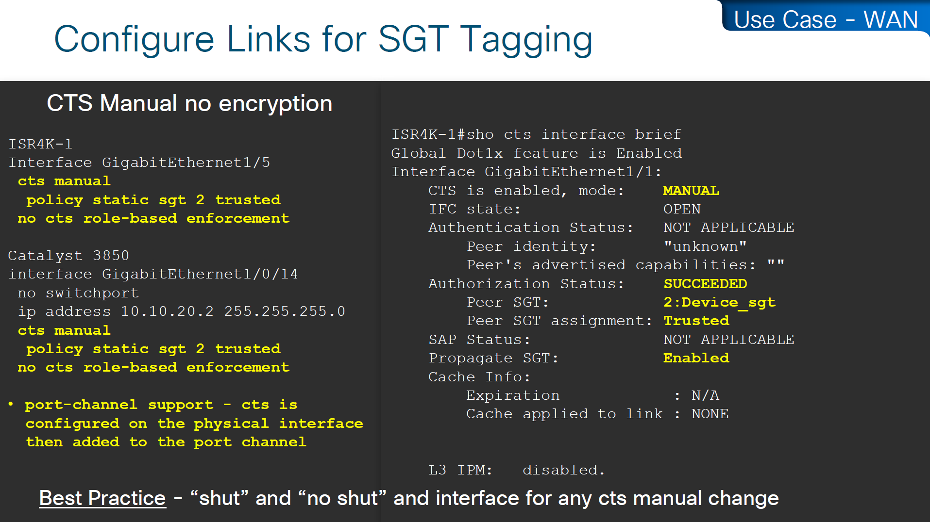
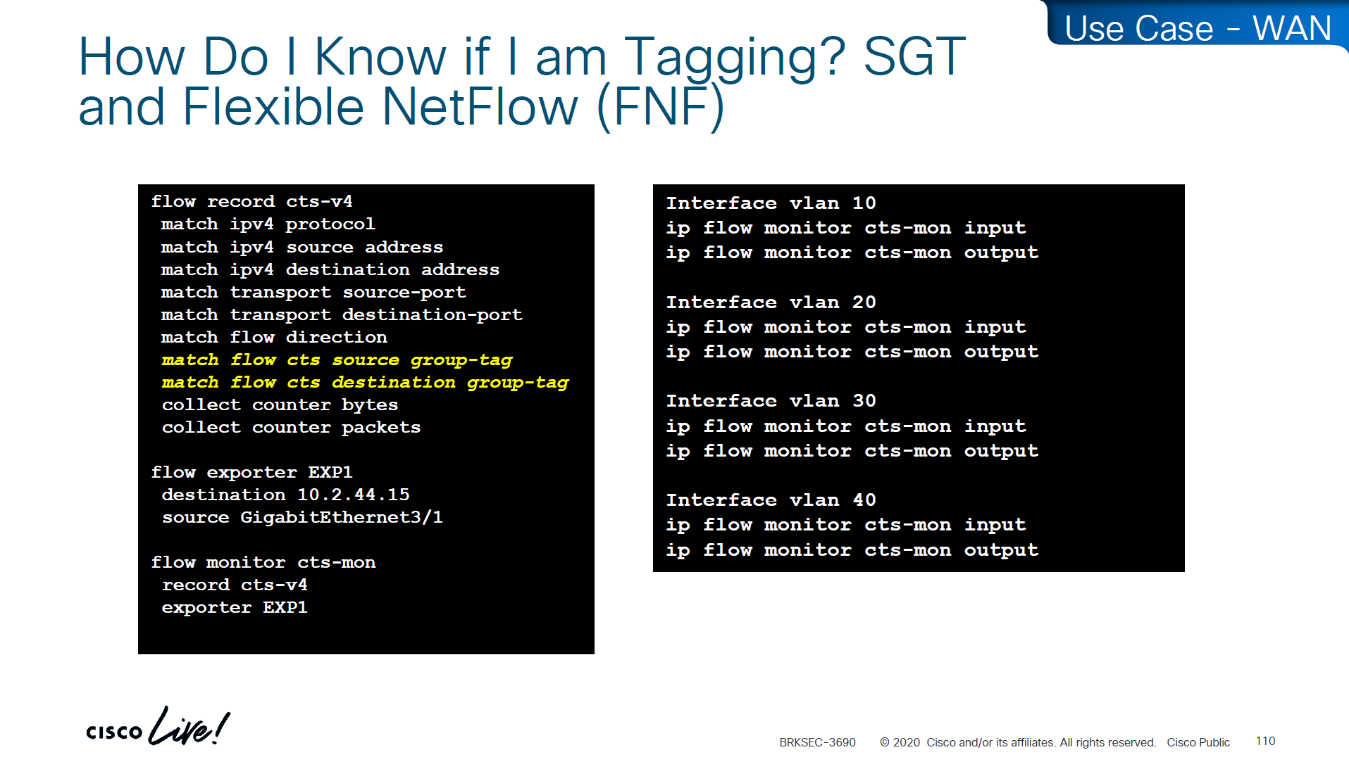
If you want to know that you are tagging traffic, simply turn on netflow with cts with above commands and even if you dont export that flow anywhere, we can see local cache , great for tshoot
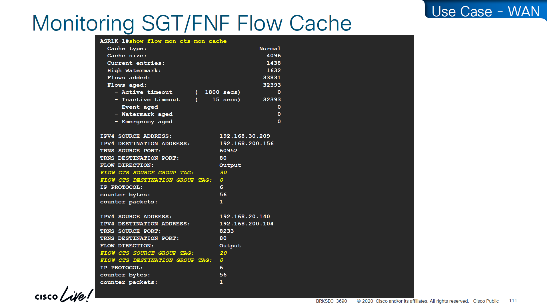
use this command to see the tagging info
show flow mon cts-mon cacheyou will see that in above output we see destination tag as 0, because we are running this command on ingress or access layer where there is no info about destination host or its assigned SGT

Stealthwatch has ability to specify source and destination tag

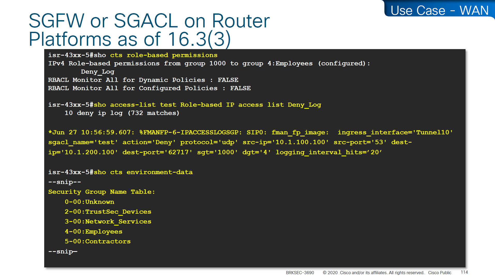

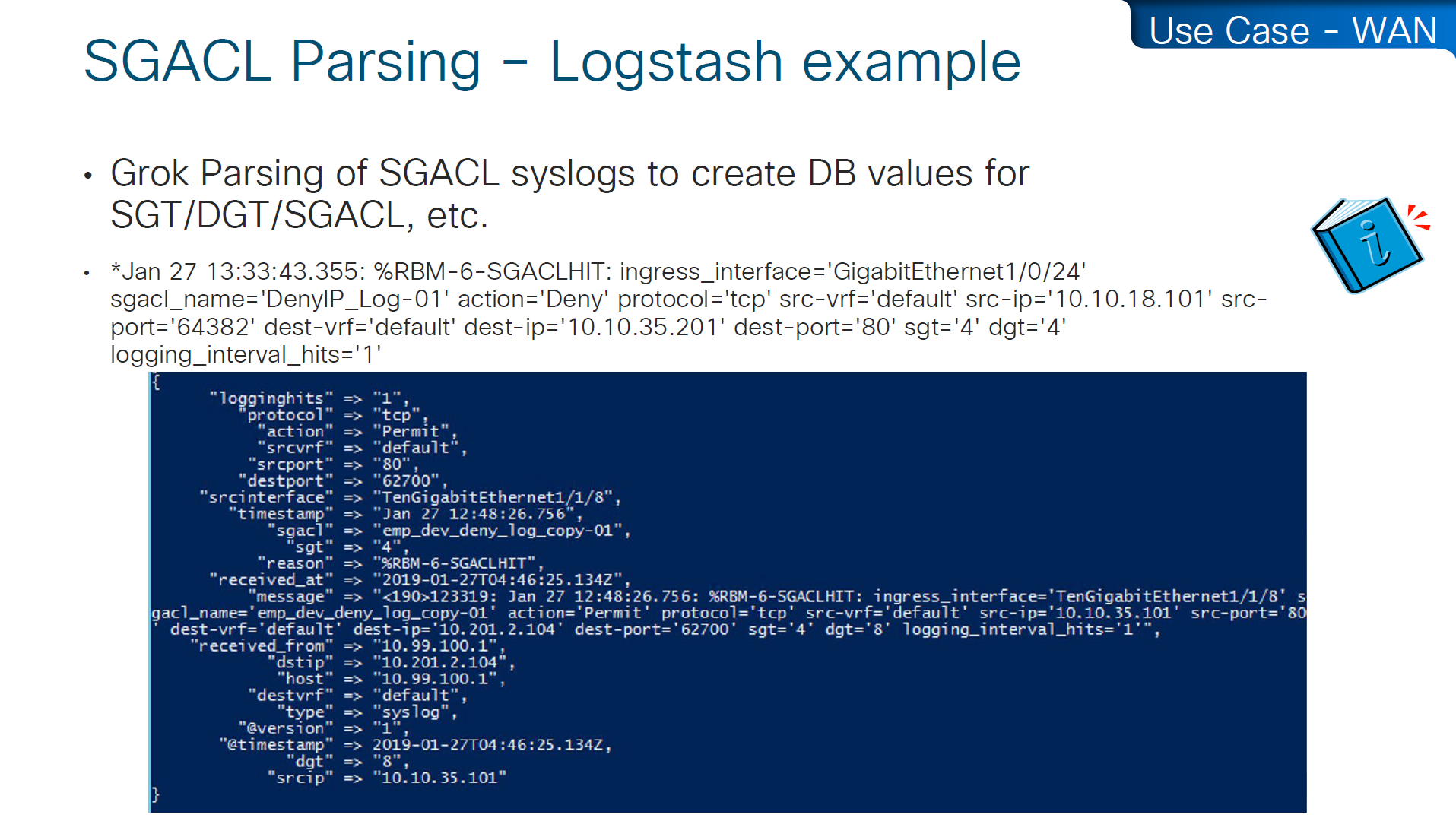
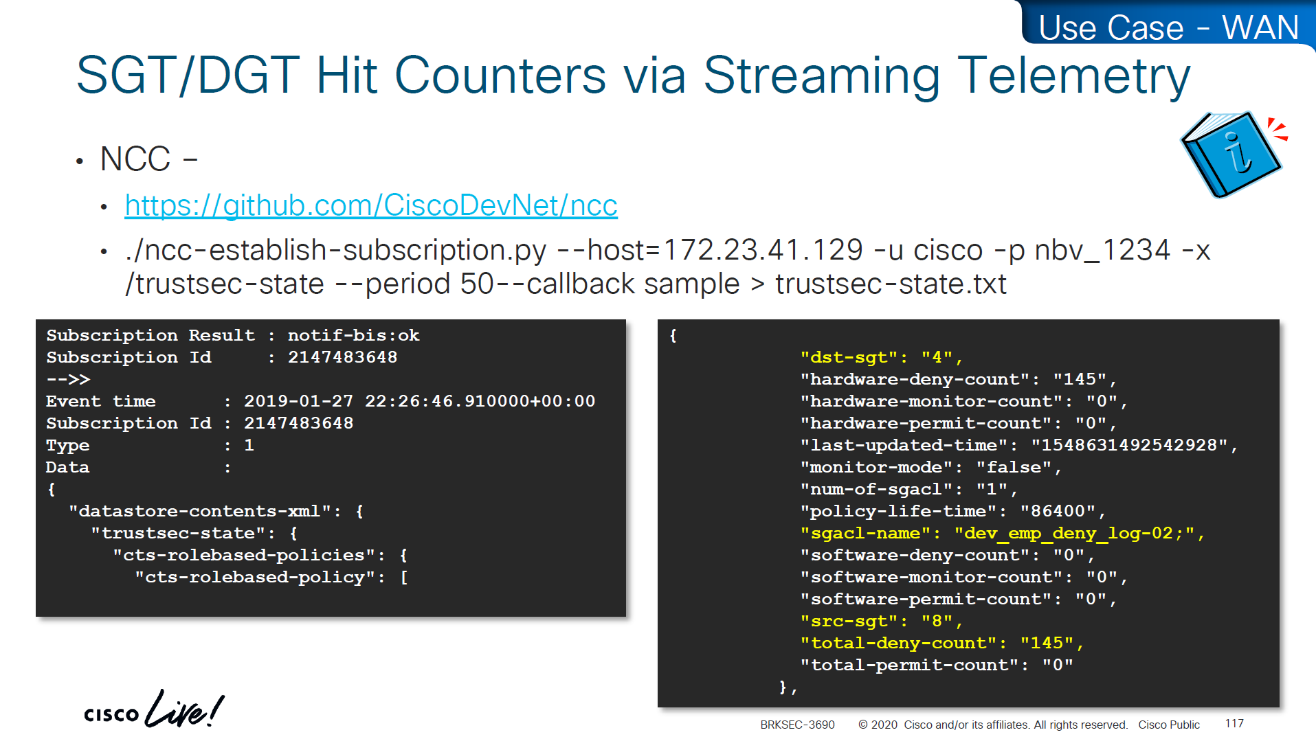

Skipped DMVPN SGT tagging
Skipped SGT/ACI
Skipped Cloud
SGT commands
! on ingress or access
cts sxp enable
cts sxp connection peer 10.1.44.1 source 10.1.11.44 password default mode local
! on core where we just learn from access as listener
cts sxp enable
cts sxp default password cisco123
! peering with Cat3K
cts sxp connection peer 10.1.11.44 source 10.1.44.1 password default mode local listener hold-time 0 0
! peering with WLC
cts sxp connection peer 10.1.33.24 source 10.1.44.1 password default mode local listener hold-time 0 0
! check IP to SGT table
show cts role-based sgt-map all details
! check SXP connection on on core
show cts sxp connections brief
----------------------------------------------
! Enable AAA
aaa new-model
! Define ISE as a RADIUS server (auth/acct) and include the PAC bootstrap secret
radius server ISE1
address ipv4 10.10.10.10 auth-port 1812 acct-port 1813
key RADIUS_SHARED_SECRET
pac key RADIUS_PAC_SECRET
!
! send vsa or vendor attributes in RADIUS authentication request
radius-server vsa send authentication
key RADIUS_SHARED_SECRET
pac key RADIUS_PAC_SECRET
!
! send vsa or vendor attributes in RADIUS authentication request
radius-server vsa send authentication
! (Optional) put servers into a group and set a source interface
aaa group server radius ISE-GRP
server name ISE1
ip radius source-interface Vlan10
! CTS/NDAC: define the authorization list used for policy download only (not tags - tags are pulled before SGACL or policy is pulled) - as clients connect with new SGT , more policy columns are pulled
cts authorization list CTS-AUTHZ
! 802.1X + CTS use the RADIUS group
aaa authentication dot1x default group ISE-GRP
aaa authorization network CTS-AUTHZ group ISE-GRP
! aaa authorization network command is usually used to allow on network or authorize audience or entity authenticated through network ports and this config says that authorized list of server (which are allowed to make CLI or COA changes) will be downloaded from ISE-GRP
! which makes it look like this
aaa authorization network ( CTS-AUTHZ ) group ISE-GRP
aaa authorization network ( cts authorization list ) group ISE-GRP
! Define credentials for EAP-FAST I-ID, these are configured under enable mode and not in config mode
cts credential id DEVICE-ID password PASSWORD
! enable 802.1x on system level
dot1x system-auth-control
! enable CTS enforcement
cts role-based enforcement
----------------------------------------------
show cts environment-data
! shows local device SGT
! shows servers that are authorized list servers
! shows downloaded SGT tags on devices
----------------------------------------------
! define SGT for local servers connected to switch
cts role-based sgt-map 192.168.31.1 sgt 100
cts role-based sgt-map 192.168.32.0/24 sgt 20
cts role-based sgt-map 10.x.x.0 sgt 30
! tag default route to Internet_SGT
! This is incase you want to use Unknown tag for something else
! for default route tag, the device must have defafult route either as a static or dynamic for this tagging to work
! this allows us to do something like Medical_devices <-> Internet_SGT deny
cts role-based sgt-map 0.0.0.0/0 sgt 2500
! enableing SGT enformcement globaly
cts role-based enforcement
! or on specific vlans for slow rollout
cts role-based enforcement vlan-list 40
----------------------------------------------
! download or refresh SGT tags
cts refresh environment-data
! download or refresh SGACLs or policy
cts refresh policy
----------------------------------------------
show cts role-based permissions
! shows SGACLs
show cts policy sgt 4
! shows SGT and its related policies in detail
show ip access-list
show cts role-based counters
! shows * to * default rule
! also shows from and to columns
! SGACL is done in hardware, unless needs punting
! for example TCAM or hardware is full, log in the end of ACE or to the box traffic such as Trust_Devices SGT, makes SW counter increment otherwise concentrate on HW-Denied and HW-Permitted columns
----------------------------------------------
show device-tracking database
show cts role-based sgt-map 10.0.0.1
show device-tracking database interface gig2/0/11
----------------------------------------------
! If SGACL download errors happen
show aaa servers
! make sure AAA servers are marked alive
show cts pac all
! make sure pac is present
show cts environment-data
! check if device can communicate with ISE
----------------------------------------------
router(config)#interface Ten1/1/1
cts manual
policy static sgt 2 trusted
no cts role-based enforcement
! tag outgoing traffic,
! trust the tag from connected device for incoming traffic
! disable enforcement because this is a transit node and not access layer policy point
show cts interface brief
----------------------------------------------
show platform hardware fed switch active fwd-asic resource tcam utilization
! Max Values column
! Used Values
! first value is IP "/" second value is SGT
! "Directly or indirectly connected routes"
! for 9300 10K limit officially for both IP and SGT combined
! "Security Access Control Entries" are number of ACEs
! "SGT_DGT" is number of cells from Policy Matrix
----------------------------------------------
flow record cts-v4
match ipv4 protocol
match ipv4 source address
match ipv4 destination address
match transport source-port
match transport destination-port
match flow direction
match flow cts source group-tag <<<<
match flow cts destination group-tag <<<<
collect counter bytes
collect counter packets
flow exporter EXP1
destination 10.1.1.1
source Gig1
flow monitor cts-mon
record cts-v4
exporter EXP1
interface vlan 10
ip flow monitor cts-mon input
ip flow monitor cts-mon output
show flow mon cts-mon cachenext post
BGP
BGP
AS autonomous system, collection of router under a domain
An organization requiring connectivity to the Internet must obtain an ASN.
ASNs were originally 2 bytes (in the 16-bit range), 65,534 ASNs.
Due to exhaustion, ASN field expanded to accommodate 4 bytes (in the 32-bit range), This allows for 4,294,967,295 unique ASNs
https://ipwithease.com/basic-understanding-of-4-byte-asn/
Private ASN 16-bit range as 64512 to 65534
Public ASN 16-bit range 1 through 64511
Private ASN 32-bit range as 4200000000 to 4294967294
in 4 bytes ASN 0 – 65535 AS numbers are same as they were with 2 byte AS. These AS numbers help in interoperability between AS using 2 byte ASNs and AS using 4 byte ASNs.
4 Byte AS representation can be done in 3 ways as listed below:
- asplain – simple decimal representation of the ASN. For example, ASN 7747 will be represented as 7747, while 123456 will be represented as 123456.
- asdot+ – breaks the number up in two 16-bit values as low-order and high-order, separated by a dot. All the 2-byte ASNs can be represented in the low-order value. For example, ASN 65535 will be 0.65535, 65536 will be 1.0, 65537 will be 1.1 and so on. The last ASN 4294967296 will be 65535.65535.
- asdot – it is a mixture of asplain and asdot+. Any ASN in the 2-byte range is represented as asplain and any ASN above the 2-byte range is represented as asdot+. For example, 65535 will be 65535 while 65536 will be 1.0. Cisco uses this form of implementation.
It is significant to understand the interoperability of the 2 Byte AS number with the 4 Byte AS number.
4 byte AS support is advertised via BGP capability negotiation. Speakers who support 4-byte AS are known as New-BGP speakers & those who do not are known as Old-BGP speakers, it includes its 4-byte ASN in the Capability advertisement
No support / backwards compatibility scenario
If one neighbor or router is very old and it does not respond to 4-byte ASN capability, in this case new BGP speaker can bring up session with this very old router using a reserved 2 byte ASN called AS_TRANS (AS23456)
Because AS_TRANS AS23456 is reserved, no Old-BGP speaker can use it as its own ASN; only New-BGP speakers can use it.
New BGP Speaker to new BGP Speaker advertise routes using 4 byte ASN but new BGP Speaker to old BGP speaker
AS_PATH
- Any 4-byte ASN in the AS_PATH is replaced with AS_TRANS (23456) so the old router can “parse” it.
AS4_PATH (optional transitive attribute)
- The real 4-byte ASNs are preserved in the AS4_PATH attribute.
- Old routers ignore AS4_PATH.
- New routers later reconstruct the correct AS_PATH using AS4_PATH.
When an Old BGP Speaker advertises routes with AS4_PATH and AS_PATH attributes to a New BGP Speaker, the New BGP Speaker uses both attributes to reconstruct the path: AS4_PATH for 4-byte ASNs and AS_PATH for 2-byte ASNs by replacing 4-byte ASN with an AS_TRANS. In this way, the AS_PATH shows the correct number of hops
AS4_AGGREGATOR
A new attribute AS4_AGGREGATOR is introduced for similar reasons. If the New BGP Speaker has to send the AGGREGATOR attribute towards old speaker neighbor and if the aggregating ASN is a 4-byte ASN, then the speaker constructs the AS4_AGGREGATOR attributes by copying the attribute length and attribute value from the AGGREGATOR attribute, places the attribute length and attribute value in the AS4_AGGREGATOR attribute, and replaces the 4-byte ASN with AS_TRANS ASN.
BGP Peering
BGP peering is also called BGP session
There 2 types of peering,
iBGP peering and eBGP peering
ibgp can be like pseudowires
iBGP: Sessions established with a router that are in the same AS or that participate in the same BGP confederation
eBGP: Sessions established with a BGP router that are in a different AS
BGP does not use hello packets to discover neighbors
BGP was designed as an inter-autonomous routing protocol, implying that neighbor adjacencies should not change frequently and are coordinated.
BGP uses TCP port 179 to communicate with other routers
Relying on TCP allows for handling of fragmentation, sequencing, and reliability (acknowledgment and retransmission)
Most recent implementations of BGP set the do-not-fragment (DF) bit to prevent fragmentation and rely on path MTU discovery PMTUD https://learn.anasather.uk/ccie-misc/ccie-everything-else/
Multihop BGP peerings
BGP uses TCP that can cross boundaries unlike IGP which use link local multicast to form neighbors, BGP can form neighbor adjacencies that are directly connected or adjacencies that are multiple hops away.
BGP neighbors connected to the same network use the ARP table to locate the IP address of the peer.
Multi-hop BGP sessions require routing table information for finding the IP address of the peer.
A default route is not sufficient to establish a multi-hop BGP session.
Multi-hop sessions require that the router use an underlying route installed in the RIB (static or from any routing protocol) to establish the TCP session with the remote endpoint
If that neighbor’s IP isn’t specifically resolvable in the routing table (e.g., via a static route or an IGP-learned route), BGP won’t even attempt to start the TCP connection.
BGP Messages
OUNK
| Type | Name | Functional Overview |
|---|---|---|
| 1 | OPEN | Sets up and establishes BGP adjacency |
| 2 | UPDATE | Advertises, updates, or withdraws routes, CRUD |
| 3 | NOTIFICATION | Indicates an error condition to a BGP neighbor |
| 4 | KEEPALIVE | Ensures that BGP neighbors are still alive |
OPEN
OPEN message is used to establish adjacency,
Session capabilities are exchanged in open messages.
OPEN message contains following:
BGP version
ASN
Hold time
RID etc
Hold time: The hold time field in OPEN messages sets hold timer in seconds,
When establishing a BGP session, the routers use the smaller hold time value between the two routers.
The hold time value must be at least 3 seconds,
the hold time is set to 0 to disable KEEPALIVE messages.
For Cisco routers, the default hold time is 180 seconds.
BGP identifier RID: The BGP router ID (RID) is a 32-bit unique number that identifies the BGP router in the advertised prefixes.
The RID is used as a loop-prevention mechanism for routers advertised within an autonomous system.
The RID can be set manually or dynamically for BGP, setting manually is much stable way.
A nonzero value must be set in order for routers to become neighbors.
Dynamic RID allocation logic uses the highest IP address of any up loopback interfaces. If there is not an up loopback interface, then the highest IP address of any active up interfaces becomes the RID
To ensure that the RID does not change, a static RID is assigned (typically represented as an IPv4 address that resides on the router, such as a loopback address). Any IPv4 address can be used, including IP addresses not configured on the router
KEEPALIVE
KEEPALIVE messages are exchanged between neighbors, by default every 60 seconds, “3rd of the default Hold timer 180” seconds
If the hold time is set to 0, no KEEPALIVE messages are also sent between the BGP neighbors.
BGP keepalive timer and hold timer can be set at the process level or per neighbor session.
UPDATE
An Update can either advertise routes or withdraw routes
Prefixes that need to be withdrawn are advertised in the WITHDRAWN ROUTES field of the UPDATE message
Update message also serves as a keepalive as well,
Upon receipt of an UPDATE or KEEPALIVE, the hold timer resets to the initial value,
If the hold timer reaches zero, the BGP session is torn down, routes from that neighbor are removed, and an appropriate update route withdraw message is sent to other BGP neighbors for the affected prefixes
Notification
A Notification message is sent when an error is detected with the BGP session,
such as a hold timer expiring,
neighbor capabilities changing,
or a BGP session reset being requested.
Notification causes the BGP connection to close.
Notification message is basically a signal to neighbor to initiate session shutdown
BGP Neighbor States
BGP FSM
- Idle
- Connect
- Active
- OpenSent
- OpenConfirm
- Established
Idle
-BGP Process start
-BGP Process starts listening on TCP 179
-BGP tries to move to next state: connect
-In case any issues revert it back to idle – set ConnectRetry timer to 60 seconds, this time must count to 0 before any connection try can be made – ConnectRetry basically a delay timer
-Further failures to leave the Idle state result in the ConnectRetry timer doubling in length
Connect
-BGP initiates the TCP connection 3 way handshake
-If the TCP connection fails, the state changes to Active
-If the three-way TCP handshake completes,
-sends the OPEN message to the neighbor,
-moves to the OpenSent state
R1# show tcp brief
TCB Local Address Foreign Address (state)
F6F84258 10.12.1.1.179 10.12.1.2.59884 ESTAB
R2# show tcp brief
TCB Local Address Foreign Address (state)
EF153B88 10.12.1.2.59884 10.12.1.1.179 ESTABActive
-In the Active state, BGP starts a new three-way TCP handshake.
-If this attempt for TCP connection fails, the state moves back or downgrades to the Connect state
-If a connection is established,
-an OPEN message is sent,
-the hold timer is set to 4 minutes (longer hold time because of issues and hence Active state, longer hold time means that neighbor’s presence will not be checked quicker)
-and the state moves to OpenSent.
OpenSent
-OPEN message has been sent from the originating router and is awaiting an OPEN message from the other router.
-When the originating router receives the OPEN message from the other router, local OPEN and received OPEN message are checked for following:
-BGP versions must match
-The source IP address of the OPEN message must match what is configured for the neighbor
-The AS number must match what is configured for the neighbor
-RID must be unique
-Security parameters (such as password and time-to-live [TTL]) must qualify.
Hold times are compared, lowest hold time is used
Keepalive is sent
Connection state is then moved to OpenConfirm
If an error is found in the OPEN message, a NOTIFICATION message is sent, and the state is moved back to Idle.
OpenConfirm
In OpenConfirm state, BGP waits for a KEEPALIVE or NOTIFICATION message – so 2 way can be confirmed
Upon receipt of a neighbor’s KEEPALIVE, the state is moved to Established
If
-hold timer expires,
-a stop event occurs,
-a NOTIFICATION message is received
the state is moved to Idle
Established
BGP session is established
BGP neighbors exchange routes through UPDATE messages. As UPDATE and KEEPALIVE messages are received, the hold timer is reset.
If the hold timer expires, BGP moves the neighbor back to the Idle state and send a withdraw to other neighbors for routes learned through the now idle neighbor
BGP PA
BGP associates attributes with each network path / route and it is called its Path Attributes, which can also be considered as qualities of the path, such as AS Path shows the length of path and ASs the traffic will traverse, metric is cost associated with path – tells us about the thinking of admin assigning initial cost , weight to the path
These Path Attributes are of 4 different types:
Well-known mandatory
Well known man
Well-known attributes must be recognized by all BGP implementations – because it is well known and known by every BGP module that is written
Mandatory as well – mandatory attributes must be included with every prefix advertisement;
Well-known discretionary
well-known discretionary attributes may or may not be included with the prefix advertisement and can be skipped in sending of an update
Optional transitive
Optional attributes do not have to be recognized by all BGP implementations – BGP module writers can fully skip it as it is optional
Optional attributes can be transitive and stay with the route advertisement from AS to AS
Optional non-transitive
Some optional PAs are non-transitive and cannot be shared from AS to AS.
AS_PATH for Loop Prevention
AS_Path is used as a loop-prevention mechanism in BGP
BGP is a path vector routing protocol and does not contain a complete topology of the network, as do link-state routing protocols, BGP behaves like distance vector protocols
The BGP attribute AS_Path is a “well-known mandatory” attribute and includes a complete list of all the ASNs that the prefix advertisement has traversed from its source AS
“If a BGP router receives a prefix advertisement with its AS listed in AS_Path, it discards the prefix because the router thinks the advertisement forms a loop“
Multi-Protocol BGP (MP-BGP)
Originally BGP was designed around IPv4 but later on Multi-Protocol BGP (MP-BGP) allowed other protocols to be carried as well and that allowed BGP to carry (Address Family) AFI such as IPv6
An address family correlates to a specific network protocol, such as IPv4 or IPv6, and additional granularity is provided through a subsequent address family identifier (SAFI), such as unicast or multicast in that protocol
Multiprotocol BGP (MP-BGP) carries separate path attributes (PAs) for Multi protocol MP_REACH_NLRI and MP_UNREACH_NLRI than IPv4 based BGP, These PA attributes are held inside BGP update messages and that is why BGP can be used for different address families or protocols, that facilitates addresses just like IPv4 , IPv6 , Multicast and even MAC addresses. Address family maintains a separate database and configuration for each protocol under same BGP session.
Address family needs to be activated on peer
An address family must be activated for a BGP peer in order for BGP to initiate a session with that peer
IOS XE activates the IPv4 address family by default. This simplifies the configuration in an IPv4 environment, command no bgp default ipv4-unicast disables the automatic activation of the IPv4 AFI
Multiple Address families per neighbor
BGP Session parameters are configured such as neighbor IP , ASN , authentication , keepalive timers , source IP etc
but address family related configuration such as Network commands and summarization occur within the address family because IPv4 unicast and IPv6 multicast cannot have same configuration, although these 2 different AFI and SAFI can belong to same neighbor
Specifying the source interface
neighbor x.x.x.x update-source <interface> only changes the source IP address used in BGP packets. It does not change the actual outgoing interface used to send the packets. Outgoing interface can only be changed or dictated with static or dynamic route for that neighbor
BGP Authentication
BGP supports authentication with MD5 in order to prevent manipulation of BGP packets
BGP Configuration
R1 (Default IPv4 Address-Family Enabled)
router bgp 65100
neighbor 10.12.1.2 remote-as 65200
neighbor 10.12.1.2 password CISCOBGP
neighbor 10.12.1.2 timers 10 40R2 (Default IPv4 Address-Family Disabled)
router bgp 65200
no bgp default ipv4-unicast
neighbor 10.12.1.1 remote-as 65100
neighbor 10.12.1.1 password CISCOBGP
neighbor 10.12.1.1 timers 15 50
!
address-family ipv4
neighbor 10.12.1.1 activateUse show commands with AFI and SAFI
R1# show bgp ipv4 unicast summary
BGP router identifier 192.168.1.1, local AS number 65100
BGP table version is 1, main routing table version 1
Neighbor V AS MsgRcvd MsgSent TblVer InQ OutQ Up/Down State/PfxRcd
10.12.1.2 4 65200 8 9 1 0 0 00:05:23 0
| | | |
| | | |
Number of messages received from peer and queued to be processed
| | |
| | |
Number of messages queued to be sent to the peer
| |
| |
Length of time the BGP session is established
|
|
Current BGP peer state or the number of prefixes received from the peerUp/Down column indicates that the BGP session is up for over 5 minutes.
R2# show bgp ipv4 unicast neighbors 10.12.1.1
! Output omitted for brevity
! The first section provides the neighbor's IP address, remote-as, indicates if
! the neighbor is 'internal' or 'external', the neighbor's BGP version, RID,
! session state, and timers.
BGP neighbor is 10.12.1.1, remote AS65100, external link
BGP version 4, remote router ID 192.168.1.1
BGP state = Established, up for 00:01:04
Last read 00:00:10, last write 00:00:09, hold is 40, keepalive is 13 seconds
Neighbor sessions:
1 active, is not multisession capable (disabled)
! This second section indicates the capabilities of the BGP neighbor and
! address-families configured on the neighbor.
Neighbor capabilities:
Route refresh: advertised and received(new)
Four-octets ASN Capability: advertised and received <<<
Address family IPv4 Unicast: advertised and received <<<
Enhanced Refresh Capability: advertised <<<
Multisession Capability:
Stateful switchover support enabled: NO for session 1 <<<
Message statistics:
InQ depth is 0
OutQ depth is 0
! This section provides a list of the BGP packet types that have been received
! or sent to the neighbor router.
Sent Rcvd
Opens: 1 1
Notifications: 0 0
Updates: 0 0
Keepalives: 2 2
Route Refresh: 0 0
Total: 4 3
Default minimum time between advertisement runs is 0 seconds
! This section provides the BGP table version of the IPv4 Unicast address-
! family. The table version is not a 1-to-1 correlation with routes as multiple
! route change can occur during a revision change. Notice the Prefix Activity
! columns in this section.
For address family: IPv4 Unicast
Session: 10.12.1.1
BGP table version 1, neighbor version 1/0
Output queue size : 0
Index 1, Advertise bit 0
Sent Rcvd
Prefix activity: ---- ----
Prefixes Current: 0 0
Prefixes Total: 0 0
Implicit Withdraw: 0 0
Explicit Withdraw: 0 0
Used as bestpath: n/a 0
Used as multipath: n/a 0
Outbound Inbound
Local Policy Denied Prefixes: -------- ------- <<<
Total: 0 0
Number of NLRIs in the update sent: max 0, min 0
! This section indicates that a valid route exists in the RIB to the BGP peer IP
! address, provides the number of times that the connection has established and
! time dropped, since the last reset, the reason for the reset, if path-mtu-
! discovery is enabled, and ports used for the BGP session.
Address tracking is enabled, the RIB does have a route to 10.12.1.1 <<<
Connections established 2; dropped 1
Last reset 00:01:40, due to Peer closed the session <<<
Transport(tcp) path-mtu-discovery is enabled <<<
Connection state is ESTAB, I/O status: 1, unread input bytes: 0
Minimum incoming TTL 0, Outgoing TTL 255 <<<
Local host: 10.12.1.2, Local port: 179
Foreign host: 10.12.1.1, Foreign port: 56824BGP Adj tables
BGP uses three tables for maintaining the network paths and path attributes (PAs)
There are 3 different ways of learning a route
-Network command
-Learned from neighbor
-Redistribution into BGP
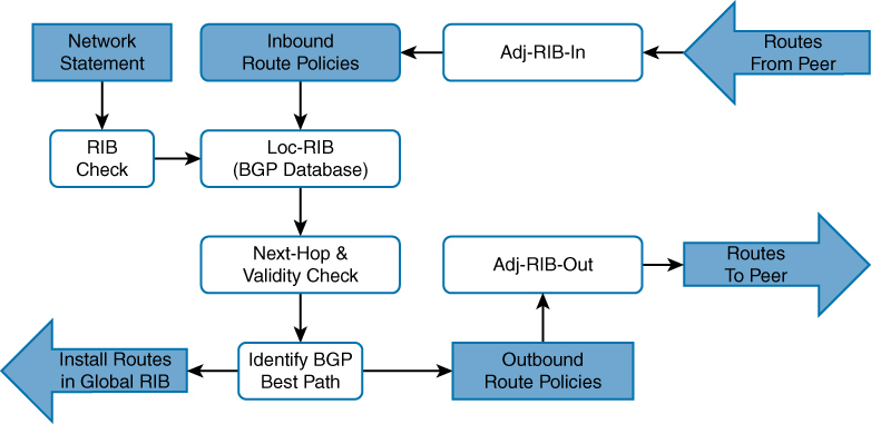
Adj-RIB-in: Contains the routes in original form (that is, from before inbound route policies were processed). The table is purgeable and is purged after all route policies are processed to save memory. After all routes have been fed through local policies it is emptied out
Loc-RIB:
-Loc-RIB contains routes after applying import policy, import policy only applies to routes learned from neighbors) Routes injected with the network command or redistributed – do not go through inbound policy – Locally-originated routes do go through best-path selection, but not through inbound policy + when a route comes from network statement then RIB check is made and only added in loc-RIB if there is same route with same subnet mask in RIB or routing table
-Routes collected in Loc-RIB are not the best routes and hence can contain multiple routes to a prefix
-contains routes that are originated locally and learned from neighbors.
-this table is “show ip bgp”
-after storing the routes here a validity check is performed, next-hop address in route if resolvable in the RIB then route is valid – and route is marked valid ” * “
-after valid routes are determined, these routes are passed through BGP best path algorithm and best routes is selected for “a prefix” and marked best with ” > ” – creating symbol of ” *> ” (valid + best)
Star means valid and not best
> means best
-Install the best-path route into the RIB
-After you enter a BGP network statement, the BGP process searches the global RIB for an exact network match. The network can be a connected network, a secondary connected network, or any route from a routing protocol.
-After verifying that the network statement matches a route in the RIB, the prefix is installed into the Loc-RIB table. As the BGP prefix is installed into the Loc-RIB, the following BGP PAs are set, depending on the RIB prefix type:
Connected network: The next-hop BGP attribute is set to 0.0.0.0, the BGP Origin attribute is set to i (for IGP), and the BGP weight is set to 32,768.
Static route or routing protocol: The next-hop BGP attribute is set to the next-hop IP address in the RIB, the BGP Origin attribute is set to i (for IGP), the BGP weight is set to 32,768, and the multi-exit discriminator (MED) is set to the IGP metric.
Remember best from > symbol, which means use this > route
Adj-RIB-out: Contains the routes after outbound route policies have been processed
This is a per neighbor table
By default, BGP only advertises the best path to other BGP peers
Advertise the route to BGP peers. If the route’s next-hop BGP PA is 0.0.0.0, the next-hop address is changed to the IP address of the BGP session.
It enables a network engineer to view routes advertised to a specific router using command show bgp afi safi neighbors ip-address advertised-routesMultiple BGP route sources
R1 already eBGP with R2
R1 has multiple routes learned from static routes, EIGRP, and OSPF
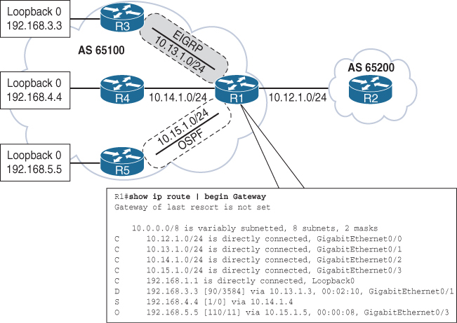
All the routes in R1’s routing table can be advertised into BGP, regardless of the source routing protocol.
Loopback networks are added as network statement except OSPF one, loopback learned over OSPF is redistributed instead
router bgp 65100
neighbor 10.12.1.2 remote-as 65200
address-family ipv4 unicast
neighbor 10.12.1.2 activate
network 10.12.1.0 mask 255.255.255.0
network 192.168.1.1 mask 255.255.255.255
network 192.168.3.3 mask 255.255.255.255
network 192.168.4.4 mask 255.255.255.255
redistribute ospf 1Redistributing routes learned from an IGP into BGP is completely safe; however, redistributing routes learned from BGP into an IGP should be done with caution. BGP is designed for large scale and can handle a routing table the size of the Internet (940,000+ prefixes), whereas IGPs could have stability problems with fewer than 20,000 routes.
Origin code is IGP (for routes learned from the network statement) or incomplete (redistributed)
R1# show bgp ipv4 unicast
BGP table version is 9, local router ID is 192.168.1.1
Status codes: s suppressed, d damped, h history, * valid, > best, i - internal,
r RIB-failure, S Stale, m multipath, b backup-path, f RT-Filter,
x best-external, a additional-path, c RIB-compressed,
Origin codes: i - IGP, e - EGP, ? - incomplete
RPKI validation codes: V valid, I invalid, N Not found
Network Next Hop Metric LocPrf Weight Path
*> 10.12.1.0/24 0.0.0.0 0 32768 i
* 10.12.1.2 0 0 65200 i
*> 10.15.1.0/24 0.0.0.0 0 32768 ?
*> 192.168.1.1/32 0.0.0.0 0 32768 i
*> 192.168.2.2/32 10.12.1.2 0 0 65200 i
! The following route comes from EIGRP and uses a network statement
*> 192.168.3.3/32 10.13.1.3 3584 32768 i
! The following route comes from a static route and uses a network statement
*> 192.168.4.4/32 10.14.1.4 0 32768 i
! The following route was redistributed from OSPF
*> 192.168.5.5/32 10.15.1.5 11 32768 ?if the LocPrf (Local Preference) attribute is not shown in the BGP table output, that means:The Local Preference is 100 by default, Cisco only displays non-default local preference values in the BGP table
R2# show bgp ipv4 unicast | begin Network
Network Next Hop Metric LocPrf Weight Path
* 10.12.1.0/24 10.12.1.1 0 0 65100 i
*> 0.0.0.0 0 32768 i
*> 10.15.1.0/24 10.12.1.1 0 0 65100 ?
*> 192.168.1.1/32 10.12.1.1 0 0 65100 i
*> 192.168.2.2/32 0.0.0.0 0 32768 i
*> 192.168.3.3/32 10.12.1.1 3584 0 65100 i
*> 192.168.4.4/32 10.12.1.1 0 0 65100 i
*> 192.168.5.5/32 10.12.1.1 11 0 65100 ?If multiple paths exist for the same prefix, only the first prefix is listed and other paths leave an empty space in the output
* valid paths
> best paths
Next hop is also a PA attribute
Metric – MED optional non-transitive BGP path attribute used in the BGP best-path algorithm for that specific path.
Optional = routers are not required to understand or use the attribute.
Non-transitive = the attribute must not be passed beyond the neighboring AS.
AS X sends a route with a MED to AS Y.
AS Y does NOT pass that MED on when advertising the route to any other AS (AS Z, etc.).
The MED is only meaningful between two directly connected ASes — it influences which entry point the neighbor should use, not the entire global internet
LocPrf – Local preference, a well-known discretionary path attribute used in the BGP best-path algorithm for that specific path.
Weight – A locally significant Cisco-defined attribute used in the BGP best-path algorithm for that specific path.
Path – AS_Path, a well-known mandatory BGP path attribute used for loop prevention and in the BGP best-path algorithm for that specific path.
Origin – Origin, a well-known mandatory BGP path attribute used in the BGP best-path algorithm. The value i represents an IGP, e is for EGP, and ? is for a route that was redistributed into BGP.
R1# show bgp ipv4 unicast 10.12.1.0
BGP routing table entry for 10.12.1.0/24, version 2
Paths: (2 available, best #2, table default)
Advertised to update-groups:
2
Refresh Epoch 1
65200
10.12.1.2 from 10.12.1.2 (192.168.2.2)
Origin IGP, metric 0, localpref 100, valid, external
rx pathid: 0, tx pathid: 0
Refresh Epoch 1
Local
0.0.0.0 from 0.0.0.0 (192.168.1.1)
Origin IGP, metric 0, localpref 100, weight 32768, valid, sourced, local, best
rx pathid: 0, tx pathid: 0x0Paths: (2 available, best #2)
Provides a count of BGP paths in the BGP Loc-RIB table and identifies the path selected as the BGP best path.
Advertised to update-groups
BGP neighbors are consolidated into BGP update groups. If a path is not advertised, Not advertised to any peer is displayed.
65200 (1st path)
Local (2nd path)
This is the AS_Path for the path as it was received or whether the prefix was locally advertised.
10.12.1.2 from 10.12.1.2 (192.168.2.2)
| | |
| | |
next hop | |
| |
advertising neighbor |
|
|
RID of the advertising neighborThe first entry lists the IP address of the next hop for the prefix.
The from field lists the IP address of the advertising neighbor. (The field could change when an external path is learned from an iBGP peer.)
The number in parentheses is the BGP identifier (RID) for the node.
Origin
Origin is well-known mandatory attribute that states the mechanism for advertising this path. In this instance, it is an internal path.
metric 0
Displays the optional non-transitive BGP attribute MED, also known as the BGP metric.
localpref 100
Displays the well-known discretionary BGP attribute Local Preference.
valid
Displays the validity of this path.
External (1st path)
Local (2nd path)
Displays how the path was learned: internal, external, or local.
R1# show bgp ipv4 unicast neighbors 10.12.1.2 advertised-routes
! Output omitted for brevity
Network Next Hop Metric LocPrf Weight Path
*> 10.12.1.0/24 0.0.0.0 0 32768 i
*> 10.15.1.0/24 0.0.0.0 0 32768 ?
*> 192.168.1.1/32 0.0.0.0 0 32768 i
*> 192.168.3.3/32 10.13.1.3 3584 32768 i
*> 192.168.4.4/32 10.14.1.4 0 32768 i
*> 192.168.5.5/32 10.15.1.5 11 32768 ?
Total number of prefixes 6R2# show bgp ipv4 unicast neighbors 10.12.1.1 advertised-routes
! Output omitted for brevity
Network Next Hop Metric LocPrf Weight Path
*> 10.12.1.0/24 0.0.0.0 0 32768 i
*> 192.168.2.2/32 0.0.0.0 0 32768 i
Total number of prefixes 2R1# show bgp ipv4 unicast summary
! Output omitted for brevity
Neighbor V AS MsgRcvd MsgSent TblVer InQ OutQ Up/Down State/PfxRcd
10.12.1.2 4 65200 11 10 9 0 0 00:04:56 2eBGP and iBGP
Internal BGP (iBGP):
in the same AS
or in same BGP confederation
iBGP learned routes are assigned AD of 200
External BGP (eBGP):
in a different AS
eBGP learned routes are assigned AD of 20
iBGP
Need for iBGP is needed when transit connectivity is needed or multi-homing is needed
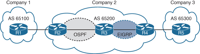
AS 65200 provides transit connectivity to AS 65100 and AS 65300
R2 could form an iBGP session directly with R4
but R3 would not know where to forward traffic when traffic from either AS reaches R3
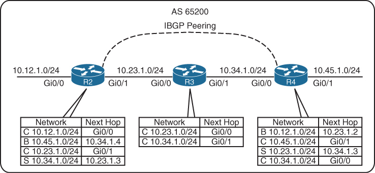
You might assume that redistributing the BGP table into an IGP overcomes the problem, but this not a viable solution, incase the BGP table is way larger than IGP can handle:
Scalability: IGPs cannot scale to that level of routes.
Routing: Link-state protocols and distance vector routing protocols use metric as the primary method for routing, while BGP uses multiple steps to identify the best path, The best path from BGP perspective could be longer, which would normally be deemed suboptimal from an IGP’s perspective.
Path attributes: All the BGP path attributes cannot be maintained within IGP protocols, upon redistribution into IGP, PA are lost
Solution to above problem is iBGP on all routers R2, R3 and R4 also called full mesh iBGP, that will allow proper forwarding of traffic
Above was just an example scenario, Enterprise organizations are consumers and should not provide transit connectivity between autonomous systems across the Internet, only service providers do.
BGP synchronization
In early iBGP deployments where the AS was used as a transit AS, network prefixes would commonly be redistributed into the IGP, To ensure full connectivity in the transit AS, BGP would use synchronization. BGP synchronization is the process of verifying that the BGP route existed in the IGP before the route could be advertised to an eBGP peer. BGP synchronization is no longer a default and is not commonly used
iBGP Full Mesh
iBGP peers do not prepend their ASN to AS_Path.
No other method exists for detecting loops with iBGP sessions so writers of BGP prohibit the advertisement of a route received from an iBGP peer to another iBGP peer.
RFC 4271 states that all BGP routers in a single AS must be fully meshed to provide a complete loop-free routing table
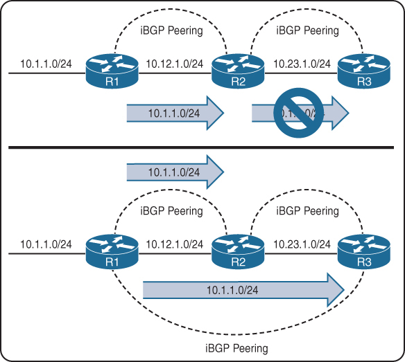
R1 advertises the 10.1.1.0/24 prefix to R2, which is processed and inserted into R2’s BGP table. R2 does not advertise the 10.1.1.0/24 route to R3 because it received the route from an iBGP peer R1
To resolve this issue, “R1 must form a multi-hop iBGP session with R3” so that R3 can receive the 10.1.1.0/24 route directly from R1
R1 and R3 either need a static route to the remote peering transit nets or R2 can advertise the 10.12.1.0/24 and 10.23.1.0/24 networks into BGP, if you think that R1’s 10.12.1.0/24 will not be passed by R2 to R3 but R1 did not advertise 10.12.1.0/24 instead R2 did, so 10.12.1.0/24 will be passed to R3 by R2
Need for peering using loopbacks

R1, R2, and R3 are a full mesh of iBGP sessions peered by transit links.
In the event of a link failure on the 10.13.1.0/24 network
R3’s BGP session with R1 will drop
R3 loses connectivity to the 10.1.1.0/24 network, even though R1 and R3 could communicate through R2 (through a multi-hop path).
This loss of connectivity occurs because iBGP does not advertise routes learned from another iBGP peer
You can overcome this issue by advertising the loopback into IGP and then creating BGP peering between loopback addresses
-loopback interface is virtual and always stays up
-Flexibility to failure: In the event of link failure, the session stays intact, and the IGP finds another path to the loopback address
-multi-hop iBGP session
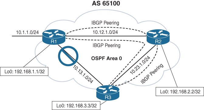
10.13.1.0/24 link fails. R1 and R3 still maintain BGP session connectivity by reaching each other’s loopback through R2, R2 will simply route the BGP packets between R1 and R3 without taking part in that BGP session
R1 (Default IPv4 Address Family Enabled)
router ospf 1
network 10.12.0.0 0.0.255.255 area 0
network 10.13.0.0 0.0.255.255 area 0
network 192.168.1.1 0.0.0.0 area 0
!
router bgp 65100
network 10.1.1.0 mask 255.255.255.0
neighbor remote-as 192.168.2.2 65100
neighbor 192.168.2.2 update-source Loopback0
neighbor remote-as 192.168.3.3 65100
neighbor 192.168.3.3 update-source Loopback0
!
address-family ipv4
neighbor 192.168.2.2 activate
neighbor 192.168.3.3 activateR2 (Default IPv4 Address Family Disabled)
router ospf 1
network 10.0.0.0 0.255.255.255 area 0
network 192.168.2.2 0.0.0.0 area 0
!
router bgp 65100
no bgp default ipv4-unicast
neighbor remote-as 192.168.1.1 65100
neighbor 192.168.1.1 update-source Loopback0
neighbor remote-as 192.168.3.3 65100
neighbor 192.168.3.3 update-source Loopback0
!
address-family ipv4
neighbor 192.168.1.1 activate
neighbor 192.168.3.3 activateas side effect of using loopback interfaces for peering is that next hop addresses are loopback addresses and recursive lookup is performed to find the outgoing interface
Another side effect that can happen is that if loopbacks are advertised It end up providing automatic load balancing if there are multiple equal-cost paths through the IGP to the loopback address (but only for iBGP)
eBGP
eBGP peerings
-AS is different from the AS configured locally in bgp router command
-The time-to-live (TTL) on eBGP packets is set to 1. BGP packets drop in transit if a multi-hop BGP session is attempted. The TTL on iBGP packets is set to 255, which allows for multi-hop sessions by default
-The advertising router modifies the BGP next hop for updates to the IP address sourcing the BGP connection
-The advertising router prepends its ASN to the existing AS_Path
-most recent AS is always prepended (the furthest to the left) since AS path is right to left
-The receiving router verifies that the AS_Path does not contain an ASN that matches the local routers. BGP discards the update if it fails the AS_Path loop-prevention check.
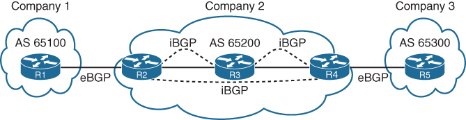
In above picture we can see ebgp peering and ibgp full mesh peering
Next hop issue for routes from eBGP to iBGP
As an eBGP prefix is advertised to an iBGP neighbor from local router, a route may not pass validity check because of next-hop reachability check and that route might be advertised from local router to first iBGP peer but not any further from that iBGP peer because that first iBGP peer considers route to be invalid due to next hop validity check failure
Because (local router) iBGP peer do not modify the next-hop address and when that foreign next hop address of eBGP router is passed to first iBGP peer and because that iBGP peer is not aware of that foreign address (next hop validity check which is first step in BGP best path selection fails), it is not advertised further to other iBGP peers as it is not even a valid route let alone best route.
The next-hop address must be resolvable in the RIB in order for it to be valid and advertised to other BGP peers.
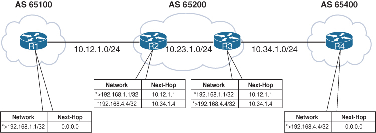
Notice that the BGP best-path symbol (>) is missing for the 192.168.4.4/32 prefix on R2 and for the 192.168.1.1/32 prefix on R3.
R1’s BGP table is missing the 192.168.4.4/32 route because the route did not pass R2’s next-hop accessibility check, preventing the execution of the BGP best-path algorithm
R4 advertised the route to R3 with the next-hop address 10.34.1.4, and R3 advertised the route to R2 with the next-hop address 10.34.1.4. R2 does not have a route for the 10.34.1.4 IP address and deems the next hop inaccessible. The same logic applies to R1’s 192.168.1.1/32 route when advertised toward R4.
R3# show bgp ipv4 unicast 192.168.1.1
BGP routing table entry for 192.1681.1/32, version 2
Paths: (1 available, no best path)
Not advertised to any peer
Refresh Epoch 1
65100
10.12.1.1 (inaccessible) from 10.23.1.2 (192.168.2.2)
Origin IGP, metric 0, localpref 100, valid, internalTo correct the issue, we can advertise those peering links using either below methods:
- IGP advertisement (Remember to use the passive interface to prevent an accidental adjacency from forming. Most IGPs do not provide the filtering capability provided by BGP.)
- Advertisement of the networks into BGP
or we could change next hop using next-hop-self, which is much better solution due to scalability as shown below
next-hop-self
Imagine that a service provider network has 500 routers, and every router has 200 eBGP peering links. To ensure that the next-hop address is reachable to the iBGP peers, the provider needs the advertisement of 100,000 peering networks in BGP or an IGP consuming router resources
using next-hop-self on ibgp neighbor we can achieve modification of that foreign ebgp peer’s address to its ibgp session address towards that ibgp peer
The next-hop-self feature only modifies prefixes going from ebgp peers to iBGP peers by default, but using the command next-hop-self [all] modifies the next-hop address on prefixes learned from iBGP to iBGP peers
R2 (Default IPv4 Address-Family Enabled)
router bgp 65200
neighbor 10.12.1.1 remote-as 65100
neighbor 10.23.1.3 remote-as 65200
neighbor 10.23.1.3 next-hop-selfR3 (Default IPv4 Address-Family Disabled)
router bgp 65200
no bgp default ipv4-unicast
neighbor 10.23.1.2 remote-as 65200
neighbor 10.34.1.4 remote-as 65400
!
address-family ipv4
neighbor 10.23.1.2 activate
neighbor 10.23.1.2 next-hop-self
neighbor 10.34.1.4 activate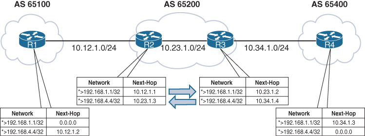
iBGP Scalability Solutions
The inability of BGP to advertise a route learned from one iBGP peer to another iBGP peer can lead to scalability issues within an AS. The formula n(n − 1)/2 provides the number of sessions required, where n represents the number of routers. A full mesh topology of 5 routers requires 10 sessions, and a topology of 10 routers requires 45 sessions
Route Reflectors
The router that is reflecting routes is known as a route reflector (RR),
the router that is receiving reflected routes is a route reflector client.
This reflector model is like an OSPF DR concept but for neighborships and not full sync, instead of all iBGP routers making adjacency with every other router, one router makes iBGP peering with all the routers
But there are few rules to follow
- Rule 1: If an RR receives an NLRI from a non-RR client, the RR advertises the NLRI to an RR client. It does not advertise the NLRI to a non-RR client.
- Rule 2: If an RR receives an NLRI from an RR client, it advertises the NLRI to RR clients and non-RR clients.
- Rule 3: If an RR receives a route from an eBGP peer, it advertises the route to RR clients and non-RR clients.
remember that RR clients receive in all scenarios / rules
Only Route Reflector is configured with RR configuration, and RR clients do not need to modify configuration, they just need to make iBGP peering with route reflecting RR router
BGP route reflector is an address family command like other loc-RIB commands
BGP route reflection is specific to each address family.
The command neighbor ip-address route-reflector-client is used under the neighbor address family configuration.
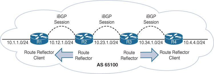
R1 is a route reflector client to R2, and R4 is a route reflector client to R3. R2 and R3 have a normal iBGP peering
You can have a gap in between 2 RRs in your design
R1 (Default IPv4 Address-Family Enabled)
router bgp 65100
network 10.1.1.0 mask 255.255.255.0
redistribute connected
neighbor 10.12.1.2 remote-as 65100R2 (Default IPv4 Address-Family Enabled)
router bgp 65100
redistribute connected
neighbor 10.12.1.1 remote-as 65100
neighbor 10.12.1.1 route-reflector-client
neighbor 10.23.1.3 remote-as 65100R3 (Default IPv4 Address-Family Disabled)
router bgp 65100
no bgp default ipv4-unicast
neighbor 10.23.1.2 remote-as 65100
neighbor 10.34.1.4 remote-as 65100
!
address-family ipv4
redistribute connected
neighbor 10.23.1.2 activate
neighbor 10.34.1.4 activate
neighbor 10.34.1.4 route-reflector-clientR4 (Default IPv4 Address-Family Disabled)
router bgp 65100
no bgp default ipv4-unicast
neighbor 10.34.1.3 remote-as 65100
!
address-family ipv4
neighbor 10.34.1.3 activate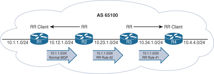
R1 advertises the 10.1.1.0/24 route to R2 as a normal iBGP advertisement.
R2 receives and advertises the 10.1.1.0/24 route using the route reflector rule 2 as just explained to R3 (a non-route reflector client) (this is why above gap [normal ibgp peering] can be made)
R3 receives and advertises the 10.1.1.0/24 route using the route reflector rule 1 as explained to R4 (a route reflector client).
- Rule 1: If an RR receives an NLRI from a non-RR client, the RR advertises the NLRI to an RR client. It does not advertise the NLRI to a non-RR client.
- Rule 2: If an RR receives an NLRI from an RR client, it advertises the NLRI to RR clients and non-RR clients.
- Rule 3: If an RR receives a route from an eBGP peer, it advertises the route to RR clients and non-RR clients.
See how iBGP between R2 and R3 is non client s
R1# show bgp ipv4 unicast | i Network|10.1.1
Network Next Hop Metric LocPrf Weight Path
*> 10.1.1.0/24 0.0.0.0 0 32768 iR2# show bgp ipv4 unicast | i Network|10.1.1
Network Next Hop Metric LocPrf Weight Path
*>i 10.1.1.0/24 10.12.1.1 0 100 0 iR3# show bgp ipv4 unicast | i Network|10.1.1
Network Next Hop Metric LocPrf Weight Path
*>i 10.1.1.0/24 10.12.1.1 0 100 0 iR4# show bgp ipv4 unicast | i Network|10.1.1
Network Next Hop Metric LocPrf Weight Path
*>i 10.1.1.0/24 10.12.1.1 0 100 0 iNotice the i immediately after the best-path indicator (>) on R2, R3, and R4. This indicates that the prefix is learned through iBGP.
Important notes on RR
Route reflector can be inband or in path or it can be outband or out of data path
With Route Reflector in our iBGP network we dont need to do full mesh iBGP instead we only do iBGP with Route Reflector only
Route Reflectors choose best path based on their perspective or exit point and not perspective of the client this can result in a situation where certain exit point in the network for a prefix is optimal for RR but not optimal for clients
When ibgp routers have multiple paths to compare then one ibgp router can say path A is better and another ibgp router can say that path B is best (based on IGP cost) but when RR is used then RR decides one best path for a prefix and then pushes that to all the clients and now all clients have one best path for a prefix regardless of IGP cost to the next hop
RR only advertise one path for a prefix to the clients and do not advertise any other path to clients
The fix for this is BGP Add Path
BGP Add Path
In standard BGP, a router advertises only one best path per prefix to its neighbors. Because of best path good alternative routes exist but are not advertised
Similarly RRs only advertise their single best path, reducing path diversity.
BGP Add-Path is an extension to BGP that allows a router to advertise multiple paths for the same prefix to a neighbor and this is how router can switch to second path faster.
BGP add path is useful for Datacenters and Large ISP, also networks that use route reflectors
But remember that add path is a capability and is exchanged in open message and needs to be supported and sent by peer
BGP routing table entry for 10.10.10.0/24
Paths: (2 available, best #1)
Advertised to update-groups:
1
Path 1:
Received Path ID 1 <<< ! Received Path ID confirms ADD-PATH
65001 65002
192.0.2.1 from 192.0.2.1 (192.0.2.1)
Origin IGP, localpref 100, valid, external, best
Path 2:
Received Path ID 2 <<< ! Received Path ID confirms ADD-PATH
65003 65002
192.0.2.1 from 192.0.2.1 (192.0.2.1)
Origin IGP, localpref 100, valid, external
Why is BGP Add Path needed when multipath is available?
Multipath makes router use multiple paths, while Additional paths from add path are kept as backup for faster failover
For multipath to work the routes must be equal including AS numbers and AS Path hops must be same and for ibgp routes must be equal including AS numbers and AS Path hops must be same + also the IGP metric to next hop too
Loop Prevention in Route Reflectors
Removing the full mesh requirement in an iBGP topology using route-reflector introduces the potential for routing loops. When RFC 1966 was drafted, two other BGP route reflector–specific attributes were added to prevent loops:
Originator: This optional non-transitive BGP attribute is created by the first route reflector and sets the value to the RID of the router that injected/advertised the prefix into the iBGP network. If Originator is already populated on a route, it should not be overwritten. If a router receives a route with its RID in the Originator attribute, the route is discarded.
Cluster List: This optional non-transitive BGP attribute is updated by the route reflector. This attribute is appended (hence the list , not overwritten) by the route reflector with its cluster ID. By default, this is the BGP identifier. If a route reflector receives a route with its cluster ID in the Cluster List attribute, the route is discarded.
R4# show bgp ipv4 unicast 10.1.1.0/24
! Output omitted for brevity
Paths: (1 available, best #1, table default)
Refresh Epoch 1
Local
10.12.1.1 from 10.34.1.3 (192.168.3.3)
Origin IGP, metric 0, localpref 100, valid, internal, best
Originator: 192.168.1.1, Cluster list: 192.168.3.3, 192.168.2.2Confederations
BGP confederations is also an alternative solution to the iBGP full mesh scalability issues
Sub-ASs known as member ASs
Larger AS known as an AS confederation
Member ASs normally use ASNs from the private ASN range (64,512 to 65,534)
eBGP peers peer using confederation AS

Notice that R3 provides route reflection in member AS 65100.
R1
router bgp 100
neighbor 10.12.1.2 remote-as 200R2
router bgp 65100 <<< local bubble
bgp confederation identifier 200 <<< larger bubble
bgp confederation peers 65200 <<< other bubbles we peer with
neighbor 10.12.1.1 remote-as 100 <<< normal peering
neighbor 10.23.1.3 remote-as 65100 <<< normal peering
neighbor 10.25.1.5 remote-as 65200 <<< normal peeringR3
router bgp 65100
bgp confederation identifier 200
neighbor 10.23.1.2 remote-as 65100
neighbor 10.23.1.2 route-reflector-client
neighbor 10.34.1.4 remote-as 65100
neighbor 10.34.1.4 route-reflector-clientR4
router bgp 65100
bgp confederation identifier 200
bgp confederation peers 65200
neighbor 10.34.1.3 remote-as 65100
neighbor 10.46.1.6 remote-as 65200R5
router bgp 65200
bgp confederation identifier 200
bgp confederation peers 65100
neighbor 10.25.1.2 remote-as 65100
neighbor 10.56.1.6 remote-as 65200R6
router bgp 65200
bgp confederation identifier 200
bgp confederation peers 65100
neighbor 10.46.1.4 remote-as 65100
neighbor 10.56.1.5 remote-as 65200
neighbor 10.67.1.7 remote-as 300R7
router bgp 300
neighbor 10.67.1.6 remote-as 200The AS_Path attribute contains a subfield called AS_CONFED_SEQUENCE.
AS_CONFED_SEQUENCE is confederation’s AS PATH but displayed in parentheses before any external ASNs in AS_Path.
As the route passes from member AS to member AS, AS_CONFED_SEQUENCE is appended to contain the member AS ASNs.
The AS_CONFED_SEQUENCE attribute is only used to prevent loops but is not used (counted) when choosing the shortest AS_Path.
Route reflectors can be used within the member AS as in normal iBGP peerings.
The BGP MED attribute is transitive to all other member ASs and Within the confederation, MED is propagated between member sub-ASes but MED is NOT advertised outside the confederation to external ASes. When routes leave the confederation and are advertised to a true external AS: The MED is stripped (unless explicitly re-set by policy).
The LOCAL_PREF attribute is transitive to all other member ASs just like iBGP
The next-hop address for external confederation routes does not change as the route is exchanged between member ASs
AS_CONFED_SEQUENCE is removed from AS_Path when the route is advertised outside the confederation.
AS 100 is not aware that AS 200 is a confederation
R1-AS100# show bgp ipv4 unicast | begin Network
Network Next Hop Metric LocPrf Weight Path
*> 10.1.1.0/24 0.0.0.0 0 32768 ?
*> 10.7.7.0/24 10.12.1.2 0 200 300 i
* 10.12.1.0/24 10.12.1.2 0 0 200 ?
*> 0.0.0.0 0 32768 ?
*> 10.23.1.0/24 10.12.1.2 0 0 200 ?
*> 10.25.1.0/24 10.12.1.2 0 0 200 ?
*> 10.46.1.0/24 10.12.1.2 0 200 ?
*> 10.56.1.0/24 10.12.1.2 0 200 ?
*> 10.67.1.0/24 10.12.1.2 0 200 ?
*> 10.78.1.0/24 10.12.1.2 0 200 300 ?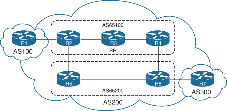
R2’s BGP table which is in member AS 65100, see that next hop IP address for 10.7.7.0/24 was not changed (advertised by R7) even though it passed different member AS
AS_CONFED_SEQUENCE in parentheses indicates that it passed through sub AS 65200
R2# show bgp ipv4 unicast | begin Network
Network Next Hop Metric LocPrf Weight Path
*> 10.1.1.0/24 10.12.1.1 111 0 100 ?
*> 10.7.7.0/24 10.67.1.7 0 100 0 (65200) 300 i
*> 10.12.1.0/24 0.0.0.0 0 32768 ?
* 10.12.1.1 111 0 100 ?
*> 10.23.1.0/24 0.0.0.0 0 32768 ?
* 10.25.1.0/24 10.25.1.5 0 100 0 (65200) ?
*> 0.0.0.0 0 32768 ?
*> 10.46.1.0/24 10.56.1.6 0 100 0 (65200) ?
*> 10.56.1.0/24 10.25.1.5 0 100 0 (65200) ?
*> 10.67.1.0/24 10.56.1.6 0 100 0 (65200) ?
*> 10.78.1.0/24 10.67.1.7 0 100 0 (65200) 300 ?
Processed 9 prefixes, 11 pathsNotice that the path information includes the attribute confed-internal or confed-external, based on whether the route was received within the same member AS or a different one.
R4# show bgp ipv4 unicast 10.7.7.0/24
! Output omitted for brevity
BGP routing table entry for 10.7.7.0/24, version 504
Paths: (2 available, best #1, table default)
Advertised to update-groups:
3
Refresh Epoch 1
(65200) 300
10.67.1.7 from 10.34.1.3 (192.168.3.3)
Origin IGP, metric 0, localpref 100, valid, confed-internal, best
Originator: 192.168.2.2, Cluster list: 192.168.3.3
rx pathid: 0, tx pathid: 0x0
Refresh Epoch 1
(65200) 300
10.67.1.7 from 10.46.1.6 (192.168.6.6)
Origin IGP, metric 0, localpref 100, valid, confed-external
rx pathid: 0, tx pathid: 0Multiprotocol BGP for IPv6
Multiprotocol BGP (MP-BGP) enables BGP to carry NLRI for different protocols
such as IPv6, MPLS Layer 3 with VRFs info
New BGPv4 optional and nontransitive attributes:
-Multiprotocol reachable NLRI: Describes IPv6 route information
-Multiprotocol unreachable NLRI: Withdraws the IPv6 route from service
These attributes are optional and nontransitive, so if an older router does not understand the attributes, the information can just be ignored as there are a lot of old routing equipment in internet
MP-BGP for IPv6 continues to use the same well-known TCP port 179
IPv4 unicast: AFI:1, SAFI:1
IPv6 unicast: AFI:2, SAFI:1
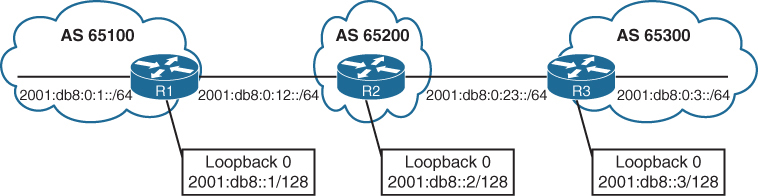
Unique global unicast addressing is the recommended method for BGP peering to avoid operational complexity. BGP peering using the link-local address may introduce risk if the address is not manually assigned to an interface
R1 advertises all its networks through redistribution
R2 and R3 use the network statement to advertise all their connected networks.
R1
router bgp 65100
bgp router-id 192.168.1.1
no bgp default ipv4-unicast
neighbor 2001:DB8:0:12::2 remote-as 65200
!
address-family ipv6
neighbor 2001:DB8:0:12::2 activate
redistribute connectedR2
router bgp 65200
bgp router-id 192.168.2.2
no bgp default ipv4-unicast
neighbor 2001:DB8:0:12::1 remote-as 65100
neighbor 2001:DB8:0:23::3 remote-as 65300
!
address-family ipv6
neighbor 2001:DB8:0:12::1 activate
neighbor 2001:DB8:0:23::3 activate
network 2001:DB8::2/128
network 2001:DB8:0:12::/64
network 2001:DB8:0:23::/64R3
router bgp 65300
bgp router-id 192.168.3.3
no bgp default ipv4-unicast
neighbor 2001:DB8:0:23::2 remote-as 65200
!
address-family ipv6
neighbor 2001:DB8:0:23::2 activate
network 2001:DB8::3/128
network 2001:DB8:0:3::/64
network 2001:DB8:0:23::/64IPv4 unicast routing capability is advertised by default in IOS XE
for pure IPv6 environment shut down the bgp on IPv4 neighbor or globally within the BGP process with the command no bgp default ipv4-unicast
show bgp ipv6 unicast neighbors ip-address [detail] displays detailed information about whether the IPv6 capabilities were negotiated successfully.
R1# show bgp ipv6 unicast neighbors 2001:DB8:0:12::2
! Output omitted for brevity
BGP neighbor is 2001:DB8:0:12::2, remote AS 65200, external link
BGP version 4, remote router ID 192.168.2.2
BGP state = Established, up for 00:28:25
Last read 00:00:54, last write 00:00:34, hold time is 180, keepalive interval is 60 seconds
Neighbor sessions:
1 active, is not multisession capable (disabled)
Neighbor capabilities:
Route refresh: advertised and received(new)
Four-octets ASN Capability: advertised and received
Address family IPv6 Unicast: advertised and received <<<
Enhanced Refresh Capability: advertised and received
..
For address family: IPv6 Unicast
Session: 2001:DB8:0:12::2
BGP table version 13, neighbor version 13/0
Output queue size : 0
Index 1, Advertise bit 0
1 update-group member
Slow-peer detection is disabled
Slow-peer split-update-group dynamic is disabled
Sent Rcvd
Prefix activity: ---- ----
Prefixes Current: 3 5 (Consumes 520 bytes)
Prefixes Total: 6 10R2# show bgp ipv6 unicast summary
BGP router identifier 192.168.2.2, local AS number 65200
BGP table version is 19, main routing table version 19
7 network entries using 1176 bytes of memory
8 path entries using 832 bytes of memory
3/3 BGP path/bestpath attribute entries using 456 bytes of memory
2 BGP AS-PATH entries using 48 bytes of memory
0 BGP route-map cache entries using 0 bytes of memory
0 BGP filter-list cache entries using 0 bytes of memory
BGP using 2512 total bytes of memory
BGP activity 7/0 prefixes, 8/0 paths, scan interval 60 secs
Neighbor V AS MsgRcvd MsgSent TblVer InQ OutQ Up/Down State/PfxRcd
2001:DB8:0:12::1 4 65100 35 37 19 0 0 00:25:08 3
2001:DB8:0:23::3 4 65300 32 37 19 0 0 00:25:11 3Notice that some of the prefixes include the unspecified address as the next hop. The unspecified address indicates that the local router is generating the prefix for the BGP table
The weight value 32,768 also indicates that the prefix is locally originated by the router.
This is to force select this as always the best path since BGP best path algorithm has highest weight as top criteria
R1# show bgp ipv6 unicast
BGP table version is 13, local router ID is 192.168.1.1
Status codes: s suppressed, d damped, h history, * valid, > best, – - internal,
r RIB-failure, S Stale, m multipath, b backup-path, f RT-Filter,
x best-external, a additional-path, c RIB-compressed,
Origin codes: – - IGP, – - EGP, – - incomplete
RPKI validation codes: V valid, I invalid, N Not found
Network Next Hop Metric LocPrf Weight Path
*> 2001:DB8::1/128 :: 0 32768 ?
*> 2001:DB8::2/128 2001:DB8:0:12::2 0 0 65200 i
*> 2001:DB8::3/128 2001:DB8:0:12::2 0 65200 65300 i
*> 2001:DB8:0:1::/64 :: 0 32768 ?
*> 2001:DB8:0:3::/64 2001:DB8:0:12::2 0 65200 65300 i
* 2001:DB8:0:12::/64 2001:DB8:0:12::2 0 0 65200 i
*> :: 0 32768 ?
*> 2001:DB8:0:23::/64 2001:DB8:0:12::2 0 65200 iR2# show bgp ipv6 unicast | begin Network
Network Next Hop Metric LocPrf Weight Path
*> 2001:DB8::1/128 2001:DB8:0:12::1 0 0 65100 ?
*> 2001:DB8::2/128 :: 0 32768 i
*> 2001:DB8::3/128 2001:DB8:0:23::3 0 0 65300 i
*> 2001:DB8:0:1::/64 2001:DB8:0:12::1 0 0 65100 ?
*> 2001:DB8:0:3::/64 2001:DB8:0:23::3 0 0 65300 i
*> 2001:DB8:0:12::/64 :: 0 32768 i
* 2001:DB8:0:12::1 0 0 65100 ?
*> 2001:DB8:0:23::/64 :: 0 32768 i
2001:DB8:0:23::3 0 0 65300 iR3# show bgp ipv6 unicast | begin Network
Network Next Hop Metric LocPrf Weight Path
*> 2001:DB8::1/128 2001:DB8:0:23::2 0 65200 65100 ?
*> 2001:DB8::2/128 2001:DB8:0:23::2 0 0 65200 i
*> 2001:DB8::3/128 :: 0 32768 i
*> 2001:DB8:0:1::/64 2001:DB8:0:23::2 0 65200 65100 ?
*> 2001:DB8:0:3::/64 :: 0 32768 i
*> 2001:DB8:0:12::/64 2001:DB8:0:23::2 0 0 65200 i
*> 2001:DB8:0:23::/64 :: 0 32768 i
*> 2001:DB8:0:23::2 :: 0 32768 i
* 2001:DB8:0:23::2 0 0 65200 iR3# show bgp ipv6 unicast 2001:DB8::1/128
BGP routing table entry for 2001:DB8::1/128, version 9
Paths: (1 available, best #1, table default)
Not advertised to any peer <<<
Refresh Epoch 2
65200 65100
2001:DB8:0:23::2 (FE80::2) from 2001:DB8:0:23::2 (192.168.2.2)
Origin incomplete, localpref 100, valid, external, best
rx pathid: 0, tx pathid: 0x0Notice that the next-hop address is the link-local address for the next-hop forwarding address, which is resolved through a recursive lookup.
R2# show ipv6 route bgp
IPv6 Routing Table - default - 10 entries
Codes: C - Connected, L - Local, S - Static, U - Per-user Static route
B - BGP, HA - Home Agent, MR - Mobile Router, R - RIP
H - NHRP, I1 - ISIS L1, I2 - ISIS L2, IA - ISIS interarea
IS - ISIS summary, D - EIGRP, EX - EIGRP external, NM - NEMO
ND - ND Default, NDp - ND Prefix, DCE - Destination, NDr - Redirect
RL - RPL, O - OSPF Intra, OI - OSPF Inter, OE1 - OSPF ext 1
OE2 - OSPF ext 2, ON1 - OSPF NSSA ext 1, ON2 - OSPF NSSA ext 2
la - LISP alt, lr - LISP site-registrations, ld - LISP dyn-eid
a - Application
B 2001:DB8::1/128 [20/0]
via FE80::1, GigabitEthernet0/0
B 2001:DB8::3/128 [20/0]
via FE80::3, GigabitEthernet0/1
B 2001:DB8:0:1::/64 [20/0]
via FE80::1, GigabitEthernet0/0
B 2001:DB8:0:3::/64 [20/0]
via FE80::3, GigabitEthernet0/1IPv6 over IPv4
BGP can exchange routes using either an IPv4 or IPv6 TCP session
In a typical deployment, IPv4 routes are exchanged using a dedicated IPv4 session, and IPv6 routes are exchanged with a dedicated IPv6 session
However, it is possible to share IPv6 routes over an IPv4 TCP session or IPv4 routes over an IPv6 TCP session
it is also possible to share IPv4 and IPv6 using a single BGP session.
R1
router bgp 65100
bgp router-id 192.168.1.1
no bgp default ipv4-unicast
neighbor 10.12.1.2 remote-as 65200
!
address-family ipv6 unicast
redistribute connected
neighbor 10.12.1.2 activateR2
router bgp 65200
bgp router-id 192.168.2.2
no bgp default ipv4-unicast
neighbor 10.12.1.1 remote-as 65100
neighbor 10.23.1.3 remote-as 65300
!
address-family ipv6 unicast
network 2001:DB8::2/128
network 2001:DB8:0:12::/64
aggregate-address 2001:DB8::/62 summary-only
neighbor 10.12.1.1 activate <<< ipv4 neighbor inside IPv6 address family
neighbor 10.23.1.3 activate <<< ipv4 neighbor inside IPv6 address familyR3
router bgp 65300
bgp router-id 192.168.3.3
no bgp default ipv4-unicast
neighbor 10.23.1.2 remote-as 65200
!
address-family ipv6 unicast
network 2001:DB8::3/128
network 2001:DB8:0:3::/64
network 2001:DB8:0:23::/64
neighbor 10.23.1.2 activateR1# show bgp ipv6 unicast summary | begin Neighbor
Neighbor V AS MsgRcvd MsgSent TblVer InQ OutQ Up/Down State/PfxRcd
10.12.1.2 4 65200 115 116 11 0 0 01:40:14 2R2# show bgp ipv6 unicast summary | begin Neighbor
Neighbor V AS MsgRcvd MsgSent TblVer InQ OutQ Up/Down State/PfxRcd
10.12.1.1 4 65100 114 114 8 0 0 01:39:17 3
10.23.1.3 4 65300 113 115 8 0 0 01:39:16 3R3# show bgp ipv6 unicast summary | begin Neighbor
Neighbor V AS MsgRcvd MsgSent TblVer InQ OutQ Up/Down State/PfxRcd
10.23.1.2 4 65200 114 112 7 0 0 01:38:49 2The IPv6 routes advertised over an IPv4 BGP session are assigned an IPv4-mapped IPv6 address in the format (::FFFF:xx.xx.xx.xx) for the next hop, where xx.xx.xx.xx is the IPv4 address of the BGP peering. This is not a valid forwarding address, so the IPv6 route does not populate the RIB.
R1# show bgp ipv6 unicast | begin Network
Network Next Hop Metric LocPrf Weight Path
* 2001:DB8::/62 ::FFFF:10.12.1.2 0 0 65200 i
*> 2001:DB8::1/128 :: 0 32768 ?
*> 2001:DB8:0:1::/64 :: 0 32768 ?
* 2001:DB8:0:12::/64 ::FFFF:10.12.1.2 0 0 65200 i
*> :: 0 32768 ?R2# show bgp ipv6 unicast | begin Network
Network Next Hop Metric LocPrf Weight Path
*> 2001:DB8::/62 :: 32768 i
S 2001:DB8::1/128 ::FFFF:10.12.1.1 0 0 65100 ?
s> 2001:DB8::2/128 :: 0 32768 i
s 2001:DB8::3/128 ::FFFF:10.23.1.3 0 0 65300 i
s 2001:DB8:0:1::/64 ::FFFF:10.12.1.1 0 0 65100 ?
s 2001:DB8:0:3::/64 ::FFFF:10.23.1.3 0 0 65300 i
* 2001:DB8:0:12::/64 ::FFFF:10.12.1.1 0 0 65100 ?
*> :: 0 32768 i
* 2001:DB8:0:23::/64 ::FFFF:10.23.1.3 0 0 65300 iR3# show bgp ipv6 unicast | begin Network
Network Next Hop Metric LocPrf Weight Path
* 2001:DB8::/62 ::FFFF:10.23.1.2 0 0 65200 i
*> 2001:DB8::3/128 :: 0 32768 i
*> 2001:DB8:0:3::/64 :: 0 32768 i
* 2001:DB8:0:12::/64 ::FFFF:10.23.1.2 0 0 65200 i
*> 2001:DB8:0:23::/64 :: 0 32768 iA quick connectivity test between R1 and R3. The output confirms that connectivity cannot be maintained.
R1# ping 2001:DB8:0:3::3
Type escape sequence to abort.
Sending 5, 100-byte ICMP Echos to 2001:DB8:0:3::3, timeout is 2 seconds:
% No valid route for destination
Success rate is 0 percent (0/1)R1# traceroute 2001:DB8:0:3::3
Type escape sequence to abort.
Tracing the route to 2001:DB8:0:3::3
1 * * *
2 * * *
3 * * *
..To correct the problem, the BGP route map needs to manually set the IPv6 next hop.
R1
route-map FromR1R2Link permit 10
set ipv6 next-hop 2001:DB8:0:12::1
!
router bgp 65100
address-family ipv6 unicast
neighbor 10.12.1.2 route-map FromR1R2LINK outR2
route-map FromR2R1LINK permit 10
set ipv6 next-hop 2001:DB8:0:12::2
route-map FromR2R3LINK permit 10
set ipv6 next-hop 2001:DB8:0:23::2
!
router bgp 65200
address-family ipv6 unicast
neighbor 10.12.1.1 route-map FromR2R1LINK out
neighbor 10.23.1.3 route-map FromR2R3LINK outR3
route-map FromR3R2Link permit 10
set ipv6 next-hop 2001:DB8:0:23::3
!
router bgp 65300
address-family ipv6 unicast
neighbor 10.23.1.2 route-map FromR3R2Link outThe next-hop IP address is valid, and the route can now be installed into the RIB.
R1# show bgp ipv6 unicast | begin Network
Network Next Hop Metric LocPrf Weight Path
*> 2001:DB8::/62 2001:DB8:0:12::2 0 0 65200 i
*> 2001:DB8::1/128 :: 0 32768 ?
*> 2001:DB8:0:1::/64 :: 0 32768 ?
*> 2001:DB8:0:12::/64 :: 0 32768 ?
* 2001:DB8:0:12::2 0 0 65200 iR2# show bgp ipv6 unicast | begin Network
Network Next Hop Metric LocPrf Weight Path
*> 2001:DB8::/62 :: 32768 i
s> 2001:DB8::1/128 2001:DB8:0:12::1 0 0 65100 ?
s> 2001:DB8::2/128 :: 0 32768 i
s> 2001:DB8::3/128 2001:DB8:0:23::3 0 0 65300 i
s> 2001:DB8:0:1::/64 2001:DB8:0:12::1 0 0 65100 ?
s> 2001:DB8:0:3::/64 2001:DB8:0:23::3 0 0 65300 i
*> 2001:DB8:0:12::/64 :: 0 32768 i
r> 2001:DB8:0:23::/64 2001:DB8:0:23::3 0 0 65300 iR3# show bgp ipv6 unicast | begin Network
Network Next Hop Metric LocPrf Weight Path
*> 2001:DB8::/62 2001:DB8:0:23::2
0 0 65200 i
*> 2001:DB8::3/128 :: 0 32768 i
*> 2001:DB8:0:3::/64 :: 0 32768 i
*> 2001:DB8:0:12::/64 2001:DB8:0:23::2 0 0 65200 i
*> 2001:DB8:0:23::/64 :: 0 32768 iSummarization
Summarizing prefixes conserves router resources and accelerates best-path calculation by reducing the size of the table.
Summarization, also known as route aggregation, provides the benefit of stability by hiding route flaps from downstream routers, thereby reducing routing churn
While most service providers do not accept prefixes larger than /24 for IPv4 (/25 through /32), the Internet, at the time of this writing, still has more than 940,000 routes and continues to grow. A router has to receive first and then summaries it towards it neighbors
Dynamic BGP summarization consists of the configuration of an aggregate network prefix. When viable component routes that match the aggregate network prefix enter the BGP table, the aggregate prefix is created. The originating router creates a discard route with next hop to Null0 for the aggregated prefix for loop prevention.
Dynamic route summarization is accomplished with the BGP address family configuration command aggregate-address network subnet-mask [summary-only] [as-set].
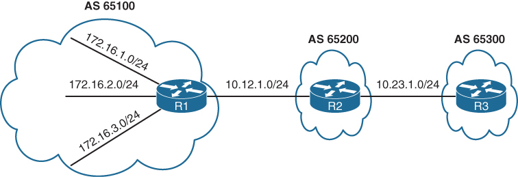
R1# show bgp ipv4 unicast | begin Network
Network Next Hop Metric LocPrf Weight Path
* 10.12.1.0/24 10.12.1.2 0 0 65200 ?
*> 0.0.0.0 0 32768 ?
*> 10.23.1.0/24 10.12.1.2 0 0 65200 ?
*> 172.16.1.0/24 0.0.0.0 0 32768 ?
*> 172.16.2.0/24 0.0.0.0 0 32768 ?
*> 172.16.3.0/24 0.0.0.0 0 32768 ?
*> 192.168.1.1/32 0.0.0.0 0 32768 ?
*> 192.168.2.2/32 10.12.1.2 0 0 65200 ?
*> 192.168.3.3/32 10.12.1.2 0 65200 65300 ?R2# show bgp ipv4 unicast | begin Network
Network Next Hop Metric LocPrf Weight Path
* 10.12.1.0/24 10.12.1.1 0 0 65100 ?
*> 0.0.0.0 0 32768 ?
* 10.23.1.0/24 10.23.1.3 0 0 65300 ?
*> 0.0.0.0 0 32768 ?
*> 172.16.1.0/24 10.12.1.1 0 0 65100 ?
*> 172.16.2.0/24 10.12.1.1 0 0 65100 ?
*> 172.16.3.0/24 10.12.1.1 0 0 65100 ?
*> 192.168.1.1/32 10.12.1.1 0 0 65100 ?
*> 192.168.2.2/32 0.0.0.0 0 32768 ?
*> 192.168.3.3/32 10.23.1.3 0 0 65300 ?R3# show bgp ipv4 unicast | begin Network
Network Next Hop Metric LocPrf Weight Path
*> 10.12.1.0/24 10.23.1.2 0 0 65200 ?
* 10.23.1.0/24 10.23.1.2 0 0 65200 ?
*> 0.0.0.0 0 32768 ?
*> 172.16.1.0/24 10.23.1.2 0 65200 65100 ?
*> 172.16.2.0/24 10.23.1.2 0 65200 65100 ?
*> 172.16.3.0/24 10.23.1.2 0 65200 65100 ?
*> 192.168.1.1/32 10.23.1.2 0 65200 65100 ?
*> 192.168.2.2/32 10.23.1.2 0 0 65200 ?
*> 192.168.3.3/32 0.0.0.0 0 32768 ?R1 aggregates all the stub networks (172.16.1.0/24, 172.16.2.0/24, and 172.16.3.0/24) into a 172.16.0.0/20 summary route
R2 aggregates all the router’s loopback addresses into a 192.168.0.0/16 summary route
R1# show running-config | section router bgp
router bgp 65100
bgp log-neighbor-changes
aggregate-address 172.16.0.0 255.255.240.0
redistribute connected
neighbor 10.12.1.2 remote-as 65200R2# show running-config | section router bgp
router bgp 65200
bgp log-neighbor-changes
no bgp default ipv4-unicast
neighbor 10.12.1.1 remote-as 65100
neighbor 10.23.1.3 remote-as 65300
!
address-family ipv4
aggregate-address 192.168.0.0 255.255.0.0
redistribute connected
neighbor 10.12.1.1 activate
neighbor 10.23.1.3 activate
exit-address-family
R1# show bgp ipv4 unicast | begin Network
Network Next Hop Metric LocPrf Weight Path
* 10.12.1.0/24 10.12.1.2 0 0 65200 ?
*> 0.0.0.0 0 32768 ?
*> 10.23.1.0/24 10.12.1.2 0 0 65200 ?
*> 172.16.0.0/20 0.0.0.0 32768 i >>> R1 will also install
*> 172.16.1.0/24 0.0.0.0 0 32768 ?
*> 172.16.2.0/24 0.0.0.0 0 32768 ?
*> 172.16.3.0/24 0.0.0.0 0 32768 ?
*> 192.168.0.0/16 10.12.1.2 0 0 65200 i >>> summary received with AS of only 65200 loosing all previous AS PATH info
*> 192.168.1.1/32 0.0.0.0 0 32768 ?
*> 192.168.2.2/32 10.12.1.2 0 0 65200 ?
*> 192.168.3.3/32 10.12.1.2 0 65200 65300 ?R2# show bgp ipv4 unicast | begin Network
Network Next Hop Metric LocPrf Weight Path
* 10.12.1.0/24 10.12.1.1 0 0 65100 ?
*> 0.0.0.0 0 32768 ?
* 10.23.1.0/24 10.23.1.3 0 0 65300 ?
*> 0.0.0.0 0 32768 ?
*> 172.16.0.0/20 10.12.1.1 0 0 65100 i
*> 172.16.1.0/24 10.12.1.1 0 0 65100 ?
*> 172.16.2.0/24 10.12.1.1 0 0 65100 ?
*> 172.16.3.0/24 10.12.1.1 0 0 65100 ?
*> 192.168.0.0/16 0.0.0.0 32768 i
*> 192.168.1.1/32 10.12.1.1 0 0 65100 ?
*> 192.168.2.2/32 0.0.0.0 0 32768 ?
*> 192.168.3.3/32 10.23.1.3 0 0 65300 ?R3# show bgp ipv4 unicast | begin Network
Network Next Hop Metric LocPrf Weight Path
*> 10.12.1.0/24 10.23.1.2 0 0 65200 ?
* 10.23.1.0/24 10.23.1.2 0 0 65200 ?
*> 0.0.0.0 0 32768 ?
*> 172.16.0.0/20 10.23.1.2 <<< 0 65200 65100 i
*> 172.16.1.0/24 10.23.1.2 0 65200 65100 ?
*> 172.16.2.0/24 10.23.1.2 0 65200 65100 ?
*> 172.16.3.0/24 10.23.1.2 0 65200 65100 ?
*> 192.168.0.0/16 10.23.1.2 <<< 0 0 65200 i
*> 192.168.1.1/32 10.23.1.2 0 65200 65100 ?
*> 192.168.2.2/32 10.23.1.2 0 0 65200 ?
*> 192.168.3.3/32 0.0.0.0 0 32768 ?Notice that the 172.16.0.0/20 and 192.168.0.0/16 network prefixes are visible, but the smaller component network prefixes still exist on all the routers. The aggregate-address command advertises the aggregated network prefix in addition to the original component network prefixes. The optional summary-only keyword suppresses the component network prefixes in the summarized network prefix range.
Configuration with the summary-only keyword.
R1# show running-config | section router bgp
router bgp 65100
bgp log-neighbor-changes
aggregate-address 172.16.0.0 255.255.240.0 summary-only
redistribute connected
neighbor 10.12.1.2 remote-as 65200R2# show running-config | section router bgp
router bgp 65200
bgp log-neighbor-changes
no bgp default ipv4-unicast
neighbor 10.12.1.1 remote-as 65100
neighbor 10.23.1.3 remote-as 65300
!
address-family ipv4
aggregate-address 192.168.0.0 255.255.0.0 summary-only
redistribute connected
neighbor 10.12.1.1 activate
neighbor 10.23.1.3 activate
exit-address-familyR3# show bgp ipv4 unicast | begin Network
Network Next Hop Metric LocPrf Weight Path
*> 10.12.1.0/24 10.23.1.2 0 0 65200 ?
* 10.23.1.0/24 10.23.1.2 0 0 65200 ?
*> 0.0.0.0 0 32768 ?
*> 172.16.0.0/20 10.23.1.2 0 65200 65100 i
*> 192.168.0.0/16 10.23.1.2 0 0 65200 i
*> 192.168.3.3/32 0.0.0.0 0 32768 ?R2# show bgp ipv4 unicast
BGP table version is 10, local router ID is 192.168.2.2
Status codes: s suppressed, d damped, h history, * valid, > best, i - internal,
r RIB-failure, S Stale, m multipath, b backup-path, f RT-Filter,
x best-external, a additional-path, c RIB-compressed,
Origin codes: i - IGP, e - EGP, ? - incomplete
RPKI validation codes: V valid, I invalid, N Not found
Network Next Hop Metric LocPrf Weight Path
* 10.12.1.0/24 10.12.1.1 0 0 65100 ?
*> 0.0.0.0 0 32768 ?
* 10.23.1.0/24 10.23.1.3 0 0 65300 ?
*> 0.0.0.0 0 32768 ?
*> 172.16.0.0/20 10.12.1.1 0 0 65100 i
*> 192.168.0.0/16 0.0.0.0 32768 i
s> 192.168.1.1/32 10.12.1.1 0 0 65100 ? >>> suppressed routes
s> 192.168.2.2/32 0.0.0.0 0 32768 ? >>> suppressed routes
s> 192.168.3.3/32 10.23.1.3 0 0 65300 ? >>> suppressed routes
! all component routes of summary route are suppressed as shown above due to summary-only keyworda summary discard route is installed to Null0 as a loop-prevention mechanism, this null0 route is generated on summarizing router only
R2# show ip route bgp | begin Gateway
Gateway of last resort is not set
172.16.0.0/20 is subnetted, 1 subnets
B 172.16.0.0 [20/0] via 10.12.1.1, 00:06:18
B 192.168.0.0/16 [200/0], 00:05:37, Null0
192.168.1.0/32 is subnetted, 1 subnets
B 192.168.1.1 [20/0] via 10.12.1.1, 00:02:15
192.168.3.0/32 is subnetted, 1 subnets
B 192.168.3.3 [20/0] via 10.23.1.3, 00:02:15R1 suppressing component routes in Loc-RIB
R1# show bgp ipv4 unicast | begin Network
Network Next Hop Metric LocPrf Weight Path
* 10.12.1.0/24 10.12.1.2 0 0 65200 ?
*> 0.0.0.0 0 32768 ?
*> 10.23.1.0/24 10.12.1.2 0 0 65200 ?
*> 172.16.0.0/20 0.0.0.0 32768 i
s> 172.16.1.0/24 0.0.0.0 0 32768 ?
s> 172.16.2.0/24 0.0.0.0 0 32768 ?
s> 172.16.3.0/24 0.0.0.0 0 32768 ?
*> 192.168.0.0/16 10.12.1.2 0 0 65200 i
*> 192.168.1.1/32 0.0.0.0 0 32768 ?R1# show ip route bgp | begin Gateway
Gateway of last resort is not set
10.0.0.0/8 is variably subnetted, 3 subnets, 2 masks
B 10.23.1.0/24 [20/0] via 10.12.1.2, 00:12:50
172.16.0.0/16 is variably subnetted, 7 subnets, 3 masks
B 172.16.0.0/20 [200/0], 00:06:51, Null0
B 192.168.0.0/16 [20/0] via 10.12.1.2, 00:06:10The Atomic Aggregate Attribute
Summarized routes act like new BGP routes with a shorter prefix length.
When a BGP router summarizes a route, it does not advertise the AS_Path information from before the route was summarized.
Also path attributes like multi-exit discriminator (MED), and BGP communities are not included in the new BGP aggregate prefix. The atomic aggregate attribute indicates that a loss of path information has occurred.
R2 can be configured to summarize the 172.16.0.0/20 and 192.168.0.0/16 routes with component route suppression
R2# show running-config | section router bgp
router bgp 65200
bgp log-neighbor-changes
no bgp default ipv4-unicast
neighbor 10.12.1.1 remote-as 65100
neighbor 10.23.1.3 remote-as 65300
!
address-family ipv4
aggregate-address 192.168.0.0 255.255.0.0 summary-only
aggregate-address 172.16.0.0 255.255.240.0 summary-only
redistribute connected
neighbor 10.12.1.1 activate
neighbor 10.23.1.3 activateR2 is aggregating and suppressing R1’s component networks (172.16.1.0/24, 172.16.2.0/24, and 172.16.3.0/24) into the 172.16.0.0/20 summary route
The component network prefixes maintain an AS_Path of 65100 on R2
with the aggregate 172.16.0.0/20 appears to be locally generated on R2.
From R3’s perspective, R2 does not advertise R1’s stub networks; instead, it is advertising the 172.16.0.0/20 network as its own
The AS_Path for the 172.16.0.0/20 route on R3 is simply AS 65200 and does not include AS 65100
R2# show bgp ipv4 unicast | begin Network
Network Next Hop Metric LocPrf Weight Path
* 10.12.1.0/24 10.12.1.1 0 0 65100 ?
*> 0.0.0.0 0 32768 ?
* 10.23.1.0/24 10.23.1.3 0 0 65300 ?
*> 0.0.0.0 0 32768 ?
*> 172.16.0.0/20 0.0.0.0 32768 i >>> summarized looks like
>>> locally originated route
s> 172.16.1.0/24 10.12.1.1 0 0 65100 ? >>> while these original
s> 172.16.2.0/24 10.12.1.1 0 0 65100 ? >>> component routes
s> 172.16.3.0/24 10.12.1.1 0 0 65100 ? >>> with real AS PATH
>>> are suppressed
*> 192.168.0.0/16 0.0.0.0 32768 i
s> 192.168.1.1/32 10.12.1.1 0 0 65100 ?
s> 192.168.2.2/32 0.0.0.0 0 32768 ?
s> 192.168.3.3/32 10.23.1.3 0 0 65300 ?R3’s BGP entry for the 172.16.0.0/20 prefix
R3# show bgp ipv4 unicast | begin Network
Network Next Hop Metric LocPrf Weight Path
*> 10.12.1.0/24 10.23.1.2 0 0 65200 ?
* 10.23.1.0/24 10.23.1.2 0 0 65200 ?
*> 0.0.0.0 0 32768 ?
*> 172.16.0.0/20 10.23.1.2 0 0 65200 i
*> 192.168.0.0/16 10.23.1.2 0 0 65200 i
*> 192.168.3.3/32 0.0.0.0 0 32768 ?Drilling down into it further we see that routes were summarized by AS 65200 by the router with the router ID (RID) 192.168.2.2
In addition, the atomic aggregate attribute has been set to indicate a loss of path attributes such as AS_Path in this scenario.
R3# show bgp ipv4 unicast 172.16.0.0
BGP routing table entry for 172.16.0.0/20, version 25
Paths: (1 available, best #1, table default)
Not advertised to any peer
Refresh Epoch 2
65200, (aggregated by 65200 192.168.2.2)
10.23.1.2 from 10.23.1.2 (192.168.2.2)
Origin IGP, metric 0, localpref 100, valid, external, atomic-aggregate, best
rx pathid: 0, tx pathid: 0x0Route Aggregation with AS_SET
To keep the component route’s BGP path information, the optional as-set keyword may be used with the aggregate-address command
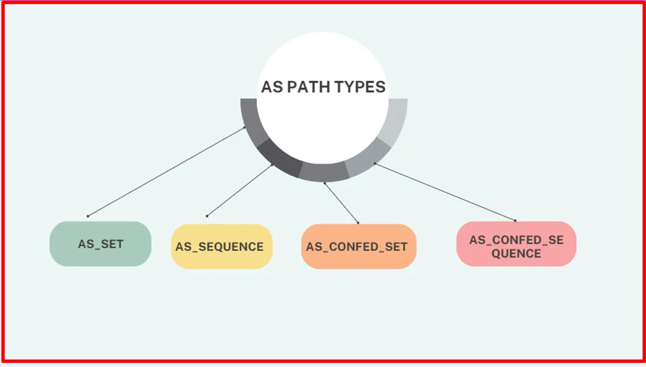
There are two types of copy actions that take place inside the AS Path of the aggregate route in BGP
- AS_SEQUENCE copy – this is when all component routes have same AS_PATH info and that is copied over as is (without { })
R3# show bgp ipv4 unicast 172.16.0.0
BGP routing table entry for 172.16.0.0/20, version 30
Paths: (1 available, best #1, table default)
Not advertised to any peer
Refresh Epoch 2
65200 65100, (aggregated by 65200 192.168.2.2)
10.23.1.2 from 10.23.1.2 (192.168.2.2)
Origin incomplete, metric 0, localpref 100, valid, external, best
rx pathid: 0, tx pathid: 0x0- AS_SET – this is when multiple component routes have differing AS_PATH, They are displayed inside { } counts as only one AS hop
R2# show bgp ipv4 unicast 192.168.0.0
BGP routing table entry for 192.168.0.0/16, version 28
Paths: (1 available, best #1, table default)
Advertised to update-groups:
1
Refresh Epoch 1
{65100,65300}, (aggregated by 65200 192.168.2.2)
0.0.0.0 from 0.0.0.0 (192.168.2.2)
Origin incomplete, localpref 100, weight 32768, valid, aggregated, local, best
rx pathid: 0, tx pathid: 0x0Configuring as-set for differing prefixes
R2# show running-config | section router bgp
router bgp 65200
bgp log-neighbor-changes
no bgp default ipv4-unicast
neighbor 10.12.1.1 remote-as 65100
neighbor 10.23.1.3 remote-as 65300
!
address-family ipv4
aggregate-address 192.168.0.0 255.255.0.0 as-set summary-only
aggregate-address 172.16.0.0 255.255.240.0 as-set summary-only
redistribute connected
neighbor 10.12.1.1 activate
neighbor 10.23.1.3 activateWe check 172.16.0.0/20 summary route again, now with the BGP path information copied into it . Notice that the AS_Path information now contains AS 65100.
R3# show bgp ipv4 unicast 172.16.0.0
BGP routing table entry for 172.16.0.0/20, version 30
Paths: (1 available, best #1, table default)
Not advertised to any peer
Refresh Epoch 2
65200 65100, (aggregated by 65200 192.168.2.2)
10.23.1.2 from 10.23.1.2 (192.168.2.2)
Origin incomplete, metric 0, localpref 100, valid, external, best
rx pathid: 0, tx pathid: 0x0R3# show bgp ipv4 unicast | begin Network
Network Next Hop Metric LocPrf Weight Path
*> 10.12.1.0/24 10.23.1.2 0 0 65200 ?
* 10.23.1.0/24 10.23.1.2 0 0 65200 ?
*> 0.0.0.0 0 32768 ?
*> 172.16.0.0/20 10.23.1.2 0 0 65200 65100 ?
*> 192.168.3.3/32 0.0.0.0 0 32768 ?Did you notice that the 192.168.0.0/16 summary route is no longer present in R3’s BGP table? The reason for this is on R2; R2 is summarizing all the loopback networks from R1 (AS 65100), R2 (AS 65200), and R3 (AS 65300). And now that R2 is copying the BGP AS_Path attributes of all the component network prefixes into the AS_SET information, the AS_Path for the 192.168.0.0/16 summary route contains AS 65300. When the aggregate is advertised to R3, R3 discards that prefix because it sees its own AS_Path in the advertisement and thinks that it is a loop.
R2# show bgp ipv4 unicast | begin Network
Network Next Hop Metric LocPrf Weight Path
* 10.12.1.0/24 10.12.1.1 0 0 65100 ?
*> 0.0.0.0 0 32768 ?
* 10.23.1.0/24 10.23.1.3 0 0 65300 ?
*> 0.0.0.0 0 32768 ?
*> 172.16.0.0/20 0.0.0.0 100 32768 65100 ?
s> 172.16.1.0/24 10.12.1.1 0 0 65100 ?
s> 172.16.2.0/24 10.12.1.1 0 0 65100 ?
s> 172.16.3.0/24 10.12.1.1 0 0 65100 ?
*> 192.168.0.0/16 0.0.0.0 100 32768 {65100,65300} ?
s> 192.168.1.1/32 10.12.1.1 0 0 65100 ?
s> 192.168.2.2/32 0.0.0.0 0 32768 ?
s> 192.168.3.3/32 10.23.1.3 0 0 65300 ?R2# show bgp ipv4 unicast 192.168.0.0
BGP routing table entry for 192.168.0.0/16, version 28
Paths: (1 available, best #1, table default)
Advertised to update-groups:
1
Refresh Epoch 1
{65100,65300}, (aggregated by 65200 192.168.2.2)
0.0.0.0 from 0.0.0.0 (192.168.2.2)
Origin incomplete, localpref 100, weight 32768, valid, aggregated, local, best
rx pathid: 0, tx pathid: 0x0R1 does not install the 192.168.0.0/16 summary route for the same reason that R3 does not install the 192.168.0.0/16 summary route. R1 thinks that the advertisement is a loop because it detects AS 65100 in AS_Path. You can confirm this by examining R1’s BGP table
R1# show bgp ipv4 unicast | begin Network
Network Next Hop Metric LocPrf Weight Path
* 10.12.1.0/24 10.12.1.2 0 0 65200 ?
*> 0.0.0.0 0 32768 ?
*> 10.23.1.0/24 10.12.1.2 0 0 65200 ?
*> 172.16.1.0/24 0.0.0.0 0 32768 ?
*> 172.16.2.0/24 0.0.0.0 0 32768 ?
*> 172.16.3.0/24 0.0.0.0 0 32768 ?
*> 192.168.1.1/32 0.0.0.0 0 32768 ?Solution here would be not to use as-set command
IPv6 Summarization
The same process for summarizing or aggregating IPv4 prefixes occurs with IPv6 prefixes, and the format is identical except that the configuration is placed under the IPv6 address family using the command aggregate-address prefix/prefix-length [summary-only] [as-set]

Summarization of the IPv6 loopback addresses (2001:db8:::1/128, 2001:db8:::2/128, and 2001:db8::3/128) and R1/R3’s stub networks (2001:db8:0:1::/64 and 2001:db8:0:3/64) is fairly simple as they all fall into the base IPv6 summary range 2001:db8:0:0::/64
The fourth hextet, beginning with a decimal value of 1, 2, or 3, would consume only 2 bits; the range could be summarized easily into the 2001:db8:0:0::/62 (or 2001:db8::/62) network range.
R2# show running-config | section router bgprouter bgp 65200
bgp router-id 192.168.2.2
bgp log-neighbor-changes
neighbor 2001:DB8:0:12::1 remote-as 65100
neighbor 2001:DB8:0:23::3 remote-as 65300
!
address-family ipv4
no neighbor 2001:DB8:0:12::1 activate
no neighbor 2001:DB8:0:23::3 activate
!
address-family ipv6
network 2001:DB8::2/128
network 2001:DB8:0:12::/64
network 2001:DB8:0:23::/64
aggregate-address 2001:DB8::/58 summary-only
neighbor 2001:DB8:0:12::1 activate
neighbor 2001:DB8:0:23::3 activateshows the BGP tables on R1 and R3. Notice that all the smaller component routes are summarized and suppressed into the 2001:db8::/58 summary route, as expected.
R3# show bgp ipv6 unicast | b Network
Network Next Hop Metric LocPrf Weight Path
*> 2001:DB8::/58 2001:DB8:0:23::2 0 0 65200 i
*> 2001:DB8::3/128 :: 0 32768 i
*> 2001:DB8:0:3::/64 :: 0 32768 i
*> 2001:DB8:0:23::/64 :: 0 32768 iR1# show bgp ipv6 unicast | b Network
Network Next Hop Metric LocPrf Weight Path
*> 2001:DB8::/58 2001:DB8:0:12::2 0 0 65200 i
*> 2001:DB8::1/128 :: 0 32768 ?
*> 2001:DB8:0:1::/64 :: 0 32768 ?
*> 2001:DB8:0:12::/64 :: 0 32768 ?BGP Route Filtering and Manipulation
Controlling what we learn and advertise can give us control and security, simply relying on peer to be able to install any prefix into our routing domain is not a good idea
IOS XE provides four methods of filtering routes inbound or outbound for a specific BGP peer. Each of these methods can be used individually, or they can be used simultaneously with other methods:
There are multiple ways of filtering or allowing prefixes from BGP neighbors
- Route maps
- Filter List
- AS_Path ACL filtering
- Prefix List or
- Distribute List
A BGP neighbor cannot use a distribute list (ACL) and prefix list at the same time in the same direction (inbound or outbound).
If all are applied together on a BGP neighbor, following are the order of operation for both inbound and outbound
RFAP|D
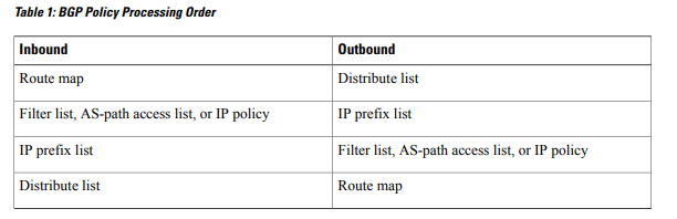
Filtering on below Loc-RIB
R1# show bgp ipv4 unicast | begin Network
Network Next Hop Metric LocPrf Weight Path
*> 10.3.3.0/24 10.12.1.2 33 0 65200 65300 3003 ?
* 10.12.1.0/24 10.12.1.2 22 0 65200 ?
*> 0.0.0.0 0 32768 ?
*> 10.23.1.0/24 10.12.1.2 333 0 65200 ?
*> 100.64.2.0/25 10.12.1.2 22 0 65200 ?
*> 100.64.2.192/26 10.12.1.2 22 0 65200 ?
*> 100.64.3.0/25 10.12.1.2 22 0 65200 65300 300 ?
*> 192.168.1.1/32 0.0.0.0 0 32768 ?
*> 192.168.2.2/32 10.12.1.2 22 0 65200 ?
*> 192.168.3.3/32 10.12.1.2 3333 0 65200 65300 ?Distribute List Filtering
Distribute lists has the allow or whitelisting effect
Distribute list uses standard or extended ACLs
Remember that extended ACLs for BGP use the source fields to match the network portion and the destination fields to match against the network mask
The first entry allows any network that starts in the 192.168.0.0 to 192.168.255.255 range with a network length of only /32. The second entry allows networks that contain the 100.64.x.0 pattern with prefix length /25 to demonstrate the wildcard abilities of an extended ACL with BGP
R1
ip access-list extended ACL-ALLOW
permit ip 192.168.0.0 0.0.255.255 host 255.255.255.255
permit ip 100.64.0.0 0.0.255.0 host 255.255.255.128
!
router bgp 65100
neighbor 10.12.1.2 remote-as 65200
address-family ipv4
neighbor 10.12.1.2 distribute-list ACL-ALLOW inThe 100.64.2.192/26 network is rejected because the prefix length or mask does not match the second ACL-ALLOW entry while two of the networks in the 100.64.x.0 pattern (100.64.2.0/25 and 100.64.3.0/25) are accepted
R1# show bgp ipv4 unicast | begin Network
Network Next Hop Metric LocPrf Weight Path
*> 10.12.1.0/24 0.0.0.0 0 32768 ?
*> 100.64.2.0/25 10.12.1.2 22 0 65200 ?
*> 100.64.3.0/25 10.12.1.2 22 0 65200 65300 300 ?
*> 192.168.1.1/32 0.0.0.0 0 32768 ?
*> 192.168.2.2/32 10.12.1.2 22 0 65200 ?
*> 192.168.3.3/32 10.12.1.2 3333 0 65200 65300 ?Prefix List Filtering
Prefix list also has the whitelisting effect same as distribute list but instead of ACL uses prefix list
A prefix list called RFC1918 is created to permit only prefixes in the RFC1918 address space.
R1# configure terminal
Enter configuration commands, one per line. End with CNTL/Z.
R1(config)# ip prefix-list RFC1918 seq 10 permit 10.0.0.0/8 le 32
R1(config)# ip prefix-list RFC1918 seq 20 permit 172.16.0.0/12 le 32
R1(config)# ip prefix-list RFC1918 seq 30 permit 192.168.0.0/16 le 32
R1(config)# router bgp 65100
R1(config-router)# address-family ipv4 unicast
R1(config-router-af)# neighbor 10.12.1.2 prefix-list RFC1918 inNotice that the 100.64.2.0/25, 100.64.2.192/26, and 100.64.3.0/25 routes are filtered as they do not fall within the prefix list matching criteria.
R1# show bgp ipv4 unicast | begin Network
Network Next Hop Metric LocPrf Weight Path
*> 10.3.3.0/24 10.12.1.2 33 0 65200 65300 3003 ?
* 10.12.1.0/24 10.12.1.2 22 0 65200 ?
*> 0.0.0.0 0 32768 ?
*> 10.23.1.0/24 10.12.1.2 333 0 65200 ?
*> 192.168.1.1/32 0.0.0.0 0 32768 ?
*> 192.168.2.2/32 10.12.1.2 22 0 65200 ?
*> 192.168.3.3/32 10.12.1.2 3333 0 65200 65300 ?AS_Path Filtering
There may be times when conditionally matching prefixes may be too complicated, and identifying all routes from a specific organization is preferred, in such cases we can use AS PATH ACL to filer out routes using regex against AS PATH PA
| Modifier | Description |
|---|---|
| _ (underscore) | Matches a space |
| ^ (caret) | Indicates the start of the string |
| $ (dollar sign) | Indicates the end of the string |
| [] (brackets) | Matches a single character or nesting within a range |
| – (hyphen) | Indicates a range of numbers in brackets |
| [^] (caret in brackets) | Excludes the characters listed in brackets |
| () (parentheses) | Used for nesting of search patterns |
| | (pipe) | Provides or functionality to the query |
| . (period) | Matches a single character, including a space |
| * (asterisk) | Matches zero or more characters or patterns |
| + (plus sign) | Matches one or more instances of the character or pattern |
| ? (question mark) | Matches one or no instances of the character or pattern |
BGP table can be parsed with regex using the command show bgp afi safi regexp regex-pattern
so we can test locally before applying it to neighbor
R2# show bgp ipv4 unicast
! Output omitted for brevity
Network Next Hop Metric LocPrf Weight Path
*> 172.16.0.0/24 172.32.23.3 0 0 300 80 90 21003 2100 i
*> 172.16.4.0/23 172.32.23.3 0 0 300 878 1190 1100 1010 i
*> 172.16.16.0/22 172.32.23.3 0 0 300 779 21234 45 i
*> 172.16.99.0/24 172.32.23.3 0 0 300 145 40 i
*> 172.16.129.0/24 172.32.23.3 0 0 300 10010 300 1010 40 50 i
*> 192.168.0.0/16 172.16.12.1 0 0 100 80 90 21003 2100 i
*> 192.168.4.0/23 172.16.12.1 0 0 100 878 1190 1100 1010 i
*> 192.168.16.0/22 172.16.12.1 0 0 100 779 21234 45 i
*> 192.168.99.0/24 172.16.12.1 0 0 100 145 40 i
*> 192.168.129.0/24 172.16.12.1 0 0 100 10010 300 1010 40 50 iAS_Path for the 172.16.129.0/24 route includes AS 300 twice non-consecutively for a specific purpose. This would not be seen in real life because it indicates a routing loop.
_ (Underscore) – Matches a space – AS anywhere regardless of AS position as origin or transit or last AS
Display prefixes coming via AS 100 (regardless of AS 100 position as last or transit or origin AS)
R2# show bgp ipv4 unicast regex 100
! Output omitted for brevity
Network Next Hop Metric LocPrf Weight Path
*> 172.16.0.0/24 172.32.23.3 0 0 300 80 90 21003 2100 i
*> 172.16.4.0/23 172.32.23.3 0 0 300 878 1190 1100 1010 i
*> 172.16.129.0/24 172.32.23.3 0 0 300 10010 300 1010 40 50 i
*> 192.168.0.0/16 172.16.12.1 0 0 100 80 90 21003 2100 i
*> 192.168.4.0/23 172.16.12.1 0 0 100 878 1190 1100 1010 i
*> 192.168.16.0/22 172.16.12.1 0 0 100 779 21234 45 i
*> 192.168.99.0/24 172.16.12.1 0 0 100 145 40 i
*> 192.168.129.0/24 172.16.12.1 0 0 100 10010 300 1010 40 50 iabove did not work so lets try again, The regex query includes the following unwanted ASN: 10010.
R2# show bgp ipv4 unicast regexp _100
! Output omitted for brevity
Network Next Hop Metric LocPrf Weight Path
*> 172.16.129.0/24 172.32.23.3 0 0 300 10010 300 1010 40 50 i <<<
*> 192.168.0.0/16 172.16.12.1 0 0 100 80 90 21003 2100 i
*> 192.168.4.0/23 172.16.12.1 0 0 100 878 1190 1100 1010 i
*> 192.168.16.0/22 172.16.12.1 0 0 100 779 21234 45 i
*> 192.168.99.0/24 172.16.12.1 0 0 100 145 40 i
*> 192.168.129.0/24 172.16.12.1 0 0 100 10010 300 1010 40 iStill did not work, lets try _ before and after _
R2# show bgp ipv4 unicast regexp _100_
! Output omitted for brevity
Network Next Hop Metric LocPrf Weight Path
*> 192.168.0.0/16 172.16.12.1 0 0 100 80 90 21003 2100 i
*> 192.168.4.0/23 172.16.12.1 0 0 100 878 1190 1100 1010 i
*> 192.168.16.0/22 172.16.12.1 0 0 100 779 21234 45 i
*> 192.168.99.0/24 172.16.12.1 0 0 100 145 40 i
*> 192.168.129.0/24 172.16.12.1 0 0 100 10010 300 1010 40 50 iThis one worked because it satisfies the condition of AS 100 existing as either last, or transit, or as origin
^ (Caret) – start of the string – Last AS
Display only prefixes that were advertised from directly connected AS 300 or last AS 300.
R2# show bgp ipv4 unicast regexp ^300_
! Output omitted for brevity
Network Next Hop Metric LocPrf Weight Path
*> 172.16.0.0/24 172.32.23.3 0 0 300 80 90 21003 2100 i
*> 172.16.4.0/23 172.32.23.3 0 0 300 878 1190 1100 1010 i
*> 172.16.16.0/22 172.32.23.3 0 0 300 779 21234 45 i
*> 172.16.99.0/24 172.32.23.3 0 0 300 145 40 i
*> 172.16.129.0/24 172.32.23.3 0 0 300 10010 300 1010 40 50 i$ (Dollar Sign) – End of the string
Display only prefixes that originated in AS 40
R2# show bgp ipv4 unicast regexp _40$
! Output omitted for brevity
Network Next Hop Metric LocPrf Weight Path
*> 172.16.99.0/24 172.32.23.3 0 0 300 145 40 i
*> 192.168.99.0/24 172.16.12.1 0 100 0 100 145 40 i[ ] (Brackets) – Matches a single character – used for common characters in same place
Display only prefixes with an AS that contains 11 or 14 in it
R2# show bgp ipv4 unicast regexp _1[14]_
! Output omitted for brevity
Network Next Hop Metric LocPrf Weight Path
*> 172.16.4.0/23 172.32.23.3 0 0 300 878 14 1100 1010 i
*> 172.16.99.0/24 172.32.23.3 0 0 300 14 40 i
*> 192.168.4.0/23 172.16.12.1 0 0 100 878 1190 14 1010 i
*> 192.168.99.0/24 172.16.12.1 0 0 100 14 40 i– Hyphen (range matching to reduce the regex size)
Display only prefixes with the last two digits of the AS (40, 50, 60, 70, or 80).
R2# show bgp ipv4 unicast regexp [4-8]0_
! Output omitted for brevity
Network Next Hop Metric LocPrf Weight Path
*> 172.16.0.0/24 172.32.23.3 0 0 300 80 90 21003 2100 i
*> 172.16.99.0/24 172.32.23.3 0 0 300 145 40 i
*> 172.16.129.0/24 172.32.23.3 0 0 300 10010 300 1010 40 50 i
*> 192.168.0.0/16 172.16.12.1 0 0 100 80 90 21003 2100 i
*> 192.168.99.0/24 172.16.12.1 0 0 100 145 40 i
*> 192.168.129.0/24 172.16.12.1 0 0 100 10010 300 1010 40 50 i[^] (Caret in Brackets) – Excludes the character
Display only prefixes where the second AS from AS 100 or AS 300 does not start with 3, 4, 5, 6, 7, or 8
The first component of the regex query restricts the AS to start with 100 or 300 with the regex query ^[13]00_
and the second component filters out AS starting with 3 through 8 with the regex filter _[^3-8].
R2# show bgp ipv4 unicast regexp ^[13]00_[^3-8]
! Output omitted for brevity
Network Next Hop Metric LocPrf Weight Path
*> 172.16.99.0/24 172.32.23.3 0 0 300 145 40 i
*> 172.16.129.0/24 172.32.23.3 0 0 300 10010 300 1010 40 50 i
*> 192.168.99.0/24 172.16.12.1 0 0 100 145 40 i
*> 192.168.129.0/24 172.16.12.1 0 0 100 10010 300 1010 40 50 i^[3][0-9]+_[3][0-9]+_[3][0-9]+_
frr.routeviews.org> show bgp ipv4 unicast regexp ^[3][0-9]+_[3][0-9]+_[3][0-9]+_
BGP table version is 264529750, local router ID is 128.223.51.23, vrf id 0
Default local pref 100, local AS 65123
Status codes: s suppressed, d damped, h history, u unsorted, * valid, > best, = multipath,
i internal, r RIB-failure, S Stale, R Removed
Nexthop codes: @NNN nexthop's vrf id, < announce-nh-self
Origin codes: i - IGP, e - EGP, ? - incomplete
RPKI validation codes: V valid, I invalid, N Not found
Network Next Hop Metric LocPrf Weight Path
V*> 1.6.9.0/24 128.223.253.9 0 3582 3701 3356 6453 4755 9583 i
V*= 128.223.253.10 0 3582 3701 3356 6453 4755 9583 i
V*> 1.6.11.0/24 128.223.253.9 0 3582 3701 3356 6453 4755 9583 i
V*= 128.223.253.10 0 3582 3701 3356 6453 4755 9583 i
V*> 1.6.12.0/22 128.223.253.9 0 3582 3701 3356 6453 4755 9583 i
V*= 128.223.253.10 0 3582 3701 3356 6453 4755 9583 i
V*> 1.6.13.0/24 128.223.253.9 0 3582 3701 3356 6453 4755 9583 i
V*= 128.223.253.10 0 3582 3701 3356 6453 4755 9583 i
V*> 1.6.17.0/24 128.223.253.9 0 3582 3701 3356 2914 9583 i
V*= 128.223.253.10 0 3582 3701 3356 2914 9583 i
V*> 1.6.19.0/24 128.223.253.9 0 3582 3701 3356 6453 4755 9583 i
V*= 128.223.253.10 0 3582 3701 3356 6453 4755 9583 i
V*> 1.6.32.0/22 128.223.253.9 0 3582 3701 3356 6453 4755 9583 i
V*= 128.223.253.10 0 3582 3701 3356 6453 4755 9583 i
V*> 1.6.40.0/22 128.223.253.9 0 3582 3701 3356 6453 4755 9583 i
V*= 128.223.253.10 0 3582 3701 3356 6453 4755 9583 i
V*> 1.6.48.0/22 128.223.253.9 0 3582 3701 3356 6453 4755 9583 i
V*= 128.223.253.10 0 3582 3701 3356 6453 4755 9583 i
V*> 1.6.56.0/22 128.223.253.9 0 3582 3701 3356 6453 4755 9583 i
V*= 128.223.253.10 0 3582 3701 3356 6453 4755 9583 i
V*> 1.6.59.0/24 128.223.253.9 0 3582 3701 3356 6453 4755 9583 i
V*= 128.223.253.10 0 3582 3701 3356 6453 4755 9583 i
V*> 1.6.67.0/24 128.223.253.9 0 3582 3701 3356 6453 4755 9583 i
V*= 128.223.253.10 0 3582 3701 3356 6453 4755 9583 i
V*> 1.6.69.0/24 128.223.253.9 0 3582 3701 3356 6453 4755 9583 i
V*= 128.223.253.10 0 3582 3701 3356 6453 4755 9583 i( ) and | (Parentheses and Pipe) – for ‘or’ functionality
AS_Path ends with AS 40 or 45 in it
R2# show bgp ipv4 unicast regexp _4(5|0)$
! Output omitted for brevity
Network Next Hop Metric LocPrf Weight Path
*> 172.16.16.0/22 172.32.23.3 0 0 300 779 21234 45 i
*> 172.16.99.0/24 172.32.23.3 0 0 300 145 40 i
*> 192.168.16.0/22 172.16.12.1 0 0 100 779 21234 45 i
*> 192.168.99.0/24 172.16.12.1 0 0 100 145 40 i. (Period) – single character, including a space
Display only prefixes originating from single digit AS
R2# show bgp ipv4 unicast regexp _.$
! Output omitted for brevity
Network Next Hop Metric LocPrf Weight Path
*> 172.16.16.0/22 172.32.23.3 0 0 300 779 21234 4 i
*> 172.16.99.0/24 172.32.23.3 0 0 300 145 4 i
*> 172.16.129.0/24 172.32.23.3 0 0 300 10010 300 1010 40 5 i
*> 192.168.16.0/22 172.16.12.1 0 0 100 779 21234 4 i
*> 192.168.99.0/24 172.16.12.1 0 0 100 145 4 i
*> 192.168.129.0/24 172.16.12.1 0 0 100 10010 300 1010 40 5 ito match prefixes originating from 2 digit AS
show bgp ipv4 unicast regexp _[0-9][0-9]?$
or
show bgp ipv4 unicast regexp _..$+ (Plus Sign) – one or more instances of the character or pattern.
Display only prefixes that contain “at least one 10” in the AS path but where the pattern 100 should not be used in matching
R2# show bgp ipv4 unicast regexp (10)+[^(100)]
! Output omitted for brevity
Network Next Hop Metric LocPrf Weight Path
*> 172.16.4.0/23 172.32.23.3 0 0 300 878 1190 1100 1010 i
*> 172.16.129.0/24 172.32.23.3 0 0 300 10010 300 1010 40 50 i
*> 192.168.4.0/23 172.16.12.1 0 0 100 878 1190 1100 1010 i
*> 192.168.129.0/24 172.16.12.1 0 0 100 10010 300 1010 40 50 i
(133388)+
frr.routeviews.org> show bgp ipv4 unicast regexp (133388)+
BGP table version is 264877433, local router ID is 128.223.51.23, vrf id 0
Default local pref 100, local AS 65123
Status codes: s suppressed, d damped, h history, u unsorted, * valid, > best, = multipath,
i internal, r RIB-failure, S Stale, R Removed
Nexthop codes: @NNN nexthop's vrf id, < announce-nh-self
Origin codes: i - IGP, e - EGP, ? - incomplete
RPKI validation codes: V valid, I invalid, N Not found
Network Next Hop Metric LocPrf Weight Path
V*> 1.7.24.0/24 128.223.253.9 0 3582 3701 11164 4637 64049 55836 9583 133388 133388 133388 133388 i
V*= 128.223.253.10 0 3582 3701 11164 4637 64049 55836 9583 133388 133388 133388 133388 i
N*> 162.44.150.0/23 128.223.253.9 0 3582 3701 174 55410 133388 i
N*= 128.223.253.10 0 3582 3701 174 55410 133388 i
N*> 162.44.150.0/24 128.223.253.10 0 3582 3701 11164 4637 64049 55836 55410 133388 i
N*= 128.223.253.9 0 3582 3701 11164 4637 64049 55836 55410 133388 i
N*> 162.44.151.0/24 128.223.253.10 0 3582 3701 11164 4637 64049 55836 55410 133388 i
N*= 128.223.253.9 0 3582 3701 11164 4637 64049 55836 55410 133388 i
N*> 162.44.250.0/24 128.223.253.10 0 3582 3701 11164 4637 64049 55836 55410 133388 i
N*= 128.223.253.9 0 3582 3701 11164 4637 64049 55836 55410 133388 i? (Question Mark) – one or no instances of the character or pattern.
Display only prefixes from the neighboring AS or its directly connected AS (that is, restrict to two ASs away).
You must use the Ctrl+V escape sequence before entering the ?.
R1# show bgp ipv4 unicast regexp ^[0-9]+ ([0-9]+)?$
! Output omitted for brevity
Network Next Hop Metric LocPrf Weight Path
*> 172.16.99.0/24 172.32.23.3 0 0 300 40 i
*> 192.168.99.0/24 172.16.12.1 0 100 0 100 40 i* (Asterisk) – zero or more characters or patterns.
Display all prefixes from any AS
decoding .*
. means any character including symbols, alphabets and numbers and * means 0 or more
combining the two means any character 0 or more times which will include content that is null empty (zero) or more (anything)
This may seem like a useless task, but it might be a valid requirement when using AS_Path access lists, which are explained in the following section.
R1# show bgp ipv4 unicast regexp .*
! Output omitted for brevity
Network Next Hop Metric LocPrf Weight Path
*> 172.16.0.0/24 172.32.23.3 0 0 300 80 90 21003 2100 i
*> 172.16.4.0/23 172.32.23.3 0 0 300 1080 1090 1100 1110 i
*> 172.16.16.0/22 172.32.23.3 0 0 300 11234 21234 31234 i
*> 172.16.99.0/24 172.32.23.3 0 0 300 40 i
*> 172.16.129.0/24 172.32.23.3 0 0 300 10010 300 30010 30050 i
*> 192.168.0.0/16 172.16.12.1 0 100 0 100 80 90 21003 2100 i
*> 192.168.4.0/23 172.16.12.1 0 100 0 100 1080 1090 1100 1110 i
*> 192.168.16.0/22 172.16.12.1 0 100 0 100 11234 21234 31234 i
*> 192.168.99.0/24 172.16.12.1 0 100 0 100 40 i
*> 192.168.129.0/24 172.16.12.1 0 100 0 100 10010 300 30010 30050 iDifference to remember between + * and ?
+ is 1 or more
while ? and * are more similar to one another
? is 0 or one
* is 0 or more / multiple
AS_Path ACLs
Selecting routes from a BGP neighbor by using AS_Path requires the definition of an AS_Path ACL
The AS_Path ACL processing is performed in a sequential top-down order just like normal ACL,
and the first qualifying match processes against the appropriate permit or deny action.
An implicit deny exists at the end of the AS path ACL.
R2# show bgp ipv4 unicast neighbors 10.12.1.1 advertised-routes | begin Network
Network Next Hop Metric LocPrf Weight Path
*> 10.3.3.0/24 10.23.1.3 33 0 65300 3003 ?
*> 10.12.1.0/24 0.0.0.0 0 32768 ?
*> 10.23.1.0/24 0.0.0.0 0 32768 ?
*> 100.64.2.0/25 0.0.0.0 0 32768 ?
*> 100.64.2.192/26 0.0.0.0 0 32768 ?
*> 100.64.3.0/25 10.23.1.3 3 0 65300 300 ?
*> 192.168.2.2/32 0.0.0.0 0 32768 ?
*> 192.168.3.3/32 10.23.1.3 333 0 65300 ?
Total number of prefixes 8R2 is advertising the routes learned from R3 (AS 65300) to R1, using an AS_Path ACL to restrict the advertisement of only AS 65200 routes is recommended.
R2 using an AS_Path ACL to restrict traffic to only “locally originated” traffic using the regex pattern ^$
R2
ip as-path access-list 1 permit ^$
!
router bgp 65200
address-family ipv4 unicast
neighbor 10.12.1.1 filter-list 1 out
neighbor 10.23.1.3 filter-list 1 outR2# show bgp ipv4 unicast neighbors 10.12.1.1 advertised-routes | begin Network
Network Next Hop Metric LocPrf Weight Path
*> 10.12.1.0/24 0.0.0.0 0 32768 ?
*> 10.23.1.0/24 0.0.0.0 0 32768 ?
*> 100.64.2.0/25 0.0.0.0 0 32768 ?
*> 100.64.2.192/26 0.0.0.0 0 32768 ?
*> 192.168.2.2/32 0.0.0.0 0 32768 ?
Total number of prefixes 5Route Maps
Route maps provide more functionality than pure filtering; they provide a method to manipulate BGP path attributes, Route maps are applied on a BGP neighbor basis for routes that are advertised or received. A different route map can be used for each direction
R1# show bgp ipv4 unicast | begin Network
Network Next Hop Metric LocPrf Weight Path
*> 10.1.1.0/24 0.0.0.0 0 32768 ?
*> 10.3.3.0/24 10.12.1.2 33 0 65200 65300 3003 ?
* 10.12.1.0/24 10.12.1.2 22 0 65200 ?
*> 0.0.0.0 0 32768 ?
*> 10.23.1.0/24 10.12.1.2 333 0 65200 ?
*> 100.64.2.0/25 10.12.1.2 22 0 65200 ?
*> 100.64.2.192/26 10.12.1.2 22 0 65200 ?
*> 100.64.3.0/25 10.12.1.2 22 0 65200 65300 300 ?
*> 192.168.1.1/32 0.0.0.0 0 32768 ?
*> 192.168.2.2/32 10.12.1.2 22 0 65200 ?
*> 192.168.3.3/32 10.12.1.2 3333 0 65200 65300 ?Step 1. Deny any routes that are in the 192.168.0.0/16 network by using a prefix list.
Step 2. Match any routes originating from AS 65200 that are within the 100.64.0.0/10 network range and set the BGP local preference to 222.
Step 3. Match any routes originating from AS 65200 that did not match step 2 and set the BGP weight to 65200.
Step 4. Permit all other routes to process.
R1
ip prefix-list FIRST-RFC1918 permit 192.168.0.0/16 le 32
ip as-path access-list 1 permit _65200$
ip prefix-list SECOND-CGNAT permit 100.64.0.0/10 le 32
!
route-map AS65200IN deny 10
description Deny any RFC1918 networks via Prefix List Matching
match ip address prefix-list FIRST-RFC1918
route-map AS65200IN permit 20
description Change local preference for AS65200 originate route in 100.64.x.x/10
match ip address prefix-list SECOND-CGNAT
match as-path 1
set local-preference 222
route-map AS65200IN permit 30
description Change the weight for AS65200 originate routes
match as-path 1
set weight 65200
route-map AS65200IN permit 40
description Permit all other routes un-modified
!
router bgp 65100
neighbor 10.12.1.2 remote-as 65200
address-family ipv4 unicast
neighbor 10.12.1.2 route-map AS65200IN indisplays R1’s BGP routing table, which shows that the following actions occurred:
The 192.168.2.2/32 and 192.168.3.3/32 routes were discarded. The 192.168.1.1/32 route is a locally generated route.
The 100.64.2.0/25 and 100.64.2.192/26 networks had the local preference modified to 222 because they originate from AS 65200 and are within the 100.64.0.0/10 network range.
The 10.12.1.0/24 and 10.23.1.0/24 routes from R2 have been assigned the locally significant BGP attribute weight 65,200.
All other routes were received and not modified.
R1# show bgp ipv4 unicast | b Network
Network Next Hop Metric LocPrf Weight Path
*> 10.1.1.0/24 0.0.0.0 0 32768 ?
*> 10.3.3.0/24 10.12.1.2 33 0 65200 65300 3003 ?
r> 10.12.1.0/24 10.12.1.2 22 65200 65200 ?
r 0.0.0.0 0 32768 ?
*> 10.23.1.0/24 10.12.1.2 333 65200 65200 ?
*> 100.64.2.0/25 10.12.1.2 22 222 0 65200 ?
*> 100.64.2.192/26 10.12.1.2 22 222 0 65200 ?
*> 100.64.3.0/25 10.12.1.2 22 0 65200 65300 300 ?
*> 192.168.1.1/32 0.0.0.0 0 32768 ?clear ip bgp
A hard reset tears down and rebuilds the peering sessions and rebuilds the BGP routing tables
Hard neighborship reset
clear ip bgp *
clear ip bgp neighbor-address
clear ip bgp peer-group group-nameSoft Reconfiguration
A soft reconfiguration uses stored prefix cache without tearing down existing peering sessions at the cost of additional memory for storing the updates, Soft reconfiguration is not on by default and needs to be configured for inbound on neighbors at least, Soft reconfiguration can be configured for inbound or outbound sessions.
neighbor soft-reconfiguration inbound
clear ip bgp 10.100.0.1 soft inRoute Refresh
route refresh capability allows the local router to reset inbound routing tables dynamically by sending route refresh requests given the neighbor not just supports it but also negotiated route refresh capability
clear ip bgp 172.16.10.2 inBGP Communities
BGP communities are optional attributes that let routers attach tags to routes so other routers can apply routing policies (like prefer, filter, or modify routes) without inspecting prefixes in detail.
A BGP community is an optional transitive BGP attribute that can traverse from AS to AS.
A BGP community is a 32-bit number that can be included with a route
A BGP community can be displayed as a full 32-bit number (0 through 4,294,967,295) or as two 16-bit numbers (0 through 65535):(0 through 65535), commonly referred to as new format.
By convention, with private BGP communities, the first 16 bits represent the AS of the community and the second 16 bits represent a pattern defined by the originating AS
Format
- 32-bit value
- Usually written as:
ASN:VALUE(e.g.65000:100)
Well-known standard communities
These have predefined meanings:
no-export→ do not advertise to eBGP peersno-advertise→ do not advertise to any peerinternet→ advertise everywhere
Extended BGP communities:
Format
- 64-bit value
- Structured into sub-fields, not just a single number
- Encoded as Type + Value
Examples (vendor CLI format varies):
rt 65000:100(Route Target)soo 65000:200(Site of Origin)
What they’re used for
Extended communities were introduced to solve the limitations of standard communities, especially for:
- MPLS VPNs
- L3VPN / L2VPN
- Advanced traffic engineering
- EVPN
- Policy precision across large networks
Common types of extended communities
- Route Target (RT) – controls VPN route import/export
- Route Distinguisher-related signaling
- Site of Origin (SoO) – prevents routing loops
- Bandwidth, color, QoS, and traffic engineering attributes
Advantages
Much more expressive
Globally meaningful when standardized
Safer for large multi-AS or service provider networks
Designed for scalable VPN and EVPN environments
Enabling BGP Community Support
IOS XE routers do not advertise BGP communities to peers by default. Communities are enabled on a neighbor-by-neighbor basis
neighbor ip-address send-community [standard | extended | both]
! If a keyword is not specified, standard communities are sent by defaultIOS XE nodes can display communities in new format, and they are easier to read if you use the global configuration command
ip bgp-community new-format! DECIMAL FORMAT
R3# show bgp 192.168.1.1
! Output omitted for brevity
BGP routing table entry for 192.168.1.1/32, version 6
Community: 6553602 6577023! New-Format
R3# show bgp 192.168.1.1
! Output omitted for brevity
BGP routing table entry for 192.168.1.1/32, version 6
Community: 100:2 100:23423Well-Known Communities
RFC 1997 defined a set of global communities (known as well-known communities) that use the community range 4,294,901,760 (0xFFFF0000) to 4,294,967,295 (0xFFFFFFFF).
All routers that are capable of sending/receiving BGP communities must implement well-known communities.
The following are the common well-known communities:
- Internet
- No_Advertise
- No_Export
- Local AS
The No_Advertise BGP Community
For the No_Advertise community (0xFFFFFF02 or 4,294,967,042), routes should not be advertised to any BGP peer. The No_Advertise BGP community can be advertised from an upstream BGP peer or locally with an inbound BGP policy.
In either method, the No_Advertise community is set in the BGP Loc-RIB table that affects outbound route advertisement. The No_Advertise community is set with the command set community no-advertise within a route map

R1 is advertising the 10.1.1.0/24 route to R2.
R2 sets the BGP No_Advertise community on the prefix on an inbound route map associated with R1.
R2 does not advertise the 10.1.1.0/24 route to R3
Notice that the route was “not advertised to any peer” and has the BGP community No_Advertise set.
R2# show bgp 10.1.1.0/24
! Output omitted for brevity
BGP routing table entry for 10.1.1.0/24, version 18
Paths: (1 available, best #1, table default, not advertised to any peer)
Not advertised to any peer
Refresh Epoch 1
100, (received & used)
10.1.12.1 from 10.1.12.1 (192.168.1.1)
Origin IGP, metric 0, localpref 100, valid, external, best
Community: no-advertiseYou can quickly see BGP routes that are set with the No_Advertise community by using the command show bgp afi safi community no-advertise
R2# show bgp ipv4 unicast community no-advertise
! Output omitted for brevity
Network Next Hop Metric LocPrf Weight Path
*> 10.1.1.0/24 10.1.12.1 0 0 100 iThe No_Export BGP Community
When a route is received with the No_Export community (0xFFFFFF01 or 4,294,967,041), the route is not advertised to any eBGP peer. If the router receiving the No_Export route is a confederation member, the route can be advertised to other sub-ASs in the confederation
The No_Export community is set with the command set community no-export within a route map.
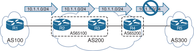
AS 200 is a BGP confederation composed of member AS 65100 and AS 65200
R1 is advertising the 10.1.1.0/24 route to R2, and R2 sets the No_Export community on an inbound route map associated with R1. R2 advertises the prefix to R3, and R3 advertises the prefix to R4. R4 does not advertise the prefix to R5 because it is an eBGP session
Notice that R4 display not advertised to EBGP peer.
R3# show bgp ipv4 unicast 10.1.1.0/24
BGP routing table entry for 10.1.1.0/24, version 6
Paths: (1 available, best #1, table default, not advertised to EBGP peer)
Advertised to update-groups:
3
Refresh Epoch 1
100, (Received from a RR-client), (received & used)
10.1.23.2 from 10.1.23.2 (192.168.2.2)
Origin IGP, metric 0, localpref 100, valid, confed-internal, best
Community: no-exportR4# show bgp ipv4 unicast 10.1.1.0/24
! Output omitted for brevity
BGP routing table entry for 10.1.1.0/24, version 4
Paths: (1 available, best #1, table default, not advertised to EBGP peer)
Not advertised to any peer
Refresh Epoch 1
(65100) 100, (received & used)
10.1.23.2 (metric 20) from 10.1.34.3 (192.168.3.3)
Origin IGP, metric 0, localpref 100, valid, confed-external, best
Community: no-exportYou can see all the BGP prefixes that contain the No_Export community by using the command show bgp afi safi community no-export
R4# show bgp ipv4 unicast community no-export | b Network
Network Next Hop Metric LocPrf Weight Path
*> 10.1.1.0/24 10.1.23.2 0 100 0 (65100) 100 iR2# show bgp ipv4 unicast community no-export | b Network
Network Next Hop Metric LocPrf Weight Path
*> 10.1.1.0/24 10.1.12.1 0 0 100 iThe Local AS (No_Export_SubConfed) BGP Community
With the No_Export_SubConfed community (0xFFFFFF03 or 4,294,967,043), known as the local AS community, a route is not advertised outside the local AS. The local AS community is set with the command set community local-as within a route map.
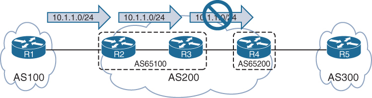
R2 sets the local AS community on an inbound route map associated with R1. R2 advertises the prefix to R3, but R3 does not advertise the prefix to R4 because the prefix contains the local AS community.
R3# show bgp ipv4 unicast 10.1.1.0/24
BGP routing table entry for 10.1.1.0/24, version 8
Paths: (1 available, best #1, table default, not advertised outside local AS)
Not advertised to any peer
Refresh Epoch 1
100, (Received from a RR-client), (received & used)
10.1.23.2 from 10.1.23.2 (192.168.2.2)
Origin IGP, metric 0, localpref 100, valid, confed-internal, best
Community: local-ASYou can see all the BGP prefixes that contain the local AS community by using the command show bgp afi safi community local-as
R3# show bgp ipv4 unicast community local-AS | b Network
Network Next Hop Metric LocPrf Weight Path
*>i 10.1.1.0/24 10.1.23.2 0 100 0 100 iR2# show bgp ipv4 unicast community local-AS | b Network
Network Next Hop Metric LocPrf Weight Path
*> 10.1.1.0/24 10.1.12.1 0 0 100 iConditionally Matching BGP Communities
R1# show bgp ipv4 unicast | begin Network
Network Next Hop Metric LocPrf Weight Path
*> 10.1.1.0/24 0.0.0.0 0 32768 ?
* 10.12.1.0/24 10.12.1.2 22 0 65200 ?
*> 0.0.0.0 0 32768 ?
*> 10.23.1.0/24 10.12.1.2 333 0 65200 ?
*> 192.168.1.1/32 0.0.0.0 0 32768 ?
*> 192.168.2.2/32 10.12.1.2 22 0 65200 ?
*> 192.168.3.3/32 10.12.1.2 3333 0 65200 65300 ?show bgp afi safi detail and then manually select a route with a specific community. However, if the BGP community is known, you can display all the routes by using the command show bgp afi safi community community, as shown in the following snippet:
R1# show bgp ipv4 unicast community 333:333 | begin Network
Network Next Hop Metric LocPrf Weight Path
*> 10.23.1.0/24 10.12.1.2 333 0 65200 ?10.23.1.0/24 route and all the BGP path attributes. Notice that two BGP communities (333:333 and 65300:333) are added to the path.
R1# show ip bgp 10.23.1.0/24
BGP routing table entry for 10.23.1.0/24, version 15
Paths: (1 available, best #1, table default)
Not advertised to any peer
Refresh Epoch 3
65200
10.12.1.2 from 10.12.1.2 (192.168.2.2)
Origin incomplete, metric 333, localpref 100, valid, external, best
Community: 333:333 65300:333 <<<
rx pathid: 0, tx pathid: 0x0Conditionally matching requires the creation of a community list that shares a structure similar to that of an ACL
Standard community lists are numbered 1 to 99 and match either well-known communities or a private community number (as-number:16-bit-number)
Expanded community lists are numbered 100 to 500 and use regex patterns.
When multiple communities are on the same ip community list statement, all communities for that statement must exist in that route’s community list. If only one out of many communities is required, you can use multiple ip community list statements.
ip community 1 permit 11:100 11:200BGP community list that matches on the community 333:333
The BGP community list is then used in the first sequence of route map COMMUNITY-CHECK, which denies any routes with that community.
The second route map sequence allows for all other BGP routes and sets the BGP weight (locally significant) to 111. The route map is then applied on routes advertised from R2 toward R1.
R1
ip community-list 100 permit 333:333
!
route-map COMMUNITY-CHECK deny 10
description Block Routes with Community 333:333 in it
match community 100
route-map COMMUNITY-CHECK permit 20
description Allow routes with either community in it
set weight 111
!
router bgp 65100
neighbor 10.12.1.2 remote-as 65200
address-family ipv4 unicast
neighbor 10.12.1.2 route-map COMMUNITY-CHECK in10.23.1.0/24 prefix is discarded, and all the other prefixes learned from AS 65200 have the BGP weight set to 111
R1# show bgp ipv4 unicast | begin Network
Network Next Hop Metric LocPrf Weight Path
*> 10.1.1.0/24 0.0.0.0 0 32768 ?
* 10.12.1.0/24 10.12.1.2 22 111 65200 ?
*> 0.0.0.0 0 32768 ?
*> 192.168.1.1/32 0.0.0.0 0 32768 ?
*> 192.168.2.2/32 10.12.1.2 22 111 65200 ?
*> 192.168.3.3/32 10.12.1.2 3333 111 65200 65300 ?Setting Private BGP Communities
You set a private BGP community in a route map by using the command set community bgp-community [additive]. By default, when you set a community, any existing communities are overwritten, but you can preserve them by using the optional additive keyword.
10.23.1.0/24 route, which has the 333:333 and 65300:333 BGP communities. The 10.3.3.0/24 route has the 65300:300 community.
R1# show bgp ipv4 unicast 10.23.1.0/24
! Output omitted for brevity
BGP routing table entry for 10.23.1.0/24, version 15
65200
10.12.1.2 from 10.12.1.2 (192.168.2.2)
Origin incomplete, metric 333, localpref 100, valid, external, best
Community: 333:333 65300:333R1# show bgp ipv4 unicast 10.3.3.0/24
! Output omitted for brevity
BGP routing table entry for 10.3.3.0/24, version 12
65200 65300 3003
10.12.1.2 from 10.12.1.2 (192.168.2.2)
Origin incomplete, metric 33, localpref 100, valid, external, best
Community: 65300:300When additive keyword is not used, so the previous community values of 333:333 and 65300:333 are overwritten with the 10:23 community.
ip prefix-list PREFIX10.23.1.0 seq 5 permit 10.23.1.0/24
ip prefix-list PREFIX10.3.3.0 seq 5 permit 10.3.3.0/24
!
route-map SET-COMMUNITY permit 10
match ip address prefix-list PREFIX10.23.1.0
set community 10:23
route-map SET-COMMUNITY permit 20
match ip address prefix-list PREFIX10.3.3.0
set community 3:0 3:3 10:10 additive
route-map SET-COMMUNITY permit 30
!
router bgp 65100
address-family ipv4
neighbor 10.12.1.2 route-map SET-COMMUNITY inAfter the route map has been applied and the routes have been refreshed, the path attributes can be examined
As anticipated, the previous BGP communities are removed for the 10.23.1.0/24 route, but they are maintained with the 10.3.3.0/24 route.
R1# show bgp ipv4 unicast 10.23.1.0/24
! Output omitted for brevity
BGP routing table entry for 10.23.1.0/24, version 22
65200
10.12.1.2 from 10.12.1.2 (192.168.2.2)
Origin incomplete, metric 333, localpref 100, valid, external, best
Community: 10:23R1# show bgp ipv4 unicast 10.3.3.0/24
BGP routing table entry for 10.3.3.0/24, version 20
65200 65300 3003
10.12.1.2 from 10.12.1.2 (192.168.2.2)
Origin incomplete, metric 33, localpref 100, valid, external, best
Community: 3:0 3:3 10:10 65300:300Maximum Prefix
Multiple Internet outages have occurred because routers have received more routes than they can handle. The BGP maximum prefix feature restricts the number of routes that are received from a BGP peer.
Prefix limits are typically set for BGP peers on low-end routers as a safety mechanism to ensure that they do not become overloaded.
You can have routers place prefix restrictions on a BGP neighbor by using the BGP address family configuration command neighbor ip-address maximum-prefix prefix-count [warning-percentage] [restart time] [warning-only].
When a peer advertises more routes than the maximum prefix count, the peer moves the neighbor to the Idle (PfxCt) state in the finite-state machine (FSM)
closes the BGP session, and sends out the appropriate syslog message. The BGP session is not automatically reestablished by default. This behavior prevents a continuous cycle of loading routes, resetting the session, and reloading the routes. If you want to restart the BGP session after a certain amount of time, you can use the optional keyword restart time.
A warning is not generated before the prefix limit is reached. By adding a warning percentage (set to 1 to 100) after the maximum prefix count, you can have a warning message sent when the percentage is exceeded. The command for a maximum of 100 prefixes with a warning threshold of 75 is maximum-prefix 100 75. When the threshold is reached, the router reports the following warning message:
%ROUTING-BGP-5-MAXPFX : No. of IPv4 Unicast prefixes received from
192.168.1.1 has reached 75, max 100You can change the maximum prefix behavior of closing the BGP session by using the optional keyword warning-only so that a warning message is generated instead.
router bgp 65100
neighbor 10.12.1.2 remote-as 65200
!
address-family ipv4
neighbor 10.12.1.2 activate
neighbor 10.12.1.2 maximum-prefix 7shows that the 10.12.1.2 neighbor has exceeded the maximum prefix threshold and shut down the BGP session.
R1# show bgp ipv4 unicast summary | begin Neighbor
Neighbor V AS MsgRcvd MsgSent TblVer InQ OutQ Up/Down State/PfxRcd
10.12.1.2 4 65200 0 0 1 0 0 00:01:14 Idle (PfxCt)R1# show log | include BGP
05:10:04.989: %BGP-5-ADJCHANGE: neighbor 10.12.1.2 Up
05:10:04.990: %BGP-4-MAXPFX: Number of prefixes received from 10.12.1.2 (afi 0)
reaches 6, max 7
05:10:04.990: %BGP-3-MAXPFXEXCEED: Number of prefixes received from 10.12.1.2
(afi 0): 8 exceeds limit 7
05:10:04.990: %BGP-3-NOTIFICATION: sent to neighbor 10.12.1.2 6/1
(Maximum Number of Prefixes Reached) 7 bytes 00010100 000007
05:10:04.990: %BGP-5-NBR_RESET: Neighbor 10.12.1.2 reset
(Peer over prefix limit)
05:10:04.990: %BGP-5-ADJCHANGE: neighbor 10.12.1.2 Down Peer over prefix limitIOS XE Peer Groups
IOS XE peer groups simplify BGP configuration and reduce system resource use (CPU and memory) by grouping BGP peers together into BGP update groups. BGP update groups enable a router to perform the outbound routing policy processing one time and then replicate the update to all the members (as opposed to performing the outbound routing policy processing for every router).
The routers in a BGP peer group must contain the same outbound routing policy and same bgp connection type iBGP or eBGP
In addition to enhancing router performance, BGP peer groups simplify the BGP configuration
All routers in the peer group are in the same update group and therefore must be of the same session type: internal (iBGP) or external (eBGP).
Members of a peer group can have a unique inbound routing policy.
router bgp 100
no bgp default ipv4-unicast
neighbor AS100 peer-group
neighbor AS100 remote-as 100
neighbor AS100 update-source Loopback0
neighbor 192.168.2.2 peer-group AS100
neighbor 192.168.3.3 peer-group AS100
neighbor 192.168.4.4 peer-group AS100
!
address-family ipv4
neighbor AS100 next-hop-self
neighbor 192.168.2.2 activate
neighbor 192.168.3.3 activate
neighbor 192.168.4.4 activateIOS XE Peer Templates
A restriction for BGP peer groups is that they require all neighbors to have the same outbound routing policy.
BGP peer templates allow for a reusable pattern of settings that can be applied as needed in a hierarchical format through inheritance and nesting of templates.
If a conflict exists between an inherited configuration and the invoking peer template, the invoking template preempts the inherited value
There are two types of BGP peer templates:
- Peer session: This template allows bgp neighbor configuration, template peer-session template-name and then enter any BGP session-related configuration commands.
- Peer policy: This template allows loc-RIB related configuration, template peer-policy template-name and then enter any BGP address family–related configuration commands.
BGP neighbor 10.12.1.2 invokes TEMPLATE-PARENT-POLICY for address family policy settings. TEMPLATE-PARENT-POLICY sets the inbound route map to FILTERROUTES and invokes TEMPLATE-CHILD-POLICY, which sets the maximum prefix limit to 10.
router bgp 100
template peer-policy TEMPLATE-PARENT-POLICY
route-map FILTERROUTES in
inherit peer-policy TEMPLATE-CHILD-POLICY 20
exit-peer-policy
!
template peer-policy TEMPLATE-CHILD-POLICY
maximum-prefix 10
exit-peer-policy
!
bgp log-neighbor-changes
neighbor 10.12.1.2 remote-as 200
!
address-family ipv4
neighbor 10.12.1.2 activate
neighbor 10.12.1.2 inherit peer-policy TEMPLATE-PARENT-POLICYA BGP peer can be associated with either a peer group or a template but not both.
A BGP peer can be attached to either peer group or peer template
BGP Deterministic MED
https://ipwithease.com/understanding-bgp-deterministic-med/
To understand the use of BGP deterministic-MED we must first understand behavior of BGP algorithm when a route is received on a router via multiple paths
As prefixes are being received, BGP algorithm assigns the first valid path as the current best path
This first valid path is then compared with the next path that is received for “same prefix”
1st and 2nd path are compared and out them the one chosen as best is then compared with 3rd path and so on until the end of paths is reached – best paths are compared as they are being received
Because of above behavior we can have an effect where it looks like MED is not being used.
Similar to BGP always compare-MED feature that ensures the MED gets compared when different AS are advertising the same route
BGP Deterministic-med feature ensures the MED gets compared deterministically for a routes advertised from different paths in same AS.
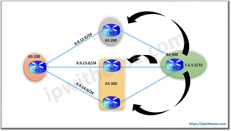
show ip bgp 5.5.5.5
BGP routing table entry for 5.5.5.5/32, version 29
Paths: (3 available, best #3, table Default-IP-Routing-Table)
Flag: 0x4842
Advertised to update-groups:
1
300 400
9.9.13.3 from 9.9.13.3
Origin IGP, metric 100, localpref 100, valid, external
200 400
9.9.12.2 from 9.9.12.2
Origin IGP, metric 150, localpref 100, valid, external
300 400
9.9.14.4 from 9.9.14.4
Origin IGP, metric 200, localpref 100, valid, external, best <<<
N
WLLA
OMNI
MAR-CL N
Next hop - Valid
Weight - Higher weight
Local preference - Highest preference
Locally originated - locally originated preferred over learned from neighbors
AS Path - shorter AS Path
Origin - origin codes i over ?
MED - lower MED from same AS <<<
Neighbor type - ebgp over ibgp
IGP metric - lower IGP metric of next hop
Multipath - if configured then BGP will keep both
Age - oldest route that was learned <<<
Router ID - lower RID
CL - shorter Cluster list length
Neighbor address - lower Between the Route from R3 and R2 , R2 is chosen as the best path. This is so because the MED isn’t compared for BGP updates from R2 & R3 as they are part of different AS and as per BGP algorithms working the older route is preferred one which here is from R2 (because if you look at the output everything else is same)
Now comparing routes from R2 with route from R4 again MED isn’t compared as they are both from different AS. R4 being the older route here is preferred over the route from R2 and hence is selected as the best. So we see in this scenario how the MED working of preferring the lower MED updates hasn’t taken effect in this scenario.
To overcome this situation we use BGP deterministic-med
Deterministic-med groups all routes for a prefix from same AS under a same group in BGP table and then compare against each other, Then the best of the group is compared against the next group down
R1(config)#router bgp 100
R1(config-router)#bgp deterministic-medshow ip bgp 5.5.5.5
BGP routing table entry for 5.5.5.5/32, version 29
Paths: (3 available, best #3, table Default-IP-Routing-Table)
Flag: 0x4842
Advertised to update-groups:
1
200 400
9.9.12.2 from 9.9.12.2
Origin IGP, metric 100, localpref 100, valid, external
300 400
9.9.13.3 from 9.9.13.3
Origin IGP, metric 150, localpref 100, valid, external best <<<
300 400
9.9.14.4 from 9.9.14.4
Origin IGP, metric 200, localpref 100, valid, external,Now we see the table has been restructured and the routes with same AS path are grouped together.
Routes from R3 and R4 are compared because they are from same AS 300 and since route from R3 has lower MED it is best out of the group.
Now R3’s route is compared with the only route of other group i.e. from R2 and since both routes are from different AS, MED comparison will be skipped again, the route from R3 is older and it wins as best despite R2 having lower MED, this comparison still takes place because of belonging to same prefix
Dynamic BGP Neighbors
https://ipwithease.com/dynamic-bgp-peering/
we use the concept of BGP peer Group, where we can group the BGP Neighbors who are sharing the same outbound policies but with peer groups alone we need to manually configure 100 Peers and then add to the peer group so we need to combine it with another feature
Configuration step of iBGP Peer Group
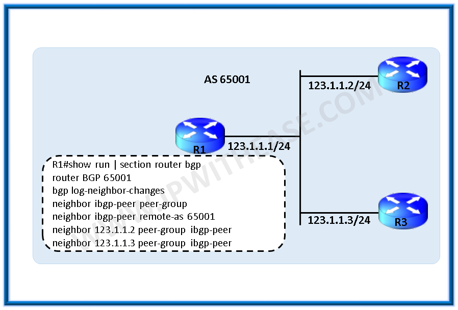
router bgp 65001
bgp log-neighbor-changes
neighbor ibgp-peers peer-group
neighbor ibgp-peers remote-as 65001
neighbor 123.1.1.2 peer-group ibgp-peers
neighbor 123.1.1.3 peer-group ibgp-peersConfiguration step of eBGP peer Group

ip route 1.1.1.2 255.255.255.255 123.1.1.2
ip route 1.1.1.3 255.255.255.255 123.1.1.3
router bgp 65001
bgp log-neighbor-changes
neighbor ebgp-peers peer-group
neighbor ebgp-peers ebgp-multihop 2
neighbor ebgp-peers update-source loopback0
neighbor 123.1.1.2 remote-as 65002
neighbor 123.1.1.2 peer-group ebgp-peers
neighbor 123.1.1.3 remote-as 65003
neighbor 123.1.1.3 peer-group ebgp-peersWith the Dynamic BGP peering feature, BGP router dynamically establishes peering with a group of remote neighbors that are configured using a range of IP addresses + BGP peer group.

R1(config-router)# neighbor dynamic-peers peer-groupCreate a global limit of BGP dynamic subnet range neighbors. The value ranges from 1 to 5000.
R1(config-router)# bgp listen limit 100define IP range for this peer-group
R1(config-router)# bgp listen range 172.16.0.0/16 peer-group dynamic-peersDefine the remote-as for the peer group, optionally, define the list of AS numbers that can be accepted to form neighborship with, max limit of alternate-as numbers is 5
R1(config-router)# neighbor dynamic-peers remote-as 65002 alternate-as 65003 65004Activate the peer group under ipv4 address-family, just like we activate a neighbor
R1(config-router)#address-family ipv4
R1(config-router-af)# neighbor dynamic-peers activate.Full configuration
R1
router bgp 65001
bgp log-neighbor-changes
bgp listen range 172.16.0.0/16 peer-group dynamic-peers
neighbor dynamic-peers peer-group
neighbor dynamic-peers remote-as 65002 alternate-as 65003 65004
!
address-family ipv4
neighbor dynamic-peers activate
exit-address-familyR2
router bgp 65002
bgp log-neighbor-changes
!
neighbor 172.16.1.1 remote-as 65001R3
router bgp 65003
bgp log-neighbor-changes
!
neighbor 172.16.2.1 remote-as 65001BGP router identifier 10.10.10.1, local AS number 65001
BGP table version is 1, main routing table version 1
Neighbor V AS MsgRcvd MsgSent TblVer InQ OutQ Up/Down State/PfxRcd
*172.16.1.2 4 65002 4 4 1 0 0 00:00:38 0
*172.16.2.2 4 65003 4 2 1 0 0 00:00:29 0
! Dynamically created based on a listen range command
Dynamically created neighbors: 2, Subnet ranges: 1
BGP peer group Dynamic-peer listen range group members:
172.16.0.0/16
Total dynamically created neighbors: 2/(100 max), Subnet ranges: 1show tcp brief all
TCB Local Address Foreign Address (state)
A2B61B90 172.16.1.1.179 172.16.1.2.64321 ESTAB
A2B62F48 172.16.2.1.179 172.16.2.2.17764 ESTAB
A2B19B20 0.0.0.0.179 *.* LISTENThe output illustrates that the router is listening on port 179 but with foreign address of *.*
BGP Allowas-in
https://ipwithease.com/allowas-in-configuration-in-bgp-2/
BGP allowas-in feature allows a router to accept BGP routes that contain its own AS number in the AS path
R2(config)#router bgp 200
R2(config-router)#neighbor 192.168.23.2 allowas-inBGP local-AS
https://journey2theccie.wordpress.com/2020/06/15/bgp-as-path-manipulations/
The local-AS feature allows a router to fool its neighbor to have a different AS then real AS at “router bgp ” configuration, but only for neighborship, the real AS still appears in AS Path and then the faked AS
R1#sh run | s router bgp
router bgp 65000
bgp log-neighbor-changes
network 1.1.1.0 mask 255.255.255.0
neighbor 12.0.0.2 remote-as 2
neighbor 12.0.0.2 local-as 1 <<<R2#sh run | s router bgp
router bgp 2
bgp log-neighbor-changes
network 2.2.2.0 mask 255.255.255.0
neighbor 12.0.0.1 remote-as 1 <<<R2#show bgp | b Network
Network Next Hop Metric LocPrf Weight Path
*> 1.1.1.0/24 12.0.0.1 0 0 1 65000 iAs you can see, both AS numbers are there in the path. They also are there on routes that R1 is learning from R2, this fake AS really acts as another AS inserted in topology:
R1#sh ip bgp | b Network
Network Next Hop Metric LocPrf Weight Path
*> 2.2.2.0/24 12.0.0.2 0 0 1 2 i
There are a couple of ways to change this. First, if we want to stop the alternate ASN from being prepended when receiving routes, we can use no-prepend:
R1(config-router)#neighbor 12.0.0.2 local-as 1 no-prepend
R1#sh bgp | b Network
Network Next Hop Metric LocPrf Weight Path
*> 1.1.1.0/24 0.0.0.0 0 32768 i
*> 2.2.2.0/24 12.0.0.2 0 0 2 i
We can see that the routes learned from R2 no longer are showing 1 in the path. However, if we look at R2….
R2#sh bgp | b Network
Network Next Hop Metric LocPrf Weight Path
*> 1.1.1.0/24 12.0.0.1 0 0 1 65000 i
*> 2.2.2.0/24 0.0.0.0 0 32768 iBoth of our ASNs are in the path. So to stop the alternate ASN from being prepended when sending routes, we can use the following:
R1(config-router)#neighbor 12.0.0.2 local-as 1 no-prepend replace-asNow if we look at R2:
R2#sh bgp | b Network
Network Next Hop Metric LocPrf Weight Path
*> 1.1.1.0/24 12.0.0.1 0 0 1 i
*> 2.2.2.0/24 0.0.0.0 0 32768 i
We can see that only 1 is in the path. Using both the no-prepend replace-as keywords allow all routers to see the BGP advertisements as if they were running AS 1 in the BGP process.
There is still one more keyword for this command, and it is the dual-as keyword:
R1(config-router)#neighbor 12.0.0.2 local-as 1 no-prepend replace-as ?
dual-as Accept either real AS or local AS from the ebgp peer
<cr>This allows the remote peer to use either ASN for the BGP session. This feature is useful during migrations.
BGP remove-private-as
https://journey2theccie.wordpress.com/2020/06/15/bgp-as-path-manipulations/
There are situations where a customer with a single ISP may use a private ASN on the internet connection. In these cases, when the ISP forwards the customer’s prefix(s) out it will remove the private ASN in the process.
This is where Cisco router’s use the remove-private-as command. However, there are certain restrictions:
EBGP neighbors only
The private ASNs are removed from outbound updates
This only works if the path has only private ASNs in the AS_PATH. If there is a mix of public and private this will not work, however there is a way to fix this
If the AS_PATH contains the ASN of the EBGP neighbor, it won’t be removed
R1#sh run | s bgp
router bgp 65000
bgp log-neighbor-changes
network 1.1.1.0 mask 255.255.255.0
neighbor 12.0.0.2 remote-as 2R2#sh run | s bgp
router bgp 2
bgp log-neighbor-changes
neighbor 12.0.0.1 remote-as 65000
neighbor 24.0.0.4 remote-as 4R4#sh run | s router bgp
router bgp 4
bgp log-neighbor-changes
neighbor 24.0.0.2 remote-as 2If we look at R2 & R4, we can see they have learned the route with the private AS in the path:
R2#show ip bgp | b Network
Network Next Hop Metric LocPrf Weight Path
*> 1.1.1.0/24 12.0.0.1 0 0 65000 i
!
R4#sh bgp | b Network
Network Next Hop Metric LocPrf Weight Path
*> 1.1.1.0/24 24.0.0.2 0 2 65000 iSo let’s enable that command on R2 and see how it shows up on R4:
R2(config-router)#neighbor 24.0.0.4 remove-private-as
!
R4#sh bgp | b Network
Network Next Hop Metric LocPrf Weight Path
*> 1.1.1.0/24 24.0.0.2 0 2 i
That worked easily enough.
So remember what I said about not being able to do it when there are public and private AS numbers in the AS path? Let’s test that by adding a bunch of AS numbers to the path and see if it still works.
R1(config)#route-map PREPEND permit 10 R1(config-route-map)#set as-path prepend 1 10 100 R1(config-route-map)#exit R1(config)#router bgp 65000 R1(config-router)#neighbor 12.0.0.2 route-map PREPEND out
Let’s check the route back on R4:
R4#sh bgp | b Network
Network Next Hop Metric LocPrf Weight Path
*> 1.1.1.0/24 24.0.0.2 0 2 65000 1 10 100 iAs you can see, the private AS is still in the path because there are public AS numbers there and Cisco IOS assumes that the remote-private-as command was a misconfiguration. We can override this with the all keyword:
R2(config-router)#neighbor 24.0.0.4 remove-private-as allThis will remove private AS numbers regardless of what else is in the path. Let’s check R4:
R4#sh bgp | b Network
Network Next Hop Metric LocPrf Weight Path
*> 1.1.1.0/24 24.0.0.2 0 2 1 10 100 iPerfect, now the private AS is gone, but the rest of the ASNs remain.
Removal of AS shortens the path unintentionally so sometimes it is important to keep the ASN entries to equal number, instead of removing them, so instead we can use replace-as with remove-private-as
R2(config-router)#neighbor 24.0.0.4 remove-private-as all replace-as
!
R4#sh bgp | b Network
Network Next Hop Metric LocPrf Weight Path
*> 1.1.1.0/24 24.0.0.2 0 2 2 1 10 100 i
Now we can see our AS (2) in the path instead of the private AS of 65000.
BGP Conditional Advertisement
https://ipwithease.com/bgp-conditional-route-advertisement-using-non-exist-map-advertise-map/
By default BGP router advertises all best path routes from Loc-RIB to all its neighbors.
Using conditional advertisement some prefixes are advertised to one of the providers only if information from the other provider is not present. This will help keep routing symmetric
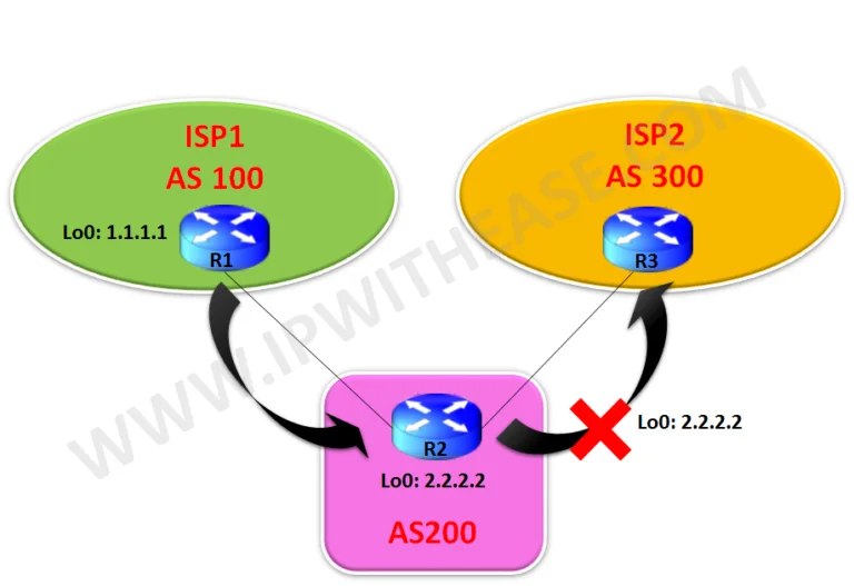
With the BGP conditional advertisement feature, you can now accomplish these tasks on R2:
- If 1.1.1.1/32 exists in R2’s BGP table, then do not advertise the 2.2.2.2/32 network to R3.
- If 1.1.1.1/32 does not exist in R2’s BGP table, then advertise the 2.2.2.2/32 network to R3.
R1
router bgp 100
bgp log-neighbor-changes
network 1.1.1.1 mask 255.255.255.255
neighbor 9.9.12.2 remote-as 200R2
router bgp 200
bgp log-neighbor-changes
network 2.2.2.2 mask 255.255.255.255
neighbor 9.9.12.1 remote-as 100
neighbor 9.9.23.3 remote-as 300
neighbor 9.9.23.3 advertise-map Advertise non-exist-map Non-Exist
!
access-list 10 permit 2.2.2.2
access-list 20 permit 1.1.1.1
!
route-map Non-Exist permit 10
match ip address 20
!
route-map Advertise permit 10
match ip address 10R3
router bgp 300
bgp log-neighbor-changes
neighbor 9.9.23.2 remote-as 200R2#sh ip bgp
BGP table version is 3, local router ID is 2.2.2.2Status codes: s suppressed, d damped, h history, * valid, > best, i – internal,
r RIB-failure, S Stale, m multipath, b backup-path, f RT-Filter,
x best-external, a additional-path, c RIB-compressed,
Origin codes: i – IGP, e – EGP, ? – incomplete
RPKI validation codes: V valid, I invalid, N Not found
Network Next Hop Metric LocPrf Weight Path
*> 1.1.1.1/32 9.9.12.1 0 0 100 i
*> 2.2.2.2/32 0.0.0.0 0 32768 iR2#sh ip bgp neighbors 9.9.23.3 advertised-routes
BGP table version is 3, local router ID is 2.2.2.2Status codes: s suppressed, d damped, h history, * valid, > best, i – internal,
r RIB-failure, S Stale, m multipath, b backup-path, f RT-Filter,
x best-external, a additional-path, c RIB-compressed,
Origin codes: i – IGP, e – EGP, ? – incomplete
RPKI validation codes: V valid, I invalid, N Not found
Network Next Hop Metric LocPrf Weight Path
*> 1.1.1.1/32 9.9.12.1 0 0 100 i
Total number of prefixes 1R3#sh ip bgp
BGP table version is 8, local router ID is 9.9.23.3Status codes: s suppressed, d damped, h history, * valid, > best, i – internal,
r RIB-failure, S Stale, m multipath, b backup-path, f RT-Filter,
x best-external, a additional-path, c RIB-compressed,
Origin codes: i – IGP, e – EGP, ? – incomplete
RPKI validation codes: V valid, I invalid, N Not found
Network Next Hop Metric LocPrf Weight Path
*> 1.1.1.1/32 9.9.23.2 0 200 100 i <<<
! Only 1.1.1.1/32 is received and not 2.2.2.2Now we will shut down Lo0 interface on R1 to stop the advertisement of 1.1.1.1 to R2 and hence will see 2.2.2.2 is received on R3 now from R2.
R1(config)#int loop 0
R1(config-if)#shutdownR2#sh ip bgp neighbors 9.9.23.3 advertised-routes
BGP table version is 5, local router ID is 2.2.2.2Status codes: s suppressed, d damped, h history, * valid, > best, i – internal,
r RIB-failure, S Stale, m multipath, b backup-path, f RT-Filter,
x best-external, a additional-path, c RIB-compressed,
Origin codes: i – IGP, e – EGP, ? – incomplete
RPKI validation codes: V valid, I invalid, N Not found
Network Next Hop Metric LocPrf Weight Path
*> 2.2.2.2/32 0.0.0.0 0 32768 i
Total number of prefixes 1R3#sh ip bgp
BGP table version is 10, local router ID is 9.9.23.3Status codes: s suppressed, d damped, h history, * valid, > best, i – internal,
r RIB-failure, S Stale, m multipath, b backup-path, f RT-Filter,
x best-external, a additional-path, c RIB-compressed,
Origin codes: i – IGP, e – EGP, ? – incomplete
RPKI validation codes: V valid, I invalid, N Not found
Network Next Hop Metric LocPrf Weight Path
*> 2.2.2.2/32 9.9.23.2 0 0 200 iBGP Multipath
https://ipwithease.com/bgp-multipath-scenario/

R1(config)#router bgp 100
R1(config-router)#maximum-paths 2R1#sh ip bgp
BGP table version is 3, local router ID is 1.1.1.1
Status codes: s suppressed, d damped, h history, * valid, > best, i – internal,
r RIB-failure, S Stale, m multipath, b backup-path, f RT-Filter,
x best-external, a additional-path, c RIB-compressed,
Origin codes: i – IGP, e – EGP, ? – incomplete
RPKI validation codes: V valid, I invalid, N Not found
Network Next Hop Metric LocPrf Weight Path
*m 4.4.4.4/32 9.9.12.2 0 200 i <<< ‘m’ means multipath enabled #
*> 9.9.13.3 0 200 iBGP Route Dampening
A route is considered to be flapping when its availability changes repeatedly. Route Dampening is a way to suppress flapping routes so that they are “suppressed” instead of being advertised.
Since BGP routing tables are huge, it’s not practical to send route flaps to neighbors, This could affect the performance of the network as well as consume more routers resources like CPU, As a best practice most ISPs use route dampening regularly.
https://ipwithease.com/bgp-route-dampening-configuration/
router bgp 1
no synchronization
bgp log-neighbor-changes
bgp dampening 10 750 2000 40 <<<
network 1.1.1.0 mask 255.255.255.0
network 192.168.12.0
neighbor 192.168.12.2 remote-as 2
no auto-summary- Penalty should be reduced by half after 10 minutes
- The dampened route must be reused when it reaches value of 750.
- Route should not be used when it reaches 2000 points.
- The routes experiencing Route flaps should not be suppressed for more than 40 minutes
R1#show ip bgp dampening parameters
dampening 10 750 2000 40
Half-life time : 10 mins Decay Time : 1550 secs
Max suppress penalty: 12000 Max suppress time: 40 mins
Suppress penalty : 2000 Reuse penalty : 750BGP backdoor
https://ipwithease.com/understanding-bgp-backdoor/
….The “Backdoor Feature” can be used to up the administrative distance of eBGP to 200 to make sure that IGP learned routes are given priority. This feature means that a backdoor network will be treated like a local one….
R1#
router bgp 100
network 9.9.0.2 mask 255.255.255.255 backdoor
neighbor 9.9.13.3 remote-as 300Impact of Load balancing due neighborship to loopbacks
+ difference between nexthop and advertising router
+ Multipathing to multiple paths through 1 neighbor vs 2 or more neighbors
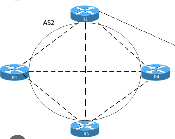
R3 has connected network 192.168.4.0/24 which is advertised in BGP
ibgp peering is only between R2 and R3,
while R1 and R4 are not participating in BGP
If direct link between R2 and R3 is lost
peering is reestablished via R1 and R4 because of peering using loopbacks
All loopbacks are advertised in IGP Multipath is enabled on R2
1. Given that R2 sees loopback of R3 from R1 and R4, how will bgp packets travel to R3?
2. Will it load balance traffic over both R1 and R4?
3. what will be “BGP” next hop for 192.168.4.0/24 on R2?
BGP control-plane traffic (the TCP session itself)
Usually: no per-packet balancing. Most routers do per-flow hashing for ECMP.
A single BGP session is typically:
- One TCP flow (same src/dst IPs + ports)
- So it gets hashed onto one of the ECMP paths (either via R1 or via R4)
It will only switch if:
- the chosen path fails, or
- the hash outcome changes
Data-plane traffic toward 192.168.4.0/24
Because not true next hop or non connected next hop is always recursively resolved, if the next-hop of ibgp in IGP is ECMP then data will be load balanced per flow.
R2 will forward traffic to the BGP next hop (R3 loopback), and if the IGP has ECMP to that loopback, then traffic to 192.168.4.0/24 can be load-balanced over R1 and R4 (again, typically per-flow hashing).
Important: “maximum-paths / BGP multipath on R2”
That only helps if R2 learns multiple BGP paths for 192.168.4.0/24 (different BGP next-hops, etc.).
Here R2 has only one iBGP neighbor (R3), so it only learns one BGP path. Multipath doesn’t create extra BGP paths; ECMP here comes from the IGP to the BGP next hop.
In case R1 and R4 are running bgp then next hop for 192.168.4.0/24 will be different and advertising router will be R3’s loopback address?
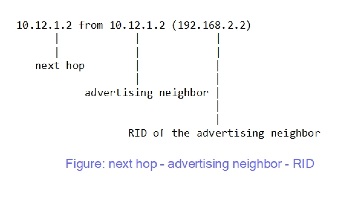
On R2, you will see:
- Next hop: ✅ R3’s loopback
- Advertising neighbor: not R3 but R1 or R4 (whoever sent the update) & RID: RID of R1 or R4
So:
✔ Advertising router ≠ next hop
✔ Next hop still points to R3 unless we use next-hop-self all on ibgp neighbor
✔ Traffic recursively follows IGP to R3 (possibly ECMP via R1/R4)
instances where you will see different next hop compared to advertising router is when route is coming from ebgp to ibgp network, on internal ibgp routes next hop is usually same as advertising router because ibgp never changes next hop when advertising to neighbor