MST
MST
In moden networks usually there is less reliance on Layer 2 / spanning tree, and there is no need for load balancing of VLANs, modern networks either use port-channels or Layer 3 networking down to access layer, MST is used to fulfil the requirement of stopping loops in case something is connected by mistake
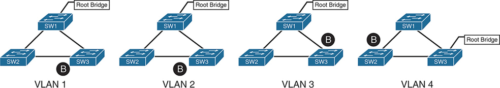
4 different VLANs , 4 different topologies and 4 different STP instances
If number of vlans increase to 10 then switch CPU will need to maintain 10 different STP instances and 10 different topologies
Not only that, switch must listen for BPDUs of every VLAN and topology changes can cause TCN and config BPDU with topology change flag
MST provides a blended approach by mapping one or multiple VLANs onto a single STP tree, called an MST instance (MSTI).

VLANs 1 and 2 correlate to one MSTI, VLAN 3 to a second MSTI, and VLAN 4 to a third MSTI.
A grouping of MST switches with the same high-level configuration is known as an MST region.
MST region appear as a single virtual switch to external switches as part of a compatibility mechanism
How MST topology is perceived outside of MST region
Everything inside the MST region looks like one virtual switch to the outside world
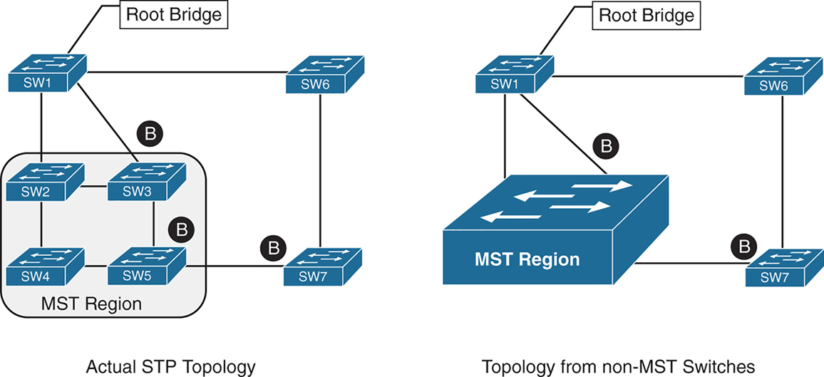
Above we can see that SW3 is blocking port to Root, which is not normal, if it was normal STP, it would become root port and not discarding, and instead it blocking port would be on SW2 – SW3 segment
For switches inside the MST region calculate STP internally
For outside switches they pretend to be a single switch
MST Instances (MSTIs)
MST uses a special STP instance called the internal spanning tree (IST), which is always the first instance, instance 0. The IST runs on all switch port interfaces for switches in the MST region, regardless of the VLANs associated with the ports.
Additional information about other MSTIs is included (nested) in the IST BPDU that is transmitted throughout the MST region. That single IST BPDU carries information for all MSTIs running
This enables the MST to advertise only one set of BPDUs, minimizing STP traffic regardless of the number of instances while providing the necessary information to calculate the STP for other MSTIs.
The number of MST instances varies by platform, but platform should support at least 16 instances allowing 15 different topologies, The IST is always instance 0, so instances 1 to 15 can support other VLANs
There is not a special name for instances 1 to 15; they are simply known as MSTIs.
MST Configuration
SW1(config)# spanning-tree mode mst
! change mode to MST

SW1(config)# spanning-tree mst 0 root primary
! The primary keyword sets the priority to 24,576, and
! the secondary keyword sets the priority to 28,672

SW1(config)# spanning-tree mst 1 root primary
SW1(config)# spanning-tree mst 2 root primary
! or set the system priority manually instead of root
! primary or root secondary keywords
! spanning-tree mst 2 priority 16384

SW1(config)# spanning-tree mst configuration
! enter MST configuration submode

SW1(config-mst)# name ENTERPRISE_CORE
! define MST region name, it must match on all switches
! in the region

SW1(config-mst)# revision 2
! this MST version number must match on all switches
! in an MST Region, By default, a region name is an empty
! string

! Associate vlans to MST instances, by default all vlans
! are associated to MST 0 instance, for varying topologies
! assign vlans to different instances
SW1(config-mst)# instance 1 vlan 10,20
SW1(config-mst)# instance 2 vlan 99
The command show spanning-tree mst configuration provides a quick verification of the MST configuration on a switch
Notice that MST instance 0 contains all the VLANs except for VLANs 10, 20, and 99, regardless of whether those VLANs are configured on the switch
MST instance 1 contains VLAN 10 and 20, and MST instance 2 contains only VLAN 99.
SW2# show spanning-tree mst configuration
Name      [ENTERPRISE_CORE]
Revision  2     Instances configured 3

Instance  Vlans mapped
--------  ---------------------------------------------------------------------
0         1-9,11-19,21-98,100-4094
1         10,20
2         99
MST Verification
The relevant spanning tree information can be obtained with the command show spanning-tree. However, the VLAN numbers are not shown and the MST instance is provided instead.
In addition, the priority value for a switch is the MST instance plus the switch priority (not the vlan number + switch priority)
SW1# show spanning-tree
! Output omitted for brevity
! Spanning Tree information for Instance 0 (All VLANs but 10,20, and 99)
MST0
  Spanning tree enabled protocol mstp
  Root ID    Priority    24576
               Address     0062.ec9d.c500
               This bridge is the root
               Hello Time   2 sec  Max Age 20 sec  Forward Delay 15 sec

  Bridge ID  Priority    24576  (priority 24576 sys-id-ext 0)
               Address     0062.ec9d.c500
               Hello Time   2 sec  Max Age 20 sec  Forward Delay 15 sec

Interface           Role Sts Cost      Prio.Nbr Type
------------------- ---- --- --------- -------- --------------------------------
Gi1/0/2             Desg FWD 20000     128.2    P2p
Gi1/0/3             Desg FWD 20000     128.3    P2p

! Spanning Tree information for Instance 1 (VLANs 10 and 20)
MST1
  Spanning tree enabled protocol mstp
  Root ID Priority 24577
            Address     0062.ec9d.c500
            This bridge is the root
            Hello Time   2 sec  Max Age 20 sec  Forward Delay 15 sec

  Bridge ID  Priority    24577  (priority 24576 sys-id-ext 1)
               Address     0062.ec9d.c500
               Hello Time   2 sec  Max Age 20 sec  Forward Delay 15 sec

Interface           Role Sts Cost      Prio.Nbr Type
------------------- ---- --- --------- -------- --------------------------------
Gi1/0/2             Desg FWD 20000      128.2    P2p
Gi1/0/3             Desg FWD 20000      128.3    P2p
! Spanning Tree information for Instance 2 (VLAN 99)  >>> instead of 24576 + 99
MST2                                                  >>> it is 24576 + 2
  Spanning tree enabled protocol mstp
  Root ID    Priority    24578
              Address     0062.ec9d.c500
              This bridge is the root
              Hello Time   2 sec  Max Age 20 sec  Forward Delay 15 sec

  Bridge ID  Priority    24578  (priority 24576 sys-id-ext 2)
               Address     0062.ec9d.c500
               Hello Time   2 sec  Max Age 20 sec  Forward Delay 15 sec

Interface           Role Sts Cost       Prio.Nbr Type
------------------- ---- --- --------- -------- --------------------------------
Gi1/0/2             Desg FWD 20000      128.2    P2p
Gi1/0/3             Desg FWD 20000      128.3    P2p
A consolidated view of the MST topology table is displayed with the command show spanning-tree mst [instance-number].
The optional instance-number can be included to restrict the output to a specific instance.
SW1# show spanning-tree mst
! Output omitted for brevity
##### MST0    vlans mapped:   1-9,11-19,21-98,100-4094
Bridge         address 0062.ec9d.c500  priority      0     (24576 sysid 0)
Root           this switch for the CIST
Operational   hello time 2 , forward delay 15, max age 20, txholdcount 6
Configured    hello time 2 , forward delay 15, max age 20, max hops    20

Interface                        Role Sts Cost      Prio.Nbr Type
----------------                 ---- --- --------- -------- ------------------------
Gi1/0/2                          Desg FWD 20000     128.2    P2p
Gi1/0/3                          Desg FWD 20000     128.3    P2p
##### MST1    vlans mapped:   10,20
Bridge         address 0062.ec9d.c500  priority      24577 (24576 sysid 1)
Root            this switch for MST1

Interface                        Role Sts Cost      Prio.Nbr Type
----------------                 ---- --- --------- -------- ------------------------
Gi1/0/2                          Desg FWD 20000     128.2    P2p
Gi1/0/3                          Desg FWD 20000     128.3    P2p

##### MST2    vlans mapped:   99
Bridge         address 0062.ec9d.c500  priority      24578 (24576 sysid 2)
Root           this switch for MST2

Interface                        Role Sts Cost      Prio.Nbr Type
----------------                 ---- --- --------- -------- ------------------------
Gi1/0/2                          Desg FWD 20000     128.2     P2p
Gi1/0/3                          Desg FWD 20000     128.3     P2p
SW2# show spanning-tree mst interface gigabitEthernet 1/0/1
GigabitEthernet1/0/1 of MST0 is root forwarding
Edge port: no (default) port guard : none (default)
Link type: point-to-point (auto) bpdu filter: disable (default)
Boundary : internal bpdu guard : disable (default)
Bpdus sent 17, received 217
Instance Role Sts Cost Prio.Nbr Vlans mapped
-------- ---- --- --------- -------- -------------------------------
0 Root FWD 20000 128.1 1-9,11-19,21-98,100-4094
1 Root FWD 20000 128.1 10,20
2 Root FWD 20000 128.1 99MST Tuning
MST supports the port cost and port priority
The interface configuration command spanning-tree mst instance-number cost cost sets the interface cost
SW3# show spanning-tree mst 0
! Output omitted for brevity
Interface                        Role Sts Cost      Prio.Nbr Type
----------------                 ---- --- --------- -------- --------------------
Gi1/0/1                          Root FWD 20000      128.1    P2p
Gi1/0/2                          Altn BLK 20000      128.2    P2p
Gi1/0/5                          Desg FWD 20000      128.5    P2p
SW3# configure term
Enter configuration commands, one per line. End with CNTL/Z.
SW3(config)# interface gi1/0/1
SW3(config-if)# spanning-tree mst 0 cost 1SW3# show spanning-tree mst 0
! Output omitted for brevity
Interface Role Sts Cost Prio.Nbr Type
---------------- ---- --- --------- -------- ---------------------
Gi1/0/1 Root FWD 1 128.1 P2p
Gi1/0/2 Desg FWD 20000 128.2 P2p
Gi1/0/5 Desg FWD 20000 128.5 P2pThe interface configuration command spanning-tree mst instance-number port-priority priority sets the interface priority.
SW4# show spanning-tree mst 0
! Output omitted for brevity
##### MST0    vlans mapped:   1-9,11-19,21-98,100-4094
Interface                        Role Sts Cost      Prio.Nbr Type
----------------                 ---- --- --------- -------- --------------------
Gi1/0/2                          Root FWD 20000     128.2     P2p
Gi1/0/5                          Desg FWD 20000     128.5     P2p
Gi1/0/6                          Desg FWD 20000     128.6     P2p
SW4# configure term
Enter configuration commands, one per line. End with CNTL/Z.
SW4(config)# interface gi1/0/5
SW4(config-if)# spanning-tree mst 0 port-priority 64SW4# show spanning-tree mst 0
! Output omitted for brevity
##### MST0 vlans mapped: 1-9,11-19,21-98,100-4094
Interface Role Sts Cost Prio.Nbr Type
---------------- ---- --- --------- -------- --------------------
Gi1/0/2 Root FWD 20000 128.2 P2p
Gi1/0/5 Desg FWD 20000 64.5 P2p
Gi1/0/6 Desg FWD 20000 128.6 P2pCommon MST Misconfigurations
Network engineers should be aware of two common misconfigurations within the MST region:
- VLAN assignment to the IST
- Trunk link pruning
VLAN Assignment to the IST
Remember that the IST operates across all links in the MST region, regardless of the VLAN assigned to the actual port.
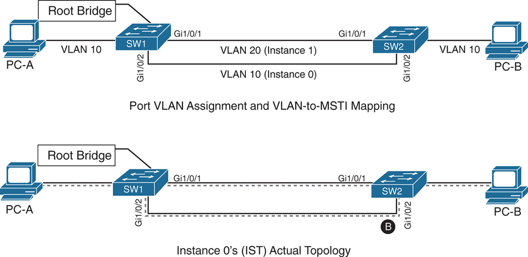
SW1 and SW2 contain two network links between them allowing VLAN 10 and VLAN 20
Gi1/0/1 and Gi1/0/2 are not trunks but they are access ports with VLANs 10 and 20 assigned
VLAN 10 is assigned to the IST, and VLAN 20 is assigned to MSTI 1
Looking at above diagram it looks like that traffic from PC 1 on VLAN 10 will traverse over the Gi1/0/2 but no, traffic will actually be blocked, we need to correct this using:
– port priority
– move VLAN 10 to MSTI 1, the switches will build a topology based on the links in use by that MST
– allow vlans on all interfaces – Trunk , configure both Gi1/0/1 and Gi1/0/2 as trunks on SW1 and SW2
The IST (Instance 0) runs over all physical links inside the MST region — regardless of VLAN assignment.
IST topology is calculated
SW1 is the root bridge
All SW1 ports = Designated Ports (DPs)
SW2 must block one of its links to prevent a loop
The IST sees:
- Two parallel physical links
- Same cost
- Same root
So one must block, even if:
- One link is “for VLAN 10”
- The other is “for VLAN 20”
To IST, they’re just two paths to same switch
Trunk Link Pruning

A network engineer made a mistake and has pruned VLANs on the trunk links between SW1 to SW2 and SW1 to SW3 to help load balance traffic.
Shortly after implementing the change, users attached to SW1 and SW3 cannot talk to the servers on SW2. The reason is that although the VLANs on the trunk links have changed, the MSTI topology has not.
You pruned VLAN 10 on one trunk but pruned VLAN 20 on a different trunk
the MST topology stays the same, but the VLAN forwarding paths no longer match it.
So rules for pruning vlans with MST are as follow:
– Never prune VLANs inconsistently if they belong to the same MST instance (MSTI).
– On any given trunk link, either allow all VLANs in an MSTI, or prune all of them together.
When configuring trunk pruning in MST:
- Think in MSTIs, not individual VLANs
- Prune per MST instance, not per VLAN
- If VLANs share an MSTI → they must travel together
MST Region Boundary
Externally, an MST region must look like one spanning-tree instance, This is non-negotiable — it’s how MST scales.
A PVST+ switch expects every VLAN has its own spanning tree
So a PVST+ switch sends:
- A BPDU for VLAN 1
- A BPDU for VLAN 10
- A BPDU for VLAN 20
- etc.
MST cannot accept per-VLAN information so MST must ignore VLAN-specific topology from outside. MST has to ask: If I can only believe ONE BPDU from outside, which one do I choose VLAN 1
Not because VLAN 1 is special logically, but because:
- VLAN 1 always exists
- VLAN 1 cannot be deleted
- VLAN 1 is guaranteed to be present end-to-end
So VLAN 1 becomes the anchor VLAN.
The IST (Instance 0) is:
“The single spanning tree that also represents the MST region to the outside world.”
When an MST switch hears PVST+ BPDUs:
- It hears many BPDUs (VLAN 1, 10, 20…)
- It must pick exactly one
- It picks VLAN 1
- That BPDU becomes the IST’s view of the outside world
But what about the other VLANs? (your natural next question) for PVST+ > MST and MST > PVST+
for MST > PVST+ , PVST+ expects a BPDU per VLAN.
So MST does this trick:
- Take the IST BPDU
- Copy it
- Send it back as:
- “VLAN 10 BPDU”
- “VLAN 20 BPDU”
- etc.
This is PVST Simulation.
The PVST simulation mechanism sends out PVST+ (and also includes RPVST) BPDUs (one for each VLAN), using the information from the IST.
for PVST+ > MST it is not needed, as long as VLAN 1’s BPDU helps in all the functions reliant on BPDU and contains
– STP type
– root path cost
– root bridge identifier
– local bridge identifier
– max age
– hello time
– forward delay
The mental model that usually makes it click
Think of MST like a company spokesperson:
- Inside the company: many departments (MSTIs)
- Outside the company: one voice
- VLAN 1 is the spokesperson’s microphone
An MST region boundary is any port that connects to a switch that is in a different MST region or that connects to 802.1D or 802.1W BPDUs.
There are two design considerations when integrating an MST region with a PVST+/RPVST environment: The MST region is the root bridge, or the MST region is not a root bridge for any VLAN. These scenarios are explained in the following sections.
MST Region as the Root Bridge

Shows the IST instance as the root bridge for all VLANs. SW1 and SW2 advertise multiple superior BPDUs for each VLAN toward SW3, which is operating as a PVST+ switch. SW3 is responsible for blocking ports
Making the MST region the root bridge ensures that Blocking does not take place on MST region or virtual switch, avoiding block on MST is the goal
MST Region Not a Root Bridge for Any VLAN
In this scenario, the MST region boundary ports can only block or forward for “all VLANs” together. Remember that only the VLAN 1 PVST BPDU is used for the IST and that the IST BPDU is a one-to-many translation of IST BPDUs to all PVST BPDUs. There is not an option to load balance traffic because the IST instance must remain consistent.
If an MST switch detects a better BPDU for a specific VLAN on a boundary port, the switch will use BPDU guard to block this port. The port will then be placed into a root inconsistent state. Although this may isolate downstream switches, it is done to ensure a loop-free topology; this is called the PVST simulation check.