DMVPN
DMVPN
DMVPN provides full mesh broadcast network type connectivity over WAN transport by using mGRE or multipoint GRE, as a result we get sites on spokes with direct spoke to spoke to communication that is on top secured with IPSec encryption, popular because of ease of configuration and scalability
Before we get into DMVPN, we need to know GRE well
With DMVPN, spokes have to register to hub just like SIP phone registers to the SIP server
Generic Routing Encapsulation (GRE) Tunnels
GRE not just provides connectivity for IP but also legacy and nowadays nonrouteble protocols like DECnet, Systems Network Architecture SNA and IPX
Running protocols over VPN was a big issue due to VPN being point to point and networks had to be designed around the point to point topologies but routing protocols function well over broadcast like topologies , mGRE resolves that problem
Additional header is added when packets travel over the GRE tunnel
GRE tunnels support IPv4 or IPv6 addresses as an overlay or transport network.
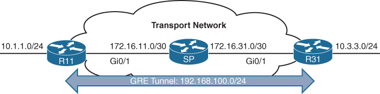
GRE creates a virtual network or overlay network over a real physical underlay network
In the routing tables of participating routers R11 and R31 , 10.1.1.0/24 is behind 192.168.0.11 and 10.3.3.0/24 is behind 192.168.0.31 , The Transport side or WAN side routing table does not have 192.168.0.0/16 network range , and that is how when tunnels are up those stub networks are accessible, and if tunnels are not up then they are not accessible
interface Tunnel100
! create tunnel interface


 bandwidth 4000
 ! Virtual interfaces do not have the concept of latency
 ! and need to have a reference bandwidth configured so that
 ! routing protocols that use bandwidth for best-path calculation
 ! can make intelligent decisions
 ! measured and configured in kilo bits
 ! Bandwidth is also used for quality of service (QoS) configuration
 ! on the interface


 ip address 192.168.100.11 255.255.255.0
 ! GRE tunnel needs IP as it is just like any other interface
 ! this is overlay IP


 ip mtu 1400
 ! reduce the mtu for tunnel interface
 ! exact added size differs based on tunnel type and encryption used
 ! min 24 bytes to 77 bytes


 keepalive 5 3
 ! The default timer is 10 seconds and three retries
 ! Tunnel interfaces are GRE point-to-point (P2P) by default,
 ! and the line protocol enters an up state when the router detects
 ! that a route to the tunnel destination exists in the routing
 ! table. If the tunnel destination is not in the routing table,
 ! the tunnel interface (line protocol) enters a down state.
 ! What if there is a problem on remote end and remote router is down
 ! By default, GRE tunnels stay “up” as long as the interface is configured
 ! and tunnel destination is in routing table
 ! Tunnel keepalives ensure that bidirectional communication exists
 ! between tunnel endpoints to keep the line protocol up


 tunnel source GigabitEthernet0/1
 ! tunnel's source interface is used for encapsulation and decapsulation
 ! tunnel source also accepts IP address as well
 ! tunnel source can be physical or loopback interface


tunnel destination 172.16.31.1
! tunnel's destination is where GRE sends packets or terminates tunnel
! for mGRE this is not defined but dynamically provided | Tunnel Type | Tunnel Header Size |
|---|---|
| GRE without IPsec | 24 bytes |
| DES/3DES IPsec (transport mode) | 18–25 bytes |
| DES/3DES IPsec (tunnel mode) | 38–45 bytes |
| GRE/DMVPN + DES/3DES | 42–49 bytes |
| GRE/DMVPN + AES + SHA-1 | 62–77 bytes |
GRE Sample Configuration
R11
interface Tunnel100
 bandwidth 4000
 ip address 192.168.100.11 255.255.255.0
 ip mtu 1400
 keepalive 5 3
 tunnel source GigabitEthernet0/1
tunnel destination 172.16.31.1
!
router eigrp GRE-OVERLAY
 address-family ipv4 unicast autonomous-system 100
  topology base
  exit-af-topology
  network 10.0.0.0
  network 192.168.100.0
 exit-address-family
R31
interface Tunnel100
bandwidth 4000
ip address 192.168.100.31 255.255.255.0
ip mtu 1400
keepalive 5 3
tunnel source GigabitEthernet0/1
tunnel destination 172.16.11.1
!
router eigrp GRE-OVERLAY
address-family ipv4 unicast autonomous-system 100
topology base
exit-af-topology
network 10.0.0.0
network 192.168.100.0
exit-address-familyR11# show interface tunnel 100
! Output omitted for brevity
Tunnel100 is up, line protocol is up
Hardware is Tunnel
Internet address is 192.168.100.1/24
MTU 17916 bytes, BW 400 Kbit/sec, DLY 50000 usec,
reliability 255/255, txload 1/255, rxload 1/255
Encapsulation TUNNEL, loopback not set
Keepalive set (5 sec), retries 3
Tunnel source 172.16.11.1 (GigabitEthernet0/1), destination 172.16.31.1
Tunnel Subblocks:
src-track:
Tunnel100 source tracking subblock associated with GigabitEthernet0/1
Set of tunnels with source GigabitEthernet0/1, 1 member (includes
iterators), on interface <OK>
Tunnel protocol/transport GRE/IP
Key disabled, sequencing disabled
Checksumming of packets disabled
Tunnel TTL 255, Fast tunneling enabled
Tunnel transport MTU 1476 bytes
Tunnel transmit bandwidth 8000 (kbps)
Tunnel receive bandwidth 8000 (kbps)
Last input 00:00:02, output 00:00:02, output hang neverR11# show ip route
! Output omitted for brevity
Codes: L - local, C - connected, S - static, R - RIP, M - mobile, B - BGP
D - EIGRP, EX - EIGRP external, O - OSPF, IA - OSPF inter area
Gateway of last resort is not set
10.0.0.0/8 is variably subnetted, 3 subnets, 2 masks
C 10.1.1.0/24 is directly connected, GigabitEthernet0/2
D 10.3.3.0/24 [90/38912000] via 192.168.100.31, 00:03:35, Tunnel100 <<<
172.16.0.0/16 is variably subnetted, 3 subnets, 2 masks
C 172.16.11.0/30 is directly connected, GigabitEthernet0/1
R 172.16.31.0/30 [120/1] via 172.16.11.2, 00:00:03, GigabitEthernet0/1
192.168.100.0/24 is variably subnetted, 2 subnets, 2 masks
C 192.168.100.0/24 is directly connected, Tunnel100 <<<Verifying that 10.3.3.3 network is reachable via Tunnel 100 (192.168.100.0/24)
R11# traceroute 10.3.3.3 source 10.1.1.1
Tracing the route to 10.3.3.3
  1 192.168.100.31 1 msec * 0 msec
Notice that from R11’s perspective, the network is only one hop away. The traceroute does not display all the hops in the underlay
In the same fashion, the packet’s time to live (TTL) is encapsulated as part of the payload. The original TTL decreases by only one for the GRE tunnel, regardless of the number of hops in the transport network.
Route recursion issue in GRE
Route recursion happens when a router tries to resolve the underlay next hop of a GRE tunnel destination using the tunnel itself, creating a logical loop, in order to prevent this we need to “not advertise” the underlay networks through GRE peering.
This scenario can occur when routing protocol is turned on all interfaces without care (regardless of passive default command)
This includes GRE tunnel destination’s subnet in the routing protocol
That route must be reachable via a physical interface
If the route to the tunnel destination disappears → GRE goes down
Sequence of events to failure
Step 1: Normal Operation
- Tunnel destination is reachable via the physical interface
- GRE tunnel comes UP
- IGP advertises routes over the tunnel
Step 2: IGP Learns a “Better” Route
- IGP learns the tunnel destination IP via the GRE tunnel
- This route has:
- Lower metric
- Or preferred administrative distance
Step 3: Recursive Dependency
- Router now thinks: “To reach the GRE destination, use the tunnel”
- But the tunnel itself requires reachability to that destination
Tunnel depends on itself
What Happens Next?
- GRE tunnel goes DOWN
- IGP adjacency over tunnel goes DOWN
- Physical-path route reappears
- Tunnel comes UP
- Loop repeats
Result:
- Tunnel flapping
- IGP instability
- High CPU
- Intermittent packet loss
Next Hop Resolution Protocol (NHRP)
NHC refers to DMVPN Spoke
NHS refers to DMVPN Hub
NHRP is just like ARP but for non-broadcast multi-access (NBMA) WAN networks such as Frame Relay and ATM networks
NHRP is a client/server protocol that allows devices to register themselves. NHRP next-hop servers (NHSs) are responsible for registering addresses or networks, and replying to any queries received by next-hop clients (NHCs).
NHC can reach NHS and ask for of underlay and overlay IP for a specific “network”
NHCs are statically configured with the IP addresses of the hubs (NHSs) so that they can register their overlay (tunnel IP) and NBMA (underlay) IP addresses with the hubs
NHRP Message Types
| Message Type | Description |
|---|---|
| Registration | Registration NHRP messages are sent by the NHC (spoke) toward the NHS (hub). The NHC (spoke) also specifies the amount of time that the registration should be maintained by the NHS (hub) |
| Resolution | Resolution NHRP messages provide the address resolution to remote spoke. Resolution reply provides underlay and overlay IP address for a remote network. |
| Redirect | This allows Hub to notify the spoke that a specific network can be reached by using a more optimal path (spoke-to-spoke tunnel). Redirect NHRP messages are essential component of DMVPN Phase 3 spoke to spoke to work. |
| Purge | Purge NHRP messages are sent to remove a cached NHRP entry. Purge messages notify routers of change. A purge is typically sent by a Hub to spoke to indicate that the mapping for an address/network that it answered is not valid anymore |
| Error | Error messages are used to notify the sender of an NHRP packet that an error has occurred. |
Dynamic Multipoint VPN (DMVPN)
Zero-touch provisioning:
It is considered a zero-touch technology because no configuration is needed on the DMVPN hub routers as new spokes are added to the DMVPN network
Spoke-to-spoke tunnels:
DMVPN provides full-mesh connectivity.
Dynamic spoke-to-spoke tunnels are created as needed and torn down when no longer needed.
There is no packet loss while building dynamic on-demand spoke-to-spoke tunnels “after the initial spoke-to-hub tunnels are established”.
Multiprotocol support: DMVPN can use IPv4, IPv6, and MPLS as either the overlay or underlay network protocol.
Multicast support: DMVPN allows multicast traffic to flow on the tunnel interfaces.
Adaptable connectivity:
DMVPN routers can establish connectivity behind Network Address Translation (NAT).
Spoke routers can use dynamic IP addressing such as Dynamic Host Configuration Protocol (DHCP).
A spoke site initiates a persistent VPN connection to the hub router.
Network traffic between spoke sites does not have to travel through the hubs.
DMVPN then dynamically builds a VPN tunnel between spoke sites on an as-needed basis. This allows network traffic, such as voice over IP (VoIP), to take a direct path, which reduces delay and jitter without consuming bandwidth at the hub site.
DMVPN was released in three phases, each phase built on the previous one with additional functions. DMVPN spokes can use DHCP or static addressing for the transport and overlay networks.
Next-hop preservation
interface Tunnel0
 ip summary-address eigrp 100 10.1.0.0 255.255.0.0
Summarization is used on hub router in DMVPN design to reduce the routing table size in hub because a lot of sites report / advertise a lot of subnets per site and can increase the size of routing table on hub
but problem occurs when summary is configured, next hop is changed to summarising router which is normal in any summarization and in DMVPN and instead of spoke to spoke communication it becomes spoke to hub to spoke communication
NHRP shortcut
A dynamically created, “more-specific” route pushed by hub (phase 3) installed by NHRP that changes the next hop from the hub to the destination spoke, allowing direct spoke-to-spoke forwarding.
That creates a shortcut tunnel between spokes
NHRP Shortcuts are
Dynamic → created on demand
More specific → overrides a summary route
Installed in the routing table → not just a cache
Changes the next hop → from hub → spoke
Enables direct tunnels → spoke-to-spokehence Phase 2 + summarisation = hub-and-spoke forwarding only
Phase 1: Spoke-to-Hub
DMVPN Phase 1, the first DMVPN implementation
VPN tunnels are created only between spoke and hub sites.
Traffic between spokes must traverse the hub to reach any other spoke.
Phase 2: Spoke-to-Spoke
DMVPN Phase 2 allows spoke-to-spoke
but DMVPN Phase 2 does not support spoke-to-spoke communication between different DMVPN networks (multilevel hierarchical DMVPN).
DMVPN spoke to spoke communication breaks when hub summarizes routes because Spokes do not know which spoke owns which subnet and cannot build NHRP shortcut and traffic must go via spoke → hub → spoke
Spoke-to-spoke still technically exists, but is never used
Same thing happens in hierarchical DMVPN because regional hubs summarize routes upward and global hub only sees big summary routes so even if local region’s hub is not using summarization, remote region’s routes are summarized so spoke to spoke (in different region) communication in DMVPN Phase 2 breaks
Phase 3 fixes exactly this problem.
Phase 3: Hierarchical Tree Spoke-to-Spoke
DMVPN Phase 3 fixes above problem and refines spoke-to-spoke connectivity by adding below NHRP messages by adding two NHRP messages:
1. Redirect message
2. Shortcut message
Step-by-step Phase 3 traffic flow
Spoke A sends traffic to Spoke B
Routing table says:
10.1.2.0/24 → HUB (summary route)
Actual Data Packet reaches the hub
Hub sees:
- “This traffic should go spoke-to-spoke”
- Sends NHRP Redirect back to Spoke A: “You should talk directly to Spoke B for network x”
Spoke A sends NHRP Resolution Request for network x
“I am trying to reach this network x”
“Tell me which tunnel endpoint owns it”
NHRP Resolution Request
-----------------------
Requested Protocol Address: 10.1.2.0/24
Source NBMA Address: Spoke A public IP
Source Tunnel Address: 172.16.0.2
so the hub responds
“That network lives behind Spoke B.
Here is its tunnel IP and public IP.”
NHRP Resolution Reply
--------------------
Destination Protocol Address: 10.1.2.0/24
Destination Tunnel Address: 172.16.0.3
Destination NBMA Address: 203.0.113.22
NHRP installs above shortcut route and saves it in NHRP cache
- More specific than the summary
- Overrides the hub route
Spoke A now builds a direct GRE/IPsec tunnel to Spoke B and data packets now go directly from spoke to spoke
so summary route still exists for scale of HUB router memory but NHRP injects more-specific routes dynamically, More specific routes override summaries
Difference in Phase 2 and Phase 3 DMVPN with multilevel hierarchical topologies
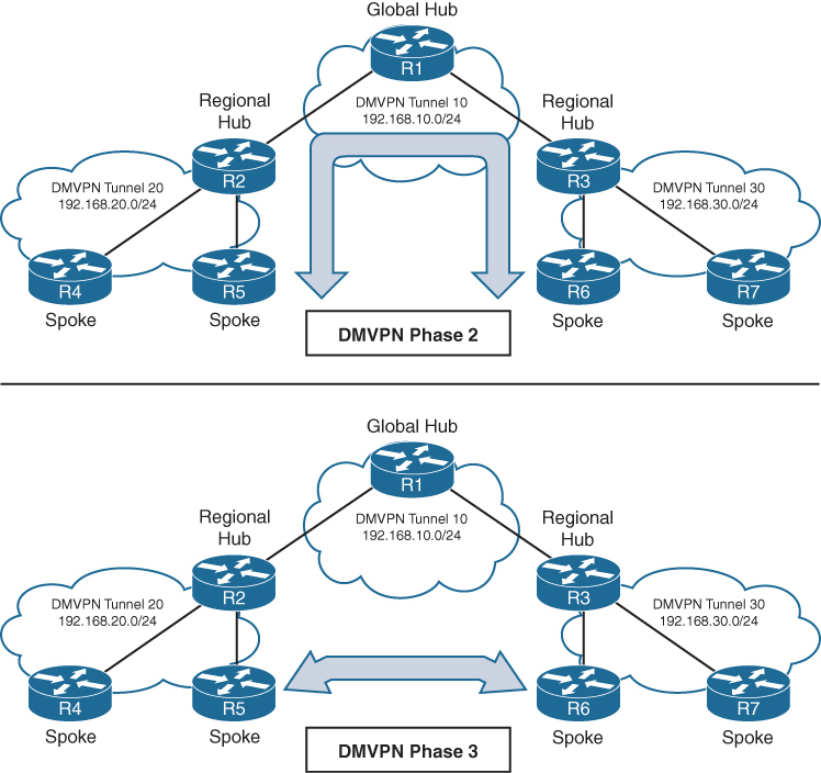
Connectivity between DMVPN tunnels 20 and 30 is established by DMVPN tunnel 10
All three DMVPN tunnels use the same DMVPN tunnel ID, even though they use different tunnel interfaces
For Phase 2 DMVPN tunnels, traffic from R5 must flow to the hub R2, where it is sent to R3 and then back down to R6
For Phase 3 DMVPN tunnels, a spoke-to-spoke tunnel is established between R5 and R6, and the two routers can communicate directly.
Each DMVPN phase has its own specific configuration. Intermixing DMVPN phases on the same tunnel network is not recommended. If you need to support multiple DMVPN phases for a migration, a second DMVPN network (subnet and tunnel interface) should be used.
DMVPN Configuration

DMVPN Hub Configuration
R11-Hub
interface Tunnel100


 bandwidth 4000
 ! Virtual interfaces do not have the concept of latency
 ! and need to have a reference bandwidth configured so that
 ! routing protocols that use bandwidth for best-path calculation
 ! can make intelligent decisions
 ! measured and configured in kilo bits
 ! Bandwidth is also used for quality of service (QoS) configuration
 ! on the interface


 ip address 192.168.100.11 255.255.255.0
 ! allocate an overlay IP address


 ip mtu 1400
 ! set ip mtu to 1400 , typical value for DMVPN to account for additional
 ! encapsulation


 ip nhrp map multicast dynamic
 ! Good to enable multicast support for NHRP
 ! NHRP just like subnets can also provide mapping of overlay IP
 ! + underlay IP for multicast addresses , To support multicast
 ! or routing protocols that use multicast, enable this on DMVPN hub
 ! routers


 ip nhrp network-id 100
 ! Enable NHRP on tunnel and assign unique network identity
 ! this NHRP network ID is not used in any negotiation but
 ! It is recommended that the NHRP network ID match on all
 ! routers participating in the same DMVPN network.
 ! It is used by local router to identify the DMVPN cloud
 ! because multiple tunnel interfaces can belong to the same
 ! DMVPN cloud


 ip nhrp redirect
 ! Enable Phase 3 or NHRP redirect function on DMVPN network


 ip tcp adjust-mss 1360
 ! to influence the TCP MSS negotiation in 3 WAY handshake
 ! for TCP packets visible on tunnel which they are even in
 ! case of TLS, typical value is 1360 to accommodate the 20
 ! bytes for IP + 20 bytes for TCP header


 tunnel source GigabitEthernet0/1
 ! this can be logical interface like loopback
 ! QoS problems can occur with the use of loopback interfaces
 ! when there are multiple paths in the forwarding table to the
 ! decapsulating router. The same problems occur automatically
 ! with port channels, which are not recommended at the time of
 ! this writing.


 tunnel mode gre multipoint
 ! configure tunnel as mGRE tunnel


 tunnel key 100
 ! Optionally use tunnel key in case multiple tunnel interfaces
 ! use same source interface , Tunnel keys, if configured, must
 ! match for a DMVPN tunnel to be established between two routers
 ! the tunnel key adds 4 bytes to the DMVPN header. The tunnel key
 ! is configured with the command tunnel key 0-4294967295
 ! If the tunnel key is defined on the hub router, it must be defined
 ! on all the spoke routers.
Note that mGRE tunnels do not support the option for using a keepalive. Keepalive is only logically possible when there is a single endpoint on other end, but in mGRE we have multiple endpoints
There is no technical correlation between the NHRP network ID and the tunnel interface number; however, keeping them the same helps from an operational support standpoint.
DMVPN Spoke Configuration for DMVPN Phase 1 (Point-to-Point)
The configuration of DMVPN Phase 1 spokes is similar to the configuration for a hub router except two differences:
- You do not use an mGRE tunnel. Instead, you specify the tunnel destination (because communication has to come back to hub)
- The NHRP mapping points to at least one active NHS
R31-Spoke (Single NHRP Command Configuration)

interface Tunnel100
 bandwidth 4000
 ! Virtual interfaces do not have the concept of latency
 ! and need to have a reference bandwidth configured so that
 ! routing protocols that use bandwidth for best-path calculation
 ! can make intelligent decisions
 ! measured and configured in kilo bits
 ! Bandwidth is also used for quality of service (QoS) configuration
 ! on the interface


 ip address 192.168.100.31 255.255.255.0
 ! assign overlay IP address to the Spoke


 ip mtu 1400


 ip nhrp network-id 100


 ip nhrp nhs 192.168.100.11 nbma 172.16.11.1 multicast
 ! define the DMVPN HUB or NHS, more can be added
 ! multicast keyword provides multicast mapping functions
 ! in NHRP and is required to support the following routing
 ! protocols: RIP, EIGRP, and Open Shortest Path First (OSPF)


 ip tcp adjust-mss 1360
 tunnel source GigabitEthernet0/1


 tunnel destination 172.16.11.1
 ! tunnel destination is DMVPN HUB underlay address


 tunnel key 100
R41-Spoke (Multiple NHRP Commands Configuration)
! NHS with MAP commands
interface Tunnel100
bandwidth 4000
ip address 192.168.100.41 255.255.255.0
ip mtu 1400
ip nhrp map 192.168.100.11 172.16.11.1
ip nhrp map multicast 172.16.11.1
ip nhrp network-id 100
ip nhrp nhs 192.168.100.11
ip tcp adjust-mss 1360
tunnel source GigabitEthernet0/1
tunnel destination 172.16.11.1
tunnel key 100Viewing DMVPN Tunnel Status
Tunnel states, in order of establishment:
- INTF: The line protocol of the DMVPN tunnel is down.
- IKE: DMVPN tunnels configured with IPsec have not yet established an IKE session.
- Ipsec: An IKE session has been established, but an Ipsec security association (SA) has not yet been established.
- NHRP: The DMVPN spoke router has not yet successfully registered.
- Up: The DMVPN spoke router has registered with the DMVPN hub and received an ACK (positive registration reply) from the hub.
R31-Spoke# show dmvpn
! Output omitted for brevity
Interface: Tunnel100, IPv4 NHRP Details
Type:Spoke, NHRP Peers:1,

# Ent  Peer NBMA Addr Peer Tunnel Add State  UpDn Tm Attrb
 ----- --------------- --------------- ----- -------- -----
     1 172.16.11.1       192.168.100.11    UP 00:05:26     S >>> static because NHS was defined
R41-Spoke# show dmvpn
! Output omitted for brevity
Interface: Tunnel100, IPv4 NHRP Details
Type:Spoke, NHRP Peers:1,

# Ent  Peer NBMA Addr Peer Tunnel Add State  UpDn Tm Attrb
 ----- --------------- --------------- ----- -------- -----
     1 172.16.11.1       192.168.100.11    UP  00:05:26    S >>> static because NHS was defined
R11-Hub# show dmvpn
Legend: Attrb ◊–S - Static,–D - Dynamic,–I - Incomplete
          –N - NATed,–L - Local,–X - No Socket
           –1 - Route Installed, –2 - Nexthop-override
          –C - CTS Capable
           # Ent --> Number of NHRP entries with same NBMA peer
           NHS Status: E --> Expecting Replies, R --> Responding, W --> Waiting
           UpDn Time --> Up or Down Time for a Tunn==

Interface: Tunnel100, IPv4 NHRP Details
Type:Hub, NHRP Peers:2,

 # Ent  Peer NBMA Addr Peer Tunnel Add State  UpDn Tm Attrb
 ----- --------------- --------------- ----- -------- -----
     1 172.16.31.1       192.168.100.31   UP 00:05:26     D
     1 172.16.41.1       192.168.100.41   UP 00:05:26     D

>>> D ! Dynamic because HUB learned spoke
with detail keyword
R11-Hub# show dmvpn detail
Legend: Attrb --> S - Static, D - Dynamic, I - Incomplete
           N - NATed, L - Local, X - No Socket
           T1 - Route Installed, T2 - Nexthop-override
           C - CTS Capable
           # Ent --> Number of NHRP entries with same NBMA peer
           NHS Status: E --> Expecting Replies, R --> Responding, W --> Waiting
           UpDn Time --> Up or Down Time for a Tunnel
==========================================================================

Interface Tunnel100 is up/up, Addr. is 192.168.100.11, VRF ""
    Tunnel Src./Dest. addr: 172.16.11.1/MGRE, Tunnel VRF ""
    Protocol/Transport: "multi-GRE/IP"", Protect ""
    Interface State Control: Disabled
    nhrp event-publisher : Disabled
Type:Hub, Total NBMA Peers (v4/v6): 2

# Ent  Peer NBMA Addr Peer Tunnel Add State  UpDn Tm Attrb    Target Network
----- --------------- --------------- ----- -------- ----- -----------------

    1 172.16.31.1        192.168.100.31    UP 00:01:05     D  192.168.100.31/32
    1 172.16.41.1        192.168.100.41    UP 00:01:06     D  192.168.100.41/32
R31-Spoke# show dmvpn detail
! Output omitted for brevity

Interface Tunnel100 is up/up, Addr. is 192.168.100.31, VRF ""
  Tunnel Src./Dest. addr: 172.16.31.1/172.16.11.1, Tunnel VRF ""
  Protocol/Transport: "GRE/IP", Protect ""
  Interface State Control: Disabled
  nhrp event-publisher : Disabled
IPv4 NHS:
192.168.100.11 RE NBMA Address: 172.16.11.1 priority = 0 cluster = 0
Type:Spoke, Total NBMA Peers (v4/v6): 1

# Ent  Peer NBMA Addr Peer Tunnel Add State  UpDn Tm Attrb    Target Ne
----- --------------- --------------- ----- -------- ----- ------------
    1 172.16.11.1        192.168.100.11    UP 00:00:28     S  192.168.100
R41-Spoke# show dmvpn detail
! Output omitted for brevity
Interface Tunnel100 is up/up, Addr. is 192.168.100.41, VRF ""
Tunnel Src./Dest. addr: 172.16.41.1/172.16.11.1, Tunnel VRF " "
Protocol/Transport: "GRE/IP", Protect ""
Interface State Control: Disabled
nhrp event-publisher : Disabled
IPv4 NHS:
192.168.100.11 RE NBMA Address: 172.16.11.1 priority = 0 cluster = 0
Type:Spoke, Total NBMA Peers (v4/v6): 1
# Ent Peer NBMA Addr Peer Tunnel Add State UpDn Tm Attrb Target Network
----- --------------- --------------- ----- -------- ----- -----------------
1 172.16.11.1 192.168.100.11 UP 00:02:00 S 192.168.100.11/32Viewing the NHRP Cache
NHRP cache very similar to ARP cache contains information returned by hub such as network entry with overlay and underlay IP of spokes , interface it was received on + expiry time (dynamic entries expire)
| NHRP Mapping Entry | Description |
|---|---|
| static | An entry created statically on a DMVPN interface, this is seen on DMVPN Spokes |
| dynamic | An entry created dynamically. This is seen on DMVPN Hub |
| incomplete | A Cisco router means the router knows it needs a mapping, but the resolution process has not finished yet. This is just like an “Incomplete” ARP entry NHRP (Next Hop Resolution Protocol) is commonly used in DMVPN to map: Tunnel IP address → NBMA (physical/WAN) IP address Routers cache these mappings in the NHRP table. An NHRP entry marked INCOMPLETE indicates: The router has initiated an NHRP resolution request, but has not yet received a valid reply. So: The router does not yet know the NBMA address The mapping cannot be used for forwarding traffic The entry is temporary – usually is seen on HUB when request sent, no reply received and this can be when destination spoke is down , not registered or has incorrect configuration – also happens when NHRP replies are being blocked by ACL, Firewall, NAT Router# show ip nhrp 10.10.10.2/32 via 10.10.10.2 Tunnel0 created 00:00:12, incompleteAn incomplete entry prevents repetitive NHRP requests for the same entry. Eventually this will time out and permit another NHRP resolution request for the same network. A healthy entry eventually changes to Dynamic or Static |
| local | Just like ARP’s local meaning that this overlay IP and underlay IP is on the router interface itself , Cisco routers automatically install a local NHRP entry so that router can correctly identify itself as an NHRP participantR1# show ip nhrp 10.0.0.1/32 via 10.0.0.1 Tunnel0 created 00:12:33, expire never Type: local, Flags: authoritative |
| (no-socket) | Mapping entries that do not have associated IPsec sockets and where encryption is not triggered. |
| NBMA address | Nonbroadcast multi-access address, or the transport IP address where the entry was received. |
NHRP message flags specify attributes of an NHRP cache entry
| NHRP Message Flag | Description |
|---|---|
| used | Indicates that this NHRP mapping entry was used to forward data packets within the past “60” seconds. |
| implicit | Indicates that the NHRP mapping entry was learned implicitly. Examples of such entries are the source mapping information gleaned from an NHRP resolution request received by the local router or from an NHRP resolution packet forwarded “through” the router. |
| unique | Indicates that this remote NHRP mapping entry must be unique and that it cannot be overwritten with an entry that has the same tunnel IP address but a different NBMA address. |
| router | Indicates that this NHRP mapping entry is from a remote “router” that provides access to a network or “host” behind the remote router. |
| rib | NHRP has injected a host route into the IP routing table This is not learned via a routing protocol (EIGRP/OSPF/BGP), but directly installed by NHRP show ip nhrp10.10.10.2/32 via 172.16.1.2 Flags: unique, dynamic, ribThis rib flag means this entry is installed in routing table show ip route 10.10.10.2Routing entry for 10.10.10.2/32 Known via "nhrp", distance 250, metric 0Why is AD 250 important? Makes sure routing protocols win Prevents NHRP from overriding real routing decisions NHRP routes are fallback / shortcut routes but because these are longest or most specific routes they always override When will you see RIB flag set? You’ll see RIB when: DMVPN Phase 2 or 3 is active NHRP resolution succeeds Spoke learns another spoke’s NBMA address Traffic triggers a shortcut |
| nho | When NHO is set, the spoke is telling the hub: “Do NOT override the next-hop with yourself when replying to NHRP resolution requests.” The hub does not insert itself as the next hop This allows direct spoke-to-spoke tunnels to form Without NHO Traffic between spokes is forced through the hub Hub becomes the next hop No dynamic spoke-to-spoke tunnels With NHO (normal DMVPN behavior) Hub returns the real NBMA address of the destination spoke Spokes build direct GRE/IPsec tunnels Enables Phase 2 / Phase 3 DMVPN |
| nhop | The nhop flag tells that this is valid next-hop for forwarding traffic |
R11-Hub# show ip nhrp
192.168.100.31/32 via 192.168.100.31
  Tunnel100 created 23:04:04, expire 01:37:26
  Type: dynamic, Flags: unique registered used nhop
  NBMA address: 172.16.31.1
192.168.100.41/32 via 192.168.100.41
  Tunnel100 created 23:04:00, expire 01:37:42
  Type: dynamic, Flags: unique registered used nhop
  NBMA address: 172.16.41.1
R31-Spoke# show ip nhrp
192.168.100.11/32 via 192.168.100.11
Tunnel100 created 23:02:53, never expire
Type: static, Flags:
NBMA address: 172.16.11.1R41-Spoke# show ip nhrp
192.168.100.11/32 via 192.168.100.11
Tunnel100 created 23:02:53, never expire
Type: static, Flags:
NBMA address: 172.16.11.1show ip nhrp “brief”
some information such as the used and nhop NHRP message flags are not shown with brief keyword
R11-Hub# show ip nhrp brief
****************************************************************************
    NOTE: Link-Local, No-socket and Incomplete entries are not displayed
****************************************************************************
Legend: Type --> S - Static, D - Dynamic
         Flags --> u - unique, r - registered, e - temporary, c - claimed
         a - authoritative, t - route
============================================================================
Intf     NextHop Address                                    NBMA Address
         Target Network                              T/Flag
-------- ------------------------------------------- ------ ----------------

Tu100    192.168.100.31                                     172.16.31.1
         192.168.100.31/32                           D/ur
Tu100    192.168.100.41                                     172.16.41.1
         192.168.100.41/32                           D/ur
R31-Spoke# show ip nhrp brief
! Output omitted for brevity
Intf NextHop Address NBMA Address
Target Network T/Flag
-------- ------------------------------------------- ------ ----------------
Tu100 192.168.100.11 172.16.11.1
192.168.100.11/32 S/R41-Spoke# show ip nhrp brief
! Output omitted for brevity
Intf NextHop Address NBMA Address
Target Network T/Flag
-------- ------------------------------------------- ------ ----------------
Tu100 192.168.100.11 172.16.11.1
192.168.100.11/32 S/The optional detail keyword provides a list of routers that submitted NHRP resolution requests and their request IDs.
Routing Table
Notice that the next-hop address between spoke routers is 192.168.100.11 (R11).
R11-Hub# show ip route
! Output omitted for brevity
Codes: L - local,   C - connected, S - static, R - RIP, M - mobile, B - BGP
         D - EIGRP, EX - EIGRP external, O - OSPF, IA - OSPF inter area

Gateway of last resort is 172.16.11.2 to network 0.0.0.0

S*    0.0.0.0/0 [1/0] via 172.16.11.2
      10.0.0.0/8 is variably subnetted, 4 subnets, 2 masks
C        10.1.1.0/24 is directly connected, GigabitEthernet0/2
D        10.3.3.0/24 [90/27392000] via 192.168.100.31, 23:03:53, Tunnel100
D        10.4.4.0/24 [90/27392000] via 192.168.100.41, 23:03:28, Tunnel100
      172.16.0.0/16 is variably subnetted, 2 subnets, 2 masks
C        172.16.11.0/30 is directly connected, GigabitEthernet0/1
      192.168.100.0/24 is variably subnetted, 2 subnets, 2 masks
C        192.168.100.0/24 is directly connected, Tunnel100
R31-Spoke# show ip route
! Output omitted for brevity
Gateway of last resort is 172.16.31.2 to network 0.0.0.0
S* 0.0.0.0/0 [1/0] via 172.16.31.2
10.0.0.0/8 is variably subnetted, 4 subnets, 2 masks
D 10.1.1.0/24 [90/26885120] via 192.168.100.11, 23:04:48, Tunnel100
C 10.3.3.0/24 is directly connected, GigabitEthernet0/2
D 10.4.4.0/24 [90/52992000] via 192.168.100.11, 23:04:23, Tunnel100
172.16.0.0/16 is variably subnetted, 2 subnets, 2 masks
C 172.16.31.0/30 is directly connected, GigabitEthernet0/1
192.168.100.0/24 is variably subnetted, 2 subnets, 2 masks
C 192.168.100.0/24 is directly connected, Tunnel100R41-Spoke# show ip route
! Output omitted for brevity
Gateway of last resort is 172.16.41.2 to network 0.0.0.0
S* 0.0.0.0/0 [1/0] via 172.16.41.2
10.0.0.0/8 is variably subnetted, 4 subnets, 2 masks
D 10.1.1.0/24 [90/26885120] via 192.168.100.11, 23:05:01, Tunnel100
D 10.3.3.0/24 [90/52992000] via 192.168.100.11, 23:05:01, Tunnel100
C 10.4.4.0/24 is directly connected, GigabitEthernet0/2
172.16.0.0/16 is variably subnetted, 2 subnets, 2 masks
C 172.16.41.0/24 is directly connected, GigabitEthernet0/1
192.168.100.0/24 is variably subnetted, 2 subnets, 2 masks
C 192.168.100.0/24 is directly connected, Tunnel100Traceroute
Traceroute shows that data from R31 to R41 will go through R11.
R31-Spoke# traceroute 10.4.4.1 source 10.3.3.1
Tracing the route to 10.4.4.1
  1 192.168.100.11 0 msec 0 msec 1 msec
  2 192.168.100.41 1 msec * 1 msec
DMVPN Configuration for Phase 3 DMVPN (Multipoint)
Phase 3 DMVPN configuration for the hub router adds the interface parameter command ip nhrp redirect on the hub router
This command checks the flow of packets on the tunnel interface and sends a redirect message to the source spoke router when it detects Hub router being used as transit, this is done by detecting for hairpinning
Hairpinning means that traffic is received and sent out an interface in the same cloud (identified by the NHRP network ID) , For instance, hairpinning occurs when packets come in and go out the same tunnel interface.
The Phase 3 DMVPN configuration for spoke routers uses the mGRE tunnel interface and uses the command ip nhrp shortcut on the tunnel interface.
R11-Hub
interface Tunnel100
 bandwidth 4000
 ip address 192.168.100.11 255.255.255.0
 ip mtu 1400
 ip nhrp map multicast dynamic
 ip nhrp network-id 100
 ip nhrp redirect <<<
 ip tcp adjust-mss 1360
 tunnel source GigabitEthernet0/1
 tunnel mode gre multipoint
 tunnel key 100
R31-Spoke
interface Tunnel100
bandwidth 4000
ip address 192.168.100.31 255.255.255.0
ip mtu 1400
ip nhrp network-id 100
ip nhrp nhs 192.168.100.11 nbma 172.16.11.1 multicast
ip nhrp shortcut <<<
ip tcp adjust-mss 1360
tunnel source GigabitEthernet0/1
tunnel mode gre multipoint
tunnel key 100R41-Spoke
interface Tunnel100
bandwidth 4000
ip address 192.168.100.41 255.255.255.0
ip mtu 1400
ip nhrp network-id 100
ip nhrp nhs 192.168.100.11 nbma 172.16.11.1 multicast
ip nhrp shortcut <<<
ip tcp adjust-mss 1360
tunnel source GigabitEthernet0/1
tunnel mode gre multipoint
tunnel key 100IP NHRP Authentication
NHRP includes an authentication capability, but this authentication is weak because the password is stored in plaintext. Most network administrators use NHRP authentication as a method to ensure that two different tunnels do not accidentally form. You enable NHRP authentication by using the interface parameter command ip nhrp authentication password.
Unique IP NHRP Registration
When Spoke regsiters with hub it adds the unique flag that forces DMVPN NHRP to keep overlay / protocol address and NBMA address unique for a spoke and same as the time of registration, If an NHC client or spoke attempts to register with the NHS using a different NBMA address while the previous entry has not expired yet, the registration process fails.
lets demonstrate this concept by disabling the DMVPN tunnel interface, changing the IP address on the transport interface, and reenabling the DMVPN tunnel interface. Notice that the DMVPN hub denies the NHRP registration because the protocol address is registered to a different NBMA address.
R31-Spoke(config)# interface tunnel 100
R31-Spoke(config-if)# shutdown
00:17:48.910: %DUAL-5-NBRCHANGE: EIGRP-IPv4 100: Neighbor 192.168.100.11
        (Tunnel100) is down: interface down
00:17:50.910: %LINEPROTO-5-UPDOWN: Line protocol on Interface Tunnel100,
     changed state to down
00:17:50.910: %LINK-5-CHANGED: Interface Tunnel100, changed state to
     administratively down
R31-Spoke(config-if)# interface GigabitEthernet0/1
R31-Spoke(config-if)# ip address 172.16.31.31 255.255.255.0
R31-Spoke(config-if)# interface tunnel 100
R31-Spoke(config-if)# no shutdown
00:18:21.011: %NHRP-3-PAKREPLY: Receive Registration Reply packet with error -
    unique address registered already(14)
00:18:22.010: %LINEPROTO-5-UPDOWN: Line protocol on Interface Tunnel100, changed
    state to up
This can cause problems for sites with transport interfaces that connect using DHCP, where they could be assigned different IP addresses before the NHRP cache times out. If a router loses connectivity and is assigned a different IP address, because of its age, it cannot register with the NHS router until that router’s entry is flushed from the NHRP cache.
The interface parameter command ip nhrp registration no-unique stops routers from placing the unique NHRP message flag in registration request packets sent to the NHS. This allows clients to reconnect to the NHS even if the NBMA address changes. This should be enabled on all DHCP-enabled spoke interfaces. However, placing this on all spoke tunnel interfaces keeps the configuration consistent for all tunnel interfaces and simplifies verification of settings from an operational perspective.
The NHC (spoke) has to register with this flag for this change to take effect on the NHS.
This can either happens during the normal NHRP expiration timers
or can be accelerated by resetting the tunnel interface on the spoke before change of transport IP
Spoke-to-Spoke Communication
In DMVPN Phase 1, the spoke devices rely on the configured tunnel destination to identify where to send the encapsulated packets. Phase 3 DMVPN uses mGRE tunnels and thereby relies on NHRP redirect and resolution request messages to identify the NBMA addresses for any destination networks
R31 initiates a traceroute to R41. Notice that the first packet travels across R11 (hub), but by the time a second stream of packets is sent, the spoke-to-spoke tunnel has been initialized so that traffic flows directly between R31 and R41 on the transport and overlay networks.
! Initial Packet Flow
R31-Spoke# traceroute 10.4.4.1 source 10.3.3.1
Tracing the route to 10.4.4.1
  1 192.168.100.11 5 msec 1 msec 0 msec <- This is the Hub Router (R11-Hub)
  2 192.168.100.41 5 msec * 1 msec
! Packetflow after Spoke-to-Spoke Tunnel is Established
R31-Spoke# traceroute 10.4.4.1 source 10.3.3.1
Tracing the route to 10.4.4.1
1 192.168.100.41 1 msec * 0 msecForming Spoke-to-Spoke Tunnels
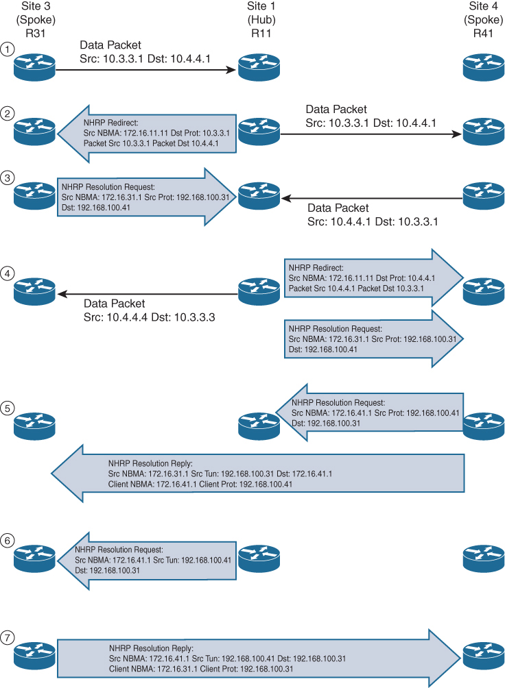
Step 1. R31 performs a route lookup for 10.4.4.1 and finds the entry 10.4.4.0/24 with the next-hop IP address 192.168.100.11 through hub. R31 encapsulates the packet destined for 10.4.4.1 and forwards it to R11 out the tunnel 100 interface.
Step 2. R11 receives the packet from R31 and performs a route lookup for the packet destined for 10.4.4.1. R11 locates the 10.4.4.0/24 network with the next-hop IP address 192.168.100.41. R11 checks the NHRP cache and locates the entry for the 192.168.100.41/32 address. R11 forwards the packet to R41, using the NBMA IP address 172.16.41.1, found in the NHRP cache.
The packet is then forwarded out the same tunnel interface (same network id / DMVPN cloud) and hub detects this as hairpinning.
R11 has ip nhrp redirect configured on the tunnel interface and recognizes that the packet received from R31 hairpinned out of the tunnel interface. R11 sends an NHRP redirect to R31, indicating the packet source 10.3.3.1 and destination 10.4.4.1. The NHRP redirect indicates to R31 that the traffic is using a suboptimal path.
Step 3. R31 receives the NHRP redirect and sends an NHRP resolution request to R11 for the 10.4.4.1 address. Inside the NHRP resolution request, R31 provides its protocol (tunnel IP) address, 192.168.100.31, and source NBMA address, 172.16.31.1. R41 performs a route lookup for 10.3.3.1 and finds the entry 10.3.3.0/24 with the next-hop IP address 192.168.100.11. R41 encapsulates the packet destined for 10.4.4.1 and forwards it to R11 out the tunnel 100 interface.
Step 4. R11 receives the packet from R41 and performs a route lookup for the packet destined for 10.3.3.1. R11 locates the 10.3.3.0/24 network with the next-hop IP address 192.168.100.31. R11 checks the NHRP cache and locates an entry for 192.168.100.31/32. R11 forwards the packet to R31, using the NBMA IP address 172.16.31.1, found in the NHRP cache. The packet is then forwarded out the same tunnel interface. R11 has ip nhrp redirect configured on the tunnel interface and recognizes that the packet received from R41 hairpinned out the tunnel interface. R11 sends an NHRP redirect to R41, indicating the packet source 10.4.4.1 and destination 10.3.3.1 The NHRP redirect indicates to R41 that the traffic is using a suboptimal path. R11 forwards R31’s NHRP resolution requests for the 10.4.4.1 address.
Step 5. R41 sends an NHRP resolution request to R11 for the 10.3.3.1 address and provides its protocol (tunnel IP) address, 192.168.100.41, and source NBMA address, 172.16.41.1. R41 sends an NHRP resolution reply directly to R31, using the source information from R31’s NHRP resolution request. The NHRP resolution reply contains the original source information in R31’s NHRP resolution request as a method of verification and contains the client protocol address of 192.168.100.41 and the client NBMA address 172.16.41.1. (If IPsec protection is configured, the IPsec tunnel is set up before the NHRP reply is sent.)
Note
The NHRP reply is for the entire subnet rather than the specified host address.
Step 6. R11 forwards R41’s NHRP resolution requests for the 192.168.100.31 and 10.4.4.1 entries.
Step 7. R31 sends an NHRP resolution reply directly to R41, using the source information from R41’s NHRP resolution request. The NHRP resolution reply contains the original source information in R41’s NHRP resolution request as a method of verification and contains the client protocol address 192.168.100.31 and the client NBMA address 172.16.31.1. (Again, if IPsec protection is configured, the tunnel is set up before the NHRP reply is sent back in the other direction.)
A spoke-to-spoke DMVPN tunnel is established in both directions after step 7 is complete. This allows traffic to flow across the spoke-to-spoke tunnel instead of traversing the hub router.
shows the status of DMVPN tunnels on R31 and R41, where there are two new spoke-to-spoke tunnels (highlighted). The DLX entries represent the local (no-socket) routes. The original tunnel to R11 remains a static tunnel.
R31-Spoke# show dmvpn detail
Legend: Attrb --> S - Static, D - Dynamic, I - Incomplete
           N - NATed, L - Local, X - No Socket
          T1 - Route Installed, T2 - Nexthop-override
          C - CTS Capable
         # Ent --> Number of NHRP entries with same NBMA peer
         NHS Status: E --> Expecting Replies, R --> Responding, W --> Waiting
         UpDn Time --> Up or Down Time for a Tunnel
============================================================================
Interface Tunnel100 is up/up, Addr. is 192.168.100.31, VRF ""
      Src./Dest. addr: 172.16.31.1/MGRE, Tunnel VRF ""
     Protocol/Transport: "multi-GRE/IP", Protect ""
     Interface State Control: Disabled
     nhrp event-publisher : Disabled

IPv4 NHS:
192.168.100.11 RE NBMA Address: 172.16.11.1 priority = 0 cluster = 0
Type:Spoke, Total NBMA Peers (v4/v6): 3

# Ent  Peer NBMA Addr Peer Tunnel Add State  UpDn Tm Attrb    Target Network
----- --------------- --------------- ----- -------- ----- -----------------
    1 172.16.31.1      192.168.100.31    UP 00:00:10   DLX        10.3.3.0/24
    2 172.16.41.1      192.168.100.41    UP 00:00:10   DT2   10.4.4.0/24
      172.16.41.1      192.168.100.41    UP 00:00:10   DT1   192.168.100.41/32
    1 172.16.11.1      192.168.100.11    UP 00:00:51     S    192.168.100.11/32
R41-Spoke# show dmvpn detail
! Output omitted for brevity
IPv4 NHS:
192.168.100.11 RE NBMA Address: 172.16.11.1 priority = 0 cluster = 0
Type:Spoke, Total NBMA Peers (v4/v6): 3
# Ent Peer NBMA Addr Peer Tunnel Add State UpDn Tm Attrb Target Network
----- --------------- --------------- ----- -------- ----- -----------------
2 172.16.31.1 192.168.100.31 UP 00:00:34 DT2 10.3.3.0/24
172.16.31.1 192.168.100.31 UP 00:00:34 DT1 192.168.100.31/32
1 172.16.41.1 192.168.100.41 UP 00:00:34 DLX 10.4.4.0/24
1 172.16.11.1 192.168.100.11 UP 00:01:15 S 192.168.100.11/32show ip nhrp detail to view NHRP cache for R31 and R41. Notice the NHRP mappings router, rib, nho, and nhop. The flag rib nho indicates that the router has found an identical route in the routing table that belongs to a different protocol. NHRP has overridden the other protocol’s next-hop entry for the network by installing a next-hop shortcut in the routing table. The flag rib nhop indicates that the router has an explicit method to reach the tunnel IP address using an NBMA address and has an associated route installed in the routing table.
NHRP Mapping with Spoke-to-Hub Traffic
uses the optional detail keyword for viewing the NHRP cache information. The 10.3.3.0/24 entry on R31 and the 10.4.4.0/24 entry on R41 display a list of devices to which the router responded to resolution request packets and the request ID that they received.
R31-Spoke# show ip nhrp detail
10.3.3.0/24 via 192.168.100.31
   Tunnel100 created 00:01:44, expire 01:58:15
   Type: dynamic, Flags: router unique local
   NBMA address: 172.16.31.1
   Preference: 255
    (no-socket)
   Requester: 192.168.100.41 Request ID: 3
10.4.4.0/24 via 192.168.100.41
   Tunnel100 created 00:01:44, expire 01:58:15
   Type: dynamic, Flags: router rib nho
   NBMA address: 172.16.41.1
   Preference: 255
192.168.100.11/32 via 192.168.100.11
   Tunnel100 created 10:43:18, never expire
   Type: static, Flags: used
   NBMA address: 172.16.11.1
   Preference: 255
192.168.100.41/32 via 192.168.100.41
   Tunnel100 created 00:01:45, expire 01:58:15
   Type: dynamic, Flags: router used nhop rib
   NBMA address: 172.16.41.1
   Preference: 255
R41-Spoke# show ip nhrp detail
10.3.3.0/24 via 192.168.100.31
Tunnel100 created 00:02:04, expire 01:57:55
Type: dynamic, Flags: router rib nho
NBMA address: 172.16.31.1
Preference: 255
10.4.4.0/24 via 192.168.100.41
Tunnel100 created 00:02:04, expire 01:57:55
Type: dynamic, Flags: router unique local
NBMA address: 172.16.41.1
Preference: 255
(no-socket)
Requester: 192.168.100.31 Request ID: 3
192.168.100.11/32 via 192.168.100.11
Tunnel100 created 10:43:42, never expire
Type: static, Flags: used
NBMA address: 172.16.11.1
Preference: 255
192.168.100.31/32 via 192.168.100.31
Tunnel100 created 00:02:04, expire 01:57:55
Type: dynamic, Flags: router used nhop rib
NBMA address: 172.16.31.1 Preference: 255DMVPN 2
DMVPN (Dynamic Multipoint Virtual Private Network) is a hub-and-spoke technology for site-to-site sites, the great advantage of DMVPN is scalability and direct spoke to spoke communication
DMVPN, we actually configure the tunnel interfaces as multipoint interfaces so that we can talk to multiple routers using the same tunnel interface, reducing the configuration and increasing the scale over point-to-point tunnels.
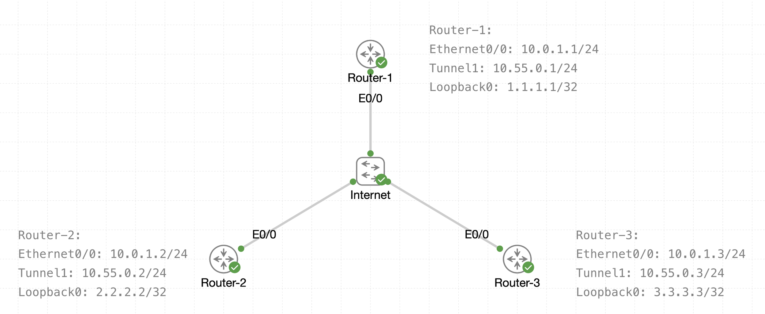
See that there is a transport IP addressing
Then there is overlay network over WAN (transport) that is multipoint GRE acting as a broadcast network, we can tell the broadcast nature by looking at Tunnel 1 Addressing
The default tunnel-type on Cisco routers is a GRE point-to-point. GRE is about as simple as a protocol gets.