SDWAN LM Notes 2
SDWAN Licensing
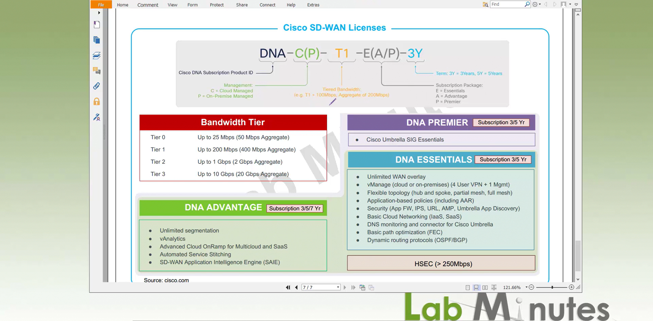
DNA C/P – Cloud managed or On-prem
Bandwidth Tier is the bandwidth offered on edge devices by license starting from 50Mbps to 20Gbps aggregate (bandwidth combined uploads and download bandwidths of all interfaces)
for example if you have 2 circuits of 100Mbps speed from ISP, your aggregate for WAN only will be 400Mbps – 200Mbps for one circuit and 200Mbps for another circuit and in that case we will need Tier 1 license offering 400Mbps of aggregate bandwidth
Then comes the DNA packages such as Essentials, Advantage and Premier
Essentials cover most of the SDWAN features needed and recently cisco has also moved some features down from Advantage into Essentials package in order to stay competitive
HSEC is something we need to keep an eye out for
Higher end routers will come with higher HSEC tier but still good to verify what is on the device
For larger environments it is good to get Cisco Enterprise Agreement as we can get a better deal on hundreds of edge devices
Recommended resources for vManage and controller numbers / sizing
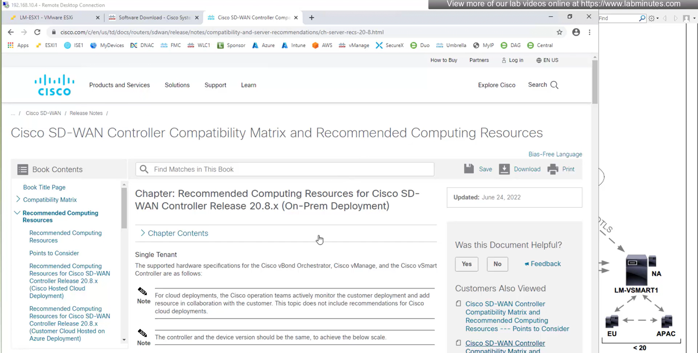
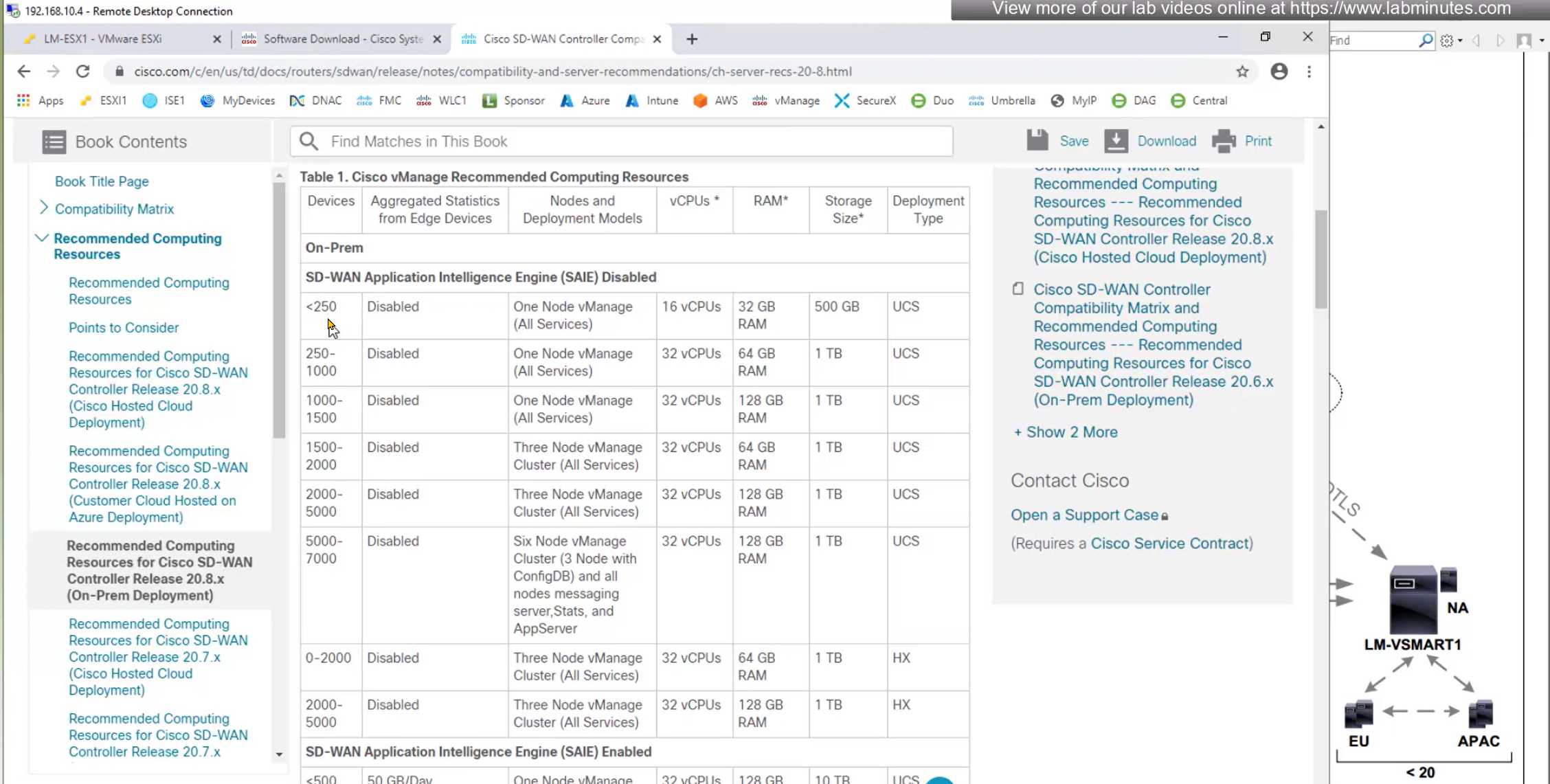
This starts by defining how many edge devices we have in the deployment and based on number of edge devices guide suggests to have vCPUs / RAM and additional VMs needed
Less than 1500 edge nodes will need 1 vManage, anything above 1500 edge nodes will require 3x vManage VMs
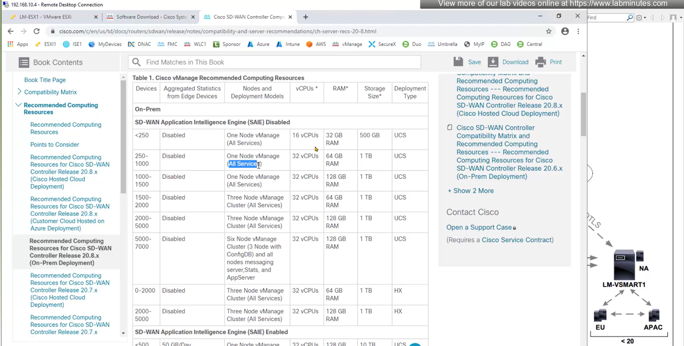
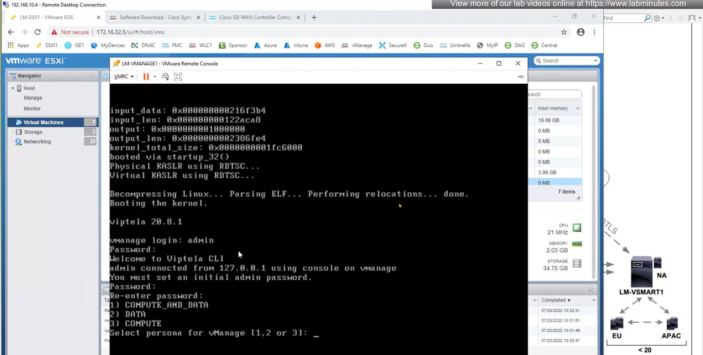
All services is a persona on vManage called COMPUTE_AND_DATA which is basically all services
A vManage with just a COMPUTE persona will only run vManage application, configuration and messaging but no Data statistics and vManage with with DATA stores statistics and data
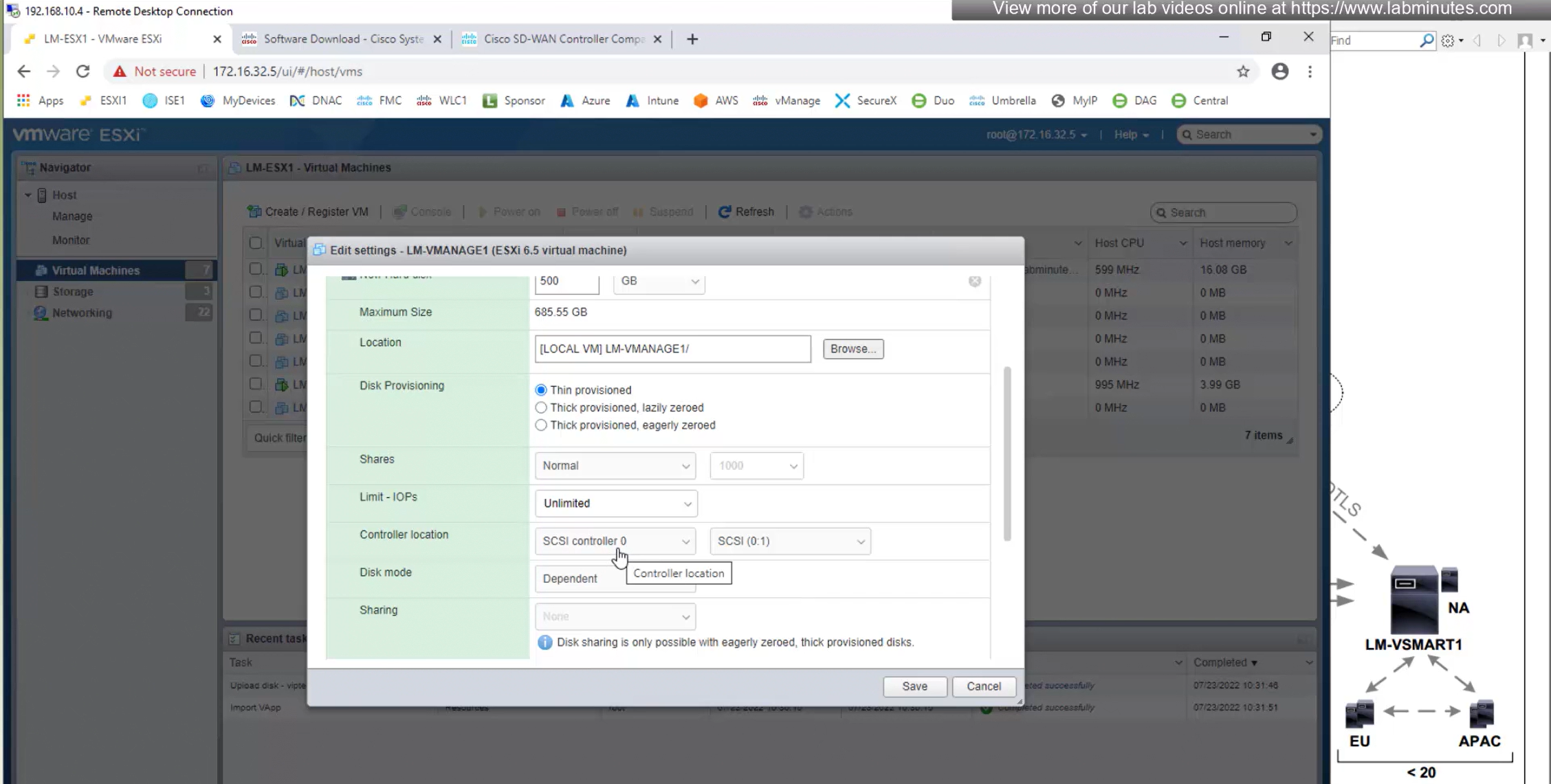
Download software from cisco.com
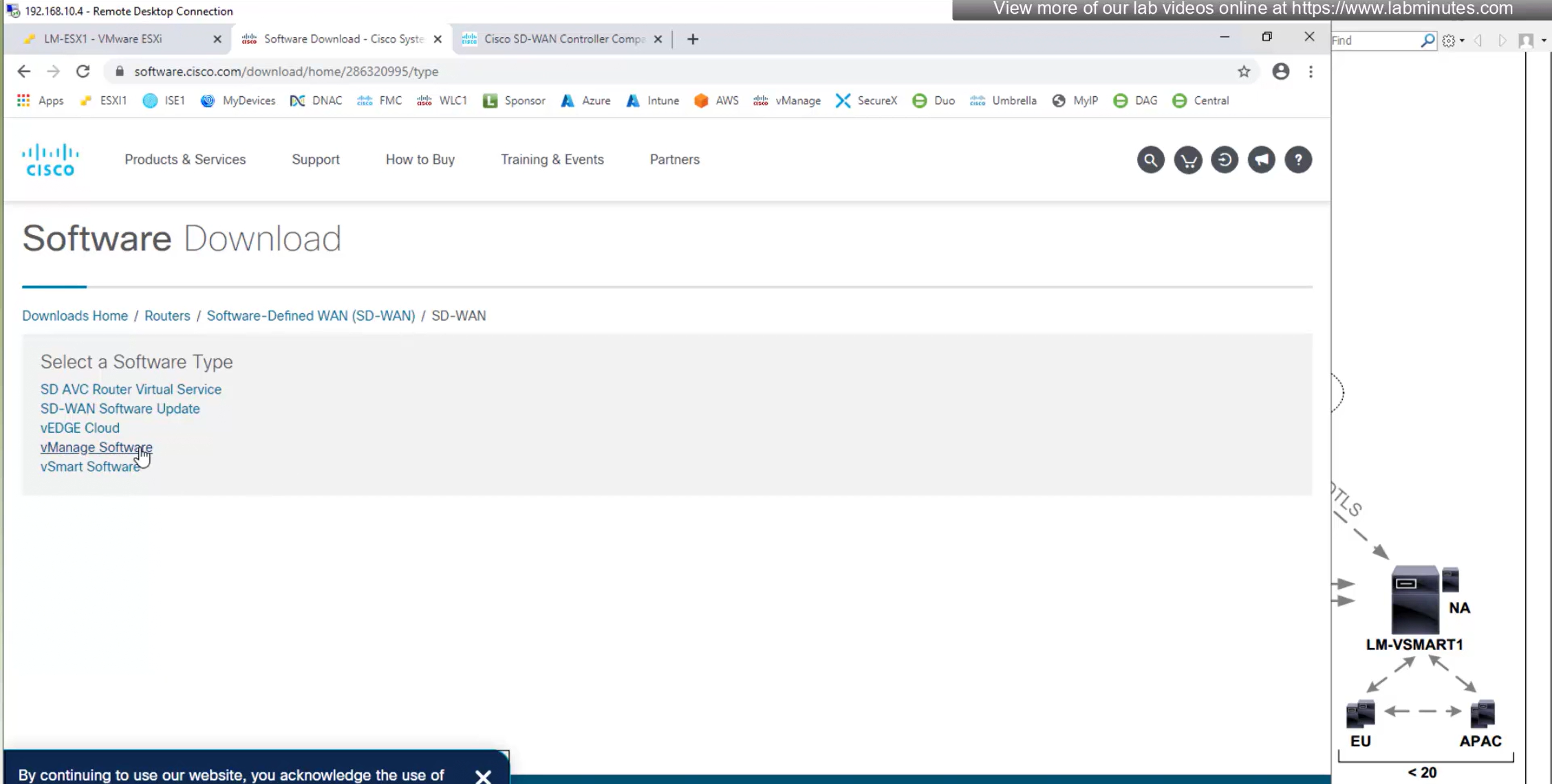
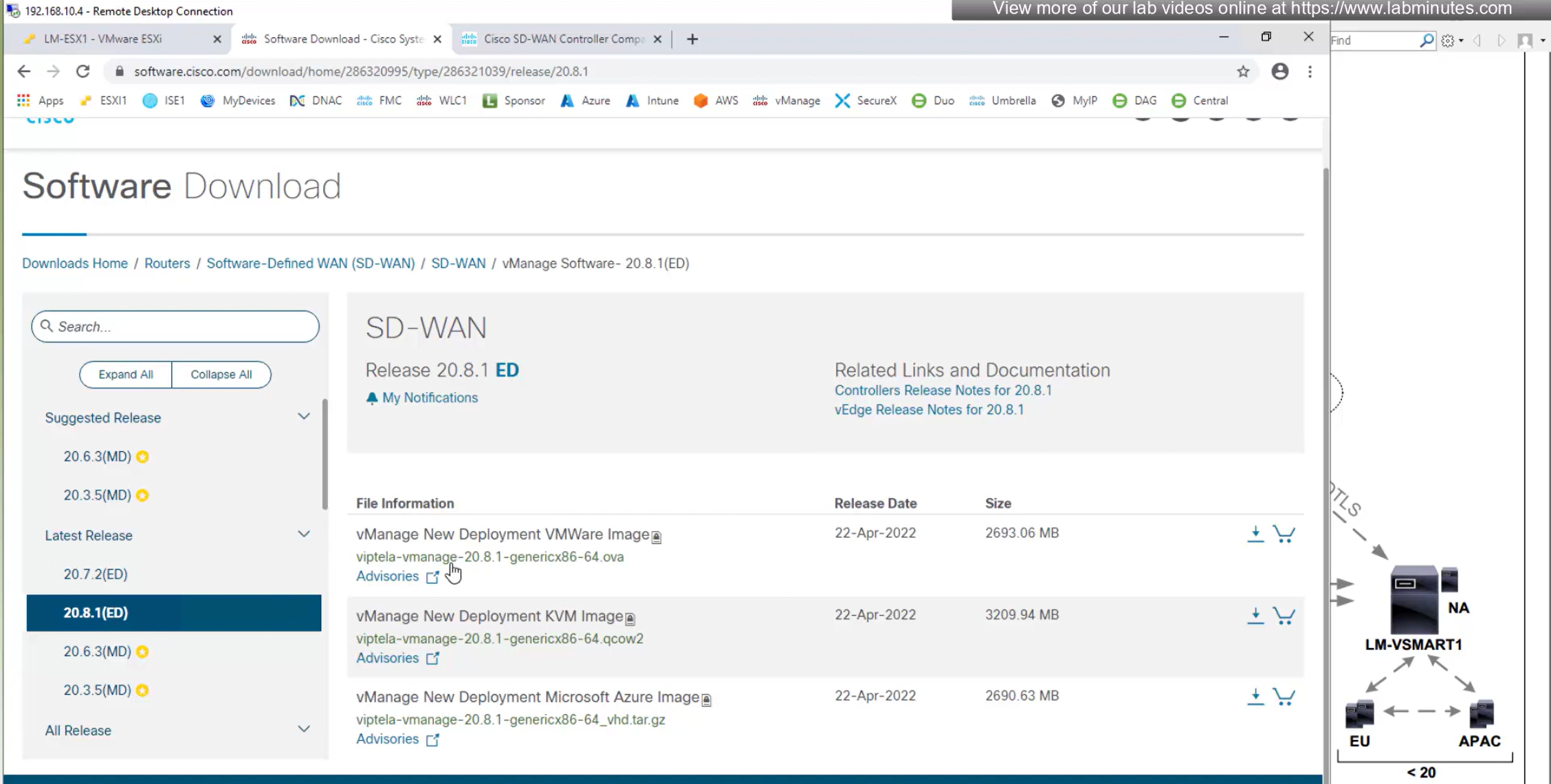
we will select ova for ESXi VM
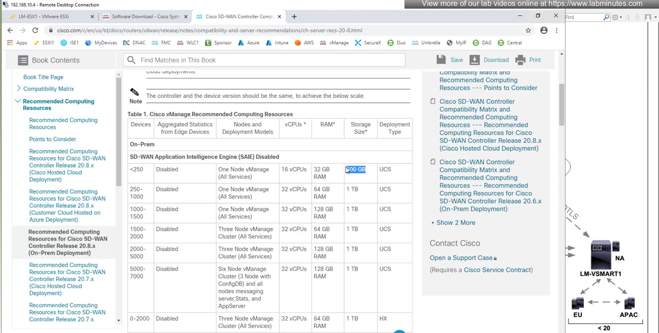
From version 20.8 onwards vManage minimum requires 500GB
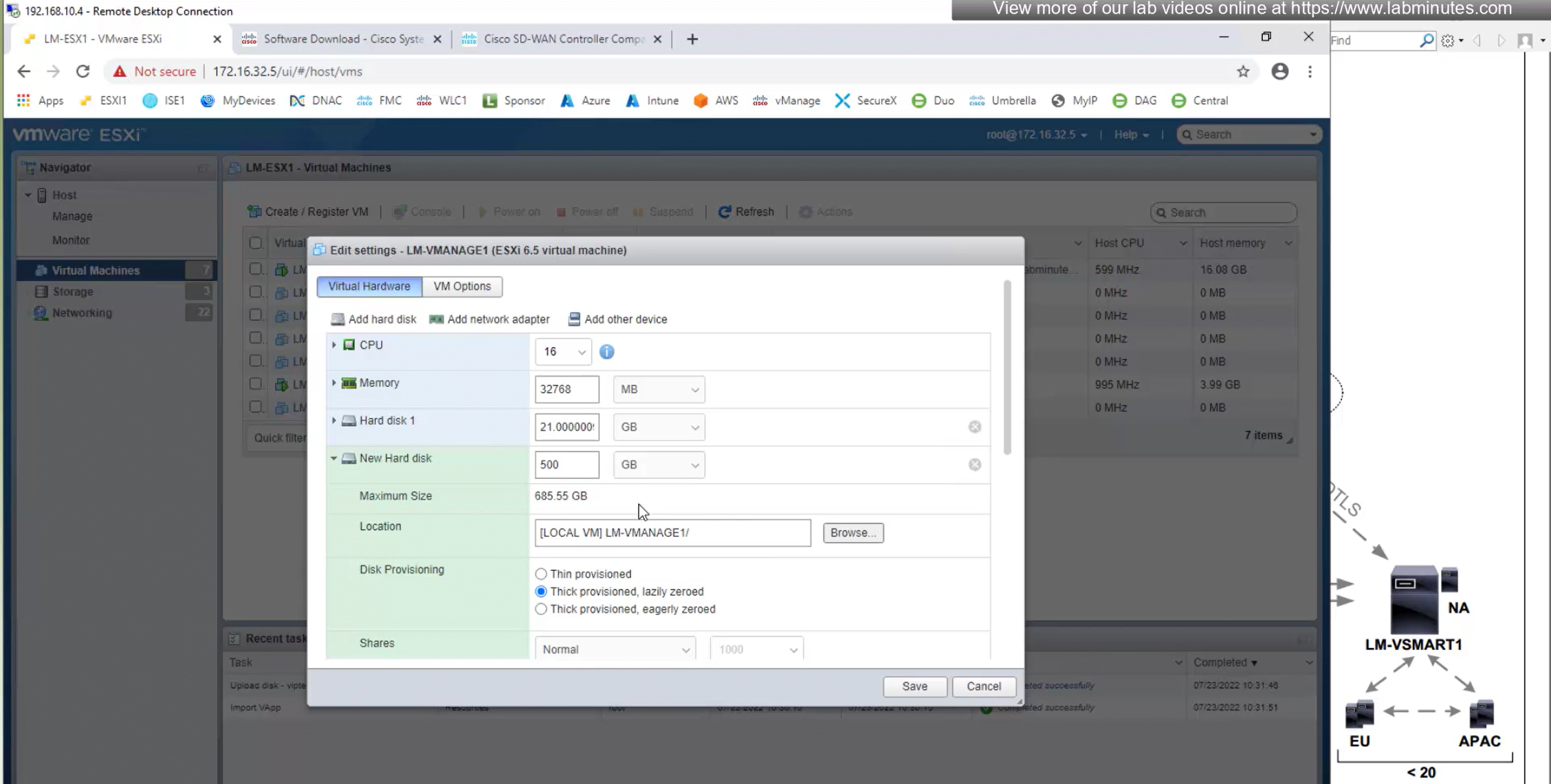
and for new version of vManage – controller type should be SCSI and not IDE
make sure that organistaion matches exactly as mentioned in Cisco smart account otherwise there will be sync issues
BFD polling
Default BFD polling is 1000 msec or 1 sec
OMP parameters
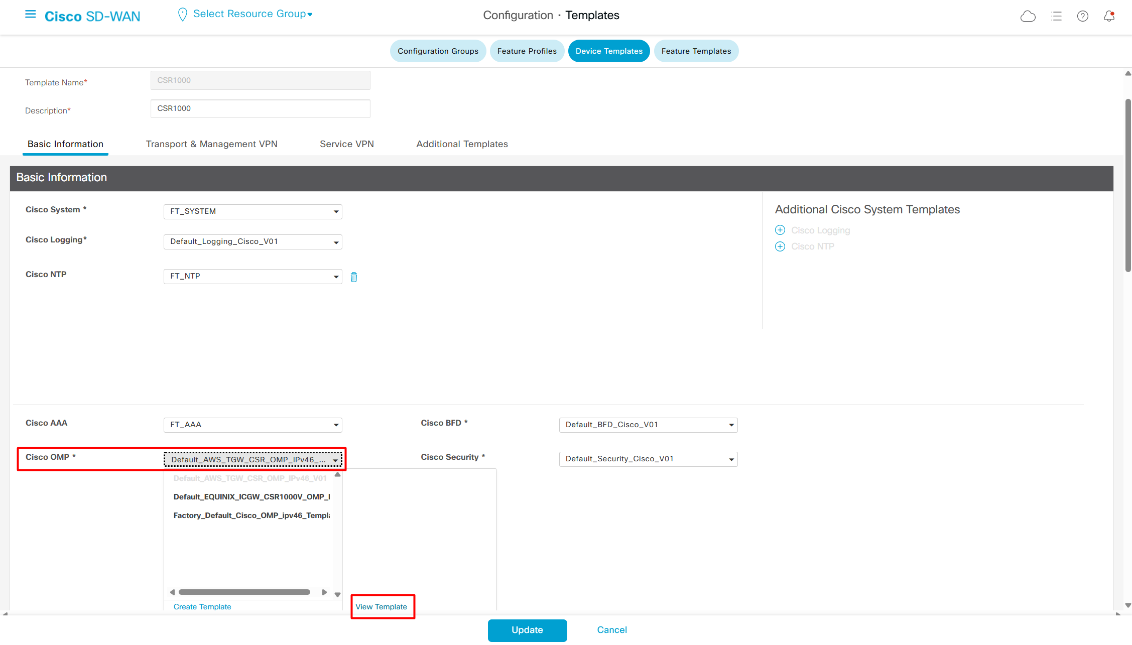
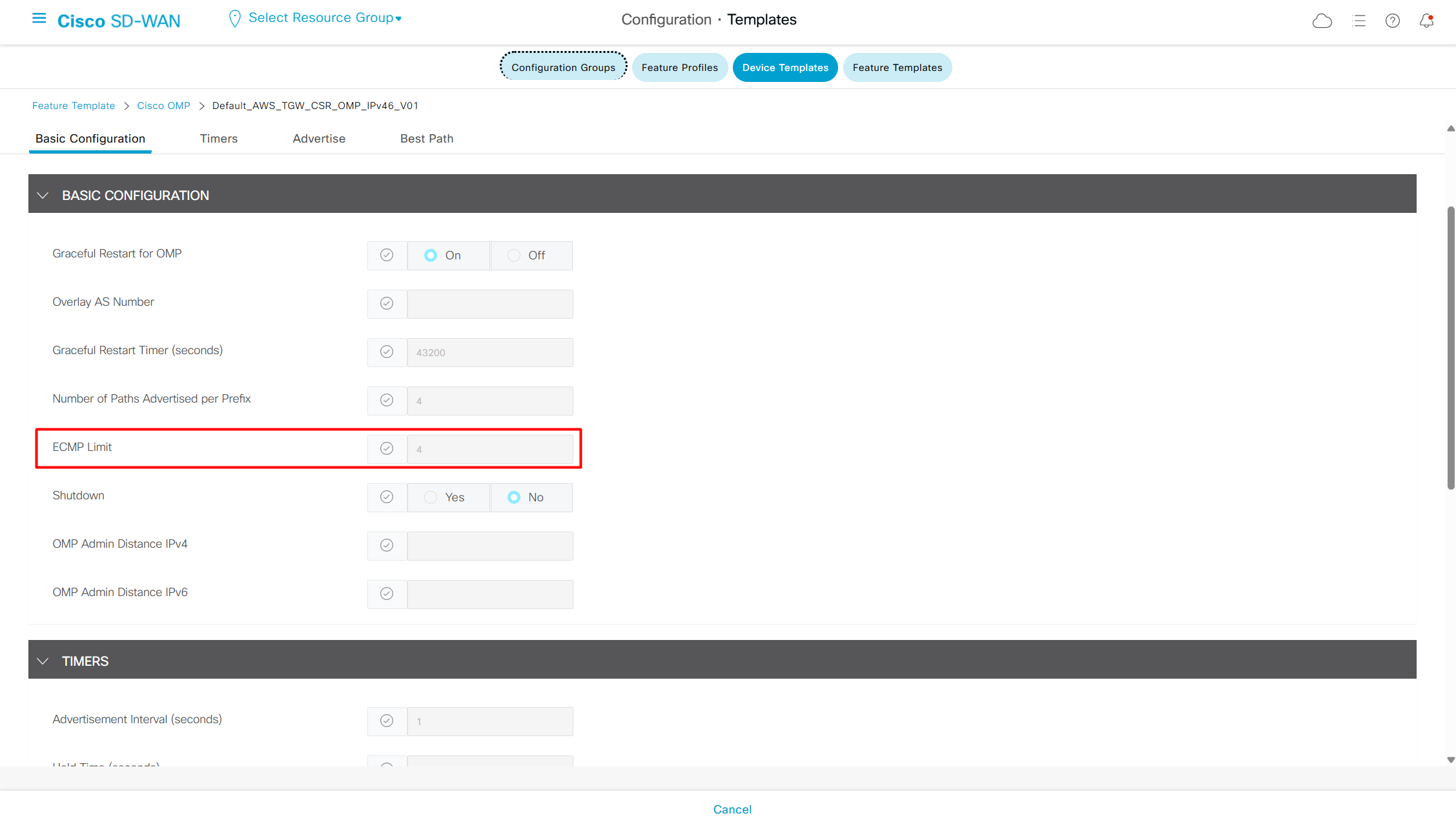
If you ever have to make changes in OMP such as increase ECMP limit then perform it here
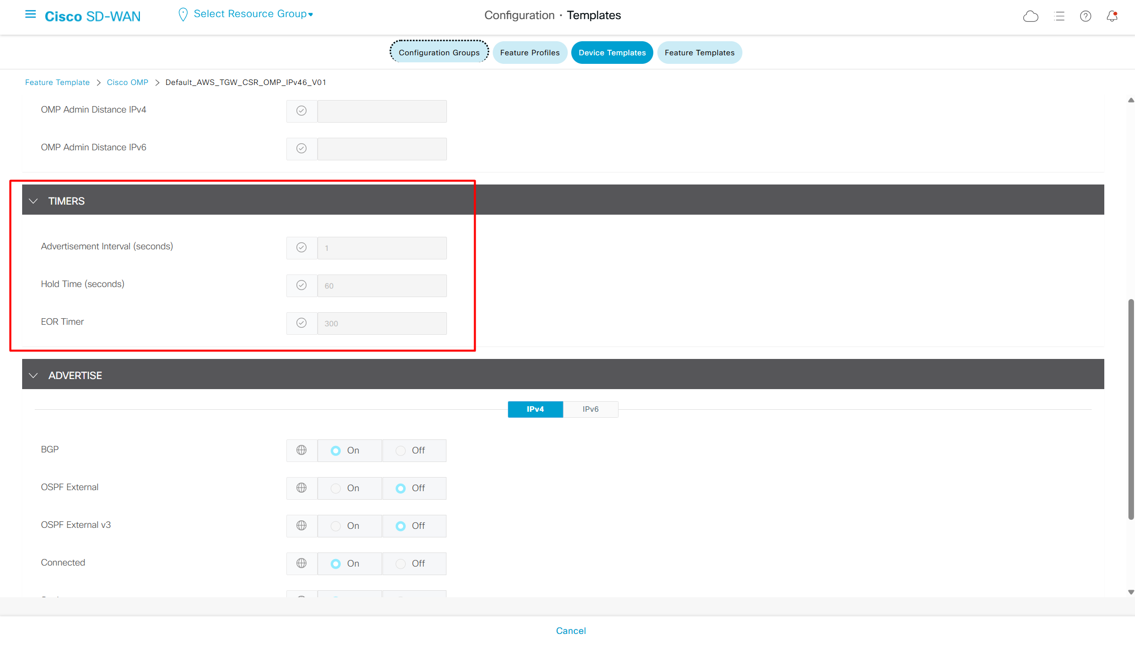
OMP timers
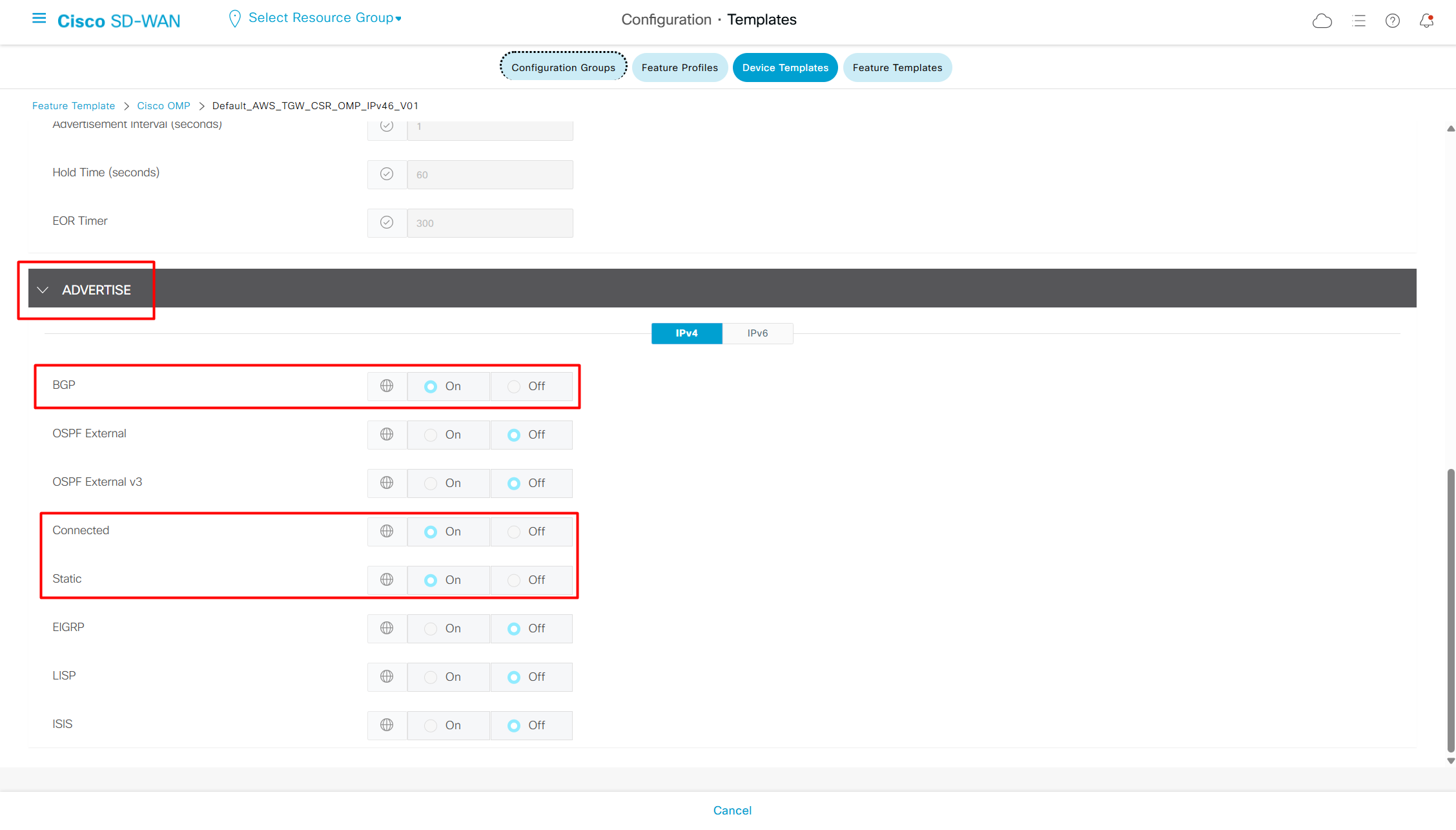
Shows what kind or routes are injected into OMP by default
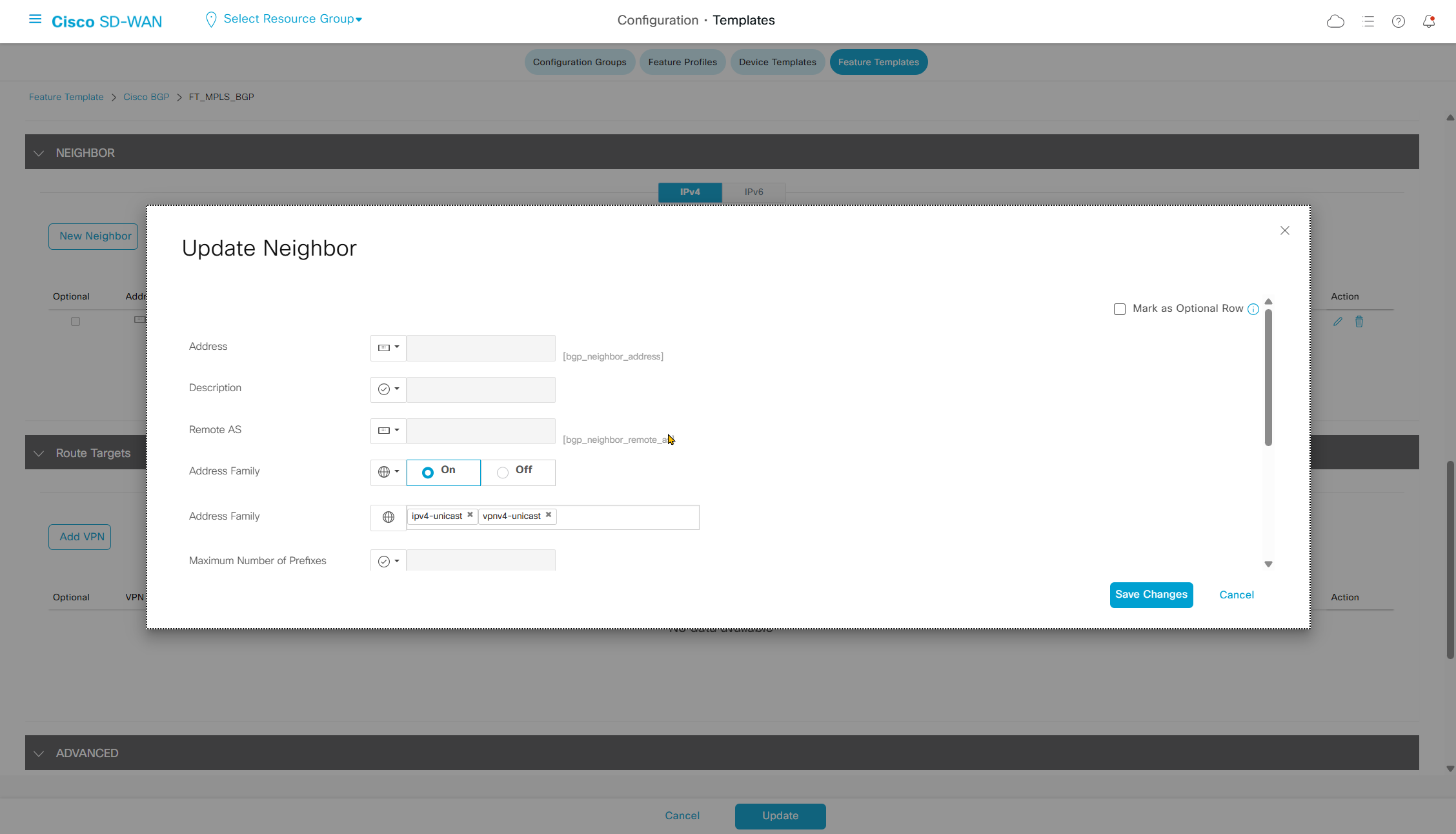
Create loopback on MPLS routers and then advertise it on Transport side using BGP

Loopback interface
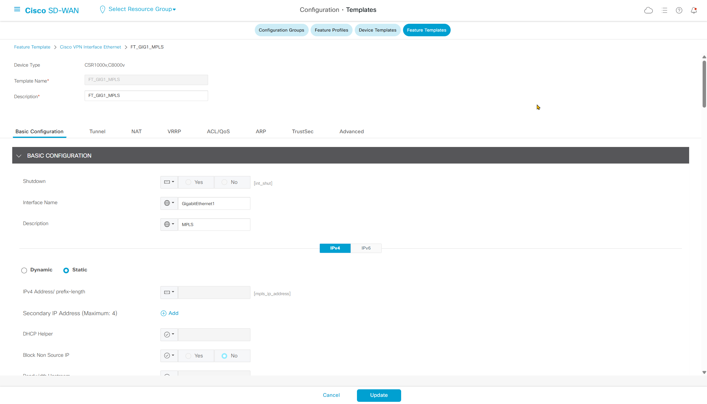
MPLS interface
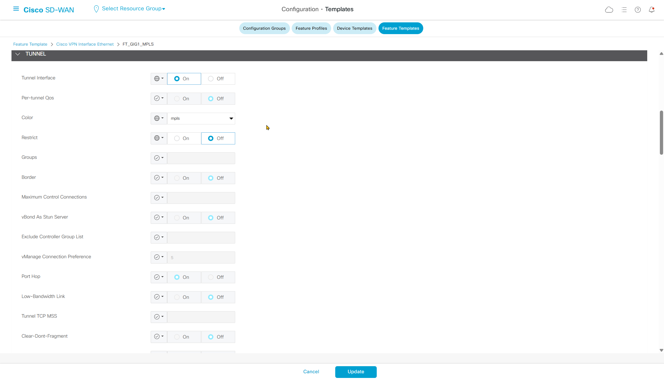
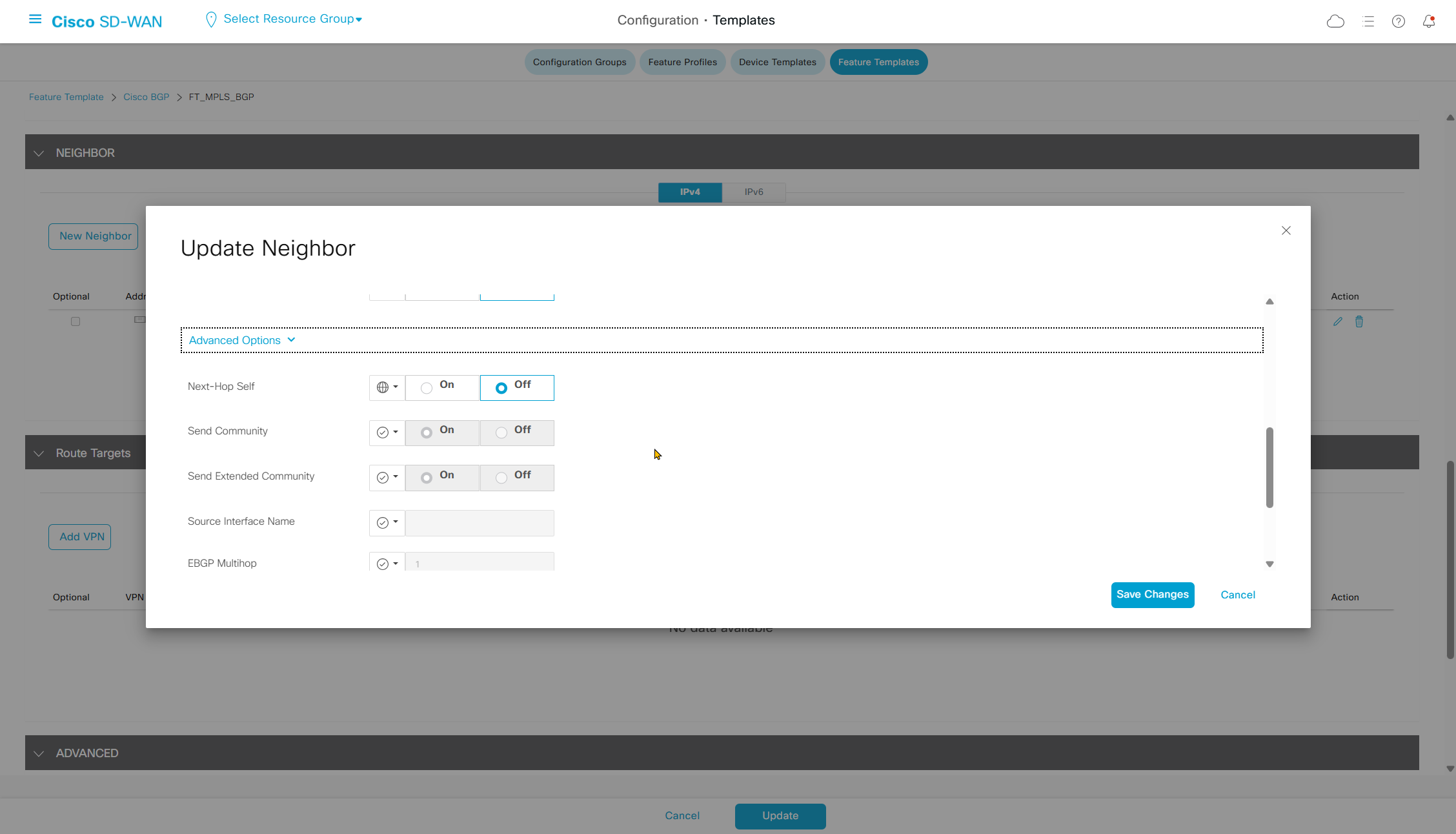
Make sure color is set under tunnel section
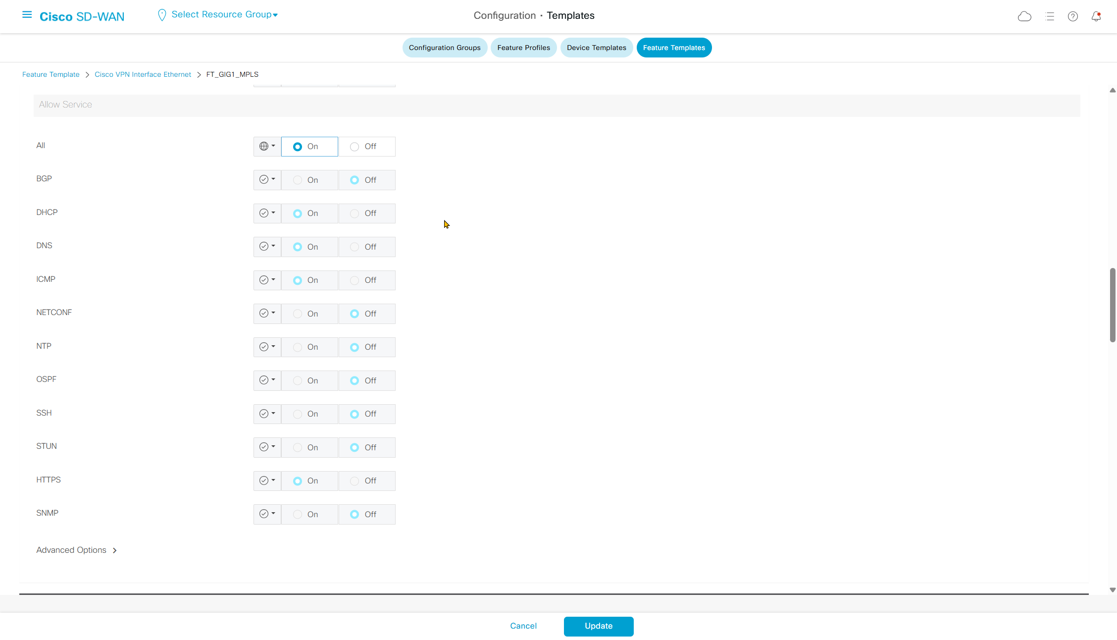
Also make sure that Allow service all is enabled, otherwise BGP did not come up and I was troubleshooting it for long time, when testing telnet at port 179 I realised SDWAN router is not sending TCP response back to switch
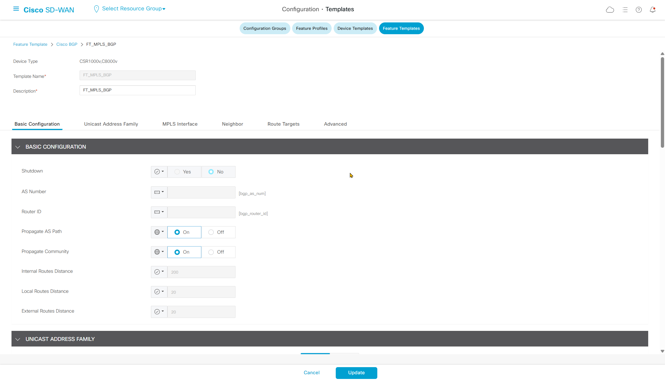
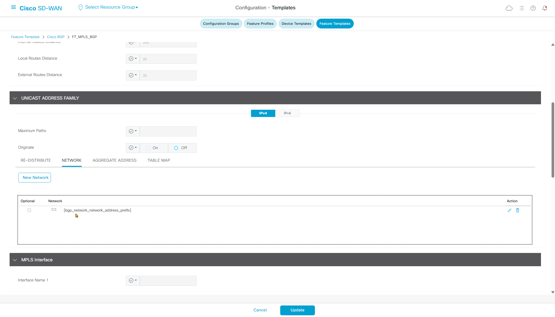
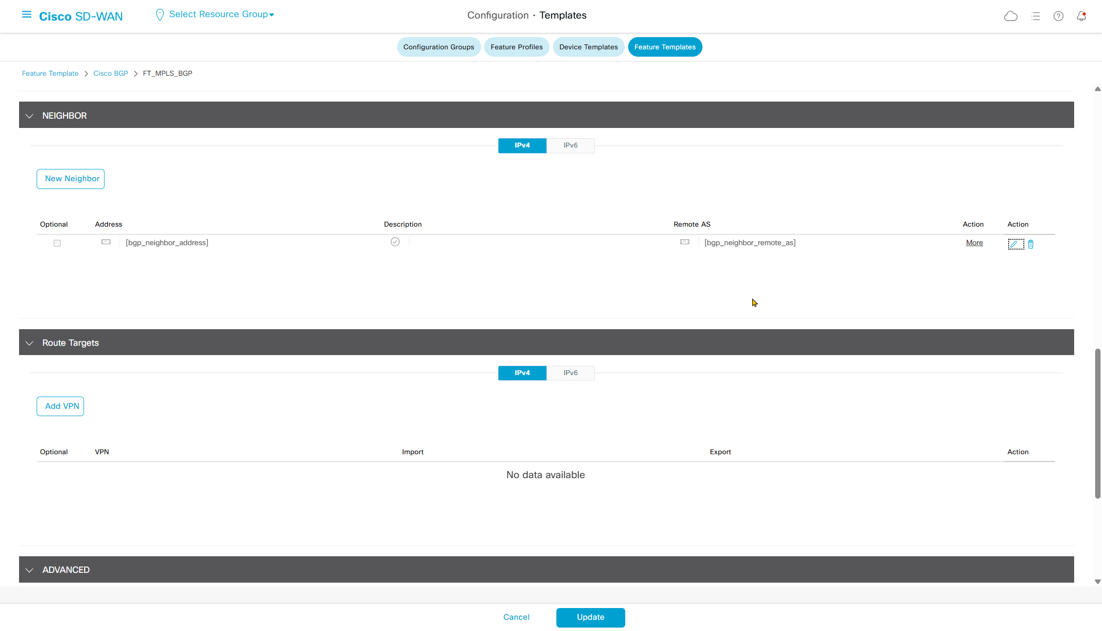
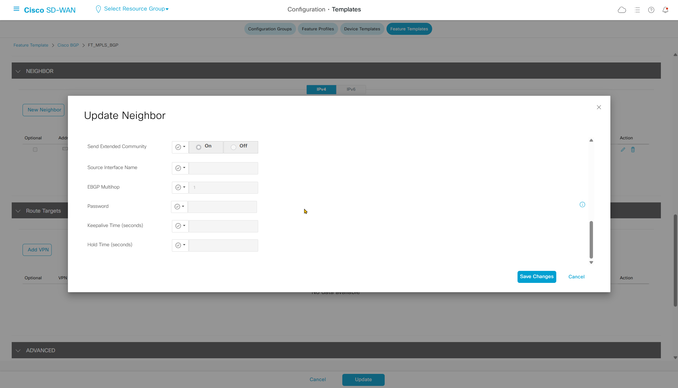
BGP Configuration
MPLS#show run
Building configuration...

Current configuration : 2669 bytes
!
! Last configuration change at 02:42:24 UTC Mon Mar 9 2026
!
version 17.12
service timestamps debug datetime msec
service timestamps log datetime msec
!
hostname MPLS
!
boot-start-marker
boot-end-marker
!
!
no aaa new-model
!
!
!
!
!
!
!
!
!
!
!
!
!
ip audit notify log
ip audit po max-events 100
ip cef
login on-success log
no ipv6 cef
!
!
!
!
!
!
!
vtp version 1
multilink bundle-name authenticated
!
!
!
!
memory free low-watermark processor 80589
!
!
spanning-tree mode rapid-pvst
spanning-tree extend system-id
!
!
vlan internal allocation policy ascending
!
!
!
!
!
interface Ethernet0/0
 description INTERNET SW
 no switchport
 ip address 172.31.255.253 255.255.255.252
 ip ospf 1 area 1
!
interface Ethernet0/1
 no switchport
 ip address 172.31.255.249 255.255.255.252
 ip ospf 1 area 1
!
interface Ethernet0/2
 no switchport
 ip address 172.31.255.245 255.255.255.252
 ip ospf 1 area 1
!
interface Ethernet0/3
 no switchport
 ip address 172.31.255.241 255.255.255.252
 ip ospf 1 area 1
!
interface Ethernet1/0
 no switchport
 ip address 172.31.255.237 255.255.255.252
 ip ospf 1 area 1
!
interface Ethernet1/1
!
interface Ethernet1/2
!
interface Ethernet1/3
!
router ospf 1
 router-id 172.31.255.254
 redistribute bgp 10
 passive-interface default
 no passive-interface Ethernet0/0
!
router bgp 10
 template peer-policy CE
  send-community both
 exit-peer-policy
 !
 template peer-session CE
  ebgp-multihop 5
  timers 5 10
 exit-peer-session
 !
 bgp log-neighbor-changes
 neighbor 172.31.255.238 remote-as 65104
 neighbor 172.31.255.238 inherit peer-session CE
 neighbor 172.31.255.242 remote-as 65103
 neighbor 172.31.255.242 inherit peer-session CE
 neighbor 172.31.255.246 remote-as 65102
 neighbor 172.31.255.246 inherit peer-session CE
 neighbor 172.31.255.250 remote-as 65102
 neighbor 172.31.255.250 inherit peer-session CE
 !
 address-family ipv4
  network 172.31.255.236 mask 255.255.255.252
  network 172.31.255.240 mask 255.255.255.252
  network 172.31.255.244 mask 255.255.255.252
  network 172.31.255.248 mask 255.255.255.252
  network 172.31.255.252 mask 255.255.255.252
  neighbor 172.31.255.238 activate
  neighbor 172.31.255.238 inherit peer-policy CE
  neighbor 172.31.255.242 activate
  neighbor 172.31.255.242 inherit peer-policy CE
  neighbor 172.31.255.246 activate
  neighbor 172.31.255.246 inherit peer-policy CE
  neighbor 172.31.255.250 activate
  neighbor 172.31.255.250 inherit peer-policy CE
 exit-address-family
!
ip forward-protocol nd
!
!
ip http server
ip http secure-server
ip ssh bulk-mode 131072
!
!
!
!
!
!
control-plane
!
!
!
line con 0
 logging synchronous
line aux 0
line vty 0 4
 login
 transport input ssh
!
!
end
Trunking configuration
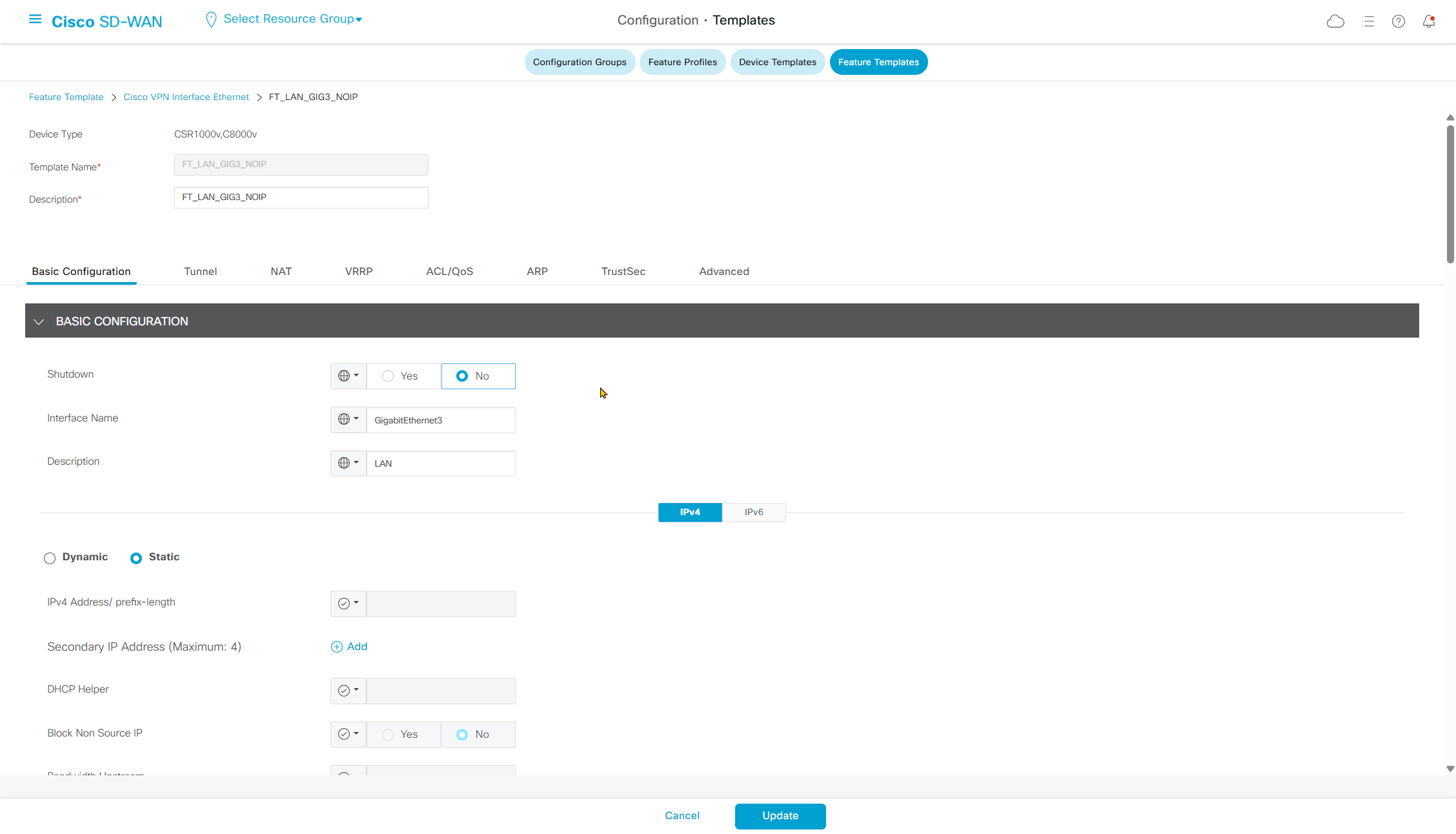
This is the GIG3 template without IP variable – no IP address so we can configure trunking
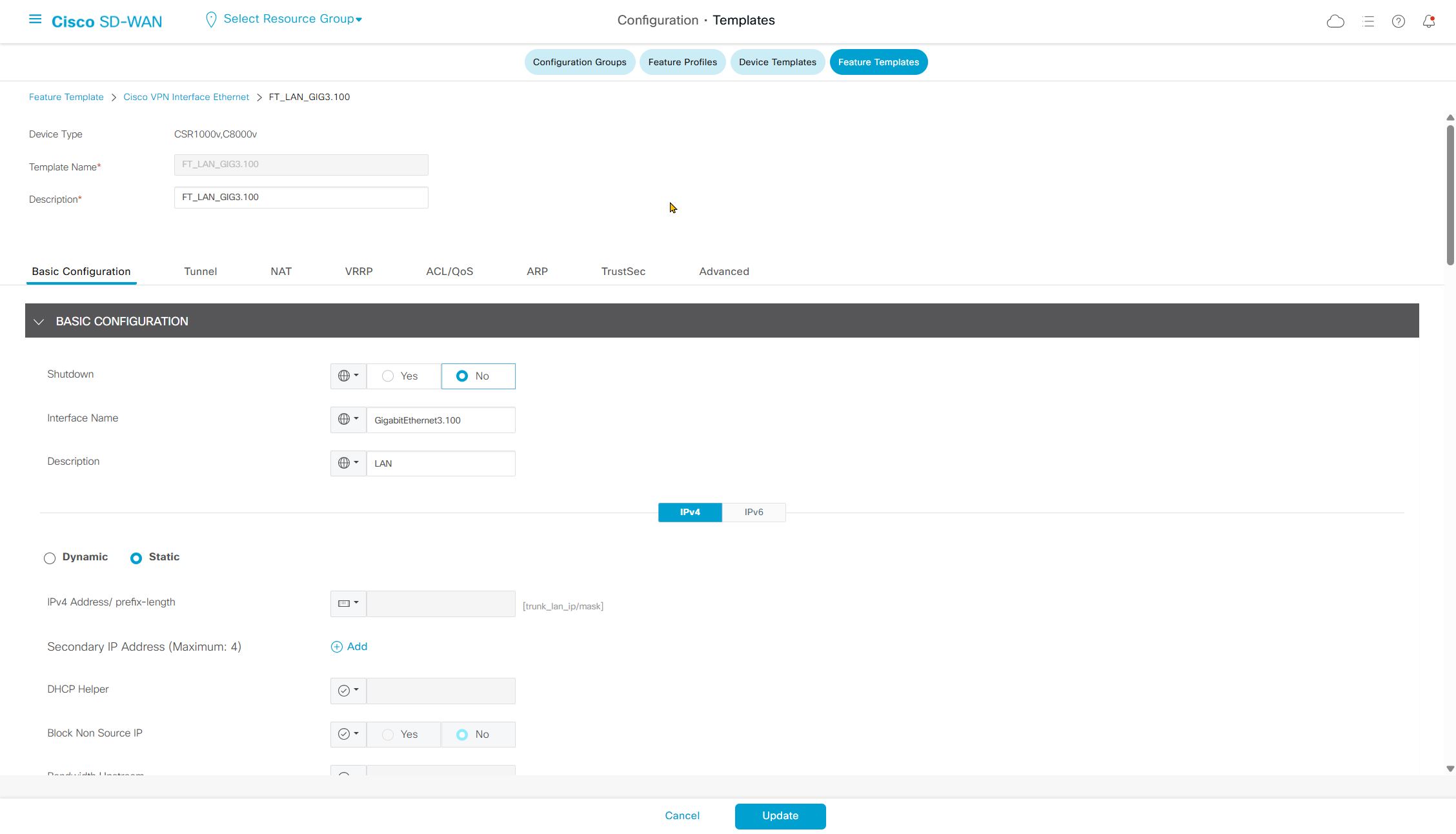
This is GIG3.100 interface that will be trunking interface
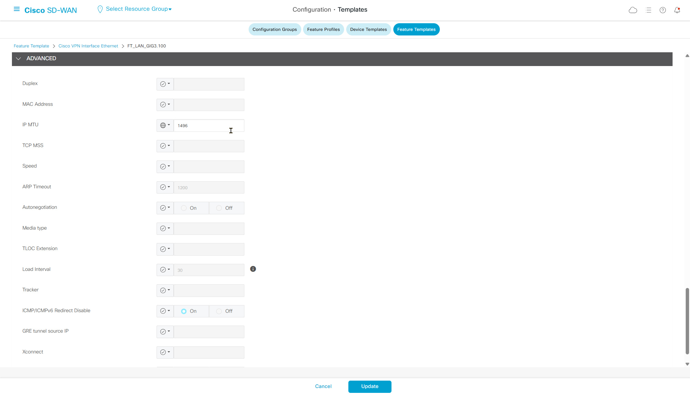
but reduce the MTU on this interface by 4 bytes to 1496 to accomodate the VLAN tag
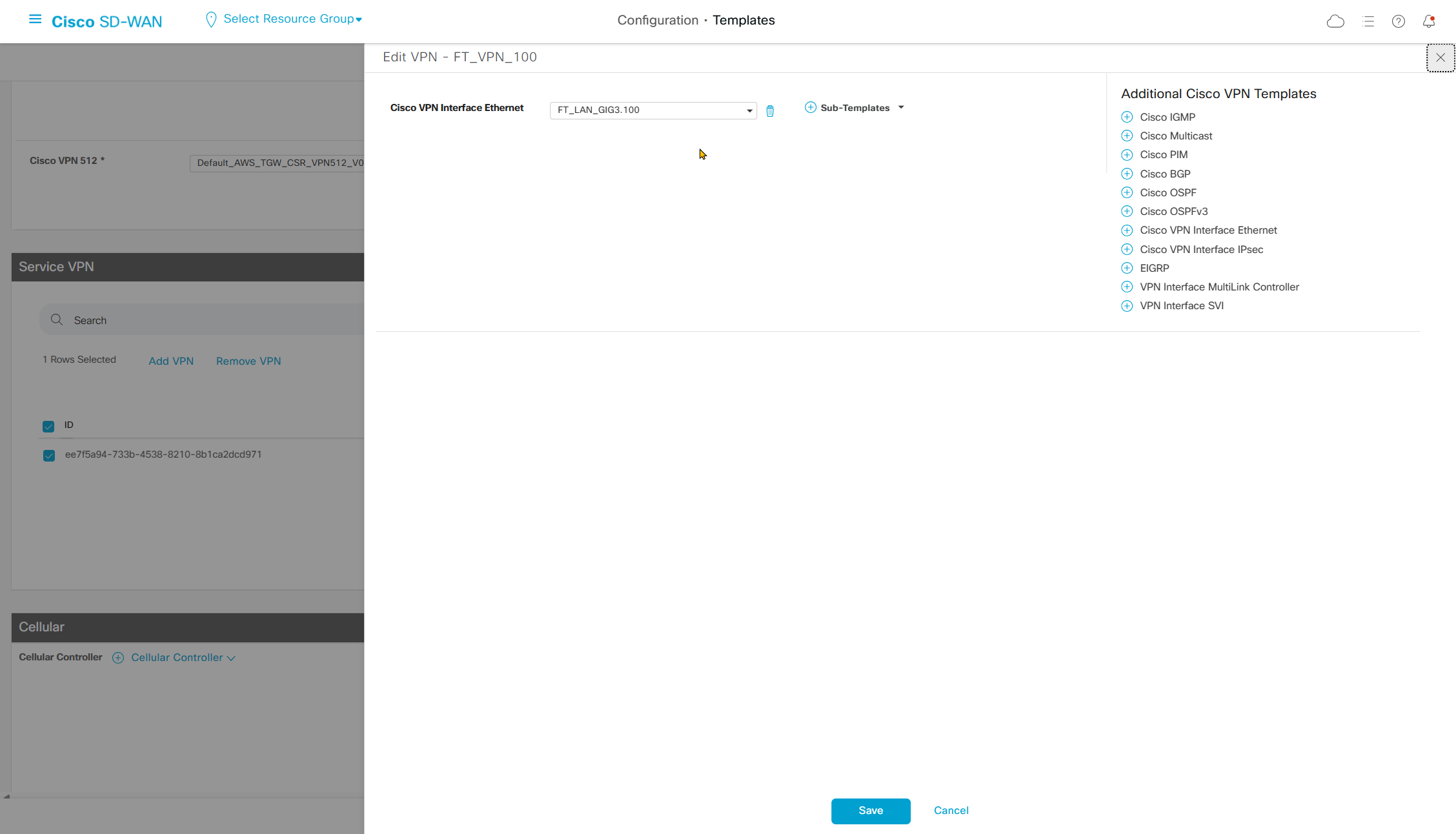
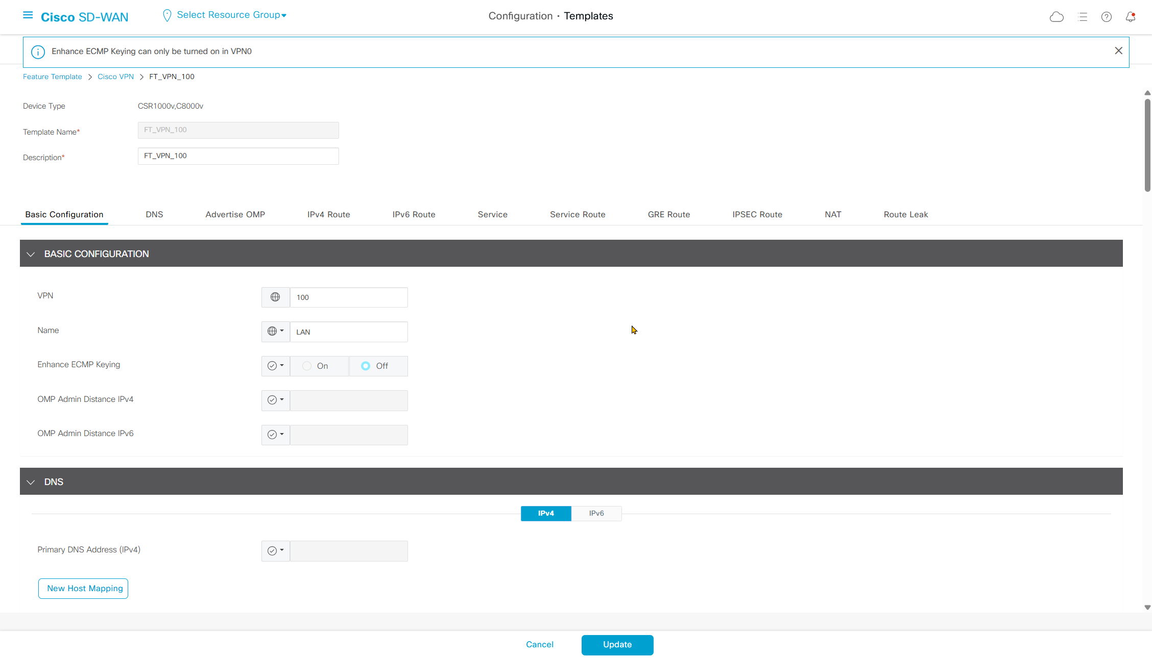
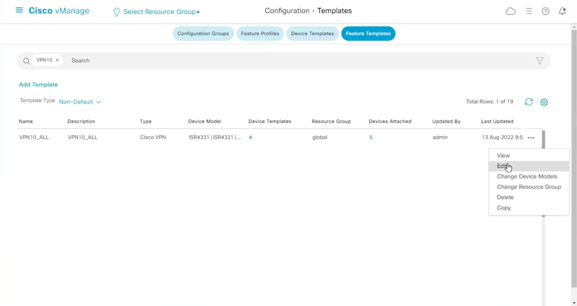
Now edit the device template
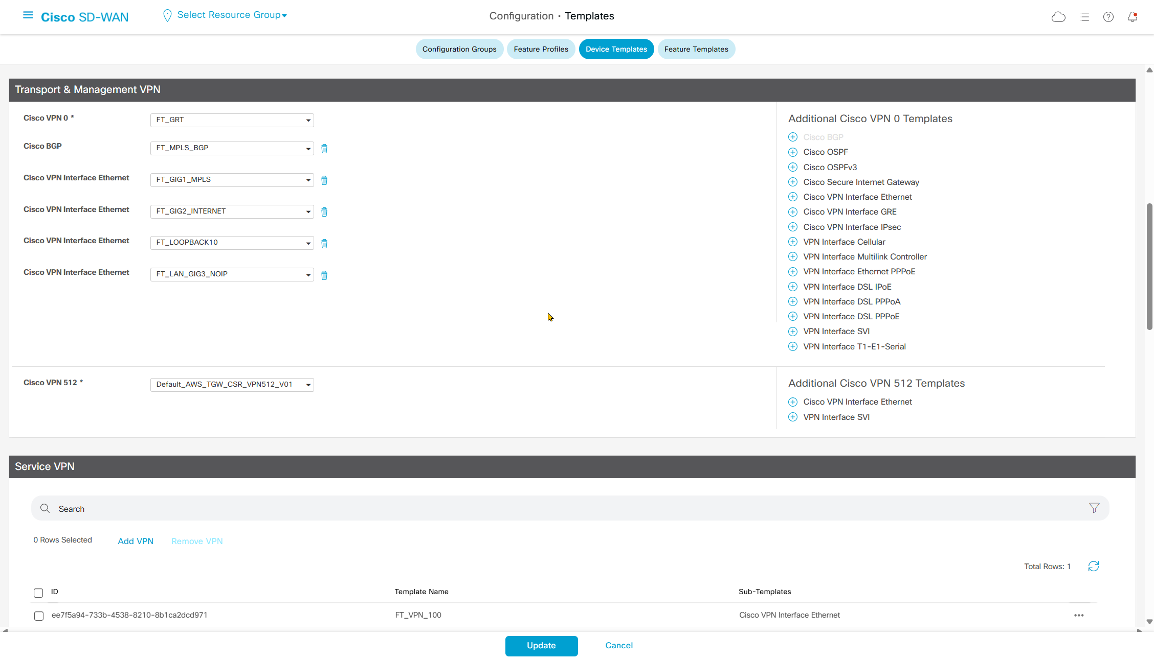
GIG3_NOIP will be assigned to VPN 0 transport VPN
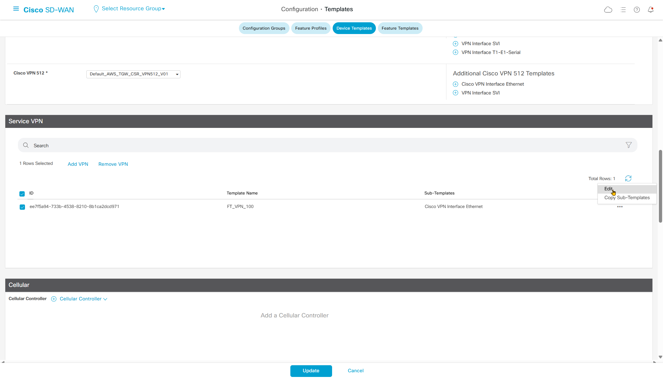
And GIG3.100 will be assigned to the VPN 100 service VPN
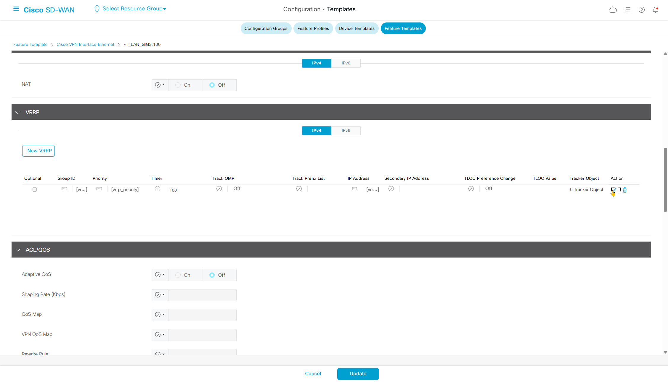
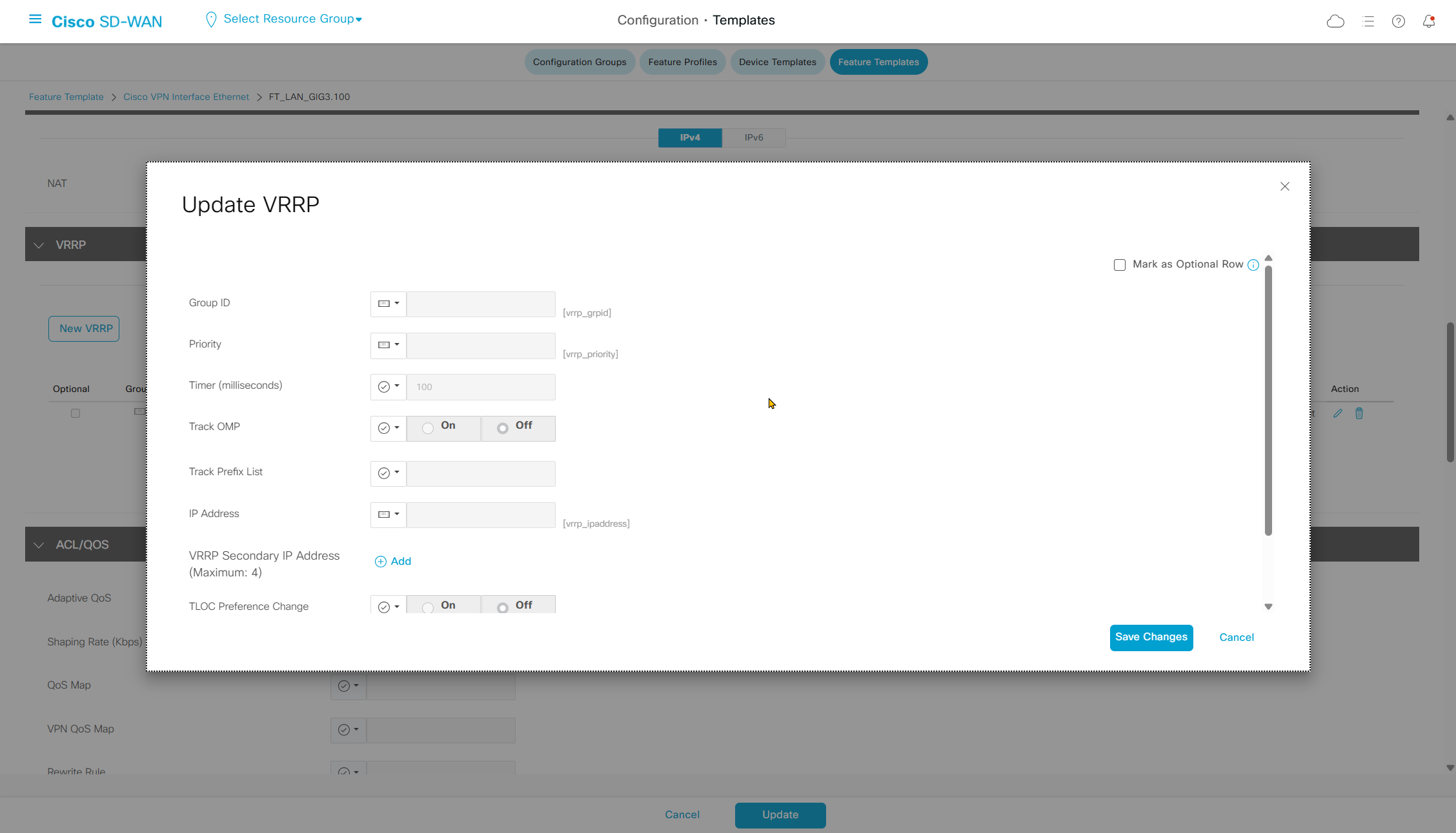
VRRP configuration
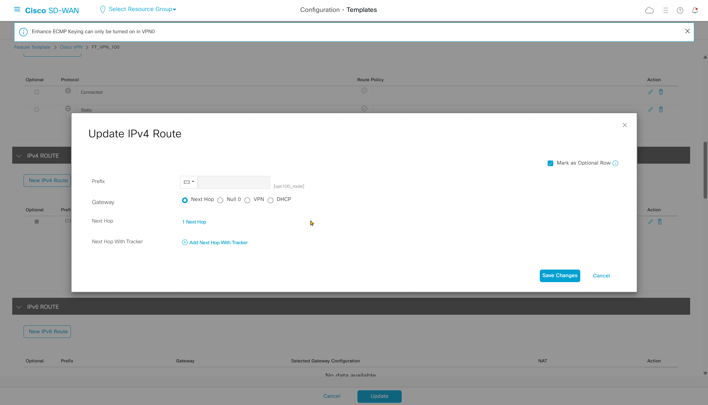
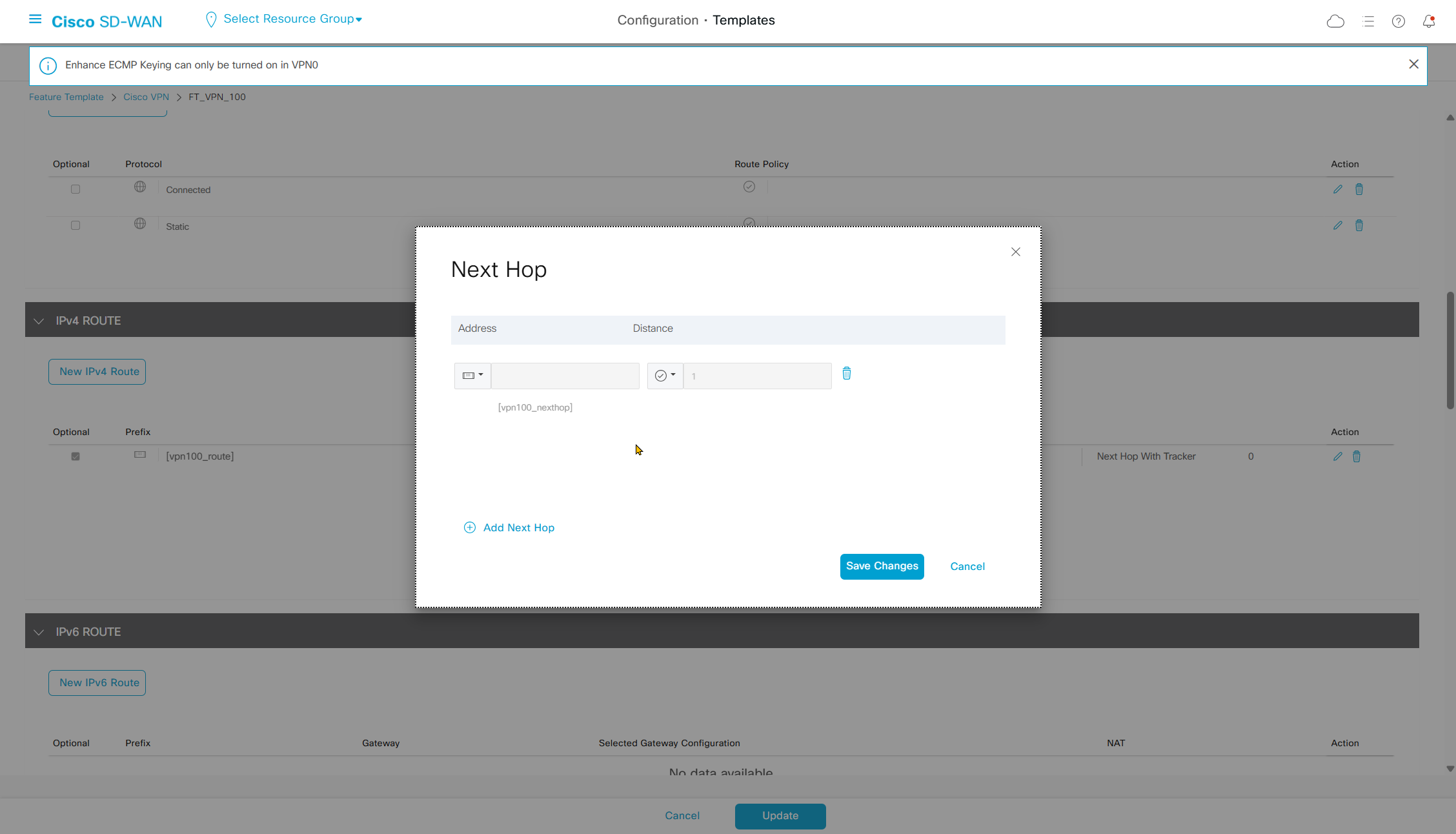
Static route
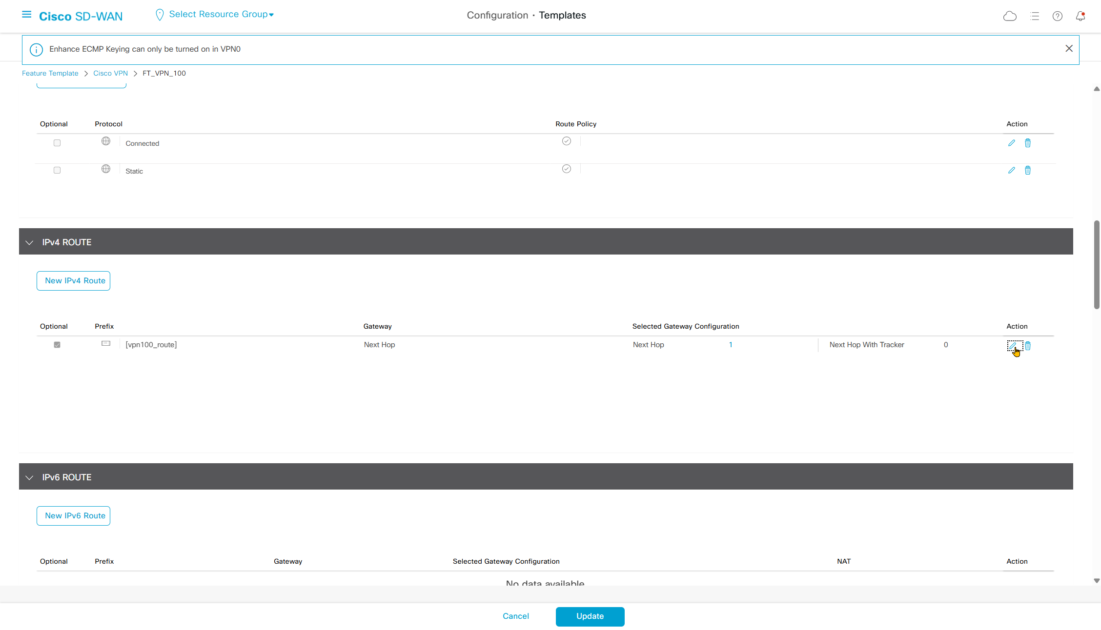
Make sure that VPN supports redistribution of connected and “static”, if static is not enabled then static route will only be on specific router but rest of the routers or sites will not learn via omp
Also make sure that static route is marked as optional row
hostname SW-1002
!
interface Ethernet0/0
 switchport access vlan 100
 switchport trunk encapsulation dot1q
 switchport trunk allowed vlan 100
 switchport mode trunk
!
interface Ethernet0/1
 switchport access vlan 100
 switchport trunk encapsulation dot1q
 switchport trunk allowed vlan 100
 switchport mode trunk
!
interface Vlan100
 ip address 172.16.2.11 255.255.254.0
!
interface Vlan200
 ip address 172.16.4.1 255.255.254.0
!
ip route 0.0.0.0 0.0.0.0 172.16.2.1
!
SW-1002#show ip int brief
Interface IP-Address OK? Method Status Protocol
Ethernet0/0 unassigned YES unset up up
Ethernet0/1 unassigned YES unset up up
Ethernet0/2 unassigned YES unset down down
Ethernet0/3 unassigned YES unset down down
Ethernet1/0 unassigned YES unset down down
Ethernet1/1 unassigned YES unset down down
Ethernet1/2 unassigned YES unset up up
Ethernet1/3 unassigned YES unset up up
Vlan100 172.16.2.11 YES manual up up
Vlan200 172.16.4.1 YES manual down down <<<Vlan 200 SVI interface was down and not coming up
because no access port is assigned to vlan 200
so I allowed vlan 200 on the uplinks to C8000 edge routers to bring vlan 200 interface up
hostname SW-1002
!
interface Ethernet0/0
 switchport access vlan 100
 switchport trunk encapsulation dot1q
 switchport trunk allowed vlan 100,200 <<<
 switchport mode trunk
!
interface Ethernet0/1
 switchport access vlan 100
 switchport trunk encapsulation dot1q
 switchport trunk allowed vlan 100,200 <<<
 switchport mode trunk
!
interface Vlan100
 ip address 172.16.2.11 255.255.254.0
!
interface Vlan200
 ip address 172.16.4.1 255.255.254.0
!
ip route 0.0.0.0 0.0.0.0 172.16.2.1
!
SW-1002#show ip int brief
Interface IP-Address OK? Method Status Protocol
Ethernet0/0 unassigned YES unset up up
Ethernet0/1 unassigned YES unset up up
Ethernet0/2 unassigned YES unset down down
Ethernet0/3 unassigned YES unset down down
Ethernet1/0 unassigned YES unset down down
Ethernet1/1 unassigned YES unset down down
Ethernet1/2 unassigned YES unset up up
Ethernet1/3 unassigned YES unset up up
Vlan100 172.16.2.11 YES manual up up
Vlan200 172.16.4.1 YES manual up up <<<C801-1002-DUAL#
ip route vrf 100 172.16.4.0 255.255.254.0 172.16.2.11CSR-1004-MPLS#show sdwan omp route
Generating output, this might take time, please wait ...
Code:
C -> chosen
I -> installed
Red -> redistributed
Rej -> rejected
L -> looped
R -> resolved
S -> stale
Ext -> extranet
Inv -> invalid
Stg -> staged
IA -> On-demand inactive
U -> TLOC unresolved
PATH ATTRIBUTE
VPN PREFIX FROM PEER ID LABEL STATUS TYPE TLOC IP COLOR ENCAP PREFERENCE
--------------------------------------------------------------------------------------------------------------------------------------
100 172.16.0.0/23 22.22.22.22 6 1003 C,I,R installed 13.13.13.13 biz-internet ipsec -
100 172.16.2.0/23 22.22.22.22 7 1004 C,I,R installed 12.12.12.12 mpls ipsec -
22.22.22.22 8 1004 C,I,R installed 12.12.12.12 biz-internet ipsec -
22.22.22.22 19 1004 C,I,R installed 11.11.11.11 mpls ipsec -
22.22.22.22 20 1004 C,I,R installed 11.11.11.11 biz-internet ipsec -
100 172.16.4.0/23 >>> 22.22.22.22 19 1004 C,I,R installed 11.11.11.11 mpls ipsec -
>>> 22.22.22.22 20 1004 C,I,R installed 11.11.11.11 biz-internet ipsec -
>>> 22.22.22.22 27 1004 C,I,R installed 12.12.12.12 mpls ipsec -
>>> 22.22.22.22 29 1004 C,I,R installed 12.12.12.12 biz-internet ipsec -
100 172.16.8.0/23 0.0.0.0 66 1003 C,Red,R installed 16.16.16.16 mpls ipsec -
C801-1002-DUAL#show ip route vrf 100
Routing Table: 100
Gateway of last resort is not set
172.16.0.0/16 is variably subnetted, 5 subnets, 2 masks
m 172.16.0.0/23 [251/0] via 13.13.13.13, 03:50:11, Sdwan-system-intf
C 172.16.2.0/23 is directly connected, GigabitEthernet3.100
L 172.16.2.2/32 is directly connected, GigabitEthernet3.100
S 172.16.4.0/23 [1/0] via 172.16.2.11
m 172.16.8.0/23 [251/0] via 16.16.16.16, 03:50:11, Sdwan-system-intf
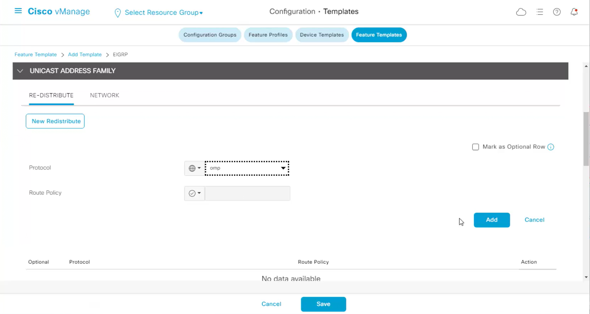
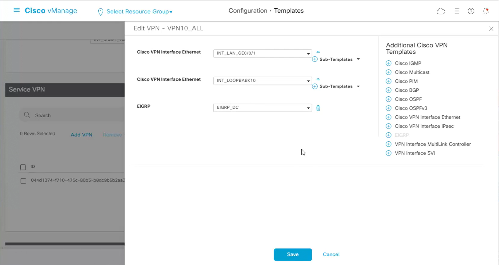
C801-1002-DUAL# EIGRP Serviceside configuration
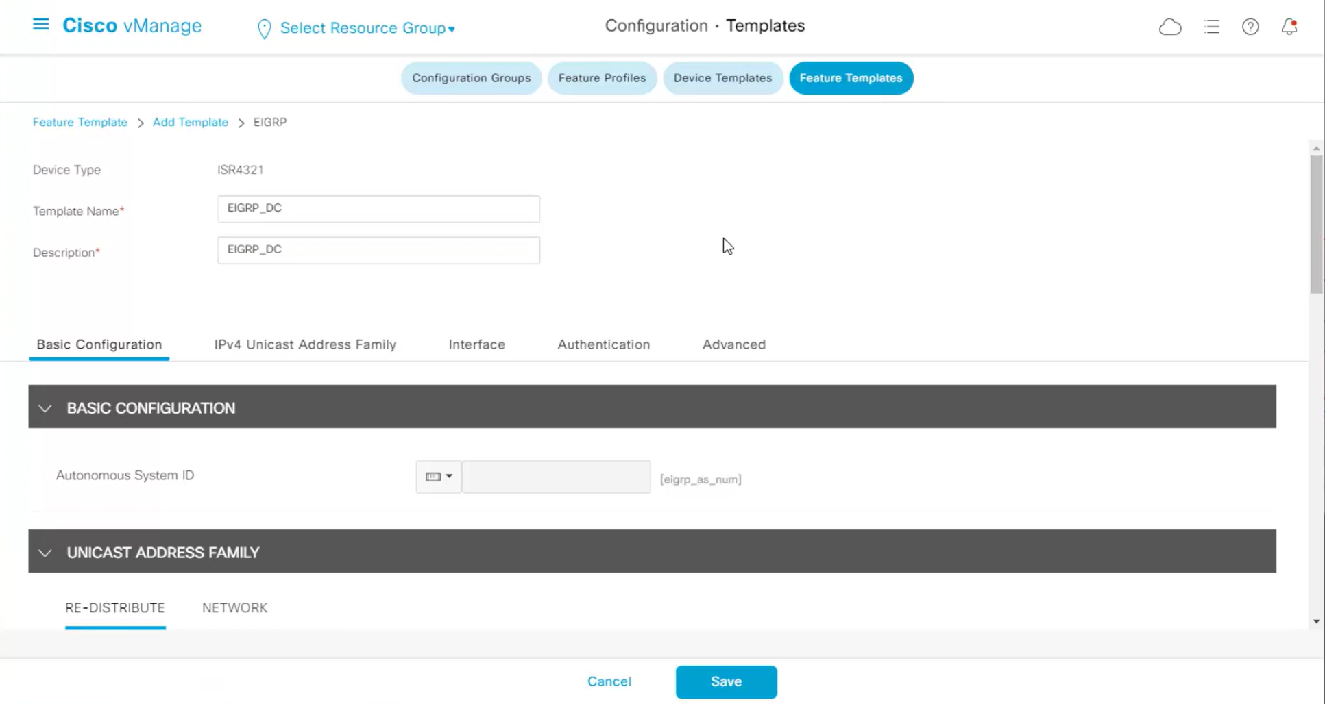
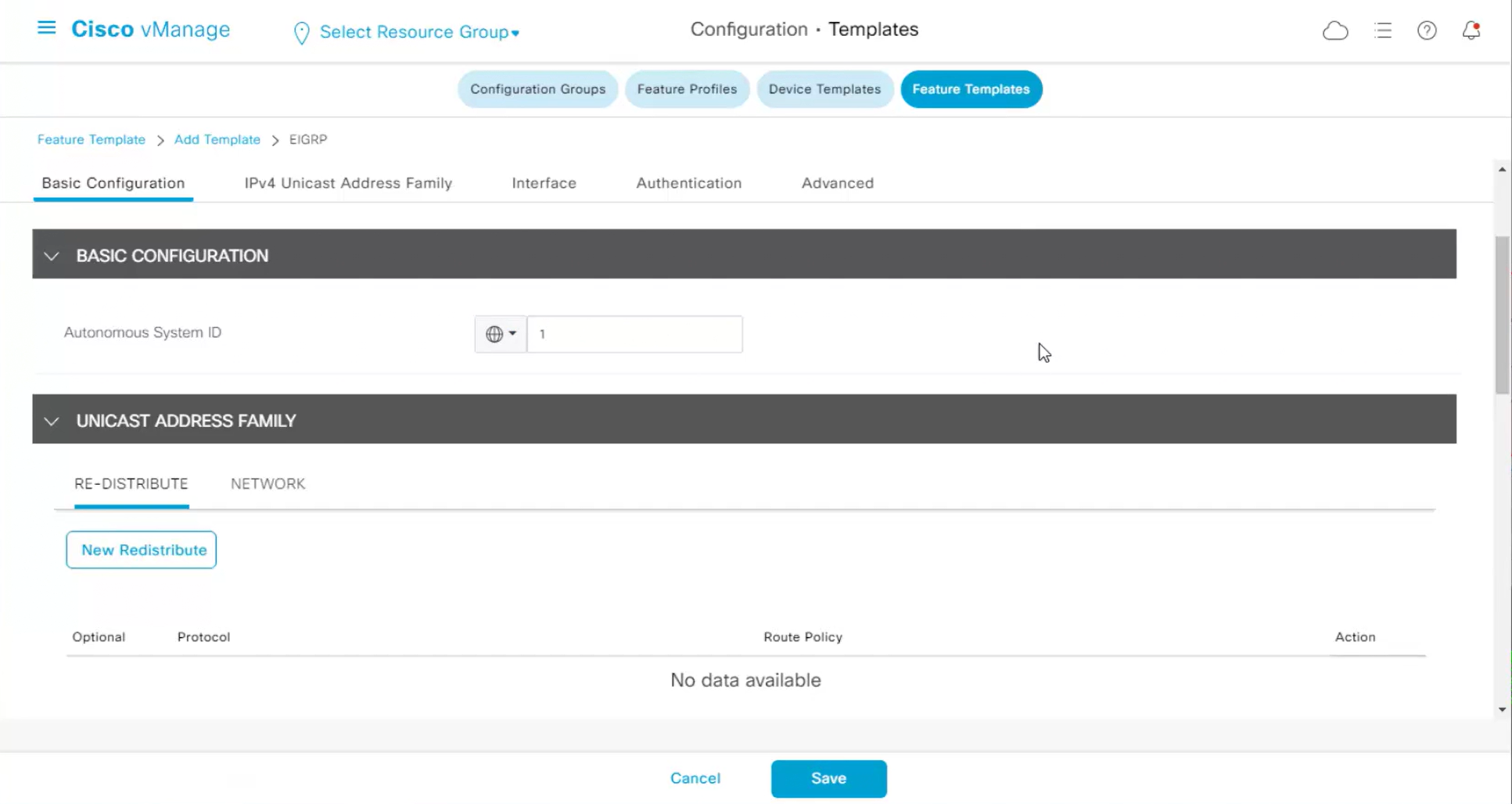
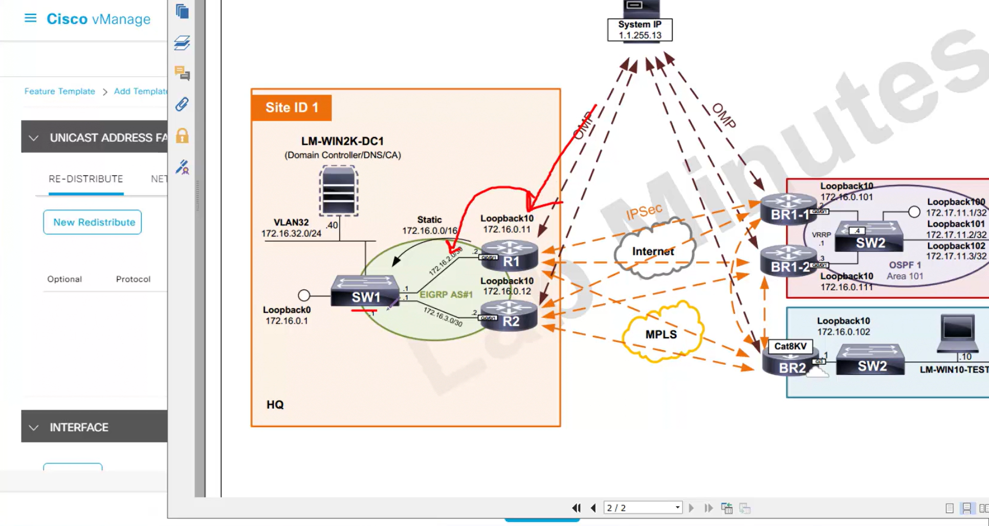
We will have to redistribute OMP routes into EIGRP in order to make sure that internal switch SW1 can ping remote site switches and remote destinations / subnets

We need to have EIGRP enabled on service side LAN interfaces and also on the loopback
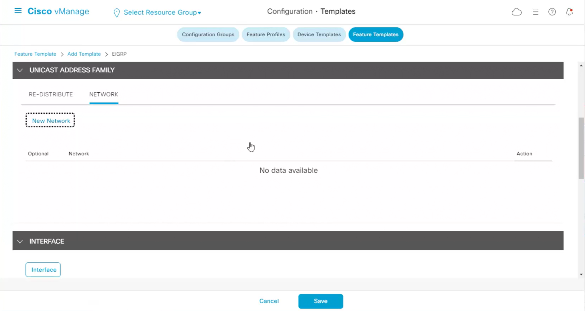
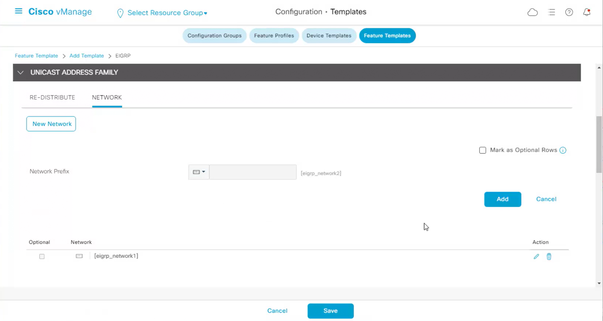
one network for physical interface
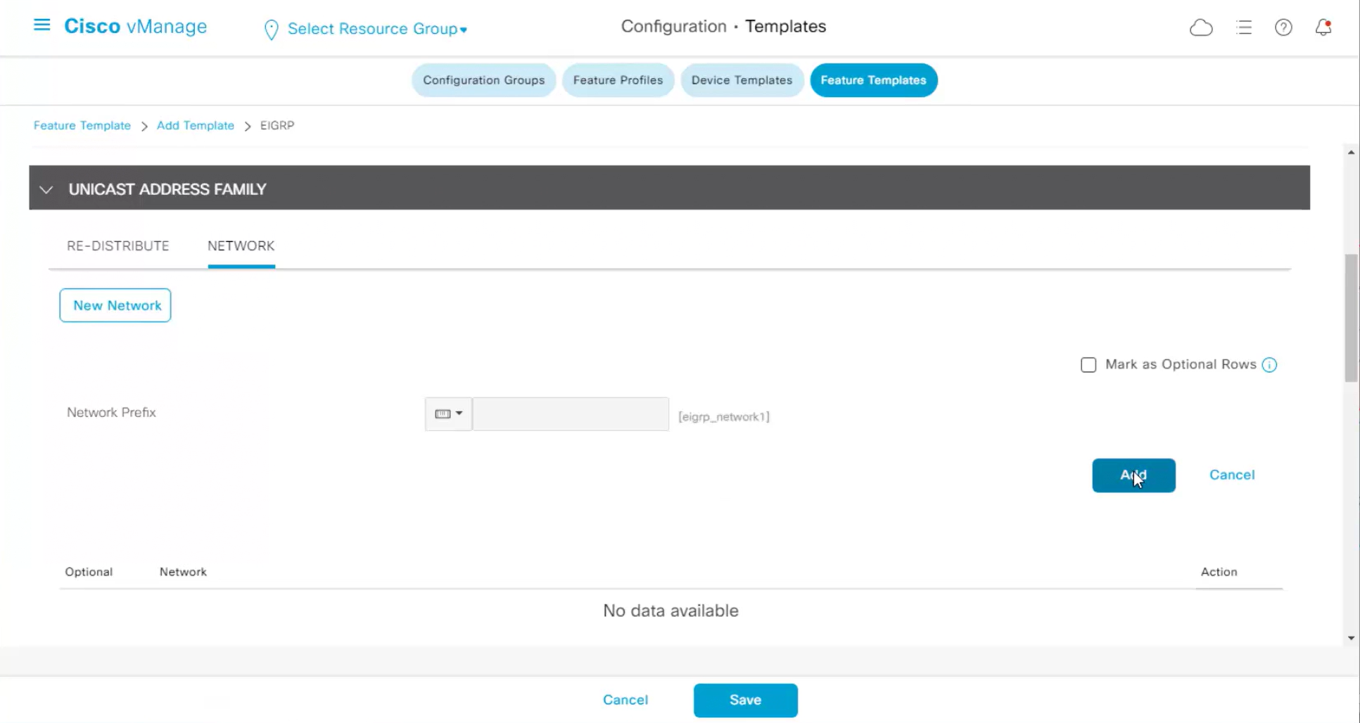
another network for loopback interface
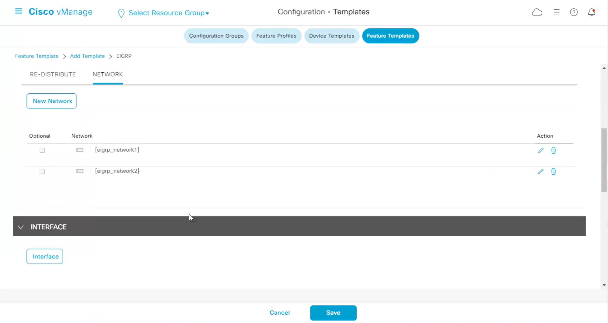
Now we need to specify the interface in GUI and that is for doing no passive interface
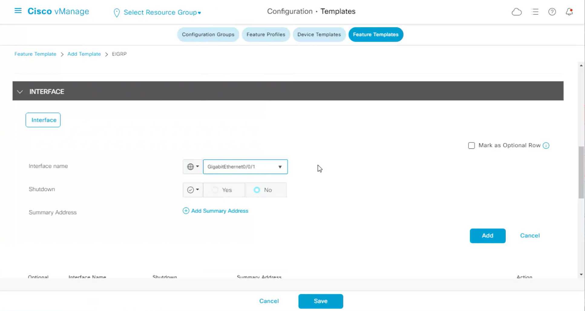
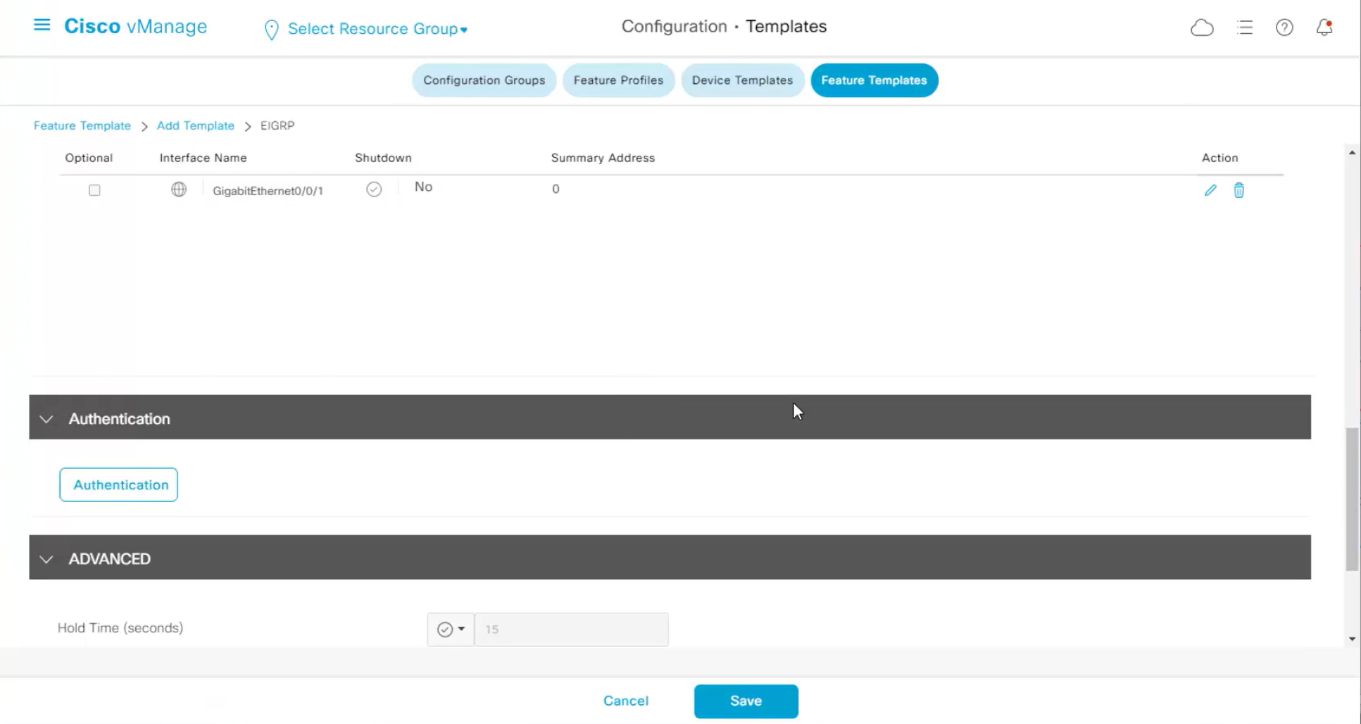
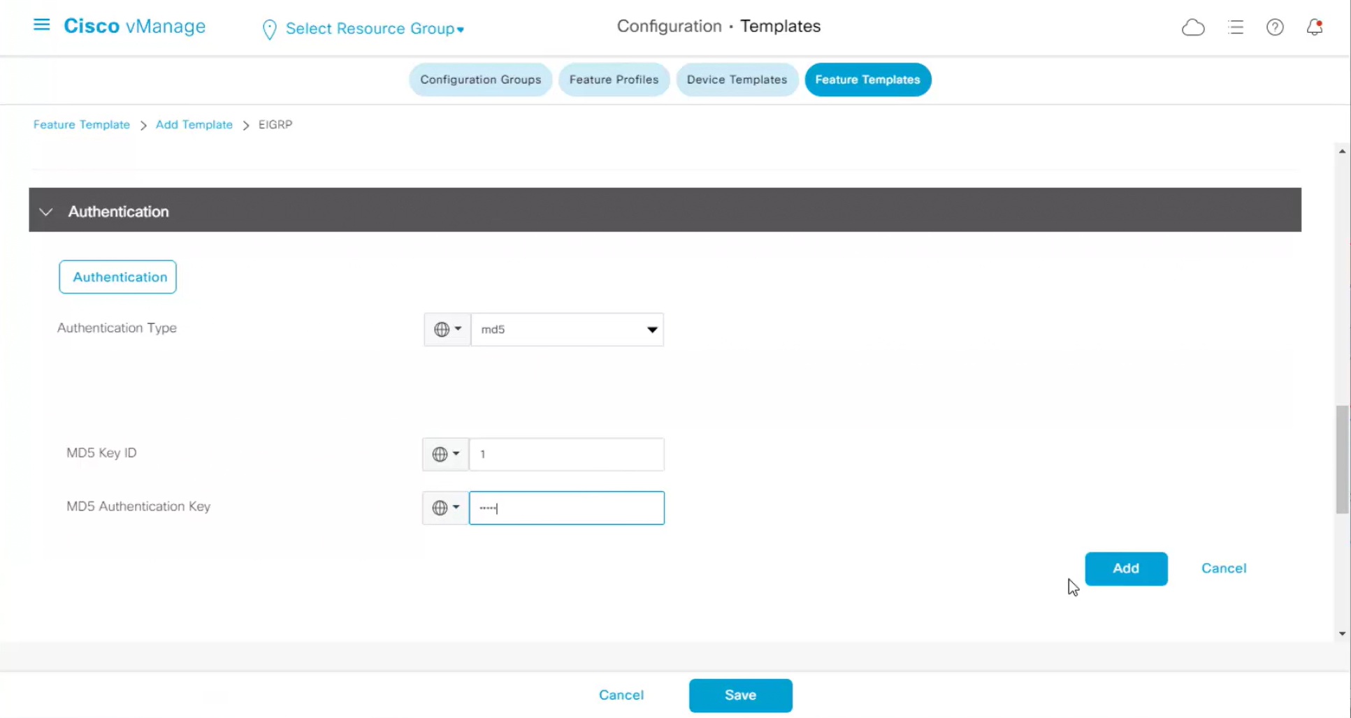
now we need to enable authentication
Rest of the configuration such as Hello time and hold time are left at defaults
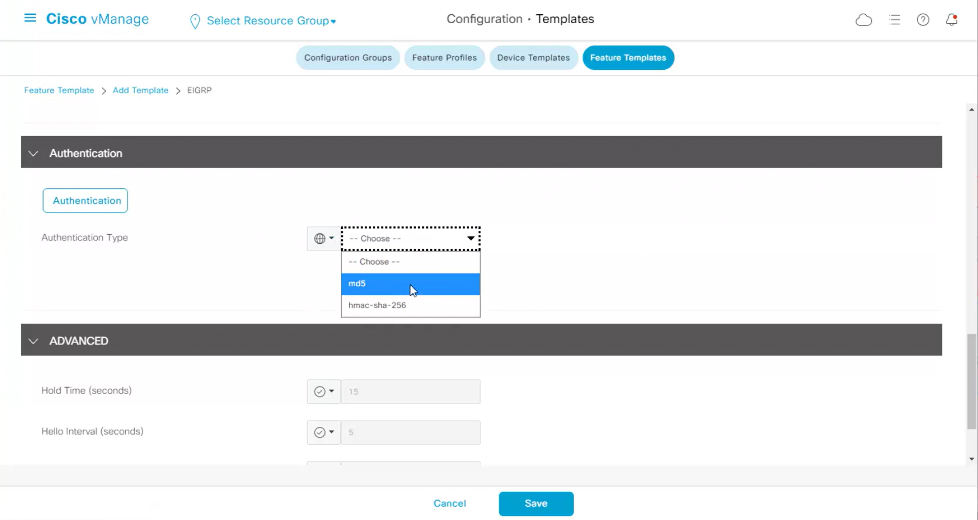
Authentication
Attach EIGRP template to VPN
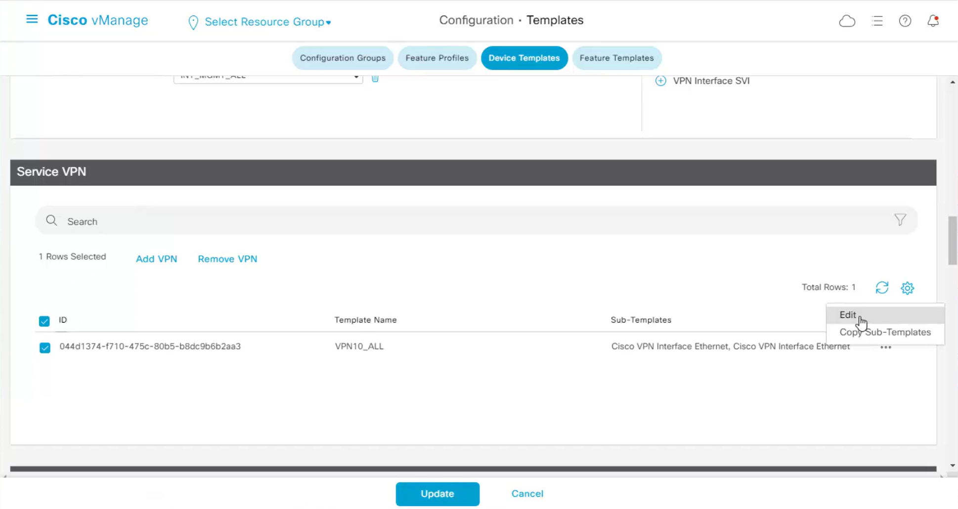

hello and hold time can be seen and also other EIGRP configuration that is being added
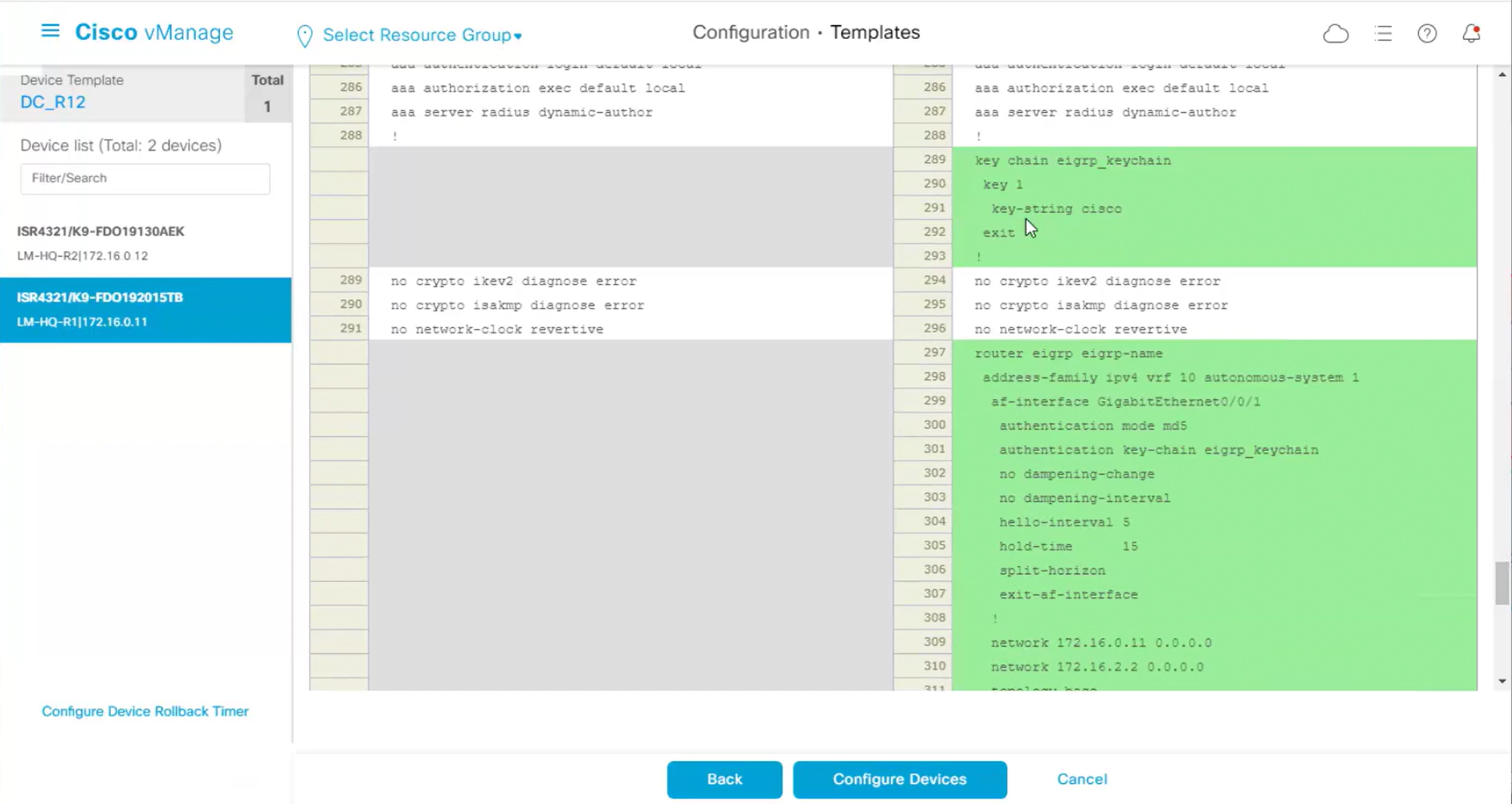
Neighborship on router will be on the vrf
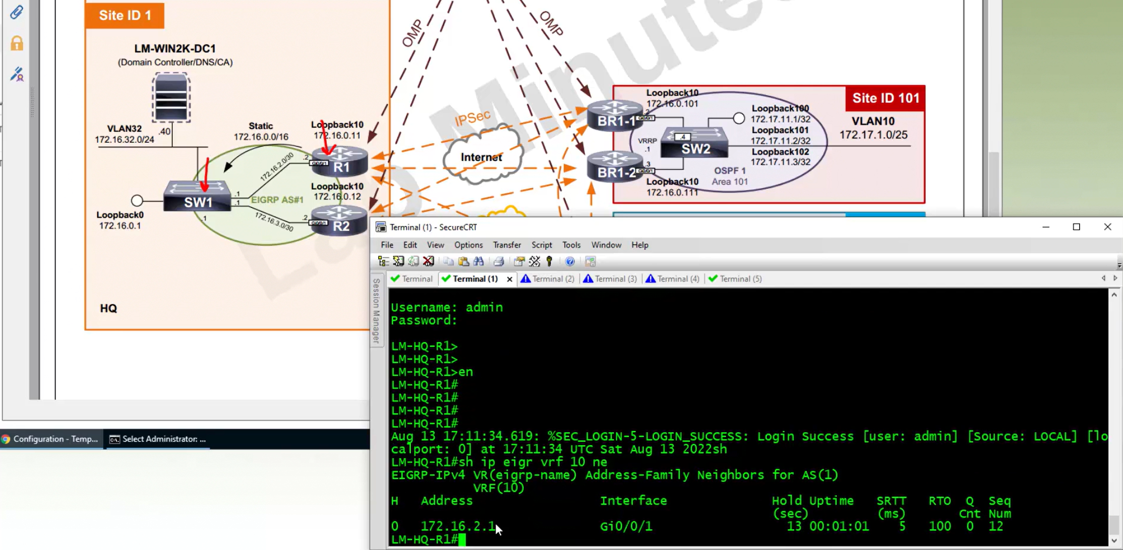
but other remote sites are not learning EIGRP routes because we imported or redistributed OMP into EIGRP but not EIGRP into OMP
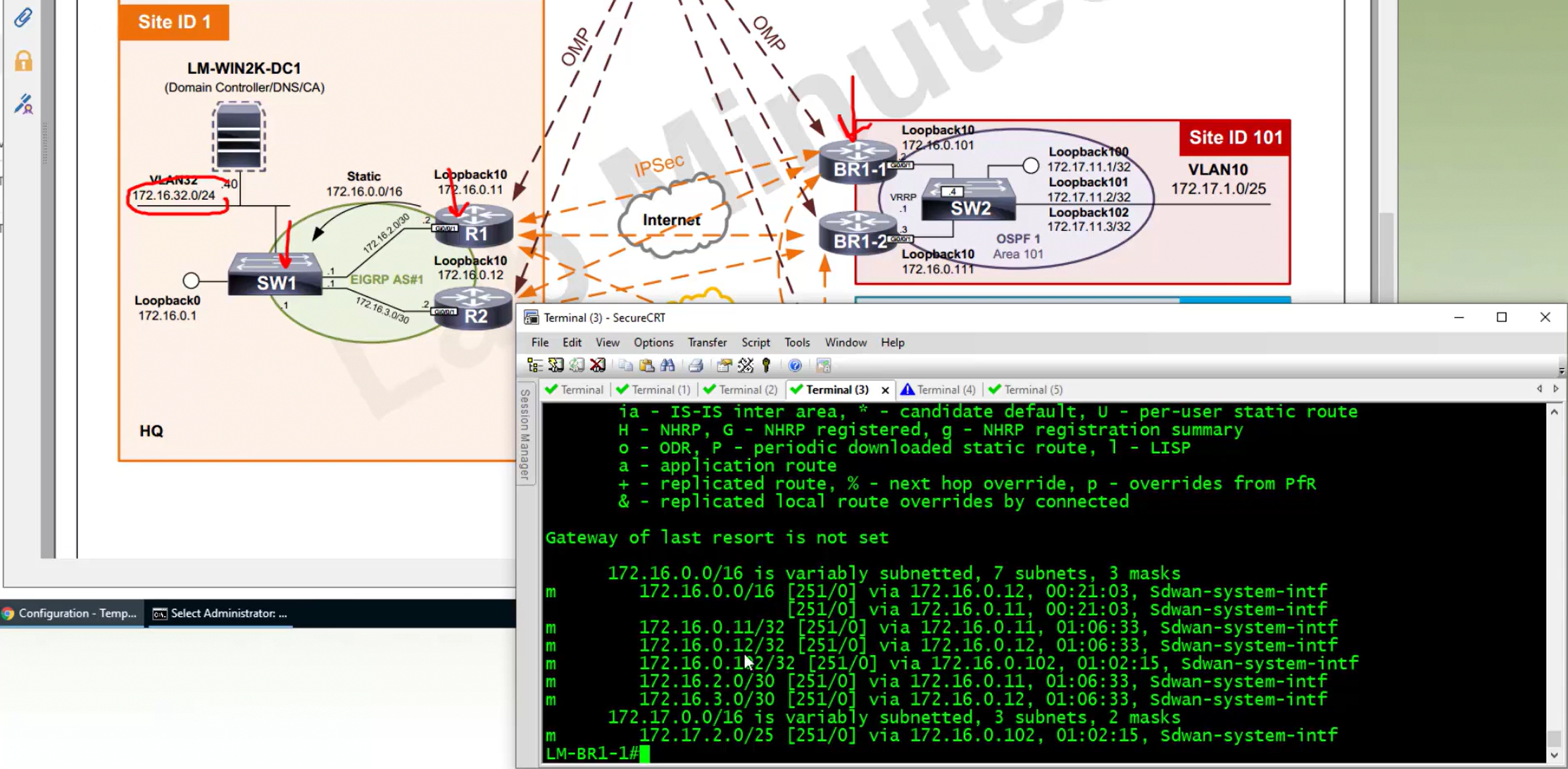
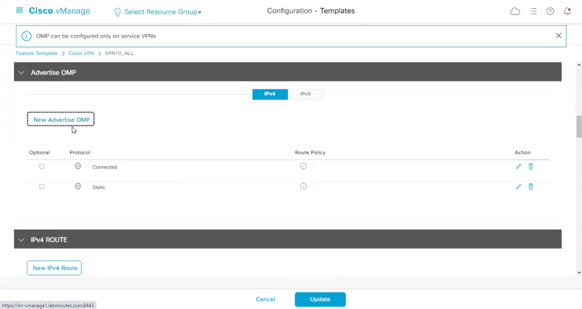
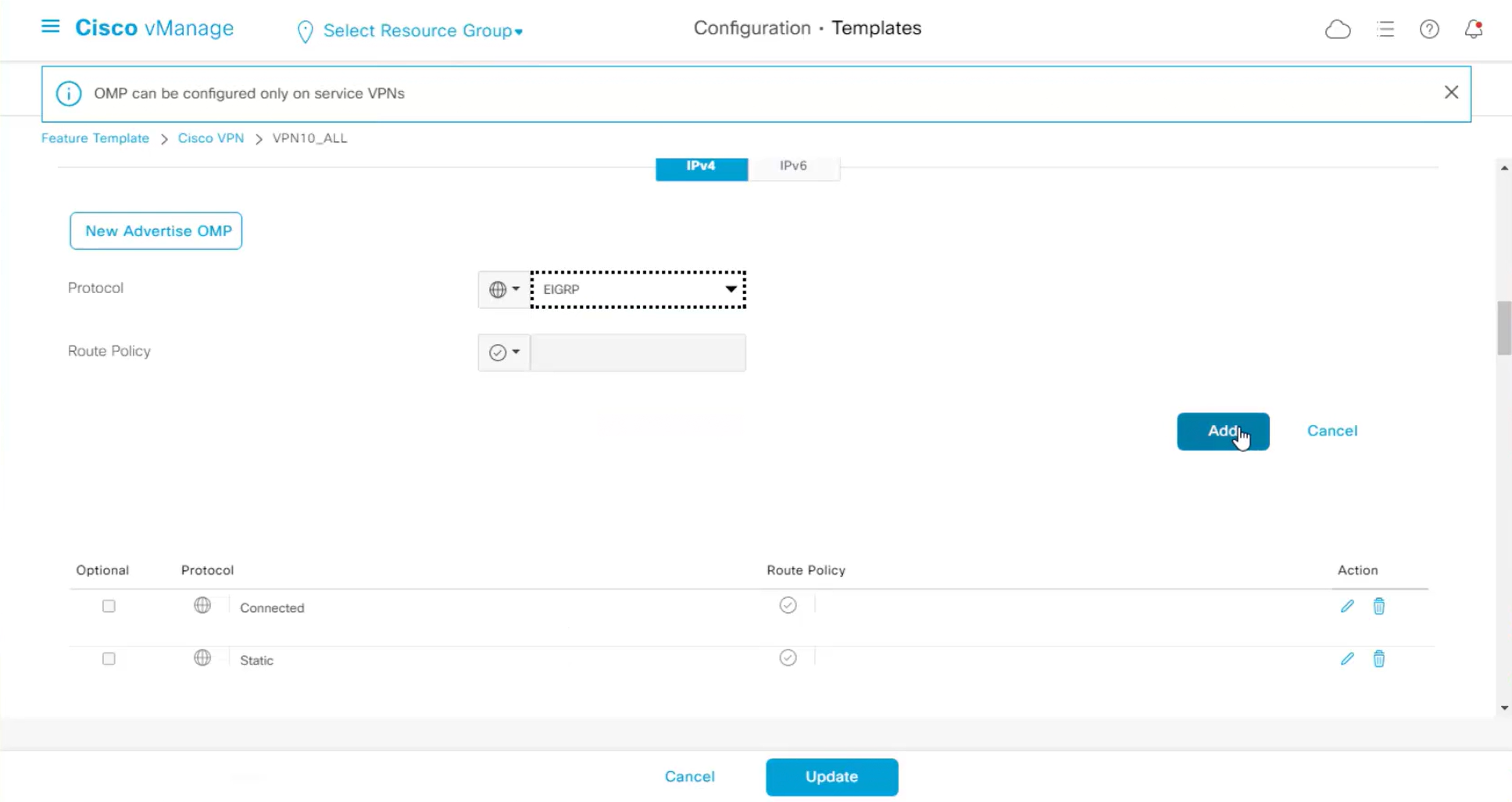
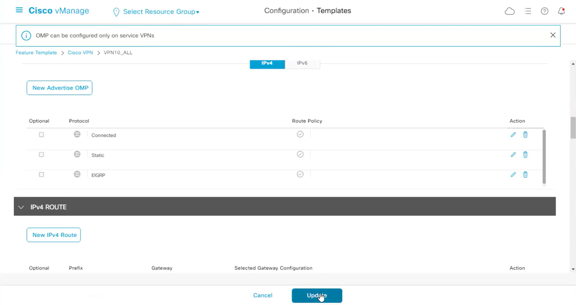
Now we are receiving EIGRP routes in OMP
router eigrp 1
 network 172.16.2.1 0.0.0.0
 network 172.16.3.1 0.0.0.0
 network 172.16.16.1 0.0.0.0
 redistribute connected
 redistribute static route-map STATIC2EIGRP
 passive-interface default
 no passive-interface GigabitEthernet1/0/2
 no passive-interface GigabitEthernet1/0/5
 eigrp router-id 172.16.0.1

interface GigabitEthernet1/0/2
 no switchport
 ip address 172.16.2.1 255.255.255.252
 ip authentication mode eigrp 1 md5
 ip authentication key-chain eigrp 1 KEY_EIGRP
OSPF Serviceside configuration
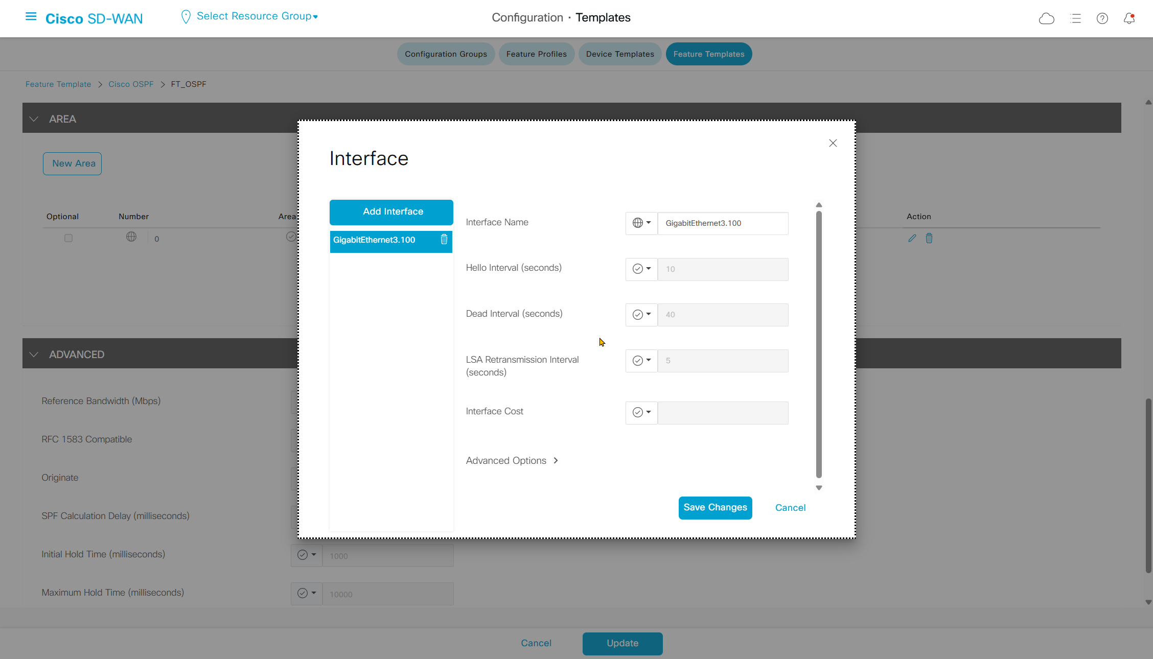
Neighborship was not coming up so I had to add this in CLI template
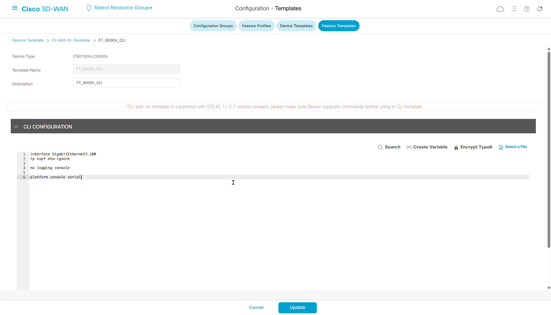
interface GigabitEthernet3.100
ip ospf mtu-ignore
no logging console
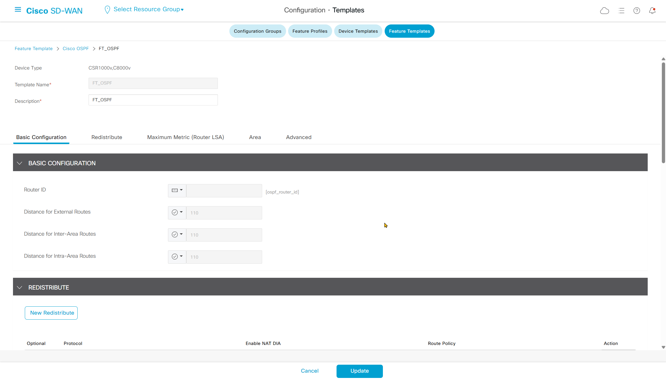
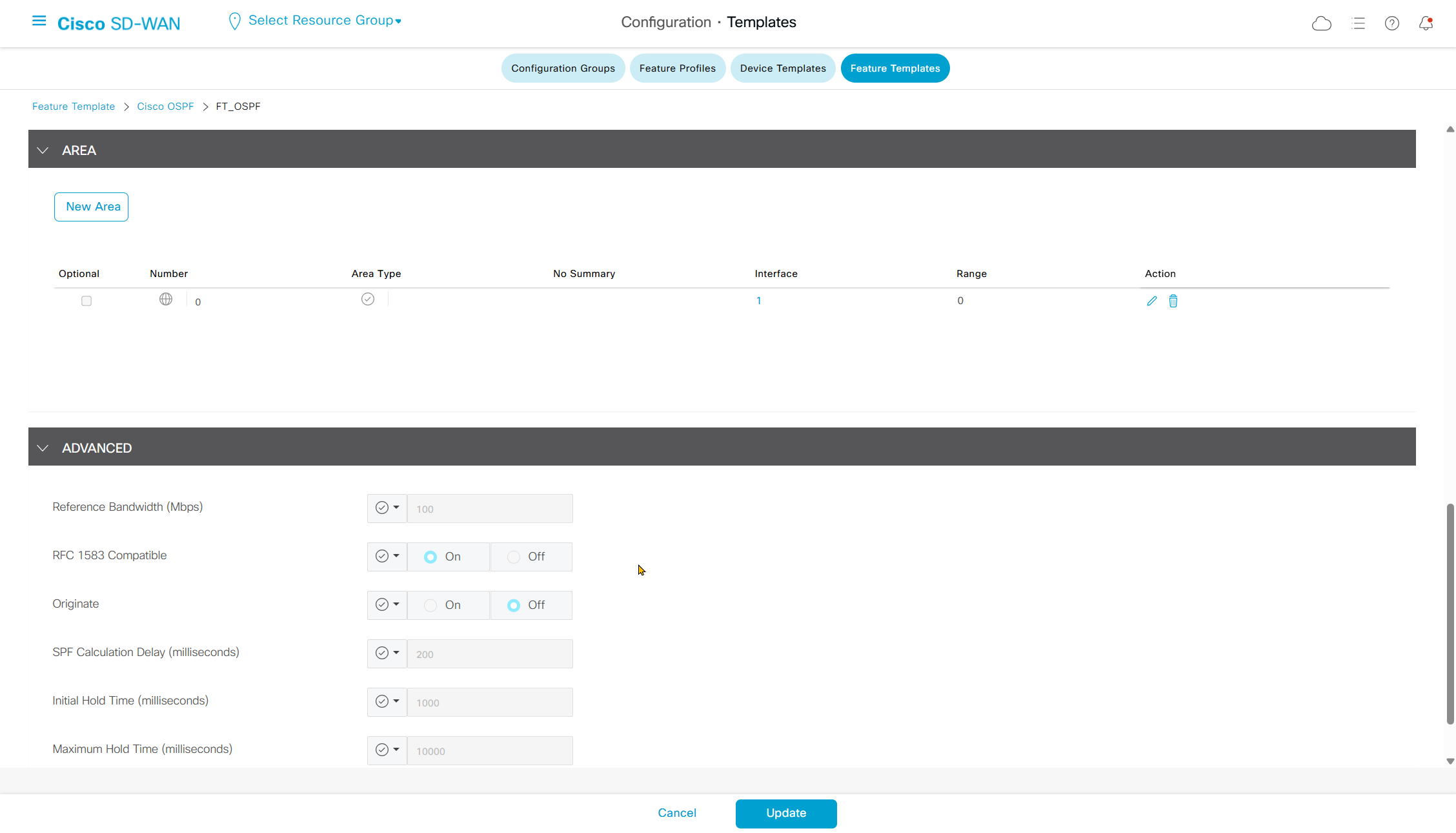
platform console serialSDWAN OSPF pushed configuration
router ospf 100 vrf 100
auto-cost reference-bandwidth 100
compatible rfc1583
distance ospf intra-area 110 inter-area 110 external 110
no local-rib-criteria
router-id 11.11.11.11
timers throttle spf 200 1000 10000
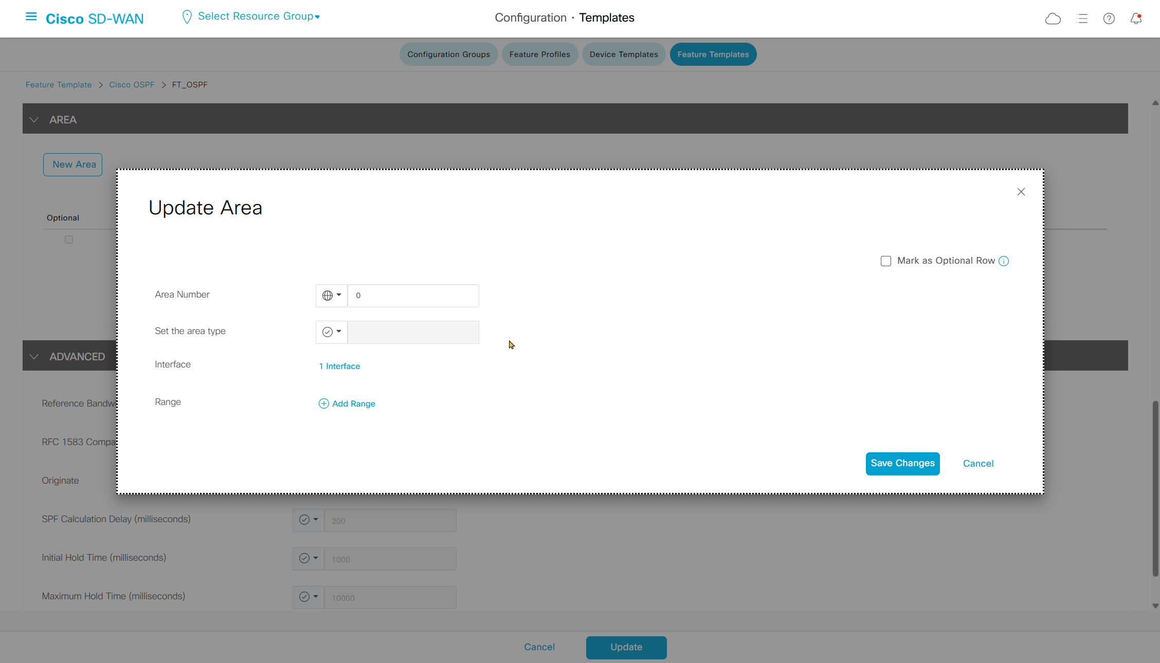
interface GigabitEthernet3.100
ip ospf 100 area 0
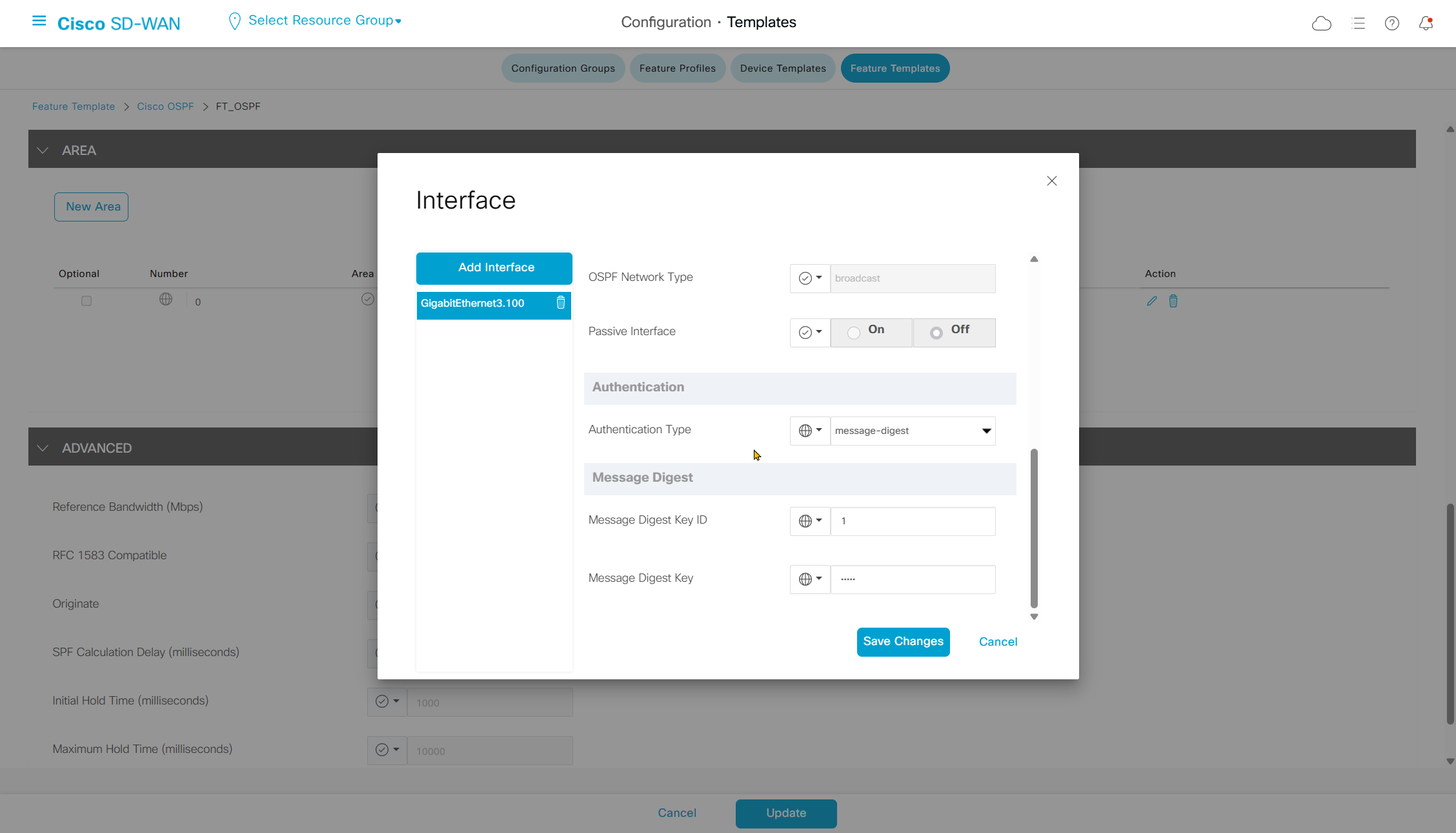
ip ospf authentication message-digest
ip ospf dead-interval 40
ip ospf hello-interval 10
ip ospf message-digest-key 1 md5 0 cisco
ip ospf network broadcast
ip ospf priority 1
ip ospf retransmit-interval 5
interface GigabitEthernet3.100 ! <<< coming from CLI template
ip ospf mtu-ignore
Switch OSPF configuration
router ospf 1
router-id 172.16.2.11
no auto-cost
area 0 authentication message-digest
! redistribute connected
passive-interface default
no passive-interface Vlan100
network 172.16.2.11 0.0.0.0 area 0
network 172.16.10.1 0.0.0.0 area 0
interface Vlan100
ip address 172.16.2.11 255.255.254.0
ip ospf authentication message-digest
ip ospf message-digest-key 1 md5 cisco
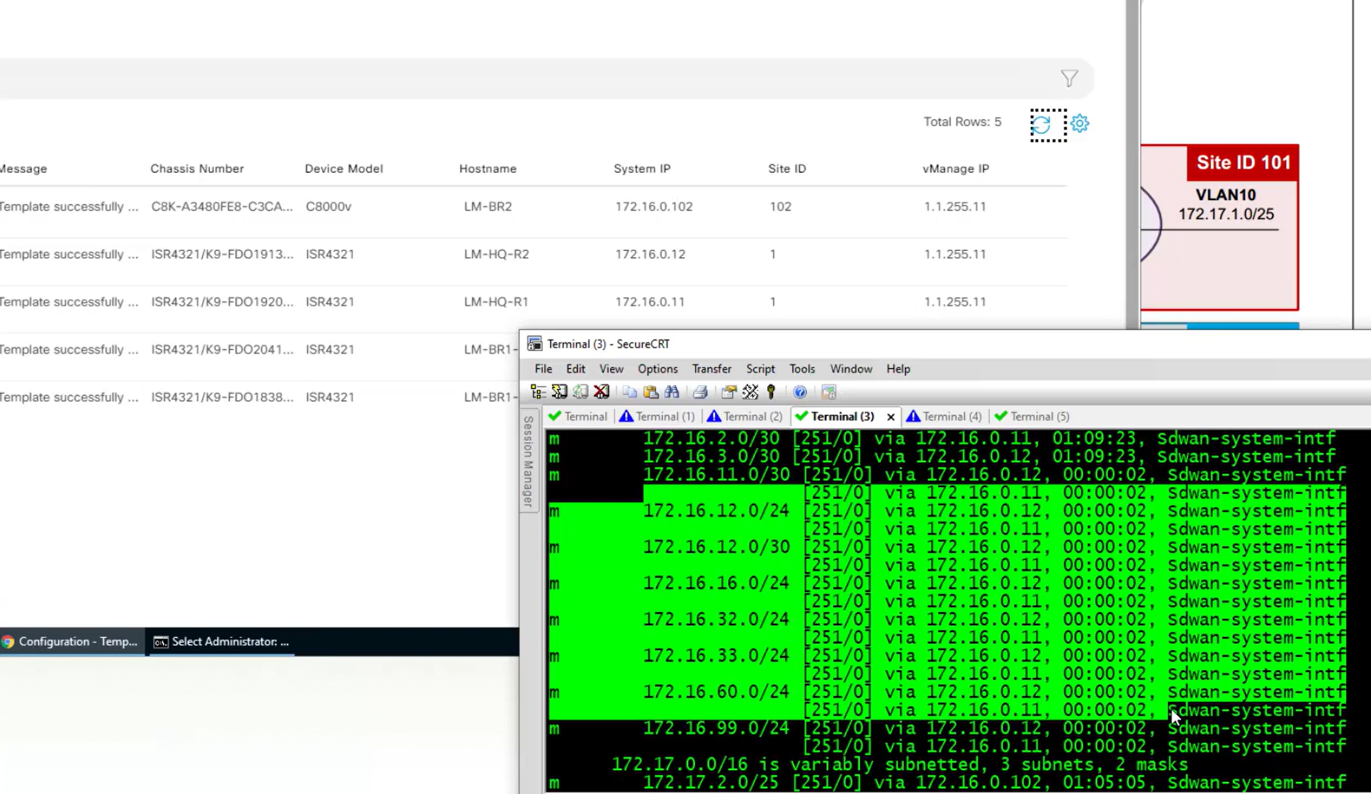
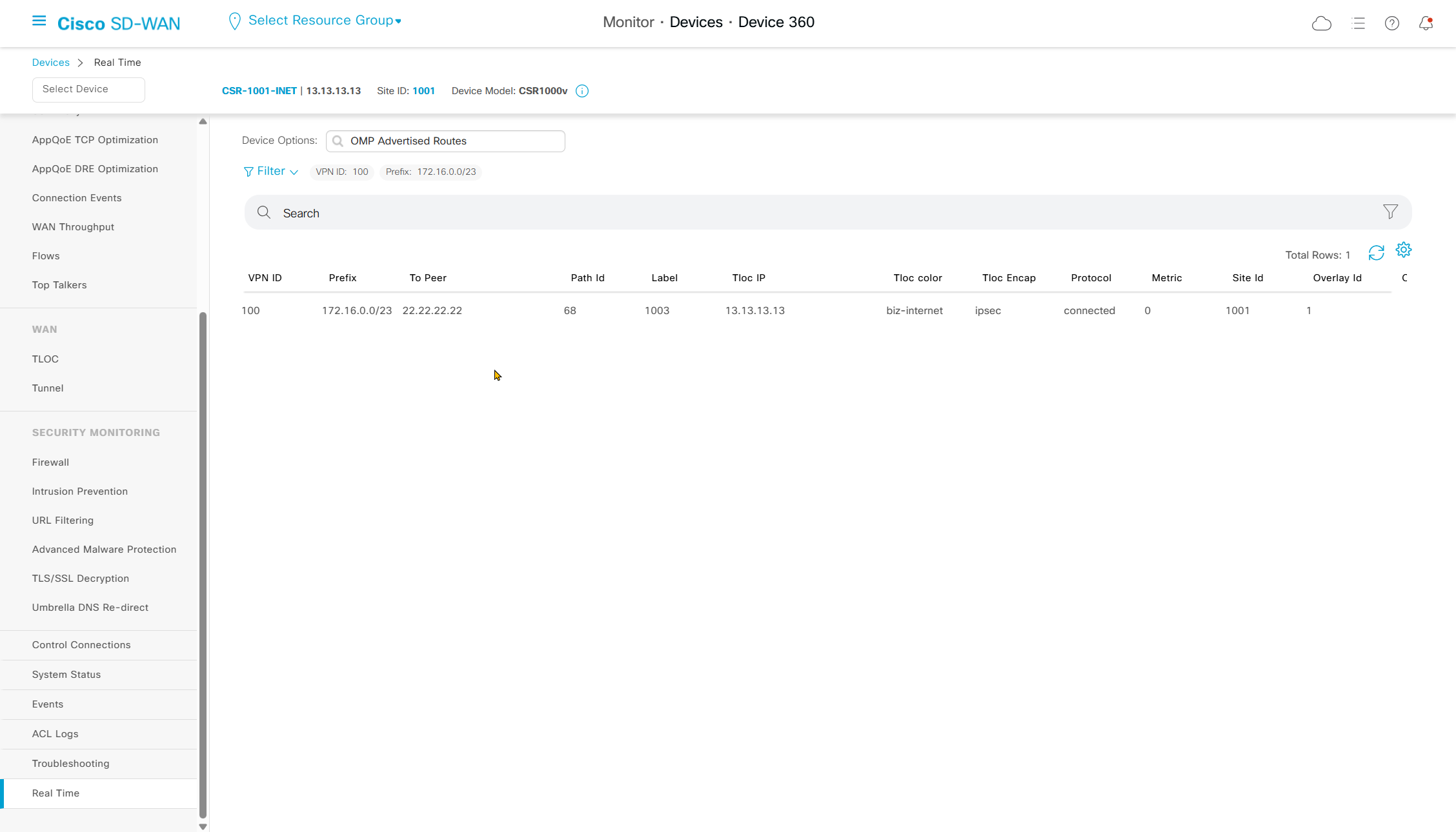
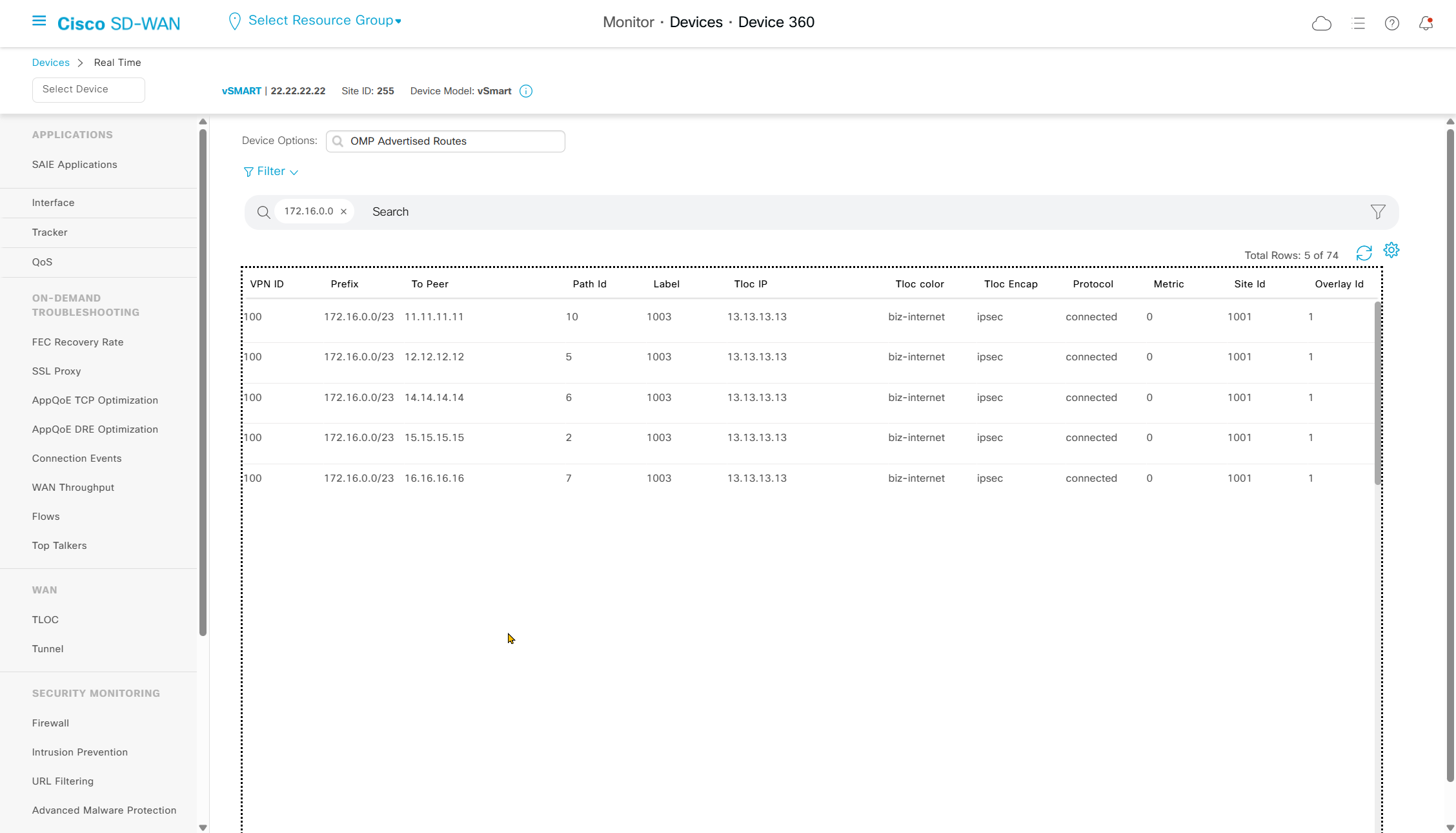
ip ospf mtu-ignoreTroubleshooting OMP route flow
This is much faster way of troubleshooting the routes instead of logging into each device CLI
This is also a quicker way of finding out whether a route is blocked by a policy inbound or outbound
See if local router advertised it to vsmart or not
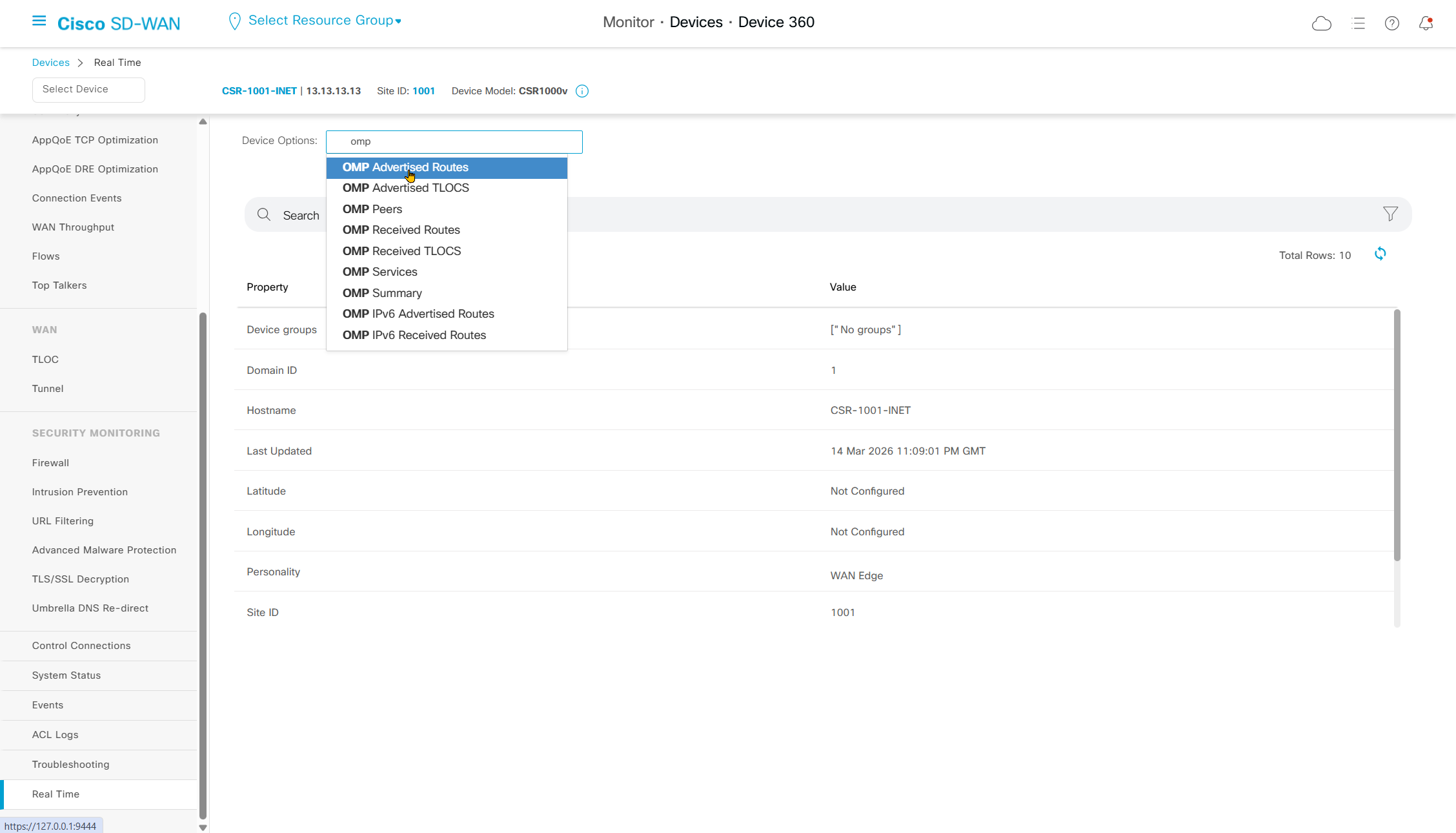
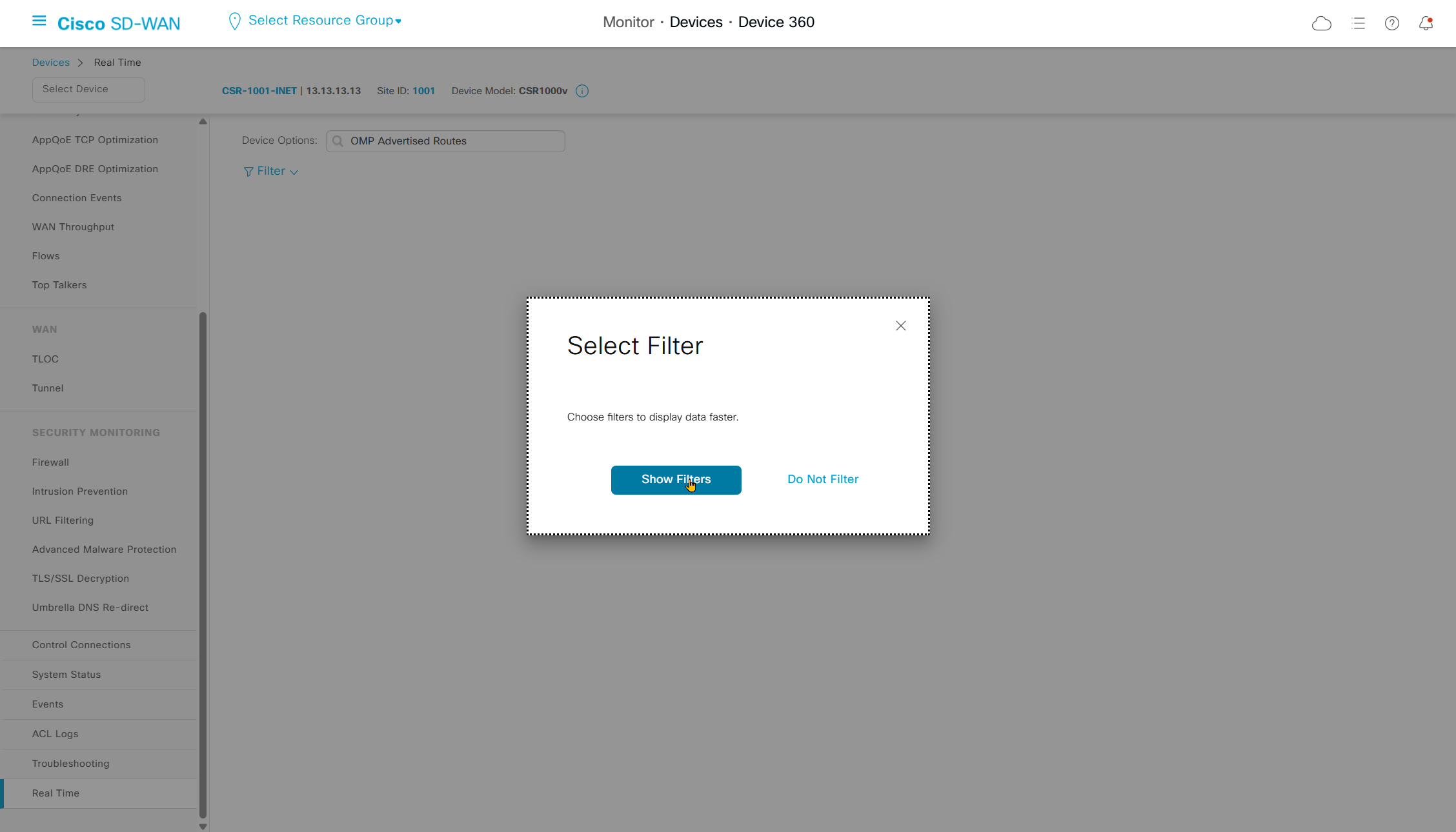
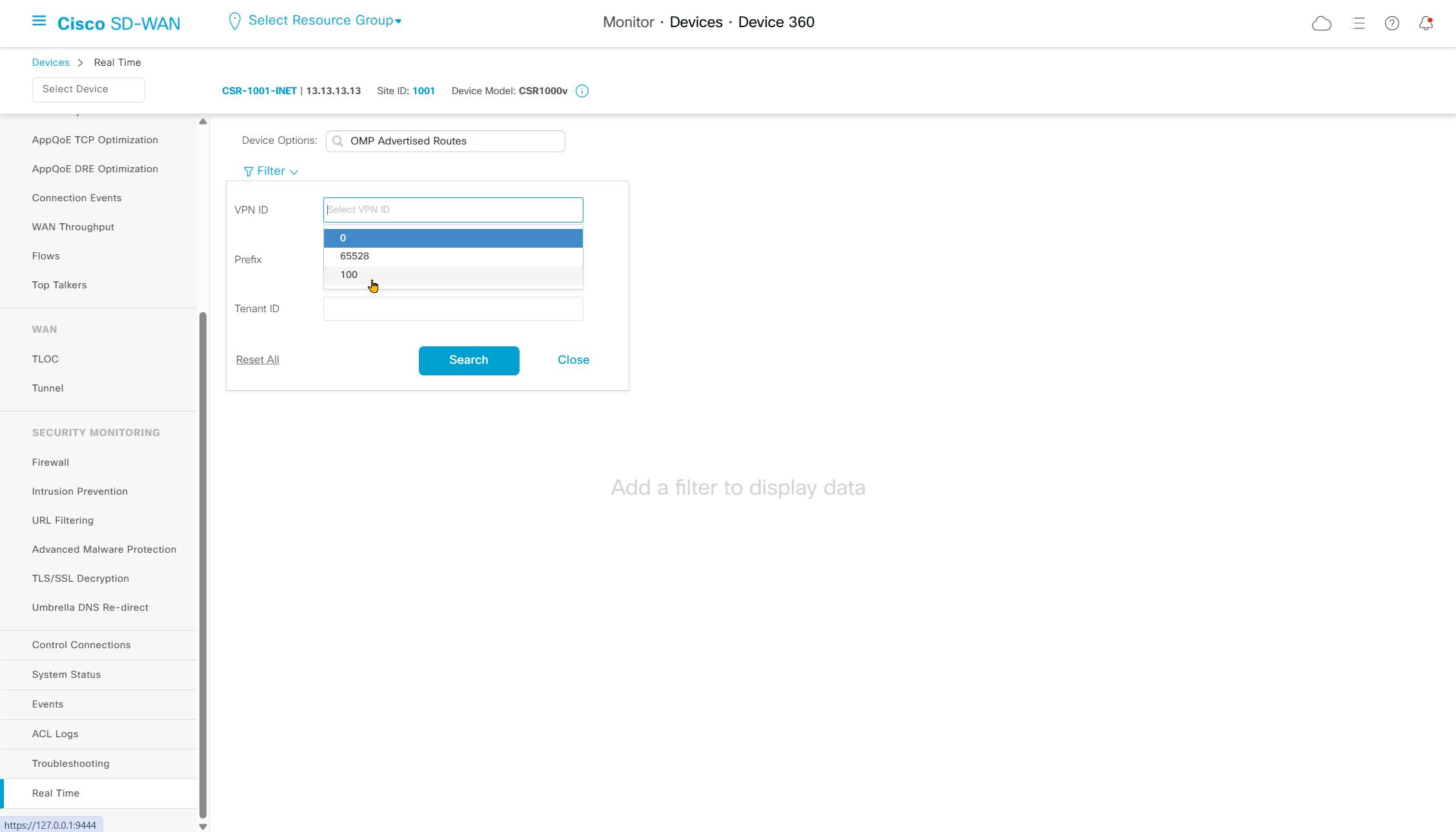
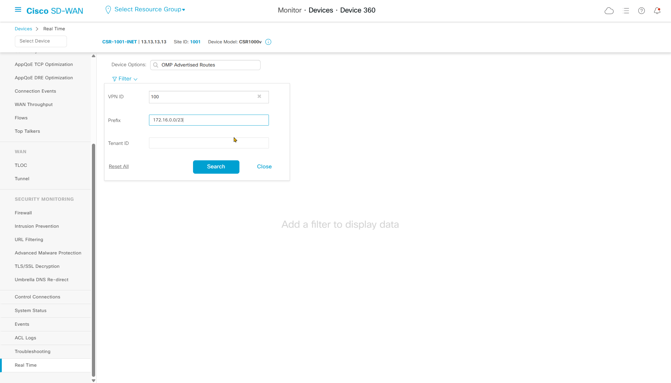
We can use filter to limit the results
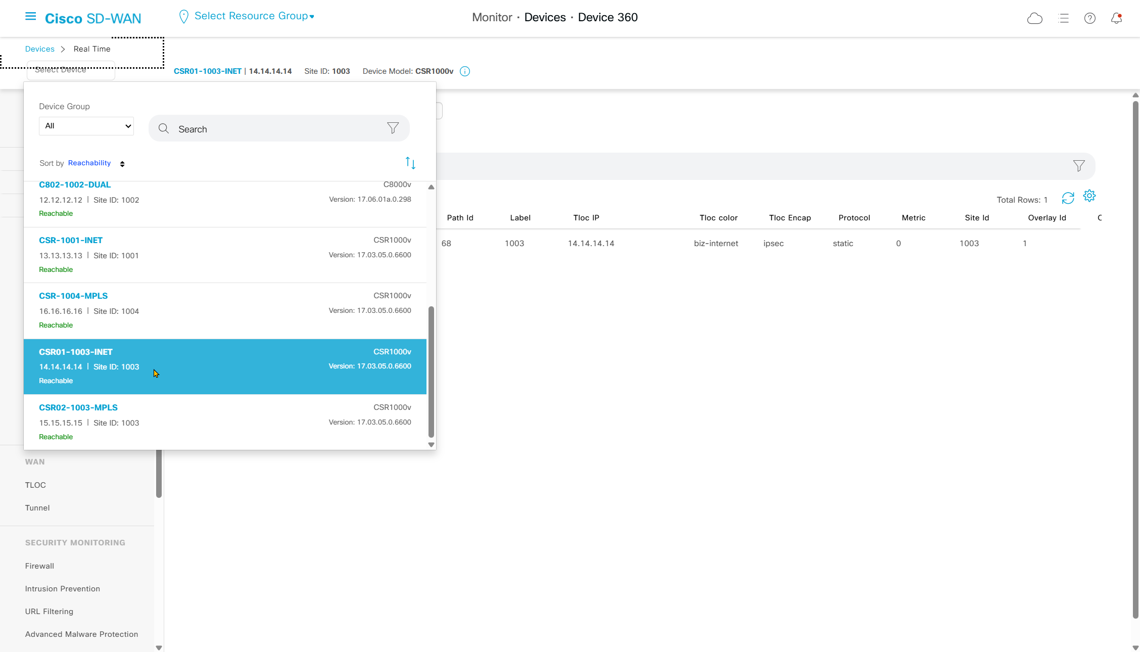
now we go to vsmart

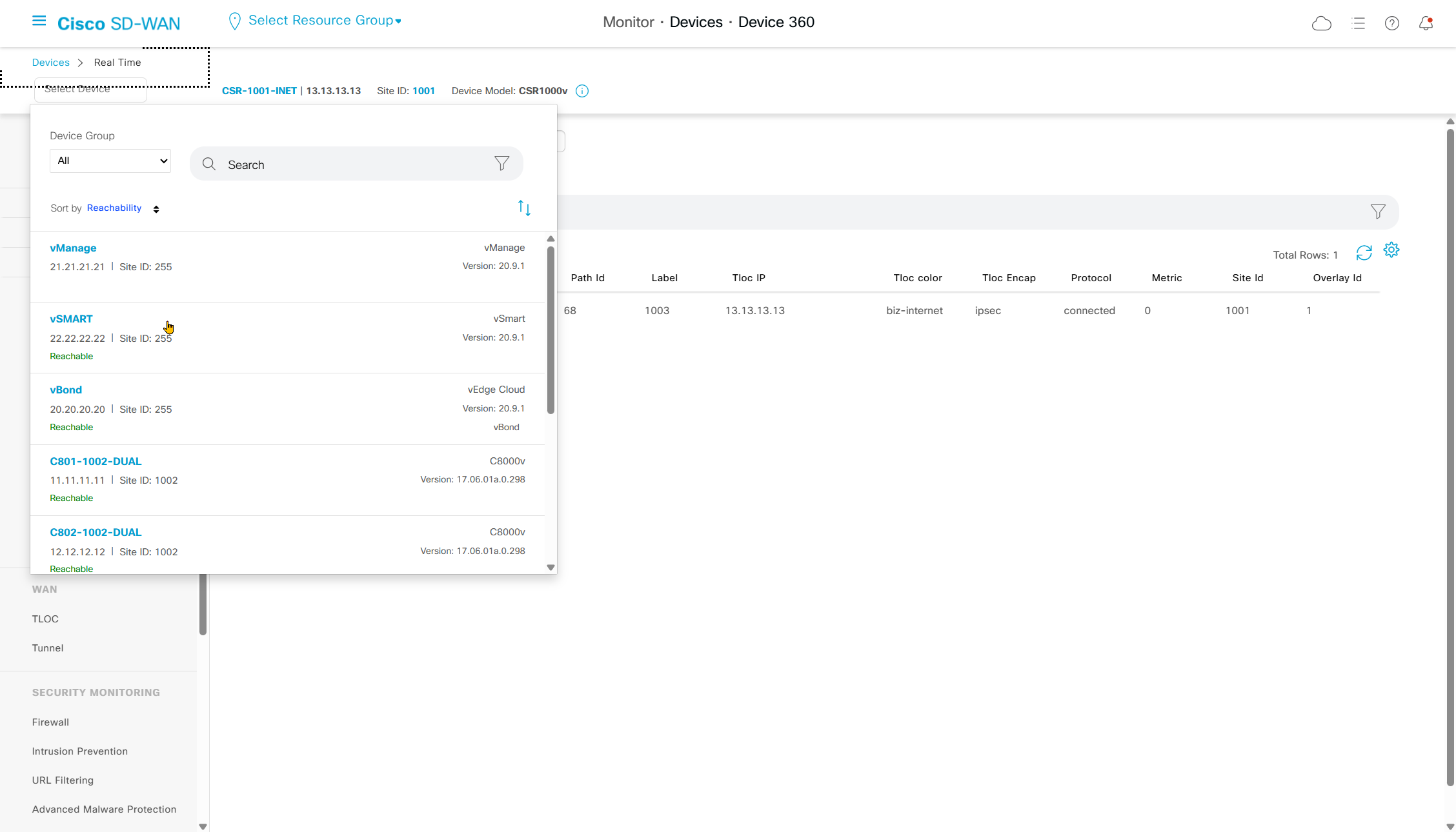
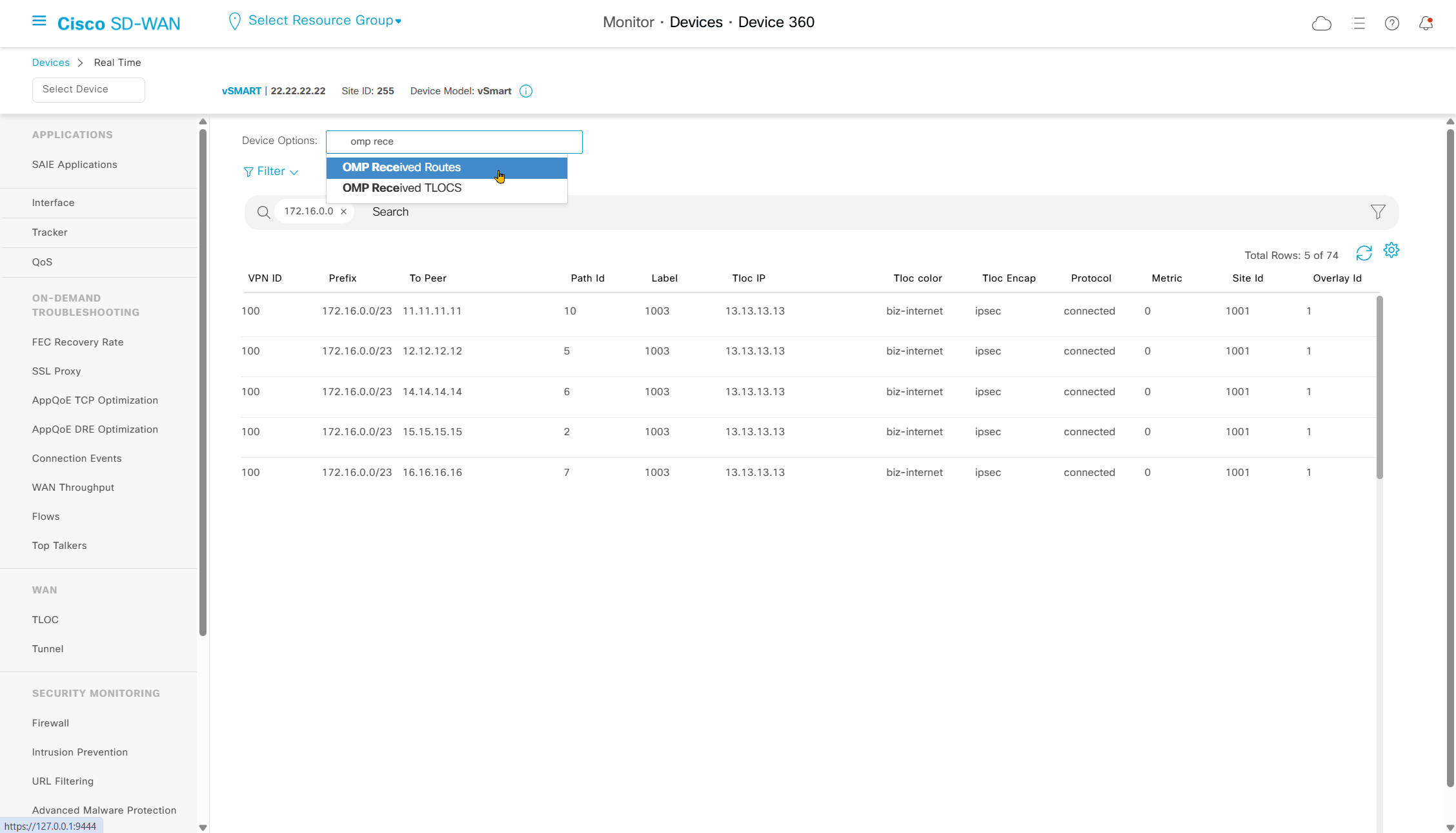
Check if vsmart received it
Check if vsmart advertised it to other edges
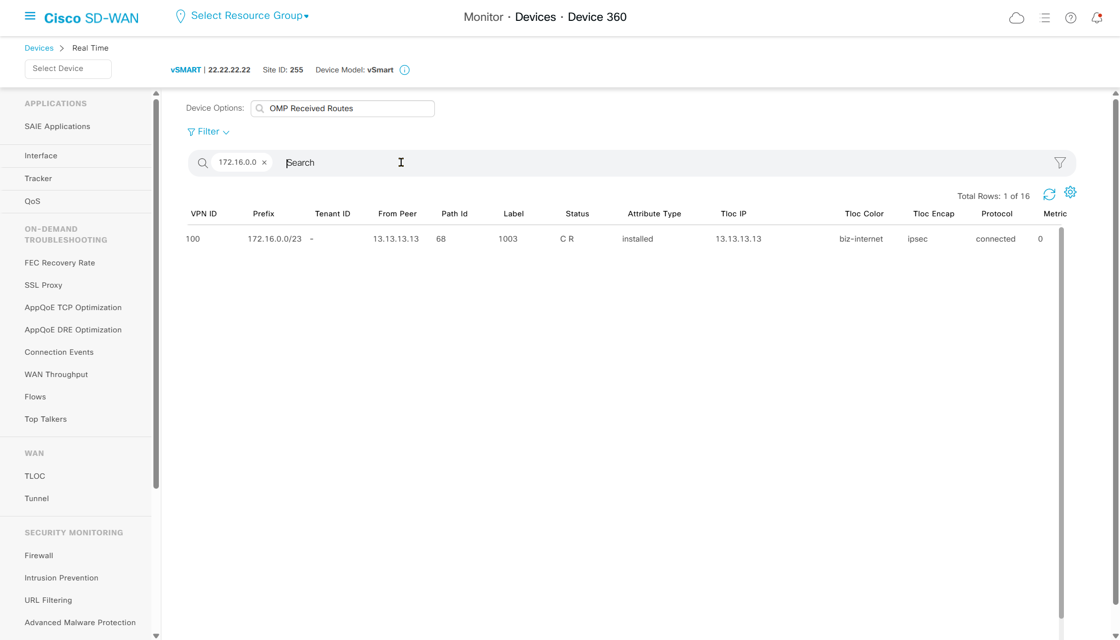
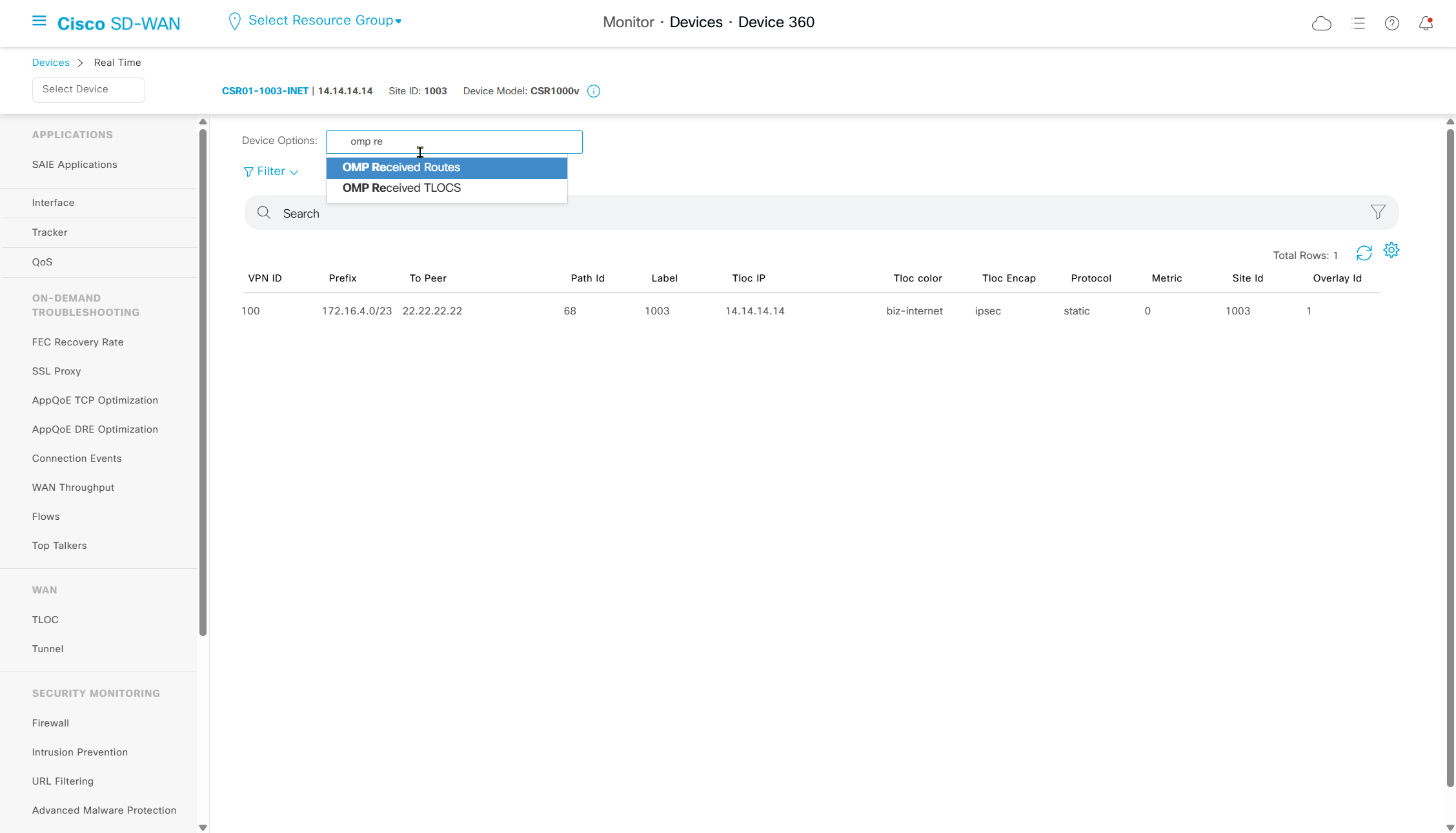
lets go to end router
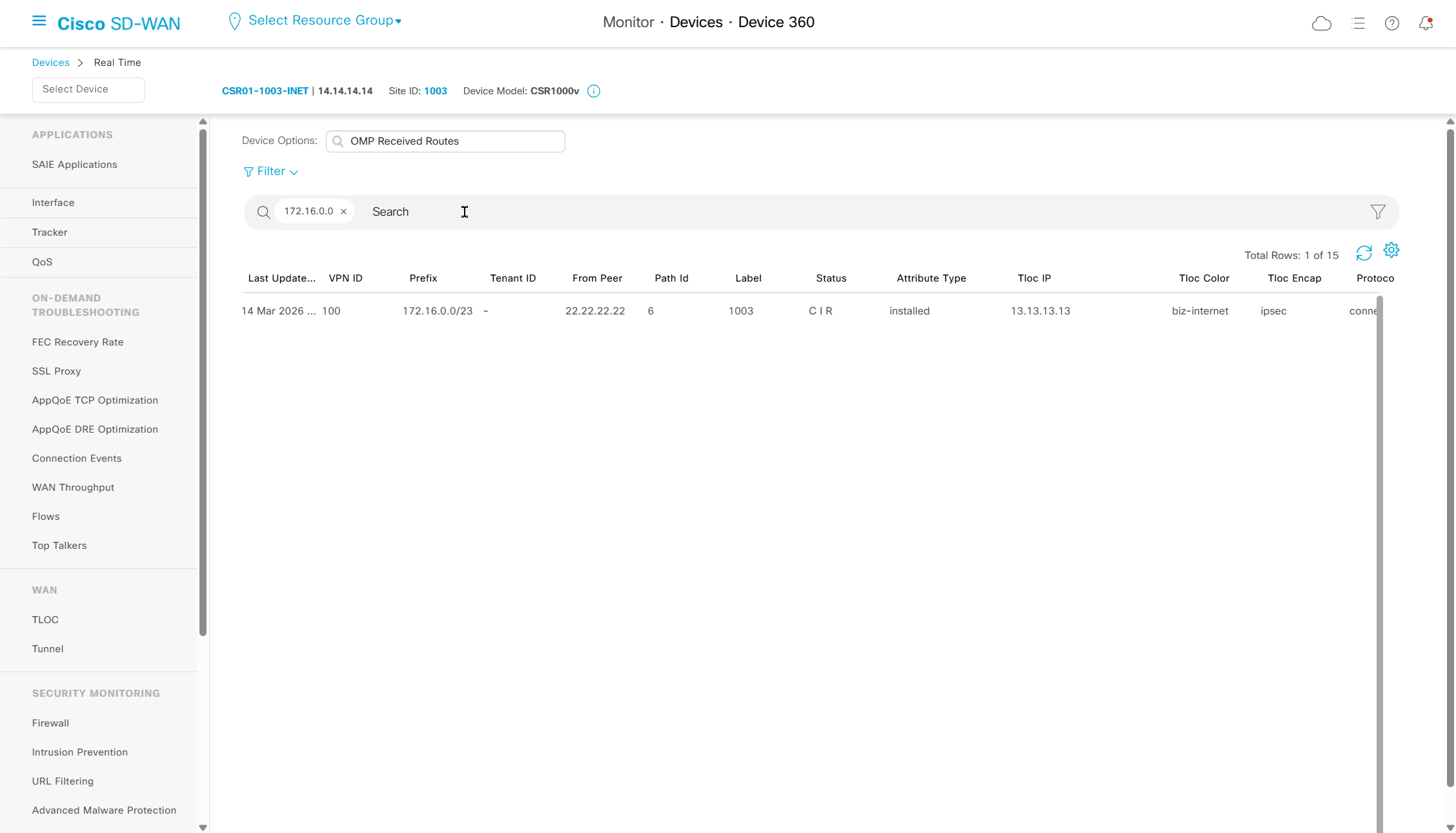
check if received it
always pay attention to the status column to see if received routes have been installed or not
and that could be because of TLOC being down or route being less preferred
CIR means Chosen , Installed , Resolved
BFD configuration for transport facing IOS-XE peerings
Here we are talking about the IOS-XE BFD and not the BFD that runs over the overlay tunnels
This BFD runs over the router interfaces to quickly detect link failure
When we tie this BFD with routing protocol, it allows routing protocol to react to change much faster rather than its default protocol timer, BFD support started in version 17.3
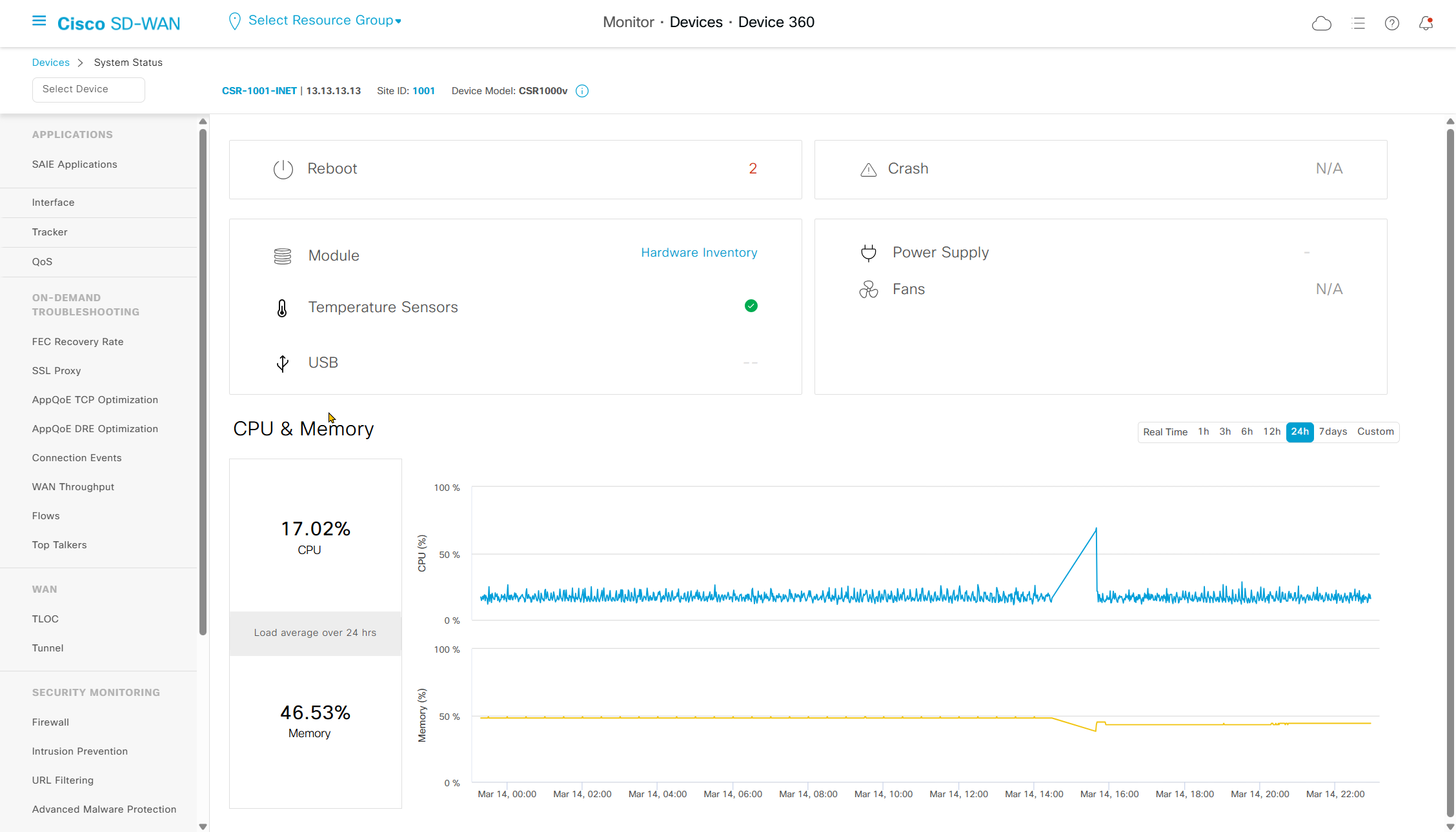
CSR-1001-INET#show version
Cisco IOS XE Software, Version 17.03.05
This BFD tieing to protocol can be done with BGP, EIGRP and OSPF
This can be applied to physical interfaces , SVI or sub interfaces
It works on service and transport side so we can use BFD on BGP peering with MPLS router to provide fast failure detection
As of 20.8 this is not supported in a feature template so we need to use CLI template
A test was carried out and an interface facing the edge node with bgp peering to this MPLS PE router was shut, but on edge node because this is not a direct connection the peering still showed as up for some time (hold time of 180 seconds) and this edge node could ping IP of its interface but could not reach the next hop IP of the MPLS router, so BGP neighborship should have gone down but it did not and it was blackholing the traffic for some time (hold time of 180 seconds) – this is where BFD is implemented
bfd-template single-hop BFD
 interval min-tx 1000 min-rx 1000 multiplier 3
! BFD type single hop is used to monitor directly connected devices
! with single hop Neighbor must be directly connected
! Send BFD packets every 1 sec
! Expect to receive BFD packets every 1 sec
! If 3 packets are missed, the neighbor is declared down

interface GigabitEthernet1
bfd template BFD

! BFD will be applied on this interface
! but any protocol "originating" from this interface can use this BFD session

router bgp 10
neighbor 172.31.255.250 fall-over bfd
! telling BGP to use bfd result of the BGP interface
IOS-XE configuration
bfd-template single-hop BFD
 interval min-tx 1000 min-rx 1000 multiplier 3

interface Ethernet0/1
 description MPLS CE
 bfd template BFD
!
interface Ethernet0/2
 description MPLS CE
 bfd template BFD
!
interface Ethernet0/3
 description MPLS CE
 bfd template BFD
!
interface Ethernet1/0
 description MPLS CE
 bfd template BFD


router bgp 10
 template peer-policy CE
  send-community both
 exit-peer-policy
 !
 template peer-session CE
  ebgp-multihop 5
  timers 5 10
  fall-over bfd <<<

show bfd summary
show bfd interface
show bfd neighbors
SDWAN CLI template configuration
BFD is attached to physical interface and not tunnel interface, because tunnel interface already has SDWAN version of BFD running
interface GigabitEthernet3.100
ip ospf mtu-ignore

bfd-template single-hop BFD
 interval min-tx 1000 min-rx 1000 multiplier 3

interface GigabitEthernet1
 bfd template BFD

router bgp {{as_num_cli}}
 neighbor {{bgp_peer_ip_cli}} fall-over bfd

sdwan
 interface GigabitEthernet1
  tunnel-interface
  allow-service bfd

no logging console

platform console serial
TLOC extension
We could have an INET switch span internet vlan between 2 edge routers but issue is that ISP only provides one internet IP address to use
TLOC extension allows us to share or use one of the colors or WAN transport from another router and build IPSEC / BFD over it
All we need is a way for a router to router connection and there are few options
- Back to back connections per transport for example 1 back to back link on Gig4 for Internet and 1 back to back link on Gig5 for MPLS
- Only one back to back connection but use sub interfaces per transport
- and least preferred option in case you dont have any spare interfaces, is to do sub interfaces on LAN side of the router and use that as the TLOC extension
We are also not allowed to have tloc extension from tunnel interface that is why we either need dedicated interfaces / sub interfaces or we need sub interfaces on LAN interface
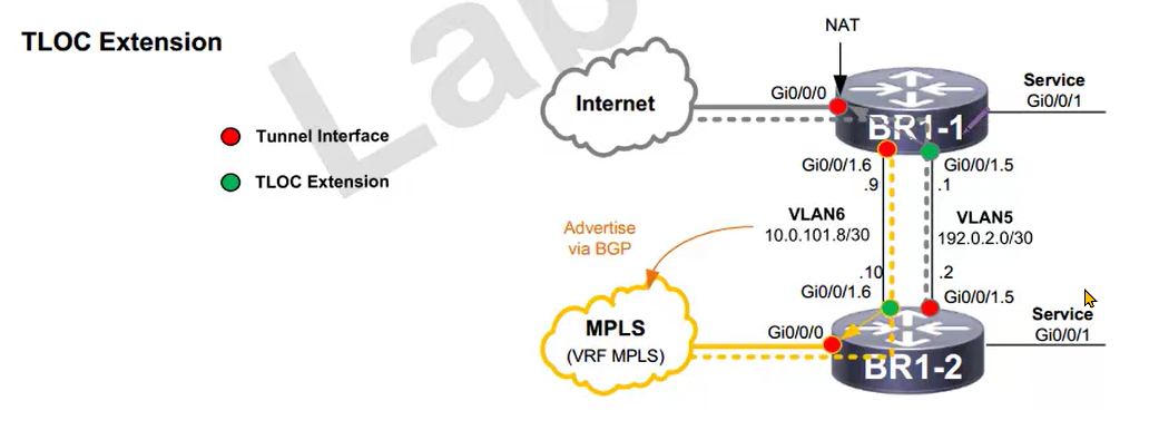
Notice that red are tunnels and green is TLOC extension
once a transport is extended via TLOC extension (green dot) and as it terminates on another router (red dot) that red dot becomes the tunnel interface / color
One thing to take care of on MPLS is that we need to advertise the TLOC subnet for MPLS into MPLS network
on the internet side we dont have to advertise the private TLOC subnet, instead everything will be NATed behind internet interface
more…
coming soon