EIGRP
EIGRP
EIGRP is distance vector routing protocol
Initially it was Cisco proprietary protocol, but it was released to the Internet Engineering Task Force (IETF)
EIGRP uses a diffusing update algorithm (DUAL) to learn loop free paths
DUAL also keeps loop-free backup paths for fast convergence
A lot of older protocols used hop count for path selection but that does not take into account link speed and total delay, EIGRP adds logic to the route-selection algorithm to use factors other than hop count alone
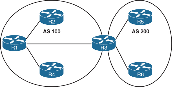
EIGRP uses ASN per process (ASN/Process)
Routers within the same domain must use the same metric calculation formula and exchange routes only with members of the same autonomous system (AS), if routing needs to be presented between 2 different EIGRP ASN / Process then router in the middle will need to redistribute between 2 ASN / Processes
For example R3 that is attached to 2 different ASN on 2 different processes does not transfer routes learned from one autonomous system into a different autonomous system
Current implementations of EIGRP support only IPv4 and IPv6.
EIGRP Terminology
Successor route
The route with the lowest path metric to reach a destination.
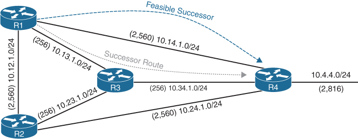
The successor route for R1 to reach 10.4.4.0/24 on R4 is R1→R3→R4.
Successor
The first next-hop router for the successor route. R1’s successor for 10.4.4.0/24 is R3.
Feasible distance (FD)
The metric value for the lowest path metric to reach a destination. The feasible distance is calculated locally using the formula
The FD calculated by R1 for the 10.4.4.0/24 destination network is 3328 (that is, 256 + 256 + 2816).
Reported distance (RD)
Distance reported by a router to reach a destination. The reported distance value is the feasible distance of the advertising router.
R3 advertises the 10.4.4.0/24 destination network to R1 and R2 with an RD of 3072 (2816 + 256).
R4 advertises the 10.4.4.0/24 destination network to R1, R2, and R3 with an RD of 2816.
Feasibility condition
For a route to be considered a backup route, the RD received for that route must be less than the FD calculated locally. This logic guarantees a loop-free path.
Feasible successor
Installed in the topology table only
Acts as a loop-free backup path
A route that satisfies the feasibility condition is maintained as a backup route. The feasibility condition ensures that the backup route is loop free.
The route R1→R4 is the feasible successor because the RD of 2816 is lower than the FD of 3328 for the R1→R3→R4 path.
Topology Table
EIGRP contains a topology table
The topology table contains all the network prefixes advertised within an EIGRP autonomous system including backup paths and not just contains metric per prefix but hop count also
Values used to calculate the metric BDRLM (Bandwidth , Delay , Reliability , Load , MTU)
show ip eigrp topology ! shows successor and feasible successor
!
show ip eigrp topology [all-links]
! shows successor and feasible successor all-links keyword shows the paths that did not pass the feasibility condition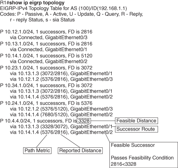
Prefix 10.4.4.0/24 has cost or FD of 3328 for best path or successor route
Successor route’s next hop router is called successor
second path that is feasible successor has RD of 2816 which is lower than FD of successor route, it passes the feasibility condition and is installed in topology table
The 10.4.4.0/24 route is passive (P), which means the topology is stable. During a topology change, routes go into an active (A) state when computing a new path.
EIGRP Neighbors
EIGRP neighbors exchange the entire routing table when forming an adjacency, and they advertise incremental updates only as topology changes occur within a network and no periodic updates
Inter-Router Communication
EIGRP uses IP protocol number (88)
uses multicast packets where possible to reduce bandwidth consumed on the links; it uses unicast packets when necessary
EIGRP uses Reliable Transport Protocol (RTP) to ensure that packets are delivered instead of TCP
A sequence number is included in each EIGRP packet. The sequence value zero does not require a response from the receiving EIGRP router; all other values require an ACK packet that includes the original sequence number
All update, query and reply packets are deemed reliable
hello and ACK packets do not require acknowledgment
If the originating router does not receive an ACK packet from the neighbor before the retransmit timeout expires, it notifies the non-acknowledging router to stop processing its multicast packets
Communication between routers is done with multicast using the group address 224.0.0.10 or the MAC address 01:00:5e:00:00:0a when possible
| Opcode Value | Packet Type | Function |
|---|---|---|
| 1 | Update | Used to transmit routing and reachability information with other EIGRP neighbors |
| 2 | Request | Used to get specific information from one or more neighbors |
| 3 | Query | Sent out to search for another path during convergence |
| 4 | Reply | Sent in response to a query packet |
| 5 | Hello | Used for discovery of EIGRP neighbors and for detecting when a neighbor is no longer available |
Forming EIGRP Neighbors
Hello messages are exchanged to become neighbors
The following parameters must match for the two routers to become neighbors:
- Metric formula K values
- Primary subnet matches
- Autonomous system number (ASN) matches
- Authentication parameters
EIGRP Configuration Modes
EIGRP configuration modes: classic mode and named mode.
EIGRP Named Mode
EIGRP named mode provides a hierarchical configuration and stores settings in three subsections:
- Address Family: This submode contains settings that are relevant to the global EIGRP AS operations, such as selection of network interfaces, EIGRP K values, logging settings, and stub settings.
- Interface: This submode contains settings that are relevant to the interface, such as hello advertisement interval, split-horizon, authentication, and summary route advertisements. In actuality, there are two methods of the EIGRP interface section’s configuration. Commands can be assigned to a specific interface or to a default interface, in which case those settings are placed on all EIGRP-enabled interfaces. If there is a conflict between the default interface and a specific interface, the specific interface takes priority over the default interface.
- Topology: This submode contains settings regarding the EIGRP topology database and how routes are presented to the router’s RIB. This section also contains route redistribution and administrative distance settings.
EIGRP named configuration makes it possible to run multiple instances under the same EIGRP process
Step 1. Initialize the EIGRP process by using the command router eigrp process-name. (If a number is used for process-name, the number does not correlate to the autonomous system number.)
Step 2. Initialize the EIGRP instance for the appropriate address family with the command address-family {IPv4 | IPv6} {unicast | vrf vrf-name} autonomous-system as-number.
Step 3. Enable EIGRP on interfaces by using the command network network wildcard-mask.
EIGRP Network Statement
Network statement enrolls interfaces in EIGRP and sends hellos on those interfaces
If wildcard is omitted then any interfaces that fall under the classful boundary are added in EIGRP, secondary networks are not added, if we want secondary networks in EIGRP then they need to be redistributed
router eigrp 1
    network 10.0.0.10 0.0.0.0
    network 10.0.0.0 0.0.0.255
    network 10.0.0.0 0.255.255.255
    network 0.0.0.0 255.255.255.255 ! enable on all interfaces
Named configuration
R2 (Named Mode Configuration)
interface Loopback0
 ip address 192.168.2.2 255.255.255.255
!
interface GigabitEthernet0/1
    ip address 10.12.1.2 255.255.255.0
!
interface GigabitEthernet0/2
    ip address 10.22.22.2 255.255.255.0
!
router eigrp EIGRP-NAMED
 address-family ipv4 unicast autonomous-system 100
  network 0.0.0.0 255.255.255.255
R2# show run | section router eigrp
router eigrp EIGRP-NAMED
!
address-family ipv4 unicast autonomous-system 100
!
topology base
exit-af-topology
network 0.0.0.0
exit-address-family The EIGRP interface submode configurations contain the command af-interface interface-id or af-interface default
router eigrp MY-EIGRP
 address-family ipv4 unicast autonomous-system 100
  network 10.0.0.0 0.0.0.255

  af-interface default
   passive-interface
   hello-interval 5
   hold-time 15
  exit-af-interface

  af-interface GigabitEthernet0/0
   no passive-interface
   bandwidth-percent 50
  exit-af-interface

  af-interface GigabitEthernet0/1
   no passive-interface
   authentication mode md5
   authentication key-chain EIGRP_KEYS
  exit-af-interface
 exit-address-family
show ip eigrp interfaces [{interface-id [detail] | detail}]R1# show ip eigrp interfaces
EIGRP-IPv4 Interfaces for AS(100)
Xmit Queue PeerQ Mean Pacing Time Multicast Pending
Interface Peers Un/Reliable Un/Reliable SRTT Un/Reliable Flow Timer Routes
Gi0/2 0 0/0 0/0 0 0/0 0 0
Gi0/1 1 0/0 0/0 10 0/0 50 0
Lo0 0 0/0 0/0 0 0/0 0 0R2# show ip eigrp interfaces gi0/1 detail
EIGRP-IPv4 VR(EIGRP-NAMED) Address-Family Interfaces for AS(100)
Xmit Queue PeerQ Mean Pacing Time Multicast Pending
Interface Peers Un/Reliable Un/Reliable SRTT Un/Reliable Flow Timer Routes
Gi0/1 1 0/0 0/0 1583 0/0 7912 0
Hello-interval is 5, Hold-time is 15
Split-horizon is enabled
Next xmit serial <none>
Packetized sent/expedited: 2/0
Hello's sent/expedited: 186/2
Un/reliable mcasts: 0/2 Un/reliable ucasts: 2/2
Mcast exceptions: 0 CR packets: 0 ACKs suppressed: 0
Retransmissions sent: 1 Out-of-sequence rcvd: 0
Topology-ids on interface - 0
Authentication mode is not set
Topologies advertised on this interface: base
Topologies not advertised on this interface:Fields explaination
Xmt Queue – Un/Reliable
Number of unreliable/reliable packets remaining in the transmit queue. The value zero is an indication of a stable network.
Mean SRTT
Average time for a packet to be sent and a received from neighbor in milliseconds.
Pending Routes
Number of routes in the transmit queue that need to be sent.
R1# show ip eigrp neighbors
EIGRP-IPv4 Neighbors for AS(100)
H   Address                 Interface              Hold Uptime   SRTT   RTO  Q  Seq
                                                   (sec)         (ms)       Cnt Num
0   10.12.1.2               Gi0/1                    13 00:18:31   10   100  0  3
Fields explaination
RTO
Timeout for retransmission (waiting for ACK)
Q Cnt
Number of packets (update/query/reply) in queue for sending
Seq Num
Sequence number that was last “received” from this router
show ip route eigrpR1# show ip route eigrp
Codes: L - local, C - connected, S - static, R - RIP, M - mobile, B - BGP
D - EIGRP, EX - EIGRP external, O - OSPF, IA - OSPF inter area
N1 - OSPF NSSA external type 1, N2 - OSPF NSSA external type 2
E1 - OSPF external type 1, E2 - OSPF external type 2
i - IS-IS, su - IS-IS summary, L1 - IS-IS level-1, L2 - IS-IS level-2
ia - IS-IS inter area, * - candidate default, U - per-user static route
o - ODR, P - periodic downloaded static route, H - NHRP, l - LISP
a - application route
+ - replicated route, % - next hop override, p - overrides from PfR
Gateway of last resort is not set
10.0.0.0/8 is variably subnetted, 5 subnets, 2 masks
D 10.22.22.0/24 [90/3072] via 10.12.1.2, 00:19:25, GigabitEthernet0/1
192.168.2.0/32 is subnetted, 1 subnets
D 192.168.2.2 [90/2848] via 10.12.1.2, 00:19:25, GigabitEthernet0/1R2# show ip route eigrp
! Output omitted for brevity
Gateway of last resort is not set
10.0.0.0/8 is variably subnetted, 5 subnets, 2 masks
D 10.11.11.0/24 [90/15360] via 10.12.1.1, 00:20:34, GigabitEthernet0/1
192.168.1.0/32 is subnetted, 1 subnets
D 192.168.1.1 [90/2570240] via 10.12.1.1, 00:20:34, GigabitEthernet0/1EIGRP routes have administrative distance (AD) of 90 and are indicated in the routing table with a D
External EIGRP routes have an AD of 170 and are indicated in the routing table with D EX
The metrics for R2’s routes are different from the metrics from R1’s routes. This is because R1’s classic EIGRP mode uses classic metrics, and R2’s named mode uses “wide metrics” “by default”
Router ID
The router ID (RID) is a 32-bit number that uniquely identifies an EIGRP router and is used as a loop-prevention mechanism. The RID can be set dynamically, which is the default, or manually.
The algorithm for dynamically choosing the EIGRP RID uses the highest IPv4 address of any up loopback interfaces. If there are not any up loopback interfaces, the highest IPv4 address of any active up physical interfaces becomes the RID when the EIGRP process initializes.
R1(config)# router eigrp 100
R1(config-router)# eigrp router-id 192.168.1.1

R2(config)# router eigrp EIGRP-NAMED
R2(config-router)# address-family ipv4 unicast autonomous-system 100
R2(config-router-af)# eigrp router-id 192.168.2.2
Passive Interfaces
Some network topologies must advertise a network segment into EIGRP but need to prevent neighbors because it stops sending hello and process received hellos
for example, when advertising access layer networks in a campus topology.
R1# configure terminal
Enter configuration commands, one per line.  End with CNTL/Z.
R1(config)# router eigrp 100
R1(config-router)# passive-interface gi0/2
R1(config)# router eigrp 100
R1(config-router)# passive-interface default
04:22:52.031: %DUAL-5-NBRCHANGE: EIGRP-IPv4 100: Neighbor 10.12.1.2
(GigabitEthernet0/1) is down: interface passive
R1(config-router)# no passive-interface gi0/1
*May 10 04:22:56.179: %DUAL-5-NBRCHANGE: EIGRP-IPv4 100: Neighbor 10.12.1.2
(GigabitEthernet0/1) is up: new adjacencyFor a named mode configuration, you place the passive-interface state on af-interface default for all EIGRP interfaces or on a specific interface with the af-interfaceinterface-id
R2# configure terminal
Enter configuration commands, one per line.  End with CNTL/Z.
R2(config)# router eigrp EIGRP-NAMED
R2(config-router)# address-family ipv4 unicast autonomous-system 100
R2(config-router-af)# af-interface gi0/2
R2(config-router-af-interface)# passive-interface
R2(config)# router eigrp EIGRP-NAMED
R2(config-router)# address-family ipv4 unicast autonomous-system 100
R2(config-router-af)# af-interface default
R2(config-router-af-interface)# passive-interface
04:28:30.366: %DUAL-5-NBRCHANGE: EIGRP-IPv4 100: Neighbor 10.12.1.1
(GigabitEthernet0/1) is down: interface passiveex
R2(config-router-af-interface)# exit-af-interface
R2(config-router-af)# af-interface gi0/1
R2(config-router-af-interface)# no passive-interface
R2(config-router-af-interface)# exit-af-interface
*May 10 04:28:40.219: %DUAL-5-NBRCHANGE: EIGRP-IPv4 100: Neighbor 10.12.1.1
(GigabitEthernet0/1) is up: new adjacencyR2# show run | section router eigrp
router eigrp EIGRP-NAMED
!
address-family ipv4 unicast autonomous-system 100
!
af-interface default
passive-interface
exit-af-interface
!
af-interface GigabitEthernet0/1
no passive-interface
exit-af-interface
!
topology base
exit-af-topology
network 0.0.0.0
exit-address-familyA passive interface does not appear in the output of the command show ip eigrp interfaces even though it was enabled but appears under “show ip protocols” command as passive. Connected networks for passive interfaces are still added to the EIGRP topology table so that they are advertised to neighbors.
show ip protocols command also shows K values set for EIGRP, RID and information such as interfaces enabled for EIGRP, passive interfaces and neighbors
R1# show ip protocols
! Output omitted for brevity
Routing Protocol is "eigrp 100"
  Outgoing update filter list for all interfaces is not set
  Incoming update filter list for all interfaces is not set
  Default networks flagged in outgoing updates
  Default networks accepted from incoming updates
  EIGRP-IPv4 Protocol for AS(100)
    Metric weight K1=1, K2=0, K3=1, K4=0, K5=0
    Soft SIA disabled
    NSF-aware route hold timer is 240
    Router-ID: 192.168.1.1
    Topology : 0 (base)
      Active Timer: 3 min
      Distance: internal 90 external 170
      Maximum path: 4
      Maximum hopcount 100
      Maximum metric variance 1

  Automatic Summarization: disabled
  Maximum path: 4
  Routing for Networks:
    10.11.11.1/32
    10.12.1.1/32
    192.168.1.1/32
  Passive Interface(s):
    GigabitEthernet0/2
    Loopback0
  Routing Information Sources:
    Gateway         Distance      Last Update
    10.12.1.2             90      00:21:35
  Distance: internal 90 external 170
Authentication
Hash is a one way function and cannot be reversed or decrypted
A password on an EIGRP router is hashed and sent with EIGRP packet
once it is received on neighbor, neighbor also hashes its password and then compare it with received hash, if both has match then packet is accepted and if they do not match then EIGRP packet is discarded
Keychain Configuration
Keychain creation is accomplished with the following steps:
Step 1. Create the keychain by using the command key chain key-chain-name.
Step 2. Identify the key sequence by using the command key key-number, where key-number can be anything from 0 to 2147483647.
Step 3. Specify the preshared password by using the command key-string password.
classic configuration, authentication must be enabled on the interface
R1(config)# key chain EIGRPKEY
R1(config-keychain)# key 2
R1(config-keychain-key)# key-string CISCO
R1(config)# interface gi0/1
R1(config-if)# ip authentication mode eigrp 100 md5
R1(config-if)# ip authentication key-chain eigrp 100 EIGRPKEY
The named mode configuration places the configurations under the EIGRP interface submode
R2(config)# key chain EIGRPKEY
R2(config-keychain)# key 2
R2(config-keychain-key)# key-string CISCO
R2(config-keychain-key)# router eigrp EIGRP-NAMED
R2(config-router)# address-family ipv4 unicast autonomous-system 100
R2(config-router-af)# af-interface default
R2(config-router-af-interface)# authentication mode md5
R2(config-router-af-interface)# authentication key-chain EIGRPKEY
R1# show key chain
Key-chain EIGRPKEY:
key 2 -- text "CISCO"
accept lifetime (always valid) - (always valid) [valid now]
send lifetime (always valid) - (always valid) [valid now]R1# show ip eigrp interface detail
EIGRP-IPv4 Interfaces for AS(100)
Xmit Queue PeerQ Mean Pacing Time Multicast Pending
Interface Peers Un/Reliable Un/Reliable SRTT Un/Reliable Flow Timer Routes
Gi0/1 0 0/0 0/0 0 0/0 50 0
Hello-interval is 5, Hold-time is 15
Split-horizon is enabled
Next xmit serial <none>
Packetized sent/expedited: 10/1
Hello's sent/expedited: 673/12
Un/reliable mcasts: 0/9 Un/reliable ucasts: 6/19
Mcast exceptions: 0 CR packets: 0 ACKs suppressed: 0
Retransmissions sent: 16 Out-of-sequence rcvd: 1
Topology-ids on interface - 0
Authentication mode is md5, key-chain is "EIGRPKEY"Path Metric Calculation
Metric calculation uses bandwidth and delay by default but can include interface load and reliability, too


A common misconception is that the K values directly apply to bandwidth, load, delay, or reliability; this is not accurate. For example, K1 and K2 both reference bandwidth (BW).
BW represents the slowest link in the path in Kbps
Delay is the total measure of delay in the path, measured in tens of microseconds (μs).
By default, K1 and K3 each has a value of 1, and K2, K4, and K5 are all set to 0

The EIGRP update packet includes path attributes associated with each prefix. The EIGRP path attributes can include hop count, cumulative delay, minimum bandwidth link speed, and RD. The attributes are updated each hop along the way

Notice that the hop count increments, minimum bandwidth decreases, total delay increases, and the RD changes with each EIGRP update.
Default EIGRP Interface Metrics for Classic Metrics
| Interface Type | Link Speed (Kbps) | Delay | Metric |
|---|---|---|---|
| Serial | 64 | 20,000 μs | 40,512,000 |
| T1 | 1544 | 20,000 μs | 2,170,031 |
| Ethernet | 10,000 | 1000 μs | 281,600 |
| FastEthernet | 100,000 | 100 μs | 28,160 |
| GigabitEthernet | 1,000,000 | 10 μs | 2816 |
| TenGigabitEthernet | 10,000,000 | 10 μs | 512 |
R1# show ip eigrp topology 10.4.4.0/24
! Output omitted for brevity
EIGRP-IPv4 Topology Entry for AS(100)/ID(10.14.1.1) for 10.4.4.0/24
  State is Passive, Query origin flag is 1, 1 Successor(s), FD is 3328
  Descriptor Blocks:
  10.13.1.3 (GigabitEthernet0/1), from 10.13.1.3, Send flag is 0x0
      Composite metric is (3328/3072), route is Internal
      Vector metric:
        Minimum bandwidth is 1000000 Kbit
        Total delay is 30 microseconds
        Reliability is 252/255
        Load is 1/255
        Minimum MTU is 1500
        Hop count is 2
        Originating router is 10.34.1.4
  10.14.1.4 (GigabitEthernet0/2), from 10.14.1.4, Send flag is 0x0
      Composite metric is (5376/2816), route is Internal
     Vector metric:
        Minimum bandwidth is 1000000 Kbit
        Total delay is 110 microseconds
        Reliability is 255/255
        Load is 1/255
        Minimum MTU is 1500
        Hop count is 1
        Originating router is 10.34.1.4
Wide Metrics
there is not a differentiation between an 11 Gbps interface and a 20 Gbps interface.
10 GigabitEthernet:
Scaled Bandwidth = 10,000,000 / 10,000,000
Scaled Delay = 10 / 10
Composite Metric = 1 + 1 * 256 = 512
11 GigabitEthernet:
Scaled Bandwidth = 10,000,000 / 11,000,000
Scaled Delay = 10 / 10
Composite Metric = 0 + 1 * 256 = 25620 GigabitEthernet:
Scaled Bandwidth = 10,000,000 / 20,000,000
Scaled Delay = 10 / 10
Composite Metric = 0 + 1 * 256 = 256EIGRP includes support for a second set of metrics, known as wide metrics, that addresses the issue of scalability with higher-capacity interfaces.
The interface delay varies from router to router, depending on the following logic:
- If the interface’s delay was specifically set, the value is converted to picoseconds. Interface delay is always configured in tens of microseconds and is multiplied by 107 for picosecond conversion.
- If the interface’s bandwidth was specifically set, the interface delay is configured using the classic default delay, converted to picoseconds. The configured bandwidth is not considered when determining the interface delay. If delay was configured, this step is ignored.
- If the interface supports speeds of 1 Gbps or less and does not contain bandwidth or delay configuration, the delay is the classic default delay, converted to picoseconds.
- If the interface supports speeds over 1 Gbps and does not contain bandwidth or delay configuration, the interface delay is calculated by 1013/interface bandwidth.
R1# show ip protocols | include AS|K
  EIGRP-IPv4 Protocol for AS(100)
    Metric weight K1=1, K2=0, K3=1, K4=0, K5=0
R2# show ip protocols | include AS|K
EIGRP-IPv4 VR(EIGRP-NAMED) Address-Family Protocol for AS(100)
Metric weight K1=1, K2=0, K3=1, K4=0, K5=0 K6=0 <<<Existence of K6 proves use of named EIGRP
Metric Backward Compatibility
EIGRP wide metrics were designed with backward compatibility in mind. EIGRP wide metrics set K1 and K3 to a value of 1 and set K2, K4, K5, and K6 to 0, which allows backward compatibility because the K value metrics match with classic metrics. As long as K1 through K5 are the same and K6 is not set, the two metric styles allow adjacency between routers.
Using a mixture of classic metric and wide metric devices could lead to suboptimal routing, so it is best to keep all devices operating with the same metric style.
Why set delay and not bandwidth
Bandwidth modification with the interface parameter command bandwidth bandwidth has a similar effect on the metric calculation formula but can impact other routing protocols, such as OSPF, at the same time. Modifying the interface delay only impacts EIGRP.
R1# show interfaces gigabitEthernet 0/1 | i DLY
  MTU 1500 bytes, BW 1000000 Kbit/sec, DLY 10 usec,
R2# show interfaces gigabitEthernet 0/1 | i DLY
MTU 1500 bytes, BW 1000000 Kbit/sec, DLY 10 usec,show interface interface-id. The output displays the EIGRP interface delay, in microseconds
R1# configure terminal
R1(config)# interface gi0/1
R1(config-if)# delay 100
R1(config-if)# do show interface Gigabit0/1 | i DLY
  MTU 1500 bytes, BW 1000000 Kbit/sec, DLY 1000 usec,
Custom K Values
K values for the path metric formula are set with the command metric weights TOS K1 K2 K3 K4 K5 [K6] under the EIGRP process. TOS always has a value of 0, and K6 is used for named mode configurations.
To ensure consistent routing logic in an EIGRP autonomous system, the K values must match between EIGRP neighbors to form an adjacency and exchange routes. The K values are included as part of the EIGRP hello packet.
Load Balancing
EIGRP allows multiple successor routes (with the same metric) to be installed into the RIB called ECMP, the default maximum ECMP setting is four routes
R1# show run | section router eigrp
router eigrp 100
 maximum-paths 6
 network 0.0.0.0
R2# show run | section router eigrp
router eigrp EIGRP-NAMED
!
address-family ipv4 unicast autonomous-system 100
!
topology base
maximum-paths 6
exit-af-topology
network 0.0.0.0
eigrp router-id 192.168.2.2
exit-address-familyUnequal Cost Load Balancing
EIGRP supports unequal-cost load balancing, which allows installation of both successor routes and feasible successors into the EIGRP RIB. To use unequal-cost load balancing change EIGRP’s variance multiplier.
Variance Value is Feasible distance (FD) for a route multiplied by the EIGRP variance multiplier
Any feasible successor’s FD with a metric below the EIGRP variance up to the maximum number of ECMP routes value is installed into the RIB
There is a way to find exact variance to use
Dividing the feasible successor metric by the successor route metric provides the variance multiplier.
The variance multiplier is a whole number, and any remainders should always round up.


the minimum EIGRP variance multiplier can be calculated so that the direct path from R1 to R4 can be installed into the RIB. The FD for the successor route is 3328, and the FD for the feasible successor is 5376. The formula provides a value of about 1.6 and is always rounded up to the nearest whole number to provide an EIGRP variance multiplier of 2

R1 (Classic Configuration)
router eigrp 100
 variance 2
 network 0.0.0.0
R1 (Named Mode Configuration)
router eigrp EIGRP-NAMED
!
address-family ipv4 unicast autonomous-system 100
!
topology base
variance 2
exit-af-topology
network 0.0.0.0
exit-address-familyR1# show ip route eigrp | begin Gateway
Gateway of last resort is not set
10.0.0.0/8 is variably subnetted, 10 subnets, 2 masks
D 10.4.4.0/24 [90/5376] via 10.14.1.4, 00:00:03, GigabitEthernet0/2
[90/3328] via 10.13.1.3, 00:00:03, GigabitEthernet0/1R1# show ip route 10.4.4.0
Routing entry for 10.4.4.0/24
Known via "eigrp 100", distance 90, metric 3328, type internal
Redistributing via eigrp 100
Last update from 10.13.1.3 on GigabitEthernet0/1, 00:00:35 ago
Routing Descriptor Blocks:
* 10.14.1.4, from 10.14.1.4, 00:00:35 ago, via GigabitEthernet0/2
Route metric is 5376, traffic share count is 149
Total delay is 110 microseconds, minimum bandwidth is 1000000 Kbit
Reliability 255/255, minimum MTU 1500 bytes
Loading 1/255, Hops 1
10.13.1.3, from 10.13.1.3, 00:00:35 ago, via GigabitEthernet0/1
Route metric is 3328, traffic share count is 240
Total delay is 30 microseconds, minimum bandwidth is 1000000 Kbit
Reliability 254/255, minimum MTU 1500 bytes
Loading 1/255, Hops 2Traffic share count is a ratio used for load-sharing
This means traffic is load-balanced unequally:
So traffic is split roughly as:
- ~62% via 10.13.1.3
- ~38% via 10.14.1.4
The better path always gets more traffic.
To get equal traffic share counts the metrics must be equal
Once variance is configured, traffic sharing is automatic