⊹ 5. CCIE SDWAN ⊹
SDWAN | LM Notes
SDWAN Basics & LAB Controllers / Edge Standup

in above, only vbond authenticates to the vmanage, every thing else authenticates to the vbond including vsmart and all wan edges
All are assigned certificate from vmanage but they all authenticate to vbond except vbond itself which has to authenticate with vmanage as there is nothing else
Step 1. First we install vmanage and add vbond to vmanage
vmanage then issues certificate to vbond
vmanage and vbond then perform mutual certificate based authentication and establish a management channel indicated by the grey arrow
Step 2. Then we add vsmart to vmanage and vmanage then issues certificate to the vsmart
you will see after step 2 vsmart information is uploaded to vbond (so vsmart can first authenticate to vbond)
vsmart then contacts and authenticates with vbond
after authentication vsmart will have management channel with vbond and vmanage
At this stage, if we have more vsmarts, they will learn about other vsmarts from vbond
Step 3. Either vmanage can sync with your smart account and download the list of devices
or we can use the serial file method which is offline method of importing devices
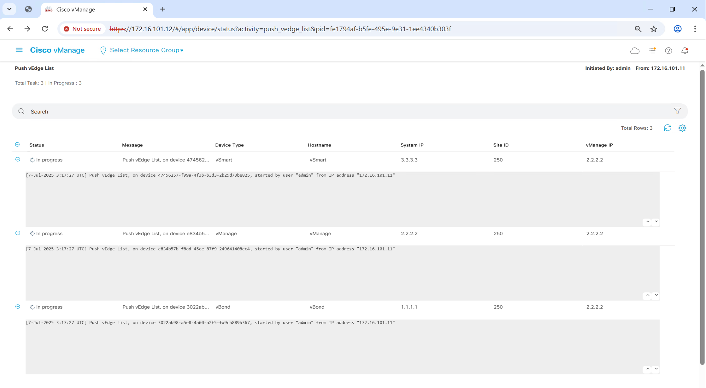
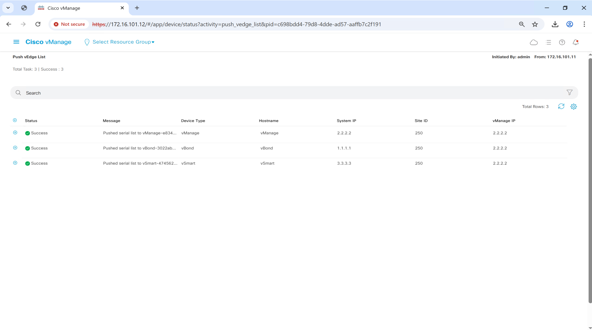
once device list has been uploaded to vmanage, it uploads this device list to all controllers (vbond and vsmart)
at this point all the controllers are aware of all the wan edge devices which will join
Step 4 When the wan edge device comes up it gets DHCP ip and contacts ZTP on a pre-defined URL
ZTP in this case is cisco’s online server that will have all the licenses generated will redirect the wan edge to organisation’s vbond
wan edge will authenticate with vbond
vbond will inform the wan edge about how to get to vmanage and vsmart
Step 5. wan edge will go and authenticate with vmanage and establish the management channel
Step 6. wan edge will go and authenticate with vsmart and establish the OMP channel
Step 7. wan edge will establish the IPSec tunnel with other wan edge routers
TLOC = System IP + Color + Encapsulation protocol
There are 3 kinds of routes
OMP routes
TLOC routes
Service routes
TLOC is maintained using BFD, if a TLOC goes down then all routes associated to that TLOC are removed just like next hop interface
BFD does more than reachability check, it checks for Loss (completely no response) , delay (delayed response) , jitter (variation in delay) as well also called path quality, these path quality metrics are then used in application aware routing
If there is a second vsmart, wan edge will have another omp peering with that vsmart
VPN number is tagged in the IPSec header so other router can land that traffic in same VPN
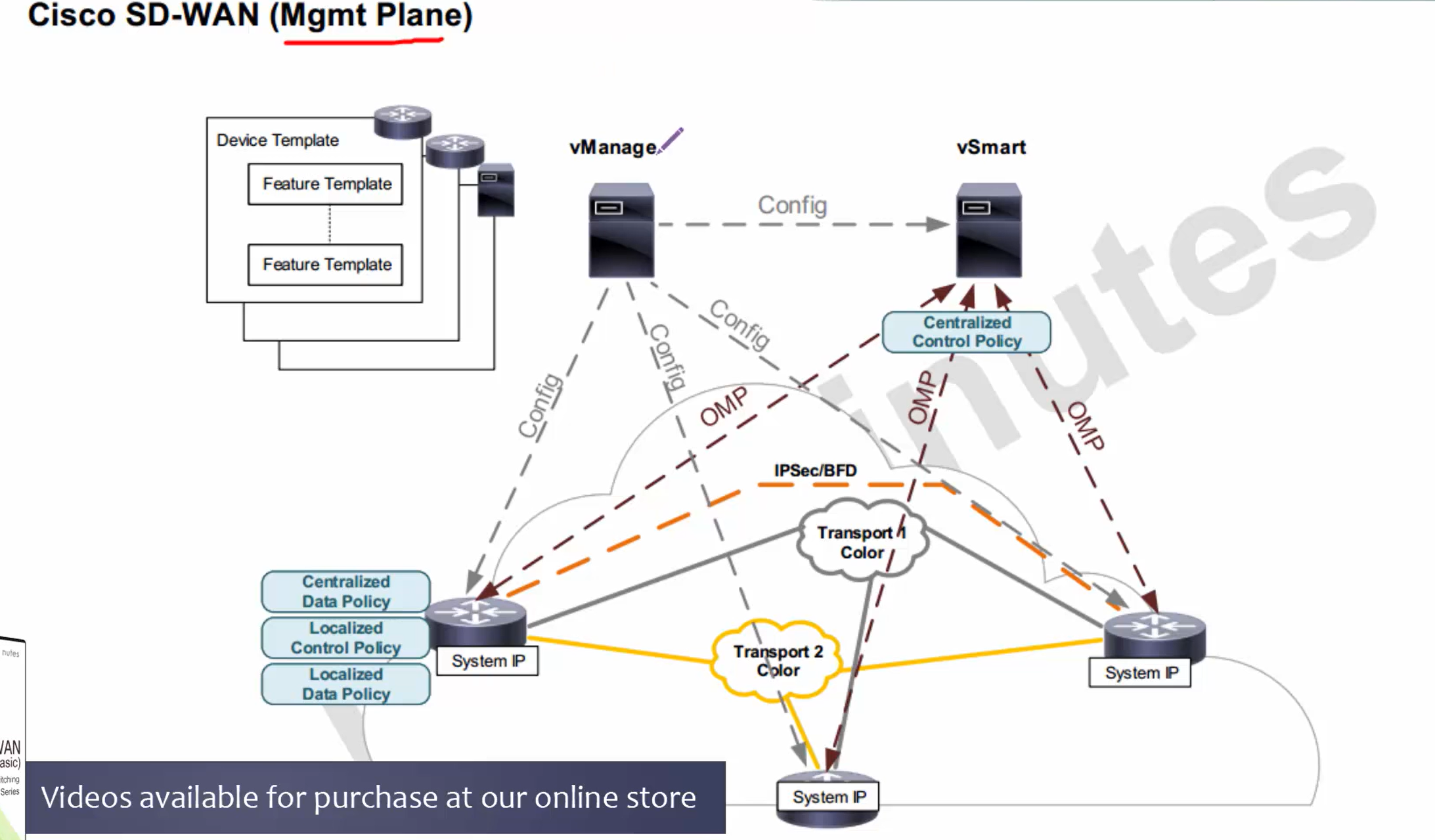
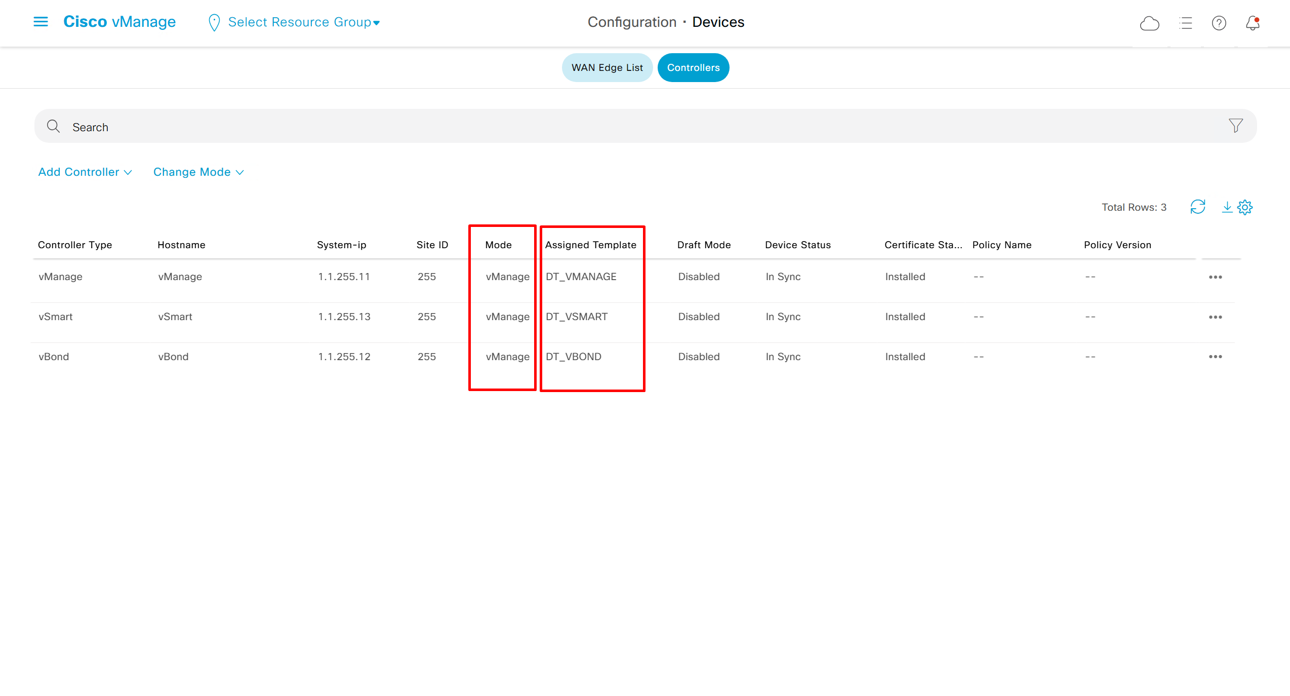
Configuration is not only pushed to wan edge devices but also to the vsmart
vsmart is also considered a managed device like wan edge router since it needs to be added to vmanage and applied configuration through the template etc just like wan edge device
once template is applied, devices go in something called vmanage mode and then we cannot configure devices from CLI (initially you can configure devices from CLI but once managed by vmanage you cannot)
Device template > feature template
As can be seen above
Centralized control policy (vsmart)
Centralized data policy (wan edge)
Localized control policy (wan edge)
Localized data policy (wan edge)
Centralized control policy is used to create different types of topologies
Centralized data policy is like route-map that is applied on interface effects the data packet directly, we can match packets based on packet header or application based matching which relies on deep packet inspection and take actions such as dropping packets, QoS classification, policing, change next hop and so on – but this is pushed by vsmart and lives in wan edge memory and does not really get added to the device local configuration, remember that from central keyword, anything that is centralized, its policies are in wan edge’s memory and not in the wan edge config
Localized control policy – this is effective or configured on the service side only, so if OSPF and BGP is running on LAN of the wan edge, localized control policy is needed
Localized Data policy is very similar to the Centralized Data policy, only difference is that is configuration is pushed and becomes part of wan edge configuration and is per interface
make sure when connecting vbond device to switch, it is connected using ge0/0 instead of eth0
this will save you a lot of troubleshooting time when standing up vBond

WINSERVER configuration
Setup same as https://learn.anasather.uk/masters/eveng/eveng-ccie-lab-and-megalinks/
Assign IP address as to Win server as below

Deploy NTP on Windows Server
https://www.domat-int.com/en/how-to-configure-a-local-ntp-server
https://docs.litmus.io/litmusedge/product-features/system/network/configure-dns-ntp-servers/configure-local-ntp-server
Configure the Windows Time Service
In the File Explorer, navigate to: Control Panel\System and Security\Administrative Tools
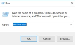
Double-click Services. This same task can be completed by entering services.msc in the Windows Run dialog (Windows Key + R).
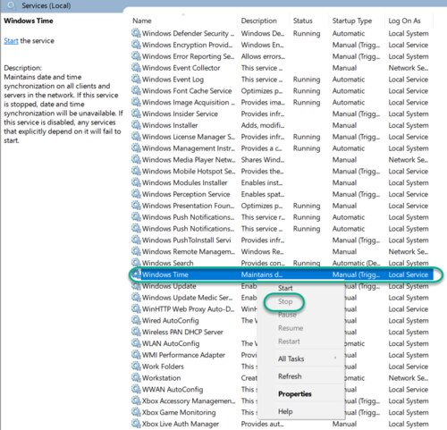
In the Services list, right-click on Windows Time and click Stop.
Note: The Windows Time service may already be stopped. In this case, skip this step and go to the next step to Update the Windows Registry
Update the Windows Registry to Create a Local NTP Service
Launch Windows Run (Windows Key + R).
Enter regedit and click OK.
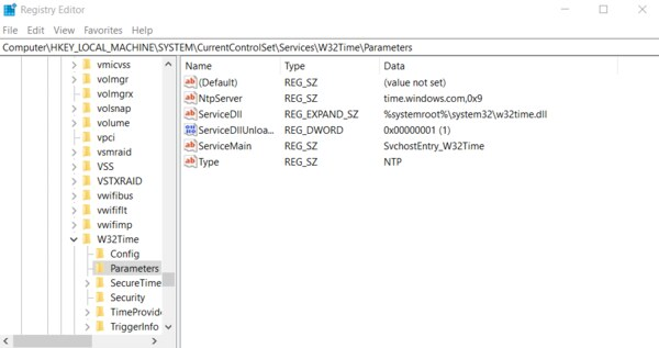
Navigate to the registry key: Computer\HKEY_LOCAL_MACHINE\SYSTEM\CurrentControlSet\Services\W32Time\Parameters
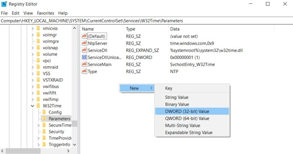
If you do not see LocalNTP REG_DWORD in the list, create it using the following steps.
Right-click in the Registry Editor, select New, select DWORD and enter LocalNTP (note that this name is case sensitive).
Double-click LocalNTP, change the Value data to 1, select a Base of Hexadecimal , and click OK.
Do not close the Registry Editor because it is used in the following steps.
Update the Windows Registry to Configure the Time Provider
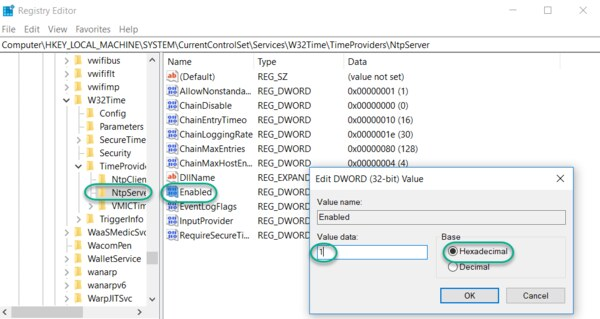
Navigate to the registry key: Computer\HKEY_LOCAL_MACHINE\SYSTEM\CurrentControlSet\Services\W32Time\TimeProviders
Select NtpServer, double-click Enabled, change the Value Data to 1, select a Base of Hexadecimal and click OK.
Do not close the Registry Editor because it is used in the following steps.
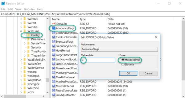
Update the Windows Registry to Configure the Announce Flags
Navigate to the registry key: Computer\HKEY_LOCAL_MACHINE\SYSTEM\CurrentControlSet\Services\W32Time\Config
Double-click AnnounceFlags, change the Value data to 5, select a Base of Hexadecimal, and click OK.
Close the Registry Editor.
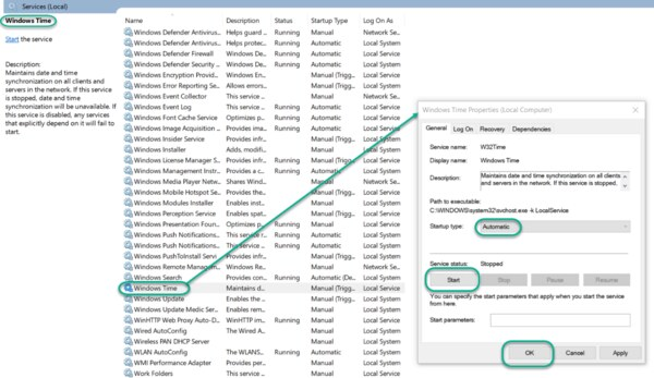
Start the Local Windows NTP Time Service
In the File Explorer, navigate to: Control Panel\System and Security\Administrative Tools
Double-click Services.
In the Services list, right-click on Windows Time and configure the following settings:
Startup type: Automatic
Service Status: Start
OK
Finally, enable UDP port 123 on the Windows firewall for incoming connections.
In Search find Firewall in Windows Defender…
Go to Incoming rules
In the right column, select New rule…
Select the rule Port
Enter UDP port 123 and click Next
Select Allow connection and click Next
Select all domains
Enter the rule name, e.g. Local NTP server, and click Finish.
The local NTP Time Server configuration is now complete. You now can synchronize the time of other computers and devices on your local network.
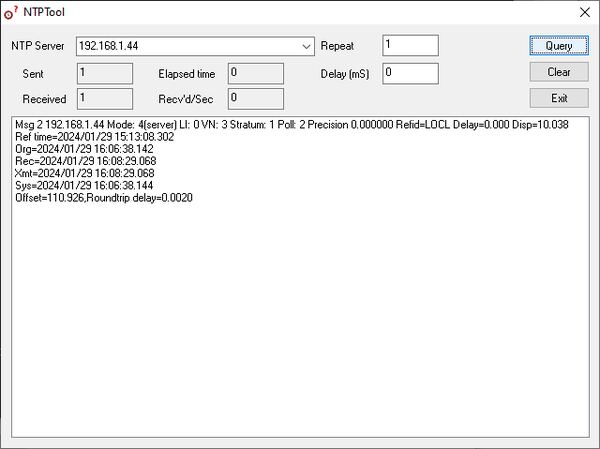
To test the server functionality from another PC (e.g. a service notebook) use for example the NTP Server Test Tool:
https://www.ntp-time-server.com/ntp-software/ntp-server-tool.html
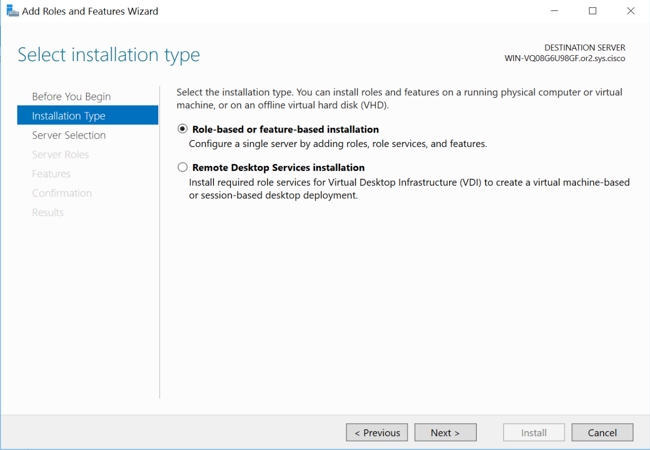
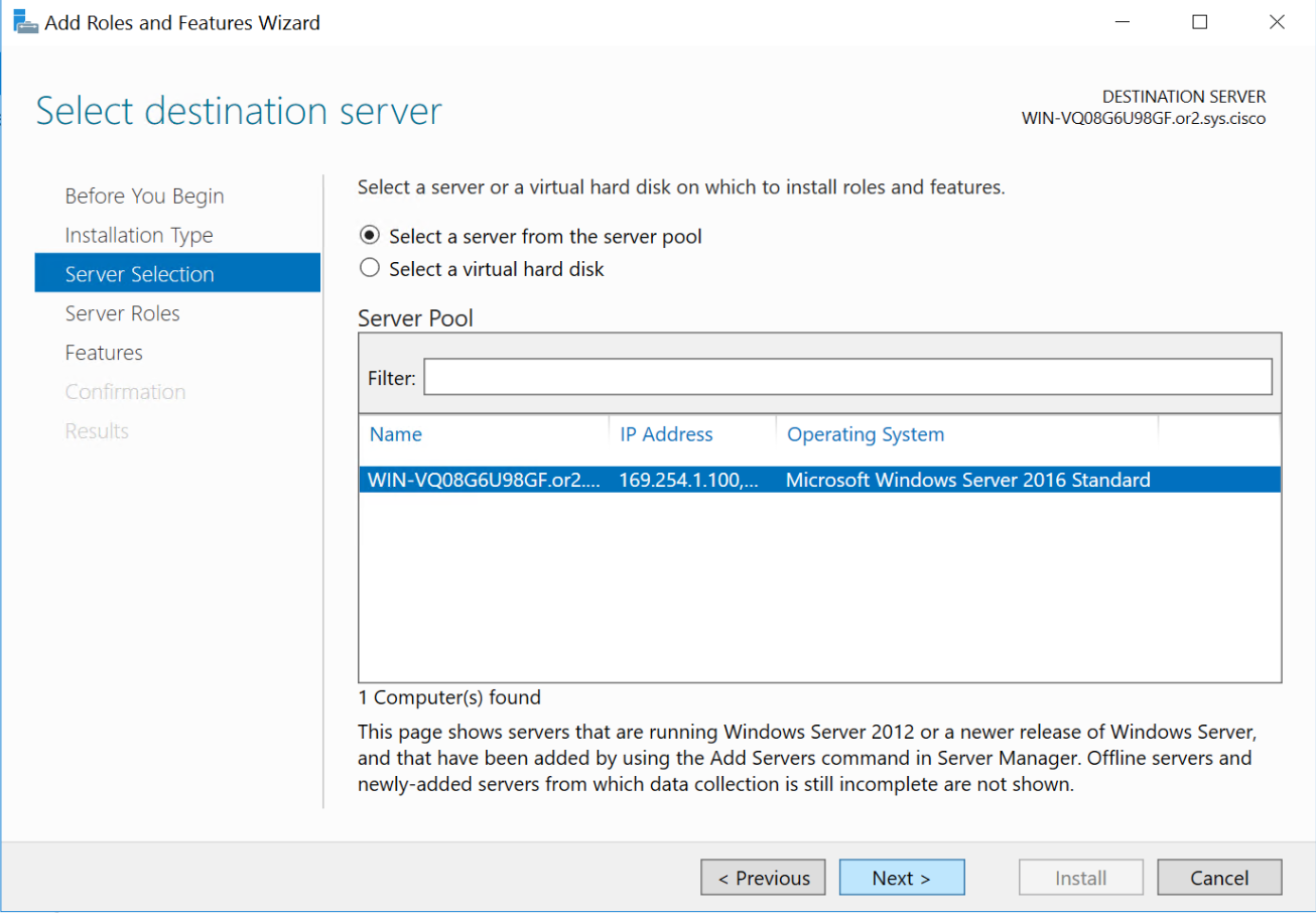
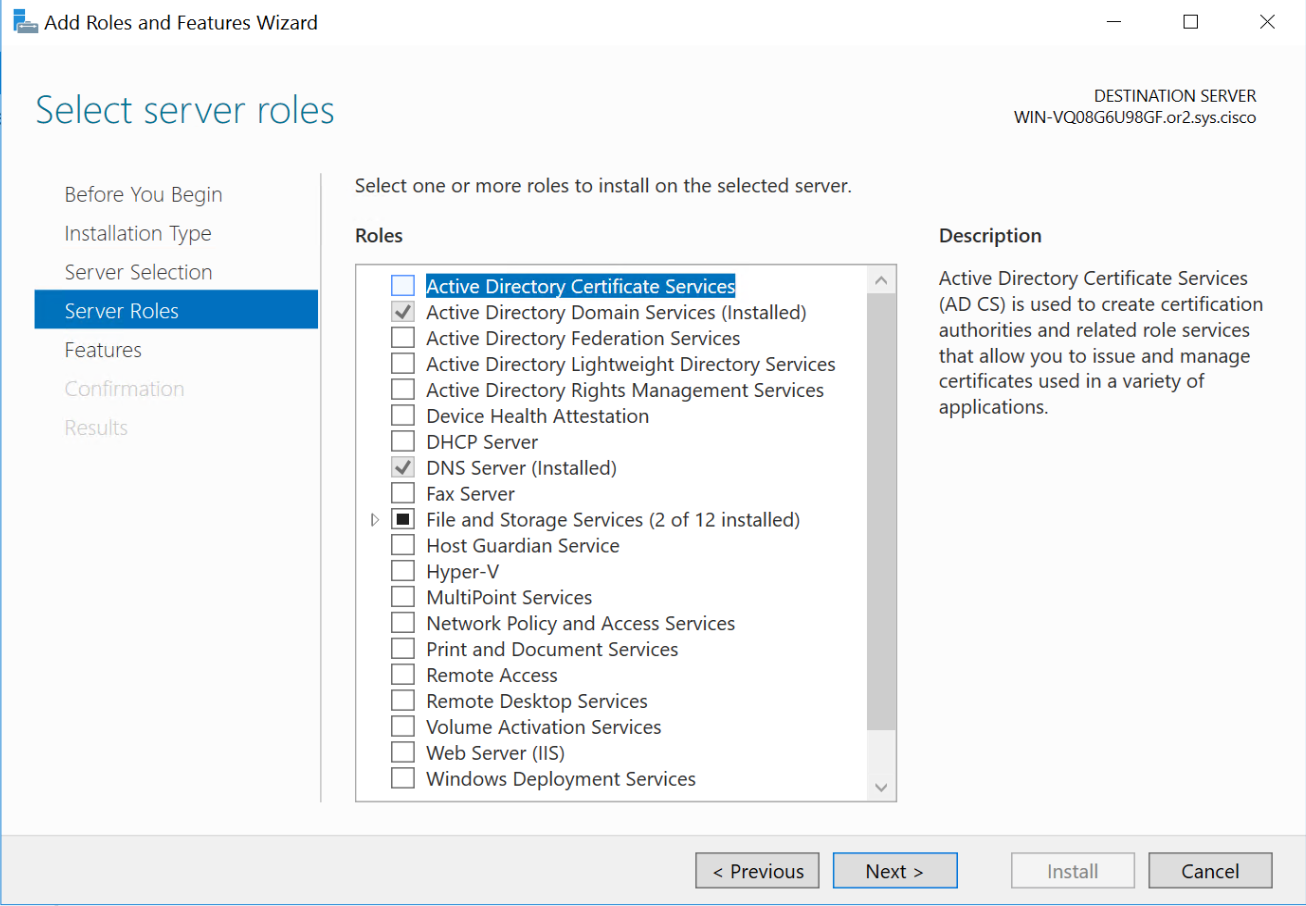
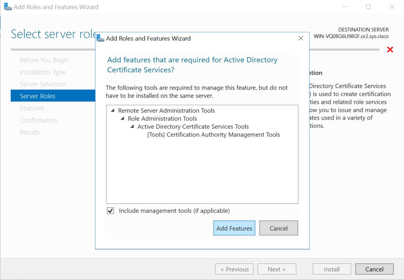
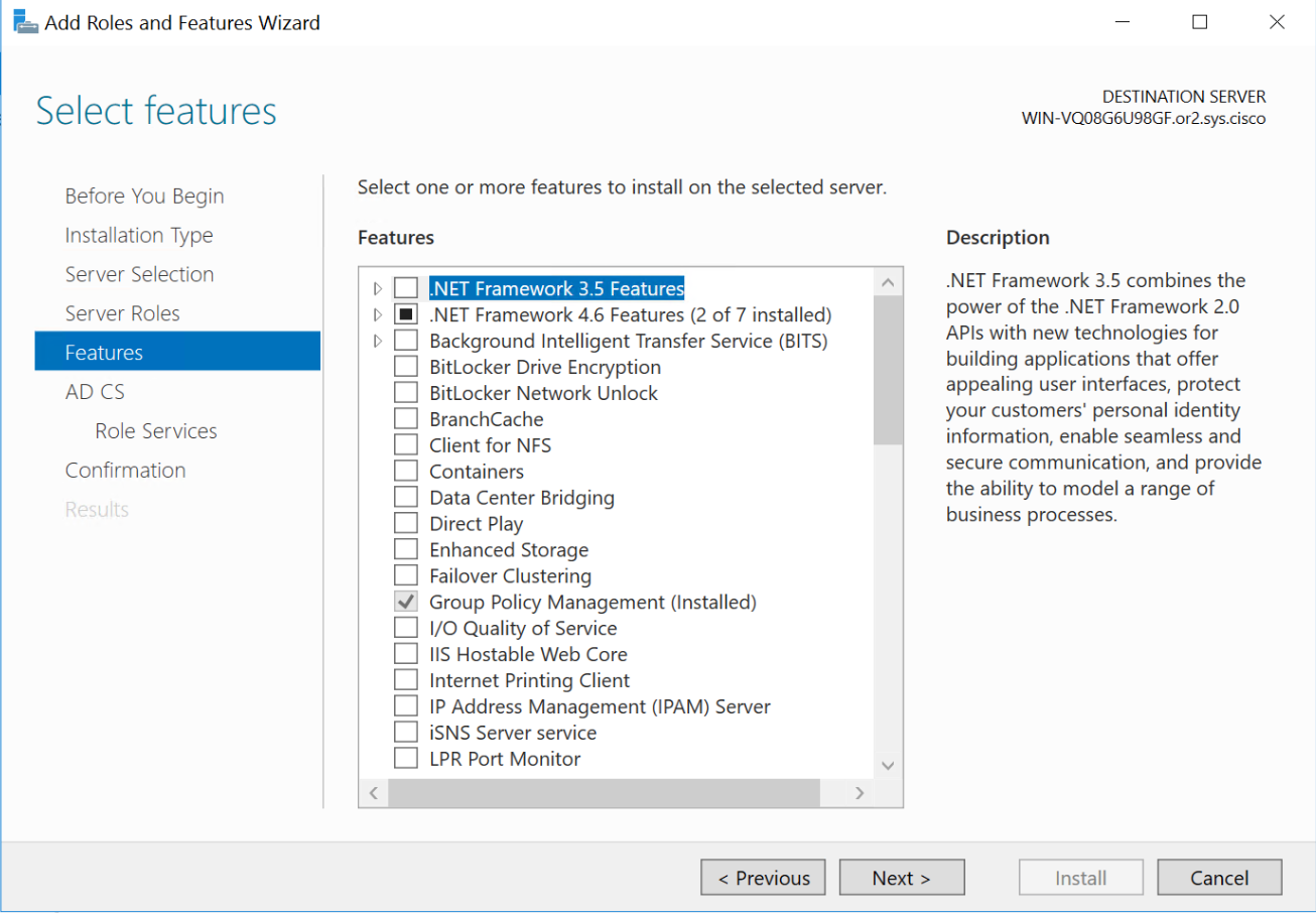
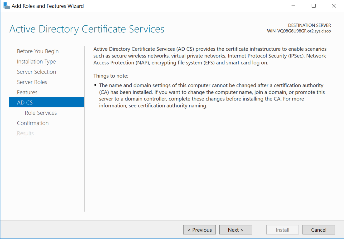
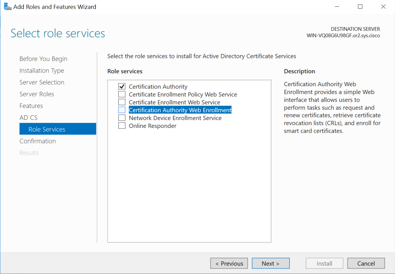
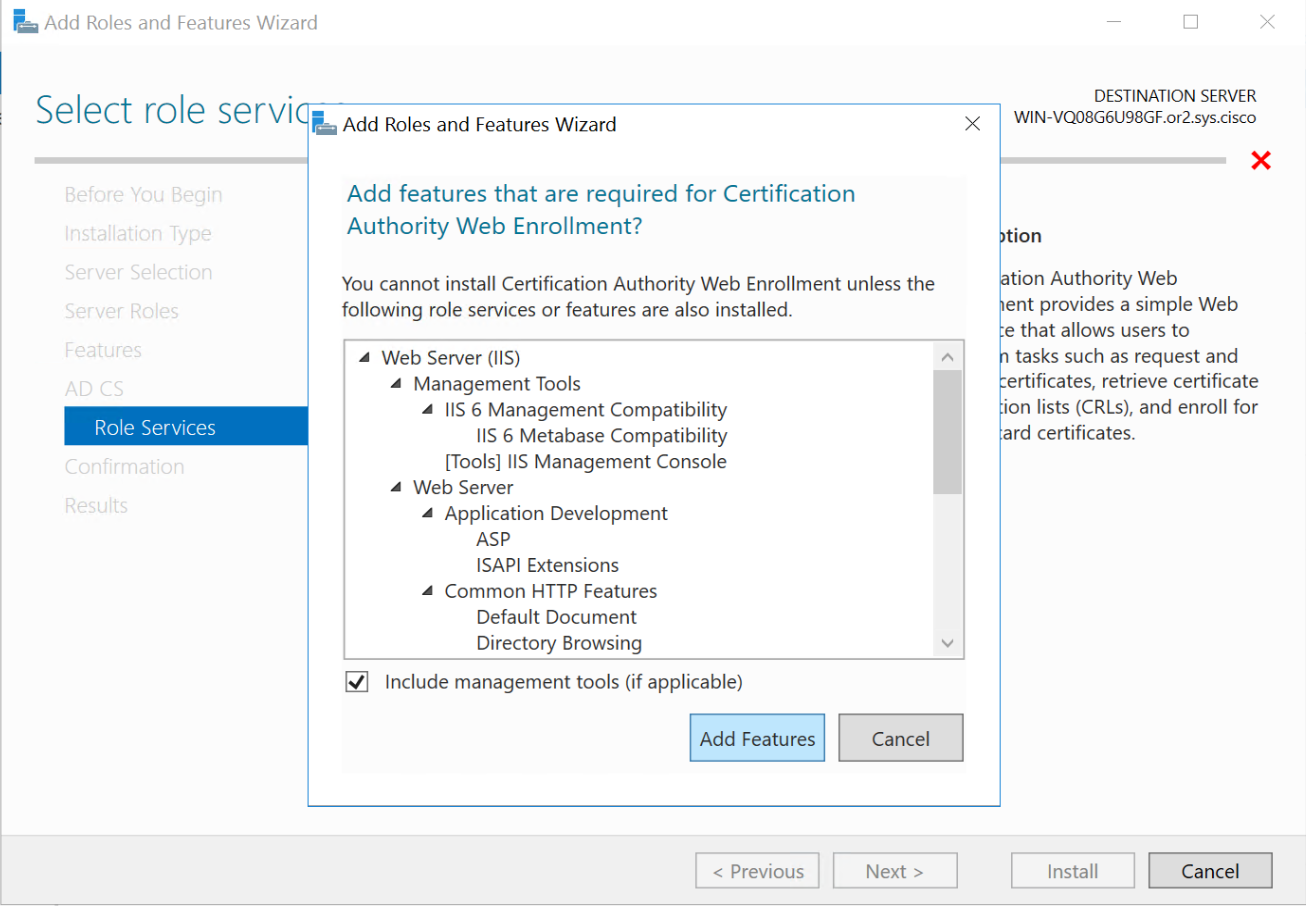
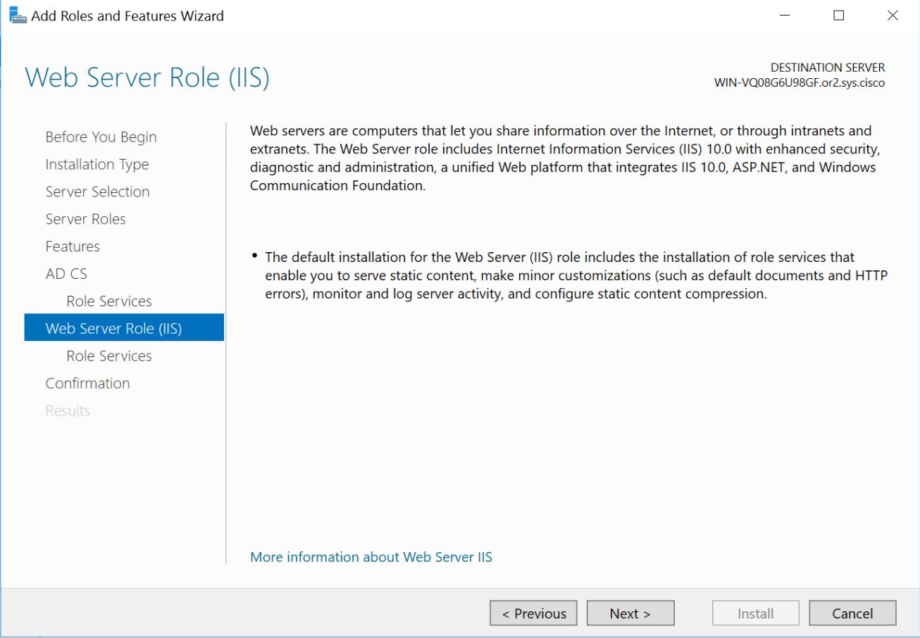
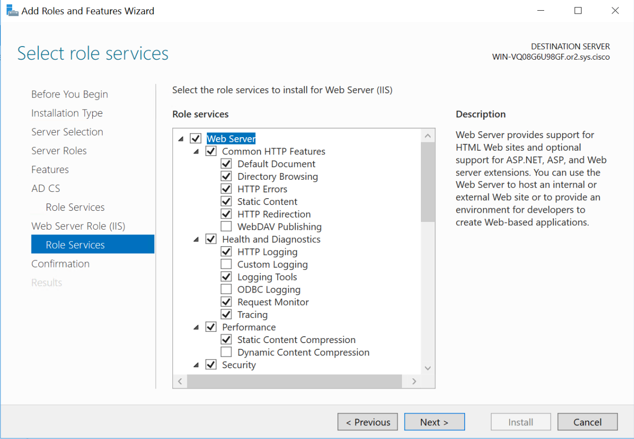
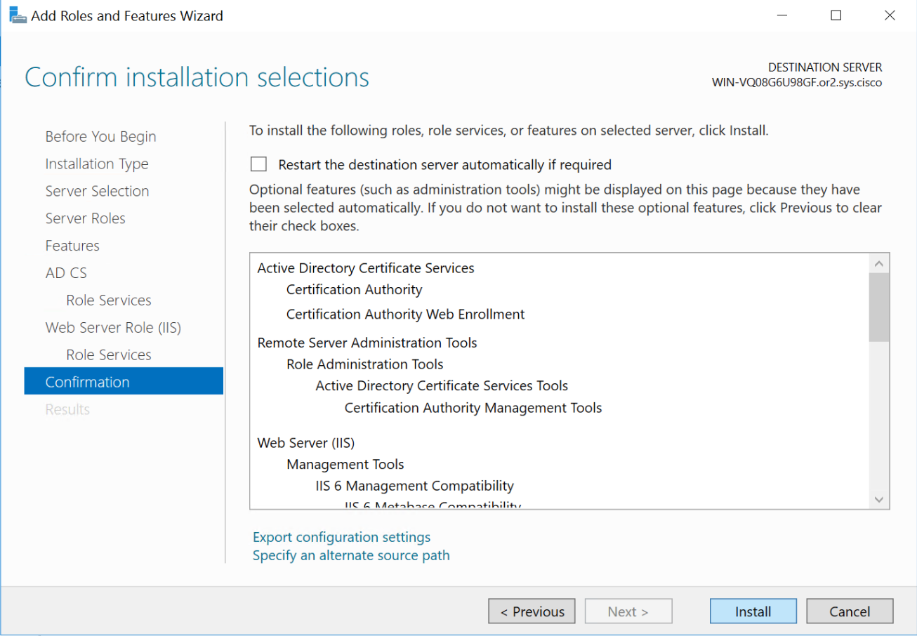
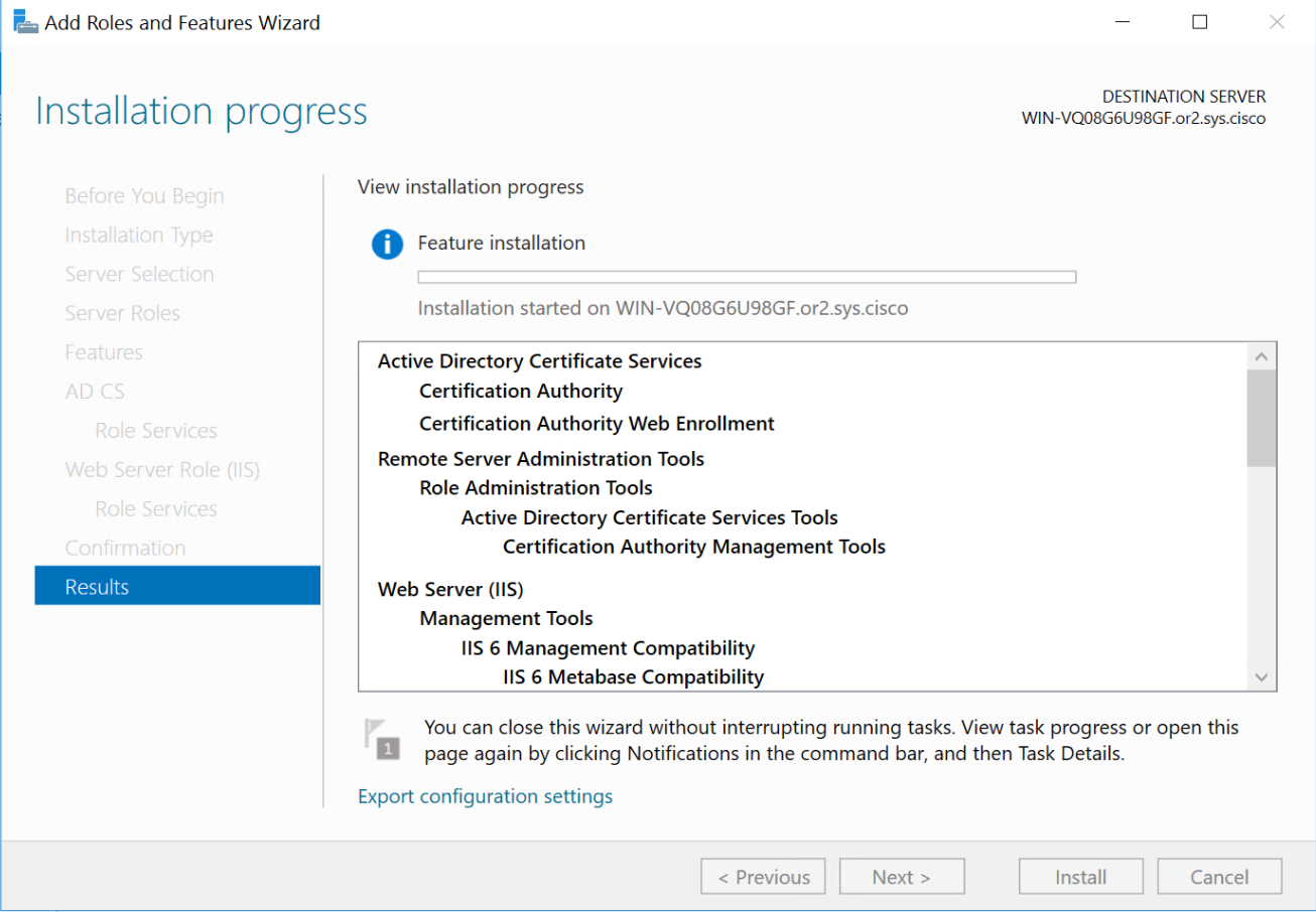
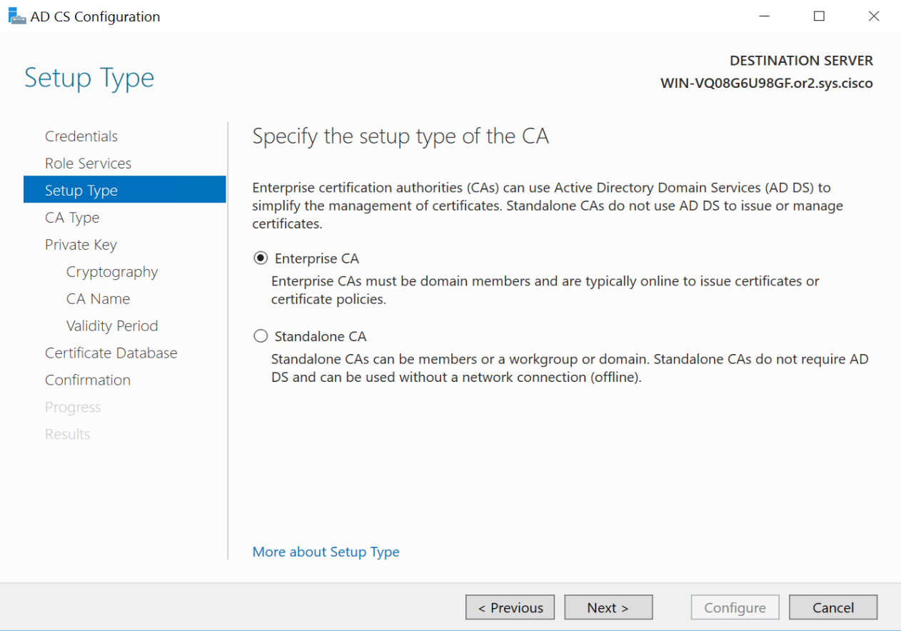
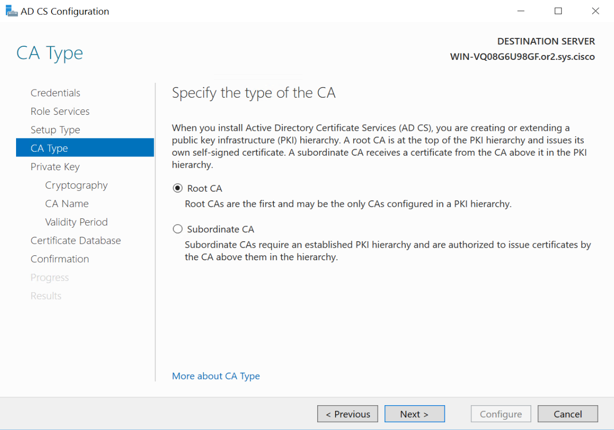
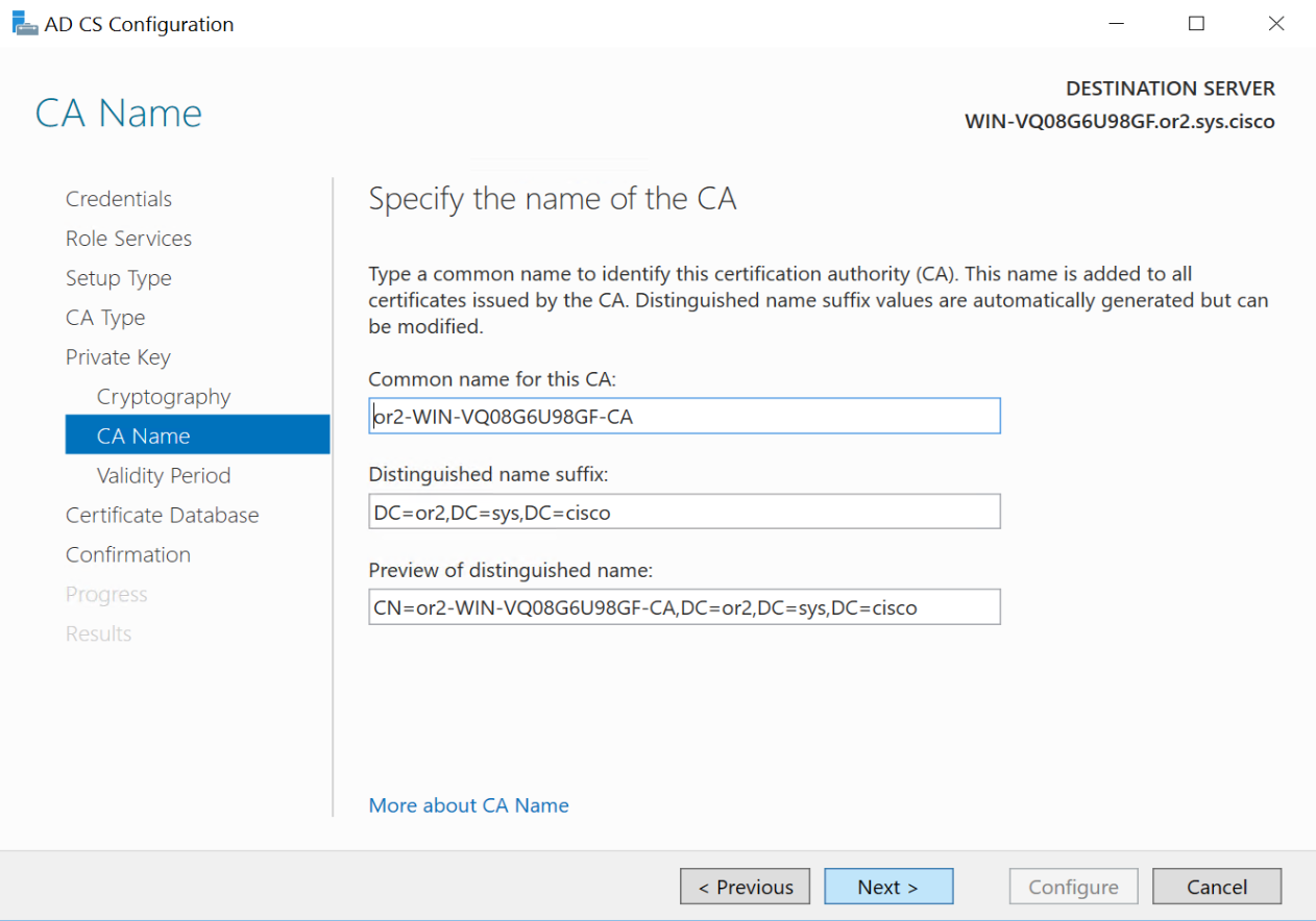
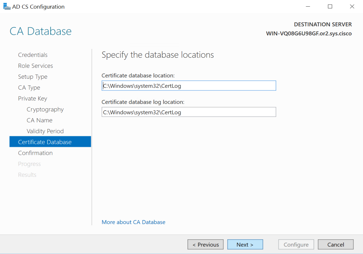
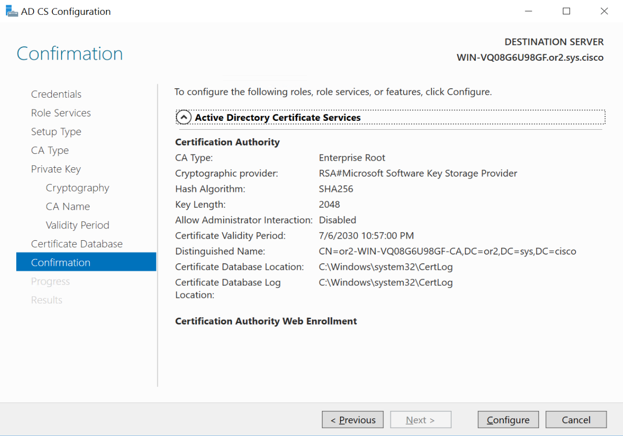
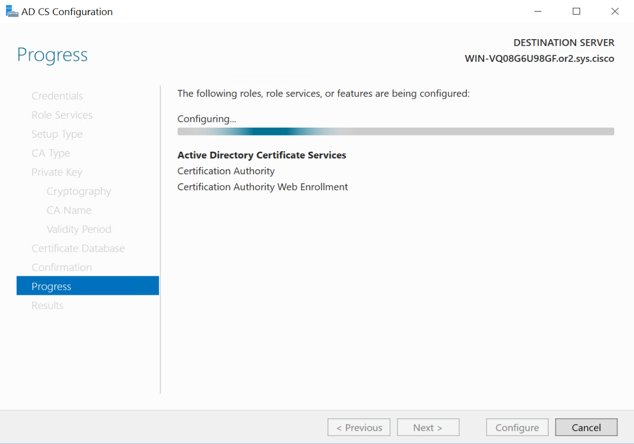
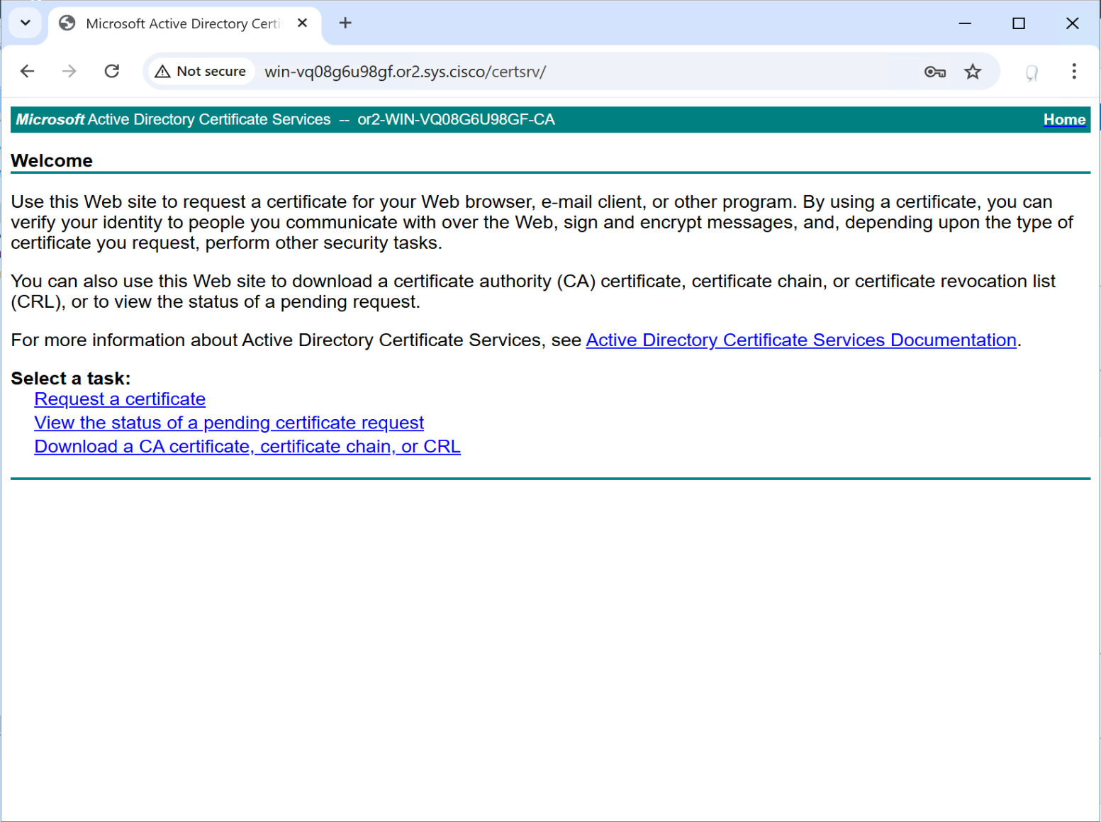
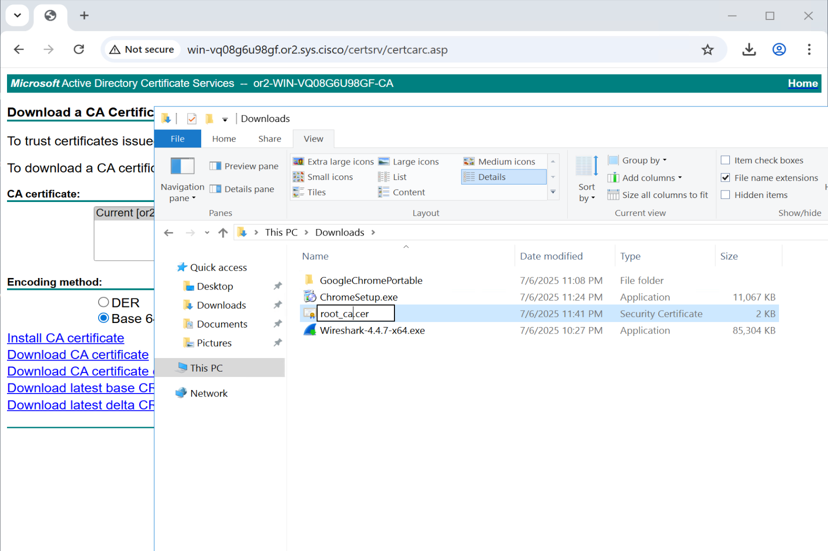
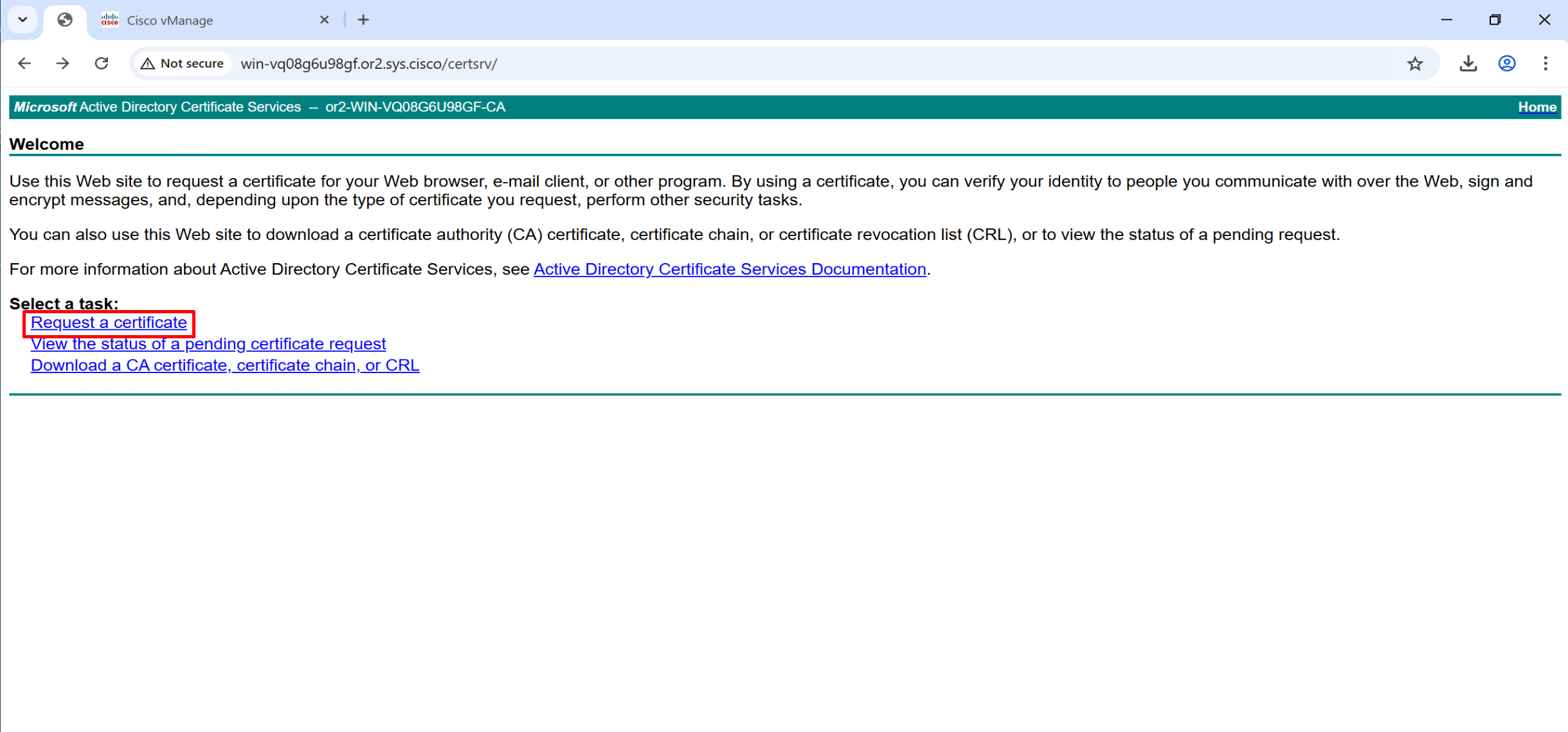
Configure CA Server
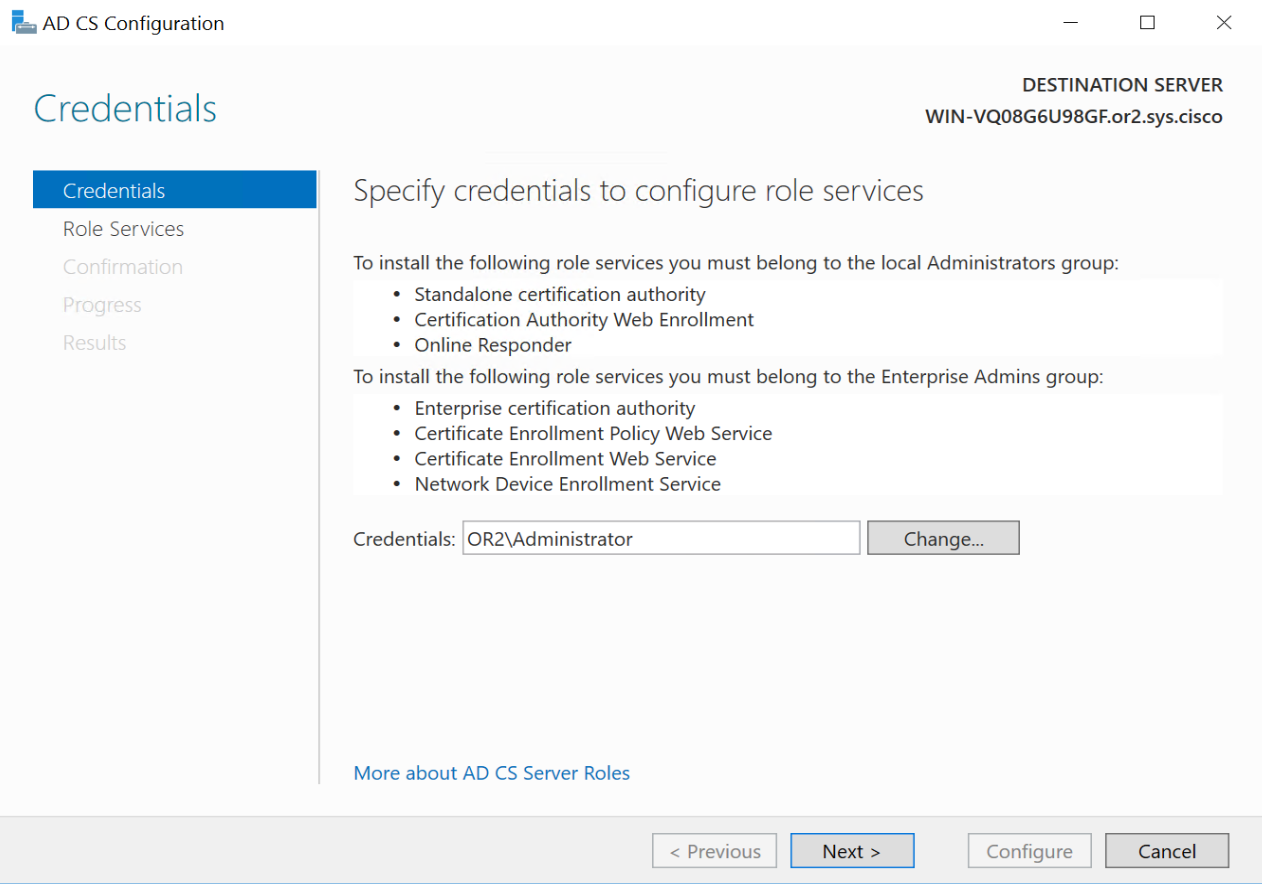


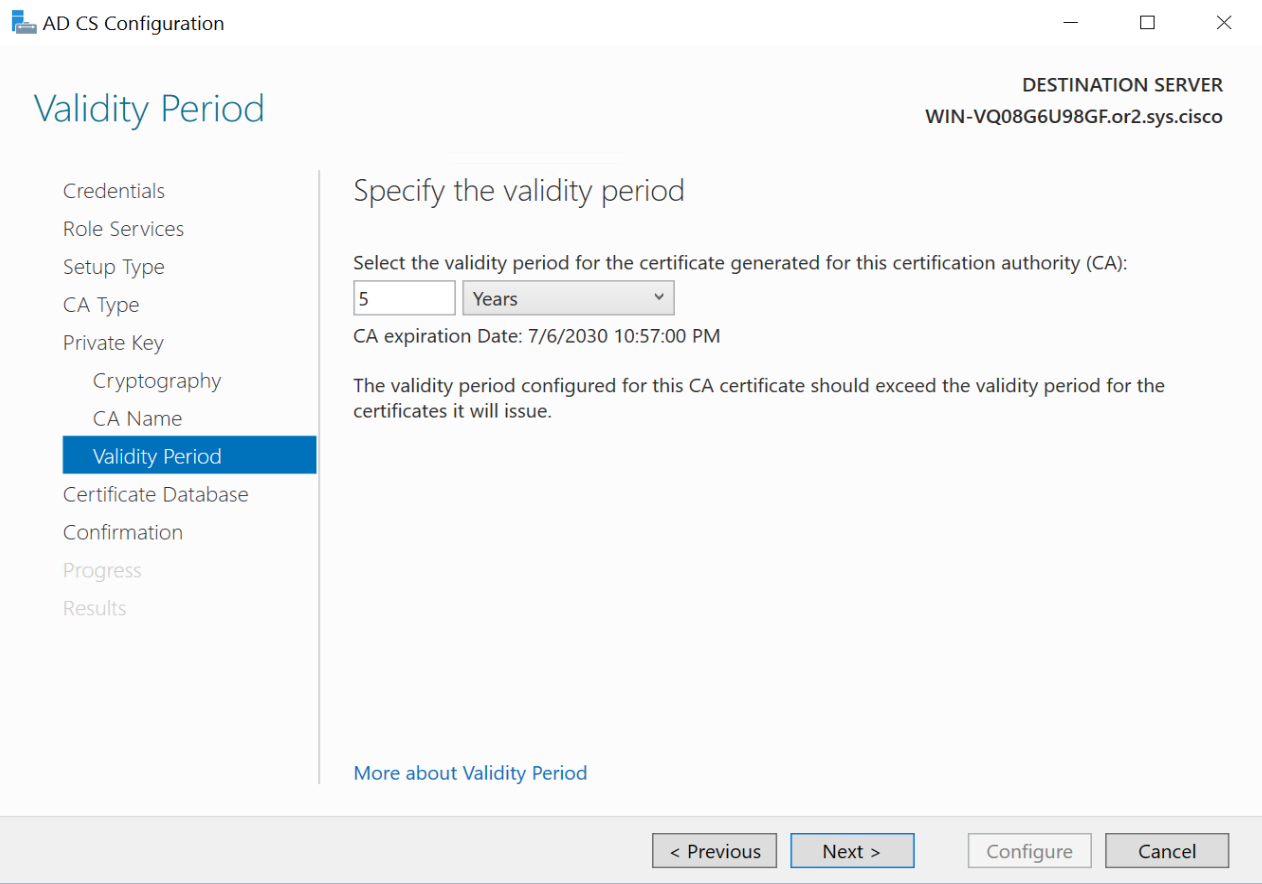
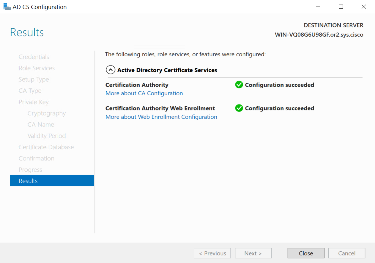
now visit http://[serverFQDN]/certsrv
http://win-vq08g6u98gf.or2.sys.cisco/certsrv/
SDWAN Standup
default username and password for vbond is admin/adminvManage requires second hard disk in vCenter
We should know this if we are deploying for onprem environment

it needs to be 100G minimum
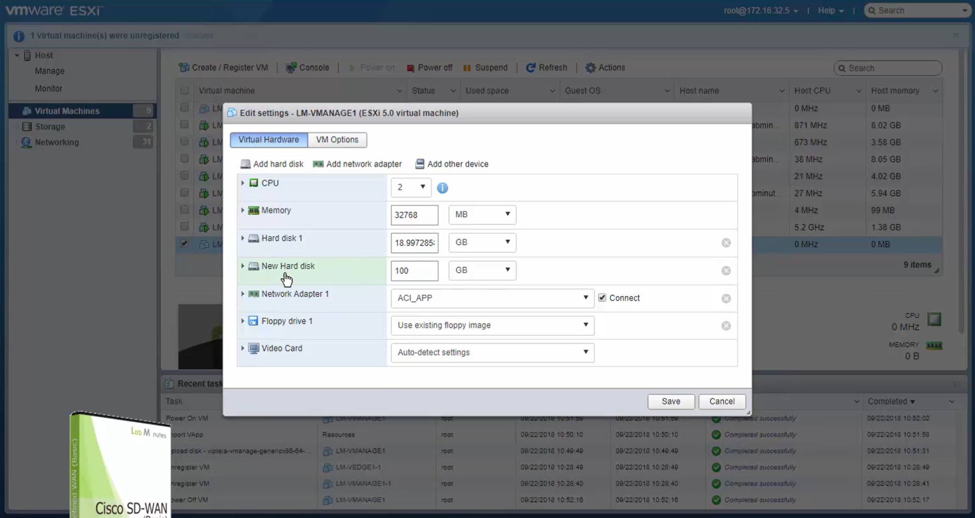
Make sure it is the master
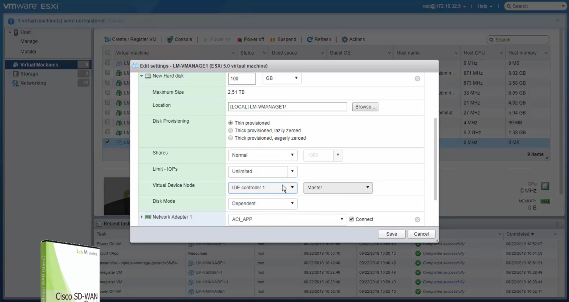
During setup we can see the additional disk we added
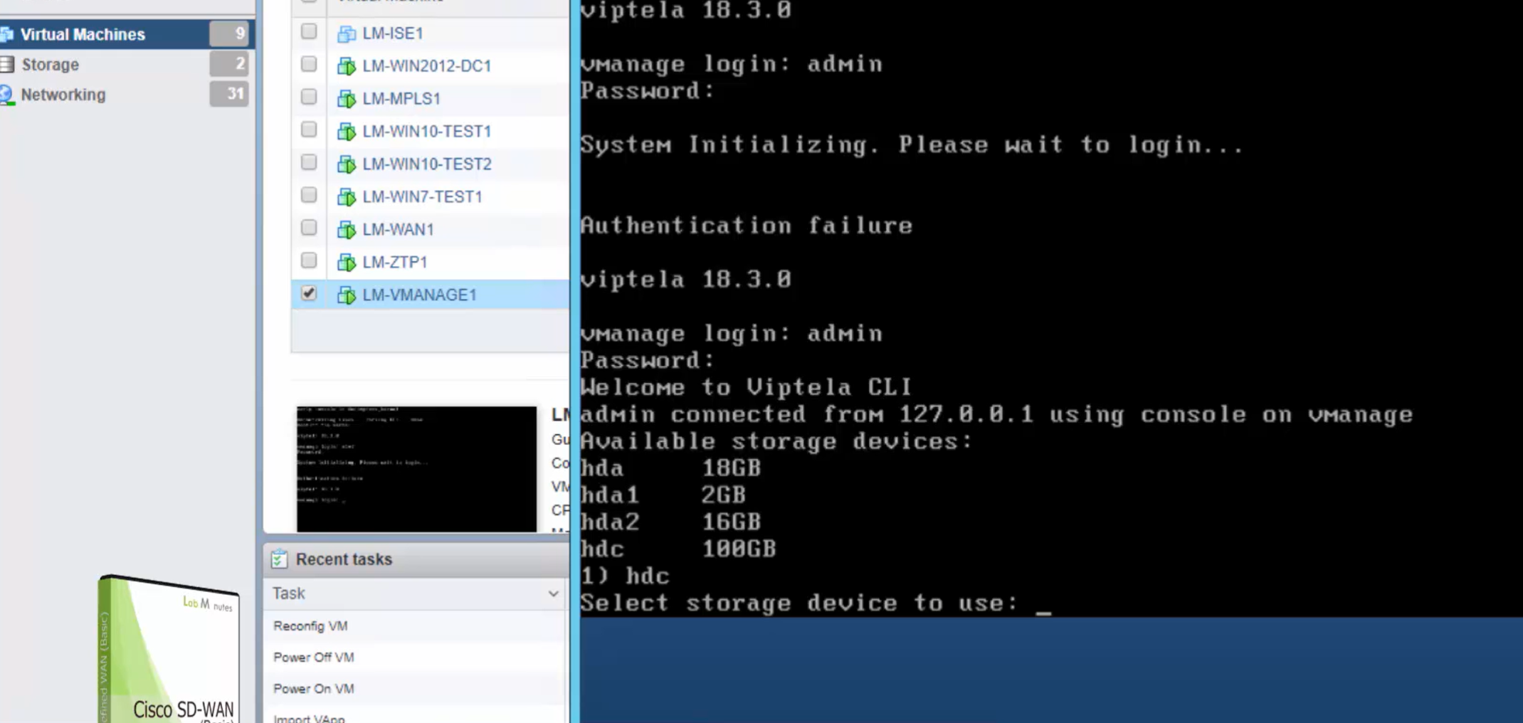
vManage system configuration
Assign vmanage second hard drive , if this has not been done already
cd /opt/unetlab/addons/qemu/vtmgmt-20.9.1
/opt/qemu/bin/qemu-img create -f qcow2 virtiob.qcow2 100G
/opt/unetlab/wrappers/unl_wrapper -a fixpermissions
show version
conf t
system
host-name vManage
system-ip 1.1.255.11
clock timezone Europe/London
site-id 255
organization-name or2.sys.cisco
vbond vbond.or.sys.cisco
ntp server ntp.or2.sys.cisco
! it is important to have ntp server and
! have all controllers and devices with same
! time because we are doing a lot of certificate
! based authentication
! vbond IP is the only controller that you
! define on each all SDWAN devices whether
! controllers or vedge if you have 2 vBond
! then it is good to add FQDN otherwise IP
! address is ok, reason is that on controllers
! we cannot define two different vbond IP addresses
! always commit the configuration
commitshow running-configvmanage(config-ntp)# do show running-config ! to see the commmitted configuration
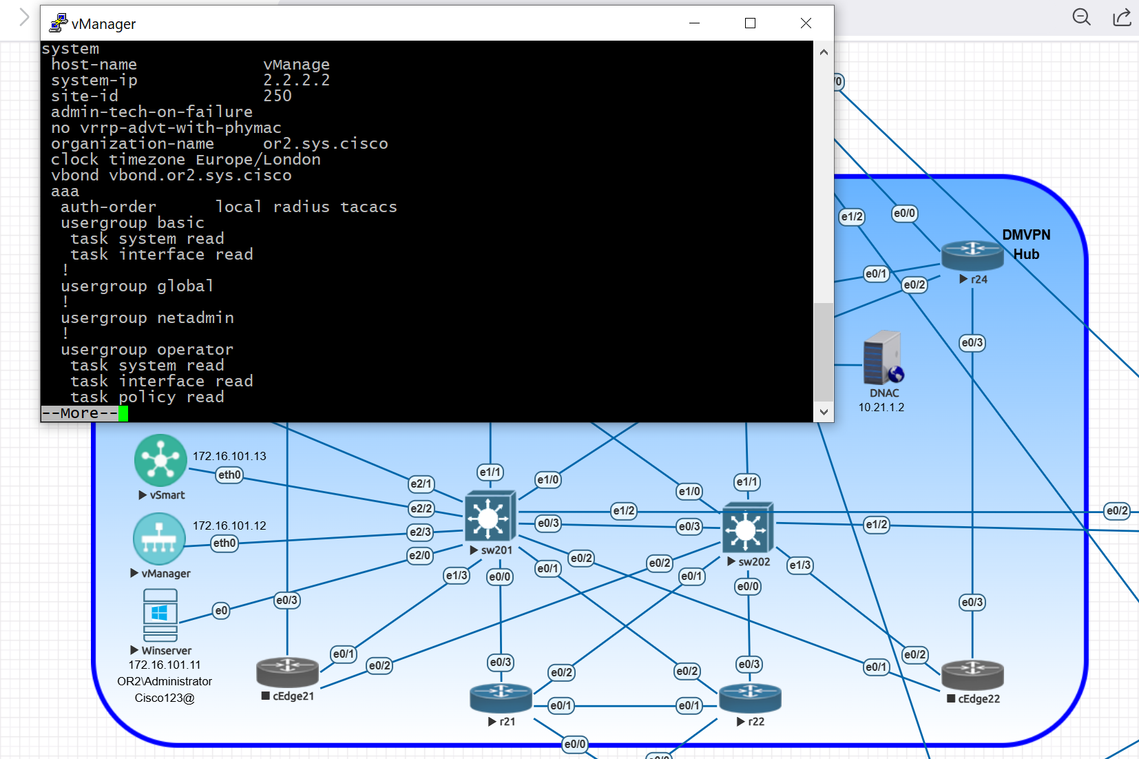
system
host-name vmanage
admin-tech-on-failure
no vrrp-advt-with-phymac
aaa
auth-order local radius tacacs
usergroup basic
task system read
task interface read
!
usergroup global
!
usergroup netadmin
!
usergroup operator
task system read
task interface read
task policy read
task routing read
task security read
!
usergroup resource_group_admin
task system read
task interface read
!
usergroup resource_group_basic
task system read
task interface read
!
usergroup resource_group_operator! check configuration of a section while in that section
vmanage(config)# system
vmanage(config-system)# show configuration ! t show uncommitted configuration but only under system section
system
host-name vManage
system-ip 1.1.255.11
site-id 255
organization-name or2.sys.cisco
clock timezone Europe/London
vbond vbond.or.sys.cisco
ntp
server ntp.or2.sys.cisco
version 4
exit
!vSmart system configuration
conf t
system
host-name vSmart
system-ip 1.1.255.13
clock timezone Europe/London
site-id 255
organization-name or2.sys.cisco
vbond vbond.or.sys.cisco
ntp server ntp.or2.sys.cisco
vBond system configuration
conf t
system
host-name vBond
system-ip 1.1.255.12
clock timezone Europe/London
site-id 255
organization-name or2.sys.cisco
vbond vbond.or.sys.cisco local
! this local keyword converts the vedge to vbond role
ntp server ntp.or2.sys.cisco
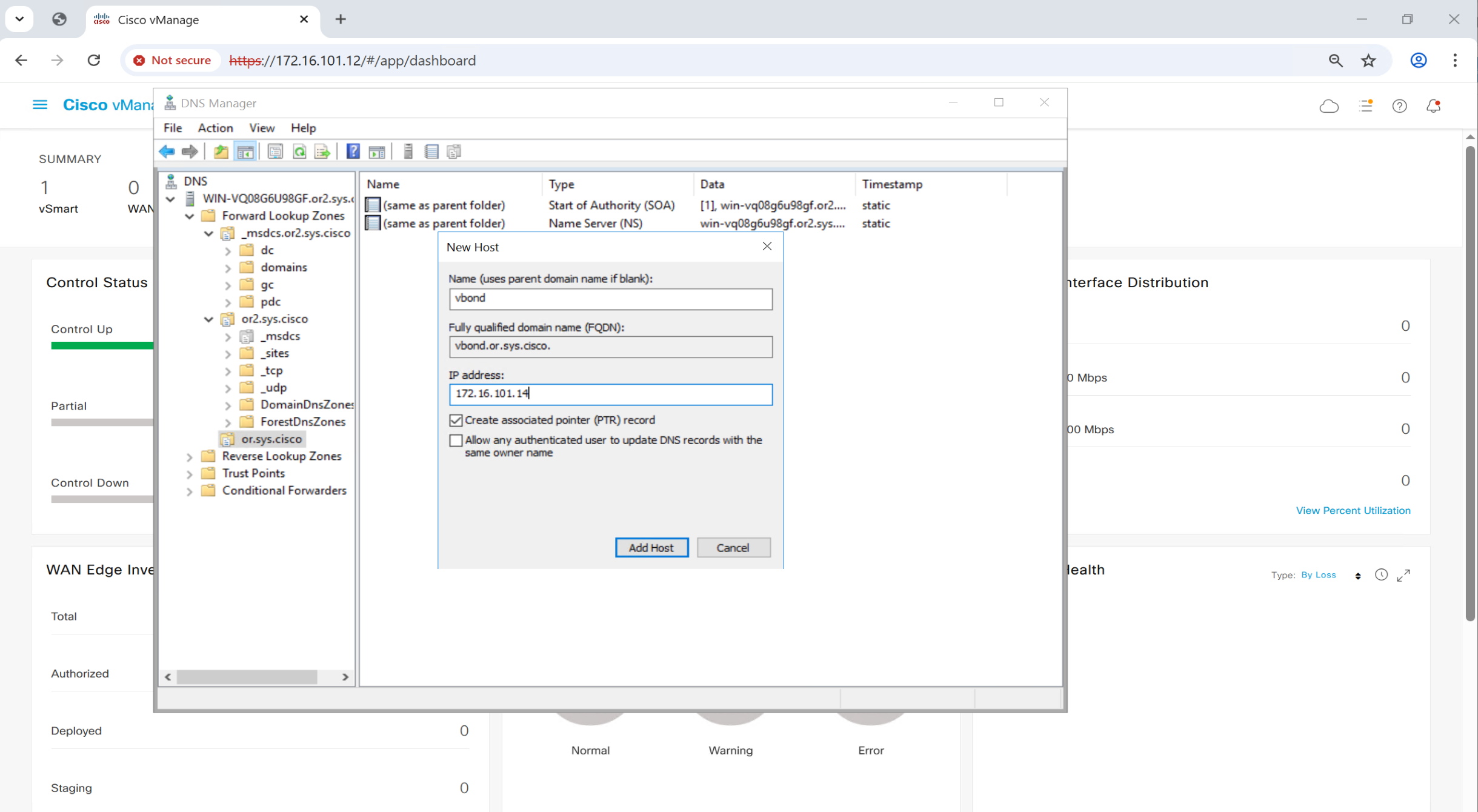
DNS server on Windows Server
Then create DNS A records
Add A record for vbond in or.sys.cisco domain
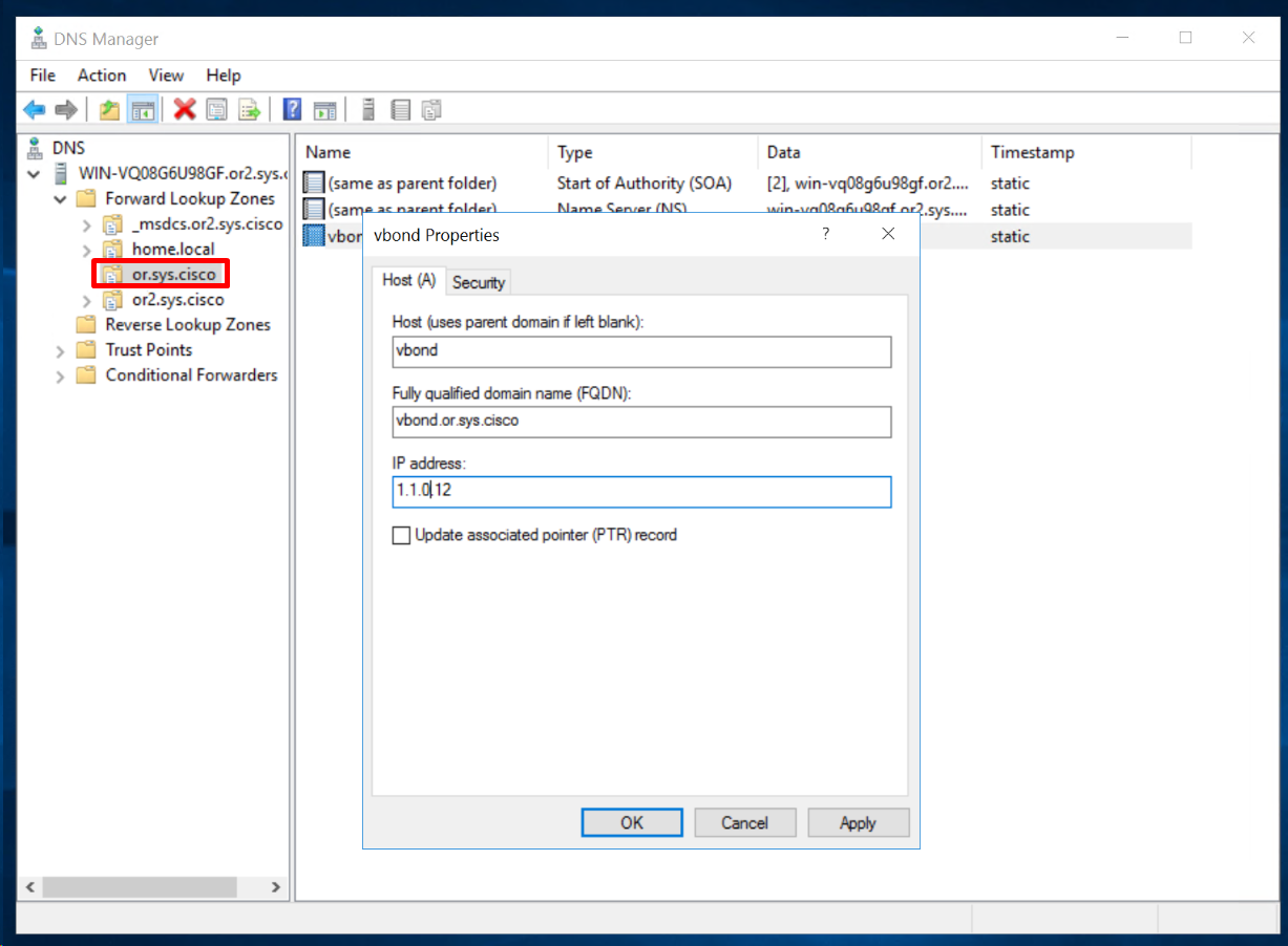
If we have a second vbond and it needs to be added then add another entry for “vbond” same as above but with different IP, multiple vbonds or vbond redundancy is supported by DNS roundrobin (default)
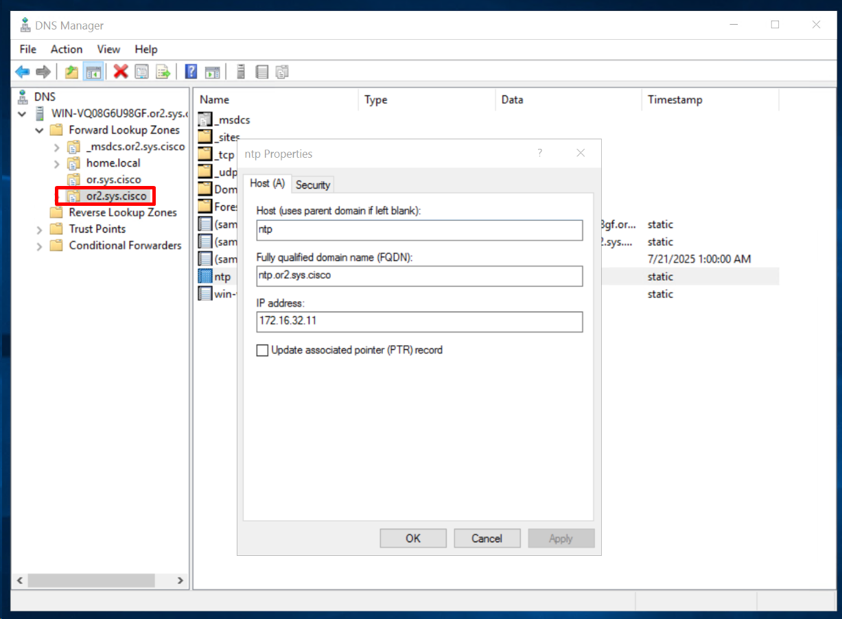
Add A record for ntp in or”2″.sys.cisco
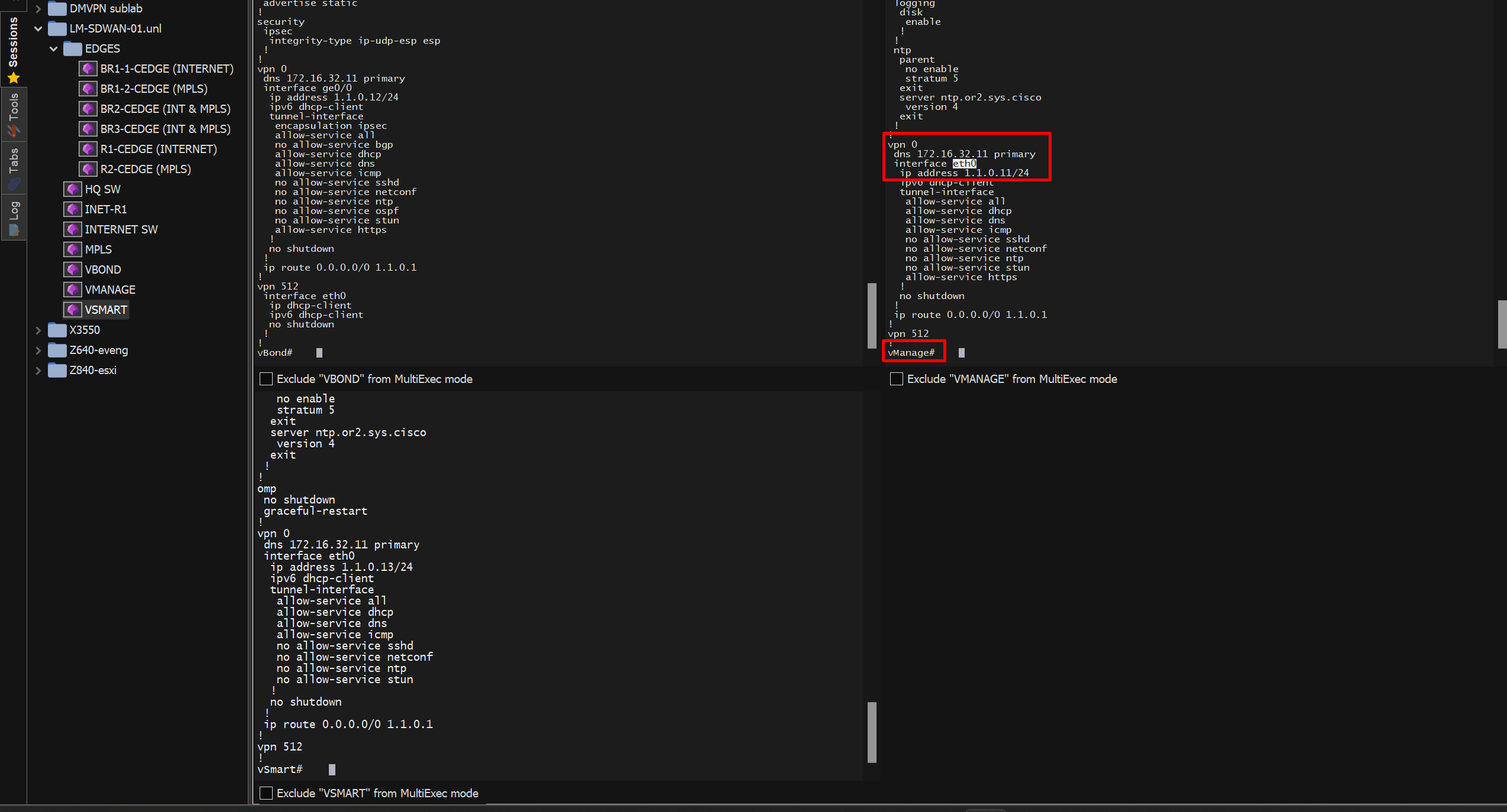
Configure the (WAN , Transport) interface of SDWAN controllers
These interfaces are configured under VPN 0 and they are used to access the GUI by admins and outbound to edge routers communication using NETCONF (vmanage), for OMP peering (vsmart) and onboarding (vbond)
There is no such thing as LAN interface for these controllers
In Cisco cedge devices we do not have VPN0 instead transport uses Global routing table or default non vrf routing table
Configure vmanage vpn0 Transport Interface (vpn0)
conf t

vpn 0
interface eth0
ip address 1.1.0.11/24
no shutdown
no tunn
! we keep the tunnel interface down for now as it is used to deal with overlay or fabric till we have basic connectivity up
! while within the vpn0 configure default route

ip route 0.0.0.0/0 1.1.0.1
dns 172.16.32.11 ! configure this DNS if your vmanage has reachability to internet for automatic sync of device serial numbers from internet rather than offline import of serial number file, "Sync Smart Account" button rather than "Upload WAN Edge List" button
You cannot have interface ip same as system ip so they both need to be different
vManage(config)# commit
Aborted: ‘vpn 0 interface eth0 ip address’: Interface eth0 with address 1.1.0.11/24 & System IP 1.1.0.11 cannot be same in vpn 0
Configure vsmart Transport Interface (vpn0)
conf t

vpn 0
interface eth0
ip address 1.1.0.13/24
no shutdown
no tunn
! we keep the tunnel interface down for now as it is used to deal with overlay or fabric
! while within the vpn0 configure default route

ip route 0.0.0.0/0 1.1.0.1
dns 172.16.32.11
Configure vbond Transport Interface (vpn0)
conf t

vpn 0
interface ge0/0

! Option 1: we need to keep this tunnel interface down for vbond's own onboarding to work

no tunnel-interface


! or

! Option 2: bring up tunnel interface but allow some services on it
vpn 0
interface ge0/0
tunnel-interface
allow-service sshd
allow-service dns
allow-service ntp

Allowed service are both inbound and outbound
such as NTP will be outbound but SSH will be inbound

!--------------------------------
vpn 0
interface ge0/0
no tunnel-interface
ip address 1.1.0.12/24
no shutdown

! while within the vpn0 router, configure default route
ip route 0.0.0.0/0 1.1.0.1
dns 172.16.32.11

ping vbond.or.sys.cisco
Download CA Certificate

Download in Base64 format
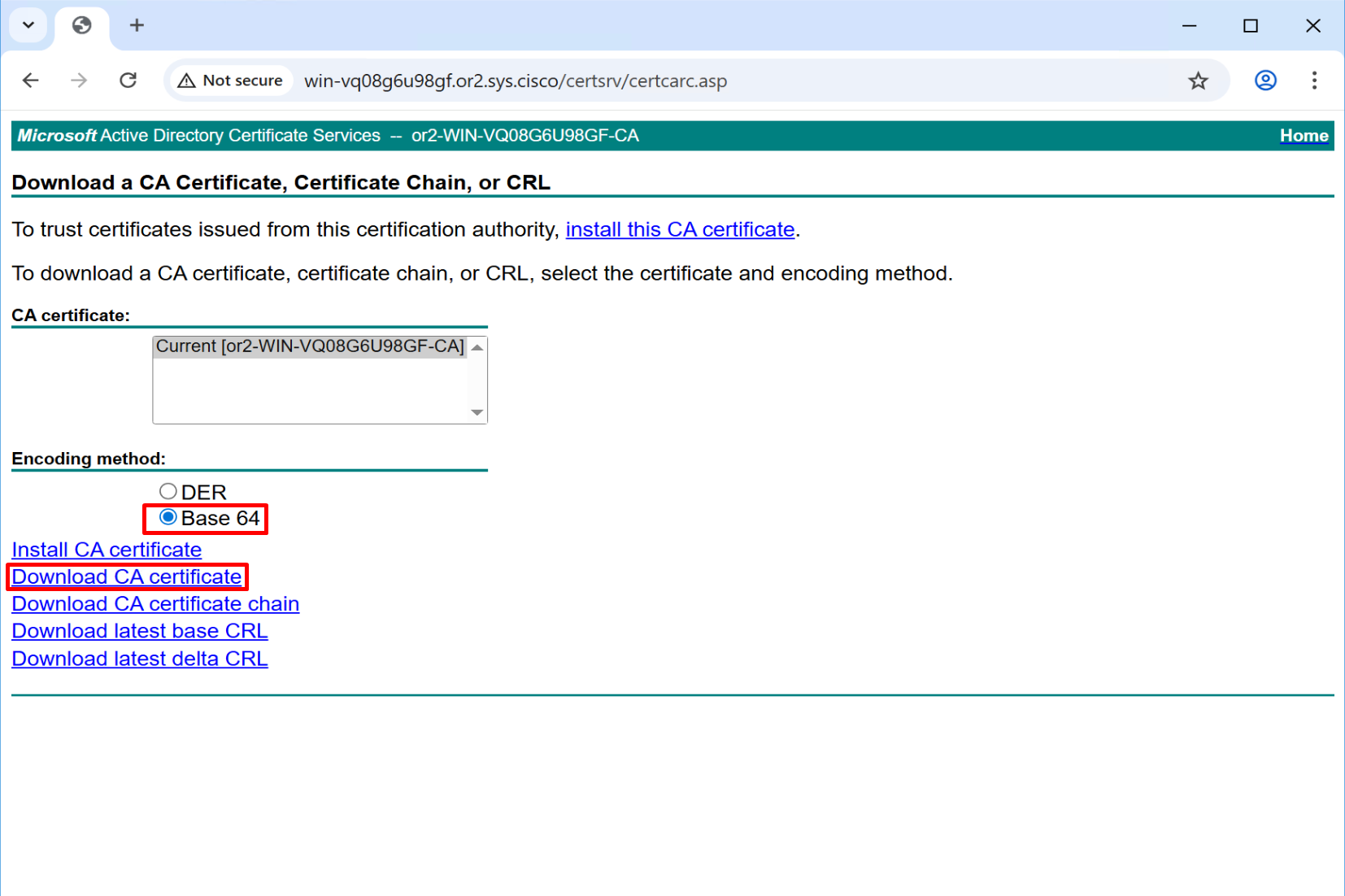
Rename this to root_ca
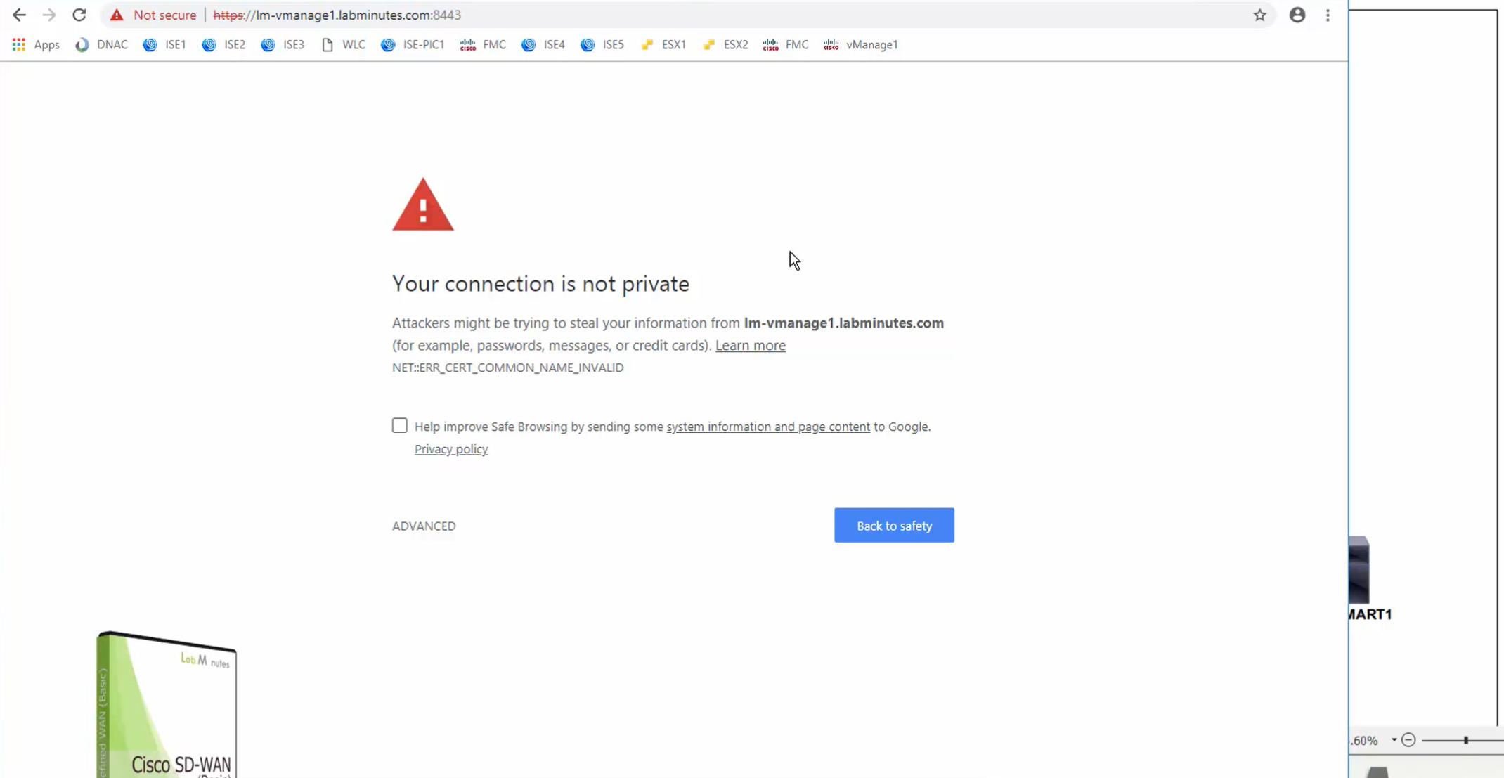
Access vmanage GUI but make sure you do using IP address and not FQDN, using FQDN it does not work and simply spins and comes back to login screen

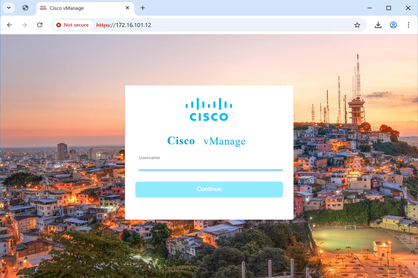
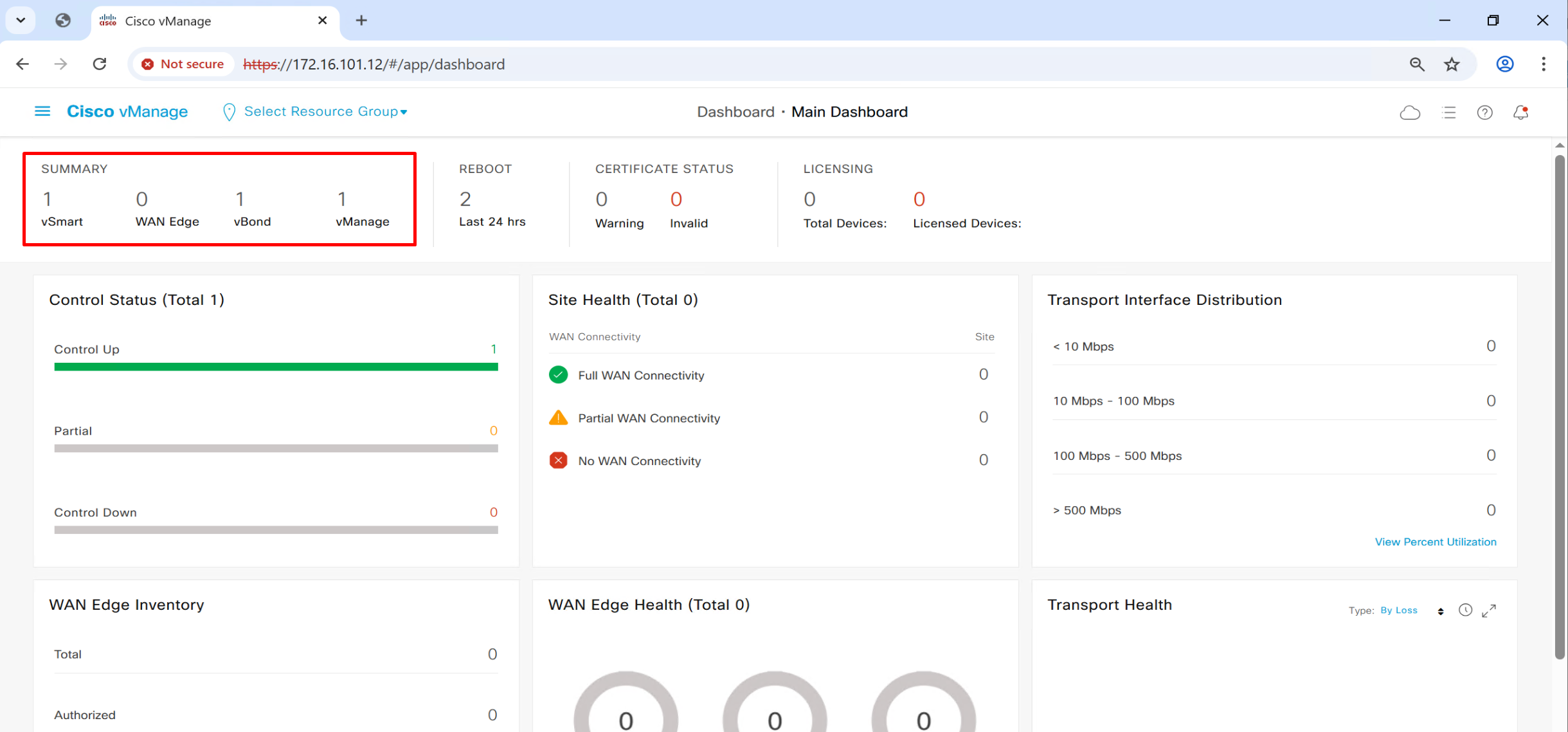
Login as admin/Cisco123@
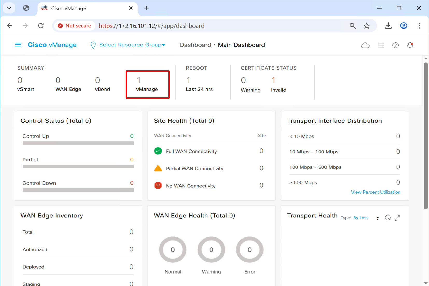
There is only one vmanage that is why we only see one on top summary
Upload root CA to all controllers’ trust store
WinSCP SFTP to the vManage
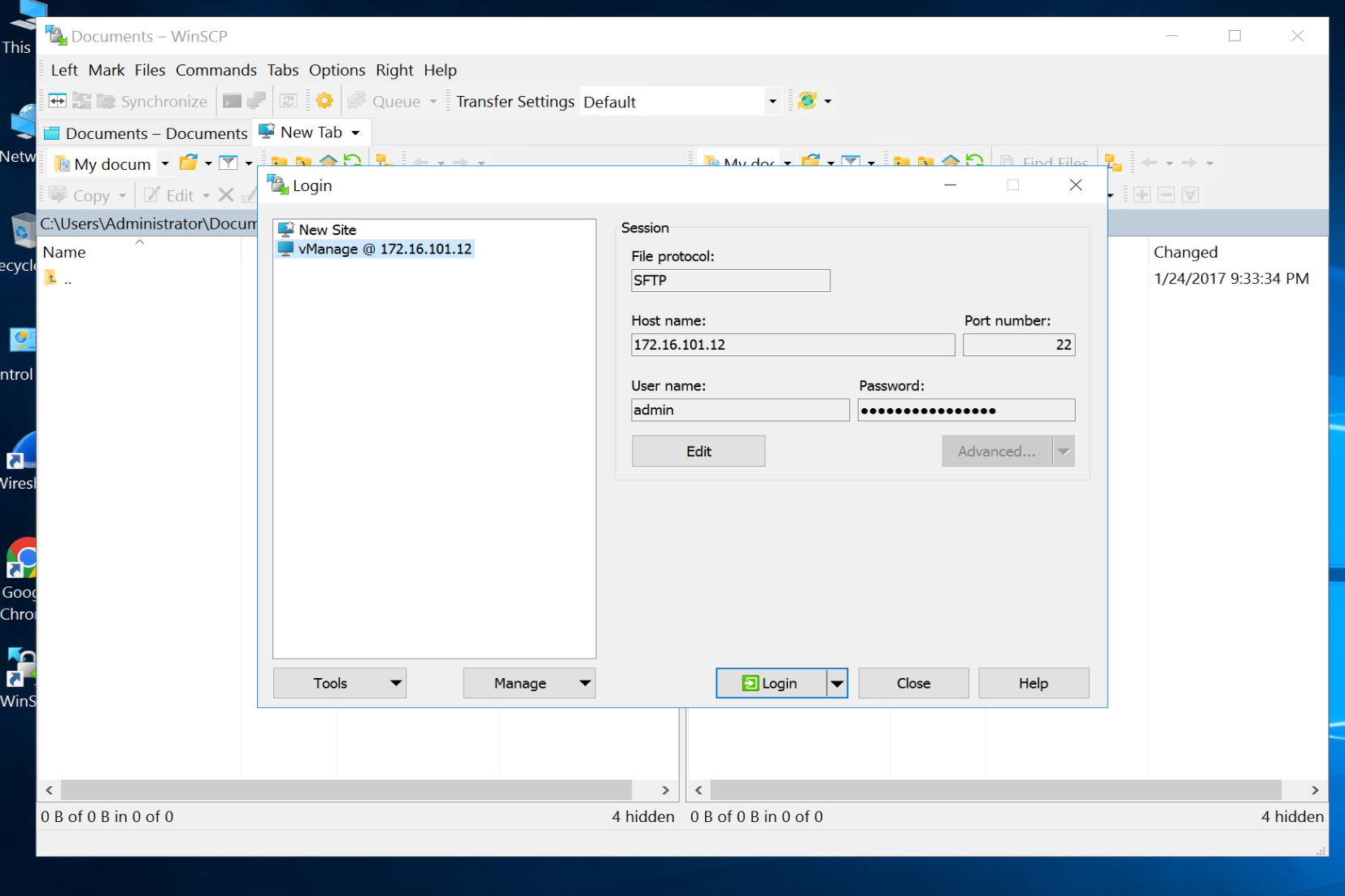
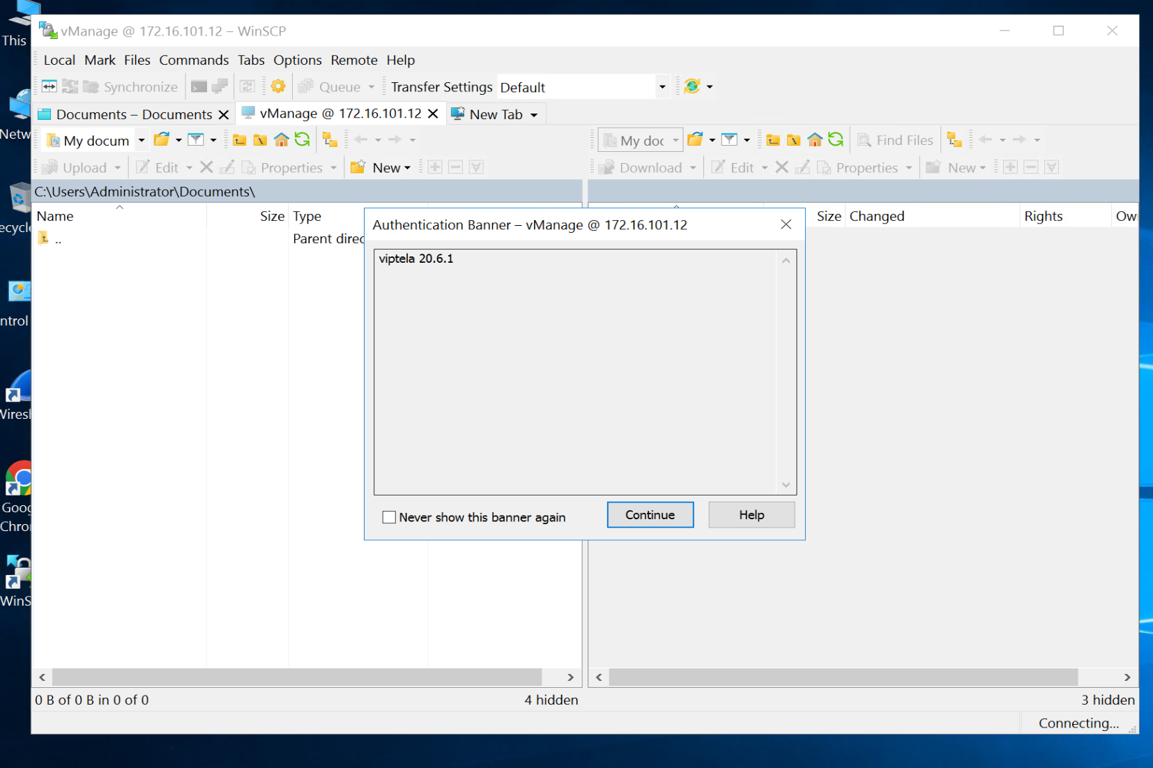
drag root.ca file to /home/admin folder
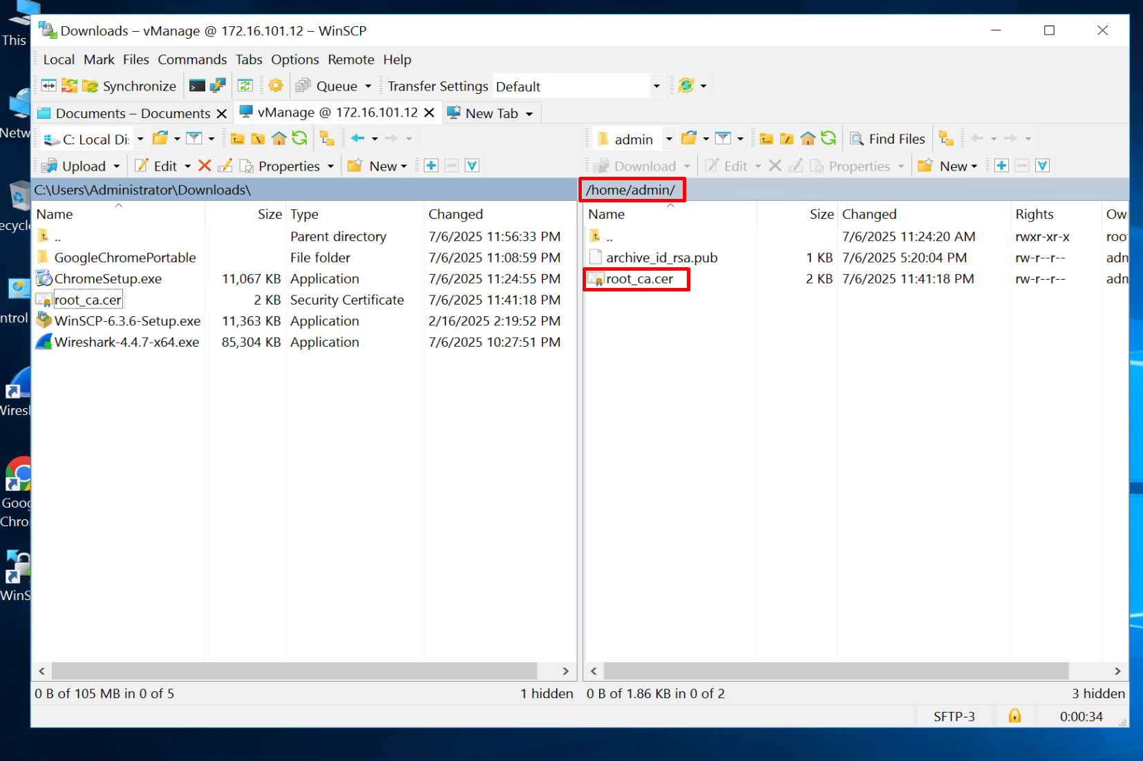
Do same for vSmart and vBond
Before adding certificate, make sure that basic system config is in place
the configuration that we configured earlier
Install root CA certificate chain in Trust store of Controllers
request root-cert-chain install /home/admin/root_ca.cervManage# request root-cert-chain install /home/admin/root_ca.cer
Uploading root-ca-cert-chain via VPN 0
Copying ... /home/admin/root_ca.cer via VPN 0
Updating the root certificate chain..
Successfully installed the root certificate chainvSmart# request root-cert-chain install /home/admin/root_ca.cer
Uploading root-ca-cert-chain via VPN 0
Copying ... /home/admin/root_ca.cer via VPN 0
Updating the root certificate chain..
Successfully installed the root certificate chainvBond# request root-cert-chain install /home/admin/root_ca.cer
Uploading root-ca-cert-chain via VPN 0
Copying ... /home/admin/root_ca.cer via VPN 0
Updating the root certificate chain..
Successfully installed the root certificate chainSync the root cert chain database on vmanage
https://1.1.0.11/dataservice/system/device/sync/rootcertchain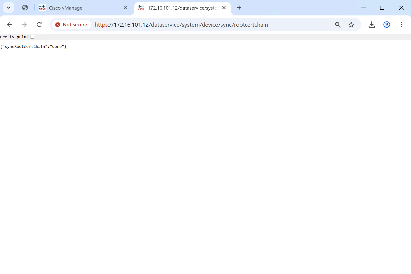
Add controllers to vManage
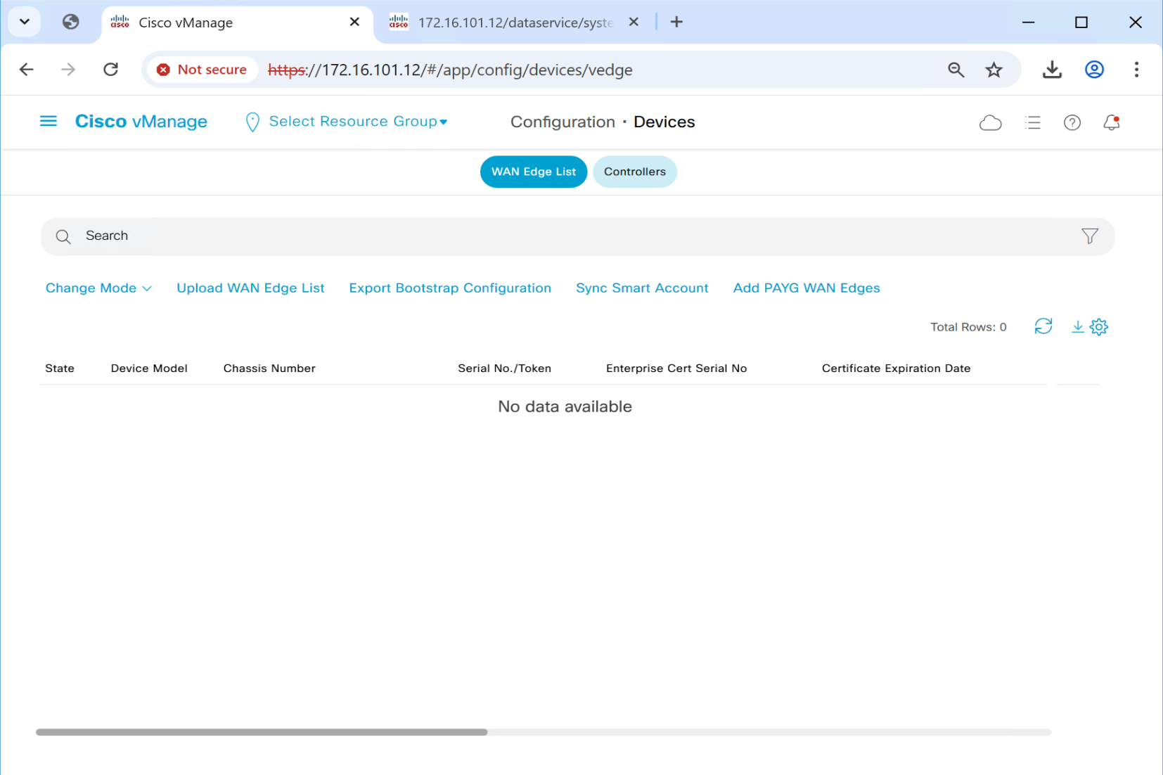
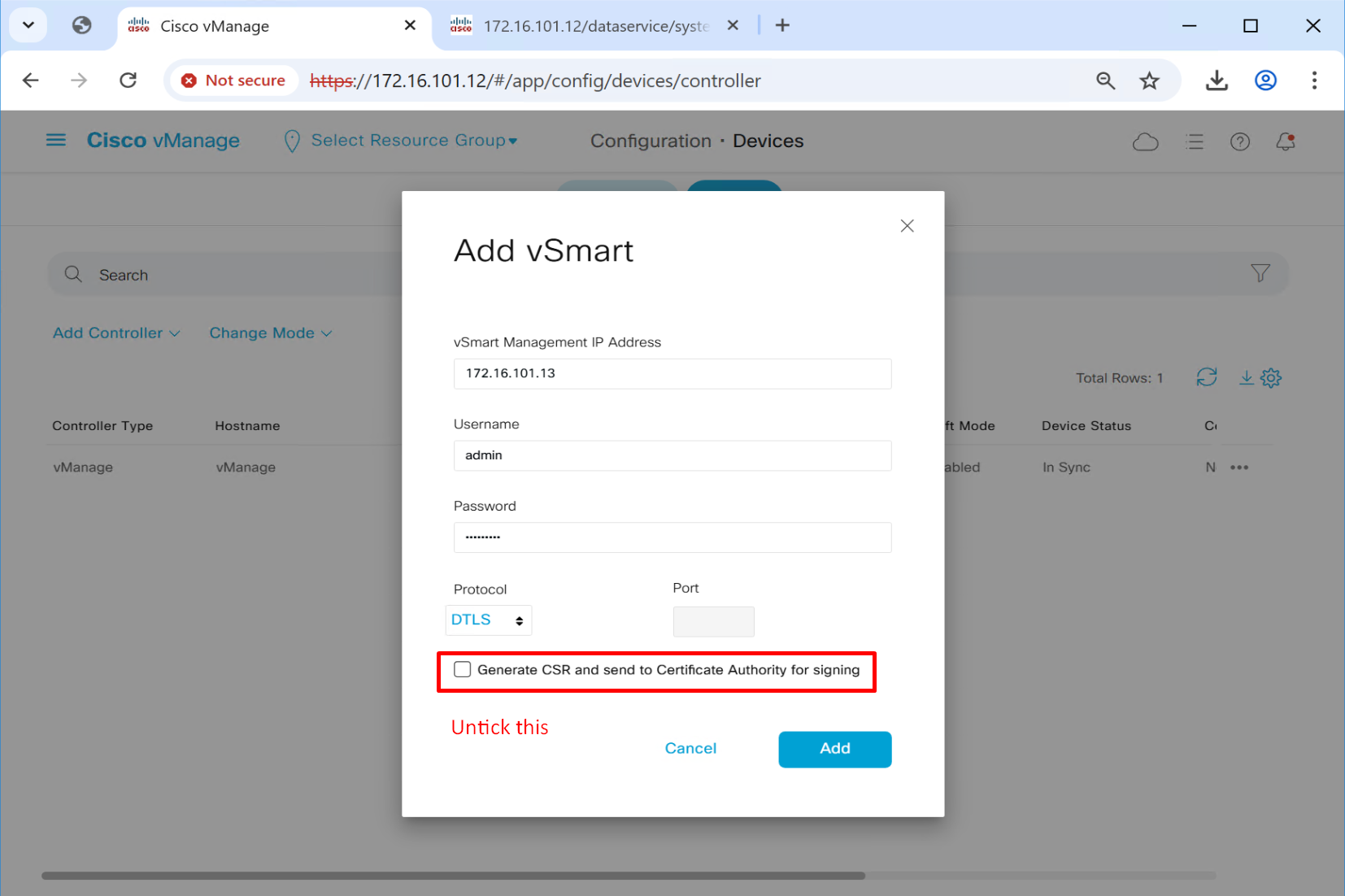
Add vsmart (credential managed)
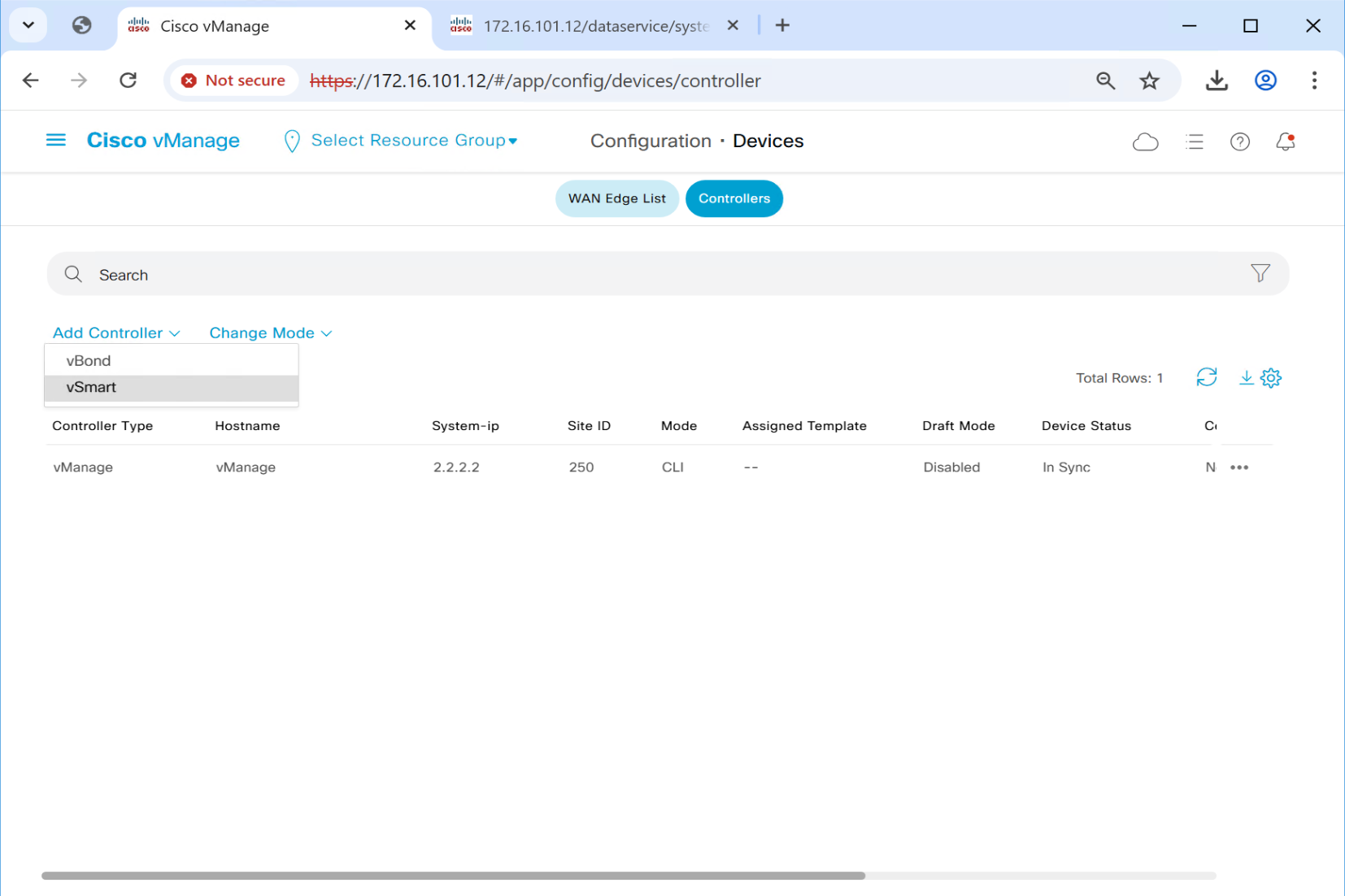
Add vbond (credential managed)
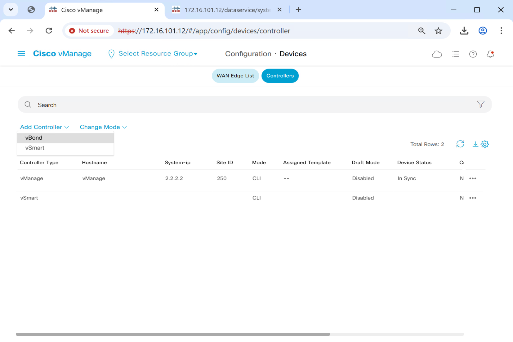
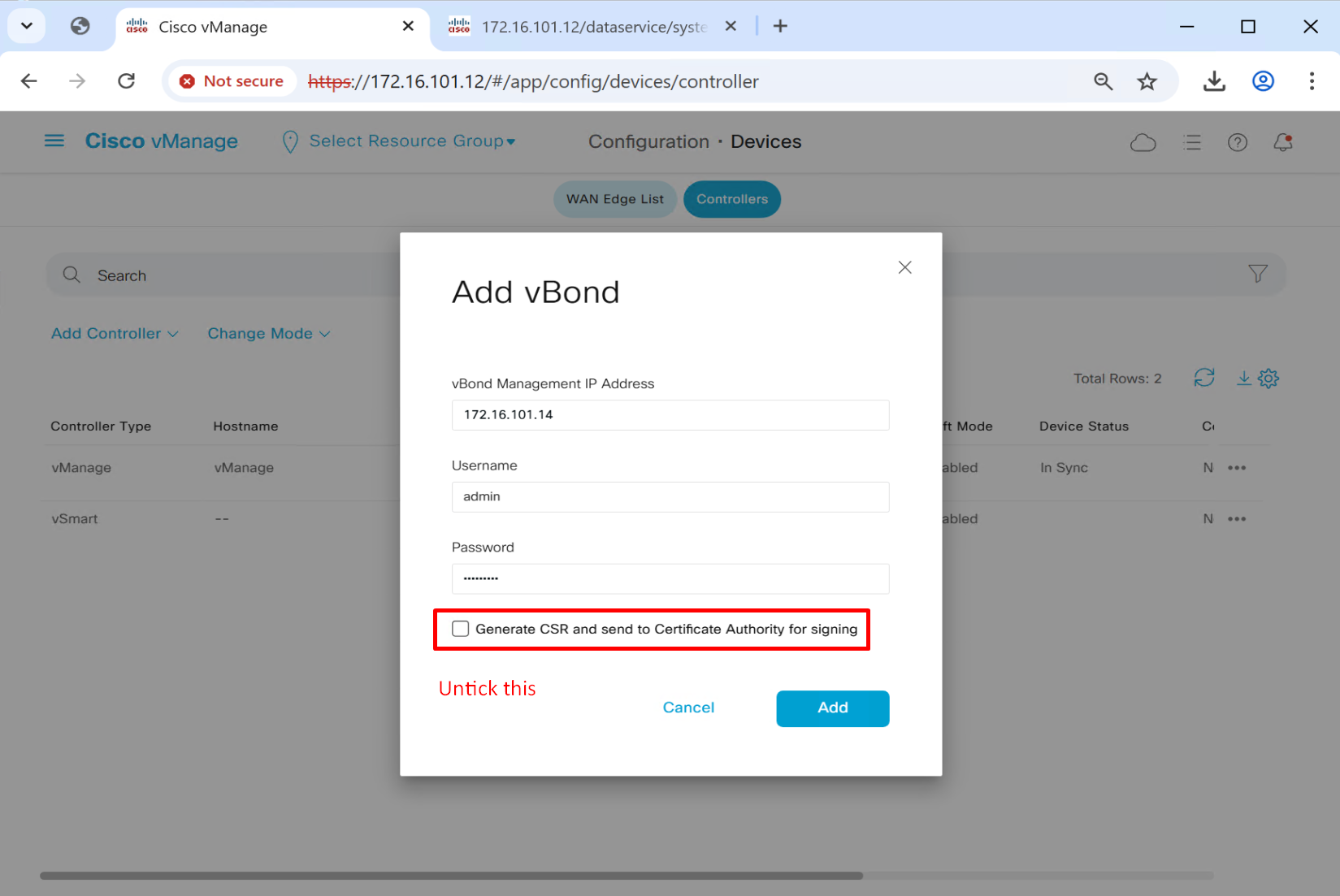
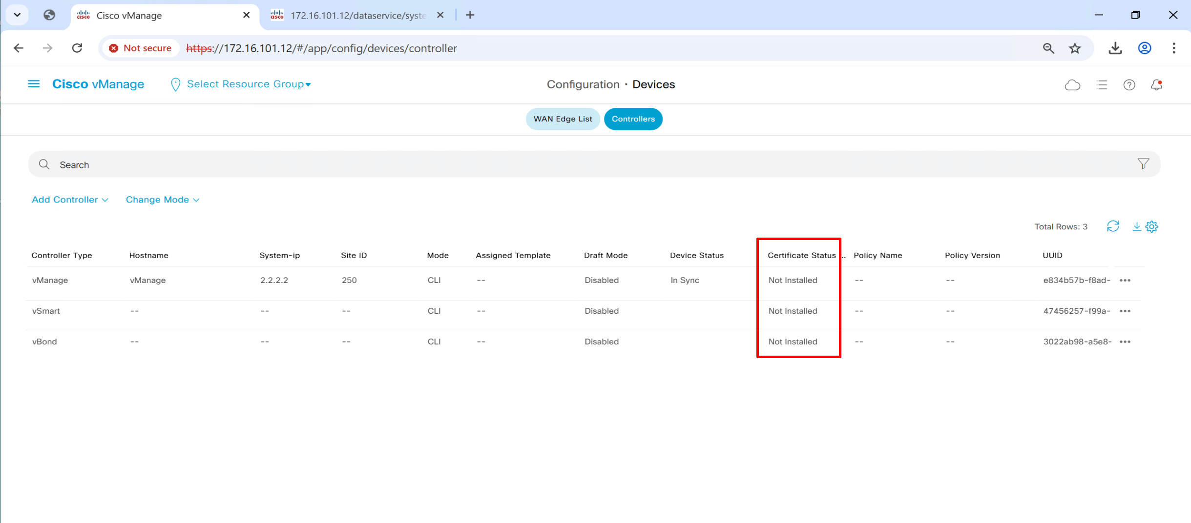
so controllers are configured but we are missing very important bit
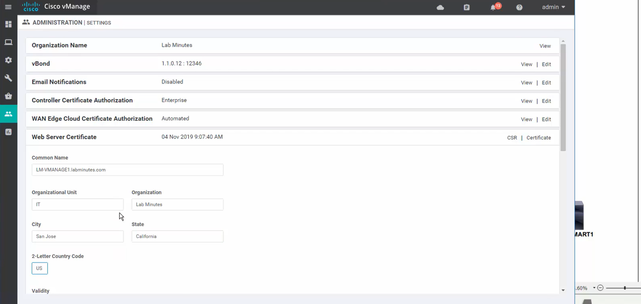
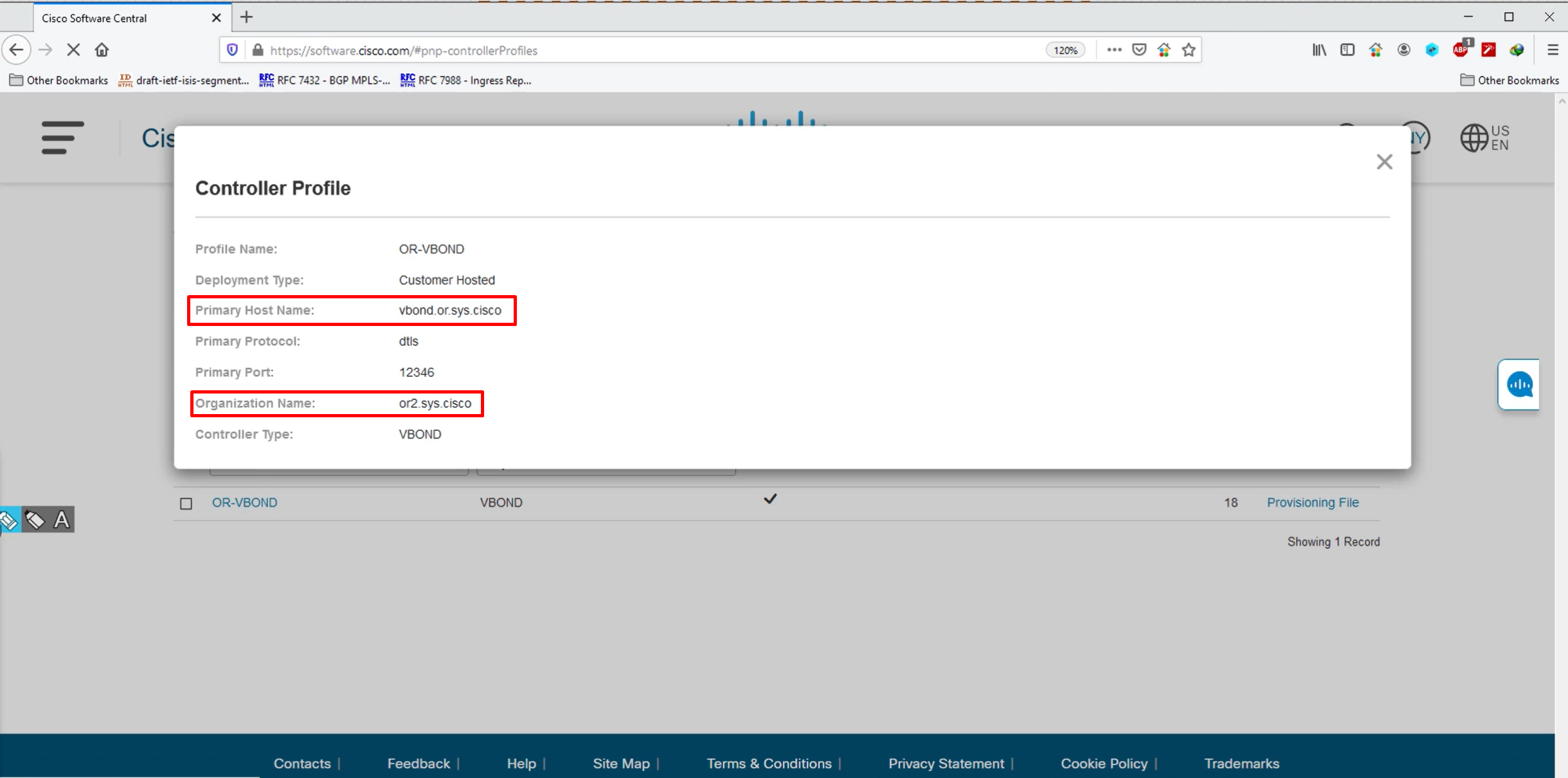
even though we configured Org name in command line, it does not get picked up automatically, so click edit to configure it


Add Organisation Name
or2.sys.cisco

Add vBond FQDN
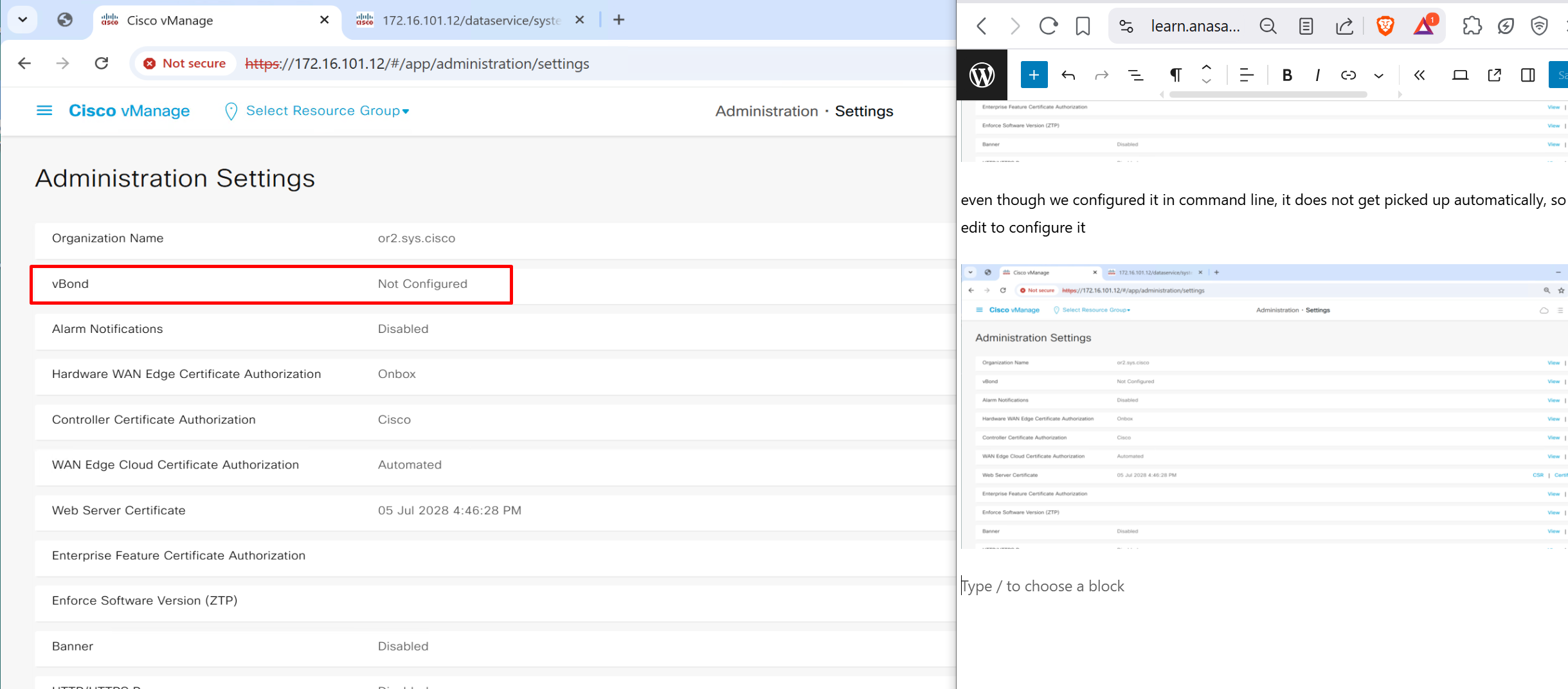
vbond.or.sys.cisco
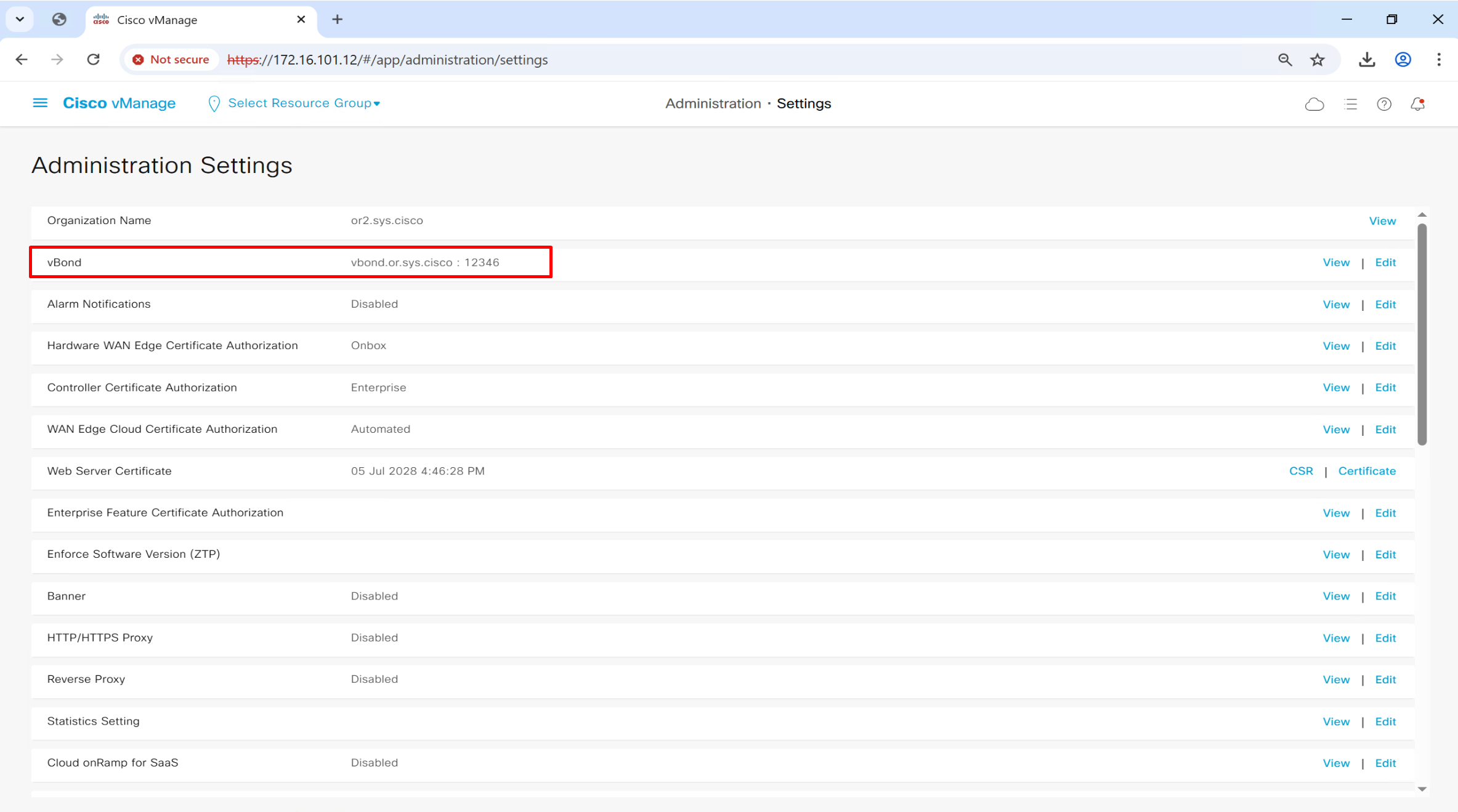
Controller Certificate Authorization mode
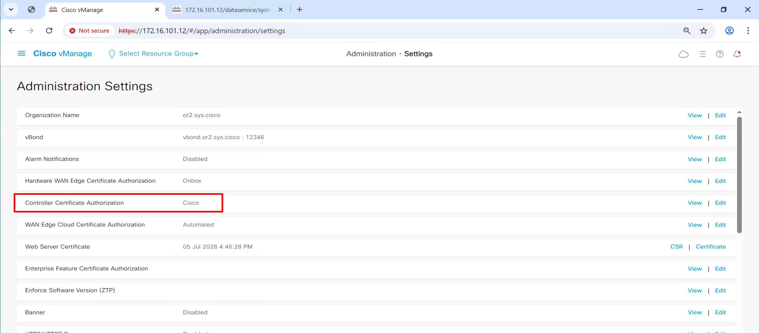
This is much simpler method as it uses Cisco’s Pre-installed Certificates

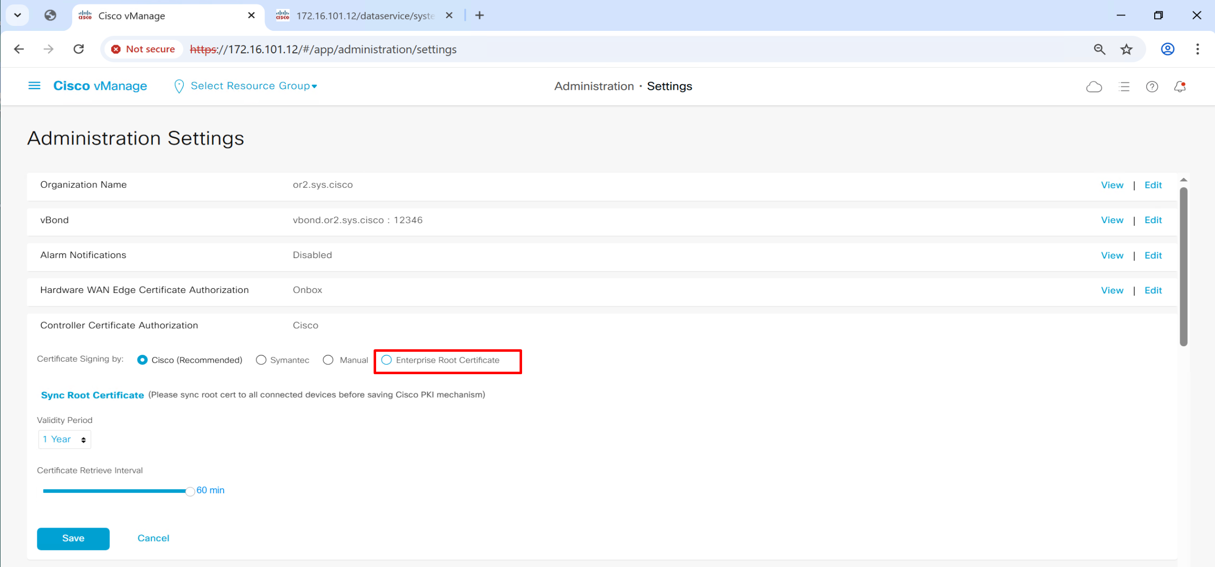
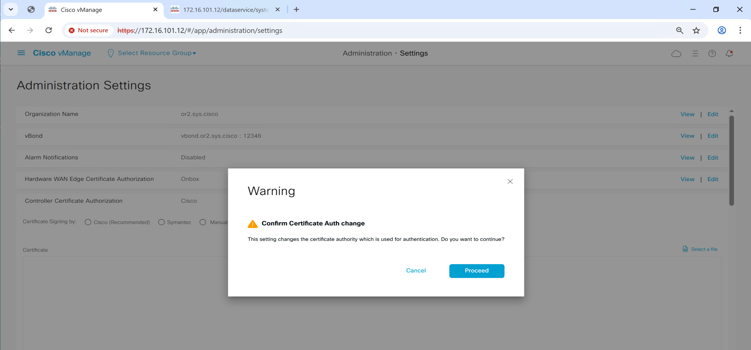
This root certificate can be same as the one added in the “trust store” earlier as this option is asking us to provide a root CA which will be used for “Authentication” for devices
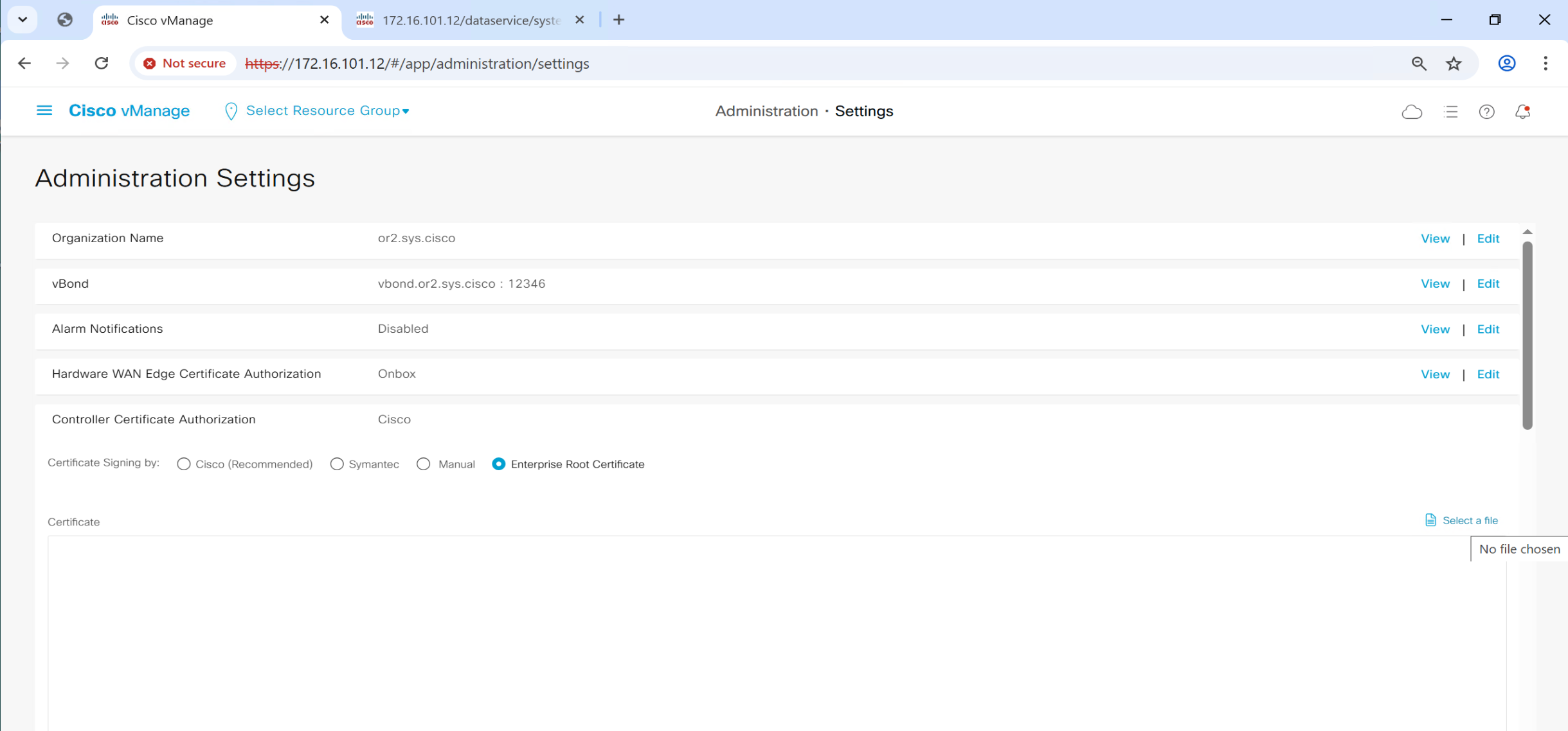
this will tell other controllers vbond and vsmart to authenticate using this certificate

Now vmanage knows about the IP addresses of the controllers like authorization or whitelisting but they are not onboarded yet, before they can be onboarded on to fabric they need certificate that is signed by CA and this will be done using each controller CSR
Install certificates on vSmart and vBond through vManage
Generate CSR per controller from vmanage

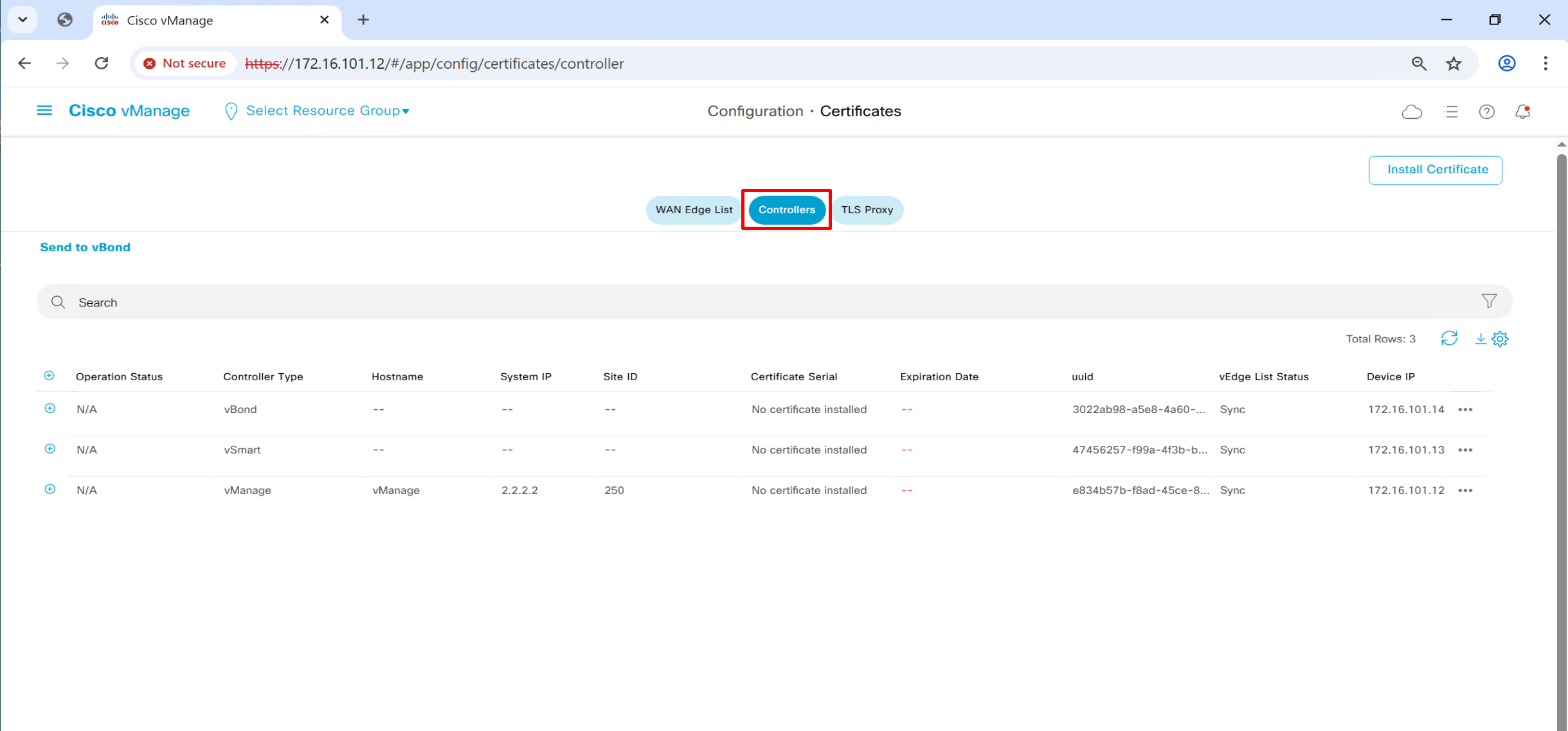
Click on vManage three dots > generate CSR
even vManage itself needs a certificate
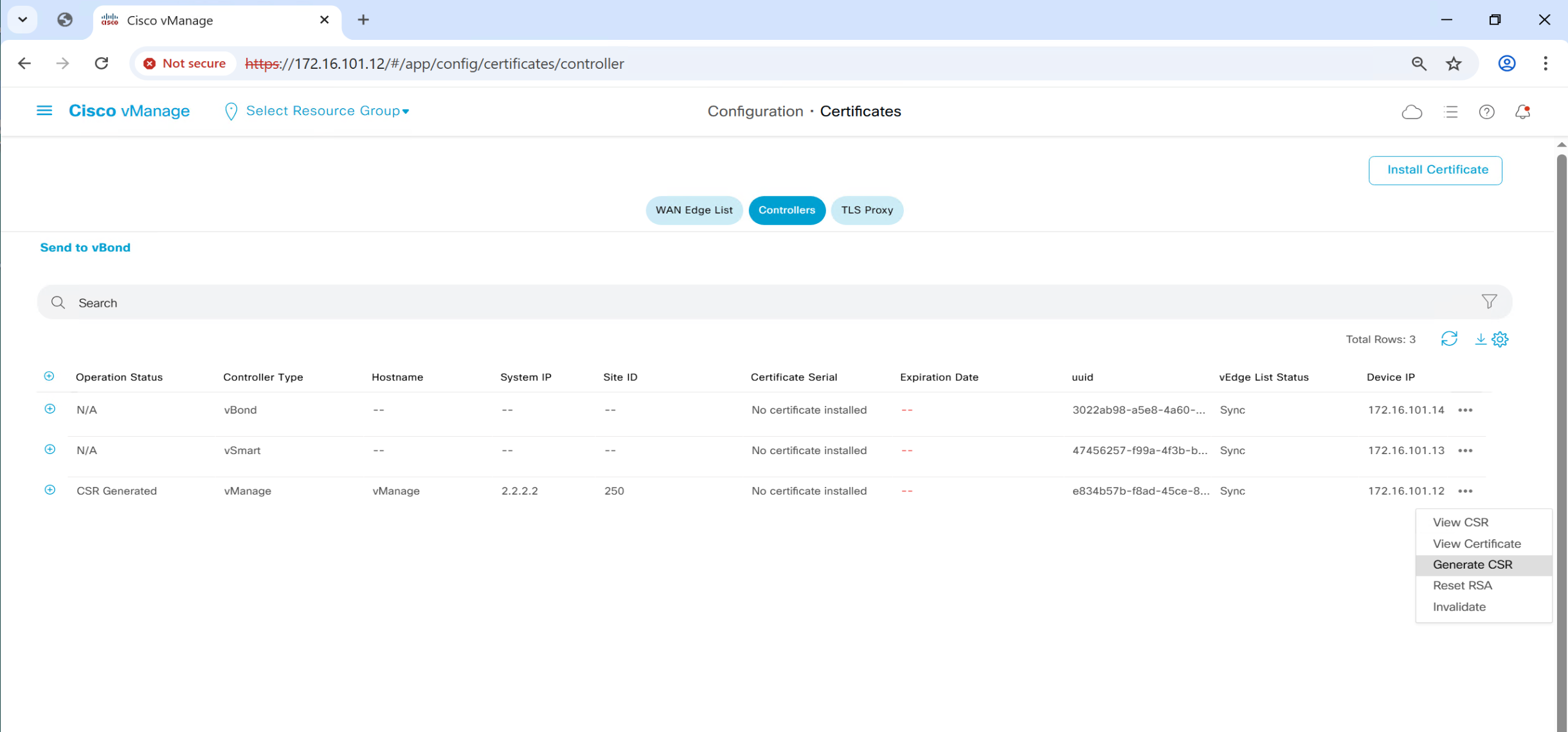
CSR for vSmart and vBond is generated and installed on vSmart and vBond
and it is then signed by our windows server CA, so when this cert is presented to vmanage, it can trust the presented cert
and once certificates are “issued” by vmanage to vbond and vsmart,
a certificate based mutual authentication will take place before controllers are added to fabric in vmanage

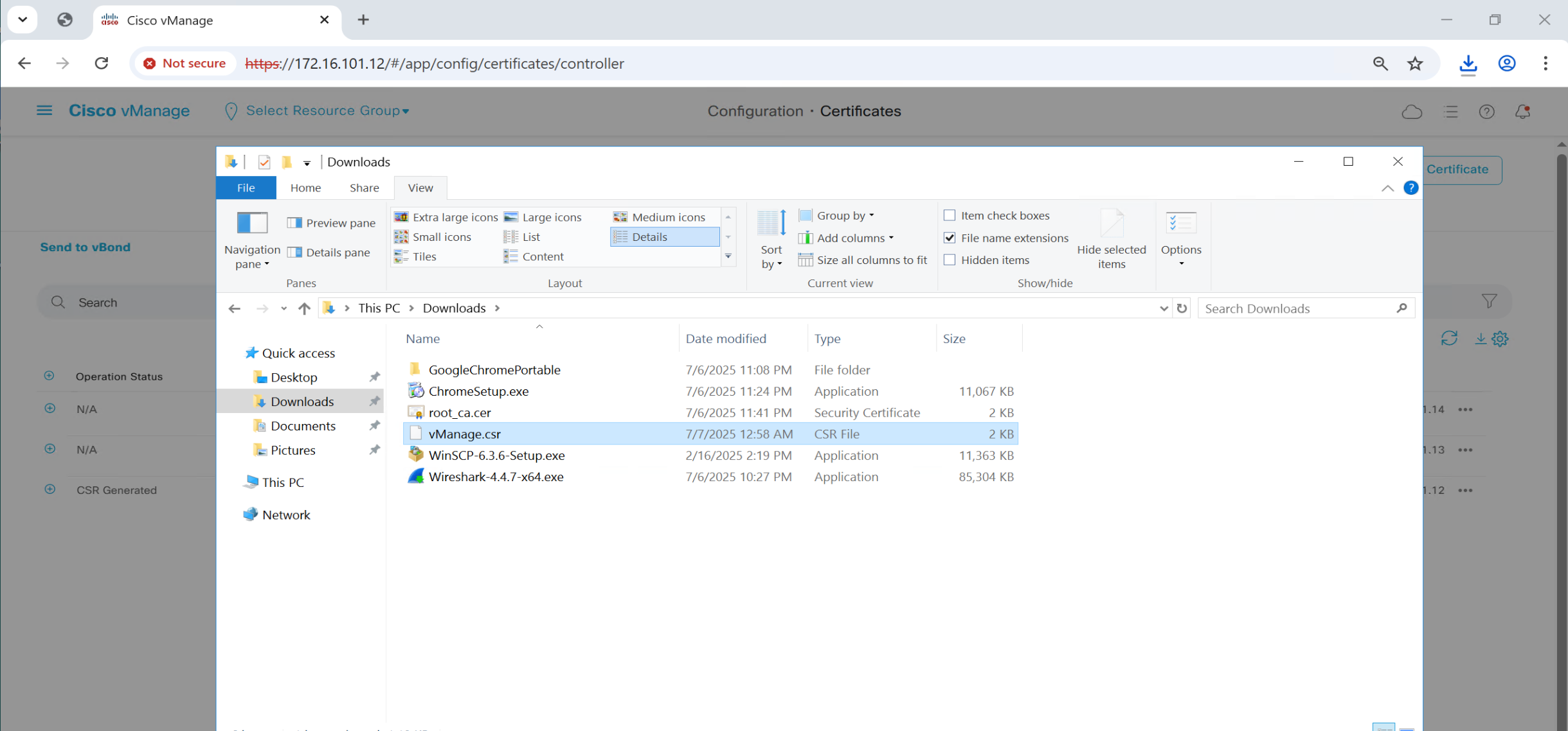
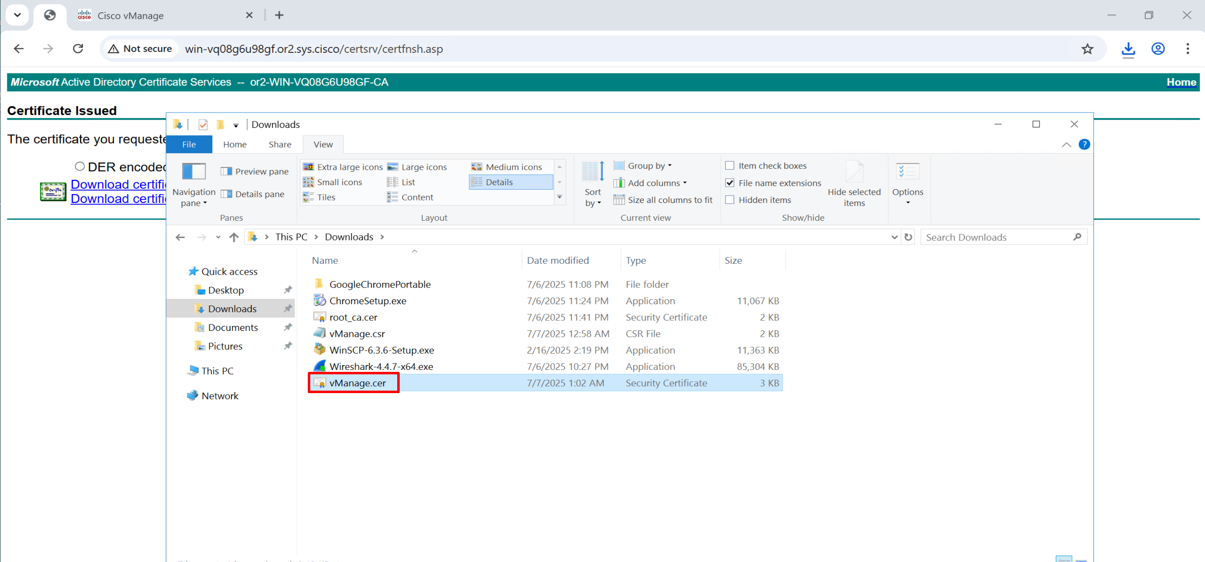
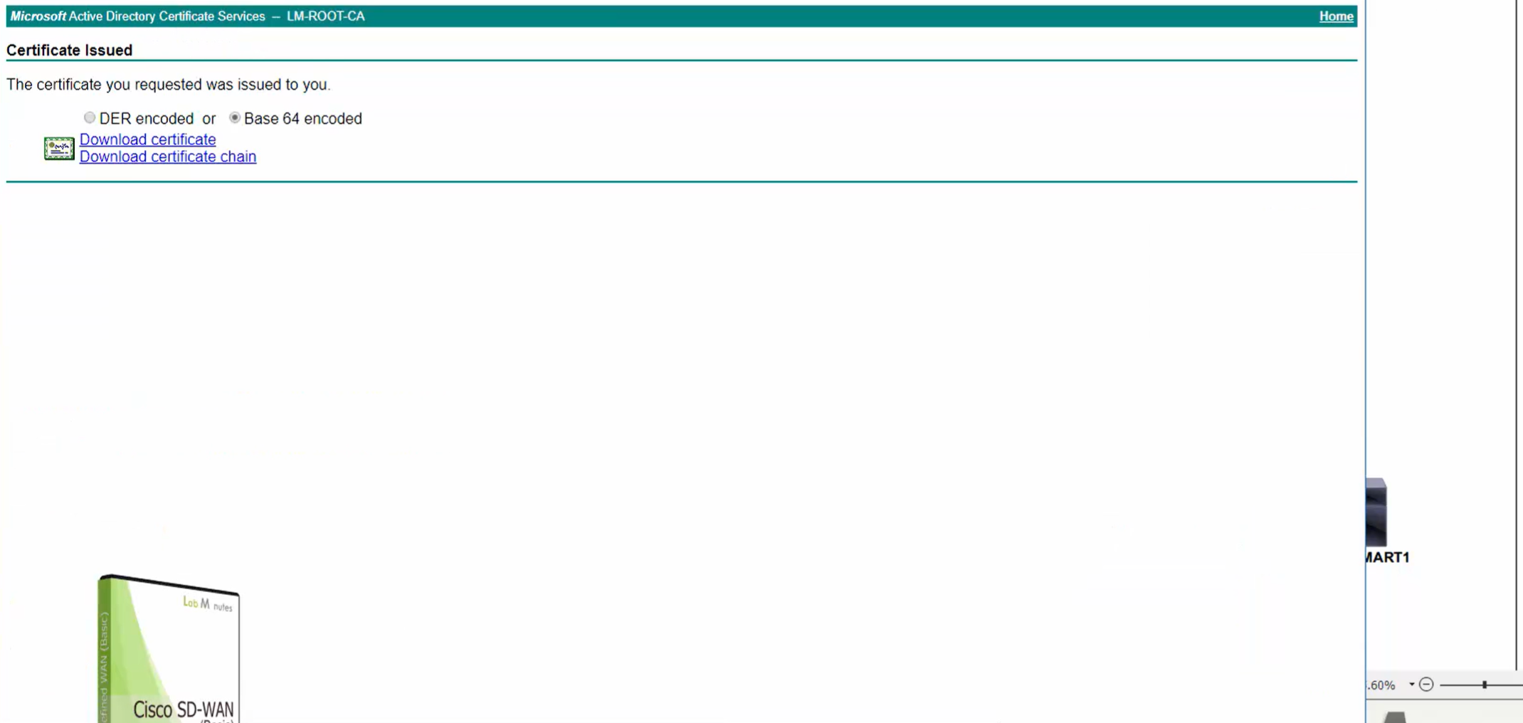
Click on download
same process is required for vmanage as well because vmanage also needs to issue certificate to itself
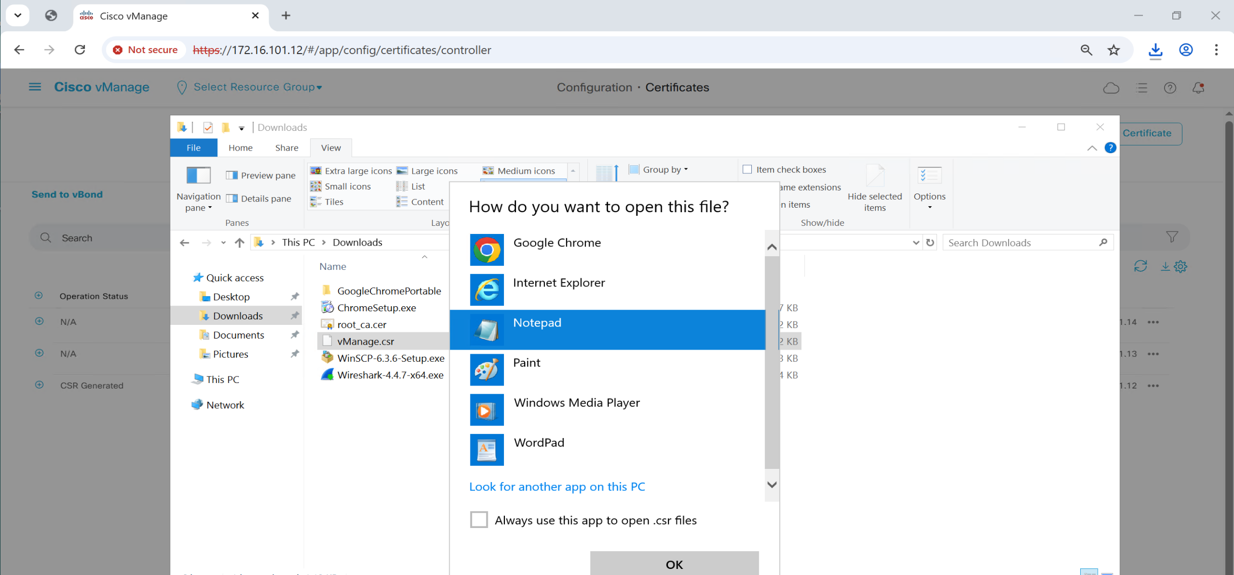
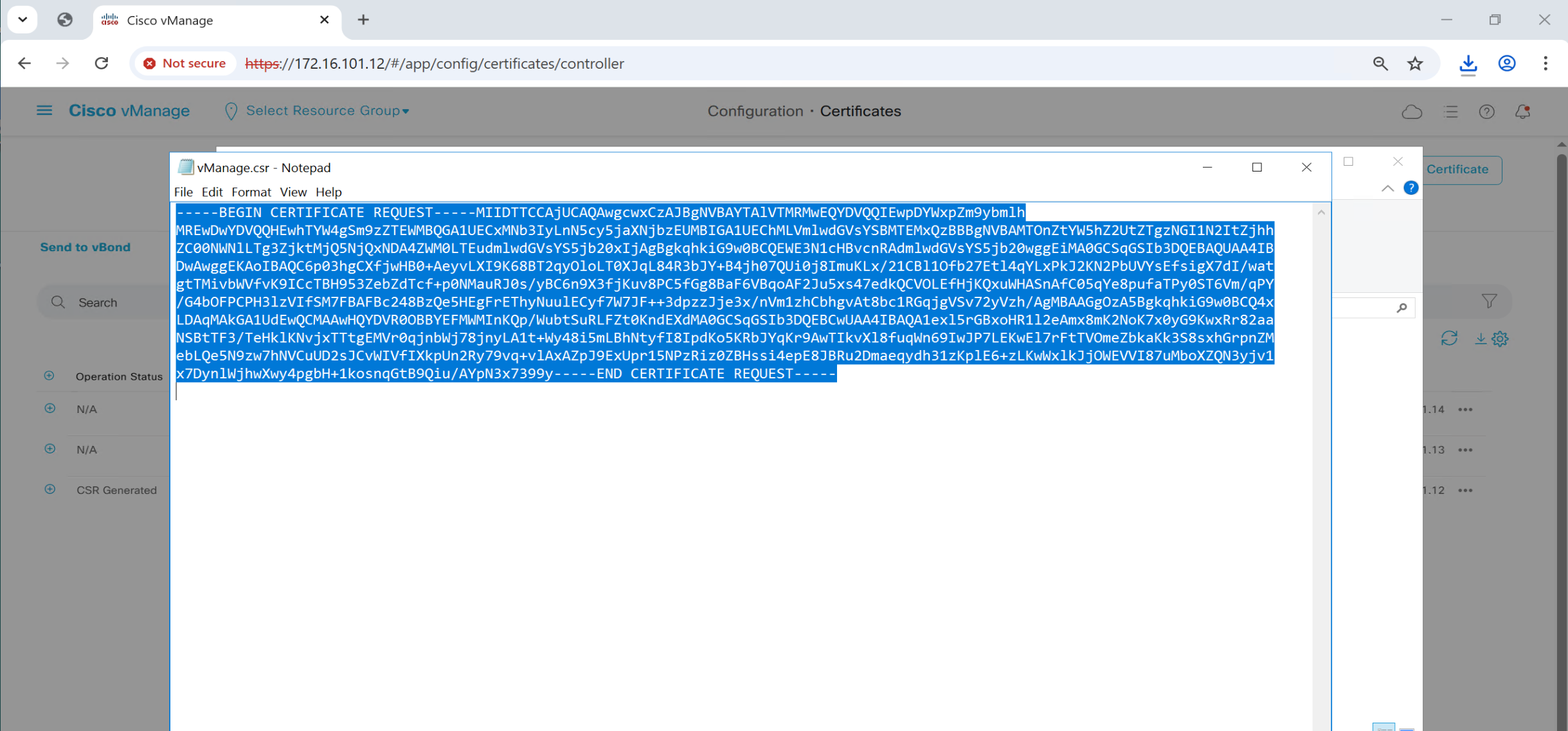
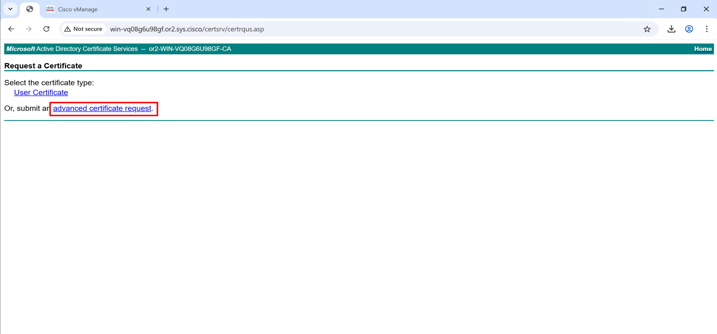
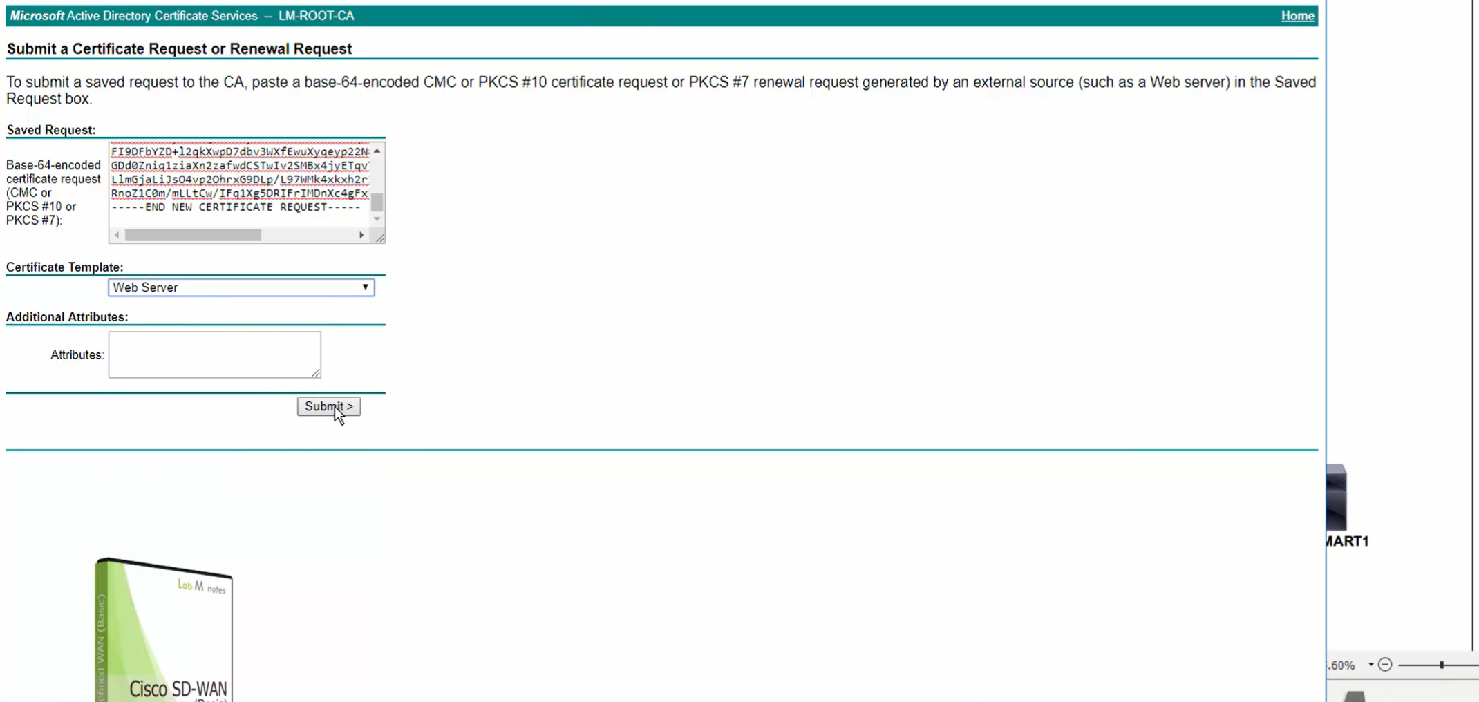
Copy and paste it to certsrv
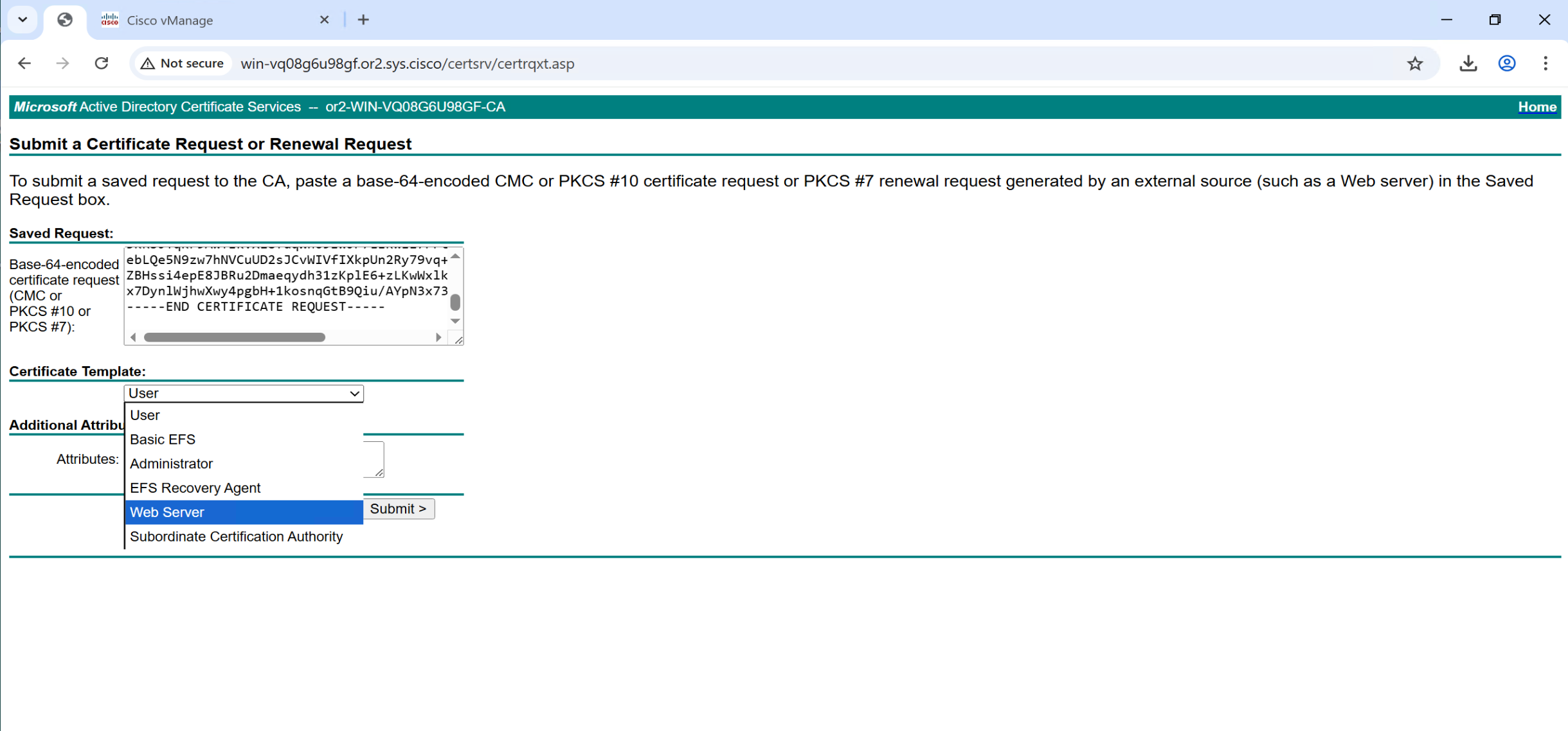

Repeat same process of CSR generate for vsmart and vbond as well
Install Certificates
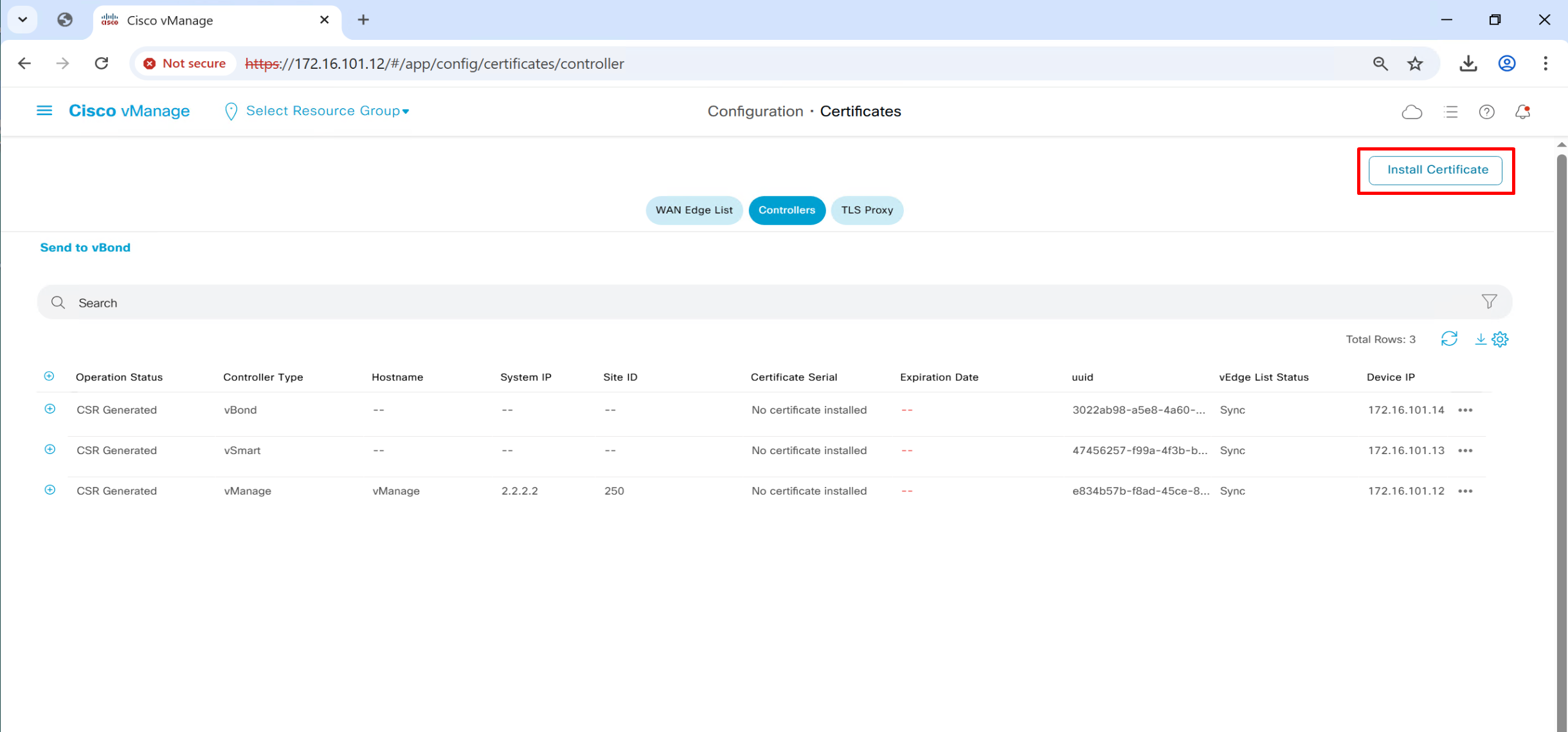
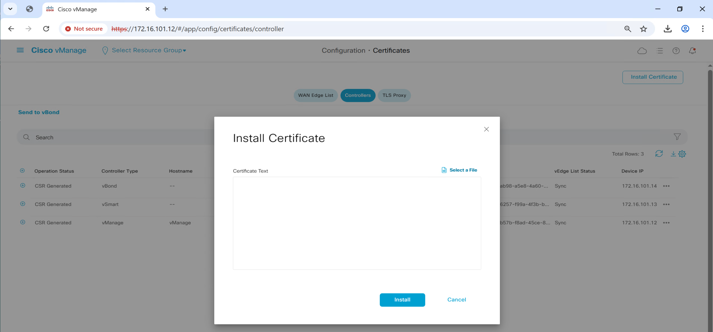
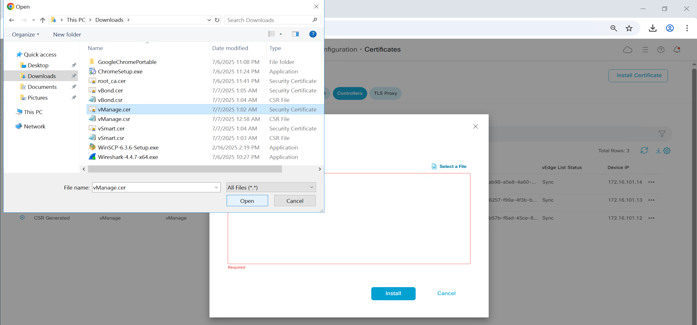


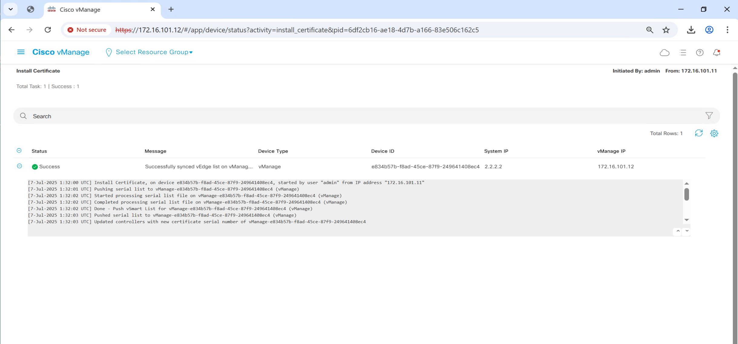

Follow same steps to install certificates on other controllers

in above screenshot we can see that “site ID” is still missing and “System IP” also
This has to do with tunnel interface, as the “site ID and System IP” are exchanged over fabric
so we need to bring up the tunnel interface with allowed services which are safe over WAN or internet such as HTTP and icmp etc, Allowed service are both inbound and outbound
such as NTP will be outbound but SSH will be inbound
vManage tunnel interface
vpn 0
interface eth0
tunnel-interface ! DTLS tunnel
allow-service all ! only use all in lab for prod restrict services

allow-service sshd
allow-service ntp
allow-service dns
allow-service https
vSmart tunnel interface
vpn 0
interface eth0
tunnel-interface ! DTLS tunnel
allow-service all ! only use all in lab for prod restrict services

allow-service sshd
allow-service ntp
allow-service dns
allow-service https
vBond tunnel interface
vpn 0
interface ge0/0
tunnel-interface ! DTLS tunnel
encapsulation ipsec ! this is also required in case of vbond
allow-service all
after bringing up the tunnel interface we can see that system IP, hostname and site ID are present
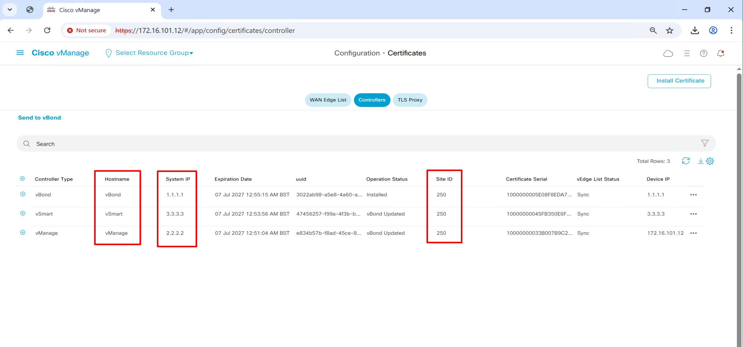
we have successfully onboarded the controllers
vManage commands
show runn
conf t
system
show configuration
commit
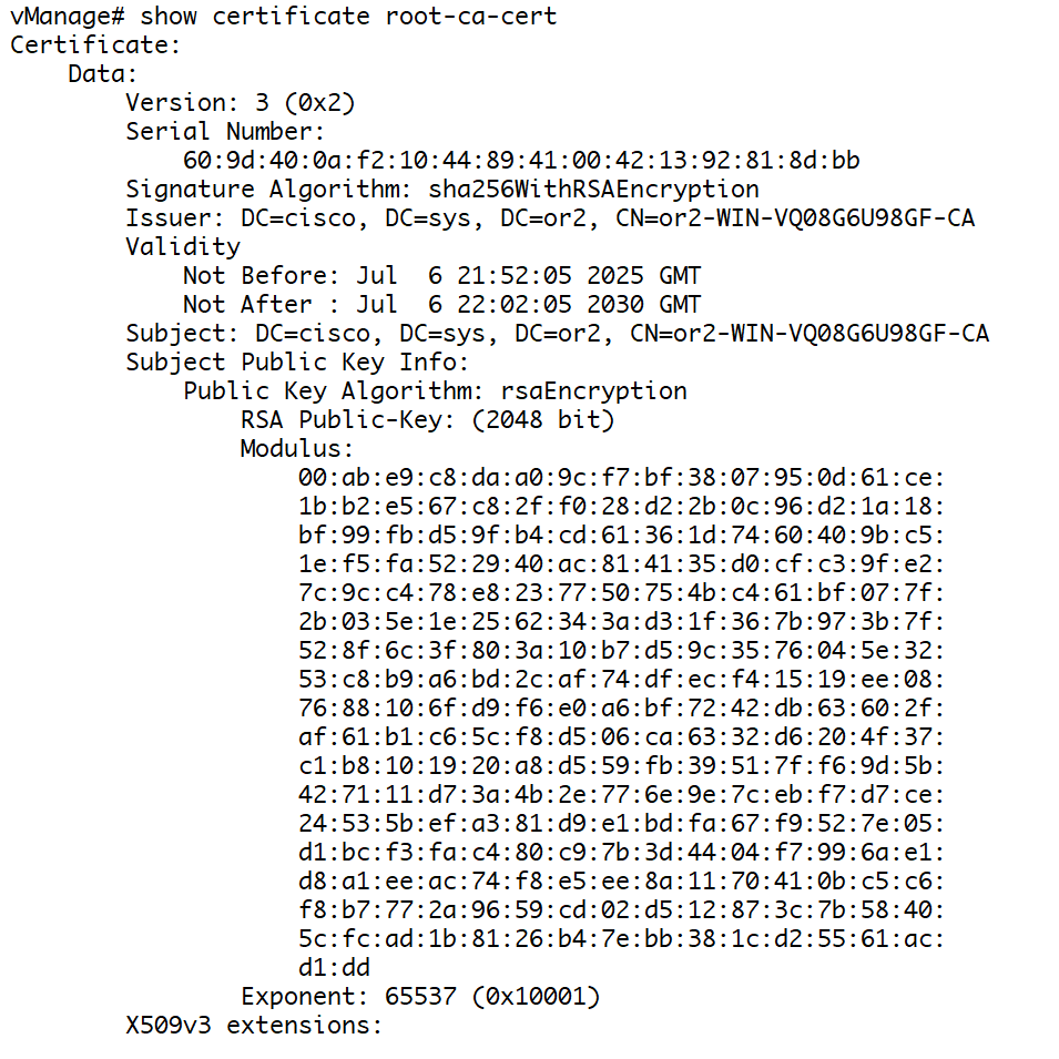
show certificate root-ca-cert ! to see installed root-ca cert
show ntp associations
show run vpn 0
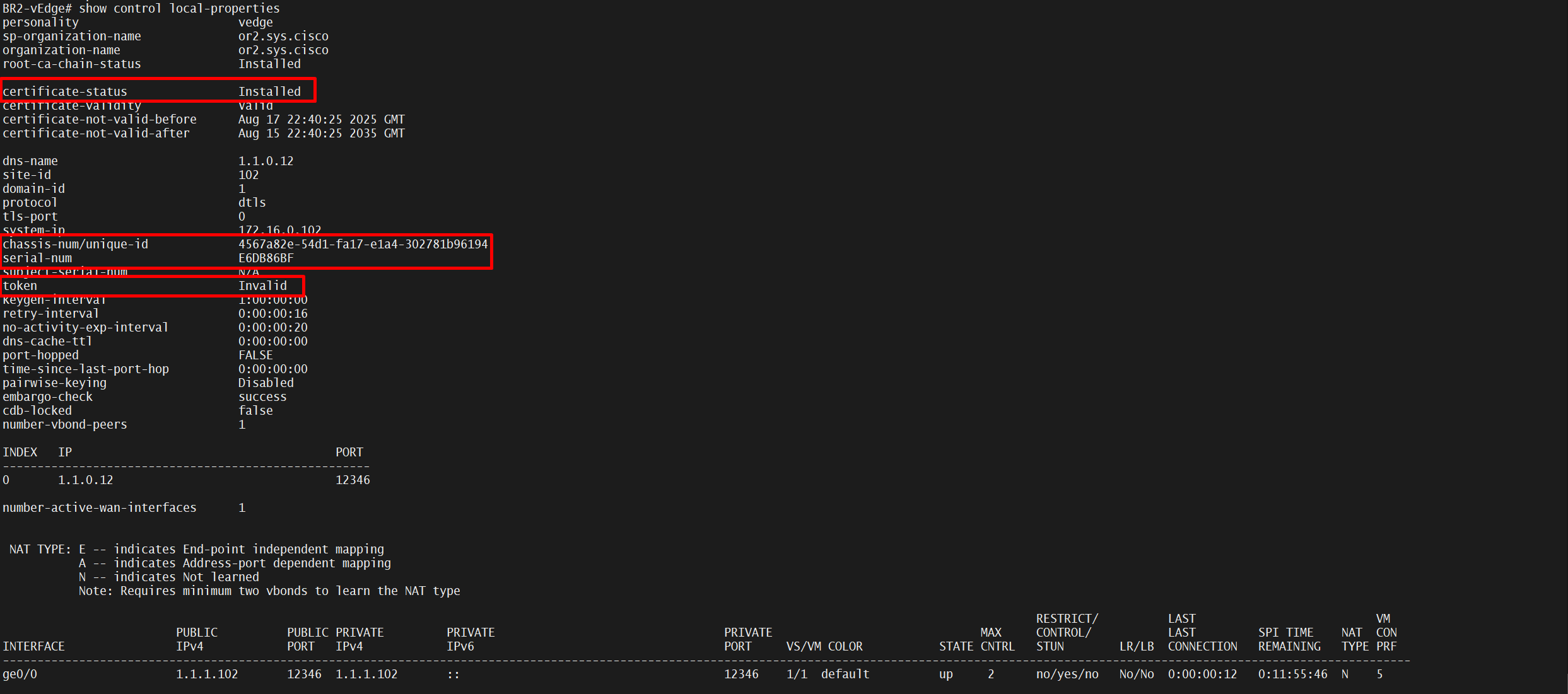
show control local-properties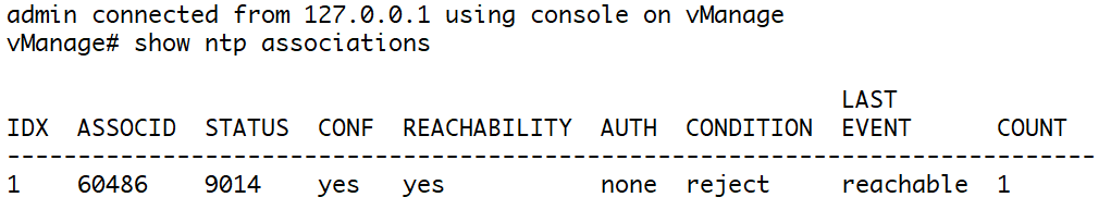
vbond commands
show orchestrator connections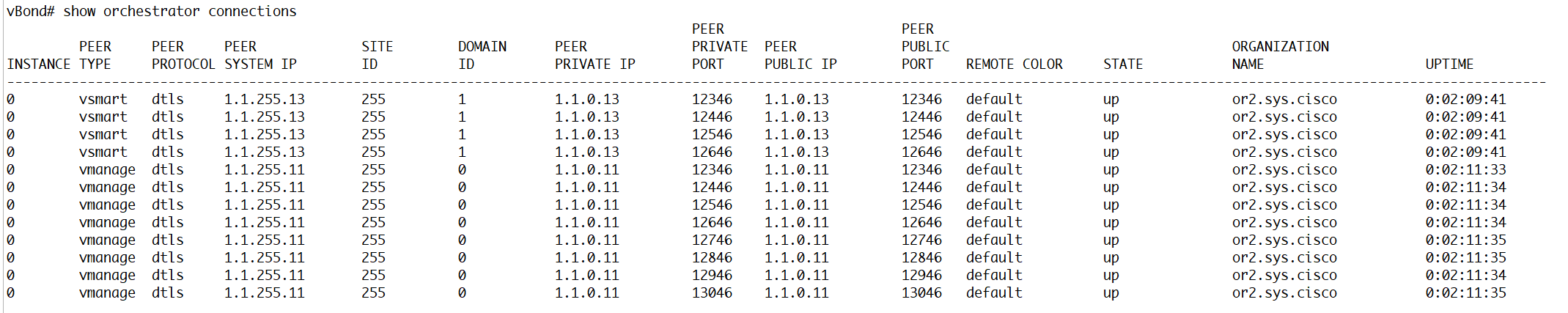
one DTLS connection per vmanage CPU core with vmanage
show orchestrator valid-vsmarts
first one is vmanage and other one is vsmart
vsmart commands
show control connections 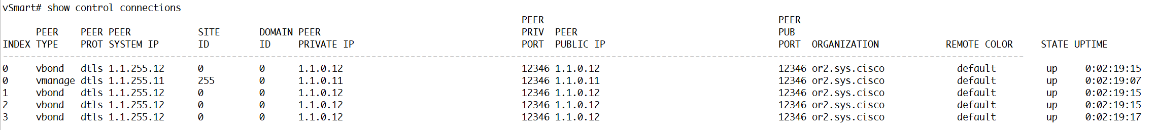
Web certificate for vmanage
We will get the CSR

it needs to be signed by CA


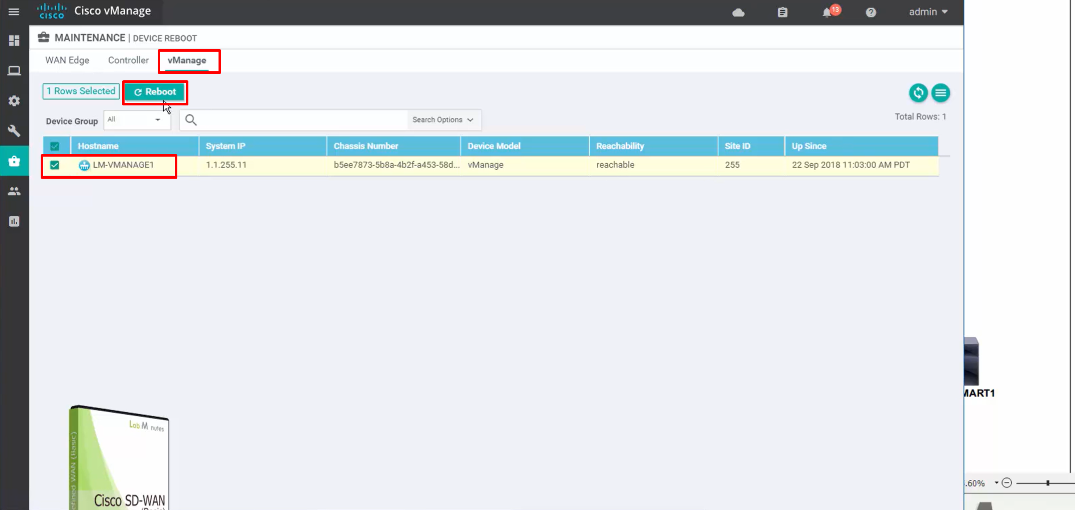
for certificate to take effect, we need to reboot the vmanage
under maintenance, device reboot

Edge device onboarding
Virtual cEdge devices themselves do not have any chassis numbers,
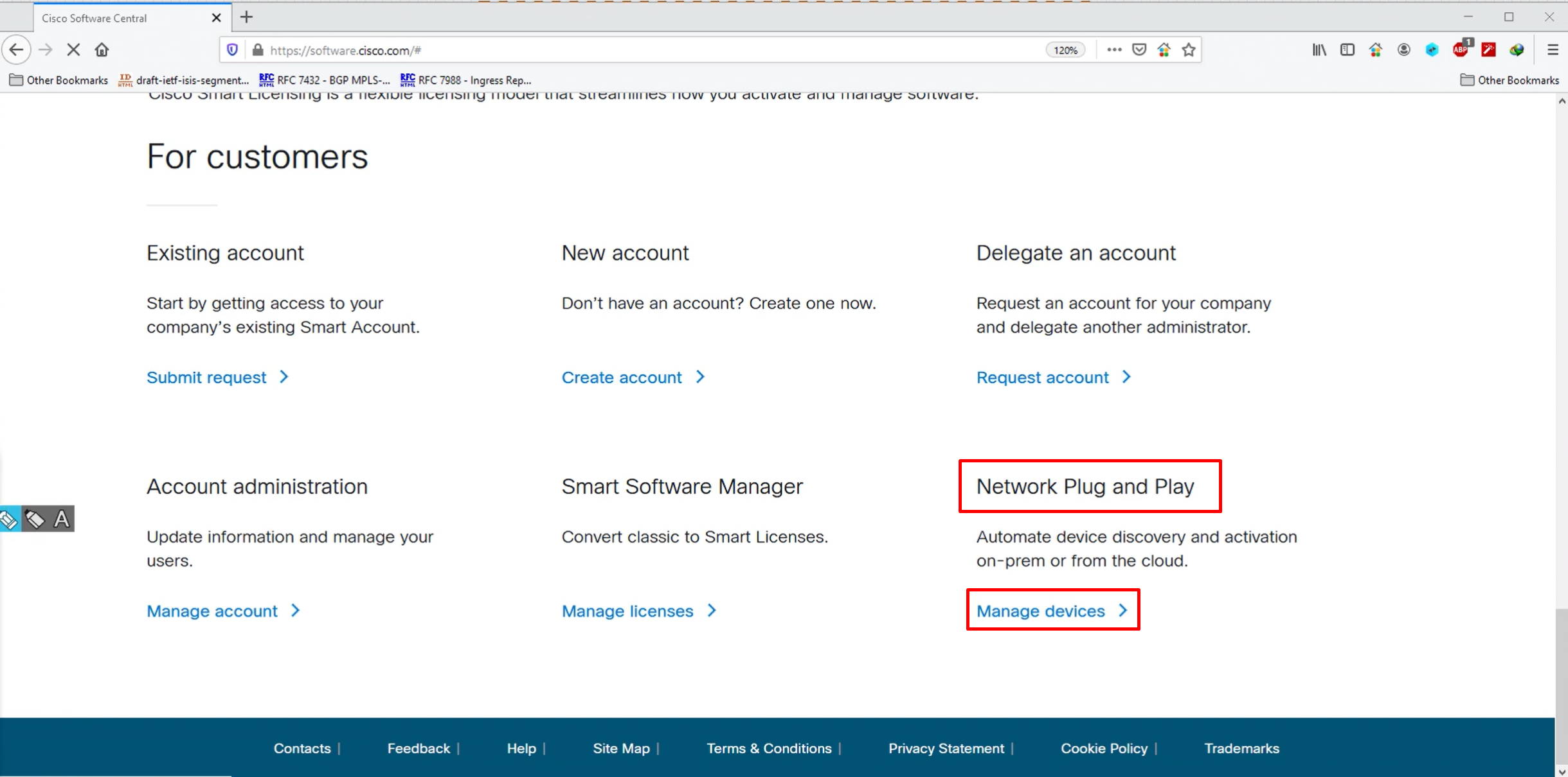
in order to get those chassis number we need to go to software.cisco.com, on the portal we need to define the vbond IP (best to define FQDN for flexibility in serial file) and Org name.
There is a different process for hardware edge devices,
For Virtual devices we specify how many virtual devices we want to generate chassis numbers for.
If we have hardware routers then we have to enter the serial numbers, PID and certificate serial number from routers into the portal
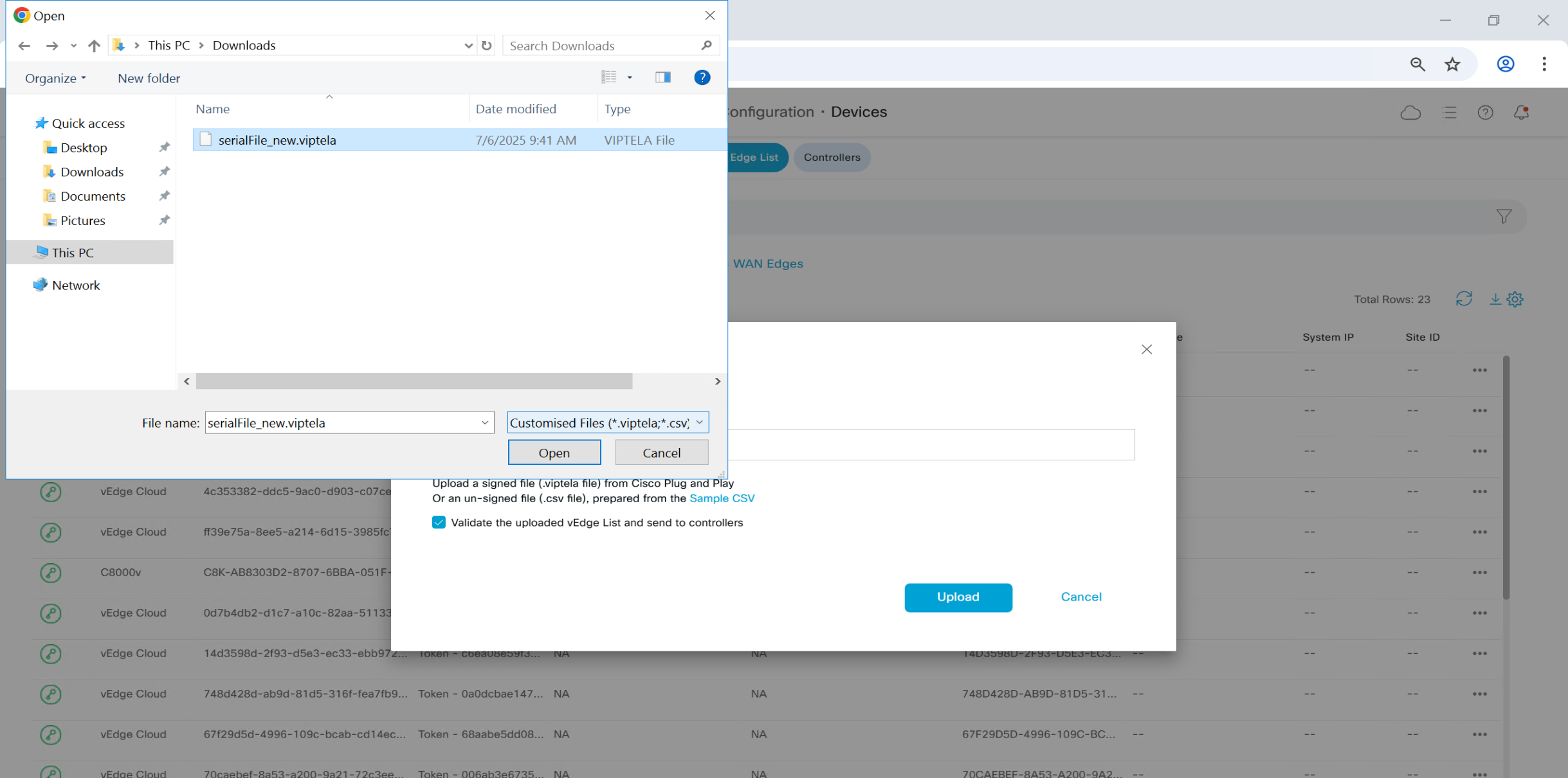
Extracted serialFile_new.viptela
The file appears to be in a compressed binary format, starting with the byte sequence \x1f\x8b\x08, which is the standard signature for a GZIP-compressed file.
I’ll attempt to decompress the file and then read its contents. Let’s proceed.
The decompressed file starts with the text viptela_serial_file, which suggests it is a Viptela serial file (used in SD-WAN deployments). However, the rest of the content contains what looks like binary padding and possibly a tar archive header, indicated by terms like ustar.
This means the GZIP file likely contains a tar archive, not a plain text file. Let me try extracting the tar contents and see what files it contains.
The archive contains the following files:
viptela_serial_file– likely the main serial/license file.viptela_serial_file.sig– likely a digital signature file to verify authenticity.cisco_cert.cer– a Cisco certificate, probably used for validation.
I’ll extract and display the contents of the main viptela_serial_file first.
The viptela_serial_file contains JSON data representing serial information for Cisco SD-WAN devices. Here’s a summary of what’s inside:
✅ Key Information Extracted:
- Version: 1.1
- Organization:
or2.sys.cisco
- Organization:
- Overlay Network:
SD-WAN-3 - 388033 - vBond Controller:
vbond.or.sys.cisco(DTLS port 12346) - Timestamp: 2022-02-25 00:06:49
✅ Chassis & Serial Numbers:
The file lists multiple devices, each with:
- Chassis ID (example:
4567A82E-54D1-FA17-E1A4-302781B96194) - SKU: (e.g.,
VEDGE-CLOUD-DNA,C8000V,CSR1KV) - HWPID: Hardware Product ID
- Serial Number: matches the chassis ID in each case
- No SUDI (Secure Unique Device Identifier) certificates included (fields are empty).
Create new DNS zone
Since the .viptella serial file contains org name as or2.sys.cisco but it vbond profile has vbond FQDN as vbond.or.sys.cisco, we will create another DNS zone
Right-click on “Forward Lookup Zones” (or Reverse Lookup Zones if needed) ➔ New Zone…
In the New Zone Wizard:
- Select Primary zone (if this is the main copy).
- Choose whether to store the zone in Active Directory (recommended).
- Select the replication scope – all DNS servers in the forest.
- Enter your zone name or.sys.cisco
- Choose how to handle dynamic updates – secure and non-secure.
- Complete the wizard.

Generate .viptela serial file
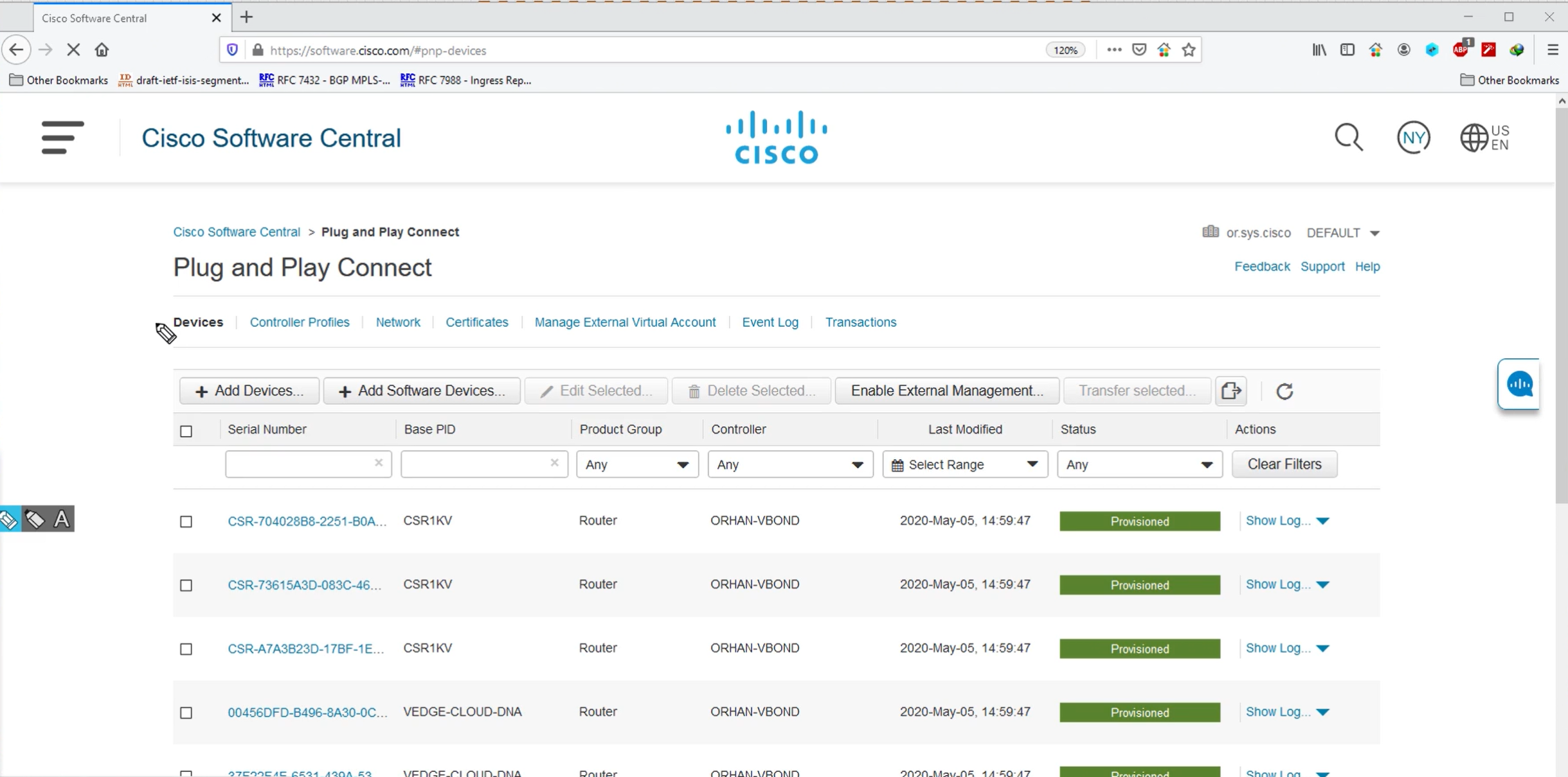
These devices PID and serial numbers will be empty when you first create Smart account and virtual account, once have been assigned chassis numbers and associated to the org show up as green and “provisioned”
This section is where we define the vBond info with FQDN or IP and Org info

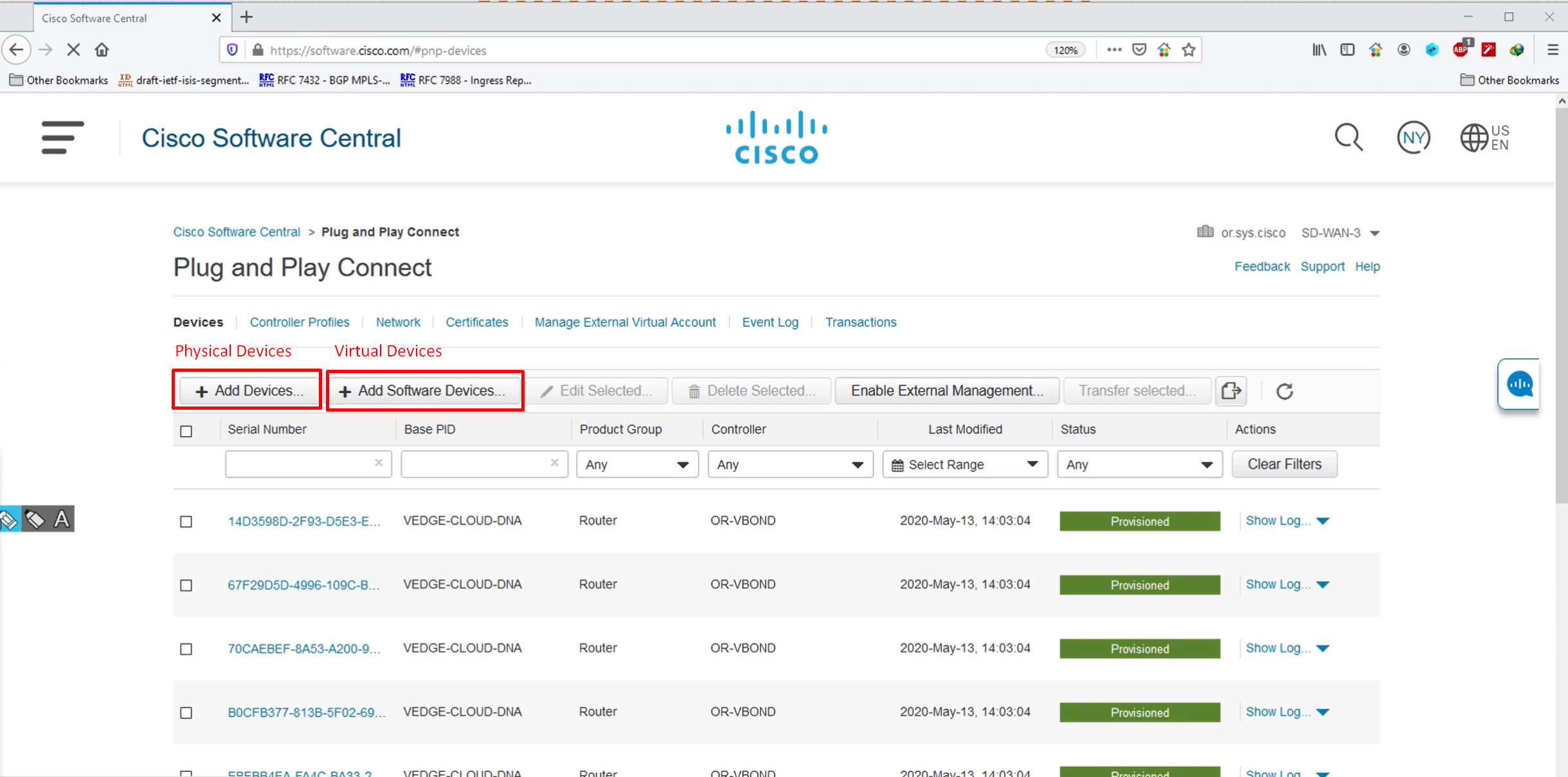

You define the PID of the device, quantity of devices and the vbond profile – this allowance will be added to our .viptela serial file


After submitting this wait for devices to be provisioned status

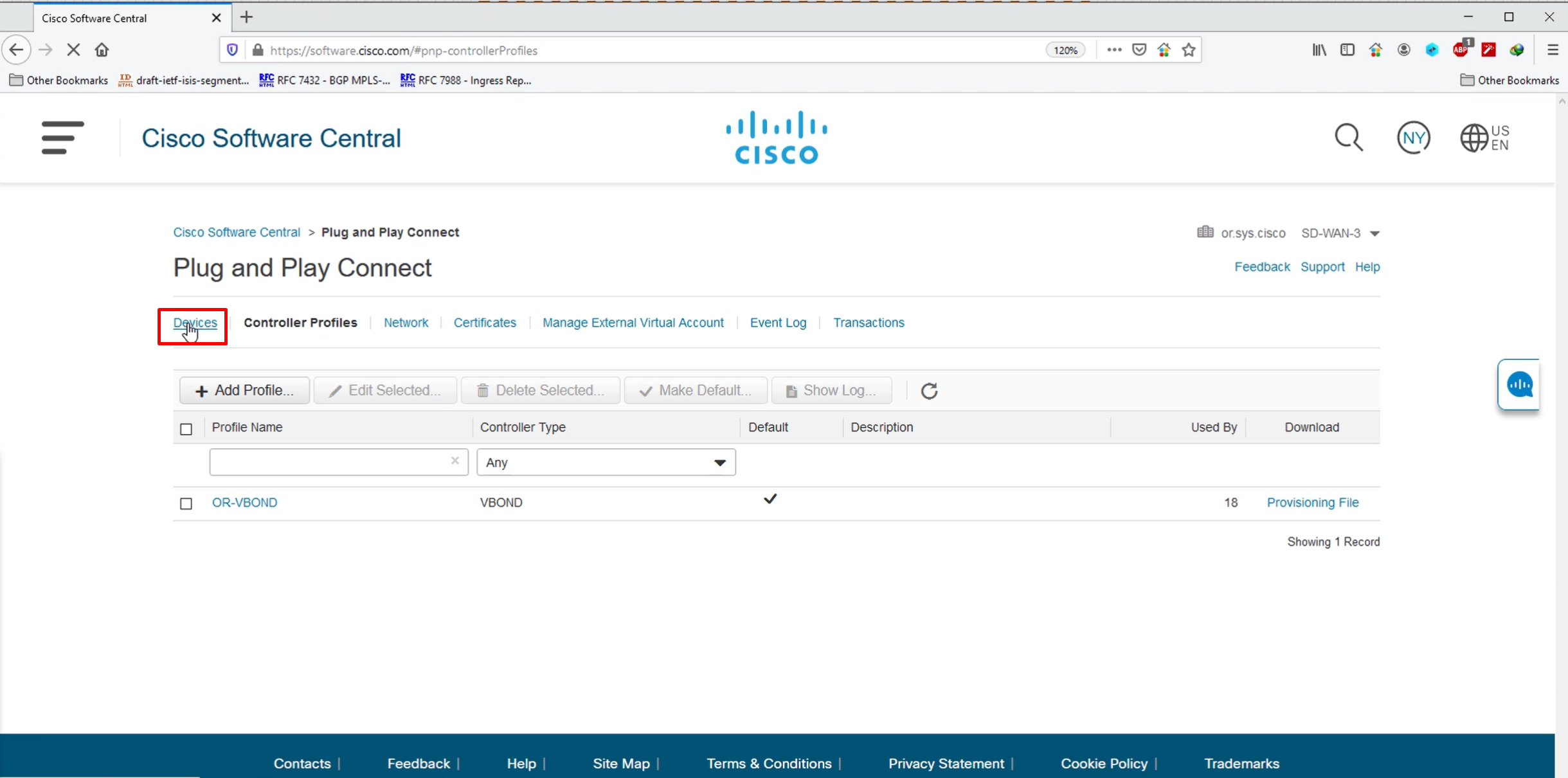
once all devices are provisioned, click on Controller profiles

Select the controller version
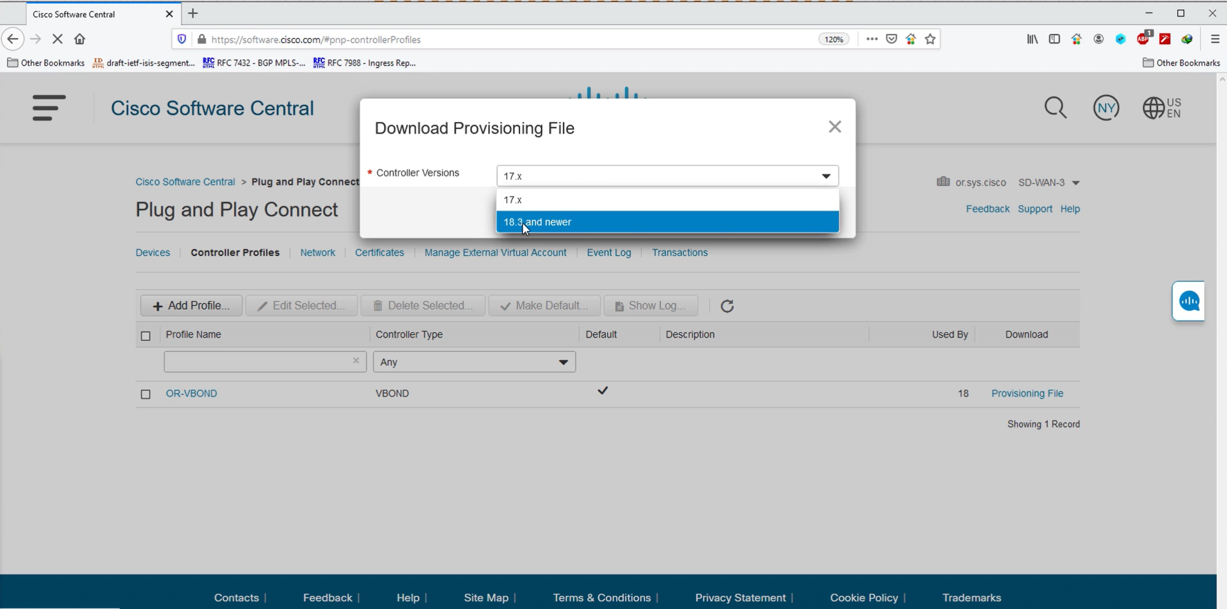

Upload .viptela serial file
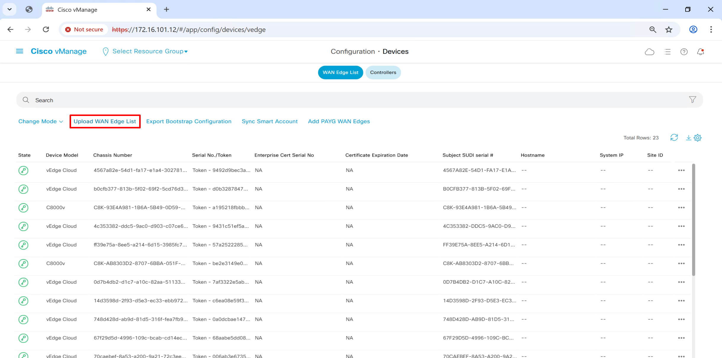

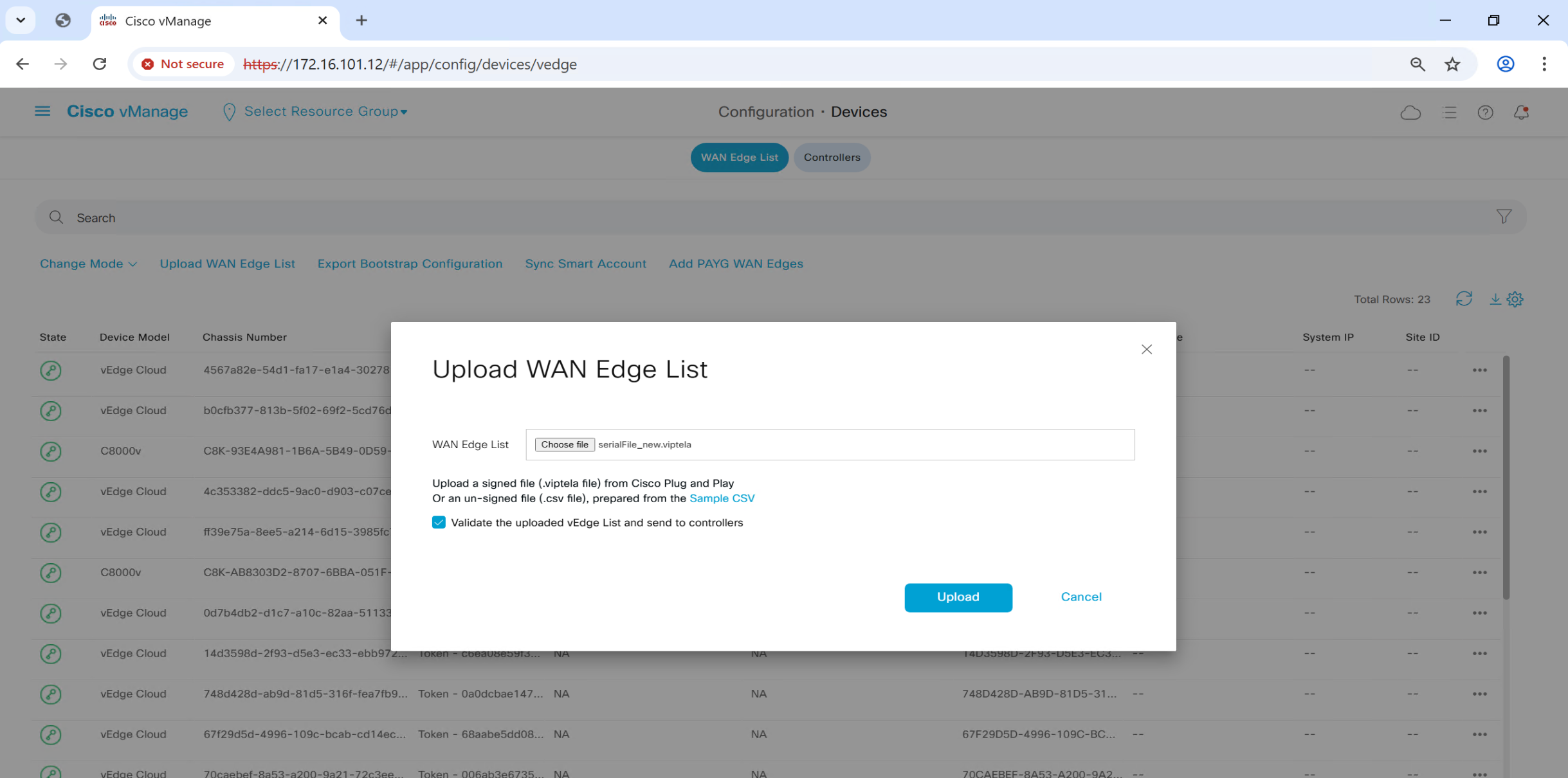
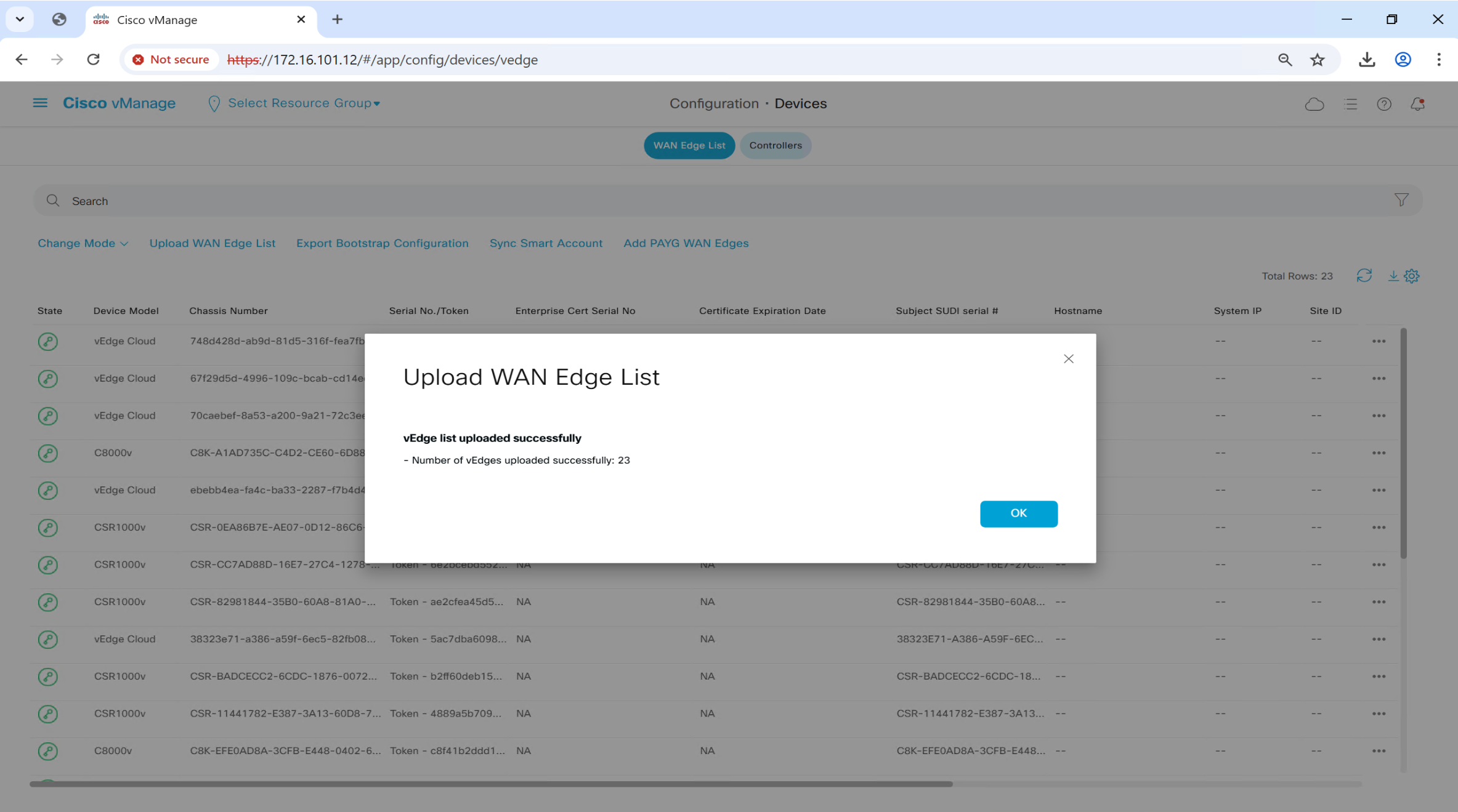
once file is uploaded, it will be pushed by vmanage to all other controllers
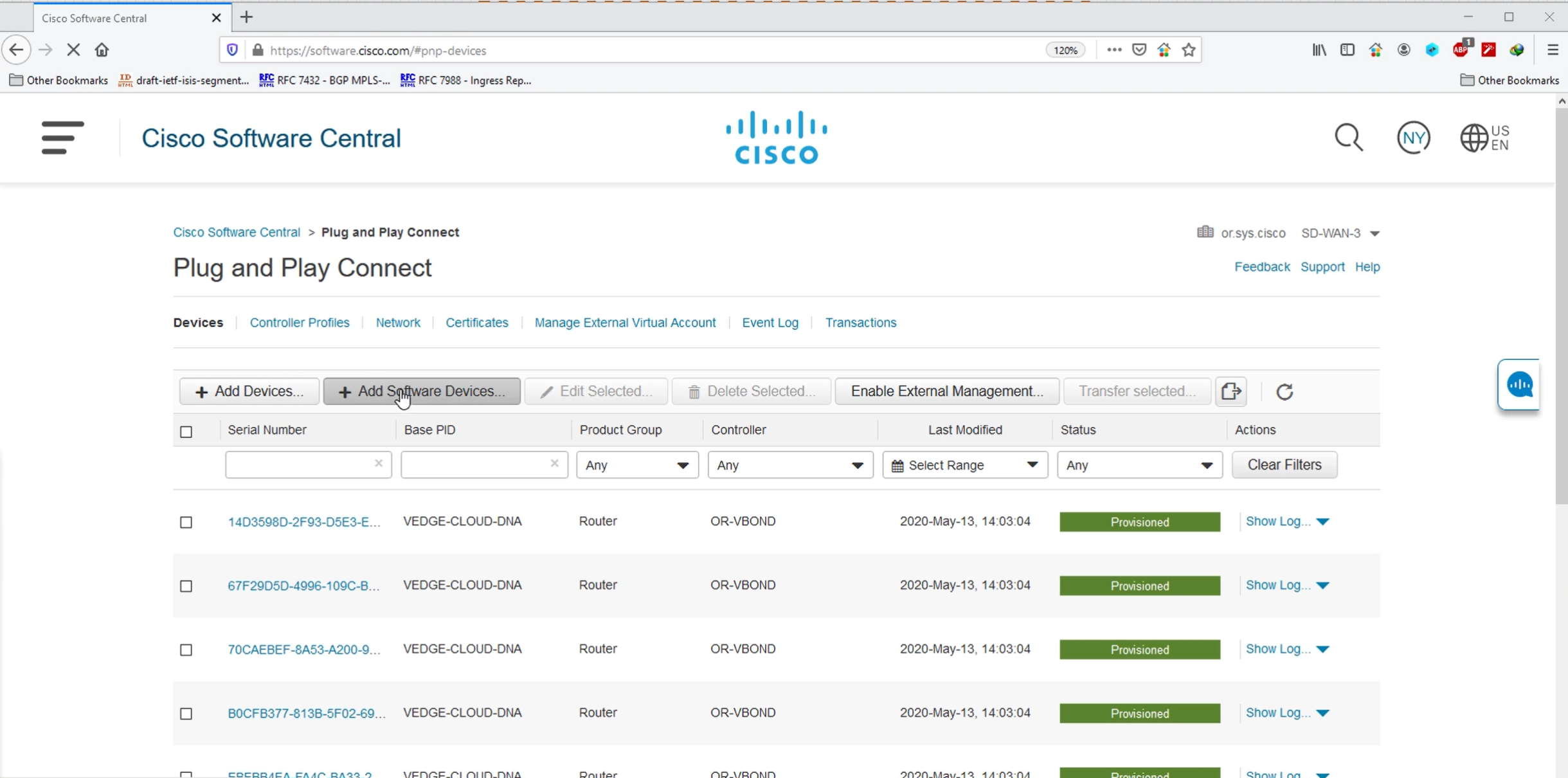
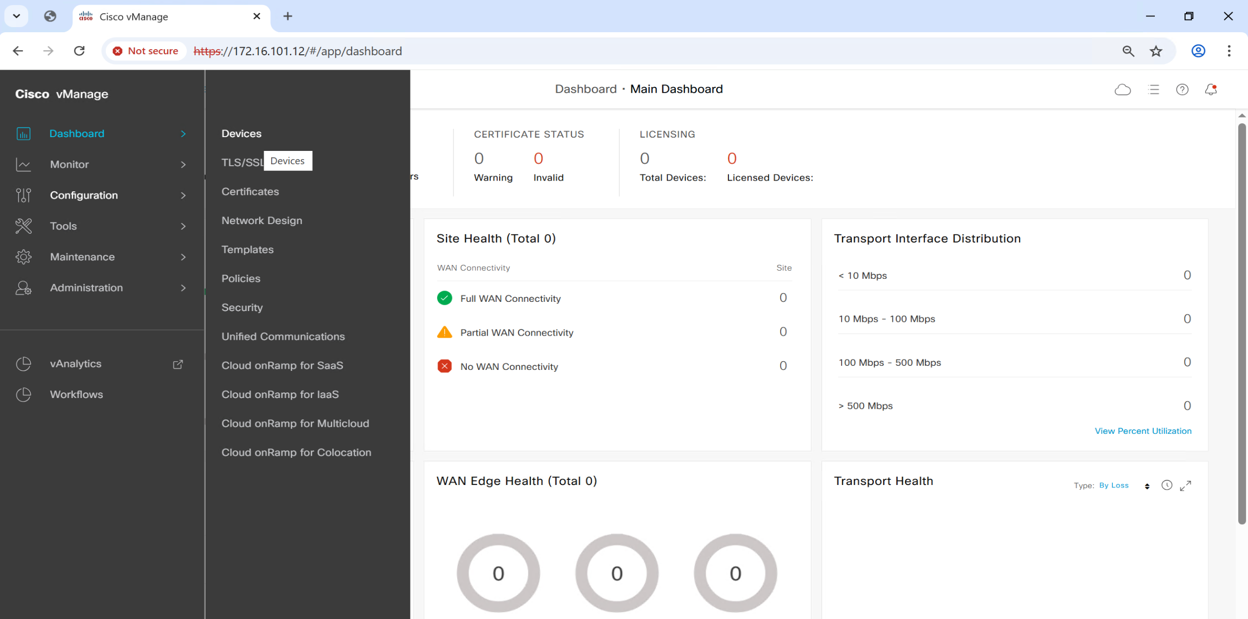
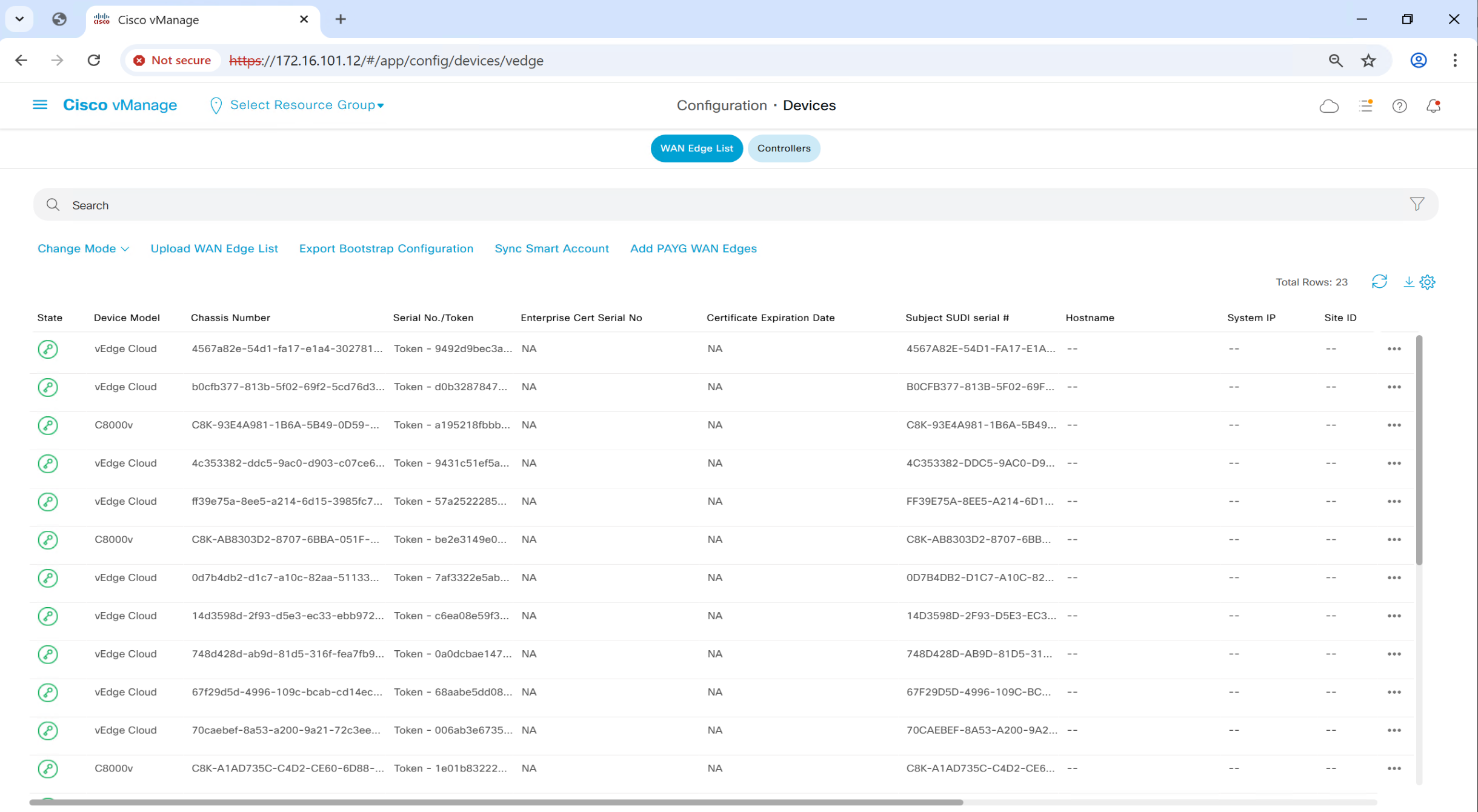
If we go to devices now
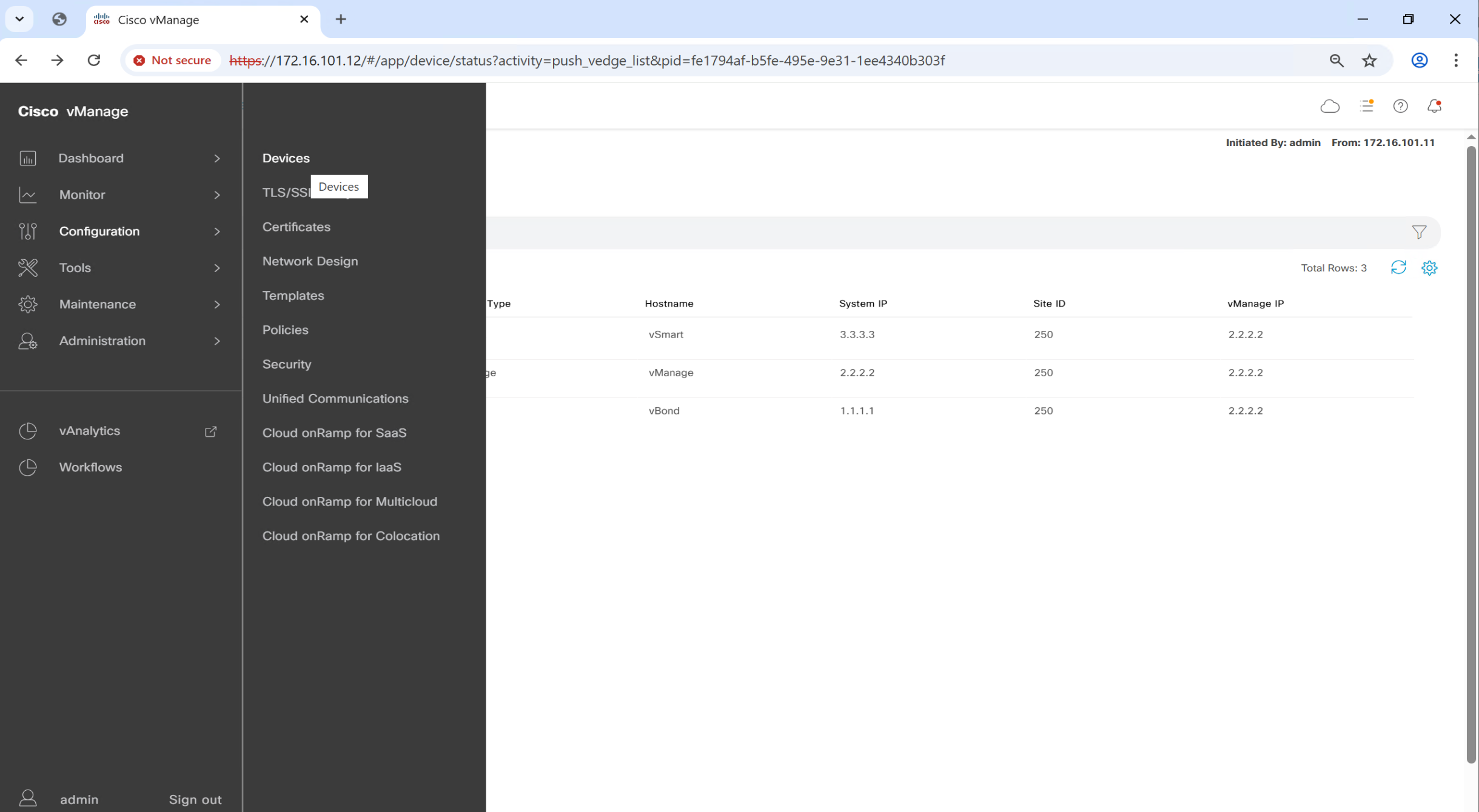
you will see available devices, this serial file has some C8000v and vEdge devices
Get rid of this annoying error message

Login to vmanage CLI
vManage# request nms configuration-db update-admin-user
Enter current user name:neo4j
Enter current user password:password
Enter new user name:admin
Enter new user password:C0mplex30
configuration-db
WARNING: sun.reflect.Reflection.getCallerClass is not supported. This will impact performance.
Successfully updated configuration database admin user
Successfully restarted NMS application server
Successfully restarted NMS data collection agent
vManage# Setting up watches.
Watches established.
This will restart the vmanage
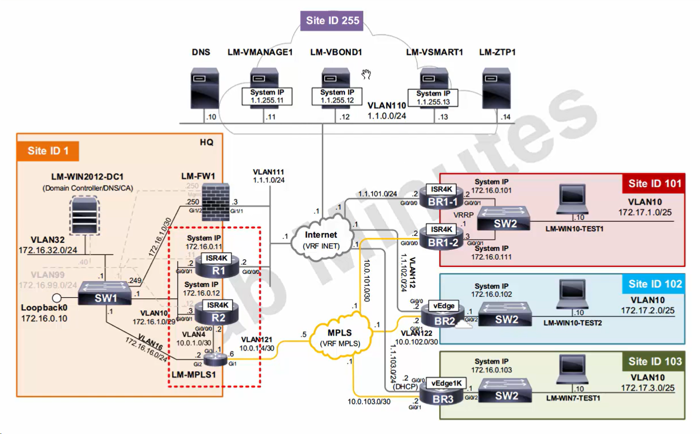
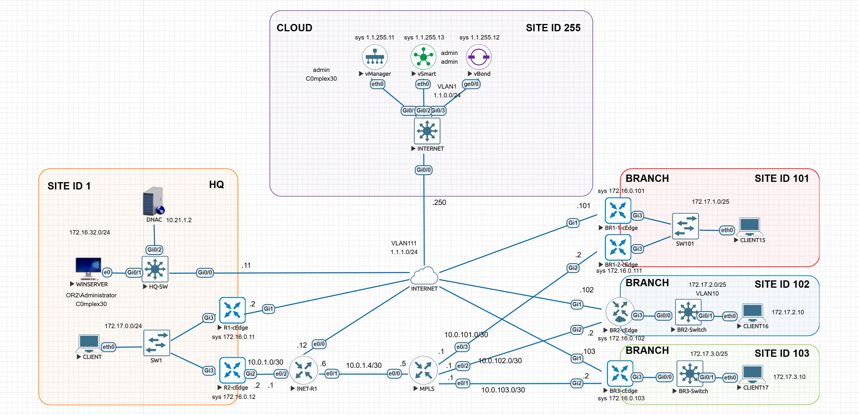
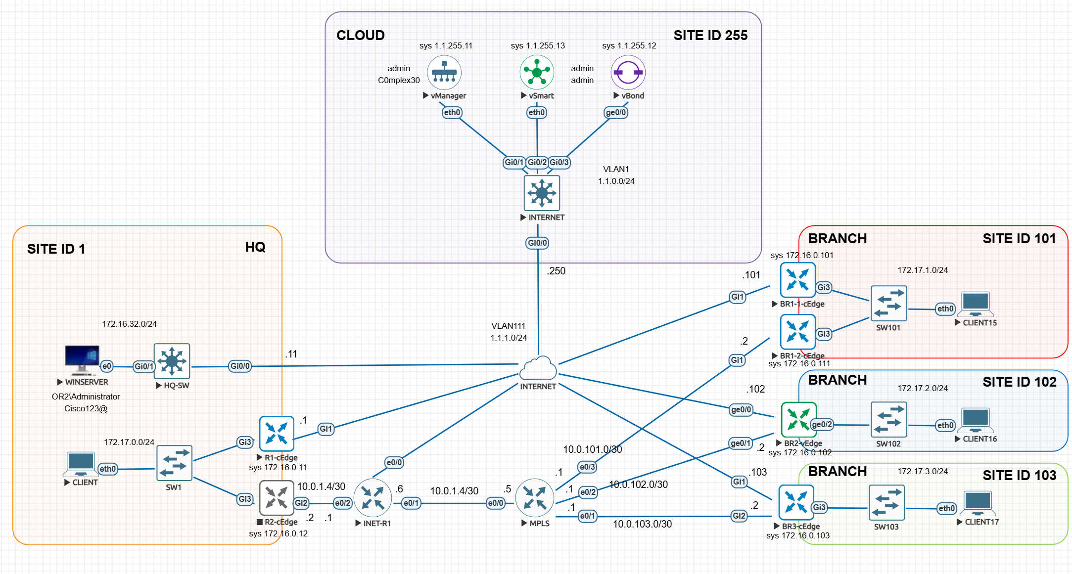
LM Topology with Wan Edge devices
Onboard cEdge devices
https://www.networkacademy.io/ccie-enterprise/sdwan/onboarding-cedge-c8000v
Prepare the software image
When a Catalyst 8000V router is powered on for the first time, it boots up in AUTONOMOUS mode, as seen in the output below.
%BOOT-5-OPMODE_LOG: R0/0: binos: System booted in AUTONOMOUS modeThe router asks if you would like to enter the initial config dialog. We answer no. Just provide enable password and save configuration to NVRAM
% Please answer 'yes' or 'no'.
Would you like to enter the initial configuration dialog? [yes/no]: no
  The enable secret is a password used to protect
  access to privileged EXEC and configuration modes.
  This password, after entered, becomes encrypted in
  the configuration.
  -------------------------------------------------
  secret should be of minimum 10 characters and maximum 32 characters with
  at least 1 upper case, 1 lower case, 1 digit and
  should not contain [cisco]
  -------------------------------------------------
  Enter enable secret: ************
  Confirm enable secret: ************
The following configuration command script was created:
enable secret 9 $9$uYATfwi9sBtruU$A4/FPncLMnru9Oo4oQjaF89yHqrCXDJBp**********
!
end
[0] Go to the IOS command prompt without saving this config.
[1] Return back to the setup without saving this config.
[2] Save this configuration to nvram and exit.
Enter your selection [2]: 2
Building configuration...
Guestshell destroyed successfully ommand to modify this configuration.
Press RETURN to get started!
Install root ca cert on edge just like controllers – so it can mutually authenticate the certificate that is presented by remote device
You should have the Root CA certificate on vBond named root_ca.cer
The easiest way to install the root certificate on a Catalyst 8000v router is by creating a local file directly on the router using TCLSH, as shown in the following example.
In the highlighted section, you should paste the root_ca.cer using the “cat root_ca.cer” command in vshell mode from vBond.
cEdge# tclsh
cEdge(tcl)# puts [open "bootflash:root_ca.cer" w+] {
+> paste root-cert-here
+> }
cEdge-1(tcl)# exit
In the end, you should have the root certificate in the cEdge router’s bootflash, as shown below.
Router# dir bootflash:
Directory of bootflash:/
31      -rw-             1315   Sep 3 2022 08:19:25 +00:00  ROOTCA.pem
131078  drwx             4096   Sep 3 2022 08:18:48 +00:00  tracelogs
131073  drwx             4096   Sep 3 2022 08:16:36 +00:00  .installer
28      -rw-              618   Sep 3 2022 08:16:25 +00:00  cvac.log
131112  drwx             4096   Sep 3 2022 08:16:24 +00:00  license_evlog
29      -rw-              157   Sep 3 2022 08:16:23 +00:00  csrlxc-cfg.log
...
...
5183766528 bytes total (3968655360 bytes free)
Now, it is time to reboot the router in CONTROLLER mode, which is required for SD-WAN. The router will notify you that a bootstrap configuration isn’t available, but we will continue anyway.
Router# controller-mode enable
Enabling controller mode will erase the nvram filesystem, remove all configuration files, and reload the box!
Ensure the BOOT variable points to a valid image
Continue? [confirm]
% Warning: Bootstrap config file needed for Day-0 boot is missing
Do you want to abort? (yes/[no]): no
 Mode change success
After the reboot, the router will boot up in CONTROLLER mode, as shown in the output below.
Oct 22 16:30:59.812: %BOOT-5-OPMODE_LOG: R0/0: binos: System booted in CONTROLLER modeThe last step is to install the root certificate using the following command.
cEdge# request platform software sdwan root-cert-chain install bootflash:root_ca.cer
Uploading root-ca-cert-chain via VPN 0
Copying ... /bootflash/ROOTCA.pem via VPN 0
Updating the root certificate chain..
Successfully installed the root certificate chain
If everything has gone smoothly, you should see our Enterprise CA Root certificate installed on the router.
cEdge# show sdwan certificate root-ca-cert | in network
        Issuer: C=US, ST=NY, L=NY, O=networkacademy-io, CN=root.certificate
        Subject: C=US, ST=NY, L=NY, O=networkacademy-io, CN=root.certificate
Now we need vManage to issue certificate to vEdge
Pick on C8000v device from the devices, click on three dots and click on “Generate Bootstrap Configuration”

#cloud-config
vinitparam:
 - uuid : C8K-A1AD735C-C4D2-CE60-6D88-01686AD4ED52
 - rcc : true
 - otp : 4a3a1eb353fc4b3b9a9c94baf06fd1f5
 - org : or2.sys.cisco
 - vbond : vbond.or.sys.cisco
ca-certs:
  remove-defaults: false
  trusted:
  - |
   -----BEGIN CERTIFICATE-----
   MIIDnzCCAoegAwIBAgIQYJ1ACvIQRIlBAEITkoGNuzANBgkqhkiG9w0BAQsFADBi
   MRUwEwYKCZImiZPyLGQBGRYFY2lzY28xEzARBgoJkiaJk/IsZAEZFgNzeXMxEzAR
   BgoJkiaJk/IsZAEZFgNvcjIxHzAdBgNVBAMTFm9yMi1XSU4tVlEwOEc2VTk4R0Yt
   Q0EwHhcNMjUwNzA2MjE1MjA1WhcNMzAwNzA2MjIwMjA1WjBiMRUwEwYKCZImiZPy
   LGQBGRYFY2lzY28xEzARBgoJkiaJk/IsZAEZFgNzeXMxEzARBgoJkiaJk/IsZAEZ
   FgNvcjIxHzAdBgNVBAMTFm9yMi1XSU4tVlEwOEc2VTk4R0YtQ0EwggEiMA0GCSqG
   SIb3DQEBAQUAA4IBDwAwggEKAoIBAQCr6cjaoJz3vzgHlQ1hzhuy5WfIL/Ao0isM
   ltIaGL+Z+9WftM1hNh10YECbxR71+lIpQKyBQTXQz8Of4nycxHjoI3dQdUvEYb8H
   fysDXh4lYjQ60x82e5c7f1KPbD+AOhC31Zw1dgReMlPIuaa9LK903+z0FRnuCHaI
   EG/Z9uCmv3JC22NgL69hscZc+NUGymMy1iBPN8G4EBkgqNVZ+zlRf/adW0JxEdc6
   Sy53bp586/fXziRTW++jgdnhvfpn+VJ+BdG88/rEgMl7PUQE95lq4dih7qx0+OXu
   ihFwQQvFxvi3dyqWWc0C1RKHPHtYQFz8rRuBJrR+uzgc0lVhrNHdAgMBAAGjUTBP
   MAsGA1UdDwQEAwIBhjAPBgNVHRMBAf8EBTADAQH/MB0GA1UdDgQWBBQ/bI8yZeKD
   fgjmmeWorjGo25t5hzAQBgkrBgEEAYI3FQEEAwIBADANBgkqhkiG9w0BAQsFAAOC
   AQEAdtt6aiABkDDg/mAlcZfFPHcqmEEvQaMPeBaUqvfZKNrFVO8GMb9kingZJ62n
   K05x5wE3tHy3jBmAl6eHZ/nUjXS11C06NwZMHpcDhty5BcDN08oEYdLF24upisNA
   aRLOBhyEtKI9VKLAWfMkpWYEd/dqgVWs67GjAFT0Osgva9QHbz24iT6/c09jbZMt
   41opmxacw8FFZcHMH9Afv1fIW9PwscrdlgjSSHR4XQLyDbyuDGsolzeh9PUVyPOd
   f+/LYkLwH9jVcHlxl4Oy7MHRPtcbG9T3+vQGLjSAXu3Ybrl2R9Tn/sz5lYs44EEB
   mqCxT00LxB3et6jAxJlEyE5vCw==
   -----END CERTIFICATE-----
We have to configure basic IP addressesing and default route and system configuration
we will also configure a DNS name for vBond, as recommended by Cisco.
config-transaction
 hostname R1-cEdge
 !
  int GigabitEthernet1
  ip address 1.1.1.1 255.255.255.0
  no shut
 !
  ip route 0.0.0.0 0.0.0.0 1.1.1.250
 !
 system
  system-ip 172.16.0.11
  site-id 1
  ip host vbond.or.sys.cisco 1.1.0.12 ! cisco recommends adding this host entry
  organization-name or2.sys.cisco
  vbond vbond.or.sys.cisco

 commit
You should be able to ping the controllers at this point, If there is no IP connectivity between the WAN edge router and the controllers, there is no point in continuing further. You should troubleshoot the problem first.
 sdwan
  int GigabitEthernet1
  tunnel-interface
   color biz-internet
   encapsulation ipsec
 !
 interface Tunnel 1 !----> this tunnel interface number should be same as physical interface
  ip unnumbered GigabitEthernet1
  tunnel source GigabitEthernet1
  tunnel mode sdwan
 !
  int GigabitEthernet2
  tunnel-interface
   color mpls restrict
   encapsulation ipsec
 !
 interface Tunnel 2
  ip unnumbered GigabitEthernet2
  tunnel source GigabitEthernet2
  tunnel mode sdwan
Router is now ready to join overlay fabric
Before the cEdge router can be able to join the SD-WAN fabric, it must have a device certificate signed and installed by vManage
this is the common rule for both controllers and edge devices, anything that needs to join fabric, requires a certificate issued from vmanage and mutual authentication
request platform software sdwan vedge_cloud activate chassis-number C8K-A1AD735C-C4D2-CE60-6D88-01686AD4ED52 token 4a3a1eb353fc4b3b9a9c94baf06fd1f5Once you’ve done, you should see in the logs that vManage logs into the cEdge using NETCONF over SSH, generates a CSR, then signs it and install a device certificate. Then the cEdge router should establish an OMP peering with vSmart and start receiving TLOCs and OMP routes.
R1-cEdge#
*Jul 21 20:27:09.257: %SYS-5-CONFIG_P: Configured programmatically by process iosp_dmiauthd_conn_100001_vty_100001 from consol6
*Jul 21 20:27:09.523: %SYS-5-CONFIG_P: Configured programmatically by process iosp_dmiauthd_conn_100001_vty_100001 from console as admin on vty42946
*Jul 21 20:27:09.503: %DMI-5-CONFIG_I: R0/0: dmiauthd: Configured from NETCONF/RESTCONF by admin, transaction-id 558pong
*Jul 21 20:27:17.068: %SYS-5-CONFIG_P: Configured programmatically by process iosp_dmiauthd_conn_100001_vty_100001 from console as admin on vty4294l
*Jul 21 20:28:03.534: %DMI-5-AUTH_PASSED: R0/0: dmiauthd: User 'vmanage-admin' authenticated successfully from 1.1.255.11:36606  for netconf over s:
*Jul 21 20:28:29.847: %Cisco-SDWAN-R1-cEdge-action_notifier-6-INFO-1400002: Notification: 7/21/2025 20:28:29 security-install-rcc severity-level:mi1
*Jul 21 20:28:30.030: %DMI-5-AUTH_PASSED: R0/0: dmiauthd: User 'vmanage-admin' authenticated successfully from 1.1.255.11:36688  for netconf over s:
*Jul 21 20:28:43.152: %Cisco-SDWAN-R1-cEdge-action_notifier-6-INFO-1400002: Notification: 7/21/2025 20:28:43 security-install-certificate severity-1
*Jul 21 20:29:25.117: %Cisco-SDWAN-Router-OMPD-3-ERRO-400002: vSmart peer 1.1.255.13 state changed to Init
*Jul 21 20:29:25.343: %DMI-5-AUTH_PASSED: R0/0: dmiauthd: User 'vmanage-admin' authenticated successfully from 1.1.255.11:36822  for netconf over ss
*Jul 21 20:29:27.205: %Cisco-SDWAN-Router-OMPD-6-INFO-400002: vSmart peer 1.1.255.13 state changed to Handshake
*Jul 21 20:29:27.218: %Cisco-SDWAN-Router-OMPD-5-NTCE-400002: vSmart peer 1.1.255.13 state changed to Up
*Jul 21 20:29:27.218: %Cisco-SDWAN-Router-OMPD-6-INFO-400005: Number of vSmarts connected : 1
*Jul 21 20:29:41.535: %DMI-5-AUTH_PASSED: R0/0: dmiauthd: User 'vmanage-admin' authenticated successfully from 1.1.255.11:36882  for netconf over s:
*Jul 21 20:30:01.736: %DMI-5-AUTH_PASSED: R0/0: dmiauthd: User 'vmanage-admin' authenticated successfully from 1.1.255.11:36928  for netconf over s:
*Jul 21 20:30:23.576: %DMI-5-AUTH_PASSED: R0/0: dmiauthd: User 'vmanage-admin' authenticated successfully from 1.1.255.11:37006  for netconf over s:
*Jul 21 20:30:33.557: %DMI-5-AUTH_PASSED: R0/0: dmiauthd: User 'vmanage-admin' authenticated successfully from 1.1.255.11:37052  for netconf over s:
*Jul 21 20:30:43.535: %DMI-5-AUTH_PASSED: R0/0: dmiauthd: User 'vmanage-admin' authenticated successfully from 1.1.255.11:37078  for netconf over s:
*Jul 21 20:30:48.611: %DMI-5-AUTH_PASSED: R0/0: dmiauthd: User 'vmanage-admin' authenticated successfully from 1.1.255.11:37108  for netconf over s:


R1-cEdge#show sdwan control connections
                                                                                       PEER                                          PEER
PEER    PEER PEER            SITE       DOMAIN PEER                                    PRIV  PEER                                    PUB
TYPE    PROT SYSTEM IP       ID         ID     PRIVATE IP                              PORT  PUBLIC IP                               PORT  ORGANIZA
----------------------------------------------------------------------------------------------------------------------------------------------------
vsmart  dtls 1.1.255.13      255        1      1.1.0.13                                12446 1.1.0.13                                12446 or2.sys.
vbond   dtls 0.0.0.0         0          0      1.1.0.12                                12346 1.1.0.12                                12346 or2.sys.
vmanage dtls 1.1.255.11      255        0      1.1.0.11                                12846 1.1.0.11                                12846 or2.sys.

R1-cEdge#
*Jul 21 20:27:09.257: %SYS-5-CONFIG_P: Configured programmatically by process iosp_dmiauthd_conn_100001_vty_100001 from consol6
*Jul 21 20:27:09.523: %SYS-5-CONFIG_P: Configured programmatically by process iosp_dmiauthd_conn_100001_vty_100001 from console as admin on vty42946
*Jul 21 20:27:09.503: %DMI-5-CONFIG_I: R0/0: dmiauthd: Configured from NETCONF/RESTCONF by admin, transaction-id 558pong
*Jul 21 20:27:17.068: %SYS-5-CONFIG_P: Configured programmatically by process iosp_dmiauthd_conn_100001_vty_100001 from console as admin on vty4294l
*Jul 21 20:28:03.534: %DMI-5-AUTH_PASSED: R0/0: dmiauthd: User 'vmanage-admin' authenticated successfully from 1.1.255.11:36606 for netconf over s:
*Jul 21 20:28:29.847: %Cisco-SDWAN-R1-cEdge-action_notifier-6-INFO-1400002: Notification: 7/21/2025 20:28:29 security-install-rcc severity-level:mi1
*Jul 21 20:28:30.030: %DMI-5-AUTH_PASSED: R0/0: dmiauthd: User 'vmanage-admin' authenticated successfully from 1.1.255.11:36688 for netconf over s:
*Jul 21 20:28:43.152: %Cisco-SDWAN-R1-cEdge-action_notifier-6-INFO-1400002: Notification: 7/21/2025 20:28:43 security-install-certificate severity-1
*Jul 21 20:29:25.117: %Cisco-SDWAN-Router-OMPD-3-ERRO-400002: vSmart peer 1.1.255.13 state changed to Init
*Jul 21 20:29:25.343: %DMI-5-AUTH_PASSED: R0/0: dmiauthd: User 'vmanage-admin' authenticated successfully from 1.1.255.11:36822 for netconf over ss
*Jul 21 20:29:27.205: %Cisco-SDWAN-Router-OMPD-6-INFO-400002: vSmart peer 1.1.255.13 state changed to Handshake
*Jul 21 20:29:27.218: %Cisco-SDWAN-Router-OMPD-5-NTCE-400002: vSmart peer 1.1.255.13 state changed to Up
*Jul 21 20:29:27.218: %Cisco-SDWAN-Router-OMPD-6-INFO-400005: Number of vSmarts connected : 1
*Jul 21 20:29:41.535: %DMI-5-AUTH_PASSED: R0/0: dmiauthd: User 'vmanage-admin' authenticated successfully from 1.1.255.11:36882 for netconf over s:
*Jul 21 20:30:01.736: %DMI-5-AUTH_PASSED: R0/0: dmiauthd: User 'vmanage-admin' authenticated successfully from 1.1.255.11:36928 for netconf over s:
*Jul 21 20:30:23.576: %DMI-5-AUTH_PASSED: R0/0: dmiauthd: User 'vmanage-admin' authenticated successfully from 1.1.255.11:37006 for netconf over s:
*Jul 21 20:30:33.557: %DMI-5-AUTH_PASSED: R0/0: dmiauthd: User 'vmanage-admin' authenticated successfully from 1.1.255.11:37052 for netconf over s:
*Jul 21 20:30:43.535: %DMI-5-AUTH_PASSED: R0/0: dmiauthd: User 'vmanage-admin' authenticated successfully from 1.1.255.11:37078 for netconf over s:
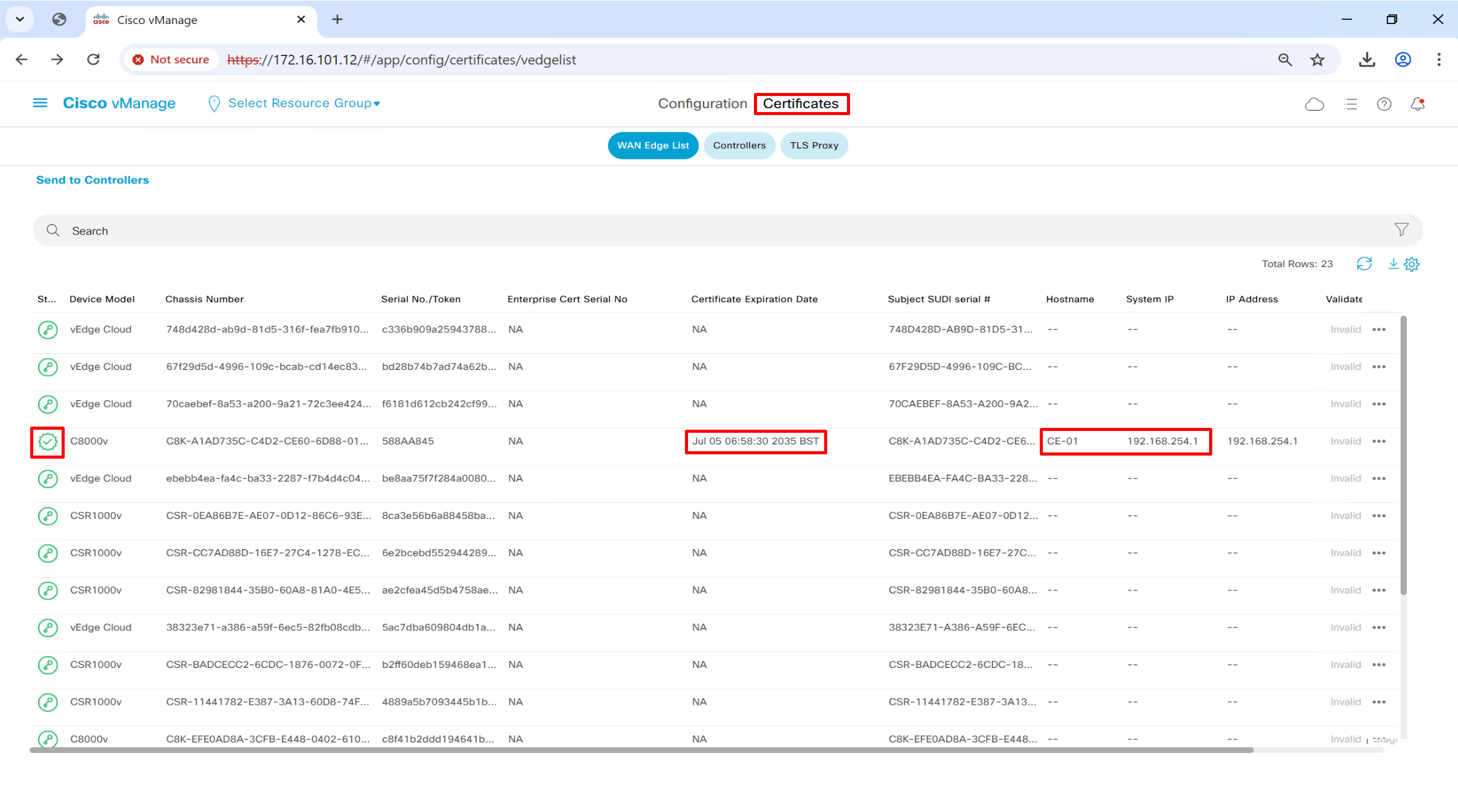
*Jul 21 20:30:48.611: %DMI-5-AUTH_PASSED: R0/0: dmiauthd: User 'vmanage-admin' authenticated successfully from 1.1.255.11:37108 for netconf over s:CE-01#show sdwan control local-properties
personality vedge
sp-organization-name or2.sys.cisco
organization-name or2.sys.cisco
root-ca-chain-status Installed
certificate-status Installed
certificate-validity Valid
certificate-not-valid-before Jul 7 05:58:30 2025 GMT
certificate-not-valid-after Jul 5 05:58:30 2035 GMT
enterprise-cert-status Not-Applicable
enterprise-cert-validity Not Applicable
enterprise-cert-not-valid-before Not Applicable
enterprise-cert-not-valid-after Not Applicable
dns-name vbond.or.sys.cisco
site-id 250
domain-id 1
protocol dtls
tls-port 0
system-ip 192.168.254.1
chassis-num/unique-id C8K-A1AD735C-C4D2-CE60-6D88-01686AD4ED52
serial-num 588AA845
subject-serial-num N/A
enterprise-serial-num No certificate installed
token Invalid
keygen-interval 1:00:00:00
retry-interval 0:00:00:16
no-activity-exp-interval 0:00:00:20
dns-cache-ttl 0:00:02:00
port-hopped TRUE
time-since-last-port-hop 0:00:30:51
embargo-check success
number-vbond-peers 1
INDEX IP PORT
-----------------------------------------------------
0 172.16.101.14 12346
number-active-wan-interfaces 1
NAT TYPE: E -- indicates End-point independent mapping
A -- indicates Address-port dependent mapping
N -- indicates Not learned
Note: Requires minimum two vbonds to learn the NAT type
PUBLIC PUBLIC PRIVATE PRIVATE PRIVATE MAX RESTRICT/ LAM
INTERFACE IPv4 PORT IPv4 IPv6 PORT VS/VM COLOR STATE CNTRL CONTROL/ LR/LB CON
STUN F
--------------------------------------------------------------------------------------------------------------------------------------------------------------------------
GigabitEthernet1 172.16.101.200 12366 172.16.101.200 :: 12366 1/1 biz-internet up 2 no/yes/no No/R1-cEdge#show sdwan control connections
PEER PEER
PEER PEER PEER SITE DOMAIN PEER PRIV PEER PUB
TYPE PROT SYSTEM IP ID ID PRIVATE IP PORT PUBLIC IP PORT ORGANIZA
----------------------------------------------------------------------------------------------------------------------------------------------------
vsmart dtls 1.1.255.13 255 1 1.1.0.13 12446 1.1.0.13 12446 or2.sys.
vbond dtls 0.0.0.0 0 0 1.1.0.12 12346 1.1.0.12 12346 or2.sys.
vmanage dtls 1.1.255.11 255 0 1.1.0.11 12846 1.1.0.11 12846 or2.sys.show run ! still works
show sdwan running-config
vbond command: show orchestrator valid-vedges
Platform Console
The last thing in running Catalyst 8000V in a virtual EVE-NG environment is to change the console method after attaching a device template.
Depending on your lab, you will most likely end up attaching a device template to the 8000V edge routers. What typically happens is that you lose access to the device via the console. This happens because, by default, the device boot up configured with the following command.
platform console serialHowever, after you attach a template, vManage changes the console method to
platform console virtualThe “virtual” option defines that the 8000V router is accessed through the virtual VGA console of the hypervisor. To change the console method back to “serial,” you must configure a CLI add-on feature template and add it to the respective device template the router is attached to.
Changing IP address on WAN side of the edge device
I changed IP address on R1-cEdge on its WAN transport interface and it re-established connections to controllers and all control connections came up, I did not have to edit or change addresses in any of the controllers, that is good. I changed IP address from 1.1.1.1 to 1.1.1.2
ISR 4000 Conversion and Standup as SDWAN router for CCIE Hardware router provisioning exam topic
Do all below videos in their accordion sections
RS0138 – SD-WAN ISR 4K Installation (Part 1)
RS0138 – SD-WAN ISR 4K Installation (Part 2)
RS0138 – SD-WAN ISR 4K Installation (Part 3)
RS0138 – SD-WAN ISR 4K Installation (Part 4)
ZTP and PnP videos
RS0140 – SD-WAN ZTP and PnP (Part 1)
RS0140 – SD-WAN ZTP and PnP (Part 2)
RS0140 – SD-WAN ZTP and PnP (Part 3)
RS0140 – SD-WAN ZTP and PnP (Part 4)
R2-cEdge standup over MPLS (apparent no reachability to controllers)
Most MPLS setup do not have the internet access unless you pay for it and then provider can provide default route from MPLS, it will have an INET-R1 router that will route traffic for 0.0.0.0/0 towards internet cloud and allow connectivity to controllers on internet to be reached via MPLS network
Traffic for MPLS prefixes will be routed towards MPLS router and for internet connectivity will be routed to internet
Add basic configuration on R2-cEdge
system
 system-ip             172.16.0.12
 site-id               1
 organization-name     or2.sys.cisco
 vbond vbond.or.sys.cisco
hostname R2-cEdge
username admin privilege 15 secret 5 $1$dYK8$TukpN4hzNpia/JRlBkEjG.
ip host vbond.or.sys.cisco 1.1.0.12
ip route 0.0.0.0 0.0.0.0 10.0.1.1
interface GigabitEthernet2
 ip address 10.0.1.2 255.255.255.252
 no shutdown
 no mop enabled
 no mop sysid
 negotiation auto
exit
interface Tunnel2
 no shutdown
 ip unnumbered GigabitEthernet2
 tunnel source GigabitEthernet2
 tunnel mode sdwan
exit
sdwan
 interface GigabitEthernet2
  tunnel-interface
   encapsulation ipsec
   color mpls
   allow-service all
  exit
exit

commit
Untick validate – this validate option will make device status as valid directly skipping invalid and staging state, if you dont want to bring device in production straight away then untick validate
#cloud-config
vinitparam:
 - vbond : vbond.or.sys.cisco
 - rcc : true
 - uuid : C8K-AB8303D2-8707-6BBA-051F-8BB318E56660
 - org : or2.sys.cisco
 - otp : 5505e0f36e3e45e181c862471c35f18d
ca-certs:
  remove-defaults: false
  trusted:
  - |
   -----BEGIN CERTIFICATE-----
   MIIDnzCCAoegAwIBAgIQYJ1ACvIQRIlBAEITkoGNuzANBgkqhkiG9w0BAQsFADBi
   MRUwEwYKCZImiZPyLGQBGRYFY2lzY28xEzARBgoJkiaJk/IsZAEZFgNzeXMxEzAR
   BgoJkiaJk/IsZAEZFgNvcjIxHzAdBgNVBAMTFm9yMi1XSU4tVlEwOEc2VTk4R0Yt
   Q0EwHhcNMjUwNzA2MjE1MjA1WhcNMzAwNzA2MjIwMjA1WjBiMRUwEwYKCZImiZPy
   LGQBGRYFY2lzY28xEzARBgoJkiaJk/IsZAEZFgNzeXMxEzARBgoJkiaJk/IsZAEZ
   FgNvcjIxHzAdBgNVBAMTFm9yMi1XSU4tVlEwOEc2VTk4R0YtQ0EwggEiMA0GCSqG
   SIb3DQEBAQUAA4IBDwAwggEKAoIBAQCr6cjaoJz3vzgHlQ1hzhuy5WfIL/Ao0isM
   ltIaGL+Z+9WftM1hNh10YECbxR71+lIpQKyBQTXQz8Of4nycxHjoI3dQdUvEYb8H
   fysDXh4lYjQ60x82e5c7f1KPbD+AOhC31Zw1dgReMlPIuaa9LK903+z0FRnuCHaI
   EG/Z9uCmv3JC22NgL69hscZc+NUGymMy1iBPN8G4EBkgqNVZ+zlRf/adW0JxEdc6
   Sy53bp586/fXziRTW++jgdnhvfpn+VJ+BdG88/rEgMl7PUQE95lq4dih7qx0+OXu
   ihFwQQvFxvi3dyqWWc0C1RKHPHtYQFz8rRuBJrR+uzgc0lVhrNHdAgMBAAGjUTBP
   MAsGA1UdDwQEAwIBhjAPBgNVHRMBAf8EBTADAQH/MB0GA1UdDgQWBBQ/bI8yZeKD
   fgjmmeWorjGo25t5hzAQBgkrBgEEAYI3FQEEAwIBADANBgkqhkiG9w0BAQsFAAOC
   AQEAdtt6aiABkDDg/mAlcZfFPHcqmEEvQaMPeBaUqvfZKNrFVO8GMb9kingZJ62n
   K05x5wE3tHy3jBmAl6eHZ/nUjXS11C06NwZMHpcDhty5BcDN08oEYdLF24upisNA
   aRLOBhyEtKI9VKLAWfMkpWYEd/dqgVWs67GjAFT0Osgva9QHbz24iT6/c09jbZMt
   41opmxacw8FFZcHMH9Afv1fIW9PwscrdlgjSSHR4XQLyDbyuDGsolzeh9PUVyPOd
   f+/LYkLwH9jVcHlxl4Oy7MHRPtcbG9T3+vQGLjSAXu3Ybrl2R9Tn/sz5lYs44EEB
   mqCxT00LxB3et6jAxJlEyE5vCw==
   -----END CERTIFICATE-----
on R2-cEdge
request platform software sdwan vedge_cloud activate chassis-number C8K-AB8303D2-8707-6BBA-051F-8BB318E56660 token 5505e0f36e3e45e181c862471c35f18d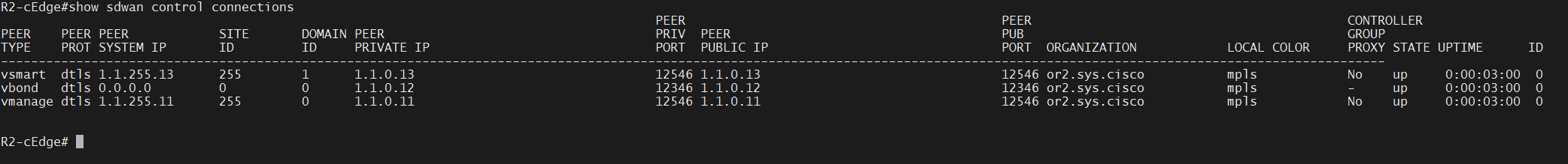

vEdge onboarding and configuration
Every time a new device is added to the WAN edge list, either via syncing from smart account or viptella serial file, we need to “send to controllers”, verify on vbond that new device is added to it
vBond# show orchestrator valid-vedges | tab

                                                                                                     HARDWARE
                                                                                                     INSTALLED  SUBJECT
                                                                                                     SERIAL     SERIAL
CHASSIS NUMBER                            SERIAL NUMBER                     VALIDITY  ORG            NUMBER     NUMBER
-----------------------------------------------------------------------------------------------------------------------------
0d7b4db2-d1c7-a10c-82aa-51133e50a3ad      56831d0a459a4d11adbebfb844115fe0  valid     or2.sys.cisco  N/A        0D7B4DB2-D1
14d3598d-2f93-d5e3-ec33-ebb972a54a96      07b454f7f0694a1a8fdc3f59915d8e97  valid     or2.sys.cisco  N/A        14D3598D-2F
38323e71-a386-a59f-6ec5-82fb08cdbc0c      6b81257104424bdc928e4c2fabfc0967  valid     or2.sys.cisco  N/A        38323E71-A3
4567a82e-54d1-fa17-e1a4-302781b96194      eca16978e13744e2ac2edda6e33c9373  valid     or2.sys.cisco  N/A        4567A82E-54
4c353382-ddc5-9ac0-d903-c07ce6fc19ac      e56d759ca369422c842d5ff98b370293  valid     or2.sys.cisco  N/A        4C353382-DD
67f29d5d-4996-109c-bcab-cd14ec837a33      6950d355072b452bb0c3c6ee348e684d  valid     or2.sys.cisco  N/A        67F29D5D-49
70caebef-8a53-a200-9a21-72c3ee424737      25936ef5caa74cff8a30118cba2e5595  valid     or2.sys.cisco  N/A        70CAEBEF-8A
748d428d-ab9d-81d5-316f-fea7fb910d6d      2b31d2d21dc141b0b0b31cf87a028ddf  valid     or2.sys.cisco  N/A        748D428D-AB
aafa211d-aee9-6dc7-ce14-829e5a025225      cc51993a8cfb46b588def2f923e09e66  valid     or2.sys.cisco  N/A        AAFA211D-AE
b0cfb377-813b-5f02-69f2-5cd76d3c261f      930d0e37929f49f2ad1fbe3d23cc7c5a  valid     or2.sys.cisco  N/A        B0CFB377-81
C8K-93E4A981-1B6A-5B49-0D59-4818588CA46A  9B10218D                          valid     or2.sys.cisco  N/A        N/A
C8K-A1AD735C-C4D2-CE60-6D88-01686AD4ED52  aac6851892a546edbc6c6b50b182ae96  valid     or2.sys.cisco  N/A        C8K-A1AD735
C8K-AB8303D2-8707-6BBA-051F-8BB318E56660  1250E1E5                          valid     or2.sys.cisco  N/A        C8K-AB8303D
C8K-EFE0AD8A-3CFB-E448-0402-6108A06678C2  88c4c032d1d1413cbf66c72166e4b070  valid     or2.sys.cisco  N/A        C8K-EFE0AD8
C8K-FF74B9C0-47EC-6B46-6F06-B63A33303C0F  3d4817593d9e42d19092a8a7804051aa  valid     or2.sys.cisco  N/A        C8K-FF74B9C
CSR-0EA86B7E-AE07-0D12-86C6-93E64EA24C46  d843a0b45dbf4b7982c930e6c5c120c6  valid     or2.sys.cisco  N/A        CSR-0EA86B7
CSR-11441782-E387-3A13-60D8-74FFCE54D959  7b5690b9065e44e1943c3e74e336625e  valid     or2.sys.cisco  N/A        CSR-1144178
CSR-82981844-35B0-60A8-81A0-4E511A9FF6FA  08086272a4174295b0ec03095b39492e  valid     or2.sys.cisco  N/A        CSR-8298184
CSR-BADCECC2-6CDC-1876-0072-0F9EAE28D879  fb7abe09c58e48daab91c73fe59a1bc1  valid     or2.sys.cisco  N/A        CSR-BADCECC
CSR-CC7AD88D-16E7-27C4-1278-EC9520C8CCD4  d58d1b454b0f45a2a16bfbeeca1b1f28  valid     or2.sys.cisco  N/A        CSR-CC7AD88
CSR-ED63ADBC-750F-E08A-5C4D-0DDEE109E9D1  46a30397d6b04e43a2b8d5cfa370126e  valid     or2.sys.cisco  N/A        CSR-ED63ADB
ebebb4ea-fa4c-ba33-2287-f7b4d4c04b74      f6a307a61d4d4fceac7e2d45a45dc528  valid     or2.sys.cisco  N/A        EBEBB4EA-FA
ff39e75a-8ee5-a214-6d15-3985fc7a9273      5718fec846484ba0b9fb0243c90fc62e  valid     or2.sys.cisco  N/A        FF39E75A-8E
For non cisco viptella based vedge onboarding this section works, this settings allows vManage to issue the cert or vedge to use the vManage as the CA and we will keep it to default setting vManage signed

configure BR2-vEdge
conf t
system
system-ip 172.16.0.102
site-id 102
organization-name or2.sys.cisco
vbond 1.1.0.12
host-name BR2-vEdge
commit
vpn 0
int ge0/0
ip address 1.1.1.102/24
no shut
tunnel-interface
allow-service all
no shut
exit
ip route 0.0.0.0/0 1.1.1.250
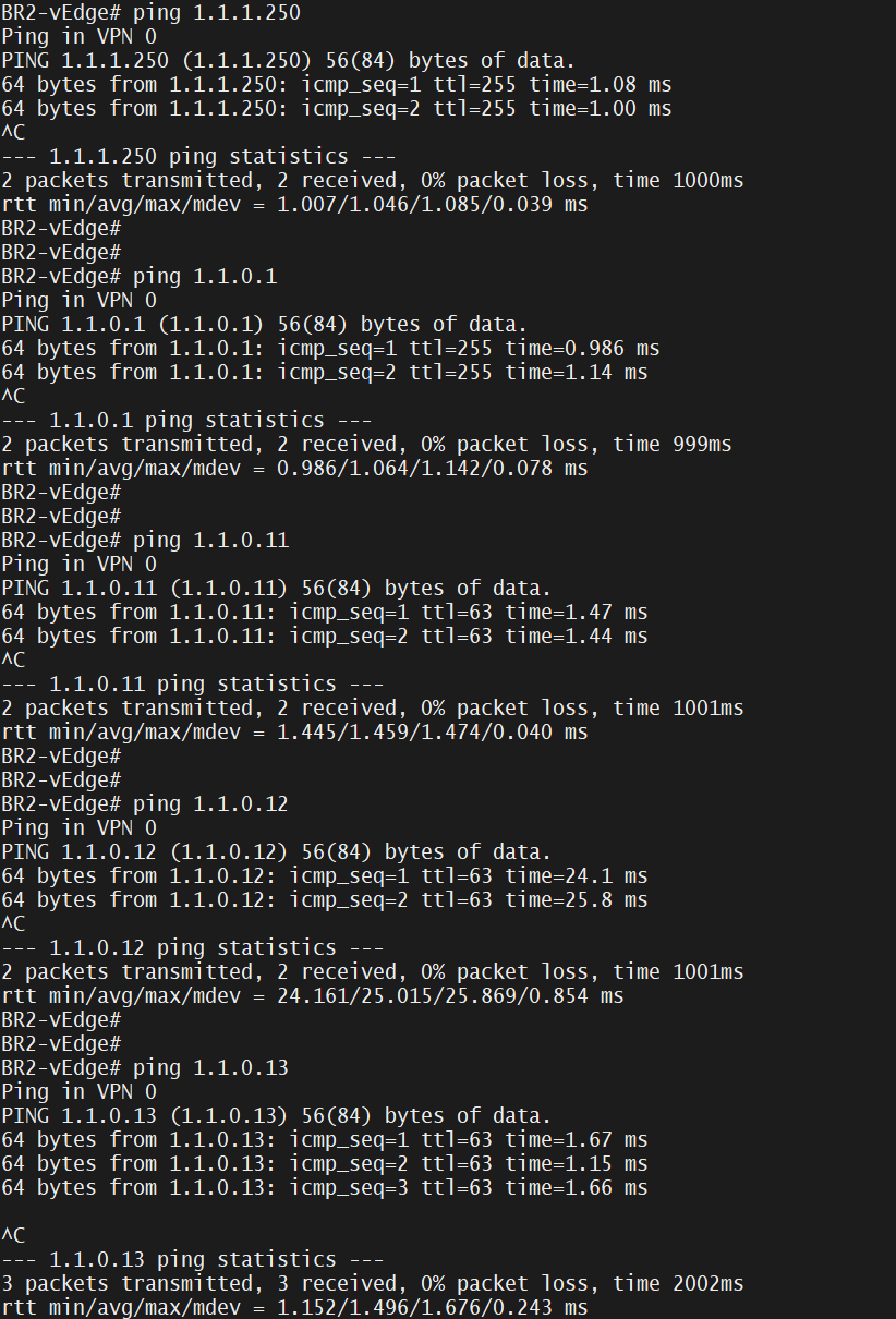
commit Make sure that we can ping hops and controllers
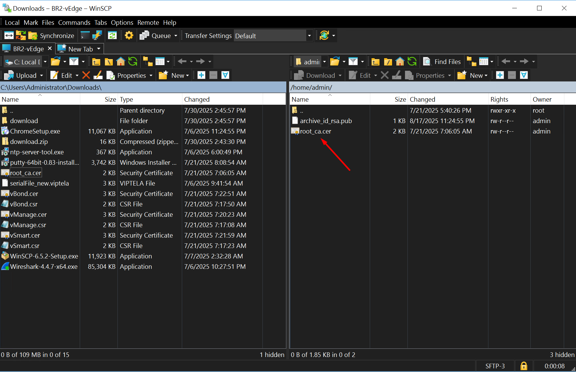
SFTP to vedge router and drag root.cer into it
because with SFTP you dont have to worry about the CLI prompt to be linux


Enter vshell and make sure that root ca cert is present as a result of the previous transfer
BR2-vEdge#
BR2-vEdge# vshell
BR2-vEdge:~$ ls -lapsh
total 32K
4.0K drwxr-x---  3 admin admin 4.0K Aug 17 22:31 ./
4.0K drwxr-xr-x 14 root  root  4.0K Jul 21 16:40 ../
4.0K -rw-------  1 admin admin    5 Aug 17 22:31 .bash_history
4.0K -rwxr-xr-x  1 admin admin  476 Aug 17 22:24 .bashrc
4.0K -rwxr-xr-x  1 admin admin  241 Aug 24  2021 .profile
4.0K drwx------  2 admin admin 4.0K Jul 21 16:40 .ssh/
4.0K -rw-r--r--  1 admin admin  564 Aug 17 22:24 archive_id_rsa.pub
4.0K -rw-r--r--  1 admin admin 1.4K Jul 21 06:06 root_ca.cer
Install root ca cert on vedge
BR2-vEdge# request root-cert-chain install /home/admin/root_ca.cer
Uploading root-ca-cert-chain via VPN 0
Copying ... /home/admin/root_ca.cer via VPN 0
Updating the root certificate chain..
Successfully installed the root certificate chain
Verify the root ca cert installation
BR2-vEdge# show certificate root-ca-cert | inc Subject
        Subject: DC=cisco, DC=sys, DC=or2, CN=or2-WIN-VQ08G6U98GF-CA
        Subject Public Key Info:
            X509v3 Subject Key Identifier:
We want vManage to install the certificate as it is not installed
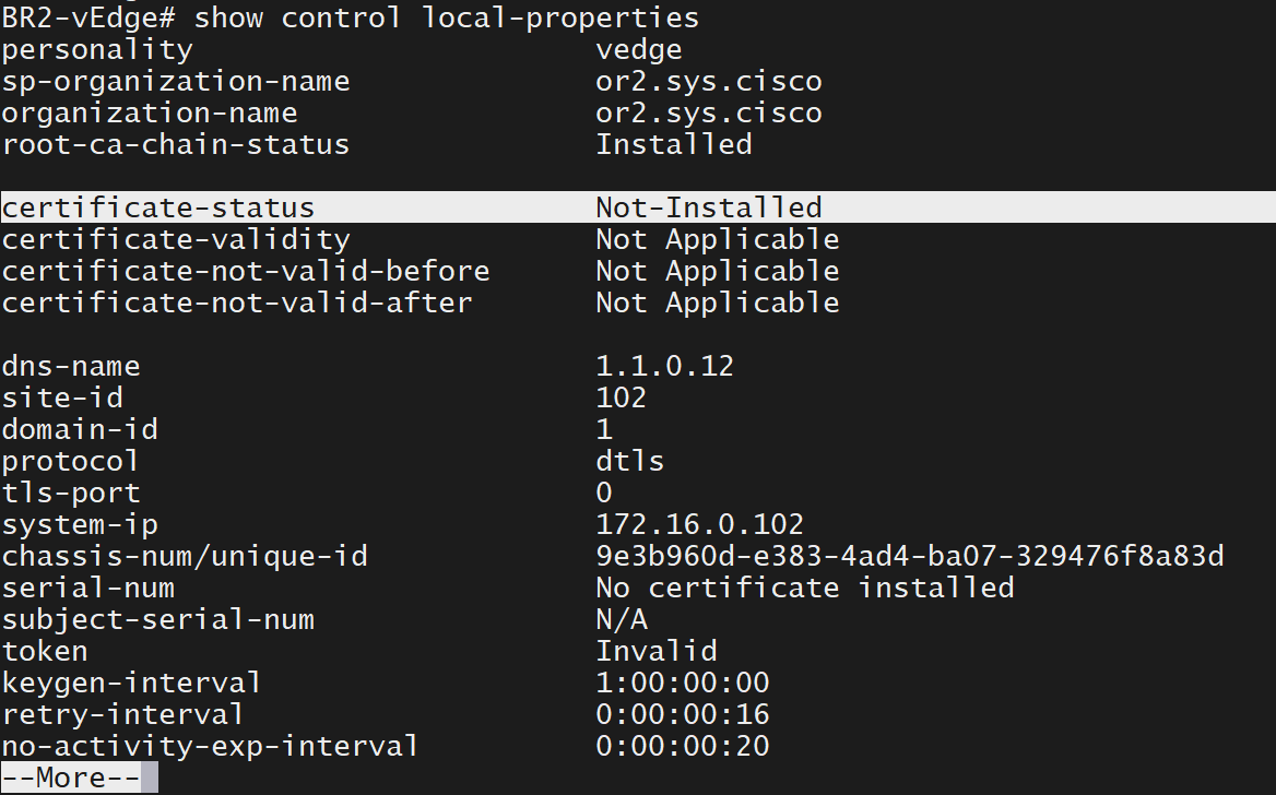
now we need to obtain the chassis number and token from vManage for one of the devices of type vEdge
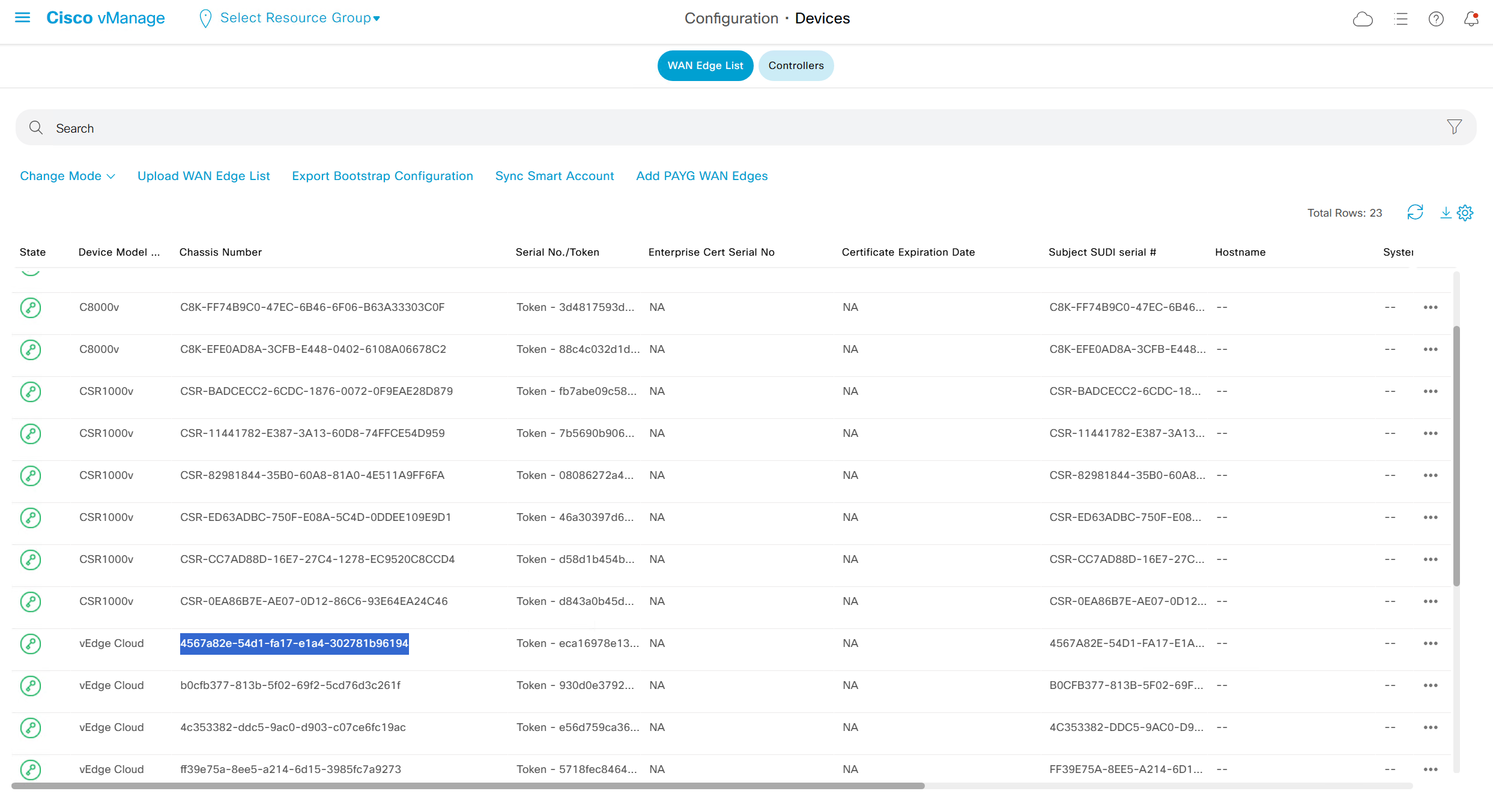
request vedge-cloud activate chassis-number 4567a82e-54d1-fa17-e1a4-302781b96194 token eca16978e13744e2ac2edda6e33c9373

show certificate installed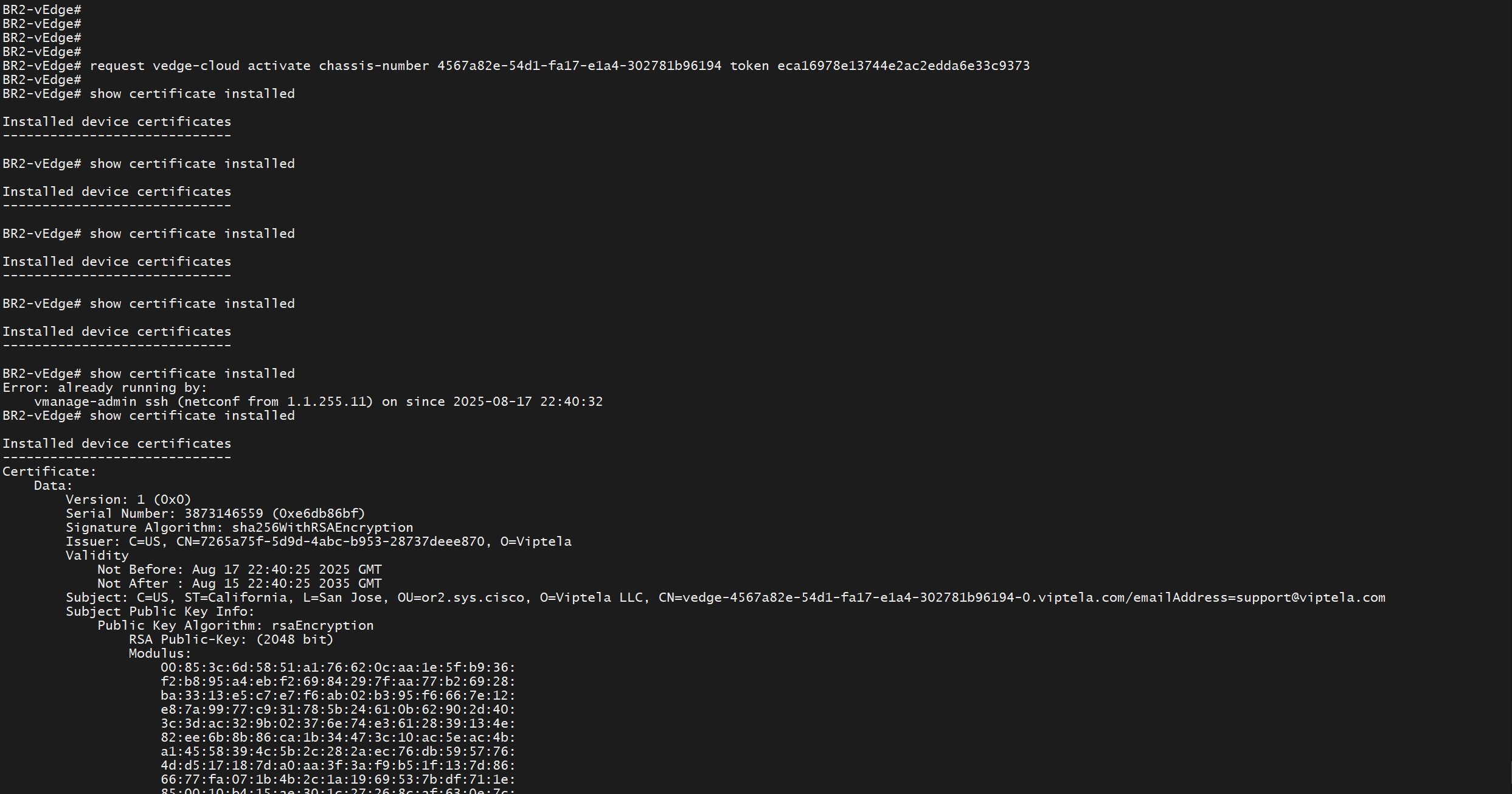
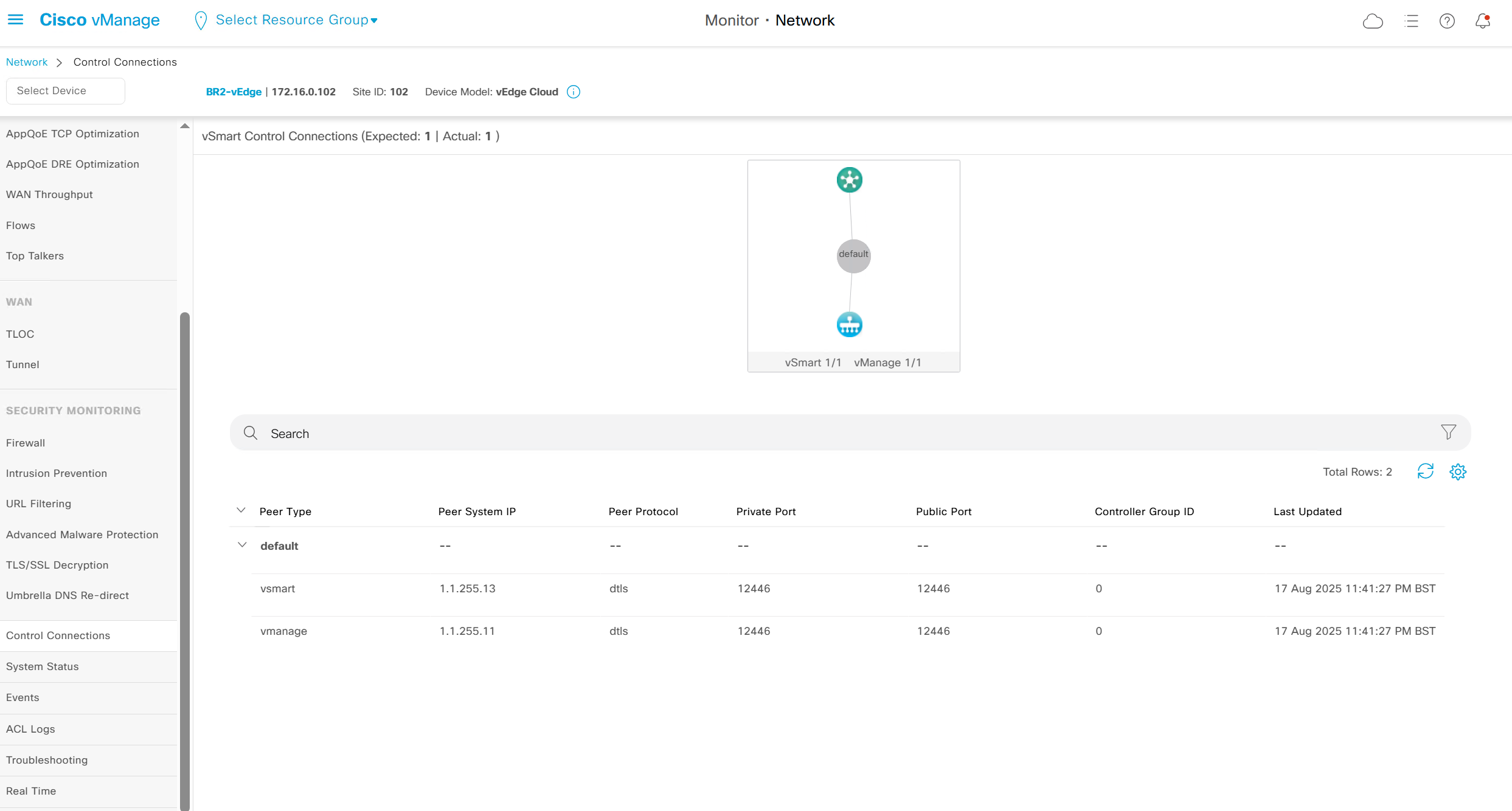
show control connections 
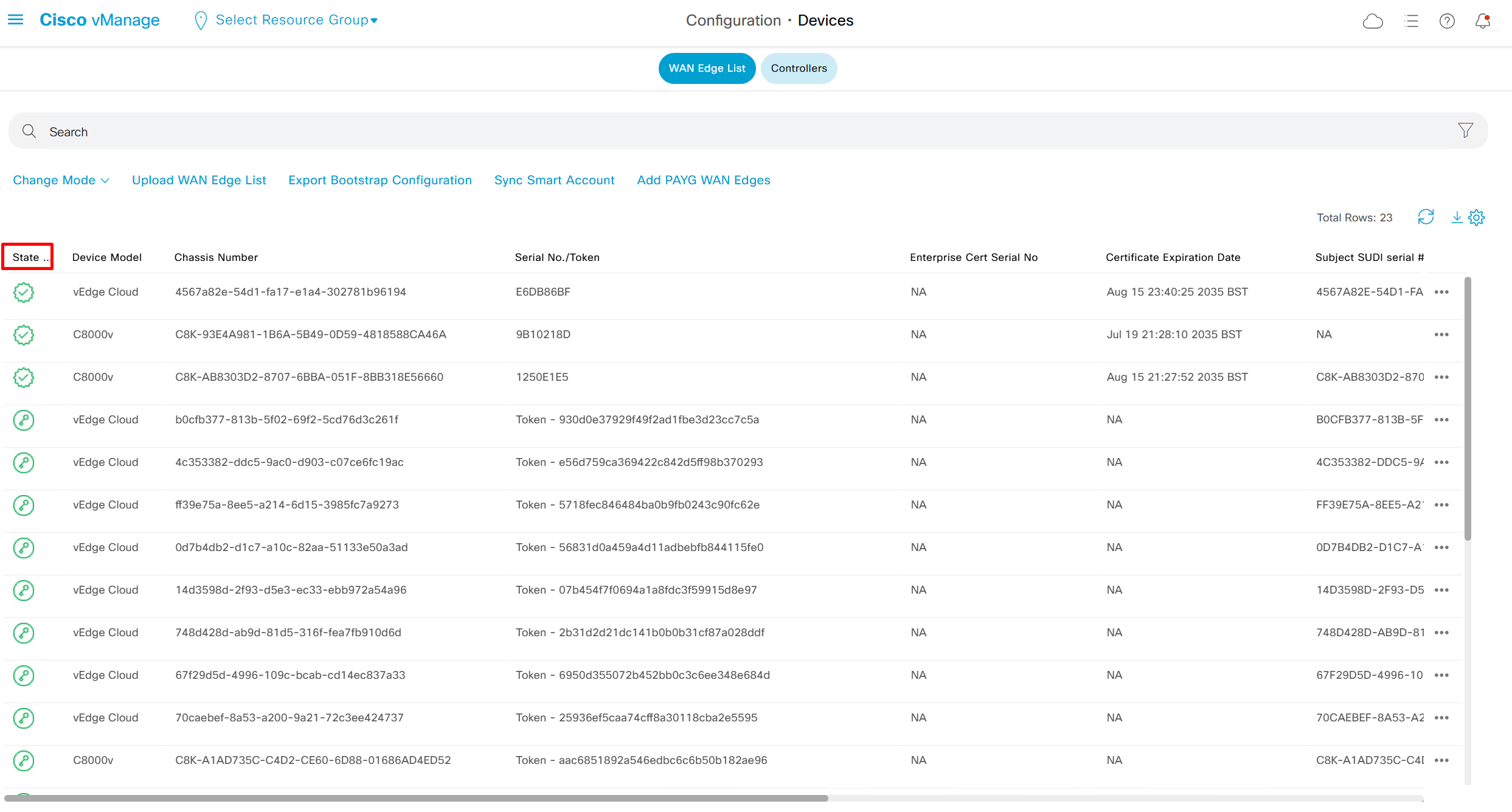
sort by state to see the installed edges and we will see latest vedge in there
color is set to default so we will set it to biz-internet


Control connections to vsmart and vmanage
BR3-cEdge
tclsh
puts [open "bootflash:root_ca.cer" w+] {
-----BEGIN CERTIFICATE-----
MIIDnzCCAoegAwIBAgIQYJ1ACvIQRIlBAEITkoGNuzANBgkqhkiG9w0BAQsFADBi
MRUwEwYKCZImiZPyLGQBGRYFY2lzY28xEzARBgoJkiaJk/IsZAEZFgNzeXMxEzAR
BgoJkiaJk/IsZAEZFgNvcjIxHzAdBgNVBAMTFm9yMi1XSU4tVlEwOEc2VTk4R0Yt
Q0EwHhcNMjUwNzA2MjE1MjA1WhcNMzAwNzA2MjIwMjA1WjBiMRUwEwYKCZImiZPy
LGQBGRYFY2lzY28xEzARBgoJkiaJk/IsZAEZFgNzeXMxEzARBgoJkiaJk/IsZAEZ
FgNvcjIxHzAdBgNVBAMTFm9yMi1XSU4tVlEwOEc2VTk4R0YtQ0EwggEiMA0GCSqG
SIb3DQEBAQUAA4IBDwAwggEKAoIBAQCr6cjaoJz3vzgHlQ1hzhuy5WfIL/Ao0isM
ltIaGL+Z+9WftM1hNh10YECbxR71+lIpQKyBQTXQz8Of4nycxHjoI3dQdUvEYb8H
fysDXh4lYjQ60x82e5c7f1KPbD+AOhC31Zw1dgReMlPIuaa9LK903+z0FRnuCHaI
EG/Z9uCmv3JC22NgL69hscZc+NUGymMy1iBPN8G4EBkgqNVZ+zlRf/adW0JxEdc6
Sy53bp586/fXziRTW++jgdnhvfpn+VJ+BdG88/rEgMl7PUQE95lq4dih7qx0+OXu
ihFwQQvFxvi3dyqWWc0C1RKHPHtYQFz8rRuBJrR+uzgc0lVhrNHdAgMBAAGjUTBP
MAsGA1UdDwQEAwIBhjAPBgNVHRMBAf8EBTADAQH/MB0GA1UdDgQWBBQ/bI8yZeKD
fgjmmeWorjGo25t5hzAQBgkrBgEEAYI3FQEEAwIBADANBgkqhkiG9w0BAQsFAAOC
AQEAdtt6aiABkDDg/mAlcZfFPHcqmEEvQaMPeBaUqvfZKNrFVO8GMb9kingZJ62n
K05x5wE3tHy3jBmAl6eHZ/nUjXS11C06NwZMHpcDhty5BcDN08oEYdLF24upisNA
aRLOBhyEtKI9VKLAWfMkpWYEd/dqgVWs67GjAFT0Osgva9QHbz24iT6/c09jbZMt
41opmxacw8FFZcHMH9Afv1fIW9PwscrdlgjSSHR4XQLyDbyuDGsolzeh9PUVyPOd
f+/LYkLwH9jVcHlxl4Oy7MHRPtcbG9T3+vQGLjSAXu3Ybrl2R9Tn/sz5lYs44EEB
mqCxT00LxB3et6jAxJlEyE5vCw==
-----END CERTIFICATE-----
}
exit

controller-mode enable

request platform software sdwan root-cert-chain install bootflash:root_ca.cer

hostname BR3-cEdge
system
system-ip 172.16.0.103
site-id 103
organization-name or2.sys.cisco
vbond vbond.or.sys.cisco
ip host vbond.or.sys.cisco 1.1.0.12
ip route 0.0.0.0 0.0.0.0 1.1.1.250
interface GigabitEthernet1
 ip address 1.1.1.103 255.255.255.0
 no shutdown
 no mop enabled
 no mop sysid
 negotiation auto
interface Tunnel1
 no shutdown
 ip unnumbered GigabitEthernet1
 tunnel source GigabitEthernet1
 tunnel mode sdwan
exit
sdwan
 interface GigabitEthernet1
  tunnel-interface
   encapsulation ipsec
   color biz-internet
   allow-service all
  exit
exit

commit

request platform software sdwan vedge_cloud activate chassis-number C8K-FF74B9C0-47EC-6B46-6F06-B63A33303C0F token 3d4817593d9e42d19092a8a7804051aa
Filter Onboarded Nodes
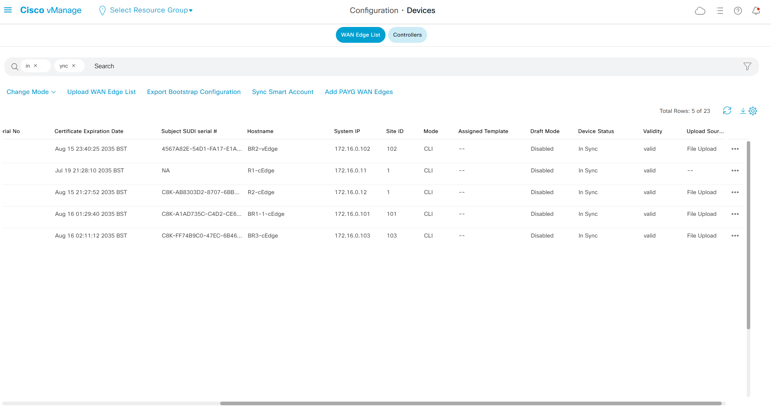
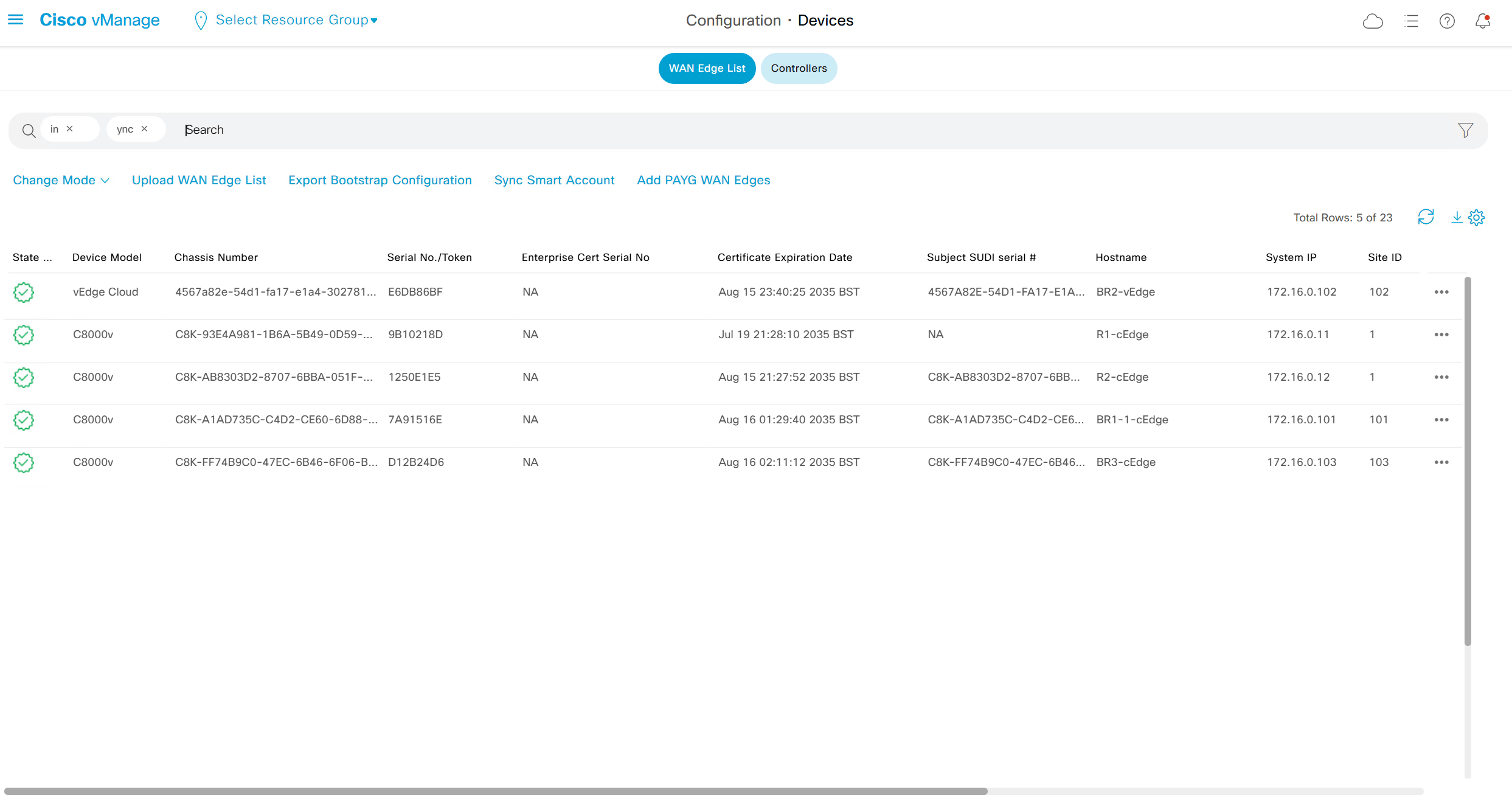
Type “In Sync” in filter on top however it is typed such as “in ync” and onboarded nodes will show
Web Interface

Control Status tells us about the down control connections
Site health shows us status of all the IPSec VPN tunnels between sites
This tells us that BR1-cEdge has 3 tunnels up out of 4, one is down due to BR2-vEdge being down
R1-cEdge and R2-cEdge has 2 tunnels since both are part of same site and they have tunnels to internet based 2 branch sites (out of 3 as site 102 is down)
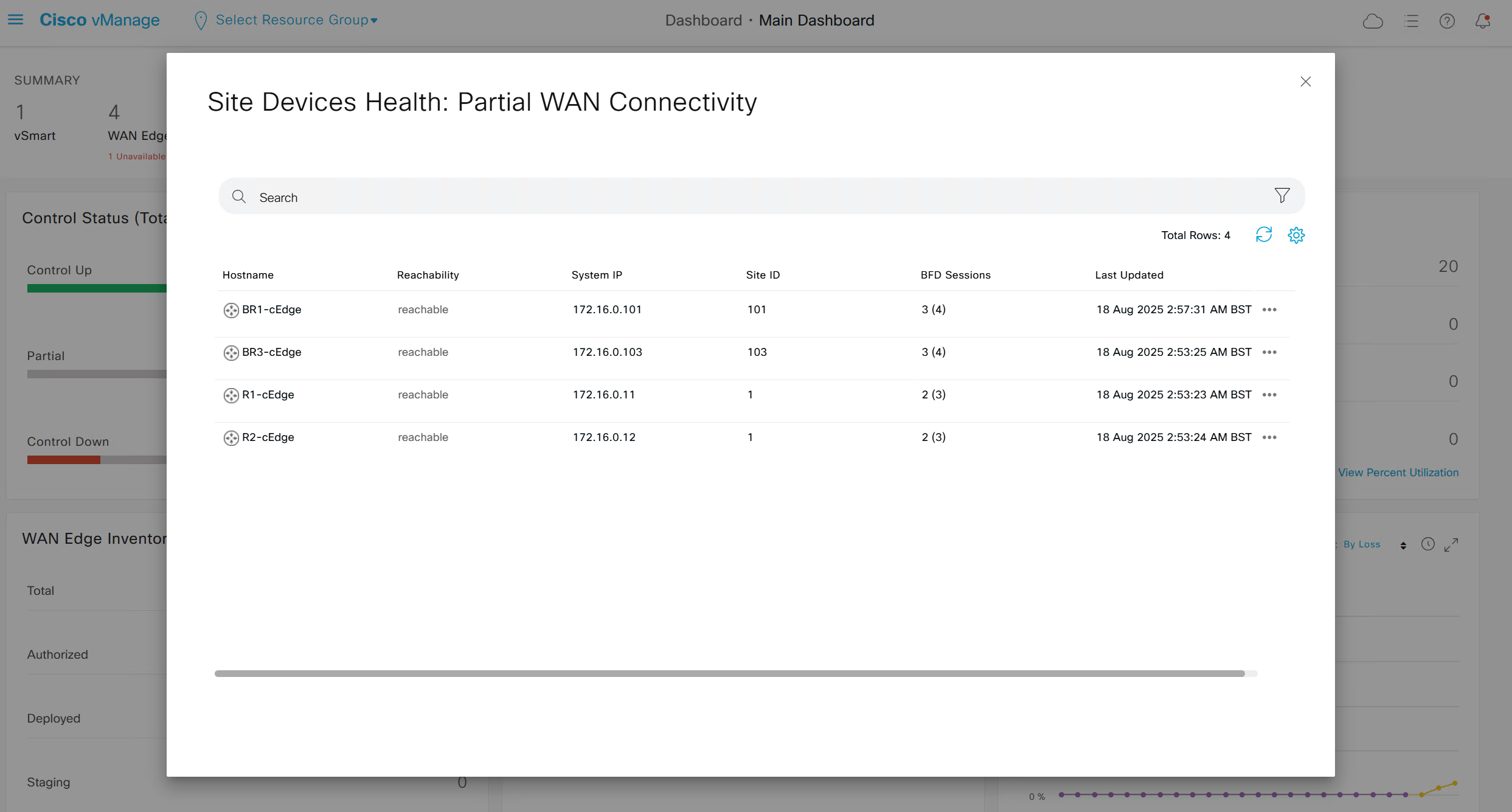
If we click on number 4 we see
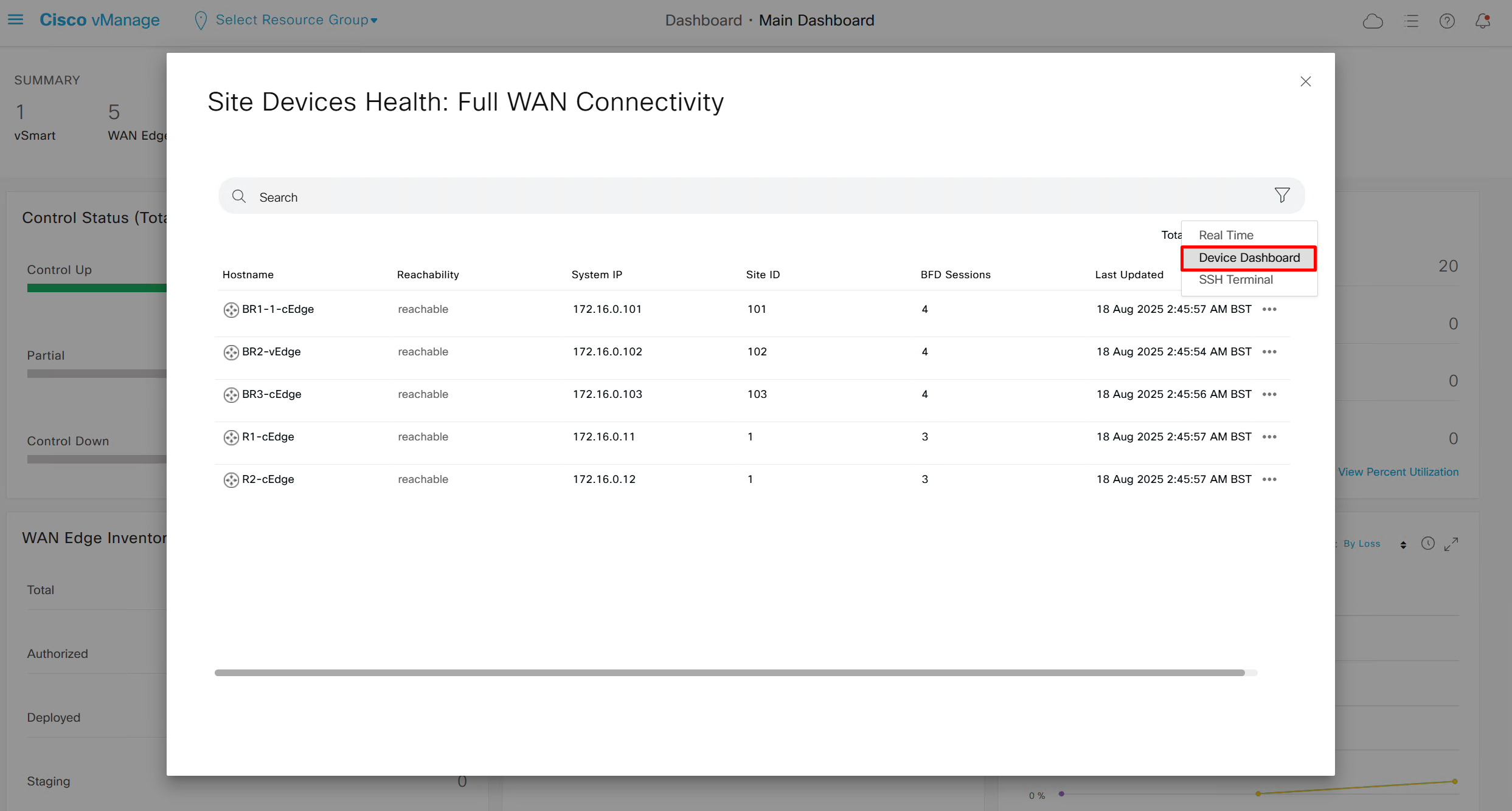
then navigate to “Tunnels” and you will see all the tunnels from one router to remote routers

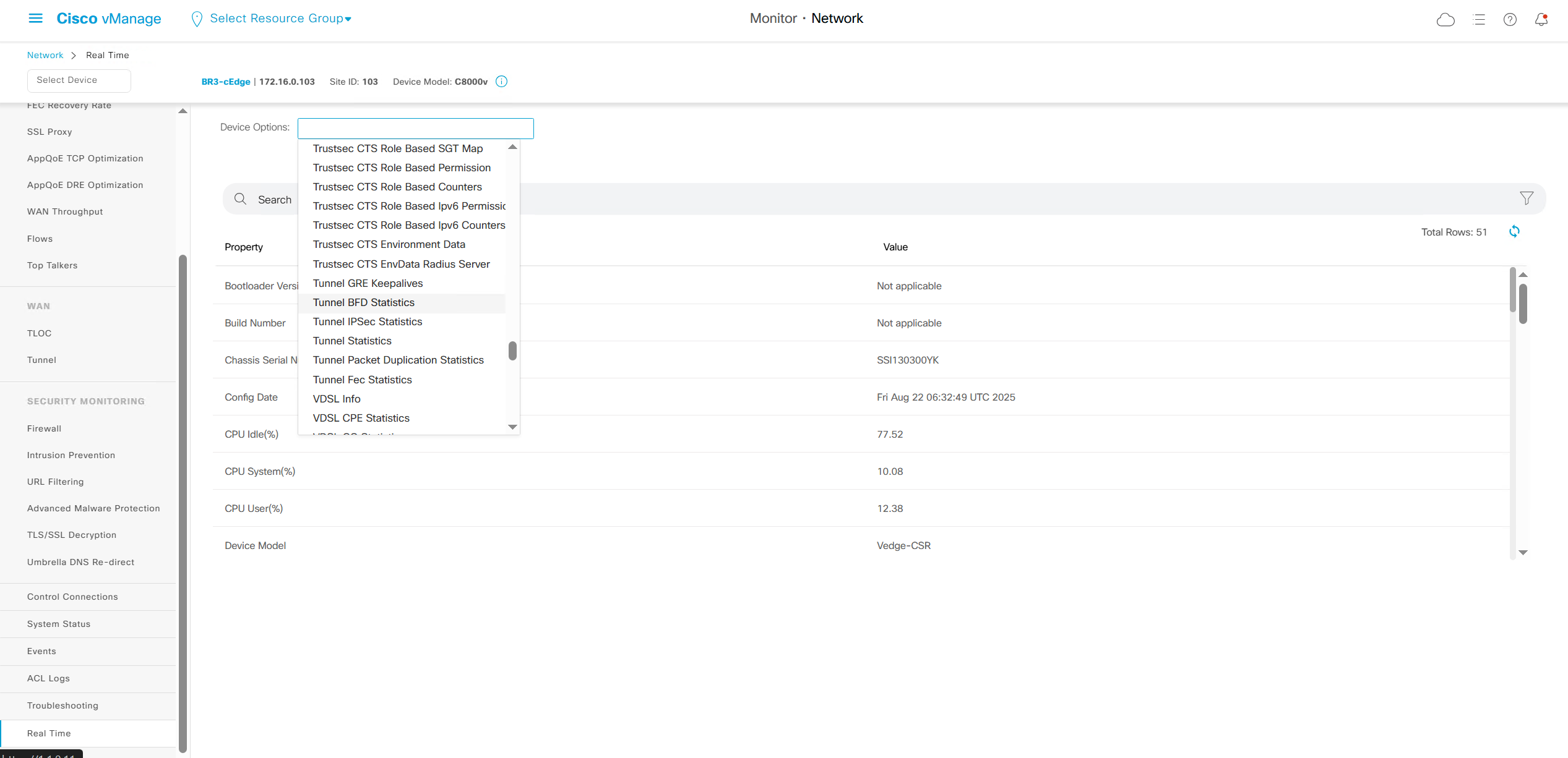
Navigate to “Real Time” > Device Options: Tunnel BFD Statistics

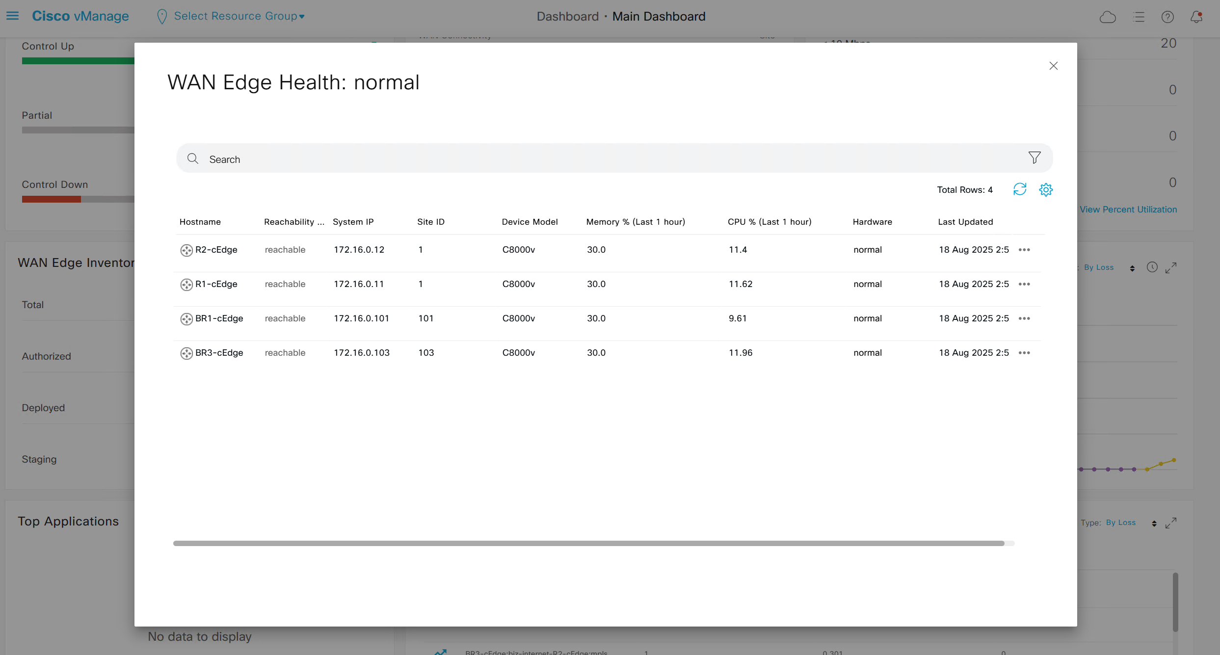
Inventory and CPU, memory and hardware health
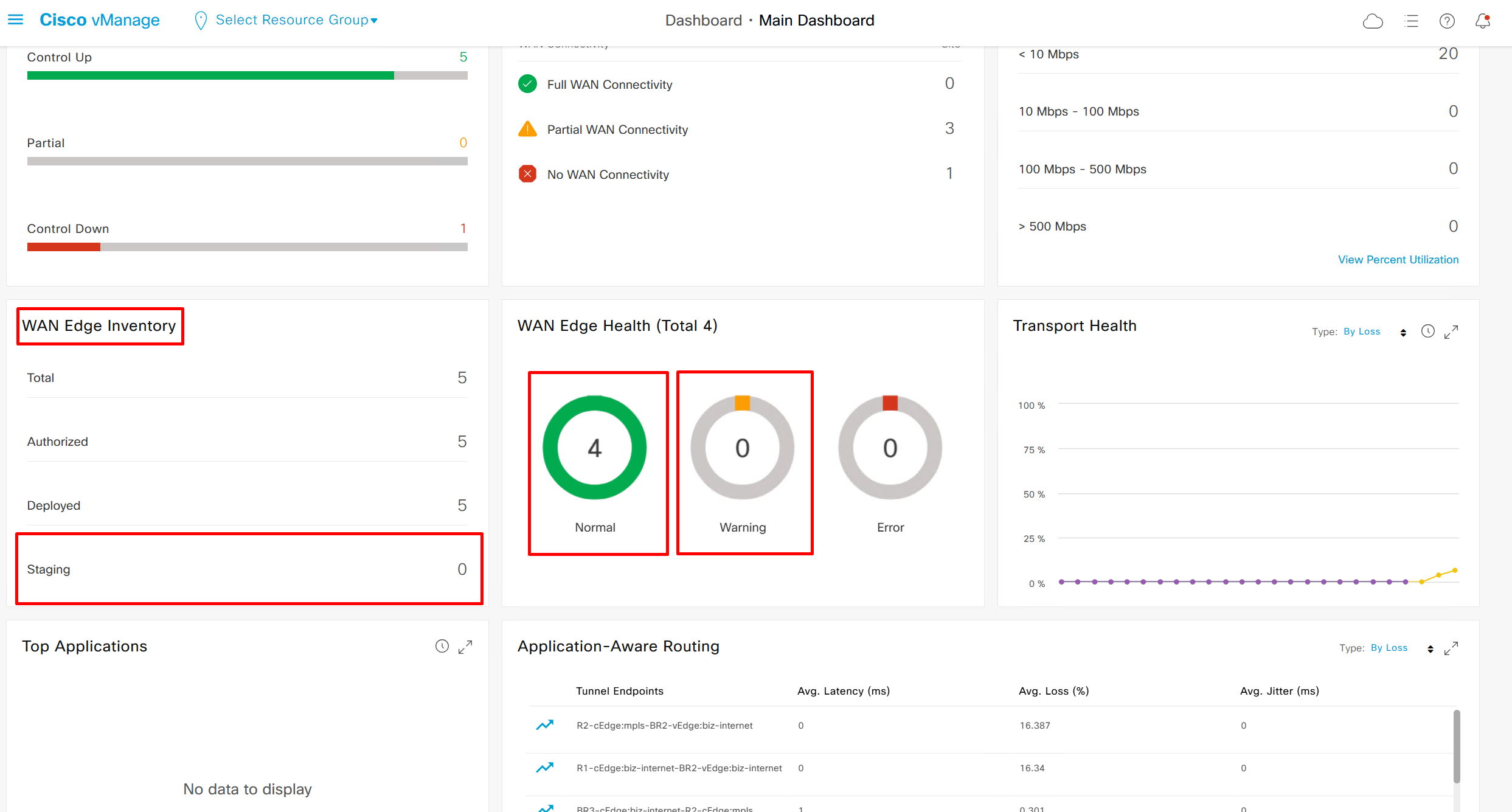
If we click on 4 we see this
Onboarding cEdge “CSR1K” because vEdge is crashing, may be because of version 20.6.1, download new version
Router(tcl)#puts [open "bootflash:root_ca.cer" w+] {
+>-----BEGIN CERTIFICATE-----
+>MIIDnzCCAoegAwIBAgIQYJ1ACvIQRIlBAEITkoGNuzANBgkqhkiG9w0BAQsFADBi
+>MRUwEwYKCZImiZPyLGQBGRYFY2lzY28xEzARBgoJkiaJk/IsZAEZFgNzeXMxEzAR
+>BgoJkiaJk/IsZAEZFgNvcjIxHzAdBgNVBAMTFm9yMi1XSU4tVlEwOEc2VTk4R0Yt
+>Q0EwHhcNMjUwNzA2MjE1MjA1WhcNMzAwNzA2MjIwMjA1WjBiMRUwEwYKCZImiZPy
+>LGQBGRYFY2lzY28xEzARBgoJkiaJk/IsZAEZFgNzeXMxEzARBgoJkiaJk/IsZAEZ
+>FgNvcjIxHzAdBgNVBAMTFm9yMi1XSU4tVlEwOEc2VTk4R0YtQ0EwggEiMA0GCSqG
+>SIb3DQEBAQUAA4IBDwAwggEKAoIBAQCr6cjaoJz3vzgHlQ1hzhuy5WfIL/Ao0isM
+>ltIaGL+Z+9WftM1hNh10YECbxR71+lIpQKyBQTXQz8Of4nycxHjoI3dQdUvEYb8H
+>fysDXh4lYjQ60x82e5c7f1KPbD+AOhC31Zw1dgReMlPIuaa9LK903+z0FRnuCHaI
+>EG/Z9uCmv3JC22NgL69hscZc+NUGymMy1iBPN8G4EBkgqNVZ+zlRf/adW0JxEdc6
+>Sy53bp586/fXziRTW++jgdnhvfpn+VJ+BdG88/rEgMl7PUQE95lq4dih7qx0+OXu
+>ihFwQQvFxvi3dyqWWc0C1RKHPHtYQFz8rRuBJrR+uzgc0lVhrNHdAgMBAAGjUTBP
+>MAsGA1UdDwQEAwIBhjAPBgNVHRMBAf8EBTADAQH/MB0GA1UdDgQWBBQ/bI8yZeKD
+>fgjmmeWorjGo25t5hzAQBgkrBgEEAYI3FQEEAwIBADANBgkqhkiG9w0BAQsFAAOC
+>AQEAdtt6aiABkDDg/mAlcZfFPHcqmEEvQaMPeBaUqvfZKNrFVO8GMb9kingZJ62n
+>K05x5wE3tHy3jBmAl6eHZ/nUjXS11C06NwZMHpcDhty5BcDN08oEYdLF24upisNA
+>aRLOBhyEtKI9VKLAWfMkpWYEd/dqgVWs67GjAFT0Osgva9QHbz24iT6/c09jbZMt
+>41opmxacw8FFZcHMH9Afv1fIW9PwscrdlgjSSHR4XQLyDbyuDGsolzeh9PUVyPOd
+>f+/LYkLwH9jVcHlxl4Oy7MHRPtcbG9T3+vQGLjSAXu3Ybrl2R9Tn/sz5lYs44EEB
+>mqCxT00LxB3et6jAxJlEyE5vCw==
+>-----END CERTIFICATE-----
+>}
Router(tcl)#exit
First stop the PnP service so that the SD-WAN software packages can install
pnpa service discovery stopOnce the PnP service has been stopped, we tell the router to install all underlying SD-WAN packages if necessary. Depending on the CSR1k software image, this may not be necessary.
request platform software sdwan software resetThe last step is to verify the software image using the following command
request platform software sdwan software upgrade-confirmsee that the sdwan software is ACTIVE and CONFIRMED as highlighted below.
show sdwan soft
VERSION         ACTIVE  DEFAULT  PREVIOUS  CONFIRMED  TIMESTAMP
---------------------------------------------------------------------------------
16.12.4.0.4480  true    true     false     user       2022-04-03T08:20:13-00:00

Total Space:388M Used Space:87M Available Space:297M
in newer CSR1000v versions we dont have to do above and we can directly do
controller-mode enableOnce the router loads up with the SD-WAN software, we can go ahead and configure the minimal configuration required to join the SD-WAN overlay fabric. Notice that when the cEdge router runs in Controller mode (basically SD-WAN mode), we enter the configuration mode using the “config-transaction” command instead of the well-known “configure terminal” or simply “conf t”.
Notice something very important – the Tunnel keyword in the “interface Tunnel” command should always be with a capital T. It is not like in a regular Cisco IOS where you can create a new tunnel using the “interface tunnel 1” command.
config-transaction
 hostname cEdge
 !
  int GigabitEthernet1
  ip address 39.3.1.1 255.255.255.0
  no shut
 !
 int GigabitEthernet2
  ip address 10.10.1.1 255.255.255.0
  no shut
 !
  ip route 0.0.0.0 0.0.0.0 39.3.1.254
  ip route 0.0.0.0 0.0.0.0 10.10.1.254
  ip host vbond.networkacademy.io 10.1.1.10
 !
 system
  system-ip 1.1.1.1
  site-id 1
  organization-name "networkacademy-io"
  vbond vbond.networkacademy.io
 commit
sdwan
int GigabitEthernet1
tunnel-interface
color biz-internet
encapsulation ipsec
!
int GigabitEthernet2
tunnel-interface
color mpls restrict
encapsulation ipsec
!
interface Tunnel 1
ip unnumbered GigabitEthernet1
tunnel source GigabitEthernet1
tunnel mode sdwan
!
interface Tunnel 2
ip unnumbered GigabitEthernet2
tunnel source GigabitEthernet2
tunnel mode sdwan
commitInstall root ca cert through tclsh and same steps can be followed as C8000v
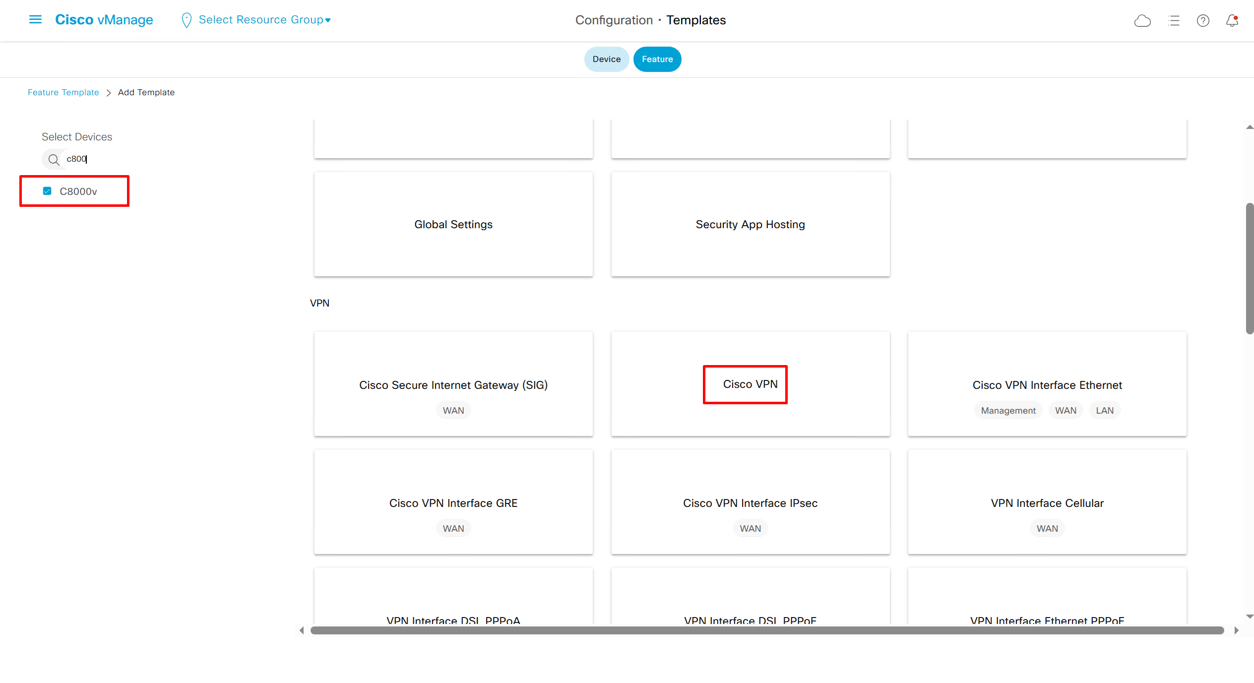
Template Configuration on Edges and Controllers
Highlighted config is the one we need to configure the template
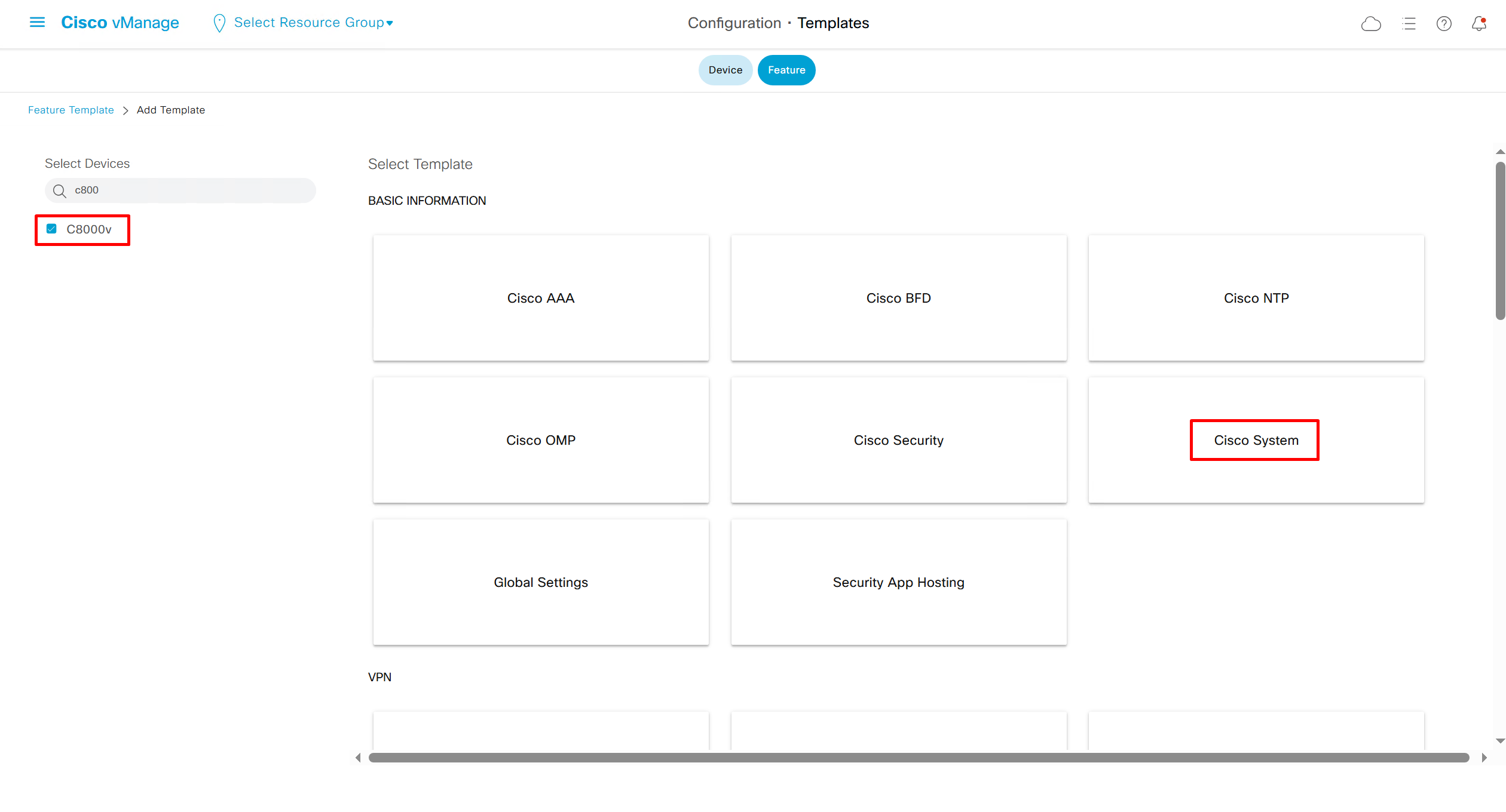
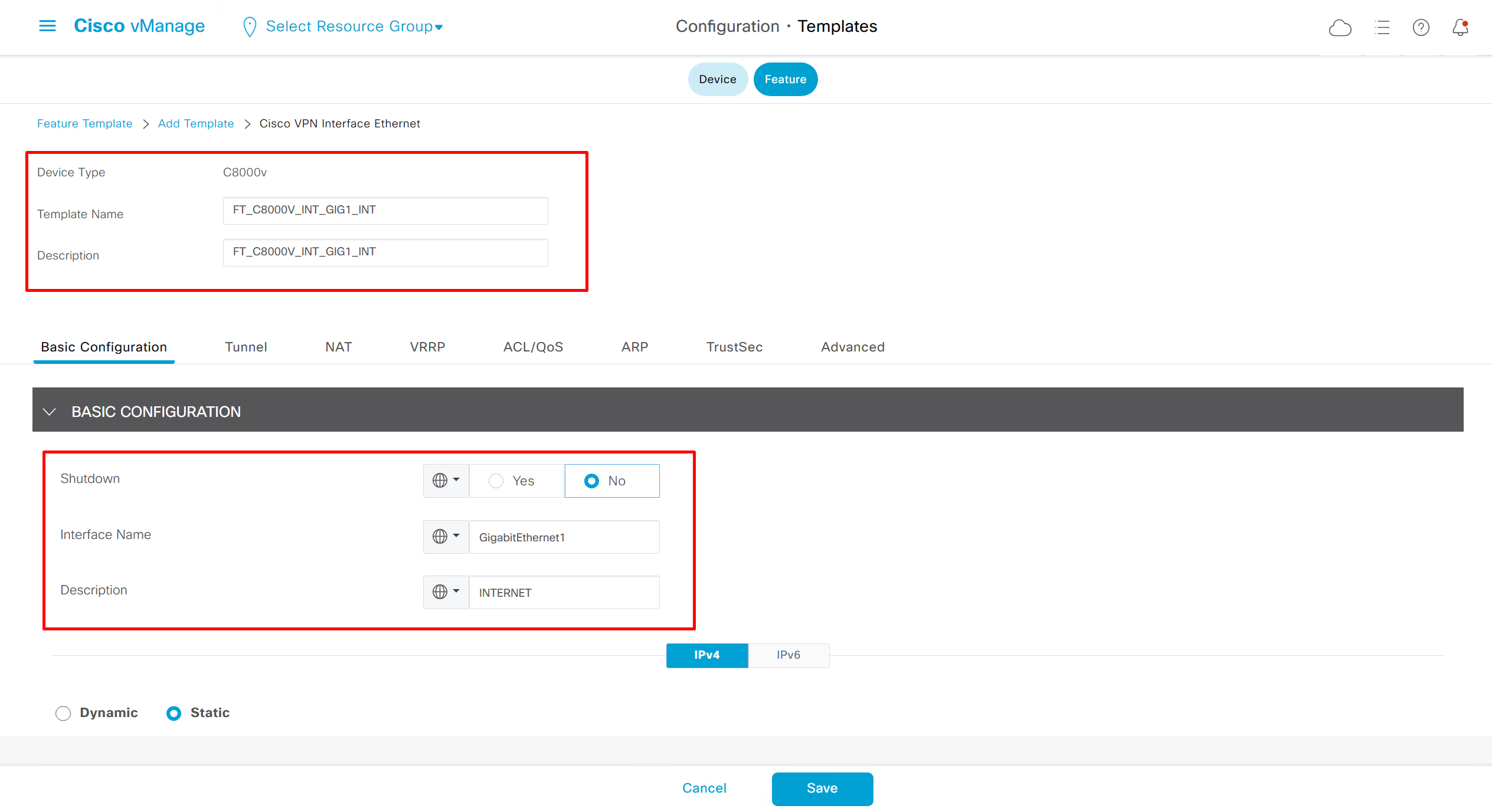
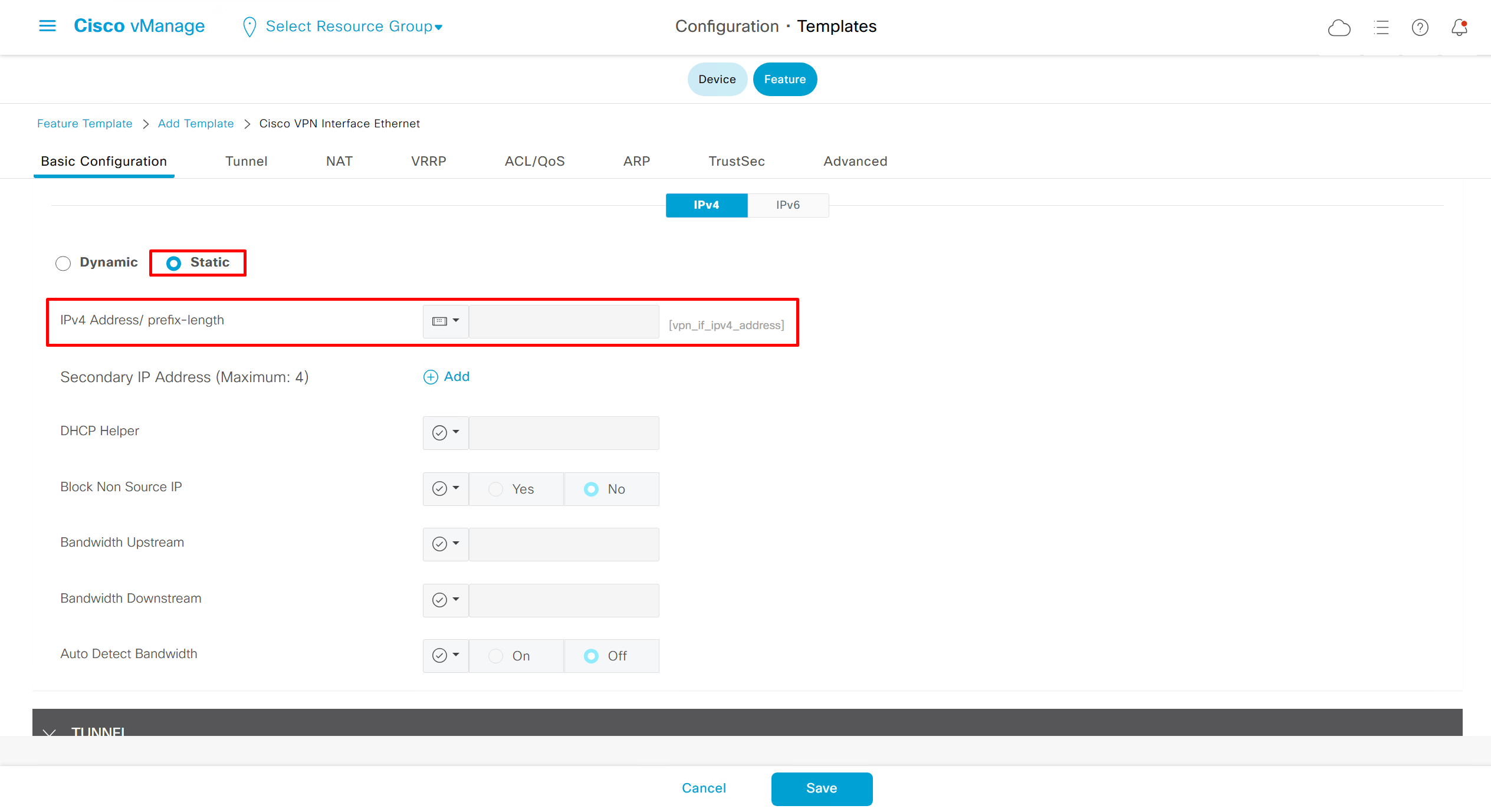
Each “section” will need a “feature template”
Remember that we need to configure system, vpn 0 (routing table for transport) and interface feature templates
BR1-1-cEdge#show sdwan running-config
system
 system-ip             172.16.0.101
 site-id               101
 admin-tech-on-failure
 organization-name     or2.sys.cisco
 vbond vbond.or.sys.cisco
!
memory free low-watermark processor 68484
no service tcp-small-servers
no service udp-small-servers
platform console serial
platform qfp utilization monitor load 80
platform punt-keepalive disable-kernel-core
hostname BR1-1-cEdge
username admin privilege 15 secret 5 $1$3/FD$EA4V.gZeQ6hMyUG2ct/ax.
no ip finger
no ip rcmd rcp-enable
no ip rcmd rsh-enable
no ip dhcp use class
ip host vbond.or.sys.cisco 1.1.0.12
ip route 0.0.0.0 0.0.0.0 1.1.1.250
ip ssh version 2
no ip http server
ip http secure-server
ip nat settings central-policy
ip nat settings gatekeeper-size 1024
interface GigabitEthernet1
 no shutdown
 ip address 1.1.1.101 255.255.255.0
 no mop enabled
 no mop sysid
 negotiation auto
exit
interface GigabitEthernet2
 no shutdown
 no mop enabled
 no mop sysid
 negotiation auto
exit
interface GigabitEthernet3
 no shutdown
 no mop enabled
 no mop sysid
 negotiation auto
exit
interface GigabitEthernet4
 no shutdown
 no mop enabled
 no mop sysid
 negotiation auto
exit
interface Tunnel1
 no shutdown
 ip unnumbered GigabitEthernet1
 tunnel source GigabitEthernet1
 tunnel mode sdwan
exit
aaa authentication enable default enable
aaa authentication login default local
aaa authorization console
aaa authorization exec default local
login on-success log
line aux 0
!
line con 0
 stopbits 1
!
line vty 0 4
!
line vty 5 80
!
sdwan
 interface GigabitEthernet1
  tunnel-interface
   encapsulation ipsec
   color biz-internet
   allow-service all
   no allow-service bgp
   allow-service dhcp
   allow-service dns
   allow-service icmp
   no allow-service sshd
   no allow-service netconf
   no allow-service ntp
   no allow-service ospf
   no allow-service stun
   allow-service https
   no allow-service snmp
   no allow-service bfd
  exit
 exit
 appqoe
  no tcpopt enable
  no dreopt enable
 !
 omp
  no shutdown
  graceful-restart
  no as-dot-notation
  address-family ipv4
   advertise connected
   advertise static
  !
  address-family ipv6
   advertise connected
   advertise static
  !
 !
!
licensing config enable false
licensing config privacy hostname false
licensing config privacy version false
licensing config utility utility-enable false
security
 ipsec
  integrity-type ip-udp-esp esp
 !
!
sslproxy
 no enable
 rsa-key-modulus      2048
 certificate-lifetime 730
 eckey-type           P256
 ca-tp-label          PROXY-SIGNING-CA
 settings expired-certificate  drop
 settings untrusted-certificate drop
 settings unknown-status       drop
 settings certificate-revocation-check none
 settings unsupported-protocol-versions drop
 settings unsupported-cipher-suites drop
 settings failure-mode         close
 settings minimum-tls-ver      TLSv1
 dual-side optimization enable
!

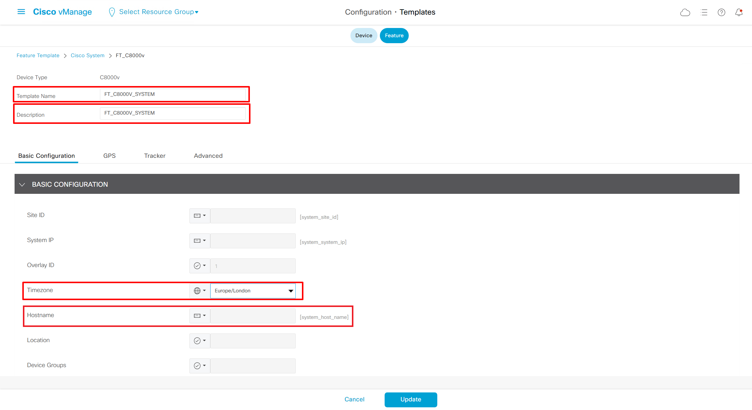
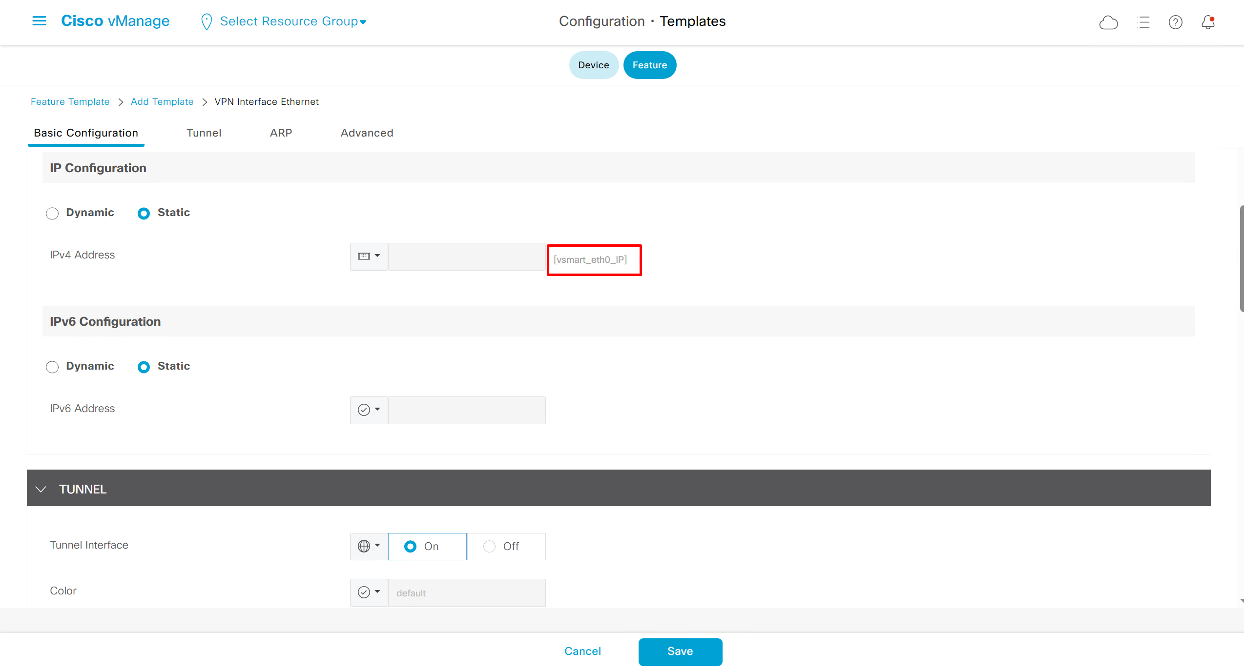
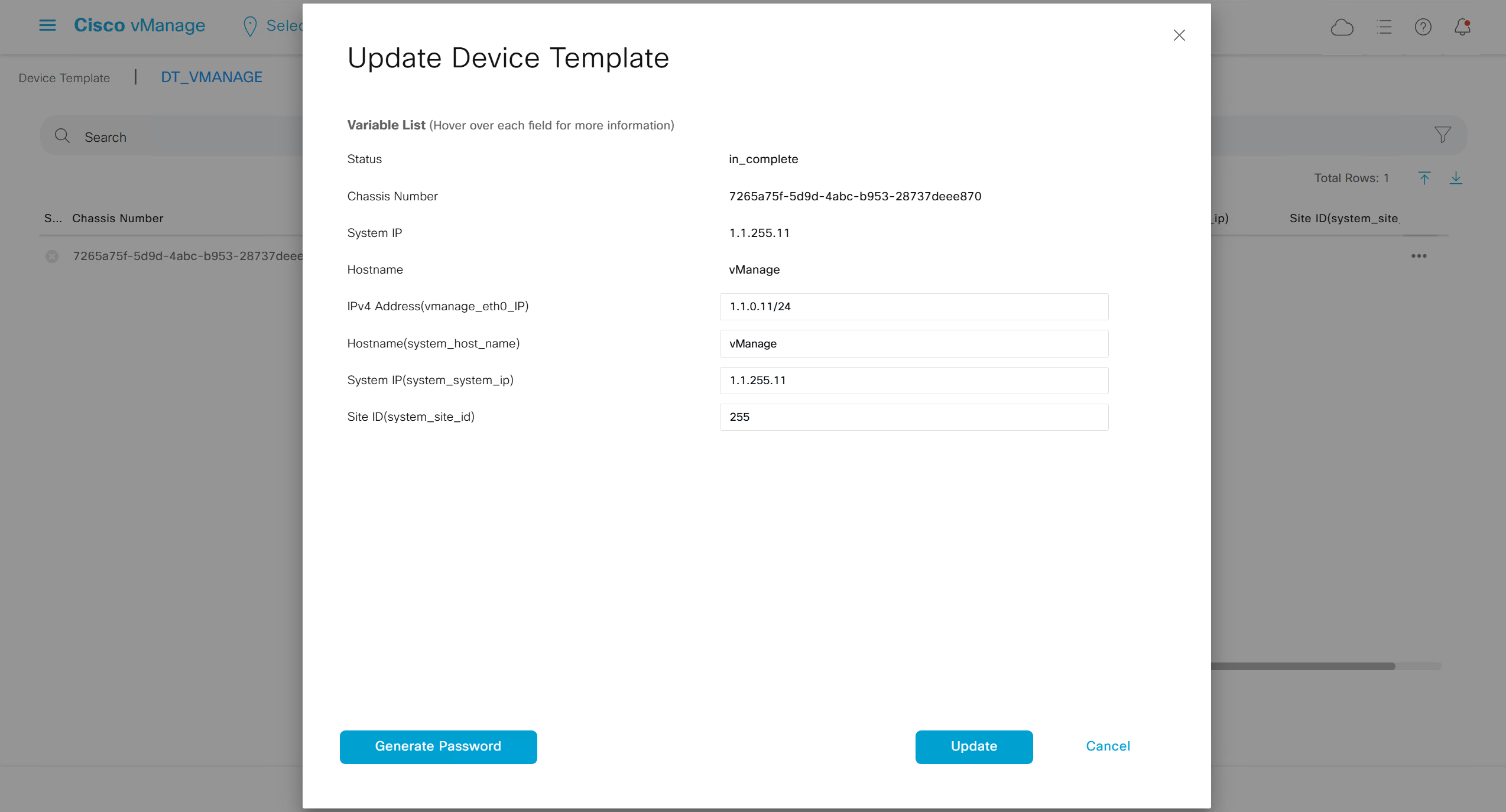
Device Specific variables mean that value will be taken from us at the time when we attach the template to device
Global means that all the devices that are attached to this template will inherit same static value
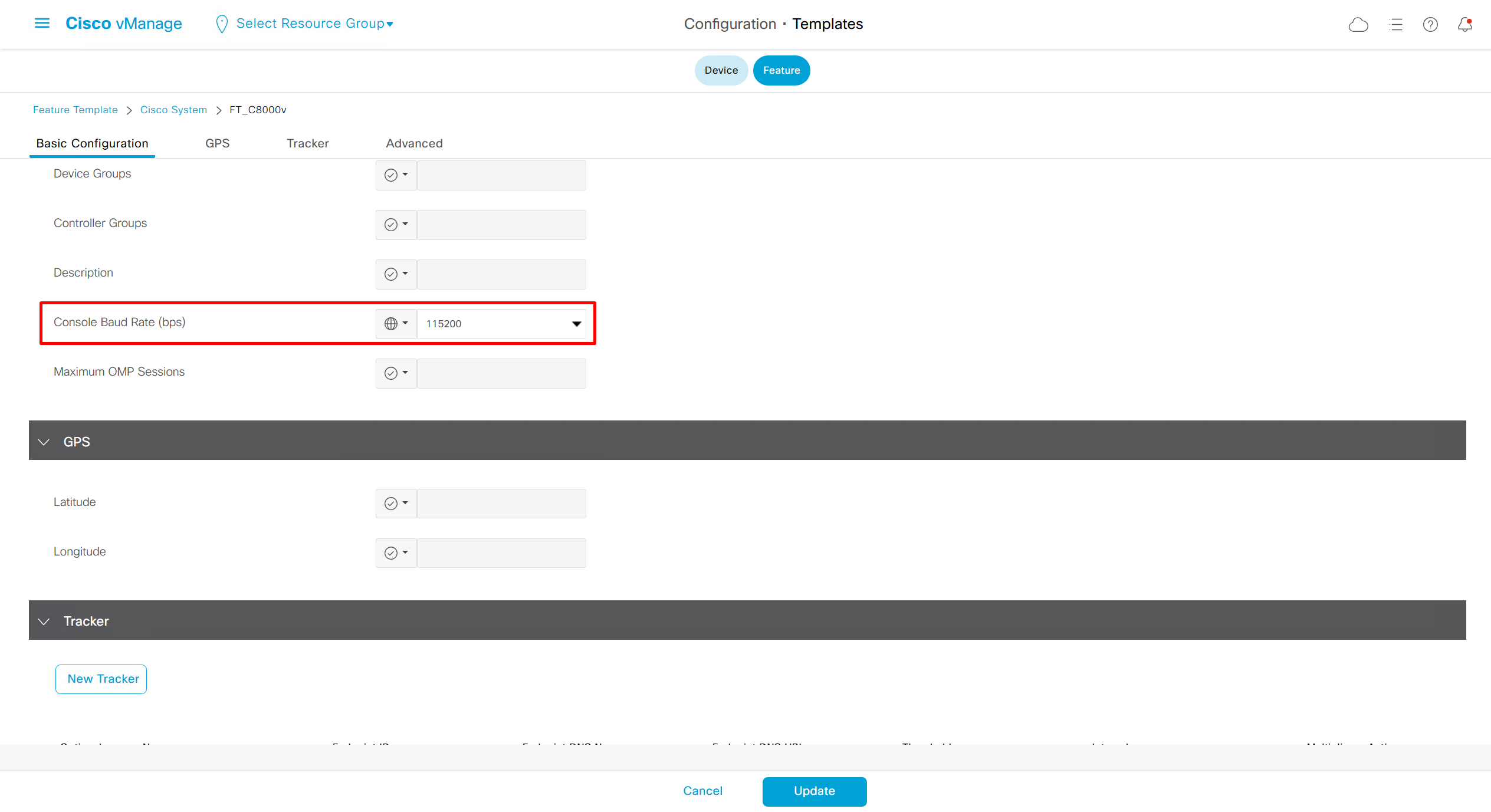
Each section of the running-config will require a feature template

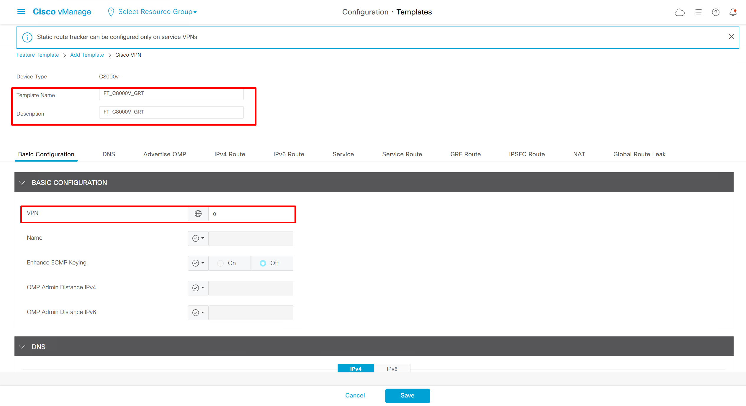
Enhance ECMP Keyring when turned on, also considers the source and destination port to calculate the ECMP
DNS and Static IPv4 routes will come under the GRT
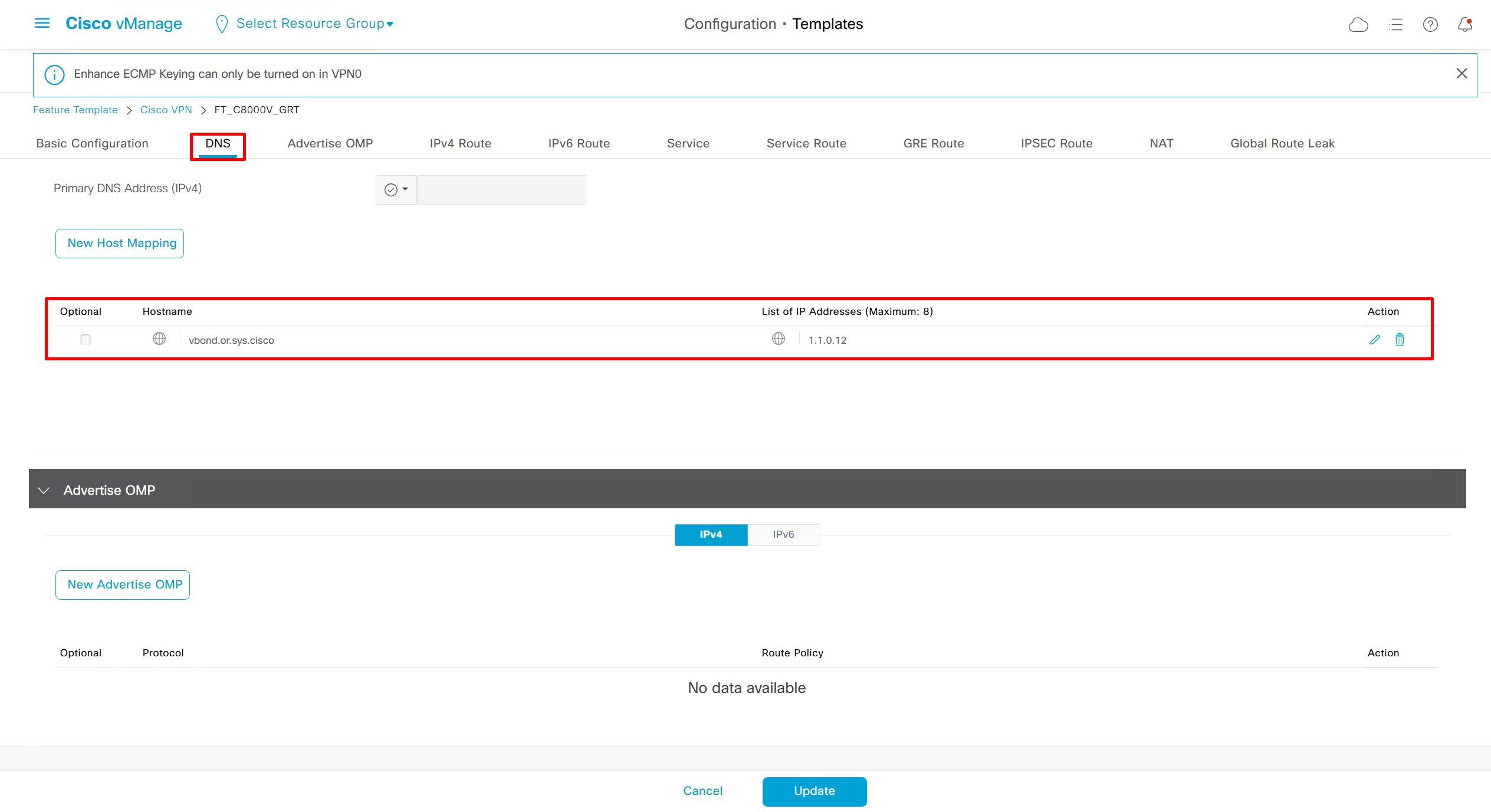
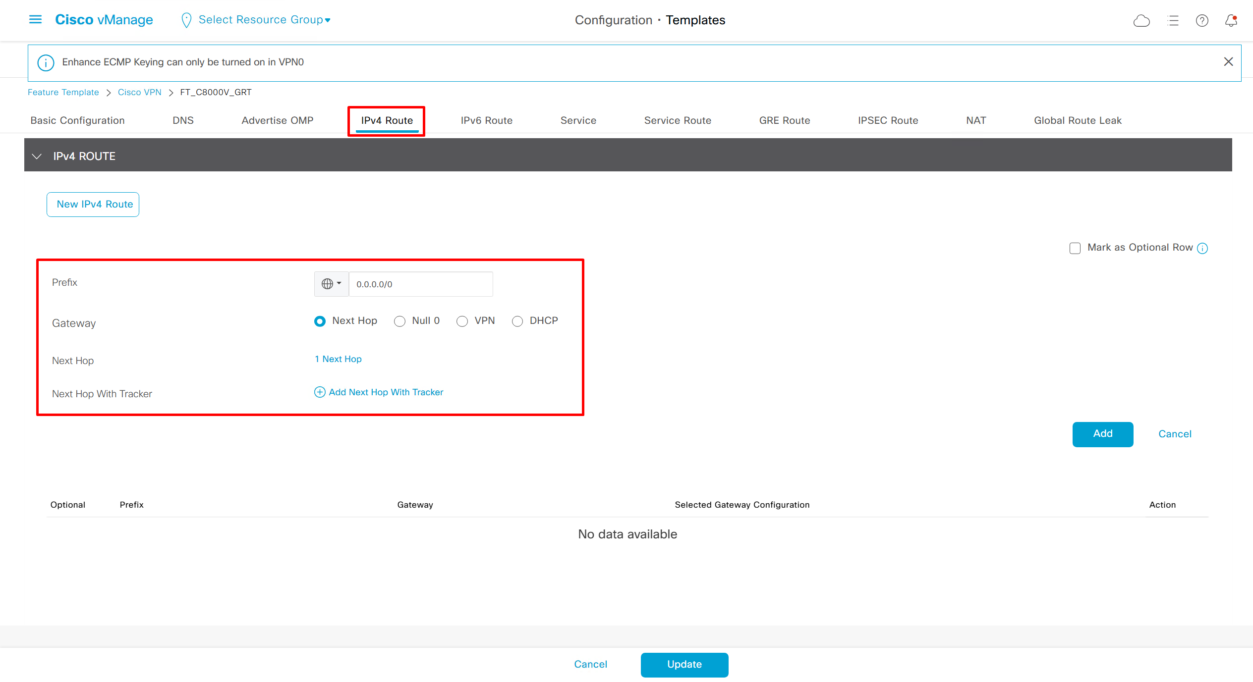
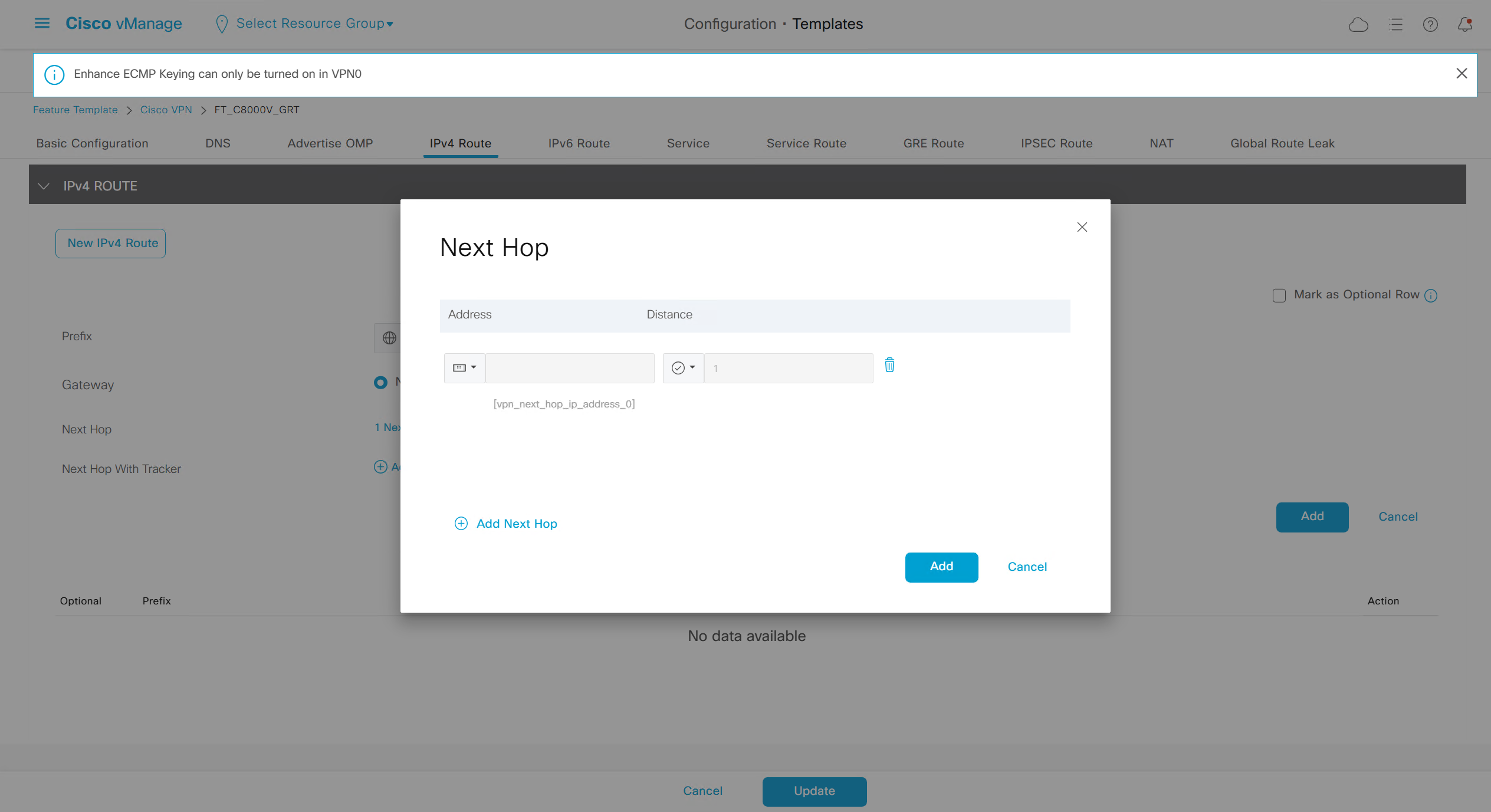
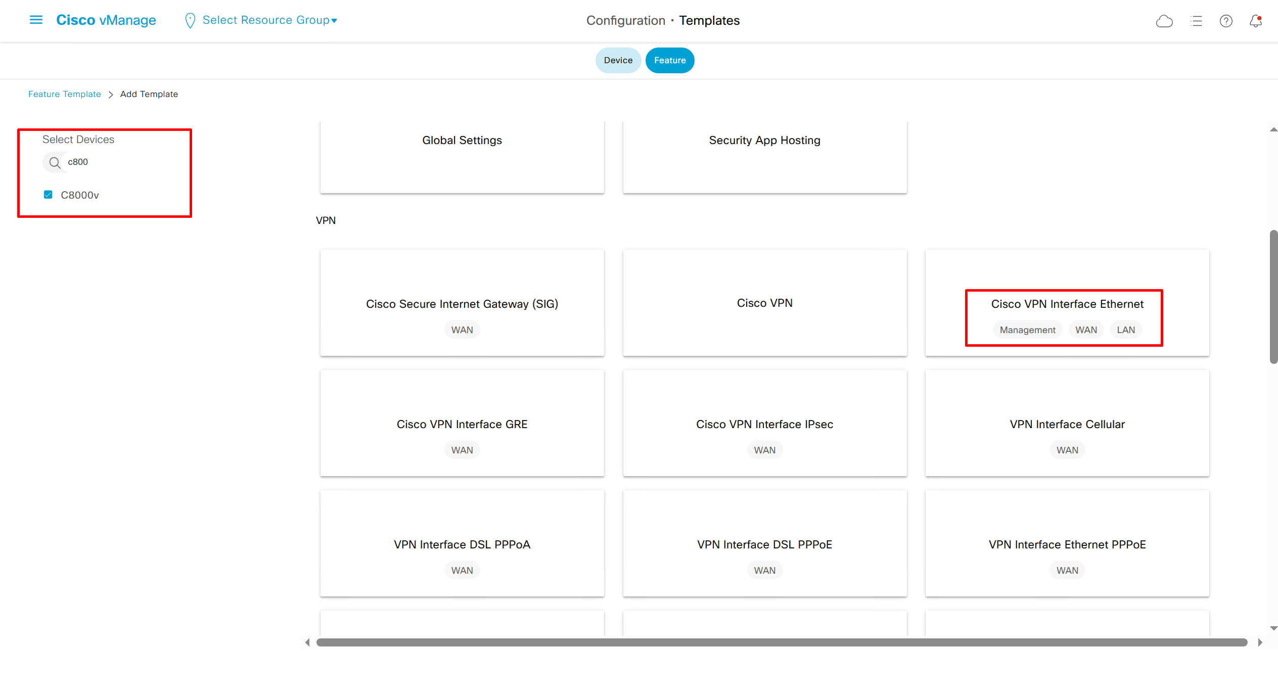
If devices models are different then each device model will need its own feature due to difference in interface names > Cisco VPN interface ethernet template

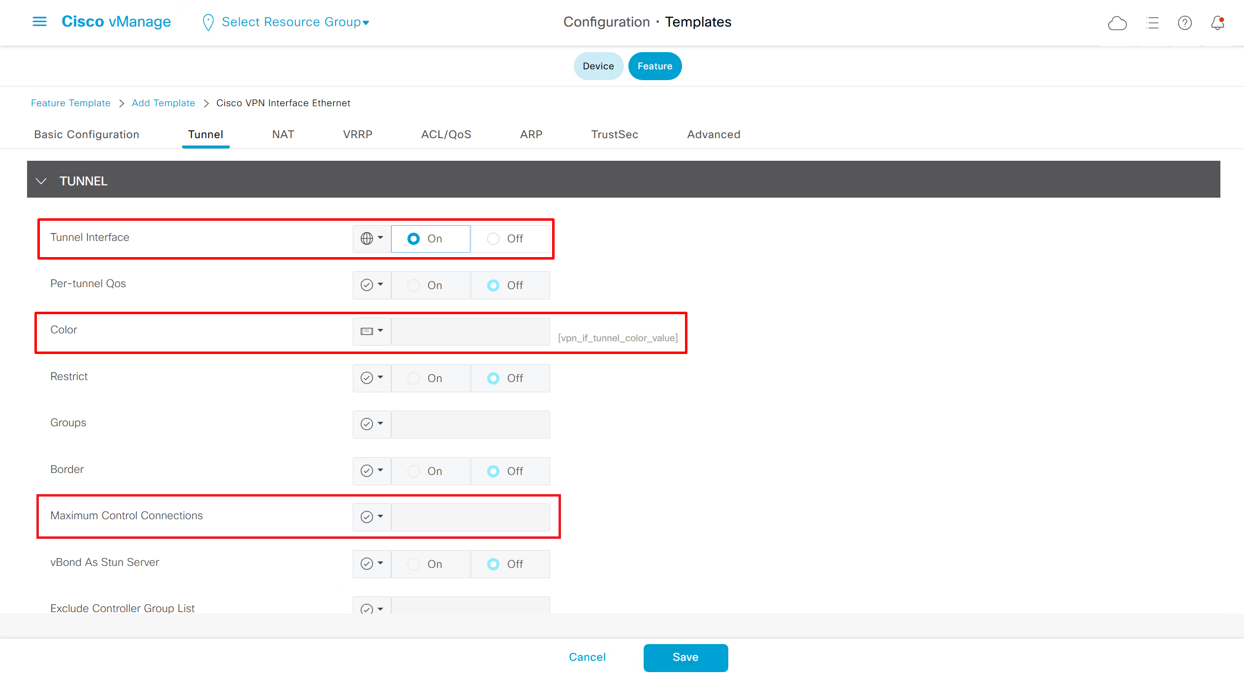
if this color does not have reachability to controllers such as MPLS connection then make Maximum Control Connections to 0
Setting Maximum Control Connections to 0 on MPLS only sites caused loss of control connections to all controllers and because of loss of connections caused rollback because MPLS was only connection to site
Maximum control connections allow sites to have no connection to controllers (not just vmanage, but vsmart and vbond also) from that color, but still have “data tunnels” from that color
Exclude Controller Group List: This is group of controllers that you dont want the edge to connect to, this is important when we dont want edge to connect to vsmart in far regions.

vManage Connection Preference: by default is 5, a link with higher preference is used to connect to vmanage in case we have 2x transports because only one vmanage connection is established
Port hop
By default, WAN Edge devices (vEdge, C8000V) form control connections with controllers (vBond, vSmart, vManage) using:
DTLS (UDP 12346)
TLS (TCP 443)
So normally, traffic will keep using those fixed ports.
When Port Hop is enabled, the “WAN Edge” will not stick to just a single fixed port. Instead, it will cycle through a range of ports if a connection attempt fails.
- DTLS (UDP):
- Starts with UDP/12346.
- If blocked, it will try other ports in the UDP range 12346–12846.
- It keeps retrying until it finds an open port.
- TLS (TCP):
- Starts with TCP/443.
- If blocked, it will try other ports in the TCP range 443–12443.
- Again, hops until success.
This makes control connections much more resilient in restrictive or dynamic network environments where firewalls are doing inspections and rate limiting traffic
Sometimes port hop can be issue
Control connections on the router, you see it is up from last 4 mins and 12 seconds. It will again retrigger after completing 5 mins
NDNA_c8000v#sh sdwan control connections
                                                               PEER                  PEER                                     CONTROLLER
PEER    PEER PEER            SITE       DOMAIN PEER            PRIV  PEER            PUB                                      GROUP
TYPE    PROT SYSTEM IP       ID         ID     PRIVATE IP      PORT  PUBLIC IP       PORT  ORGANIZATION       LOCAL COLOR     PROXY STATE UPTIME      ID
------------------------------------------------------------------------------------------------------------------------------------------------------------
vsmart  dtls 10.10.10.11    1          1      10.10.3.5         12646 17.23.12.11    12646      NDNA-111     gold            No    up     0:00:04:12 0
vsmart  dtls 10.10.10.12    2          1      10.10.3.15        12646 17.23.12.25    12646      NDNA-111     gold            No    up     0:00:04:12 0
vmanage dtls 10.10.10.10    1          0      10.10.3.12        13046 17.23.12.88    13046     NDNA-111      gold            No    up     0:00:04:12 0
checked again after like a minute now and you will notice, it is showing 8 seconds now which means it is bounced again.
NDNA_c8000v#sh sdwan control connections
                                                               PEER                  PEER                                     CONTROLLER
PEER    PEER PEER            SITE       DOMAIN PEER            PRIV  PEER            PUB                                      GROUP
TYPE    PROT SYSTEM IP       ID         ID     PRIVATE IP      PORT  PUBLIC IP       PORT  ORGANIZATION       LOCAL COLOR     PROXY STATE UPTIME      ID
------------------------------------------------------------------------------------------------------------------------------------------------------------
vsmart  dtls 10.10.10.11    1          1      10.10.3.5         12646 17.23.12.11    12646      NDNA-111     gold            No    up     0:00:00:08 0
vsmart  dtls 10.10.10.12    2          1      10.10.3.15        12646 17.23.12.25    12646      NDNA-111     gold            No    up     0:00:00:08 0
vmanage dtls 10.10.10.10    1          0      10.10.3.12        13046 17.23.12.88    13046     NDNA-111      gold            No    up     0:00:00:08 0
For troubleshooting, move the router to CLI mode
First check the mode in which router is working, if we see below in red, the template is attached to the router which means the router is in controller mode.
Personality:             vEdge
Model name:              C8000V
Device role:             cEdge-SDWAN
Services:                None
vManaged:                true
Commit pending:          false
Configuration template:  AZURE-NDNA-V01
Chassis serial number:   XXXXXXXXXXXXXX
Move the router from controller mode to CLI mode in order to do packet captures on the router. Although it is recommended to capture using vmanage datastream mode
Once you moved, run the below script in order to capture the packets on the interface with the source and the destination IPs as shown below :
!
ip access-list extended CAP-Filter
10 permit ip host 10.10.1.23 host 17.23.12.88
20 permit ip host 17.23.12.88 host 10.10.1.23
exit
monitor capture CAP access-list CAP-Filter interface GigabitEthernet1 both buffer circular size 25
monitor capture CAP limit pps 1000000
monitor capture CAP access-list CAP-Filter both buffer circular size 25
monitor capture CAP start
monitor capture CAP stop
!
Now run below commands to get debugs
NDNA_c8000v# debug platform software sdwan vdaemon all high
NDNA_c8000v# monitor logging process vdaemon internal
Once you run the above commands, you will see logs related to the interfaces
You will see that in debug logs , TLOC Disable … Why ?
2024/04/19 17:47:59.779970993 {vdaemon_R0-0}{255}: [event] [18342]: (debug): Disabling tloc GigabitEthernet1.
2024/04/19 17:47:59.780001093 {vdaemon_R0-0}{255}: [misc] [18342]: (ERR): Delta preference value added to TLOC pref.
2024/04/19 17:47:59.780003193 {vdaemon_R0-0}{255}: [misc] [18342]: (ERR): Sending TLOC: ifname:GigabitEthernet3 color:gold spi:18915 smarts:2 manages:1 state:DOWN LR encap:0 LR hold time:7000 bw:0, down-bw 0 range: 0-0,adapt period 0 up-bw range 0-0 up_fia 0 capability:0x3f
Check the interface for port-hop and you will see port-hop is enabled. Now disable the port hop and you will see the control connections will be stable
interface GigabitEthernet1
  tunnel-interface
   encapsulation ipsec weight 1
   no border
   color gold restrict
   no last-resort-circuit
   no low-bandwidth-link
   no vbond-as-stun-server
   vmanage-connection-preference 5
  port-hop
Check the control connection after disabling port-hop on the interface , you will see it is up from last 19 min. and stable.
NDNA_c8000v#sh sdwan control connections
                                                               PEER                  PEER                                     CONTROLLER
PEER    PEER PEER            SITE       DOMAIN PEER            PRIV  PEER            PUB                                      GROUP
TYPE    PROT SYSTEM IP       ID         ID     PRIVATE IP      PORT  PUBLIC IP       PORT  ORGANIZATION       LOCAL COLOR     PROXY STATE UPTIME      ID
------------------------------------------------------------------------------------------------------------------------------------------------------------
vsmart  dtls 10.10.10.11    1          1      10.10.3.5         12646 17.23.12.11    12646      NDNA-111     gold            No    up     0:00:19:02 0
vsmart  dtls 10.10.10.12    2          1      10.10.3.15        12646 17.23.12.25    12646      NDNA-111     gold            No    up     0:00:19:02 0
vmanage dtls 10.10.10.10 1 0 10.10.3.12 13046 17.23.12.88 13046 NDNA-111 gold No up 0:00:19:02 0 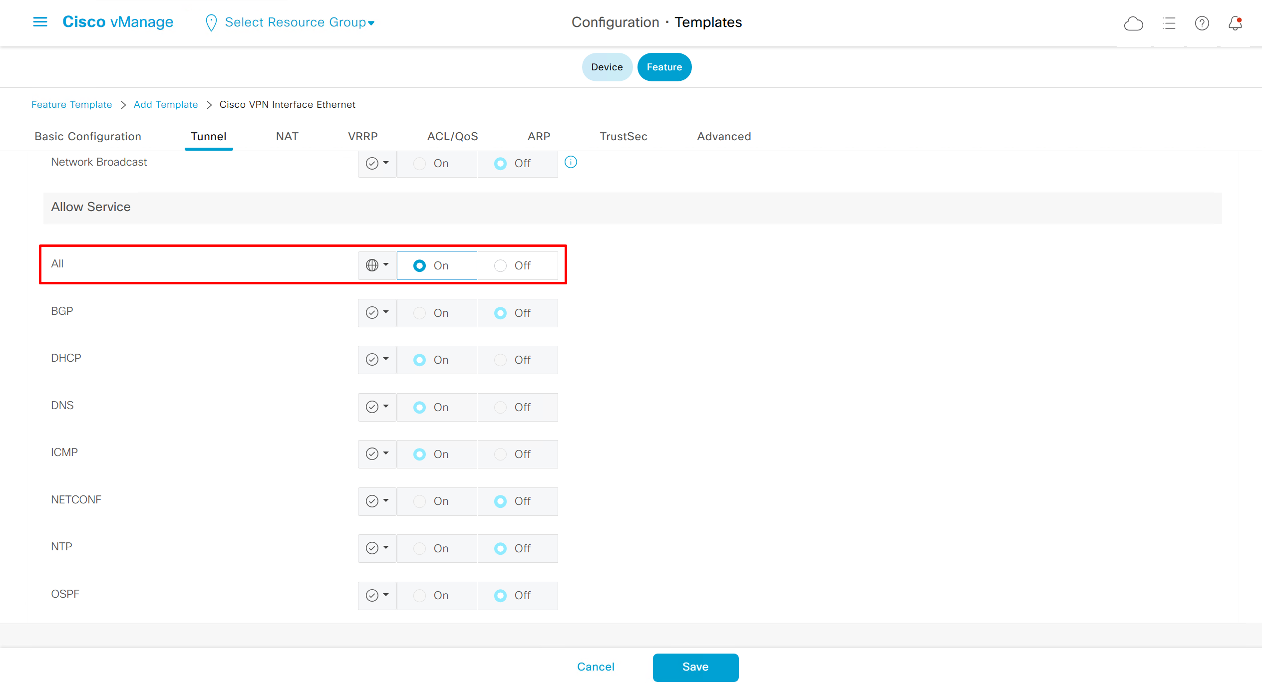
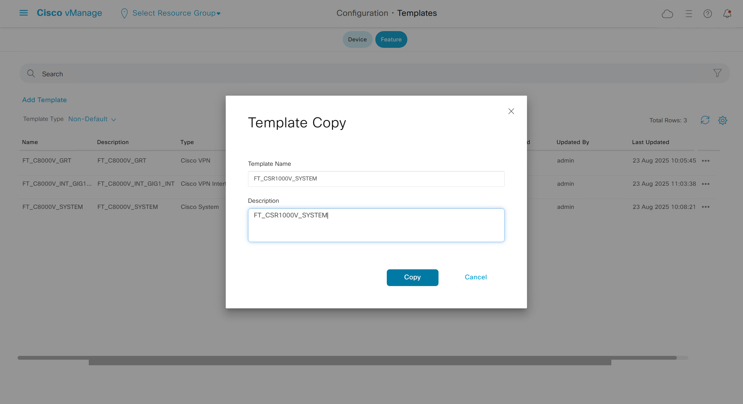
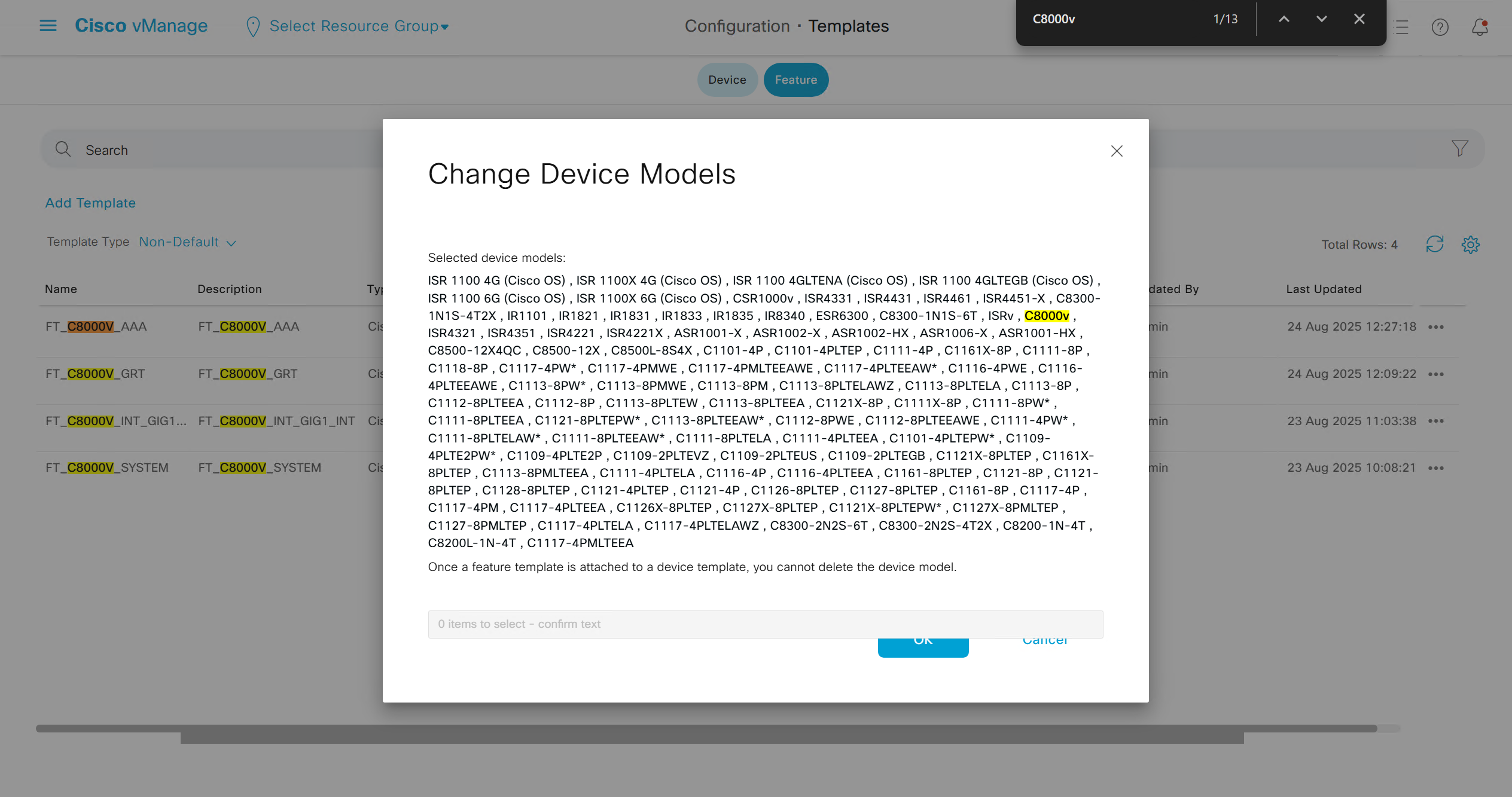
Now we can copy the template and also change its device model as well
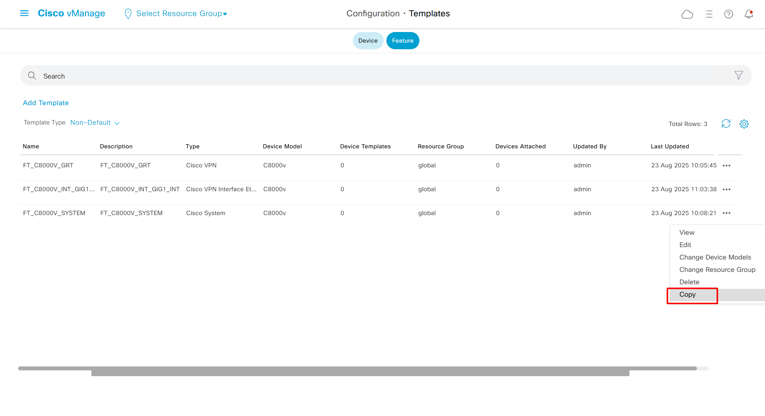
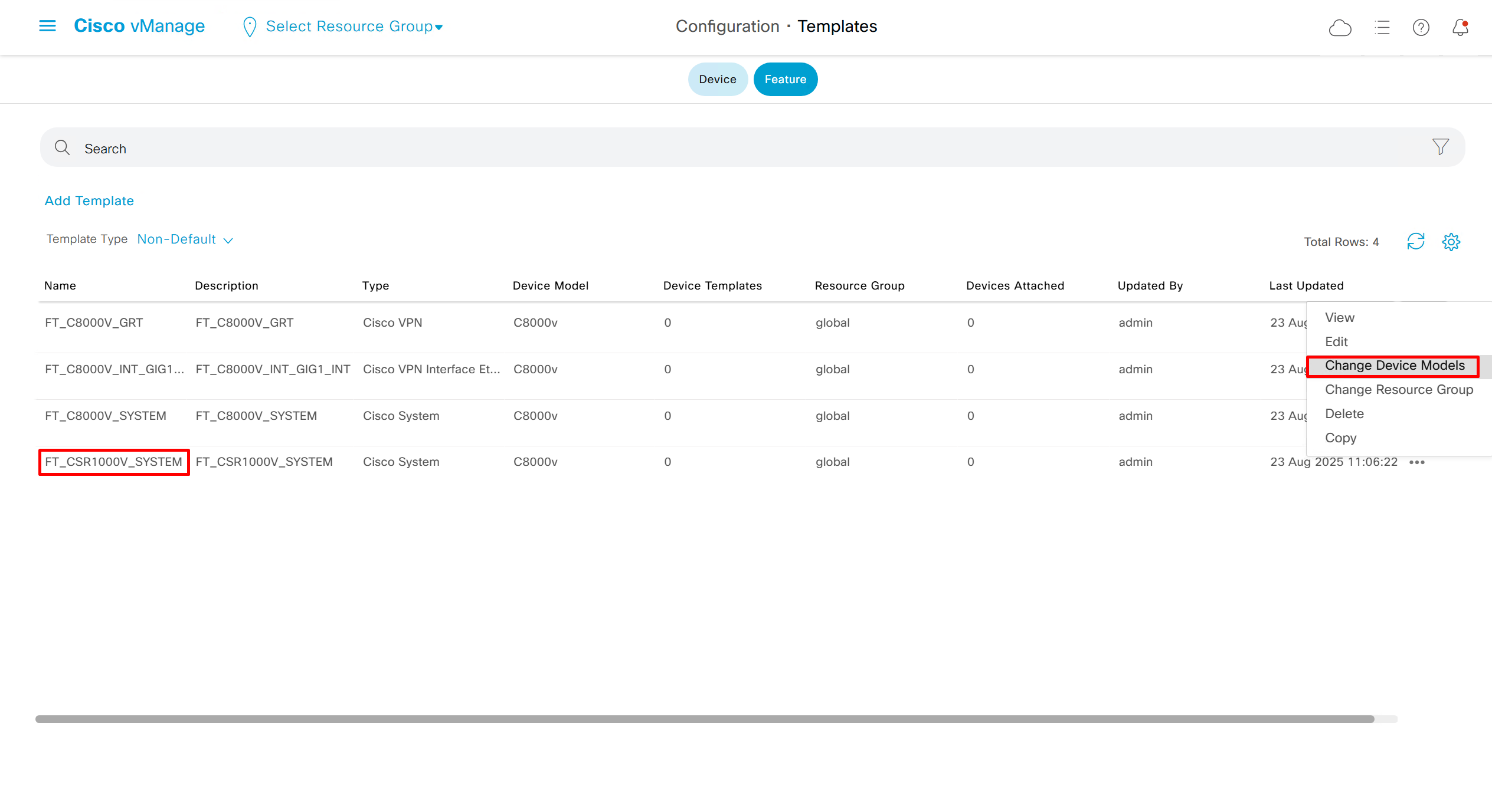
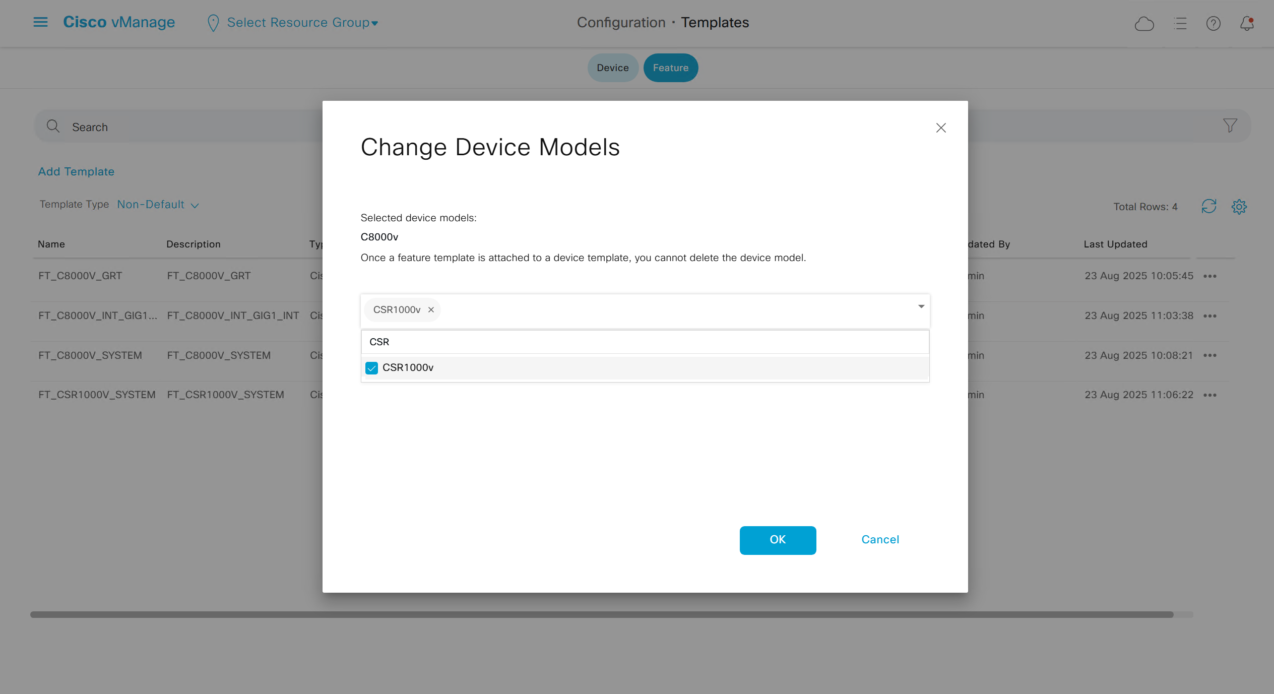
Once you have changed the device model, make sure that interface names match, such as make sure that interface name is not GigabitEthernet0/0/0 and GigabitEthernet1, if it is different then change it inside template as well
on hardware models we also need to make sure that we have template for management gig0 interface to satisfy the requirement for device template on hardware platforms otherwise deployment fails, for managemet gig0 interface same template “Cisco VPN Interface Ethernet” is used and input its name from “show ip int brief”
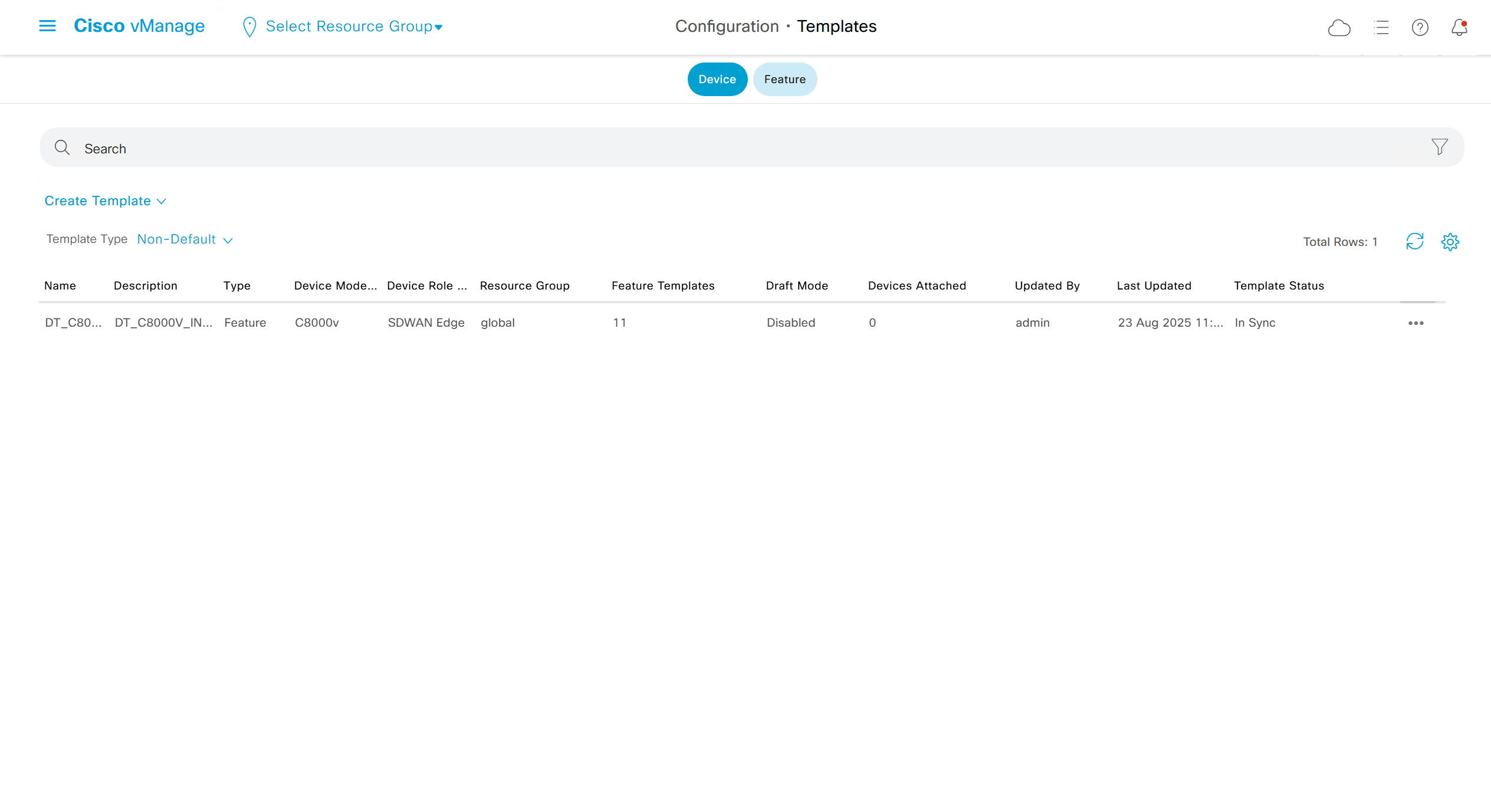
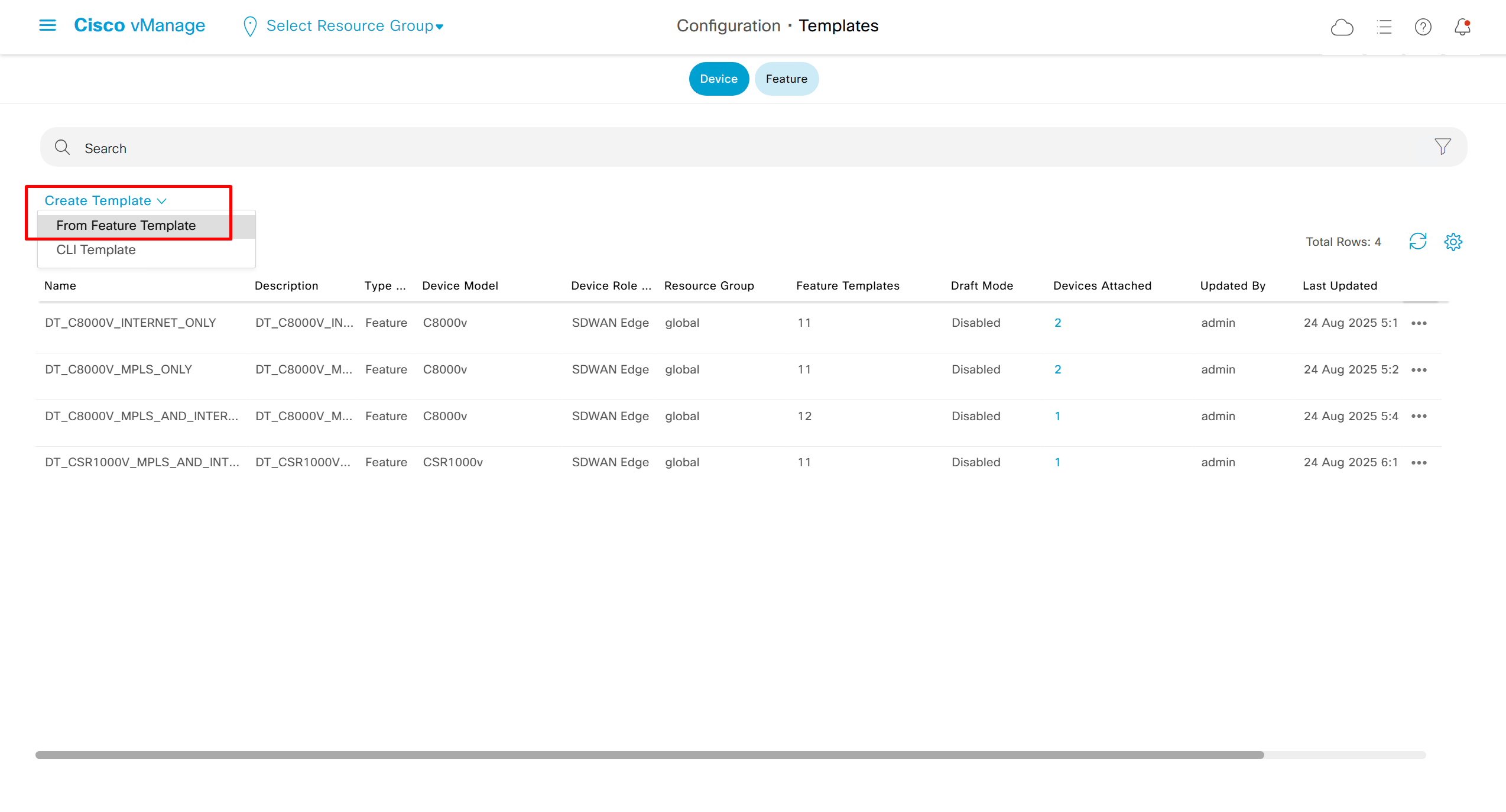
Now create device template
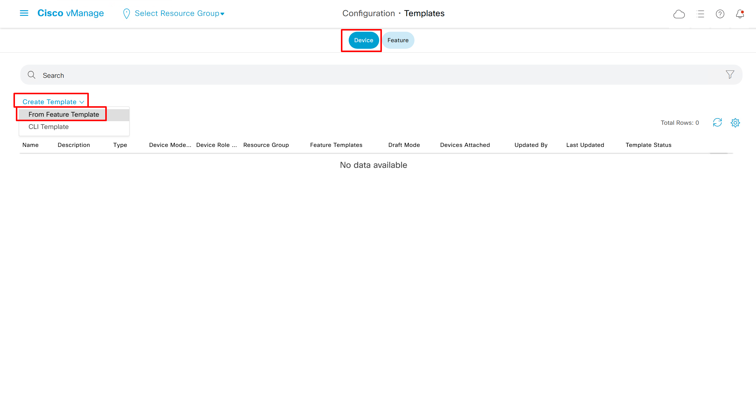
This template is device specific + transport connectivity types specific
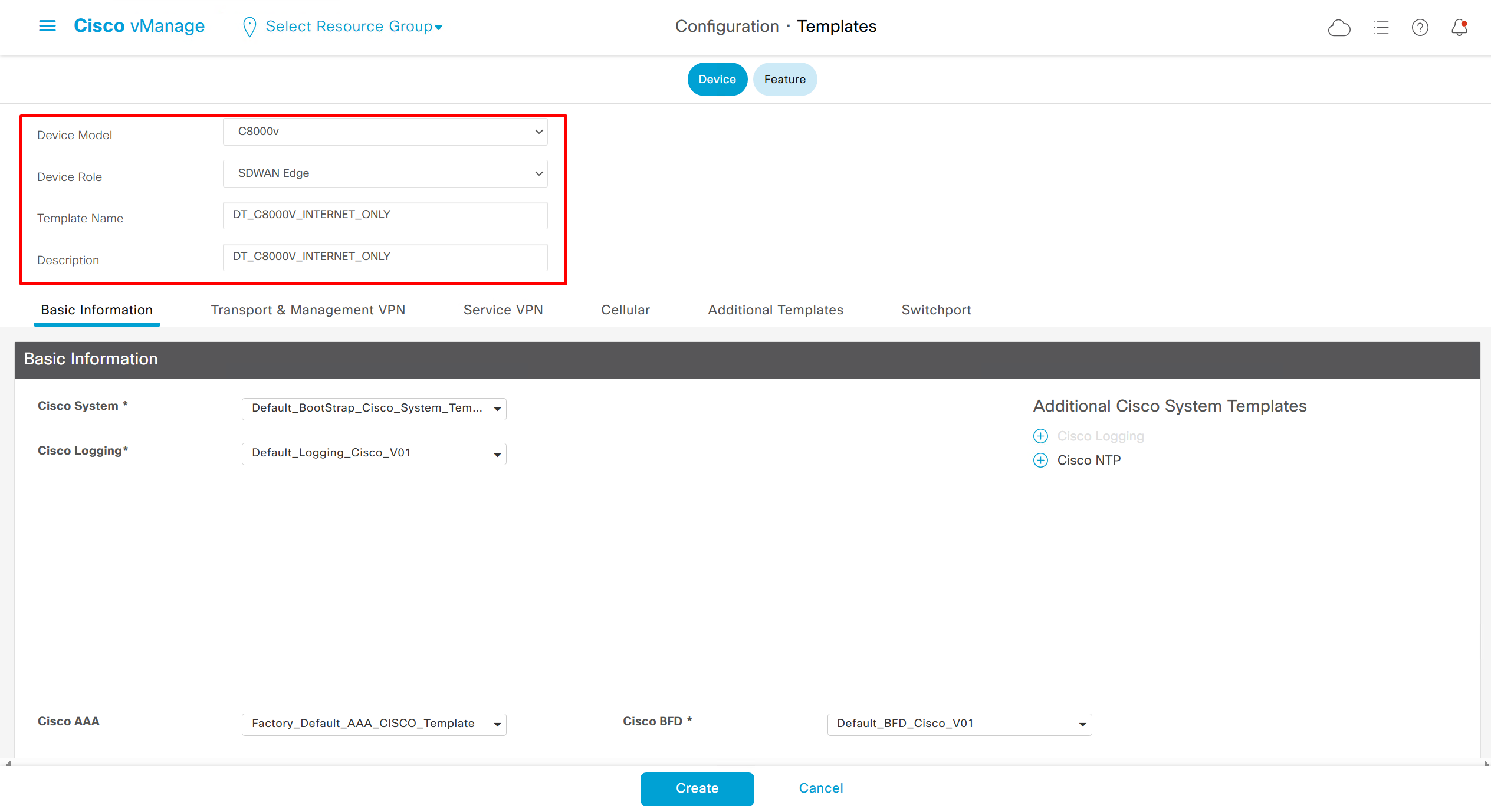
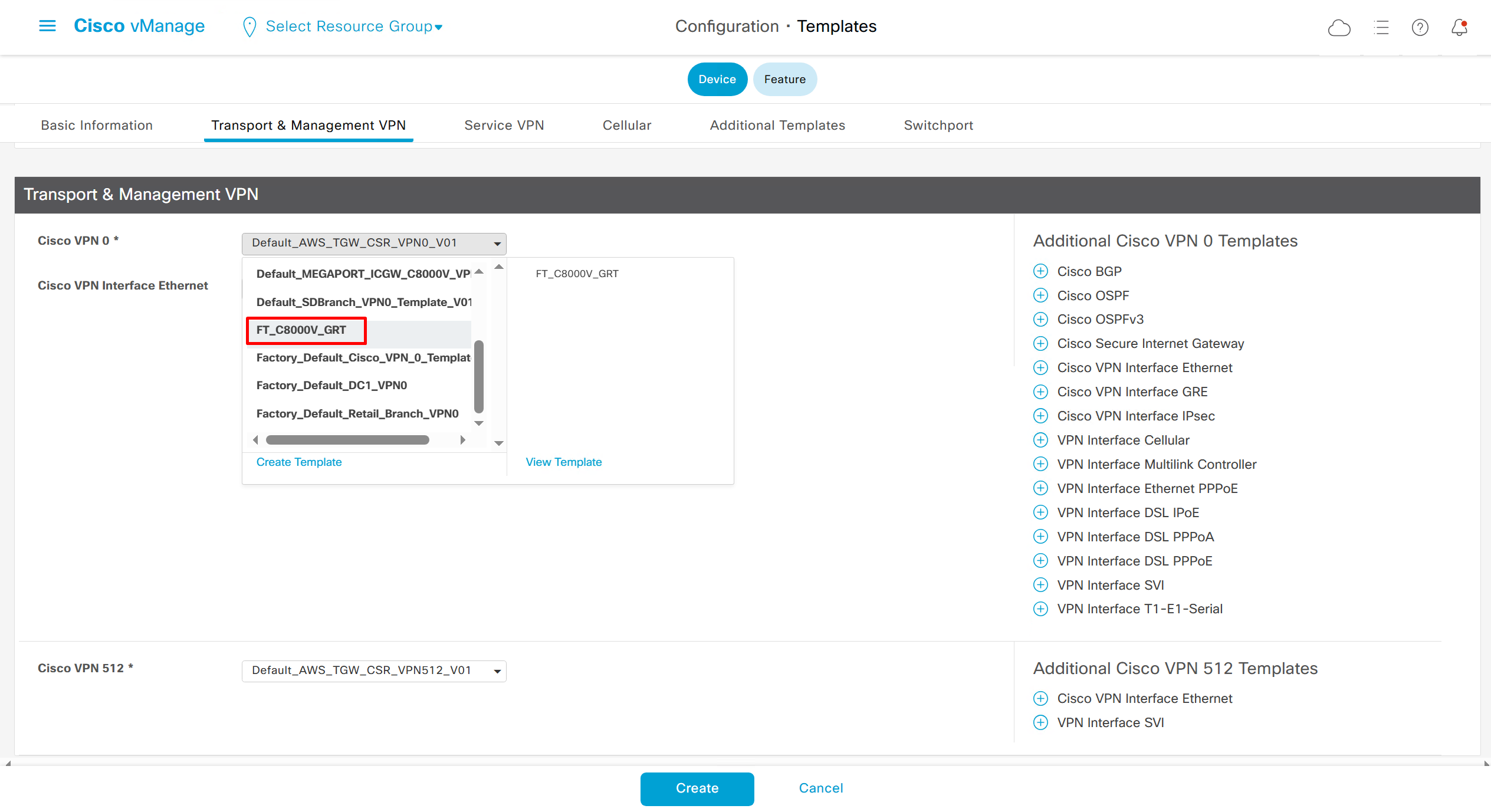
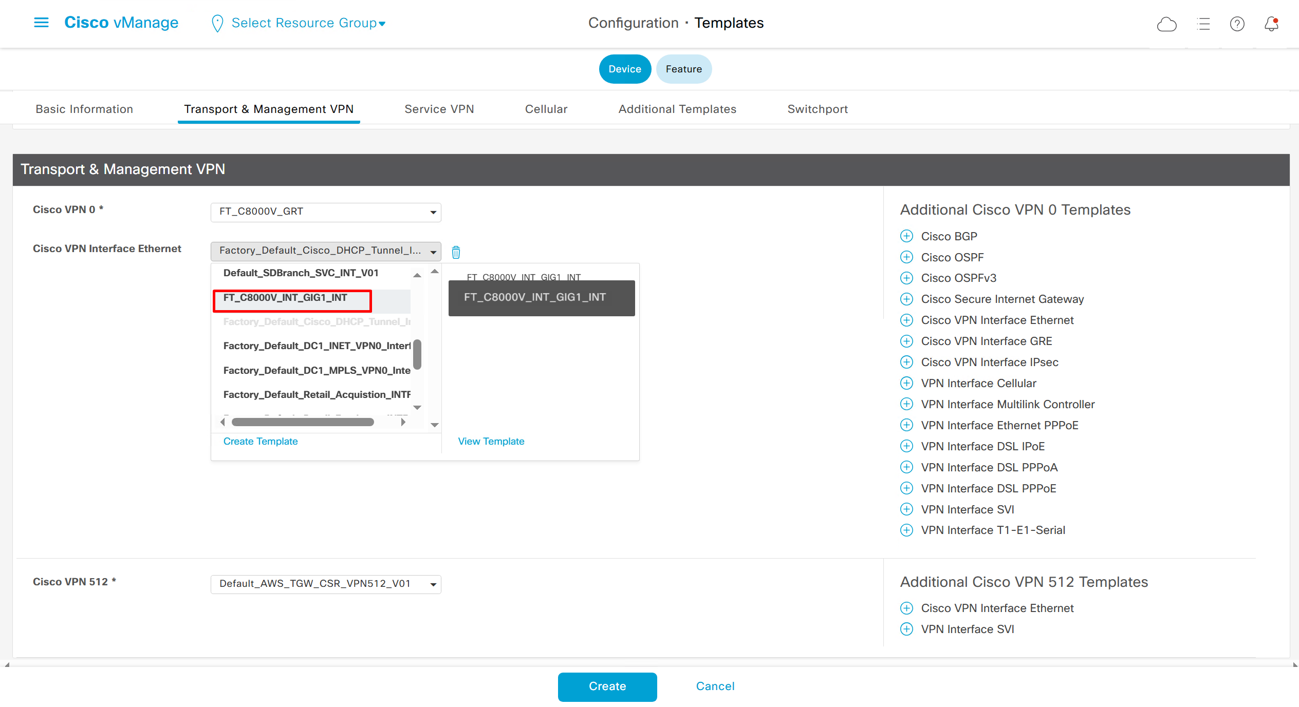
In case we have another transport interface, we can add another from plus icon next to the type of interface

In case we have to attach mgmt interface to avoid deployment errors on hardware device
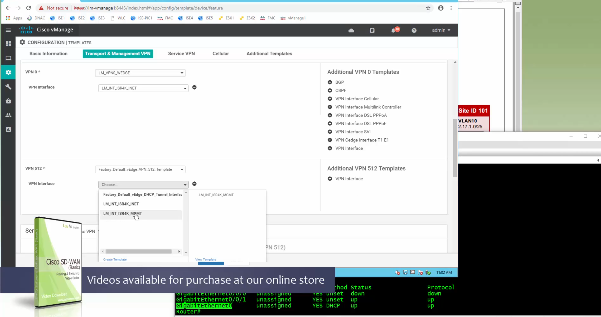
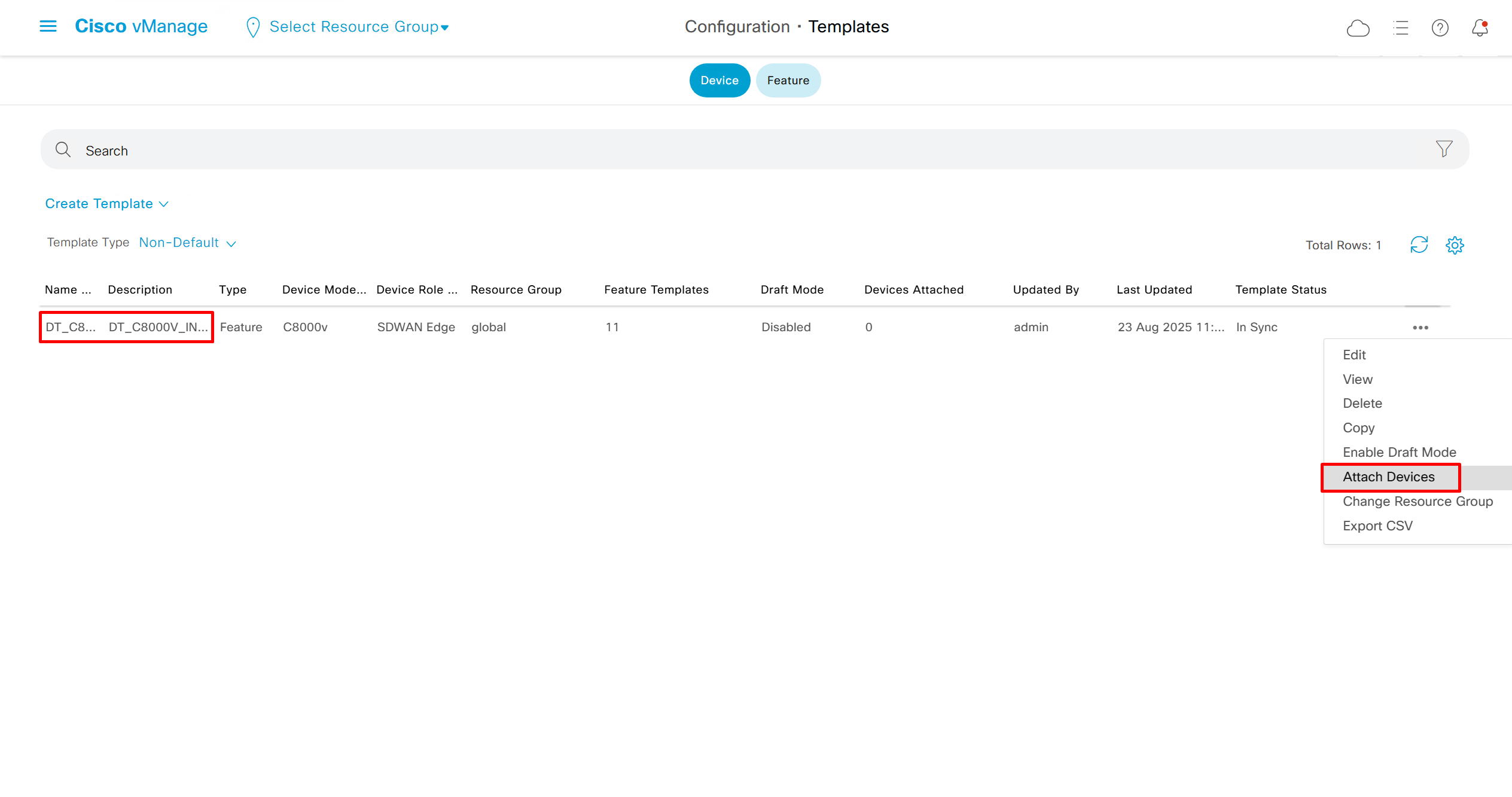
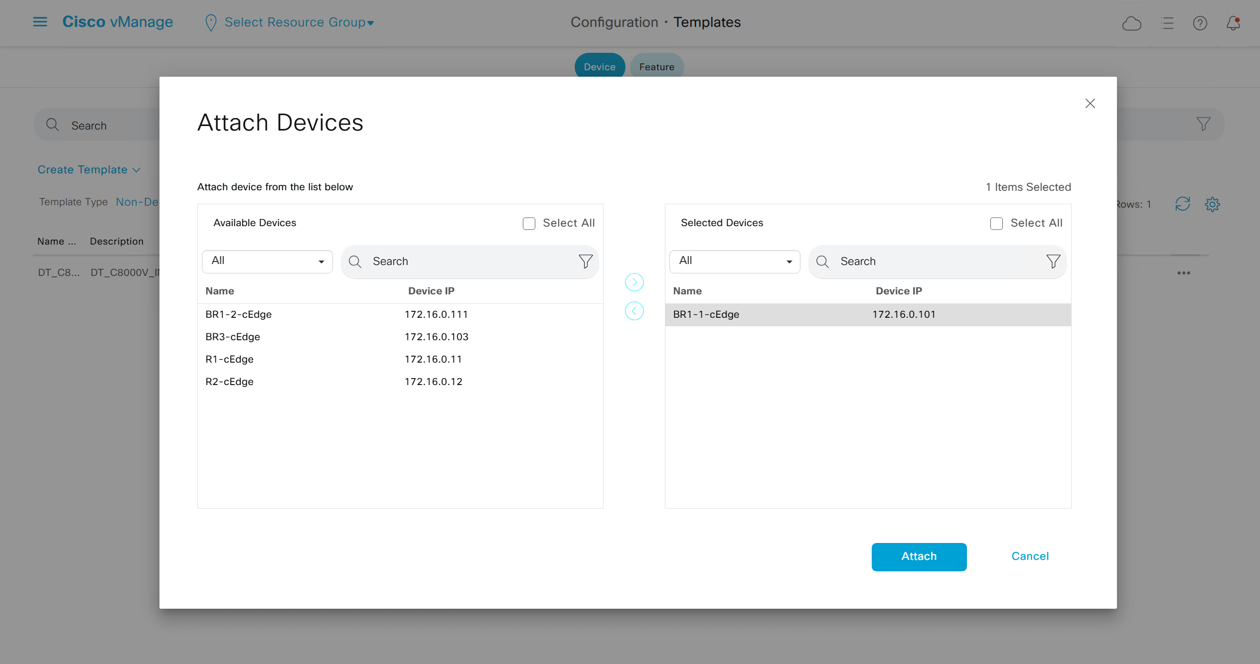
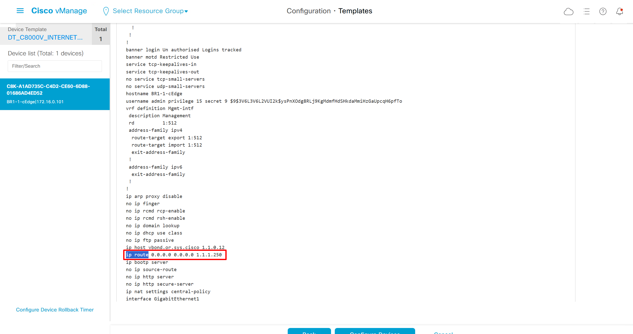
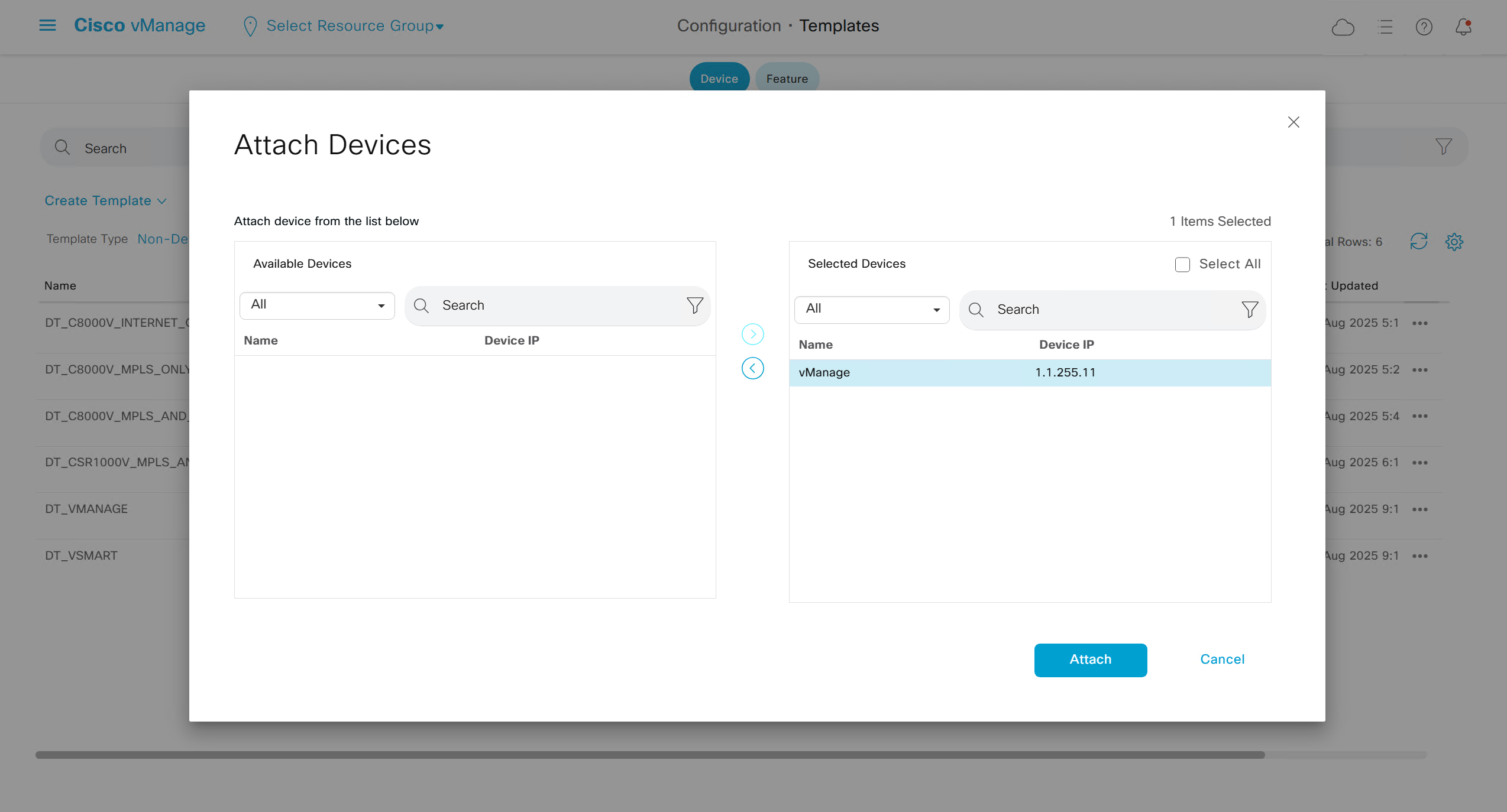
Now we need to attach the device template to a device – C8000v that has internet only connectivity
And you do that from the template itself
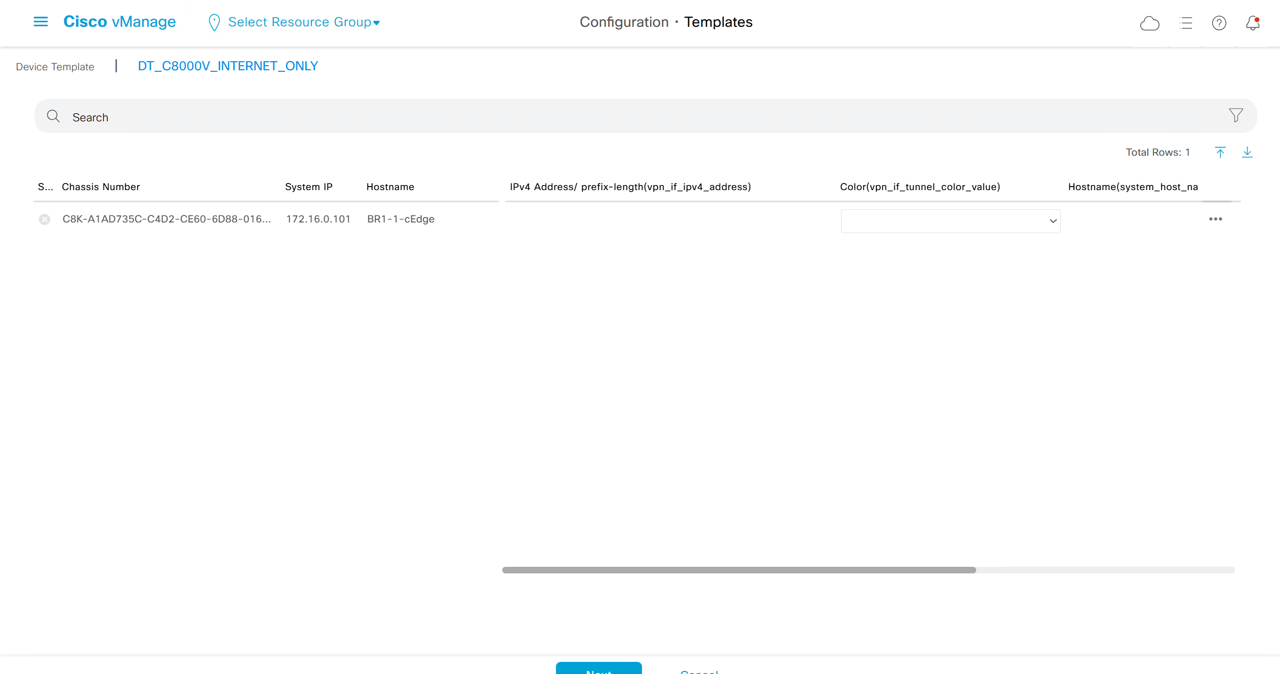
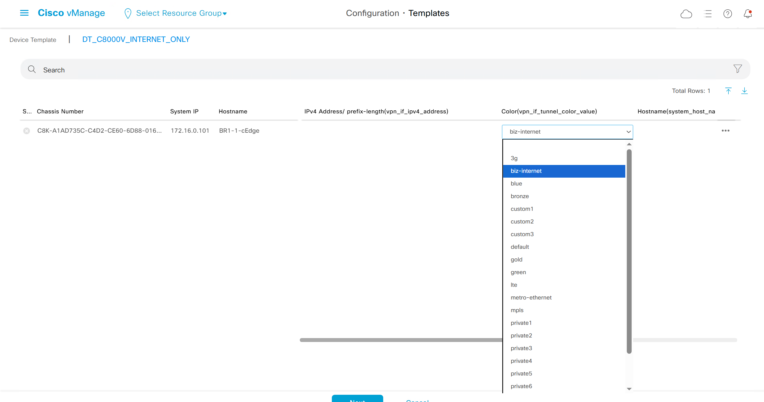

fill the variables with following information from the running-config of edge device


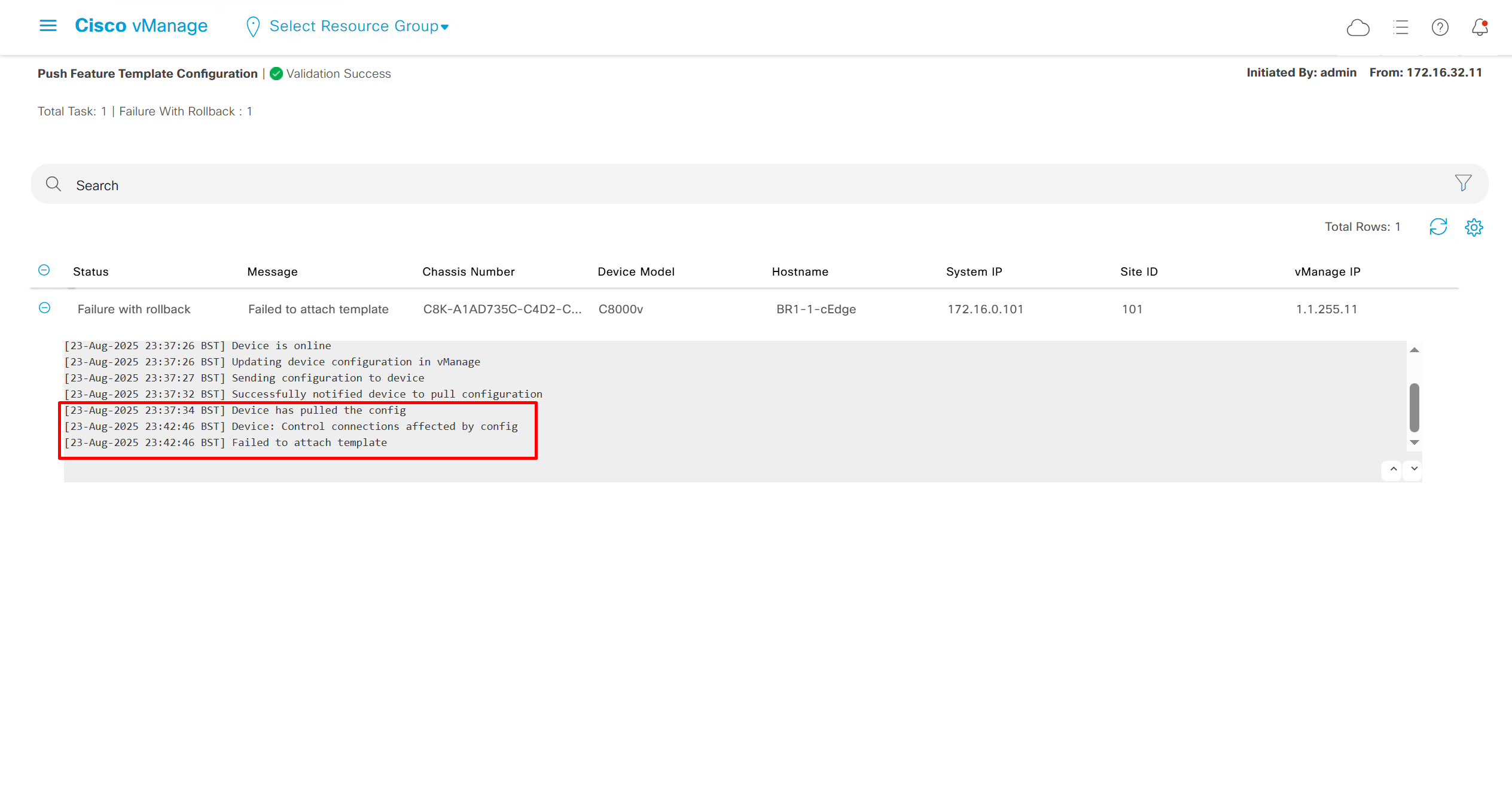
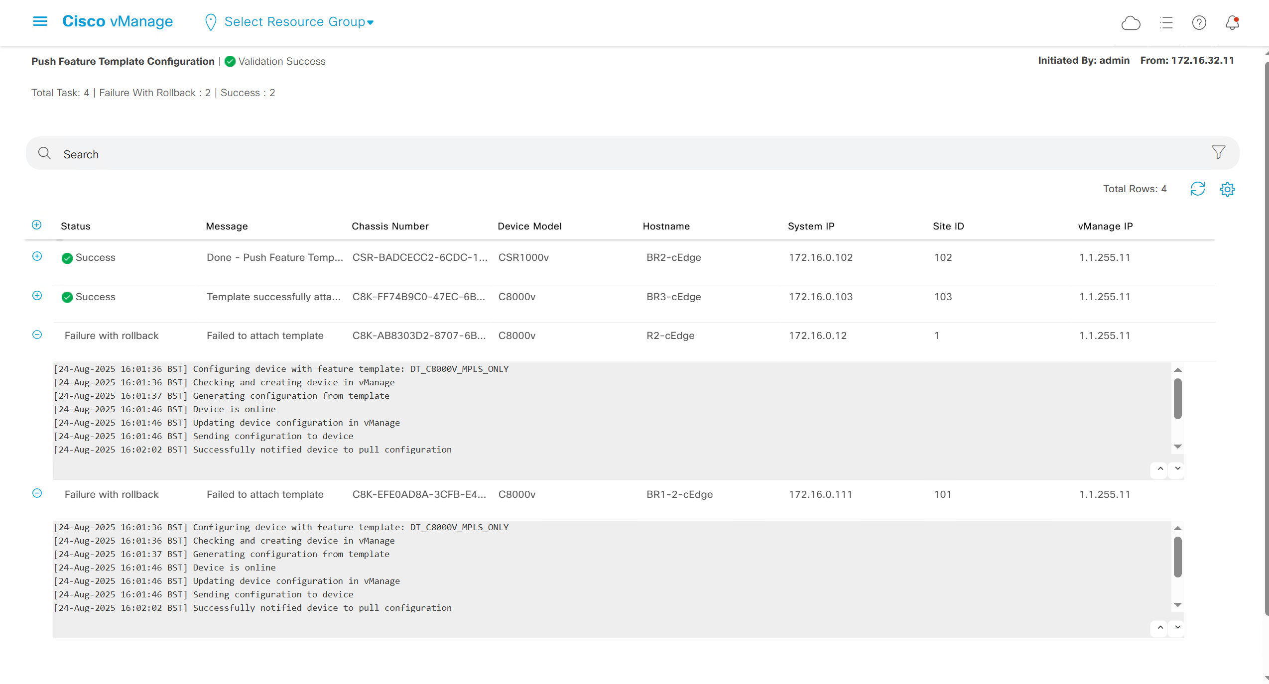
deployment failed and it rolled back to restore connectivity to vmanage as edge lost connectivity to vmanage and also other controllers
As I checked the template, the default route was missing from feature template FT_C8000V_GRT
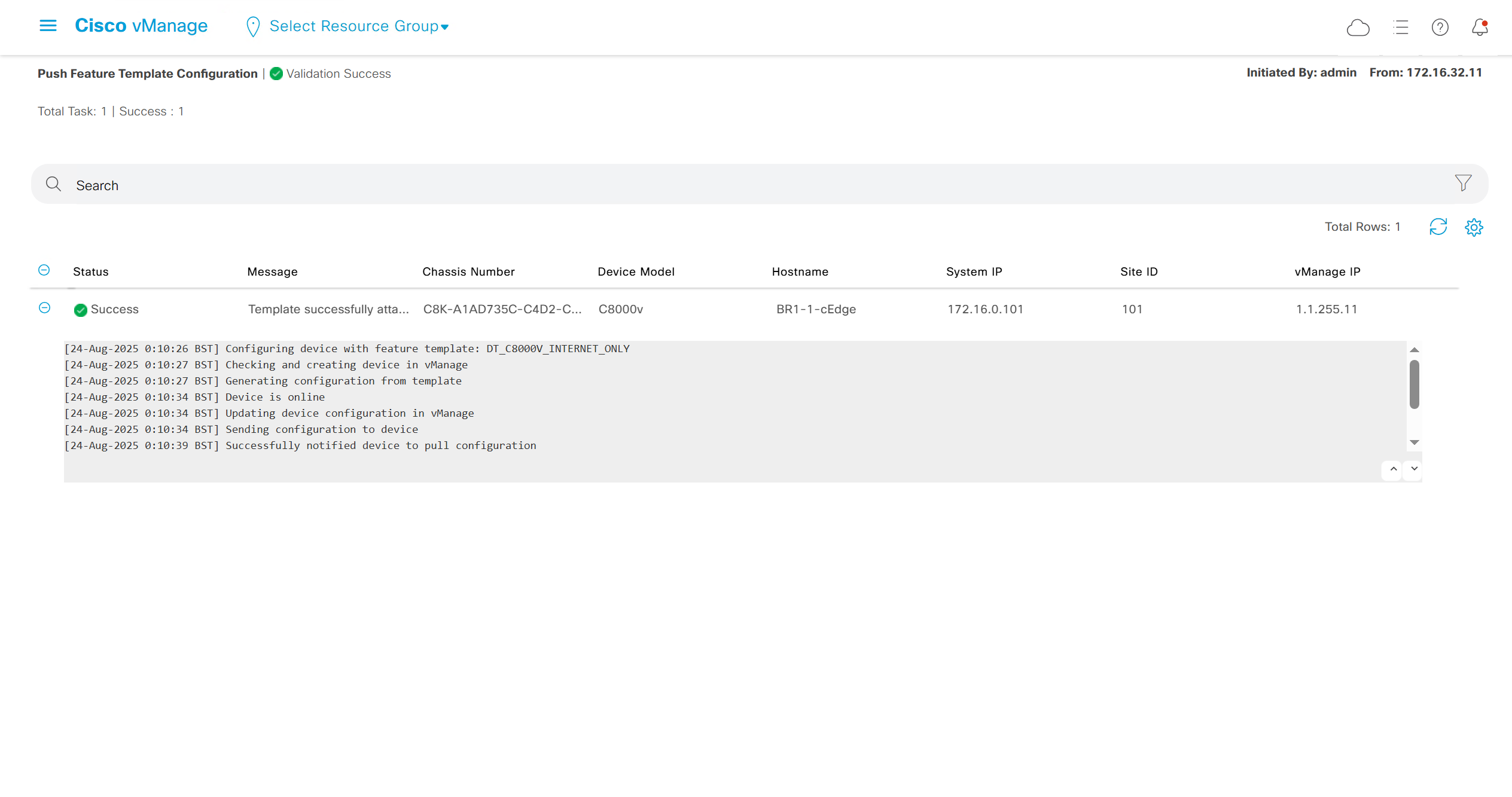
after successful deployment I was not able to login, so new AAA policy was attached
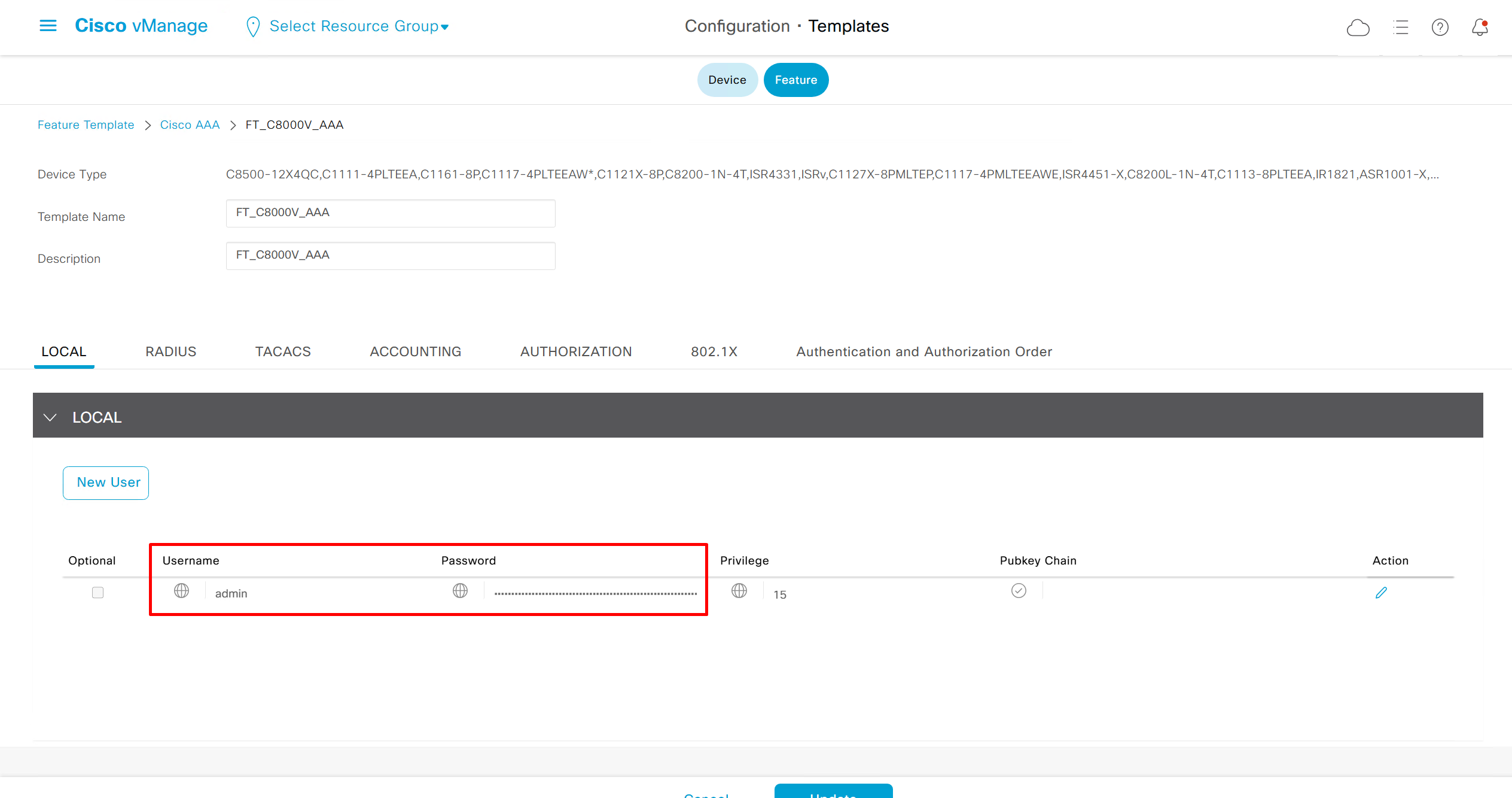

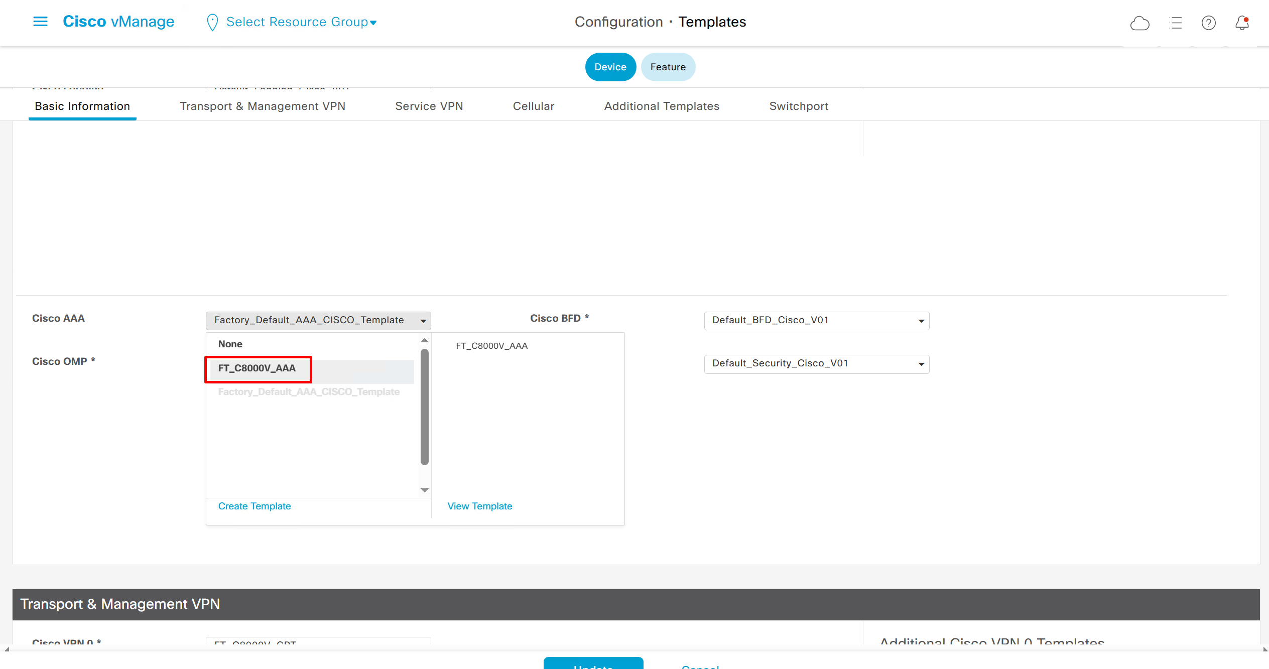
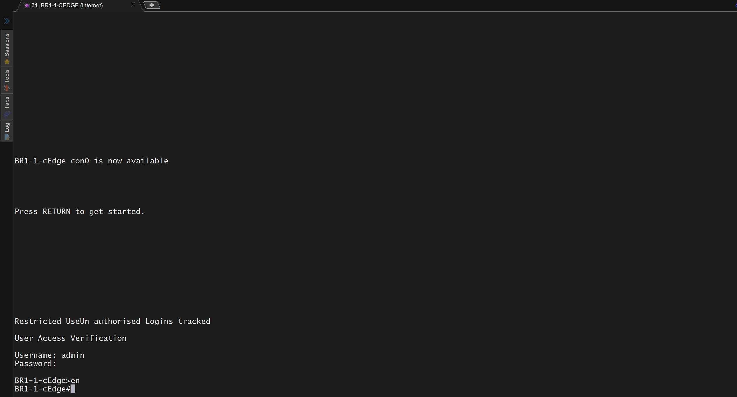
now I can login
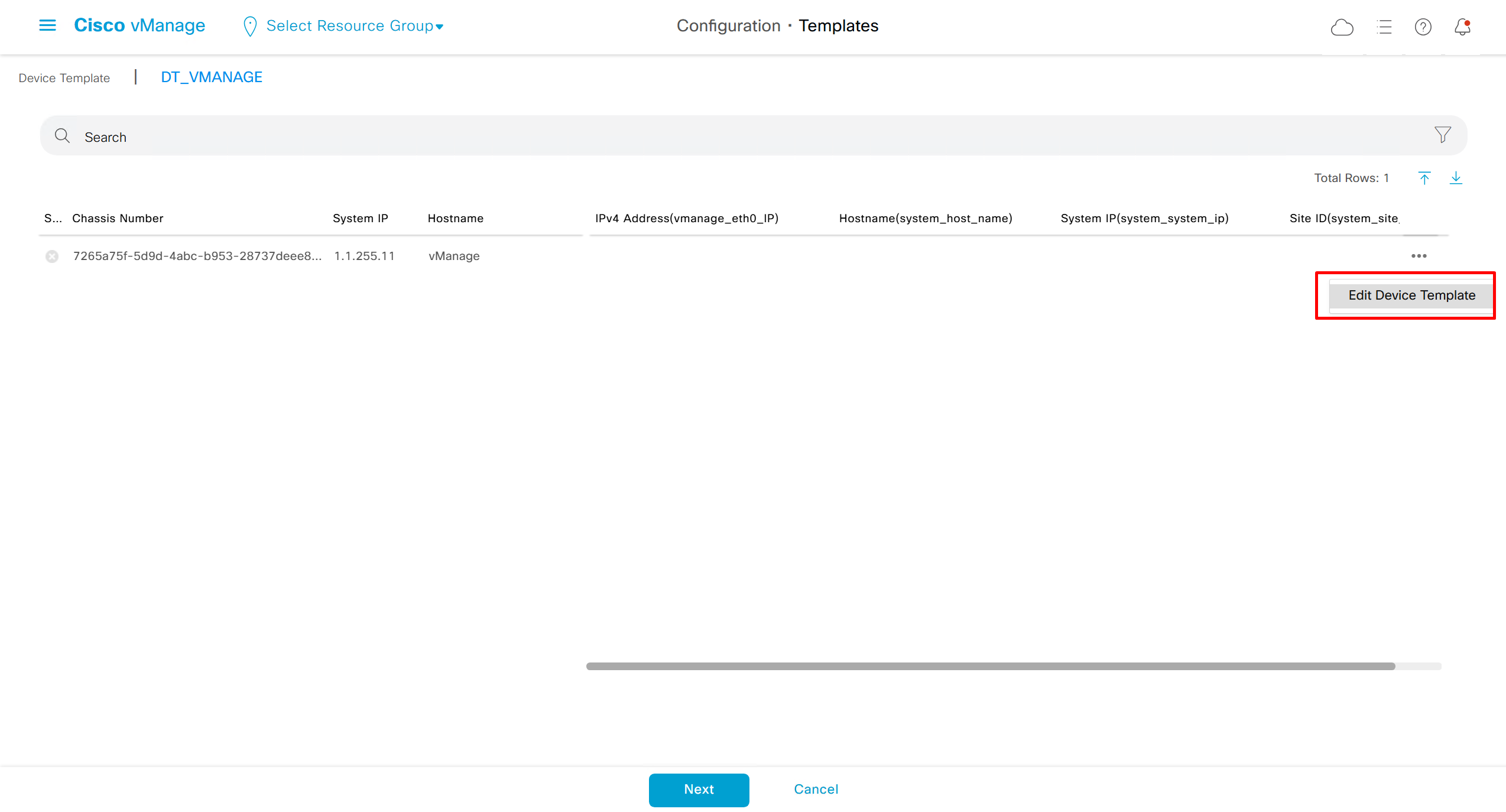
Whenever there is a change made on templates, these changes need to be pushed to the devices
While making those changes there is an option to download the CSV and make bulk changes and then upload the CSV back
This is very useful when you have large number of devices
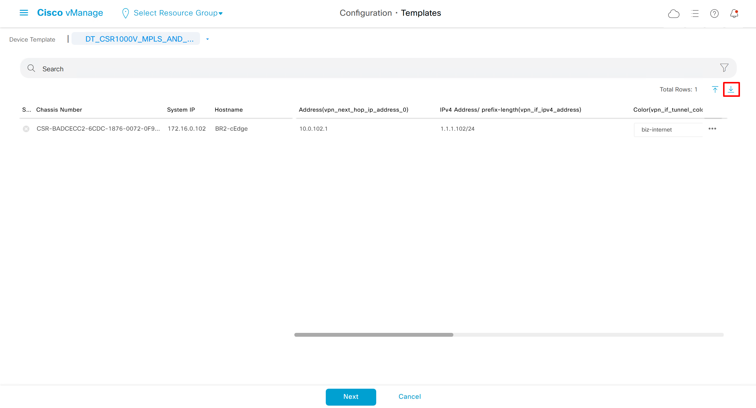
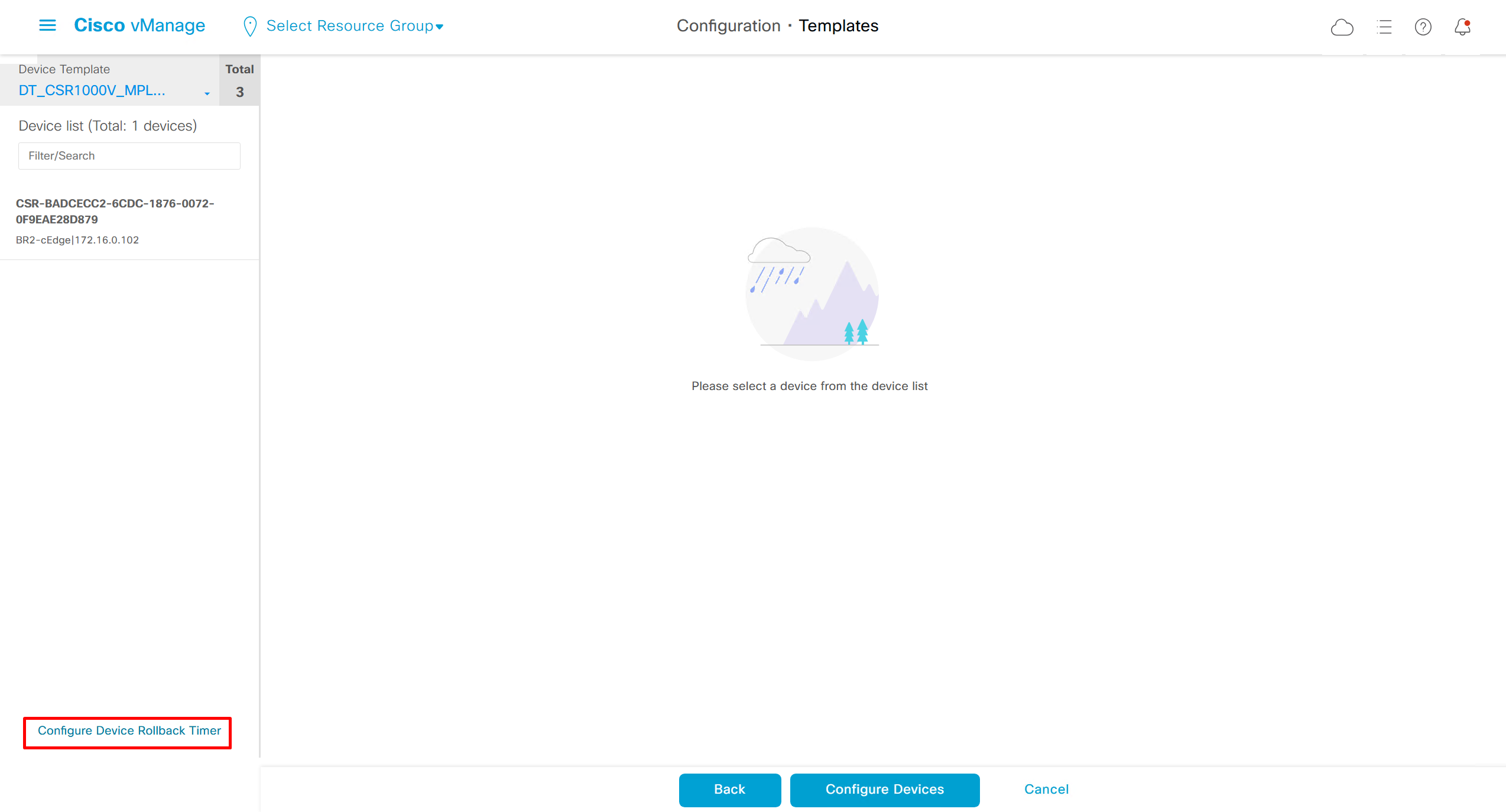
When making changes there is an option on the bottom left corner
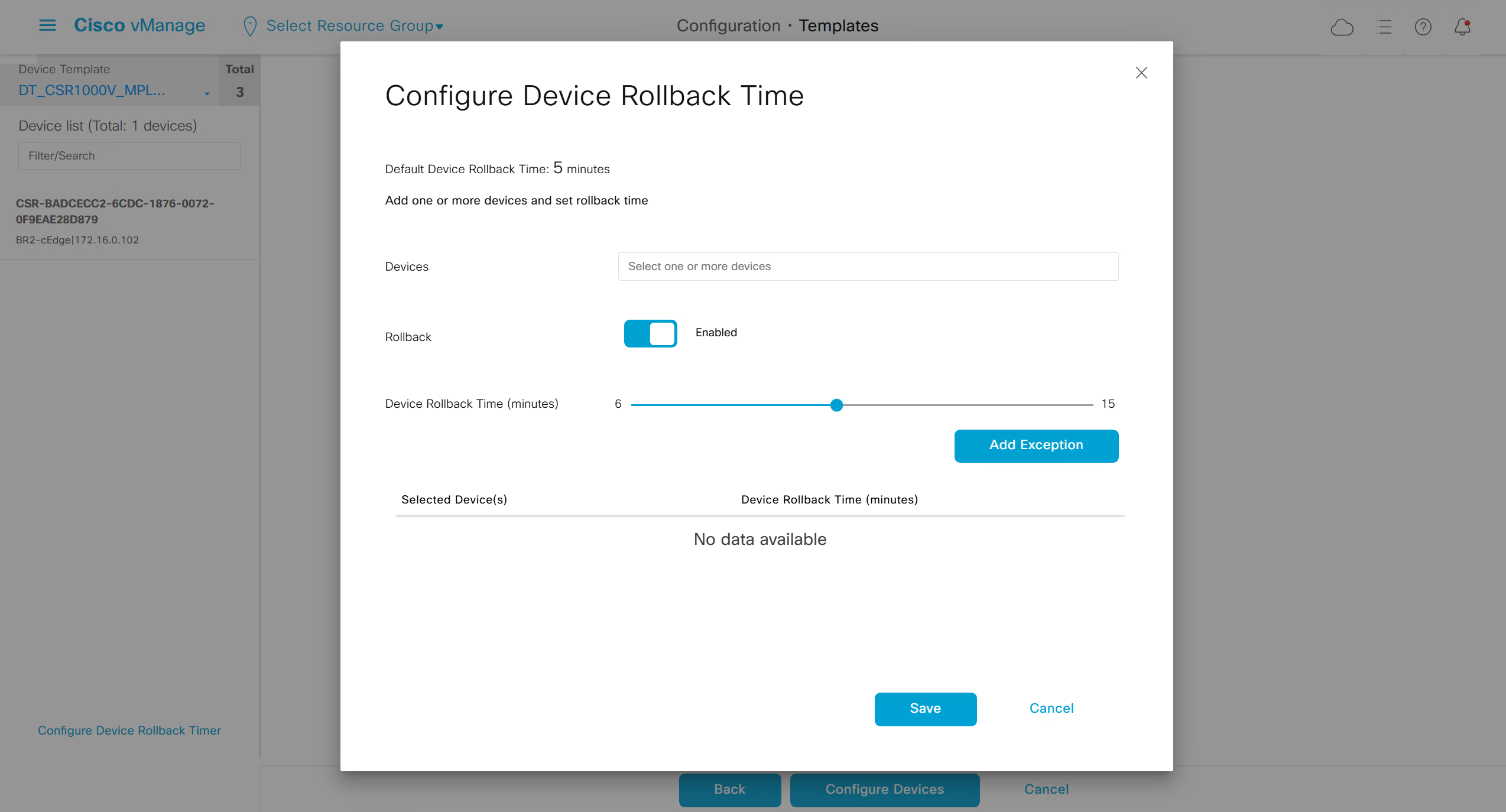
Configure Device Rollback Timer
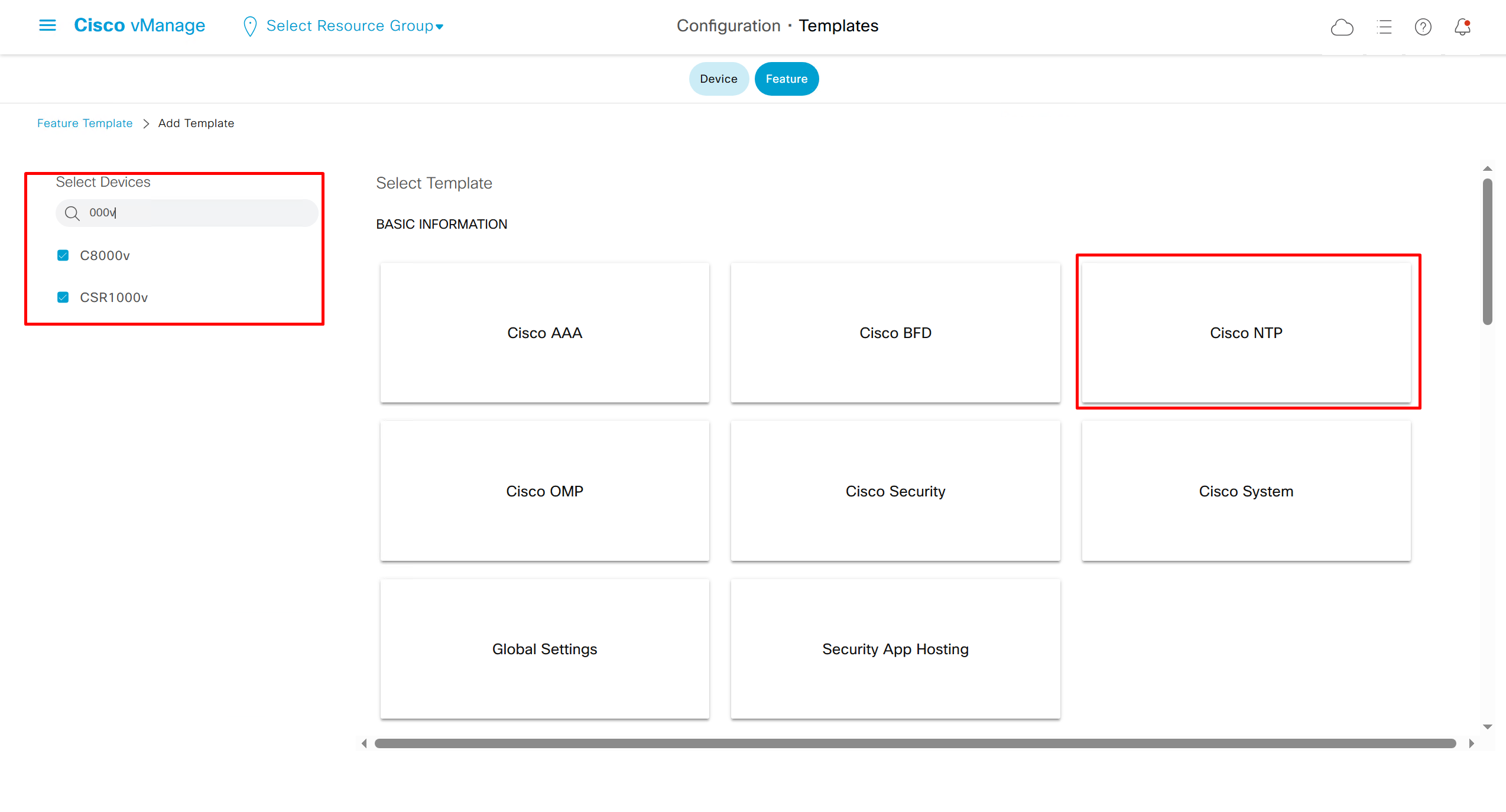
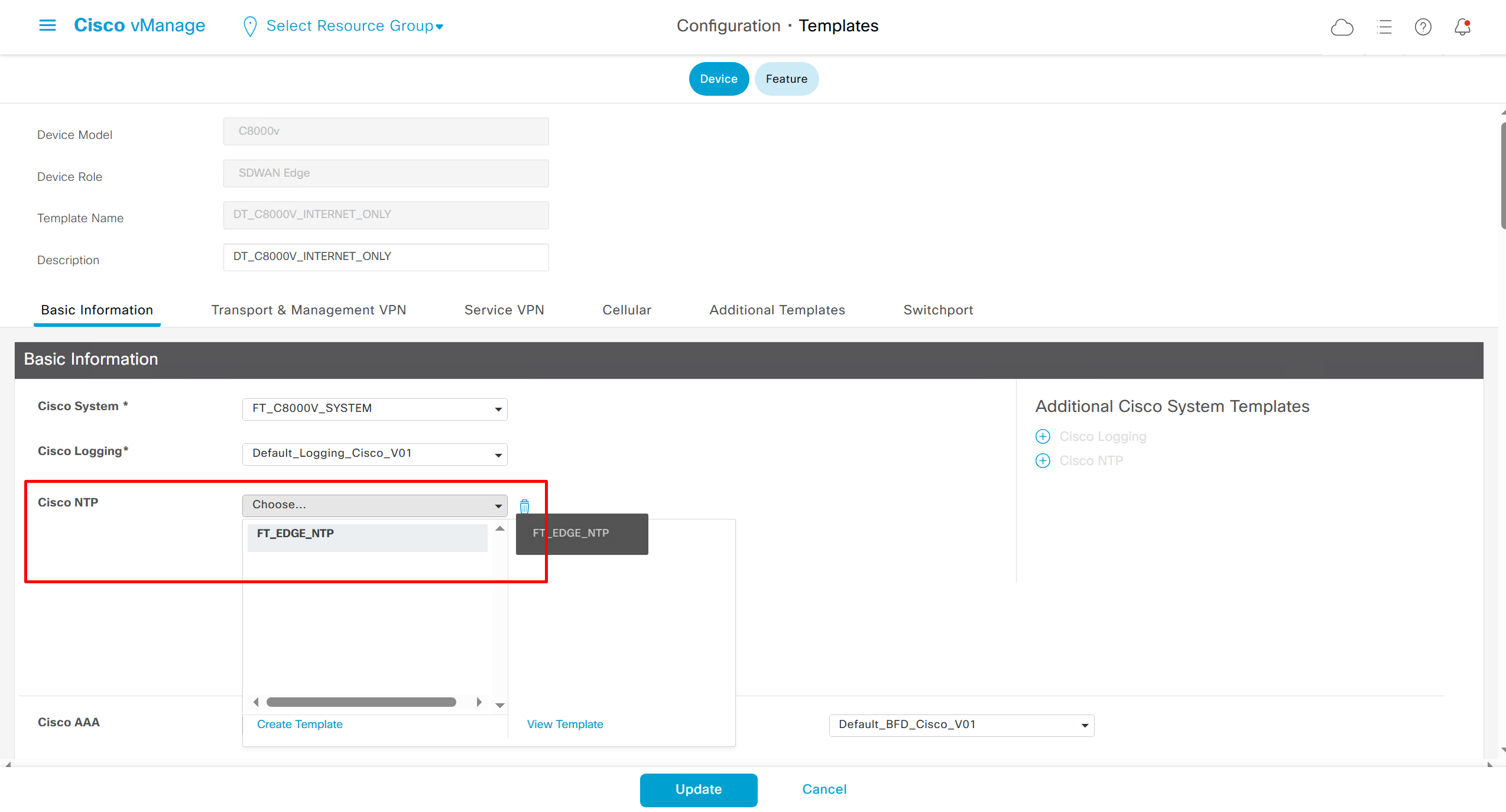
NTP Feature Template common for all edges
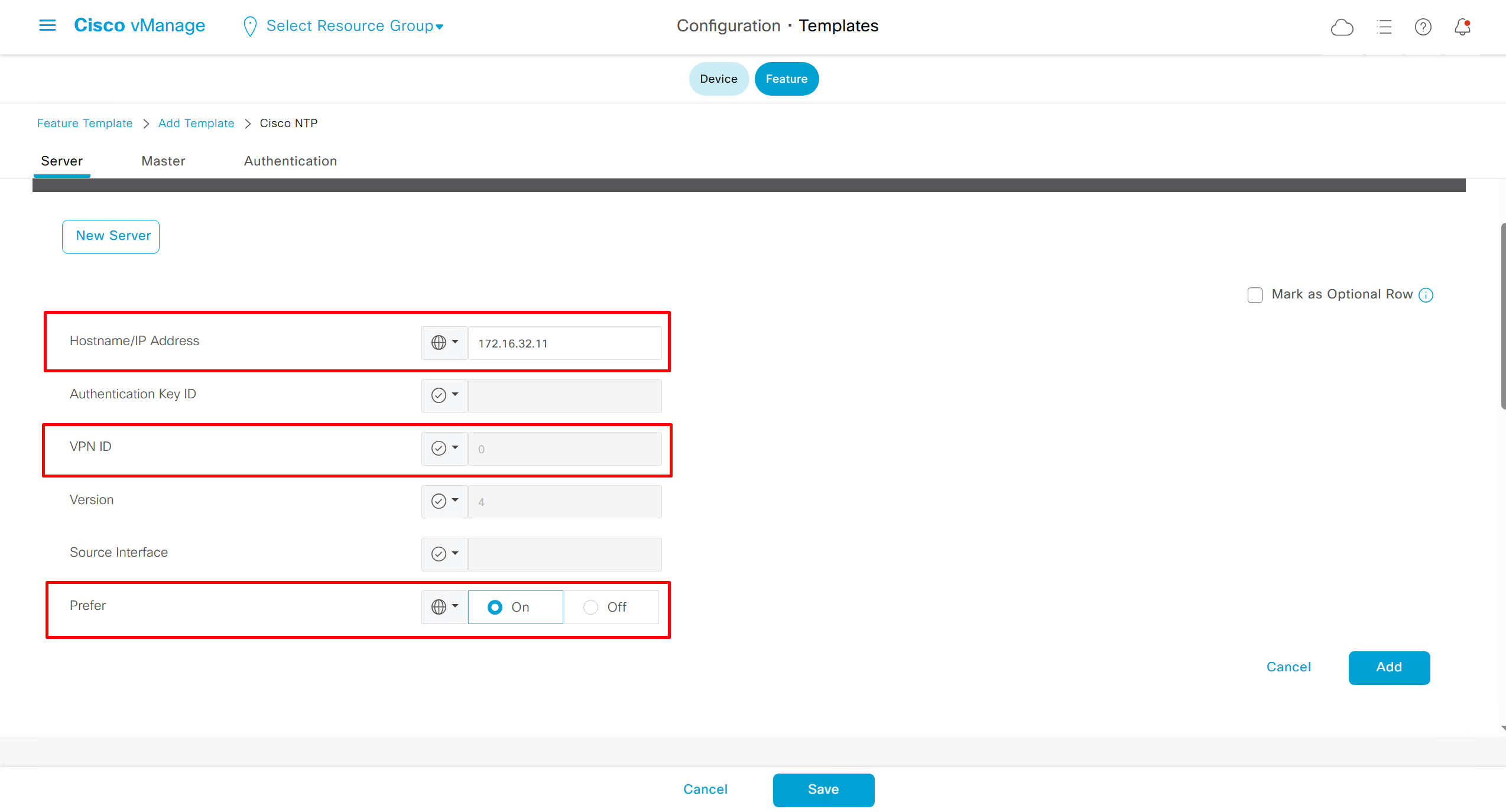

Login Banner Feature Template
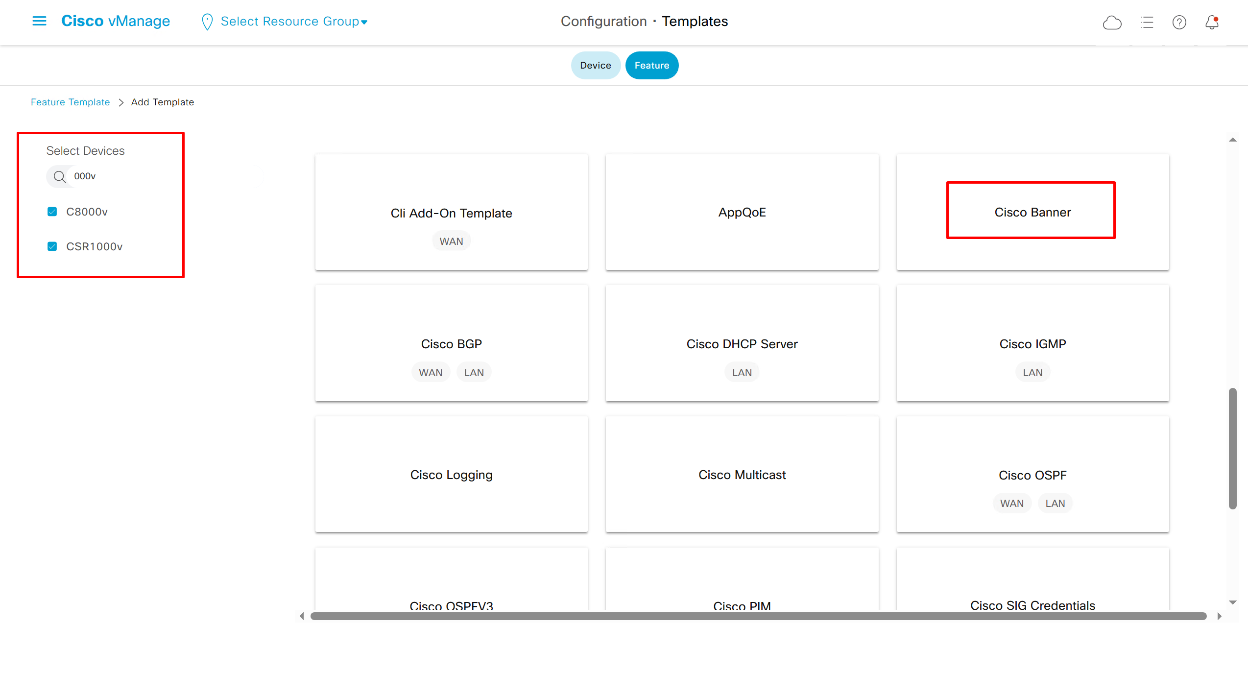
Banner text new lines should be replaced with \n so it can be pasted in this box
************************************************************\n* *\n* WARNING: Authorized Access Only! *\n* *\n* This system is for the use of authorized users only. *\n* Any unauthorized access or use is prohibited and *\n* may be subject to criminal and civil penalties. *\n* *\n* All activities on this system are monitored. *\n* *\n************************************************************
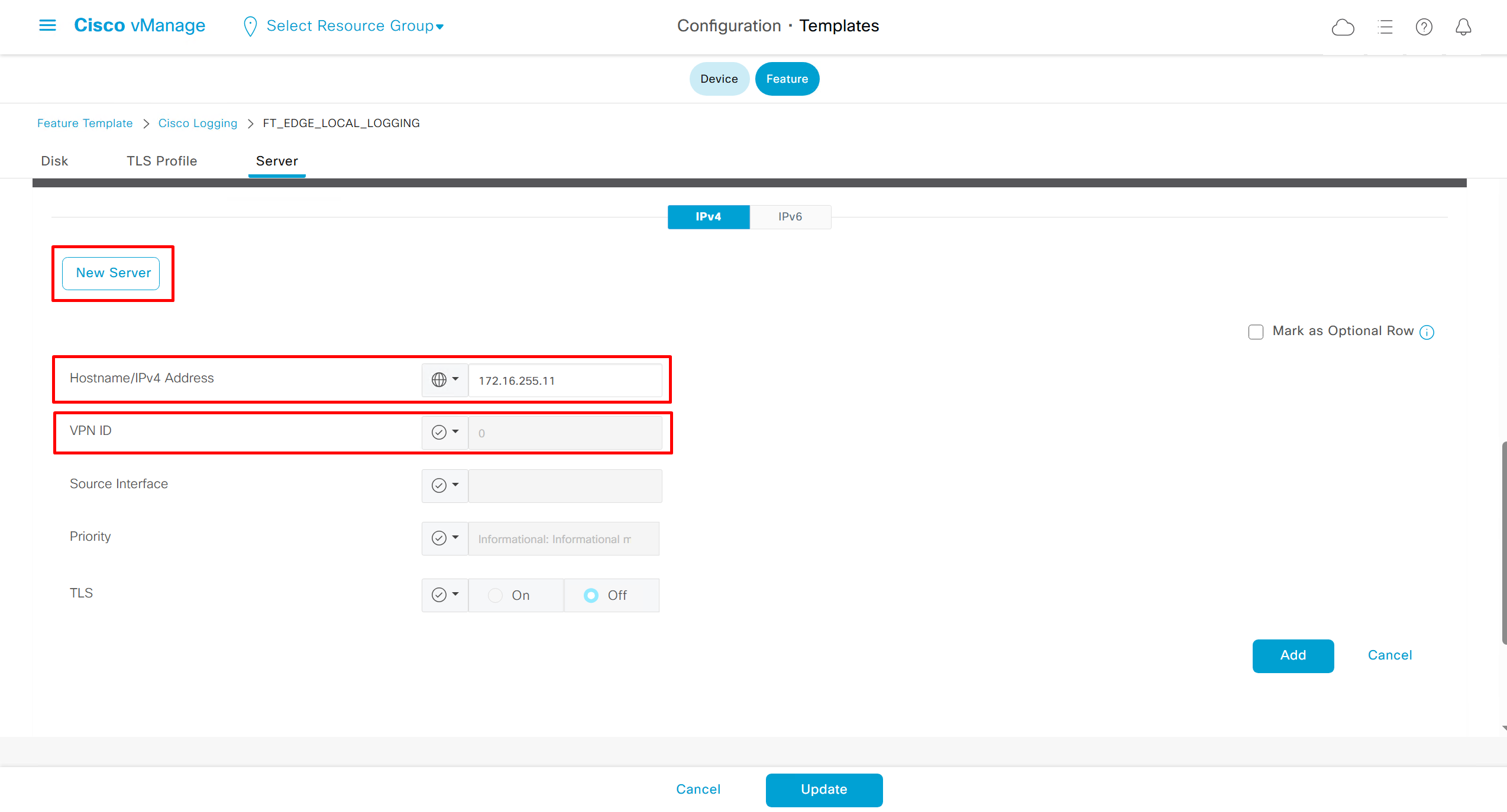
Local Disk Logging Feature Template
As log messages are in /var/log for troubleshooting
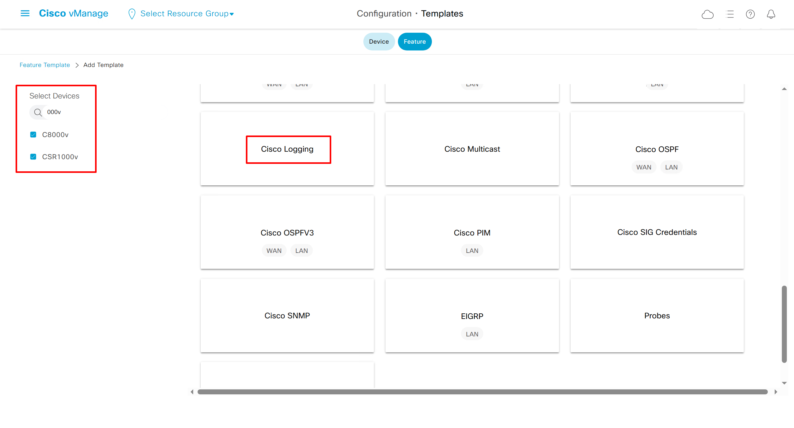
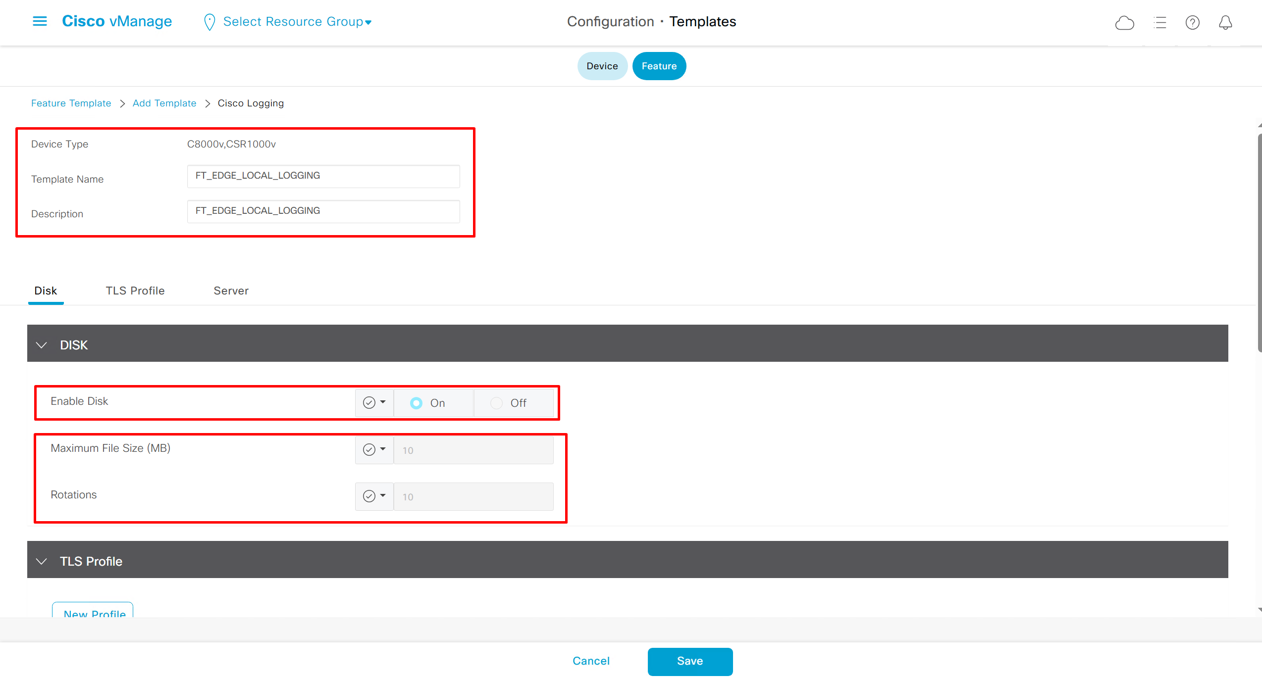
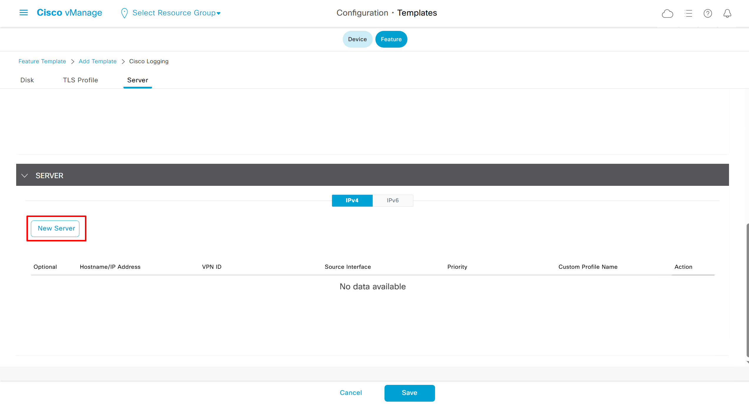
In case Syslog server is inside Datacenter and not over the WAN transport then we have to change the below VPN number and change it from 0 to service side VPN / VRF number of local site / datacenter in which Syslog server lives
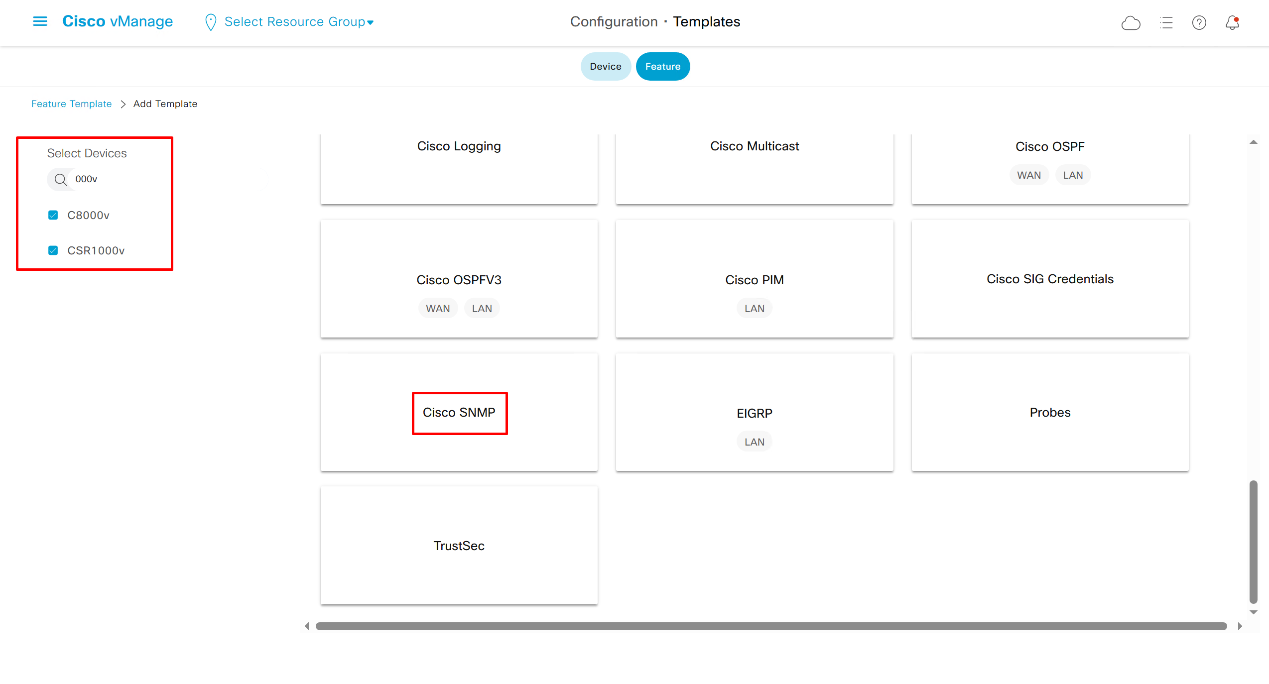
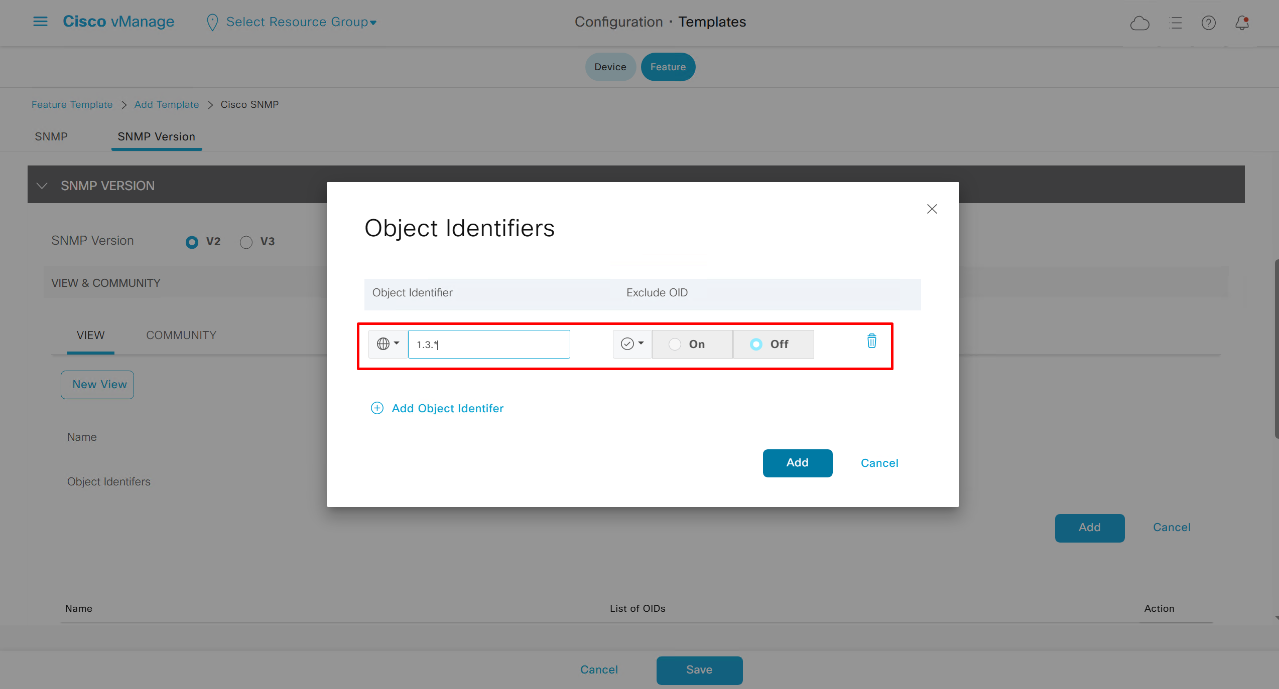
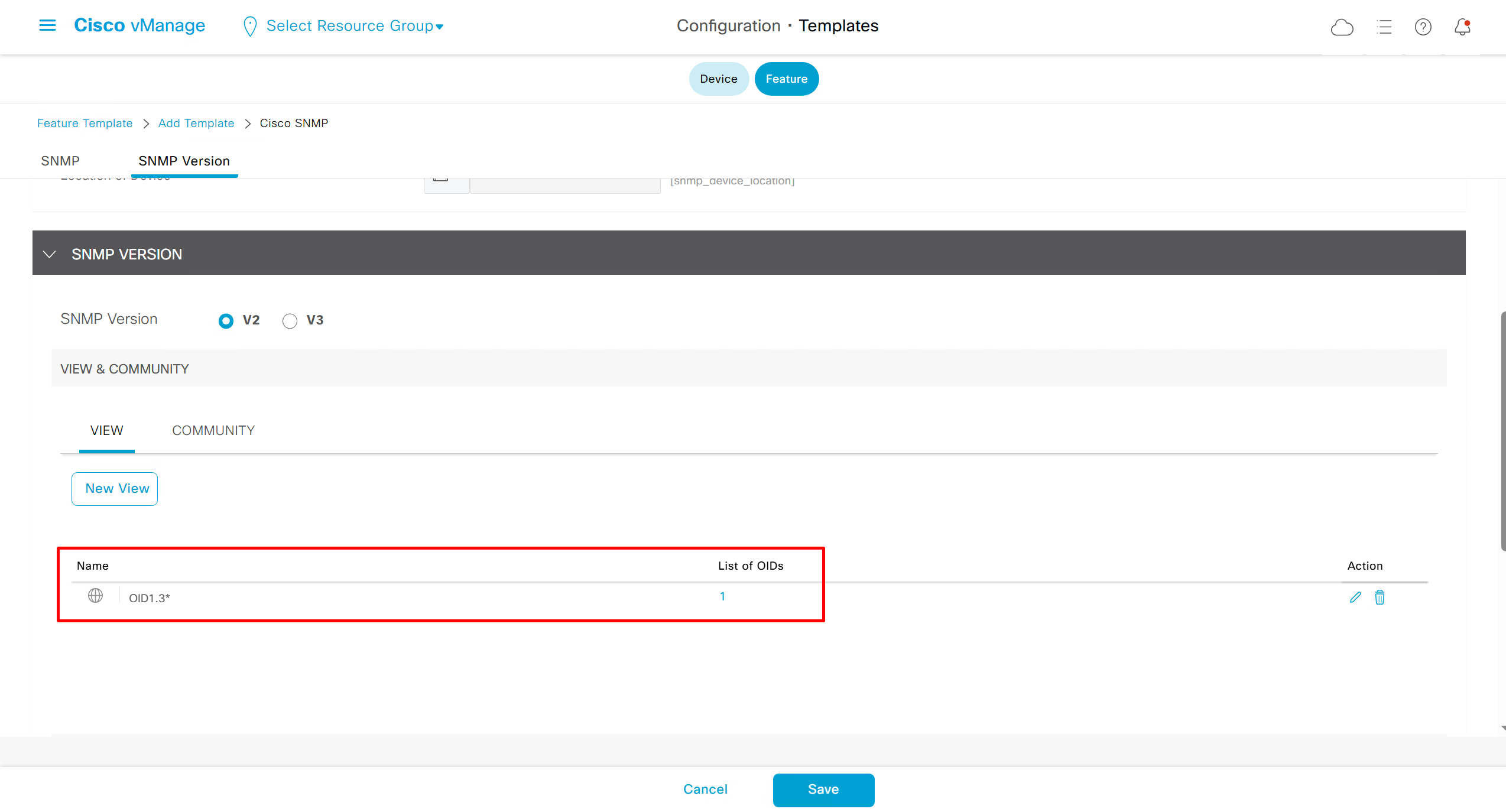
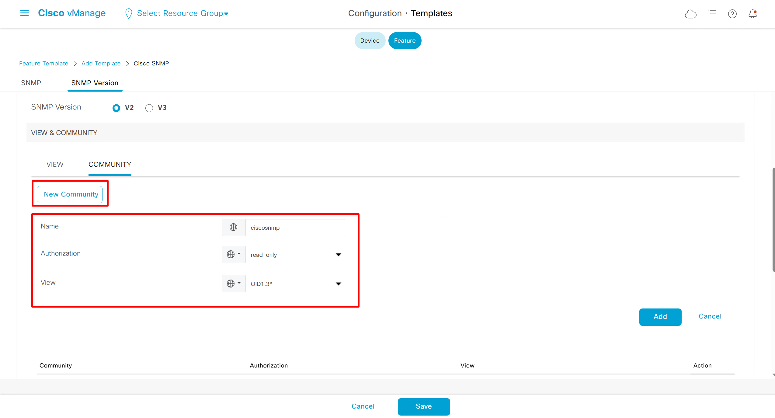
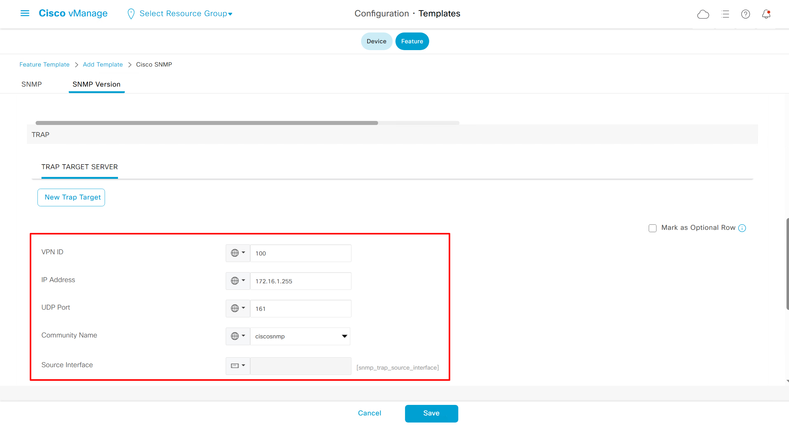
SNMP Feature Template

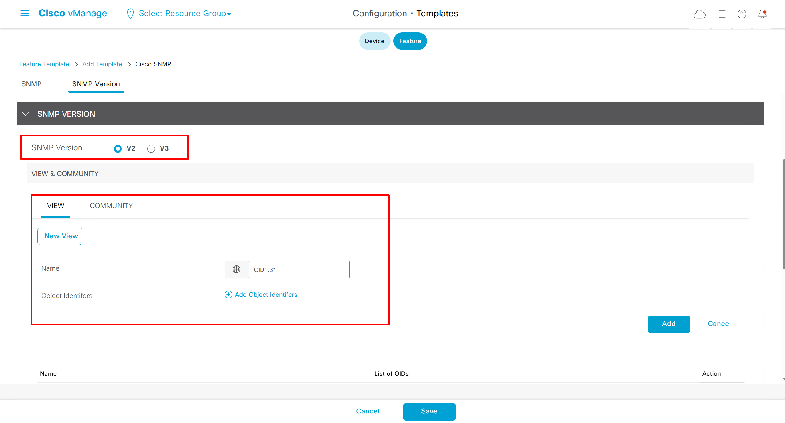

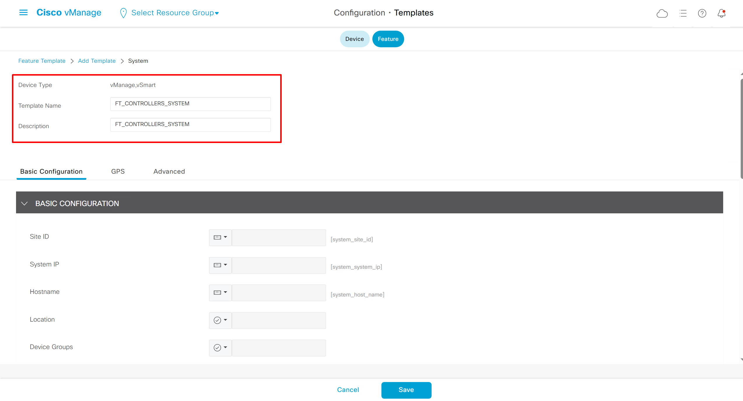
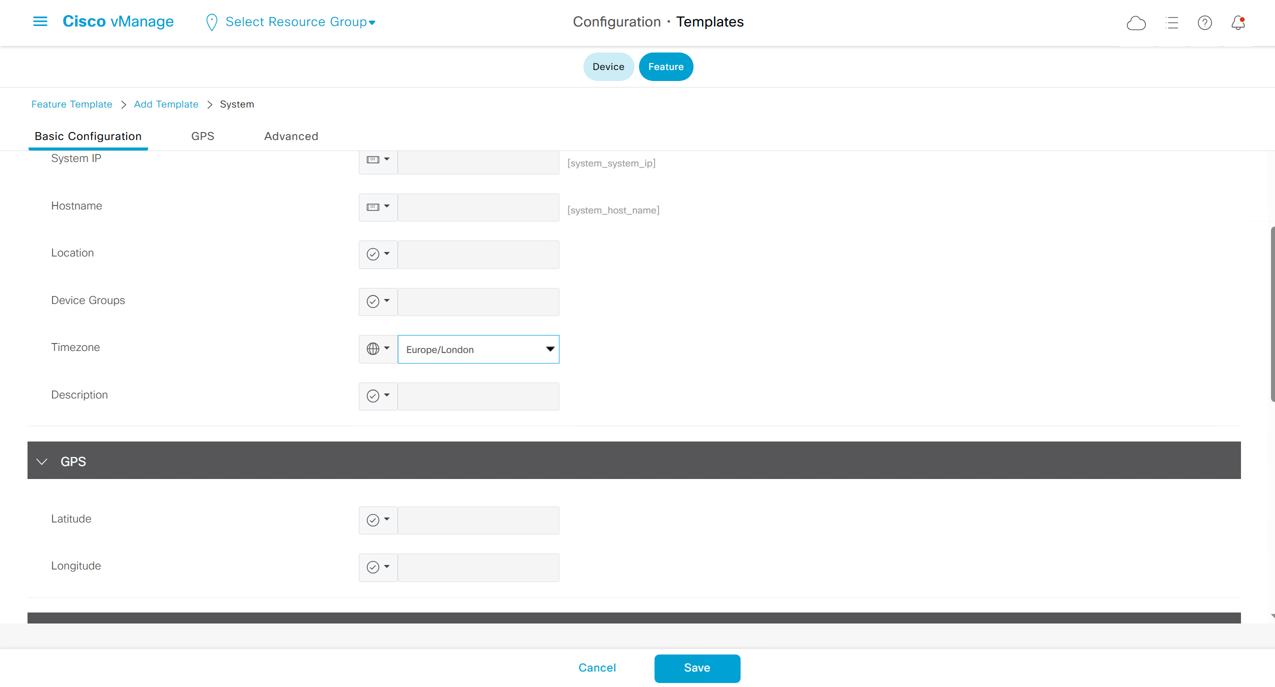
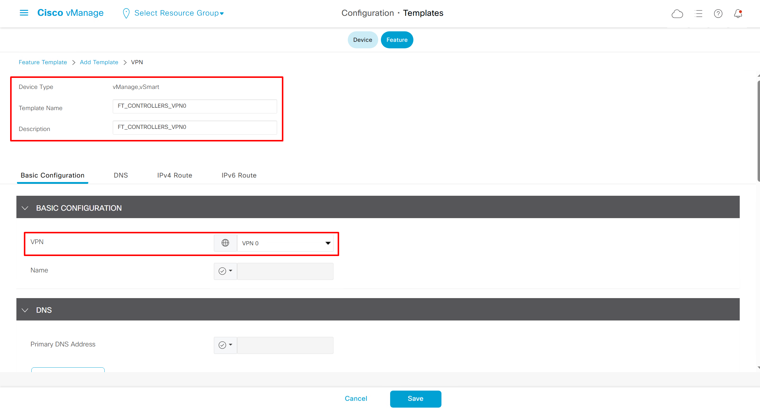
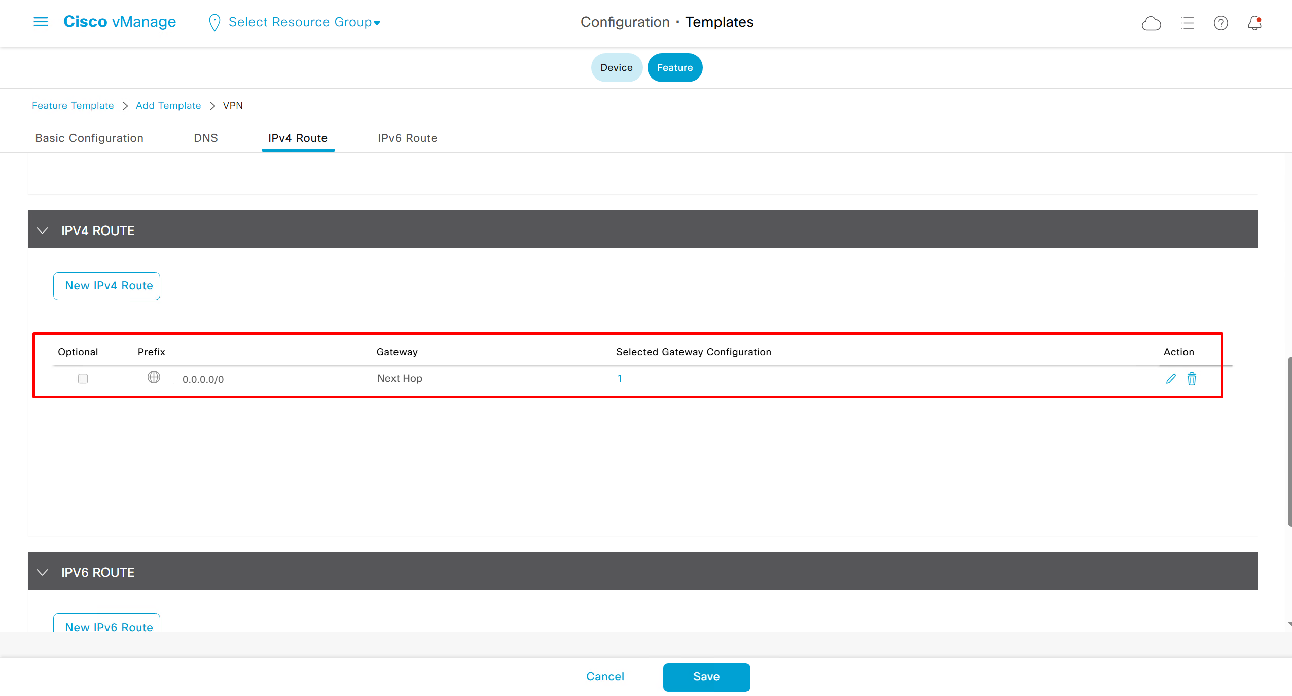
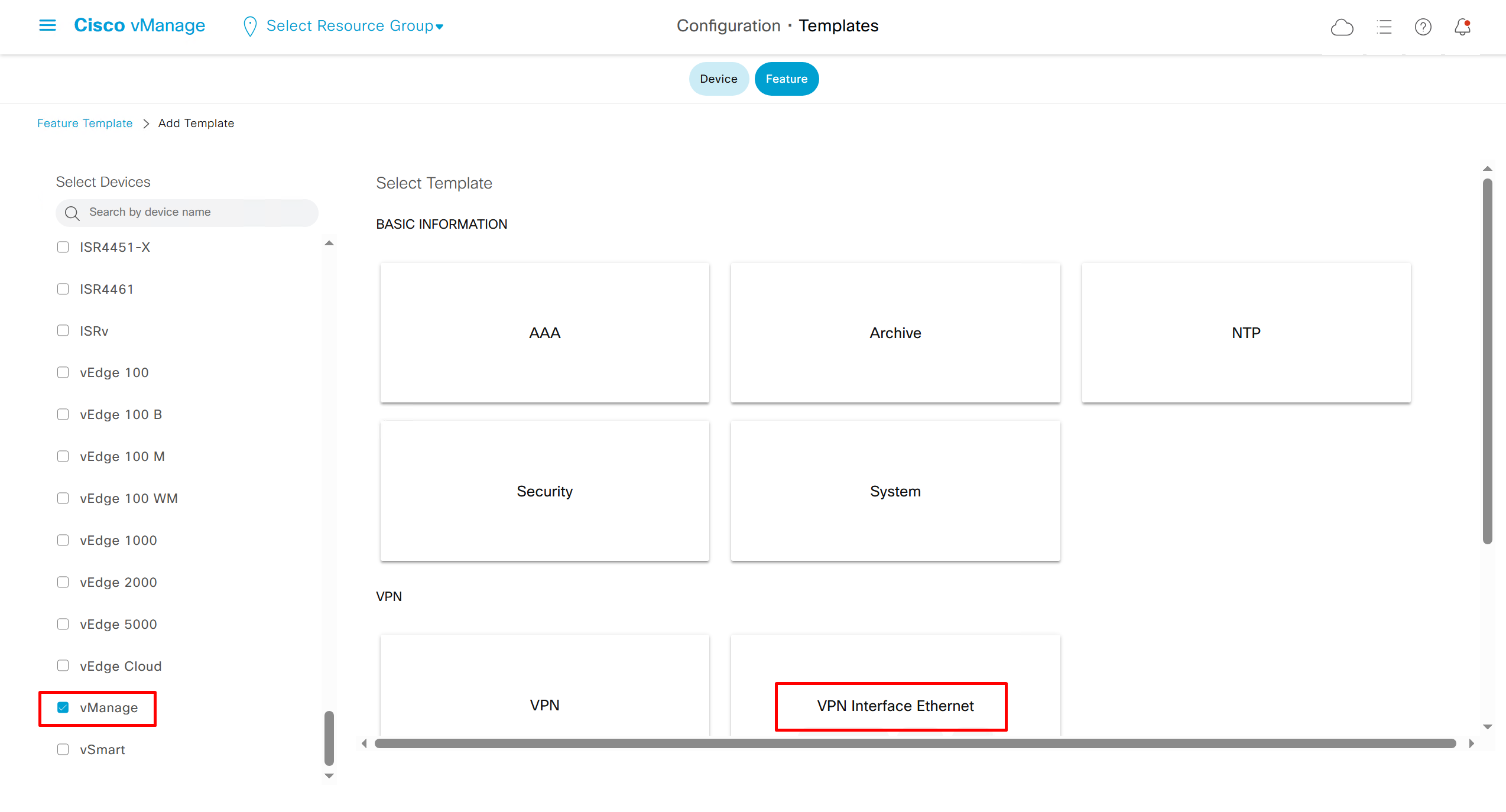
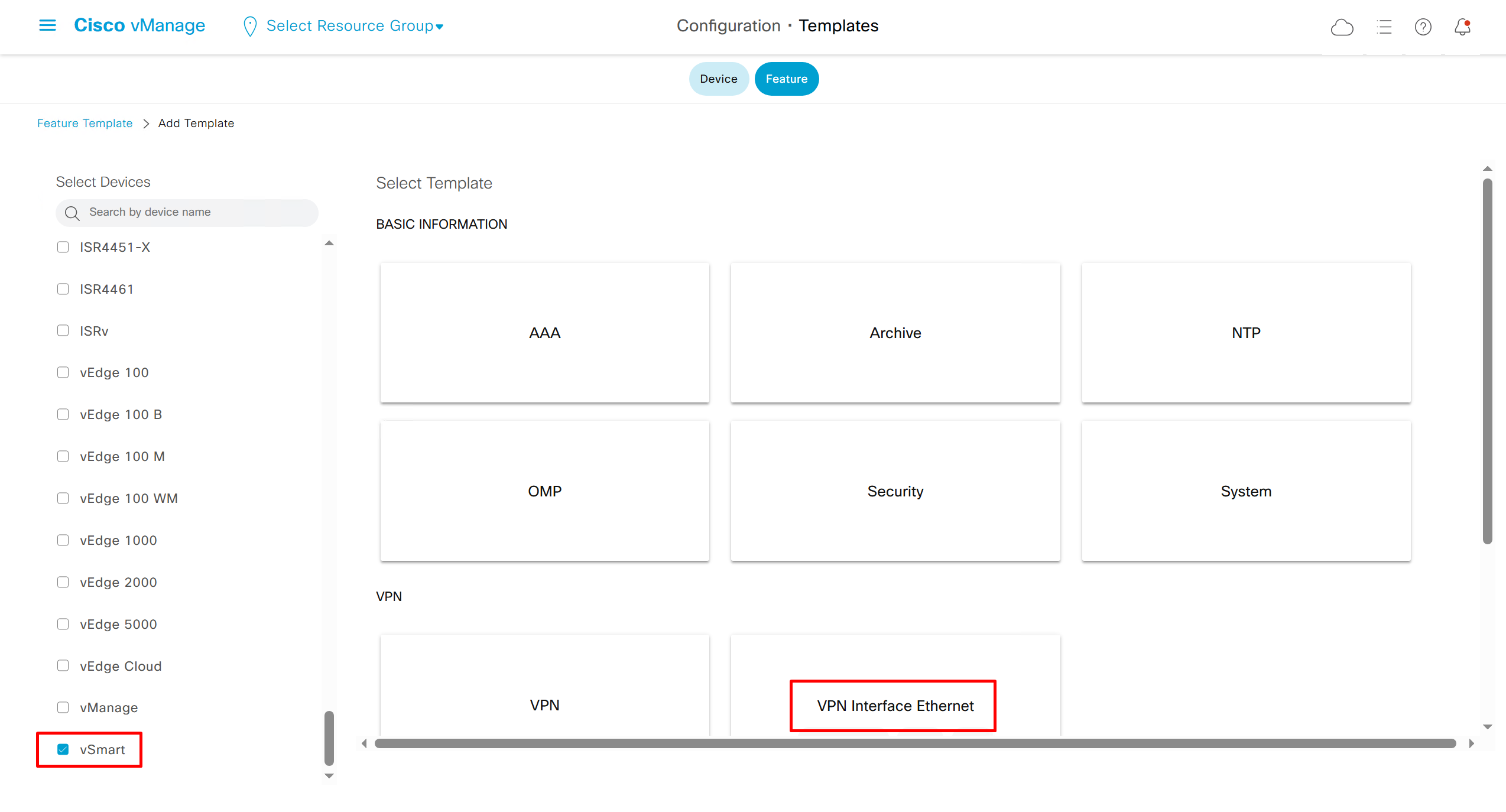
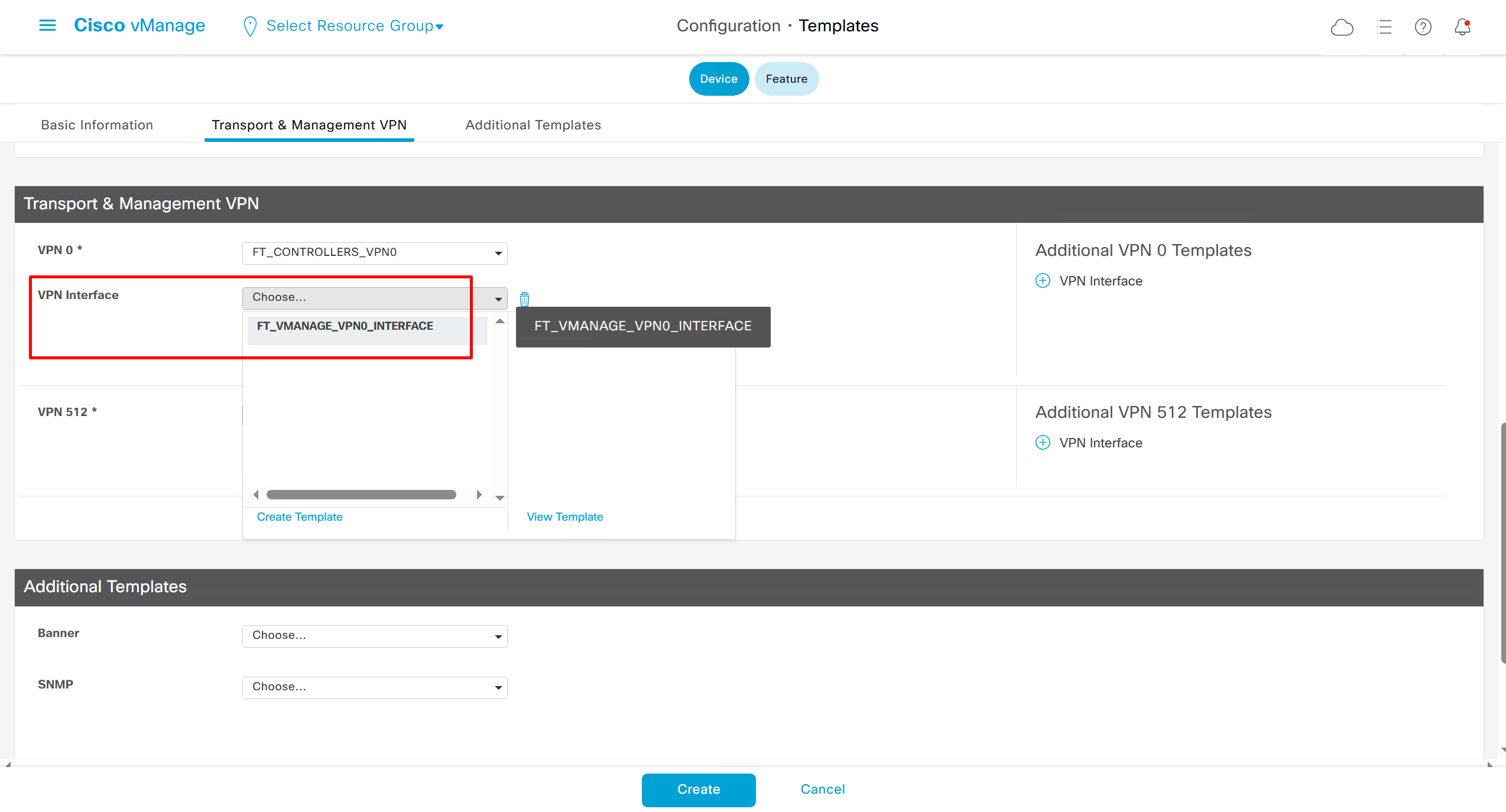
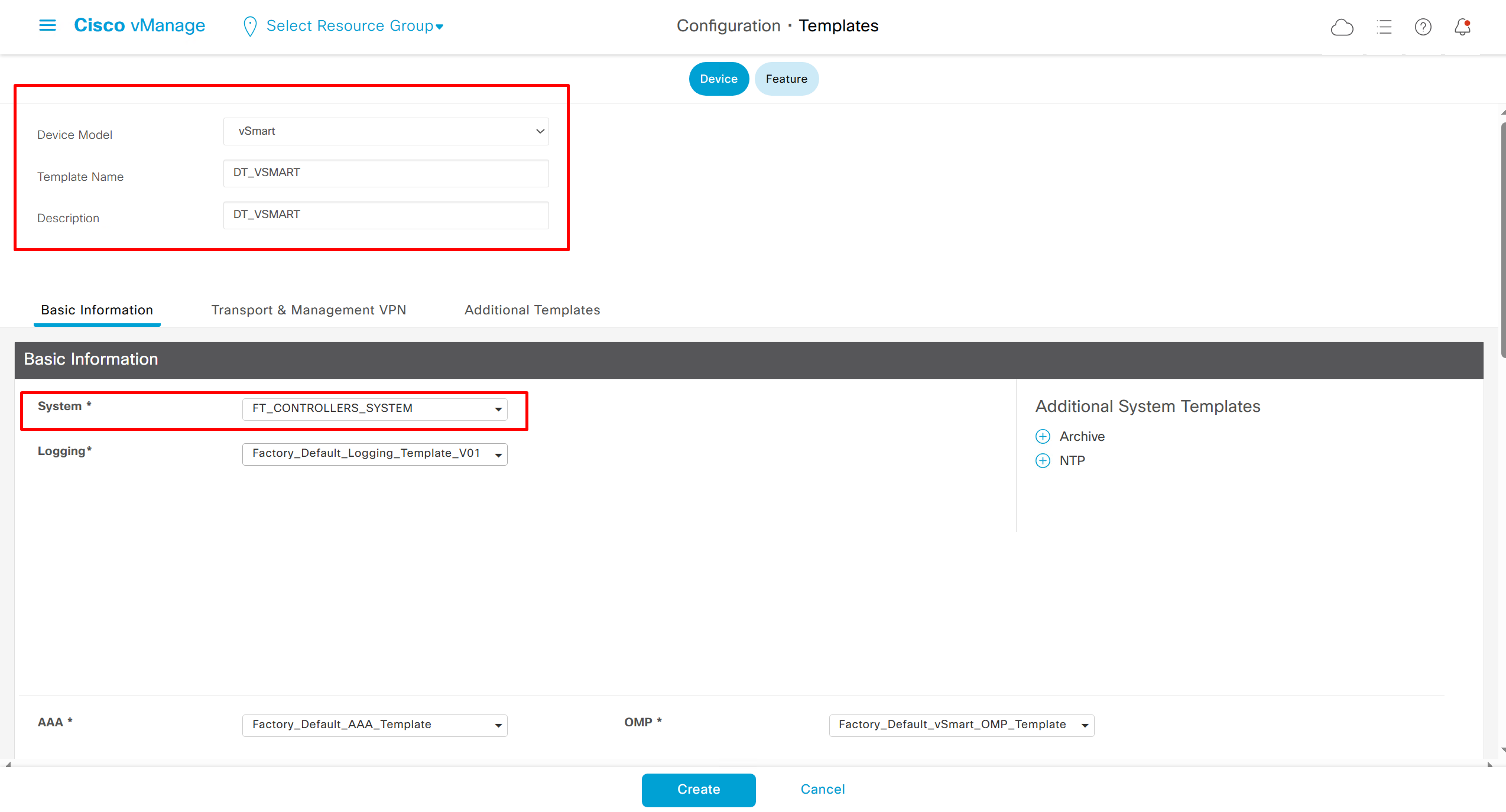
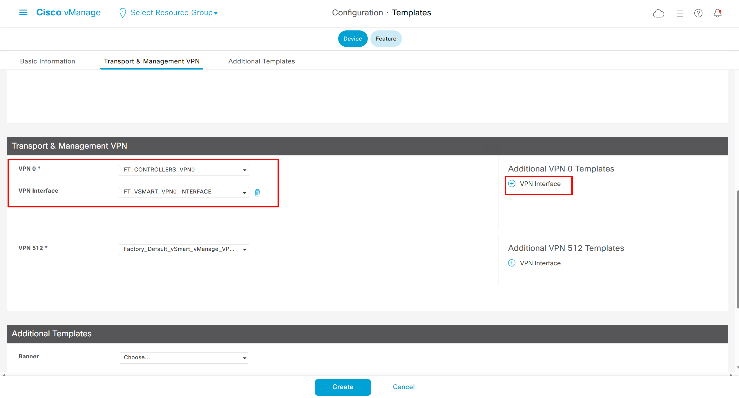
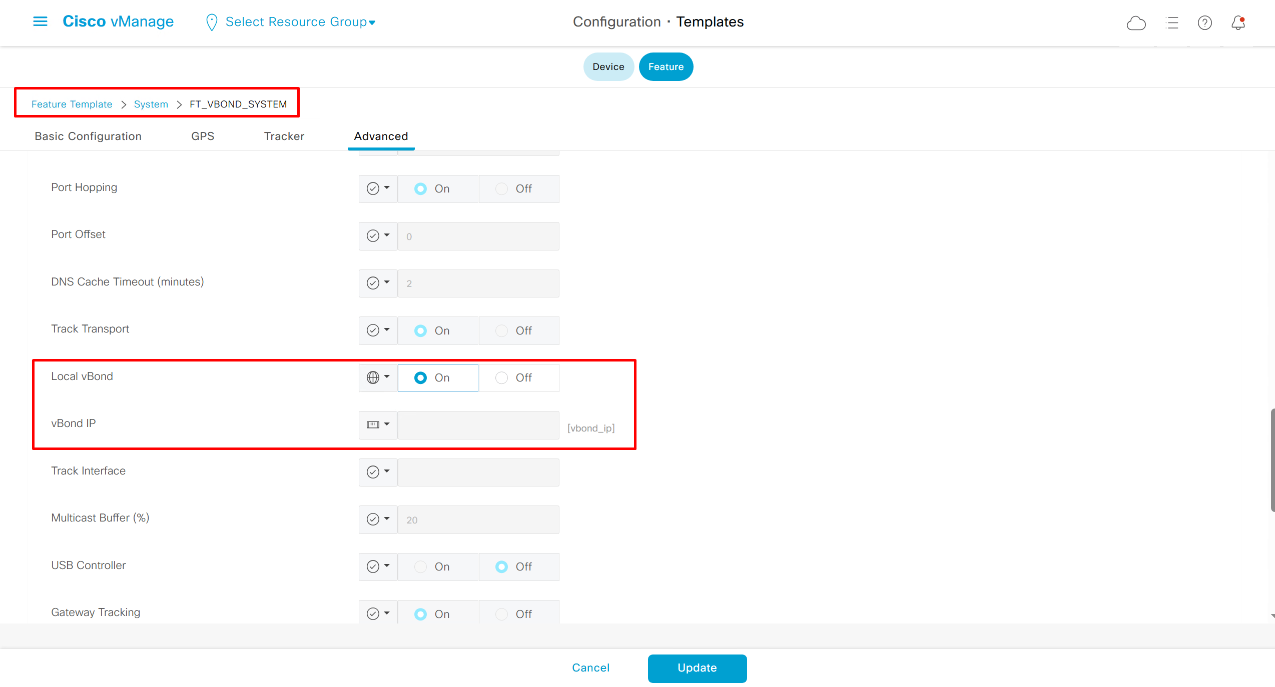
Templates on Controllers
Remember that we need to configure system, vpn 0 (routing table for transport) and interface feature templates
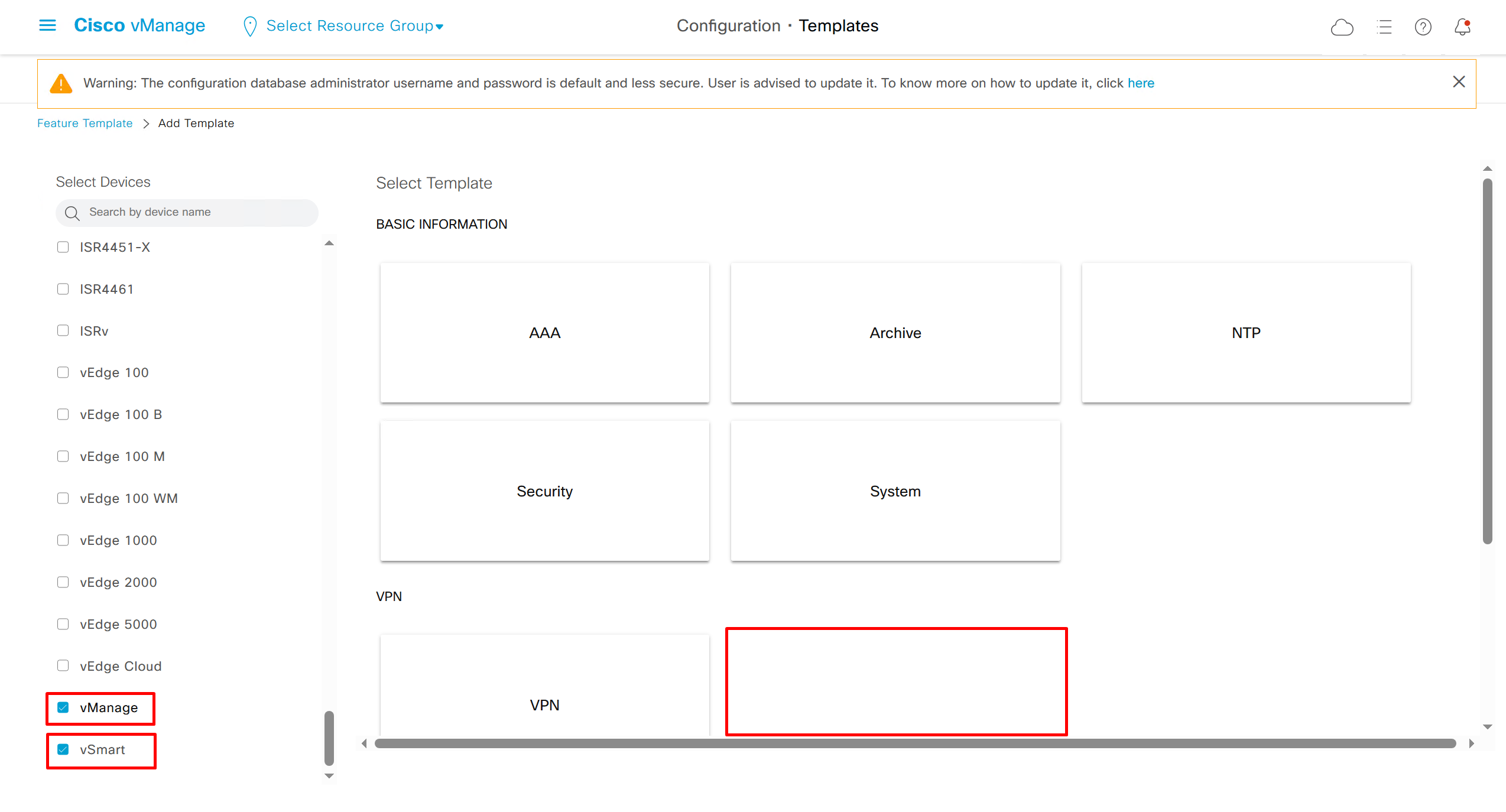
but when device type vManage and vSmart, template types are reduced

with vmanage and vsmart selected we can have common feature template for system and vpn
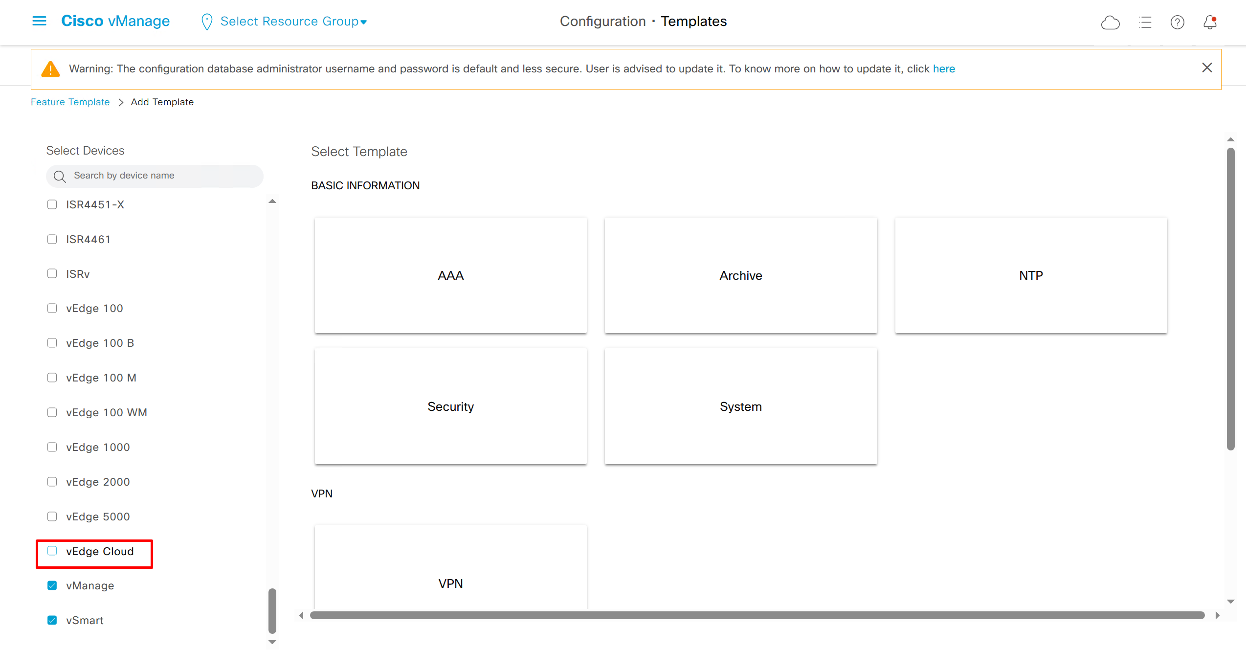
vedge cloud is applied on vbond
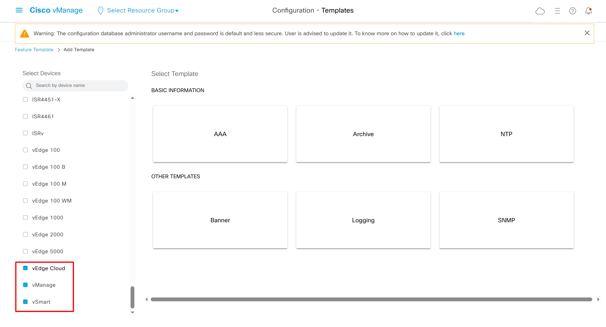
we are more limited in terms of template when we select vedge cloud, vmanage and vsmart
Lets configure template for vmanage

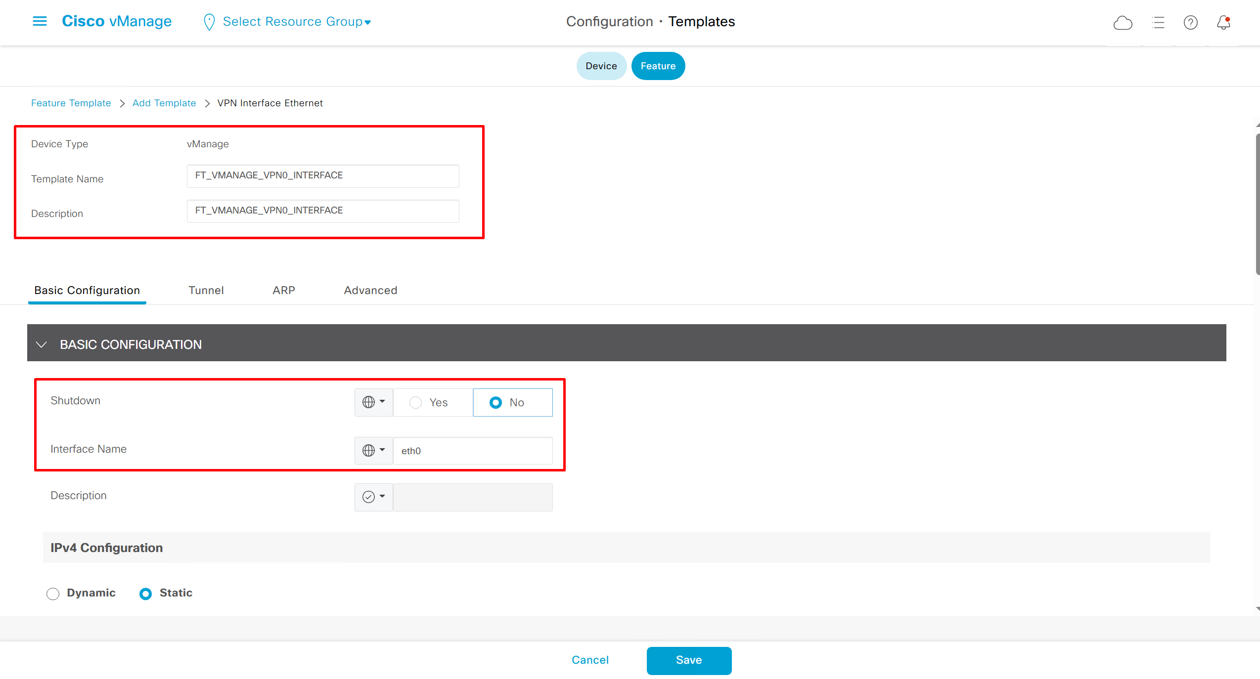


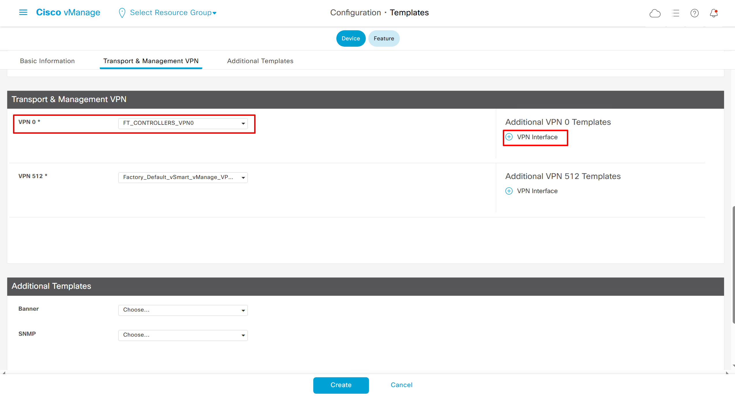
SDWAN – GUI
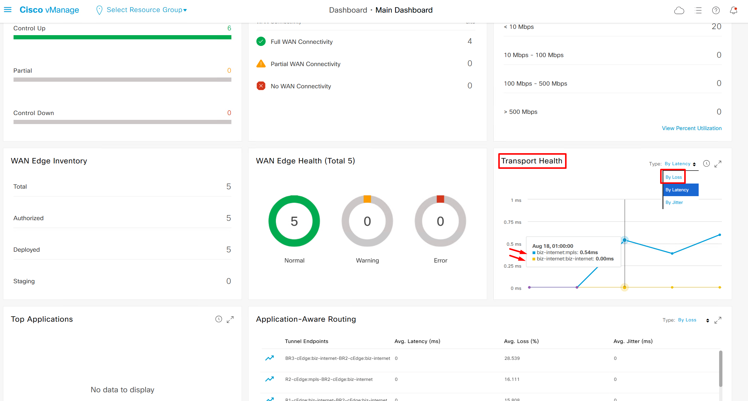
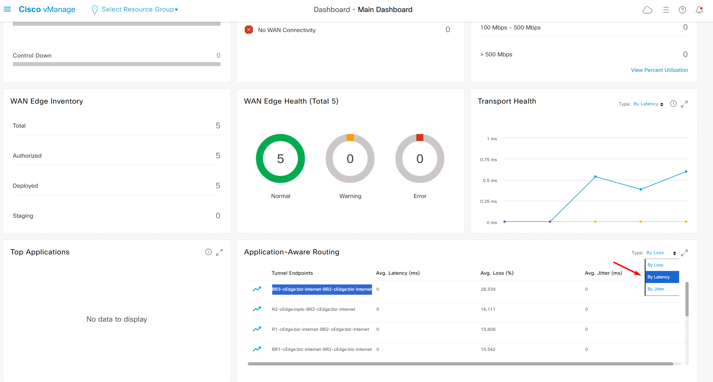
This transport health is of different transports to transports and by loss by default

We can see that these are BFD stats telling us that BR3-cEdge (branch 3) to BR2-cEdge (branch 2) there is Avg Loss of 28.539 %, this is per connection as compared to color to color stats shown in “Transport Health”
It is displayed by loss by default
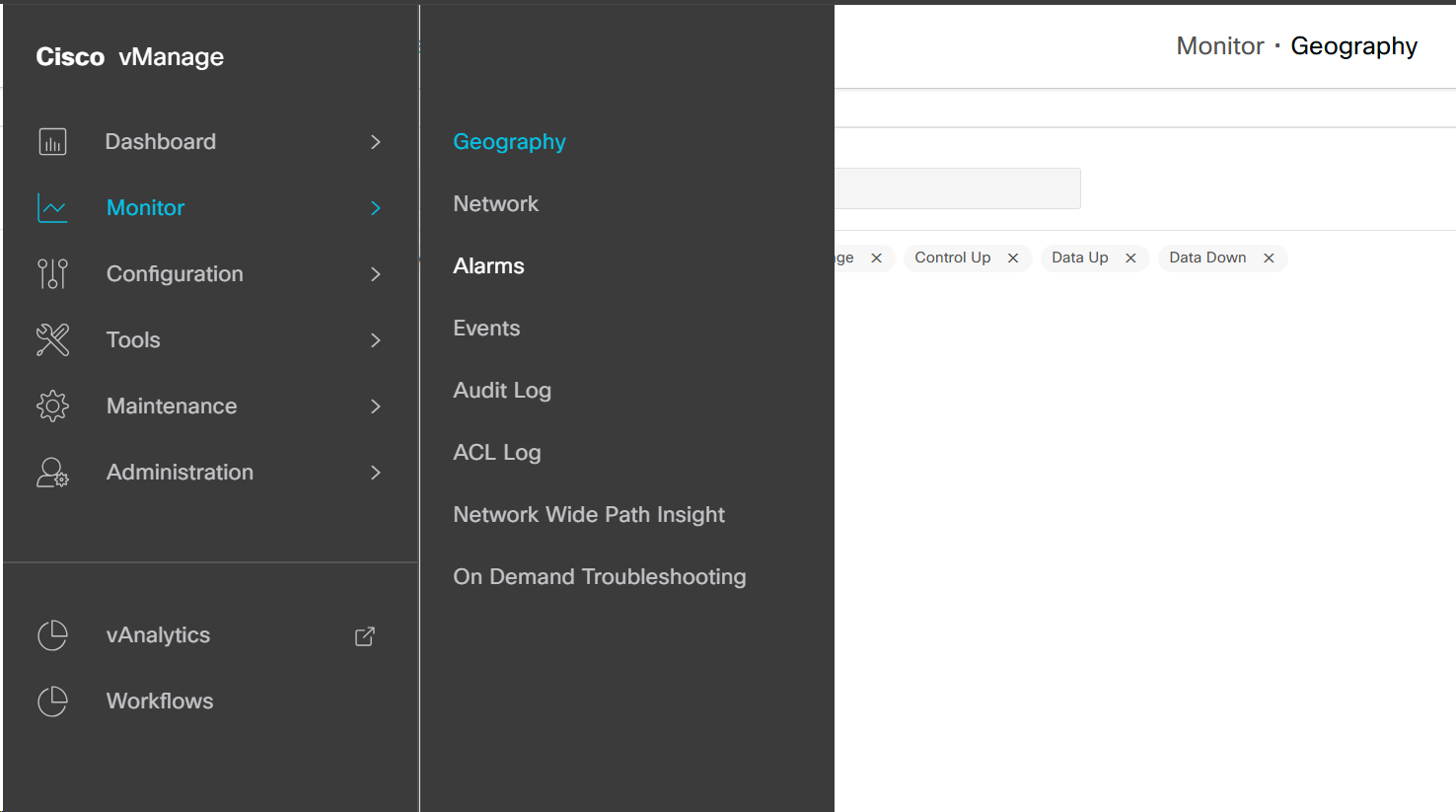
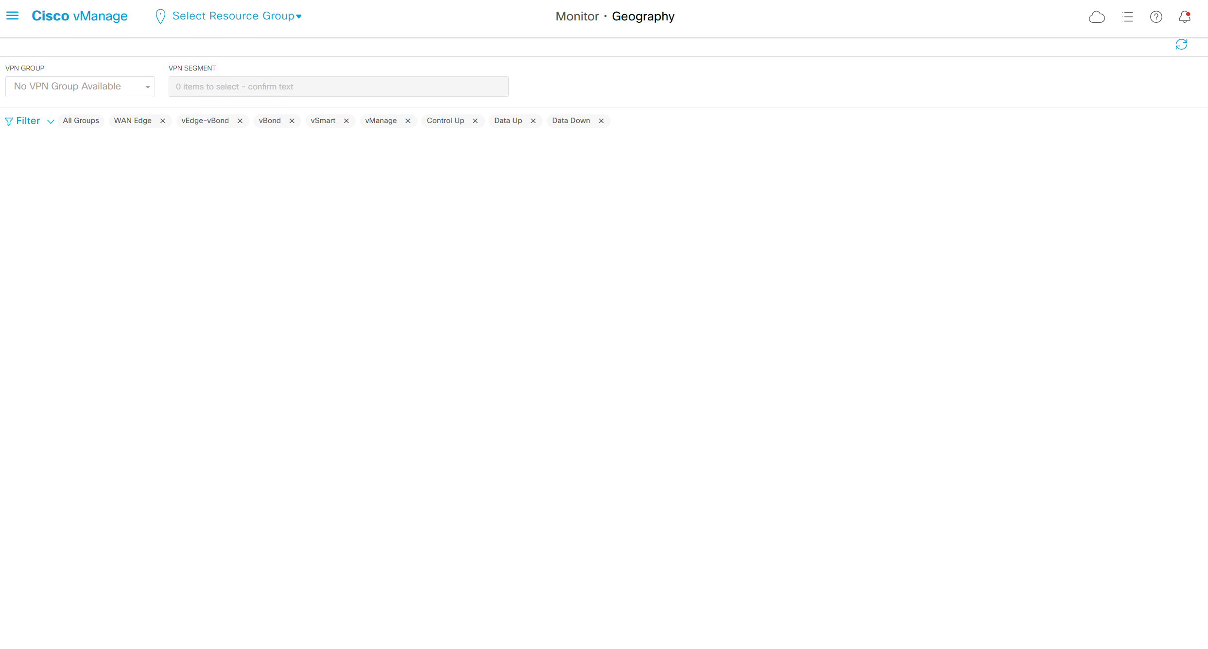
Monitor > Geography shows geographical location of our sites / edges
for now because we have not assigned any coordinates, it shows as blank
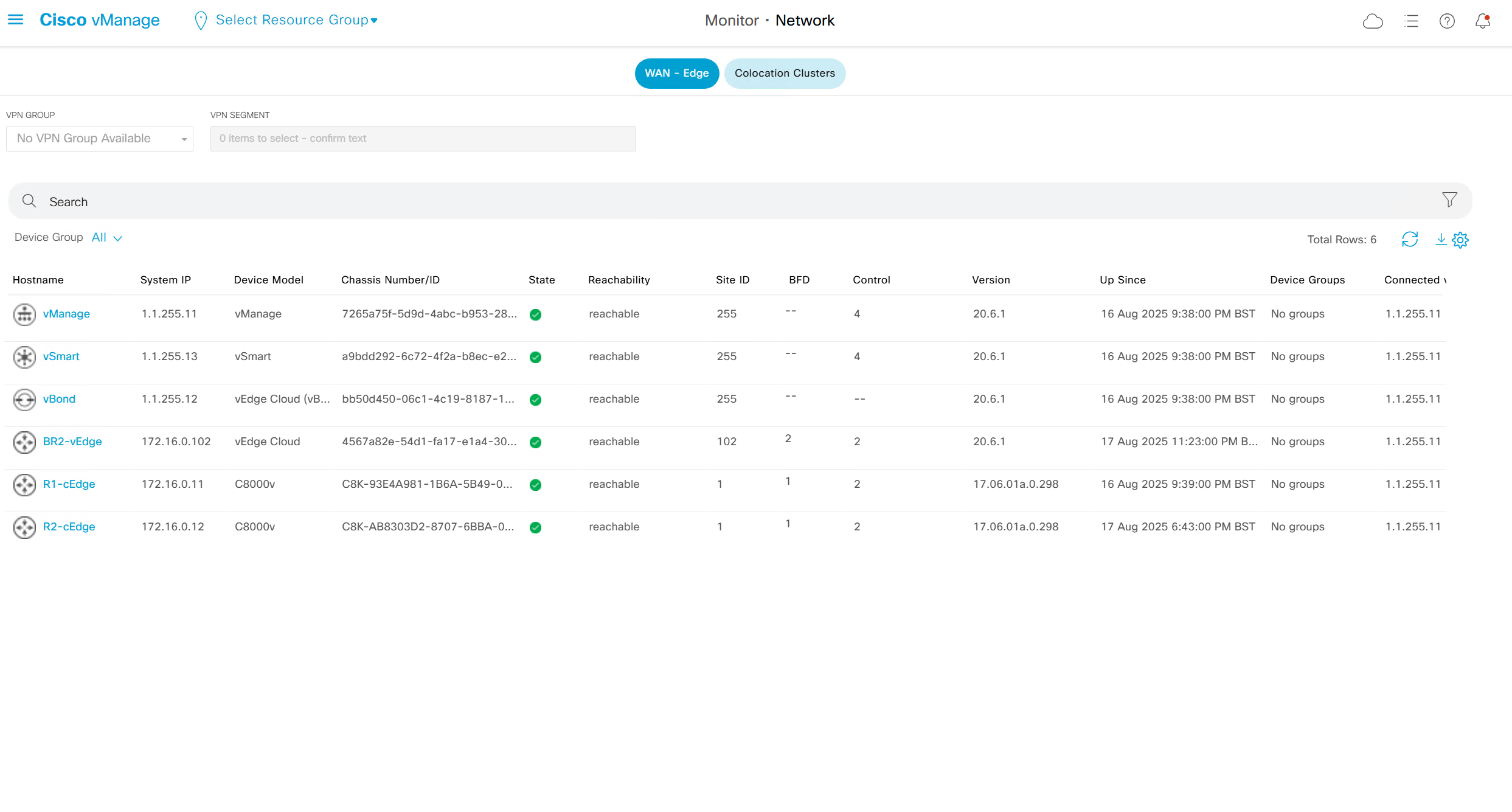
Monitor > Network
shows all network devices and all of their information such as names, states, system ip, reachability, site id, bfd tunnels, control DTLS sessions, version, up since, device groups etc
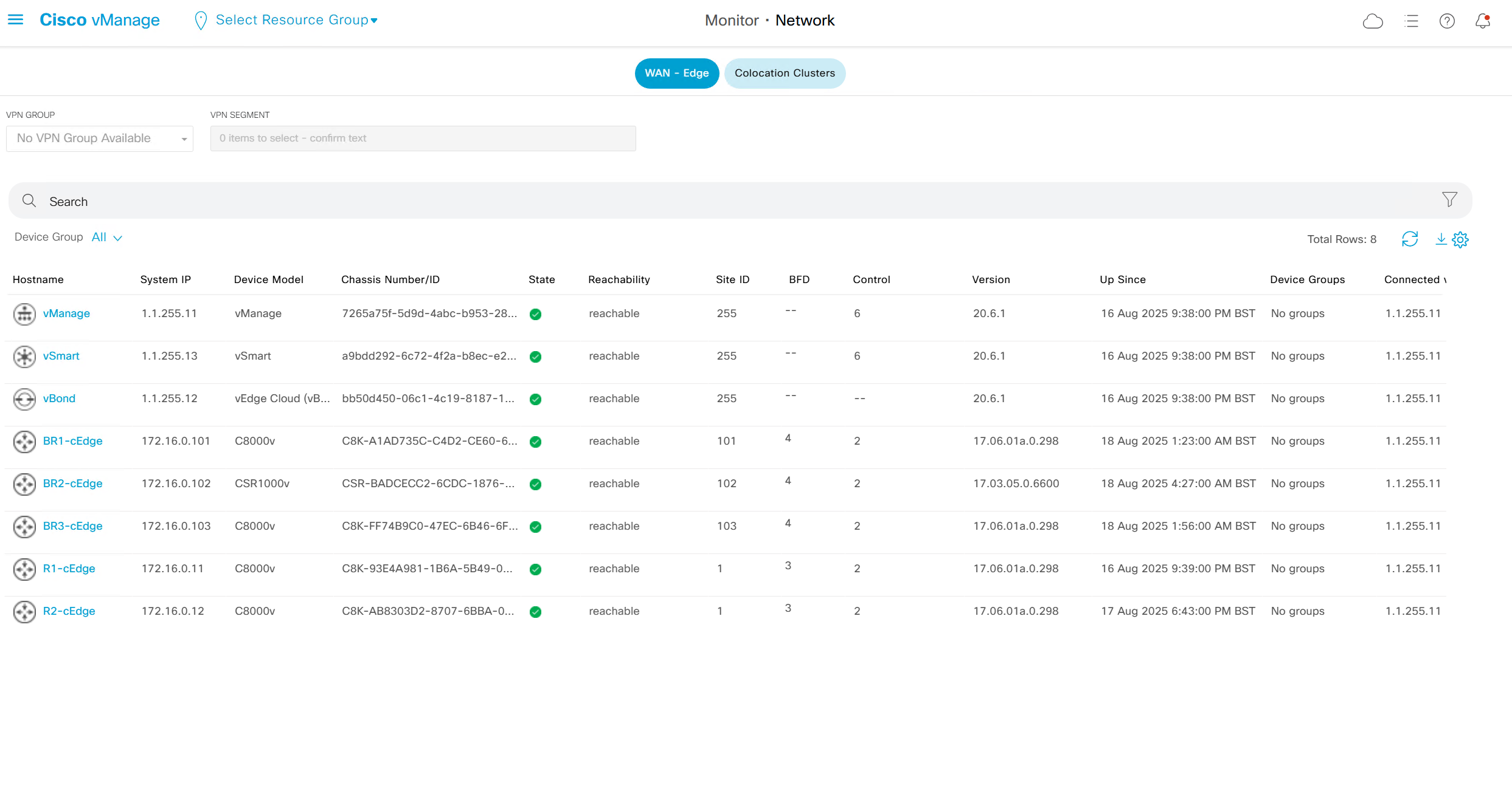
Clicking on one of the devices takes us into the device
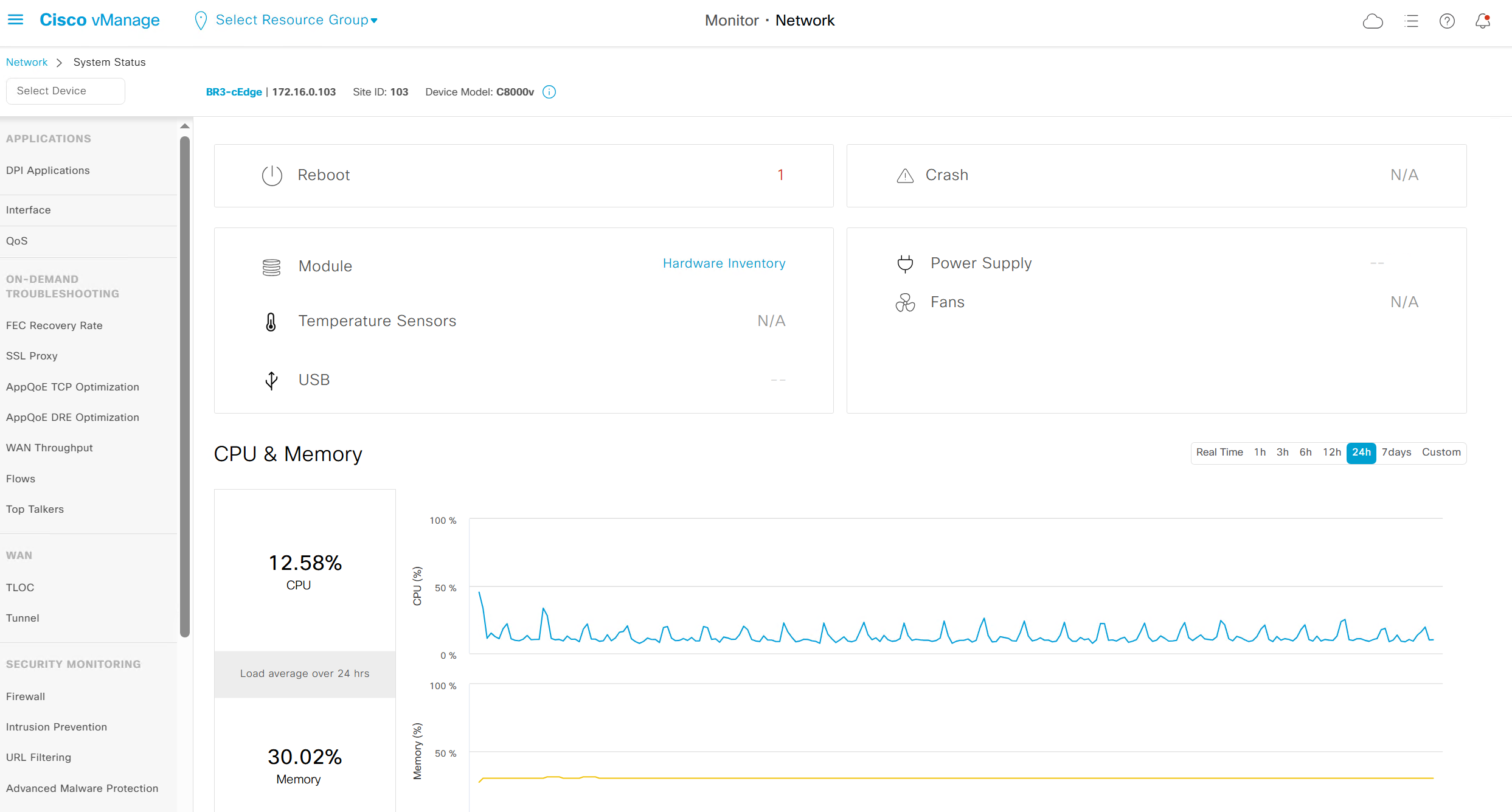
we can see hardware inventory, power supply and fan info – reboot menu – CPU and memory
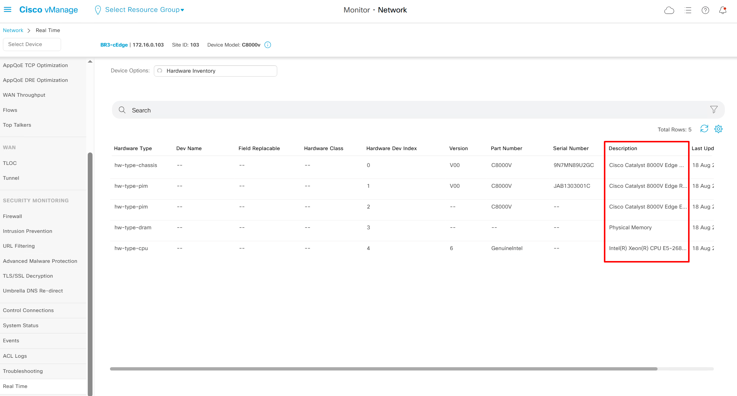
Hardware Inventory
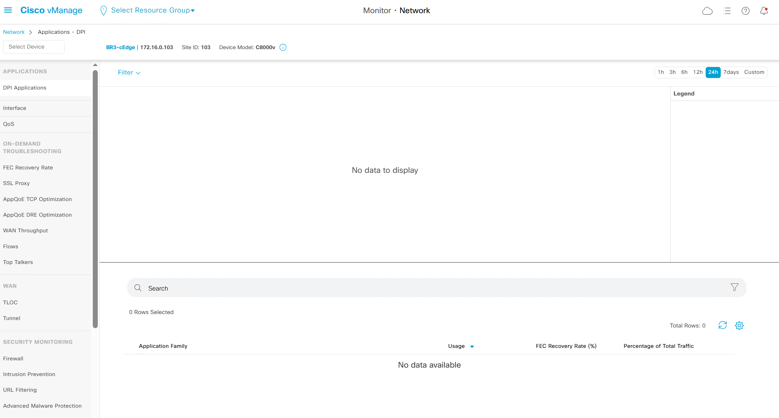
DPI Applications – when traffic passes through router, traffic discovered applications show here
it is not showing as no traffic is passing through router
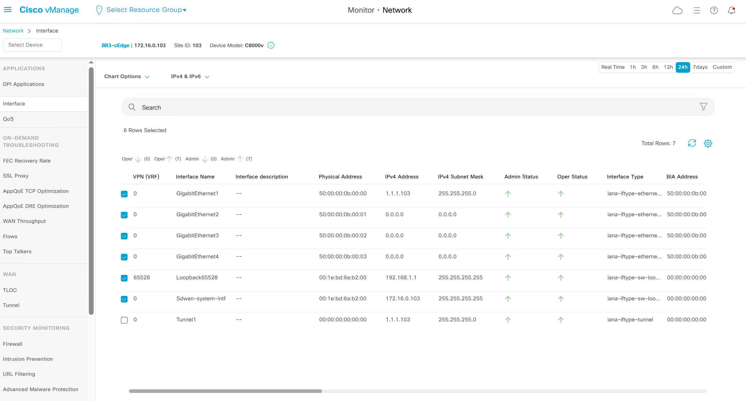
Interface shows all stats on interfaces

This is good place to check the admin / operational status of the interfaces
WAN throughput, Flows and Top Talkers as there are TCP optimisation features and are only available on hardware routers
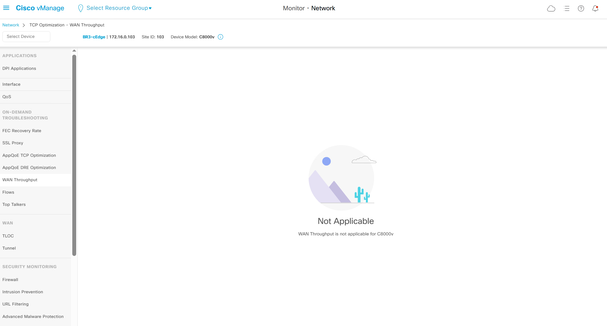
It says “WAN Throughput is not applicable for C8000v”

It says “TCP Optimization Flows are not applicable for C8000v”
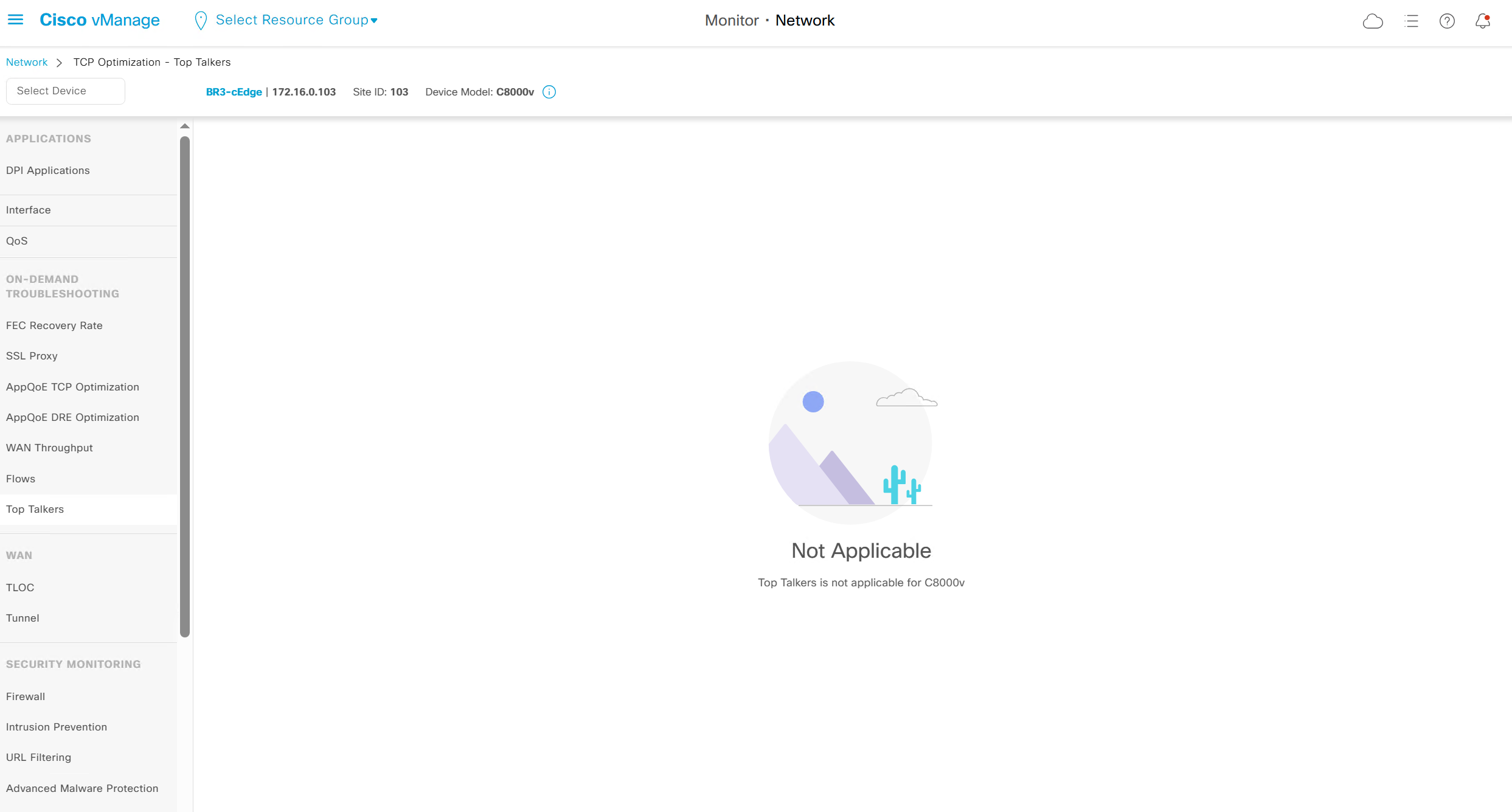
It says “Top Talkers is not applicable for C8000v”
WAN > TLOC

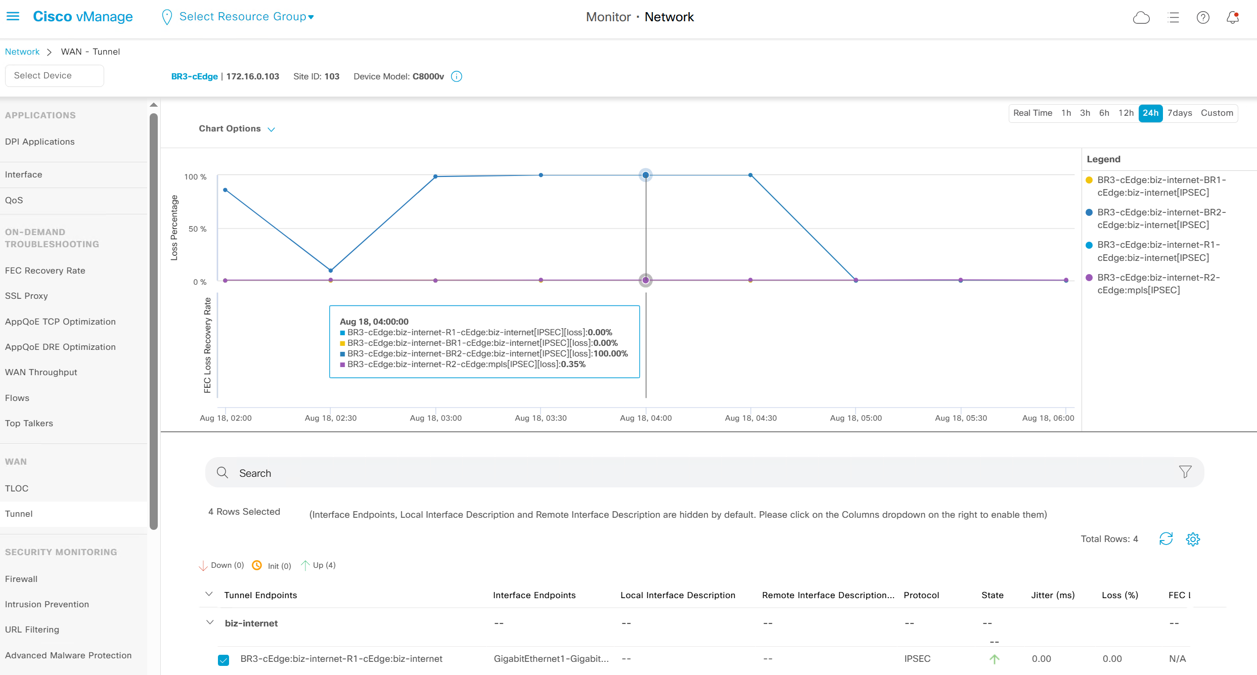
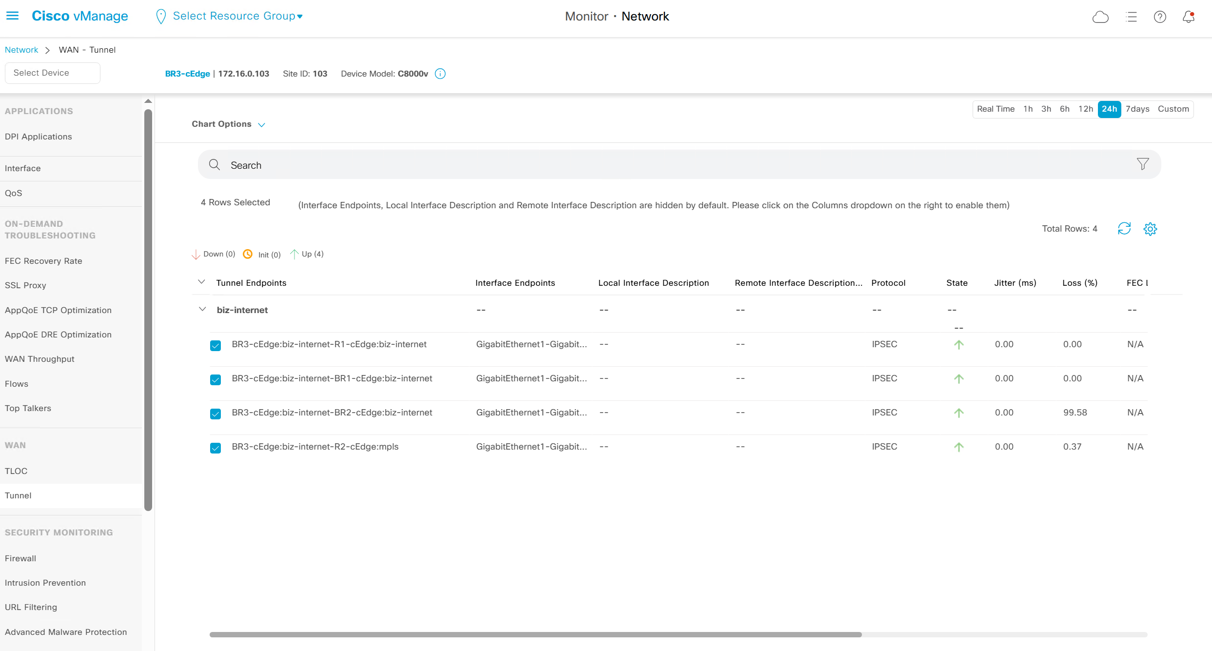
WAN > Tunnels
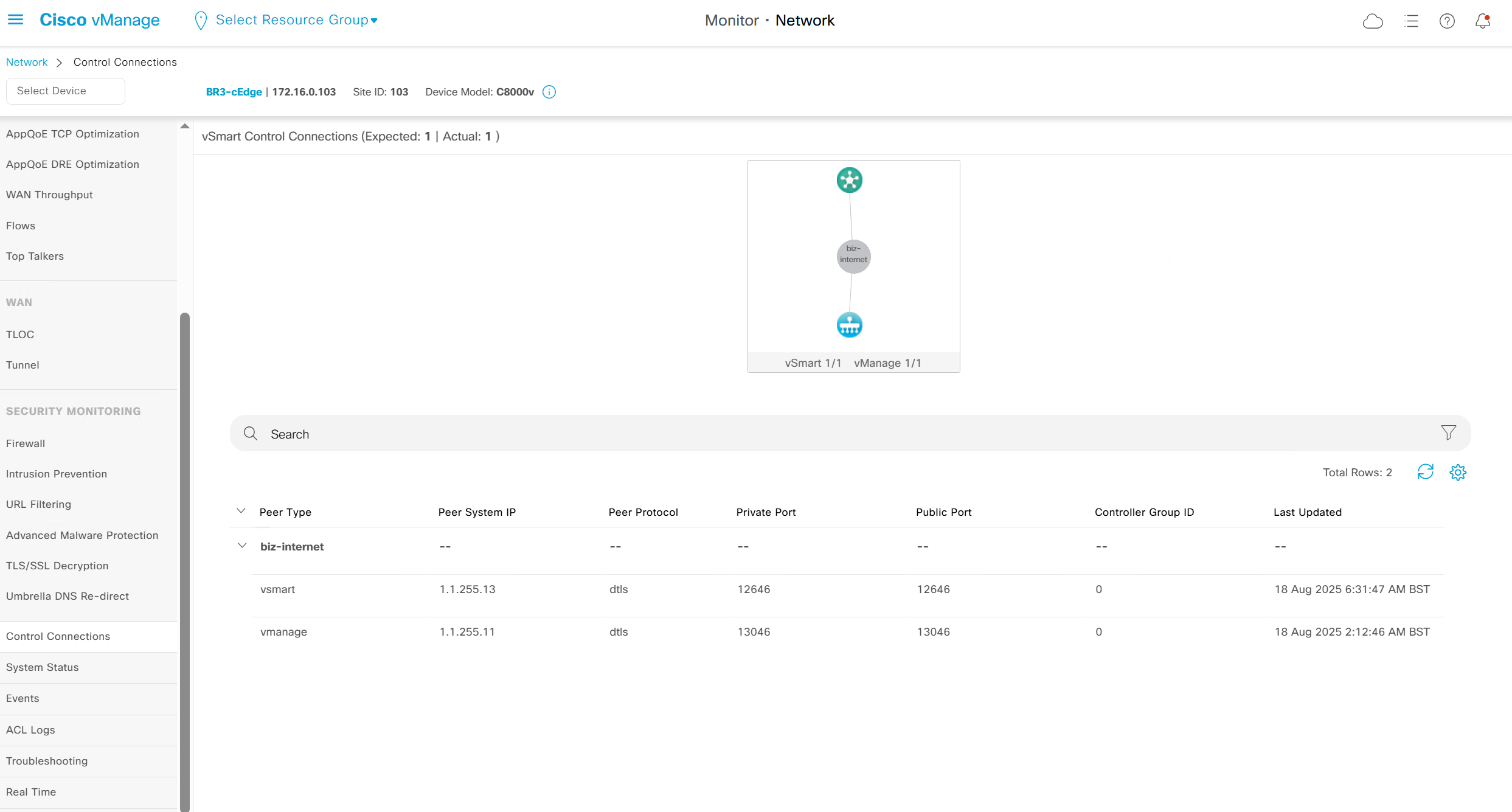
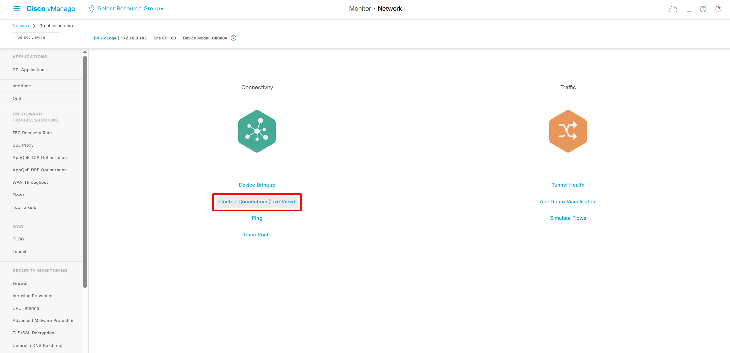
Control Connections
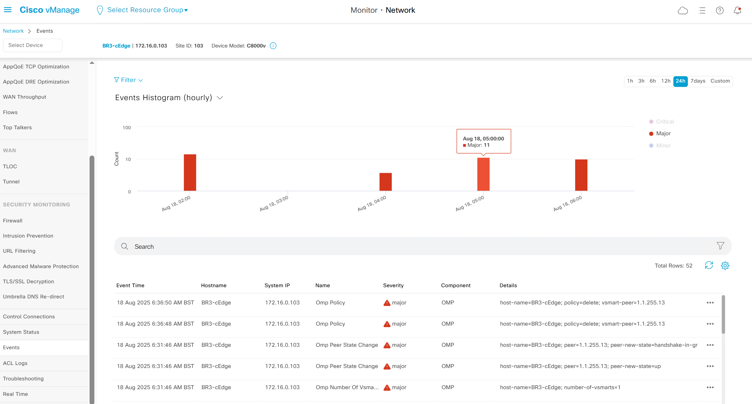
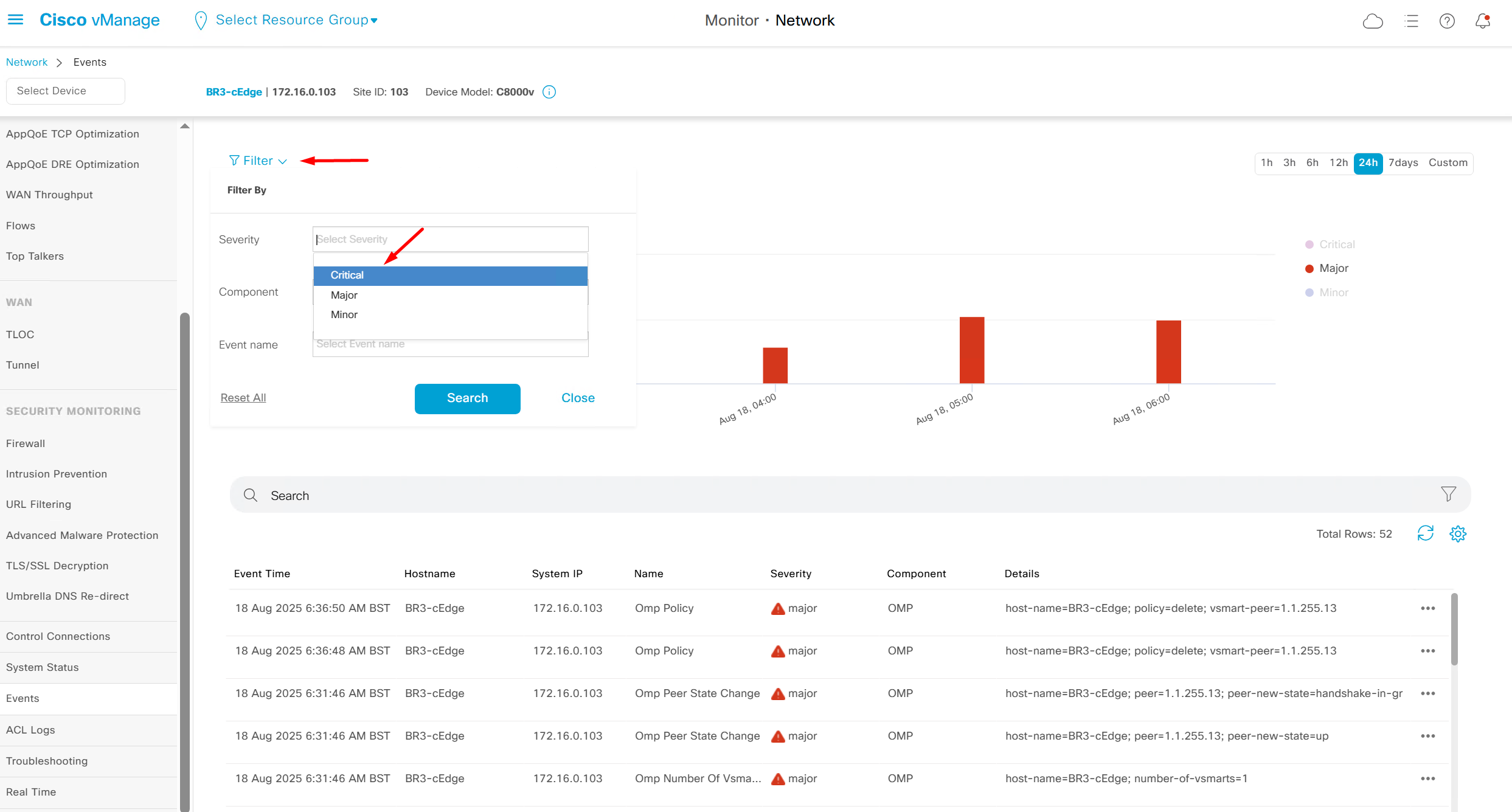
Events
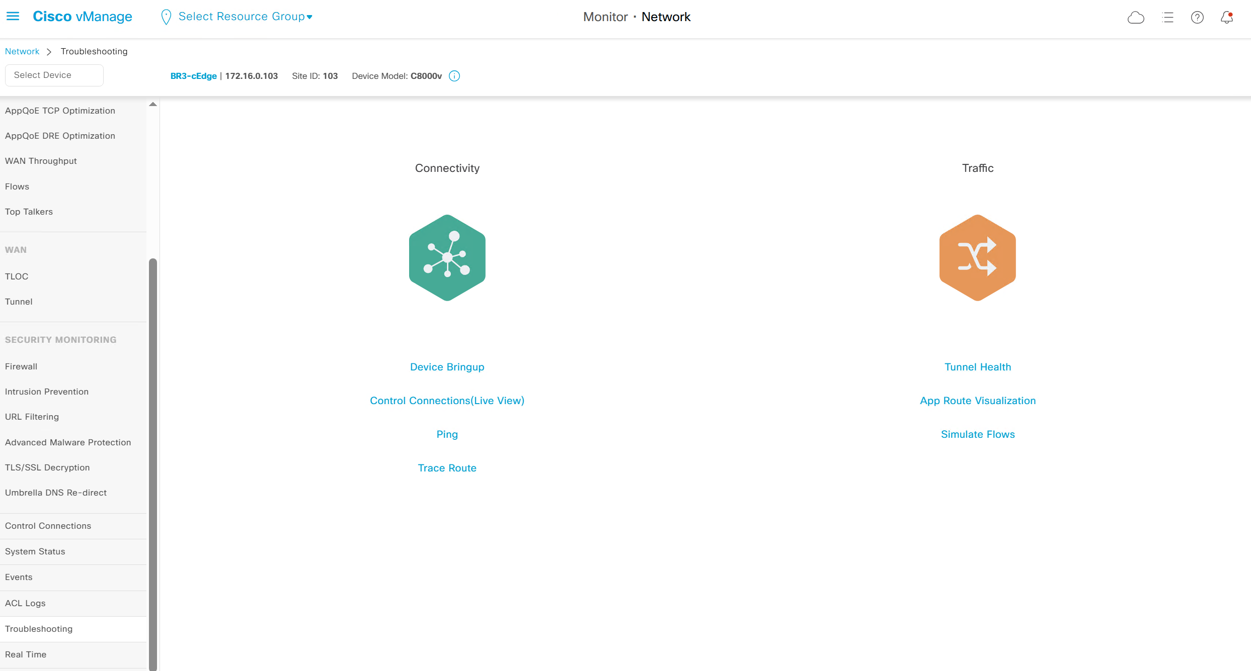
Troubleshooting
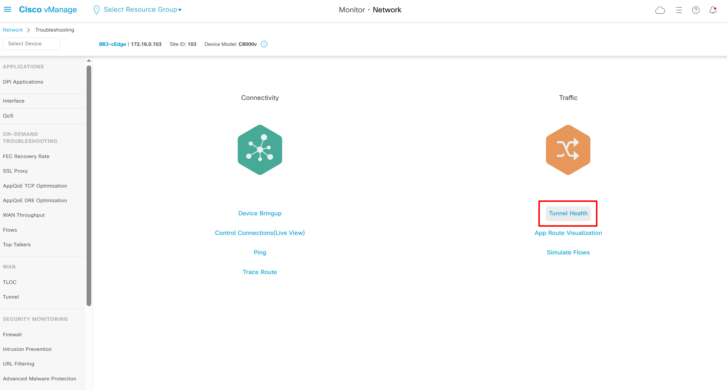
Tunnel Health
Good for troubleshooting per tunnel health
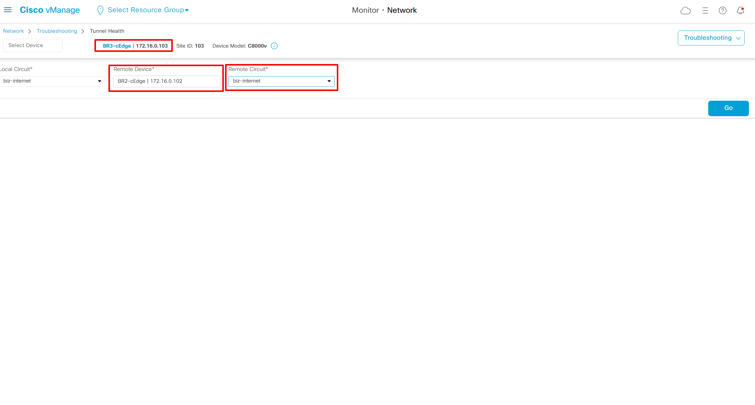
Per tunnel health check for loss, latency and octets or bytes

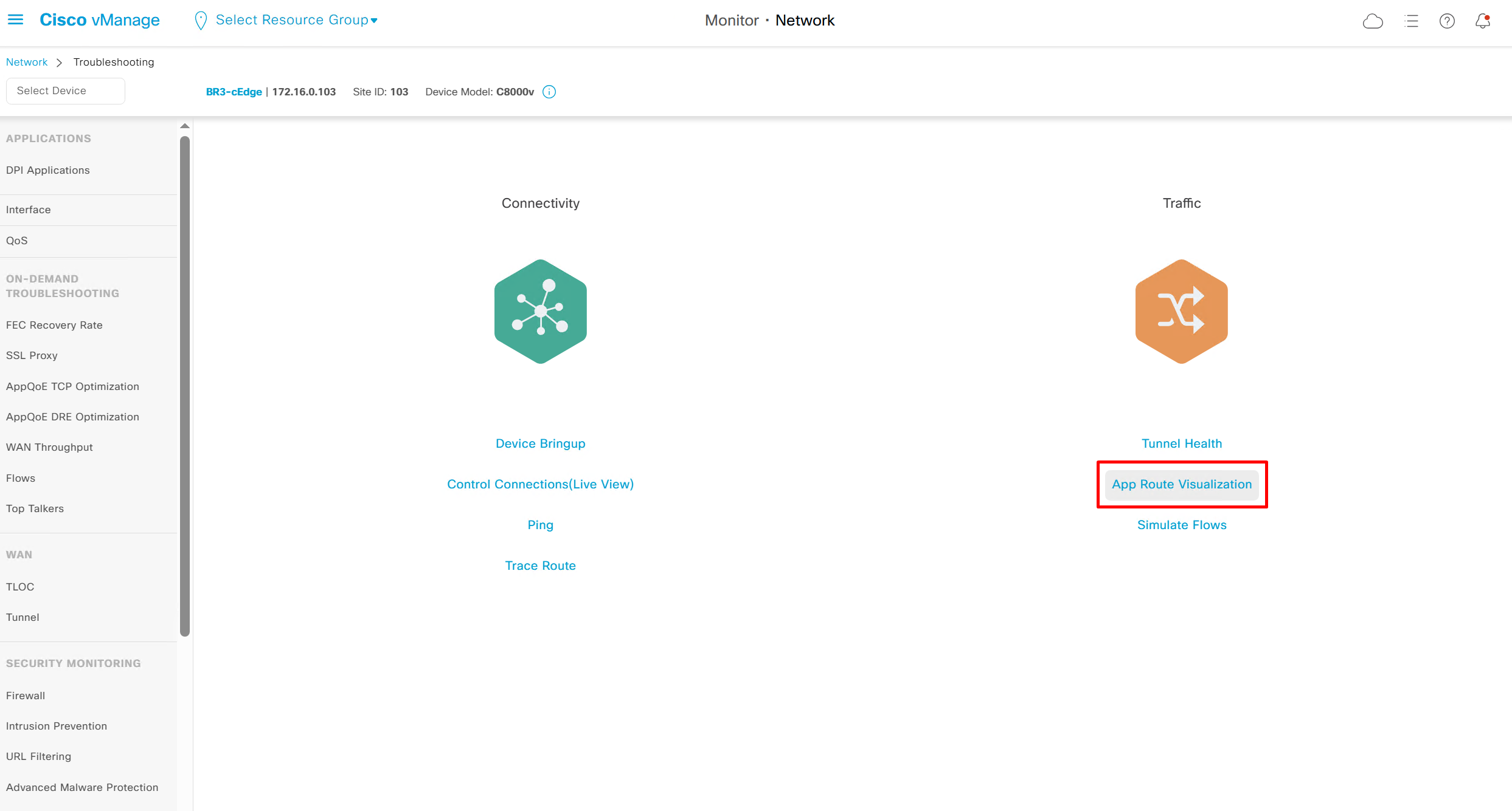
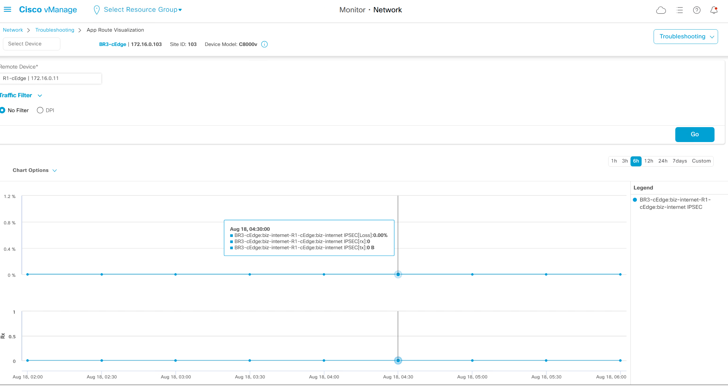
App route visualisation
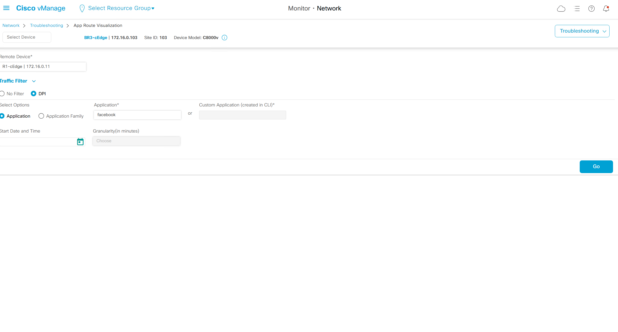
DPI is Deep Packet Inspection
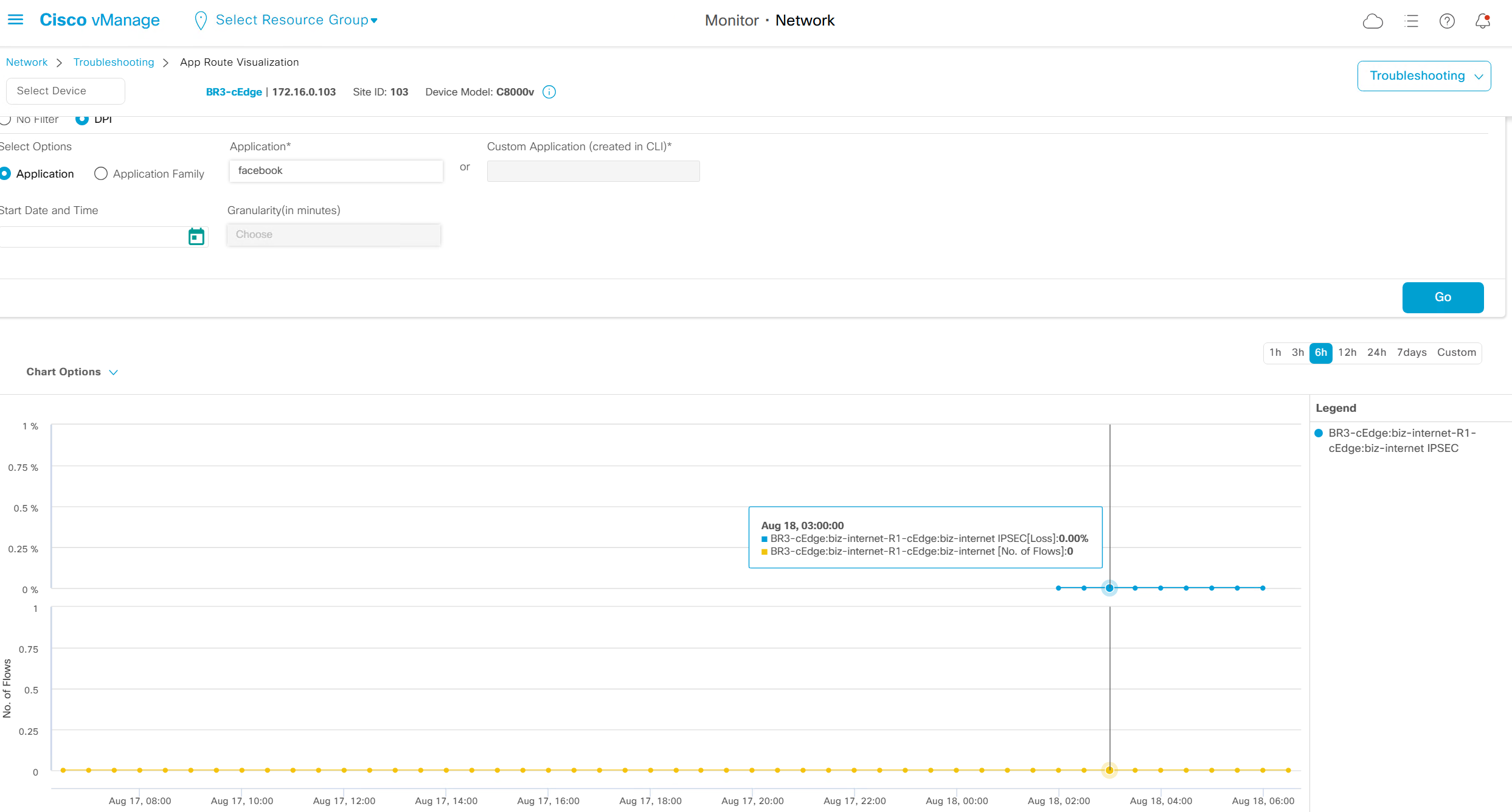
This shows applications stats from site to site as previously we say per tunnel health, this options allows us to check beyond tunnels and applications stats after the tunnel
No filter option will show us stats for all traffic
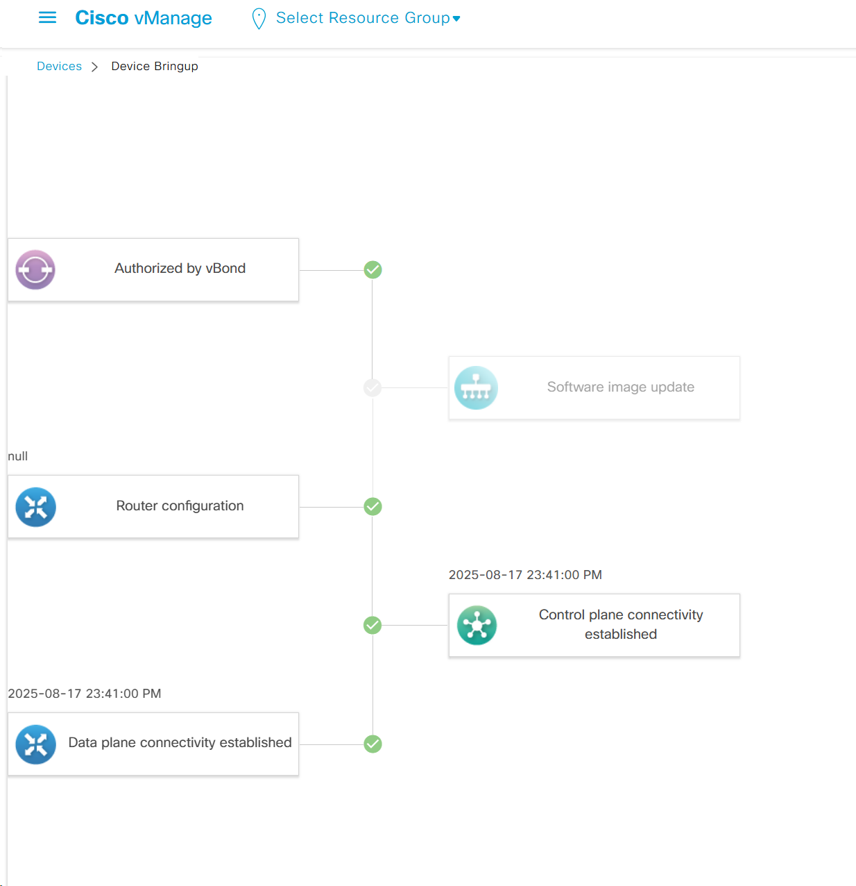
Troubleshooting

It shows us that
1. edge was authorized by vbond
2. Software image update
3. Router configuration
4. Control plane connectivity established
5. Data plane connectivity established
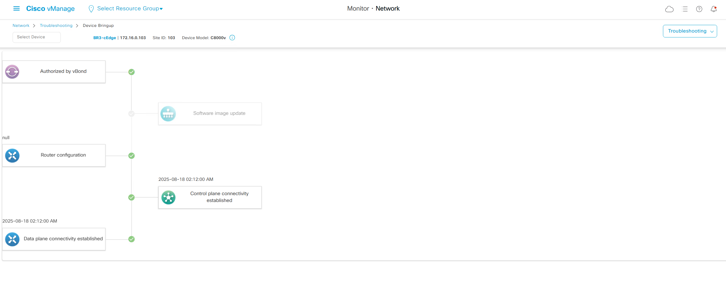
in case edge is behind the firewall and firewall is blocking control place connectivity

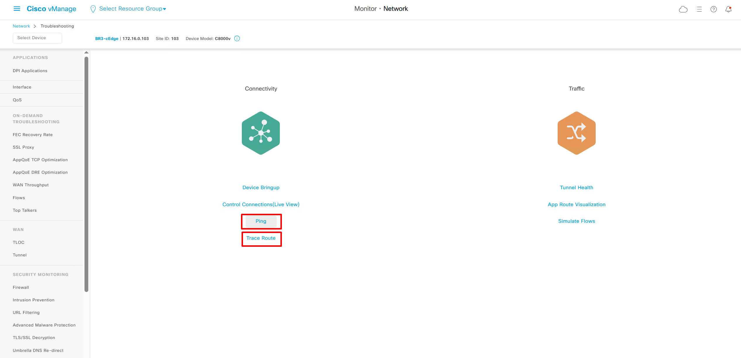
We also have option for ping and traceroute
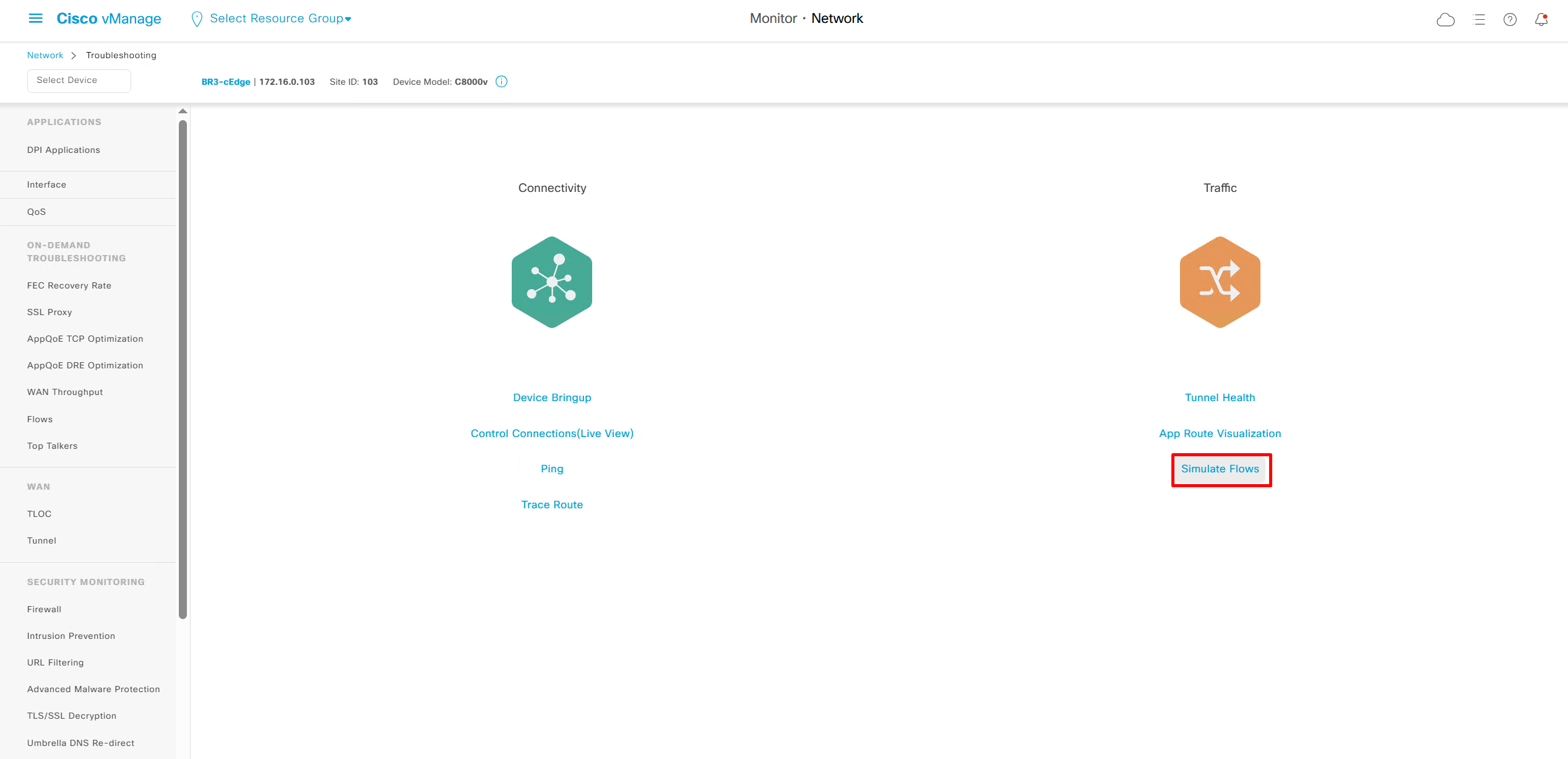
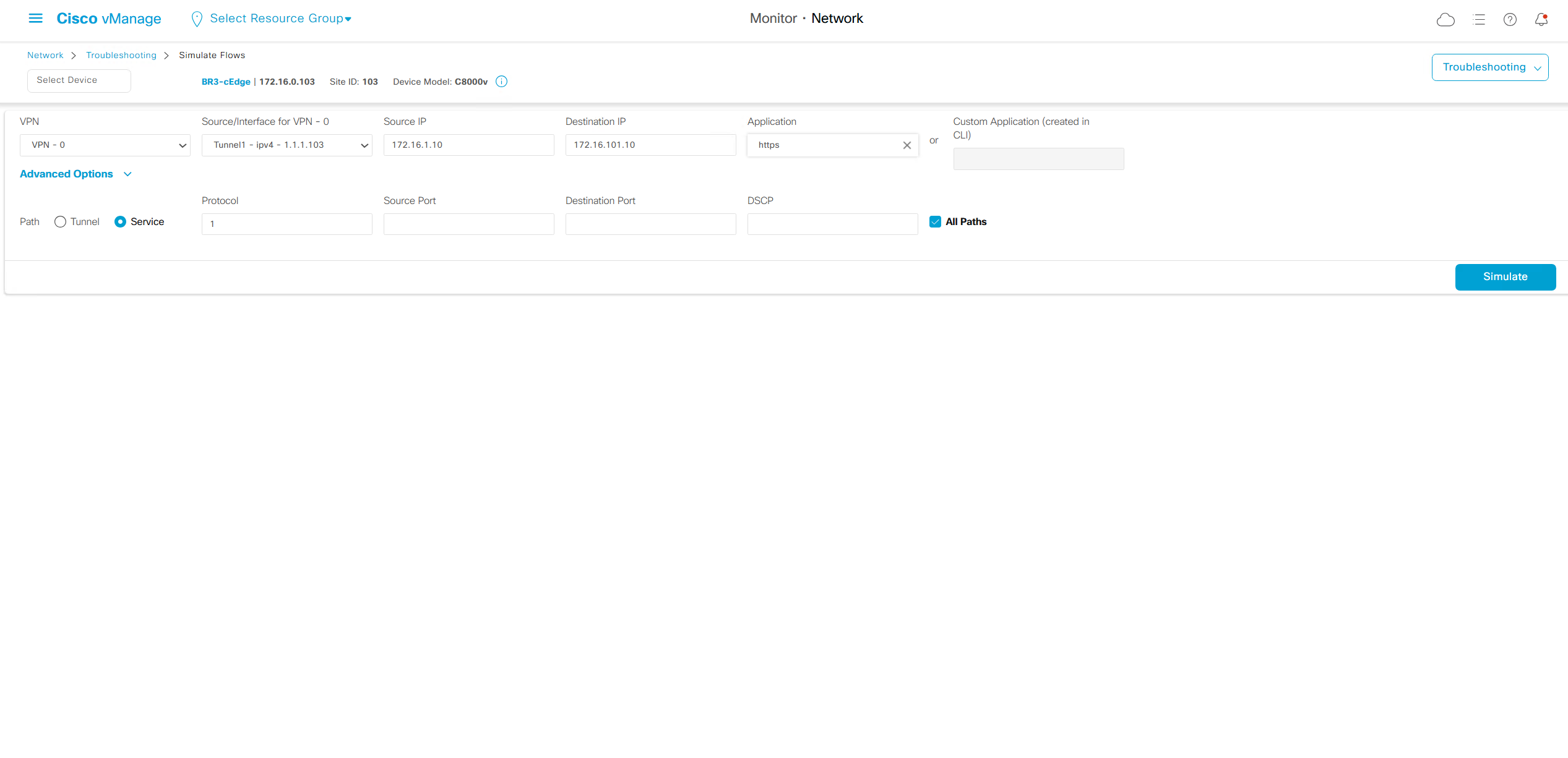
Simulate flow allows us to see how our applications will route and which TLOCs it will pass through
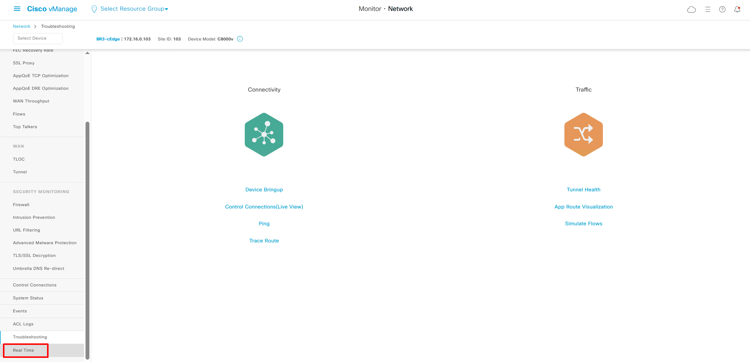
Real time shows us any information that we can see on command line also
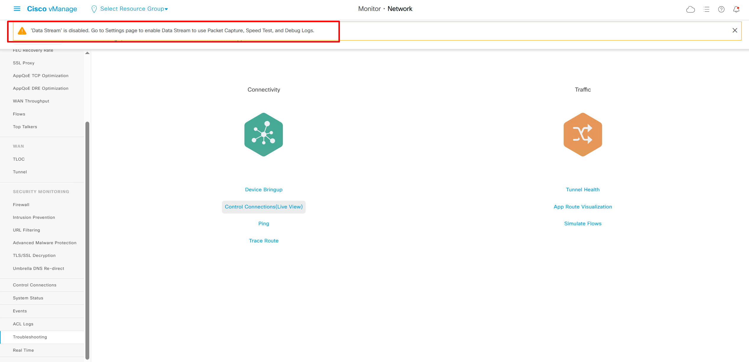
Some troubleshooting options are not available as we dont have Data stream enabled such as Packet Capture, Speed Test, and Debug Logs
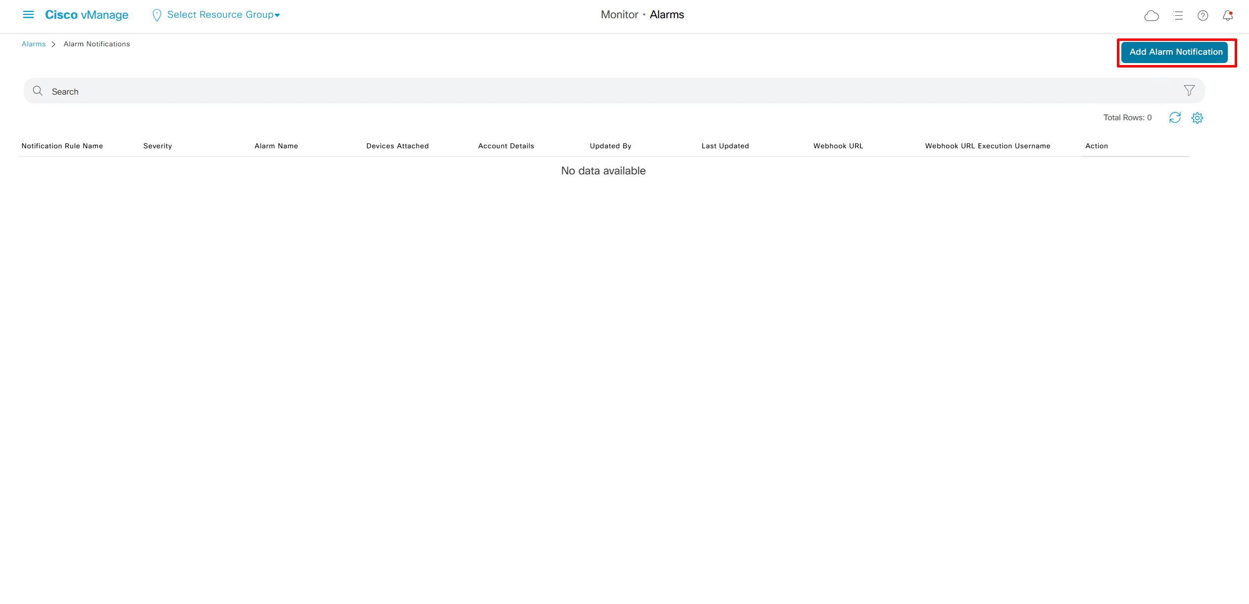
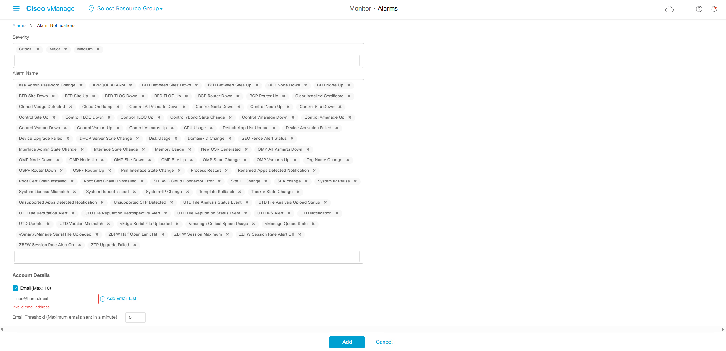
We can add Alarm notification email as well
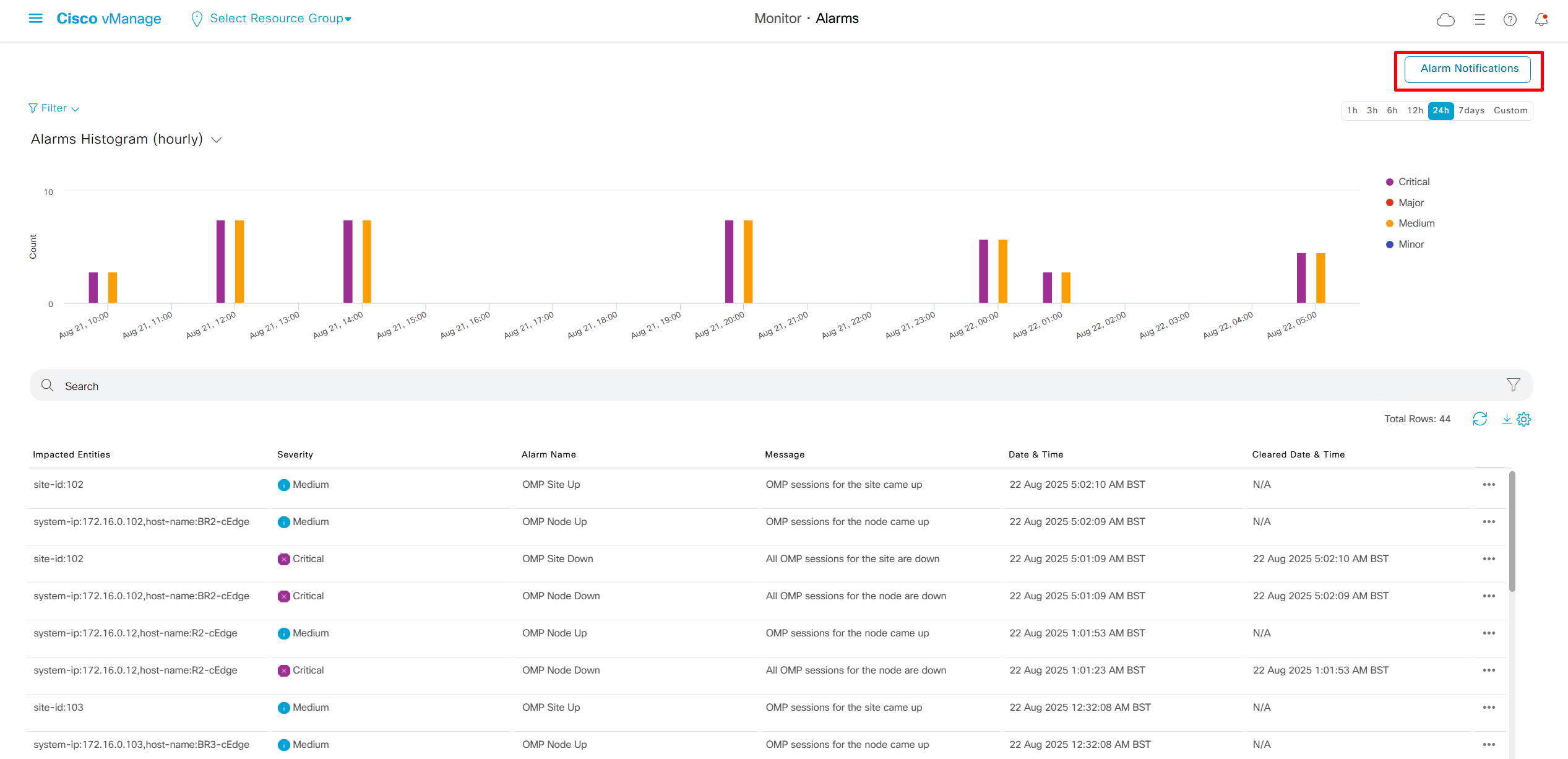
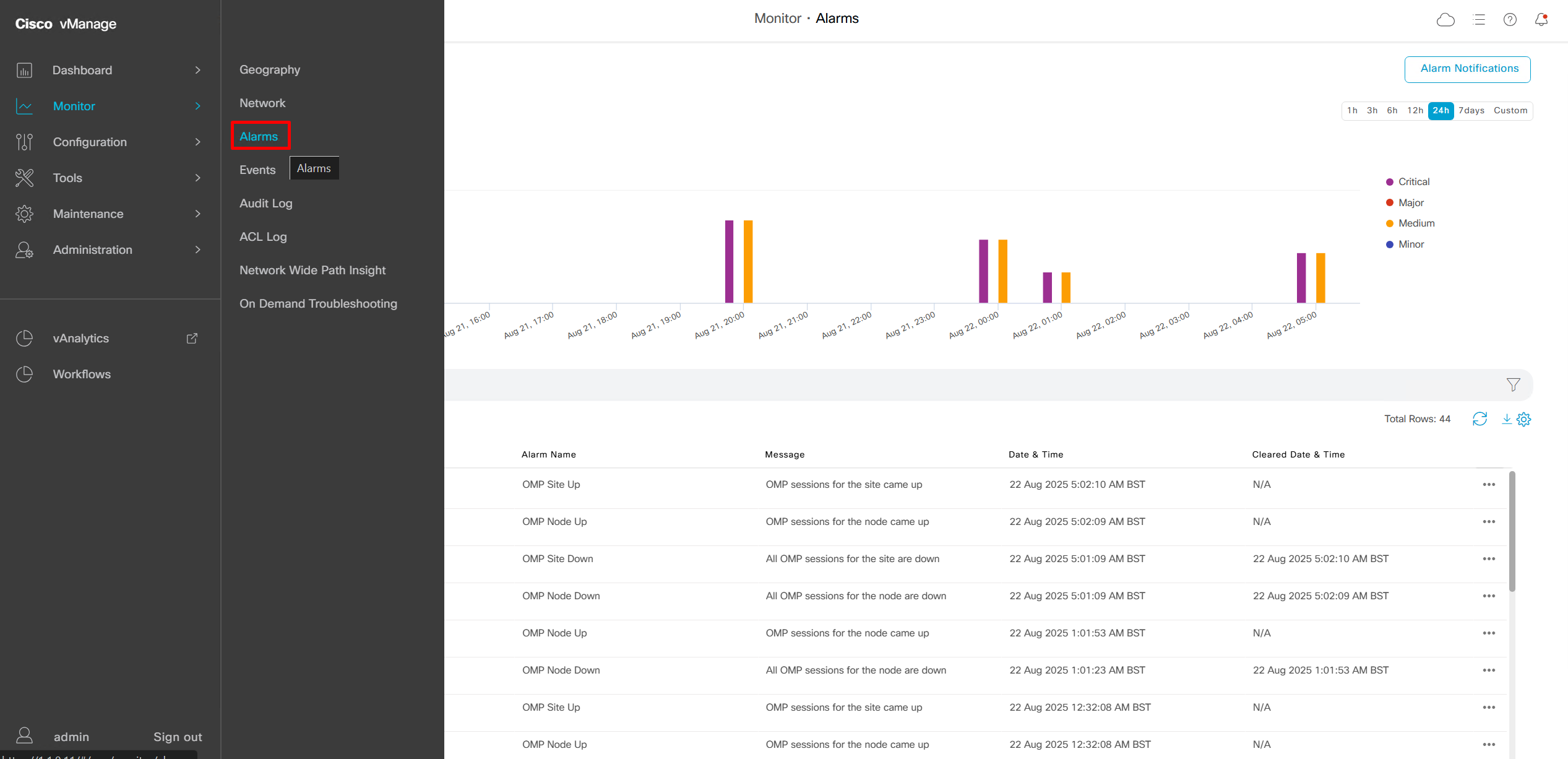
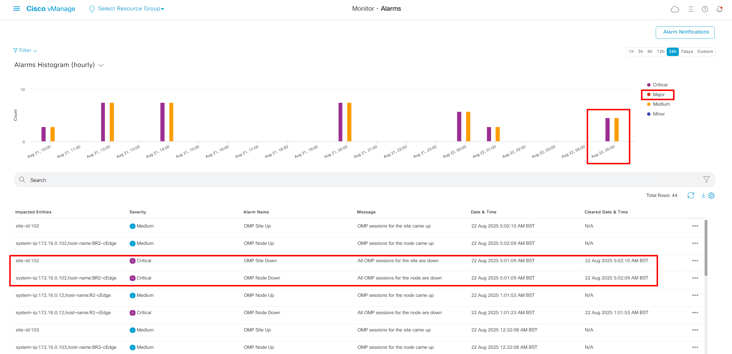
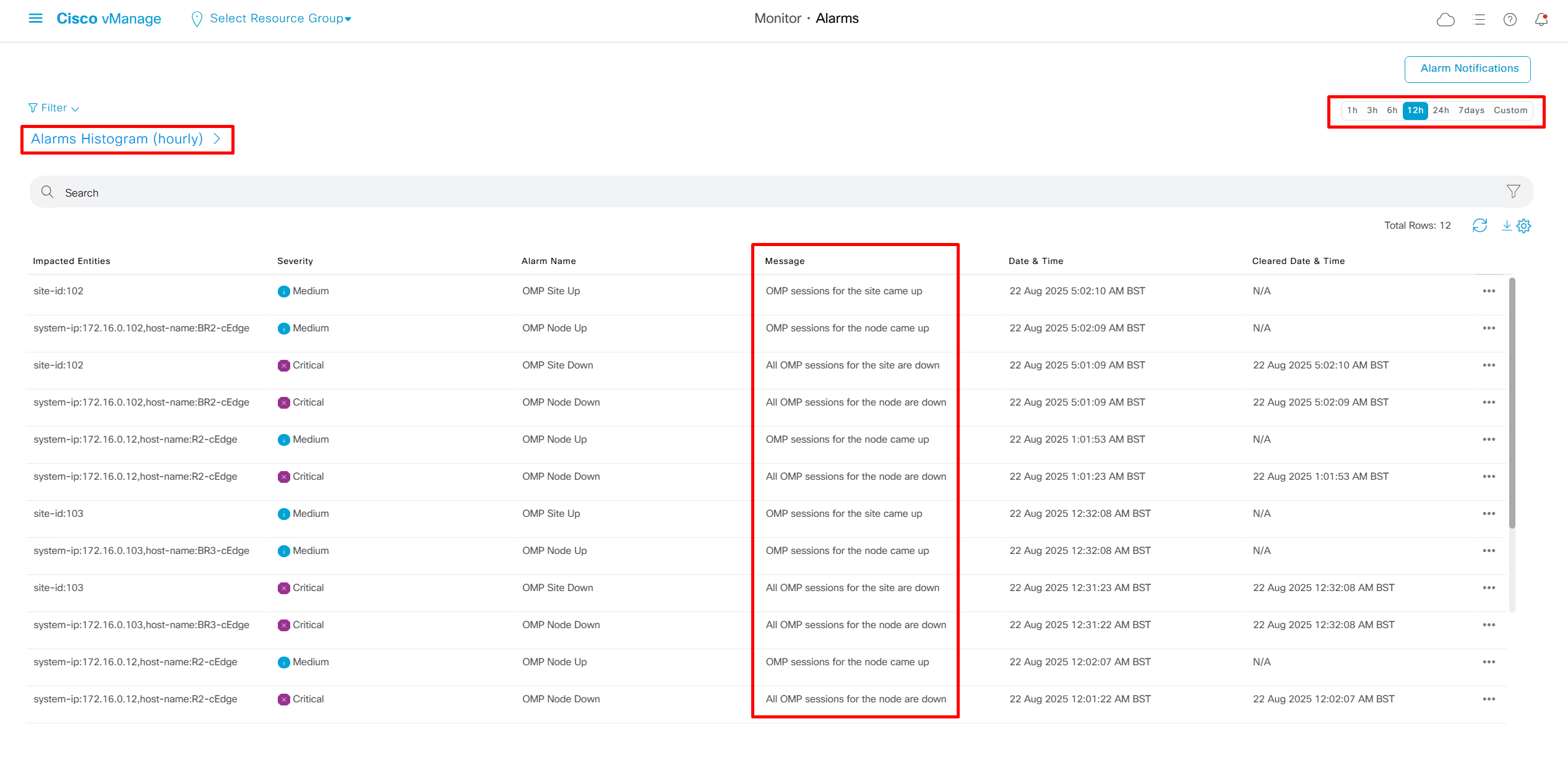
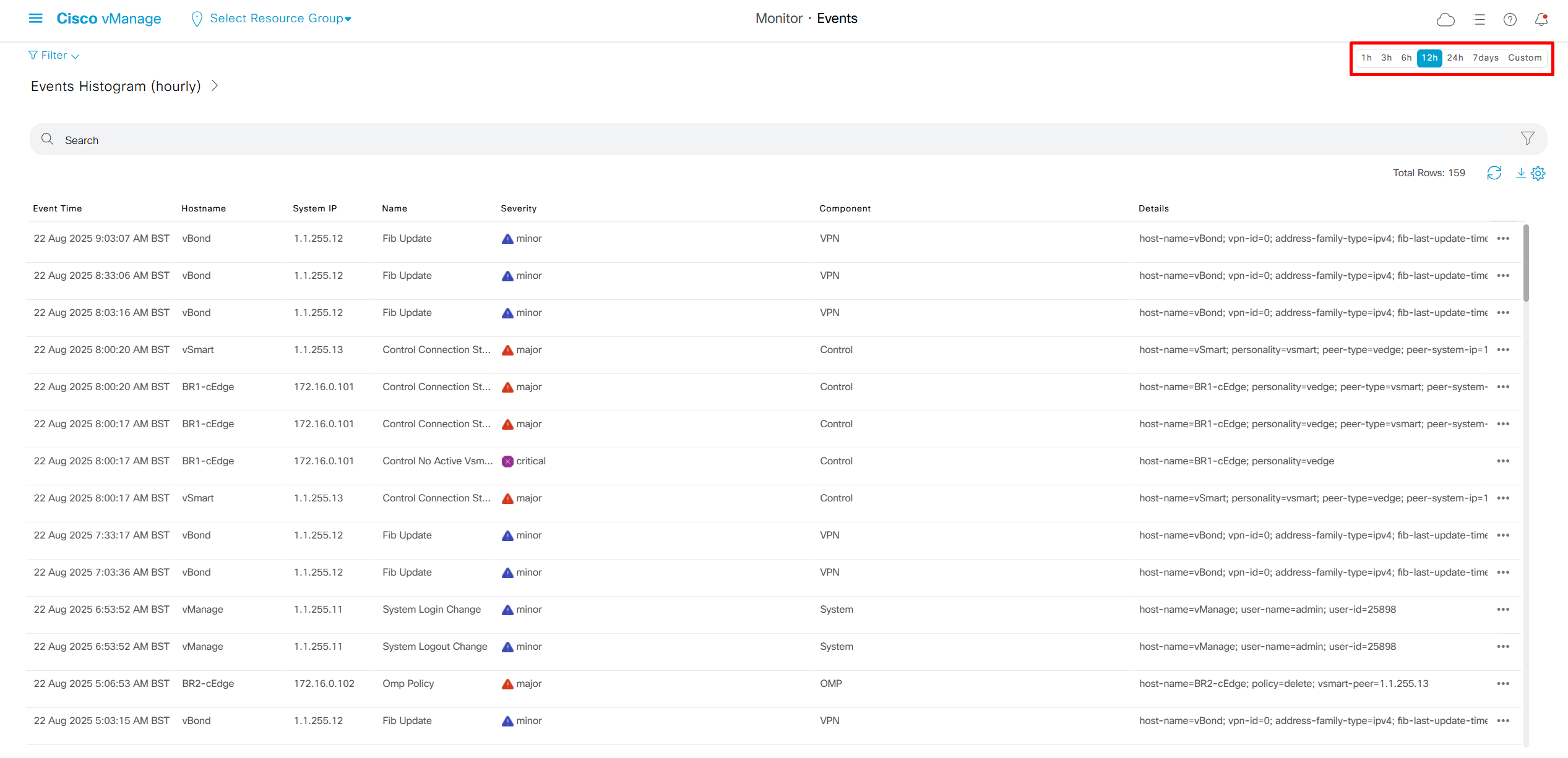
Now we move to events, Alarms are like syslogs generated and events are more detailed events
Audit log
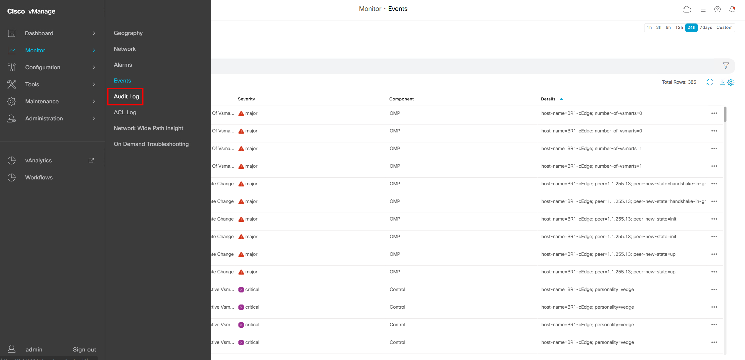
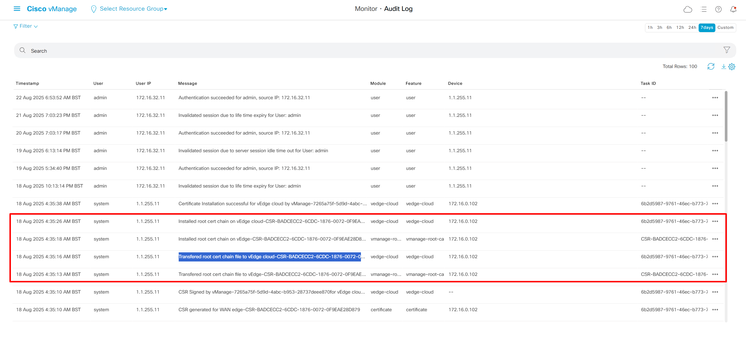
We can see all the audit trail for who did what and what was pushed to which device
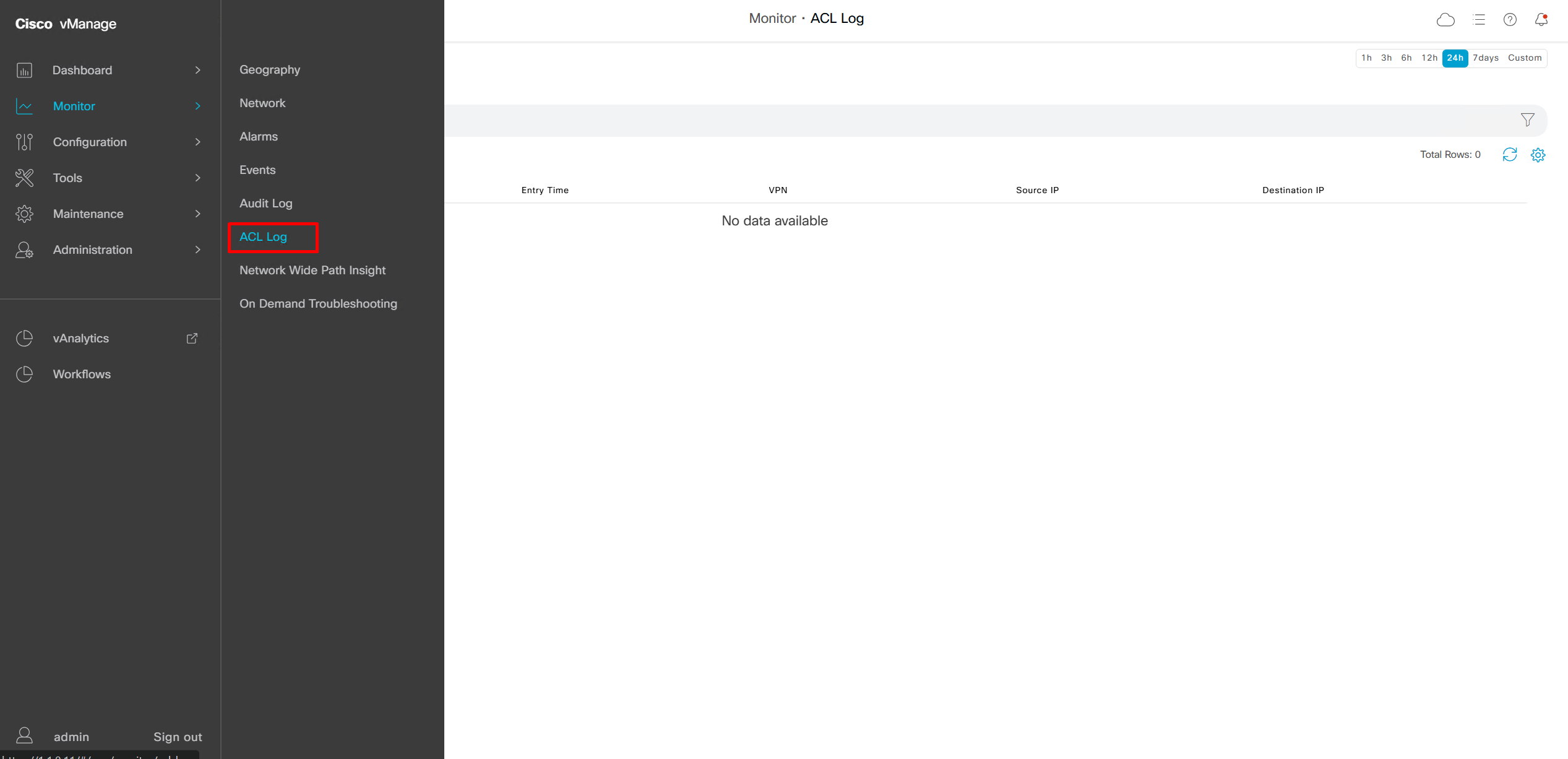
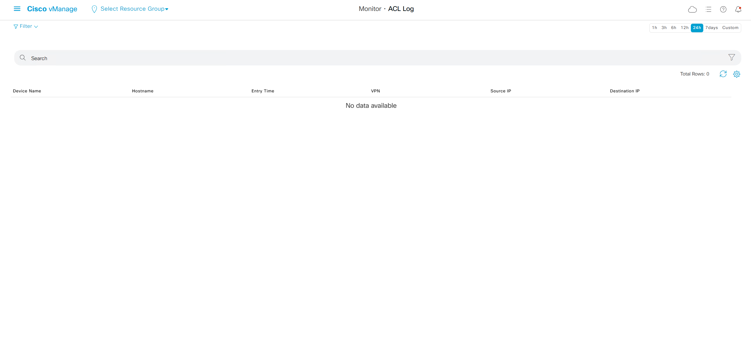
This comes in very handy as we can see ACL logs not just for one device but for the whole system
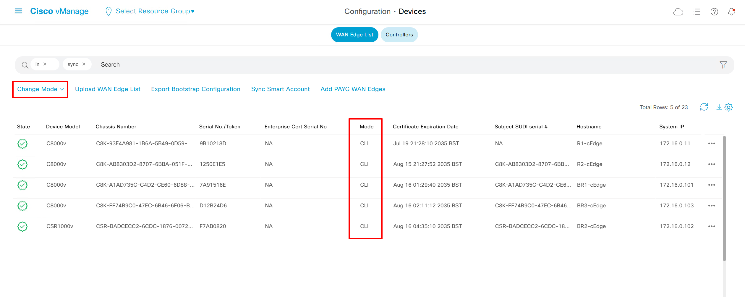
once a device is managed by vmanage, local CLI changes cannot be made on device
nodes which are PNP or ZTP enrolled are already in vmanage mode as at time of enrolment a template is applied and devices are vmanage managed
device manually enrolled are CLI managed as they are manually enrolled
one reason to convert from vmanage mode to CLI is to quickly test a command and then return device to vmanage mode, you dont even have to revert the changes made in CLI as we change back to vmanage mode, the changes made in CLI will disappear because configuration from template will be applied, if change test was successful then make that change part of the template
Device status must always be “In Sync”
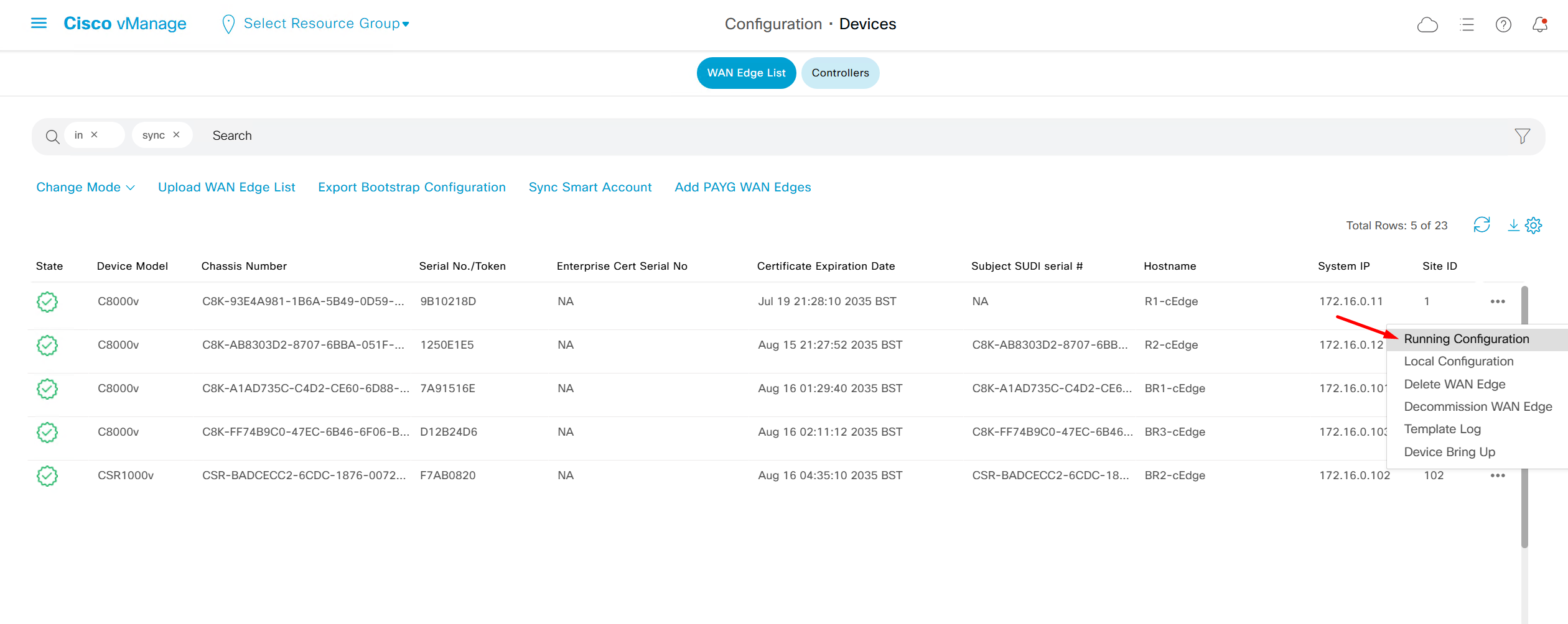
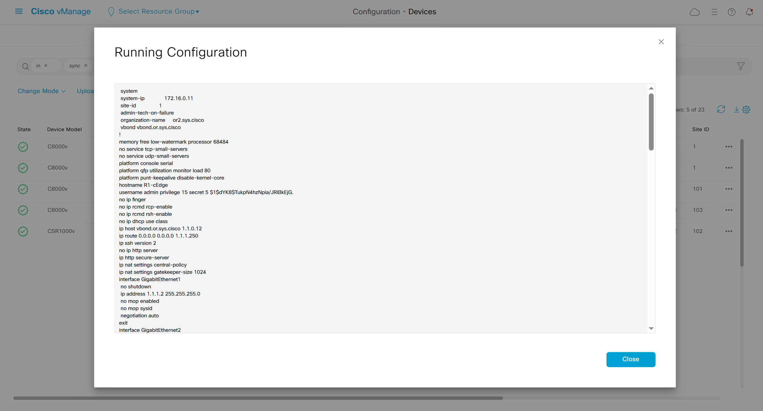
To see if device communication is working with vmanage, pull its running configuration, if it works then we know that netconf over DTLS (control connection) is working between vmanage and edge
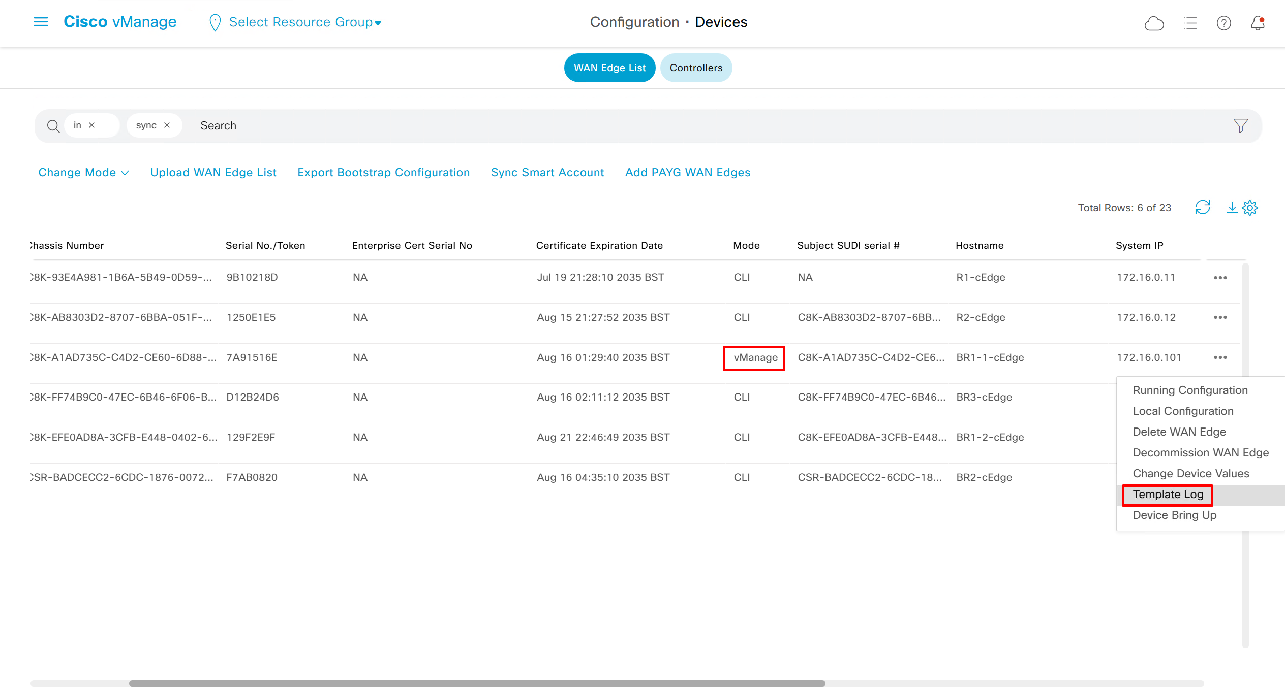
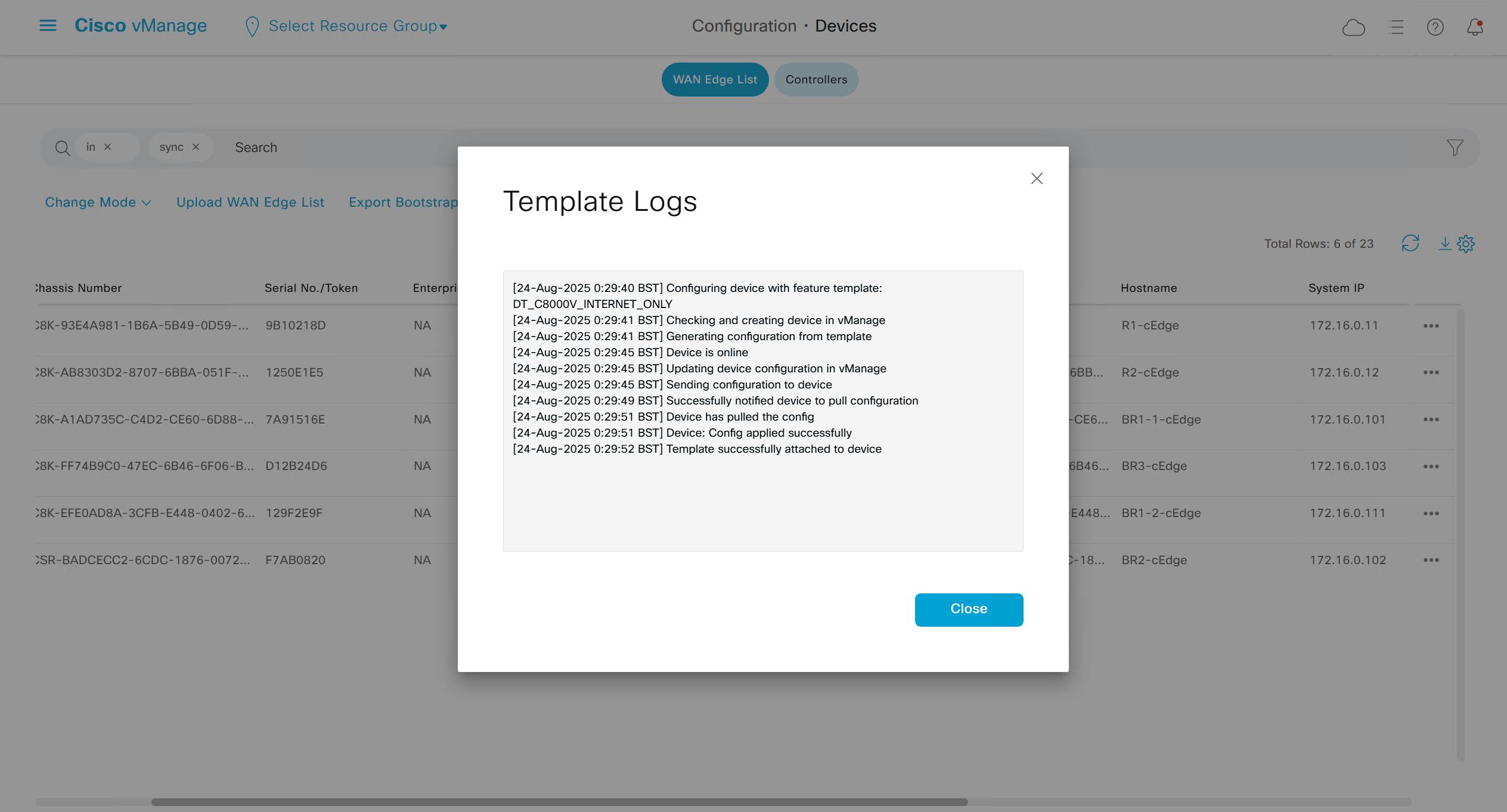
Template log is where we can see the changes
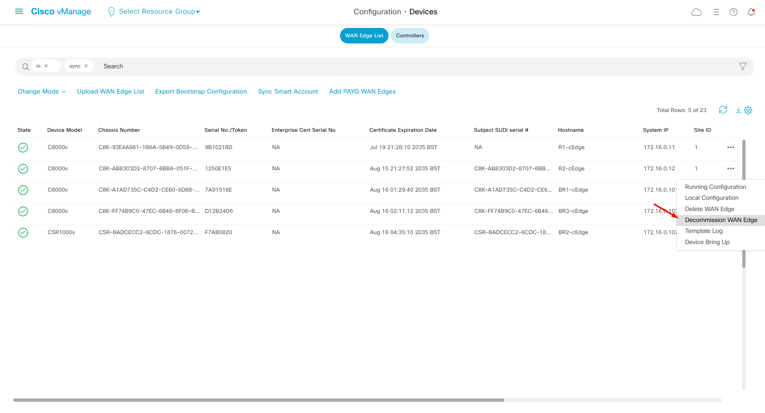
Decommission WAN edge – removes the edge device and puts chassis number back in the controllers so new virtual device can be assigned that chassis / token
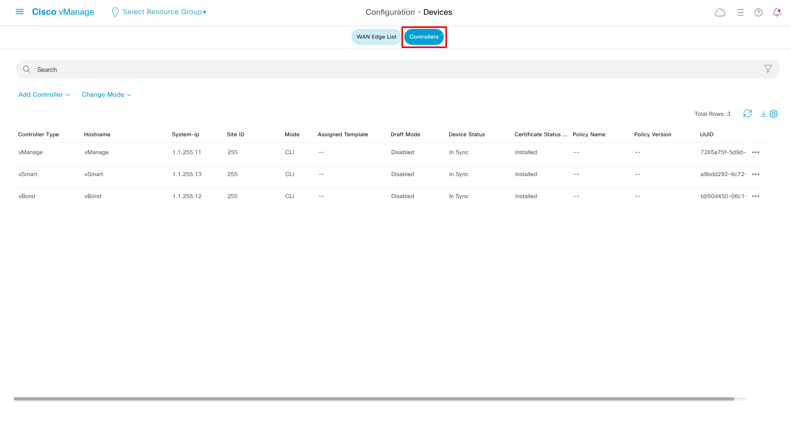
Similar options for controllers
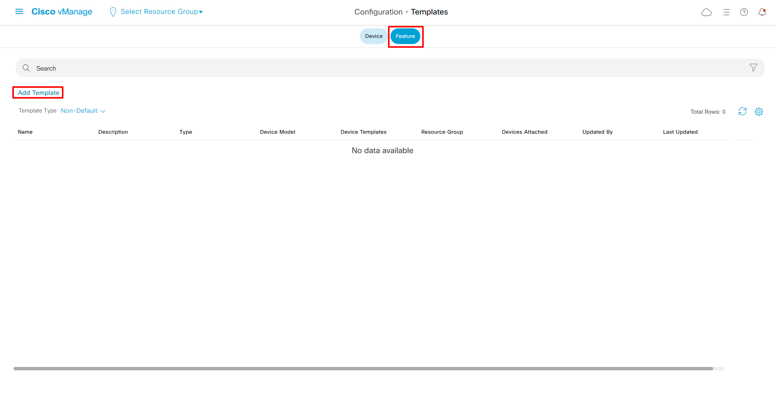
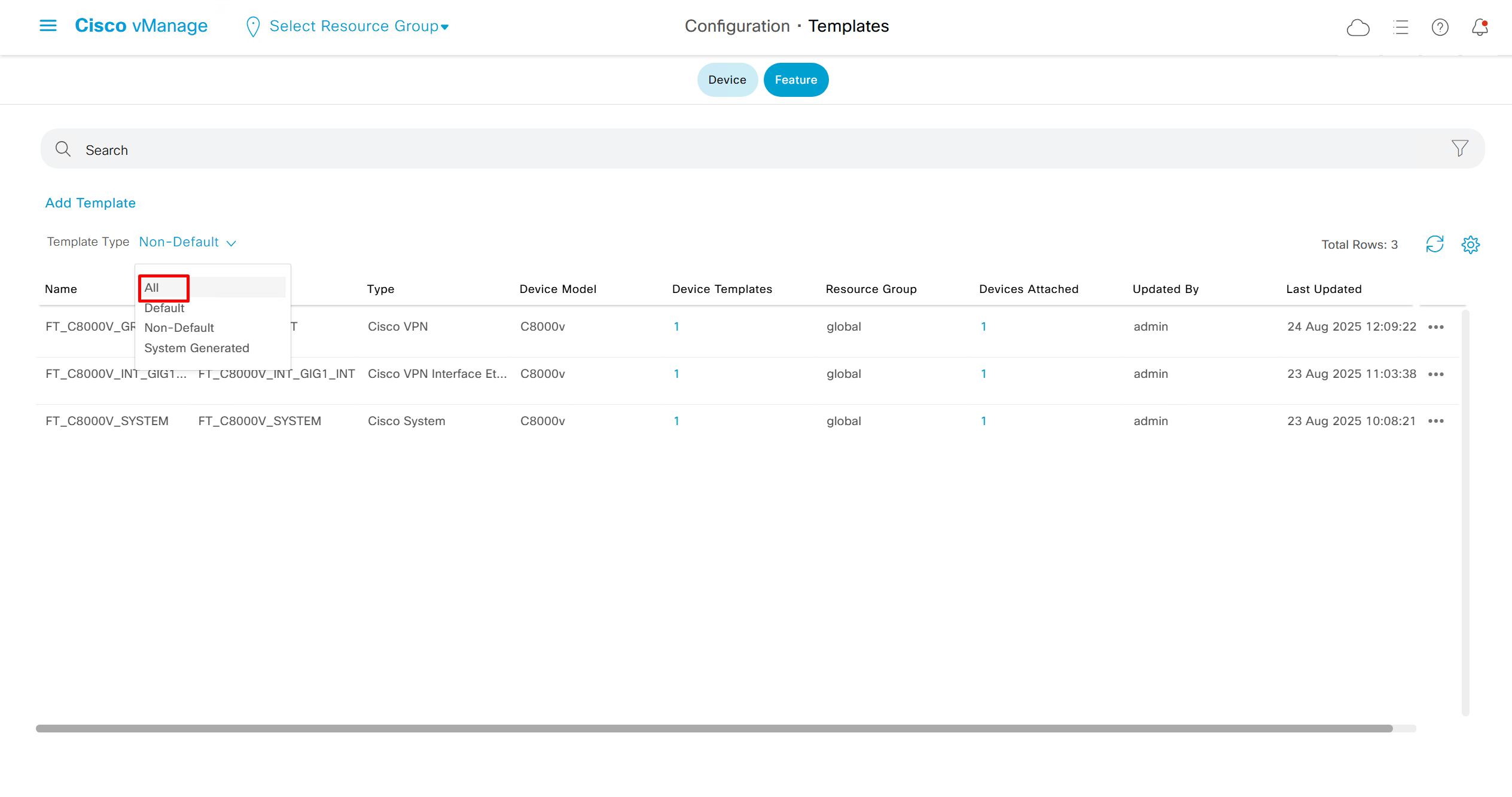
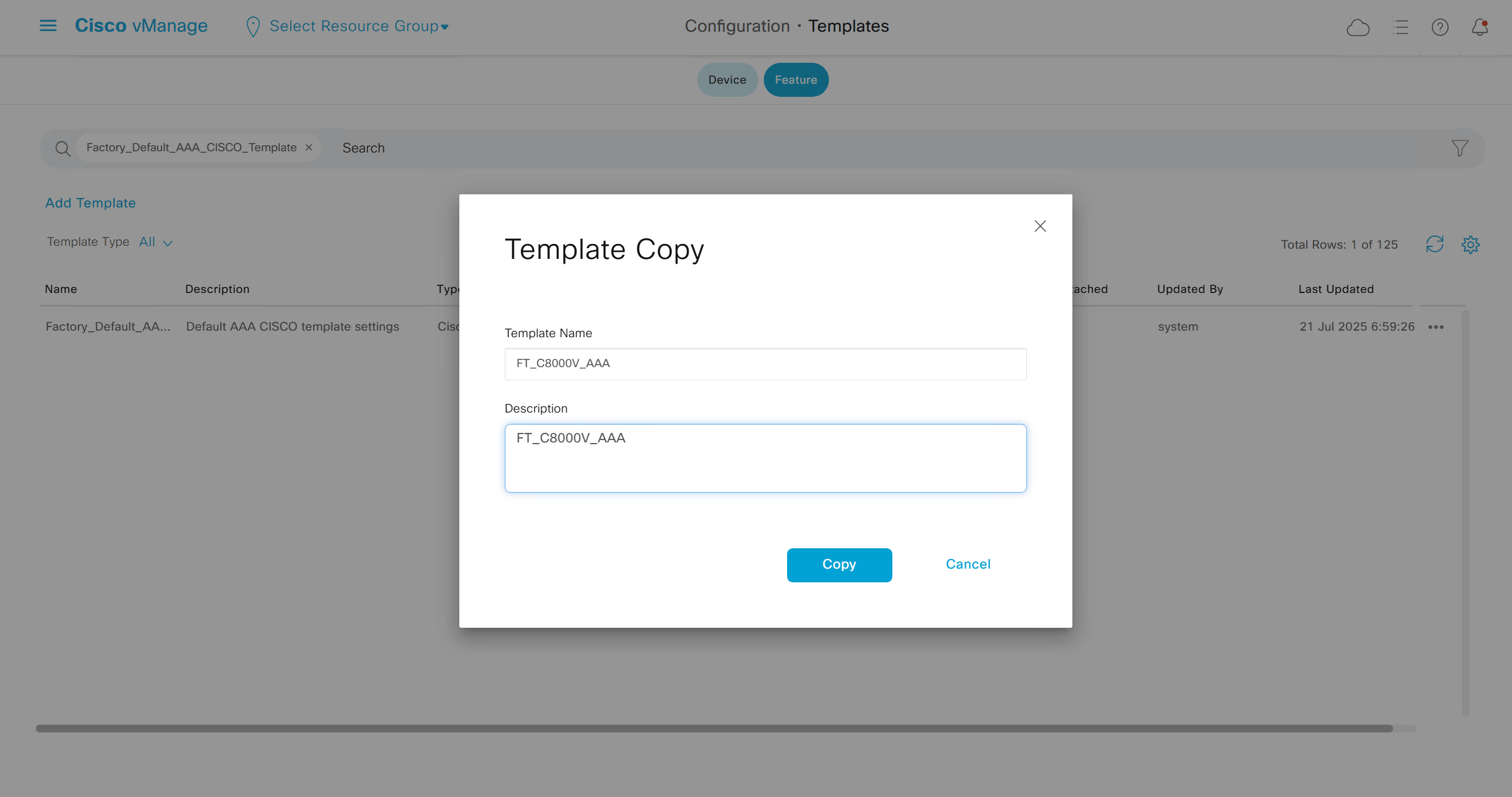
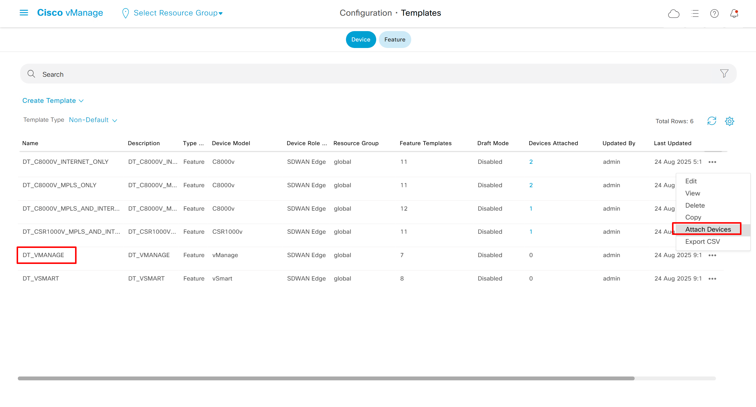
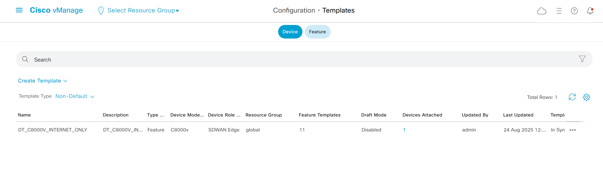
Templates
Device Templates
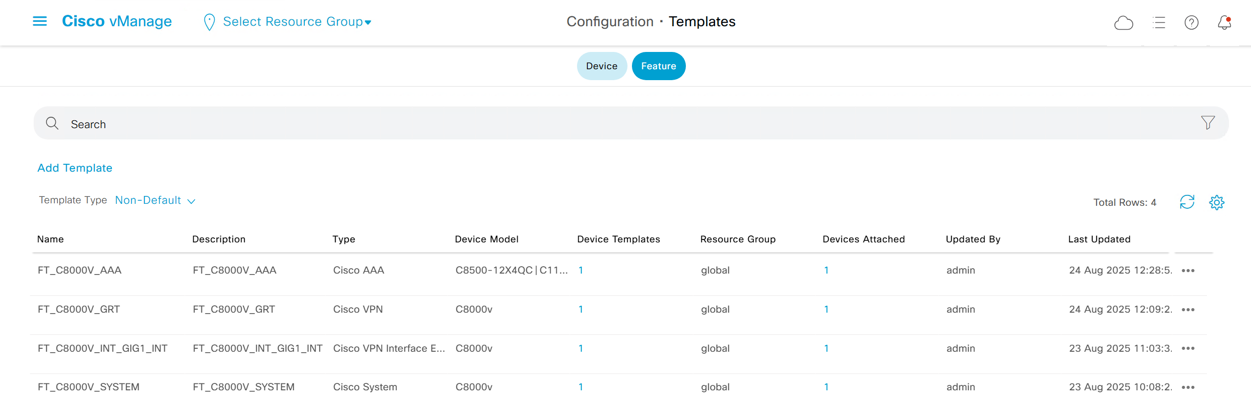
Feature Templates
Centralized Policy

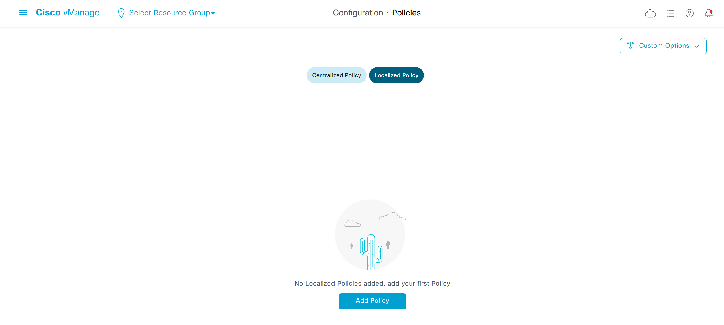
Localized Policy
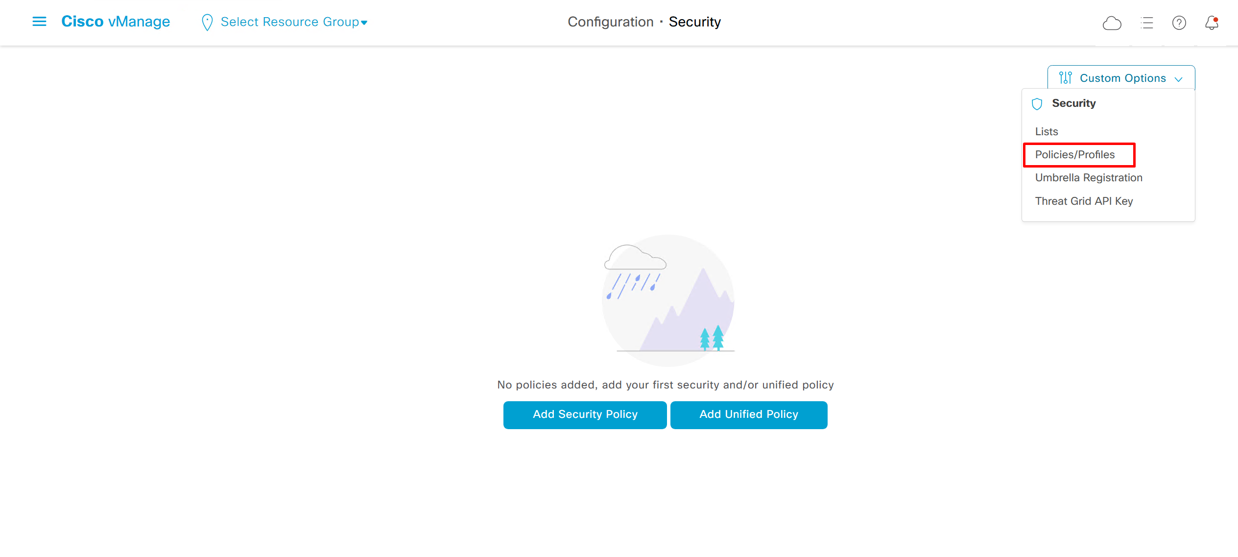
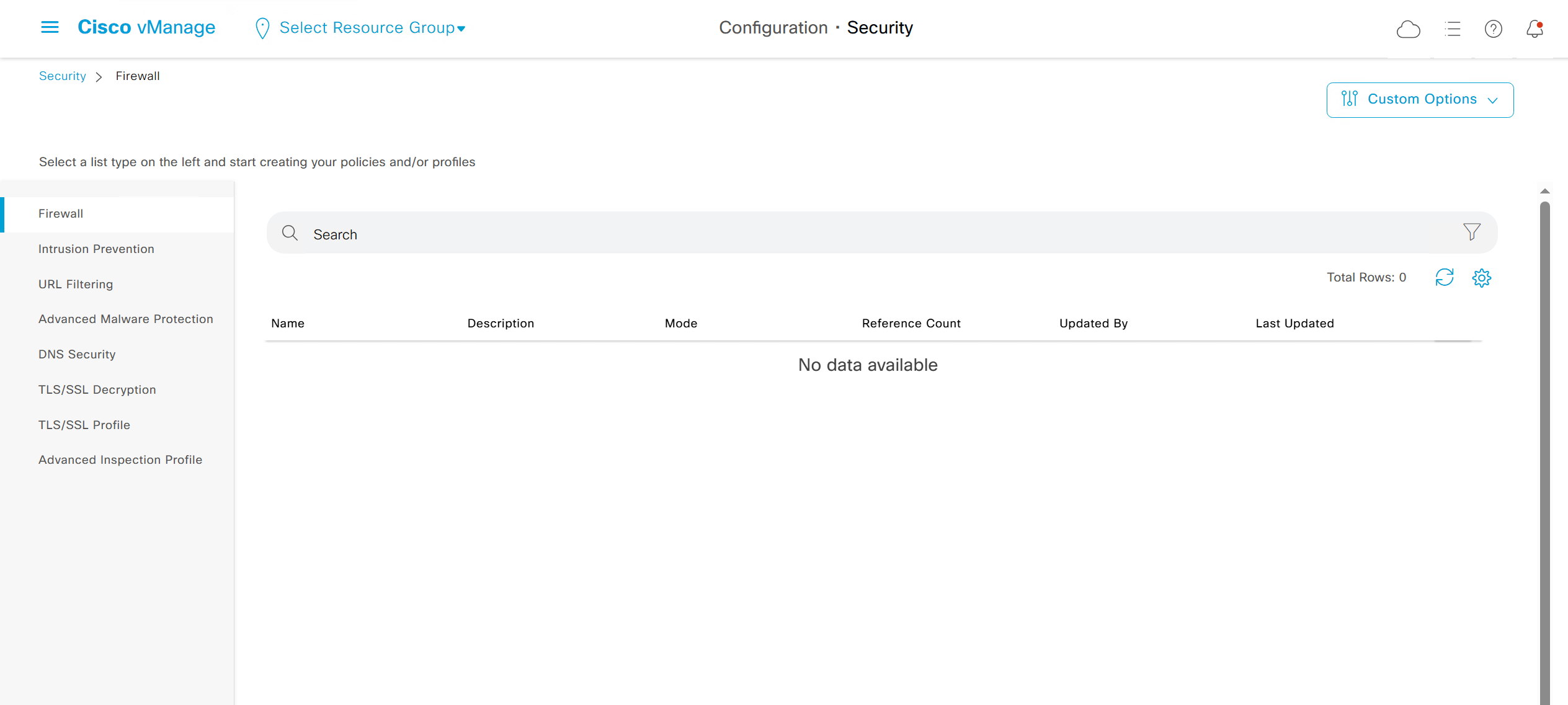
Security section where we can configure Zone Based Firewall etc


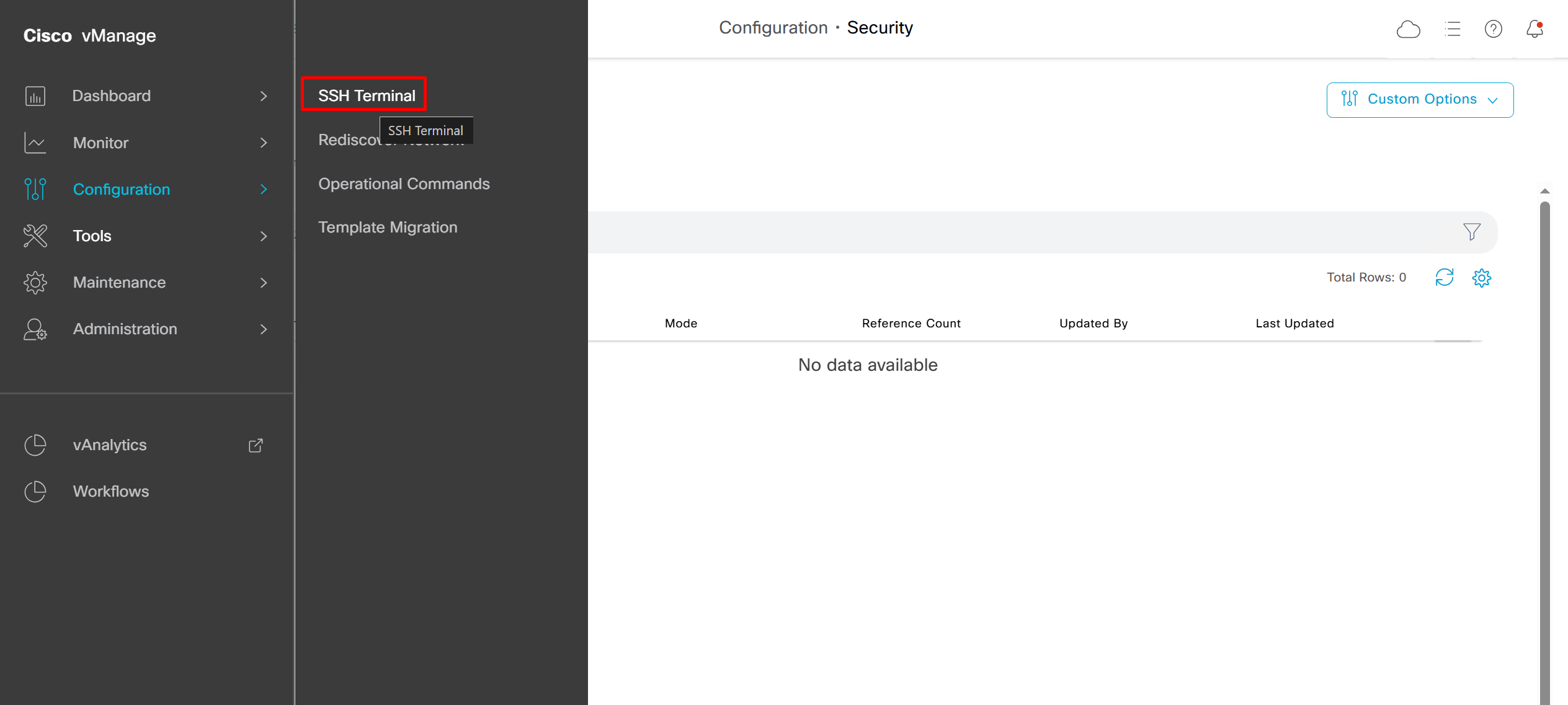
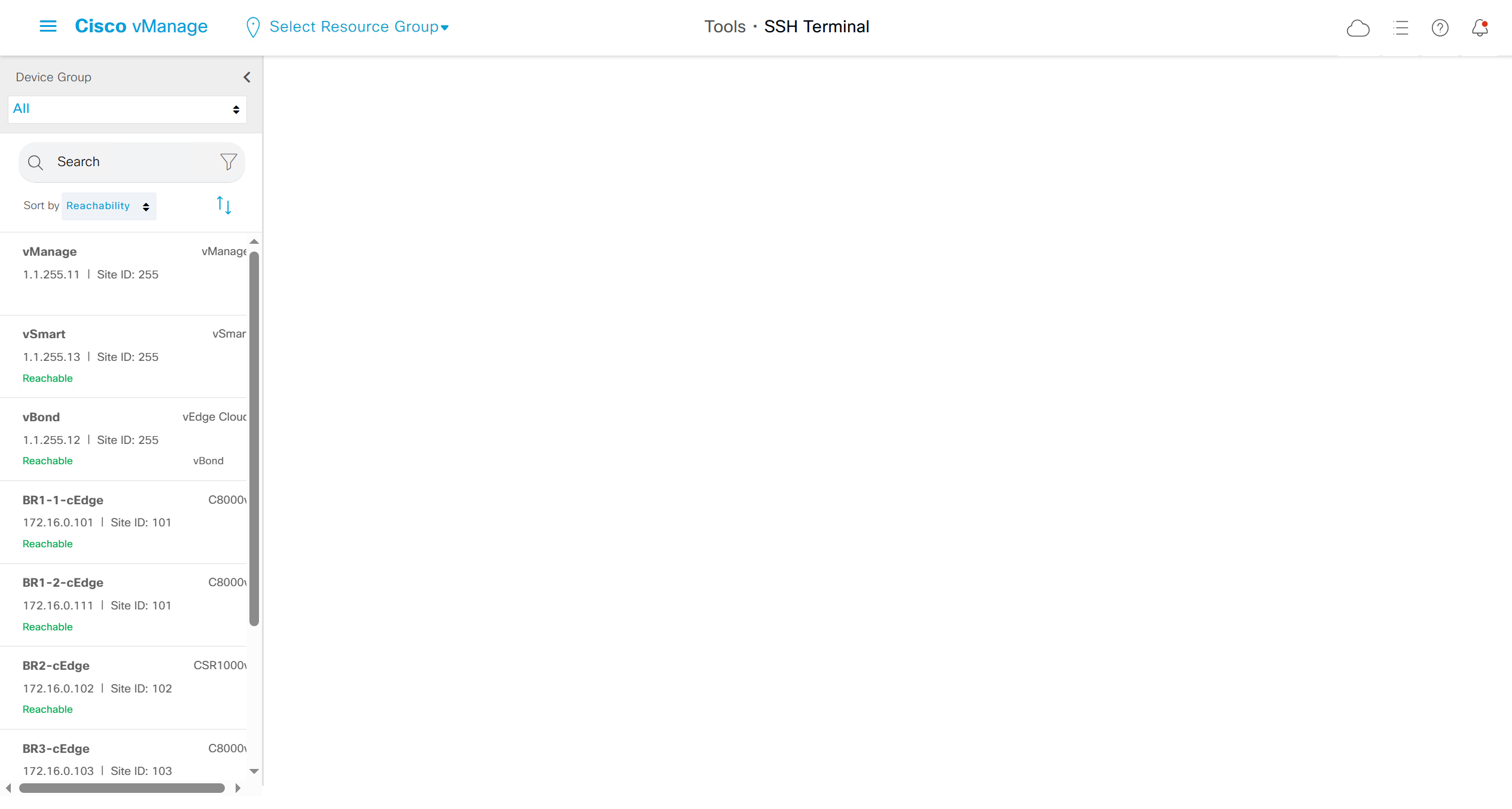
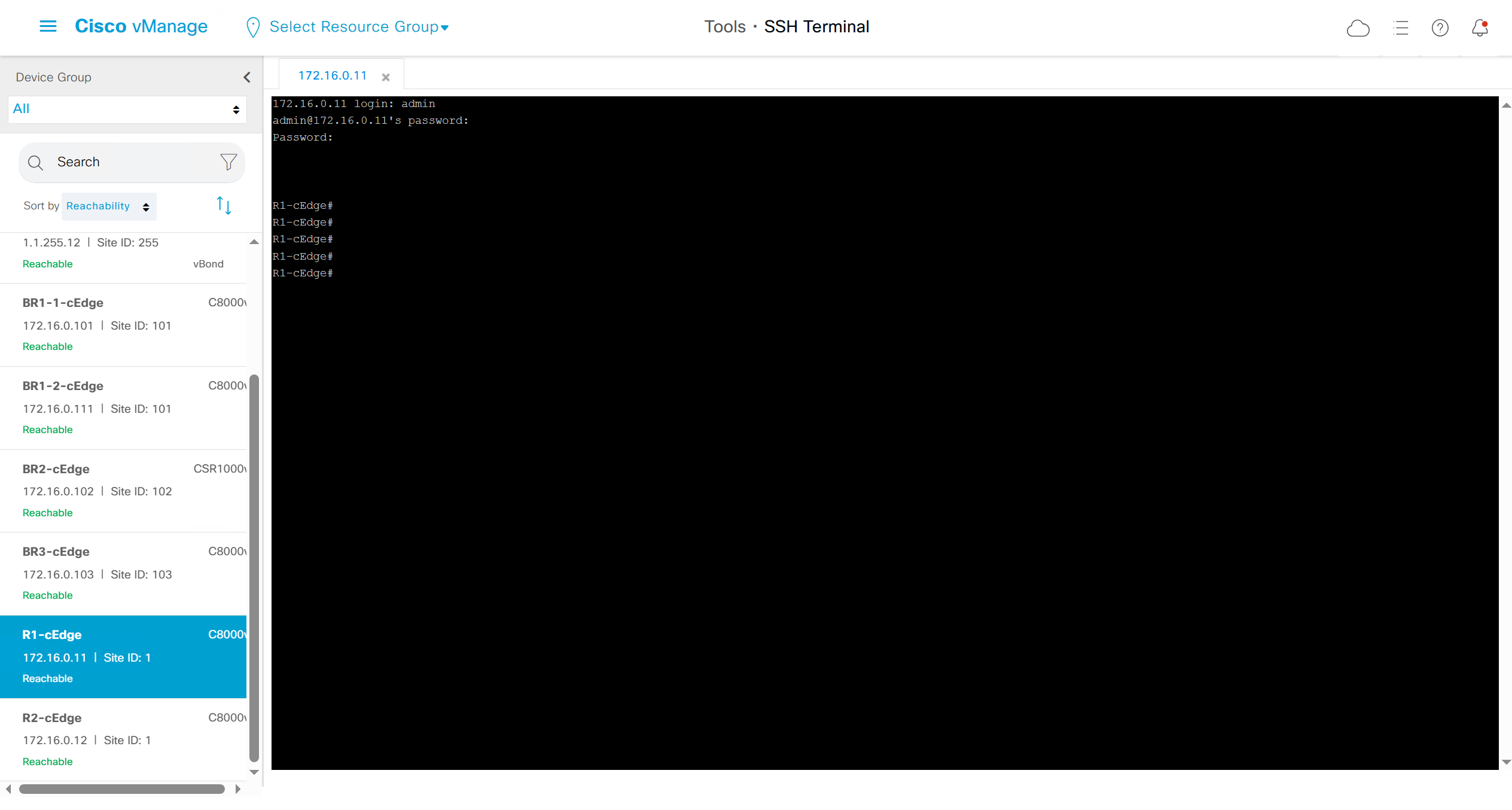
This is great when you want to quickly check something in SSH
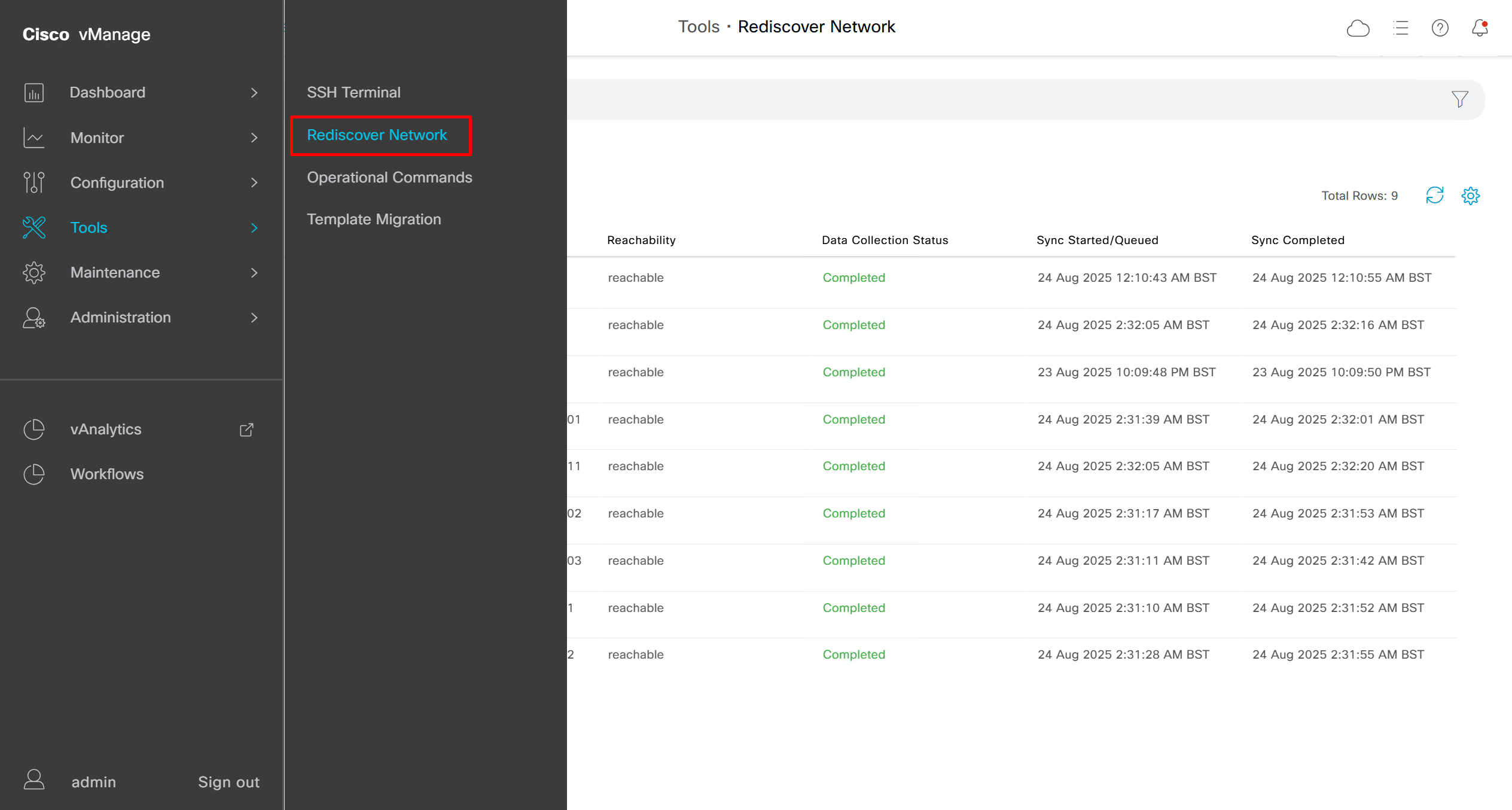
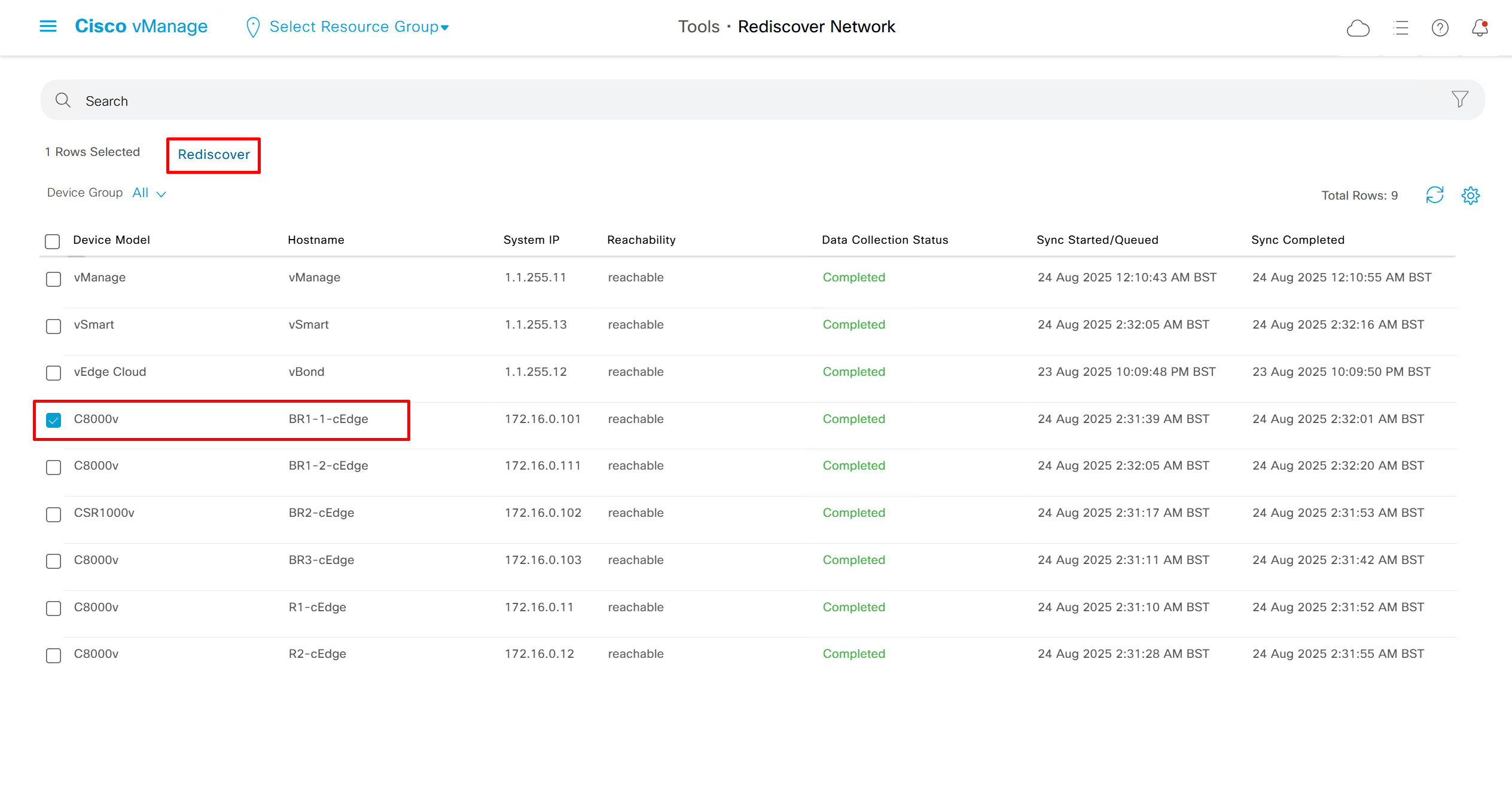
Rediscover network if there is a difference in configuration between vmanage and edge device
Rediscover edge device to sync all those changes
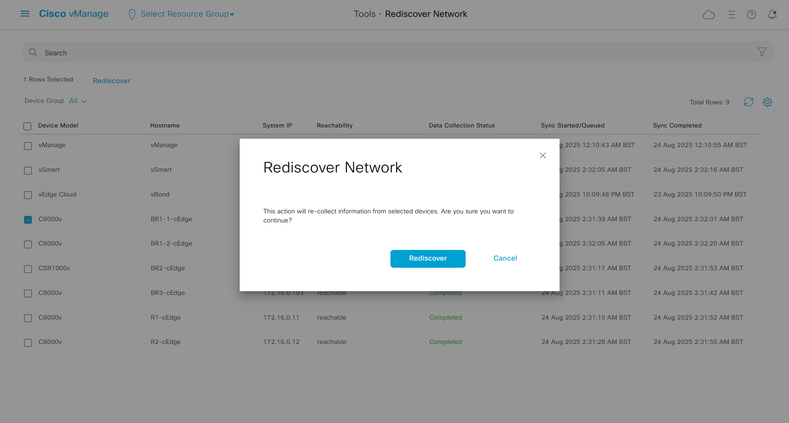
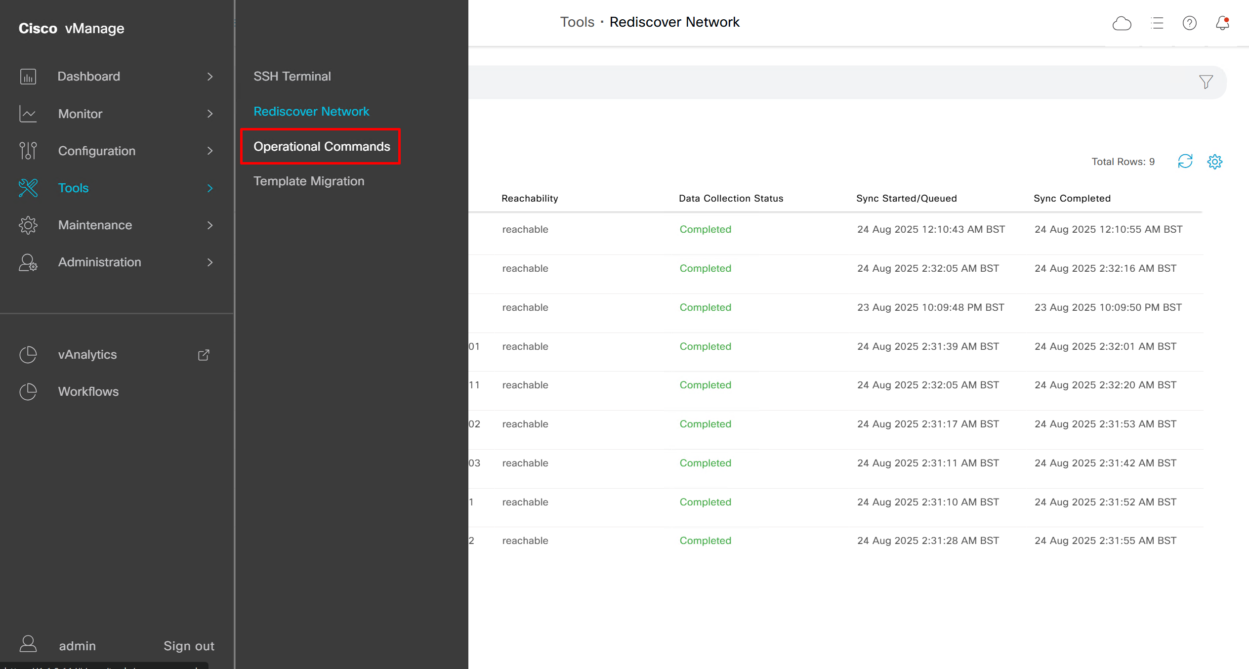
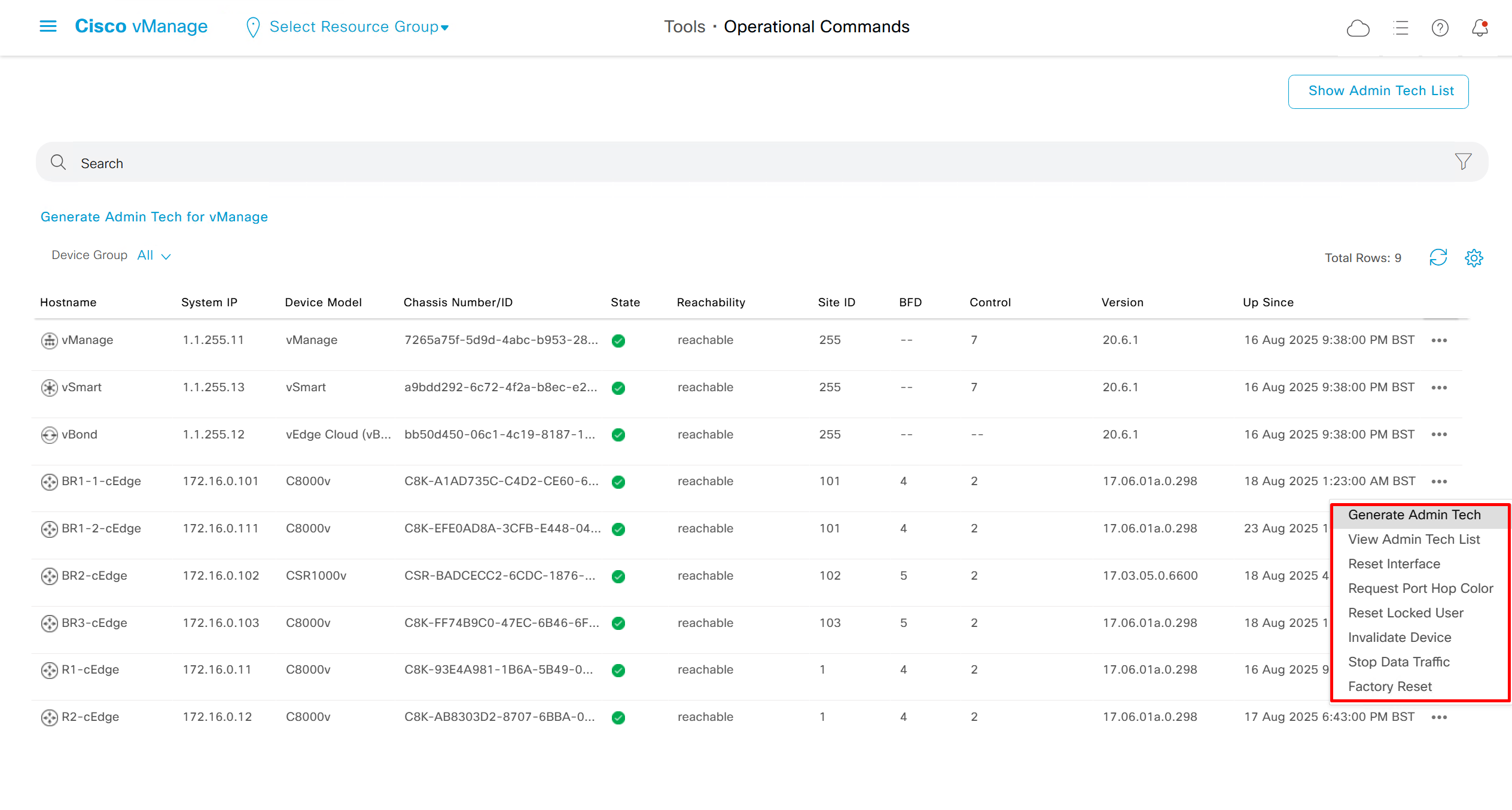
Generate Admin Tech for support
Reset interface is to bounce the port
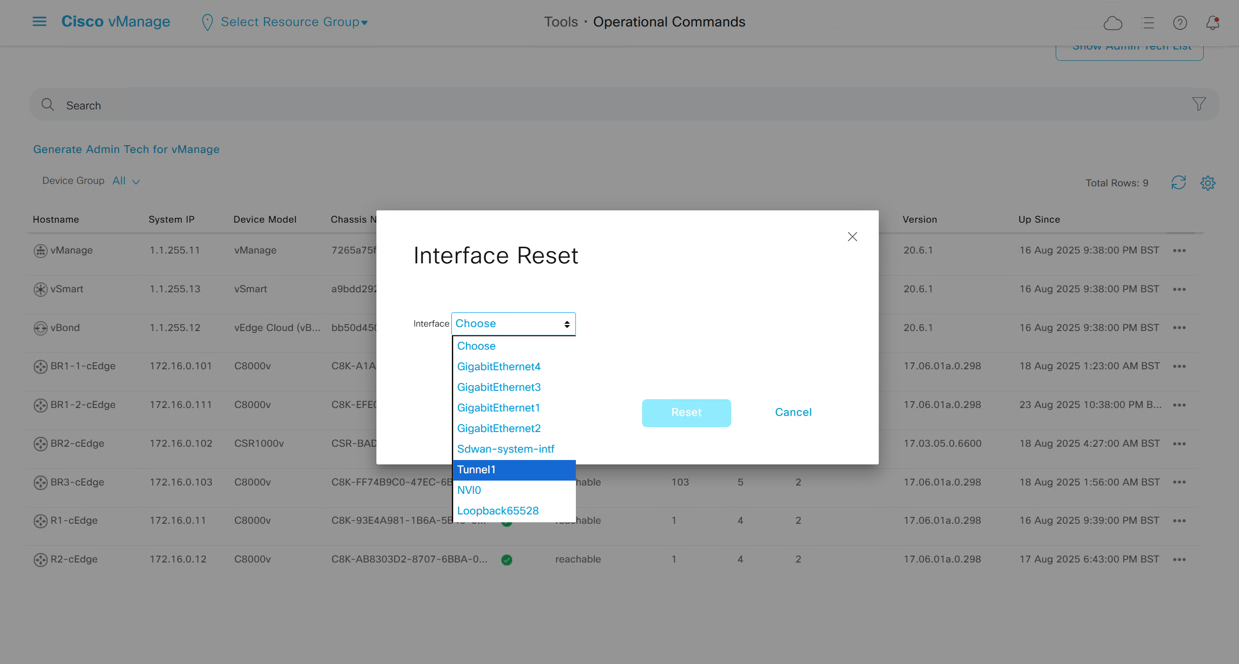
BR1-1-cEdge#
*Aug 24 02:18:57.042: %DMI-5-AUTH_PASSED: R0/0: dmiauthd: User 'vmanage-admin' authenticated successfully from 1.1.255.11:47394  for netconf over ssh. External groups:
BR1-1-cEdge#
*Aug 24 02:19:00.560: %Cisco-SDWAN-RP_0-VDAEMON-3-ERRO-500012: Device does not have an active connection to a vSmart controller
*Aug 24 02:19:04.058: %DMI-5-AUTH_PASSED: R0/0: dmiauthd: User 'vmanage-admin' authenticated successfully from 1.1.255.11:47412  for netconf over ssh. External groups:
BR1-1-cEdge#
*Aug 24 02:19:13.388: %DMI-5-AUTH_PASSED: R0/0: dmiauthd: User 'vmanage-admin' authenticated successfully from 1.1.255.11:47468  for netconf over ssh. External groups:
BR1-1-cEdge#
Request port hop color – Essentially, it forces a TLOC (Transport Locator) color hop so the device re-initiates connections using another WAN interface/color (for example: from biz-internet → public-internet, or mpls → lte).
This is mostly used for troubleshooting and validating policies (e.g., checking failover between MPLS and Internet links).
Reset locked user is used to unlock admin
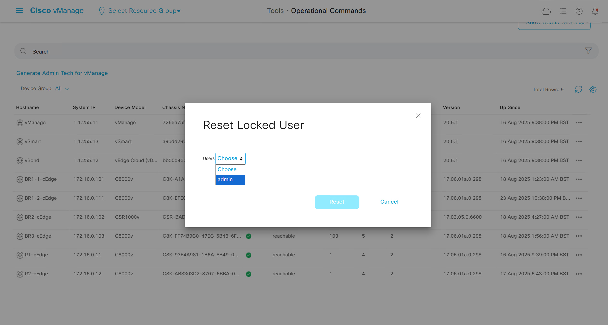
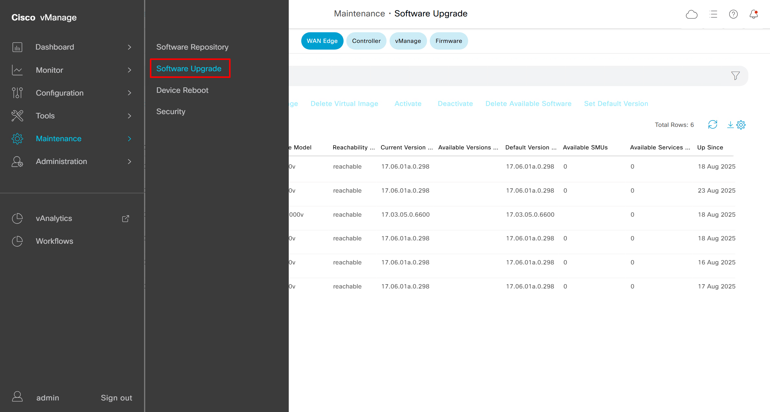
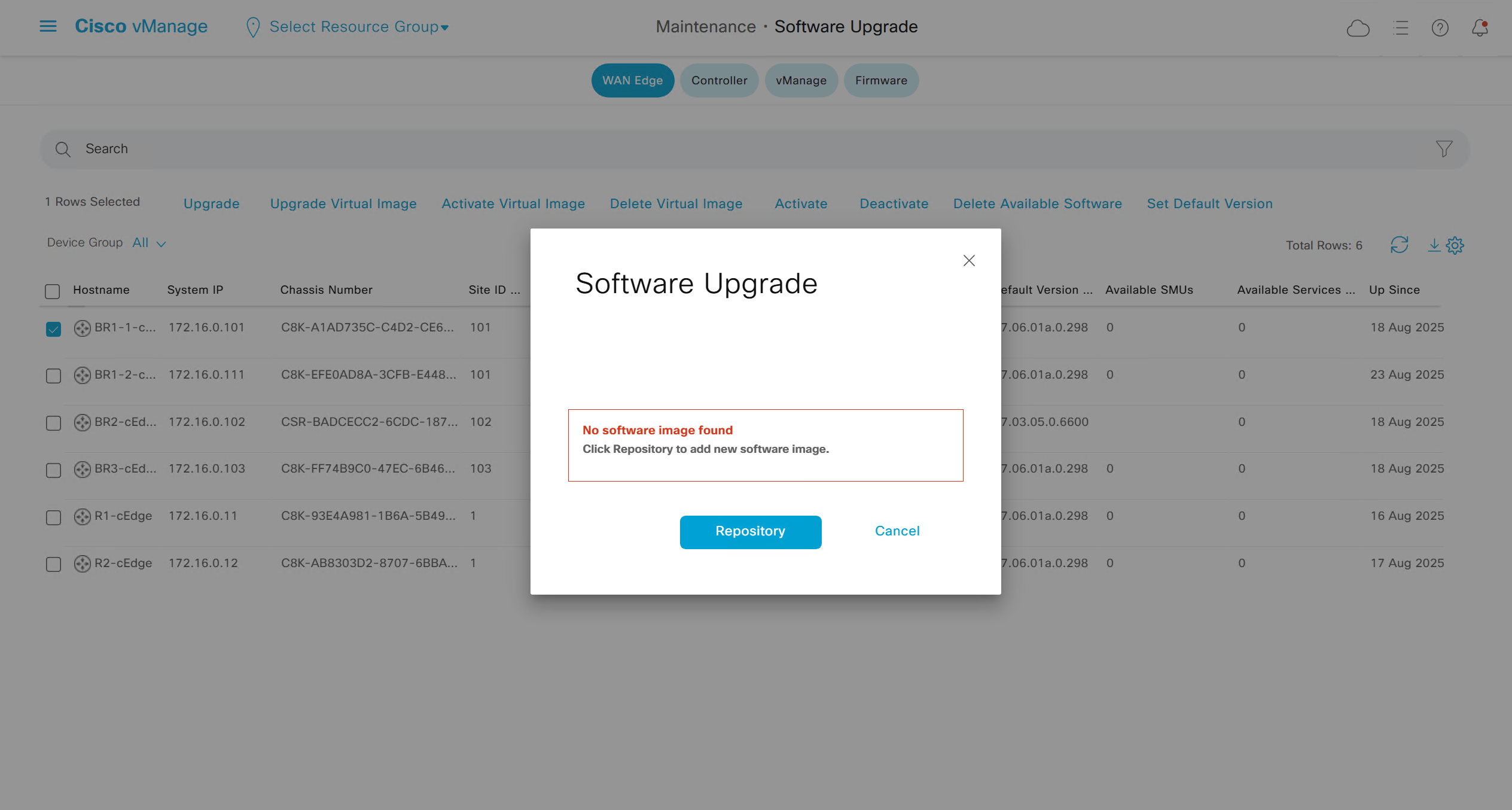
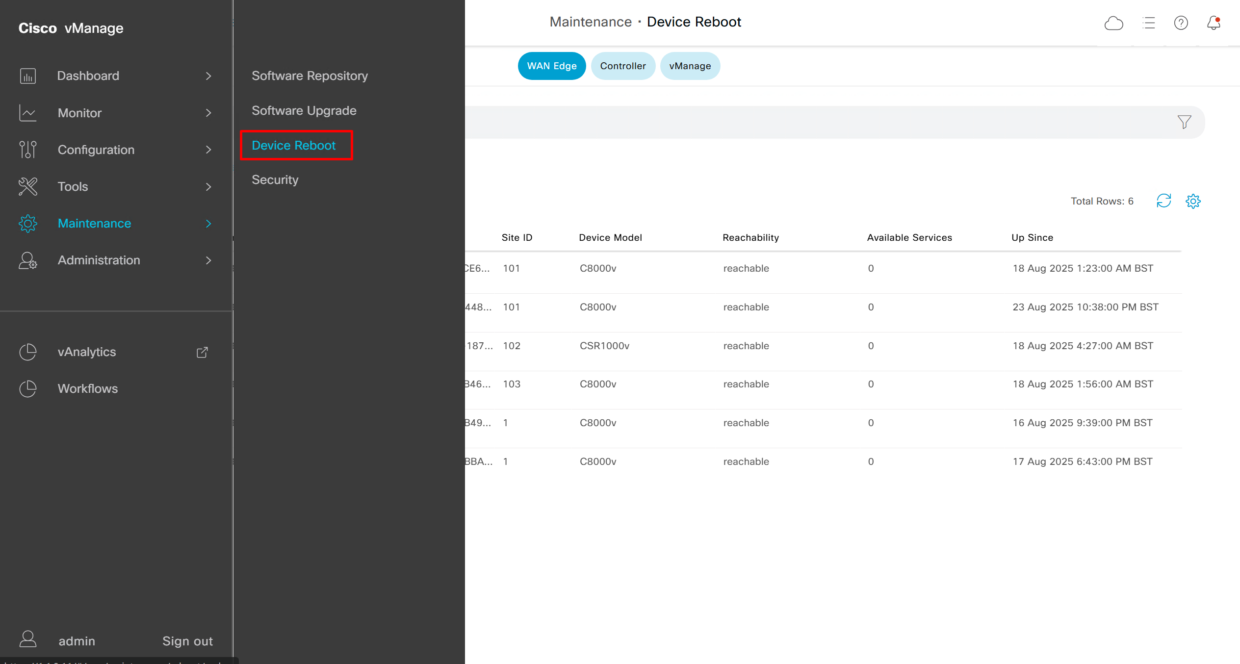
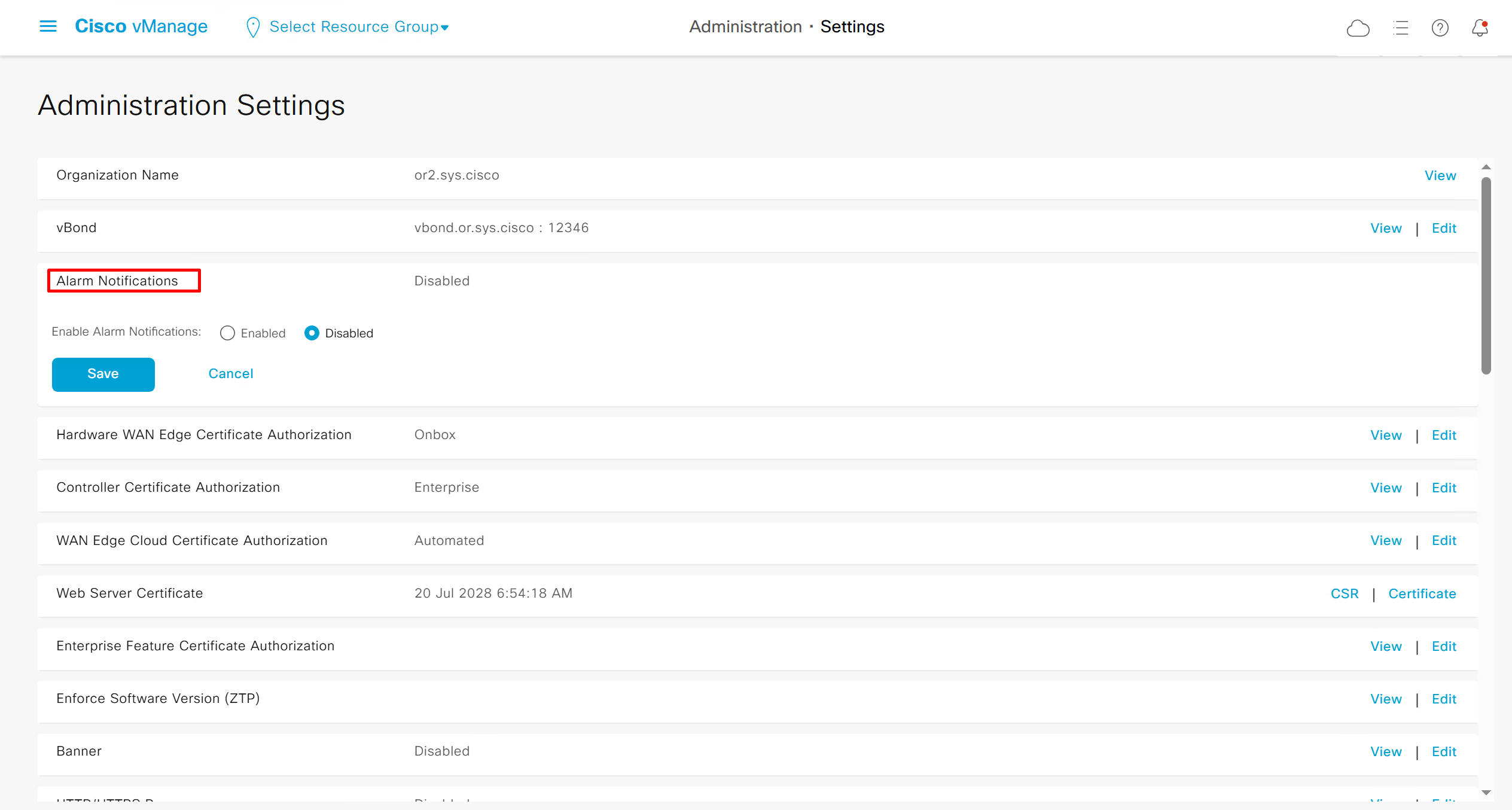
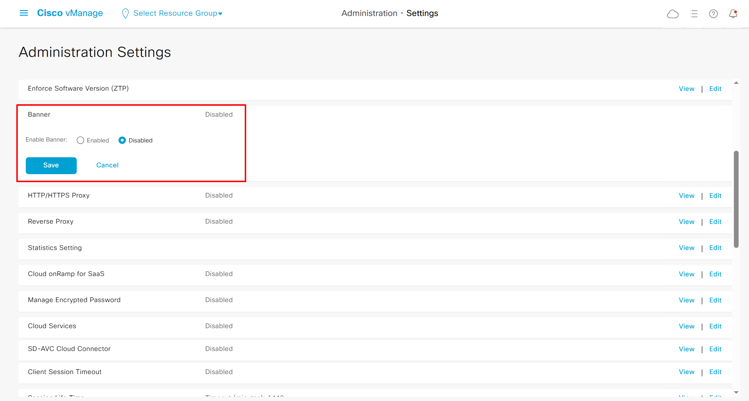

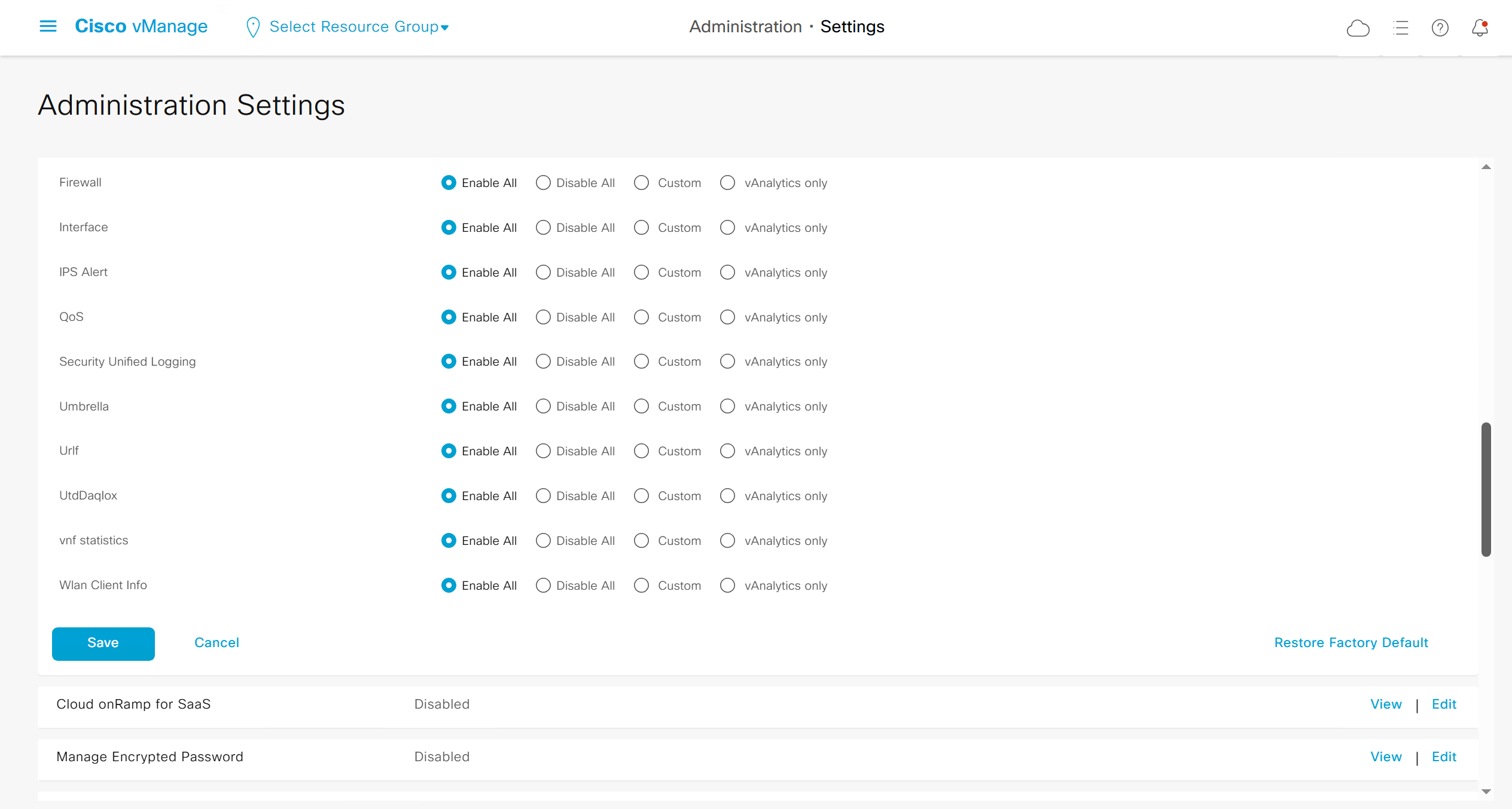

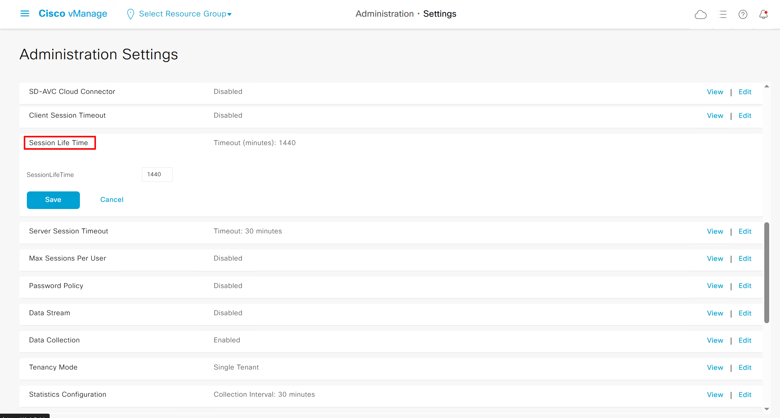
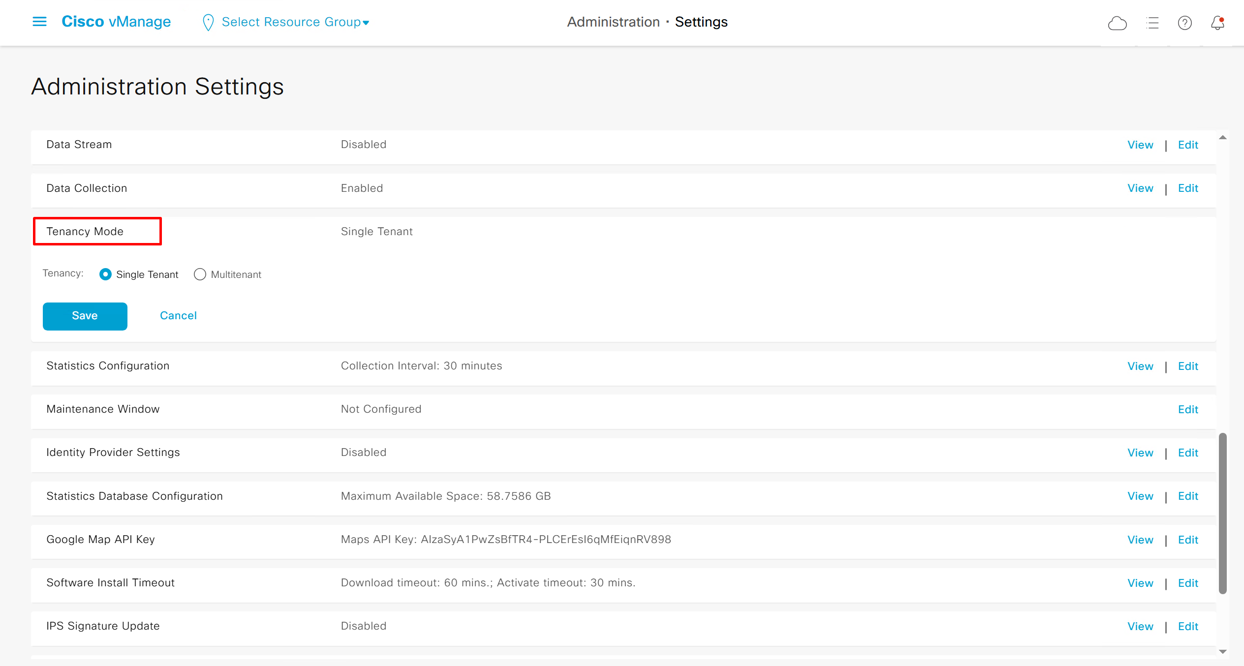
once a vmanage is switched from single tenant to multitenant then it cannot go back to single tenant
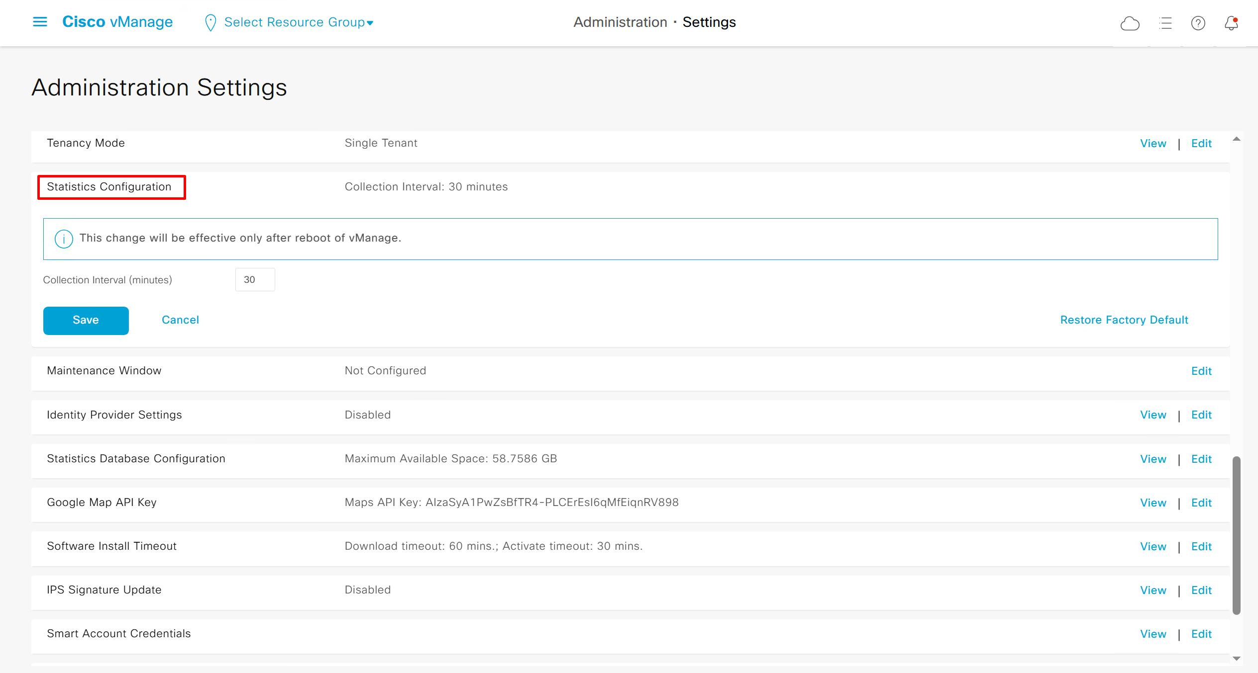
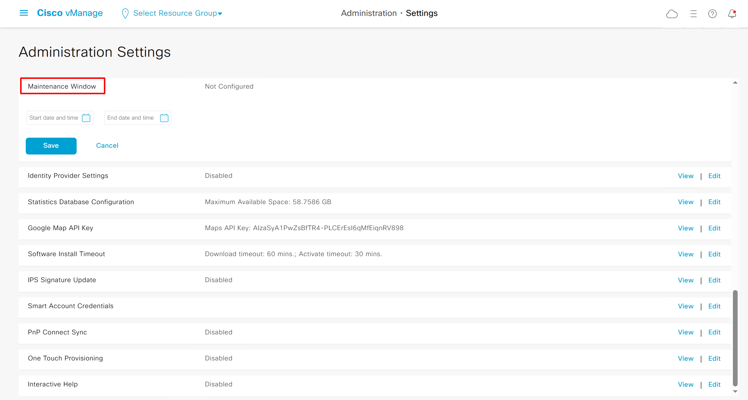
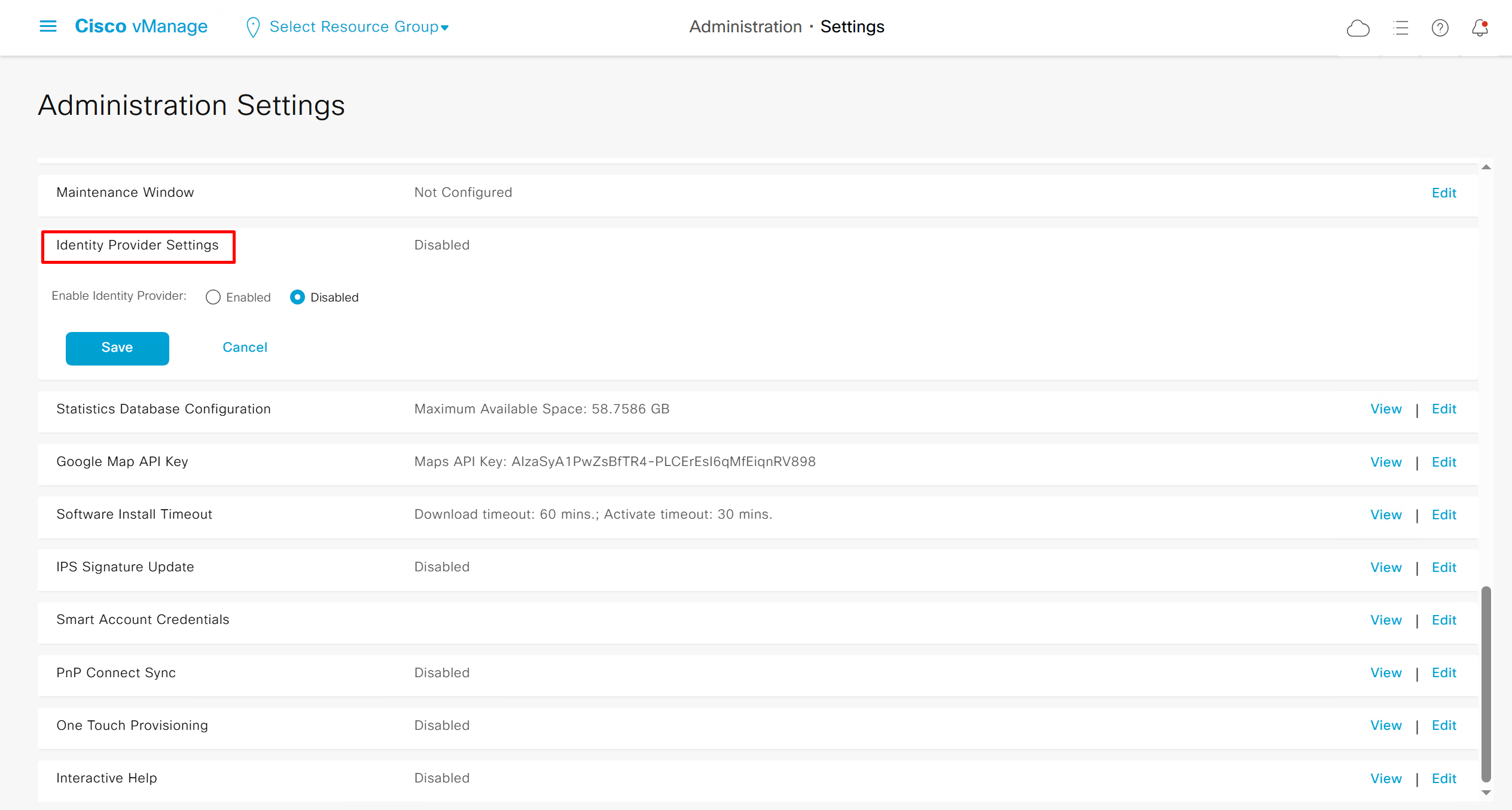
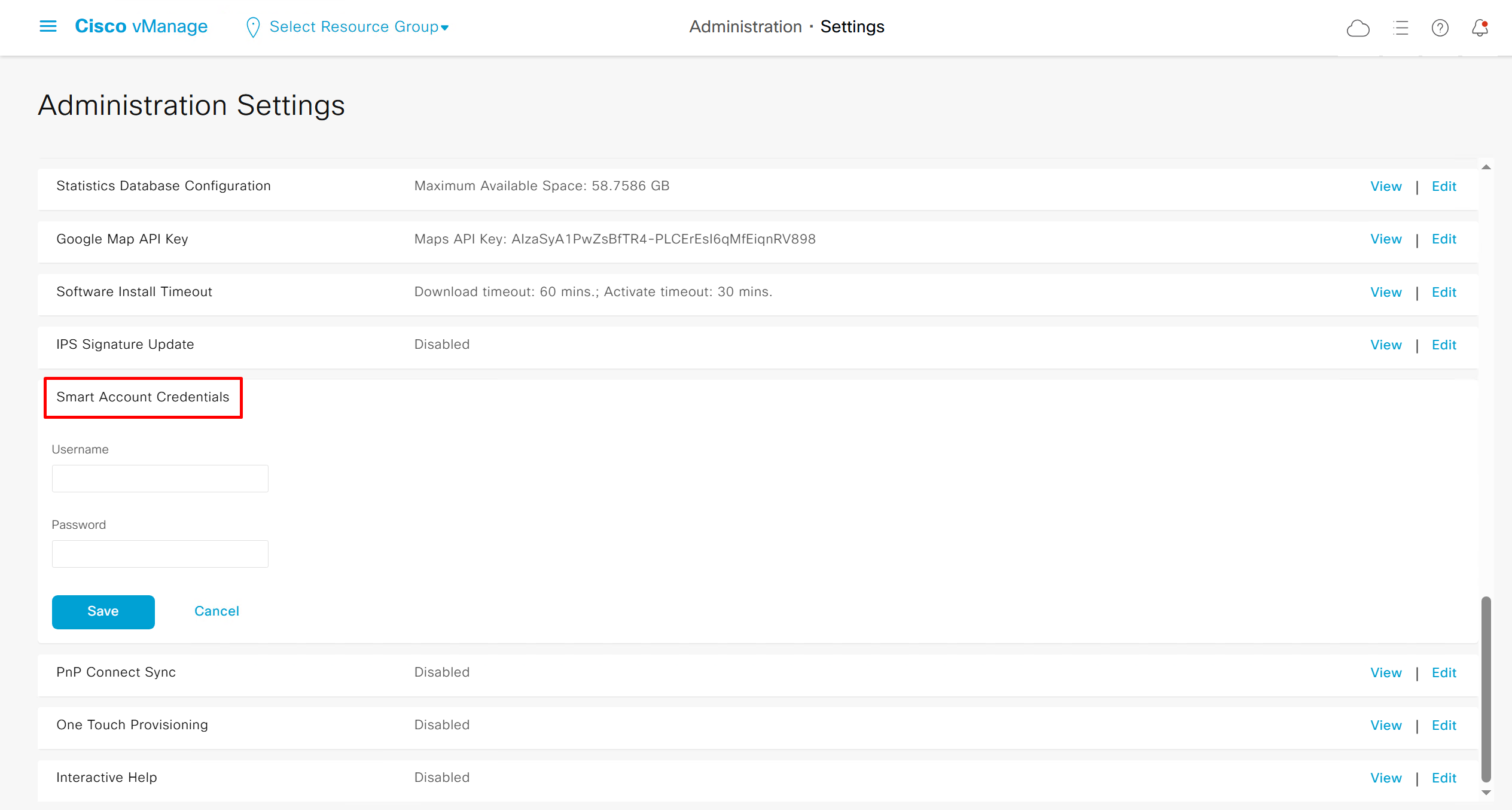


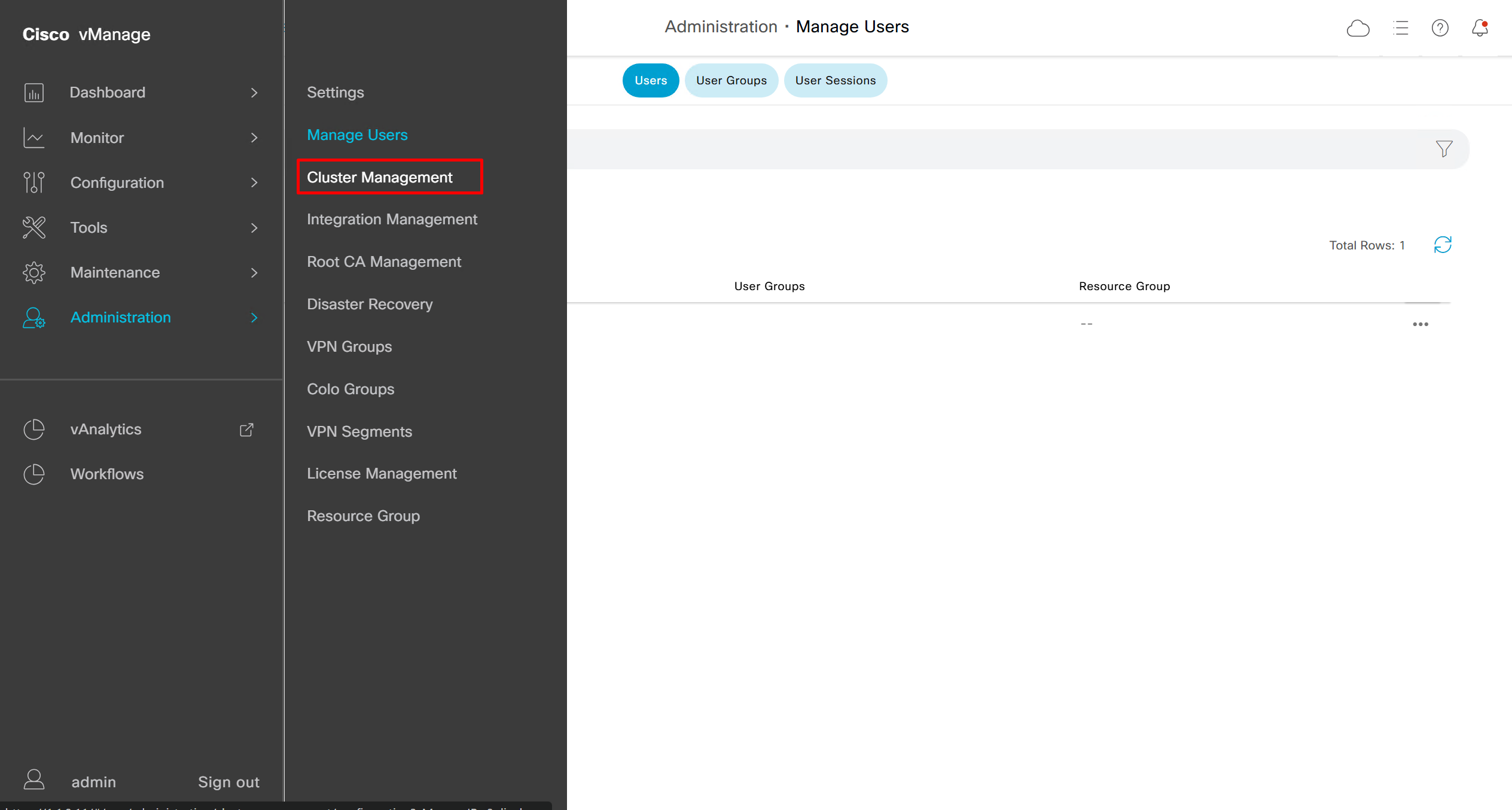
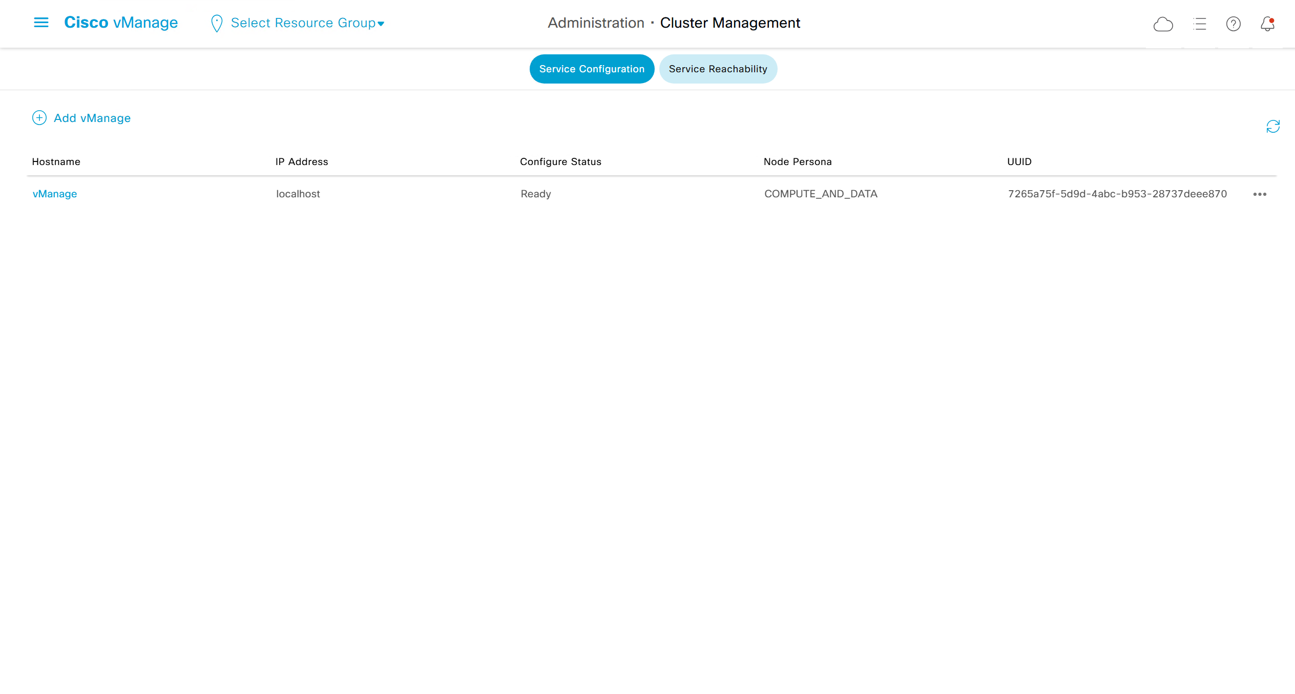
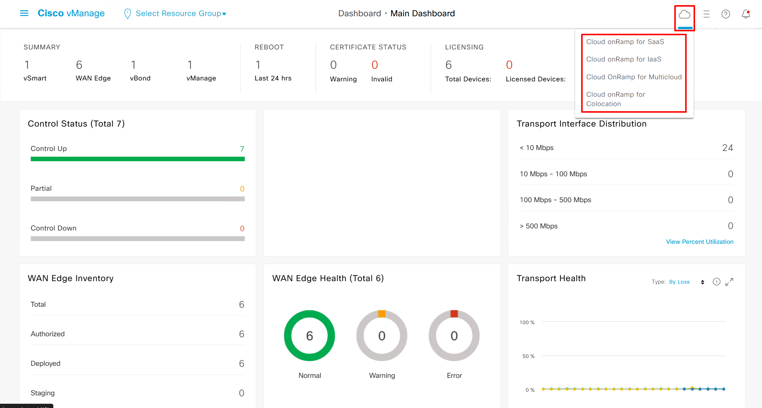
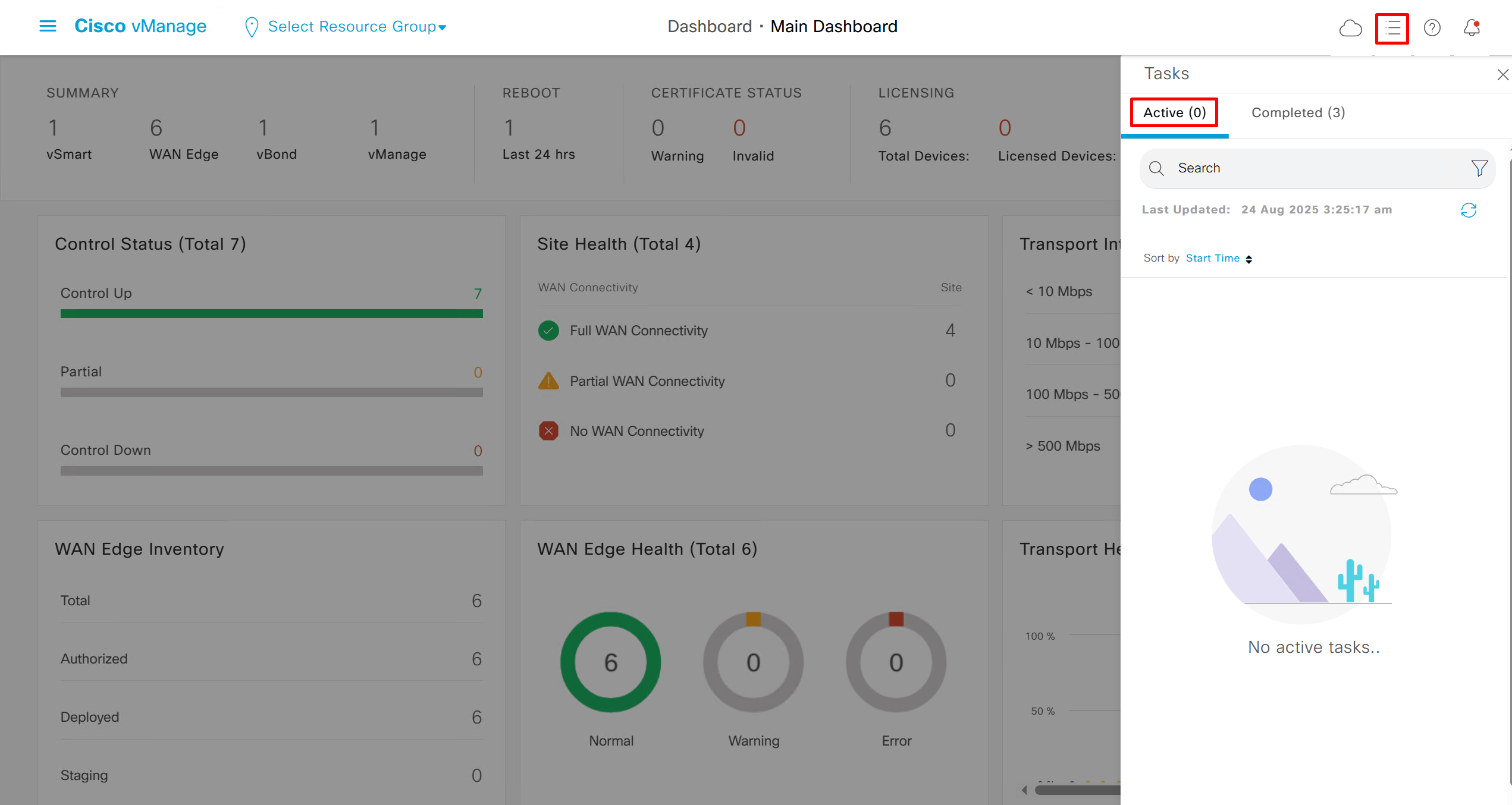
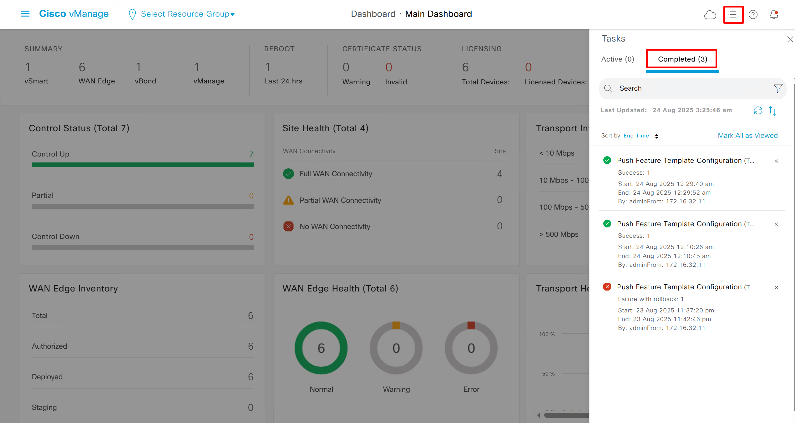
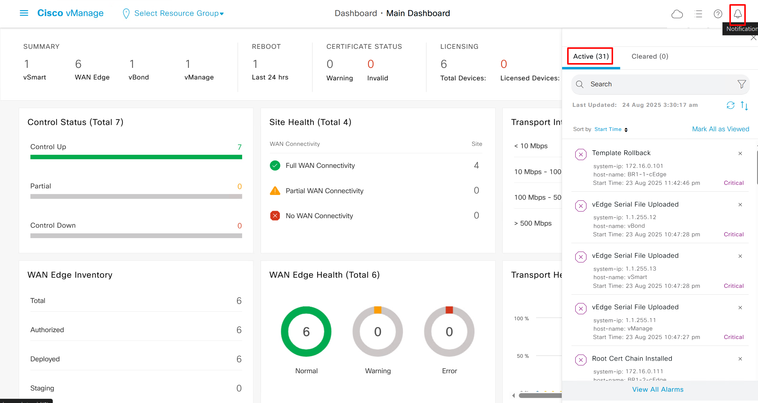
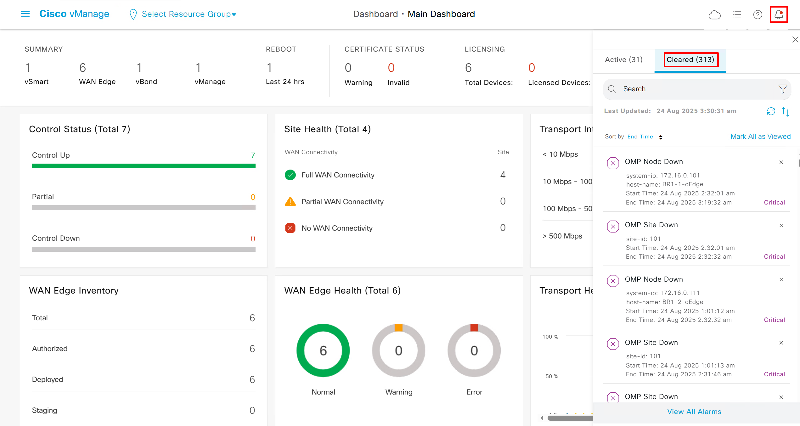
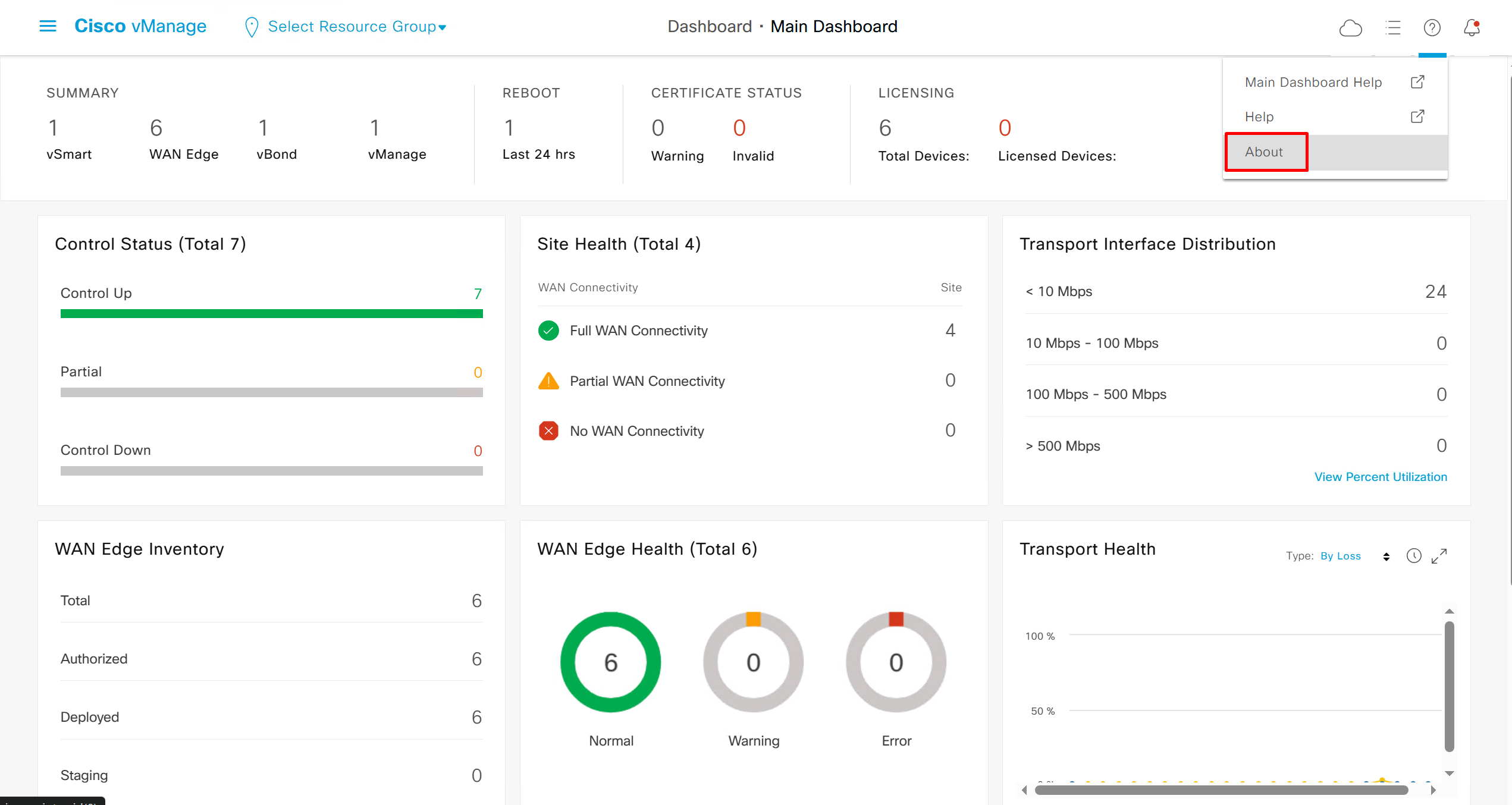


OMP , TLOCs and IPSec VPN
vSmart# show omp peers
R -> routes received
I -> routes installed
S -> routes sent

                         DOMAIN    OVERLAY   SITE
PEER             TYPE    ID        ID        ID        STATE    UPTIME           R/I/S
------------------------------------------------------------------------------------------
172.16.0.11      vedge   1         1         1         up       0:04:15:03       0/0/0
172.16.0.12      vedge   1         1         1         up       0:03:16:13       0/0/0
172.16.0.101     vedge   1         1         101       up       0:02:45:09       0/0/0
172.16.0.102     vedge   1         1         102       up       0:04:15:21       0/0/0
172.16.0.103     vedge   1         1         103       up       0:04:14:59       0/0/0
172.16.0.111     vedge   1         1         101       up       0:02:45:31       0/0/0
R1-cEdge#show sdwan omp peers
R -> routes received
I -> routes installed
S -> routes sent
DOMAIN OVERLAY SITE
PEER TYPE ID ID ID STATE UPTIME R/I/S
------------------------------------------------------------------------------------------
1.1.255.13 vsmart 1 1 255 up 0:04:17:40 0/0/0All the TLOCs known by router, two repeating system IPs means router has transports / colors
R1-cEdge#show sdwan omp tloc-paths
tloc-paths entries 172.16.0.11 biz-internet ipsec
tloc-paths entries 172.16.0.12 mpls ipsec
tloc-paths entries 172.16.0.101 biz-internet ipsec
tloc-paths entries 172.16.0.102 mpls ipsec
tloc-paths entries 172.16.0.102 biz-internet ipsec
tloc-paths entries 172.16.0.103 mpls ipsec
tloc-paths entries 172.16.0.103 biz-internet ipsec
tloc-paths entries 172.16.0.111 mpls ipsec
Full TLOC details
R1-cEdge#show sdwan omp tlocs
---------------------------------------------------
tloc entries for 172.16.0.11
                 biz-internet
                 ipsec
---------------------------------------------------
            RECEIVED FROM:
peer            0.0.0.0
status          C,Red,R
loss-reason     not set
lost-to-peer    not set
lost-to-path-id not set
    Attributes:
     attribute-type    installed
     encap-key         not set
     encap-proto       0
     encap-spi         284
     encap-auth        sha1-hmac,ah-sha1-hmac
     encap-encrypt     aes256
     public-ip         1.1.1.2
     public-port       12366
     private-ip        1.1.1.2
     private-port      12366
     public-ip         ::
     public-port       0
     private-ip        ::
     private-port      0
     bfd-status        up        << BFD status should be up
     domain-id         not set
     site-id           1
     overlay-id        not set
     preference        0
     tag               not set
     stale             not set
     weight            1
     version           3
    gen-id             0x80000001
     carrier           default
     restrict          0
     on-demand          0
     groups            [ 0 ]
     bandwidth         0
     bandwidth-dmin    0
     bandwidth-down    0
     bandwidth-dmax    0
     adapt-qos-period  0
     adapt-qos-up      0
     qos-group         default-group
     border             not set
     extended-ipsec-anti-replay      not set
     unknown-attr-len  not set

---------------------------------------------------
tloc entries for 172.16.0.12
                 mpls
                 ipsec
---------------------------------------------------
            RECEIVED FROM:
peer            1.1.255.13
status          C,I,R
loss-reason     not set
lost-to-peer    not set
lost-to-path-id not set
    Attributes:
     attribute-type    installed
     encap-key         not set
     encap-proto       0
     encap-spi         287
     encap-auth        sha1-hmac,ah-sha1-hmac
     encap-encrypt     aes256
     public-ip         10.0.1.2
     public-port       12406
     private-ip        10.0.1.2
     private-port      12406
     public-ip         ::
     public-port       0
     private-ip        ::
     private-port      0
     bfd-status        down
     domain-id         not set
     site-id           1
     overlay-id        not set
     preference        0
     tag               not set
     stale             not set
     weight            1
     version           3
    gen-id             0x80000000
     carrier           default
     restrict          0
     on-demand          0
     groups            [ 0 ]
     bandwidth         0
     bandwidth-dmin    0
     bandwidth-down    0
     bandwidth-dmax    0
     adapt-qos-period  0
     adapt-qos-up      0
     qos-group         default-group
     border             not set
     extended-ipsec-anti-replay      not set
     unknown-attr-len  not set

---------------------------------------------------
tloc entries for 172.16.0.101
                 biz-internet
                 ipsec
---------------------------------------------------
            RECEIVED FROM:
peer            1.1.255.13
status          C,I,R
loss-reason     not set
lost-to-peer    not set
lost-to-path-id not set
    Attributes:
     attribute-type    installed
     encap-key         not set
     encap-proto       0
     encap-spi         285
     encap-auth        sha1-hmac,ah-sha1-hmac
     encap-encrypt     aes256
     public-ip         1.1.1.101
     public-port       12386
     private-ip        1.1.1.101
     private-port      12386
     public-ip         ::
     public-port       0
     private-ip        ::
     private-port      0
     bfd-status        up
     domain-id         not set
     site-id           101
     overlay-id        not set
     preference        0
     tag               not set
     stale             not set
     weight            1
     version           3
    gen-id             0x80000000
     carrier           default
     restrict          0
     on-demand          0
     groups            [ 0 ]
     bandwidth         0
     bandwidth-dmin    0
     bandwidth-down    0
     bandwidth-dmax    0
     adapt-qos-period  0
     adapt-qos-up      0
     qos-group         default-group
     border             not set
     extended-ipsec-anti-replay      not set
     unknown-attr-len  not set

---------------------------------------------------
tloc entries for 172.16.0.102
                 mpls
                 ipsec
---------------------------------------------------
            RECEIVED FROM:
peer            1.1.255.13
status          C,I,R
loss-reason     not set
lost-to-peer    not set
lost-to-path-id not set
    Attributes:
     attribute-type    installed
     encap-key         not set
     encap-proto       0
     encap-spi         262
     encap-auth        sha1-hmac,ah-sha1-hmac
     encap-encrypt     aes256
     public-ip         10.0.102.2
     public-port       12426
     private-ip        10.0.102.2
     private-port      12426
     public-ip         ::
     public-port       0
     private-ip        ::
     private-port      0
     bfd-status        up
     domain-id         not set
     site-id           102
     overlay-id        not set
     preference        0
     tag               not set
     stale             not set
     weight            1
     version           3
    gen-id             0x80000000
     carrier           default
     restrict          0
     on-demand          0
     groups            [ 0 ]
     bandwidth         0
     bandwidth-dmin    0
     bandwidth-down    0
     bandwidth-dmax    0
     adapt-qos-period  0
     adapt-qos-up      0
     qos-group         default-group
     border             not set
     extended-ipsec-anti-replay      not set
     unknown-attr-len  not set

---------------------------------------------------
tloc entries for 172.16.0.102
                 biz-internet
                 ipsec
---------------------------------------------------
            RECEIVED FROM:
peer            1.1.255.13
status          C,I,R
loss-reason     not set
lost-to-peer    not set
lost-to-path-id not set
    Attributes:
     attribute-type    installed
     encap-key         not set
     encap-proto       0
     encap-spi         280
     encap-auth        sha1-hmac,ah-sha1-hmac
     encap-encrypt     aes256
     public-ip         1.1.1.102
     public-port       12366
     private-ip        1.1.1.102
     private-port      12366
     public-ip         ::
     public-port       0
     private-ip        ::
     private-port      0
     bfd-status        up
     domain-id         not set
     site-id           102
     overlay-id        not set
     preference        0
     tag               not set
     stale             not set
     weight            1
     version           3
    gen-id             0x80000000
     carrier           default
     restrict          0
     on-demand          0
     groups            [ 0 ]
     bandwidth         0
     bandwidth-dmin    0
     bandwidth-down    0
     bandwidth-dmax    0
     adapt-qos-period  0
     adapt-qos-up      0
     qos-group         default-group
     border             not set
     extended-ipsec-anti-replay      not set
     unknown-attr-len  not set

---------------------------------------------------
tloc entries for 172.16.0.103
                 mpls
                 ipsec
---------------------------------------------------
            RECEIVED FROM:
peer            1.1.255.13
status          C,I,R
loss-reason     not set
lost-to-peer    not set
lost-to-path-id not set
    Attributes:
     attribute-type    installed
     encap-key         not set
     encap-proto       0
     encap-spi         265
     encap-auth        sha1-hmac,ah-sha1-hmac
     encap-encrypt     aes256
     public-ip         10.0.103.2
     public-port       12366
     private-ip        10.0.103.2
     private-port      12366
     public-ip         ::
     public-port       0
     private-ip        ::
     private-port      0
     bfd-status        up
     domain-id         not set
     site-id           103
     overlay-id        not set
     preference        0
     tag               not set
     stale             not set
     weight            1
     version           3
    gen-id             0x80000000
     carrier           default
     restrict          0
     on-demand          0
     groups            [ 0 ]
     bandwidth         0
     bandwidth-dmin    0
     bandwidth-down    0
     bandwidth-dmax    0
     adapt-qos-period  0
     adapt-qos-up      0
     qos-group         default-group
     border             not set
     extended-ipsec-anti-replay      not set
     unknown-attr-len  not set

---------------------------------------------------
tloc entries for 172.16.0.103
                 biz-internet
                 ipsec
---------------------------------------------------
            RECEIVED FROM:
peer            1.1.255.13
status          C,I,R
loss-reason     not set
lost-to-peer    not set
lost-to-path-id not set
    Attributes:
     attribute-type    installed
     encap-key         not set
     encap-proto       0
     encap-spi         286
     encap-auth        sha1-hmac,ah-sha1-hmac
     encap-encrypt     aes256
     public-ip         1.1.1.103
     public-port       12426
     private-ip        1.1.1.103
     private-port      12426
     public-ip         ::
     public-port       0
     private-ip        ::
     private-port      0
     bfd-status        up
     domain-id         not set
     site-id           103
     overlay-id        not set
     preference        0
     tag               not set
     stale             not set
     weight            1
     version           3
    gen-id             0x80000000
     carrier           default
     restrict          0
     on-demand          0
     groups            [ 0 ]
     bandwidth         0
     bandwidth-dmin    0
     bandwidth-down    0
     bandwidth-dmax    0
     adapt-qos-period  0
     adapt-qos-up      0
     qos-group         default-group
     border             not set
     extended-ipsec-anti-replay      not set
     unknown-attr-len  not set

---------------------------------------------------
tloc entries for 172.16.0.111
                 mpls
                 ipsec
---------------------------------------------------
            RECEIVED FROM:
peer            1.1.255.13
status          C,I,R
loss-reason     not set
lost-to-peer    not set
lost-to-path-id not set
    Attributes:
     attribute-type    installed
     encap-key         not set
     encap-proto       0
     encap-spi         266
     encap-auth        sha1-hmac,ah-sha1-hmac
     encap-encrypt     aes256
     public-ip         10.0.101.2
     public-port       12406
     private-ip        10.0.101.2
     private-port      12406
     public-ip         ::
     public-port       0
     private-ip        ::
     private-port      0
     bfd-status        up
     domain-id         not set
     site-id           101
     overlay-id        not set
     preference        0
     tag               not set
     stale             not set
     weight            1
     version           3
    gen-id             0x80000000
     carrier           default
     restrict          0
     on-demand          0
     groups            [ 0 ]
     bandwidth         0
     bandwidth-dmin    0
     bandwidth-down    0
     bandwidth-dmax    0
     adapt-qos-period  0
     adapt-qos-up      0
     qos-group         default-group
     border             not set
     extended-ipsec-anti-replay      not set
     unknown-attr-len  not set
Interval for BFD session is 1000 msec
R1-cEdge#show sdwan bfd sessions
                                   SOURCE TLOC      REMOTE TLOC                    DST PUBLIC      DST PUBLIC         DETECT      TX
SYSTEM IP        SITE ID  STATE    COLOR            COLOR            SOURCE IP     IP              PORT        ENCAP  MULTIPLIER  INTERVAL(msec  UPTIME          TRANSITIONS
-----------------------------------------------------------------------------------------------------------------------------------------------------------------------------
172.16.0.101     101      up       biz-internet     biz-internet     1.1.1.2       1.1.1.101       12386       ipsec  7           1000           10 0:23:51:18   0
172.16.0.102     102      up       biz-internet     biz-internet     1.1.1.2       1.1.1.102       12386       ipsec  7           1000           10 0:00:48:47   2
172.16.0.103     103      up       biz-internet     biz-internet     1.1.1.2       1.1.1.103       12426       ipsec  7           1000           10 0:03:48:08   0
172.16.0.111     101      up       biz-internet     mpls             1.1.1.2       10.0.101.2      12406       ipsec  7           1000           10 0:23:14:16   1
172.16.0.102     102      up       biz-internet     mpls             1.1.1.2       10.0.102.2      12426       ipsec  7           1000           10 0:13:47:48   0
172.16.0.103     103      up       biz-internet     mpls             1.1.1.2       10.0.103.2      12366       ipsec  7           1000           10 0:12:48:23   0
on ipsec outbound connections destination IP will be of remote routers
R1-cEdge#show sdwan ipsec outbound-connections
SOURCE          SOURCE  DEST               DEST                        REMOTE           REMOTE           INTEGRITY                   NEGOTIATED
IP              PORT    IP                 PORT    SPI     TUNNEL MTU  TLOC ADDRESS     TLOC COLOR       USED           KEY HASH   ENCRYPTION ALGORITHM  TC SPIs
----------------------------------------------------------------------------------------------------------------------------------------------------------------
1.1.1.2         12366   1.1.1.101          12386   285     1438        172.16.0.101     biz-internet     ip-udp-esp       *****346f  AES-GCM-256           8
1.1.1.2         12366   1.1.1.102          12386   281     1438        172.16.0.102     biz-internet     ip-udp-esp       *****60d6  AES-GCM-256           8
1.1.1.2         12366   1.1.1.103          12426   286     1438        172.16.0.103     biz-internet     ip-udp-esp       *****d535  AES-GCM-256           8
1.1.1.2         12366   10.0.101.2         12406   266     1438        172.16.0.111     mpls             ip-udp-esp       *****bf3e  AES-GCM-256           8
1.1.1.2         12366   10.0.102.2         12426   262     1438        172.16.0.102     mpls             ip-udp-esp       *****8f3f  AES-GCM-256           8
1.1.1.2         12366   10.0.103.2         12366   266     1438        172.16.0.103     mpls             ip-udp-esp       *****863f  AES-GCM-256           8
on the ipsec inbound connections, source IP will be of the remote routers
R1-cEdge#show sdwan ipsec inbound-connections
SOURCE            SOURCE  DEST           DEST    REMOTE           REMOTE           LOCAL            LOCAL            NEGOTIATED
IP                PORT    IP             PORT    TLOC ADDRESS     TLOC COLOR       TLOC ADDRESS     TLOC COLOR       ENCRYPTION ALGORITHM  TC SPIs
--------------------------------------------------------------------------------------------------------------------------------------------------
1.1.1.101         12386   1.1.1.2        12366   172.16.0.101     biz-internet     172.16.0.11      biz-internet     AES-GCM-256           8
10.0.102.2        12426   1.1.1.2        12366   172.16.0.102     mpls             172.16.0.11      biz-internet     AES-GCM-256           8
1.1.1.102         12386   1.1.1.2        12366   172.16.0.102     biz-internet     172.16.0.11      biz-internet     AES-GCM-256           8
10.0.103.2        12366   1.1.1.2        12366   172.16.0.103     mpls             172.16.0.11      biz-internet     AES-GCM-256           8
1.1.1.103         12426   1.1.1.2        12366   172.16.0.103     biz-internet     172.16.0.11      biz-internet     AES-GCM-256           8
10.0.101.2        12406   1.1.1.2        12366   172.16.0.111     mpls             172.16.0.11      biz-internet     AES-GCM-256
Service Side VPN , Site Local LAN
Setup VPN 10 VRF
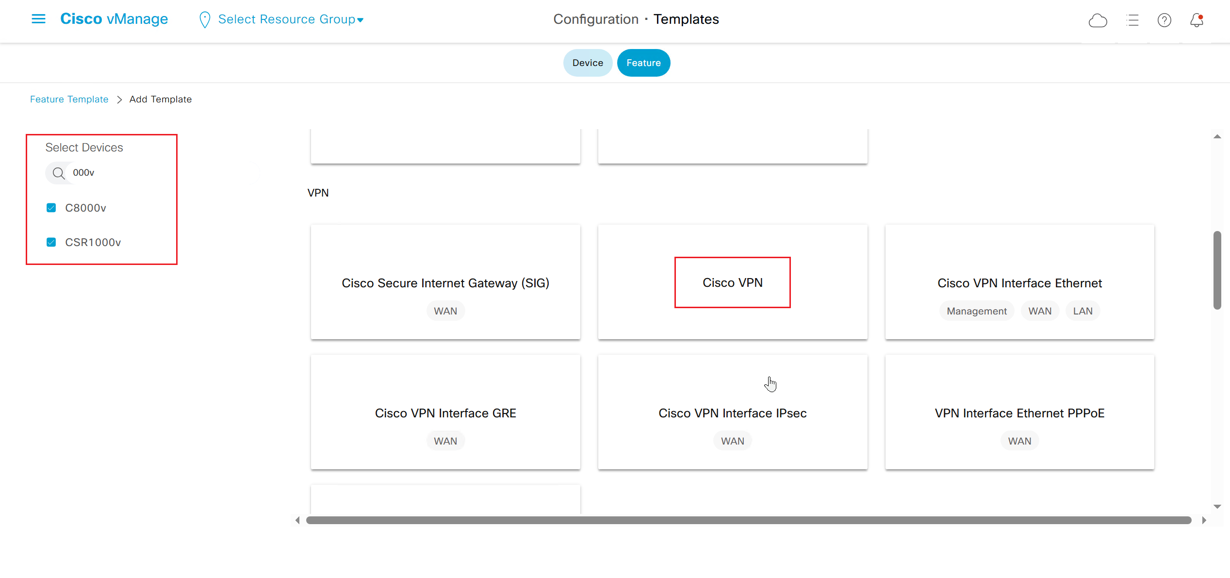
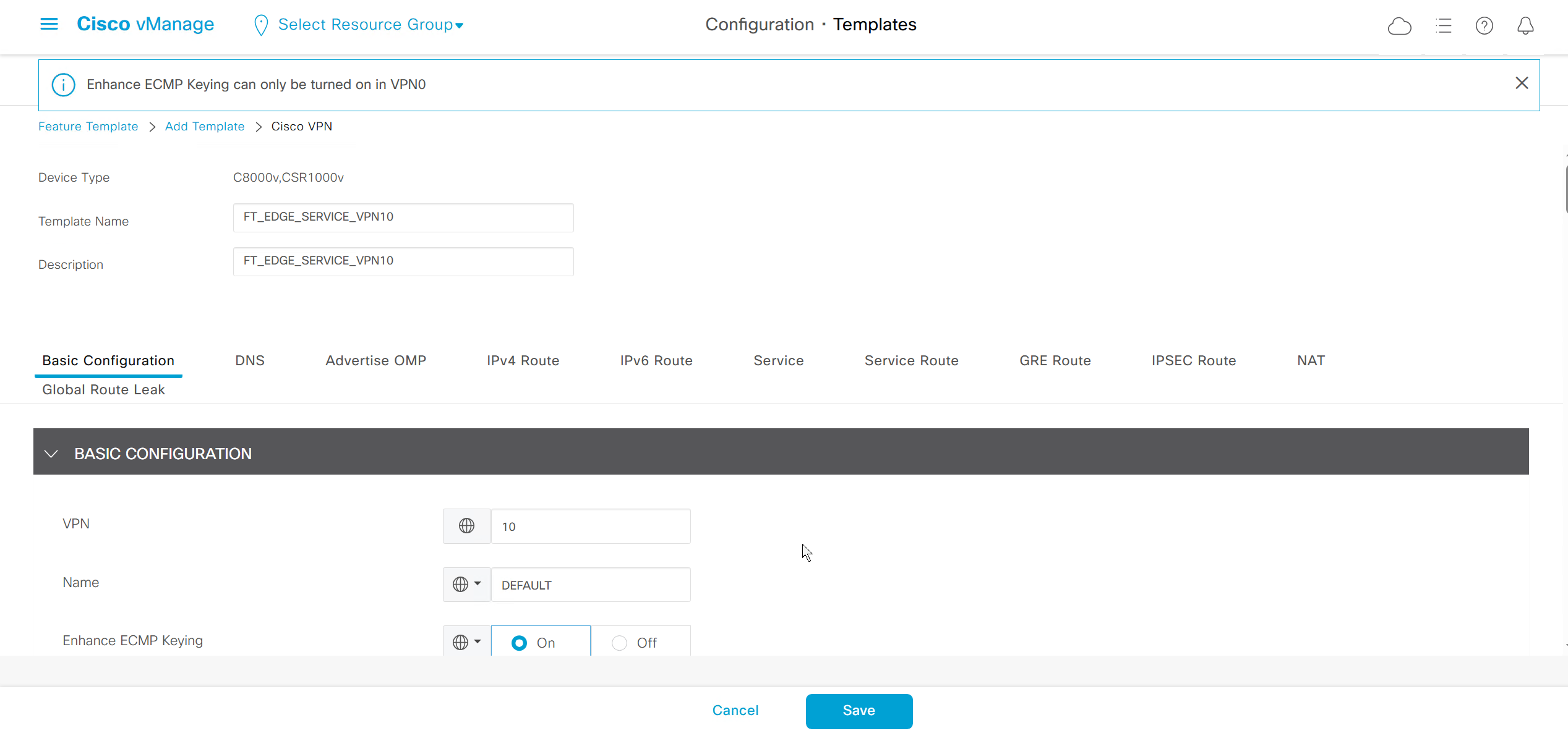
This is to redistribute connected routes in OMP
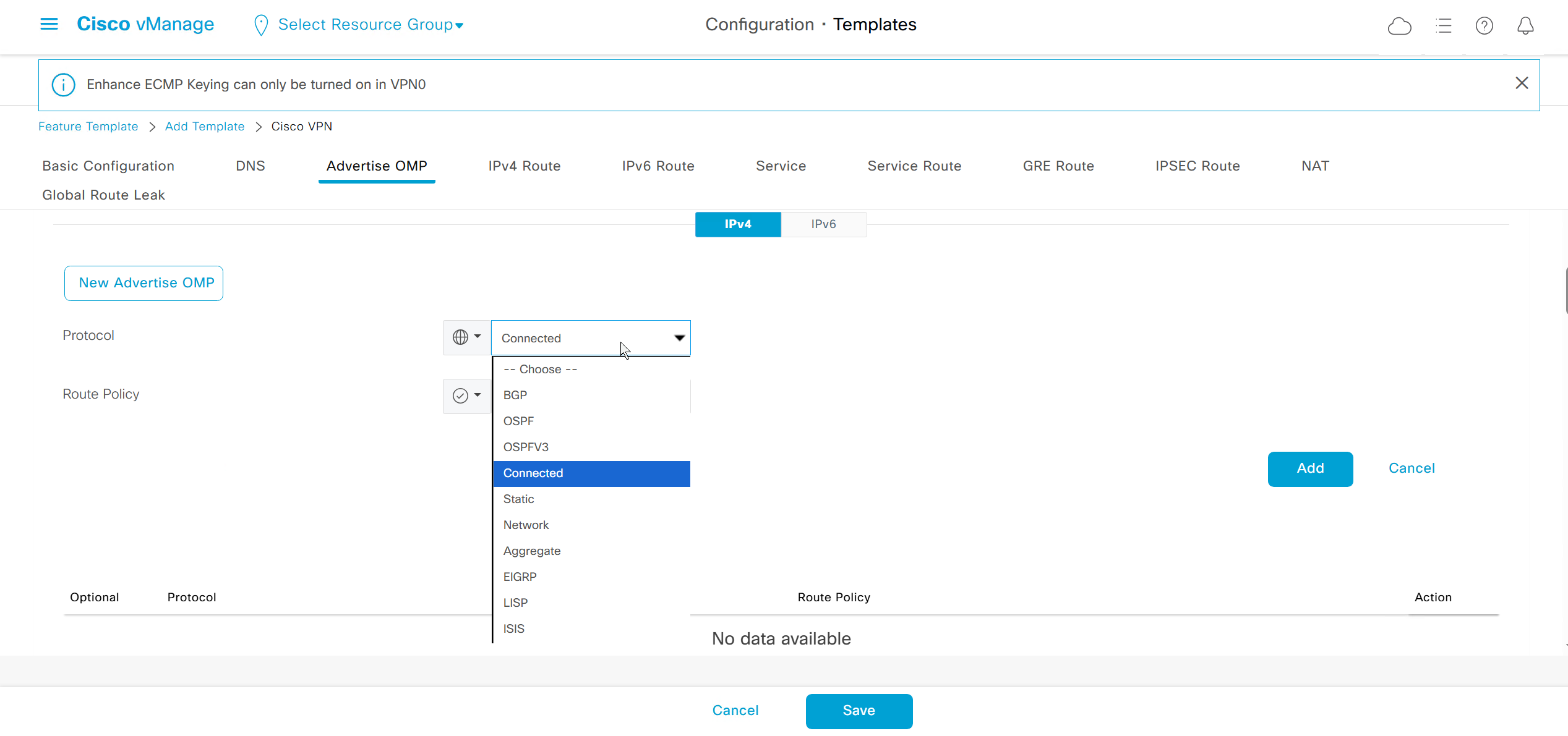
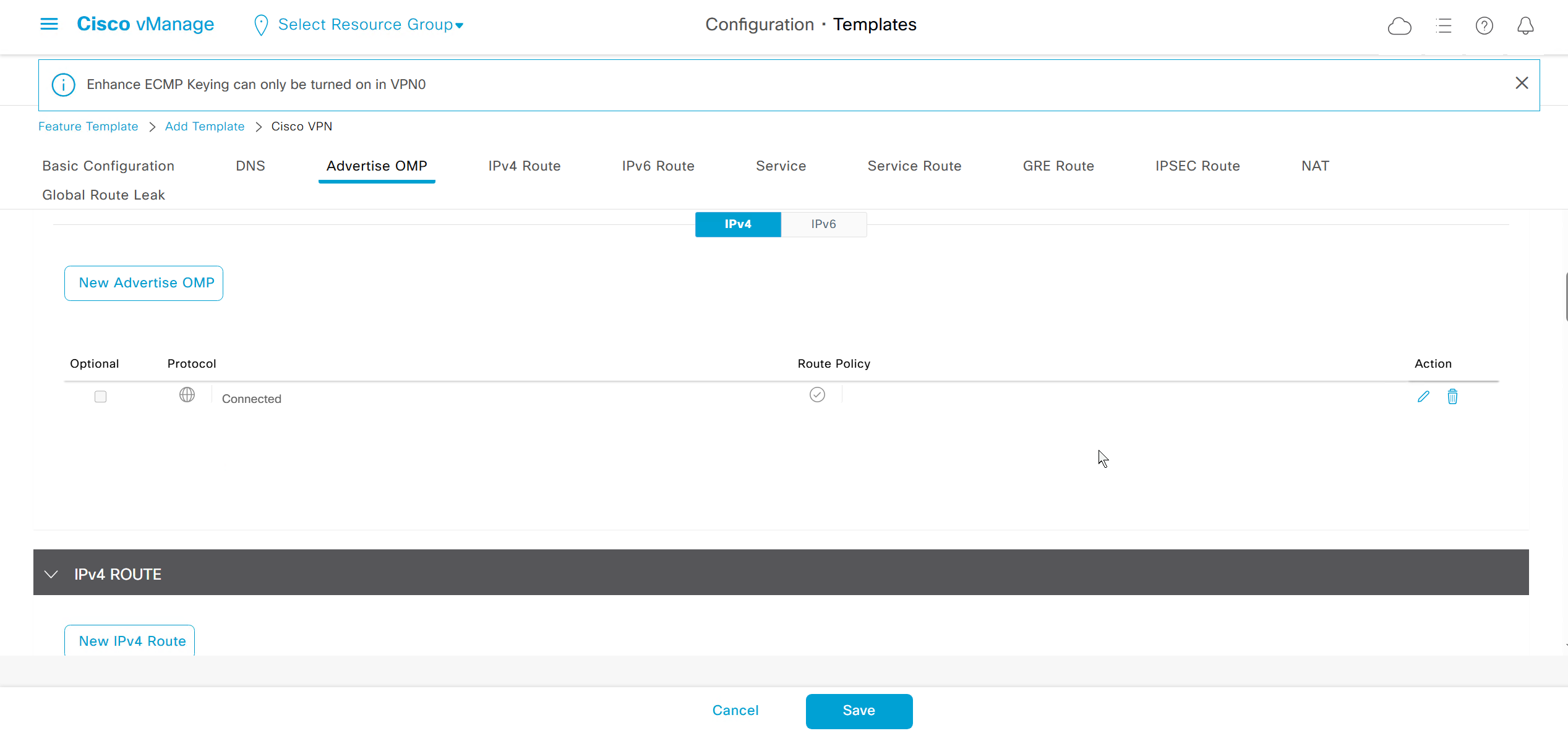
This is to redistribute static routes in OMP
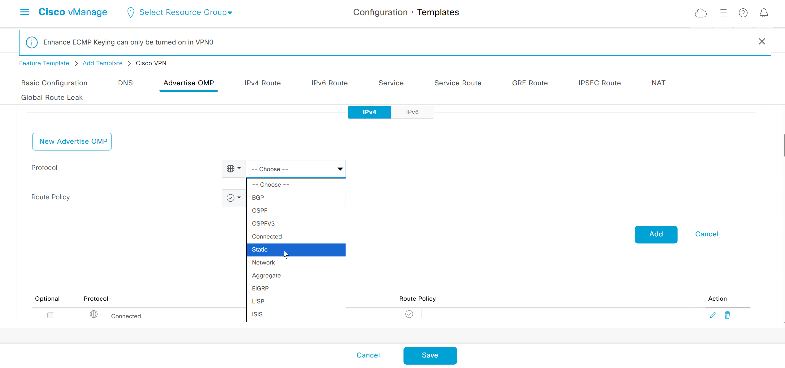
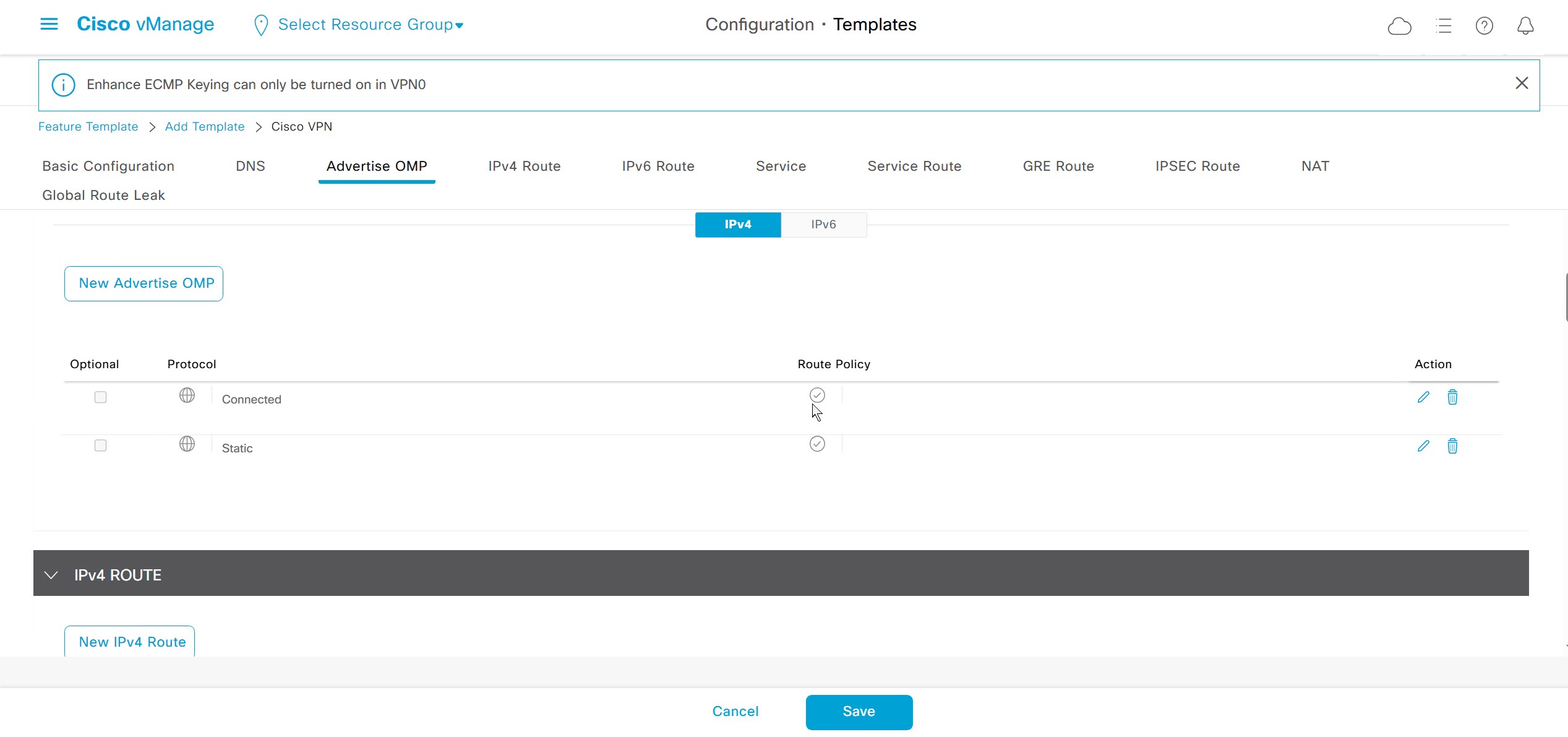
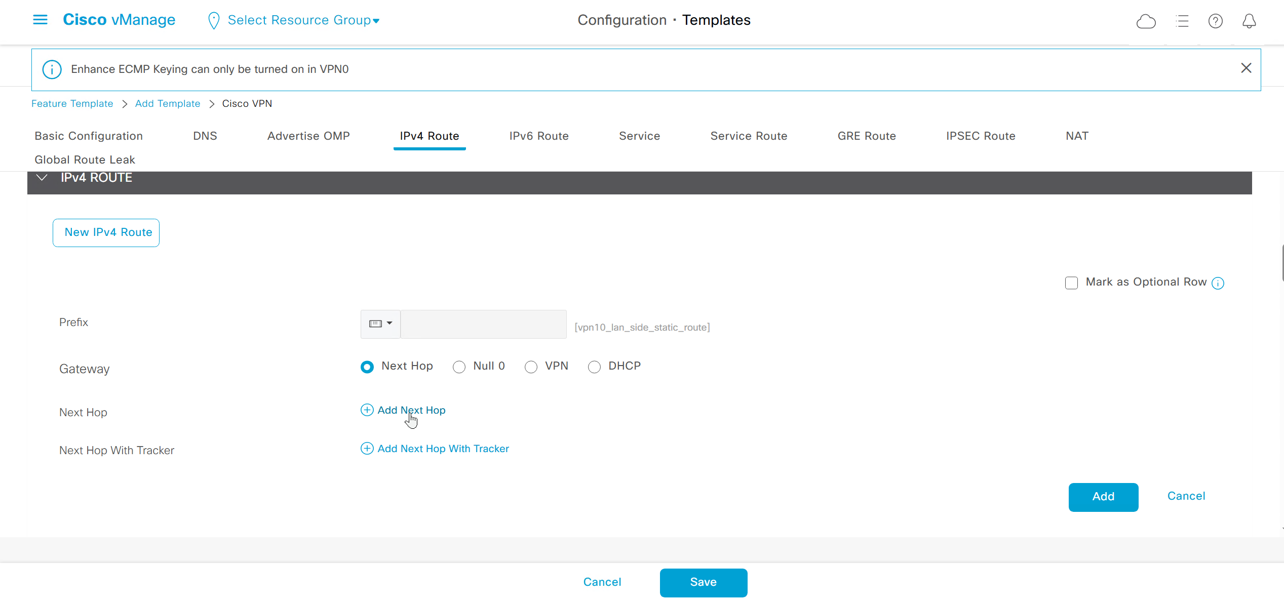
These IPv4 routes are for pointing at the LAN side networks
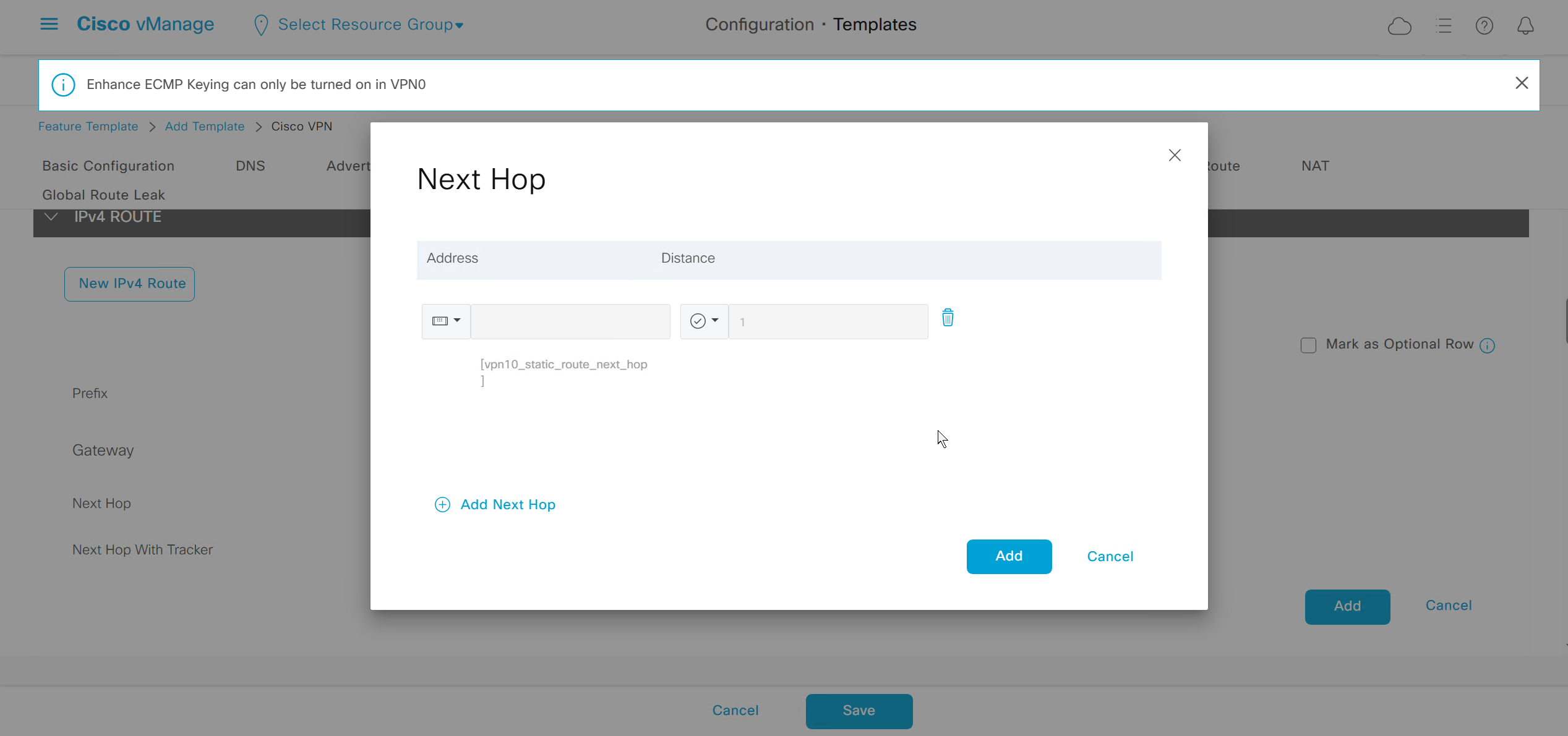
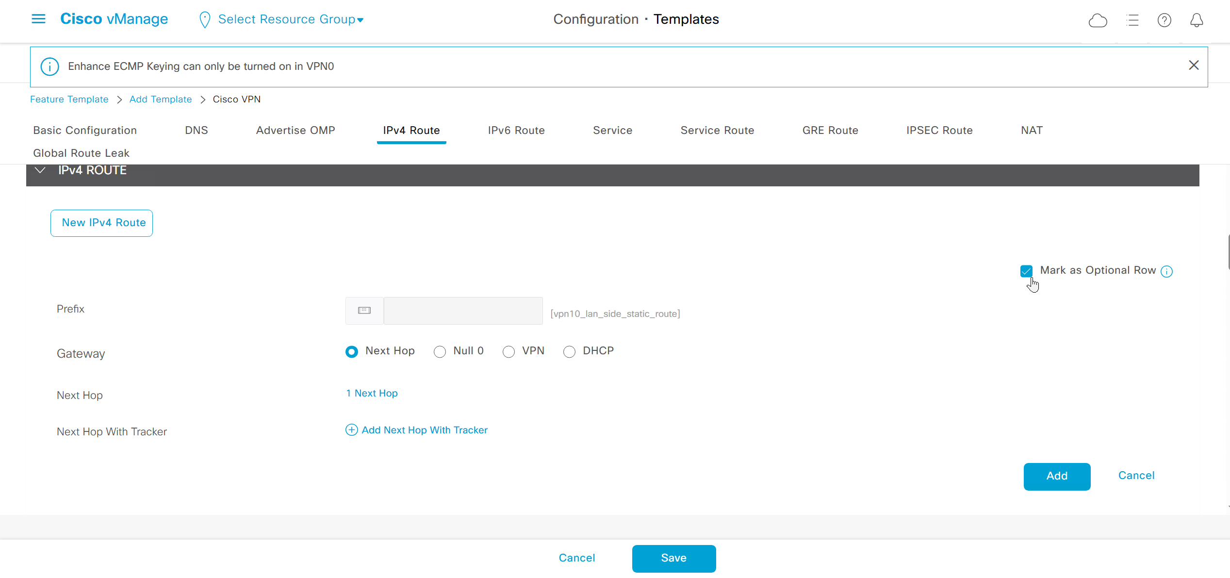
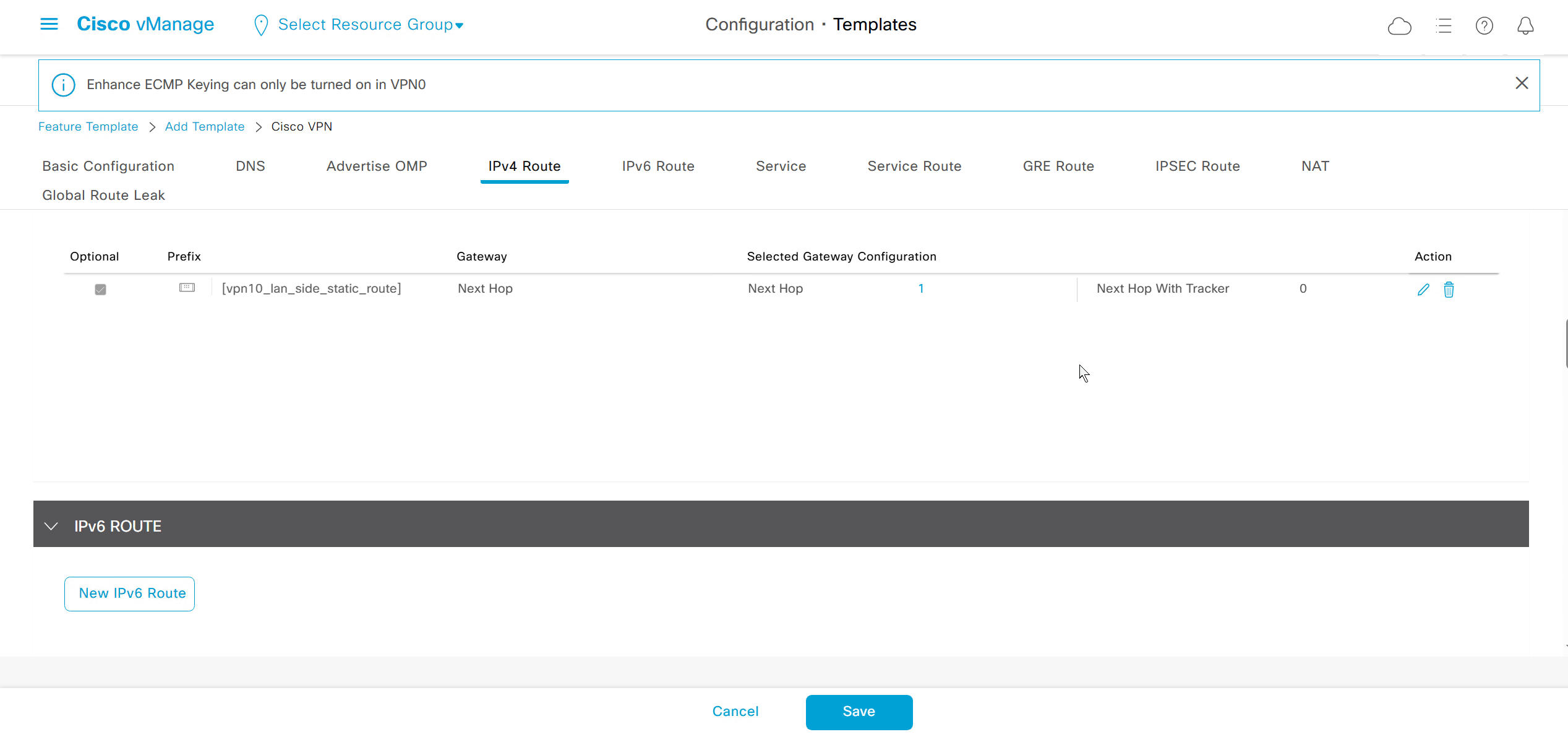
ECMP Keyring can only be turned on in VPN0
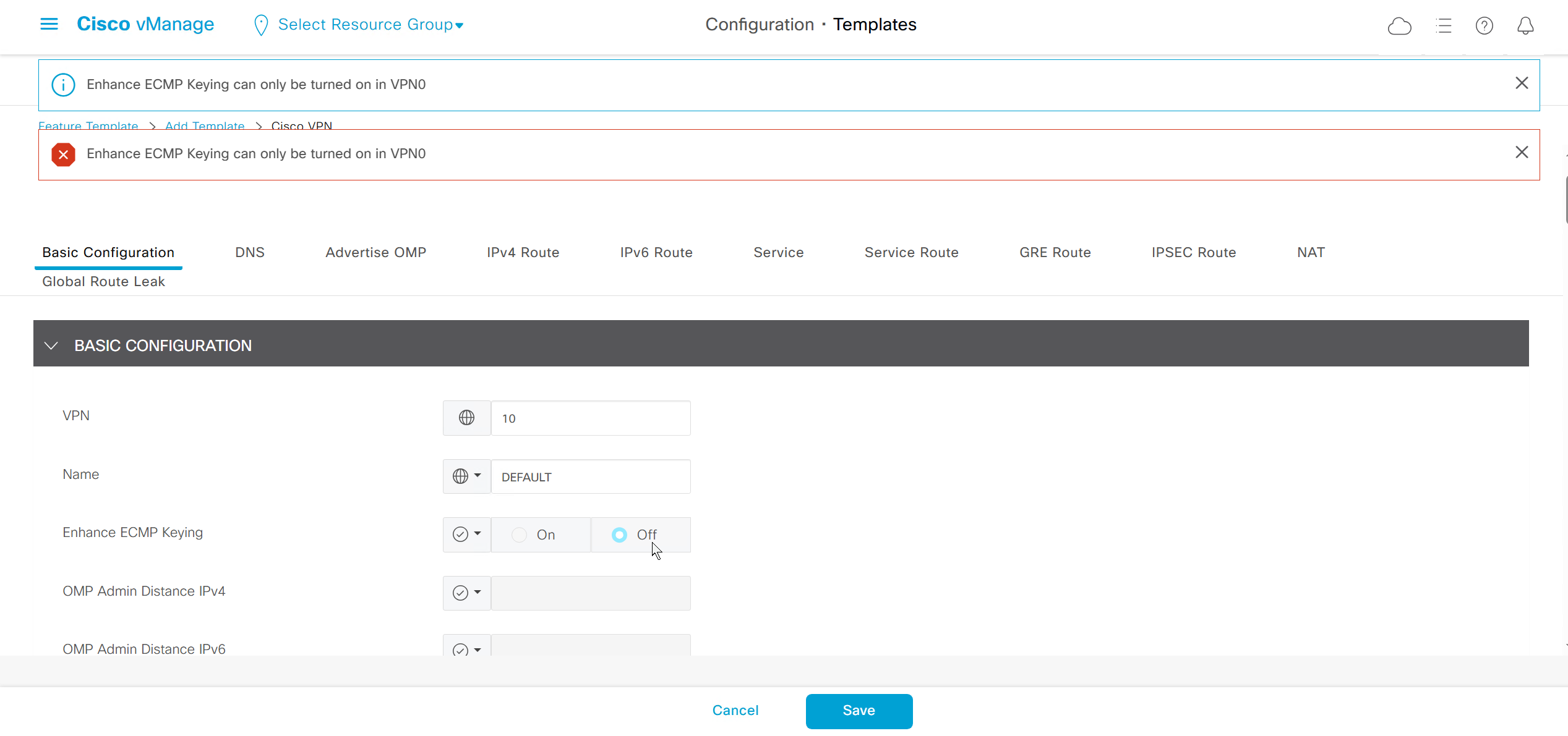
Create new VPN Ethernet Interface Feature templates
Physical Interface GIG3 with IP address variable (so sites without dot1q switch can operate such as Branch 1)
Physical Interface GIG3 without IP address so sites like Branch 2 and Branch 3 can do trunk interface on router with dot1q switch
dot1q interface for Vlan 10 with IP address and reduced MTU of 1496 to compensate for VLAN header on trunk

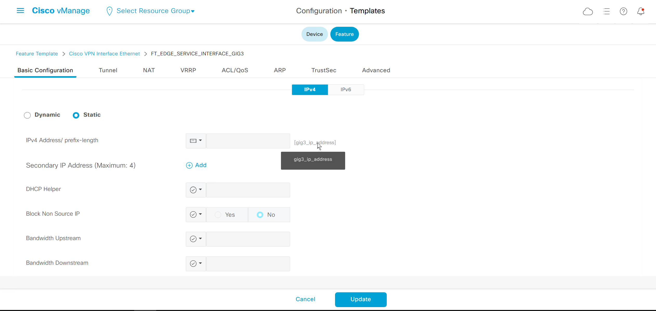
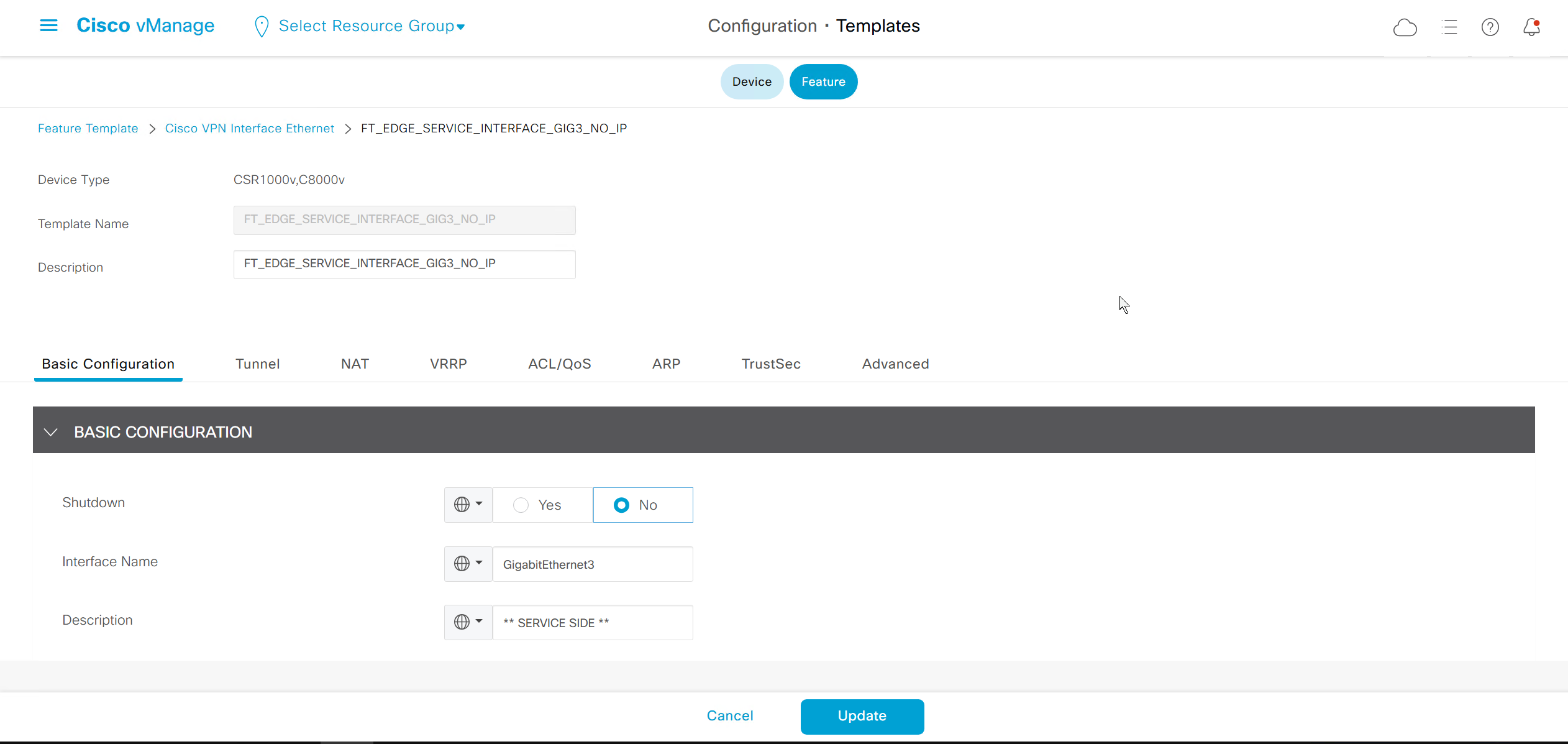


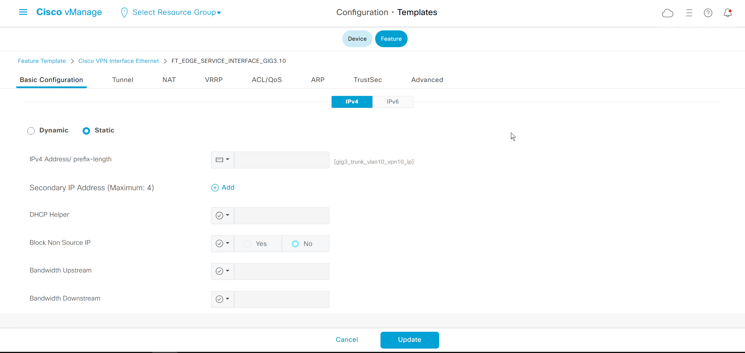
reduce the MTU to 1496
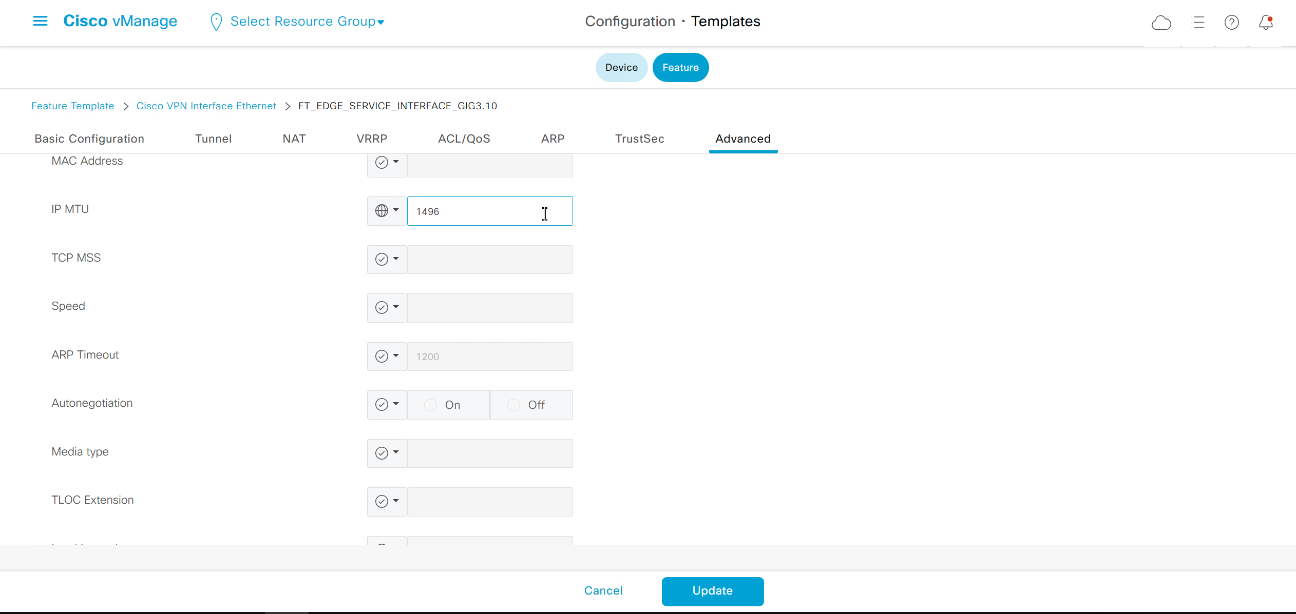
for dot1q interfaces we need to have Physical interface but without IP under VPN 0
and dot1q interface under service VPN
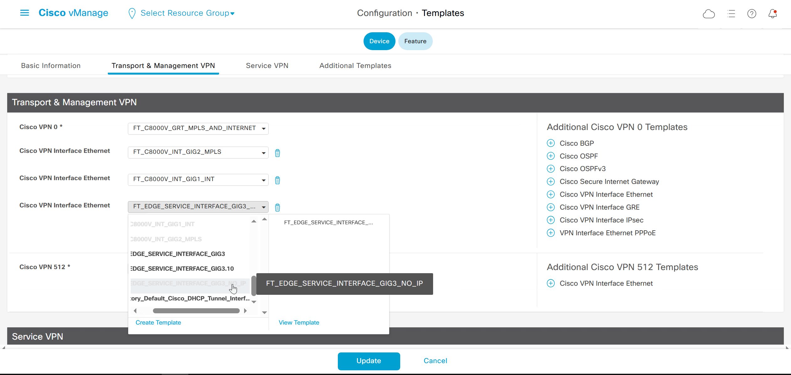
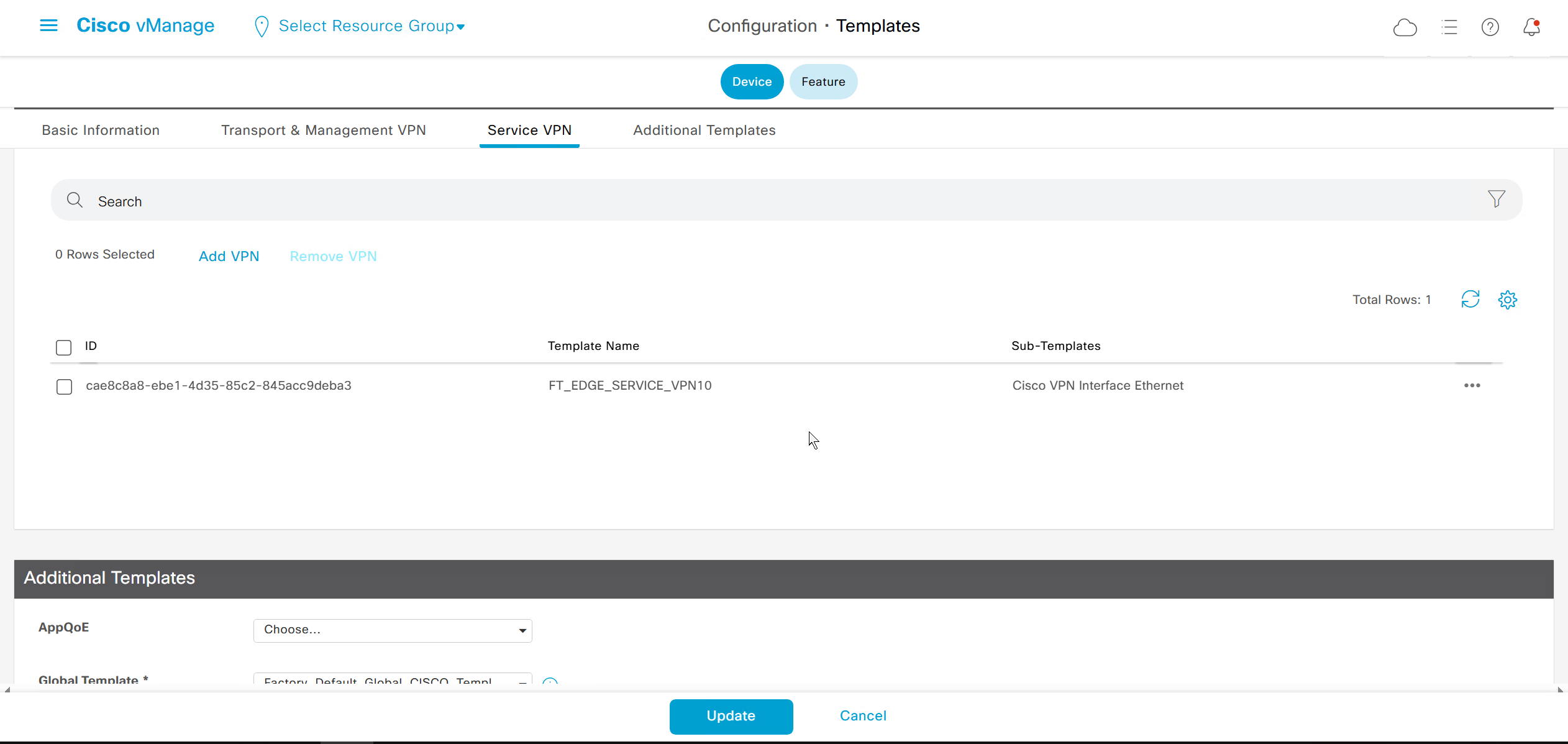
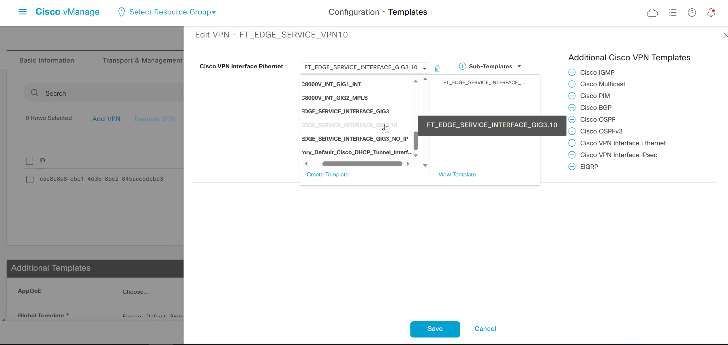
VPCS> ip 172.17.3.10 /25 172.17.3.1
Checking for duplicate address...
VPCS : 172.17.3.10 255.255.255.128 gateway 172.17.3.1

VPCS> ping 172.17.3.1

172.17.3.1 icmp_seq=1 timeout
84 bytes from 172.17.3.1 icmp_seq=2 ttl=255 time=1.393 ms
84 bytes from 172.17.3.1 icmp_seq=3 ttl=255 time=1.470 ms
84 bytes from 172.17.3.1 icmp_seq=4 ttl=255 time=1.429 ms
84 bytes from 172.17.3.1 icmp_seq=5 ttl=255 time=1.350 ms

VPCS> ping 172.17.3.10

172.17.3.10 icmp_seq=1 ttl=64 time=0.001 ms
172.17.3.10 icmp_seq=2 ttl=64 time=0.001 ms
172.17.3.10 icmp_seq=3 ttl=64 time=0.001 ms
172.17.3.10 icmp_seq=4 ttl=64 time=0.001 ms
172.17.3.10 icmp_seq=5 ttl=64 time=0.001 ms

VPCS> ping 172.17.2.1

84 bytes from 172.17.2.1 icmp_seq=1 ttl=254 time=6.716 ms
84 bytes from 172.17.2.1 icmp_seq=2 ttl=254 time=3.531 ms
84 bytes from 172.17.2.1 icmp_seq=3 ttl=254 time=2.678 ms
84 bytes from 172.17.2.1 icmp_seq=4 ttl=254 time=3.613 ms
84 bytes from 172.17.2.1 icmp_seq=5 ttl=254 time=3.625 ms

VPCS> ping 172.17.2.10

84 bytes from 172.17.2.10 icmp_seq=1 ttl=62 time=5.851 ms
84 bytes from 172.17.2.10 icmp_seq=2 ttl=62 time=2.274 ms
84 bytes from 172.17.2.10 icmp_seq=3 ttl=62 time=3.498 ms
84 bytes from 172.17.2.10 icmp_seq=4 ttl=62 time=3.398 ms
84 bytes from 172.17.2.10 icmp_seq=5 ttl=62 time=3.495 ms

VPCS>
VPCS> set pcname BR3-CLIENT

BR3-CLIENT>
BR3-CLIENT> save
Saving startup configuration to startup.vpc
.  done
BR1-CLIENT> trace 172.17.2.10
trace to 172.17.2.10, 8 hops max, press Ctrl+C to stop
1 *172.17.1.1 0.351 ms 0.194 ms
2 *1.1.1.102 1.300 ms 1.543 ms
3 *172.17.2.10 5.741 ms (ICMP type:3, code:3, Destination port unreachable)BR3-cEdge#show sdwan omp routes
Generating output, this might take time, please wait ...
Code:
C -> chosen
I -> installed
Red -> redistributed
Rej -> rejected
L -> looped
R -> resolved
S -> stale
Ext -> extranet
Inv -> invalid
Stg -> staged
IA -> On-demand inactive
U -> TLOC unresolved
PATH ATTRIBUTE
VPN PREFIX FROM PEER ID LABEL STATUS TYPE TLOC IP COLOR ENCAP PREFERENCE
--------------------------------------------------------------------------------------------------------------------------------------
10 172.17.2.0/25 1.1.255.13 9 1003 C,I,R installed 172.16.0.102 mpls ipsec -
1.1.255.13 10 1003 C,I,R installed 172.16.0.102 biz-internet ipsec -
10 172.17.3.0/25 0.0.0.0 66 1003 C,Red,R installed 172.16.0.103 mpls ipsec -
0.0.0.0 68 1003 C,Red,R installed 172.16.0.103 biz-internet ipsec -BR3-cEdge#show sdwan omp routes 172.17.2.0/25 detail
---------------------------------------------------
omp route entries for vpn 10 route 172.17.2.0/25
---------------------------------------------------
RECEIVED FROM:
peer 1.1.255.13
path-id 9
label 1003
status C,I,R
loss-reason not set
lost-to-peer not set
lost-to-path-id not set
Attributes:
originator 172.16.0.102
type installed
tloc 172.16.0.102, mpls, ipsec
ultimate-tloc not set
domain-id not set
overlay-id 1
site-id 102
preference not set
tag not set
origin-proto connected
origin-metric 0
as-path not set
community not set
unknown-attr-len not set
RECEIVED FROM:
peer 1.1.255.13
path-id 10
label 1003
status C,I,R
loss-reason not set
lost-to-peer not set
lost-to-path-id not set
Attributes:
originator 172.16.0.102
type installed
tloc 172.16.0.102, biz-internet, ipsec
ultimate-tloc not set
domain-id not set
overlay-id 1
site-id 102
preference not set
tag not set
origin-proto connected
origin-metric 0
as-path not set
community not set
unknown-attr-len not setBR3-cEdge#routing-context vrf 10
BR3-cEdge%10#ping 172.17.3.1
Type escape sequence to abort.
Sending 5, 100-byte ICMP Echos to 172.17.3.1, timeout is 2 seconds:
!!!!!
Success rate is 100 percent (5/5), round-trip min/avg/max = 1/1/1 ms
BR3-cEdge%10#ping 172.17.3.10
Type escape sequence to abort.
Sending 5, 100-byte ICMP Echos to 172.17.3.10, timeout is 2 seconds:
!!!!!
Success rate is 100 percent (5/5), round-trip min/avg/max = 1/1/2 ms
BR3-cEdge%10#ping 172.17.2.1
Type escape sequence to abort.
Sending 5, 100-byte ICMP Echos to 172.17.2.1, timeout is 2 seconds:
!!!!!
Success rate is 100 percent (5/5), round-trip min/avg/max = 1/1/3 ms
BR3-cEdge%10#ping 172.17.2.10
Type escape sequence to abort.
Sending 5, 100-byte ICMP Echos to 172.17.2.10, timeout is 2 seconds:
!!!!!
Success rate is 100 percent (5/5), round-trip min/avg/max = 2/3/6 ms
BR3-cEdge%10#exitSDWAN Peering with OSPF and BGP
router bgp 10
 template peer-policy CE
  send-community both
 exit-peer-policy
 !
 template peer-session CE
  ebgp-multihop 5
  timers 30 90
 exit-peer-session
 !
 bgp log-neighbor-changes
 neighbor 10.0.1.2 remote-as 65001
 neighbor 10.0.1.2 inherit peer-session CE
 neighbor 10.0.101.2 remote-as 65101
 neighbor 10.0.101.2 inherit peer-session CE
 neighbor 10.0.102.2 remote-as 65102
 neighbor 10.0.102.2 inherit peer-session CE
 neighbor 10.0.103.2 remote-as 65103
 neighbor 10.0.103.2 inherit peer-session CE
 !
 address-family ipv4
  network 10.0.101.0 mask 255.255.255.252
  network 10.0.102.0 mask 255.255.255.252
  network 10.0.103.0 mask 255.255.255.252
  neighbor 10.0.1.2 activate
  neighbor 10.0.1.2 inherit peer-policy CE
  neighbor 10.0.101.2 activate
  neighbor 10.0.101.2 inherit peer-policy CE
  neighbor 10.0.102.2 activate
  neighbor 10.0.102.2 inherit peer-policy CE
  neighbor 10.0.103.2 activate
  neighbor 10.0.103.2 inherit peer-policy CE
 exit-address-family
!
interface Loopback0
ip address 3.3.3.3 255.255.255.255
ip ospf network point-to-point
ip ospf 10 area 0
!
interface Loopback1
ip address 4.4.4.4 255.255.255.255
ip ospf network point-to-point
ip ospf 10 area 0
!
interface Loopback2
ip address 5.5.5.5 255.255.255.255
ip ospf network point-to-point
ip ospf 10 area 0
!
interface Loopback3
ip address 6.6.6.6 255.255.255.255
ip ospf network point-to-point
ip ospf 10 area 0
!
interface Loopback4
ip address 7.7.7.7 255.255.255.255
ip ospf network point-to-point
ip ospf 10 area 0
!
interface Loopback5
ip address 8.8.8.8 255.255.255.255
ip ospf network point-to-point
ip ospf 10 area 0
!
interface Loopback6
ip address 9.9.9.9 255.255.255.255
ip ospf network point-to-point
ip ospf 10 area 0
!
interface Loopback7
ip address 10.10.10.10 255.255.255.255
ip ospf network point-to-point
ip ospf 10 area 0
!
interface Vlan10
ip address 172.17.3.3 255.255.255.128
ip mtu 1496
ip ospf authentication message-digest
ip ospf message-digest-key 1 md5 cisco123
!
router ospf 10
router-id 3.3.3.3
no auto-cost
passive-interface Loopback0
network 172.17.3.3 0.0.0.0 area 0
!
We will configure ebgp with interfaces (point to point links) and not loopbacks
For fun we will create loopback interfaces with same IP address as system ID and then advertise them in BGP
for that we need to create Ethernet interface feature template
(while creating loopback0 interface on C8000v with same IP as system IP was not an issue, it was rejected on CSR1000v so loopback IP address on CSR1000v is set different from its system IP)
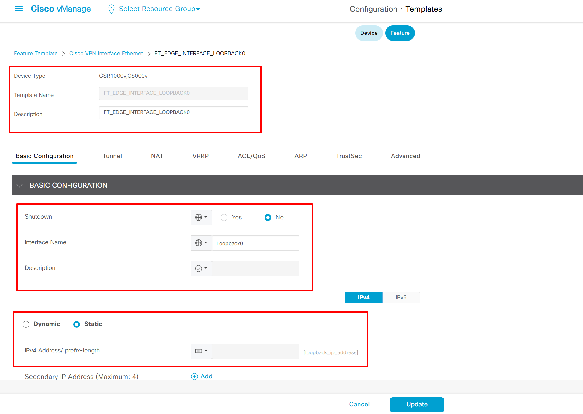
then we create BGP feature template
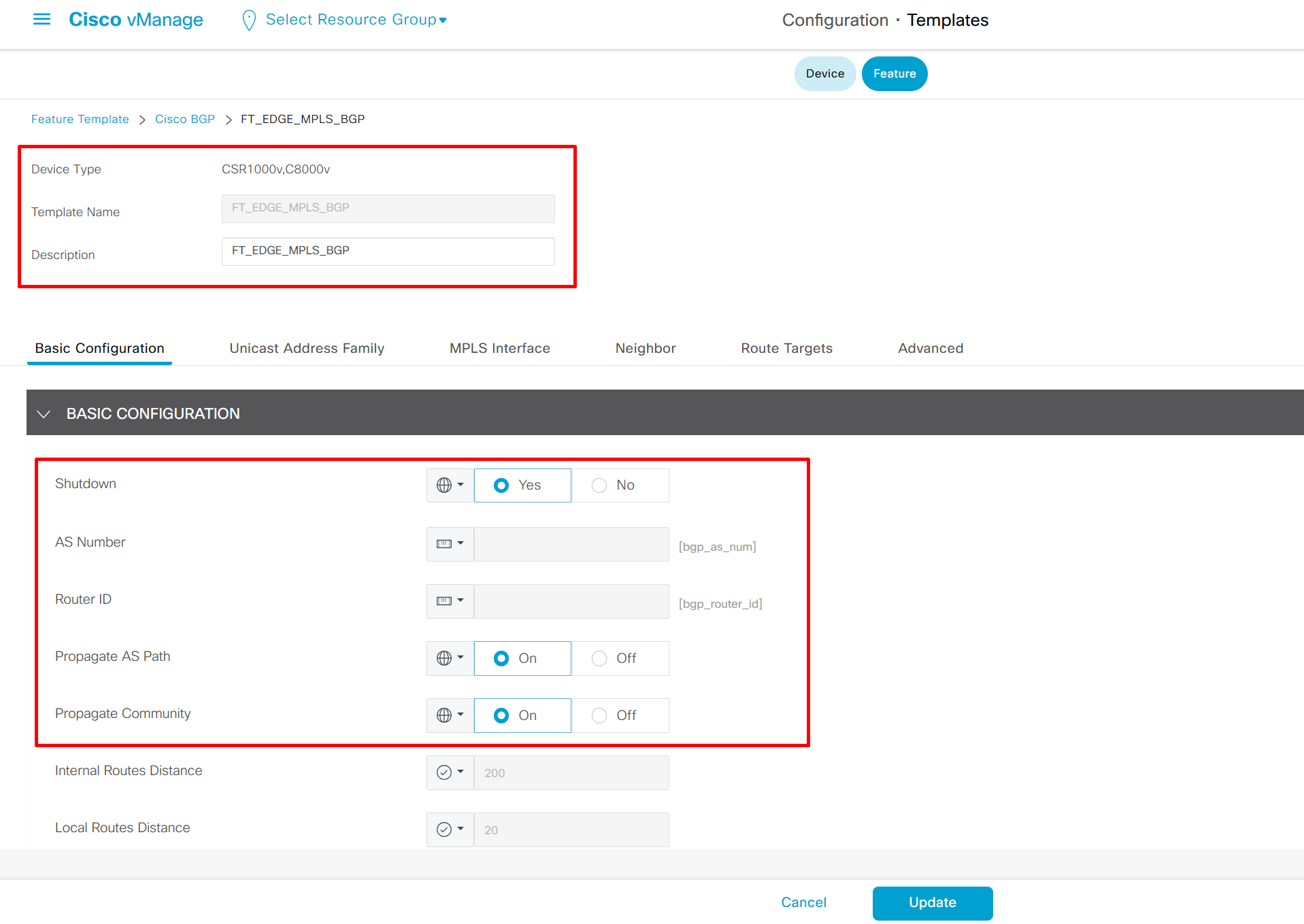
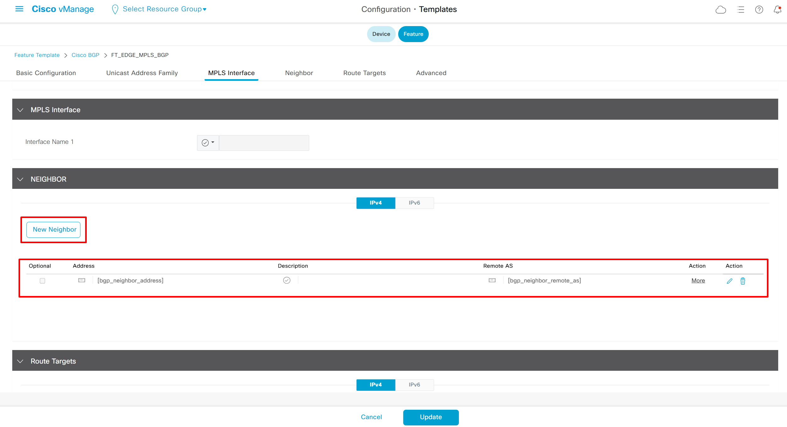

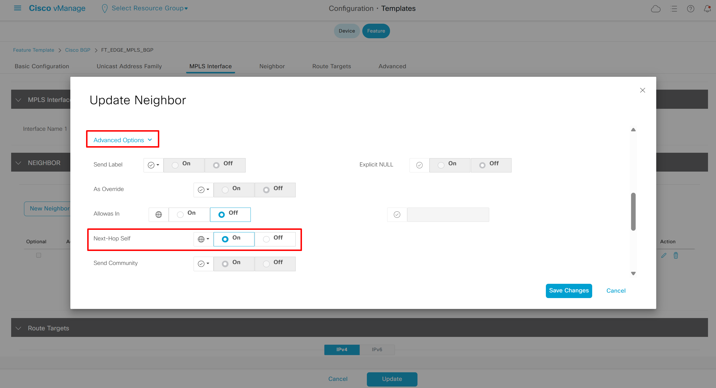
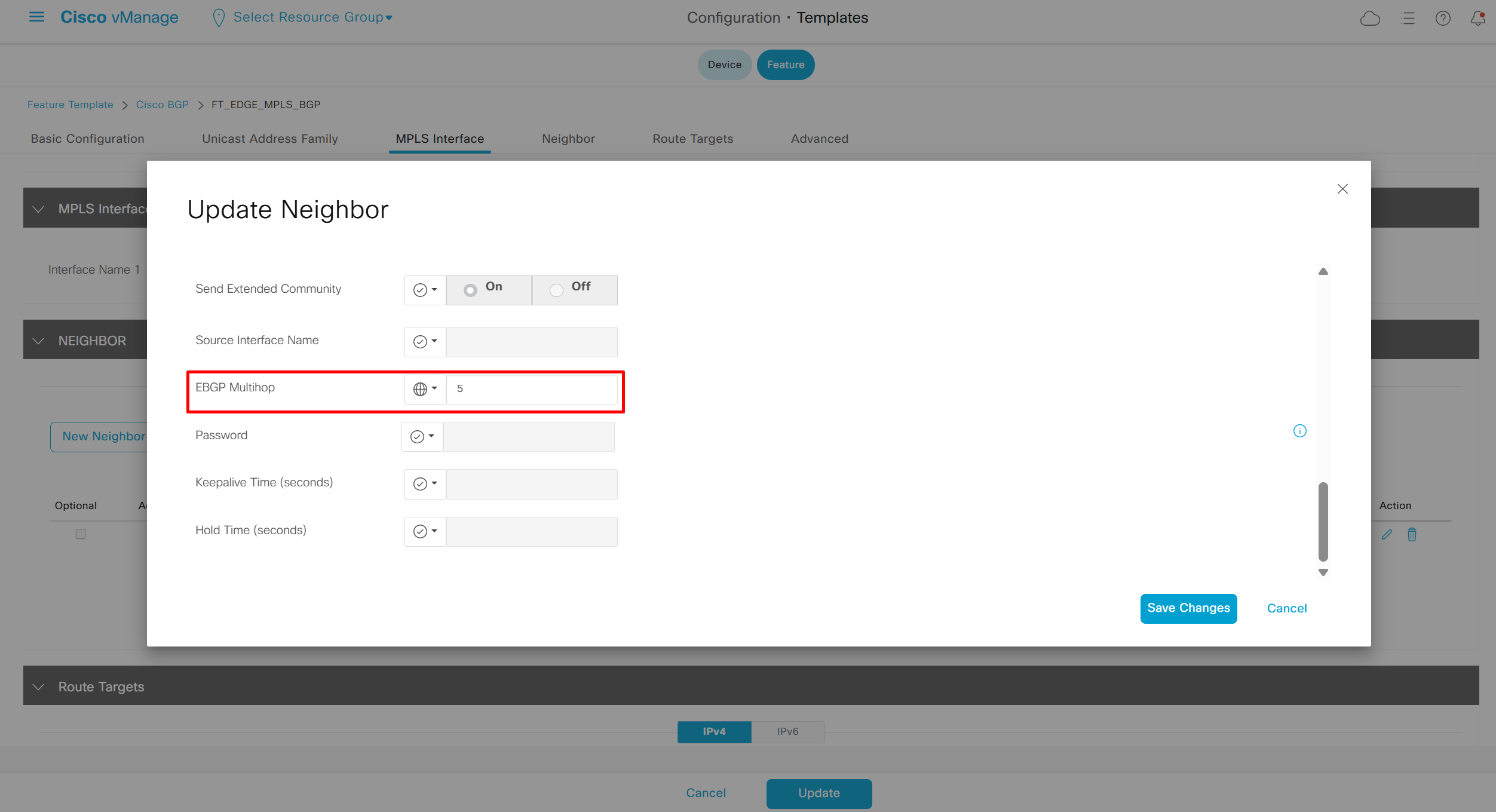
Policy Introduction
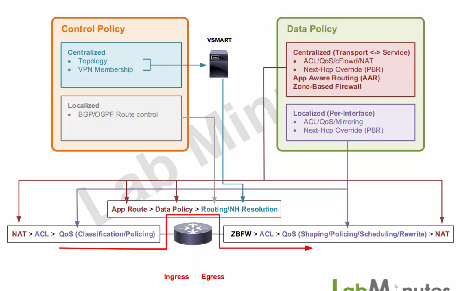
in our mind it can be laid out as
Centralized Control policy
Localized Control policy
Centralized Data policy
Localized Data policy
A way to think is
Centralized means that configuration is done on a central location vmanage and then pushed to vsmart (central control plane)
Localized means that configuration will be pushed directly to edge devices
Centralized Control policy (CCP)
Topology
VPN Membership
Centralized Control Topology policy – can be used to match routes and change it any way we like – for example we can use Topology Policy or centralized policy to prevent certain sites from reaching a certain subnet from central view of vsmart – if we think topology means that we are dealing with topology (Top view of network in OMP language – just like OSPF also does) and that view can be manipulated for certain routers so they do not reach certain subnets – it is not just used for filtering but also used for changing route’s next hop TLOC, or to change TLOC preference (from centralized view of vsmart) to prefer one tunnel / route over another – not part of the config instead as routes
Centralized Control VPN Membership policy – this is used to take a site from participating in a certain service / VPN
Centralized Control policies result in – routes, all edge devices see are resulting routes that are pushed to them by vsmart
Centralized Control policy can be applied inbound or outbound to vsmart
Inbound applied to vSmart will apply on all the routes – as inbound direction is vsmart
Outbound applied from vsmart will apply to a specific edge or group of edges – as outbound is always towards one edge or group of edges
Localized Control policy (LCP)
strictly deals with BGP and OSPF protocols local to the edge, turning on OSPF / BGP and redistribution is “turned on” only in feature templates, for applying route map and actions we need to configure localized control policy – becomes part of config
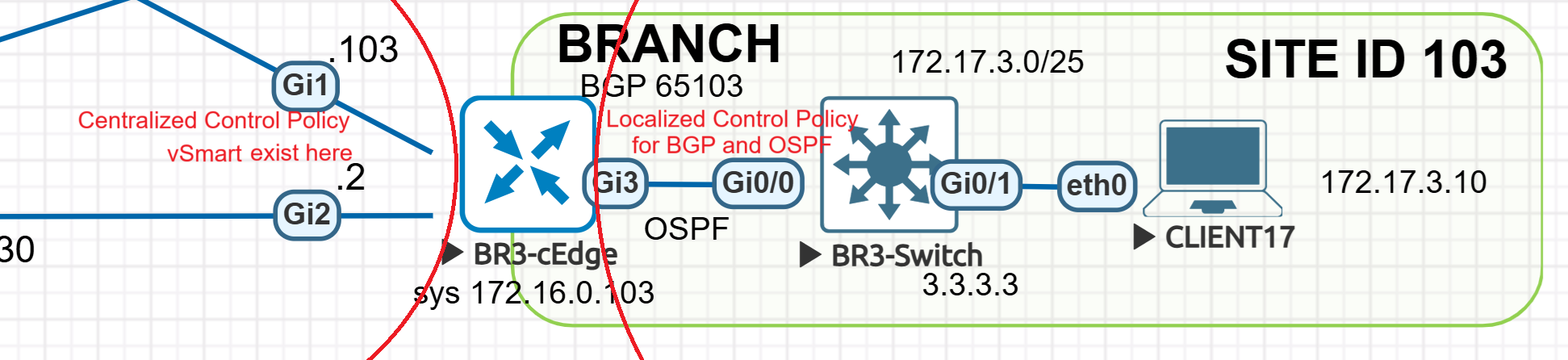
Centralized Data policy (CDP)
Centralized Data policy do not become part of config instead they are added to wan edge’s memory but not in the configuration
Deals with manipulation of actual data packets, it works by “matching” actual “packets” using ACL such as L3 and L4 header information, packets can also be matched using AVC or application visibility feature on edge and not just L3 – L4 information, after matching actions can be to either permit or deny packets just like normal ACL, QoS, we can send copy of the packet using cFlowd or event NAT (used in local DIA circuit) but because this is Centralized Data Policy this is all central vsmart perspective, NAT in a Centralized Data policy can do NAT for either traffic going out over Transport (DIA) known as Transport side NAT or NAT for traffic going towards service VPN (towards LAN on overlay) also called Service Side NAT
using Centralized Data policy we can also override next hop TLOC just like PBR also known as Traffic Data policy
AAR is also part of the Centralized Data policy and it keeps track of tunnel’s health such as Latency, Loss and Jitter (LLJ)
Zone Based Firewall, this is also part of the Centralized Data Policy, because it is Centralized Policy, it is from vSmart’s perspective and all those Centralized policies are pushed to vmanage -> vsmart and then passed as a policy in “WAN edge memory” but not in the wan edge’s config
Localized Data policy (LDP)
Localized Data policy is per interface and can do most things Centralized Data policy can do but not all of them
Localized Data policy cannot do Deep packet inspection for matching (can only do L3 / L4 matching), cFlowd, NAT and so on
On the other hand there are some things that can only be done through Localized Data policy such as Traffic shaping, scheduling and rewriting for QoS and Mirroring which are very local things
Configuration for Localized Data policy go on the edge
Because there is an overlap of ACL and QoS in Centralized (not cFlowd and NAT) and Localized policy (Mirroring, scheduling and traffic shaping etc) it is best to use Centralized Data policy first and if things cannot be accomplished using Central then use Localized Data policy
Packet Flow
as Packet moves from Ingress direction to Egress direction, Ingress can be any direction, from overlay (LAN) to transport (VPN) or from transport (VPN) to overlay (LAN)
if you look at the ingress and egress they are same in terms of order of operation but opposite from ingress
NAT > [ ACL > Qos ] <—router—> [ ACL > Qos ] > NAT
Ingress
NAT – Central (Data)
ACL – Localized (Data)
QoS (Classification , Policing) – Localized (Data)
In Chassis, Backplane
Once packet is in chassis and past the ingress interface
packet routing happens and here are three things that can happen
App route – Central (Data) – if an AAR is defined for application, packet matches to be that app, the router has to determine all eligible transports / tunnels over which this app “can be routed”. This is done using BFD performance of the tunnels
Data Policy – Central (Data) – If a packet matches a data policy from CDP this includes all (ACL/QoS/cFlowd/NAT/PBR/ZBFW) then packet will follow the action from CDP, for example if packet is matched by Data policy then it will even override previously matched AAR policy – this can happen when we have same packet matching criteria defined in both AAR and Data policy
OMP Routes – Central (Control) – If packet is not matched by either AAR Policy (CDP) or Data Policy (CDP) then packets will be routed based on routing table, packet could be routed to VPN (using OMP route) or could even be routed back to service side again (using local BGP or OSPF or static route) because routing table is being consulted
Egress
ZBFW
ACL – Local (Data)
QoS (Shaping , Policing , Scheduling / Shaping , Rewrite) – Local (Data)
NAT – Central (Data)
Local Control – Local Control Policy (BGP – Service Side)
BGP Route filter
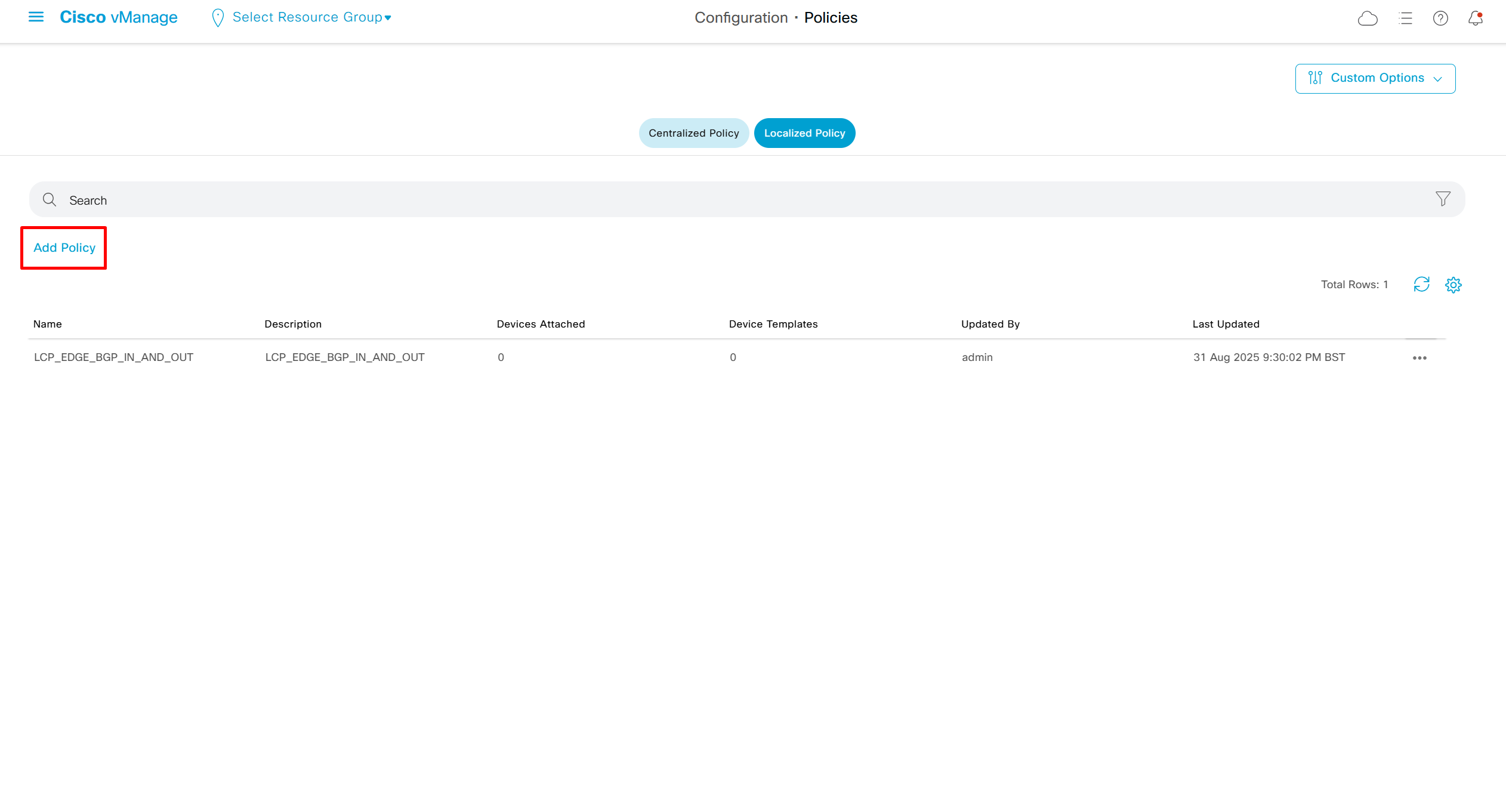
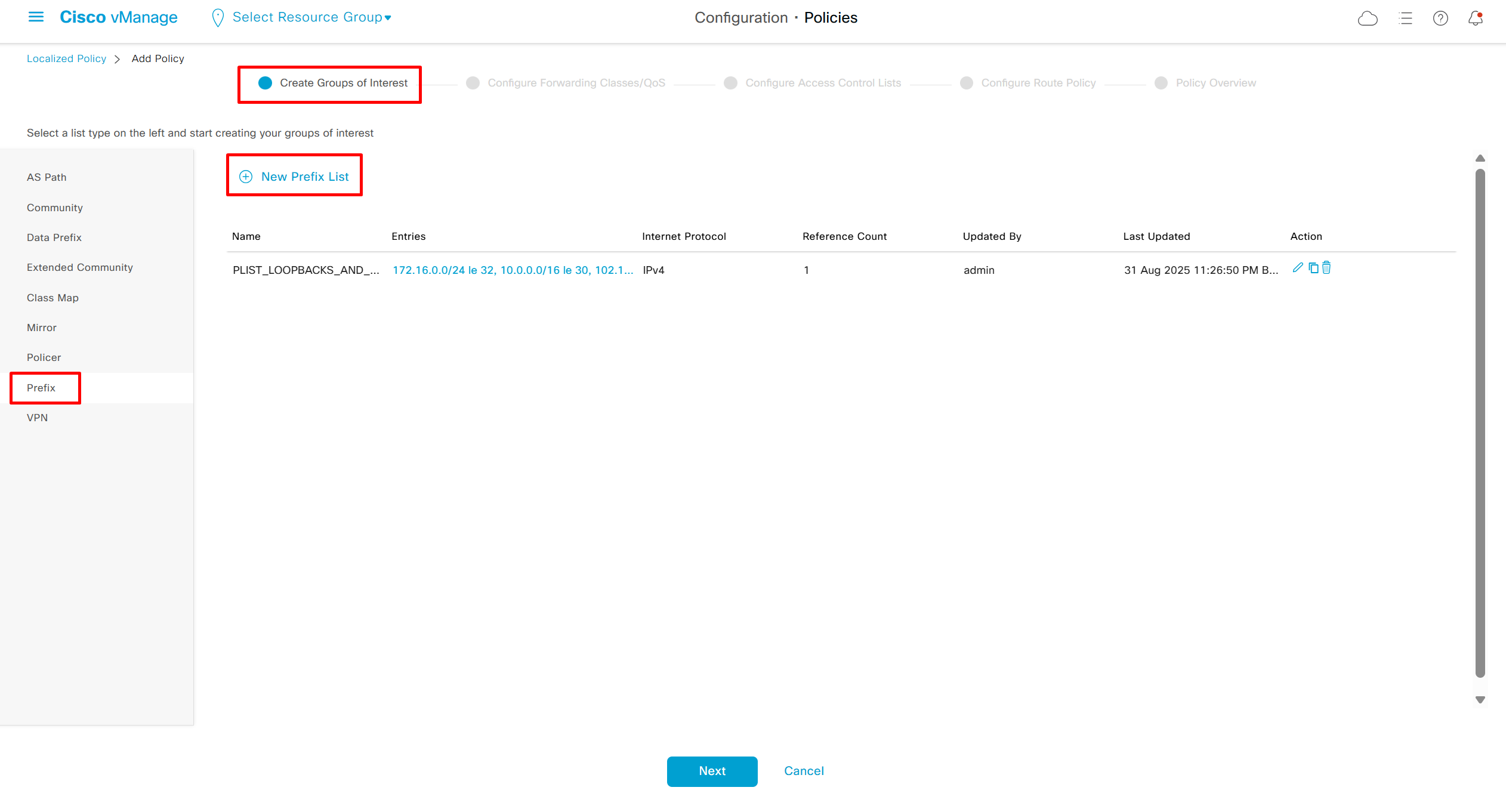
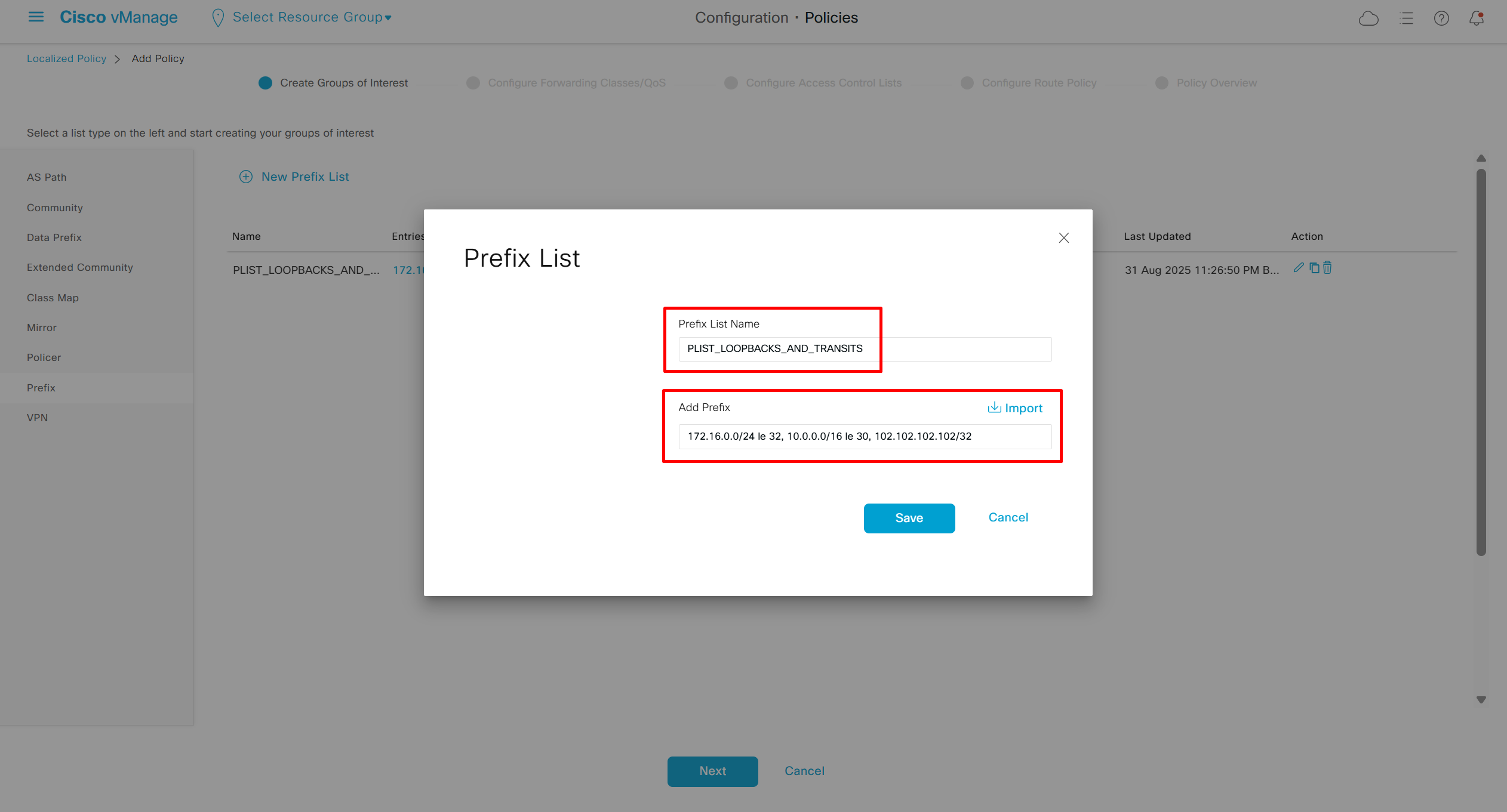
172.16.0.0/24 le 32
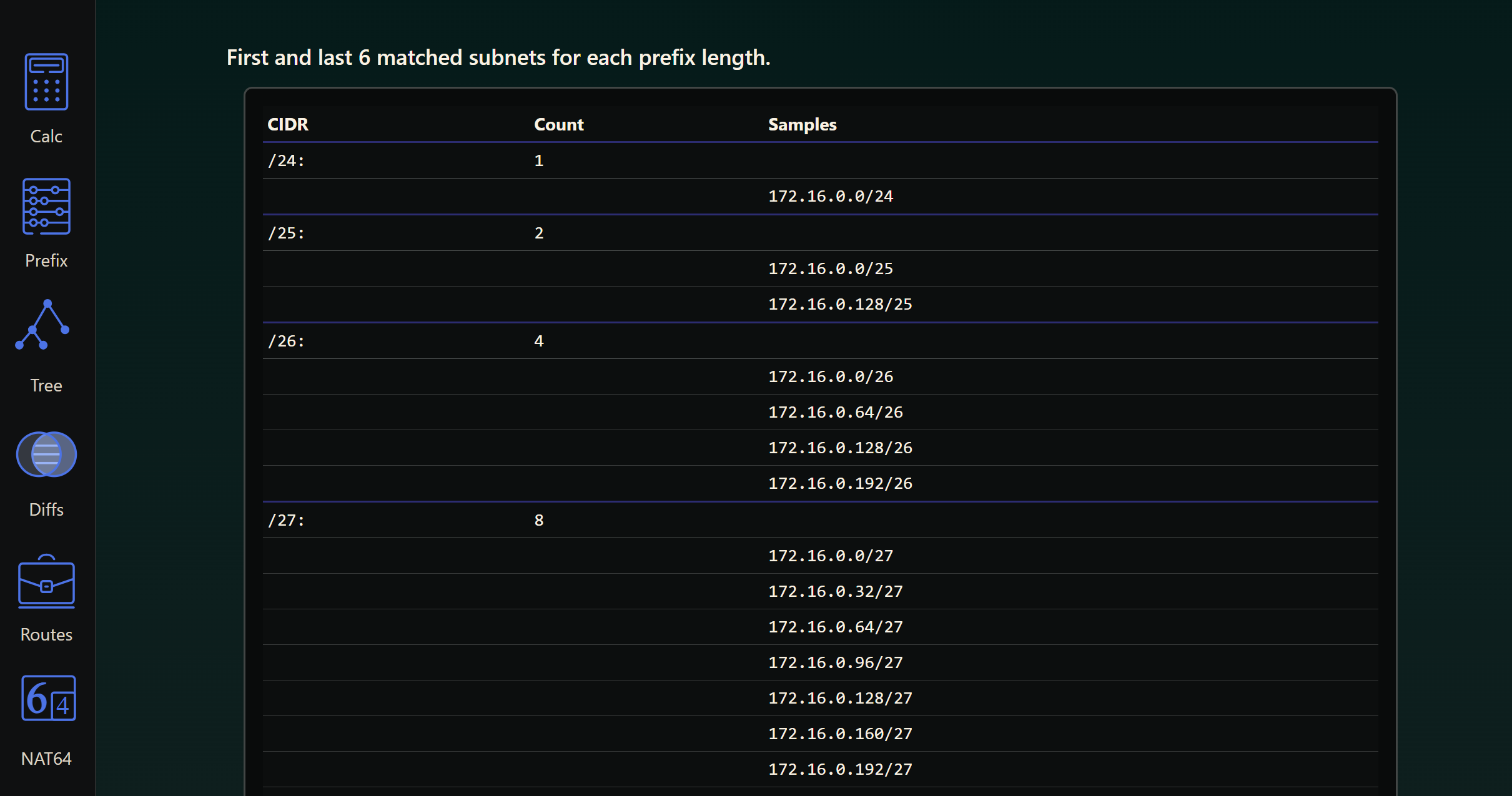
10.0.0.0/16 le 30
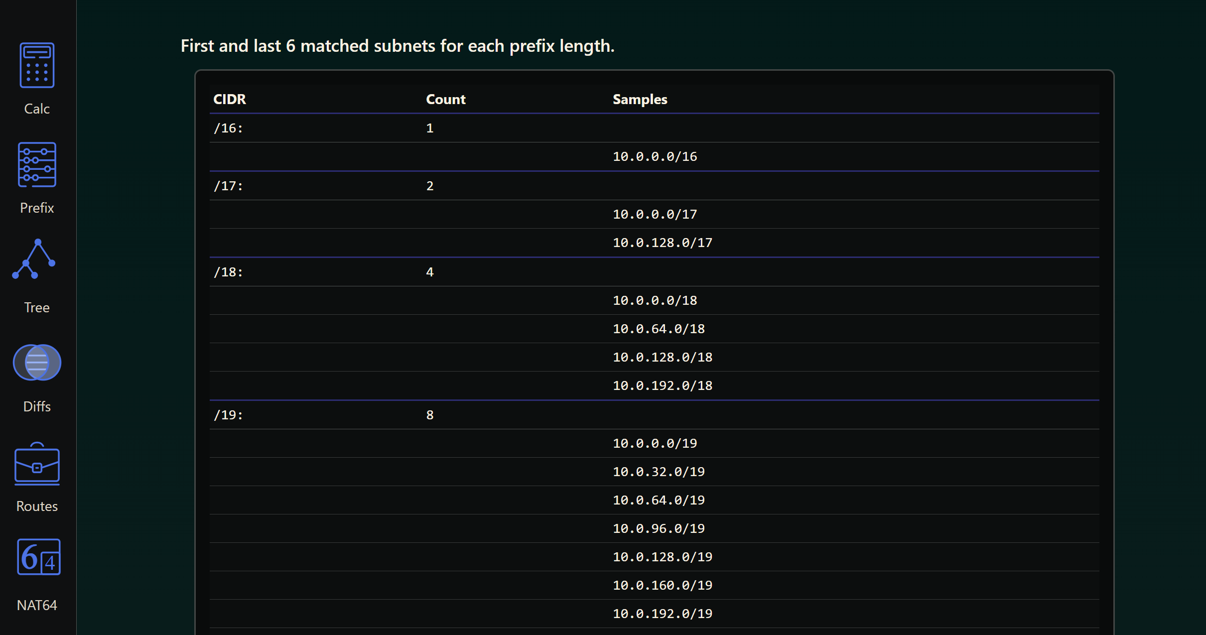
102.102.102.102/32
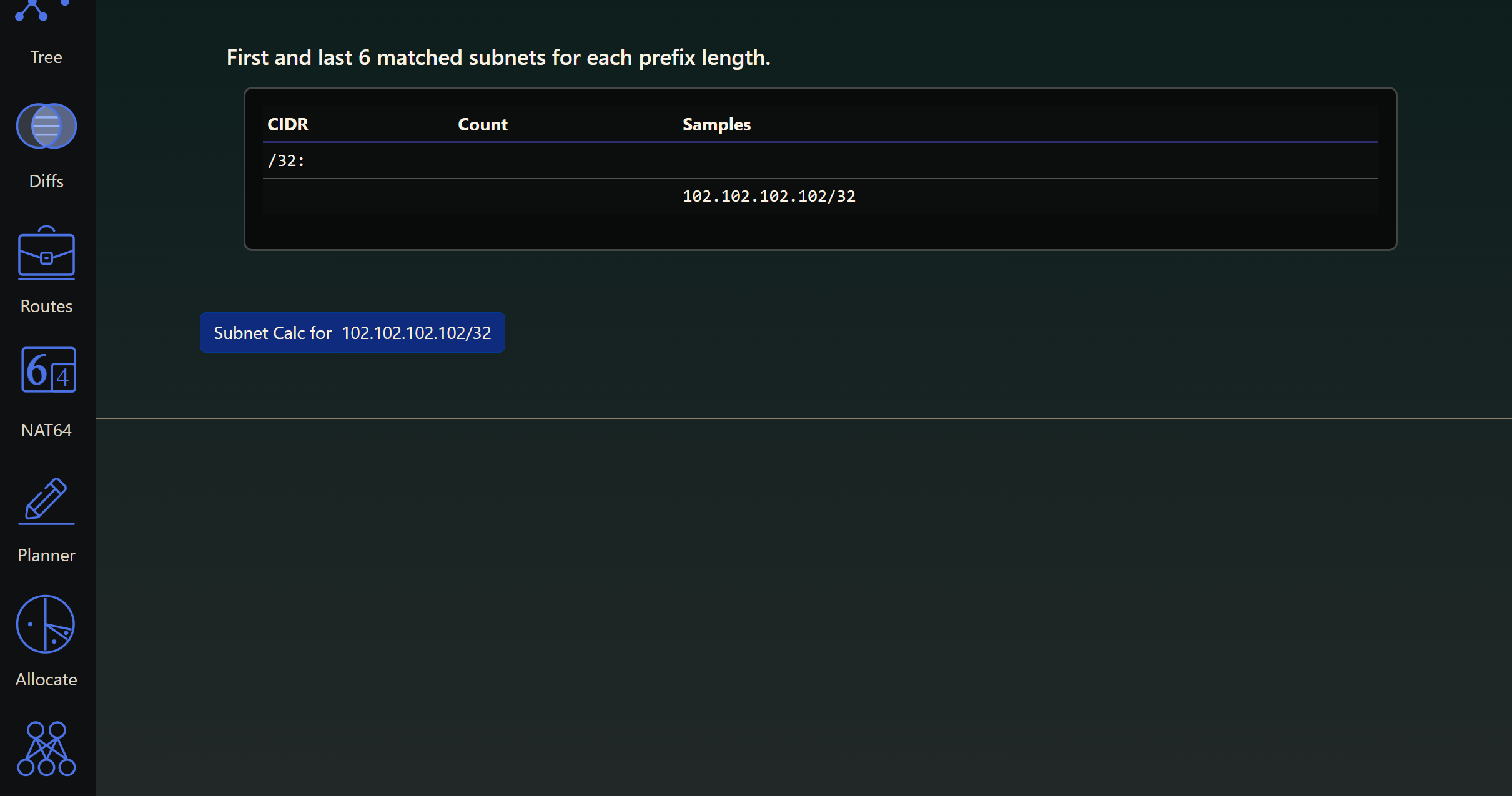
because we want to capture all those routes
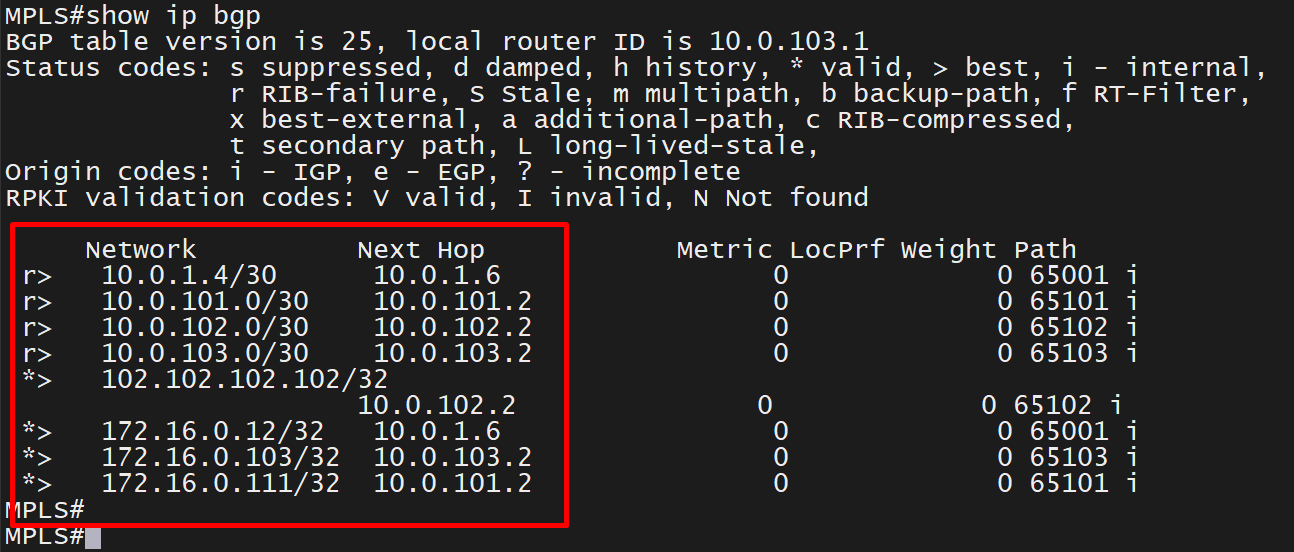
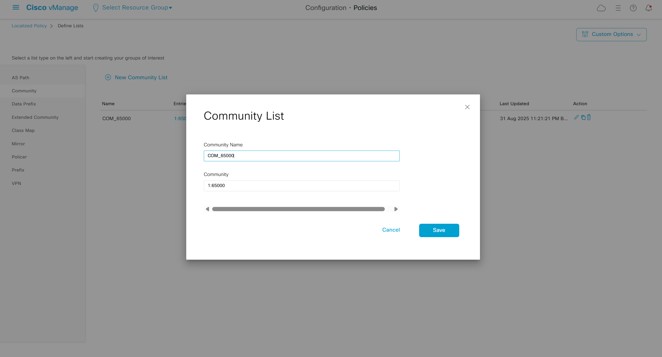
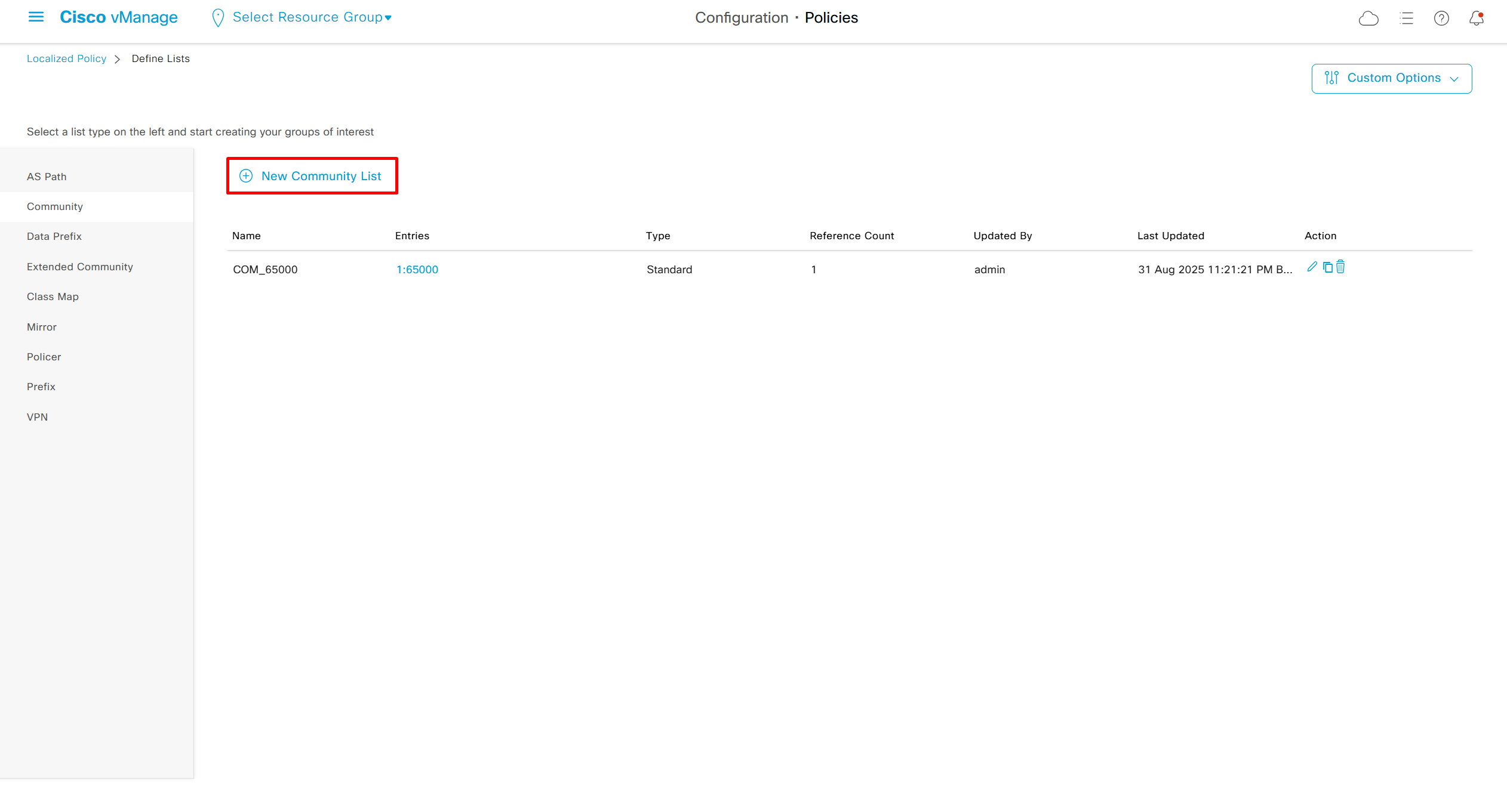
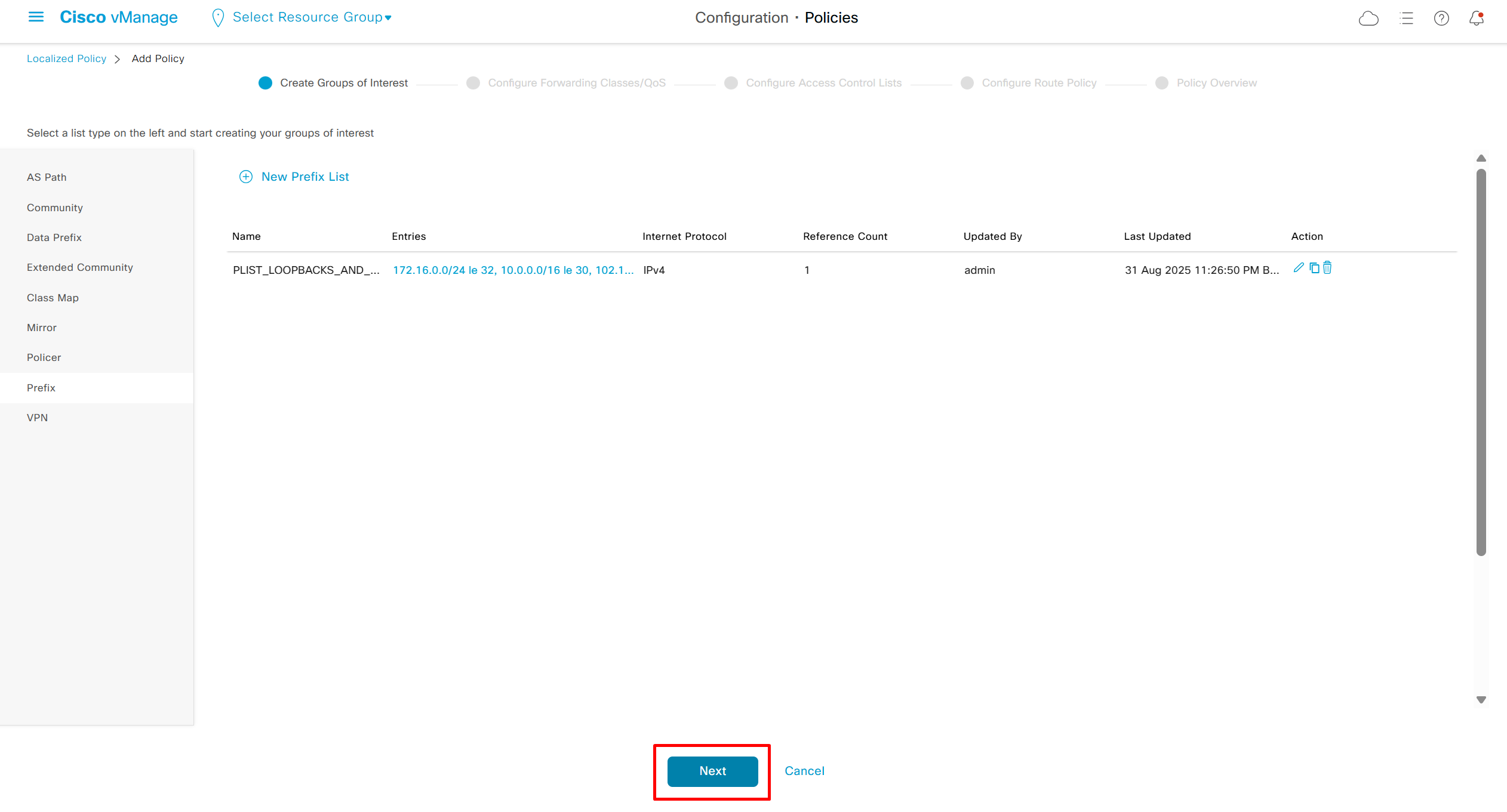
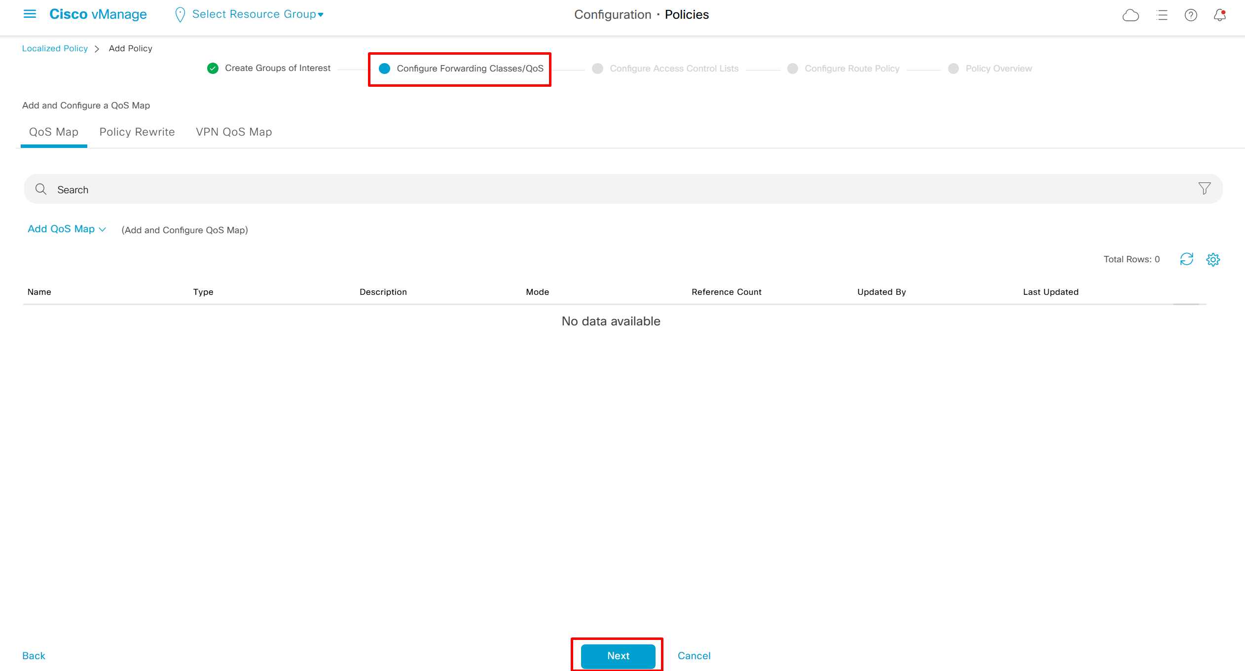
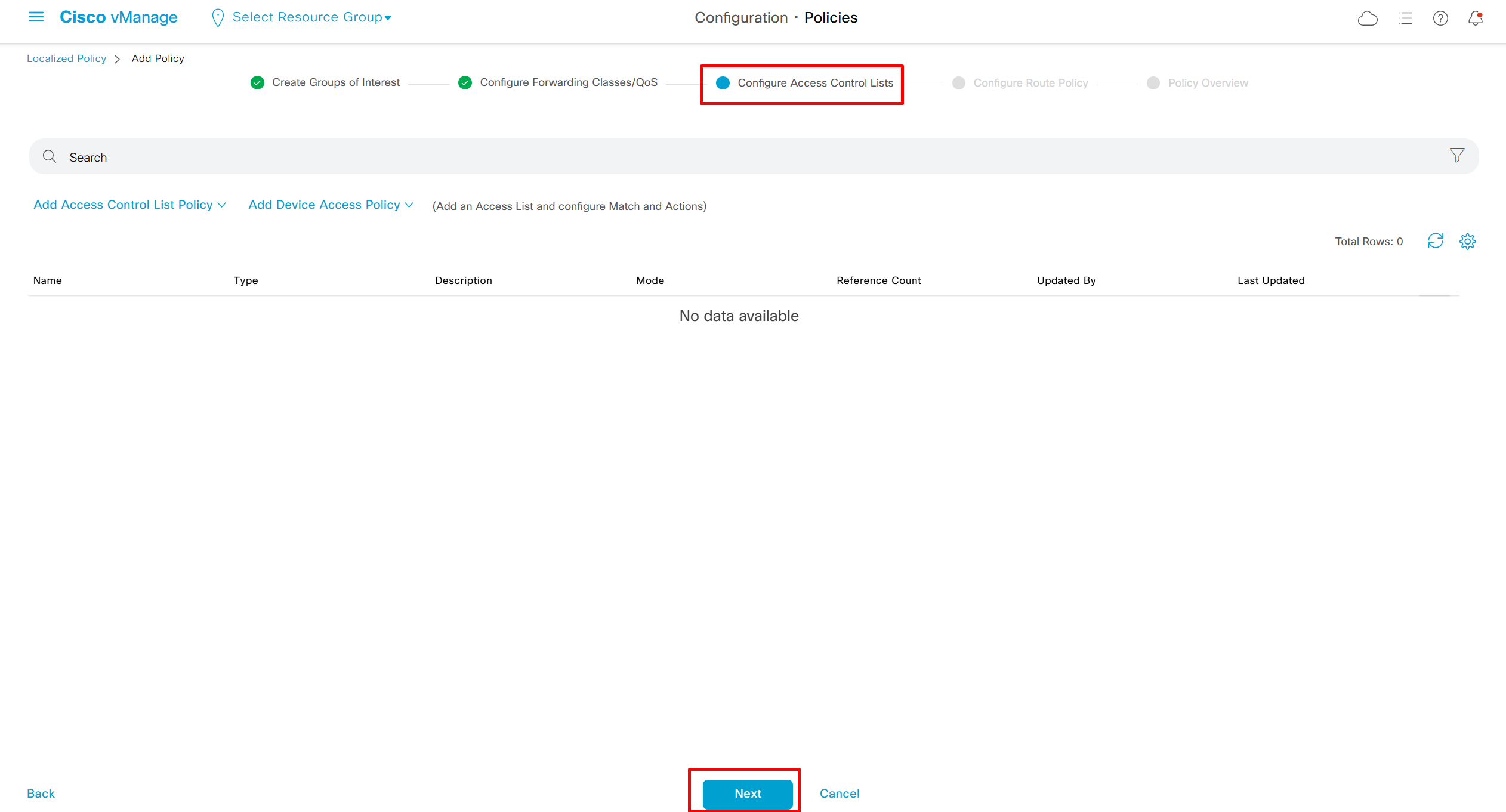
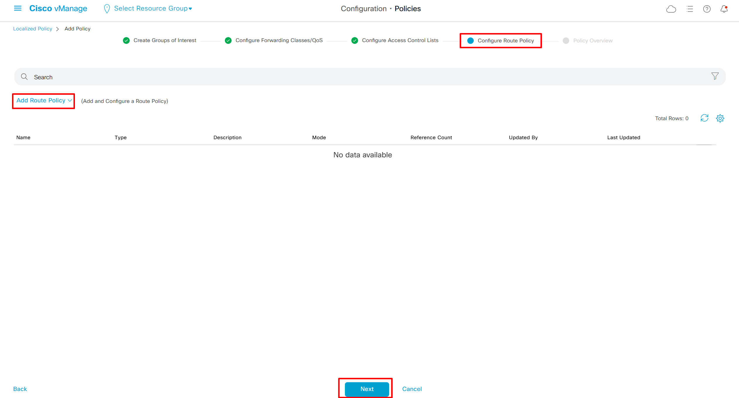
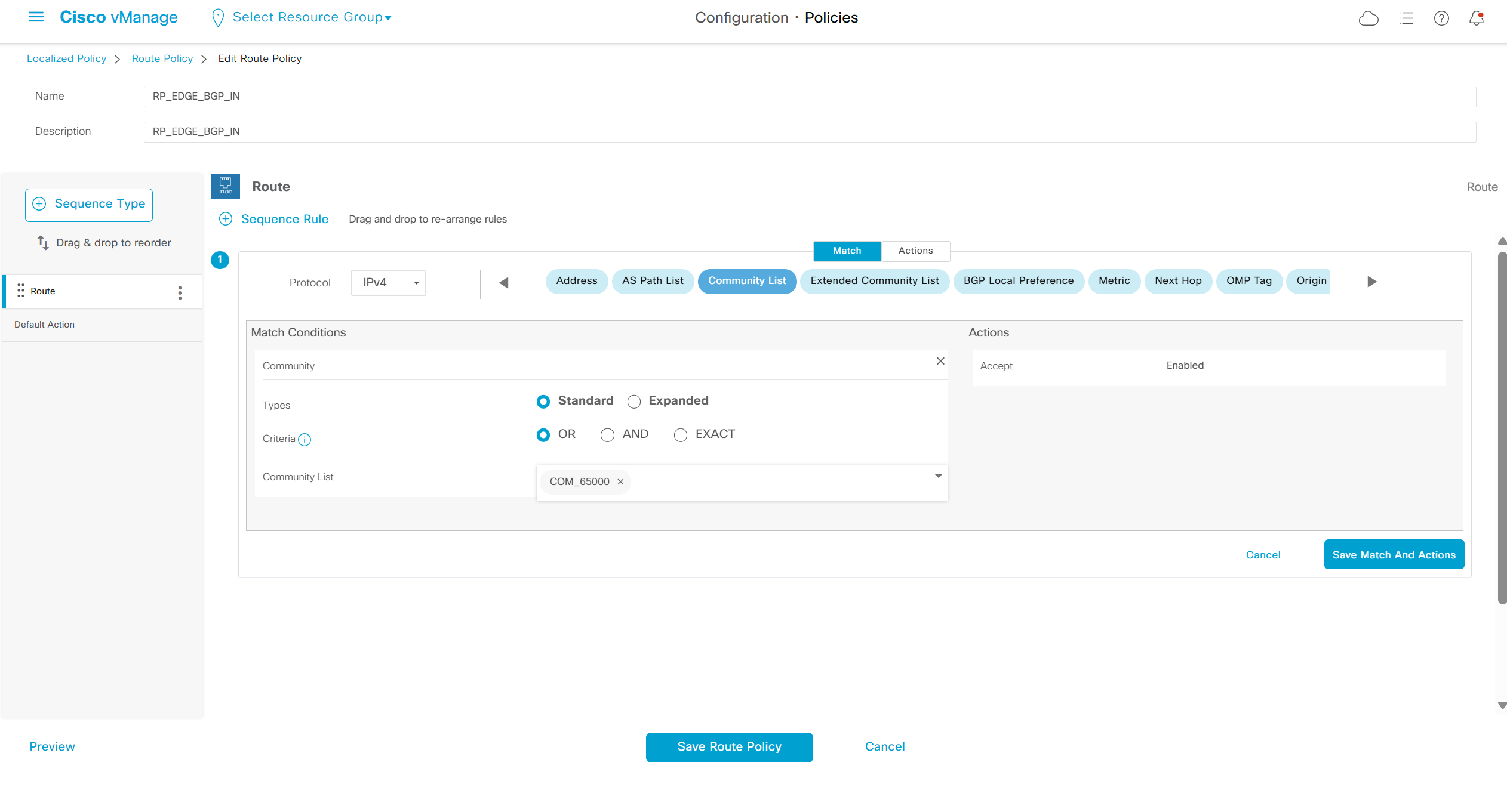
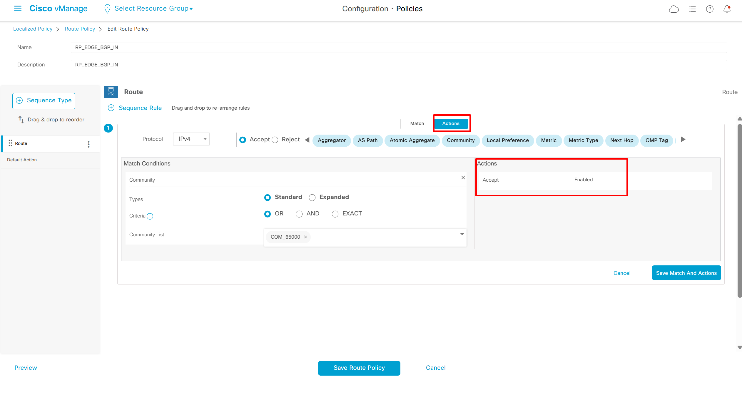
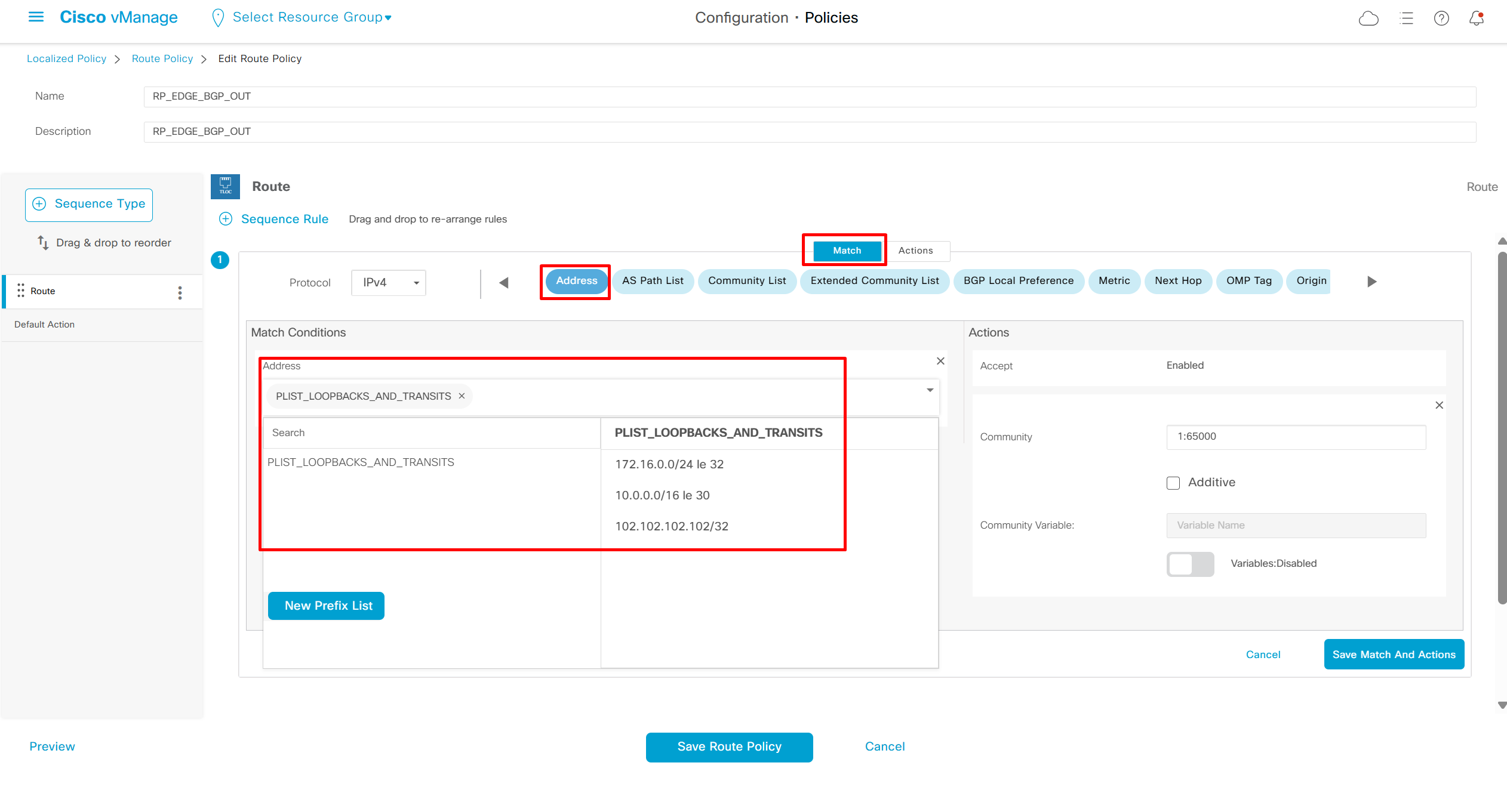
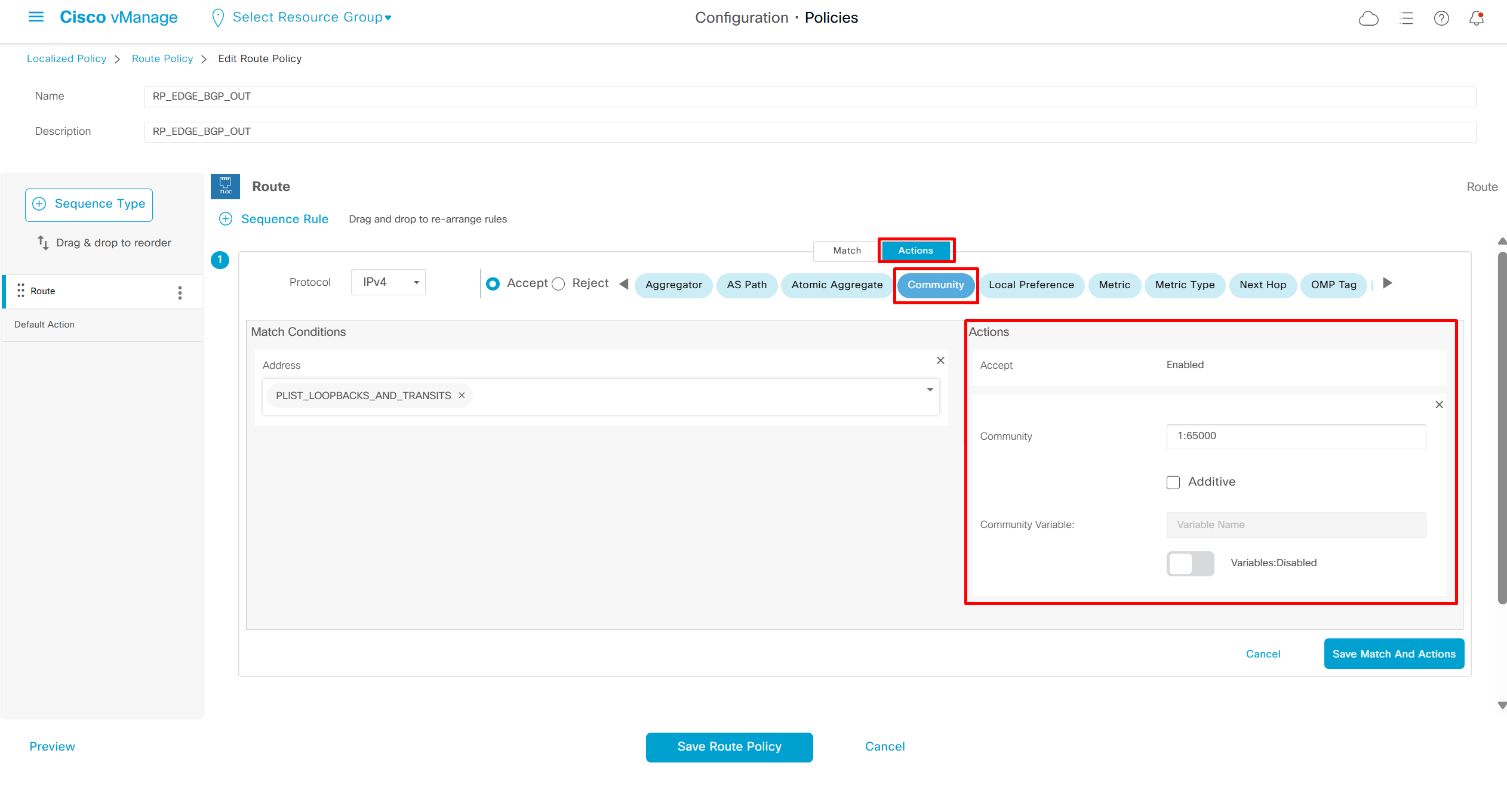
This was just policy definition
Now we need to first download this LCP policy on the routers before it can be applied on the neighbor
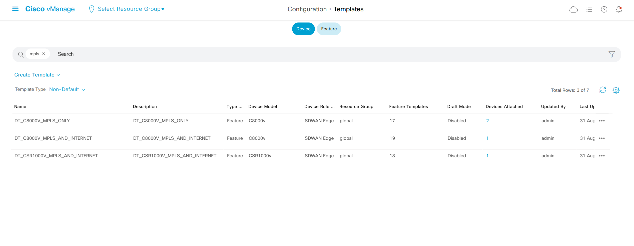
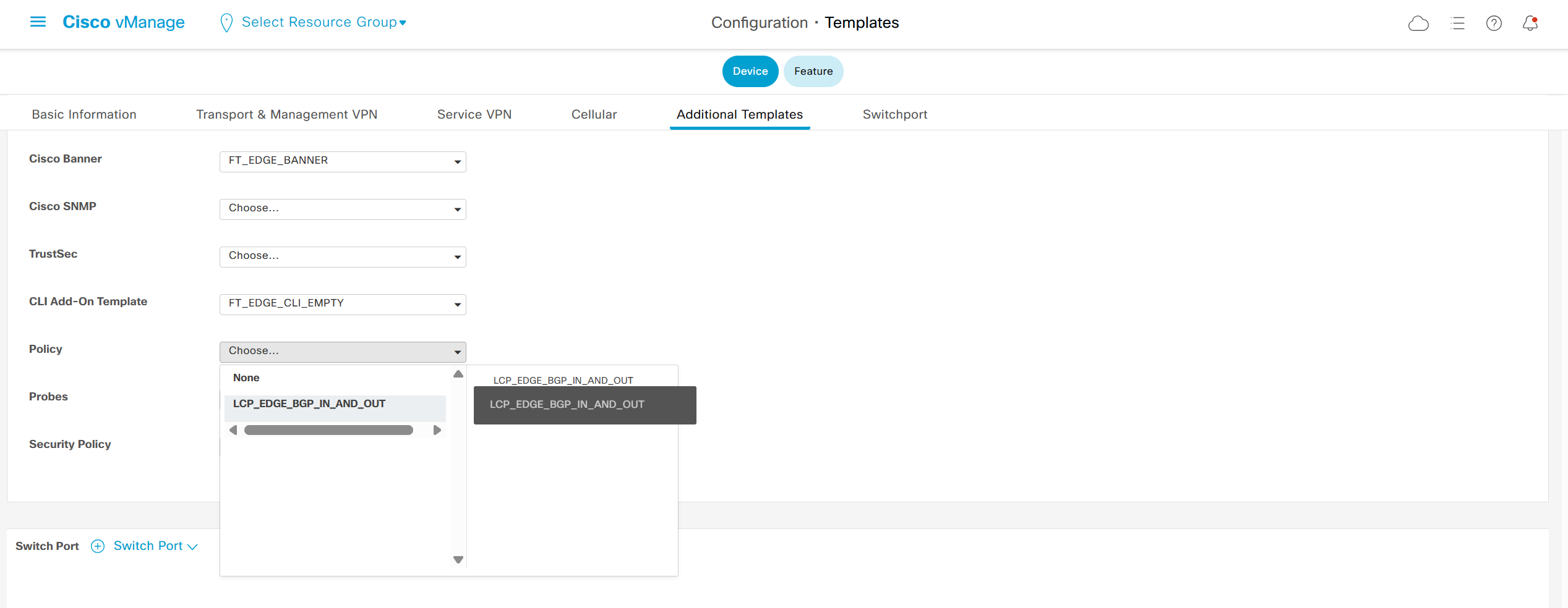
Local Control policy LCP is downloaded
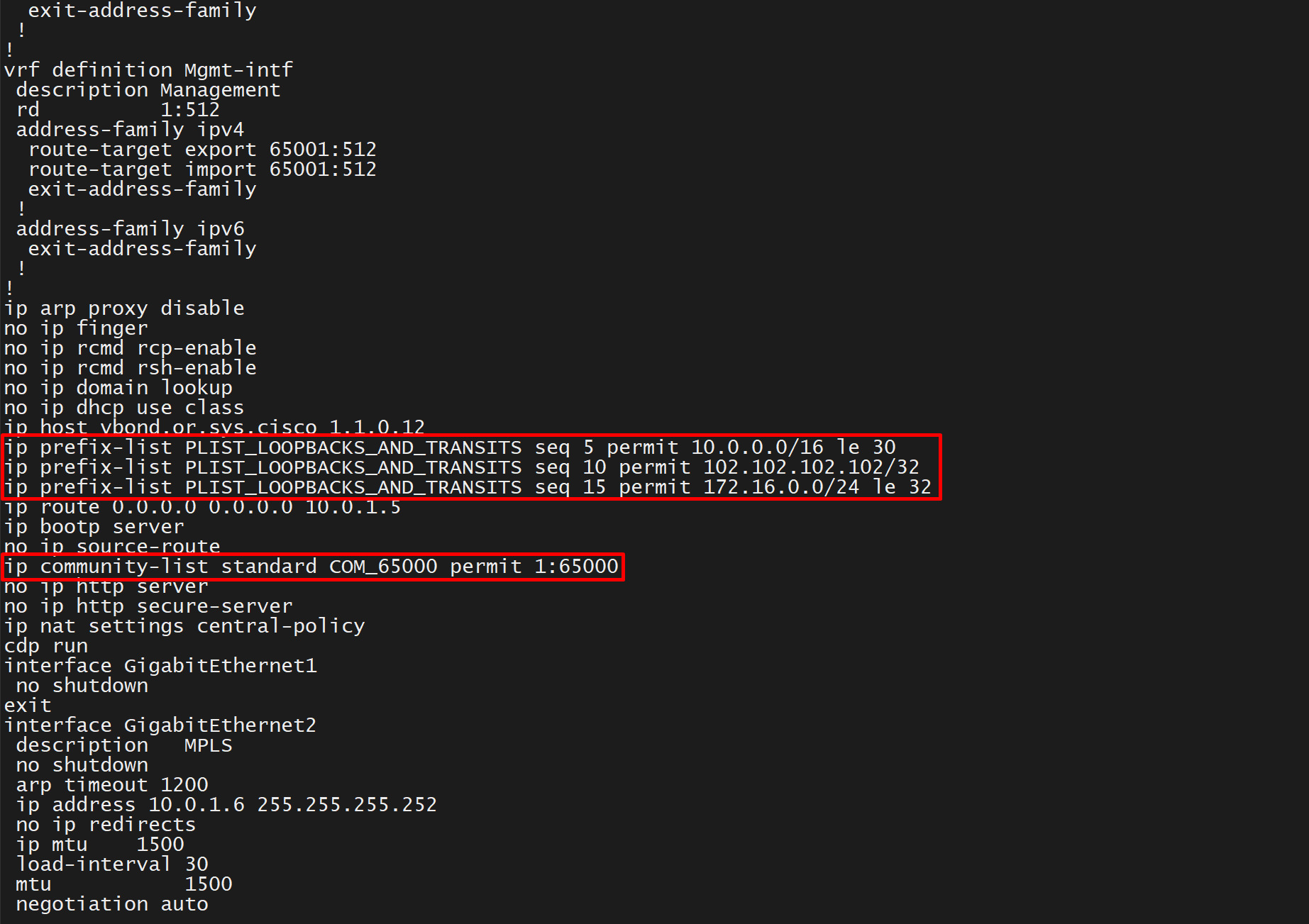
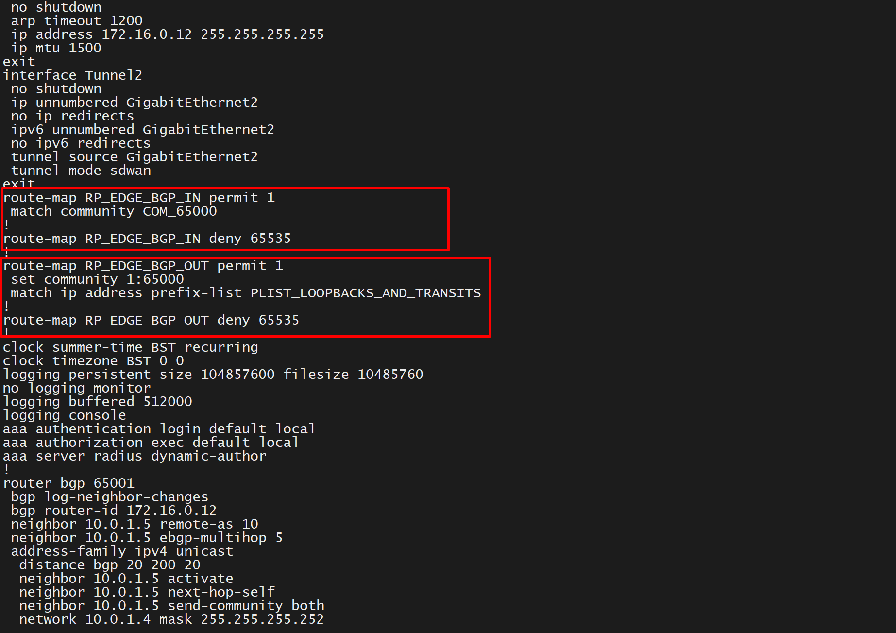
if LCP is not pushed to the edge device and if route policy is used then we can get this deployment error
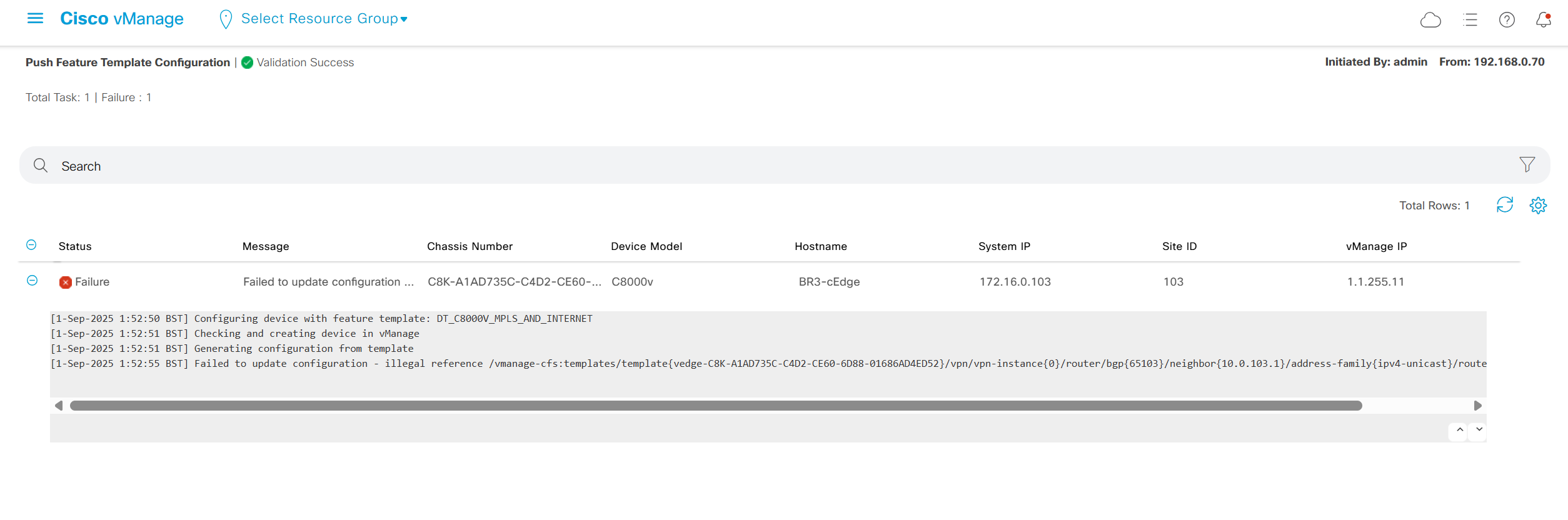
Now we need to assign it to BGP neighbors
We need to be careful when assigning the policy because there is no dropdown and you have to paste the name of route policy
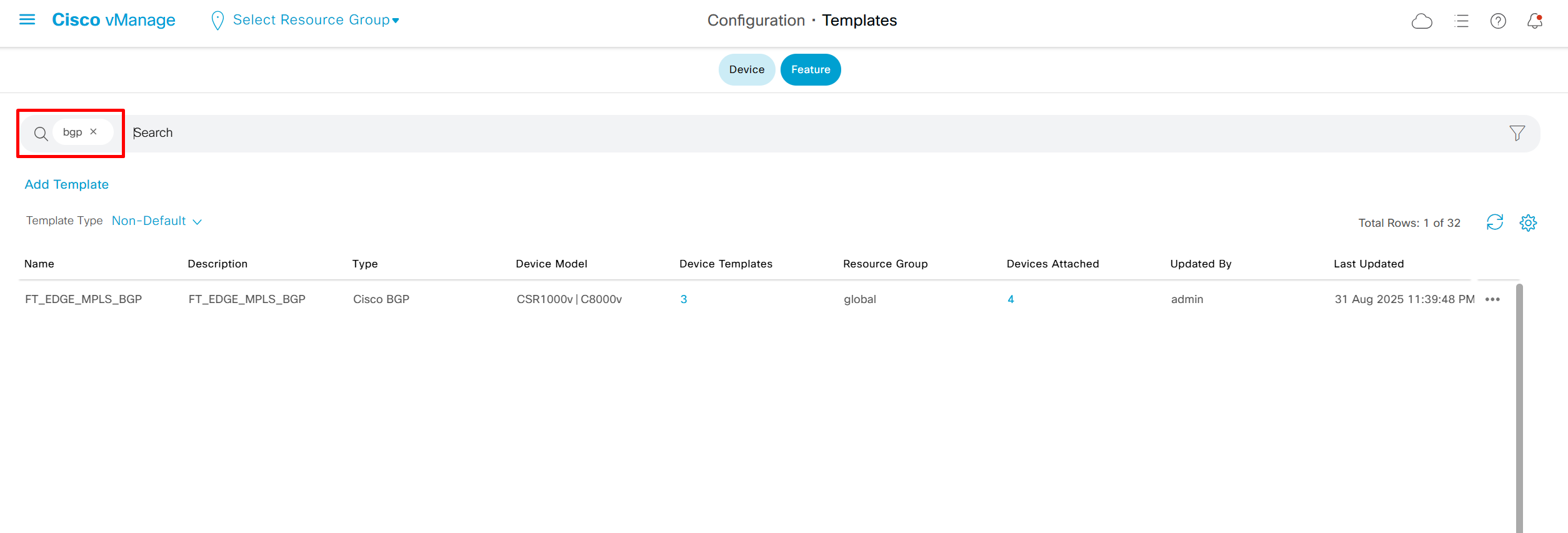
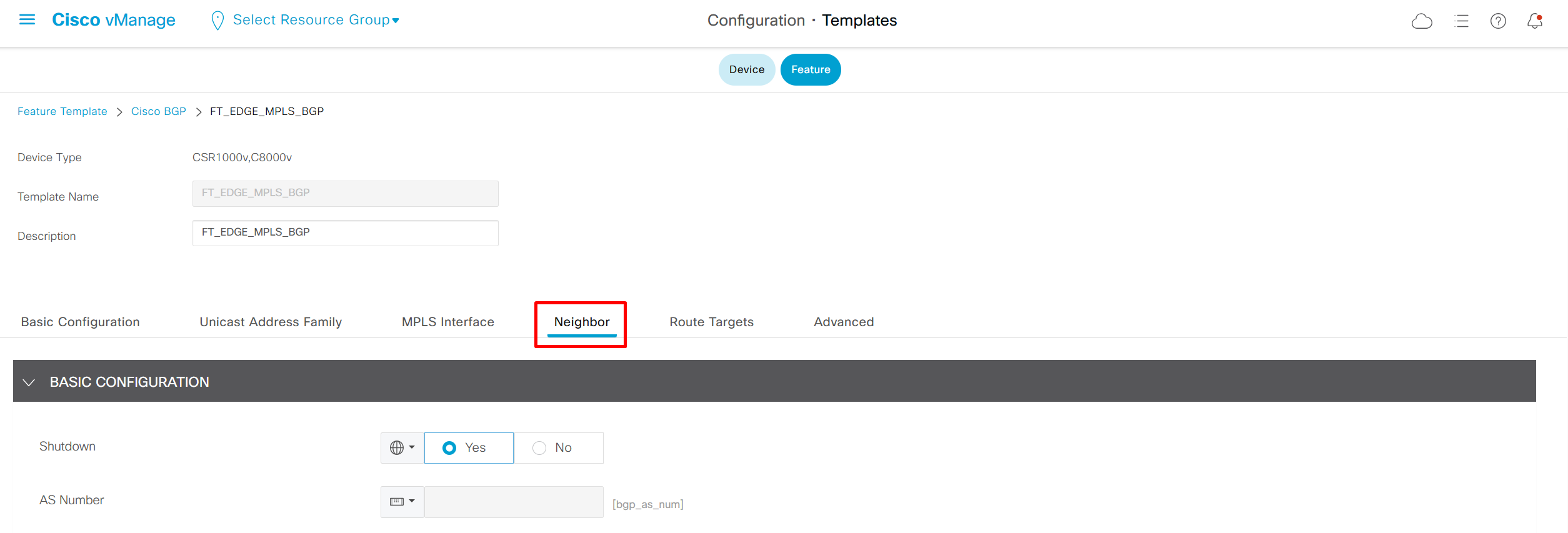
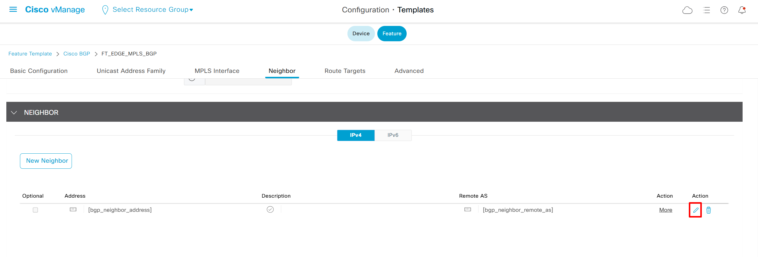
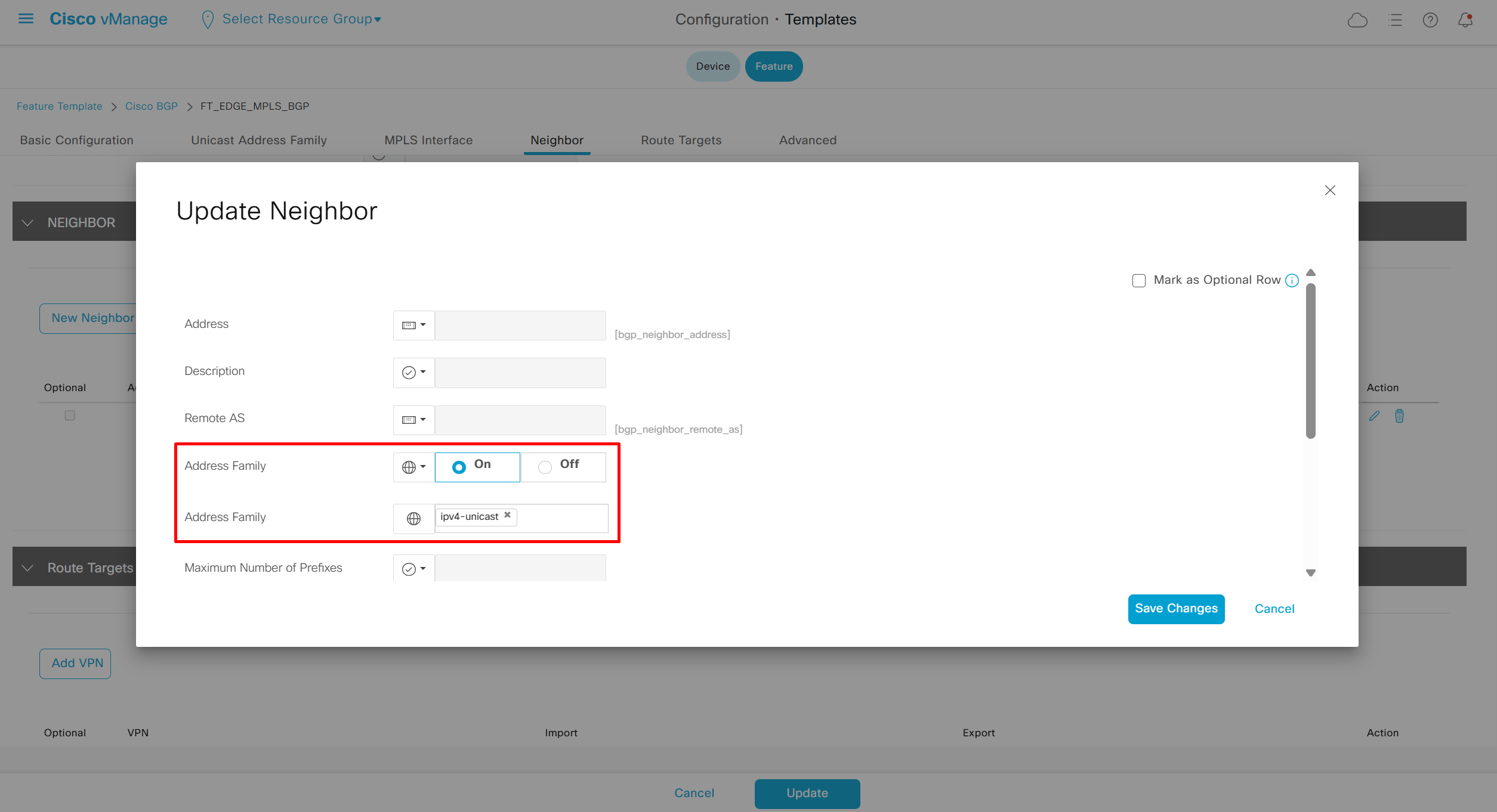
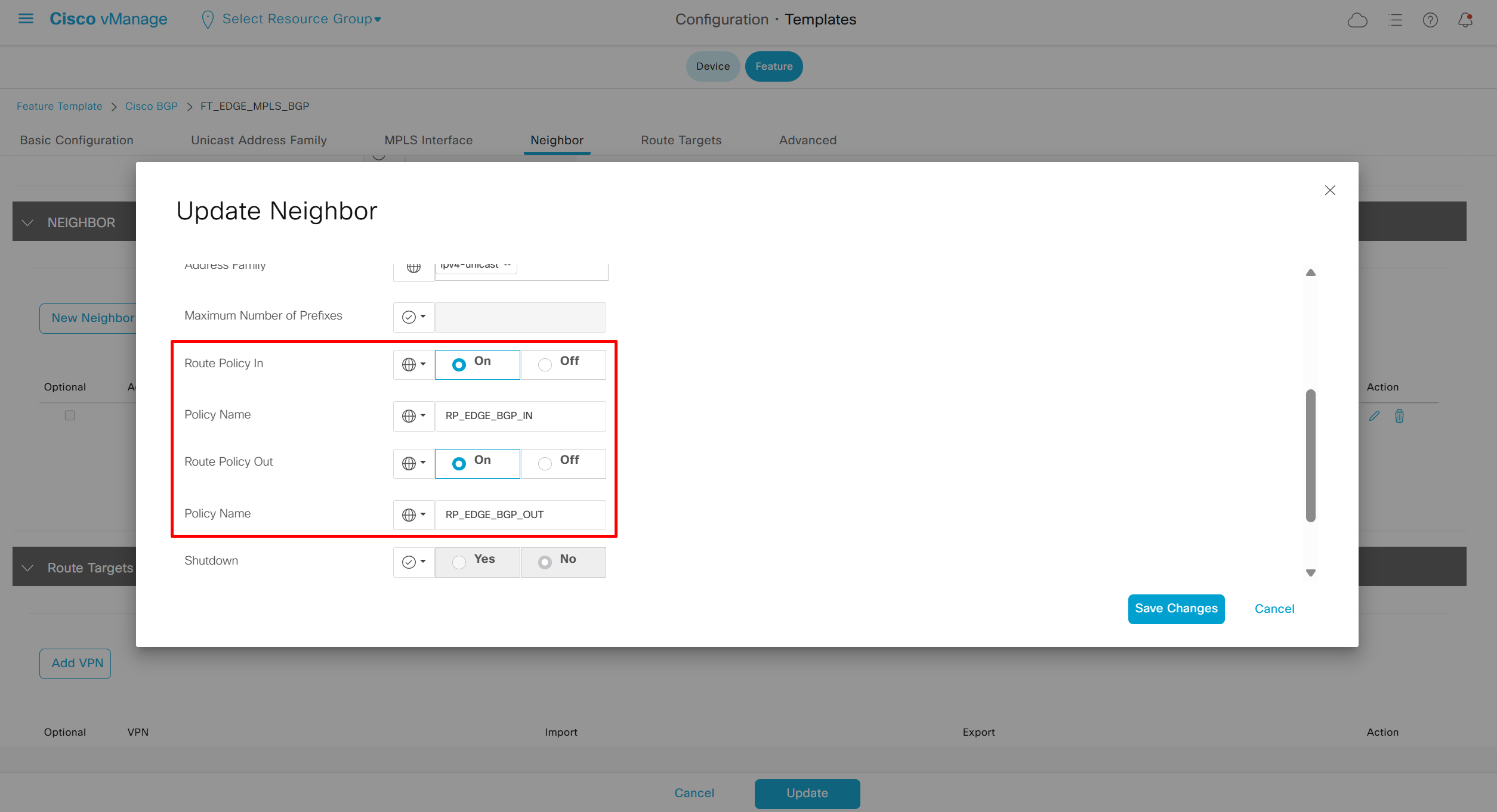
We can see community tagged on route
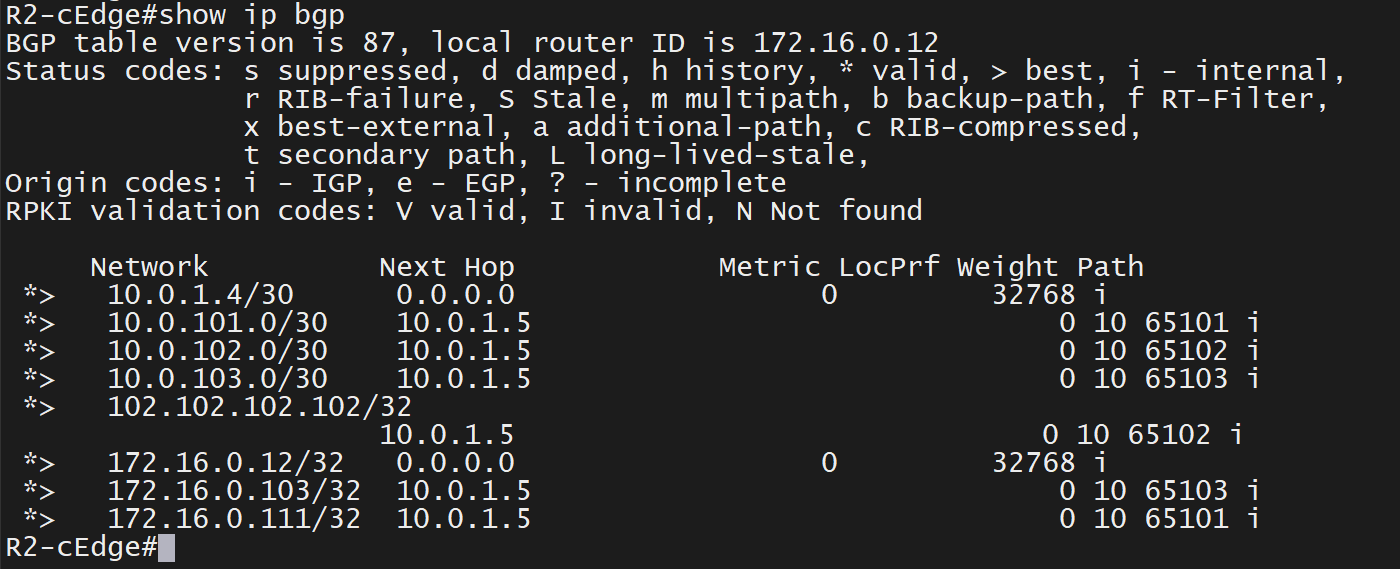
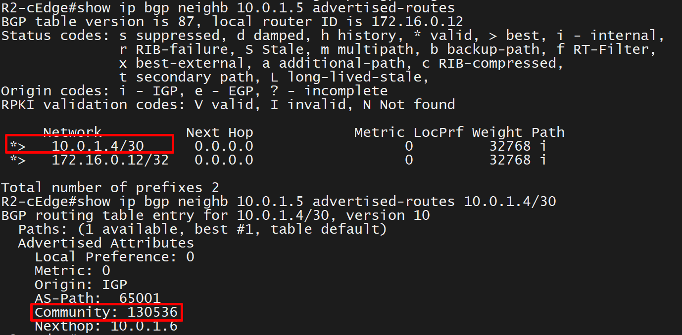
next post
SDWAN commands
SDWAN commands
vsmart -
show omp routes
show omp route 192.168.33.0/24 | nomore

show license all 				> to check HSEC
show platform hardware throughput level 	> throughput levels licensed

show sdwan system 				> cli managed or vmanage managed
show sdwan control local-properties		> certificate installed and token should be invalid
show sdwan control connection-history		> what error code generated
show sdwan control connections			> DTLS tunnels with SDWAN manager, controller and orches
show sdwan running—config			> useful to check config and creating CLI template
show sdwan bfd sessions				> check IPSEC tunnels to other TLOCs
show omp routes					> omp routes
show sdwan omp routes 				> omp routes
show ip route vrf * 				> all sdwan and global routing table
show interface gig1				> check the service vpn interface
show interface gig2				> check the transport interface
show interface Tunn1				> check tunnel interface

show policy service-path vpn 1 interface Gi0/2 source-ip 192.168.33.1 dest-ip 192.168.44.1 protocol 1
show policy service-path vpn 1 interface Gi0/2 source-ip 192.168.33.1 dest-ip 192.168.44.1 protocol 1 all
show sdwan tunnel statistics

show processes cpu sorted

show platform hardware qfp active statistics drop
! drop statistics
! 'platform hardware' -> means ASIC
! 'qfp' -> means Quantum Flow Processor , This is Cisco’s hardware chip that processes packets at very high speed
! 'statistics' -> Counters and performance numbers
! 'drop' -> Packets that were discarded instead of being forwarded

show sdwan config-pull history
                            PROCESS
INDEX  TIMESTAMP            NAME         TOTAL TIME      RESULT   FAIL REASON
----------------------------------------------------------------------------------
1      2025-04-30 12:13:18  pycfg-26502  0:00:02.547027  success  -
2      2025-06-10 21:06:49  pycfg-17134  0:00:02.381984  success  -
3      2025-06-10 21:13:47  pycfg-24614  0:00:02.234331  success  -
4      2025-06-10 21:18:11  pycfg-29603  0:00:02.265134  success  -
5      2025-06-10 21:31:13  pycfg-16327  0:00:02.295202  success  -
6      2025-06-10 21:49:19  pycfg-1014   0:00:04.337417  failure  commit-failure
7      2025-06-10 21:51:40  pycfg-3698   0:00:06.398463  success  -
8      2025-06-10 21:57:49  pycfg-10648  0:00:06.921389  success  -
9      2025-06-10 21:59:22  pycfg-13383  0:00:02.373731  success  -
10     2025-06-10 22:02:32  pycfg-22890  0:00:07.149522  success  -
11     2025-06-10 22:08:22  pycfg-29622  0:00:36.597725  success  -
12     2025-06-11 22:38:01  pycfg-13695  0:00:07.507785  success  -
13     2025-06-11 23:06:07  pycfg-14473  0:00:07.382631  success  -
14     2025-06-11 23:26:44  pycfg-4645   0:00:02.468943  success  -