SDA LM 1 – Initial Configuration & Setup
Videos
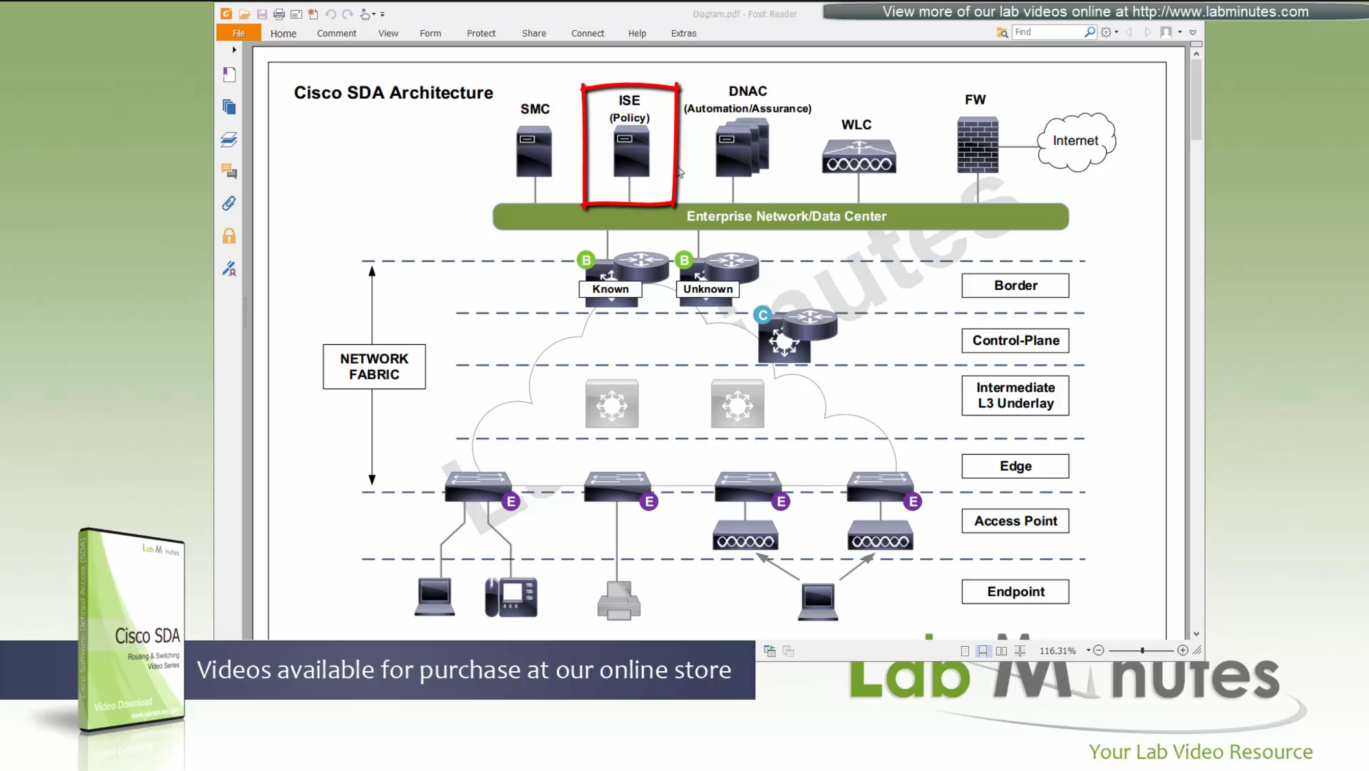
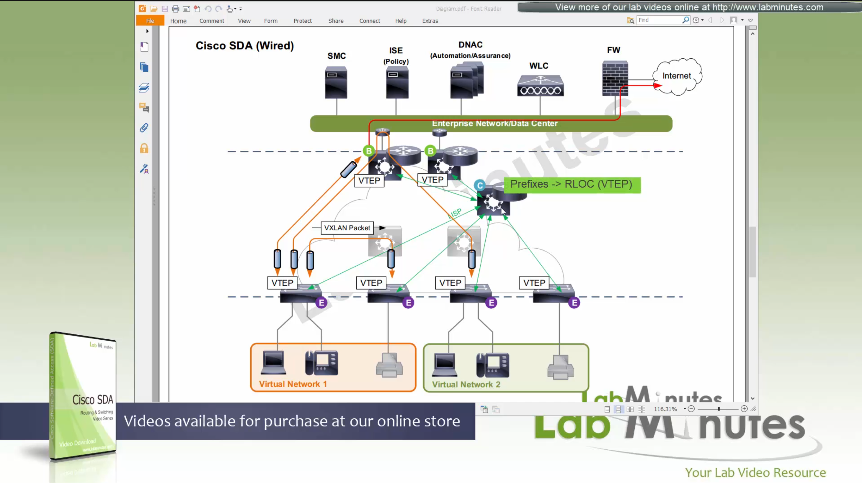
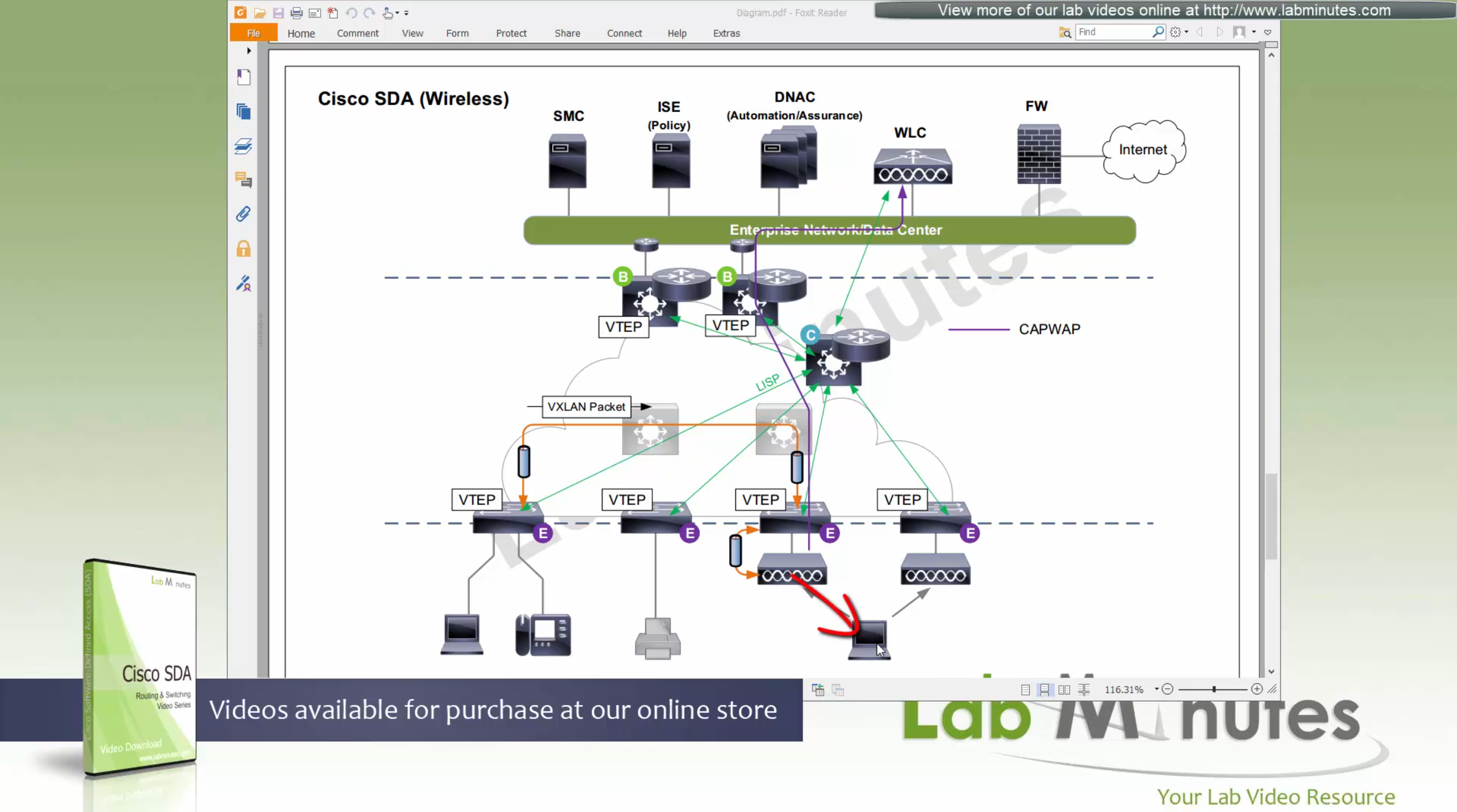
SDA – LISP and Routing introduction
Fabric spans from border nodes
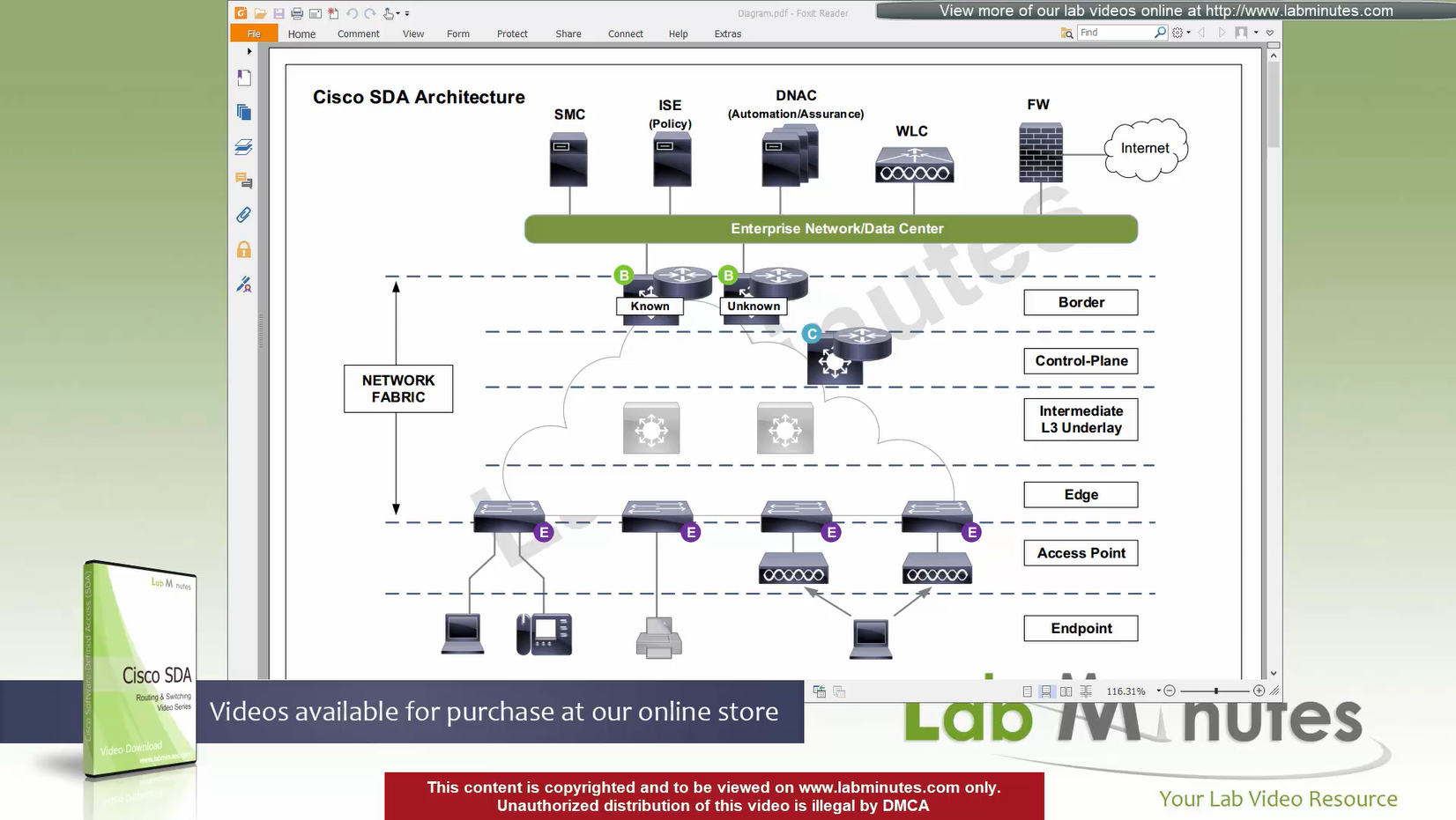
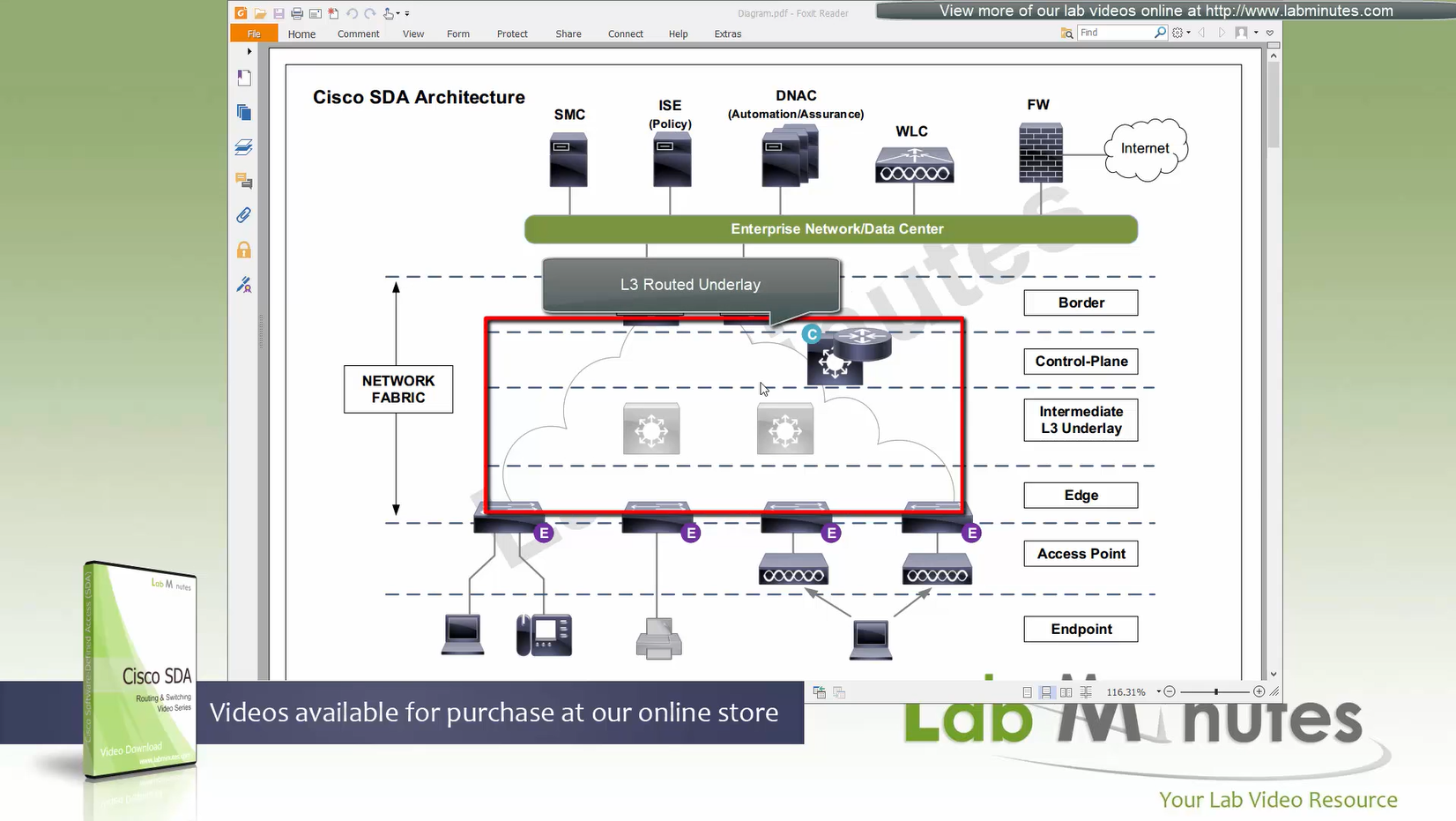
VXLAN (tunnel packets) routed across the point to point L3 (underlay)
Edge and border run L3 eliminating L2
Underlay routing is only there for mostly learning loopbacks of switches in fabric
Client data can be vlan tagged or untagged
Edge switches receive data from clients, if destination is on another switch in the fabric
or in an outside world (via border)
then VXLAN encapsulation (tunnel) is created to other switch or border node
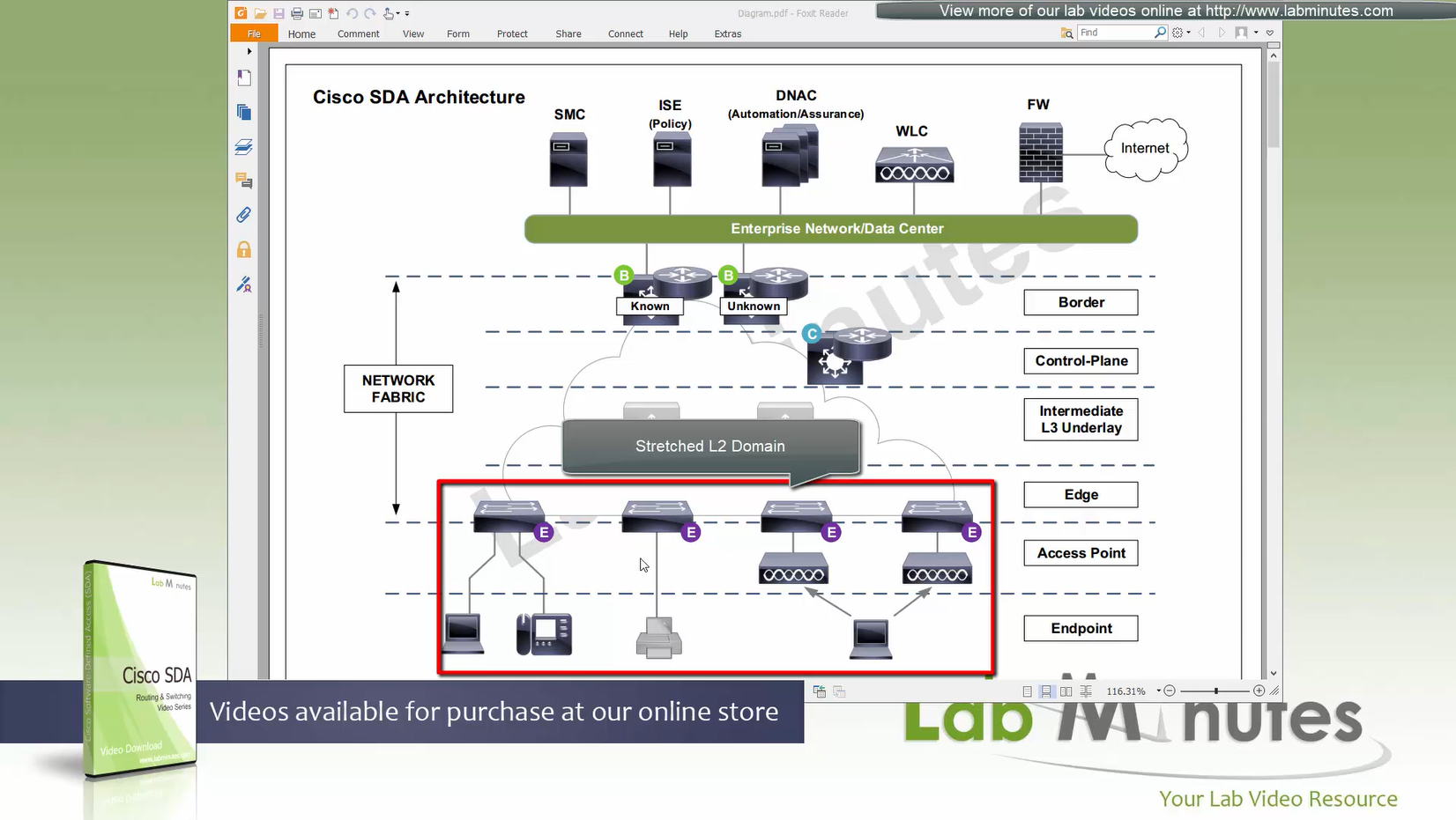
Client can roam from one location to another keeping their original IP address and L2 domain due to “stretched” subnets,
Same subnets (SVIs and also vlans) are available in all edge switches for both wired and wireless
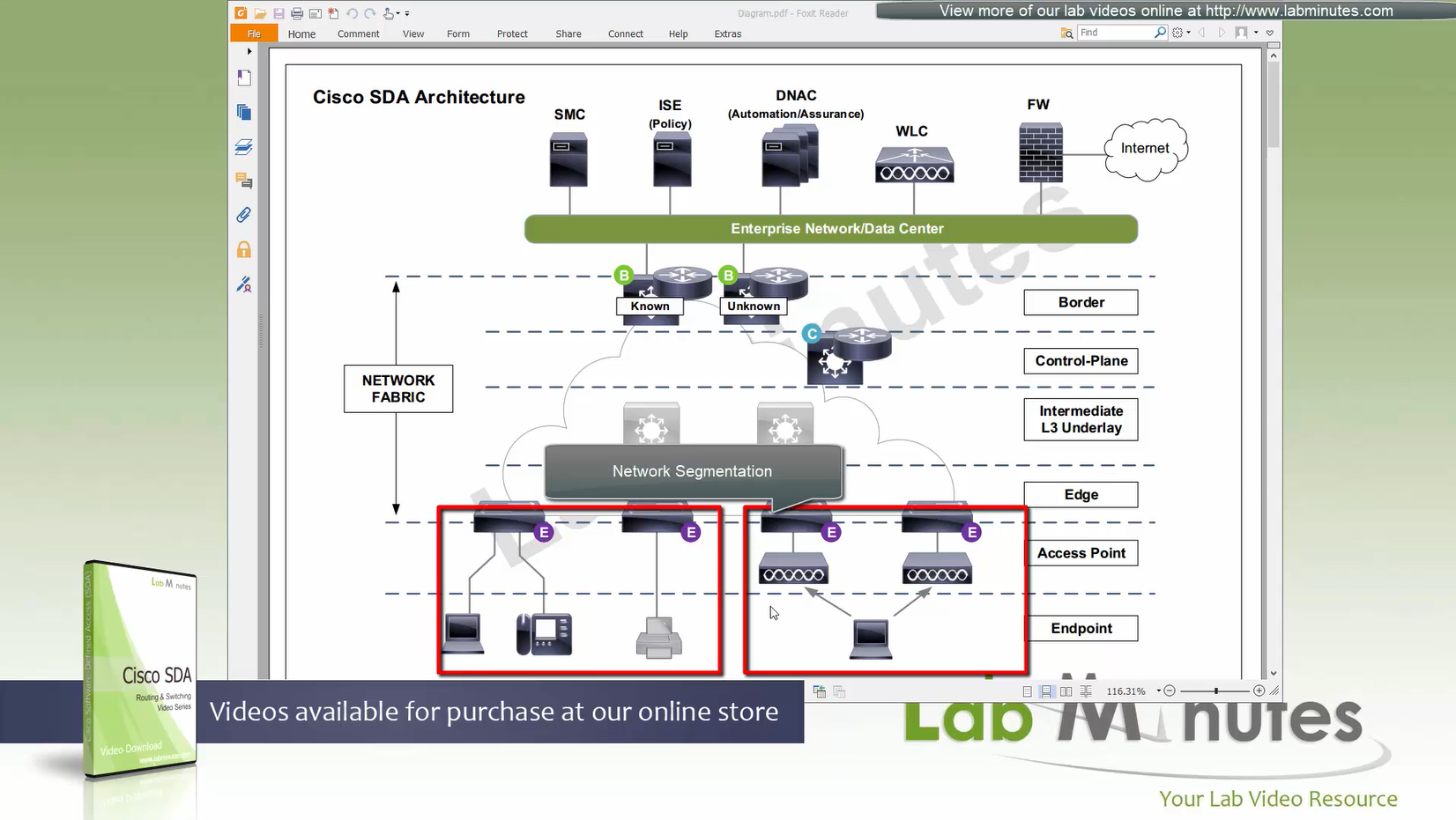
Network segmentation (different virtual networks) or Micro segmentation (using SGT tags and TrustSec)
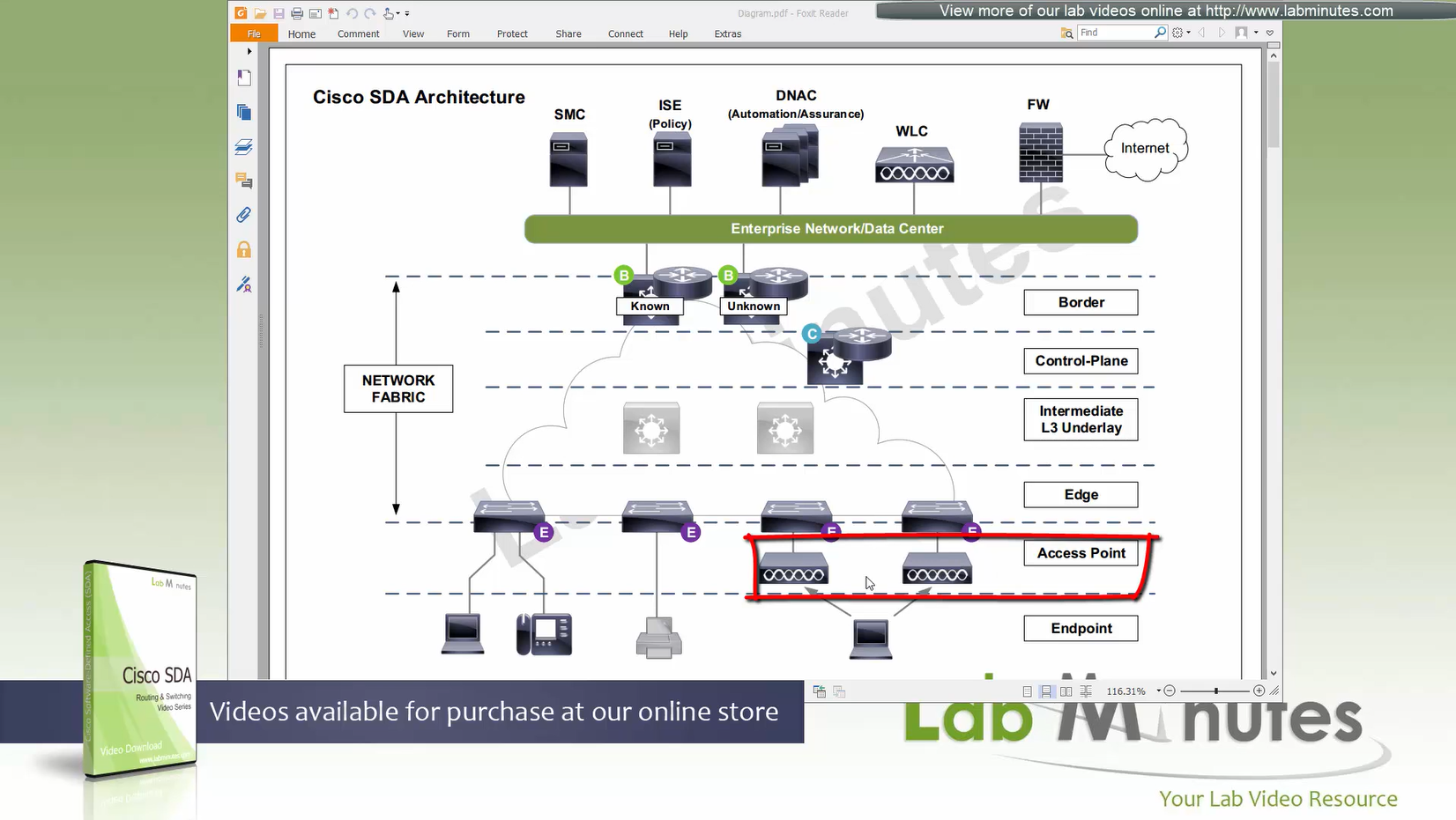
You can also have “Fabric” enabled WLC and AP,
this makes wireless clients consistent policy wise in DNAC same as wired clients policies
Edge nodes detect the endpoints and updates the control plane about these endpoints
Edge nodes are also responsible for VXLAN encapsulation and decapsulation
Control plane node is the brains of the Fabric and provides “Endpoint to Location mapping” to the edge nodes and border nodes using LISP
Control plane node(s) is LISP Map Server and LISP Map Resolver
VXLAN can carry both Layer 2 frames and also Layer 3 packets
Border node and control plane node should be deployed in pair (2x) to have redundancy in the network
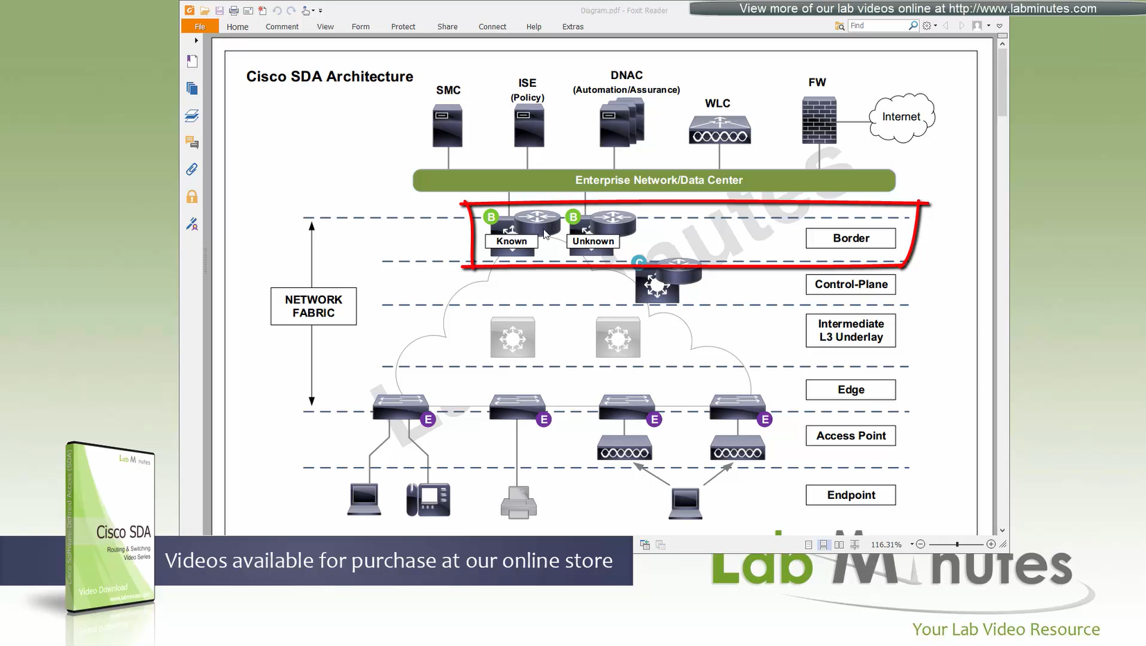
Fabric border node – acts as a gateway to fabric world
Network traffic will need to leave via the fabric border node to access the rest of the enterprise network and internet
Border node peers with external “Fusion” router and advertise Fabric -> fusion and also redistribute external networks -> fabric.
Any external routes learned will be registered with control plane so that those external destinations are registered in LISP
Because edge nodes only follow LISP routing and not any other routing protocol
Control plane is consulted if any packets need to leave for destination other than local switch
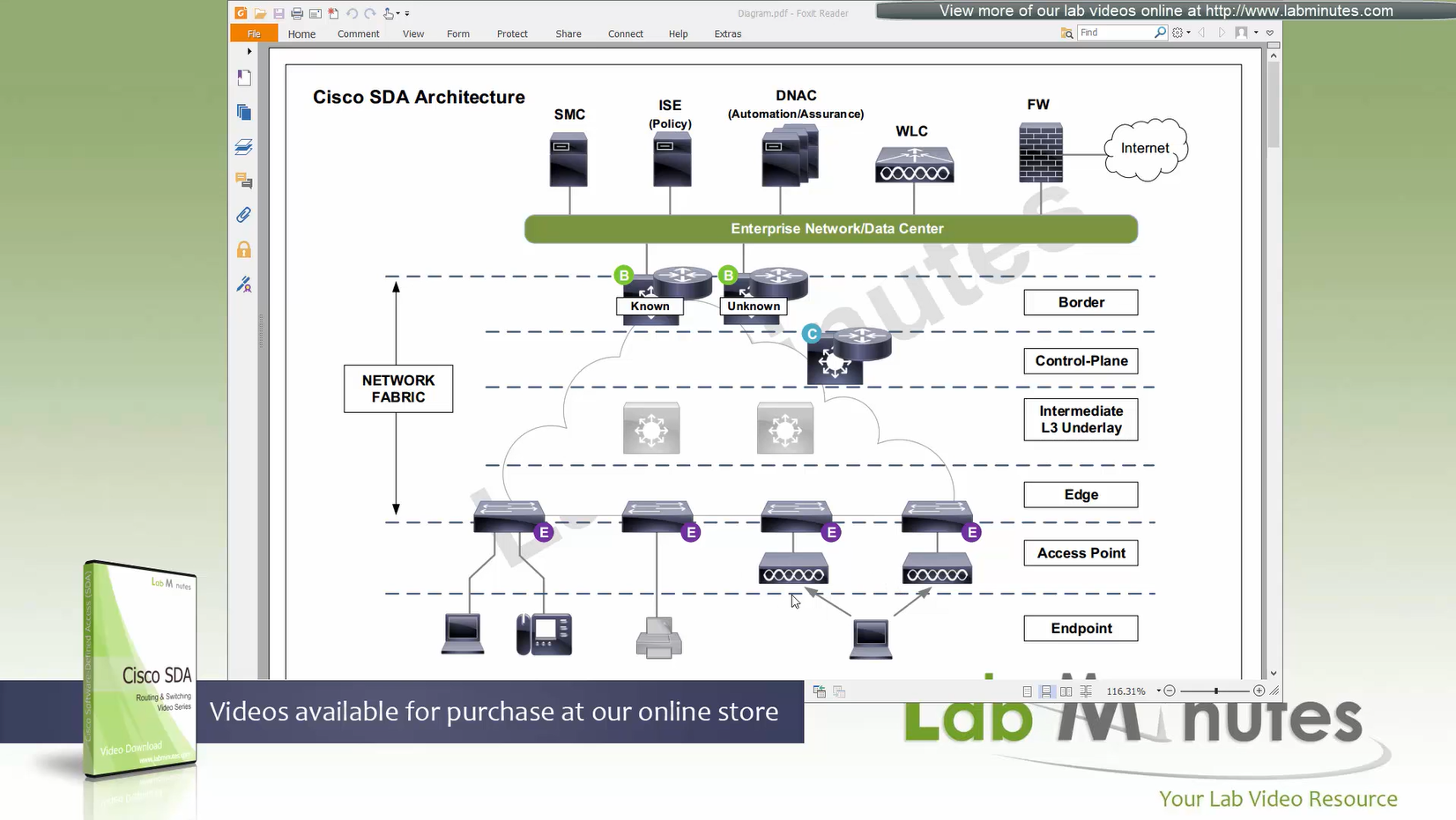
There are 2 types of border nodes
1. Known Border Node
2. “Default Border Node”
Known Border node is for destinations that are known subnets
Second type of border node is that deals with unknown routes and is also called Default Border
Traffic is encapsulated to Default Border if LISP has no entry in control plane and control plane responds back with Default Border
Both Known Border and Unknown Border can live on same device or two different devices
but sometimes in diagrams they are shown to be 2 different devices
- control plane node
- border node
- known border node
- default border node
Intermediate Underlay device:
Intermediate Underlay devices need to be able to support the “Jumbo frame” and use ISIS
Cisco recommends this intermediate devices to participate ISIS (shortest path) with redundant links
there should be no spanning-tree or layer 2 in the Fabric.
Underlay Intermediate device aggregate all the access edge nodes into something and then connect into border switch or router
Direct connections to border are supported but should not be done for larger site due to scalability issues
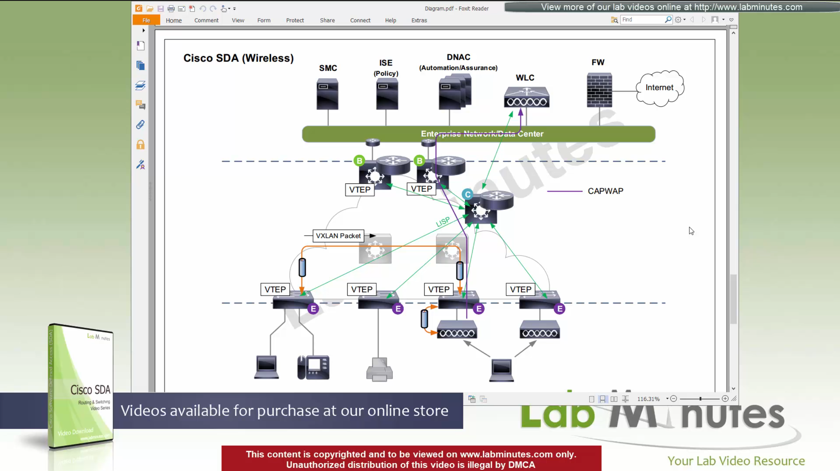
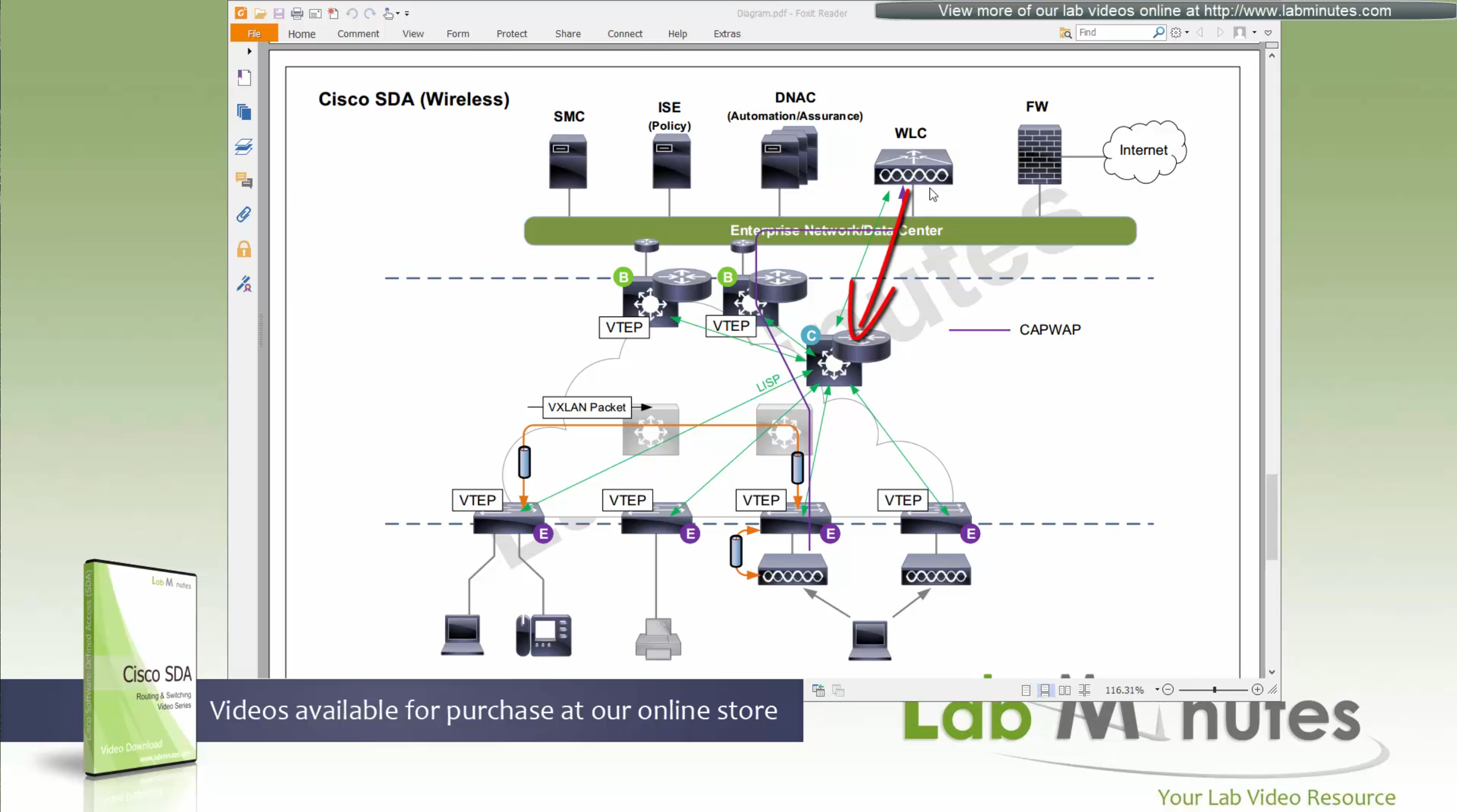
Fabric mode WLCs still manages the AP and maintains client connection information via CAPWAP control channel
Fabric mode WLC reports to control plane node and lets it know about the client
Communicates associations and communicates roaming to control plane
Controller sits outside of the fabric and APs sit inside the fabric directly connected to edge nodes
WLC can be connected outside the fabric as long as it has reachability to the border and control and APs
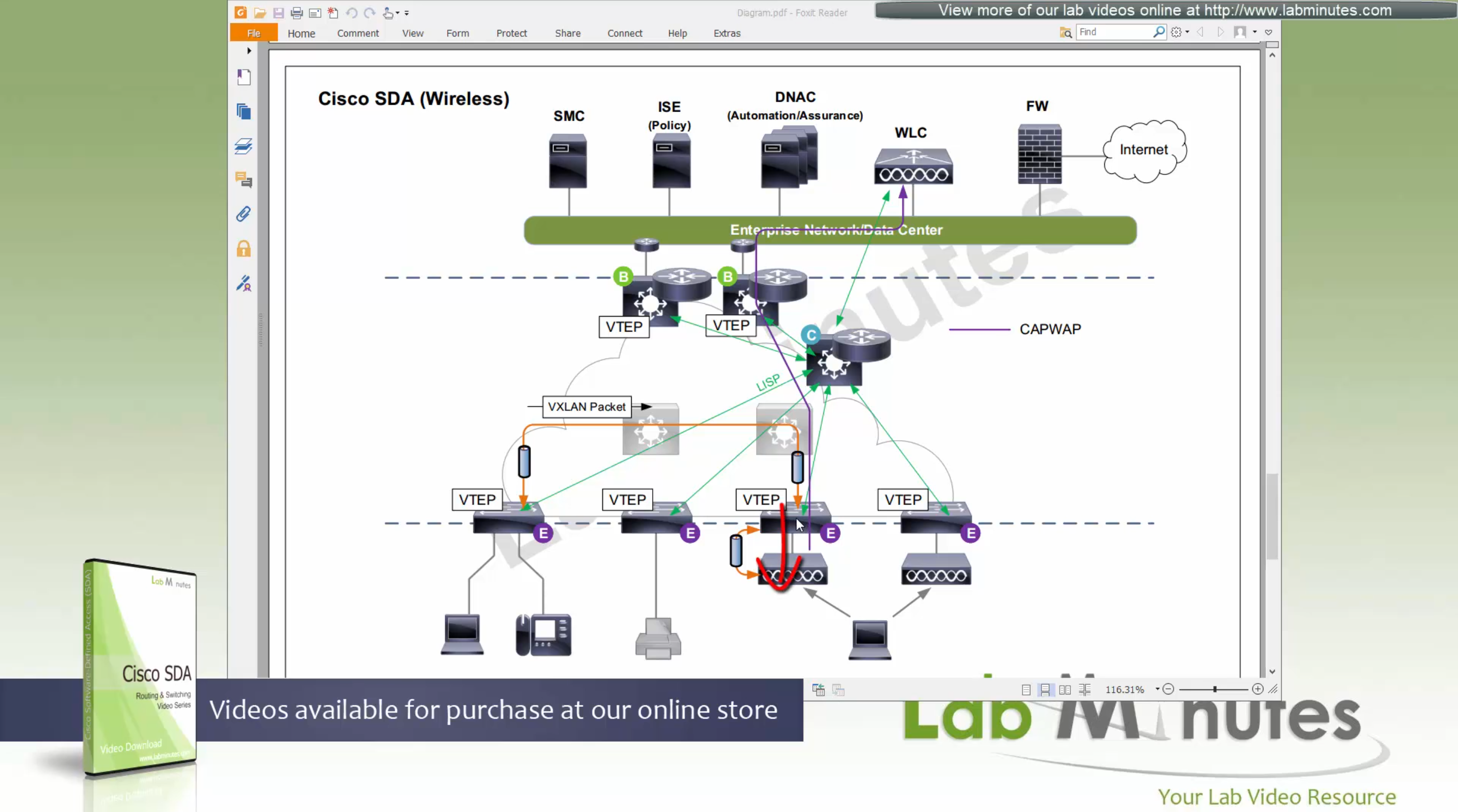
Fabric mode AP
(Data tunnel) they will not send data to WLC for it to be centrally switched but exit data locally on the fabric via VXLAN tunnel > edge switch
Fabric AP participates in VXLAN encapsulation
however they maintain CAPWAP tunnel (Control tunnel only) to the WLC at the same time,
This allows wireless clients to be treated within the same system and policies of the fabric.
Control: AP <–CAPWAP CONTROL–> WLC
Control: WLC <–LISP–> Control node
Data: AP <–VXLAN–> Edge node
AP must connect to edge node “directly”, there should be no switches in between AP and Edge node
WLC sits outside the fabric or Fabric border node and APs sits directly under the edge nodes
because Access points connect to edge nodes directly clients are connected like
Client <–Wireless–> AP <–VXLAN–> Edge node
DNAC
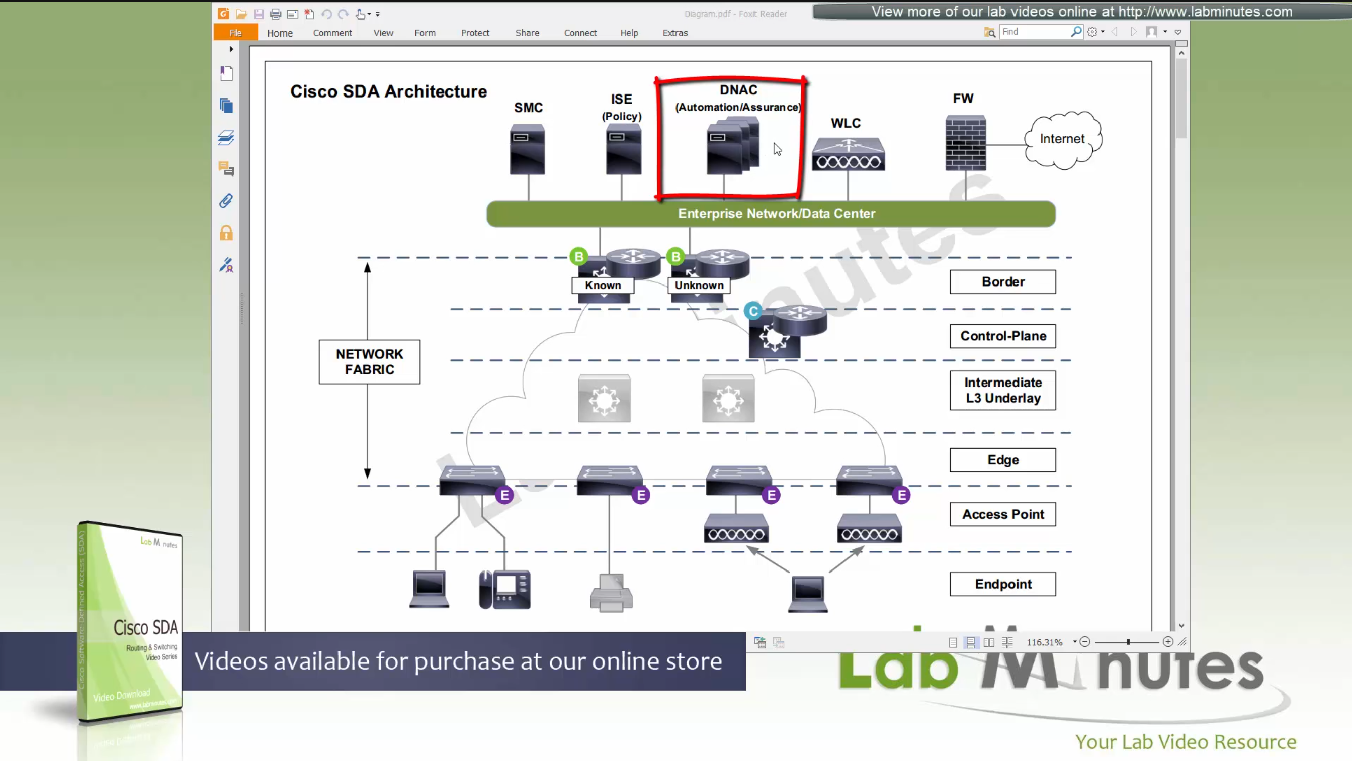
ISE maintains the security policy and contains Authentication / Authorization policy and also TrustSec related components
DNAC uses APIs to push configuration to ISE for SGT but ISE is separately managed
Management loosing network such as DNAC will keep the data forwarding and not cause outage
One thing to keep in mind is that we need to have high speed LAN like access between all fabric nodes and DNAC, that is why DNAC cannot be spanned across WAN, all Fabrics must have high speed access to DNAC
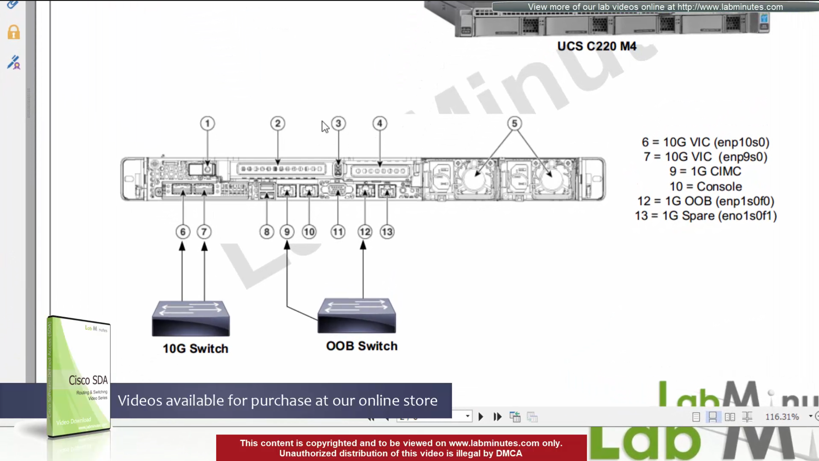
DNAC is available as C220-M4 which is same C series server as APIC for ACI
It is always recommended by Cisco to deploy DNAC in cluster of 3
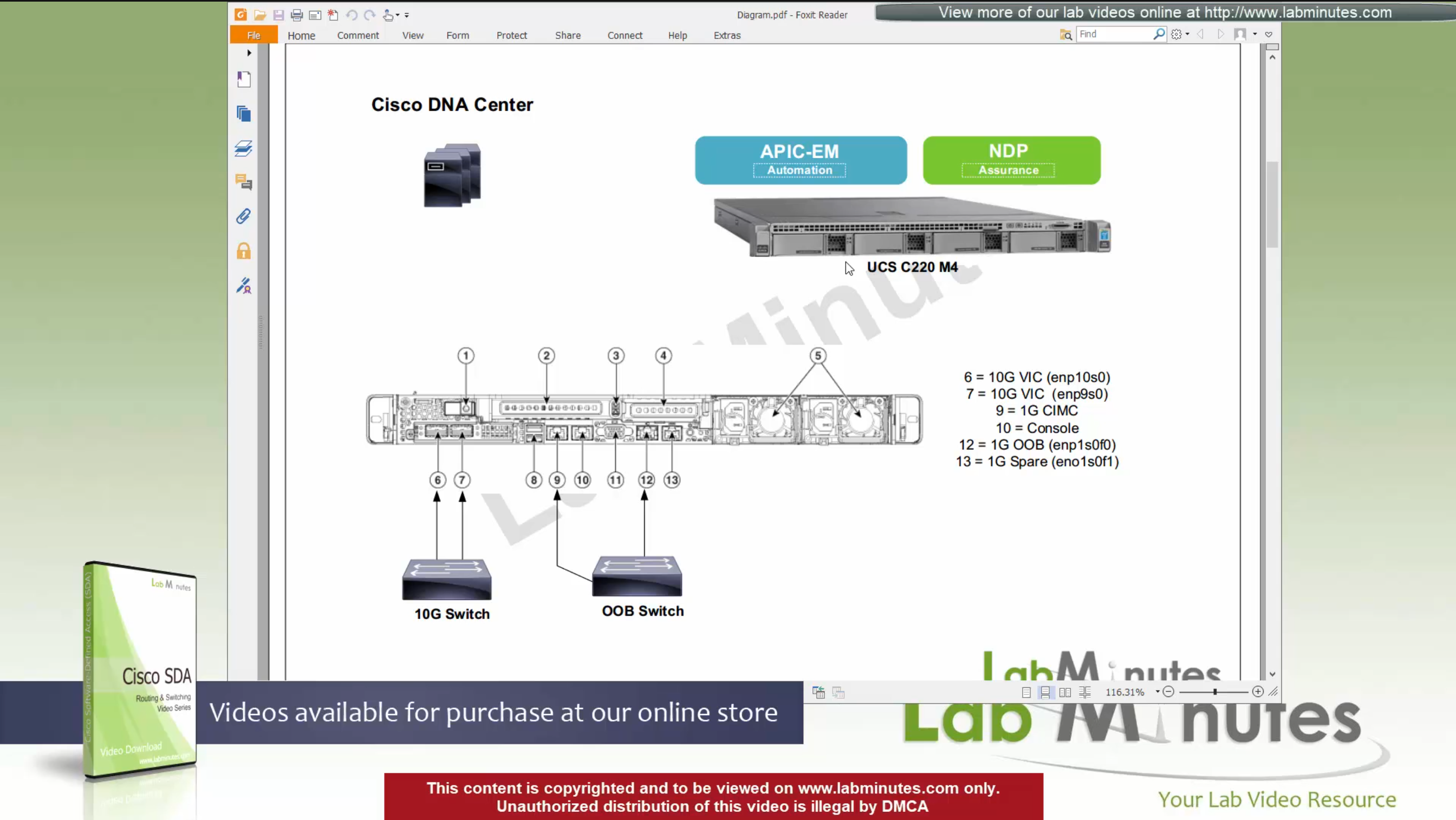
For connectivity DNAC has 2x (redundant) 10G VIC Cards – Data interfaces for fabric facing communication
It is not mandatory to configure the OOB interface for management connections
Data port IP can also be used for management
unlike ACI, where GUI and SSH must strictly be done via OOB IP
CIMC interface – Server interface for KVM and firmware upgrades
Console interface – in case network connectivity is lost
OOB Mgmt interface – optional for HTTP and SSH
it is recommended so we have another path for accessing the GUI and SSH
There are 2 engines running on DNAC,
APIC-EM
NDP
There is 3rd engine called policy engine but it does not run on DNAC but on ISE
APIC-EM shares a lot of features with APIC and helps with Network topology discovery, software management and upgrades aspect etc, APIC-EM is also responsible for the network automation
NDP stands for Network Data Platform
NDP takes care of the, “monitoring”, “telemetry”, “assurance” and “data analytics”, This is like Solarwinds NPM
NDP is more with Analysis and alerting
while the APIC-EM is like NCM for pushing changes and making changes
In NDP Assurance comes from the fact that it goes one level deep and it not just relies on polling from network devices for system stats and health but it also gets the Client’s connectivity monitored from client and their experience perspective
Client connection stats and connection health and client experience is one of the big things, and it is client connectivity that “assures” that network is working because clients are live and using the network, so instead of SLA on the box, client data traversing the network is a better testament that network is working or not
NDP also has “machine learning” elements
DNAC Assurance or NDP collects data from various sources, once data is received, Assurance engine does correlation and provide bigger picture pieced together to reveal issues which administrators are either not aware or know before
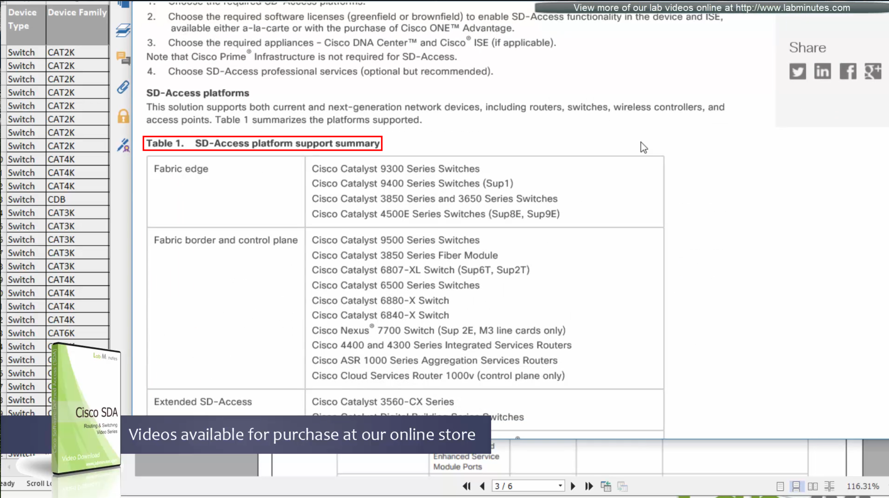
SDA is not fully supported by all switches / routers
Some devices have some features supported
Others fully support all the features.
This sheet can be found on google, Y and N in column have been added, older hardware possibly cannot support those features
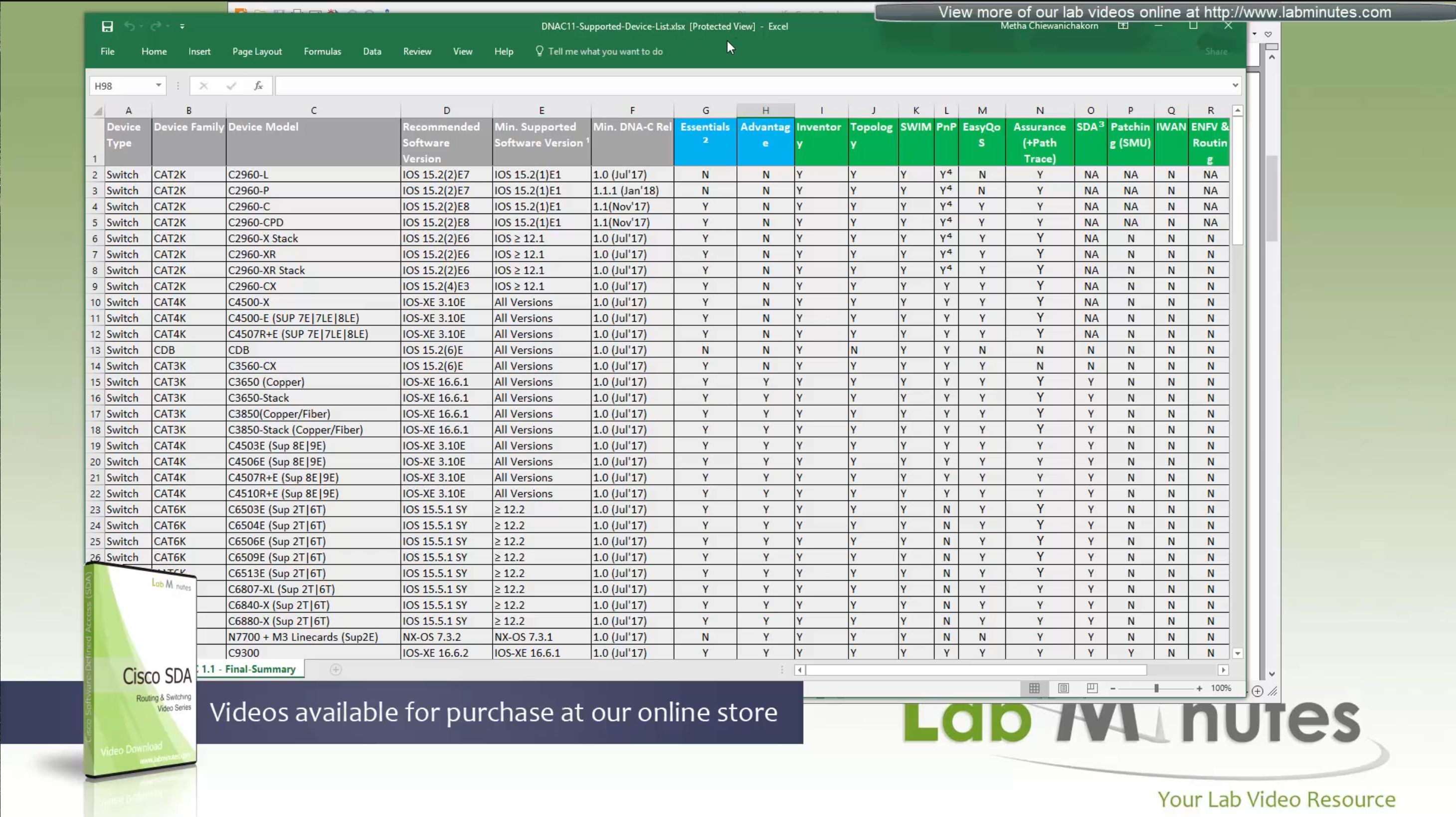
We can see that very first switch that can do SDA is 3650 Copper
Some cisco models can be the edge nodes only but not the border node or control node.
So make sure that we order right kind of hardware before deployment.
Cat 9k will support most of the SDA features
This list also includes routers, as routers are also supported in SDA for Border and control nodes but do not deploy anything outside of Validated designs in CVD
Similarly there are WLCs that are validated for SDA, be sure to check SDA hardware sheet
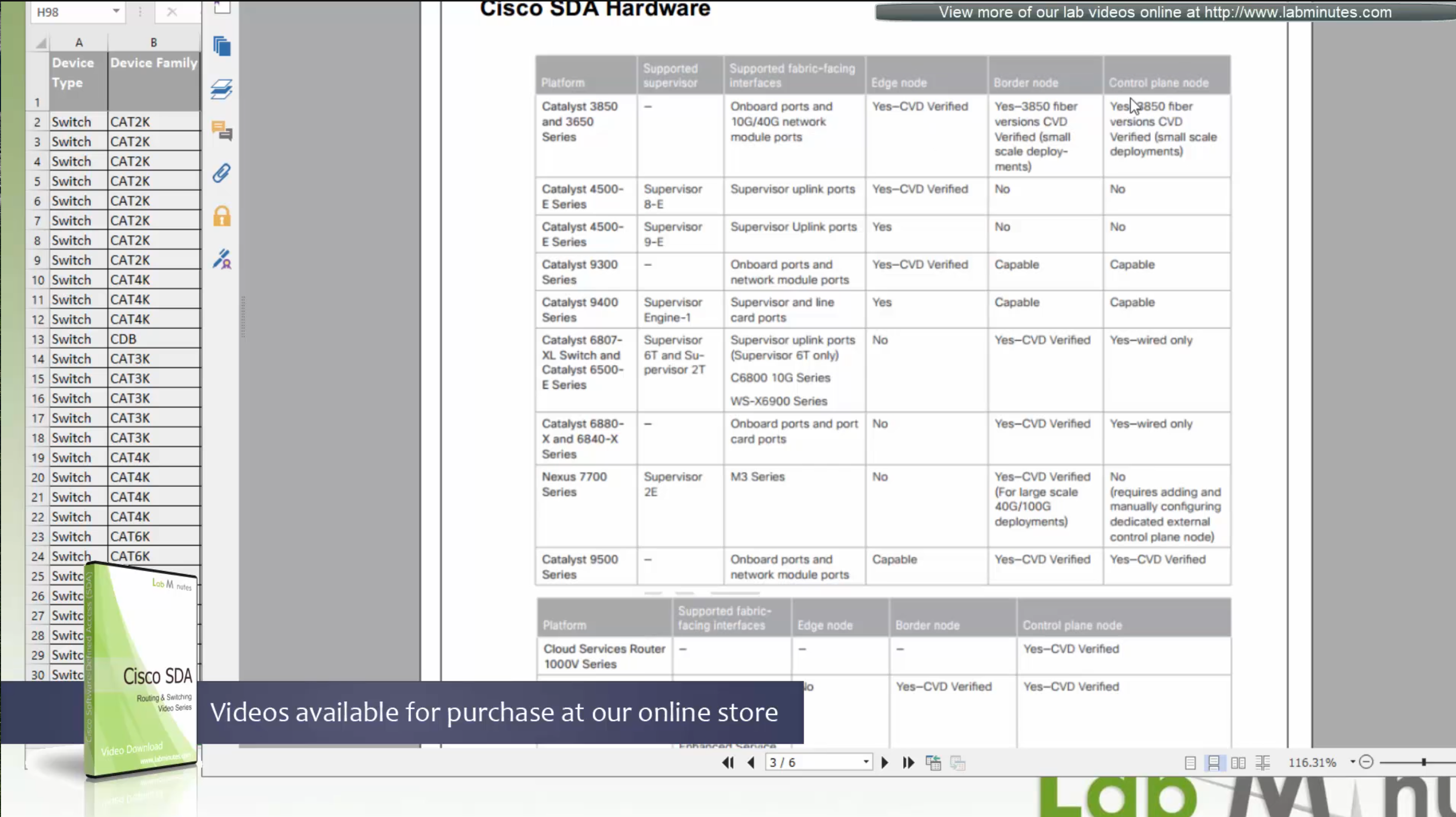
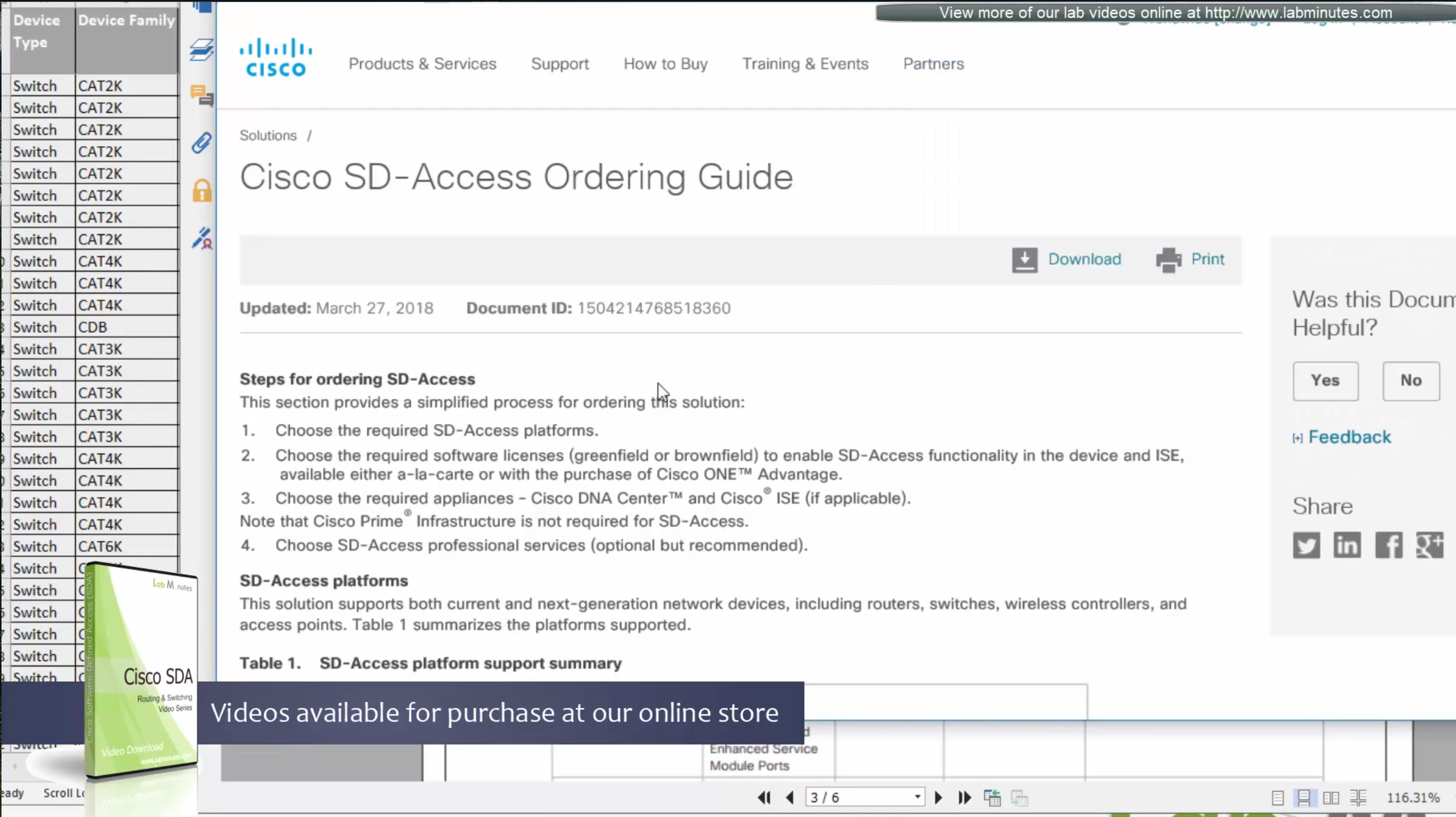
Always consult “ordering guide” for new deployments
Fabric is consistent across the network and is not different unlike legacy network which can have different networks between switches because of inconsistent configuration. Fabric on the other hand is consistent from L2 and L3 perspective.
All the underlay network is going to see is UDP packets


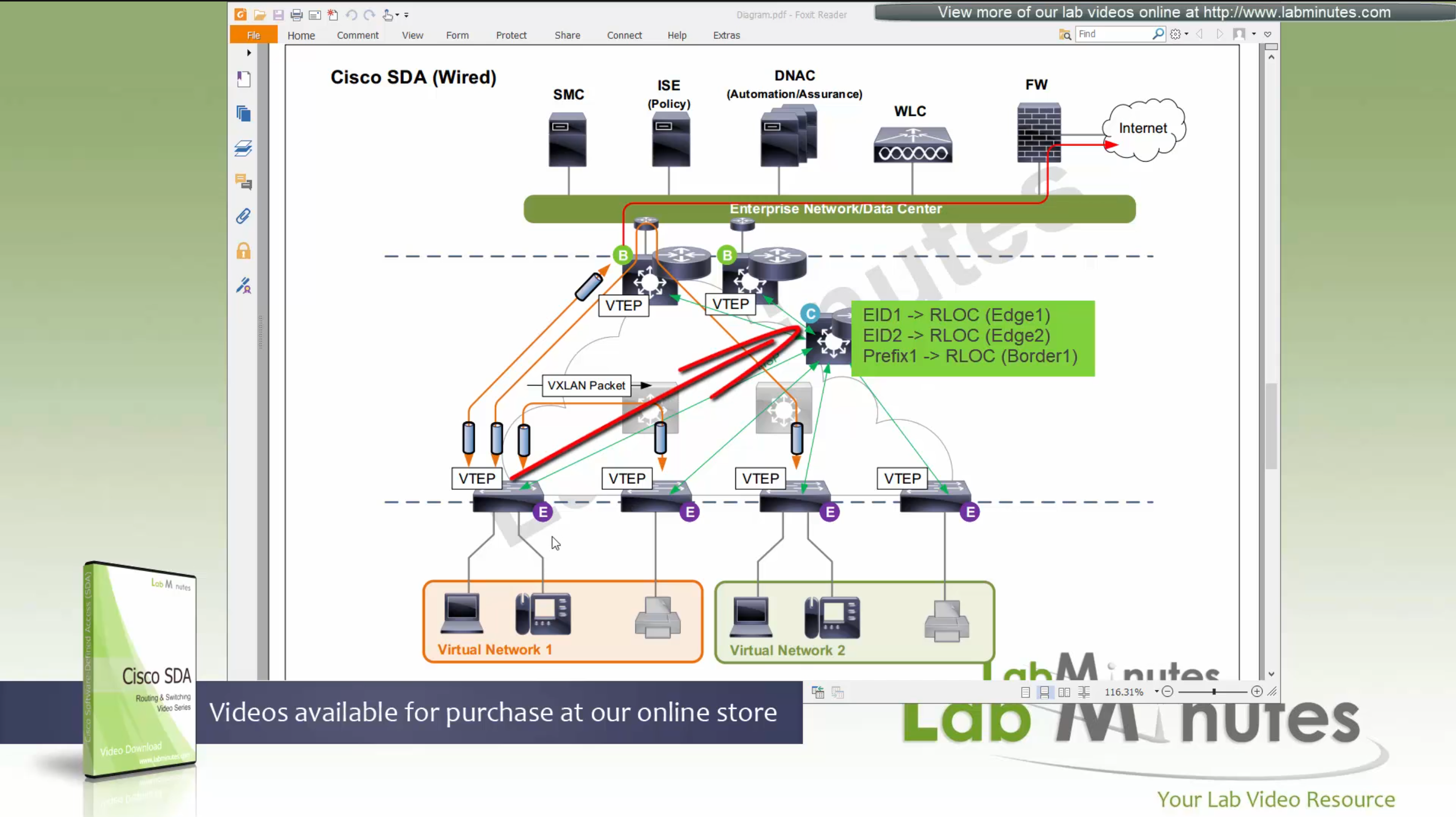
Fabric edge nodes tell the control plane about new endpoint
by snooping the ARP response and DHCP offer packets (device tracking on edge),
information told to control pane includes “MAC addresses”, “IP addresses”, “port connected to”, “Liveliness” (to see if host is there or not) and “VNI host belongs to” (VNI is equivalent of the VLAN in VXLAN world).
Edge node sends a “MAP register” message to control node
Control node creates an EID (Endpoint identifier) to RLOC (Routing locator) entry is created in database
VTEP and RLOC refers to same thing, the loopback IP address on the switch

Border node does the same thing the edge nodes do with control node
but instead of registering Endpoint IDs it has prefixes to register
prefixes it learns from Fusion for external networks (outside of fabric) as prefixes to Control node.

Control plane node not only maintains the EID but also the prefixes
border node needs to be redundant

Caching: border or edge node then caches in a local cache that RLOC entry for future use
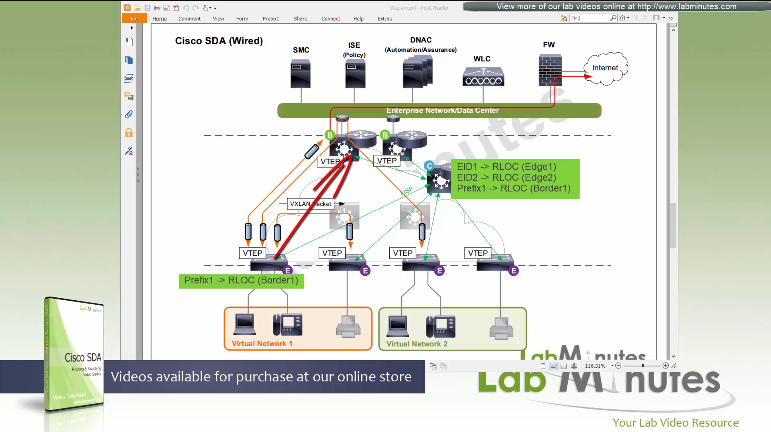
because edge and border receives or caches the RLOC entries on need to basis
it keeps their routing table or FIB small and this translates to scalability,
Remember that edges only use LISP and not routing table
Edge nodes have Anycast gateway which makes SVI available on all the edge and border nodes
These SVIs also have same MAC addresses so when client roams from one node to another, it is seamless
These SVI anycast gateways exist on both Border nodes and also on edge nodes
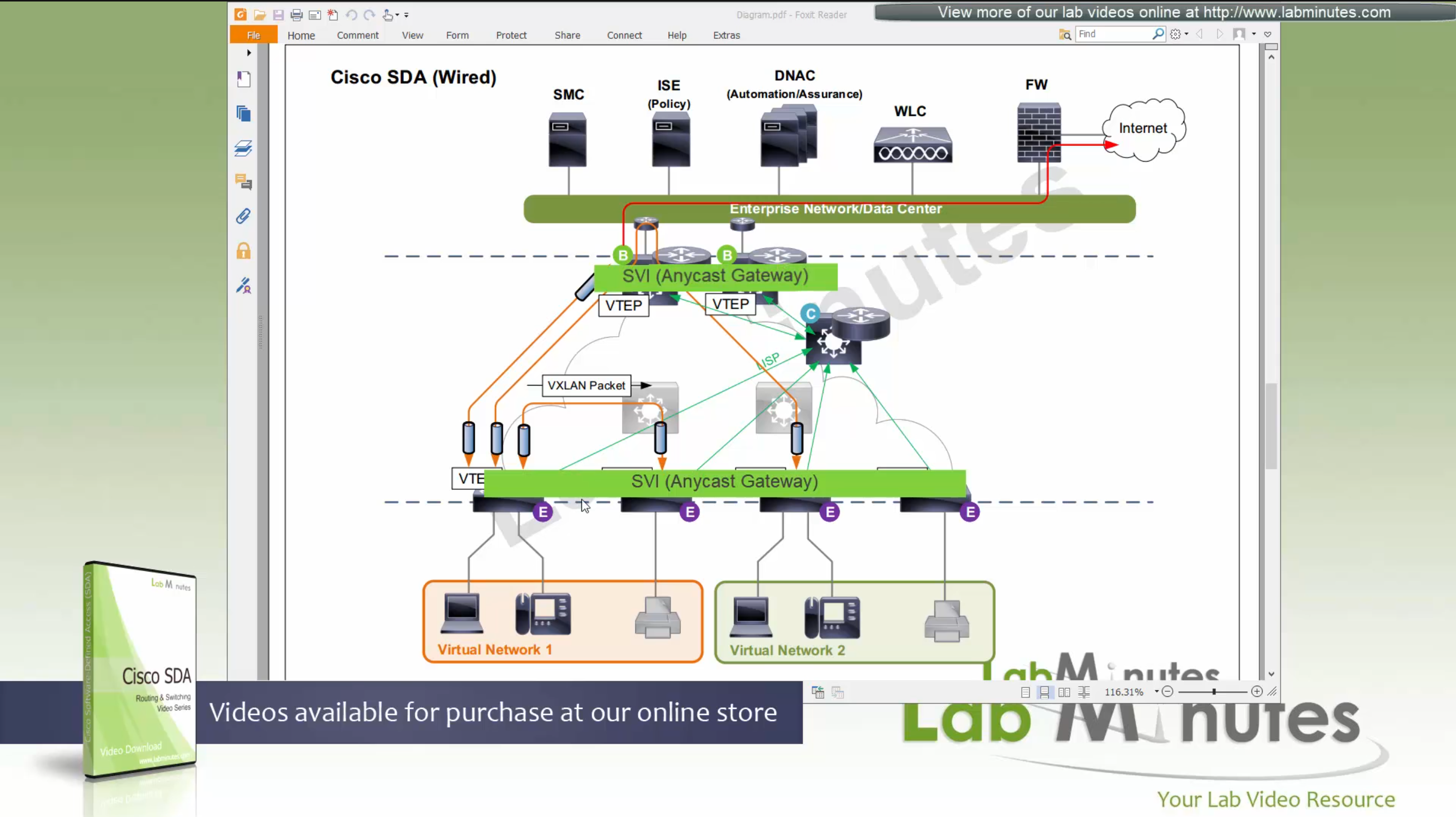
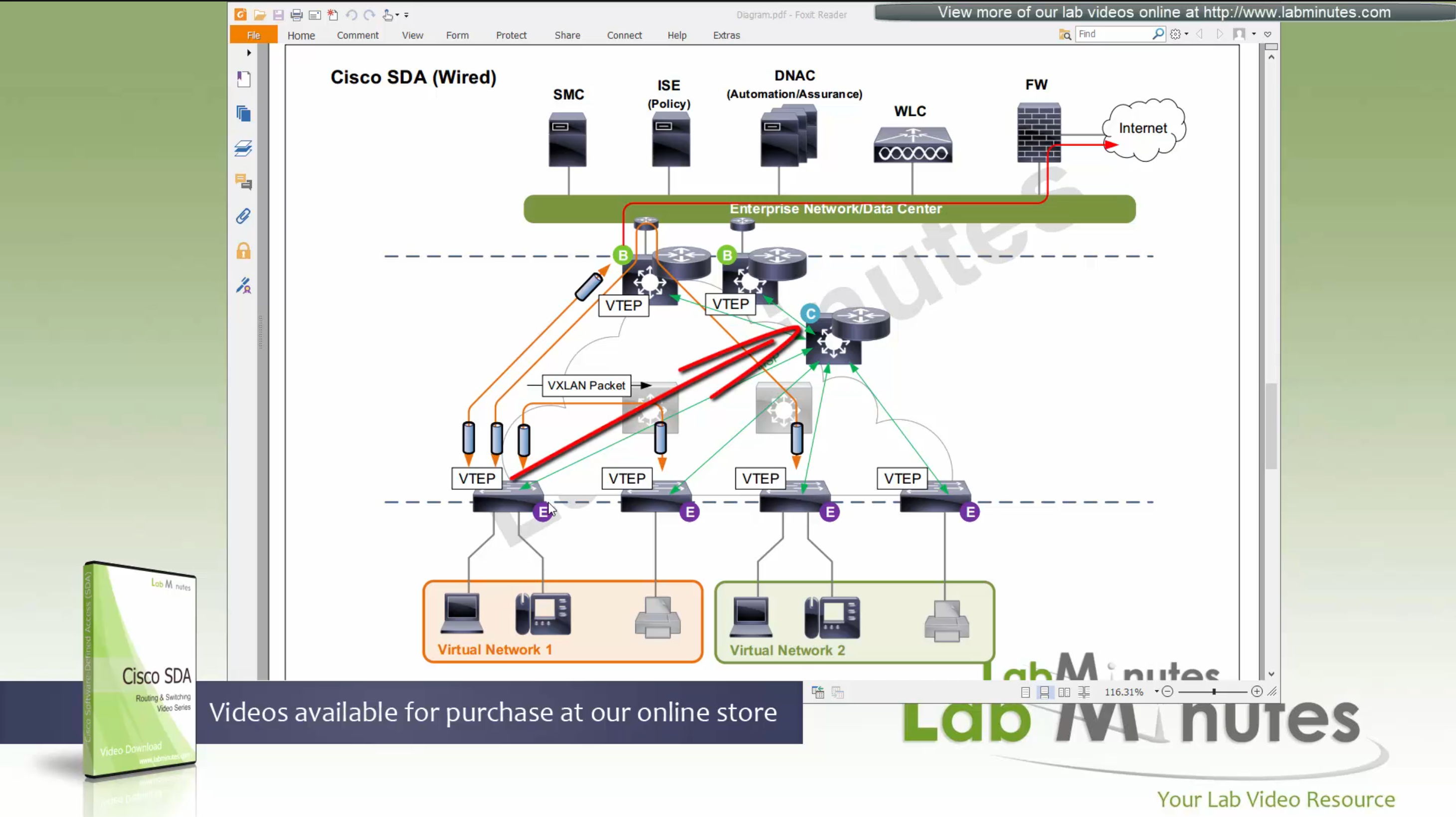
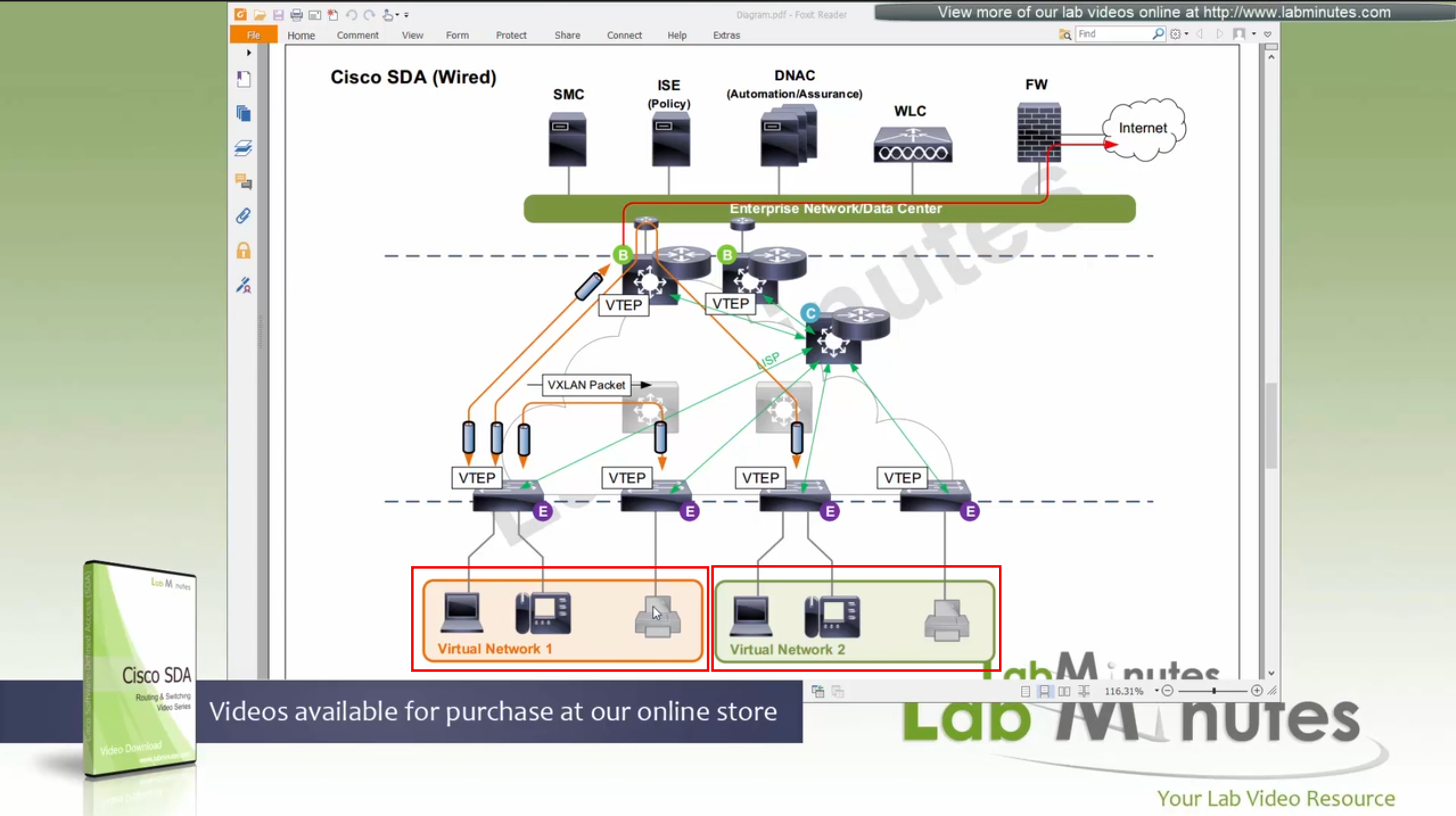
Here we have two different virtual networks or VRFs
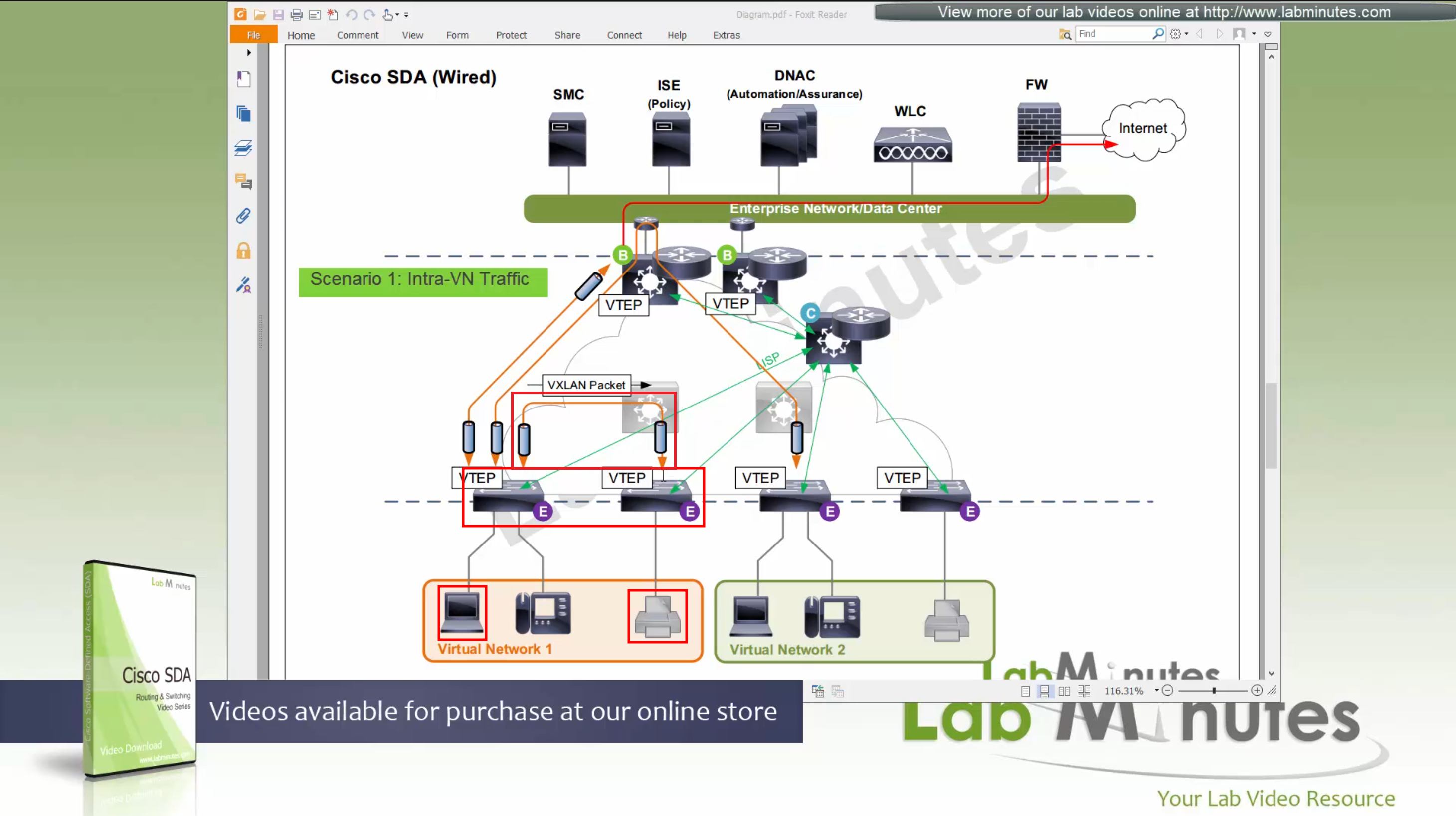
Scenario 1: Packet stays on same switch
In this scenario packet does not leave the switch and is switched from one port to another and that makes it fastest, if you have low latency requirement where even couple of milliseconds of latency such as 2 ms or latency of VXLAN packetization and encapsulation is not tolerable then place the hosts on same switch
Scenario 2: Packet stays within the Fabric, IntraVN (same VN) traffic
When PC needs to communicate to the printer,
it speaks to control node (because printer is on another edge node)
obtains RLOC for that edge node where printer is attached,
it will create a vxlan packet with correct L2 VNI tag, and correct outer L3 RLOC destination IP address
and insert original IP packet into it as a payload
send it out to the underlay to deliver.
Underlay will deliver
As seen in diagram, this VXLAN flow will not touch border node
As these VXLAN packets reach Intermediate Nodes,
because loopbacks being advertised in ISIS (shortest paths for loopbacks) VXLAN packets will be switched from “edge node to Intermediate node to edge node” Triangle: Edge <–> Intermediate <–> Edge
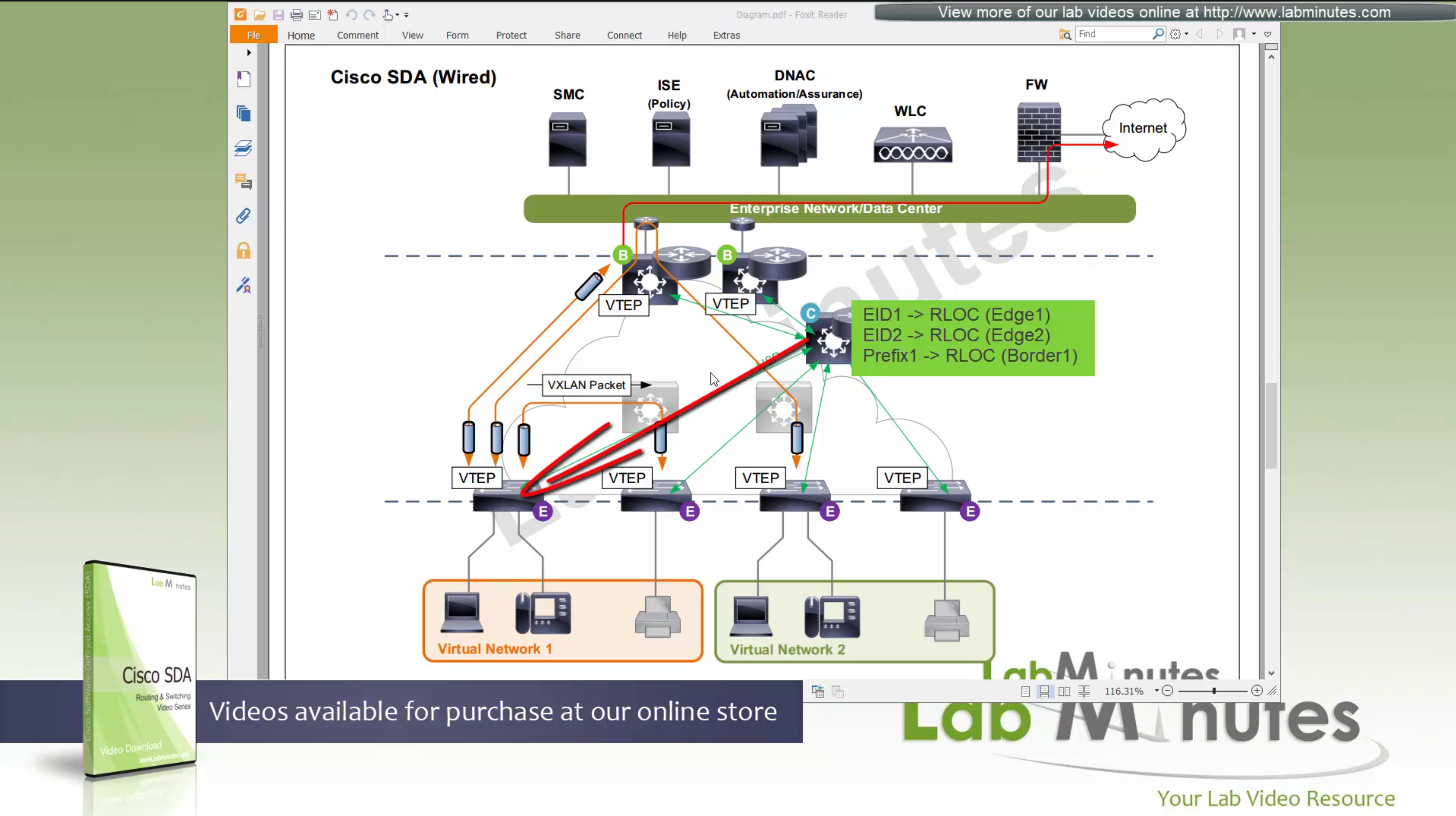
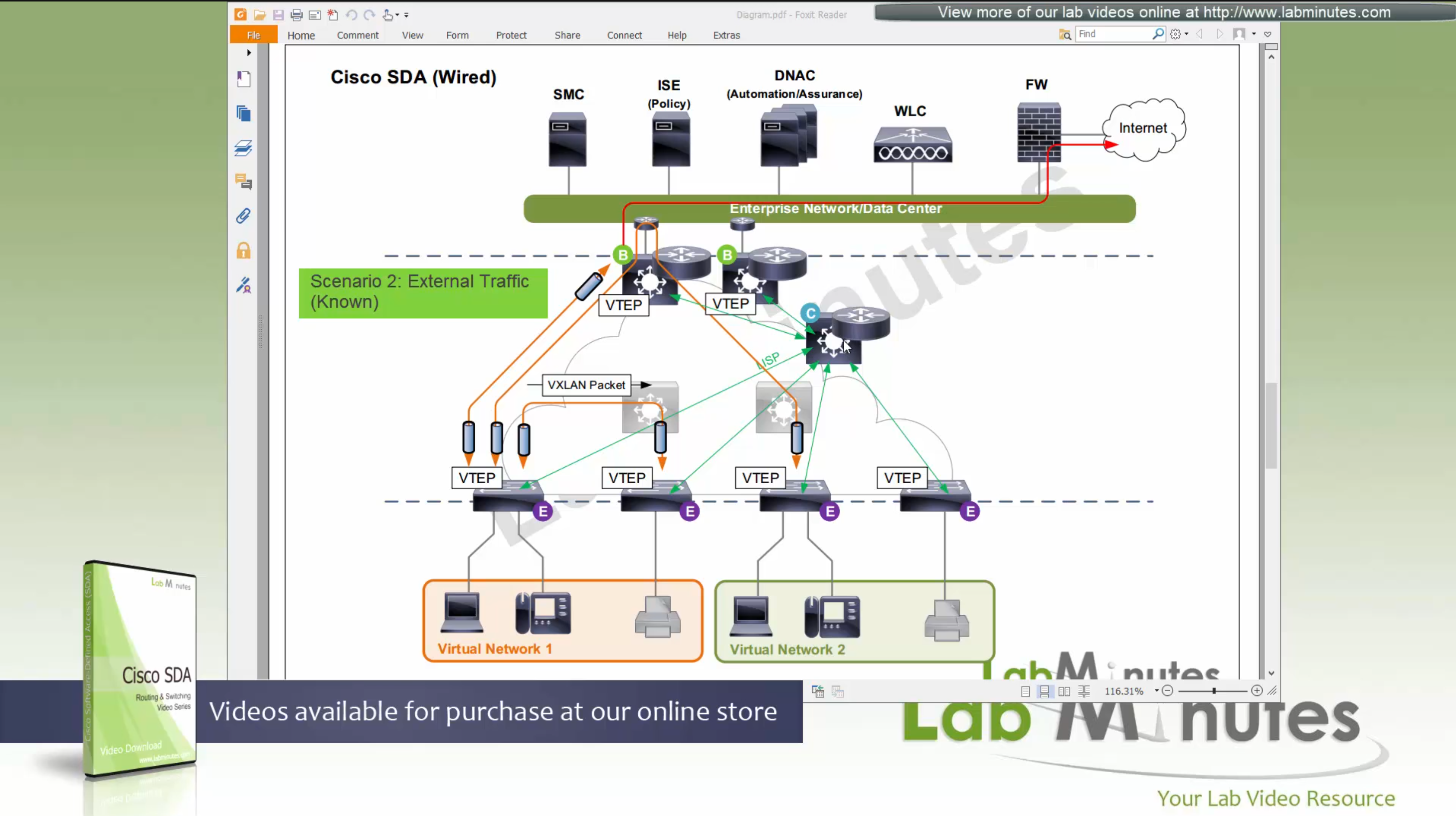
Scenario 3: Packet destined for “Known” external network outside the fabric.
Edge node inquires the control plane for destination
Control plane returns the RLOC of the border node that registered the prefix
then edge sends the packet to border node,
it will create a vxlan packet with L2 VNI tag, outer IP header will have RLOC destination IP address
and insert original IP packet into it
send it out to the underlay to deliver.
Underlay will deliver vxlan packets to the border node
border node will “decapsulate and deliver it out to the external network”
Packets will flow from edge node to intermediate node to border node and then fusion node to get to external networks
Edge <–> Intermediate <–> Border <–> Fusion <–> External destinations
Scenario 4: Packet destined for “Unknown” external network outside the fabric.
Edge node inquires the control plane for destination
Control plane returns the RLOC of the Default Border Node
then edge sends the packet to default border node
it will create a vxlan packet with L2 VNI tag, outer IP header will have RLOC destination IP address
and insert original IP packet into it
send it out to the underlay to deliver.
Underlay will deliver vxlan packets to the border node
border node will “decapsulate and deliver it out to the external network”
Packets will flow from edge node to intermediate node to border node and then fusion node to get to external networks
Edge <–> Intermediate <–> Border <–> Fusion <–> External destinations

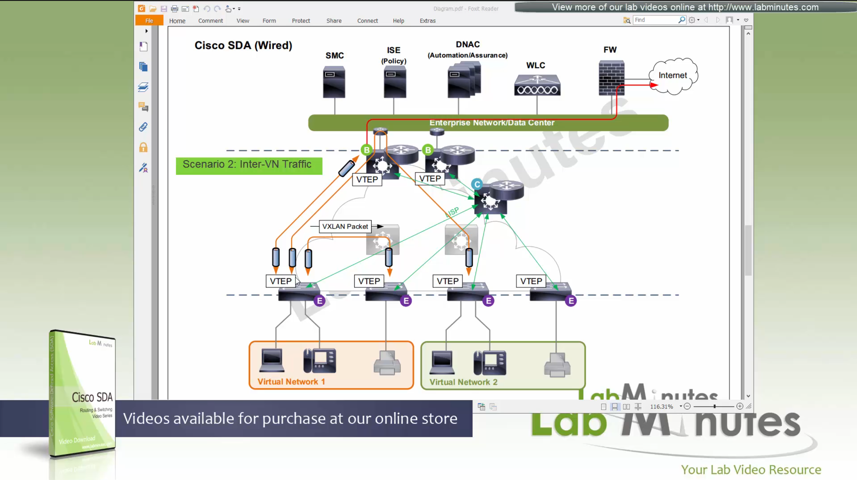
Scenario 5: Packet destined for another Virtual Network, InterVN (to another VN) traffic
This scenario applies when host in Virtual Network 1 needs to communicate with host inside Virtual Network 2 below, queries will still happen as in previous scenarios with control plane
Now this gets a bit trickier in these notes because this is an old video for an old release when SDA did not allow route leaking inside the Fabric, so that meant that packets will be routed all the way out of the fabric to the fusion router and fusion router will route it towards other virtual network making packet route back into the fabric, because border node cannot be routing “between” different Virtual Networks, and for this to work fusion router also needs one “transit” sub-interface per Virtual Network or VRF
Obviously this is not optimal as InterVN traffic will face more delays than IntraVN traffic and fusion router is also single point of failure
AP maintains the CAPWAP to WLC but it is only for CAPWAP control connection, data is locally switched to the edge node over the mini VXLAN tunnel.
This VXLAN tunnel between Fabric mode AP and edge is only between AP and edge that are directly connected, it does not extend from AP to remote edge switches
Client will associate and authenticate with the SSID, obtain IP address

“WLC will do MAP register with control plane node” and tell control plane node about the client as EID and which AP it belongs to (just like it does same for switchport)
When wired client needs to communicate with the wireless client

edge node of the wired client will obtains the RLOC from control plane and make tunnel to the edge switch where wireless client’s AP is connected
once edge node de-encapsulates the VXLAN tunnel, it checks and sees that mac address of the wireless client is behind that mini VXLAN tunnel, so it will re-encapsulate the traffic and send that to AP and vice versa in reverse
The reason for AP mini VXLAN is so that AP can inform the switch of the correct VNI the client belongs to
This is the mechanism that keeps consistency from the wired world for VNI
Making wireless clients seem like just like wired clients policy and monitoring wise
SGT are tagged on the VXLAN packets themselves
When user roams from one AP on one edge switch to another AP on another edge switch
WLC will be informed about the roam by the roamed to and from APs
WLC will inform the control plane also and control plane will update the entry’s RLOC to be the new edge switch whose new AP client has roamed to
While in Fabric, WLC and APs can still be connected to the Fabric but operate in “Legacy mode” which is also called “over the top” setup, in which data from AP is sent in CAPWAP (Data tunnel) to WLC and WLC switches the traffic out
There is also a low latency requirement of 20ms between the WLC and AP so keep in mind that APs have to stay somewhat close to the controller in the campus setup
Licensing
DNA Essential gives most of the feature set of the APIC-EM
DNA Advantage gives most of the features in Assurance and NDP + SDA
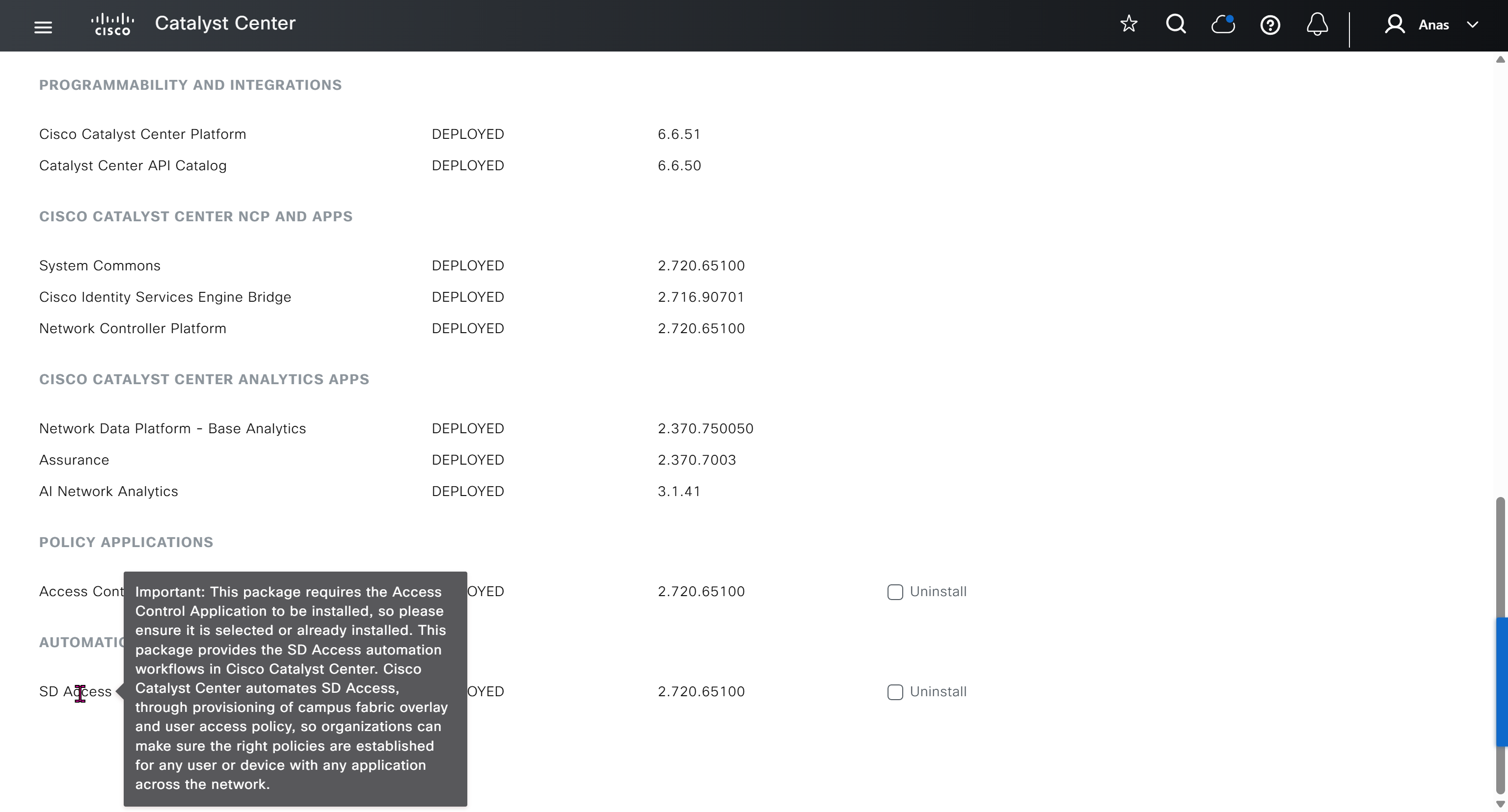
SDA is only available with DNA Advantage license
Cisco offers a license called One Advantage that offers DNA + ISE + Stealthwatch all in one license

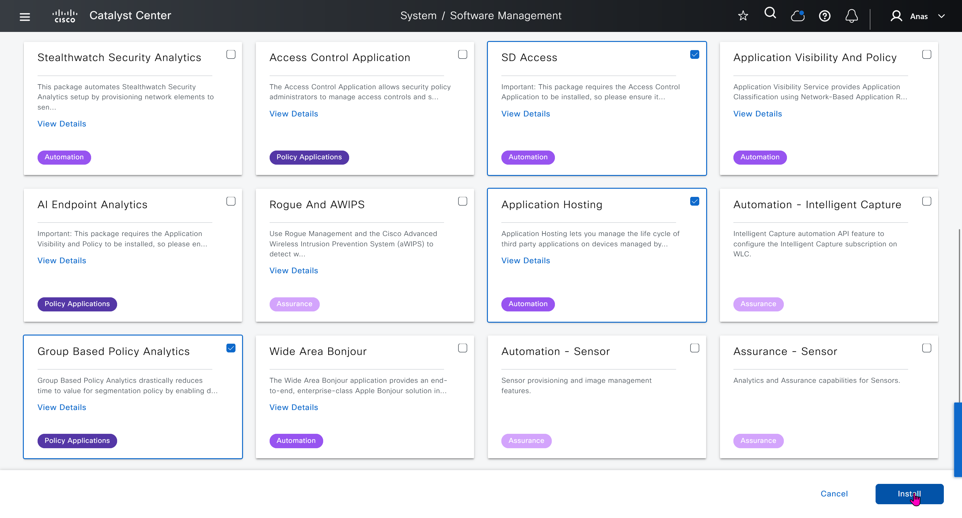
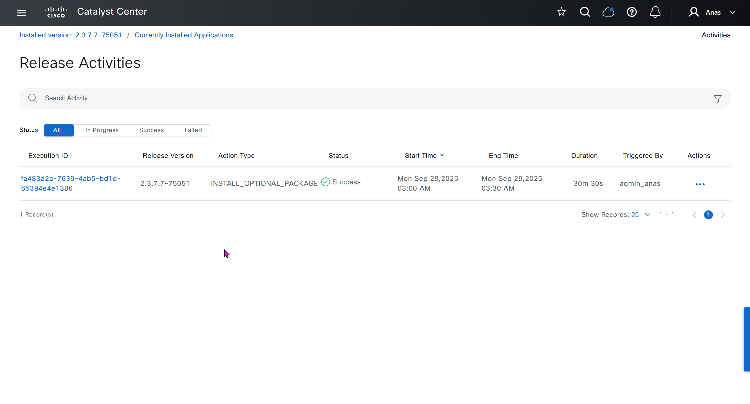
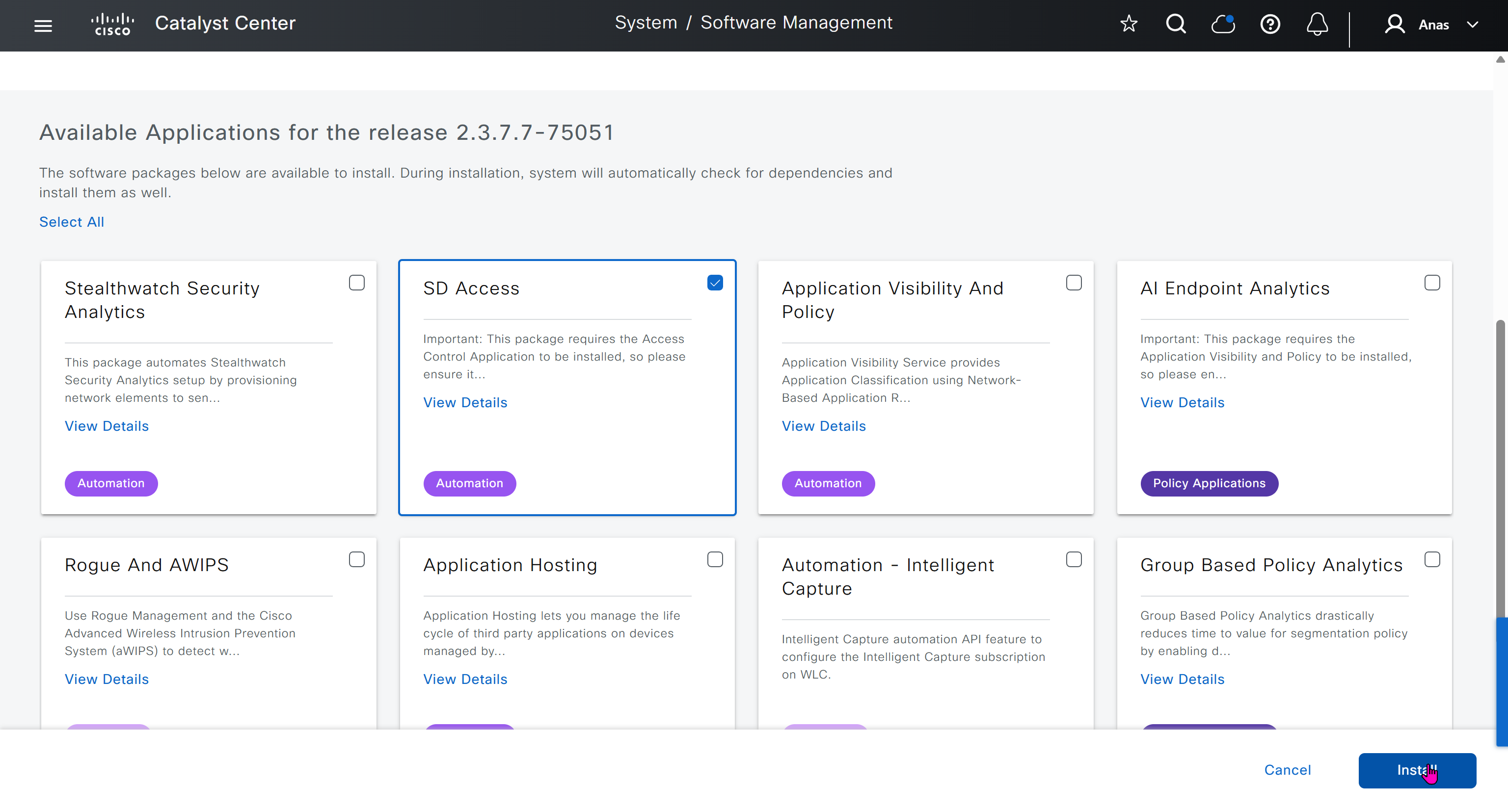
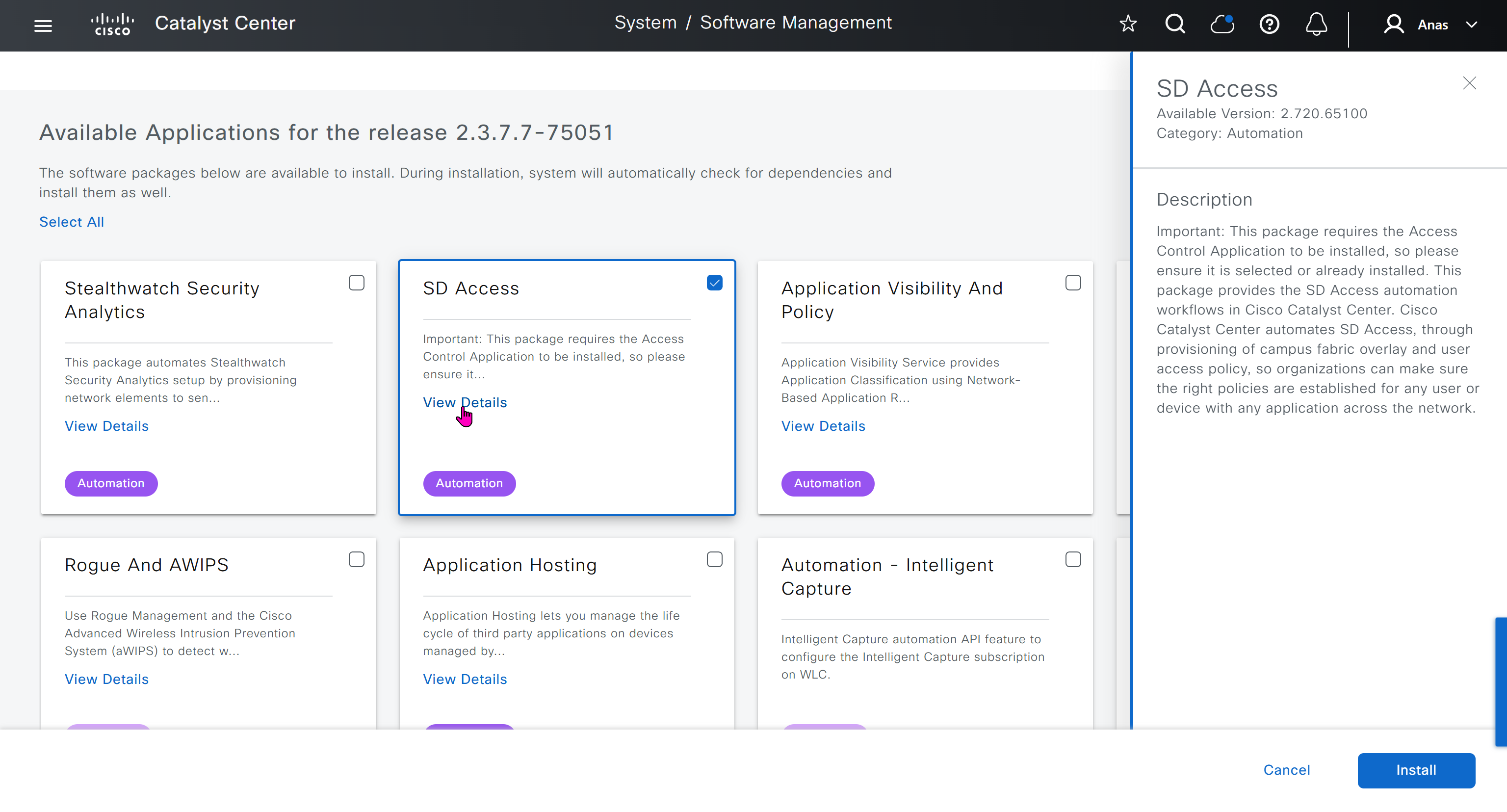
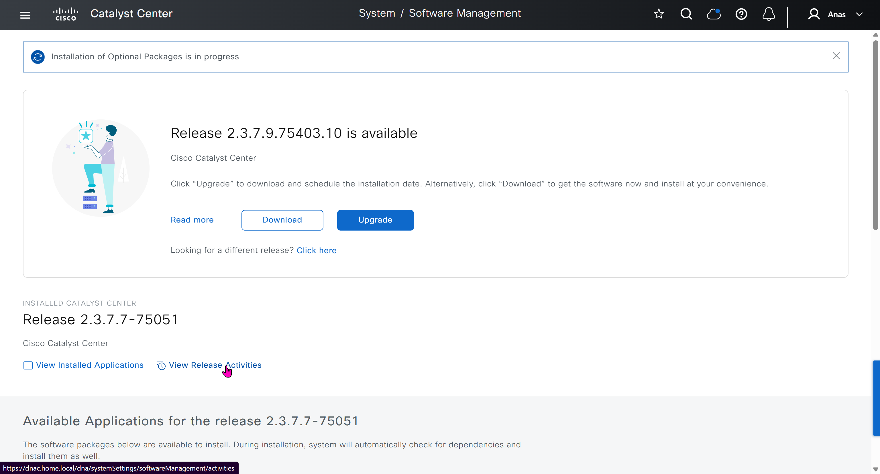
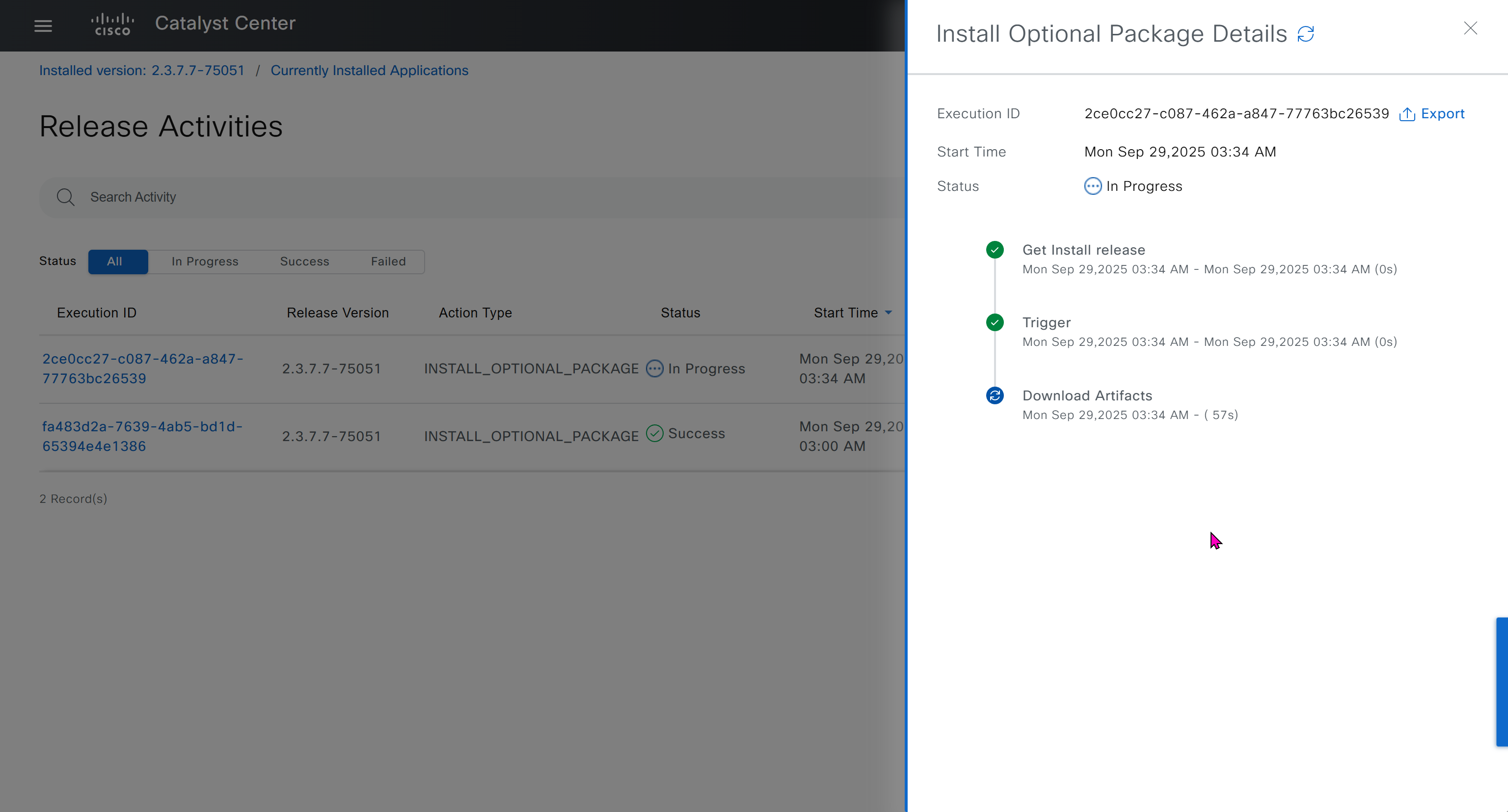
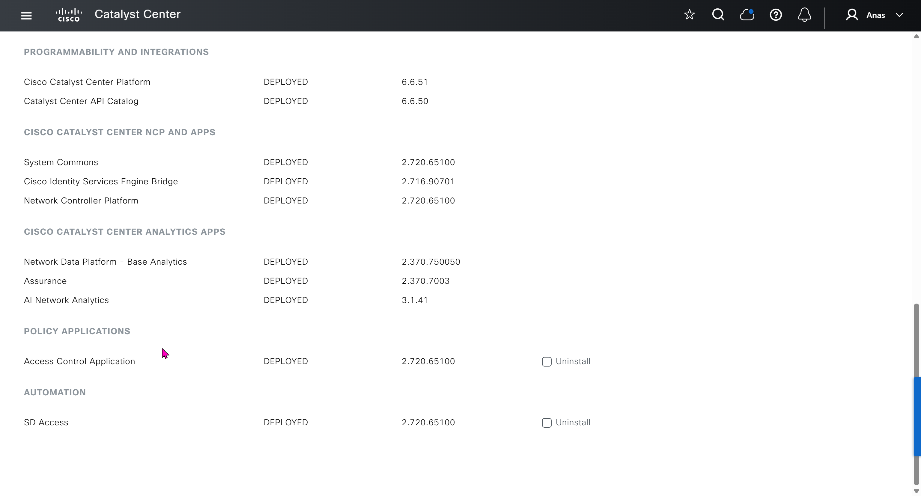
Right after installation of DNAC and first GUI login we need to quickly download the packages or software apps which are GBAC Group Based Acccess Control ( SGT / SXP / ISE ) and also SDA package to enable SDA in DNAC. Cisco does not readily ship the DNAC with ova or iso, SDA and a lot of other modules need to be downloaded using below very specific settings


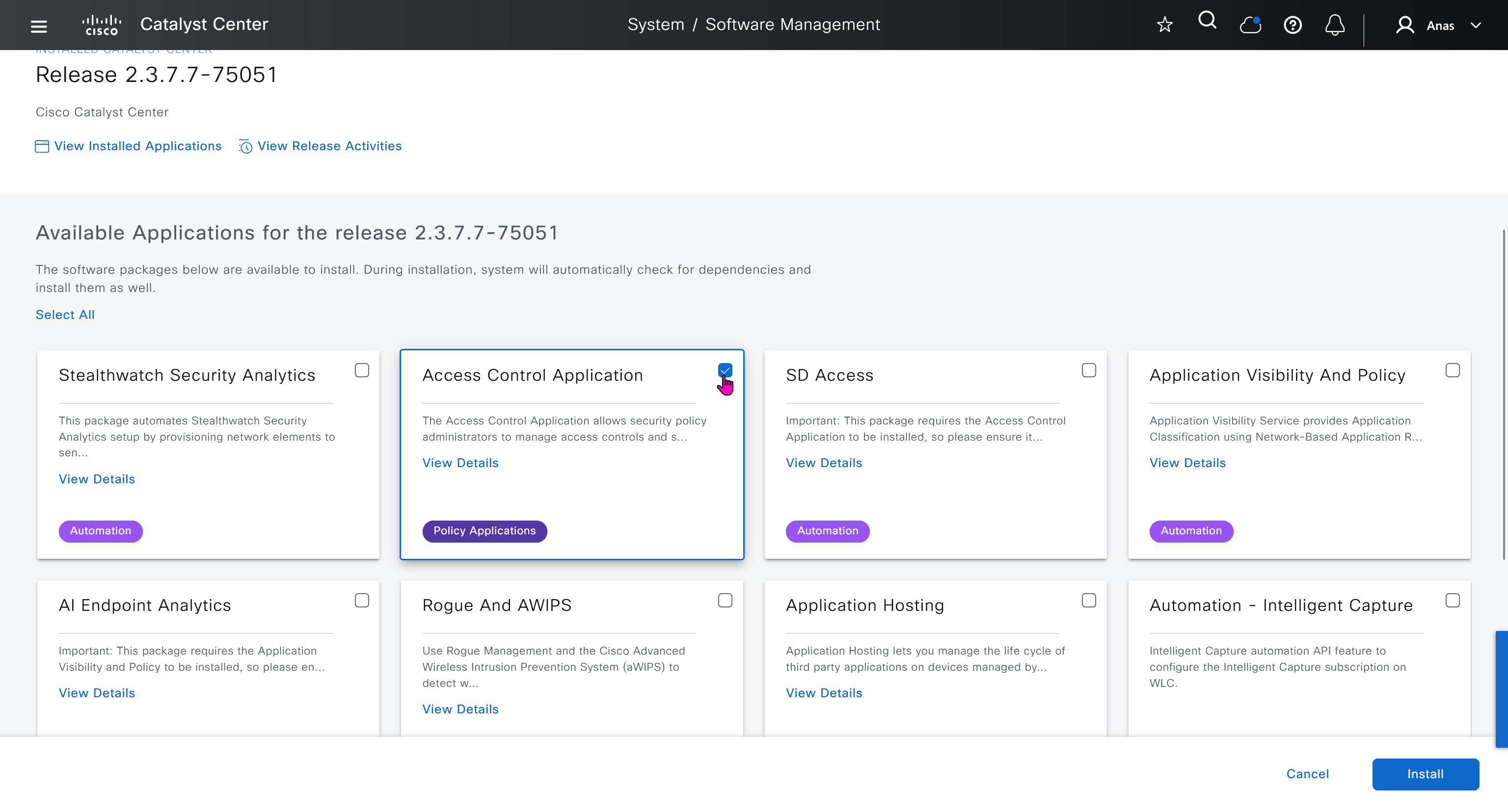
Group Based Access Control is not there and needs to be downloaded

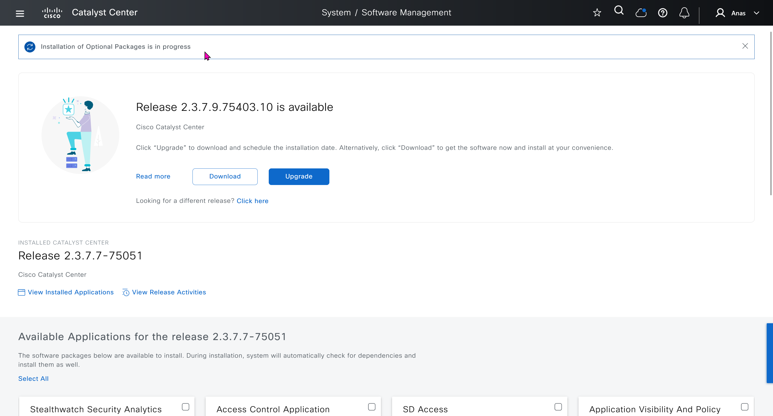

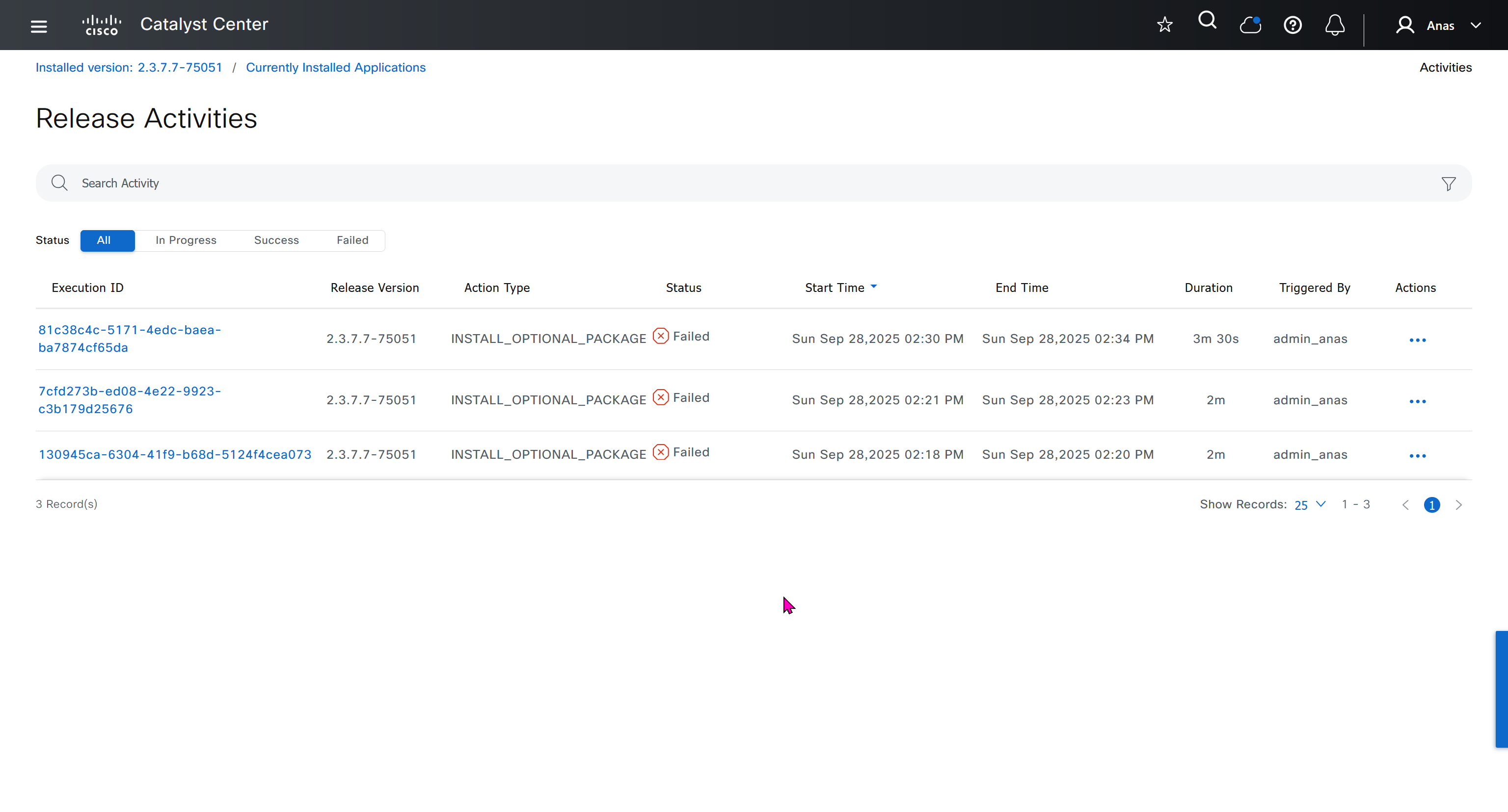
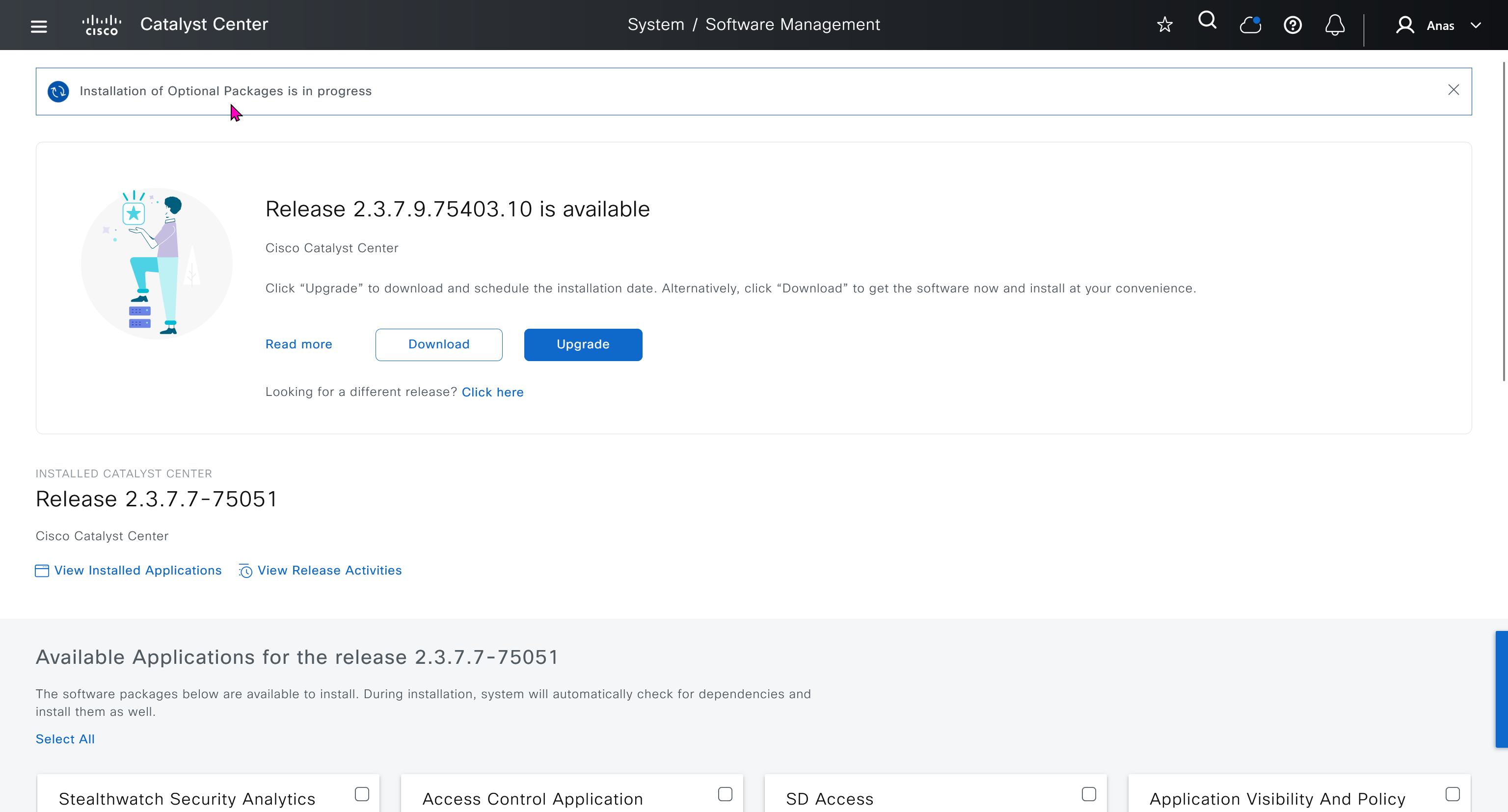
Installation kept failing at download stage

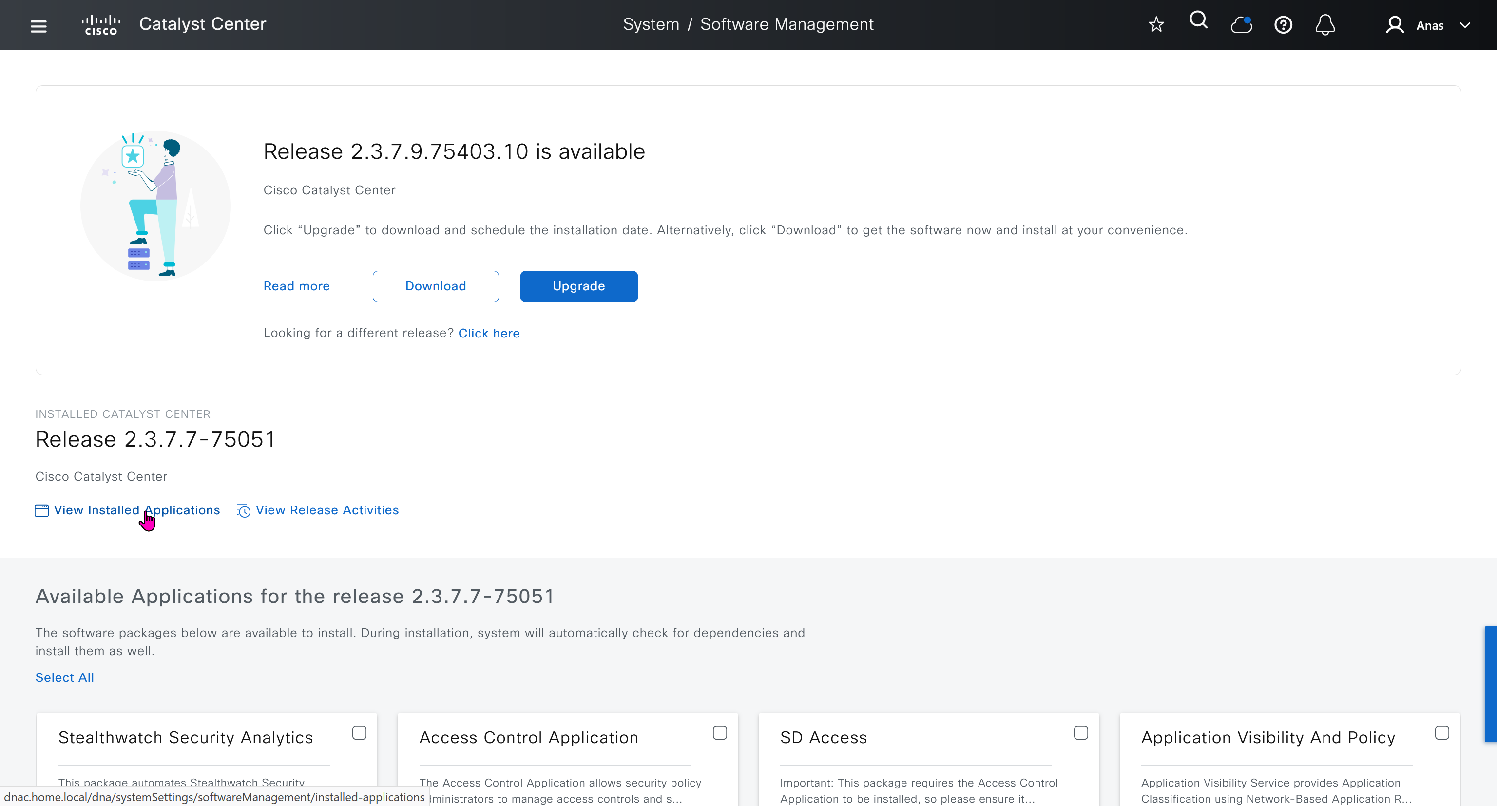
I had to remove the VM as there was something wrong and when new dnac was installed, one thing I did is I added the company’s cco information here but not in the smart licensing, dont add to the smart licensing section instead add at the beginning on first GUI login


Finally it installed well
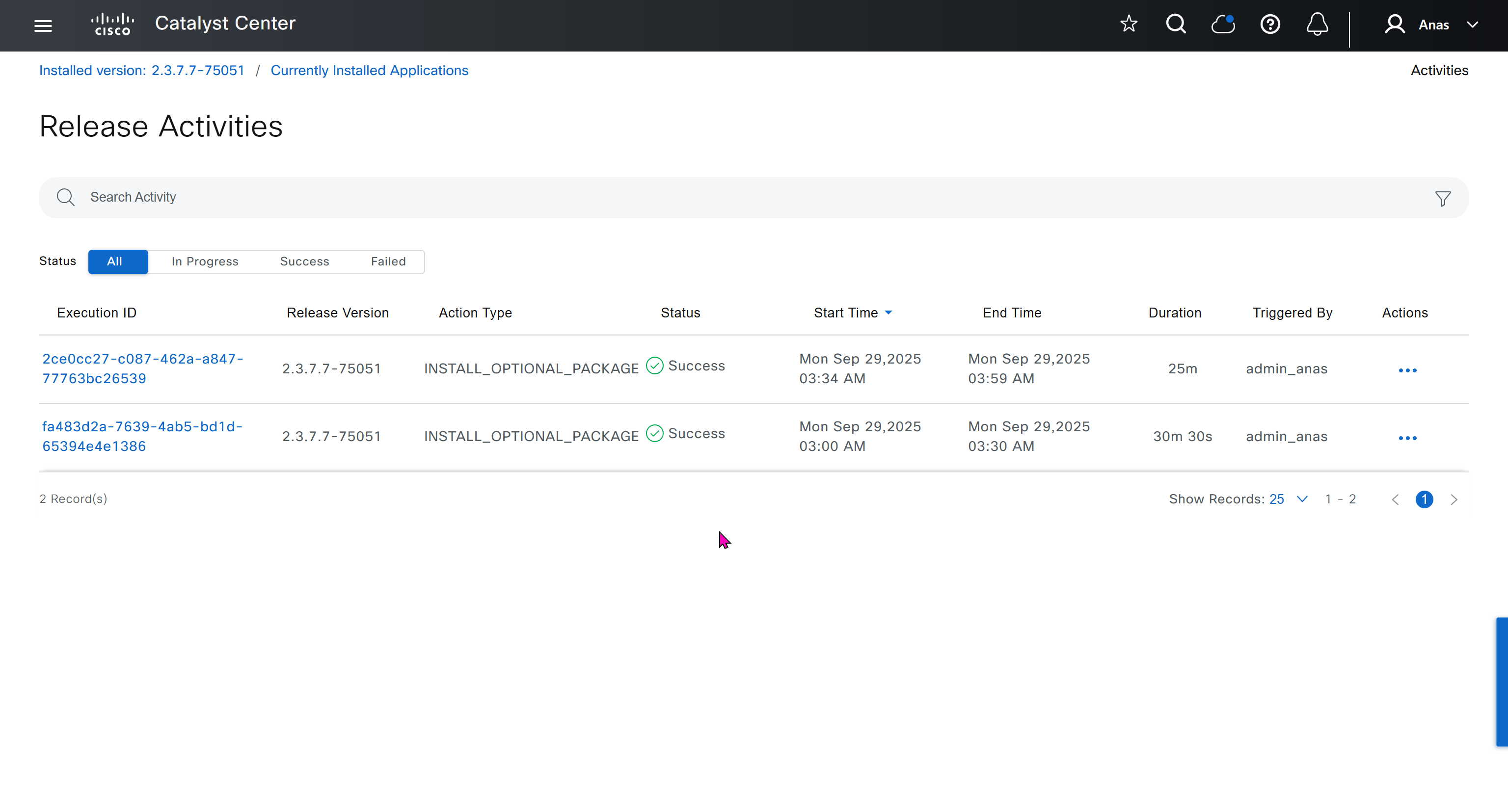
now Group Based Access Control GBAC is showing in menu now

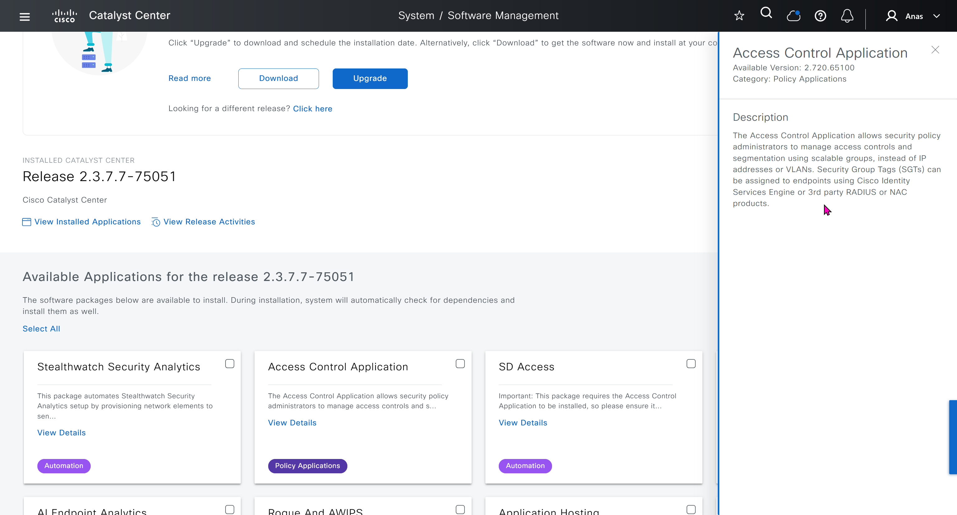
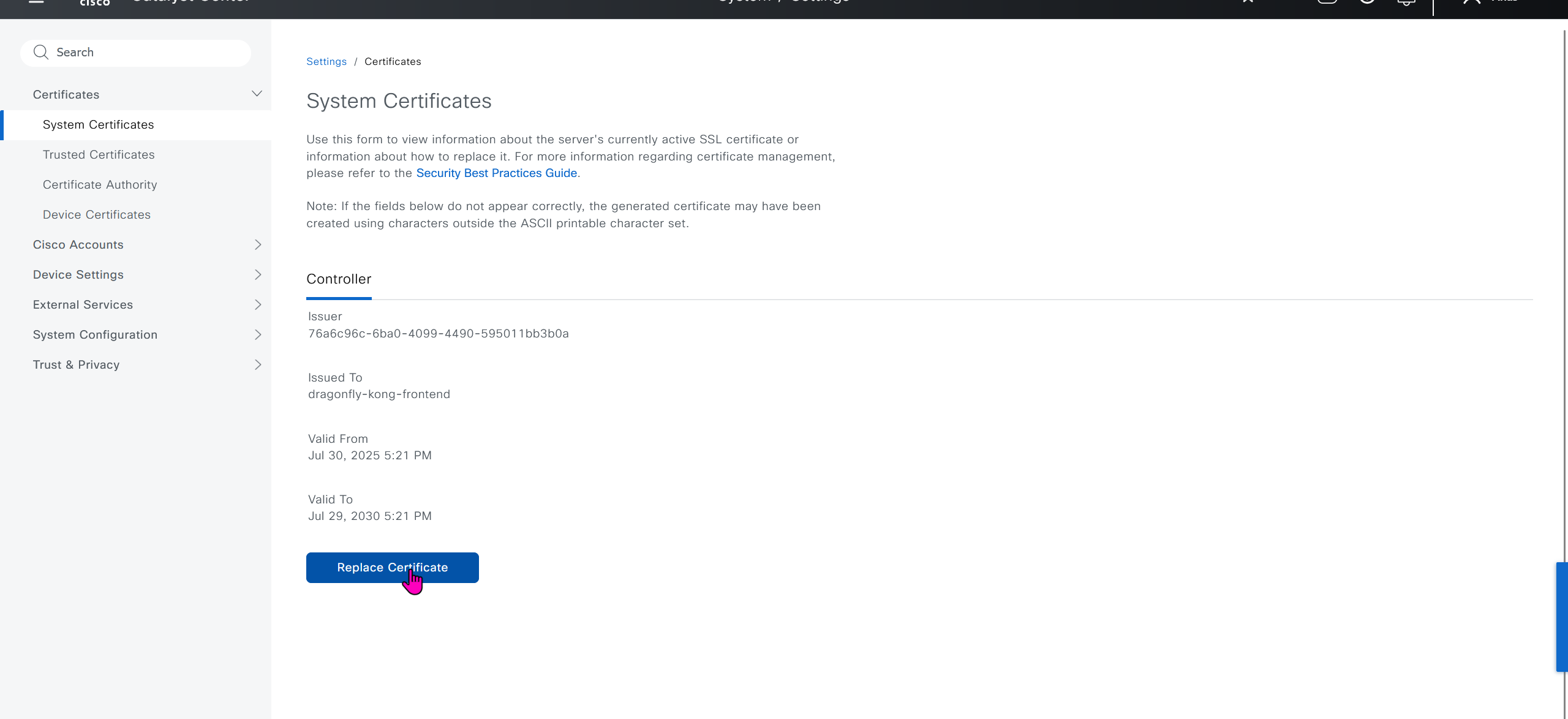
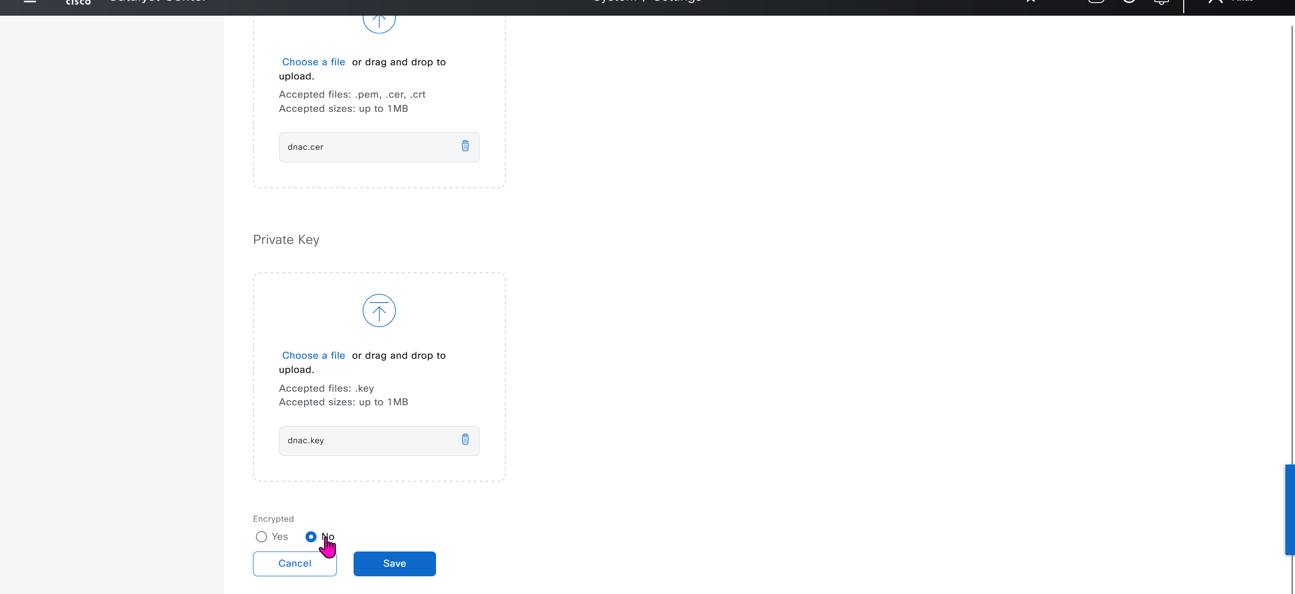
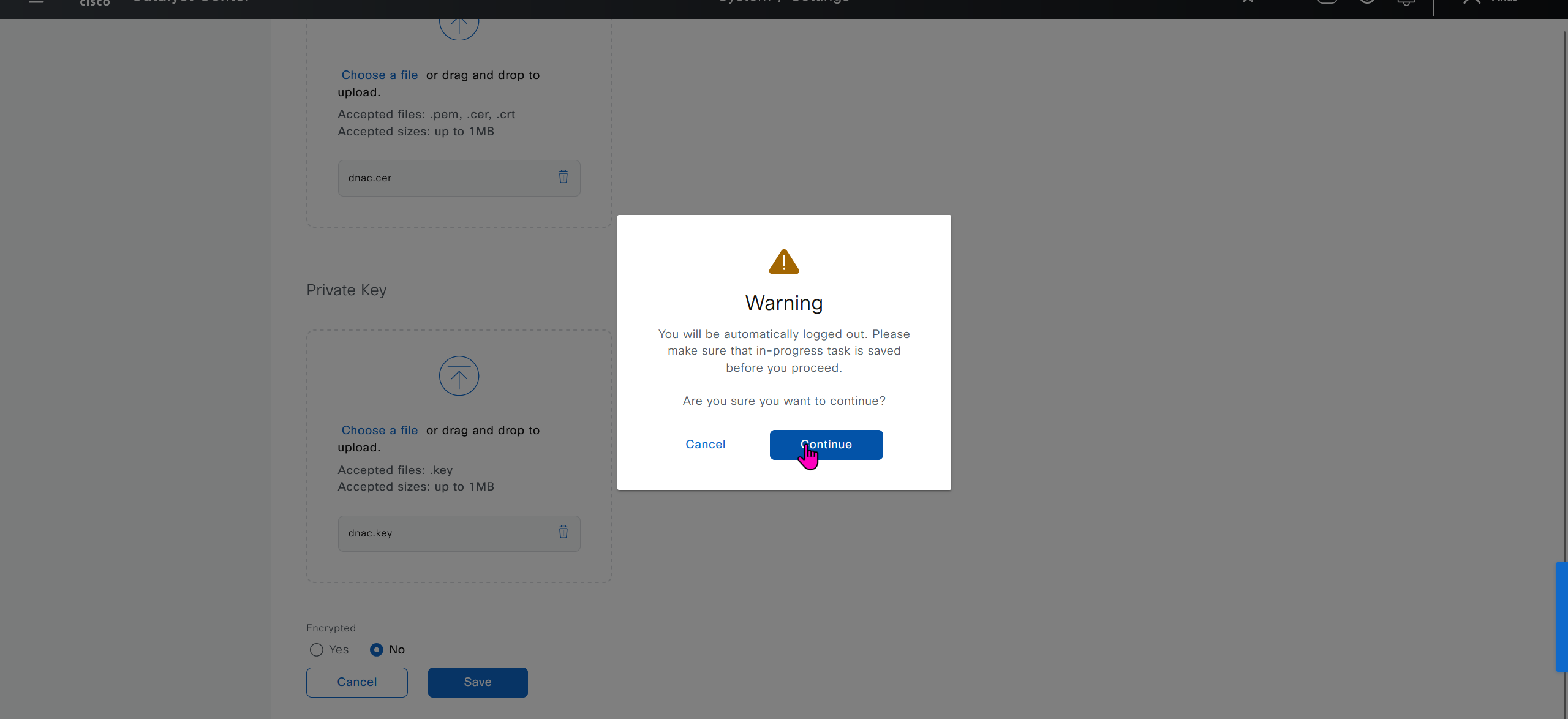
We will take a look at installing certificate as ISE needs to be integrated, and for that we need to take information from default certificate’s information, common name is the name that we provided during the initial installation of DNAC

If we look at subject alternative names we can see a lot of SAN entries, these SAN entries contain IP addresses as well and one of those IP addresses will be of the VIP in case we have multiple DNAC appliances

Enhanced Key Usage: Server Authentication, Client Authentication as this is used for ISE PX Grid integration

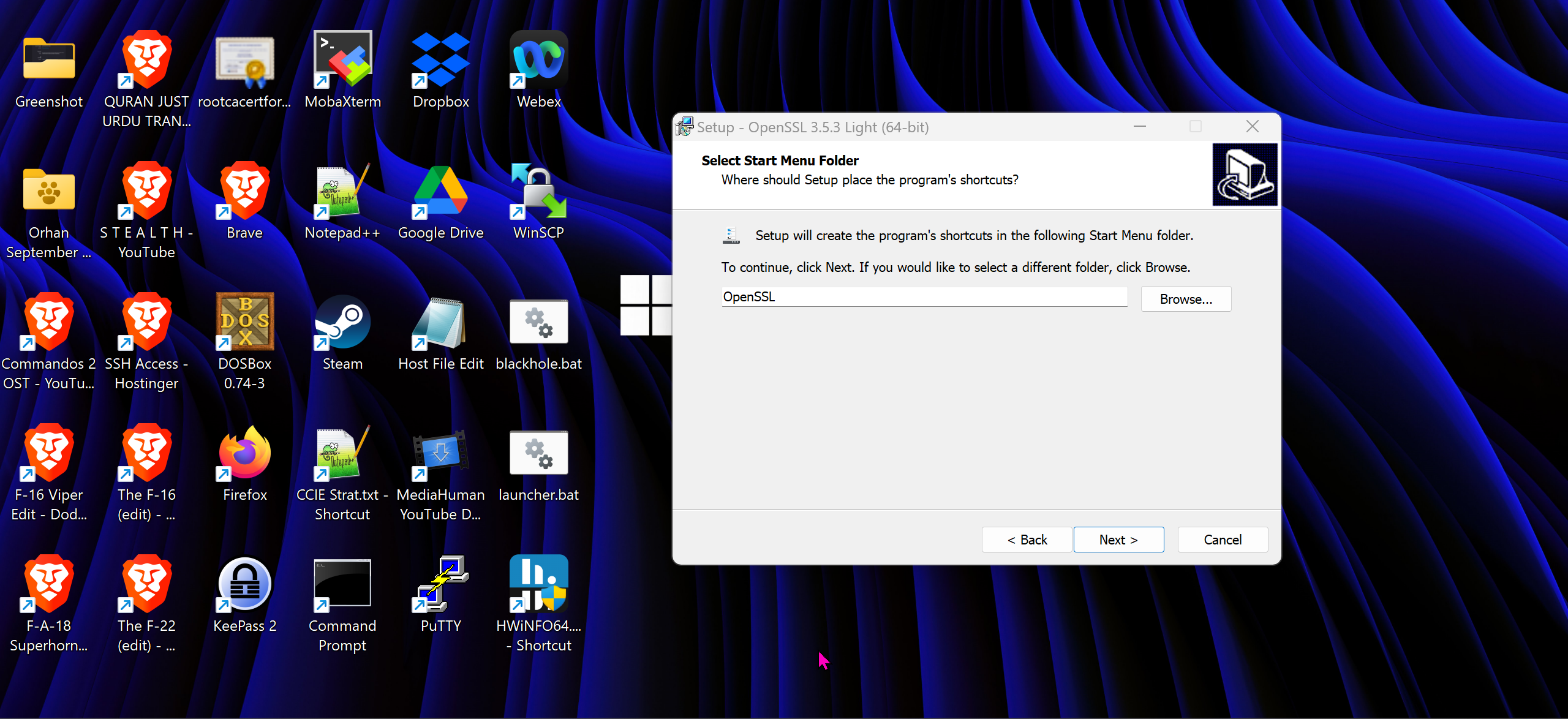
We will have to install the OpenSSL for Windows
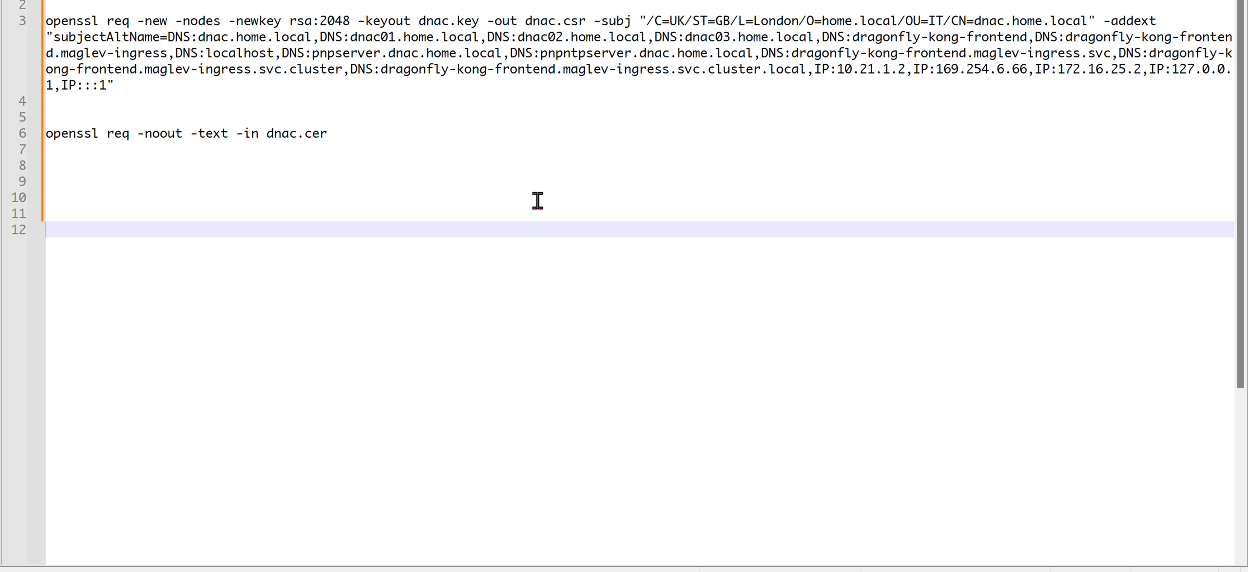
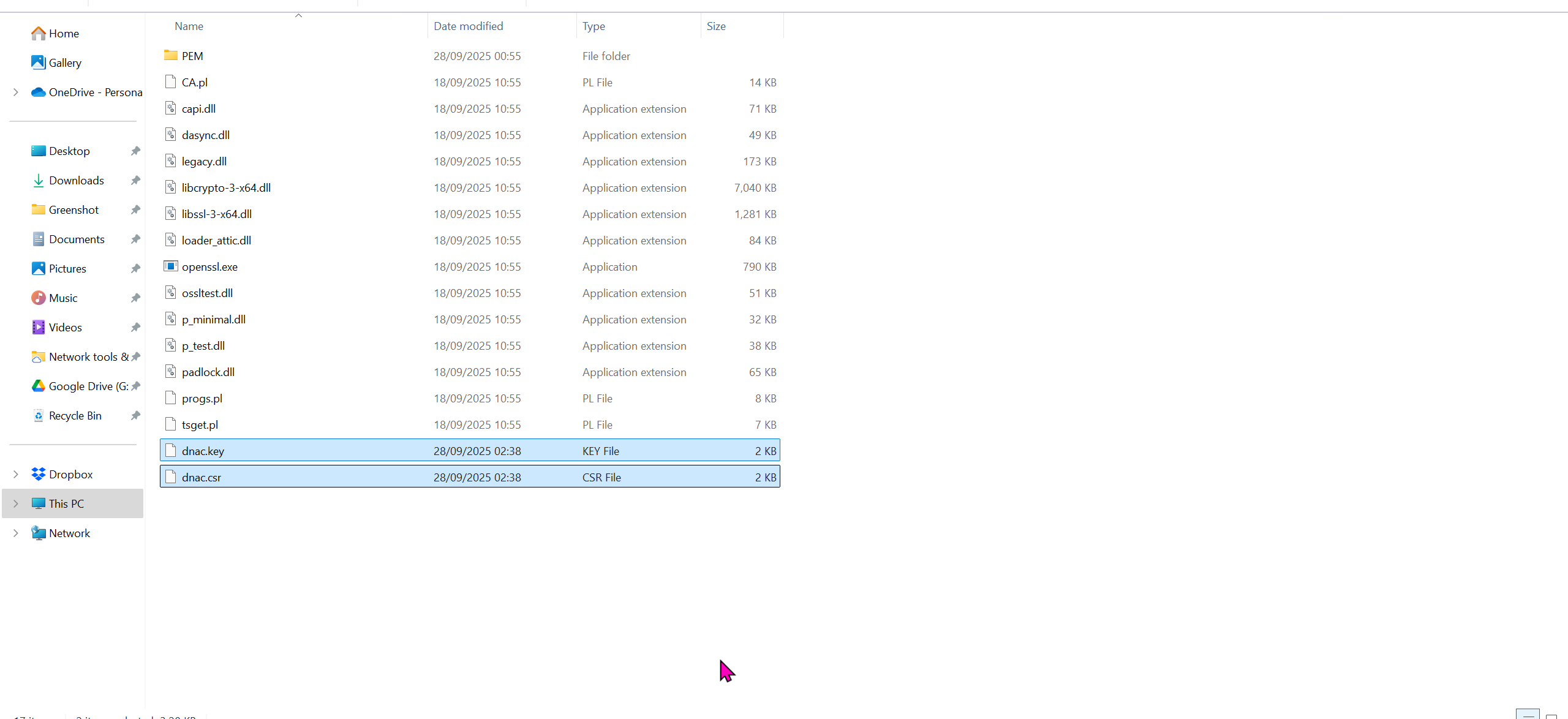
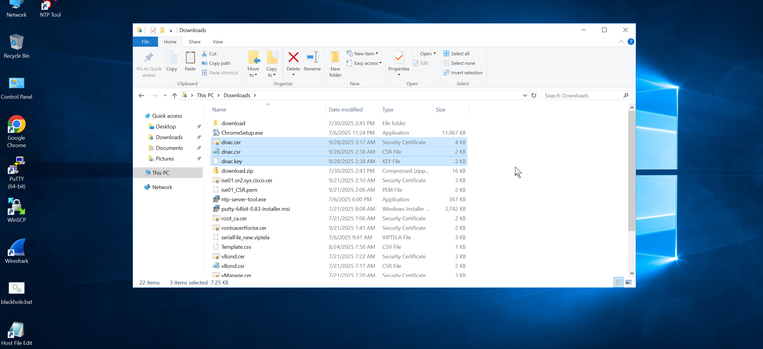
cd C:\Program Files\OpenSSL-Win64\binopenssl req -new -nodes -newkey rsa:2048 -keyout dnac.key -out dnac.csr -subj "/C=UK/ST=GB/L=London/O=home.local/OU=IT/CN=dnac.home.local" -addext "subjectAltName=DNS:dnac.home.local,DNS:dnac01.home.local,DNS:dnac02.home.local,DNS:dnac03.home.local,DNS:dragonfly-kong-frontend,DNS:dragonfly-kong-frontend.maglev-ingress,DNS:localhost,DNS:pnpserver.dnac.home.local,DNS:pnpntpserver.dnac.home.local,DNS:dragonfly-kong-frontend.maglev-ingress.svc,DNS:dragonfly-kong-frontend.maglev-ingress.svc.cluster,DNS:dragonfly-kong-frontend.maglev-ingress.svc.cluster.local,IP:10.21.1.2,IP:169.254.6.66,IP:172.16.25.2,IP:127.0.0.1,IP:::1"openssl req -noout -text -in dnac.cercd C:\Program Files\OpenSSL-Win64\bin
openssl req -new -nodes -newkey rsa:2048 -keyout dnac.key -out dnac.csr -subj "/C=UK/ST=GB/L=London/O=Cisco-DNA/OU=IT/CN=dragonfly-kong-frontend" -addext "subjectAltName=DNS:dnac.home.local, DNS:dragonfly-kong-frontend, DNS:dragonfly-kong-frontend.maglev-ingress, DNS:localhost, DNS:dragonfly-kong-frontend.maglev-ingress.svc, DNS:dragonfly-kong-frontend.maglev-ingress.svc.cluster, DNS:dragonfly-kong-frontend.maglev-ingress.svc.cluster.local, IP:10.21.1.2, IP:127.0.0.1, IP:::1"
openssl req -noout -text -in dnac.cerWe have added those lines
Make sure that Data and OOB IP addresses are added including all Data and OOB IP addresses from clusters too


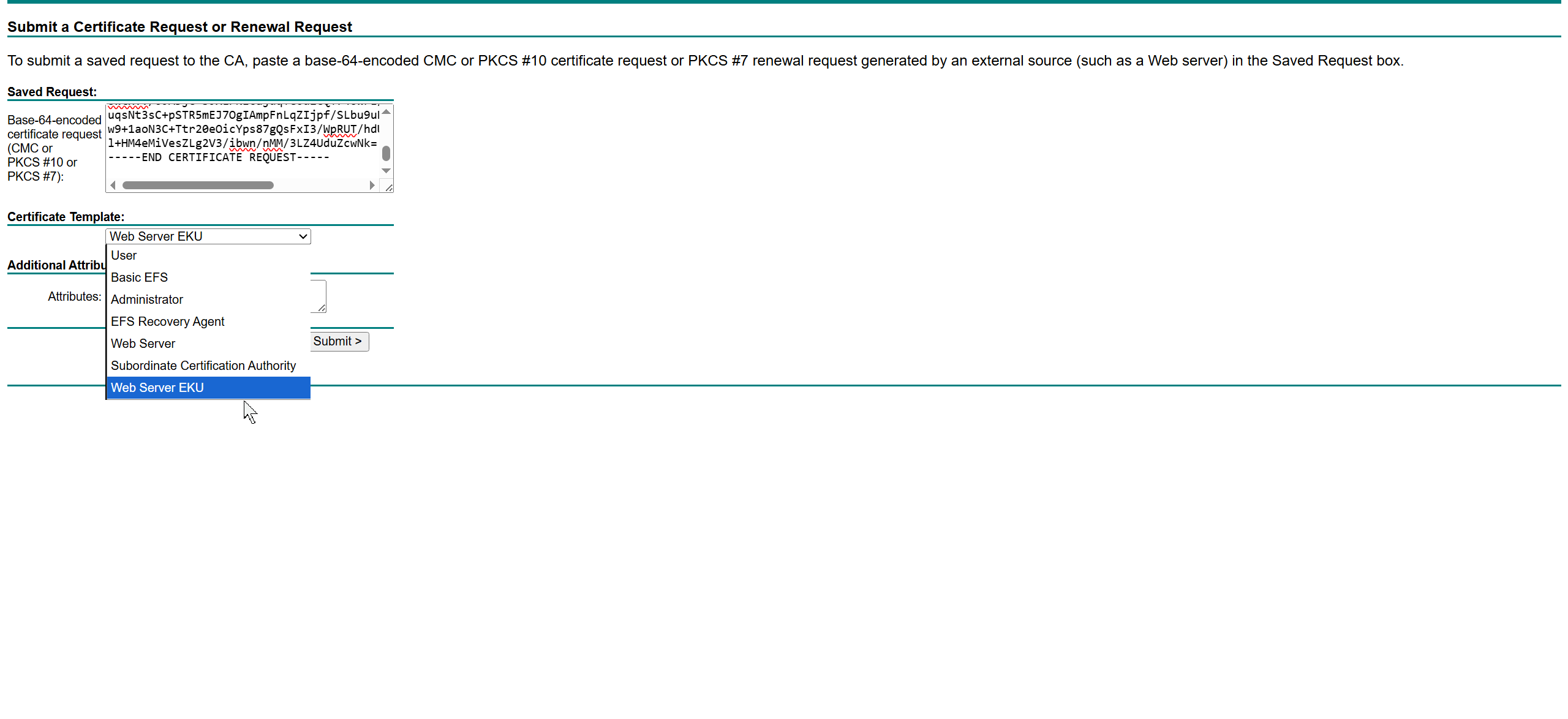
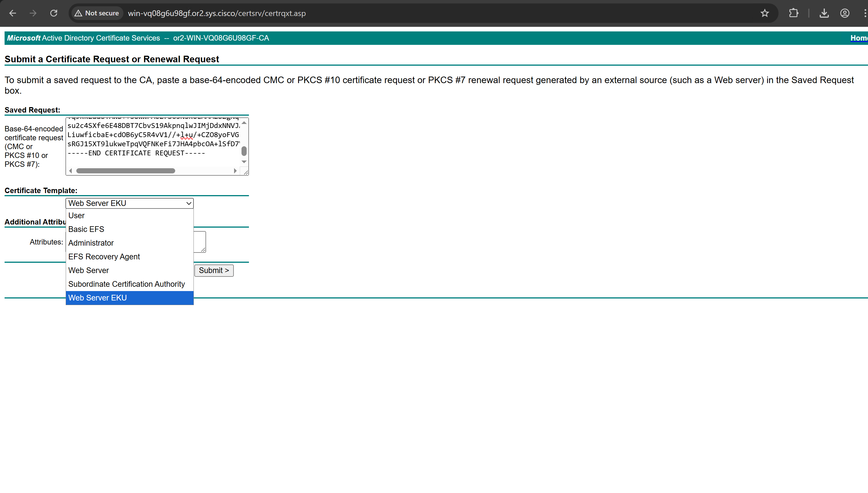
This Web Server EKU as Extended Key Usage has Client Authentication
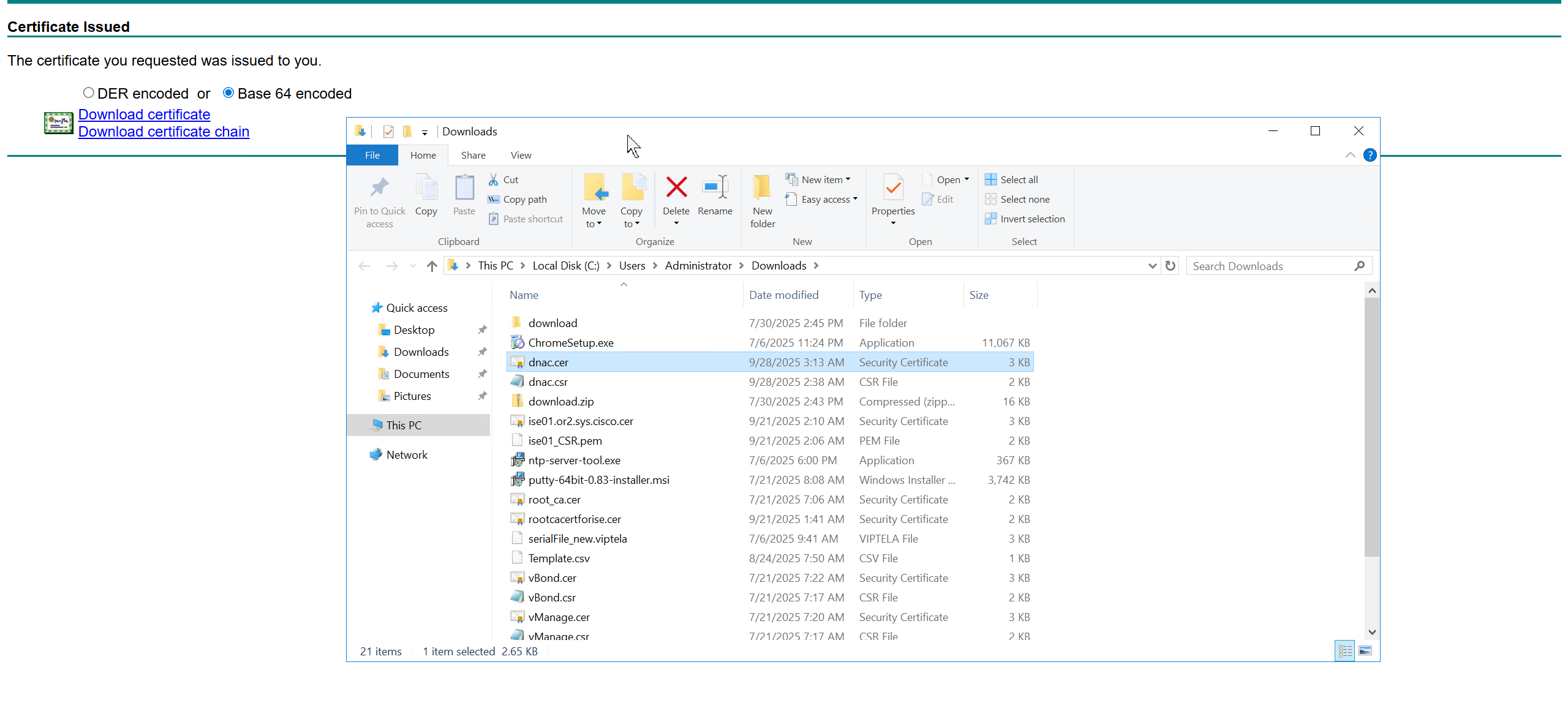
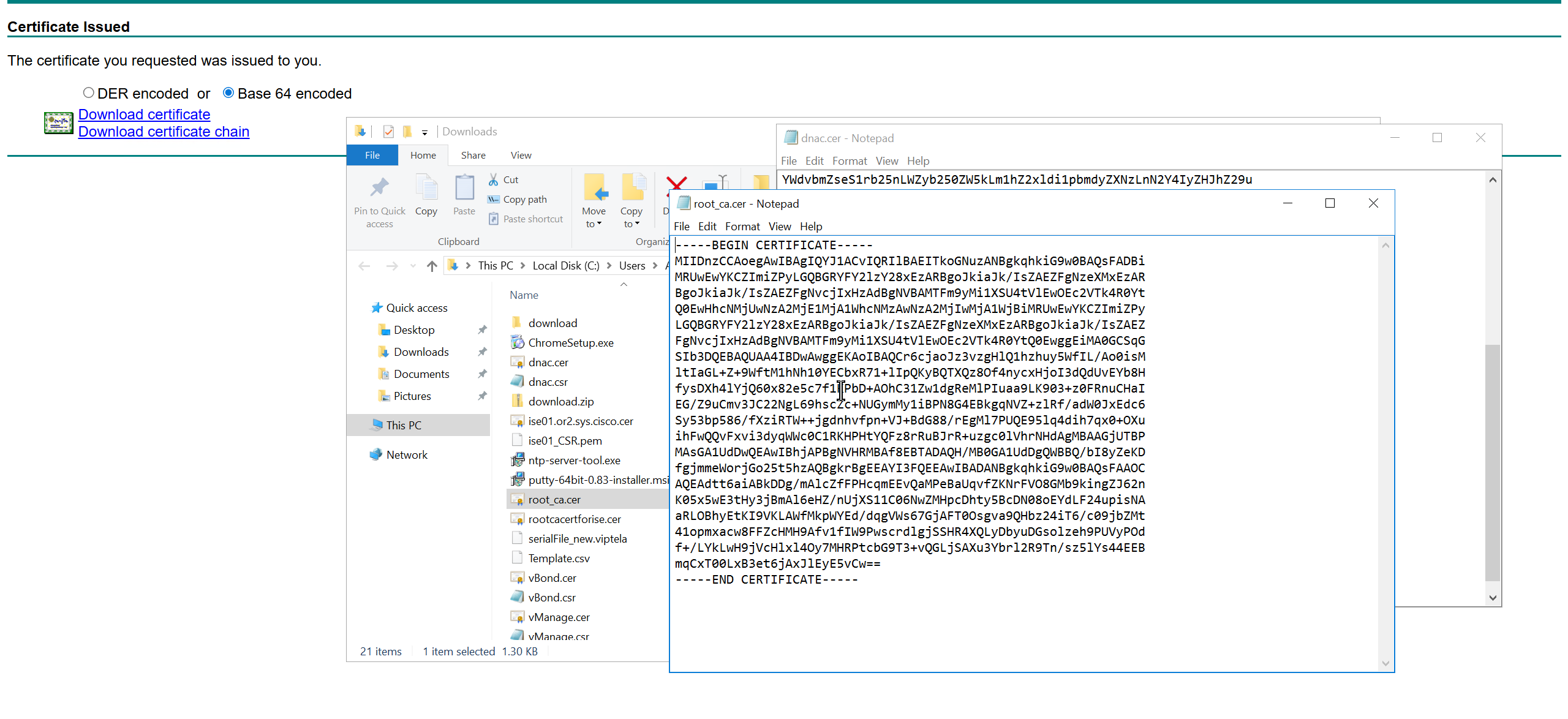

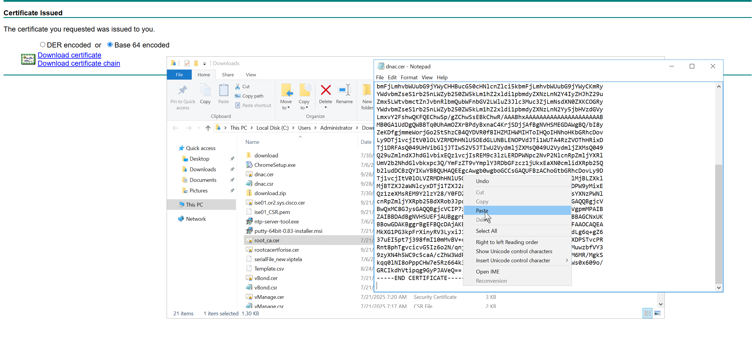
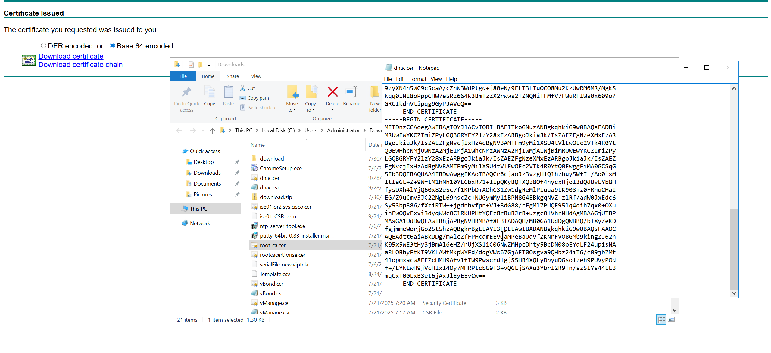
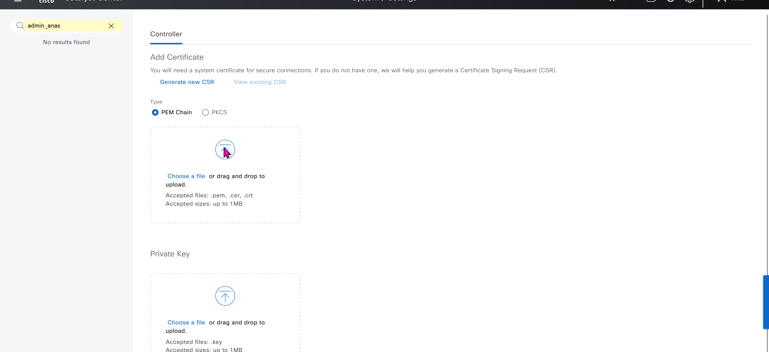
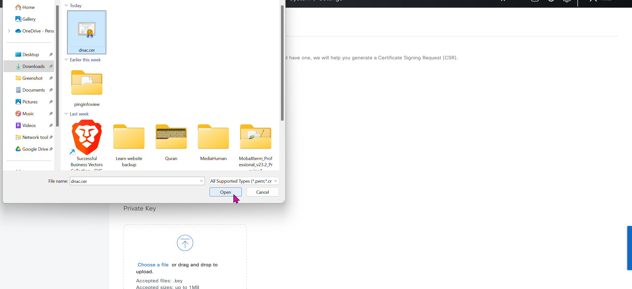
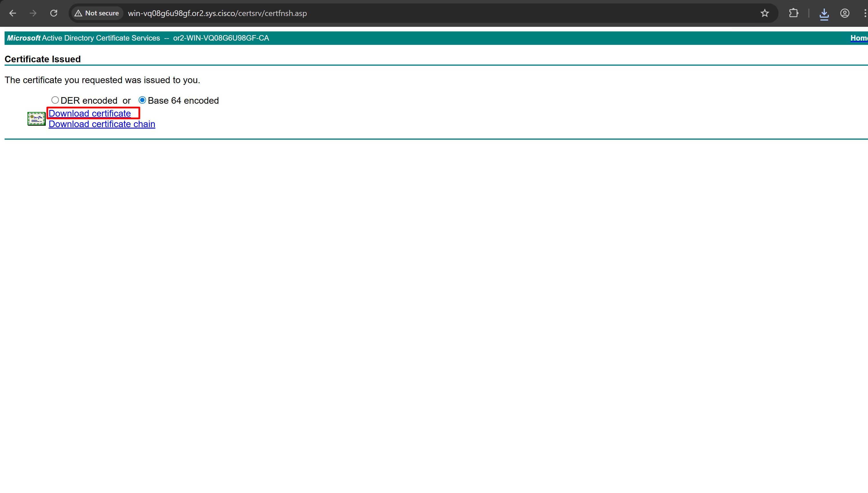
We will append the root ca certificate (because identity cert comes first) in this notepad file and combine it for DNAC, in case you have any intermediate CA certificates then add them as well in the middle of identity and root ca certificate


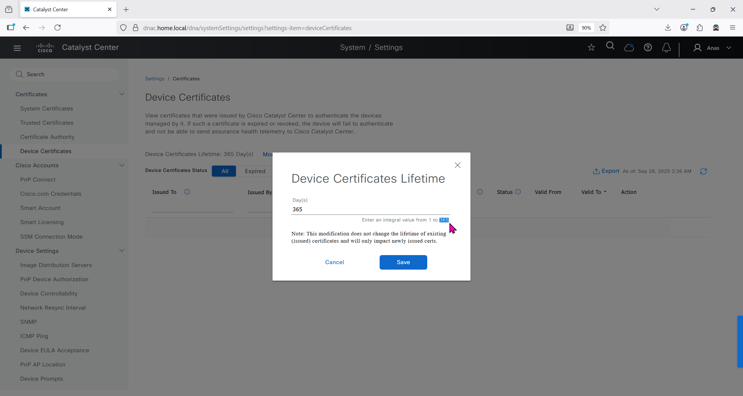
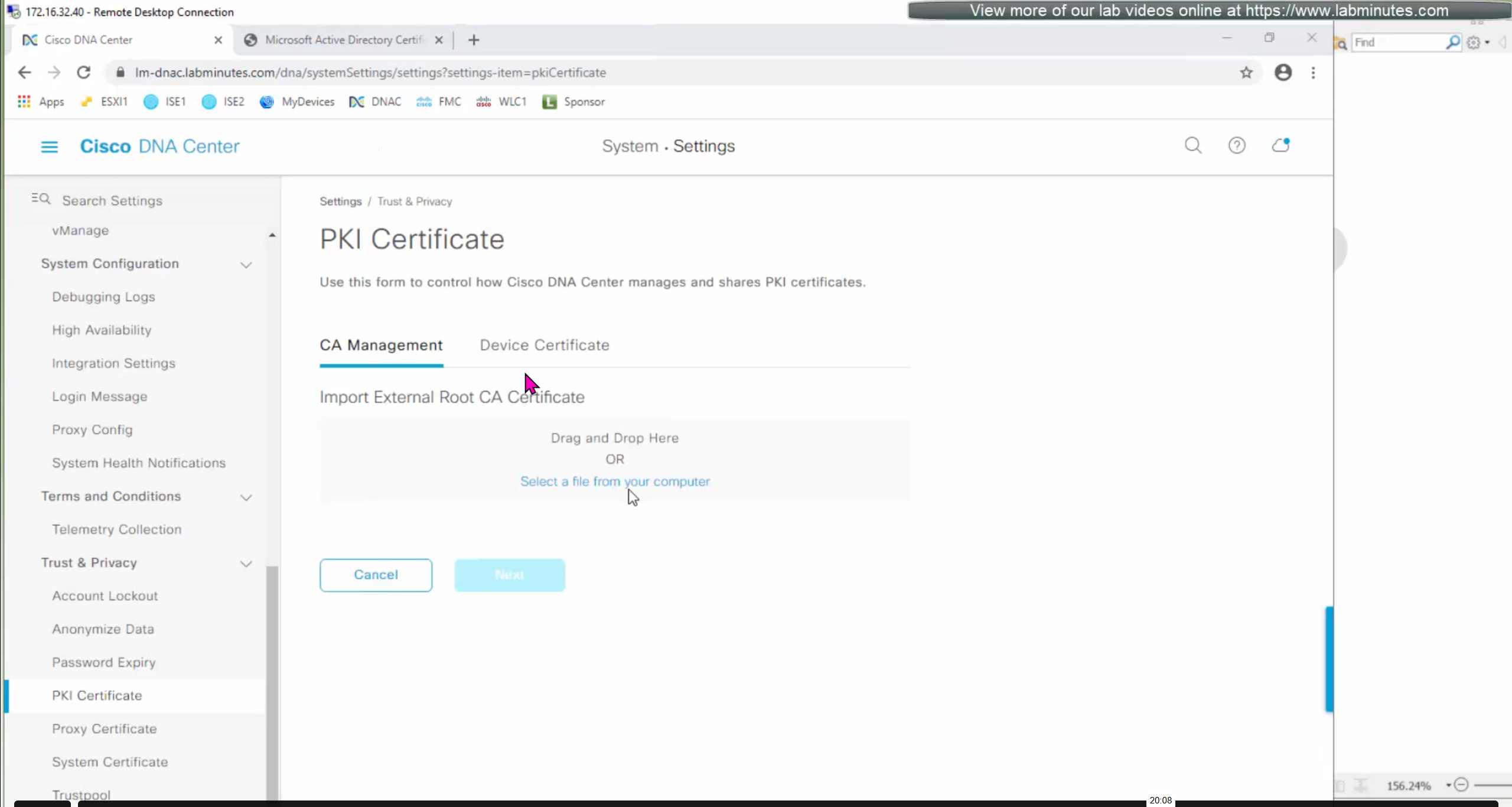
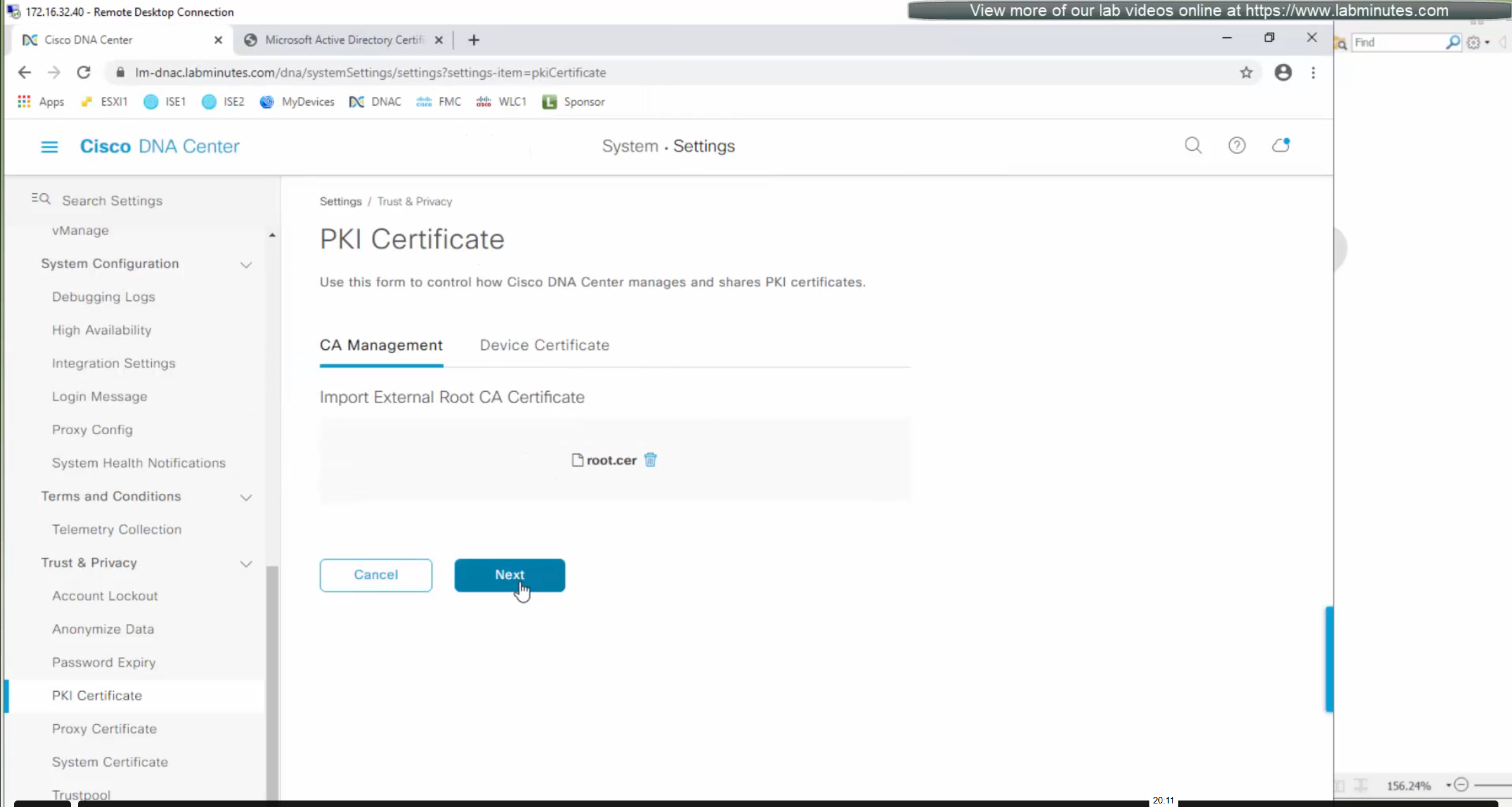
DNAC also issues certificates to devices which get added to it, and by default DNAC acts as the internal root ca but we can add our enterprise root ca or windows root ca too and this decision should be made right at the beginning before adding devices in DNAC or SDA fabric but once enterprise root ca is added we cannot convert this setting back to internal CA, usually we leave DNAC as the root ca for those devices

We can control the period for certificate’s validity
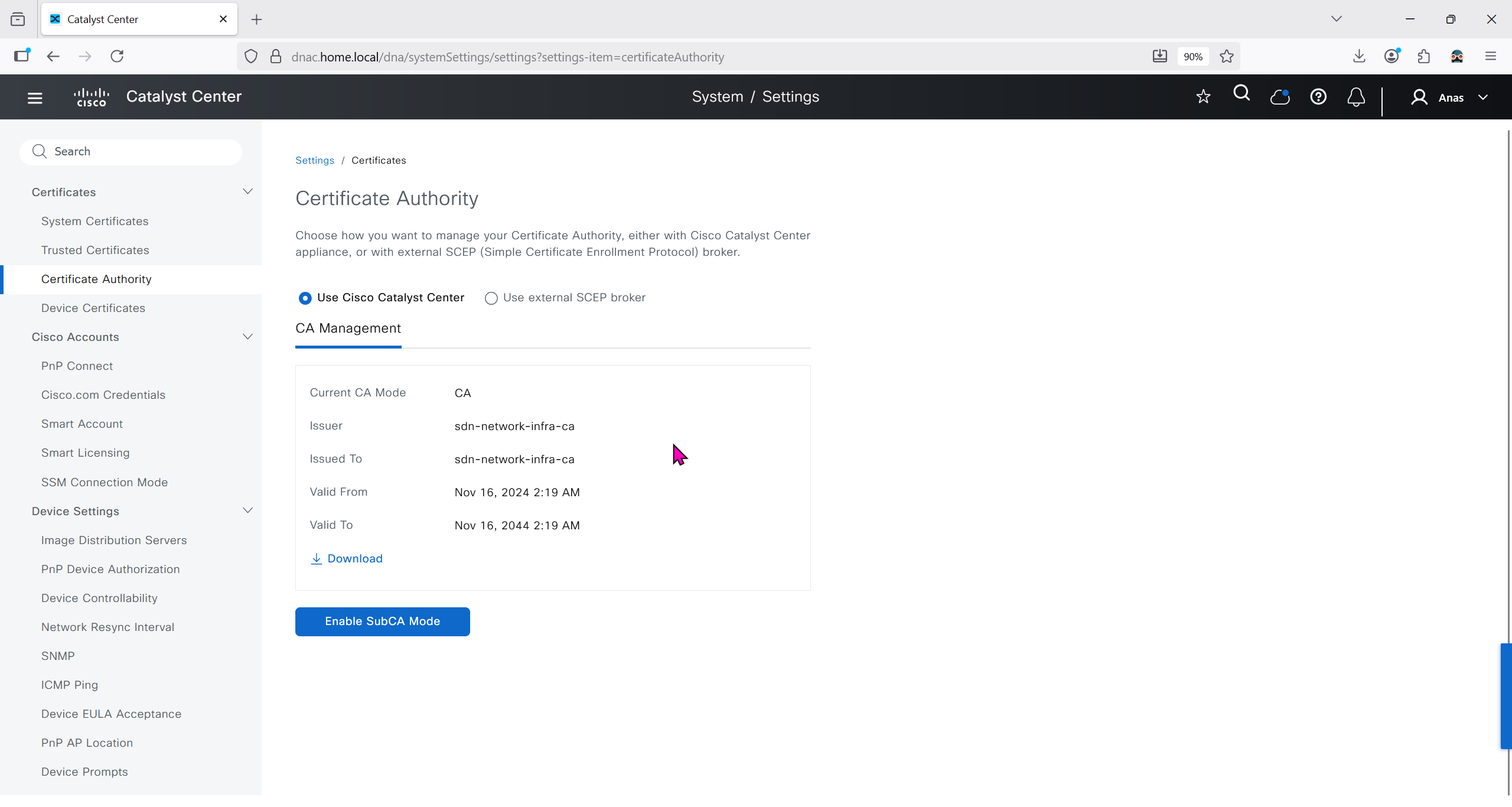
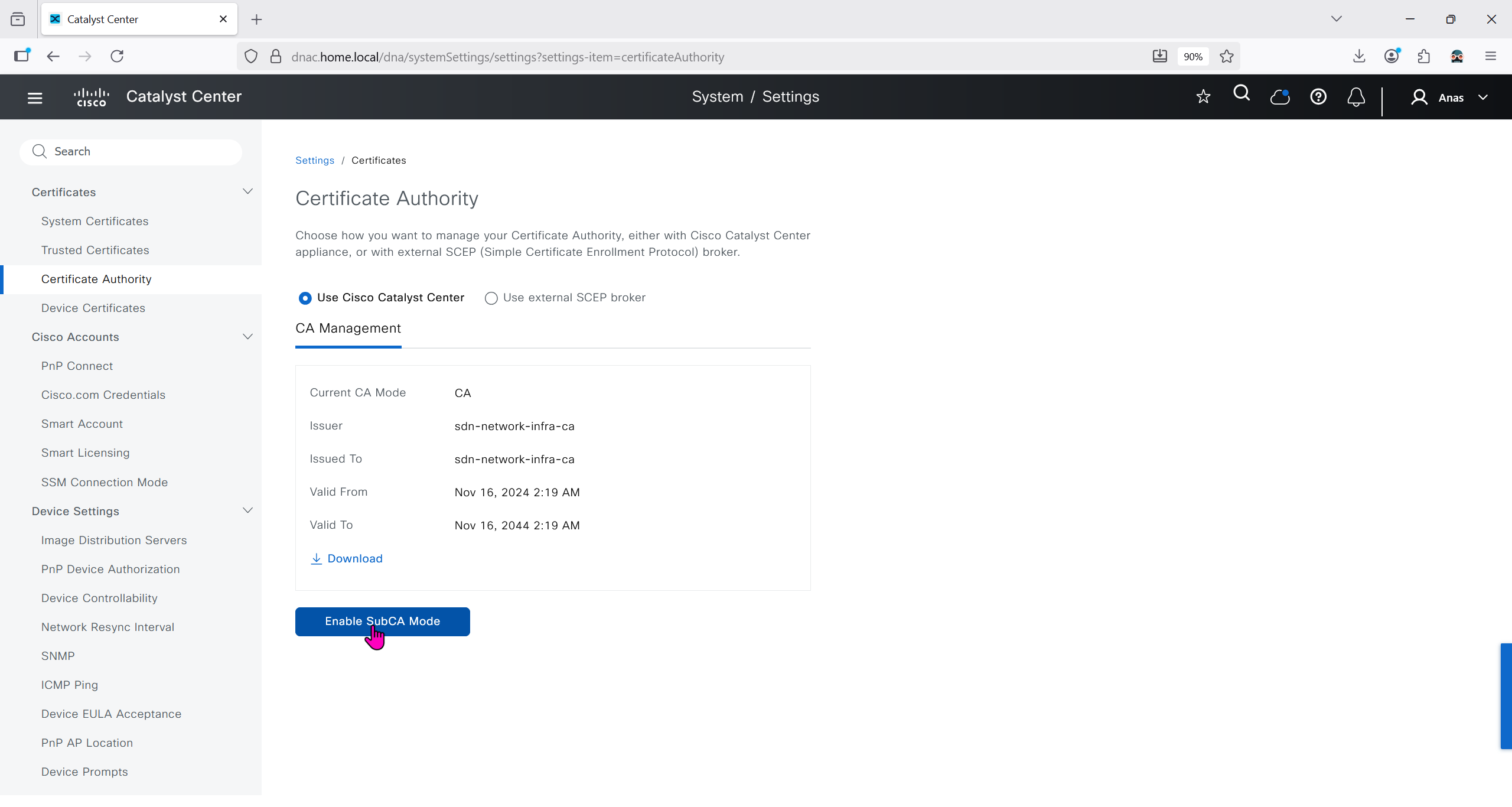
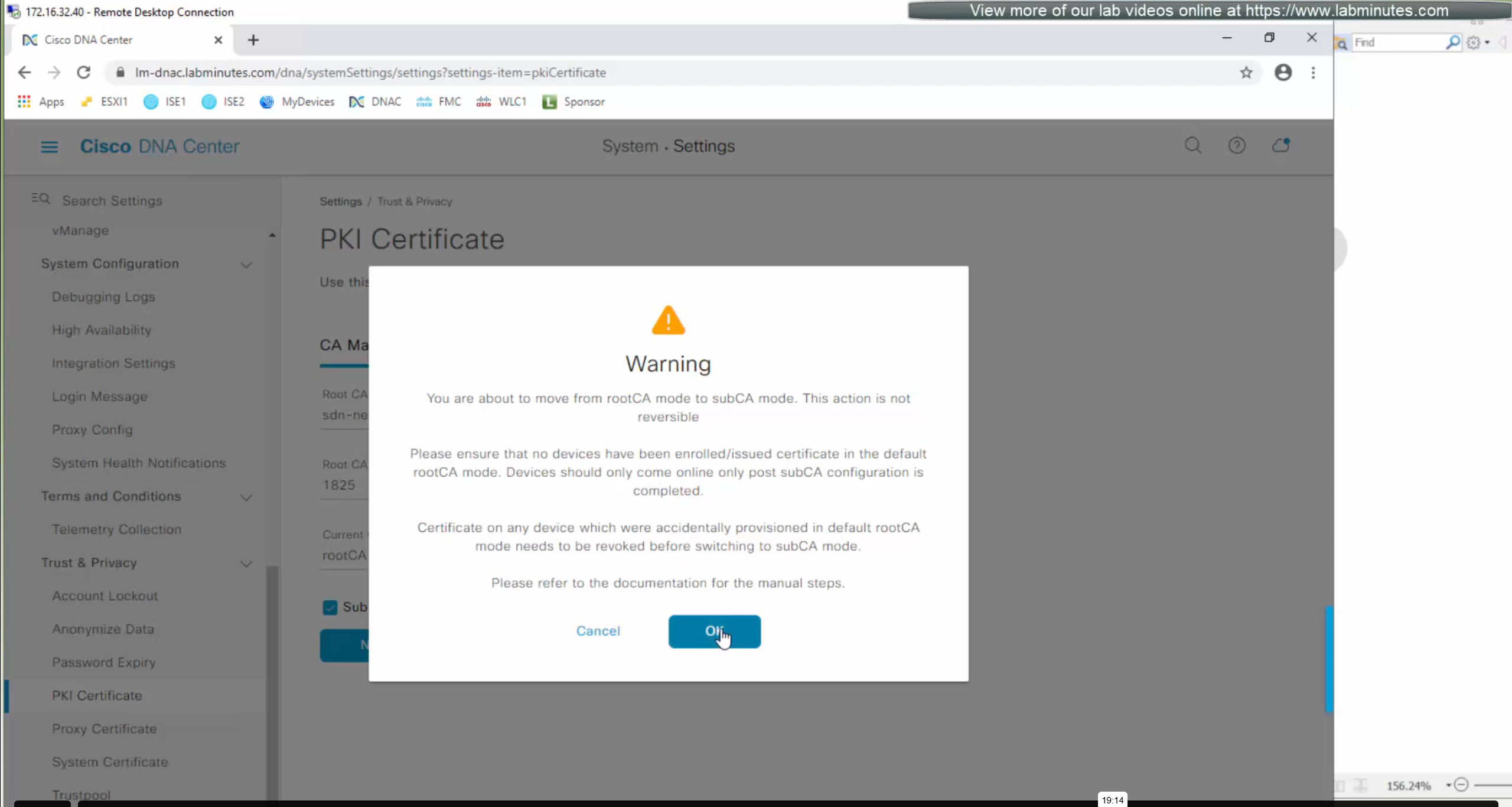
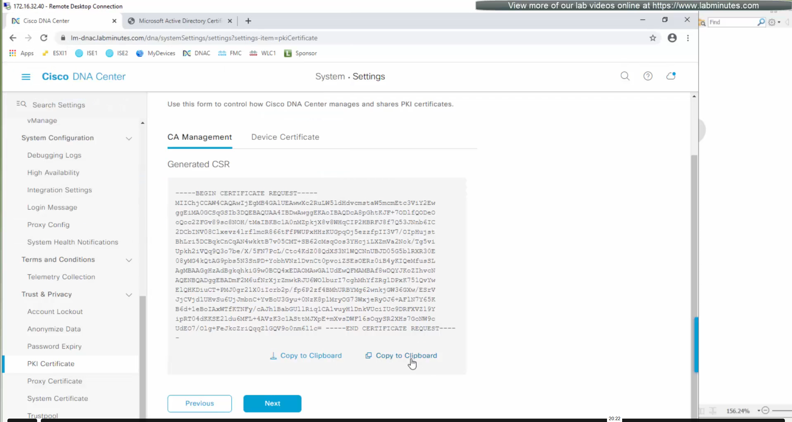
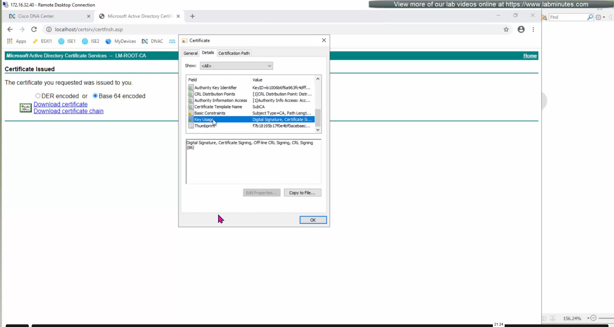
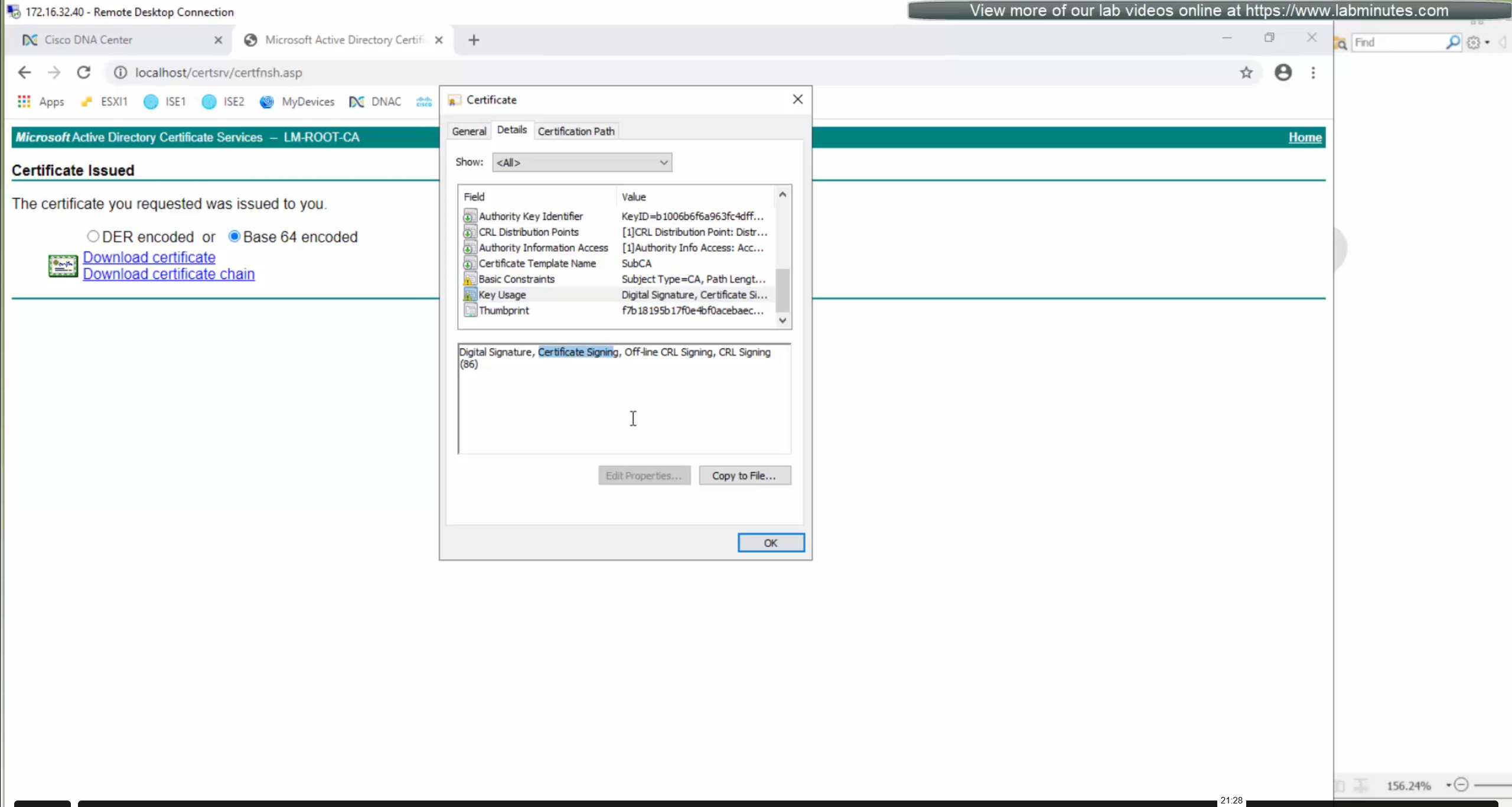
We will just click on option to enable SubCA mode but will not enable it just to see the message from DNAC
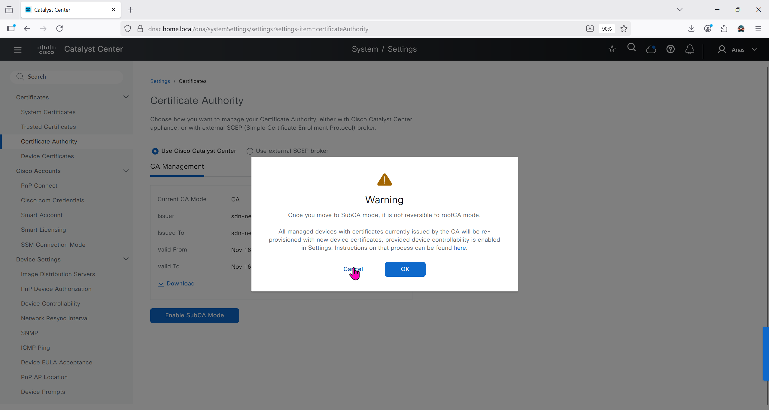
But if we were to enable it then following will be the steps


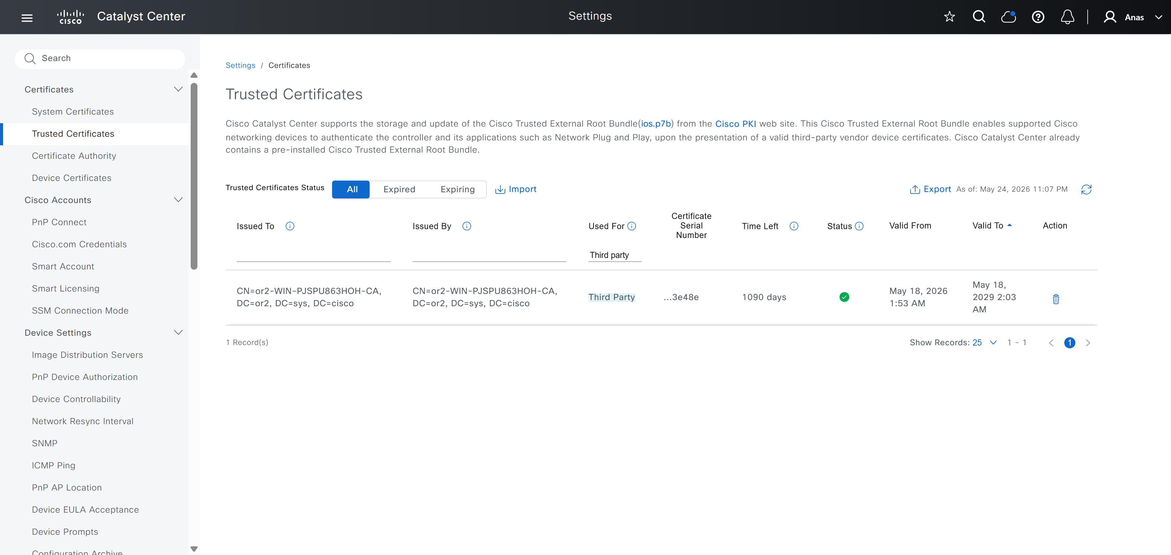
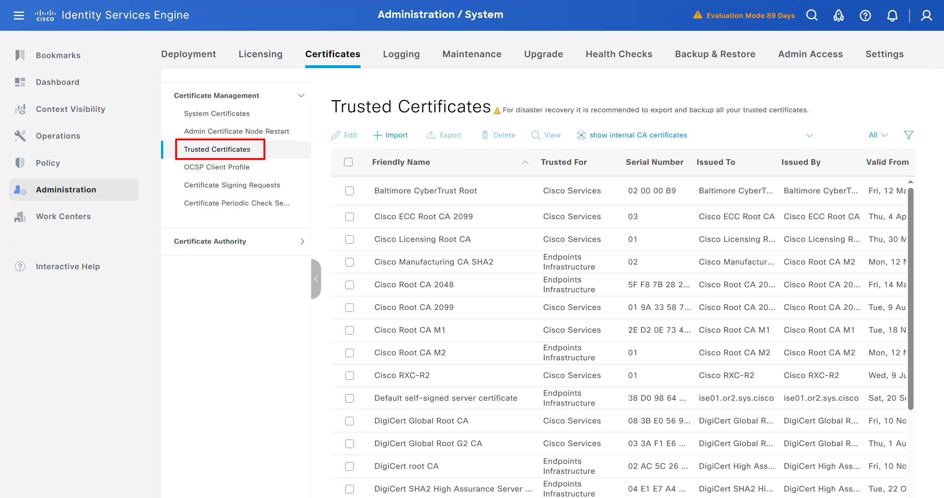
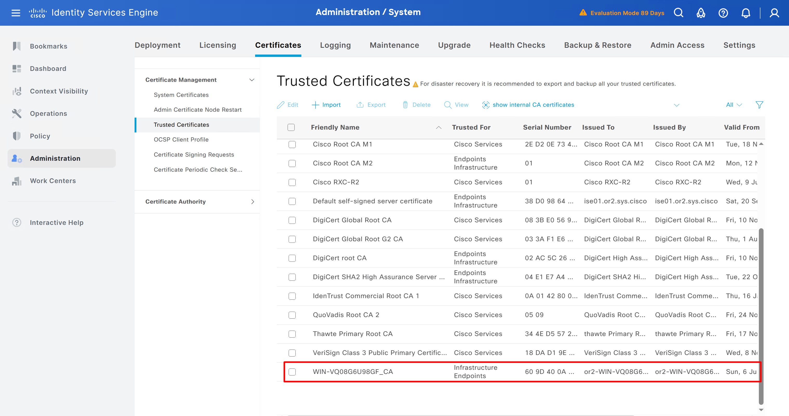
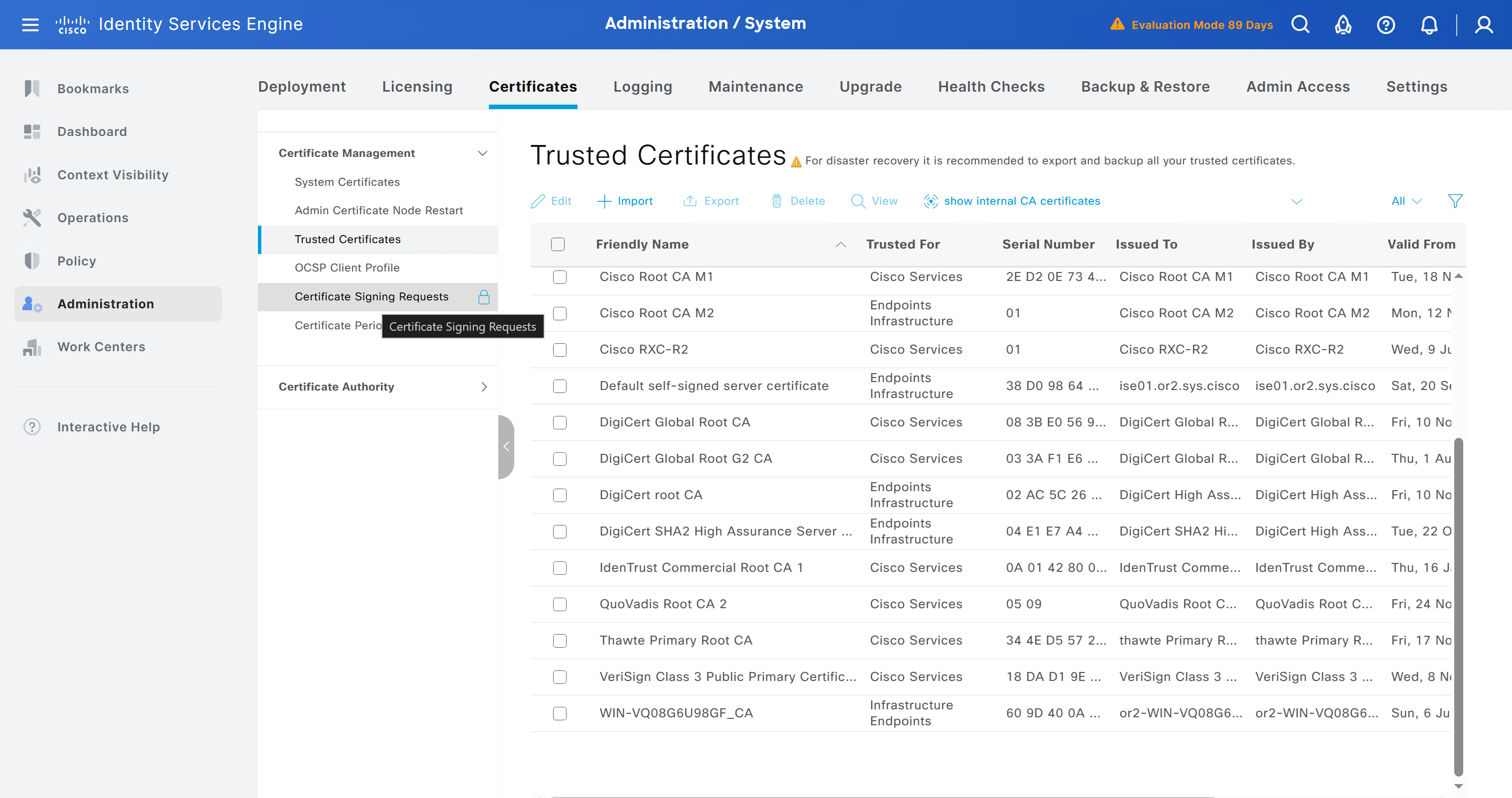
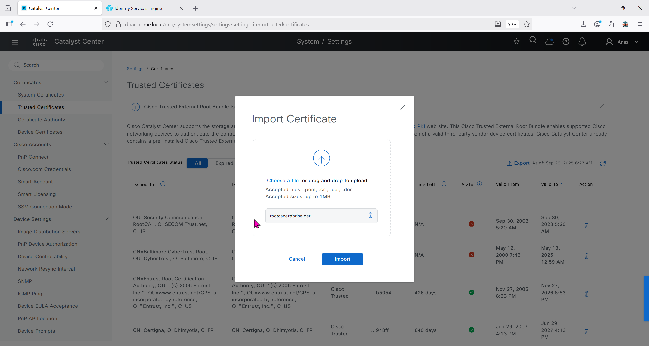
Checking imported CA certificate in Trusted Certificates section
ISE is part of the SDA architecture by using RADIUS (Policy Server with mab and dot1x), TACACS and PXGrid
We need to have dot1x and mab authentication and
authorization configured in ISE
It used to be that ISE should not have TrustSec configuration configured, as config from DNAC will overwrite the existing config
If you bypass Cisco DNA Center and manually modify an SGACL directly inside ISE, the systems will fall out of sync. Cisco DNA Center will not automatically inherit changes made locally on ISE, creating a configuration mismatch until a manual resynchronisation or re-integration is performed
After integration, DNAC continues to poll ISE in order to keep trustsec configuration in sync
Integration between DNAC and ISE is very version specific so make sure you check documentation to see which version of ISE will integrate with which version of DNAC
Make sure that DNAC can reach ISE on ssh, and it is very important that GUI and CLI credentials are same
Also make sure that our ISE certificate has SAN entries for ISE IP and FQDN in ISE certificate


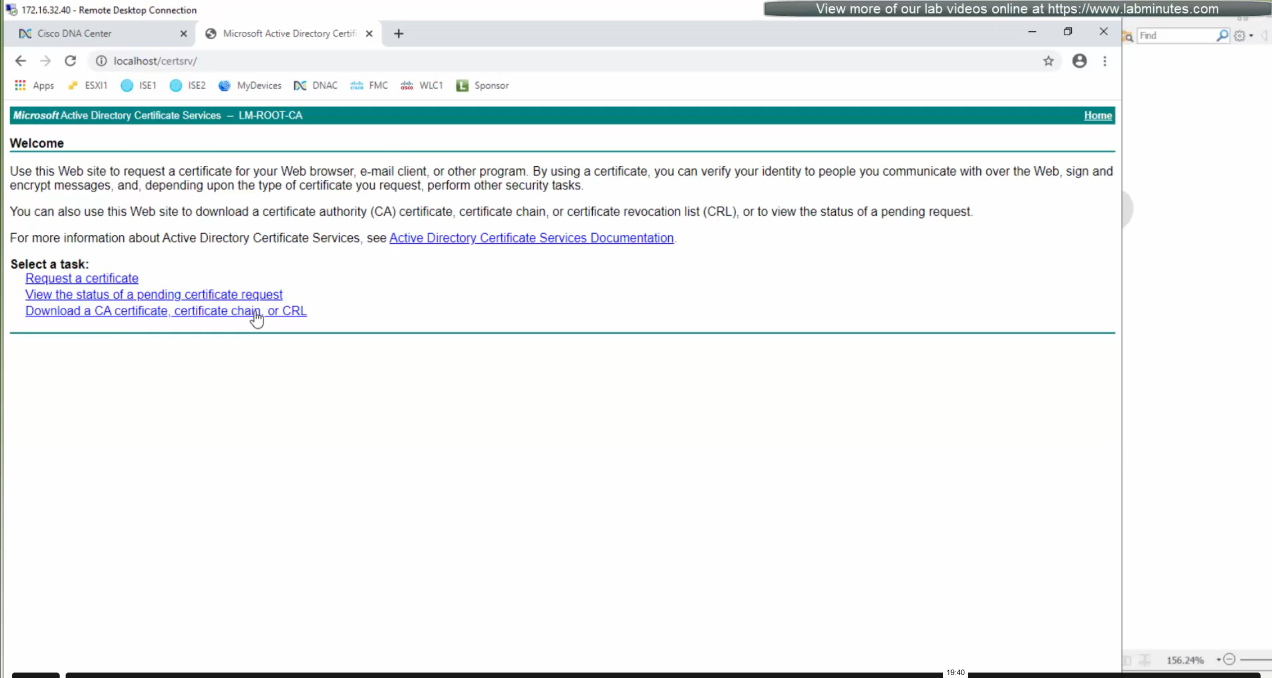
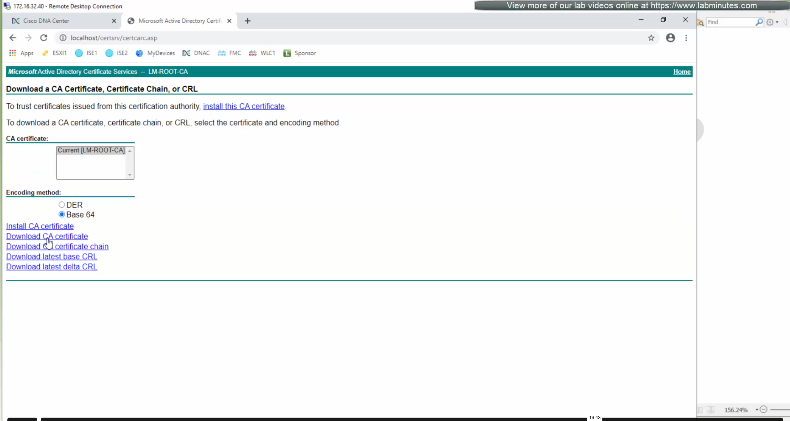
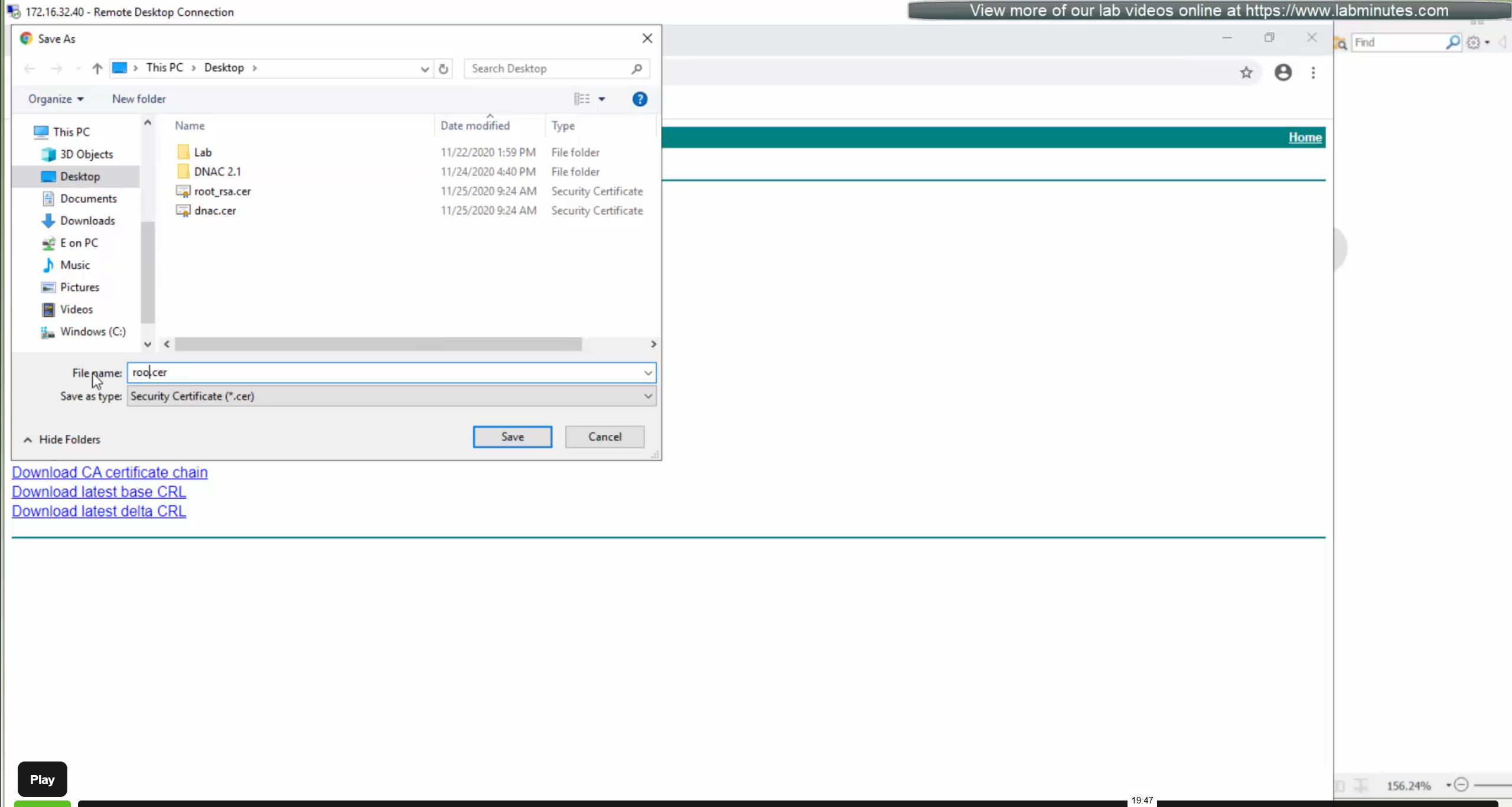
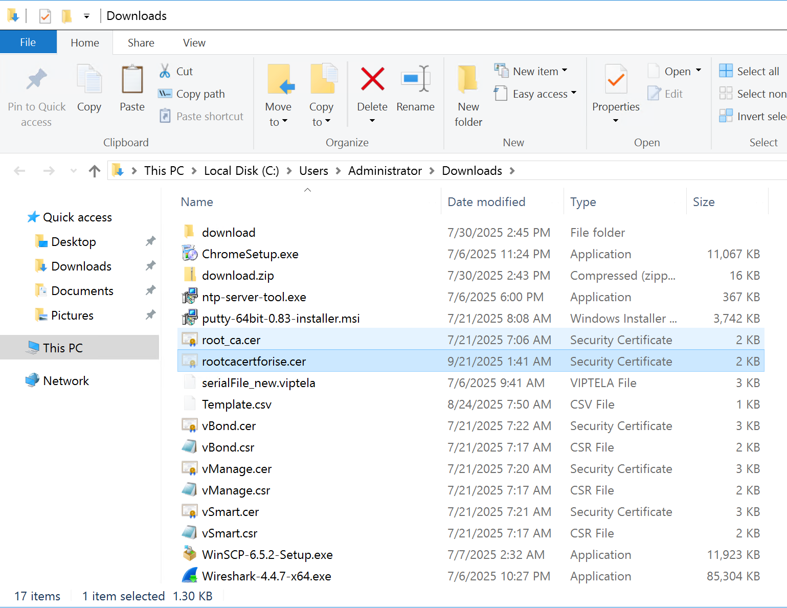
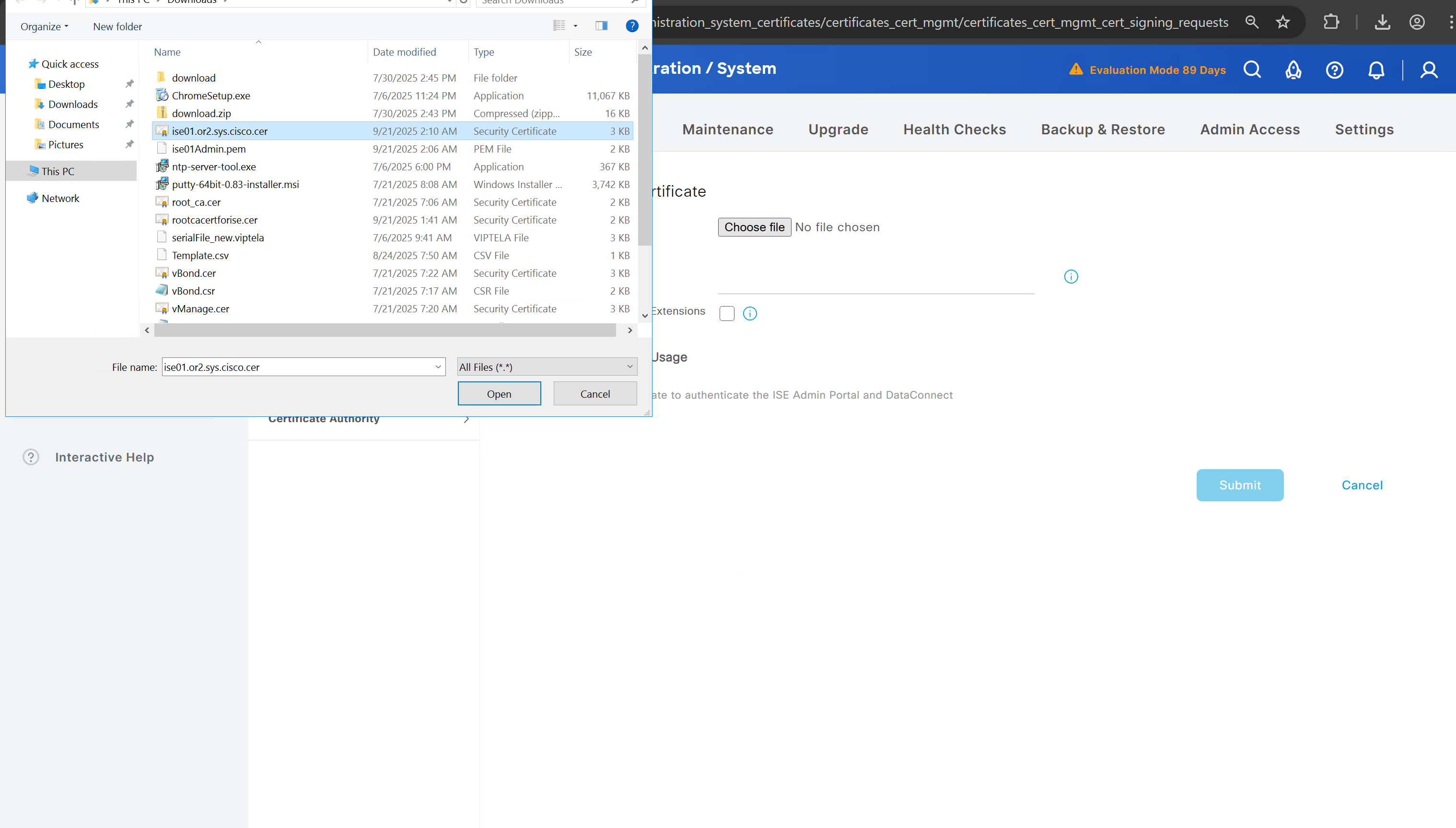
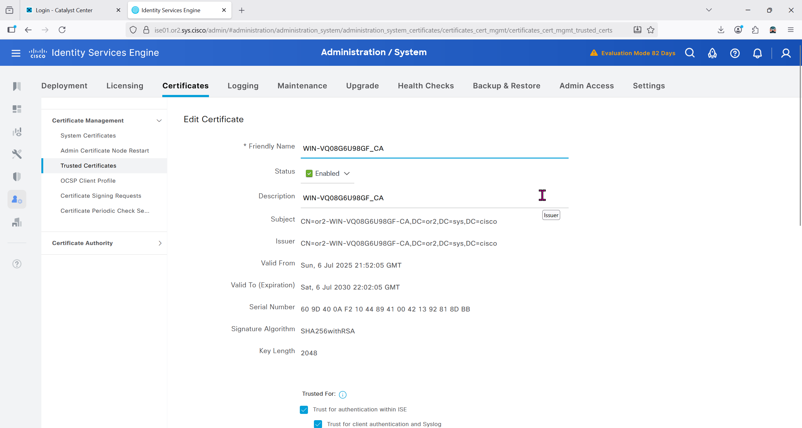
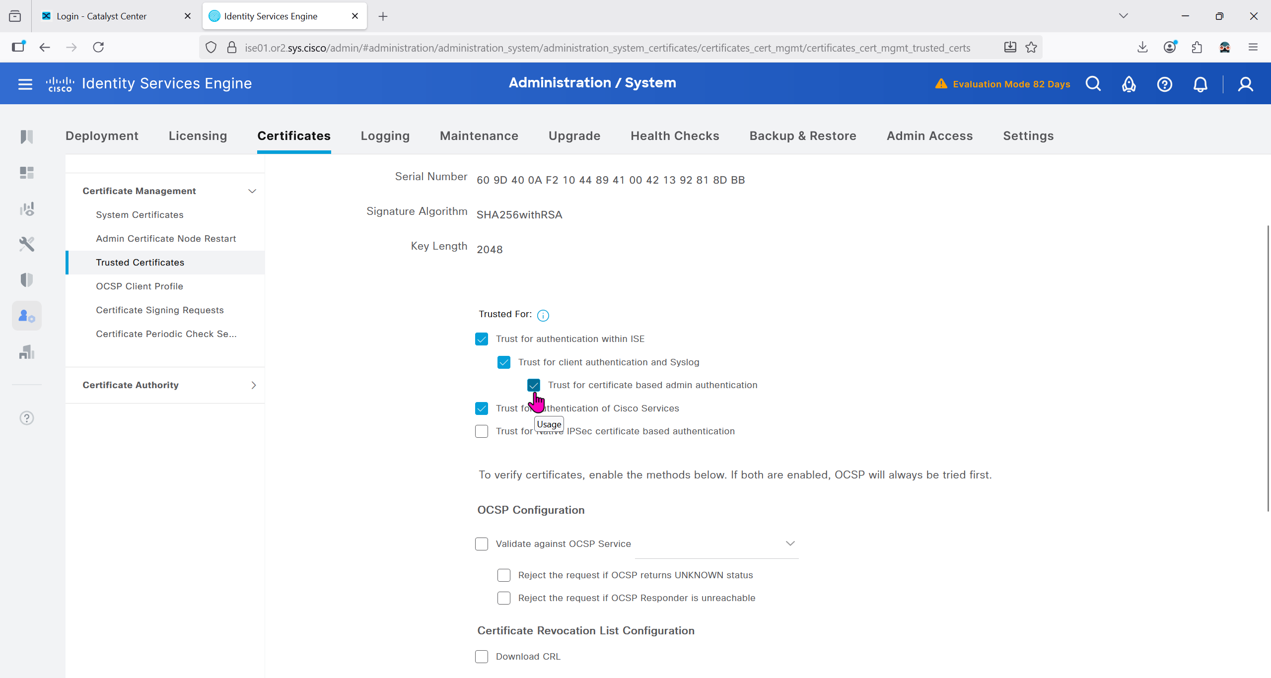
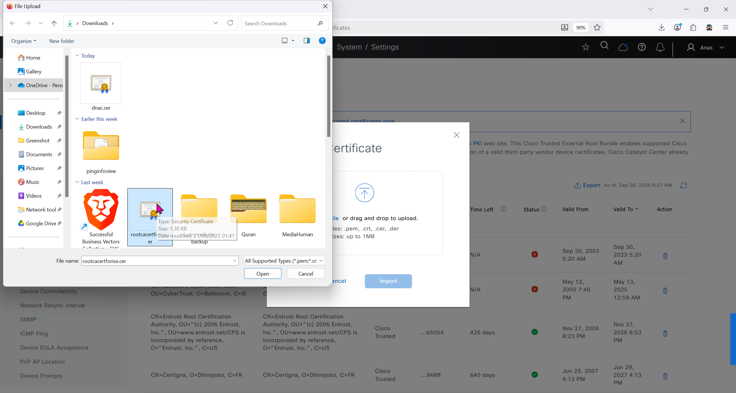
Make sure that when DNAC’s cert is presented it is trusted by ISE, for that we will have to upload the root CA cert
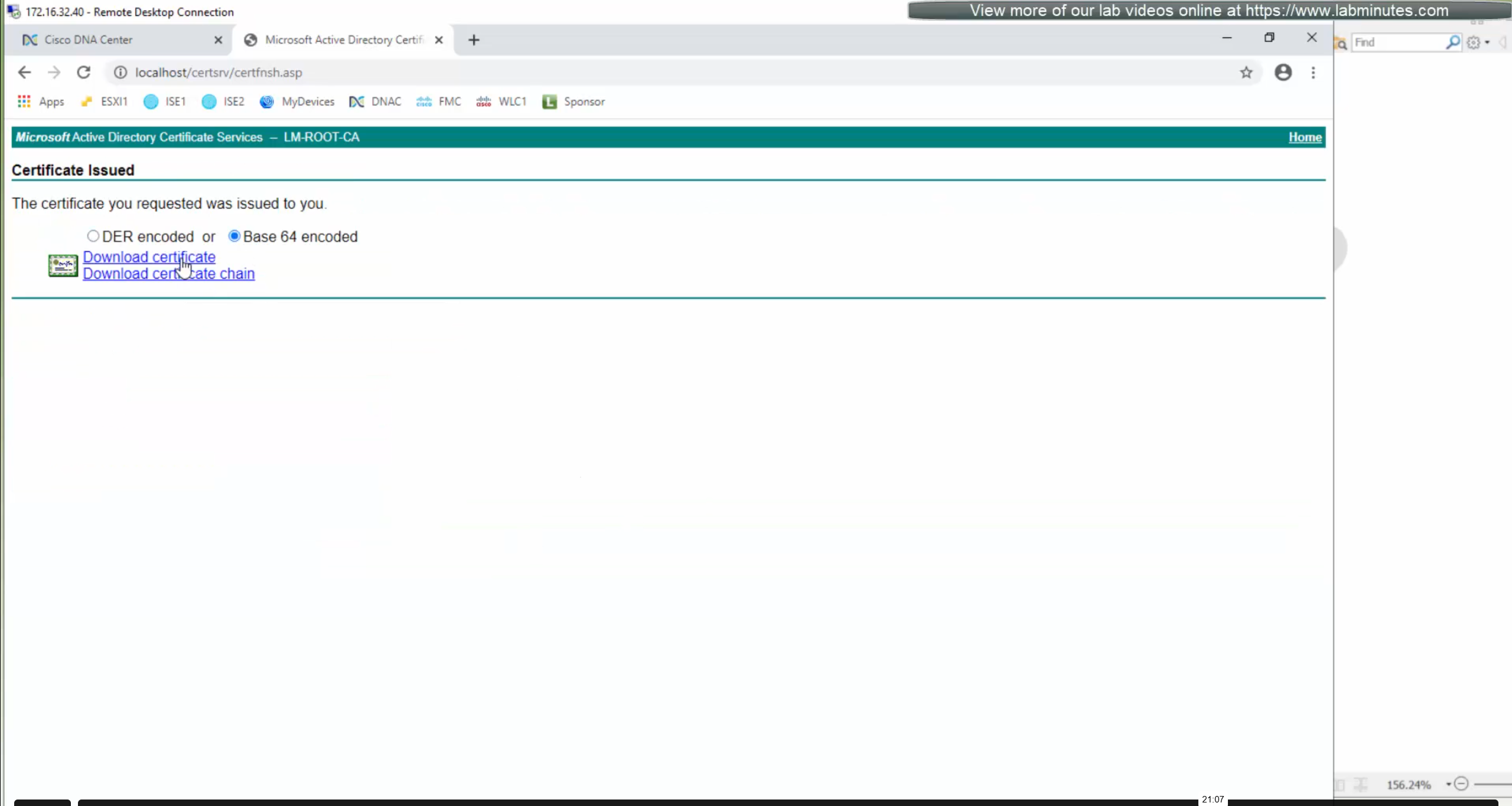
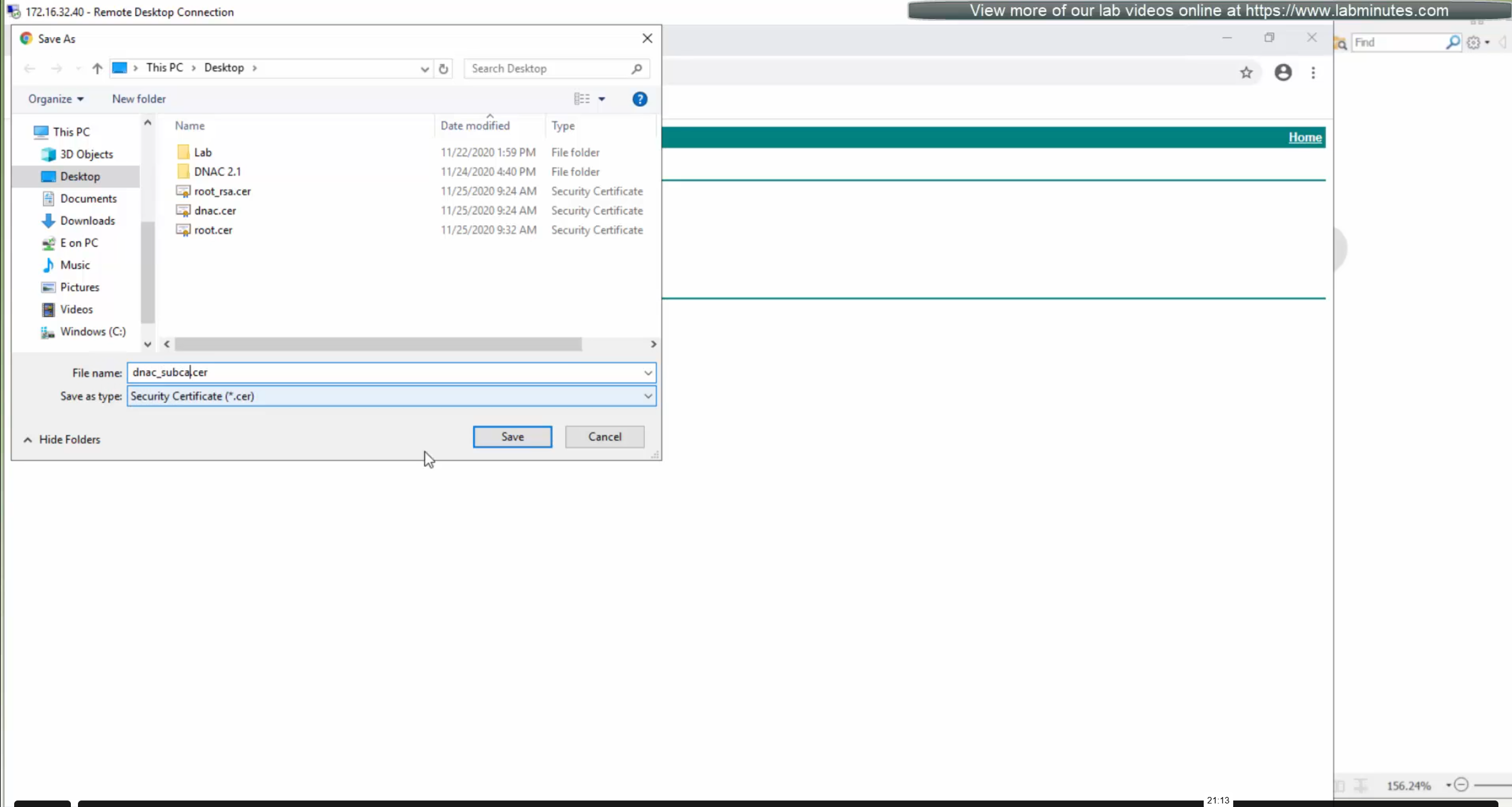
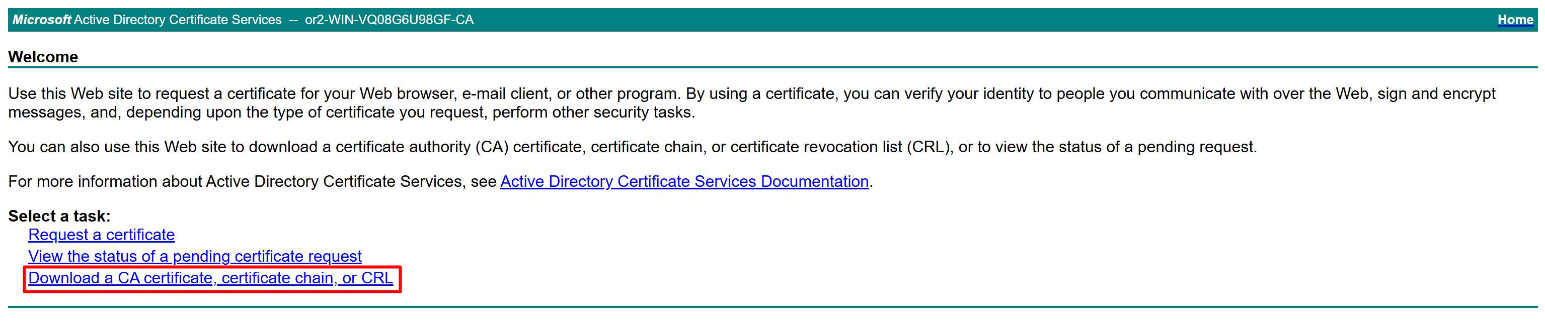
Download CA certificate and upload it to the Trusted store of ISE
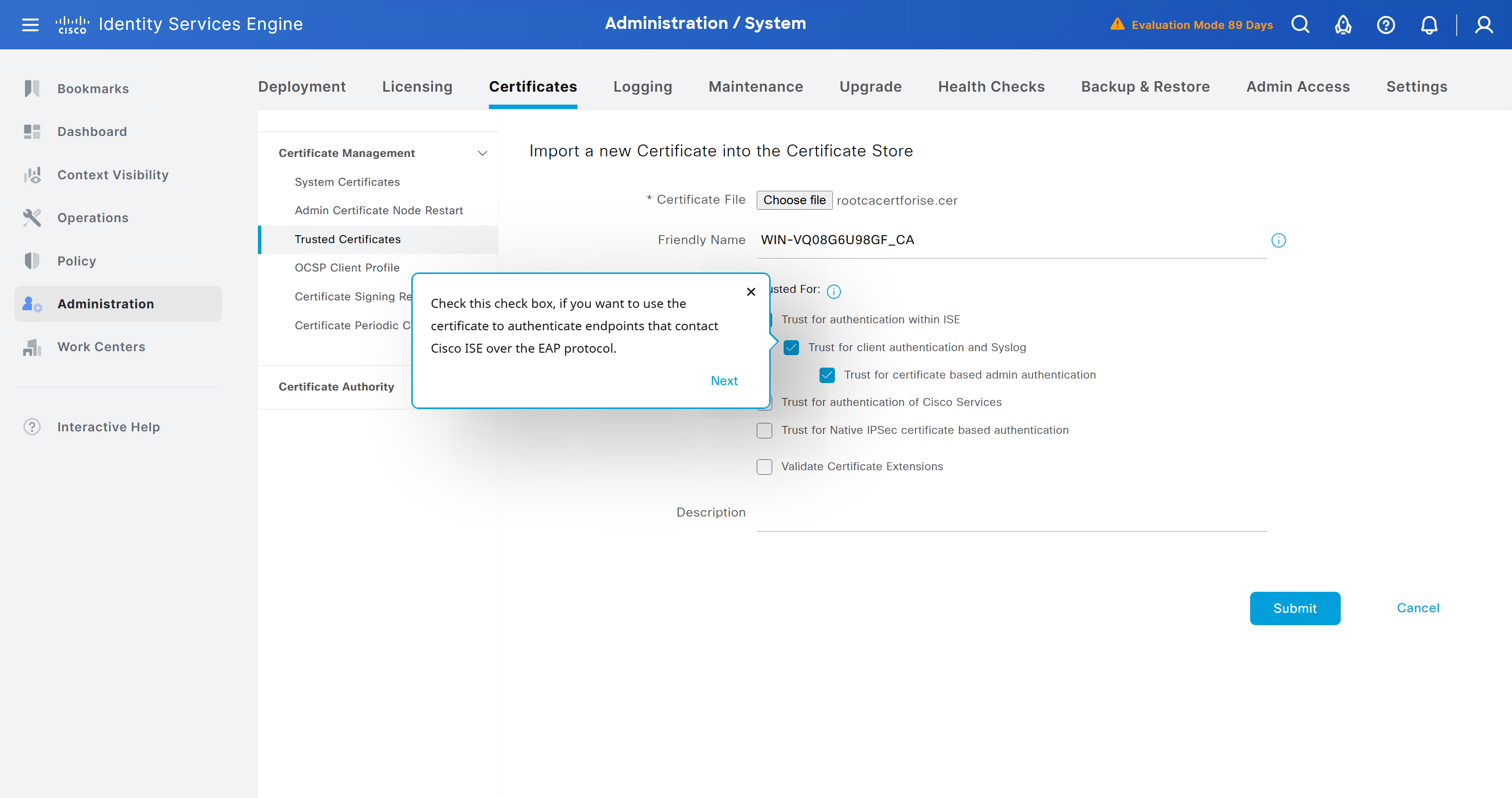
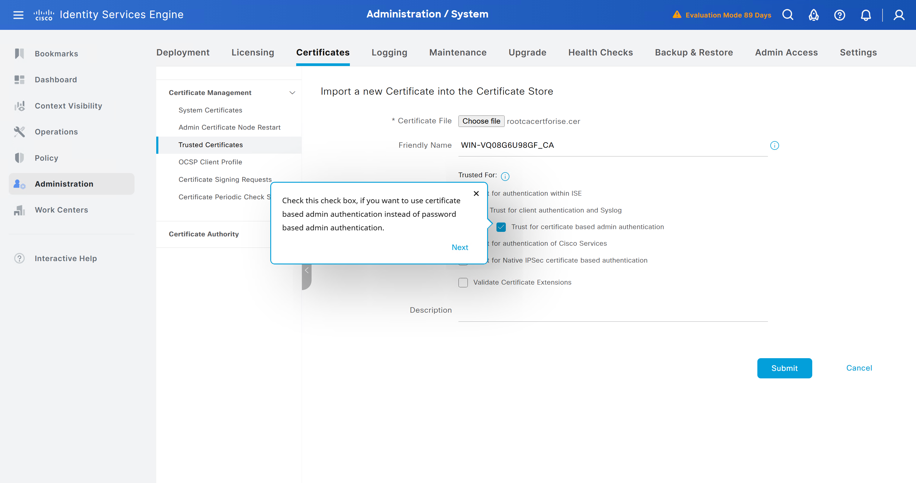
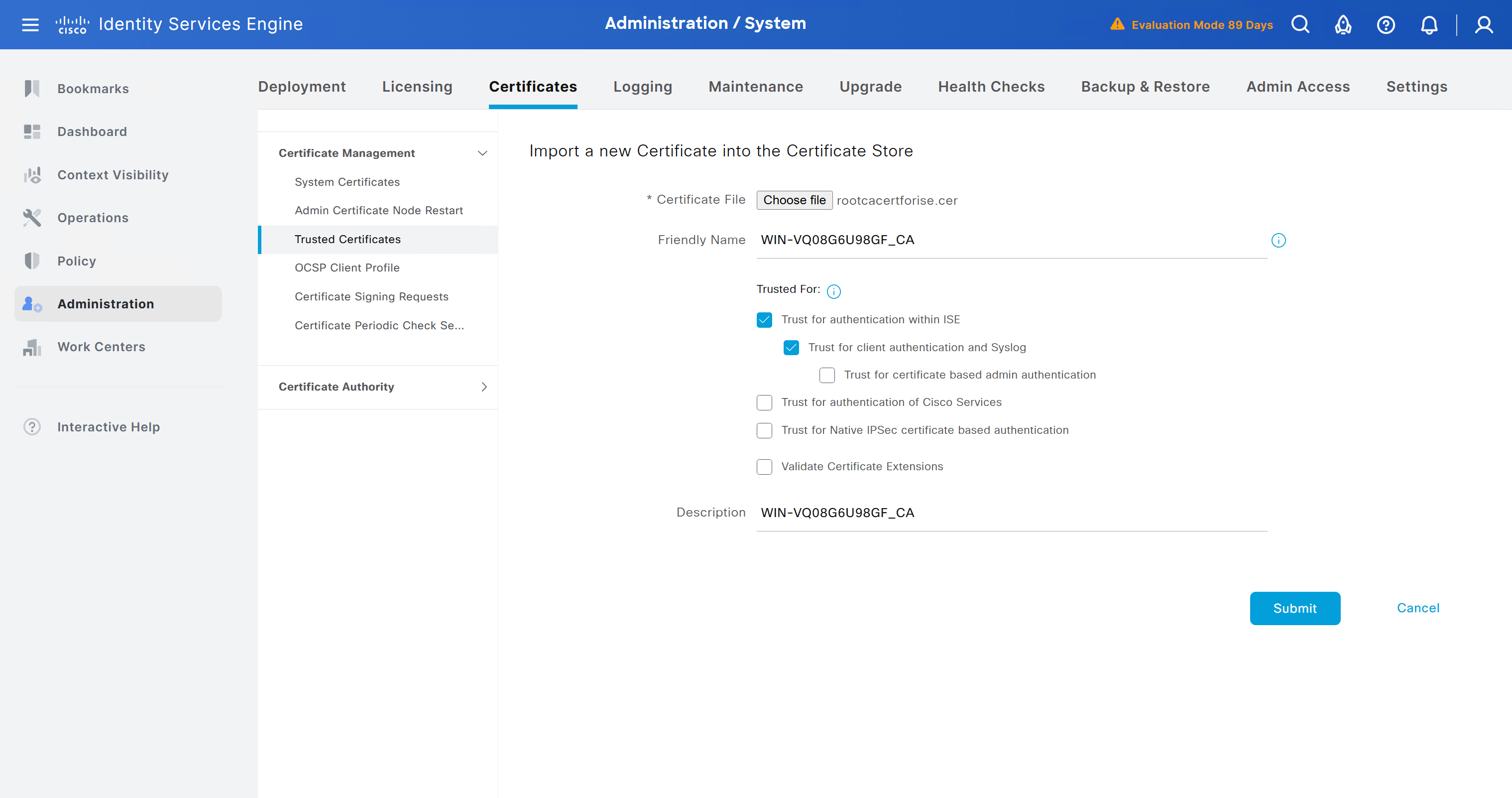
We will select this option “Trust for client authentication and Syslog” as certificate presented to ISE during EAP TLS 802.1x authentication will be certificates issued by this same CA
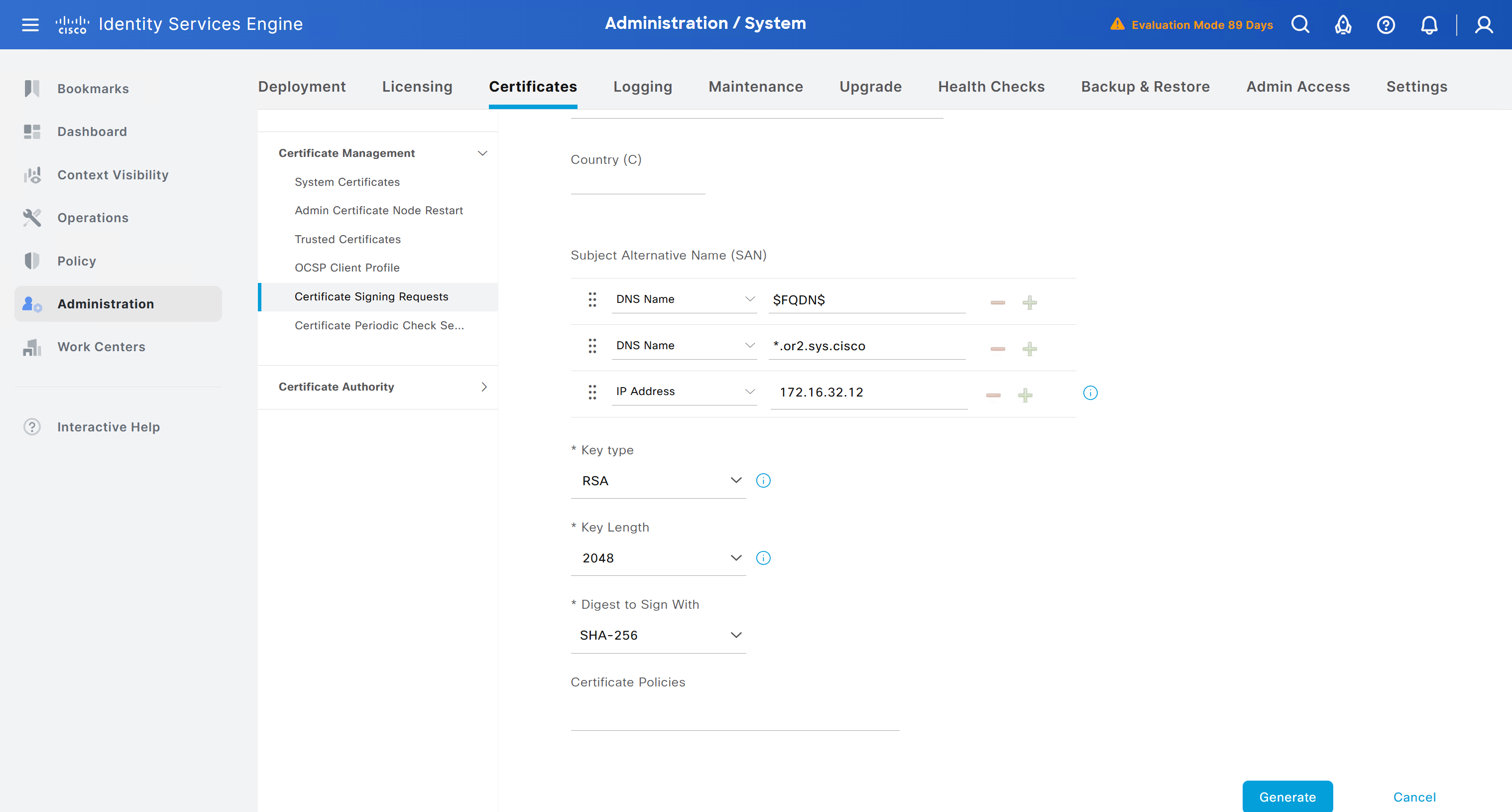
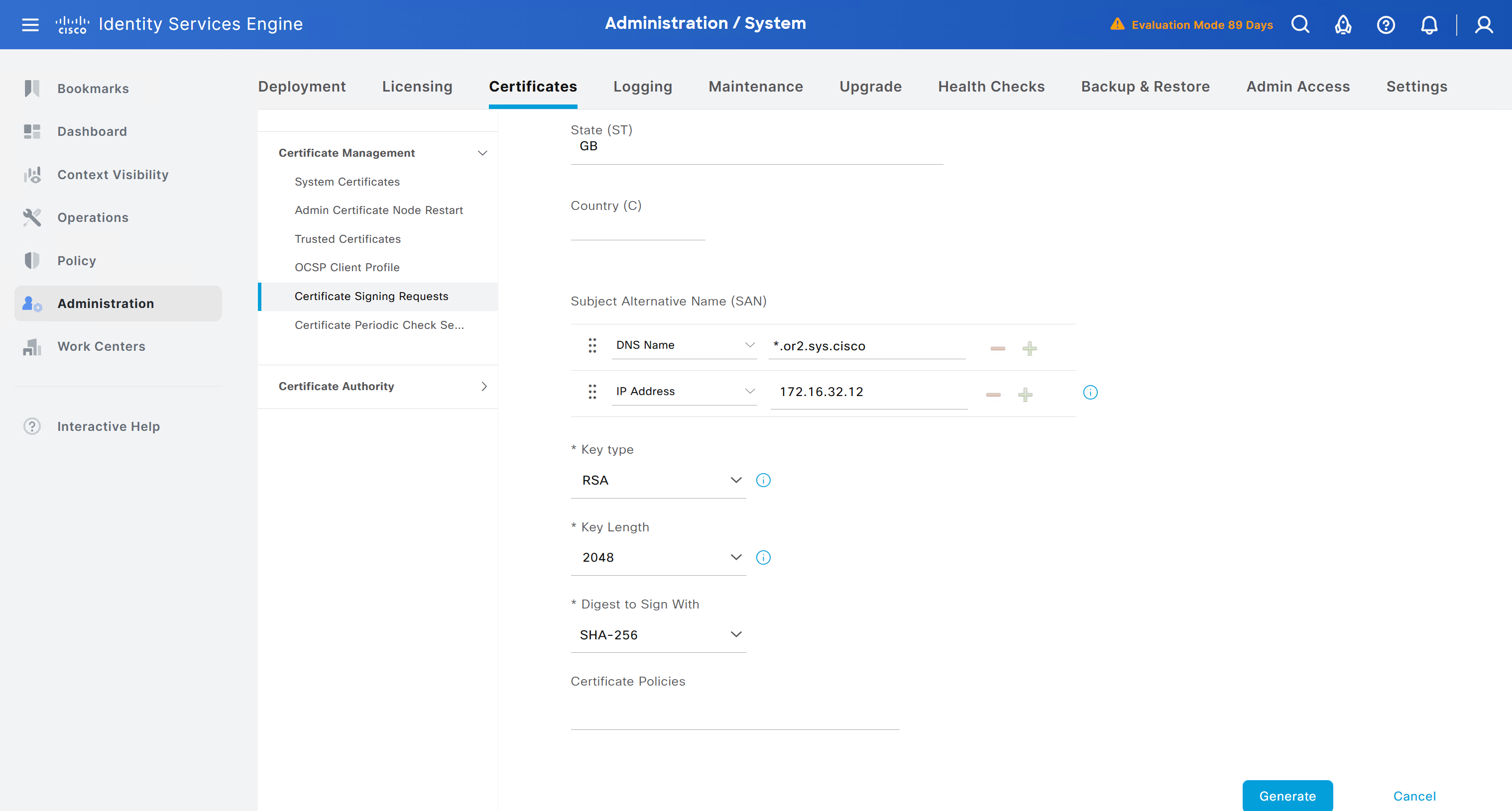
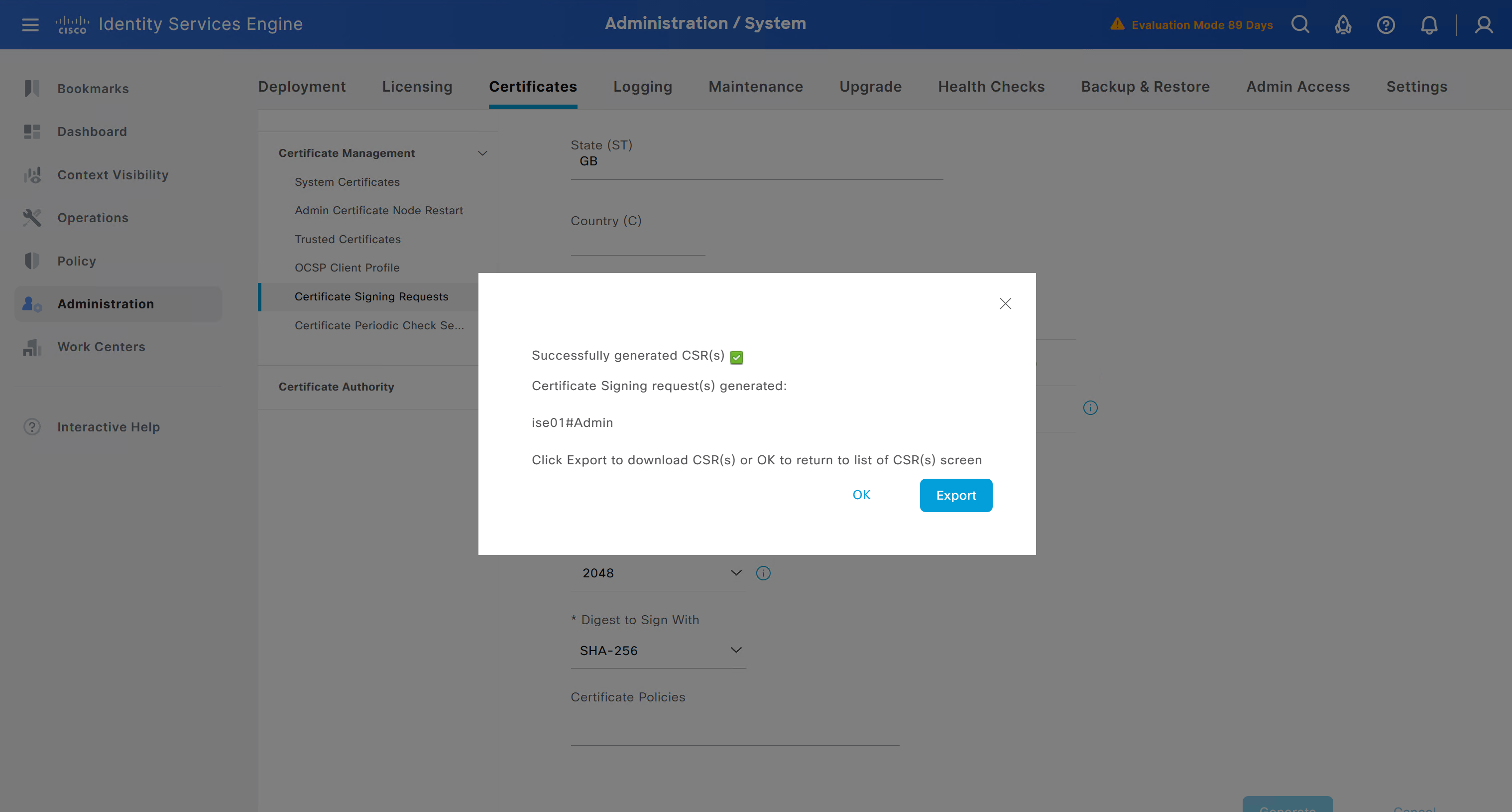
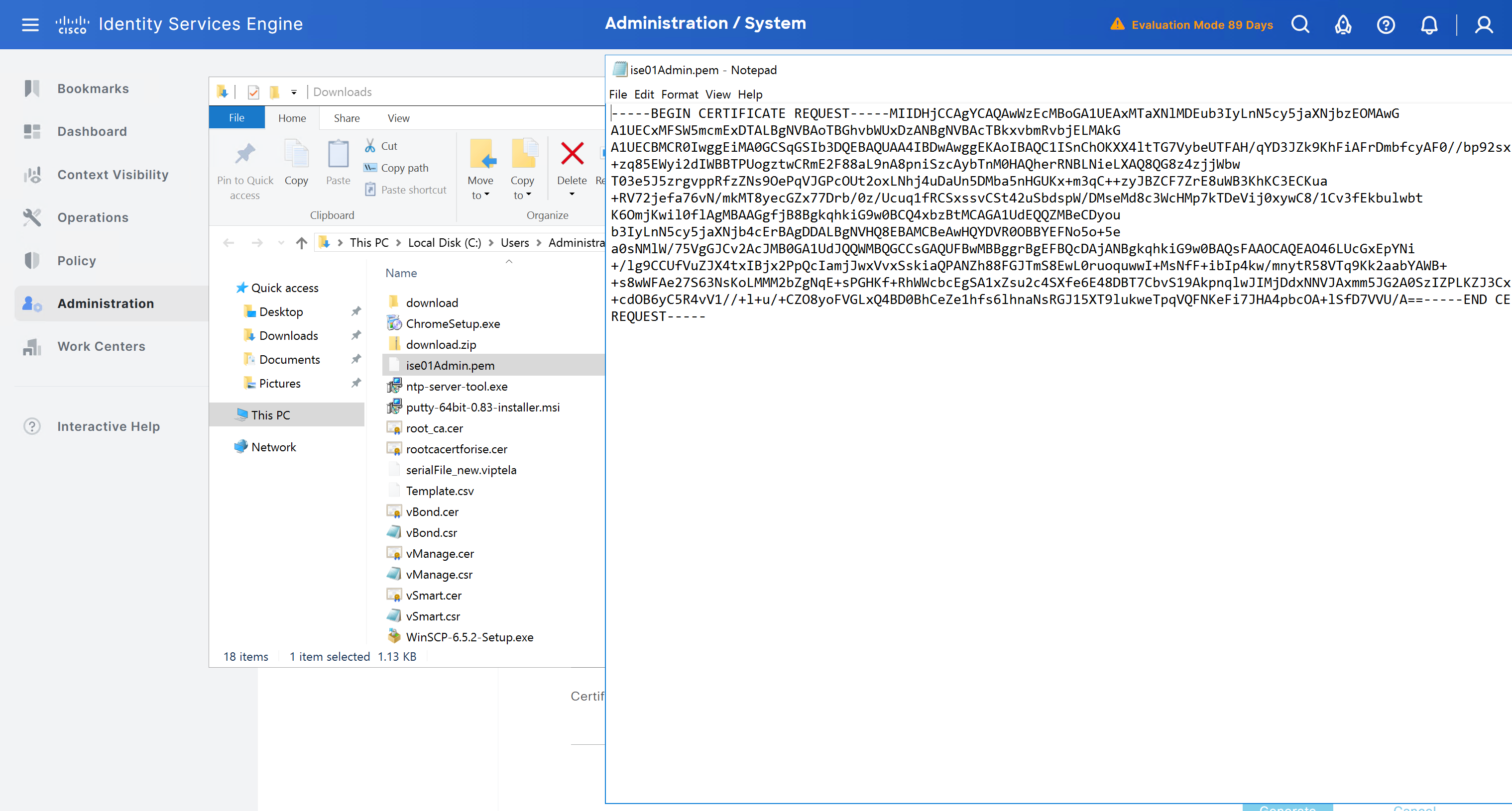
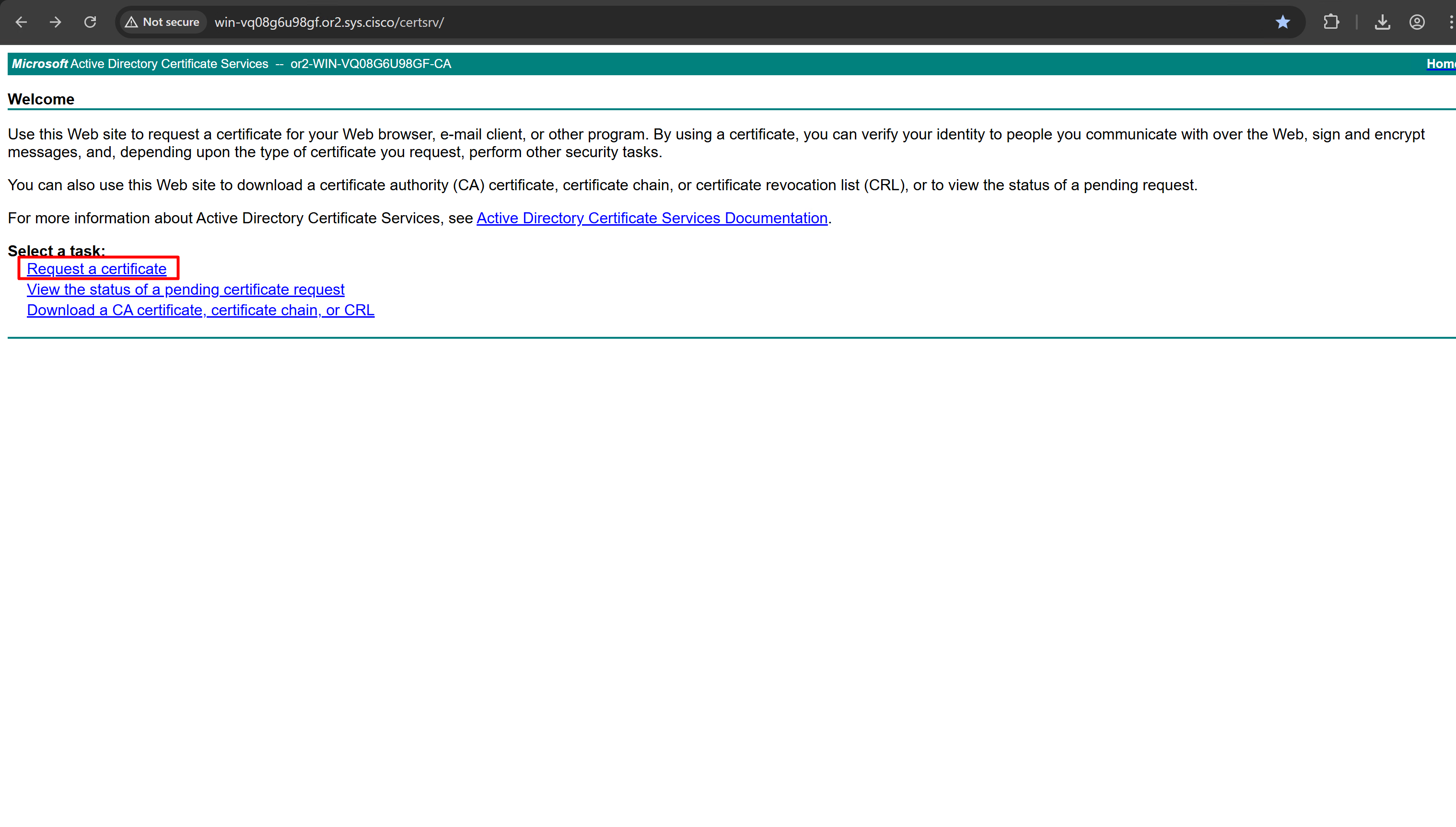
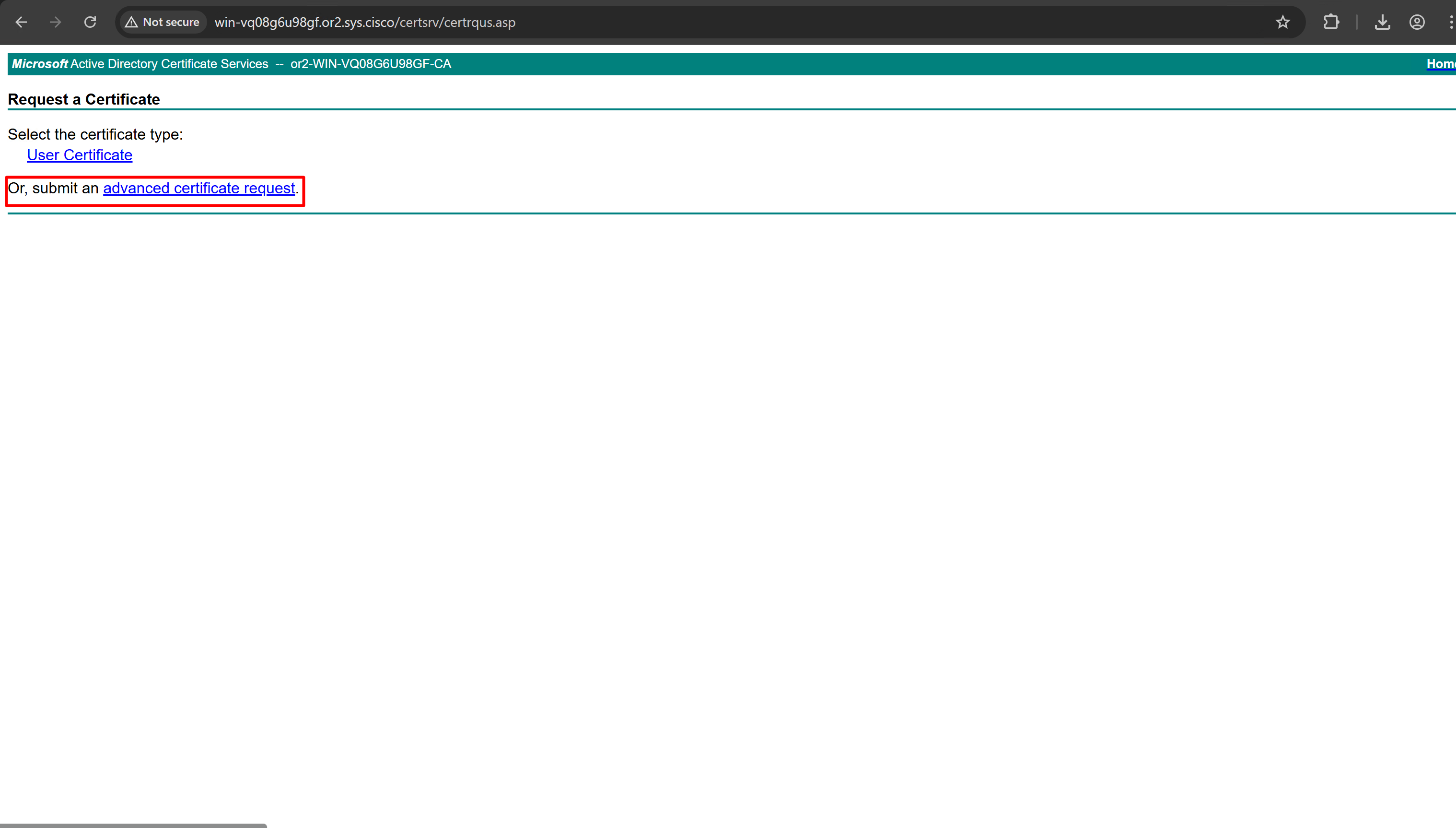
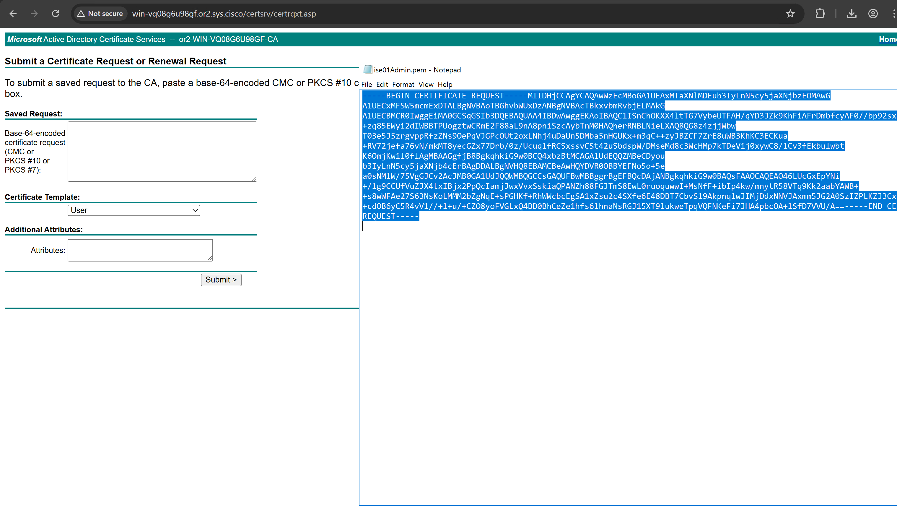
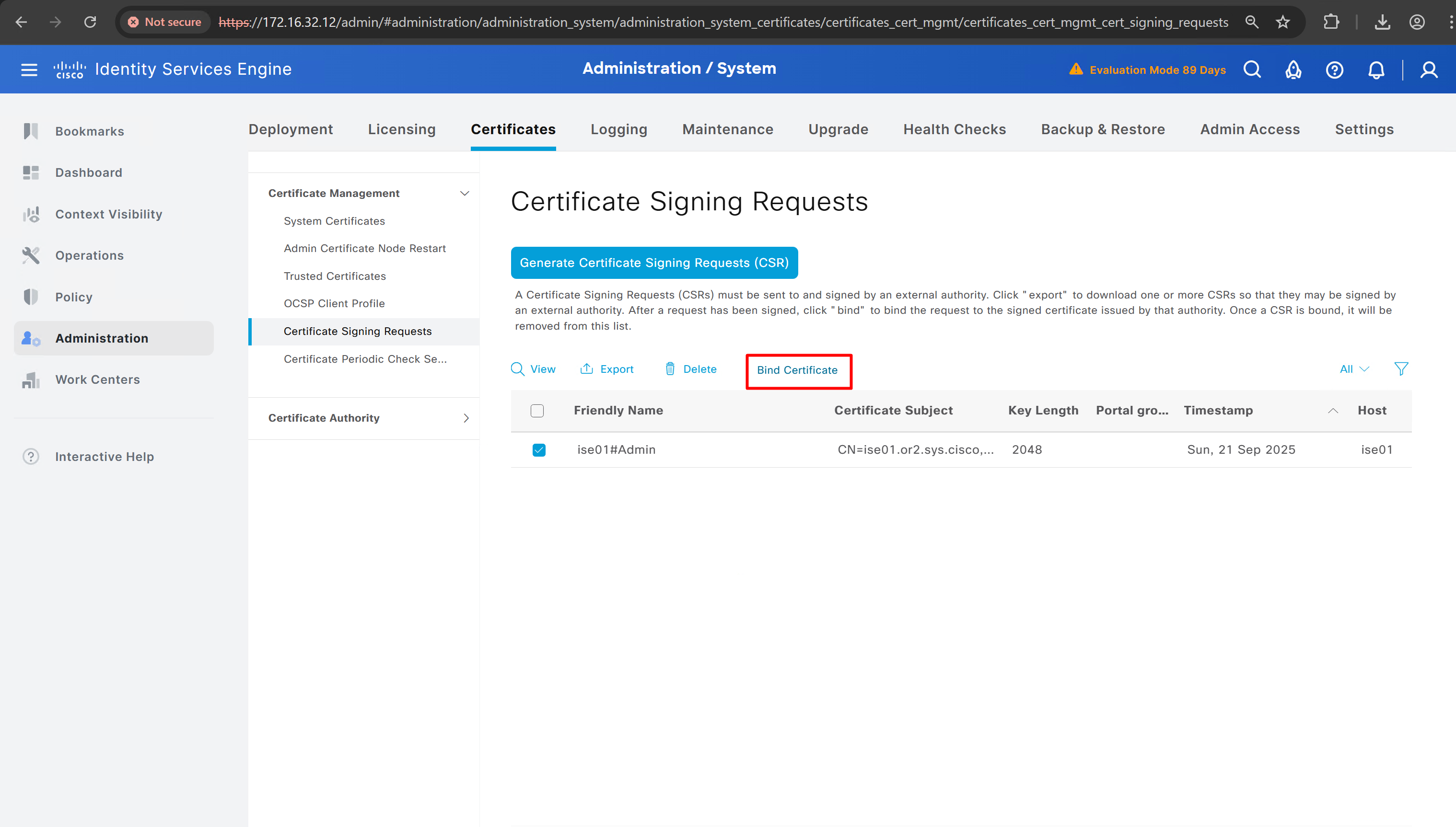
Create CSR for Admin usage
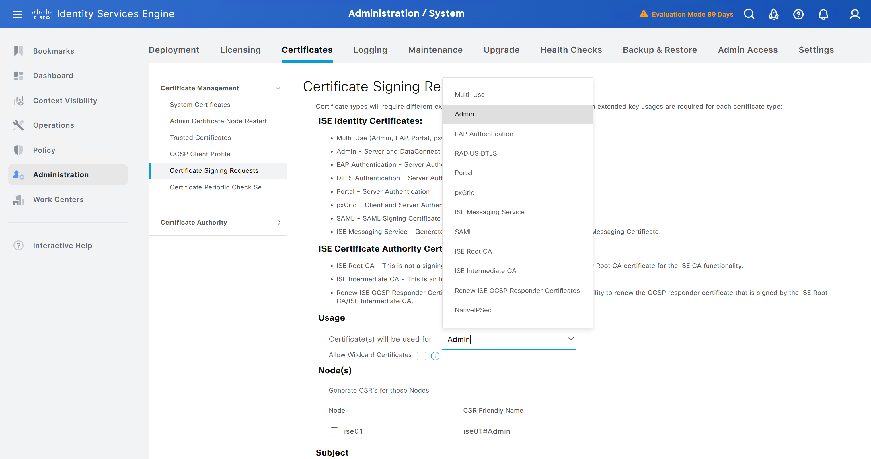
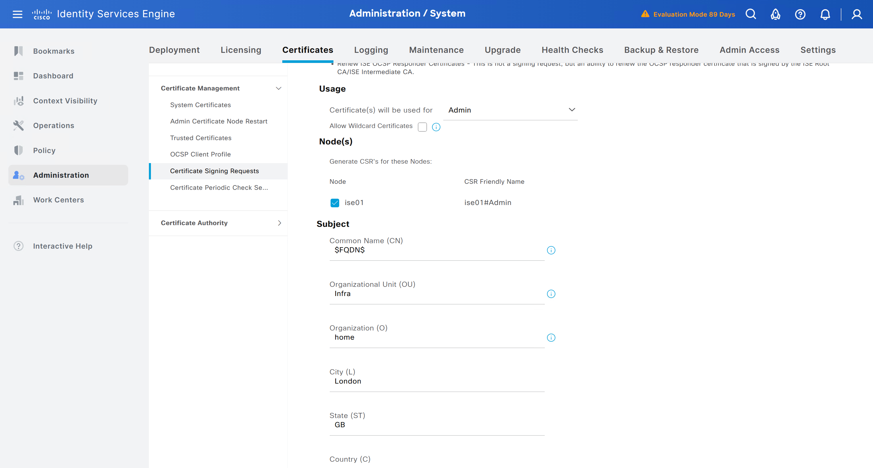
enter DNS Name as $FQDN$
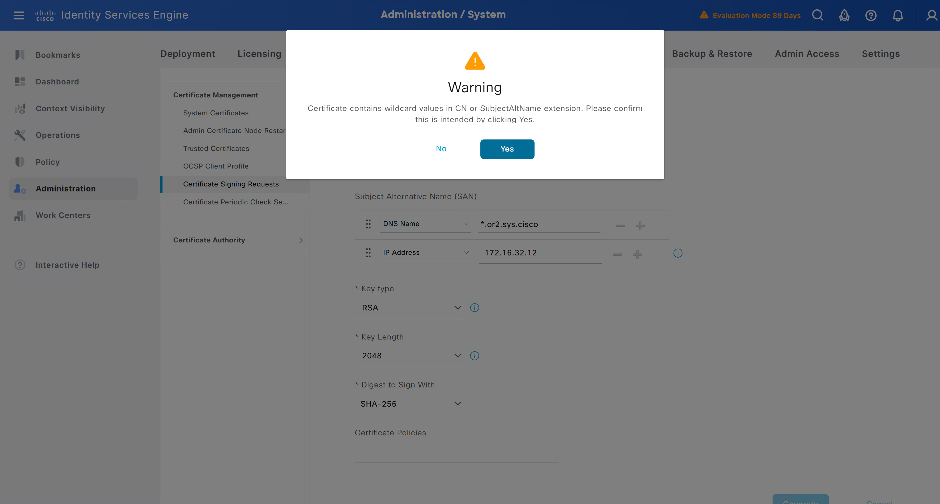
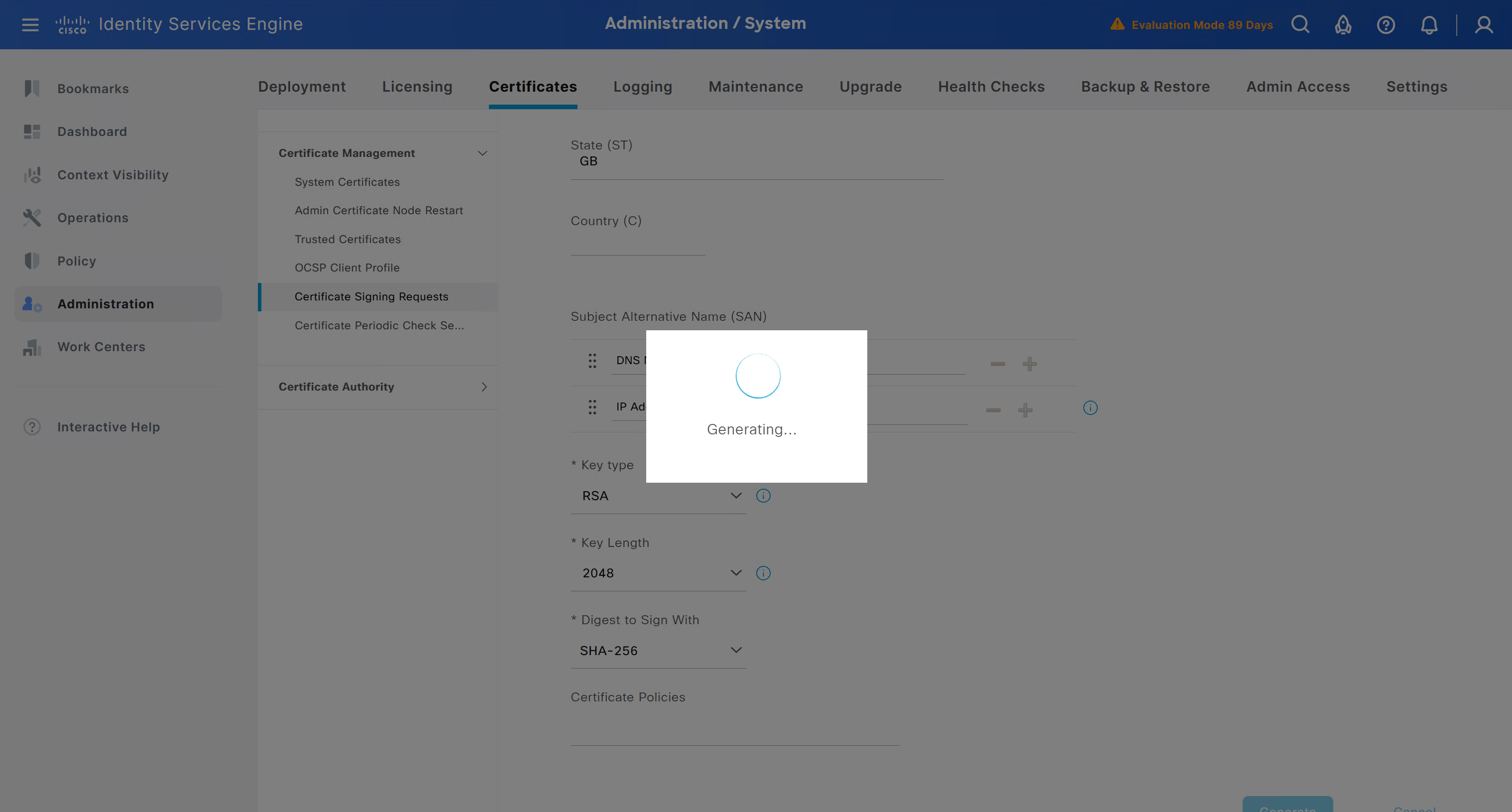
and also enter second DNS name as wildcard with remaining domain name *.or2.sys.cisco
and also add the SAN entry of type IP address with value of 172.16.32.12
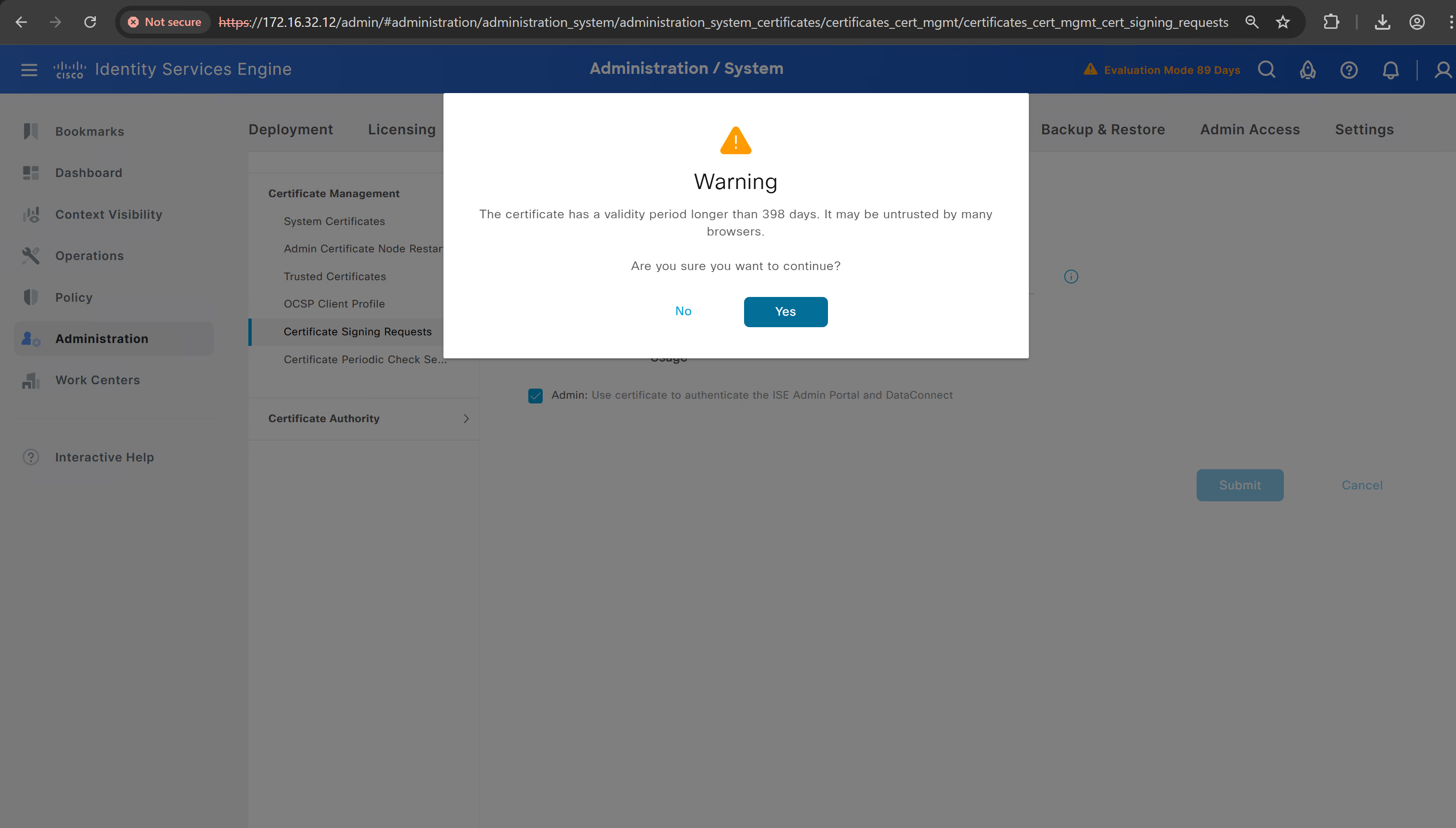
ISE gave this error
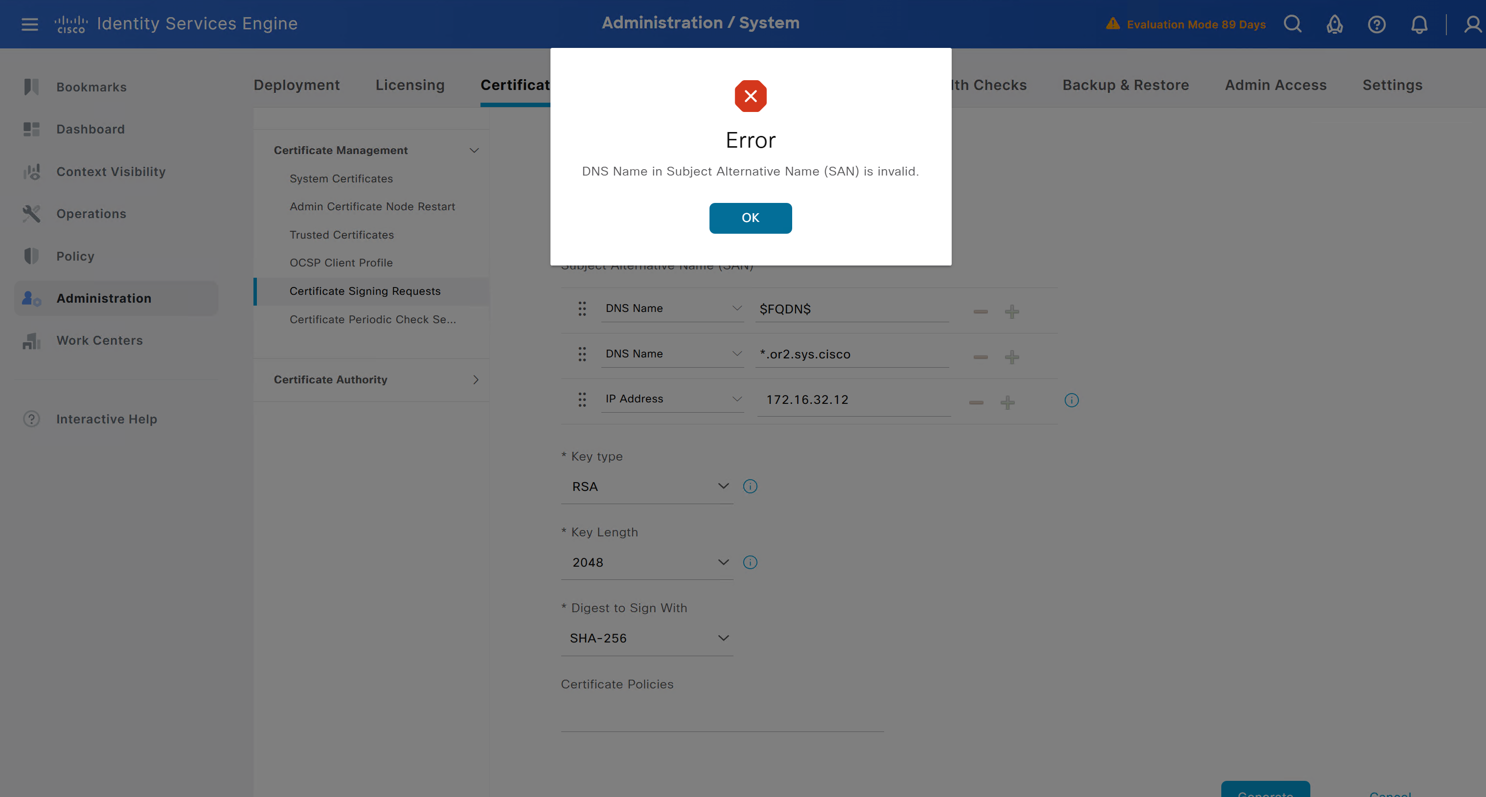
So I removed first entry of $FQDN$
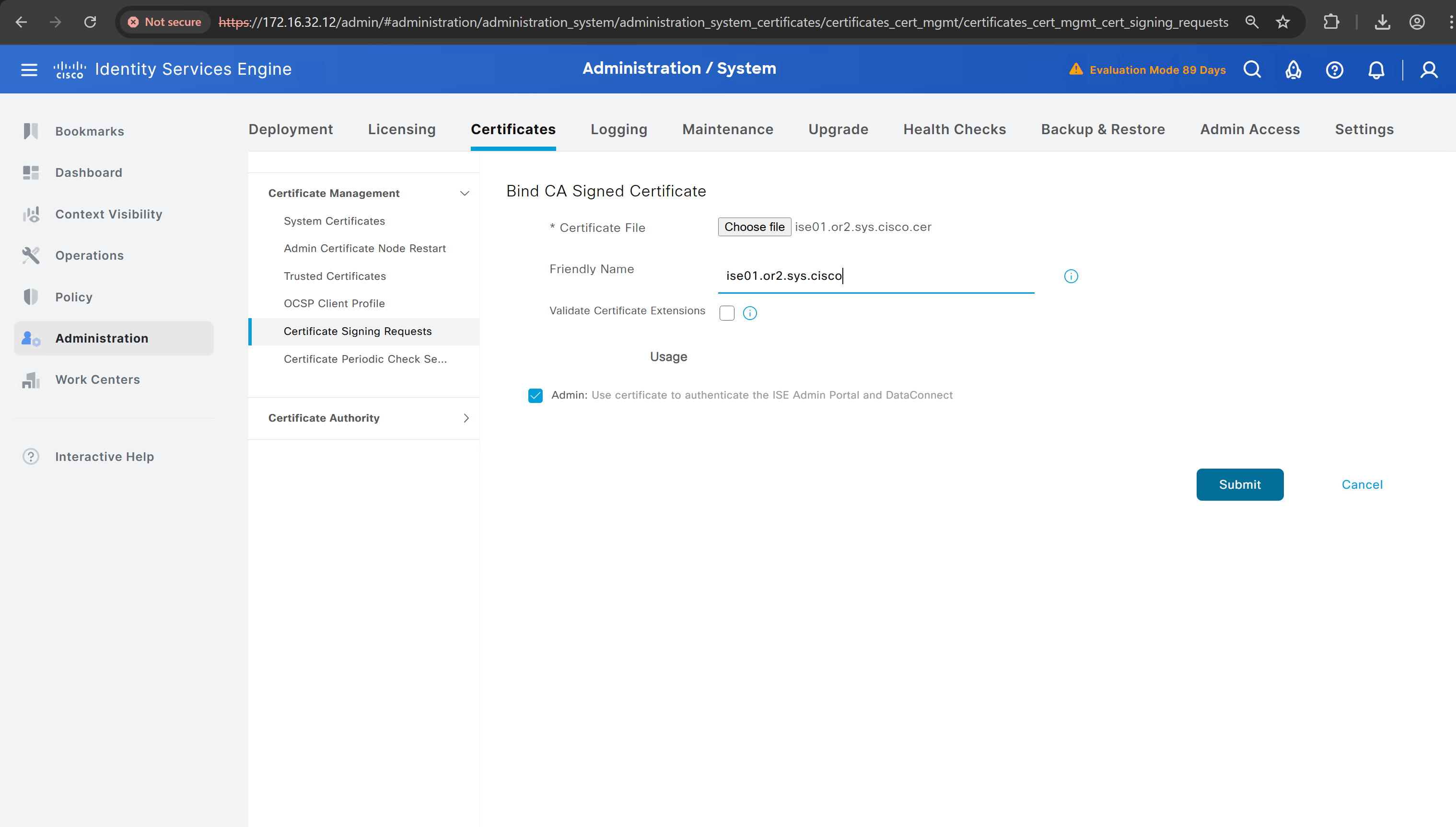
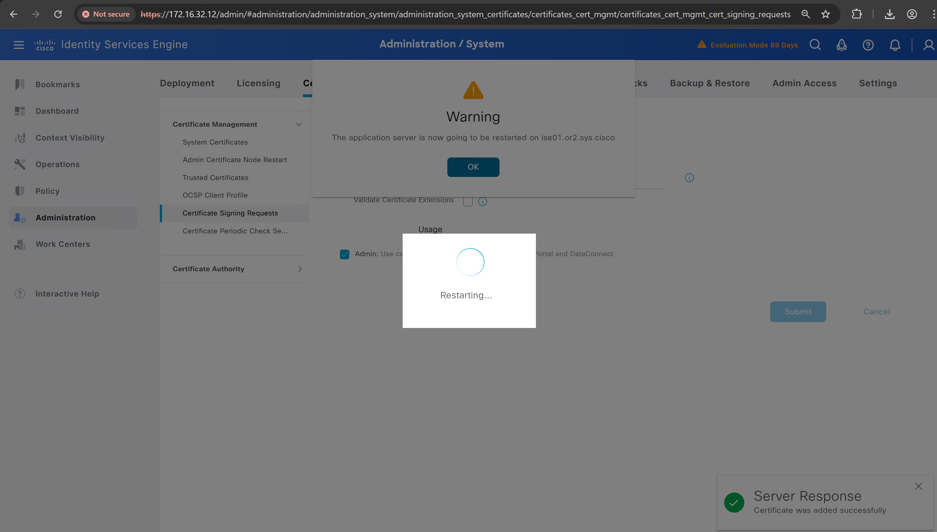
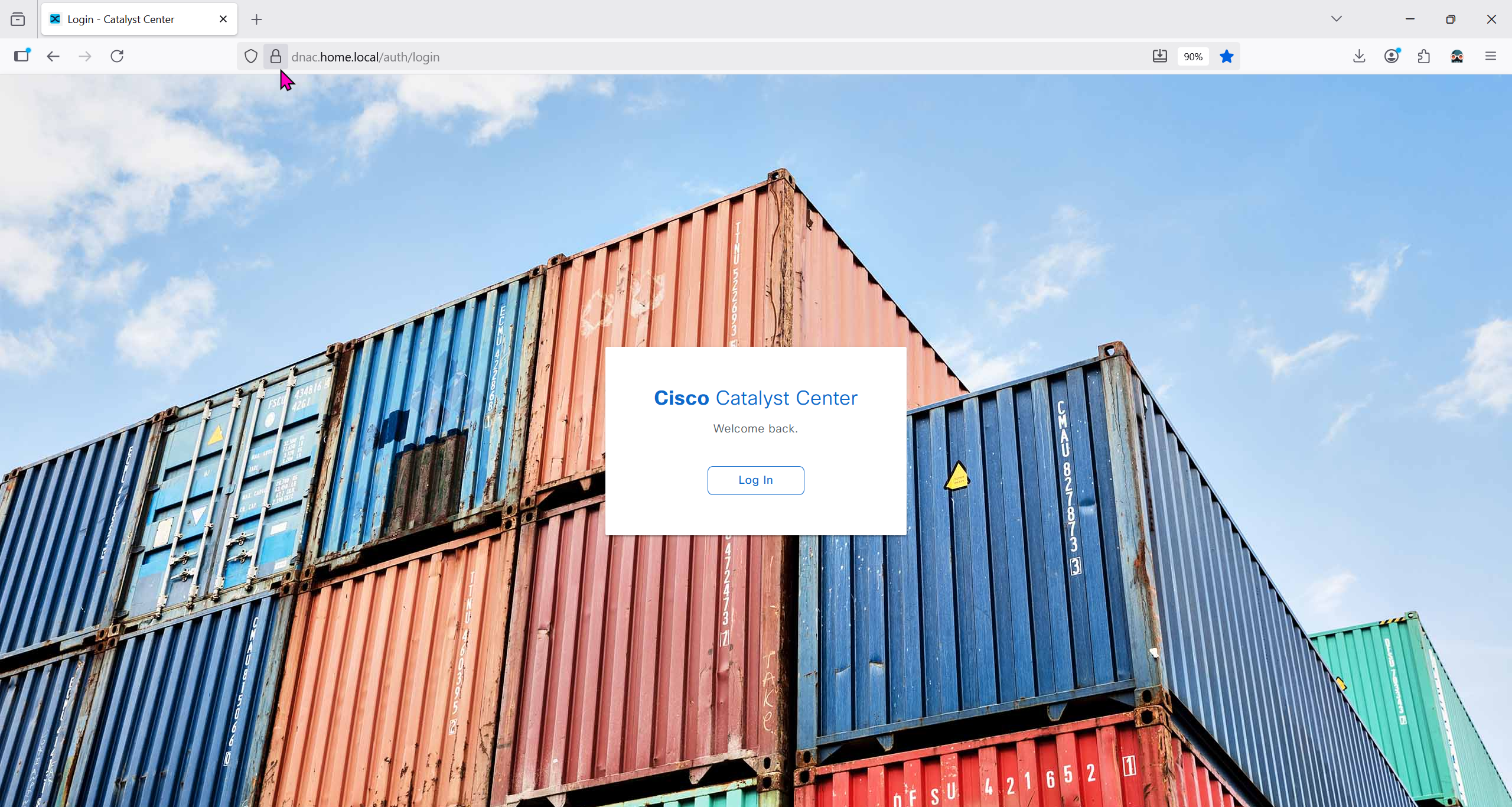
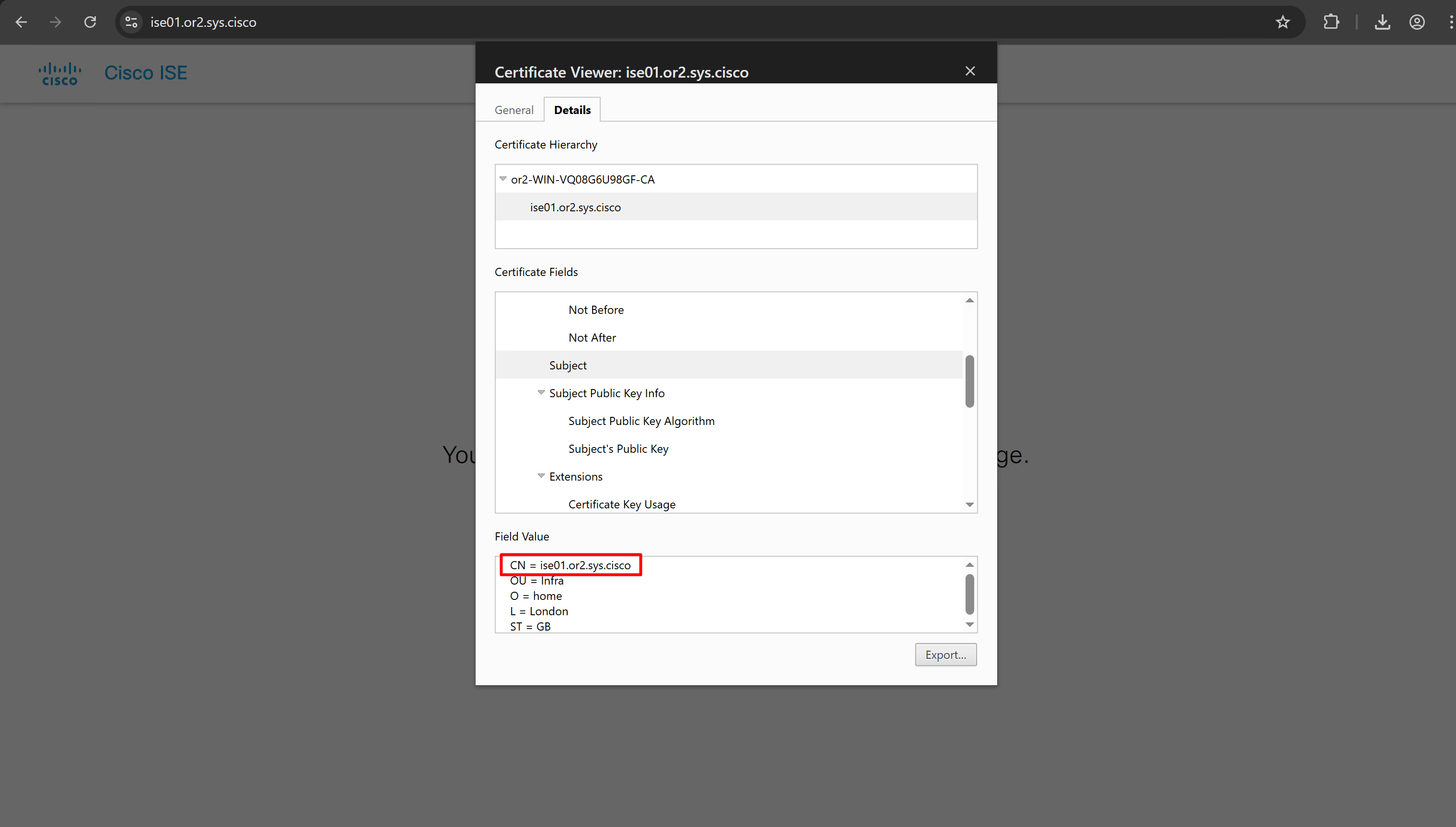
it is trusted now in browser if we access it on its FQDN
CN is the FQDN of the ISE


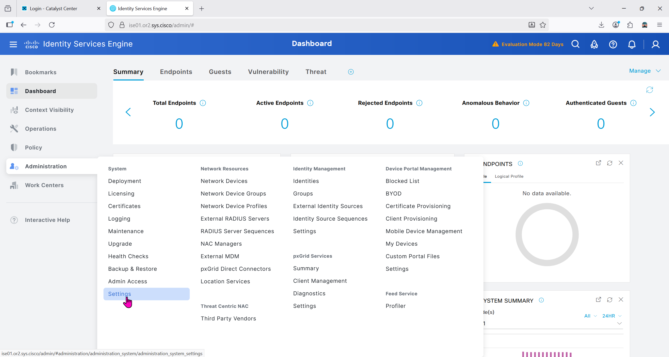
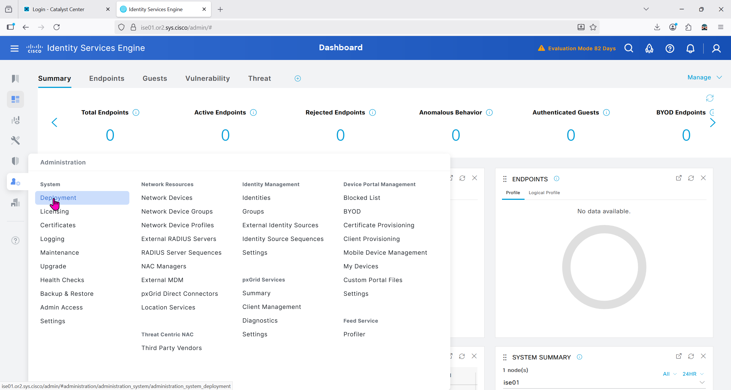
Because DNAC uses API to communicate with ISE, ERS needs to be enabled
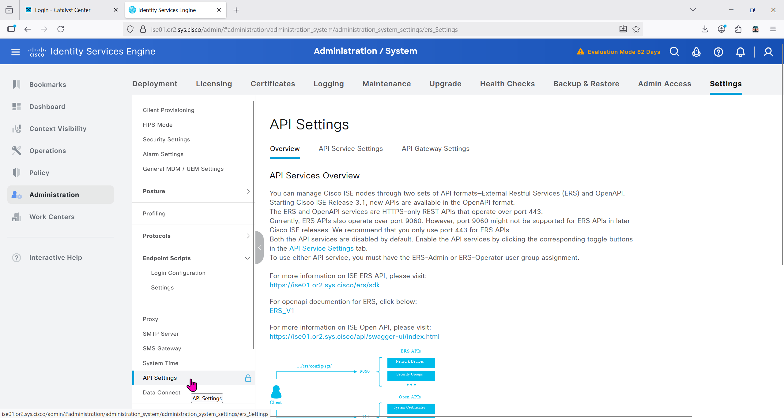


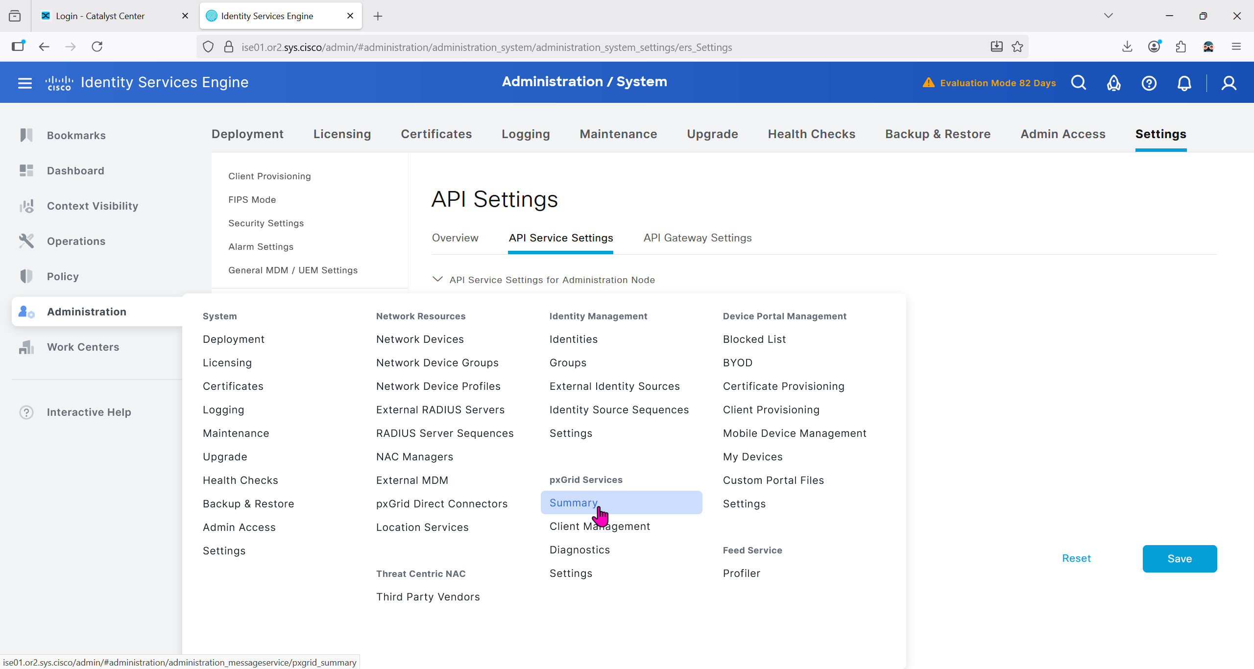
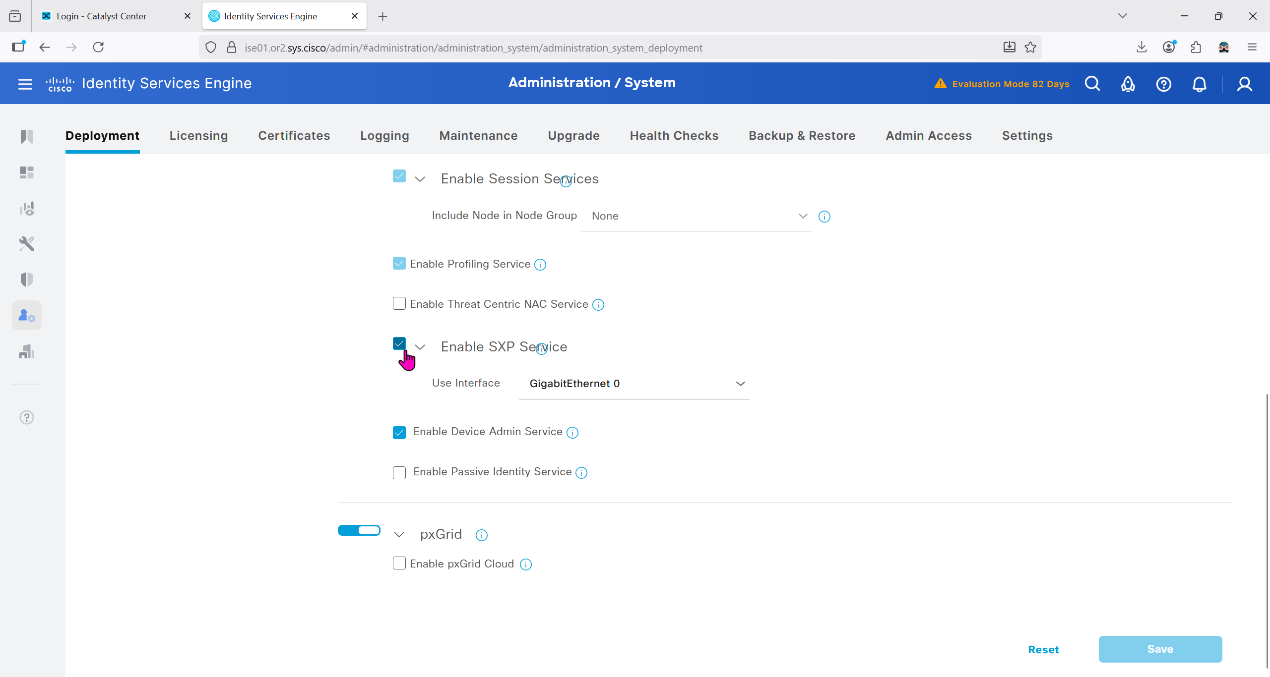
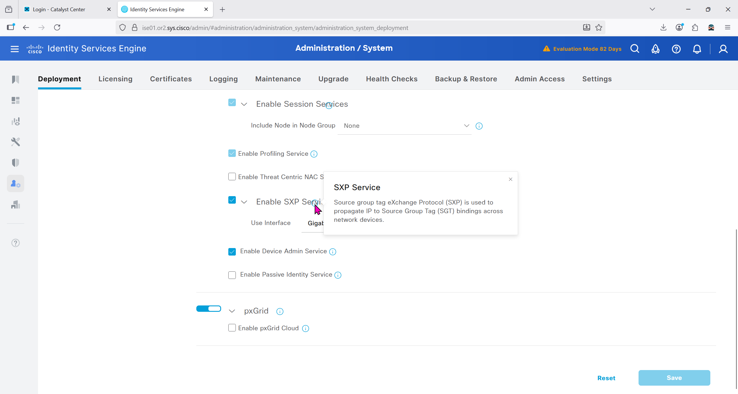
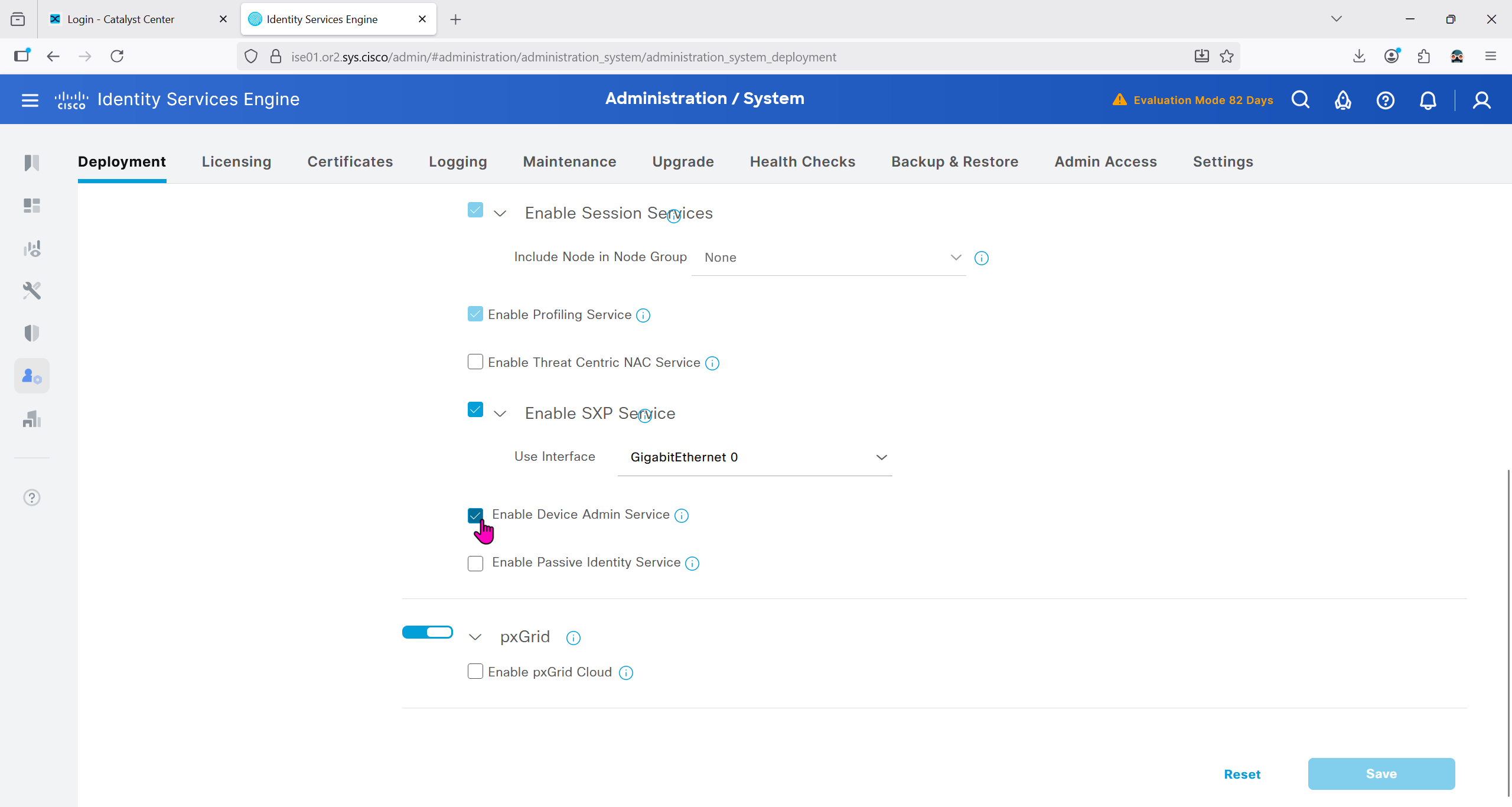
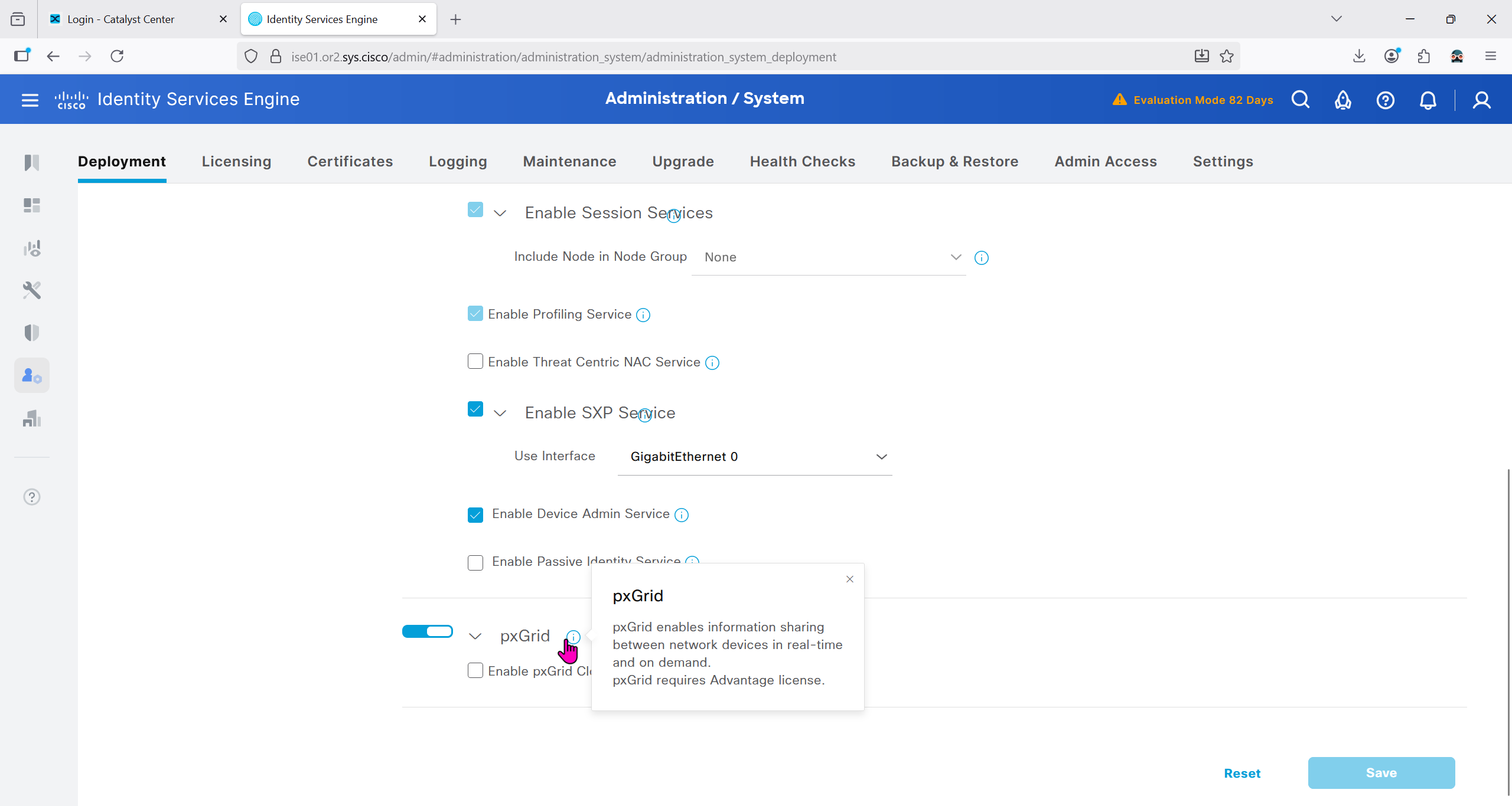
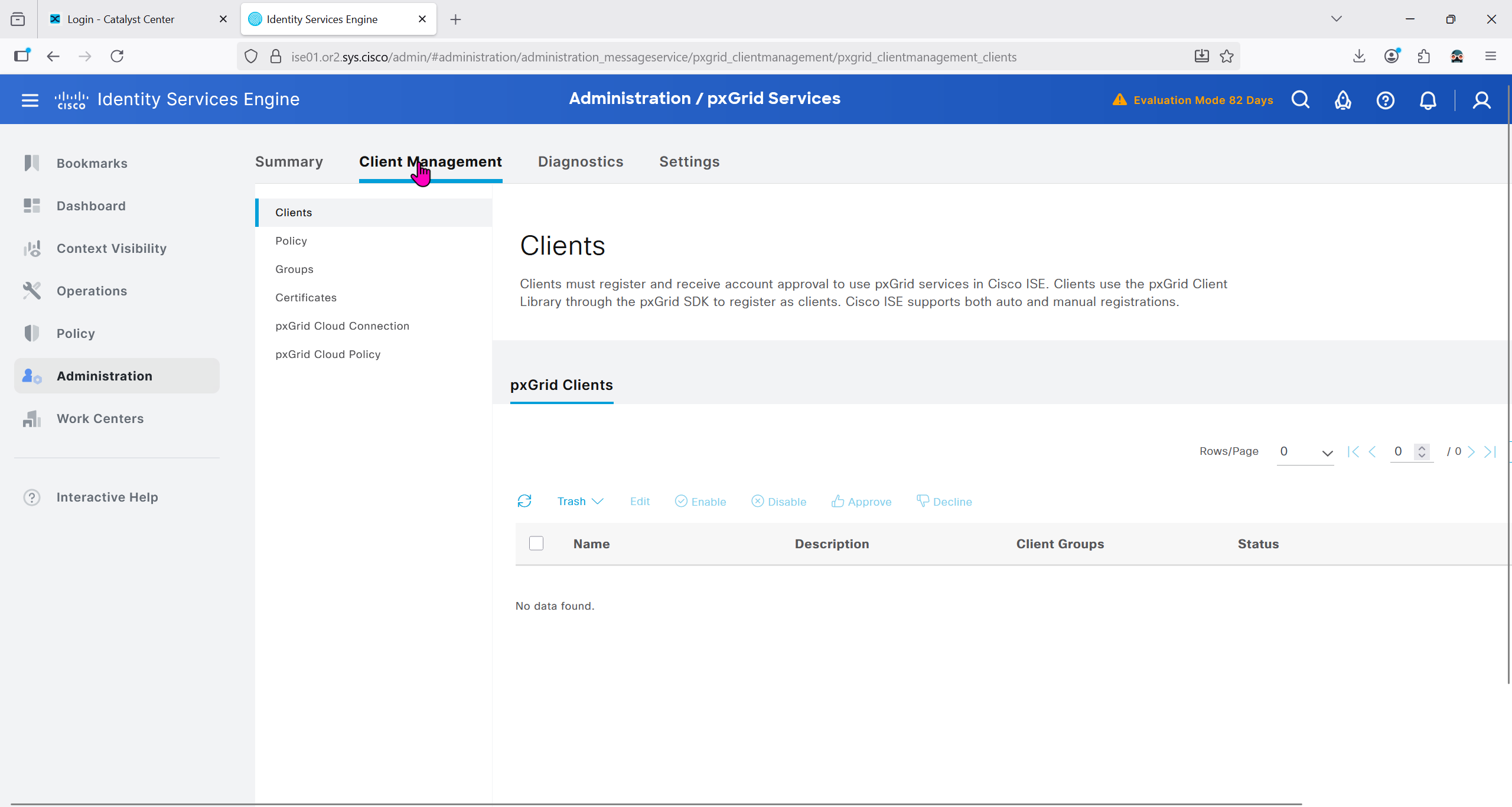
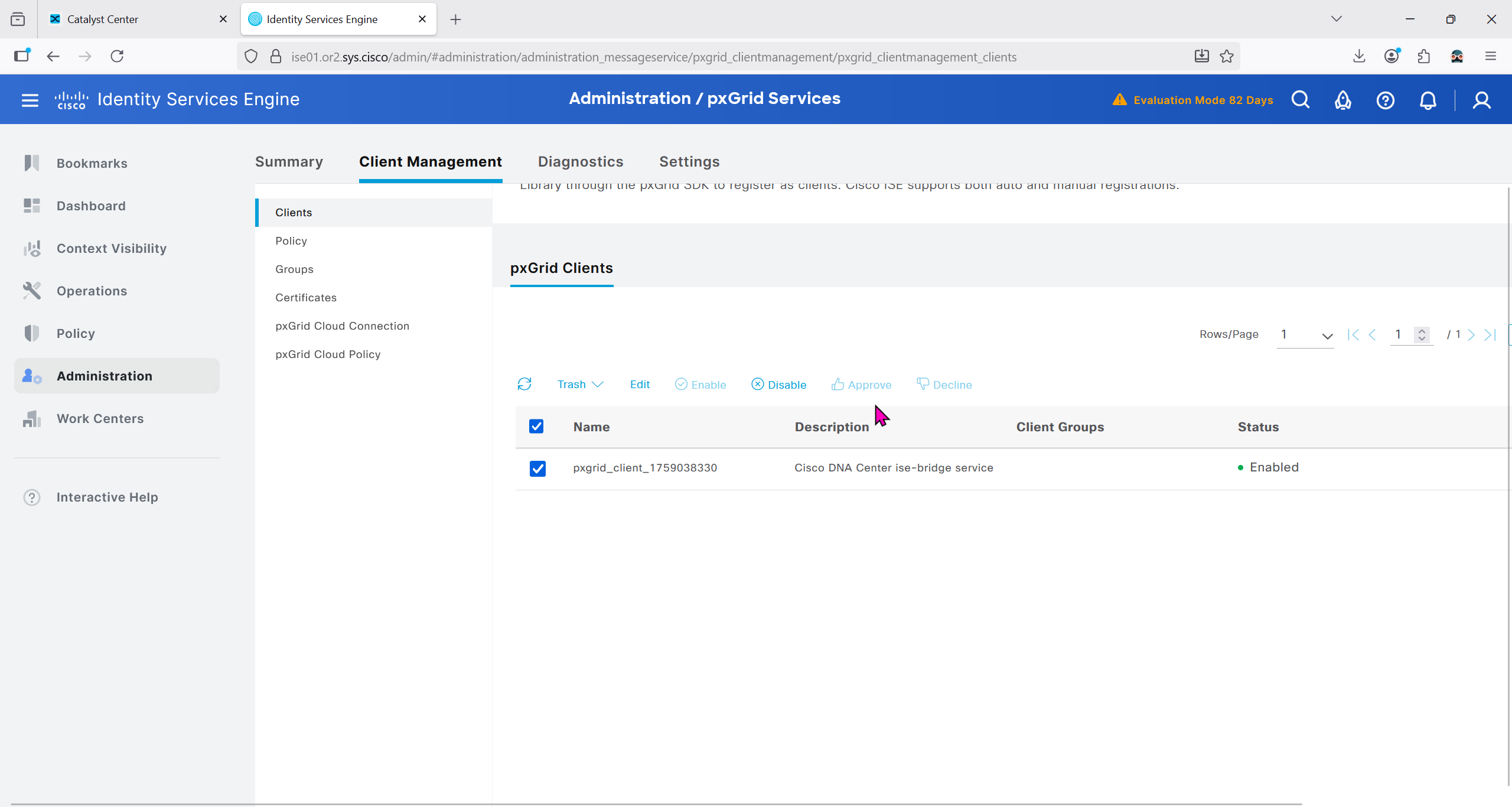
Make sure PXgrid service is running
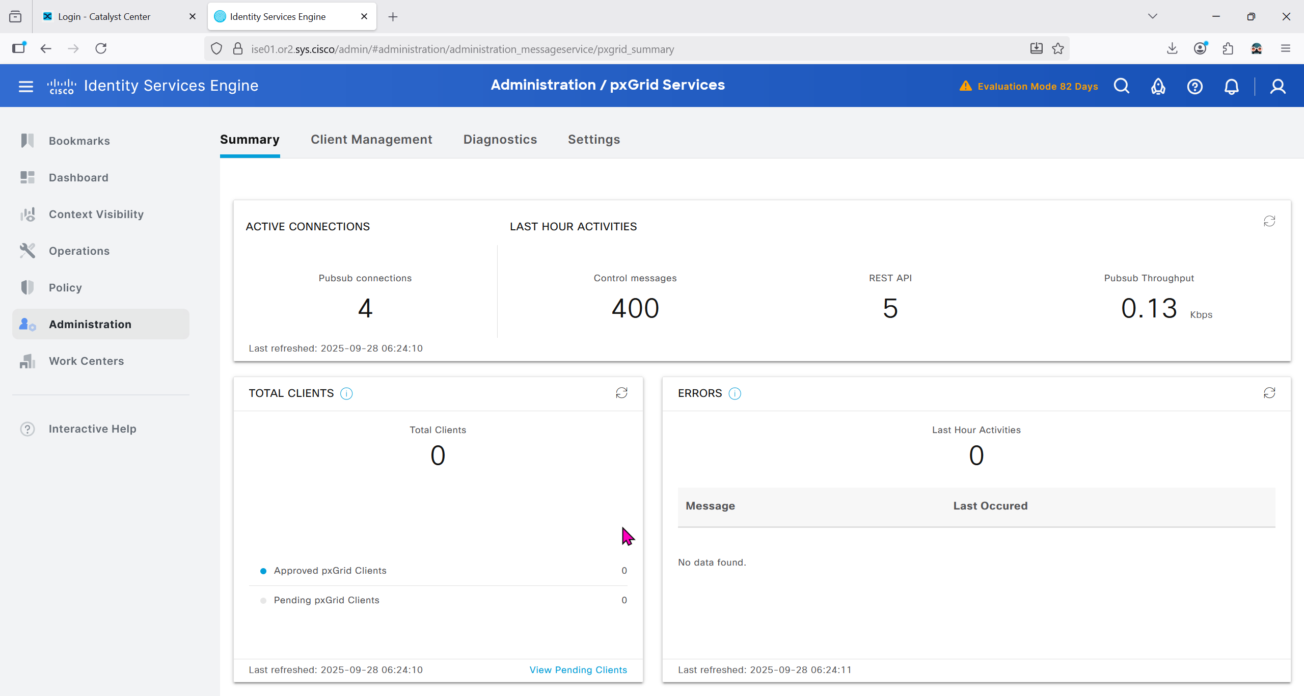
Currently in Client management we do not have any PXgrid clients yet
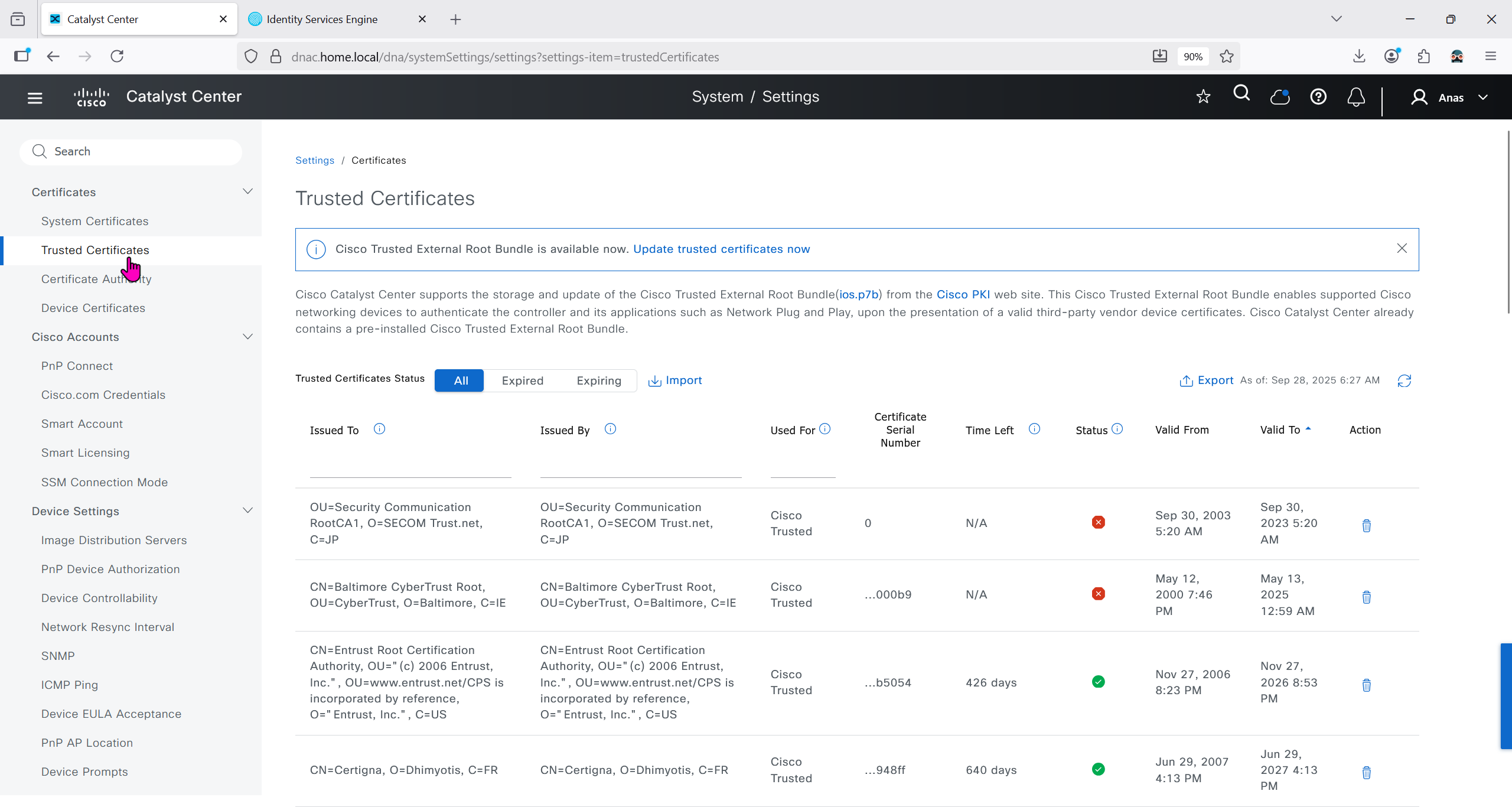
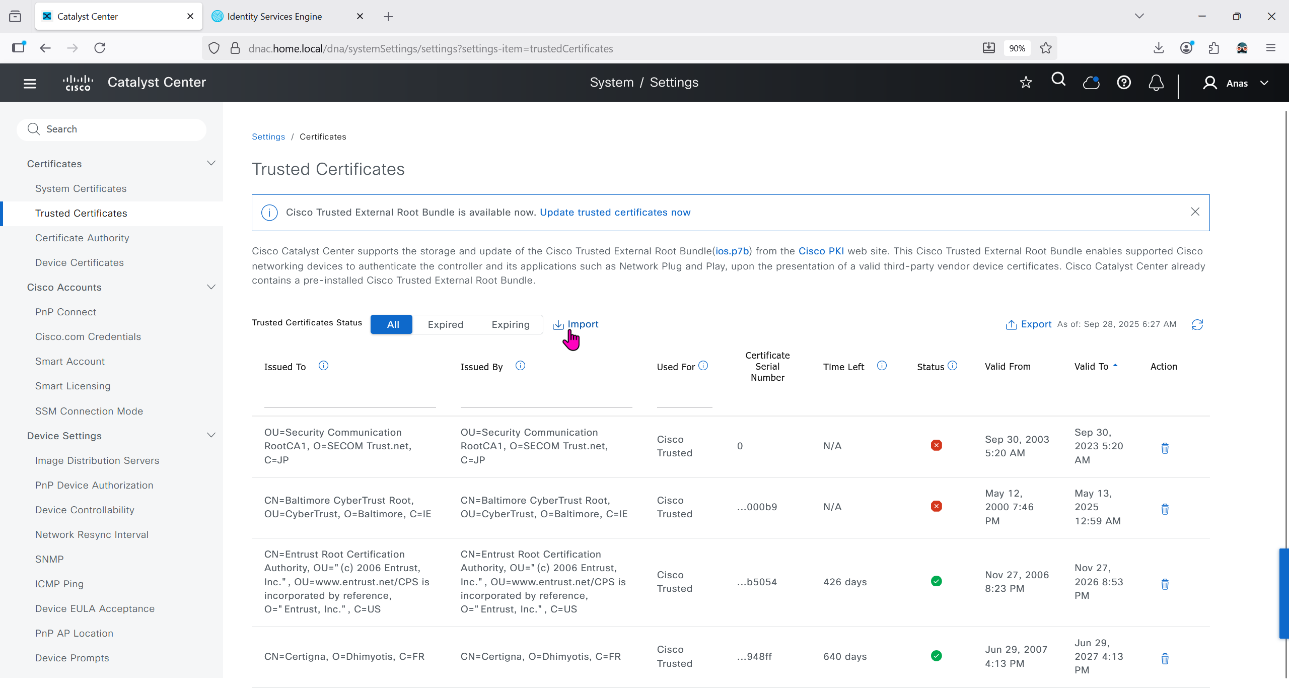
We will import the root ca cert in dnac so it can trust the certificate presented by ISE

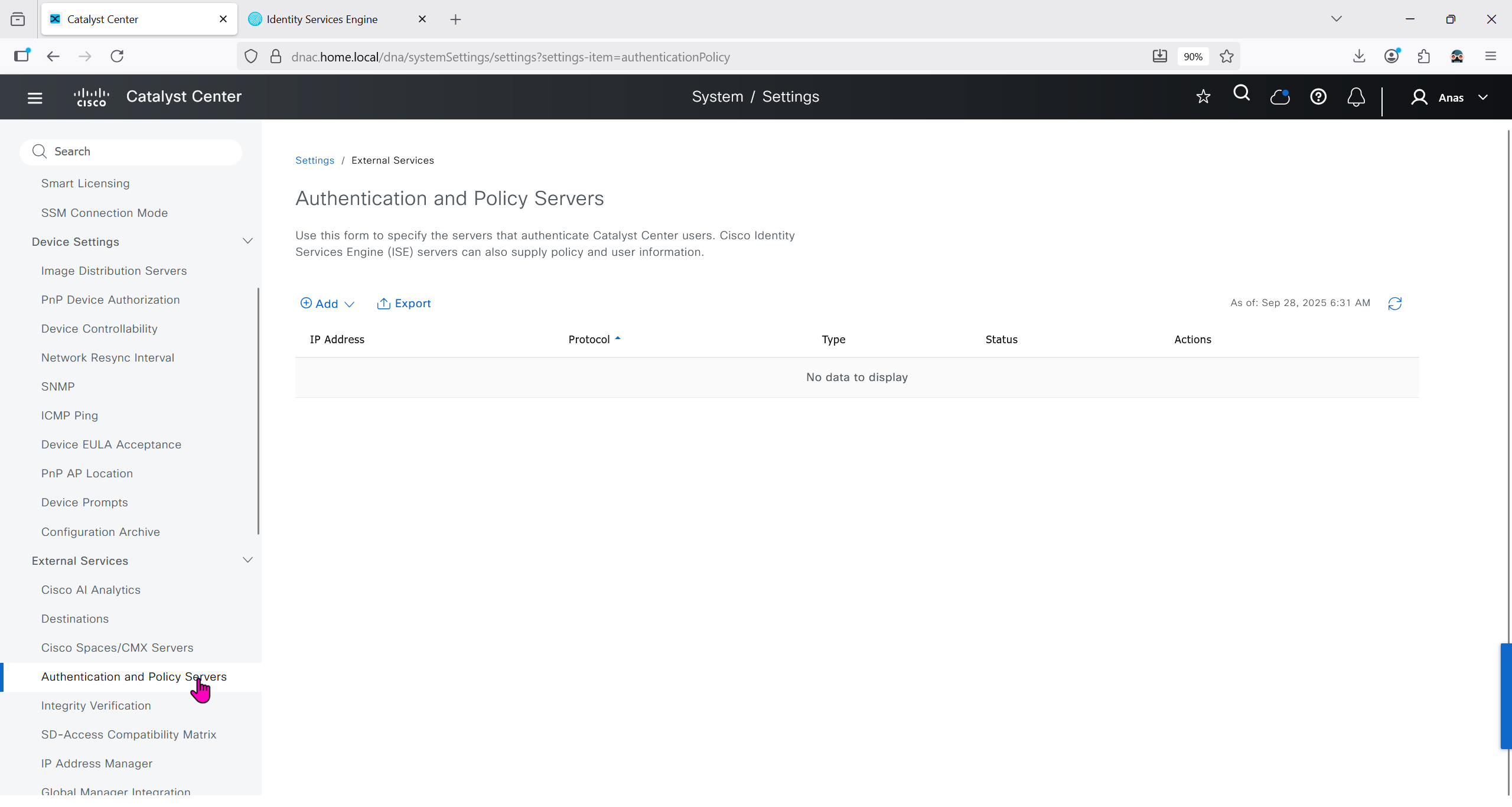
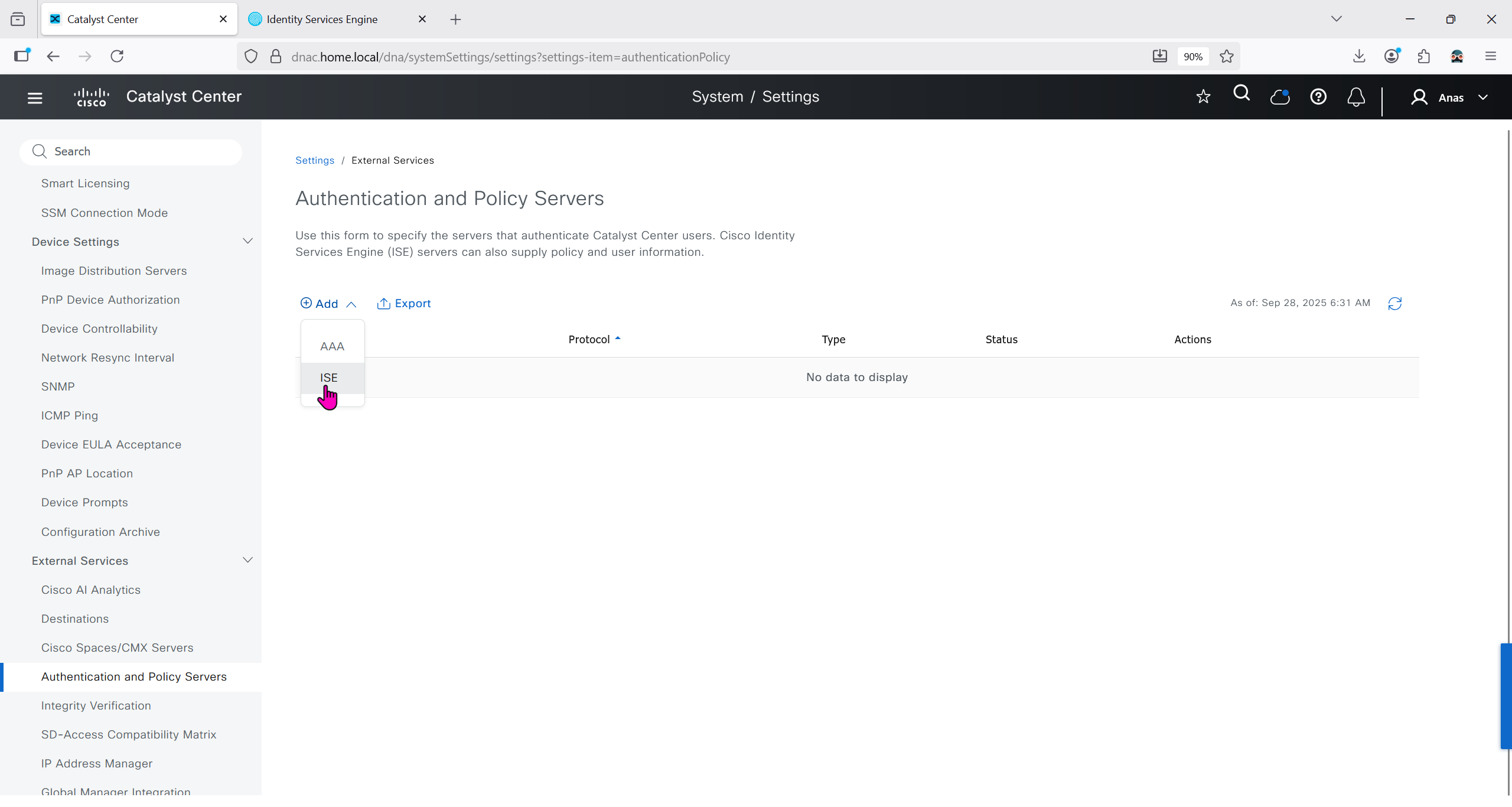
Make sure dnac can reach ise 172.16.32.12

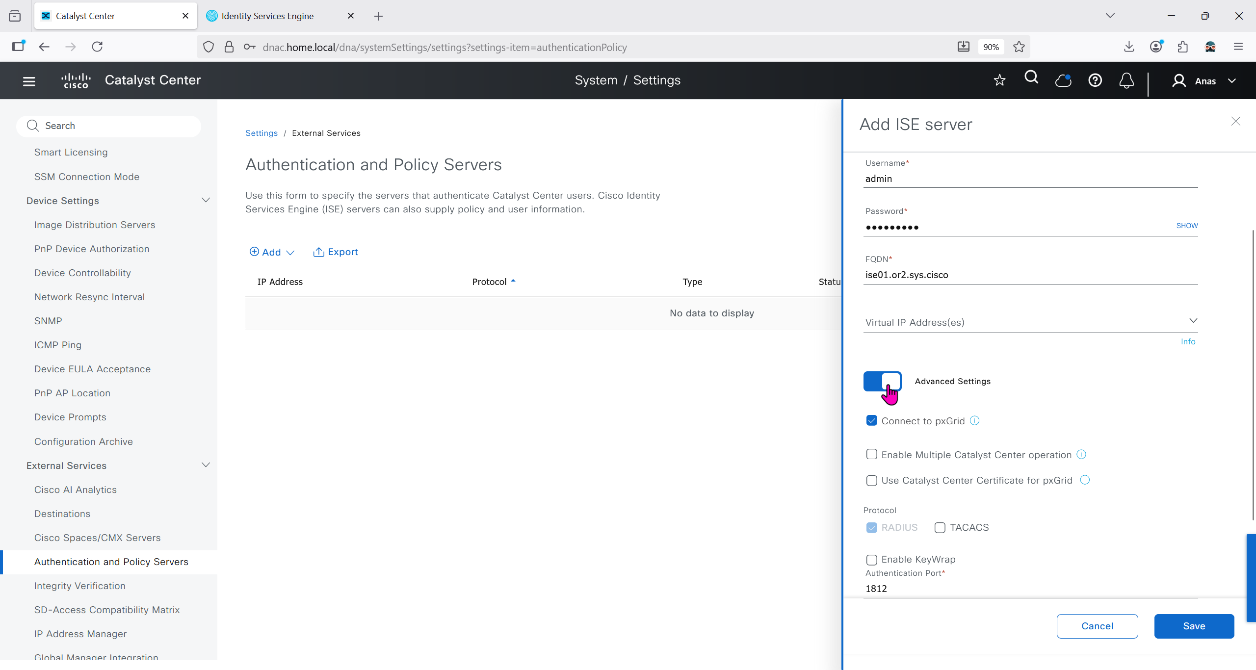
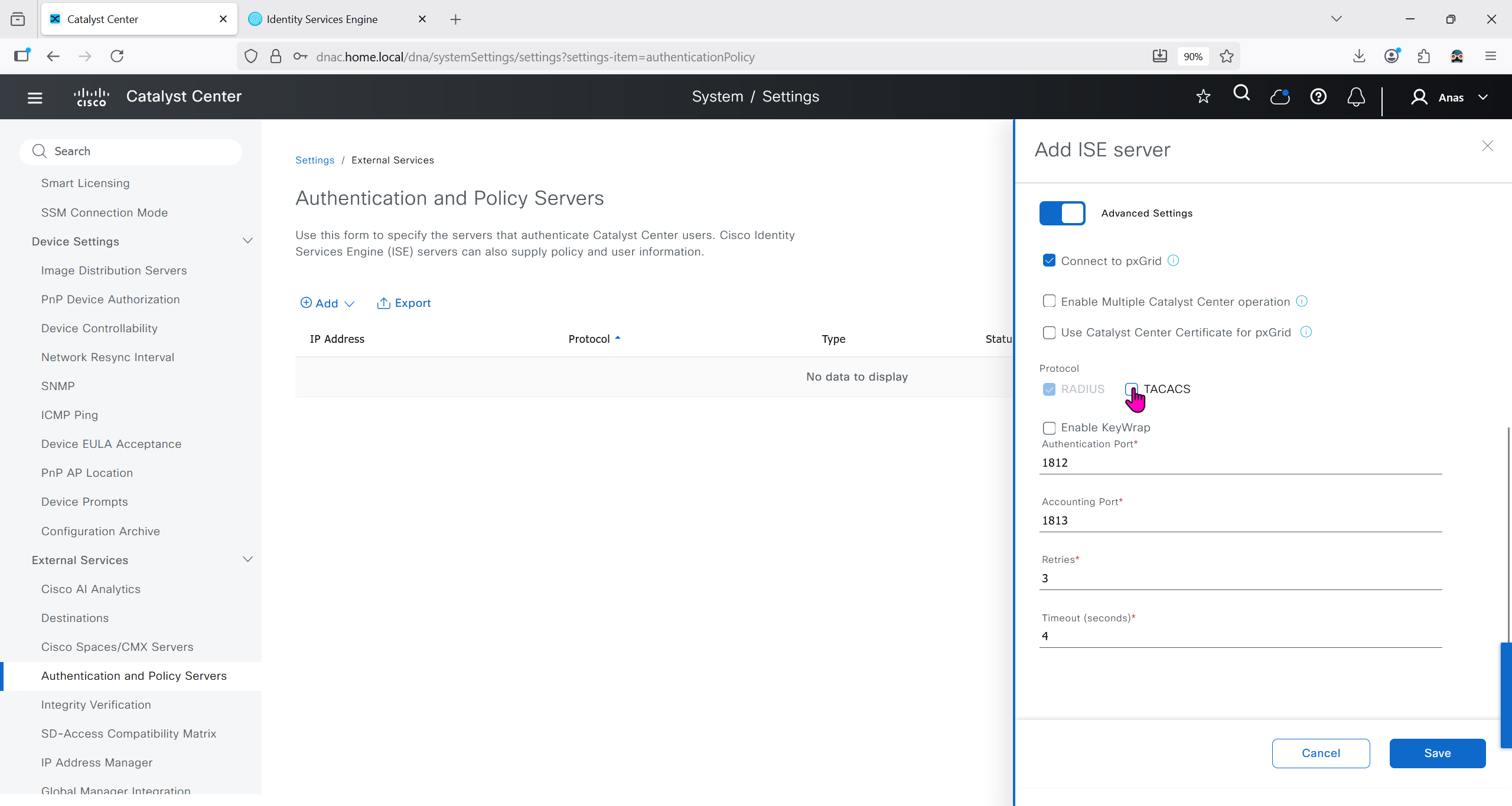
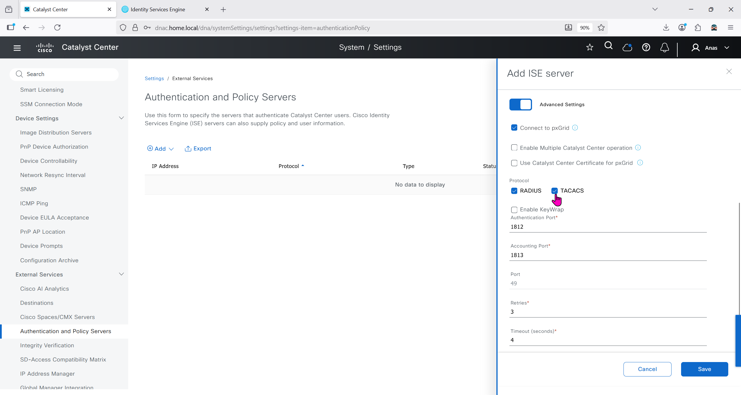
Add ISE server 172.16.32.12 and this shared secret is the secret that will be used on catalyst devices which are added to dnac
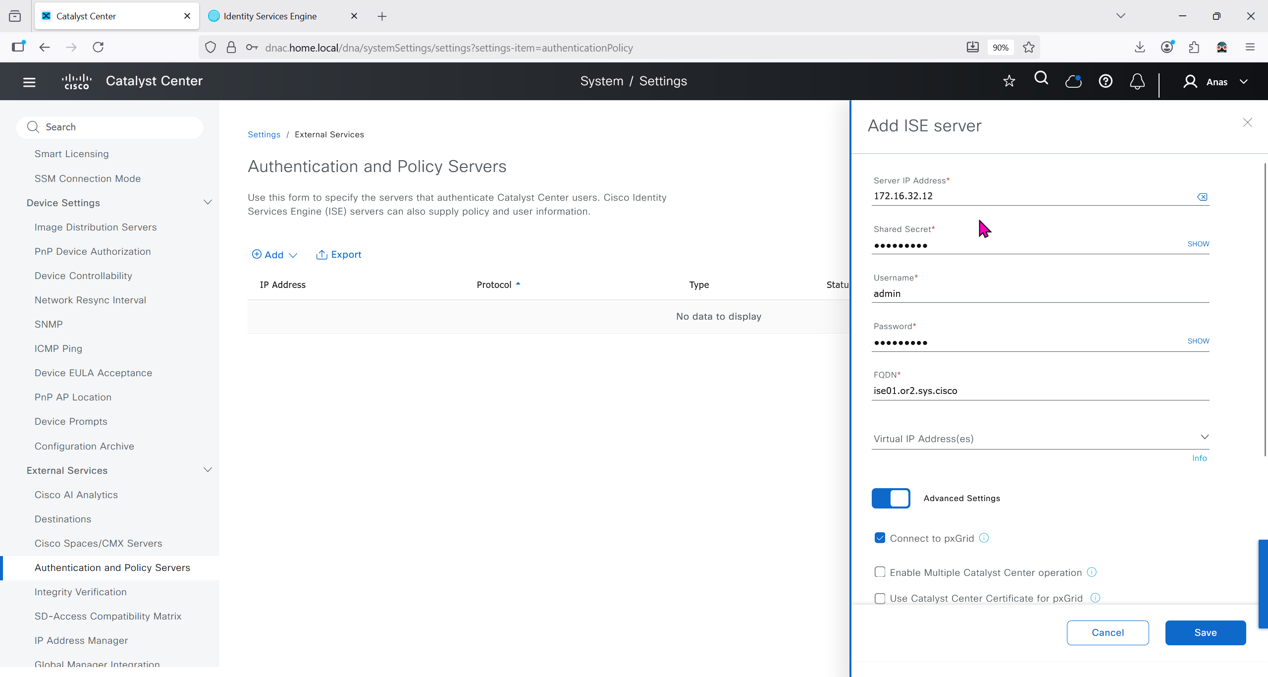

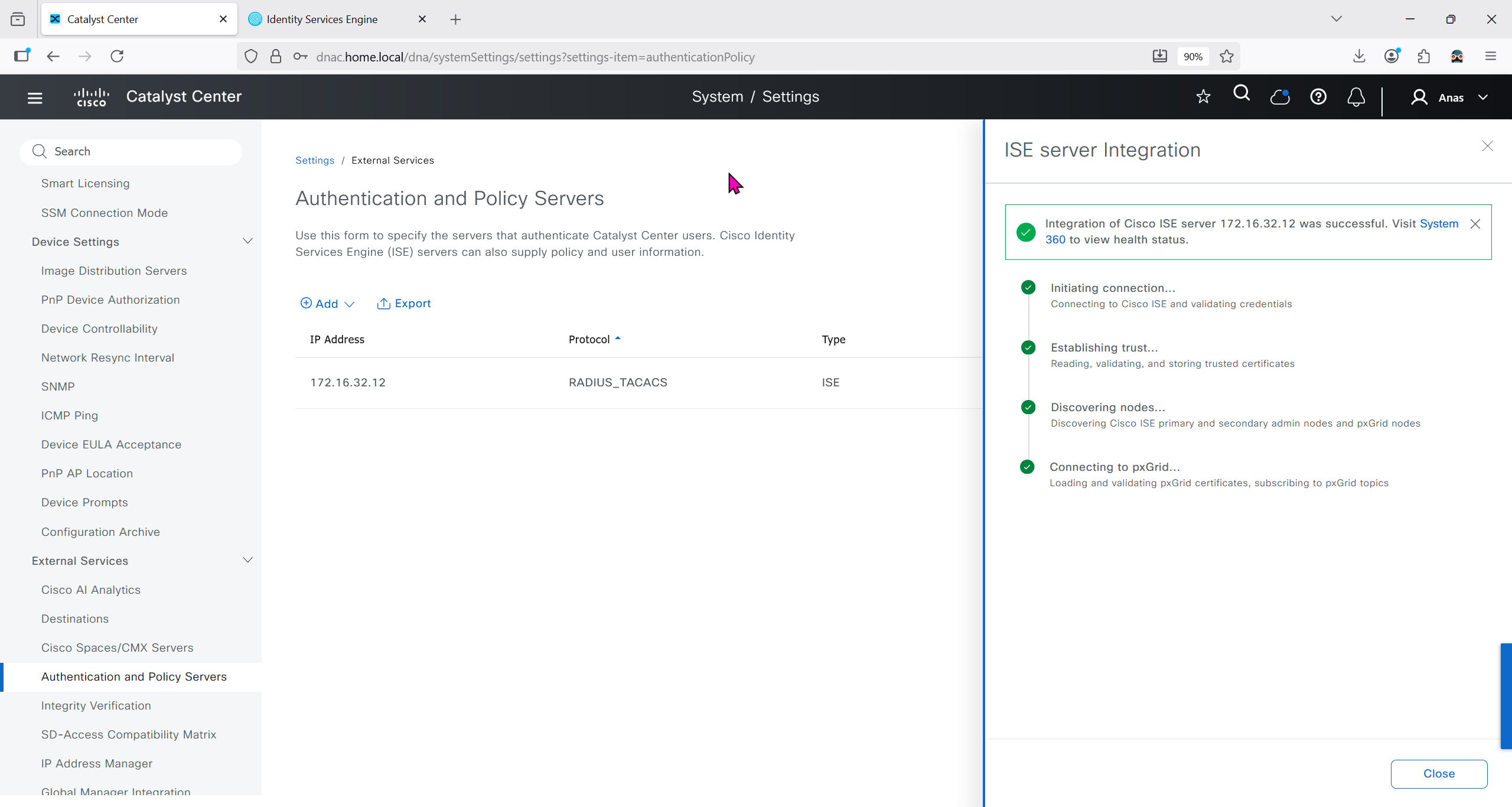
It should say IN PROGRESS and then it should move on to ACTIVE
In ISE we will check Administration > pxgrid > summary for 1 client that is dnac

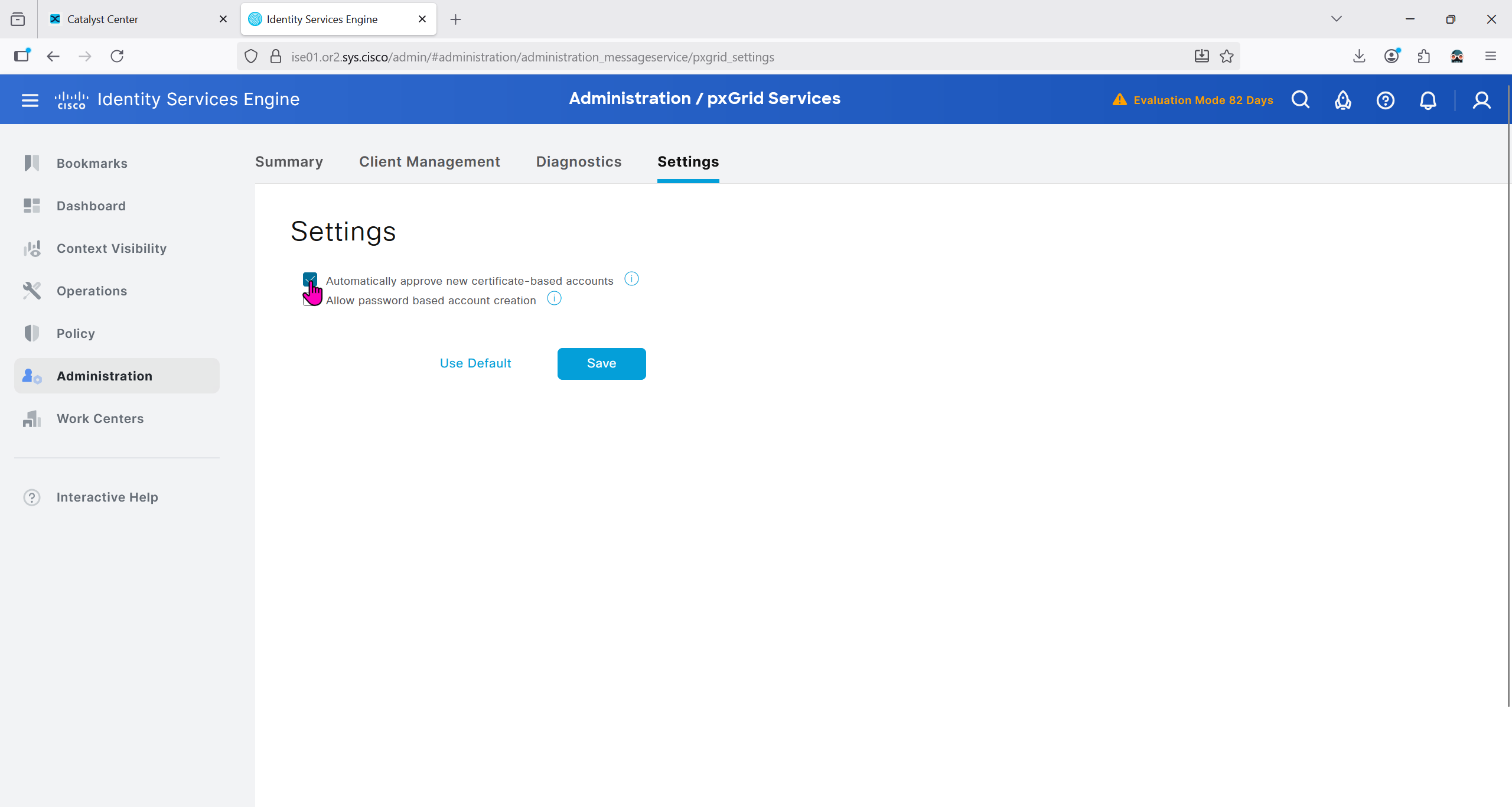
in pxgrid > client management, if dnac is showing pending then approve it


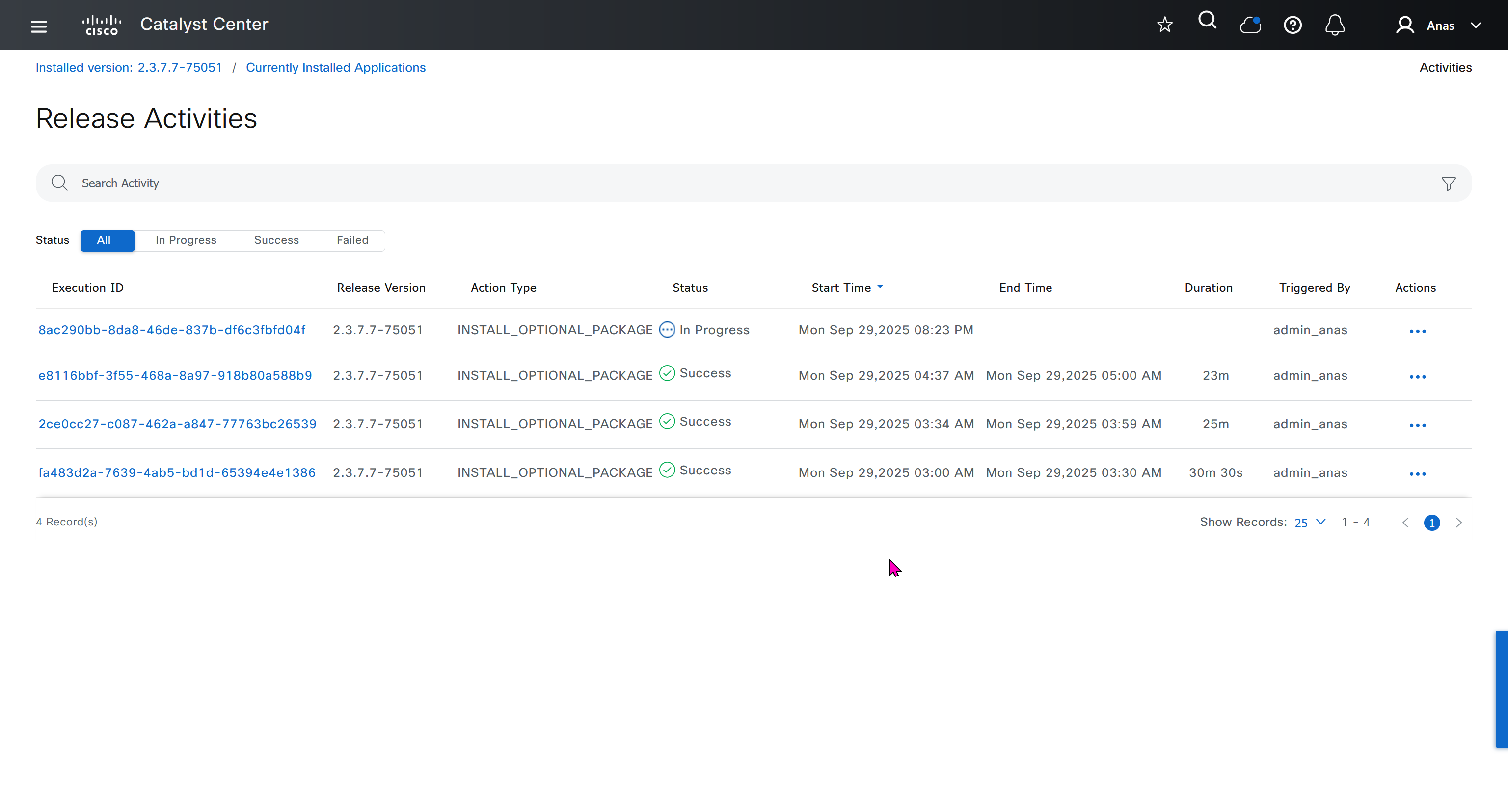
We should have installed Group based policy analytics, which we will do now
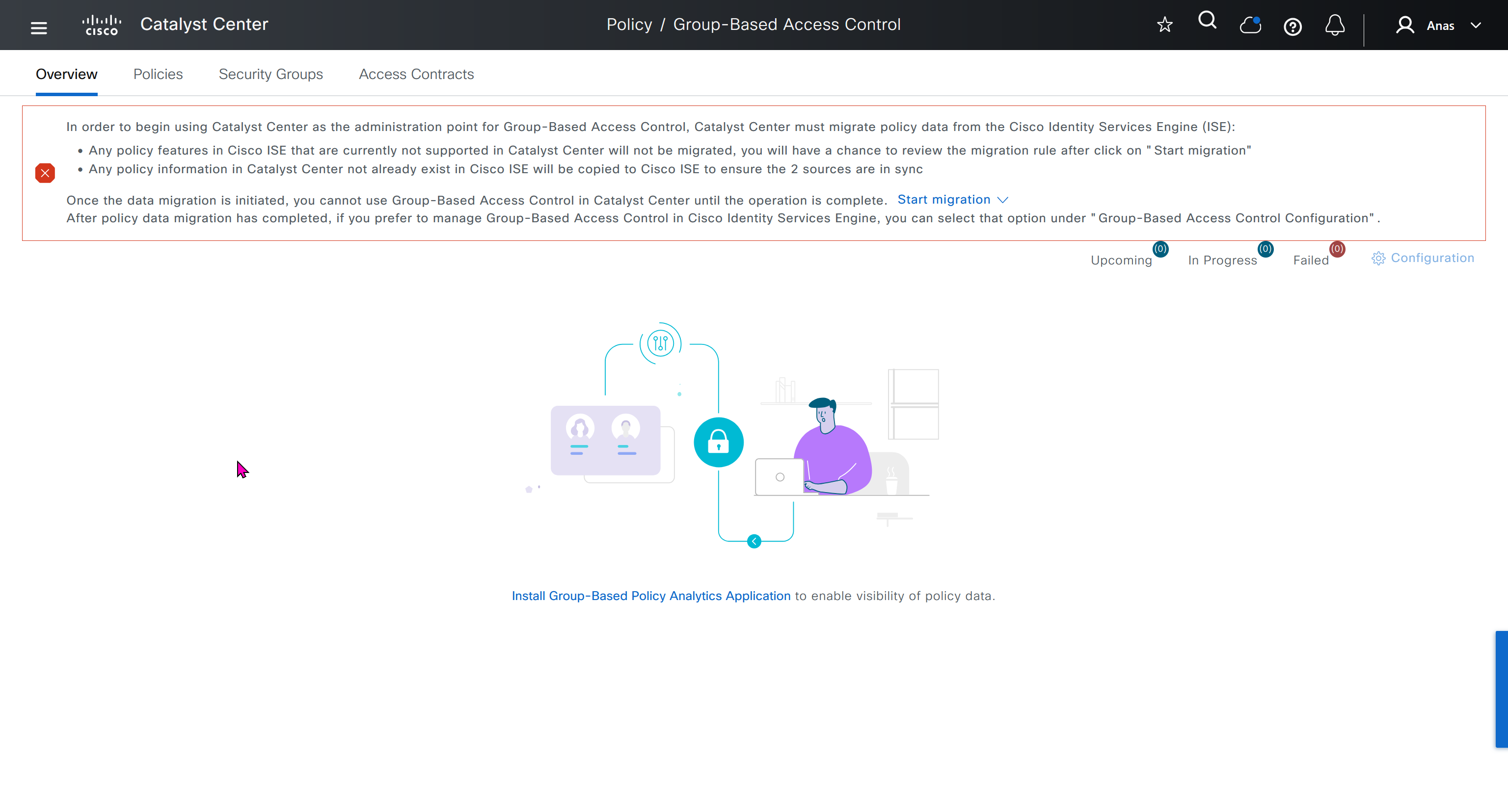

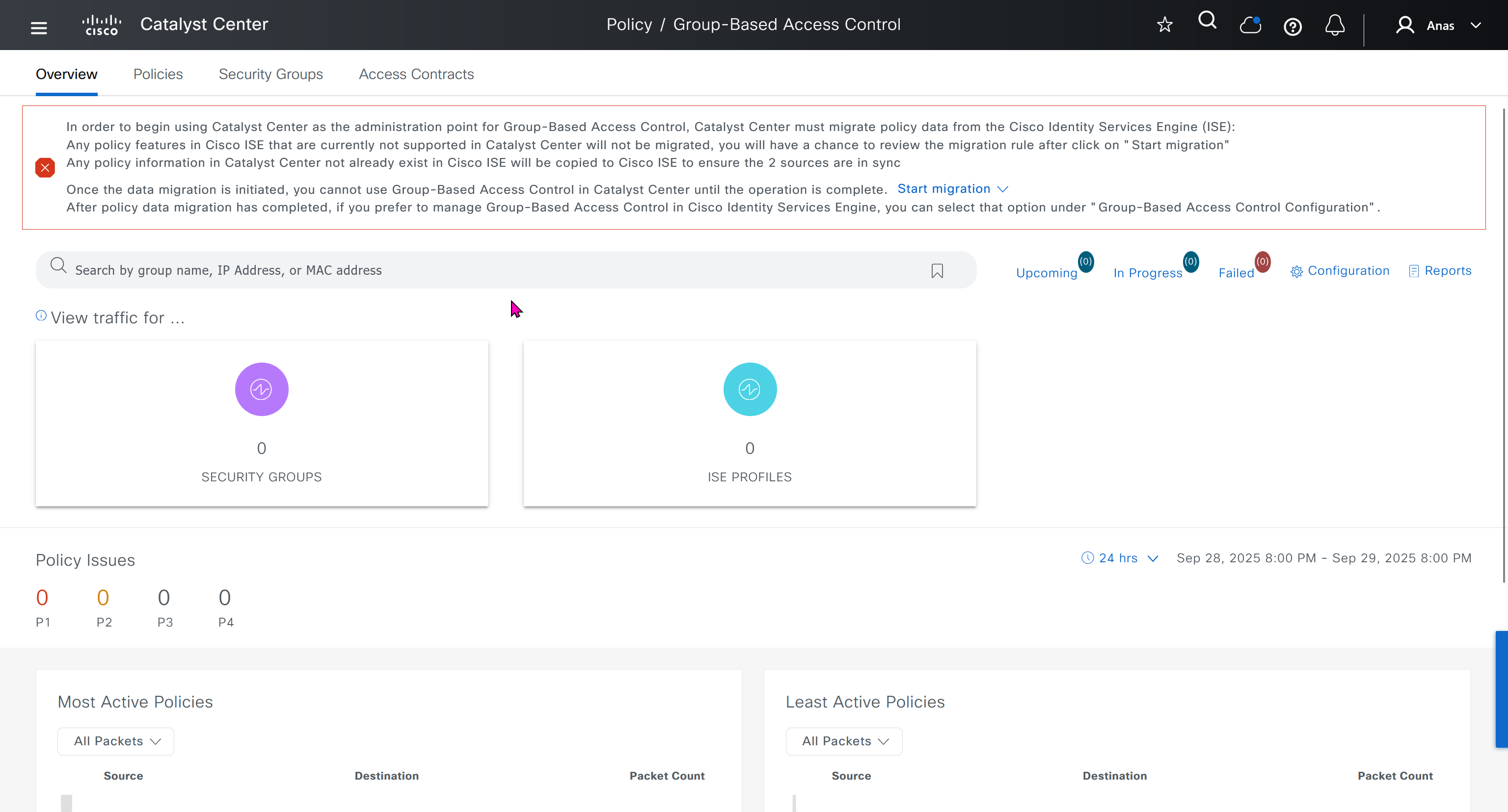
This message basically says to config sync between DNAC and ISE and use DNAC as the administration point for GBAC policy
In order to begin using Catalyst Center as the administration point for Group-Based Access Control, Catalyst Center must migrate policy data from the Cisco Identity Services Engine (ISE):
Any policy features in Cisco ISE that are currently not supported in Catalyst Center will not be migrated, you will have a chance to review the migration rule after click on "Start migration"
Any policy information in Catalyst Center not already exist in Cisco ISE will be copied to Cisco ISE to ensure the 2 sources are in sync
Once the data migration is initiated, you cannot use Group-Based Access Control in Catalyst Center until the operation is complete.
Start migration
After policy data migration has completed, if you prefer to manage Group-Based Access Control in Cisco Identity Services Engine, you can select that option under “Group-Based Access Control Configuration”.
We need to click on Start migration, Backup is recommended because this is a 2 way sync and configuration in ISE will also change if there is pre existing config in DNAC
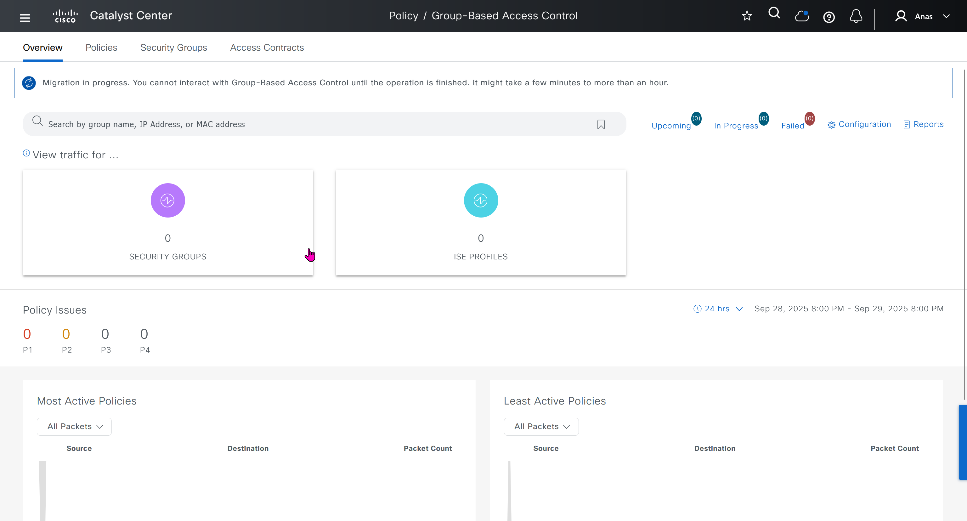
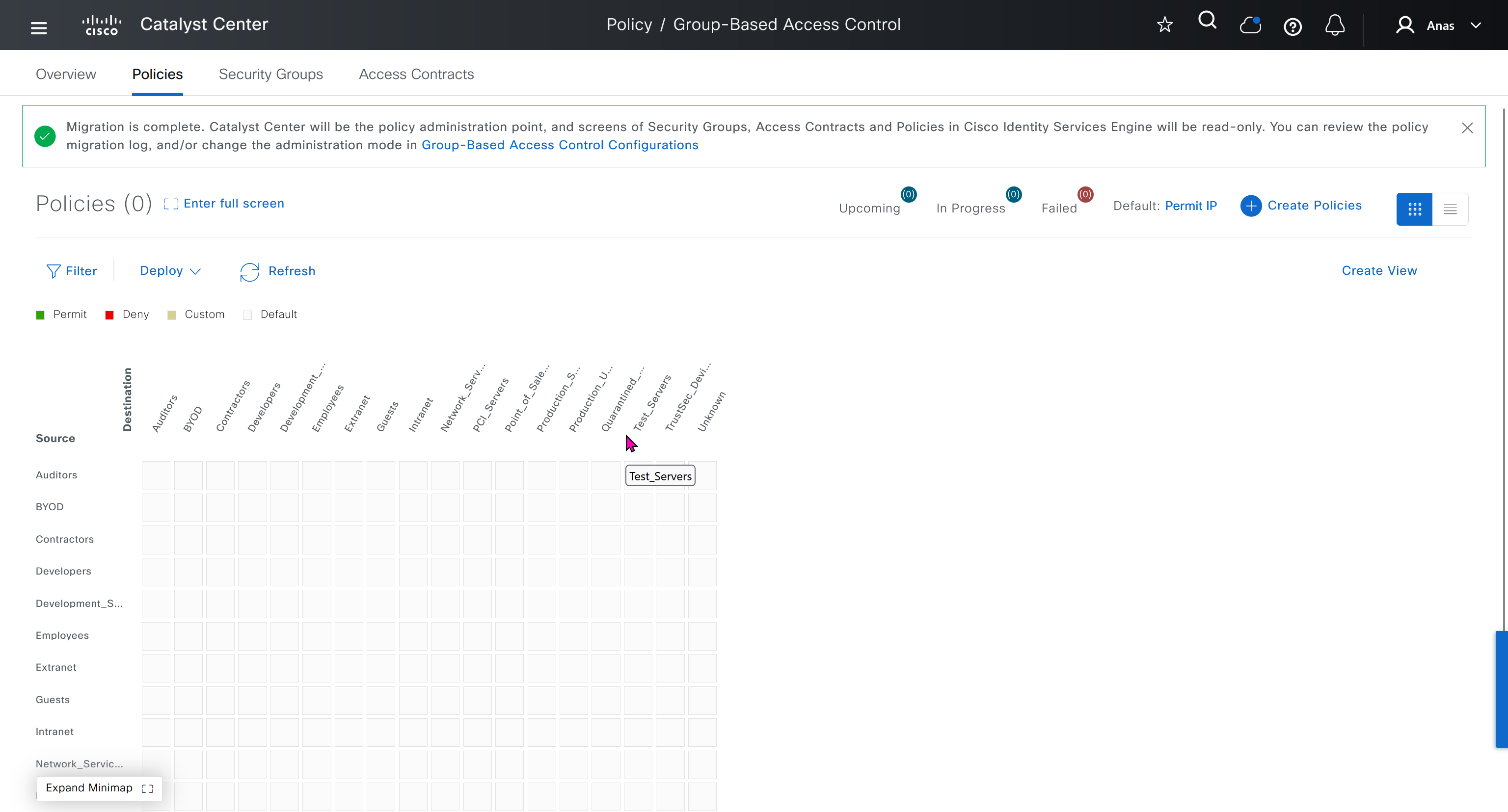
After migration DNAC has become the policy administration point and all changes should be made in ISE
“Migration is complete. Catalyst Center will be the policy administration point, and screens of Security Groups, Access Contracts and Policies in Cisco Identity Services Engine will be read-only. You can review the policy migration log, and/or change the administration mode in Group-Based Access Control Configurations”
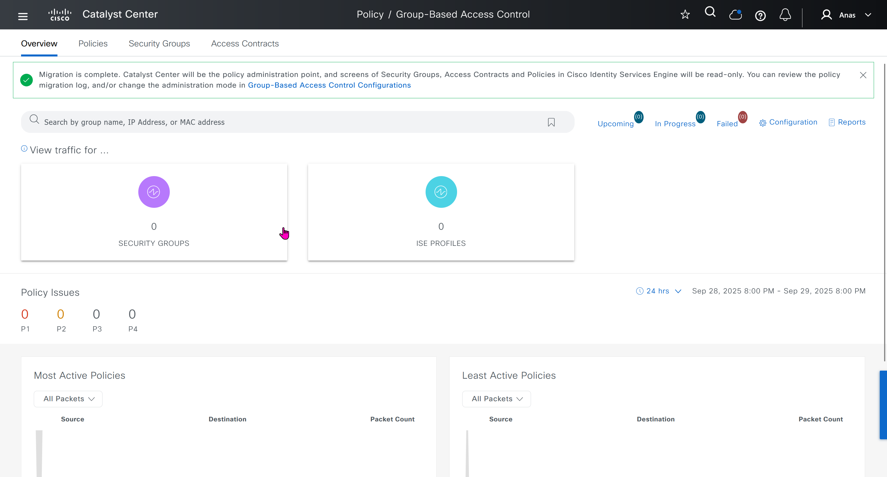
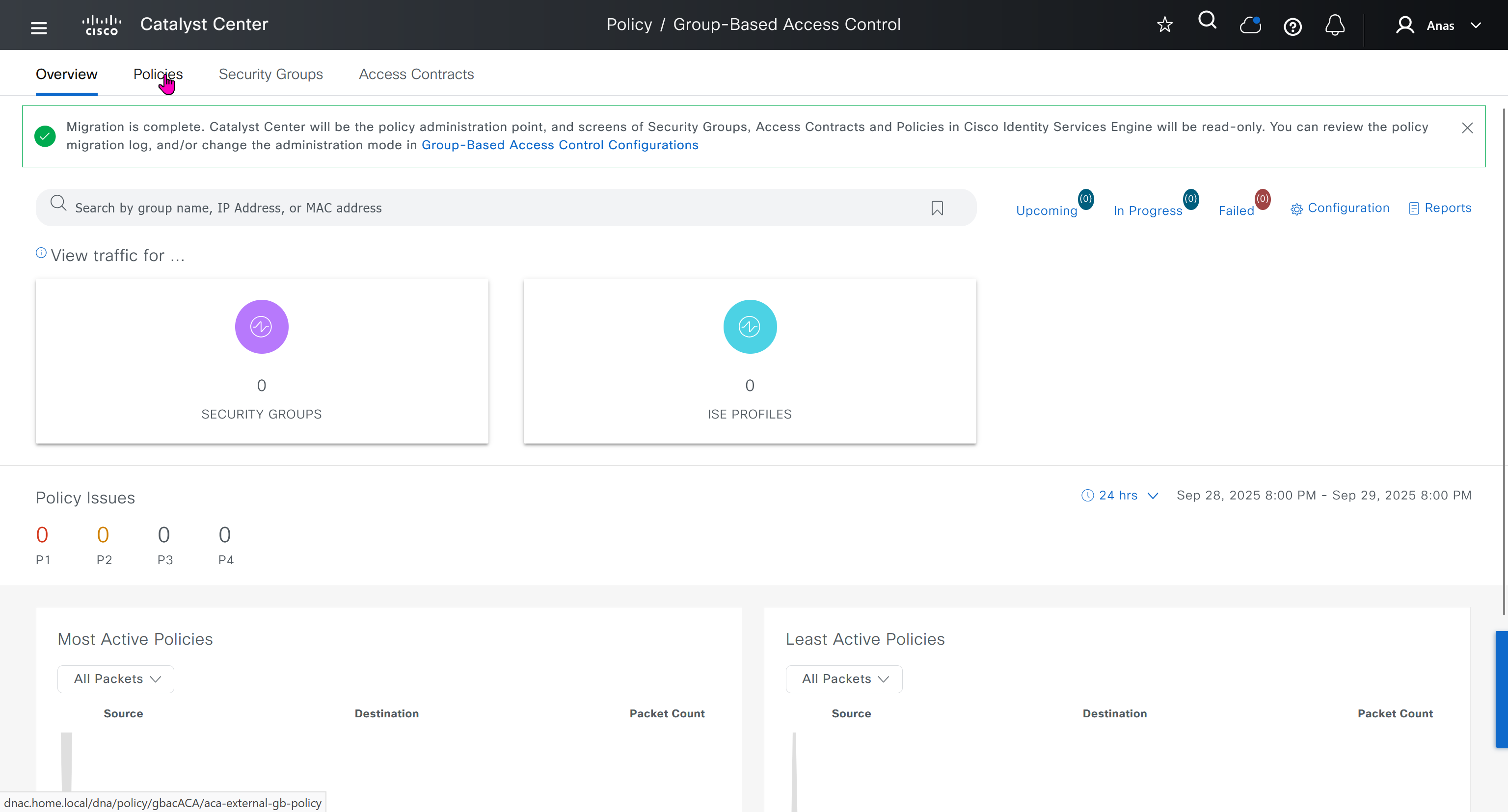
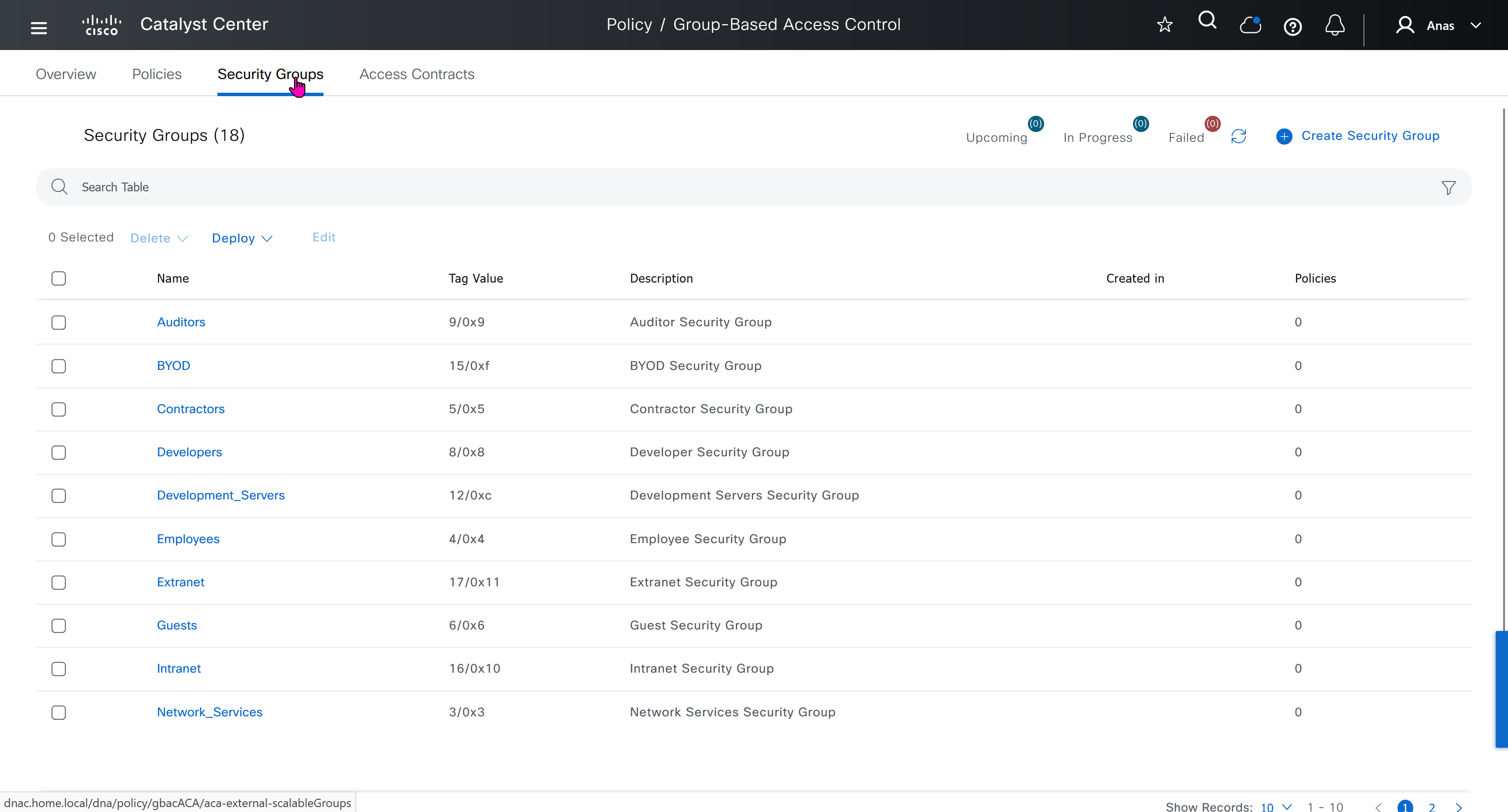
All these security groups have been downloaded into DNAC and any future configuration changes you make in DNAC will be reflected in ISE


SDA Deployment – Learn
[…] SDA | LM […]