⊹ F5 ⊹
F5 commands
! ping command without -I flag will ping from mgmt interface
ping 8.8.8.8
! ping using -I flag from data interface
! ping dest_IP -I source_IP
ping 8.8.8.8 -I 10.11.10.1
------------------------------------
! enter bash
bash
run util bash
------------------------------------
! TMSH commands
! enter tmsh mode
tmsh
------------------------------------
! view full running config
show running-config all-properties recursive
------------------------------------
! show management IP
list sys management-ip
------------------------------------
! interfaces, vlans and routes
show net interface
show net route
show net vlan
------------------------------------
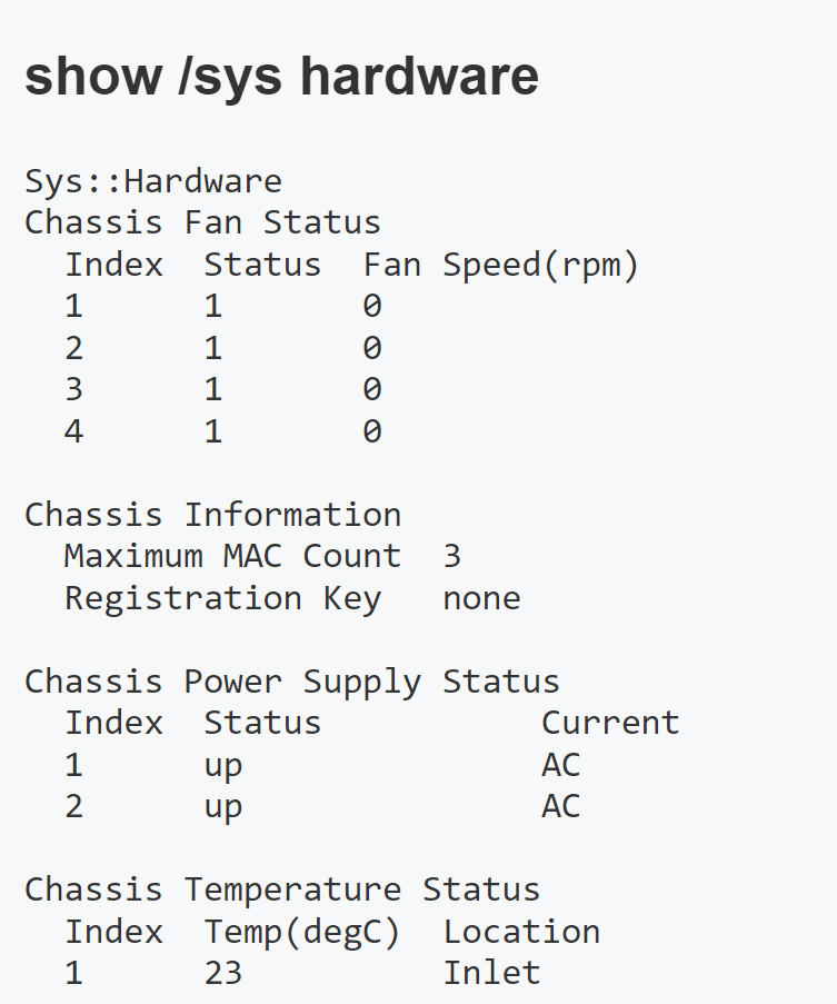
! system hardware and model number
show sys hardware
------------------------------------
! License
show sys license
------------------------------------
! create a ucs archive
tmsh save sys ucs /var/tmp/UPGRADE_`date “+%Y%m%d”`.ucs
------------------------------------
! perform failover from command line, make current node standby
run sys failover standby ! execute from active node
------------------------------------
! CPU and memory live stats
tmstat
------------------------------------
! show virtual servers
list ltm virtual | less
------------------------------------
! show connections from external clients and to the nodes
show sys connection
! Understanding command options
cs-client-addr:cs-client-port ----> cs-server-addr:cs-server-port [ VIP ]--[ F5 ]--[ Self/SNAT IP ] ss-client-addr:ss-client-port ----> ss-server-addr:ss-server-port
! Client side: client side, usually public addresses abreviated as 'cs'
! Server side: These are outgoing connections initiated by the BIG-IP as the proxy, abbreviated as 'ss'
! If you want to see all connections for a specific client's public IP address
show sys connection cs-client-addr 1.1.1.1
! If you want to see all connections to a specific virutal server then
show sys connection cs-server-addr 10.1.1.1 cs-server-port 443
! If you want to see all connections from a specific SNAT address then
show sys connection ss-client-addr 192.168.2.2
! If you want to see all connections to a specific real server which was load balanced to
show sys connection ss-server-addr 172.16.29.1
! or
show sys connection ss-server-addr 172.16.29.1 ss-server-port 443
! for detailed output per connection
show sys connection all-properties
! details for connections from a specific client IP address
show /sys connection cs-client-addr 2.2.2.2 all-properties
! delete all connections initiated from a specific client IP
delete /sys connection cs-client-addr 2.2.2.2
! delete all connections, be careful
delete /sys connection
------------------------------------
! show persistence records
show ltm persistence persist-records
------------------------------------
! F5 Upgrade commands when GUI Breaks
! find large files and delete those files
find / -size +300000000c
! start installation from GUI because it breaks after installation starts
! monitor the progress of software upgrades
watch -n 10 tmsh show sys software status
! when GUI was reachable before change started
! record which is the current volume
! and which is the destination volume
cpcfg --source=HD1.1 HD1.3
info: Getting configuration from HD1.1
info: Copying configuration to HD1.3
info: Applying configuration to HD1.3
tmsh reboot volume HD1.3
The system will be rebooted momentarily
Broadcast message from systemd-journald@CCSLO-EDGE-F5-A.vdipod.local (Fri 2024-04-12 23:11:59 BST):
overdog[5161]: 01140043:0: Ha feature software_update reboot requested.
after booting up into new location
switchboot -l
! if it still shows old boot location
switchboot -b HD1.3
! reboot if not already in that partition
reboot
------------------------------------
! Tcpdump
! view all traffic on internal vlan
tcpdump -i internal
! view traffic on all interfaces, be careful
tcpdump -i 0.0
! tcp flags and arguments
-n disables the name resolution
-nn double n will not only just disable the name resolution but also port / service name resolution
-w capture packets in a file
host - shows all the packets to and from a specific IP
src host - shows all packets from a specific source IP
dst host - shows all packets to a specific destination IP
port
src port
dst port
and
-s also called snaplen can let you specify how much of bytes to capture per packet
-s 0 will capture full packet
-c limit the number of packets to capture
-v captures and displays verbose output about traffic and tcp parameters
-vv increases verbosity
-vvv increases verbosity even more
-i interface:<noise level+p [full traffic flow[> such as -i 0.0:nnn
--n captures low details
--nn captures low and medium details
--nnn captures low, medium and high details
--p allows you to capture both sides of the connection in CS and SS world
tcpdump -ni 0.0 -w /var/tmp/capture.pcapng
! -n , no name resolution
! -i 0.0 , capture on all interfaces
tcpdump -ni 0.0 host 10.90.100.1 and port 80 -w /var/tmp/capture.pcapng
! -n , no name resolution
! -i 0.0 , capture on all interfaces
! -s200 , only capture first 200 bytes as capture is going to run for long time unattended
tcpdump -ni 0.0 -s200 host 10.90.100.1 and port 80 -w /var/tmp/capture.pcapng
! -nn , no IP and port name resolution
! -i 0.0 , capture on all interfaces
! -s200 , only capture first 200 bytes as capture is going to run for long time unattended
! -c2000 , stop capture after 2000th packet is captured
tcpdump -nni 0.0 -s200 -c2000 host 10.90.100.1 and port 80 -w /var/tmp/capture.pcapng
! stop capture
ctrl + c
! if tcpdump is running in another session which is locked and not accessible
! then kill tcpdump process
killall tcpdump
! capture all legs of the connection from client <-> VIP and from self IP <-> Pool member in a single capture - full traffic flow end to end using option p on the interface
client <--> VIP and Self IP <--->Pool Members
tcpdump -nni 0.0:nnnp -s400 -c 10000 -w /var/tmp/capture.pcap host 10.0.0.1 and port 443
-nni 0.0 means capture on all interfaces and vlans with no ip to name and port to service name resolution
:nnnp means capture traffic at highest levels of debugs and p means capture data in both directions end to end of the load balancing
-s400 means only capture first 400 bytes of per packet
-c 10000 means stop captures once 10,000 packets have been captured
-w means save packet capture
------------------------------------
! check APM logs for authenitcation issues (Jupiter)
tail -f /var/log/apmnext post
F5 Upgrade commands when GUI Breaks
! find large files and delete those files
find / -size +300000000c

! Start installation from GUI

! monitor the progress of software upgrades
watch -n 10 tmsh show sys software status

cpcfg --source=HD1.1 HD1.3
info: Getting configuration from HD1.1
info: Copying configuration to HD1.3
info: Applying configuration to HD1.3

tmsh reboot volume HD1.3
The system will be rebooted momentarily

Broadcast message from systemd-journald@CCSLO-EDGE-F5-A.vdipod.local (Fri 2024-04-12 23:11:59 BST):

overdog[5161]: 01140043:0: Ha feature software_update reboot requested.
next post
F5 Backing up UCS archive from CLI
If path is not specified then default path for UCS archives is
/var/local/ucs
Archives that you locate in a directory other than the default directory do not appear in the list of available archives
F5 recommends that you include the BIG-IP host name and current time stamp as part of the file name
bash
ls -laps /var/local/ucs
tmsh
save sys ucs CHANGE_14_AUGUST_2024 passphrase C0mplex30
quit
ls -laps /var/local/ucs
tmsh list /sys ucs
If it fails with the message “Error: Bad encryption password.” then it means below bug is being hit
Bug ID 791365 (f5.com), workaround is to create another admin account such as adm_[firstname] with permissions of “Resource Administrator” and tmsh as shell, log in to CLI from that user and then perform above steps and it should work
next post
F5 Single config file backups and running-config
In order to view full running-config file on F5 you need to run command
show running-config all-properties recursiveSCF is a single file containing all configuration in a flat text file, if you want to backup the F5 config outside of the UCS archives for restore purpose on the same device then UCS archives are still the king, we can use SCF only for comparing configurations post change
tmsh save sys config file myscffile no-passphrase
Saving running configuration...
/var/local/scf/myscffile
/var/local/scf/myscffile.tar
next post
F5 BIG-IP Device Service Clustering
If you have two BIG-IP devices only, you can create either an active-standby or an active-active
With more than two devices, you can create a configuration in which multiple devices are active
device group
device group is a collection of BIG-IP devices that trust each other, can sync and fail over
x
x
x
x
Certificate signing authority
A certificate signing authority can sign x509 certificates for another BIG-IP device that is in the local trust domain already. In a standard redundant system configuration of two BIG-IP devices, both devices are usually certificate signing authority devices. For security reasons, F5 Networks recommends you limit the number of authority devices in a local trust domain to as few as possible
Peer authorities
Peer authority is another device in the local trust domain that can sign certificates if the certificate signing authority is not available. In a standard redundant system configuration of two BIG-IP devices, each device is typically a peer authority for the other.
Subordinate non-authorities
A subordinate device cannot sign a certificate for another device. Subordinate devices provide an additional level of security because in the case where the security of an authority device in a trust domain is compromised, the risk of compromise is minimized for any subordinate device. Designating devices as subordinate devices is recommended for device groups with many member devices, where the risk of compromise is high.
Certificate and Device discovery
Each device in a device group has a x509 certificate installed on it that the device uses to authenticate itself to the other devices in the group, exchange of device properties such as device serial number, IP address and certificate, is known as device discovery. If a device joins a trust domain that already contains three trust domain members, the device exchanges device properties with the three other domain members. The device then has a total of four sets of device properties defined on it: its own device properties, plus the device properties of each peer.
Establishing device trust
To configure the local trust domain to include all three devices, you can simply log into device Bigip_1 and add devices Bigip_2 and Bigip_3 to the local trust domain; there is no need to repeat this process on devices
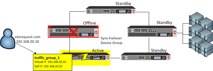
Traffic group failover
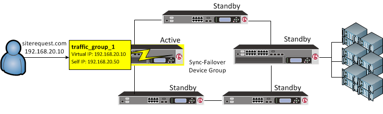
On failover, traffic_group_1 becomes active on another device in the Sync-Failover device group
You can also control the way that the BIG-IP chooses a target failover device. This control is especially useful when a device group contains heterogeneous hardware platforms that differ in load capacity. you can ensure that when failover occurs, the system will choose the device with the most available resource to process the application traffic
Device groups and local trust domain
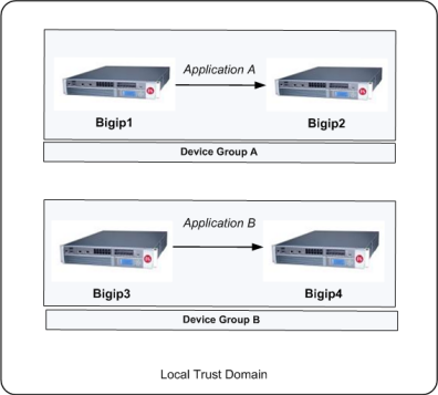
You can use a Sync-Failover device group in a variety of ways. This sample configuration shows two separate Sync-Failover device groups in the local trust domain.
Device group A
Prior to failover, only Bigip1 processes traffic for application A. This means that Bigip1 and Bigip2 synchronize their configurations, and Bigip1 fails over to Bigip2 if Bigip1 becomes unavailable. Bigip1 cannot fail over to Bigip3 or Bigip4 because those devices are in a separate device group.
Device group B
Bigip3 normally processes traffic for application B. This means that Bigip3 and Bigip4 synchronize their configurations, and Bigip3 fails over to Bigip4 if Bigip3 becomes unavailable. Bigip3 cannot fail over to Bigip1 or Bigip2 because those devices are in a separate device group.
Each traffic group on a device includes application-specific floating IP addresses as its members. Typical traffic group members are: floating self IP addresses, virtual addresses, NAT or SNAT translation addresses, and IP addresses associated with an iApp application service. When a device with active traffic groups becomes unavailable, the active traffic groups become active on other device in the device group. This ensures that application traffic processing continues with little to no interruption
What triggers failover?
The BIG-IP system initiates failover of a traffic group according to any of several events that you define. These events fall into these categories:
System fail-safe
With system fail-safe, the BIG-IP system monitors various hardware components, as well as the heartbeat of various system services. You can configure the system to initiate failover whenever it detects a heartbeat failure.
Gateway fail-safe
With gateway fail-safe, the BIG-IP system monitors traffic between an active BIG-IP® system in a device group and a pool containing a gateway router. You can configure the system to initiate failover whenever some number of gateway routers in a pool of routers becomes unreachable.
VLAN fail-safe
With VLAN fail-safe, the BIG-IP system monitors network traffic going through a specified VLAN. You can configure the system to initiate failover whenever the system detects a loss of traffic on the VLAN and the fail-safe timeout period has elapsed.
HA groups
With an HA group, the BIG-IP system monitors the availability of resources for a specific traffic group. Examples of resources are trunk links, pool members, and VIPRION® cluster members. If resource levels fall below a user-defined level, the system triggers failover.
Auto-failback
When you enable auto-failback, a traffic group that has failed over to another device fails back to a preferred device when that device is available. If you do not enable auto-failback for a traffic group, and the traffic group fails over to another device, the traffic group remains active on that device until that device becomes unavailable.
About pre-configured traffic groups
Each new BIG-IP® device comes with two pre-configured traffic groups:
traffic-group-1
A floating traffic group that initially contains any floating self IP addresses that you create on the device. If the device that this traffic group is active on goes down, the traffic group goes active on another device in the device group.
traffic-group-local-only
A non-floating traffic group that contains the static self IP addresses that you configure for VLANs internal and external. This traffic group never fails over to another device.
Configuration
Prerequisites
You must meet the following prerequisites to use this procedure:
- You have configured the following configuration elements on all BIG-IP devices:
- Network components, such as VLANs, Self IP addresses, and routes.
- Administrative components, such as network time protocol (NTP), the management IP address, and licensing.
- Each BIG-IP device that will be part of the device group has a device certificate installed on it.
Forcing the system offline
You should force the new BIG-IP system offline to ensure that it does not become active until after it is added to the device group and the configuration is synchronized from the other device(s) in the device group:
Select OK to confirm.
Log in to the Configuration utility.
Go to Device Management > Devices.
Select the host name of the local device.
Select Force Offline.
Configuring the ConfigSync and failover IP addresses
Before creating the device group, you should configure the ConfigSync and failover IP addresses for each BIG-IP system in the device group. The ConfigSync address is the IP address that the system uses when synchronizing configuration with peer devices, and the failover address is the IP address that the system uses for network failover. As a best practice, F5 recommends selecting both the management address and a Traffic Management Microkernel (TMM) network address to use for network failover.
To configure the ConfigSync and failover addresses, perform the following procedure:
Note: You must enable network failover for high availability (HA) configurations (device groups with two or more active traffic groups).
Impact of procedure: Performing the following procedure should not have a negative impact on your system.
- Log in to the Configuration utility.
- Go to Device Management > Devices.
- Select the host name of the local device.
- Select the ConfigSync tab.
- For Local Address, select the self IP address that you want to use for synchronization.
- Select Update.
- Select the Failover Network tab.
- Select Add.
- For Address, select the self IP address you want to use for failover, for Port, type the port you want to use, and then select Repeat.
- Select the management address, type 1026 for Port, then select Finished.
- Select Finished.
- Repeat these steps for each BIG-IP system you want to add to the device group.
Adding a device to the local trust domain
When a BIG-IP device joins the local trust domain, it establishes a trust relationship with peer BIG-IP devices that are members of the same trust domain. For example, if you are creating a device group with four members, you must log in to one of the devices and join the other devices to that system’s local trust domain. The devices can then exchange their device properties and device connectivity information.
Impact of procedure: Performing the following procedure should not have a negative impact on your system.
- Log in to the Configuration utility of a device that will be part of the device group.
- Go to Device Management > Device Trust > Local Domain.
- Select the Device Trust Members tab.
- Select Add.
- For Device Type, select either Peer or Subordinate, as appropriate.
- Type the management IP address, administrator user name, and administrator password for the remote BIG-IP device, and then select Retrieve Device Information.
- Verify that the certificate is correct, and then select Device Certificate Matches.
- Verify that the remote device name is correct, and then select Add Device.
- Repeat these steps for each BIG-IP system to be added to the local trust domain.
Creating a device group
After you’ve added all members to the same local trust domain, you can create a new device group. The device group type can be either Sync-Failover or Sync-Only.
Creating a Sync-Failover device group
A Sync-failover device group contains devices that synchronize configuration data and fail over to one another when the active device becomes unavailable. To create a Sync-Failover device group, perform the following procedure:
Impact of procedure: Performing the following procedure should not have a negative impact on your system.
- Log in to the Configuration utility.
- Go to Device Management > Device Groups.
- Select Create.
- Enter the name for the device group.
- For Group Type, select Sync-Failover.
- Under Configuration, in the Available list, select the name(s) of the members that you want to add to the device group and move them to the Includes list.
- For Sync Type, select the appropriate synchronization type. The default is Manual with Incremental Sync.Note: For more information on ConfigSync type options, see Managing Configuration Synchronization in BIG-IP Device Service Clustering Administration. For information about how to locate F5 product manuals, refer to K98133564: Tips for searching AskF5 and finding product documentation.
- Confirm the group settings, and then select Finished.
next post
F5 ping from data interface
using ping command without -I flag will ping from mgmt interface
ping 8.8.8.8So we have to ping using -I flag
ping dest_IP -I source_IP
ping 8.8.8.8 -I 10.11.10.1
next post
Check F5 for hardware issues
iHealth > Status > Hardware > Ctrl + F ‘Passed’
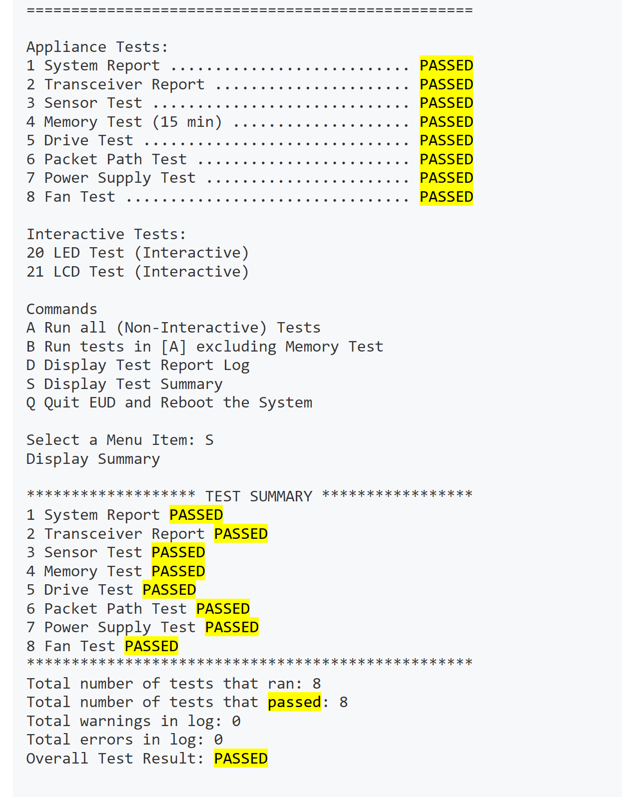
Commands > tmsh > show sys hardware