⊹ CCIE Design ⊹
CCIE Design
IP Headers
Protocol: This field is 8 bits in length. It indicates the upper-layer protocol. The Internet Assigned Numbers Authority (IANA) is responsible for assigning IP protocol values. Table 1-2 shows some key protocol numbers. You can find a full list

Header Checksum: This field is 16 bits in length. The checksum does not include the data portion of the packet in the calculation. The checksum is verified and recomputed at each point the IP header is processed (on end clients)
Padding: This field is variable in length. It ensures that the IP header ends on a 32-bit boundary.
Header Length: This field is 4 bits in length. It indicates the length of the header in 32-bit words (4 bytes) so that the beginning of the data can be found in the IP header. The minimum value for a valid header is 5 (0101) for five 32-bit words.
Total Length: This field is 16 bits in length. It represents the length of the datagram, or packet, in bytes, including the header and data. The maximum length of an IP packet can be 216 − 1 = 65,535 bytes. Routers use this field to determine whether fragmentation is necessary by comparing the total length with the outgoing MTU.
Identification: This field is 16 bits in length. It is a unique identifier that denotes fragments for reassembly into an original IP packet.
Flags: This field is 3 bits in length. It indicates whether the packet can be fragmented and whether more fragments follow. Bit 0 is reserved and set to 0. Bit 1 indicates May Fragment (0) or Do Not Fragment (1). Bit 2 indicates Last Fragment (0) or More Fragments to Follow (1).
Fragment Offset: This field is 13 bits in length. It indicates (in bytes) where in the packet this fragment belongs. The first fragment has an offset of 0.
ToS (Type of Service): This field is 8 bits in length. Quality of service (QoS) parameters such as IP precedence and DSCP are found in this field. (These concepts are explained later in this chapter.)
The ToS field of the IP header is used to specify QoS parameters. Routers and Layer 3 switches look at the ToS field to apply policies, such as priority, to IP packets based on the markings. An example is a router prioritizing time-sensitive IP packets over regular data traffic such as web or email, which is not time sensitive.
DSCP
DSCP has 2’6 = 64 levels of classification, which is significantly higher than the eight levels of the IP precedence bits
backward compatible with IP precedence
Defines three sets of PHBs: Class Selector (CS), Assured Forwarding (AF), and Expedited Forwarding (EF).
CS PHB set is for DSCP values that are compatible with IP precedence bits
The AF PHB set is used for queuing and congestion avoidance.
The EF PHB set is used for premium service
IPv4 Fragmentation
Although the maximum length of an IP packet is 65,535 bytes, most of the common lower-layer protocols do not support such large MTUs. For example, the MTU for Ethernet is approximately 1518 bytes. When the IP layer receives a packet to send, it first queries the outgoing interface to get its MTU. If the packet’s size is greater than the interface’s MTU, the layer fragments the packet.
When a packet is fragmented, it is not reassembled until it reaches the destination IP layer. The destination IP layer performs the reassembly
Any router in the path can fragment a packet, and any router in the path can fragment a fragmented packet again, and these kind of double fragmentation can cause unrecoverable packets on destination
Each fragment receives its own IP header and identifier, and it is routed independently from other packets. Routers and Layer 3 switches in the path do not reassemble the fragments. The destination host performs the reassembly and places the fragments in the correct order by looking at the Identification and Fragment Offset fields.
If one or more fragments are lost, the entire packet must be retransmitted. Retransmission is the responsibility of a higher-layer protocol (such as TCP). Also, you can set the Flags field in the IP header to Do Not Fragment; in this case, the packet is discarded if the outgoing MTU is smaller than the packet like full drop or like an ACL drop
IPv4 Addressing
Classes A, B, and C are unicast IP addresses, meaning that the destination is a single host. IP Class D addresses are multicast addresses, which are sent to multiple hosts
Class A address range 1.0.0.0 to 126.0.0.0. Networks 0 and 127 are reserved. For example, 127.0.0.1 is reserved for the local host or host loopback.
Class B addresses range from 128 (10000000) to 191 (10111111) in the first byte. Network numbers assigned to companies or other organizations are from 128.0.0.0 to 191.255.0.0
As with Class A addresses, having a segment with more than 65,000 hosts broadcasting will surely not work; you resolve this issue with subnetting.
Class C addresses range from 192 (11000000) to 223 (11011111) in the first byte. Network numbers assigned to companies are from 192.0.0.0 to 223.255.255.0.
254 IP addresses for host assignment per Class C network
Class D addresses range from 224 (11100000) to 239 (11101111) in the first byte. Network numbers assigned to multicast groups range from 224.0.0.1 to 239.255.255.255
These addresses do not have a host or network part. Some multicast addresses are already assigned; for example, routers running EIGRP use 224.0.0.10
Class E addresses range from 240 (11110000) to 254 (11111110) in the first byte. These addresses are reserved for experimental networks. Network 255 is reserved for the broadcast address, such as 255.255.255.255

Networks 0.0.0.0 and 127.0.0.0 are reserved as special-use addresses
Large organizations can use network 10.0.0.0/8 to assign address space throughout the enterprise. Midsize organizations can use one of the Class B private networks 172.16.0.0/16 through 172.31.0.0/16 for IP addresses. The smaller Class C addresses, which begin with 192.168, can be used by corporations and are commonly used in home routers.
NAT
NAT performs a many-to-one translation which is usally from many private addresses to one public address, the process is called Port Address Translation (PAT) because different port numbers identify translations
It is called port based translation because source ports are also translated because a source port might be used by one host inside network , at the same time same port could also be used by another host, for second host using a same port will translate to a different source port on the public side
Router or firewall performing translation keeps track of translation in a translation table This translation record is just like connection table and also times out if connection becomes idle. Some applications also send packets out at interval to keep the NAT entry alive , in The absence of data traffic
source addresses for outgoing IP packets are converted to globally unique IP addresses

NAT has several forms
Static NAT: Host is manually / statically assigned an external address, making that host avaiable to the external world when coming outside to inside and also allows host going out with that static address from inside to outside
Dynamic NAT: Dynamically maps a private IP address to a registered IP address from a pool (group) of registered addresses. The are two types of dynamic NAT
Overloading: Maps multiple unregistered or private IP addresses to a single registered IP address by using different ports. This is also known as PAT, single-address NAT. The number of PAT translations are limited by maximum of 65,535 internal hosts via PAT.
Overlapping: Overlapping networks result when you have overlapping subnets in two different locations. Overlapping networks also result when two companies, merge. These two networks need to communicate, preferably without having to readdress all their devices.
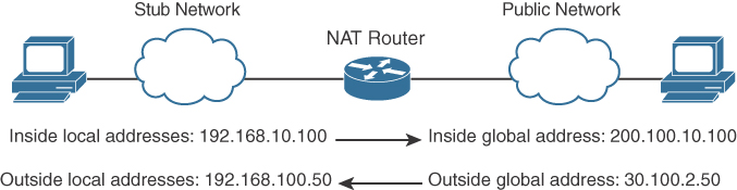
- Inside local address: The real IP address of the device that resides in the internal network. This address is used in the stub domain.
- Inside global address: The translated IP address of the device that resides in the internal network. This address is used in the public network.
- Outside global address: The real IP address of a device that resides in the Internet, outside the stub domain.
- Outside local address: The translated IP address of the device that resides in the Internet. This address is used inside the stub domain.
Different types of NAT
Static NAT
Commonly used to assign a network device with an internal private IP address a unique public address so that it can be accessed from the Internet.
Dynamic NAT
Dynamically maps an unregistered or private IP address to a registered IP address from a pool (group) of registered addresses.
PAT
Maps multiple unregistered or private IP addresses to a single registered IP address by using different ports.
Inside local address
The real IP address of a device that resides in the internal network. This address is used in the stub domain.
Inside global address
The translated IP address of the device that resides in the internal network. This address is used in the public network.
Outside global address
The real IP address of a device that resides on the Internet, outside the stub domain.
Outside local address
The translated IP address of a device that resides on the Internet. This address is used inside the stub domain.
IPv4 Address Subnets
Multicast addresses do not use subnet masks
IP Address Subnet Design Example
The development of an IP address plan or IP address subnet design is an important concept for a network designer. You should be capable of creating an IP address plan based on many factors, including the following:
-Number of locations
-Number of devices per location
-IP addressing requirements for each individual location or building
-Number of devices to be supported in each comms room
-Site requirements, including VoIP devices, wireless LAN, and video
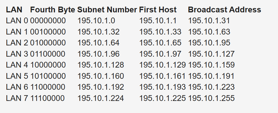
Subnetting for a small company. Suppose the company has 200 hosts and is assigned the Class C network 195.10.1.0/24. The 200 hosts need to be in six different LANs.
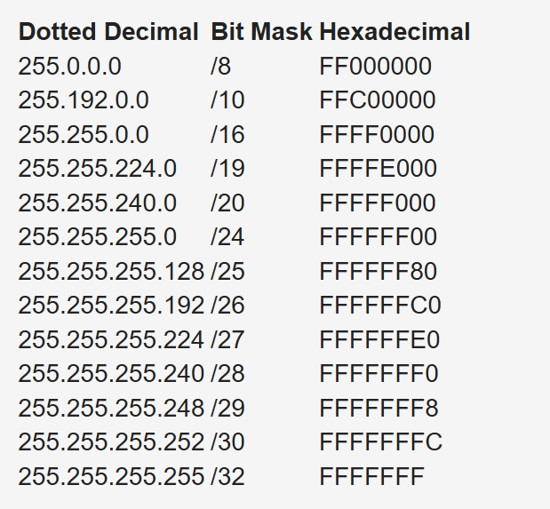
You can subnet the Class C network using the mask 255.255.255.224
Deriving number of networks from default networks
Variable-length subnet masking (VLSM) is a process used to divide a network into subnets of various sizes to prevent wasting IP addresses. If a Class C network uses 255.255.255.240 as a subnet mask, 16 subnets are available, each with 14 IP addresses
Class B network 130.20.0.0/16. Using a /20 mask produces 16 subnetworks,
The loopback address is a single IP address with a 32-bit mask. In the previous example, network 130.20.75.0/24 could provide 256 loopback addresses for network devices, starting with 130.20.75.0/32 and ending with 130.20.75.255/32.
Global companies divide this address space into continental regions for the Americas, Europe/Middle East, Africa, and Asia/Pacific. An example is shown in Table 1-25, where the address space has been divided into four major blocks:
10.0.0.0 to 10.63.0.0 is reserved.
10.64.0.0 to 10.127.0.0 is for the Americas.
10.128.0.0 to 10.191.0.0 is for Europe, Middle East, and Africa.
10.192.0.0 to 10.254.0.0 is for Asia Pacific.
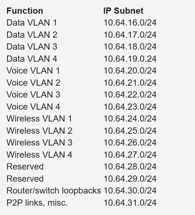
Subnets to be assign for data, voice, wireless, and management VLANs. Table 1-26 shows an example. The large site is allocated network 10.64.16.0/20. The first four /24 subnets are assigned for data VLANs, the second four /24 subnets are assigned for voice VLANs, and the third four /24 subnets are assigned for wireless VLANs. Other subnets are used for router and switch interfaces, point-to-point links, and network management devices.
When assigning subnets for a site or perhaps a floor of a building, do not assign subnets that are too small. You want to assign subnets that allow for growth
For example, if a floor has a requirement for 50 users, do you assign a /26 subnet (which allows 62 addressable nodes)? Or do you assign a /25 subnet, which allows up to 126 nodes?
Assigning a subnet that is too large will prevent you from having other subnets for IPT and video conferencing.
The company might make an acquisition of another company. Although a new address design would be the cleanest solution, the recommendation is to avoid re-addressing of networks. Here are some other options:
- If you use 10.0.0.0/8 as your network, use the other private IP addresses for the additions.
- Use NAT as a workaround.
Performing Route Summarization
As a network designer, you will want to allocate IPv4 address space to allow for route summarization. Large networks can grow quickly from 500 routes to 1000 and higher. Route summarization reduces the size of the routing table
Planning for a Hierarchical IP Address Network
When IPv4 addressing for a companywide network, recommended practice dictates that you allocate contiguous address blocks to regions of the network. Hierarchical IPv4 addressing enables summarization, which makes the network easier to manage and troubleshoot.
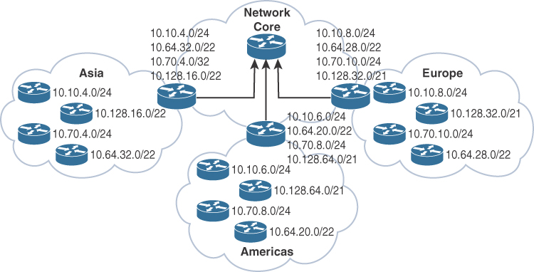
Network subnets cannot be aggregated because /24 subnets from many different networks are deployed in different areas of the network. For example, subnets under 10.10.0.0/16 are deployed in Asia (10.10.4.0/24), the Americas (10.10.6.0/24), and Europe (10.10.8.0/24). The same occurs with networks 10.70.0.0/16 and 10.128.0.0/16. This lack of summarization in the network increases the size of the routing table, making it less efficient. It also makes it harder for network engineers to troubleshoot because it is not obvious in which part of the world a particular subnet is located.
Network That Is Not Summarized
By contrast, Figure 1-6 shows a network that allocates a high-level block to each region:
10.0.0.0/18 for Asia Pacific networks
10.64.0.0/18 for Americas networks 10.128.0.0/18 for European/Middle East networks
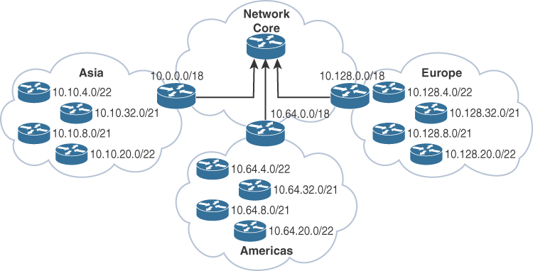
This solution provides for summarization of regional networks at area borders and improves control over the growth of the routing table.
Here are some examples of standards:
Use .1 or .254 (in the last octet) as the default gateway of the subnet.
Match the VLAN ID number with the third octet of an IP address. (For example, the IP subnet 10.10.150.0/25 is assigned to VLAN 150.)
Reserve .1 to .15 of a subnet for static assignments and .16 to .239 for the DHCP pool.
Allocate /24 subnets for user devices (such as laptops and PCs).
Allocate a parallel /24 subset for VoIP devices (IP phones).
Allocate subnets for access control systems and video conferencing systems.
Reserve subnets for future use.
Use /30 subnets for point-to-point links.
Use /32 for loopback addresses.
Allocate subnets for remote access and network management.
Case Study: IP Address Subnet Allocation
Consider a company that has users in several buildings in a campus network. Building A has four floors, and building B has two floors

the building’s Layer 3 switches will be connected via a dual-fiber link between switch A and switch B. Both switches will connect to the WAN router R1. Assume that you have been allocated network 10.10.0.0/17 for this campus and that IP phones will be used.

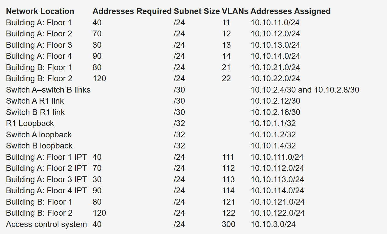
Notice that the VLAN number matches the third octet of the IP subnet. The second floor is assigned VLAN 12 and IP subnet 10.10.12.0/24. For building B, VLAN numbers in the 20s are used, with floor 1 having a VLAN of 21 assigned with IP subnet 10.10.21.0/24.
VLANs for IP telephony (IPT) are similar to data VLANs, with the correlation of using numbers in the 100s. For example, floor 1 of building A uses VLAN 11 for data and VLAN 111 for voice, and the corresponding IP subnets are 10.10.11.0/24 (data) and 10.10.111.0.24 (voice). This is repeated for all floors.
This solution uses /30 subnets for point-to-point links from the 10.10.2.0/24 subnet. Loopback addresses are taken from the 10.10.1.0/24 network starting with 10.10.1.1/32 for the WAN router. Subnet 10.10.3.0/24 is reserved for the building access control system.
BOOTP and DHCP
The BOOTP server port is UDP port 67. The client port is UDP port 68
DHCP is extension of BOOTP that is why the behavior is exactly same with enhancements in DHCP but BOOTP requires that you build a MAC address–to–IP address table on the server. You must obtain every device’s MAC address, which is a time-consuming effort.
That is DHCP was introduced with “lease” function for any client / mac address
DHCP not just provides network address but also delivers configuration parameters to hosts
An IP address is assigned as follows:
Step 1. The client sends a DHCPDISCOVER message to the local network using a 255.255.255.255 broadcast.
Step 2. DHCP relay agents (routers and switches) can forward the DHCPDISCOVER message to the DHCP server in another subnet.
Step 3. The server sends a DHCPOFFER message to respond to the client, offering IP address, lease expiration, and other DHCP option information.
Step 4. Using DHCPREQUEST, the client can request additional options or an extension on its lease of an IP address. This message also confirms that the client is accepting the DHCP offer.
Step 5. The server sends a DHCPACK (acknowledgment) message that confirms the lease and contains all the pertinent IP configuration parameters.
Step 6. If the server is out of addresses or determines that the client request is invalid, it sends a DHCPNAK message to the client.
ARP
When ARP response is received it is cached as well in the ARP table , listing IP addresses with MAC addresses
ARP is a broadcast and ARP request contains the sender’s IP and MAC address and the target IP address. That is why ARP response is unicast
All nodes in the broadcast domain receive the ARP request and process it.
ARP request is always a broadcast and ARP response is always a unicast
