⊹ 92. CCIE STP ⊹
STP
STP
Redundancy requires that we connect second link between switches
but that is loop – this is where spanning tree steps in disables one side of the link / interface to remove the loop
One indication of loop is that mac shows up behind different ports which it should not
Layer 2 looped frames do not have TTL mechanism so if looped they keep going around and it grinds network equipment to halt
STP works by first making switches aware by sending and receiving BPDUs to one another rather than silence or dark network
STP selects one switch in the network as a root switch and a tree is built from this root switch’s perspective by simply stretching STP network down from that root switch
STP has multiple versions:
- 802.1D, which is the original specification
- Per-VLAN Spanning Tree (PVST)
- Per-VLAN Spanning Tree Plus (PVST+)
- ———————————————
- 802.1W Rapid Spanning Tree Protocol (RSTP)
- 802.1S Multiple Spanning Tree Protocol (MST)
Cisco switches can operate in PVST+, RSTP, and MST modes.
All three of these modes are backward compatible with 802.1D.
Original version of STP only ensures Loop free topology in one VLAN
802.1D Port States
Disabled: The port is in an administratively off position (that is, shut down).
Blocking:
The switch port is enabled
but the port is not forwarding any traffic to ensure that a loop is not created.
The switch does not modify the MAC address table.
Special: Port can only receive BPDUs
Listening:
The switch port has transitioned from a blocking state
Port can now send or receive BPDUs.
It still cannot forward any other network traffic.
The duration of the state correlates to the STP forwarding time.
Special: Port can send and receive BPDUs
Learning:
The switch port can add MAC entries in MAC address table from network traffic that it receives.
The switch still does not forward any other network traffic besides BPDUs.
The duration of the state correlates to the STP forwarding time. The next port state is forwarding.
Special: Port can send and receive BPDU but can also do mac learning on port (learn is in the name)
Forwarding:
The switch port can forward all network traffic and can update the MAC address table as expected.
This is the final state for a switch port to forward network traffic.
Special: only forwarding actually forwards traffic (forward is in the name)
Broken:
The switch has detected a configuration or an operational problem on a port that can have major effects.
The port discards packets as long as the problem continues to exist.
If timers are left to defaults 802.1D takes about 30 seconds for a port to transition from Blocking to Forwarding state
802.1D Port Types
Root port (RP):
A network port that connects to the root bridge or an upstream switch that leads to root switch in the spanning-tree topology.
There should be only one root port per VLAN on a switch.
Designated port (DP):
A network port that receives and forwards BPDU frames to other switches.
Designated ports provide connectivity to downstream devices and switches or Drives away from root
There should be only one active designated port on a link.
Blocking port: A network port that is not forwarding traffic because of STP calculations.
Several key terms are related to STP:
Root bridge:
The root bridge has all ports are in a forwarding state and non blocking
This switch is considered the top of the spanning tree for all path calculations by other switches.
All ports on the root bridge are categorized as designated ports.
Bridge protocol data unit (BPDU):
This network packet is used for network switches to identify each other and notify of changes in the topology.
A BPDU uses the destination MAC address 01:80:c2:00:00:00. There are two types of BPDUs:
- Configuration BPDU:
This BPDU is used to identify the root bridge, root ports, designated ports, and blocking ports. The configuration BPDU consists of the following fields:
– STP type
– root path cost
– root bridge identifier
– local bridge identifier
– max age
– hello time
– forward delay - Topology change notification (TCN) BPDU:
This BPDU is used to communicate changes in the Layer 2 topology to other switches. It is explained in greater detail later in the chapter. - Root path cost: This is the combined cost toward the root switch.
- System priority:
This 4-bit value indicates the desire for a switch to be root bridge.
The default value is 32,768. - System ID extension:
This 12-bit value indicates the VLAN (12 bits because VLAN ID is 12 bit) that the BPDU belongs to because BPDU are generated per vlan or BPDU can belong to only one VLAN.
The system priority (root making value) and system ID extension (VLAN) are combined as part of the switch’s identification of a bridge - Root bridge identifier:
Root bridge’s system MAC address + system ID extension + system priority of the root bridge - Local bridge identifier:
System MAC address + system ID extension + system priority of the local bridge. - Max age:
This is the maximum length of time that a bridge port stores its BPDU information.
The default value is 20 seconds (10x the default hello time) but can be configured with the command spanning-tree vlan vlan-id max-age maxage.
If a switch loses contact with the BPDU’s source, switch keeps that the BPDU information on interface till Max Age timer counts down.
Max age timer counts down when there is an indirect failure and not the interface down event - Hello time:
This is the time interval that a BPDU is advertised out of a port.
The default value is 2 seconds, but the value can be configured to 1 to 10 seconds with the command spanning-tree vlan vlan-id hello-time hello-time. - Forward delay:
The name is actually Forwarding Delay
This is the amount of time that a port stays in a listening and learning state (where it does not forward traffic).
The default value is 15 seconds, but the value can be changed to a value of 4 to 30 seconds with the command spanning-tree vlan vlan-id forward-time forward-time.
STP cost is assigned on interface and root path cost is calculated by adding cumulative cost to reach root
Long mode and short mode
Original default costs were set for different speeds upto only 20 Gbps but as networking has advanced 10 Gbps has become common.
Another method, called long mode, uses a 32-bit value and uses a reference speed of 20 Tbps
The original method, known as short mode, has been the default for most switches, but has been transitioning to long mode based on specific platform and OS versions.
| Link Speed | Short-Mode STP Cost | Long-Mode STP Cost |
|---|---|---|
| 10 Mbps | 100 | 2,000,000 |
| 100 Mbps | 19 | 200,000 |
| 1 Gbps | 4 | 20,000 |
| 10 Gbps | 2 | 2000 |
| 20 Gbps | 1 | 1000 |
| 100 Gbps | 1 | 200 |
| 1 Tbps | 1 | 20 |
| 10 Tbps | 1 | 2 |
Devices can be configured with the long-mode interface cost with the command spanning-tree pathcost method long. The entire Layer 2 topology should use the same setting for every device in the environment to ensure a consistent topology. Before you enable this setting in an environment, it is important to conduct an audit to ensure that the setting will work.
1. Elect Root Bridge, starts with I am root
As switch boots it wants to find root bridge, and starts by assuming that it itself is root
uses the local bridge identifier as the root bridge identifier
listens for BPDUs coming from all the ports for neighbors
If the neighbor’s configuration BPDU is inferior to its own BPDU, the switch ignores that BPDU
If the neighbor’s configuration BPDU is better than its own BPDU
the switch updates its BPDUs to include the new better root bridge + new root path cost.
This process continues until all switches in a topology have identified the root bridge switch.

STP favours the switch with lowest priority inside the bridge ID
If priority is same then switch with lower system MAC address wins
Generally, older switches have a lower MAC address and are considered more preferable
but configuration changes in priority should be made for optimal placement of the root bridge
show spanning-tree root to display the root bridge
SW1# show spanning-tree root
                                            Root    Hello Max Fwd
Vlan                   Root ID            Cost    Time  Age Dly  Root Port
---------------- -------------------- --------- ----- --- ---  ------------
VLAN0001         32769 0062.ec9d.c500         0    2   20  15
VLAN0010         32778 0062.ec9d.c500         0    2   20  15
VLAN0020         32788 0062.ec9d.c500         0    2   20  15
VLAN0099         32867 0062.ec9d.c500         0    2   20  15
this command is like a snapshot or view of root for all VLANs
there can be different root switches for some VLANs, it is not mandatory to one root for all VLANs
When a switch generates the BPDUs, the root path cost includes only the calculated metric to the root and does not include the cost of the port that the BPDU is advertised out of
The receiving switch adds the port cost for its interface on which the BPDU was received with the value of the root path cost in the BPDU and that is the value switch thinks to reach the root is
The root path cost is always zero on the root bridge
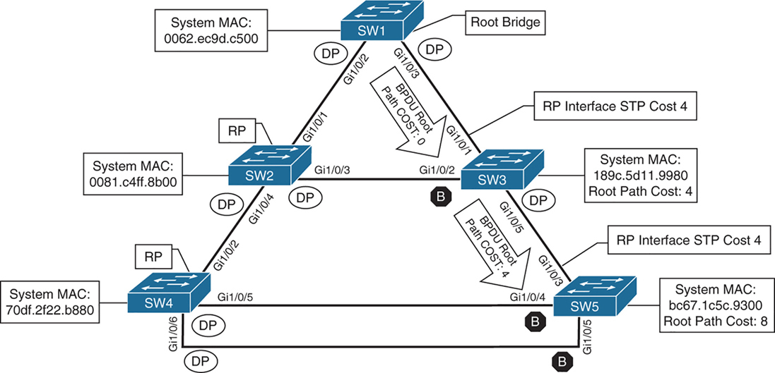
cost on those links is 4 because of 1 gig links (short mode)
SW2# show spanning-tree root
                                            Root    Hello Max Fwd
Vlan                   Root ID            Cost    Time  Age Dly  Root Port
---------------- -------------------- --------- ----- --- ---  ------------
VLAN0001         32769 0062.ec9d.c500         4    2   20  15  Gi1/0/1
VLAN0010         32778 0062.ec9d.c500         4    2   20  15  Gi1/0/1
VLAN0020         32788 0062.ec9d.c500         4    2   20  15  Gi1/0/1
VLAN0099         32867 0062.ec9d.c500         4    2   20  15  Gi1/0/1
SW3# show spanning-tree root
Root Hello Max Fwd
Vlan Root ID Cost Time Age Dly Root Port
---------------- -------------------- --------- ----- --- --- ------------
VLAN0001 32769 0062.ec9d.c500 4 2 20 15 Gi1/0/1
VLAN0010 32778 0062.ec9d.c500 4 2 20 15 Gi1/0/1
VLAN0020 32788 0062.ec9d.c500 4 2 20 15 Gi1/0/1
VLAN0099 32867 0062.ec9d.c500 4 2 20 15 Gi1/0/1Locating Root “Ports“
After the switches have identified the root bridge, they must determine their root port (RP).
Only the root bridge continues to advertise configuration BPDUs out all of its ports. The switch compares the BPDU information received on its port to identify the RP.
The RP is selected using the following logic , only moves to next step when there is a tie
This step is interface centric because we are selecting a root “port”
- The interface associated to lowest path cost is more preferred.
- The interface associated to the lowest system priority of the “advertising switch” is preferred next.
- The interface associated to the lowest system MAC address of the advertising switch is preferred next.
- When multiple links are associated to the same switch, the lowest port priority from the advertising switch is preferred.
- When multiple links are associated to the same switch, the lower port number from the advertising switch is preferred.
Locating Blocked / Designated Switch “Ports“
Root for a VLAN is elected
Root ports are elected
Now next is Designated ports / blocking ports between 2 non-root switches needs to be decided
one of those switch’s “designated ports” must be set to a blocking state to prevent a forwarding loop
- The interface is a designated port and must not be considered an RP.
- The switch with the lower path cost to the root bridge forwards packets, and the one with the higher path cost blocks. If they tie, they move on to the next step.
- The system priority of the local switch is compared to the system priority of the remote switch. The local port is moved to a blocking state if the remote system priority is lower than that of the local switch. If they tie, they move on to the next step.
- The system MAC address of the local switch is compared to the system MAC address of the remote switch. The local designated port is moved to a blocking state if the remote system MAC address is lower than that of the local switch.
- When multiple links are associated to the same switch, the lowest port priority from the advertising switch is preferred.
- When multiple links are associated to the same switch, the lower port number from the advertising switch is preferred.
SW1# show spanning-tree vlan 1

VLAN0001
  Spanning tree enabled protocol rstp
! This section displays the relevant information for the STP root bridge
  Root ID    Priority    32769
              Address     0062.ec9d.c500
              This bridge is the root
              Hello Time   2 sec  Max Age 20 sec  Forward Delay 15 sec
! This section displays the relevant information for the Local STP bridge
  Bridge ID  Priority    32769  (priority 32768 sys-id-ext 1)
               Address     0062.ec9d.c500
               Hello Time   2 sec  Max Age 20 sec  Forward Delay 15 sec
               Aging Time  300 sec

Interface           Role Sts Cost      Prio.Nbr Type
------------------- ---- --- --------- -------- --------------------------------
Gi1/0/2             Desg FWD 4          128.2    P2p
Gi1/0/3             Desg FWD 4          128.3    P2p
Gi1/0/14            Desg FWD 4          128.14   P2p Edge
If the Type field includes *TYPE_Inc -, this indicates a port configuration mismatch between this switch and the switch it is connected to, it is seen when port mode is mixed Access and Trunk between switches
These port types are expected on Catalyst switches:
P2p
P2p is point-to-point link only, i.e.:
- The port connects directly to a switch or router device on full-duplex Ethernet link
Why it matters in STP:
- STP can converge faster on point-to-point links
- Rapid STP (RSTP) can move these ports to forwarding almost immediately when safe
P2p Edge
- A point-to-point link
- AND an edge port (connected to an end device)
This is essentially PortFast
What STP assumes:
- No risk of loops
- The device is not a switch
- The port can go to Forwarding immediately
Typical devices on P2p Edge ports:
- PCs
- Servers
- Printers
- IP phones
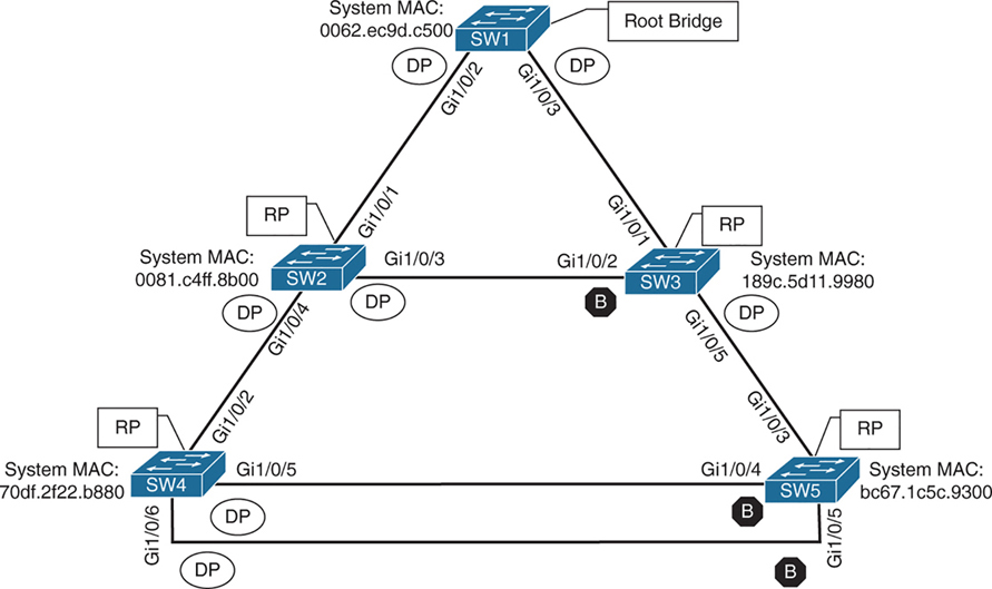
Ports that are blocked go in BLK state
Alternate port is the alternate port to reach root in an event Gi1/0/1 fails
All the ports on SW2 are in a forwarding state, but port Gi1/0/2 on SW3 is in a blocking (BLK) state.
SW3’s Gi1/0/2 port has also been designated as an alternate port to reach the root in the event that the Gi1/0/1 connection fails.
SW3’s Gi1/0/2 port rather than SW2’s Gi1/0/3 port was placed into a blocking state is that SW2’s system MAC address (0081.c4ff.8b00) is lower than SW3’s system MAC address (189c.5d11.9980).
SW2# show spanning-tree vlan 1


VLAN0001
  Spanning tree enabled protocol rstp
  Root ID    Priority    32769
              Address     0062.ec9d.c500
              Cost         4
              Port         1 (GigabitEthernet1/0/1)
              Hello Time   2 sec  Max Age 20 sec  Forward Delay 15 sec

  Bridge ID  Priority    32769  (priority 32768 sys-id-ext 1)
               Address     0081.c4ff.8b00
               Hello Time   2 sec  Max Age 20 sec  Forward Delay 15 sec
               Aging Time  300 sec

Interface           Role Sts Cost      Prio.Nbr Type
------------------- ---- --- --------- -------- --------------------------------
Gi1/0/1             Root FWD 4          128.1    P2p
Gi1/0/3             Desg FWD 4          128.3    P2p
Gi1/0/4             Desg FWD 4          128.4    P2p
SW3# show spanning-tree vlan 1
VLAN0001
Spanning tree enabled protocol rstp
! This section displays the relevant information for the STP root bridge
Root ID Priority 32769
Address 0062.ec9d.c500
Cost 4
Port 1 (GigabitEthernet1/0/1)
Hello Time 2 sec Max Age 20 sec Forward Delay 15 se
! This section displays the relevant information for the Local STP bridge
Bridge ID Priority 32769 (priority 32768 sys-id-ext 1)
Address 189c.5d11.9980
Hello Time 2 sec Max Age 20 sec Forward Delay 15 sec
Aging Time 300 sec
Interface Role Sts Cost Prio.Nbr Type
------------------- ---- --- --------- -------- --------------------------------
Gi1/0/1 Root FWD 4 128.1 P2p
Gi1/0/2 Altn BLK 4 128.2 P2p
Gi1/0/5 Desg FWD 4 128.5 P2pshow spanning-tree interface interface-id [detail]
shows STP state for only the specified interface.
The detail keyword provides
1. port cost
2. port priority
3. number of transitions
4. link type
5. count of BPDUs sent or received for every VLAN supported on that interface.
show spanning-tree vlan x
shows where that vlan spans to on current switch
SW3# show spanning-tree interface gi1/0/1

Vlan                Role Sts Cost      Prio.Nbr Type
------------------- ---- --- --------- -------- --------------------------------
VLAN0001            Root FWD 4         128.1    P2p
VLAN0010            Root FWD 4         128.1    P2p
VLAN0020            Root FWD 4         128.1    P2p
VLAN0099            Root FWD 4         128.1    P2p
SW3# show spanning-tree interface gi1/0/1 detail
! Output omitted for brevity
Port 1 (GigabitEthernet1/0/1) of VLAN0001 is root forwarding
Port path cost 4, Port priority 128, Port Identifier 128.1.
Designated root has priority 32769, address 0062.ec9d.c500
Designated bridge has priority 32769, address 0062.ec9d.c500
Designated port id is 128.3, designated path cost 0
Timers: message age 16, forward delay 0, hold 0
Number of transitions to forwarding state: 1
Link type is point-to-point by default
BPDU: sent 15, received 45908
Port 1 (GigabitEthernet1/0/1) of VLAN0010 is root forwarding
Port path cost 4, Port priority 128, Port Identifier 128.1.
Designated root has priority 32778, address 0062.ec9d.c500
Designated bridge has priority 32778, address 0062.ec9d.c500
Designated port id is 128.3, designated path cost 0
Timers: message age 15, forward delay 0, hold 0
Number of transitions to forwarding state: 1
Link type is point-to-point by default
MAC BPDU: sent 15, received 22957
..STP Topology Changes
Configuration BPDUs always flow from the root bridge toward the edge switches
However, changes in the topology (for example, switch failure, link failure, or links becoming active) have an impact on “all” the switches in the Layer 2 topology.
The switch that detects a fault sends a topology change notification (TCN) BPDU toward the root bridge, out its RP.
If an upstream switch receives the TCN, it sends out an acknowledgment and forwards the TCN out its RP to the root bridge.
By default, a switch ages out MAC entries after 300 seconds (5 minutes)
When STP detects a topology change (link up/down, port role change):
The switch temporarily reduces the MAC aging time
Upon receipt of the TCN, the root bridge creates a new configuration BPDU with the Topology Change flag set, and it is then flooded to all the switches. When a switch receives a configuration BPDU with the Topology Change flag set, all switches change their MAC address timer to the forwarding delay timer (with a default of 15 seconds). This flushes out MAC addresses for devices that have not communicated in that 15-second window but maintains MAC addresses for devices that are actively communicating.
However, a side effect of flushing the MAC address table is that it temporarily increases the unknown unicast flooding while it is rebuilt. Remember that this can impact hosts because of their CSMA/CD behavior.
The MAC address timer is then reset to normal (300 seconds) after the 2 configuration BPDU are seen
“I’ve now seen two consecutive consistent BPDUs — the topology is stable again.”
Because these TCNs are generated on per VLAN basis, as a side effect that VLAN’s mac table mac entry retainer time will be reduced creating rebroadcasting of unknown unicast for MAC address relearning by the switch on that VLAN.
As the number of hosts (without portfast) increases, the more likely TCN generation is to occur and the more hosts that are impacted by the broadcasts. Topology changes should be checked as part of the troubleshooting process. Portfast stops generation of TCN and reduce the generation of TCNs.
Topology changes are seen with the command show spanning-tree [vlan vlan-id] detail on a switch.
The output of this command shows the topology change count and time since the last change has occurred.
A sudden or continuous increase in TCNs indicates a potential problem and should be investigated further for flapping ports or events on a connected switch.
SW1# show spanning-tree vlan 10 detail

 VLAN0010 is executing the rstp compatible Spanning Tree protocol
 Bridge Identifier has priority 32768, sysid 10, address 0062.ec9d.c500
 Configured hello time 2, max age 20, forward delay 15, transmit hold-count 6
 We are the root of the spanning tree
 Topology change flag not set, detected flag not set
 Number of topology changes 42 last change occurred 01:02:09 ago
           from GigabitEthernet1/0/2
 Times: hold 1, topology change 35, notification 2
         hello 2, max age 20, forward delay 15
 Timers: hello 0, topology change 0, notification 0, aging 300
The process of determining why TCNs are occurring involves finding a port that is flapping and it does not have portfast enabled, if it is connected to another switch then trace port on another switch but in same VLAN
Direct Link Failures of blocking segment- traffic impact
When a port goes down STP process is aware of that “direct link” failure

In below scenario link between SW2 and SW3 goes down
SW2 Gi1/0/3 is DP and SW3 Gi1/0/2 Blocking
This link going down will not impact traffic as both switches transmit traffic through SW1 and because of this direct link blocking between SW2 and SW3, SW2 learns all the MAC addresses behind SW3 via SW1 and SW3 learns all the MAC addresses behind SW2 via SW1
Blocked ports cannot send data and do not receive Data, also do not send BPDU but can receive BPDU only
switches also do not learn MAC on blocked ports
but designated port can send and receive data but in this case SW2’s Designated port will never forward out of Gi1/0/3 because no MAC has been learned through that port so even though designated port can send data, it will never send it because traffic outflow is dictated by MAC address learning
Dont forget about TCN generated from P2p port going down, both SW2 and SW3 will advertise a TCN toward the root switch, which results in the Layer 2 topology flushing its MAC address table.
Direct Link Failures – Loss of root – traffic impact 30 seconds for 802.1D

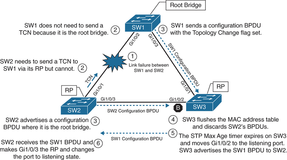
In the second scenario, the link between SW1 and SW3 fails.
Network traffic to and from SW1 to SW3 and Network traffic to and from SW2 -> SW1 -> SW3 and SW3 -> SW1 -> SW2 will be affected because of blocking segment between SW2 and SW3, all traffic between SW2 and SW3 goes via SW1 but because link between SW1 and SW3 is down , Layer 2 network will have to reconverge with the help of STP
– SW1 detects a link failure on its Gi1/0/3 interface.
– SW3 detects a link failure on its Gi1/0/1 interface and SW3 does not use max age timer on its Gi1/0/1
1. TCNs from all switches to root but no way to send in this scenario so switch will wait:
– Normally, SW1 would generate a TCN flag out its root port, but it itself is a root bridge, so it does not. SW1 will wait for a TCN from non root switches
– At this point, SW3 would attempt to send a TCN toward the root switch to notify it of a topology change; however, its root port is down, and its only other port that is connected to this layer 2 network is in blocking mode , so SW3 will wait for this port to come out of blocking mode but it will still send TCN once the port is out of blocking mode
2. Affected interfaces remove their best BPDU (root / root port) and activate alternative port as BPDUs from root are still coming in another (blocking) port:
– SW3 removes its best BPDU (was root port as best only comes on root port) without waiting for max age timer on its Gi1/0/1 interface because it is now in a down state.
– SW2 was always receiving BPDU from SW1 and relaying it to SW3
– because root port was lost SW3 must look for a new root port
– SW3 never lost access to root as it was receiving BPDUs on its Gi1/0/2 in Blocked state
– because BPDU are coming on blocking port Gi1/0/2 of SW3, and SW3 detects that this root is reachable over Gi1/0/2 Blocking port so it transitions to listening and then learning
3. TCN can now reach root
– once SW3 bring its port Gi1/0/2 to forwarding state then TCN is dispatched towards root from Gi1/0/2
– SW1 advertises a configuration BPDU with the Topology Change flag out of all its ports. It keeps TC set for the topology change period (commonly Max Age + Forward Delay = 35s by default).
– This BPDU is received and relayed to all switches in the environment , SW2 receives it and relays it to SW3
4. Non root switches reduce their MAC address age timer to forward delay
– These switches then reduce the MAC address age timer to the forward delay timer to flush out older MAC entries.
– If other switches were connected to SW1, they would receive a configuration BPDU with the Topology Change flag set also for all the VLANs on trunk port. These packets have an impact for all switches in the same Layer 2 domain.
The total convergence time for SW3 is 30 seconds: 15 seconds for the listening state and 15 seconds for the learning state before SW3’s Gi1/0/2 can be made the RP.
Direct Link Failure Scenario 3
In the third scenario, the link between SW1 and SW2 fails
Network traffic from SW1 or SW3 toward SW2 is impacted because SW3’s Gi1/0/2 port is in a blocking state.
SW1 detects a link failure on its Gi1/0/2 interface.
SW2 detects a link failure on its Gi1/0/1 interface and SW3 does not use max age timer on its Gi1/0/1
1. TCNs from all switches to root but no way to send in this scenario so switch will wait:
– Normally SW1 would generate a TCN flag out its root port, but it is the root bridge, so it does not as root does not do that. SW1 would advertise a TCN if it were not the root bridge.
– At this point, SW2 would attempt to send send TCN towards the root switch to notify it of a topology change however its root port is down and unable to do as its RP port is down so it will wait for path to root to resolve and then send TCN
2. Affected interfaces remove their best BPDU and best BPDU (root) via different interface as BPDU are not coming on Desgnated port due to adjacent port is blocking:
– SW2 removes its best BPDU (was root port as best only comes on root port) without waiting for max age timer on its Gi1/0/1 interface because it is now in a down state.
– because root port was lost SW2 must look for a new root port
– but because the local port facing SW3 is Designated port and port on SW3 is blocking as blocking port does not send BPDUs but only receives BPDU, visibility or path to root is lost
3. Declaring itself root because of remote blocking port and then receiving and loosing root election
– SW2 will declare itself root and generate its own BPDU and send it to SW3
– SW3 receives SW2’s inferior BPDUs and discards them as it is still receiving superior BPDUs from SW1
– Because this BPDU from SW2 was not accepted this leads to expiry of max age timer on Gi1/0/2 of SW3 and transitions from blocking to listening state. SW3 can now forward the next configuration BPDU it receives from SW1 to SW2.
– SW2 receives SW1’s configuration BPDU via SW3 and recognizes it as superior. It marks its Gi1/0/3 interface as the root port and transitions it to the listening state.
4. TCN can now reach root
– once SW2 bring its port Gi1/0/2 to forwarding state then TCN is dispatched towards root from Gi1/0/2
– SW1 advertises a configuration BPDU with the Topology Change flag out of all its ports. It keeps TC set for the topology change period (commonly Max Age + Forward Delay = 35s by default).
– This BPDU is received and relayed to all switches in the environment , SW3 receives it and relays it to SW2
5. Non root switches reduce their MAC address age timer to forward delay
– These switches then reduce the MAC address age timer to the forward delay timer to flush out older MAC entries.
– If other switches were connected to SW1, they would receive a configuration BPDU with the Topology Change flag set also for all the VLANs on trunk port. These packets have an impact for all switches in the same Layer 2 domain.
The total convergence time for SW2 is 50 seconds: 20 seconds for the Max Age timer on SW3, 15 seconds for the listening state on SW2, and 15 seconds for the learning state.
Indirect Failures
In some scenarios involving signalling over WAN, switch do not see direct interface failures, but WAN signalling is not present while the interface is up and this is where hello and max age timer comes in
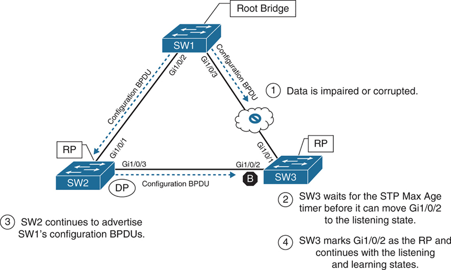
– An event occurs that impairs or corrupts data on the link. SW1 and SW3 still report a link up condition.
– SW3 stops receiving configuration BPDUs on its RP, SW3’s max age timer expires and removes the best BPDU after max age expiry
– because SW3 lost path to root it will have to find the path to root through another best path (lowest cost to root) and that is next port that is Gi1/0/2 in blocking port
– SW3 transitions Gi1/0/2 from blocking to listening state
– SW2 continues to advertise SW1’s configuration BPDUs toward SW3
– SW3 receives SW1’s configuration BPDU via SW2 on its Gi1/0/2 interface. This port is now marked as the RP
The total time for reconvergence on SW3 is 50 seconds: 20 seconds for the Max Age timer on SW3, 15 seconds for the listening state on SW3, and 15 seconds for the learning state on SW3.
Rapid Spanning Tree Protocol
Although 802.1D did a decent job of preventing Layer 2 forwarding loops, it was not designed to support multiple VLANs, also for traffic engineering requirements such as blocking one link for half vlans and blocking another link for other half of vlans for load balancing and equally utilising both uplinks
Cisco also created other versions like PVST and PVST+ which were Cisco proprietary
but standard versions that are compatible with other vendors such as RSTP and MST should be used in production
RSTP (802.1W) Port States
RSTP reduces the number of port states to three:
Discarding: Blocking, This state combines the traditional STP states disabled, blocking, and listening.
Learning: The switch port modifies the MAC address table with any network traffic it receives. The switch still does not forward any other network traffic besides BPDUs.
Forwarding: The switch port forwards all network traffic and updates the MAC address table as expected. This is the final state for a switch port to forward network traffic.
RSTP relies on handshake with a switch connected on the other end, If a handshake does not occur, the other device is assumed to be non-RSTP compatible and for backwards compatibility the port defaults to regular 802.1D behavior
RSTP (802.1W) Port Roles
RSTP defines the following port roles:
Root port (RP): A network port that connects to the root switch or an upstream switch in the spanning-tree topology. There should be only one root port per VLAN on a switch.
Designated port (DP): A network port that receives and forwards frames to other switches. Designated ports provide connectivity to downstream devices and switches. There should be only one active designated port on a link. Designated port drives packets away from root
Alternate port:
A network port that provides alternate connectivity toward the root switch “through a different switch”.
It does not forward traffic, So if the main (active) path to the root switch fails, the alternate port can take over.
Backup port:
These are very rare because this port is only seen when a switch connects with 2 links into hub or shared segment , a backup port is kept blocked to prevent loops, one link going to hub becomes Designated port and second link becomes backup port (blocks traffic)
RSTP (802.1W) Port Types
RSTP defines three types of ports that are used for building the STP topology:
Edge port: A port at the edge of the network where hosts connect to the Layer 2 topology with one interface and “cannot form a loop”. These ports directly correlate to ports that have the STP portfast feature enabled.
Non-Edge port: A port that has received a BPDU.
Point-to-point port: Any port that connects to another RSTP switch with full duplex. “Full-duplex links do not permit more than two devices on a network segment, so determining whether a link is full duplex is the fastest way to check the feasibility of being connected to a switch”.
Multi-access Layer 2 devices such as hubs can connect only at half duplex. If a port can connect only via half duplex, it must operate under traditional 802.1D forwarding states.
Building the RSTP Topology
With RSTP, switches exchange handshakes with other RSTP switches to transition through the following STP states and it is faster this way
When two switches first connect, they establish a bidirectional handshake across the shared link to identify the root bridge.
This is straightforward for an environment with only two switches; however, large environments require greater logic
RSTP uses a synchronization process to add a switch to the RSTP topology, The synchronization process starts when two switches (such as SW1 and SW2) are first connected. The process proceeds as follows:
– As the first two switches connect to each other, they verify that they are connected with a point-to-point link by checking the full-duplex status.
– They establish a handshake with each other to advertise a proposal (in configuration BPDUs) that their interface should be the DP for that segment.
– There can be only one DP per segment, so each switch identifies whether it is the superior or inferior switch, using the same logic as in 802.1D for the system identifier (that is, the lowest priority and then the lowest MAC address). Using the MAC addresses from figure, SW1 (0062.ec9d.c500) is the superior switch to SW2 (0081.c4ff.8b00).

– The inferior switch (SW2) recognizes that it is inferior and marks its local port (Gi1/0/1) as the RP. At that same time, it moves all non-edge ports to a discarding state. At this point in time, the switch has stopped all local switching for non-edge ports.
– The inferior switch (SW2) sends an agreement (configuration BPDU) to the root bridge (SW1), which signifies to the root bridge that synchronization is occurring on that switch.
– The inferior switch (SW2) moves its RP (Gi1/0/1) to a forwarding state. The superior switch moves its DP (Gi1/0/2) to a forwarding state too.
– The inferior switch (SW2) repeats the process for any downstream switches connected to it.
RSTP Convergence
The RSTP convergence process can occur quickly. RSTP ages out the port information after it has not received hellos in three consecutive cycles. Using default timers, the Max Age would take 20 seconds, but RSTP requires only 6 seconds. And thanks to the new synchronization, ports can transition from discarding to forwarding in an extremely low amount of time.
If a downstream switch fails to acknowledge the proposal, the RSTP switch must default to 802.1D behaviors to prevent a forwarding loop.
STP Topology Tuning
A properly designed network places the root bridge on a specific switch and influences which ports should be designated ports (forwarding state) and which ports should be alternate ports (that is, discarding state) based on hardware platform and topology.
Ideally, the root bridge is placed on a core switch, and a “secondary” root bridge is designated.
Root bridge placement is accomplished by “lowering” the system priority on the root bridge to the lowest value possible,
raising the secondary root bridge to a value slightly higher than that of the root bridge,
and (ideally) increasing the system priority on all other switches unless you plan to keep switches on default priority.
By increasing non root switch priority and lowering switch priority for root and secondary root switches, it is made sure that when a new non-configured switch is connected to topology, it does not take over as root.
The priority is set with either of the following commands:
spanning-tree vlan vlan-id priority priority: The priority is a value between 0 and 61,440, in increments of 4096.
spanning-tree vlan vlan-id root {primary | secondary} [diameter diameter]: This command executes a script that sets the priority numerically, along with the potential for timers if the diameter keyword is used. The primary keyword sets the priority to 24,576, and the secondary keyword sets the priority to 28,672.
If a different switch has a priority of 24,576 (or lower) and is more preferred when the command spanning-tree vlan vlan-id root {primary | secondary} is executed, the script has logic to lower the priority to a lower value in an attempt to make it the root bridge, this is possible because current root is in BPDU and along with that system ID or name contains system priority value and system mac address
The optional diameter command makes it possible to tune the Spanning Tree Protocol (STP) convergence and modifies the timers; it should reference the maximum number of Layer 2 hops between a switch that is maximum hops away and the root bridge.
The timers do not need to be modified on other switches because they are carried throughout the topology through the root bridge’s bridge protocol data units (BPDUs) as you only configure timers in one place, you only change timers on root bridge
All the other switches automatically learn those timer values, because the root bridge advertises them inside its BPDUs, which are sent throughout the Layer 2 network. So there’s no need to manually configure timers on every switch. When other switches receive the root’s BPDUs:
– They propagate those same values further downstream
– They adopt the root’s timer values
The root bridge generates the “authoritative” BPDUs
These BPDUs include:
- Hello time
- Max age
- Forward delay (used for learning state)
! Verification of SW1 Priority before modifying the priority
SW1# show spanning-tree vlan 1
VLAN0001
  Spanning tree enabled protocol rstp
  Root ID    Priority    32769
               Address     0062.ec9d.c500
               This bridge is the root
               Hello Time   2 sec  Max Age 20 sec  Forward Delay 15 sec
  Bridge ID  Priority    32769  (priority 32768 sys-id-ext 1)
               Address     0062.ec9d.c500
               Hello Time   2 sec  Max Age 20 sec  Forward Delay 15 sec
               Aging Time  300 sec
! Configuring the SW1 priority as primary root for VLAN 1
SW1(config)# spanning-tree vlan 1 root primary! Verification of SW1 Priority after modifying the priority
SW1# show spanning-tree vlan 1
VLAN0001
Spanning tree enabled protocol rstp
Root ID Priority 24577 <<<
Address 0062.ec9d.c500
This bridge is the root
Hello Time 2 sec Max Age 20 sec Forward Delay 15 sec
Bridge ID Priority 24577 (priority 24576 sys-id-ext 1) <<<
Address 0062.ec9d.c500
Hello Time 2 sec Max Age 20 sec Forward Delay 15 sec
Aging Time 300 sec
Interface Role Sts Cost Prio.Nbr Type
------------------- ---- --- --------- -------- --------------------------------
Gi1/0/2 Desg FWD 4 128.2 P2p
Gi1/0/3 Desg FWD 4 128.3 P2p
Gi1/0/14 Desg FWD 4 128.14 P2p! Configuring the SW2 priority as secondary root for VLAN 1
SW2(config)# spanning-tree vlan 1 root secondarySW2# show spanning-tree vlan 1
VLAN0001
Spanning tree enabled protocol rstp
Root ID Priority 24577 <<<
Address 0062.ec9d.c500
Cost 4
Port 1 (GigabitEthernet1/0/1)
Hello Time 2 sec Max Age 20 sec Forward Delay 15 sec
Bridge ID Priority 28673 (priority 28672 sys-id-ext 1) <<<
Address 0081.c4ff.8b00
Hello Time 2 sec Max Age 20 sec Forward Delay 15 sec
Aging Time 300 sec
Interface Role Sts Cost Prio.Nbr Type
------------------- ---- --- --------- -------- --------------------------------
Gi1/0/1 Root FWD 4 128.1 P2p
Gi1/0/3 Desg FWD 4 128.3 P2p
Gi1/0/4 Desg FWD 4 128.4 P2pThe best way to prevent erroneous devices from taking over the STP root role is to set the priority to 0 for the primary root switch and to 4096 for the secondary root switch. “In addition, root guard should be used”
Modifying STP Root Port and Blocked Switch Port Locations
Cost calculation method forces how we implement cost on interface, The receiving switch adds the port cost for the interface on which the BPDU was received in conjunction with the value of the root path cost in the BPDU.

SW1 advertises its BPDUs to SW3 with a root path cost of 0.
SW3 receives the BPDU and adds its STP port cost of 4 to the root path cost in the BPDU (0), resulting in a value of 4.
SW3 then advertises the BPDU toward SW5 with a root path cost of 4, to which SW5 then adds its STP port cost of 4.
SW5 therefore reports a root path cost of 8 to reach the root bridge via SW3.
SW1# show spanning-tree vlan 1
! Output omitted for brevity
VLAN0001

  Root ID    Priority    32769
               Address     0062.ec9d.c500
               This bridge is the root
..
Interface           Role Sts Cost      Prio.Nbr Type
------------------- ---- --- --------- -------- --------------------------------
Gi1/0/2             Desg FWD 4         128.2    P2p
Gi1/0/3             Desg FWD 4         128.3    P2p
SW3# show spanning-tree vlan 1
! Output omitted for brevity
VLAN0001
Root ID Priority 32769
Address 0062.ec9d.c500
Cost 4
Port 1 (GigabitEthernet1/0/1)
..
Interface Role Sts Cost Prio.Nbr Type
------------------- ---- --- --------- -------- --------------------------------
Gi1/0/1 Root FWD 4 128.1 P2p
Gi1/0/2 Altn BLK 4 128.2 P2p
Gi1/0/5 Desg FWD 4 128.5 P2pSW5# show spanning-tree vlan 1
! Output omitted for brevity
VLAN0001
Root ID Priority 32769
Address 0062.ec9d.c500
Cost 8
Port 3 (GigabitEthernet1/0/3)
..
Interface Role Sts Cost Prio.Nbr Type
------------------- ---- --- --------- -------- --------------------------------
Gi1/0/3 Root FWD 4 128.3 P2p
Gi1/0/4 Altn BLK 4 128.4 P2p
Gi1/0/5 Altn BLK 4 128.5 P2pYou can lower a path that is currently an alternate port while making it designated,
or you can raise the cost on a port that is designated to turn it into a blocking port
The spanning-tree command modifies the cost for all VLANs unless the optional vlan keyword is used to specify a VLAN
SW3# conf t
SW3(config)# interface gi1/0/1
SW3(config-if)# spanning-tree cost 1
SW3# show spanning-tree vlan 1
! Output omitted for brevity
VLAN0001
Root ID Priority 32769
Address 0062.ec9d.c500
Cost 1
Port 1 (GigabitEthernet1/0/1)
Bridge ID Priority 32769 (priority 32768 sys-id-ext 1)
Address 189c.5d11.9980
..
Interface Role Sts Cost Prio.Nbr Type
------------------- ---- --- --------- -------- --------------------------------
Gi1/0/1 Root FWD 1 128.1 P2p
Gi1/0/2 Desg FWD 4 128.2 P2p
Gi1/0/5 Desg FWD 4 128.5 P2pSW2# show spanning-tree vlan 1
! Output omitted for brevity
VLAN0001
Root ID Priority 32769
Address 0062.ec9d.c500
Cost 4
Port 1 (GigabitEthernet1/0/1)
Bridge ID Priority 32769 (priority 32768 sys-id-ext 1)
Address 0081.c4ff.8b00
..
Interface Role Sts Cost Prio.Nbr Type
------------------- ---- --- --------- -------- --------------------------------
Gi1/0/1 Root FWD 4 128.1 P2p
Gi1/0/3 Altn BLK 4 128.3 P2p
Gi1/0/4 Desg FWD 4 128.4 P2pModifying STP Port Priority
STP port priority impacts which port is an alternate port when multiple links are used between same switches. Remember that system ID and port cost are the same, so the next check is port priority, followed by the port number. “Both the port priority and port number are controlled by the upstream switch”, because it is closer to the root bridge.
You can modify the port priority on SW4’s Gi1/0/6 (toward SW5’s Gi1/0/5 interface) with the command spanning-tree [vlan vlan-id] port-priority priority. The optional vlan keyword allows you to change the priority on a VLAN-by-VLAN basis
SW4# configure terminal
Enter configuration commands, one per line. End with CNTL/Z.
SW4(config)# interface gi1/0/6
SW4(config-if)# spanning-tree port-priority 64
Additional STP Protection Mechanisms
The following scenarios are common for Layer 2 forwarding loops:
- STP disabled on a switch
- A misconfigured load balancer that transmits traffic out multiple ports with the same MAC address
- A misconfigured virtual switch that bridges two physical ports (Virtual switches typically do not participate in STP.)
- End users using a dumb network switch or hub
Catalyst switches detect a MAC address that is flapping between interfaces and notify via syslog with the MAC address of the host, VLAN, where MAC is flapping
12:40:30.044: %SW_MATM-4-MACFLAP_NOTIF: Host 70df.2f22.b8c7 in vlan 1 is flapping
 between port Gi1/0/3 and port Gi1/0/2
Root Guard
Root Guard prevents a configured port from becoming a “root port”
it “is configured on designated port” facing switches that should never become root
Root guard prevents a downstream switch (often misconfigured or rogue) from becoming a root bridge in a topology
Root guard places a port in a root inconsistent state for interfaces or vlan that receives a “superior BPDU” when root guard is configured
Interfaces in root inconsistent state cannot forward traffic out of this port,
root guard does not block port permanently but it only blocks when superior BPDU are received
“I received a superior BPDU on this port, but I’m not allowed to accept it as the root path.”
Prevents an unauthorized or misconfigured switch from becoming the root bridge
How it recovers
Once the superior BPDU stops, the port:
– Automatically leaves root inconsistent
– Returns to normal forwarding (no manual reset needed)
! configure on designated port that is facing "down stream"
spanning-tree guard root
root guard should be configured on SW2’s Gi1/0/4 port toward SW4
root guard should be configured on SW3’s Gi1/0/5 port toward SW5
this configuration prevents SW4 and SW5 from becoming root
but still allows SW2 to maintain connectivity to SW1 via SW3 if link between SW2 and SW1 goes down
but if link between SW2 and SW3 also goes down then it will not work even if alternate path via SW4 exists, it will not work
Root Guard protects you from an “unexpected root” on that port, but the trade-off is that it can also kill an otherwise-valid backup path.
STP Portfast
Portfast as name suggests brings port up faster by skipping learning (listening also if not RSTP)
Portfast also stops generation of TCN when port goes down
Portfast is configured on host , access ports only
Portfast allows traffic forwarding immediately, this is useful for DHCP and PXE boot ports
If BPDU is received on portfast enabled port then portfast “functionality” is removed from port and it progressed through learning (and listening if not RSTP) states
! portfast on interface
interface gig 1/0/1
spanning-tree portfast

! enable globally
spanning-tree portfast default
If portfast needs to be disabled on a specific port when portfast is enabled globally, you can configure interface
spanning-tree portfast disableThis removes portfast from the port
Sometimes you will see portfast enabled on a trunk port but this should only be the case when a “single” port is connected to a server
spanning-tree portfast trunkenabling portfast on an interface changes port to RSTP port type to “Edge port – P2p Edge”
SW1(config)# interface gigabitEthernet 1/0/13
SW1(config-if)# switchport mode access
SW1(config-if)# switchport access vlan 10
SW1(config-if)# spanning-tree portfast
SW1# show spanning-tree vlan 10
! Output omitted for brevity
VLAN0010
Interface Role Sts Cost Prio.Nbr Type
------------------- ---- --- --------- -------- --------------------------------
Gi1/0/2 Desg FWD 4 128.2 P2p
Gi1/0/3 Desg FWD 4 128.3 P2p
Gi1/0/13 Desg FWD 4 128.13 P2p EdgeSW1# show spanning-tree interface gi1/0/13 detail
Port 13 (GigabitEthernet1/0/13) of VLAN0010 is designated forwarding
Port path cost 4, Port priority 128, Port Identifier 128.13.
Designated root has priority 32778, address 0062.ec9d.c500
Designated bridge has priority 32778, address 0062.ec9d.c500
Designated port id is 128.13, designated path cost 0
Timers: message age 0, forward delay 0, hold 0
Number of transitions to forwarding state: 1
The port is in the portfast mode <<<
Link type is point-to-point by default
BPDU: sent 23103, received 0SW2# conf t
Enter configuration commands, one per line. End with CNTL/Z.
SW2(config)# spanning-tree portfast default
%Warning: this command enables portfast by default on all interfaces. You
should now disable portfast explicitly on switched ports leading to hubs,
switches and bridges as they may create temporary bridging loops.
SW2(config)# interface gi1/0/8
SW2(config-if)# spanning-tree portfast disableBPDU Guard
Remember that Guard is placed outside to stop things coming in, not going out
so remember that BPDU Guard is always to stop from receiving or entering of BPDU
BPDU guard is a safety mechanism that places ports configured with STP portfast into an ErrDisabled state upon receipt of a BPDU
Err-disabled port is “disabled” or in shutdown like state
This ensures that loop cannot be accidentally created if a switch is connected because just configuring portfast is not enough, switche removes portfast functionality from port as BPDU is received on port even though it shows in configuration, you have to look at the show spanning-tree interface detail command to see it
BPDU guard is typically configured with all host-facing ports that are enabled with portfast.
! BPDU guard is enabled globally on all STP portfast ports
spanning-tree portfast bpduguard default

! but can be disabled on specific port if enabled globally
spanning-tree bpduguard disable

! enabling on a single port
spanning-tree bpduguard enable
SW1# configure terminal
Enter configuration commands, one per line. End with CNTL/Z.
SW1(config)# spanning-tree portfast bpduguard default
SW1(config)# interface gi1/0/8
SW1(config-if)# spanning-tree bpduguard disableSW1# show spanning-tree interface gi1/0/7 detail
Port 7 (GigabitEthernet1/0/7) of VLAN0010 is designated forwarding
Port path cost 4, Port priority 128, Port Identifier 128.7.
Designated root has priority 32778, address 0062.ec9d.c500
Designated bridge has priority 32778, address 0062.ec9d.c500
Designated port id is 128.7, designated path cost 0
Timers: message age 0, forward delay 0, hold 0
Number of transitions to forwarding state: 1
The port is in the portfast mode
Link type is point-to-point by default
Bpdu guard is enabled by default <<<
BPDU: sent 23386, received 0SW1# show spanning-tree interface gi1/0/8 detail
Port 8 (GigabitEthernet1/0/8) of VLAN0010 is designated forwarding
Port path cost 4, Port priority 128, Port Identifier 128.8.
Designated root has priority 32778, address 0062.ec9d.c500
Designated bridge has priority 32778, address 0062.ec9d.c500
Designated port id is 128.8, designated path cost 0
Timers: message age 0, forward delay 0, hold 0
Number of transitions to forwarding state: 1
The port is in the portfast mode by default
Link type is point-to-point by default
BPDU: sent 23388, received 0syslog messages are generated when a BPDU is received on a BPDU guard–enabled port. The port is then placed into an ErrDisabled state, as shown with the command show interfaces status
12:47:02.069: %SPANTREE-2-BLOCK_BPDUGUARD: Received BPDU on port GigabitEthernet1/0/2 with BPDU Guard enabled. Disabling port.
12:47:02.076: %PM-4-ERR_DISABLE: bpduguard error detected on Gi1/0/2, putting Gi1/0/2 in err-disable state
12:47:03.079: %LINEPROTO-5-UPDOWN: Line protocol on Interface GigabitEthernet1/0/2, changed state to down
12:47:04.082: %LINK-3-UPDOWN: Interface GigabitEthernet1/0/2, changed state to down
SW1# show interfaces status
Port Name Status Vlan Duplex Speed Type
Gi1/0/1 notconnect 1 auto auto 10/100/1000BaseTX
Gi1/0/2 SW2 Gi1/0/1 err-disabled 1 auto auto 10/100/1000BaseTX <<<
Gi1/0/3 SW3 Gi1/0/1 connected trunk a-full a-1000 10/100/1000BaseTXBy default, ports that are put in the ErrDisabled state because of BPDU guard do not automatically restore themselves, reason is for administrators to be notified of a switch connecting to an access port that is only meant to connect hosts
But Error Recovery service can be used to reactivate ports that are shut down for a specific problem reducing manual work using command errdisable recovery cause bpduguard and interval can be configured using errdisable recovery interval time-seconds , this time controls how long a port stays in err state before it is shut and unshut to bring it up by switch itself
SW1# configure terminal
Enter configuration commands, one per line. End with CNTL/Z.
SW1(config)# errdisable recovery cause bpduguard
SW1# show errdisable recovery
! Output omitted for brevity
ErrDisable Reason Timer Status
----------------- --------------
arp-inspection Disabled
bpduguard Enabled
..
Recovery command: "clear Disabled
Timer interval: 300 seconds
Interfaces that will be enabled at the next timeout:
Interface Errdisable reason Time left(sec)
--------- ----------------- --------------
Gi1/0/2 bpduguard 295! Syslog output from BPDU recovery. The port will be recovered, and then
! triggered again because the port is still receiving BPDUs.
SW1#
01:02:08.122: %PM-4-ERR_RECOVER: Attempting to recover from bpduguard err-disable
state on Gi1/0/2
01:02:10.699: %SPANTREE-2-BLOCK_BPDUGUARD: Received BPDU on port Gigabit
Ethernet1/0/2 with BPDU Guard enabled. Disabling port.
01:02:10.699: %PM-4-ERR_DISABLE: bpduguard error detected on Gi1/0/2, putting
Gi1/0/2 in err-disable stateError Recovery service operates every 300 seconds (5 minutes). This can be changed to a value of 30 to 86,400 seconds with the global configuration command errdisable recovery interval time.
BPDU Filter
BPDU Filter is something that stops sending and receiving of BPDUs
BPDU filter blocks BPDUs from being transmitted out a port.
BPDU filter means Don’t participate in STP on this port.
BPDU filter can be enabled globally or on a specific interface.
The global BPDU filter configuration uses the command spanning-tree portfast bpdufilter default.
The interface-specific BPDU filter is enabled with the interface configuration command spanning-tree bpdufilter enable.
If BPDU filter is enabled on a portfast enabled port, the behavior changes depending on the configuration:
- If BPDU filter is enabled globally using command
spanning-tree portfast bpdufilter default- Cisco does not blindly stop sending BPDUs forever on all interfaces Instead, it does a “safety probe.” , The port initially sends ~10–12 BPDUs to ask “Is there another switch out there?”
- If no BPDU is received back
- The port assumes it’s an end device
- BPDU filtering kicks in
- STP is effectively disabled on that port
- —————————————
- If a BPDU is received
- switch thinks there is another switch connected
- STP logic turns back on for that port
- Now because there is a switch connected and a BPDU is received
- Switch must decide which switch is superior:
- to decide which port will be designated and which port will be blocking on that segment
Global BPDU filter is “safe-ish”:
- It allows PortFast convenience
- But auto-recovers STP if a switch is accidentally plugged in
Enabling interface level BPDU filter is dangerous unless you know the topology and you know what you are doing interface gi1/0/1
spanning-tree bpdufilter enable
– No safety check
– No listening
– STP is completely disabled, no sending of BPDUs and no receiving of BPDUs
– Easy way to create a loop
Be careful with the deployment of BPDU filter because it could cause problems. Most network designs do not require BPDU filter, which adds an unnecessary level of complexity and also introduces risk.
after BPDU filter is enabled on the Gi1/0/2 interface prohibiting any BPDUs from being sent or received
! SW1 was enabled with BPDU filter only on port Gi1/0/2
SW1# show spanning-tree interface gi1/0/2 detail | in BPDU|Bpdu|Ethernet
 Port 2 (GigabitEthernet1/0/2) of VLAN0001 is designated forwarding
    Bpdu filter is enabled
    BPDU: sent 113, received 84 <<<
SW1# show spanning-tree interface gi1/0/2 detail | in BPDU|Bpdu|Ethernet
 Port 2 (GigabitEthernet1/0/2) of VLAN0001 is designated forwarding
    Bpdu filter is enabled
 BPDU: sent 113, received 84   <<< same
! SW2 was enabled with BPDU filter globally
SW2# show spanning-tree interface gi1/0/2 detail | in BPDU|Bpdu|Ethernet
Port 1 (GigabitEthernet1/0/2) of VLAN0001 is designated forwarding
BPDU: sent 56, received 5
SW2# show spanning-tree interface gi1/0/2 detail | in BPDU|Bpdu|Ethernet
Port 1 (GigabitEthernet1/0/2) of VLAN0001 is designated forwarding
BPDU: sent 58, received 5 <<< probes sentProblems with Unidirectional Links
Fiber-optic cables consist of strands of glass/plastic with one strand that transmits and one strand that receives and order is opposite on remote side. Networks that rely on fibre optics can sometimes encounter unidirectional traffic if one strand breaks so it feels like one site is sending and other site is receiving but there is no return traffic
If tx is bad and rx is good, interface will show as up but BPDUs are not able to be transmitted, and the downstream switch eventually times out the existing root port and identifies a different port as the root port. Traffic is then received on the new root port of remote switch and also forwarded out of the working tx strand that is still working of the former root port of remote switch, thereby creating a forwarding loop
A couple solutions can resolve this scenario:
- STP loop guard
- Unidirectional Link Detection
STP Loop Guard
STP loop guard prevents any “alternative” (candidate root) or “root ports” from becoming designated ports. Loop guard places the original port in a “loop inconsistent” state while BPDUs are not being received on remote switch on root or alternate ports. When BPDU transmission starts again on that interface, the port recovers and begins to transition through the STP states again.
Loop guard is enabled globally by using the command spanning-tree loopguard default, or it can be enabled on an interface basis with the interface command spanning-tree guard loop. It is important to note that loop guard should not be enabled on portfast-enabled ports (because it directly conflicts with the root/alternate port logic).
SW2# config t
SW2(config)# interface gi1/0/1
SW2(config-if)# spanning-tree guard loop
! Placing BPDU filter on SW2’s RP (Gi1/0/1) triggers loop guard.
SW2(config-if)# interface gi1/0/1
SW2(config-if)# spanning-tree bpdufilter enable
01:42:35.051: %SPANTREE-2-LOOPGUARD_BLOCK: Loop guard blocking port Gigabit
    Ethernet1/0/1 on VLAN0001
SW2# show spanning-tree vlan 1 | b Interface
Interface Role Sts Cost Prio.Nbr Type
------------------- ---- --- --------- -------- --------------------
Gi1/0/1 Root BKN*4 128.1 P2p *LOOP_Inc
Gi1/0/3 Root FWD 4 128.3 P2p
Gi1/0/4 Desg FWD 4 128.4 P2pPorts in an inconsistent state and does not forward any traffic.
Inconsistent ports are viewed with the command show spanning-tree inconsistentports
SW2# show spanning-tree inconsistentports

Name                    Interface                Inconsistency
-------------------- ------------------------ ------------------
VLAN0001             GigabitEthernet1/0/1     Loop Inconsistent
VLAN0010             GigabitEthernet1/0/1     Loop Inconsistent
VLAN0020             GigabitEthernet1/0/1     Loop Inconsistent
VLAN0099             GigabitEthernet1/0/1     Loop Inconsistent

Number of inconsistent ports (segments) in the system : 4
Unidirectional Link Detection
Unidirectional Link Detection (UDLD) allows for the bidirectional monitoring of fiber-optic cables.
UDLD operates by transmitting UDLD packets to a neighbor device that includes the system ID and port ID of the interface transmitting the UDLD packet. The receiving device then repeats that information, including its system ID and port ID, back to the originating device. The process continues indefinitely.
UDLD must be enabled on the remote switch as well. After it is configured, the status of UDLD neighborship can be verified with the command show udld neighbors, neighbor information because like CDP system ID is exchanged. You can view more detailed information with the command show udld interface-id.
UDLD operates in two different modes:
- Normal: In normal mode, if a frame is not acknowledged, the link is considered undetermined and the port remains active – almost useless
- Aggressive: In aggressive mode, when a frame is not acknowledged, the switch sends another eight packets in 1-second intervals. If those packets are not acknowledged, the port is placed into an error state.
UDLD is enabled globally with the command udld enable [aggressive].
This command enables UDLD on any small form-factor pluggable (SFP)–based port.
UDLD can be disabled on a specific SFP port with the interface configuration command udld port disable.
UDLD recovery can be enabled with the command udld recovery [interval time], where the optional interval keyword allows for the timer to be modified from the default value of 5 minutes.
UDLD can be enabled on a port-by-port basis with the interface configuration command udld port [aggressive], where the optional aggressive keyword places the ports in UDLD aggressive mode.
SW1# conf t
Enter configuration commands, one per line. End with CNTL/Z.
SW1(config)# udld enable
SW1# show udld neighbors
Port Device Name Device ID Port ID Neighbor State
---- ----------- --------- ------- --------------
Te1/1/3 081C4FF8B0 1 Te1/1/3 Bidirectional <<<SW1# show udld Te1/1/3
Interface Te1/1/3
---
Port enable administrative configuration setting: Follows device default
Port enable operational state: Enabled
Current bidirectional state: Bidirectional
Current operational state: Advertisement - Single neighbor detected
Message interval: 15000 ms
Time out interval: 5000 ms
Port fast-hello configuration setting: Disabled
Port fast-hello interval: 0 ms
Port fast-hello operational state: Disabled
Neighbor fast-hello configuration setting: Disabled
Neighbor fast-hello interval: Unknown
Entry 1
---
Expiration time: 41300 ms
Cache Device index: 1
Current neighbor state: Bidirectional
Device ID: 081C4FF8B0
Port ID: Te1/1/3
Neighbor echo 1 device: 062EC9DC50
Neighbor echo 1 port: Te1/1/3
TLV Message interval: 15 sec
No TLV fast-hello interval
TLV Time out interval: 5
TLV CDP Device name: SW2next post
MST
MST
In moden networks usually there is less reliance on Layer 2 / spanning tree, and there is no need for load balancing of VLANs, modern networks either use port-channels or Layer 3 networking down to access layer, MST is used to fulfil the requirement of stopping loops in case something is connected by mistake
4 different VLANs , 4 different topologies and 4 different STP instances
If number of vlans increase to 10 then switch CPU will need to maintain 10 different STP instances and 10 different topologies
Not only that, switch must listen for BPDUs of every VLAN and topology changes can cause TCN and config BPDU with topology change flag
MST provides a blended approach by mapping one or multiple VLANs onto a single STP tree, called an MST instance (MSTI).

VLANs 1 and 2 correlate to one MSTI, VLAN 3 to a second MSTI, and VLAN 4 to a third MSTI.
A grouping of MST switches with the same high-level configuration is known as an MST region.
MST region appear as a single virtual switch to external switches as part of a compatibility mechanism
How MST topology is perceived outside of MST region
Everything inside the MST region looks like one virtual switch to the outside world
Above we can see that SW3 is blocking port to Root, which is not normal, if it was normal STP, it would become root port and not discarding, and instead it blocking port would be on SW2 – SW3 segment
For switches inside the MST region calculate STP internally
For outside switches they pretend to be a single switch
MST Instances (MSTIs)
MST uses a special STP instance called the internal spanning tree (IST), which is always the first instance, instance 0. The IST runs on all switch port interfaces for switches in the MST region, regardless of the VLANs associated with the ports.
Additional information about other MSTIs is included (nested) in the IST BPDU that is transmitted throughout the MST region. That single IST BPDU carries information for all MSTIs running
This enables the MST to advertise only one set of BPDUs, minimizing STP traffic regardless of the number of instances while providing the necessary information to calculate the STP for other MSTIs.
The number of MST instances varies by platform, but platform should support at least 16 instances allowing 15 different topologies, The IST is always instance 0, so instances 1 to 15 can support other VLANs
There is not a special name for instances 1 to 15; they are simply known as MSTIs.
MST Configuration
SW1(config)# spanning-tree mode mst
! change mode to MST

SW1(config)# spanning-tree mst 0 root primary
! The primary keyword sets the priority to 24,576, and
! the secondary keyword sets the priority to 28,672

SW1(config)# spanning-tree mst 1 root primary
SW1(config)# spanning-tree mst 2 root primary
! or set the system priority manually instead of root
! primary or root secondary keywords
! spanning-tree mst 2 priority 16384

SW1(config)# spanning-tree mst configuration
! enter MST configuration submode

SW1(config-mst)# name ENTERPRISE_CORE
! define MST region name, it must match on all switches
! in the region

SW1(config-mst)# revision 2
! this MST version number must match on all switches
! in an MST Region, By default, a region name is an empty
! string

! Associate vlans to MST instances, by default all vlans
! are associated to MST 0 instance, for varying topologies
! assign vlans to different instances
SW1(config-mst)# instance 1 vlan 10,20
SW1(config-mst)# instance 2 vlan 99
The command show spanning-tree mst configuration provides a quick verification of the MST configuration on a switch
Notice that MST instance 0 contains all the VLANs except for VLANs 10, 20, and 99, regardless of whether those VLANs are configured on the switch
MST instance 1 contains VLAN 10 and 20, and MST instance 2 contains only VLAN 99.
SW2# show spanning-tree mst configuration
Name      [ENTERPRISE_CORE]
Revision  2     Instances configured 3

Instance  Vlans mapped
--------  ---------------------------------------------------------------------
0         1-9,11-19,21-98,100-4094
1         10,20
2         99
MST Verification
The relevant spanning tree information can be obtained with the command show spanning-tree. However, the VLAN numbers are not shown and the MST instance is provided instead.
In addition, the priority value for a switch is the MST instance plus the switch priority (not the vlan number + switch priority)
SW1# show spanning-tree
! Output omitted for brevity
! Spanning Tree information for Instance 0 (All VLANs but 10,20, and 99)
MST0
  Spanning tree enabled protocol mstp
  Root ID    Priority    24576
               Address     0062.ec9d.c500
               This bridge is the root
               Hello Time   2 sec  Max Age 20 sec  Forward Delay 15 sec

  Bridge ID  Priority    24576  (priority 24576 sys-id-ext 0)
               Address     0062.ec9d.c500
               Hello Time   2 sec  Max Age 20 sec  Forward Delay 15 sec

Interface           Role Sts Cost      Prio.Nbr Type
------------------- ---- --- --------- -------- --------------------------------
Gi1/0/2             Desg FWD 20000     128.2    P2p
Gi1/0/3             Desg FWD 20000     128.3    P2p

! Spanning Tree information for Instance 1 (VLANs 10 and 20)
MST1
  Spanning tree enabled protocol mstp
  Root ID Priority 24577
            Address     0062.ec9d.c500
            This bridge is the root
            Hello Time   2 sec  Max Age 20 sec  Forward Delay 15 sec

  Bridge ID  Priority    24577  (priority 24576 sys-id-ext 1)
               Address     0062.ec9d.c500
               Hello Time   2 sec  Max Age 20 sec  Forward Delay 15 sec

Interface           Role Sts Cost      Prio.Nbr Type
------------------- ---- --- --------- -------- --------------------------------
Gi1/0/2             Desg FWD 20000      128.2    P2p
Gi1/0/3             Desg FWD 20000      128.3    P2p
! Spanning Tree information for Instance 2 (VLAN 99)  >>> instead of 24576 + 99
MST2                                                  >>> it is 24576 + 2
  Spanning tree enabled protocol mstp
  Root ID    Priority    24578
              Address     0062.ec9d.c500
              This bridge is the root
              Hello Time   2 sec  Max Age 20 sec  Forward Delay 15 sec

  Bridge ID  Priority    24578  (priority 24576 sys-id-ext 2)
               Address     0062.ec9d.c500
               Hello Time   2 sec  Max Age 20 sec  Forward Delay 15 sec

Interface           Role Sts Cost       Prio.Nbr Type
------------------- ---- --- --------- -------- --------------------------------
Gi1/0/2             Desg FWD 20000      128.2    P2p
Gi1/0/3             Desg FWD 20000      128.3    P2p
A consolidated view of the MST topology table is displayed with the command show spanning-tree mst [instance-number].
The optional instance-number can be included to restrict the output to a specific instance.
SW1# show spanning-tree mst
! Output omitted for brevity
##### MST0    vlans mapped:   1-9,11-19,21-98,100-4094
Bridge         address 0062.ec9d.c500  priority      0     (24576 sysid 0)
Root           this switch for the CIST
Operational   hello time 2 , forward delay 15, max age 20, txholdcount 6
Configured    hello time 2 , forward delay 15, max age 20, max hops    20

Interface                        Role Sts Cost      Prio.Nbr Type
----------------                 ---- --- --------- -------- ------------------------
Gi1/0/2                          Desg FWD 20000     128.2    P2p
Gi1/0/3                          Desg FWD 20000     128.3    P2p
##### MST1    vlans mapped:   10,20
Bridge         address 0062.ec9d.c500  priority      24577 (24576 sysid 1)
Root            this switch for MST1

Interface                        Role Sts Cost      Prio.Nbr Type
----------------                 ---- --- --------- -------- ------------------------
Gi1/0/2                          Desg FWD 20000     128.2    P2p
Gi1/0/3                          Desg FWD 20000     128.3    P2p

##### MST2    vlans mapped:   99
Bridge         address 0062.ec9d.c500  priority      24578 (24576 sysid 2)
Root           this switch for MST2

Interface                        Role Sts Cost      Prio.Nbr Type
----------------                 ---- --- --------- -------- ------------------------
Gi1/0/2                          Desg FWD 20000     128.2     P2p
Gi1/0/3                          Desg FWD 20000     128.3     P2p
SW2# show spanning-tree mst interface gigabitEthernet 1/0/1
GigabitEthernet1/0/1 of MST0 is root forwarding
Edge port: no (default) port guard : none (default)
Link type: point-to-point (auto) bpdu filter: disable (default)
Boundary : internal bpdu guard : disable (default)
Bpdus sent 17, received 217
Instance Role Sts Cost Prio.Nbr Vlans mapped
-------- ---- --- --------- -------- -------------------------------
0 Root FWD 20000 128.1 1-9,11-19,21-98,100-4094
1 Root FWD 20000 128.1 10,20
2 Root FWD 20000 128.1 99MST Tuning
MST supports the port cost and port priority
The interface configuration command spanning-tree mst instance-number cost cost sets the interface cost
SW3# show spanning-tree mst 0
! Output omitted for brevity
Interface                        Role Sts Cost      Prio.Nbr Type
----------------                 ---- --- --------- -------- --------------------
Gi1/0/1                          Root FWD 20000      128.1    P2p
Gi1/0/2                          Altn BLK 20000      128.2    P2p
Gi1/0/5                          Desg FWD 20000      128.5    P2p
SW3# configure term
Enter configuration commands, one per line. End with CNTL/Z.
SW3(config)# interface gi1/0/1
SW3(config-if)# spanning-tree mst 0 cost 1SW3# show spanning-tree mst 0
! Output omitted for brevity
Interface Role Sts Cost Prio.Nbr Type
---------------- ---- --- --------- -------- ---------------------
Gi1/0/1 Root FWD 1 128.1 P2p
Gi1/0/2 Desg FWD 20000 128.2 P2p
Gi1/0/5 Desg FWD 20000 128.5 P2pThe interface configuration command spanning-tree mst instance-number port-priority priority sets the interface priority.
SW4# show spanning-tree mst 0
! Output omitted for brevity
##### MST0    vlans mapped:   1-9,11-19,21-98,100-4094
Interface                        Role Sts Cost      Prio.Nbr Type
----------------                 ---- --- --------- -------- --------------------
Gi1/0/2                          Root FWD 20000     128.2     P2p
Gi1/0/5                          Desg FWD 20000     128.5     P2p
Gi1/0/6                          Desg FWD 20000     128.6     P2p
SW4# configure term
Enter configuration commands, one per line. End with CNTL/Z.
SW4(config)# interface gi1/0/5
SW4(config-if)# spanning-tree mst 0 port-priority 64SW4# show spanning-tree mst 0
! Output omitted for brevity
##### MST0 vlans mapped: 1-9,11-19,21-98,100-4094
Interface Role Sts Cost Prio.Nbr Type
---------------- ---- --- --------- -------- --------------------
Gi1/0/2 Root FWD 20000 128.2 P2p
Gi1/0/5 Desg FWD 20000 64.5 P2p
Gi1/0/6 Desg FWD 20000 128.6 P2pCommon MST Misconfigurations
Network engineers should be aware of two common misconfigurations within the MST region:
- VLAN assignment to the IST
- Trunk link pruning
VLAN Assignment to the IST
Remember that the IST operates across all links in the MST region, regardless of the VLAN assigned to the actual port.
SW1 and SW2 contain two network links between them allowing VLAN 10 and VLAN 20
Gi1/0/1 and Gi1/0/2 are not trunks but they are access ports with VLANs 10 and 20 assigned
VLAN 10 is assigned to the IST, and VLAN 20 is assigned to MSTI 1
Looking at above diagram it looks like that traffic from PC 1 on VLAN 10 will traverse over the Gi1/0/2 but no, traffic will actually be blocked, we need to correct this using:
– port priority
– move VLAN 10 to MSTI 1, the switches will build a topology based on the links in use by that MST
– allow vlans on all interfaces – Trunk , configure both Gi1/0/1 and Gi1/0/2 as trunks on SW1 and SW2
The IST (Instance 0) runs over all physical links inside the MST region — regardless of VLAN assignment.
IST topology is calculated
SW1 is the root bridge
All SW1 ports = Designated Ports (DPs)
SW2 must block one of its links to prevent a loop
The IST sees:
- Two parallel physical links
- Same cost
- Same root
So one must block, even if:
- One link is “for VLAN 10”
- The other is “for VLAN 20”
To IST, they’re just two paths to same switch
Trunk Link Pruning

A network engineer made a mistake and has pruned VLANs on the trunk links between SW1 to SW2 and SW1 to SW3 to help load balance traffic.
Shortly after implementing the change, users attached to SW1 and SW3 cannot talk to the servers on SW2. The reason is that although the VLANs on the trunk links have changed, the MSTI topology has not.
You pruned VLAN 10 on one trunk but pruned VLAN 20 on a different trunk
the MST topology stays the same, but the VLAN forwarding paths no longer match it.
So rules for pruning vlans with MST are as follow:
– Never prune VLANs inconsistently if they belong to the same MST instance (MSTI).
– On any given trunk link, either allow all VLANs in an MSTI, or prune all of them together.
When configuring trunk pruning in MST:
- Think in MSTIs, not individual VLANs
- Prune per MST instance, not per VLAN
- If VLANs share an MSTI → they must travel together
MST Region Boundary
Externally, an MST region must look like one spanning-tree instance, This is non-negotiable — it’s how MST scales.
A PVST+ switch expects every VLAN has its own spanning tree
So a PVST+ switch sends:
- A BPDU for VLAN 1
- A BPDU for VLAN 10
- A BPDU for VLAN 20
- etc.
MST cannot accept per-VLAN information so MST must ignore VLAN-specific topology from outside. MST has to ask: If I can only believe ONE BPDU from outside, which one do I choose VLAN 1
Not because VLAN 1 is special logically, but because:
- VLAN 1 always exists
- VLAN 1 cannot be deleted
- VLAN 1 is guaranteed to be present end-to-end
So VLAN 1 becomes the anchor VLAN.
The IST (Instance 0) is:
“The single spanning tree that also represents the MST region to the outside world.”
When an MST switch hears PVST+ BPDUs:
- It hears many BPDUs (VLAN 1, 10, 20…)
- It must pick exactly one
- It picks VLAN 1
- That BPDU becomes the IST’s view of the outside world
But what about the other VLANs? (your natural next question) for PVST+ > MST and MST > PVST+
for MST > PVST+ , PVST+ expects a BPDU per VLAN.
So MST does this trick:
- Take the IST BPDU
- Copy it
- Send it back as:
- “VLAN 10 BPDU”
- “VLAN 20 BPDU”
- etc.
This is PVST Simulation.
The PVST simulation mechanism sends out PVST+ (and also includes RPVST) BPDUs (one for each VLAN), using the information from the IST.
for PVST+ > MST it is not needed, as long as VLAN 1’s BPDU helps in all the functions reliant on BPDU and contains
– STP type
– root path cost
– root bridge identifier
– local bridge identifier
– max age
– hello time
– forward delay
The mental model that usually makes it click
Think of MST like a company spokesperson:
- Inside the company: many departments (MSTIs)
- Outside the company: one voice
- VLAN 1 is the spokesperson’s microphone
An MST region boundary is any port that connects to a switch that is in a different MST region or that connects to 802.1D or 802.1W BPDUs.
There are two design considerations when integrating an MST region with a PVST+/RPVST environment: The MST region is the root bridge, or the MST region is not a root bridge for any VLAN. These scenarios are explained in the following sections.
MST Region as the Root Bridge

Shows the IST instance as the root bridge for all VLANs. SW1 and SW2 advertise multiple superior BPDUs for each VLAN toward SW3, which is operating as a PVST+ switch. SW3 is responsible for blocking ports
Making the MST region the root bridge ensures that Blocking does not take place on MST region or virtual switch, avoiding block on MST is the goal
MST Region Not a Root Bridge for Any VLAN
In this scenario, the MST region boundary ports can only block or forward for “all VLANs” together. Remember that only the VLAN 1 PVST BPDU is used for the IST and that the IST BPDU is a one-to-many translation of IST BPDUs to all PVST BPDUs. There is not an option to load balance traffic because the IST instance must remain consistent.
If an MST switch detects a better BPDU for a specific VLAN on a boundary port, the switch will use BPDU guard to block this port. The port will then be placed into a root inconsistent state. Although this may isolate downstream switches, it is done to ensure a loop-free topology; this is called the PVST simulation check.
next post
Difference between BPDU guard & Root guard
Difference between BPDU guard & Root guard
What Is the Difference Between STP BPDU Guard and STP Root Guard
BPDU guard and root guard are similar, but their impact is different. BPDU guard disables the port upon BPDU reception if PortFast is enabled on the port. The disablement effectively denies devices behind such ports from participation in STP. You must manually reenable the port that is put into errdisable state or configure errdisable-timeout .
Root guard allows the device to participate in STP as long as the device does not try to become the root. If root guard blocks the port, subsequent recovery is automatic. Recovery occurs as soon as the deviant device ceases to send superior BPDUs.