⊹ 91. CCIE Multicast ⊹
Multicast
Multicast
It allows a source host to send packets to a group of destination hosts (receivers) in an efficient manner
IGMP operates on Layer 2
PIM operates on Layer 3
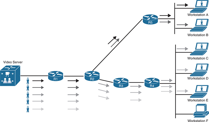
Always start from source when thinking of multicast and then branch out to receivers top to bottom
Multicast Source connects to a router called First-Hop router or FHR, “First hop from the top but below source”
Router that has receivers connected is called Last-Hop router or LHR, on its LAN side it will have IGMP enabled, and also a role called IGMP querier will be active on that LAN side
Between these 2 routers, PIM will operate
Switch will run IGMP snooping in order to snoop the IGMP messages
Without Mutlicast
the network link between R1 and R2 needs 50 Mbps of bandwidth
Stream of data is sent to special addresses called group addresses
Local network control block 224.0.0.0 to 224.0.0.255
Addresses in the local network control block are used for “control traffic” that is not forwarded outside of a local broadcast domain. Examples of this type of multicast control traffic are all hosts in this subnet (224.0.0.1), all routers in this subnet (224.0.0.2), and all PIM routers (224.0.0.13). control traffic sent out on this range has TTL of 1 and packet expires as soon as it enters next hop router, you might think that packers from 224.0.0.0 network cannot propagate through the network? even though the packet expires reaching next router but that message is delivered through out the network using these packets with TTL of 1
224.0.0.1
All hosts in this subnet (all hosts listen on this address)
224.0.0.2
All routers in this subnet
224.0.0.5
All OSPF routers (AllSPFRouters)
224.0.0.6
All OSPF DRs (AllDRouters)
224.0.0.10
All EIGRP routers
224.0.0.13
All PIM routers
224.0.0.18
VRRP
224.0.0.22
IGMPv3
224.0.0.102
HSRPv2 and GLBP
Internetwork control block (224.0.1.0/24):
Addresses in the internetwork control block are used for “control traffic” that may be forwarded through the Internet. Examples include Network Time Protocol (NTP) (224.0.1.1), Cisco-RP-Announce (224.0.1.39), and Cisco-RP-Discovery (224.0.1.40).
224.0.1.1
NTP
224.0.1.39
Cisco-RP-Announce (Auto-RP)
224.0.1.40
Cisco-RP-Discovery (Auto-RP)
Source Specific Multicast (SSM) block
232.0.0.0 to 232.255.255.255 232.0.0.0/8
This is the default range used by SSM. SSM is a PIM extension
SSM forwards traffic only from sources for which the receivers have explicitly expressed interest.
Used for one-to-many applications.
Administratively scoped block 239.0.0.0 to 239.255.255.255
This range is like private 10.0.0.0/8 range that can be used for multicasting internally in organsiation’s network
Multicast & Layer 2
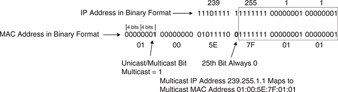
In order for multicast packets to be delivered to end hosts, their NIC needs to listen to “Multicast Group’s MAC address”
The first 24 bits of a multicast MAC address always start with “01:00:5E”
That “01” is Individual / Group bit (group means multicast group)
remaining 23 bits of the MAC address come from the lower 23 bits of the IPv4 multicast address.
an example of mapping the multicast IP address 239.255.1.1 into the multicast MAC address 01:00:5E:7F:01:01
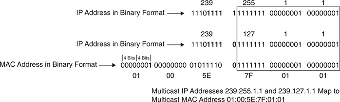
“some multicast group IP addresses can map to single MAC address“
because first 9 bits of the multicast IP address are not copied into the multicast mac address – and all multicast IP address have common first 1110, that leaves 9 – 4 = 5 bits that are varaible between multicast IP addresses that are not copied into the Multicast mac address
Because of this, there are 32 (25) multicast IP addresses that are not universally unique and could correspond to a single MAC address or overlap
When a receiver wants to receive a specific multicast feed, it sends an IGMP join using the multicast IP group address for that feed, The receiver reprograms its interface to accept the multicast MAC group address that correlates to the group address
IGMPv2
Receivers use IGMP to join multicast groups and leave multicast groups, When a receiver wants to receive multicast traffic from a source, it sends an IGMP join to its router. If the router does not have IGMP enabled on the interface, the request is ignored.
Most common IGMP version is IGMPv2
IGMPv3 is used by SSM
IGMPv2 uses “packet” that travels to the router with TTL of 1, if a router is the one that decremented the TTL from 1 to 0, that router does not proceed with forwarding / routing of that packet and that packet is then discarded.
Type Field
Version 2 membership report
also known as IGMP join
used by receivers to join a multicast group
or to respond to a local router’s membership query message
Version 1 membership report
is used by receivers for backward compatibility with IGMPv1
Version 2 leave group
is used by receivers to indicate they want to stop receiving multicast traffic for a group they joined.
General membership query is periodically sent to the all-hosts group address 224.0.0.1 to see whether there are any receivers in the attached subnet. It sets the group address field to 0.0.0.0 (and not to a specific group address).
Group specific query is sent in response to a leave group message to the group address the receiver requested to leave, this is a test by local router to see if there are any more receivers on LAN and if this leaving router is the last receiver.
Upstream after receiving IGMP join message from LAN
The local router once receives a IGMP join message on LAN side then sends a PIM join message upstream toward the source to request the multicast stream
When the local router starts receiving the multicast stream, it forwards it downstream to the subnet where the receiver that requested it resides.
Router then starts periodically sending general membership query messages into the subnet, to the all-hosts group address 224.0.0.1, to see whether any members are in the attached subnet. The general query message contains a max response time field that is set to 10 seconds by default
In response to this query, “receivers” set an internal random timer between 0 and 10 seconds (which can change if the max response time is using a non-default value). When the timer expires, receivers send membership reports for each group they belong to. If a receiver receives another receiver’s report for one of the groups it belongs to while it has a timer running, it stops its timer for the specified group and does not send a report; this is meant to suppress duplicate reports.
When the leave group message is received by the router, it follows with a group-specific membership query to the group multicast address to determine whether there are any receivers interested in the group remaining in the subnet. If there are none, the router removes the IGMP state for that group.
IGMP querier election (if there is more than one IGMP router on segment)
If there is more than one router in a LAN segment, an IGMP querier election takes place to determine which router will be the querier.
IGMPv2 routers send general membership “query” messages destined to the 224.0.0.1 multicast address
When an IGMPv2 router receives such a message, It cannot receive this “query” message, as host only “report” and not “query” that means there is another router on thet network
The router with the lowest interface IP address in the LAN subnet is elected as the IGMP querier.
All the non-
querier routers (routers that did not have lowest IP and lost) start a timer that resets each time they receive a membership query report from the querier router.
If the querier router stops sending membership queries for some reason (for instance, if it is powered down), a new querier election takes place. A non-querier router waits twice the query interval, which is by default 60 seconds, and if it has heard no queries from the IGMP querier, it triggers IGMP querier election.
IGMPv3
In IGMPv2, when a receiver sends a membership report to join a multicast group, it does not specify which source it would like to receive multicast traffic from. IGMPv3 is an extension of IGMPv2 that adds support for multicast source
gives the receivers the capability to pick the source they wish to accept multicast traffic from, it could be sender in same group such as 239.0.0.12 but receiver has ability to receive from better sender
IGMPv3 is designed to coexist with IGMPv1 and IGMPv2
IGMPv3 sources can be mentioned by receivers in following ways:
Include mode: In this mode, the receiver announces membership to a multicast group address and provides a list of source addresses (the include list) from which it wants to receive traffic.
Exclude mode: In this mode, the receiver announces membership to a multicast group address and provides a list of source addresses (the exclude list) from which it does not want to receive traffic. The receiver then receives traffic only from sources whose IP addresses are not listed on the exclude list. To receive traffic from all sources, which is the behavior of IGMPv2, a receiver uses exclude mode membership with an empty exclude list.
IGMPv3 is used to provide source filtering for Source Specific Multicast (SSM).
IGMP Snooping
To optimize forwarding and remove flooding, switches need a method of sending traffic only to interested receivers.
A multicast MAC address is never used as a source MAC address
And because multicast mac address is never seen as source MAC address, and never learned (because of source based learning), multicast frame going into the switch as destination is treated as unknown frame and flood them out all ports just like broadcast
IGMP snooping works by examining IGMP joins sent by receivers and maintaining a table of groups, IGMP joins and interfaces. When the switch receives a multicast frame destined for a multicast group, it forwards the packet only out the ports where IGMP joins were received for that specific multicast group
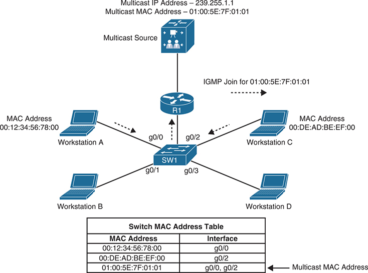
source sending traffic to 239.255.1.1 (01:00:5E:7F:01:01). Switch 1 receives this traffic, and it forwards it out only the g0/0 and g0/2 interfaces because those are the only ports that received IGMP joins for that group.
Even with IGMP snooping enabled, some multicast groups are still flooded on all ports (for example, 224.0.0.0/24 reserved addresses Local Network Control Block).
If IGMP snooping is not enabled, then a static entry can also be added in mac address table. A multicast static entry can also be manually programmed into the MAC address table, but this is not a scalable solution because it cannot react dynamically to changes; for this reason, it is not a recommended approach.
Protocol Independent Multicast
PIM uses routing table built and works at Layer 3
The two basic types of multicast distribution trees are
source trees as shortest path trees (SPTs), and shared trees (not shortest)
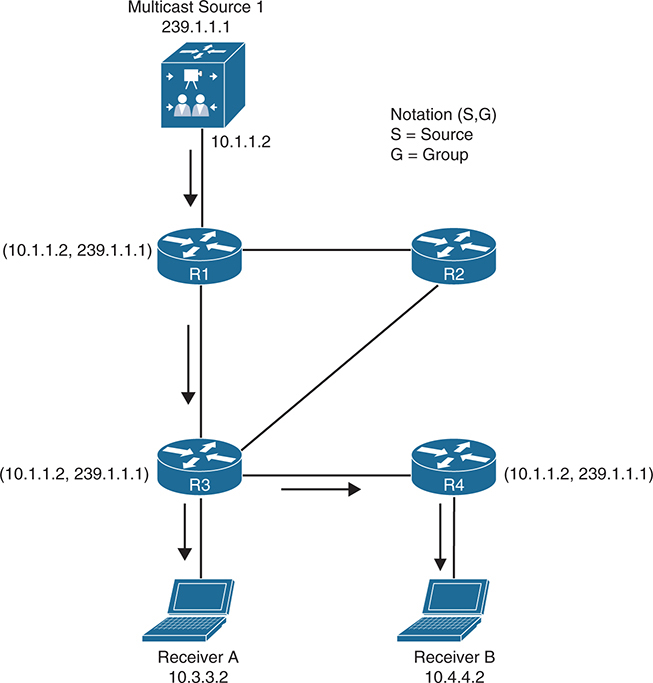
Source Trees or Shortest Path Tree SPT
A source tree or SPT or (S,G) is a multicast distribution tree where the source is the root of the tree, and branches form a distribution tree through the network towards receivers. When this tree is built, it has the shortest path through from the source to the leaves of the tree; for this reason, it is also referred to as a shortest path tree (SPT).
Forwarding state of the SPT is known by the notation (S,G), pronounced “S comma G,” where S is the sender of the multicast stream (server), and G is the multicast group address
Notice that this is Specific source / sending server per group, if a new server or sender is creates a new (S,G) will need to be built
Shared Trees or Rendezvous Point Trees RPT
A shared tree or (*,G) is a multicast distribution tree where the root of the shared tree is not the source but a router designated as the rendezvous point (RP) is, For this reason, shared trees are also referred to as rendezvous point trees (RPTs)
Multicast traffic is forwarded down the shared tree via RP even if source is next to receivers
shared tree is referred to by the notation (*,G), pronounced “star comma G.”
notice that it is any senders / source servers per group
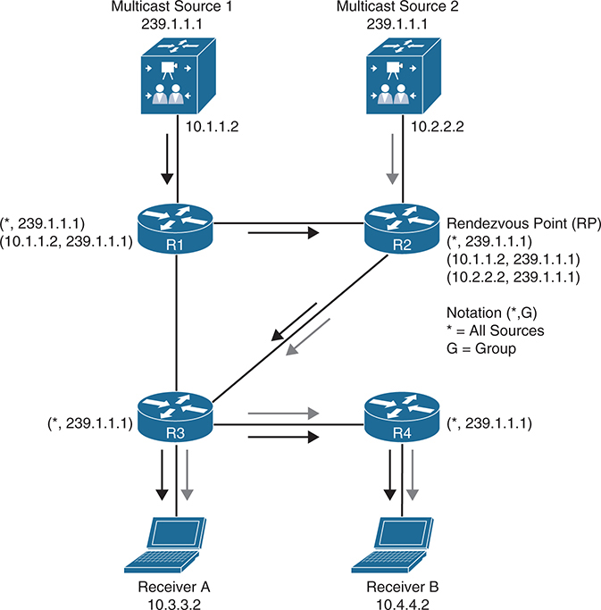
RP keeps record of all the senders (while R1 only has record of its sender) and is also responsible for receiving all Mcast streams, and then forwarded out of the RP
One of the benefits of shared trees over source trees is that they require fewer multicast entries (for example, S,G and *,G). For instance, as more sources are introduced into the network, sending traffic to the same multicast group, the number of multicast entries for R3 and R4 always remains the same: (*,239.1.1.1)
The major drawback of shared trees is that the receivers receive traffic from all the sources sending traffic to the same multicast group. Even though the receivers’ applications can filter out the unwanted traffic, this situation still generates a lot of unwanted network traffic, wasting bandwidth. In addition, because shared trees can allow multiple sources in an IP multicast group, there is a potential network security issue because unintended sources could send unwanted packets to receivers.
PIM Terminology
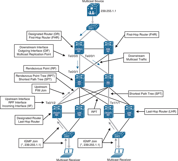
This diagram should be read from top or source to down, all the roles are from top to bottom such as First-hop Router
Reverse Path Forwarding (RPF) interface
The interface with the lowest-cost path to the IP address of the source (SPT) or the RP, If multiple interfaces have the same cost, the interface with the highest IP address is chosen as the tiebreaker
Also known as the incoming interface (IIF) (Incoming interface because this is where incoming multicast traffic will come), The only type of interface that can accept multicast traffic coming from the source, which is the same as the RPF interface. An example of this type of interface is Te0/0/1 on R3 because the shortest path to the source is known through this interface.
Another example of this type of interface is Te0/1/2 on R5 because it is the shortest path to the source. Another example is Te1/1/1 on R7 because the shortest path to the source was determined to be through R4.
RPF neighbor
The PIM neighbor or PIM enabled router on the RPF interface, if R7 is using the RPT shared tree, the RPF neighbor would be R3, which is the lowest-cost path to the RP. If it is using the SPT, R4 would be its RPF neighbor because it offers the lowest cost to the source.
A PIM join always travels upstream toward the source
Downstream interface
Any interface that is used to forward multicast traffic down the tree, also known as an outgoing interface (OIF). An example of a downstream interface is R1’s Te0/0/0 interface, which forwards multicast traffic to R3’s Te0/0/1 interface.
Outgoing interface (OIF)
Any interface that is used to forward multicast traffic down the tree, also known as the downstream interface.
Outgoing interface list (OIL)
A group of OIFs that are forwarding multicast traffic to the same group. An example of this is R1’s Te0/0/0 and Te0/0/1 interfaces sending multicast traffic downstream to R3 and R4 for the same multicast group.
Last-hop router (LHR)
A router that is directly attached to the receivers, also known as a leaf router. It is responsible for sending PIM joins upstream toward the RP or to the source.
First-hop router (FHR)
A router that is directly attached to the source, also known as a root router. It is responsible for sending register messages to the RP.
Multicast Routing Information Base (MRIB)
A topology table that is also known as the multicast route table (mroute). It is built based on information from the unicast routing table and PIM. MRIB contains the
source S, group G,
incoming interfaces (IIF),
outgoing interfaces (OIFs),
and RPF neighbor information
for each multicast route as well as other multicast-related information.
Multicast Forwarding Information Base (MFIB)
A forwarding table that uses the MRIB to program multicast forwarding information in hardware for faster forwarding.
There are currently five PIM operating modes:
- PIM Dense Mode (PIM-DM)
- PIM Sparse Mode (PIM-SM)
- PIM Sparse Dense Mode
- PIM Source Specific Multicast (PIM-SSM)
- PIM Bidirectional Mode (Bidir-PIM)
PIM-DM and PIM-SM are also commonly referred to as any-source multicast (ASM)
All PIM control messages use the IP protocol number 103
they are either unicast (higher TTL)
or multicast, with a TTL of 1 to the all PIM routers address 224.0.0.13
PIM Control Message Types
| Type | Message Type | Destination | PIM Protocol |
|---|---|---|---|
| 0 | Hello | 224.0.0.13 (all PIM routers) | PIM-SM, PIM-DM, Bidir-PIM, and SSM |
| 1 | Register | RP address (unicast) | PIM-SM |
| 2 | Register stop | First-hop router (unicast) | PIM SM |
| 3 | Join/prune | 224.0.0.13 (all PIM routers) | PIM-SM, Bidir-PIM, and SSM |
| 4 | Bootstrap | 224.0.0.13 (all PIM routers) | PIM-SM and Bidir-PIM |
| 5 | Assert | 224.0.0.13 (all PIM routers) | PIM-SM, PIM-DM, and Bidir-PIM |
| 8 | Candidate RP advertisement | Bootstrap router (BSR) address (unicast to BSR) | PIM-SM and Bidir-PIM |
| 9 | State refresh | 224.0.0.13 (all PIM routers) | PIM-DM |
| 10 | DF election | 224.0.0.13 (all PIM routers) | Bidir-PIM |
PIM hello messages are sent by default every 30 seconds out each PIM-enabled interface to learn about the neighboring PIM routers on each interface to the all PIM routers address
Hello messages are also the mechanism used to elect a designated router (DR)
PIM Dense Mode
PIM Dense Mode (PIM-DM), Dense means that there are Multicast receivers in every subnet of the network, in other words, when the multicast receivers of a multicast group are densely populated across the network.
For PIM-DM, the multicast tree is built by flooding traffic out every interface from the source to every Dense Mode router in the network
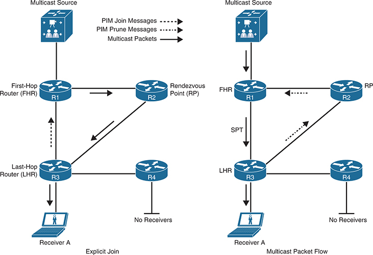
As each router receives traffic for the multicast group, it must decide whether it already has active receivers wanting to receive the multicast traffic. If so, the router remains quiet and lets the multicast flow continue. If no receivers have requested the multicast stream for the multicast group on the LHR, the router sends a prune message toward the source.
That branch of the tree is then pruned off so that the unnecessary traffic does not continue.
Initial Flooding
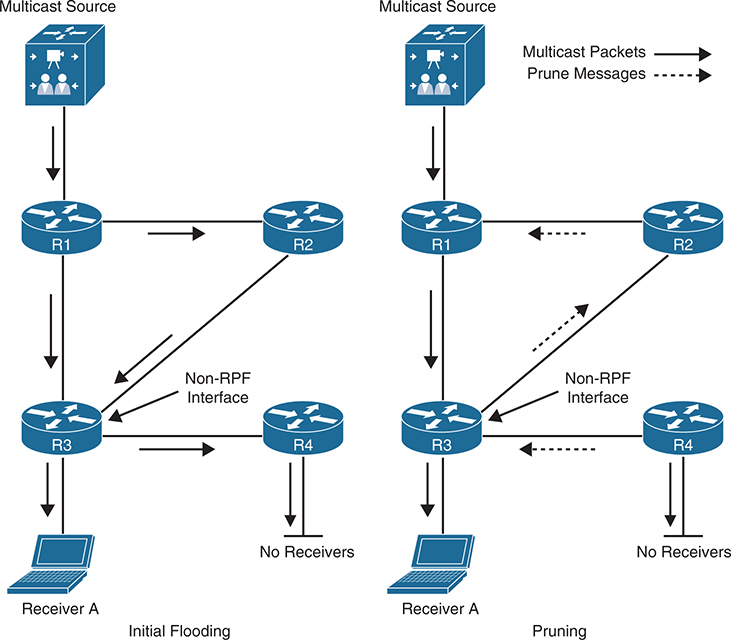
As each router receives the multicast traffic from its upstream neighbor via its RPF interface, it forwards the multicast traffic to all its PIM-DM neighbors, This results in some traffic arriving via a non-RPF interface, as in the case of R3 receiving traffic from R2 on its non-RPF interface. Packets arriving via the non-RPF interface are discarded because it is duplicate traffic and a prune message is prepared
Each router uses Reverse Path Forwarding (RPF) to decide which incoming interface is the correct one for multicast traffic from a particular source.
R3 checks its unicast routing table to see “Which interface would I use to reach the source?”
Route to the source (through R1) is the best path.
So, the interface from R1 is the RPF interface.
The interface from R2 is non-RPF.
That means:
R3 accepts multicast packets coming from R1 (RPF interface).
R3 drops multicast packets received from R2 (non-RPF interface).
These non-RPF multicast flows are normal for the initial flooding of multicast traffic and are corrected by the normal PIM-DM pruning mechanism.
Pruning after Initial Flooding
Prunes are sent out the RPF interface when the router has no downstream members that need the multicast traffic, as is the case for R4, which has no interested receivers, and they are also sent out non-RPF interfaces to stop the flow of multicast traffic that is arriving through the non-RPF interface, as is the case for R3
the resulting topology after all unnecessary links have been pruned off. This results in an SPT from the source to the receiver.
This (S,G) state remains until the source stops transmitting. S,G in this topology stands for, source is allowed / will come in to router from top and allowed / will go out from below interface
In PIM-DM, prunes expire after three minutes.
This causes the multicast traffic to be reflooded to all routers just as was done during the initial flooding. This periodic (every three minutes) flood and prune behavior is normal and must be taken into account when a network is designed to use PIM-DM.
PIM-DM is applicable to small networks where there are active receivers on every subnet of the network. Because this is rarely the case, PIM-DM is not widely deployed and not recommended for production environments.
PIM Sparse Mode
PIM Sparse Mode (PIM-SM) was designed for networks with multicast application receivers scattered throughout the network—in other words, when the multicast receivers of a multicast group are sparsely populated across the network. However, PIM-SM also works well in densely populated networks. It also assumes that no receivers are interested in multicast traffic unless they explicitly request, it opposite of PIM DM
Just like PIM-DM, PIM-SM uses the unicast routing table to perform RPF checks, and it does not care which routing protocol (including static routes) populates the unicast routing table; therefore, it is protocol independent.
PIM Shared and Source Path Trees
PIM-SM uses an explicit join model where the receivers send an IGMP join to their locally connected router, which is also known as the last-hop router (LHR), and this join causes the LHR to send a PIM join in the direction of the root of the tree, which is either the RP in the case of a shared tree (RPT) or in case of SPT, the first-hop router (FHR) where the source transmitting the multicast streams is connected
A multicast forwarding state is created as the result of these explicit joins
Multicast source sends multicast traffic to the FHR. The FHR then sends this multicast traffic to the RP, which makes the multicast source known to the RP
Receiver sends an IGMP join to the LHR to join the multicast group. The LHR then sends a PIM join (*,G) to the RP, and this forms a shared tree from the RP to the LHR, this (*,G) PIM join would travel hop-by-hop to the RP, building (*,G) on all routers it is passing through.
In essence, two trees are created: an SPT from the FHR to the RP (S,G) and a shared tree from the RP to the LHR (*,G).
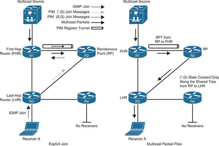
multicast starts flowing down from the source to the RP
and from the RP to the LHR and then finally to the receiver.
Receiver A attached to the LHR joins multicast group G using IGMP join. The LHR knows the IP address of the “RP for group G” – “there can be different RP per group” and LHR then sends (*,G) PIM join for this group to the RP.
Source for a group G sends a packet, the FHR that is attached to this source creates a “unidirectional ” PIM register tunnel interface that encapsulates the multicast data received from the source in a special PIM-SM message called the register message. The encapsulated multicast data is then unicast to the RP using the PIM register tunnel. This Multicast packet needs to be encapsulated in a unicast packet to RP, so it is not multicasted through the network below FHR
When the RP receives a register message, it decapsulates the multicast data packet inside the register message, and if there is no active shared tree because there are no interested receivers, the RP unicasts a register stop message directly to the registering FHR, without traversing the PIM register tunnel, instructing it to stop sending the register messages.
If there is an active shared tree for the group, it forwards the multicast packet down the shared tree, and it sends an (S,G) join back toward the source network S to create an (S,G) SPT. If there are multiple hops (routers) between the RP and the source, this results in an (S,G) state being created in all the routers along the SPT, There will also be a (*,G) in R1 and all of the routers between the FHR and the RP. So how can (*,G) and (S,G) co exist on same router?
(*,G): The “shared tree” state — means “any source for group G.”
It’s built towards the Rendezvous Point (RP).
Used before the specific source is known or joined.
(S,G): The “source tree” state — means “specific source S for group G.”
It’s built directly toward the multicast source (shortest path tree).
1. Initial IGMP Join
Receiver A (host) on R3 sends an IGMP Join for group G.
R3 (the Last-Hop Router, LHR) sends a PIM Join (*,G) upstream — towards the RP (R2).
So:
- R3 and R2 now have (*,G) state entries.
- This builds the shared tree (R3 → R2 → R1).
2. Source Starts Sending
When the multicast source (at R1) begins transmitting for group G:
- R1 (the First-Hop Router, FHR) registers with the RP using a PIM Register message.
- The RP learns that source S exists for group G.
3. Receiver Activity Triggers (S,G) Join
When the RP receives traffic from S, it knows there are active receivers (due to the earlier (*,G) join from R3).
So, the RP sends a PIM (S,G) Join back toward the source network — i.e., towards R1.
This creates:
- An (S,G) entry in R2 and R1 (routers along that source tree path).
- But — crucially — the (*,G) state still remains in R1 (and the path between R1 ↔ R2).
So Why Does (*,G) Exist in R1?
Even though R1 is the first-hop router (directly connected to the source), it forms a (*,G) state because:
- It’s part of the shared tree path from the RP to the source (built earlier when RP didn’t yet know the source existed).
The shared tree extends from RP → R1, so all routers on that path (including R1) must maintain(*,G)state. So this (*,G) is created on all routers around RP in 360 degrees. - Transitions are gradual, not instantaneous — both trees (shared and source) coexist temporarily while the network optimizes to the SPT.
As soon as the SPT is built from the source router to the RP, multicast traffic begins to flow natively from the source S to the RP instead of being encapsulated inside unicast PIM Regsiter tunnel
Once the RP begins receiving data natively from source S
it sends a register stop message to the source’s FHR to inform it that it can stop sending the unicast register messages. At this point, multicast traffic from the source is flowing down the SPT to the RP and, from there, down the shared tree (RPT) to the receiver – register stop message’s only function is to make FHR stop sending Register message for speicific group and not to stop multicast operation
The PIM register tunnel from the FHR to the RP remains in an active up/up state even when there are no active multicast streams, and it remains active as long as there is a valid RPF path for the RP.
PIM SPT Switchover
PIM-SM allows the LHR to switch from the RPT (shared tree) to an SPT for a specific source
In Cisco routers, this is the default behavior, and it happens immediately after the first multicast packet is received from the RP via the RPT on LHR, even if shortest parth to the source is through RP.
When the LHR receives the first multicast packet from the RP, it becomes aware of the IP address of the multicast source, at this point LHR sends (S,G) PIM Join towards the source IP following routing table (and not RP IP) and that can result in PIM Join going out of a different interface (shorter route) than interface through which RP is reachable
This PIM Join going from LHR to FHR creates (S,G) on all routers in the path
When the LHR receives a multicast packet from the source through the SPT, if the SPT RPF interface differs from the RPT RPF interface, the LHR will start receiving duplicate multicast traffic from the source; at this moment, it will switch the RPF interface to be the SPT RPF interface and send an (S,G) PIM prune message to the RP to shut off the duplicate multicast traffic coming through the RPT.
the shortest path to the source is between R1 and R3; if that link were shut down or not present, the shortest path would be through the RP, in which case an SPT switchover would still take place, even though the path used by the SPT is the same as the RPT.
The PIM SPT switchover mechanism can be disabled for all groups or for specific groups.
If the RP has no other interfaces that are interested in the multicast traffic, it sends a PIM prune message in the direction of the FHR. If there are any routers between the RP and the FHR, this prune message would travel hop-by-hop until it reaches the FHR.
Designated Routers
When multiple PIM-SM routers exist on a LAN segment, PIM hello messages are used to elect a designated router (DR) to avoid sending duplicate multicast traffic into the LAN (LHR) or to the RP (FHR). “Designated” router on LAN to receive traffic or send traffic, so second router does not duplicate multicast on network.
By default, the DR priority value of all PIM routers is 1, and it can be changed to force a particular router to become the DR during the DR election process, where a higher DR priority is preferred. If a router in the subnet does not support the DR priority option or if all routers have the same DR priority, the highest IP address in the subnet is used as a tiebreaker.
On an FHR, the designated router is responsible for encapsulating in unicast register messages any multicast packets originated by a source that are destined to the RP.
On an LHR, the designated router is responsible for sending PIM join and prune messages toward the RP to inform it about host group membership, and it is also responsible for performing a PIM SPT switchover.
Without DRs, all LHRs on the same LAN segment would be capable of sending PIM joins upstream, which could result in duplicate multicast traffic arriving on the LAN. On the source side, if multiple FHRs exist on the LAN, they all send register messages to the RP at the same time.
The default DR hold time is 3.5 times the PIM hello interval (PIM Hello is 30 seconds) which makes DR hold time to 105 seconds. If there are no hellos after this interval, a new DR is elected. To reduce DR failover time, the hello query interval can be reduced to speed up failover with a trade-off of more control plane traffic and CPU resource utilization of the router.
Reverse Path Forwarding
Reverse Path Forwarding is a method routers use when multicast traffic arrives on interface and it checks source address against routing table and if this is the interface., if not then interface is non RPF interface.
This is used to prevent loops and also avoid duplicated multicast traffic
If a router receives a multicast packet on an interface it uses to send unicast packets to the source, the packet has arrived on the RPF interface.
Next If the packet arrives on the RPF interface, a router forwards the packet out the interfaces present in the outgoing interface list (OIL) of a multicast routing table entry.
If the packet does not arrive on the RPF interface, the packet is discarded to prevent loops.
RPF check is performed differently for RPT and SPT
If a PIM router has an (S,G) entry present in the multicast routing table (an SPT state), the router performs the RPF check against the IP address of the source for the multicast packet.
If a PIM router has no explicit source-tree state, this is considered a shared-tree state. The router performs the RPF check on the address of the RP, which is known when members join the group.
PIM Assert , forwarder role
PIM assert mechanism is used to stop duplicate flows into LAN, well was it not the function of DR? yes DR does its best from control plane perspective to prevent duplicate flows, after DR elections only one router sends out PIM Join to receive traffic only on that specific DR router but in some cases (discussed below) you can still end up having duplicate multicast coming from 2 routers on same LAN and if that happens then this condition is detected and remediated using PIM Assert mechanism
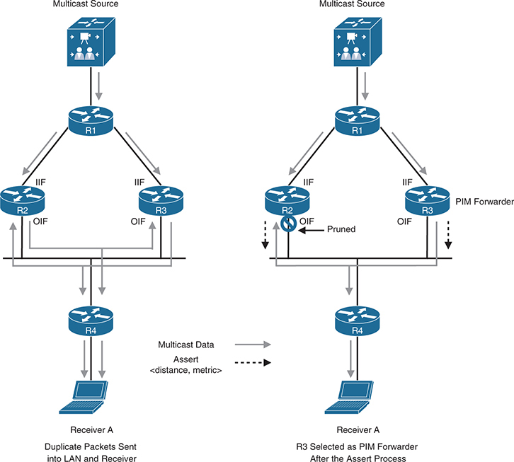
in above figure, Both R2 and R3 receive traffic on their (one and only) RPF interface, as these routers dispatch multicast traffic on LAN, R2’s sent multicast hits R3’s OIF interface and R3’s sent multicast traffic hits R2’s OIF, this triggers the PIM Assert mechanism on both routers as this should not happen
In other words, they detect a multicast packet for a specific (S,G) coming into their OIF that is also OIF for the same (S,G) (this OIF cannot be also IIF for same group)
R2 and R3 both send PIM assert messages into the LAN. These assert messages “send” each other following inside PIM Assert message to determine which router should forward the multicast traffic to that network segment.
- Administrative distance / preference
- Metric to the source (unicast routing metric)
- IP address (tie-breaker)
Each router compares its own values with the received values. Preference is given to the PIM message with the lowest AD to the source. If a tie exists, the lowest route metric for the protocol wins; and as a final tiebreaker, the highest IP address is used.
The losing router prunes its interface just as if it had received a prune on this interface, and the winning router is the PIM forwarder for the LAN.
The prune times out after three minutes on the losing router and causes it to begin forwarding on the interface again. This triggers the assert process to repeat. If the winning router were to go offline, the loser would take over the job of forwarding on to this LAN segment after its prune timed out.
The PIM forwarder concept applies to PIM-DM and PIM-SM. It is commonly used by PIM-DM but rarely required by PIM-SM because duplicate packets can end up in a LAN only if there is some sort of routing inconsistency.
PIM-SM would not send duplicate flows into the LAN as PIM-DM would because of the way PIM-SM operates.
Corner case for PIM-SM to send duplicated Multicast in LAN
PIM-SM will only forward duplicated multicast in LAN because of routing inconsistency only
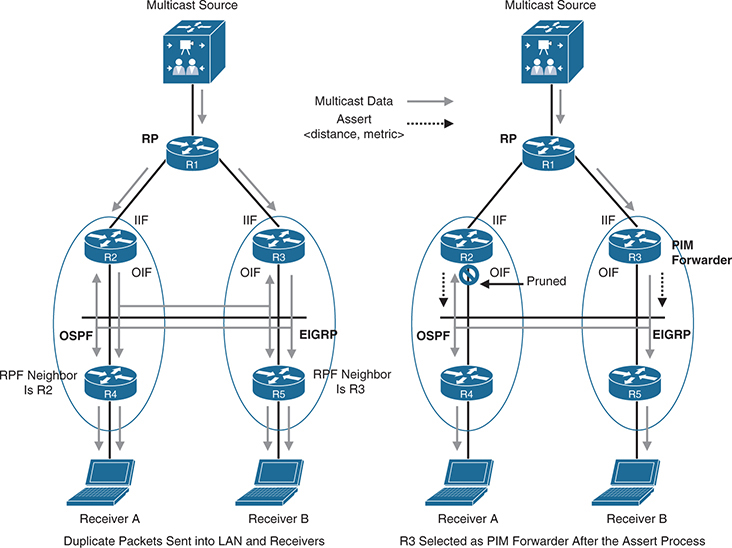
R1 is the RP
R2 and R4 are running the OSPF, and R3 and R5 are running EIGRP, and this is inconsistency in this network – to be more specific 2 different routing domains on same LAN.
R4 learns about the RP (R1) through R2, and R5 learns about the RP through R3
when R4 sends a PIM join message upstream toward it, it sends the message to the all PIM routers address 224.0.0.13, and R2 and R3 receive it but in PIM-SM PIM join message includes the IP address of the upstream neighbor, also known as the RPF neighbor (which is only one neighbor – PIM neighbor on RPF interface)
R4’s RPF neighbor is R2, and R5’s RPF neighbor is R3
Receiver A and Receiver B join the same group
Receiver A’s IGMP join will cause PIM Join from R4 to both R2 and R3 (because of same LAN) R2 is the only one that will send a PIM join to R1 because PIM join from R4 has header that contains R2 as its RPF neighbor, R3 will not because the PIM join was not meant for it, from R4 it was only meant for R2 (its RPF neighbor) and R2 will send PIM Join message to RP
Similarly IGMP join from receiver B will trigger R5 to send a PIM join to to both R2 and R3, but because PIM SM’s PIM Join has RPF neighbor R3 is specified in packet, R3 is the one that will send a PIM join to R1.
At this point, traffic starts flowing downstream from R1 into R2 and R3, and duplicate packets are then sent out into the LAN and to the receivers.
At this point, the PIM assert mechanism kicks in, R3 is elected as the PIM forwarder, and R2’s OIF interface is pruned, as illustrated in the topology on the right side.