OSPF
OSPF
OSPF is a link state routing protocol, an IGP
OSPF exchanges routing information with other routers , neighbors over LSA
LSA contains information on the link state (Subnet(s) on interface(s)) and link metric (cost to reach that IP and mask)
OSPF advertises this information to neighboring routers exactly as the original advertising router advertised it, in fact the whole area gets same LSAs and it is up to individual routers to compute SPT (Shortest Path Tree [to every subnet])
Received LSAs are stored in a local database called the link-state database (LSDB).
and then local router spreads LSAs through the OSPF area, interface by interface – link local multicast to next interface’s link local multicast.
All OSPF routers run Dijkstra’s shortest path first (SPF) algorithm to construct a loop-free topology of shortest paths. OSPF dynamically detects topology changes within the network and calculates loop-free paths in a short amount of time – this is the main purpose of all the routing protocols so we dont have to add static routes through the network and OSPF brings that
Each router sees itself as the root or top of the SPF tree (SPT), and the SPT contains all network destinations within the OSPF domain. The SPT differs for each OSPF router, but the LSDB used to calculate the SPT is identical for all OSPF routers.
There seems to be some difference in connectivity to the 10.3.3.0/24 network from R1’s and R4’s SPTs. From R1’s perspective, the serial link between R3 and R4 is missing; from R4’s perspective, the Ethernet link between R1 and R3 is missing.
The SPTs give the illusion that no redundancy exists to the networks, but remember that an SPT shows the shortest path to reach a network and is built from the LSDB, which contains all the links for an area.
A router can run multiple OSPF processes. Each process maintains its own unique database, and routes learned in one OSPF process are not available to a different OSPF process without redistribution of routes between processes.
The OSPF process numbers are locally significant and do not have to match among routers. If OSPF process number 1 is running on one router and OSPF process number 1234 is running on another, the two routers can become neighbors.
Areas
OSPF allows scalability by using areas
Area is set at interface level
An interface can belong to only one area
All routers within the same OSPF area maintain an identical copy of the LSDB.
Inside an area:
-A full SPT calculation runs when a link flaps within the area
-With a single area, the LSDB increases in size and becomes unmanageable, as area grows, consumes more memory, and takes longer during the SPF computation process.
-With a single area, no summarization of route information occurs.
If a router has interfaces in multiple areas, the router has multiple LSDBs (one for each area)
The internal topology of one area is invisible from outside that area. Outside areas only learn the prefixes of that area, only topology is not visible (like which prefix is attached to which router), outside areas just know about the prefixes
If a topology change occurs (such as a link flap or an additional network added) within an area, all routers in the same OSPF area calculate the SPT again. Routers outside that area do perform a partial SPF calculation
Segmenting the OSPF domain into multiple areas reduces the size of the LSDB for each area, making SPT calculations faster and decreasing LSDB flooding between routers when a link flaps.
Just because a router connects to multiple OSPF areas does not mean the routes from one area will be injected into another area
Area 0 is a special area called backbone area. OSPF uses a two-tier hierarchy in which all areas must connect to the upper tier Area 0.
All areas inject routing information into Area 0
Area 0 advertises the routes into other areas
Area ID is a 32-bit field and can be formatted as decimal (0 through 4294967295) or dotted decimal (0.0.0.0 through 255.255.255.255) like IPv4
If we use decimal format on one router and dotted-decimal format on a different router, the routers will be able to form an adjacency.
ABRs
Area border routers (ABRs) are OSPF routers connected to Area 0 and another OSPF area, ABR is responsible for sending its connected Area’s routes into -> Area 0 and send all the learned routes from all areas from Area 0’s routes into its areas
Every ABR must participate in Area 0
ABRs compute an SPT for every area that they participate in
OSPF Communication
OSPF runs directly over IPv4, using protocol 89 and does not use TCP or UDP because OSPF communication never travels over distance, it stays on link local using multicast
There are two OSPF multicast addresses:
AllSPFRouters: IPv4 address 224.0.0.5, 01:00:5E:00:00:05.
AllDRouters: IPv4 address 224.0.0.6, 01:00:5E:00:00:06
Remember multicast address of OSPF using 5E, E if flipped becomes M and 5 is S so Multicast
OSPF Packet Types
| 1 | Hello | Packets are sent out periodically on all OSPF interfaces to discover new neighbors while also ensuring that existing neighbors are still online. |
| 2 | Database description (DBD or DDP) | Packets are exchanged when an OSPF adjacency is first being formed. These packets are used to describe the contents of the LSDB, Remember only describe |
| 3 | Link-state request (LSR) | When a router thinks that part of its LSDB is stale after reading the DBD, it may request a portion of a neighbor’s database by using this packet type. |
| 4 | Link-state update (LSU) | This is the “LSA” for a specific network link, and normally it is sent in direct response to an LSR. |
| 5 | Link-state acknowledgment | These packets are sent in response to the flooding of LSAs, thus making the flooding a reliable transport feature. |
Router ID
The OSPF router ID (RID) is unique and identifies router in OSPF domain as a unique participant. The OSPF RID is an essential component in building an OSPF topology. The output of some OSPF commands uses the term neighbor ID as a synonym for RID. The RID must be unique for each OSPF process in an OSPF domain and must be unique between OSPF processes on a router.
The RID is dynamically allocated by default, using the highest IP address of any up loopback interfaces. If there are no up loopback interfaces, the highest IP address of any active up physical interfaces becomes the RID when the OSPF process initializes. The OSPF process selects the RID when the OSPF process initializes, and it does not change until the process restarts. This means that the RID can change if a higher loopback address has been added and the process (or router) is restarted.
Setting a static RID helps with troubleshooting and reduces LSAs when an RID changes in an OSPF environment
OSPF Hello Packets
OSPF Hello packets discover and maintain already discovered neighbors
OSPF router sends out hello on AllSPFRouters 224.0.0.5
Information carried inside OSPF hello:
| Router ID (RID) | A unique 32-bit ID within an OSPF domain that is used to build the topology. |
| Authentication Options | A field that allows secure communication between OSPF routers to prevent malicious activity. Options are none, plaintext, or Message Digest 5 (MD5) authentication. |
| Area ID | The OSPF area that the OSPF interface belongs to. It is a 32-bit number that can be written in dotted-decimal format (0.0.1.0) or decimal (256). |
| Interface Address Mask | The network mask for the primary IP address for the interface out which the hello is sent. |
| Interface Priority | The router interface priority for DR elections. |
| Hello Interval | The time interval, in seconds, at which a router sends out hello packets on the interface. |
| Dead Interval | The time interval, in seconds, that a router waits to hear a hello from a neighbor router before it declares that router down. |
| Designated Router and Backup Designated Router | The IP address of the DR and backup DR (BDR) for that network link. |
| Active Neighbor | A list of OSPF neighbors seen on that network segment. To qualify in this neighbor list a router must have received a hello from the neighbor within the dead interval. |
See how Active neighbors and DR / BDR information is inside the hello packets
Neighbors
An OSPF neighbor is a router that shares a common OSPF-enabled network link
Discover neighbors through hello messages
An adjacent OSPF neighbor is an OSPF neighbor that has shared all the LSDB to its neighbor as opposed to 2 way
OSPF Neighbor States
| Down | Router has not yet received hello yet |
| Attempt | A state that is relevant to nonbroadcast multi-access (NBMA) networks that do not support broadcast and require neighbor configuration. This state indicates that the router is still attempting communication. |
| Init | A state in which a hello packet has been received from another router, but bidirectional communication has not been established. Remember from “in” in Init |
| 2-Way | A state in which bidirectional communication has been established. If a DR or BDR is needed, the election occurs during this state. |
| ExStart | The first state in forming an adjacency. Routers identify which router will be the primary or secondary for the LSDB synchronization. |
| Exchange | A state during which routers are exchanging link states by using DBD packets. |
| Loading | A state in which LSR packets are sent to the neighbor, asking for the more recent LSAs that have been discovered (but not received) in the Exchange state. |
| Full | A state in which neighboring routers are fully adjacent. |
Neighbor Adjacency Requirements
R – The RIDs must be unique for whole OSPF domain, To prevent errors, they should be unique for the entire OSPF routing domain.
S – The interfaces must share a common subnet. OSPF uses the interface’s primary IP address when sending out OSPF hellos. The network mask (netmask) in the hello packet is used to extract the network ID of the hello packet.
M – The interface maximum transmission unit (MTU) must match because the OSPF protocol does not support fragmentation.
A – The area ID must match for that segment.
D – The need for a DR must match for that segment.
H – OSPF hello and dead timers must match for that segment.
A – The authentication type and credentials (if any) must match for that segment.
T – Area type flags must be identical for that segment (stub, NSSA, and so on).

see step 2 and 3, init and 2 way, how the neighbor list builds up
R1# debug ip ospf adj
OSPF adjacency events debugging is on

*21:10:01.735: OSPF: Build router LSA for area 0, router ID 192.168.1.1,
 seq 0x80000001, process 1
*21:10:09.203: OSPF: 2 Way Communication to 192.168.2.2 on GigabitEthernet0/0,
 state 2WAY
*21:10:39.855: OSPF: Rcv DBD from 192.168.2.2 on GigabitEthernet0/0 seq 0x1823
 opt 0x52 flag 0x7 len 32 mtu 1500 state 2WAY

*21:10:39.855: OSPF: Nbr state is 2WAY
*21:10:41.235: OSPF: end of Wait on interface GigabitEthernet0/0
*21:10:41.235: OSPF: DR/BDR election on GigabitEthernet0/0
*21:10:41.235: OSPF: Elect BDR 192.168.2.2
*21:10:41.235: OSPF: Elect DR 192.168.2.2
*21:10:41.235: DR: 192.168.2.2 (Id) BDR: 192.168.2.2 (Id)
*21:10:41.235: OSPF: GigabitEthernet0/0 Nbr 192.168.2.2: Prepare dbase exchange
*21:10:41.235: OSPF: Send DBD to 192.168.2.2 on GigabitEthernet0/0 seq 0xFA9
 opt 0x52 flag 0x7 len 32
*21:10:44.735: OSPF: Rcv DBD from 192.168.2.2 on GigabitEthernet0/0 seq 0x1823
 opt 0x52 flag 0x7 len 32 mtu 1500 state EXSTART
*21:10:44.735: OSPF: GigabitEthernet0/0 Nbr 2.2.2.2: Summary list built, size 1
*21:10:44.735: OSPF: Send DBD to 192.168.2.2 on GigabitEthernet0/0 seq 0x1823
 opt 0x52 flag 0x2 len 52
*21:10:44.743: OSPF: Rcv DBD from 192.168.2.2 on GigabitEthernet0/0 seq 0x1824
 opt 0x52 flag 0x1 len 52 mtu 1500 state EXCHANGE
*21:10:44.743: OSPF: Exchange Done with 192.168.2.2 on GigabitEthernet0/0
*21:10:44.743: OSPF: Send LS REQ to 192.168.2.2 length 12 LSA count 1
*21:10:44.743: OSPF: Send DBD to 192.168.2.2 on GigabitEthernet0/0 seq 0x1824
 opt 0x52 flag 0x0 len 32
*21:10:44.747: OSPF: Rcv LS UPD from 192.168.2.2 on GigabitEthernet0/0 length
 76 LSA count 1
*21:10:44.747: OSPF: Synchronized with 192.168.2.2 GigabitEthernet0/0, state FULL
*21:10:44.747: %OSPF-5-ADJCHG: Process 1, Nbr 192.168.2.2 on GigabitEthernet0/0
 from LOADING to FULL, Loading Done
OSPF Configuration
Most configuration for OSPF is done under OSPF process but some configuration can be done at interface level
command ip ospf process-id area area-id [secondaries none]. This method also adds secondary connected networks to the LSDB unless the secondaries none option is used.
Making the network interface passive still adds the network segment to the LSDB but prevents the interface from forming OSPF adjacencies. A passive interface does not send out OSPF hellos and does not process any received OSPF packets.
The command passive-interface interface-id under the OSPF process makes the interface passive, and the command passive-interface default makes all interfaces passive, Then command no passive-interface interface-id is used to make interfaces non passive
Different ways of configuring OSPF
R1
router ospf 1
 router-id 192.168.1.1
 network 0.0.0.0 255.255.255.255 area 1234
R2
router ospf 1
router-id 192.168.2.2
network 10.123.1.2 0.0.0.0 area 1234
network 10.24.1.2 0.0.0.0 area 1234R3
router ospf 1
router-id 192.168.3.3
network 0.0.0.0 255.255.255.255 area 1234
passive-interface GigabitEthernet0/1R3
router ospf 1
router-id 192.168.3.3
network 0.0.0.0 255.255.255.255 area 1234
passive-interface GigabitEthernet0/1R4
router ospf 1
router-id 192.168.4.4
!
interface GigabitEthernet0/0
ip ospf 1 area 0
interface Serial1/0
ip ospf 1 area 1234R5
router ospf 1
router-id 192.168.5.5
network 10.45.1.0 0.0.0.255 area 0
network 0.0.0.0 255.255.255.255 area 56R6
router ospf 1
router-id 192.168.6.6
network 0.0.0.0 255.255.255.255 area 56R4# show ip ospf interface
GigabitEthernet0/0 is up, line protocol is up
Internet Address 10.45.1.4/24, Area 0, Attached via Interface Enable
Process ID 1, Router ID 192.168.4.4, Network Type BROADCAST, Cost: 1
Topology-MTID Cost Disabled Shutdown Topology Name
0 1 no no Base
Enabled by interface config, including secondary ip addresses
Transmit Delay is 1 sec, State BDR, Priority 1
Designated Router (ID) 192.168.5.5, Interface address 10.45.1.5
Backup Designated router (ID) 192.168.4.4, Interface address 10.45.1.4
Timer intervals configured, Hello 10, Dead 40, Wait 40, Retransmit 5
oob-resync timeout 40
Hello due in 00:00:02
..
Neighbor Count is 1, Adjacent neighbor count is 1
Adjacent with neighbor 192.168.5.5 (Designated Router)
Suppress hello for 0 neighbor(s)
Serial1/0 is up, line protocol is up
Internet Address 10.24.1.4/29, Area 1234, Attached via Interface Enable
Process ID 1, Router ID 192.168.4.4, Network Type POINT_TO_POINT, Cost: 64
Topology-MTID Cost Disabled Shutdown Topology Name
0 64 no no Base
Enabled by interface config, including secondary ip addresses
Transmit Delay is 1 sec, State POINT_TO_POINT
Timer intervals configured, Hello 10, Dead 40, Wait 40, Retransmit 5
..
Neighbor Count is 1, Adjacent neighbor count is 1
Adjacent with neighbor 192.168.2.2
Suppress hello for 0 neighbor(s)R1# show ip ospf interface brief
Interface PID Area IP Address/Mask Cost State Nbrs F/C
Gi0/0 1 1234 10.123.1.1/24 1 DROTH 2/2R2# show ip ospf interface brief
Interface PID Area IP Address/Mask Cost State Nbrs F/C
Se1/0 1 1234 10.24.1.1/29 64 P2P 1/1
Gi0/0 1 1234 10.123.1.2/24 1 BDR 2/2R3# show ip ospf interface brief
Interface PID Area IP Address/Mask Cost State Nbrs F/C
Gi0/1 1 1234 10.3.3.3/24 1 DR 0/0
Gi0/0 1 1234 10.123.1.3/24 1 DR 2/2R4# show ip ospf interface brief
Interface PID Area IP Address/Mask Cost State Nbrs F/C
Gi0/0 1 0 10.45.1.4/24 1 BDR 1/1
Se1/0 1 1234 10.24.1.4/29 64 P2P 1/1PID
The OSPF process ID associated with this interface
Nbrs F
This is neighbors that are “Fully” adjacent, The number of neighbor OSPF routers for a segment that are fully adjacent
Nbrs C
This is neighbor “Count”, The number of neighbor OSPF routers for a segment that have been detected and are in a 2-Way state
DROTHERs do not establish full adjacency with other DROTHERs.
show ip ospf neighbor [detail]
R2# show ip ospf neighbor
Neighbor ID     Pri   State           Dead Time   Address         Interface
192.168.4.4       0   FULL/ -         00:00:38    10.24.1.4       Serial1/0
192.168.1.1       1   FULL/DROTHER    00:00:37    10.123.1.1      GigabitEthernet0/0
192.168.3.3       1   FULL/DR         00:00:34    10.123.1.3      GigabitEthernet0/0
Notice that the state for R2’s S1/0 interface does not reflect a DR status with its peering with R4 (192.168.4.4) because a DR can not exist on a point-to-point link so it simply shows –
R1# show ip route ospf
! Output omitted for brevity
Codes: L - local, C - connected, S - static, R - RIP, M - mobile, B - BGP
       D - EIGRP, EX - EIGRP external, O - OSPF, IA - OSPF inter area
       N1 - OSPF NSSA external type 1, N2 - OSPF NSSA external type 2
       E1 - OSPF external type 1, E2 - OSPF external type 2
Gateway of last resort is not set

O        10.3.3.0/24 [110/2] via 10.123.1.3, 00:18:54, GigabitEthernet0/0
O        10.24.1.0/29 [110/65] via 10.123.1.2, 00:18:44, GigabitEthernet0/0
O IA     10.45.1.0/24 [110/66] via 10.123.1.2, 00:11:54, GigabitEthernet0/0
O IA     10.56.1.0/24 [110/67] via 10.123.1.2, 00:11:54, GigabitEthernet0/0
two sets of numbers are presented in brackets (for example, [110/2]). The first number is the administrative distance (AD), which is 110 by default for OSPF, and the second number is the metric
intra-area (O routes)
inter-area (O IA routes)
R5# show ip route ospf | begin Gateway
Gateway of last resort is not set

O IA     10.3.3.0/24 [110/67] via 10.45.1.4, 00:04:13, GigabitEthernet0/0
O IA     10.24.1.0/29 [110/65] via 10.45.1.4, 00:04:13, GigabitEthernet0/0
O IA     10.123.1.0/24 [110/66] via 10.45.1.4, 00:04:13, GigabitEthernet0/0
routing table for R5 and R6. R5 and R6 contain only inter-area routes in the OSPF routing table because intra-area routes are directly connected. Directly connected routes are not installed in routing table only because of AD competition only, these O Intra area routes will still show in OSPF LSDB
Routes that are injected into an OSPF domain through redistribution are known as external OSPF routes.
The router that redistributes prefixes into an OSPF domain, the router is called an autonomous system boundary router (ASBR)
There are 2 types of external routes:
Type 1 routes are preferred over Type 2 routes.
The Type 1 metric equals the redistribution metric plus the total path metric to the ASBR. In other words, as the LSA propagates away from the originating ASBR, the metric increases.
The Type 2 metric equals only the redistribution metric. The metric is the same for the router next to the ASBR as the router 30 hops away from the originating ASBR. This is the default external metric type used by OSPF.
172.16.6.0/24 network is redistributed as a Type 1 route, and the 172.31.6.0/24 network is redistributed as a Type 2 route
External OSPF network routes are marked as O E1 and O E2
R1# show ip route ospf
! Output omitted for brevity
Codes: L - local, C - connected, S - static, R - RIP, M - mobile, B - BGP
       D - EIGRP, EX - EIGRP external, O - OSPF, IA - OSPF inter area
       E1 - OSPF external type 1, E2 - OSPF external type 2
Gateway of last resort is not set

O        10.3.3.0/24 [110/2] via 10.123.1.3, 23:20:25, GigabitEthernet0/0
O        10.24.1.0/29 [110/65] via 10.123.1.2, 23:20:15, GigabitEthernet0/0
O IA     10.45.1.0/24 [110/66] via 10.123.1.2, 23:13:25, GigabitEthernet0/0
O IA     10.56.1.0/24 [110/67] via 10.123.1.2, 23:13:25, GigabitEthernet0/0
O E1     172.16.6.0 [110/87] via 10.123.1.2, 00:01:00, GigabitEthernet0/0
O E2     172.31.6.0 [110/20] via 10.123.1.2, 00:01:00, GigabitEthernet0/0
R2# show ip route ospf | begin Gateway
Gateway of last resort is not set
O 10.3.3.0/24 [110/2] via 10.123.1.3, 23:24:05, GigabitEthernet0/0
O IA 10.45.1.0/24 [110/65] via 10.24.1.4, 23:17:11, Serial1/0
O IA 10.56.1.0/24 [110/66] via 10.24.1.4, 23:17:11, Serial1/0
O E1 172.16.6.0 [110/86] via 10.24.1.4, 00:04:45, Serial1/0
O E2 172.31.6.0 [110/20] via 10.24.1.4, 00:04:45, Serial1/0metric for the 172.31.6.0/24 network is the same on R1 as it is on R2, but the metric for the 172.16.6.0.0/24 network differs on two routers because Type 1 metrics include the path metric to the ASBR.
OSPF supports advertising the default route into the OSPF domain. The advertising router must have a default route in its routing table for the default route to be advertised. To advertise the default route, you use the command default-information originate [always] [metric metric-value] [metric-type type-value] underneath the OSPF process. The always optional keyword advertises the default route regardless of whether a default route exists in the RIB. In addition, the route metric can be changed with the metric metric-value option, and the metric type can be changed with the metric-type type-value option.
R1
ip route 0.0.0.0 0.0.0.0 100.64.1.2
!
router ospf 1
 network 10.0.0.0 0.255.255.255 area 0
 default-information originate
OSPF advertises the default route as an external OSPF route.
R2# show ip route | begin Gateway
Gateway of last resort is 10.12.1.1 to network 0.0.0.0

O*E2  0.0.0.0/0 [110/1] via 10.12.1.1, 00:02:56, GigabitEthernet0/1
C        10.12.1.0/24 is directly connected, GigabitEthernet0/1
C        10.23.1.0/24 is directly connected, GigabitEthernet0/2
Order of Route Preference
O — Intra-Area route
Most preferred
Best because it stays inside the same area
O IA — Inter-Area route
From another area
Preferred over all external types
N1 — NSSA External Type 1
External + internal cost
Same logic as E1 but inside NSSA
Most preferred external type
E1 — External Type 1
External + internal cost to ASBR
Preferred over type 2
N2 — NSSA External Type 2
External metric only
Treated like E2 but originates in NSSA
E2 — External Type 2
External metric only
Lowest preference
Designated Router and Backup Designated Router
Multi-access networks allow more than two routers to exist on a network segment. With OSPF when each router becomes neighbor of each router, it can flood more LSAs, we dont worry about the hellos since they are still sent to all ospf routers as they needed for 2 way neighborships, it is only the LSAs that can cause issues in n (n – 1) / 2 setup due to excessive traffic
Not just the network but having so many adjacencies per segment consumes more bandwidth, more CPU processing, and more memory to maintain each of the neighbor states.
One router on the network becomes a designated router DR and one router becomes BDR, all OSPF routers then become 2 way adjacent using hellos DROTHER but only fully adjacent with the DR and BDR by sending their full LSDB, this LSDB received by DR and BDR is then synced with all or rest of the OSPF routers, but all of this happens per subnet or per segment
DR/BDR election occurs with OSPF neighborship—specifically, during the last phase of the 2-Way neighbor state and just before the ExStart state
Router interface having OSPF priority of non-zero will attempts DR/BDR elections, if priority is 0 then that OSPF router “interface” (not the whole router) does not take part in DR/BDR elections
Default priority is 1, higher priority wins
If all OSPF routers on a multi-access segment (e.g., Ethernet) have the same priority, OSPF uses the highest Router ID (RID) as the tie-breaker to elect the DR and BDR.
Routers place their RID and also the priority inside hellos
The OSPF DR and BDR roles cannot be preempted but only upon the failure of router control plane
or
manual process restart from CLI
Wait timer
To ensure that all routers on a segment have fully initialized or booted into OS and running OSPF
OSPF initiates a wait timer when OSPF hello packets do not contain a DR/BDR router for a segment. The default value for the wait timer is the dead interval timer When the wait timer has expired, a router participates in the DR election.
The wait timer starts when OSPF first starts on an interface, so a router can still elect itself as the DR for a segment without other OSPF routers; it only waits until the wait timer expires
point-to-point link and has no DR/BDR
If all the OSPF routers have the same OSPF priority, and the next decision is to use the higher RID (and RID selection is also a per node’s local process, to find the highest IP on the loopback interfaces and if no loopback interfaces with IP, then highest IP address on the physical interfaces)
Increasing priority on one router increases its chances of becoming the DR or BDR since default priority on an OSPF interface is 1 and Remember that OSPF does not preempt the DR or BDR roles, so it might be necessary to restart the OSPF process on the current DR/BDR for the changes to take effect.
Setting an interface priority to 0 removes that interface from the DR/BDR election immediately.
OSPF Network Types
Not every transport or network is multiaccess
We have to determine the right network / media type and set OSPF network type based on that
Remember the rule for need of DR/BDR on the network, wherever B is then DR/BDR are needed such as “B”roadcast and non “B”roadcast
| Type | Description | DR/BDR Field in OSPF Hellos | Timers |
|---|---|---|---|
| Broadcast | Default setting on OSPF-enabled Ethernet links. | Yes | Hello: 10 Wait: 40 Dead: 40 |
| Nonbroadcast | Default setting on enabled OSPF Frame Relay main interface or Frame Relay multipoint sub-interfaces. | Yes | Hello: 30 Wait: 120 Dead: 120 |
| Point-to-point | Default setting on enabled OSPF Frame Relay point-to-point sub-interfaces. | No | Hello: 10Wait: 40Dead: 40 |
| Point-to-multipoint | Not enabled by default on any interface type. Interface is advertised as a host route (/32), and sets the next-hop address to the outbound interface. Primarily used for hub-and-spoke topologies. | No | Hello: 30 Wait: 120 Dead: 120 |
| Loopback | Default setting on OSPF-enabled loopback interfaces. Interface is advertised as a host route (/32). | N/A | N/A |
Broadcast
Broadcast networks are multi-access in that they are capable of connecting more than two devices, and broadcasts sent out one interface are capable of reaching all interfaces attached to that segment hence broadcast
ip ospf network broadcast overrides the automatically configured setting and statically sets an interface as an OSPF broadcast network type.
Nonbroadcast
Frame Relay, ATM, and X.25 are considered NBMA in that they can also connect more than two devices but some devices could be in different virtual circuits while in a same subnet
Virtual circuits may provide connectivity, but the topology may not be a full mesh and might only provide a hub-and-spoke topology.
Frame Relay interfaces set the OSPF network type to nonbroadcast by default. The hello protocol interval takes 30 seconds for this OSPF network type. Multiple routers can exist on a segment, so the DR functionality is used. Neighbors are statically defined with the neighbor ip-address command because multicast and broadcast functionality do not exist on this type of circuit. Configuring a static neighbor causes OSPF hellos to be sent using unicast.
command ip ospf network non-broadcast manually sets an interface as an OSPF nonbroadcast network type
R1
interface Serial 0/0
 ip address 10.12.1.1 255.255.255.252
 encapsulation frame-relay
 no frame-relay inverse-arp
 frame-relay map ip address 10.12.1.2 102
!
router ospf 1
 router-id 192.168.1.1
 neighbor 10.12.1.2
 network 0.0.0.0 255.255.255.255 area 0
R1# show ip ospf interface Serial 0/0 | include Type
Process ID 1, Router ID 192.168.1.1, Network Type
NON_BROADCAST, Cost: 64Point-to-Point Networks
Only two nodes can exist on this type of network medium, so OSPF does not waste CPU cycles on DR functionality. The hello timer is set to 10 seconds on OSPF point-to-point network types.
OSPF network type is set to point-to-point by default for serial interfaces (HDLC or PPP encapsulation), Generic Routing Encapsulation (GRE) tunnels, and point-to-point Frame Relay sub-interfaces
R1
interface serial 0/1
  ip address 10.12.1.1 255.255.255.252
!
router ospf 1
   router-id 192.168.1.1
   network 0.0.0.0 255.255.255.255 area 0
R2
interface serial 0/1
ip address 10.12.1.2 255.255.255.252
!
router ospf 1
router-id 192.168.2.2
network 0.0.0.0 255.255.255.255 area 0R1# show ip ospf interface s0/1 | include Type
Process ID 1, Router ID 192.168.1.1, Network Type POINT_TO_POINT, Cost: 64R2# show ip ospf interface s0/1 | include Type
Process ID 1, Router ID 192.168.2.2, Network Type POINT_TO_POINT, Cost: 64R1# show ip ospf neighbor
Neighbor ID Pri State Dead Time Address Interface
192.168.2.2 0 FULL/ - 00:00:36 10.12.1.2 Serial0/1Point-to-point OSPF network types do not use a DR. Notice the hyphen (-) in the State field.
Interfaces using an OSPF P2P network type form an OSPF adjacency quickly because the DR election is bypassed, and there is no wait timer. “Ethernet interfaces” that are directly connected with only two OSPF speakers in the subnet could be changed to the OSPF point-to-point network type to form adjacencies more quickly and to simplify the SPF computation
command ip ospf network point-to-point manually sets an interface as an OSPF point-to-point network type.
Point-to-Multipoint Networks
Point-to-multipoint OSPF network type supports hub-and-spoke connectivity while using the same IP subnet and is commonly found in Frame Relay and Layer 2 VPN (L2VPN) topologies.
OSPF network type point-to-multipoint is not enabled by default for any medium. It requires manual configuration. A DR is not enabled for this OSPF network type, and the hello timer is set to 30 seconds.
Interfaces set for the OSPF point-to-multipoint network type add the interface’s IP address to the OSPF LSDB as a /32 network which means that this interface address will be advertised as /32 network and will be received by neighbors as /32 and routes received on neighbors through this router and neighbors will use this /32 interface as the next hop
Why? Because OSPF wants to treat each neighbour as a separate logical link, not part of a shared network. Using /32: Removes the idea of a shared subnet.
command ip ospf network point-to-multipoint manually sets an interface as an OSPF point-to-multipoint network type
R1
interface Serial 0/0
  encapsulation frame-relay
  no frame-relay inverse-arp
!
interface Serial 0/0.123 multipoint
  ip address 10.123.1.1 255.255.255.248
  frame-relay map ip 10.123.1.2 102 broadcast
  frame-relay map ip 10.123.1.3 103 broadcast
  ip ospf network point-to-multipoint
!
router ospf 1
  router-id 192.168.1.1

  network 0.0.0.0 255.255.255.255 area 0
R2
interface Serial 0/0
encapsulation frame-relay
no frame-relay inverse-arp
!
interface Serial 0/1/0/0.123 multipoint
ip address 10.123.1.2 255.255.255.248
frame-relay map ip 10.123.1.1 201 broadcast
ip ospf network point-to-multipoint
!
router ospf 1
router-id 192.168.2.2
network 0.0.0.0 255.255.255.255 area 0R3
interface Serial 0/0
encapsulation frame-relay
no frame-relay inverse-arp
!
interface Serial 0/0.123 multipoint
ip address 10.123.1.3 255.255.255.248
frame-relay map ip 10.123.1.1 301 broadcast
ip ospf network point-to-multipoint
!
router ospf 1
router-id 192.168.3.3
network 0.0.0.0 255.255.255.255 area 0R1# show ip ospf interface Serial 0/0.123 | include Type
Process ID 1, Router ID 192.168.1.1, Network Type POINT_TO_MULTIPOINT, Cost: 64R2# show ip ospf interface Serial 0/0.123 | include Type
Process ID 1, Router ID 192.168.2.2, Network Type POINT_TO_MULTIPOINT, Cost: 64R3# show ip ospf interface Serial 0/0.123 | include Type
Process ID 1, Router ID 192.168.3.3, Network Type POINT_TO_MULTIPOINT, Cost: 64Notice that all three routers are on the same subnet, but R2 and R3 do not establish an adjacency with each other.
R1# show ip ospf neighbor

Neighbor ID     Pri     State        Dead Time       Address         Interface
192.168.3.3       0   FULL/ -         00:01:33    10.123.1.3     Serial0/0.123
192.168.2.2       0   FULL/ -         00:01:40    10.123.1.2     Serial0/0.123
R2# show ip ospf neighbor
Neighbor ID Pri State Dead Time Address Interface
192.168.1.1 0 FULL/ - 00:01:49 10.123.1.1 Serial0/0.123R3# show ip ospf neighbor
Neighbor ID Pri State Dead Time Address Interface
192.168.1.1 0 FULL/ - 00:01:46 10.123.1.1 Serial0/0.123R1# show ip route ospf | begin Gateway
Gateway of last resort is not set
O 10.123.1.2/32 [110/64] via 10.123.1.2, 00:07:32, Serial0/0.123
O 10.123.1.3/32 [110/64] via 10.123.1.3, 00:03:58, Serial0/0.123
192.168.2.0/32 is subnetted, 1 subnets
O 192.168.2.2 [110/65] via 10.123.1.2, 00:07:32, Serial0/0.123
192.168.3.0/32 is subnetted, 1 subnets
O 192.168.3.3 [110/65] via 10.123.1.3, 00:03:58, Serial0/0.123R2# show ip route ospf | begin Gateway
Gateway of last resort is not set
O 10.123.1.1/32 [110/64] via 10.123.1.1, 00:07:17, Serial0/0.123
O 10.123.1.3/32 [110/128] via 10.123.1.1, 00:03:39, Serial0/0.123
192.168.1.0/32 is subnetted, 1 subnets
O 192.168.1.1 [110/65] via 10.123.1.1, 00:07:17, Serial0/0.123
192.168.3.0/32 is subnetted, 1 subnets
O 192.168.3.3 [110/129] via 10.123.1.1, 00:03:39, Serial0/0.123R3# show ip route ospf | begin Gateway
Gateway of last resort is not set
O 10.123.1.1/32 [110/64] via 10.123.1.1, 00:04:27, Serial0/0.123
O 10.123.1.2/32 [110/128] via 10.123.1.1, 00:04:27, Serial0/0.123
192.168.1.0/32 is subnetted, 1 subnets
O 192.168.1.1 [110/65] via 10.123.1.1, 00:04:27, Serial0/0.123
192.168.2.0/32 is subnetted, 1 subnets
O 192.168.2.2 [110/129] via 10.123.1.1, 00:04:27, Serial0/0.123Loopback Networks
OSPF network type loopback is enabled by default for loopback interfaces and can be used only on loopback interfaces, always advertised with a /32 prefix length, even if the IP address configured on the loopback interface does not have a /32 prefix length.
R1interface Loopback0
    ip address 192.168.1.1 255.255.255.0
interface Serial 0/1
    ip address 10.12.1.1 255.255.255.252
!
router ospf 1
   router-id 192.168.1.1
   network 0.0.0.0 255.255.255.255 area 0R
R2’s loopback interface is set to the OSPF point-to-point network type to ensure that R2’s loopback interface advertises the network prefix 192.168.2.0/24
R2
interface Loopback0
    ip address 192.168.2.2 255.255.255.0
    ip ospf network point-to-point
interface Serial 0/0
    ip address 10.12.1.2 255.255.255.252
!
router ospf 1
   router-id 192.168.2.2
   network 0.0.0.0 255.255.255.255 area 0
R1# show ip ospf interface Loopback 0 | include Type
Process ID 1, Router ID 192.168.1.1, Network Type LOOPBACK, Cost: 1R2# show ip ospf interface Loopback 0 | include Type
Process ID 1, Router ID 192.168.2.2, Network Type POINT_TO_POINT, Cost: 1R1# show ip ospf database router | I Advertising|Network|Mask
Advertising Router: 192.168.1.1
Link connected to: a Stub Network
(Link ID) Network/subnet number: 192.168.1.1
(Link Data) Network Mask: 255.255.255.255
Link connected to: a Stub Network
(Link ID) Network/subnet number: 10.12.1.0
(Link Data) Network Mask: 255.255.255.0
Advertising Router: 192.168.2.2
Link connected to: a Stub Network
(Link ID) Network/subnet number: 192.168.2.0
(Link Data) Network Mask: 255.255.255.0
Link connected to: a Stub Network
(Link ID) Network/subnet number: 10.12.1.0
(Link Data) Network Mask: 255.255.255.0Design difference between P2MP and NBMA and Why use where
NBMA
Frame Relay, DMVPN, MPLS
Like Ethernet segment without broadcast
DR/BDR election due to Ethernet like segment and because of “B”
Hub can become DR
NBMA can’t do broadcast or multicast (no 224.0.0.5/6).
Hellos and LSAs must be sent using unicast to neighbours.
Neighbors must be configured manually neighbor x.x.x.x
Both P2MP and NBMA offer single subnet WAN
Configured using command ip ospf network non-broadcast
In NBMA spoke to spoke become neighbors but by default, in a typical hub-and-spoke NBMA design (like Frame Relay), spokes do not become neighbors with each other, because they cannot directly communicate unless the underlying NBMA network provides full-mesh VC connectivity.
P2MP
Frame Relay, DMVPN, MPLS
Hub-and-spoke and the spokes do not fully mesh
Can work with (broadcast command) or without broadcast (default P2MP)
P2MP (with broadcast capable media) can discover neighbours dynamically via multicast
This allows simpler configuration vs NBMA with manual config for many spokes
No DR but bunch of P2P while HUB is P2MP
For example, hub router with 20 spokes across DMVPN or MPLS, spokes never talk directly.
Neighbors are configured manually
/32 Host routes P2P links
Both P2MP and NBMA offer single subnet WAN
P2MP is used over NBMA when there is no spoke to spoke communication allowed
Failure Detection
OSPF Dead interval timer, which defaults to four times the hello timer. Upon receipt of the hello packet from a neighboring router, the OSPF dead timer resets to the initial value, and then it starts to decrement again.
If a router does not receive a hello before the OSPF dead interval timer reaches 0, the neighbor state is changed to down. The OSPF router immediately sends out the appropriate LSA, reflecting the topology change, and the SPF algorithm processes on all routers within the area.
Changing the hello timer interval modifies the default dead interval, too. The OSPF hello timer is modified with the interface configuration submode command ip ospf hello-interval 1-65,535
You can change the dead interval timer to a value between 1 and 65,535 seconds. You change the OSPF dead interval timer by using the command ip ospf dead-interval 1-65,535 under the interface configuration submode.
show ip ospf interface shows timers
R1# show ip ospf interface | i Timer|line
Loopback0 is up, line protocol is up
GigabitEthernet0/2 is up, line protocol is up
 Timer intervals configured, Hello 10, Dead 40, Wait 40, Retransmit 5
GigabitEthernet0/1 is up, line protocol is up
 Timer intervals configured, Hello 10, Dead 40, Wait 40, Retransmit 5
Authentication
An attacker can forge OSPF packets or gain physical access to a network, manipulate the routing and take control of traffic
OSPF authentication is enabled on an interface-by-interface basis or for all interfaces in an area
You can set the password only as an interface parameter, and you must set it for every interface.
If you miss an interface, the default password is set to a null value.
OSPF supports two types of authentication:
Plaintext: This type of authentication provides little security, as anyone with access to the link can see the password by using a network sniffer.
You enable plaintext authentication for an OSPF area with the command area area-id authentication, then use the interface parameter command ip ospf authentication to set plaintext authentication only on that interface. You configure the plaintext password by using the interface parameter command ip ospf authentication-key password.
MD5 cryptographic hash: This type of authentication uses a hash, so the password is never sent out the wire. This technique is widely accepted as being the more secure mode. You enable MD5 authentication for an OSPF area by using the command area area-id authentication message-digest, and then the interface parameter command ip ospf authentication message-digest to set MD5 authentication for that interface. You configure the MD5 password with the interface parameter command ip ospf message-digest-key key-number md5 password.
MD5 authentication is a hash of the key number and password combined. If the keys do not match, the hash differs between the nodes. That is why keys much match between the nodes and this is the use of the keys
Area 12 uses plaintext authentication, and Area 0 uses MD5 authentication
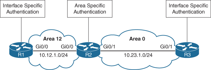
R1 and R3 use interface-based authentication
R2 uses area-specific authentication
R1
interface GigabitEthernet0/0
 ip address 10.12.1.1 255.255.255.0
 ip ospf authentication
 ip ospf authentication-key CISCO
!
router ospf 1
 network 10.12.1.0 0.0.0.255 area 12
R2
interface GigabitEthernet0/0
ip address 10.12.1.2 255.255.255.0
ip ospf authentication-key CISCO
!
interface GigabitEthernet0/1
ip address 10.23.1.2 255.255.255.0
ip ospf message-digest-key 1 md5 CISCO
!
router ospf 1
area 0 authentication message-digest
area 12 authentication
network 10.12.1.0 0.0.0.255 area 12
network 10.23.1.0 0.0.0.255 area 0R3
interface GigabitEthernet0/1
ip address 10.23.1.3 255.255.255.0
ip ospf authentication message-digest
ip ospf message-digest-key 1 md5 CISCO
!
router ospf 1
network 10.23.1.0 0.0.0.255 area 0You verify the authentication settings by examining the OSPF interface without the brief option
R1# show ip ospf interface | include line|authentication|key
GigabitEthernet0/0 is up, line protocol is up
  Simple password authentication enabled
R2# show ip ospf interface | include line|authentication|key
GigabitEthernet0/1 is up, line protocol is up
Cryptographic authentication enabled
Youngest key id is 1
GigabitEthernet0/0 is up, line protocol is up
Simple password authentication enabledR3# show ip ospf interface | include line|authentication|key
GigabitEthernet0/1 is up, line protocol is up
Cryptographic authentication enabled
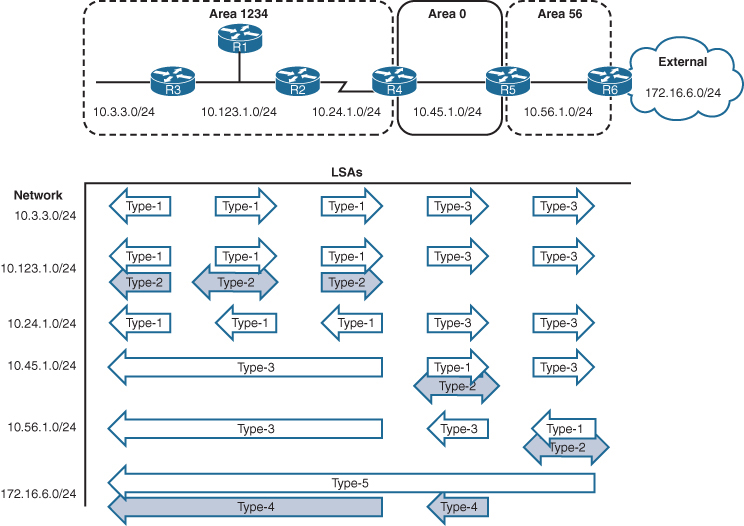
Youngest key id is 1OSPF uses six LSA types for IPv4 routing:
Type 1, router: LSAs that advertise prefixes within an area
Type 2, network: LSAs that indicate the routers attached to broadcast segment within an area
Type 3, summary: LSAs that advertise prefixes that originate from a different area
Type 4, ASBR summary: LSA used to locate the ASBR from a different area
Type 5, AS external: LSA that advertises prefixes that were redistributed in to OSPF
Type 7, NSSA external: LSA for external prefixes that were redistributed in a local NSSA area
LSA Types 1, 2, and 3 are used for building the SPF tree for intra-area and inter-area route routes.
LSA Types 4, 5, and 7 are related to external OSPF routes (that is, routes that were redistributed into the OSPF routing domain).
LSA Sequences
In OSPF, the LSA sequence number is used for versioning, and the originating router increments it each time it reoriginates (updates) the LSA
If a receiving router receives an LSA sequence that is greater than the one in the LSDB, it processes the LSA, If the LSA sequence number is lower than the one in the LSDB, the router deems the LSA old and discards it.
LSA Age and Flooding
Every local router keeps the LSA and also maintains the timer against that LSA called “age”, when LSA is first created in database, that “age” field is 0 but it start incrementing in the DB each second locally, once that age reaches 1800 seconds which is 30 mins, the originating router automatically generates a new copy of that LSA.
This is built into OSPF to keep the LSDB fresh and ensure routers don’t accidentally keep stale information forever.
Another LSA increment (over the links – inflight)
When a router forwards (floods) an LSA to a neighbour, the age increases by a small calculated delay
This accounts for:
- Link transmission delay
- Router processing time
In practice, this increment is small, but the LSA age always increases as it moves across the network.
If any LSA reaches 3600 seconds, it is considered expired or MaxAge.
If a router receives an LSA that has reached MaxAge (3600 seconds), it will reflood that LSA with LS age = 3600 to all its neighbors.
This behaviour ensures that every router, both downstream and upstream, deletes the LSA from its LSDB.
This flooding happens even if the router is not the original creator of the LSA.
Why flood the MaxAge LSA?
Because OSPF relies on synchronized LSDBs.
If one router deletes an LSA silently but others don’t, the network becomes inconsistent.
Router A (originator) publishes LSA
      ↓
Routers B, C, D store it
      ↓
LSA in Router D reaches 3600 seconds
      ↓
Router D floods LSA age = 3600 to neighbors (C)
      ↓
Router C deletes LSA, floods MaxAge to Router B
      ↓
Router B deletes LSA, floods MaxAge to Router A
      ↓
Router A deletes its own stale LSA
LSA Types
ABRs maintain a separate set of LSAs for each OSPF area
LSA Type 1: Router Link
A Type 1 LSA entry exists for each OSPF-enabled link (that is, an interface and its attached networks).
Type 1 LSAs are not advertised outside Area thus making the underlying topology in an area invisible to other areas.

R1# show ip ospf database
            OSPF Router with ID (192.168.1.1) (Process ID 1)

                Router Link States (Area 1234)

Link ID         ADV Router      Age         Seq#       Checksum Link count
192.168.1.1     192.168.1.1     14          0x80000006 0x009EA7 1
192.168.2.2     192.168.2.2     2020        0x80000006 0x00AD43 3
192.168.3.3     192.168.3.3     6           0x80000006 0x0056C4 2
192.168.4.4     192.168.4.4     61          0x80000005 0x007F8C 2
Link ID
Identifies the object that the link connects to. It can refer to the neighboring router’s RID, the IP address of the DR’s interface, or the IP network address.
ADV Router
The OSPF router ID of the router that originated the LSA
AGE
The age of the LSA on the router on which the command is being run. Values over 1800 are expected to refresh soon.
Seq #
Sequence number for the LSA
Checksum
The checksum of the LSA to verify integrity during flooding.
Link Count
3 links → Router has three OSPF interfaces/networks it advertises.
If we explore this LSA further we will see networks mentioned inside it
This makes it functions just like a router LSA, router telling us how many links it has in a certain area
You can examine the Type 1 OSPF LSAs by using the command show ip ospf database router
R1# show ip ospf database router
! Output omitted for brevity
            OSPF Router with ID (192.168.1.1) (Process ID 1)

                Router Link States (Area 1234)

  LS age: 352                 <<< start of LSA
  Options: (No TOS-capability, DC)
  LS Type: Router Links       <<< Type 1 LSA
  Link State ID: 192.168.1.1  <<< how it shows in sh ip ospf database
  Advertising Router: 192.168.1.1
  LS Seq Number: 80000014
  Length: 36
  Number of Links: 1

   Link connected to: a Transit Network
     (Link ID) Designated Router address: 10.123.1.3
     (Link Data) Router Interface address: 10.123.1.1
                                               |
                                 No hint of the network yet
       TOS 0 Metrics: 1


  LS age: 381
  Options: (No TOS-capability, DC)
  LS Type: Router Links
  Link State ID: 192.168.2.2
  Advertising Router: 192.168.2.2
  LS Seq Number: 80000015
  Length: 60
 Number of Links: 3
    Link connected to: another Router (point-to-point)
     (Link ID) Neighboring Router ID: 192.168.4.4
     (Link Data) Router Interface address: 10.24.1.1
       TOS 0 Metrics: 64

    Link connected to: a Stub Network
     (Link ID) Network/subnet number: 10.24.1.0
     (Link Data) Network Mask: 255.255.255.248
       TOS 0 Metrics: 64

    Link connected to: a Transit Network
     (Link ID) Designated Router address: 10.123.1.3
     (Link Data) Router Interface address: 10.123.1.2
       TOS 0 Metrics: 1
  LS age: 226
  Options: (No TOS-capability, DC)
  LS Type: Router Links
  Link State ID: 192.168.3.3
  Advertising Router: 192.168.3.3
  LS Seq Number: 80000014
  Length: 48
  Number of Links: 2

    Link connected to: a Stub Network
     (Link ID) Network/subnet number: 10.3.3.0
     (Link Data) Network Mask: 255.255.255.0
       TOS 0 Metrics: 1

    Link connected to: a Transit Network
     (Link ID) Designated Router address: 10.123.1.3
     (Link Data) Router Interface address: 10.123.1.3
       TOS 0 Metrics: 1


  LS age: 605
  Options: (No TOS-capability, DC)
  LS Type: Router Links
  Link State ID: 192.168.4.4
  Advertising Router: 192.168.4.4
  LS Seq Number: 80000013
  Length: 48

  Area Border Router  <<< telling us that even though this
  Number of Links: 2                    is in our area but
                                       this is an ABR with
                                       one leg in our area

    Link connected to: another Router (point-to-point)
     (Link ID) Neighboring Router ID: 192.168.2.2
     (Link Data) Router Interface address: 10.24.1.4
       TOS 0 Metrics: 64

    Link connected to: a Stub Network
     (Link ID) Network/subnet number: 10.24.1.0
     (Link Data) Network Mask: 255.255.255.248
       TOS 0 Metrics: 64
If a router is functioning as an ABR, an ASBR, or a virtual-link endpoint, the function is listed between the Length field and the Number of links field.

“show ip ospf database” Link ID can mean different things based the LSA type
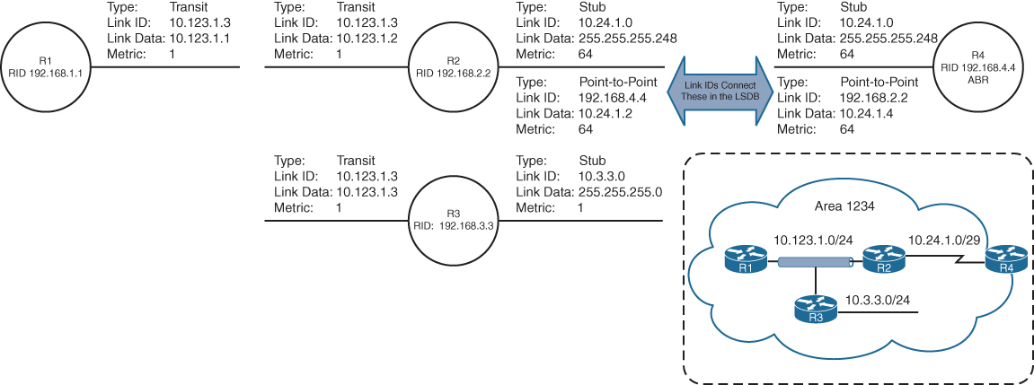
Point-to-point link (IP address assigned)
Link type 1
Neighbor RID
Link to transit network
Link type 2
Interface address of the DR
Link to stub network
Link type 3
Network address
Virtual link
Link type 4
Neighbor RID
Transit link in router LSA shows DR and IP address facing DR
Point to point link in router LSA advertise two links
One link is the point-to-point link type that identifies the OSPF neighbor RID for that segment, and the other link is a stub network link that provides the subnet mask for that network
Stub Network in router LSA has no neighbors, Point-to-point and transit link types that did not become adjacent with another OSPF router are classified as a stub network link type
Secondary connected networks are always advertised as stub link types because OSPF adjacencies can never form on them
Just by using information from Router LSA type 1, we can build a topology
Notice that the three router links on R1, R2, and R3 (10.123.1.0) have not been directly connected yet.
Also see how topology uses Link ID and then its corresponding Link Data
R3 is elected as the DR (that is why Link ID is 10.123.1.3), and R2 is elected as the BDR
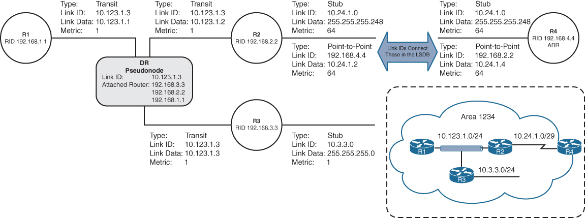
LSA Type 2: Network Link
A Type 2 LSA (network LSA) represents a multi-access network
DR always advertises the Type 2 LSA
identifies all the routers attached to that network segment.
If a DR has not been elected, a Type 2 LSA is not present in the LSDB
Type 2 LSAs are not flooded outside the originating OSPF area in an identical fashion to Type 1 LSAs.
R1# show ip ospf database
! Output omitted for brevity
            OSPF Router with ID (192.168.1.1) (Process ID 1)
..
                Net Link States (Area 1234)

Link ID        ADV Router        Age         Seq#       Checksum
10.123.1.3     10.192.168.3.3    1752        0x80000012 0x00ADC5
Type 2 LSA that is advertised by “R3” but show command is on R1
The network mask for the subnet is included in the Type 2 LSA
R1# show ip ospf database network
            OSPF Router with ID (192.168.1.1) (Process ID 1)

                Net Link States (Area 1234)

  LS age: 356
  Options: (No TOS-capability, DC)
  LS Type: Network Links
  Link State ID: 10.123.1.3 (address of Designated Router)
  Advertising Router: 192.168.3.3
  LS Seq Number: 80000014
  Checksum: 0x4DD
  Length: 36
  Network Mask: /24
        Attached Router: 192.168.3.3
        Attached Router: 192.168.1.1
        Attached Router: 192.168.2.2
Visualization of the Type 1 and Type 2 LSAs
When the DR changes for a network segment, a new Type 2 LSA is created, causing SPF to run again within the OSPF area.
Pseudonode because that box is considered a node in OSPF LSDB but it is not real node or router
LSA Type 3: Summary Link
Type 3 LSAs (summary LSAs) represent networks from other areas. The role of the ABRs is to participate in multiple OSPF areas and ensure that these Type 1 networks are reachable from other areas
As explained earlier, ABRs do not forward Type 1 or Type 2 LSAs into other areas. When an ABR receives a Type 1 LSA, it creates an equivalent Type 3 LSA
The ABR then advertises the Type 3 LSA into other areas
If an ABR receives a Type 3 LSA from Area 0 (backbone area), it regenerates a new Type 3 LSA for the nonbackbone area and lists itself as the advertising router with the additional cost metric

Type 1 LSAs exist only in the area of origination and convert to Type 3 when they cross the ABRs (R4 and R5).
The Type 3 LSAs show up under the appropriate area where they exist in the OSPF domain. For example, the 10.56.1.0 Type 3 LSA exists only in Area 0 and Area 1234 on R4.
R4# show ip ospf database
! Output omitted for brevity
            OSPF Router with ID (192.168.4.4) (Process ID 1)
..
                Summary Net Link States (Area 0)
                              |
                              v
          This just means that these are Type 1 LSAs of
          foreign or remote areas in this area
Link ID         ADV Router      Age         Seq#       Checksum
10.3.3.0        192.168.4.4     813         0x80000013 0x00F373
10.24.1.0       192.168.4.4     813         0x80000013 0x00CE8E
10.56.1.0       192.168.5.5     591         0x80000013 0x00F181
10.123.1.0      192.168.4.4     813         0x80000013 0x005A97

..
                Summary Net Link States (Area 1234)
                              |
                              v
          This just means that these are Type 1 LSAs of
          foreign or remote areas in this area
Link ID         ADV Router      Age         Seq#       Checksum
10.45.1.0       192.168.4.4     813         0x80000013 0x0083FC
10.56.1.0       192.168.4.4     813         0x80000013 0x00096B
R5# show ip ospf database
! Output omitted for brevity
OSPF Router with ID (192.168.5.5) (Process ID 1)
..
Summary Net Link States (Area 0)
|
v
This just means that these are Type 1 LSAs of
foreign or remote areas in this area
Link ID ADV Router Age Seq# Checksum
10.3.3.0 192.168.4.4 893 0x80000013 0x00F373
10.24.1.0 192.168.4.4 893 0x80000013 0x00CE8E
10.56.1.0 192.168.5.5 668 0x80000013 0x00F181
10.123.1.0 192.168.4.4 893 0x80000013 0x005A97
..
Summary Net Link States (Area 56)
|
v
This just means that these are Type 1 LSAs of
foreign or remote areas in this area
Link ID ADV Router Age Seq# Checksum
10.3.3.0 192.168.5.5 668 0x80000013 0x00F073
10.24.1.0 192.168.5.5 668 0x80000013 0x00CB8E
10.45.1.0 192.168.5.5 668 0x80000013 0x007608
10.123.1.0 192.168.5.5 668 0x80000013 0x005797The advertising router for Type 3 LSAs is the last ABR that advertises the prefix. The metric in the Type 3 LSA uses the following logic:
- If the Type 3 LSA is created from a Type 1 LSA, it is the total path metric to reach the originating router in the Type 1 LSA.
- If the Type 3 LSA is created from a Type 3 LSA (from Area 0), it is the total path metric to the ABR plus the metric in the original Type 3 LSA
R4# show ip ospf database summary 10.56.1.0
            OSPF Router with ID (192.168.4.4) (Process ID 1)

                Summary Net Link States (Area 0)

  LS age: 754
  Options: (No TOS-capability, DC, Upward)
  LS Type: Summary Links(Network)
  Link State ID: 10.56.1.0 (summary Network Number)
  Advertising Router: 192.168.5.5
  LS Seq Number: 80000013
  Checksum: 0xF181
  Length: 28
  Network Mask: /24
        MTID: 0         Metric: 1 <<< this is in Area 0


                Summary Net Link States (Area 1234)

  LS age: 977
  Options: (No TOS-capability, DC, Upward)
  LS Type: Summary Links(Network)
  Link State ID: 10.56.1.0 (summary Network Number)
  Advertising Router: 192.168.4.4
  LS Seq Number: 80000013
  Checksum: 0x96B
  Length: 28
  Network Mask: /24
        MTID: 0         Metric: 2 <<< when sent to non Area 0
                                      incremented
shows the Type 3 LSA for the Area 56 prefix (10.56.1.0/24) from R4’s LSDB. R4 is an ABR, and the information is displayed for both Area 0 and Area 1234. Notice that the metric increases in Area 1234’s LSA compared to in Area 0’s LSA.
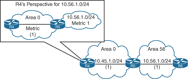
R4’s perspective of the Type 3 LSA created by ABR (R5) vs Reality visualized below
R4 does not know if the 10.56.1.0/24 network is directly attached to the ABR (R5) or if it is multiple hops away (due to area obfuscation). R4 knows that its metric to the ABR (R5) is 1 and that the Type 3 LSA already has a metric of 1, so its total path metric to reach the 10.56.1.0/24 network is 2.
R3’s perspective of the Type 3 LSA created by the ABR (R4) for the 10.56.1.0/24 network vs reality visualised
R3 does not know if the 10.56.1.0/24 network is directly attached to the ABR (R4) or if it is multiple hops away (due to area obfuscation). R3 knows that its metric to the ABR (R4) is 65 and that the Type 3 LSA already has a metric of 2 (the metric R4 brings for network 10.56.1.0/24), so its total path metric is 67 to reach the 10.56.1.0/24 network
LSA Type 5: External Routes
When a route is redistributed into OSPF, the router is known as an autonomous system boundary router (ASBR). The external route is flooded throughout the entire OSPF domain (every area) as a Type 5 LSA (external LSAs).
Notice that the Type 5 LSA exists in all OSPF areas of the routing domain. Type 5 LSA is not regenerated unlike Type 4 instead only LSA Age is incremented
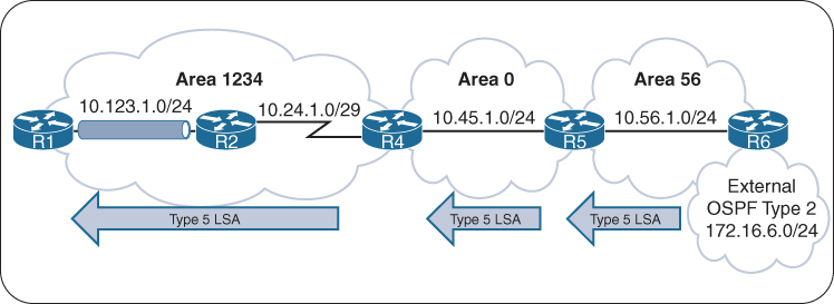
The link ID is the external network number, and the advertising router is the RID for the router originating the Type 5 LSA
R6# show ip ospf database
! Output omitted for brevity
                Type-5 AS External Link States

Link ID         ADV Router      Age         Seq#       Checksum Tag
172.16.6.0      192.168.6.6     11          0x80000001 0x000866 0
R6# show ip ospf database external
OSPF Router with ID (192.168.6.6) (Process ID 1)
Type-5 AS External Link States
LS age: 720
Options: (No TOS-capability, DC, Upward)
LS Type: AS External Link
Link State ID: 172.16.6.0 (External Network Number )
Advertising Router: 192.168.6.6
LS Seq Number: 8000000F
Checksum: 0xA9B0
Length: 36
Network Mask: /24
Metric Type: 2 (Larger than any link state path)
MTID: 0
Metric: 20
Forward Address: 0.0.0.0
External Route Tag: 0R1# show ip ospf database external
OSPF Router with ID (192.168.1.1) (Process ID 1)
Type-5 AS External Link States
LS age: 778
Options: (No TOS-capability, DC, Upward)
LS Type: AS External Link
Link State ID: 172.16.6.0 (External Network Number )
Advertising Router: 192.168.6.6
LS Seq Number: 8000000F
Checksum: 0xA9B0
Length: 36
Network Mask: /24
Metric Type: 2 (Larger than any link state path)
MTID: 0
Metric: 20
Forward Address: 0.0.0.0
External Route Tag: 0LSA Type 4: ASBR Summary
A Type 4 LSA (ASBR summary LSA) locates the ASBR for a Type 5 LSA
Routers examine the Type 5 LSA, check to see whether the RID is in the local area (because if in local area then cost advertised can be believed for E1), but if the ASBR is not local, a mechanism is required to locate the ASBR or measure distance to ASBR (for cases where we have 2 competing routes, which both have ASBR in remote area for which we dont have a view of)
Type 4 LSAs provide a way for routers to locate the ASBR when the ASBR is in a different area
A Type 4 LSA is created by the first ABR, and it provides a summary route strictly for the ASBR of a Type 5 LSA
The metric for a Type 4 LSA uses the following logic:
- When the Type 5 LSA crosses the first ABR (Area 0 ***ABR*** Area 56) creates a Type 4 LSA with a metric set to the total path metric to the ASBR.
- When an ABR receives a Type 4 LSA from Area 0, the ABR creates a new Type 4 LSA with a metric set to the total path metric of the first ABR (Area 1234 ***ABR*** Area 0) plus the metric to ASBR in the original Type 4 LSA, (Cost to ASBR or type 4 LSA is not added through every router’s outgoing interface)
R4# show ip ospf database
! Output omitted for brevity
            OSPF Router with ID (192.168.4.4) (Process ID 1)
..
                Summary ASB Link States (Area 0)

Link ID         ADV Router      Age         Seq#       Checksum
192.168.6.6     192.168.5.5     930         0x8000000F 0x00EB58
..
                Summary ASB Link States (Area 1234)

Link ID         ADV Router      Age         Seq#       Checksum
192.168.6.6     192.168.4.4     1153        0x8000000F 0x000342
R4# show ip ospf database asbr-summary
! Output omitted for brevity
OSPF Router with ID (192.168.4.4) (Process ID 1)
Summary ASB Link States (Area 0)
LS age: 1039
Options: (No TOS-capability, DC, Upward)
LS Type: Summary Links(AS Boundary Router)
Link State ID: 192.168.6.6 (AS Boundary Router address)
Advertising Router: 192.168.5.5
Length: 28
Network Mask: /0
MTID: 0 Metric: 1
Summary ASB Link States (Area 1234)
LS age: 1262
Options: (No TOS-capability, DC, Upward)
LS Type: Summary Links(AS Boundary Router)
Link State ID: 192.168.6.6 (AS Boundary Router address)
Advertising Router: 192.168.4.4
Length: 28
Network Mask: /0
MTID: 0 Metric: 2An ABR advertises only one Type 4 LSA for every ASBR, even if the ASBR advertises thousands of Type 5 LSAs
LSA Type 7: NSSA External Summary
A Type 7 LSA (NSSA external LSA) exists only in NSSAs where route redistribution is occurring.
An ASBR sitting on the edge of an NSSA Area injects external routes as Type 7 LSAs in an NSSA
The ABR does not advertise Type 7 LSAs outside the originating NSSA but it converts the Type 7 LSA into a Type 5 LSA
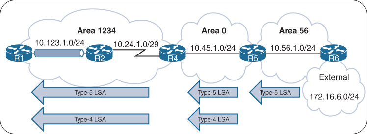
If the Type 5 LSA crosses Area 0, the second ABR creates a Type 4 LSA for the Type 5 LSA

R5 injects the Type 5 LSA (only) in Area 0, which propagates to Area 1234, and R4 creates the Type 4 LSA for Area 1234 and also forwards Type 5 (only LSA age is incremented).
R5# show ip ospf database
! Output omitted for brevity
            OSPF Router with ID (192.168.5.5) (Process ID 1)

..
Type-7 AS External Link States (Area 56) <<< Type 7

Link ID         ADV Router      Age         Seq#       Checksum Tag
172.16.6.0      192.168.6.6     46          0x80000001 0x00A371 0

!   Notice that no Type-4 LSA has been generated. Only the Type-7 LSA for Area 56
!   and the Type-5 LSA for the other areas. R5 advertises the Type-5 LSA
                Type-5 AS External Link States <<< converted to Type 5

Link ID         ADV Router      Age         Seq#       Checksum Tag
172.16.6.0      192.168.5.5     38          0x80000001 0x0045DB
R4# show ip ospf database
! Output omitted for brevity
OSPF Router with ID (192.168.4.4) (Process ID 1)
..
Summary ASB Link States (Area 1234) <<< Type 4
Link ID ADV Router Age Seq# Checksum
192.168.5.5 192.168.4.4 193 0x80000001 0x002A2C
Type-5 AS External Link States <<< for this Type 5
Link ID ADV Router Age Seq# Checksum Tag
172.16.6.0 192.168.5.5 176 0x80000001 0x0045DB 0R5# show ip ospf database nssa-external
OSPF Router with ID (192.168.5.5) (Process ID 1)
Type-7 AS External Link States (Area 56)
LS age: 122
Options: (No TOS-capability, Type 7/5 translation, DC, Upward)
LS Type: AS External Link
Link State ID: 172.16.6.0 (External Network Number )
Advertising Router: 192.168.6.6
LS Seq Number: 80000001
Checksum: 0xA371
Length: 36
Network Mask: /24
Metric Type: 2 (Larger than any link state path)
MTID: 0
Metric: 20
Forward Address: 10.56.1.6
External Route Tag: 0LSA Type Visualization
Notice that the Type 2 LSAs are present only on the broadcast network segments
OSPF Stubby Areas
Stubby areas filter out external routes and even inter-area with some stub types – logic is to not have a massive Type 5 database on small routers, stub allows us to replace these massive type 5 in every area LSDB to be replaced with one external default route
OSPF stubby areas are identified by the area flag in the OSPF hello packet
Every router within an OSPF stubby area needs to be configured as a stub so that the routers can establish/maintain OSPF adjacencies
The following sections explain the four types of OSPF stubby areas in more detail:
- Stub areas
- Totally stubby areas
- Not-so-stubby areas (NSSAs)
- Totally NSSAs
Stub Areas
OSPF stub areas prohibit “Type 5” LSAs (external routes) and “Type 4” LSAs (ASBR summary LSAs) from entering the area at the ABR
When a Type 5 LSA reaches the ABR of a stub area, the ABR generates a default route for the stub via a Type 3 LSA
A Cisco ABR generates a default route when the area is configured as a stub and has an OSPF-enabled interface configured for Area 0

R3 and R4 before Area 34 is configured as a stub area, Notice the external 172.16.1.0/24
R3# show ip route ospf | begin Gateway
! Output omitted for brevity
Gateway of last resort is not set

O IA     10.12.1.0/24 [110/2] via 10.23.1.2, 00:01:36, GigabitEthernet0/1
O E1     172.16.1.0 [110/22] via 10.23.1.2, 00:01:36, GigabitEthernet0/1
O IA     192.168.1.1 [110/3] via 10.23.1.2, 00:01:36, GigabitEthernet0/1
O        192.168.2.2 [110/2] via 10.23.1.2, 00:01:46, GigabitEthernet0/1
O        192.168.4.4 [110/2] via 10.34.1.4, 00:01:46, GigabitEthernet0/0
R4# show ip route ospf | begin Gateway
! Output omitted for brevity
Gateway of last resort is not set
O IA 10.12.1.0/24 [110/3] via 10.34.1.3, 00:00:51, GigabitEthernet0/0
O IA 10.23.1.0/24 [110/2] via 10.34.1.3, 00:00:58, GigabitEthernet0/0
O E1 172.16.1.0 [110/23] via 10.34.1.3, 00:00:46, GigabitEthernet0/0
O IA 192.168.1.1 [110/4] via 10.34.1.3, 00:00:51, GigabitEthernet0/0
O IA 192.168.2.2 [110/3] via 10.34.1.3, 00:00:58, GigabitEthernet0/0
O IA 192.168.3.3 [110/2] via 10.34.1.3, 00:00:58, GigabitEthernet0/0All routers in the stub area must be configured as stubs, or an adjacency cannot form because the area type flags in the hello packets do not match
R3# configure terminal
Enter configuration commands, one per line.  End with CNTL/Z.
R3(config)# router ospf 1
R3(config-router)# area 34 stub
R4# configure terminal
Enter configuration commands, one per line. End with CNTL/Z.
R4(config)# router ospf 1
R4(config-router)# area 34 stub
The routing table from R3’s perspective is not modified as it receives the Type 4 and Type 5 LSAs from Area 0, But when the Type 5 LSA (172.16.1.0/24) reaches the R3 ABR, the R3 ABR generates a default route by using a Type 3 LSA. While R4 only receives Intra Area routes, Inter-Area route and Type 3 (not Type 5) the default route
R3# show ip route ospf | begin Gateway
! Output omitted for brevity
Gateway of last resort is not set

O IA     10.12.1.0/24 [110/2] via 10.23.1.2, 00:03:10, GigabitEthernet0/1
O E1     172.16.1.0 [110/22] via 10.23.1.2, 00:03:10, GigabitEthernet0/1
O IA     192.168.1.1 [110/3] via 10.23.1.2, 00:03:10, GigabitEthernet0/1
O        192.168.2.2 [110/2] via 10.23.1.2, 00:03:10, GigabitEthernet0/1
O        192.168.4.4 [110/2] via 10.34.1.4, 00:01:57, GigabitEthernet0/0
R4# show ip route ospf | begin Gateway
! Output omitted for brevity
Gateway of last resort is 10.34.1.3 to network 0.0.0.0
O*IA 0.0.0.0/0 [110/2] via 10.34.1.3, 00:02:45, GigabitEthernet0/0
O IA 10.12.1.0/24 [110/3] via 10.34.1.3, 00:02:45, GigabitEthernet0/0
O IA 10.23.1.0/24 [110/2] via 10.34.1.3, 00:02:45, GigabitEthernet0/0
O IA 192.168.1.1 [110/4] via 10.34.1.3, 00:02:45, GigabitEthernet0/0
O IA 192.168.2.2 [110/3] via 10.34.1.3, 00:02:45, GigabitEthernet0/0
O IA 192.168.3.3 [110/2] via 10.34.1.3, 00:02:45, GigabitEthernet0/0Totally Stubby Areas
An OSPF totally stubby area prohibits Type 3 LSAs (inter-area), Type 4 LSAs (ASBR summary LSAs), and Type 5 LSAs (external routes) from entering the area at the ABR
When an ABR of a totally stubby area receives a Type 3 or Type 5 LSA, the ABR generates a default route for the totally stubby area.
In fact, an ABR for a totally stubby area advertises the default route into the totally stubby area
Assigning the interface acts as the trigger for the Type 3 LSA that leads to the generation of the default route
Only intra-area and default routes should exist within a totally stubby area.
Routing Tables of R3 and R4 Before the Totally Stubby Area
R3# show ip route ospf | begin Gateway
! Output omitted for brevity
Gateway of last resort is not set

O IA     10.12.1.0/24 [110/2] via 10.23.1.2, 00:01:36, GigabitEthernet0/1
O E1     172.16.1.0 [110/22] via 10.23.1.2, 00:01:36, GigabitEthernet0/1
O IA     192.168.1.1 [110/3] via 10.23.1.2, 00:01:36, GigabitEthernet0/1
O        192.168.2.2 [110/2] via 10.23.1.2, 00:01:46, GigabitEthernet0/1
O        192.168.4.4 [110/2] via 10.34.1.4, 00:01:46, GigabitEthernet0/0
R4# show ip route ospf | begin Gateway
! Output omitted for brevity
Gateway of last resort is not set
O IA 10.12.1.0/24 [110/3] via 10.34.1.3, 00:00:51, GigabitEthernet0/0
O IA 10.23.1.0/24 [110/2] via 10.34.1.3, 00:00:58, GigabitEthernet0/0
O E1 172.16.1.0 [110/23] via 10.34.1.3, 00:00:46, GigabitEthernet0/0
O IA 192.168.1.1 [110/4] via 10.34.1.3, 00:00:51, GigabitEthernet0/0
O IA 192.168.2.2 [110/3] via 10.34.1.3, 00:00:58, GigabitEthernet0/0
O IA 192.168.3.3 [110/2] via 10.34.1.3, 00:00:58, GigabitEthernet0/0ABRs of a totally stubby area have no-summary appended to the configuration, Member routers (non-ABRs) of a totally stubby area are configured the same as those in a stub area and do not need no-summary.
The command area area-id stub no-summary is configured under the OSPF process. The keyword no-summary does exactly what it states: It blocks all Type 3 (summary) LSAs going into the stub area, making it a totally stubby area.
R3# configure terminal
Enter configuration commands, one per line.  End with CNTL/Z.
R3(config)# router ospf 1
R3(config-router)# area 34 stub no-summary
R4# configure terminal
Enter configuration commands, one per line. End with CNTL/Z.
R4(config)# router ospf 1
R4(config-router)# area 34 stubRouting tables for R3 and R4 after Area 34 is converted to a totally stubby area, Notice that only the default route exists on R4
The routing table on R3 has not changed at all
R3# show ip route ospf | begin Gateway
! Output omitted for brevity
Gateway of last resort is not set
O IA     10.12.1.0/24 [110/2] via 10.23.1.2, 00:02:34, GigabitEthernet0/1
O E1     172.16.1.0 [110/22] via 10.23.1.2, 00:02:34, GigabitEthernet0/1
O IA     192.168.1.1 [110/3] via 10.23.1.2, 00:02:34, GigabitEthernet0/1
O        192.168.2.2 [110/2] via 10.23.1.2, 00:02:34, GigabitEthernet0/1
O        192.168.4.4 [110/2] via 10.34.1.4, 00:03:23, GigabitEthernet0/0
R4# show ip route ospf | begin Gateway
! Output omitted for brevity
Gateway of last resort is 10.34.1.3 to network 0.0.0.0
O*IA 0.0.0.0/0 [110/2] via 10.34.1.3, 00:02:24, GigabitEthernet0/0Not-So-Stubby Areas
An OSPF not-so-stubby-area (NSSA) prohibits Type 5 LSAs from entering at the ABR but allows for redistribution of external routes into the NSSA and into Area 0
As the ASBR redistributes the route into OSPF in the NSSA, the ASBR advertises the route with a Type 7 LSA instead of a Type 5 LSA. When the Type 7 LSA reaches the ABR, the ABR converts the Type 7 LSA to a Type 5 LSA
The ABR does not automatically advertise a default route into an NSSA when a Type 5 or Type 7 LSA is blocked (because it might have its own NSSA based default route so it does not do it automatically, thinking may be it is not needed)
During configuration, an option exists to advertise a default route to provide connectivity to the blocked LSAs; in addition, other techniques can be used to ensure bidirectional connectivity.

Routing tables of R1, R3, and R4 before Area 34 is converted to an NSSA
R1# show ip route ospf | section 172.31
O E1     172.31.4.0 [110/23] via 10.12.1.2, 00:00:38, GigabitEthernet0/0
R3# show ip route ospf | begin Gateway
! Output omitted for brevity
Gateway of last resort is not set
O IA 10.12.1.0/24 [110/2] via 10.23.1.2, 00:01:34, GigabitEthernet0/1
O E1 172.16.1.0 [110/22] via 10.23.1.2, 00:01:34, GigabitEthernet0/1
O E1 172.31.4.0 [110/21] via 10.34.1.4, 00:01:12, GigabitEthernet0/0
O IA 192.168.1.1 [110/3] via 10.23.1.2, 00:01:34, GigabitEthernet0/1
O 192.168.2.2 [110/2] via 10.23.1.2, 00:01:34, GigabitEthernet0/1
O 192.168.4.4 [110/2] via 10.34.1.4, 00:01:12, GigabitEthernet0/0R4# show ip route ospf | begin Gateway
! Output omitted for brevity
Gateway of last resort is not set
O IA 10.12.1.0/24 [110/3] via 10.34.1.3, 00:02:28, GigabitEthernet0/0
O IA 10.23.1.0/24 [110/2] via 10.34.1.3, 00:02:28, GigabitEthernet0/0
O E1 172.16.1.0 [110/23] via 10.34.1.3, 00:02:28, GigabitEthernet0/0
O IA 192.168.1.1 [110/4] via 10.34.1.3, 00:02:28, GigabitEthernet0/0
O IA 192.168.2.2 [110/3] via 10.34.1.3, 00:02:28, GigabitEthernet0/0
O IA 192.168.3.3 [110/2] via 10.34.1.3, 00:02:28, GigabitEthernet0/0The command area area-id nssa [default-information-originate] is placed under the OSPF process on the ABR. All routers in an NSSA must be configured with the nssa option, or they do not become adjacent
A default route is not injected on the ABRs automatically for NSSAs, but the optional command default-information-originate can be appended to the configuration if a default route is needed in the NSSA.
R3# show run | section router ospf
router ospf 1
 router-id 192.168.3.3
 area 34 nssa default-information-originate
 network 10.23.1.0 0.0.0.255 area 0
 network 10.34.1.0 0.0.0.255 area 34
 network 192.168.3.3 0.0.0.0 area 0
R4# show run | section router ospf
router ospf 1
router-id 192.168.4.4
area 34 nssa
redistribute connected metric-type 1 subnets
network 10.34.1.0 0.0.0.255 area 34
network 192.168.4.4 0.0.0.0 area 34shows the routing tables of R3 and R4 after converting Area 34 to an NSSA
On R3, the previous external route from R1 still exists as an OSPF external Type 1 (O E1) route, and R4’s external route is now an OSPF external NSSA Type 1 (O N1) route
On R4, R1’s external route is no longer present. R3 is configured to advertise a default route, which appears as an OSPF external NSSA Type 2 (O N2) route.
R3# show ip route ospf | begin Gateway
! Output omitted for brevity
Gateway of last resort is not set

O IA     10.12.1.0/24 [110/2] via 10.23.1.2, 00:04:13, GigabitEthernet0/1
O E1     172.16.1.0 [110/22] via 10.23.1.2, 00:04:13, GigabitEthernet0/1
O N1     172.31.4.0 [110/22] via 10.34.1.4, 00:03:53, GigabitEthernet0/0
O IA     192.168.1.1 [110/3] via 10.23.1.2, 00:04:13, GigabitEthernet0/1
O        192.168.2.2 [110/2] via 10.23.1.2, 00:04:13, GigabitEthernet0/1
O        192.168.4.4 [110/2] via 10.34.1.4, 00:03:53, GigabitEthernet0/0
R4# show ip route ospf | begin Gateway
! Output omitted for brevity
Gateway of last resort is 10.34.1.3 to network 0.0.0.0
O*N2 0.0.0.0/0 [110/1] via 10.34.1.3, 00:03:13, GigabitEthernet0/0
O IA 10.12.1.0/24 [110/3] via 10.34.1.3, 00:03:23, GigabitEthernet0/0
O IA 10.23.1.0/24 [110/2] via 10.34.1.3, 00:03:23, GigabitEthernet0/0
O IA 192.168.1.1 [110/4] via 10.34.1.3, 00:03:23, GigabitEthernet0/0
O IA 192.168.2.2 [110/3] via 10.34.1.3, 00:03:23, GigabitEthernet0/0
O IA 192.168.3.3 [110/2] via 10.34.1.3, 00:03:23, GigabitEthernet0/0Totally NSSAs
Totally NSSA block Type 3 and Type 5 LSAs and still provide the capability of redistributing external networks
When the ASBR redistributes the route into OSPF, the ASBR advertises the route with a Type 7 LSA. As the Type 7 LSA reaches the ABR, the ABR converts the Type 7 LSA to a Type 5 LSA.
When an ABR for a totally NSSA receives a Type 3 LSA from the backbone, the ABR generates a default route for the totally NSSA. When an interface on the ABR is assigned to Area 0, it acts as the trigger for the Type 3 LSA that leads to the default route generation within the totally NSSA.
R1’s, R3s, and R4’s Routing Tables Before Area 34 Is a Totally NSSA
R1# show ip route ospf | section 172.31
      172.31.0.0/24 is subnetted, 1 subnets
O E1     172.31.4.0 [110/23] via 10.12.1.2, 00:00:38, GigabitEthernet0/0
R3# show ip route ospf | begin Gateway
! Output omitted for brevity
Gateway of last resort is not set
O IA 10.12.1.0/24 [110/2] via 10.23.1.2, 00:01:34, GigabitEthernet0/1
O E1 172.16.1.0 [110/22] via 10.23.1.2, 00:01:34, GigabitEthernet0/1
O E1 172.31.4.0 [110/21] via 10.34.1.4, 00:01:12, GigabitEthernet0/0
O IA 192.168.1.1 [110/3] via 10.23.1.2, 00:01:34, GigabitEthernet0/1
O 192.168.2.2 [110/2] via 10.23.1.2, 00:01:34, GigabitEthernet0/1
O 192.168.4.4 [110/2] via 10.34.1.4, 00:01:12, GigabitEthernet0/0R4# show ip route ospf | begin Gateway
! Output omitted for brevity
Gateway of last resort is not set
O IA 10.12.1.0/24 [110/3] via 10.34.1.3, 00:02:28, GigabitEthernet0/0
O IA 10.23.1.0/24 [110/2] via 10.34.1.3, 00:02:28, GigabitEthernet0/0
O E1 172.16.1.0 [110/23] via 10.34.1.3, 00:02:28, GigabitEthernet0/0
O IA 192.168.1.1 [110/4] via 10.34.1.3, 00:02:28, GigabitEthernet0/0
O IA 192.168.2.2 [110/3] via 10.34.1.3, 00:02:28, GigabitEthernet0/0
O IA 192.168.3.3 [110/2] via 10.34.1.3, 00:02:28, GigabitEthernet0/0Member routers of a totally NSSA use the same configuration as members of an NSSA and do not need no-summary, ABRs of a totally NSSA area have no-summary appended to the configuration. The command area area-id nssa no-summary is configured under the OSPF process.
R3# show run | section router ospf 1
router ospf 1
 router-id 192.168.3.3
 area 34 nssa no-summary
 network 10.23.1.0 0.0.0.255 area 0
 network 10.34.1.0 0.0.0.255 area 34
 network 192.168.3.3 0.0.0.0 area 0
R4# show run | section router ospf 1
router ospf 1
router-id 192.168.4.4
area 34 nssa
redistribute connected metric-type 1 subnets
network 10.34.1.0 0.0.0.255 area 34
network 192.168.4.4 0.0.0.0 area 34Routing tables of R3 and R4 after Area 34 is converted into a totally NSSA.

R3 detects R1’s redistributed route as an O E1 (Type 5 LSA) and R4’s redistributed route as an O N1 (Type 7 LSA)
R3# show ip route ospf | begin Gateway
! Output omitted for brevity
Gateway of last resort is not set

O IA     10.12.1.0/24 [110/2] via 10.23.1.2, 00:02:14, GigabitEthernet0/1
O E1     172.16.1.0 [110/22] via 10.23.1.2, 00:02:14, GigabitEthernet0/1
O N1     172.31.4.0 [110/22] via 10.34.1.4, 00:02:04, GigabitEthernet0/0
O IA     192.168.1.1 [110/3] via 10.23.1.2, 00:02:14, GigabitEthernet0/1
O        192.168.2.2 [110/2] via 10.23.1.2, 00:02:14, GigabitEthernet0/1
O        192.168.4.4 [110/2] via 10.34.1.4, 00:02:04, GigabitEthernet0/0
Notice that only the default route exists on R4
R4# show ip route ospf | begin Gateway
! Output omitted for brevity
Gateway of last resort is 10.34.1.3 to network 0.0.0.0

O*IA  0.0.0.0/0 [110/2] via 10.34.1.3, 00:04:21, GigabitEthernet0/0
OSPF Path Selection
OSPF executes Dijkstra’s shortest path first (SPF) algorithm to create a loop-free topology of shortest paths, All routers use same SPF algorithm and come up with their own topology of shortest paths.
Path selection prioritizes paths in the following order:
- O
- O IA
- N1
- E1
- N2
- E2
Link Costs
Router’s outgoing interface cost is used to accumulate path cost
but every interface is given its cost based on below formula

Or OSPF cost can be set manually with the command ip ospf cost 1-65535 under the interface.
Each OSPF link cost (interface cost) is stored in LSAs.
LSAs use a 16-bit field for cost → maximum value = 65,535.
But OSPF does not store the full path cost in the LSA, instead 1 – 65535 limited costs are assigned to interfaces in LSDB topology and then cumulative path cost is calculated each router when each router executes its own SPF, Therefore, the total path metric can exceed 65,535, even though each individual link cost cannot.
The default reference bandwidth is 100 Mbps due to legacy OSPF design
There is no differentiation in the link cost associated with a Fast Ethernet interface and a 10-Gigabit Ethernet interface which is bad because there is a huge difference and should be differentiated
Changing the reference bandwidth to a higher value allows for differentiation of cost between higher-speed interfaces.
Under the OSPF process, the command auto-cost reference-bandwidth bandwidth-in-mbps changes the reference bandwidth for all OSPF interfaces associated with that process.
If the reference bandwidth is changed on one router, then the reference bandwidth should be changed on all OSPF routers to ensure that SPF uses the same logic to prevent routing loops. It is a best practice to set the same reference bandwidth for all OSPF routers.
NX-OS uses a default reference cost of 40,000 Mbps
Intra-area Routes
OSPF intra-area routes (Type 1 and 2 LSAs) are always preferred over inter-area routes (Type 3 LSAs).

R1 is calculating the route to the 10.4.4.0/24 network. Instead of taking the faster Ethernet connection (R1→R2→R4), R1 takes the path across the slower serial link to R4 (R1→R3→R4) because that is the intra-area path.
R1# show ip route 10.4.4.0
Routing entry for 10.4.4.0/24
  Known via "ospf 1", distance 110, metric 111, type intra area
  Last update from 10.13.1.3 on GigabitEthernet0/1, 00:00:42 ago
  Routing Descriptor Blocks:
  * 10.13.1.3, from 10.34.1.4, 00:00:42 ago, via GigabitEthernet0/1
      Route metric is 111, traffic share count is 1
Inter-area Routes

R1 is computing the path to R6. R1 uses the path R1→R3→R5→R6 because its total path metric is 35 as compared to the metric of 40 for the R1→R2→R4→R6 path
External Route Selection
External routes are classified as Type 1 or Type 2. The main differences between Type 1 and Type 2 external OSPF routes are as follows:
- Type 1 routes are preferred over Type 2 routes.
- The Type 1 metric equals the redistribution metric plus the total path metric to the ASBR. In other words, as the LSA propagates away from the originating ASBR, the metric increases.
- The Type 2 metric equals only the redistribution metric. The metric is the same for the router next to the ASBR as for the router 30 hops away from the originating ASBR. This is the default external metric type that OSPF uses.
E1 and N1 External Routes
External OSPF Type 1 route calculation involves the redistribution metric plus the lowest path metric to reach the ASBR that advertised the network. Type 1 path metrics are lower for routers closer to the originating ASBR, whereas the path metric is higher for a router 10 hops away from the ASBR.
If there is a tie in the path metric, both routes are installed into the RIB. If the ASBR is in a different area, the path of the traffic must go through Area 0. An ABR does not install O E1 and O N1 routes into the RIB at the same time. O N1 is always given preference for a typical NSSA, and its presence prevents the O E1 from being installed on the ABR.
E2 and N2 External Routes
External OSPF Type 2 routes do not increment in metric, regardless of the path metric to the ASBR. If there is a tie in the redistribution metric, the router compares the metric to the ASBR that advertised the network, and the path with lower metric to ASBR wins. If there is a tie in metric to ASBR, both routes are installed into the routing table
An ABR does not install O E2 and O N2 routes into the RIB at the same time. O N2 is always given preference for a typical NSSA, and its presence prevents the O E2 from being installed on the ABR.
show ip ospf border-routersTypes of routers shown in above command
- ASBRs — Autonomous System Boundary Routers
(Routers that inject external routes into OSPF using E1/E2 LSAs) - ABRs — Area Border Routers
(Routers that connect one OSPF area to another and generate Type-3/4/5 LSAs)

172.16.0.0/24 has a metric of 20
R1→R2→R4→R6 path is 31, and the forwarding metric of the R1→R3→R5→R7 path is 30. R1 installs the R1→R3→R5→R7 path into the routing table.
R1# show ip route 172.16.0.0
Routing entry for 172.16.0.0/24
  Known via "ospf 1", distance 110, metric 20, type extern 2, forward metric 30
  Last update from 10.13.1.3 on GigabitEthernet0/1, 00:12:40 ago
  Routing Descriptor Blocks:
  * 10.13.1.3, from 192.168.7.7, 00:12:40 ago, via GigabitEthernet0/1
      Route metric is 20, traffic share count is 1
The logic of choosing an O Nx route over an O Ex route is defined in RFC 3101. Choosing an O Nx is the current default for IOS XE implementations. RFC 1583 prefers an O Ex route over an O Nx route. RFC 1583 path selection can be enabled with the command compatible rfc1583
Equal-Cost Multipathing
If OSPF calculates same path cost for multiple prefixes, they are all installed in the routing table. The default max ECMP paths is four. The default ECMP setting can be overwritten with the command maximum-paths maximum-paths under the OSPF process to modify the default setting.
Summarization
OSPF LSDB size can become large even after splitting OSPF into multiple areas due to large number of Type 3 LSAs and also the Type 5 LSAs
Summarization is a method of shrinking the LSDB
Newer routers have more memory and faster processors than do older ones, but because all routers have an identical copy of the LSDB, an OSPF area needs to accommodate the smallest and slowest router in that area.
Summarization of routes also helps SPF calculations run faster.
A router that has 10,000 network routes will take longer to run the SPF calculation than a router with 500 network routes. Because all routers within an area must maintain an identical copy of the LSDB
Summarization only occurs between areas on the ABRs.
Summarization can protect against the changes in prefixes outside the area for the summarized prefixes because the smaller prefixes are hidden.
shows the networks in Area 1 being summarized at the ABR into the aggregate 10.1.0.0/18 prefix
If the 10.1.12.0/24 link fails, all the routers in Area 1 still run the SPF calculation, but routers in Area 0 are not affected because the 10.1.13.0/24 and 10.1.34.0/24 networks are not known outside Area 1.
Inter-area summarization reduces the number of Type 3 LSAs that an ABR advertises into an area when it receives Type 1 LSAs. The network summarization range is associated with a specific source area for Type 1 LSAs.
When a Type 1 LSA in the summarization range reaches the ABR from the source area, the ABR creates a Type 3 LSA for the summarized network range. The ABR suppresses the more specific Type 3 LSAs.
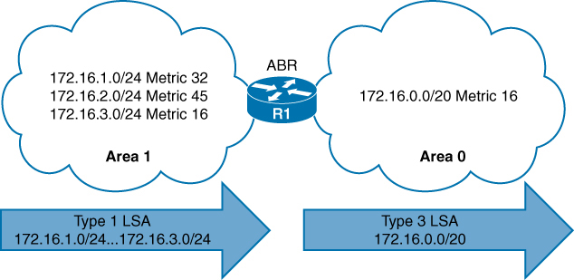
Type 1 LSAs (172.16.1.0/24, 172.16.2.0/24, and 172.16.3.0/24) being summarized into one Type 3 LSA
Summarization works only on Type 1 LSAs and is normally configured (or designed) so that summarization occurs as routes enter the backbone from nonbackbone areas Area x -> Area 0.
At the time of this writing, IOS XE routers set the default metric for the summary LSA to be the lowest metric associated with an LSA
However, the summary metric can statically be set as part of the configuration
R1 summarizes three prefixes with various path costs. The 172.16.3.0/24 prefix has the lowest metric, so that metric will be used for the summarized route.
OSPF behaves similar to Enhanced Interior Gateway Routing Protocol (EIGRP) in that it checks every prefix in the summarization range when a matching Type 1 LSA is added or removed. If a lower metric is available, the summary LSA is advertised with the newer metric; if the lowest metric is removed, a newer and higher metric is identified, and a new summary LSA is advertised with the higher metric.
Configuration of Inter-area Summarization
You define the summarization range and associated area by using the command area area-id range network subnet-mask [advertise | not-advertise] [cost metric] under the OSPF process.
The default behavior is to advertise the summary prefix, so the keyword advertise is not necessary. Appending cost metric to the command statically sets the metric on the summary route.

Routing Table Before OSPF Inter-area Route Summarization
R3# show ip route ospf | begin Gateway
Gateway of last resort is not set

O IA     10.12.1.0/24 [110/2] via 10.23.1.2, 00:02:22, GigabitEthernet0/1
O IA     172.16.1.0 [110/3] via 10.23.1.2, 00:02:12, GigabitEthernet0/1
O IA     172.16.2.0 [110/3] via 10.23.1.2, 00:02:12, GigabitEthernet0/1
O IA     172.16.3.0 [110/3] via 10.23.1.2, 00:02:12, GigabitEthernet0/1
router ospf 1
router-id 192.168.2.2
area 12 range 172.16.0.0 255.255.0.0 cost 45
network 10.12.0.0 0.0.255.255 area 12
network 10.23.0.0 0.0.255.255 area 0
R2 summarizes them into a single summary route, 172.16.0.0/16 static cost of 45 is added to the summary route to reduce CPU load if any of the three networks flap.
R3’s routing table shows that smaller component routes were suppressed while summary route is being advertised
Notice in this output that the path metric is 46 whereas previously the metric for the 172.16.1.0/24 network was 3.
R3# show ip route ospf | begin Gateway
Gateway of last resort is not set

O IA    10.12.1.0/24 [110/2] via 10.23.1.2, 00:02:04, GigabitEthernet0/1
O IA  172.16.0.0/16 [110/46] via 10.23.1.2, 00:00:22, GigabitEthernet0/1
The ABR performing inter-area summarization installs discard routes, which are routes to the Null0 interface that match the summarized network. Discard routes prevent routing loops where portions of the summarized network range do not have a more specific route in the RIB. The administrative distance (AD) for the OSPF summary discard route for internal networks is 110, and it is 254 for external networks.
R2# show ip route ospf | begin Gateway
Gateway of last resort is not set

O        172.16.0.0/16 is a summary, 00:03:11, Null
O        172.16.1.0/24 [110/2] via 10.12.1.1, 00:01:26, GigabitEthernet0/0
O        172.16.2.0/24 [110/2] via 10.12.1.1, 00:01:26, GigabitEthernet0/0
O        172.16.3.0/24 [110/2] via 10.12.1.1, 00:01:26, GigabitEthernet0/0
External Summarization
During OSPF redistribution, external routes are redistributed into the OSPF domain as Type 5 or Type 7 LSAs (NSSA). External summarization reduces the number of external LSAs in an OSPF domain
An external summarization route is configured on the ASBR router, and a smaller component route generates a Type 5/Type 7 external summary route, and the smaller component routes in the summary route are suppressed.
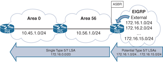
Routing Table Before External Summarization
R5# show ip route ospf | begin Gateway
! Output omitted for brevity
Gateway of last resort is not set

O IA     10.3.3.0/24 [110/67] via 10.45.1.4, 00:01:58, GigabitEthernet0/0
O IA     10.24.1.0/29 [110/65] via 10.45.1.4, 00:01:58, GigabitEthernet0/0
O IA     10.123.1.0/24 [110/66] via 10.45.1.4, 00:01:58, GigabitEthernet0/0
O E2     172.16.1.0 [110/20] via 10.56.1.6, 00:01:00, GigabitEthernet0/1
O E2     172.16.2.0 [110/20] via 10.56.1.6, 00:00:43, GigabitEthernet0/1
..
O E2     172.16.14.0 [110/20] via 10.56.1.6, 00:00:19, GigabitEthernet0/1
O E2     172.16.15.0 [110/20] via 10.56.1.6, 00:00:15, GigabitEthernet0/1
R6
router ospf 1
router-id 192.168.6.6
summary-address 172.16.0.0 255.255.240.0
redistribute eigrp 1 subnets
network 10.56.1.0 0.0.0.255 area 56R5# show ip route ospf | begin Gateway
Gateway of last resort is not set
O IA 10.3.3.0/24 [110/67] via 10.45.1.4, 00:04:55, GigabitEthernet0/0
O IA 10.24.1.0/29 [110/65] via 10.45.1.4, 00:04:55, GigabitEthernet0/0
O IA 10.123.1.0/24 [110/66] via 10.45.1.4, 00:04:55, GigabitEthernet0/0
172.16.0.0/20 is subnetted, 1 subnets
O E2 172.16.0.0 [110/20] via 10.56.1.6, 00:00:02, GigabitEthernet0/1R5# show ip route 172.16.0.0 255.255.240.0
Routing entry for 172.16.0.0/20
Known via “ospf 1”, distance 110, metric 20, type extern 2, forward metric 1
Last update from 10.56.1.6 on GigabitEthernet0/1, 00:02:14 ago
Routing Descriptor Blocks:
* 10.56.1.6, from 192.168.6.6, 00:02:14 ago, via GigabitEthernet0/1
Route metric is 20, traffic share count is 1The summarizing ASBR installs a discard route to Null0 that matches the summary route as part of a loop-prevention mechanism and it will be seen on router that is doing summarization in this case R6
R6# show ip route ospf | begin Gateway
Gateway of last resort is not set

      10.0.0.0/8 is variably subnetted, 6 subnets, 3 masks
O IA     10.3.3.0/24 [110/68] via 10.56.1.5, 00:08:36, GigabitEthernet0/1
O IA     10.24.1.0/29 [110/66] via 10.56.1.5, 00:08:36, GigabitEthernet0/1
O IA     10.45.1.0/24 [110/2] via 10.56.1.5, 00:08:36, GigabitEthernet0/1
O IA     10.123.1.0/24 [110/67] via 10.56.1.5, 00:08:36, GigabitEthernet0/1
      172.16.0.0/16 is variably subnetted, 15 subnets, 3 masks
O        172.16.0.0/20 is a summary, 00:03:52, Null0
ABRs for NSSAs act as ASBRs when a Type 7 LSA is converted to a Type 5 LSA. External summarization can be performed on ABRs only when they match this scenario.
Discontiguous Network and Virtual links
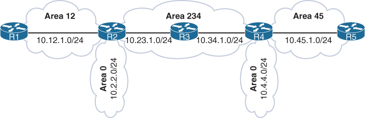
Above is a topology with mistake in design, where R2 and R4 are technically ABRs connected to Area 0 but this will not work, this is called discontiguous network. OSPF can catch this mistake because of all seeing LSDB
Most people would assume that R1 would learn about the route learned by Area 45 because R4 is an ABR. However, they would be wrong. ABRs follow three fundamental rules for creating Type 3 LSAs:
Type 1 LSAs received from an area create Type 3 LSAs into backbone area and nonbackbone areas.
Type 3 LSAs received from Area 0 are created for the nonbackbone area.
Type 3 LSAs received from a nonbackbone area are only inserted into the LSDB for the source area. An ABR does not create a Type 3 LSA for the other areas (including a segmented Area 0).
When suspect, make sure that every ABR is touching Area 0 where all other Aera 0 routers show to be part of it, In above topology only R2 will find itself in the Area 0 and also R4 will only see itself as part of Area 0
Create a detection strategy in lab and practice against that
Virtual Links
OSPF virtual links provide a method to overcome discontiguous networks
Virtual Links are not just used for discontiguous Area 0s but it is also used to connect a topology in which Area 0 <–R100–> Area 1 <–R101–> Area 2, R101 ABR is deprived of Area 0
Area 0 can be extended to remote Areas
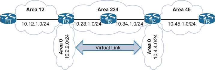
in above topology Area 12 and Area 45 were not orphaned
Area 12 , Area 0 and Area 234 kept working as R2 ABR has Area 0
Similarly Area 45 , Area 0 and Area 234 kept working as R4 ABR has Area 0
But Area 12 routes will not be learned by Area 45 and Area 45 routes will not be learned by Area 12 R2’s Area 0 and R4’s Area 0 are not same, practically preventing both from being in same Area 0
Virtual links are built between routers in the same area
The area in which the virtual link endpoints are established is known as the transit area
The virtual link can be one hop away or multiple hops away from the remote device between the ABRs
The virtual link is built using Type 1 LSAs
virtual links cannot be formed on any OSPF stubby areas
Area 234 cannot be an OSPF stub area. Or in this example Area 0 <–> Area 1 <–> Area 2 , Area 1 cannot be stub area
After Virtual Link configuration both Area 0 will become one Area 0 with 2x subnets 10.2.2.0/24 and 10.4.4.0/24 in Area 0
Think of virtual link being in Area 0, so once virtual link is established between ABRs, ABR that was not part of Area 0 will become part of Area 0 with one link in Area 0 which is virtual link
R2
router ospf 1
 router-id 192.168.2.2
 area 234 virtual-link 192.168.4.4 <<< like tunnel endpoint
 network 10.2.2.2 0.0.0.0 area 0
 network 10.12.1.2 0.0.0.0 area 12
 network 10.23.1.2 0.0.0.0 area 234
R4
router ospf 1
router-id 192.168.4.4
area 234 virtual-link 192.168.2.2 <<< like tunnel endpoint
network 10.4.4.4 0.0.0.0 area 0
network 10.34.1.4 0.0.0.0 area 234
network 10.45.1.4 0.0.0.0 area 45Interface cost for a virtual link cannot be set or dynamically generated as the metric for the intra-area distance between the two virtual link endpoints.
R2# show ip ospf virtual-links
Virtual Link OSPF_VL0 to router 192.168.4.4 is up
  Run as demand circuit
  DoNotAge LSA allowed.
  Transit area 234, via interface GigabitEthernet0/1
Topology-MTID    Cost    Disabled     Shutdown      Topology Name
        0           2         no             no            Base
  Transmit Delay is 1 sec, State POINT_TO_POINT,
  Timer intervals configured, Hello 10, Dead 40, Wait 40, Retransmit 5
    Hello due in 00:00:01
    Adjacency State FULL (Hello suppressed)
    Index 1/1/3, retransmission queue length 0, number of retransmission 0
    First 0x0(0)/0x0(0)/0x0(0) Next 0x0(0)/0x0(0)/0x0(0)
    Last retransmission scan length is 0, maximum is 0
    Last retransmission scan time is 0 msec, maximum is 0 msec
R4# show ip ospf virtual-links
! Output omitted for brevity
Virtual Link OSPF_VL0 to router 192.168.2.2 is up
Run as demand circuit
DoNotAge LSA allowed.
Transit area 234, via interface GigabitEthernet0/0
Topology-MTID Cost Disabled Shutdown Topology Name
0 2 no no Base
Transmit Delay is 1 sec, State POINT_TO_POINT,
Timer intervals configured, Hello 10, Dead 40, Wait 40, Retransmit 5
Hello due in 00:00:08
Adjacency State FULL (Hello suppressed)Notice that the cost here is 2, which accounts for the metrics between R2 and R4
OSPF Virtual Link as an OSPF Interface
R4# show ip ospf interface brief
Interface    PID   Area            IP Address/Mask    Cost  State Nbrs F/C
Gi0/2        1     0               10.4.4.4/24        1     DR    0/0
VL0          1     0               10.34.1.4/24       2     P2P   1/1
Lo0          1     34              192.168.4.4/32     1     DOWN  0/0
Gi0/1        1     45              10.45.1.4/24       1     BDR   1/1
Gi0/0        1     234             10.34.1.4/24       1     BDR   1/1
A Virtual Link Displayed as an OSPF Neighbor
R4# show ip ospf neighbor
Neighbor ID     Pri   State           Dead Time   Address         Interface
192.168.2.2       0   FULL/  -           -        10.23.1.2       OSPF_VL0
192.168.5.5       1   FULL/DR         00:00:34    10.45.1.5       GigabitEthernet0/1
192.168.3.3       1   FULL/DR         00:00:38    10.34.1.3       GigabitEthernet0/0
R1’s and R5’s Routing Tables After the Virtual Link Is Created
R1# show ip route ospf | begin Gateway
Gateway of last resort is not set

O IA     10.2.2.0/24 [110/2] via 10.12.1.2, 00:00:10, GigabitEthernet0/0
O IA     10.4.4.0/24 [110/4] via 10.12.1.2, 00:00:05, GigabitEthernet0/0
O IA     10.23.1.0/24 [110/2] via 10.12.1.2, 00:00:10, GigabitEthernet0/0
O IA     10.34.1.0/24 [110/3] via 10.12.1.2, 00:00:10, GigabitEthernet0/0
O IA     10.45.1.0/24 [110/4] via 10.12.1.2, 00:00:05, GigabitEthernet0/0
R5# show ip route ospf | begin Gateway
Gateway of last resort is not set
O IA 10.2.2.0/24 [110/4] via 10.45.1.4, 00:00:43, GigabitEthernet0/1
O IA 10.4.4.0/24 [110/2] via 10.45.1.4, 00:01:48, GigabitEthernet0/1
O IA 10.12.1.0/24 [110/4] via 10.45.1.4, 00:00:43, GigabitEthernet0/1
O IA 10.23.1.0/24 [110/3] via 10.45.1.4, 00:01:48, GigabitEthernet0/1
O IA 10.34.1.0/24 [110/2] via 10.45.1.4, 00:01:48, GigabitEthernet0/1